Turbine Operation Manual 600 MW Dongfang - baixardoc
10
- 0 - Table of Content Part I Turbine Mainframe Operation .............................................................................. - 2 - Chapter I Overview and Specifications of Unit Equipment ............................................ - 2 - 1. Overview of Steam Turbine and Auxiliaries ............................................................... - 2 - 2. Main Design Specifications of the Unit ...................................................................... - 7 - 2.1 Main Design Specifications of the Steam Turbine ............................................ - 7 - 2.2 Index of Steam and Water Quality.................................................................. - 11 - Chapter II Protection, Control and Test of the Unit ...................................................... - 12 - 1. General Rules of Interlock Protection Test .............................................................. - 12 - 1.1 Purpose and Division of Interlock Protection.................................................. - 12 - 1.2 Test Method of Interlock Protection ................................................................ - 13 - 1.3 Verification for Interlock Protection Test Results ............................................ - 13 - 2. Interlock Protection of Mainframe............................................................................ - 13 - 2.1 Main Thermal Protection of Steam Turbine .................................................... - 13 - 3. Thermal Interlock Protection of Auxiliaries .............................................................. - 25 - 4. Unit Control and Regulation Devices ...................................................................... - 49 - 4.1 Sequence Control System (SCS)................................................................... - 49 - 4.2 Analogue Control System (MCS) ................................................................... - 49 - 4.3 Turbine Digital Electro-hydraulic Control System (DEH) ................................ - 60 - 5. Main Test of the Unit ............................................................................................... - 69 - 5.1 Static Test of the Control System ................................................................... - 69 - 5.2 Manual Trip Test ............................................................................................. - 70 - 5.3 Trip Protection Test of Turbine Emergency Trip System (ETS) ...................... - 71 - 5.4 Turbine Main Trip Solenoid Valve Test ........................................................... - 72 - 5.5 Power-load Unbalance Relay (PLU) Loop Test .............................................. - 73 - 5.6 Eccentric Ring Oil Spray Test of Emergency Governor .................................. - 73 - 5.7 Emergency Governor Minimum Oil Spray Action Speed Test......................... - 74 - 5.8 Turbine Mechanical Over-speed Test ............................................................. - 75 - 5.9 Electric Over-speed Test of Steam Turbine .................................................... - 77 - 5.10 Valves Activity Test ....................................................................................... - 79 - 5.11 MSV and CV Leak Test ................................................................................ - 79 - 5.12 Mainframe Low Lube Oil Pressure Interlock Protection Test ........................ - 79 - 5.13 Vacuum Leakage Test .................................................................................. - 80 - 5.14 Extraction Check Valve Activity Test............................................................. - 81 - 5.15 Load Rejection Test...................................................................................... - 81 - Chapter III Start-up and Outage of the Unit and Operating Maintenance Thereof ....... - 84 - 1 Start-up of the Unit ................................................................................................... - 84 - 1.1 Start-up Specifications and Requirements ..................................................... - 84 - 1.2 Start-up Prohibition Conditions of the Unit ..................................................... - 85 - 1.3 Start-up State Classification of the Unit .......................................................... - 86 - 1.4 Inspection before the Steam Turbine Start-up ................................................ - 87 - 1.5 Operation of Auxiliaries and Systems before the Unit Start-up....................... - 88 - 1.6 Unit Start-up Parameters and Mode Selection Principal ................................ - 90 - 1.7 Cold Start-up of the Unit ................................................................................. - 91 - 1.8 Warm and Hot Start-up of Unit ..................................................................... - 103 - 1.9 Extreme Hot Start-up of Unit ........................................................................ - 105 - 2. Normal Operation and Maintenance of Unit .......................................................... - 106 - 2.1 Routine Maintenance and Requirements ..................................................... - 106 - 2.2 Operational Parameters of Unit .................................................................... - 107 - 2.3 Adjustment and Maintenance for Normal Operational Parameters of Unit ... - 109 - 3. Normal Shutdown of Unit ...................................................................................... - 112 - 3.1 Preparations before Shutdown ..................................................................... - 112 - 3.2 Shutdown with Variable Parameter .............................................................. - 113 - 3.3 Operations after Generator Disconnection ................................................... - 115 - 3.4 Cautions for Unit Shutdown ......................................................................... - 116 - Chapter Ⅳ Accident Management of Unit ............................................................... - 118 - 1. General Principles ................................................................................................. - 118 -
-
Upload
khangminh22 -
Category
Documents
-
view
1 -
download
0
Transcript of Turbine Operation Manual 600 MW Dongfang - baixardoc

- 0 -
Table of Content Part I Turbine Mainframe Operation .............................................................................. - 2 - Chapter I Overview and Specifications of Unit Equipment ............................................ - 2 - 1. Overview of Steam Turbine and Auxiliaries ............................................................... - 2 - 2. Main Design Specifications of the Unit ...................................................................... - 7 -
2.1 Main Design Specifications of the Steam Turbine ............................................ - 7 - 2.2 Index of Steam and Water Quality.................................................................. - 11 -
Chapter II Protection, Control and Test of the Unit ...................................................... - 12 - 1. General Rules of Interlock Protection Test .............................................................. - 12 -
1.1 Purpose and Division of Interlock Protection.................................................. - 12 - 1.2 Test Method of Interlock Protection................................................................ - 13 - 1.3 Verification for Interlock Protection Test Results ............................................ - 13 -
2. Interlock Protection of Mainframe............................................................................ - 13 - 2.1 Main Thermal Protection of Steam Turbine .................................................... - 13 -
3. Thermal Interlock Protection of Auxiliaries .............................................................. - 25 - 4. Unit Control and Regulation Devices ...................................................................... - 49 -
4.1 Sequence Control System (SCS)................................................................... - 49 - 4.2 Analogue Control System (MCS) ................................................................... - 49 - 4.3 Turbine Digital Electro-hydraulic Control System (DEH) ................................ - 60 -
5. Main Test of the Unit ............................................................................................... - 69 - 5.1 Static Test of the Control System ................................................................... - 69 - 5.2 Manual Trip Test............................................................................................. - 70 - 5.3 Trip Protection Test of Turbine Emergency Trip System (ETS) ...................... - 71 - 5.4 Turbine Main Trip Solenoid Valve Test ........................................................... - 72 - 5.5 Power-load Unbalance Relay (PLU) Loop Test.............................................. - 73 - 5.6 Eccentric Ring Oil Spray Test of Emergency Governor .................................. - 73 - 5.7 Emergency Governor Minimum Oil Spray Action Speed Test......................... - 74 - 5.8 Turbine Mechanical Over-speed Test............................................................. - 75 - 5.9 Electric Over-speed Test of Steam Turbine .................................................... - 77 - 5.10 Valves Activity Test....................................................................................... - 79 - 5.11 MSV and CV Leak Test ................................................................................ - 79 - 5.12 Mainframe Low Lube Oil Pressure Interlock Protection Test........................ - 79 - 5.13 Vacuum Leakage Test.................................................................................. - 80 - 5.14 Extraction Check Valve Activity Test............................................................. - 81 - 5.15 Load Rejection Test...................................................................................... - 81 -
Chapter III Start-up and Outage of the Unit and Operating Maintenance Thereof....... - 84 - 1 Start-up of the Unit ................................................................................................... - 84 -
1.1 Start-up Specifications and Requirements ..................................................... - 84 - 1.2 Start-up Prohibition Conditions of the Unit ..................................................... - 85 - 1.3 Start-up State Classification of the Unit .......................................................... - 86 - 1.4 Inspection before the Steam Turbine Start-up ................................................ - 87 - 1.5 Operation of Auxiliaries and Systems before the Unit Start-up....................... - 88 - 1.6 Unit Start-up Parameters and Mode Selection Principal ................................ - 90 - 1.7 Cold Start-up of the Unit................................................................................. - 91 - 1.8 Warm and Hot Start-up of Unit ..................................................................... - 103 - 1.9 Extreme Hot Start-up of Unit ........................................................................ - 105 -
2. Normal Operation and Maintenance of Unit .......................................................... - 106 - 2.1 Routine Maintenance and Requirements ..................................................... - 106 - 2.2 Operational Parameters of Unit.................................................................... - 107 - 2.3 Adjustment and Maintenance for Normal Operational Parameters of Unit ... - 109 -
3. Normal Shutdown of Unit ...................................................................................... - 112 - 3.1 Preparations before Shutdown..................................................................... - 112 - 3.2 Shutdown with Variable Parameter .............................................................. - 113 - 3.3 Operations after Generator Disconnection................................................... - 115 - 3.4 Cautions for Unit Shutdown ......................................................................... - 116 -
Chapter Ⅳ Accident Management of Unit ............................................................... - 118 -
1. General Principles................................................................................................. - 118 -

- 1 -
2. Regulations on the Handling of Unit Accidents ..................................................... - 120 - 2.1 Emergency Outage Conditions of Unit ......................................................... - 120 - 2.2 Fault Shutdown Conditions of Unit............................................................... - 124 - 2.3 Comprehensive Accident Management of Unit ............................................ - 126 -
3. Abnormal Operation and Accident Management of Steam Turbine ...................... - 133 - 3.1 Condenser Vacuum Drop............................................................................. - 133 - 3.2 Steam Turbine Water Attack......................................................................... - 135 - 3.3 Abnormal Vibration of Steam Turbine........................................................... - 137 - 3.4 Increased Axial Displacement ...................................................................... - 139 - 3.5 Damaged or Broken Blade........................................................................... - 140 - 3.6 Lubricating Oil System Failure ..................................................................... - 141 - 3.7 EH Oil System Failure.................................................................................. - 144 - 3.8 Feed Pump Failure ...................................................................................... - 145 - 3.9 Deaerator Failure ......................................................................................... - 149 - 3.10 Heater Failure ............................................................................................ - 152 - 3.11 Generator Sealing Oil System Failure ........................................................ - 153 - 3.12 Generator Hydrogen Cooling System Failure ............................................ - 155 - 3.13 Generator Stator Cooling Water System Failure ........................................ - 157 -
Part II Auxiliary System Operation............................................................................. - 159 -
Chapter Ⅰ General Rules on Start-up (in operation) and Shutdown (out of service) of
Auxiliaries and systems............................................................................................. - 159 - 1. General Operating Rules of Auxiliaries ................................................................. - 159 - 2 General Outage Rules of Auxiliaries ...................................................................... - 162 - Chapter II Auxiliaries and Systems............................................................................ - 163 - 1. Lubricating Oil System .......................................................................................... - 163 - 2. EH Oil System....................................................................................................... - 167 - 3. Unit Bypass System .............................................................................................. - 171 - 4. Gland Sealing System........................................................................................... - 173 - 5. Vacuum System .................................................................................................... - 179 - 6. Circulating Water System...................................................................................... - 183 - 7 Open Circulating Cooling Water System................................................................ - 185 - 8. Condensate System.............................................................................................. - 186 - 9. Regeneration and extraction Steam System ......................................................... - 190 - 10. Feed pump System............................................................................................. - 202 - 11. Auxiliary Steam System....................................................................................... - 211 - 12. Generator Sealing Oil System............................................................................. - 214 - 13. Generator Hydrogen Cooling System ................................................................. - 217 -

- 2 -
Part I Turbine Mainframe Operation
Chapter I Overview and Specifications of Unit Equipment
1. Overview of Steam Turbine and Auxiliaries
The N600-16.7/538/538/-3 steam turbine used in this project is a subcritical, single
reheat, condensing, tandem, three-cylinder four-exhaust, impulse steam turbine
produced and designed by Dongfang Steam Turbine Works. The main and reheat
steam of it is configured to unit system in form of two-one-two. Its high pressure (HP)
cylinder contains one single-governing stage and eight-pressure stage; the
intermediate pressure (IP) cylinder has five-pressure stage; the high and intermediate
pressure (HIP) flow passages are designed to two-layer countercurrent with a
common casing; and the low pressure (LP) is two-layer double-flow LP cylinder with
2*2*7 pressure stages. Through four pieces of admission pipe that are vertically and
symmetrically arranged at the middle of the HIP outer casing, the main steam enters
into the steam turbine, and then to the boiler reheater after experiencing HP 9-stage
work. Similarly, the reheat steam enters into the IP part of the steam turbine in the
same way as the main steam, and then enters into two LP two-pass cylinders
separately through a piece of reducing connector after IP five-stage work; at last it is
exhausted into a double-back pressure condenser through the bi-directionally
arranged exhaust pipe of the two cylinders after the 7-stage work.
The steam turbine is equipped with two HP main stop valves that are used for
contacting the sealing surface well so as to prevent steam leak at the status of wide
open. There are steam strainers inside the valves for purpose of preventing foreign
substances from flowing into the flow passage. The unit is provided with four main
steam control valves for regulating steam volume entering the steam turbine. They
are equipped with a balance chamber for preventing from vibrating and arranged into
a shared valve casing in the form of straight line. The valve casing is independent of
the steam turbine proper. The IP main steam valves and control valves are union
valves with a common valve seat, wherein the former two are sleeve valves and the
later four are spherical valves. Both of them are able to move independently during
the total stroke, and opened, closed by hydraulic pressure and spring separately. The
unit is also provided with two IP union valves each of which has a steam strainer for
preventing foreign substances from entering the flow passage. Under normal
condition, the IP main stop valves and control valves are widely open. The main stop
valves, control valves and union valves are equipped with on-off testers solely used

- 3 -
after overhaul and the remote test can be performed in operation of them on the
condition that the load is not subject to large fluctuation.
The structure of HIP cylinder with common casing and double-shell is used. It
consists of four parts, including an integrated HIP outer casing divided into upper and
low half casings from the split, a HP inner casing divided into upper and lower half
casings, an IP inner casing divided into upper and lower half casings and an IP outer
casing. Two LP cylinders are symmetrical double split flow structure with the function
of middle steam admission and divided into upper and lower parts from the split. The
LP cylinders are designed to three-layer with the first layer served as inner casing for
accommodating the elements of the flow passage, the second one as a heat
insulating layer and the third one as an outer casing for exhausting steam and
supporting the elements in the inner casing. The LP cylinder is connected with the
condenser by a stainless steel elastic expansion joint.
The shaft system of the unit is composed of a steam turbine HP rotor and IP rotor, LP
rotor A and B and a generator rotor. Each of them is connected by a solid coupling.
The steam turbine rotors without center holes are totally integral rotor.
The steam turbine is supported by six pieces of bearing blocks; the HIP rotors are
supported by two titling-pad bearings with #1 and #2 numbers of bearing block; two
LP rotors are supported by two elliptical bearing with #3, #4, #5 and #6 numbers of
bearing block, horizontal split and spherical types, and automatic alignment and
regulation functions. A thrust bearing with the capability of withstanding much high
axial thrust load, whereas resulting in little loss on any loads is structured to bevel
dual thrust disc and located in a middle bearing housing beside the #2 bearing block.
The expansion dead points of the HIP cylinder locates near the center line of the #2
bearing block, the LP cylinder A and B, respectively. A transverse pin at the dead
point restricts the axial displacement of the cylinder, and longitudinal pins in front and
back of the front bearing housing and the longitudinal center line of the two low
pressure cylinders guide the cylinders to expand freely along the axial direction and
restrict the deviation laterally.
An automatic-meshing turning gear of the steam turbine consisting of a motor and
gear train is equipped between the steam turbine and the generator. Its revolution is
1.5r/min and it is able to automatically operate and trip.
To avoid water and steam from returning back the steam turbine, the drainage and
exhaust steam systems of the steam turbine are designed to able to exhaust
condensate in all of devices, pipelines and valves and steam in the HIP cylinder and
HIP gland sealing system discharged at the time of unit trip. Their pneumatic drain
valves are able to be automatically and widely opened at the time of lacking
compressed air resource. To prevent steam from arriving at the intermediate and low

- 4 -
pressure parts to do work through the steam sealing gland located between the high
and intermediate pressure parts at the time of load rejection, an emergency discharge
valve is set at the place of the steam sealing gland. In case that the IP control valve is
closed, it automatically opens and reliefs most of leaked steam into the condenser. In
order to avoid overheat at the HP steam exhaust part resulting from windage loss in
case that the unit is started by the IP cylinder or high and low pressure bypass on low
load, a vent valve (VV) is equipped on the exhaust pipeline of the HP cylinder to
connect with the condenser. There are no drain points on the high and intermediate
pressure cylinders, and so water can be drained solely through the drain point on an
extraction steam pipe. Water of the LP cylinder is drained to a condenser hot well
level and water of the HP main steam pipes and valves is drained to a drain flash tank
of the condenser. The unit is provided with two sets of rectangular drain flash tank
located at lateral outer walls of the HP condenser and the LP condenser, respectively,
and a spray de-superheating device that is used for spraying water while the unit is in
operation.
The regenerative system of the steam turbine has 8-stage non-regulatory extraction
for three sets of HP heater, one deaerator and four sets of LP heater, respectively.
Water of the HP and LP heaters reflows to the deaerator and the condenser,
respectively by means of cascaded drain. Drain water can flow into the condenser
directly in case of accident or low load. Steam source of the steam turbine for feed
water pump is from four-stage extraction under normal conditions; in case of startup
of the unit and low load, it is automatically switched to reheat steam. Its exhaust
steam is discharged into a main condenser. Besides, for regenerative extraction
steam and steam of the steam turbine of the feed water pump, four-stage extraction
of the steam turbine is able to provide auxiliary steam for others. To meet the demand
of connecting the steam exhaust pipe and the drain pipe, the #7 and #8 LP heaters
are designed to compound heaters with a common shell and horizontally configured
at throat part of the condenser with part of which out of the shell.
The condensate system employs an IP condensate polishing system each of which is
provided with a vertical condensate pump with 2*100% volume and one of which is
served as standby. Condensate after boosting pressure enters into the deaerator
through a polishing unit, a gland heater and four LP heaters.
The gland sealing system of the steam turbine is a self-sealing system, i.e. in normal
operation of the unit, steam leakage from the shaft-end steam gland of the HIP
cylinder, and the steam leakage from HIP main stop valve and valve stems of the
control valves after being sprayed and de-superheated is provided for the LP
shaft-end steam gland. The redundant steam flows to the LP heater or condenser
through an overflow station. During startup or operation of unit on low load, the
- 5 -
auxiliary steam station is used for providing steam for the steam gland. The unit is
provided with one set of gland heater with 100% volume and two sets of gland
extraction fan with 100% volume. The gland cooler and the steam turbine of the feed
water pump shares the gland steam. During startup and operation of the unit with low
load, gland steam is fresh or auxiliary steam and pressure of the gland main pipe is
maintained by a gland steam supply valve and an overflow valve. During operation of
the unit with 25%-60% of load, its gland steam is provided by the gland cooler; while
the load is over 60%, the unit is self-sealed and the gland steam supply valve is
closed. The set value of the gland pressure is maintained by the overflow valve and
the redundant steam is discharged into #8 A LP heater through the overflow valve.
The redundant steam is discharged into the condenser through a conversion valve in
case of #8 A LP heater failures.
The emergency governing system is the actuating mechanism of the HP fire-resistant
oil DEH, which works on instruction reception from the DEH and completion of
latching, meets the requirements of combined startup of high and intermediate
pressure cylinders, startup of the IP cylinder and activity test of the valves, and has
the functions of over-speed limitation, fast reliable steam admission interruption and
over-speed protection. The system comprises a LP governing system and a HP
fire-resistant oil system. The LP governing system is composed of an emergency
governor, an emergency governor device and its link lever, a manual stop mechanism,
a reset test valve block, a mechanical shutdown electromagnet and an oil guide ring,
etc. Main functions of it comprise latch, interruption, oil spray and speed hoisting. The
HP fire-resistant oil system consists of a hydraulic servo system, a HP trip system and
a fire-resistant oil supply system. The hydraulic servo system, consisting of a valve
control stage and a servomotor, is used for controlling opening of the valves and
completing fast shutdown of them. This unit is provided with four sets of servomotor
for HP control valves, two for HP main stop valves, IP main stop valves and IP control
valves, respectively. All of said servomotors, with unilateral oil feed, are started up by
fire-resistant oil pressure and closed by spring force of the control stage, so as to
guarantee all of them can be shut down in case of pressure oil loss. The oil supply
system, mainly consisting of two sets of pressure-compensated variable plunger
pump, a regenerative device, an accumulator, oil filtering components, etc., is used
for supplying HP working oil for every actuating mechanisms of the emergency
governing system.
The lubricating oil system is served as main oil pump-oil turbine system driven by the
major axis of the steam turbine. In addition to all bearings of the turbine generators, it
supplies oil for the hydrogen sealing system of the generators, the lubricating device
of the turning gear and the jacking oil pump as well. It comprises a packaged oil
- 6 -
container, a main oil pump (MOP), an AC auxiliary oil pump (TOP), a DC emergency
oil pump (EOP), a boiler oil pump (BOP), a jacking oil device, an oil purification and
regeneration device, six sets of electric heater, two sets of oil cooler with 100%
volume, a change-over valve, a flume extractor, etc. The strainers in the lubricating oil
system are able to be replaced to clean. In view from the head, the lubricating oil
system locates on the right.
For the purpose of successfully putting the turning gear into operation, the jacking oil
system is applied to providing HP oil for every bearing at the time of startup and
shutdown of the unit. Therefore, two sets of jacking oil pump, with the advantages of
high efficiency, low heat value and noise, reliable performance and no leakage under
continuous HP operation, and high volumetric efficiency, etc., are applied in the
system.
The unit employs a HLP two-stage series-wound pneumatic bypass system, in which
the capacity of high pressure bypass is 60%BMCR. This system is able to make the
unit optimally start and shut down, realize two operating modes in accordance with
the operating conditions, startup and stop curves of the steam turbine, shorten the
starting time of the unit in cooperation of setting up a steam temperature of the steam
turbine suitable for the boiler’s. In case that the unit load is variable, the system can
be applied to regulating it so as to improve the stability of the boiler in operation.
The feed water system is configured to unit system, with two sets of 50% BMCR
turbo-feed pump and one set of 50% BMCR electro-driven variable-speed feed water
pump for one set of unit. The turbo-feed pump is put into normal operation and the
electro-driven variable-speed feed water pump is served as standby or startup. The
turbo-feed pump is provided with HP and LP steam sources and configured at the
operating floor of the steam turbine, and its steam is exhausted into the condenser of
the turbine mainframe. The feed water system also provides attemperating water for
overheat and reheat attemperators, and the bypass system.
The unit adopts a distributed control system (DCS) that has the functions of
monitoring the DEH, MEH operator stations and other control systems (data
communication interface) and meeting the requirements of various operating
conditions. The DEH produced by Dongfang Electric Automatic Control Cooperation
Limited for controlling the rotating speed and load of the steam turbine is employed in
the turbine governing system.
Startup mode of the unit: IP cylinder startup, combined startup of the HP, IP cylinders,
whereas IP cylinder startup in priority. The combined startup mode is solely used in
case that the bypass system is cut off due to failure.
Operating mode of the unit: constant pressure, and constant pressure-to-sliding
pressure-to-constant pressure

- 7 -
Load character: with the main functions of bearing base load, and peak load
regulation function
Arrangement of the unit: the turbine generating set is indoors longitudinal sequential
arrangement. The lubricating oil system is configured on the right in view from the
head to the generating set.
Cooling mode of the unit: unit system with counter-flow circulating water system
2. Main Design Specifications of the Unit
2.1 Main Design Specifications of the Steam Turbine
2.1.1 Steam Turbine Proper Specifications
S/N Item Unit Data
Unit specifications
1 Unit model Sub-critical,
single reheat,
three-cylinder
four-exhaust,
tandem and
condensing
2 Steam turbine model N600-16.7/538/5
38-3
3 TMCR output MW 600
4 VWO output MW 640.647
5 HP heater and omni-segmentation
output
MW 600
6 TMCR main steam pressure MPa(a) 16.7

- 8 -
S/N Item Unit Data
7 TMCR main steam temperature ℃ 538
8 TMCR HP cylinder exhaust steam
pressure
Mpa(a) 3.849
9 TMCR inlet pressure of reheat steam Mpa(a) 3.464
10 TMCR inlet temperature of reheat steam ℃ 538
11 TMCR main steam throttle flow t/h 1876
12 Maximum throttle flow of main steam t/h 2028
13 TMCR throttle flow of reheat steam t/h 1596.377
14 TMCR exhaust steam pressure Mpa(a) 0.01013
15 Steam distribution mode Composite
(nozzle/throttle)
16 Design temp of cooling water ℃ Open
32.4/closed 38
17 TMCR feed temperature ℃ 277.2
18 Rated speed R/Min 3000
19 TMCR heat consumption kJ/kW.
h
kcal/kW
8130/1942
- 9 -
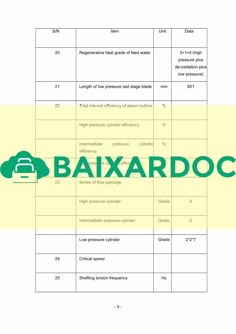
S/N Item Unit Data
20 Regenerative heat grade of feed water 3+1+4 (high
pressure plus
de-oxidation plus
low pressure)
21 Length of low pressure last stage blade mm 851
22 Total internal efficiency of steam turbine %
High pressure cylinder efficiency %
Intermediate pressure cylinder
efficiency
%
Low pressure cylinder efficiency %
23 Series of flow passage
High pressure cylinder Grade 9
Intermediate pressure cylinder Grade 5
Low pressure cylinder Grade 2*2*7
24 Critical speed
25 Shafting torsion frequency Hz