
Layout design for efficiency improvement and cost reduction
9
547 Bull. Pol. Ac.: Tech. 67(3) 2019 BULLETIN OF THE POLISH ACADEMY OF SCIENCES TECHNICAL SCIENCES, Vol. 67, No. 3, 2019 DOI: 10.24425/bpasts.2019.129653 Abstract. In a reality of global competition, companies have to minimize production costs and increase productivity in order to boost com- petitiveness. Facility layout design is one of the most important and frequently used efficiency improvement methods for reducing operational costs in a significant manner. Facility layout design deals with optimum location of facilities (workstation, machine, etc.) on the shop floor and optimum material flow between these objects. In this article, the objectives and procedure of layout design along with the calculation method for layout optimization are all introduced. The study is practice-oriented because the described case study shows how the layout of an assembly plant can be modified to form an ideal re-layout. The research is novel and innovative because the facility layout design and 4 lean methods (takt-time design, line balance, cellular design and one-piece flow) are all combined in order to improve efficiency more significantly, reduce costs and improve more key performance indicators. From the case study it can be concluded that the layout redesign and lean methods resulted in significant reduction of the following seven indicators: amount of total workflow, material handling cost, total travel distance of goods, space used for assembly, number of workers, labor cost of workers and the number of Kanban stops. Key words: facility layout design, lean method, efficiency improvement. Layout design for efficiency improvement and cost reduction G. KOVÁCS * University of Miskolc, Faculty of Mechanical Engineering and Informatics, Institute of Logistics, 3515 Miskolc, Hungary distance for the flow of materials and workers between facil- ities, and minimize the material handling cost and lead times in the manufacturing process. There are two types of facility layout improvement: new facility design and redesign of an existing layout. In the study, the objectives, the procedure of layout design and the calculation method for layout optimization are all intro- duced. The article is relevant and practice-oriented because besides the introduction of theoretical background, a practical efficiency improvement method is also introduced for redesign of the layout of an assembly plant in a case study. The research is original and unique because two efficiency improvement methods are combined in the case study. The clas- sical facility layout design method is used as the basis, but four lean methods (takt-time design, line balance, cellular design and one-piece flow) are also applied. The goal of the application of lean methods is to form a more effective re-layout, meaning that costs will be reduced and KPIs (key performance indicators) will be improved. In the case study the combination of the two methods resulted in significant reduction of the following seven indica- tors: the amount of total workflow, the material handling cost, the total travel distance of goods, the space used for assembly, the number of workers, the labor cost of workers and the num- ber of Kanban stops. Consequently, the case study also confirms that the combination of facility layout design and lean methods is an effective tool for process improvement. 2. Literature review There are numerous tools and methods for improvement of production processes. The most frequently used efficiency improvement methods are simulation, lean method and facility 1. Introduction Among the growing market globalization, where customer demands are changing continuously, enterprises have to improve efficiency and focus on cost reduction and profitabil- ity in order to increase their competitiveness. Therefore, the application of efficiency improvement methods is essential for such companies. This is the reason why the topic of the study is highly important and relevant. Manufacturing systems have to become more complex and flexible in order to respond to the rapidly changing economic environment. The resources required in manufacturing (materials, machines, labor force, space and other facilities) are limited. Therefore, it is very important for manufacturing companies to produce cost-effec- tive and high-quality products, which can be achieved by max- imized utilization of resources and minimized production costs. Facility layout design is one of the most important and fre- quently used efficiency improvement methods, since it can lead to significant reduction in the operational costs of companies. Therefore, this method is used by more and more manufacturing companies and service providers. Facility layout design means the process of finding an optimum arrangement of facilities (objects: department, workstation, machine, equipment, etc.) on – in this particular case – a manufacturing shop floor. Addi- tionally, the layout of the manufacturing facilities in a plant has to be adjusted from time to time to fit changing production plans and processes. The main objectives of facility layout design are to improve the performance of the production process, minimize the total * e-mail: [email protected] Manuscript submitted 2018-09-01, revised 2018-10-01, initially accepted for publication 2018-10-22, published in June 2019.
-
Upload
khangminh22 -
Category
Documents
-
view
2 -
download
0
Transcript of Layout design for efficiency improvement and cost reduction
547Bull. Pol. Ac.: Tech. 67(3) 2019
BULLETIN OF THE POLISH ACADEMY OF SCIENCES TECHNICAL SCIENCES, Vol. 67, No. 3, 2019DOI: 10.24425/bpasts.2019.129653
Abstract. In a reality of global competition, companies have to minimize production costs and increase productivity in order to boost com-petitiveness. Facility layout design is one of the most important and frequently used efficiency improvement methods for reducing operational costs in a significant manner. Facility layout design deals with optimum location of facilities (workstation, machine, etc.) on the shop floor and optimum material flow between these objects. In this article, the objectives and procedure of layout design along with the calculation method for layout optimization are all introduced. The study is practice-oriented because the described case study shows how the layout of an assembly plant can be modified to form an ideal re-layout. The research is novel and innovative because the facility layout design and 4 lean methods (takt-time design, line balance, cellular design and one-piece flow) are all combined in order to improve efficiency more significantly, reduce costs and improve more key performance indicators. From the case study it can be concluded that the layout redesign and lean methods resulted in significant reduction of the following seven indicators: amount of total workflow, material handling cost, total travel distance of goods, space used for assembly, number of workers, labor cost of workers and the number of Kanban stops.
Key words: facility layout design, lean method, efficiency improvement.
Layout design for efficiency improvement and cost reduction
G. KOVÁCS*University of Miskolc, Faculty of Mechanical Engineering and Informatics, Institute of Logistics, 3515 Miskolc, Hungary
distance for the flow of materials and workers between facil-ities, and minimize the material handling cost and lead times in the manufacturing process. There are two types of facility layout improvement: new facility design and redesign of an existing layout.
In the study, the objectives, the procedure of layout design and the calculation method for layout optimization are all intro-duced. The article is relevant and practice-oriented because besides the introduction of theoretical background, a practical efficiency improvement method is also introduced for redesign of the layout of an assembly plant in a case study.
The research is original and unique because two efficiency improvement methods are combined in the case study. The clas-sical facility layout design method is used as the basis, but four lean methods (takt-time design, line balance, cellular design and one-piece flow) are also applied. The goal of the application of lean methods is to form a more effective re-layout, meaning that costs will be reduced and KPIs (key performance indicators) will be improved.
In the case study the combination of the two methods resulted in significant reduction of the following seven indica-tors: the amount of total workflow, the material handling cost, the total travel distance of goods, the space used for assembly, the number of workers, the labor cost of workers and the num-ber of Kanban stops. Consequently, the case study also confirms that the combination of facility layout design and lean methods is an effective tool for process improvement.
2. Literature review
There are numerous tools and methods for improvement of production processes. The most frequently used efficiency improvement methods are simulation, lean method and facility
1. Introduction
Among the growing market globalization, where customer demands are changing continuously, enterprises have to improve efficiency and focus on cost reduction and profitabil-ity in order to increase their competitiveness. Therefore, the application of efficiency improvement methods is essential for such companies. This is the reason why the topic of the study is highly important and relevant. Manufacturing systems have to become more complex and flexible in order to respond to the rapidly changing economic environment. The resources required in manufacturing (materials, machines, labor force, space and other facilities) are limited. Therefore, it is very important for manufacturing companies to produce cost-effec-tive and high-quality products, which can be achieved by max-imized utilization of resources and minimized production costs.
Facility layout design is one of the most important and fre-quently used efficiency improvement methods, since it can lead to significant reduction in the operational costs of companies. Therefore, this method is used by more and more manufacturing companies and service providers. Facility layout design means the process of finding an optimum arrangement of facilities (objects: department, workstation, machine, equipment, etc.) on – in this particular case – a manufacturing shop floor. Addi-tionally, the layout of the manufacturing facilities in a plant has to be adjusted from time to time to fit changing production plans and processes.
The main objectives of facility layout design are to improve the performance of the production process, minimize the total
*e-mail: [email protected]
Manuscript submitted 2018-09-01, revised 2018-10-01, initially accepted for publication 2018-10-22, published in June 2019.
548
G. Kovács
Bull. Pol. Ac.: Tech. 67(3) 2019
layout design [1, 2]. These methods are often applied at compa-nies in many sectors to increase competitiveness. In this article, facility layout design will be introduced in detail.
The reasons for design/redesign of facility layouts are the continuously changing customer demands, which lead to poor utilization of machines, labor force and facilities [3]. Facil-ity layout planning means the allocation design of facilities in a manufacturing shop floor. A facility is an entity that facilitates the performance of any job [4].
Optimum location of facilities in a plant has a massive impact on the system performance, e.g. manufacturing costs, lead times, productivity and amount of work in process (WIP). A well-designed manufacturing layout can reduce the operating cost by up to 50% [5] and minimize material handling costs while considering any physical restrictions on such arrangement [6, 7].
The facility layout problem (FLP) involves a given num-ber of facilities in order to minimize the total cost of moving the required amount of material between the facilities [8–10]. A number of theoretical methods exist for designing and opti-mizing FLPs, both for new facility design and for redesign of an existing layout [11, 12]. Layout problems can be classified in different ways, depending on the workshop characteristics, general problems to be solved and the static or dynamic nature of the layout problems to be solved [13, 14], among others. The facility layout problem has been modelled in the litera-ture as a quadratic assignment problem, quadratic set covering problem, linear integer programming problem, mixed integer programming problem, graph theoretic problem, etc. [5, 13]. Relevant publications on this topic mainly focus on mathe-matical solutions of theoretical models, rather than on real-life practical layout problems.
In contrast, in this publication I wish to use a real case study to confirm that facility layout design is an effective method which can be widely used in practice for process improvement at manufacturing companies and service providers. There-fore, my article is practice-oriented, because in addition to the introduction of theoretical background, the layout redesign of an assembly plant is introduced in a case study and its effec-tiveness is calculated. The results of the facility redesign were obtained successfully at an assembly plant within the frame-work of an R&D project.
3. Definition and objectives of facility layout design
Definition of facility layout design: optimum arrangement of facilities in a manufacturing site and optimum flow of materials from one facility to another, which minimizes material handling costs. A facility may be a department, workstation, machine, equipment, etc.
The facility layout problem is a fundamental optimization problem encountered at many manufacturing companies and service providers. Solving FLPs requires mathematical exper-tise and competences which are computationally intensive and time-consuming. There are two types of facility layout design: 1) new layout design, and 2) redesign of an existing layout.
The main objective of facility layout design is to design more effective workflow and improve productivity of the manu-facturing process by improving the flow of materials and work-ers between machines in the manufacturing area to minimize the total distance of goods flow, the material handling cost and the time spent in the manufacturing system. Optimum facility lay-out provides higher utilization of resources and cost reduction.
Generally, an efficient facility layout should attempt to meet the following objectives:● to maximize utilization of resources (space, facilities, labor
force, etc.),● to increase productivity of the company,● to minimize material handling cost,● to minimize the movement of goods, workers and equip-
ment,● to minimize overall production time,● to minimize investments in equipment,● to create a safe and comforTable work environment,● to maintain the flexibility of operation (changes in the layout
to introduce new products or production technology).
4. Optimization method for facility layout design
In the facility layout problem, a non-overlapping planar orthog-onal arrangement of n rectangular workstations has to be defined within a given rectangular shop floor of size Lx£Ly. During the optimization, all of the possible alternative facility layouts/re-layouts are defined taking design constraints into consider-ation. After that the optimum layout/re-layout is selected, based on the objective function (1).
4.1. Objective function. Material flow efficiency is a fre-quently used term for the description of the amount of work-flow that should be minimized. A typical formulation of the optimization problem can be as follows:
min E = i =1
n
∑j =1
n
∑ fij dij (1)
where n is the number of facilities in the layout, fij is the amount of material flow from facility i to facility j, dij is the rectilin-ear distance between their centroids and fij dij is the material flow efficiency realized by material flow between facility i and facility j [UL.m, etc.] (UL is a unit load, which can be a pallet, box, etc.).
Material flow matrix:
‗F =
1 … j … n
1⁝i⁝n
fij
fij: average amount of material flow from facility i to facility j per hour or shift [pieces of goods (pcs), pieces of unit loads (UL), etc.].
549
Layout design for efficiency improvement and cost reduction
Bull. Pol. Ac.: Tech. 67(3) 2019
Distance matrix:
‗D =
1 … j … n
1⁝i⁝n
dij
dij: distance between the centroids of facility i and facility j [m].
4.2. Constraints. Constraints for optimum allocation of facili-ties in a manufacturing shop floor can be the following: archi-tectural limitations, space requirements of facilities, founda-tion of machines (fixed position or moveable), relations of the facilities (e.g. order of machines), vibration and noise effects, relation with internal and external transport paths, etc.
5. Combination of facility layout design and lean methods
The research is novel and unique because facility layout design and lean methods were combined in order to improve efficiency to a more significant extent, to reduce costs and improve more KPIs. The combination of the two methods is advantageous because the essence of the layout design is the optimum arrangement of n workstations on a given shop floor, while the lean methods provide the possibility of reducing the number of workstations.
Advantages of combining the two methods:● the operational cost of the company can be significantly
reduced,● the performance of the production process can be improved, ●many KPIs can be improved.
The classical facility layout design and 4 lean methods [1 – takt-time design, 2 – line balance, 3 – cellular design, and 4 – one-piece flow] are combined and applied in a case study (described in section 8) in order to improve efficiency and reduce costs to a more significant extent.
Theories, general characteristics and calculation procedures of the above-mentioned 4 lean methods are described in sec-tion 6. The application of these methods is introduced in a real case study in section 8.3.
6. Application of 4 lean methods
The aim of the lean philosophy is cost reduction by means of eliminating non-value added activities [2]. The focus of the philosophy is to improve quality, decrease wastes and optimize the cost of production processes.
6.1. Takt-time design method. The scheduling of production is determined by the customer. Takt-time is the average time in which a final product needs to be produced in order to satisfy customer demand [16, 17].
Takt-time can be calculated by:
Ttakt = Ta
Dsecunit
(2)
where Ta is the net time available to work [work time per shift: sec], D is the customer demand [final products required per shift: unit].
Activities at workstations that require more time than takt-time form bottlenecks in the manufacturing process. These bottlenecks can be identified very easily with the help of this analysis. Activities at workstations that require less time than takt-time are also critical, because the unutilized resources (labor force, equipment) are also wastes in the process.
6.2. Line balance method and calculation of the number of operators and workstations. The next step is to define how many workers and workstations are required to run the assem-bly work cell.
Assembly line balancing deals with reconfiguration (bal-ancing) of the size of the line and assignment of workers on the assembly line. The aim is to create task groups that mini-mize the idle time of workers and machines and result in high utilization of human work and machines. This can be achieved if the time consumption of the task groups is approximately equal, close to takt-time. The required number of operators can be calculated by:
Noper = Ttotal
Ttakt (3)
where Ttotal is the time consumption to make one final product on the assembly line [sec], and Ttakt is takt-time [sec].
Line balancing means levelling the workload of all pro-cesses in the assembly cell to eliminate bottlenecks and free capacities. On the assembly line, every operator and machine is doing the same amount of work over time, no one is overloaded and no one is underloaded.
6.3. Cellular design and one-piece flow methods. Traditional process layout can be changed by means of cellular layout and moveable workstations can be organized into a U-shaped cell. Cellular manufacturing has lots of advantages [16–17]. The goal of the cellular design is to achieve perfect goods flow allowing one-piece flow on the assembly line.
The main benefits of the U-shaped cellular layout are the following: continuous one-piece flow and balanced worksta-tions can provide fast flow of goods inside the assembly pro-cess. Productivity can be increased, lead times can be reduced, and the compactness of a cell minimizes the space needed for the assembly process. Additionally, the amount of work in pro-cess stock can be minimized.
7. General steps of layout redesign in practice
The main objective of facility layout redesign is to achieve effective workflow, improve productivity and reduce total mate-rial flow in the shop floor.
550
G. Kovács
Bull. Pol. Ac.: Tech. 67(3) 2019
The main steps of facility layout redesign are the follow-ing:Step 1: Define the objectives of the facility design.Step 1: Generally, the main objectives of facility layout plan-
ning are to minimize the total distance of goods flow, the material handling cost and the time spent in the manufacturing system.
Step 2: Define the main and supporting activities of the man-ufacturing process.
Step 2: Constraints and requirements relating to the activities (e.g. workstations), human resources, equipment and material flows all have to be specified.
Step 3: Determine the space requirements for all activitiesStep 3: Space requirement for all objects and material flow
paths has to be calculated.Step 4: Create alternatives for facility layouts.Step 4: Variations of layouts have to be formed that consider
alternative facility locations and material flow paths.Step 5: Select the most effective facility layout.Step 4: The elaborated layout alternatives have to be evaluated
and compared based on the objective defined in step 1.Step 6: Implement the best layout.Step 4: The best facility plan has to be selected and imple-
mented.In the following sections of the paper a real case study will
be introduced that employs a layout redesign method.
8. Case study for layout redesign
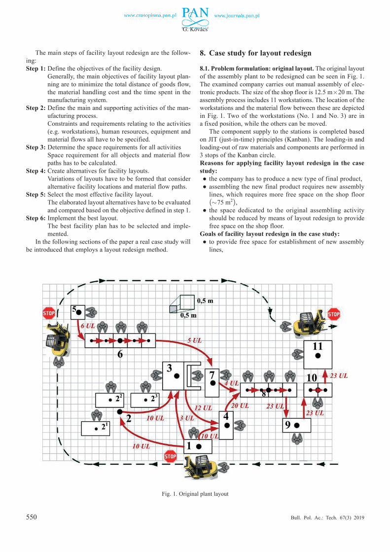
8.1. Problem formulation: original layout. The original layout of the assembly plant to be redesigned can be seen in Fig. 1. The examined company carries out manual assembly of elec-tronicproducts.Thesizeoftheshopflooris12.5 m£20 m.Theassembly process includes 11 workstations. The location of the workstations and the material flow between these are depicted inFig.1.Twoof theworkstations (No. 1andNo. 3)are ina fixed position, while the others can be moved.
The component supply to the stations is completed based on JIT (just-in-time) principles (Kanban). The loading-in and loading-out of raw materials and components are performed in 3 stops of the Kanban circle.Reasons for applying facility layout redesign in the case study:● the company has to produce a new type of final product,● assembling the new final product requires new assembly
lines, which requires more free space on the shop floor (»75 m2),
● the space dedicated to the original assembling activity should be reduced by means of layout redesign to provide free space on the shop floor.
Goals of facility layout redesign in the case study:● to provide free space for establishment of new assembly
lines,
Fig. 1. Original plant layout
551
Layout design for efficiency improvement and cost reduction
Bull. Pol. Ac.: Tech. 67(3) 2019
● to arrange the workstations on the shop floor in an optimum manner,
● to minimize total distance of flow of materials and workers between facilities,
● to minimize the material handling cost,● to reduce lead times and increase productivity,● to reduce the number of workers (reduce labor costs),● to create a safe and comfortable environment for the work-
ers.
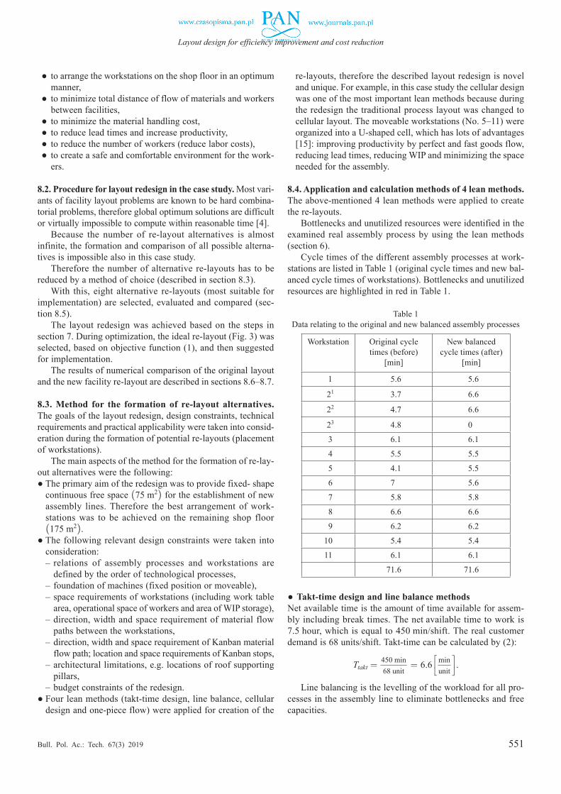
8.2. Procedure for layout redesign in the case study. Most vari-ants of facility layout problems are known to be hard combina-torial problems, therefore global optimum solutions are difficult or virtually impossible to compute within reasonable time [4].
Because the number of re-layout alternatives is almost infinite, the formation and comparison of all possible alterna-tives is impossible also in this case study.
Therefore the number of alternative re-layouts has to be reduced by a method of choice (described in section 8.3).
With this, eight alternative re-layouts (most suitable for implementation) are selected, evaluated and compared (sec-tion 8.5).
The layout redesign was achieved based on the steps in section 7. During optimization, the ideal re-layout (Fig. 3) was selected, based on objective function (1), and then suggested for implementation.
The results of numerical comparison of the original layout and the new facility re-layout are described in sections 8.6–8.7.
8.3. Method for the formation of re-layout alternatives. The goals of the layout redesign, design constraints, technical requirements and practical applicability were taken into consid-eration during the formation of potential re-layouts (placement of workstations).
The main aspects of the method for the formation of re-lay-out alternatives were the following:●The primary aim of the redesign was to provide fixed- shape
continuous free space (75 m2) for the establishment of new assembly lines. Therefore the best arrangement of work-stations was to be achieved on the remaining shop floor (175 m2).
●The following relevant design constraints were taken into consideration:– relations of assembly processes and workstations are
defined by the order of technological processes,– foundation of machines (fixed position or moveable),– space requirements of workstations (including work table
area, operational space of workers and area of WIP storage),– direction, width and space requirement of material flow
paths between the workstations,– direction, width and space requirement of Kanban material
flow path; location and space requirements of Kanban stops,– architectural limitations, e.g. locations of roof supporting
pillars,– budget constraints of the redesign.
●Four lean methods (takt-time design, line balance, cellular design and one-piece flow) were applied for creation of the
re-layouts, therefore the described layout redesign is novel and unique. For example, in this case study the cellular design was one of the most important lean methods because during the redesign the traditional process layout was changed to cellularlayout.Themoveableworkstations(No.5‒11)wereorganized into a U-shaped cell, which has lots of advantages [15]: improving productivity by perfect and fast goods flow, reducing lead times, reducing WIP and minimizing the space needed for the assembly.
8.4. Application and calculation methods of 4 lean methods. The above-mentioned 4 lean methods were applied to create the re-layouts.
Bottlenecks and unutilized resources were identified in the examined real assembly process by using the lean methods (section 6).
Cycle times of the different assembly processes at work-stations are listed in Table 1 (original cycle times and new bal-anced cycle times of workstations). Bottlenecks and unutilized resources are highlighted in red in Table 1.
Table 1 Data relating to the original and new balanced assembly processes
Workstation Original cycle times (before)
[min]
New balanced cycle times (after)
[min]
11 15.6 15.6
121 13.7 16.6
122 14.7 16.6
123 14.8 10.1
13 16.1 16.1
14 15.5 15.5
15 14.1 15.5
16 17.1 15.6
17 15.8 15.8
18 16.6 16.6
19 16.2 16.2
10 15.4 15.4
11 16.1 16.1
71.6 71.6
●Takt-time design and line balance methodsNet available time is the amount of time available for assem-bly including break times. The net available time to work is 7.5 hour, which is equal to 450 min/shift. The real customer demand is 68 units/shift. Takt-time can be calculated by (2):
Ttakt = 450 min68 unit
= 6.6 minunit
.
Line balancing is the levelling of the workload for all pro-cesses in the assembly line to eliminate bottlenecks and free capacities.
552
G. Kovács
Bull. Pol. Ac.: Tech. 67(3) 2019
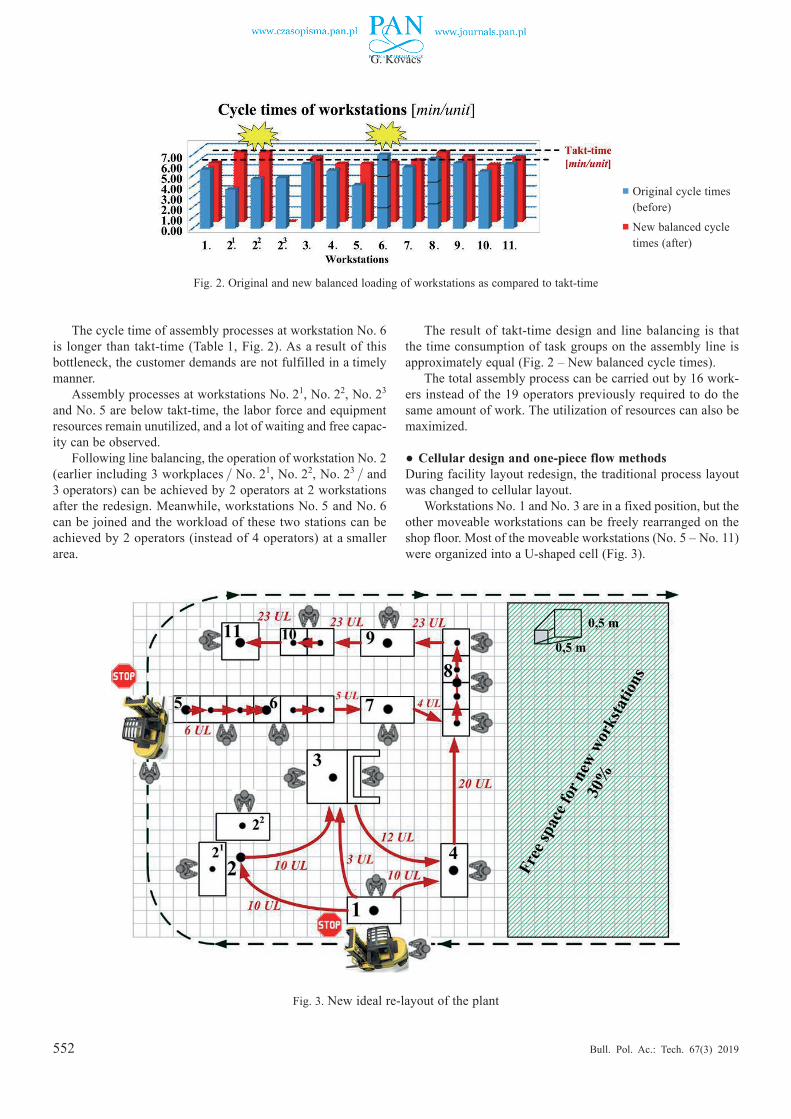
The cycle time of assembly processes at workstation No. 6 is longer than takt-time (Table 1, Fig. 2). As a result of this bottleneck, the customer demands are not fulfilled in a timely manner.
Assembly processes at workstations No. 21, No. 22, No. 23 and No. 5 are below takt-time, the labor force and equipment resources remain unutilized, and a lot of waiting and free capac-ity can be observed.
Following line balancing, the operation of workstation No. 2 (earlierincluding3workplaces / No.21, No. 22, No. 23 / and3 operators) can be achieved by 2 operators at 2 workstations after the redesign. Meanwhile, workstations No. 5 and No. 6 can be joined and the workload of these two stations can be achieved by 2 operators (instead of 4 operators) at a smaller area.
The result of takt-time design and line balancing is that the time consumption of task groups on the assembly line is approximately equal (Fig. 2 – New balanced cycle times).
The total assembly process can be carried out by 16 work-ers instead of the 19 operators previously required to do the same amount of work. The utilization of resources can also be maximized.
●Cellular design and one-piece flow methodsDuring facility layout redesign, the traditional process layout was changed to cellular layout.
Workstations No. 1 and No. 3 are in a fixed position, but the other moveable workstations can be freely rearranged on the shop floor. Most of the moveable workstations (No. 5 – No. 11) were organized into a U-shaped cell (Fig. 3).
Fig. 2. Original and new balanced loading of workstations as compared to takt-time
Fig. 3. New ideal re-layout of the plant
■ Original cycle times (before)
■ New balanced cycle times (after)
553
Layout design for efficiency improvement and cost reduction
Bull. Pol. Ac.: Tech. 67(3) 2019
The main advantages of the new U-shaped cell: free space can be provided on the shop floor and risk to the component supply can be minimized.
Due to line balancing, one-piece flow can be realized, which results in the reduction of WIP in the assembly process.
8.5. Evaluation of the elaborated re-layouts in order to select the ideal re-layout. Because the number of re-layout alterna-tives is almost infinite, the number of alternative re-layouts had to be reduced by a method of choice (described in section 8.3).
With this, eight alternative re-layouts (most suiTable for implementation) were selected, evaluated and compared.
During optimization, the ideal re-layout was selected, based on objective function (1).
Due to the lack of space, in this paper only the ideal re-lay-out (Fig. 3) will be presented in detail and numerically com-pared to the original layout (Table 2).
In our case, the comparison (before/after) was achieved based on the following aspects:
1) material flow efficiency,2) material handling cost,3) total travel distance of goods,4) space used for assembly,5) number of workers,6) labor cost of workers,7) number of stops in the Kanban circle.
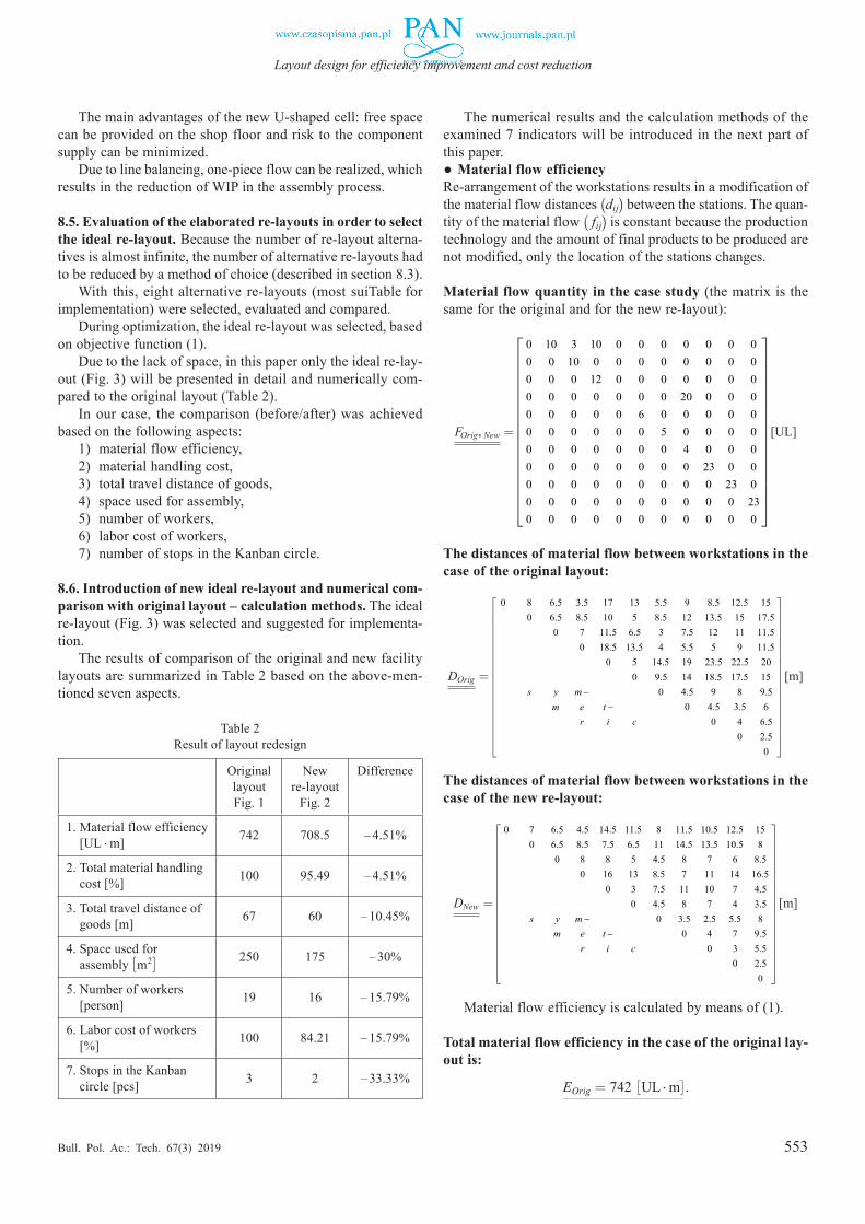
8.6. Introduction of new ideal re-layout and numerical com-parison with original layout – calculation methods. The ideal re-layout (Fig. 3) was selected and suggested for implementa-tion.
The results of comparison of the original and new facility layouts are summarized in Table 2 based on the above-men-tioned seven aspects.
Table 2 Result of layout redesign
Original layoutFig. 1
New re-layout
Fig. 2
Difference
1. Material flow efficiency [UL ¢ m] 742 708.5 – 4.51%
2. Total material handling cost [%] 100 95.49 – 4.51%
3. Total travel distance of goods [m] 67 60 – 10.45%
4. Space used for assembly [m2] 250 175 – 30%
5. Number of workers [person] 19 16 – 15.79%
6. Labor cost of workers [%] 100 84.21 – 15.79%
7. Stops in the Kanban circle [pcs] 3 2 – 33.33%
The numerical results and the calculation methods of the examined 7 indicators will be introduced in the next part of this paper.●Material flow efficiencyRe-arrangement of the workstations results in a modification of the material flow distances (dij) between the stations. The quan-tity of the material flow ( fij) is constant because the production technology and the amount of final products to be produced are not modified, only the location of the stations changes.
Material flow quantity in the case study (the matrix is the same for the original and for the new re-layout):
FOrig, New = ,
0 10 3 10 0 0 0 0 0 0 00 0 10 0 0 0 0 0 0 0 00 0 0 12 0 0 0 0 0 0 00 0 0 0 0 0 0 20 0 0 00 0 0 0 0 6 0 0 0 0 0
0 0 0 0 0 0 5 0 0 0 00 0 0 0 0 0 0 4 0 0 00 0 0 0 0 0 0 0 23 0 00 0 0 0 0 0 0 0 0 23 00 0 0 0 0 0 0 0 0 0 230 0 0 0 0 0 0 0 0 0 0
ULOrig NewF
=
[UL]
The distances of material flow between workstations in the case of the original layout:
DOrig =
0 8 6.5 3.5 17 13 5.5 9 8.5 12.5 150 6.5 8.5 10 5 8.5 12 13.5 15 17.5
0 7 11.5 6.5 3 7.5 12 11 11.50 18.5 13.5 4 5.5 5 9 11.5
0 5 14.5 19 23.5 22.5 200 9.5 14 18.5 17.5 15
0 4.5 9 8 9.50 4.5 3.5 6
0 4 6.50 2.5
0
Origs y m
m e tr i c
D
= −
−
m
[m]
The distances of material flow between workstations in the case of the new re-layout:
DNew =
0 7 6.5 4.5 14.5 11.5 8 11.5 10.5 12.5 150 6.5 8.5 7.5 6.5 11 14.5 13.5 10.5 8
0 8 8 5 4.5 8 7 6 8.50 16 13 8.5 7 11 14 16.5
0 3 7.5 11 10 7 4.5 0 4.5 8 7 4 3.5
0 3.5 2.5 5.5 80 4 7 9.5
0 3 5.50 2.5
0
mNews y m
m e tr i c
D
= −
−
[m]
Material flow efficiency is calculated by means of (1).
Total material flow efficiency in the case of the original lay-out is:
EOrig = 742 £UL ¢ m
¤.
554
G. Kovács
Bull. Pol. Ac.: Tech. 67(3) 2019
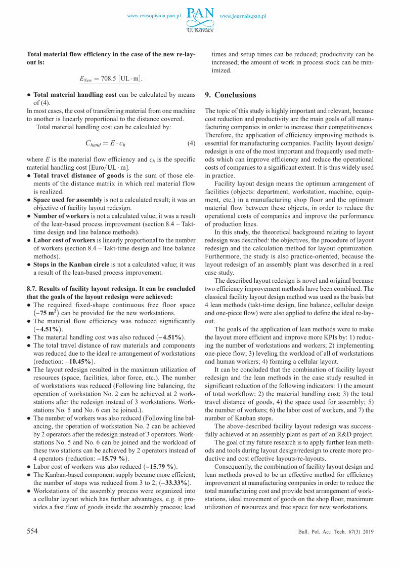
Total material flow efficiency in the case of the new re-lay-out is:
ENew = 708.5 £UL ¢ m
¤.
●Total material handling cost can be calculated by means of (4).
In most cases, the cost of transferring material from one machine to another is linearly proportional to the distance covered.
Total material handling cost can be calculated by:
Chand = E ¢ ch (4)
where E is the material flow efficiency and ch is the specific material handling cost [Euro/UL ¢ m].●Total travel distance of goods is the sum of those ele-
ments of the distance matrix in which real material f low is realized.
●Space used for assembly is not a calculated result; it was an objective of facility layout redesign.
●Number of workers is not a calculated value; it was a result of the lean-based process improvement (section 8.4 – Takt-time design and line balance methods).
●Labor cost of workers is linearly proportional to the number of workers (section 8.4 – Takt-time design and line balance methods).
●Stops in the Kanban circle is not a calculated value; it was a result of the lean-based process improvement.
8.7. Results of facility layout redesign. It can be concluded that the goals of the layout redesign were achieved:●The required fixed-shape continuous free floor space
(–75 m2) can be provided for the new workstations.●The material flow efficiency was reduced significantly
(– 4.51%).●The material handling cost was also reduced (– 4.51%).●The total travel distance of raw materials and components
was reduced due to the ideal re-arrangement of workstations (reduction: –10.45%).
●The layout redesign resulted in the maximum utilization of resources (space, facilities, labor force, etc.). The number of workstations was reduced (Following line balancing, the operation of workstation No. 2 can be achieved at 2 work-stations after the redesign instead of 3 workstations. Work-stations No. 5 and No. 6 can be joined.).
●The number of workers was also reduced (Following line bal-ancing, the operation of workstation No. 2 can be achieved by 2 operators after the redesign instead of 3 operators. Work-stations No. 5 and No. 6 can be joined and the workload of these two stations can be achieved by 2 operators instead of 4 operators (reduction: –15.79 %).
●Labor cost of workers was also reduced (–15.79 %).●The Kanban-based component supply became more efficient;
the number of stops was reduced from 3 to 2, (–33.33%).●Workstations of the assembly process were organized into
a cellular layout which has further advantages, e.g. it pro-vides a fast flow of goods inside the assembly process; lead
times and setup times can be reduced; productivity can be increased; the amount of work in process stock can be min-imized.
9. Conclusions
The topic of this study is highly important and relevant, because cost reduction and productivity are the main goals of all manu-facturing companies in order to increase their competitiveness. Therefore, the application of efficiency improving methods is essential for manufacturing companies. Facility layout design/redesign is one of the most important and frequently used meth-ods which can improve efficiency and reduce the operational costs of companies to a significant extent. It is thus widely used in practice.
Facility layout design means the optimum arrangement of facilities (objects: department, workstation, machine, equip-ment, etc.) in a manufacturing shop floor and the optimum material flow between these objects, in order to reduce the operational costs of companies and improve the performance of production lines.
In this study, the theoretical background relating to layout redesign was described: the objectives, the procedure of layout redesign and the calculation method for layout optimization. Furthermore, the study is also practice-oriented, because the layout redesign of an assembly plant was described in a real case study.
The described layout redesign is novel and original because two efficiency improvement methods have been combined. The classical facility layout design method was used as the basis but 4 lean methods (takt-time design, line balance, cellular design and one-piece flow) were also applied to define the ideal re-lay-out.
The goals of the application of lean methods were to make the layout more efficient and improve more KPIs by: 1) reduc-ing the number of workstations and workers; 2) implementing one-piece flow; 3) leveling the workload of all of workstations and human workers; 4) forming a cellular layout.
It can be concluded that the combination of facility layout redesign and the lean methods in the case study resulted in significant reduction of the following indicators: 1) the amount of total workflow; 2) the material handling cost; 3) the total travel distance of goods, 4) the space used for assembly; 5) the number of workers; 6) the labor cost of workers, and 7) the number of Kanban stops.
The above-described facility layout redesign was success-fully achieved at an assembly plant as part of an R&D project.
The goal of my future research is to apply further lean meth-ods and tools during layout design/redesign to create more pro-ductive and cost effective layouts/re-layouts.
Consequently, the combination of facility layout design and lean methods proved to be an effective method for efficiency improvement at manufacturing companies in order to reduce the total manufacturing cost and provide best arrangement of work-stations, ideal movement of goods on the shop floor, maximum utilization of resources and free space for new workstations.
555
Layout design for efficiency improvement and cost reduction
Bull. Pol. Ac.: Tech. 67(3) 2019
References [1] M. Magiera, “A multi-level method of support for management
of product flow through supply chains”, Bull. Pol. Ac.: Tech. 63 (4),933‒946(2015).
[2] M. Holweg, “The genealogy of lean production”, J. Oper. Manag. 25(2),420‒437(2007).
[3] B.S. Naik and S. Kallurkar, “A Literature review on efficient plant layout design”, Int. J. Ind. Eng. Res. Dev.7(2),43‒51(2016).
[4] M.F. Anjos and M.V.C. Vieira, “Mathematical optimization approaches for facility layout problems: The state-of-the-art and future research directions”, Eur. J. Oper. Res. 261,1‒16(2017).
[5] J.A. Tompkins, J. A. White, Y. A. Bozer, and J. M. A. Tanchoco, Facilities Planning, John Wiley & Sons, New York, 2010.
[6] H. Riyad, R. Kamruzzaman, and T. Subrata, “Increasing pro-ductivity through facility layout improvement using systematic layout planning pattern theory”, Global J. Res. Eng.14(7),1‒7(2014).
[7] M. Matalytski and O. Kiturko, “Finding of the expected income of the closed queueing structure and its application in transport logistics”, J. Appl. Math. Comp. Mech.,12(1),85‒92(2013).
[8] A. Dolgui, N. Guschinsky, and G. Levin, “A design of DSS for mass production machining systems”, Bull. Pol. Ac.: Tech. 57 (3),265‒271(2009).
References [9] B. Keller and U. Buscher, “Single row layout models”, Eur. J.
Oper. Res.245,629‒644(2015). [10] S.S. Heragu, Facilities Design, CRC Press, 2016. [11] Y. Ojaghi, A. Khademi, N.M. Yusof, N.G. Renani, and
S.A. Helmi, “Production layout optimization for small and medium scale food industry”, Procedia CIRP 26, 247‒251(2015).
[12] A. Drira, H. Pierreval, and S. Hajri-Gabouj, “Facility layout problems: A survey”, Annu. Rev. Control. 31, 255–267 (2007).
[13] S. Vitayasak, P. Pongcharoen, “Re-layout and robust machine layout design under stochastic demand”, Appl. Mech. Mater. 789‒790,1252‒1257(2015).
[14] G. Kovacs, “Productivity improvement by lean manufacturing philosophy”, Adv. Log. Sys.6(1)9‒1(2012).
[15] J. Miltenburg, “U-shaped production lines: A review of theory and practice”, Int. J. Prod. Econ.70,201‒214(2001).
[16] P. Peetu, J. Koshy, and C. A. Biju, “Conversion of regular assem-bly line into cellular manufacturing layout”, Int. J. Eng. Innov. Tech.2(7),1‒9(2013).
[17] C. Huawei, L. Guoping, T. Haining, W. Aimin, and N. Ruxin, “Layout adjustment of cellular production line based on mate-rial logistic analysis”, Int. J. Adv. Manuf. Tech.87,1409‒1420(2016).