Performance Improvement & Weight Reduction of Mono Leaf Spring by using Composite Material
11
[Palaskar, 3(7): July, 2014] ISSN: 2277-9655 Scientific Journal Impact Factor: 3.449 (ISRA), Impact Factor: 1.852 http: // www.ijesrt.com (C)International Journal of Engineering Sciences & Research Technology [438-448] IJESRT INTERNATIONAL JOURNAL OF ENGINEERING SCIENCES & RESEARCH TECHNOLOGY Performance Improvement & Weight Reduction of Mono Leaf Spring by using Composite Material Mahesh. P. Palaskar *1 , Prof. Santosh. V. Bhaskar 2 *1 Senior Lecturer Department of Mechanical Engineering, SRES K.B.P. Polytechnic Kopargaon Dist- Ahmednagar ME (Design) student SRES COE Kopargaon Dist- Ahmednagar, India 2 M.E (Design) Associate Professor & PG Co-ordinater Department of Mechanical Engineering, SRES College of Engineering Kopargaon Dist- Ahmednagar, India [email protected] Abstract An important parameter in the design of leaf spring is the width to thickness ratio (W/T). Decrease in W/T ratio decreases the material required & consequently the weight of the leaf spring for the same vertical load caring capacity. But at the same time this increases the stiffness and required deflection in the vertical direction may not be obtained. Deflection/stiffness is also equally important in spring design since a certain minimum required amount of deflection at a particular load is always necessary in springs, although in design of other mechanical components, deflection is undesirable within the working load range. The increase in vertical stiffness due to decrease in W/T ratio is beyond the acceptable limit due to the high value of modulus of elasticity for steel i.e. 210000 MPa[1]. But W/T ratio can be decreased without increase in vertical stiffness if some material having low value of modulus of elasticity i.e. 32500 MPa [1] is used. Reduction in vertical stiffness i.e. increase in vertical deflection range is also possible if W/T ratio is decreased within a certain limit. Hence in the present work the width to thickness ratio is decreased followed by change in material and stress analysis of a mono leaf spring is done by F.E.M. before and after changing the material. After this the values of stress at different points along the length (average values at various cross sections) after applying a point load of 2943 N [2] for both materials are compared by overlapping of graphs. Keywords: stiffness, leaf spring, material, modulus of elasticity, stress.. Introduction Leaf spring suspension system is the simplest cheapest and the most sturdy suspension system. Moreover the leaf spring itself acts as a link of the suspension mechanism. In addition to heavy duty vehicles, leaf springs are still used in light carriers and vehicles like Maruti Omni. The authors recommend the use of mono leaf spring in cars also as it was being used in Maruti 800 car. This is due to the better resistance offered by it to cornering & breaking forces [3] . These advantages of leaf spring can be realized better by highly improved & advanced design. For example in the present work it is proposed to use new material i.e. a composite material. The material bonded by mechanical and chemical bonds on a macroscopic scale is called as a composite material. Typical composite materials are composed of inclusions suspended in a matrix where the constituents retain their identities [4] . Reduction in weight is also achieved due to the low density 2600 Kg/m 3 [1] of composite material as compared to the high value of density of steel 7800 Kg/m 3 [1] . Such advantages can be achieved in spite of the low value of the maximum allowable stress 550 MPa [1] for the composite material as compared to the high value of maximum allowable stress 800 MPa [1] for steel. Yield strength of steel in tension being 1158 MPa [5] . It means that the strength to weight ratio [6] of composite material is higher than that of steel. This is also revealed from the Finite element analysis and the comparison of deflection obtained in case of both the materials. Finite element analysis of leaf spring Pro-E software is used for modeling and Abacus software for Analysis of Leaf spring. The finite element analysis of leaf spring is to be subdivided in following steps-
Transcript of Performance Improvement & Weight Reduction of Mono Leaf Spring by using Composite Material

[Palaskar, 3(7): July, 2014] ISSN: 2277-9655 Scientific Journal Impact Factor: 3.449
(ISRA), Impact Factor: 1.852
http: // www.ijesrt.com (C)International Journal of Engineering Sciences & Research Technology
[438-448]
IJESRT INTERNATIONAL JOURNAL OF ENGINEERING SCIENCES & RESEARCH
TECHNOLOGY Performance Improvement & Weight Reduction of Mono Leaf Spring by using Composite
Material Mahesh. P. Palaskar *1, Prof. Santosh. V. Bhaskar 2
*1 Senior Lecturer Department of Mechanical Engineering, SRES K.B.P. Polytechnic Kopargaon Dist-
Ahmednagar ME (Design) student SRES COE Kopargaon Dist- Ahmednagar, India 2 M.E (Design) Associate Professor & PG Co-ordinater Department of Mechanical Engineering, SRES
College of Engineering Kopargaon Dist- Ahmednagar, India
Abstract An important parameter in the design of leaf spring is the width to thickness ratio (W/T). Decrease in W/T
ratio decreases the material required & consequently the weight of the leaf spring for the same vertical load caring
capacity. But at the same time this increases the stiffness and required deflection in the vertical direction may not be
obtained. Deflection/stiffness is also equally important in spring design since a certain minimum required amount of
deflection at a particular load is always necessary in springs, although in design of other mechanical components,
deflection is undesirable within the working load range. The increase in vertical stiffness due to decrease in W/T
ratio is beyond the acceptable limit due to the high value of modulus of elasticity for steel i.e. 210000 MPa[1]. But
W/T ratio can be decreased without increase in vertical stiffness if some material having low value of modulus of
elasticity i.e. 32500 MPa [1] is used. Reduction in vertical stiffness i.e. increase in vertical deflection range is also
possible if W/T ratio is decreased within a certain limit. Hence in the present work the width to thickness ratio is
decreased followed by change in material and stress analysis of a mono leaf spring is done by F.E.M. before and
after changing the material. After this the values of stress at different points along the length (average values at
various cross sections) after applying a point load of 2943 N [2] for both materials are compared by overlapping of
graphs.
Keywords: stiffness, leaf spring, material, modulus of elasticity, stress..
Introduction Leaf spring suspension system is the
simplest cheapest and the most sturdy suspension
system. Moreover the leaf spring itself acts as a link
of the suspension mechanism. In addition to heavy
duty vehicles, leaf springs are still used in light
carriers and vehicles like Maruti Omni. The authors
recommend the use of mono leaf spring in cars also
as it was being used in Maruti 800 car. This is due to
the better resistance offered by it to cornering &
breaking forces [3]. These advantages of leaf spring
can be realized better by highly improved &
advanced design. For example in the present work it
is proposed to use new material i.e. a composite
material. The material bonded by mechanical and
chemical bonds on a macroscopic scale is called as a
composite material. Typical composite materials are
composed of inclusions suspended in a matrix where
the constituents retain their identities [4]. Reduction in
weight is also achieved due to the low density 2600
Kg/m3 [1] of composite material as compared to the
high value of density of steel 7800 Kg/m3 [1]. Such
advantages can be achieved in spite of the low value
of the maximum allowable stress 550 MPa [1] for the
composite material as compared to the high value of
maximum allowable stress 800 MPa [1] for steel.
Yield strength of steel in tension being 1158 MPa [5].
It means that the strength to weight ratio [6] of
composite material is higher than that of steel. This is
also revealed from the Finite element analysis and the
comparison of deflection obtained in case of both the
materials.
Finite element analysis of leaf spring Pro-E software is used for modeling and Abacus
software for Analysis of Leaf spring.
The finite element analysis of leaf spring is to be
subdivided in following steps-

[Palaskar, 3(7): July, 2014] ISSN: 2277-9655 Scientific Journal Impact Factor: 3.449
(ISRA), Impact Factor: 1.852
http: // www.ijesrt.com (C)International Journal of Engineering Sciences & Research Technology
[438-448]
Modeling, 2. Meshing, 3. Loads and restraints, 4. Analysis
Fig.1 Geometry of Leaf Spring in AutoCAD Modeling, Mesh Generation, Loading and Boundary Conditions
By using the overall dimensions and geometry leaf
spring is modeled in Pro-E software. Leaf spring is
modeled in CAD software PRO-E
This leaf spring is not clamped at the center but
at a distance of 425 mm from the centre of small eye
since it is a non-symmetrical leaf spring. Larger eye
end (right end) acts as a fixed hinge while smaller
eye is shackled and acts as a movable hinge in order
to accommodate the change in distance between eye
centers. To represent the pivoted boundary condition
at larger eye, a master node is created at the central
axis of larger eye. This master node was connected to
remaining nodes of eye with rigid body element
RBE2. At master node all degrees of freedom except
rotational DOF about y-axis were constrained. To
represent the boundary condition at smaller eye,
master node was created at the central axis of smaller
eye. This master node was connected to remaining
nodes of eye with rigid body element RBE2. At
master node all DOF except rotational DOF about y-
axis and translation in X direction were constrained [7]. Certain boundary conditions are required to be
approximated due to limitations of F.E.M.
Fig. 2- Finite Element Modeling and Meshing of steel leaf spring.

[Palaskar, 3(7): July, 2014] ISSN: 2277-9655 Scientific Journal Impact Factor: 3.449
(ISRA), Impact Factor: 1.852
http: // www.ijesrt.com (C)International Journal of Engineering Sciences & Research Technology
[438-448]
Fig. 3. Loading and Boundary Conditions
Material Properties of Leaf Springs
Card used in analysis -
*MATERIAL, NAME = steel (65Si7/SUP9) [5]
*ELASTIC, TYPE = ISOTROPIC210000.0, 0.266 ,
0.0
Where - Modulus of elasticity = 210000 MPa
Poison's ratio = 0.266
Analysis Methodology
• Finite element model is prepared on CAD
geometry.
• Hyper mesh software used to create mesh.
• Hexahedral mesh done on leaf spring
geometry.
• Then deck is prepared
• Deck preparation steps –
1) Apply material properties.
2) Apply boundary conditions.
3) Apply load.
4) Export deck as *.inp file.
• Submit run in Abacus and obtain results odb
file.
• Post process the results
• Plot deformation animation
• Plot displacement
• Plot Principal stresses.

[Palaskar, 3(7): July, 2014] ISSN: 2277-9655 Scientific Journal Impact Factor: 3.449
(ISRA), Impact Factor: 1.852
http: // www.ijesrt.com (C)International Journal of Engineering Sciences & Research Technology
[438-448]
Fig. 4. Deformation shape of steel leaf spring, max displacement=29.9mm
Fig. 5. Graph of Displacement v/s Percentage Load for steel leaf spring.

[Palaskar, 3(7): July, 2014] ISSN: 2277-9655 Scientific Journal Impact Factor: 3.449
(ISRA), Impact Factor: 1.852
http: // www.ijesrt.com (C)International Journal of Engineering Sciences & Research Technology
[438-448]
Point load of 2943 N applied Yield strength= 1158 MPa
Fig. 6. Stress Contour Plot along the Length for steel leaf spring.
Table 1. Stress Variation along the length for steel leaf spring
Sr. no.
Distance of point
From Left end
in mm
Stress value
at the point
in MPa
Thickness of leaf
At the point
in mm
1 90 2 6.9
2 198 123 8.5
3 310 351 9.5
4 342 405 9.7
5 425 586 10.2
6 478 461 10.2
7 558 357 10
8 611 298 9.9
9 735 129 8.9
10 853 2 7.4

[Palaskar, 3(7): July, 2014] ISSN: 2277-9655 Scientific Journal Impact Factor: 3.449
(ISRA), Impact Factor: 1.852
http: // www.ijesrt.com (C)International Journal of Engineering Sciences & Research Technology
[438-448]
Fig. 7 Graph of Stress Distribution along the Length for steel leaf spring
Investigation of epoxy resin as material for
leaf spring design theory While considering the optimization of leaf spring
it is observed that if we try to reduce the material by
increasing the thickness and decreasing the width of
the leaf spring, although weight reduction is possible
without compromise in the strength in terms of its
capacity to resist vertical bump loads, but this
increases the stiffness of the leaf spring, decreasing
the deflection. This reduces the capacity of the spring
to absorb the shocks and hence the comfort of the
drive decreases. This is due to the high value of
modulus of elasticity of steel EN47A, i.e. 210000
MPa [1]. If we can have some material having low
modulus of elasticity, as low as 325000 MPa [1], we
can considerably increase the value of thickness as
compared to the width of the leaf spring while
maintaining the required deflection at lower loads
also.
Properties of Composite Material (Epoxy Resin)
SR. NO PROPERTY UNIT VALUE
1 Modulus of
elasticity
MPa 32500
2 Max. allowable
stress
MPa 550
3 Mass density Kg/m3 2600
4 Poission’s ratio --- 0.217
5

[Palaskar, 3(7): July, 2014] ISSN: 2277-9655 Scientific Journal Impact Factor: 3.449
(ISRA), Impact Factor: 1.852
http: // www.ijesrt.com (C)International Journal of Engineering Sciences & Research Technology
[438-448]
Epoxy resin leaf spring
Deformation shape –Max Displacement = 68 mm
432 mm
68 mm
Epoxy Resin Material study
Fig. 8 Deformation of composite leaf spring with linear variation in thickness
Percentage load
Dis
plac
emen
t in
‘mm
’
Graph of percentage load vs displacement in mm
Total load of 2943 N applied at this point
Fig. 9 Graph of deflection v/s percentage load
for composite leaf spring with linear variation in thickness
[Palaskar, 3(7): July, 2014] ISSN: 2277-9655 Scientific Journal Impact Factor: 3.449
(ISRA), Impact Factor: 1.852
http: // www.ijesrt.com (C)International Journal of Engineering Sciences & Research Technology
[438-448]
Stress contour plots-
233 MPa
Epoxy resin leaf spring
425 mm
90 mm
310 mm
1 MPa
258 MPa270 MPa
558 mm
1 MPa
853 mm
478 mm
249 MPa
342 mm
611 mm
125 MPa
198 mm
230 MPa204 MPa
113 MPa
735 mm
Fig.10 Stress values for composite leaf spring with linear variation in thickness

[Palaskar, 3(7): July, 2014] ISSN: 2277-9655 Scientific Journal Impact Factor: 3.449
(ISRA), Impact Factor: 1.852
http: // www.ijesrt.com (C)International Journal of Engineering Sciences & Research Technology
[438-448]
TABLE 2 Stress variation
Table stress along the length for Epoxy resin leaf spring
Sr.
no.
Distance of point
From Left end
In mm
Stress value
at the point
in MPa
Thickness of leaf
At the point
in mm
1 90 1 13.8
2 198 125 16.9
3 310 233 20
4 342 249 21.1
5 425 270 21.15
6 478 258 20.32
7 558 230 18.7
8 611 204 17.8
9 735 113 15.2
10 853 1 12.7
Distance in ‘mm’
Stressesin MPa
Fig. 11 Graph of Stress Distribution along the Length
for composite leaf spring
[Palaskar, 3(7): July, 2014] ISSN: 2277-9655 Scientific Journal Impact Factor: 3.449
(ISRA), Impact Factor: 1.852
http: // www.ijesrt.com (C)International Journal of Engineering Sciences & Research Technology
[438-448]
Table 3 - Results of change in material of Spring
Sr. no. Parameter Value for Steel Value for Epoxy
Resin
Percentage
Improvement
1 Maximum stress value in MPa 586 270 53.92
2 Volume Of springs in mm3 484975 387633 20.07
3 Mass of springs in kg 3.789 1.008 73.4
4 Maximum deflection
(deflection at max load).
29.9 68 127.4
Distance in ‘mm’
Stressesin MPa
0
100
200
300
400
500
600
700
90 138 310 342 425 478 558 611 735 853
STEEL COMPOSITE
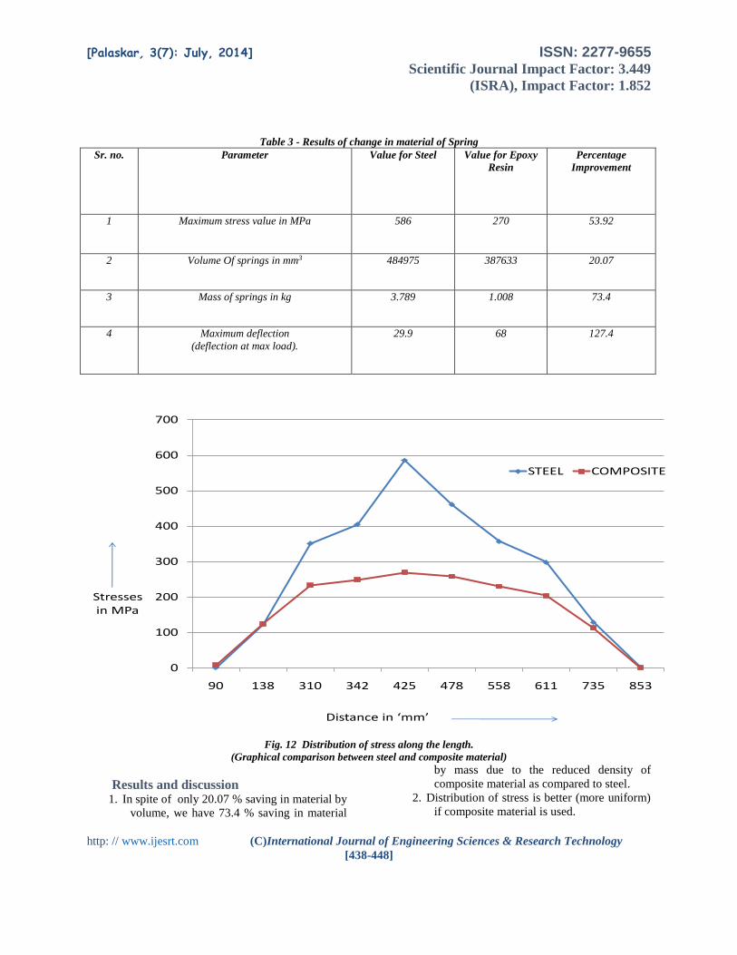
Fig. 12 Distribution of stress along the length.
(Graphical comparison between steel and composite material)
Results and discussion 1. In spite of only 20.07 % saving in material by
volume, we have 73.4 % saving in material
by mass due to the reduced density of
composite material as compared to steel.
2. Distribution of stress is better (more uniform)
if composite material is used.

[Palaskar, 3(7): July, 2014] ISSN: 2277-9655 Scientific Journal Impact Factor: 3.449
(ISRA), Impact Factor: 1.852
http: // www.ijesrt.com (C)International Journal of Engineering Sciences & Research Technology
[438-448]
3. Utilization of material is improved by
changing the material from steel to
composite.
4. A considerable reduction in the stress values
is observed by replacing steel by epoxy
resin.
5. The reduction in maximum stress is 53.92 %.
This value is safe even though the maximum
allowable stress for epoxy resin is much
lower than steel.
Conclusion Material saving up to 73.40 % can be achieved by
shifting to new/composite material.
By shifting to new material volume of leaf spring is
be reduced by 20.07 %.
In other words distribution of stress is improved (it
becomes more uniform) by using new
material. Utilization of material is improved by
shifting to new material.
Riding comfort of passengers is improved due to
reduction in unspung mass of the vehicle by shifting
to new material. Deflection is also improved by 127.4
% by shifting to new material i.e. epoxy resin due to
reduction in stiffness. This results in added increase
in the riding comfort.
Acknowledgement It gives me a great pleasure to express my
deep sense of gratitude towards my project guide and
ME Coordinator Prof. S.V. Bhaskar for his valuable
guidance and motivation from time to time for the
completion of this work.
At the same time it delights me a lot to
extend my sincere and profound gratitude towards
Prof. Dr. A.G. Thakur HOD (Mechanical) and Vice
Principal for his constant encouragement and
valuable directions in due course of completion of the
work.
I am greatly inspired by Principal COE
Kopargaon Prof. Dr. D.N. Kyatanavar and I am
constantly supported by Principal KBP Polytechnic
Prof. R. A. Kapgate for which I express my deep
sense of gratitude to both of them.
References 1. Rajendran, S. Vijayarangan “Optimal
design of a composite leaf spring using
genetic algorithms”, ‘Computers and
Structures’ 2001,7.,79., pp. 1121-1129.
2. K.K. Jadhao and Dr. R.S.Dalu,
“Experimental Investigation and Numerical
analysis of composite leaf-spring”,
‘International Journal of Engineering
Science and Technology’
2011,3.,6., pp. 4759 to 24764.
3. Dr. Kirpal Singh, “Automobile
Engineering” , ’Standard Publishers
Distributers’. 2011,1., pp 168-175.
4. M. Venkatesan, D. Helmen Devraj, “Design
and Analysis of Composite Leaf Spring in
Light Vehicle”, ‘International Journal of
Modern Engineering Research (IJMER)’.
2012,2., 2249-6645 pp-213-128.
5. Kumar Krishan and Agrawal M.L., “A
Finite Element Approach for Analysis of a
Multi Leaf Spring Using CAE Tools”,
‘Research Journal of Recent Sciences’,
2012, 1.,2., pp. 92 to 96.
6. Jadhav Mahesh V, Zoman Digambar B, Y.R.
Kharde, R.R. Kharde, “Performance
Analysis of Two Mono Leaf Spring Used for
Maruti 800 Vehicle ,’International Journal
of Innovative Technology and Exploring
Engineering’, 2012,2.,1.,pp.65 to 67
7. V.K.Aher, R.A.Gujar, J,P,Wagh &
P.M.Sonawane, “Fatigue Life Prediction of
Multi Leaf Spring used in the Suspension
System of Light Commercial Vehicle”,
‘International Journal on Theoritical &
Applied Reaserch in Mechanical
Engineering (IJTARME)’ 2012,1.,1., pp. 71
to 77.