LAYING OF MDPE NETWORK AND GI/Cu INSTALLATION
136
LAYING OF MDPE NETWORK AND GI/Cu INSTALLATION WORK FOR DOMESTIC, COMMERCIAL AND INDUSTRIAL CUSTOMERS FOR CUGL GA'S IN JHANSI IN THE STATE OF UTTAR PRADESH E-Tender ID - 51007 Project No. P.014714 Document No. P.014714 G 11031 R009 CENTRAL UP GAS LIMITED (CUGL) KANPUR | INDIA PUBLIC 26 August 2021 TECHNICAL DOCUMENTATION Technicial, Vol II of II, Rev. 0 Page 1 of 235
-
Upload
khangminh22 -
Category
Documents
-
view
0 -
download
0
Transcript of LAYING OF MDPE NETWORK AND GI/Cu INSTALLATION

LAYING OF MDPE NETWORK AND GI/Cu INSTALLATIONWORK FOR DOMESTIC, COMMERCIAL AND INDUSTRIALCUSTOMERS FOR CUGL GA'S IN JHANSI IN THE STATE OF UTTAR PRADESH
E-Tender ID - 51007Project No. P.014714Document No. P.014714 G 11031 R009
CENTRAL UP GAS LIMITED (CUGL)KANPUR | INDIA
PUBLIC
26 August 2021
TECHNICAL DOCUMENTATIONTechnicial, Vol II of II, Rev. 0
Page 1 of 235

SL.NO.DOCUMENT /
DRAWING NO.REV. NO PAGE PAGE Nos.
I
1
2
3
4
5
6
II
1 P.014714 G 11031 070 0 3
2 P.014714 G 11031 071 0 25
3 P.014714 G 11031 072 0 13
4 P.014714 G 11031 073 0 8
5 P.014714 G 11031 074 0 21
6 P.014714 G 11031 075 0 7
7 P.014714 G 11031 076 0 5
8 P.014714 G 11031 077 0 5
9 P.014714 G 11031 078 0 5
12 P.014714 G 11031 079 0 4
13 P.014714 G 11031 080 0 14
14 P.014714 G 11031 081 0 4
15 P.014714 G 11031 082 0 5
16 P.014714 G 11031 083 0 5
17 P.014714 G 11031 084 0 5
17.1 COPPER TUBE P.014714 G 11031 085 0 4
18 70000_740_GTS_0011 0 25
1970000 / 740 / GTS /
00120 11
2070000 / 740 / GTS /
00150 19
DESCRIPTION
SECTION A - COMMERCIAL (VOLUME I OF II)
NIT
GTSPE VALVES FOR NATURAL GAS DISTRIBUTION UNDERGROUND NETWORK(70000 / 740 / GTS / 0015)
SECTION - IV
PTS
PTS
P.014714 G11031 R009
1
WARNING MAT
SUPPLY OF MDPE FITTINGS,VALVES AND TRANSITION FITTINGS
PTS
INSTRUCTION TO BIDDERS (ITB)
HEALTH, SAFETY & ENVIRONMENT
SECTION - III
PTS
GTSPE ACCESSORIES FOR UNDERGROUND NETWORK FOR NATURAL GAS DISTRIBUTION (70000 / 740 / GTS / 0011)
P.014714 G11031 R009
GENERAL CONDITIONS OF CONTRACT (GCC)
SPECIAL CONDITIONS OF CONTRCT (SCC)
FORMS AND FORMAT
PTS
SECTION - VI
INTRODUCTION
PTS LAYING OF MDPE MAIN PIPELINE & SERVICE PIPELINE
ELECTROFUSION FOR PE PIPES & FITTINGS
MAIN TABLE OF CONTENTS LAYING OF MDPE LAYING AND GI / Cu INSTALLATION WORK ALONG WITH
REGISTRATION OF DOMESTIC CUSTOMERS” FOR CUGL IN JHANSI GA IN U.P.
SECTION-I
SECTION - II
GI PIPES
SECTION B - TECHNICAL (VOLUME II OF II)
SECTION - V
INVITATION FOR BID (IFB)
SCHEDULE OF RATES (SOR) - FOR JHANSI GA IN THE STATE OF U.P
INSTALLATION OF ABOVE GROUND GI PIPING & FITTINGS
PTS
PTS
PTS
CORRUGATED FLEXIBLE METAL HOSE
GI FIITINGS
PTS
INSTALLATION GI, COPPER
POWDER COATING
COPPER FITTINGS
BRASS FITTINGS
PTS
PTS
PTS
PTS
PTS
STEEL REINFORCED RUBBER HOSEPTS
GTSPE COMPOUNDS FOR MANUFACTURE OF PIPES AND FITTINGS FOR UNDERGROUND NETWORKS FOR NATURAL GAS DISTRIBUTION - ACCEPTANCE PROCEDURE (70000 / 740 / GTS / 0012)
CITY GAS DISTRIBUTION PROJECT Page 1 of 2
Page 2 of 235
VD6049
Stamp
VD6049
Stamp
VD6049
Stamp
VD6049
Stamp
VD6049
Stamp
VD6049
Stamp

21 P.014714 G 11031 086 0 1
22 P.014714 G 11031 087 0 1
23 P.014714 G 11031 088 0 1
24 P.014714 G 11031 089 0 2
25 P.014714 G 11031 090 0 1
26 P.014714 G 11031 91 0 2
29 P.014714 G 11031 092 0 1
30 P.014714 G 11031 093 0 1
31 P.014714 G 11031 094 0 1
32 P.014714 G 11031 095 0 1
33 P.014714 G 11031 096 0 1
34 P.014714 G 11031 097 0 5
35
35.2 0 1
35.1 0 1
35.3 0 1
35.4 0 1
35.5 0 1
35.6 0 1
35.7 0 1
35.8 0 1
35.9 0 1
35.1 0 1
35.11 0 1
35.12 0 1
35.13 0 1
35.14 0 1
35.15 0 1
35.16 0 1
35.17 0 1
35.18 0 1
35.19 0 1
35.20 0 1
35.21 0 4
35.22 0 1
DRAIN / NALLAH CROSSING
DRS FOUNDATION DETAILS
QCT
SCHEMATIC DIAGRAM OF HOUSING FOR SINGLE STREAM SERVICE REGULATOR
BRICK VALVE CHAMBER (1.5 M X 1.0 M)
MDPE VALVES
QCT ELECTROFUSION FITTING & TRANSITION FITTINGS
TYPICAL DETAILS OF RCC ROUTE MARKER
GI PIPES
SCHEME FOR DOMESTIC CONSUMER CONNECTION
BRASS FITTING
RECOMMENDED VENDORS LIST
POLE MARKER WITH FOUNDATION
STANDARD / PROJECT DRAWING
QCT
QCT
COPPER FITTINGS
GI FITTINGS
WARNING MAT
TYPICAL DETAILS OF CAUTION BOARD
QCT
QCT
QCT
QCT MDPE FITTINGS
TYPICAL DETAILS OF GATE
TYPICAL UNDERGROUND CABLE CROSSING DETAILS
ROAD/HIGHWAY CASED CROSSING FOR MDPE PIPE
SPECIFICATION FOR WOOD SCREWS
POLE MARKER WITH FOUNDATION (INDIVIDUAL SOCIETIES & AREAS)
TYPICAL TRENCH DIMENSIONS FOR PIPELINE
BRICK VALVE CHAMBER (1.5 M X 1.5 M)
RCC VALVE CHAMBER (1.5 M X 1 M)
RCC VALVE CHAMBER (1.5 M X 1.5 M)
TYPICAL DETAILS OF FENCING
SCHEMATIC DIAGRAM OF SINGLE STREAM SERVICE REGULATOR
QCT
QCT STEEL REINFORCED RUBBER HOSE
PLATE MARKER
CORRUGATED FLEXIBLE METAL HOSE
HALF ROUND CONCRETE SLEEVE
COPPER TUBE
TYPICAL DETAILS OF BARRICADING
QCT
CITY GAS DISTRIBUTION PROJECT Page 2 of 2
Page 3 of 235
INTRODUCTION P.014714
G 11031 070
Page 1 of 3
0 20.08.2021 Issued for Work PM NN NN
Rev. Date Description Prepared by Checked by Approved by
CENTRAL U.P. GAS LIMITED (CUGL)
LAYING OF MDPE NETWORK AND GI / Cu INSTALLATION WORK ALONG WITH REGISTRATION OF DOMESTIC CUSTOMERS” FOR
CUGL IN JHANSI GA IN U.P.
INTRODUCTION
Page 4 of 235
VD6049
Stamp
INTRODUCTION P.014714
G 11031 070
Page 2 of 3
TABLE OF CONTENTS
1.0 INTRODUCTION ................................................................................................................. 3
Page 5 of 235
INTRODUCTION P.014714
G 11031 070
Page 3 of 3
1.0 INTRODUCTION
1.1. Central U.P. Gas Limited (CUGL) is a joint venture company of Gail & BPCL is responsible for distribution of Natural Gas for Domestic, Commercial & Industrial sectors including setting up CNG refuelling stations for vehicles etc. in district of Kanpur, Unnao, Bareilly, Jhansi.
1.2. Central U.P. Gas Limited (CUGL) (hereinafter referred as Owner), is supplying piped natural gas (PNG) to domestic, commercial and industrial consumers and compressed natural gas (CNG) to automobiles in above mentioned GAs through its CGD and CNG networks. CUGL intends to develop its CGD and CNG network in above mentioned GA.
TRACTEBEL Engineering Pvt. Ltd. (TE), a subsidiary of TRACTEBEL Engineering S.A. has been appointed as Technical Consultant (hereinafter referred as Consultant), by CUGL for aforementioned of project.
The present document covers the technical specifications for the enquiry.
Page 6 of 235
PTS - LAYING OF MDPE MAIN PIPELINE AND SERVICE PIPELINE
P.014714 G 11031
071
Page 1 of 25
0 20.08.2021 Issued for Work PM NN NN
Rev. Date Description Prepared by Checked by Approved by
CENTRAL U.P. GAS LIMITED (CUGL)
LAYING OF MDPE NETWORK AND GI / Cu INSTALLATION WORK ALONG WITH REGISTRATION OF DOMESTIC CUSTOMERS FOR
CUGL IN JHANSI GA IN U.P.
PTS - LAYING OF MDPE MAIN PIPELINE AND SERVICE PIPELINE
Page 7 of 235
VD6049
Stamp

PTS - LAYING OF MDPE MAIN PIPELINE AND SERVICE PIPELINE
P.014714 G 11031
071
Page 2 of 25
TABLE OF CONTENTS
1.0 GENERAL INFORMATION ............................................................................................................................. 3
2.0 DEFINITIONS ..................................................................................................................................................... 3
3.0 SCOPE OF WORK.............................................................................................................................................. 3
5.0 MATERIAL, MANPOWER, EQUIPMENT AND MACHINERY ................................................................. 5
6.0 PROGRESS OF WORK ..................................................................................................................................... 7
7.0 CO-ORDINATION/LIAISON FOR PIPELINE LAYING .............................................................................. 7
8.0 REFERENCE SPECIFICATION, CODES AND STANDARD ...................................................................... 7
9.0 QUALITY OF WORK ........................................................................................................................................ 8
10.0 SAFETY ................................................................................................................................................................ 8
11.0 ROUTE SURVEY ................................................................................................................................................ 8
12.0 ORGANISATION STRUCTURE ...................................................................................................................... 9
13.0 STRUCTURES, SERVICES AND OTHER PROPERTY ............................................................................... 9
14.0 TRENCHING ..................................................................................................................................................... 10
15.0 LAYING ............................................................................................................................................................. 13
16.0 JOINTING OF POLYETHYLENE PIPE ....................................................................................................... 14
17.0 BACKFILLING ................................................................................................................................................. 15
18.0 TRENCHLESS LAYING (ONLY FOR 125 MM) .......................................................................................... 16
19.0 RESTORATION ................................................................................................................................................ 17
20.0 TESTING ............................................................................................................................................................ 18
21.0 PURGING .......................................................................................................................................................... 18
22.0 VALVE CHAMBERS ....................................................................................................................................... 18
23.0 PERMANENT MARKERS .............................................................................................................................. 19
24.0 ASSISTANCE IN COMMISSIONING............................................................................................................ 20
25.0 STANDARD OF WORK ................................................................................................................................... 20
26.0 RECORDING (AS-BUILT DRAWINGS) ......................................................................................................... 20
27.0 CIVIL WORKS .................................................................................................................................................. 21
Page 8 of 235

PTS - LAYING OF MDPE MAIN PIPELINE AND SERVICE
PIPELINE
P.014714 G 11031
071
Page 3 of 25
1.0 GENERAL INFORMATION
Central UP Gas Limited (CUGL), is a joint venture of Bharat Petroleum Corporation Limited (BPCL) and GAIL (India). CUGL plans to install an underground Natural Gas Distribution network in District of Kanpur, Unnao, Bareilly, Jhansi. The objective is to supply Natural Gas to both Domestic and Commercial customers and to provide compressed gas as a fuel for automobiles. CUGL is seeking contractors to assist in meeting the above objective.
The main scope of this Specification comprises of laying of underground Medium Density Polyethylene (MDPE) main pipelines and service pipeline. The scope covers all the activities associated with the purchasing (specified items only), laying, testing and commissioning of MDPE main pipelines and service pipelines in new gas charged areas of sizes ranging from 20 mm upto 125mm OD, which includes PE/GI transition fitting above ground level and LMC work.
This technical specification defines the basic guidelines to develop an acceptable design and suitable construction methodology for carrying out different activities listed out in the schedule of rates of this tender.
Compliance with these specifications and / or approval of any of the Contractor’s documents shall in no case relieve the Contractor of his contractual obligations.
2.0 DEFINITIONS
Owner CENTRAL U.P. GAS LIMITED (CUGL)
PMC TRACTEBEL Engineering Private Ltd.,
PTS Present <<Particular Technical Specification>>and its entire
appendix, if any.
TPIA Third Party Inspection Agency
EIC Engineer – in – charge
3.0 SCOPE OF WORK
Generally, the following shall constitute the Contractor’s scope of work but not limited to:
3.1 Plan and prepare a schedule for execution and work implementation as per QA/QC plans to be issued by Owner / Owner’s representative. Contractor has to submit the Construction/Execution procedures before commencement of work to Owner / Owner’s representative for approval.
3.2 Prior to start of construction activity, contractor shall prepare route survey drawing marked for proposed gas pipeline laying and submit to OWNER/PMC for approval.
3.3 Co-ordination /Liaison from respective land-owning agencies such as CPWD, NHAI, etc. for road cutting for laying of the pipelines, Liaison with the concerned authorities during execution of the job, obtaining NOC from concerned authorities once the work is completed. Getting back/Refund of Bank Guarantee/security deposits made to the agencies for laying of the pipelines.
3.4 Obtaining clearances and coordination with concerned RWA of the allotted area for internal network laying.
3.5 Proper storing, stacking, providing security, insurance cover during storage, laying, commissioning and handing over the pipelines to Owner.
3.6 Making trial pits to determine the underground utilities/services such as existing pipelines, Cables (Electrical/Communication), Conduits, U/G drainage, Sewers, tunnels, Subways foundations etc. for deciding optimum feasible route and depths for laying the pipelines based on the route plans indicated by Owner.
3.7 Wherever required the grass/turfing, pavement, linings, drains roads and other such ‘pucca’ area shall be locally removed to facilitate trenching and pipe laying works. The same is to be reinstated as original.
Page 9 of 235

PTS - LAYING OF MDPE MAIN PIPELINE AND SERVICE
PIPELINE
P.014714 G 11031
071
Page 4 of 25
3.8 Installation of Safety/warning Signs and barricading of the entire route to be trenched. Pits to be similarly barricaded along with warning signs and caution boards.
3.9 To make trenches with stable slopes but restricting minimum disturbance to above ground/underground services/installation as per specifications and approved route plans keeping the trenches free from water and soil till placement of pipes.
3.10 Unloading/stringing the MDPE pipes of required sizes (i.e. 125, 63, 32 & 20 mm) pipes into trenches as per approved procedure.
3.11 Joining the pipe ends with fittings & valves by approved automated electro-fusion techniques only as per Tender Specification.
3.12 Laying pipelines by any methodology including trenchless technology methods with or without casing pipes (HDPE pipes) as per specifications and as directed by EIC. Casing Pipe (HDPE Pipes) shall be supplied by Contractor i.e. PE 80/PE 63, PN 6, IS 4984.
3.13 Fabrication, Supply and Inspection of good quality of GI sleeve and half concrete sleeves and other materials, fittings to be supplied by the contractors as per the provisions of tender.
3.14 Back filling and compaction by jumping jack compactor, wherever required, using approved ‘good’ soil or using excavated earth or borrow earth as per requirement and specifications and replacement of the tiles, slabs removed during the excavation. Cleaning all unserviceable materials, debris, excess earth trenches etc. to designated disposal area.
3.15 Carrying out pneumatic testing and purging as per specifications and approved procedures, providing all tools & tackles, instruments, manpower and other related accessories for carrying out the testing of pipes.
3.16 Supply, fabrication & Installation of RCC route marker, Pole marker with foundations, Plate markers, valve chamber etc. as per the directions of the EIC/Owner’s representative.
3.17 Commissioning of gas in the tested PE Line shall be done as per the approved procedure.
3.18 Restoration of existing ground features such as grass/turfing, paving, roads, drains, concrete, floral beds, fencing, tiles, marbles, flooring masonary etc. to original condition and to match with adjoining conditions, functionally and aesthetically up to the entire satisfaction of Owner / Owner’s representative /any other Third Party agency designated by Owner and local authorities, failing which, it will be done at the risk and cost of the contractor. Obtaining satisfactory completion certificates form the restoration work done from the concerned authorities.
3.19 Returning surplus material to Owner stores after obtaining clearance from TPIA/Consultant/ Owner, reconciliation of free issue material/consumables.
3.20 Handing over the completed works to Owner for their operation/use purposes.
3.21 Rectification of defects arising due to poor workmanship during defect liability period of pipelines / installations handed over to Owner.
3.22 Preparation and submission of all documents like Pit wise As graph, As-built drawings, details of crossings, utility graphs, PE cards for service line and deviation statements on completion/commissioning of work by way of drawing, sketches and tables in soft & hard copy.
3.23 Any other activities not mentioned/covered explicitly above, but otherwise required for satisfactory completion/operation/safety/statutory/maintenance of the works shall also be covered under the Scope of work and has to be completed by the Contractor within specified schedule at no extra cost to OWNER.
3.24 Contractor to note that sizes to be taken as precisely as per drawing given in tender document. In any case due to site constraint, sizes given in drawing may vary.
4.0 Industrial and Commercial Work
Supply and Installation of MS Pipe and Fittings
4.1 Supply of Transition Fitting of 32mm x 1 Inch with coupler will be provided by the client for Industrial and Commercial Connectivity.
Page 10 of 235

PTS - LAYING OF MDPE MAIN PIPELINE AND SERVICE
PIPELINE
P.014714 G 11031
071
Page 5 of 25
4.2 Supply & Installation of MS pipes & fittings, Installation of meter, regulators, filter etc. including NPT threading, as specified, Drillings of holes through the walls (Brick, RCCI, Granite, Marble, Wood Cutting, Glass Cutting with proper heavy duty hammer drill machine, tools & tackles using proper sealant/grout material and colors to match the original replacement of the damages during drilling, restoring the area to the original condition Painting of pipe and fittings after proper surface finish by one coat of approved primer paint and two coats of approved synthetic enamel paint.
4.3 Assessment of material requirement for installation at site, Purchasing of MS Pipes & fittings from approved /recommended vendors of CUGL, Scheduling, planning of material & Forwarding inspection call, getting dispatch clearance, handling, loading, transportation and unloading of these items at respective contractor's store. Receiving, taking over, handling loading, transportation and unloading of owner supplied above ground fittings such as regulators, meters, Filter, Isolation Valves and other free issue items as defined in specification from owner's designated stock yards to Contractor's own stores / work sites, proper storing, stacking, identification, providing security and insurance cover.
4.4 Preparation and approval of sketches, schedules & execution procedures. Finalizing optimum route with consent of customer from transition fitting to meter outlet connection (as per drawing) and ensuring installations in well ventilated area."
4.5 Supply & fixing of approved clamps & nylon rawl plugs with SS 304 2" screws, grout material, suitable thread sealant i.e. Teflon Tape, foining of transition fitting to above ground MS pipes, testing & Jumper, purging and commission of the complete installation.
5.0 MATERIAL, MANPOWER, EQUIPMENT AND MACHINERY 5.1 Material, Procurement and Supply
Material to be Supplied by Owner as Free Issue
5.2 Unless otherwise specified, Owner will only supply following material such as MDPE – pipes (125, 63, 32 & 20mm OD), Appliance Valves & Isolation Valves.
5.3 The free issue material shall not be procured from any other source by contractor. (Only from recommended vendor list).
5.4 Material reconciliation statement of free issue material duly certified by Owner and PMC shall be submitted to OWNER on monthly basis.
5.5 Material to be supplied by the contractor: The supply of items as indicated in SOR shall be strictly as per relevant Technical Specifications enclosed with the Tender and as per guidelines of various clauses of SCC and SOR. All materials shall be handled safely and stored in a permanent, covered, lockable store/ ware house preferably near site in such a manner as to prevent any damage to the materials from scratching, gouging, indentation, excessive heat or by contact with any sharp objects or chemicals. The MDPE pipes and fittings shall be stored in covered storage to protect material from sunshine, rain etc.
5.6 Contractor shall procure all MDPE fittings & MDPE Valves.
5.7 Contractor shall procure the materials such as HDPE Casing Pipes & required fittings and Warning Mat etc.
5.8 Backfilling material
The Contractor shall be responsible to arrange the supply of approved coarse sand (size 0.6 – 2 mm as per IS 383) free from any impurities like clay, mica, and soft flaky pieces, as per the instructions of EIC/Owner’s representative. For supply of sand in trench for rocky terrain, no separate charges are payable and is included in rates - excavation of hard rock / Morrum. Also, supply of sand in Valve Chambers, Normal surface & built up surface, if required, as per the instructions of EIC¸ is not separately payable.
5.9 In case specified trench, depths are not achieved & if directed by Engineer-In Charge Contractor has to provide concrete casing pipes / slabs or cement concrete, without any cost implication to Owner.
5.10 Other Materials: The Contractor shall supply the following items wherever required:
All materials required for framework, trench support and temporary trench crossings.
Page 11 of 235
PTS - LAYING OF MDPE MAIN PIPELINE AND SERVICE
PIPELINE
P.014714 G 11031
071
Page 6 of 25
All sign boards, barricades, tin sheets, lighting arrangement and protective equipment. All minor items not mentioned in the Contract but necessary for the satisfactory completion and
performance of the Work under this Contract. Material required for installation of valve chambers. GI/ Half Round Concrete Sleeves. Permanent markers with foundation
5.11 Manpower
The Contractor shall provide the skilled labour, tools, material and equipment necessary for the proper execution of the Work.
5.12 Equipment, Machinery & Tools
This will include but is not limited to the list of specialized items included in Annexure # 1.
5.13 All vehicular type machinery shall be in good working order and shall not cause spillage of oil or grease. To avoid damage to paved surfaces, the Contractor will provide pads of timber or thick rubber under the hydraulic feet or outriggers of machinery.
5.14 Contractor must also have to arrange his own equipment for restoration work like water tanker and jumping jack compactor for compaction of backfilled trenches and roller and other required equipment/ machinery for asphalting/ road works.
In case there is non-availability of approved equipments, tools and tackles during the work at site, suitable penalties, as per special terms and conditions of the contract, will be levied and deducted from the running bills.
5.15 Acquisition, Receipt & Storage of Materials
The Contractor shall collect all free issue materials from OWNER during stores working hours following all documentation procedures laid down and as directed by the EIC. The Contractor shall carry pipe in such a manner as to preclude damage during transportation and handling. PE pipes supplied in straight lengths may be carried in straight pipe racks.
The Contractor shall at the time of receipt of material physically examine all materials and notify the EIC immediately of any damage or defect noticed by the Contractor. The EIC shall duly note any damage or defect in a site instruction book and both parties shall countersign the entry. Any damage not so recorded will be deemed not to have existed at the time of receipt of material by the Contractor and the cost of repair or replacement or rectification shall be borne by the Contractor. Any material once issued from OWNER store, if found in nonworking condition at site shall be brought to the notice of EIC with PO reference in written within 15 days and after subsequent approval shall return defective material in OWNER stores within 30 days.
If delay is more than 30 days and material is under warranty, the material will be accepted with a penalty, else the material will not be reconciled and amount of the same will be deducted from bills and same shall be levied as per SCC. The contractor shall ensure that no defective material shall be returned to store at the time of closure of contract. The format for defective materials returning to stores will be made available by EIC.
The contractor shall maintain permanent locked store preferably near site so that all the materials are stored in such a manner so as to prevent any damage to the materials from scratching, gouging, indentation, excessive heat or by contact with any sharp objects or chemicals. The PE pipes and fittings shall be stored in covered storage to protect material from sunshine, rain etc.
The Contractor shall maintain logbook at their respective stores stating issue and availability of free issue material at a given day. Further, it is mandatory that the contractor is required to undertake and submit inventory details of free issue and purchased materials on monthly basis to Owner/ Owner’s representative as per the approved format of the owner. The inventory details shall be in correlation with the Daily progress chart and material reconciliation sheet.
In case of non-submission of material reconciliation on first week of every month, applicable penalties shall be levied as per SCC from the running bills.
Page 12 of 235

PTS - LAYING OF MDPE MAIN PIPELINE AND SERVICE
PIPELINE
P.014714 G 11031
071
Page 7 of 25
6.0 PROGRESS OF WORK
The contractor shall proceed with the work under the contract with due expedition and without delay. The EIC may direct in what order and at what time, the various stages or parts of the work under the Contract shall be performed. Contractor has to regularly submit daily progress reports, weekly progress reports, graphs with utilities, testing reports, material consumption and inventory reports, deviation statements, completion schedule etc.
7.0 CO-ORDINATION/LIAISON FOR PIPELINE LAYING
Contractor has to CO-ORDINATE from statutory bodies for laying of pipelines. Statutory bodies in this case are NHAI, CPWD, Indian Railways, LDA and any other Government Agencies who maintains the public lands and accord permissions for laying of the utilities. The contractor shall obtain demand note (Road Restoration charges) from these statutory bodies. Contractor shall ensure that the Road Restoration Charges are to the minimum against the work to be carried out. OWNER may return back the demand note, if the Road Restoration charges are not found reasonable then OWNER shall not be liable to pay any Road Restoration Charges against the same to Concern Authority.
However, OWNER will pay the road restoration / Departmental charges / security deposit / Bank guarantees for getting the clearances from statutory bodies. It is the contractor’s responsibility to inform and co-ordinate the concerned local authorities and also other utility agencies before and after the commencement of work at site. To ensure smooth execution of the work on a day-do-day basis, the contractor has to liaison with respective authorities. The contractor shall plan and ensure that work taken up under a single permission shall be completed within the stipulated time period and revalidation process is avoided. No separate Road Restoration Charges are liable to OWNER for revalidation cases.
It is the responsibility of the contractor to obtain “No Objection Certificate” (NOC) from land owing agencies/Statutory bodies after completion of the restoration to their satisfaction and getting released the security deposit / bank guarantees submitted by OWNER for obtaining permissions on production of documentary evidence.
On behalf of the owner, contractor shall prepare in advance and submit the proposed route plan complete in all respect and well ahead of time so that the actual construction work is not delayed because of approval/inspection / permission by concerned authorities. Further, the contractor shall also coordinate with the relevant authorities for necessary approvals of these proposed pipeline route drawings / certificates. The inspection of work by statutory authorities shall be the responsibility of the contractor without any extra cost to OWNER.
In case contractor delays laying of pipeline work under a single permission, the work or part of work may be offloaded to some other contractor on his risk and cost.
Any change / addition required to be made to meet the requirements of the statutory authorities shall be carried out by the contractor without any extra cost to OWNER. The inspection and acceptance of the work by statutory authorities shall, however, not absolve the contract from any of his responsibilities under this contract
8.0 REFERENCE SPECIFICATION, CODES AND STANDARD
The contractor shall carry out the work in accordance with the requirement of latest relevant applicable standards, this specification, Owner’s Engineering Standards; relevant Oil Indian Safety Directorate (OISD) norms, PNGRB Regulations, ASME B31.8-Gas Transmission and Distribution Piping Systems; Australian Standard 3723-Installation and Maintenance of Plastics Pipe Systems for Gas; and the American Gas Association Document – Purging Principles and Practice. ISO-4437/IS: 14885 for underground polyethylene pipes and OWNER’s approved procedures.
Should the contractor find any discrepancy, ambiguity or conflict in or between any of the Standards and the contract documents, then this should be promptly referred to the Engineer-in-Charge (EIC) for his decision, which shall be considered binding on the contractor.
Page 13 of 235

PTS - LAYING OF MDPE MAIN PIPELINE AND SERVICE
PIPELINE
P.014714 G 11031
071
Page 8 of 25
9.0 QUALITY OF WORK
All works carried out under this contract shall confirm to applicable standards, codes of practice, construction procedures and other technical requirements as defined in the technical specifications.
The manpower deployed on the respective activities shall be adequately trained & shall have necessary skills to execute / supervise the work. However, the assessment on the qualification of the personnel shall be at the discretion of EIC.
Fusion operators and other skilled personnel shall be approved by Owner / Owner’s representative and identification cards duly signed by EIC shall be issued to them. Only those personnel who are approved by EIC shall be allowed to execute the critical activities like Electro fusion jointing of MDPE Pipes & Fittings. OWNER may provide Training and certification on chargeable basis where the cost shall be borne by contractor.
10.0 SAFETY
10.1 The Contractor shall conform to the safety requirements outlined elsewhere in the tender document. In addition, the Contractor shall observe safe working practices in the storage and handling of cleaning fluids, flammable fluids, etc, and ensure smoking or naked flames are not permitted in the vicinity when these materials are being used.
10.2 Trench walls shall be battered with sufficient slope in order to minimize a trench collapse. Where there is a danger of an earth slide or collapse, the trench shall remain open for the minimum time possible with proper barricading. The Contractor is to ensure that no person enters a trench, which is of a depth of 1.5 meters or greater, unless the trench has adequate shoring, or the sides are battered to such an extent as to prevent a trench collapse.
10.3 The Contractor shall also protect all work sites with warning signs, barricades and night lighting. The Contractor shall inspect all fenced excavations daily and maintain them in good order.
10.4 The trenches/ pits shall not be kept open in night times. However, in case the same is essential the same shall be properly barricaded with proper lighting arrangements & manned.
10.5 The Contractor shall provide PPE’s like helmets, safety shoes, etc. to the labour which are necessary for safe working practice.
10.6 Any accident causing injury to any person or damage to property or equipment shall be reported to the EIC and the cost of repair / replacement of the damage equipment shall be borne by the contractor. Where the EIC determines that the work is being performed by the Contractor in an unsafe manner, he may suspend the Work until corrective action is taken by the Contractor.
10.7 For further details Refer “Special Terms and conditions of Contract” and attached PTS – Laying of MDPE Main Pipeline and Service pipeline.
11.0 ROUTE SURVEY
11.1 Planning, detailing the size, underground utilities, foreign pipelines, crossings, and location of valve chamber, FRS / DRS / MRS as well as service line location.
11.2 Main lines
The final alignment of mainlines will be worked out at site in consultations with the Owner /Owner’s representatives after route survey and trial pits, at contractor cost. Any change in routing from the issued drawings due to site constraint will be notified to EIC & his specific written approval shall be obtained before carrying out the job.
11.3 Service lines
Consultant/Third Party Inspection Agency and the contractor will conduct a joint survey at each probable premise / housing colony/pockets/area to be supplied with gas. The survey record will note customer’s detailed potential gas supply points, proposed regulator positions and estimates of material quantities. The contractor’s representatives will make sketch of the agreed pipe routes.
Page 14 of 235
PTS - LAYING OF MDPE MAIN PIPELINE AND SERVICE
PIPELINE
P.014714 G 11031
071
Page 9 of 25
The contractor will be responsible for contacting the customer and making the necessary arrangements for access and appointments to carry out the work. Contractor shall maintain job card and complaint books at site. Owner will not be responsible for time lost due to failed appointments or disputes with customers.
12.0 ORGANISATION STRUCTURE
12.1 Contractor shall designate Project Manager / Coordinator who will be responsible to interact with EIC/Consultant/TPIA and authorized to attend review meetings, receive material, authorized to sign documents, claims and receive payments etc. Contractor shall employ a Project Manager / Coordinator on company roll. The Project Manager / Coordinator must have qualification of BE / Diploma in Engg. with min. 5 - 8 years of work experience in gas pipeline job respectively. He shall be single point of contact for all the works and must represent company in the review meetings.
12.2 All construction work will be carried out as per direction of EIC, and this will be the primary point of contact between the contractor and Owner on site. All work will be issued and sanctioned through the EIC and site control exercised by Site Engineers. The contractor shall ensure that technical quality standards are maintained that construction is carried out cost effectively and that a good customer and public image is maintained for Owner.
12.3 The contractor will deploy his own supervisors as directed by site engineers/EIC. These personnel will be reporting to the Site Engineer for monitoring construction standards and for ensuring that all technical requirements are met for the job being carried out. The contractor’s supervisor(s) will have day-to-day liaison with the Site Engineer and will provide the Site Engineer with technical reports and audits, and other management information as is required on work progress and construction quality standards.
12.4 The contractor’s supervisor shall have mobile telephones to ensure that they can be contacted at all times. The contractor will also nominate one person who can be contacted if necessary, in odd hours, for the duration of the works. The contractor’s supervisor will have access to transport at all times to allow them to visit sites and attend meetings with Owner. The normal day-to-day issue of work instructions, communication between Owner and the contractor’s supervisor and the Site Engineer.
13.0 STRUCTURES, SERVICES AND OTHER PROPERTY
13.1 Location of Underground Utilities
The contractor shall locate all buried utility pipes, underground cables, water mains and other obstructions intersecting or adjacent to the Works and shall make available the necessary labour to expose and record the depth of cover over all obstructions in advance of excavation. This shall be done far enough in advance of excavation to facilitate gradual change in grade or position found necessary to clear any obstructions.
In addition, the contractor shall excavate trial pits as necessary to determine the pipe route. The number of trial pits will be agreed with the Site Engineer in advance of any excavation. In any event, trial pits shall be made at intervals of a maximum of 30 meters. Restoration of the abandoned trial pits and trenches shall be the contractor’s responsibility. No payments shall be made for such type of jobs. The trial pits shall be excavated to minimum depth of 1.5 meters so as to locate any utilities present in the trench.
It is contractor’s responsibility to interact with other utility agencies regarding their existing utilities and finalise the route along with these agencies and Owner/ Owner’s representative.
There will be no additional payments in respect of abandoned trenches incurred because of insufficient or inadequate trial pits, or any associated loss of time or delays.
13.2 Protection of Structures and Utilities
The Contractor shall at his own cost support and protect all buildings, walls, fences or other structures and all utilities e.g. Electrical cables, Telephone Cables, Water pipelines, Sewer pipelines etc., and property which may be damaged as a result of the execution of the works. He shall also comply with the requirements in the specification relating to protective measures applicable to particular operations or kind of work. Special care shall be taken while laying of pipelines near the trees.
Page 15 of 235

PTS - LAYING OF MDPE MAIN PIPELINE AND SERVICE
PIPELINE
P.014714 G 11031
071
Page 10 of 25
13.3 Interference with Traffic, Street Drainage and General Public
The Work shall be executed in such a manner so as to cause a minimum inconvenience to persons using public or private roads, lanes, thoroughfares, walkways, rights-of use or passages through which the Works are to be executed. The trench shall be back filled, compacted, levelled and extra soil shall be removed immediately after laying of pipeline to avoid public inconvenience. Closure of roads, etc, shall not be permitted without the approval of the EIC.
The Contractor shall comply with all local Authorities requirements to traffic and keep roads open to traffic and maintain access to and within any private property.
Wherever the pipe route crosses driveways, access tracks or entrances to private properties the Contractor shall give the owner, occupier or relevant authority at least 24 hours prior notice of intended commencement of excavation and shall be restricted to pass through.
The Contractor shall not use a private driveway, access track or entrance without the prior approval of the EIC in any circumstance.
The Contractor shall provide suitable access wherever necessary in the form of temporary bridges, culverts, flumes, etc., of a size and type approved by the EIC.
The Contractor shall comply with all relevant road Laws. Where limits and/or speed limits have been placed in the vicinity of the Works, the Contractor shall provide for the necessary movement of plant and equipment in accordance with the requirements of the relevant authority.
The Contractor shall not obstruct any drainage pipes or channels in any road but shall divert them wherever necessary and use all proper measures to provide for the free passage of water.
The Contractor shall handover the completed works after proper cleaning of the site.
The contractor shall conduct his operation at all times, with a view to minimize as far as practicable noise and other objectionable nuisances (e.g. oil leakage).
14.0 TRENCHING
The schematic drawing with the details of trench is enclosed in the tender.
The Contractor shall perform the excavation works so as to enable the pipe to be laid in conformity with the levels, depths, slopes, curves, dimensions and instructions shown in the Drawings, Specifications or as otherwise directed by the EIC.
Contractor shall excavate and maintain the pipeline trench on staked centreline as per approved drawing taking into account the horizontal curves of the pipelines.
While trenching, care shall be taken to ensure that all underground structures and utilities are disturbed to the minimum. Suitable crossing shall be provided and maintained over the ROU wherever necessary to permit general public, property owners or his tenants to cross or move stock or equipment from side of the trench or another.
Trenching shall be made with sufficient slopes on sides in order to minimize collapsing of the trench. On slopes wherever there is danger of landslides, the pipeline trench shall be maintained open only for the time strictly necessary. Owner may require excavation by hand, local route and detouring and limiting the period of executing of the works. Before trench cuts through water table, proper drainage shall be ensured, both near the ditch and ROU in order to guarantee the soil stability.
The Contractor shall ensure that trench bottom is maintained in the square form as far as possible, with equipment, so as to avoid/minimize the hand grading at the bottom of the trench. The Contractor shall do all such handwork in the trench as required to free the bottom of trench from loose rock, pebbles and to trim protruding roots the bottom and sidewalls of the trench.
14.1 Depth of Trench
The minimum depth of cover shall be measured from top of pipe to the top of undisturbed surface of the soil or top of the graded working strip or top of road or top of rail, whichever is lower.
Page 16 of 235
PTS - LAYING OF MDPE MAIN PIPELINE AND SERVICE
PIPELINE
P.014714 G 11031
071
Page 11 of 25
In case of crossing of water bodies, the minimum depth shall be measured from the top of the pipe to the bottom of Scour level.
The depth of the trench will be such as to provide minimum cover as stipulated below:
For Distribution and service lines
Minor Water Crossing/Canal 2.5 meter
Uncased/Cased Road Crossing 1.5 meter
Rail/Road Cased Crossing 1.5 meter
Normal Areas 1.0 meter
The minimum depth may be greater than as mentioned above as may be required by Government/Public authorities under jurisdictions. The Contractor shall perform such work without extra compensation, according to the requirement of concerned authorities.
Also, in case of Drains/Culverts/Utilities crossing through open cut where excavation cut is more than 1.5m, the extra excavation is inclusive in the laying rates. No separate payment is chargeable for extra excavation and includes backfilling as well.
In case, the depth could not be achieved due to practical problems and the same is demonstrated, EIC after examining thoroughly and considering the codes and standards may allow the contractor to provide suitable protection by way of concrete casing pipes or slabs without any extra cost to Owner.
14.2 Width of Trench
The width of the trench shall be wide enough to provide bedding around the pipe as specified and to prevent damage to the pipe inside the trench. Unless otherwise directed by the EIC and where ground conditions permit, the minimum distance from the inside edge of the trench wall to the outside of the pipe shall be as per the drawing enclosed in the tender.
14.3 Trench Base
The trench bottom shall be cut or trimmed to provide a uniform bedding for the pipe and shall be free from stones, metal, wood, vegetation, clods of earth or other debris before placement of the pipe.
In case trenching is done in rocky terrain, a bedding of soft soil or sand shall be provided in the trench base to the satisfaction of EIC. Hard Rock:
Hard rock is defined as trench material with a single piece of rock, dimension exceeding 1.0 m in any direction, which requires cutting only by use of chisel / pneumatic chisel / drill or sledge hammer or removal of the same by additional excavation. Additional rates shall be payable for hard rock excavation as per the SOR item no. (refer in SOR) over and above the pipeline laying rates. Excavation through soil mixed with small boulders that have been used for a road base will not be considered as hard rock for the purpose of payment.
Murram
It shall be obtained from pits of weathered disintegrated rocks. It should preferably contain siliceous material and natural mixture of clay of cal carious origin. The size of the Murram shall not be more than 20 mm. Murram for filling shall be clean and well graded. Murram shall not contain any vegetation, organic, clayey or other material. Additional rates shall be payable for Murram excavation as per the SOR item no. (refer in SOR) over and above the pipeline laying rates.
Boulder
It is a rock with grain size of usually not less than 256 mm (10 inches) diameters. Additional rates shall be payable for Boulders excavation as per SOR item no. (refer in SOR) over and above the pipeline laying rates.
14.4 Clearances
Page 17 of 235

PTS - LAYING OF MDPE MAIN PIPELINE AND SERVICE
PIPELINE
P.014714 G 11031
071
Page 12 of 25
Unless otherwise approved, the following clearances shall be maintained between the external wall of the gas pipe and the external surface of other underground assets/utilities in the vicinity of the Works.
150 – 300 mm where the gas pipe crosses other assets/utilities, etc., for electric cables, the clearance shall be 300mm minimum or special protection shall be provided as per approval of EIC.
300mm where the gas pipe is on a similar alignment to the other assets/utilities.
Where the above clearances cannot be achieved, or in other special circumstances, the EIC may approve/specify protection with concrete/MS coated pipe, etc. The protective material shall be supplied and installed by the Contractor at his cost subject to discretion of EIC.
14.5 Under Ground Interferences
The Contractor shall locate and expose manually all underground facilities if any during trenching. Safety barriers shall be erected along the trench to prevent any damages or accident. On locations where pipeline is laid under the existing facilities and near the approaches of the crossing, the trench shall be gradually deepened to avoid sharp bends.
All sewers, drains, ditches and other natural waterways encountered while trenching shall be maintained open and functional by providing proper temporary installations if required. Suitable dewatering pumps shall be deployed to dewater, if required.
Whenever it is permitted by Authorities and /or Owner to open cut paved road crossing, or where the line is routed within the road pavement, the Contractor shall remove the paving in accordance with the restrictions and requirements of the authorities having jurisdiction thereof as directed by Owner. After laying the pipeline, backfilling shall be immediately performed, and all the areas affected connected with the excavation works shall be temporarily restored.
In case of damage to any of above referred structures/utilities the Contractor shall be responsible for repairs/replacement at his own cost, which shall be carried out to the satisfaction of concerned authorities, resident and Owner.
14.6 Others
Throughout the period of execution of such work, the Contractor shall provide and use warning signs, traffic lights or lanterns, barricades, fencing, watchman etc. As required by the local authorities’ jurisdiction and/or Owner.
For all roads, paths, walkways etc. which are open cut, the Contractor shall provide temporary diversions properly constructed to allow the passage of normal traffic with the minimum inconvenience and interruptions.
The paving shall be restored to its original condition after the pipeline is installed.
The Contractor shall excavate to additional depth at all the points where the contour of the earth may require extra depth, or where as deep trenches is required at the approaches to crossings of roadways, railroads, rivers, streams, drainage and ditches without any extra cost implication to Owner.
The Contractor shall excavate all such aforesaid depths as may be required at no extra cost to Owner.
The trench shall be cut to a grade that will provide a firm, uniform and continuous support for the pipe.
The Contractor shall take conducive measures to ensure the protection of underground utilities as per the instructions of Owner or relevant authorities.
Where the pipeline crosses underground utilities/structures, Contractor shall first manually excavate to a depth and in such a manner that the utilities/structures are located, then proceed with the conventional methods.
The locations, where the pipeline has to be laid more or less parallel to an existing pipeline cable and/or other utilities in the Right-of-way the Contractor shall perform the work to the satisfaction of the Owner of the existing pipeline/cable/utility. In such locations, the Contractor shall perform work in such a way that even under the worst weather and flooding conditions, the existing pipeline/utilities remain stable and shall neither become undermined nor have the tendency to slide towards the trench.
Page 18 of 235
PTS - LAYING OF MDPE MAIN PIPELINE AND SERVICE
PIPELINE
P.014714 G 11031
071
Page 13 of 25
14.7 Bedding
The Contractor shall ensure that the pipe when placed in the trench is supported and surrounded by a bed of screened excavated soil, which shall be stone free and have a maximum grit size of 5mm, in order to ensure no damage occurs to the pipe. However, in case of rocky soil the bedding shall be done with approved good quality packing sand subject to the approval of the Site Engineer. The packing sand shall be placed to a minimum thickness of 150mm around the pipe in case of rocky terrain. Unless directed by the EIC the quantity of bedding and surrounding sand shall confirm specifications. There shall be no void space in the packing sand around the pipe.
15.0 LAYING
Main line Laying of MDPE pipelines shall be commenced only after ensuring proper dimensions and clean surface of the trench. The trench bottom shall be free from the presence of cuts, stones, roots, debris, stakes, rock projections up to 150mm below underside of pipe and any other material, which could lead of perforation/tearing of the pipe wall. After ensuring above, the MDPE pipe coil shall be uncoiled smoothly through proper equipment’s/care inside the trench ensuring no damage to pipe coil during laying. The contractor must ensure that Pipe caps are provided before lowering of Pipeline. The trench after this can be released for back filling leaving adequate lengths open at the ends for jointing.
Contractors shall ensure open ends of pipe placed in the trench shall be securely capped or plugged to prevent the ingress of water or other matter. The Contractor is to ensure that nothing enters inside the pipe during the laying process as this could cause a future blockage or regulator malfunction due to dust, etc.
In case of open cuts where two pipes are to be laid parallel in same trench or same pits, 30% of the respective SOR of the lower pipe size for the laid length shall be paid in additionally to the rates applicable to the higher pipe size.
Valves shall be installed at locations shown in the Design Plan or as directed by the EIC and joined with PE pipes by electro fusion techniques. The valves shall be placed on a concrete square block at the bottom to achieve equivalent support of the incoming and outgoing pipe work.
Laying graphs/As-graphs with details of depth, length, offsets from fixed references, other utility crossings, fittings, sizes of the casing pipe used for the pipeline shall be prepared on daily basis and to be submitted to Owner Engineers for approval. These details will further be incorporated in to As-Built Drawings.
A pipe may pass through an open drain or nallah with prior approval from EIC. Where this is permitted, the PE pipe shall be installed inside a concrete or steel sleeve for protection with no cost implications to the owner. The sleeve material shall be procured and laid by the Contractor with prior inspection and approval of the EIC for the quality of material. In general, the GI Sleeve material specification shall be confirming to IS 1239 (Heavy Duty) specification of reputed make.
Contractor to ensure majority (up to 70% of the available potential) of service lines for connecting houses shall be laid at first instance of internal network laying, however any slippage / deviation shall be submitted with consents for approval from EIC/PMC
In case of service lines, EIC shall decide either half round concrete sleeve or GI pipe sleeve shall be installed at any particular site depending upon site condition. The half round concrete sleeve shall be preferred over GI Sleeve, however in case where the installation of half round Concrete Sleeve is not possible due to technical feasibility and site conditions, GI sleeves shall be installed only after written approval from EIC. The rate of GI Sleeve / half round concrete sleeve shall be included in laying of 20/32 mm dia., depending upon surface conditions. The details are mentioned below:
Page 19 of 235

PTS - LAYING OF MDPE MAIN PIPELINE AND SERVICE
PIPELINE
P.014714 G 11031
071
Page 14 of 25
GI Sleeve:
A bending tool shall be used to bend the GI sleeve pipe so that it has the appropriate curvature and is free of kinks. The installation of GI sleeve for service lines shall be done by sealing the annulus between pipe and sleeve, firm fixing of the GI sleeves by concrete mix pedestal, clamping, sand filling, etc.
The contractor shall supply the minimum dia. Size of 2.5” & 3”, 300 mm in length, GI sleeves (Heavy Duty reputed make) respectively for domestic & commercial / industrial installations. The vertical portion of the sleeves shall be fixed to the wall of the premises in a secure manner. The material test certificates/ inspection reports shall be submitted at the time of submission of bill. The material shall be inspected by TPIA / PMC before installation.
Half Round Concrete Sleeve:
The installation of Half Round Concrete sleeve for service lines shall be done by sealing the annulus between pipe and sleeve, firm fixing of the Concrete sleeves by concrete mix pedestal, clamping, sand filling, etc. Half round concrete sleeve shall be made as per enclosed drawing in the tender. The dimensions shown are tentative and may vary depending upon the site conditions. The material shall be inspected by TPIA / PMC at the fabrication stage & prior to final dispatch at site for installation. The material test certificates/ inspection reports shall be submitted at the time of submission of bill.
16.0 JOINTING OF POLYETHYLENE PIPE
The procedure for jointing of PE pipes and fittings shall be as per applicable PTS which is part of this tender document. Only Bar coded electro-fusion machine (Automatically Readable) that can read the bar code of the fittings automatically shall be used for joining of the MDPE pipes/fittings. Manual feeding Electro-fusion machines are not acceptable for jointing purpose. The contractor has to submit the certificate of calibration of Fusion machine at the time of start of work and at fixed intervals as per the instructions of Owner. Contractor shall ensure that the machines are always available at site. No stoppage of work due to the non availability of machines shall be allowed.
The contractor shall flush the Pipeline with air to remove dust, water, mud etc. before fusing the joints. Before jointing, the Contractor shall place packing sand under the pipes on both sides of the joint to keep the pipes in line and at the correct alignment during the jointing process. The jointing process shall start only after Alignment clamps with the correct size are aligned with the pipe and coupler during the electro-fusion cycle.
The Contractor shall ensure that polyethylene pipe is only cut with an approved plastic pipe-cutting tool (Rotary Cutter up to 63mm/Guillotine Cutter for 63mm and above). Before fusion is attempted, the contractor shall remove the oxidised surface of the pipe using Universal Scrapper up to 63mm/Rotary Peeler for 63 mm and above before inserting into the electro-fusion coupler. The tool must remove a layer of 0.1mm to 0.4mm from the outer surface of the polyethylene pipe. No fusion will be allowed without clamping device and the approved cutting tools (Hack saw shall not be allowed for cutting the pipe).
The contractor has to supply all the consumables required for carrying fusion of the joints (like tissue paper, napkin, acetone etc.).
If, upon inspection, the EIC determines a joint is defective, Contractor shall remove the joint by an approved method. The cost of replacing joint shall be borne by the Contractor including the cost of pipe and fittings removed.
For electro-fusion joining, the contractor must bring own tools, tackles and equipments.
Only, approved Jointers shall carry out fusion of all joints. Contractors shall provide the list of jointers to be used on the job and make arrangements for Qualification Testing of the jointers in presence of Owner / Owner’s representative as per the standard procedures. All approved Jointers shall bear identity cards signed by Owner / Owner’s representative during fusion job and shall furnish the same on demand by Owner / Owner’s representative.
Contractor shall arrange generator along with voltage stabilizer for power supply to fusion machine. Taking power connection form electric poles, connections without written permission from the concerned authorities or residential premises is strictly not permitted.
Page 20 of 235

PTS - LAYING OF MDPE MAIN PIPELINE AND SERVICE
PIPELINE
P.014714 G 11031
071
Page 15 of 25
17.0 BACKFILLING
Backfilling shall be done after ensuring that appurtenance have been properly fitted and the pipe is following the trench profile at the required depth that will provide the required cover and has a bed which is free of extraneous material and which allows the pipe to rest smoothly and evenly. Dewatering shall be carried out prior to backfilling. No backfilling shall be allowed if the trench is not completely dewatered.
Prior to backfilling it should be ensured that the post padding of compacted thickness 150mm is put over and around the pipe immediately after lowering where required.
Backfilling shall be carried out immediately after the post padding where required has been completed in the trench, inspected and approved by Owner/ Owner’s representative, so as to provide a natural anchorage for the pipe avoiding sliding down of trench sides and pipe moment in the trench. If immediate backfilling is not possible, a padding of at least 300mm of earth, free of rock and hard lumps shall be placed over and around the pipe and coating.
The backfill material shall contain no extraneous material and/or hard lumps of soil, which could damage the pipe and/or coating or leave voids in the backfilled trench. In case, it is required and directed by EIC screening of the backfill material shall be carried out with specified equipment before backfilling the trench.
The surplus material shall be neatly crowned directly over the trench and the adjacent excavated areas on both sides of the trench to such a height which will, in Owner/Owner’s representative opinion of provide adequately for future settlement of the trench backfill during the maintenance period and thereafter. The down shall be high enough to prevent the formation of the depression in the soil when backfill has settled into its permanent position should depression occur after backfilling; Contractor shall be responsible for remedial work at no extra cost to Company. Surplus material, including rock left from this operation shall be disposed off to the satisfaction of landowner or authority having jurisdiction at no extra cost to Owner.
Where rock, gravel, lumps of hard soil or like materials are encountered at the time of trench excavation, sufficient earth, sand or select backfill materials shall be placed around and over the pipe to form a protective cushion extending at least to a height of 150mm above the top of the pipe. Select backfill materials for padding that area acceptable shall be soil, sand, clay or other material containing no gravel, required selected backfill material has been placed, provided the rock or lumps of hard soil. The padding earth shall not contain any stones, i.e. the earth shall be screened for sand padding of the Pipeline in order to avoid damage to the pipeline. Contractor shall carry out all these works at no extra cost to Owner. Loose rock may be returned to the trench after the required selected backfill material has been placed, provided the rock placed in the ditch will not interfere with the use of the land by landowner, or tenant.
In case where hard rock is encountered or as desired by EIC / site engineer sand padding is to be provided upto height of 150 mm around the pipe.
When the trench has been dug through driveways or roads, all backfilling shall be executed with sand/suitable material in layers as approved by Owner /Owner’s representative and shall be thoroughly compacted. Special compaction methods as specified may be adopted. All costs incurred there upon shall be borne by the Contractor.
Trenches excavated in dikes which are the properties of railways or which are parts of main roads shall be graded and backfilled in their original profile and condition. If necessary, new and/or special backfill materials shall be supplied and worked-up to.
PE Warning Grid/Mat 1mm thick and 300mm wide shall be placed on distribution main and service line inside premises, after backfilling of the trench up to a height of 300mm on the top of the carrier pipes. The warning grid is to be unrolled centrally over the pipe section and thereafter further backfilling will commence.
Backfilling activity shall include proper compaction by jumping jack compactor, wherever required and as per instruction of EIC, and watering in layers of 150mm above the warning mat. Proper crowning of not more than 150mm shall be done. All the excavated material that could be used during the Restoration process shall be stacked and kept separately and properly. Wherever Road cutting / Tiles removal/PCC cutting has been done during excavation for laying, the area shall be back filled and compacted immediately so that no inconvenience is caused to the general public.
Page 21 of 235

PTS - LAYING OF MDPE MAIN PIPELINE AND SERVICE
PIPELINE
P.014714 G 11031
071
Page 16 of 25
Electro-fusion of joints is to be undertaken immediately after lowering and the activity shall not be kept pending for lack of Electro-fusion jointing. The backfilling shall be considered complete only after the jointing of pipes.
Debris and other surplus material shall be removed immediately after the back filling.
18.0 TRENCHLESS LAYING (FOR ALL SIZES)
Both Manual Moling and HDD are to be considered as methods of trenchless laying for all diameters pipelines.
Note: - Manual Moling and HDD are to be considered as per the requirement of site irrespective of sizes.
Manual Moling
The Manual Moling shall be carried out as per the requirement specified by Owner / Owner’s representative and approved procedures. The contractor has to carry out survey of the underground utilities before going for the Moling to avoid any damage to other utilities. No extra payment will be made for any trial/abandoned pits made during the survey. The supply of all equipment required for carrying out moling work is in contractor’s scope. The type of moling to be carried out i.e. with or without casing shall be at the discretion of Owner and prior approval is to be taken before starting the Moling.
For Moling the contractor shall ensure that the size of the hole shall not be more than 20% of the size of the casing/carrier pipes whichever is applicable. After completion of Moling the hole shall be properly compacted / filled with soil by watering and by approved procedures.
The length of the Hole (excluding the sizes of the pits on both ends) shall be considered for the measurement of Moling length.
The usage of casing pipe will be decided by EIC at the time of final approval for crossing/laying.
Any damages occurred to other utilities during the Moling operation shall be immediately, notified and rectified by the contractor without any cost implication to Owner.
HDD (Horizontal Directional Drilling)
HDD is required to be carried out where conventional trenching/Moling is not possible viz. major waterways, highways, roads, congested areas etc. The Contractor shall obtain details of such crossings and the Contractor in consultation with Owner shall prepare construction drawings.
Execution of the work shall be based on the Owner / Owner’s representative approved drawings. The contractor has to do the thorough survey of the underground utilities before commencement of HDD to avoid the damage to the other utilities. No other extra payment will be made for any trail/abandoned pits made during the survey. The supply of all equipment required for carrying out the HDD is in contractor’s scope. The HDD operation shall be carried out in accordance with API-1102. The type and availability of machines is sole responsibility of the contractor and as per the site conditions & requirements to entire satisfaction of EIC.
Once the work is allotted, any delay in mobilising / non – availability of HDD machines as per site requirement and conditions shall result in levying of penalties on daily basis as per contract. However, in such cases, owner may mobilise HDD machines and carry out execution of work on the contractor’s risk and cost.
The length of the Hole (excluding the sizes of the pits on both ends) shall be considered for the measurement of HDD length and is payable as per relevant SOR item no. The type of HDD to be carried out with or without casing shall be at the discretion of Owner and prior approval is to be taken from EIC before starting. The rates are inclusive of excavation of pits, jointing, pilot boring, bentonite cleaning, reaming, insertion of carrier pipe, backfilling, compaction, etc.
As per the specification, HDD to be carried out with or without casing pipe depends on the type of crossing. Any damages occurred to other utilities during the HDD operation shall be immediately notified and rectified by the contractor without any cost implication to OWNER.
HDD profiles should be properly marked/ recorded in graphs as per scale before it is drafted in the as built drawing.
Page 22 of 235
PTS - LAYING OF MDPE MAIN PIPELINE AND SERVICE
PIPELINE
P.014714 G 11031
071
Page 17 of 25
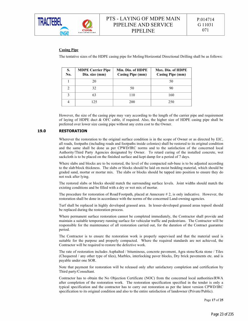
Casing Pipe
The tentative sizes of the HDPE casing pipe for Moling/Horizontal Directional Drilling shall be as follows:
S. No.
MDPE Carrier Pipe Dia. size (mm)
Min. Dia. of HDPE Casing Pipe (mm)
Max. Dia. of HDPE Casing Pipe (mm)
1 20 50
2 32 50 90
3 63 110 160
4 125 200 250
However, the size of the casing pipe may vary according to the length of the carrier pipe and requirement of laying of HDPE duct & OFC cable, if required. Also, the higher size of HDPE casing pipe shall be preferred over lower size casing pipe without any extra cost to the Owner.
19.0 RESTORATION
Wherever the restoration to the original surface condition is in the scope of Owner or as directed by EIC, all roads, footpaths (including roads and footpaths inside colonies) shall be restored to its original condition and the same shall be done as per CPWD/IRC norms and to the satisfaction of the concerned local Authority/Third Party Agencies designated by Owner. To retard curing of the installed concrete, wet sackcloth is to be placed on the finished surface and kept damp for a period of 7 days.
Where slabs and blocks are to be restored, the level of the compacted sub-base is to be adjusted according to the slab/block thickness. The slabs or blocks should be laid on moist bedding material, which should be graded sand, mortar or mortar mix. The slabs or blocks should be tapped into position to ensure they do not rock after lying.
The restored slabs or blocks should match the surrounding surface levels. Joint widths should match the existing conditions and be filled with a dry or wet mix of mortar.
The procedure for restoration of Road/Footpath, placed at Annexure # 2, is only indicative. However, the restoration shall be done in accordance with the norms of the concerned Land-owning agencies.
Turf shall be replaced in highly developed grassed area. In lesser-developed grassed areas topsoil should be replaced during the restoration process.
Where permanent surface restoration cannot be completed immediately, the Contractor shall provide and maintain a suitable temporary running surface for vehicular traffic and pedestrians. The Contractor will be responsible for the maintenance of all restoration carried out, for the duration of the Contract guarantee period.
The Contractor is to ensure the restoration work is properly supervised and that the material used is suitable for the purpose and properly compacted. Where the required standards are not achieved, the Contractor will be required to restore the defective work.
The rate of restoration includes Asphalted / bituminous, concrete pavement, Agra stone/Kota stone / Tiles (Chequered / any other type of tiles), Marbles, interlocking paver blocks, Dry brick pavements etc. and is payable under one SOR.
Note that payment for restoration will be released only after satisfactory completion and certification by Third party/Consultant.
Contractor has to obtain the No Objection Certificate (NOC) from the concerned local authorities/RWA after completion of the restoration work. The restoration specification specified in the tender is only a typical specification and the contractor has to carry out restoration as per the latest version CPWD/IRC specification to its original condition and also to the entire satisfaction of landowner (Private/Public).
Page 23 of 235
PTS - LAYING OF MDPE MAIN PIPELINE AND SERVICE
PIPELINE
P.014714 G 11031
071
Page 18 of 25
The expenditure incurred towards testing of the material used for restoration, as per the applicable standards, shall be borne by contractor.
20.0 TESTING
Pressure testing will be carried out with compressed air (free from oil and greases). Compressed air will be provided by Contractor for testing purposes and is to be included in the laying rates.
For both main & service pipeline laying, the Contractor shall perform progressive pressure testing to ensure no leaks in long lengths of pipe. The test pressure shall be 6.0 bar (g), and there shall be no unaccountable pressure loss during the test period.
Overall scheme drawing for pressure testing shall be prepared by the contractor and get approval from Owner/Owner representative.
For main line, the test duration shall be 24 hrs. with stabilization period of 30 minutes after pressurization. Then only the holding period may commence and continue for 24 hours. Measuring instruments shall have been calibrated and their accuracy and sensitivity confirmed before the start of testing, where in, calibrated pressure gauges of suitable range shall be supplied by the contractor. The pressure gauges shall be calibrated from time to time as desired by EIC.
All testing shall be witnessed and approved by the EIC or his delegated representative. Tie-in joints may be tested at working pressure following commissioning.
In special cases, where the mainline or service line length is less than 500 mtrs. holding period for testing may be reduced to 4 hrs with stabilisation period of 15 minutes.
For service lines, in some cases, testing shall be carried out independently than of mains for which the test duration may be reduced to 4 hrs. The service line testing in this case will be performed after the service line installation is complete but before the service line tee has been tapped for gas charging.
21.0 PURGING
Purging shall be carried out in accordance with the principles defined in the American Gas Association publication “Purging Principles and Practice”.
The Contractor shall also provide nitrogen required for purging as per the direction of Site In-charge. Nitrogen shall be supplied in labelled, tested and certified cylinders and completed with all necessary regulators, hoses and connections, which will be in good and working condition. No separate payment shall be paid for supplying Nitrogen cylinders for purging and is included in the laying rates.
In addition, the Contractor shall submit purging plan and get approval from Owner / Owner representative before commencing any purging work. The Plan shall include, but not be limited to the provision of the following materials and equipment: Personal Safety Equipment, Fire Extinguisher, Purging Adaptor, Purge stack with flame trap and gas sampling point, Gas sampling equipment (may be gas leak detector), squash-off tool, Polyethylene connecting pipe.
The Plan shall also include the purging process along with detail on the sequence of events. The process is to also specifically mention the need to lay a wet cloth over the PE main and in contact with the ground, to disperse static electricity during the purging work.
A purge stack with flame trap shall be used when purging services. Care shall be taken to ensure that the purge outlet is so located that vent gas cannot drift into buildings.
22.0 VALVE CHAMBERS
Valve Chambers (RCC/Brick Wall) shall be constructed as per drawing. Prefabricated valve chambers with same dimensions are also allowed however the final designing and specifications shall be approved by EIC/PMC before start of production, without any extra cost to owner.
The construction of the valve chambers shall be taken up immediately after installation of valve, before commissioning of the pipeline network.
If required, it may also be instructed for construction of new valve chambers on existing gas charged pipeline before or after Gas charging for extensions or new pipeline network.
Page 24 of 235
PTS - LAYING OF MDPE MAIN PIPELINE AND SERVICE
PIPELINE
P.014714 G 11031
071
Page 19 of 25
The location for construction of valve chamber shall be proposed by contractor and approved by EIC/PMC before start extension / new MDPE network.
Materials for Valve Pit
RCC Pre-cast Slab shall conform to IS: 456. Heavy Duty RCC Manhole Cover shall be used. It shall be with raised with Lifting hooks. The RCC manhole cover shall have a clear opening as per the Construction Drawings issued to the contractor.
Workmanship The excavation work shall be done at a location given by Engineer-in-Charge. All care shall be taken
not to damage existing facilities and surface of construction shall be restored to its original state. Sandbags to be placed below pipeline without disturbing the laid pipe. Gunny bags and Sand should be of approved quality.
PCC to be placed below the pipe as indicated. Once PCC is set sand is to be filled and properly rammed so that pipe and pre-cast concrete blocks are firmly place.
Valve will be supplied without the operating stem. Approved quality sand is to be placed in between area. The supply of sand is included in the rates.
Surrounding area to be properly cleared and PCC to be placed around the location where pre-cast slab with RCC Manhole cover is placed. The RCC pre-cast slab to be laid in level and finished smooth.
23.0 PERMANENT MARKERS
23.1 Permanent Markers (As per Drawings enclosed with the tender document) shall be Fabricated, supplied and installed on the ROU at regular intervals as per the instructions of the EIC immediately after laying of the Pipeline. The installation of the type of the Permanent Marker shall be decided by the EIC depending on the site condition. The contractor shall also ensure that a sample of all type of markers shall be inspected and approved by Owner / Owner representative before shipment of the lot at site and prior to installation at the site. The inspection of all types of markers shall be carried out lot wise.
23.2 The RCC Markers shall be painted before installation as per the approved procedure. Whereas the Pole marker (Markers with foundation) are to be supplied with powder coated Golden Yellow paint. The supply of the paint and application as per the specification is in contractor’s scope. Contractor shall obtain the approval lot wise & before installation at site from the PMC / TPIA.
23.3 Guidelines for Marker installation:
The installation of these markers shall be such that in between two Pole markers two RCC markers are installed with equal spacing of 50 mtrs. on either sides. However, Pole markers shall be installed at all the Tapping /Branching points in the mainline.
Interval between any two markers for mainline (for 20 mm up to 125 mm) shall not be more than 50m.
A Pole marker shall be installed next to valve chamber on Mainline & internal network for apartments/pockets respectively for indication.
Pole markers with foundations shall be installed after every two RCC route marker
Every entry and exit pits for laying of pipeline by HDD
Road crossings shall be marked by Pole markers or RCC markers depending upon the site conditions.
In addition to above, Pole markers with foundation (Enclosed in Tender) shall be installed outside of individual societies/areas as per the instructions of the Owner representative.
For the distribution network, 125, 63, 32 & 20mm OD pipe, plate markers shall be installed as per the site conditions and directions of the Site-in-Charge.
23.4 The artwork is typical for all the markers, with Owner’s logo on it. The contractor must take prior approval for the artwork from EIC before installation of Markers. The lot wise approval shall be attached with bills.
Page 25 of 235
PTS - LAYING OF MDPE MAIN PIPELINE AND SERVICE
PIPELINE
P.014714 G 11031
071
Page 20 of 25
24.0 ASSISTANCE IN COMMISSIONING
Contractor shall provide the required personnel, Vehicles, labour, supervision, tools, equipment, instruments and technical assistance for performance tests and commissioning activities as per requirement / satisfaction of Owner /Owner’s representative.
25.0 STANDARD OF WORK
All work carried out under this contract shall be to standards, codes of practice construction procedures and other technical requirements as defined in the technical specifications. The manpower deployed on the respective work shall be adequately trained and shall have necessary skills to executive/supervise the work. However, the assessment on the qualification of the personal shall be at the discretion of EIC.
Fusion Operators and other skilled personnel like plumbers, conversion techniques shall be approved by Third Party Inspector Agency/Owner’s representative. Simultaneously Identification Cards duly signed by Third Party Inspector Agency/Owner’s representative shall be issued to them. The contractor shall maintain proper record for the identification cards issued to their workers.
26.0 RECORDING (AS-BUILT DRAWINGS)
The following points shall be taken care to the preparation of as built drawings.
a) The as laid drawings should be in the scale of 1:200 and shall be submitted in an A-0 sheet. The drawings shall be in layers according the AUTOCAD features category.
b) Pipeline feature shall be shown as a continuous line, breaks only at joints, fittings, valves, tee point, etc. Diameter, Pipe material, length, and location of pipeline whether on the road or footpath, should be clearly indicated.
c) Distance of pipeline from permanent property/structure should be provided at least every 20 metres. If there is any change in alignment / orientation and offset distances etc. Of the pipeline in between the above said 20 mtr, the same shall be dearly mentioned in the as laids. Gas objects (off valves, tees, elbows, couplers, transition fittings etc.,) shall be shown as block objects (which form a single node to connect) with respect to Owner symbols / legend. The As laid drawings shall be as per the approved legends provided by EIC.
d) Details & offset distances from other utilities present (e.g. BSES, DJB etc.) should be given in as laid drawing. If there is any change in depth of the pipeline, the same shall be clearly marked with details in the as laids drawings. The details (material, size &. Length) of additional protection provided to pipeline shall also be clearly indicated.
e) Details of the PE stop off valves &. Other fittings used (i.e. tees, elbows, couplers, transition fittings, etc.) should be shown with adequate information orientation &. Offsets from permanent structures in the immediate vicinity.
f) Technical deviations (if any) should be provided with reference to the building’s permanent structures around, and the same should be cited clearly with all the relevant details, including separate sketches/Blowups / sectioned drawings / exploded view.
g) Total as laid length (size wise), bill of materials should be mentioned in each sheet.
h) Complete details of nallah crossings should be shown in a separate sketch.
i) Names of roads, major landmarks and buildings should be mentioned appropriately for reference.
j) Proper chainage shall be mentioned on all the drawings to be referred with continuation reference.
k) Direction of gas flow shall be indicated in each of the drawings.
l) Text on the as laid drawing should be clearly visible.
m) Land base features shown on the drawing shall match the exact distance as they were on real ground with respect to scale (1:200).
n) As laid drawings shall be duly signed & stamped by area TPIA / PMC.
Page 26 of 235

PTS - LAYING OF MDPE MAIN PIPELINE AND SERVICE
PIPELINE
P.014714 G 11031
071
Page 21 of 25
o) The details shall be prepared in standard format using MAP INFO/AUTOCAD MAP and submitted CD RAM. Contractor shall also make the item wise material consumption report for the respective areas in a soft copy and to be submitted along with the as-built drawings
27.0 CIVIL WORKS
The contractor has to supply the adequate materials and skilled manpower for the completion of all the civil works. The contractor shall also ensure that the work is carried out as per the details mentioned in the Schedule of rates.
Special cares shall be taken at the time of labours working in depths/lifting of the skids by hydras/ cranes considering all the safety guidelines.
The contractor has to ensure that sample of the all the materials shall be inspected and approved by EIC before carrying out installation or erection work. The contractor has to submit the test certificates for all the materials to be used at the site. The construction shall be carried out strictly as per the drawings provided by the OWNER/PMC. The contractor shall ensure extra / surplus materials / malba shall be immediately removed from the site after completion of the job.
Page 27 of 235

PTS - LAYING OF MDPE MAIN PIPELINE AND SERVICE
PIPELINE
P.014714 G 11031
071
Page 22 of 25
ANNEXURE # 1
TOOLS & EQUIPMENTS TO BE PROVIDED BY THE CONTRACTOR FOR PE LAYING
Sl. No. Equipment Details
Indicative Requirement (In Nos.)
1 Automated Electro Fusion Machine 2
2 Voltage Stabilizer 2
3 Generator (5.5 KVA) 2
4 Moling Equipment (for all sizes) As and when required
5 HDD Machines & Equipment (for all types & sizes) As and when required
6 Squeeze Tools (Manual) 4
7 Squeeze Tools (Hydraulic) from 63 mm upto 125 mm 2
8 Rotary Peelers 2
9 Universal Scrapers 2
10 Tapping Tools/Allen Keys Three sets of all sizes
11 Pipe Cutter (Round) 2
12 Pipe Cutter (Guillotine) 2
13 Gas Detection Unit As and when required
14 Cable and Pipe Locator As and when required
16 Pipe Alignment Clamps 2
17 Joining Clamps for Coupler (All sizes) 2
18 Joining Clamps for Saddle (All sizes) 2
19 Pipe Straightener 2
20 Re-rounding Tools (All sizes) 2
21 Jumping Jack Compactor As and when required
22 Roller for Asphalting As and when required
23 Calibrated Pressure Gauges (0-10 Bar) * 10
24 Water Tankers As and when required
25 Heating Element for HDPE Butt Joint along with clamping, roller and other accessories.
As and when required
Note: * All Pressure Gauges (0-10 Bar) shall be calibrated at every Six months.
Page 28 of 235
PTS - LAYING OF MDPE MAIN PIPELINE AND SERVICE
PIPELINE
P.014714 G 11031
071
Page 23 of 25
ANNEXURE # 2
RESTORATION PROCEDURE / GUIDELINES FOR ROAD CUTS 1.0 PURPOSE AND OBJECTIVE
The main purpose and objective of this document is to ensure that all the work are carried out with proper specifications and standards with high quality and timely accomplishment, and the restoration of infrastructure is according to standards Aimed at achieving the original condition of the road infrastructure.
2.0 DOCUMENTS/FILES TO BE MAINTAINED:
The following documents shall be maintained during execution of the job and shall be handed over to OWNER/Consultant/TPI after completion of the job;
Copy of permission letter obtained from Competent authority.
Drawing/Sketch showing the details of stretch to be cut, highlighting the type of surfaces and its chainage/length (area).
Stage wise Photographs of the stretch.
Test Certificates of the Construction materials to be used.
Routine Test Certificates for construction materials during progress of job.
3.0 RESTORATION OF TRENCHES/PITS
After laying pipeline, backfill material without containing extraneous material or hard lumps of soil or stones shall be filled and watered in layers of 150mm. Warning mats shall be placed as per specification. Earth shall be filled watered and compacted in layers with the help of earth compactor (Jumping jack compactor wherever space is available). After backfilling, the crown of the earth shall be between 50mm and 100mm above road surface and shall be free from sharp-edge stone and boulders. After consolidation of backfill, the surplus earth shall be removed and disposed at place directed by OWNER (at suitable locations, as per direction of Competent authority)
Further, depending upon the Surface types of following specification shall be adopted:
Sl. No.
Surface Types Specification Recommended
1 Cement Concrete Surface
Top Surface – PCC 1:2:4, 100 mm Thick Compacted with Plate Vibrator shall be laid over base course. Base Course – PCC 1:5:10, 75 mm Thick laid over compacted backfilled earth.
2 Brick Soiling
Top Surface – Brick Soiling (as per original type) shall be laid over base course. Base Course – PCC 1:5:10, 75 mm Thick laid over compacted backfilled earth.
3 Interlocking CC Paver Block
Top Surface – Interlocking CC Paver Blocks (as per original type) shall be laid over compacted fine sand 50 mm Thick over base course. Base Course – PCC 1:5:10, 75 mm Thick laid over compacted backfilled earth.
4 Chequered Cement Concrete Tiles/Pre-cast CC Tiles/Kota Stone Floor/Red Stone Floor
Top Surface – Tiles/Floor (as per original type) shall be laid over Cement Sand Mortar 1:6, 20mm Thick over base course, Joints shall be pointed/finished to match colour. Base Course – PCC 1:5:10, 75 mm Thick laid over
Page 29 of 235
PTS - LAYING OF MDPE MAIN PIPELINE AND SERVICE
PIPELINE
P.014714 G 11031
071
Page 24 of 25
compacted backfilled earth.
5 Bituminous Surface (for Category D Roads i.e.; Roads less than 13.70 M width)
Top Surface – 40mm Thick Bituminous Concrete (as per original type) shall be laid over PCC 1:2:4, 100 mm Thick over base course. Base Course – PCC 1:5:10, 75 mm Thick laid over compacted backfilled earth.
6
Bituminous Surface (for Category C Roads i.e.; Roads less than 18 M width but greater than 13.70 M width.)
Top Surface – 40mm Thick Bituminous Concrete (as per original type) shall be laid over PCC 1:2:4, 150mm Thick over base course. Base Course – PCC 1:5:10, 150 mm Thick laid over compacted backfilled earth.
The specification mentioned above may be modified in line with relevant CPWD/IRC specifications. Contractor has to follow the changes as informed to them time and again.
NOTE:
Wherever the Bituminous portion is cut in small patches or isolated locations where area of Bituminous portion is very less due to constraints like other utilities, the surface shall be restored, same as specified for the cement concrete surface, with prior approval of EIC/TPI.
4.0 TESTING OF CONSTRUCTION MATERIALS
For the different construction materials proposed to be used the following tests are required to be carried out for approval:
Sl. No. Material Test Method of
Testing Frequency of Test
1 Cement Setting time, soundness, compressive strength and fineness
As per IS: 4031
Once for each consignment or as and when required/directed
2 Bricks Compressive strength, water absorption and efflorescence
As per IS: 3495 Minimum five samples or as per IS: 5454
3 Coarse Aggregates
Sieve analysis, flakiness index, estimation of deleterious materials, organic impurities, moisture contents and specific gravity
As per IS: 2386
One test per source of supply and routine test regularly as directed
4 Fine Aggregates Sieve analysis, clay silt and moisture contents and specific gravity
As per IS: 2386
One test per source of supply and routine test regularly as directed
In addition to the above construction materials such as interlocking paver blocks, chequered cement concrete tiles, Pre-cast CC tiles, Kota/Red Stones Flooring samples shall be arranged for approval before use and if required testing shall be arranged. For Cement concrete works the minimum frequency of sampling of concrete (CC cubes) shall be as follows:
Page 30 of 235

PTS - LAYING OF MDPE MAIN PIPELINE AND SERVICE
PIPELINE
P.014714 G 11031
071
Page 25 of 25
Sl. No. Quantity of concrete in Cu. M No. of Samples 1 1 – 5 1 2 6 – 15 2 3 16 – 3 3 4 31 – 50 4
5 51 and above 4 + 1 additional sample for each additional 50 Cu. M and part thereof.
The cement concrete cubes shall be tested for 7 & 28 days as per relevant IS code.
5.0 INSPECTION BY THIRD PARTY INSPECTION AGENCIES (TPIA) NOMINATED BY LAND
OWNING AGENCIES
It is the responsibility of the contractor to give inspection call, at least one week in advance to OWNER/PMC, to arrange for inspection by TPI nominated by land owning agencies along with the file containing all documents mentioned in Clause No. 2 of this document. Before inspection by TPI nominated by land owning agencies, contractor has to arrange for the inspection of the restored area by OWNER/PMC/TPI and get the work certified. Contractor has to arrange for all necessary equipment, tools & tackles, labour for carrying out the inspection of the restored area. It is the responsibility of the contractor to obtain “No Objection Certificate” (NOC) from the TPI nominated by the land owning agencies and further NOC from Land Owning Agencies and to get the securities/Bank Guarantees paid to them, for obtaining the permissions.
Page 31 of 235

PTS - INSTALLATION OF ABOVE GROUND GI PIPING & FITTINGS
P.014714 G 11031
072
Page 1 of 13
0 20.08.2021 Issued for Work PM NN NN
Rev. Date Description Prepared by Checked by Approved by
CENTRAL U.P. GAS LIMITED (CUGL)
LAYING OF MDPE NETWORK AND GI / Cu INSTALLATION WORK ALONG WITH REGISTRATION OF DOMESTIC CUSTOMERS FOR
CUGL IN JHANSI GA IN U.P.
PTS - INSTALLATION OF ABOVE GROUND GI PIPING & FITTINGS
Page 32 of 235
VD6049
Stamp
PTS - INSTALLATION OF ABOVE GROUND GI PIPING & FITTINGS
P.014714 G 11031
072
Page 2 of 13
TABLE OF CONTENTS
1.0 GENERAL INFORMATION ...................................................................................... 3
1.1 INTRODUCTION .................................................................................................... 3
2.0 DEFINITIONS ........................................................................................................ 3
3.0 SCOPE OF WORK ................................................................................................... 3
4.0 MATERIAL, MANPOWDER, EQUIPMENT AND MACHINERY ................................... 4
5.0 ISSUE OF WORK INSTRUCTIONS .......................................................................... 6
6.0 EXTRA GI FLOW CHART ........................................................................................ 6
7.0 PROGRESS OF WORK ............................................................................................ 7
8.0 WORK SHEETS ....................................................................................................... 7
9.0 CO-ORDINATION /LIAISON .................................................................................. 7
10.0 REFERENCE SPECIFICATION, CODES AND STANDARDS ....................................... 7
11.0 RIGHT OF USE SURVEY AND MARKING ................................................................. 8
12.0 PROTECTION OF STRUCTURES AND UTILITIES .................................................... 8
13.0 GI ABOVE GROUND SERVICE PIPE ........................................................................ 8
14.0 TESTING OF GI PIPE INSTALLATION .................................................................. 10
15.0 INSPECTION ....................................................................................................... 10
16.0 PURGING & COMMISSIONING ............................................................................ 10
17.0 RESTORATION .................................................................................................... 10
18.0 SUBMISSION OF FINAL RECORDS ...................................................................... 11
Page 33 of 235

PTS - INSTALLATION OF ABOVE GROUND GI PIPING & FITTINGS
P.014714 G 11031
072
Rev.0 City Gas Distribution Project Page 3 of 15
1.0 GENERAL INFORMATION
1.1 Introduction
CENTRAL U.P. GAS LIMITED (CUGL) plans to augment PNG network. It supplies natural gas to Domestic, Industrial & Commercial consumers in the city of Jhansi. The main scope of this contract comprises the installation of above ground pipes from the outlet of ‘PE/GItransition fitting’ up to the meter regulator as per the Distribution schedule placed in enclosed drawing.
The scope includes installation & procurement of above ground GI pipes and associated fittings including for commercial/Domestic Customers.
Except Regulator/MRS/Metering Skid/DRS/DCU/Meter, Contractor shall procure each material (GI pipe,GI fittings etc.) which is required from the outlet of PE / GI transition fitting up to the Domestic / commercial customers’ meter regulator.
This technical specification defines the basic guidelines to develop an acceptable design and suitableconstruction methodology for carrying out different activities listed out in the schedule of rates of thistender.
Compliance with these specifications and/or approval of any of the Contractor’s documents shall in no caserelieve the Contractor of his contractual obligations.
2.0 DEFINITIONS
OWNER CENTRAL U.P. GAS LIMITED (CUGL)PMC TRACTEBEL Engineering Private Ltd.,PTS Present <<Particular Technical Specification>>and its entire
appendix, if any.TPIA Third Party Inspection AgencyEIC Engineer – in – charge
3.0 SCOPE OF WORK
Generally, the following shall constitute the Contractor’s scope of work but not limited to:
3.1 Plan and prepare a schedule for execution and work implementation as per QA / QC plans to be issued byOwner / Owner’s representative. Contractor has to submit the Construction/Execution procedures beforecommencement of work to Owner / Owner’s representative for approval.
3.2 Contractor shall submit the QCT/procedure/drawing etc. of all the material to be procured by him forapproval before procuring the items. If, QCT/procedure/drawing etc are not approved from client/consultantthen owner has the authority to refuse /reject the same lot material.
3.3 Receipt of Regulator/MRS/Metering Skid/DRS/DCU/Meter as a free issue items from Owner’s stores,loading, transportation, unloading at project site. Proper storing, stacking, identification, providing securityand insurance during and before installation and commissioning of pipelines. Obtaining the approval foroptimum route and permission for work from the concerned authority and EIC.
3.4 Selection of route with the EIC / Consultant and marking the same on walls/floors between ‘transitionfitting’ to ‘cooking oven/stove/appliance’, making openings and making provisions for fixing clamps.Making temporary but stable platforms/scaffolding/rope ladder etc., required for installation of pipes/fittingsat all heights/multi storied flats and locations.
3.5 Contractor shall procure all material except free issue items for installation at the outlet of PE/ GI transitionfitting upto the Domestic customers “Appliance /stove / oven for satisfactory completion to theowner/owner’s representative.
Page 34 of 235

PTS - INSTALLATION OF ABOVE GROUND GI PIPING & FITTINGS
P.014714 G 11031
072
Page 4 of 13
3.6 Supply and Installation of powder coated GI pipes of ½” & ¾” dia. between transition fittings to meterregulator including NPT threading of GI pipes, supply of proper seal outs for threads to join fittings such aselbows, tees, connectors, etc., as per laid procedures and specification including clamping and sealing etc.The scratched powder coated GI pipe and fittings shall be painted after the testing of the GI installation.
3.7 Contractor shall procure the materials such as GI Pipes (1/2” & 3/4”), GI fittings, Brass fitting, Cop-per Pipe (12mm) Transition fitting of all sizes etc. for required connections except free issue materials.
3.8 Free issue materials such as Meter, Regulator, MRS/ DRS, DCU, Isolation Valve and Appliance Valve.
3.9 Supply of clamps for fixing pipes wherever required painting of scratched powder coated pipes and fittings.Providing consumables grout material, repair/restoration of walls/floors changes for the pipes including thematerials required for conversions and tools and tackles etc. shall be complete as per specification.
3.10 Cleaning, flushing, pneumatic testing and commissioning to the GI pipe & fittings, valves etc as perspecification and hand over the same to Owner/Customer to the entire satisfaction of EIC / CONSULTANT.
3.11 Dismantling of scaffolding/temporary structures and cleaning of site & restore the site as per its originalcondition.
3.12 Restoration of walls, flooring and other damages while executing the above ground installation.
3.13 Any other activities not mentioned/covered explicitly above, but otherwise required for satisfactorycompletion/operation/safety/statutory/maintenance of the works in new & existing gas charged areas shallalso be covered under the Scope of work and has to be completed by the Contractor within specifiedschedule at no extra cost to Owner.
4.0 MATERIAL, MANPOWDER, EQUIPMENT AND MACHINERY
4.1 Material to be supplied as a free issue material
Service Regulator/MRS/Metering Skid/DRS/DCU/Meter shall be supplied as a free issue material to thecontractor. The contractor shall not use any other material from any other source of supply other thanowner’s supplied material without any written approval from EIC.
4.2 Material / Equipment & machinery to be supplied by contractor
Contractor shall procure / purchase powder coated GI Pipe & GI fittings,with other materialwhich is required to satisfactory completion / safety / statutory of the works as per tender at no extra cost toOwner. The OWNER logo shall be marked on the material supplied by contractor. The contractor shall takeapproval from owner / owner representative for marking on the material to be procured by contractor beforeplacement of order.
The Contractor shall provide labour, tools (such as Hammer Drill, Piston Drill, Pipe Cutters, Dies forthreading, Pipe wrenches, spanners, conversion kits, solder torch, , tube benders, lacquering, thinner etc.) inspecified numbers, all types of clamps, Plant and equipment necessary for the proper execution of the work.This will include but not limited to list of specialised tools and tackles indicated in Annexure # 1.
Special tools shall be required at site for carrying out drilling work in walls other than Brick or RCC (Ex.Granite, Marble, Wooden, Glass Cutting etc.)
The contractor has to ensure the availability of DG sets for continuous powder supply. In case the powdersupply is availed at the site from societies, individual residents, contractor shall settle the claims raised bythe electricity providers without any cost implication to OWNER. In case contractor doesn’t settle theclaims for using the electricity from societies/individual residents, on demand by the providers, OWNERwill settle the claims and the same will be deducted from the contractor’s bills. The progress of work shallnot hamper due to non-availability of powder supply.
The contractor has to submit the valid calibration certificate for Pressure gauges.
Contractor shall submit the manufacturer test certificate / lab test certificate for all items procured by himfor approval before commencing the execution.
No hiring of equipments, tools and tackles by the contractors is allowed at the site. In case, any contractoris found not in possession of enlisted required tools and tackles, penalty will be levied as per SCC whichshall be deducted from the running bill.
Page 35 of 235
VD6049
Highlight

PTS - INSTALLATION OF ABOVE GROUND GI PIPING & FITTINGS
P.014714 G 11031
072
Page 5 of 13
4.2.1 Plant and Equipment
All vehicular type machinery shall be in good working condition and shall not cause spillage of oil orgrease. To avoid damage to paved surfaces, the contractor will provide pads of timber or thick rubber underthe hydraulic feet or outriggers of machinery.
4.2.2 Sealant, Grout
The contractor shall be responsible to arrange the supply of any consumable sealant or ready mix groutmaterial required for restoration of holes. The sealant/grout supplied by the contractor shall be compatiblewith the area to be restored / rectified. No separate payment for the supply of sealant and grout shall bemade to the contractor.
4.2.3 Clamps, Rawal Plugs, Screws and Nozzles etc.
The Clamps, Rawal Plugs, Screws, Nozzles, etc. shall be approved lot wise by EIC prior to installation. Thequality of materials procured will be got approved and will be as directed by EIC.
The indicative sketch of the Regulator Boxes and GI/Copper tube Clamps is enclosed with the tender. Noseparate payment for the supply of Meter Brackets and GI clamps shall be made to the contractor.
4.2.4 Consumables Items
Special Consumables such as Teflon Tapes, solder wire, flux, lacquer, thinner shall be supplied bythe contractor and are included in installation rates.
These consumables shall be of reputed make companies and required grades/class.
4.2.5 Other Materials
The contractor shall supply & Installation the following items wherever required:
All materials required for work, NPT threading, testing etc.
All signs, barricades, lights and protective equipment.
All material required for working at higher floor levels (i.e., scaffolding, Ladder, Safety Belts, SelfLocking Safety Harness Belts etc.).
Special consumable such as grease for maintenance of domestic appliances, all paints for painting ofscratched portion of powder coated GI Pipes, GI fittings, Regulator Boxes, Consumables such asTeflon Tapes, Flux, Lacquer, Thinner, Petrol, Diesel, Fuels and Oils required are to be supplied bythe contractor and are included for within the rates.
All minor items not expressly mentioned in the contract, but which are necessary for the satisfactorycompletion and performance of the work under this contract.
4.3 Acquisition, Receipt and Storage of Materials
The Contractor shall collect DRS/DCU/MRS/Metering skid, Meters & Regulators from Owner’sdesignated stores in between the hours to be advised by the EIC and installation of the same items.
The contractor shall carry out assessment of material required for GI installation in allocated area. Afterapproval from Owner, contractor shall place order for purchasing of GI Pipes & fittings etc. (Technical specifications attached in the tender document) to anyone of approved vendors as per the list attached in the tender document. The contractor shall also ensure that the QCT for these materials shall be ap-proved before the start of production activity. Once QCT is approved, contractor shall forward inspectioncall to the Owner depending upon the material requirement at the site. The inspection of these materialsshall be carried out by Owner appointed third party inspection agency. It is contractor’s responsibility fordocument submission, arranging dispatch clearance, handling, loading, transportation and unloading ofthese materials at their own respective store.
Any other activity not mentioned / covered, explicitly, but otherwise required for satisfactory completion /operation / safety / statutory / maintenance of works shall also be covered under scope of work and has to becompleted by contractor within specified schedule at no extra cost to Owner. The Contractor shall carry freeissue material in such a manner as to preclude damage during transportation and handling.
Page 36 of 235

PTS - INSTALLATION OF ABOVE GROUND GI PIPING & FITTINGS
P.014714 G 11031
072
Page 6 of 13
The Contractor shall physically examine all materials at the time of acceptance the material in store and notify the EIC immediately of any damage or defect noticed by the Contractor. The EIC shall duly note any damage or defect in a site instruction book and both parties shall countersign the entry.
Any damage not so recorded will be deemed not to have existed at the time of acceptance of material in store by the Contractor and the cost of repair or replacement or rectification shall be borne by the Contractor.
All materials shall be stored in contractor’s stores near site in such a manner so as to prevent any damage to the materials from scratching, gouging, indentation, excessive heat or by contact with any sharp objects or chemicals.
The Contractor shall be required to submit inventory details of materials every month.
The Contractor shall maintain logbook at their respective stores stating issue and availability of free issue material at a given day. Further, it is mandatory that the contractor is required to undertake and submit inventory details of free issue and purchased materials on monthly basis to Owner/ Owner’s representative as per the approved format of the owner. The inventory details shall be in correlation with the Daily progress chart and material reconciliation sheet.
Material reconciliation indicating issue of material, consumptions and defective material shall be submitted on every three months basis.
5.0 ISSUE OF WORK INSTRUCTIONS
5.1 The contractor will be required to carry out GI installation in the areas where MDPE laying is under progress. However, testing of GI installation shall be done in conjunction with laying of MDPE Service Lines to respective premises.
5.2 The rates to be quoted by contractor shall be inclusive of all preparatory/bye works, platform materials, labour, , supervision, tools, taxes, duties, levies, salaries, wages, overheads, profits, escalations, fluctuations in exchange rates and no change in the rates shall be admissible during tenancy of the contract.
5.3 The schedule of items of GI installations have been described in brief and shall be held to be completed in all respect including safety requirements as per PTS of HSE, tests, inspection, QA/QC works, enabling and sundry works. The payment shall be made against completed and measured works only. No extra works whatsoever shall be considered in execution of these items.
6.0 EXTRA GI FLOW CHART
6.1 Initially, a survey report shall be generated by contractor duly certified by TPI/PMC on the basis of technically feasible route to calculate the approximate measurement of total pipeline as well as extra GI/Cu pipeline along with tentative amount for installation of extra GI/Cu amount as per applicable rate + 18% GST. The same survey report shall be shared with customer and should be signed through customer before start of work.
6.2 After completion of work, Contractor will take actual measurement and the same shall be shared with the customer. Copy of same report shall be signed by customer. Customer has to provide the cheque in favor of CUGL against the cost incurred for installation of extra GI/Cu pipeline to the contractor.
6.3 Contractor will collect cheques from customer and submit to project department of CUGL along with a format duly filled with required details of extra GI/Cu & rate etc on weekly basis.
6.4 Project team will verify the cheques, rate charged by the contractor & other details. After verification of details filled in format, project department will submit all cheques to Finance Department for clearance. (Soft copy of format will be shared with finance department)
6.5 Finance department will provide details regarding clearance of cheques in prescribed format. (Cleared/ cheque bounced /under clearance).
6.6 In case of cheque bounce, Rs.250/- cheque bouncing charges shall also be borne by the customer.
6.7 After the clearance of cheques in bank, finance department will generate invoices against installation of extra GI/Cu pipe & the date of invoices shall be the date of clearance of cheques in the bank.
Page 37 of 235

PTS - INSTALLATION OF ABOVE GROUND GI PIPING & FITTINGS
P.014714 G 11031
072
Page 7 of 13
6.8 After the issue of invoices against installation of extra GI/Cu pipe, finance department will hand over the invoices to Marketing Department for distribution to the customers.
6.9 After the confirmation received from finance department regarding the clearance of cheques against extra GI/Cu pipe, concerned contractor shall claim 100% extra GI payment in separate invoice duly certified from TPI/PMC & Project department against cleared cheques as per SOR rate + 18 % GST.
7.0 PROGRESS OF WORK
The contractor shall proceed with the work under the contract with due expedition and without delay.
Contractor shall assess the material requirement of the allotted area and submit the schedule plan for execution & purchasing before start of actual work.
The EIC may direct in what order and at what time the various stages or parts of the work under the contract shall be performed. Weekly progress reports shall be submitted in the formats approved by Owner, indicating broadly the laying, testing, RFC, conversions and extra piping.
8.0 WORK SHEETS
8.1 The quantities of GI/Cu pipe and other details will be checked by Owner’s site engineer and the same shall be incorporated in RFC cards, signed & dated as certified, on site. The cards will then be approved by the EIC.
8.2 Measurement sheets shall be prepared based on the RFC cards and checked and certified by the site engineers for billing purpose.
8.3 If measurement sheets submitted are illegible, incomplete or incorrectly booked they will be returned to the contractor.
9.0 CO-ORDINATION /LIAISON
9.1 Contractor shall be responsible for co-ordination with society management, RWA, individual residents and any other concerned authority, if required, for completion of the work. Contractor must take the prior appointment from the residents for carrying out the work.
9.2 The prospective bidder shall work in close consultation/coordination with the EIC.
9.3 The prospective bidder shall not sign/execute any agreement and/or undertaking on any such documents which amounts to be undertaken by Owner. The same shall only be signed and executed by Owner; however, the prospective bidder shall also liaison and coordinates for the same.
9.4 The necessary coordination, liaison and arrangements for inspection and approval shall be the contractor’s responsibility. Inspection and acceptance of the work by authority shall not relieve the contractor from any of these responsibilities under this contract. The contractor shall plan the execution of work in such a manner so that all the registered customers are attended in phased manner. However, it is the contractor’s responsibility to fix a firm appointment with the consumer for carrying out the work.
A logbook/job card for such appointments with Consumer/any other agencies shall be maintained and the schedule/appointment once taken shall be adhered to by the contractor. PMC/EIC shall review the records every week. The contractor shall submit the detailed list of RFC/Conversions and balance work on Registrations at least once a week as per approved format.
9.5 The contractor is also required to obtain a “Labour License” from the Assistant Labour Commissioner of respective Administration/Central Govt.
9.6 It will be the contractor’s responsibility to familiarise himself and comply with, any other local rules, regulations or statutory requirements applicable to the work.
9.7 The contractor has to take responsibility of the actions of supervisors, plumbers and helpers provided by him.
10.0 REFERENCE SPECIFICATION, CODES AND STANDARDS
The contractor shall carry out the work in accordance with this specification, Owner’s Engineering Standards: ASME B31.8 – Gas Transmission and Distribution Piping Systems; Oil Indian Safety
Page 38 of 235

PTS - INSTALLATION OF ABOVE GROUND GI PIPING & FITTINGS
P.014714 G 11031
072
Page 8 of 13
Directorate Norms (OISD), the American Gas Association Document – Purging Principles and Practice and PNGRB Guidelines.
If the contractor find any discrepancy, ambiguity or conflict in between any of the Standards and the contract documents, then this should be promptly referred to the Engineer-in-Charge (EIC) for his decision, which shall be considered binding on the contractor.
11.0 RIGHT-OF-USE SURVEY AND MARKING
The route of the pipeline to be installed shall be decided with consent of the consumer and Site Engineer/EIC. Contractor must ensure that the persons/workers/supervisors/ working at site shall have proper identity cards prior to entering the premises of the consumer.
No temporary or permanent deposit of any kind of material resulting from the work shall be permitted in the approach or any other position, which might hinder the passage and / or natural water drainage, or any area where there is objection from consumer.
The contractor shall obtain necessary permissions from landowners and tenants and shall be responsible for all damages caused by the construction and use of such approaches, pavements, gardens, rooms, walls, roof etc., at no extra cost to Owner.
Owner/Consultant and the contractor at each premises or housing colony to be supplied with gas will conduct a joint survey. The survey record will note Customer details, the potential gas supply points and proposed meter positions and estimates of material quantities. The contractor’s representatives will make as sketch of the agreed pipe routes, if necessary.
The contractor will be responsible for contacting the Customer and making the necessary arrangements for access and appointments to carry out the work. Owner will not be responsible for any time lost due to failed appointments or disputes with Customer.
The contractor shall confine its operations within limits of the Right in use. The contractor shall restore any damage to property outside ROU.
The contractor shall also carryout all necessary preparatory work if needed to permit the passage of men and equipment. Lights, Curbs, signs shall be provided wherever and/or required by the Owner necessary to protect the public.
12.0 PROTECTION OF STRUCTURES AND UTILITIES
The contractor shall at his own cost, support and protect all buildings, walls, fences or other structures and all utilities and property which may, unless so protected, be damaged as a result of the execution of the works. He shall also comply with the requirements in the specification relating to protective measures applicable to particular operations or kind of work.
While painting, contractor must take care of the consumer premises while carrying out the job such as spillage on floor, walls, ceilings, such shades etc. If the same does occur, the contractor has to immediately make things to original.
13.0 GI ABOVE GROUND SERVICE PIPE
The GI service pipe installation work includes all work necessary to connect from the PE/GI transition fitting on the down-stream of the PE service, to the Customers appliance, including the installation of regulator, valves, fittings, clamps etc. The contractor shall be required to provide all equipment, tools and materials necessary to execute the work in an efficient and effective manner. Along with ladders, scaffolding pipe, dies, tripods, vices, fittings and Teflon tape, drills for concrete and other masonry, drills for timber, Granite, Marble Stones and laminated surfaces inside Customers property, bending tools, clamps, sleeves to facilitate the pipe passing through floors and walls, paint for marking etc.
All GI risers at the outside of buildings shall be fully supported to carry the weight of piping. A flanged foot or similar device, capable of supporting the total weight of the riser, shall support risers. The riser shall be installed in a vertical line form its point of support to its highest point with a minimum of changes in direction. The threading of GI pipe shall be NPT and conforming to ANSI B1 20.1
Page 39 of 235

PTS - INSTALLATION OF ABOVE GROUND GI PIPING & FITTINGS
P.014714 G 11031
072
Page 9 of 13
Contractor has to supply different types/sizes of approved powder coated clamps (Mild Steel) for fixing GIpipes suiting to the site conditions. The contractor shall get approval from EIC for every fresh lot of theclamps, brackets, regulator boxes and other consumables, prior to start of installation. The detailed crosssectional of Powder coated GI Pipe Clamps/Meter brackets are as per enclosed Drawing in the tender.
All riser and lateral pipe shall be clamped to the building at intervals not exceeding 1.5 mtrs. Maximumdistance between clamps shall be 1.0 - 1.5 m when pipe goes to the straight, if any tee or fittings lies inbetween the pipe then clamp shall be placed 150 mm far away from centre line of fittings at every sides.However, the same may be changed as per site conditions/as directed by EIC. Minimum gap between pipe& wall shall be 25 mm. The joints/ fittings of the GI installation shall be painted only after carrying outtesting of the installation.
Where pipe passes through the balcony and the surface is slightly elevated around the service pipe or itssurrounding sleeve to prevent the accumulation of water at that point. Where a short piece of sleeve is usedaround the gas pipe, the sleeve should be embedded in the concrete with a mix of mortar and the voidbetween the pipe and sleeve filled with a suitable sealant. The sealant should be bevelled such as to preventan accumulation of water. Supply of clamps for all sizes of the GI pipes is in contractor’s scope. Contractorhas to take prior approval for design/types of clamps, paintings etc.
Pipe shall preferably be entered into building above ground and remain in a ventilated location. Thelocation for entry shall be such that it can be easily routed to the usage points by the shortest practicableroute.
The rates for providing a connection are payable depending upon the length of the GI pipe installed fromTransition fittings to meter regulator. It also includes the installation of service regulator with associatedinlet connections and outlet connection shall be proper sealed so that foreign particles cannot be entered , onthe wall with approved powder coated meter brackets and angles, painting, testing upto meter regulator ThePipe installation includes all type of Pipe & Fittings (GI Pipe & Fittings, Isolation valve etc.)
Except Regulator/MRS/Metering Skid/DRS/DCU/Meter, Contractor shall procure all other materials(i.e. Pipe, fittings, transition fitting, clamps for Isolation & Appliance Valve etc.) as per attached specification for installation and to the entire satisfaction of EIC/consultant.
The contractor shall also ensure that gas supply shall not be provided to the customer in any ConcealedPiping.
Powder Coating/ Painting of GI Pipes
The entire lengths of the pipeline along with fittings are to be painted/ powder coated after proper surfacepreparation as follows:
(a) PAINTING (for scratched powder coated pipes and fittings only)
One coat of Primer Application (Appropriate Zinc based primer)
Two coats of synthetic enamel paint – canary yellow of minimum of 30 microns per coat of reputedmake like Asian, Berger, Nerolac. (No other make shall be used for painting).
All painting materials including primers and thinners brought to site by contractor for application shall beprocured directly from manufacturers/dealers as per specifications and shall be accompanied bymanufacturer’s test certificates. Paint formulations without certificates are not acceptable. The contractorshall ensure that smooth finish is attained after carrying out painting.
Engineer-in-Charge at his discretion may call for test for paint formulations. Contractor shall arrange tohave such tests performed including batch wise test of wet paints for physical and chemical analysis. Allcosts there shall be borne by the contractor.
The painting work shall be subject to inspection and certification by Engineer-in-Charge at all times.Painting of GI pipe shall be paid with installation of GI pipes.
(b) POWDER COATING
Contractor will be required to install Powder coated GI pipes and shall submit detailed procedure of powdercoating for approval to Consultant prior to supply of powder coated GI pipes. After installation of the entirepiping system, final touching with paint shall be done to the satisfaction of EIC.
Page 40 of 235

PTS - INSTALLATION OF ABOVE GROUND GI PIPING & FITTINGS
P.014714 G 11031
072
Page 10 of 13
14.0 TESTING OF GI PIPE INSTALLATION
13.1 The installation from PE/GI transition fitting up to regulator shall be tested at the pressure of 6.0 bar (g).
14.2 The testing of GI riser pipe up to meter regulator shall be done with the isolation valve in open condition and open end plugged.
14.3 The joints shall be painted only after carrying out testing of the installation. Powder coating to GI pipes shall be carried out in factory/shop, and repair / touching shall be carried out at site.
14.4 The contractor shall supply the Calibrated Pressure Gauges / Manometer / Diaphragm Gauges of suitable range for testing of GI/Copper Installations ranging from 0-4 bars/0-150 m bar/0-250 m bar respectively. The calibration certificate shall be submitted before the start of the execution work.
14.5 The pressure gauges shall be calibrated from time-to-time as desired by EIC but positively once in every six months.
14.6 The details of testing shall be properly recorded in the GI/Copper cards.
14.7 While testing of GI Riser, the pressure of 2 bar to be hold for minimum 2 hours without loss of any pressure.
15.0 INSPECTION
The contractor to the entire satisfaction of EIC before proceeding further shall rectify any defect noticed during the various stages of inspection. Irrespective of the inspection, repair and approval at intermediate stages of work, contractor shall be responsible for making good any defects found during final inspection/guarantee period/defect liability period as defined in general condition of contract.
16.0 PURGING & COMMISSIONING
The rate for purging & commissioning shall be included in the GI/Cu installations.
Care shall be taken to ensure that the outlet is so located that vent gas cannot drift into buildings.
The commissioning of the GI installation should be performed as follows:
Ensure the method of purging is such that no pockets of air are left in any part of the Customer’s piping.
Ensure that all appliance connections are gas tight, all appliance gas valves are turned off and there are no open ends.
Where possible, select an appliance with an open burner at which to commence the purge i.e., a hotplate burner.
Ensure the area is well ventilated, and free from ignition sources.
Ensure branches that do not have an appliance connected are fitted with a plug or cap.
Turn on one burner control valve until the presence of gas is detected. A change in the audible tone and smell is a good indication that gas is at the burner. Let the gas flow for a few seconds longer, then turn off and allow sufficient time for any accumulated gas to disperse.
Turn on one gas control valve again and keep a continuous flame at the burner until the gas is alight and the flame is stable.
Continue to purge until gas is available at other appliances.
17.0 RESTORATION
Contractor has to restore the area wherever he has carried out drilling, clamping etc. to its original condition to the satisfaction of the consumer and to ensure no passage to the premises and seepage. If the work was carried out in Govt. Flats (CPWD/ Institutional areas), contractor has to restore the area according to CPWD specifications and obtain a NOC / Clearance certificate from the concerned authorities maintaining the flats, after completion of the work.
The restored slabs or brickwork should match the surrounding surface levels. Joint widths should match the existing conditions and be filled with a dry or wet mix of mortar.
Page 41 of 235
PTS - INSTALLATION OF ABOVE GROUND GI PIPING & FITTINGS
P.014714 G 11031
072
Page 11 of 13
Wherever any items of the consumer is damaged/broken during working, the same will be made good or replace to the total satisfaction of the consumer.
The contractor will be responsible for the maintenance of all restoration carried out, for the duration of the contract guarantee period.
The contractor is to ensure the restoration work is properly supervised, and that the material used is suitable for the purpose. Wherever the required standards are not achieved the contractor will be required to replace the defective reinstatement work.
Note that Payment for GI/Copper installation will be released only after satisfactory restoration and clearing of the sites of all surplus materials etc.
18.0 SUBMISSION OF FINAL RECORDS
Contractor shall submit three sets each of the following documents in hard & soft copy:
a) Total material consumption report.
b) Material reconciliation with respect to the materials issued.
c) Test reports & calibration certificates of gauges etc.
d) Any other documents/records required.
e) Extra Piping details
Page 42 of 235

PTS - INSTALLATION OF ABOVE GROUND GI PIPING & FITTINGS
P.014714 G 11031
072
Page 12 of 13
ANNEXURE # 1
TOOLS & EQUIPMENT TO BE PROVIDED BY CONTRACTOR FOR GI/COPPER WORK FOR BUILDING OF HEIGHT BELOW 20 METERS
S. No. HAND TOOLS DESCRIPTION PER TECHNICIAN PER TEAM
1 Pipe wrench 250 mm 1 4
2 Pipe wrench 350 mm 1 4
3 Pipe wrench 450 mm - 2
4 Adjustable spanner 50 mm - 4
5 Adjustable spanner 150 mm 1 2
6 Adjustable spanner 250 mm 1 2
7 Set of combination spanner 3/16”-11/4” AF 1 1
8 Set of combination spanners 5mm - 30mm 1 1
9 Large toolboxes 1 2
10 Set flat-headed screw drivers 1 2
11 Set Philips screw drivers 1 2
12 Small hammer 1 2
13 Combination pliers/mole grips 1 2
14 Set of files 1 2
15 Drill bits for 1” pipe - 2
16 Stocks and dies for NPT threading ½”, ¾”, GI Pipe
- 3
17 Blowtorch - 1
18 Soldering iron - 2
19 Copper tube Bending Machine - 2
20 Hand drill 3/8” chuck - 2
21 Portable electric drill 240V, heavy duty - 2
22 Spare blades 4 4
23 Battery powdered torches 2 2
24 Measuring tape 30 m 1 2
25 Wire brush 1 2
26 Portable pipe vice & tripod - 2
27 Set steel twist drills 0.5-2.0 mm (for appliance conversion)
- 1
Page 43 of 235

PTS - INSTALLATION OF ABOVE GROUND GI PIPING & FITTINGS
P.014714 G 11031
072
Page 13 of 13
28 Set steel twist drills 1mm-10mm - 2 29 Set masonry drills 1mm-10mm 1 2 30 Graphite based grease As required As required
31 Lubricating oil As required As required
32 Hand cleaner As required As required
33 Copper tube Cutter 12mm - 4
34
GI Pipe Cutters ½” Gas Detection Equipment Powder Generator 2.5 KVA Pressure Gauge (0-10 bar) Pressure Gauge (0-4 bar) Diaphragm Gauge (0-400 m bar) Manometer (0-150 m bar)
- As required
1 2 2 1 1
2 - - 4 8 2 1
35 Automatic Thread cutting machine - 2
36 GI Pipe Cutter - 2
∑ ∑ ∑
Page 44 of 235
PTS – ELECTRO FUSION FOR PE PIPES & FITTINGS
P.014714 G 11031
073
Page 1 of 8
CENTRAL U.P. GAS LIMITED (CUGL)
LAYING OF MDPE NETWORK AND GI / Cu INSTALLATION WORK ALONG WITH REGISTRATION OF DOMESTIC CUSTOMERS FOR
CUGL IN JHANSI GA IN U.P.
PTS - ELECTROFUSION FOR PE PIPES & FITTINGS
p
0 20.08.2021 Issued for Work PM NN NN
Rev. Date Description Prepared by Checked by Approved by
Page 45 of 235
VD6049
Stamp

PTS – ELECTRO FUSION FOR PE PIPES & FITTINGS
P.014714 G 11031
073
Page 2 of 8
TABLE OF CONTENTS
1.0 ELECTRO FUSION FOR PE PIPE ............................................................................................ 3
Page 46 of 235

PTS – ELECTRO FUSION FOR PE PIPES & FITTINGS
P.014714 G 11031
073
Page 3 of 8
1.0 ELECTRO FUSION FOR PE PIPE
1.1 Electro Fusion Fitting Jointing
1.1.1 For electro fusion fitting jointing, an electrical resistance element is incorporated in the socket of the fitting which, when connected to an appropriate power supply, melts and fuses the materials of the pipe and fitting together.
1.1.2 The effectiveness of this technique depends on attention to the preparation of the jointing surfaces, in particular the removal of the oxidized surface of the pipe over the socket depth and ensuring the jointing surfaces area clean. Also, the pipe should be checked for ovality. If ovality causes a gap between concentrically located pipe and the fitting to exceed 1% of the pipe OD, the pipe must be re-rounded to ensure correct welding. If the gap still exceeds 1% of the pipe OD after re-rounding, then a check should be made of the pipe OD dimensions to determine if it meets specification.
Max gap 1% of pipe OD Max gap 2%of pipe OD
Concentrically Eccentrically Located Located 1.1.3 The maximum gap between eccentrically located pipe and fitting i.e. Pipe touching fitting at one point, must
not exceed 2% of the pipe OD.
1.1.4 Sometimes coiled pipes may be too oval to fit into couplers, or the end of the pipe may make the alignment of the ends impossible. In such circumstances the use of a mechanical pipe straightener or rounding tool is necessary.
1.1.5 The equipment and procedures following relate to fittings with center stops. If fittings without center stops are used, the maximum insertion depth must be clearly marked on the pipe ends prior to jointing (felt tip pen).
Equipment
a. The control box input supply is to be from a nominal 240V generator, which is normally of
approximately 5kVA capacity. The nominal output of the generator is to be 240V + 15%, - 10% between no load and full load. Control boxes are to include safety devices to prevent excessive voltages being present at the control box output. The safety device shall operate in less than 0.5 s.
Note that extension leads are not to be used on the control box outlet connections.
WARNING: Control boxes are not intrinsically safe and must therefore not be taken into the trench.
b. A mechanical pipe surface preparation tool is to be used before fusion is attempted. The tool is to be capable of removing the oxidized surface of the pipe in excess of the insertion depth. The tool is to remove a layer of surface material 0.2 – 0.4 mm thick from the outer surface of the pipe preferably in a continuous strip of swarf over that length and round of the pipe.
c. Pipe clamps for restraining, aligning and re-rounding the pipes in the fusion process are to be used.
d. Pipe cutters with saw and saw guide.
e. Protection against adverse weather conditions.
1.2 Electro Fusion Jointing Method / Procedure
Preparation
Page 47 of 235

PTS – ELECTRO FUSION FOR PE PIPES & FITTINGS
P.014714 G 11031
073
Page 4 of 8
a. Ensure there is sufficient space to permit access to the jointing area. In a trench, a minimum clearance of 150 mm is required.
b. Check that the pipe ends to be jointed are cut square to the axis of the pipe and any burrs removed. c. Wipe pipe ends using clean lint-free material to remove traces of dirt or mud, etc… d. Mark the area over which the oxidized pipe surface is to be removed, i.e. In excess of the insertion
depth, on each pipe to be jointed by placing the socket of the bagged fitting along side the pipe end. Trace a line round the circumference at the appropriate distance from the end of the pipe using a felt tip pen or similar.
Note that the fitting should not be removed from the packaging at this stage. e. Connect the electro fusion control box input leads to the generator. f. Check that the reset stop button, if fitted on the control box, is in the correct mode. g. Using the pipe end preparation tool, remove the entire surface of the pipe uniformly, preferably in
continuous swarf over the area identified, i.e. In excess of the insertion depth. A mechanical scraper could be used; however, there is a considerable risk that the end preparation will not be adequate with the use of such a tool.
Note that the prepared pipe surface should not be touched by hand.
h. Remove the fitting from its packing and clean the scraped area of the pipe surface and the bore of the
fitting with a disposable wipe impregnated with Iso-propanol / Acetone. Ensure the prepared surfaces are completely dry before proceeding.
Note that while Iso-propanol is a suitable cleaner, its use is subject to local Health and Safety Regulations.
i. Check that the pipe clamps are of the correct size for the pipes to be jointed.
j. Insert the pipe ends into the fitting so that they are in contact with the center stop.
k. Using the pipe clamps, secure the pipes so that they cannot move during the fusion cycle. Check that
the pipe ends and the fitting are correctly aligned.
l. Check that there is sufficient fuel for the generator to finish the joint. Start the generator and check that it is functioning correctly.
m. Switch on the control box.
n. Connect the control box output leads to the fitting terminals and check that they have been fully inserted.
If required by the control box enter the fusion jointing time into the control box timer. The jointing time is indicated on the fitting. Check the correct time is shown on the control box display.
Note 1: Automatic control boxes are available which obviate the need to enter the fusion time.
Note 2: Gloves and goggles should be worn during the Fusion process. o. Press the start button on the control box and check that the heating cycle is proceeding as indicated on
the display.
Page 48 of 235

PTS – ELECTRO FUSION FOR PE PIPES & FITTINGS
P.014714 G 11031
073
Page 5 of 8
p. On completion of the heating cycle, the melt indicators should have risen. If there is no apparent move in the melt indicators, the joint should be cut out and a fresh joint made (See note 3 below).
q. If a satisfactory joint has been made, the joint is to be left in the clamps for the cooling time specified
on the fitting or the automatic control box. Note 3: If the fusion cycle terminates before completion of the countdown, check for faults as indicated by the control box warning lights and check that there is adequate fuel in the generator. DO NOT attempt a second fusion cycle within one hour / cooling of joint at Ambient Temperature of the first attempt.
1.3 Records
Records of appropriate servicing and calibration shall be kept.
1.4 Training It is necessary that operators, inspection and supervisory personnel acquire the skills of electro fusion fitting fusion. The necessary training should be carried out by a qualified instructor with the objective of enabling participants to. Understand the principles of electro fusion fitting jointing. Identify pipe and appropriate fitting markings. Carry out pre-jointing machine and equipment checks. Make satisfactory electro fusion fitting joints from pipes and fittings of different sizes. Inspect for and identify joints of acceptable quality. Note that some form of assessment and certification should be associated with the training. The certificate should detail the pipe and fitting size range. And the equipment used. A register of successful participants should be kept.
1.5 Electro Fusion Saddle Jointing
a. With electro fusion saddle jointing, an electrical resistance element is incorporated in the base
of the saddle which, when connected to the appropriate power supply, melts and fuses the material of the fitting and the pipe together.
b. The success of the technique depends on effective preparation of the jointing surfaces, in
particular the removal of the oxidized surface of the pipe over the area equivalent to the area of the saddle base, and cleaning of the pipe surfaces.
c. Methods of holding the tapping tee saddle during the fusion cycle are used namely, top
loading and under clamping. The general parameters are similar. In some cases, if the manufacturer’s procedure for holding the fitting is provided, then the same should be followed during the fusion cycle.
1.6 Electro Fusion Saddle Jointing Method / Procedure
Preparation
a. Expose the pipe onto which the tapping tee is to be assembled, ensuring there is sufficient
clear space around the pipe. In a trench, a minimum clearance of 150 mm is required. b. Clean the pipe over the general area on which the saddle is to be assembled using clean,
disposable lint -free material.
Page 49 of 235

PTS – ELECTRO FUSION FOR PE PIPES & FITTINGS
P.014714 G 11031
073
Page 6 of 8
c. Without removing the fitting from its packaging, place it over the required position on the main. Mark the pipe surface all around and clear of the saddle base area using a felt tip pen or similar.
d. Remove the surface of the pipe to a depth of 0.2 to 0.4 mm over the full area marked using a
suitable tool. Remove the swarf. e. Connect the electro fusion control box input leads to the generator. f. Check that the reset stop button, if fitted on the control box, is in the correct mode.
g. Remove the two halves of fitting from its packing and clean the scraped area of the pipe
surface and the bore of the fitting with a disposable wipe impregnated with Iso-propanol / Acetone. Ensure the prepared surfaces are completely dry before proceeding.
Note again that while Iso-propanol is a suitable cleaner, its use is subject to local Health and Safety Regulations.
h. Position the fitting base onto the prepared pipe surface, and bring the lower saddle into position then gradually and evenly tighten the nuts until the upper saddle makes firm contact with the scraped pipe.
i. Check that there is sufficient fuel for the generator to complete the joint. Start the generator
and check that it is functioning correctly. j. Switch on the control box if applicable. k. Connect the control box output leads to the fitting terminals and check that they have been
fully inserted. l.
If required by the control box, enter the fusion jointing time into the control box timer. The jointing time is indicated on the fitting. Check the correct time is shown on the control box display.
Note 1: Automatic control boxes are available which obviate the need to enter the fusion time.
Note 2: Gloves and goggles should be worn during the jointing process.
m. Press the start button on the control box and check that the heating cycle is proceeding as
indicated on the display. n. On completion of the heating cycle, the melt indicators, where incorporated should have risen.
If there is no apparent move in the melt indicators, a new saddle joint should be made. Cut the tee of the faulty joint from its base.
o. If a satisfactory joint has been made, the joint is to be left in the clamps for the cooling time
specified on the fitting label or by the automatic control box.
Note 3: If the fusion cycle terminates before completion of the countdown, check for faults as indicated by the control box warning lights and check that there is adequate fuel in the generator. DO NOT attempt a second fusion cycle within one hour of the first attempt.
Note 4: The connection of the service pipe to the fitting outlet should be carried out in accordance with the procedure of the appropriate section of this Item.
Note 5: DO NOT attempt to tap the main with the integral cutter for at least 10 minutes after completion of the cooling cycle.
1.7 Records
Records of appropriate servicing and calibration of Electro Fusion machines/ joints shall be kept.
Page 50 of 235

PTS – ELECTRO FUSION FOR PE PIPES & FITTINGS
P.014714 G 11031
073
Page 7 of 8
1.8 Training
AS PER 1.6
Note that some form of assessment and certification should be associated with the training. The certificate should detail the pipe and fitting size range and the equipment used. A register of successful participants should be kept.
1.9 Stopping the gas flow
In the operation of a distribution system there is a periodic need to stop the gas flow for either routine or emergency maintenance. The flow may be stopped through the use of installed fittings such as valves. Where installed fittings are not available or the use of such would cause significant supply disruption, then one of the following methods may be employed.
1.10 Squeeze-off
a. To control the gas, flow a special tool may be used to squeeze the pipe walls together. Hydraulic jacks are used to supply the necessary force to compress the pipe walls for sizes 90 mm and above.
b. As will be seen the squeeze-off equipment comprises two bars to apply pressure to the outside
of the pipe. The bars are brought together, either manually or hydraulically, squeezing the pipe material together until a seal is formed where the upper and lower walls meet.
c. The hydraulic machines should have a spring return for the jack and locking to prevent
accidental release of pressure during operation. All squeeze-off machines should be fitted with check plate or stops to avoid over compression of the pipe.
d. Where the pipe walls are compressed the polyethylene pipe will be severely deformed in the
regions of maximum compression. The pipe will eventually regain its original shall after squeezing but there will be some reduction in the pressure bearing properties.
e. A complete stop may not always be obtainable because of wrinkling of the inside of the pipe.
If a complete stop is required then a second squeeze can be used, with an intermediate vent to remove the gas which passes the first squeeze from say the trench area. A second squeeze-off procedure should be a minimum of three pipe diameters and right angles to the initial squeeze.
f. While not essential it would be good practice to fit a reinforcing stainless-steel band / do not
squeeze again adhesive tape around the pipe upon the completion of a squeezing operation.
1.11 Bending-Back
Bending back of the pipe may be performed where the pipe has been severed damaged and stopping the gas flow is imperative. Its application is of a temporary nature and will provide relief until a permanent repair can be affected. The section of pipe, which has been bent back, will have to be replaced because of the damage caused by the severe ness of the bend back operation. The need for any bend back operation is most likely to occur as a consequence of damage caused to a PE service pipe.
While it is not the prime function of a saddle tee, controlling the flow in a service may be achieved by opening up on an installed saddle tee and winding down the internal tapping tool to shut off the flow into the service pipe.
Page 51 of 235

PTS – ELECTRO FUSION FOR PE PIPES & FITTINGS
P.014714 G 11031
073
Page 8 of 8
ATTACHMENT # 1
FUSION COUPLERS FROM 20MM TO 180MM
Mark around End of Pipe to A Depth of ½ Coupler 25mm
Scrap Pipe to Remove Old Surface and Leave New Surface Clean & Dry
Remove Plastic Bag from Fitting & Push onto Pipe until Fitting Stops Mark around the Pipe with
Fitting in Position
Type of Fitting Cop
When fitting a Cop it must be supported
Repeat Cleaning for other End of the Pipe
FIT RESTRAINING CLAMP
Decide what type of leads you are using CHECK THE FUSION & COLLING OR USE BAR
Press End when Fusion Cycle is Complete
Let Fitting Cool for time indicated on fitting
Remove Restraining Clamp
Auto Type Leads
Fit Leads
Read the Bar code with the Wand Provided
Check Time on the Fusion Box & Press Start
Manual
Fit Leads
Input Time on Fitting
Press Start
Page 52 of 235
PTS - HEALTH, SAFETY & ENVIRONMENT
P.014714 G 11031
074
CENTRAL U.P. GAS LIMITED (CUGL)
LAYING OF MDPE NETWORK AND GI / Cu INSTALLATION WORK ALONG WITH REGISTRATION OF DOMESTIC CUSTOMERS” FOR
CUGL IN JHANSI GA IN U.P.
PTS – HEALTH, SAFETY & ENVIRONMENT
0 20.08.2021 Issued for Work PM NN NN
Rev. Date Description Prepared By Checked By Approved By
Page 53 of 235
VD6049
Stamp

PTS - HEALTH, SAFETY & ENVIRONMENT
P.014714 G 11031
074
Rev.0 City Gas Distribution Project Page I of I
TABLE OF CONTENTS
1.0 SCOPE ................................................................................................................................... 1
2.0 REFERENCES ........................................................................................................................ 1
3.0 RESPONSIBILITY & ORGANISATION ................................................................................... 1
4.0 GENERAL REQUIREMENT ..................................................................................................... 1
5.0 ACCIDENT, INCIDENT AND NEAR-MISS REPORTING .......................................................... 1
6.0 HSE REQUIREMENTS AT SITE .............................................................................................. 2
ANNEXURE – A ..................................................................................................................... 1
ANNEXURE – B ..................................................................................................................... 1
Page 54 of 235

PTS - HEALTH, SAFETY & ENVIRONMENT
P.014714 G 11031
074
Rev.0 City Gas Distribution Project Page 1 of 6
1.0 SCOPE
This specification establishes the Health, safety and Environment (HSE) aspects to be complied with by the contractor during construction at site.
2.0 REFERENCES
This document should be read in conjunction with following.
General Condition of Contract (GCC)
Special Condition of Contract (SCC)
Job Specifications
Relevant IS codes
Reporting Formats
3.0 RESPONSIBILITY & ORGANISATION
Safety activities at site shall be under control of contractor’s RCM. He shall be responsible for implementation of HSE provisions. The nominated or designated safety engineer/ officer shall assist and perform day to day HSE work as per his advice.
4.0 GENERAL REQUIREMENT
4.1. The contractor should follow HSE policy of owner as applicable to construction site.
4.2. The contractor shall deploy a full time HSE engineer / officer to coordinate the site.
The HSE officer shall be duly qualified in Industrial Health & Safety management with an experience of 4 -5 years.
4.3. The contractor shall ensure that HSE requirements are clearly understood & faithfully implemented at all level, at each site.
4.4. The contractor shall organize safety awareness programs regularly.
4.5. The contractor shall ensure his participation in the every HSE meeting called by owner/owner representative.
4.6. The contractors shall conduct daily toolbox talk.
4.7. The contractor shall submit Monthly HSE reports (Form attached in ANNEXURES).
4.8. The contractor shall provide all help and support to the injured person got injury at site during construction work and arrange compensation as per insurance policy / Act.
4.9. The contractor shall adhere consistently to all provisions of HSE.In case of non- compliance or continuous failure the owner/ owner representative may impose stoppage of work without any cost time implication to owner. A penalty amount of Rs 1000/-shall be imposed on the contractor for the serious HSE violation.
4.10. Three times of this penalty may count as a serious violation of contractor in line with HSE. This may affect to new work assignment/award of contractor.
5.0 ACCIDENT, INCIDENT AND NEAR-MISS REPORTING
Accident
Unintended occurrence arising out of and in the course of employment of a person, which results in to injury with or without damage to plant/equipment/materials.
Incident
means an unplanned and uncontrolled event which results in damage to plant or equipment or loss of material without causing any injury to persons, like fire, spill, leak, property damage etc.
Page 55 of 235

PTS - HEALTH, SAFETY & ENVIRONMENT
P.014714 G 11031
074
Rev.0 City Gas Distribution Project Page 2 of 6
Near-miss
An unexpected, unwanted event not causing loss, injury or illness but which under slightly altered conditions can lead to an accident.
can be defined as “Any event which under slightly unfavorable circumstances, may have resulted in any of the following:
- Injury, fatal or otherwise or ill health to people
- Loss of property, damage to plant or materials
- Damage to the environment
- A business interruption”
Accident, Incident and Near miss reporting form listed in ANNEXURES
6.0 HSE REQUIREMENTS AT SITE
6.1 Personnel Protective Equipments
The contractors shall provide sufficient numbers of following personal protective equipment’s (PPEs) to workmen and supervisors/engineers to use them properly at work site.
Following five numbers of Personnel protective equipments are identified as MANDATORY for all.
Safety Helmet
Coverall
Safety shoes/footwear
Safety Glasses
Hand Gloves (as per job requirement)
Other PPEs are depending upon nature of job like
Arc Welding – Welding face shield
Grinding – Grinding face shield
Height work – Full Body harness (above 2 meters)
Ask site supervisor for proper use and selection of protective clothing / equipment for specialised jobs
6.2 Welding
Ensure that welding machine is in order and approved by site engineer.
Ensure that welding cables are in order.
Ensure that welding machine is properly earthed.
Remove all combustible material from welding area to avoid fire
Place a fire extinguisher near by welding premises.
Ensure welding holder, cable and its lugs in good condition and use only industrial power socket and plugs (3 Pin) to avoid electricity risk.
Make sure that welding machine is provided with ON/OFF switch and is earthed/grounding.
Do not overload electrical appliances and cable, Shocked pin etc,
Ground the work piece separately from the welding return connection only.
Page 56 of 235

PTS - HEALTH, SAFETY & ENVIRONMENT
P.014714 G 11031
074
Rev.0 City Gas Distribution Project Page 3 of 6
6.3 Gas Cutting
Check the cylinder and its valve or leakage and move out any leaking cylinder immediately.
Ensure that flash back arresters are installed with torch and NRV (Non return valve) on the gas cylinders side.
Ensure cylinders in vertical position (Cylinder trolley) and far away from fall of sparks and hot metal.
Check the regulator and torches that they are inspected prior to every use.
Check for leaks around regulators, hoses/fittings & nozzle with soap solution.
Check the entire hose length if it is cracked or worn out cut that length of hose or replace the hose.
Check that flash back arrester used for the purpose is of approved make/specification only.
Place a fire extinguisher near by welding premises.
6.4 Grinding Operation
Grinding wheels should be stored in dry place.
After expiry date, grinding wheel must be condemned, broken into pieces.
Power supply cable of adequate current carrying capacity shall be used and it should be in good workable condition without abrasions, cuts or puncture in outer insulation.
Socket pin provided at supply end and on/off switch in working condition.
Proper earthing of the body in case of metallic body.
Wheel guard properly fitted in position.
Machine body without any damage like crack etc.
Moving part (wheel) must be properly fixed to the machine with the help of spanner.
Grinding wheel must be of suitable size as per the speed of grinding machine.
Grinding wheel without manufacturer’s sticker showing size, speed and expiry date must be condemned.
Don’t use portable grinding machine as bench grinder.
Don’t fit over size wheel than recommended size by machine/wheel manufacturer.
Don’t grind small, unstable object without fixing it in the vice.
Don’t over press the grinding wheel against the job for fast removal of metal.
Put OFF the main switch, while machine is not in use (tea break etc.)
Don’t chip off grinding/cutting wheel for achieving fast cutting rate.
PPEs:
Use of helmet, face shield or safety goggles (where face shield is not possible.) and hand gloves. 6.5 Use of Power Tools and Cables
All electrical equipment and tools used by the contractors and their employees shall be properly checked by contractor’s supervisor before use.
All power tools must have proper guard at all time.
Leads /cables must be placed so that they do not create a tripping hazard.
Page 57 of 235
PTS - HEALTH, SAFETY & ENVIRONMENT
P.014714 G 11031
074
Rev.0 City Gas Distribution Project Page 4 of 6
6.6 Material Handling and Storage
The Contractor will only use crane/Hydra and lifting equipment that has been tested and certified as fit for purpose by 3rd Party. All crane operators and riggers will be adequately trained and certified. The Contractor will keep records of tests and certification of all lifting equipment crane employed on the Works.
Maintenance records shall be routinely inspected by the Contractor and made available for Safety audits.
LIFTING GEAR: Lifting machine, chains, ropes and lifting tackles used at site shall conform to the following:
All parts shall be good construction, sound material and adequate strength and free from defects.
Shall be properly maintained, thoroughly examined, load tested by competent person.
No lifting machine and no chain, rope or lifting tackle shall except for purpose of test be loaded beyond safe working load and this safe working load must be plainly marked on the gear concerned.
All material must be properly stacked and secured to prevent sliding, falling or collapse.
Stairs and passageways must be kept clear at all time.
6.7 Trenches and Excavation
Before commencing any excavation work the Site in charge will ensure that the proposed works have been adequately assessed and planned to ensure that they are executed safely and without risks to Health and safety. The factors to be assessed and planned will include: -
The nature and stability of the material being excavated and the need for any support of walls.
The effect of excavation on nearby area.
The foreseeable presence of hazardous contaminants.
The proximity of mobile plant.
The provision of edge protection (fall prevention of people and materials)
Access and egress
6.8 Pipe Transportation and lowering
All drivers shall hold a valid driving license for the class of vehicle.
Securing of the load shall be according to established and approved methods.
All overhangs shall be made clearly visible and restricted to acceptable limits.
Load shall be checked before moving off and after traveling a suitable distance.
All vehicles used by Contractors shall be in worthy condition and in conformance to the Land Transport requirement.
Use of certified side booms after 3rd Party inspection.
Effective communication should be done among all involved personals.
Signaling shall be done by authorized foreman only.
Ensure appropriate measures are taken for overhead hazards.
Persons are not allowed towards trench side / under the boom at the time of lowering.
Co-ordination of lowering in by a single man only.
Inspection of equipment before use.
All personnel should stay clear of moving equipment.
Page 58 of 235

PTS - HEALTH, SAFETY & ENVIRONMENT
P.014714 G 11031
074
Rev.0 City Gas Distribution Project Page 5 of 6
Use of certified lifting tools and tackles.
6.9 Pressure / Leak Testing
Hydraulic and Pneumatic Test
Access to the test area shall be limited to essential personnel only before the test commences compliance is required with the following points:
Persons supervising pressure or leak tests must have sufficient knowledge and experience of testing to fully understand the hazards of the activity and the precaution, which must be taken.
Effective communication, including formal procedures, must be established between sites whenever the test envelope extends beyond one site, for example, pipelines.
The area shall be cordoned off (using tape, shields or barriers, etc) at an adequate distance from the equipment to be tested, as specified on the Permit to Work
Warning signs shall be posted at access ways, at other strategic positions, and on the equipment to be tested (including the doors of test workshops or other designated areas
Pressuring equipment shall be provided with suitably calibrated pressure control / regulator devices.
Pressuring equipment shall not be left unattended at any time during the test.
Pressuring equipment shall be isolated from the equipment under test and where practicable disconnected, when the test pressure has been reached.
Care must be taken to ensure that materials of construction have the required ductility at the test temperature to prevent brittle fracture.
A safety valve should be fitted to the equipment/system being tested, set to relieve at a pressure that will prevent over pressurization
Sufficient venting / draining points shall be provided in order to prevent trapping of pressurizing medium behind non-return valves, check valves, between isolation valves, or within dead legs of the pressure envelope
The equipment/plant to be pressure tested must be subjected to thorough examination prior to testing. It may be necessary to 100% inspect all welds using visual, radiographic or other NDT techniques
The gas supply must be isolated when test pressure has been achieved
The pressure envelope must contain sufficient vents, to a safe location.
De-pressurization after pneumatic testing must be gradual
6.10 Scaffolding and Ladder
All working platform must be constructed with the specific requirement of job.
All portable ladders must be in good condition as per the site norms.
If the working platform is not permanent, then safety belt must be used.
There shall be firm foundation for all scaffoldings. All scaffolding shall be made of sound material.
Scaffolding material shall be inspected and used, only if found in good condition.
Provide metal base plate is used under all upright or standard scaffoldings. Correct type of couplers shall be used for all connections.
Plumb and level scaffoldings as erection proceeds, so that braces will fit without forcing. Fasten all braces securely.
Page 59 of 235

PTS - HEALTH, SAFETY & ENVIRONMENT
P.014714 G 11031
074
Rev.0 City Gas Distribution Project Page 6 of 6
Working platforms shall be provided with guards. This should consist of top rail, mid rail, and toe board. The toe board shall be of minimum height 100 mm, while the mid rail and top rail shall be at heights of 600 mm and 1200 mm respectively.
Do not use ladders or makeshift devices on top of scaffoldings to increase the height.
Shall be placed at least 75 deg. to the floor.
Ladder shall extend 3' to 4' above the point of Landing and topmost 3 rungs shall not be used.
Ladder is checked visually for defects before every use.
Ladders shall not be used in a horizontal position as runways or scaffoldings.
Ladders shall not be placed in front of a door that opens toward the ladder unless the door is locked, blocked or guarded.
Fall arrestor to be used wherever applicable.
6.11 Work Permit Procedure
For working at more than 10’ height the permission must be obtained from site in-charge.
For doing any Hot work in the fire risk areas the permission must be obtained from site in charge or safety officer.
For any Excavation work it must be ensured that there are no underground utilities like cables, Water pipeline etc.
For any work inside confined space, entry permit must be obtained from site engineer.
6.12 Barricades and Warning Signs
Area where work is being carried out above man height or below 1’ ground depth must be barricaded.
Follow the instruction of all types of warning signs like “NO SMOKING” “NO ENTRY” “DANGER”
“Work at height”
6.13 Emergency Plan and Procedures
All Contractor’s employees should be aware of site Emergency control plan
Periodic drill to train employees for their awareness & information should be followed.
6.14 Road Safety Norms
For roadside working site to be barricaded as per approved barricading norms given in drg. No. 7452-L-15-0107. Penalty clause for road safety & barricading shall be applicable as per relevant clause of commercial part of tender.
Only eligible driver can drive required vehicle inside site
Speed limit norms of site must be followed
No riding or travelling on the back of open-end vehicle, fork lift or trailers should be done.
6.15 Labour Welfare & Legal Requirement
All mandatory provisions with regard to safety as prescribed under contract Labour (Abolition & Regulation) Act 1970 and Rules made there under are applicable.
Workmen compensation insurance and registration under ESI should be maintained.
Time to time, all rules and regulations suggested by safety committee of site must be followed and implemented.
Page 60 of 235

ANNEXURES
Rev.0 City Gas Distribution Project Aneex A -Page 1 of 1
ANNEXURE – A
RELEVANT IS-CODES FOR PERSONNEL PROTECTION
IS : 2925 – 1984 : Industrial Safety Helmets.
IS : 4770 – 1968 : Rubber gloves for electrical purposes
IS : 6994 – 1973 (Part – I) : Industrial Safety Gloves (Leather & Cotton)
IS : 1989 – 1986 (Part – I & III) : Leather safety boots and shoes
IS : 3738 – 1975 : Rubber knee boots
IS : 5557 – 1969 : Industrial and Safety rubber knee boots
IS : 6519 – 1971 : Code of practice for selection, care and repair of Safety footwear
IS : 11226 – 1985 : Leather Safety footwear having direct moulding sole
IS : 5983 – 1978 : Eye protectors
IS : 9167 – 1979 : Ear protectors.
IS : 3521 – 1983 : Industrial Safety belts and harness
Page 61 of 235
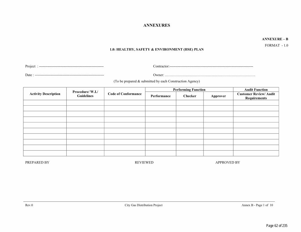
ANNEXURES
Rev.0 City Gas Distribution Project Annex B - Page 1 of 10
ANNEXURE – B
FORMAT - 1.0 1.0: HEALTHY, SAFETY & ENVIRONMENT (HSE) PLAN
Project : ------------------------------------------------------ Contractor:----------------------------------------------------------------------
Date : ---------------------------------------------------------- Owner: ………………………………………………………………….
(To be prepared & submitted by each Construction Agency)
Activity Description Procedure/ W.I./
Guidelines Code of Conformance
Performing Function Audit Function
Performance Checker Approver Customer Review/ Audit
Requirements
PREPARED BY REVIEWED APPROVED BY
Page 62 of 235
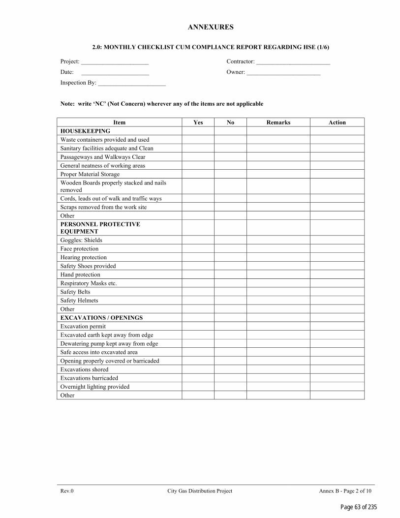
ANNEXURES
Rev.0 City Gas Distribution Project Annex B - Page 2 of 10
2.0: MONTHLY CHECKLIST CUM COMPLIANCE REPORT REGARDING HSE (1/6) Project: ______________________ Contractor: ________________________
Date: ______________________ Owner: ________________________
Inspection By: ______________________
Note: write ‘NC’ (Not Concern) wherever any of the items are not applicable
Item Yes No Remarks Action
HOUSEKEEPING
Waste containers provided and used
Sanitary facilities adequate and Clean
Passageways and Walkways Clear
General neatness of working areas
Proper Material Storage
Wooden Boards properly stacked and nails removed
Cords, leads out of walk and traffic ways
Scraps removed from the work site
Other
PERSONNEL PROTECTIVE EQUIPMENT
Goggles: Shields
Face protection
Hearing protection
Safety Shoes provided
Hand protection
Respiratory Masks etc.
Safety Belts
Safety Helmets
Other
EXCAVATIONS / OPENINGS
Excavation permit
Excavated earth kept away from edge
Dewatering pump kept away from edge
Safe access into excavated area
Opening properly covered or barricaded
Excavations shored
Excavations barricaded
Overnight lighting provided
Other
Page 63 of 235

ANNEXURES
Rev.0 City Gas Distribution Project Annex B - Page 3 of 10
MONTHLY CHECKLIST CUM COMPLIANCE REPORT REGARDING HSE (2/6)
Item Yes No Remark Action
Welding Cutting
Valid not work permit
Flashback arrester provided for cylinders
Power cable not crossing the welding cable
Adequate earthing provided
No combustible materials kept near welding & cutting works
Gas cylinder chained upright & kept in trolleys
Cables and hoses not obstructing
Screens or shields used
Flammable materials protected
Fire extinguisher (s) accessible
Other
SCAFFOLDING
Fully decked platform
Guard and intermediate rails in place
Toe boards in place & tied properly
Adequate shoring
Adequate access
Other
LADDERS
Extension side rails I m above
Top of landing
Properly secured at top & bottom
Angle + 70° from horizontal
Other
Page 64 of 235

ANNEXURES
Rev.0 City Gas Distribution Project Annex B - Page 4 of 10
MONTHLY CHECKLIST CUM COMPLIANCE REPORT REGARDING HSE (3/6)
Item Yes No Remark Action
HOISTS, CRANES AND DERRICKS
Condition of cables and sheaves OK
Condition of slings, chains, hooks and eyes OK
Inspection and maintenance logs maintained
Outriggers used
Singh/ barricades provided
Signals observed and understood
Qualified operators
Other
MACHINERY, TOOLS AND EQUIPMENT
Proper instruction
Safety devices
Proper cords
Inspections and maintenance
Other
VEHICLE AND TRAFFIC
Rules and regulations observed
Inspection and maintenance
Licensed drivers
Others
Page 65 of 235

ANNEXURES
Rev.0 City Gas Distribution Project Annex B - Page 5 of 10
MONTHLY CHECKLIST CUM COMPLIANCE REPORT REGARDING HSE (4/6)
Item Yes No Remark Action
TEMPORARY FACILITIES
Emergency instruction posted
Fire extinguishers provided
Fire-aid equipment
Secured against storm damage
General nemeses
In accordance with electrical requirements
Other
Fire Prevention
Personnel instructed
Fire extinguishers checked
No smoking in prohibited areas
Hydrants clear
Other
ELECTRICAL
Proper wiring & earthing
ELCB’s provided
Ground fault circuit interrupters
Protection against damage
Prevention of tripping hazards
Proper electrical cable joints
Light poles secured
Clear way to power distribution board
Proper rating of fuses
Page 66 of 235

ANNEXURES
Rev.0 City Gas Distribution Project Annex B - Page 6 of 10
MONTHLY CHECKLIST CUM COMPLIANCE REPORT REGARDING HSE (5/6)
Item Yes No Remark Action
HANDLING AND STORAGE OF MATERIALS
Properly stored or stacked
Passageways clear
Other
FLAMMABLE GASES AND LIQUIDS
Containers clearly identified
Proper storage
Fire extinguishers nearby
Other
WORKING AT HEIGHT
Erection plan
Safety nets
Safety belts tied properly
Illumination
No loose material at height
No body under working area
All openings covered
Other
ENVIRONMENT
Chemical and other Effluents properly disposed
Cleaning liquid of pipes disposed off properly
Seawater used for hydrotesting disposed off as per agreed proceeding
Lubricant Waste/ Engine oils properly disposed
Waster from Canteen office, sanitation etc. disposed properly
Disposal of surplus earth stripping materials, Oily rags and combustible materials done properly
Green belt protection.
Page 67 of 235

ANNEXURES
Rev.0 City Gas Distribution Project Annex B - Page 7 of 10
MONTHLY CHECKLIST CUM COMPLIANCE REPORT REGARDING HSE (6/6)
Item Yes No Remark Action
HEALTH CHECK
Hygienic conditions at labour camps OL
Availability of First Aid facilities
Proper sanitation at site, office and labour camps
Arrangements of medical facility
Measures for dealing with illness
Availability of potable drinking waters for workmen & staff
Provision of cretches for children
ERECTION
Slings/ D’shakle checked
Signal Man
Tag line for guiding the load
Protecting the slings from sharp edges
No loose materials at height
Ladder & platform welding inspected
No one under the suspended load
Stay rope
SWL
----------------------------------------- Signature of Resident
Engineer with Seal
Page 68 of 235

ANNEXURES
Rev.0 City Gas Distribution Project Annex B - Page 8 of 10
Monthly Health, Safety & Environmental (HSE) Report (To be submitted by each Contractor)
Actual work start date: ___________________ For the month of: ________________________ Project:_______________________________ Report No.:_____________________________ Name of the Contractor: ___________________ Status as on: ____________________________ Name of Work: __________________________ Name of Safety officer: ____________________
Item This Month Cumulative Total strength (Staff – Workmen) Number of HSE meeting organised at site Number of HSE awareness programmes conducted at site
Whether workmen compensation policy taken
Y/N
Whether workmen compensation policy valid Y/N Whether workmen registered under ESI Act Y/N Number of Fatal Accident Number of Loss Time Accident (Other than Fatal)
Other accident (non loss time) Total No. of accident Total man-hours worked Man-hour loss due to fire and accident Compensation cases raised with insurance Compensation cases resolved and paid to workmen
Remark Date: _____/_____/_____ Safety Officer/RCM (Signature and name) To: OWNER………………………………… 1 COPY RCM/SITE-IN-CHARGE 1 COPY
Page 69 of 235

ANNEXURES
Rev.0 City Gas Distribution Project Annex B - Page 9 of 10
SUPPLEMENTARY ACCIDENT, INCIDENT & NEAR MISS REPORT
Project: _________________________ Supplementary to Report No.: ______________ (Copy enclosed) Site: ____________________________ Date: ___________________ Contractor: ______________________
NAME OF THE INJURED……………………………………………………………………………………... FATHER’S NAME………………………………………………………………………………………………. SUB-CONTRACTOR M/S…………………………………………………………………………………….. DATE & TIME OF ACCIDENT………………………………………………………………………………… LOCATION……………………………………………………………………………………………………… BRIEF DESCRIPTION & CAUSE OF A ACCIDENT NATURE OF INJURY / DAMAGE COMMENTS FROM MEDICAL PRACTITIONER WHO ATTENDED THE VICITIM/INJURED SUGGESTED IMPROVEMENT IN THE WORKING CONDITION IF ANY LOSS OF MANHOURS AND IMPACT ON SITE WORKS ANY OTHER COMMENT BY SAFETY OFFICER Date: ______/_____/______/ SIGNATURE OF CONTRACTOR WITH SEAL To : OWNER………………………………… 1 COPY : RCM/SITE-IN-CHARGE 1 COPY
Page 70 of 235

ANNEXURES
Rev.0 City Gas Distribution Project Annex B - Page 10 of 10
ACCIDENT REPORT
(To be submitted by Contractor after every accident within 2 hours of accident) Report No.______________________ Date:__________________________ Name of Site:_____________________________ COTRACTOR_____________________________ NAME OF THE INJURED …………………………………………………………………………………….. FATHER’S NAME………………………………………………………………………………………………. SUB-CONTRACTOR M/S……………………………………………………………………………………... DATE & TIME OF ACCIDENT………………………………………………………………………………… LOCATION……………………………………………………………………………………………………… BRIEF DESCRIPTION OF ACCIDENT CAUSE OF ACCIDENT NATURE OF INJURY / DAMAGE MEDICAL AID PROVIDED / ACTIONS TAKEN INTIMATION TO LOCAL AUTHORITIES Date : ______/_____/______/ SIGNATURE OF CONTRACTOR WITH SEAL To : OWNER………………………………… 1 COPY : RCM/SITE-IN-CHARGE 1 C
Page 71 of 235

ANNEXURE C – (CUGL - HSE)
Annex C - Page 2 of 2
ANNEXURE – C
CUGL - HEALTH, SAFETY AND ENVIRONMENT [HSE] SPECIFICATIONS
1.0 SCOPE
These specifications establish the 'Health, Safety and Environment [HSE] Management' requirement to be complied with by the Contractors during executing their Job. Requirements stipulated in these specifications shall supplement the requirements of 'HSE Management' given in relevant act(s) / legislation(s).
2.0 REQUIREMENTS OF 'HEALTH, SAFETY AND ENVIRONMENT [HSE] MANAGEMENT
SYSTEM' TO BE COMPLIED BY BIDDERS
2.1 Preferably, the Contractor should have a documented 'HSE Policy' to cover commitment of their organization to ensure health, safety and environment aspects in their line of operations or they must follow the ‘HSE policy’ of CUGL for safe execution of work.
2.2 The Contractor shall ensure that the CUGL's 'Health, Safety and Environment [HSE]' requirements are
clearly understood and faithfully implemented at all level, at sites. 2.3 Contractor shall promote & develop consciousness for Health, Safety & Environment among all personnel
working for the Contractor. Regular work-site meetings (Tool box talk) shall be arranged as 'HSE' activities to cover hazards involved in various operations during executing their jobs, location of First Aid Box, trained personnel to give First Aid, Assembly Points, and fire protection measures such as water and fire extinguishers etc.
2.4 Non-conformance of 'HSE' policy and directives as per CUGL by Contractor [including their sub-
Contractors] as brought out during review/audit by CUGL / external agency authorized by CUGL, shall be complied by Contractor and its report to be submitted to CUGL.
2.5 Contractor shall adhere consistently to all provisions of 'HSE' requirements. In case of non-compliance of
continuous failure in implementation of any of the 'HSE' provisions, CUGL may impose penalty and subsequent stoppage of work for non-compliance. The decision of imposing monitory penalty & work-stoppage shall be taken by EIC with consultation with Safety Officer of CUGL.
2.6 All fatal accidents and other personnel accidents shall be investigated for root cause by CUGL and
Contractor shall extend all necessary help and cooperation in this regard. Recommend corrective and preventive actions of findings will be communicated to Contractor for taking suitable actions should be taken by the Contractors to avoid recurrence of such incidences.
2.7 Contractor shall ensure that all their staffs and workers, including their sub-Contractor(s), shall wear
'Personal Protective Equipment’s [PPEs]' such as safety helmets, safety shoes, safety belts, dust mask, ear plug, protective goggles, gloves, etc., as per job requirements. All these gadgets shall conform to relevant IS specifications or equivalent.
2.8 Contractor shall assign competent & qualified personnel for carrying out various tasks/jobs as per requirement. 2.9 All equipment’s should be tested and certified for its capacity before use. 2.10 Contractor shall ensure storage and utilization methodology of materials that are not detrimental to the
environment. Where required, Contractor shall ensure that only the environment-friendly materials are used. 2.11 All persons deployed at site shall be knowledgeable of and comply with the environmental laws, rules and
regulations relating to the hazardous material substances and waste. Contractor shall not dump release or
Page 72 of 235

ANNEXURE C – (CUGL - HSE)
Annex C - Page 2 of 2
otherwise discharge of dispose-off any such materials without the express authorization of EIC of CUGL. 2.12 Contractor should obtain all work permits before start of activities [as applicable] like hot work, cold work,
confined space, electrical isolation, work at heights and its use & implement all precautions mentioned therein.
2.13 Contractor should display at site office and work locations caution boards, provide posters, banners for safe
working to promote safety consciousness, etc. 2.14 Contractor should properly barricade the facility where work is in progress for safe working and reclaim the
work zone after completion of work to promote safety consciousness. 3.0 RELEVANT CODES FOR 'PERSONAL PROTECTION EQUIPMENTS'
IS: 2925 - 1984 Industrial Safety Helmets IS: 47701 - 1968 Rubber Gloves for Electrical Purpose IS: 6994 - 1973 [Part-I] Industrial Safety Gloves [Leather & Cotton Gloves] IS: 1989 - 1986 [Part-II] Leather Safety Boots & Shoes IS: 5557 - 1969 Industrial & Safety Rubber Knee Boots
IS: 6519 - 1971 Code of Practice for Selections, Care & Repair of Safety Footwear IS: 11226 - 1985 Leather Safety Footwear Having Direct Molding Sole IS: 5983 - 1978 Eye Protectors IS: 9167 - 1979 Ear Protectors IS: 3521 - 1983 Industrial Safety Belts & Harnesses
GUIDELINES FOR IMPOSITION OF PUNITIVE FINES
4.0 Punitive fines on contractors are imposed for violation of safety rules & regulations during execution of jobs. Objective of punitive fines is to work as deterrent for contractors in violation of safety rules & regulation and to improve safety atmosphere in general at all site.
PROPOSED GUIDELINES FOR IMPOSITION ARE DESCRIBED BELOW:
4.1 For first time violation of safety rules & regulation by any contractor, HSE-officer will issue a warning letter to contractor with intimation to EIC of work centre with a copy to MD & DC.
4.2 In case of second time violation of safety rules & regulations by same contractor, EIC will call contractor in person and will have a meeting to discuss reason for repetitive violation along with HSE-Officer. A warning letter will also be issued by EIC to contractor.
4.3 In case of further violation, punitive fines will be imposed on contractor. Amount as fine will be decided as per severity of violation of safety. However, minimum fine would be Rs.5,000/- and in multiple of Rs.5,000/-, thereafter for every instant.
4.4 This will be limited to 5% of contract value, as maximum cumulative penalty.
4.5 This practice of punitive fines is to be implemented across all CUGL sites for all contracts.
4.6 Practice of punitive fines will be applicable for projects sites also and would be over and above the deduction made by M/s CUGL for safety violation from running bills.
Page 73 of 235
PTS - SUPPLY OF MDPE FITTINGS, VALVES AND TRANSITION FITTINGS
P.014714 G 11031
075
CENTRAL U.P. GAS LIMITED (CUGL)
LAYING OF MDPE NETWORK AND GI / Cu INSTALLATION WORK ALONG WITH REGISTRATION OF DOMESTIC CUSTOMERS FOR CUGL
IN JHANSI GA IN U.P.
PTS – SUPPLY OF MDPE FITTINGS, VALVES AND TRANSITION FITTINGS
0 20.08.2021 Issued for Work PM NN NN
Rev. Date Subject of Revision Prepared By Checked By Approved By
Page 74 of 235
VD6049
Stamp

PTS - SUPPLY OF MDPE FITTINGS, VALVES AND TRANSITION FITTINGS
P.014714 G 11031
075
Rev.0 Supply of MDPE Valves, MDPE Fittings and Transition Fittings Page I of I
TABLE OF CONTENTS
1.0 INTRODUCTION & SCOPE ..................................................................................................... 1
2.0 DEFINITIONS ........................................................................................................................ 1
3.0 MATERIAL GRADE ................................................................................................................. 1
4.0 APPROVED MANUFACTURER FOR RAW MATERIAL .............................................................. 1
5.0 TRANSITION FITTINGS ......................................................................................................... 1
6.0 MDPE PIPE MATERIAL .......................................................................................................... 1
7.0 MATERIAL REQUISITION ...................................................................................................... 2
8.0 QUALITY ASSURANCE (QA) ................................................................................................... 2
9.0 DEFECT LIABILITY PERIOD .................................................................................................. 2
10.0 PACKAGING ........................................................................................................................... 2
Page 75 of 235

PTS - SUPPLY OF MDPE FITTINGS, VALVES AND TRANSITION FITTINGS
P.014714 G 11031
075
Rev.0 Supply of MDPE Valves, MDPE Fittings and Transition Fittings Page 1 of 5
1.0 INTRODUCTION & SCOPE
Owner plans to augment the PE Network. The present document covers the technical specifications for the procurement of PE Fittings, Valves & Transition Fittings.
2.0 DEFINITIONS
Manufacturer Means the Manufacturer of the PE Fitting, Valves and Transition
Fitting PTS Means the present <<Particular Technical Specification<< and all its
appendix, if any. Third Party Inspection Agency Means the Inspection Agency. GTS Means the present <<General Technical Specification<< and all its
appendix, if any.
3.0 MATERIAL GRADE
The material grade of polyethylene PE Fittings shall be PE100. The bidder shall submit the details by clearly indicating the make, country of origin, part nos. /Product codes and catalogue number along with catalogues written in English for the Items quoted, in the Unpriced Bid.
The bidder shall provide approvals of internationally recognized authorities for their products along with their un-priced bids.
4.0 APPROVED MANUFACTURER FOR RAW MATERIAL
1. INEOS (Formerly SOLVAY)
2. BOROUGE
3. TOTAL PETROCHEMICALS
4. DOW
5. ELENAC
6. BOREALIS
7. LYONDELLBASELL
5.0 TRANSITION FITTINGS
Transition fittings shall be supplied in accordance with “Plastic piping systems for supply of gases fuels – Part 3: Fitting” EN 1555-3.
Bidder shall provide catalogue for all the fittings including transition fittings.
The material grade (SS-304 as per ASTM A-479) and end connection (in built EF Ends with integral pipe fixation device) shall be as per MR. Steel and MDPE pipe should be so joined in factory so as to have a monolithic joint, which is leak free and should be mechanically stronger than the PE pipe. On placement of order, the bidder shall submit the drawing with dimensions for approval of Owner before starting production.
NOTE: -
1- Supply of Transition Fitting of 32mm x 1 Inch with coupler will be provided by the client for Industrial and Commercial Connectivity.
2- Contractor shall procure all MDPE fittings & MDPE Valves.
6.0 MDPE PIPE MATERIAL
The raw material of MDPE pipe shall be PE100, thick as per SDR11. The MDPE pipe shall confirm standards for polyethylene pipes for supply of gaseous fuels IS 14885 (latest edition).
Page 76 of 235

PTS - SUPPLY OF MDPE FITTINGS, VALVES AND TRANSITION FITTINGS
P.014714 G 11031
075
Rev.0 Supply of MDPE Valves, MDPE Fittings and Transition Fittings Page 2 of 5
7.0 MATERIAL REQUISITION
As per SOR/Contract
8.0 QUALITY ASSURANCE (QA)
Manufacturer to submit their Inspection and Test Procedure (ITP) for the approval of Owner/PMC.
9.0 DEFECT LIABILITY PERIOD
Defect liability period shall be as per the GCC, of commercial volume I of II.
10.0 MARKING
Following information shall be embossed upto height of 0.15 mm onto the fitting and also in the
Form of bar code:
a) Owner name as CUGL.
b) Manufacturer’s name and/or trademark
c) Material and Designation
d) Design application series
e) The size of the fitting in mm
f) Fusion time in seconds
g) Cooling time in minutes
h) Fusion parameters in BAR code
i) Traceability code (fittings) as per standard ISO 12176-4.
j) Number of the system standard. This information can be printed/formed directly on the fitting or on a label associated with the fitting or on an individual bag
k) Production period, year and month
The marking shall stay legible during normal manipulation, storage and installation.
The marking shall not adversely influence the performance of the fitting and prevent the nonconformity of the fitting.
11.0 PACKAGING
All the MDPE fittings of more than one piece shall be kept in single box/packets according to type and size during packaging.
Packing size to be mentioned to ensure uniformity in delivery conditions of the material being procured. Bidder shall submit the packaging details during offer and also complied with at the time of delivery. The material for each SOR Item is essentially required to be packed in one case/packet /box.
AMENDMENT TO GTS 70000/740/GTS/0011
3.2 ADD
Branch piping/tapping saddle of sizes upto 63 mm OD shall preferably be supplied along with integral PE Clamp which is to ensure sufficient pressure welding and is to be left in place after the welding. Further, the upper shell of the Tapping Tees shall be a single piece to avoid dual welds.
5.2 ADD
Page 77 of 235

PTS - SUPPLY OF MDPE FITTINGS, VALVES AND TRANSITION FITTINGS
P.014714 G 11031
075
Rev.0 Supply of MDPE Valves, MDPE Fittings and Transition Fittings Page 3 of 5
The raw material PE, used for accessory production, is in compliance with all prescription in EN 1555-1 standards.
The raw material shall be virgin material belonging to class PE 100
The following are strictly forbidden:
Use of recycled raw materials
Mixing of different raw materials
The addition of supplementary additives to the raw material.
5.2.1 ADD
Material and end connection of transition fittings shall be as per Owner/Owner’s representative.
6.3 REPLACE
All accessories shall be of yellow colour.
6.5.2 REPLACE
Classification
Electrofusion accessories are divided into three classes according to the voltage and/or current characteristics.
Class A Electrical supply based on voltage set between 8V and 42 V
Class B Electrical supply based on voltage set between 42 V and 220 V
Class C Electrical supply based on power supply settings.
All supplies, unless otherwise stipulated in the order, concern Class A accessories.
Unless stipulated otherwise in the order, only “wrap-around” saddles, Electrofusion and Transition fittings with integral pipe fixation device to be supplied up to 63 mm dia.
Unless otherwise agreed between Owner/PMC and the supplier, all electrofusion accessories must be “single wire “type.
6.5.3 REPLACE
Connector (terminal pin) 4.0 mm/4.7mm shall be required.
6.6 REPLACE
The support drilling equipment to be designed so that during drilling the maximum immediate leak flow will never exceed 200 litres per hour at 5 bar pressure, in the main pipe. According to this flow rate, the supports are divided into two categories: - models 1 and 2 (refer to par. 3.2.) The required model will be specified when ordered.
The bell drill is equipped with a maneuver opening for the insertion of a requisite (range may vary from 5 mm to 21mm) hexagonal spanner/Allen Key.
The bell drill path is limited at the top by a limit block.
The drill mechanism is designed so that no additional tools (except the hexagonal spanner/Allen Key) are required for carrying out drilling operations. On placement of order the proposed sizes of hexagonal spanner/Allen Key required for various sizes of Tapping Saddle shall be informed by the bidder alongwith drawing of particular saddle for approval of Owner.
Page 78 of 235
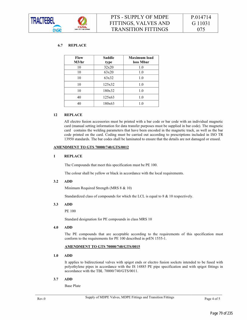
PTS - SUPPLY OF MDPE FITTINGS, VALVES AND TRANSITION FITTINGS
P.014714 G 11031
075
Rev.0 Supply of MDPE Valves, MDPE Fittings and Transition Fittings Page 4 of 5
6.7 REPLACE
Flow
M3/hr Saddle
type Maximum load
loss Mbar
10 32x20 1.0 10 63x20 1.0
10 63x32 1.0
10 125x32 1.0
10 180x32 1.0
40 125x63 1.0
40 180x63 1.0
12 REPLACE
All electro fusion accessories must be printed with a bar code or bar code with an individual magnetic card (manual setting information for data transfer purposes must be supplied in bar code). The magnetic card contains the welding parameters that have been encoded in the magnetic track, as well as the bar code printed on the card. Coding must be carried out according to prescriptions included in ISO TR 13950 standards. The bar codes shall be laminated to ensure that the details are not damaged or erased.
AMENDMENT TO GTS 70000/740/GTS/0012
1 REPLACE
The Compounds that meet this specification must be PE 100.
The colour shall be yellow or black in accordance with the local requirements.
3.2 ADD
Minimum Required Strength (MRS 8 & 10)
Standardized class of compounds for which the LCL is equal to 8 & 10 respectively.
3.3 ADD
PE 100
Standard designation for PE compounds in class MRS 10
4.0 ADD
The PE compounds that are acceptable according to the requirements of this specification must conform to the requirements for PE 100 described in prEN 1555-1.
AMENDMENT TO GTS 70000/740/GTS/0015
1.0 ADD
It applies to bidirectional valves with spigot ends or electro fusion sockets intended to be fused with polyethylene pipes in accordance with the IS 14885 PE pipe specification and with spigot fittings in accordance with the TBL 70000/740/GTS/0011.
3.7 ADD
Base Plate
Page 79 of 235

PTS - SUPPLY OF MDPE FITTINGS, VALVES AND TRANSITION FITTINGS
P.014714 G 11031
075
Rev.0 Supply of MDPE Valves, MDPE Fittings and Transition Fittings Page 5 of 5
Model 2 is applicable for present project.
6.2 ADD
The valve will be designed for a maximum operating pressure (mop) equal to 8 & 10 bar.
6.3 ADD
BULLET: 2
The colour of the PE valve shall be black/yellow.
7.4 REPLACE
PRESSURE DROP AT LOW PRESSURE
Nominal diameter dn. Flow
M3/hr
32 10
63 60
125 450
180 765
8.0 ADD
Marking
b) Material and designation (e.g. PE 100)
DELETE
f) Traceability Code (Valve and Component as per standard ISO/FDIS 12176-4
Page 80 of 235
PTS – G.I. PIPES P.014714 G 11031
076
CENTRAL U.P. GAS LIMITED (CUGL)
LAYING OF MDPE NETWORK AND GI / Cu INSTALLATION WORK ALONG WITH REGISTRATION OF DOMESTIC CUSTOMERS FOR CUGL
IN JHANSI GA IN U.P.
PTS - GI PIPES
0 20.08.2021 Issued for Work PM NN NN
Rev. Date Description Prepared by Checked by Approved by
Page 81 of 235
VD6049
Stamp

PTS – G.I. PIPES P.014714 G 11031
076
Rev. 0 Supply of GI Pipes Page 1 of 1
TABLE OF CONTENTS
1.0 INTRODUCTION AND SCOPE................................................................................................ 1
2.0 DEFINITIONS ....................................................................................................................... 1
3.0 MATERIAL ............................................................................................................................ 1
4.0 DIMENSIONS, THICKNESS & DIMENSIONAL TOLERANCES ................................................ 1
5.0 END CONNECTION OF PIPE.................................................................................................. 1
6.0 FREEDOM FROM DEFECTS .................................................................................................... 1
7.0 GALVANIZING ...................................................................................................................... 2
8.0 PRESSURE TEST ................................................................................................................... 2
9.0 MARKING ............................................................................................................................. 2
10.0 INSPECTION / DOCUMENTS ................................................................................................ 3
11.0 PACKAGING .......................................................................................................................... 3
Page 82 of 235

PTS – G.I. PIPES P.014714 G 11031
076
Rev. 0 Supply of GI Pipes Page 1 of 3
1.0 INTRODUCTION AND SCOPE
Owner plans to augment PNG network. It supplies natural gas to Domestic & Commercial & Industrial consumers. This present document covers the technical specification for the procurement of GI Pipes used in high pressure natural gas transportation and distribution systems. It describes the general requirements, controls, tests, QA/QC examination and final acceptance criteria which needs to be fulfilled. This specification covers the requirements for GI pipes of heavy steel tube. Unless modified by this specification, requirements of IS 1239 (Part-I): 2004 (Latest edition) shall be valid.
2.0 DEFINITIONS
Manufacturer Means the Manufacturer of the GI pipe.
PTS Means the present <<Particular Technical Specification>>and all its appendix, if any.
TPIA Means the Third-Party Inspection Agency.
GTS Means the present <<General Technical Specification>> and its entire appendix, if any.
3.0 MATERIAL
The material used for the manufacturing of GI pipes confirming to IS 1239 (Part -1): 2004 (Latest edition).
4.0 DIMENSIONS, THICKNESS & DIMENSIONAL TOLERANCES
The dimensions & nominal mass of tubes shall be in accordance with Table 5 subject to the tolerances permitted in CL.8.1 & 9 of IS 1239 (Part-I): 2004 (Latest edition). Length of each pipe shall be 6 mtrs with. + 6, - 0 mm tolerance. However, pipe length shall be considered 6 m. only for measurement / payment purpose.
Nominal Diameter DN
15 mm 20 mm
Grade Heavy Heavy
Outer Dia. (Max. / Min.)
21.8 mm / 21.0 mm 27.3 mm / 26.5 mm
Thickness (mm)
3.2 3.2
Nominal weight (Kg / m)
1.44 1.87
5.0 END CONNECTION OF PIPE GI Pipes shall be supplied with plain end.
6.0 FREEDOM FROM DEFECTS On visual examination the outside & inside surfaces of pipes shall be smooth & free from defects such as cracks etc.
Page 83 of 235

PTS – G.I. PIPES P.014714 G 11031
076
Rev. 0 Supply of GI Pipes Page 2 of 3
7.0 GALVANIZING i. Pipes shall be galvanized to meet the requirement of IS: 4736 – 1986 with latest amendment. ii. Zinc conforming to any grade specified in IS: 13229- 1991 with latest amendment shall be used for
the purpose of galvanizing. iii. Galvanizing bath: The molten metal in the galvanizing bath shall contain not less than 98.5% by
mass of zinc.
iv. Mass of zinc coating: Minimum mass of zinc coating determined as per IS: 6745 shall be 360 gms/m2.
v. Uniformity of galvanized coating: The galvanized coating when determined on a 100 mm long test
piece in accordance with IS 2633: 1986 with latest amendment shall withstand 5 one – minute dips.
vi. Freedom from defect: The zinc coating on internal & external surfaces shall be uniform adhered,
reasonably smooth & free from such imperfections as flux, ash & drop inclusions, bare patches, black spots, pimples, lumpiness runs, rust stains, bulky white deposits & blisters. Rejection & acceptance for these defects shall be as per Appendix - A of IS 2629: 1985 with latest amendments.
vii. Samplings
a) All materials of the same type in coating bath having uniform coating characteristics shall be
grouped together to continue a lot. Each lot shall be tested separately for the various requirements of the specification. The number of units to be selected from each lot for this purpose shall be IS: 4711 1995 with latest amendment.
b) The sample selected according to Clause 6.1 & 6.2 of IS: 4736 – latest edition.
c) The sample found conforming to above requirements shall then be tested for mass of zinc
coating in accordance with Clause 5.1 of IS: 4736 – 1986 with latest amendment. d) Criteria for conformity: As per IS: 4736 – 1986 with latest amendments.
8.0 PRESSURE TEST
Hydrostatic pressure test shall be carried out at a pressure of 5 Mpa for the duration of at least 3 second and shall not show any leakage in the pipe. Vendor to submit the internal pressure test certificate for the same. Owner Representative or Third-party Inspection Agency appointed by Owner shall witness finish goods testing as per the sample procedure specified in IS: 1239 (Part-1) – latest edition.
9.0 MARKING
Each pipe shall be embossed with Owner’s logo, manufacturer’s name or trademark, size designation, class of pipe at the interval of not more than 1 meters.
Each packing containing pipes shall carry the following embossed, stamped or written by indelible ink.
a) Manufacturers name or trademark.
b) Class of pipe – Heavy
c) Indian standard mark (ISI)
d) Lot number / Batch no. of production
Each pipe conforming to this standard shall also be marked with BIS standard mark.
Page 84 of 235

PTS – G.I. PIPES P.014714 G 11031
076
Rev. 0 Supply of GI Pipes Page 3 of 3
10.0 INSPECTION / DOCUMENTS
Inspection shall be carried out as per Owner Technical Specification.
Owner Representative or Third-Party Inspection Agency appointed by Owner shall carry out stage wise inspection during manufacturing / final inspection.
The manufacturer shall have a valid licence to use ISI monogram for manufacturing of pipe in accordance with the requirement of IS:1239.
Vendor shall furnish all the material test certificates, proof of approval / licence from specified authority as per specified standard, if relevant, internal test / inspection reports as per Owner Tech. Spec. & specified code for 100% material, at the time of final inspection of each supply lot of material.
For any control, test or examination required under the supervision of TPIA/Owner/Owner’s representative, latter shall be informed in writing one (1) week in advance by vendor about inspection date and place along with production schedule.
Even after third party inspection, Owner reserves the right to select a sample of pipes randomly from each manufacturing batch & have these independently tested. Should the results of these tests fall outside the limits specified in Owner technical specification, then Owner reserves the right to reject all production supplied from the batch.
11.0 PACKAGING
Packing size to be mentioned to ensure uniformity in delivery conditions of the material being procured. Bidder shall submit the packaging details during QAP and also complied with at the time of delivery.
Page 85 of 235

PTS – G.I. FITTINGS P.014714 G 11031
077
CENTRAL U.P. GAS LIMITED (CUGL)
LAYING OF MDPE NETWORK AND GI / Cu INSTALLATION WORK ALONG WITH REGISTRATION OF DOMESTIC CUSTOMERS FOR CUGL
IN JHANSI GA IN U.P.
PTS - GI FITTINGS
0 20.08.2021 Issued for Work PM NN NN
Rev. Date Description Prepared by Checked by Approved by
Page 86 of 235
VD6049
Stamp

PTS – G.I. FITTINGS P.014714 G 11031
077
Rev. 0 Supply of GI Fittings Page 1 of 1
TABLE OF CONTENTS
1.0 INTRODUCTION AND SCOPE................................................................................................ 1
2.0 DEFINITIONS ....................................................................................................................... 1
3.0 MATERIAL ............................................................................................................................ 1
4.0 DIMENSIONS & DIMENSIONAL TOLERANCES ..................................................................... 1
5.0 WEIGHT ................................................................................................................................ 1
6.0 THREADS .............................................................................................................................. 1
7.0 FREEDOM FROM DEFECTS .................................................................................................... 2
8.0 GALVANIZING ...................................................................................................................... 2
9.0 PRESSURE TEST ................................................................................................................... 2
10.0 COMPRESSION TEST ............................................................................................................ 2
11.0 SAMPLING ............................................................................................................................ 2
12.0 MARKING ............................................................................................................................. 3
13.0 PACKAGING .......................................................................................................................... 3
14.0 INSPECTION / DOCUMENTS ................................................................................................ 3
Page 87 of 235

PTS – G.I. FITTINGS P.014714 G 11031
077
Rev. 0 Supply of GI Fittings Page 1 of 3
1.0 INTRODUCTION AND SCOPE
Owner plans to augment PNG network. It supplies natural gas to domestic & commercial consumers.
This present document covers the technical specification for the procurement of GI fittings used in high pressure natural gas transportation and distribution systems. It describes the general requirements, controls, tests, QA/QC examination and final acceptance criteria which need to be fulfilled.
This specification covers the requirements for Malleable Cast Iron Fittings unless modified by this specification, requirements of IS 1879 – latest edition shall be valid.
2.0 DEFINITIONS
Manufacturer Means the Manufacturer of the GI fittings.
PTS Means the present <<Particular Technical Specification>>and its appendix, if any.
TPIA Means the Third-Party Inspection Agency.
GTS Means the present <<General Technical Specification>> and its entire appendix, if any.
3.0 MATERIAL
The material used for the manufacturing of GI fittings shall conform to ISI 14329 – 1995 with latest amendments Grade BM 300.
4.0 DIMENSIONS & DIMENSIONAL TOLERANCES
i. Dimensions of various types of fittings shall be as specified in sections 2 to 10 of IS 1879 – 1987 with latest amendments, as applicable.
ii. Wall thickness of fittings and tolerances on them shall be as given in Table 1.2 of S 1879 – 1987 with latest amendments,
iii. In case of reducing fittings, the dimensions at each outlet shall be those appropriate to the nominal size of the outlet.
iv. Elbows, Tees, Sockets and caps shall be of reinforced type.
5.0 WEIGHT
Weights of various types of fittings shall be as specified in sections 2 to 10 of S 1879 – 1987 with latest amendments, as applicable.
6.0 THREADS
i. Threads shall be NPT type and conforming to ASME B1.20.1.
ii. Outlets of fittings shall be threaded to dimensions & the tolerances as specified in ASME B1.20.1.
iii. All internal & external threads shall be tapered.
iv. For checking conformity of threads gauging practice in accordance with ASME B1.20.1 shall be followed.
v. Chamfering: The outlet of fittings shall have chamfer.
Page 88 of 235

PTS – G.I. FITTINGS P.014714 G 11031
077
Rev. 0 Supply of GI Fittings Page 2 of 3
7.0 FREEDOM FROM DEFECTS On visual examination, the outside & inside surfaces of fittings shall be smooth & free from any defects such as cracks, injurious flaws, fine sand depth etc.
8.0 GALVANIZING i. Fittings shall be galvanized to meet the requirement of IS: 4759 – 1996 with latest amendments. ii. Zinc conforming to any grade specified in IS: 13229-1991 with latest amendments shall be used for the
purpose of galvanizing. iii. Galvanizing bath: The molten metal in the galvanizing bath shall contain not less than 98.5% by mass
of zinc. iv. Coating requirements: Mass of coating shall be 610 - 700 gms/m2. v. Freedom from defect: The zinc coating shall be uniform adhered, reasonably smooth & free from such
imperfections as flux, ash bare patches, black spots, pimples, lumpiness runs, rust stains, bulky white deposits & blisters.
vi. Samplings
a) All materials of the same type in coating bath having uniform coating characteristics shall be
grouped together to continue a lot. Each lot shall be tested separately for the various requirements of the specification. The number of units to be selected from each lot for this purpose shall be given in Table 2 of IS 4759 – latest edition.
b) The sample selected according to Column 1 & 2 of Table 2, IS: 4759 – latest edition shall be tested for visual requirements as per Clause 6.2 of IS:4759 – latest edition
c) The sample found conforming to above requirements shall then be tested for mass of zinc coating in accordance with Clause 9.2 of IS: 4759 – latest edition.
d) Criteria for conformity: As per Clause 8.3 of IS: 4759-latest edition.
e) Test procedure shall be as per Clause 9 of IS: 4759-latest edition. 9.0 PRESSURE TEST
Vendor shall carry out pneumatic pressure test as per Clause 11.1b of 1879 – 1987 with latest amendments on each & every fittings. Vendor to submit the Internal Quality control certificate for the same. Owner shall witness pneumatic testing as per the sampling procedure specified in 1879 – 1987 with latest amendments.
10.0 COMPRESSION TEST
This test shall be conducted to judge the malleability of the pipe fittings & shall be carried out as per Clause 12 of 1879 – 1987 with latest amendments.
11.0 SAMPLING
Owner Representative of Third-Party Inspection Agency appointed by Owner shall witness the tests as per clause 14 of 1879 – 1987 with latest amendments. However, vendor to perform 100% inspection of visual, dimensional & pressure test. Vendor shall furnish Internal test certificates at the time of final inspection to the Owner.
Page 89 of 235

PTS – G.I. FITTINGS P.014714 G 11031
077
Rev. 0 Supply of GI Fittings Page 3 of 3
12.0 MARKING
Each fitting shall be embossed with OWNER’s logo, manufacturer’s name or trademark and the size designation.
Each packing containing fittings shall carry the following embossed, stamped or written by indelible ink. a. Manufacturer’s name or trademark. b. Designation of fittings. c. Lot number.
Each fitting conforming to this standard shall also be marked with BIS standard mark.
13.0 PACKAGING
Packing size to be mentioned to ensure uniformity in delivery conditions of the material being procured. Packing size shall be approved by owner / owner’s representative before packing the material. The vendor shall submit the packaging details during QAP and also complied with at the time of delivery.
14.0 INSPECTION / DOCUMENTS
i. Inspection shall be carried out as per Owner Technical Specification.
ii. Owner Representative or Third-Party Inspection Agency shall carry out stage wise inspection during manufacturing / final inspection.
iii. Vendor shall furnish all the material test certificates, proof of approval / licence from specified authority as per specified standard, if relevant, internal test / Inspection reports as per Owner Tech Spec. & specified code for 100% material, at the time of final inspection of each supply lot of material.
iv. Even after third party inspection, Owner reserves the rights to select a sample of fittings randomly from each manufacturing batch & have these independently tested. Should the results of these tests fall outside the limits specified in Owner technical specification, then Owner reserves the rights to reject all production supplied from the batch.
Page 90 of 235
PTS - WARNING MAT P.014714 G 11031
078
CENTRAL U.P. GAS LIMITED (CUGL)
LAYING OF MDPE NETWORK AND GI / Cu INSTALLATION WORK ALONG WITH REGISTRATION OF DOMESTIC CUSTOMERS FOR CUGL IN JHANSI
GA IN U.P.
PTS – WARNING MAT
0 20.08.2021 Issued for Work PM NN NN
Rev. Date Description Prepared by Checked by Approved by
Page 91 of 235
VD6049
Stamp

PTS - WARNING MAT P.014714 G 11031
078
Rev. 0 GI/CU Installations for City Gas Distribution Project Page I of I
TABLE OF CONTENTS 1.0 INTRODUCTION & SCOPE ..................................................................................................... 1
2.0 DEFINITIONS ........................................................................................................................ 1
3.0 REFERENCE CODE ................................................................................................................. 1
4.0 FEATURES .............................................................................................................................. 1
5.0 QUALITY ASSURANCE (QA) ................................................................................................... 3
6.0 DEFECT LIABILITY ................................................................................................................ 3
7.0 RECOMMENDED MANUFACTURER FOR RAW MATERIAL ...................................................... 3
Page 92 of 235

PTS - WARNING MAT P.014714 G 11031
078
Rev. 0 Supply of warning Mat Page 1 of 3
1.0 INTRODUCTION & SCOPE
Owner plans to augment the PNG Network. It supplies natural gas to Domestic, Industrial & Commercial Consumers.
The present document covers the technical specifications for the procurement of Warning Mat. Warning Mats shall be laid in the ground above the gas main line in order to indicate their presence.
2.0 DEFINITIONS
Manufacturer Means the Manufacturer of the Warning Mat / Warning Grid / Warning Net / Warning Tape.
PTS Means the present <<Particular Technical Specification>> and its entire appendix, if any.
TPIA Means the Third-Party Inspection
3.0 REFERENCE CODE
EN 12613 – Plastics warning devices for underground cables and pipelines with visual characteristics
4.0 FEATURES
4.1. Material
Warning Tape, Type 1 as per EN 12613 shall be used for the present project.
The material grade of Warning Mat shall be Virgin Low-density polyethylene (PE) material with warning sticker / stamp. The material shall be having the density between 0.913 to 0.923 g/cc at 27 deg. Celsius as per IS 2508.
The tape shall be uniform in colour, texture and finish and shall be free from holes and foreign materials.
Rodent repellent chemicals to be added to the plastic master batch for protection against rodents.
The material and colour, if used, for printing shall have no detrimental effects on the environment.
4.2. Mechanical properties
Mechanical properties of the Warning Mat (Type I) shall be in accordance with the code EN 12613.
Minimum tensile withstand load in longitudinal direction shall not be less than 200 N. The test piece shall not exhibit a reduction of more than 20% of its width after removal of the specified load.
4.3. Colour
The Warning Mat shall be of bright golden yellow colour. This colour must not take any alteration in the course of time.
4.4. Dimensions
Warning Mat shall have following dimensions:
Width 300 ± 2 mm
Thickness 1.0 mm (Minimum)
Negative tolerance on the thickness is not allowed.
Page 93 of 235

PTS - WARNING MAT P.014714 G 11031
078
Rev. 0 Supply of warning Mat Page 2 of 3
4.5. Marking
4.5.1. The warning mat shall be marked at intervals not exceeding 1 meter. Marking on the mat shall be approved by owner. The marking shall be legible and durable. The warning mat must be printed with “Caution: High Pressure Gas Pipeline Below” in both English and Hindi, Chainage marking along with OWNER’s logo and OWNER’s 24 Hours Emergency Number -----------------, ----------------- at a frequency of every meter. In addition, name or trademark of the manufacturer, year of manufacture and reference of code of manufacture of warning mat shall be included in the marking.
4.5.2. Vendor shall submit proposed Artwork to be marked on the Warning Mat for approval from Owner / Owner’s representative.
4.5.3. Vendor shall submit 02 Metres sample of Warning Mat meeting the tender requirements along with the Bid.
4.6. Tests
All the tests and test procedures for Warning Mats shall be as per EN 12613 or as per required National/ International standards mentioned in EN 12613. In addition, all requirements pertaining to statutory requirements, if any, as specified from time to time shall be complied.
The required tests are briefed as below:
4.6.1. Colouring
Three separate tests shall be carried out in accordance with:
As per normative annexure B of EN 12613, using 20% ammonium sulphide. As per EN ISO 175, using 10% nitric acid & 20% sodium carbonate solution.
The tests shall be repeated for each colour (if any). There shall be no discolouration or change of the initial colour of the warning tape after the tests.
4.6.2. Tensile Withstand Strength
The test sample shall be selected as per mentioned in EN 12613. The test samples shall be preconditioned for not less than 12 h at 23±2 oC. Static loads shall be carried out to the samples over a period of 10 s. After the test, the test piece shall withstand without starting to separate at weak points (if any) for not less than 5 minutes. Also it should no exhibit a reduction of more than 20% of its width after removal of specified load.
The minimum tensile withstand load for the warning mat in the longitudinal direction shall be not less than 200 N.
4.6.3. Visual Warning Characteristics
The test shall be carried out in accordance with normative annexure A of EN 12613.
4.6.4. Permanence of Printing
The test shall be performed as per CL. 9.3 of IEC 60898:1995. The test is made by rubbing the marking by hand for 15 sec with a piece of cotton soaked with water and again for 15 sec with a piece of cotton soaked with aliphatic solvent hexane with a content of aromatics of max. 0.1% by volume, a kauributanol value of 29, an initial boiling point value of approx. 65 oC, a dry point of approx. 69 oC and a density of approx. 0.68 gm/cm3. After the test, the marking shall be easily legible.
Page 94 of 235

PTS - WARNING MAT P.014714 G 11031
078
Rev. 0 Supply of warning Mat Page 3 of 3
4.6.5. Test of laying Characteristics
The test is for the assessment of transverse rigidity of the warning mats. The test shall be performed as per EN 12613.
4.6.6. Warning Mat Virginity Test
Differential Scanning Calorimeter (DSC) Scan test along with the temperature of melting (Tm) shall be performed for the Warning Mat and its raw polymer i.e. virgin low density polyethylene (LDPE). The Differential Scanning Calorimeter (DSC) Scan curve of the Warning Mat obtained from its DSC Scan test along with its Temperature of Melting (Tm) shall then be compared with the DSC Scan curve and the Temperature of Melting (Tm) of its raw polymer (i.e. virgin LDPE). To ensure the virginity of the Warning mat, the DSC Scan curve and Tm of the Warning Mat (finished product manufactured from the raw polymer) shall match on overlapping with its corresponding raw polymer’s DSC Scan curve and Tm.
4.7. Packing
The warning mat shall be delivered in rolls of minimum 50 meters. Packing size to be mentioned to ensure uniformity in delivery conditions of the materials being procured. Bidder shall submit the packing details during offer and also compiled with at the time of delivery. Packaging of the Warning Mat shall be such that there won’t be any deterioration due to Ultraviolet (UV) effect during transportation and storage of the Warning Taps prior to use.
5.0 QUALITY ASSURANCE (QA)
Manufacturer shall prepare detailed QAP and submit for the approval from Owner / Owner’s representative.
6.0 DEFECT LIABILITY
Defect liability period shall be as per the commercial volume I of II.
7.0 RECOMMENDED MANUFACTURER FOR RAW MATERIAL
1. SOLVAY 2. BOREALIS 3. TOTAL PETROCHEMICALS 4. DOW 5. ELENAC 6. RELIANCE 7. GAIL 8. HALDIA
However, any other reputed national or international Manufacturer may also be considered for supply of Raw material with approval of Owner / Owner’s representative.
Page 95 of 235

PTS – POWDER COATING P.014714 G 11031
079
0 20.08.2021 Issued for Work PM NN NN
Rev. Date Description Prepared by Checked by Approved by
CENTRAL U.P. GAS LIMITED (CUGL)
LAYING OF MDPE NETWORK AND GI / Cu INSTALLATION WORK ALONG WITH REGISTRATION OF DOMESTIC CUSTOMERS FOR
CUGL IN JHANSI GA IN U.P.
PTS – POWDER COATING
Page 96 of 235
VD6049
Stamp

PTS – POWDER COATING P.014714 G 11031
079
Rev. 0 City Gas Distribution Project Page 1 of 1
TABLE OF CONTENTS
1.0 INTRODUCTION ............................................................................................................... 1
2.0 SPECIFICATION ............................................................................................................... 1
3.0 TESTING ........................................................................................................................... 1
4.0 INSPECTION .................................................................................................................... 1
Page 97 of 235

PTS – POWDER COATING P.014714 G 11031
079
Rev. 0 City Gas Distribution Project Page 1 of 2
1.0 INTRODUCTION
Owner plans to augment PNG network. It supplies natural gas to Domestic, Industrial & Commercial consumers.
This present document covers the technical specification for the Powder coating of GI Pipes used in high pressure natural gas transportation and distribution systems. It describes the general requirements, controls, tests, QA/QC examination and final acceptance criteria which needs to be fulfilled.
This specification covers the requirements of powder coatings for GI pipes of heavy steel tube. Unless modified by this specification, requirements of IS 13871: 1993 (Latest edition) shall be valid.
2.0 SPECIFICATION
Powder Material : Pure Polyester
Application : Electrostatic Spraying (40-90 KV Manual / Automatic)
Backing Schedule : 180 C to 200 C for 10 MM (Metal Temp.)
Coating Thickness : 60- 70 Microns
3.0 TESTING
Film Type Glossy / Satin
Gloss 60 º (ASTM D-523-60 )
86 – 95%
Cross Hatch Adhesion (ASTM D-5870)
GT = 0/100
Cylindrical bending Test (ASTM D 522) 5 mm Rod dia
Passes
Enrichen Cupping (min) 8 Passes Pencil Hardness (min) 2H Scratch Resistance (Kg Min) 3 Impact Resistance Direct 150 Kg. Min (ASTM D-2794) Indirect 150 Salt Spray Resistance ASTM B-117)
1000 hrs (min)
Porosity (DIN-53161)
Passes
Humidity Resistance (ASTM D-2247)
1000 Hrs (min)
Weathering Gloss retention after 1000 Hrs (sun test with water immersion, Xenon 150 K.lux)
60 – 70%
Color Canary Yellow
4.0 INSPECTION
Inspection shall be carried out as per Owner Technical Specification.
Owner Representative or Third-Party Inspection Agency appointed by Owner shall carry out stage wise inspection during manufacturing / final inspection.
The manufacturer shall have a valid license for Powder coatings of pipe in accordance with the requirement of IS:13871.
Page 98 of 235
PTS – POWDER COATING P.014714 G 11031
079
Rev. 0 City Gas Distribution Project Page 2 of 2
Vendor shall furnish all the material test certificates, proof of approval / license from specified authority as per specified standard, if relevant, internal test / inspection reports as per Owner Tech. Spec. & specified code for 100% material, at the time of final inspection of each supply lot of material.
For any control, test or examination required under the supervision of TPIA/Owner/Owner’s representative, latter shall be informed in writing one (1) week in advance by vendor about inspection date and place along with production schedule.
Even after third party inspection, Owner reserves the right to select a sample of pipes randomly from each manufacturing batch & have these independently tested. Should the results of these tests fall outside the limits specified in Owner technical specification, then Owner reserves the right to reject all production supplied from the batch.
Page 99 of 235

PTS - INSTALLATION OF ABOVE GROUND GI/ COPPER PIPING &
FITTINGS
P.014714 G 11031
080
0 20.08.2021 Issued for Work PM NN NN
Rev. Date Description Prepared by Checked by Approved by
CENTRAL U.P. GAS LIMITED (CUGL)
LAYING OF MDPE NETWORK AND GI / Cu INSTALLATION WORK ALONG WITH REGISTRATION OF DOMESTIC CUSTOMERS FOR
CUGL IN KANPUR, UNNAO & BAREILLY GA IN U.P GA
PTS - INSTALLATION OF ABOVE GROUND GI /COPPER PIPING & FITTINGS
Page 100 of 235
VD6049
Stamp
PTS - INSTALLATION OF ABOVE GROUND GI/ COPPER PIPING &
FITTINGS
P.014714 G 11031
080
Rev.0 City Gas Distribution Project Page 1 of 1
TABLE OF CONTENTS
1.0 GENERAL INFORMATION ..................................................................................................... 1
2.0 DEFINITIONS ....................................................................................................................... 1
3.0 SCOPE OF WORK .................................................................................................................. 1
4.0 MATERIAL, MANPOWDER, EQUIPMENT AND MACHINERY .................................................. 2
5.0 ISSUE OF WORK INSTRUCTIONS ......................................................................................... 4
6.0 PROGRESS OF WORK ........................................................................................................... 5
7.0 WORK SHEETS ...................................................................................................................... 5
8.0 CO-ORDINATION /LIAISON ................................................................................................. 5
9.0 REFERENCE SPECIFICATION, CODES AND STANDARDS ..................................................... 6
10.0 RIGHT-OF-USE SURVEY AND MARKING .............................................................................. 6
11.0 PROTECTION OF STRUCTURES AND UTILITIES .................................................................. 6
12.0 GI AND COPPER ABOVE GROUND SERVICE PIPE ................................................................ 6
13.0 TESTING OF GI/COPPER INSTALLATION ............................................................................ 8
14.0 INSPECTION ......................................................................................................................... 9
15.0 PURGING & COMMISSIONING ............................................................................................. 9
16.0 CONVERSION OF DOMESTIC APPLIANCES .......................................................................... 9
17.0 RESTORATION .................................................................................................................... 10
18.0 SUBMISSION OF FINAL RECORDS ..................................................................................... 10
Page 101 of 235
PTS - INSTALLATION OF ABOVE GROUND GI/ COPPER PIPING &
FITTINGS
P.014714 G 11031
080
Rev.0 City Gas Distribution Project Page 1 of 15
1.0 GENERAL INFORMATION
1.1 Introduction
Owner plans to augment PNG network. It supplies natural gas to Domestic, Commercial & Industrialconsumers in the GA i.e.
District of Jhansi GA in U.P.
The main scope of this contract comprises the installation of above ground pipes from the outlet of ‘PE/GItransition fitting’ up to the domestic/commercial Customers ‘Appliance/stove/oven valve’ as per theDistribution schedule placed in enclosed drawing.
The scope includes installation & procurement of above ground GI / Cu pipes and associated fittings forcommercial/Domestic/industrial Customers. However, the piping may have to be carried out up toAppliance valve, in case of some commercial/industrial/domestic Customers required.
Except MRS/Metering Skid, meter & regulator/service regulator, Contractor shall procure the each material(GI pipe, GI fittings, Cu pipe, Cu/Brass fittings, Corrugated Flexible metal Hose (Anaconda) SteelReinforced Rubber Hose, etc.) which is required from the outlet of PE / GI transition fitting up to the Do-mestic / commercial customers “Appliance / stove / oven valve.
This technical specification defines the basic guidelines to develop an acceptable design and suitableconstruction methodology for carrying out different activities listed out in the schedule of rates of thistender.
Compliance with these specifications and/or approval of any of the Contractor’s documents shall in no caserelieve the Contractor of his contractual obligations.
2.0 DEFINITIONS
OWNER Central U.P. Gas Limited (CUGL)PMC TRACTEBEL Engineering Private Ltd.,PTS Present <<Particular Technical Specification>>and its entire
appendix, if any.EIC Engineer – in – charge
3.0 SCOPE OF WORK
Generally, the following shall constitute the Contractor’s scope of work but not limited to:
3.1 Plan and prepare a schedule for execution and work implementation as per QA / QC plans to be issued byOwner / Owner’s representative. Contractor has to submit the Construction/Execution procedures beforecommencement of work to Owner / Owner’s representative for approval.
3.2 Contractor shall submit the QCT/procedure/drawing etc. of all the material to be procured by him forapproval before procuring the items. If, QCT/procedure/drawing etc are not approved from client/consultantthen owner has the authority to refuse /reject the same lot material.
3.3 Receipt of regulator / Service Regulator / meters / MRS/Metering Skid as a free issue items from Owner’sstores, loading, transportation, unloading at project site. Proper storing, stacking, identification, providingsecurity and insurance during and before installation and commissioning of pipelines. Obtaining theapproval for optimum route and permission for work from the concerned authority and EIC.
3.4 Selection of route with the EIC / Consultant and marking the same on walls/floors between ‘transitionfitting’ to ‘cooking oven/stove/appliance’, making openings and making provisions for fixing clamps.Making temporary but stable platforms/scaffolding/rope ladder etc., required for installation of pipes/fittingsat all heights/multi storied flats and locations.
Page 102 of 235

PTS - INSTALLATION OF ABOVE GROUND GI/ COPPER PIPING &
FITTINGS
P.014714 G 11031
080
Rev.0 City Gas Distribution Project Page 2 of 12
3.5 Contractor shall procure all material except free issue items for installation at the outlet of PE/ GI transitionfitting upto the Domestic customers “Appliance /stove / oven for satisfactory completion to theowner/owner’s representative.
3.6 Supply and Installation of powder coated GI pipes of ½”, ¾”, 1” & 1.5” dia. between transition fittings tocustomer’s kitchen appliances including NPT threading of GI pipes, supply of proper seal outs for threads tojoin fittings such as elbows, tees, connectors, regulators, meters, appliance & isolation valves etc., as perlaid procedures and specification including clamping and sealing etc. The scratched powder coated GI pipeand fittings shall be painted after the testing of the GI installation.
3.7 Supply & Installation of 12 mm Copper tube including supply of solder wire and flux to join fittings such aselbows, tees, connectors, meters, valves etc., complete as per procedures and specifications includingclamping and sealing etc.
3.8 Supply of clamps for fixing pipes, Meters wherever required, painting of scratched powder coated pipes andfittings. Providing consumables grout material, repair/restoration of walls/floors changes for the pipesincluding the materials required for conversions and tools and tackles etc. shall be complete as perspecification.
3.9 Conversion of all types of LPG kitchen appliances to NG based appliances & to take Sign on RFC card &Joint Meter Records (JMRs) of customer.
3.10 To demonstrate the Customer regarding use, safety and maintenance related aspects of NG based appliancesand installations.
3.11 Cleaning, flushing, pneumatic testing and commissioning to the GI / Cu tube & fittings, meters, valves etcas per specification and hand over the same to Owner/Customer to the entire satisfaction of EIC /CONSULTANT.
3.12 Dismantling of scaffolding/temporary structures and cleaning of site & restore the site as per its originalcondition.
3.13 Restoration of walls, flooring and other damages while executing the above ground installation.
3.14 Preparation and submission of above ground installation card for each house indicating the laid GI/Cu tubeincluding fittings, mentioned the reasons, if connection is not provided to the customers and deviationstatements on completion /commissioning of work.
3.15 Any other activities not mentioned/covered explicitly above, but otherwise required for satisfactorycompletion/operation/safety/statutory/maintenance of the works in new & existing gas charged areas shallalso be covered under the Scope of work and has to be completed by the Contractor within specifiedschedule at no extra cost to Owner.
3.16 All printable materials are in the scope of contractors like RFC book, Sticker, Safety Guideline, FeasibilityReport, consent reports etc printable documents as per Owner requirements.
3.17 All size of GI pipes shall be powder coated before installations and it is in the scope of contractors.Contractors shall submit powder coating procedure to EIC/Consultants before powder coating of pipes.
4.0 MATERIAL, MANPOWDER, EQUIPMENT AND MACHINERY
4.1 Material to be supplied as a free issue material
Meter, Regulator, service regulator, MRS/Metering Skid shall be supplied as a free issue material to thecontractor. The contractor shall not use any other material from any other source of supply other thanowner’s supplied material without any written approval from EIC.
4.2 Material / Equipment & machinery to be supplied by contractor
Contractor shall procure / purchase powder coated GI Pipe & GI fittings, Brass fittings, Cu tube & fittings,Corrugated Flexible metal Hose (Anaconda), and Reinforced rubber hose with other material which is re-quired to satisfactory completion / safety / statutory of the works as per tender at no extra cost to Owner. The OWNER logo shall be marked on the material supplied by contractor. The contractor shall take ap-proval from owner / owner representative for marking on the material to be procured by contractor before placement of order.
Page 103 of 235

PTS - INSTALLATION OF ABOVE GROUND GI/ COPPER PIPING &
FITTINGS
P.014714 G 11031
080
Rev.0 City Gas Distribution Project Page 3 of 12
The Contractor shall provide labour, tools (such as Hammer Drill, Piston Drill, Pipe Cutters, Dies for threading, Pipe wrenches, spanners, conversion kits, solder torch, copper tube Cutters, tube benders, lacquering, thinner etc.) in specified numbers, all types of clamps, Plant and equipment necessary for the proper execution of the work. This will include but not limited to list of specialised tools and tackles indicated in Annexure # 1.
Special tools shall be required at site for carrying out drilling work in walls other than Brick or RCC (Ex. Granite, Marble, Wooden, Glass Cutting etc.)
The contractor has to ensure the availability of DG sets for continuous powder supply. In case the powder supply is availed at the site from societies, individual residents, contractor shall settle the claims raised by the electricity providers without any cost implication to OWNER. In case contractor doesn’t settle the claims for using the electricity from societies/individual residents, on demand by the providers, OWNER will settle the claims and the same will be deducted from the contractor’s bills. The progress of work shall not hamper due to non-availability of powder supply.
The contractor has to submit the valid calibration certificate for Pressure gauges.
Contractor shall submit the manufacturer test certificate / lab test certificate for all items procured by him for approval before commencing the execution.
No hiring of equipments, tools and tackles by the contractors is allowed at the site. In case, any contractor is found not in possession of enlisted required tools and tackles, penalty will be levied as per SCC which shall be deducted from the running bill.
4.2.1 Plant and Equipment
All vehicular type machinery shall be in good working condition and shall not cause spillage of oil or grease. To avoid damage to paved surfaces, the contractor will provide pads of timber or thick rubber under the hydraulic feet or outriggers of machinery.
4.2.2 Sealant, Grout
The contractor shall be responsible to arrange the supply of any consumable sealant or ready-mix grout material required for restoration of holes. The sealant/grout supplied by the contractor shall be compatible with the area to be restored / rectified. No separate payment for the supply of sealant and grout shall be made to the contractor.
4.2.3 Clamps, Rawal Plugs, Screws and Nozzles etc.
The Clamps, Brackets for meter, Rawal Plugs, Screws, Nozzles, etc. shall be approved lot wise by EIC prior to installation. Re-drilling of existing appliance (burners) nozzles is strictly not permitted. The quality of materials procured will be got approved and will be as directed by EIC.
The indicative sketch of the Brackets for Meter, Regulator Boxes and GI/Copper tube Clamps is enclosed with the tender. No separate payment for the supply of Meter Brackets and GI/Copper clamps shall be made to the contractor.
4.2.4 Consumables Items
Special Consumables such as Teflon Tapes, solder wire, flux, lacquer, thinner shall be supplied by the contractor and are included in installation rates.
These consumables shall be of reputed make companies and required grades/class.
4.2.5 Other Materials
The contractor shall supply & Installation the following items wherever required:
All materials required for work, NPT threading, Copper tube jointing, testing etc.
All signs, barricades, lights and protective equipment.
All material required for working at higher floor levels (i.e., scaffolding, Ladder, Safety Belts, Self Locking Safety Harness Belts etc.).
Page 104 of 235
PTS - INSTALLATION OF ABOVE GROUND GI/ COPPER PIPING &
FITTINGS
P.014714 G 11031
080
Rev.0 City Gas Distribution Project Page 4 of 12
Special consumable such as grease for maintenance of domestic appliances, all paints for painting of scratched portion of powder coated GI Pipes, GI fittings, Regulator Boxes, Consumables such as Teflon Tapes, Solder-wire, Flux, Lacquer, Thinner, Petrol, Diesel, Fuels and Oils required are to be supplied by the contractor and are included for within the rates.
All minor items not expressly mentioned in the contract, but which are necessary for the satisfactory completion and performance of the work under this contract.
4.3 Acquisition, Receipt and Storage of Materials
The Contractor shall collect MRS/Metering skid, Service Regulator, Domestic/Commercial/Industrial meter and Regulators from Owner’s designated stores in between the hours to be advised by the EIC and installation of the same items.
The contractor shall carry out assessment of material required for GI/Copper installation in allocated area. After approval from Owner, contractor shall place order for purchasing of GI Pipes & fittings, Copper tubes & fittings, Brass Fittings, Corrugated Flexible metal Hose (Anaconda), Isolation & Appliance Valve and Reinforced Rubber hose (Technical specifications attached in the tender document) to anyone of approved vendors as per the list attached in the tender document. The contractor shall also ensure that the QCT for these materials shall be approved before the start of production activity. Once QCT is approved, contractor shall forward inspection call to the Owner depending upon the material requirement at the site. The inspection of these materials shall be carried out by Owner appointed third party inspection agency. It is contractor’s responsibility for document submission, arranging dispatch clearance, handling, loading, transportation and unloading of these materials at their own respective store.
Any other activity not mentioned / covered, explicitly, but otherwise required for satisfactory completion / operation / safety / statutory / maintenance of works shall also be covered under scope of work and has to be completed by contractor within specified schedule at no extra cost to Owner. The Contractor shall carry free issue material in such a manner as to preclude damage during transportation and handling.
The Contractor shall physically examine all materials at the time of acceptance the material in store and notify the EIC immediately of any damage or defect noticed by the Contractor. The EIC shall duly note any damage or defect in a site instruction book and both parties shall countersign the entry.
Any damage not so recorded will be deemed not to have existed at the time of acceptance of material in store by the Contractor and the cost of repair or replacement or rectification shall be borne by the Contractor.
All materials shall be stored in contractor’s stores near site in such a manner so as to prevent any damage to the materials from scratching, gouging, indentation, excessive heat or by contact with any sharp objects or chemicals.
The Contractor shall be required to submit inventory details of materials every month.
The Contractor shall maintain logbook at their respective stores stating issue and availability of free issue material at a given day. Further, it is mandatory that the contractor is required to undertake and submit inventory details of free issue and purchased materials on monthly basis to Owner/ Owner’s representative as per the approved format of the owner. The inventory details shall be in correlation with the Daily progress chart and material reconciliation sheet.
Material reconciliation indicating issue of material, consumptions and defective material shall be submitted on every three months basis.
5.0 ISSUE OF WORK INSTRUCTIONS
5.1 The contractor will be required to carry out GI installation in the areas where MDPE laying is under progress. However, testing of GI installation shall be done in conjunction with laying of MDPE Service Lines to respective premises. A general scheme of distribution to domestic consumer is indicated in enclosed drawing for reference. It may vary in case of individual and multi storied flats.
5.2 All skilled personnel like jointers, conversion technicians will be approved and certified by EIC. The technicians who will carry out joining of copper material and conversions will undergo a test by Owner. Those who clear the test will be issued identity cards duly signed by EIC. These technicians shall be only
Page 105 of 235
PTS - INSTALLATION OF ABOVE GROUND GI/ COPPER PIPING &
FITTINGS
P.014714 G 11031
080
Rev.0 City Gas Distribution Project Page 5 of 12
authorized to take up respective jobs. In case it is found that contractor personnel other than authorized are carrying out these works, applicable penalty will be levied to the contractor as per contract.
5.3 The rates to be quoted by contractor shall be inclusive of all preparatory/bye works, platform materials, labour, , supervision, tools, taxes, duties, levies, salaries, wages, overheads, profits, escalations, fluctuations in exchange rates and no change in the rates shall be admissible during tenancy of the contract.
5.4 The schedule of items of GI/Cu installations have been described in brief and shall be held to be completed in all respect including safety requirements as per PTS of HSE, tests, inspection, QA/QC works, enabling and sundry works. The payment shall be made against completed and measured works only. No extra works whatsoever shall be considered in execution of these items.
6.0 PROGRESS OF WORK
The contractor shall proceed with the work under the contract with due expedition and without delay.
Contractor shall assess the material requirement of the allotted area and submit the schedule plan for execution & purchasing before start of actual work.
The EIC may direct in what order and at what time the various stages or parts of the work under the contract shall be performed. Weekly progress reports shall be submitted in the formats approved by Owner, indicating broadly the laying, testing, RFC, conversions and extra piping.
7.0 WORK SHEETS
7.1 The quantities of GI/Cu pipe and other details will be checked by Owner’s site engineer and the same shall be incorporated in RFC cards, signed & dated as certified, on site. The cards will then be approved by the EIC.
7.2 Measurement sheets shall be prepared based on the RFC cards and checked and certified by the site engineers for billing purpose.
7.3 If measurement sheets submitted are illegible, incomplete or incorrectly booked they will be returned to the contractor.
8.0 CO-ORDINATION /LIAISON
8.1 Contractor shall be responsible for co-ordination with society management, RWA, individual residents and any other concerned authority, if required, for completion of the work. Contractor must take the prior appointment from the residents for carrying out the work.
8.2 The prospective bidder shall work in close consultation/coordination with the EIC.
8.3 The prospective bidder shall not sign/execute any agreement and/or undertaking on any such documents which amounts to be undertaken by Owner. The same shall only be signed and executed by Owner; however, the prospective bidder shall also liaison and coordinates for the same.
8.4 The necessary coordination, liaison and arrangements for inspection and approval shall be the contractor’s responsibility. Inspection and acceptance of the work by authority shall not relieve the contractor from any of these responsibilities under this contract. The contractor shall plan the execution of work in such a manner so that all the registered customers are attended in phased manner. However, it is the contractor’s responsibility to fix a firm appointment with the consumer for carrying out the work.
A logbook/job card for such appointments with Consumer/any other agencies shall be maintained and the schedule/appointment once taken shall be adhered to by the contractor. PMC/EIC shall review the records every week. The contractor shall submit the detailed list of RFC/Conversions and balance work on Registrations at least once a week as per approved format.
8.5 The contractor is also required to obtain a “Labour License” from the Assistant Labour Commissioner of respective Administration/Central Govt.
8.6 It will be the contractor’s responsibility to familiarise himself and comply with, any other local rules, regulations or statutory requirements applicable to the work.
Page 106 of 235

PTS - INSTALLATION OF ABOVE GROUND GI/ COPPER PIPING &
FITTINGS
P.014714 G 11031
080
Rev.0 City Gas Distribution Project Page 6 of 12
8.7 The contractor has to take responsibility of the actions of supervisors, plumbers and helpers provided by him.
9.0 REFERENCE SPECIFICATION, CODES AND STANDARDS
The contractor shall carry out the work in accordance with this specification, Owner’s Engineering Standards: ASME B31.8 – Gas Transmission and Distribution Piping Systems; Oil Indian Safety Directorate Norms (OISD), the American Gas Association Document – Purging Principles and Practice and PNGRB Guidelines.
If the contractor find any discrepancy, ambiguity or conflict in between any of the Standards and the contract documents, then this should be promptly referred to the Engineer-in-Charge (EIC) for his decision, which shall be considered binding on the contractor.
10.0 RIGHT-OF-USE SURVEY AND MARKING
The route of the pipeline to be installed shall be decided with consent of the consumer and Site Engineer/EIC. Contractor must ensure that the persons/workers/supervisors/ working at site shall have proper identity cards prior to entering the premises of the consumer.
No temporary or permanent deposit of any kind of material resulting from the work shall be permitted in the approach or any other position, which might hinder the passage and / or natural water drainage, or any area where there is objection from consumer.
The contractor shall obtain necessary permissions from landowners and tenants and shall be responsible for all damages caused by the construction and use of such approaches, pavements, gardens, rooms, walls, roof etc., at no extra cost to Owner.
Owner/Consultant and the contractor at each premises or housing colony to be supplied with gas will conduct a joint survey. The survey record will note Customer details, the potential gas supply points and proposed meter positions and estimates of material quantities. The contractor’s representatives will make as sketch of the agreed pipe routes, if necessary.
The contractor will be responsible for contacting the Customer and making the necessary arrangements for access and appointments to carry out the work. Owner will not be responsible for any time lost due to failed appointments or disputes with Customer.
The contractor shall confine its operations within limits of the Right in use. The contractor shall restore any damage to property outside ROU.
The contractor shall also carryout all necessary preparatory work if needed to permit the passage of men and equipment. Lights, Curbs, signs shall be provided wherever and/or required by the Owner necessary to protect the public.
11.0 PROTECTION OF STRUCTURES AND UTILITIES
The contractor shall at his own cost, support and protect all buildings, walls, fences or other structures and all utilities and property which may, unless so protected, be damaged as a result of the execution of the works. He shall also comply with the requirements in the specification relating to protective measures applicable to particular operations or kind of work.
While painting, contractor must take care of the consumer premises while carrying out the job such as spillage on floor, walls, ceilings, such shades etc. If the same does occur, the contractor has to immediately make things to original.
12.0 GI AND COPPER ABOVE GROUND SERVICE PIPE
The GI service pipe installation work includes all work necessary to connect from the PE/GI transition fitting on the down-stream of the PE service, to the Customers appliance, including the installation of regulator, valves, fittings, meters, clamps etc. The contractor shall be required to provide all equipment, tools and materials necessary to execute the work in an efficient and effective manner. Along with ladders, scaffolding pipe, dies, tripods, vices, fittings and Teflon tape, drills for concrete and other masonry, drills for timber, Granite, Marble Stones and laminated surfaces inside Customers property, bending tools, clamps, sleeves to facilitate the pipe passing through floors and walls, paint for marking etc.
Page 107 of 235

PTS - INSTALLATION OF ABOVE GROUND GI/ COPPER PIPING &
FITTINGS
P.014714 G 11031
080
Rev.0 City Gas Distribution Project Page 7 of 12
All GI risers at the outside of buildings shall be fully supported to carry the weight of piping. A flanged foot or similar device, capable of supporting the total weight of the riser, shall support risers. The riser shall be installed in a vertical line form its point of support to its highest point with a minimum of changes in direction. The threading of GI pipe shall be NPT and conforming to ANSI B1 20.1
Contractor has to supply different types/sizes of approved powder coated clamps (Mild Steel) for fixing GI pipes suiting to the site conditions. The contractor shall get approval from EIC for every fresh lot of the clamps, brackets, regulator boxes and other consumables, prior to start of installation. The detailed cross sectional of Powder coated GI Pipe Clamps/Meter brackets are as per enclosed drawing.
All riser and lateral pipe shall be clamped to the building at intervals not exceeding 1.5 mtrs. Maximum distance between clamps shall be 1.0 - 1.5 m when pipe goes to the straight, if any tee or fittings lies in between the pipe then clamp shall be placed 150 mm far away from centre line of fittings at every sides. However, the same may be changed as per site conditions/as directed by EIC. Minimum gap between pipe & wall shall be 25 mm. The joints/ fittings of the GI installation shall be painted only after carrying out testing of the installation.
Where pipe passes through the balcony and the surface is slightly elevated around the service pipe or its surrounding sleeve to prevent the accumulation of water at that point. Where a short piece of sleeve is used around the gas pipe, the sleeve should be embedded in the concrete with a mix of mortar and the void between the pipe and sleeve filled with a suitable sealant. The sealant should be bevelled such as to prevent an accumulation of water. Supply of clamps for all sizes of the GI pipes is in contractor’s scope. Contractor has to take prior approval for design/types of clamps, paintings etc.
Pipe shall preferably be entered into building above ground and remain in a ventilated location. The location for entry shall be such that it can be easily routed to the usage points by the shortest practicable route.
The rates for providing a connection are payable depending upon the length of the GI and Copper tube installed. It also includes the installation of meters, meter regulator with associated inlet and outlet connections (GI/Brass fittings, Corrugated Flexible metal Hose (Anaconda)), on the wall with approved powder coated meter brackets and angles, painting, testing upto Appliance valve The Pipe installation includes all type of Pipe & Fittings (GI/Copper and Corrugated Flexible metal Hose (Anaconda),etc
Except Meter, Regulator, Contractor shall procure all other materials (i.e. Pipe, fittings, clamps etc.) as per attached specification for installation and to the entire satisfaction of EIC/consultant.
The contractor shall also ensure that gas supply shall not be provided to the customer in any Concealed Piping.
The Copper service pipe installation work includes all work necessary to connect downstream of the meter to the Customers appliances. The contractor shall be required to provide all equipment, tools and materials necessary to execute the work in an efficient and effective manner. Along with these, he will be required to provide ladders, scaffolding pipe, drills for concrete and other masonry, special drills for timber, Granite, Marble Stones and laminated surfaces inside Customers property, bending tools, sleeves to facilitate the pipe passing through floors and walls, etc. Copper tubes & fittings shall be provided by Contractor.
During installation the Copper tube is to be cut to proper length with tube Cutter, the burrs removed with a file, cleaning of outside surface of pipe & inside surface of fitting, applying flux to the tube and fitting around the outer/inner ends, inserting the tube in to the fitting, applying heat to the assembled joints using conventional blow torch to melt solder wire. Contractor shall submit the joining procedure of Cu tube & Fitting to the approval or as per the instructions of EIC.
Contractor has to supply different types/sizes of approved clamps (PE 80/PVC) for fixing Copper tubes suiting to the site conditions Contractor has to take prior approval of EIC for quality of the clamps, solder, flux, lacquer, thinner etc. The approval shall be taken for every fresh lot of clamps from EIC before installation at site.
All copper piping shall be clamped to the walls at intervals not exceeding 500 mm. The solder wire shall be of reputed company of diameter size 3.25mm, Lead free as per BS 29453:1994 (Soft solder alloys) and supplied in coils. The detail specification is attached in tender for reference. Solders for use with copper
Page 108 of 235

PTS - INSTALLATION OF ABOVE GROUND GI/ COPPER PIPING &
FITTINGS
P.014714 G 11031
080
Rev.0 City Gas Distribution Project Page 8 of 12
tube & fittings generally melt within the temperature range 180°C - 250°C. The contractor has to furnish the certificate of confirmation of standards before start of work.
Installation of Meter
Installation of meters with associated inlet and outlet connections (GI/Brass fittings), on the wall with approved powder coated meter brackets and angles in new & existing gas charged areas.
The contractor shall supply approved powder coated meter brackets and angle brackets. A sketch of the brackets is referred from the enclosed drawing for reference. It is required that one sample of each type of bracket is approved before the work is started.
Firmly secure the meters on the wall with good quality Rawal Plugs, screws etc. In case the Rawal Plugs are not holding then wooden blocks or other fixing arrangements like cement etc. to be used for proper grouting.
The Meter installation will be preferred in open/ventilated space so as to prevent Gas accumulation and easy dispensation of gas to atmosphere in case of any smell/leakage of gas. The Meter installations will not be provided in any fixed enclosures, cabinets (below or above the slab) or confined space in the customer premises.
The contractor shall ensure that GI installations and steel reinforced rubber hoses shall not be exposed to direct heat of Gas burners. The installation should have minimum clearance of about 1 meter from electric point mains & switches. Minimum distance between Appliance Valve & Gas Burners shall be 0.3 Meters. The isolation valves shall be installed after entering the customer premises/kitchen but before the meter installation.
The above activities along with restoration of the area to original shall be carried out to the complete satisfaction of consumer and EIC.
Powder Coating/ Painting of GI Pipes
The entire lengths of the pipeline along with fittings are to be painted/ powder coated after proper surface preparation as follows:
(a) PAINTING (for scratched powder coated pipes and fittings only)
One coat of Primer Application (Appropriate Zinc based primer)
Two coats of synthetic enamel paint – canary yellow of minimum of 30 microns per coat of reputed make like Asian, Berger, Nerolac. (No other make shall be used for painting).
All painting materials including primers and thinners brought to site by contractor for application shall be procured directly from manufacturers/dealers as per specifications and shall be accompanied by manufacturer’s test certificates. Paint formulations without certificates are not acceptable. The contractor shall ensure that smooth finish is attained after carrying out painting.
Engineer-in-Charge at his discretion may call for test for paint formulations. Contractor shall arrange to have such tests performed including batch wise test of wet paints for physical and chemical analysis. All costs there shall be borne by the contractor.
The painting work shall be subject to inspection and certification by Engineer-in-Charge at all times. Painting of GI pipe shall be paid with installation of GI pipes.
(b) POWDER COATING (REFER ATTACHED PTS FOR POWDER COATING)
Contractor will be required to install Powder coated GI pipes and shall submit detailed procedure of powder coating for approval to Consultant prior to supply of powder coated GI pipes. After installation of the entire piping system, final touching with paint shall be done to the satisfaction of EIC.
13.0 TESTING OF GI/COPPER INSTALLATION
13.1 The installation from PE/GI transition fitting up to regulator shall be tested at the pressure of 6.0 bar (g).
13.2 The testing of GI riser pipe up to regulator shall be done with the isolation valve in open condition and open end plugged.
Page 109 of 235

PTS - INSTALLATION OF ABOVE GROUND GI/ COPPER PIPING &
FITTINGS
P.014714 G 11031
080
Rev.0 City Gas Distribution Project Page 9 of 12
13.3 The joints shall be painted only after carrying out testing of the installation. Powder coating to GI pipes shall be carried out in factory/shop, and repair / touching shall be carried out at site.
13.4 The GI/Copper installation from regulator outlet to appliance valve (except meter) shall be tested at a pressure of 2.0 bar (g) for a holding period of 2 hour with no pressure drop. All the joints in the installation shall be checked with soap solution.
13.5 The meter shall be removed while carrying out the testing at 2 bar (g) and joints of the meter shall be tested online with soap solution after completion of the work. For testing proper test ends shall be made along with gauges and subsequently approved by EIC. For the installation to be tested by manometer or diaphragm gauge the meter shall not be dismantled/removed and testing shall be carried out at 60 m bar with holding period of 15 min with no pressure drop.
13.6 The contractor shall supply the Calibrated Pressure Gauges / Manometer / Diaphragm Gauges of suitable range for testing of GI/Copper Installations ranging from 0-4 bars/0-150 m bar/0-250 m bar respectively. The calibration certificate shall be submitted before the start of the execution work.
13.7 The pressure gauges shall be calibrated from time-to-time as desired by EIC but positively once in every six months.
13.8 The details of testing shall be properly recorded in the GI/Copper cards.
14.0 INSPECTION
The contractor to the entire satisfaction of EIC before proceeding further shall rectify any defect noticed during the various stages of inspection. Irrespective of the inspection, repair and approval at intermediate stages of work, contractor shall be responsible for making good any defects found during final inspection/guarantee period/defect liability period as defined in general condition of contract.
15.0 PURGING & COMMISSIONING
The rate for purging & commissioning shall be included in the GI/Cu installations.
Care shall be taken to ensure that the outlet is so located that vent gas cannot drift into buildings.
The commissioning of the GI installation should be performed as follows:
Ensure the method of purging is such that no pockets of air are left in any part of the Customer’s piping.
Ensure that all appliance connections are gas tight, all appliance gas valves are turned off and there are no open ends.
Where possible, select an appliance with an open burner at which to commence the purge i.e., a hotplate burner.
Ensure the area is well ventilated, and free from ignition sources.
Ensure branches that do not have an appliance connected are fitted with a plug or cap.
Turn on one burner control valve until the presence of gas is detected. A change in the audible tone and smell is a good indication that gas is at the burner. Let the gas flow for a few seconds longer, then turn off and allow sufficient time for any accumulated gas to disperse.
Turn on one gas control valve again and keep a continuous flame at the burner until the gas is a light and the flame is stable.
Continue to purge until gas is available at other appliances.
16.0 CONVERSION OF DOMESTIC APPLIANCES
The work in this section includes:
The changing of nozzles and associated controls in accordance with manufactures instructions for both domestic and imported burners/ovens/grills/hotplate.
The changing of old appliance connection Reinforced rubber hoses and nozzles and re-greasing taps as necessary.
The contractor shall supply the Reinforced rubber hoses at the time of conversions.
Page 110 of 235

PTS - INSTALLATION OF ABOVE GROUND GI/ COPPER PIPING &
FITTINGS
P.014714 G 11031
080
Rev.0 City Gas Distribution Project Page 10 of 12
The contractor has to supply all types of nozzles/jets required for all types of appliances including imported burners, Grills, Ovens.
Cleaning and performing minor maintenance of appliances.
Testing for gas escapes, soundness and performance of appliances.
Instructing the Customer for safe use of natural gas and for fixing of safety and conversion labels.
Contractor must attend the complaints regarding appliances, leakage, fire etc. till the total area is handed over to Owner’s operation and maintenance.
All consumables (Nozzles, greases etc.) are in contractor’s scope.
Changing or repairing of any items damaged during conversion.
It may be noted that the rates as per applicable SOR item will apply to conversion of all type of domestic appliances under the rates, the contractor will have to provide both Pin gauges and standard sized nozzles. The payment shall be released only after submission of necessary documents i.e. RFC & JMR Card of the individual house to Owner.
17.0 RESTORATION
Contractor has to restore the area wherever he has carried out drilling, clamping etc. to its original condition to the satisfaction of the consumer and to ensure no passage to the premises and seepage. If the work was carried out in Govt. Flats (CPWD/ Institutional areas), contractor has to restore the area according to CPWD specifications and obtain a NOC / Clearance certificate from the concerned authorities maintaining the flats, after completion of the work.
The restored slabs or brickwork should match the surrounding surface levels. Joint widths should match the existing conditions and be filled with a dry or wet mix of mortar.
Wherever any items of the consumer is damaged/broken during working, the same will be made good or replace to the total satisfaction of the consumer.
The contractor will be responsible for the maintenance of all restoration carried out, for the duration of the contract guarantee period.
The contractor is to ensure the restoration work is properly supervised, and that the material used is suitable for the purpose. Wherever the required standards are not achieved the contractor will be required to replace the defective reinstatement work.
Note that Payment for GI/Copper installation will be released only after satisfactory restoration and clearing of the sites of all surplus materials etc.
18.0 SUBMISSION OF FINAL RECORDS
Contractor shall submit three sets each of the following documents in hard & soft copy:
a) Total list of houses in the area allotted to him giving details of connections provided & reasons where connection could not be given / completed.
b) The details recorded in RFC cards of every domestic house.
c) Details of houses where piping done along with materials used.
d) Total material consumption report.
e) Material reconciliation with respect to the materials issued.
f) Test reports & calibration certificates of gauges etc.
g) Any other documents/records required.
h) Extra Piping details
Page 111 of 235
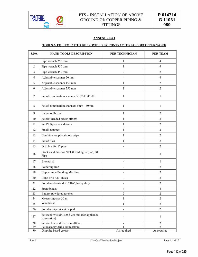
PTS - INSTALLATION OF ABOVE GROUND GI/ COPPER PIPING &
FITTINGS
P.014714 G 11031
080
Rev.0 City Gas Distribution Project Page 11 of 12
ANNEXURE # 1
TOOLS & EQUIPMENT TO BE PROVIDED BY CONTRACTOR FOR GI/COPPER WORK
S.N0. HAND TOOLS DESCRIPTION PER TECHNICIAN PER TEAM
1 Pipe wrench 250 mm 1 4
2 Pipe wrench 350 mm 1 4
3 Pipe wrench 450 mm - 2
4 Adjustable spanner 50 mm - 4
5 Adjustable spanner 150 mm 1 2
6 Adjustable spanner 250 mm 1 2
7 Set of combination spanner 3/16”-11/4” AF 1 1
8 Set of combination spanners 5mm - 30mm 1 1
9 Large toolboxes 1 2
10 Set flat-headed screw drivers 1 2
11 Set Philips screw drivers 1 2
12 Small hammer 1 2
13 Combination pliers/mole grips 1 2
14 Set of files 1 2
15 Drill bits for 1” pipe - 2
16 Stocks and dies for NPT threading ½”, ¾”, GI Pipe
- 3
17 Blowtorch - 1
18 Soldering iron - 2
19 Copper tube Bending Machine - 2
20 Hand drill 3/8” chuck - 2
21 Portable electric drill 240V, heavy duty - 2
22 Spare blades 4 4
23 Battery powdered torches 2 2
24 Measuring tape 30 m 1 2
25 Wire brush 1 2
26 Portable pipe vice & tripod - 2
27 Set steel twist drills 0.5-2.0 mm (for appliance conversion)
- 1
28 Set steel twist drills 1mm-10mm - 2 29 Set masonry drills 1mm-10mm 1 2 30 Graphite based grease As required As required
Page 112 of 235
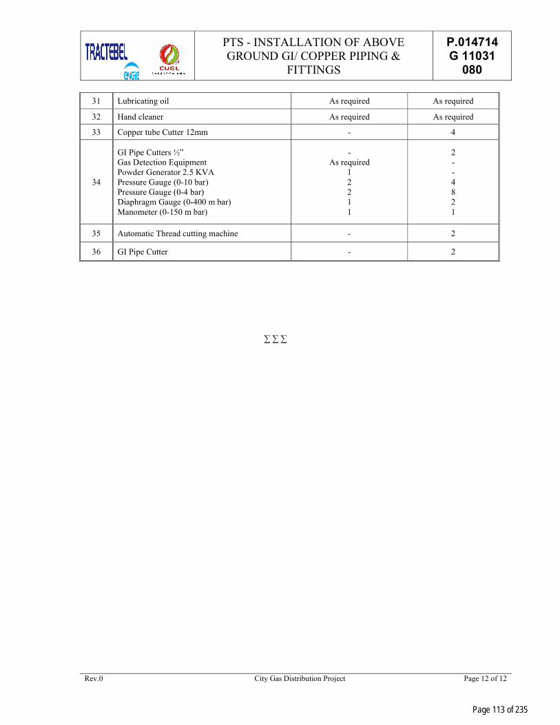
PTS - INSTALLATION OF ABOVE GROUND GI/ COPPER PIPING &
FITTINGS
P.014714 G 11031
080
Rev.0 City Gas Distribution Project Page 12 of 12
31 Lubricating oil As required As required
32 Hand cleaner As required As required
33 Copper tube Cutter 12mm - 4
34
GI Pipe Cutters ½” Gas Detection Equipment Powder Generator 2.5 KVA Pressure Gauge (0-10 bar) Pressure Gauge (0-4 bar) Diaphragm Gauge (0-400 m bar) Manometer (0-150 m bar)
- As required
1 2 2 1 1
2 - - 4 8 2 1
35 Automatic Thread cutting machine - 2
36 GI Pipe Cutter - 2
∑ ∑ ∑
Page 113 of 235

PTS-COPPER FITTINGS P.014714 G 11031
081
CENTRAL U.P. GAS LIMITED (CUGL)
LAYING OF MDPE NETWORK AND GI / Cu INSTALLATION WORK ALONG WITH REGISTRATION OF DOMESTIC CUSTOMERS FOR
CUGL IN JHANSI GA IN U.P GA
PTS - COPPER FITTINGS
0 20.08.2021 Issued for Work PM NN NN
Rev. Date Description Author Checked Approved
Page 114 of 235
VD6049
Stamp

PTS-COPPER FITTINGS P.014714 G 11031
081
Rev.0 City Gas Distribution Project Page I of I
TABLE OF CONTENTS
1.0 SCOPE................................................................................................................................... 1
2.0 MATERIAL ............................................................................................................................ 1
3.0 DIMENSIONAL TOLERANCES ............................................................................................... 1
4.0 END CONNECTION ............................................................................................................... 1
5.0 CARBON IN BORE ................................................................................................................. 1
6.0 CHEMICAL PROPERTIES ...................................................................................................... 1
7.0 STRESS CORROSION RESISTANCE TEST ............................................................................. 1
8.0 FREEDOM FROM DEFECT ...................................................................................................... 2
9.0 HYDROSTATIC PRESSURE TEST ........................................................................................... 2
10.0 PNEUMATIC PRESSURE TEST ............................................................................................... 2
11.0 MARKING ............................................................................................................................. 2
12.0 PACKAGING .......................................................................................................................... 2
13.0 INSPECTION / DOCUMENTS ................................................................................................ 2
Page 115 of 235
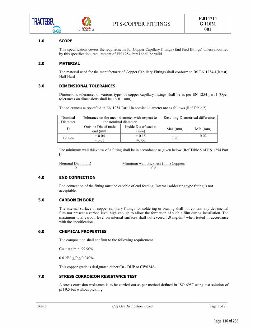
PTS-COPPER FITTINGS P.014714 G 11031
081
Rev.0 City Gas Distribution Project Page 1 of 2
1.0 SCOPE
This specification covers the requirements for Copper Capillary fittings (End feed fittings) unless modified by this specification, requirement of EN 1254 Part I shall be valid.
2.0 MATERIAL
The material used for the manufacturer of Copper Capillary Fittings shall conform to BS EN 1254-1(latest), Half Hard
3.0 DIMENSIONAL TOLERANCES
Dimensions tolerances of various types of copper capillary fittings shall be as per EN 1254 part I (Open tolerances on dimensions shall be +/- 0.1 mm). The tolerances as specified in EN 1254 Part I in nominal diameter are as follows (Ref Table 2).
Nominal Diameter
Tolerance on the mean diameter with respect to the nominal diameter
Resulting Diametrical difference
D Outside Dia of male
end (mm) Inside Dia of socket
(mm) Max (mm) Min (mm)
12 mm +.0.04 -.0.05
+ 0.15 +0.06
0.20 0.02
The minimum wall thickness of a fitting shall be in accordance as given below (Ref Table 5 of EN 1254 Part I)
Nominal Dia mm, D Minimum wall thickness (mm) Coppers 12 0.6
4.0 END CONNECTION
End connection of the fitting must be capable of end feeding. Internal solder ring type fitting is not acceptable.
5.0 CARBON IN BORE
The internal surface of copper capillary fittings for soldering or brazing shall not contain any detrimental film nor present a carbon level high enough to allow the formation of such a film during installation. The maximum total carbon level on internal surfaces shall not exceed 1.0 mg/dm2 when tested in accordance with the specification.
6.0 CHEMICAL PROPERTIES
The composition shall confirm to the following requirement Cu + Ag min. 99.90% 0.015% < P < 0.040%. This copper grade is designated either Cu - DHP or CW024A.
7.0 STRESS CORROSION RESISTANCE TEST
A stress corrosion resistance is to be carried out as per method defined in ISO 6957 using test solution of pH 9.5 but without pickling.
Page 116 of 235

PTS-COPPER FITTINGS P.014714 G 11031
081
Rev.0 City Gas Distribution Project Page 2 of 2
8.0 FREEDOM FROM DEFECT
The fittings shall be free from internal fins, blow holes, skin defects etc. or other irregularities which might restrict the free flow of fluid and shall be designed that resistance to the flow of fluid through the fittings is minimized.
9.0 HYDROSTATIC PRESSURE TEST
All fittings shall be leak tightness tested at 1.5x25 bars for a period of 15 minutes and no leakage is permitted. This test shall be performed on each size of the fittings.
10.0 PNEUMATIC PRESSURE TEST
All fittings shall be leak tested at 6 bars for a period of 10 seconds and no leakage is permitted.
11.0 MARKING
Each tube shall be embossed with OWNER’s logo, manufacturers name or trademark EN 1254 Part I and designation of fittings. Each packing containing fittings shall carry the following stamped or written in indelible ink. a) Manufacturer’s name or trademark.
b) Designation of fittings.
c) Lots no.
d) Month and year of manufacture
12.0 PACKAGING
Packing size to be mentioned to ensure uniformity in delivery conditions of the material being procured. Bidder shall submit the packaging details during QAP and also complied with at the time of delivery.
13.0 INSPECTION / DOCUMENTS
i) Inspect shall be carried out as per OWNER Technical Specification, relevant codes/standards and Inspection Plan/ Vendor’s detailed QAP duly approved by owner/owner’s representative.
ii) OWNER representative or third-party inspection agency shall carry out stage wise inspection
during manufacturing/ final inspection. iii) Vendor shall furnish all the material test certificates, proof of approval/ license from specified
authority as per specified standard, if relevant, internal test/ inspection reports as per OWNER Technical Specification, at the time of final inspection of each supply lot of material.
iv) Even after third party inspection, OWNER reserves the right to select a sample of tube randomly
from each manufacturing batch and have these independently tested. Should the results of these tests fall outside the limits specified in OWNER Technical specification, ten OWNER reserves the rights to reject all production supplied from the batch.
v) Vendor shall prepare and submit the detail drawings of required copper fittings for approval by
OWNER /TECPL before starting production vi) For any control test or examination required under the supervision of TPIA/owner/owner’s
representative, latter shall be informed in writing one (1) week in advance by vendor about inspection date & place along with production schedule.
Page 117 of 235

PTS - BRASS FITTINGS P.014714 G 11031
082
CENTRAL U.P. GAS LIMITED (CUGL)
LAYING OF MDPE NETWORK AND GI / Cu INSTALLATION WORK ALONG WITH REGISTRATION OF DOMESTIC CUSTOMERS FOR
CUGL IN JHANSI GA IN U.P.
PTS - BRASS FITTINGS
0 20.08.2021 Issued for Work PM NN NN
Rev. Date Description Author Checked Approved
Page 118 of 235
VD6049
Stamp
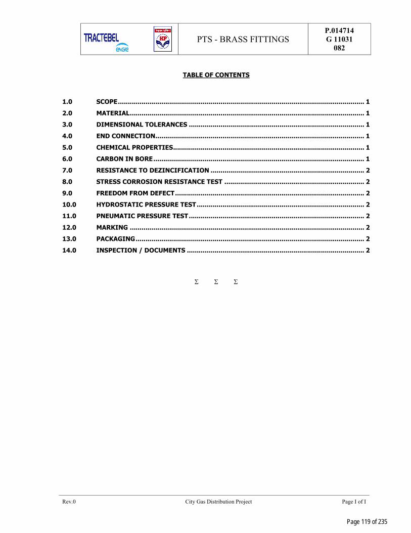
PTS - BRASS FITTINGS P.014714 G 11031
082
Rev.0 City Gas Distribution Project Page I of I
TABLE OF CONTENTS
1.0 SCOPE ............................................................................................................................. 1
2.0 MATERIAL ....................................................................................................................... 1
3.0 DIMENSIONAL TOLERANCES ......................................................................................... 1
4.0 END CONNECTION .......................................................................................................... 1
5.0 CHEMICAL PROPERTIES ................................................................................................. 1
6.0 CARBON IN BORE ........................................................................................................... 1
7.0 RESISTANCE TO DEZINCIFICATION .............................................................................. 2
8.0 STRESS CORROSION RESISTANCE TEST ....................................................................... 2
9.0 FREEDOM FROM DEFECT ................................................................................................ 2
10.0 HYDROSTATIC PRESSURE TEST ..................................................................................... 2
11.0 PNEUMATIC PRESSURE TEST ......................................................................................... 2
12.0 MARKING ....................................................................................................................... 2
13.0 PACKAGING .................................................................................................................... 2
14.0 INSPECTION / DOCUMENTS .......................................................................................... 2
Page 119 of 235
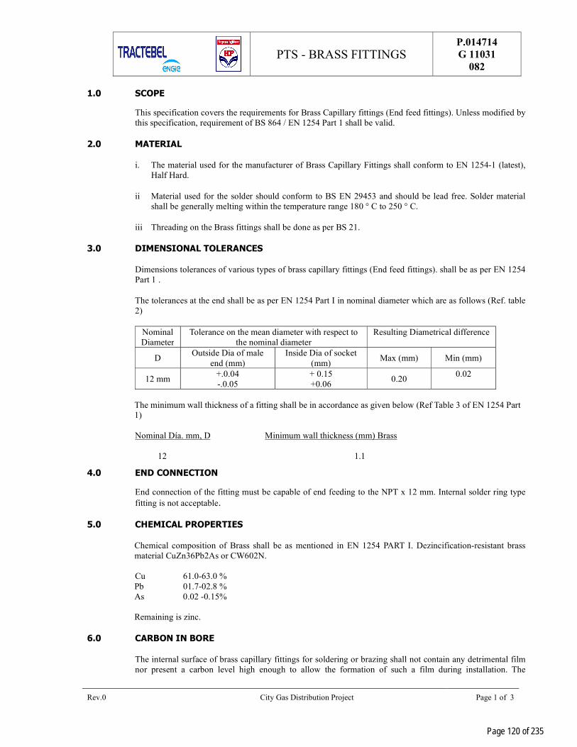
PTS - BRASS FITTINGS P.014714 G 11031
082
Rev.0 City Gas Distribution Project Page 1 of 3
1.0 SCOPE
This specification covers the requirements for Brass Capillary fittings (End feed fittings). Unless modified by this specification, requirement of BS 864 / EN 1254 Part 1 shall be valid.
2.0 MATERIAL
i. The material used for the manufacturer of Brass Capillary Fittings shall conform to EN 1254-1 (latest), Half Hard.
ii Material used for the solder should conform to BS EN 29453 and should be lead free. Solder material shall be generally melting within the temperature range 180 ° C to 250 ° C.
iii Threading on the Brass fittings shall be done as per BS 21.
3.0 DIMENSIONAL TOLERANCES
Dimensions tolerances of various types of brass capillary fittings (End feed fittings). shall be as per EN 1254 Part 1 .
The tolerances at the end shall be as per EN 1254 Part I in nominal diameter which are as follows (Ref. table 2)
Nominal Diameter
Tolerance on the mean diameter with respect to the nominal diameter
Resulting Diametrical difference
D Outside Dia of male
end (mm) Inside Dia of socket
(mm) Max (mm) Min (mm)
12 mm +.0.04 -.0.05
+ 0.15 +0.06
0.20 0.02
The minimum wall thickness of a fitting shall be in accordance as given below (Ref Table 3 of EN 1254 Part 1)
Nominal Día. mm, D Minimum wall thickness (mm) Brass 12 1.1
4.0 END CONNECTION
End connection of the fitting must be capable of end feeding to the NPT x 12 mm. Internal solder ring type fitting is not acceptable.
5.0 CHEMICAL PROPERTIES
Chemical composition of Brass shall be as mentioned in EN 1254 PART I. Dezincification-resistant brass material CuZn36Pb2As or CW602N.
Cu 61.0-63.0 % Pb 01.7-02.8 % As 0.02 -0.15% Remaining is zinc.
6.0 CARBON IN BORE
The internal surface of brass capillary fittings for soldering or brazing shall not contain any detrimental film nor present a carbon level high enough to allow the formation of such a film during installation. The
Page 120 of 235

PTS - BRASS FITTINGS P.014714 G 11031
082
Rev.0 City Gas Distribution Project Page 2 of 3
maximum total carbon level on internal surfaces shall not exceed 1.0 mg/dm2 when tested in accordance with the specification. This test shall be carried out as per clause no. 5.4 of EN 1254 -1.
7.0 RESISTANCE TO DEZINCIFICATION
The fittings shall be manufactured from alloys containing more than 10% Zinc. So, fittings shall be required to be resistant to dezincification. It shall be carried out as per Cl. 5.5 of EN 1254 -1.
8.0 STRESS CORROSION RESISTANCE TEST
A stress corrosion resistance is to be carried out as per method defined in ISO 6957 using test solution of pH 9.5 but without pickling.
9.0 FREEDOM FROM DEFECT
The fittings shall be free from internal fins, blow holes, skin defects etc. or other irregularities which might restrict the free flow of fluid and shall be designed that resistance to the flow of fluid through the fittings is minimized.
10.0 HYDROSTATIC PRESSURE TEST
All fittings shall be leak tightness tested at 1.5x25 bars for a period of 15 minutes and no leakage is permitted. This test shall be performed on each size of the fittings.
11.0 PNEUMATIC PRESSURE TEST
All fittings shall be leak tested at 6 bars for a period of 10 seconds and no leakage is permitted.
12.0 MARKING
Each fitting shall be embossed with OWNER’ s logo, manufacturers name and trademark BS 864 / EN 1254 Part – I and designation of fittings. Each packing containing fittings shall carry the following stamped or written in indelible ink. a) Manufacturer’s name or trademark.
b) Designation of fittings.
c) Month and year of manufacturing
13.0 PACKAGING
Packing size to be mentioned to ensure uniformity in delivery conditions of the material being procured. Bidder shall submit the packaging details during QAP and also complied with at the time of delivery.
14.0 INSPECTION / DOCUMENTS
i. Inspection shall be carried out as per design codes/standards, OWNER Technical Specification and Inspection Plan/ Vendor’s detailed QAP duly approved by owner/owner’s representative.
ii. OWNER representative or third-party inspection agency shall carry out random inspection during manufacturing/ final inspection.
iii. Vendor shall furnish all the material test certificates, proof of approval/ license from specified authority as per specified standard, if relevant, internal test/ inspection reports as per OWNER Technical Specification, at the time of final inspection of each supply lot of material.
Page 121 of 235
PTS - BRASS FITTINGS P.014714 G 11031
082
Rev.0 City Gas Distribution Project Page 3 of 3
iv. Even after third party inspection, OWNER reserves the right to select a sample of tube randomly from each manufacturing batch and have these independently tested. If the results of these tests fall outside the limits specified in OWNER Technical specification, then OWNER reserves the rights to reject all production supplied from the batch.
v. Vendor shall prepare and submit the detail drawings of required brass fitting for approval by OWNER /TECPL before starting production.
vi. For any control test or examination required under the supervision of TPIA/owner/owner’s representative, latter shall be informed in writing one (1) week in advance by vender about inspection date & place along with production schedule.
Page 122 of 235

PTS- CORRUGATED FLEXIBLE METAL HOSE
P.014714 G 11031
083
0 20.08.2021 Issued for Work PM NN NN
Rev. Date Description Author Checked Approved
CENTRAL U.P. GAS LIMITED (CUGL)
LAYING OF MDPE NETWORK AND GI / Cu INSTALLATION WORK ALONG WITH REGISTRATION OF DOMESTIC CUSTOMERS FOR
CUGL IN JHANSI GA IN U.P.
PTS - CORRUGATED FLEXIBLE METAL HOSE
Page 123 of 235
VD6049
Stamp

PTS- CORRUGATED FLEXIBLE METAL HOSE
P.014714 G 11031
083
Rev. 0 City Gas Distribution Project Page I of I
TABLE OF CONTENTS
1.0 INTENT OF SPECIFICATION ................................................................................................. 1
2.0 SCOPE OF WORKS ................................................................................................................ 1
3.0 DEFINITIONS ....................................................................................................................... 1
4.0 TECHNICAL SPECIFICATIONS .............................................................................................. 1
5.0 TESTING, CLEANING & PACKAGING .................................................................................... 2
6.0 MARKING ............................................................................................................................. 2
7.0 PACKAGING .......................................................................................................................... 2
8.0 INSPECTION / DOCUMENTS ................................................................................................ 3
Page 124 of 235

PTS- CORRUGATED FLEXIBLE METAL HOSE
P.014714 G 11031
083
Rev. 0 City Gas Distribution Project Page 1 of 3
1.0 INTENT OF SPECIFICATION
The intent of this specification is to establish minimum requirements to manufacture and supply of corrugated flexible metal hose used for supply of domestic natural gas.
2.0 SCOPE OF WORKS
The scope of the tender will include manufacture/ supply, inspection, testing, marking, packaging handling and dispatch of corrugated flexible metal hose assembly, as indicated in the Material Requisition & Schedule of Rates, meeting all the requirements as laid down in manufacturing standard BS: 6501 Part 1(latest).
All codes and standard for manufacture, testing, inspection etc. shall be of latest edition.
Owner/ Owner’s Representative reserves the right to delete or order additional quantities during execution of order, based on unit rates and other terms & conditions in the original order.
3.0 DEFINITIONS
Manufacturer Means the Manufacturer of the corrugated flexible metal hose assembly.
PTS Means the present <<Particular Technical Specification>> and all its appendix, if any.
TPIA Means the Third-Party Inspection Agency.
4.0 TECHNICAL SPECIFICATIONS
Item : Corrugated Flexible metal Hose Assembly (Type-A flexibility) for Natural Gas Service
Applicable Code : BS: 6501 Part-I: (latest)
Specification for Corrugated Hose Assemblies
Nominal Size : DN 12 Total Length of Hose Assembly : 350mm end to end
Movement Required : Static Medium Flowing through : Natural gas (PNG) Hose assembly Nominal Pressure/Design Pressure : 0.25 bar (g) at 20°C Temperature Range : 0–65°C Cyclic Life : 30 Bends minimum when tested in accordance with Cl.
14.2 Of BS: 6501 Part-I (latest). Static Bend Radius : 25mm
Page 125 of 235

PTS- CORRUGATED FLEXIBLE METAL HOSE
P.014714 G 11031
083
Rev. 0 City Gas Distribution Project Page 2 of 3
Type & Material of End Fitting : ¾” NPT SS Female Swivel Nut with Flat Seat Nipple with Rubber Gasket / `O’ Ring (and second end shall be SS Male ½’ NPT and threads shall be conforming to ANSI B 1.20.1. Fittings shall be conforming to SS316.
Note: TIG welding shall be carried out for welding SS fittings to corrugated hose.
Material of rubber gasket : Polymer NBR / nitrile with thickness 3-4 mm Material of Hose : SS316 conforming to BS: 1449 Part-2
(latest) & 0.3 mm thickness
Braiding : Not required
Product to be conveyed : Natural Gas Heat Treatment Requirement : Parent sheet or the finished hose must undergo annealing.
The purpose of this is to relieve stress due to cold working.
Surface Coating : No zinc plating is required on SS hose, SS fittings & welded portion. At the welded portion suitable anti rusting provision shall be made. .
5.0 TESTING, CLEANING & PACKAGING
Tests : Pneumatic Test at a pressure of 1.5 kg/cm2(g) & Type testing as per Cl.Nos. 14.1, 14.2, 14.5 & 14.6 of BS: 6501 Part-I (latest)
Cleaning & Packaging : As per Cl.No. 17.0 of BS:6501 Part-I (latest) Test Certificate : As per Cl.No. 18.0 of BS:6501 Part-I (latest)
6.0 MARKING
Each corrugated flexible metal hose and SS316 fittings shall be embossed with OWNER’s logo, manufacturers name or trademark BS: 6501 part I (latest) and designation of fittings.
Each packing containing corrugated flexible metal hose shall carry the following stamped or written in indelible ink.
Indication of the source of manufacture/Trademark/Type
Designation of fittings
Maximum working pressure
Nominal bore
Month and year of manufacture
7.0 PACKAGING
Packing size to be mentioned to ensure uniformity in delivery conditions of the material being procured. Bidder shall submit the packaging details like numbering of pieces per package, along with QAP and also
Page 126 of 235

PTS- CORRUGATED FLEXIBLE METAL HOSE
P.014714 G 11031
083
Rev. 0 City Gas Distribution Project Page 3 of 3
complied with at the time of delivery. One package will consist of one corrugated flexible metal hose assembly (metal hose + end fitting on both sides) & two gaskets for each end.
8.0 INSPECTION / DOCUMENTS
a) Inspection shall be carried out as per design code/standard, OWNER Technical Specification and Inspection Plan/ Vendor’s detailed QAP duly approved by Owner/Owner’s representative.
b) OWNER representative or third-party inspection agency shall carry out random inspection during manufacturing/ final inspection.
c) Vendor shall furnish all the material test certificates, proof of approval/ license from specified authority as per specified standard, if relevant, internal test/ inspection reports as per OWNER Technical Specification and specified code for 100% material, at the time of final inspection of each supply lot of material.
d) Even after third party inspection, OWNER reserves the right to select a sample of flexible metal hose randomly from each manufacturing batch and have these independently tested. If the results of these tests fall outside the limits specified in OWNER Technical specification, then OWNER reserves the rights to reject all production supplied from the batch.
e) For any control test or examination required under the supervision of TPIA/owner/owner’s representative, latter shall be informed in writing one (1) week in advance by vender about inspection date & place along with production schedule.
f) Vendor shall submit the dimensional drawing for Hose, end fittings and Rubber Gasket along with the technical bid.
Page 127 of 235
PTS – STEEL REINFORCED RUBBER HOSE
P.014714 G 11031
084
CENTRAL U.P. GAS LIMITED (CUGL)
LAYING OF MDPE NETWORK AND GI / Cu INSTALLATION WORK ALONG WITH REGISTRATION OF DOMESTIC CUSTOMERS FOR
CUGL IN JHANSI GA IN U.P.
PTS - STEEL REINFORCED RUBBER HOSE
0 20.08.2021 Issued for Work PM NN NN
Rev. Date Description Author Checked Approved
Page 128 of 235
VD6049
Stamp
PTS – STEEL REINFORCED RUBBER HOSE
P.014714 G 11031
084
Rev.0 City Gas Distribution Project Page I of I
TABLE OF CONTENTS
1.0 INTRODUCTION AND SCOPE ............................................................................................... 1
2.0 DEFINITIONS ....................................................................................................................... 1
3.0 MATERIAL ............................................................................................................................ 1
4.0 DIMENSIONS & TOLERANCES .............................................................................................. 1
5.0 FEATURES ............................................................................................................................. 1
6.0 MARKING ............................................................................................................................. 2
7.0 PACKAGING .......................................................................................................................... 2
8.0 INSPECTION / DOCUMENTS ................................................................................................ 3
Page 129 of 235

PTS – STEEL REINFORCED RUBBER HOSE
P.014714 G 11031
084
Rev.0 City Gas Distribution Project Page 1 of 3
1.0 INTRODUCTION AND SCOPE Owner plans to augment PNG network. It supplies natural gas to domestic & commercial consumers in GA. This present document covers the technical specification for the procurement of steel reinforced rubber hose, Type 4 used in distribution systems. It describes the general requirements, controls, tests, QA/QC examination and final acceptance criteria which need to be fulfilled. This specification covers the requirements for steel reinforced rubber hose unless modified by this specification, requirements of IS: 9573 shall be valid.
2.0 DEFINITIONS
Manufacturer Means the Manufacturer of the Steel Reinforced Rubber Hose.
PTS Means the present <<Particular Technical Specification>>and its appendix, if any.
Third Party Inspection Agency Means the Inspection Agency to be appointed by OWNER.
Type 4 Wire Reinforced hose for domestic / commercial installations
3.0 MATERIAL
i. Lining: - It shall be nitrile – butadiene rubber (NBR) or chloroprene rubber (CR) compound. It shall be smooth in bore, uniform in thickness and free from air blisters, porosity and splits.
ii Reinforcement material: - It shall have wire reinforcement in braided form in between the lining & cover.
iii Cover: - It shall be manufactured out of synthetic rubber compound resistant to abrasion, weather and natural gas. The cover color shall be orange.
iv. The whole shall be consolidated by wrapping or any other suitable method and uniformly vulcanized to give good adhesion between reinforcement plies and the rubber lining of the cover.
4.0 DIMENSIONS & TOLERANCES
i. Bore size
Nominal size (mm )
Minimum base diameter (mm )
Minimum bend radius (mm )
8 mm 7.9 95
The Nominal bore size of the hose shall be accordance to table # 1 of IS 9573: 1998 shall be as given above table. It shall be tested/ checked as method defined in IS 4143 ii. The Minimum thickness of lining & cover shall be 2 mm & 1 mm respectively. iii. Length of hose shall be as defined in M.R. & the tolerances on length shall be permitted ± 1%.
5.0 FEATURES 5.1 Mechanical properties
Tensile strength (Lining & cover) at break - 10 MPa (minimum)
Elongation (Lining & cover) in at break (%) - 200 & 250 respectively (minimum)
Page 130 of 235

PTS – STEEL REINFORCED RUBBER HOSE
P.014714 G 11031
084
Rev.0 City Gas Distribution Project Page 2 of 3
5.2 Resistance of Lining to n-pentane
The n-pentane absorbed and the n-pentane extractable matter as determined Clause no. 5.4.3.2 of IS 9573: 1998 shall not exceed 10% & 5% respectively to the initial mass of lining.
5.3 Adhesion
The minimum adhesion between rubber lining & reinforcement, between layers of reinforcement and between reinforcement & cover shall be 2KN/m.
5.4 Low temperature flexibility
Flexible hose is conditioned at -40 ° C for at least 5 hrs. and then bent at 180° around a mandrel with a diameter 12 times the nominal bore diameter of the hose, no cracks or breaks shall be shown.
5.5 Flexibility of Hose
The hose shall be capable of being bent empty to the radius 95 mm without flattening and suffering structural damages.
5.6 Ozone resistance
It shall be carried out as per clause no. 5.5. of IS 9573: 1978
5.7 Hydrostatic test
All hoses shall be leak tightness tested at 2 Mpa for a period of 1 minutes and no leakage is permitted. This test shall be performed on each size of the hoses as per clause no. 5.5.5.1 of IS 9573: 1978.
5.8 Bursting pressure
It shall be carried out as per Clause 5.5.2 of IS 9573. The minimum burst pressure shall be 5 Mpa.
5.9 Grip strength test
The hose shall comply to the requirement of Clause no. 5.5.7 of IS 9573.
5.10 Burning behaviour
The burning test shall be carried out on hose as per clause no. 5.5.8 of IS 9573. The hose at least shall not burn till 45 second.
6.0 MARKING
Each hose shall be indelibly marked as follows: a) Manufacturer’s name or trademark., if any
b) Nominal bore
c) Batch no. / Lot no.
d) Month and year of manufacturer
e) Type of hose i.e Type 4
f) BIS marking
7.0 PACKAGING
Packing size to be mentioned to ensure uniformity in delivery conditions of the material being procured. Bidder shall submit the packaging details during offer and also complied with at the time of delivery.
Page 131 of 235

PTS – STEEL REINFORCED RUBBER HOSE
P.014714 G 11031
084
Rev.0 City Gas Distribution Project Page 3 of 3
8.0 INSPECTION / DOCUMENTS
i. Inspection shall be carried out as per design codes/standards, OWNER Technical Specification and Inspection Plan/ Vendor’s detailed QAP duly approved by owner/owner’s representative.
ii. For all test’s purposes, the minimum time between vulcanization & testing shall be 16 h.
iii. OWNER representative or third-party inspection agency shall carry out random inspection during manufacturing/ final inspection.
iv. Vendor shall furnish all the material test certificates, proof of approval/ license from specified authority as per specified standard, if relevant, internal test/ inspection reports as per OWNER Technical Specification, at the time of final inspection of each supply lot of material.
v. Even after third party inspection, OWNER reserves the right to select a sample of hose randomly from each manufacturing batch and have these independently tested. If the results of these tests fall outside the limits specified in OWNER Technical specification, then OWNER reserves the rights to reject all production supplied from the batch.
vi. Vendor shall prepare and submit the detail drawings of required steel reinforced rubber hose for approval by OWNER /TEPL before starting production.
vii. For any control test or examination required under the supervision of TPIA/owner/owner’s representative, latter shall be informed in writing one (1) week in advance by vender about inspection date & place along with production schedule.
Page 132 of 235

PTS-COPPER TUBE P.014714 G 11031 085
CENTRAL U.P. GAS LIMITED (CUGL)
LAYING OF MDPE NETWORK AND GI / Cu INSTALLATION WORK ALONG WITH REGISTRATION OF DOMESTIC CUSTOMERS FOR
CUGL IN JHANSI GA IN U.P.
PTS - COPPER TUBE
0 20.08.2021 Issued for Work PM NN NN
Rev. Date Subject of revision Author Checked Approved
Page 133 of 235
VD6049
Stamp

PTS-COPPER TUBE P.014714 G 11031 085
Rev.0 City Gas Distribution Project Page I of I
TABLE OF CONTENTS
1.0 SCOPE ................................................................................................................................... 1
2.0 MATERIAL ............................................................................................................................. 1
3.0 DIMENSIONAL TOLERANCES ................................................................................................ 1
4.0 MANUFACTURE ..................................................................................................................... 1
5.0 FREEDOM FROM DEFECTS ..................................................................................................... 1
6.0 HYDROSTATIC TEST .............................................................................................................. 1
7.0 DRIFT EXPANDING TEST....................................................................................................... 2
8.0 CARBON FILM TEST .............................................................................................................. 2
9.0 CARBON CONTENT TEST ....................................................................................................... 2
10.0 MARKING .............................................................................................................................. 2
11.0 PACKAGING .......................................................................................................................... 2
12.0 INSPECTION / DOCUMENTS................................................................................................. 2
Page 134 of 235

PTS-COPPER TUBE P.014714 G 11031 085
Rev.0 City Gas Distribution Project Page 1 of 3
1.0 SCOPE
This specification covers the requirements for 12 mm OD X 0.6 mm wall thickness Copper tube, Half Hard. Unless modified by this specification, requirement of BS EN 1057 (latest), Half Hard, shall be valid, with the recommended changes in physical properties to suit wrinkle free bend ability.
2.0 MATERIAL
The material used for the manufacturer of Copper tube shall confirm to BS EN 1057(latest), Grade Cu - DHP or CW024A.
a. Mechanical Properties:
i. Ultimate Tensile Strength – 250 N/ sq.mm (min) ii. Elongation – 30% (min)
iii. Hardness - 75 to 100 on HV scale.
b. Chemical Properties:
In Each heat one no. of the copper tube will be tested for chemical properties to confirm to non-
arsenical Cu - DHP / CW024A as per BS EN 1057 to have the following chemical composition: Copper Percentage including silver : Min 99.9% Phosphorus Percentage : 0.015 to 0.040% 3.0 DIMENSIONAL TOLERANCES
The mean outside Diameter of the tube shall not vary from the specified outside diameter by more than the amount of tolerances specified in table 4 of BS EN 1057. The tolerance on the wall thickness shall be as specified in table 5 of BS EN 1057.
The length of the tube shall be 3 m. Allowable tolerance shall be (-0, +0.5 mm). 4.0 MANUFACTURE
The tubes shall be solid drawn by the process of melting, extrusion and thereafter Bright annealing. The ends shall be cut clean & square with the axis of the tube in no case shall tubes be redrawn from old or used tubes.
5.0 FREEDOM FROM DEFECTS
a. The tubes shall be free from internal & external fins, flaws, skin defects, blow holes etc. or other irregularities which might restrict the free flow of fluid and shall be so designed that resistance to the flow of fluid through the tubes is minimized.
b. All tubes will be supplied 100% Eddy Current tested as per ASTM E243 and BS EN 1057. Eddy
Current testing is a computer aided test, wherein the tube passes through a probe & an electro magnetic field is created around the peripheral of the tube to detect any flaw or blow hole which may not be visible to the naked eye. The manufacturer must have in-house Eddy Current testing facilities to supply to OWNER. OWNER reserves the right to witness the Eddy Current facility at the manufacturer’s factory premises.
6.0 HYDROSTATIC TEST Hydrostatic test shall be carried out minimum 35 bar pressure for a period of 10 second as per EN 1057
(latest).
Page 135 of 235

At the helm of the Energy Transition, Tractebel provides a full range of engineering and advisory servicesthroughout the life cycle of its clients’ projects, including design and project management. As one of the world’sleading engineering and advisory companies and with more than 150 years of experience, it's our mission toactively shape the world of tomorrow. With about 5,000 experts and presence in more than 70 countries, we areable to offer our customers multidisciplinary solutions in energy, water and urban.
TRACTEBEL ENGINEERING PVT. LTD.
GURGAON OFFICEIntec House, 37Institutional Area, Sector 44122002 - Gurgaon - INDIAtractebel-engie.com
NITISH NANDItel. +91 124 469 8500fax +91 124 469 8586 [email protected]
Page 235 of 235
VD6049
Stamp