Layer-Aware Forward Error Correction for Mobile Broadcast of Layered Media
12
MM-003398 1 1 Abstract— The bitstream structure of layered media formats such as Scalable Video Coding (SVC) or Multiview Video Coding (MVC) opens up new opportunities for their distribution in Mobile TV services. Features like graceful degradation or the support of the 3D experience in a backwards-compatible way are enabled. Reason is that parts of the media stream are more important than others with each part itself providing a useful media representation. Typically, the decoding of some parts of the bitstream is only possible, if the corresponding more important parts are correctly received. Hence, unequal error protection (UEP) can be applied protecting important parts of the bitstream more strongly than others. Mobile broadcast systems typically apply forward error correction (FEC) on upper layers to cope with transmission errors, which the physical layer FEC cannot correct. Today's FEC solutions are optimized to transmit single layer video. The exploitation of the dependencies in layered media codecs for UEP using FEC is the subject of this paper. The presented scheme, which is called layer-aware FEC (LA-FEC), incorporates the dependencies of the layered video codec into the FEC code construction. A combinatorial analysis is derived to show the potential theoretical gain in terms of FEC decoding probability and video quality. Furthermore, the implementation of LA-FEC as an extension of the Raptor FEC and the related signaling are described. The performance of layer-aware Raptor code with SVC is shown by experimental results in a DVB-H environment showing significant improvements achieved by LA-FEC. Index Terms—SVC, layered media, LA-FEC, Mobile TV, MVC, UEP I. INTRODUCTION ayered media formats, such as Scalable Video Coding (SVC) [1] or Multiview Video Coding (MVC) [2] open up new opportunities for distributing Mobile TV services. Such services can benefit from features like graceful degradation behavior or introducing new services, e.g. providing additional Manuscript received October 31, 2010. Copyright (c) 2010 IEEE. Personal use of this material is permitted. However, permission to use this material for any other purposes must be obtained from the IEEE by sending a request to [email protected]. C. Hellge and T. Schierl are with Multimedia Communications Group, Image Processing Department, Fraunhofer HHI, 10587 Berlin, Germany and with Image Communication Laboratory, Berlin Institute of Technology, 10623 Berlin, Germany (phone: +49-30-314-28772; e-mail: [email protected]; [email protected]). D. Gómez-Barquero is with Universidad Politécnica de Valencia, Valencia, 46022 Valencia, Spain and Multimedia Communications Group, Image Processing Department, Fraunhofer HHI, 10587 Berlin, Germany (e-mail: [email protected]). T. Wiegand is with Image Processing Department, Fraunhofer HHI, 10587 Berlin, Germany and with Image Communication Laboratory, Berlin Institute of Technology, 10623 Berlin, Germany (e-mail: [email protected]). higher resolution or 3D enhancements, in a backwards- compatible way. Layered media codecs are considered as a candidate technology in ongoing standardization on mobile broadcast services like e.g. SVC in DVB-NGH [3] or already adopted in ATSC-M [4]. Due to inter-layer prediction, parts of the media stream are more important than others. The loss of a certain quality layer affects all layers that depend on it. Therefore an efficient transmission of layered media requires a differentiation in robustness for the different layers of quality. Forward error correction (FEC) is typically used in mobile broadcast systems to increase service robustness. FEC mechanisms can be categorized into those working at the physical layer or at any upper layer above it, such as the link or application layers [5]. On physical layer, typically LDPC [6] or Turbo codes [7] are applied. On upper layers, today's state of the art FEC solutions of mobile broadcast standards are Raptor code [8] or RaptorQ [9]. All these FEC algorithms are optimized for transmitting single layer video. The traditional FEC approach to achieve a more efficient delivery for multi-layer media is to apply unequal error protection (UEP) to the media stream, where more important layers get stronger FEC protection. This approach can already be implemented using the existing upper layer FEC schemes within DVB (DVB-H [10] or DVB-SH [11]) or 3GPP (MBMS [12]) by applying different code rates to the different video layers. On the physical layer, UEP can be implemented by applying hierarchical modulation [13] or different modulation and coding for the different video layers [14]. However, when UEP is done in such a way that both streams are independent, the referencing video layer (enhancement layer) is unusable if the referenced video layer (base layer) is lost. With traditional UEP, the FEC parity data is generated separately for each layer. Several protection schemes have been proposed, which benefit in performance by considering the layered characteristic by integrating the UEP behavior within the FEC algorithm [15] - [23]. The Layer-Aware FEC (LA-FEC) [27] - [30] follows a similar approach. But instead of changing the basic FEC algorithm, it extends existing FEC algorithms towards improved decoding capabilities in case of dependent video layers. The basic FEC algorithm is not modified. Thereby preserving the optimized correction performance and easing backwards compatible introduction into existing systems. The LA-FEC scheme can be applied to the physical layer or upper layer FEC. In this paper we focus on upper layer FECs. The rest of the paper is organized as follows. In Section II we discuss related work and the differences to this work. Cornelius Hellge, David Gómez-Barquero, Thomas Schierl, Member, IEEE, and Thomas Wiegand, Fellow, IEEE Layer-Aware Forward Error Correction for Mobile Broadcast of Layered Media L
-
Upload
independent -
Category
Documents
-
view
0 -
download
0
Transcript of Layer-Aware Forward Error Correction for Mobile Broadcast of Layered Media
MM-003398 1
1
Abstract— The bitstream structure of layered media formats
such as Scalable Video Coding (SVC) or Multiview Video Coding
(MVC) opens up new opportunities for their distribution in
Mobile TV services. Features like graceful degradation or the
support of the 3D experience in a backwards-compatible way are
enabled. Reason is that parts of the media stream are more
important than others with each part itself providing a useful
media representation. Typically, the decoding of some parts of
the bitstream is only possible, if the corresponding more
important parts are correctly received. Hence, unequal error
protection (UEP) can be applied protecting important parts of
the bitstream more strongly than others. Mobile broadcast
systems typically apply forward error correction (FEC) on upper
layers to cope with transmission errors, which the physical layer
FEC cannot correct. Today's FEC solutions are optimized to
transmit single layer video. The exploitation of the dependencies
in layered media codecs for UEP using FEC is the subject of this
paper. The presented scheme, which is called layer-aware FEC
(LA-FEC), incorporates the dependencies of the layered video
codec into the FEC code construction. A combinatorial analysis is
derived to show the potential theoretical gain in terms of FEC
decoding probability and video quality. Furthermore, the
implementation of LA-FEC as an extension of the Raptor FEC
and the related signaling are described. The performance of
layer-aware Raptor code with SVC is shown by experimental
results in a DVB-H environment showing significant
improvements achieved by LA-FEC.
Index Terms—SVC, layered media, LA-FEC, Mobile TV,
MVC, UEP
I. INTRODUCTION
ayered media formats, such as Scalable Video Coding
(SVC) [1] or Multiview Video Coding (MVC) [2] open up
new opportunities for distributing Mobile TV services. Such
services can benefit from features like graceful degradation
behavior or introducing new services, e.g. providing additional
Manuscript received October 31, 2010.
Copyright (c) 2010 IEEE. Personal use of this material is permitted.
However, permission to use this material for any other purposes must be
obtained from the IEEE by sending a request to [email protected].
C. Hellge and T. Schierl are with Multimedia Communications Group,
Image Processing Department, Fraunhofer HHI, 10587 Berlin, Germany and
with Image Communication Laboratory, Berlin Institute of Technology,
10623 Berlin, Germany (phone: +49-30-314-28772; e-mail:
[email protected]; [email protected]).
D. Gómez-Barquero is with Universidad Politécnica de Valencia, Valencia,
46022 Valencia, Spain and Multimedia Communications Group, Image
Processing Department, Fraunhofer HHI, 10587 Berlin, Germany (e-mail:
T. Wiegand is with Image Processing Department, Fraunhofer HHI, 10587
Berlin, Germany and with Image Communication Laboratory, Berlin Institute
of Technology, 10623 Berlin, Germany (e-mail: [email protected]).
higher resolution or 3D enhancements, in a backwards-
compatible way. Layered media codecs are considered as a
candidate technology in ongoing standardization on mobile
broadcast services like e.g. SVC in DVB-NGH [3] or already
adopted in ATSC-M [4]. Due to inter-layer prediction, parts of
the media stream are more important than others. The loss of a
certain quality layer affects all layers that depend on it.
Therefore an efficient transmission of layered media requires a
differentiation in robustness for the different layers of quality.
Forward error correction (FEC) is typically used in mobile
broadcast systems to increase service robustness. FEC
mechanisms can be categorized into those working at the
physical layer or at any upper layer above it, such as the link
or application layers [5]. On physical layer, typically LDPC
[6] or Turbo codes [7] are applied. On upper layers, today's
state of the art FEC solutions of mobile broadcast standards
are Raptor code [8] or RaptorQ [9]. All these FEC algorithms
are optimized for transmitting single layer video. The
traditional FEC approach to achieve a more efficient delivery
for multi-layer media is to apply unequal error protection
(UEP) to the media stream, where more important layers get
stronger FEC protection. This approach can already be
implemented using the existing upper layer FEC schemes
within DVB (DVB-H [10] or DVB-SH [11]) or 3GPP (MBMS
[12]) by applying different code rates to the different video
layers. On the physical layer, UEP can be implemented by
applying hierarchical modulation [13] or different modulation
and coding for the different video layers [14]. However, when
UEP is done in such a way that both streams are independent,
the referencing video layer (enhancement layer) is unusable if
the referenced video layer (base layer) is lost.
With traditional UEP, the FEC parity data is generated
separately for each layer. Several protection schemes have
been proposed, which benefit in performance by considering
the layered characteristic by integrating the UEP behavior
within the FEC algorithm [15] - [23]. The Layer-Aware FEC
(LA-FEC) [27] - [30] follows a similar approach. But instead
of changing the basic FEC algorithm, it extends existing FEC
algorithms towards improved decoding capabilities in case of
dependent video layers. The basic FEC algorithm is not
modified. Thereby preserving the optimized correction
performance and easing backwards compatible introduction
into existing systems. The LA-FEC scheme can be applied to
the physical layer or upper layer FEC. In this paper we focus
on upper layer FECs.
The rest of the paper is organized as follows. In Section II
we discuss related work and the differences to this work.
Cornelius Hellge, David G ó mez-Barquero, Thomas Schierl, Member, IEEE, and Thomas Wiegand, Fellow, IEEE
Layer-Aware Forward Error Correction for
Mobile Broadcast of Layered Media
L

MM-003398 2
Section III gives a brief overview on layered video codecs and
using FEC in mobile broadcast environments. In Section IV,
the LA-FEC principle is explained, a combinatorial analysis is
provided, and a discussion on implementation issues is given
related to the integration into Raptor codes. The section
further contains a discussion of the transport and signaling
extensions required for the LA-FEC. In Section V exemplary
simulation results are presented for an upper layer FEC
integration with a layer-aware Raptor code in a DVB-H
scenario.
II. RELATED WORK
Already in 1967, Masnick and Wolf proposed linear codes
with UEP behavior [15] for the unequal protection of binary
coded integer values. In 1972, the idea of two overlapping
generator matrices was applied to cyclic codes by Kilgus and
Gore [16] as well as to linear codes over Galois fields by
Boyarinov and Katsman [17] in 1982. In 2006, Rahnvard et al.
proposed an UEP-LDPC code [18], where parity symbols are
generated across symbols of different importance classes. The
selection of symbols depends on a probability distribution
following its importance of the class. In [19], the same authors
applied a similar scheme to LT-codes. Also in 2006,
Bouabdallah and Lacan proposed to apply UEP erasure codes
across temporal media coding dependencies within a single
layer video stream [20]. In 2007, Bogino et al. [21] introduced
a sliding window approach, which is based on a fixed size
window following the chronological order of the data. This
approach virtually increases the source block length which
increases the FEC correction capability. In the same year,
Sejdinovic et al. proposed the expanding window fountain
(EWF) code [22][23]. EWF codes generate multiple windows
over the source symbols, where windows expand according to
the importance of the data. Encoding symbols are generated
from a certain window, selected by a probability distribution.
All these approaches introduce the UEP behavior within the
FEC algorithm, which can be referred to as inner UEP FEC. In
contrast to the mentioned inner UEP FEC approaches, the LA-
FEC approach can be seen as an outer UEP FEC, leaving the
basic FEC algorithm untouched. I.e. the base layer processing
is not changed at all. This eases the backwards compatible
integration into existing systems, and preserves the high
performance of state of the art FECs like Raptor [8] or
RaptorQ [9].
III. TECHNICAL BACKGROUND
A. Layered Media Codecs
Rate distortion efficient video codecs use prediction for
exploiting statistical dependencies in the video signal, which
introduces dependencies that typically also exist between
packets. One important dependency structure is introduced by
motion compensation, where a reference picture (e.g. from the
past) is used to predict another picture [43]. Another set of
dependency structures is introduced in layered video coding
allowing for efficient scalability of the media data, such as
Scalable Video Coding (SVC) [1] or Multiview Video Coding
(MVC) [2], where in the simplest case a base layer is
referenced by one enhancement layer (or enhancement view).
An enhancement layer can be further referenced by other
enhancement layers potentially introducing multiple
dependent layers. A loss of a picture in the base layer affects
all pictures in the enhancement layer that reference the base
layer, i.e. typically they cannot be decoded. Using layered
media streams, each layer has a different level of importance
in the decoding process of an access unit, representing a
certain time instance of the video. If an access unit of a base
layer gets lost, all referencing frames of the enhancement
layers are affected as well.
Scalable Video Coding (SVC)
The Scalable Video Coding (SVC) extension of H.264/AVC
allows for extracting different video representations from a
single bitstream, where the different substreams are referred to
as layers [1]. The base layer of SVC provides the lowest level
of quality and is a H.264/AVC compliant bitstream to ensure
backwards-compatibility with existing receivers. Each
additional enhancement layer improves the video quality in a
certain dimension. SVC allows up to three different scalability
dimensions within one bitstream: temporal, spatial, and quality
scalability. SVC utilizes different temporal and inter-layer
prediction methods for gaining coding efficiency while
introducing dependencies between quality layers of the SVC
video stream. Figure 1 shows an exemplary coding structure,
with the base layer and one enhancement layer at the same
time enhancing temporal and the spatial resolution of the base
layer. The arrows in the figure denote the coding dependencies
between the different access units. In case of a lost access unit
all referencing frames are affected too. E.g., if the I frame of
the base layer gets lost, all other frames are affected.
A differentiation in robustness is in general beneficial for
the transmission of the SVC format, where the base layer gets
a stronger protection than the enhancement layers.
Multiview Video Coding (MVC)
Multiview video coding (MVC) is an amendment of the
H.264/AVC standard that enables efficient encoding of
sequences captured simultaneously from multiple cameras
using a single video stream [2]. For MVC, the single-view
concepts of H.264/AVC are extended in a way that a picture
Figure 1: Dependencies within an SVC bitstream using hierarchical
prediction and inter-layer prediction.
Figure 2: Dependencies within two views of a MVC stream, where the right
view is encoded dependent on the base view.
BBBI BBBP P
BI BP P
Base layer
Spatio/temporal enhancement layer
BBBP BBBP P
Left view
Right view
BI BP I
Inter view dependencies
B B B B

MM-003398 3
uses temporal reference pictures as well as inter-view
reference pictures for predictive coding. Figure 2 illustrates an
exemplary inter-view prediction structure using MVC. Due to
the inter-view prediction in MVC, a differentiation in
robustness is in general beneficial, like in SVC, where the
base view gets a stronger protection than the enhancement
view.
B. Forward Error Correction (FEC)
In mobile broadcast systems the transmission is typically
designed to serve the worst-case user. Retransmissions of lost
packets are generally not feasible due to a missing return
channel in broadcast systems. Therefore, error correction is
achieved using FEC mechanisms transmitting redundant data
in form of additional repair data. This repair data allows the
receivers for reconstructing the original data even if some data
is not correctly received due to transmission errors. The error
correction is “forward” in the sense that no feedback (return
channel) from the receiver to the transmitter is required. FEC
mechanisms can be categorized into those integrated at
physical layer of a communication system and FEC
mechanisms integrated at any layer above the physical layer,
such as the link or application layers [24].
Physical layer FEC codes work at the bit level and are
traditionally implemented as part of the radio interface of a
wireless communication systems. Examples of physical layer
FEC codes that are adopted in standards for mobile
broadcasting are: convolutional codes in DVB-H [31], turbo-
codes in DVB-SH [44] or 3GPP [46], and Low-Density-
Parity-Check (LDPC) codes in DVB-T2 [45] or the future
DVB-NGH system [3]. In contrast to physical layer FEC that
corrects bit errors, upper layer FEC (UL-FEC) recovers packet
losses and are categorized as block codes that work with
fixed-size blocks (packets) of bits or symbols of a
predetermined size performing erasure decoding. In UL-FEC,
packets are considered either correct or lost. Examples of
upper layer FEC codes in mobile broadcasting standards are
Reed-Solomon in DVB-H [31] and Raptor codes in DVB-SH
[44] and 3GPP [12].
IV. LAYER-AWARE FORWARD ERROR CORRECTION
(LA-FEC)
A. General Description
The basic idea of the Layer-Aware FEC (LA-FEC) approach
is to extend the encoding process of the FEC algorithm across
dependent video layers. The FEC processing of the base layer
remains untouched, thereby still allowing the base layer to be
decoded independently and preserving the correction
capabilities of the original FEC algorithm. Due to the
introduced connection from less important media layers within
the FEC algorithm, the more important media layers are
protected by additional repair data. This increases the error
correction capabilities of the more important layers without
adding additional repair data. The scheme in Figure 3
illustrates the cross layer FEC generation. While the base layer
("Layer 0") FEC generation process is not changed, the FEC
data of "Layer 1" is generated across source symbols of
"Layer 1" and "Layer 0", FEC data of "Layer 2" is generated
across "Layer 2", "Layer 1", and "Layer 0" and so on up to the
FEC data of "Layer N", which is generated across the source
symbols of "Layer N" and all dependent media layers. As a
generic FEC approach, LA-FEC can be integrated at any OSI
layer (physical, link, or application layer), and to FEC codes
like LDPC, Raptor, or RaptorQ, by simply extending the
encoding process of the media enhancement layers over all
dependent media layers.
To illustrate the principle of the LA-FEC approach we apply
a simple FEC algorithm which generates parity bits by XOR
combinations of source symbols (one bit per symbol). Figure 4
compares the encoding process, and Figure 5 the decoding
process of standard FEC (ST-FEC) on the left side and LA-
Figure 3: Generation of FEC data by LA-FEC across layers following
dependency within the media stream.
Figure 4: Encoding for ST-FEC (left) and LA-FEC (right). LA-FEC extends generation of parity bits across "Layer 0" symbols.
Layer N
Layer 2
Layer 0
LA-
FEC
LA-
FEC
LA-
FEC
FEC
Layer 1
Dependency
Layer 0
Layer 1 1
0 1
1 0
0
0 1
0 1
FEC 1
De
pe
nd
en
cy
FEC 0
Encoding (Standard FEC)
Parity bits
Parity bits
Layer 0
Layer 1 1
1 1
1 0
0
0 1
0 1
LA-FEC 1
De
pe
nd
en
cy
FEC 0
Encoding (LA-FEC)
Additional
connections
across layers
Parity bits
Parity bits
Source bits
Source bits Source bits
Source bits

MM-003398 4
FEC on the right side of each figure. LA-FEC modifications
are marked in green. In the given example, which is based on
an erasure channel (erroneous packets are treated as lost
packets), there are two media quality layers, where "Layer 1"
depends on "Layer 0" within the media stream. Each layer
consists of three source bits and two parity bits.
With respect to the exemplary encoding process presented in
Figure 4, the parity bits are computed by a simple XORing
process of the source bits. Using ST-FEC, the XORing process
is applied independently for each media layer, whereas using
LA-FEC, the XORing process is extended across media layers
following existing media coding dependencies. Hence, the
parity bits of "Layer 1" are generated over the source bits of
both layers, "Layer 0" and "Layer 1". The "Layer 1" parity bits
can further be used jointly with the parity bits of "Layer 0" for
error correction of both media layers. After FEC encoding, the
source and parity bits of each media layer are combined to
codewords. The codewords are in the example transmitted
over an error prone channel.
In the decoding example in Figure 5, the codeword of
"Layer 0" is affected by three transmission errors labeled by
"?". "Layer 1" is received error free. In case using ST-FEC,
there are not enough parity bits within "Layer 0" for successful
FEC decoding. The source bits can therefore not be recovered.
Although "Layer 1" codeword is correctly received, it cannot
be used due to the missing media coding dependencies on
"Layer 0". In contrast to that, if using the LA-FEC, the parity
bits of "Layer 1" can be used jointly with the parity bits of
"Layer 0" for also correcting "Layer 0". Since "Layer 1" is
correctly received, there are overall four parity bits available
for correction of the three source bits of "Layer 0". In the
given example, both media layers can only be corrected with
LA-FEC. It should be noted, that if using the LA-FEC, the
enhancement layer cannot be corrected independently of the
base layer. Therefore, the improvement in base layer
protection comes at the expense of a reduced protection of the
enhancement layer. Nevertheless, in cases where the base
layer is lost, the enhancement layer data cannot be used in the
media decoding process anyway due to missing media
dependencies within the media stream. Therefore, LA-FEC
does not perform worse than the ST-FEC in terms of media
quality.
B. Combinatorial Analysis of LA-FEC
In this section the LA-FEC approach is analyzed towards its
influence on the decoding probability of each media layer. The
performance of LA-FEC in comparison to ST-FEC is shown
by a combinatorial analysis based on an erasure channel
model.
The conducted analysis is based on an example, illustrated
in Figure 6, with two video layers, "Layer 0" and "Layer 1".
Due to media coding dependencies, "Layer 1" directly
depends on "Layer 0". Each layer consists of a certain amount
of source symbols k1,k2 and a number of parity symbols p1,p2.
All symbols of the two media layers n=n0+n1 are sent over a
binary erasure channel. Transmission errors results in loss of a
symbol. An ideal FEC code is assumed, where any k source
symbols can be corrected as soon as r ≥ k symbols have been
received. The average decoding probability for each layer is
calculated for each number of r and all possible distributions
of the lost symbols (loss constellations). In Figure 7 - Figure 9,
r is referred to as ratio of received packets, which means the
percentage of received packets of the sent packets n, and can
be calculated by
. Figure 6 depicts the example with k0,k1=3,
p0,p1=3, n=12 and one exemplary loss constellation for r0=2,
r1=4, and r=6.
The number of all possible loss constellations for a
number of received symbols r can then be calculated by the
binominal coefficient of the received packets r choose n sent
packets as shown in (1).
(1)
The decoding probability of each media layer L:0|1 depends
on the number of decodable loss constellations . For ST-
FEC, the number of decodable combinations can be calculated
by comparing the number of received symbols r0|1 and source
symbols k0|1. Thus, for ST-FEC, media layer is decodable if
Figure 5: Decoding of ST-FEC (left) and LA-FEC (right). Using LA-FEC the parity bits of both layers can be used for a combined decoding.
Figure 6: Toy example with two layers and n=n0+n1 =12 transmitted and
r=r0+r1=6 received symbols. The figure shows one exemplary distribution
of lost symbols for r0 = 2 and r1 = 4.
Layer 0
Layer 1 1
1 1
1 0
?
? ?
? ?
FEC 1D
ep
en
de
ncy
FEC 0
Decoding (Standard FEC)Source bits
0 0 1
? 0 1
Codeword
Codeword
Error
Layer 0
Layer 1 1
1 1
1 0
0
? ?
0 1
LA-FEC 1
De
pe
nd
en
cy
FEC 0
Decoding (LA-FEC)
Source bits
0 1 1
? 0 1
Codeword
Codeword
SolvedJoint
decoding
Source bits
Source bits
Layer 0 (Base layer); r0 = 2
n0= 6
k0 = 3 p0 = 3
Layer 1 (Enhancement layer); r1 = 4
n1= 6
k1 = 3 p1 = 3
Dependency
Lost symbols
Received symbols

MM-003398 5
condition (2) is true.
(2)
The number of all constellations fulfilling condition
(2) for a given received number of symbols r can be derived
by equation (3).
(3)
For ST-FEC the decoding probability of each media
layer can further be derived by equation (4).
(4)
However, the media coding dependencies between media
layers are not taken into account in (4). Taking such media
coding dependencies into account, the decoding probability of
the media layers is also affected by the decoding probability of
the media layer it depends on. Thereby, the decoding
probability of the enhancement layer L=1 depends on the
number of loss constellations fulfilling condition (5).
(5)
According to this formula, the number of constellations
giving a successfully decodable enhancement layer can be derived by equation (6). Note that for being
able to decode both layers, condition r ≥ k0+k1 must be true.
(6)
and the probability is calculated by equation (7).
(7)
In the case of LA-FEC, the additional FEC connections
between dependent media layers influences the decoding
probability of all media layers. The decoding probability for
the base layer is increased by the probability that the
enhancement layer receives more symbols than required for
decoding of the enhancement layer symbols. Therefore, with
LA-FEC, the condition for a successfully decodable base layer
in (2) changes to the condition in (8)
(8)
and thereby the number of decodable constellations is
increased, where the additional constellations can be
calculated by (9). Note that there is only gain if both layers
can be decoded, i.e. the condition r ≥ k0 + k1 is true.
(9)
and the decoding probability can be calculated by
(10).
(10)
On the other side, using LA-FEC without taking media
coding dependencies into account, the sheer FEC decoding
probability for the enhancement layer decreases since it can
only be corrected if the base layer can also be corrected.
Therefore, the condition for a successfully decodable
enhancement layer without taking media coding dependencies
into account changes from equation (2) to equation (11).
(11)
The number of non decodable constellations
enabled by the LA-FEC can be determined by (12)
(12)
and the decoding probability of the enhancement layer in equation (4) decreases for the case using the LA-FEC to
P( following (13).
(13)
Taking media coding dependencies into account, the
decoding probability of the enhancement layer P( is
equal to P( , since all non decodable cases are already
taken into account due to the dependencies introduced by the
LA-FEC. Therefore equation (14) is true for the decoding
probability .
(14)
All discussed decoding probabilities are summarized in Table
I.
Table I: DECODING PROBABILITIES
Base
layer
Enh.
layer
LA-FEC Media
dependencies
X - - -
- X - -
- X - X
X - X -
- X X -
- X X X
Figure 7: Decoding probability (cf. Table I) for "Layer 0" and "Layer 1" over
the ratio of received packets for ST-FEC and LA-FEC.
0 20 40 60 80 1000
10
20
30
40
50
60
70
80
90
100
Received packets [%]
Decodin
g p
robabili
ty [
%]
P(0), P(
1)
P(1de0
)
P(0-LA
)
P(1-LA
),P(1de0-LA
)
MM-003398 6
The decoding probability for the different cases is shown in
Figure 7 over the ratio of received symbols. For ST-FEC,
taking the media coding dependency into account, the
enhancement layer decoding probability compared
to the base layer decoding probability is significantly
reduced. Using LA-FEC instead, the base layer decoding
probability is increased from 43% to 75% of ratio of
received packets and already reaches 100% decoding
probability after reception of 50% of all transmitted symbols.
On the other side, the sheer enhancement layer FEC decoding
probability decreases compared to due to the
additional FEC dependencies introduced by LA-FEC.
However, taking the media coding dependency into account
using the LA-FEC, even the enhancement layer shows a
higher decoding probability , which is due to the
higher FEC decoding probability of the base layer.
The presented decoding probabilities are calculated for one
exemplary distribution of parity data within the toy example
with p1,p2 = 3, which is referred to as equal error protection
(EEP). We further analyze the influence of the distribution of
the parity symbols among the media layers on the decoding
probability. The distribution of parity symbols is indicated by
the code rate (CR) cl for each layer l, which is calculated by
the number of source symbols kl of layer l to the number of
transmitted symbols per layer nl=kl+pl following equation
(15).
(15)
For the enhancement layer we assume a successful decoding
only if the base layer can be decoded as well. The results for
both media layers are shown in Figure 8.
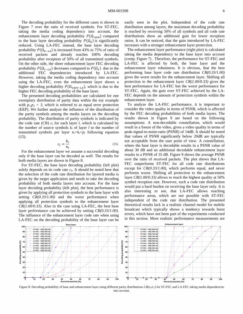
For ST-FEC, the base layer decoding probability (left plot)
solely depends on its code rate c0. It should be noted here that
the selection of the code rate distribution for layered media is
given by the target application and needs to take the decoding
probability of both media layers into account. For the base
layer decoding probability (left plot), the best performance is
given by applying all protection symbols to the base layer with
setting CR(0.33/1.00) and the worst performance when
applying all protection symbols to the enhancement layer
CR(1.00/0.33). Also in the case using LA-FEC, the best base
layer performance can be achieved by setting CR(0.33/1.00).
The influence of the enhancement layer code rate when using
LA-FEC on the decoding probability of the base layer can be
easily seen in the plot. Independent of the code rate
distribution among layers, the maximum decoding probability
is reached by receiving 50% of all symbols and all code rate
distributions show an additional gain for lower reception
ratios. It can be noticed, that the gain introduced by LA-FEC
increases with a stronger enhancement layer protection.
The enhancement layer performance (right plot) is calculated
taking the media dependency to the base layer into account
(comp. Figure 7) . Therefore, the performance for ST-FEC and
LA-FEC is affected by both, the base layer and the
enhancement layer robustness. It is obvious, that the best
performing base layer code rate distribution CR(0.33/1.00)
gives the worst results for the enhancement layer. Shifting all
protection to the enhancement layer CR(1.00/0.33) gives the
best performance for LA-FEC but the worst performance for
ST-FEC. Again, the gain over ST-FEC achieved by the LA-
FEC depends on the amount of protection symbols within the
enhancement layer.
To analyze the LA-FEC performance, it is important to
consider the video quality in terms of PSNR, which is affected
by the FEC decoding probabilities of both media layers. The
results shown in Figure 9 are based on the following
assumptions: A non-decodable constellation, which would
result in a freeze of the video, gives a video quality in terms of
peak-signal-to-noise-ratio (PSNR) of 14dB. It should be noted
that values of PSNR significantly below 20dB are typically
not acceptable from the user point of view. A constellation,
where the base layer is decodable results in a PSNR value of
about 30 dB and an additional decodable enhancement layer
results in a PSNR of 35 dB. Figure 9 shows the average PSNR
over the ratio of received packets. The plot shows that LA-
FEC outperforms ST-FEC for all code rate distributions
except for CR(0.33/1.00), which performs equal, and never
performs worse. Shifting all protection to the enhancement
layer CR(1.00/0.33) allows to reach the highest quality at 50%
symbol reception rate. However, such a code rate distribution
would put a hard burden on receiving the base layer only. It is
also interesting to see, that LA-FEC allows reaching
performance areas, which are not possible with ST-FEC
independent of the code rate distribution. The presented
theoretical results lack in a realistic channel model for mobile
broadcast which typically shows a tendency towards burst
errors, which have not been part of the experiments conducted
in this section. More realistic performance measurements are
Figure 8: Decoding probability of base and enhancement layer using different parity distributions CR(c0/c1) for ST-FEC and LA-FEC taking media dependencies
into account.
0 10 20 30 40 50 60 70 80 90 1000
10
20
30
40
50
60
70
80
90
100
Received packets [%]
De
co
din
g p
rop
ab
ilit
y [
%]
Base layer
ST-FEC - CR(1.00/0.33)
LA-FEC - CR(1.00/0.33)
ST-FEC - CR(0.75/0.38)
LA-FEC - CR(0.75/0.38)
ST-FEC - CR(0.50/0.50)
LA-FEC - CR(0.50/0.50)
ST-FEC - CR(0.38/0.75)
LA-FEC - CR(0.38/0.75)
ST-FEC - CR(0.33/1.00)
LA-FEC - CR(0.33/1.00)
0 10 20 30 40 50 60 70 80 90 1000
10
20
30
40
50
60
70
80
90
100
Received packets [%]
De
co
din
g p
rop
ab
ilit
y [
%]
Enhancement layer
ST-FEC - CR(1.00/0.33)
LA-FEC - CR(1.00/0.33)
ST-FEC - CR(0.75/0.38)
LA-FEC - CR(0.75/0.38)
ST-FEC - CR(0.50/0.50)
LA-FEC - CR(0.50/0.50)
ST-FEC - CR(0.38/0.75)
LA-FEC - CR(0.38/0.75)
ST-FEC - CR(0.33/1.00)
LA-FEC - CR(0.33/1.00)

MM-003398 7
given in Section V.
C. Implementation of Layer-Aware Raptor code
The LA-FEC scheme can be applied on both, physical layer
FEC, as similarly shown for LDPC in [40], and upper layer
FECs [8][9]. This paper focuses on an exemplary integration
of the LA-FEC to an upper layer FEC. The here considered
upper layer FEC is the Raptor FEC.
The application of the LA-FEC to the Raptor code has
already been presented in [27]. This section gives a brief
summary of [27]. The required extensions for a systematic
Raptor code as, e.g. specified in 3GPP MBMS [12] and or
DVB-SH (for MPE-iFEC) [11]. A full specification based on
[26] can be found in the Annex D of the DVB Upper layer
FEC overview [5], which discusses the possibility to integrate
LA-FEC within DVB. Note that the extension could be
applied in a similar way to the more efficient RaptorQ FEC [9]
codes.
Raptor codes are in general one of the first known classes of
fountain code with linear time encoding and decoding [8]. In
preparation of the encoding, a certain amount of data is
collected within a source block. The data of a source block is
further divided in k source symbols (SSs) of a fixed symbol
size. Figure 10 illustrates the Raptor encoding process for a
single media "Layer 0", which consists of two encoding steps
[26]. In the first step, a fixed rate 'precode' step, here typically
any erasure code like, e.g. LDPC, can be applied on the SSs0
to generate the so called precoding symbols (PSs0). The values
of the PSs0 are determined by the matrix GSys0, which consists
of the precode matrix GP0, the identity matrix I, and the LT
matrix GLT0[0:k0-1], where the latter is identical to the first k0
rows of GLT0[0:n0-1] in the second encoding process. The
values within the brackets denote the number of rows. The
integration of the matrix GLT0 assures, that the first k0 encoding
symbols (ESs0) after LT encoding are identical to the SSs0.
After finalizing the first step, the PSs0 are forwarded to the
second step. The fountain of n0 encoding symbols ESs0 are
calculated by XORing PSs0 following the connection given by
the LT code and illustrated by the GLT0[0:n0-1] matrix. Note,
that also with LA-FEC, the generation of base layer ESs0
follows the original Raptor process.
For the enhancement "Layer 1", the LA-FEC approach needs
to be integrated into the Raptor coding process [26], which
requires on one hand the extension of the GLT matrix of the
LT-encoding step of the PSs in the dependent media layers
and on the other hand the extension of the GLT matrix of the
precoding process to preserve the systematic behavior of the
code. Figure 11 shows the required extensions, highlighted in
green, for generation of ESs1.
In the first encoding step, the generation of the matrices Gp1,
I, and GLT1[0:k1-1] is identical to the related matrices shown in
Figure 10. LA-FEC requires the extension of the matrix GSys1
Figure 9: Average PSNR using different parity distributions CR(c0/c1) for ST-FEC and LA-FEC assuming PSNR 14dB for a non decodable constellation, 30dB
for a decodable base layer, and 35dB for decodable enhancement layer.
Figure 10: The Raptor encoding process for one layer (L=0) as specified in [10]. The first encoding step generates the precoding symbols (PSs0) from the source
symbols (SSs0) by use of an erasure code like LDPC. In the second step, the encoded symbols (ESs0) are generated from the PSs0 by use of a fountain code, e.g.
LT code. The code is systematic, since the first k encoding symbols consist of the k source symbols.
Received packets [%]
PS
NR
[d
B]
0 10 20 30 40 50 60 70 80 90 10014
16
18
20
22
24
26
28
30
32
34
36 ST-FEC - CR(1.00/0.33)
LA-FEC - CR(1.00/0.33)
ST-FEC - CR(0.75/0.38)
LA-FEC - CR(0.75/0.38)
ST-FEC - CR(0.50/0.50)
LA-FEC - CR(0.50/0.50)
ST-FEC - CR(0.38/0.75)
LA-FEC - CR(0.38/0.75)
ST-FEC - CR(0.33/1.00)
LA-FEC - CR(0.33/1.00)
SS
s0
. =
01
k0 -1
...
PS
s0
12
p0 -1
...5
0
00
1 0 0 1 1 0
0 0 1 1 1 1
0 1 0 0 0 0
...
...
...
...
1 1 1 0 0 1
... ...
...
...
...
...
10
1 0
0 0
...
...
...1 0 0 1
0 0 1 1
0 1 0 0
Gp0
...
...
...
I
02
34
0 4 p0-11 2 3
PSs0
1 0 0 1 1 0
0 0 1 1 1 1
0 1 0 0 0 0
...
...
...
...
1 1 1 0 0 1
...
...
...
...
...
...
...
...
...
...
... ...
0 0 1 0 0 1...
01
...2
...n
0 -1
ES
s0
k0 -1
1. encoding step:
Precoded symbols
(PSs) generation
2. encoding step:
LT Encoding
...
GLT0[0:n0-1]
GLT0 [0:k0-1]
GSys0

MM-003398 8
by the matrix GLT0*[n0:n0+k1-1] which is the continuation of
the GLT0[0:n0-1] matrix in Figure 10. GSys1 represents the first
k1 rows of the GLT0*[n0:n0+n1-1] matrix in the second
encoding step. Furthermore, the PSs0 symbols from the
"Layer 0" processing are included in the encoding process.
These extensions assure, that the output symbols PSs1 still
lead to a systematic code after the second encoding step. The
generation of the ESs1 symbols in the second step is extended
to the PSs0 through extending the GLT1[0:n1-1] matrix by
GLT0*[n0:n0+n1-1]. Therefore, the ESs1 symbols can be used in
the LA-FEC together with the ESs0 symbols for joint
decoding. This is also shown in the example in Section IV.
The extensions required by the LA-FEC use the algorithms for
precode generation and LT Encoding as already specified in
[25], leaving the specification and the defined constraints of
the algorithms untouched. In case of a successful decoded
"Layer 0", the introduced connections across the layers by the
LA-FEC extension are not required anymore and can be
removed by XORing the PSs0 in the FEC process of
"Layer 1". In such a case, "Layer 1" can be corrected
following the standard Raptor coding process [26], enabling
its full correction performance.
D. Signaling and Transport of Layer-Aware FEC
The usage of the LA-FEC in transmission systems requires
specific signaling and transport techniques to support the
multi-layer approach in combination with LA-FEC coding.
The integration of the LA-FEC Raptor extension on link or
application layer is assumed to be applied for real-time
transmission over RTP [32]. For real-time applications,
typically RTP is used over UDP [33] due to its connectionless
and non-reliable nature it allows for minimal delay in
transport. RTP provides basic features such as media
synchronization, transmission order recovery, multiplexing,
source identification and reception feedback information. For
SVC, the RTP Payload Format for Scalable Video Coding
[34] is required for media payload packetization and for MVC,
the RTP Payload Format for Multiview Video Coding [35]. In
particular, these payload formats for SVC and MVC define the
transmission of the layered SVC and MVC data in multiple
RTP sessions, which allows a transmission system using the
LA-FEC coding process to simply differentiate between SVC
layers and MVC views based on the transport address, such as
an IP address, the UDP port or the synchronization source
identifier in the RTP packet header (SSRC) [32]. Signaling of
session related information is defined in the Session
Description Protocol [37]. In order to signal the dependency of
RTP sessions containing layers or views of the same codec,
the SDP extensions in [36] are required.
For transporting the FEC coded data, the IETF created the
generic FECFRAME framework defining basic means for
FEC based content delivery protocols, which can be also used
in RTP. This framework defines beside other features how
multiple media and repair flows are treated and further
provides an identification mechanism for source symbols as a
part of the payload packetization information. To use this
framework with the Raptor code, [38] is intended to be used.
In order to make this framework applicable to the LA-FEC
the Raptor FEC scheme [39] and the Raptor RTP Payload
format [40] can be used without modifications for packetizing
the repair flow. The signaling for the Raptor FEC scheme is
defined in [38], where the indication of depending repair flows
is already defined in [41], as required for LA-FEC base layer
protection and LA-FEC enhancement layer protection.
V. SIMULATION RESULTS FOR SVC LA-FEC AT THE
APPLICATION LAYER IN DVB-H
A. Simulation Setup
The simulations in this section are based on a mobile
Broadcast scenario where two device capabilities, QVGA and
VGA, are supported by a single DVB-H service using SVC
(cf. Figure 12). For increasing the robustness of the whole
service, the link layer FEC defined in DVB-H, MPE-FEC, and
the proposed Raptor-based LA-FEC solution is evaluated on
Figure 11: LA-FEC extended Raptor encoding process. The required extensions for LA-FEC are marked in green. Extending the first encoding step keeps the
systematic code. The extension for the LT-Encoding connects enhancement layer to base layer. Note, the extension matrices (GLT0*) are generated by
standard Raptor algorithm.
0 1 2 3 p0-1
PSs0
0 1 2 3 4 p1-1
1 1 0 1 1 0
1 1 1 1 1 1
0 1 0 0 0 0
...
...
...
...
1 0 0 0 0 1
...
...
...
...
...
GLT0*[n0:n0+n1-1]
...
...
...
...
...
... ...
0 0 1 0 0 1...
1 0 0 1 1 0
0 0 1 1 1 1
0 0 0 0 1 0
...
...
...
...
1 1 1 0 0 1
...
...
...
...
...
...
...
...
...
...
... ...
0 0 1 0 0 1...
01
...2
...n
1 -1
ES
s1
PSs1
k1 -1
LA-FEC extension
.
PS
s0
12
p0 -1
...5
03
4
1 1 0 1 1 0
0 0 1 1 1 1
0 0 0 0 1 0
...
...
...
...
...
1 1 1 0 0 1
... ...
...
...
...
...
10
1 0
0 0
...
...
...1 1 0 1
0 0 1 0
0 1 0 0
Gp1
...
...
...
I0
1 0 0 1 1 0
1 1 1 1 1 1
0 1 0 0 0 0
...
...
...
...
...
1 0 0 0 0 1
... ...
...
...
...
...
GLT0*[n0:n0+k1-1]
SS
s1
=
01
k1 -1
...
PS
s1
12
p1 -1
...5
0
00
02
34
GLT1 [0:k1-1]
LA-FEC extension
4 ... ...
1. encoding step:
Precoded symbols
(PSs) generation
2. encoding step:
LT Encoding
GSys1
GLT1 [0:n1-1]

MM-003398 9
the application layer using different code rate distributions
across media coding layers.
B. Channel Model
The simulation scenario consists on a Typical Urban 6-taps
(TU6) channel model with a constant Doppler (i.e., user
velocity). The TU6 channel models the time variant small-
scale fluctuations of the received signal due to receiver
mobility (fast fading), and it was proven to be representative
for DVB-H mobile reception for Doppler frequencies above
10 Hz (i.e., vehicular reception) [31]. We consider the DVB-H
physical layer transmission mode: FFT size 8K, OFDM
symbol guard interval (GI) 1/4, modulation 16-QAM and code
rate 1/2, which provides a channel capacity of about 10 Mbps.
C. Media Encoding
The video encoding was performed using the SVC reference
software version JSVM 9.1. A simple rate control was
employed to achieve an approximately constant service rate.
The video was encoded in small chunks, where each chunk
consists of a preceding IDR frame followed by three groups of
picture of size 8 (GOP8), i.e. 25 frames. Each chunk was
encoded multiple times with different quantization parameters
(QP) values. Depending on the selected video rate, the chunk
with QP value providing the target bitrate was selected and the
different chunks were concatenated to one video stream. The
chunk wise encoding gives a random access point (RAP)
interval of 1 second at 25 frames per second (fps).
The test sequence “Soccer” 1 with a duration of 10 seconds
was selected for the simulations. An SVC bit stream with two
scalable layers was encoded using the scalable high profile of
H.264/AVC. In particular the stream contained a base layer
which provides QVGA at 12.5 fps, and an enhancement layer
increasing the quality to VGA at 25 fps. Freeze frame error
concealment was used, where in case of frame loss, the last
decoded picture is copied for output. In cases where only the
enhancement layer was lost, the up-scaled picture of the
QVGA layer was used for PSNR calculation. A summary of
the encoding parameters can be found in Table II.
Table II: ENCODING PARAMETERS FOR SVC BITSTREAM WITH
TEMPORAL AND SPATIAL SCALABILITY.
Quality Bitrate PSNR VGA
H.264/AVC
Base layer
QVGA
12.5fps
225 kbps 31.3 dB
(upscaled)
SVC
Enhancement layer
VGA
25fps
647 kbps 35.4 dB
1 Other sequences have been tested which show a different rate-distortion
performance but similar performance in the comparison of LA-FEC and ST-
FEC.
D. DVB-H Transmission Scheduling
DVB-H applies a so called time slicing approach, where data
is transmitted in bursts in order to save battery power by
switching off the receiver between bursts. Therefore, the two
SVC layers were transmitted in two different time-sliced
bursts, the second containing the enhancement layer directly
following the first containing the base layer. Figure 13
illustrates such a transmission scheduling, where the red
arrows show the SVC layer coding dependencies, the black
arrows the protection by ST-FEC and the green arrows the
protection added by LA-FEC.
The source block size for FEC generation is aligned to the
chunk size, i.e. each source block starts with an IDR RAP and
incorporates all GOP8s of the chunk, equivalent to 1 sec of
media data.
E. FEC Settings
The overall service bitrate (including media data and parity
bits) was fixed to 1300 kbps. The code rates for base and
enhancement layer are adjusted to reach this bitrate. For
example, the equal error protection (EEP) scheme allows for a
code rate of 0.68 for each media layer. Furthermore, different
unequal error protection (UEP) schemes were applied with
either stronger protection in base layer or stronger protection
in the enhancement layer. It should be noted here, that with
ST-FEC, typically UEP with a stronger protection for the
enhancement layer is a non reasonable setting. The selected
video streams are encapsulated in RTP packets according to
their specific RTP payload format [34] and the FEC symbols
are encapsulated within the related RTP payload format [40]
and subsequently into IP streams.
F. Results
The plots in Figure 14 show the IP packet error rate for the
SVC base (left) and enhancement layer (right) and Figure 15
shows the resulting video quality in terms of average PSNR
(right) and the number of freeze frames (left) over different
reception conditions in terms of C/N for the different
transmission schemes. Note that there are in total 250 frames.
The IP packet error plot in Figure 14 illustrates the effect of
the LA-FEC scheme compared to the ST-FEC scheme.
Although the total amount of protection packets is the same
for the different coding schemes, the number of lost base layer
IP packets is for all code rate distributions significantly lower
when applying LA-FEC. All LA-FEC schemes show a similar
base layer decoding probability whereas the ST-FEC decoding
probability strongly depends on the assigned code rate. As
expected from the theoretical analysis in Section IV.B, the
effective IP packet error rate of enhancement layer data after
FEC correction is increased due to the introduced dependency
Figure 12: Support of different device capabilities (QVGA+VGA) using
SVC in a DVB-H broadcast system.
Figure 13: SVC transmission of base ([email protected]) and enhancement
layer (VGA@25fps) in different time-sliced bursts, the second immediately
following the other.
Base layer
(QVGA)
Enhancement
layer (VGA)
SVC
QVGA user
VGA user
DVB-H
Dependency
Base
layer
Enh.
layer...
Dependency
FE
C
FE
C Δt
Additional
LA-FEC protection
Protection
Base
layer
Enh.
layer...
Dependency
FE
C
FE
C
Protection

MM-003398 10
to the base layer data when applying LA-FEC. However, due
to the fact that enhancement layer data is useless without the
reception of the respective base layer data, the increased IP
packet error rate has no negative impact on the perceived
video quality.
Considering the video quality in Figure 15, all LA-FEC
settings show a better performance compared to ST-FEC. The
best ST-FEC scheme has a strong UEP spreading (cf.
CR(0.50/0.78) in the figure). However, further increasing the
base layer protection in the ST-FEC case decreases the overall
performance (cf. CR(0.40/0.90) in the figure). Although there
is not a significant performance difference between the tested
LA-FEC settings, the best LA-FEC scheme is the one using
EEP code rate setting (cf. (CR(0.68/0.68) in the figure). The
LA-FEC EEP scheme outperforms the best ST-FEC scheme
by approx. 2dB in terms of PSNR for the C/N value range
from 14 dB to 16 dB. Within this area, the video service with
LA-FEC achieves a video quality in terms of PSNR over 30
dB, which can be assumed as an acceptable quality from a
users point of view. It is further interesting, that the difference
in performance between the difference LA-FEC schemes is
not as big as between the ST-FEC schemes. Even a stronger
protection for the enhancement layer shows a relatively better
performance than the ST-FEC schemes when applying LA-
FEC. This also allows for applying new operation points using
stronger protections in the enhancement layer, which might be
useful in applications such as conditional access. With LA-
FEC and conditional access, a service could be applied with a
free base layer providing low quality and low robustness, e.g.
CR 0.80. With additionally receiving the enhancement layer of
the premium service would not only increase the video quality
but also the service robustness (cf. CR(0.80/0.64) in Figure
15). Taking into account that LA-FEC with EEP gives the best
performance, LA-FEC eases the adjustment of the code rates
for a multi layer transmission system. Considering freeze
frames, LA-FEC gives a significant improvement to the
number of frozen frames, which is due to the lower base layer
IP packet error rate. All LA-FEC schemes show a lower
number of freeze frames than the related ST-FEC scheme and
all LA-FEC scheme reach at least the performance of the best
ST-FEC scheme. Thereby, LA-FEC significantly increases the
service reliability. This is in general interesting, since
increasing the service robustness with layered-media by UEP
compared to single layer typically comes at the cost of a
reduced enhancement layer protection. Using LA-FEC allows
to achieve a similar effect without reducing the enhancement
layer robustness (cf. CR(0.68/0.68) in Figure 15).
VI. CONCLUSION
In this work, we present the layer-aware FEC (LA-FEC)
concept for improving performance in broadcast of multi-
layered media. The LA-FEC concept can be implemented
either on the physical or any upper communication system
layer. We present a theoretical model, which shows the gain
introduced by LA-FEC compared to standard FEC schemes.
We described the application of the LA-FEC concept to the
Raptor code at the link or application layer. We further
describe the application means for transport and signaling of
LA-FEC. Simulations results for application layer LA-FEC in
Figure 14: IP packet error rate for base (left) and enhancement layer (right) using ST-FEC and LA-FEC with different code rate distributions across SVC layers
at a fixed service bitrate of 1300 kbps.
Figure 15: Average number of freeze frames of 250 frames (left) and the average PSNR value (right) for a VGA receiver using ST-FEC and LA-FEC with
different code rate distributions across SVC layers at a fixed service bitrate of 1300 kbps.
13 14 15 16 17 18 190
5
10
15
20
25
30
35
40
45
C/N [dB]
Base layerIP
Packet
Err
or
Rate
[%
]
ST-FEC - CR(0.40/0.90)
LA-FEC - CR(0.40/0.90)
ST-FEC - CR(0.50/0.78)
LA-FEC - CR(0.50/0.78)
ST-FEC - CR(0.60/0.71)
LA-FEC - CR(0.60/0.71)
ST-FEC - CR(0.68/0.68)
LA-FEC - CR(0.68/0.68)
ST-FEC - CR(0.80/0.64)
LA-FEC - CR(0.80/0.64)
13 14 15 16 17 18 190
5
10
15
20
25
30
35
40
C/N [dB]
Enhancement layer
IP P
acket
Err
or
Rate
[%
]
ST-FEC - CR(0.40/0.90)
LA-FEC - CR(0.40/0.90)
ST-FEC - CR(0.50/0.78)
LA-FEC - CR(0.50/0.78)
ST-FEC - CR(0.60/0.71)
LA-FEC - CR(0.60/0.71)
ST-FEC - CR(0.68/0.68)
LA-FEC - CR(0.68/0.68)
ST-FEC - CR(0.80/0.64)
LA-FEC - CR(0.80/0.64)
13 14 15 16 17 18 190
20
40
60
80
100
120
140
160
C/N [dB]
Fre
eze f
ram
es
ST-FEC - CR(0.40/0.90)
LA-FEC - CR(0.40/0.90)
ST-FEC - CR(0.50/0.78)
LA-FEC - CR(0.50/0.78)
ST-FEC - CR(0.60/0.71)
LA-FEC - CR(0.60/0.71)
ST-FEC - CR(0.68/0.68)
LA-FEC - CR(0.68/0.68)
ST-FEC - CR(0.80/0.64)
LA-FEC - CR(0.80/0.64)
11 12 13 14 15 16 17 18 19
15
20
25
30
35
C/N [dB]
PS
NR
[d
B]
ST-FEC - CR(0.40/0.90)
LA-FEC - CR(0.40/0.90)
ST-FEC - CR(0.50/0.78)
LA-FEC - CR(0.50/0.78)
ST-FEC - CR(0.60/0.71)
LA-FEC - CR(0.60/0.71)
ST-FEC - CR(0.68/0.68)
LA-FEC - CR(0.68/0.68)
ST-FEC - CR(0.80/0.64)
LA-FEC - CR(0.80/0.64)

MM-003398 11
a DVB-H scenario showed that the theoretical gain can also be
translated to a real channel. Future work will be the
investigation of the performance of LA-FEC on physical layer.
We further plan to analyze the performance of combinations
of LA-FEC with related schemes.
REFERENCES
[1] H. Schwarz, D. Marpe, and T. Wiegand, “Overview of the scalable
video coding extension of the H.264/AVC standard,” IEEE Trans.
Circuits and Systemd for Video Technology, Vol. 17, Issue 9, pp. 1103–
1120, September 2007.
[2] P. Merkle, Y. Morvan, A. Smolic, D. Farin, K. Müller, P.H.N. de With,
and T. Wiegand, "The effects of multiview depth video compression on
multiview rendering," Signal Processing: Image Communication -
special issue on advances in three-dimensional television and video, Vol.
24, Issues 1-2, pp. 73-88, January 2009.
[3] DVB TM-H NGH, "Call for Technologies (CfT) v 1.0," DVB TM
4270r2, November 2009.
[4] ATSC, "ATSC-Mobile DTV Standard, Part 7 – AVC and SVC Video
System Characteristics," Document A/153 Part 7:2009, October 2009.
[5] ETSI TR 102 993 V1.1.1, "Digital Video Broadcasting (DVB); Upper
Layer FEC for DVB Systems," February 2011.
[6] D. J. C. MacKay and R. M. Neal, "Near Shannon limit performance of
low density parity check codes", Electron Letters, Vol. 33, Issue 6, pp.
457-458, March 1997.
[7] C. Berrou, "The ten-year-old turbo codes are entering into service,"
IEEE Communications Magazine, Vol. 41, Issue 8, pp. 110-116, August
2003.
[8] A. Shokrollahi, "Raptor Codes," IEEE Transactions on Information
Theory, Vol. 52, Issue 6, pp. 2551-2567, 2006.
[9] M. Luby, A. Shokrollahi, M. Watson, T. Stockhammer, L. Minder,
"RaptorQ Forward Error Correction Scheme for Object Delivery," IETF
RMT, draft-ietf-rmt-bb-fec-raptorq-04, August 2010,
http://tools.ietf.org/html/draft-ietf-rmt-bb-fec-raptorq-04.
[10] ETSI TS 102 472 v1.3.1, “Digital Video Broadcast (DVB); IP Datacast
over DVB-H: Content Delivery Protocols”, June 2009.
[11] ETSI TS 102 584 v1.2.1, "Digital Video Broadcasting (DVB); DVB-SH
Implementation Guidelines", January 2011.
[12] 3GPP TS 26.346, “Technical specification group services and system aspects; multimedia broadcast/multicast service (MBMS); Protocols and
codecs”.
[13] C. Hellge, S. Mirta, T. Schierl, and T. Wiegand, "Mobile TV with SVC
and Hierarchical Modulation for DVB-H Broadcast Services," IEEE
International Symposium on Broadband Multimedia Systems and
Broadcasting (BMSB), Bilbao, Spain, May 2009.
[14] S. Mirta, et al., "HD Video Broadcasting using Scalable Video Coding
combined with DVB-S2 Variable Coding and Modulation," ASMA and
SPSC, September 2010.
[15] B. Masnick and J. Wolf, “On linear unequal error protection codes,”
IEEE Transactions on Information Theory, Vol. 13, Issue 4, pp. 600-
607, 1967.
[16] C. C. Kilgus and W. C. Gore, “A class of cyclic unequal-error-protection
codes,” IEEE Transaction on Information Theory, Vol. 18, Issue 5, pp.
687-690, September 1972.
[17] I. Boyarinov and G. Katsman, “Linear unequal error protection codes,”
Information Theory, IEEE Transactions on, Vol. 27, Issue 2, pp. 168-
175, 1981.
[18] N. Rahnavard and F. Fekri, “New results on unequal error protection
using LDPC codes,” IEEE Communications Letters, Vol. 10, Issue 1,
pp. 43-45, 2006.
[19] N. Rahnavard, B. N. Vellambi, and F. Fekri, “Rateless Codes With Unequal Error Protection Property,” IEEE Transactions on Information
Theory, Vol. 53, Issue 4, pp. 1521-1532, 2007.
[20] A. Bouabdallah and J. Lacan, ”Dependency-aware unequal erasure
protection codes,” Journal of Zhejiang University SCIENCE A 2006
7(Suppl. I):27-33, 2006.
[21] M. Bogino, P. Cataldi, M. Grangetto, E. Magli and G. Olmo, ”Sliding-
Window Digital Fountain Codes for Streaming of Multimedia
Contents,” ISCAS 2007, USA, May 2007.
[22] D. Sejdinovic, D. Vukobratovic, A. Doufexi, V. Senk, und R. Piechocki,
“Expanding window fountain codes for unequal error protection,” IEEE
Transactions on Communications, Vol. 57, Issue 9, pp. 2510-2516,
2009.
[23] D. Vukobratovic, V. Stankovic, D. Sejdinovic, L. Stankovic, Z. Xiong,
"Scalable video multicast using expanding window fountain codes,"
IEEE transaction on Multimedia, Vol. 11, Issue 6, pp. 1094-1104, 2009.
[24] OSI Reference Model, Hubert Zimmermann, IEEE Transactions on
Communications, Vol. COMM-28(4), p425, April 1980.
[25] M. Luby, ”LT-Codes,” in Proceedings of the ACM Symposium on
Foundation of Computer Science (FOCS), 2002.
[26] M. Luby, A. Shokrollahi, M. Watson, T. Stockhammer, "Raptor
Forward Error Correction Scheme for Object Delivery," IETF RFC
5053, Internet Engineering Task Force (IETF), Network Working
Group, September 2007, http://tools.ietf.org/html/rfc5053.
[27] C. Hellge, T. Schierl, and T. Wiegand, "Mobile TV using scalable video
voding and layer-aware forward error correction," IEEE International
Conference on Multimedia and Expo (ICME'08), Hanover, Germany,
June 2008.
[28] C. Hellge, T. Schierl, and T. Wiegand, "Multidimensional Layered
Forward Error Correction Using Rateless Codes," IEEE International
conference on communication (ICC), Bejing, China, 2008. [29] C. Hellge, T. Schierl, and T. Wiegand, “Receiver driven layered
multicast with layer-aware forward error correction,” Proceedings of
ICIP 2008, pp. 2304-2307, 2008.
[30] C. Hellge, D. Gomez-Barquero, T. Schierl, and T. Wiegand, "Intra-burst
Layer Aware FEC for Scalable Video Coding Delivery in DVB-H,"
Proceedings of ICME 2010, Singapur, Singapur, July 2010.
[31] G. Faria, J. A. Henriksson, E. Stare, and P. Talmola, “DVB-H: Digital
Broadcast Services to Handheld Devices,” Proc of the IEEE, Vol. 94,
Issue 1, pp. 194-209, January 2006.
[32] H. Schulzrinne, S. Casner, R. Frederick, and V. Jacobson, "RTP: A
Transport Protocol for Real-time Applications", IETF STD 0064, RFC
3550, July 2003, http://tools.ietf.org/html/rfc3550.
[33] J. Postel, "User Datagram Protocol", IETF STD 6, RFC 768, September
1981, http://tools.ietf.org/html/rfc768.
[34] S. Wenger, Y.-K. Wang, T. Schierl, and A. Eleftheriadis, "RTP payload
format for SVC video", work in progress, Internet Engineering Task
Force (IETF), Audio Video Transport Group (avt), draft-ietf-avt-rtp-svc-
21, April 2010, http://tools.ietf.org/html/draft-ietf-avt-rtp-svc.
[35] Y.-K. Wang, T. Schierl, "RTP Payload Format for MVC Video," work
in progress, IETF AVT, draft-ietf-avt-rtp-mvc-01.txt, October 2010,
http://tools.ietf.org/html/draft-ietf-avt-rtp-mvc-01.
[36] T. Schierl and S. Wenger, "Signaling media decoding dependency in
Session Description Protocol (SDP)", IETF MMUSIC, April 2009,
http://tools.ietf.org/html/rfc5583.
[37] M. Handly, V. Jacobson, and C. Perkins, "SDP: Session Description
Protocol", IETF RFC 4566, July 2006, http://tools.ietf.org/html/rfc4566.
[38] M. Watson, "Forward Error Correction (FEC) Framework", IETF
FECFRAME draft-ietf-fecframe-framework-09, July 2010,
http://tools.ietf.org/html/draft-ietf-fecframe-framework.
[39] M. Watson, "Raptor FEC Schemes for FECFRAME", IETF
FECFRAME, draft-ietf-fecframe-raptor-02, March 2010,
http://tools.ietf.org/html/ draft-ietf-fecframe-raptor.
[40] M. Watson, "RTP Payload Format for Raptor FEC", IETF FECFRAME,
draft-ietf-fecframe-rtp-raptor-03, March 2010, http://tools.ietf.org/html/
draft-ietf-fecframe-rtp-raptor.
[41] A. Begen, "SDP Elements for FEC Framework", IETF FECFRAME,
draft-ietf-fecframe-sdp-elements-07, July 2010,
http://tools.ietf.org/html/draft-ietf-fecframe-sdp-elements-04.
[42] DVB TM-H, "Response to DVB-NGH Call for Technologies, Layer-
Aware FEC for Layered Media Transmission," TM-NGH092, February
2010.
[43] T. Wiegand, G.J. Sullivan, G. Bjontegaard, and A. Luthra, "Overview of
the H.264/AVC Video Coding Standard," IEEE Transactions on Circuits
and Systems for Video Technology, Vol. 13, Issue 7, pp. 560-576, July
2003.
[44] ETSI EN 302 583 V1.1.2, "Digital Video Broadcasting (DVB); Framing
Structure, channel coding and modulation for Satellite Services to
Handheld devices (SH) below 3 GHz," February 2010.
[45] ETSI EN 302 755 V1.1.1, "Digital Video Broadcasting (DVB); Frame
structure channel coding and modulation for a second generation digital
terrestrial television broadcasting system (DVB-T2)," September 2009.
[46] C. Berrou, "The ten-year-old turbo codes are entering into service,"
IEEE Communications Magazine, Vol. 41, Issue 8, pp. 110-116, August
2003.

MM-003398 12
Cornelius Hellge received the Dipl.-Ing. degree (M.Sc.) in
Media Technology from the Ilmenau University of
Technology, Germany in July 2006. He has been with
Fraunhofer HHI since 2005. Since 2009, he works in parallel
as a researcher in the Image Communication Laboratory at
the Berlin Institute of Technology. He contributed to different
standardization bodies (e.g., DVB, 3GPP) and has done
different research works on reliable real-time transmission of H.264/AVC and
Scalable Video Coding (SVC) in mobile point-to-point, multicast, broadcast,
IPTV, and P2P environments. His main research interests are in the area of
reliable video transmission and signaling, in particular in forward error
correction and in the joint use of channel and source coding. Currently, he is
working on media delivery in CDNs in the context of the European research
project of the FP7 program OCEAN. He was a Co-editor of the DVB
bluebook on upper layer forward error correction. Currently, he is actively
participating in the standardization process of the next generation handheld
standard DVB-NGH and the 3GPP SA4 group.
David Gómez-Barquero is a post-doc guest researcher at the
Fraunhofer Heinrich Herzt Institute (HHI) in Berlin,
Germany. He received a double M.Sc. degree in
Telecommunications engineering from the Universidad
Politécnica de Valencia (UPV), Spain, and the University of
Gavle, Sweden, in 2004; and a Ph.D. in Telecommunications
from UPV in 2009. During his doctoral studies he was a
guest researcher at the Royal Institute of Technology, Sweden, the University
of Turku, Finland, and the Technical University of Braunschweig, Germany.
He also did an internship at Ericsson Eurolab, Aachen, Germany. His main
research interests are in the area of mobile multimedia broadcasting, in
particular radio resource management, forward error correction, and network
planning issues in both DVB and 3GPP MBMS systems. Dr. Gómez-Barquero
chaired the special interest group on hybrid cellular and broadcasting
networks in the European COST2100 cooperation action, and co-edited the
DVB bluebook on upper layer forward error correction as an invited expert.
Currently, he is actively participating in the standardization process of the
next generation handheld mobile broadcasting standard DVB-NGH.
Thomas Schierl (M’07) received the Dipl.-Ing. (M.Sc.)
degree in Computer Engineering from the Berlin Institute of
Technology, Germany in December 2003 and Dr.-Ing.
(Ph.D) degree in Electrical Engineering and Computer
Science from Berlin Institute of Technology in October 2010.
Since 2010, Thomas is head of the Multimedia
Communications Group in the Image Processing Department
of Fraunhofer HHI, Berlin. Since September 2004, Thomas is a Senior
Researcher in the Image processing department, where Thomas is responsible
as a project manager for various scientific as well as Industry-funded research
projects. Thomas is the co-author of various IETF RFCs, beside others he is
author of the IETF RTP Payload Format for H.264 SVC (Scalable Video
Coding), the IETF RTP Payload for Multi View Coding (MVC) as well as of
the IETF RFC on Rapid Synchronization of RTP flows (RFC 6051). In the
ISO/IEC MPEG group, Thomas is co-editor of the MPEG Standard on
Transport of H.264 SVC as well as H.264 MVC over MPEG-2 Transport
Stream. Thomas is also a co-editor of the AVC File Format. Typically, he is
participating MPEG, IETF, 3GPP and DVB meetings.
In 2007, he visited the Image, Video, and Multimedia Systems group of
Prof. Bernd Girod at Stanford University, CA, USA for different research
activities. Thomas' research interests include real-time media delivery over IP
networks, which may be mobile or wired, with or without infrastructure (e.g.,
Mobile Ad Hoc Networks (MANETs)), or based on traditional as well as on
overlay/Peer-to-Peer (P2P) mobile IPTV approaches. Currently, Thomas is
working on mobile media content delivery over HTTP.
Thomas Wiegand (M'05, SM'08, F'11) is a professor at the
department of Electrical Engineering and Computer Science at
the Berlin Institute of Technology, chairing the Image
Communication Laboratory, and is jointly heading the Image
Processing department of the Fraunhofer Institute for
Telecommunications - Heinrich Hertz Institute, Berlin,
Germany. He received the Dipl.-Ing. degree in Electrical
Engineering from the Technical University of Hamburg-Harburg, Germany, in
1995 and the Dr.-Ing. degree from the University of Erlangen-Nuremberg,
Germany, in 2000. He joined the Heinrich Hertz Institute in 2000 as the head
of the Image Communication group in the Image Processing department. His
research interests include video processing and coding, multimedia
transmission, as well as computer vision and graphics.
From 1993 to 1994, he was a Visiting Researcher at Kobe University,
Japan. In 1995, he was a Visiting Scholar at the University of California at
Santa Barbara, USA. From 1997 to 1998, he was a Visiting Researcher at
Stanford University, USA and served as a consultant to 8x8, Inc., Santa Clara,
CA, USA. From 2006-2008, he was a consultant to Stream Processors, Inc.,
Sunnyvale, CA, USA. From 2007-2009, he was a consultant to Skyfire, Inc.,
Mountain View, CA, USA. Since 2006, he has been a member of the technical
advisory board of Vidyo, Inc., Hackensack, NJ, USA.
Since 1995, he has been an active participant in standardization for
multimedia with successful submissions to ITU-T VCEG, ISO/IEC MPEG,
3GPP, DVB, and IETF. In October 2000, he was appointed as the Associated
Rapporteur of ITU-T VCEG. In December 2001, he was appointed as the
Associated Rapporteur / Co-Chair of the JVT. In February 2002, he was
appointed as the Editor of the H.264/MPEG-4 AVC video coding standard
and its extensions (FRExt and SVC). From 2005-2009, he was Co-Chair of
MPEG Video.
In 1998, he received the SPIE VCIP Best Student Paper Award. In 2004, he
received the Fraunhofer Award and the ITG Award of the German Society for
Information Technology. The projects that he co-chaired for development of
the H.264/MPEG-4 AVC standard have been recognized by the 2008 ATAS
Primetime Emmy Engineering Award and a pair of NATAS Technology &
Engineering Emmy Awards. In 2009, he received the Innovations Award of
the Vodafone Foundation, the EURASIP Group Technical Achievement
Award and the Best Paper Award of IEEE Transactions on Circuits and
Systems for Video Technology. In 2010, he received the Eduard Rhein
Technology Award. Professor Wiegand was elected Fellow of the IEEE in
2011.
He was a Guest Editor for the IEEE Transactions on Circuits and Systems
for Video Technology for its Special Issue on the H.264/AVC Video Coding
Standard in July 2003, its Special Issue on Scalable Video Coding-
Standardization and Beyond in September 2007, and its Special Section on the
Joint Call for Proposals on High Efficiency Video Coding (HEVC)
Standardization. Since January 2006, he has been an Associate Editor of IEEE
Transactions on Circuits and Systems for Video Technology.