Gustavo Barchet – Direito Administrativo Curso de Leis Administrativas -Lei 8
Upload
khangminh22Category
view
0download
0
Laser Safety Training Manual
Sandu Sonoc
Gustavo Moriena

ii

iii
Tables of Contents
1 INTRODUCTION ...................................................................................................... 1
2 LIGHT ....................................................................................................................... 2
2.1 Nature of light ..................................................................................................... 2
2.2 Emission and absorption of light ......................................................................... 7
2.3 Properties of light ................................................................................................ 9
2.3.1 Reflection of light ......................................................................................... 9
2.3.2 Refraction of light ....................................................................................... 10
2.3.3 Absorption of light ...................................................................................... 13
2.3.4 Scattering of light ....................................................................................... 13
2.3.5 Diffraction of light ....................................................................................... 15
2.3.6 Interference of light .................................................................................... 16
2.3.7 Dispersion of light ...................................................................................... 19
2.3.8 Polarization of light ..................................................................................... 19
2.3.9 Brewster’s Angle ........................................................................................ 21
2.3.10 Beam splitter ........................................................................................... 23
2.4 Non-linear effects ............................................................................................. 24
2.4.1 Raman Effect ............................................................................................. 25
2.4.2 Harmonic Generation ................................................................................. 25
2.4.3 Electro-Optic Effects .................................................................................. 27
2.4.4 Saturable absorption .................................................................................. 27
3 LASERS ................................................................................................................. 29
3.1 Laser levels ...................................................................................................... 29
3.2 Laser components ............................................................................................ 30
3.2.1 Lasing medium ........................................................................................... 30
3.2.2 Optical cavity .............................................................................................. 33
3.2.3 Energy pump .............................................................................................. 34
3.3 Laser Modes ..................................................................................................... 36
3.3.1 Axial modes ............................................................................................... 36
3.3.2 Transverse modes ..................................................................................... 38
3.4 Laser Operation ................................................................................................ 41
3.4.1 Continuous-wave lasers ............................................................................. 41

iv
3.4.2 Pulsed Lasers ............................................................................................ 41
3.4.3 Q switched laser ........................................................................................ 42
3.4.4 Mode-locked laser ...................................................................................... 44
3.5 Laser safety properties ..................................................................................... 46
3.5.1 Properties directly related to the laser ........................................................ 46
3.5.2 Properties of the laser interacting with the target ....................................... 49
3.6 Point and extended light sources...................................................................... 50
4 LASER SAFETY PRINCIPLES .............................................................................. 53
4.1 General principles of health and safety ............................................................ 53
4.2 Engineering Controls ........................................................................................ 54
4.3 Principles of laser safety ................................................................................... 55
4.4 The objective of the ANSI Z136 standards ....................................................... 56
4.5 Laser classes.................................................................................................... 56
4.5.1 Class 1 ....................................................................................................... 56
4.5.2 Class 2 ....................................................................................................... 57
4.5.3 Class 3 ....................................................................................................... 58
4.5.4 Class 4 ....................................................................................................... 60
4.5.5 Overview of Laser Safety Classes ............................................................. 60
4.5.6 Laser labels ................................................................................................ 61
5 LASER BEAM HAZARDS ...................................................................................... 63
5.1 Tissue damage mechanisms ............................................................................ 63
5.1.1 Photochemical interaction .......................................................................... 63
5.1.2 Thermal interaction .................................................................................... 64
5.1.3 Tissue ablation ........................................................................................... 65
5.2 Human eye ....................................................................................................... 65
5.2.1 The anatomy of the eye ............................................................................. 66
5.2.2 The physiology of the eye .......................................................................... 69
5.2.3 Laser eye injuries ....................................................................................... 72
5.3 Skin .................................................................................................................. 77
5.3.1 Structure of the skin ................................................................................... 77
5.3.2 Laser skin injuries ...................................................................................... 79
6 NON-BEAM HAZARDS .......................................................................................... 81
6.1 Physical hazards .............................................................................................. 81

v
6.1.1 Electrical hazards ....................................................................................... 81
6.1.2 Fire and explosions .................................................................................... 84
6.1.3 Cryogenic fluids ......................................................................................... 85
6.1.4 Radiation (X-rays, UV, visible, EMF and plasma) ...................................... 85
6.1.5 Mechanical hazards ................................................................................... 86
6.1.6 Other physical hazards (noise, nanoparticles, fibre optics fragments, sharp
objects, etc.) ........................................................................................................... 87
6.2 Chemical hazards ............................................................................................. 88
6.2.1 Laser generated air contaminants .............................................................. 88
6.2.2 Compressed gasses chemicals ................................................................. 88
6.2.3 Laser dyes and solvents ............................................................................ 88
6.2.4 Chemical agent control measurement ....................................................... 88
6.3 Biological hazards ............................................................................................ 89
6.4 Other hazards ................................................................................................... 89
6.4.1 Ergonomics ................................................................................................ 89
6.4.2 Human factors ............................................................................................ 89
7 LASER HAZARDS CONTROL ............................................................................... 90
7.1 Hazard assessment .......................................................................................... 90
7.1.1 Principles of hazard evaluation .................................................................. 90
7.1.2 The person in charge of hazard assessment ............................................. 90
7.1.3 When is the hazard assessment required? ................................................ 91
7.1.4 How is the hazard assessment performed? ............................................... 91
7.2 Elements of hazard assessment....................................................................... 92
7.2.1 Beam diameter ........................................................................................... 92
7.2.2 Maximum permissible exposure ................................................................. 93
7.2.3 Nominal Ocular Hazard Distance ............................................................... 93
7.2.4 Nominal Hazard Zone ................................................................................ 95
7.2.5 Calculating the laser class ......................................................................... 96
7.2.6 Non-beam hazards .................................................................................... 97
7.3 Hazard controls ................................................................................................ 97
7.3.1 Optical table 101 ........................................................................................ 98
7.3.2 Engineering controls .................................................................................. 99
7.3.3 Administrative and procedural controls .................................................... 104

vi
7.3.4 Entrance controls, signs, and lights ......................................................... 105
7.3.5 Personal protective equipment ................................................................. 108
8 LASER ALIGNMENT AND MEASUREMENT ...................................................... 113
8.1 Laser alignment procedure ............................................................................. 113
8.2 Laser measurements ...................................................................................... 116
8.2.1 Beam’s profile .......................................................................................... 116
8.2.2 Beam’s Diameter Measurement ............................................................... 117
8.2.3 Beam’s Divergence .................................................................................. 118
8.3 Beam’s Energy and Power Measurements .................................................... 119
8.3.1 Photodiode Sensors ................................................................................. 119
8.3.2 Thermocouple Sensor .............................................................................. 120
8.3.3 Pyroelectric Sensor .................................................................................. 122
8.3.4 Beam’s Power and Energy Measurement Procedure .............................. 122
9 LASER SAFETY PROGRAM ............................................................................... 124
9.1 Principals of Program Development ............................................................... 124
9.2 Content of the Laser Safety Program ............................................................. 124
9.3 Responsibilities............................................................................................... 125
9.4 Education and Laser Safety Training .............................................................. 125
9.5 Laser Safety Database ................................................................................... 127
9.6 Medical Surveillance ....................................................................................... 128
10 Laser Accidents ................................................................................................. 130
10.1 Direct causes of accidents .......................................................................... 130
10.2 Root causes of accidents ............................................................................ 131
10.3 Emergency preparedness ........................................................................... 132
10.4 Accident analysis ........................................................................................ 133
10.5 Accident Reporting ...................................................................................... 134

vii
Index of Figures
Figure 1-1: Optics is Light Work. ..................................................................................... 2
Figure 2-2: Typical shape of a longitudinal wave. C showing the crest and T showing the
trough. ............................................................................................................................. 3
Figure 2-3: Transverse (top) and longitudinal (bottom) waves. ........................................ 3
Figure 2-4: Wavefront in a 2-dimensional medium (left) and 3 dimensional medium
(right). .............................................................................................................................. 4
Figure 2-5: Electromagnetic wave. .................................................................................. 5
Figure 2-6: Coherent and non-coherent light sources. .................................................... 6
Figure 2-7: Absorption and emission of photons by electrons changing energy levels. ... 7
Figure 2-8: Stimulated emission of radiation. ................................................................... 7
Figure 2-9: Population inversion and stimulated emission. .............................................. 8
Figure 2-10: Example of specular reflection. The angle of reflection is equal to the angle
of incidence (top-left). Roughness of the surface (top-right). Comparison of specular and
diffuse reflection. After a diffuse reflection the beam is not preserved (bottom). ............. 9
Figure 2-11: Reflection and refraction. .......................................................................... 10
Figure 2-12: Stray beams from flat and curved surfaces (top). Stray beams from prisms
and windows (bottom).................................................................................................... 10
Figure 2-13: Total internal reflection. ............................................................................. 11
Figure 2-14: Optical fibre core and cladding. The index of refraction of the core is greater
than the index of refraction of the cladding (n1 > n2). ..................................................... 11
Figure 2-15: Cross-section of an optical fibre showing the different parts. Silica core,
Silica classing, coating, and jacket. ............................................................................... 12
Figure 2-16: Optical fibre acceptance cone (left). Different types of optical fibre jackets
(right). ............................................................................................................................ 12
Figure 2-17: Absorption of light by a semi-transparent material. ................................... 13
Figure 2-18: Reflection of multiwavelength (white) light in surfaces of different colours. 13
Figure 2-19: The efficiency of the Rayleigh scattering depends on the wavelength (left).
Rayleigh scattering is the reason why the sky is blue (right). ........................................ 14
Figure 2-20: Different types of interactions between light and matter. ........................... 14
Figure 2-21: Diffraction of light around objects. ............................................................. 15
Figure 2-22: Diffraction of light around small obstacles (top). Effect of the slit width in the
diffraction of waves. A wider slit produces a smaller distortion of the wavefront (bottom-
left). A narrower slit produces a greater distortion of the wavefront (bottom-right). ....... 15
Figure 2-23: Interference pattern created by two slits. Similar configuration to Young’s
double-slit experiment.................................................................................................... 16
Figure 2-24: Constructive (left) and destructive (right) interference of an electromagnetic
wave. ............................................................................................................................. 16
Figure 2-25: Diffraction pattern created by a transmission diffraction grating and a lens.
...................................................................................................................................... 17
Figure 2-26: Interference by reflection in a think layer. .................................................. 17
Figure 2-27: Interference pattern created by a thin film. ................................................ 18

viii
Figure 2-28: A thin layer of a dielectric material of the proper thickness can create a total
destructive interference. Antireflex coatings for optical elements are based on this
phenomenon. ................................................................................................................. 18
Figure 2-29: A thin layer of a dielectric material of the proper thickness can create a total
constructive interference. High reflectivity Bragg mirrors are based on this phenomenon.
...................................................................................................................................... 18
Figure 2-30: Dispersion of light in a prism. .................................................................... 19
Figure 2-31: Light dispersion by reflection in a diffraction grating. ................................. 19
Figure 2-32: Left-handed circularly polarized light (left) and right-handed circularly
polarized light (right). ..................................................................................................... 20
Figure 2-33: Polarizers can filter light based on their orientation with respect to the
incident polarization. Polarizer filtering out horizontal polarization (top), vertical
polarization (center). No light passes through two polarizers oriented perpendicularly
(bottom). ........................................................................................................................ 20
Figure 2-34: Examples of linearly polarized light (left), circularly polarized light (center)
and elliptically polarized light (right). .............................................................................. 21
Figure 2-35: Polarization of light can be achieved by transmission though a polarizer(left)
or by reflection on a dielectric material at some particular angle (right). ........................ 21
Figure 2-36: Light polarized parallel to the plane of incident hitting the interface of two
transparent media at Brewster’s angle. No reflected beam is created. All the energy is
transmitted to the second medium. ................................................................................ 22
Figure 2-37 : Reflection and refraction of an unpolarized beam hitting the interface at
Brewster’s angle (left). : Two mirrors mounted at Brewster’s angle (right)..................... 22
Figure 2-38 : Examples of windows mounted at Brewster’s angle. The beam exiting the
laser medium is polarized parallel to the plane of incidence. ......................................... 23
Figure 2-39: Optical mount for Brewster’s angle windows. ............................................ 23
Figure 2-40: Principle of functioning of beam splitter (left). Incident light from opposite
directions (right). ............................................................................................................ 23
Figure 2-41: Cube beam splitter (left). Window beam splitter (right). ............................. 24
Figure 2-42 Energy levels involved in IR absorption, Rayleigh scattering and Raman
scattering. ...................................................................................................................... 24
Figure 2-43: Energy levels in a second-harmonic generation. ....................................... 25
Figure 2-44: Light of frequency (fundamental) incident to a non-linear optical medium.
The generated light of frequency 2 (SHG) exits medium mixed to the residual of the
fundamental (top). The fundamental and SHG lights can be separated by a prism
(bottom). ........................................................................................................................ 26
Figure 2-45: Two different polarization travel different paths in a birefringent material as
Iceland Spar. ................................................................................................................. 27
Figure 2-46: Mechanism of increased transmittance in a saturable absorber................ 28
Figure 3-1: Energy diagrams of a three-levels laser (left) and four-levels laser (right). . 29
Figure 3-2: Ruby laser including Ruby rod, helicoidal flash lamp and end mirrors. ....... 30
Figure 3-3: 3 stages excitation of a Ruby laser. ............................................................. 30
Figure 3-4: Q-switched Nd:YAG laser. .......................................................................... 31
Figure 3-5: Helium-Neon laser. ...................................................................................... 31

ix
Figure 3-6: Diagram of a CO2 laser tube. ....................................................................... 31
Figure 3-7: Diagram of an Argon ion laser. .................................................................... 32
Figure 3-8: Diode laser. ................................................................................................. 32
Figure 3-9: Diagram of a Titanium-Sapphire laser cavity. .............................................. 33
Figure 3-10: Different types of optical cavities used in lasers. ....................................... 33
Figure 3-11: Fiber laser amplifier. .................................................................................. 34
Figure 3-12: Flash lamp used to excited Nd:YAG laser media (top). Diagram of a
Nd:YAG laser excited with two flash lamps (bottom). .................................................... 35
Figure 3-13: Diagram of electrical excitation of He-Ne laser.......................................... 35
Figure 3-14: Laser diode used to excite a fibre laser. .................................................... 36
Figure 3-15: Diode laser used to excite a solid-state laser (DPSSL). ............................ 36
Figure 3-16: Longitudinal modes of a laser cavity. ........................................................ 37
Figure 3-17: Gain curve of laser medium and all possible longitudinal modes for a given
cavity length (top). Only the cavity modes with frequencies within the laser gain curve
are amplified. ................................................................................................................. 37
Figure 3-18: Etalon used to reduce the number of longitudinal modes in a laser cavity. 38
Figure 3-19: Etalon as additional cavity mirror. .............................................................. 38
Figure 3-20: Images of different tranverse modes. TEM00 (top row), TEM10 (center
row), TEM01 (bottom left) and TEM01 + TEM10 “bagel” (bottom right). ........................ 39
Figure 3-21: Shapes of different transverse modes. ...................................................... 39
Figure 3-22: : Low-quality real beam profile. .................................................................. 40
Figure 3-23: Limiting diaphragm used to reduce the number of transversal modes. ..... 40
Figure 3-24: Longitudinal and transverse modes. .......................................................... 41
Figure 3-25: Different types of laser operations. ............................................................ 41
Figure 3-26: Definition of pulse duration (t) and pulse repetition time (PRT). ................ 42
Figure 3-27: Different techniques to achieve Q-switch. Rotating chopper (top), rotating
prism (center) and electrooptical device (bottom). ......................................................... 43
Figure 3-28: Comparison of longitudinal modes locked in-phase (top) and with random
phases (bottom). ............................................................................................................ 44
Figure 3-29: A modulator used for active mode-locking................................................. 44
Figure 3-30: Kerr lens mode-locking. ............................................................................. 45
Figure 3-31: Ultrafast pulse circulating in an optical cavity (top). Hybrid mode-locking
(bottom). ........................................................................................................................ 46
Figure 3-32: Pulse duration measured as full width at half maximum, FWHM (left) and
pulse repetition time, PRT (right). .................................................................................. 46
Figure 3-33: Comparison of peak power Pmax and average power, Pavg. The area in
orange represents the energy of the pulse. ................................................................... 47
Figure 3-34: Definition of 1/e2 beam diameter (left). Other common definitions of the
laser beam diameter ...................................................................................................... 48
Figure 3-35: Beam diameter for elliptical beams. .......................................................... 48
Figure 3-36: Definition of laser beam divergence. ......................................................... 49
Figure 3-37: Calculation of power density. ..................................................................... 49
Figure 3-38: Nominal Ocular Hazard Distance (NOHD). ............................................... 50

x
Figure 3-39: Wavefronts close to the point source and far from it (left). Plane wavefronts
as they are seen by an observer far from the point source (right). ................................ 50
Figure 3-40: Parallel light rays from a distant object. They form a point image in the
retina (left). Light rays from a close object are not parallel. They form an extended image
in the retina (right). ........................................................................................................ 51
Figure 3-41: Apparent visual angle of an extended source (left). Difference between
beam spread () and apparent angle () (right). ............................................................ 51
Figure 3-42: Definition of apparent visual angle. ........................................................... 51
Figure 3-43: A laser spot on the wall (left) and laser arrays (right) are considered an
extended source. ........................................................................................................... 52
Figure 4-1: Differences between Risk and Hazard. ....................................................... 53
Figure 4-2: Effectiveness of controls. ............................................................................ 54
Figure 4-3: Likelihood and consequences of injury. ....................................................... 55
Figure 4-4: Class 1C laser. ............................................................................................ 57
Figure 4-5: Class 2 lasers. ............................................................................................. 58
Figure 4-6: Class 3R lasers. .......................................................................................... 58
Figure 4-7: Class 3B laser. ............................................................................................ 59
Figure 4-8: Class 4 laser. ............................................................................................... 60
Figure 4-9: Laser hazard warning sign. ......................................................................... 61
Figure 4-10: Class 2 laser warning sign (top-left). Class 3B laser warning sign (top-right).
Different types of class 4 laser warning signs (bottom left and right). ............................ 62
Figure 4-11: Wrong laser label. ..................................................................................... 62
Figure 5-1: Types of laser beam-tissue interactions. ..................................................... 63
Figure 5-2: Photochemical interactions.......................................................................... 64
Figure 5-3: Thermal interactions. ................................................................................... 64
Figure 5-4: Potential energy surface and energy transfer in the photoablation process. 65
Figure 5-5: Plume created by a plasma-induced ablation. ............................................. 65
Figure 5-6: Anatomy of the human eye.......................................................................... 66
Figure 5-7: Structure of the human cornea. ................................................................... 66
Figure 5-8: Structure of the human lens and mechanism of cell replication (left). Old lens
cells in the central part and young, stem cells in the equatorial region. ......................... 67
Figure 5-9: Direct and oblique rays reaching different parts of the lens. ........................ 67
Figure 5-10: Structure of the human retina (left). Electron microscope photography of
human cones and rods (right). ....................................................................................... 68
Figure 5-11: Distribution of rods and cones in the retina. .............................................. 68
Figure 5-12: Focusing of light on the macula. ................................................................ 69
Figure 5-13: Retinal absorption and ocular transmission of the human eye.
Electromagnetic radiation between 400 and 1400 nm can reach the retina. ................. 69
Figure 5-14: Spectral luminous efficiency. ..................................................................... 70
Figure 5-15: Photopic and scotopic efficiency curves. ................................................... 70
Figure 5-16: Different refractive error conditions of the eye and its corrections ............. 71
Figure 5-17: Light absorption in different parts of the eye. Visible and near infrared reach
the retina and are focussed on the macula. ................................................................... 72
Figure 5-18: Corneal photochemical injury (left). Corneal treatment (right). .................. 73

xi
Figure 5-19: Corneal burns by CO2 laser. ...................................................................... 73
Figure 5-20: Cloudy lens due to cataract (left). Comparison between a healthy clear lens
and one with cataract (right). ......................................................................................... 74
Figure 5-21: Comparison of how the same image is seen by a healthy eye (left) and one
suffering from cataract (right). ........................................................................................ 74
Figure 5-22: Fresh retinal injury (left). After a few days the scotoma will develop (centre).
Multiple retinal scars (right) ............................................................................................ 75
Figure 5-23: Typical laser range finder used in the military (left). Retinal injury produced
by a class 4 Nd:YAG laser range finder. (right). ............................................................ 75
Figure 5-24: A 150 mW laser pointer (A). Subretinal hemorrhage created by the laser
pointer (B). Scar in the foveolar area of the right eye (C). The left eye after four months
(D). ................................................................................................................................ 76
Figure 5-25: Structure and physiology of the skin. ......................................................... 78
Figure 5-26: Accidental exposure of scattered radiation from a CO2 kilowatt laser. ...... 79
Figure 5-27: Penetration of electromagnetic radiation of different wavelengths in the
skin. ............................................................................................................................... 79
Figure 5-28: Skin injury after improper laser hair removal. ............................................ 80
Figure 6-1: Fuses and circuit breakers are normally used to protect equipment and
buildings. ....................................................................................................................... 82
Figure 6-2: Ground-fault circuit breaker. ........................................................................ 82
Figure 6-3: Arc-fault circuit interrupter. .......................................................................... 83
Figure 6-4: Skin burns due to contact with Cryogenic liquids. ....................................... 85
Figure 6-5: Cryogenic hazards (left). Gloves used when handling cryogenic liquids
(right). ............................................................................................................................ 85
Figure 6-6: Moving equipment at workplace (left). Moving robots (right). ...................... 86
Figure 6-7: Correct way to storage compressed gas cylinders (left). Damage caused by
a compressed gas cylinder (right). ................................................................................. 87
Figure 6-8: Razor blade used in beam profiling left on the optical table. ....................... 87
Figure 7-1: Laser beam diameter at distance r. ............................................................. 92
Figure 7-2: Laser beam waist. ....................................................................................... 92
Figure 7-3: Nominal ocular hazard distance. ................................................................. 93
Figure 7-4: Nominal ocular hazard distance for a beam with an initial diameter a. ........ 93
Figure 7-5: Nominal ocular hazard distance when a lens is mounted on the beam. ...... 94
Figure 7-6: Nominal ocular hazard distance of a beam transmitted through an optical
fibre................................................................................................................................ 95
Figure 7-7: Coupling the laser beam through an optical fibre (left). Laser tip used in
surgery (right). ............................................................................................................... 95
Figure 7-8: Diffuse reflection Nominal Hazard Zone. ..................................................... 96
Figure 7-9: A He-Ne laser with and without a protective housing. ................................. 99
Figure 7-10: Plastic beam enclosure that is transparent to many wavelengths but
absorbs the laser wavelength (left). Metallic beam enclosure which is completely opaque
(right). .......................................................................................................................... 100
Figure 7-11: Different types of beam dumps (left). Beam dump design (right). ........... 101
Figure 7-12: Interlock switch (left). Reset button (right). .............................................. 101

xii
Figure 7-13: Laser viewing portal. ............................................................................... 102
Figure 7-14: Control key. ............................................................................................. 102
Figure 7-15: Red mushroom emergency stop button. ................................................. 103
Figure 7-16: Class 1 enclosure. ................................................................................... 103
Figure 7-17: Stray beams from curved surfaces. ......................................................... 104
Figure 7-18: Destructive interference used to control stray beams (left). Glass substrate
with antireflex coating at 45° and perpendicular viewing (right). .................................. 104
Figure 7-19: Window protection, non-transparent cover (left). Window protection with
adequate OD for the laser wavelength (right). ............................................................. 105
Figure 7-20: Area entry control with interlock (left). Interlock system (right). ............... 106
Figure 7-21: Examples of class 3B laser sign (left) and class 4 laser sign (right). ....... 106
Figure 7-22: Door interlock (top-left). Non-defeatable interlock (top-right) Interlock can be
defeated entering the proper passcode on the keypad (bottom-left). Area entry control
without an interlock (bottom-right). .............................................................................. 107
Figure 7-23: Laser sign stressing the importance of communication before entering the
NHZ. ............................................................................................................................ 107
Figure 7-24: Three colours laser sign for class 4 lasers (top-left) and its control system
(top-right).Other types of common laser lights (bottom row). ....................................... 108
Figure 7-25: Knowledge is the best defence. ............................................................... 108
Figure 7-26: Optical density and transmission curve for certain filter material. ............ 109
Figure 7-27: Laser goggles labels. In the left filter are the labels complying with the ANSI
standard. On the right filter are the labels complying with the international standard. . 110
Figure 7-28: Labels complying with the international standard (followed in Europe). .. 110
Figure 7-29: When working with class 4 UV laser, protection of the face is also important
(left). Face shields provide protection for the skin of the face (right). .......................... 111
Figure 7-30: Laser-generated air contaminants. .......................................................... 112
Figure 7-31: Specially designed clear laser room. ....................................................... 112
Figure 8-1: Example of a misaligned system. .............................................................. 113
Figure 8-2: Laser alignment sketch. ............................................................................ 114
Figure 8-3: IR viewing card and the UV lamp used for charging it. .............................. 115
Figure 8-4: Thermal alignment paper. ......................................................................... 115
Figure 8-5: Different types of beam profiles. ................................................................ 116
Figure 8-6: Knife-edge technique. ............................................................................... 116
Figure 8-7: Qualitative measurement of beam diameter with ruler (left). Beam profiles of
high-power laser taken with hear sensitive paper. ....................................................... 117
Figure 8-8: Scanning slit setup (left). Irregular beam profile (right). ............................. 117
Figure 8-9: Fitting of a beam profile with a Gaussian function. .................................... 118
Figure 8-10: 3D shape of a Gaussian beam profile. .................................................... 118
Figure 8-11: Calculation of beam divergence. ............................................................. 119
Figure 8-12: Photoelectric effect (left). Photodiode (center). Photodiode sensor (right).
.................................................................................................................................... 119
Figure 8-13: Photodiode dependence on wavelength for different semiconductor
materials (left). Example of wavelength dependence of a Si photodiode (right). ......... 120
Figure 8-14: Thermoelectric effect. .............................................................................. 120

xiii
Figure 8-15: Laser thermal sensor (left). Thermocouples used as laser power detectors
(center and right). ........................................................................................................ 121
Figure 8-16: Thermopile detector used to measure energy per pulse. ........................ 121
Figure 8-17: Pyroelectric effect (left). Pyroelectric detectors (right). ............................ 122
Figure 9-1: U of T Responsibility chart......................................................................... 126
Figure 9-2: EHS database. .......................................................................................... 127
Figure 9-3: Fundoscopic examination (left). Normal fundus (right). ............................. 128
Figure 9-4: Age macular degeneration. ....................................................................... 128
Figure 9-5: Color vision tests. ...................................................................................... 129
Figure 10-1: Laser accidents (left). Scotoma (right) ..................................................... 130
Figure 10-2: Importance of not repeating mistakes. .................................................... 133
Figure 10-3: Accident analysis. .................................................................................... 133

xiv

xv
Index of Tables
Table 4-1: Laser classes chart* ..................................................................................... 60
Table 6-1: Irradiance dependency of specific non-beam hazards. ................................ 84
Table 7-1: Limiting aperture for AEL determination ....................................................... 96

xvi

1
1 INTRODUCTION
This training manual is intended for the users of open beam class 3B and class 4 lasers.
It is mainly written for academic research laboratory environments i.e. university
laboratories users but can be successfully used for the laser safety training of users in
industry or medical applications. The content covers the requirements of the American
Standard for the Safe Use of Lasers (ANSI Z-136.1) for the training of the personnel
routinely working with or potentially exposed to Class 3B or Class 4 laser radiation.
The training manual is based on laser safety training lectures presented for more than
15 years to students, staff, and faculty at the University of Toronto.
The manual covers basic notions regarding light and optics at the level considered
necessary to understand the principles of laser operation and the safety aspects of
working with open beam high-class lasers. The fundamentals of laser operations –
physical principles, construction, types of lasers, modes, pulse shapes, etc.– are treated
in greater detail. Starting from the general principles of health and safety, the principles
of laser safety are discussed in section 4.5 with the laser classification. In laser safety
literature, hazards to eyes and skin directly connected to a laser beam are called beam
hazards. These are explained together with fundamental notions about the anatomy of
an eye and the skin and their function. All other hazards encountered in a laser
workplace are covered in the chapter on non-beam hazards.
In the vision of the authors, the user’s first defence against hazards is his or her
knowledge of lasers. Based on this, training on laser safety is essential for controlling
hazards and reducing the risks of working with open beam high-class lasers.
Engineering, administrative, and procedural controls as well as personal protective
equipment are covered in the chapter dedicated to laser hazards control. Principles of
beam alignment and beam measurements are explained in chapter 8.
A solid laser safety program is the best method to prevent injuries to ensure compliance
with regulations. The main components of the program are: responsibilities, inventory,
training, inspections, audits, commissioning and decommissioning lasers and laser
rooms, and the duties and responsibilities of the Laser Safety Officer.
Principles of laser accident investigations learned lessons, improvements of the program
as a result of incidents and accidents, are presented in the last chapter.
DISCLAIMER
This training manual uses materials (tables, pictures, diagrams, etc.) available on the
world wide web. All materials used are taken from pages anyone can access free,
without a password.

2
2 LIGHT
This picture was taken from a door of one of the laser labs in a department at the
University of Toronto. If the word “OPTICS” is replaced by “LASER”, it is easy to
understand why there is a need to have basic notions of the nature of light, light
emission, absorption, reflection, refraction to learn about laser safety.
2.1 Nature of light
For many centuries, the nature of light was a mystery, rising many controversies. During
the XVIIth century, two main theories were developed. In the first one, the light was
considered as being formed of particles of matter and in the second one, the light was
considered a wave. Both theories were successful in explaining some properties of light.
A wave is a disturbance that transfers energy through matter or space. Waves consist
of oscillations or vibrations of a physical medium or a field, around relatively fixed
locations. There are two main types of waves: mechanical and electromagnetic.
Mechanical waves propagate through a physical medium, whose matter is being
deformed. Restoring force of the physical medium then reverses the deformation and
transmit the deformation further into the medium.
Sound waves propagate via air molecules colliding with their neighbours. When
molecules collide, they also bounce away from each other. This keeps molecules from
continuing to travel in the direction of the wave. Sound waves are mechanical
longitudinal waves.
The source of the wave is the point in the physical medium that moves first. If the
movement of the source is periodic (repeats after a certain time) the points of the
Figure 1-1: Optics is Light Work.

3
physical medium will repeat the movement of the source with a certain delay. This delay
depends on the speed of propagation of the wave in the physical medium.
Transverse waves are waves that propagate in a direction perpendicular to the direction
of oscillations/vibrations.
Waves propagate in a string when the perturbation happens in a direction perpendicular
to the string. This is an example of a mechanical transverse wave.
Longitudinal waves propagate in the same direction as the oscillations/vibrations.
The period of the oscillation is the time after which the motion repeats and is noted with
“T”. The frequency of the oscillation is noted with “f”, which is equal to 1/T, and measures
the number of oscillations in a unit of time. In the International System of Units, the period
Figure 2-2: Typical shape of a longitudinal wave. C showing the crest and T showing the trough.
Figure 2-3: Transverse (top) and longitudinal (bottom) waves.

4
is measured in seconds (s) and the frequency in s-1. The unit for frequency is also called
hertz (Hz).
In one period T, the oscillation propagates in the medium a distance called the
wavelength. The wavelength is noted with “λ” and is measured in meters (m). With the
speed of propagation of the wave in the medium “v”, we have the following equation:
𝜆 = 𝑣𝑇 =𝑣
𝑓 ; 𝑣 =
𝜆
𝑇= 𝜆𝑓
The set of points in the medium that starts oscillating at a given time is called the
wavefront. If the oscillation is sinusoidal, these points on the wavefront oscillate in the
same phase. The wavefront can be a point (if the wave is transmitted in a linear medium
like the ones in a string), a circle if the waves are transmitted in a 2-dimension medium,
or a sphere when waves are transmitted in a 3-dimensional medium.
In the XIXth century, electromagnetic waves were discovered. These waves are
generated by moving electrical charges.
An electric charge generates an electric field in the surrounding space. If the electric
charge moves (say it vibrates back and forth), then the motion will be transferred to the
electric field lines, which will become wavy. Ørsted discovered that a moving electric
charge generates a magnetic field. The magnetic field lines also become wavy when the
electric charge moves back and forth. The combined electric and magnetic fields waves
reinforce one another. This perturbation can be transmitted at distance from the original
moving electric charges, as electromagnetic waves. Electromagnetic waves can travel
through a physical medium, but also through a vacuum.
The electric and the magnetic fields created by the moving of charged particles oscillate
perpendicular to each other.
Classical physics proved that light is an electromagnetic wave. The electromagnetic
wave, and therefore light, is transmitted in a direction perpendicular to the oscillation of
electric field (E) and magnetic field (M). This direction is called a light ray. The speed of
light in a vacuum is noted as “𝑐” (c ≈ 3*108 m/s). The wavelength, the frequency and the
speed of light relate to the formula λ = c*f. The speed of light in a physical medium “v” is
Figure 2-4: Wavefront in a 2-dimensional medium (left) and 3 dimensional medium (right).

5
lower than the speed of light in the vacuum. The ratio between the two speeds is called
the index of refraction of the physical medium and is noted with “𝑛” (𝑛 is a dimensionless
number greater than 1).
𝑛 =𝑐
𝑣
By the end of the XIXth century even though the electromagnetic wave theory of light
was widely accepted, it could not explain the energy emission of a black body and the
newly discovered photoelectric effect (emission of electrons when some metals were
illuminated).
The emission of the black body was explained by Max Planck in 1900. At the core of his
explanation stays the idea that the emission of electromagnetic radiation is possible only
in multiples of a fundamental unit he called quanta of energy.
In 1905 Albert Einstein proposed that not only emission of electromagnetic radiation is
quantized, but also absorption and transmission.
The quanta of electromagnetic energy were later called photons. The energy of a photon
relates to the frequency of the electromagnetic field with the formula:
𝐸 = ℎ𝑓
where “ℎ” is the Plank’s constant (a quantum of action equal to 6.626 * 10-34 J*s), and
“𝑓” is the frequency of the electromagnetic radiation measured in Hz. These new ideas led to the creation of quantum physics. Quantum physics
revolutionized the understanding of the atomic and sub-atomic processes and generated
applications that affect every aspect of civilization.
Atomic and sub-atomic particles behave in many ways similar to macroscopic bodies.
For example, these have a certain energy, mass, speed, or momentum. However, these
particles behave differently than macroscopic bodies in many aspects. As such, sub-
atomic particles have a specific quantum property called spin. The spin has no similar
classical physics property. It is measured by a number that can be positive or negative;
Figure 2-5: Electromagnetic wave.

6
and can have values either an integer (like 0, 1, -1, 2, -2, etc.) or multiples of ½ (1/2, -
1/2, 3/2. -3/2, etc.).
The atomic and sub-atomic particles with integer spin behave differently from the ones
with half spins. To explain this difference, Paul Dirac used an idea that came from
Satyendra Nath Bose. Bose explained that throwing two coins that are both nickels gives
a different result than the one obtained by throwing a nickel and a dime. Even though
the outcome events are similar (tail-tail, tail-head, head-tail, or head-head), and the
probability of each event is the same, the two situations are different.
Dirac called particles with integer spin bosons and the particles with half spin fermions.
Bosons obey a statistical law called Bose-Einstein, and fermions a statistical law called
Fermi-Dirac.
In 1940 Wolfgang Pauli formulated the exclusion principle that in a quantum system no
two fermions can occupy the same quantum state. The exclusion principle explains how
electrons, which are fermions, are arranged inside an atom.
All fermions obey the exclusion principle, but bosons do not. Experiments show that
photons are bosons. Since photons do not obey the Pauli exclusion principle, it is
possible to create a system in which all photons occupy the same quantum state. Due
to the process of stimulated emission (see chapter 3), all photons in laser pulse are in
the same quantum state. They have the same direction, the same energy (frequency
and wavelength), the same phase and polarization.
The fundamental difference between laser light and light from a regular bulb is that laser
light is one wave (many photons in the same quantum state), while regular light is a
quantum system with many states mixed. This fact makes laser light much more
dangerous than non-coherent light.
laserlightsource
bulb
light white
mono
light
source
chromatic
Figure 2-6: Coherent and non-coherent light sources.

7
2.2 Emission and absorption of light
The acronym LASER stands for Light Amplification by Stimulated Emission of Radiation.
In 1905 Albert Einstein answered the old question “How light is produced?” by explaining
the photoelectric effect.
Excitation of atoms can be caused, for example, by an increase in temperature.
Depending on the temperature, many atoms in a light source (like an incandescent bulb)
will be in the fundamental state, and others will be in excited states. Atoms in the excited
state i.e. with electrons in a higher energy state, the de-excitation occurs at a random
moment, and radiation (light) is emitted. This process is known as the spontaneous
emission of radiation. Since emission happens randomly, from different atoms, the
radiation is emitted in all directions with various energies and at different moments. The
emitted radiation is non-coherent; it cannot produce interference (see section 2.3.5). The
light emitted in this way has different frequencies (wavelengths), different phases,
different polarizations, different directions.
In 1917 Einstein publishes the article “The Quantum Theory of Radiation” in which he
explains the stimulated emission of radiation.
When a photon passes nearby an atom excited in the same energy level as the energy
of the photon, de-excitation of the atom occurs. This is called the stimulated emission of
radiation. The second photon has the same direction, energy, phase, and polarization
as the first photon.
Figure 2-7: Absorption and emission of photons by electrons changing energy levels.
Figure 2-8: Stimulated emission of radiation.

8
A system with more atoms in an excited state than in a ground state is called a system
with population inversion.
Boltzmann distribution
The numbers of atoms/molecules of a system at temperature T, with two energy states
(the ground state with energy E1 and an excited state with energy E2) N1 and N2 obeys
the Boltzmann distribution
𝑁2
𝑁1= 𝑒
−(𝐸2−𝐸1)𝑘𝑇
⁄
where k is the Boltzmann’s constant and T is the temperature. At room temperature, N2
is close to zero. At higher temperatures, N2 increases. When trying to obtain N2 higher
than N1 using different types of excitations e.g. by increasing the temperature of the
system or by pumping light with the required wavelength into the system, the probability
of absorption becomes equal to the probability of emission. At some point, the system
will reach saturation and the number of atoms absorbing energy is equal to the number
of atoms emitting radiation. At this point N2 = N1 and the temperature of the system is
infinite. No population inversion can be obtained in a system with two levels of energy.
Population inversion can be obtained in a system with 3 or more states (see section 3.1).
The stimulated emission of radiation can be an exponential process. If in a medium with
population inversion, a photon is emitted and this photon passes near an excited atom,
it will stimulate the de-excitation of that atom. As part of the de-excitation process, a
second photon will be emitted. This second photon will be in the same quantum state as
the first one. As a result, two photons in the same quantum state are present in the
medium. These two photons can create four photons and so on. This cause an
exponential increase in the number of photons in the same quantum state.
Such stimulated emission of radiation in a medium in which the population inversion is
obtained is the basic functioning principle of the laser.
Figure 2-9: Population inversion and stimulated emission.

9
2.3 Properties of light
To understand the functioning of mirrors, lenses, prisms, beam splitters, optical fibres,
and other optical instruments used in a laser laboratory, laser users must understand
some fundamental properties of light.
2.3.1 Reflection of light
When light hits a plane mirror it is reflected at an angle of reflection equal to the angle
of incidence. This type of reflection is called specular reflection. In specular reflection,
the laser beam is preserved.
When light hits a rough surface, the reflected light travels in different directions. This
type of reflection is called diffuse. Following a diffuse reflection, the laser beam is
replaced by a luminous spot.The type of reflection (specular or diffuse) depends on the
type of material and the roughness of the interface. For example, a shiny metal surface
is more likely to cause specular reflection while a marble surface will cause a diffuse
reflection.
The roughness Ra of a surface is defined as:
𝑅𝑎 =1
𝑛∑|𝑦𝑖|
𝑛
𝑖
Figure 2-10: Example of specular reflection. The angle of reflection is equal to the angle of incidence (top-left). Roughness of the surface (top-right). Comparison of specular and diffuse reflection. After a diffuse reflection the beam is not preserved (bottom).

10
A specular reflection happens when λ is greater than Ra and a diffuse reflection when λ
is comparable or smaller than Ra. A He-Ne laser (λ = 633 nm) will produce a specular
reflection on a metallic surface with a roughness of 100 nm, and a diffuse reflection on
a wall with a roughness of 1000 nm. A CO2 laser (λ = 10,600 nm) will create mostly a
specular reflection on a surface with a roughness of 1000 nm.
2.3.2 Refraction of light
As mentioned in 2.1, the index of refraction of a transparent material “n” is a
dimensionless number greater than 1. When light passes from one transparent material
with an index of refraction n1 to another material with the index of refraction n2, the
direction of the propagation of light changes. This process is called refraction. Refraction
Figure 2-11: Reflection and refraction.
Figure 2-12: Stray beams from flat and curved surfaces (top). Stray beams from prisms and windows (bottom).

11
is always accompanied by reflection. The amount of light that is reflected depends on
the two materials, the polarization of light and the angle of incidence.
At the interface between air and glass, when the incident ray is normal (angle of
incidence = 0°), 4 % of the light will be reflected. When the light passes perpendicular
through a window approximately 8 % is reflected. When the angle of incidence is greater
than 0°, more light will be reflected. Windows in a laser laboratory, if any, must be
covered to protect not only individuals from outside the laboratory but also individuals
inside because of reflecting properties.
When the reflected ray of a laser beam is undesired, it is called a “stray beam”. Most
laser eye accidents are caused by stray beams.
A user may pay attention to the main beam and may not think about stray beams. Stray
beams often get neglected because they are, in general, less intense. However, these
can carry enough energy/power to create a significant hazard. Stray beams from a flat
surface are particularly dangerous.
Figure 2-14: Optical fibre core and cladding. The index of refraction of the core is greater than the index of refraction of the cladding (n1 > n2).
Figure 2-13: Total internal reflection.

12
When light travels from a material with a higher index of refraction n1 to a material with
a lower index of refraction n2, the angle of refraction is greater than the angle of
incidence.
If the angle of incidence is increased above a certain critical value, all light is reflected
in the first medium, and no light passes to the second one. This phenomenon is called
total internal reflection. The value of the critical angle θc can be calculated used the
following equation:
𝑠𝑖𝑛 𝜃𝑐 = 𝑛2
𝑛1
Total internal reflection is the basic principle used in fibre optics to transmit laser light.
The refractive index of the fibre core must be bigger than the refractive index of the
cladding.
A coating and a jacket cover the optical fibre core and cladding to protect from physical
damage.
To maximize the amount of light entering the optical fibre the laser beam must be within
the acceptance cone of the fibre. Based on the use, the optical fibres have jackets made
of different materials.
Figure 2-15: Cross-section of an optical fibre showing the different parts. Silica core, Silica classing, coating, and jacket.
Figure 2-16: Optical fibre acceptance cone (left). Different types of optical fibre jackets (right).

13
2.3.3 Absorption of light
When radiation passes through a transparent material it is partially absorbed.
Transmission T is defined as the ratio between the intensity of light that is transmitted
and the incident light.
T =I
I0
The colour of the objects is given by the scattered light. When white light is directed to
a blue object, for example, only blue light is reflected, and the rest of the colours are
absorbed.
2.3.4 Scattering of light
Transmitted or reflected light can be scattered. The process in which the wavelength of
the incident light and the scattered light are the same is called elastic or Rayleigh
Figure 2-17: Absorption of light by a semi-transparent material.
Figure 2-18: Reflection of multiwavelength (white) light in
surfaces of different colours.

14
scattering. Inelastic scattering is the process in which the wavelength of the scattered
light is different from the incident light’s wavelength (Raman effect – see section 2.4.1)
Rayleigh scattering is predominant when the wavelength is much greater than the
dimension of the particles causing the light scattering. Since the light scattering in the
air is caused by its constituent i.e. water molecules, O2, N2, and CO2 (with sizes smaller
than 1 nm), the scattering of light coming from the Sun is mostly Rayleigh. Rayleigh
scattering is inverse proportional to the λ4. Therefore, light with a shorter wavelength
(like violet and blue) will be scattered more than light with a longer wavelength (like
yellow or red). This explains the blue colour of the sky.
As a result of the interaction of light with a medium, the following phenomena are
possible: reflection, transmission, absorption or scattering. All these phenomena can
occur at the same time and the efficiency of each phenomenon will depend on the
interaction between the material and the light which also depends on the properties of
the material and the wavelength of the light.
Figure 2-19: The efficiency of the Rayleigh scattering depends on the wavelength (left). Rayleigh scattering is the reason why the sky is blue (right).
Figure 2-20: Different types of interactions between light and matter.

15
2.3.5 Diffraction of light
In the wave theory of light when light approaches an obstacle or a slit, light can bend
and reach into the region of the geometrical shadow.
The intensity of light into the shadow region decreases further from the obstacle. Light
can go around a small obstacle.The smaller is the slit, the greater is the diffraction effect.
Figure 2-21: Diffraction of light around objects.
Figure 2-22: Diffraction of light around small obstacles (top). Effect of the slit width in the diffraction of waves. A wider slit produces a smaller distortion of the wavefront (bottom-left). A narrower slit produces a greater distortion of the wavefront (bottom-right).

16
2.3.6 Interference of light
The interference of light is the phenomenon in which two coherent (with the same
wavelength) waves combine to form a resultant wave with an amplitude equal to the
combination of the two original amplitudes. The resultant amplitude depends on the
phase difference between the original waves.
In the Young double-slit experiment light with a certain wavelength passes through a
small opening resembling a point source. Two small slits are located in front of the point
source, creating two identical light sources S1 and S2. The light coming from sources S1
and S2 interact with each other and create an interference pattern. This pattern is a
succession of bright and dark light fringes.
When the two waves interference in phase, the resulting wave will have an amplitude
equal to the sum of the original amplitudes (constructive interference).
If the two waves interfere out of phase, the resulting wave will have zero amplitude
(destructive interference).
Figure 2-23: Interference pattern created by two slits. Similar configuration to Young’s double-slit experiment.
+ +
Figure 2-24: Constructive (left) and destructive (right) interference of an electromagnetic wave.

17
An interference pattern like the one obtained in a Young double-slit experiment can be
also obtained with a grating. A grating is a succession of grooves or slits at equal
distances.
In grating diffraction, the central maximum is surrounded by smaller maximum fringes.
The interference of light is also possible when light is reflected by a thin layer of
transparent material.
In Figure 2-26, if A and B are two rays from the laser beam, the reflection of ray A
passes twice through the thin layer and creates a phase change compared with ray B.
When the reflection of ray A interferes with the one of ray B, the result can be a
maximum or a minimum (or something in between), depending on the thickness of the
layer.
If the layer thickness is such that produces a shift phase of 180° a minimum interference
is obtained. This happens when the thickness of the film is equivalent to λ/4.
The thin film layer destructive interference is used in laser safety to protect the user
against stray beams (see section 2.3.2).
Constructive interference occurs when the thickness of the thin layer is the equivalent of
λ/2. Using optics covered with a thin layer intended for a different wavelength can
increase the dangers of stray beams.
n0 < nf < ns
Figure 2-25: Diffraction pattern created by a transmission diffraction grating and a lens.
Figure 2-26: Interference by reflection in a think layer.

18
Interference produced by thin layers is also used to make dielectric mirrors (also called
Bragg mirrors). Multiple layers of thin dielectric material are used to create mirrors with
ultra-high reflectivity (>99.9%) for certain wavelengths (by using constructive
interference). These mirrors can be transparent or show very low reflectivity for
wavelengths for which there is not constructive interference.
Figure 2-27: Interference pattern created by a thin film.
Figure 2-28: A thin layer of a dielectric material of the proper thickness can create a total destructive interference. Antireflex coatings for optical elements are based on this phenomenon.
Figure 2-29: A thin layer of a dielectric material of the proper thickness can create a total constructive interference. High reflectivity Bragg mirrors are based on this phenomenon.

19
2.3.7 Dispersion of light
The light coming from the Sun, from an incandescent bulb, or a flame, is a combination
of different wavelengths. Indices of reflection of materials in the visible light range
spectrum slightly depend on the wavelength of the light. During the refraction process,
the angle at which the light bend depends on the wavelength. This creates the effect
called light dispersion. Light dispersion is the spatial separation of the white light beam
into its components of different wavelengths.
The same process happens during the diffraction of light. If a grating is illuminated with
a white light the pattern described in section 2.3.6 will have a succession of maxima with
different colours. The diffraction on a grating can also be obtained through reflection
(Figure 2-31).
2.3.8 Polarization of light
Polarization is the property of waves to oscillate in more than one direction. Longitudinal
waves are not polarized (the oscillations can only move in the direction of the
Figure 2-30: Dispersion of light in a prism.
Figure 2-31: Light dispersion by reflection in a diffraction grating.

20
transmission of the wave). Transverse waves can be polarized (oscillations are forced
to move in one direction).
A polarizer is a device that forces a transverse wave to oscillate only in one direction
by blocking all other directions of oscillation. After an unpolarised transverse wave
passes through two perpendicular polarizers the wave is completely stopped. This type
of polarization is called linear polarization since, after the wave passes through the
polarizer, the vector oscillates in one direction.
When the oscillating vector of the wave rotates only in one direction (counterclockwise
or clockwise), the wave is called circularly polarized. If the oscillating vector rotates
counterclockwise the waves are called left hand polarized, if it rotates clockwise the
waves are called right-hand polarized.
Light is a transverse wave that can be polarized linear, circular or a mixture of both
(elliptical). In quantum mechanics, the polarization of light is a manifestation of the spin
Figure 2-32: Left-handed circularly polarized light (left) and right-handed circularly polarized light (right).
Figure 2-33: Polarizers can filter light based on their orientation with respect to the incident polarization. Polarizer filtering out horizontal polarization (top), vertical polarization (center). No light passes through two polarizers oriented
perpendicularly (bottom).

21
of the photon. The polarization of light can be obtained by transmission. In this case, the
dumped light is absorbed in the polarizer.
Polarization can also be obtained by reflection. In this case, the light oscillating in one
direction penetrates in the second medium and the one oscillating in perpendicular
direction returns in the first medium. The light coming back in the first medium is
transmitted in a different direction. When working with a polarizer, the laser user must
understand how the polarizer works and where the light goes.
2.3.9 ’
Brewster's angle (also known as the polarization angle) is an angle of incidence at which
light with a polarization parallel to the incident plane is completely transmitted through a
transparent dielectric surface, with no reflection.
Figure 2-34: Examples of linearly polarized light (left), circularly polarized light (center) and elliptically polarized light (right).
Figure 2-35: Polarization of light can be achieved by transmission though a polarizer(left) or by reflection on a dielectric material at some particular angle (right).

22
When unpolarised light is incident at the Brewster angle, the light that is reflected from
the surface is therefore perfectly polarized. In this case, the reflected and refracted rays
are perpendiculars.
If the indices of refractions are n1 and n2, the Brewster angle θB can be found with the
equation:
𝑡𝑎𝑛 θ𝐵 =𝑛2
𝑛1 θ𝐵 = 𝑎𝑟𝑐𝑡𝑎𝑛(
𝑛2
𝑛1)
The Brewster’s angle at the interface between air and glass with refraction index n 1.5
is around 56°.Two mirrors arranged at the Brewster angle (the first will act as a polarizer
and the second as the analyzer) will completely stop unpolarised light.
Figure 2-36: Light polarized parallel to the plane of incident hitting the interface of two transparent media at Brewster’s angle. No reflected beam is created. All the energy is transmitted to the second medium.
B
Incident ray
(unpolarised)Reflected ray
(polarised)
Refracted ray
(slightly polarised)
Figure 2-37 : Reflection and refraction of an unpolarized beam hitting the interface at Brewster’s angle (left). : Two mirrors mounted at Brewster’s angle (right).

23
When the incident ray is polarized and hits the glass at Brewster angle there is no
reflection (there is no stray beam). This is used in some lasers to reduce losses in a
laser cavity.
2.3.10 Beam splitter
A beam splitter is an optical device, which can split an incident laser beam into two
beams, which may or may not have the same optical power or polarization. When the
direction of the incident beam changes, the direction of the reflected beam also changes.
If a flat optic (like a mirror, window, or prism) is located after the beam splitter, the stray
Figure 2-39: Optical mount for Brewster’s angle windows.
Figure 2-40: Principle of functioning of beam splitter (left). Incident light from opposite directions (right).
Figure 2-38 : Examples of windows mounted at Brewster’s angle. The beam exiting the laser medium is polarized parallel to the plane of incidence.

24
beam coming back will be separated from the reflected beam in the opposite direction
of the first reflected beam. The user must block both reflected beams when they are not
used.
If two polarizer beam splitters are used one after another, they form an attenuator that
can be used to control the power of the transmitted beam. By rotating the second beam
polarizer the user can replace light filters.
2.4 Non-linear effects
Some non-linear optical effects are important in laser manufacturing, experiments,
applications, and laser safety. When light interacts with a material, linear effects (effects
proportional to the beam’s intensity I) are most likely to happen. Other effects that are
proportional to higher powers of the intensity (I2, I3, I4, etc.) happen with much lower
probability. These are called non-linear effects. In certain conditions, the probability of
non-linear effects can be increased.
Figure 2-41: Cube beam splitter (left). Window beam splitter (right).
irtualenergystates
0
1
2
3
4
Rayleighscattering
StokesRamanscattering
Anti StokesRamanscattering
Infraredabsorption
ibrationalenergy states
Figure 2-42 Energy levels involved in IR absorption, Rayleigh scattering and Raman scattering.
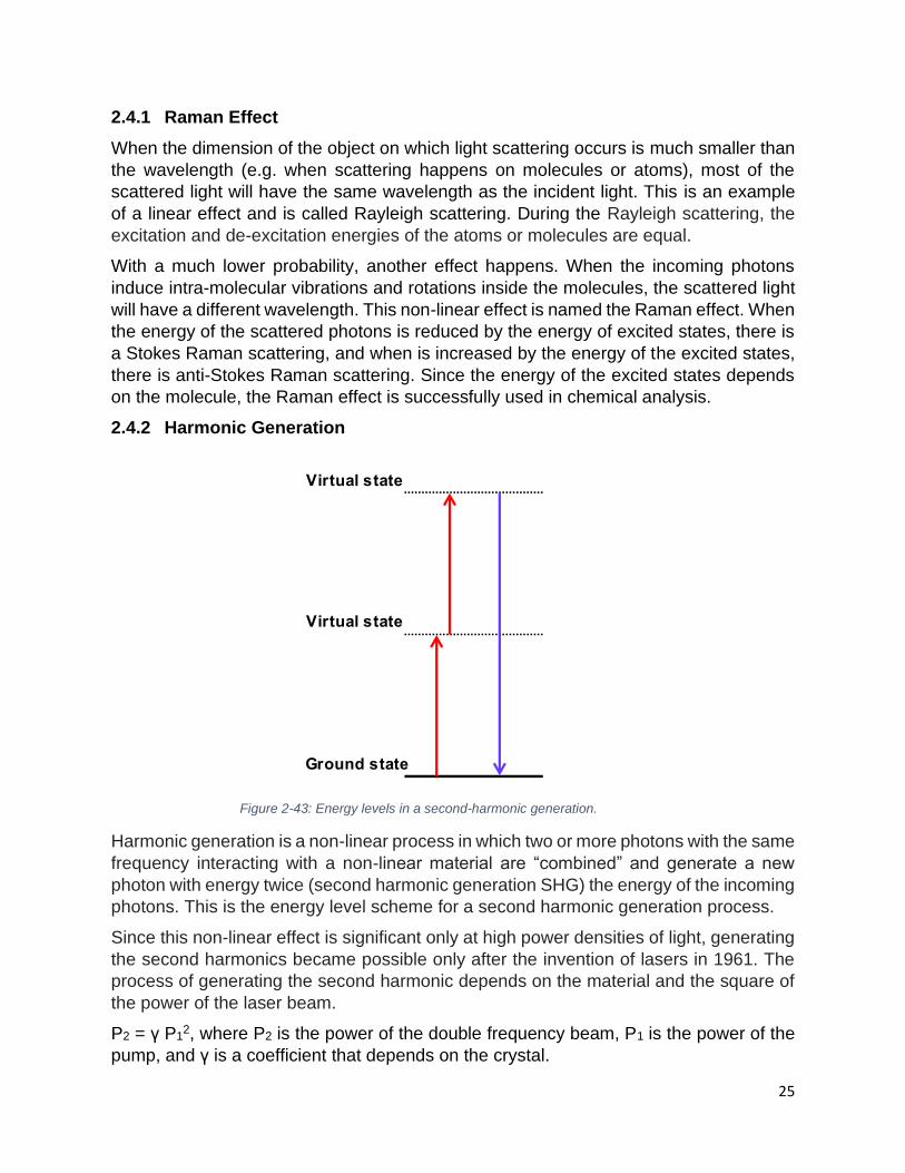
25
2.4.1 Raman Effect
When the dimension of the object on which light scattering occurs is much smaller than
the wavelength (e.g. when scattering happens on molecules or atoms), most of the
scattered light will have the same wavelength as the incident light. This is an example
of a linear effect and is called Rayleigh scattering. During the Rayleigh scattering, the
excitation and de-excitation energies of the atoms or molecules are equal.
With a much lower probability, another effect happens. When the incoming photons
induce intra-molecular vibrations and rotations inside the molecules, the scattered light
will have a different wavelength. This non-linear effect is named the Raman effect. When
the energy of the scattered photons is reduced by the energy of excited states, there is
a Stokes Raman scattering, and when is increased by the energy of the excited states,
there is anti-Stokes Raman scattering. Since the energy of the excited states depends
on the molecule, the Raman effect is successfully used in chemical analysis.
2.4.2 Harmonic Generation
Harmonic generation is a non-linear process in which two or more photons with the same
frequency interacting with a non-linear material are “combined” and generate a new
photon with energy twice (second harmonic generation SHG) the energy of the incoming
photons. This is the energy level scheme for a second harmonic generation process.
Since this non-linear effect is significant only at high power densities of light, generating
the second harmonics became possible only after the invention of lasers in 1961. The
process of generating the second harmonic depends on the material and the square of
the power of the laser beam.
P2 = γ P12, where P2 is the power of the double frequency beam, P1 is the power of the
pump, and γ is a coefficient that depends on the crystal.
Figure 2-43: Energy levels in a second-harmonic generation.

26
Harmonic generation in the perturbative (weak-field) regime is characterized by rapidly
decreasing efficiency with increasing harmonic order. This behaviour can be understood
by considering an atom absorbing n photons then emitting a single high energy photon.
The probability of absorbing n photons decreases as n increases, explaining the rapid
decrease in the higher harmonic intensities.
The SHG is used, for example, to produce a 532 nm beam from a 1064 nm beam of
Nd:YAG lasers. Many materials show relatively high efficiency in non-linear processes.
When these materials are crystals, they are called non-linear crystals. Examples of these
crystals are lithium niobate (LiNbO3), potassium titanyl phosphate (KTP = KTiOPO4),
lithium triborate (LBO = LiB3O5), etc. The crystals need to be oriented at some particular
angle with respect to the beam to fulfil the phase-matching condition. For high-intensity
beams, especially for picoseconds (ps) and femtoseconds (fs) pulses where the peak
power is very high, almost 100 % of energy can be converted to double frequency. For
lower powers (longer pulses) or when the phase-matching condition is not good, the
conversion can be much less. In these cases, an important amount of laser power at the
fundamental wavelength is present in the beam after the conversion. When laser
radiation at the fundamental wavelength is not filtered out by the laser manufacturer or
the user, the laser goggles must provide protection against the SHG wavelength and
also the fundamental one. If the goggles only protect the user from the SHG wavelength,
serious laser eye injuries can happen.
Since the generation of higher harmonics generation is even less efficient than SHG,
direct third or fourth harmonic generation is not very common. In the case of the Nd:YAG
laser (l1 = 1064 nm), the third harmonic wavelength of 355 nm (l3= l1/3 = 1064 nm/3 =
355 nm) is obtained by using a sum-frequency mixing between the 1064 nm and 532
nm beams. For the same laser, the fourth harmonic wavelength (l4 = l1/4 = 1064 nm/4 =
266 nm), is obtained by doubling the frequency of the 532 nm beam. A higher harmonic
2
Figure 2-44: Light of frequency (fundamental) incident to a non-linear optical medium. The generated light of
frequency 2 (SHG) exits medium mixed to the residual of the fundamental (top). The fundamental and SHG lights can be separated by a prism (bottom).

27
generation (HHG with frequency five times or higher than the original laser beam
frequency) was first observed in 1977 with a CO2 laser.
2.4.3 Electro-Optic Effects
A birefringent material has two different indices of refraction, one for each of the two
perpendicular components of polarization. When unpolarized light passes through a
birefringent material, two different components of polarization travel in two different
directions.
Some materials (like quartz or calcite) exhibit birefringence naturally, without the
application of an electric voltage. The birefringence is present all the time.
The change in the birefringence properties of the materials under the influence of the
electric field is used in the electro-optical Q-switch to create short laser pulses (see
section 3.2.3).
When an electric field is applied to an electro-optic material, the indices of refraction and
polarization properties of the material change. The Kerr or quadratic electro-optic effect
is a second-order effect that is a change in the index of refraction of a material that is
proportional to the square of the electric field intensity.
When the electric field oscillates rapidly, as in the case of visible light frequency, it is
called the optical Kerr effect. This causes a local variation in the index of refraction,
which is proportional to the square of the irradiance of the beam. This refractive index
variation is the basis for the functioning of Kerr-lens mode-locking (see section 3.4.4).
The effect only becomes significant with very intense beams such as those created by
very short pulses (ps or fs).
2.4.4 Saturable absorption
Saturable absorption is a property of materials where the absorption of light decreases
with increasing light intensity. Most materials show some saturable absorption, but often
Figure 2-45: Two different polarization travel different paths in a birefringent material as Iceland Spar.

28
only at very high optical intensities, close to the optical damage of the material. The
decreased absorption at the high light intensity competes with other mechanisms like an
increase in temperature or the formation of colour centers.
For pulsed operation, when the pulse duration “t” is smaller than the relaxation time of
the medium, the absorption can decrease very fast and increase back after the pulse
ends. In some situations, for very short pulses and relaxation times, the material can
look unchanged after the laser pulse passes through the material.
Saturable absorption is used in creating very short laser pulses. Also, when the front
mirror of the laser cavity is made of the saturable absorber to let pass the very high
intensity, short laser pulses and return to reflectivity when the intensity of the light is
lower. Saturable absorption can be a challenge for the laser goggles used for ps and fs
lasers (see section 7.3.5).
Figure 2-46: Mechanism of increased transmittance in a saturable absorber.

29
3 LASERS
3.1 Laser levels
As mentioned in section 2.2 population inversion is required to produce the lasing effect.
Theoretically, this can be obtained only in atoms or molecules with three or more levels
of energy involved in the laser operation.
The transition from level 1 to level 3, in the three levels system, is called the pump
transition. A fast transition from level 3 to level 2 is necessary to create the population
inversion. This transition is radiationless and the energy is transferred to vibrational
modes increasing the temperature of the system. The transition from level 2 to level 1 is
called laser transition. To achieve population inversion, the number of atoms in the
excited state, N2; must be greater than the number of atoms in the ground state, N1. The
gain medium of the first laser was a Ruby rod, which is a three-level system. The laser
was extremely inefficient. Since most atoms or molecules of systems at room temperature
are in the ground state, it is very difficult to create population inversion with three energy
levels.
A more efficient system is a laser with four levels. To have the population inversion N3
must be greater than N2. The transitions between levels 4 and 3 and between levels 2
and 1 are fast and radiationless. This process makes the populations N4 and N2 close to
zero. Also, the transition from level 3 to level 2 is slow compared with the transitions from
levels 4 to 3 and from levels 2 to 1. Therefore, it is easier to obtain N3 greater than N2.
Most modern lasers have a four-level energy system.
More than four energy levels may be involved in the laser process, with complex excitation
and relaxation processes involved between these levels. In particular, the pump band
may consist of several distinct energy levels, or a continuum of levels, which allow optical
pumping of the medium over a wide range of wavelengths.
The laser transition can also be considered between several energy sublevels giving the
broad energy/wavelength range (bandwidth) measured in the laser emission. For some
lasers, the emission can cover an extended energy/wavelength range, like the emission
fast radiationless transition
slow laser transition
pump
transition
fast radiationless transition
slow laser transition pump
transition
fast radiationless transition
Figure 3-1: Energy diagrams of a three-levels laser (left) and four-levels laser (right).

30
of a Ti:Sapphire which is between 660 and 1180 nm, and for others, a narrow range like
the emission of a He-Ne laser which is 632.800 ± 0.001 nm.
It is important to understand that the energy of the pumping photons for any laser is higher
than the energy of the lasing photons. As can be seen in the above pictures, in a 4-level
energy laser, the energy between levels 4 and 1 is higher than the energy of the laser
emission (the energy between levels 3 and 2). In a 3-level laser the energy between levels
3 and 1, is higher than between levels 2 and 1. For example a Ti:Sapphire laser emits in
red and near IR range, but needs to be pumped by a green laser.
3.2 Laser components
The three main components of a laser are the lasing medium, the excitation source and
the optical cavity.
3.2.1 Lasing medium
The material in which the population inversion is obtained is called lasing or gain medium.
In the first laser (Ted Maiman – May 16, 1960) a ruby rod was used as a gain medium.
Figure 3-2: Ruby laser including Ruby rod, helicoidal flash lamp and end mirrors.
Figure 3-3: 3 stages excitation of a Ruby laser.

31
The ruby rod is made of Al2O3 crystals with 0.5 % Al replaced by Cr. The three levels of
energy of the Cr3+ ions are used for this laser.
Nd:YAG is a very common solid-state laser emitting in the near-infrared region of the
electromagnetic spectrum (1064 nm). The gain medium of this laser is made of a crystal
called Yttrium Aluminum Garnet doped with Nd. Nd replaces around 1 % of Yttrium from
the YAG crystal. The YAG crystal can also be doped with Cr, Tm, Er or Ho to obtain other
wavelengths.
The lasing medium can also be a gas. A mixture of He (85%) and Ne (15%) is the gain
medium for the first gas laser: HeNe laser. As explained in section 3.1 HeNe can have a
complex energy level with many possible laser transitions. It can emit in different
wavelengths, but the most common one is 633 nm.
CO2 is a very common gas laser. The gain medium is a mixture of gases (10–20 % CO2,
10–20 % N2, a few percent H2 and/or Xe, and the remainder is He).
Figure 3-4: Q-switched Nd:YAG laser.
Figure 3-5: Helium-Neon laser.
Figure 3-6: Diagram of a CO2 laser tube.

32
The heart of the argon laser in the plasma tube. The design of the plasma tube must be
such that it can sustain extremely high temperatures without damage while maintaining
an excellent vacuum seal. The material of choice for the bore of an argon-ion laser plasma
tube is BeO since it has a low vapour pressure and can be produced with a high chemical
purity. Beryllium, however, is a carcinogen and the tube of the argon laser must be
disposed of as hazardous material when the laser is decommissioned.
Most of the lasers having liquid gain medium are dye lasers. A dye laser uses a gain
medium consisting of an organic dye, which is a carbon-based soluble stain that is often
fluorescent. The dye is mixed with a compatible solvent allowing the molecules to diffuse
evenly throughout the liquid. Most of the dyes (like rhodamine or stilbene) are toxic or
carcinogenic. For the diode lasers, the gain medium is the semiconductor itself (usually
Silicon) in which different elements are used for the doping process.
The diode laser has, in general, an elliptical beam. Manufacturers normally mount a
cylindrical lens in front of the laser to make the beam circular.
A fibre optic in which rare elements are used for doping can be used as a gain medium
for fibre lasers.
A Ti:Sapphire oscillator has a gain medium made of Al2O3 (Sapphire) doped with Titanium
atoms. Ti emits at 800 nm with large bandwidth. Ti:Sapphire lasers are tunable from
around 650 to 1100 nm. The pulse duration of a laser is inversely proportional to the
Figure 3-7: Diagram of an Argon ion laser.
Figure 3-8: Diode laser.

33
bandwidth (see section 3.4.2). Having a large emission band this laser is suitable for
obtaining very short pulses (ps and fs).
3.2.2 Optical cavity
In general, if photons of the proper wavelength pass just once through the lasing medium
in the population inversion state, the stimulated emission and then the obtained
amplification is not enough to produce an intense laser beam. An optical cavity is
necessary to force the light to pass many times through the gain medium. The simplest
optical cavity is made of two parallel mirrors. One mirror has 100 % reflectivity at the laser
wavelength and the other mirror is just partially reflective. This second mirror is known as
the output coupler. Depending on the laser, the reflectivity of the output coupler can be
anywhere between 1 % to 99 %.
The mirrors can have different shapes. Inside the optical cavity, standing waves are
created (see section 3.3.1).
Figure 3-9: Diagram of a Titanium-Sapphire laser cavity.
Figure 3-10: Different types of optical cavities used in lasers.

34
When the optical cavity can sustain the standing waves, it is said to have a large quality
factor (Q). When, due to different reasons, standing waves cannot appear the optical
cavity has a small Q. A “Q-switched laser” is a laser in which the quality factor can be
changed between low and high values (see section 3.4.3).
Laser amplifiers are the type of lasers that don’t necessarily have an optical cavity. Low-
intensity laser beams from a regular laser, normally called an oscillator, is injected in a
laser gain medium that was previously activated by an excitation source. This low-
intensity beam acts as a “seed” inducing stimulated emission in the exciting medium. After
just one pass on the medium, the beam is amplified several orders of magnitude.
Examples of amplifiers are Doped Fiber Amplifiers (DFA), Erbium-Doped Fiber Amplifier
(EDFA) with a wavelength in the range 1525-1565 nm or 1570-1610 nm, Thulium (1450-
1490 nm), Praseodymium (1300 nm region), Ytterbium (1000 nm region), or
Semiconductor Optical Amplifiers (SOA).
3.2.3 Energy pump
To create the population inversion in the gain medium a source of energy is necessary.
The energy pump is dependent on the lasing medium and other characteristics of the
laser.
In optical pumping, a source of light such as a flash lamp with broad emission bandwidth
is used to excite a medium with an excitation band extremely narrow. The disadvantage
of this type of excitation is its low energy yield. Most of the energy emitted by the flash
lamp is lost as heat. These types of lasers need to have a cooling system (usually water)
to remove the excess heat. Ruby and Nd:YAG lasers use optical pumping.
Electrical pumping is the most common energy pump for gas lasers. In this kind of laser
pumping a high voltage, alternative current (AC) or direct current (DC) is used to create
a discharge in the gas. The discharge will create ions inside the lasing medium, these
ions will be accelerated, collide, and excite other components of the gain medium.
Arc lamps are used for pumping some solid-state lasers that can operate in continuous
wave mode (CW). The voltage must be high enough to create a current around 20 to 50
A. Arc lamps must also be cooled by water.
Figure 3-11: Fiber laser amplifier.

35
The diode laser is pumped by passing a high-density current through the p-n junction.
This type of laser diode is called an injection laser diode (ILD). Laser diodes can also use
the optical pump. Optically pumped semiconductor lasers (OPSL) offer some advantages
over the ILD for some wavelengths.
Chemical pumping is also used to excite chemical lasers. Infrared lasers based on the
vibrationally excited products of a chemical reaction was first proposed by John Polanyi
in 1961. These types of lasers can reach MW power in CW operation.
Figure 3-12: Flash lamp used to excited Nd:YAG laser media (top). Diagram of a Nd:YAG laser excited with two flash lamps (bottom).
Figure 3-13: Diagram of electrical excitation of He-Ne laser.

36
A much more efficient photoexcitation is obtained when a laser is used to pump another
laser. The pump laser must have an emission band that overlaps with the absorption band
of the gain material of the pumped laser. The mirrors used for the optical cavity of the
pumped laser are transparent to the excitation wavelength but reflect the wavelength of
the pumped laser. The most common laser used as a pump is a diode laser.
This type of energy excitation is used in fibre and solid-state diode pump (SSDP) lasers.
For fibre lasers, gratings are used to create the optical cavity.
Using this type of pumping powerful lasers could be obtained with small dimensions and
low energy consumption.
3.3 Laser Modes
The laser cavities can have two types of modes: axial (longitudinal) and transverse
modes.
3.3.1 Axial modes
Inside the optical cavity, waves of different frequencies can coexist. Just those whose
electric field amplitude is zero at the surface of the mirror will be enhanced or amplified.
That establishes a set of stable standing waves in the cavity as the ones shown in Error! R
eference source not found.. The frequency of those waves depends on the length of
the cavity.
Figure 3-14: Laser diode used to excite a fibre laser.
Figure 3-15: Diode laser used to excite a solid-state laser (DPSSL).

37
The mode number “q”, the length of the cavity “L”, the wavelength “λ” and the frequency
“f” of the standing waves that can be produced in the optical cavity is connected. If ‘n’ is
the index of refraction of the gain material, the following formulae are valid:
L = qλ
2= q
c
2f f = q
c
2nL Δf =
c
2nL
Δf represents the difference between the frequencies of two successive modes.
For a cavity, with L 0.3 m, and with n ≈ 1 (in case of air or a low-density gas) the
frequency difference will be 0.5 * 109 Hz 0.5 GHz. The equation for Δf is more complex
when the cavity consists of multiple materials.
Out of all possible axial modes for a given optical cavity length, only the modes with
frequencies within the material gain response will be amplified. The number of modes can
be obtained by dividing the gain bandwidth (Df) of the particular laser by the frequency
difference (Δf).
For a typical He-Ne laser with a length of the cavity 0.3 m and a Full Width at Half
Maximum (FWHM) gain bandwidth Df =1.5 GHz, using the Δf 0.5 GHz, we obtain 3
Figure 3-16: Longitudinal modes of a laser cavity.
Figure 3-17: Gain curve of laser medium and all possible longitudinal modes for a given cavity length (top). Only the cavity modes with frequencies within the laser gain curve are amplified.

38
modes. Since the He-Ne has a very narrow bandwidth and few axial modes, this laser is
ideal to be used as a standard for wavelength calibrations.
For a Ti:Sapphire laser, the FWHM gain bandwidth is Df = 1014 Hz = 105 GHz. For a cavity
length of 1.5 m and neglecting the optical path in the Ti:Sapphire crystal, the frequency
difference is Δf 0.1 GHz. Using these values, the number of amplified modes in this
laser will be 1,000,000.
The number of longitudinal modes can be reduced by reducing the length (L) of the cavity.
In this way, the Δf increases and the number of possible modes are reduced. This
procedure will reduce the power of the laser.
Another way of reducing the number of modes is by adding Fabry-Perot etalon (a crystal
with parallel flat surfaces) inside the optical cavity.
The etalon will act as an additional mirror. The number of longitudinal modes will be
reduced because the laser must satisfy the condition for both “mirrors”.
The etalon can be fixed or rotating. By rotating the etalon, the user can tune the
transmission to the desired frequency.
3.3.2 Transverse modes
Transverse modes are modes in the cross-section of the beam, perpendicular to the
optical axis of the laser. They are created by the width of the cavity, which enables a few
diagonal modes to develop inside the laser cavity. A little misalignment of the laser mirrors
causes different path lengths for different rays inside the cavity.
Figure 3-18: Etalon used to reduce the number of longitudinal modes in a laser cavity.
Figure 3-19: Etalon as additional cavity mirror.

39
Transverse modes are also called transverse electromagnetic modes, and the notation
used is TEMnm. Different transverse mode patterns exist inside the laser beam. The first
letter (“n”) refers to the number of beams on the OX axis, and “m” on the OY axis. TEM00
is the beam with the smallest diameter and beam spread
All other modes influence the beam quality factor, M2. The beam quality factor of a laser
is the ratio between the beam spread and the natural spread of light obtained by solving
the Maxwell equations of an electromagnetic field. Beam quality factor of an embedded
Gaussian beam with TEMmn:
M2 on x-axis = 2m + 1
M2 on y-axis = 2n + 1
Figure 3-21: Shapes of different transverse modes.
Figure 3-20: Images of different tranverse modes. TEM00 (top row), TEM10 (center row), TEM01 (bottom left) and TEM01 + TEM10 “bagel” bottom right .
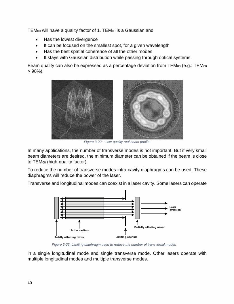
40
TEM00 will have a quality factor of 1. TEM00 is a Gaussian and:
• Has the lowest divergence
• It can be focused on the smallest spot, for a given wavelength
• Has the best spatial coherence of all the other modes
• It stays with Gaussian distribution while passing through optical systems.
Beam quality can also be expressed as a percentage deviation from TEM00 (e.g.: TEM00
> 98%).
In many applications, the number of transverse modes is not important. But if very small
beam diameters are desired, the minimum diameter can be obtained if the beam is close
to TEM00 (high-quality factor).
To reduce the number of transverse modes intra-cavity diaphragms can be used. These
diaphragms will reduce the power of the laser.
Transverse and longitudinal modes can coexist in a laser cavity. Some lasers can operate
in a single longitudinal mode and single transverse mode. Other lasers operate with
multiple longitudinal modes and multiple transverse modes.
Figure 3-22: : Low-quality real beam profile.
Figure 3-23: Limiting diaphragm used to reduce the number of transversal modes.
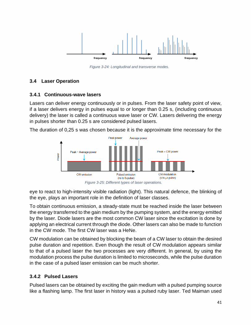
41
3.4 Laser Operation
3.4.1 Continuous-wave lasers
Lasers can deliver energy continuously or in pulses. From the laser safety point of view,
if a laser delivers energy in pulses equal to or longer than 0.25 s, (including continuous
delivery) the laser is called a continuous wave laser or CW. Lasers delivering the energy
in pulses shorter than 0.25 s are considered pulsed lasers.
The duration of 0,25 s was chosen because it is the approximate time necessary for the
eye to react to high-intensity visible radiation (light). This natural defence, the blinking of
the eye, plays an important role in the definition of laser classes.
To obtain continuous emission, a steady-state must be reached inside the laser between
the energy transferred to the gain medium by the pumping system, and the energy emitted
by the laser. Diode lasers are the most common CW laser since the excitation is done by
applying an electrical current through the diode. Other lasers can also be made to function
in the CW mode. The first CW laser was a HeNe.
CW modulation can be obtained by blocking the beam of a CW laser to obtain the desired
pulse duration and repetition. Even though the result of CW modulation appears similar
to that of a pulsed laser the two processes are very different. In general, by using the
modulation process the pulse duration is limited to microseconds, while the pulse duration
in the case of a pulsed laser emission can be much shorter.
3.4.2 Pulsed Lasers
Pulsed lasers can be obtained by exciting the gain medium with a pulsed pumping source
like a flashing lamp. The first laser in history was a pulsed ruby laser. Ted Maiman used
Figure 3-25: Different types of laser operations.
Figure 3-24: Longitudinal and transverse modes.

42
a photographic flash lamp to create the excitation state in the ruby rod. In the past, some
of these flashing lamps were connected to capacitor banks. These capacitors were
charged first and then rapidly discharged, providing the energy for the flash lamp. As
explained later in section 6.1.1, capacitors are an electrical hazard. The pulse duration is
normally measured as the full width at half maximum (FWHM) of the laser pulse.
If a laser emits pulses at a certain interval the difference in time between two successive
pulses is called pulse repetition time “PRT”. The number of pulses that a laser emits per
second is the pulse repetition frequency “PRF”. PRF is equal to 1/PRT and is measured
in hertz ( 1Hz = 1/s).
The pulse duration can vary many orders of magnitude from ms (10-3 s) to fs (10-15 s)
range for lasers in the visible or infrared. Attoseconds (as = 10-18 s) can only be obtained
with the centre frequency above the visible (UV and higher frequencies). The pulse
duration is inversely proportional to the laser bandwidth. High harmonics generation (see
section 2.4.2) allows the formation of 10-18 s pulses or pulse trains.
3.4.3 Q switched laser
As explained in section 3.2.2, the cavity quality factor Q is a number that tells how much
an optical cavity can sustain the standing waves. When the Q of the optical cavity is low,
the lasing does not occur. The process of rapidly changing the quality factor of the optical
cavity from low to high and vice-versa is called Q-switching. This process is used to make
laser emitting pulses with duration in the nanosecond range. The energy from the
excitation source brings atoms to a high energy level. Since at low Q there is no stimulated
emission, to produce the de-excitation of the atoms the energy stored in the gain medium
increases. Then Q is rapidly switched to a high value and all the stored energy is released
in a very short time creating a high peak power nanosecond laser pulse. The total energy
emitted by the laser is not greater than a similar laser operating in CW mode, but because
is released in a very short time the peak power can reach hundreds of MW.
The cavity quality factor can be switched actively or passively.
In passive Q-switching, the Q-switch is a saturable absorber—material that transmission
increases when the intensity of light exceeds a threshold. After the short pulse of large
Figure 3-26: Definition of pulse duration (t) and pulse repetition time (PRT).

43
energy is emitted from the laser, the Q-switch will block again the transmission of light
causing a low-quality factor in the optical cavity.
The active Q-switch can be a mechanical device such as a shutter, a chopper wheel, or
a spinning mirror/prism placed inside the cavity. Other devices used for active Q-switching
are acousto-optic, magneto-optic or electro-optic devices.
Some properties of an optical crystal can be changed by applying an electric or magnetic
field to it. For example, the crystal can act as a quarter waveplate changing the
polarization from light to left. In this way, the crystal will block the transmission of light
creating a low Q inside the laser cavity.
Figure 3-27: Different techniques to achieve Q-switch. Rotating chopper (top), rotating prism (center) and electrooptical device (bottom).

44
3.4.4 Mode-locked laser
As it was mentioned before, Q-switching can produce laser pulses in the nanosecond
range but not shorter than that. To produce laser pulses in the picoseconds or
femtoseconds range another method needs to be used. This other method is called
mode-locking and it is based on combining several longitudinal cavity modes with a fixed
phase relation between them. The result of this is a series of very short and high peak
power laser pulses. The pulse width of each mode-locked pulse is inversely proportional
to the gain bandwidth of the laser cavity.
As in the case of Q-switch, there are active and passive methods.
Active mode-locking
Active mode-locking can be obtained by placing a standing wave acoustic-optic modulator
in the optical cavity. This modulator is a semiconductor device and by changing the
electric voltage applied to it, its energy bandgap changes which in turn will control the
intensity of the laser beam. Driven by an electric signal the modulator creates sinusoidal
amplitude modulation, acting as a shutter (when opened, the light passes, when closed,
light is stopped). Typically, pulses with a duration of 0.5 to 5 ps can be obtained. One of
Figure 3-28: Comparison of longitudinal modes locked in-phase (top) and with random phases (bottom).
Figure 3-29: A modulator used for active mode-locking.

45
the disadvantages of active mode-locking is that precise synchronization must be kept at
all times. Small jitter in the synchronization circuitry will make the laser have important
fluctuations in pulse intensity.
Passive mode-locking
One way the passive mode-locking can be obtained is by placing a saturable absorber in
the optical cavity. The saturable absorber is a chemical compound that will absorb light
when the intensity of the pulse is low, i.e. at the head and tail of the pulse. When the
intensity of the pulse increases, the absorption transitions of the chemical saturate in a
phenomenon normally called “bleaching”. At this point the chemical becomes transparent
to the light, letting the full intensity pass unperturbed. This process effectively shortens
the pulse duration.
Another way to achieve passive mode-locking is by taking advantage of Kerr lensing in
the gain medium. The Kerr Lens Modelocking (KLM) is based on the optical Kerr effect,
nonlinear optical process (electro-optic effects – see section 2.4.3). In this case, the index
of refraction of the laser medium changes due to the high intensity of the short pulses.
Short pulses get focused more tightly than CW beam. Adding an aperture to the cavity or
adjusting the shape and diameter of the excitation beam to match the ones of short pulses
will favour the mode-locking.
Passive mode-locking can have difficulties to start the mode-locking and relay on random
fluctuations of the intensity of the light in CW mode. Modern lasers overcome this problem
by mounting an extra mirror in the laser cavity on a piezoelectric actuator. Applying an
oscillating signal to the actuator will produce vibrations in the mirror providing the random
intensity fluctuations needed to start the mode-locking.
Hybrid mode-locking
The hybrid mode-locking is a combination of active and passive mode-locking. A
saturable absorber is placed in the optical cavity and the injection current is modulated at
the same frequency. In this way, it is possible to control the pulse timing externally, and
also achieve a shorter pulse duration as in a passive mode-locking device.
Figure 3-30: Kerr lens mode-locking.

46
3.5 Laser safety properties
Two types of physical properties are used in laser safety. The first type is directly
related to the laser itself and the second one laser interacting with the target.
3.5.1 Properties directly related to the laser
For a continuous wave CW laser, the most common property to measure the laser output
is laser radiant power – P. Laser power is measured in watts – W.
Figure 3-31: Ultrafast pulse circulating in an optical cavity (top). Hybrid mode-locking (bottom).
Figure 3-32: Pulse duration measured as full width at half maximum, FWHM (left) and pulse repetition time, PRT (right).

47
For a pulsed laser, the pulse duration is noted as t and is measured in s. The energy
emitted per pulse, also known as the radiant energy is noted with E and is measured in
joules – J.
The difference in time between two consecutive pulses is called the pulse repetition
period (see section 3.4.2).
When more pulses are emitted the number of pulses per second is measured with the
pulse repetition frequency - PRF. The pulse repetition frequency is measured in Hertz –
Hz = s-1.
To calculate the maximum or peak power of a pulsed laser, the energy per pulse is divided
by the pulse duration.
𝑃max =𝐸
𝑡
The average power of a repetitively pulsed laser is found by multiplying the energy per
pulse by the pulse repetition frequency.
𝑃avg = 𝐸 ∗ 𝑃𝑅𝐹
The laser beam diameter is noted D and is usually measured in mm.
Usually, the symmetric laser beam profile (see section 8.2.2) can be fitted to a Gaussian
function. The most common definition of the beam diameter is the distance between the
points where the intensity of the beam decreases to 1/e2 of its maximum (e is the base of
the natural logarithm).
In laser safety, the beam diameter is defined slightly differently and is the distance
between the points where the intensity decreases at 1/e of the maximum. This definition
conducts a safer calculation of the required laser goggles' optical density.
Assuming that the beam is Gaussian, only 63 % of the total energy passes through an
aperture with the diameter defined at 1/e and 86 % when the diameter is defined at 1/e2.
Figure 3-33: Comparison of peak power Pmax and average power, Pavg. The area in orange represents the energy of the pulse.

48
A third definition of the beam diameter is the diameter of an aperture through which 95 %
of the beam’s energy will pass.
The three definitions are related to each other. The following formula can be used to
change from one to another:
𝐷1𝑒⁄ =
𝐷1𝑒2⁄
√2=
𝐷95%
1.7
If the beam shape is elliptical the beam diameter can be estimated by averaging the
diameter on OX and OY axis.
The laser beam is, in general, very well collimated. However, small beam divergence is
unavoidable. For small beam divergence, the angle of divergence is defined as the ratio
between the beam diameter D at the distance r from the laser exit and the distance itself.
Figure 3-34: Definition of 1/e2 beam diameter (left). Other common definitions of the laser beam diameter
y
x
Figure 3-35: Beam diameter for elliptical beams.

49
𝜙 =𝐷
𝑟
In the above formula, if the beam diameter is measured in mm and the distance to the
laser exit is measured in m, the beam’s divergence will be expressed in mrad.
The beam quality factor is noted as M2 and is defined as the ratio between the real angle
of divergence and the theoretical divergence of a perfect Gaussian beam. This ratio is
always greater than one.
𝑀2 =𝜙real
𝜙theoretical
The quality factor of the beam is also defined as a measure of the beam’s deviation from
the transverse mode TEM00.
3.5.2 Properties of the laser interacting with the target
When referring to the target or receiver of the laser beam, the interest switches from the
energy or power of the laser beam, to energy or power density incident on a surface.
The energy density Ed is defined as the total beam energy divided by the incident surface.
The preferred unit for the Ed is J/cm2. The Ed’s is also called radiant exposure. Similarly,
the power density Pd is defined as the total power incident on the surface and is measured
in W/cm2. The Pd’s is also called irradiance.
For a 20 W laser, the power density where the beam diameter is 1cm is Pd = 25 W/cm2.
If a lens is placed in front of the beam, the focused beam will have a higher Pd. If the Pd
is calculated where the beam diameter decreases to 0.01 cm, the calculated value is
approximate 250,000 W/cm2. Therefore, if the beam diameter decreases 100 times, the
power density (or the energy density) increases 10,000 times.
Figure 3-37: Calculation of power density.
Figure 3-36: Definition of laser beam divergence.

50
Sometimes the Ed or Pd of a laser beam is loosely called the beam’s “intensity – I”. The
Maximum Permissible Exposure (noted MPE) is the energy or power density of the laser
beam to which a person’s eye or skin may be exposed without hazardous effects.
As mentioned above, every laser beam has a divergence. Therefore, at a certain
distance, the intensity of the laser beam is low enough to reach the applicable MPE. The
distance at which the intensity of the laser beam is low enough for a person to look directly
into the beam without sustaining any hazard is called Nominal Ocular Hazard Distance.
For some lasers used at the University of Toronto, this distance can be multiple hundreds
of meters.
Similarly, the nominal skin hazard distance can be defined.
3.6 Point and extended light sources
Due to the type of image formed on the retina, a light source can be a point source or an
extended source. Any type of light source can be considered a point source if they are at
a very long distance from the observer, like a star.
If the observer is close to the light source, the source has a visible dimension and it is an
extended source. If the observer is far from the source, the wavefronts are planes.
Figure 3-39: Wavefronts close to the point source and far from it (left). Plane wavefronts as they are seen by an observer far from the point source (right).
Figure 3-38: Nominal Ocular Hazard Distance (NOHD).

51
The image on the retina depends on the type of source. If the source is a point source
the image will be close to a point (a few micrometres – see section 5.2.3.3). If the source
is an extended source the image on the retina is much bigger.
To distinguish between the two types of light sources, a physical quantity named apparent
visual angle is defined. This angle is calculated with the help of the source size and the
distance from the eye to the source.
The apparent visual angle is different from the angle of divergence (defined in section
3.5.1).
For small angles, the apparent visual angle can be defined as the ratio between the
diameter of the object and the distance to the eye.
For larger angles, a more precise definition involves the following formula:
Figure 3-40: Parallel light rays from a distant object. They form a point image in the retina (left). Light rays from a close object are not parallel. They form an extended image in the retina (right).
Figure 3-42: Definition of apparent visual angle.
Figure 3-41: Apparent visual angle of an extended source (left). Difference between beam spread () and apparent
angle () (right).

52
𝛼 =𝐷
𝑟
𝛼 = 2 arctan (𝐷
2𝑟)
A light source is considered a point source if the apparent visual angle is smaller than 1.5
mrad.
α ≤ αmin = 1.5 mrad
The Sun is not considered a point source since the subtended angle of the Sun is
approximately equal to 8.7 mrad.
Because the image on the retina from an extended source is larger than the one created
by a point source, the safety analysis when using an extended source provides less
restrictive results.
The light generated by a laser is coherent (the wavefronts are parallel planes and light
rays are parallel) and generates on the retina an image similar to the image of a faraway
star. Therefore, a laser is not an extended source, even when the subtended angle is
larger than 1.5 mrad (e.g.: a laser with a diameter of 2 mm viewed from a distance of 0.5
m has a subtended angle of 4 mrad, but cannot be considered an extended source).
After a diffuse reflection, the beam loses coherence. The diffuse reflection spot on the
rough surface can be considered an extended source for laser safety calculations.
An array of multiple diode lasers can also be considered an extended source since there is no coherence between different diode lasers.
In this case, the safety analysis must be made considering one diode as a point source, followed by calculations considering 4, 9, 16, 25, etc., diodes and the system being an extended source. The safest values must be used in the calculation of protective measures.
Figure 3-43: A laser spot on the wall (left) and laser arrays (right) are considered an extended source.
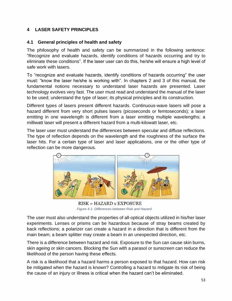
53
4 LASER SAFETY PRINCIPLES
4.1 General principles of health and safety
The philosophy of health and safety can be summarized in the following sentence:
“Recognize and evaluate hazards, identify conditions of hazards occurring and try to
eliminate these conditions”. If the laser user can do this, he/she will ensure a high level of
safe work with lasers.
To “recognize and evaluate hazards, identify conditions of hazards occurring” the user
must: “know the laser he/she is working with”. In chapters 2 and 3 of this manual, the
fundamental notions necessary to understand laser hazards are presented. Laser
technology evolves very fast. The user must read and understand the manual of the laser
to be used; understand the type of laser; its physical principles and its construction.
Different types of lasers present different hazards. Continuous-wave lasers will pose a
hazard different from very short pulses lasers (picoseconds or femtoseconds); a laser
emitting in one wavelength is different from a laser emitting multiple wavelengths; a
milliwatt laser will present a different hazard from a multi-kilowatt laser, etc.
The laser user must understand the differences between specular and diffuse reflections.
The type of reflection depends on the wavelength and the roughness of the surface the
laser hits. For a certain type of laser and laser applications, one or the other type of
reflection can be more dangerous.
The user must also understand the properties of all-optical objects utilized in his/her laser
experiments. Lenses or prisms can be hazardous because of stray beams created by
back reflections; a polarizer can create a hazard in a direction that is different from the
main beam; a beam splitter may create a beam in an unexpected direction, etc.
There is a difference between hazard and risk. Exposure to the Sun can cause skin burns,
skin ageing or skin cancers. Blocking the Sun with a parasol or sunscreen can reduce the
likelihood of the person having these effects.
A risk is a likelihood that a hazard harms a person exposed to that hazard. How can risk
be mitigated when the hazard is known? Controlling a hazard to mitigate its risk of being
the cause of an injury or illness is critical when the hazard can’t be eliminated.
Figure 4-1: Differences between Risk and Hazard.

54
Physically remove or replace lasers from a laboratory is not applicable in most research
situations.
To eliminate conditions of a hazard occur, the laser user must implement engineering,
administrative and procedural controls. The personal protective equipment, typically laser
goggles, must be the last line of defence.
4.2 Engineering Controls
Engineering controls are physical barriers between the hazard and the user or other
individuals that may be present. The user may be exposed to the hazard only if these
physical barriers are: removed, disabled, or bypassed. In the case of a commercially
available laser, engineering controls may be built around the laser allowing the hazardous
beam to be emitted only in one direction. In this case, the user is protected against the
other hazards present near the laser cavity, such as stray beams, electrical contacts,
excitation sources, etc. In cases when the laser is used for one specific application, the
manufacturer may also limit hazards by building an enclosure and limiting the access to
the laser beam. This type of configuration where a higher-class laser is mounted inside
an enclosure with interlocks is called a class 1 working environment.
For a laboratory-built laser, none of these controls is usually present. These types of
situations are encountered in a laser lab when the user builds his/her laser for
experimental/research purpose. In this case, it is up to the user to build engineering
controls to reduce all risks related to its experimental setting. Besides, when a commercial
laser (with built-in engineering controls) is used in new applications, the user is required
to build the engineering controls adequate to control all hazards.
When assembling engineering controls, the user must understand all basic principles of
the functioning of controls, the limitations of applicability, the necessity to build other
controls when the current ones do not offer adequate protection.
The concept of “defence in depth” implies using more than one method to control a hazard.
By applying this concept, the user is protected even when mistakes are made.
Examples of engineering controls are presented in section 7.3.2.
Mosteffective
Leasteffective
Protect the worker withPersonal Protective Equipment
Change the way
people work
Isolate peoplefrom the hazard
Replacethe hazard
Physically removethe hazard
Figure 4-2: Effectiveness of controls.

55
When physical barriers are not possible to be built, or not practical for a particular
application, other controls must be put in place to mitigate risks and ensure the safe use
of lasers. As requested by the applicable laws, regulations or standards, rules for the safe
use of lasers must be followed. These rules may be in the form of standard operating
procedures, alignment procedures, restrictions for operating the laser only by authorized
trained people, defining the nominal hazard zones, controlling access, etc. Examples of
administrative and procedural controls are presented in section 7.3.3.
Personal Protective Equipment (PPE) must be the last layer of defence. The PPE is meant
to protect individuals when controls fail to prevent an incident or an accident.
An easy way to understand the principles behind the need for knowing your laser,
introducing controls, and wearing the PPE is by comparing the use of a laser with driving
a car. The first and most important condition for a person to drive a car is knowing how to
drive, and especially how to stop the car safely. The manufacturer installs the turning
wheel, the brakes, windshield, etc. The government establishes requirements for training,
regulations and rules to drive on public roads. Finally, the last defence comes from the
seatbelt, airbags, etc.
4.3 Principles of laser safety
When applying the general principles of health and safety to the use of lasers, it is
important to understand that a laser is an important hazard with a low probability.
The probability of accident increases when the user does not know where the main beam
and all stray beams are located. Unexpected reflections, either specular or diffuse from
walls or objects around the laser are also increasing the likelihood of injuries. The same
can happen when the user does not understand how optical elements are used in an
experimental setting.
The user can reduce the probability of injury by controlling and containing the laser beam
and stray beams. One way to control stray beams generated by back reflections on optical
elements is to have an anti-reflective coating on those elements. Any type of beam can
be controlled by enclosing the experimental setup, and if it’s possible by creating a “Class
1 working environment” (see section 4.5).
Figure 4-3: Likelihood and consequences of injury.
56
4.4 The objective of the ANSI Z136 standards
The American Standard for Safe Use of Laser ANSI Z136 is the most used laser safety
standard in North America. The objective of this standard is “to provide reasonable and
adequate guidance for the safe use of lasers”.
The objective is achieved by classifying lasers according to their hazard, and by specifying
appropriate controls for each laser class.
The Laser Safety Officer (LSO) is an individual nominated by the institution/employer to
oversee the laser safety program implementation inside the institution/company. The LSO
should be a person trained in laser safety, optical engineering, or a related field. In this
case, the LSO can perform/verify the classification of lasers. When the LSO does not have
the qualification, knowledge, or experience to do the classification, he/she can delegate
this responsibility to a knowledgeable person.
The best way to ensure protection to laser users, bystanders, visitors, etc., is to develop
a clear laser safety program. The program must support research and innovation and
must establish a high level of laser safety across the institution. To ensure these
objectives, the laser safety program must be adapted to the level of hazards within the
institution. Some elements of the programs will be common, for example, the need for
laser classification, alignment procedures, laser safety for contractors, etc. Other parts of
the program must be specific to applications, for example, if the laser will be used for
research, medical or industrial applications. The environment where the laser is to be
operated is also specific. Lasers can be used indoors or outdoors, the beam can be
completely open, or partially open, or enclosed.
The ANSI Z136 standard requires establishing hazard controls based on laser class. In
some situations, the LSO may decide to ensure hazard controls based on the hazard
zones. The “alternate control measures” must offer the same or better protection to the
laser users, bystanders, and visitors.
4.5 Laser classes
Laser classification is the basis of installing the laser controls. The laser manufacturer
must post the laser class on the laser label. If the laser is made in the institution or
modified, or if there is a doubt about the laser class, the LSO must determine the laser
class. The procedure for classifying the lasers is detailed in section 7.2.5.
4.5.1 Class 1
A class 1 laser is a laser that during any foreseeable exposure time emits power or energy
at a level that poses no danger to the eye or the skin of a person. This type of laser is
exempted from any control measures. It is safe for unrestricted use including be used by
the general population.
A class 1 M (M stands for Magnification) is a class 1 laser where the level of irradiation is
measured with a smaller aperture or at a greater distance from the apparent source.

57
Therefore it is potentially hazardous when viewed using an optical instrument, such as
lenses, microscope, binoculars, etc. This type of lasers is exempted from any control
measures unless: optically aided viewing of the beam is expected and unattended
operation in areas where the public is present.
Class 1 working environment is a laser system, which can contain a higher-class laser
enclosed in a structure in such a way that is incapable of causing injury during normal
operation. In general, such a structure has an interlocked door and a reset button. No
additional controls are required for a laser used in a class 1 working environment. The
system does not need to have high-class laser labels outside. If the system is opened and
the safety interlock system is defeated; for example, during repair, maintenance, or
service, all controls required for the actual laser class that is embedded, must be put in
place. The label indicating the high-class laser must be visible after the system is opened.
A special case of class 1 working environment is a class 1C laser, as defined in the IEC
60825-1 or EN60825-1 standard. Class 1C (C stands for “contact” or “conditional”) is
dedicated to commercial laser products like laser hair removal devices. The interlock
system of this device monitors if a sensor is in contact with the skin. The laser will not
operate when the skin is not in contact with the sensor.
4.5.2 Class 2
A class 2 laser emits higher energy/power than a class 1, but the protection comes from
the natural aversion of the eye against high levels of illumination. The protection by the
natural aversion can be obtained by blinking, moving the eyes or the head, which reduces
the exposure time of the eye to the laser radiation. This natural aversion is only possible
if the person can see the laser beam. Therefore, all class 2 lasers are in the visible range,
from 400 to 700 nm.
Examples of class 2 lasers are laser pointers or laser scanners. If the laser is a continuous
wave (CW) laser, to be considered class 2, its power must range between the maximum
power of a class 1 laser and 1 mW. Class 2 lasers are exempted from any controls unless
intentional direct viewing of the beam is expected. However, it is illegal for aiming a laser
at an aircraft or into airspace. These lasers are not safe for children.
A class 2M laser is a class 2 laser where the level of irradiation is measured with a smaller
aperture or at a greater distance from the apparent source, therefore is potentially
Figure 4-4: Class 1C laser.

58
hazardous when viewed using an optical instrument. This laser is exempted from any
control measures unless: intentional direct and optically aided viewing of the beam is
expected; or when an unattended operation is probable in areas where the public is
present.
4.5.3 Class 3
A class 3 laser is normally hazardous when direct viewing of the beam is expected. They
can also be dangerous after specular reflections. Viewing diffuse reflections is normally
safe.
Class 3 was divided into two subclasses: class 3R (former 3a or 3A) and class 3B.
Class 3R (R comes from “reduce risk”) covers lasers with wavelengths in both visible and
invisible ranges. Class 3R visible lasers (400 to 700 nm) have emissions between 1 to 5
times class 2 lasers. Therefore, in this wavelength range, CW lasers have emissions
between 1 to 5 mW.
Class 3R lasers outside visible range (UV from 180 to 400 nm, and IR from 700 nm to 1
mm) have emissions between 1 to 5 times class 1 laser. Many low-power fibre lasers used
for telecommunications are classified as class 3R.
A class 3B laser emits an average power/energy above class 3R but under class 4.
For the wavelengths in the UV (<400 nm) and FIR (>1400 nm) ranges, a class 3B emits
more than 5 times Class 1 AEL, but less than 0.5 W for T > 0.25 s or less than 0.125 J
total energy emitted in T < 0.25 s.
Figure 4-5: Class 2 lasers.
Figure 4-6: Class 3R lasers.

59
For the wavelengths in the visible (400 to 700 nm) and NIR (700 to 1400 nm) range, a
class 3 B emits more than class 3R but:
• Less than 0.5 W for exposure time > 0.06 CA (CA from Table 6a ANSI Z136.1 –
2014)
• Less 0.03 J*CA per pulse for exposure time < 0.06 CA when 0.5 W peak power is
exceeded (pulses separated by less than tmin – Table 1 ANSI Z136.1 – 2014, are
considered one pulse), and
• Less than 0.125 J total energy in 0.25 s
For continuous wave (CW) visible lasers, class 3B ranges from 5 mW to 500 mW.
The list of controls required to operate a class 3B laser is presented in chapter 7.
In Canada1, you cannot possess a hand-held laser over 1 mW outside of a private
dwelling within:
• municipalities within the greater Montréal, Toronto or Vancouver regions • a 10-kilometre radius of an airport and certified heliports
You may possess a hand-held laser anywhere in Canada for any of the following reasons:
• The laser has 1 mW of power or less • You own the laser for a legitimate purpose, such as for work, school or
educational purposes o Learn more about enforcement and penalties
• You are a member of an astronomy society and own the laser for that purpose o Learn more about lasers for astronomy and laser light shows
1 https://tc.canada.ca/en/programs/non-funding-programs/transportation-security-clearance-program/transportation-security-clearance-program-aviation/use-hand-held-lasers-legally-safely
Figure 4-7: Class 3B laser.

60
4.5.4 Class 4
The class 4 lasers are high power lasers in the UV, visible and IR regions of the spectrum
(wavelength between 180 nm to 1 mm). They present an eye hazard for direct viewing of
the beam and viewing of specular and diffuse reflections. They can also present a hazard
to the skin, they can start a fire, can generate air contaminants, and hazardous plasma
radiation.
A class 4 laser emits power or energy per pulse above the limits of a Class 3B laser. The
controls associated with a class 4 laser are presented in chapter 7.
4.5.5 Overview of Laser Safety Classes
Table 4-1: Laser classes chart*
Class Type of lasers Meaning Relationship to MPE Hazard area Typical AEL for CW
lasers
Class 1 Very low power or
embedded lasers Safe
MPEs are not exceeded, even for
long exposure duration (either
100 seconds or 30000 seconds),
even with the use of optical
instruments
No hazard area (NOHA) 40 µW for blue
Class 1M
Very low power
lasers; either
collimated with large
beam diameter or
highly divergent
Safe for the naked
eye, potentially
hazardous when
optical instruments**
are used
MPEs are not exceeded for the
naked eye, even for long
exposure durations, but may be
exceeded with the use of optical
instruments**
No hazard area for the
naked eye, but hazard
area for the use of
optical instruments**
(extended NOHA)
Same as Class 1, a
distinction with
measurement
requirements
Class 2 Visible low power
lasers
Safe for unintended
exposure, prolonged
staring should be
avoided
Blink reflex limits exposure dura-
tion to nominally 0.25 seconds.
MPE for 0.25 seconds is not
exceeded, even with the use of
optical instruments.
No hazard area when
based on unintended
exposure (0.25 seconds
exposure duration)
1 mW
Class 2M
Visible low power
lasers; either
collimated with large
beam diameter or
highly divergent
Same as Class 2, but
potentially hazardous
when optical
instruments** are
used
MPE for 0.25 seconds not
exceeded for the naked eye, but
maybe exceeded with the use of
optical instruments**
No hazard area for the
naked eye when based
on accidental exposure
(0.25 seconds exposure
duration), but hazard
area for the use of
optical instruments**
(extended NOHA)
Same as Class 2, a
distinction with
measurement
requirements
Class 3R Low power lasers
Safe when handled
carefully. Only a small
hazard potential for
accidental exposure
MPE with the naked eye and
optical instruments may be
exceeded up to 5 times
5 times the limit of Class
1 in UV and IR, and 5
times the limit for Class
2 invisible, i.e. 5 mW
5 times the limit of Class
1 in UV and IR, and 5
times the limit for Class
2 invisible, i.e. 5 mW
Figure 4-8: Class 4 laser.

61
Class 3B Medium power lasers
Hazardous when the
eye is exposed. Wear
Eye Protection within
NOHA. Usually no
hazard to the skin.
Diffuse reflections
usually safe
Ocular MPE with the naked eye
and optical instruments may be
exceeded more than 5 times.
Skin MPE is usually not
exceeded.
Hazard area for the eye
(NOHA), no hazard area
for the skin
500 mW
Class 4 High power lasers
Hazardous to eye and
skin, also diffuse
reflection may be
hazardous. Protect
Eye and skin. Fire
hazard.
Ocular and skin MPE exceeded,
diffuse reflections exceed ocular
MPE
Hazard area for the eye
and skin, hazard area for
diffuse reflections
No limit
* Chart courtesy of David Sliney
**Note for optical instruments: two classes of optical instruments are accounted for: such that increase
hazard of the well-collimated beam with large diameter, i.e. telescopes and binoculars, and such that
increase hazard of highly divergent beams (such as from fibres or LEDs), i.e. eye loupes and magnifiers.
Generally, only one of the groups of optical instruments for a given laser product leads to an increase in the
hazard.
4.5.6 Laser labels
All lasers must be labelled with a sticker indicating the laser hazard, laser class, the word
“caution”, “warning’ or “danger”. For classes 3B or 4 also the wavelength and maximum
laser power must be mentioned.
The international sign for laser hazard is black on a yellow background. Labelling the laser
can be challenging when the dimensions of the laser product are very small. If you douth
the accuracy of the information indicated on the laser, please consult the University LSO
before using the laser.
Some laser components do not emit laser radiation unless mounted in an electric circuit.
In this case, the whole system is the laser.
Lower laser classes (class 1, 1M, 2, 2M and 3R) labels must have the word “caution”.
Commercial laser products are required to be labelled by the manufacturer. When a laser
is built or modified at U of T (in-house laser product) the LSO must classify and label the
laser. These laser products cannot be sold or lend to other institutions.
Figure 4-9: Laser hazard warning sign.

62
What is wrong with this laser label in Figure 4-11? Firstly, the colour is not the standard
colour for laser labels. The laser sign must be black on a yellow background or red on a
white background. Secondly, the emission of a class 3A, or more accurate a class 3R,
must be a maximum of 5 mW at 450 nm. A laser label like this indicates that the
manufacturer does not follow the appropriate labelling and classification procedure.
Laser users at the U of T must inform the LSO when a wrong laser label is discovered.
The LSO will classify the laser and install a correct laser label.
Figure 4-10: Class 2 laser warning sign (top-left). Class 3B laser warning sign (top-right). Different types of class 4 laser warning signs (bottom left and right).
Figure 4-11: Wrong laser label.
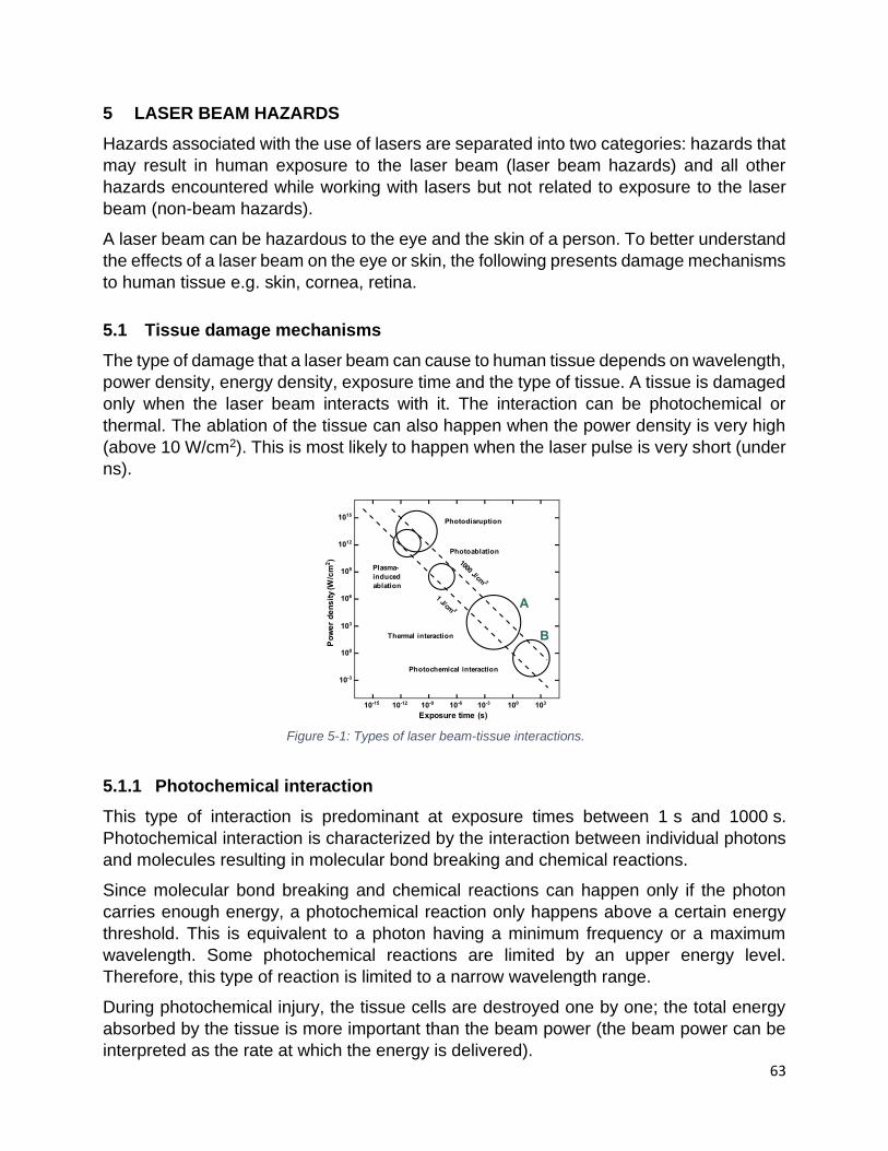
63
5 LASER BEAM HAZARDS
Hazards associated with the use of lasers are separated into two categories: hazards that
may result in human exposure to the laser beam (laser beam hazards) and all other
hazards encountered while working with lasers but not related to exposure to the laser
beam (non-beam hazards).
A laser beam can be hazardous to the eye and the skin of a person. To better understand
the effects of a laser beam on the eye or skin, the following presents damage mechanisms
to human tissue e.g. skin, cornea, retina.
5.1 Tissue damage mechanisms
The type of damage that a laser beam can cause to human tissue depends on wavelength,
power density, energy density, exposure time and the type of tissue. A tissue is damaged
only when the laser beam interacts with it. The interaction can be photochemical or
thermal. The ablation of the tissue can also happen when the power density is very high
(above 10 W/cm2). This is most likely to happen when the laser pulse is very short (under
ns).
5.1.1 Photochemical interaction
This type of interaction is predominant at exposure times between 1 s and 1000 s.
Photochemical interaction is characterized by the interaction between individual photons
and molecules resulting in molecular bond breaking and chemical reactions.
Since molecular bond breaking and chemical reactions can happen only if the photon
carries enough energy, a photochemical reaction only happens above a certain energy
threshold. This is equivalent to a photon having a minimum frequency or a maximum
wavelength. Some photochemical reactions are limited by an upper energy level.
Therefore, this type of reaction is limited to a narrow wavelength range.
During photochemical injury, the tissue cells are destroyed one by one; the total energy
absorbed by the tissue is more important than the beam power (the beam power can be
interpreted as the rate at which the energy is delivered).
Figure 5-1: Types of laser beam-tissue interactions.

64
Since not all cells of human tissues will be affected immediately, photochemical effects
appear with a delay—between a few hours to days—after the accident.
5.1.2 Thermal interaction
In this type of interaction, photons are absorbed in the tissue producing an increase in
temperature.
As opposed to photochemical damage, thermal damage is not limited by the photon’s
energy. The temperature increase is resulting from the rapid absorption of energy carried
by photons in the tissue without enough time for heat dissipation. The thermal damage is
predominant when the exposure time range between 10-6 s and 1 s. The thermal
interaction is a rate process; the rate at which the energy is absorbed—the power of the
laser—is more important than the total energy absorbed. Damages created by thermal
interaction are instantaneous.
Thermal interactions are used in laser surgery. During surgery, a certain temperature is
desired to be obtained. At other temperatures, the tissue will be damaged without
obtaining the desired clean cut. If the temperature is too low the cells will die due to
coagulation, but there will be no cut. If the temperatures are too high, carbonization occurs
resulting in an unnecessary number of cell necrosis.
Isomerization
Bond forming reaction
Bond breaking reaction
**
Figure 5-2: Photochemical interactions.
42 60 Cell death, but no coagulation (Hemostasis) unneccesary necrosis, temperature range undesireable
60 100 Coagulation (Hemostasis) temperature range undesireable
100 300 aporisation (Cutting) temperature range desireable
300 Carbonisation (Black Color) Absorption of all light, prevents heat transfer , undesireable
42 no damage
Figure 5-3: Thermal interactions.

65
5.1.3 Tissue ablation
At high power densities (above 106 W/cm2) the tissue ablation is the prevalent damage
process. Such power densities are obtained with very short laser pulses (under ns).
The photoablation process results in the excitation and dissociation of the molecules. This
process is predominant in the ns laser pulse range.
Photo disruption and plasma-induced ablation are predominant effects in the ps and fs
range. Plasma, which is the state of matter in which atoms are separated into nuclei and
electrons, is generated at extremely high power densities (above 1010 W/cm2).
5.2 Human eye
There is no “eye-safe laser”. This term was improperly used to refer to lasers outside the
visible and near-infrared range (wavelengths shorter than 400 nm and longer than 1400
nm) where the laser radiation normally does not reach the retina.
Any part of the human eye can be damaged by a laser beam. To better understand the
connection between the type of damage and the affected part of the eye, the laser user
Figure 5-4: Potential energy surface and energy transfer in the photoablation process.
Figure 5-5: Plume created by a plasma-induced ablation.

66
must understand the main components of the human eye and their role in the viewing
process.
In this section, the anatomy and physiology of the eye are presented only to the level
necessary to understand the type of precautions necessary to be taken against laser
hazards.
5.2.1 The anatomy of the eye
The cornea is the transparent skin that separates the eye from the environment. It has
two main functions: protection from the environmental agents and focusing the light
entering the eye. Due to its shape and curvature, the cornea acts as a lens focusing the
light into the retina. Since the curvature of the cornea cannot be adjusted, focusing is not
always perfect for every viewing condition. Other components in the human eye, to be
discussed later, will do fine adjustments to create an image in the retina.
The epithelium is the outer layer of the cornea and is constantly regenerating. The eyelids
remove the dead cells from the surface, which are replaced by new cells.
The iris, which is the coloured part of the eye, controls the amount of light that enters the
eye. The iris is a ring-shaped tissue with a central opening, which is called the pupil. The
iris has a ring of muscle fibres around the pupil, which, when they contract, causes the
pupil to constrict and its diameter becomes smaller. This contraction is normally triggered
Figure 5-6: Anatomy of the human eye.
Figure 5-7: Structure of the human cornea.

67
when the eye is in a bright environment. The second set of muscle fibres are responsible
to dilate the pupil. When these muscles contract, the diameter of the pupil becomes larger.
This happens when the eye is under reduced illumination or in darkness. The diameter of
the pupil varies between 2-3 mm in bright conditions and 7 mm in the dark. Certain drugs,
such as the ones used for fundoscopy, can dilate the pupil even more to a diameter of
around 8 mm. The diameter of the pupil continuously changes to control the amount of
light that can reach the interior of the eye.
Behind the iris and pupil is the lens of the eye. The role of the lens is to fine-tune the image
on the back of the eye. As opposed to the cornea which can be compared to an optical
lens with fixed focus, the lens of the eye is an optical lens with adjustable focus.
The lens is supported by the ciliary muscles. When these muscles contract or stretch, they
change the shape of the lens, changing the focal distance to ensure that the image is
formed on the right spot of the retina.
The eye lens has many stem cells that are responsible for making new corneal cells to
replace damaged ones are located at the edge of the cornea closer to the equatorial part.
When these stem cells are damaged, the regeneration process is affected. This is the
reason why the oblique rays absorbed in the lens are more dangerous than the direct
rays.
In the back of the eye is situated the retina. The retina is the extension of the optical nerve
and consists of multiple layers.
Figure 5-8: Structure of the human lens and mechanism of cell replication (left). Old lens cells in the central part and young, stem cells in the equatorial region.
Figure 5-9: Direct and oblique rays reaching different parts of the lens.

68
The last layer of the retina is formed by specific cells that are light receptors, the cones,
and the rods. On the back of the eye, behind the rods and cones, there is a layer of cells
called the retinal-pigmented epithelium. The main role of this epithelium is the absorption
of light, which passes unabsorbed by the rods and cones. This absorption prevents the
back reflections, which can result in the perturbation of the image formed in the rods and
cones and is responsible for the black (dark brown) appearance of the pupil. When
photography is taken using a flash, the absorption in the cones, rods and the epithelium
is not complete, and the pupil appears red (the “red-eye”). This is due to the reflection of
light from the epithelium cells on the back of the eye.
The human eye has approximately 6 million cones and there are three types of them
corresponding to the main colours (blue, green, and red). They are mostly located in the
middle of the eye, in a portion of the retina called fovea centralis. Fovea centralis is around
30 m in diameter and is situated in the centre of the macula, which is around 0.6 mm in
diameter. The cones are relatively insensitive to light and they need good illumination to
form an image, but they can distinguish colours and fine details.
Rods are the other type of light-sensing cells in the human retina. They have high
sensitivity to radiation and therefore, they can function with a low level of illumination. As
Figure 5-10: Structure of the human retina (left). Electron microscope photography of human cones and rods (right).
Figure 5-11: Distribution of rods and cones in the retina.

69
a difference to the cones, they cannot distinguish colours or fine details. They are
distributed on the peripheral part of the retina except for the blind spot. The blind spot is
the part of the retina that is connected to the optic nerve.
The optic nerve, a bundle of over 1 million nerve fibres, is responsible for transmitting
nerve signals from the eye to the brain. These nerve signals contain information to be
processed by the brain. The front surface of the optic nerve, which is visible on the retina,
is called the optic disk or optic nerve head.
5.2.2 The physiology of the eye
How does the eye work? In a simplistic explanation, the light passes through the cornea
(where visible light is focused), then through the pupil and the lens, and is absorbed in the
retina. The iris controls the dimension of the pupil and therefore the amount of light
reaching the retina. The cornea and the lens ensure that the focus of the image is on the
right spot of the retina. The light absorbed in the cones and rods triggers a chemical
reaction in these specialized cells. The chemical reaction will generate a signal that is
transmitted through the optic nerve to the brain. In the brain, the information is processed
and an image is interpreted. The image formed on the retina is upside-down. In the brain,
the image is restored to normal. The brain needs time and training to interpret the signals
received from the eye. A newly born child does not see the way an adult sees.
Figure 5-12: Focusing of light on the macula.
Figure 5-13: Retinal absorption and ocular transmission of the human eye. Electromagnetic radiation between 400 and 1400 nm can reach the retina.

70
It is important to understand that the eye is an organ and different parts of the eye are in
continuous movement to ensure focus and stability of images received. The eyeball
moves, the iris changes the dimension of the pupil, the lens changes the focal distance,
etc. A laser accident can cause the melting of the cornea and iris together resulting in a
person's incapacity to see, even if the optic nerve, the cones, and rods are not been
affected.
In laser safety, only the electromagnetic radiation in the wavelength range between 180
nm and 1 mm is considered. Because of the eye's structure, different wavelengths affect
different parts of the eye in different ways. Only the wavelengths between 400 and 1400
nm reach the retina.
Electromagnetic radiation between 400 and 700 nm is considered visible light. For lasers
emitting in the region between 700 and 800 nm, the user may still distinguish a weak
image on a white card, especially in a dark room.
Not all individuals perceive colours in the same way. For example, 8 % of the male
population has a colour perception difference that is usually described as 'red-green
colour blindness' due to the lack of the red or green retinal photoreceptor in their eyes.
Figure 5-14: Spectral luminous efficiency.
Figure 5-15: Photopic and scotopic efficiency curves.

71
The light with wavelengths on either side of the visible spectrum and near-infrared (i.e.
ultraviolet, medium, and far-infrared) are absorbed in the front of the eye by the cornea,
the iris, and the lens, and therefore never reach the retina. This absorption can damage
the front of the eye.
Spectral luminous efficiency (luminosity efficiency function) connects the power/energy
density that reaches the retina with the human perception of brightness and it is measured
in lumens per watts. For the day vision (photopic vision) the maximum efficiency is at 555
nm, which is connected to the solar emission spectrum. For the dark-adapted vision
(scotopic vision) the maximum is at 507 nm. The efficiency of scotopic vision is around
three times higher than for photopic vision. This is related to the higher light sensitivity of
eye rods compared to one of the cones.
An interesting feature of eye physiology is that parts of the cornea and the lens can
regenerate themselves from damage in a few days (depending on severity), whereas the
retina cannot.
Vision is measured by the Snellen Visual Acuity Chart. According to this chart, the 20/20
vision means the normal eye of a person can see clearly at 20 feet distance. A person
with 20/40 vision at 20 feet away from an object will see what a normal eye sees when it
is 40 feet away from the object. A person with a 20/15 vision at 20 feet away from an
object will see what a normal eye sees when it is 15 feet away from the object. This means
this person will see details more clearly than someone with 20/20 vision will.
There are many reasons an individual may not have 20/20 vision, some of which are not
correctable such as amblyopia or better known as lazy eye, trauma to the eye, or even
diseases such as diabetes or macular degeneration. There are causes of less than a
perfect vision that is correctable; these are known as refractive errors. When light focuses
accurately onto the retina, clear vision is achieved. The result is often 20/20 vision.
However, millions of people in the world cannot focus clearly without a crutch such as
(prescription eyeglasses) or contact lenses. This is because they have refractive errors.
There are four main refractive errors; they are:
Hyperopia—also known as farsightedness—is a condition in the eyes that see objects
better at long distances rather than short ones. Hyperopia occurs due to light not being
bent enough and the image would hypothetically form behind the retina. Hyperopia must
not be confused with presbyopia.
Figure 5-16: Different refractive error conditions of the eye and its corrections

72
Myopia—also known as nearsightedness—is a condition in the eyes that sees objects
better at short distances rather than long ones. This is due to light rays being bent too
much and the image forms before the retina.
Astigmatism is a condition due to an irregularly shaped eyeball and causes light rays to
bend erratically resulting in blurred vision at any distance.
Presbyopia is a condition in which the muscles of the lens (ciliary muscles) lose elasticity
and can no longer focus on objects located at a short distance. It is connected to age. It
is also common for people having both myopic and hyperopic problems, requiring reading
and distance eyeglasses.
5.2.3 Laser eye injuries
Tissue damage is possible only when the laser radiation is absorbed. If there is no
absorption in the tissue, there is no damage.
When a user of a medium power green laser has an injury to the cornea and no injury to
the retina, it is most likely that the injury is not caused by the green laser. For a CO2 laser
(wavelength 10,600 nm) to cause injury to the retina, the laser beam must perforate first
the cornea, iris (when not passing through the pupil), and the lens.
Radiation Wavelength Predominantly absorbed in
UV C 180 – 280 nm Cornea
UV B 280 – 315 nm Cornea and lens
UV A 315 – 400 nm Lens
Visible 400 – 700 nm Retina
IR A 700 – 1400 nm Retina
IR B 1.4 – 3.0 m Lens and cornea
IR C 0.003 – 1 mm Cornea
5.2.3.1 Corneal injury
Photochemical corneal injury is caused by UV B and UV C light. This type of injury has
different names: photo-kerato-conjunctivitis, photokeratitis, welder’s flash or snow
Figure 5-17: Light absorption in different parts of the eye. Visible and near infrared reach the retina and are
focussed on the macula.

73
blindness (some connected with the origin of the injury). The pain starts hours after
exposure. In photokeratitis, the corneal epithelium and the conjunctiva, which is the
cellular layer covering the inside of the eyelids and the whites of the eye, are affected. It
can be very painful with a sensation of sand in the eye. It is the equivalent of a skin
sunburn but in the eye. By using eye drops for pain relief medication, by preventing
inflammation, and by resting the eye in a dark room, the person may recover in a few
days. For a deeper burn, the complete recovery may take longer.
Thermal burns on the cornea are caused by IR C and IR B. When the burn is superficial
the symptoms, treatment and recovery are similar to photokeratitis.
A deeper burn may result in the formation of a scar in the cornea. If the scar is outside the
pupil, the vision will not be impaired. Sometimes the scars move and can reach the pupil
area interfering with the vision. A surgery involving corneal replacement may be necessary
to correct the problem.
5.2.3.2 Lens injury
One of the most typical lens injuries is the cataract. As mentioned before, in a healthy eye,
the pupil should look black. A sign of a cataract is when the pupil looks cloudy.
Cataract normally appears with old age and is caused by exposure to the Sun’s natural
light. In sunny tropical countries, especially on people working outdoors, the natural
cataract will develop at an earlier age than in countries at higher latitudes. For example,
in India people develop cataracts 20 years earlier than people in Canada (on average).
Figure 5-18: Corneal photochemical injury (left). Corneal treatment (right).
Figure 5-19: Corneal burns by CO2 laser.

74
Another type of cataract is the one created by heat. It was common in glassblowers who
did not wear eye protection after several years of exposure to high temperature due to the
melted glass. It is produced by IR B wavelength in the range 1.4 – 3.0 m.
Cataracts can also be the result of exposure to ionizing radiation. There are specific limits
for the ionizing radiation dose for the nuclear energy workers for the lens of the eye. These
limits are lower than for other organs.
Cataracts will create a blur in a person’s vision. The only correction is lens replacement
or removal.
Accidents involving a certain type of lasers can also produce cataracts. Excimer lasers
emitting UV B radiation with a maximum around 300 nm are principally responsible for
laser involved UV cataract. In laser jargon, Xe-Cl excimer laser, which emits at 308 nm,
was nicknamed “cataract machine”. A laser emitting IR B radiation can produce heat
cataract in the laser users.
5.2.3.3 Retinal injury
The most common and the most dangerous eye injury is retinal injury. As mentioned
before some parts of the cornea or the lens can regenerate, can be removed, or replaced
Figure 5-20: Cloudy lens due to cataract (left). Comparison between a healthy clear lens and one with cataract (right).
Figure 5-21: Comparison of how the same image is seen by a healthy eye (left) and one suffering from cataract (right).

75
with surgery. The retina does not regenerate, and it is not possible to replace it. Damage
to the retina results, in general, in permanent eye injury.
Factors that influence the laser damage to the retina are pupil size, amplification obtained
by the cornea and lens, transparency of the cornea and lens for the particular wavelength,
exposure time, total amount of energy entering into the eye, and the rate at which the
energy enters to the eye.
The pupil size controls the amount of light entering the eye. The diameter can vary
between 2 mm (at daylight), 3-4 mm indoor, and 7 mm in a dark-adapted situation. With
special drugs, the pupil diameter can reach up to 8 mm.
As mentioned above the cornea has the most important part in the focusing of the light on
the retina. The lens ensures a fine adjustment. The total concentration of laser light in the
human eye can be up to 100,000. This means that the power density is 1 mW/cm2 at the
surface of the cornea it can reach, depending on the wavelength, up to 100W/cm2 at the
surface of the retina. This increases the retinal injury hazard compared to corneal or lens
injury hazards.
Image diameter on the retina is also an important factor in retinal damage. For point
sources (most of the lasers are considered point sources) the instantaneous image is few
microns in diameter. However, due to the continuing micro-movements of the eye, the
image is in general around 20 microns (slightly smaller than the fovea centralis). For
Figure 5-22: Fresh retinal injury (left). After a few days the scotoma will develop (centre). Multiple retinal scars (right)
Figure 5-23: Typical laser range finder used in the military (left). Retinal injury produced by a class 4 Nd:YAG laser range finder. (right).

76
extended sources, (see section 3.6) the image is in general larger than the fovea centralis,
resulting in a reduced hazard.
Photochemical injury of the retina is called photo retinitis. It is most likely to happen in the
400 to 600 nm range for exposures over 10 s long. The most common causes are by
looking at Sun eclipse without protections (in this case is called eclipse retinitis), by the
welding arc, and by laser. For a person having the lens removed, the retina can also be
damaged by UVA (315 to 400 nm). Photo retinitis has a delay of 24 to 48 hours
appearance after the exposure.
Retinal thermal burns are the result of photocoagulation of the retina because of brief
exposure to intense light in the region from 400 to 1400 nm. The immediate result is an
injury resulting in a haemorrhage causing pain, loss of vision due to the blood in the eye.
“My vision was obscured almost immediately by streams of blood floating in the vitreous humour,
and by what appeared to be particulate matter suspended in the vitreous humour. It was like
viewing the world through a round fishbowl full of glycerol into which a quart of blood and a
handful of black pepper has been partially mixed. There was local pain within a few minutes of the
accident, but it did not become excruciating. The most immediate response after such an accident
is a horror.”
C. DAVID DECKER in “Laser Focus” August 1977.
After the initial injury heals, a scar develops on the retina leaving a blind spot in the field
of vision. This scar is called a scotoma. The scotoma can appear on the macula, resulting
in the permanent loss of central vision. The person sees a black spot in the centre of the
visual field. The person cannot read, distinguish faces, colours, or any details with that
eye. The blind spot is the point where the optic nerve connects to the retina. If the laser
hits the blind spot of the eye, the person loses total vision on that eye. When the scotoma
develops in other parts of the retina, peripheral vision is lost. The person can still read,
Figure 5-24: A 150 mW laser pointer (A). Subretinal hemorrhage created by the laser pointer (B). Scar in the foveolar area of the right eye (C). The left eye after four months (D).
77
see faces, identify colours or details, but will have problems with driving. When the eye is
moving and a pulsed laser causes the injury, multiple retinal injuries can appear in different
places of the retina.
5.3 Skin
The skin is the largest human organ. On average, an adult person’s skin has around 3.6
kg covering a surface of approximately 2 m2. The skin has an extremely important role in
our survival. Among other roles, the skin ensures protection against external agents, such
as extreme temperatures, sunlight, dangerous chemicals, biological agents, acting as a
shield. It also prevents evaporation of water, produces vitamin D, which is essential in
converting calcium into healthy bones, ensures the function of sensorial nerves. Damage
to large portions of our skin can result in death.
Although the skin prevents the entry of water and many other substances into the body, it
is not a complete barrier between the body and the outside world. Some medicines are
absorbed through the skin, which is beneficial for us. Unfortunately, some toxic chemicals
used in cosmetics can also be absorbed, and they may harm the body. The skin pores
allow water to leave the body during perspiration. This process helps us to maintain a
constant body temperature.
5.3.1 Structure of the skin
The outermost layer of skin is called the epidermis. The main constituent of the epidermis
is keratinocytes cells, made from keratin (the same protein as hair and nails).
Keratinocytes form several layers. The exterior layer dies and is constantly replaced by
the internal layers. The layer of dead skin varies considerably in thickness in different
parts of the body (on the soles of the feet or the palms can be 10 times thicker than around
the eyes). The epidermis also contains Langerhans cells. These cells have the role to alert
the immune system about the presence of viruses and other infectious agents. Merkel
cells present in the epidermis help in the detection of light touches.
UV radiation absorbed in the epidermis induces the photoproduction of pre-vitamin D3 in
the skin and thus provides the major natural source for vitamin D3 for humans. Our skin
has not evolved as a mere sunblock, but also as a sunscreen. Vitamin D helps the
absorption of calcium in the small intestine (to be used in the bones) and boosts our
immune system. Melanocyte cells are located at the bottom layer of the epidermis. These
cells make melanin, a pigment that gives colour to the skin. Melanin absorbs ultraviolet
light, preventing it from damaging the body, and has an important role in preventing skin
cancer.
The next layer of the skin is the dermis. This layer contains collagen and elastin fibres,
hair follicles, sebaceous glands, the coiled sections of the sweat glands, blood and lymph
vessels, nerves, sensory receptors, and cells from the immune system. The collagen and
elastin fibres give firmness, flexibility, and elasticity to the dermis, enabling it to act as a
supporting layer for the skin. The sebaceous glands produce an oily substance called

78
sebum. Most sebaceous glands are connected to a hair follicle. Sebum lubricates and
waterproofs the skin and hair.
Our skin contains two types of sweat glands. Eccrine glands are found over most of the
body and release sweat directly to the surface of the skin. This sweat is watery and almost
odourless. It contains many dissolved chemicals, including water, urea (a waste
substance produced from protein metabolism), lactic acid, and sodium chloride. The other
type of sweat glands, apocrine glands, are found only in certain areas, such as the
armpits. Certain conditions, such as stress, stimulate the release of liquid from the
apocrine glands. When the odourless liquid reaches the surface of the skin, bacteria break
it down, producing odoriferous compounds.
Attached to each hair follicle is an erector pili muscle which causes the hair to become
erect when the skin is cold or when we experience strong emotions. The erect hairs
produce a "goosebumps" or "goose flesh" appearance on the surface of the skin. The
dermis contains other sensory cells as well as a variety of chemicals. These chemicals
include lipids and antimicrobial peptides (short chains of amino acids that fight pathogens).
The epidermis does not contain blood vessels. Nutrients for the epidermal cells are
supplied by the blood vessels in the dermis, which also removes waste substances made
by the cells.
The subcutaneous tissue (also known as hypodermis or subcutis) is considered by some
as not being part of the skin. The subcutis lies below the dermis. Its purpose is to attach
the skin to underlying bone and muscle as well as supplying it with blood vessels and
nerves. It consists of loose connective tissue, adipose tissue and elastin. The main cell
types are fibroblasts, macrophages, and adipocytes (subcutaneous tissue contains 50 %
of body fat). Fat serves as padding and insulation for the body.
Figure 5-25: Structure and physiology of the skin.

79
5.3.2 Laser skin injuries
The skin injury due to laser radiation depends on wavelength, radiation intensity and
exposure time. The laser radiation penetration depends on the wavelength, skin colour
and spot diameter. Laser radiation with wavelengths in the UV C range (180 to 280 nm)
and far IR are absorbed in the epidermis. Visible and near IR may reach the subcutaneous
layer and UV A, UV B and mid-IR reach the dermis. In various laser applications, such as
hair removal, a spot size between 4 to 6 mm in diameter is used to reach the dermis. It
has also been found that, although the penetration depth increases with spot size, there
is a point at which the beam width has no further effect on the penetration depth. This is
expected to be in the region of 5–12 mm in beam diameter.
Similar to eye laser injuries, the main skin injuries can be photochemical and thermal.
Possible photochemical skin injuries are accelerated skin colouration (skin darkening),
ageing, wrinkles, and skin cancer. Thermal injuries to the skin result in burns. When only
the epidermis is affected, either due to photochemical or thermal effects, the healing may
take a few days (similar to sunburns). If the base of the epidermis, the dermis or
subcutaneous layers are affected, the injury may be permanent.
Figure 5-27: Penetration of electromagnetic radiation of different wavelengths in the skin.
Figure 5-26: Accidental exposure of scattered radiation from a CO2 kilowatt laser.

80
The exposure time is most important for the photochemical effects. Long-time exposure
in the red and IR is less likely since the exposed person will feel the heat and move out of
the beam. Short pulses in the ns or sub-ns range can cause explosive effects due to
photoablation or plasma generation in the tissue. Exposure in the range of milliseconds to
a few seconds predominantly result in thermal effects, while exposures above 100
seconds produce mostly photochemical effects. Chronic exposure to UV radiation will
cause the other photochemical effects mentioned before (skin ageing, wrinkles, and
potentially skin cancer). Thermal burns are classified as first, second, and third-degree
burns.
A first-degree burn affects only the epidermis and causes pain and redness in the burned
area, but usually heals within a few days and does not cause scarring. A typical sunburn
is a first-degree burn. A second-degree burn affects all layers of the epidermis and often
part of the dermis. A third-degree burn affects the full thickness of both epidermis and
dermis, and often the skin appendages, such as hair roots and glands, as well.
Second- and third-degree burns require much longer healing and usually leading to
permanent scars. Second and third-degree burns to major portions of the body can result
in death.
Figure 5-28: Skin injury after improper laser hair removal.
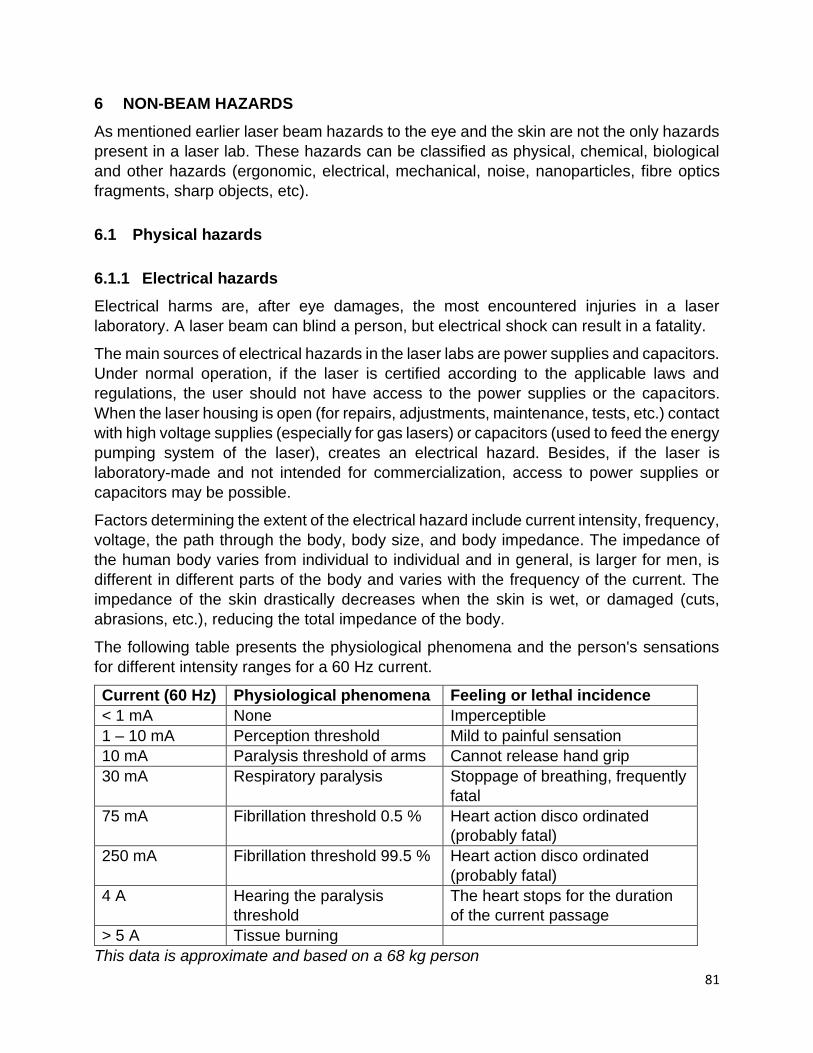
81
6 NON-BEAM HAZARDS
As mentioned earlier laser beam hazards to the eye and the skin are not the only hazards
present in a laser lab. These hazards can be classified as physical, chemical, biological
and other hazards (ergonomic, electrical, mechanical, noise, nanoparticles, fibre optics
fragments, sharp objects, etc).
6.1 Physical hazards
6.1.1 Electrical hazards
Electrical harms are, after eye damages, the most encountered injuries in a laser
laboratory. A laser beam can blind a person, but electrical shock can result in a fatality.
The main sources of electrical hazards in the laser labs are power supplies and capacitors.
Under normal operation, if the laser is certified according to the applicable laws and
regulations, the user should not have access to the power supplies or the capacitors.
When the laser housing is open (for repairs, adjustments, maintenance, tests, etc.) contact
with high voltage supplies (especially for gas lasers) or capacitors (used to feed the energy
pumping system of the laser), creates an electrical hazard. Besides, if the laser is
laboratory-made and not intended for commercialization, access to power supplies or
capacitors may be possible.
Factors determining the extent of the electrical hazard include current intensity, frequency,
voltage, the path through the body, body size, and body impedance. The impedance of
the human body varies from individual to individual and in general, is larger for men, is
different in different parts of the body and varies with the frequency of the current. The
impedance of the skin drastically decreases when the skin is wet, or damaged (cuts,
abrasions, etc.), reducing the total impedance of the body.
The following table presents the physiological phenomena and the person's sensations
for different intensity ranges for a 60 Hz current.
Current (60 Hz) Physiological phenomena Feeling or lethal incidence
< 1 mA None Imperceptible
1 – 10 mA Perception threshold Mild to painful sensation
10 mA Paralysis threshold of arms Cannot release hand grip
30 mA Respiratory paralysis Stoppage of breathing, frequently
fatal
75 mA Fibrillation threshold 0.5 % Heart action disco ordinated
(probably fatal)
250 mA Fibrillation threshold 99.5 % Heart action disco ordinated
(probably fatal)
4 A Hearing the paralysis
threshold
The heart stops for the duration
of the current passage
> 5 A Tissue burning
This data is approximate and based on a 68 kg person

82
Ref: R. H. Lee ” The Other Electrical Hazard: Electric Arc Blast Burns ” IEEE Trans. Industrial
Applications, 1A-18 (3): p246, 1982
It is important to understand that an ordinary fuse or circuit breaker cannot protect the
user from an electric shock.
The over-limit protection device (a fuse or a circuit breaker) will not break the circuit until
the current exceeds the pre-established value (15, 20, 25 or 30 A), while currents as low
as 30 mA can be fatal. The role of this device is to protect the instruments or the building
against fire from over-heating electrical wires.
The ground-fault circuit interrupter (GFCI) interrupts a circuit when there is a difference in
the currents in the live and neutral lines. Such a difference indicates an abnormal diversion
of current either through the ground line or through a person’s body who is in contact with
the live wire and is being electrocuted. The device activates with a minimum current
difference of 5 mA. This keeps the person safe. When a circuit functions normally, the
difference in current is always zero.
GFCIs are required to be used in bathrooms, swimming pools, and some kitchen
receptacles. The GFCIs have a “Test” button which causes a small difference between
the live and neutral lines.
The arc-fault circuit interrupter (AFCI) is a device intended to protect from the effects of
arc faults by recognizing characteristics unique to arcing (integrated processors) and by
Figure 6-1: Fuses and circuit breakers are normally used to protect equipment and buildings.
Figure 6-2: Ground-fault circuit breaker.
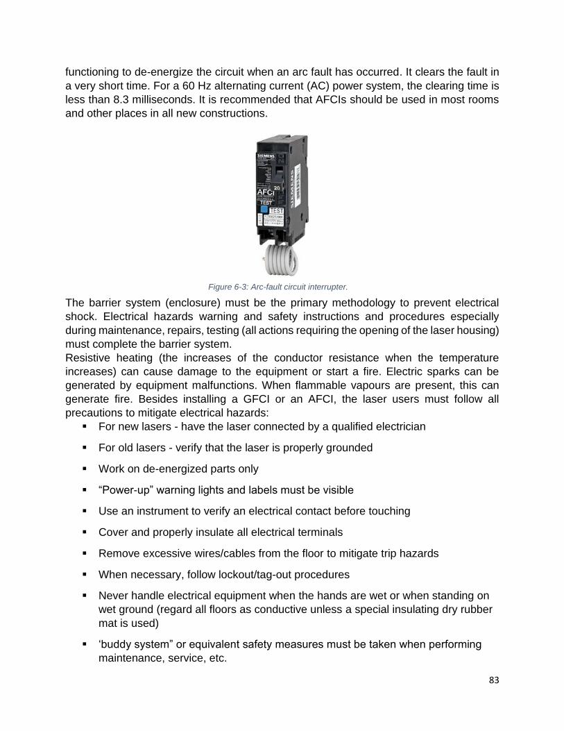
83
functioning to de-energize the circuit when an arc fault has occurred. It clears the fault in
a very short time. For a 60 Hz alternating current (AC) power system, the clearing time is
less than 8.3 milliseconds. It is recommended that AFCIs should be used in most rooms
and other places in all new constructions.
The barrier system (enclosure) must be the primary methodology to prevent electrical
shock. Electrical hazards warning and safety instructions and procedures especially
during maintenance, repairs, testing (all actions requiring the opening of the laser housing)
must complete the barrier system.
Resistive heating (the increases of the conductor resistance when the temperature
increases) can cause damage to the equipment or start a fire. Electric sparks can be
generated by equipment malfunctions. When flammable vapours are present, this can
generate fire. Besides installing a GFCI or an AFCI, the laser users must follow all
precautions to mitigate electrical hazards:
▪ For new lasers - have the laser connected by a qualified electrician
▪ For old lasers - verify that the laser is properly grounded
▪ Work on de-energized parts only
▪ “Power-up” warning lights and labels must be visible
▪ Use an instrument to verify an electrical contact before touching
▪ Cover and properly insulate all electrical terminals
▪ Remove excessive wires/cables from the floor to mitigate trip hazards
▪ When necessary, follow lockout/tag-out procedures
▪ Never handle electrical equipment when the hands are wet or when standing on
wet ground (regard all floors as conductive unless a special insulating dry rubber
mat is used)
▪ ‘buddy system” or equivalent safety measures must be taken when performing
maintenance, service, etc.
Figure 6-3: Arc-fault circuit interrupter.

84
▪ Restrict access until capacitors are discharged
▪ Conduct manual discharging of capacitors before touching
▪ Avoid wearing metallic items (rings) when working with electrical equipment
6.1.2 Fire and explosions
In a laser laboratory, a fire can start because of interaction between the laser beam and
flammable or combustible materials, as well as faulty electrical circuits or flammable laser
dyes. Any beam that can reach irradiance of 10 W/cm2 can start a fire if it is not properly
enclosed. Laser beam enclosures must be built of flammable resistant materials, and laser
beam stoppers used for high power lasers must be built of ceramics or metal with proper
air or water-cooling.
Table 6-1: Irradiance dependency of specific non-beam hazards.
Non-Beam Hazard Approximate minimum
irradiance (W/cm2)
Recommended control
measures Ignition if easily ignited
materials 1 to 10 Non-combustible barriers
LGAC production (the
irradiance required greatly
increases with atomic number-
Z of the target material)
• 103 (low z material)
• 103 – 106 (plastics)
• 106 – 107 (high Z materials, composite metals, tissue)
• Adequate building ventilation required
• Local exhaust ventilation (LEV)
• LEV or respiratory protection
Plasma production • 1012 (metals)
• 1014 (dielectrics)
Limit personnel exposure to
plasma radiation
Production of X-rays 1016 (depending on
wavelength, target materials)
Monitoring, shielding, radiation
training, restrict access to
authorized personnel
As mentioned in section 6.1.1, faulty electrical circuits can cause sparks and over-heating
of the circuits and start a fire. Invisible beam lasers interacting with unprotected wire
insulation can also be the cause of fires.
The cause of explosions in a laser lab can be:
• High-pressure arc lamps
• Filament lamps
• Capacitor banks
• Interaction between the laser beam and targets or optical components
• Explosive chemical reactions
• Ignition of dust
To prevent explosion hazards, the components that have the potential of causing
explosions must be enclosed in a housing that can withstand the maximum explosive
pressure.

85
6.1.3 Cryogenic fluids
Liquid nitrogen and liquid helium are the most common cryogenics in laser labs. If during
the handling of cryogenics, large amounts are released in the room, this can create an
oxygen-deficient atmosphere and may result in asphyxiation. Improper handling of
cryogenic can result in burns on fingers, face, eyes, etc. To prevent accidents when
handling cryogenic fluids, the users must follow appropriate procedures and wear
protective equipment (cryogenic gloves and face shield). Specific training on handling
cryogens is available through EHS.
6.1.4 Radiation (X-rays, UV, visible, EMF and plasma)
Dangerous levels of X-rays can be produced in experiments involving high-energy
electrons that are slowed down in a metallic target, or when a current leakage exists in
high voltage sources (above 15 kV). Besides, in experiments with class 4 lasers, plasma,
X-rays, UV, visible and other electromagnetic radiation can be produced when the laser
beam hits the target (see Table 6-1 for approximate irradiance values).
The flashing lamps used to pump solid-state laser (e.g.: Nd:YAG) can be a source of
intense visible light. This can cause retinal damage when the eyes are not protected.
The best control for the radiation and plasma hazards is enclosing the components that
can produce the hazard. The users must not remove the existent shielding of the power
Figure 6-4: Skin burns due to contact with Cryogenic liquids.
Figure 6-5: Cryogenic hazards (left). Gloves used when handling cryogenic liquids (right).

86
sources and build an additional lead or other metal shielding around the areas where X-
rays can be produced.
When X-rays are generated, the users must have X-ray safety training and learn how to
measure the level of X-rays. The X-ray safety program may also require wearing personal
radiation badges or installing area radiation badges.
In some experiments, high intensity static electric and magnetic fields or high-intensity
electromagnetic fields (EMF) may be involved. Applicable EMF limits for each frequency
must be followed. If the fields are close or possible above the public limits, the area must
be marked, access must be restricted, and adequate EMF shielding must be installed.
6.1.5 Mechanical hazards
In many applications involving robots or moving equipment, since the laser user may have
reduced visibility due to laser goggles and darkness in the workplace, accidents are
possible. Some accidents happen when the laser user is pinned between a moving robot
or piece of equipment and a confining object (“pinch effect”). Measures must be taken to
reduce this type of hazard by the use of surface interlock mats, interlock light curtains,
non-rigid walls, and barriers. Besides, robots safeguarding measures against malfunction
and improving the work illumination (when possible), are necessary.
In many laser labs, compressed gas cylinders are used for different reasons. All
compressed gases are hazardous because of the high pressures inside the cylinders. Gas
can be released deliberately by opening the cylinder valve, or accidentally from a broken
or leaking valve or a safety device. Even at relatively low pressure, gas can flow rapidly
from an open or leaking cylinder. Handling, storage and use of compressed gas cylinders
must comply with the applicable guidelines. When stored in the laser lab the compressed
gas cylinders must be:
▪ Secured in an upright position
▪ The control valve (other than a cylinder connected to a regulator, supply line or
hose) should be covered by a protective cap that is secured in its proper position
Figure 6-6: Moving equipment at workplace (left). Moving robots (right).

87
▪ Store empty cylinders outside the building
If possible, do not store gas cylinders containing flammables in the laser room.
6.1.6 Other physical hazards (noise, nanoparticles, fibre optics fragments, sharp
objects, etc.)
Excessive noise produced by the laser, vacuum pumps, power supplies, the ventilation
system can be a cause of fatigue and a source of accidents in a laser lab. Most of the
laser accidents happened during alignment. In general, alignment is a long and tedious
process. If the work area is also noisy, the conditions for an accident are created.
Measures to reduce the noise by appropriate shielding, repairing the defective vacuum
pumps or ventilation system, or moving the noisy equipment to a different room, must be
implemented.
More and more laser experiments involve the use of nanoparticles. Special precautions
to avoid inhalation or ingestion must be taken when preparing the samples containing
them. Special attention must be paid when cutting fibre optics to avoid glass splinters.
Wear appropriate protection equipment (gloves, face and eye protection, long sleeves,
etc.) and clean the workplace of any residual glass. Accidents happened when blades
used for beam characterization, needles used for experimental work, are left on the optical
Figure 6-7: Correct way to storage compressed gas cylinders (left). Damage caused by a compressed gas
cylinder (right).
Figure 6-8: Razor blade used in beam profiling left on the optical table.

88
table. Reduced visibility during laser experimental work combined with sharp objects on
the table create conditions for an accident.
To prevent injuries, sharps must be removed from the optical table.
6.2 Chemical hazards
6.2.1 Laser generated air contaminants
The interaction between the laser beams of high-class lasers with certain materials can
generate air contaminants. The amount of laser-generated air contaminants (LGAC)
depends on the composition of the target and the irradiance (see Table 6-1 for
approximate irradiance levels). If the laser beam is mostly absorbed on the surface of the
material, the amount of LGAC is larger.
Special optical materials used for far infrared windows and lenses (like CaTe or ZnTe) can
burn in the presence of oxygen. During experiments involving Te and Te compounds (like
TeF6), or CaO, additional controls must be implemented.
6.2.2 Compressed gasses chemicals
The compressed gases used in the laser labs may contain toxic gases (as Cl2, F2, HCl, or
HF) or inert gases (as He or N2). When toxic gases are used, all users must have the
WHIMIS training, read and understand the Safety Data Sheet (SDS) for each hazardous
material, and implement the applicable control measures. All compressed gases having a
hazardous material information system (HMIS), flammability or reactivity rating 3 or 4 (see
the SDS) must be stored in an approved cabinet with the appropriate exhaust. These
cabinets must have sensors to indicate the potential leakage that will trigger an alarm.
6.2.3 Laser dyes and solvents
Certain dyes and solvents used as a lasing medium are potentially hazardous.
Rhodamines can be mutagenic or carcinogenic, and polymethine compounds are toxic.
Lasing dyes must be prepared in fume hoods or glove boxes. Storage of chemicals must
be on separate shelves or in double containers to prevent spills and unwanted reactions.
Other toxic or flammable solvents may be used to clean optical components. Handling,
storage and disposal of these chemicals must be performed according to the applicable
rules and procedures.
6.2.4 Chemical agent control measurement
There are three major control measures available to control the chemical agents’ hazards:
process isolation, exhaust ventilation, and respiratory protection.
The process isolation may be implemented by enclosing the process with physical barriers
and using a remote control apparatus. It is recommended when cutting, engraving,
welding materials made of metals or plastics. It can be also used for work with biological

89
materials to prevent contamination (disinfection and sterilization must be performed
immediately after use).
Exhaust ventilation is easier when the enclosing hoods are used. Building and local
exhaust ventilation must be sufficient to keep the concentration of the hazardous
chemicals under the applicable limits. Sensors and alarms may be required in some
workplaces, gas cabinets, exhaust ducts, etc.
Respiratory protection is only recommended to control brief exposures or as interim
measures until engineering controls are put in place.
6.3 Biological hazards
Laser generated air contaminants (LGAC) may be present when high power lasers beams
interact with tissue (see Table 6-1 for approximate irradiance values). Infectious materials
(bacteria e.g.: Staphylococcus aureus, Escherichia coli, and viruses e.g.: HIV DNA, viable
bacteriophage, human and bovine papillomavirus) may survive beam irradiation and
contaminate the environment. When handling biological agents, the users must have the
appropriate biosafety training and apply the necessary precautions.
6.4 Other hazards
6.4.1 Ergonomics
Restricted space is a real problem in some laboratories. Users must have enough space
to move around the laser system. Consider removing the unnecessary equipment or
furniture to allow sufficient space around the laser system set-up. Optical setup alignment
may take a long time. Performing alignment may require having the arm or wrist in
awkward positions, bending one’s back or do repetitive motions. These positions can
produce pain in different parts of the body, creating distractions and increasing the
chances of eye injuries.
6.4.2 Human factors
Stress, fatigue, hunger, and use of medications, alcohol, or drugs are additional physical
or emotional factors, which could influence a user’s behaviour to take unnecessary risks.
Consuming or being under the influence of any substances that cause impairment when
in a laboratory increases the chances of an accident including a laser accident. When
working after hours, weekends, or holidays, arrange for a colleague to be present in the
lab. If this is not possible, when the users are tired, they should not engage in complicated
alignment, testing or changing of the experimental setting.

90
7 LASER HAZARDS CONTROL
To reduce the risks of a laser accident the following actions are required: recognize and
evaluate the hazards, identify the conditions in which the hazards appear, and try to
eliminate these conditions.
7.1 Hazard assessment
7.1.1 Principles of hazard evaluation
Hazard evaluation must take into account the capability of the laser/laser system to cause
an injury, the environment in which the laser/laser system is used and the persons who
might be affected.
The first principle is the knowledge of laser classification. The laser class is essential when
judging the capability of a laser to cause an injury. A class 1 laser or a class 1 working
environment (an enclosed laser system with locks and interlocks) is considered safe under
normal operations. For class 2, which is always visible, the natural aversion against high
brightness light protects the user in case of unintentional eye exposure. Intentionally
staring at the class 2 laser beam for more than 0.25 s can cause an injury to the eyes. A
class 3R presents a reduced risk of injury under normal conditions of use. Class 3B
(average power) and class 4 lasers (high power) can cause harm even when viewing for
less than 0.25 s.
The second principle used in the laser hazard evaluation is the experimental setting in
which the laser is used. With proper mitigation measures, even a class 4 laser can present
a low risk when used under certain conditions; for example, when the laser beam travels
inside a multimode optical fibre. In this particular case, the laser will be dangerous just for
a short distance compared to the situation when is used directly.
The third principle of hazard evaluation connects the risk with the user’s attitude regarding
safety. The following considerations must be taken into account:
• The ability of a user to understand the basic physical principles and the different
components of lasers
• Competency of a user in understanding and following standard operating
procedures
• The maturity of a user to follow instructions and to wear personal protective
equipment.
7.1.2 The person in charge of hazard assessment
Performing hazard assessments at the workplace is a duty of the supervisor. However,
for laser hazards, the Laser Safety Officer (LSO) have the competency and knowledge to
oversees the hazard assessment. To perform the hazard assessment, the LSO must be
informed of the presence of the lasers in the lab as per the University laser safety program.
Whilst there are no regulatory controls for purchasing class 3B and class 4 lasers as for

91
radioactive materials, under the general duty clause 25(2) (h) of the Occupational Health
and Safety Act (OHSA) of Ontario, employers are required to take every precaution
reasonable in the circumstances for the protection of a worker. This includes the protection
of workers from the hazards associated with lasers. When enforcing the general duty
clause under OHSA, the Ontario Ministry of Labour’s Radiation Protection Service takes
into consideration the American National Standards Institute (ANSI) Z136 series of laser
safety standards. For the University to ensure compliance with OHSA, laser Permit
Holders (PHs) must inform the LSO whenever a new class 3B or class 4 laser is brought
into the University.
7.1.3 When is the hazard assessment required?
Hazard assessment is required for both existing installations and new equipment. For
new equipment, the LSO will analyze the experimental setting and check for the
possibility of exposure to the direct and reflected beams (both due to specular or diffuse
reflections). The LSO will determine or approved the Nominal Hazard Zone (NHZ) and
ensure the access to this area adequately controlled. The possible exposure to every
non-beam hazard must be analyzed. All necessary controls must be implemented before
any experiments with the laser begin.
For the existing installations, a new hazard assessment is necessary when an
experimental setting is changed. All hazards (both beam and non-beam hazards) and the
level of the risk must be re-analyzed. The hazard analysis will determine when the
controlled area must be changed, the need to re-establish the level of training, when
improvements of operating and alignment procedures required, PPE validation, etc.
In a situation where a laser system must be serviced on-site, many control features
designed by the manufacturer and required by regulations are likely to be removed or
bypassed. In such a special case, the temporary NHZ must be redefined, and new controls
must be put in place. Under the general duty, clause 25(2) (h) of OHSA as explain above,
the University verifies the credentials, knowledge and experience of the individual
performing a service when it is a University staff as well as when it’s an external
contractor/vendor. The Permit Holder must obtain the contractor’s proof of training and
previous experience with equipment to be serviced. Under no circumstances, an untrained
person or a trainee will be allowed to service unsupervised laser equipment.
The hazard assessment may also be part of an inspection or audit, or when an
investigation following an incident or accident.
7.1.4 How is the hazard assessment performed?
The individual performing the hazard assessment—usually the LSO—must visit the lab
and analyse the system and experimental setting, identify the beam and the non-beam
hazards. Results of the hazard assessment are communicated to laser users, the
supervisor and the Permit Holder. A record of the hazard assessment must be kept until
the experimental setup is changed.

92
7.2 Elements of hazard assessment
7.2.1 Beam diameter
A laser beam with an initial diameter and a beam divergence will increase with distance.
To calculate the diameter of the laser beam with beam divergence there are two
approximations linear and Gaussian. To decide which approximation needs to be used,
the beam waist (the smallest diameter) location must be determined. If the beam waist is
inside the laser enclosure the linear approximation will be used
𝐷 = 𝑎 + 𝑟𝜙
If the beam waist is located outside the laser enclosure the Gaussian approximation will
be used:
𝐷 = √𝑎2 + (𝑟𝜙)2
The Gaussian approximation gives a larger value for the diameter of the beam. This will
result in safer values for further calculations.
Figure 7-2: Laser beam waist.
Figure 7-1: Laser beam diameter at distance r.
/2
/2

93
7.2.2 Maximum permissible exposure
For each laser in the laboratory, the Maximum Permissible Exposure (MPE) will be
determined for each wavelength used during experiments. This can be performed by using
an approved software using the tables and procedures from the ANSI Z 136.1 standard
or a combination of both. One example of an approved software that can be used directly
using a web browser can be found at https://lasersafetyu.kentek.com/easy-haz-laser-
hazard-software-basic-web-version.
The individual determining the MPE must know the exposure time, the type of laser if the
system is a point or an extended source, the wavelength, and in the case of pulsed lasers
the pulse duration and the number of pulses per second (PRF).
The exposure can be accidental or non-accidental/intentional i.e. planned for medical
purpose. For accidental exposures to the direct or specular reflected laser beam the
exposure duration will be 0.25 s for visible (between 400 and 700 nm), 10 s for IR (more
than 700 nm) and 100 s for UV (between 180 to 400 nm). For diffuse UV exposure, the
duration must be equal to the time spent in the lab (it can be the whole day). If exposure
to diffuse UV is possible on consecutive days up to two days must be considered the
exposure time. The non-accidental exposure times are applicable only during intentional
exposure to laser radiation like in laser surgeries.
7.2.3 Nominal Ocular Hazard Distance
The Nominal Ocular Hazard Distance (RNOHD) is the distance along the axis of the
unobstructed beam from the laser to the human eye beyond which the irradiance or
radiant exposure during operation is not expected to exceed the appropriate MPE.
Figure 7-3: Nominal ocular hazard distance.
Figure 7-4: Nominal ocular hazard distance for a beam with an initial diameter a.

94
For a CW laser emitting a beam with power P having a negligible initial beam diameter
and a beam divergence , the beam diameter at distance RNOHD is D = *RNOHD, and the
beam area A = *D2/4. Assuming no absorption in the air and unobstructed beam the
irradiance will be E = P/A. If we assume no damage to the eye, the power density must
be MPE and we have P = MPE*A. Therefore, RNOHD is:
RNOHD =1
𝜙× √
4 × P
π × MPE
When the initial diameter of the beam is not negligible, the formula to calculate the RNOHD
must include the beam diameter a:
𝑅NOHD =1
𝜙√(
4𝑃
𝜋MPE− 𝑎2)
The lens on the beam
When a lens with focal distance f0 is mounted in front of a beam with a diameter b0 the
RNOHD from the focal point of the lens is calculated with the formula:
𝑅NOHD =𝑓0
𝑏0
√4𝑃
𝜋MPE
Single-mode fibre optic
If the laser beam is transmitted through a single-mode fibre the RNOHD calculated from the
end of the fibre is given by the formula:
𝑅NOHD =𝐷𝑓
𝜆√
𝜋𝑃
2MPE
Figure 7-5: Nominal ocular hazard distance when a lens is mounted on the beam.

95
Where Df is the diameter of the fibre and 𝜆 is the wavelength.
If the laser beam is transmitted through a multimode optical fibre with a numerical aperture
NA the RNOHD is obtained with the formula:
𝑅NOHD =1.7
NA√
𝑃
𝜋MPE
The lens on fibre optic
In many applications, the beam exiting the fibre is collimated with a lens mounted at the
end of the fibre.
The same formula as with the lens on the beam needs to be used. The user needs to
know the characteristics of the output coupling optics.
7.2.4 Nominal Hazard Zone
The Nominal Hazard Zone (NHZ) is the space within which the level of direct, reflected,
or scattered laser radiation during operation exceeds the applicable MPE. The NHZ can
be the result of diffuse reflection of the laser beam from an obstacle (e.g. wall, barrier) or
of the movement of optics inserted into the laser beam. The horizontal tilt of a lens, mirror,
Figure 7-6: Nominal ocular hazard distance of a beam transmitted through an optical fibre.
Figure 7-7: Coupling the laser beam through an optical fibre (left). Laser tip used in surgery (right).

96
and prism will transform the RNOHD from a line to a surface. If the beam encounters another
optical object that can tilt vertically, the dangerous surface (two dimensions) will be
transformed into a dangerous space (three dimensions).
Since in a laser experiment there are many optical objects, the nominal hazard zone in a
typical open beam class 3B or class 4 laser laboratory is the whole room or the part of the
room separated by curtains, barriers, enclosures, etc.
7.2.5 Calculating the laser class
For commercial products in general, classification is made by the manufacturer. It must
be written on the labels, together with the wavelength and the maximum power.
For “made in-house” products, or modified laser systems, the classification is determined
by the Laser Safety Officer.
The classification is based on the maximum accessible emission level (AEL). To
determine the Class 1 AEL, the MPE for total anticipated exposure duration Tmax is
multiplied by the area of the limiting aperture. See Table 7-1.
Table 7-1: Limiting aperture for AEL determination
Spectral region
(mm)
Exposure
duration t (s)
Aperture
diameter for
the eye (mm)
Aperture
area for the
eye (cm2)
Aperture
diameter for
skin (mm)
Aperture
area for
skin (cm2)
0.180 – 0.400 10-9 to 0.3 1.0 7.85*10-3 3.5 9.6*10-2
0.180 – 0.400 0.3 to 10a 1.5* t0.375 2.25*10-2* t0.375 3.5 9.6*10-2
0.180 – 0.400 10 to 3*104 3.5 9.6*10-2 3.5 9.6*10-2
0.180 – 0.400 100 3.5 9.6*10-2 3.5 9.6*10-2
0.400 – 0.700 0.25 7 0.385 3.5 9.6*10-2
0.700 – 1.400 10 7 0.385 3.5 9.6*10-2
1.400 – 100 10-9 to 0.3 1.0 7.85*10-3 3.5 9.6*10-2
1.400 – 100 0.3 to 10a 1.5 * t0.375 2.25*10-2 *t0.375 3.5 9.6*10-2
1.400 – 100 10 to 3*104 3.5 9.6*10-2 3.5 9.6*10-2
100 – 1000 10-9 to 3*104 11 0.95 11 0.95
*Under normal conditions, these exposure durations would not be used for hazard evaluation or
classification.
Figure 7-8: Diffuse reflection Nominal Hazard Zone.
97
Low classes (1, 1M, 2, 2M and 3R)
After calculating Class 1 AEL, the following rules are applied to determine the low classes
lasers:
▪ Class 1 laser does not emit above Class 1 AEL measured at 10 cm for an unaided
eye with Tmax = 30,000 s UV and V and 100 s for IR
▪ Class 1M – cannot emit above Class 1 AEL measured at 10 cm but can emit
above Class 1 AEL measured at 2 m (optics transmission) and is under 5 times
Class 1 AEL (Class 3B)
▪ Class 2 and 2M must be visible and the same as for Class 1 and 1M but when
determining the MPE use t = 0.25 s instead of Tmax and the average power must
be under 1 mW in 0.25 s. For CW point sources MPE is 2.55 mW/cm2
▪ Class 3R: between 1 to 5 times Class 1 AEL for UV and IR and 1 to 5 times Class
2 AEL for visible radiation (400 to 700 nm)
Class 3B:
▪ UV (< 400 nm) and FIR (> 1400 nm) more than 5 times Class 1 AEL, but less than
0.5 W for T > 0.25 s or less than 0.125 J total energy emitted in T < 0.25 s
▪ V (400 to 700 nm) and NIR (700 to 1400 nm) more than class 3R but:
▪ Less than 0.5 W for exposure time > 0.06CA (CA from Table 6a)
▪ Less 0.03 J*CA per pulse for exposure time < 0.06 CA when 0.5 \ W peak power
is exceeded, and
▪ Less than 0.125 J per pulse (pulses separated by less than tmin – Table 1, are
considered one pulse)
Class 4:
• Power or energy emitted more than Class 3B
7.2.6 Non-beam hazards
The hazard assessment must include the analysis of all non-beam hazards presented in
chapter 6. Some of them may be limited to the power supplies (electrical hazards), or to
the areas where chemicals are used (e.g. a fume hood or a glovebox). A list of all non-
beam hazards and the areas where they are encountered must be included in the
standard operating procedure (SOP).
7.3 Hazard controls
To implement the best hazard controls in the lab, the laser user needs first to know the
laser and to understand the experimental setup. It is important to read as much as possible
about the laser being used and ask questions if something is not clear. The goal of the

98
experiment must be clear to the user. The role of each optical component must be
understood. When dealing with complex optics like beam splitters or beam polarizer, is
important to understand how they work, where are going the other beams, including all
stray beams. An enclosure with locks and interlocks can change an open beam
experiment into a class 1 working environment. The laser user may still need to access
the beam for alignments and during changes to the experimental setup. If it is possible,
the power should be reduced during these procedures. A good idea is to replace the
invisible lasers with low power visible laser for alignment purposes.
7.3.1 Optical table 101
The following are the basics of working with an open beam. The laser user must follow
them at all times.
• The beam should not leave the optical table;
• The beam should not be at eye level (both standing or sitting positions);
• Block the beam when adding or removing optics;
• Avoid oblique and vertical beams;
• The user must always know where the beam and all possible stray beams are;
• Implement all engineering and administrative controls in the lab.
The good:
• Use shutters (devices placed in front of the laser exit port with no space in
between) to block the beam when inserting a new optical element in the beam;
• Use apertures, irises, and beam tubes;
• Use barriers and enclosures;
• When working with invisible lasers use viewers and cards;
• In the end, the beam must be terminated in beam blocks and dumps;
• Use perimeter guards to prevent all beams and stray beams from leaving the
optical table.
The bad:
• The use of polarizers (they select a particular polarization and discard the others
– know where the discarded beams are). Rotating polarizers have been involved
in more laser injuries than any other type of optic;
• Use of beam splitters (partially reflect the incident beam). Accidents occurred with
beam splitters inserted in the wrong direction;
• Periscopes are sometimes necessary for your optical setup. The danger comes
from unblocked vertical beams;
• The use of vertical optical tables is sometimes required. This violates one of the
basic principles of laser safety exposed above (beam should not be at eye level).
Additional precautions are required in this situation.
The ugly:

99
• Enemy No. 1: an optical table that is partially used for the experiment and partially
for storage;
• Remove spare mirrors and mounts, solvents and other flammables, exposed
voltage (most deaths in laser lab come from electrocution), tools and other
equipment;
• The most overlooked laser hazard: other people – clear all non-essential,
unnecessary, and untrained individuals from the work area.
7.3.2 Engineering controls
Engineering controls are physical barriers placed between the hazard and the user. They
are installed to reduce the risk of exposure to the hazard. An example of an engineering
control is a panel that can be removed only by using a tool. If the panel can be removed
involuntary; for example, by hitting it with an elbow by mistake, it is not a good engineering
control. When building engineering controls in the laser lab the user must consider the
beam paths. There are three types of beam paths:
• The total open beam is a beam with an open path larger than 10 cm. In this
situation, the user may be hit by the direct beam;
• A limited accessibility beam is the beam path where the open part is smaller than
10 cm. In this case, the user may be exposed to reflected beams from shiny
objects;
• The enclosed beam path is the situation when no direct viewing of the beam or
the reflected beams (including stray beams) is possible.
Depending on the beam path, different engineering controls may be required. Examples
of engineering controls are presented below. When the below-mentioned engineering
controls are not practical (due to the laser work complexity), they can be replaced by other
controls. The new controls must offer similar or better protection.
Protective housing
A commercial laser is usually enclosed in protective housing. The protective housing will
cover all electrical contacts and will prevent unexpected exposure to laser radiation. The
Figure 7-9: A He-Ne laser with and without a protective housing.

100
laser beam will be available only through a marked exit port, sometimes controlled by a
shutter. When the laser is ON and the shutter is open, the laser beam can be used. Labels
indicating the laser power, wavelength and class are required to be visible on the
protective housing. Some protective housing has interlocks, preventing the use of lasers
when the protective house is removed.
The use of class 3B and 4 lasers without protective housing must be approved by
the Laser Safety Officer.
Some protective housings have viewing portals and service access panels in case the
user needs to see or have access inside of the laser system. These systems must be
interlocked to protect the user when inadvertently open.
Beam enclosures
When enclosed in protective housing, the laser must be mounted in such a way as to
avoid the beam hitting directly the protective housing. To terminate the beam, a beam
stopper must be used. The role of the protective housing is to avoid exposure to the stray
beams and unintentional exposure to the direct or reflected beam.
Beam enclosures can be made of plastic transparent to certain wavelengths. In this case,
the OD of the plastic at the laser wavelength must be sufficient to decrease the laser beam
power density under the applicable MPE. For higher power lasers it is recommended to
have metallic protective housing. Black anodized metal is recommended.
Beam Dump
A beam dump (or a beam block) is necessary to terminate the laser beam at the end of
the experiment. For low power laser class 3B, the beam dump can be made of plastic or
other materials. For higher power lasers the beam dump must be made of metal or
ceramic to withstand the beam for long periods. When high-power lasers are used for long
Figure 7-10: Plastic beam enclosure that is transparent to many wavelengths but absorbs the laser wavelength (left). Metallic beam enclosure which is completely opaque (right).
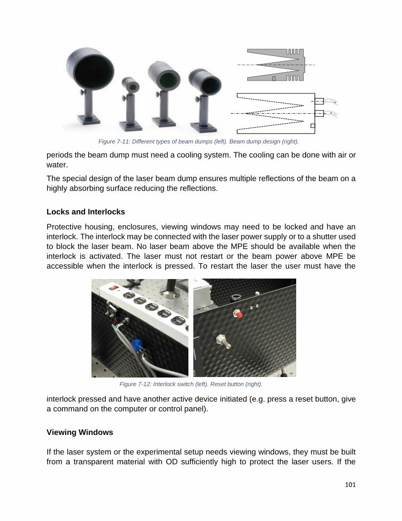
101
periods the beam dump must need a cooling system. The cooling can be done with air or
water.
The special design of the laser beam dump ensures multiple reflections of the beam on a
highly absorbing surface reducing the reflections.
Locks and Interlocks
Protective housing, enclosures, viewing windows may need to be locked and have an
interlock. The interlock may be connected with the laser power supply or to a shutter used
to block the laser beam. No laser beam above the MPE should be available when the
interlock is activated. The laser must not restart or the beam power above MPE be
accessible when the interlock is pressed. To restart the laser the user must have the
interlock pressed and have another active device initiated (e.g. press a reset button, give
a command on the computer or control panel).
Viewing Windows
If the laser system or the experimental setup needs viewing windows, they must be built
from a transparent material with OD sufficiently high to protect the laser users. If the
Figure 7-11: Different types of beam dumps (left). Beam dump design (right).
Figure 7-12: Interlock switch (left). Reset button (right).

102
viewing windows can be open, they must have an interlock and a reset button or similar
device to restart the laser.
Key Control
All class 3B and 4 lasers must have a key to start the laser. The key can be replaced by
a computer password or similar device. The key or the computer password must be
accessible only to authorized laser users. When finishing the laser work the user must
remove the key, close the computer/control panel to prevent unauthorized access to the
laser.
Remote Interlock Connector
All class 3B and 4 laser or laser systems must have a remote interlock connector. This is
used to install a switch that can disconnect the power supply to the laser in case of an
emergency (e.g. a red mushroom emergency stop button). In case of fire, laser accident
or another emergency, the red mushroom button (or equivalent) will shut down the laser.
Class 1 Working Environment
When a class 3B or class 4 laser is enclosed and the user is not exposed to laser power
densities above MPE during normal operation, the system can be considered a class 1
working environment. No additional controls are necessary for a system considered a
Figure 7-13: Laser viewing portal.
Figure 7-14: Control key.

103
class 1. The enclosure must have locks and interlocks, and it must be built such that no
accidental opening of the enclosure is possible. If the enclosure is opened unintentionally
by the user who may be exposed to laser power densities above MPE, the interlock must
disable the laser or block the beam. The interlock must disable the laser system fast
enough so the exposure time on the eye is minimum. For example, if the total amount of
energy entering the eye in one microsecond is above MPE, the time in which the interlock
shuts down the system must be less than one microsecond. The LSO must inspect and
approved any laser/laser system to qualify as a class 1 working environment.
Controlling the stray beams
Stray beams can carry 4% or more of the total incident beam (more if the incident angle
is larger – see section 2.3.1).
The best way to control them is by using enclosures. When it is not possible to use
enclosures or when they are not practical, anti-reflecting coating (based on destructive
interference) can be used. A thin layer of transparent material is deposited on top of optics
to prevent reflections. n0<n
f<n
s
Figure 7-15: Red mushroom emergency stop button.
Figure 7-16: Class 1 enclosure.

104
7.3.3 Administrative and procedural controls
When engineering controls are not possible or practical, they can be replaced by
administrative and procedural controls. In a research environment, detailed Standard
Operation Procedures (SOPs) may not always be practical. If the experimental setup
needs to be changed very often, a more general SOP that includes the areas presented
below must be accompanied by the procedure to implement these changes. If changes in
the experimental setup are implemented, the procedure must indicate the person who is
required to approve these changes (e.g. laser supervisor, permit holder, LSO).
The required elements of an SOP:
• The location, the experimental setup, and list of lasers involved;
• Authorized people involved;
• List of hazards (beam hazards and all applicable non-beam hazards);
• Hazards control implemented to prevent beam and non-beam accidents;
• Alignment procedure;
• Normal operation;
• Emergency procedure.
Figure 7-17: Stray beams from curved surfaces.
Figure 7-18: Destructive interference used to control stray beams (left). Glass substrate with antireflex coating at
45° and perpendicular viewing (right).

105
All open beam class 3B should have and 4 lasers must have an SOP verified by the LSO
and approved by the laser Permit Holder.
Other administrative controls required for open beam class 3B and 4 lasers are:
• Output emission limitations – the laser power must be set at the minimum possible
value required for the experiment;
• All people working with lasers must be trained – a list of authorized laser users
must be maintained up to date by the PH (or laser supervisor);
• All people present in the room when the laser is ON must be informed about the
beam and non-beam hazards (e.g. awareness training), must have the approval
of the PH, and wear the appropriate Personal Protective Equipment (e.g. laser
goggles);
• Laser repairs, maintenance, internal calibrations must be performed only by
trained, experienced people;
• Windows protections must be installed to prevent laser beam transmission and
reflections;
• Entrance controls, signs and laser warning lights, must be in place (see section
7.3.4)
7.3.4 Entrance controls, signs, and lights
Entrance in the Nominal Hazard Zone (NHZ) of an open beam class 3B or class 4 laser
must be controlled.
Entry controls for an open beam class 3B laser must have:
• Posted by appropriate warning signs;
• Have all windows, doorways, open portals covered;
• All beams above MPE terminated;
• Only diffusive materials in the vicinity of the beam;
• Laser secured to prevent beam at eye level standing or sitting positions;
• Visitors access controlled.
Figure 7-19: Window protection, non-transparent cover (left). Window protection with adequate OD for the laser wavelength (right).

106
Operated only by trained people such that path is well defined. No direct or specular
reflected beams with power above MPE are present outside the optical table. Operators
must follow the approved procedures, and remove the key when the laser is not used.
If direct or specular reflected beams are directed towards the entrance, the additional
entry controls (required for class 4 lasers) must also be implemented.
For class 4 lasers, all entry controls applicable for class 3B must be followed. Besides,
one of the following three controls are mandatory:
• Non-defeatable interlocks are installed at the door or on the floor in front of the
entrance. The interlock must shut down the laser or activate a shutter to reduce
the beam power density under the applicable MPE. This type of interlock will stop
the experiment anytime a person from outside the NHZ enters, even if it is an
authorized laser user. A non-defeatable interlock is recommended for very high-
power laser applications;
• Defeatable interlocks are also installed at the door entrance. In this type of control,
the authorized users can enter using a key, a code, or a magnetic card.
Procedural entry control must be put in place when interlocks are not possible or practical.
A barrier, curtain, or similar arrangement must completely cover the entrance inside of the
room. This is required to prevent any person from entering the room and be injured by a
direct beam or by specular or diffuse reflections.
The entrance in the NHZ of a class 3B laser must be marked with appropriate laser signs.
For NHZ of a class 4 laser, in addition to the laser signs, a light indicating when the laser
Figure 7-20: Area entry control with interlock (left). Interlock system (right).
Figure 7-21: Examples of class 3B laser sign (left) and class 4 laser sign (right).

107
is ON must be installed. The light can be connected to the laser system or controlled
manually by the laser user.
A good practice is to communicate with the person using the laser before entering the
NHZ.
The best are light signs with three colours: green indicating when the laser is off, yellow
(amber) indicating when the laser is ready to be used, and red when the laser is
Figure 7-22: Door interlock (top-left). Non-defeatable interlock (top-right) Interlock can be defeated entering the proper passcode on the keypad (bottom-left). Area entry control without an interlock (bottom-right).
Figure 7-23: Laser sign stressing the importance of communication before entering the NHZ.

108
operational. A red flashing light or a light sign indicating when the laser is on is also
acceptable.
7.3.5 Personal protective equipment
Eye protection
Your best defence is knowledge, your last defence is your protective equipment. When all
other controls fail, and the beam or the stray beams are directed towards your eye, you
Figure 7-24: Three colours laser sign for class 4 lasers (top-left) and its control system (top-right).Other types of common laser lights (bottom row).
Figure 7-25: Knowledge is the best defence.

109
need to have the correct laser goggles. Safety eye protection is mandatory inside the NHZ
if class 3B and class 4 laser.
Laser goggles work by absorbing or reflecting the laser light. For the laser goggles based
on absorption, an absorbing dye is mixed with the laser goggles material, or deposited on
top of the glass or plastic. The laser goggles based on reflection use the same principle
of dichroic mirrors (also called dielectric or Bragg mirrors – see section 2.3.6).
The transmission of light through the material as defined in section 2.3.3, is the ratio
between the intensity of transmitted light to the intensity of the incident light.
T =I
I0
As the opposite of the transmission, we have the absorption of light. A measure of the
absorption is the optical density (OD) of the material.
OD = log10𝑇−1 = log10 𝐼0
𝐼
The transmission and absorption are wavelength dependent. The absorption and the
transmission bands of a certain dye are published by the laser goggles manufacturer.
If the transmitted light can reach the eye of the user it must be at the MPE for the eye or
lower level. When MPE is measured in W/cm2 the incident intensity of the light must be
measured in the same units. Then OD needed for the eye protection is calculated using
the following formula:
OD = log𝑃𝑑
MPE
where Pd power density power /area. The area used in this formula must be the area of
the beam if the beam is larger than the aperture area from Table 7-1, or the aperture area
if the area of the beam is smaller. OD can also be determined using the free web-based
calculator found at https://lasersafetyu.kentek.com/easy-haz-laser-hazard-software-
basic-web-version
The OD of each laser goggles must be specified on the labels.
For ps and fs laser pulses, saturable absorption (see section 2.4.4) can create a hazard.
Figure 7-26: Optical density and transmission curve for certain filter material.

110
To solve this problem the manufacturers are asked to test the laser goggles at these
exposure times. A copy of the test results must be given to the users, at their request.
The international laser safety standards (followed in Europe) require laser goggles labels
for time exposures.
D R I M
CW > 100ns 1-100ns < 1ns
When the user orders laser goggles they must have the correct OD for the wavelengths
involved in the laser experiment. For the visible laser beams, OD should not be much
higher than necessary since this can decrease the visible light transmittance of the
goggles. If viewing cards are used for UV and IR lasers, the laser goggles must have a
good transmittance for the colour of the viewing card.
Before putting on the laser goggles, the user must always verify:
• The physical integrity of the goggles (do not use broken or scratched goggles);
Figure 7-27: Laser goggles labels. In the left filter are the labels complying with the ANSI standard. On the right filter are the labels complying with the international standard.
Figure 7-28: Labels complying with the international standard (followed in Europe).

111
• The wavelength and the OD. If multiple wavelengths can be involved (produced
by laser or by harmonic generators), the laser goggles must cover all possible
wavelengths;
• For ps and fs, verify if the goggles were tested for saturable absorption or if they
have the “M” marking;
• The visible light transmission (VLT) must be enough to comfortable perform the
alignment and the experiment.
When laser goggles are impossible to use (e.g.: when using a supercontinuum laser with
emission in all visible spectrum), the user must consider other options for protection. The
laser system must be enclosed, and a closed-circuit TV used to perform the alignment
and the operation.
Skin protection
When working with class 4, skin must be protected if the power density is above the MPE
for the skin. For possible long-term exposure to UV light, the skin must also be protected.
For face protection, a face shield can be used. The OD for the UV radiation must be
sufficient to reduce the exposure under the MPE.
If exposure to other parts of the body (arms, hands, legs, etc.) is possible they must be
covered. The user must wear long sleeves lab coats, gloves, etc.
If exposure to a beam with a power density above 10 W/cm2 is possible the materials used
to cover the skin must be flame retardant.
Other PPE
When a high-power laser beam interacts with the sample, laser-generated air
contaminants (LGAC) can be produced (see section 6.2.1).
Local exhaust ventilation systems must ensure that the level of toxic chemicals in the
breathing air is kept under legal limits. Gas monitoring instruments may be necessary to
Figure 7-29: When working with class 4 UV laser, protection of the face is also important (left). Face shields provide protection for the skin of the face (right).

112
ensure this. The same precautions may be necessary when dangerous gases are used
as a lasing medium (e.g.: excimer lasers) or for other purposes in the laser lab.
If the local exhaust ventilation is not adequate, personal respiratory protection may be
required. Surgical masks are in general not suitable for LGACs. They offer mainly
protection only for nasal or oral droplets. For protection against LGACs and other aerosols
or gases, tested mask respirators must be worn.
Figure 7-30: Laser-generated air contaminants.
Figure 7-31: Specially designed clear laser room.

113
8 LASER ALIGNMENT AND MEASUREMENT
The laser alignment must be performed only by trained and experienced users. A beginner
laser user must not attempt to perform these operations without supervision. Due to the
complexity of these operations, most of the laser eye accidents in the laser labs are
happening during the alignments.
The alignment of laser components inside the laser protective housing is sometimes called
internal alignment. If a misalignment of laser components inside the protective housing
happens, it is recommended to contact the manufacturer. The manufacturer should send
a qualified technician to perform the alignment.
A laser experiment may require many optical components. The alignment of these
components is sometimes called external alignment. External alignment is necessary
during the initial setting, reconfiguration of the optical setup, replacement of optical
components, or when the optical components are misaligned by accident. Fine
adjustments may be necessary to be performed often and depend on the required
precision of the laser experiment.
External alignment can be necessary between the optical components required for the
laser experiment on the optical table. If the laser beam is delivered through an optical fibre
the alignment from the laser to the fibre port, from fibre to fibre, and from fibre to the target.
8.1 Laser alignment procedure
All laboratories performing laser alignments must have written alignment procedures. It is
recommended the procedure be written by an experienced laser user, verified by the
Laser Safety Officer, and approved by the laser Permit Holder. Sometimes the laser work
may require a small change of the position of an optical component or the addition/removal
of an optical component without changing the whole experimental setup. A procedure to
Figure 8-1: Example of a misaligned system.

114
perform this change may involve a discussion between the laser worker and a more
experienced laser user, like the laser supervisor. This should also be included in the
alignment procedure.
The user must include the following in the alignment procedure:
• Perform alignment only after you receive training to do so;
• Only after you received approval from the supervisor;
• Work with a colleague (“buddy system”);
• Draw a plan of the setup (a sketch including all optical components and their
relative positions) and make a risk assessment;
• Discuss the hazard assessment and the alignment procedure with your supervisor
and your “buddy”;
• Identify the equipment and materials you need:
o Indirect viewing of the beam (thermal paper, ceramic discs, IR/UV cards or scopes,
business cards can be used for UV)
• Make sure you have eye protection for both low power and high-power beam;
• When necessary, verify if UV skin protection is available (face shield, long sleeves);
• Pay attention to housekeeping by removing all possible specular reflective
materials;
• Remove jewellery;
• Isolate and mark the NHZ;
• Reduce the power or replace a high-power laser with a low power visible laser;
• Use the appropriate alignment goggles;
• Remember to switch to the high OD goggles when you increase the laser power;
• Restrict access to the area;
• Turn on the laser warning light at the entrance of the room;
Before you start:
• Revise the alignment procedure, the list of hazards, and hazard controls;
• Make sure that all controls are in place;
Figure 8-2: Laser alignment sketch.

115
• All unnecessary/untrained persons should leave the room;
• Prepare the lab for the work (clean the lab, put a notice on the door, open the laser
light, etc.;
• Prepare the laser table (remove what you do not need and have close-by all tools
and optics you need);
Aligning invisible lasers
When possible replace the invisible laser with a visible low power laser to perform the
laser alignment. When alignment is performed with invisible lasers use viewing cards. The
viewing cards will change the invisible radiation into a visible one by fluorescence. When
changing UV to visible no charge of the cards is required. When changing from IR to
visible the cards must be charged before the alignment. From near IR cards, the charging
is done automatically by exposing the cards to visible light. For mid or far IR, the cards
may need charging with specially designated UV lamps.
The cards will change the UV or IR radiation to a certain colour. When choosing the cards
attention must be paid to the colour which is transmitted by the laser goggles. For
example; if the laser goggles will block the red but will transmit green, the viewing card
must change the UV or IR radiation into green light.
For aligning far IR may not be possible to use the viewing cards since the yield of
transformation may be too low. In these cases, special thermal papers may be necessary.
For high power far IR (like a CO2 laser) regular duct tape may be used to perform the
alignment.
Figure 8-3: IR viewing card and the UV lamp used for charging it.
Figure 8-4: Thermal alignment paper.

116
8.2 Laser measurements
Different types of measurements may be required during research involving lasers. The
most usual ones are the beam power or energy per pulse (see section 8.3). Other
properties that need to be measured are beam diameter, beam divergence or beam
profile. All this information may be presented by the manufacturer in the laser manual or
the datasheet. Sometimes the user may need to verify the manufacturer’s information. In
other situations, like in the case of a home-build or a modified laser, the information may
not exist or is modified. For many lasers, the properties may change after many hours of
usage and need to be measured again.
8.2.1 Beam’ profile
The ideal laser beam has a Gaussian profile. By determining the intensity of the beam on
two perpendicular axes, the user can determine the real beam profile.
A camera connected to a computer can be used to determine the beam’s profile. If the
power is too high, knife edge or slit scanning techniques are used. The laser beam power
is measured using a sharp edge or a scanning slit plotted on a graph to obtain the beam
profile.
Figure 8-5: Different types of beam profiles.
Figure 8-6: Knife-edge technique.
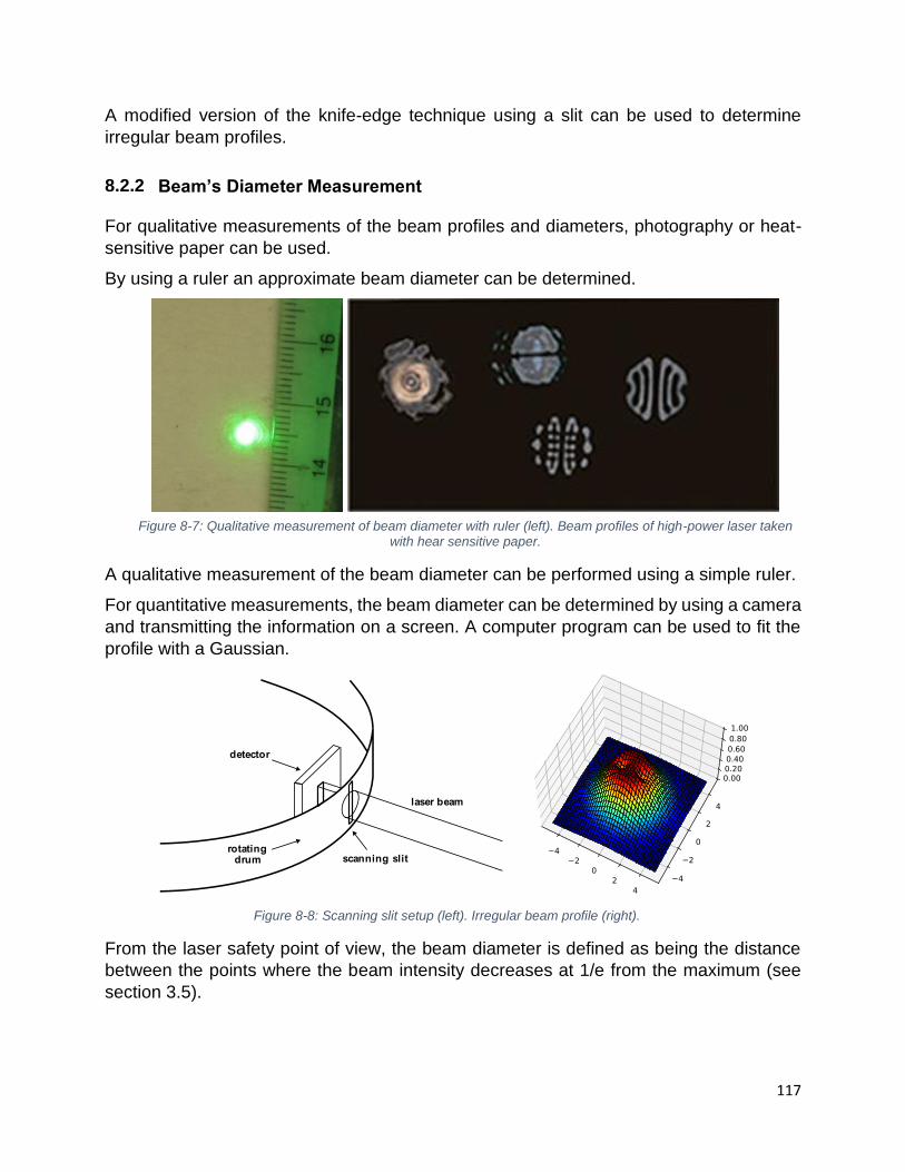
117
A modified version of the knife-edge technique using a slit can be used to determine
irregular beam profiles.
8.2.2 ’
For qualitative measurements of the beam profiles and diameters, photography or heat-
sensitive paper can be used.
By using a ruler an approximate beam diameter can be determined.
A qualitative measurement of the beam diameter can be performed using a simple ruler.
For quantitative measurements, the beam diameter can be determined by using a camera
and transmitting the information on a screen. A computer program can be used to fit the
profile with a Gaussian.
From the laser safety point of view, the beam diameter is defined as being the distance
between the points where the beam intensity decreases at 1/e from the maximum (see
section 3.5).
Figure 8-8: Scanning slit setup (left). Irregular beam profile (right).
Figure 8-7: Qualitative measurement of beam diameter with ruler (left). Beam profiles of high-power laser taken with hear sensitive paper.

118
Usually, the beam diameter is measured on both OX and OY axis. For safety purposes,
arithmetic means can be used to calculate the beam’s diameter.
8.2.3 B ’ Divergence
To measure the beam’s divergence, the user needs to measure the beam’s diameter DL1
at distance r1 from the laser head, and the beam’s diameter DL2 at distance r2.
Calculate the beam’s divergence using the formula:
𝜙 = 𝐷𝐿2
− 𝐷𝐿1
𝑟2 − 𝑟1
Figure 8-9: Fitting of a beam profile with a Gaussian function.
Figure 8-10: 3D shape of a Gaussian beam profile.

119
8.3 Beam’ Energy and Power Measurements
There are many methods to measure the beam energy or power. The method used will
depend on the power or energy range. For low power or energy lasers, it is common to
use a photodiode sensor. The light of the laser will generate a photocurrent in the sensor
and, with the proper calibration, this current is related to power. For intermediate to high
power or energy lasers, the sensor has a black surface that absorbs the laser light and
converts it into heat. This heat can be measured with a thermocouple or a pyroelectric
sensor. For very high-power beams, the measurement is done by slowly burning acrylate
blocks.
8.3.1 Photodiode Sensors
The photoelectric effect is the emission of electrons from a metal when electromagnetic
radiation is absorbed. A minimum photon energy is required to create the effect. The
kinetic energy of the electrons is the difference between the energy carried by each photon
and the electrons’ extraction energy (work function) from the metal.
The most used materials for the laser power photodetectors are semiconductors like Si,
Ge, GaAs and InGaAs. Photodiode sensors have a strong wavelength dependence.
Depending on the used material, the photodiode sensors can have a good sensitivity in
the wavelength range from around 200 nm to 1800 nm.
Instruments using photodiodes sensors, which may have the photodetector made of
different materials, have a measuring efficiency that is wavelength dependent. To have
Figure 8-11: Calculation of beam divergence.
Figure 8-12: Photoelectric effect (left). Photodiode (center). Photodiode sensor (right).

120
an accurate value of the power or energy, a calibration curve is provided by the meter’s
manufacturer. The wavelength correction can be included in the meter’s software and/or
provided by the manufacturer.
Photodiodes can measure laser beam powers in the range of microwatts to tens of
milliwatts. They can be used to measure both power and energy per pulse. The typical
response time is around 5 milliseconds. Photodiode sensors can measure energy per
pulse for a repetitive pulse laser with an upper frequency of around 20 kHz. From the laser
safety point of view, a laser with higher frequencies is similar to the CW lasers.
Typical photodiode sensors are between 5 and 10 mm in diameter. Laser power
photodetectors are faster and less sensitive to ambient temperature than thermal power
detectors.
8.3.2 Thermocouple Sensor
The thermoelectric effect is the conversion of a difference in temperature to a voltage and
vice-versa. Two wires, each of a different metal, are joined at one end creating a junction.
The junction and the free ends of the wires are kept at different temperatures. An electric
potential of a few microvolts is created at the free ends of the wires. This voltage is
Figure 8-13: Photodiode dependence on wavelength for different semiconductor materials (left). Example of wavelength dependence of a Si photodiode (right).
Figure 8-14: Thermoelectric effect.
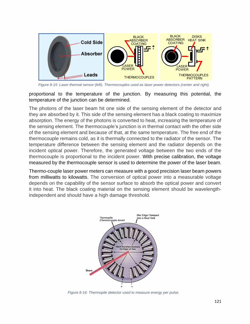
121
proportional to the temperature of the junction. By measuring this potential, the
temperature of the junction can be determined.
The photons of the laser beam hit one side of the sensing element of the detector and
they are absorbed by it. This side of the sensing element has a black coating to maximize
absorption. The energy of the photons is converted to heat, increasing the temperature of
the sensing element. The thermocouple’s junction is in thermal contact with the other side
of the sensing element and because of that, at the same temperature. The free end of the
thermocouple remains cold, as it is thermally connected to the radiator of the sensor. The
temperature difference between the sensing element and the radiator depends on the
incident optical power. Therefore, the generated voltage between the two ends of the
thermocouple is proportional to the incident power. With precise calibration, the voltage
measured by the thermocouple sensor is used to determine the power of the laser beam.
Thermo-couple laser power meters can measure with a good precision laser beam powers
from milliwatts to kilowatts. The conversion of optical power into a measurable voltage
depends on the capability of the sensor surface to absorb the optical power and convert
it into heat. The black coating material on the sensing element should be wavelength-
independent and should have a high damage threshold.
BLAC ABSORBERCOATING
LASERPO ER
THERMOCOUPLES
BLAC ABSORBERCOATING
LASERPO ER
THERMOCOUPLESPATTERN
DIS SHEAT SIN
Figure 8-15: Laser thermal sensor (left). Thermocouples used as laser power detectors (center and right).
Figure 8-16: Thermopile detector used to measure energy per pulse.

122
The thermocouple itself is insensitive to the laser wavelength - it only converts the heat
into a voltage. However, the absorptive coating shows a wavelength dependence because
the coating's surface reflects a small part of the incident light, and the reflectance slightly
depends on the wavelength. Since the coating is not transparent, it does not transmit light
and, to a very good approximation, the efficiency of the conversion process is solely
dependent on the reflection (R) and absorption (A) factors with the equation R + A = 1 or
A = 1- R. Consequently, absorbance as a function of wavelength can be calculated by
measuring the reflectivity over a certain wavelength range.
When thermocouples are connected in series, this array is called a thermopile. The energy
per pulse in a pulsed laser can be measured with a thermopile.
8.3.3 Pyroelectric Sensor
The pyroelectric effect is the generation of an electric voltage across the opposite faces
of a crystal when the temperature of the crystal changes. If the temperature stays constant
at its new value, the pyroelectric voltage gradually disappears due to the leakage current.
The leakage can be due to electrons moving through the crystal, ions moving through the
air, or current leaking through a voltmeter attached across the crystal.
Pyroelectric sensors are very good indicators of the changes in the temperatures of their
environment. Since the voltage dissipates fast in time the pyroelectric sensors are not
suitable for measuring the CW laser power but are excellent for measuring the energy per
pulse of a pulsed laser. Pyroelectric detectors have a good response from wavelengths
between 100 nm to a few mm and response times in the nanosecond range. These
sensors can measure energy per pulse for repetitive laser with frequencies up to 25 kHz.
From the laser safety point of view, a laser with higher frequencies is similar to the CW
lasers.
The energy per pulse range measured with a pyroelectric detector can be from micro
joules to tens of joules per pulse.
8.3.4 ’
Procedure:
• Read the manual first;
Figure 8-17: Pyroelectric effect (left). Pyroelectric detectors (right).

123
• Powerheads can be used with CW and pulsed lasers;
• Energy heads can be used only with pulsed lasers;
• If external cooling is needed (a fan or water cooling) the air/water flow may
influence the measurements. Make sure they are those recommended by the
manufacturer;
• Avoid changes in the airflow or drafts around the detector during the
measurements;
• Never touch the power detector by hand when measuring, touch only the stand;
• Use only approved connectors between the meter and the detector;
• You should have an approximate idea of what you are measuring. Using the
instrument at the wrong wavelength and/or power range might damage it;
• Be aware of other sources of heat;
• Warm up the laser for 25 – 30 minutes. Make sure the laser intensity is stable
before starting the measurement;
• Be aware of diffuse back reflections from the surface of the detector (5-15 %);
• Center the beam to the sensor face (more than 98 % of the encircled power
centered to the 50 % of the surface of the sensor;
• Warm up the detector for 2 minutes with the laser beam on;
• Block the detector head for 2 minutes;
• With the beam blocked establish the zero level;
• Unblock the beam and wait 1 minute to have the equilibrium;
• Take 5 distinct measurements and use the average of them;
• The instrument may have a self-correction for different wavelengths;
• If it does not, use the calibration chart to make the corrections.

124
9 LASER SAFETY PROGRAM
9.1 Principals of Program Development
The best way to protect employees, students and visitors from the hazards associated
with the use of lasers, and to satisfy the regulatory requirements, is to develop a good
Laser Safety Program. A good Laser Safety Program is a program that, while not
interfering with the freedom of research, offers an excellent level of safety.
The extend of the program must be adapted to the number and class of lasers, as well as
to the lasers’ setup. If an institution has a small number of class 3B or class 4 lasers,
which may be enclosed, a shorter laser safety program, implemented by a part-time laser
safety officer, may be sufficient. An institution with hundreds of open beam class 3B and
class 4 lasers will have a more comprehensive laser safety program. Such an institution
will have a Laser Safety Committee, a designated Laser Safety Officer and one or more
deputies. The LSO must have sufficient resources to implement and maintain the
program, as well as enough authority/support from the institution authorities to enforce the
requirements of the program.
The U of T has over 400 hundred open beam class 3B and class 4 lasers, an extensive
laser safety program and a Laser Safety Committee (LSC), and two Laser safety Officers.
The main role of the U of T LSC is to establish the policies and procedures related to laser
safety in the university, to approve the laser safety program and its amendments.
The U of T Laser Safety Program is based on:
• U of T Health and Safety Policy;
• Occupational Health and Safety Act of Ontario;
• ANSI standard Z136.1 Safe Use of Lasers;
• ANSI standard Z136.5 for educational institutions;
• ANSI standard Z136.8 for research facilities.
Due to the continuous technological advances and legislation updates, the program needs
to be periodically revised. Easier implementation of the laser safety program can be
obtained by issuing a laser safety permit for all Principal Investigators who possess open
beam class 3B and 4 lasers.
9.2 Content of the Laser Safety Program
The U of T laser safety program, which can be found in the following link,
https://ehs.utoronto.ca/our-services/laser-safety/laser-safety-program/, contains:
• Definitions;
• Responsibilities;
• Laser registration;
• Laser safety inspections;
• Training and education;

125
• Accident/incident reporting and emergency response;
• Medical surveillance;
• Personal protective equipment;
• Engineering controls;
• Administrative and procedural controls;
• Program audit.
In the appendices to the program are presented:
• Laser safety permit;
• Laser inspection check sheet;
• Laser loan form;
• List of authorized laser users;
• Laser registration form;
• Laser room commissioning;
• Decommissioning of class 3B and 4 lasers;
• External contractors form.
9.3 Responsibilities
The employer, U of T, has the overall responsibility for laser safety in the institution. This
can be achieved by developing and maintaining a good laser safety program. This
program is maintained and implemented by the Environmental Health and Safety through
the LSOs. Changes to the program are approved by the U of T Laser Safety Committee.
The program contains a detailed list of responsibilities for all people involved in laser
safety at the university.
The permit holder has the main responsibility for the hazard assessment and the
implementation of the laser safety controls in his/her laser laboratories. The Laser Safety
Officer verifies the implementation of these controls and gives detailed instructions, if
necessary.
The person operating the laser (laser user) has the primary responsibility to operate the
laser safely. All responsibilities are correlated with rights. Since the operator of the laser
has the right to know the hazards connected with the laser, he/she must be responsible
for the safe use of the laser.
9.4 Education and Laser Safety Training
As a research and teaching institution, the U of T considers training an essential part of
the laser safety program. The level of training must be appropriate for the hazard involved
in the laser work.
The work with open beam class 3B or class 4 laser is the most dangerous type of laser
work. Therefore, it can be only performed by the users who took the full laser safety
training. The full laser safety training has four parts. Laser safety theory can be taken

126
online or in-class, depending on the level of background knowledge in optics and physics
of the applicant. The second part is the practical laser safety training. This training is taken
in the laser training laboratory where students see and handle lasers and optical
components. The third part is on-job training. The on-job training is delivered in the laser
laboratory where the work with an open beam is performed. This training is delivered by
the Permit Holder or a member of the laboratory with more experience in laser work. The
university has a good tradition of mentorship. The students learn from somebody with
more experience. The LSO verifies the student’s knowledge about laser experimental
work during the laser safety follow-up session. Once these three parts of the training are
completed, the person using the laser is added to the authorized laser users list in the
laboratory. The fourth component of the full laser safety training is the laser safety
refresher. The refresher is available online and is mandatory to be taken every 3 years.
Users of laser fibre-coupled lasers or enclosed beams and lower classes can choose to
take the full laser safety training or shorter versions of laser safety training dedicated to
these specific applications. These laser safety trainings are available online. If the fibre-
coupled laser is a class 3B or 4, the online training dedicated to the safe use of fibre-
coupled lasers is followed by a follow-up session with the LSO. The users are added to a
list of authorized fibre-coupled lasers. For the users of the low class or enclosed beam,
online training is recommended. There are no follow-up sessions and no list of authorized
users for these types of lasers.
Any person working in the laser laboratory when the open beam class 3B or class 4 laser
is ON, but not operating the lasers, must have laser safety awareness training. Examples
of these persons are researchers present in the laser laboratory, caretakers, U of T
Campus Police, members of the Fire Protection Services, or members of Joint Health and
Safety Committees. The laser safety awareness training is available online.
All visits to the laser labs when open beam class 3 B or class 4 laser is on must be
approved by the laser Permit Holder. The visitors of the laser labs must be informed about
all hazards present in the lab and they have to be provided with the same level of
personnel protective equipment as the one used by the laser users.
Figure 9-1: U of T Responsibility chart.

127
9.5 Laser Safety Database
The Environmental Health and Safety database has a component dedicated to laser
safety. The laser safety database is an important part of the laser safety program. The
information in the database is kept up to date by the U of T LSO.
All class 3B and class 4 lasers used in open beam experiments must be registered with
the Environmental Health and Safety office. People in charge of laser laboratories/facilities
must inform the LSO of any new laser being installed. They must provide the following
information about the laser:
• Name of supervisor/PH;
• Location (building, room);
• Department;
• Type of laser (CO2, Nd:YAG, He-Ne, etc.);
• Production class (commercial, modified, home-made), manufacturer, model and
serial number (SN);
• Laser class, wavelength, maximum power, pulse duration, PRF, energy per pulse,
etc.;
• Proposed use (research, teaching, medical, etc.).
This information is registered and kept up-to-date, by the U of T LSO.
Besides the information on the lasers, the database contains information on the laser
permits, the list of laser labs, ODs of the laser eyewear, the list of laser users with their
history of laser safety training, medical surveillance, etc.
Figure 9-2: EHS database.

128
9.6 Medical Surveillance
All users of open beam class 3B and class 4 lasers must enrol and take the pre-
assignment medical surveillance. During this assessment, the U of T occupational medical
doctor and the occupational nurse will:
• Establish a baseline of ocular conditions before exposure to laser radiation;
• Detect early signs of any ocular damage and initiate prompt treatment;
• Identify persons with photosensitivity of the skin;
• Check visual acuity;
• Check the visual field test – for peripheral vision;
• Perform Amsler Grid test (for macular degeneration);
• Check for colour vision problems.
Fundoscopic examination (the visualization of the retina using an ophthalmoscope) is
performed to discover evidence of laser accidents, and also, to diagnose high blood
pressure, diabetes, endocarditis, and other vascular problems.
The Amsler test for Age Macular Degeneration (AMD), shows the patient a grid pattern. If
the grid looks undistorted, the macula is healthy. Distortions in the grid are an indication
of a possible AMD.
Figure 9-3: Fundoscopic examination (left). Normal fundus (right).
Figure 9-4: Age macular degeneration.
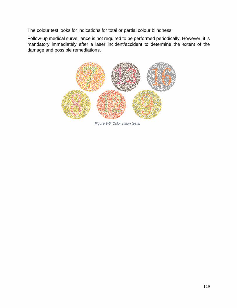
129
The colour test looks for indications for total or partial colour blindness.
Follow-up medical surveillance is not required to be performed periodically. However, it is
mandatory immediately after a laser incident/accident to determine the extent of the
damage and possible remediations.
Figure 9-5: Color vision tests.

130
10 Laser Accidents
When a laser accident happens the first reaction of the injured person is surprise and
shame. The person asks him/herself “how this could happen to me?”. Later, the second
reaction is fear of never see with that eye again. Finally, the person feels pain in the eye.
Famous last words before a laser accident
• I knew better … I knew better!
• I thought I knew where the beam was
• I only look there for a second
• I thought I could see better without the eyewear on
When people consider themselves infallible is when more likely the accidents happen.
People first need to consider that they are human, and humans make mistakes. The
approach known as “defence-in-depth” (building multiple barriers) considers all
known/possible mistakes and puts controls in place to prevent accidents.
When an accident happens, people need to be prepared to diminish the consequences
and to give first aid to the victim of the accident. The laser must be shut down but the laser
settings must remain unchanged. The permit holder and the laser safety officer must
analyze the accident and prepare a report. In the report, the direct and the root causes of
the accident must be identified. To prevent future accidents, corrective measures have to
be put into practice at the laser lab and university level. A list of learned lessons may be
useful to develop.
10.1 Direct causes of accidents
Human failure is a more general example of a direct cause of accidents. No wearing the
laser goggles or wearing the wrong ones, removing the goggles for a second (to wipe
them or to see better) and not blocking the laser beam when inserting new optics are the
most common examples of human failure. As mentioned before the laser goggles must
be the last line of defence, not the first. Therefore, we should look for a more general
approach.
Figure 10-1: Laser accidents (left). Scotoma (right)

131
Equipment failure is also possible. The user must verify all optical elements for their
physical integrity and functionality.
Engineering controls may be missing or deficient. The user must always understand the
principles standing behind any engineering control. For example, the protective layer in
the engineer control presented in section 2.3.6 (optics covered with an anti-reflex coating),
works only for certain wavelengths and angles of incidence. When used for lasers with
other wavelengths, they are ineffective and they can increase the hazard by causing total
reflection.
Examples of engineering control deficiencies:
• Beam blockers not used as required
• Beam blockers for stray beams inexistent
• Beam tubes are not used when vertical beams are present.
Not following rules and procedures is another common direct cause of accidents. The
standard operating procedures must be read and understood by each user before starting
the experiment. In many cases, mistakes happen when new optical elements are added
to the experiment without a complete understanding of their functions. Examples of SOPs
or alignment procedures deficiencies:
• Laser beams not used for the experiments not being blocked or disabled;
• Not using viewing cards and indirect viewing when possible;
• The beam is not aligned correctly, oblique beams are generated
Criminal intention can be a direct cause of laser accidents. The laser must never be
pointed towards a person. Legislation exists and is enforced to prevent using lasers close
to the airport areas or pointing the lasers towards the flying planes or helicopters.
Remember that bending or blinking will not help the person towards which the laser is
pointed to prevent the accident.
10.2 Root causes of accidents
When a laser incident or accident happens, the determination of direct causes is not
sufficient. The root causes must be identified. A useful technique to determine the root
cause of an accident is by repeatedly asking the question “why?”. For example: why the
user was not wearing the laser goggles?
The most common root cause of accidents is the lack of leadership. An accident is always
considered a management failure. Safety must be considered a priority by the upper
management of any institution. An Integrated Safety Management system must be
developed and implemented.
Accidents, in general, happen to two categories of laser users: users with many years of
experience and beginners. Experienced users are normally overconfident and this is
exacerbated after many years without any incident. They always tell themselves, “If it did

132
not happen in all these years will not happen now”. On the other side of the spectrum are
the beginners. They may be afraid of working with high power lasers, they lack experience,
knowledge. In university, there is a culture of mentorship. More advanced users are willing
to teach newcomers. Depending on the experimental set up the “on-the-job training” may
take from a few hours to weeks or months. The beginners must pay attention and ask
questions.
Miscommunication is another common root cause of accidents. The users must make
sure they understand how the laser works, the experimental setup and operation of each
optical component before they attempt to insert it into the laser system.
More concern about “job to be done” than “job to be done right” is a cause of accidents.
The users may be in a hurry to finish the work for various reasons. On Friday afternoon
people may want to finish the working week and start enjoying the weekend. This can lead
to speed up a delicate and dangerous procedure that otherwise should be done at a
normal pace. If the experimental setup requires work overnight, the user must perform
only simple tasks (e.g.: changing samples). If a more complicated task is necessary (e.g.:
laser alignment), this must be performed the next day when the person is on full rest.
A general cause of the accident is inadequate training. In a research setting by following
old experiments is unlikely to discover something new. The users must invent new
experiments and new procedures. In this case, the importance of understanding, and
therefore of the training, is crucial.
10.3 Emergency preparedness
To dimmish the consequences of laser accidents, the users must be prepared by having
emergency phone numbers readily available. The laser must be shut down immediately,
but the experimental settings must be kept undisturbed. This is necessary when the
accident analysis is performed.
The next step is to call for help. If the accident happened to the eye, assist the person to
visit an ophthalmologist as soon as possible. If major portions of the skin are burned, call
911 and help transport the injured person to the closed hospital.
A class 4 laser can start a fire. To prepare for a fire emergency a fire extinguisher must
be available in the laser laboratory. The laser users must know how to use the fire
extinguisher. If the fire cannot be stopped with one fire extinguisher, the user must close
the door and start the fire alarm. Never go to another room and try to use a second
extinguisher. All fires, including the small ones, must be reported.
In case of a fire alarm in the building, the laser user must leave the laser beam enclosed
or blocked, if the laser cannot be shut down.
An explosion can cause serious injury. Call 911 for help immediately.
The most common non-beam accident involves electricity. Never try to save a person
which is being electrocuted by touching the person directly. Use a tool made of plastic or

133
wood to remove the person from the electrical contact. Cardiopulmonary resuscitation
(CPR) must be performed only by a CPR certified person.
10.4 Accident analysis
The actions taken after any incident or accident are extremely important in the prevention
of future accidents.
The best is to learn from somebody’s else mistakes. A thorough incident/accident analysis
must be performed.
Unfortunately, many accidents are not reported. This practice makes it difficult to learn
from previous mistakes. The U of T laser users are encouraged to report any incident,
even the ones without consequences, to help prevent future accidents.
The accident analysis must contain a detailed description of the circumstances and the
events. The health and safety consequences suffered by the persons involved, and the
measures are taken to reduce the consequences of the accident.
The analysis must also contain a list of direct and root causes of the accident (see sections
10.1 and 10.2).
Figure 10-2: Importance of not repeating mistakes.
Figure 10-3: Accident analysis.

134
The lessons learned and the suggested changes to the laser safety program must also
be part of the accident analysis. Examples of lessons learned, and suggested program
changes are:
• Improvements to the laser safety general training insisting on practical alignment
training;
• Improvements to the site-specific On Job Training (OJT) performed in the laser
laboratory;
• Improving supervision including supervision of settings changes;
• Improving work planning and controls;
• Address specific hazards as:
o Dimly visible laser beams
o Optics that can generate out of plane beams
• Authorizing and releasing work (pre-job briefing) required when:
o New, unfamiliar, or infrequent tasks;
o Significant configuration change;
o The facility is returning to operation from extended downtime;
• Improving compliance with safety requirements (supervisors and senior members
of the team must be a role model in safety culture);
• Take appropriate corrective and disciplinary actions for safety violations
(proportional with gravity: oral warning, written warning, suspension from performing
an activity, discharge from employment);
• Develop performance metrics for laser safety.
10.5 Accident Reporting
Reportable incidents/accidents are those which result in personal injury or have the
potential to result in significant personal injury or property damage. The incident/accident
must occur on U of T premises or to U of T employees while performing their work on or
off U of T premises.
For a U of T employee, the following form available on the EHS webpage
https://ehs.utoronto.ca/report-an-incident/online-accidentincident-eform-for-employees/
and in case of an injury of a student, visitor, or contractor the following form
https://ehs.utoronto.ca/report-an-incident/online-accidentincident-eform-for-students-
contractors-and-visitors/
must be completed by the laser Permit Holder. The form will be transmitted to the Office
of Environmental Health and Safety, the Joint Health and Safety Committee, and the
Union.
As defined in Ontario Health and Safety Act and regulations a critical injury means an
injury of a serious nature that,

135
a) places life in jeopardy,
b) produces unconsciousness,
c) results in substantial loss of blood,
d) involves the fracture of a leg or arm but not a finger or toe,
e) involves the amputation of a leg, arm, hand or foot but not a finger or toe,
f) consists of burns to a major portion of the body, or
g) causes the loss of sight in an eye. R.R.O. 1990, Reg. 834, s.1.
The laser beam can cause loss of sight in an eye or burns to major portions of the skin.
The non-beam hazards can result in loss of life or a critical injury. In all these situations,
the Laser Permit Holder must notify the LSO immediately. The site of the accident must
remain undisturbed until the Ontario Ministry of Labor inspector arrives. The Laser Permit
Holder must assist the U of T LSO to investigate the circumstances of the accident and
preparing a written report.
Any injured person must be referred immediately to a physician or ophthalmologist. The
U of T Environmental Health and Safety will inform the Ontario Ministry of Labor.
Copyright © 2022 FDOKUMEN