LANDSCAPE MANUAL - City of Chula Vista
71
-
Upload
khangminh22 -
Category
Documents
-
view
0 -
download
0
Transcript of LANDSCAPE MANUAL - City of Chula Vista
Cl1Y OF
CHUIA VISfA
LANDSCAPE
MANUAL
1 ....,
'
�l
1
n
J
n
n .. I
'1 · . .
· . ' : J
1 _J
f'.,
: I
1 . .
J
Introduction
By Resolution No. 17735, the Chula Vista City Council approved this updated and expanded Landscape Manual and repealed its predecessor. The City Ordinances that implements this manual arc located within Titles 17 and 19 of the Chula Vista Municipal Code. This revised manual addresses issues specific to site development, landscaping and irrigation, both . for . private development and for public projects. The design and implementation of a project's landscape should address all functional and aesthetic site specific design issues, in addition to integrating the project into the immediate surroundings and adjacent properties. The Manual also. specifics materials that will assist the City and its residents in achieving long range durability and cost effectiveness. ·
Because of the semi-arid climate that Chula Vista is located in, and the increasing demand for limited imported water resources that serve Southern California, the principles of drought tolerant, or xeriscape landscaping. arc emphasized. The ability to conserve water while establishing and maintaining landscape installations is a primary concern for the future of the landscape industry and the region in general. This effort is not only desirable, it is a legal requirement of the State of California, as set forth in Government Code Section 65590 ct. seq. (AB325 1990), and the State Department of Water Resources Water Efficient Landscape Ordinance.
With these concepts in mind, this landscape manual outlines the process, requirements, and support information necessary for the review and approval of a project being processed through the City of Chula Vista.
The manual is comprised of three main components. Part One - General City Requirements, addresses the overall requirements and processes for a project. Part Two - Private, addresses items specific to private projects such as residential subdivisions and commercial centers. Part Three - Public which is divided into six (6) section, addresses the requirements and criteria of public projects including parks, open space and streetscapes (whether a City Public Works project or a private "turnkey" project) .
The policies and requirements described in this manual arc minimum standards. Projects must meet or exceed these standards. If any specific questions regarding a project require clarification, please contact either the Planning Department for private development projects, or the Parks and Recreation Department for public projects.
! l
� . .
Planning Department (619) 691-5101
Parks and Recreation Department (619) 691-5071
Part One - General City Requirements
1. APPLICABILITY.
All building permit applications for industrial, commercial, civic, or multi-family residential buildings or structures; residential developments with common areas; development of parklands, recreation facilities, maintenance districts, street medians; and all discretionary permit applications for the aforementioned types of land uses regulated in any manner by the provisions of Titles 17 and 19 of the Municipal Code shall be subject to review and approval in accordance with the provisions of this City Landscape Manual . . Interior remodels or minor modifications to building exteriors constituting a valuation of less than $20,000 arc IlQ! subject to the provisions of this Manual.
2. PLAN REVIEW AND APPROVAL PROCESS.
2.1 Applicants for the following types of projects shall submit and obtain approval of Landscape Plans prior to the issuance of the applicable permit or other discretionary approval.
a. Multiple family (CVMC 19.14.485) b. Commercial (CVMC 19.14.485) c. Industrial (CVMC 19.14.485) d. Planned Unit Developments (CVMC 19.14.485) e. Unclassified uses (CVMC 19.14.485) f. Remodels with a valuation of $20,000 or more for the above uses (CVMC
19.14.485) g. Projects requiring Precise Plans (CVMC 19.14.485) h. Parking lots with five or more stalls (CVMC 19.14.485) i. Graded slopes (CVMC 19.14.485) j. Parks and open space (CVMC 17.10) k. Model home complexes for single family and/or multi-family projects shall submit
a landscape plan for at least Qlll< model home. Construction of single family homes or duplexes on individual lots arc not normally required to submit a landscape plan. In addition, developers of single family residential projects with 5 or more units shall provide written information on designing, installing, and maintaining water efficient landscapes, to all new homeowners. At least one model home shall post a sign directing the attention of prospective purchasers to drought-tolerant features within the landscape design.
2.2 Plan Review Process The procedure for processing all Landscape Plans shall be as follows.
2.2.l Submittal/Application: Submit four (4) copies of the Landscape Plans, to the Zoning Administrator (herein referred to as the ZNDirector) (Private Projects) or Parks & Recreation Department Landscape Architect (Public Projects), as the case may be, and simultaneously submit three sets of plans to affected local utility companies for review.
l
---. . . ,
' . I
J
·1
1
"l . i
· 1
' i .,.J
1 . !
2.2.2 Distribution/Review/Comment: The ZA/Director shall distribute the Landscape Plan for review by the Public Works Department and City Landscape Architect, and Parks and Recreation Landscape Architect for compliance with applicable
. ordinances, this Landscape Manual, and any other applicable manuals, procedures or policies. Which department the plans arc distributed to will depend on the project type.
l
1 .. I
... �,
• 1
. 1
. .,...,
I . '
2..2..3 Consideration of Comments: The ZA/Director shall conduct an appropriate proceeding pursuant to CVMC § 19.14.030, taking into consideration advice and. comments received from other departments, affected utilities, and the City Landscape Architect. The Landscape Plan may be approved or conditionally approved if in compliance with all applicable requirements including this Manual. The Landscape Plan shall be denied approval if not in compliance.
2.2.4 Notice of Decision: The ZA/Dircctor shall notify Applicant in writing of the decision to approve, conditionally approve, or deny approval. The applicant may appeal denial or conditions imposed upon approval, per Section 19.14.486 of the Chula Vista Municipal Code .
2.2.S Submittal Following Final Approval: Following approval, the Applicant shall furnish the Engineering Division of the Public Works Department with four (4) blueline or blackline copies of the Landscape Plans as finally approved. Applicant will also furnish one complete set of 3 mil. photo black line mylars for City records. In the case of an application for a building permit, and where landscape plans arc required per City code, the applicant shall furnish three (3) blueline sets of landscape plans to the Building and Housing Department.
2.2.6 Following landscape plan final approval, the Applicant shall implement the Landscape Plan only in accordance with the approved plan.
3. GRAPHICS.
3.1 General To insure consistency and clarity, the' following graphic standards apply to all Landscape Plans submitted for processing, and arc to be adhered to in the preparation of those plans. These applyto all new development projects, renovation projects, plan revisions, and "as built" drawings.
3.1.1 Conceptual Landscape Plan and Master Landscape Plans are to be on sheet size no larger than 32" x 40", unless approved by Staff prior to preparation.
3.1.2 If a project requires more than one sheet, a key map is to be included on all sheets.
3.1.3 All Landscape Plan(s) are to be done on City mylar "D" sheets with the appropriate title block modifications with the exception of building permit processing. which also can be prepared on a different title block, however the mylar size shall be no smaller than 24" x 36".
3.1.4 All plans arc to be done at a scale no smaller than l" - 20'.
�"':".M-1'%.ir���w� :X"Attttr-:·�··m..-w�n:..":'%�":"":a.���··= �·· +·,,:-;r;:; :� -.::.-%ii.�"1?''"::!·��*-.a."x-<r--:;;;%':i"-:i'tr:r«.:·mz;;%�a-»;;:.rw.*�i.��m::s�v.
'A'PC M:�\pLl.aaia11J.N1C11p\dr11ftl Page 3
----��-------- -----------

3.1.5 Graphic symbols are to be easily discemable; clarity is imperative.
3.1.6 All Landscape Plan(s) sheets are to be issued City sheet numbers, in addition to providing the following for each sheet type in a separate number block:
l
C
HC LC
U
LP -
Civil Engineer Sheets Horizontal Control Sheets Landscape Construction Landscape Irrigation Landscape Planting
... ,
.·.1.
3.2 Final Working Drawing Preparation
Note: Some or all of the following items are to be included on each plan or sheet, contingent on the specific project and the existing or proposed conditions at the project site.
3.2.1 Title Sheet: This sheet shall always be numbered 'T-1" and is to include the following:
3.2.1.1 Vicinity map showing nearest arterial intersection, street names, north arrow, and project location.
3.2.1.2 Index of Sheets
3.2.1.3 Title Block which includes:
a. Project Title b. Developer's name, complete address and phone number (if
applicable) c. Date plans prepared d. Seal of Registered Landscape Architect, signed and dated, including
expiration date pf license e. Tract/parcel map number, tentative tract number or project address i. Revision block g. Sheet number of of . h. Permit number i. Signature block for approvals by the following individuals and/or
agencies: • Director of Parks & Recreation • City Landscape Architect • Local water purveyor and County Health Department if
reclaimed water is being used.
3.2.2 Grading Plan: Grading Plans for projects that require grading shall conform to the Grading Ordinance Chapter 15.04 of the Municipal Code, and the Street Design Standards (current edition).
3.2.3 Layout and Construction Plan: Shall include but not be limited to the following.
'. J I
l """\
I ' '
j
. 1 ·,
3.2.3.1 Graphics that indicate and identify:
a. Walls b. Fences c. Walkways d. Pathways e. Signs f. Site furnishings g. Structures h. Recreational facilities i. Parking lots j. Site or landscape lighting
3.2.3.2 Construction details.
3.2.3.3 General construction notes.
3.2.3.4 . Specifications.
3.2.3.5 Any aspect of the landscape construction (including but not limited to those items above) shown on either any architect's or engineer's plans, shall have information regarding those items indicated on the Landscape Plans and referenced by plan and sheet number.
3.2.3.6 Plans that include construction items requiring building permits per the current Unifonn Building Code shall be noted to require said permit and shall state the party responsible for obtaining the permit. If the permit number is known, it shall be referenced on the plan.
3.2.3.7 Reference City plan numbers for all existing and proposed improvements. Show and note depth of any utility line that may interfere with the proposed construction. References shall include the type of improvement and responsible party for the improvement.
3.2.4 Irrigation Plan: Shall include but not be limited to the following.
3.2.4.1 Graphic presentation of all components of the system.
3.2.4.2 A legend showing all symbols stating the manufacturer, precipitation rate, gpm 's, radii of each head type and detail reference call out as well as all pertinent data for materials used in the system.
3.2.4.3 Irrigation details.
3.2.4.4 Description and location of the water service/meter(s) including:
a. Domestic vs. reclaimed service b. Installation requirements and responsibilities of the water purveyor
and the Contractor c. Available static water pressure at P.0.C.
d. Design pressure e. Peak flow through water meter (GPM) f. Total area served through the water meter in acres or square feet g. Yearly demand in acre/ft.
3.2.4.6 General irrigation notes.
3.2.4. 7 Specifications.
3.2.5 Planting Plan: Shall include but not be limited to the following.
3.2.5.1 Location and spacing of all plants.
3.2.5.2 Plant material species, container size, quantity, minimum ground and aerial setbacks, and spacing requirements.
3.2.5.3 Standards for tree caliper, height and spread shall be specified.
3.2.5.4 Location of all existing and proposed surface structures.
3.2.S.S All existing casements shall be indicated and labeled.
3.2.5.6 Seed mix information (including but not limited to):
a. rate b. mix c. mulch d. binder e. fertilization
f. inoculation
3.2.5. 7 Planting details.
3.2.5.8 General planting notes.
3.2.5.9 Specifications.
3.2.6 Public: Sec pages 37-44 for additional information.
-,
I
·-.
l _j
' l
l ....,
i
' I __ J
' 1

-,
4. LANDSCAPE PLANS CONTENTS. (PRIVATE)
4.1 General -,
.· i
. \ Planting. irrigation, and water management plans arc clements that arc mandatory for all required landscape plans. Other elements are required, as applicable.
' : !
j
i
' i , . _)
4.2 Preparer Qualifications
Landscape Plans shall be prepared by a registered landscape architect or by a person who demonstrates to the satisfaction of the City by the completeness and content of the plan that the preparer has sufficient knowledge of irrigation systems, characteristics of plant materials, design principles, planting techniques, soil characteristics and grading principles, to cause the landscape plan to achieve its objectives (such as erosion control, screening of a storage area, beautification of the development, etc.) without causing such problems as uprooting of sidewalks, loss of sight distance, or death or deterioration of the plant materials. In general, a high degree of professionalism shall be required of all projects.
4.3 Certification
Prior to the issuance of a certificate of occupancy for all private projects which require the installation of planting and irrigation, the project Landscape Architect must certify, in writing, that the project is completed in accordance with the approved set of plans. The certifier shall provide evidence of a laboratory soils analysis and that the recommendations were taken into consideration in the amendment, fertilization and drainage specifications.
Any changes that occur in the field due to site conditions or plant material availability must be submitted to and receive approval of the City Landscape Architect.
' . I . ,
4.4 Elements
4.4.1 Planting Elements:
4.4.1.1 Graphic representation of mature size of proposed plants.
4.4.1.2 Botanical and common names of all plants including seeds or stolons to be planted.
4.4.1.3 Specification of size, quantity, quality, and installation of plants, seeds, soil amendments, herbicides, insecticides, and fertilizers.
4.4.1.4 Details of various landscape features as required to clearly define the intended finished installation.
4.4.2 Irrigation Elements:
4.4.2.1 Static water pressure available at the meter .
m-@�� � ;-:t�w*���--m·..;en�:c-=wi>,1Jii.!mimm·*IZ!il2.mru·:1-,LiW'�J��m::t%��..=:¥:'.!:f;�"M
WPC M,11,_,, .. """"'"_pldnfll Page 7
4.4.2.2 Meter size and location. 4.4.2.3 Point of connection to water source. 4.4.2.4 Type, size, and location of backtlow device(s) proposed 4.4.2.5 Type, size, and location of control valves. 4.4.2.6 Type, size and location of automatic controller. 4.42. 7 Type, size, class and location of all pipes. 4.4.2.8 Type and size of all conduits, sleeves, or chase pipes. 4.4.29 Type, size and location of all irrigation heads. 4.4.2.10 Elevations sufficient to calculate energy gradient gain or loss in any given ·· 1
circuit and to determine the need for pressure reduction, pressure relief or air release devices when elevation variations create a head (psi) gain � or loss of ten (10) pounds or more. :J
4.42.11 Provide modcl(s)/brand(s) of irrigation equipment specified or complete description of equipment as a material and performance specification.
4.4.2.12 Show all existing underground and overhead utility lines. 4.4.3 Water Management Element:
A water management plan shall be submitted as part of the landscape plan and shall address water management procedures, equipment, and their application to plant materials and seasonal use. The clement shall be in substantial compliance with the "Sample Water Management Plan" (Attachment 1) and shall consist of the following clements: Statement of Site Conditions; Water Requirements; Water Delivery System; and Summary of Water· Conservation Methods and Water Savings. A sample water management plan is provided within this manual to assist in the preparation of Landscape Water Management Plans. It is intended to be used as a guide for the applicant. It is not intended to be merely copied. The owner shall be responsible for the implementation of the water management plan. 4.4.3.1 Reclaimed Water:
When reclaimed water is available within the basin containing the project site or when a reclamation master plan indicating the availability of reclaimed water in the future has been adopted by the water purveyor which governs the territory of the proposed project, the Applicant shall incorporate the use of reclaimed water into the project design except in the vicinity of any location where food is served or consumed.
4.4.3.2 Declared Water Shortage:

1
1
i
-,
\
--,
. !
. I
.. ,
,
-.-,,
.,
.--.
. !
In the event of a declared water shortage, mandatory and/or voluntary water conservation measure, the project shall comply with all water allocation programs adopted by state and local government authorities. In the event of any conflict between such programs and these regulations, the stricter conditions shall apply.
4.4.4 Other Elements:
4.4.4.1 Landscaping within the Public Right-of-Way or Tree Easement
For landscaping within the Public Right of Way, approval by the Department of Public Works is required. Sec Chapters 12.32 and 18.32 of the Chula Vista Municipal Code for further information,
4.4.4.2 Parking Areas:
• Any parking lot for 5 or more vehicles shall include a landscape strip (10 feet minimum) between the parking area and the public right _of way. This strip shall effectively screen the parking lot from the public right of way to a minimum height of 3-1/2 feet. Any approved combination of planting mounds, walls and/or decorative features, which are visually compatible with community aesthetic values, may be utilized.
• A 6-foot wide side yard landscape strip shall be installed in commercial and industrial lots where they abut a residential or institutional zone or land use where a zoning wall is not required. A 5 foot minimum decorative masonry wall or chain-link fence or approved equal type fencing with vines in combination with tree planters may be considered in lieu of a planting strip.
• A minimum of 10 % of the interior of any parking area shall be devoted to landscaping. The 6 foot landscaped strip and the 10 foot landscaped strip mentioned above will not be included in the 10 %
figure. Pleasing decorative paving such as: brick, stone or tile, will be considered in lieu of a plant ground cover although one tree in a minimum sixteen square foot cutout for every 100 square feet of decorative paving will be required.
• Planters, walls and fences in the parking areas shall have a protective 6 inch concrete curb to protect against damage to plants and irrigation heads. Planting areas which abut vehicle stalls will have a minimum concrete paved strip 1s• wide (including curb) to provide for access to and from parked vehicles. Appropriate paving should be used where pedestrians are likely to cross landscaped areas.
• Protective concrete curbs or standard concrete wheel stops arc required where walls and fences abut driveways and parking stalls.
'°W:::-�.rn:t�;i}�:,r;t:too�:m�t:w��-��-w.,,>$•:«?-�-w:.���.s�mmi - ..... �:rw,:·;,:.�*'r®rffi.0:im::-,;c,,�,,�*�r-..u�.;...'°:?lli
WPC M,'"'8,lploW11slJo""""P"'nhl Page 9
l
• Parking lots will require submittal of landscape, planting and irrigation plans.
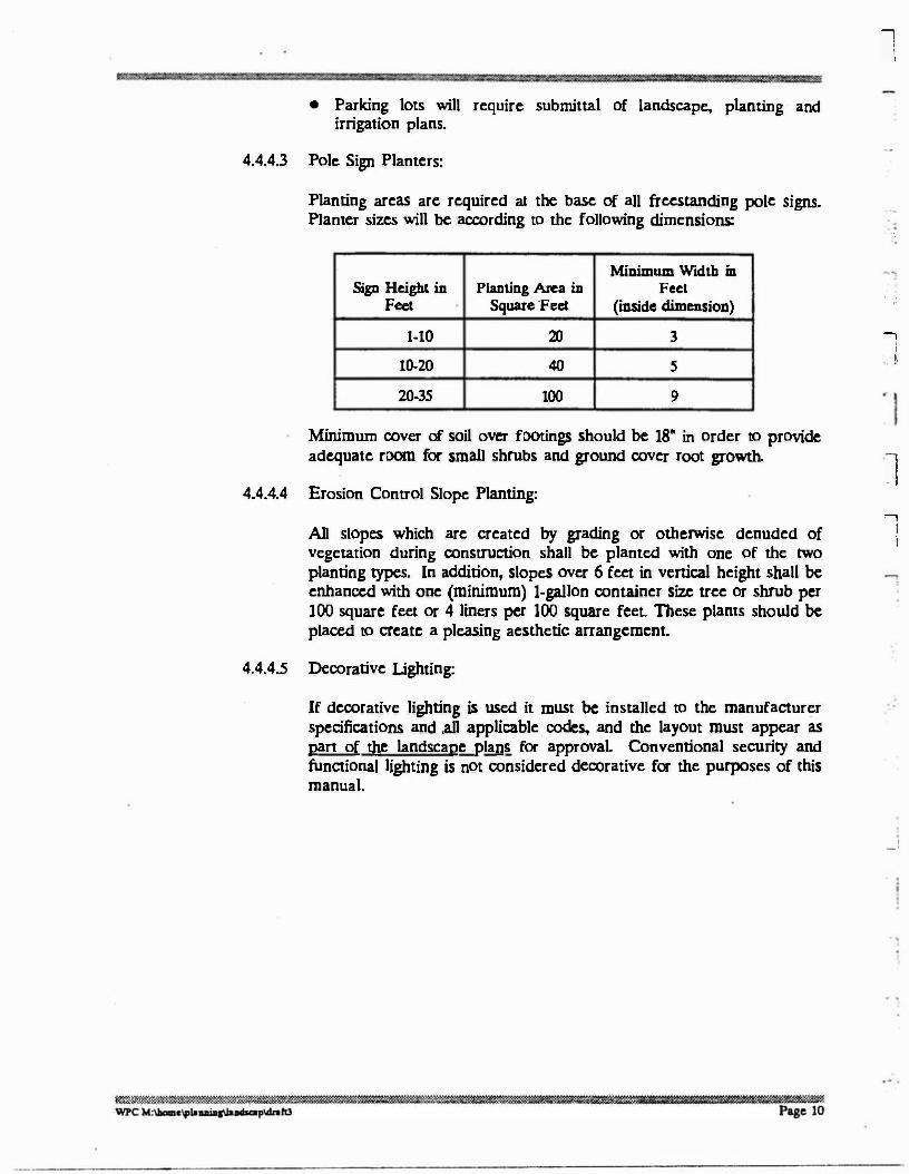
4.4.4.3 Pole Sign Planters:
Planting areas arc required at the base of all freestanding pole signs. Planter sizes will be according to the following dimensions:
.,
Minimum Width in Sign Height in Planting Arca in Feet
Feet Square 'Feet (inside dimension)
1-10 20 3
10-20 40 5
20-35 100 9
Minimum cover of soil over footings should be 18" in order to provide adequate room for small shrubs and ground cover root growth.
4.4.4.4 Erosion Control Slope Planting:
All slopes which are created by grading or otherwise denuded of vegetation during construction shall be planted with one of the two
planting types. In addition, slopes over 6 feet in vertical height shall be
enhanced with one (minimum) I-gallon container size tree or shrub per l 00 square feet or 4 liners per 100 square feet. These plants should be
placed to create a pleasing aesthetic arrangement,
4.4.4.5 Decorative Lighting:
If decorative lighting is used it must be installed to the manufacturer specifications and .all applicable codes, and the layout must appear as pan of the landscape plans for approval. Conventional security and functional lighting is not considered decorative for the purposes of this manual.
. ' ,
-,
I
'. t
l -,
I i
__ t
: i
4.4.4.6 Special Standards for Planned Unit Developments:
These standards supplement the specific standards above and do not ::-1 replace them.
! I
a. A preliminary landscape plan is required at the time of filing the tentative subdivision map and a final landscape planting and irrigation plan is required at the time of submitting an improvement or grading plan (CVMC 19.56.150). Prior to the issuance of any building permits, at least one model home landscape plan addressing the use of water efficient and drought tolerant landscape practices shall be submitted to and be approved by the City Landscape Architect.
b. Level areas (5% grade or less) shall be predominantly covered with a ground cover such as decorative turf, to promote recreational use .
. c. A minimum of two trees per dwelling arc required exclusive of street trees and slope trees. These trees may be installed anywhere as required to effect a good design.
d. At least 15 per cent of the trees shall have a minimum caliper of 3" if standards, and 2" if multiple trunks.
e. At least 25 per cent of the trees shall be a minimum of 1-1/2" caliper . if standards and 1" if multiple trunks.
f. The balance (60 % maximum) shall be 5 gallon size.
g. Additional trees shall be required in open space areas. They shall be a minimum size of 5 gallon. A variety of trees shall be utilized to effect interest: columnar, wide and medium spreading. etc. Additional 5 gallon shrubs and trees shall be used throughout the project in adequate number to accept open areas, buildings and screen parking areas.
h. Additional specimen materials shall be utilized near the entrance to the project and along dedicated streets. Street trees shall be a minimum of 15 gallon container size and shall be a minim um of 6 feet tall with a 1-1/2" caliper when planted, and double staked.
4.4.4.7 Special Standards for Multi-Family Developments: The required planting for usable (recreational) open space as defined by the Chula Vista Zoning Ordinance shall consist of turf grass or an equal ground cover which can be used for recreation or leisure use.
4.4.4.8 Special Standards for Brush Management: Projects in, upon or adjoining hazardous fire areas must meet the requirements of the City's Brush Management Program.
w,4-;:;�.;,�=�<;:..."::W-<s-�n:::.��'w:'t����.Rlr����:wwn!-$·��:::'t--®'�rnw:,:0,;�r��.;:;::::$«:R�:m��'='��
WPC M,1aom<1p1o .... t,1a-pldtdll Page 11
4.5 Maintenance
4.5.1 Private: All landscaping required in connection with the construction of multiple family, commercial, industrial, Planned Unit Development, and unclassified uses shall be maintained by the owner. A copy of a valid landscape maintenance contract or an affidavit of the person responsible shall be filed with the Planning Department. Contract copies shall be refiled upon renewal. Affidavits of the responsible person shall be refiled upon change of responsibility. Overall appearance of the landscape shall be neat, healthy and free of weeds and debris. Individual plants shall show vigorous growth typical of their species. If at any time, in the opinion of the City Landscape Architect, the maintenance level drops below the level described above, the City Landscape Architect will notify the owner in writing. The owner shall have sixty (60) days after notice to correct the condition or the City may initiate litigation procedures, and/or clean and maintain the development and bill the owner(s) for such services.
4.5.2 Public All new construction shall conform to the requirements of this Manual and, in addition, are subject to at least a one year installation guarantee for both landscape and irrigation. The installation shall conform to the City approved Landscape Plan. All planting and irrigation equipment shall be guaranteed by owner for one full year after written acceptance of the installation by the Parks Landscape Architect. The rate of growth and establishment of all planting will be monitored by the Parks and Recreation Landscape Architect. If plants do not grow in a manner typical of their species under the site conditions, the Parks and Recreation Landscape Architect may require remedial measures such as additional planting or replanting, weeding, additional fertilizer or other adjustments. The Parks and Recreation Landscape Architect has the option to extend the one year period in order to achieve normal plant growth and establishment.
5. LANDSCAPE PLANS CONTENTS. (PUBLIC)
See Pan III "Public Section" of the Landscape Manual for specific information and requirements relative to Public improvements.
6. AITACHMENTS.
6.1 Sample Water Management Plan
Introduction:
The purpose of this landscape water management plan is to provide the Owner and/or the Irrigation Manager with the means to operate and manage the landscape irrigation system on a continuing basis. This document provides information and instructions necessary to achieve this goal and includes the following:
a. Goal of the water management plan.
��1im1��1Jll'IIJrum�,���·����·�a�:m>1111m1®"!.l&!fflll�:10����e·rn�=�=um!m!!l��ZLllm.'t!flmlllli!ii?H�lilil!l!!Slildl!l�.m&&�•'lli'��.�
WPC M,-."'lawalllo ...... pldnlll · Page 12
-,
\
' ' ' . l
. . '
• !
J
l l
' ! . l

1 ..,
' I
1
"\
I
b.
c.
d.
e.
f.
g.
g.
h.
i.
Description of the existing soil and climatic conditions.
Annual precipitation rates (annual rainfall).
Anticipated ET ( evapotranspiration)- (the measurement in inches of soil moisture;
consumed by the plant and evaporated from the soil not to exceed 80% of the annual evapotranspiration rate).
The proposed water source and quality.
Toe annual anticipated landscape irrigation water requirements and soil percolation rates.
A description of the water delivery system and the precipitation rates ( actual water applied in inches per hour) of each type of sprinkler head nozzle.
A iiilfil soils report, which shows the percentage organic matter within the soil texture. Also, a measurement of pH and total soluble salts.
Water Delivery Systems
Water Savings
r··o
:j . I
;."i
· '
j. Irrigation Schedule
Goal:
The goal of this water management plan is to conserve water by combining water conserving design practices with guidelines for the landscape irrigation manager. This plan will provide the owner with the necessary information to maintain systems in peak performance, and make decisions on when and how much to irrigate.
'"! .,
:...J
I :
a.
b.
c.
Irrigation systems should be maintained to distribute water as uniformly as possible.
To assure adequate irrigation of all areas the system should be operated only long enough to apply water to a soil depth that the plants' roots utilize. Verify with soil probe.
The irrigation system is designed for maintenance and operation to avoid surface runoff.
This landscape water management plan provides information for the irrigation manager to implement the following water conservation concepts:
tti�.:c::;,;,;.:::o,...;;.c.��:$'�:Wr.-t���$�,Z$°�fu;;,;.�'m;'t�W:.::£,t�%���S:����1.-m�Y*WU: Q &"Y@Sf"®'!"t:
Wl'C M:\M>m,""°uiq\l,..i.a.p ..... hl Page 13
'· -· ---- ---·--- ------------

Soil and Climatic Conditions:
a. Soil Conditjons arc widely variable for the project area. The soil ranges from silty sand and decomposed granite to rocky granitic concentrations.
b. Climatic Conditions - The site, though located in a Southern California thermal belt, is influenced by south coastal cloud, fog and wind conditions, and sometimes experiences Santa Ana winds from the desert.
Annual Precipitation Rates - (Rainfall in Inches per Year):
1 I
a. Anticipated Er< cvapotranspiration) - the measurement in inches of soil moisture consumed by plants and evaporated from the soil: (San Diego County Water Authority, Model Water Efficient Landscape Ordinance and City of Chula Vista Landscape Manual limits the ETo to 80% of the measured ETo for calculations in each locale).
Again, due to current drought conditions both ETo (historical ETo) and ET for 1990 are shown below:
ETo (Historical
Month Reference) Iao • 1991
January 2.2 2.65 February 2.65 2.44 March 3.42 295 April 3.78 3.94 May 4.88 6.32 June 4.88 7.20 July 5.13 7.96 August 4.88 6.78 September 4.49 5.87 October 3.42 4.65 November 2.36 3.53 December 1.95 1.fil!
Annual Averages: 3.67 4.75
' l
1 ..,
! '
The annual "historical" precipitation rate (average from 1940 to 1991) is 9.45 inches per year. Currently San Diego County is in a drought mode and the historical precipitation rate may not apply. For this reason the annual precipitation rate for 1991 is possibly more indicative of current precipitation rates.
For updated ETo and precipitation figures for this area, contact the Department of Water Resources, Office of Water Conservation, P. 0. Box 942836, Sacramento, California 94236-0001. Upon· your request, they will furnish you with California Irrigation Management Information Systems (C.I.M.I.S.) daily weather data from Station No. 74, San Diego or 1-800-339-9954 (24hrs.).
������rn- ���wm«rnm�·m&1rnH�.,,,,.����mmmm��m..rn11t,....oi,slli!ll!=r111m==r111111&:=a=iaiW1111�""' WPC M:U.-C .. laaaiaa\laadaa.p\dnhJ Page 14
Water Source and Quality:
The irrigation water source will be tapped from an existing and functioning on-site potable pumped ground water system. This system is operated and maintained by fire station personnel.
Precipitation Rates • Planted Areas:
The precipitation rates for each variety of planted, irrigated area are as follows (they are listed by plant type and the sprinkler nozzle servicing them operating at 40 psi).
Trees, Shrubs and Ground Cover:
Series, Low Gallonage, Matched Precipitation Rates, Pressure Compensating Nozzles;
xx' Coverage Radius ( full )x.xx PR xx' Coverage Radius (half)x.xx PR xx' Coverage Radius (quaner)x.xx PR
Summary of Water Conservation Methods:
The irrigation design and water management program described utilizes known and documented water conservation principles.
The irrigation equipment and layout in the design reflect the water conservation methods that have been a standard in the industry, including: an automatic controller with multiple daily run times, the use of moisture sensors and a rain gauge to interrupt the automatic programming of the controller when necessary, "head to head" sprinkler layout to increase distribution uniformity (DU), matched precipitation rate nozzles to increase DU, low precipitation rate nozzles to decrease the probability of surface runoff, separate irrigation stations according to: sun exposures; slopes (top and bottom); turf and shrub areas.
The planting plan utilizes hardy native and drought tolerant plant species, adjunct to existing native areas. Ground cover-type plant masses act as living mulches to shade and cool soil temperatures and reduce moisture loss. Decorative turf areas are not designed into this project.
Water Requirements:
The annual anticipated water demand has been estimated in inches, gallons, and acre feet. Please note that the figures below were arrived at by utilizing 1990 C.I.M.I.S.data, and the water demand in non-drought years may be lowered by twenty percent. The City of Chula Vista is adopting the State Department of Water and Power mandate an ETo @ 80% of the yearly average ETo. The values shown below will reflect this mandate as water consumers in the Chula Vista area.
�����J:$ ... �! .. %rn'""'����---llil· .r,i. ;-IWJll!lmf APll!'l!il::o!<Jffl:mJll!lZl··:w@i�i ��-W$�,€:'.��.k»l:s.,·:��ffi.� "?C M,11m,,1p1,uiaa\lo ..... pwlnhl Page JS

-, I
!
Annual Anticipated Water Demand Inches Gallons Acre Feet
sq. ft. of trees, shrubs &
ground covered require:
Water Delivery Systems:
The type of irrigation system utilized for this project consists of an automaticaJly controlled, PVC, pop-up spray system. Many water conserving principles have been -,, applied in the design, such as:
•
•
•
An automatic irrigation controller that has the capability of being set for multiple run times in one day for each station, thus reducing run-off by only applying the amount of water that the soil can absorb at anyone time. Also, the irrigation manager can set the run times to reflect the current C.I.M.I.S. data.
Sprinkler head layout is "head to head", meaning that each sprinkler's coverage radius reaches to the next sprinkler head in the system, thus providing the best distribution uniformity (DU) possible.
Matched precipitation rate nozzles have been utilized. By matched precipitation rate it is meant that a designer can mix in the same irrigation station nozzles with varying spray patterns (ie; 90·s, 1so·s, and 360.s) and still have even precipitation rates throughout the area, again providing better distribution uniformity. This project analysis allows for low rate irrigation application for trees, shrubs and ground cover, depending upon soil percolation rate.
1 . l
...,
I
\
• Low precipitation rate nozzles have also been utilized to reduce the amount of flow on all slopes 10% or greater. (In comparison to conventional or standard gallonage nozzles which emit considerably more water in the same amount of time, increasing the probability of water waste by runoff.)
• Irrigation stations (the area that one irrigation valve services) have been separated to conserve water as follows: sun and shade exposures are separated; slopes arc separated from flat areas; turf and shrub areas arc separated. All the areas listed have different watering requirements, and run times are to be scheduled individuaJly to reflect current C.I.M.I.S.data and the runoff characteristics of each station by the Owner or Irrigation Manager.
.
I
_J
. . i
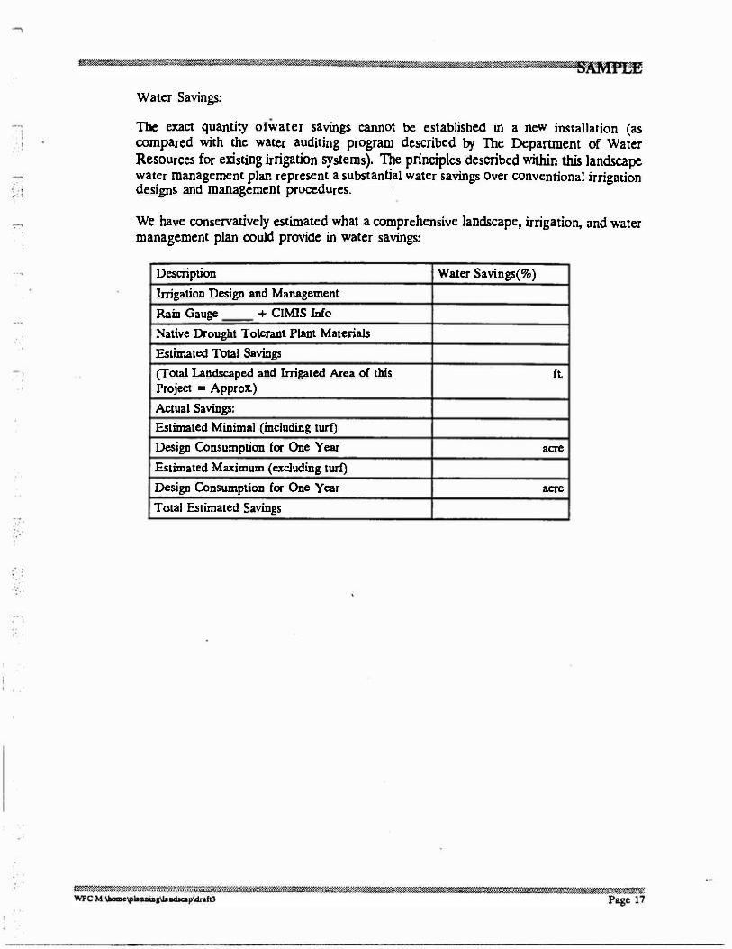
Water Savings:
The exact quantity orwater savings cannot be established in a new installation (as compared with the water auditing program described by The Department of Water Resources for existing irrigation systems). The principles described within this landscape water management plar.. represent a substantial water savings over conventional irrigation designs and management procedures.
We have conservatively estimated what a comprehensive landscape, irrigation, and water management plan could provide in water savings:
Description Water Savings(%)
Irrigation Design and Management
Rain Gauge + CIMIS Info
Native Drought Tolerant Plant Materials
Estimated Total Savings
(Total Landscaped and Irrigated Area of this ft. Project = Approx.)
Actual Savings:
Estimated Minimal (including turf)
Design Consumption for One Year acre
Estimated Maximum ( excluding turf)
Design Consumption for One Year acre
Total Estimated Savings
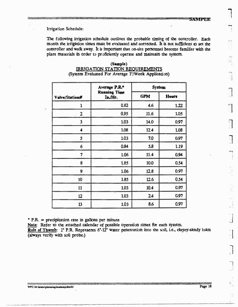
Irrigation Schedule:
The following irrigation schedule outlines the probable timing of the controller. Each
month the irrigation times must be evaluated and corrected. It is not sufficient to set the controller and walk away. It is important that on-site personnel become familiar with the plant materials in order to proficiently operate and maintain the system.
(Sample) IRRIGATION STATION REQUIREMENTS
(System Evaluated For Average 1"/Week Application)
Average P.R.• System Running Time
Valve/Station# InJHr. GPM Honn
1 0.82 4.6 1.22
2 0.95 11.6 1.05
3 1.03 14.0 0.97
4 1.08 12.4 I.OB
5 1.03 7.0 0.97
6 0.84 5.8 1.19
7 1.06 11.4 0.94
8 1.85 10.0 0.54
9 1.06 12.8 0.97
10 1.85 12.6 0.54
11 1.03 10.4 0.97
12 1.03 2.4 0.97
13 1.03 8.6 0.97
• P.R. = precipitation rate in gallons per minute Note: Refer to the attached calendar of possible operation times for each system. Rule of Thumb: 1" P.R. Represents 6"-12" water penetration into the soil, i.e., clayey-sandy loam (always verify with soil probe.)
·-----·-----------·------
l -,
...,
I
1
l �
I
i ._J
: l
l

1
1 1
l
ONE IRRIGATION CYCLE DURATION TO APPLY 1/3 INCH WATER
(EACH • REPRESENTS 4 MINUTES APPLICATION TIME)
STATION# 1
2 3
4
5
6
7
8
9
10 11 12 13
•••••
•••••
•••••
•••••
•••••
•••••••
•••••
•••
•••••
•••••
......
•••••
•••••
CONCLUSION:
Under the Summer and Fall conditions, it is critical that native plant materials be kept much closer to the dry end of the spectrum or bell curve of moisture content, than to the moist and wet end. Paying close attention to ET observations will give guidance to irrigation application rates (sec summary). Contrary to customary belief, it is not proper horticultural practice to keep the soil surface in an artificially wetted condition. Optimum field moisture displaces oxygen needed for creation of biological gasses and nutrients required for healthy root, stem and crown growth.
Nature in its mysticism will always outwit man. It is essential that we avoid trying to be too good to the flora and accept the natural signals given off by the subject genus or species. As an example, a broad leaf evergreen may start to curl its leaves as the sun rises hotter in the sky; does this mean the leaves arc drying out? Chances are the opposite is true; i.e., the leaf may curl to reduce its surface area to keep from getting too much light and/or reduce the actual evaporation rate. Keep in mind that steady winds cause evaporation also even under cloudy conditions.
The true test of this or any other system as designed is the ability to observe plant behavior before drowning the plant with water. It does not make sense to irrigate native plants during a rainy season because native plant materials thrive on seasonal rainfall only; even during times of installation of the plants, it is unnecessary to maintain optimum moisture for an extended period of time to guarantee survival. In fact, survival can pretty well be guaranteed by prudent use of a soil probe and diligent inspection, maintenance and operation of the irrigation system.
The advent of winter and spring conditions will provide ample moisture to the native plant material for the first season after transplant and may only need minor supplemental ( customary psychological) irrigation, when in reality the native plant material will perform better on neglect.
·-··- -·-·------··--·---------- --------

1
6.2 Glossary
For the purpose of this Manual, the following terms shall have the meaning set fonh below:
"anti-drain valve" or "check valve": a valve located under a sprinkler head to hold water in the system so it minimizes drainage from the lower elevation sprinkler heads.
"application rate": the depth of water applied to a given area, usually measured in inches per hour.
"applicant": any person or business, requmng a construction permit per City code requirements. This person or business shall apply for and receive any and all permits from the Building and Housing and/or Engineering dcpartmcnt(s).
"automatic controller": a mechanical or solid state timer, capable of operating valve stations to set the days and length of time of a water application.
"bacldlow prevention device": a safety device used to prevent pollution or contamination of the water supply due to the reverse flow of water from the irrigation system.
"C.I.M.I.S. ": the California Irrigation Management Information System. This is a system administered by the California Department of Water Resources, which maintains weather stations throughout the state which records the daily ET numbers.
"common area": that area which will be maintained by a homeowners association, County service area, or other form of cooperative organization. For purposes of these regulations, "common area" docs not include open space which cannot legally be disturbed.
"drought tolerant plant": a container or seed propagated plant that has the ability to endure prolonged periods of dry weather after establishment.
"ecological restoration project": a -project where the site is intentionally altered to establish a defined indigenous historic ecosystem.
"emitter": drip irrigation fittings that deliver water slowly from the system to the soil.
' I
l
1 . .
-,
"established landscape": the point at which plants in the landscape have developed roots into the soil adjacent to the root ball. _j
"establishment period": the first year after installing the plant in the landscape.
"Estimated Total Water Use": the annual total amount of water estimated to be needed to keep the plants in the landscape area healthy. It is based upon such factors as the local evapotranspiration rate, the size of the landscape area, the types of plants, and the efficiency of the irrigation system.
"ET adjustment factor": a factor of0.8, that, when applied to reference cvapotranspiration, adjusts for plant factors and irrigation efficiency, two major influences upon the amount of water than needs to be applied to the landscape.
-·,
Page 20
-,
'
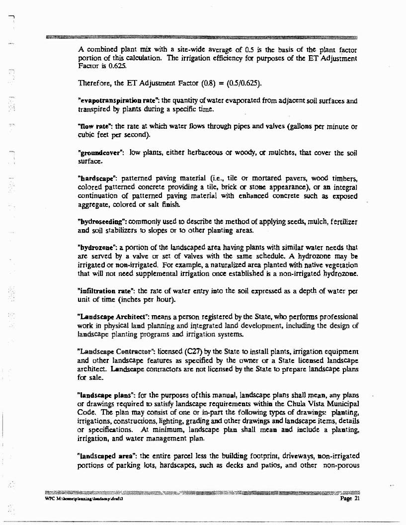
A combined plant mix with a site-wide average of 0.5 is the basis of the plant factor ponion of this calculation. The irrigation efficiency for purposes of the ET Adjustment Factor is 0.625.
Therefore, the ET Adjustment Factor (0.8) = (0.5/0.625).
"evapotranspiration rate": the quantity of water evaporated from adjacent soil surfaces and transpired by plants during a specific time.
"Dow rate": the rate at which water flows through pipes and valves (gallons per minute or cubic feet per second).
"groundcover": low plants, either herbaceous or woody, or mulches, that cover the soil surface.
"hardscape": patterned paving material (i.e., tile or mortared pavers, wood timbers, colored patterned concrete providing a tile, brick or stone appearance), or an integral continuation of patterned paving material with enhanced concrete such as exposed aggregate, colored or salt finish.
"hydroseeding": commonly used to describe the method of applying seeds, mulch, fertilizer and soil stabilizers to slopes or to other planting areas.
"hydrozone": a portion of the landscaped area having plants with similar water needs that are served by a valve or set of valves with the same schedule. A hydrozone may be irrigated or non-irrigated. For example, a naturalized area planted with native vegetation that will not need supplemental irrigation once established is a non-irrigated hydrozone.
"infiltration rate": the rate of water entry into the soil expressed as a depth of water per unit of time (inches per hour).
"Landscape Architect": means a person registered by the State, who performs professional work in physical land planning and integrated land development, including the design of landscape planting programs and irrigation systems.
"Landscape Contractor": licensed (C27) by the State to install plants, irrigation equipment and other landscape features as specified by the owner or a State licensed landscape architect. Landscape contractors arc not licensed by the State to prepare landscape plans for sale.
"landscape plans": for the purposes ofthis manual, landscape plans shall mean, any plans or drawings required to satisfy landscape requirements within the Chula Vista Municipal Code. The plan may consist of one or in-pan the following types of drawings: planting, irrigations, constructions, lighting, grading and other drawings and landscape items, details or specifications. At minimum, landscape plan shall mean and include a planting. irrigation, and water management plan.
"landscaped area": the entire parcel less the building footprint, driveways, non-irrigated ponions of parking lots, hardscapes, such as decks and patios, and other non-porous
�W:��:::��'m:��4�����%..,.�:uJJ! · 3 i:��Tu"'WY l m: t: :� & ��$���
'WPC M:llaomclflluia&Uallduap\dnfll Page 21
l
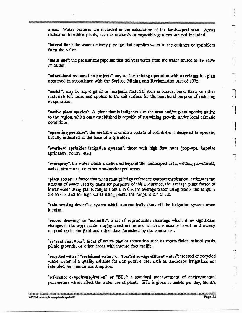
areas. Water features are included in the calculation of the landscaped area. Areas dedicated to edible plants, such as orchards or vegetable gardens arc not included.
"lateral line": the water delivery pipeline that supplies water to the emitters or sprinklers from the valve.
"main line": the pressurized pipeline that delivers water from the water source to the valve or outlet.
"mined-land reclamation projects": any surface mining operation with a reclamation plan approved in accordance with the Surface Mining and Reclamation Act of 1975.
"mulch": may be any -organic or inorganic material such as leaves, bark, straw or other materials left loose and applied to the soil surface for the beneficial purpose of reducing evaporation.
"native plant species": A plant that is indigenous to the area and/or plant species native to the region, which once established is capable of sustaining growth under local climatic conditions.
"operating pressure": the pressure at which a system of sprinklers is designed to operate, usually indicated at the base of a sprinkler.
"overhead sprinkler irrigation systems": those with high flow rates (pop-ups, impulse sprinklers, rotors, etc.)
"overspray": the water which is delivered beyond the landscaped area, wetting pavements, walks, structures, or other non-landscaped areas.
"plant factor": a factor that when multiplied by reference cvapotranspiration, estimates the amount of water used by plans for purposes of this ordinance, the average plant factor of lower water using plants ranges from O to 0.3, for average water using plants the range is 0.4 to 0.6, and for high water using .plants the range is 0.7 to 1.0.
"rain sensing device": a system which automatically shuts off the irrigation system when it rains.
l
' l
l
1 :
"record drawing" or "as-builts": a set of reproducible drawings which show significant changes in the work made during construction and which arc usually based on drawings _ _; marked up in the field and other data furnished by the contractor.
"recreational area": areas of active play or recreation such as sports fields, school yards, picnic grounds, or other areas with intense foot traffic.
-,
I
"recycled water," "reclaimed water," or "treated sewage effluent water": treated or recycled , ! waste water of a quality suitable for non-potable uses such as landscape irrigation; not intended for human consumption.
"reference evapotranspiration" or "ETo": a standard measurement of environmental parameters which affect the water use of plants. ETo is given in inches per day, month,

:11
;
•· =:
or year, and is an estimate of the evapotranspiranon of a large field of four- to seven-inch tall, cool-season grass that is well watered. Reference evapotranspiration is used as the basis of determining the Maximum Applied Water Allowances so that regional differences in climate can be accommodated. ·
"rehabilitated landscape": any re-landscaping project that requires a permit.
"run off": water which is not absorbed by the soil or landscape to which it is applied and flows from the area. For example, run off may result from water that is applied at too great a rate (application rate exceeds infiltration rate) or when there is a severe slope.
"shrub": a woody perennial plant with single or multiple basal stems.
"slope": the inclined exposed surface of a fill, cut or natural terrain.
"soil moisture sensing device": a device that measures the amount of water in the soil.
"soil texture": the classification of soil based on the percentage of sand, silt, and clay in the soil.
"sprinkler bead": a device which sprays water through a nozzle.
"static water pressure": the pipeline or municipal water supply pressure when water is not flowing.
"station": an area served by one valve or by a set of valves that operate simultaneously.
"tree": a perennial woody plant with one or more well defined stems or trunks which can achieve heights of 15' or greater.
"turf': a surface layer of earth containing mowed grass with its roots. Annual bluegrass, Kentucky bluegrass, Perennial ryegrass, Red fescue, and Tall fescue are cool-season grasses. Bermuda grass, Kikuyu grass, Seashore paspalum, St. Augustine grass, Zoysia grass, and Buffalo grass arc warm-season grasses.
"valve": a device used to control the flow of water in the irrigation system.
"xeriscape": water conservation through creative, appropriate landscaping and water management. The concept has seven basic aspects. Planning and design, practical turf areas, efficient irrigation, soil analysis, mulches, low water use plants, appropriate maintenance.
l
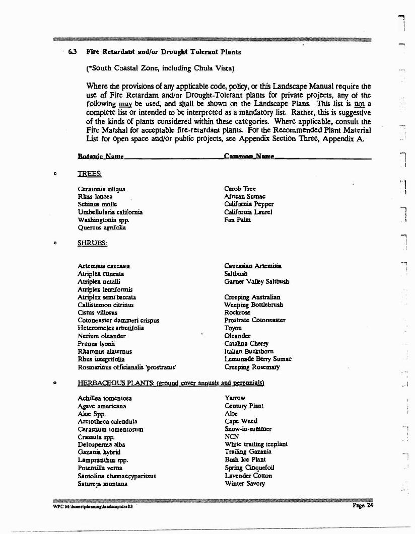
6.3 Fin, Retardant and/or Drought Tolerant Plants
("South Coastal Zone, including Chula Vista)
Where the provisions of any applicable code, policy, or this Landscape Manual require the use of Fire Retardant and/or Drought-Tolerant plants for private projects, any of the following filll be used, and shall be shown on the Landscape Plans. This list is not a complete list or intended to be interpreted as a mandatory list. Rather, this is suggestive of the kinds of plants considered within these categories. Where applicable, consult the Fire Marshal for acceptable fire-retardant plants. For the Recommended Plant Material list for open space and/or public projects, sec Appendix Section Three, Appendix A .. i
0
Botanic Name
Ceratonia siliqua Rhus Iancea Scbinus molle Umbellularia califomia Washingtonia spp. Quercus agrifolia
SHRUBS:
Anemisia caucasia
Atripla euneata Alripla nutalli Alriplcx lentiformis Alriplex scnullaccata Callistcmon cilrinus Cistus villosus Cotoneastcr danuneri crispus Heteromeles arbutifolia Nerium oleander Prunus lyooii Rhamnus alatcmus Rhus integrifolia Rosmarinus officianalis 'prostratus'
Common Name
Carob Tree African Sumac California Pepper California Laurel Fan Palm
Caucasian Anemisia Saltbush Gamer Valley Sallbush
Creeping Australian Weeping Bonlcbrush Rockrose Prostrate Cotoneastcr Toyon Oleander Catalina Cherry l talian Buclr.lhom Lemonade Berry Sumac Creeping Rosemary
...,
I . l
. 1 . )
,--,
I . 1
-,
I !
.. ,
o TREES:
0 HERBACEOUS Pl.ANTS: <ground cover annua!s apd perennials) . . I
Achillea tomcntosa Agave americana Aloe Spp. Arctotheca calendula Cerastium tomcntosum
Crassula spp. Delospcrma alba Gazania hybrid Lampranthus spp. Potcntilla verna Santolina chamaecyparissus Satureja montaoa
Yarrow
Century Plant Aloe Cape Weed Snow-in-sum.mer
NCN White trailing ieeplant Trailing Gazania Bush Ice Plant Spring CiDqucfoil Lavender Cotton Winter Savory
Page 24
I . !

l
1
1
J
n : .I
1 I
. '
J
i
I J -,
I . I i - J
6.4
Solanum jasminoidcs Tecomaria capcnsis Verbcua pcnivian.a Vinca spp. Wisteria spp.
Discouraged Plant List
Anlndo donax Carpobrollls edulis Cortaderia sclloana Cytisus scoparius Pcmtisetum sctaceum Tamarix cbinensis
· f tii J IB�X :
Potato Vine Cape Honeysuckle Peruviau Verbcn.a Periwinkle Wisteria
Giant Recd Hottentot Fig Pampas Grass
Scotch Broom Fountain Grass Tamarisk
These plants tend to be invasive and dominate when established in either riparilD or coastal sage scrub plant communities. These plants shall not be proposed for use in the open space or parks. When: these have established in project areas, a eradication program is to determined, approved and implemented.
I I .. ,
i
W"$;',;,�mr:=:!%U��l�����W'W>t"t:O:°™"&�W&�'�?zi:.t��19'���*it1«'.it1:'%Wf'f'-1::..., �2 ?'£*.!Zma"�:U-t:::"$'ffi..:W�:i;li��.U1:: WPC M:\llamclf!lallUAJ\alldlap\drahl Page 2S

1 I
Part Two - Private City Requirements � - @WW
1. STANDARDS APPLICABLE TO REQUIRED LANDSCAPING.
All landscaping required by City regulations for landscape plan approval whether building permits, grading permits, or other regulations shall meet the following minimum standards and requirements.
1.1 Landscape Elements
1.1.1
1.1..2
Grading: All grading shall conform to City grading standards. (See Chapter 15.04 of the Municipal Code.)
Planting: All areas of the site on which new grades. have been created or vegetation has been disturbed will be planted. One of twO types of plantings listed below will be required:
a. Type I plantings may require supplemental irrigation which is greater than natural rainfall, to ensure a manicured and healthy appearance. Generally, all visible areas adjacent to the right-of-way will be Type I plantings. Included in Type I planting will be the controlled use of "fire retardant/drought tolerant" planting strips necessary between structures and to be selected from the "Fire Retardant Plant and/or Drought Tolerant Plant • list.
b. Type II plantings arc drought tolerant and do not require supplemental irrigation and once established, will survive and grow only with natural rainfall. Type II plantings could consist of "hydro-seeding• with drought tolerant and selected containerized native vegetation which may require temporary irrigation until materials arc established.
l
) I
. '
1.1.3 Materials: Shall include the planting of combinations of trees to provide Solar energy conservation and utilization, ground cover, shrubs, vines, flowers, or limited turf varieties with the plant materials consisting of native species and/or drought resistant plant materials. In addition, when appropriate for the site and intended use, the landscaping may include natural features such as rock and stone, and materials, and structural features including but not limited to fountains, reflecting pools, an work, screens, walls and fences.
1.1.4 Fertilizers: All planted areas shall be fertilized with a complete organic or inorganic commercial fertilizer (nitrogen, phosphate, potassium). It shall also contain iron or a separate application of iron must be made ( contingent on recommendations made by soil analysis laboratory). Slow release fertilizers shall · ·! be applied during plant installation and at the end of the one year guarantee period.
1.1.S Decorative Landscaping: The use of architectural features, paving. fences, walls, mounds, boulders, gravel, lighting. decorative water features, inert ground covers, and organic mulches (3" deep) is encouraged in conjunction with landscape
,���W?M':tl;i:!l:,,...,.�WWS
WPC M:\llomc'fllluiaa\lallda,mp\dnh3
� :-1.1agm
Page 26

1
1 :] : I
1
1
l ;
l
,..,
·_.,1' . .
,.
r= l
r. \ . I
'.l
i I
J
'. !
.. ,
l
�i I
' �
plantings, if they are well designed and compatible with community aesthetic values. Recirculating water shall be used for decorative water features.
1.2 lmgation Elements
1.2.1 General: Irrigation either by a permanent automatic sprinkler system or manually controlled sprinkler system shall be installed as appropriate to the type of planting served. ·
1.2.1.1 Material Standards: All pipe shall be made from N.S.F. approved, type I, Grade II PVC, conforming to AS1M resin specification O 1784. All pipe shall meet requirements set forth in Federal Specification PS 22-70.
1.2.1.2 Sprinkler Heads: Sprinkler heads shall be a commercially manufactured type and shall be selected for proper area coverage, application rate, operating pressure, adjustment capability, and ease of maintenance.
1.2.1.3 .Automatic Control Valves (Electric & Hydraulic). All automatic control valves (electric) shall be globe or angle pattern, electrically controlled, normally closed type. Valves shall automatically close in event of electrical power failure. All control wire shall be of the Underwriter's Laboratory type UF (underground feeder), single conductor, solid copper, plastic insulated, 12 or 14 gauge minimum, 600 volt rated for direct burial application.
Electrically controlled irrigation systems shall comply with the requirements of the 1990 National Electrical Code, Article 725 .
1.2.1.4 Backflow Protection: Backflow protection must be provided for all irrigation systems and shall conform to all local water purveyor codes and requirements.
1.2.2 Miscellaneous Design Criteria:
1.2.2.1 Gate valves are to be used as emergency shut- off valves and not as manual control valves for sprinkler systems.
1.2.2.2 Sprinkler circuits shall run parallel or as close to parallel to the contour lines as is practical.
1.2.2.3 Sprinkler heads within a circuit shall have a uniform precipitation rate.
1.2.2.4 Within subdivision lot development, every lot shall have an independent irrigation system unless otherwise specified by the approved plans .
1.2.2.5 Pressure regulators, pressure relief valves, thrust blocks and other irrigation appurtenances shall be required.
���™}:-: . .t ®""'s::�ri%"..:WS:3'S:Wwwzzt .,,.,, ·smr«rrm:rz, ::..mw/.'��w:<-m.·'°"-m:r.�1t.:��a:
WPC M:\Mm,.,louiaallo.-pldn"3 Page 27
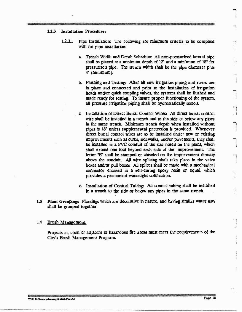
1.2.3 Installation Procedures
1.2.3.1 Pipe Installation: The following are minimum criteria to be complied with for pipe installation:
a. Trench Width and Depth Schedule: All non-pressurized lateral pipe shall be placed at a minimum depth of 12• and a minimum of 18" for pressurized pipe. The trench width shall be the pipe diameter plus 4" (minimum).
b. Flushing and Testing: After all new irrigation piping and risers arc in place and connected and prior to the installation of irrigation heads and/or quick coupling valves, the systems shall be flushed and made ready for testing. To insure proper functioning of the system, all pressure irrigation piping shall be hydrostatically tested.
c. Installation of Direct Burial Control Wires: All direct burial control wire shall be installed in a trench and to the side or below any pipes in the same trench. Minimum trench depth when installed without pipes is 18" unless supplemental protection is provided. Whenever direct burial control wires arc to be installed under new or existing improvements such as curbs, sidewalks, and/or pavements, they shall be installed in a PVC conduit of the size noted on the plans, which shall extend one foot beyond each side of the improvement. The letter "E" shall be stamped or chiseled on the improvement directly above the conduit. All wire splicing shall take place in the valve boxes and/or pull boxes. All splices shall be made with a mechanical connector encased in a self-curing epoxy resin or equal, which provides a permanent watertight connection.
d. Installation of Control Tubing: All control tubing shall be installed in a trench to the side or below any pipes in the same trench.
1.3 Plant Groupings Plantings which arc decorative in nature, and having similar water use, shall be grouped together.
1.4 Brush Management:
Projects in, upon or adjacent to hazardous fire areas must meet the requirements of the City's Brush Management Program.
....,
i
:,
I . J
. I
l . I
....,
\
.J
WPC M:\Jmmc'ttl-aiaa\llilGIQp\dn.hJ Page 28
' !
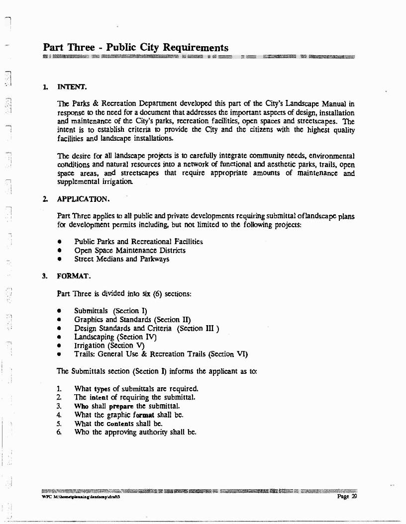
Part Three - Public City Requirements r,·�&$•�lillli�i.s\1'!�1��""""�1lm<:>lltlitl'ml�am!�m,11,1il\lll!l�llll>Cl31iffi,Um'Sl�77i!!:!<lW�""""'""2'"""�·�:<m="""�"�·""'�··=·a��'�1$3;:wi:i�?&�,,�·=="""��-�
1. INTENT.
The Parks & Recreation Department developed this pan of the City's Landscape Manual in response to the need for a document that addresses the important aspects of design, installation and maintenance of the City's parks, recreation facilities, open spaces and streetscapes. The intent is to establish criteria to provide the City and the citizens with the highest quality facilities and landscape installations.
I
· '
·,
... ,
. l '
2.
The desire for all landscape projects is to carefully integrate community needs, environmental conditions and natural resources into a network of functional and aesthetic parks, trails, open space areas, and streetscapes that require appropriate amounts of maintenance and supplemental irrigation.
APPLICATION •
Pan Three applies to all public and private developments requiring submittal oflandscape plans for development pennits including, but not limited to the following projects:
• Public Parks and Recreational Facilities • Open Space Maintenance Districts • Street Medians and Parkways
3. FORMAT •
. . ,
.: , Pan Three is divided into six (6) sections:
. !
'
• •
•
• •
•
Submittals (Section I) Graphics and Standards (Section II) Design Standards and Criteria (Section III ) Landscaping (Section IV) Irrigation (Section V) Trails: General Use & Recreation Trails (Section VI)
The Submittals section (Section I) informs the applicant as to:
1. What types of submittals are required. 2. The intent of requiring the submittal. 3. Who shall prepare the submittal. 4. What the graphic format shall be. 5. What the contents shall be.
6. Who the approving authority shall be.
a..�.%������$.'?...ZW�� .. :,,�·-s1m•.i,nia·,ili1:¥lilll'-1:lilll• lilll' :m.1=!1\-u��==lll!,ia•o1e11Jt�r:i»wmz1;1 . .i····m.·;;;,n�mr�:r#.l't�; WPC M:\laomc-.•uiaa\bad.acap\dnhl Page 29
.,
I !
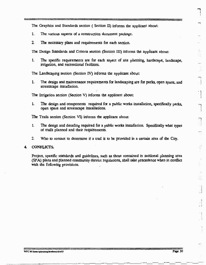
The Graphics and Standards section ( Section II) informs the applicant about:
I. The various aspects of a construction document package.
2. The necessary plans and requirements for each section.
The Design Standards and Criteria section (Section III) informs the applicant about:
1. The specific requirements arc for each aspect of site planning, hardscapc, landscape, irrigation, and recreational facilities.
The Landscaping section (Section IV) informs the applicant about:
1. The design and maintenance requirements for landscaping arc for parks, open space, and . i streetscape installation.
The Irrigation section (Section V) informs the applicant about:
1. The design and components required for a public works installation, specifically parks, open space and streetscape installations.
The Trails section (Section VI) informs the applicant about:
: 1 i .
'l
I
' '
1. The design and detailing required for a public works installation. Specifically what types of trails planned and their requirements.
.
2. Who to contact to determine if a trail is to be provided in a certain area of the City.
4. CONFLICTS.
Project, specific standards and guidelines, such as those contained in sectional planning area (SPA) plans and planned community district regulations, shall take precedence when in conflict with the following provisions.
. ! • J
. '
'
Page 30
--·· .. ·---· -- ------------------------------
Section One - Submittals
'l I 1, GENERAL
The Parks & Recreation Department requirements for submittals varies relative to the type of project and the phase of work being addressed. Specifically, the basis of the submittal is contingent on whether the project is a park, open space or streetscape installation. It is recommended that the owner and/or consultants meet with Staff to review the scope of the project prior to initiating work on any of the required submittals. Early communication between the applicant and the City will help clarify the actual scope and product of the project.
The following information is an overview of the park and open space development process and the specific products required for submittal. This framework and process has been developed to benefit the Applicant and staff by streamlining the review and approval time required for each· type of project.
2, PARKS.
• Concept Plan:
The Concept Plan is the initial phase in the park design process. Work product relative to this phase includes, but is not limited to: meeting with staff to discuss the project and the desired uses, site analysis, program development of site features and components: development of various schematic alternatives to evaluate site planning options; determination by staff of the preferred alternative; preparation and submittal of the refined concept plan.
• Master Plan:
The Master Plan phase is the refinement of the Concept Plan to bring the park design to a detail and graphic level acceptable for presentation to the Parks & Recreation Commission and City Council. The plan(s) are to be colored renderings, mounted on foam-core. All Master Plans will be retained by the Parks & Recreation Department for presentation purposes and archival data.
• Design Development:
This phase focuses on the refinement of the Master Plan, to a level of detail sufficient to move into the Construction Document Phase. The determination of materials, finishes, colors, plants, quantities, etc. are to be analyzed and determined.
• Construction Documents:
The Construction Document phase consists of the preparation, review and approval of all plans necessary for utilization by the contractor for the installation of the project. Typical sheets may include: Planting. Irrigation, Construction, Grading. Layout, and related Construction Details.
w��:l"�����'*1��isn.�«�J".::».�����,,.mixt:�;.t::xm*' .. {r'f'"":=·=v. �-w.'w"",;r���X!W'�,,:,:7""°»=:>',@�w.m���L.;..;.;:�
WPC M:\llomc"fllaaai81\J.ltwbclip\dr11f0 . Page 31
----------------------------
1 !
3. OPEN SPACE.
• Concept and Analysis Plan:
The Concept Plan for an Open Space project shall serve as a comprehensive plan identifying the following aspects: analysis of the existing conditions, mitigation of any impacts generated by the proposed project; existing features on-site and any sensitive plant, habitat or wildlife; existing on-site that might be impacted; identification of the various Open Space lots being proposed for turnover to the City by letter designation; the level of modifications or improvements to be installed relative to the "Code" system utilized by the City; gross area of each lot and total area of all Open Space lots; proposed or existing adjacent land uses; and, if applicable, a proposed fire and brush management plan in accordance with the Qty's Brush Management Program, as well as other proposed improvements such as trails, kiosks, signagc, walls, etc.
• Master Plan:
The focus of this submittal is to graphically indicate the location of the project, the types and locations of improvements, relationships to the adjacent land uses and the benefits that will be derived from the project by the City and its citizens. The Plan shall, when applicable, also include the identification and location of brush management "zones" to the satisfaction of the Fare Marshal. The plan shall be at an appropriate scale to allow for accurate analysis. This plan shall be a rendered plan, mounted on foam-core and will be retained by the Parks & Recreation Department for presentation purposes and archival data. • Construction Documents:
The Construction Document phase consists of the preparation, review and approval of all plans and documents necessary for utilization by the developer and contractor for the installation of the project. Typical sheets may include: planting, irrigation, construction, grading, layout, and related construction details. Based upon the scope and type of project, staff will identify the quantity of sets to be submitted for review. Four sets of plans will typically be. required for routing to other Qty Dcpanrnents. ·
4. STREETSCAPE. (MEDIANS & PARKWAYS) • Master Plan:
' I
. l
i
• I I
The �ocus off this submittal is1 to gra�hicaUy indicad. te the1 locad tion of tdhehprobejcct,fi thehtyp�11anbed _i locations o improvements, re ationshtps to the a [acent an uses an t e ne ts t at wi
derived from the project by the Qty and its citizens. The plan shall be at an appropriate scale to allow for accurate analysis. This plan shall be a rendered plan,
• Construction Do cum en ts:
The Construction Document phase consists of the preparation, review and approval of all plans and documents necessary for utilization by the developer and contractor for the installation of the project. TYPical sheets may include: planting, irrigation, construction, grading, layout, and related construction details. Based upon the scope and type of project, staff will identify the quantity of sets to be submitted for review. Four sets of plans will typically be required for routing to other City Departments,
w� .... mmr!..: � m·wm:.'d¥ii#@-'1� · z��·11 1 : 11 .. s;
wPC M:\llcmc\pauilil'-Nlmp'idnlll
a . �
Page 32
Section Two - Graphics & Standards
"' 1. GENERAL.
To insure consistency and clarity, the following standards apply to all projects submitted to the Parks & Recreation Department. These are to be adhered to in the preparation of construction documents utilized in the implementation of a park or open space project, whether publicly or privately constructed. These standards shall apply to all new development projects, capital improvement renovation projects, plan revisions, and "as-built" drawings.
1.1 Concept and Master Plans shall be on sheet size no larger than 32" x 40", unless approved by Staff prior to preparation.
1.2 If a project requires more than one sheet, a key map shall be included on all sheets.
1.3 All Construction Plans are to be done on City mylar "D" sheets with the appropriate title block modifications.
1.4 All plans shall be done at a scale no smaller than 1" - 20'. Prior departmental approval is necessary if projects require a smaller scale to fit onto sheet size. If additional detail is required, a smaller scale is to be utilized to provide sufficient clarity. Open Space plans shall at 1" - 40' for large scale areas. For more detailed planting and irrigation, 1" - 20' scale plans shall be required (verify with staff).
1.S Graphic symbols are to be easily discemable; clarity is imperative.
1.6 Provide bar scale on all plans to verify actual scale of plans.
1. 7 All Construction Plan sheets shall be issued City sheet numbers, in addition to providing the following for each sheet type in a separate number block:
C - Civil Engineer Sheets HC - Horizontal Control Sheets LC- Landscape Construction LI - Landscape Irrigation LP - Landscape Planting
1.8 Matchlines are to be labeled to provide adequate reference for identification and cross indexing to other sheets.
1.9 North arrow with scale shall be shown on all plans. North orientation of plan to be to the top or to the left of each sheet.
1.10 Label streets that are adjacent to the project or within the project's immediate sphere.
I
1.11 All areas deemed to be maintained by the City shall be clearly identified on the plans (Open Space requirement).
w-���:4�f�W.$�'%W%".�tw�w«·w ���:::B.iW&l"ln��"wmwi=-=·l"l==•=··!·w�·=tw··'iW:iffil"l··W· ·™=?���1;m:w:
WPC M,\IMm,lpl, ............... pldnhl Page 33
--- -------· -------
EK
1
2. FINAL WORKING DRAWING PREPARATION.
Some or all of the following items shall be included for each plan or sheet, contingent on the specific project and the existing or proposed conditions at the project site. All Construction Plans shall use City of Chula Vista "D" Sheets.
2.1 Title Sheet
The title sheet shall numbered "T-t• and is to include the following infonnation:
2.1.1 Vicinity map: Show nearest arterial intersection, street names, north arrow, and project location.
2.1.2 Locator Map: Shall show the following. l
a.
b.
c.
d.
e. f. g.
2.1.3 Index
Street configuration within, or adjacent to the tract or project Street names North arrow Match lines, if applicable Project limits Tract boundaries Scale ·
' I . J
l --·,
I
2.1.4 Title Block: Shall include the following.
a. Project Title b. Developer's name, complete address and phone number (if applicable) c. Landscape Architectural finn, complete address, phone number d. All other consultant's, complete address, phone number e, Date plans prepared f. Seal of Registered' Landscape Architect, signed and dated, including
expiration date of license g. Tract/parcel map number, tentative tract number or project address h. Revision block i.
j. k.
Sheet number of _ Permit number Signature block for approvals by the following agencies: • Director of Parks & Recreation • City Landscape Architect • Otay Water District (if reclaimed water for irrigation) • County Health Department (if reclaimed water for irrigation)
I
i .I
2.1.S General Notes: The following general notes arc provided to give directions to the Contractor. The City Engineer's signature on these plans docs not constitute approval of these notes and the City will not be responsible for their enforcement.
a.
f.
g.
i.
j.
k.
I.
m.
Contractor shall verify with owner's representative that plans are current and approved, . Work shall be in accordance with the requirements of the City of Chula Vista Landscape Manual (most recent edition) and the San Diego County Handbook for Public Works Construction. Whenever special requirements conflict on any matter, the City Engineer or his representative shall determine which special condition or code shall govern. These plans are based on improvements by dated _ The Contractor shall comply with the Engineering Soils Report recommendations as they relate to his work. The Contractor shall obtain all necessary and/or required permits ad pay all related fees and/or taxes required to install the work on these plans. The Contractor shall be appropriately licensed as required by the State of California. A separate plumbing permit and inspection will be required from the Building and Housing Department for the installation of irrigation systems shown on this drawing. The contractor shall notify the Engineering Inspection Division prior to beginning work and shall be responsible for coordinating with the owner, Landscape Architect, governing agencies and other trades. Contractor shall notify the Engineering Inspection Division immediately of any errors, omissions or discrepancies in existing conditions or with the plans prior to beginning the work. Unit prices for all improvements shall be established as a pan of the contract with the City, prior to beginning work, to accommodate additions and/or deletions of material and/or labor. Determination of "equal" substitutions shall be made only by the Landscape Architect. Landscape Architect and/or Engineering Inspection Division shall be notified no less than 4 hours in advance of the start of construction, any site observations, or meetings. Site observations shall include, but not be limited to: Main Lines a. Trenches complete b. Hydrostatic pressure test c. Backfill and compaction Control Lines a. Trenches complete b. Wires, connections and pull boxes in c. Backfill and compaction and circuit test Lateral Lines a. Trenches and sleeves b. Pipe, fittings, swing joints-spotcheck c. Backfill and compaction
··-------·------------------------------
l
n.
o.
P·
q.
Note: "Landscape" shall refer to all improvements within this set of documents that have been designed by the City or bid out in this project as a component of the project. Site observations by the Landscape Architect during any phase of this project does not relive Contractor of his primary responsibility to perform all work in accordance with the plans, specifications and governing codes. · The Contractor shall provide full maintenance of all landscape areas for a minimum of 90 days after initial written City approval. All open space areas which will ultimately be maintained by the City of Chula Vista, shall be maintained for a minimum of one year after initial written City approval. The Developer shall provide a "non-exclusive easement" when public trails or sidewalks occur outside the public right-of-way. The Developer shall provide easements for public utilities that occur outside of the public right-of-way.
, I I
2.2 Grading Plan
Shall include but not be limited to the following.
2.2.l Grading Plans for projects that require grading shall conform to the Grading Ordinance #1797.
2.2.2 Existing and proposed grades with flow lines.
2.2.3 All existing and proposed surface structures, improvements, underground drainage systems and utility lines with depths noted.
2.2.4 Elevations at curb returns and control points.
2.2.5 Reference to City plan numbers for all existing and proposed improvements within and adjacent to the project boundary. Reference shall include the type of improvements and responsible pany for the improvements.
2.3 Layout and Construction Plan
Shall include but not be limited to the following.
2.3.l Graphically shall indicate and identify all:
a. Walls b. Fences c. Walkways d. Pathways e. Signs f. Site furnishings g. Structures h. Recreational facilities
l j

1 l h i
* ' 'Ii
---i \ l
i. Parking lots j. Site or landscape lighting
2.3.2 Construction details.
2.3.3 General construction notes.
2.3.4 Specifications.
2.3.S Any aspect of the landscape construction (including but not limited to those items above) shown on either any architect's or engineer's plans, shall have information regarding those items indicated on the Landscape Plans and referenced as to plans and sheet numbers.
2.3.6 Plans that include construction items requiring building permits per the current Uniform Building Code shall be identified as requiring permits and state the party responsible for obtaining the permit. The permit number (if known) shall be referenced on the plan.
2.3.7 Reference to City plan numbers for all existing and proposed improvements. Identify the location and depth of any utility line that may interfere with the proposed construction. References shall include the type of improvement and responsible party for the improvement.
2.3.8 All sleeves and other construction items requiring coordination between other phases of work shall be included in plans and details.
2.4 Irrigation Plan
Shall include but not be limited to the following.
2.4.I Graphic presentation of all components of the system.
2.4.2 A legend showing all symbols 'stating the manufacturer, precipitation rate, gallons per minute (gpm ), radii of each head type and detail reference call out as well as all pertinent data for materials used in the system.
2.4.3 Irrigation details;
2.4.4 All systems shall have their equipment sized, their control valve size and station number given, and their gallon per minute (gpm) stated. Pipe sizes shall be indicated numerically (i.e. 3/4", l ", etc.)
2.4.S Description and location of the water service/meter(s) shall include:
a. Domestic or reclaimed service b. Water meter size and address c. Installation requirements and responsibilities of the water purveyor and
the Contractor d. Available static water pressure at point of connection (POC)

*®* ::m ;rm
-,
' '
e. Design pressure f. Peak flow through water meter (GPM) g. Total area served through the water meter in acres or square feet h. Yearly demand in acre/ft. i, Irrigation program that documents the system as designed provides
sufficient supplemental irrigation based on the precipitation rate of the specific head(s), and the irrigation coverage of the site can meet the highest demand monthly ETo within the following watering window:
•
•
Parks Open Space/Streetscapcs
4 day, 8 hr window 5 day, 9 hr window - for Code 1, 2 & 3 areas
10 p.m. - 6 a.m, 9 p.m. - 6 a.m .
. !
--,
l
· 1 2.4. 7 Description and location of the electrical service which shall include:
2.4.6 Pressure loss calculations for each point of connection. Calculations shall show pressure loss for the system with the highest pressure requirement.
a.
b.
c. d.
Point of connection to the electrical service High voltage line to the electric meter Electric meter type, location and address Installation requirements and responsible panics
l
1 . '
2.4.8 Booster pump locations (if required).
2.4.9 Location of all existing and proposed surface improvements and structures.
2.4.10 Reference to City plan numbers for all existing and proposed improvements. Identify the location and depth of any utility line that may interfere with proposed construction. References shall include the type of improvement and responsible party for the improvement.
2.4.11 Location of existing trees and requirements for performing work around them.
2.4.12 General irrigation notes.
2.4.13 Specifications.
2.4.14 The following requirements pertain to reclaimed water projects, These notes shall be included on all plans for irrigation systems using (or designed for) reclaimed water:
i
A. The installation of the reclaimed system shall conform to the rules and regulations for the construction of reclaimed water system within the Otay Water District.
-r
'
B. The Otay Water District shall be notified two days prior to the start of construction at (619) 670-2222 and each workday thereafter until completion of the project.

Detectable warning tapes shall be used on all constant pressure main line piping carrying either reclaimed or potable water.
All on-site constant pressure reclaimed and potable water main line piping installed on this project shall be identified in accordance with the district's regulations and the irrigation specifications. ·
Warning tapes shall be a minimum of 3" wide and shall run continuously for the entire length of-all constant pressure main line piping. The tape shall be installed in the trench 6" above the top of the pipe at the top of the sand bedding material.
Warning tape for the constant pressure potable water piping shall be BLUE in color with the words "CAUTION BURIED WAlERLlNE BELOW" imprinted in minimum 1" high letters black in color. Imprinting shall be continuous and permanent.
c.
. ' 1
i D.
-· · ; i ' E.
·1
F.
G. · Warning tape for the constant pressure reclaimed water piping shall be PURPLE in color with the words "CAUTION BURIED WAlERUNE BELOW" imprinted in minimum 1" high letters black in color. Imprinting shall be continuous and permanent.
H. All pressure main line piping from the reclaimed water system shall be installed to maintain 10' minimum horizontal separation from all potable water piping. Where reclaimed and potable water pressure main line piping cross, the reclaimed water piping shall be installed below the· potable water piping in a PVC Cl 200 pipe sleeve which extends a minimum of 5' on either side of the potable water piping. Provide a minimum vertical clearance of 6".
I. Contact the Otay Water District and the City of Chula Vista Parks &
Recreation Department to arrange for a coverage test and a system walk through.
2.4.15 Exterior drinking fountains must be shown and called out on the reclaimed water irrigation plans. If no exterior drinking fountains are present in the design area, it must be specifically stated on the plans that none exist.
2.5 Planting Plan
Shall include but not be limited to the following.
2.5.1 Location and spacing of all plants.
�::Wtm�4����!-i��W�:W:'PJ��i%��'*'�-i=�����.,e-.;;��·�.\!����-t®r,&������li�$®�Th�,:.t��<'.1£::.m:,�W;:'::�t:H:::�
WPC M,11MD,1p1o...,.11o..i.o.p .... hl Page 39
2.5.2 Plant material species, container size, quantity, minimum ground and spacing requirements. ·
2.5.3 Standards for tree caliper, height and spread shall be specified.
2..5.4 Location of all existing and proposed surface structures.
2.5.S All existing easements shall be indicated and labeled.
2.5.6 Edge of buildings on all adjacent properties (if applicable for solar access).
2.5. 7 Reference to City plan numbers for all existing and proposed improvements. Locate and identify depth of any utility lines that may interfere with proposed construction. References shall include the type of improvement and responsible party for the improvement.
2..5.8 Seed mix information (including but not limited to):
a. rate b. mix c. mulch d. binder e. fertilization f. inoculation
2.5.9 Planting details.
2.5.10 General planting notes.
2.5.11 Specifications.
2.6 Electrical Plan
Shall include but not be limited to the following.
2.6.l Location and spacing of all light fixtures, pull boxes, transformers and other components.
2.6.2 Light Fixture Schedule indicating the manufacturer, product number(s), light source type, etc.
2.6.3 Panel Schedule that conveys all information relative to each control panel.
2.6.4 Location of all existing and proposed surface structures.
2.6.5 All existing easements shall be indicated and labeled.
2.6.6 Edge of buildings on all adjacent properties (if applicable for solar access).
1 I
- 1 .I
I • I
l .
. I
Page 40
"l i
�4lP'&:P,'<l F ">'!':#t :; mas:PJt? w * &+·'
---.
l
· '
2.6. 7 Reference to City plan numbers for all existing and proposed improvements. Locate and identify depth of any utility lines that may interfere with proposed construction. References shall include the type of improvement and responsible party for the improvement.
2.6.8 Installation details that indicate the installation of all components specified .
�&:m-t,m:�t,.'o/..,t;�):!��,t:���-�!..™-!'.:����..J.��4£�-$-J.:,:J,��mm:..-;.:.o::,.;.;:;:..,m,$� -�c C!���-:tr'��a".f..Z�;
WPCM,-.-.,i..,..,u..._p .... ltl Page 4]

..., I
Section Three - Park Design Standards & Criteria
1. GENERAL
The following design standards and criteria address functional and aesthetic issues for park design, and arc to be referenced and utilized during the formulation of conceptual designs, design development and final working drawing preparation. The specified items arc requirements and shall be followed.
2. PARK DESIGN.
2.1 Site Planning l 2.1.1 Park site planning is a dynamic process that can vary greatly contingent on the site
context, existing conditions, size, scale, proponion, program and concept. -; ·1 Appropriate site design includes the identification and controlling of views, the organization of site components; recreation features, paths, roads and parking; structures and maintenance facilities, along with the types of furnishings necessary l to suppon passive and active recreational activities. .
Planning must include analysis and integration of off-site features such as bicycle and pedestrian trails, open space areas and joint-use of adjacent schools to assist in providing for the recreational components, while maximizing the passive use areas.
2.1.2 Refer to the Parks & Recreation Master Plan for specific issues when analyzing and evaluating the above mentioned site planning issues for a new park design. For existing sites, coordination with Staff is required to come to resolution for site planning.
2.1.3 All areas of every park are to be designed to be handicapped accessible, as per the latest requirements as set forth in the Americans with Disabilities Act (ADA).
2.2 Hardscape
2.2.l · Primary walkways in City parks shall be concrete: 6" thick x 10'-0' wide, minimum. Secondary walkways shall be 4" thick x 6'0" wide, minimum. Walkways should be located around turf areas to provide a transition from turf to planting areas. Locations of walkways at park perimetcr(s) and at the parking Jots are to be located to provide a logical, convenient and aesthetic means of accessing the park. Mix design shall be 564 • D - 3000 for enriched paving. 520 -C - 2500 for basic walkways.
2.2.2 Decomposed granite (D.G.) paths may be proposed or required as a secondary or tertiary component of a park circulation element, in addition to recreation trail. These walkways shall be retained on both sides with a 2 x 6 redwood header as a minimum, or preferably with a 6" concrete mow curb. D.G. to be a minimum of 6" thick. Trail width requirements arc contingent on the proposed use. If the trail is for recreational use and maintenance vehicle access, the width shall be 10' wide
1 . i
-,
\
. ,
i i
l
1
'l '. J
l
1 -,
;
' J
•• 1 . I . . I
. i
,
· · 1 . .
-: I '
mmimum. Park use requires a minimum width of 6'. Recreation use requires a minimum width of 10'.
2.2.3 Group use or pooling areas should be designed with enriched paving that is consistent with the design theme, colors and site concept. Provide sufficient information regarding the proposed paving for Staff to evaluate the proposed types, patterns, materials, etc.
2.2.4 All benches, tables, trash and hot-ash receptacles are shall be installed on concrete pads. Pads shall to be installed at a gradient no steeper than l %. Paving can be enriched or detailed for emphasis of site features.
2.2.S Concrete mow curbs shall to be provided to separate all lawn areas from planting areas, under all chain link fencing, as an integral component of any wall (both at the top and bottom where lawn areas exist) and where directed by the Department. Widths will vary depending on condition and location.
2.3 Recreation Facilities
The following is a partial listing of potential recreational facilities that may be required or desired for inclusion in the development of a park design, contingent on the specific park site, scale, existing facilities in adjacent parks and the Parks Master Plan. Specific recreational amenities will be determined by the department based on a needs analysis. The Department will also take into consideration ensnng or proposed amenities within the Parks and Recreation Planning Area.
2.3.1 Basketball Courts:
Basketball courts shall to be 94' x 50', with an additional 10' wide perimeter band of concrete. Court orientation shall be north - south. Courts shall be constructed of 6" thick concrete, with reinforcing as required (based on the soils report), minimum of #3 rebar at 18" o.c. each direction. Rebar dowels are to be provided at the mid-court joint. Resilient court surfacing and striping to be provided. Color(s) to be blue field, white striping and green
If lighting is provided, then the court lighting recommendation is ( 4) . perimeter 30' poles with (2) - 400 watt metal hallide luminaries on each pole. Soils testing and structural calculations are required for submittal relative to the steel reinforcing and the footing details for the light poles. Coin meter boxes may be required for operation of the lighting.
Site features related to a basketball court shall include a drinking fountain, bench(es), trash receptacle and bike rack. Backboard supports are to be arching precast concrete components set on a concrete footing. Backboards shall be milled aluminum with ribbed reinforcement, primed and powdercoated white with an orange "box". The shape is to be a "fan" product. Rims are to be orange, spring loaded with metal chain nets. Three (3) point lines shall be painted white at the 19' - 9" distance (NCAA standards).
t.;;.%',1��W�W.ffl:�.wa�«�0:.:W7P'trFW$�8\'l\:l"a'«�illlm...11 ... �-:�&Jll����.4'@11tmr:'!'3S'.4,(,����:;fu.���
WPC M,1M1m,1pla .... ,111 ..... pldnhl · Page 43
1 IU(
2.3.2 Tennis Courts:
Tennis courts shall be 120' x 60' in paved surfaced area, and 78' x 36' in actual court area. Courts shall be constructed of 6" thick concrete, with reinforcing as required based on the soils report, minimum of #3 rcbar at 18" o.c. each direction. Rebar dowels shall be provided at the mid-court joint. Resilient court surfacing and white striping shall be provided. ·
If lighting is provided, then the court lighting recommendation for each court is (8) - 20' poles with (1) - 400 watt metal hallidc luminaire on each pole. Soils testing and structural calculations are required for submittal relative to the steel reinforcing and the footing details for the light poles. Coin meter boxes shall be required for operation of the lighting. Site features related to a tennis court shall include a drinking fountain, bench(es), trash receptacle and bike rack. Court orientation shall be north - south.
12' high green vinyl coated chain-link fencing with windscreen fabric shall be provided around entire court perimeter.
2.3.3 Swimming Pool:
Swimming pools are shall be a minimum of 25 meters x 15 meters. Preferred size is 50 meters x 20 meters. Specific facilities and site detailing to be coordinated with, reviewed and approved by the Parks and Recreation Department.
2.3.4 Softball Field:
Softball fields shall be designed and sized to accommodate men's professional league games. 60' baselines and 300' radius outfield.
If lighting is provided, then light poles are to be a maximum of 65', tapered galvanized steel poles. Soils. testing and structural calculations are required for submittal relative to the steel reinforcing and the footing details for the light poles. Each field is to be switched independently. Orientation shall be home plate facing north, or as determined by the approved project Master Plan.
2.3.S Soccer Field:
Soccer fields can vary in size from 165' x 300' minimum to 225' x 360' maximum. The actual field layout shall be as directed by staff based on the land area available.
l _I
' 1 I
l
1 !
. t
If lighting is provided, then light poles shall be a maximum of 65', tapered -; galvanized steel poles. Soils testing and structural calculations arc required for submittal relative to the steel reinforcing and the footing details for the light poles. Each field shall be switched independently. Orientation shall be north/south.
�a::*-'-1C'"™�-: roy a-,e : : : : : usi-: 'tl-:m 8 89-fffll'
WPC M:�\pbilUliq\la.._p\dt'Sfll Ji &t-?M 1· i:ffl
Page 44
1 I
..,
::1
1
2.3.6 Volleyball Court:
Volleyball couns shall be 60' x 30', with a 10' wide clear area around the court perimeter. Courts shall be constructed with sand, 12" thick, minimum. The actual court layout is to be defined by nylon rope, secured at the comers by metal stakes. Orientation shall be north/south.
:i ' i
2.3.7 Comfort Station/Maintenance building: For all new park sites and facilities undergoing renovation, a comfort station/maintenance building will typically be included in the project program.
.,
.1
.2
Comfort station in active parks shall contain three (3) separate storage areas, sized to have sufficient room to allow for a small utility vehicle (if ballfields arc at site). Rooms to have adequate shelving. lighting, ventilation and have drains to allow for hosing out. All rooms to have separate locking doors, sized to allow for access and removal of
· applicable league equipment.
Interior of all comfort station toilet areas shall be constructed and scaled to prevent the potential for bacterial growth .
. --- l
. 3 All areas including floors, walls and ceilings shall be scaled and graffiti coated .
.4 All toilet fixtures shall be low flow and sink fixtures shall be low-flow with automatic water shut-off fixtures .
. 5 All stainless steel fixtures shall be pre-approved .
. 6 Metal mirrors will be installed in lieu of glass .
. 7 Electric hand dryers shall be utilized in lieu of paper towel dispensers.
--,
I
: ' -·
' I \
.,
.8
.9
Toilet paper dispensers shall be vandal proof with two or more roll storage capacity.
All toilet partitions shall be solid poly material, "Santana" of equal, with sturdy installation hardware.
.10 All floors to be designed and constructed with adequate drainage to allow for high pressure cleaning .
. 11 Any skylights designed into the facility to be designed to prevent break-in access. Mesh or bars in the interior shall be included.
.12 All restrooms shall be equipped with locking doors that have concealed locking mechanism which do not detract from the building aesthetics.
�j;�tt$�f.&°,t'���&��m'*'*�X����������«���£j,< &&'�,£'._,.,.!,_��:
wPC M:\Jlomc\pLluiq\laDCbop\dnhJ Page 45
----------
.13 All facilities shall be handicapped accessible and conform to all applicable ADA guidelines and requirements, including necessary signage .
. 14 Building shall be well lit, both exterior and interior, with vandal resistant light fixtures .
.15 Design of the building is to relate to the aesthetics of the site, with no concealed areas.
..,
I 1
'
.16 For parks and sites with league activities, a '\'ending area may be_ required, including electrical, sewer, water, service window, and other components as determined by staff .
.17 Utility area for staff shall be sized sufficiently for equipment and supply storage. Shelving and hanging components shall to be included. Adequate electrical and phone service shall be provided.
2.4 Lighting & Electrical Systems
All park sites and parking lots shall to be designed and provided with security lighting as a required feature of the project. The types of poles, luminaries, light fixtures and installation shall be per the specific project design and requirements. The minimum amount of lighting along walkways and in the parking lots shall be 1 foot candle.
All electrical components shall be installed in stainless steel, vandal proof, outdoor enclosures, unless installed in an interior application such as a maintenance facility. If in the open space, and a remote irrigation controller is being installed, then a back-to-back enclosure that also houses the electric meter shall be provided
2.4.1 Lighting system designs shall be developed for all park projects by a licensed electrical engineer. Conduit and pull-boxes shall be installed in the first phase, even if the light poles and fixtures are not installed until subsequent phases of the project.
2.4.2 The power source to be utilized for all park lighting and power requirements is not to exceed 120v / 208 watt power. Transformer location(s) to be coordinated with SDG&E.
2.4.3 Additional conduit and pull boxes are to be installed to the furthest use component or area, to allow for future demands or replacement of failed circuits or where future lighting or fixtures arc to be installed.
2.4.4 Security lights shall be mounted on 14 - 18' poles. Poles to be either precast concrete or spun aluminum with handholes at the base. Color shall be consistent with the project accent color. The fixtures shall have a JES classification of type
IV semi-cutoff or non-cutoff. The refraetor shall be U.V. stabilized, prismatic acrylic or polycarbonate.
' ]
l
. -,
j
i
I
'

- ' .
.. ,
I
1
ci
!
....,
: I
......, ' i '
l _J
1 ' I
. ,
I ;, _ ;
' . I · . '
·• . .J
! ;
2.4.S Lighting for all courts and sport fields shall be with metal hallidc fixtures. Security and parking lot lights shall be high pressure sodium (HPS). Minimum foot candles shall be provided arc as follows:
2.4.5.1 Tennis Courts:30 foot candles 2.4.5.2 Basketball Courts:20 foot candles 2.4.5.3 Ball/Soccer fields: 40 foot candles - infield
25 foot candles - outfield 2.4.5.4 Security Llghts:l foot candle • minimum
2.4.6 Each court, field, parking lot and security system shall be individually switched.
2.4. 7 Each court may be required to have a separate coin meter wired through the electrical panel. Each court shall be lighted independently with each coin meter being located on the respective court,
2.4.8 City maintenance vehicles must have access to court facilities to maintain light fixtures for relamping and maintenance. A 10' wide clear path shall be provided to all light fixture locations.
2.4.9 Irrigation heads shall be located equidistant in respect to the light pole locations. Llght fixture locations shall be shown accurately on the lighting plan .
2.4.10 All underground conduit shall be Sch, 40 PVC. Minimum size to be l '. Conduit running parallel to hardscapc features shall run adjacent to the hardscapc and not underneath the paving.
2.4.11 Above grade conduit is to be galvanized rigid steel, 3/4" minimum size.
2.4.12 Provide a pull box fuse and fuse holder at each light standard. Each feeder going up the pole shall be fused with a waterproof fuse.
2.4.13 All light standards in lawn areas will have a concrete base/mow strip installed as per San Diego Regional Standard Drawing(s) L-5.
2.4.14 The anchor bolts and nuts for all light standards shall be grout covered. Manufacturer's metal base covers arc not acceptable.
2.4.15 All park lighting shall be operated through a lighting controller. Unit to have an adjustable light sensor and be completely programmable relative to 'on" and "off"
time settings.
2.5 Parking Lots
2.5.1 Drive lanes shall be a minimum width of 26'.
2.5.2 Minimum stall size shall be 10' wide x 18' deep.
2.5.3 Minimum handicapped stall size shall be 10' wide x 18' deep with a 5' wide off. loading lane adjacent; Two (2) stalls can off-load onto one (l) 5' lane.
W�ll?X::Vi"Xf:W�1'T'1,�, : , . * & rwt2t�-e;�·�:�ir��W?8<S'::�:xrmr-rew�2:iw���::;;s-;m™�rn.�:;::;.w$=;-:
WPC M:IMm,,plouiq\lo-p\dnltl Page 4 7
2.5.4 A geotcchnical test is to be conducted and provided to provide for a paving section design for the parking lot and all vehicular access paths.
2.5.5 12" concrete step-offs shall be provided in all planting islands where adjacent to a parking stall.
2.5.6 Security gates shall be provided at the entry to the parking lot. Site design is to allow for the prevention of vehicles· circumventing the gates when closed (i.e. bollards).
2.5. 7 Signagc and bollards arc to be provided as required and directed by the Parks &
Recreation Department,
2.5.8 25 - 50 stalls shall be provided for neighborhood parks, with 50 - 80+ stalls to be provided for community parks. Quantities may vary based on actual types and quantities of recreational components and size of park. Verify with Staff.
2.5.9 Security lighting shall be provided. A minimum of 1 foot candle of illumination throughout the parking lot is to be provided Luminaries arc to be High Pressure Sodium (HPS).
2.5.10 Gradients in parking lots shall be sufficient to provide for positive drainage (1 %
minimum) but also allow for the acceptable installation of handicapped stalls. Cross gradients shall not exceed 4% at handicapped stall and access areas.
2.5.11 Dumpster enclosures shall to be located in the parking lot areas. Final location shall be reviewed and approved by staff. A heavy vehicle load paving section for the drive lane and the concrete apron shall to be provided at the head of the enclosure. Minimum size of the concrete apron shall be sufficient to allow refuse vehicle access to the trash containers. Specific dimensions and design shall be reviewed and approved by the Departmem,
2.5.12 The paint utilized for striping and mark-outs shall be consistent with CalTrans Specification quality. Paint color shall be "white". For handicapped stalls and areas paint color shall be "blue", For fire access areas and no parking zones, color shall be "yellow".
2.5.13 See Pan II for additional parking lot requirements.
1.6 Grading, Drainage & Landfurm Contouring
The modification of a site to allow for the preparation and installation for the construction ofa park site or Open Space is critical to the success of the specific project. Gcotcchnical testing. analysis and recommendations arc required. A registered soils engineer or a person under the supervision and direction of a registered soils engineer should to be on site continuously during grading operations. The Civil Engineer will be required to attest to the completeness and accuracy of the work as designed and installed. The Department will be involved in determining and reviewing all proposed grading . and landform contouring plans prior to final development and approval of any Concept Plans, Design Development and Construction Plans.
------------------
.,
!
l
• 1 I

1 i
..., !
. j
1 · . !
J
" . !
. .,
. I
"_.I
: l
Grading. Horizontal Control, Irrigation and Planting Plans shall show the proposed finish contour grades on the base sheet, at a 50% screen.
2.6.1 All projects will have positive drainage and provides the necessary components and drainage as required by the City Subdivision Manual for the design of drainage facilities. Indicate spot elevations at comers, critical locations and as necessary to properly and adequately indicate the proposed grading of the project site. Drainage arrows and sheet flow gradients shall be indicated. Drainage is to be directed away from buildings, electrical enclosures and irrigation controllers.
Design is to provide for drain inlets, catch basins and underground piping as required to meet above referenced criteria. Open drainage swales may be considered where deemed appropriate by the Department, Site grading and drainage shall also conform to the following minimum requirements:
2.6.1.l Sport Field Areas:2.0% min. and 3.0% max.
2.6.l .2 ·Open Play Areas: 2% min. and 5% max.
2.6.1.3 Lawn Areas: 2% min. and 4:1 max. gradient
2.6.l.4 Parking Lots: l % min. and 4% max. Handicapped Stalls to meet current Title 24 requirements
2.6.l.5 Hardscape Areas: 1% min. and 3% max. cross-slope. Paving not adjacent to streets shall meet current Title 24 requirements
2.6.1.6 Softball/Baseball Fields: l % - 1.5% grading away from home plate, Crowned from the pitcher's mound and home plate and sloping towards lst and 3rd bases
2.6.l.7 Mulched Planting Areas (P.A.): 2% min. and 3:1 max. gradient
..... ,
J
2.7 Trails
The various trail components within the City of Chula Vista include pedestrian, bicycling and hiking/equestrian trails. If the park site is adjacent to, or located along a existing or proposed trail component, then this feature shall be integrated into the park design. The General Plan also identifies trails as being the component to connect all city parks and schools, as well as open space areas.
User group safety is of the utmost concern when locating and designing trails for inclusion in the City-wide and regional network. Trails should intersect all crossings at 90° if possible. Motorcycle or vehicular access onto the trail is to be prevented through proper design and detailing. Do not allow curbs or vertical features within 5' of the edge of the trail. Active sports shall not be closer than 20' to the trail. Do not locate any valve boxes, vaults or drain inlets in the trail. No obstructions will be allowed in any trail, and a minimum overhead clearance of 12' - O" shall be provided and maintained for both built and natural features. All trails are to be installed with City standard signage for the
' ' .,
®:$::-'.:�rt-���'*i�$��&*,,.:*���"2,"'!'"#ff��J.t.�«r;;.si.· ·=='·li!'mtr==i:· ··!:t.:v,iamw�rua;:��tt'>'"���;1%� Page 49
1 I
specific trail type. Trail signage shall be located at the beginning, end, and as required by CalTrans standards not to exceed 500'.
2.7.1 Pedestrian:
2. 7.1.1 To be as per the description above in Section 2.1 "Hardscape",
2.7.2 Bicycling:
2.7.1.l To be as per the description above in Section 2.1 "Hardscape" , or as approved by staff.
2. 7.1.2 A minimum centerline radius of 15' shall be maintained with appropriate. signage identifying any hazardous or changing condition, and a continuous 3" wide dashed yellow strip shall be provided.
2. 7.3 HikinwEquestrian:
2.7.2.1 To be as per the description above in Section 2.2 "Hardscape",
2.8 Walls & Fences
The following are the primary wall or fence types that may be required or desired for inclusion in the design of the specific project: Concrete masonry unit (CMU), cast-in place concrete, CMU with a stucco finish, and hand-set precast-concrete block modules. Fencing types are wrought iron, chain-link and post and rail wood fencing.
2.8,1 Walls:
All walls are to be treated with an anti-graffiti coating as per the Department's specification. Safety railings as per code requirements are to be installed at the top of all walls that exceed 18" in height.
2.8.1.1 Concrete Masonry Unit (CMU):
.1 Shall be designed and implemented to utilize the flexibility and other positive aspects of CMU products and features while addressing the intended design application for the project.
2.8.1.2 Cast-In-Place Concrete:
J
'. l
l -,
. !
. l May be proposed when the massing and character of a design project merits its consideration. Design of walls and detailing shall be 1
effective, yet feasible to construct.
2.8.1.3 CMU with Stucco Finish:
.1 For use in project areas where a higher level of detail and design character is desired or called for relative to the use of standard
���� • .mmt"i'!i'.t?'&fl'J· �™"£ ; t a , · @ ii m .li!
WPC M:\ltomc'41IIUiaa\JallidlCllp\dr8ftJ
1
...,
l . 1
]
CMU. Design shall reflect the project concept, theme and detailing in order to merit use of this wall type.
2.8.1.4 Precast-Concrete Block:
.1 Typically utilized in Open Space areas, this product may also be utilized in park projects. where appropriate. Acceptable areas are low-use areas of parks.
2.8.2 Fences:
:,
: I
2.8.2.1 Galvanized Steel (wrought iron):
.1 Used primarily in open space view fence conditions, galvanized steel fences may also have appropriate uses in park projects contingent on the project concept, proposed use and site detailing. All components shall be fabricated from galvanized steel.
1 !
1 I
2.8.2.2 Chain-Link Fence:
.l Varies in height and detailing as per the specific site feature use(s) and requirements. Galvanized or vinyl coated installations shall be specified on the construction plans.
2.8.2.3 Post and Rail Fence:
1 c.l .1 To be a minimum of 42" high, with the posts a maximum of 8' o.c.
Fences are to have (3) rails and shall be installed as per CVSD 16.
2.9 Signage
The inclusion of signage for a park or open space access point, at the appropriate location (i.e. entry to project, primary visual point) is required.
2.9.1 Monument Sign:
The entry monumentation signage for all projects shall be designed to emphasize the design and theme of the specific park and/or open space. The scale of these components shall be sized to be an appropriate element in the landscape, and to provide a feature of correct mass and proportion for which to mount the project name and identification. The City logo shall be included in the monument sign design, and shall be per City requirements.
I -1 i � I I I
, l I :...J
.. 1
j
. . . l
! I , I
The monument sign and component(s) shall be constructed of materials that will provide for the longest lasting /most durable installation. Materials shall be considered for use include Concrete Masonry Units (CMU), cast in place or pre cast concrete or stucco over CMU. Wood features with signage may be acceptable for use at open space trail head locations. Verify with staff.
2.9.2 Dedication Plaques:
liW.:,W.a,:i�:m:mmo 1:m-!l!Z�mml-"'<'.l:Jrai1i'Z"IW!i&l·!ll.l!l!ill::l��----·i/ll··i/ll&:v�=-i/ll\\ ill!ill!lil!!ll-i!rill!llllllllS!lllllll!l!!l!tll111ioii!IW!milial!!llll3il.a.r�mm�Y4,....J.?.:. ... �
'M'C M,,..,..1p1o...,&11o-plolnhl Page SJ
···----�--·------------------------

Dedication plaques shall be provided for each new park project as a required component of the park development. Plaque shall be wall mounted where on appropriate building exists or on a dedication plaque podium. Verify with staff.
l I
2.9.3 Miscellaneous Signage:
A signage program shall be developed for each park site based on the specific facilities that are identified for inclusion in the project scope. All areas that are
· designed for handicapped access or use shall be identified as such to the requirements of the ADA. Other signage aspects shall include, but shall not be limited to:
a.
b.
c.
d.
Handicapped Parking Park Rules and Regulations No Parking ( Red Curb ) Coun Regulations ( Where Applicable )
l J
. ]
l l
--,
1
Section Four - · Landscaping
--,
l
: i 1. GENERAL.
Every project is unique in terms of site location, adjacent land uses, design constraints, positive and negative views, etc. The functional, aesthetic, soil moisture, and maintenance requirements of all proposed plant material are issues that must be taken into consideration in the development of landscape designs and plans.
The following design guidelines address issues relative to maintenance and site design. It is the responsibility of the design consultant to design the landscape and make plant material recommendations that address all relevant site issues and constraints.
Selecting and matching plant material into specific condition areas or 'hydrozones', that have similar requirements (water and maintenance) is to be emphasized. Native or low water requiring plants are to be situated away from turf areas, either by distance or elevation. Turf areas shall be separated from planting areas by walkways or concrete mow curbs.
2. PARKS.
2.1 Planting Design
2.1.1 Turf:
2.1.1.l The type of turf grass to be utilized on a park site is dependant upon the· type of activity proposed for the specific area. Common Bermuda shall be utilized for passive use areas, 'Tifgreen' Hybrid Bermuda shall be utilized for sport field (softball, soccer, baseball, etc.) applications.
2.1.1.2 The quantity and configuration of turf shall be determined primarily on the park uses, needs and scale (to a lesser degree in consideration of the irrigation design). This in an effort to maximize the efficiency of the irrigation system and the on-going maintenance of the project installation.
2.1.2 Trees and Shrubs:
2.1.1.l Plant material locations and spacings for shrub plantings shall be determined based on 75 - 100% of mature plant size. Spacing shall allow for proper plant development without crowding, and for basic trimming . (min. one plant per 100 S.F.) ·
2 .1.1.2 Prostrate spreading shrubs, in conjunction with shredded mulch, shall be used for groundcover in medium and large scale planting areas. Only in areas of high visibility will annual, perennial or succulent groundcovers be proposed and/or considered.
2.1.1.3 Plant material selection is to emphasize the use of plant that are relatively pest and disease resistant and require minimal maintenance.
4:"'l..-::-;;;.��*�w:m����w�&�::P:::::-,;=:t��i..�:���uw:,.,��?™���,w::tr�1!,·r..:;""'"-IIWlil\WWlri!·zm:wtwm'%%..ia•m""«�n:;;r-ww:."""=u�m�:='AWm11�i�:r: wrc M,11o<,m,lf'"'uiaa\lo-p\drohl Page S3
- ------------·-----------

.,
I I
2.1.1.4 Dense groves of trees shall ·not be located in turf areas. Grove features shall be in planting areas, with a 3" minimum layer of shredded mulch or wood chips as a ground cover.
2.1.1.5 Security and safety shall be a primacy consideration in the development of the plant palette. All plantings along perimeter streets, parking lots and maintenance walkways shall be selected to allow for visibility into the site.
2.1.1.6 All non-planted areas shall be covered with a layer of shredded mulch, wood chip product or decomposed granite to prevent erosion, control dust and allow for use of the area. The type of cover is to be determined based on intended use of the area. l
, )
2.1.1. 7 If the existing configuration or grading of the site creates moist or dry conditions, then the planting design and selection of plant types shall :·) emulate these situations. 1
2.1.3 Drought Tolerant and/or Native Landscapes: Utilize drought tolerant and/or California native plant material in all planting area applications. This is in an effort to emphasize reduced water consumption and maintenance requirements. High water need or high maintenance planting designs are not to be developed unless the project program or site specific conditions make such a proposal justifiable. Verify with staff.
2.2 Maintenance
2.2.1 Site Maintenance: Landscaping shall be designed and plant material selected to allow for case of maintenance throughout the park site. Specifically:
2.2.1.1 The planting design shall be designed in close coordination with the irrigation system design to assure that the coverage of the irrigation will not be affected or compromised upon completion of the installation, nor in the future when the plant material matures.
2.2.1.2 No shrub shall be located within one-half of the mature spread of the plant to the nearest irrigation head or to the edge of any hardscape surface (i.e. walkways, mow curbs, parking lots, etc.).
2.2.1.3 All trees located in lawn areas shall be kept a minimum of 10' apart, and 15' away from adjacent hardscape or site furnishings to allow for mowers to circulate between trees.
22.1.4 Trees and irrigation system designs shall be coordinated with one another to prevent having coverage shadows from either tree trunks or canopies.
w�.;p�������s<::J;.),;,.,c;..� ..... <:��m.µ;s;; ,m- =:1nm,s,�· ;m� sm====mil'lll!===!ll:lill==..:;:.w.im·��:f&..>,a,,: \\'PC M:\liclme1ftlauilil\,bi9daap\dnftJ Page S4
1 . )
...,
!
_j
-, • I
1 . .
3. OPEN SPACE.
3.1 General
The City's open space maintenance districts are identified and budgeted for using a "Coding" system. The five (5) different codes are as follows:
C"1
l
'·
• •
• • •
Code 1: Ornamental and high maintenance landscape areas Code 2: Lawn areas Code 3: Irrigated and erosion control slopes Code 4: Non-irrigated native or drought tolerant areas Code 5: Undisturbed native habitat
'.l l
! :
�- l
.: l : . J
This Coding System is the basis on which the contracts in the Landscape Maintenance Districts are awarded and administered. With the growth of the City and the installation and subsequent "turnover" of open space acreage to the Parks & Recreation Department, effective management and use of both staff and resources is a high priority.
To this end the Parks & Recreation Department, in conjunction with plant ecologists, biologists, and environmental planners, supports the concept of reestablishment of native plant communities in the City of Chula Vista open space areas. The revegetation and establishment of the indigenous native plant communities is beneficial to the wildlife, while providing many benefits for the City, the citizens and the environment.
The City of Chula Vista is located in the coastal zone of Southern California. The existing coastal sage scrub and riparian habitat that occurs throughout the City is home to several endangered plant and wildlife species. A balance must be achieved to allow for planned development and habitat preservation. In addition to this condition is the supply of imported water, and the minimal amount of local water supplies. A growing population and demand for water also adds to the pressures of this decision making process. A sensible approach must be developed to respond to this sensitive equation.
The City is also responsible for establishing the Landscape Maintenance Assessment Districts that collects the fees to pay for the materials and maintenance of these areas, which, when landscaped and irrigated using typical plant material and irrigation, consumes precious natural resources and in tum requires a higher level of maintenance.
In response to this situation, the City of Chula Vista is a proponent of utilizing the concept of native habitat revegetation. This provides numerous benefits, among which include:
•
•
•
•
The deletion of the need to provide long term irrigation to support the new installation The blending and integration of the newly installed landscape into existing, undisturbed areas The recreation of habitat for the indigenous and endangered plant and wildlife species that occur in this region The reduction in the cost of assessments and demand for contract maintenance personnel for extensive areas of open space within the City.
�$����m· l!!a=-·.mt' m. =,iJm.J!i!il!f;l1ltl!a!railm;._llllll Wllm:i'll.mitlilm!ll!Z.1J;···im, m· ·�,.!!W,,i:,m.:�;,;1:u;;:�;�:w::wt:tm�r*"::�fKK�:·:
\\?C M:llloo,elflll,.....\lllldlap\drlhJ Page SS
• The cost and energy savings realized by having native habitat.
3.2 Revegetation Guidelines
3.2.1 Drought Tolerant and/or Native Landscapes: Utilize drought tolerant and/or California Native plant material in all planting area applications in an effort to emphasize reduced water consumption and maintenance requirements.
Native and Naturalized Plantings: The restoration of natural plant communities in areas that have. been disturbed by site development is encouraged in transitional areas and in open space areas. These installations are to be designed such that minimal maintenance will be required and that irrigation systems may or may not be installed. Plant material is to be selected to provide "seamless" transitions from undisturbed areas to the restoration areas.
These installations shall also to be designed to emulate a natural succession of plants that will provide an initial cover and surface stabilization, with a sequential establishment of long term and environmentally correct plant materials and communities for the specific location.
Basic Components of• Revegetation Program:
Shall include but not be limited to the following.
-,
i
-.
. l i
1 ·I l
.l
.2
Site Description:
Conceptual Proposal:
Identifiable features of the site Model sites with native vegetation (same environmental conditions) Complete description of climatic conditions Description of topographic, geologic, and soil conditions Existing vegetation survey and diversity analysis (method utilized) along with photographs Description of changes generated from site grading
Impor tant pr inc ip le s , p lann ing , implementation and maintenance to be observed by the project List of plants to be introduced Propagules of each species Schedule for all significant project activities Plans for any mid-course corrections Schedule and approach for project monitoring Estimate of project total cost( s)
. . i
.3 Technical Specifications: Detailed Schedules for activities Final Plant List Kinds of propagule for each plant species Means of seed collections and container plant production Procedures for any plant salvage Collection, storage, and re-application of top soil Introduction of beneficial microorganisms Methods of applying seed Methods of installing container or salvaged plants Methods of treating the soil surface Methods of caring for seeds and plants
The following is provided for general information. A complete list shall be prepared by the project consultant for submittal and review by staff prior to proceeding with the development of the revegetation plan.
The revegetation guideline provides a recommended standard for the design of projects that are within one of the following categories:
• City maintained and/or owned open space properties • Initial landscape installations of open space and park transition areas • Open Space Landscape Maintenance Districts or Assessment Districts
4. STREETSCAPES.(MEDIANS & PARKWAYS)
4.1 General
The street medians and parkways are important components of the overall landscape image for the City and its citizens. While the roadways provide safe and efficient circulation through the City, the streetscapes weave the landscape fabric into the overall vehicular interface throughout the City. Gateways at key entries signify the entrances into Chula Vista and are "anchors "for the beginning and exits for the City's circulation component.
As identified in Section One, an overall Master Plan is required to be prepared for all new and renovation streetscape projects in the City. For new streets, this plan is to be prepared by the developer for review by staff. For street renovation projects, this plan shall be prepared by staff or by the consultant contracted for the project.
The specific street types that will require landscape planning are as follows:
• Expressway • Six Lane Prime Arterial • Six Lane Major • Four Lane Major
m:::;:�-m.�(�!# ... �:r�:cs:uw����a:��-H=�����? .. ,.:��;
'NPC M:Ulmne'f,i.uiq\Ja1Mbcap\dnf13 Page S7
In addition to addressing the landscape issue, planning at this phase shall address the inclusion of trails or bike lanes as a component of the layout and the cross section, as per the City General Plan. Sec Section Six, "General Use and Recreation Trails" for specific information.
4.2 Spec,ilic
4.2.1 Medians:
4.2.1.1 Street medians in the City of Chula Vista arc required by ordinance to .conform to the 60/40 ratio of hardscape to planting area. Within the medians the plant material is to be comprised of trees, shrubs and groundcovers. No turf is to be proposed or installed in center medians.
4.2.12 Specific plant material shall be as proposed in the master plan of the project. When developing the plant palette, consideration shall be given to the location of the project (i.e. bayfront, valley, riparian, mesa, inland, etc.). Plant selection should reinforce or emulate the climatic and locational aspects of each street segment.
4.2.1.3 Hardscape for the medians shall reinforce and be consistent with the theme or concept that is being proposed with the plant palette. Actual layout and relationship of landscape to hardscape can be flexible based on the location and proposed design concept.
4.2.2 Parkways:
4.2.1.1 Parkways adjacent to the major roadways specified above shall reinforce the concept and image being created by the median design and plant palette. The minimum width of a parkway is 5', with a maximum width of 30'. When sufficient area is available or if a project planning document requires, a 10' wide recreational trail in a meandering layout shall be provided. lbis will provide for a sense of movement and create opponunities for the design of "drifts" or "masses" of plant material.
4.2.1.2 Specific plant material shall be as proposed in the master plan of the project. When developing the plant palette, consideration shall be given to the location of the project (i.e. bayfront, valley, riparian, mesa, inland, etc.), Plant selection should reinforce or emulate the climatic and locational aspects of each street segment. Turf can be proposed at intersections or in areas that merit the consideration of turf in relationship to adjacent projects.
1 !
l . l
I
;
I J
. I
' I
. ·' . '
Section Five - Irrigation
1. GENERAL.
The City of Chula Vista is primarily serviced by two water agencies, the SWcctwatcr Authority and the Otay Water District. The Sweetwater Authority services the western portion of the city, and the Otay Water District services the eastern portion of the city. With the large scale development and construction occurring in the cast, and Otay Water District being the purveyor, the design requirements relative to volume, for the City, are based on the Otay Water District allocation standards.
The Parks and Recreation Department has the responsibility of reviewing the designs and plans for parks, open space, and streetscape, irrigation installations. One of the primary considerations is to assure that these irrigation systems will be able to meet the time constraints placed on the operation of these systems within the prescribed ''windows of operation" or quantity of water available during the course of the year.
Therefore, the design of irrigation systems for both parks, open space and streetscape areas is of extreme importance, for the efficient distribution of water to all landscaped areas and getting correct application of water to the subsurface depths for the specific plants being irrigated. The issue of preventing any surface runoff or waste of water in the process of operation of any and all systems is also a strict requirement.
The Parks and Recreation Department has developed irrigation design criteria and a list of irrigation components that have been deemed acceptable for use on parks, open space and streetscape.installations. The following design requirements address issues relative to the design and installation of irrigation systems.
Refer to the Section One of the Landscape Manual for a detailed description of the City's requirements relating to irrigation water use and the water management plan.
2. IRRIGATION DESIGN.
Any irrigation system that is in a park, open space or streetscape that is to be turned over to the City must be designed and installed to meet the following requirements:
2,1 P.O.C.
2.1.1 All projects shall to be analyzed to determine the size of the water meter and pressure mainline relative to the scale of the irrigated area at the project site.
���������=��wX�-::-(,wr.�J.:W:���:;s:��i-��:1't:���r�:wntt?»."�!:iih;c:::i•�*·!l.!Ztim1t������:s:'ZlZt*8���w.M:
WPC M,,. ... ,1p1a .... ,11a.-pldnftJ Page 59
2.1.2 The system must be able to apply the volume of water necessary to achieve the ETo for the highest demand month within the following criteria:
Parks: 8 hours per day, 4 days per week Open Space/Streetscape: 9 hours per day, S days per week for Code 1,
2, and 3 areas Streetscape: 9 hours per day, 5 days per week
2.1.3 The water meter and pressure mainline shall be sized to match the flow capacities of each, (i.e. 2" meter and 3• mainline, 1-1/2" meter and 2-1/2" mainline, etc.).
2.1.4 All systems shall be designed to operate at a water velocity not to exceed five (5) feet per second. �
i .
.
2.1.5 A reduced pressure backflow preventer is mandatory per code requirements. The installation is to include an expanded panel stainless steel enclosure set on a · · 1 concrete pad. I
2.1.6 A master valve shall be provided directly after the backflow preventer. See below for additional information.
2.1. 7 Each POC shall have only one irrigation controller. Maximum amount of stations per controller is ( 40) stations.
2.1.8 All POC's shall be located in planting areas, NOT in lawn areas.
2.1.9 Gate valve(s) shall be provided wherever pressure mainlines branch off in different directions and on mainline runs of 250' maximum.
2.2 Controllers
2.1.1 All irrigation controllers shall be installed in stainless steel enclosures on concrete pads.
2.1.2 Enclosures shall be installed at approved locations. Location to allow for observation of area serviced by controller.
2.1.3 A master controller and slave controllers can be installed, when more than one controller is required for a specific project installation. The master controller will provide for remote access to program all the controllers that arc "hard wired" to the master. The access to program the controllers shall be through either radio or telephone. Verify with staff for correct components and feature requirements,
2.1.4 In remote locations, the enclosure can be a front/back unit that allows for the installation of the electric meter for the controller.
j
l

1 \
Each master valve shall be installed in a "jumbo" valve box.
Parks: Controllers to be located in maintenance building or approved location. Open Space: Controllers to be located at approved location, adjacent to P.O.C. Street Medians: Controllers to be located in parkway, adjacent to P.0.C.
Master valve shall be wired independently and have a separate station at the irrigation controller. The master valve shall be open only during periods when RCV's for the P.O.C. are programmed to be operating.
2.1.5
1 2.3 Valves
,....,
-::1 2.3.1 I
·";; 2.3.2
Each remote control valve shall be installed in its own valve box.
Master valve shall be located directly after the backflow preventer. Valve box to be located in a planting area.
The master valve can also function as a pressure reducing valve in conditions where the static PSI is greater than 75 PSI.
Remote control valves shall be installed in a manifold. Each manifold is to be isolated by a gate valve. Remote control valves shall be installed with the largest valve and GPM flow installed first on the manifold, with smaller valves and capacities transitioning from there. The line size of the stub-off feeding the manifold shall be the same size as the mainline.
2.3.3
i 2.3.4
',
2.3.S
2.3.6
--.
2.3. 7 Remote control valves shall be located in planting areas only. Valve boxes shall be set parallel to each other, and perpendicular to adjacent paving or concrete curb.
2.3.8 All remote control valves should be set and installed in planting areas where possible.
2.3.9 Each remote control valve shall operate area(s) that are sequentially correct. i.e.: top of slope-initially , mid slope-next, bottom of slope-last higher elevations initially, mid elevations • next, lower elevations-last
2.3.10 Maximum valve size is 2". Maximum design flow through valve is 80 GPM.
2.3.11 Heads that irrigate ball field areas shall be on separate valves than adjacent areas.
2.3.12 Each quick coupler valve shall be installed in its own valve box.
2.3.13 Locate quick couplers at remote control valve manifolds, or at a maximum spacing of 200' o.c.
2.3.14 All quick couplers shall be double lug. l" size units with a swivel
w.����"t::�WJ;.::::;'$�..,.:;,,'@"!�··,·· ·····1·=�-=-���··liSf :, .... -·Y.·��:+:�:-;:,,;g�,�,o!+'k&:.M·�-::x:w�"'TI····· ··?i'it.@m��.$-Z:iri"·0�
WPC M,11oom,1p1,..,.,11a ..... pldnhl Page 61
' f
2.3.15 All quick coupler valves shall be set and installed in planting areas or as directed.
2.3.16 All quick couplers shall should be isolated with its own ball valve.
2.3.17 Minimum line size supplying a quick coupler is 1-1/2".
2.3.18 Each gate valve shall be installed in its own valve box. Gate valves to be used for line sizes of 2%" to 6".
2.3.19 Gate valve(s) shall be provided wherever pressure mainlines branch off in different directions and on mainline runs of 250' maximum.
2.3.20 All gate valves shall be full port design only.
2.3.21 All gate valves should be set and installed in planting areas where possible.
2.3.22 Each ball valve shall be installed in its own valve box. Ball valves to be used for line sizes 1" to 2".
2.3.23 Ball valves shall be used only on manifolded sub-mains or on lateral lines.
2.3.24 All ball valves shall be set and installed on level areas.
2.3.25 All ball valves should be set and installed in planting areas, where possible.
2.3.26 All ball valves shall be full port design only.
2.4 Irrigation Heads
2.4.1 Every irrigation head, regardless of change in elevation, shall have an integral or in-line check valve as a component of the head installation.
2.4.2 All turf heads shall be pop-up heads. Spray heads to be 4" or 6", depending on turf type and mow height. Stream rotors shall have a 4" minimum pop-up height.
2.4.3 All turf stream rotors shall have stainless steel risers.
2.4.4 All shrub heads at top and toe of slope shall be pop-up heads. Also any heads to be deemed in a "accessible area' or prone to vandalism, as determined by staff shall be pop-up heads.
2.4.S All heads directly adjacent to any walk, curb, parking area, or pedestrian accessible area shall be a pop-up head.
2.4.6 All heads are to have a "shut-off" valve integral with the swing joint assembly.
2.4. 7 All irrigation heads are to have an anti-theft device integral with the swing joint assembly.
l . l
::;::
2.5 Trenching
Hb.S4& ··¥
2.5.1 No shared use of trenches will be allowed between various trades and for incompatible uses. Potable water lines for drinking fountains shall be in a designated trench. Electrical conduit shall be in a designated trench. Pressure mainline and lateral lines will only be allowed in the same trench when a minimum trench width 18' is provided.
2.5.2 No pipes are to be installed directly over one another. A minimum of 6" horizontal shall be provided between parallel lateral lines to allow for accessing all pipes.
2.5.3 Sand bedding is required for all pressure mainline.
2.5.4 Detectable warning tape is required for all pressure mainline.
2.6 Piping
2.6.1 All pressure mainline for pipe 1-1/2" or smaller shall be Sch. 40 PVC. All pressure mainline for pipe 2" • 3' shall be Cl. 315 PVC. All pressure mainline for pipe 4" - 6" shall be Cl. 315 PVC, A WW A rated, bell gasket type pipe, with Sch. 80 or cast iron fittings.
2.6.2 All lateral non-pressure pipe shall be sch. 40 PVC.
2.6.3 All end runs, regardless of head type shall be 3/4" line size minimum, l" if the head inlet is 1 ".
2.6.4 Lateral lines on slopes are to be laid parallel to the slope contours.
2.6.S No on-grade piping is allowed.
2.7 Wiring
2. 7.1 A minimum of two (2) spare wires control wires shall be run along each mainline branch to the furthest valve manifold. Bundle and tape 10' of additional wire and install in a pull box adjacent to the valve manifold.
2.7.2 Control wires runs under paving shall be installed in Sch. 40 PVC. See wire schedule for size of sleeve per quantity of wire.
2.7.3 All control wires shall be color coded. Submit a proposed color coding schedule.
2.7.4 No splices will be allowed on runs of less than 500". On runs of greater than 500', splices are to be made with an approved splice unit, and to be installed in a concrete pull box. Identify on Irrigation Plans were splices and boxes are required.
2.8 Miscellaneous
&"�:;t.��2.W.�4:ii<>Sc:::.�..d,' ,··cir �����:::-m.��<��rnw��;;:w.t@-"-1:7.@fii��:��* Wl'C M:11Mm,lf>louiqlla-p\dnll3 Page 63
:::: M�AA .. nm 7 nm. rm
· '
2.8.1 A booster pump will be required to be provided when the static PSI available at the POC does not provide sufficient pressure at the furthest head to effectively operate that station.
2.8.2 The pump and all related equipment arc to be installed in a protected enclosure on a concrete pad.
2.8.3 Location and access to the equipment will be as determined by staff.
2.8.4 Booster pump to be located directly after the backflow preventer and before the master valve.
��������;:,!'J!mlili· !'11�.il'itl:l���· · -�r.\ll'.l·\Wl'.Ml:01.:1 till· -im!il!S.!lalS=1.;i..=·=iliJ=p!.lfflll!Wl"'.lffilll!>!llV-llolliW.:.!la'll1:i.11wm� ii!lli:!1!"*�4cil:l11!1fZ�:.1 WPC M,�o'f,lo..,..U.-p.inhl , Page 64
-,
I
,. )
""l \ I
. ....,
Section Six - Trails: General use and Recreation
1. GENERAL.
As identified in the City General Plan, the identification of trails is to be considered in all projects, is to be considered. Trails shall be included to provide connections from parks, schools and public facilities to each other, in addition to accessing city open space areas and trails.
Trails provide for the use of alternative modes of transportation, as well as recreational activities. Two types of trails are used within the city and open space areas. They arc the "General Use Trail" and the "Recreation Trail".
This section addresses the two (2) types of trails to be considered, in addition to the design requirements and construction detailing.
2. TRAIL TYPES .
2.1 General Use Trail
A general use trail is a trail that is synonymous with pedestrian sidewalk, with the main differences being the size and detailing. A general use trail shall conform to the CalTrans "Bikeway Planning and Design Criteria" (7-1000) design standards and to be constructed as follows:
2.1.1 A minimum of 10' wide x 4" thick, concrete with #8 wire mesh throughout, minimum. Trail shall be constructed on compacted subgradc and designed to be accessible for physically disabled individuals.
2.1.2 A post and rail fence shall be provided along the side of the trail when a down slope condition higher than 5' exists within 5' adjacent to either side of the trail.
2.1.3 A minimum overhead clearance of 12'-0" shall be provided and maintained.
2.2 Recreational ·Trail
A Recreation trail is a trail that is more rural in character and material. A recreation trail shall conform to the Caltrans "Bikcway Planning and Design Criteria" (7-1000) design standards and to be constructed as follows:
2.1.1 Trails shall be constructed with decomposed granite (d.g.), 6" thick, minimum and may be contained on the edges with either a redwood header or a concrete mow curb.
2.1.2 A post and rail fence shall be provided along the side of the trail when a slope condition higher than 5' exists within 5' adjacent to either side of the trail.
2.1.3 A minimum overhead clearance of 12'-0" shall be provided and maintained.
��if-����··:..-«<>r;t��:t�W.J'i����$¥""""*:WJ:mt�Z.i%tW"�'$:.%:-,.4�W-�:mF���™*J.™-'='*�t.:�:�:r,.�w. \\TC M:�am�\plall.lLUl11laadacap\d,-hJ Page 65
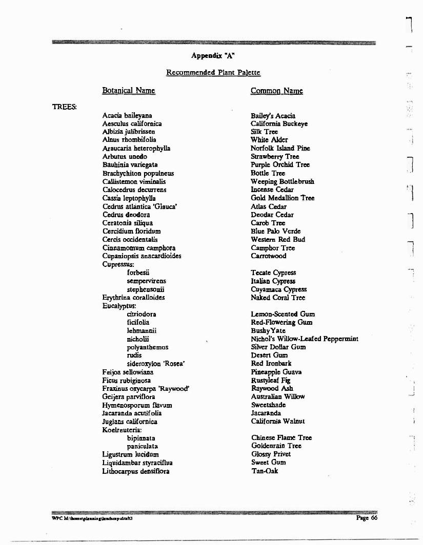
Appendix "A"
Recommended Plant Palette
1
TREES:
Botanical Name
Acacia baileyana Aeseulus californica Albizia julibrissen Alllus rhombifolia Araucaria heterophylla Arbutus uaedo Bauhillia variegata Brachychito11 populaeus Callistemon viminalis Calocedrus decurrens Cassia leptophylla Cedrus atlantica 'Glauca' Cedrus deodora Ceratonia siliqua Cercidium floridum Cercis occidentalis Cinnamomum camphora Cupaniopsis anacardioides Cupressus:
forbesii sempervirens stephensonii
Erythrina coralloides Eucalyptus:
citriodora ficifolia Jehmannii nicholii polyanthemos rudis siderozylon 'Rosea'
F eijoa sellowiana Ficus rubiginosa Fraxinus oxycarpa 'Raywood' Geijera parviflora Hymenosporum flavum Jacaranda acutifolia Juglans califomica Koelreuteria:
bipinnata paniculata
Ligustrum Jucidum Liquidambar styraciflua Li thocarpus densiflora
Common Name
Bailey's Acacia California Buckeye Silk Tree White Alder Norfolk Island Pine Strawberry Tree Purple Orchid Tree Bottle Tree Weeping Bottle brush Incense Cedar Gold Medallion Tree Atlas Cedar Deodar Cedar Carob Tree Blue Palo Verde Western Red Bud Camphor Tree Carrotwood
Tecate Cypress Italian Cypress Cuyam.aca Cypress Naked Coral Tree
Lemon-Scented Gum Red-Flowering Gum BushyYate Nichol's Willow-Leafed Peppermint Silver Dollar Gum Desert Gum Red Ironbark Pineapple Guava R ustylea( Fig Raywood Ash Australian Willow Sweetshade Jacaranda California Walnut
Chinese Flame Tree Goldenrain Tree Glossy Privet Sweet Gum Tan-Oak
J
l
l
l __ J
- .
WPC M:Ulamc\f*UUl&'\11;9dlaip\dnftl Pase 66

i ¥ a i '·@ice? ? if
-,
· · 1
I
Botanical Name
Lyonothamnus floribundus 'asplenifolius' Magnolia grandifiora Melaleuca:
linarifolia quinquencrvia
Mctrosidcros escelsus
Olea curopaea 'Fruitless' Parkinsonia aculeata Pin us:
canariensis
halepensis pin ea torreyana
Pittosporum: rhombifolium undulatuui
Platanus: aceri(olia racemosa
Podocarpus gracilior Populus Cremontii Prunus:
cerasi(era 'Krauter Vesuvius' lyonii
Psidium littoralc Pyrus:
callcryana'Brad(ord' kawakamii
Qucrcus: agrifolia chrysolepis engclmannii ilex subcr tomentella
Salix:
gooddingii hindsiana lasiolcpis
Sambucus mexicana Schinus molle Sequoia sempcrvircns Tabcbuia chrysotricha Tipuana tipu Tristania confcrta Umbcllularia califomica
Common Name
Fernleaf Catalina Ironwood Southern Magnolia
Flaxlca( Papcrbark Cajeput Tree New Zealand Christmas Tree Olive Mexican Palo Verde
Canary Island Pinc Aleppo Pine Italian Stone Pinc Torrey Pinc
Queensland Pittosporum Victorian Box
London Plane Tree California Sycamore Fem Pinc Fremont Cottonwood
Purple Lea( Plum Catalina Cherry Strawberry Guava
Ornamental Pear Evergreen Pear
Coast Live Oak Canyon Live Oak Engelman Oak Holly Oak Cork Oak Island Oak
Black Willow
Sandbar Willow Arroyo Willow
Mcdcan Elderberry California Pepper Coast Redwood Golden Trumpet Tree Tipu Tree Brisbane Box California Laurel
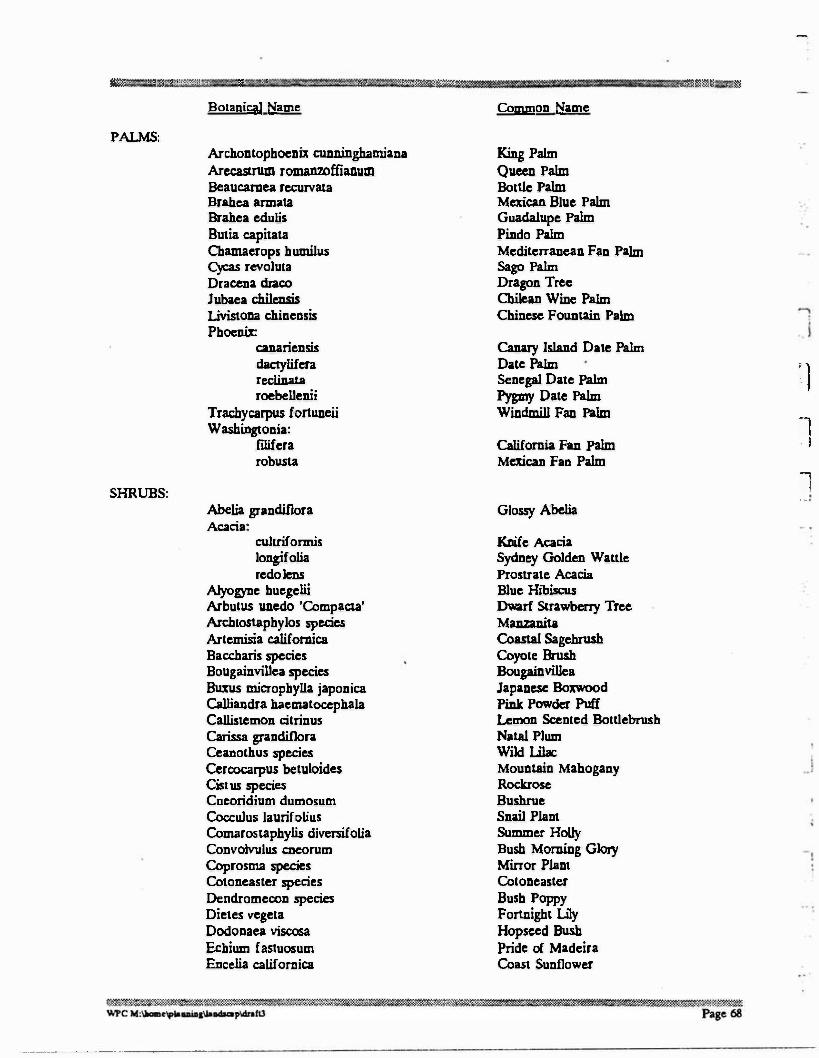
fGM · ' 'I & ? ,:.�e:: ·· n= : , . A s c:: ... ;+:$*®1 : .. ·ik&H:C c �
-.
Botanical Name
PALMS: Archontopboenix cunningbamiana Arecastrum romanzoffianum Beaucarnea recurvata Brabea armata Brabea edulis
Butia capitata Cbamaerops b umilus Cycas revoluta Dracena draco
J ubaea chilensis Livistona cbinensis Pboeni:11::
canariensis dac:tylifera reciinata roebellenii
Trachycarpus fortuaeii
Washingtonia: filifera robusta
SHRUBS: Abella grandiflora Acacia:
c:ultriformis longifolia redo lens
Alyogyne buegelii Arbutus unedo 'Compacta' Archtostapbylos species Artemisia californica Baccharis species Bougainvillea species B= micropbylla japonica Calliandra baematocepbala Callistemon citrinus Carissa grandiflora Ceanotbus species Cerc:ocarpus betuloides Cist us species Cneoridium dumosum Cocculus laurifolius Comarostapbylis diversifolia Convolvulus cneorum Coprosma species Cotoneaster species Dendromeeon species Dietes vegeta Dodonaea viscosa Ecbium fastuosum Encelia californica
Common Name
King Palm Queen Palm Bottle Palm Mexican Blue Palm Guadalupe Palm Pindo Palm Mediterranean Fan Palm Sago Palm Dragon Tree Chilean Wine Palm Chinese Fountain Palm
Canary Island Date Palm Date Palm Senegal Date Palm pygmy Date Palm Windmill Fan Palm
California Fan Palm Mexican Fan Palm
Glossy Abelia
Knife Acacia Sydney Golden Wattle Prostrate Acacia Blue Hibiscus Dwarf Strawberry Tree Manzanita Coastal Sagebrush Coyote Brush Bougainvillea Japanese Boxwood
Pink Powder Puff
Lemon Scented Bottlebrusb Natal Plum Wild Ulac
Mountain Mahogany Rocluose Bushrue Snail Plant Summer Holly Bush Morning Glory Mirror Plant Cotoneaster Bush Poppy Fortnight lily Hopseed Bush Pride of Madeira Coast Sunflower
' l
l . I
1 . . .
---------- .. -·-----·
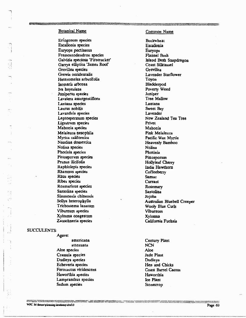
Botanical Name
Enogonum species Escallonia species Euryops pectinatus Fremontodendron species Galvizia speciosa 'Firecracker' Ganya elliptica 'James Roof Grevillea species Grewia occidentalis Heteromeles arbutifolia lsomeris arborea Iva hayesiana Juniperus species Lavatera assurgentillora Lantana species Laurus nobilis
Lavandula species Leptospermum species Llgustrum species Mahonia species Melaleuca nesophila Myrica californica N andina domestica N olina species Photinia species Pinosporum species Prunus ilicifolia Raphiolepis species Rhamnus species Rhus species Ribes species Rosmarinus species Santoliaa species Simmonsia chinensis Sollya heterophylla Trichostema lanatum Viburnum species Xylosma congestum Zauschneria species
SUCCULENTS: Agave:
americana
auenuata Aloe species Crassula species Dudleya species Echeveria species Ferocactus viridescens Haworthia species Lampranthus species Sedum species
Common Name
Buckwheat Escallonia
Euryops Flannel Bush Island Bush Snapdragon Coast Sillctassel Grevillea Lavender Starflower Toyon Bladderpod Poverty Weed Juniper Tree Mallow Lantana Sweet Bay Lavender New Zealand Tea Tree Privet Mahonia Pink Melaleuca Pacific Wax Myrtle Heavenly Bamboo Nolina Photinia Pillosporum Hollyleaf Cheny India Hawthorn Coffeebeny Sumac Cunant Rosemary Santolina Jojoba Australian Bluebell Creeper Wooly Blue Curls Viburnum Xylosma California Fuchsia
Century Plant NCN
Aloe Jade Plant Dudleya Hen and Chicks Coast Barrel Cactus Haworthia Ice Plant Stonecrop
��%.���«���;�:.;1�����-<-:s,»,,n-����..m:sw::��Jii.:�::����w,:;,,:�m-::�:;:;t,w.::;,m���w.���;a,w;...��t!::W'�1:�:r:r::x WPC M:-•lf,il....,sllo-pldnfll Page 69
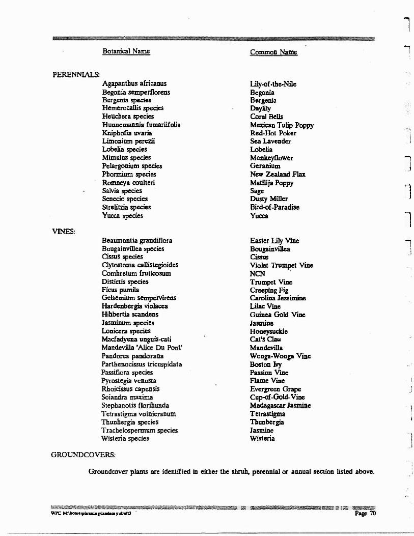
··o/-
Botanical Name
PERENNIALS: Agapantbus africanus Begonia semperflorens Bergenia species Hemerocallis species Heucbera species H unnemannia fumariifolia Kniphofia uvaria Llmonium perezii Lobelia species Mimulus species Pelargonium species Pbormium species Romneya couheri Salvia species Senecio species Strelitzia species Yucca species
VINES: Beaumontia grandiflora Bougainvillea species Cissus species Clytostoma callistegioides Combretum frutirosum Distictis species Ficus pumila Gelsemium sempervirens Hardenbergia violacea Hibbertia sc:andens Jasminum species Loaicera species Macfadyena unguis-cati Mandevilla 'Alice Du Pont' Pandorea pandorana Parthenocissus tricuspidata Passifiora species Pyrostegia venusta Rhoicissus capensis Sciandra maxima Stephanotis noribunda Tetrastigma voinieranum Thunbergia species Trachelospermum species Wisteria species
GROUNDCOVERS:
Common Name
lily-of-the-Nile Begonia Bergenia Daylily Coral Bells MexicaD Tulip Poppy Red-Hot Poker Sea Lavender Lobelia Monkeyflower Geranium New Zealand Flu
Matilija Poppy Sage Dusty Miller Bird-of-Paradise Yucca
Easter lily Vine Bougainvillea Cissus
Violet Trumpet Ville NCN .
Trumpet Vine Creeping Fig Carolina Jessirnine
Lilac Vine Guillea Gold Ville Jasmine Honeysuckle Cat's Claw Mandevilla Wonga-Wonga Vine Boston Ivy Passion Vine Flame Vine Evergreen Grape Cup-of-Gold- Vine Madagascar Jasmine Tetrastigma Thunbergia Jasmine Wisteria
1 -,
l
J
' l
l -,
!
I
: _j
Groundcover plants are identified in either the shrub, perennial or annual section listed above.
�z;:K:1:�J.::��rmi,;;���z����u��r:.��.Y=:®�@�[email protected]:m.1am:;:111#J.:.,.:..:.�.::·.::�� wPc M,...._,,.,....., .......... P""'"' · Page 70