
lain Carlyle Cooke Supervisor: A Scarr - Cranfield University
181
nnýoýma 1401614797 Cranfield Institute of Technology College of Manufacturing PhD Thesis Academic Year 1989-90 lain Carlyle Cooke Design of a PR-oduction Activity Control System 1. or the- Computer Integrated Ma; iuufacturing Environment Supervisor: A Scarr February 1990
-
Upload
khangminh22 -
Category
Documents
-
view
4 -
download
0
Transcript of lain Carlyle Cooke Supervisor: A Scarr - Cranfield University

nnýoýma 1401614797
Cranfield Institute of Technology
College of Manufacturing
PhD Thesis
Academic Year 1989-90
lain Carlyle Cooke
Design of a PR-oduction Activity Control System
1. or the- Computer Integrated Ma; iuufacturing Environment
Supervisor: A Scarr
February 1990

To Kailash

Abstract
This thesis describes the results of research into provision of Production Activity Control (PAC) in Computer Integrated Manufacturing Systems for manufacture of discrete parts. The role and environment of PAC systems is described, against the background of development of the discrete parts manufacturing industry. Strategies and architectures for building PAC systems are reviewed, in terms of the goals of PAC systems, and the categorisation of existing design approaches.
A novel design for a PAC system is presented. A model of manufacturing is described upon which the system design is based, and which defines the applicability of the proposed system. The heterarchical, data-driven system architecture is explained, and the way in which the system's design supports the various aspect of PAC functionality is described. A simple example is presented to illustrate the workings of the system as it accepts production orders and controls production.
An experimental implementation of the system is described, and the results discussed. Recommendations for future implementations are'made in further discussion, stemming from the experiences of this experimentation, and from consideration of wider issues in the development of manufacturing technology. The thesis concludes with a brief statement of achiever nts, an'' some recommendations for directions of further research.

[1
CONTENTS
Chapter 1 Introduction ...... »»... ».. »..... »»»».. »... »»»». ».. ».. »»... »».. »... »».. »»..... »». 1 1.1 Background ......................................................................................................... 1
1.2 The Manufacturing Context ............................................................................. 3
1.2.1 Automation Technologies .......................................................................... 3
1.2.1.1 Production Management Systems ......................................................... 4 1.2.1.2 Computer Aided Design/Computer Aided NC Programming (CAD/CAM) .......................................................................................................... 4 1.2.1.3 Computer Aided Process Planning (CAPP) ......................................... 5
1.2.1.4 Automated Warehousing, Storage and Retrieval ............................... 5 1.2.1.5 Automated Material Handling .............................................................. 5 1.2.1.6 CNC Machining Centres ......................................................................... 5 1.2.1.7 Automated Testing .................................................................................. 6 1.2.1.8 Robotics ...................................................................................................... 6 1.2.1.9 Programmable Logic Controllers (PLCs) ............................................. 7 1.2.1.10 Computers in the Manufacturing Environment ................................ 7 1.2.1.11 Digital Communications and Networks ............................................. 7 1.2.1.12 Database technology .............................................................................. 8
1.2.2 Application ................................................................................................... 9 1.2.2.1 Direct Numerical Control (DNC) .......................................................... 9 1.2.2.2 FMS ............................................................................................................. 10 1.2.2.3 CIM ............................................................................................................. 12 1.2.2.4 The Role of Production Activity Control in CIM ................................ 13
Chapter 2 Status of Production Activity Control »»»»»... »»»»»... »»»». »».. »..... 18 2.1 Supply .................................................................................................................. 18
2.2 Flexibility ............................................................................................................. 19 2.3 Integration ........................................................................................................... 22
2.4 Architectures ....................................................................................................... 26
2.4.1 Executive Logic ............................................................................................ 27
2.4.1.1 Centralised or Hierarchical, Coded Logic ............................................ 27
2.4.1.2 Hierarchical, Data Driven Logic ............................................................ 29
2.4.1.3 Heterarchical, Coded Logic .................................................................... 31
2.4.1.4 Heterarchical, Data Driven Logic .......................................................... 32
2.4.2 Configuration ............................................................................................... 34 2.4.2.1 Generative ................................................................................................. 34 2.4.2.2 Data-based ................................................................................................. 35 2.4.2.3 Compositional ........................................................................................... 36
2.5 Summary ............................................................................................................. 36

II
Chapter 3A Proposed Design »»»»»». »»»»..... »»....... »»»...... .... »... ».. »......... »... 38
3.1 A Model of Manufacturing ............................................................................... 38
3.1.1 The Production Model ................................................................................ 39
3.1.2 The Factory Model ...................................................................................... 42
3.2 Architectural Overview .................................................................................... 44
3.3 Functionality ....................................................................................................... 46
3.3.1 Automated Workstation Control .............................................................. 47
3.3.2 Manual Station Control .............................................................................. 50
3.3.3 Material Handling Control ........................................................................ 50
3.3.4 Schedule Execution ..................................................................................... 51
3.3.5 Job Control ................................................................................................... 55 3.3.6 Production Scheduling ............................................................................... 56
3.3.6.1 Scheduling Information ........................................................................... 56 3.3.6.2 Scheduling Messages ............................................................................... 59
3.3.7 Process Data Management ......................................................................... 62 3.3.8 Tool Management ....................................................................................... 65 3.3.9 Alarm Management .................................................................................... 66
3.3.10 Production Monitoring ............................................................................. 68
3.3.11 Traceability Data Collection/Recording ................................................ 68
3.3.12 Human Resource Management ............................................................... 68
3.3.13 Quality Control .......................................................................................... 69
3.3.14 Production Simulation .............................................................................. 69
3.4 Walkthrough ....................................................................................................... 70
3.4.1 The Manufacturing Model ......................................................................... 70
3.4.2 Scheduling an Order ................................................................................... 74
3.4.3 Manufacturing the Product ....................................................................... 76
3.4.4 Discussion .................................................................................................... 77
Chapter 4A Prototype Implementation N.. NNN. NNNNN... NNNNN. NNNNN ............... ýN" 79
4.1 The CIM Demonstrator ..................................................................................... 79
4.2 Design Feature Testing ...................................................................................... 81 4.2.1 Distributed Processing ............................................................................... 82 4.2.2 Operation Controllers ................................................................................. 83 4.2.3 Location Modelling ..................................................................................... 84 4.2.4 Integration into a CIM System .................................................................. 85 4.2.5 Signals and System Monitoring ................................................................ 86 4.2.6 Commissioning Tools ................................................................................. 87
4.3 Conclusion .............................. N.......................................................................... 87

iii
Chapter 5 Discussion and Recommendations »»........... »...... ». ».... ». ».......... ».... 88 5.1 Implementation Issues ...................................................................................... 88
5.1.1 Operation Controllers ................................................................................. 88 5.1.2 Configurable Algorithms ........................................................................... 90 5.1.3 Messaging Services ..................................................................................... 92 5.1.4 Manufacturing Message Service .............................................................. 93 5.1.5 Databases ...................................................................................................... 94 5.1.5.1 Data Storage .............................................................................................. 94 5.1.5.2 Data Management .................................................................................... 95
5.2 Packaging and Supply ....................................................................................... 97 5.3 Flexibility ............................................................................................................. 98
5.3.1 Sources of Flexibility ................................................................................... 98 5.3.2 The Signalling System ................................................................................ 99 5.3.3 Review .......................................................................................................... 100
5.4 Integration ........................................................................................................... 101 5.5 Summary ............................................................................................................. 103
Chapter 6 Conclusion »»....... ».. »»»»». »».. »». »»»».. ». ».... »». »»»..... »........ »............ 105 6.1 Innovation ........................................................................................................... 105 6.2 Contribution ........................................................................................................ 105 6.3 Areas for Further Work ..................................................................................... 106
6.3.1 Scheduling .................................................................................................... 106 6.3.2 Techniques for Algorithmic Configuration
............................................. 107 6.3.3 Shared Location Management ................................................................... 108 6.3.4 Extending Spatial Modelling ..................................................................... 108 6.3.5 Fault Tolerance ............................................................................................ 109
Acknowledgements . I. N....... N.... N.......... . ............. N. """ 110
References »»»»». »»»»»»». »»»»». »»»»»»... »»»». ».. »»»». »»»»»... »»»»»..... »»». »»».. 111
Appendix A Specification of the Proposed Design .. »......... »...... »............ »...... ». 120 A. 1 The Structure ...................................................................................................... 120 A. 2 The Database ....................................................................................................... 122 A. 3 The Protocols ...................................................................................................... 128
A. 3.1 Operation Controller Interface .................................................................. 129 A. 3.2 Activity Controller Interface ..................................................................... 131 A. 3.2.1 Executive and Operational Messages
................................................... 131 A. 3.2.2 Normal Data Management Messages
................................................... 141 A3.2.3 External Command Messages ................................................................ 147 A. 3.2.4 Enquiry and Reporting Messages
.......................................................... 150

iv
A. 4 The Algorithms .................................................................................................. 153 A. 4.1 Ranking ......................................................................................................... 153 A. 4.1.1 First In, First Out ...................................................................................... 153 A. 4.1.2 Importance and Urgency ........................................................................ 153 A. 4.1.3 Assessing the schedule ............................................................................ 154 A. 4.2 Order Processing ......................................................................................... 154 A. 4.2.1 Simple Fixed Preference .......................................................................... 154 A. 4.2.2 Ranked Option Assessment - Minimum Loading .............................. 155 A. 4.2.3 Ranked Option Assessment - Quality of Service ................................ 155 A. 43 Scheduling .................................................................................................... 156 A. 4.3.1 Priority-Based Back Loading .................................................................. 156 A. 4.3.2 Forward Loading ..................................................................................... 157 A. 4.4 Validating ..................................................................................................... 157 A. 4.5 Quoting ......................................................................................................... 158
A. 5 The Events ........................................................................................................... 159
Appendix B Operation Controllers »»»»»». »»».. ». ».. ».... »... »».. »....... »........... »..... 162 B. 1 Single CNC Machine or Robot ......................................................................... 162 B. 2 Manual Workstation .......................................................................................... 163 B. 3 Complex Workstations ...................................................................................... 164
Appendix C Petri Nets »»»»». »»»»»»..... »»»». »»».. »». ».. »»........... »... »».. »... »».... ». 166
Appendix D Fault Tolerance NNNNNNýNNNNNNýwNNNNýNNNýýNwýNýýNýýýNNNýýýý1ýýNýýNýýýýýýý 169

V
FIGURES
FMS Application Range ............................................................................................... 11
PAC Interfaces to CIM Subsystems ........................................................................... 14
Sharing Data Between Systems ................................................................................... 23
PAC Input Data Structure ........................................................................................... 25 PAC System Design Features ...................................................................................... 26 Simple Production Operation Models ....................................................................... 39 Production Model of a Turning Operation ............................................................... 41 A Simple Factory Model .............................................................................................. 42 Process Architecture ..................................................................................................... 46
Operation Controller State Machine .......................................................................... 47
Common Location Exchange Message Sequences ................................................... 54
An Example Machining Cell ....................................................................................... 71
Schematic of Control Structure ................................................................................... 72
Example Operation Models ......................................................................................... 73 Schematic of a Production Schedule .......................................................................... 76 The CIM Demonstrator Manufacturing System ...................................................... 80 Schematic of CIM Demonstrator Control System
.................................................... 81
Processing Architecture ............................................................................................... 120 Entity-Relationship Diagram of Activity Controller Database .............................. 121
Effect of Fault Tolerance on Performance Under Failure ....................................... 168

vi
Abbreviations
AC Activity Controller
ACK Acknowledge(ment)
AGV Automatic Guided Vehicle
AI Artificial Intelligence
Automated Manufacturing Research Facility, an experimental installation at the NBS
AS/RS Automated Storage and Retrieval System
BOM Bill of Materials
CAD Computer Aided Design
CAD/CAM Computer Aided Design and Manufacture
CAM Computer Aided Manufacturing. In this context, refers to computer (aided) preparation of process machine programs.
CAPP Computer Aided Process Planning
CAT Computer-Aided Testing
CIM Computer Integrated Manufacture
CIM/OSA CIM Open Systems Architecture
CMM Co-ordinate Measuring Machine
CNC Computer Numerically Controlled (of machine tools)
DC Direct Current
DNC Direct Numerical Control
FIFO First-In-First-Out -a queuing algorithm
FMS Flexible Manufacturing System
ID Identifier, or Identification
ISO International Standards Organisation
ITT Invitation to Tender
JIT just-In-Time
vii
LIFO Last-In-First-Out -a queuing algorithm
MAP Manufacturing Automation Protocol, a communications network standard
MMS Manufacturing Message Service, an application-level communications protocol definition
MRP Materials Requirement Planning
MRP II Manufacturing Resource Planning
MSc Master of Science
NACK Negative Acknowledge(ment)
NBS National Bureau of Standards, a US standards body
NC Numerically Controlled (of machine tools)
OC Operation Controller
OSI Open Systems Interconnect(ion)
PAC Production Activity Control
PC-AT An 80286-based (IBM) Personal Computer
PES Production Engineering System (as used in this thesis, consists of CAD, CAPP, CAM, and other engineering systems)
PLC Programmable Logic Controller
PMS Production Management System
RAM Random Access Memory
RDA Remote Database Access
RDBMS Relational Database Management System
RS232 A serial communications standard RS511 see MMS
SQC Statistical Quality Control
SQL Structured Query Language
VDU Visual Display Unit, a computer-driven screen

1
Chapter 1 Introduction
This thesis addresses a part of the problem of providing control for highly
automated discrete parts manufacturing plants. The objective of the research was to develop a novel design for a Production Activity Control system, providing that level of control which is concerned with the minute to minute co-ordination of the machines and people in the Computer Integrated Manufacturing (CIM) environment. The design was to seek to overcome some of the problems associated with providing control at this level, and thus to bridge the divide between the high-level management and engineering applications, and the low-level machine control systems that are found in industry today.
The rest of this introduction describes the context of this work in manufacturing systems and practice. The evolution of manufacturing industry is outlined, followed by a discussion of the systems that are being applied in manufacturing today, and the directions of development. This defines the frame of reference within which this work was carried out, and within which the results of this work have their application.
The next chapter raises some of the issues and problems within this frame of reference, and identifies and defines those that this work seeks to address. Other work and systems in this area are reviewed to illustrate the problems and some of the solutions that have been proposed.
This is followed by a description of the solution to these problems that is proposed in this thesis; a strategy and system design for managing the control of production activities. The major features of the design are laid out, and its operation walked through.
In Chapter 4, an experimental implementation of the system is described. This implementation controlled a highly automated flexible manufacturing cell, which formed part of a demonstrator of CIM principles. The results of this work are then analysed and discussed, and some recommendations made for future implementations. In conclusion, a brief statement of the work is presented, and recommendations made for further research related to this work.
1.1 Background Manufacturing industry is constantly evolving towards ever more capability and productivity. The evolution of manufacturing is driven by competition, and goes hand in hand with the evolution of the products of manufacturing. It is fuelled

2
by advances in technology and social and organisational science. The key factors in the evolution of manufacturing are those that affect the competitive standing of a company's products. These can be listed as [50]:
" Cost of Manufacture,
" Product Quality,
" Diversity/Variability of Product, coupled with, " Manufacturing Lead Time,
" Speed of Introduction of New Product,
" Cost of Introduction of New Product.
The drive is always to be able to manufacture a greater range of products, of higher quality, at lower cost. In addition, there are significant advantages to being able to manufacture to order, which is determined by manufacturing lead time, especially if there is a wide product range, since this reduces the requirement for holding finished stock. Reduced 'concept-to-market' time is becoming an increasingly important marketing weapon in many standard-product industries, whereas in the jobbing shop* environment, these factors directly affect the order-delivery lead time. Similarly, the costs of introducing new products must be reduced as the product lifetimes, and hence the available sales for amortization are reduced.
In any one company at any one time, there exists a balance between these factors, because with a given level of applied technology and techniques, they exist in a complex equilibrium. Improving performance against one of these factors will almost always affect some of the others adversely. Changes in manufacturing practice and technology allow progress which is more than just shifting the focus from one factor to another.
The significant changes in manufacturing practice can be seen to contribute to improvement of one or more of these factors across a broad range of companies. The chief trend, especially in the West, has been an increasing use of mechanization, automation and, more recently, computer based systems, in progressively more areas of manufacturing activity [56,97]. It has been suggested [21,53] that this process can be seen as passing through four stages:
(i) Mechanization - Human labour replaced or assisted by machine. This process has continued since the industrial revolution, and is exemplified by power lathes and other machine tools, conveyors, forklift trucks, sewing machines, and any number of dedicated machines, or hard automation [521.

3
(ii) Point Automation, or Soft Automation - Direct human control replaced by some form of program. This really caught hold in the 1960s with the advent of digital technology, and is exemplified by NC and CNC' machine tools, AGVs2, and the introduction of Computer Aided Draughting, MRP3, Accounting systems, and other specialist software systems.
(iii) Islands of Automation - Extension of point automation to interface with the local environment and manage a part of the manufacturing system. Islands of automation became a noticeable trend in the 1970s with the advent of FMS' and DNC5, Integrated Material Handling, CAD/CAME, MRP ll and other systems. Manufacturing as a whole is still moving towards full exploitation of these systems [88].
(iv) Computer Integrated Manufacturing (CIM) - The integrated application of computer-based automation and support systems to all areas of manufacturing business. CIM is a essentially statement of the goal of current developments in manufacturing, and is further described in the next section.
1.2 The Manufacturing Context Discrete parts manufacturing, as an industry, is undergoing a period of rapid development. New management and organisational outlooks are attracting a great deal of interest, and are being adopted by some, though perhaps more slowly than might be desired [25]. Many companies are in the process of implementing one or more islands of automation, and for some this is a part ut a long term plan to move towards CIM [1,88]. The more significant of the new technologies, with respect to this work, are summarised here.
1.2.1 Automation Technologies This section outlines the relevant automation technologies that are being applied in industry today. The focus of these descriptions is on features of these technologies that impinge on the problems and solutions of providing
1 Numerical Control and Computer Numerical Control machines. 2 Automatic Guided Vehicles.
3 Material Requirements Planning.
4 Flexible Manufacturing System(s).
5 Direct Numerical Control.
6 Computer-Aided Design, linked to Computer Aided Manufacturing, which generally means automatic generation of NC programs in this context. 7 Manufacturing Resource Planning.

4
Production Activity Control. For a fuller treatment of the technologies themselves, the reader is referred to other works. The first three are 'office'
systems, concerned with defining what is to happen in the manufacturing system. Sections 1.2.1.4 to 1.2.1.8 highlight important shop-floor, 'executive' technologies. Finally, some enabling technologies, which are important to the development of CIM, are mentioned.
1.2.1.1 Production Management Systems Production management systems apply computer power to a wide range of planning and clerical tasks that exist within the manufacturing business [21]. Actual implementations of PMSs vary considerably in their scope and capabilities, but they typically:
" Support planning and scheduling activities within time scales from a few
years down to days or hours.
" Support generation of the purchase orders necessary to accomplish these plans.
" Support recording of actual incoming orders, and, relate them to the forecasts.
" Generate, for use on the shop floor, the appropriate data and documentation for executing production plans.
" Support modelling of production information in the form of bills of materials, and rudimentary process plans.
These last two functions can be seen to overlap with functions of other areas (PAC and CAPP), which is a typical consequence of the development of islands of automation. Normally, although two islands may make use of essentially the same data, it is very difficult to have them share this data, or even transfer the relevant parts of it between them.
1.2.1.2 Computer Aided Design/Computer Aided NC Programming (CAD/CAM) Computer aided design (CAD) systems are tools which contribute to reducing the concept-to-product lead time, by facilitating the production of product design information, especially drawings. They are quite often successfully linked to, or supplied with computer aided NC programming tools, resulting in
a system that can significantly aid production of a machine tool program that will manufacture parts that are drawn on the system [36]. Furthermore, some systems are now able to generate programs for robotic devices, through the use

5
of simulation and three-dimensional modelling [103]. Unfortunately, this program generation functionality overlaps with process planning functions, but is not usually integrated with CAPP systems.
1.2.1.3 Computer Aided Process Planning (CAPP) These systems help to define the complete set of manufacturing operations that must be performed to produce a finished part or product [51]. Together with the preparation of production process programs, this potentially generates all the information needed to actually manufacture a product [109].
1.2.1.4 Automated Warehousing, Storage and Retrieval These systems provide the ability to store, under computer control, all of the tools, materials, and finished or un-finished parts that are required within the manufacturing system [52]. They can not only greatly reduce the floor space required by stocks, but can also make dramatic improvements in inventory control. As a part of an automated materials handling system, they allow highly automated manufacturing facilities to work on a much bigger scale than is otherwise possible. It is vital to the efficiency of a manufacturing system that materials and tools be available at the right place at the right time. In industries where storage of significant amounts of material or tools are necessary, integration of the control of inventory with the PAC system is a vital link in the CIM chain.
1.2.1.5 Automated Material Handling Automation of material handling provides for movement of materials, tools, and parts around a production facility without human intervention [52]. When installed as a part of an FMS or other highly automated system, the material handling system will generally be capable of interfacing to the various process machines to the point where loading and unloading of work-pieces and sometimes tools, is entirely automated [62,101]. This arrangement removes the physical requirement for human machine operators. Bringing material handling
and movement under the control of the PAC system increases the levels of complexity and flexibility of movements that can practically be achieved.
1.2.1.6 CNC Machining Centres CNC machines offer a fundamental level of flexibility for automated production systems, not only by being extremely versatile in their machining capabilities,

6
but also by often having features which facilitate long periods of unsupervised operation, and integration into fully automated systems [42]. Some of the more advanced machining centres feature:
" automatic pallet changers,
" wide-capability machining (i. e. turning and 5 or 6-axis milling).
" automated tool changing from a tool carousel,
" automated stocking of tool carousel,
" in-process gauging, and tool monitoring. Most feature some method of electronic transfer of machining program to and from the machine, although they vary considerably in technical details of this', and what other features or data are accessible through a computer link. It is therefore often not trivial to interface a CNC machine into an integrated system [11].
1.2.1.7 Automated Testing Automated testing not only allows the more extensive testing that is necessary for stringent quality assurance, but also can be used to replace much of the 'casual' testing that is lost as people are removed from the production system. Automated testing systems use a variety of technologies [52], and many are capable of reporting complex test data in addition to simple pass/fail assessments, allowing statistical quality control systems to predict failure before it occurs. This information can be fed back into the PAC system, and may IT used for both influencing the activities performed, and for quality tracing and audit.
1.2.1.8 Robotics Industrial robots allow for programmable automation of a wide range of tasks,
especially as a direct replacement of people as manipulators and tool-users [45]. The range of tasks they have been successfully applied to is continually expanding as ever higher-specification robots and as sensor technologies are integrated into robot application systems. Most robots have I/O capability through both DC signals and computer links, although as with CNC machines, the facilities available through computer links vary considerably. Robots can be
controlled by a PAC system either as process machines, or as a part of the materials handling system.
1 For older machines, it is often a case of replacing a paper tape reader with a serial interface.

7
1.2.1.9 Programmable Logic Controllers (PLCs) PLCs provide the ability to handle, process, and control large amounts of discrete signals in real time [52]. Often they have been used to implement all the control functions of automated systems by means of the combinatorial and sequential logic that makes up a PLC program [108]. Many PLCs now feature a general purpose computer interface, through which programs can be transferred and the execution of the program affected. As usual, though, there is a wide range of capabilities available through these interfaces. PLCS are evolving from programmable implementations of relay logic systems towards general-purpose computers with extensive I/O capability, whilst some general-purpose computers are converging on this same niche from the opposite direction [17]. The main identifying characteristics of PLC systems are the programming system (usually ladder logic) and the dedication to fast responses to signals.
1.2.1.10 Computers in the Manufacturing Environment General-purpose computers are finding increasing use in the manufacturing environment. Much of their early use was for 'office' applications, where the computers were restricted to reasonably friendly environments, and not directly applied to shop floor activities. More recently, general purpose computers have been increasingly used in applications concerning shop floor activities, and sometimes the machines themselves have been installed in the harsher manufacturing environment. This has been made possible not only by a general increase in the reliability and tolerance of standard computers to electrical and electromagnetic noise, temperature, and dirt, but also by the introduction of a new breed of "hardened" Industrial Computers [991, whose software characteristics are the same as more standard machines, but which have been specially adapted for the harsher environment.
1.2.1.11 Digital Communications and Networks The ability to communicate between the various sub-systems and programs that make up the manufacturing system is absolutely vital if any form of integration is to be achieved. There is a plethora of systems and methods of communication which can be used in the task of system integration [32,75], the diversity of which can of itself cause significant problems and costs when it comes to effecting systems integration [1].

8
Communications systems can be partitioned into three basic types:
(a) Point-to-point, (b) Polled, or hosted network, and (c) Peer network. Each of these have implications for the cost and complexity of connecting up the elements of an installation. As a rule, peer networks are the most expensive in simple node connection costs, and the most flexible in functional terms, whilst point-to-point connections (e. g. RS232) are the least expensive interfaces, but also the least flexible in functional terms. It is these simpler interfaces that are almost invariably found on manufacturing equipment today. Unfortunately, for any but the simplest systems, point-to-point connections carry a heavy overhead in installation, management, and maintenance. The emergence of peer networks will have a major impact on the architectures of future control systems, encouraging the development and use of more distributed systems [100].
Moves are being made in the industry to standardise communications networks. Many of these are now being based on the ISO Open Systems Interconnection (OSI) 7-layer model, an international standard defining a framework for communications protocol definition [3]. Of special interest in the manufacturing arena is a communications standard designed especially for the application: Manufacturing Automation Protocol (MAP) [5].
Apart from defining protocols for message transmission across peer networks, MAP also specifies a number of application-level protocols. One of these, Manufacturing Message Service (MMS) is aimed at standardising the messages used across the network to effect control and monitoring of shop floor equipment [30]. MMS offers a standard for the message syntax and meaning for a wide range of operations, including functions such as program transfer and remote cycle start. If MAP gains widespread acceptance, it will make the task of providing off-the-shelf shop-floor control packages much easier, by eliminating the variability in machine interfaces and providing a basic level of service that control systems can expect [33].
1.2.1.12 Database technology
Complex computer systems often require storage and retrieval of large amounts of structured data. Advanced systems for performing this function have now emerged, notably in the form of relational database management systems [35], which offer an independent and open systems approach to the storage and retrieval of data. The protocol and language for data retrieval and manipulation is becoming standardised around SQL [4], which presents the opportunity of

9
interchangeable database management systems which may then be selected on the basis of their performance and cost characteristics. The separation of data
management and storage into a system separate from the applications programs can offer significant benefits when trying to integrate independent applications into a coherent system [57,65].
1.2.2 Application All of the above technologies are being applied in industry at the time of writing. 60-70% of British manufacturing companies have Stock Control and Production Planning systems (which makes up the bulk of PMSs), and around 50% have CAD or CAD/CAM systems installed [1,88]. The other technologies are also being applied, but often as implementations of point automation, using the technology to attack a specific task or problem within the manufacturing system.
Increasingly, though, industry is taking steps to integrate the application of these various automation technologies. This integration process often involves building islands of automation, but effectively is leading towards CIM. In order to achieve this integration, control at the level that this thesis is concerned with becomes necessary. The integrated systems that are being implemented and used in industry vary considerably in their capability and scope, and consequently the requirements for their controlling systems vary.
1.2.2.1 Direct Numerical Control (DNC) Direct Numerical Control is essentially the integration of CNC machining centres with a computer system that will store a library of part programs, and which can download these programs to the machine tools when required. It has evolved from early systems where the programs were downloaded one instruction at a time, (hence 'Direct'), and is now occasionally called Distributed Numerical Control to emphasize the difference [52]. Often, the central 'controlling' software has additional functionality that allows determination of which program is to be
used next on which machine, and record keeping and reporting facilities so that management can determine what is happening, and what has happened.
The main benefits of DNC are [11]:
" Removal of paper tape (or other media) from shop floor, resulting in greater data integrity, and
" Greatly improved configuration control and management of NC data,
" Ability to impose schedules on the shop floor, by pre-determining the next program to be run,

10
" Accurate feedback of time taken for jobs,
" Accurate logging of machine breakdowns, and
" On-line status information available from a single point,
although these last three are much less commonly exploited than the others.
DNC systems are often effectively linked to automated NC programming systems, by the simple expedient of sharing or transferring program files between the systems.
Elements of activity control that sometimes exist in DNC systems are:
The ability to follow a 'schedule' of work for each machine, so that the operator of the machine will simply request the 'next job',
0 The ability to log and report job times and breakdowns,
0 The ability to provide on-the-spot status reports. Typically, the implementation of these functions is fairly simplistic, and involves interaction with both machine operators and engineering management staff to enter the data and carry out the actions required. The only part of the production activity that is fully automated is the transfer of NC programs. Nevertheless, DNC systems represent the first integration step towards achieving CIM, and can provide substantial benefits by themselves.
1.2.2.2 FMS Flexible Manufacturing Systems can be seen as applying CIM principles and techniques to a limited part of the manufacturing system [92]. Typically, they are used for production of families of parts in medium' volumes (Figure 1), and make up a part of a larger manufacturing system. The FMS as a whole can be regarded as a single production resource, albeit very complex and capable, and generally able to process many jobs at once.
FMSs are usually very highly, if not fully automated. Sometimes, 'roving' machine operators will be included, who are each responsible for jobs like loading and unloading several machines. There will often be 'servicing' personnel who carry out jobs such as replenishing tool magazines for the machine tools. These kinds of operations continue to be performed by people when automating them would not be cost-effective, which can often be the case if machines and processes are used which were not designed with integration into an automated environment in mind. For some systems, it is also economic
1 Roughly 5,000 to 75,000 parts per year, dependent on a wide variety of factors.

11
High
Flexible Medium C Manufacturing
Systems
Low
Product Diversity
Low Medium High
Figure 1: FMS Application Range
to include human workstations for particular processes, when the process itself is not amenable to automation. However, these operatives can be serviced by the system as would other, automated processes.
The main benefits of FMSs are:
" Higher machine utilization. This is usually a result of more efficient work handling, better co-ordination of processes /better scheduling, and off-line set-ups (on-line set-up time tending to zero).
" Smaller economic batch sizes, tending to a batch size of one.
" Lower manufacturing lead times.
" Greater flexibility in production scheduling.
" Reduced work in progress. These factors depend on each other to a significant extent, and largely result from the changes in methods, organisation, and control that are required or used to build the FMS. Quality also tends to become more uniform as automation levels are increased, which of itself will reduce quality problems. Cost and speed of introduction of new products (with respect to the FMS) can also be reduced drastically, as long as the new product falls within the scope of the design flexibility of the system. It is interesting to compare these benefits with the key factors in manufacturing noted in section 1.1. Further discussion of FMS systems can be found in [52], [62] and [63].
A key factor of FMS installations is the fact that they are organised and controlled by computer systems. The requirements for the control system of an FMS are largely the same as the requirements for the control system for the shop floor activities in a CIM environment. The main differences are issues of interfacing

12
the control system with the 'office' systems (PMS, CAPP, and CAD/CAM), and with other parts of the shop floor, including other production areas, tool shops, stores, etc. Almost by definition, the control system of the FMS will not be fully integrated with these other areas. Often, the other areas of the shop floor will not be under computer control anyway.
With respect to the 'office' systems, an FMS control system will normally be given short-term schedules as an input, though will often be responsible for scheduling that work within the FMS. The controller needs to know the materials, routings and NC programs that are required for each part that the FMS can make. This data can be transferred from the PMS, CAD/CAM and CAPP systems, if they exist, but it is often entered into the FMS separately, if only because of the difficulty of getting disparate systems to communicate. Consequently, FMS control systems often contain a lot of functionality which is not properly Production Activity Control, but supporting functionality that really belongs in other parts of a CIM system.
Generally, raw materials, input parts, tools, etc. are all supplied from the 'outside' of the FMS system, and are assumed by the FMS to be available when required. These items are typically delivered and loaded into the appropriate parts of the FMS manually. Consequently, the loading interface of the FMS consists of some physical device to receive and locate the object, and some method of informing the control system what has been loaded, ranging from bar code readers through keyboards and VDUs to simple push-buttons. Sometimos the information flow is two-way, with the control system requesting what is to be loaded.
FMS control systems also typically have a 'management console' at which various reports can be obtained, the operation of the FMS can be monitored, and through which action can be taken in the event of alarms and errors, or for other reasons, to control the operation of the FMS [60].
1.2.2.3 CIM CIM is a label for a wide range of ideas and concepts, and descriptions of CIM, though many and varied, all centre around the idea of providing very high levels of computer assistance to all aspects of the manufacturing business, together with the idea of integrating all of these systems and activities together into an harmonious and efficient business. The goal is to bring together all the weapons that have been developed for improving the six key manufacturing factors of section 1.1, and employ the synergy between them to advance on a broad front.

13
Whilst there is no agreed strict definition of CIM, there is a general consensus as to what sort of systems are included, and there have been suggestions for
reference models for manufacturing [85], and an "open systems" architecture for CIM [90]. The key element, though, is integration. It is necessary for the various sub-systems to communicate effectively to move from the islands of automation phase into CIM, and exploit the full potential of introducing computer systems into all areas of the manufacturing business.
As such, it represents an extension of the functionality and integration that has been developed and implemented in the FMS systems of today. Alternatively, broad-brush application of computer systems in the factory, where all areas of the shop floor are linked to the computer systems by both shop-floor data collection devices and some means of managing and co-ordinating activity, is also a legitimate route to CIM, without the high levels of automation that are typically found in FMS systems [43]. Along both of these development routes, and in part due to the absence of any strict definition of CIM, the 'achievement' of CIM can be a difficult thing to determine. It is probably best to regard CIM in the same way as Japanese manufacturers regard Just In Time manufacturing, as a goal which is never reached, but towards which improvements can always be
made [93].
A result of taking this view is to be able to form a simple definition of CIM:
" All information which needs to be stored in the manufacturing system should be held and managed by computer systems,
" All activities within the manufacturing system should be supported and automated as far as possible by computer-based systems, and
" All of these systems should be integrated so that all information flow between them is achieved by direct, system-to-system communication.
The scope of this is intended to be as wide as possible - by referring to "the manufacturing system", this can include several separate businesses. In line with the style of the JIT goals of no waste, no set-up, total quality, etc., this definition could not ever be said to have been achieved.
1.2.24 The Role of Production Activity Control in CIM Production Activity Control forms the executive arm of a CIM system. It takes information on how to make products, and schedules of when to make them, and is responsible for managing the actions required to meet those schedules, and for providing management information needed by other CIM sub-systems.

14
Throughout this thesis, the phrase Production Engineering System(s) (PES) is used as a collective term to refer to the family of computer systems that aid the complete design and production planning activities. This definition is useful as a categorisation contrasting with Production Management System(s).
The interfaces and information flows between PAC and its environment are shown in Figure 2, and detailed in the tables below.
Production Management System Production Engineering Systems
Stock Production Control Control CAD
Bill of NC ý. Materials Programming
Production Activity Control
Materials Process Handling Machines UT
Figure 2: PAC Interfaces to CIM Subsystems

15
Table 1: Information Flows into PAC
From Information
Production Scheduling Short-term schedule information, manufacturing orders
Bill of Materials Product structures
Process Planning Part processing specifications, tooling requirements, quality requirements
Stock Control Stock locations and quantities NC Programming, Part processing programs Robot Programming, etc Process Machines Progress information, perhaps quality information
and tool wear information
Stores, Material retrieval and storage details Automated Storage and Retrieval (AS/RS)
Materials Handling Location and movement status information
Computer-Aided Test results, quality information Testing (CAT)
Table 2: Information Flows out of PAC
To Information
Production Scheduling Progress/order dosing information, timing information
Process Planning Actual performance, times, tool usage, etc. Stock Control Stock movement information Process Machines Part Programs, control commands
Materials Handling Routing/movement instructions
Stores, AS/RS Material requests CAT Testing instructions

16
The detailing of functionality within PAC systems tends to vary from one specification to another. This can be attributed to:
" Real differences in functionality supplied,
" Different groupings or division of functions,
" Differences in the assumed environment for the system. This last point reflects both the uncertainty over the architecture and functional allocations of CIM, and also that implementations and designs for PAC systems are often conceived as essentially stand-alone systems, which may be integrated into a CIM system when such an environment exists. Prime examples of this are FMS and other cell controllers, designed and implemented for stand-alone, or only partially integrated cells.
However, a set of functionality can be drawn up which includes the major PAC functions [941. The list below represents functions that are usually found in PAC systems:
(a) Job Control
Tracks jobs or orders through the production system, supporting status enquiries.
(b) Production Scheduling
Supports short-term scheduling activities, by manual specification and/or automatic generation.
(c) Schedule Execution
Co-ordinates of production resources according to the production schedule.
(d) Automated Workstation Control
Communicates with automated production resources, causing physical actions to occur, and tracking status.
(e) Manual Station Control
Provides direction and assistance to manual workstations, and tracks status.
(fl Material Handling Control
Communicates with various devices/people to cause the movement and storage of material. Also tracking status and position of materials as far as necessary.

17
(g) Process Data Management
Manages the information requirements of the production system; process plans, routings, part programs, quality specifications, manual instructions, etc.
(h) Tool Management
Ensures that the right tools are at the right workstations when needed. Can also include tracking/maintenance of tool lifetime information.
(i) Alarm Management
Provides notification, dispatching, and logging of problems and errors. Possibly also takes automatic action such as re-routing parts, shutting down, etc.
Some other functions are sometimes included within the PAC remit:
(j) Production Monitoring
Tracks production results and statistics such as utilisation, down time, etc. (k) Traceability Data Collection/Recording
Compiles detailed records for traceability requirements, such as input batches, process /machines used, test results, etc.
(1) Human Resource Management
Directs and tracks assignment of people whose tasks are not confined to workstations, such as tool loading, set-ups, maintenance, etc.
(m) Quality Control
Supports real-time quality control functions such as statistical quality control, tracking/analysing test results, and possibly taking corrective action (such as unscheduled tool changing).
(n) Production Simulation
Allows a simulation of production system activities to be run, perhaps to identify potential problems, and to provide information to help with management of the system.
In order for a PAC system to be integrated into a CIM system, it is necessary for the interfaces to exist to facilitate appropriate information exchanges with other CIM sub-systems, and for the functionality to make use of these connections to the rest of the CIM system as and when appropriate. For example, the Process Data Management function, in a CIM environment, could be no more than a means of accessing information that is properly managed by other systems, but which is required for operation of the system.

18
Chapter 2 Status of Production Activity Control
This chapter examines the state of the art in Production Activity Control.
The key issues in industrial implementation of CIM (with respect to Production Activity Control) are highlighted in sections 2.1 to 2.3, and some of the problems of industrial implementation to date are detailed. In this discussion, the design goals and requirements of PAC systems are derived.
Section 2.4 presents a critical survey of approaches to providing PAC that have been proposed or implemented. The various strategies are categorised, and the philosophy and representative systems in each category discussed, with analysis of the strengths and weaknesses of the strategy.
Finally, the discussion of this chapter is consolidated by a summary of the problems that have been highlighted, and a brief statement of the goals and requirements of the strategy that is the subject of this thesis.
2.1 Supply Introduction of computer-based control to the shop floor, whether for highly automated or largely manual facilities, faces the problem of procurement of the control system software. Until recently, the only realistic options that were open to system integrators were:
Develop an in-house control system, or Have an external contractor develop the control system.
This is evident from accounts of implementation experience [41,62,63], and is the first stage in the application of computer technology to a new area. The problems of bespoke systems development are significant, though, and can be summed up as:
High cost, High risk, High levels of required expertise.
The cost is high both in monetary terms, because the entire development cost is applied to just one installation, and also in terms of the time taken by the development process. The risk is high, largely because software development is difficult to estimate and is currently a high risk activity [15,20]. Development of a software control system, by nature, requires a very high level of expertise, in both specifying the requirements, and also in designing and implementing a

19
system. If this expertise is not already available within the company or companies involved in the development, then it must be gained, which implies a longer time lag, and also greater cost and risk.
Reduction of these three factors requires the development of 'packaged', standard solutions to (elements of) the problem of providing PAC, which can be fitted to a wide range of circumstances and installations [105]. The benefits of packaged approaches are:
" Spreading the development cost over multiple installations, hence reducing the cost of each one,
" Reduction in risk by re-using proven designs and software, " Reductions in expertise requirements by applying known and developed
solutions. A market in PAC systems and solutions which are packaged to various degrees is beginning to develop, which offers a new third option of installing a packaged solution. The vendors fall into four categories [94]:
" Machine tool vendors,
" Computer and control hardware vendors,
" Third party software products,
" Systems integrators.
However, there is still no fully packaged, generally applicable system or strategy, and hence there is also a good deal of research work being done in this area [55,70,81]. The aim for any PAC system design must be to reduce cost, risk, and the expertise required for installation and use to the minimum, by increasing the applicability, robustness, and ease of use of a packaged system.
2.2 Flexibility In order to be a viable packaged solution, a PAC system must exhibit a high degree of flexibility. Eight types of flexibility have been defined for the analysis of Flexible Manufacturing Systems [22], which apply equally well when considering production facilities and systems within a CIM business. The higher the level of flexibility in a manufacturing system, the better it is able to weather the changes of product and production that are required to remain competitive in today's world markets [24]. The manufacturing system flexibilities are:
(i) Machine Flexibility - measures the ease of making changes required to produce a set of parts; ability to change tools, fixtures, etc.

20
(ii) Process or Mix Flexibility - measures the mix of jobs that the system can process at once.
(iii) Product Flexibility - measures the ease of changing product details, or introducing a new product.
(iv) Routing Flexibility - the ability to use secondary/alternative production routes when a machine is inoperative or breaks down.
(v) Volume Flexibility - the production volume range between minimum profitable volume and maximum capacity.
(vi) Expansion Flexibility - the ability to expand the system easily and modularly.
(vii) Operation Flexibility - the ability to change the ordering of part production steps, especially as a real time scheduling decision.
(viii) Production Flexibility -a measure of the scope of total production capability.
It can be seen that most of these flexibilities of the production system as a whole must be effectively supported by corresponding flexibilities in the control system. In addition, in order to succeed in designing a packaged PAC system that can be applied to a wide range of production installations, there must also be some elements of flexibility in the system relating to the installations it can be applied to. To some extent, this overlaps with the requirement for Expansion Flexibility, since expanding the controlled system could be equated to applying control to a different system.
A set of flexibilities that are desirable in a strategy for Production Activity Control can therefore be defined:
(i) Mix Flexibility - measures the mix of jobs that the system can control at once.
(ii) Product Flexibility - measures the ease of changing product details, or introducing a new product, with respect to the control system.
(iii) Routing Flexibility - the ability to use secondary/alternative production routes when a machine is inoperative or breaks down. Also, the ability to make use of alternative production routes as an aid to throughput. This encompasses Process Flexibility from the manufacturing system definitions.
(iv) Expansion Flexibility - the ability to cope with expansion of the system controlled (and if necessary, with expansion of the control system) easily and modularly, after the system has been initially installed.

21
(v) Scheduling Flexibility - measures the time frames within which changes to the production schedule can be made or accepted. Schedule changes should include taking advantage of the routing flexibility of the control system.
(vi) Device Flexibility - the range of types of devices (including humans) that can be controlled by the system, and the ease of accommodating new devices.
(vii) Interface Flexibility - the ease of interfacing the system to the various devices; a measure of the range of communications types and protocols supported.
(viii) Size Flexibility - the range of production system size' that can be economically controlled. This implies a scalable architecture which is economic to apply to small systems, yet which will cope with the much greater complexities of larger systems.
(ix) Application Flexibility -a measure of the range of production systems that the PAC system package can feasibly be applied to.
Computer-based PAC systems are generally quite mix flexible, if only because in most installations this is one of the prime reasons for installing computerised control in the first place. Installations with low requirements for mix flexibility tend towards being hard automation, often controlled by simple sequencing programs implemented in PLCs.
Levels of product flexibility vary considerably, since it is largely a measure of the ease of use of the Process Data Management function of the PAC system. This will typically depend on factors such as:
" Conceptual simplicity of the database structure. " The degree of transformation required to map between information
available from product engineering departments and the information dealt with by the PAC system.
" The degree of automation of this transfer. Bespoke systems, which represent the majority- of installed PAC systems, can fare very badly in expansion flexibility, sometimes requiring major surgery to the software when the controlled system is changed [58,106]. This is a typical result of designing and implementing a software system to a set of requirements which define the particular problem to be solved (i. e. the particular installation to be
1 Size here is effectively a measure of the complexity that must be handled, in terms of the manufacturing system hardware.

22
controlled), which is a common feature of software development methodologies. It also tends to be a problem with some PAC package strategies, as outlined in section 2.4.
The degree of scheduling flexibility of PAC systems ultimately depends on the strategy adopted for performing production scheduling, and the provision for routing flexibility; consequently few generalizations can be made.
Many systems' device flexibility fails to include human operators and manual workstations in an integrated way, treating human interaction as a special case only. This effectively limits their applicability to highly automated systems.
A system's interface flexibility depends on the separation of communications tasks from the rest of the system, so that different interface 'modules' can be exchanged transparently. Unfortunately, this is not often the case in solutions provided by manufacturers of machine tools and control hardware, where the protocols supported tend to be the proprietary system [94]. PLC-based systems, especially, can often be restricted to DC signalling for communication with machine tools, robots, material handling equipment, etc., although the more up-market models can be extremely versatile.
Size flexibility depends on the architecture of the control system. To some extent, increasing production system size can be addressed by use of larger and more powerful platforms for the control system, but the nature of most manufacturing systems is such that the complexity of the control problem is an exponential function of the number of workstations, number of parts, etc. This makes it imperative to be able to break up the problem in some way, applying some degree of parallelism, otherwise the cost of powerful enough computing platforms quickly limits the feasible size of the system controlled.
2.3 Integration For a PAC system to be integrated into a CIM environment, the data flows detailed in section 1.2.2.4 between PAC and PMS and PES must be achieved by transferring the information through system-system interfaces, and not through a human-based 'transcription' processes. Furthermore, the functionality within the PAC system must complement the . functionality found outside it. Duplication of functionality and/or data is not only a waste of system resource and effort, but can also be confusing and a cause of errors and inconsistencies [61,76].

23
For instance, keeping independently managed process plan information in the CAPP system and the PAC system would inevitably result in divergence between the two databases. In order to try to avoid such a problem, artificial procedures would have to be introduced, and in due course, people will (occasionally) fail to follow them.
It is therefore important that responsibilities for managing the manufacturing information are assigned properly, and that the systems that share information have an appropriate protocol for sharing the data and for informing each other of changes. This problem is considerably eased if the data required by one system matches the data that is supplied as the product of another. In this case, the following organisation will suffice (Figure 3):
Server System Local (Information Generator) Data
" Shared Data
a ä Data Management Areas
Client System Local Onformation Conwmer)
--. -,. "
Data
_0 ........ ...
Figure 3: Sharing Data Between Systems
" The server system is solely responsible for management of the shared data.
" The client system has read-only access to the shared data.
" The dient system has facilities for managing and verifying its own data in relation to the shared data.
" The dient system is notified of changes to the shared data.
" Whenever such a change occurs, the dient system validates, and if necessary, modifies its own related data.
For convenience and ease of use, the following additional facilities may be included:

24
" The dient system can present a facility to change the shared data which is implemented by invoking the server system and requesting that it make the changes.
" The client system (perhaps in collusion with the server) can continue to operate with the 'old' version of the shared data until it is prepared to accept the 'new' version.
This last is not a substitute for engineering change procedures; in the case of interfaces to PAC, the shared data represents 'released' manufacturing information, and probably some products/processes under test (which may be kept separate anyway). This facility allows an engineering change to be released, and for some (short) delay to follow before it is adopted by the PAC system - until all affected parts that are in production have been finished, or until the end of a shift, for example.
The desirable input data for a PAC system is therefore the 'natural' products of the systems that it interfaces with in the CIM environment, PMS anti ? ES. Referring back to Section 1.2.2.4:
Bill of material information:
raw materials (including castings, etc)
assembly compositions. Process plan information:
processing step sequences (all legitimate sequences) for each step, legitimate workstations for executing the process for each workstation, corresponding process specifications (identification of NC program, manual instructions, standard times, etc).
Process information:
NC programs, manual workstation instructions, etc
- process requirements (tools etc). Production schedule information:
which parts/products to make batch/order references due date/times, and possible start date/times.
Stock information:
stock locations to be used, perhaps to the detail of identifying particular stored batches to be used for particular orders.

25
This information actually forms a complex cross referenced data structure, as shown in Figure 4. Ideally, the information would be available to the PAC system in the form of a database reflecting this structure, but as long as the information provided is self consistent, any equivalent form would be acceptable (as long as the PAC system can interpret it).
''".. 'Dynamc' Information '''""".. "
Stock using p Manufacturing Location fiom s Order
""'""".., ordered by
ý.... """"'"
Part made by Process Identification Step
Sequence
Y
'Static' Information T E
Process Is part of Step
Process using p Workstation Instructions at w Identification
or Program
Figure 4: PAC Input Data Structure
The feedback from PAC to the PMS and PES systems are less complex, and will largely consist of reporting actuals:
" Actual times taken in process and transport, to improve planning data.
" Quality data and test results for engineering and management analysis. " Actual tool lives / tool wear information.
" Actual stocks used, especially deviations from plan and traceability data (audit trails).
" Manufacturing order completions.

26
Though less complex, this feedback data is vital for the effective use of higher-level planning tools [77]. As with input data, integration implies that this feedback should be communicated to the appropriate systems through system interfaces; the requirements of the higher-level systems for accurate and up to date information make this integration especially important.
There is another level of integration problem, which is the problem of the method and format of the transfer of "database" information between the various sub-systems, and of sharing information between sub-systems. This is especially acute if the various systems have been designed and written independently of one another [12,611. Standards in this area are most likely to emerge from the work on Open Systems Architecture for CIM (CIM/OSA), CAM-I, and other CIM architectural work [14,27,90,110], and the OSI move towards specifying Remote Database Access (RDA) protocols.
2.4 Architectures There are many approaches and component variations to the range of PAC system designs. In order to discuss the aspects of PAC architectures in a structured way, the alternative approaches to particular aspects within the range of strategies are characterized. A representation of the 'feature space' discussed, within which the examples are discussed can be found in Figure 5.
Figure 5: PAC System Design Features

27
2.4.1 Executive Logic The approach taken to setting up and processing the 'logic' of the manufacturing system is the core of a PAC system architecture. This is what drives the PAC system to issue signals and commands to the processing equipment in order to achieve production. It determines what occurs within the system when manufacturing events are notified to it, such as a cycle end signal, or the result of some quality check.
The executive logic strategy can also fundamentally constrain the ability of the PAC system to exhibit the desirable qualities and flexibilities identified previously. The methods adopted in defining the manufacturing 'knowledge' of how to make the products, together with the computing effort involved in causing individual manufacturing actions to occur, create lower bounds in the level of detail at which the PAC system can feasibly operate.
The requirements of the executive logic strategy also affect deeply the type and organisation of the data required for operation of the system, and hence affect its basic ability to integrate well with other CIM sub-systems.
2.4.1.1 Centralised or Hierarchical, Coded Logic This is probably the earliest approach to providing PAC logic, and as a strategy, is the most conceptually simple. The strategy essentially consists of constructing a 'program' that embodies the control and decision-making required of the PAC system. Within this category, there are a number of different methods of specifying and constructing this program, which can often be seen to be variations only in the language in which the program is written.
The most common implementations of this approach would probably not, in the main, be described as PAC systems, and few have pretensions to easy and comprehensive integration into CIM systems. These implementations are the myriad of control systems implemented with PLCs and ladder logic. This is probably the clearest example of this approach to providing activity control functions, since there is little opportunity to confuse the issue with complex stored data structures. A good example can be found in [67].
A common variation on the basic PLC implementation consists of using the (PLC-type) I/O capability of process machine controllers (CNCs and Robots typically) and programming the production logic in the language of the machine controller [8,83] Another variation is to supplement the PLC-based functionality by use of simplistic computer-based functions such as NC program storage and macro-level operation sequencing [84].

28
As the capabilities of PLC systems converges with the domain of general-purpose computers, PLC suppliers are beginning to offer peripheral functionality to integrate with production logic programs in order to produce a more fully-functional PAC system which is still essentially based on this approach. Together with increasingly common network/messaging interfaces to PLCs, these systems now offer an implementation route for this strategy based
on familiar technology and systems.
A number of systems based on this strategy are primarily implemented on more general-purpose computers [6,16,34,47,69]. Typically, the systems that are designed to be a package solution are based around some special-purpose high level language that is designed to make design and implementation of the system logic program simpler and more reliable than using the rather low-level language of ladder logic. These languages fall into the following categories:
" Graphical - e. g. Graphcet, and Petri-Nets.
" Extensions of general-purpose programming languages such as Pascal.
" New textual languages and macro-based systems. The coded logic approach can be further categorised into cell-oriented and part-oriented systems. Cell oriented systems build an activity model based on the workstations in the cell, and the interactions between them. Order requirements, and input parts are then presented to this system, and passed around the cell model according to the logic. Part oriented systems tend to represent the workstations and machines as servers, capable of responding to particular orders, such as "run program x" or "move part from x to y". The logic of the system is then programmed from the point of view of the products, as a sequence (perhaps
with branches) of orders to the servers, in order to result in the particular product.
One of the major problems of the centralised coded logic approach is that introducing flexibility into the PAC system is an explicit task. This may be said to be an advantage in that the approach allows exactly as much flexibility as is required in the areas of:
" Mix,
" Routing,
9 Scheduling.
Unfortunately, because this must be designed and implemented explicitly, it is very likely that these flexibilities will not, in practise, be introduced to any great extent. However, this approach can often score well in device flexibility, because of the power of applying general-purpose languages to this area. This is not

29
necessarily true, however, of systems where the logic code is generated through the use of software tools, since the tools are often forced to make the same generalizations as other approaches.
Depending on the exact organisation of the system, product flexibility is usually quite low because introducing new products, especially with new routings, will typically involve modifications to the control program code. The same argument applies for expansion flexibility, where the control program may require major surgery. Typically this can be expected to be a relatively skilled and time-consuming task. Moreover, the skills required are not skills in manufacturing, but skills of programming and logical design. Integration with PES functions such as CAPP will be difficult because the mismatch in CAPP output and the program-based input to the CAPP system.
Size flexibility will be very limited, unless there are both supporting intelligent programming tools and a hierarchical approach to controlling the system. This inflexibility is largely a problem of comprehension on the part of programmers, although without hierarchical decomposition of the problem domain, the computer power will also restrict the problem size that can be addressed.
2.4.1.2 Hierarchical, Data Driven Logic This strategy is the most common direction of research and development in PAC, and could almost be termed the 'standard' approach. The key characteristics of this approach are:
" Use of a database to hold information on product manufacturing information. This forms the 'static', configuration data of the system.
" Use of dynamic data structures to model the state of the controlled system, often detailed to the lowest level of control dealt with by the system. This dynamic data model is often large and complex.
" Generalization of the interfaces to the controlled equipment. Typically, there will be separate interfaces designed for interaction with materials handling, process machines, and sometimes testing equipment. These interfaces will be intended to allow integration with a wide variety of actual systems in each of these categories.
" An algorithmic approach to responding to external events, according to a combination of the static configuration data and the dynamic state model.
" In hierarchical systems, data and command flows are almost exclusively vertical, passing from 'controller' to 'controlled' modules, as opposed to heterarchical systems, where data and command flows primarily horizontally between peers.

30
Much research effort is being applied to development of high-performance
algorithms which will fit into this model, especially in the area of scheduling. There are also a good number of designs and implementations of systems in this category, both in research institutions and in industry, such as [7,10,54,64,66,68,72,74,91,96,104]
This approach typically offers a great improvement in product flexibility over coded logic systems, due to the data-driven nature of the control. Moreover, the data-oriented nature of the set-up information relating to product structure and manufacturing sequences lends itself, in principle, to simpler integration with the PMS and PES sub-systems. The expansion flexibility of these systems really stems from the approach taken to defining the controlled system, categories of which are discussed in section 2.4.2.
In order to offer some level of flexibility of control, these systems will often, on receipt of some manufacturing event, make a decision as to what action to take based upon the current modelled status of the system. This decision may be made simply on the basis of a state-transition table or some equivalent, and increasing use is being made of AI techniques, e. g. [44,87]. The characteristic, though, is to attempt to take some 'global' state into account when making these decisions, and to do so at a central, supervisory point. Decisions tend to be
passed up any hierarchy of control to a point where at least the triggering event and the resultant action, and any possible influencing factors are all 'in scope'.
The trend in development of these systems is a definite shift away from centralised approaches towards greater emphasis on the hierarchical approach [82]. This allows the problems of scheduling and control to be partitioned, and therefore reduced significantly, and can yield significant performance benefits in the calculated schedules [9]. Hierarchical organisations are now being exploited further by a move towards distributed systems, which allow partition of the problem between a number of communicating processes, usually implemented on different processors.
In these systems, there is typically an explicit division of functionality between the various levels. For instance, in the AMRF five-layer system [79], the "shop" level is responsible for capacity and resource planning, including tool allocation and storage, whilst the "cell" level is responsible for workstation sequencing and material movement, and the "workstation" level for real-time interaction of two or three devices. However, use of appropriate planning horizons and parallel use of a number of computing engines improves the performance and flexibility of these systems considerably.

31
Some architectures are abandoning vertical functional differentiation by developing recursive styles of hierarchical organisation [91,96]. In these systems, there are typically several layers in the hierarchy which are made up of identical algorithms, it is merely the scope of the data that differentiates them. This approach holds a great deal of potential in reducing the cost and conceptual complexity of the PAC system. Many of the ideas and techniques used are similar to those of heterarchical systems and can blur the distinctions, but the flow of data and control remains fundamentally hierarchical.
2.4.1.3 Heterarchical, Coded Logic Heterarchical control system architectures are organised around independent processes which cooperate on a peer-to-peer basis. This approach offers [38]:
" Reduced complexity, " Reduced software development costs,
" High modularity,
" High flexibility,
" Opportunities for highly distributed processing,
" Improved fault tolerance. The simplicity comes from localising the concerns and data associated with the processes. Elimination of dependence on global data increases modularity, and this modularity in turn contributes to the flexibility of the architecture. Modularity and distributed processing, combined with suitable logic, can lead to greatly improved fault tolerance [39].
There are a few systems which operate on the basis of heterarchical, coded logic [38,48,49,80,107]. As with the centralised systems, these can also be part, or workstation instead of cell, oriented. These systems offer better flexibility then their centralised cousins, in line with the expectations of the architecture, and because the code is more modular. This is essentially equivalent to modularization of any software system, and the corresponding benefits result:
" Smaller code modules are more easily re-used as part of larger schemes. " The entire system can be safely modified by changing individual
modules.
0 Additions to the system are similarly localised.
These systems typically offer very good performance in:
" Mix flexibility,

32
" Routing flexibility,
" Expansion flexibility,
" Interface flexibility,
" Device flexibility,
" Size flexibility.
Scheduling flexibility in these systems tends to become an interesting question. Because they are truly distributed, there is often no real 'schedule' operating at all; instead, the processes take local decisions as to what to do next based on their own local information, and also sometimes on their 'perception' of the environment, information obtained by sending messages to other processes in the system. Consequently, trying to intervene or control the 'natural' sequence of events that the system will take can be difficult, if not impossible, to do at a comprehensible level. On the other hand, this decentralised approach to operation ordering can have very good results compared to more analytic scheduling methods [71], achieving up to 93% of full machine utilisation under some circumstances.
Product flexibility is greatly enhanced over the centralised versions because of the more modular nature of the systems. However, because the system is
essentially code-driven, this aspect of the system still does not match well with the expected output of PES, making integration into a full CIM environment difficult.
2.4.1.4 Heterarchical, Data Driven Logic Heterarchical, data driven architectures use the same strategy of peer-level cooperation and high modularity as heterarchical, code-driven systems. The additional benefit of this approach is the ability to integrate these systems into a true CIM environment, and use the data output of PES functions to enhance product flexibility. There are also opportunities for improving on the reporting and intervention capabilities of coded systems with minimal effort.
Examples of heterarchical, data driven logic are very scarce in the literature. Interestingly, two examples that have been reported are both industrially implemented systems, and bear a good deal of architectural similarity to each other [13,59], despite being independent developments. One system controls the manufacture of turbocharger turbines in seven automated cells, and the other controls assembly of computer systems. Both systems only exhibit heterarchical behaviour at the "shop" or "area" level control, however. The cell controllers cooperate with their peers to effect the "area" level control in a heterarchical manner.

33
The cell controllers therefore are responsible for their own capacity planning and resource scheduling, and interact with each other on a producer-customer basis similar to that modelled in PMS systems. Both systems are based on demand-pull, Just-In-Time OTT) operating philosophies, where the production activities of each cell are determined by the orders it receives from other cells, or the PMS system of the company.
Unfortunately, neither of these systems is a 'pure' heterarchical system, because the cell controllers operate internally in the fashion of hierarchical systems, acting as a strong supervisor of a number of unintelligent machines. However, both of these systems demonstrate the feasibility and flexibility of a heterarchical system interfacing to other CIM sub-systems.
Another example of a heterarchical, data driven system was constructeJ by the author and others and controlled an automated assembly cell [29]. This work provided the conceptual foundation of the design that is the subject of this thesis. As with the other two examples, this system was conceived as a computerised implementation of the kanban systems that form a central part of many JIT
production systems. Unlike the other two systems, however, the heterarchical
philosophy was used to build a cell controller on the basis of modelling peer-level interactions between the machines that made up the cell, rather than peer-level interactions between cells.
Although the cell controller was actually implemented as a single program, it
emulated the activities of a number of separate, communicating processes by use of a central routine-call dispatcher that provided a simplistic form of multi-process operation. In the main, the data areas of the several process controllers were kept separated, although some mechanisms violated this encapsulation. The practical demands of implementation exposed many areas of the architecture and design that required further work, and problems for which some ad hoc solutions were devised under the time pressures of the project.
The design and implementation were rather limited in their scope, especially in the failure to model physical locations, to be easily integrated with other CIM sub-systems, and to encompass many of the functions of a PAC system. However, despite its limitations, it did demonstrate the feasibility of the data-driven, heterarchical approach to Production Activity Control at the level of individual programmable machines.

34
2.4.2 Configuration Configuration refers to the method adopted for adapting a 'generalized' package solution to the particular production system that it is to control. To some degree, the choice of method is independent of the approach taken to providing executive logic, though there are some combinations which are not well matched.
The method of configuration, and its ease of use, has a strong bearing on the expansion flexibility of a system, as well as the ease of application to a particular installation initially. The configuration of a system can also be taken to include the communications interfaces, and for some of the systems this is an integral part of the configuration process. However, the configuration of the communications interfaces does not necessarily use the same techniques as configuration of the system as a whole, and really is a function which can be implemented independently of the strategies chosen for the rest of the PAC system; for this reason it is ignored here.
The three approaches identified are:
0 Generative,
0 Data-based, and
0 Compositional.
The boundaries between these three approaches are not as clear cut as might be imagined, probably because of the intangible nature of software and the fuzzy distinction between data and program under certain circumstances. Consequently, categorisation of a system is best based on the perceived 'spirit' of the approaches taken, and also upon matching the tangible effects of the configuration process with the effects attributed to each approach.
2.4.2.1 Generative The generative approach is to apply a tailored control system to each installation, 'generating' a new system each time. In essence, the control system itself is not generic, and therefore simply applied to different production systems, but the architecture and philosophies of the control strategy are. The strategy is therefore a 'recipe' for construction of successful control systems.
This is the most natural approach to take for hierarchical or centralised, coded logic systems, and indeed is used for a number of them. However, it is also the approach taken for some hierarchical, data-driven architectures [104], and heterarchical, coded logic [48]. The exact method of generating a new system affords some variety:

35
" Generation of new systems can be aided by software tools, which greatly improve the reliability of the generation process, while reducing the time and cost factors.
" The systems can be designed so that the basic operation of generating a new system will be at a high enough conceptual level for design and implementation of a new system to be a relatively straightforward affair.
" An analysis, design and implementation methodology can be suggested, which guides the implementor towards a solution for a particular installation.
While the more sophisticated examples can be very successful at reducing the time and cost required to generate a new system, implementation will remain a matter of replacement of one (working) system with another, which is intrinsically disruptive and risky. The technical characteristic of the generative approach is that the processing code, and perhaps its organisation changes according to the production system to which it is applied.
2.4.2.2 Data-based Data-based configuration is perhaps the natural approach for data-driven
systems. The discriminating characteristic of data-based configuration is that the processing architecture and structure remain constant from one installation to the next, and it is the configuration data, and the operational data that is dependent on the organisation of the controlled production facility.
This approach offers good performance in expansion flexibility and ease of application to different production systems, since all that is needed is to supply. the relevant data. This is normally implemented as a separate configuration function, which involves building a model of the production facility in the PAC
system database. It may be a requirement that this function only be used when the operational side of the system is dosed down.
The main drawback of this approach is internal, in that it greatly increases the complexity and sophistication required of the algorithms and software that makes up the PAC system. This will of course have a corresponding effect on the cost and development time of the package, and is likely to also affect the computing power requirements of the system.

36
2.4.2.3 Compositional The compositional approach lends itself best to heterarchical and distributed hierarchical systems, although it can be applied to others. The characteristic of this approach is that the system is built by a process of composition from various software modules, in much the same way as an assembly is built by a process of composition from various parts.
Typically, the software modules will be separate processes, often running on separate computers, which communicate with one another through operating system protocols and over networks. The key to this approach is that the software modules that are used, or the quantity of each one, will depend on the details of the controlled system. Thus a system which is made up of a scheduling process, a monitoring process and a dispatching process would not be compositional (unless the various processes were chosen according to the controlled system).
A common characteristic of compositional configuration is that the final system will have a number of identical processes running in parallel, for example the "cell controller" of the AMRF control system [64]. Another variation is for a system to be made up of a number of processes which present similar interfaces to other modules in the system, but which may be specialised to particular control cases [107]. In some architectures, almost the entire PAC system is built from a multitude of identical processes, differing only in the data that they process [91,96].
This approach to configuration provides a high degree of flexibility in both
application and expansion, and in those cases where it stems from the fundamentally distributed nature of the PAC architecture, has no drawbacks in terms of added complexity.
2.5 Summary To significantly reduce the cost, risk, and required expertise of implementing CIM in industry, there must be a supply of packaged Production Activity Control systems available to the systems integrator. In order to address the needs of as many system integrators as possible, and to have as great an impact on the feasibility of moving towards CIM as possible, a PAC system should exhibit the following properties:
" Application Flexibility, and within that
" Mix Flexibility,
" Product Flexibility,

37
" Routing Flexibility,
" Expansion Flexibility,
" Scheduling Flexibility,
" Device Flexibility,
" Interface Flexibility,
" Size Flexibility,
" Integrability, stemming from
" Complementing other CIM sub-systems in data I/O.
These factors are taken as the design goals for the PAC strategy proposed in this thesis.

38
Chapter 3A Proposed Design
This chapter presents a novel strategy for building a Production Activity Control package.
In section 3.1, a model of manufacturing systems is described. This model aims to be an abstract definition of a very wide range of manufacturing systems, in particular encompassing discrete parts manufacturing. The model defines those manufacturing contexts in which the proposed PAC system could operate; that is, the PAC system is designed to control manufacturing systems that the model can accurately represent.
The definition of the fundamental model is followed, in Section 3.2, by an overview of the proposed architecture, describing the basic modules and organisation of the system. This description does not aim to cover many of the important aspects and functionality of the system, but to provide a conceptual framework within which more detailed discussion of these aspects can be
understood.
Section 3.3 then describes how the functions of Production Activity Control are supported within this framework. The discussion concentrates on each functional area in turn, in a sequence that it is hoped will introduce the activities and information of the system in an incremental and comprehensible manner. A simple example is then presented to illustrate the main operational activities of' an implementation.
3.1 A Model of Manufacturing
In order to design a control system for a range of manufacturing enterprises, it is first necessary to have an abstract model that defines the essence of manufacturing, while removing the obscuring detail of any particular installation. The accuracy of the model, in terms of its generality and completeness, effectively determines the applicability of any control system that is designed against it.
The manufacturing model is expressed in terms of two connected models, one representing the materials and products of manufacturing, and the actions and processes associated with them, called the production model. The other is a model of the factory in which the manufacturing takes place, the factory model. The totality of the manufacturing process is then modelled by an interplay of these two related models.

39
3.1.1 The Production Model The production model can be described in terms of a Petri net [86], a powerful modelling technique described in Appendix C. It is based on the idea that production is a process in which discrete functions are performed on materials [40]. The places are used to represent production materials in particular states, or parts, and the transitions represent production actions, or operations, similarly to [37]. The term "operation" is to be understood as quite a general concept, including:
" Transformational actions - (Combinative, Disjunctive, or Sequential) physical or chemical transformations, such as machining, heat treatment, painting, etc.
" Positional actions - turning, fixturing, etc.
" Informational actions - inspection, measuring, testing, etc. Similarly, "part" is a general concept, including:
" Stock Items - finished parts, raw materials, assemblies, etc.
" Work-In-Progress - differentiable states of an item from one stock item status to another.
" Tools - cutters, fixtures, and other 'consumables'.
" Computer Information - NC and robot programs, measurement results, etc.
A few simplistic examples are illustrated in Figure 6.
PART A PART 8
PART A
ASSFJrIBLY
PART 5
(a) Simple transformation (b) Assembly operation
PALLET
PALLET AND PART
PART
TOOL
BLANK
-9kMAAACI'LHAllWNIECID PART
(c) Depalletization operation (d) Machining operation
Figure 6: Simple Production Operation Models

40
The model can be extended to include consideration of operation times by associating a time value with transitions. Concepts such as batch quantities and tool life can be represented by associating values with the arcs between places and transitions. Two values are catered for:
" An integer, representing the quantity required. In Petri-net terms, this determines the number of tokens that are consumed by the transition, and represents the number of discrete items of the same type that are fed into the operation.
"A real number, representing a characteristic size that is required. This number can represent any continuous characteristic of the part that is useful for modelling partial consumption; length of a bar, remaining tool life, even volumes of fluids. The current model is restricted to applying one size to a transition only. If a quantity is specified, then the size applies to each of the input parts. If a quantity is not specified, it is assumed to be equal to one.
The value on an input arc (from a place to a transition) can be considered to be required for the transition to successfully fire, whilst the value on an output arc represents the quantity that is produced after the transition. Where sizes are concerned, the input size subtracted from the input token, and the output size is added back to the size of the output token after the operation.
It may be possible for an operation to result in a variety of output options, for instance if tool breakage is detected (or for any other reason), the produced part may be designated as scrap. This kind of variability of output is especially likely for explicitly quality checking operations such as a set of co-ordinate measurements being taken. Within the production model, these output alternatives are labelled, so that they can be distinguished upon completion of the operation, using an extension to standard Petri net modelling [102]. One of these labels is designated as the standard result of the operation. A more complex model of a turning operation is illustrated in Figure 7.
It may be the case that an "operation" could be applied to a variety of parts, and result in a range of corresponding parts. For example, a heat treatment cycle could be applied to a wide range of input components, and for each input part type, there would be a corresponding output part type. These can be modelled concisely by defining a number of ordered sets, vectors, of part types, where each vector has the same number of members. Each place in the model of a transition can either be one of these vectors, or a single part type. This representation is defined to be identical in meaning to duplicating the model once for each position in the vectors in turn.

41
Tool 1
part
0 iIIIID q: 1 Bar i
q- 1 Scrap
s: 0.75
Tool 2
Figure 7: Production Model of a Turning Operation
The proposed model is currently restricted to supporting one quantity, and one characteristic size per arc. It is felt that this places little practical constraint on the
range of manufacturing systems that can be modelled, and results in significant simplification in terms of the control system design. Note that the Petri net is
used only in order to define and to represent the production model, and does not represent a system of control, and can therefore be used to analyse the
manufacturing system independent of control algorithms [23]. However, any process plan that can be expressed in the terms of this model can be executed under the control of the proposed system.
On a wider scale, the interconnections between parts and operations can include
alternative operations, and alternative sequences. Choices of input parts to an operation are modelled as similar operations. In this way the range of production flexibility can be modelled, and hence is allowed for in the control system.
The production model as described is essentially 'factory-independent' in that it
purely describes the materials and production activities that are essential to the
manufacturing process. It is not intended that movements between one machine and the next, or storage of any kind be modelled in the production model, but
only those positional actions which are an integral part of the production process. This is perhaps arbitrary, but it restricts all information about the
structure of the work environment to the factory model, simplifying the
modelling domains.

42
3.1.2 The Factory Model The factory model defines the manufacturing facility in which production is to occur, both in terms of regions of responsibility, and the physical locations and transportation routes.
Figure 8: A Simple Factory Model
The factory is divided into independent, but intersecting areas of control called workstations (Figure 8). Each workstation will typically contain a number of locations, which are connected into a network by a set of directed arcs, representing possible transfers of parts from one location to another. Some of these locations will be shared with (a number of) other workstations. Each of the transfer arcs is associated with a non-productive operation. Non-productive
operations are neutral materials handling operations, and the control system can add an arbitrary number of these operations to the processing sequence of any part. These non-productive operations are modelled in the same way as productive operations, but they are more properly a property of the factory
model since they depend on the locations and movements between them.
Note that the workstation model includes any materials handling system, and automated storage /retrieval systems. For most factories, the materials handling
would be partitioned into a number of interconnected workstations.
,ýý., :, ý ,, :'4ý, I

43
Locations can be modelled as having particular capacities. Many locations will have a simple capacity of one part. Locations with capacities greater than one can be modelled as one of three types:
" Homogeneous - The location is allowed to contain any number of parts up to the stated capacity, but the parts must all be of the same type at any time. Parts with active size characteristics are not permitted in homogeneous locations.
" First In, First Out Queue - The location can contain a number of parts of different types up to the stated capacity. However, when parts are extracted, they can only be removed in the same order as they were entered into the location (FIFO).
" Last In, First Out Queue - Similar to FIFO, except that parts arc) iemoved in the reverse order (LIFO).
Each location will have defined set of parts that may be stored there. The model of locations includes modelling of data storage areas, such as the NC program memory of a CNC controller, or some defined portion of a general-purpose computer's hard disk. Accordingly, the action of moving a data file or program from one place to another is also modelled as a non-productive operation. All of the normal operations that can be applied to data, such as copy, move (rename), delete, can be modelled in the same way as productive operations.
The production model and the factory model are linked through a mapping of each operation to the location(s) in which they can occur, and the workstation(s) which is responsible for managing the operation. Note that most operations will involve several locations within the controlling workstation, so the mapping must express both the set of valid input part/location pairs and the resultant set of output part locations. These sets are currently limited to only one position being specified for each part at the start and end of an operation. This is equivalent to associating a location with every place in the production model. For multiple alternative outputs, it is acceptable for the same locations to be mapped to one place in each output option. Operations that deal with locations of capacities greater than one work as follows:
"A homogeneous location is used in its entirety by the operation. Quantities are simply added to or subtracted from the contents.
"A FIFO queue is accessed at the entrance for outputs of operations, and at the exit for inputs to operations. Quantities are modelled as serial inputs or outputs from the queue. A LIFO queue is accessed at the "head" for both inputs and outputs. Quantities are modelled as serial inputs or outputs from the queue.

44
This mapping completes a description of the totality of manufacturing in a particular factory that can come under the control of the system described here; it determines all possible movements, materials, and actions that are needed to produce each of the defined products of the factory.
3.2 Architectural Overview The system has a data-driven, heterarchical architecture. The structure is founded on independent processes that control individual workstations: activity controllers. A collection of activity controllers (ACs) perform the functions of Production Activity Control by control of their respective workstations and through peer-to-peer communication and cooperation. Activity controllers have a messaging interface through which all of their functionality can be exercised.
Each workstation of the factory model will correspond with one activity controller in the control system for that factory; the basic approach to system configuration is therefore compositional. The activity controller has an internal
model of the portion of the manufacturing model associated with that workstation: the available locations and the routes between them, the set of operations that can be performed at that workstation, and the parts/locations required for each operation.
Activity controllers operate by providing production services to clients which are typically other ACs. In order to perform a manufacturing operation, an AC will need a variety of parts, as defined by the manufacturing model. These parts may be supplied by activity controllers which have an interface to the client AC. Each AC therefore also has a model of the server ACs from which each part can be
obtained.
An activity controller is ultimately responsible for scheduling and executing the operations of the workstation. Operations are regarded by an AC as atomic, which is to say that an AC has no more detailed level of control of an operation than causing it to commence, and noting when it has finished, and determining what the result is. Effectively this means that operations are the fundamental unit of flexibility within the activity controller domain; one would expect operations to map onto indivisible steps of manufacturing, where there are no choices to be made in the course of executing the step. Any time that an activity controller has all of the required parts for an operation in legal places, it can execute the operation.
In order to isolate the general-purpose activity controller from the variety of devices that perform the actual operations, a secondary concept is introduced, the operation controller (OC). Operation controllers present a common interface to

45
activity controllers through which they are directed to execute operations. Operation controllers are an architectural artefact through which all shop-floor devices and workstations can be connected to the activity controllers with a particular interface. They will have a range of 'intelligence' and functionality dependent upon the nature and details of what they are controlling; the operation controller for a manual workstation, for instance, will be significantly different to that of a CNC machine.
The concept of an operation influences the appropriate partition of the manufacturing systems into workstations. Since a workstation is to perform atomic operations, the natural extent of a workstation will tend to be of the order of a single significant production device, such as a NC machine, a robot, or a human worker. This results in the control system having a very high degree of distribution. It may be desirable to consider a group of workstations and their controlling ACs together for organisational or scheduling purposes. In order to do this, it is merely necessary to define 'virtual' workstations which have a suitable set of common locations with the individual workstations that a higher-level activity controller will correspondingly represent. In some respects, this is similar to the technique of the "virtual manufacturing cell" [78], though one would expect a lower turnover of cell definitions. The 'enclosed' activity controllers can be isolated from ACs outside the cell, interfacing only (or mainly) to each other and the higher level AC.
This technique allows a hierarchy to be defined, although within any particular level, the operation of the ACs remains fundamentally heterarchical; such a system can be considered to be a hybrid architecture. This technique is most appropriately applied to complementary agglomerations of workstations, such as a machine tool and a servicing robot and pallet-changers, a cell of workstations derived through group technology [26] techniques, or a number of materials handling workstations, for instance. The advantage derived is an encapsulation of detailed sub-operations and interchanges into a single perceived action, which can then be considered in large-scale scheduling and control terms. The technique may also be applied to a group of similar machines arranged as a process-oriented cell, but there are smaller gains in terms of scheduling and control tasks.
The architecture is illustrated in Figure 9.

46
Hierarchical Structure
Figure 9: Process Architecture
3.3 Functionality This section describes how the functionality of PAC, as defined in section 1.2.2.4, is provided. The range of functionality is quite broad, and the system design is
a complex interrelationship between many functions and data structures. Consequently, for simplicity of presentation, the description is approached in an incremental manner, so that for each piece of functionality only the directly
supporting data and algorithms are discussed. Moreover, some of the finer details and are left out of this section altogether; a full definition of the
architecture can be found in Appendix A. In the earlier stages of the discussion, therefore, the existence and set-up of some information must be taken for
granted, as the description of the functionality that provides it comes later. The labels that are associated with the messages described in this section, such as 0-1
or A-1, are the labels used in Appendix A, so that the fuller descriptions can be
referred to easily. 'O' messages are received by the operation controller, and hence usually sent by the activity controller, and'A' messages are handled by the activity controller.
The description aims to detail the architecture and design of the system independently of precise implementation details, since these are very dependent
on the languages, operating system facilities, and indeed the hardware used for
any implementation. A discussion on recommendations for concrete implementations can be found in section 5.1.

47
3.3.1 Automated Workstation Control Automated workstation control is carried out by the operation controller, in accordance with instructions from the activity controller that are passed through the message-based AC/OC interface. From the point of view of the activity controller, the operation controller acts as a finite state machine, moving between the following states:
(a) Inoperative - The workstation is outside the control of the activity controller. Typically this will mean the machine has broken down, is undergoing maintenance, or in the case of a manual workstation, the operator is absent. The workstation can move to and from this state from any other (as a result of a breakdown, for instance), but both moving to and from this state occur 'spontaneously', as far as the activity controller is concerned.
(b) Standby - The workstation is shut down, but under the control of the activity controller. This is the normal exit state from inoperative, and is the state from which inoperative would normally be entered under controlled conditions (for scheduled maintenance, for example).
(c) Ready - The workstation is ready to receive a request to perform an operation. This is the result of initialization from the standby state.
(d) Busy - The workstation is operating, but not ready to receive requests. This state is entered when the workstation accepts a request to perform an operation.
Perform Operation
Ready
Busy Ready
Emergency Stop Initialise
Standby Shutdown
Workstation Status
Inoperative
Workstation Status can signal ' any non-standard, transition
Figure 10: Operation Controller State Machine

48
The messaging protocol, in relation to the operation controller state machine is illustrated in Figure 10. The main messages that make up the protocol are:
0-5 Initialise
Requests the operation controller and the workstation to reset to an initial state of readiness.
A-7 Ready
Signals to the activity controller that the operation controller is ready to receive requests to perform operations. This message is sent when the operation controller moves to the ready state from busy. Note that if the workstation can perform more than one operation simultaneously, then this message may be sent before any currently executing operations are completed.
0-6 Perform Operation
Requests that the operation controller perform an operation. Defines which operation is to be performed. By implication, the operation controller moves to the busy state. Control, or ownership of the locations defined for that operation passes to the operation controller. The activity controller will not take any action to change the status of these locations until control of them is returned to it.
A-1 Acknowledge Request'
Positively or negatively acknowledges a request message. A negative acknowledgement indicates a refusal or inability to satisfy the request, and implies no change of state has or will occur as a result of the request, and that ownership of the relevant locations is returned to the activity controller. A positive acknowledgement indicates that the request has been accepted, and that any state change implied by the request has occurred. In the case of "Perform Operation", a positive acknowledgement confirms the change of state to busy, and "Shutdown" confirms change to standby.
A-9 Operation Completed
Identifies the operation that has finished, and a status corresponding with one of the labels for alternative outcomes in the production model, indicating the output parts and locations produced. Ownership of the locations is returned to the activity controller. This message has no implicit
1 Unless specifically requested through the message interface. 2 There are many uses of this message. Only those relevant here are discussed here.

49
change of operation controller state associated with it. If the operation that has just completed has held the operation controller in the busy state, then a "Ready" message can be expected to be sent at about the same time.
A-10 Operation Failed
Identifies the operation that failed. Ownership of the locations is returned to the activity controller, which does not modify the parts recorded for them (i. e. assuming no change). This message also has no implicit change of state of the operation controller.
0-9 Shutdown Requests that the workstation moves to standby. The activity controller will not send any message to the operation controller other than "Initialise"
after this, unless a negative acknowledgement is received.
0-10 Report Status
Requests the operation controller to report its current state. This is used as a reporting tool, or when some problem has occurred and the activity controller and the operation controller have got out of step, for example.
A-67 Workstation Status Report
Reports the current state of the operation controller, and the operation(s) it is currently executing, to the activity controller. If it is a reply to a "Report State" request, the request is identified. It is used as an unsolicited message (with no identified request) to move into and out of inoperative state, so it
contains all the information necessary to re-synchronise the activity controller with the real status of the workstation.
As implied by the manufacturing model, movement of program files within a workstation is achieved by execution of operations that bring about the required transfer. In some cases this will require certain operations to be performed by the operation controller itself, rather than by the "workstation".
This framework for operation controllers will allow a wide range of devices to be
controlled through a common interface. It allows for workstations, that can perform multiple operations simultaneously, as well as workstations capable of only one operation at once. Furthermore, the workstation has the final control over whether any particular set of operations can be executed in parallel, although such cross-coupling would be best modelled in the production model domain in order to restrain the operation controller from requesting invalid
operation combinations.

50
From an architectural point of view, it is not valid to discuss the internal organisation of operation controllers in more detail than their external interface and protocols, because there is such a wide range of possible implementations. If the automated machines have a high-level messaging interface, then it is quite possible to map the operation controller interface directly to the machine controller interface, and have the machine controller perform the operation controller functions. Implementations on PLCs and shop-floor computers are also possible, and the route taken will depend on the nature and interfaces available on the systems to be controlled.
3.3.2 Manual Station Control Manual station control operates in precisely the same manner as automated workstation control, the control differences being encapsulated in the operation controller. The interaction between the activity controller and the operation controller is entirely independent of the nature of the controlled workstation.
As is the case with automated workstations, one could expect a variety of operation controllers to be implemented, with different facilities and man-machine interfaces presented to the worker. The most appropriate implementation for the circumstances of any particular workstation could then be chosen and installed, using a compositional approach to system configuration.
3.3.3 Material Handling Control Material handling control operates in precisely the same manner as automated workstation control and manual workstation control. In general, the materials handling system would be broken up into a number of separate workstations, and perhaps built into larger virtual workstations as well. If these divisions are made using the same criteria as any other part of the production system, then materials handling will typically actually be controlled by a number of activity controllers, some of which will be controlling manual handling, and some controlling automated equipment.
Some workstations will include some measure of material handling within them, especially manual workstations and those involving devices such as robots. These workstations may well be interfaced directly to each other without the need for intermediate, dedicated materials handling workstations.

51
The primary distinguishing feature of material handling workstations will be the lack of any associated production steps in the production model. All operations of the workstation will be non-productive movements between locations, and therefore will be derived solely from the factory model.
3.3.4 Schedule Execution Within a workstation, the schedule of operations is executed by the activity controller through interaction with the operation controller. The activity controller manages this interaction, and hence the directions given to the operation controller by using general-purpose, application independent logic.
The activity controller maintains an ordered list of operations that can be executed. The conditions that must hold for an operation to be a member of this list are:
" All the parts required by the operation are situated in their input locations, and
" The operation's earliest start time has passed. The activity controller will attempt to execute all operations that are in this list. However, the requests to the operation controller must be serialized, and this serialisation is done according to a ranking algorithm. The ranking algorithm will normally operate on the properties associated with each operation, and a few 'environmental' factors:
" The current date/time,
" The earliest start date/time of the operation,
" The scheduled start date/time of the operation,
" The required finish date/time of the operation,
" The standard time for the operation,
0 The priority rating of the operation. It is intended that the algorithm used be configurable, to allow individual activity controllers to approach their internal operations in a manner appropriate to their circumstances. Some candidate algorithms are presented in Appendix A, and the ramifications of configurable algorithms in more general terms are discussed in section 5.1.2. In practice, however, the list of executable operations is generally small, and in most cases a simple FIFO algorithm is perfectly adequate (and often indistinguishable from others).

52
Whenever a triggering event occurs and the operation controller is "Ready", the list is re-ordered according to the ranking algorithm and then a "Perform Operation" message is sent for each operation in turn, until an operation is successfully started, signalled by return of a positive acknowledgement. Upon receipt of a positive acknowledgement, the relevant operation is removed from the list and placed in a list of executing jobs, and the operation controller is recorded as being "Busy", and the processing of the list stops. This action can be triggered by either of:
"A "Ready" message being received from the operation controller, and
"A new operation being added to the list.
New operations are added to the list when all the parts are in the right place, and the earliest start time has passed. Prior to these conditions being satisfied, the operations are merely recorded as scheduled operations, along with their allocated parts and their locations, in a local version of a "production scheduling" system. The parts and locations are recorded in a local "stock control" system. If the parts are not in the correct locations for the operation to be executable, then there will be one or more operations scheduled to move the parts to the correct locations; movements between locations within a workstation are operations to be performed in the same manner as any productive operations.
When a message is received by the activity controller from the operation controller that an operation has finished, the parts resulting from the operation are returned to local stock. Typically, there will be an order outstanding for some of the products of the operation from some other activity controller, recorded in
a local "order processing" system. This order will record the destination, typically another activity controller, of the part(s) produced. Satisfaction of this order as achieved by placing the part in the designated location, that is shared with the client activity controller, and sending a delivery notice message to that AC.
The exchange of ownership of parts must also involve the exchange of ownership of locations, because a process can only affect the status and contents of a location to which it has exclusive rights. Each shared location has an arbiter, often drawn from the set of activity controllers that share it, designated as part of the configuration of the control system. The arbiter keeps track of which AC has ownership of the location, and is responsible for managing change of ownership of it from one AC to another, and therefore for resolving contention among a number of ACs for control of one location.

53
The messages that make up the part exchange protocol are:
A-11 Request Location
This is sent to the arbiter of the location whenever an AC requires ownership of a location. It identifies the requesting AC and the desired location, and the required free capacity in the location.
A-1 Acknowledge Request
A positive acknowledgement sent by the arbiter to the requestor if the request has been accepted, and the arbiter is attempting to grant the location. A negative acknowledgement is sent if the location is not available.
A-12 Demand Location
This is sent by the arbiter to the current owner of the location, and passes on the identity of the location, and the capacity required.
A-14 Surrender Location
Used by the current owner of the location to return control of the location to the arbiter.
A-15 Grant Location
Sent by the arbiter to the requesting AC to transfer control of the location to the requestor.
A-16 Deliver Part
Transfers control of a location and the part to the receiver. A-17 Delivery Received
Sent by the receiving AC to the location arbiter, to inform it that control of the location has changed hands.
A-18 Acknowledge Delivery
Sent by the location arbiter, as a result of receiving a "Delivery Received" message.
Some common sequences of messages that can occur within this protocol are illustrated in Figure 11.
If either the sending or the receiving activity controllers is also the location arbiter, then the protocol will involve the arbiter AC sending a number of these messages to itself. However, the AC is playing a different role in these two cases, and this reflexive message sending retains the isolation of arbiter functions from the other AC functions. If the communications system is appropriately

54
Location Location Location Requestor Arbiter Owner
Request Location
Demand Location Acknowledge Request
Surrender location
Grant Location
Location Location Location Requestor Arbiter Owner
Surrender L=on Request location
rGrant Location
Supplier AC Customer AC Location Arbiter
Deliver Part
Delivery Received
Acknowledge Delivery
Figure 11: Common Location Exchange Message Sequences
implemented, this will impose negligible overhead. Normally, if an AC has no need to retain a location, it will surrender control to the arbiter, so that it may be
granted to requestors quickly.
From the receiving AC's point of view, the newly delivered part is checked off against outstanding "purchase orders", and, if it is the last missing part, may well result in a satisfaction of the requirements for some operation(s) to be placed on the executable list. In this way, the transfer of parts from one workstation to another results in production operations being executed, and as the operations and transfers occur, the manufacturing schedule is executed.
The inclusion of functions such as "stock control" and "order processing" that are similar to Production Management System functionality is fundamental to the heterarchical approach. Each workstation can be seen as operating as an independent manufacturing business, using other workstations as customers, suppliers and subcontractors. The localised nature of the workstation, and the

55
more restricted environment in which they operate reduces the complexity and power required of these PMS functions, to the point where they can be quite simply implemented.
3.3.5 Job Control Each job is presented to the system as a manufacturing order, and has a unique identifier, such as a number. During execution of the schedule, records are kept of all outstanding orders related to each activity controller. Scheduled operations can be related to the orders that they aim to satisfy, according the ordered parts that result from them. Parts also have a record of the operations /orders that they are allocated to, although some parts may represent free stock, and are therefore not allocated.
Thus a trace of the destination or requestor of all parts, operations, and orders in the system is maintained as a network of references. This structure can be interrogated through another part of the activity controller interface, supporting status and tracking enquiries.
A-68 Report Estimated Delivery
Requests a report of the scheduled delivery of a part against a particular order.
A-69 Estimated Delivery Report
Contains the requested report.
A-70 Report Order Status
Requests a report of the current stock holdings and their locations, and the (projected or actual) start and finish times of the manufacturing operation relevant to that order. This gives all the information about the order status known at the receiving activity controller only.
A-71 Report Complete Order Status
The receiver compiles a complete status report by recursive dispatch of this message, following the order trail. A trail stops when all the parts required for an operation are present, the operation is under way, or the product is awaiting delivery, or at goods receipt points interfacing with the world outside the management of the system.
A"72 Order Status Report
Variations and limits on the information supplied in order status reports could be implemented to allow more specific enquiries such as reporting the material situation only, or operation schedules only. These are classed as implementation

56
decisions for the purposes of this discussion. Other reports of status and schedules are defined in more specific sections below, and a full list of defined
reports can be found in Appendix A.
3.3.6 Production Scheduling The design of the system includes a distributed production scheduling system that works within the heterarchical philosophies of the architecture as a whole. This works on the basis of local scheduling within the environs of, and message passing between the individual activity controllers. However, in order to integrate into a CIM environment, and to be flexibly controllable there is a need for other facilities in connection with production scheduling:
" Manual intervention or adjustment to the schedule, " Introduction of production or works orders from the PMS system.
Under the heterarchical philosophy, the production schedule of an activity controller is exclusively owned, controlled, and manipulated by that activity controller. The need for facilities for manual intervention can be generalised into a requirement for manipulation of the schedule held internally by the activity controllers by external agents, whether these agents be other activity controllers, or some other, unspecified system.
The inclusion of a facility like this allows a variable level of integration with other systems in the CIM environment; the level of detail to which scheduling is
carried out by the PMS can be complemented precisely by the PAC system performing scheduling at the more detailed levels that the PMS ignores. This facility also allows a different style of scheduling to be adopted if the particular circumstances of an installation would compromise the efficiency or effectiveness of heterarchical scheduling algorithms.
3.3.6.1 Scheduling Information
Some of the information that makes up an activity controller's production schedule has already been mentioned. The production schedule exists to provide the information necessary for an activity controller to perform operations and deliver materials to its clients at the correct times; the interpretation of when the "correct times" are is an issue of determination of the schedule. The fundamental notion of what the "correct time" for an operation to occur consists of has been implicitly covered in the discussion on schedule execution; it is a composite of the earliest start, scheduled start, and latest acceptable finish time.

57
The production schedule contains information about planned operations, for each of which the following information is recorded:
" The operation identity,
" The earliest start date/time,
" The scheduled start date/time,
" The required (latest) finish date/time,
" The priority rating of the operation.
The standard time for each operation is recorded as part of the operation definition, and is therefore not kept as part of the schedule data.
There is also a body of information stored about planned transfers of parts to clients, previously referred to as orders. The production schedule also contains information about these orders:
" The order identification,
" The priority rating of the order,
" The part required,
" The minimum and maximum quantity and size required,
" The destination activity controller',
" The destination location,
" The earliest acceptable delivery date/time,
" The scheduled delivery date/time,
" The requested delivery date/time,
" The latest acceptable delivery date/time.
A corresponding set of information is recorded for orders that have been placed with suppliers, with the same details, except that the destination activity controller is replaced with the supplying activity controller. This information is essentially redundant, unless the scheduling and quotation algorithms make use of it, except for its use in reporting and tracing jobs. However, maintenance of this information improves the resilience of the system to failure of individual activity controllers, since a client can discover what it had ordered from a supplier that has failed, and take action based on that. Responses to failure are discussed later.
1 This is actually a message address, and may include processes which are not activity controllers.

58
An activity controller also needs to record information about actual and projected stock, and its allocation against orders and operations. This information needs to be recorded in order to support:
" Matching incoming deliveries against the operations they are destined for.
" Possible analysis of part-based dependencies of different operations; using the right parts for the right operation.
" Scheduling of new operations based on keeping a record of projected free stock.
For each part that is or will be owned by the activity controller, the following information is recorded:
" The part type,
" The quantity and size,
" The location it is/will be at,
" The date/time it is expected to get there,
"A reference to the order or operation that will produce it,
" The date/time it will be used,
"A reference to the order or operation that will consume it. Some of this information, the times and locations, is actually a duplication of information defined elsewhere. In fact, given a current stock holding, the schedule of orders and operations defines the known stock position for all of the future. It is therefore architecturally feasible to only record actual stock positions, and to completely ignore the predictive and time-based elements of these records, and this is the behaviour associated with the 'executive' algorithms of the activity controller that are concerned with receiving and dispatching parts, and executing operations.
These records do form the explicit link between the operations and orders that produce stock, and those that consume those parts, and thus represents a schedule of stock allocations and movements. The management of the projected stock records is therefore part of the scheduling and quotation algorithms, and can be as simplistic or as complex as those systems desire.

59
3.3.6.2 Scheduling Messages The messaging interface that supports scheduling activities contains the messages enumerated below. For the most part, the meaning of the acknowledgement messages that result are straightforward, and are therefore only defined in section A. 3.
A-19 Part Order
This places an order for a quantity and size of a part. It contains all the order information listed above, and can be sent to any activity controller that knows how to supply (or manufacture) that part.
A-53 Record Purchase Order
Requests the AC to make a record that it has sent an order to another AC. The message can also indicate that the AC should actually send the order to the supplier. Message contains all the order information listed above.
A-54 Cancel Order
A-55 Cancel Purchase Order
Deletes record of a purchase order sent to another activity controller. The message can also indicate whether to send a "Cancel Order" message to the supplier.
A-59 Schedule Operation
Instructs the receiving activity controller to enter an operation into its schedule. It contains all the information listed above: There is no implicit check that the operation schedule produces clashes with other operations.
A-60 Re-schedule Operation
Contains a new set of schedule times and a priority for an operation. This message sets a new schedule for the operation, it does not request that the AC re-schedule the operation itself.
A-58 Delete Scheduled Operation
A-20 Request Delivery Quote
An 'invitation to tender', requesting a quotation for the delivery of a part. The message contains the information specified for an order, with the addition of a trace of the choices made between alternative operations or suppliers, signified by a quote/choice identifier pair for each choice point where alternative quotes were requested. This allows "rival" quotations to discount any resources allocated to each other.

60
A-21 Delivery Quotation
Response to an invitation to tender. Contains the same fields as the request, but the scheduled delivery time and quantity values may be
changed according to the production capability of the sender.
A-22 Request Delivery Re-quote
Requests that the details of an order or quote be changed, and that a revised quote be supplied. If the re-quote is for a previously confirmed order, then no change to this status will result from rejection of this quote.
A-23 Accept Quote
A response to a delivery quotation, confirming that the order is placed, and that delivery is expected as quoted. The required quantity may be reduced from that quoted, and the acceptable limits of delivery are re-stated. If the quote was a re-quote on a previous order, then the appropriate changes are made to the order record.
A-24 Reject Quote
Allows the activity controller to release any resources it had reserved for that quotation. The status of the activity controller should return to what it was prior to the request for a quote (in the absence of any unrelated changes of state).
A-25 Re-schedule
Commands the activity controller to re-schedule its internal operations according to its scheduling algorithm.
A-56 Make Stock Record
Contains stock record information. Primarily used for initializing and adjusting system to actual material status.
A-57 Delete Stock Record
Also used for adjusting stock system to reflect reality. A-61 Request Stock Report
Requests a statement of the stock situation. The request can specify particular sets of stock records.
A-62 Stock Report
Reports stock information as requested.
A-63 Request Scheduled Order(s) Report
Requests a statement of a part of the order information. The request can specify a set of orders, whether 'purchase' orders or 'sales' orders.

61
A-64 Order Schedule Report
Reports the order book information as requested. This message may be
sent unsolicited if desired by supplier activity controllers.
A-65 Report Scheduled Operation(s)
Requests a statement of part of the operation schedule. The request can specify one operation, or a set of operations.
A-66 Operation Schedule Report
Reports the operation schedule information as requested. As with the ranking algorithm for serializing executable operations, it is intended that the algorithm for (heterarchical) scheduling should be configurable. The scheduling task is divided between three configurable algorithms, which define the response to:
" A-19 Part Order,
" A-20 Request Delivery Quote, and
" A-25 Re-schedule.
The general aim of the scheduling algorithms will be to schedule receipt of deliveries and internal operations so as to "best" serve the AC's clients. A
secondary aim of the algorithms might well be to be a "good" dient of the AC's
suppliers. The exact details of the algorithms really depend on the way in which these two quantities are measured. If the metric for serving clients well is simply to provide the fastest delivery, then the appropriate action may be to ask for
quotes whenever there is are alternative actions or suppliers, and choose the actions that would result in the earliest delivery. The appropriate metric is a function of the organisation in which the system is to be installed, and may even change with time.
The very simplest algorithm is simply not to do any calculation, but place orders directly with "preferred" suppliers, and to use "preferred" operations. Within the PAC system, this approach effectively results in a simple form of residual scheduling - each new job is merely fitted in around the resource usage that results from all the jobs already in the system. This activity would be primarily the responsibility of the algorithm receiving orders, so that re-scheduling would only have to deal with orders for which the scheduled actions and supplies had become invalid somehow. In the absence of defined time boundaries, all jobs will compete in an opportunistic fashion, each with the basic motivation to be completed "as soon as possible", perhaps modified by the use of assigned priorities. This approach not only reduces communication traffic significantly, but can be remarkably efficient.

62
The most obvious non-trivial strategy for preparing a quote is to examine local methods of supplying the part being quoted for, and request quotes from any necessary suppliers, and then perform a comparison as to which production option "best" fits the details of the invitation to tender, and quote on that. It may even be desirable to offer a number of different quotes satisfying different strategies such as partial delivery on time and full delivery later than requested. Following such an algorithm implies a full recursive search for the best operation at every level. Unfortunately, not only is this likely to consume a lot of computing power (by being a full search of possibilities), but in industries where disruptions to production are at all likely, it is a waste of time to schedule all operations at that level of detail [73].
If workstations have been grouped into cells, it may be reasonable for activity controllers representing the cell as a whole to prepare quotes on the basis of standard processing times for compound operations, and thus to have the more wide-ranging scheduling occur at a lower level of detail. The cell can then schedule its internal operations when the last delivdzies of the required parts is imminent, choosing the best processing route internally on the basis of more reliable information. This approach would demand different quotation and scheduling algorithms at the different levels in the workstation hierarchy. Further discussion on scheduling algorithms can be found in later sections, notably A. 4.3 and 5.1.
3.3.7 Process Data Management Process data management can be divided into two areas:
" Management of the data that drives the executive logic of the PAC system itself; process plans, routings, etc.
" Management of data that is required by the workstations themselves; part programs, manual instructions, etc.
Information such as part programs and manual instructions are treated by the activity controllers in precisely the same way as other, more tangible, parts that are managed by the system. Global movements between workstations are managed by the activity controllers, and the actual movements from one location to another are delegated to the operation controllers. Thus operation controllers can have the ability to download programs to CNC machine tools, or to choose the program that the machine will run. The details of this are more fully covered in section 5.1.

63
The information required by the PAC system has mostly been implicitly defined
already. It is closely related to the information about the manufacturing system that can be captured by the manufacturing model. In order to provide enough information to drive the basic algorithms of an activity controller, the manufacturing system definition parts of the AC database must define:
(a) What operations an activity controller can perform, and their parameters. (b) What other activity controllers the AC can use as suppliers, and what can
be obtained from them.
(c) Information on the available locations.
The information for (a) is centred around the operations that an AC has defined. The information that defines an operation consists of:
" The operation identifier.
"A list of the required parts (or vectors of parts) for the operation, paired with their required positions, and the sizes and quantities consumed.
"A list of the products of the operation, paired with their output positions, and sizes and quantities produced, divided under the labels of alternate predicted outcomes.
" The standard outcome of the operation. This determines the standard products that the activity controller should plan on having as a result of the operation.
0 The standard processing time for the operation. There is also an additional set of information that is used by the order scheduling /quoting system, centred on "standard" products of the workstation, and consisting of:
" The part identifier.
" An ordered list of operations that can manufacture the part.
"A ranking for each manufacturing operation.
"A standard lead time for each manufacturing operation, and an overall lead time for the part.
Normally an order received for a part will be rejected if there is not an entry in this table for it, or there is no location shared with the client that can handle the part. If a part may be ordered from this AC, but it is not manufactured here, than an entry will exist in this table with no manufacturing operations associated with it. This normally indicates that the part can be obtained from some supplier.

64
Part (b) of the model concerns possible sources of supply and is based on the parts that can be "purchased". The information defining a purchasable part is simply:
" The part identifier.
"A ranked, ordered list of the ACs that can supply that part. "A ranked, ordered list of locations through which the part can be ordered
for each supplier.
The location information, (c), consists of:
" The location identifier.
" The capacity of the location.
"A list of the parts that can be handled at that location.
" The arbiter of the location, if any. If no arbiter is specified, the location is deemed to be wholly owned by the local
workstation. The arbiter identifier can be the local activity controller, of course, which still indicates that the location is shared with other ACs.
All of this information is accessible through the AC messaging interface:
A-28 Define Operation
Requests that the operation definition contained in the message is added to the repertoire of the AC. Contains all of the information defined above.
A-29 Modify Standard Time
Request to modify the standard time associated with an operation identified in the message.
A-30 Delete Operation
A-33 Define Standard Product
Adds an entry in the standard product list.
A-34 Add Product Manufacturing Operation
Add a new manufacturing operation to the standard product information. This message identifies a defined operation, defines the standard lead time, gives it a ranking, and determines whether the operation is added at the top or bottom of the order of operations with its ranking.
A-35 Delete Product Manufacturing Operation

65
A-36 Set Manufacturing Operation Lead Time
Modifies the lead time associated with an operation in the standard product table for a defined product. If the operation is not specified, modifies the overall lead time.
A-37 Add Part Supplier
Adds the supplier to the list of suppliers that a part can be obtained from. If necessary, makes a new entry for the part.
A-38 Delete Part Supplier
Deletes the supplier from the list of suppliers. If no suppliers are left, the part is removed from the table.
A-39 Add Location
Adds a location, specifying the arbiter if there is one, and the capacity. A-40 Delete Location
A-43 Add Part To Location Capability
Adds a part to the list of parts that are allowed to be placed at that location. A-44 Remove Part From Location Capability
Most of the information that comes under (a) and (b) can be provided by CAPP systems. The only detail which is likely to be missing from the output of most CAPP systems would be the detailed definition of input and output locations for the process, and the specification of materials handling and storage steps in the supplier network. It is arguable that when planning for automated systems, specifying locations is a vital part of the overall process planning function. However, it is recognized that this detail is a function of matching the production model to the factory model, and is therefore in a grey area between process planning and production management.
3.3.8 Tool Management Tool management is provided directly by the integration of tools into the general management of the system by defining them to be parts. Tool life can be adequately tracked by defining the size of a tool to be its remaining life. Scheduling and execution of tool movements is included in the general scheduling and executive functionality.

66
3.3.9 Alarm Management Activity controllers are not designed to deal directly with people, but rather to be background processes, possibly executing on machines with no screens or printers at all. Alarm management is therefore dealt with through the messaging interface.
Each activity controller will keep information about external processes that it is to notify in the event of particular problems, errors, or events arising. In order to increase the flexibility of this system, it is proposed that different events may be notified to different processes, through the sending of a signal, a defined message. A "default" destination will also be defined, which has the special position of being informed about all events that are not specifically routed to other processes.
There will be a defined list of events that can be generated by the normal operation of an activity controller. Coping with fatal bugs in the software, or with hardware failure is a separate issue, which must be approached by different methods'. A certain amount of information is stored about each defined event:
" The event identifier.
"A record of whether the event is enabled or disabled.
"A definition of supplementary information that is made available to the event handler as part of raising the exception.
" An ordered list of signals to be sent if the event occurs. A signal can be defined in terms of constant parameters, or from the supplementary information available for the event. A "default" signal, containing all the supplementary information, can be sent to a destination, and the destination for any signal can be defined as being the default signal destination. Each signal has a unique identifier within the scope of the event identifier.
ACs have an internal event handler which is responsible for managing the actions taken when an event occurs. Whenever one of these (enabled) events is detected by one of the AC algorithms, the internal event handler is notified, and the event identification and the information which further characterises the event is provided to it. The event handler will then compose the signals defined in the event database, and send them out. If no action is specified, the event handler will simply send all the information to the default signal destination. Events can
1 Some notes on fault tolerance may be found in Appendix D.

67
be disabled to prevent any action occurring; ideally, disabling an event will remove the overhead of activating the event handler, but this is of course an implementation issue.
This system allows for a great deal of flexibility in dealing with events such as machine breakdown, and even less dramatic problems such as inability to complete an operation according to schedule. The correct action to take in the event of a machine breakdown undoubtedly depends on the particular circumstances of the workstation. It may be desirable to immediately inform all customers that their outstanding orders are effectively cancelled, or re-quote delivery for some indeterminate future time. It is likely to be advantageous to cancel some undelivered orders to suppliers, so that any production that they have undertaken can be halted or re-allocated to other routes.
A messaging interface is provided to allow external management of the events:
A-45 Enable Event
Enables event identified in the message. A-46 Disable Event
A"73 Request Event Status Report
Requests information concerning the event(s) identified.
A-74 Event Status Report
Reports on the status of the events as requested: enabled/disabled, available supplementary information, signal definitions.
A-47 Add Event Signal
Adds a new signal definition to the list of the event specified, before a specified message. If no prior message is defined, adds to the end of the list.
A-48 Remove Event Signal
By taking a broad view of events, and defining 'events' for a number of events that may merely be of interest to other processes in the CIM environment allows the next two functions to be discussed to be implemented very easily and flexibly. In addition, it will allow for more flexible human monitoring of the operation of the PAC (and the production) system through some interactive intermediate system, driving real-time mimic displays or similar applications. A list of events that have been identified is presented in section AS.

68
3.3.10 Production Monitoring No direct production monitoring functionality is defined. Instead, the signaling system is provided as an open systems approach to allowing these statistics to be gathered. One reason for this approach is the wide range of information that may want to be monitored, and the range of systems that may want this data. It is felt that this is a better solution than attempting to define the range of data that could be collected, and the range of processing that may be required for it. Data that is required, but is not directly provided as supplementary information for relevant events can be obtained by requesting a relevant report when a signal is received by the monitoring system.
3.3.11 Traceability Data Collection/Recording No direct data collection functionality is defined. Instead, the signalling system is provided as an open systems approach to allowing these statistics to be gathered.
3.3.12 Human Resource Management Human resource management concerns management of people whose tasks are not confined to one workstation, such as tool loading, set-ups, maintenance, etc. These are typically service activities that do not have any exchange of tangible parts. Two possible approaches to this task are proposed:
(a) Introduce logical parts and related operations into the system, that represent the provision of the service.
(b) Manage these operations through the use of an external "human resource management" application, which keeps contact with the service requirements through the signalling system.
Introduction of logical parts seems an attractive option for many requirements, such as set-ups and scheduled maintenance. To model the requirement for a set-up before a particular operation, a logical part can be introduced as a requirement for that operation, which is supplied by the activity controller that manages the (roving) setter. An operation is defined for the setter's AC, detailing the set-up procedure, and a logical location is defined to allow the delivery of the logical part. The operation cannot proceed until the setter has reported the set-up has been completed, and the logical part has been delivered.
Similarly, routine maintenance can be defined as a logical operation at the workstation concerned, requiring a logical part from the maintenance team. By extending the model, and defining a further logical part which models the time before maintenance is next required, which is a product of the maintenance

69
operation, and by consuming this progressively as production operations are executed, it is possible to integrate maintenance operations into the operation of the manufacturing system. The complexity of logical systems like this can be extended almost at will. However, some of these solutions can intrude on the definition of normal manufacturing operations, which could be seen as a problem since they are unlikely to be modelled in CAPP systems.
Another potential problem of this approach is that of reporting that the operations have been completed back to the operation controller that is in contact with the roving human operative. This can be coped with if the shop floor is fully networked, with terminals available at enough places, and by using a suitable operation controller geared up to communicating through a selection of these terminals.
Some resource management requirements are likely not to fit well into the controllable manufacturing model, such as unplanned maintenance and repair. For these cases, it is proposed that advantage be taken of the signalling system to drive an external management system.
3.3.13 Quality Control Quality control, like production monitoring and traceability falls outside the scope of this architecture, and is provided for primarily through the event system and the ability to interface to the PAC system through a wide variety of functional levels. Of course, quality data is a legitimate product of operations, and can be moved or transferred to places where a quality system can get to it in the same manner as movement of NC programs is effected. The set-up of the interface to the quality system may involve the quality system being interacted with as though it were another activity controller, in order to arrange such transfers of data.
Corrective action can be taken by the quality system through the messaging interface so far described, by adjusting stock records, re-ordering components, re-routing components, etc.
3.3.14 Production Simulation Simulations can be set up simply by replacing the operation controllers for real workstations by operation controllers that will operate to simulate the execution of operations, and by controlling the current time as available to the activity (and operation) controllers. If a simulation is wanted that will run in parallel with the

70
real system, allowing exploration of the effects of possible future events, then it can be kept in step using the signalling system up until the point where it begins to run ahead of the real system.
Implementation of operation controllers to perform simulations should be a relatively simple task, since they only have to simulate appropriate delays and products of each operation they can be assigned. Suitable statistical or interactive determination of failures and breakdowns can be applied. It may be desirable to use the operation controllers to drive any interactive display of the operation of the system, but where a monitoring system has been implemented based on signals, this could just as well be used to monitor the activities of the simulation.
This approach to providing simulation facilities has a number of advantages. Such a configuration would provide a training tool for system managers in the same vein as flight simulators. All of the statistical tools that may be used for analysis of the production system are usable for analysis of the simulation without change. Furthermore, other CIM sub-systems can also be interfaced to the simulation and/or the real production system without change.
The simulation can be set up with precisely the same operating parameters and architecture as the real system, in which case it is will demonstrate the Lame behaviour as the real system would'. Of course, a simulation can also be used to experiment with different configurations, routings, and determine their effect on production performance.
3.4 Walkthrough This section illustrates the basic operation of the system by describing the sequence of actions that takes place in a simplified manufacturing situation. The actual procedures for setting up the AC databases are assumed to be straightforward enough to require no further explanation, and neither does this illustration attempt to cover the full range of features and activities that. are possible within the system specification.
3.4.1 The Manufacturing Model
The production facility consists of two CNC machines, a lathe and a milling machine. Both of these machines are serviced by a robot, which is responsible for loading and unloading the machines. The robot in turn is serviced by a
1 Providing that the messaging system behaves in the same way.

71
circulating conveyor, which connects the automated cell to a manual load/unload station. The conveyor is continuously powered, but pallet movement can be halted at six fixed locations: four within reach of the robot, and two at the manual load/unload point. The system is divided into workstations as shown in Figure 12 and Figure 13.
S1 Machinin Centre S2 Stores
NC Lathe M S3
0® Ll L2 Load/Unload Points
B1 B2 B3 Transfer Buffers
Handling B4 Robot
T Chuck
s' e2 B3 B4 Mi Pallet Changer M2
Conveyor
Manual Load/Unload
E sz 9
T M2
0000 Bi B2 B3 B4
Robot Workstation
Ml M7
Machining Centre Workstation
Figure 12: An Example Machining Cell
Conveyor Workstation

72
Manual Load/Unload
Conveyor
0000 B1 B2 B3 B4
Handling Robot
0 M1
Figure 13: Schematic of Control Structure
Consider the manufacture of one product of the system, which must be both
milled and turned. These operations can be performed in either order, and stocks are sometimes kept of components that have been turned only. The parts will be referred to by labels shown in table 3.
Table 3: Manufactured Parts
Part No. Turned Milled
PO No No
Pi Yes No
P2 No Yes
P3 Yes Yes
The conveyor has four pallets, which can hold any of these four parts, except for P2. There are 4 possible states of a conveyor pallet, as detailed in table 4.
Machining Lathe Centre

73
Table 4: Pallet Part Numbers
Part No Contents
Co Nothing Cl PO
C2 PI
C3 P3
The Petri-net models of cell operations, and their bindings to workstation locations, are illustrated in Figure 14. For simplicity, all the locations have a capacity of 1, except for location L2, which is a FIFO queue of capacity 4. Conveyor locations can only hold conveyor pallets in the various states, whilst the machine locations can only hold the workpiece part in its various states.
PO
Cl (B 1)
(B1) Co R1
m
[PP3
(T)
CO (FB2c3i )
(B2) R3
POJ Egi ')i
i (B3) CO
R2 (B3)
P3 (M2)
Co
HC3
)
(B4) R4
Robot Palletizing/Depailetizing Operations
CPZJ
mm LP3ý ii TO1
Turning Operation
LP1J (M1) (M1)
CP3J
ii MO1
Machining Operation
Figure 14: Example Operation Models

74
3.4.2 Scheduling an Order To manufacture a P3 product, it is necessary to schedule the various operations that are needed to accomplish this. This schedule can be imposed by an external system, but consider the effect of an order being placed. An order message must be sent to the manual workstation activity controller, ACH, from a 'PMS' process, or some equivalent, specifying the part P3 is required at L2, together with the other order details. For the purposes of this example, the order time bands are:
Earliest. Now,
Requested: Now,
Latest Infinite.
This effectively represents the notion of "As Soon As Possible".
ACH inspects its product list, and finds P3 has a 'manufacturing' operation of removing it from a C3 pallet. Assuming there is no projected stock of P3 or C3, then the part must be ordered. ACH has only one possible supplier for C3, and it is therefore reasonable for the scheduling algorithm to simply order a C3 from the conveyor activity controller, ACC, to be supplied at L2.
ACC is purely a materials handling system, and has no productive operations. Therefore, when it looks up C3 in the product list, no manufacturing operations will be found. A C3 must consequently be ordered from the robot, who is the only supplier of the part. However, there are four locations shared with the robot that can handle the part C3, from which transport operations to L2 exist, and thus potentially four different orders that could be sent to the robot. Assuming that no additional detail about these locations has been entered to choose one over another, then the scheduling algorithm may request delivery quotes from the robot, ACR, to determine which option should be used.
ACR will therefore receive four quotation requests with complementary quotation traces, and will prepare quotes for each independently. There are no known transportation operations to move C3 to any of the four locations, and only two manufacturing operations listed, one with a product at B2, and one at B4. Negative acknowledgements are therefore sent for the quote requests that cannot be satisfied at Bl and B3. If ACR's quotation algorithm is fully recursive, and it has no parts in projected stock, it will then merely send quotation requests to the suppliers necessary to perform either of those manufacturing options. This means that complementary quotation requests will be sent to the conveyor for a CO pallet at either B2 or B4, and to both ACL (the lathe) and ACM (the milling machine) for P3, at L and M2 respectively.

75
The ACC quotation algorithm will allocate a CO (empty) pallet to be available at the requested times, since it has CO in projected stock. ACL has a policy of quoting a standard lead time, because all lathe products are manufactured from raw material from one entry into the cell, and it is assumed that there will be a sufficient supply of raw stock.
Manufacture at ACM involves two pallet change operations to move the workpiece in and out of Ml. ACM can use a standard process time to prepare its quote, but also requests another quote from ACR, in order to explore the supply of turned components, Pl. ACR, following its recursive quotation policy, will ask ACL for a Pl directly, receiving a quote based on standard lead time, and will also request ACC for a C2 at B3, in order to perform a depalletization operation to supply a Pl to ACM. This will pass a quote request back to ACH, through ACC, by way of enquiring on the stock holdings of pre-turned parts.
If any P1 are projected to be in stock, then the quotations will run back up the chain, and for argument's sake, will result in delivery of P1 closer to the required time than that possible from ACL, quoted on the basis of standard lead times. If, on the other hand, there is no projected stock of P1 until some time later, or none at all, then the fully manufactured option will be accepted. During this phase, two choices are to be made:
"A choice by ACR to decide the supply of P1 to ACM.
"A choice by ACC to decide on which quote from ACR for C3' wiil LAO accepted, deciding whether to mill the part before or after the turning operation.
Let us assume that the fully manufactured option is chosen, with milling performed second. Appropriate quotation acceptances and rejections will be sent, together with a direct orders being sent by ACL when its quotation based on standard lead times is accepted, resulting in a firm schedule being created for the production of the ordered product, as illustrated in Figure 15.

76
51 -L1 L2-S3
Manual Load/Unload
BT2
L1-BB 1 -)I-B 1--B2+B2--B3 ; B3--B4
Conveyor
G1T:
M2RD
Robot
M1 y Mý M2
TOI M01 Lathe Machining Centre
Figure 15: Schematic of a Production Schedule
3.4.3 Manufacturing the Product
Consider that all locations are initially in the possession of their arbiters, except for L2, which is owned by ACC and contains four empty pallets. To perform the initial operation in the schedule, ACC will request Ll from the arbiter, and will duly be granted possession. ACC can move an empty pallet, CO, to Ll from L2,
and deliver it to ACH. ACH acknowledges delivery, and can move the scheduled palletization of PO to the executable operation list. There are no other entries, and so the operation is executed by a message to the operation controller OCH.
OCH will print instructions to the manual operator on the VDU (or however
communication is effected). The operator places the raw part on the pallet and signals that the job is done. OCH then signals Operation Complete to ACH,
which will deliver C1 to ACC. ACC will request ownership of B1 from the
arbiter, and can then initiate moving the pallet to Bl by the same sequence of
moving the operation to the executable list, and then executing it by
communication with OCC. When the pallet has arrived, it is delivered to ACR.

77
ACR will then perform the depalletization operation, having obtained ownership of L from the arbiter. This results in PO at L, being delivered to ACL,
and CO at B1 being delivered back to ACC. ACC will execute the move to B2
when it gets control of B2, and then to B3 and B4 in the same way, finally delivering CO back to ACR at B4. Meanwhile, ACL will perform the turning operation. After the turning is finished operation, ACR will move P1 to ACM,
and after the milling, will place the finished part P3 on the pallet, delivering C3 back to ACC.
ACC then needs to deliver this pallet to ACH at the exit of L2. In the absence of any other activity or scheduled operations, this is achieved by adding a few
non-productive operations to the schedule to remove three pallets from L2, in
order for the loaded pallet to move to the exit point. By definition, the scheduler is allowed to add non-productive operations to the schedule as necessary, and so this is not a problem. In this simple case, there is only one possible operation to remove a part from L2, which results in the part being moved to Ll, and so on around the system. Therefore the minimum logical method of moving C3 to the exit of L2 will result in pallets being placed at Ll, Bl, and B2.
3.4.4 Discussion The strategy adopted with regard to cycling pallets to deliver the product at the exit of L2 is a function of the scheduler. A simplistic scheduler algorithm ý. y simply wait until some other activity clears the backlog in L2; for a busy cell, this
would be a reasonable policy to adopt, because little delay is likely to result in this case. An alternative simplistic approach would be to aim for a 'base load' of pallet movements, for example if in any five-minute period there were no movements scheduled, a movement of unallocated pallets would be added. A
more intelligent, generic scheduling algorithm could follow the options defined by the non-productive operations available, and schedule these as desired,
possibly as outlined above. Finally, a specific scheduler for the conveyor could be employed, which took account of specific knowledge of the operational constraints of the system. The facility of configurable scheduling algorithms allows for all of these possibilities. In general, generic algorithms could be
expected to give fair results over a wide range of systems, but where special or unusual considerations apply, improvements can be developed as they are deemed necessary.
Variations on this simple production example can be considered to examine other aspects of AC behaviour. If the milling operation produces a non-standard outcome of scrap, then the system may be set up to discard this, and automatically re-order a replacement. In order to achieve this, the appropriate changes to the manufacturing model must be made. Firstly, a new part type,

78
representing scrap must be defined (S). The milling operation model may be extended to include a non-standard outcome of S at M1, which is the recommended approach if the machine will automatically detect and report the failure through the operation controller. A new operation could be defined for the robot, to remove an S from M2, and discard it. Of course, the scrap could be removed from the cell through the conveyor and manual unloading, and the technique described below can be used for that arrangement.
What is required to execute removal of the scrap product is a long-standing order, or scheduled operation, at each stage of the removal process. Hence, the milling machine activity controller will have an order for S from ACR. ACR will have a scheduled discarding operation. All of these orders and scheduled operations will have time bands which indicate "whenever it is possible":
Earliest: Now, or some time in the past, Required: Infinite,
Latest: Infinite.
At the end of the operation, ACM finds itself with a stock of S. It is therefore possible to execute delivery to ACR, which in turn will execute the operation to discard the part.
To automatically order a replacement, a signal can be programmed for ACM to re-schedule when an non-standard outcome occurs. The scheduling algorithm will find an outstanding order, but no scheduled operations to satisfy it, other than a pallet-change operation. It must therefore schedule a new production of the required part, which will involve sending new orders (and possibly quotation requests) to its supplier, the robot.
The signalling mechanism could also be used as an alternative approach to removing the scrap part, by inserting a discard operation into the robot schedule, and then telling the robot to re-schedule. However, this approach involves interference to one AC's internal state by another, which in complex systems is more likely to give rise to unnecessary complexity and errors. More acceptable variations on this would be for strategies like sending an order to another AC which will result in removal, or notifying some supervisory system that deals with exceptions to normal production.

79
Chapter 4A Prototype Implementation
During the course of this work, a practical test of some aspects of the design was carried out by implementation of a control system for a Computer Integrated Manufacturing demonstration system. This demonstration system was built by
the students of the 1987-88 Industrial Robotics and Advanced Manufacturing Technology MSc courses at the Cranfield Institute of Technology, under the
supervision and guidance of the author.
This system did not implement all of the features of the design described in Chapter 3, and indeed, some details of the design were modified as a result of experience gained, notably the signalling system, and location handling. However, the implementation is felt to be a valid test of the fundamental
assumptions and design of the system.
4.1 The CIM Demonstrator The "CIM Demonstrator" was the Cranfield Robotics and Automation Group (CRAG) group project for the academic year 1987-88. The aim of the project was to build a CIM system which could be used as a demonstrator of the principles and techniques of Computer Integrated Manufacturing [2]. It comprised:
" An automated manufacturing facility integrated with manual workstations.
"A Production Management System.
" CAD/CAM facilities, including simple CAPP.
"A computer-based demonstration /tutorial system, monitoring and illuminating the operation of the system.
In short, it contained all the sub-system elements of a'real' CIM system, although some of these elements, especially the PMS and the production cell itself, would be best described as representative of the systems that are actually found in industry. A fuller description of the various parts of the demonstrator system can be found in [18,19,28,46].

80
The production system consisted of (Figure 16):
0A manual fixturing workstation,
0A manual assembly workstation,
" An automated materials handling system, comprising a circulating conveyor system and a robot mounted on rails, counting as two workstations,
" An automated flexible fixturing workstation,
" An automated test workstation based on a Co-ordinate Measuring Machine (CMM), and
" An automated milling workstation, comprising an NC milling machine and a robot dedicated to tool-changing.
Automated Fixturing Cell
Manual Load/Unload
Station I Mobile Material Handling Robot
Manual Assembly/Fixturing
Workstation
CNC Milling Circulating Tool Rack
Machine Conveyor
Tool-Changing Robot
Milling Cell
Figure 16: The CIM Demonstrator Manufacturing System

81
The control system was implemented as a one-layer set of peer activity controllers', and their associated operation controllers communicating over a MAP 2.1 network (Figure 17). A process called the "cell controller", allowed order entry and reporting by interfacing the activity controller network to both the PMS emulator and directly to human operators. This process therefore played the role of an activity controller on one side, and presented a different interface on the other, in the same way as an (hierarchical) controller interfaces to subordinate activity controllers.
Commissioning Tools
MAP & Local Communications Service
PMS CAE
7-
PLC AC AC Server AC AC AC
L
AC
Circulating Mobile Automated CMM Milling Manual Conveyor Robot Fixturing Cell Cell Workstation
Figure 17: Schematic of CIM Demonstrator Control System
4.2 Design Feature Testing
The CIM Demonstrator tested a number of features of the architecture, as it had progressed beyond the author's earlier work on assembly cell control. The major differences could be summarised as:
" Distributed processing.
" Operation controllers.
" Modelling of locations.
1 In the references describing the system, "Activity Controllers" are referred to as "Process Controllers". The name was changed subsequently to avoid confusion with systems in the continuous process industries.

82
" Integration into a CIM system.
" Signals and system monitoring.
" The ability to interface auxiliary systems. The development for the CIM Demonstrator also explored the use of the enabling technologies of digital data networks and database technology, and demonstrated their impact on system implementation. Additionally the application of the heterarchical data-driven approach to a totally different
manufacturing cell effectively demonstrated the flexibility of the fundamental design with regard to the controlled system configuration and function.
4.2.1 Distributed Processing
The implementation of the system tested the distributed nature of the architecture, and demonstrated the flexibility of configuration that results. The control system as a whole was distributed across six IBM PC-ATs, each of which was running several independent processes under the OS/2 multitasking operating system. Most of these processes were either activity controllers or operation controllers.
Implementation of activity controllers and operation controllers as separate processes, and running separate ACs and OCs for each workstation confirmed the feasibility of the message-based, independent concurrent process architecture. The previous implementation [29] was compromised by the sharing of certain data structures held in memory between the separate 'processes', which was used as a short-cut in the implementation, to save on the overhead of implementing a full-scale messaging system. Furthermore, at that stage, the concept of operation controllers as separate processes had not been developed.
Each machine had a messaging process called the communications module, which had the responsibility of routing messages between processes on the same machine, or transferring them across the MAP network to remote machines. All
other processes interfaced to the communications module through the operating system's inter-process communication facilities; the communications module routed messages locally or over the network transparently to its users. This
arrangement provided the AC and OC processes with totally location-independent communication facilities, where messages could be sent based solely on logical names for each process, as required by the architecture.

L-N
The practical result of this arrangement was that the activity controller processes could be executed on any computer in the system. Most of the operation controllers were restricted by their direct communication with the controlled machines, but control of the tool-changing robot and the circulating conveyor were also network-based, and therefore moveable feasts. This ability to move control tasks from one computing platform to another provides a number of benefits:
" Ability to expand the computing power available to the control system incrementally.
" Ability to match the computing power requirements to the resource flexibly.
" Ability to degrade the system gracefully in the face of computing hardware failure, by simply re-distributing the processes. The fault tolerance provided by this may be limited by the communication with process machines.
In the course of development, the locations of processes were changed a number of times, for reasons of computing load and also as an aid to commissioning the system. Except for a few problems of allowing the routing database to become an inaccurate reflection of the true locations of processes, this fully distributed implementation was very successful, and demonstrated considerable flexibility.
4.2.2 Operation Controllers
The CIM Demonstrator system tested the concept of operation controllers as independent processes, as opposed to using driver subroutines combined with the generic body of the activity controller at link time'. The strategy of using independent operation controllers results in the following benefits:
" The location of the activity controller is not bound by the requirements of interfacing to the shop floor devices.
" Activity controller programs are completely unaffected by the controlled equipment.
" With the advent of standards for messages controlling shop floor equipment (such as MAP/MMS), the operation controller functionality is likely to be supplied as part of the machine controller software, and therefore incur no development cost.
1 Linking is a process whereby independently developed modules of a program are integrated into a (single) executable program file, forming part of the standard sequence of code, compile, link, execute.

84
The processes within the production cell were only capable of executing one operation at a time, which allowed the operation controller interface to be simplified. Furthermore, the controlled shutdown and standby portions of the OC specification were not implemented. "Operation Completed" and "Ready" were combined into one message, and so the messages were restricted to
" Perform Operation,
" Acknowledge Request, and
9 Operation Complete (with status code). Operation controllers were implemented as independent processes communicating with their activity controllers. This resulted in the activity controller code being demonstrably 100% independent of the Controlled workstation, with identical copies of the activity controller program being used for each.
The operation controllers were developed with a common core of software that dealt with communication with the activity controller, and with the fundamental operation logic corresponding to the OC state machine. Performing operations and ascertaining the results was implemented in specific software for each workstation. This was accomplished through a number of means, some of which were combined to effect control of a single workstation:
" RS232 serial communications with process machines,
" Local PC-Bus digital I/O cards,
" Communication with a remote I/O facility in the form of a PLC,
" Network communication over MAP, and
" Screen and keyboard interaction with humans.
Overall, the development of this implementation demonstrated the benefits and viability of the operation controller concept.
4.2.3 Location Modelling
The CIM Demonstrator software explored the modelling of locations within the AC/OC architecture. Activity controllers tracked the locations of parts within the system, and delivered parts to each other in particular locations. The operation of this system was quite successful, especially as demonstrated in the interaction between the circulating conveyor and the materials handling robot. Because locations were only ever shared between two workstations in this system, it was not necessary to implement the concept of arbiters of shared locations.

EM
Each pallet on the conveyor could hold four workpiece pallets, in four separate locations. When the robot was picking or placing a workpiece pallet from/to the conveyor pallet (i. e. just after or just before a delivery of the workpiece), the location information passed between the ACs was used to determine which of the robot movement programs to use. Similarly, the robot carriage itself had two local storage locations, and these were also modelled and managed by the system.
The system experimented with an additional flexibility with regard to locations: it was arranged that operations could make use of parts in a variety of locations,
as opposed to the single set proposed in Chapter 3. This was achieved by passing the details of the locations to be used in the operation to the operation controller, in order that it could perform the operation appropriately. Similarly, the operation controller reported back the location information of the output parts as part of the operation complete message.
Although this scheme worked successfully in the CIM Demonstrator cell, it requires a higher level of specialisation and intelligence of the operation controllers, because they must be set up to deal with variable locations in addition to the activity controllers, and for workstations where these facilities are unneeded, represents an unnecessary complication. In the interests of reducing the scope of those parts of the system which are not fully generic, the handling of locations has been restricted to the activity controller domain only.
4.2.4 Integration into a CIM System The CIM Demonstrator was more than a Flexible Manufacturing System. Included in the functionality was CAD/CAM, CAPP, and BOM, MRP, and Order Processing modules. Although these modules, with the exception of the CAD/CAM system, were implemented as part of the project, and therefore simplistic in their operation, they did accurately reflect the functional areas of a CIM system.
With regard to matching areas of responsibility, the implementation could be
regarded as a test of one particular scenario: that of an MRP system managing the gross aspects of manufacturing planning and control, by ensuring that materials were available when necessary, and (potentially) planning production against standard capacities. By phased release of works orders direct to the PAC system, the master production schedule could be executed. Within the system itself, manufacturing operations were executed on a simple pull-through basis, producing parts only as required by the works orders, and forward loading the manufacturing on a simple first-come-first-served basis.

86
Process plans were prepared centrally, and distributed to the local AC databases, as part programs could be developed either on the process machine, or on the CAD/CAM system, and then transferred to the OC local data areas. The details of moving these data files across the MAP network were not fully implemented, resulting in rather more primitive file transfer facilities based on serial links and floppy disks. However, the principles of file transfer under the control of operation controllers were exercised, as were the principles of integrating the PES functions with the PAC system, and demonstrated to be sound.
4.2.5 Signals and System Monitoring Although not implemented as flexibly as defined in section 3.3.9, signals were generated by the activity controllers to report their actions. Some of these were routed to the demonstration system (which could be regarded as a real-time mimic display system), and some routed to a "cell manager" interface program so that the operation of the control system could be monitored in more technical detail. The signals to the demonstrator system were relayed by the communications module, which copied every message it handled to that process. It was then the responsibility of the demonstrator system to decide which messages to ignore. Similarly, the activity controllers themselves sent status/action messages to a process labelled as the cell manager ("central"),
whenever they received orders, deliveries, or started or finished an operation.
This setup demonstrated the ability to remove much of the overhead of monitoring and reporting activity from the basic control system and drive a (potentially wide) range of monitoring systems through a lightweight signalling system. The implementation explored two approaches to this strategy, one of simply "eavesdropping" on network messages, and the other of specifically sending status messages as required. Although the eavesdropping route seems to reduce the potential network traffic, it became apparent that this has
problems:
" Messages between processes on a single machine are unlikely "o appear on the network itself. Thus, full eavesdropping requires some messages to be sent on the network that would not otherwise be transmitted.
" Interception of messages addressed to another process is very difficult on most addressed-based networks: one of their design aims is usually to prevent this occurring.
" Unrestricted eavesdropping of network traffic can result in high
processing power requirements, and potentially complex programs being
required to filter out "interesting" messages in real time.

87
As a result, the preferred strategy is to specifically send messages that processes are interested in; the signalling system is a specification for a flexible expression of this strategy.
4.2.6 Commissioning Tools During the development of the cell, a number of small programs were written as tools to aid the commissioning of the cell systems. The tools of interest here were interfaces to allow human interaction with the OCs and ACs through the messaging interface that these programs exhibited. Without affecting the architecture or program code of the control system, it was possible to implement external tools which allowed:
" Individual control of machines through operation controllers. " Individual testing of workstation control by 'impersonating' both client
and supplier workstations.
" Testing of particular interactions through the same method. The development of these tools can be seen as confirmation of the power and flexibility offered by a system which is distributed and operates through a messaging interface. This open systems approach has been demonstrated to allow 'external' software systems to interact with the defined system, and allow extension to its functionality, and enhanced control of its behaviour, without requiring modification to the control system programs themselves. With the more comprehensive messaging interface defined here, it can be seen that a wide range of auxiliary activities could be integrated with the basic system. It can be especially important to be able to provide some facilities for only limited periods in the life of an installation, such as the commissioning phase. However, outside these periods, it may even be detrimental to the reliability of the system to have certain facilities commonly available. By being able to separate this functionality into auxiliary programs, it is possible to have such functionality available only when necessary, and at a cost of little or no overhead during normal operation.
4.3 Conclusion A PAC system controlling a highly automated cell within a CIM environment was implemented, using the basic architecture proposed in this thesis. This experimental system confirmed the feasibility of the fundamental architecture, and demonstrated the power and flexibility that results from the design. The implementation also provided the opportunity to explore the ramifications of some of the design details, and the experience from these explorations has been fed back into the formulation of the detailed design presented in this thesis.

88
Chapter 5 Discussion and Recommendations
5.1 Implementation Issues
There are a number of subjects which have been passed over in the exposition of the architecture and design of the proposed PAC system, because they have been classed as implementation issues. Implementation issues are taken to be design decisions and opportunities which depend heavily on the media and tools through which an implementation is achieved.
To a large extent, implementation issues can also be regarded as addressing the finer details of a particular implementation, over and above the facilities and functionality defined by the implementation-independent design. However, this is not to suggest that these niceties are insignificant with regard to the value a particular implementation would have to industry. The ease with which a PAC system implementation can be fitted to a particular production environment, and integrated with both the other CIM sub-systems and the shop-floor equipment, will have a significant effect on that system's industrial utility. For example, the computing hardware that a system can run on, the compatible network protocols, and the database system used may often be primary selection factors, because these are seen as strategic decisions to be made by an organisation contemplating development of CIM - and generally for valid reasons:
" Integration of independently developed systems is considerably eased.
" Overall purchase costs can be significantly reduced by sharing general computing resources.
" Maintenance costs can be significantly reduced by reduced diversity and complexity of the total computing system.
" Often the decisions about 'computing infrastructure' will be much more stable than the population of individual systems using it.
Consequently, some of these implementation issues are raised here, and some recommendations and suggestions made which reflect the author's opinions, experiences and experimental results gained during the course of this work.
S. 1.1 Operation Controllers As has been pointed out, operation controllers can come in a wide variety of levels of complexity and intelligence. The interface defined for operation controllers is designed to allow this wide range, by restricting itself to a simple protocol and a spare state-transition model of OC behaviour.

89
This provides for lightweight implementation of OCs for simple workstations, such as NC machines or simple robot cells. For those workstations which are not really designed for integration into a CIM system, it is usually necessary to implement the following functions in the operation controller, through interaction with the machine's facilities as necessary:
" Reception and transmission of messages according to the OC protocol, together with appropriate state-transition logic.
" Transfer of process programs from the 'CIM domain' to the machine controller.
" If appropriate, selection of the program to be executed.
" Control of machine activity through cycle start and stop commands.
" Ability to ascertain operation outcome, where appropriate. However, where a more complex workstation is concerned, there may well be a control system already installed for the workstation. Where this is the case (especially if the workstation controller is designed to fit 'into a hierarchical control architecture), the simple specification for operation controllers makes it very likely that the protocol will map directly onto facilities offered by the resident control system. In these cases, the resident conUö1 system may'be' the operation controller, if it will support the messages directly. Otherwise, a simple gateway implementation of an operation controller which merely translates between the one message syntax or protocol and the other will suffice. In the worst case, for intelligent workstation controllers, it may be necessary to implement a dose equivalent to the OC for a simple workstation.
Where a control system is not previously installed, the specification for an operation controller provides a design specification and framework for the implementation of an appropriate controller which is not particularly demanding. Depending on the flexibility of the controlled equipment, more or less of the 'operation program' may be interpreted by the operation controller itself. This more complex implementation of an operation controll' r could be
expected for manual workstation controllers, amongst others.
It is recommended that operation controllers be implemented so that they may be flexibly applied to a range of physical workstations. This may involve developing software routines that can be re-used to build individual OCs for individual workstations efficiently, or developing configurable OC programs that can address a range of members of a particular dass of workstation - NC
machines, or robots, or manual workstations for example. This would allow a library of operation controllers to be built up from which an OC for a particular workstation could be selected and configured simply and quickly.

90
Some implementation suggestions for operation controllers of various types can be found in Appendix B.
5.1.2 Configurable Algorithms Within the description of the architecture, the concept of configurable algorithms was introduced. Configurable algorithms have been specified where, architecturally, a range of algorithms could be employed to satisfy the functional requirements, and the overall design of the system would be unaffected. Of course, the 'performance' of an implementation, however measured, would probably be affected by the algorithm(s) used. In principle, any particular installation will have a corresponding ordering of the efficiency of a set of different algorithms; the difficulty arises because different installations may well rank the same algorithms in a different order of efficiency [98].
The architectural concept of configurable algorithms addresses this problem by potentially allowing the most efficient set of algorithms for a particular installation to be chosen for that implementation. It would even be possible to use different algorithms at various points within a single system, divided perhaps by level in the control hierarchy (such as different algorithms for cell controller ACs and workstation controller ACs), or divided by department (different algorithms for production and assembly, for instance), or divided on some other criteria.
The configurable algorithms will affect the behaviour and interaction of an entire system built from activity controllers. They do this by determining whether and when a variety of messages are sent from one AC to another, and by determining the amount of forward planning and exploration of alternative production routes that an activity controller performs in the course of its operations. The configurable algorithms are:
" The Ranking Algorithm - Determines the order in which executable operations are actually executed, whenever there is more than one executable operation to choose between for execution.
" The Order-Processing Algorithm - Determines the actions taken upon receipt of a direct order, which has not been previously presented as an invitation to tender. The general aim is to introduce operations and stock into the schedule as necessary to satisfy the order. This may involve
sending orders or event quote requests to suppliers. However, the level
of detail and completeness to which this aim is fulfilled depends on the algorithm.
91
" The Scheduling Algorithm - Determines the effect on the AC database of a request to re-schedule. The general aim is to schedule operations and ensure orders are sent to suppliers in such a way as to satisfy all outstanding orders. However, the level of detail and precision to which this occurs is a function of the algorithm.
" The Quotation Algorithm - Used to calculate and provide quotations to requesting processes. Can allocate resources and provisionally schedule operations, and must therefore be well matched with the operation of the scheduling algorithm.
The architectural design says nothing about what it means to implement configurable algorithms. The most simplistic approach would be to merely develop a version of the activity controller program for all required combinations of algorithm, and configure the system through purely compositional techniques at the AC level. An alternative would be to implement activity controllers in such a way that the algorithms can be added with a minimum of effort, and maximum speed. This would range through link options to produce statically-linked versions of all the required options through to some dynamic linking or insertion of the algorithm as data (through some interpretive or data driven system, for instance).
Current software technology will support all of these options, although there are costs and benefits for each one, primarily in processing overhead as e. �c inst flexibility. It is likely that the algorithms employed- would be left unchanged for considerable periods of time, so processing overhead is likely to be a major factor in determining the appropriate method. On the other hand, when periodically tuning up an installation, or installing it for the first time, it may be appropriate to experiment with different combinations in rapid succession. Overall, it is recommended that few compromises should be made on the computing overhead of the method used; within this, it should be as easy as possible to chop and change the algorithms. For most software environments, this implies using the strategy of link options.
It should be noted that algorithms that are to be fitted into the architecture as configurable algorithms should largely be algorithms that follow the heterarchical approach of the AC architecture. This is because they will typically only have the local AC's data to work on. Of course, it is possible to extract data from other AC's by sending messages to them, and then working on the answers that they supply. It is recommended that these messages either be an implementation of recursion (for example a quote request resulting in quote requests to suppliers), or be restricted to enquiries of direct suppliers/ customers only (such as asking for a report of scheduled operations to ascertain current

92
loading). It is not recommended that an algorithm to be inserted into an AC involve communication with ACs other than those that it would otherwise have direct dealings with as a supplier or a customer for the following reasons:
" The complexity of communication links will be greatly expanded, and maintenance/configuration of them will become more difficult.
" Network topologies/architectures may be compromised by unexpected communication paths and their traffic load.
" The modularity of the control system is compromised; it will be more difficult to cope with failure or arrange for isolated testing of particular areas.
For algorithms which are not designed to opcratie in a heterarchical manner, it is possible to prepare a schedule in an external system and impose it on the AC system through the messaging interface. Information required for this preparation can, of course, be gathered from the various ACs as needed, or kept up to date through the signalling mechanism. It may even be an optimal solution to impose a schedule calculated centrally periodically, and let a distributed, heterarchical scheduling system based on configured algorithms deal with perturbations and deviations from this schedule on a minute-to-minute basis.
An alternative to this approach would be to implement some of the configurable algorithms as a separate process, and define additional message protocol to communicate between an AC and its algorithmic process. This would then potentially allow a number of ACs to share a single scheduling process, for
example, which would then legitimately be able to base its calculations on a wider view than an algorithm embedded within an AC. This is a subject that
requires further investigation.
It can be seen, therefore, that the architecture proposed allows a good deal of flexibility in the often crucial area of production scheduling, by being designed as an open system. It allows the fruits of research into methods of production scheduling to be applied to the control of a physical production system in a simple and effective manner, which avoids the implementation of an entire control system based on each and every scheduling method. Finally, the system design provides an architectural environment within which further research on scheduling algorithms could be pursued, and different approaches compared accurately.
5.1.3 Messaging Services For a distributed architecture that depends on messaging, it is important that the messaging service available to the internal software be efficient. It would also be

93
desirable for the interface between the messaging service and the internal
software to be fairly independent of the network used, and, if possible, of the protocols and message standards of the network. Such a messaging service was effectively implemented for the CIM Demonstrator system. On the other hand, introducing protocol and message format independence is likely to introduce
extra processing overhead (as indeed it did).
An issue with regard to messaging services is one of efficiency. As has been stated in some sections of Chapter 3, and can be inferred from the possible uses to which the signalling system can be put, there are a number of occasions when an AC may desire to send a message to itself. The most elegant solution to avoiding the overhead of message transmission and reception is for the messaging service internal to the AC, (the interface to the external messaging facilities), to detect that the destination address is the local process, and directly transfer the message to the receiving logic.
In order to improve the efficiency of this, and to provide some measure of isolation of the bulk of the software from the precise message format, it is recommended that the messaging service of the AC (and the OC) perform the bulk of the message coding and decoding from the transmitted format. Interaction with the internal software can then be through 'messages' or procedure calls with parameters in the form of data structures, whose format is easily digested by, and pertinent to the internal processing. Such a scheme allows the by-passing of transmission of self-addressed messages to avoid even the overhead of message syntax coding and decoding.
5.1.4 Manufacturing Message Service With regard to message format and supporting protocol, attention should be
paid to the increasing movement towards standardisation of manufacturing messages, especially around the RS511, or Manufacturing Message Service (MMS) specification that now forms a part of the MAP standard. If the MAP
standard, continues to gain acceptance in industry, implementing a system as a 'native MMS speaker' would have significant benefits in reducing the cost of interfacing the system to a wide range of shop-floor devices [31].
If a MAP interface is to be developed for communication to shop-floor devices, it is further recommended that the messaging interface of ACs and OCs be implemented using MAP-compatible message syntax and semantics. This will provide a framework within which to implement the messages, and will provide a means of integrating with other CIM systems and components directly where they are MAP-compatible, and where MAP specifies message semantics equivalent to those of the AC and OC messages as defined here.
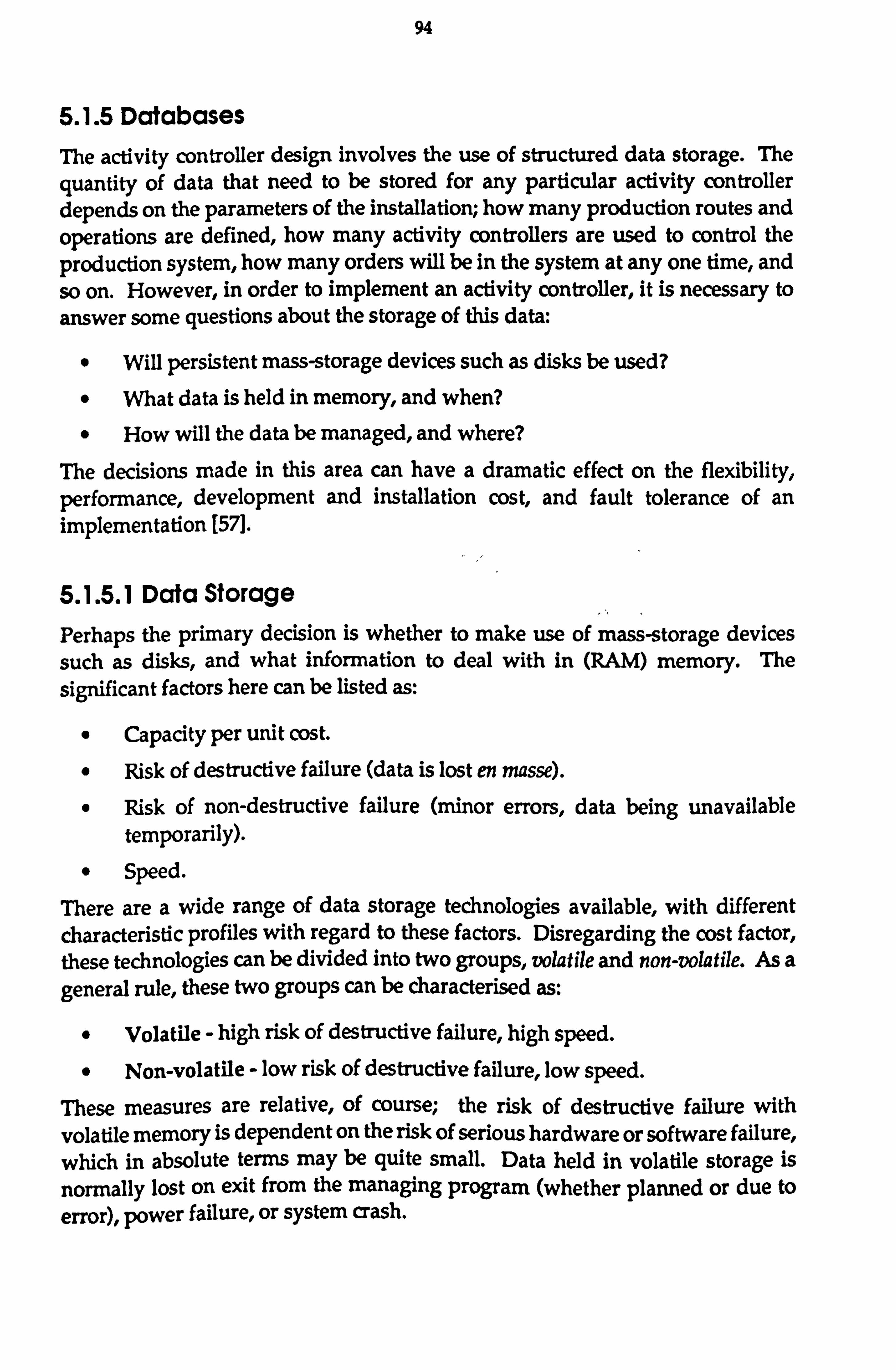
94
5.1.5 Databases The activity controller design involves the use of structured data storage. The quantity of data that need to be stored for any particular activity controller depends on the parameters of the installation; how many production routes and operations are defined, how many activity controllers are used to control the production system, how many orders will be in the system at any one time, and so on. However, in order to implement an activity controller, it is necessary to answer some questions about the storage of this data:
" Will persistent mass-storage devices such as disks be used?
" What data is held in memory, and when? " How will the data be managed, and where?
The decisions made in this area can have a dramatic effect on the flexibility, performance, development and installation cost, and fault tolerance of an implementation [571.
5.1.5.1 Data Storage Perhaps the primary decision is whether to make use of mass-storage devices
such as disks, and what information to deal with in (RAM) memory. The
significant factors here can be listed as:
" Capacity per unit cost.
" Risk of destructive failure (data is lost en masse).
" Risk of non-destructive failure (minor errors, data being unavailable temporarily).
" Speed.
There are a wide range of data storage technologies available, with different characteristic profiles with regard to these factors. Disregarding the cost factor, these technologies can be divided into two groups, volatile and non-volatile. As a general rule, these two groups can be characterised as:
" Volatile - high risk of destructive failure, high speed.
" Non-volatile - low risk of destructive failure, low speed. These measures are relative, of course; the risk of destructive failure with volatile memory is dependent on the risk of serious hardware or software failure, which in absolute terms may be quite small. Data held in volatile storage is normally lost on exit from the managing program (whether planned or due to error), power failure, or system crash.

95
Comprehensive use of non-volatile storage reduces the risk of destructive failure, by effectively reducing the effects of many of these otherwise catastrophic failures to temporary non-availability of data, and perhaps minor data errors. Thus, fault recovery is greatly enhanced simply by use of non-volatile storage. Where data access speed is significant, a good solution can be to use both
systems, with the non-volatile storage merely being used to track changes to the
volatile state. In the event of failure, the non-volatile image can be used to
reconstruct the volatile one.
Where the amount of data to be stored is uncertain, or certain to be large, the cost factor is likely to favour disk storage of the bulk of the data. It is recommended that, if only for fault tolerance purposes, data is recorded in non-volatile storage. In order to reduce installation costs, it is further recommended that only truly time-critical information is retained in memory on a permanent basis.
5.1.5.2 Data Management
It may be inferred from the architecture of the system that AC data should be locally managed, and form a distributed database. However, this is not necessarily so, and the relationship of the database to the processing architecture is an implementation decision, because the organisation of this is hidden by the AC interface as defined. Data management can be either internal to the AC processes, or delegated to an external, possibly third party database management system (DBMS). Use of an external, third party DBMS will typically bring the following benefits:
" Reduced size and complexity of the AC code itself.
" Reduction in development time and cost for the PAC system.
" Ability to respond to a wider range of requests and queries than would be
reasonable for ACs to implement.
" Improved opportunities for fault tolerance.
The first three of these effects were experienced in the implementation of the CIM Demonstrator. With regard to code complexity, the implementation of the
activity controller behaviour (excluding communications software) resulted in 737 lines of 'C', including comments. Despite the design differences, it is interesting to compare this with the 1718 lines of Pascal used in the implementation of the equivalent behaviour for the assembly cell implementation mentioned in section 2.4.1.4.

96
Use of an external DBMS also offers a measure of independence between the process and control architecture and the division and storage strategy adopted for the data that it uses. For instance, it would be possible to centralise data
storage and management, and have all of the ACs access their data by
communicating with the central DBMS. Such an arrangement can have a number of advantages:
0 Back-up of operating data is easily centralised.
" Fault tolerant data management may be economically introduced through data/machine/process duplication at the central point only.
" Data storage is centralised, possibly to a less hostile environment than the shop floor.
" Complex status queries and other data manipulation can be carried out without a potentially large number of messages to individual ACs.
" External systems that operate in a centralised manner, such as production scheduling, may be even more easily integrated.
Because the data management functions are external to the AC, any such move to centralization is completely transparent to the AC implementation. There are many possible scenarios ranging from total centralization through to the complete distribution of the database to match the AC distribution. Use of an external DBMS allows the optimum data distribution solution to be implemented for any particular installation, irrespective of the optimum arrangement of AC processes.
Implementation using a Relational DBMS, which offers standard SQL as an interface, will allow for ease of integration with other CIM systems through the medium of data exchange using the database. RDBMSs are an implementation of three-schema database systems, which allows different users of the database to access the contained information through different views. So, for instance, a CAPP system and the PAC system could both access the same physical information recorded about the processes and routings of the manufacturing system, but the CAPP system would only "see" the information that it dealt with, while the PAC system would only "see" the information that it dealt with; these different views can even have different apparent structures. This approach not only leads to savings in storage space, but also ensures that the various interacting systems work on information that is consistent across applications.
This solution, of external, industry-standard RDBMS data management is therefore recommended unless the data access speed requirements for a particular installation could only be met by data management being implemented internally to the activity controllers. Use of local, high-speed

97
databases which update, and are updated by the RDBMS when necessary can provide a higher-performance system with the same desirable properties as the pure RDBMS solution.
It is also recommended that the report request messages and responses be formatted in a standard query language, such as SQL This will not only improve the likelihood of being able to integrate with external systems which need to interrogate an AC about its state more easily, but, if the data management is handled by an external DBMS which offers the standard interface, then these requests may be passed on by the AC with very little processing and code overhead.
5.2 Packaging and Supply The proposed PAC system design lends itself to economic packaging, combined with availability for a wide range of manufacturing circumstances. There are a number of design features that lead to this conclusion:
" The system is extremely modular, by virtue of having numerous separate programs making up the control system, communicating through a defined messaging protocol.
" With a defined message syntax (such as MMS), it would be possible to build a system from programs from numerous software vendors. This allows diversity of supply, covering a wider range of specialist hardware and application areas.
" The concept and specification for operation controllers would allow OCs to be available economically for a wide range of shop-floor workstations, possibly supplied by the equipment suppliers or by independent software vendors.
" The specification of configurable algorithms allows adaptation of the system to the requirements of a wide range of manufacturing systems.
" The encapsulation of implementation details behind the messaging interface allows for evolutionary improvement of both the implementation techniques and the basic algorithms over time.
" The design of the system allows for incremental implementation in multi-vendor, distributed computing environments. Progressive implementation can significantly reduce the risk associated with moving to CIM, while also spreading the cost over a period of time.
" No one program in the system is required to be particularly complex or large-scale, reducing development time and cost accordingly.

98
" No one program in the system has to exhibit any great configurability or portability, thus also reducing development time and cost. However, by composing the complete control system from a variety of suitable implemented programs, great configurability and portability can be available at the system application level.
5.3 Flexibility The flexibility of a PAC system strategy, with regard to both the systems that could be controlled, and the flexibility with which they are controlled, was identified as an important factor with regard to its utility in industry. It is contended that the proposed design exhibits a high degree of flexibility, and should therefore be successfully applicable as an industrial PAC system.
5.3.1 Sources of Flexibility The operational algorithms and behaviour of the system, coupled with appropriate implementation techniques offer a substantial contribution to the flexibility exhibited by the production system when under the control of the proposed PAC system. Flexibility can also be seen to stem from a variety of design features of the system:
"A compositional approach to PAC system building provides flexibility in the range of systems that can be controlled.
" The division of the control system into a number of independent communicating processes provides flexibility in the computing environments and configurations that can be supported.
" The location-independence of the bulk of the PAC system (database, ACs, and some OCs) provides configuration flexibility.
" The clear separation of interfaces to shop floor devices from the generic control system provides flexibility in the individual workstations that can be controlled, whilst reducing the development cost.
" The data-based approach to definition of manufacturing procedures and processes provides flexibility in the products that can be produced and in the way in which they are produced.
" The configurable algorithms provide flexibility in the way manufacturing decisions are taken by the PAC system.
" The open systems interface allows for a variety of external systems to provide additional functionality and alter the operation of the system.

99
" The signalling system provides flexibility in the operation, reporting, and control of the system's actions.
5.3.2 The Signalling System The signalling system deserves special attention in this section because it can be said to provide two levels of flexibility: not only does it allow configuration of the reporting and interfaces to other systems that may be used to provide additional functionality, but it also allows flexible configuration of the response of the system to events.
Consider the events that are generated when a workstation is shutdown unexpectedly, or an operation does not complete on time. Within the signalling system, it is possible to configure the system to respond to events such as these in a number of ways:
" The workstation operations could be re-scheduled in the light of the changed circumstances.
The AC's customers can be informed of the delay or indefinite postponement of delivery. These ACs can then take action (as configured through the signalling system) to re-schedule their work, cancel orders, obtain supplies from elsewhere, etc. Supervisory systems and human operators can be alerted, or the event merely logged for future analysis.
The validity of these and other possible actions will depend on the circumstances of the particular installation; if there are no alternative suppliers for a customer AC, it should probably pass a notification of delay to its customer, rather than searching for alternative suppliers. In some circumstances, it may be desirable to drop all production activities that are related to a blocked operation, and bring other operations forward. Following the JIT philosophies, it may be desirable to let other processes wait and concentrate resources on solving the problem.
The configurability of the signalling system allows an "appropriately" flexible automatic response to events of many kinds to be programmed into an installed system. It is the author's belief that this is a better approach than confining a PAC system to just one defined response (or finite range of responses) to any particular stimulus; however sophisticated or simple that response is, there are bound to be circumstances where it is not appropriate.

100
5.3.3 Review Evaluating the proposed system against the flexibility criteria identified:
(i) Mix Flexibility
The mix flexibility of an installed system will be ultimately dependent on the implementation techniques used for recording the data about scheduled and executing operations, orders, and so on. If there are any artificial capacity limits imposed by implementation or hardware, then these cannot be exceeded. However, given an implementation with no limits, or non-restrictive limits, the mix flexibility supported by the PAC
system is not restricted either, and therefore the limiting factor will be the controlled production system, as it should be.
(ii) Product Flexibility
Product flexibility can be claimed as high because:
" Definition of a product to the PAC system is entirely data-based.
" The bulk of this data can be extracted from the output of a CAPP system: operation names/numbers, required tools, parts, programs, quantities consumed and produced, production routings and alternatives.
The remainder of the information required depends on the characteristics of the workstations; if they are fully automated, then the precise loca'. ion information must be provided. This may be available from a : APP system, but would probably have to be specified to any PAC system in one form or another.
(iii) Routing Flexibility
Fundamental routing flexibility is high; the data structure supports routing/operation flexibility in a number of ways. The use made of this fundamental flexibility can be matched to the environment within which the PAC system is installed by appropriate choice of scheduling algorithms and configuration of the signals.
(iv) Expansion Flexibility
Expansion flexibility is high; it is merely a matter of installing a new AC and OC for the new workstations, and setting up the databases appropriately. Older parts of the system need only be affected if they are to directly interact with the new parts, and this too is merely a change to the contents of their databases.

101
(v) Scheduling Flexibility
Scheduling flexibility is fundamentally high, though dependent on the
choice of scheduling algorithms. The PAC system can be configured to
change the production schedule as often as required through configuration of the signalling system. New schedules can always be imposed externally for all operations that are not currently under way.
(vi) Device Flexibility Device flexibility is high, due to the isolation of device characteristics within the operation controller. From the activity controller point of view, new devices can be controlled effortlessly, by simply providing the messaging address of the appropriate OC. It is maintained that the OC
specification makes it relatively simple to accommodate new devices and workstations.
(vii) Interface Flexibility
This is partly determined by the range and flexibility of OCs available, and partly by the implementation of the messaging service interface. On the part of OCs, the same arguments can be applied as for device flexibility. For most purposes, then, an implementation can be expected to have a high interface flexibility.
(viii) Size Flexibility
The combination of distributed processing and possible hierarchical organisation of the system provide a high upper limit on the size of systt n. that can be controlled. On the other hand, the relatively lightweight programs of OCs and ACs will allow an economical small-scale implementation. Size flexibility is therefore claimed to be high.
(ix) Application Flexibility
Application flexibility is claimed to be high due to the preceding points and the compositional and open systems approach to a PAC system architecture.
5.4 Integration Four main points were raised with regard to the integration of a PAC system into
a CIM environment.
" It is important for the functionality of PAC to complement, rather than duplicate, the functionality of PMS and PES.
" It is beneficial if the data generation and use of the various systems is also complementary.

102
" It is very beneficial if data can be shared between systems, where the same data is used in both. On the other hand, if divergence is required, then the data should be separated.
" It is also desirable to have an 'open' method of transferring data from one system to another, as opposed to implementing specific interfaces and gateway software.
The functionality of the proposed system is somewhat variable, allowing it to be
matched with that of the other CIM sub-systems, especially PMS. It is possible for the PMS system to generate schedules at any level between periodic works order release through to detailed scheduling of operations and material movements, and the PAC system, by configuration of a suitable scheduling algorithm, can be matched to complement the PMS system perfectly. Similarly, the monitoring functionality of the PMS system can be complemented by implementation of an appropriate production monitoring system d given by AC signals.
As with complementary functionality, so the proposed system can vary its data
generation responsibilities to match the requirements of the PMS and PES systems, through appropriate use of the signalling system. If PMS and PES only require consolidated statistics, then the consolidation functions can be implemented in an intermediate monitoring system. Variable data input
requirements (outside scheduling information) have not been achieved; if location information is not provided by CAPP, then this does have to be supplied by some other means. It is argued that the data requirements of this system are a satisfactory match with the trend in other CIM sub-systems, and this should present few problems in integration with most systems.
If the recommendation to use external, Relational Database Management Systems for data management in an implementation is followed, then, assuming that the other systems also move in this direction, data sharing and separation should be possible to implement as necessary. Even allowing only for some external data management system, this may be possible, but it is likely to depend on the ability of the DBMS to present different views of the data to different applications. Implementations which use high performance local databases for their normal operation, and a full-scale DBMS as a "master database", keeping the two up to date within the limitations of messaging and performance, will also benefit from the master database being shared appropriately with other sub-systems. In these cases, one would expect the ACs to be fully responsible for keeping the two data sets in step, and for all changes made by external systems to be to the master or through the AC interface.

103
The use of external DBMS systems also allows an implementation to move towards an open system approach to data transfer. Using a suitably standard DBMS interface (such as SQL), would tend to allow a variety of systems to transfer data through the database by making use of different views as appropriate to perform the 'translation' between two system's different data
organisations and contents. Unfortunately, current database systems are quite limited in their ability to handle divergent views of data structure, so although this offers an improvement, the problem is not yet solved.
5.5 Summary It is the contention of this thesis that if the PAC system architecture and design
presented here were implemented as industrial-quality software, building or evolving towards a Computer Integrated Manufacturing system for a manufacturer of discrete components would become more feasible. This would be especially true if the recommendations made above with regard to the implementation of the design were followed. The basic points and features
supporting this contention are covered or explained in this thesis, and are listed below in summary:
" The design lends itself to becoming a packaged software product, possibly with multi-vendor supply. This is primarily due to:
(a) The small granularity with which it can be implemented.
(b) The high degree of modular independence.
(c) The wide applicability of the system, and hence potentially high unit sales.
(d) The firm separation of generic portions of the system from installation-specific portions (ACs and OCs, primarily).
(e) The data-driven nature of the generic portions of the system. The design is capable of integrating well into many variants of CIM implementations and - with other, independently developed, CIM
sub-systems. This results from:
(f) Taking an open systems approach, and being designed for integration with other systems at a number of levels.
(g) By having data input and output complement the data generation and requirements of other systems. This is helped by being somewhat configurable with regard to data output capabilities.
(h) By being able to match functional responsibilities with those of other systems, through a degree of configurability.

104
" The design will support a high degree of flexibility on the part of the
controlled production system, if such capability exists. However, it does
not demand a highly flexible, nor even a highly automated production system to control. Some of the more unusual features of the system contributing to this are:
(a) Capability of controlling machines or workstations that can do more than one thing at a time.
(b) Ability to define responses to events, including taking action such as automatic re-routing of production on machine breakdown.
(c) Integrated approach to tool management and manual workstations.
(d) Ability to construct a system with scheduling algorithms truly appropriate to that installation.
" The design can take advantage of a wide range of computing environments, especially distributed computing and network-based message passing. This allows for incremental installation, matching computing power requirements and provision flexibly, and embracing truly multi-vendor computing within the manufacturing enterprise.

105
Chapter 6 Conclusion
This thesis has examined the CIM environment and identified the role of Production Activity Control in bridging the gap between the high-level
management and engineering applications and the low-level automation control systems in industry today. From this, and from consideration of other PAC
systems and the literature, the challenges of providing this level of control were recognized, and the design goals were developed. A system specification was presented, and its ability to meet these goals discussed in the light of an experimental prototype implementation. A review of existing PAC systems revealed that the design presented broke new ground by exploring further the little-researched area of heterarchical, data-driven architectures for PAC. The
author believes that this work should help make the implementation of CIM a lower cost, lower risk enterprise than it currently is. Arguments to support this belief have been presented.
6.1 Innovation A novel architecture and design for a Production Activity Control system for the discrete manufacturing industry has been proposed. The architecture has been developed from previous work by the author, with substantial changes to the system design. A model of manufacturing has been derived which defines the range of manufacturing systems which an implementation of the design would control. The concept of "configurable algorithms" to fit within the system architecture and adapt an implementation to its environment has been introduced.
6.2 Contribution The area of data-driven, heterarchical PAC systems has been explored, and a system designed and tested with that basic architecture. Configuration of the system is primarily effected through a compositional approach, with supplementary data-driven configuration possibilities. This new PAC design lends itself to packaging as a software product and to economic installation in industry.
The work also provides an architecture and framework within which further research can be done into various areas, especially on production scheduling, and heterarchical or distributed scheduling algorithms in particular. The architecture developed could also be used as a common testbed within which a variety of scheduling algorithms could be meaningfully tested and compared.

106
An approach to modelling manufacturing was presented, which could be used to analyse manufacturing systems, or perhaps as a basis for further development. A categorisation of PAC systems was established, and a review of the state of the art in Production Activity Control presented within that framework.
6.3 Areas for Further Work
This work has concentrated on establishing an architecture for building a Production Activity Control system. It has aimed to provide an answer to the question of how to organise a PAC system implementation so that it can be realistically packaged, easily integrated with other CIM systems, and exhibit a high degree of flexibility. Computing processes have been identified, and their roles within the overall system defined, together with the way in which the system is constructed from these processes. A design has been specified to the level of defining the semantics of the interactions between these processes, and a general modus operandi for the processes themselves. In this way, an alternative answer to those developed by others has been proposed.
Notwithstanding the implementation of an experimental system, and the suggestions made in this thesis, the general question of how the architectural roles are fulfilled, and how the system should be implemented, have not been fully explored. This is outside the scope of an architectural design, and essentially addresses different questions, concerning optimising productic i. t sequences, and software technology. The approach taken has been to develop an architecture which allows for a range of answers to these questions, so that further research may determine the best strategies for particular circumstances. In the case that different strategies are appropriate to different circumstances, this approach has the added benefit of broadening, rather than restricting, the manufacturing systems to which the architecture can be fruitfully applied.
6.3.1 Scheduling The subject of heterarchical scheduling algorithms, especially within the context of this architecture, would benefit from considerably more investigation and research. Some ideas that would be interesting to explore, but that the author declined to pursue are:
" Formalising a probabilistic extension to the production model with regard to alternative outcomes of operations (i. e. measuring probabilities of different failure modes), and then including this information in considerations of scheduling. Potentially, this could result in a system that makes provision for likely scrap/failure rates, which could be a significant advantage in long lead-time industries.

107
" Introducing of a 'cost' concept into the model to allow scheduling and selection between alternative production routes to be decided on factors
not currently included in the model. This may be equivalent to introduction of accounting information into the system [89], but the 'cost' factors need not be restricted to purely monetary considerations.
These options would involve extensions to the information managed by the ACs, and consequently to the manufacturing model. Appropriate extensions to the message definitions would also be needed to allow communication of the new data to and between ACs.
However, even without extending the data that drives the system, a wide range of algorithms for quoting, scheduling, and ranking operations can be conceived. There is much opportunity for definition of new heterarchical scheduling algorithms, and analysis of their relative effects on computing and communications loads. One of the more interesting aspects of scheduling within a highly distributed environment is the move towards highly complex scheduling systems made up of individually simplistic scheduling elements.
Related to the definition of a wider range of configurable algorithms, there is much scope for further work on the circumstances under which particular algorithms should be used. It seems likely that no single algorithm will be the best performer in all circumstances. Indeed, in the author's opinion, it is likely that the best performance for an entire system would be achieved by employing a mix of different algorithms at different points within the system. This broadens the scope of analysis of the effects of using various algorithms in different circumstances substantially, and would probably involve development of techniques to categorise and describe the features of the manufacturing system and its workstations. Ultimately, this could lead to a method of determining the best configuration to manage production within any particular installation.
6.3.2 Techniques for Algorithmic Configuration
More investigation could fruitfully be carried out into the means, costs and benefits of implementing configurable algorithms in various ways. Some possible alternatives were discussed briefly in the text. This would cover not only the software technology appropriate to configuring algorithms, but also the effect of various strategies on the level and quality of packaging that can be
achieved for a commercial implementation.
To some extent, the requirement for algorithmic configuration depends on the
results of any investigations into the algorithms as described above; the
variability over time and across different installations will have a significant effect on the economics of different implementations. Furthermore, if the

108
method of determination of optimum solutions for a particular system that is developed involves simulation, then it is likely that a system would be needed that allows for rapid selection and installation of different algorithms, and perhaps of rapid specification and development of experimental algorithms.
6.3.3 Shared Location Management
The functions of arbiters of shared locations would benefit from further research. It is realised that arbiters as specified are unable to resolve some possible location-contention based deadlocks, especially those concerning more than one shared location. More theoretical work into the range of possible deadlock
situations would seem appropriate, especially if tempered by a practical study of which possibilities are found in real manufacturing systems. Given such a basis,
appropriate behaviour for arbiters could be specified and tested. Possible
extensions to the arbiter concept that could be investigated include:
" Introducing scheduling to locations, so that ACs can 'book' use of a location as they schedule their operations.
" Development of arbiters that can co-ordinate the management of a number of locations, so that a wider view can be used to resolve contentions.
" Development of additional protocol between arbiters, or between arbiters and ACs to allow cooperative resolution of deadlocks.
Of course, because arbiters are interfaced with through the messaging interface, it would be possible to develop separate arbiter processes that were considerably more sophisticated in their handling of location arbitration than would be
appropriate for the implementation embedded in a standard AC. Taking this
approach, the configuration flexibility available through composition would expand; given certain approaches to arbiter design, the data-based
configurability could also be increased.
6.3.4 Extending Spatial Modelling Further research could be pursued on the modelling of locations and spatial relationships, with respect to Production Activity Control. It may be
advantageous to be able to model fixturing a workpiece into a pallet-fixture, for instance, as the workpiece being held in a location that itself may be moved from
one location to another, rather than as a composite part, as is implied by the current manufacturing model. By researching techniques and ideas such as introducing 'intelligent' locations, this extended spatial modelling may be
possible without a concomitant explosion of the data that must be supplied to and handled by the control system.

109
Working in the opposite direction, it may be possible to reduce the requirement for specific location modelling information as an input to the PAC system. The
ability to introduce automated procedures to map factory-independent
production models to a particular manufacturing system would further increase the flexibility of integration of the PAC system into the CIM environment. It may even be desirable to re-define the boundaries of CAPP, or move some of the production planning process out of the office-based PES environment. By this expedient, decisions about methods and procedures of production would be taken closer to where the effects of those decisions are felt.
6.3.5 Fault Tolerance Finally, there is a great need in manufacturing control systems for effective handling and tolerance of a wide range of failures and "unexpected" events. Some of the design aspects of the proposed system, notably its distributed, message-based architecture, lend themselves to implementation of a system that is tolerant to a range of computing failures. The signalling system concept provides a broad scope for handling unusual events in the controlled system, from non-standard operation outcomes to failures to stick to schedule.
However, as with the configurable algorithms, it has been the policy to design in provision for fault tolerance, and not to attempt to develop or specify the details of how that tolerance should actually be achieved. This is because, in the case of unexpected manufacturing events, the appropriate action depends very much upon the circumstances of the manufacturing system, and perhaps will even vary across time in one installation. Similarly, the tolerance to computing failure that needs to be provided depends on the reliability of the computing environment, and of the software itself. The costs and benefits of providing this kind of fault tolerance depend on the circumstances of installation.
Nevertheless, there is scope for research into characterising faults and unusual events, and analysing the costs and benefits of different approaches to handling these events when they occur. The approaches taken to the handling of failure can range from large scale strategies such as just-In-Time versus just-In-Case, to small scale decisions, such as:
" Who or what should be notified of failures of different types and severities,
" Whether the reaction to failure is fully prescribed or dependent upon dynamic considerations, and
" How are any decisions made, and by whom, or by which process?

110
Acknowledgements
The author would like to thank the 1987-88 CRAG students for their efforts to materialise the CIM Demonstrator system, and Sharron Burgmeier, Kailash Cooke, Tom Crawford, Alex Livesley, Frederico Magalhaes, and Tony Scarr for their help and encouragement.

111
References
1 Appropriate Communications Initiative 1988 - Summary Report, Benchmark Research Ltd, Orpington Kent
2 CRAG CIM Demonstrator Group Project Report to Industry, Cranfield Institute of Technology, 1988
3 Information Processing Systems, Open Systems Interconnection, Basic Reference Model, International Standards Organisation
4 Information Processing Systems - Database Systems SQL (ISO 9075), International Standards Organisation, 1987
5 Manufacturing Automation Protocol Version 3.0, Society of Manufacturing Engineers, Michigan, USA, 1988
6 Reflex CIM Strategy, Reflex Automation Ltd, Crawley, England, 1987
7 Acaccia GM "A Distributed Interconnected Control for Computer- Michelini RC Integrated Manufacturing", Computer-Integrated Molfino RM Manufacturing Systems, Vol 2 No 2, pp: 108-114, Butterworth & Stolfo F Co, May 1989 Tacchella A
8 Agrawal AK "Real Time Control for Multi Vendor Manufacturing Cells", Watt G Advanced Manufacturing Systems - Proceedings of AMS 86, IFS
Ltd 1986, pp: 829-836
9 Akella R "Performance of Hierarchical Production Scheduling Policy", Choong Y IEEE Transactions on Computers, Hybrids, and Manufacturing Gershwin S Technology CHMT-7 (3), September 1984
10 Amin P CRAG-FMS Group Project Systems Software Group Report, Fenn AJ Cranfield Institute of Technology, 1985 Curley T RomannFJP Khalil A Escott SM
11 Anstiss P 'The Implementation and Control of Advanced Manufacturing Systems", Aerospace Dynamics, No 21 pp: 14-19,1987
12 Ballakur A "Integration of Job Shop Control Systems: A State-of-Art Steudel H Review", Journal of Manufacturing Systems, v3 Nol, pp71-79,
1984

112
13 Bennett DJ 'System Integration of Modularised Assembly FMS" Proc. Int. Forrester PL Conf. on Factory 2000, Inst. of Electronic and Radio Engineers,
31 Aug-2 Sept 1988, pp: 133-137
14 Biemans F "Reference Model of Production Control Systems", Proceedings of IECON International Conference on Industrial Electronics, Control &Instrumentation Industrial Applications of Mini, Micro, and Personal Computers, Vol. 1, IEEE 1986, pp: 55-60
15 Boehm B Software Engineering Economics, Prentice-Hall, 1981
16 Bonfioli M "Production Scheduling and Operational Control of Flexible Garetti M Manufacturing Systems", Robotica, 3, pp: 233-243 1985 Pozzetti A
17 Bonner DT "Traditional Information Technology: PLCs vs PCs", Proceedings of 2nd Int. Conf. Machine Control Systems, IFS Publications Ltd, pp: 129-138, May 1987
18 Bourner N CRAG CIM Demonstrator Group Project Production Planning, Ching K CAD/CAM, and Simulation Group Report, Cranfield Institute of Metenier L Technology, 1988 Sene T Stroutzas K
19 Bradley I CRAG CIM Demonstrator Group Project Processes Group Report, Wilkinson T Cranfield Institute of Technology, 1988 (Eds)
20 Brooks FP
21 Browne J Harhen J Shivnan J
22 Browne J Dubois D Rathmill K Sethi S Sticke K
23
24
The Mythical Man-Month, Addison-Wesley, 1982
Production Management Systems: A CIM Perspective Addison-Wesley Publishing Co. 1988
"Classification of Flexible Manufacturing Systems", The FMS Magazine, IFS Publications Ltd., April 1984 pp 114117
Budnikov YV "FIFO Nets and Modelling of Manufacturing Processes in Rudnev VV FMS" Information Control Problems in Manufacturing Tal' AA Technology; Proceedings of 5th IFACSIIFIPIIMACSIIFORS
Conference, 1986 pp: 81-86
Burbidge JL "Production Control for Flexible Production Systems", Advances in Production Management Systems IFIP, Elsevier (North Holland) 1984
25 Burbidge JL "Production Planning and Control: a Personal Philosophy", Computer in Industry No 6 1985 pp: 477-487

113
26 Burbidge JL Production Flow Analysis for Planning Group Technology, Clarendon Press, Oxford, 1989
27 CAM-I, Inc "Conceptual Information Model for an Advanced Factory Management System", Factory and Jobshop Level Final Report R-84-FM-03, August 1984
28 Clayton RN CRAG CIM Demonstrator Group Project Demonstrator Group Fitzsimmons CDA Report, Cranfield Institute of Technology, 1988 WhiteHJA
29 Cooke IC CRAG-EHV Group Project Control Group Report, Cranfield Frew I Institute of Technology, 1986 (Eds)
30 Cooke IC "What MAP Means in Practice", Recente Evolutie in Verband met MAP, BIRA (Belgian Institute for Robotics and Automation), October 1987
31 Cooke IC "FMS Under MAP/TOP in Under Three Months... How We Did It", Proceedings of 2nd International Conference Machine Control Systems, pp: 33-44, IFS (Conferences) Ltd, May 1987
32 Corbet J "Local Area Networks and Shopfloor. Data Collection", P& IM Review, December 1985, pp: 40,41,44,46,48,72
33 Cornwell Pj "Off-the-Shelf Manufacturing Systems Software", Proc. 2nd Int. Conf. Machine Control Systems, pp: 187-194, ITS (Conferences) Ltd, May 1987
34 Costa A "Design of a Control System for a Flexible Manufacturing Genetti M Cell", Journal of Manufacturing Systems, Vol 4 No I
35 Date Cj An Introduction To Database Systems, Addison-Wesley, 1986
36 Dillman R "State of the Art in CAD/CAM/Robotics", Applications of Computers to Engineering Design, Manufacturing and Management, GL Lastra, jL Encarnasäo, &AAG Requicha (Eds), Elsevier Science Publishers (North-Holland) 1989 pp: 73-90
37 Dubois D "Using Petri Nets to Represent Production Processes", Proc. Stecke KE 22nd IEEE Conf. on Decision and Control, Vol 3, San Antonio,
Texas, Dec 1983, pp: 1062-1067
38 Duffle NA "Non Hierarchical Control of a Flexible Manufacturing Cell", Piper RS Robotics and Computer-Integrated Manufacturing, Vol 3 No 2,
pp: 175-179, Pergamon Journals Ltd, 1987
39 Duffle NA "Fault-Tolerant Heterarchical Control of Heterogeneous Chitturi R Manufacturing System Entities" Journal of Manufacturing Mou j-I Systems Vol 7 No 41988

114
40 Duggan j "An AI Based Simulation for Production Activity Control Browne J Systems", 4th International Conference on Simulation in
Manufacturing, IFS Publications, November 1988
41 Dunn JG "Cell control systems in the aerospace industry - implementation experience", Proc 23rd Euro Conf on Production & Inventory Control, BPICS, Nov 1988
42 Dupont-Catelmand C "Machine Tools Evolutions for Flexible Manufacturing Systems", Computer Integrated Manufacturing, American Society of Mechanical Engineers, Nov 1983 pp: 133-140
43 Eastwood MA "Computer-Controlled Manual Assembly", Autofact 88 Proceedings, pp: 19/15-19/24, Society of Manufacturing Engineers, USA, 1988
44 Ellerby P "Reactive Constraint-Based Job Shop Scheduling", Proceedings Fargher HE of 2nd Internamtional Conference on Expert Systems & the Leading Addis TR Edge in Production Planning and Control, May 1988
45 Engleburger JF Robotics in Practice: Management and Applications of Industrial Robots, Kogan Page, 1980
46 Ford RE CRAG CIM Demonstrator Group Project Database, Wilson PH Communications, and Cell Control Group Report, Cranfield (Eds) Institute of Technology, 1988
47 Gagi B "Grafcet Synthesised Computer System and Procedure Ladet P Description in FMS", Advances in Production Management
Systems, North-Holland 1984, pp: 205-213
48 Gentina JC "Coloured Adaptive Structured Petri-Net" Computer Integrated Bourey JP Manufacturing Sytems, Vol 1 No 1, Butterworth & Co, pp: Kapusta M 39-47, February 1988
49 Gentina JC "Coloured Adaptive Structured Petri-Net (Part II)" Computer
Bourey JP Integrated Manufacturing Sytems, Vol 1 No 2, Butterworth & Kapusta M Co, pp: 103-109, May 1988
50 Goddard WE Just-In-Time Surviving by Breaking Tradition, Oliver Wight Publications, USA, 1986
51 Groover MP "Computer-Aided Process Planning - An Introduction", Proceedings, Conference on Computer-Aided Process Planning, Provo, Utah, October 1984
52 Groover MP Automation, Production Systems, and Computer Integrated Manufacturing, USA: Prentice-Hall International, Inc, 1987
53 Harhen J "Production Activity Control -A Key Node in CIM" Browne J Production Management Systems: Strategies and Tools For Design,
Ed. H Hubner, North-Holland 1984 pp: 107-122

115
54 Harley M "A Specification for a Production Activity Control (PAC) Cooney B System in a CIM Environment", Proceedings of CAPE 1986 Joyce R Conference, Ed. K Be, L Estensen, P Falster, &E Warman, Browne J Copenhagen: North Holland Publishing Co. 1987
55 Hindi KS "On the Integrative Approach To Planning and Control in Singh MG AMT', International Conf. on Factory 2000, Inst. of Electronic
and Radio Engineers, 31 Aug-2 Sept 1988
56 Hitorni K Manufacturing Systems Engineering, London: Taylor and Francis, 1979
57 Hodgson A "Planning and Control Information Flow in CIM: Current Weston RH Research Directions and the Need for Intermediate Solutions", Sumpter CM International Conf. on Factory 2000, Inst. of Electronic and Gascoigne JD Radio Engineers, 31 Aug-2 Sept 1988 Rui A
58 Holmdahl PE "Shop-Floor Control in a CIM Environment", Proc. 3rd CIM Europe Conference, IFS (Publications) Ltd, May 1987 pp: 59-66
59 Hudson PG "An FMS User's Design and Application of a Computer Webb S Control System", Proceedings of 2nd Int. Conf. Machine Control
Systems, IFS (Conferences) Ltd, pp: 219-230,1987
60 Hwang S "Integration of Humans and Computers in the Operation and Barfield W Control of FMSs" International Journal of Production Research, Chang T v25 No 7 pp: 979-994,1987 Savedy G
61 Ingersoll Engineers Integrated Manufacture, IFS (Publications) Ltd, 1985
62 Ingersoll Engineers The FMS Report, IFS (Publications) Ltd, (Revised) 1984
63 Jablonski J "Reexamining FMSs"; Special Report 774, American Machinist, pp: 125-40, March 1985
64 Jones AT "A Proposed Hierarchical Control Model for Automated McClean CR Manufacturing Systems", Journal of Manufacturing Systems,
Vol 5 No 1,1986
65 Jovic F Process Control Systems - Principles of Design and Operation, Kogan Page Ltd, 1986
66 Kaltwasser J "Hierarchical Control of Flexible Manufacturing Systems", Hercht A Information Control Problems in Manufacturing Technology - Lang R Proc. 5th IFACS/IFIP/IMACS/IFORS Conf, Suzdal USSR, pp:
37-44, Pergamon 1986
67 Kehoe DF "Implementing Manufacturing Strategies through the Bititci US Application of Programmable Control", Proceedings of 2nd Int.
Conf. Machine Control Systems, IFS (Conferences) Ltd, pp: 75-90,1987

116
68 Kimia j "An Algorithm for the Computer Control of Flexible Gershwin SB Manufacturing Systems" DE Transactions, December 1983 Vol
15, No 4 pp: 353-362
69 Komoda N "An Autonomous Decentralised Control System for Factory Kera K Automation", Computer, IEEE Dec 84 pp: 73-83 Kubo T
70 Larin DJ "Cell Control: Widespread Use Awaits Technology Improvements", Chilton's I& CS, Vol 61 No 10, Oct 1988, pp: 63-65
71 Lewis W "Computer Integrated Manufacturing System Control: a Data Barash MM Flow Approach", Journal of Manufacturing Systems, Vol 6 No 3, Solberg JJ 1987
72 Liu D "New Concepts in Shop Floor Control: an Isst of Transition", Autofact 87 Conference Proceedings, pp: 9/135-9/142, SME (North-Holland), 1987
73 Lulu M "Effect of Process Unreliability on Integrated Manufacturing/ Black JT Production Systems", Journal of Manufacturing Systems, Vol 6
No 1, pp: 15-22,1987
74 Maimon 0Z "Real-Time Operational Control of Flexible Manufacturing Systems", Journal of Manufacturing Systems, Vol 6 No 2,1987
75 Marshall J "Communications in a Flexible Manufacturing System", Proc. Int. Conf on Computer Aided Engineering, Coventry, 10-17, December 1984 pp: 118-124
.
76 May HJ "Computer Integrated Flexible Manufacturing - 1985", Advanced Manufacturing Systems - Proceedings of AMS 86, IFS Ltd 1986, pp: 119-137
77 McCarthy SW Development of the Structure and Functionality of an Integrated Finite Capacity Planning and Shopfloor Data Collection System, PhD Thesis, Faculty of Total Technology, University of Manchester, October 1988
78 McLean CR 'he Virtual Manufacturing Cell", Proceedings of 4th IFAC/IFIP Bloom HM Conference on Information Control Problems in Manufacturing Hopp TH Technology, Gaithersburg, MD, USA, October 1982
79 McLean CR "The Automated Manufacturing Research Facility at the Brown PF National Bureau of Standards", New Technologies for
Production Management Systems H Hoshikawa &JL Burbidge (Eds), Elsevier Science Pub. (North-Holland) 1987, pp: 177-199
80 Merabet AA 'Synchronization of Operations in a Flexible Manufacturing Cell: The Petri Net Approach", Journal of Manufacturing Systems, Vol 5 No 3,1986

117
81 O'Grady PJ "State of the Art of Production Planning and Control in Automated Manufacturing Systems", Proceedings of I Mech E C330/86, pp: 195-202,1986
82 O'Grady PJ "Issues in Intelligent Cell Control Systems for Flexible Bao H Manufacturing Systems", Computers in Industry, Vol 9, pp: Lee KH 25-36, North-Holland 1987
83 Ohlson M "Adaptive Control and Coordination in a Distributed Lemone K Network Environment", Advanced Manufacturing Systems -
Proceedings of AMS 86, IFS Ltd 1986, pp: 751-761
84 Ono Y "Cell Control System", Robotics and Computer Integrated Manufacturing, Vol 3 No 4 pp: 389-393, Pergamon Jourlans Ltd, 1987
85 Parunak HVD "A Synthesis of Factory Reference Models", Industrial White jF Technology Institute, Ann Arbor, Michigan, USA, September
1987
86 Peterson JL Petri Net Theory and the Modelling of Systems, 1981
87 Ravichandran R "Decision Support in Flexible Manufacturing Systems Using Chakravarty AK Timed Petri Nets", Journal of Manufacturing Systems, Vol 5 No
2,1986
88 Rogers K (ed) "Survey Supplement" to Industrial Computing, Issue 19
89 Romanoff E "Manufacturing Information and the Analysis of Production Levine SH Processes", Proceedings 1986 IEEE International Conference on
Systems, Manufacturing, and Cybernetics, 1986 Vol 2' pp: 1583-5
90 Russell PJ "Open Systems Architecture for CIM", International Conf. on Factory 2000, Inst. of Electronic and Radio Engineers, 31 Aug-2 Sept1988
91 Saikkonen H "A Framework for Building Distributed Control Systems in an Sulonen R Automatic Factory", Proceedings of CAPE 1986 Conference, Ed. Eloranta EK Be, L Estensen, P Falster, &E Warman, pp: 51-60,
Copenhagen: North-Holland 1987
92 Saul G "Flexible Manufacturing System is CIM implemented at the Shop Floor Level", Industrial Engineering, June 1985 pp 35-39
93 Schonberger J Japanese Manufacturing Techniques - Nine Hidden Lessons in Simplicity, Free Press, New York 1982
94 Scott Rhodes J "The Challenge of a Standard Cell Controller", Autofact 87 Conference Proceedings, pp: 4/1391/155, SME (North-Holland) 1987

118
95 Singh V CRAG CIM Demonstrator Group Project Low Level Control Group Ikonomou C Report, Cranfield Institute of Technology, 1988 (Eds)
96 Skevington C "A Distributed System Architecture for Job-Shop Control", Aufofact 87 Conference Proceedings, pp: 9/157-9/167, SME (North-Holland), 1987
97 Spur G "Growth, Crisis, and the Future of the Factory", Robotics and Computer Integrated Manufacturing, Vol 1 No 1,1984, pp: 21-37
98 Stecke KE "Heuristic Loading Algorithms for Flexible Manufacturing Talbot FB Systems", Proc. 7th Int. Conf on Production Research
Proceedings, Vol. 1, Windsor, Ontario 1983 pp: 570-576
99 Stringer H "Industrial Computers in Machine Control", Proc. 2nd Int. Conf. Machine Control Systems, pp: 139-164, IFS (Conferences) Ltd, May 1987
100 Suski GJ "Current and Future Issues in the Design, Analysis and Rodd MG Implementation of distributed, Computer-Based Control
Systems", Proc. 7th IFAC Workshop on Distributed Computer Control Systems 1986, Pergamon Press, 1987 pp: 1-23
101 Tanimoto H "Factory Automation: An Automatic Assembly'Line for the Manufacture of Printers", Computer, December 1981, IEEE, pp: 50-68
102 Wadhwa S "Modelling FMS with Decision Petri Nets", The International Browne J Journal of Flexible Manufacturing Systems, Vol 1, Kluwer
Academic Publishers, Boston, 1989 pp: 255-280
103 Walker EC "Off-line Programming of the Cincinnati Milacron 73 Derby SJ Industrial Robot", Computer Integrated Manufacturing,
American Society of Mechanical Engineers, Nov 1983 pp: 75-81
104 Weck M "Configurable Control for FMS", Software for Discrete Kohen E Manufacturing, Ed. JP Crestin &jF McWaters, pp: 437-445,
North-Holland 1986
105 Weston R "Distributed Manufacturing Systems", Robotica Vol 4 No 1, Sumpter C 1986, pp: 15-26 Gascoigne J
106 Weston RH "Systems Integration in PCB Manufacture" International Conf. Gascoigne JD on Factory 2000, Inst. of Electronic and Radio Engineers, 31 Hodgson A Aug-2 Sept 1988 Sumpter CM
107 Wilczynski D "A Common Device Control Architecture - The Savoir Actor", Autofact 88 Conference Proceedings, pp: 10/31-10/40, Society of Manufacturing Engineers, USA, 1988

119
108 Wilson M "Kegging with Confidence", Proc. Conf. Programmable Controllers '86, Peter Peregrinus, Nov 1986 pp: 74-77
109 Wolfe PM "Computer-Aided Process Planning is a Unk Between CAD and CAM", Industrial Engineering, August 1985, pp: 72-77
110 Yeomans RW Design Rules for a CIM System, Amsterdam: North-Holland Choudray A Publishing Co., 1985 Ten Hagen PJW

120
Appendix A Specification of the Proposed Design
This section gives a more compact, but also a more complete definition of the
system design introduced above. The orientation of this section is more technical, in that the various aspects of the system are presented in more implementation-oriented groupings, and some of the details of meaning or protocol are defined where previously they were merely assumed.
However, this remains a presentation of the architecture and a specification for implementation; it is not a definition of implementation, and implementation dependent details are not discussed.
A. 1 The Structure The system is composed of multiple instances of two basic types of process:
" Activity Controllers (ACs), and
" Operation Controllers (OCs).
Other processes that are not ACs or OCs may also be present in the environment, which can perform complementary functions within a CIM system. All of these
processes conceptually execute independently and concurrently.
Each of these processes will communicate with a number of other processes in the system from time to time as a part of their normal operation. Operation controllers and activity controllers have a defined set of messages making up a protocol for interaction with them. Other processes may communicate with OCs
and ACs through the sending and receiving of messages according to this protocol.
The communication model is one of a reliable address-based messaging network, where a message can be sent to another process by addressing it correctly and depending on the network to reliably deliver the message to the destination
process. At any time, ACs and OCs will have a defined set of other processes whose addresses they know, and to whom they may send messages from time to time, according to the defined protocol and the activities of the AC or OC.
The communication between these processes forms a network structure of processes and message exchanges that forms the processing structure of the
system.
The processing structure of the PAC system is related to the physical structure and organisation of the controlled production system by:

121
" The assignment of an AC/OC pair to each workstation as identified in the factory model. Normally, each OC will only communicate with one AC.
" The assignment of an AC, or other process, as an arbiter for each location shared between workstations.
" The possible grouping of a number of AC/OC pairs into a cell, to which another AC is assigned. The ACs within such a cell will normally have few direct contacts with external processes, particularly ACs other than the "cell controller". These groupings can be more than one level deep, but cannot be cyclic.
This is illustrated in Figure 18.
Other Processes
AC
AC AC AC Ci
AC
O
o
o O'O u 040 00 OO Workstation Workstation Workstation S Workstation
A Cell 0 Shared Location
Figure 18: Processing Architecture

122
A. 2 The Database The Activity Controllers are largely data-driven processes, and therefore each AC has an associated database. An entity-relationship diagram for this database is illustrated in Figure 19. Corresponding descriptions of the entities are presented below. In the descriptions, items of data listed in Bold print are references to other entities. The method of implementation of these references will depend largely on the type of database technology used. Where it is useful from a human management point of view, and for the purposes of constructing messages to be sent between processes, identity label fields (ID) have been specified. These may take any form, but are best thought of as unique numbers or character strings.
Product
Operation Output Outcome Product
Executable 1
Manufacturing Operation Operation
Input Vector Requirement Index
Scheduled Operation Operation Definition
Part Part Location Definition vector
Supplementary Supplier Information
Stock Order ýý
Signal External Process
Transfer location
Event
Cardinality
-6- Zero -4- One Many
Figure 19: Entity-Relationship Diagram of Activity Controller Database

123
Executable Operation
" Scheduled Operation
" Position in list of Executable Operations
Scheduled Operation
" Operation Definition
" Earliest start date/time
" Scheduled start date/time
" Latest finish date/time
" Operation priority
Order
" Order ID
" Order priority
" Stock Lot (being ordered)
" Customer Activity Controller (External Process)
" Supplier Activity Controller (External Process)
Orders are divided into Purchase Orders and Sales Orders, but the method of this division depends on the implementation. Hence these "entities" are not listed here since they may not actually exist in the database.
The stock lot is used as a standard way of expressing the details of when, where, and what is required.
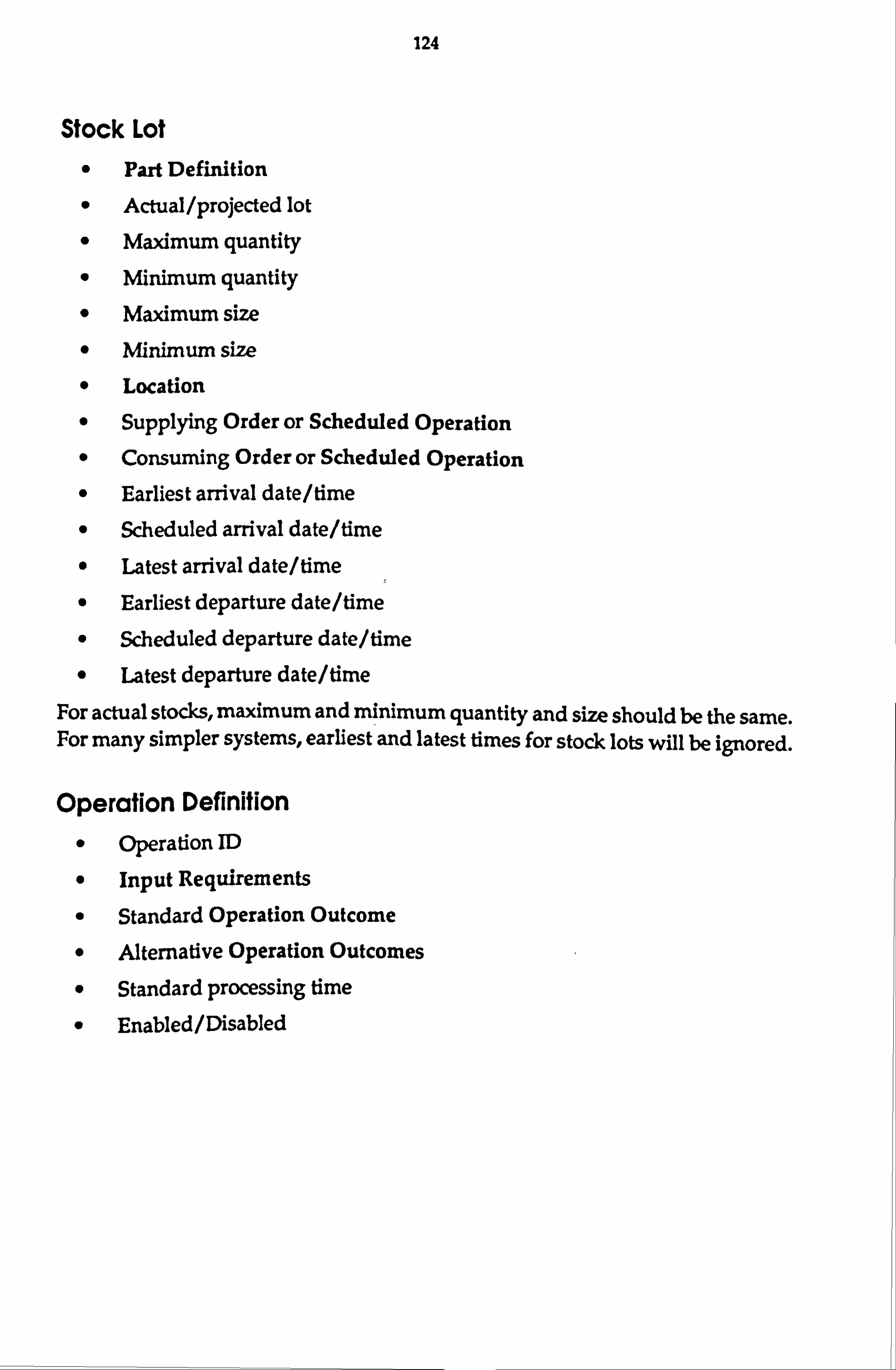
124
Stock Lot
" Part Definition
" Actual /projected lot
" Maximum quantity
" Minimum quantity
" Maximum size " Minimum size
" Location
" Supplying Order or Scheduled Operation
" Consuming Order or Scheduled Operation
" Earliest arrival date/time
" Scheduled arrival date/time
" Latest arrival date/time
" Earliest departure date/time
" Scheduled departure date/time
" Latest departure date/time
For actual stocks, maximum and minimum quantity and size should be the same. For many simpler systems, earliest and latest times for stock lots will be ignored.
Operation Definition " Operation ID
" Input Requirements
" Standard Operation Outcome
" Alternative Operation Outcomes
" Standard processing time
" Enabled/ Disabled

125
Input Requirement " Location
" Part Definition or Part Vector
" Quantity Consumed
" Size Consumed
" Vector Index
Operation Outcome
" Outcome ID (Label)
" Output Products
Output Product
" Location
" Part Definition or Part Vector
" Quantity Produced
" Size Produced
" Vector Index
The vector index is ignored if a Part Definition is recorded rather than a Part Vector.
Part Vector " Ordered list of Part Definitions
A part vector may be defined in terms of other part vectors. When accessed by vector index, however, the part vector will appear as a single level list of part definitions, containing the contents of any vectors that are used to define it.

126
Vector Index " Vector ID
" Value The value of a vector index is associated with one scheduled operation only, thus indicating the appropriate set of input/output parts. There are many ways of implementing this, possibly splitting the Vector ID from the value, and keeping the values as part of a scheduled operation record. For operation definitions, the value may be ignored, or used to record the maximum index allowed for the set of vectors.
Part Definition
" Part iro 0 List of Suppliers (for that part)
Supplier " External Process
0 List of Transfer Locations
Transfer Location
" Location
" Ranking
" Position in list
Location
0 Label
" Type
" Capacity
" Vector of acceptable parts
9 Location arbiter (External Process)
" Enabled/Disabled The location arbiter may be left null to indicate that the location is not shared. Alternative methods of discriminating between shared and non-shared locations
exist, and the method choice is an implementation decision.
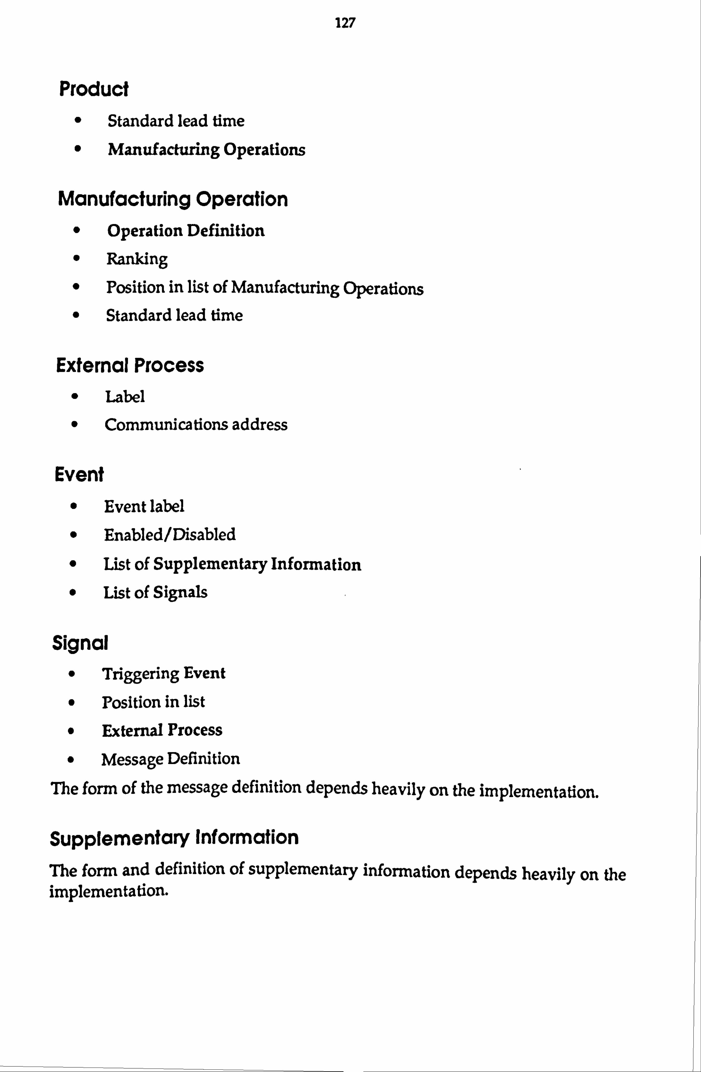
127
Product " Standard lead time
" Manufacturing Operations
Manufacturing Operation " Operation Definition
" Ranking
" Position in list of Manufacturing Operations
" Standard lead time
External Process " Label
" Communications address
Event
" Event label
" Enabled/Disabled
" List of Supplementary Information
" List of Signals
Signal
" Triggering Event
" Position in list
" External Process
" Message Definition
The form of the message definition depends heavily on the implementation.
Supplementary Information
The form and definition of supplementary information depends heavily on the implementation.
128
A. 3 The Protocols The messages that form the interface to the Activity Controllers and Operation Controllers are listed below. For each message, the information contained is described, followed by a description of the semantics of the message. All messages are implicitly identifiable, and where appropriate in the description of reply messages, specification of another message as one of the fields in the message indicates that the identifier of the relevant message will be used. All messages also implicitly contain the sender's address, which can be used for sending replies, etc.
After a description of the meaning of the message, there is brief statement of the actions taken as a result of receiving the message, if any. Much of the operation of activity controllers is simple algorithms triggered by the receipt of a message. Hence this description of the messages and their immediate results forms the bulk of the definition of the operation of the system. Section A. 4 details the workings of the more complex algorithms referred to from this section.
Where it is particularly relevant to the description of the activities taken after receipt of a message, the generation of an event is be noted. Synchronous events are generated in such a manner that if a signal to the local process is indicated, then that signal is generated and the appropriate action taken before the algorithm generating the event continues; in other words, a procedure generating a synchronous event waits for all the local processing that results from that signal, before carrying on with its own procedure. Asynchronous events are generated in a manner that will trigger the signal after the current message has been dealt with. In this way, the processing is not slowed down by the generation of an event and any subsequent signal processing.

129
A. 3.1 Operation Controller Interface This section defines the messages that can be sent to any operation controller. Some implementations of operation controllers may accept other messages, but they will not be used by activity controllers unless an activity controller is configured to do so as part of the signalling system.
0-1 Acknowledge Request
" ACK/NAK
" Request ID
Acknowledgement messages are not separately listed, but for each request that expects an acknowledgement, the meanings of positive and negative acknowledgements are described, marked by "+" and "-" respectively.
0-2 Set Activity Controller
" Activity controller address Sets the address of the controlling activity controller, as understood by the messaging system. This allows activity controllers to be set up, or to have their allegiance changed at any time. A workstation status report A-67, is sent to the new activity controller.
+ Change made successfully.
- Change could not be made.
0-3 Report Activity Controller
Requests the address of the controlling activity controller. Responds with 0-4.
0-4 Activity Controller Report
" Address of controlling activity controller
0-5 Initialise
Requests the operation controller and the workstation to reset to an initial state of readiness.
+ Change to initialized Ready state under way.
- Change to initialized Ready state not possible (workstation is not in standby).

130
0-6 Perform Operation 0 Operation ID to perform
From the controlling activity controller point of view, ownership of the locations defined for that operation passes to the operation controller. The activity controller will not take any action to change the status of these locations until control of them is returned to it, unless by direct request A-56, A-57, bearing the address of the operation controller
+ Request accepted. OC moved to busy state, & operation under way.
- Request failed. No change of state, & operation not started. Sent if OC in an incorrect state, or operation not known.
0-7 Stop " Stop severity
Instructs the machine to suspend operation. Severity code indicates one of.
" Stop at end of cycle
" Stop with resumption possible (i. e. sooner than EOC if possible) " Emergency stop
+ Stop executed. If emergency stop, OC moves to standby.
- Already stopped at a higher stop level.
0-8 Resume Resumes operations after an EOC or resumable stop.
0-9 Shutdown Requests that the workstation moves to standby. The activity controller will not send any message other than "Initialise" after this unless a negative acknowledgement is received.
+ Workstation in standby state.
- Change of state not possible.
0-10 Report Status
Requests the operation controller to report its current state. Response is A-67 Workstation Status Report.

131
A. 3.2 Activity Controller Interface
A. 3.2.1 Executive and Operational Messages
A-1 Acknowledge Request
" ACK/NAK Request ID
Acknowledgement messages are not separately listed, but for each request that expects an acknowledgement, the meanings of positive and negative acknowledgements are described, marked by "+" and "-" respectively. Messages which are sent expecting an acknowledgement register their request id, together with a procedure (depending on the implementation) to activate upon receipt of the acknowledgement. When the acknowledgement returns, control is passed to this procedure with the acknowledgement message.
A-2 Error
" Error identification
" Request identification
" Text Message
An error has occurred at a remote process as a result of the identified request sent from this AC. Error returns are handled in the same way as acknowledgements, but a synchronous event is generated.
A-3 Perform Operation Operation ID
Requests that the activity controller attempts to perform an operation. The
activity controller will check that its stock position and the OC state will allow this request, and then sends 0-6 Perform Operation to the OC.
+ Operation under way.
- Request failed.

132
A-4 Stop " Severity Code
Suspends operation of the activity controller. Severity level can be one of:
" Start no new operations
" Stop at end of cyde
" Stop with resumption possible (i. e. sooner than EOC if possible) " Emergency stop
The last three are passed on to the operation controller. The current "stop level" is recorded. If the system is stopped at a more severe level than "start no new operations", then only minimal actions will be taken as a result of incoming messages, otherwise business continues as normal except for activities that result in the sending of "Perform Operation" to the operation controller.
+ Stop executed. Already stopped at a higher stop level.
A-5 Resume Cancel stop order (reset recorded stop level), and resume as best possible. If it was an emergency stop, this is likely to involve human intervention because of its effects on the workstation.
A-6 Shutdown Forwards request to operation controller as soon as convenient, equivalent to stop level 1. Responds with A-67 Workstation Status Report when shutdown is complete.

133
A-7 Ready Signals to the activity controller that the operation controller is ready to receive requests to perform operations. This message is sent by operation controllers when they move to the ready state from busy. If the workstation can perform more than one operation simultaneously, then this message may be sent before any currently executing operations are completed.
If the activity controller is not stopped, it checks to see if any operations are eligible for starting, by examining the list of executable operations. If there are any entries, a synchronous event is generated. If the AC is not stopped, the operation at the top of the list is then executed by sending 0-6 Perform Operation to the operation controller.
A-8 Order Executable Operations
Re-orders the list of executable operations according to the resident ranking algorithm.
A-9 Operation Completed " Operation ID
" Perform Operation message ID
0 Completion status
Ownership of the locations is returned to the activity controller. The activity controller adjusts its stock records according to the input/output parts defined for the reported outcome. If the reported outcome is not the standard outcome, an event is generated. If completion of the operation is behind schedule, an event is generated. If any of the stock changes warrant it, operations will be moved from the scheduled operations list to the executable operations list. If the operation controller is not stopped, and the operation controller is in the "Ready" state, a synchronous event is generated. If the AC is not stopped, the operation at the top of the list is then executed by sending 0-6 to the operation controller.

134
A-10 Operation Failed
" Operation ID " Perform Operation message ID
Ownership of the locations is returned to the activity controller. The stock in the operation's locations is examined, and if the stock situation warrants it, operations will be moved from the scheduled operations list to the executable operations list. If the operation controller is not stopped, and the operation controller is in the "Ready" state, a synchronous event is generated. If the AC is not stopped, the operation at the top of the list is then executed by sending 0-6 to the operation controller.
A-11 Request Location
" Requesting AC " Location ID
" Required Capacity
This should be received by the arbiter of the location. If this AC is not the arbiter, an error message is returned. The details are recorded, and A-12 Demand Location is sent to the current owner. If the location is already on demand, a negative acknowledgement is sent.
+ Taking steps to grant location.
- Location cannot be provided at this time.
A-12 Demand Location
" Requesting AC (original, not the arbiter)
" Location ID
" Required Capacity
If the arbiter is requesting the location for use as an arbiter, the requesting AC field is null. AC responds with A-14 if location immediately available, otherwise sends an acknowledgement:
+ AC taking local steps to free location.
- Location can only be freed by interaction with other ACs, but action being taken. (This indicates a possible deadlock).
If the AC has just given control to another AC, it replies with A-13.

135
A-13 Not Location Owner
" Location ID
" Old owner " New Owner
The arbiter re-sends its demand to the new owner.
A-14 Surrender Location
" Requesting AC
" Location ID
" Current contents and their ownership Arbiter passes on message as a grant location if there is a requesting AC, otherwise it keeps it as a free location.
A-15 Grant Location
0 Location ID
" Current contents and their ownership Arbiter records the new owner. The new owner records that it has possession, and may therefore be in a position to move an operation to the executable list. If so, this follows the same logic as A-9 Operation Completed.
A-16 Deliver Part
" Dispatching AC
" Receiving AC
" Order ID
" Location ID
" Current contents and their ownership; newly delivered parts flagged
Transfers control of a location and some of the parts contained to receiving AC. The dispatching AC records who the location was transferred to until it receives an acknowledgement. The receiving AC updates its stock records, sends a delivery received message, and may move some operation(s) to the executable list, following the logic of A-9. If delivery is behind schedule, an event is generated.

136
A- 17 Delivery Received
" Dispatching AC " Receiving AC
" Part ID
" Order ID
" Location ID
Sent by the receiving AC to the location arbiter, to inform it that control of the location has changed hands. The arbiter records the new location owner, and forwards the message to the dispatching AC in the form of A-18.
A-18 Acknowledge Delivery
" Dispatching AC " Receiving AC
" Part ID
" Order ID
" Location ID
The AC records the owner of the location as the arbiter, and can delete all information about the order completed.

137
A-19 Part Order
" Order ID
" Order priority rating " Part ID
" Minimum & maximum quantity
" Minimum & maximum size " Delivery AC
" Delivery Location ID
" Earliest acceptable delivery date/time
" Requested delivery date/time
" Latest acceptable delivery date/time
The receiving AC looks for the ordered part in its product table. If it is not found, responds with an error. Otherwise, the information is recorded in the order book. The operations required to satisfy the order are then chosen and scheduled by the configured ordering algorithm. Orders for parts which are required for these operations, but not projected to be in stock are sent to suppliers. Those parts that are projected to be in stock are allocated to the job. This procedure results in all of the activities required to supply the ordered part being scheduled to occur when required. The precise level of scheduling detail, and the manner in which the operations and suppliers are chosen is dependent upon the ordering algorithm. It is sufficient to merely add the operations to the list of scheduled operations, with no definite times associated with them.
+ Order accepted. This does not necessarily imply that the delivery will be made on time.
- Order not accepted.

138
A-20 Request Delivery Quote
" Quote ID
" Proposed order priority rating " Part ID
" Minimum & maximum quantity " Minimum & maximum size
" Delivery AC
" Delivery Location ID
" Earliest acceptable delivery date/time
" Requested delivery date/time
" Latest acceptable delivery date/time
" Quotation choices trace
An 'invitation to tender', requesting a quotation for the delivery of a part. The receiving AC will respond with Delivery Quotation, if the order can be satisfied, as determined by the quotation algorithm.
+ Quote being prepared.
- Order not possible.

139
A-21 Delivery Quotation " Quote ID
" Proposed order priority rating
" Part ID
" Minimum & maximum quantity " Minimum & maximum size
" Delivery AC
" Delivery Location ID
" Earliest possible delivery date/time
" Scheduled delivery date/time
" Latest probable delivery date/time
" Quotation choices trace
Response to an invitaticn k :.: ;: tder. Contains the same fields as the request, but the scheduled deli,!: j time and quantity values may be changed according to the production capability of the sender, and the quotation algorittutl...
A-22 Request Delivery Re-quote
" Quote/Order ID
" Proposed order priority rating
" Part ID
" Minimum & maximum quantity
" Minimum & maximum size
" Delivery AC
" Delivery Location ID
" Earliest acceptable delivery date/time
" Requested delivery date/time
" Latest acceptable delivery date/time
" Quotation choices trace
Requests a revised quote be supplied for an order or quote that has previously been sent. The quotation algorithm will recalculate the quote, possibly ignoring the load resulting from the replaced quote/order, and using any appropriate pre-ordered parts. Any details may be changed from the old quotation request/order to the new, except for the quote/order number. Response is A-21.

140
A-23 Accept Quote
" Quotation ID (now Order ID)
" Minimum & maximum quantity
" Minimum & maximum size
" Earliest acceptable delivery date/time
" Requested delivery date/time
" Latest acceptable delivery date/time
A response to a delivery quotation, confirming that the order is placed, and that delivery is expected as quoted. The required quantity may be reduced from that quoted, and the acceptable limits of delivery are re-stated. If the quote was a re-quote on a previous order, then the appropriate changes are made to the order record. The net result of the quote /acceptance is the same as that of simply placing an order.
A-24 Reject Quote
" Quote ID
Allows the activity controller to release any resources it had reserved for that quotation. The status of the activity controller should return to what it was prior to the request for a quote (in the absence of any unrelated changes of state).
A-25 Re-schedule Commands the activity controller to re-schedule its internal operations according to its scheduling algorithm.
A-26 Validate Schedule Commands the activity controller to check that the schedule is complete, and schedule or order anything that is required to make it complete. This is
accomplished according to the validation algorithm.

141
A. 3.2.2 Normal Data Management Messages
A-27 Define Part Vector
" Vector ID
" Ordered list of parts contained in vector Defines an ordered vector of parts that can be used as a set of alternative inputs to, or outputs from an operation. The vector is recorded.
A-28 Define Operation
" Operation ID
" Standard processing time
" Standard outcome label
" List of input parts, related to input locations, sizes, and quantities
" List of outcome labels, with a list of product/location/size/quantity records for each label
The operation definition contained in the message is added to the repertoire of the AC. Where a part occurs in one of the input or output lists, the message can also specify a part vector, coupled with an index identifier. Each output vector must be coupled with an index identifier that is also coupled with an input vector of equal or fewer members. The standard outcome label must be one of the specified outcomes. These rules are checked before the entry is recorded, and error message(s) returned if there is a violation.
-+, Operation added successfully.
- Request failed - error messages will follow.
A-29 Modify Standard Time
" Operation ID
" Standard processing time
Modifies the standard time associated with an operation identified in the message. This is the only operation record modification that is allowed.

142
A-30 Delete Operation
" Operation ID
Removes the operation from the list of operations defined.
+ Operation removed successfully.
- Operation not removed: some operations of this type are scheduled or executing. Operation marked as disabled to prevent further scheduling.
A-31 Disable Operation
40 Part ID
" Operation ID
40 Rank
The operation is marked as disabled to prevent further scheduling. Any operations already scheduled will be performed unless they are re-scheduled as different operations.
A-32 Enable Operation " Part ID
I' ̀ : Operation ID
" Rank
The operation is marked as enabled to scheduling again.
A-33 Define Standard Product ý: ý` Part ID
An ordered list of productive operations which produce the part, each with a ranking and a standard lead time
Adds an entry in the standard product list. All operations with the same ranking should be in a group of consecutive operations in the list. These groups should be ordered according to the ranking associated with each group. The list of operations may be null. If there are any, there is no necessity to employ ranking; the order of the list is paramount.

143
A=34 Add Product Manufacturing Operation
" Part ID
" Operation ID
" Ranking
Standard lead time
" Add to top/bottom
Adds a new manufacturing operation to the list of operations for that standard product, at the top or the bottom of the list of operations with that rank for that part, as indicated. The part ID must be registered as a standard product.
A-35 Delete Product Manufacturing Operation
" Part ID " Operation ID
" Rank
The operation is removed from the list of standard manufacturing operations as specified.
A-36 Set Manufacturing Operation Lead Time Part ID
" Operation ID
" Lead time
Modifies the lead time associated with an operation in the standard product table for a defined product. If the operation is not specified, modifies the overall lead time.

144
A-37 Add Part Supplier
0 Partin ". Supplier ID
" Ranking
"" 'Add at top/bottom of ranking
" Ranked, ordered list of delivery locations for that supplier Adds the supplier to the list of suppliers that a part can be obtained from. If necessary, makes a new entry for the part. If no list of delivery locations is supplied, then all locations shared with that supplier that can handle the part can be used, ordered randomly.
A-38 Delete Part Supplier } Part ID
"; Supplier ID
" Ranking
Deletes the supplier from the list of suppliers. If no suppliers are left, the part is removed from the table.
A-39 Add Location
Location ID
Arbiter ID
Capacity
Type (Homogeneous, FIFO, LIFO)
., k List of parts, or part vectors, that can be stored at that location
Adds a location and the associated information. If no arbiter is defined, implies that the location is wholly owned by the receiving AC. The list of parts may be null.

145
A-40 Delete Location
" Location ID
Removes the location from the workstation definition. If there are any scheduled operations, or parts currently located at the location, the location is not removed, but marked as disabled.
+ Location removed.
- Location not removed, but marked as disabled.
A-41 Disable Location 0 Location ID
Location is marked as disabled. It can be used by operations that are already scheduled, but not in any future scheduling.
A-42 Enable location
0 Location ID
Enables the location, and any contained parts for all use again.
A-43 Add Part To Location Capability
" Location ID " Part/vector ID
Adds a part or a part vector to the parts that are allowed to be placed at that location.
A-44 Remove Part From Location Capability
0 Location ID
0 Part ID
The specified part is removed from the list of parts that can be handled at this location. Does not affect status of any parts currently at that location, or any scheduled operations using it.
A-45 Enable Event
9 Event ID
Enables specified event.

146
A-46 Disable Event
" Event ID
Disables specified event.
A-47 Add Event Signal
" Event ID
" Signal destination
" Message definition
" ID of insertion point - message after this one, after operation. Adds a new signal definition to the list of the event specified, before the specified message. If no prior message defined, adds to the end of the list. Response is A-74 Event Status Report, specifying signal recorded.
A-48 Remove Event Signal
" Event ID
" Signal ID
Removes signal from list.
A-49 Add External Process
" Label
" Communication Address
Adds a new external process record, defining a process to which messages can be sent.
A-50 Delete External Process
" Label
Deletes external process record.
A-51 Modify Process Address
" Label " New communications Address
Changes the recorded communications address for the identified label.
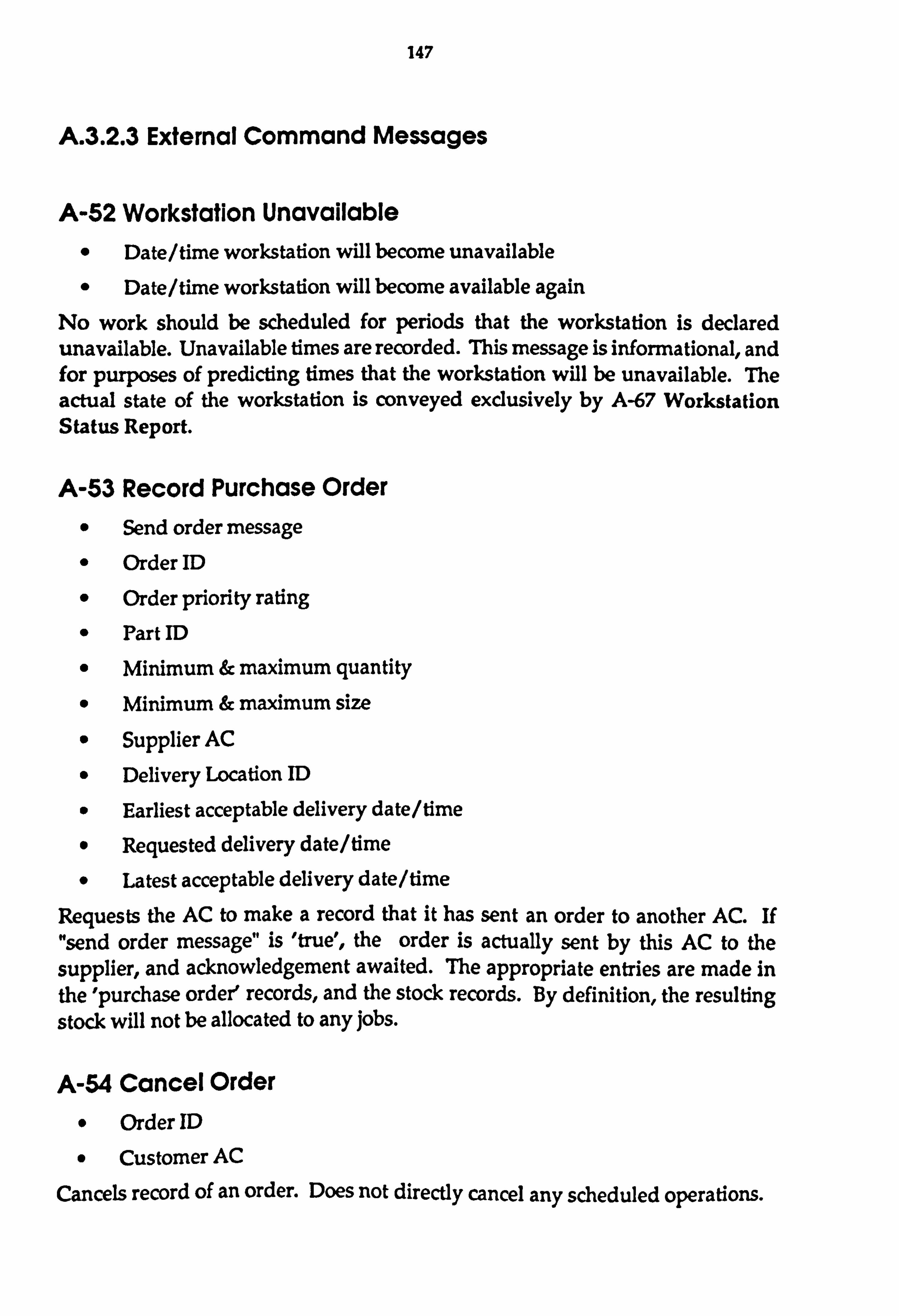
147
A. 3.2.3 External Command Messages
A-52 Workstation Unavailable
0 Date/time workstation will become unavailable
" Date/time workstation will become available again No work should be scheduled for periods that the workstation is declared unavailable. Unavailable times are recorded. This message is informational, and for purposes of predicting times that the workstation will be unavailable. The actual state of the workstation is conveyed exclusively by A-67 Workstation Status Report.
A-53 Record Purchase Order
" Send order message " Order ID
" Order priority rating
" Part ID
" Minimum & maximum quantity
" Minimum & maximum size
" Supplier AC
" Delivery Location ID
" Earliest acceptable delivery date/time
" Requested delivery date/time
" Latest acceptable delivery date/time
Requests the AC to make a record that it has sent an order to another AC. If "send order message" is 'true', the order is actually sent by this AC to the supplier, and acknowledgement awaited. The appropriate entries are made in the 'purchase order' records, and the stock records. By definition, the resulting stock will not be allocated to any jobs.
A-54 Cancel Order
" Order ID
" Customer AC
Cancels record of an order. Does not directly cancel any scheduled operations.

148
A-55 Cancel Purchase Order
" Order ID
" Supplier AC
" Cancel Order Deletes record of a purchase order sent to another activity controller. Also indicates whether to send a "Cancel Order" message to the supplier. Any projected stock that would result from the order is also deleted. No further direct action is taken.
A-56 Make Stock Record
" Part type " Quantity @ location
" Size © location
0 Location ID
" Arrival time
" Consumption/departure time
" Producing Order/Operation
" Consuming Order/Operation
Contains stock record information. Primarily used for initializing and adjusting system to actual material status. Response is A-62, detailing the recorded stock record.
A-57 Delete Stock Record
" Stock Record ID
Stock record is deleted. No further direct action is taken.
A-58 Delete Scheduled Operation
0 Scheduled operation ID
Operation is removed from the schedule, all the parts allocated to that operation are de-allocated, and all parts produced are removed from the projected stock. No further direct action is taken.

149
A-59 Schedule Operation
" Operation ID " Order ID
" Earliest start date/time
" Scheduled start date/time
" Required finish date/time
" Priority rating Instructs the receiving activity controller to enter an operation into its schedule. It contains all the information listed above. There is no implicit check that the operation schedule produces clashes with other operations, or that any of the parts will be available. Order ID may indicate no related order. Response is A-66 Operation Schedule Report, detailing the scheduled operation.
A"60 Re-schedule Operation
" Operation ID " Scheduled operation ID
" Order ID
" Earliest start date/time
" Scheduled start date/time
" Required finish date/time
" Priority rating
Contains a new set of schedule times and a priority for an operation which is identified by the schedule ID field (as reported by A-66).

150
A. 3.2.4 Enquiry and Reporting Messages The reporting messages and their responses should be as flexible as possible within the general aim of the message. The enquiries and reports listed here are those which have been identified as being the minimum specialised set that will allow external systems to infer the total state of an AC. Other enquiries and reports may make implementing particular functionality that depends on AC information easier. For this reason, it is recommended that arbitrary reporting be made available through a system such as a relational database being used to support the data management needs of activity controllers, or through an implementation of a general-purpose enquiry interface to Activity controllers. The details of the enquiries and reports are not expanded on here because they depend to a great degree on the features of the implementation. Instead, in most cases, the general purpose and contents of the messages are described.
A-61 Request Stock Report Requests a statement of the stock situation. The request can specify particular sets of stock records.
A-62 Stock Report Reports stock information as requested.
A-63 Request Scheduled Order(s) Report
Requests a statement of a part of the order information. The request can specify a set of orders, whether 'purchase' orders or 'sales' orders.
A-64 Order Schedule Report Reports the order book information as requested. This message may be sent unsolicited if desired by supplier activity controllers.
A-65 Report Scheduled Operation(s)
Requests a statement of part of the operation schedule. The request can specify one operation, or a set of operations.
A-66 Operation Schedule Report
Reports the operation schedule information as requested.

151
A-67 Workstation Status Report
" OC State (Inoperative, standby, ready, busy, suspended)
" List of currently executing operations AC checks state against its own records, and updates them if necessary. No further direct action taken, but an event is generated according to the status. If the operation controller identity has changed, a synchronous event is generated.
A-68 Report Estimated Delivery
" Report Destination
" Ordering AC
" Part ID
" Order ID
Requests a report of the scheduled delivery of a part against a particular order. A synchronous event is generated, and then an estimate is prepared according to the scheduled time of the last scheduled operation required to satisfy the order.
A-69 Estimated Delivery Report
0 Estimated date/time of delivery
If different from scheduled delivery that the receiving AC has recorded, records new estimate, and generates a synchronous event.
A-70 Report Order Status
Reports the current stock holdings and their locations, and the (projected or actual) start and finish times of the manufacturing operation relevant to that order. This gives all the information about the order status known at the receiving activity controller only.
A-71 Report Complete Order Status Compiles a complete status report by recursive dispatch of this message, following the order trail. A trail stops when all the parts required for an operation are present, the operation is under way, or the product is awaiting delivery, or at goods receipt points interfacing with the world outside the management of the system.

152
A-72 Order Status Report Variations and limits on the information supplied in order status reports could be implemented to allow more specific enquiries such as reporting the material situation only, or operation schedules only. These are classed as implementation decisions for the purposes of this discussion. Other reports of status and schedules are defined in more specific sections below, and a full list of defined reports can be found in section .
A-73 Request Event Status Report Requests information concerning the event(s) identified.
A-74 Event Status Report Reports on the status of the events as requested: enabled/disabled, available supplementary information, signal definitions.
A-75 Request External Processes Report Requests information on the labels and addresses of external processes.
A-76 External Processes Report Reports on the labels and addresses of the required external processes.

153
A. 4 The Algorithms This section deals with the major activity controller algorithms that have not been covered in the previous section. These form the body of configurable algorithms that can vary from one activity controller to another, and possibly within any particular AC over time.
The aim of this section is to illustrate a few different approaches to planning and decision taking within the PAC system, by outlining a range of algorithms that will express those approaches. It is not intended that this discussion should be taken as being an exhaustive study of the range or effectiveness of all possible algorithms; this subject is large enough to warrant a major research project on its
own.
A. 4.1 Ranking The ranking algorithm is called upon to order the set of operations that are ready for execution, so that the operations can be executed in the 'best' order. It is generally only of real importance in situations where a number of operations are typically executable at the same time. However, it can also be used to affect the operation of the activity controller when this is not the case. It is executed by receipt of A-8 Order Executable Operations.
A. 4.1.1 First In, First Out
This is probably the simplest algorithm, and with a suitable implementation of the function of adding to and removing from the list of executable operations, will degenerate into taking no action at all. Simply stated, the operations are executed in the order in which they become executable.
A. 4.1.2 Importance and Urgency A family of algorithms which rank the operations according to a judgement based on the operation priority, the standard process time and the difference between the current time and the due date or scheduled start. The exact function
can take many forms, but some simple functions are:
" Rank first by priority, and then within each priority band by increasing amount of float time, the difference between time remaining before latest acceptable finish time and the standard process time.
" Rank by priority, and then according to the difference between current time and scheduled start time.

154
" Rank according to the difference between current time and scheduled start time, using priority only when the difference is sufficiently small.
A. 4.1.3 Assessing the schedule This style of algorithm may be used to prevent an operation of above a threshold duration just pre-empting a more important one by a combination of circumstances. The schedule of operations is scanned to discover whether there are any non-executable operations which are scheduled to occur before any of the ones on the executable list. If there are, then the requirements are traced back to the missing part(s) that prevents those operations from being executed. If an order has been placed for these parts, an enquiry message is sent to the supplier to determine when delivery is likely. Operations to execute will then be chosen from the list which should terminate before the outstanding part(s) are delivered, in order that the operation behind schedule is not held up.
A. 4.2 Order Processing The ordering algorithm is responsible for dealing with orders which do not go through the quote/acceptance protocol, but rather are directly placed with the receiving AC. Orders are likely to be placed in this way if the customer AC has no alternative supplier for the ordered part, or it has a simplistic approach to ordering and quotations, which does not involve sending quotation requests to supplier ACs. The ordering algorithm is executed upon receipt of A-19 Part Order.
A. 4.2.1 Simple Fixed Preference
This algorithm expresses the strategy of having a 'preferred' production sequence for all products, which is deviated from only under abnormal circumstances, such as machines breaking down or being otherwise unavailable. The logic is simply to attempt to schedule the order on the basis of choosing the highest-ranked manufacturing operation whenever a productive operation is necessary, and always sending orders to the highest-ranked supplier for each particular part. If a manufacturing operation is not possible, or the preferred supplier declines to accept the order, then the next choice on the list is tried, until either the operations are scheduled, or the order cannot be satisfied, and a negative acknowledgement must be sent.
Any orders to suppliers will of course be sent with time constraints reflecting the local processing time and current schedule of the local AC. There remains the choice of whether to fit the new operations into the existing schedule, or whether

155
to attempt to rearrange the schedule so as to optimise the scheduled production sequence as a whole. Given the simplicity of the ordering policy, it seems more in keeping to take the simple residual scheduling approach, and not disturb the scheduled operations. A minor variant on this would be to allow 'small' movements of existing scheduled operations within their established time constraints to concentrate enough non-productive time to fit in the new order.
Any non-productive (materials movement) operations that are required to complete the chain from local stock and ordered parts through to delivery at the required location would be most simply scheduled with time constraints representing "as soon as possible", and in most cases, simply lump the times associated with these movements into the standard processing time of the manufacturing operations. Since under most circumstances the sequence of movement operations will be identical for any given production operation, by virtue of the "preferred" supply route almost always being used, this will not normally introduce any unacceptable scheduling inaccuracy. In the case of purely materials handling workstations, the movement time could be expressed most simply in the standard lead time for that product, again with reasonable accuracy for most of the time.
A. 4.2.2 Ranked Option Assessment - Minimum Loading This algorithm will attempt to minimise the workload scheduled for the local workstation, while satisfying the order, by making a choice between the production and ordering options on a rank-by-rank basis.
Assuming that productive operations are involved, the top rank of operations is inspected. For each option, the required supplies are calculated, and quotes requested from suppliers for the delivery of the parts required. A calculation is then made to determine which options will result in delivery within the time constraints of the order. If more than one option will satisfy the order, the choice is made on the basis of minimising the process time at this workstation.
If none of the first-rank options can satisfy the order, the next rank of options is inspected in the same way. If at the end of this process there is still no clear option, then the best of the first rank options is chosen.
A. 4.2.3 Ranked Option Assessment - Quality of Service This algorithm is similar to that above, except that the choice is made on the basis of being able to deliver the product closest to the requested delivery time, with early delivery (if necessary) preferred to late delivery within the time constraints.

156
A. 4.3 Scheduling The scheduling algorithm is used as a mechanism to perform some more comprehensive, and generally more detailed rearrangement of the production schedule than would normally be considered by the other algorithms. The algorithm is executed upon receipt of A-25. The first decision in considering the scheduling algorithms is to determine the scope of the activity, from options such as:
" Local adjustments only,
" Local adjustments and upstream re-timing, " Local adjustments and upstream re-ordering (i. e. changing suppliers),
and
" All the above and changing delivery schedule to customers. For most cases, though, expanding the scope from purely local adjustments is liable to result in too much disturbance to the entire system schedule. It seems likely that scheduling behaviour which is permitted to change delivery schedules, by moving outside the boundaries of quoted or estimated delivery times, will lead to system-wide schedule instability. Of course, in cases where delivery to schedule becomes impossible, the consequences cannot be avoided, and indeed, it is under such circumstances that one would expect most re-scheduling behaviour to be invoked; the algorithmic 'scopes' above refer to the space that is searched for the optimum solution. Changes outside the scope are only made if they are unavoidable. Only the local adjustment option is examined here, which allows any changes to be made to the local schedule in order to optimise local productivity and resource usage, as long as those changes stay within the boundaries of the time constraints set by both purchase and sales orders.
A. 4.3.1 Priority-Based Back Loading
This approach to re-scheduling effectively takes the set of orders that are currently outstanding, the current stock position, and the projected stock that results from purchase orders that are still outstanding, and re-schedules the activities of the AC in this context. The scheduled times of the productive operations that have been scheduled are discarded, and non-productive operations are dispensed with completely. A variant on this approach is to send A-68 Report Estimated Delivery to all suppliers to get an accurate picture of when parts are going to be delivered.

157
Each sales order is taken in order of priority, and operations scheduled to deliver at the requested time. If it is found that currently scheduled operations (of higher priority) will not allow delivery to be made on time, a check is made on previously scheduled operations to determine whether they can be moved within their time boundaries to solve the problem. If they cannot, then an unsolicited A-69 Estimated Delivery Report message is sent to the customer. If delivery cannot be made on time because of the existing purchase order schedule, then A-22 Request Delivery Re-quote is sent to the current supplier. If the answer will still not satisfy the order, then A-69 is also sent to the customer.
If the scope of the algorithm included upstream re-ordering, then invitations to tender would likely be requested of alternative suppliers at the point when it was realised that the current supplier would not be able to deliver early enough. However, considering the algorithm with restricted scope, one would expect the result to be a general improvement in delivery punctuality, with sales orders being satisfied later than originally planned only if a higher priority delivery is now being made within the time constraints of the order where this was not the case before. If priorities are assigned with propriety by the PMS system to reflect the true importance of jobs, then this'is almost bound to be an 'better' schedule than was achieved by the more simplistic residual scheduling to be expected of the quotation or order algorithm.
A. 4.3.2 Forward loading This algorithm similarly ignores the current schedule, retaining only the times of outstanding orders, current stock and the scheduled operations without their times. In contrast with the previous algorithm, however, the algorithm loads operations on an "as soon as possible" basis. Where deliveries must consequently be made outside time boundaries, an unsolicited A-69 is also went to the customer. No attempt is made to change incoming delivery times.
A. 4.4 Validating The validation algorithm is aimed at repairing any damage that has been done to the AC production schedule, in terms of making the structure inconsistent. It is suggested that the logic of the repairs should be the same as the logic of one of the other algorithms, especially the quotation algorithm or the order processing algorithm.
The difference is that the algorithm inspects the entire schedule, working backwards from outstanding orders, to make sure that a valid chain of scheduled operations and deliveries exists to support each order. If some element of the chain is missing, or times do not match (other than projected late deliver of the

158
product), then the appropriate logic is executed to re-schedule the invalid sequence. If this results in delivery being later than the time constraints of the order, then an unsolicited A-69 Estimated Delivery Report message is sent. Because this algorithm is following the order processing or quotation logic, it is allowed to cancel orders, and re-schedule or re-order any parts required.
A. 4.5 Quoting The quoting algorithm aims to prepare a reasonable estimate of when the receiving AC will be able to satisfy an order. Part of this process is similar to the process of responding to a direct order, in that the same sorts of strategies for scheduling internal operations and asking for quotes from upstream processes can be followed. The main differences, however, are that the resource allocation is provisional, in that a subsequent message can instruct the AC to forget that the quotation was made, and that the resource allocation is not exclusive; it should be possible for two or more quotes to be prepared (perhaps serially) is such a way that each calculation ignores the loading and resource usage attributable to the other(s).
Discounting of "rival" quotations involves building a table based on the choice traces received in the quotation request. Quotation requests, or Invitations To Tender (ITTs) can be grouped into a logically-related tree on the basis of the trace (Figure 20):
" Reading from 'earliest' to 'latest' choice, group ITTs together whose first choice matches.
" All ITT groups that differ in choice number only can be "ORed" in the discount at that level. In other words, a quote in one group can ignore the load due to quotes in all groups which differ in choice number only at each level.
" All ITT groups that differ in quote number/AC ID pair are "ANDed". In other words, the quotes in groups that differ in quote number at that level take account of the resources and loading allocated to the quotes in the other groups.
" Repeat until bottom level, then prepare quote, on the basis of the loading that must be taken into account.
The preparation of quotations also has some simpler options than are realistically available to the order processing algorithm. These options consist of making a quote on the basis of entirely local information about stock levels and standard lead times recorded against the various production alternatives. This approach offers a single layer enquiry, which establishes whether the receiving AC has

159
either the parts ordered as 'finished stock', whether satisfying the order is simply a matter of processing existing (or already projected) stock, or whether placement of the order will result in supplies being ordered from another AC. The great advantage of this is to avoid full recursive distribution of quotation request messages.
One possible enhancement to the scheduling/quotation mechanism would be to include an extra field in the quotation request message indicating the number of levels of recursion to be followed in preparing a quote. Thus, an AC requesting a number of quotes to make a choice between alternative suppliers could specify 5 levels of recursion. Each receiver of a quotation request would prepare a quote in a recursive manner, reducing the recursion count on the quotation requests it
sends out itself. When a request is received with 0 in this extra field, a quotation is prepared on the basis of standard lead times and/or local stock position. Such
a system will allow for advantage to be taken of 'close' free stock, while considerably reducing the network load caused by quotation requests and answers.
A. 5 The Events A large number of events are defined in order to provide hooks for configuring the operation of the system internally, and to provide a flexible method of integrating the system with other applications. The events that have been identified as being of potential value are described below, indicated as asynchronous (A), or synchronous (S). All events have the current time, the AC identity, and the event ID available.
(1) Message Sent or Received (A)
Each message that an AC sends or receives generates an asynchronous event. The information available is the contents of the message. Receipt of an acknowledgement generates an event appropriate to the type of message that is being acknowledged, making it possible to trap both a particular message type being sent, and acknowledgements to those messages only.
(2) Error (S)
Contains the same information as the message, but allows action to be taken before the message is processed by the normal reception process.

160
(3) Ready to Execute Operation (S)
This event is generated when an entry is about to be taken from the list of executable operations; it allows the ranking algorithm to be activated before the operation is chosen. Alternatively, it would allow the activity controller to be stopped pending examination of the operation to be performed, when testing or commissioning the system. Generated by the earliest start time of an operation passing, or during processing of A-7, A-9, A-10, and A-16.
(4) Operation Completed Behind Schedule (A)
Generated if an operation is completed behind schedule, upon receipt of A-9 Operation Completed. Message contents available.
(5) Operation Not Executable On Schedule (A)
Generated when the scheduled start time for an operation passes if it cannot be moved to the executable operations list. Operation schedule information available.
(6) Operation Not Executable Before Latest Start Time (A)
Similar to above, but generated if the operation has not been moved to executable list before its latest start time passes. Operation schedule information available.
(7) Operation Not Started On Schedule (A)
Generated if the scheduled start time passes and the operation has not been
started, although it is on the executable list. Operation schedule information available.
(8) Operation Not Started Before Latest Start Time (A)
Generated if the operation has not been started, although it is on the executable list, before its latest start time passes. Operation schedule information available.
(9) Non-Standard Outcome of Operation (S)
Generated if the outcome of an operation, as reported by A-9 Operation Completed, is not the standard result. Message contents available.
(10) Operation Failed (S)
Gives opportunity for synchronous reaction to failure of an operation. A-10 Operation Failed contents available.
(11) Delivery Received Behind Schedule (A)
Generated if a delivery is received later than scheduled, on receipt of A-16 Deliver Part. Message contents available.

161
(12) Operation Controller Changed (S)
Generated if the identity of the operation controller has changed, prior to generation of workstation status change (if it, is generated for the same received message). Old and new OC IDs are available.
(13) Workstation Status Change (S)
Generated if the workstation status has changed, and this has only been detected upon receipt of a workstation status report. Information available is the contents of the message, the expected status of the workstation, and a flag indicating whether the status report was solicited or unsolicited.
(14) Report Estimated Delivery (S)
Allows the receiving AC to re-calculate its estimates of delivery before responding, if desired. Message contents available.
(15) Estimated Delivery Time Changed (S)
Generated when an Estimated Delivery Report is received with a different time than that recorded for the order at this end. Allows re-scheduling activity to be dependent on perturbations to scheduled deliveries. Message contents available.
Another kind of event that occurs is the arrival of particular times, such as start times for operations. In the case of an operations' earliest start times, for instance, a check must be made to see if all the requirements for that operation are available, because if so, it must be moved to the executable operations list. Similarly, some of the events listed above result from a time-based event occurring and certain other conditions holding at that time. Such an "alarm clock" facility is available in almost all real-time, and in most other operating systems, and so it should not be a problem to implement. Such events are not events in the sense just discussed, which can be programmed to send specific signals to processes. Rather, they are an implementation tool for building the general operational logic of activity controllers.

162
Appendix B Operation Controllers
It is assumed for all of the following discussion that the basic functions of an operation controller, such as handling and decoding messages, and modelling the OC state machine are similar for all operation controllers. It is not felt that the implementation of these supporting warrants any length of discussion since they are fairly common software functions. What is of interest in this discussion is the nature of the main functionality of the operation controllers, that distinguishes one from another. These differences reflect the diversity of the workstations that the operation controllers outlined are intended to control.
B. 1 Single CNC Machine or Robot Implementation of an operation controller for a single programmable machine is necessary where the machine will not directly support the full needs of the OC-AC protocol, or where the message syntax of the AC implementation does
not match that of the machine.
If we consider a highly flexible workstation, especially with a machine tool as the workstation machine, it is unlikely that the machine controller will be able to store the full range of production programs. Therefore, the operation controller must have some way of managing the programs held in the controller. The OC must also have sufficient control over the machine to execute chosen operations, and stop operations if required by an incoming stop message. It must also have sufficient communication with the controller to determine the outcome of operations, if any of the operations may have non-standard outcomes defined. Finally, it is advantageous if the operation controller has some means of discovering the status of the machine in reality, especially when the machine becomes inoperative or active again.
The functionality to support file transfer largely depends on the sophistication of the communications interface of the machine itself. The ultimate effect of the implementation is to treat the transfer of a program file into a position where it can be executed as a straightforward non-productive operation. The operation controller will receive a command to perform a particular operation, which must result in the transfer of the file.
With the right sort of machine controller, the operation request can be simply translated into a command sent to the machine indicating that it should download a program (from a pre-determined location). Alternatively, if the machine is more passive than this, incoming "perform operation" commands must be filtered for file transfer operation IDs, and when one comes along, an

163
additional piece of functionality in the operation controller must transfer the program to or from the machine controller's memory. If the machine's controller is unusually sophisticated, then from the operation controller's point of view there need be no difference between the performance of physical operations and file transfers; the machine's controller will take the appropriate action depending upon the operation ID.
Where a machine only has the capability of holding one program in memory, it is interesting to note that all productive operations are likely to result in the same "cycle start" command being sent to the machine controller. The operation to be performed is defined entirely by the presence of the appropriate program in the right location - the machine's memory. Where programs can be identified by name or number, it is sensible to link the name of a program to the operation it represents in some standard way, so that the operation controller can deduce the correct command to send to the machine from the incoming "Perform Operation" message. This approach was used in the experimental system.
Cycle control can be exercised by the operation controller in a number of ways, again depending on the nature and sophistication of the available interface to the machine controller. In the case of robots with a fixed repertoire of operations, it is sometimes advantageous to combine the range of activities into a single large program which endlessly cycles, and choose which operation to perform, and perform cycle starts through signals which merely determine which part of the program will be run in the next cycle. This approach had to be used for the Cincinnati Milacron robot used for tool-changing in the experimental cell, because the communications interface did not provide an operational cycle start command.
B. 2 Manual Workstation The operation controller for a manual workstation can offer an opportunity to provide good support for workers information needs. It would be possible to implement a minimal operation controller that merely displayed the raw information as to which operation to perform, by ID, as received from the activity controller. However, it seems much more constructive to provide more extensive support by regarding the information that a worker is likely to want as parts in much the same way as NC programs were considered above.
A fully interactive operation controller could therefore be built which manages a database of information required by workers as requested by the activity controller. Performing an operation, will then consist of attracting attention to the operation to be performed, by flashing a message on the screen, for example. The worker can interact with the system, perhaps accessing supporting

164
information if necessary, which has been made available by its being copied to the right files, until the job is completed. When the operation is completed, some final interaction with the shop-floor terminal will signal the result; perhaps choosing the outcome from a menu.
For manual workstations with a more restricted and predictable set of operations to be performed, a different approach can be taken, using techniques such as lights and push-buttons to make up the human interface. This is particularly suited to repetitive, low technical content jobs, such as loading or unloading machines, or palletizing/depalletizing where the parts to be loaded are constrained irrespective of the instructions given to the operator. The role of the human interface is then reduced to one of determining when an operation should be done and when it is completed, with perhaps a simple choice being made between a set number of options. This kind of interface can be implemented very adequately through the use of a PLC.
An intermediate kind of operation controller could make use of devices such as printers and bar-code readers. Simple instructions could be printed out, together with bar codes representing the possible operation outcomes. This information would, of course, be contained in an informational part required for the operation. When the operation is completed, the bar code could be wiped to inform the OC of the eventual outcome. This kind of interface would be especially useful for situations where the operator must leave the vicinity of the terminal during the course of executing the operation; for some classes of maintenance job or retrieving some items from storage, for example. For this kind of "workstation", it would be reasonable for the operation controller to behave as though the workstation were capable of multiple simultaneous operations, so that each requirement would be printed out as it arose, allowing a batch to be performed by simply following a list of instructions.
B. 3 Complex Workstations Control of complex workstations, such as a conveyor system or other materials handling systems, may be achieved by implementing a control system for the system as a whole which has an operation controller interface. Execution of an operation (moving a part from A to B), may require a complex sequence of actions by the operation controller. In many cases, the best way to handle these situations will be to use a PLC, but even then the option remains of implementing both the low-level logic of switches and actuators, and the higher level interface concerned with complete composite operations as a part of the same system, as long as the PLC is versatile enough to support the necessary interfaces and communications facilities.

165
Another approach to this is to implement the low-level logic separately, as a PLC program, for instance, and send commands to this program from an operation controller which, as with NC machine controllers, is fairly generic. This approach was taken in dealing with the circulating conveyor in the experimental system.
Another type of complex workstation is one which consists of a programmable machine, with some supporting hardware which must be controlled separately. An example of this can be found in the CMM cell of the experimental system where a small conveyor moved pallets into and out of the measuring envelope of the CMM. The logic of the operations was fairly simple: prior to a measuring operation, the conveyor must move the pallet to the measuring location, and afterwards, it must be moved back to the pick-up point for the materials handling robot. To control this system, messages were sent to another process, the PLC server, when movement of the conveyor was required. The operation controller could therefore be seen as controlling two distinct parts of the cell, according to some simple logic embodying a knowledge of the physical parameters of the cell. Given a wider range of movement possibilities, it would probably have been desirable to codify the locations and movements as non productive operations.
The ability to implement more intelligent operation controllers such as these allows an installation to avoid using a full activity controller & operation controller pair to control trivial pieces of equipment. Furthermore, even within the operation controller, there are a number of options-that can be explored with regard to how complex the logic embodied in the OC software is, and how much of the complexity of the workstation is managed by the activity controller. Development of an activity controller with suitably powerful general purpose location modelling and scheduling capabilities could potentially reduce the operation controller in all circumstances to an unintelligent executor of simple operations. However, this scenario may be unrealistic in some circumstances due to the requirements of real-time control of physical activities.

166
Appendix C Petri Nets
Petri nets are a formal modelling tool, especially useful for systems with concurrent, interacting components. A Petri net can be represented both graphically and mathematically; the mathematical model provides the basis for analysis, while the graphical representation lends itself to easy interpretation and construction, in small models, or portions of larger models. When modelling physical systems, there is usually an easily identifiable link between parts of the model, and the various parts of the physical system. Basic Petri net graphs consist of an arrangement of four elements:
" Places - generally represented graphically by (small, unfilled) circles.
" Transitions - represented by bars.
" Directed Arcs - represented by arrows, linking places and transitions into a network; each arc joins exactly one place and one transition.
" Tokens - generally represented by small, filled circles.
The arcs of the graph map to input and output functions of the net in the mathematical model, and are expressed, as would be expected, in terms of the places and transitions of the net. The arcs, or I/O functions, define the behaviour of the net in terms of markings of the net.
A marking is a definition of a distribution of tokens among the places of the net. Each place may contain zero or more tokens at any one time. The net executes by firing transitions. A transition firing is enabled if there is at least one token in each place that has an arc directed into the transition (input places). When a transition fires, one token is removed from each of the input places, and a token is added to each place that has an arc directed to it from the transition (output places).
Petri nets have been applied to modelling manufacturing systems by a number of researchers, in applications ranging from system simulation, and decision support through to work on direct control of manufacturing equipment, as implemented by PAC systems. This work has led to development of a number of extensions to the basic Petri net definition. In some cases, these extensions provide a shorthand representation for system features that can be modelled adequately by basic Petri net systems, but in a rather complex of long-winded way. Other extensions add truly new capabilities to the modelling power of Petri nets. Some of these extensions are used in the definition of the production model.

167
It should be noted that the proposed manufacturing model merely uses the semantics of Petri nets to provide a concise definition of the range of manufacturing activity that can be encoded in totality of the AC databases, and therefore defines the range of activity that can be controlled by the PAC system proposed. The approach taken is not to require the definition of the manufacturing system and its activities in terms of a Petri net, and implement sub-net execution processes which are then capable of controlling the factory, although in certain respects the two approaches are quite similar.
The extensions to basic Petri nets utilised in the production model are:
" Introduction of times associated with transitions, resulting in a timed Petri net which can be then used to model temporal as well as static logic. However, since the production model is not really intended for analysis under execution, this is really a notational convenience for associating times with production operations.
" Introduction of quantities associated with arcs determining the number of tokens which are used or produced when a transition fires.
" introduction of sizes associated with arcs and as properties of tokens; the size associated with an input arc determines a threshold value required to enable the transition, and is subtracted from the token values as they are removed from the input places. Similarly, a size associated with an output arc determines the value added to an output token as it passes through the transition. This is a continuous-function extension of the notion of coloured Petri nets.
" Introduction of input and output place (part) vectors, allowing a concise representation of a number of similar transitions which differ in the names of their I/O places, but not in their overall structure, in terms of I/O functions. For convenience, the group of transitions so defined are referred to by one name, and can be distinguished by the index(es) used in the various vectors.
" Introduction of decision points, which allow labelling of alternative outcomes of a transition. Currently, the decision as to which outcome is chosen is arbitrary, and is imposed from outside the model. One of the choices is designated as the standard outcome.
More information on Petri nets in general, and applications of some of the various extensions to basic Petri net theory can be found in [37,48,86,102].
Petri nets are conceived of in the production model as possibly being used as analysis or representational aids to defining single operations. Typically, therefore, each graph will consist of one transition, and a number of arcs and

168
places labelled appropriately. Implicitly, a production sequence can be built up by matching input and output place labels over a number of separate transitions, to give a large picture of a number of production operations related to each other by common parts. However, such an exercise is not a valid use of the production model as far as determining the behaviour of the PAC system is concerned.
This is because there is no static model which expresses the dynamic allocation of parts as they are produced and consumed. In other words, each model of a productive operation is separated from another by an indeterminate set of choices and non-productive operations that are defined by the factory model in their scope (by transfer operations and the lists of alternative suppliers/manufacturing operations for any given part), but decided by the dynamics of scheduling and ordering within the entire system.

169
Appendix D Fault Tolerance
Fault tolerance can be defined as the ability of a system to continue operation effectively despite failure of a part of the system. Measures of fault tolerance includes consideration of what combinations of single failures are required to make the entire system fail; if any single failure results in failure of the system, then the system cannot be said to be tolerant of that fault. The greater the fault tolerance of a system, the more separate failures can occur simultaneously without the entire system failing.
To some extent, the likelihood of any of these single failures occurring can be analysed to derive a measure of how likely complete system failure is. However, fault tolerance is a different matter from trying to reduce the chances of any single failure, although it is an effective technique for reducing the likelihood of total system failure. In many schemes for fault tolerance, a key concept is graceful degradation of performance, where any failure may result in the system performance being reduced, but will cause no errors or catastrophic failure (Figure 21). Of course, for real-time systems, degradation of performance in terms of response times will eventually constitute a complete system failure in itself, when the responses, although correct, are not forthcoming within the time limits imposed by the system.
Fault-Intolerant System
Fault-Tolerant System
Fault-Tolerant System 41 C with
Graceful Degradation ö
CL.
Simultaneous Failures
Figure 21: Effect of Fault Tolerance on Performance Under Failure

170
Many approaches to fault tolerance have been explored in computer systems, covering possible faults in both hardware and software. The diversity of these techniques and approaches precludes a serious survey here. The aim of this discussion is to outline some of the ways in which the PAC system architecture proposed in this thesis can support fault tolerance.
Allowing for integration of external, and possibly remote data management systems for the activity controllers allows any amount of required fault tolerance to be included in an installation by integration with a DBMS with appropriate characteristics. For the purposes of this discussion, it is therefore taken or granted that any required level of data integrity, and data management fault tolerance can be maintained.
The simple fact that the architecture is distributed reduces to some extent the effects of a single failure. For installation where a high proportion of production routes have alternative processing workstations for their operations, a failure in an activity controller or an operation controller can be dealt with by re-routing production as though the controlled workstation had failed unexpectedly. This of course depends on detection of the failure, which can be achieved by raising the alarm when a message is not acknowledged (or the communication system reports a failure in communication). A more active failure detection system would involve regular communication between "watched" processes and watchdog processes which will raise the alarm if one of these regular check-ins is missed.
Re-routing production around a failed AC requires all customer ACs to cancel their outstanding orders to that AC, perhaps remove the AC from their supplier lists, and re-validate their production schedules. Orders will then be routed through the production alternatives. This procedure would be enhanced if all suppliers to the failed AC had their sales orders cancelled, so that stock could be re-allocated to other customers as appropriate. Some of this behaviour could be implemented through the signalling system, but an external fault recovery director process would probably give a more compact implementation.
A more sophisticated approach to providing fault tolerance can be taken, exploiting the location independence of many of the processes that make up the PAC system, especially the activity controllers. Given an external data management system, which is itself fault tolerant, or at least not affected by the failure that has occurred, a failed AC can be replaced by a new AC process, perhaps running on a different processor, which uses the data left by the previous, failed process. All that is necessary to integrate this new AC into the system is to ensure that the messaging system routes messages to the new process. This may be done at a number of levels, from broadcasting changes to

171
address information to all ACs and the appropriate OC, to the new process simply registering itself with the same identity as the failed process. The complexity of this depends on the implementation of the messaging system.
It should be noted that without hardware support, the ability to start a new process and initialise it to the same state as the old process just before failure, depends on all but the most transient state information being handled through the data management system, at least on a write-through basis. For some implementations this may be seen to be too high an overhead, effectively ruling out this approach to fault tolerance. In such circumstances, it would be possible to run shadow processes, which track the state of the active processes continuously, and in the event of the active process failing, have enough information to take over as the new process, or initialise a new process for that purpose. In effect, this is a different way of implementing the same basic strategy of (transparent) replacement of failed processes with new copies, with different costs and overheads for implementation.
These approaches to fault tolerance do depend on the fact that the cause of the failure was not some corruption of the working data which is propagated to the replacement process. Of course, where this is the case, the new process will instantly fail as well, and fault tolerance has not been achieved. In such cases, less disruptive strategies must be err. ployed, such as holding up the work associated with the failed process, or re-routing work around the failure as above, while some 'external' force can be employed to reconstruct or repair the data to the point where normal processing will not lead to another failure. Of course, this manipulation can be achieved through the data access messages of the AC while it is stopped from executing any independent behaviour itself. Alternatively, the software of the AC itself can employ finer-grained fault tolerance methods to eliminate process failure due to data corruption or internal algorithmic failure.
Tlie architecture of the system therefore lends itself to various levels of fault to1t Dance being implemented on the basis of process failure. This includes proces- failure for any reason, including failure of the processing hardware, as long as the system is implemented in a multi-processing environment of which only a portion has failed. Within such an environment, the replacement processes can be re-distributed among the various processing elements, giving the ability to manifest a high degree of graceful performance degradation in the face of hardware failure. Of course, this property extends to failure of hardware running OCs, as long as a replacement OC can be executed on another machine - implying that the secondary processor has an acceptable line of communication to the workstation equipment.