lABorAtory MANUAl - Geethanjali Group of Institutions
218
lABorAtory MANUAl prodUCtioN teCHNoloGy lAB (Subject Code: 54604) II Year B.TECH. II-Semester MECHANICAL ENGINEERING LABORATORY IN-CHARGE: 1. P.SREELATHA Assistant professor DEPARTMENT OF MECHANICAL ENGINEERING GeetHANJAli ColleGe of eNGiNeeriNG & teCHNoloGy
-
Upload
khangminh22 -
Category
Documents
-
view
2 -
download
0
Transcript of lABorAtory MANUAl - Geethanjali Group of Institutions

lABorAtory MANUAl
prodUCtioN teCHNoloGy lAB (Subject Code: 54604)
II Year B.TECH. II-Semester MECHANICAL ENGINEERING LABORATORY IN-CHARGE: 1. P.SREELATHA Assistant professor
DEPARTMENT OF MECHANICAL ENGINEERING
GeetHANJAli ColleGe of eNGiNeeriNG & teCHNoloGy

CHeeryAl (v), KeeSArA (M), r.r. diSt. - 501 301 (AffiliAted to JNtUH, Approved By AiCte, NeW delHi, ACCredited By NBA)
www.geethanjaliinstitutions.com 2015 – 2016
1

Laboratory Schedule (BATCH-B) DATE
Expt
. No.
1 2 3 4 5 6 7 8 9 10 11 12 13 14 15
07.1
2.20
15
14.1
2.20
15
21.1
2.20
15
28.1
2.20
15
04.0
1.20
16 11
.01.
2016
18.0
1.20
16
25.0
1.20
16 01
.02.
2016
08.0
2.20
16
15.0
2.20
16
22.0
2.20
16
29.0
2.20
16
01 02 03 04 05 06 07 08 09 10 11 12
Laboratory Schedule (BATCH-A)
DATE
Expt
. No.
1 2 3 4 5 6 7 8 9 10 11 12 13 14 15
11.1
2.20
15
18.1
2.20
15
8.01
.201
6
22.0
1.20
16
29.0
1.20
16 05
.02.
2016
12.0
2.20
16
19.0
2.20
16 26
.02.
2016
04.0
3.20
16
11.0
3.20
16
18.0
3.20
16
25.0
3.20
16
01.0
4.20
16
08.0
4.20
16
01 02 03 04 05 06 07 08 09 10

11 12
1

BATCHES
Batch H.T.No. Batch H.T.No.
B1 14R11A0301 - 304 A1 14R11A0341 - 344
B2 14R11A0305 - 308 A2 14R11A0345- 348
B3 14R11A0309 - 312 A3 14R11A0349 - 52
B4 14R11A0313 - 316 A4 14R11A0353 - 356
B5 14R11A0317 - 320 A5 14R11A0360 - 364
B6 14R11A0321 - 324 A6 13R11A0301- 304
B7 14R11A0325- 328 A7 13R11A0305 – 308
B8 14R11A0329- 332 A8 13R11A0309-312
B9 14R11A0333 - 336
B10 14R11A0337 - 340
Ist Mid Semester Examination: 16.02.2016
2nd Mid Semester Examination: 20.04.2016
Laboratory Examination: 22.04.2015 to 24.04.2016
End Semester Examination: 04.05.2015 to 16.05.2016

2

GeetHANJAli ColleGe of eNGiNeeriNG& teCHNoloGy Keesara (M), Cheeryal (V), R.R –dist 501 301
prodUCtioN teCHNoloGy lAB
LAB OBSERVATION
CERTIFICATE Hall Ticket No.: Certified that this is the bonafide record of work done by
Mr.………………………………………………..……… of …………. ……………semester B.Tech. Mechanical Engineering Branch / Batch during the academic year …………………………. in the PRODUCTION TECHNOLOGY laboratory Head of the Department Staff In-Charge Submitted for the University practical examination held on…………………… at GEETHANJALI College of Engineering and Technology, Cheeryal, Hyderabad. Internal Examiner External Examiner

Date: ……………… Date: ………………
3

A LIST OF BASIC SAFETY RULES 1. When you handle chemicals wear eye protection (chemical splash goggles or full
face shield). 2. When you work with furnaces for heat treatment procedures or other thermally
activated equipment you should use special gloves to protect your hands. 3. Students should wear durable clothing that covers the arms, legs, torso and feet.
(Note: sandals, shorts, tank tops etc. have no place in the lab. Students
inappropriately dressed for lab, at the instructors discretion, be denied access) 4. To protect clothing from chemical damage or other dirt, wear a lab apron or lab coat.
Long hair should be tied back to keep it from coming into contact with lab chemicals
or flames. 5. In case of injury (cut, burn, fire etc.) notify the instructor immediately. 6. In case of a fire or imminently dangerous situation, notify everyone who may be
affected immediately; be sure the lab instructor is also notified. 7. If chemicals splash into someone's eyes act quickly and get them into the eye
wash station, do not wait for the instructor. 8. In case of a serious cut, stop blood flow using direct pressure using a clean towel,
notify the lab instructor immediately. 9. Eating, drinking and smoking are prohibited in the laboratory at all times. 10. Never work in the laboratory without proper supervision by an instructor. 11. Never carry out unauthorized experiments. Come to the laboratory prepared. If you
are unsure about what to do, please ask the instructor. 12. Always remember that HOT metal or ceramic pieces look exactly the same as
COLD pieces are careful what you touch. 13. Know the location and operation of : Fire Alarm Boxes

Exit Doors
Telephones
4
LABARATORY CLASSES - INSTRUCTIONS TO STUDENTS 1. Students must attend the lab classes with ID cards and in the prescribed uniform. 2. Boys-shirts tucked in and wearing closed leather shoes. Girls’ students with cut shoes,
overcoat, and plait incite the coat. Girls’ students should not wear loose garments. 3. Students must check if the components, instruments and machinery are in working
condition before setting up the experiment. 4. Power supply to the experimental set up/ equipment/ machine must be switched on
only after the faculty checks and gives approval for doing the experiment. Students
must start to the experiment. Students must start doing the experiments only after
getting permissions from the faculty. 5. Any damage to any of the equipment/instrument/machine caused due to carelessness,
the cost will be fully recovered from the individual (or) group of students. 6. Students may contact the lab in charge immediately for any unexpected incidents and
emergency. 7. The apparatus used for the experiments must be cleaned and returned to the
technicians, safely without any damage. 8. Make sure, while leaving the lab after the stipulated time, that all the power
connections are switched off. EVALUATIONS:
All students should go through the lab manual for the experiment to be carried out for
that day and come fully prepared to complete the experiment within the prescribed
periods. Student should complete the lab record work within the prescribed periods. Students must be fully aware of the core competencies to be gained by doing
experiment/exercise/programs. Students should complete the lab record work within the prescribed periods. The following aspects will be assessed during every exercise, in every lab class and

marks will be awarded accordingly: Preparedness, conducting experiment, observation, calculation, results, record
presentation, basic understanding and answering for viva questions. In case of repetition/redo, 25% of marks to be reduced for the respective component.
5

NOTE 1: Preparation means coming to the lab classes with neatly drawn circuit diagram
/experimental setup /written programs /flowchart, tabular columns, formula, model
graphs etc in the observation notebook and must know the step by step procedure to
conduct the experiment. Conducting experiment means making connection, preparing the experimental setup
without any mistakes at the time of reporting to the faculty. Observation means taking correct readings in the proper order and tabulating the
readings in the tabular columns. Calculation means calculating the required parameters using the approximate formula
and readings. Result means correct value of the required parameters and getting the correct shape
of the characteristics at the time of reporting of the faculty. Viva voice means answering all the questions given in the manual pertaining to the
experiments. Full marks will be awarded if the students performs well in each case of the above
component
NOTE 2: Incompletion or repeat of experiments means not getting the correct value of the required parameters and not getting the correct shape of the characteristics of the first
attempt. In such cases, it will be marked as “IC” in the red ink in the status column of the
mark allocation table given at the end of every experiment. The students are expected to
repeat the incomplete the experiment before coming to the next lab. Otherwise the marks
for IC component will be reduced to zero.
NOTE 3 Absenteeism due to genuine reasons will be considered for doing the missed
experiments. In case of power failure, extra classes will be arranged for doing those experiments

only and assessment of all other components preparedness; viva voice etc. will be
completed in the regular class itself.
6

NOTE 4: The end semester practical internal assessment marks will be based on the average of all the experiments.

7

INDEX
S. DATE NAME OF THE EXPERIMENT MARKS
Page Signatur
No No e
1 To determine of the Strength of the green sand by
Universal Testing Machine
2 To determine permeability number of green sand,
core sand and raw sand.
3 Prepare a stepped pulley pattern of given dimensions
by using wood turn lathe.
4 To prepare a knurling and turning stepped pulley
pattern by using wood turning lathe
5 To make the mould for the given stepped cone
pulley.
6 To make the mould for the given split pattern.
7 To join the given two work pieces as a lap joint by
arc welding
8 To join the given two work pieces as a ‘square butt
joint’ by arc welding.
9 To prepare a rectangular tray Spot joint using given
work pieces.
10 To join the given two work pieces as required type
of joint by gas welding
11 To do bending and drawing operations on hydraulic
press by using dies.
12 To do blanking and piercing operations on fly wheel
press by using proper dies.
13 To Make a Bottle by Using Blow Moulding
14 To Make a Screw type Bottle Cap by Using
Injection Moulding

Completed date:
Average Mark: Staff - in - charge
8

SAND SIEVER USE: It is used 'to determine the finesse number i.e. the grain size of foundry sand. MACHINE CONTAINS: 1. Timer 2. On Off Switch 3. Sieves10 Nos, 4. Lid and pan. 5. Vibrator assembly 6. Sieve Separator key 7. Sieve clamp Patti 8. Clapping springs SPECIFICATION: Input voltage: 230 Volt, 50 Hz. Motor: 1/8 Hp Single Phase, Cycles — 50. Timer: 10-15 minutes Sieves: 53, 75, 106, 150, 212, 300, 425, 600, 850, 1700 Mic. SETUP: Unpack the equipment as well as accessory of the machine let it on plane & sturdy platform. Plug
three prong connecting cord in to a three-prong outlet of proper voltage rating. Switch on the
instrument mains indicator will glow indicating the power supply is o.k. Refer the sketch diagram
supplied with this manual for the location of the component as they are mentioned in this
procedure. OPERATING INSTRUCTION:

1. Keep the instrument on plane and sturdy platform. . Connect single-phase A.C. supply 2. Remove the clamping Patti by pulling the knobs of side clapping springs bar. 3. Take out the set of sieves. It is recommended to Weight each emBy sieve before the test Use
9

soft brush for cleaning sieves and pan. 4. Take 100 Gms. Of washed and dried sand sample in the top sieve (1700 mic).
5. Put the lid. Keep entire sieve set on shaking mechanism (vibrator assembly). Course sieves
should be at top and fine at bottom i.e. in the form of descending order (1700, 850, 600, 425,
300, 212, 150, 106, 75, 53 mic). 6. Set the timer for desired sieving time (Average time of the cycles is recommended as
15 minutes). Put 'ON 'the switch. 7. After completing of time motor will be stop automatically.
8. Disconnect the supply. Remove the side clapping springs bar.
9. Weight the sand grains remaining in the individual (Each and every sieve) sieves. Weight
each sieve after the test along with sand 10. The difference between two Weights will give accurate Weight of sand grains. Put
obtained results in the following table to get finesse number. CALCULATION:
Sieve Weight In gms. Multiplying
Aperture in % Retained=b Product
On sieve Factor
microns
(a) (b) (c) (d) (e) = c x d
1700 5
850 10
600 20
425 30
300 40
212 50
150 70
106 100
75 140

53 200
Sieve pan 300
Total .,"<;-.N. Total
10

Total of e Fineness No.
C Total of c Precautions:
1. Keep the instrument clean.
2. Remove sand grains from each sieve using soft brush only.
3. Do not rotate timer knob in anti-clock-wise direction. Figure: SAND SIEVER

11

CALACULATION:

12

SAND MIXER USE: Sample batches of the sand mixes are mixed in the sand mixer. These moles are available in 10
Kg. Or 5 Kg. capacities suitable for Production and Laboratory purpose. MACHINE CONTAINS: 1. Two Blades 2. Discharge Door 3. On Off Switch EQUIPMENT:
1 . S a n d M u l l e r
2 . H o t T r a y 3. S h
o v e l PRE-SETTING: Keep the instrument on the floor level. Connect to three-phase AC supply. OPERATING INSTRUCTIONS: 1. Switch 'ON' the instrument. 2. Add the weighed dried sand in the pan gradually from one side. 3. Add measured quantity of binding material. 4. Thoroughly mix the sand for approx. 5 minutes. 5. Opening bottom door of the pan discharges the sand. 6. Switch 'OFF' the instrument and clean the pan by brush. 7. Clean the discharge door. PRECAUTION: 1. Clean the instrument after use. 2. Grease and lubricate the moving parts each month.

13

Figure: SAND MIXER

14

CALACULATION:

15

SAND MULLER USE: Sample batches of green sand mixing & mulling in the Sand Muller. The Models are available in
5 Kg. & 2 Kg. capacities suitable for Laboratory purpose. MACHINE CONTAINS: 1. Two rollers in 5 Kg capacity 2. Plough with the water sprinkling attachment. 3. Discharge Door 4. On Off Switch Overview: Silica sand (SiO2) is used more frequently for making castings than any other moulding
materials. It is relatively cheap, and has sufficiently refractoriness even for steel foundry use . A sui table bondin g agent (c lay or mola sses) is m ixe d wit h the sand;
m ixtu re is moistened with wate r to devel op st rength and plast icity and to
make t he a ggre gate suitable for molding. A definite mulling action is always required for thorough mixing, in which sand grains, bonding agent, and water are rubbed intimately together.
Different types of sand mullers are used to serve this purpose PRE-SETTING: Keep the instrument on the floor level. Connect to single-phase A.C. supply. OPERATING INSTRUCTIONS: 1. Switch on the instrument. 2. Add weighed dried sand (5 Kg in Model 5 Kg. capacity) in the pan gradually from one side. 3. Add measured quantity of binding material. 4. Add the required quantity of water through funnel provided at the centre. 5. The mutter performs the blending action on the sand while mixing to achieve maximum
plasticity. 6. The plough directs the sand under the Muller with mixing action. 7. This ensures rapid and thorough blending and avoids grinding due to proper suspension
mechanism of the Muller. 8. After thorough mixing and blending of the sand, the moulding sand is discharge by opening

bottom discharge door. 9. Rotating plough removes the material from the pan easily and quickly. 10. Switch 'OFF the instruments clean pan, plough and roller.
16

11. Close the door. PRECAUTION: 1. Clean the instrument after use. 2. Grease and lubricate the moving parts each month. Figure: SAND MULLER

17

CALACULATION:

18

PRACTICE OF MAKING SAND SAMPLES USING SAND RAMMER
USE: Sand Rammer is used for preparing standard specimen under standard conditions. MACHINE CONTAINS: 1. Main Body 2. Specimen Tube 3. Pedestal Cup 4. Stripping Post Overview: The sand rammer is a machine for preparing specimens for testing of the permeability and strength
of moulding sand and is comprised mainly of a base, ram, tamping bar and lever. The machine is so
constructed that the ram is brought up by the crank and is then caused to drop to strike and drive
down the tamping bar at the lower end of which is fixed tamping plate which slides into a sand tube
to press the sand tube into a certain size with certain energy. OPERATING INSTRUCTIONS: 1. Place the machine on non- vibrating platform. 2. Take the height such that the reading marks of the top bracket should be in eye level. 3. Place the Specimen Tube in the Pedestal Cup. 4. Fill approx. 135-160 grams Sand Sample in the Specimen Tube. 5. Lift the left cam upward; 6. Place the Specimen Tube with Pedestal Cup on the base. 7. Take Ramming head downward with left cam. 8. Ram the sample three times with the help of right cam. 9. See that the top of plunger rod matches the zero of the scale.

10. It should match within + 1 mm. 11. Lift the left cam upward.
19

12. Take the specimen tube.
13. Place it on stripping post.
14. Pull the tube downward for removing the specimen.
PRECAUTION: .21111,
1. Keep the instrument clean
2. Apply rust preventive oil to Moving Parts, Specimen Tube, and Pedestal Cup.
3. Do Not Ram Right Handle Without Specimen.
4. Lubricate All Moving Parts At Least Once In The Week.
ASSEMBLY:
Place the Ramming Cam & Lifting Cam As shown Position At 1 & 2.
CALACULATION:

20
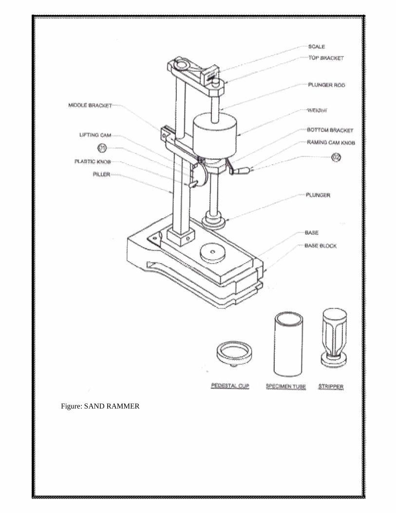
Figure: SAND RAMMER

21

TENSILE CORE BOX . USE: To Prepare specimen to determine tensile strength. MACHINE CONTAINS: This consists of a hopper, split core box with base plate.
PROCEDURE 1. Remove the two Allen Screw and Separate the clamp from the plunger head. 2. Insert the clamp on rammer plunger rod and place it on the plunger. 3. Hold the plunger head under rammer plunger and tight clamp with Allen Screw. 4. Lift the plunger by lifting cam. 5. Dismantle split core box from base plate by loosing Allen Screw for cleaning. 6. Assemble the split core box with hopper on base plate. 7. Insert the scrapper taking care that the cutting edge of the scrapper points downward and the
cavity of the core box is clear for the scrapper. 8. Fill the core box with sand under the test and place it under plunger head. 9. Gently bring the plunger head down with lifting cam; taking care that plunger slides freely in
the split mould. 10. Rest the plunger head on the sand. Ram the sand by dropping the sliding weight 3 times by
rotating ramming cam. 11. Lift the plunger by the lifting cam and remove the core box assembly from rammer base. 12. Pull out the scrapper to cut sample to standard height. 13. Remove the hopper. 14. Remove the excess sand carefully by any soft brush. 15. Place any suitable metal plate, remove the base plate and separate the split core box carefully
without damaging the specimen. 16. The specimen is ready for further process.

22

Figure: TENSILE CORE BOX

23

CALACULATION:

24

TRANSVERSE CORE BOX USE: To Prepare specimen to determine Transverse strength. MACHINE CONTAINS: This consists of a hopper, split core box with base plate.
PROCEDURE. 1. Remove the two Allen Screw and Separate the clamp from the plunger head. 2. Insert the clamp on rammer plunger rod and place it on the plunger. 3. Hold the plunger head under rammer plunger and tight clamp with Allen Screw. 4. Lift the plunger by lifting cam. 5. Dismantle split core box from base plate by loosing Allen Screw for cleaning. 6. Assemble the split core box with hopper on base plate. 7. Insert the scrapper taking care that the cutting edge of the scrapper points downward and the
cavity of the core box is clear for the scrapper. 8. Fill the core box with sand under the test and place it under plunger head. 9. Gently bring the plunger head down with lifting cam; taking care that plunger slides freely in
the split mould. Rest the plunger head on the sand. 10. Ram the sand by dropping the sliding weight 3 times by rotating ramming cam. 11. Lift the plunger by the lifting cam and remove the core box assembly from rammer base. 12. Pull out the scrapper to cut sample to standard height. Remove the hopper. 13. Remove the excess sand carefully by any soft brush. 14. Place any suitable metal plate, remove the base plate and separate the split core box carefully
without damaging the specimen. 15. The specimen is ready for further process.

25

Figure: TRANSVERSE CORE BOX

26

CALACULATION:

27

EXPERIMENT: 01: UNIVERSAL STRENGTH MACHINE USE: This instrument is used for determining the various strengths of prepared specimen. MACHINE CONTAINS: 1. Hydraulic Unit With Loading Assembly, Quick Release Coupling. 2. Pressure Gauges (Low & High) Low gauge — Range:-0- 1600 Gms/cm2 High gauge — Range: - 0- 13kg/cm2 3. Compression Pads 4. Oil Filling Funnel OPERATING INSTRUCTION: 1. Take the instrument on plane platform. 2. Place the oil-filling funnel in quick release coupling. 3. Pour the oil in funnel, rotate the wheel clockwise & anticlockwise. 4. Repeat the procedure until the air bubbles do not appear in oil. 5. Then remove the oil-filling funnel and place the Low pressure gauge. 6. Place the compression pads in its location. 7. Put the cylindrical specimen in between two compression pads. 8. Rotate the wheel clockwise. 9. Loading piston applying the load on cylindrical specimen. See at the pressure gauge. 10. Pointer of the pressure gauge moves with reference pointer (Red pointer). When the specimen
breaks, the Pointer of the pressure gauge will came back to its home position and reference
pointer indicates compression strength of specimen. PRECAUTION:
1. Keep instrument clean.

2. Do not cross maximum range of pressure gauges.
3. Use only hydraulic oil no. 150 - 220
28

Figure: UNIVERSAL STRENGTH MACHINE

29

CALACULATION:

30

EXPERIMENT: 01: TENSILE STRENGTH ATTACHMENT USE: To check the Tensile strength of Tensile specimen. With the help of universal strength machine MACHINE CONTAINS: 1. A movable and a stationary jaw with rollers 2. Guide bracket 3. Two rods and knurled screw. 4. Adjustable ball pad PRE-SETTING: 1. The knurled screw is removed from stationary jaw. 2. Insert the attachment as shown in the illustration and clamp the stationary jaw by knurled
screw. Adjust the position of the rollers, So that flat side of roller will touch together (as shown in
illustration). 3. Then both jaws are pushed together. OPERATING INSTRUCTIONS: 3. The Tensile specimen is placed in the jaws carefully. 4. Follow the same loading procedure adoBed for compression strength till sample breaks. Read
compression strength (CS.) and multiply by factor provided from the Tensile strength (T.S.) on
inner scale of the gauge. (C.S. X 3.9275 = Tensile strength.) PRECAUTION: 1. Keep the instrument clean.

31
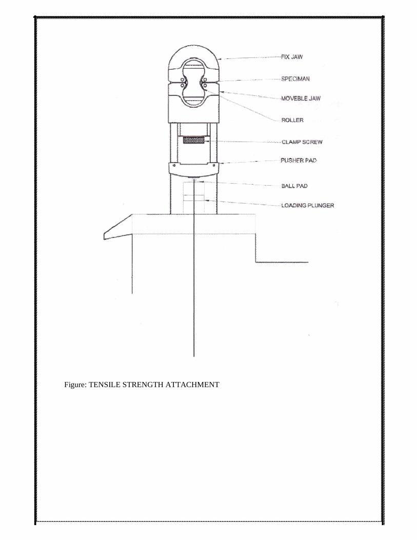
Figure: TENSILE STRENGTH ATTACHMENT

32

CALACULATION:

33

EXPERIMENT: 02: PERMEABILITY METER AIM: To determine permeability number of green sand, core sand and raw sand. OVERVIEW: Permeability is that property which allows gas and moisture to pass through the moldings a nd . It i
s dete rmi ned by measurin g the rate of fl ow of ai r through A . F . S . sta ndar d rammed
specimen under a standard pressure. The volume of air in cm 3/ min. passing through a specimen
of length 1 cm. and cross sectional area of 1 cm 2 under a pressure difference of 1 cm. water gauge
is called Permeability Number. Permeability Number: The volume of air passing through a sand specimen 1 sq. cm area and 1 cm. in height at a pressure
of 1 gram per square centimeter in 1 min. is called the Permeability Number and is computed by
the formula = (v x h) / (p x a x t) Where = Permeability Number v = Volume of air passing through
the specimen (cubic centimeter or in mil)h = Height of specimen (centimeters) p = Pressure
difference between upper and lower surfaces of test specimen (in centimeter of water column)a =
Cross-sectional area of specimen (square centimeter)t = time (minutes) Permeability Meter: The body of the Permeability Meter is an aluminum casting of a water tank and base. Inside water
tank floats a balanced air drum carefully weighed and designed to maintain constant pressure of 10
cm during its fall. The outlet from the air drum is connected to a centre post in the base via three
way air valve. The centre post incorporates a pipe for measuring pressure, which is connected to
the water manometer and an expandable “O” ring for sealing the specimen tube. It also
accommodates the orifices MACHINE CONTAINS:
1. Water tank
2. Air tank
3. Manometer

4. Standard chart
5. Rubber boss
6. O-P-D valve
34

7. Orifices OPERATING INSTRUCTIONS: 1. Place the instrument on leveled platform. 2. Take 'O-P-D' valve knob at 'D' position. 3. Close the opening of the air tube inside water tank by thumb and pour water up to the W' mark. 4. Insert air tank into water tank carefully. 5. A screw is provided at the left side of the manometer to fill the water in manometer.
Unscrewing the knob operates this screw and water is filled in the manometer. 6. The water level should coincide with the zero of the manometer scale The screw is closed by
tightening. 7. Final zero level is adjusted by opening 'zero adjust screw' provided in front of manometer 8. Selection of orifice it is recommended to use small orifice for permeability below 50Nos. and
large orifice for permeability above 50Nos. 9. Tighten the orifice by fingers only. Take the specimen tube with rammed specimen and place it
inverted over the rubber boss. 10. Put the valve on 'P position. Read the height of the water column in the manometer tube. Find
out corresponding permeability number from the chart provided with the instrument. 11. Put the valve on '0' position. Whenever the air tank is flush with water tank, keep the valve on
'D' position and slowly lift the air tank to the top position. 12. Lift the air tank drum slowly up keeping the valve in 'D' position PRECAUTIONS:
1. Keep the instrument dust proof.
2. Keep the instrument clean.
3. Lift the air drum only in 'D' Position to avoid any water entering the air passage.

4. For removal of the water tank completely from manometer
5. Use zero adjustment knob valves. RESULTS:
35

Figure: PERMEABILITY METER

36

CALACULATION:

37

EXPERIMENT: 02: MOULD PREMEABILITY TESTER AIM: To determine the relative permeability of moulds directly on moulding boxes in conjunction with Permeability Tester and Electric Permeability Tester. MACHINE CONTAINS: It consists of measuring head, rubber tubing approximately l meter long and adobe. OPERATING INSTRUCTION: 1. Pre-setting of respective instrument Permeability Tester and Electric Permeability Tester has
been done.
2. Place tightly the adobe on the rubber-sealing boss. 3. Place the measuring head against the flat surface on the mould, pressing it firmly enough to
ensure the full contact against the surface.
4. Avoid pressing hard enough to depress the sand surface. 5. When used with Electric Permeability Tester switch ON the instrument and put the valve on 'P
position.
6. When used with Permeability Tester put the valve in 'P' position. 7. Take the permeability reading as usual.

Figure: Mould Permeability Tester
38

EXPERIMENT: 02: CORE PERMEABILITY TUBE OPERATION: 1. Take out the sample from split specimen tube on the drying plate. 2. Dry the Specimen in the drying Oven to the desired temperature and time. 3. Insert the sample carefully in the core permeability tube. 4. Seal the gap between the sample and core permeability by pumping air by the air
pump. Place the core Permeability tube on rubber boss of permeability meter. 5. Follow the usual Procedure for determining permeability Number. 6. After each test release the air from the special rubber tube by unscrewing the air inlet valve
and remove the sample.

Figure: CORE PERMEABILITY TUBE
39

CALACULATION:

40

“PATTERN”- MAKING, ALLOWANCES AND ITS TYPES:
PATTERN: A pattern may be defined as a model of desired casting which when moulded in sand forms an impression called mould. The mould when filled with the molten metal forms casting after
solidification of the poured metal. The quality and accuracy of casting depends upon the pattern
making. The pattern may be made of wood, metal (cast iron, brass, and aluminum and alloy steel.),
plaster, plastics and wax.
PATTERN ALLOWANCES: A pattern is always made larger than the required size of the casting
considering the various allowances. These are the allowances which are usually provided in a
pattern.
1: Shrinkage or Contraction Allowance: The various metals used for casting contract after
solidification in the mould. Since the contraction is different for different materials, therefore it will
also differ with the form or type of metal.
2: Draft Allowance: It is a taper which is given to all the vertical walls of the pattern for easy and
clean withdraw of the pattern from the sand without damaging the mould cavity. It may be
expressed in millimeters on a side or in degrees. The amount of taper varies with the type of
patterns. The wooden patterns require more taper than metal patterns because of the greater
frictional resistance of the wooden surfaces.
3: Finish or Machining Allowance: The allowance is provided on the pattern if the casting is to be
machined. This allowance is given in addition to shrinkage allowance. The amount of this allowance
varies from 1.6 to 12.5 mm which depends upon the type of the casting metal, size and the shape of the
casting. The ferrous metals require more machining allowance than non ferrous metals.
4: Distortion or Camber Allowance: This allowance is provided on patterns used for casting of
such design in which the contraction is not uniform throughout.
5: Rapping or Shaking Allowance: This allowance is provided in the pattern to compensate for the
rapping of mould because the pattern is to be rapped before removing it from the mould. Types of Patterns: The common types of patterns are as follows:
1. Solid or single piece patterns 2. Split or two/multiple piece patterns 3. Match plate pattern
4. Cope and drag pattern 5. Loose piece pattern 6. Gated patterns 7. Sweep pattern

8. Skeleton pattern 9. Shell pattern 10. Segmental pattern 11. Follow board pattern
12. Lagged up pattern 13. Left and right hand pattern
41

PATTERN DESIGN AND MAKING: PATTERN: A Pattern may be defined as a model (Replica of the object) about which is to be formed
a sand mold, in which a casting is to be made. Patterns used in sand casting may be made of wood, metal, plastics or other materials. Patterns are made to exacting standards of construction.
Making of pattern is called as Pattern making. For making patterns we
have to be using wood working, it is the process of building, making or carving something using
wood. Wood turning: It is a form of wood working; it is used to be creating wooden objects on a lathe
using cutting tools. Woodturning differs from most other forms of woodworking, in that the wood
is moving while a (relatively) stationary tool is used to cut and shape it. Many intricate shapes and
designs can be made by turning wood. There are two distinct methods of turning wood, Spindle turning
Faceplate turning.
In spindle turning, the grain of the wood runs lengthwise, and the piece is typically spun on centers
between the headstock of the lathe and the tailstock, with material removed from the side of the wood. In face plate turning, the grain of the wood runs perpendicular to the axis of rotation, and the piece is often attached to the lathe via a plate or a chuck. Most bowls, platters and vessels are face plate turned, while pens, table legs, and other slender pieces are typically spindle turned. Regardless of the method of attachment, the orientation of the grain determines the method in use, the type of tools to use, and the direction of cut.
It is one of the oldest types of wood-working machines which
still justify its existence in the modern workshop. It essentially consists of a cast iron bed, a head stock,
tail stock, tool rest, live and dead centers and a speed control device. The whole unit is mounted on a
wooden or metal frame. The drive in all modern lathes is individual and is contained in the frame, the
motor being mounted on a base inside the frame. A cone pulley on the head stock spindle is connected
by a belt to a similar cone pulley on the motor shaft. The bed carries horizontal ways at its top on which
WOOD-TURNING LATHE:
PATTERN MAKING:

the tail stock and the tool rest move. They can be clamped at any desired place along these ways. Some
very costly designs incorporate a variable speed motor in their head stock. The work piece is either
clamped between two centers, the live centre on the head stock spindle and the dead centre in the tail
stock, or on a face plate. The operation done in the former
42

case is known as turning between centres, whereas in the latter case it is known as turning on a
faceplate. Figure: Wood-Turning Lathe
There are so many materials used for making patterns like wood, metals and alloys,
plasters, plastics and waxes etc. But wood is the most common material used for making the patterns. The main reasons for its popularity are its cheapness, easy availability, light in weight, easily shaped, worked and joined to form any complex shape. Surface can be made smooth very easily by sanding and surface can be preserved by applying a coating of shellac. Before wood is used for pattern making, it should be properly dried and it should be straight grained, free from knots and free from excessive sap wood. The most common wood used for pattern making is pine wood, teak wood and deodar etc.
The pattern is the replica or model of the desired casting, which is packed in a suitable
molding material, produces a cavity called the mould, this cavity is filled with molten metal,
produce the desired casting after solidification. Depending upon the complexity of the job, the
types of patterns commonly used in foundry are single piece or solid pattern, split pattern or two
piece pattern, multi piece or loose piece pattern and match plate patterns etc. patterns are not made
the exact same size as the desired casting. This is because during solidification and after that the
casting is subjected to various metallurgical and mechanical effects and hence to compensate these
effects the allowances must be made on the pattern for shrinkage, machine finish, draft or taper,
rapping or shake and distortion or chamber etc. WOOD TURNING TOOLS: Turning tools are generally made from two different types of steel,
Carbon steel and High speed steel (HSS). Woodturning tools, require more frequent sharpening, And
THEORY:
METERIAL:

To maintain a clean cut, the sharpness of the tools edge must be maintained. The given below listed are
different type of tools used for wood turning.
43
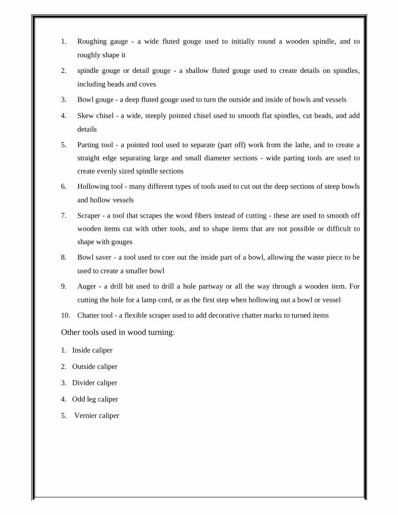
1. Roughing gauge - a wide fluted gouge used to initially round a wooden spindle, and to
roughly shape it 2. spindle gouge or detail gouge - a shallow fluted gouge used to create details on spindles,
including beads and coves 3. Bowl gouge - a deep fluted gouge used to turn the outside and inside of bowls and vessels 4. Skew chisel - a wide, steeply pointed chisel used to smooth flat spindles, cut beads, and add
details 5. Parting tool - a pointed tool used to separate (part off) work from the lathe, and to create a
straight edge separating large and small diameter sections - wide parting tools are used to
create evenly sized spindle sections 6. Hollowing tool - many different types of tools used to cut out the deep sections of steep bowls
and hollow vessels 7. Scraper - a tool that scrapes the wood fibers instead of cutting - these are used to smooth off
wooden items cut with other tools, and to shape items that are not possible or difficult to
shape with gouges 8. Bowl saver - a tool used to core out the inside part of a bowl, allowing the waste piece to be
used to create a smaller bowl 9. Auger - a drill bit used to drill a hole partway or all the way through a wooden item. For
cutting the hole for a lamp cord, or as the first step when hollowing out a bowl or vessel 10. Chatter tool - a flexible scraper used to add decorative chatter marks to turned items Other tools used in wood turning: 1. Inside caliper 2. Outside caliper 3. Divider caliper 4. Odd leg caliper 5. Vernier caliper

6. Dial caliper
44

EXPERIMENT: 03: STEPPED PULLEY PATTERN AIM: Prepare a stepped pulley pattern of given dimensions as shown in fig. using wood turn lathe. Apparatus Required: Wood turning lathe, wood turning tools like chisels, calipers. Model Diagram: Figure: stepped pulley pattern PROCEDURE:
1. Take the work piece of required length and size.
2. Check the end faces weather they are perpendicular or not with the rectangular faces.
3. Mark the centers on both end faces.
4. Fix the work piece between centers. That is live center and dead center.
5. Rotate the work piece in anti clock wise direction.
6. Feed the tools manually to get the desired shape. PRECAUTIONS:

1. Know Your Equipment and Yourself
2. Inspect Your Lathe
3. Wear Safety Equipment
45

4. Don’t force a tool or use it for an unintended purpose. Reposition the tool rest
frequently to keep it close to the work
5. Always keep your hands behind the plane of the tool rest
6. Focus on Your Work
7. The wood, making for pattern should be properly dried.
8. The tool is set for turning very carefully
9. Proper feed should be given. RESULT: Thus we obtain single piece pattern of required dimensions from given wooden piece.

46

EXPERIMENT: 04: STEPPED PULLEY TAPPERED PATTERN AIM: To prepare a pattern by using wood turning lathe. APPARATUS REQUIRE D: Wood turning lathe, wood turning tools like chisels, calipers. Model Diagram: Figure: PROCEDURE:
1. Take one wooden piece with known dimensions.
2. Prepare spur centre on wooden piece.
3. Fix wooden piece in betw een two jaws (spindle).
4. Start power source and tu rn gently.
5. Obtain required shape. PRECAUTIONS: 1. Know Your Equipment and Yourself 2. Inspect Your Lathe 3. Wear Safety Equipment 4. Don’t force a tool or use it f or an unintended purpose. Reposition the tool r est frequently to
keep it close to the work

5. Always keep your hands behind the plane of the tool rest 6. Focus on Your Work 7. The wood, making for pattern should be properly dried.
47

8. The tool is set for turning very carefully 9. Proper feed should be given. RESULT: Thus we obtain single piece pattern of required dimensions from given wooden piece.

48

PATTERN MAKING AIM: Prepare a pattern for casting as shown in fig. Using draft allowance 40 . TOOLS REQUIRED: Planning tools, sawing tools, marking and lay out tools.
A pattern may be a replica model of the desired casting
which when packed or embedded in a suitable moulding material produces a cavity called mould.
A pattern may be differing from an actual component. That is it carries additional allowance, draft
allowance like shrinkage allowance, machining allowance, draft allowance, it carries additional
projection like core prints etc. CALCULATIONS: Draft angle=40 Vertical side length of casting=h Increment in length due to draft angle =L+δL+δL
=L+2δl Where δL=L+2×h×tan 40 Increment in breadth due to draft angle=b+ δb+ δb
=b+2δb Where δb=b+2×h×tan 40
DESCRIBION OF PATTERN:

49

PROCEDURE: 1. Calculate the dimension considering draft angle. 2. Mark the dimensions on given wooden work piece. 3. Shape the work piece to the calculated size. 4. Finish the surface of pattern. PRECAUTIONS: Top surface of pattern must match with parting surface. RESULT: The pattern is prepared by considering draft angle 40.

50

MOLD MAKING & CASTING Objective
1. To prepare a pattern for given object for lost form casting. 2. To prepare a molasses sand mold from the prepared pattern. 3. To melt and pour iron metal into the mold. Equipment and Materials
Pattern, core box, molding flasks, molding tools, sand muller, riddle, sand, molasses, bentonite,
core baking oven, thermocole, melting furnace, fluxes, pouring ladle, pyrometer, hacksaw, file. Procedure: Core making 1. Prepare the core sand 2. Assemble (clamp) the core-box after applying some parting sand 3. Fill the core box cavity with core sand and ram it 4. Make vent holes or insert reinforcing wire as desired 5. Tap the mold box on all sides to loosen the core from the box, unclamp the core box
and carefully transfer the core on to a baking plate or stand. 6. Keep the core in the baking oven and bake it for desired length of the time at a predetermined
temperature. After baking take the core out of the oven and allow it to cool at room temperature. Mold Making 1. Place the drag part of the pattern with parting surface down on ground or molding board at
the center of the drag (flask). 2. Riddle molding sand to a debt of about 2 cm in the drag and pack this sand carefully around
the pattern with fingers. 3. Heap more molding sand in the drag and ram with rammer carefully. 4. Strike off the excess sand using strike bar.

5. Make vent holes to within 1 cm of the pattern surface in the drag. 6. Turn this complete drag and place the cope portion (flask) over it.
51

7. Place the cope half of the pattern over the drag pattern matching the guide pins and apply
parting sand over the parting surface. Also place the sprue pin and riser pin in proper positions. 8. Complete the cope half by repeating steps (ii) to (v). 9. Remove the sprue and riser pins and make a pouring basin. Separate the cope and drag
halves, and place them with their parting faces up. 10. Moisten sand at the copes of the pattern and remove pattern halves carefully using draw spikes. 11. Cut gate and runner in the drag. Repair and clean the cavities in the two mold halves. 12. Place the core in position, assembled the two mold halves assemble and clamp them together. Melting and Pouring
1. Melt the metal in the furnace. Use appropriate fluxes at proper stages and measure
metal temperature from time to time. 2. Pour the molten metal into the pouring ladle at a higher temperature (say 100oC higher) than
the pouring temperature. As soon as the desired pouring temperature is reached, pour the liquid metal into the mold in a steady stream with ladle close to the pouring basin of the mold. Do not allow any dross or slag to go in.
3. Allow sufficient time for the metal to solidify in the mold. Break the mold carefully and
remove the casting. 4. Cut-off the riser and gating system from the casting and clean it for any sand etc. 5. Inspect the casting visually and record any surface and dimensional defects observed. Report The Following 1. Sketches of the product made, pattern and core.
2. Composition of molding sand and core sand used. 3. Melting and pouring temperature of the used metal. 4. List the allowances that are generally provided on a pattern. 5. Type, amount and manner of addition of fluxes, if any used.

6. Defects produced in your casting.
52

MOULDING MATERAILS
A large variety of moulding materials are used in foundries fro manufacturing moulds and cores.
They are:
1. Moulding sand, 2. System sand (backing sand), 3. Rebounded sand, 4. Facing sand,
5. Parting sand and 6. Core sand.
The properties that are generally required in Moulding materials are
Refractoriness: It is the ability of the moulding material to with stand the high temperatures of
the molten metal so that is does not cause fusion. Properties of Some refractory materials are
Material Melting point,0C Coefficient of linear expansion, X 106/0C Silica( SiO) 1710 16.2
Alumina(Al2O3) 2020 8
Magnesia(MgO) 2800 13.5
Thoria(ThO2) 3050 9.5
Ziroconia(ZrO2) 2700 6.5
Zircon(ZrO2.SiO2) 2650 4.5
Silicon Carbide(SiC) ̃ 2700 3.5
Graphite 4200 ̃--- Green strength: The moulding sand that contains moisture is termed as green sand. The green sand
should have enough strength so that the constructed mould retains its shape.
Dry strength: When the moisture in the moulding sand is completely expelled, it is called dry sand.
When molten metal is poured into a mould, the sand around the mould cavity is quickly converted
into dry sand as the moisture in the sand immediately evaporates due to the heat in the molten
metal. At this stage, it should retain the mould cavity and at the same time withstand the
metallostatic forces.
Hot strength: After all the moisture is eliminated, the sand would reach a high temperature when
the metal in the mould is still in the liquid state. The strength of the sand that is required to hold the
shape of the mould cavity then is called hot strength.
Permeability: During the solidification of a casting, large amounts of gases are to be expelled from the

mould. The gases are those which have been absorbed by the metal in the furnace, air absorbed from the
atmosphere and steam and other gases that are generated by the moulding and core sands. If these gases
are not allowed to escape from the mould, they would be trapped inside the casting and
53

cause defects. The moulding sand should be sufficiently porous so that the gases are allowed to
escape from the mould. This gas evolution capability of the moulding sand is termed as
permeability. Besides these specific properties, the moulding sand should also have collapsibility
so that during the contraction of the solidified casting, it does not provide any resistance which may
result in cracks in the casting; they should be reusable and should have good thermal conductivity
so that heat from the casting is quickly transferred. MOULDING SAND COMPOSITION: The main ingredients of any moulding sand are: The silica grains (SiO2), the clay as binder, and
Moisture to activate the clay and provide plasticity SILICA SAND: The sand which forms the major portion of the moulding sand (up to 96%) is
essentially silica grains, the rest being the other oxides such as alumina, sodium (Na2O+K2O) and
magnesium oxide (MgO+CaO). These impurities should be minimized to about 2% since they affect the fusion point of the silica sands. The main source is the river sand which is used with or
without washing. Ideally the fusion point of sand s should be about 14500C for cast irons and about
15500C for steels. In the river sand, all sizes and shapes of grains are mixed. The sand grains may
vary in size from a few micrometers to a few millimeters. Shape of the grains may be round, sub-angular, angular and very angular. The size and shapes of these sand grains greatly affect the properties of the moulding sands. Zircon sand is basically a zirconium silicate (ZrSiO4). The typical composition is ZrO2-66.25%,
SiO2-30.96%, Al2O3-1.92%, Fe2O3-0.74% and traces of other oxides. It is very expensive. In India
it is available in the quilon beach of Kerala. It has a fusion point of about 24000C and also a low coefficient of thermal expansion. It is generally used to manufacture precision steel castings requiring better surface finish and for precision investment casting. Chromite sand is crushed from the chrome ore whose typical composition is Cr2O3-44%, Fe2O3-
28%, SiO2-2.5%, CaO-0.5%, and Al2O3+MgO—25%. The fusion point is about 18000C. it also
used to manufacture heavy steel castings requiring better surface finish. It is best suited to austenitic manganese steel castings. Olivine sand contains the minerals fosterite (Mg2SiO4) and fayalite (Fe2SiO4). It is very versatile
sand and the same mixture can be used for a range of steels.

Clay: clays are the most generally used binding agents mixed with the moulding sands to provide
the strength, because of their low cost and wider utility. The most popular clay types used are
54

Kaolinite or Fire clay ( Al2O32SiO22H2O) Bentonite (Al2O34SiO2H2OnH2O) Kaolinite or Fire clay
has a melting point of 1750-17870C and Bentonite has a melting temperature range of 1250-13000C. Of
the two, bentonite can absorb more water which increases its bonding power. The clays besides these
basic constituents may also contain some mixtures of lime, alkalies and other oxides which tend to
reduce their refractoriness. There are basically two types of bentonites, one with sodium as adsorbed
ion which is often called western bentonite and the other with calcium ion called southern bentonite.
Sodium bentonites produce better swelling properties-volume increases some 10-20 times, high dry
strength and high resistance but higher green strength. It is possible to improve the properties of
calcium bentonite by treating it chemically with soda ash (sodium carbonate) Water: clay is activated by water so that it develops the necessary plasticity and strength. The
amount of water used should be properly controlled. This is because a part of the water absorbed
by clay helps in bonding while the remainder up to a limit helps in improving the plasticity but
more than that would decrease the strength and formability. The normal percentages of water used
are from 2-8. TESTING SAND PROPERTIES: Sand preparation: tests are conducted on a sample of the standard sand. The moulding sand should
be prepared exactly as is done in the shop on the standard equipment and then carefully enclosed in
a closed container to safeguard its moisture content. Moisture content: moisture is an important element of the moulding sand as it affects many
properties. To test the moisture of a moulding sand a carefully weighted test sample of 50g is dried
at a temperature of 1050C to 1100C for 2 hours by which time all the moisture in the sand would
have been evaporated. The sample is then weighted. The weight difference in grams when
multiplied by 2 would give the percentage of moisture contained in the moulding sand.
Alternatively a moisture teller can also be used for measuring the moisture content. In this the sand
is dried by suspending the sample on a fine metallic screen and allowing hot air to flow through the
sample. This method of drying completes the removal of moisture in a matter of minutes compared
to 2 hours as in the earlier method. Another moisture teller utilizes calcium carbide to measure the
moisture content. A measured amount of carbide in a container along with a separate cap consisting
of measured quantity of moulding sand is keB in the moisture teller care has to be taken before

closing the apparatus that carbide and sand do not come into contact. The apparatus is then shaken
vigorously such that the following reaction takes place. CaC2+2H2O→C2H2+Ca (OH)2
55

The acetylene (C2H2) coming out will be collected in the space above the sand raising the pressure.
A pressure gauge connected to the apparatus would give directly the amount of acetylene generated
which is proportional to the moisture present. It is possible to calibrate the pressure gauge to
directly read the amount of moisture. Clay content: the clay content of moulding sand is determined by dissolving of washing it off the
sand. To determine the clay percentage a 50g sample is dried at 105 to 1100C and the dried sample
is taken in a one litre glass flask and added with 475 ml of distilled water and 25ml of a one percent
solution of caustic soda (NaOH 25g per litre). This sample is thoroughly stirred. After the stirring,
for a period of five minutes the sample is diluted with fresh water up to a 150mm graduation mark
and the sample is left undisturbed for 10 minutes to settle. The sand settles at the bottom and the
clay particles washed from the sand would be floating in the water. 125mm of this water is
siphoned off the flask and it is again topped to the same level and allowed to settle for five minutes.
The above operation is repeated till the water above the sand becomes clear, which is an indication
that all the clay in the moulding sand has been removed. Now the sand is removed from the flask
and dried by heating. The difference in weight of the dried sand and 50g when multiplied by two
gives the clay percentage in the moulding sand. Sand grain size: To find out the sand grain size, a sand sample which is devoid of moisture and
clay such as the one obtained after the previous testing is to be used. The dried clay-free sand
grains are placed on the top sieve of a sieve shaker which contains a series of sieves one upon the
other with gradually decreasing mesh sizes. The sieves are shaken continuously for a period of
15min. After this shaking operation, the sieves are taken apart and the sand left over on each of the
sieve is carefully weighed. The sand retained on each of the sieve expressed as a percentage of the total mass can be plotted
against the sieve number as in figure. To obtain the grain distribution. But more important is the
Grain Fineness Number (GFN) which is a quantitative indication of the grain distribution. To
calculate the grain fineness, each sieve has been given a weight age factor as shown in table. The
amount retained on each sieve is multiplied by the respective weight age factor, summed up, and
then divided by the total mass of sample, which gives the grain fineness number. The same can be
expressed as GFN=ΣMifi/Σfi

Mi =Multiplying factor for the i th sieve, fi=amount of sand retained on the ith sieve. Permeability: the rate of flow of air passing through a standard specimen under a standard pressure is termed as permeability number. The standard permeability test is to measure time taken by a
56

2000cm3 of air at a pressure typically of 980 pa to pass through a standard sand specimen confined
in a specimen tube. The standard specimen size is 50.8mm in diameter and a length of 50.8mm. Then the permeability number P is obtained by P=VH/p AT Where V= volume of air=2000cm3 H= height of the sand specimen=5.08cm P= air pressure, g/cm2 A= C/S area of sand specimen=20.268cm2 T= time in minutes for the complete air to pass through the gaps, Inserting the above standard
values in to the expression, we get P=501.28/B Specimen preparation: since the permeability of sand is dependent to a great extent, on the degree of
ramming, it is necessary that the specimen be prepared under standard conditions. To get reproducible
ramming conditions, a laboratory sand rammer is used along with a specimen tube. The measured
amount of sand is filled in the specimen tube, and a fixed weight of 6.35-7.25kg is allowed to fall on the
sand three times from a height of 50.8}0.8mm. to produce this size of specimen usually sand of 145 to
175g would be required. After preparing a test sample of sand as described, 2000cm3 of air are passed
through the sample and the time taken by it to completely pass through the specimen is noted. Then
from the above equation the permeability number can be calculated. Strength: measurement of strength of moulding sands can be carried out on the universal sand
strength testing machine. The strength can be measured in compression, shear and tension. The
sands that could be tested are green sand. Dry sand of core sand. The compression and shear test
involve the standard cylindrical specimen that was used for the permeability test. Green compression strength: green compression strength or simply green strength generally refers
to the stress required to ruBure the sand specimen under compressive loading. The sand specimen
is taken out of the specimen tube and is immediately (any delay causes the drying of the sample
which increases the strength) put on the strength testing machine and the force required to cause
the compression failure is determined. The green strength of sands is generally in the range of 30 to
190kPa. Green shear strength: with a sand sample similar to the above test, a different adapter is fitted in the

universal machine so that the loading now be made for the shearing of the sand sample. The stress
required to shear the specimen along the axis is then represented as the green shear strength. The
green shear strengths may vary from 10 to 50 kPa.
57

Dry strength: the tests similar to the above can also be carried with the standard specimens dried
between 105 and 1100C for 2 hours. Since the strength greatly increases with drying, it may be
necessary to apply larger stresses than the previous tests. The range of dry compression strengths found in moulding sands is from 140 to 1800 kPa, depending on the sand sample. Mould hardness: the mould hardness is measured by a method similar to the Brinell hardness test.
A spring loaded steel ball with a mass of 0.9kg is indented into the standard sand specimen
prepared. The depth of indentation can be directly measured on the scale which shows units 0 to
100. When no penetration occurs, then it is a mould hardness of 100 and when it sinks completely,
the reading is zero indicating a very soft mould. Besides these, there are other tests to determine
such properties as deformation, green tensile strength, hot strength, expansion, etc.

58

EXPERIMENT No. 5: STEPPED CONE PULLEY
Date : AIM: To make the mould for the given stepped cone pulley.

59

Material Required 1. Moulding board (2). Riser pin (3) Moulding box (4) Sprue pin (5) Green sand (6) Rammer (7) Trowel (8) Lifter (9) Riddle (10) Draw spike (11) Gate cutter (12) Bellow (13)Vent rod PROCEDURE: 1. Place the moulding board on a horizontal surface. 2. A suitable core is prepared with the help of core box. 3. The drag box is placed above the moulding board. Now the pattern is keB at center of drag. 4. Now parting sand in sprinkled before we keep pattern. 5. Facing sand is sprinkled over the pattern to a deBh of 5mm. then green sand is filled over it. 6. Proper ramming is done on the green sand to get a air tight packing. 7. Excess sand is removed by strike off bar. 8. The drag box is inverted upside down. 9. The cope box is placed over the drag box and locked. 10. The riser pin sprue pin placed at right position and green sand is filled over the pattern. 11. Proper ramming is done on the green sand to get air tight packing with strike off bar leaving
is done. 12. Now riser pin and sprue pin get removed from the green sand mould. The pattern is removed
by draw spike tool. 13. Gate is prepared using gate cutter and core is placed vertically inside the cavity. 14. The vent holes are made with vent rod and cope. RESULT: Thus the mould is created for given stepped cone pulley. QUESTIONS
1. Define Casting.
2. Explain the core making process?

3. What are pattern allowances?
4. Describe the types of patterns.
5. Explain the composition and properties of moulding sand?
60

EXPERIMENT No. 6: MOULD WITH SPLIT PATTERN AIM: To make the mould for the given split pattern.
Material Required

i. Moulding board (2). Riser pin (3) Moulding box (4) Sprue pin (5) Green sand (6) Rammer
(7) Trowel (8) Lifter (9) Riddle (10) Draw spike (11) Gate cutter (12) Bellow (13)Vent rod
61

PROCEDURE 1. Place the moulding board on a horizontal surface. 2. The drag box is placed above the moulding board. Now one piece of pattern is keB at center
of the drag as shown in figure. 3. The parting sand is spread before we keep the pattern. 4. Facing sand is sprinkled over the pattern to a deBh of 2mm. then greensand is filled over it. 5. Proper ramming is done on the green sand to get a air free packing. 6. Excess sand is remove with strike off bar. 7. The drag is inverted upside down. 8. The cope box is place over the drag box. 9. Now the parting sand is sprinkled over the parting surface. 10. The other piece of pattern is placed over the drag pattern. 11. Facing sand is riddled over the pattern to a depth of 5mm. then riser is place over the pattern
and another sprue pin above parting surface. 12. Now green sand is filled over it. 13. Ramming operation is done to get an air tight packing with strike off bar leaving it. 14. Riser pin and sprue pin gets removed from the green sand. 15. Pattern is removed gently now. 16. Gate is cut using gate cutter. 17. The vent holes are made with vent rod on the cope side. RESULT: Thus the mould is created for the given split pattern. QUESTIONS
1. Explain Casting Defects.
2. Explain the different types of furnaces?

3. What is shell moulding?
4. Describe the various moulding methods.
5. List the components used in moulding process?
62

CALACULATION:

63

INTRODUCTION TO CASTING PROCESSES OBJECTIVE: To study and observe various stages of casting through demonstration of Sand
Casting Process. BACKGROUND
Casting is one of oldest and one of the most popular processes of converting materials into final
useful shapes. Casting process is primarily used for shaping metallic materials; although it can be
adopted for shaping other materials such as ceramic, polymeric and glassy materials. In casting, a
solid is melted, treated to proper temperature and then poured into a cavity called mold, which
contains it in proper shape during solidification. Simple or complex shapes can be made from any
metal that can be melted. The resulting product can have virtually any configuration the designer
desires. Casting product range in size from a fraction of centimeter and fraction of kilogram to over
10 meters and many tons. Moreover casting has marked advantages in production of complex
shapes, of parts having hollow sections or internal cavities, of parts that contain irregular curved
surfaces and of parts made from metals which are difficult to machine. Several casting processes have been developed to suit economic production of cast products with
desired mechanical properties, dimensional accuracy, surface finish etc. The various processes differ primarily in mold material (whether sand, metal or other material) and pouring method (gravity, pressure or vacuum). All the processes share the requirement that the material solidify in a manner that would avoid potential defects such as shrinkage voids, gas porosity and trapped inclusions. Any casting process involves three basic steps, i.e. mold making, melting and pouring of metals into the mold cavity, and removal and finishing of casting after complete solidification.
Sand is one of the cheaper, fairly refractory materials and
hence commonly used for making mold cavities. Sand basically, contains grains of silica (SiO2)
and some impurities. For mold making purposes sand is mixed with a binder material such as clay,
molasses, oil, resin etc. GREEN SAND MOLDING: In green sand molding process, clay (a silicate material) along with water (to activate clay) is used as binder. The mold making essentially consists of preparing a
cavity having the same shape as the part to be cast. There are many ways to obtain such a cavity or
SAND CASTING PROCESSES:

mold, and in this demonstration you will learn to make it using a wooden ‘pattern’, metal ‘flasks’ and
‘green-sand’ as mold material.
64

A pattern is a reusable form having approximately the same shape and size as the part to be cast. A
pattern can be made out of wood, metal or plastic; wood being the most common material. Green
sand refers to an intimate mixture of sand (usually river sand), bentonite clay (3-7 percent by
weight of sand, to provide bonding or adhesion between sand grains), and water (3-6 percent by
weight of sand, necessary to activate the bonding action of the clay). Mixing the above ingredients
in a sand-muller best provides the intimate mixing action. In practice, a major part of this sand
mixture consists of ‘return sand’, i.e. the reusable portion of the sand left after the solidified metal
casting has been removed from the mold. Molding flasks are rectangular frames with open ends,
which serve as containers in which the mold is prepared. Normally a pair of flasks is used; the
upper flask is referred to as ‘Cope’ and the lower one as ‘drag’. A riddle is a relatively coarse sieve.
Riddling the green sand helps in breaking the lump and aerates the sand. Sometimes the casting itself must have a hole or cavity in or on it. In that case the liquid metal
must be prevented from filling certain portions of the mold. A ‘core’ is used to block-off portions
of the mold from being filled by the liquid metal. A core is normally made using sand with a
suitable binder like molasses. Core is prepared by filling the core-box with core sand to get the
desired shape and the baking this sand core in an oven at suitable temperature. During mold making a suitable ‘gating system’ and a riser’ is also provided. The gating system is
the network of channels used to deliver the molten metal from outside the mold into the mold
cavity. The various components of the gating system are pouring cup, sprue, runners and gates.
Riser or feeder head is a small cavity attached to the casting cavity and the liquid metal of the riser
serves to compensate the shrinkage in the casting during solidification. Fig. 1.1 shows the various parts of a typical sand mold. Several hand tools, such as rammer, trowel,
sprue pin, draw spike, slick, vent wire, gate cutter, strike off bar etc. are used as aids in making a
mold.

65
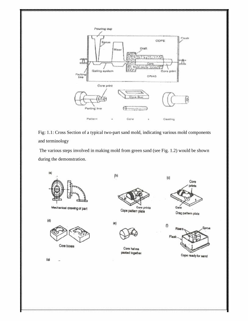
Fig: 1.1: Cross Section of a typical two-part sand mold, indicating various mold components
and terminology The various steps involved in making mold from green sand (see Fig. 1.2) would be shown
during the demonstration.

66

Fig 1.2: Schematic illustration of the sequence of operations for sand casting Source: Steel
founders society of America MELTING AND POURING OF METALS The next important step in the making of casting is the melting of metal. A melting process must be
capable of providing molten metal not only at the proper temperature but also in the desired
quantity, with an acceptable quality, and within a reasonable cost. In order to transfer the metal
from the furnace into the molds, some type of pouring device, or ladle, must be used. The primary
considerations are to maintain the metal at the proper temperature for pouring and to ensure that
only quality metal will get into the molds. The operations involved in melting of metal in oil fired
furnace/induction furnace and pouring of liquid metal into the mold cavity will be shown during
the demonstration. REMOVAL AND FINISHING OF CASTINGS After complete solidification, the castings are removed from the mold. Most castings require
some cleaning and finishing operations, such as removal of cores, removal of gates and risers,
removal of fins and flash, cleaning of surfaces, etc.

67
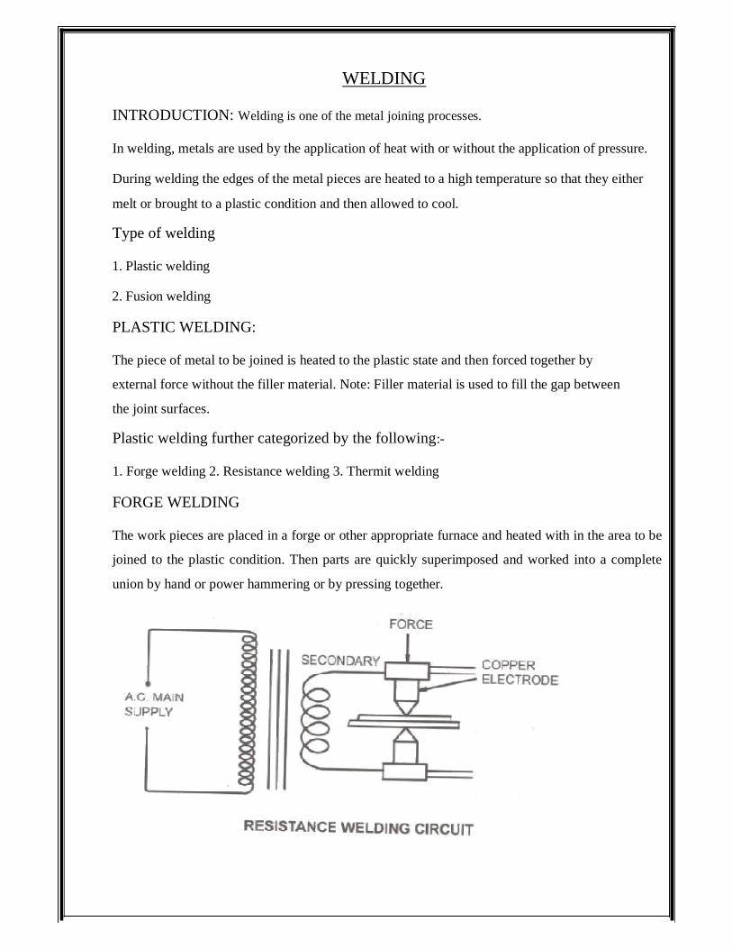
WELDING INTRODUCTION: Welding is one of the metal joining processes. In welding, metals are used by the application of heat with or without the application of pressure. During welding the edges of the metal pieces are heated to a high temperature so that they either
melt or brought to a plastic condition and then allowed to cool. Type of welding 1. Plastic welding 2. Fusion welding PLASTIC WELDING: The piece of metal to be joined is heated to the plastic state and then forced together by
external force without the filler material. Note: Filler material is used to fill the gap between
the joint surfaces. Plastic welding further categorized by the following:- 1. Forge welding 2. Resistance welding 3. Thermit welding FORGE WELDING The work pieces are placed in a forge or other appropriate furnace and heated with in the area to be
joined to the plastic condition. Then parts are quickly superimposed and worked into a complete
union by hand or power hammering or by pressing together.

Figure: Resistance Welding Circuit
68

FUSION WELDING: The fusion welding is categorized as follows
1. Gas welding
2. Electric welding
3. Thermit welding(without pressure) Gas welding is the process in which the required heat to melt the surface is
GAS WELDING:
Figure: THERMIT WELDING
RESISTANCE WELDING: In resistance welding, a heavy electric current is passed through the metals to be joined over limited area causing them to locally heat to plastic state and the welding is completed by the application of pressure for prescribed period time.
Example: Spot welding, Projection welding, Seam welding Butt welding.
THERMIT WELDING: Thermit welding is a fusion process in which weld is effected by pouring super heated liquid hermit steel, around the parts to be united with or without the pressure.

supplied by a high temperature flame obtained by mixture of two gases. Usually the mixture
of oxygen and acetylene is used for welding purpose.
69

In oxy-acetylene gas welding process, a flame is produced by burning mixture of oxygen and acetylene to get a flame temperature up to 3500°C in two stages. TYPES OF FLAMES The ratio of oxygen and acetylene in the mixture leads to any one of the following flames.
1. Neutral flame
2. Oxidizing flame
3. Carburizing flame Figure: Oxy-acetylene Welding
OXY-ACETYLENE WELDING:

70

NEUTRAL FLAME: 1. This flame has equal volumes of oxygen and acetylene. 2. According to the application this flame is used to weld steel, stainless steel and cast iron. OXIDIZING FLAME: 1. It has more volumes of oxygen than acetylene. 2. This flame is used to weld copper and copper alloys. CARBURIZING FLAME: 1. It has more volumes of acetylene than oxygen. 2. This flame is used to weld Monel metal, low carbon steel and alloy steel.
It is the metal that is added to the metal that is added to the weld pool to
assist infilling the gap. Filler material forms an integral part of the weld. The filler metal is
usually available in the rod form. ARC WELDING 1. In arc welding process, the source of heat is electricity 2. In arc welding process, coalescence is produced by heating the work piece. With an electric
arc stick between an electrode and the work piece. 3. Welding may be carried out in air or in an inert atmosphere. PRINCIPLE OF ARC WELDING:
FILLER MATERIAL:

1. The electricity is important thing in arc welding.
71

2. The electricity motor generator or transformer sets are used to supply high electric current and
the electrodes are used to produce the necessary arc. The electrode serves as the filler rod and
the arc melts the metals to be joined are fused together. 3. The electrodes are used in arc welding as a filler rod. 4. The electrodes are made of metallic wire called core wire Figure: ARC WELDING

Figure: DIRECTION OF WELDING, WELDING ARC
72

1. It is coated uniformly with a protective coating called flux while fluxing an electrode about
20 mm of length is left bare at one end for holding it using electric holder. 2. It is used to transmit full current from electrode holder to the front end of the electrode coating. 3. The size or diameter of the core wire will depend upon the amount of weld metal to be
deposited and on the type of joint. TOOLS USED IN ARC WELDING:
(1) Electric holder (2) Chipping hammer (3) Wire brush (4) Hand screen (5) Helmet (6)
Tongs 7. Goggles (8) Hand gloves 1. ELECTRODE HOLDER:
2. It is the device used for mechanical holding the electrode and conducting the current to it.
3. Electrode holder should be light to minimize fatigue in cured by the welder. Jams are made
to hold the bare of the electrode in either a vertical or an angular position. 2. CHIPPING HAMMER A chipping hammer is chisel shaped one and it is used to remove slag from the weld bed.
3. Wire brush:

A wire brush made up of shift steel wire, embedded in wood, removes small
particulars of slag from the weld after the chipping hammer has done its job.
73

8. Hand gloves: Hand gloves are used to protect the hands from the electric shocks, arc radiation and hot spatters.
fitter lens.
6. Tongs: Tongs are used to handle the hot metal. Welding job while cleaning, they are also used to hold the metal for hammering.
7. Goggles: Chipping goggles are used to protect the eyes while chipping the slag. They are fitted while a plain glass to see the area to be cleaned.
It is used for shielding and protecting the face and neck of the welder and it fitted with
5. Helmet:
4. Hand Screen: It is protective device used in arc welding, a hand shield is held in the hand of the welder and it is fitted with a suitable fitter lens.

74

EXPERIMENT No: 7: LAP JOINT AIM: To join the given two work pieces as a lap joint by arc welding. Material used: Mild Steel plates. Tools required : (1) Welding power supply (2) Flat file (3) Welding rod (4) Chipping hammer (5) Electrode holder (6) Wire brush (7) Gloves and apron (8) Earthing clamps (9)Shield
and goggles PROCEDURE: 1. The given work pieces are thoroughly cleaned, i.e. rust, scales are removed and the edges
are filed. 2. The electrode is held in an electrode holder and ground clamp is clamped to the welding
plates and the power is supplied. 3. The work pieces are positioned on the table to form a “Lab joint”. 4. The tag weld is done on the both the ends of joining plates to avoid the movement of work

pieces during welding. 5. The welding is carried throughout the length of the work pieces on both sides by
maintaining 3mm gap between plates and the welding rod.
75

6. The welded plates are allowed for air cooling after the slags are removed. 7. The weld joint portions are cleaned by wire brush. Result: Thus the required Lap joint is made by arc welding process. Questions: 1. What is the difference between arc welding and gas welding? 2. What is pressure welding? 3. What are the components of arc welding machine? 4. Name the different work holding mechanisms in a drilling machine. 5. How drilling is being carried out in lathe?

76

EXPERIMENT No: 8: SQUARE BUTT JOINT
Date : AIM: To join the given two work pieces as a ‘square butt joint’ by arc welding. Material used: Mild steel plates.
(1) Welding power supply (2) Flat file (3) Welding rod (4) Chipping hammer
(5) Electrode holder (6) Wire brush (7) Gloves and apron (8) Earthing clamps (9)Shield
and goggles PROCEDURE 1. The given work pieces are thoroughly cleaned, i.e. rust, scales are removed and the edges
are filed. 2. The electrode is held in an electrode holder and ground clamp is clamped to the welding
plates and the power is supplied. 3. The work pieces are positioned on the table form a “square butt joint”. 4. The tag weld is done on the both the ends of joining plates to avoid the movement of work
pieces during welding. 5. The welding is carried throughout the length of the work pieces on both sides by maintaining
3 mm gap between plates and the welding rod.
Tools required :

6. The welded plates are allowed for air cooling after the slags are removed. 7. The weld joint portions are cleaned by wire brush.
77

Result: Thus the required square butt joint is made by arc welding process. Questions 1. What is electrode and give its purpose? 2. What is consumable and non-consumable electrode? 3. What are the components of arc welding machine? 4. Define welding process. 5. Explain MIG and TIG?

78

EXPERIMENT No: 9: TEE FILLET JOINT
Date: AIM: To join the given two work pieces as a ‘Tee fillet joint’ by arc welding. Material used: Mild steel plates. Tools required : (1) Welding power supply (2) Flat file (3) Welding rod (4) Chipping hammer
(5) Electrode holder (6) Wire brush (7) Gloves and apron (8) Earthing clamps (9)Shield
and goggles PROCEDURE 1. The given work pieces are thoroughly cleaned, i.e. rust, scales are removed and the edges
are filed. 2. The electrode is held in an electrode holder and ground clamp is clamped to the welding
plates and the power is supplied.

3. The work pieces are positioned on the table to form a “Tee fillet joint”. 4. The tag weld is done on the both the ends of joining plates to avoid the movement of work
pieces during welding. 79

5. The welding is carried throughout the length of the work pieces on both sides by
maintaining 3mm gap between plates and the welding rod. 6. The welded joint portions are allowed for air cooling after the slag is removed. 7. The weld joint portions are cleaned by wire brush. Result: Thus the required ‘Tee fillet joint’ is made by arc welding process. Questions 1. Explain PAW? 2. Explain friction welding and its advantages? 3. Explain Thermit welding? 4. Explain EBW? 5. Explain LBW?

80

EXPERIMENT No: 10: SPOT WELDING Aim: To study the effect of the current on weld strength-using spot welding process Equipment: Spot welding machine Material Required: Two metal pieces of size 4”x2” Description of The Equipment:
FIG : PRINCIPLE OF SPOT WELDING A typical resistance spot welding machine essentially consists of two electrodes, out of which one is fixed. The other electrode is fixed to a rocker arm (to provide mechanical advantage) for transmitting mechanical force from a pneumatic cylinder. This
is simplest type of arrangement. The other possibility is that of a pneumatic or hydraulic
cylinder being directly connected to the electrode without any rocker arm. For welding large assemblies such as car bodies, portable spot welding machines are used.

Here the electrode holder and the pneumatic pressurizing system is present in the form of a portable assembly which is taken to the place, where the spot is to be made. The electric
81

current, compressed air and the cooling water needed for the electrodes is supplied through cable and hoses from the main welding machine to the portable unit.
In spot welding, a satisfactory weld is obtained when a proper current density (A/Sq mm) is maintained. The current density depends on the contact area between the electrode and the work piece. With the continuous use, if the tip becomes upset and the contact area increases, the current density will be lowered and consequently the weld is obtained over a large area. This would not but able to melt the metal and hence there would be no proper fusion.
A resistance-welding schedule is the sequence of events that normally take place in each of the welds. The events are the squeeze time is the time required for the electrodes to align and clamp the two work pieces together under them and provides the necessary electrical contact. The weld time is the time of the current flow through the work pieces till they are heated to the melting temperature. The hold time is the time when the pressure is to be maintained on the molten metal without the electric current. During this time, the pieces are to be forge welded. The off time is time during which, the pressure on the electrode is taken off so that the plates can be positioned for the next spot. The off time is not normally specified for simple spot welding, but only when a series of spots are to be made in a predetermined pitch.
THEORY:
Resistance welding: the category resistance welding (RW) covers a number of processes
in which the heat required for welding is produced by means of electrical resistance across the two components to be joined. These processes have major advantages, such as not requiring consumable electrodes, shielding gases, or flux. The heat generated in resistance welding is given by the general expression
H = I2RT,
Where
H = heat generated (in joules (watt-seconds)) I = current (in amperes),
R= resistance (in ohms), and
T= time of current flow (in seconds)
82

The actual temperature rise at the joint depends on the specific heat and on the thermal
conductivity of the metals to be joined. The tips of two opposing solid cylindrical
electrodes touch a lap joint of two sheet metals, and resistance heating produces a spot
weld. In order to obtain a strong bond in the weld nugget, pressure is applied until the
current is turned off. Accurate control and timing of the electric current and of the pressure
are essential in resistance welding. The strength of the bond depends on surface
roughness and on the cleanness of the mating surface. Oil, paint, and thick oxide layers
should, therefore, be removed before welding. The presence of uniform, thin layers of
oxide and of other contaminants is not critical. The weld nugget is generally 6 to 10 mm in
diameter. The surface of the weld spot has a slightly discolored indentation. Currents
range from 3000 A to 40000 A: the level depends on t he materials being welded and on
their thicknesses. EXPERIMENT DIAGRAM: PROCEDURE: 1. Switch on the machine and set the current in the machine to 2 Ampere

2. Set the timer to two seconds 3. Over lap the two metal pieces to the requires size and place them between the two
electrodes.
83

4. Apply pressure by foot on the lever such that two electrodes come into contact if the
over lapped metals. 5. After 2 seconds remove the pressure on the lever slowly. 6. Now the joint is ready for use. 7. Repeat the same procedure at various amperes 8. Test the strength of the joints using universal testing machine. ADVANTAGES OF SPOT WELDING: 1. Low cost. 2. Less skilled worker can do it. 3. Higher productivity. 4. Operation may be made automatic or semiautomatic. 5. No edge preparation is needed. APPLICATION OF SPOT WELDING: 1. Welding of low carbon steels, high speed steels, stainless steels, AI, Cu, nickel, nickel
alloys etc. 2. In automobile and aircraft industries. 3. Steel household furniture. 4. Containers. PRECAUTIONS: 1. Ensure that the electrodes should not be touched. 2. Don’t touch the welded potion by hand immediately after the welding is done. Result: Effect of current on strength of spot weld is studied.

84
EXPERIMENT No: 11: GAS WELDING
Date : Aim: To make butt-welding using gas welding equipment. Equipment And Material Required: Oxy – acetylene welding outfit, MS Sheets 50x50x1mm (2No) Tools Required: Wire brush, Hand gloves, Chipping hammer, Spark lighter. Procedure: 1. Acetylene valve on the torch is opened slightly and lightened with the help of a spark
lighter. 2. Now acetylene valve is opened to get required the flow of acetylene. 3. Oxygen valve is opened till the intermediate flame feather reduces into inner cone to
get a neutral flame. 4. The torch tip is to be positioned above the plates so that white cone is at a distance of
1.5mm to 3mm from the plates. 5. Torch is to be held at an angle of 300 to 450 to the horizontal plane. 6. Now filler rod is to be held at a distance of 10mm from the flame and 1.5 mm to 3 mm
from the surface of the weld pool. 7. As the backward welding allows better penetration, back ward welding is to be used. 8. After the completion of welding, slag is to be removed by means of chipping hammer,

wire brush. Precautions: 1. Ensure that torch movement is uniform.
85

2. See that the joints are extremely clean. Result: A butt joint is prepared using gas welding process. QUESTIONS
1. Explain SAW?
2. What are the different types of flames?
3. Explain upset and flash butt welding?
4. Explain the types of gas welding?
5. What are the components of gas welding?

86

CALACULATION/FIGURE:

87

EXPERIMENT No: 12: BRAZING
Date : AIM: To join the given two work pieces as required type of joint by brazing. Material used: Mild steel plate.
Tools used
1. Filler rod 2. Safety goggles, gloves 3. Brazing torch PROCEDURE 1. The given work piece are thoroughly cleaned, i.e., rust, scales are removed. 2. The joining work pieces are positioned properly. 3. A flux is applied to all surfaces where the filler material is flow. 4. After that the joint is heated to the proper brazing temperature. 5. Solid filler metal may be replaced on the metal pieces and thus melted as the metal pieces
are heated. 6. Only small amount of filler metal is needed to fill the joint completely. RESULT: Thus the required welding is obtained by brazing process.
QUESTIONS 1. Describe brazing process? 2. Name some welding defects. 3. Compare brazing and welding? 4. Explain soldering process? 5. Compare soldering and brazing?

88

PRESS WORKING Press working may be defined as, a manufacturing process by which various components are made
from sheet metal. This process is also termed as cold stamping. The machine used for press
working is called a press. The main features of a press are: a. A frame which support a ram or a slide and a bed, a source of mechanism for operating the ram
in line with and normal to the bed. b. The ram is equipped with suitable punch/punches and a die block is attached to the bed. c. A stamping is produced by the downward stroke of the ram when the punch moves towards and
into the die block. d. The punch and die block assembly is generally termed as a “die set” or simple as the “die” Press working operations: The sheet metal operations done a press may be grouped into two categories. 1: Cutting operations 2: Forming operations In cutting operations the work piece is stressed by its ultimate strength. The stresses caused in the
metal the applied forces will be shear stresses. The cutting operations include: (a) Blanking (b) Punching (c) Notching (d) Perforating (e) Trimming (f) Shaving
(g) Slitting (h) Lancing In forming operations, the stresses are below the ultimate strength of the metal, in this operation,
there is no cutting of the metal but only the contour of the work piece is changed to get the desired
product. The forming operations include: (a) Bending (b) Drawing (c) Squeezing Press Working Terminology: A simple cutting die used for punching and blanking operation as
shown:

89

1: Bed: The bed is the lower part of the press frame that serves as a table to which a Bolster plate is
mounted. 2: Bolster Plate: This is a thick plate secured to the press bed , which is used for locating and
supporting the die assembly. It is usually 5 to 12.5 cm thick. 3: Die Set: It is unit assembly which incorporates a lower and upper shoe, two or more guide parts
and guide part bushings. 4: Die Block: It is a block or a plate which contains a die cavity 5: Lower Shoe: The lower shoe of the die set is generally mounted on the bolster plate of a press.
The die block is mounted on the lower shoe, also the guide post are mounted on it. 6: Punch: This is male component of a die assembly, which is directly or indirectly moved by and
fastened to the press ram or slide. 7: Upper Shoe: This is the upper part of the die set which contains guide post bushings. 8: Punch Plate: The punch plate or punch retainer fits closely over the body of the punch and holds
it in proper relative position. 9: Back up Plate: Back up plate or pressure plate is placed so that intensity of pressure does not
become excessive on punch holder. The plate distributes the pressure over a wide area and the
intensity of pressure on the punch holder is reduced to avoid crushing. 10: Stripper: It is a plate which is used to strip the metal strip from cutting a non-cutting Punch or

die. It may also guide the sheet.
90

PUNCHING/BLANKING
Punching or blanking is a process in which the punch removes a portion of material from the
larger piece or a strip of sheet metal. If the small removed piece is discarded, the operation is called
punching, whereas if the small removed piece is the useful part and the rest is scrap, the operation
is called blanking, see figure below. Figure. Comparison of basic stamping operations. In punching, the metal inside the part is removed; in blanking, the metal around the part is removed. A typical setup used for blanking is shown in below figure.

Figure Blanking punch and die.
91

The clearance between the die and punch can be determined as c = 0.003 t. t where t is the
sheet thickness and t is the shear strength of sheet material. For blanking operation, dies size =
blank size, and the punch is made smaller, by considering the clearance. The maximum force, P
required to be exerted by the punch to shear out a blank from the sheet can be estimated as
P = t. L. t
Where t is the sheet thickness, L is the total length sheared (such as the perimeter of hole),
and t is the shear strength of the sheet material. Stripping force. Two actions take place in the
punching process – punching and stripping. Stripping means extracting the punch. A stripping
force develops due to the spring back (or resiliency) of the punched material that grips the punch.
This force is generally expressed as a percentage of the force required to punch the hole, although
it varies with the type of material being punched and the amount of clearance between the cutting
edges. The following simple empirical relation can be used to find this force
SF = 0.02 L.t Where SF = stripping force, kN, L = length of cut, mm, t = thickness of material, mm Piercing: It is a process by which a hole is cut (or torn) in metal. It is different from punching in
that piercing does not generate a slug. Instead, the metal is pushed back to form a jagged flange on
the back side of the hole. A pierced hole looks somewhat like a bullet hole in a sheet of metal. Trimming: When parts are produced by die casting or drop forging, a small amount of extra metal gets
spread out at the parting plane. This extra metal, called flash, is cut – off before the part is used, by an
operation called trimming. The operation is very similar to blanking and the dies used are also similar to
blanking dies. The presses used for trimming have, however, relatively larger table. Notching: It is an operation in which a specified small amount of metal is cut from a blank. It is
different from punching in the sense that in notching cutting line of the slug formed must touch one
edge of the blank or strip. A notch can be made in any shape. The purpose of notching is generally
to release metal for fitting up. Nibbling: Nibbling is variation of notching, with overlapping notches being cut into the metal. The
operation may be resorted to produce any desired shape, for example flanges, collars, etc. Perforating: Perforating is an operation is which a number of uniformly spaced holes are punched in a

sheet of metal. The holes may be of any size or shape. They usually cover the entire sheet of metal. According to the method of operation: According to this criterion, the dies may be classified as: single
operation or simple dies, compound dies, combination dies, progressive dies, transfer dies and
multiple dies. 92

1: Simple Dies: Simple dies or single action dies perform single operation for each stroke of the
press slide. The operation may be one of the operations listed under cutting or forming dies. 2: Compound Dies: In these dies, two or more operations may be performed at one station. Such
dies are considered as cutting tools since, only cutting operations are carried out. Figure shows a
simple compound die in which a washer is made by one stroke of the press. The washer is
produced by simulation blanking and piercing operations. Compound dies are more accurate and
economical in production as compared to single operation dies. 3: Combination Dies: In this die also, more than one operation may be performed at one station. It
is difficult from compound die in that in this die, a cutting operation is combined with a bending or
drawing operation, due to that it is called combination die.

4: Progressive Dies: A progressive or follow on die has a series of operations. At each station, an
operation is performed on a work piece during a stroke of the press. Between stroke the piece in the
93

metal strip is transferred to the next station. A finished work piece is made at each stroke of the
press. While the piercing punch cuts a hole in the stroke, the blanking punch blanks out a portion of
the metal in which a hole had been pierced at a previous station. Thus after the first stroke, when
only a hole will be punched , each stroke of the press produces a finished washer. 6: Transfer Dies: Unlike the progressive dies where the stroke is fed progressively from one station
to another. In transfer dies the already cut blanks are fed mechanically from one station to other
station. 7: Multiple Dies: Multiple or gang dies produce two or more work piece at each stroke of the press.
A gang or number of simple dies and punches are ganged together to produced two or more parts at
each stoke of the press.

94

EXPERIMENT No: 13: HYDRAULIC PRESS AIM: To do bending and drawing operations on hydraulic press by using dies. MATERIAL: CRCA (cold rolled cold annealing) sheet. TOOLS AND ACCESSORIES: Hydraulic press dies.
Large machine parts can’t be forged by hand, since the
comparatively light blow of a hand or sledge hammer is unable to produce a great degree of
deformation in the metal being forged. More over hand forging is a lengthy process and requires
heating of the metal, this has lead to the use of power hammer and presses in forging machines,
which work on pressure are called presses. Press forging is done in presses rather than with
hammers. Press forgings are generally more accurate dimensionally than drop forgings. Hydraulic
presses are load restricted machines in which hydraulic pressure moves a piston in a cylinder. A
chief feature is that the full press load is available at any point during the full stroke of the ram.
This feature makes the hydraulic press ideally suited for extrusion-type foreign operations. The ram
velocity can be controlled and even raised during the stroke. The hydraulic press is a relatively
slow speed machine. This results in longer contact time, which may lead to problems with the heat
loss from the work piece and die deterioration. On the other hand the slow squeezing action of a
hydraulic press results in close-tolerance forgings. Hydraulic presses area available in rating from
500 to 18000 tons, although several presses with rating of 50000 tons have been built. PROCEDURE: 1. Fix the die holder to the ram of the press. 2. Fix the top part of the die(punch) in the die holder and tighten it. 2. Raise the bed to the required height and place the bottom part of the die on it. 3. Place the material (CRCA Sheet) between the punch and die. 4. Close the release valve of the pump. 5. Operate the low pressure lever i.e. plunger with bigger dia. The ram will move very fast and
THEORY AND DESCRIBION:

touch the job. 6. Then operate the high pressure lever i.e. plunger with smaller dia. The gauge will start
indicating the load.
95

7. Open the release valve, the ram will return to the original position. PRECAUTIONS: 1. Punch and die should be aligned. 2. Apply the load up to the mark. Do not exceed the red mark given in the dial gauge. RESULT: Thus bending and drawing operations are performed on hydraulic press. QUESTIONS: FIGURE:

96

EXPERIMENT No: 14: FLY PRESS AIM: To do blanking and piercing operations on fly wheel press by using proper dies. MATERIAL: CRCA (Cold Rolled Cold Annealing) sheet. TOOLS AND ACCESSORIES: Fly wheel press, dies and required spanners. THEORY AND DESCRIBION: Blanking: It is a process in which the punch removes a portion of material from the stock which is a
strip of sheet metal of the necessary thickness and width. The removed portion is called a blank and is
usually further processed to be of some use. In this operation the cut out piece is of importance and in it
we can measure only the maximum diameter. Therefore incase of blanking operation the die should be
given exact size and the clearance should be made on the punch. Piercing: Piercing also called sometimes as punching, is used for making hole in a sheet. It is identical
to blanking, except of the fact that the punched out portion coming out through the die is discharged as
scrap. In this case the left out piece is importance and in it the minimum diameter is measured. Thus the
punch should be given exact size and the clearance should be provided on the die. Fly wheel is used to
supply energy for that period of operation which requires more energy and during other periods, it
stores the energy. If machine lacks sufficient flywheel energy, it will come to stop and will not be able
to complete the operation. Actually by employing flywheel, we can work with motor of less capacity
and at the same time supply maximum tonnage at the desired used of operation. For faster working
operational (in case of blanking and piercing operations) more energy and power must be provided. In
case of blanking and piercing operations, the work is completed in a very brief portion of stroke. So in
this entire energy is to be tapped from flywheel, and flywheel supplies instantaneously whole energy
required for operation and for remaining period of cycle, it will restore. PROCEDURE: 1. Fix the top part of the die (punch) in the fly press shaft and tighten it with nut. 2. Place the die on base of the fly press and fix with clamps.

2. Place the material in the die 3. Rotate the fly wheel, the shaft will come down and punch the material. 4. Lift the fly press shaft and remove the material from the die.
97

5. Repeat the cycle for the second operation. PRECAUTIONS: 1. Die and punch should be aligned. RESULT: Thus blanking and piercing operations are performed on fly press. FIGURE:

98

BLOW MOULDING Blow molding is a manufacturing process that is used to create hollow plastic parts by inflating a
heated plastic tube until it fills a mold and forms the desired shape. The raw material in this process
is a thermoplastic in the form of small pellets or granules, which is first melted and formed into a
hollow tube, called the PARISON. Types of Blow molding:
1. Extrusion blow molding
2. Injection blow molding
3. Stretch blow molding Extrusion blow molding is perhaps the simplest type of blow molding. A hot tube of plastic material is dropped from an extruder and caBured in a water cooled mold. Once the molds are closed,
air is injected through the top or the neck of the container; just as if one were blowing up a balloon.
When the hot plastic material is blown up and touches the walls of the mold the material "freezes" and
the container now maintains its rigid shape. Injection blow molding is part injection molding and part blow molding. With injection blow molding, the hot plastic material is first injected into a cavity where it encircles the blow stem, which is
used to create the neck and establish the gram weight. The injected material is then carried to the next
station on the machine, where it is blown up into the finished container as in the extrusion blow
molding process above. Injection blow molding generally suitable for smaller containers and absolutely
no handle ware. Stretch blow molding is perhaps best known for producing P.E.T. bottles commonly used for water,
juice and a variety of other products. There are two processes for stretch blow molded P.E.T.
containers. In one process, the machinery involved injection molds perform, which is then transferred
within the machine to another station where it is blown and then ejected from the machine. This type of
machinery is generally called injection stretch blow molding (ISBM) and usually requires large runs to
justify the very large expense for the injection molds to create the perform and then the blow molds to
finish the blowing of the container. This process is used for extremely high volume (multi-million) runs
of items such as wide mouth peanut butter jars, narrow mouth water bottles and etc…

Materials used for Blow molding:
99

1. Low Density Polyethylene (LDPE) 2. High Density Polyethylene (HDPE) 3. Polyethylene Terephtalate (PET) 4. Polypropylene (PP) 5. Poly Vinyl Chloride (PVC) Figure: BLOW MOLDING

100

EXPERIMENT No: 15: BLOW MOULDING AIM: To prepare a bottle of 200ml using blow moulding machine. APPARATUS REQUIRED: Die, blow-moulding equipment, air compressor. MATERIALS REQUIRED: Plastic pellets TOOLS REQUIRED: Blow Molding machine, grained plastic, Die (bottle shaped) Sample figure: Operating instructions: 1. Install the machine on leveled strong flooring near the compressor (within 2 meters). For
letter rigidity foundation bolt is recommended & anti vibration rubber mounting can be used. 2. The machine must be placed in a position where all parts are accessible readily. 3. Check for loose any loose electrical connection with the help of certified electrician and

with the electrical circuit enclosed.
101

4. Fill the lubricator with SAE 20 grade oil to the level indicated. The lubrication has been
set to allow one drop of oil for every 5 strokes of air cylinder (oil) drop is factory set, no
need to adjust) 5. Connect the air filter to the compressor by rubber/nylon hose (Min inside dia 10mm),
pressure with standing capacity 20kg/cm2 .6.Set the pressure switch in the compressor as per the compressor manual to switch on 7
kg/cm2 pressure & switch off at 10kg/cm2 (NOTE: The air pressure should not exceed 10cm2 ) 7. Set the air pressure in machine by adjusting the injection & release regulator (18). 8. Set release pressure 2kg/cm2 by adjusting release regulator. 9. Operate the hand lever valve (13) and check for smooth functioning of plunger. 10. Set the blow pressure in regulator (15) and operate the hand lever valve (14) to check
flow of air throw blow nozzle. 11. Electrical connection should be given as indicated on the main plug phase, neutral
and earth. 12. Proper earthing should be done. 13. Check the incoming voltage (230VAC, 50Hz) Now the machine is ready for operation. Working Principle: The process is applied to only thermo plastics, which are used for producing hollow objects
such as bottle, and flow table objects by applying air pressure to the sheet material when it is in heated and in soft pliable condition. Blow moulding can be accomplished in two
manners; one is direct blow moulding and other indirect blow moulding. In the former case, a measured amount of material in the form of tube is either injected or extruded
in a split cavity die. The split mould is closed around the tube, sealing off the lower end. The
air under pressure is blown into the tube, which causes the tube to expand to the walls of
cavity. In the latter case, a uniformly softened sheet material by heat is clamped at the edges
between the die and cover, which causes the sheet to attain a hemispherical

shape or the configuration of mould whatever it may be parts obtained by indirect blow
moulding have excellent appearance but they are more costly as only to percent of
the sheet stock is utilized and also there is a tendency for excessive thinning of
sheet at the deepest point.
102

PROCEDURE: 1. Set the die in position. Adjust the guide rod nuts to suit die height. Align the tapered
face of the die for sealing the parison while blowing also checks for the face opening and
closing of the die. 2. Ensure minimum die height is 80mm. provide spacing plates if necessary. 3. Set the injection, release and blow pressure by rotating (clockwise) the regulator knob
to suit the requirement of moulding the container. 4. Feed correct quantity & quality of plastic material and switch on the power supply. 5. Switch on the heater. 6. Set the required timings controller to control the bottom heater. 7. Allow sufficient time to stabilizer. 8. When temperature reached, operate the hand lever valve. 9. Extrude the parison (Tubular form) to the required length and close the two die halves.
Release the injection cylinder. 10. Operate the hand lever valve and blow the air so that the parison to form the shape of
the container as designed in the die. 11. Allow the component to cool. 12. Open the die & take the product out of the die. 13. Now the machine is ready for nest cycle. RECAUTIONS:
1. The material should not be heated rapidly.
2. The die should be placed exactly below the nozzle.
3. Proper temperature should be maintained while heating the plastic. RESULT: Required product is made using blow moulding process.

EXPERIMENT No: 16:
INJECTION MOULDING Aim: To Prepare a Plastic product using Injection Moulding machine (screw type bottle cap) Equipment: Injection moulding machine. Material Required: High grade poly ethylene APPARATUS REQUIRED: Die, injection-moulding equipment. Description of the Equipment: Hydraulic Plastic Injection Moulding machine, Model JIM-1HD has been designed for
moulding variety components up to 45 Gms capacity in polystyrene. The machine is
robustly built to ensure consistent high quality and volume production of precision
components. Operator fatigue due to injection process is completely eliminated by use of
hydraulic power for both the injection and releases operations. Locking Unit: This locking made by Hydraulic Cylinder. Injection Unit: Injection Unit consists of two guide rods, nuts, top and bottom plates with
injection cylinder and barrel. Injection cylinder is designed to develop 3 Tons load. Barrel

diameter 30mm is attached with the machine as standard. Hydraulics: Hydraulic pump is driven by 3 HP Induction motor for a rated delivery of 14 lp, at
1440 Rpm and at 80kg/cm2. The maximum pressure in the hydraulic system is present in
104

our works and is not to be altered. The oil tank capacity is 60 liters. All hydraulic system manufacturers safety precautions are provided to hydraulic system by using section strainer, which will prevent the contamination entering into the system. Oil Cooler: Oil
cooler provided to keep the oil temperatures below 500c which will gives more life to
hydraulic oil in continuous use. Electricals: Electrical control panel with automatic blind temperature controller is fixed on
the right hand side of the machine for clear viewing of the temperature and for easy to
operate the switches. Designed with safety measure, which will protect the motor from
over load. Working Procedure: Injection moulding makes use of heat softening characteristics of thermo plastic materials.
These materials soften when heated and re harden when cooled. No chemical change
takes place when the material is heated or cool. For this reason the softening and re
hardening cycle can be repeated any no. of times. 1. The granular moulding material is loaded hopper where it is metered out in a heating
cylinder by a feeding device. 2. The exact amount of material is delivered to a cylinder, which is required to fill the
mould completely. 3. Set the die in position Provide spacing plates if necessary. Clamping the Die using
hydraulic operate ram. 4. Set the injection pressure by rotating (clockwise) the regulator knob to suit the
requirement of moulding the container. 5. Switch on the heater. Set the required timings to the timers, for top and middle Heater. Set the temperature by adjusting automatic temperature controller to control the
bottom heater. Allow sufficient time to stabilizer. When temperature reached, operate the
hand lever valve to inject the material. 6. Apply injection pressure on the heated material using plunger rod. 7. The injection ram pushes the material in to the heating cylinder and in doing so pusa

small amount of heated material out of the other end of the cylinder through the nozzle
and screw bushing and into the cavity of closed mould. 8. The material is cooled in a rigid state in the mould.
105

9. Release the injection pressure. In clamp the Die using hydraulic operated ram. 10. The mould is then opened and piece I ejected out. PRECAUTIONS:
1. The material should not be heated rapidly.
2. The die should be placed exactly below the nozzle.
3. Proper temperature should be maintained while heating the plastic. Result: Required product is made using injection moulding process.

Experiment no :17
BRAZING (BUTT JOINT)
AIM: Prepare a Butt joint using Brazing process.
APPARATUS REQUIRED: Hand blower, heating rods, filler material, acid, wire brush
MATERIAL REQUIRED: G.I. Sheet of 50x50mm ………2 Nos.
THEORY:
Brazing is a metal-joining process whereby a filler metal is heated above melting point and distributed between two or more close-fitting parts by capillary action. Brazing
operation temperature ranges between 427o C and less than the melting temperature of
parent material. The filler metal is brought slightly above its melting (liquidus) temperature while protected by a suitable atmosphere, usually a flux. It then flows over the base metal (known as wetting) and is then cooled to join the work pieces together. It is similar to soldering, except the temperatures used to melt the filler metal are higher for brazing.
In order to obtain high-quality brazed joints, parts must be closely fitted, and the base metals must be exceptionally clean and free of oxides. In most cases, joint

clearances of 0.03 to 0.08 mm are recommended for the best capillary action and joint strength. Cleanliness of the brazing surfaces is also important, as any contamination can cause poor wetting (flow). The two main methods for cleaning parts, prior to brazing, are chemical cleaning and abrasive or mechanical cleaning.
Another consideration that cannot be overlooked is the effect of temperature and time on the quality of brazed joints. As the temperature of the braze alloy is increased with increase in the alloying and wetting action.
In general, the brazing temperature selected must be above the melting point of the filler metal. However, there are several factors that influence the joint designer's temperature selection.
The best temperature is usually selected so as to: (1) be the lowest possible braze temperature, (2) minimize any heat effects on the assembly, (3) keep filler metal/base metal interactions to a minimum, and (4) maximize the life of any fixtures or jigs used. In some cases, a higher temperature may be selected to allow for other factors in the design. However, in general most production processes are selected to minimize brazing time and the associated costs.

PRINCIPLE OF OPERATION:

PROCEDURE:
1. Good fit and proper clearance: Prepare the work pieces flat with the hammer. The best clearance between the two metal parts being brazed is a close one - usually 0.2 to 0.5 mm, and generally not more than 1mm.
2. Cleaning the metals: Clean the two work pieces with acid to increase capillary action and can’t work properly on dirty surfaces. If the surfaces of the metals are contaminated (with oils, dirt, etc.) the brazing filler metals will not adhere to them and the joint will fail.
3. Fluxing the parts: Flux is a chemical compound, usually made in the form of a liquid or paste, which is applied to the joint surface prior to brazing. Its purpose is to protect the joint surface from the oxides that form during heating.
4. Assemble for Brazing: Place the two work pieces in required position for butt joint. Before the parts can be heated and brazed, they have to be aligned and then supported.
5. Brazing the assembly: The actual brazing operation is a two-part process: first, heating
the base metals, and second, applying the filler metal to the joint. The filler metal used is lead. Regardless of the heating equipment being used, be sure to heat both base metals broadly and evenly, so the filler metal will wet equally well on both metal surfaces and completely fill the joint.
6. Cleaning the Brazed joint: Clean the brazed joint. However, in some cases where flux has been used, it may be necessary to remove the flux residues after the joint has set. A hot water wash,assisted by brushing or swabbing, usually does the job.

VIVA QUESTIONS 1. What are the various parts in the wood turning lathe? 2. List different types of pattern? 3. What are the operations in making the pattern? 4. Define welding? 5. Give classification of welding process? 6. Define Arc welding? 7. What is effect of polarity on weld strength? 8. ow much gap should maintain between weld rod and work piece? 9. What type of flux used on weld rods? 10. What is the minimum voltage for arc initiation? 11. What is the effect of current on weld strength? 12. What are different arc welding processes? 13. Differentiate between MIG and TIG welding? 14. Define spot welding?
15. Which type of electrode is used in spot welding? 16. Which type of electrode is used in spot welding? 17. What is the maximum thickness of the sheets that are spot welded? 18. What is difference between arc welding and gas welding? 19. What are the types of flames used in welding of MS plates? 20. What do you mean by backward welding and forward welding? 21. Which type of flame is used in welding of MS plates? 22. Which type of gas welding is used in welding of MS plates?

23. What is brazing? 24. What type of flame is used for brazing? 25. What is the difference between brazing and welding? 26. Difference between brazing and soldering? 27. What are the advantages of hydraulic press? 28. What is the difference between compound die and progressive die? 29. Define Deep-drawing operation? 30. Give the classification of presses? 31. Define Injection moulding process? 32. Which type of injection is used in this experiment? 33. What is raw material used in injection moulding? 34. Why oil cooler provided in this equipment? 35. Define Blow moulding process? 36. Differentiate between thermosetting and thermoplastics? 37. What is the raw material used in blow moulding? 38. Which type of compressor used in this experiment? 39. Differentiate between hydraulic and pneumatic pressure