
Laboratory Manual - mavraidopoulos.gr
100
Laboratory Manual
-
Upload
khangminh22 -
Category
Documents
-
view
3 -
download
0
Transcript of Laboratory Manual - mavraidopoulos.gr

Laboratory Manual

General prosthetic advice for ANKYLOS®
In order to obtain utmost benefit from the unique restorative features of the ANKYLOS implant system, please observe the following guidelines:• Avoid occlusal overload, aim for initial infra-occlusion to
ensure clearance of contacts in function.• If possible, use B-implants or larger for single molar
restorations.• Use gingiva height 0.75 and 1.5 only if really necessary,
and in correspondence with thin gingiva. • Minimize the functional occlusal surface in buccal-lingual
dimension to avoid lateral levers.• Take adequate precautions to avoid occlusal overload in
correspondence to any prosthetic cantilevers.• Bear in mind the resilience of neighboring teeth when
planning for single tooth restorations. Establish full contact on the implant crown only during maximal clenching ensuring an even load distribution on all teeth during maximum chewing force.
• Check for parafunctional habits. Consider changes during recall appointments.
• In case of any changes to the occlusal scheme in other areas, evaluate the consequences for the implant restoration and, if required, take appropriate measures.
• Advice for the dental laboratory: The abutment design must not be manipulated at the areas of the connection taper or adjacent to the sulcus.
Please read this manual carefully before using the system for the first time andalways observe the clinical indications, directions and notes in the instructions for use of the system components and instruments. Furthermore, we recommend that all users attend a training course specific to the system prior to first using a new implant system.
Some products may not be available in all countries.Please contact your DENTSPLY Implants representative to obtainup to date information on the product range and on availability.
To improve readability for our customers, DENTSPLY Implants does not use ® or ™ in body copy. However, DENTSPLY Implants does not waive any right to the trademark and nothing herein shall be interpreted to the contrary.
3
Treatment planning
Aspects of treatment planning 4Conventional treatment planning 6Computer-guided treatment planning 7
Prosthetic concept
The prosthetic principle of ANKYLOS 8ANKYLOS prosthetics navigator 11Solutions for single-tooth restoration 12Solutions for larger tooth gaps 14Solutions for the edentulous jaw 16Basic guidelines for soft tissue management 18
ANKYLOS® Balance C/X
Crowns and bridges on ANKYLOS Balance Anterior C/X, crowns on ANKYLOS CERCON Balance C/ 20
ANKYLOS® Regular C/X
Crowns and bridges on ANKYLOS Regular C/X 30
ANKYLOS® Balance Base Abutment C/
Bar-supported overdentures and bridges, also CAD/CAM-fabricated, on ANKYLOS Balance Base Abutment C/ 42
ANKYLOS® SynCone® C/
Overdentures on ANKYLOS SynCone C/ 66
ANKYLOS® Snap Attachment® C/
Overdentures on ANKYLOS Snap Attachment C/ 80
ANKYLOS® Standard C/
Crowns, bridges and bar-supported dentures on ANKYLOS Standard C/ 84
CONTENTS

4
Precise planning for any implantological procedure in close coordination between practitioners and laboratory is the basic prerequisite for lasting therapeutic success. All suitable measures and alternatives that will fulfill the expectations of the patient in terms of function and esthetics of the implant prosthetic rehabilitation should be stipulated in the planning.
Today, along with conventional treatment planning, treatment can be planned using computer-guided facilities for three-dimensional “crown down” treatment with planning of the op-timal implant placement from the point of view of the desired prosthetic restoration, both functionally and esthetically.
Aspects of treatment planning
Trea
tmen
tpl
anni
ng

5
The basis of treatment planning is always a thorough discus-sion with the patient with a view towards determining the wishes and perceptions of the patient, excluding contraindica-tions and clarifying matters thoroughly with the patient. Next, a complete general and specific medical history is taken and an intraoral diagnostic assessment is made with an analysis of the initial anatomical situation.
The following points should be taken into account:• Medical history• General diagnosis – elimination of contraindications• Specialist consultation where there are risk factors• Extensive intraoral diagnosis (PAR diagnosis, functional
examination, reasons for tooth loss, assessment of the existing tooth replacement, radiological examination)
After all the diagnostic details have been submitted and evaluated, the treatment can be planned.
This comprises the following elements:• Preprosthetic planning• Surgical planning• Schedule• Cost projection

6
Treatment Planning
Conventional treatment planning
Preprosthetic planning
Preprosthetic planning with the dental technician is the most important factor for the esthetic and functional success of the implant procedure.
Surgical planning
During preoperative planning it is very important to check that the height and width of the jawbone is sufficient for placement of the implant.
The target is the best possible, tooth-analog placement of the implants. During the first planning session with the patient situation impressions are made to be used as the base for laboratory-fabricated diagnostic aids.
A diagnostic wax-up of the planned prosthetic restoration is made.
A thermoformed splint with radiographic balls that can be accurately repositioned in the patient‘s mouth is prepared. It can be subsequently modified to a conventionally fabricated surgical template.
The width of the vestibular and oral lamellae should be at least 1.5 mm after implant placement. The position and direc-tion of important anatomical structures such as the mental foramen or maxillary sinus must be determined by radiology.
Grafted regions must be confirmed to have completely regen-erated to a mechanically stable state before preparation.
Planned prosthetic measures must be checked to ensure that they can actually be implemented with appropriate surgical procedures. All aspects of preprosthetic and surgical planning interact directly with one another. Every change in the pre- prosthetic planning will affect the surgical planning and vice versa. This will also include the number, diameter, lengths, positions and alignment of the implants.
The available bone volume and important anatomical struc-tures are examined in an x-ray image, which is prepared with the laboratory-fabricated x-ray template with the radio-graphic balls in the patient‘s mouth. The dimensions of the intraoral structures can be calculated from the defined dia-meter of the radiographic balls, taking the magnification factors resulting from radiological processes into account.
The implant lengths are selected by placing the transparent radiographic template on the OPG. If desired, the x-ray analysis must consider a subcrestal implant position (note magnification scale).

7
Treatment Planning
Computer-guided treatment planning
Digital treatment planning based on three-dimensional imaging procedures enables the therapy to be planned with absolute accuracy and makes the result of the treatment exactly predictable.
DENTSPLY Implants offers a complete solution for digital treatment planning and full-guided implant placement based on the world-renowned SIMPLANT software.
The advantages over conventional planning include:• Safe three-dimensional planning in the sub-millimeter range
and with reference to the desired restoration• Automatic collision control, which displays too narrow
clearances between implants or to the nerve • Information on peri-implant bone quality for accurate
conclusions on the expected primary stability
An individual SIMPLANT drill guide is fabricated using stereolithography, based on the digital planning data. Depending on the individual case scenario, the guide is prepared tooth-supported, mucosa-supported or bone- supported, thus enabling a complete and accurate transfer to the patient‘s mouth.
The Sleeve-on-Drill drill system, drills with a guide sleeve that can be attached to the instrument for precise guidance in the template, has been especially developed for template-guided implant placement in order to facilitate accurate, straight-forward implant placement with the added security of the drill stop.
These instruments enable simpler and precisely fitting placement of the implants with the reliability of the drill stop.
SIMPLANT drill guides are also available with lateral access for easier management of the instruments, even with a restricted oral cavity.
Digital treatment planning with SIMPLANT.
Patient-specific SIMPLANT guide.
Sleeve-on-drill drill system and drill guide with lateral access.

8
ANKYLOS implants are available in four diameters and in six lengths. This allows the surgeon to select the best possible implant according to the indication and the anatomical conditions.
Thanks to the geometry of the ANKYLOS TissueCare connec-tion, identical for all implant diameters, however, you can provide each implant with all available prosthetic components and thus you can obtain the optimal prosthetic result, regard-less of surgical requirements.
The prosthetic principle of ANKYLOS®
Pros
thet
icco
ncep
t
ANKYLOS®
CERCON® Balance C/
ANKYLOS®
TitaniumBaseC/X
ANKYLOS®
Regular C/XANKYLOS®
Balance Anterior C/X

9
The ANKYLOS system includes a variety of prosthetics ranges from which you can choose depending on the indication and your preferred approach. Each range of prosthetics contains abutments in various sizes and forms, with and without positioning aid (index), if needed. Hence, a large variety of prosthetic conditions are provided, with the optimal functional and esthetic solution.
One-fi ts-all connection
Thanks to the identical dimensions of the tapered connection, for all implant diameters, every ANKYLOS prosthetic abutment fi ts into every implant of any diameter. Hence, a decision as to the prosthetic strategy can still be made, even after implant healing or when the abutment is uncovered. In fact, the compatibility of ANKYLOS prosthetic abutments offers further crucial advantages:
• The number of prosthetic parts required is markedly reduced, as compared with diameter-specifi c abutment concepts
• The diameter and length of the implant is solely selected commensurate with the bone volume
• The abutment is only selected in keeping with prosthetic requirements
ANKYLOS®
TitaniumBaseC/X
ANKYLOS®
Balance Base Abutment C/
ANKYLOS®
SynCone® C/ANKYLOS®
LOCATOR® C/ANKYLOS®
Snap Attachment C/
ANKYLOS®
Standard C/ATLANTIS™ patient-specifi c CAD/CAM abutments

10
Prosthetics
The prosthetic principle of ANKYLOS®
Based on the friction-locked and keyed TissueCare connec-tion, the ANKYLOS system concept also facilitates the greatest possible flexibility in placing the abutments in the implant. The abutments with tapered connection geometry (C/) can be freely turned in the implant and, hence, can always be positioned at the optimal angle for the respective prosthetic restoration.
Additional indexed prosthetic components (/X) may facilitate positioning the abutments, provided that the abutment is not required to be freely rotatable.
Indexing option
Regardless of which implant is placed, abutments from the ANKYLOS Balance Anterior and Regular prosthetics ranges as well as the TitaniumBase, offer you the choice between indexed and non-indexed prosthetic restorations:• Indexed components for precise, straightforward placement
of the abutments in a range of six positions• Non-indexed components for freely positionable abutmentsThe tapered ANKYLOS TissueCare connection provides both options with optimal stability and rotation locking.
The placement of the prosthetic abutments can also be simplified by using the positioning aid (index) whenever this facilitates the prosthetic procedure. If the index hampers the procedure, abutments fitted with the tapered connection alone can be used.
All ANKYLOS prosthetic abutments are laser-marked corres-ponding with your intended use:• Components with the “C/” marking use only the taper for
the connection and are not indexed.• Components with the “/X” marking are indexed. These
use the index for positioning the abutments in six possible positions.
• Components with the “C/X” marking are used for indexed or non-indexed prosthetics.
Please note:All components marked C/X, C/ or /X will fit ANKYLOS C/X. Restorations using ANKYLOS plus implants are only possible using components with the C/ marking.
C/ /X

11
ANKYLOS® prosthetics navigator
Depending on the indication and the type of prosthetic restoration intended, the ANKYLOS system offers different options for fabricating the suprastructure. A decision as to the prosthetic strategy is based on the compatibility of the abut-ments (see page 13) and can still be made even after implant healing or when the abutment is uncovered. Hence, prostheti-
cally, the best functional and esthetic solution is realized for each individual case.
Detailed directions for selecting the most suitable prosthetic procedure for the individual case can be found on the follow-ing pages.
Crown / anterior region:• ANKYLOS Balance C/X Anterior• ANKYLOS CERCON Balance C/• ANKYLOS TitaniumBase C/X• ATLANTIS patient-specific abutments
Bridge (fixed):• ANKYLOS Balance Base Abutment C/, ATLANTIS ISUS bridge• ANKYLOS Regular C/X• ANKYLOS Regular C/X with 3-in-1 cap or ANKYLOS Standard C/
Bridge / anterior region:• ANKYLOS Balance C/X Anterior• ANKYLOS TitaniumBase C/X
Crown / posterior region:• ANKYLOS Regular C/X• ANKYLOS Regular C/X with 3-in-1 cap• ANKYLOS Standard C/• ANKYLOS TitaniumBase C/X• ATLANTIS patient-specific abutments
Overdenture (removable):• ANKYLOS Balance Base Abutment C/, ATLANTIS ISUS bar• ANKYLOS Balance Base Abutment C/• ANKYLOS SynCone C/• ANKYLOS LOCATOR C/• ANKYLOS C/X Snap Attachment C/
Bridge / posterior region:• ANKYLOS Regular C/X• ANKYLOS Regular C/X with 3-in-1 cap• ANKYLOS Standard C/• ANKYLOS Balance Base Abutment C/• ANKYLOS TitaniumBase C/X• ANKYLOS Balance Base Abutment C/, ATLANTIS ISUS bridge
Single-tooth replacement
Larger tooth gaps
Edentulous jaw

12
Prosthetics
Solutions for single-tooth replacement
For the replacement of single teeth with implant-supported single crowns, the ANKYLOS system provides a wide selection of prosthetic options for fabricating naturally and esthetically pleasing restorations with durable retention of the peri-implant hard and soft tissue.
Select the most suitable solution for the individual case based on the following overview. Both, prefabricated abutments for conventionally fabricated prosthetics as well as patient-specifi-cally planned and CAD/CAM-fabricated abutments for highly esthetic restorations are at your disposal.
Esthetic:ANKYLOS Balance Anterior C/X
The design of the ANKYLOS Balance Ante-rior C/ and /X abutments is specially adapted to the anatomical and peri-implant situation in the anterior region.A wide assortment of indexed and non-indexed design variants and the option of grinding the abutments provide optimal integration for the crowns which can be cemented or laterally screw-retained.
Directions: see page 20 ff.
Highly esthetic:ANKYLOS CERCON Balance C/
Thanks to its brilliant light dynamics, porcelain resto- rations on ANKYLOS CERCON Balance C/ zirconium oxide abutments provide superior esthetics for the anterior region and, impressively, are extremely stable at the same time.The basic design, identical to the Anterior Balance, is likewise customizable and is available in various design variants. The two shades of white of this outstandingly biocompat-ible material create the perfect integration for the cementable crowns.
Directions: see page 20 ff.
Esthetic:ANKYLOS Regular C/X
The particular strength of the ANKYLOS Regular C/ and /X abutments is in the posterior region. Thanks to the convex sulcus design, you can also optimally fulfill the esthetic requirements of your patients in the side tooth region.Customizable indexed and non-indexed abut-ments with a wide range of forms and sizes facilitate the efficient fabrication of the crowns which can be cemented or laterally screw-retained.
Directions: see page 30 ff.
Functional:ANKYLOS Regular C/X with 3-in-1 cap
If you require a simple, economical solution, ANKYLOS Regular C/ and /X abutments with 3-in-1 cap are your first choice. The abutment selected at the chairside remains in the mouth during the entire treatment procedure; there is no need to change abut-ment components. Taking the impression on the abutment level, fabricating a temporary denture at the chairside and fabricat-ing the cementable crown in the laboratory are all performed on the multifunc-tional cap, which is simply clicked onto the abutment in the patient‘s mouth.
Directions: see page 30 ff.
Conventionally fabricated solutions for Crowns / anterior region
Conventionally fabricated solutions for Crowns / posterior region

13
Functional:ANKYLOS Standard C/
ANKYLOS Standard C/ abutments are another option for straightforward reconstruction of edentulous gaps by means of caps that can be attached to the in-tegrated abutments. Due to the narrower design of the standard abutments, these are particularly suitable for more confined spaces.Both cementable and screw-retained crowns can be fabricated on ANKYLOS Standard C/ abutments.
Directions: see page 84 ff.
Patient-specific andhighly esthetic: ANKYLOS TitaniumBase C/X
The ANKYLOS Titanium-Base allows for the fabrication of esthetically high-quality ceramic abut-ments with titanium core. With these adhesive bases with prefabricated taper connection, available both, indexed and non-indexed, patient-specific restorations can be fabricated that are as close as possible to the natural esthetics of the ante-rior and posterior regions.
Patient-specific andhighly esthetic: ATLANTIS CAD/CAM abutments
ATLANTIS abutments for ANKYLOS are the one-piece solution for fabrica-tion of patient-specific CAD/CAM restorations.The abutments are centrally fabricated on the basis of the individual anatomical conditions. They are available indexed made from titanium, gold-shaded titanium and zirconia; available in different shades. Your dental labo-ratory will coordinate the process and elaborate the crown just as usual.
Directions: see page 20 ff. corresponding to ANKYLOS Balance C/X
CAD/CAM prosthetics for Crowns / anterior and posterior region

14
Prosthetics
Solutions for larger tooth gaps
ANKYLOS also provides a large range of options for restoration in larger edentulous gaps and free-ends – both, for conventional restorations as well as for digitally fabricated CAD/CAM prosthetics. The following is an overview of the options for providing your patients with a multi-span bridge.
As well as a bridge, in these cases, restoration is also pos-sible using single crowns following a tooth-by-tooth concept. For this purpose, make your decision using the options shown on the previous page for single-tooth restorations.
Esthetic:ANKYLOS Balance Anterior C/X
The design of the ANKYLOS Balance Ante- rior C/ and /X abutments is specially adapted to the anatomical and peri-implant situation in the anterior region.A wide assortment of indexed and non-indexed design variants and the option of grinding the abutments provide optimal integration for the bridges which can be cemented or laterally screw-retained.
Directions: see page 20 ff.
Esthetic:ANKYLOS Regular C/X
The particular strength of the ANKYLOS Regular C/ and /X abutments is in the posterior region. Thanks to the convex sulcus design, you can also optimally fulfill the esthetic requirements of your patients in the side tooth region.Indexed and non-indexed customizable abutments with a wide range of forms and sizes facilitate the efficient fabrication of the bridges which can be cemented or laterally screw-retained.
Directions: see page 30 ff.
Functional:ANKYLOS Regular C/Xwith 3-in-1 cap
If you require a simple, economical solution, ANKYLOS Regular C/ and /X abutments with 3-in-1 cap are your first choice. The abutment selected at the chairside remains in the mouth during the entire treatment procedure; there is no need to change abut-ment components. Taking the impression on the abutment level, fabricating a temporary denture at the chairside and fabricating the cementable bridge in the laboratory are all performed on the multifunc-tional cap, which is simply clicked onto the abutment in the patient‘s mouth.
Directions: see page 30 ff.
Functional:ANKYLOS Standard C/
ANKYLOS Standard C/ abutments are another option for straightforward reconstruction of edentu-lous gaps by means of caps that can be attached to the integrated abutments. Due to the narrower design of the standard abutments, these are particularly suitable for more confined spaces.Both cementable and screw-retained bridges can be fabricated on ANKYLOS Standard C/ abutments.
Directions: see page 84 ff.
Conventionally fabricated solutions for Bridges /anterior region
Conventionally fabricated solutions for Bridges / posterior region

15
Simple:ANKYLOS Balance Base Abutment C/
If straightforward and efficient fabrication of the bridge should be a prio-rity, a bridge restoration on ANKYLOS Balance Base Abutments C/ is an option.The prosthetic abutments can be selected both in the laboratory and directly at the chairside. As cementing is contra-indicated due to the low abutment height, only screw-retained bridges can be fabricated on these abutments.
Directions: see page 42 ff.
Patient-specific and highly esthetic: ANKYLOS TitaniumBase C/X
The ANKYLOS Titanium-Base allows for the fabrication of esthetically high-quality ceramic abut-ments with titanium core. With these adhesive bases with prefabricated taper connection, available both, indexed and non-indexed, patient-specific restorations can be fabricated that are as close as possible to the natural esthetics of the ante-rior and posterior regions.
Individual by CAD design:ANKYLOS Balance Base Abutment C/ with ATLANTIS ISUS bar
With patient-specific, screw-retained ATLANTIS ISUS bridgework on ANKYLOS Balance Base Abutments C/, you can provide edentulous and partially edentulous patients with a fixed resto-ration of utmost precision. The bridge framework is centrally designed and fabricated with the collabo- ration of your dental labo-ratory and fits tension-free. The individually milled metal structure is veneered in your dental laboratory as usual.
Directions: see page 42 ff.
CAD/CAM prosthetics for Bridges / anterior and posterior region

16
Prosthetics
Solutions for the edentulous jaw
With ANKYLOS, the edentulous jaw can be restored either using an implant-supported bridge (fixed) or a removable overdenture anchored to the implant.
Here, too, there are several options for both methods – from straightforward, standardized solutions right up to customized premium restorations designed using the CAD/CAM process.
Individual by CAD design:ANKYLOS Balance Base Abutment C/ with ATLANTIS ISUS bridge
With patient-specific screw-retained ATLANTIS ISUS bridgework on ANKYLOS Balance Base Abutments C/, you can also provide edentulous and partially edentulous patients with CAD/CAM bridges on six or more implants, tension-free and with utmost preci-sion. Dividing the spans is not necessary. In addition, the individually milled metal structure that is veneered in your dental laboratory as usual will ensure a brilliant esthetic result.
Directions: see page 42 ff.
Esthetic:ANKYLOS Regular C/X
ANKYLOS Regular C/ and /X abutments with convex sulcus design guarantee the optimal combination of functionality and esthetics, even for extensive multi-span bridge constructions. Customizable indexed and non-indexed abut-ments with a wide range of forms and sizes facilitate the efficient fabrication of the bridges, which can be cemented or laterally screw-retained.
Directions: see page 30 ff.
Functional:ANKYLOS Regular C/X with 3-in-1 cap or ANKYLOS Standard C/
Without doubt, the preeminent choice in the prosthetics range when an economical, straight-forward procedure that is gentle on the patient is required, the simplified procedure using caps that can be attached to the abutment is also suitable for extensive prosthetic work. Both ANKYLOS Regular C/X and ANKYLOS Standard C/ abutments with the correct caps for each situation can be used here.
Directions:see page 30 ff.: (Regular) and page 84 ff. (Standard)
Individual by CAD design:ANKYLOS Balance Base Abutment C/ with ATLANTIS ISUS bar
With patient-specific ATLANTIS ISUS bar restorations on ANKYLOS Balance Base Abutments C/, edentulous patients can be provided with removable CAD/CAM restorations on implants, tension-free and with utmost precision.The bar is centrally fabri-cated with the collabo-ration of your dental laboratory in a custom-ized design and is seated tension-free, even on the first insertion. The pros-thesis is fabricated in the laboratory as usual.
Directions: see page 42 ff.
Conventionally and CAD/CAM-fabricated solutions for Bridges (fixed)

17
Functional: ANKYLOS Balance Base Abutment C/ or ANKYLOS Standard C/ with prefabricated bar
A simple option for the fab-rication of functional bar- supported prostheses for the maxilla and the mandible on ANKYLOS Balance Base Abutments C/. The prosthetic abutments can be selected in the labora-tory as well as directly at the chairside. Prefabricated high gold-content precious metal alloy or titanium components facilitate the efficient fabrication of the bar prosthesis in the laboratory.
Directions: see page 48 ff. (Balance Base Abutment) and page 84 ff. (Standard)
Prefabricated with imme-diate restoration option:ANKYLOS SynCone C/
ANKYLOS SynCone C/ abutments facilitate rapid and minimal invasive resto-ration of the edentulous mandible with an immedia-tely loaded prosthesis on four prefabricated interforaminally telescopic crowns. ANKYLOS SynCone can also be used in the maxilla and the mandible for the purposes of delayed resto-ration. Intraoral bonding provides the prosthesis with a tension-free fit.The delicate denture saddle gives a high degree of wearing comfort and al-lows excellent hygiene.
Directions: see page 66 ff.
Simply flexible:ANKYLOS LOCATOR C/
With the ANKYLOS LOCATOR, you secure coverdentures in the eden-tulous jaw fast and simple, even when space is limited. The self-aligning design supports fixation in the mouth with one click yet for patients with restricted mobility. Prosthesis retention can be defined individually and axial divergences up to 40° between two implants can be compensated.
Directions: see folderANKYLOS LOCATOR, order no. 6-252064.
Simple:ANKYLOS Snap Attachment C/
ANKYLOS Snap Attach-ment C/ abutments allow a straightforward, inexpen-sive fixation for overden-tures on two implants in the edentulous mandible. The restoration can be fabricated directly at the chairside or the prosthesis can be fabricated in the laboratory.
Directions: see page 74 ff.
Conventionally and CAD/CAM-fabricated solutions for Overdentures (removable)

18
Free from micro-movement and conceived for bacteria tight-ness, the ANKYLOS TissueCare connection ensures stable tissues on the long term.
The advantages of this specific connection geometry however only become effective, if the procedure of soft tissue contour-ing complies with the following guidelines.
Transition implant-abutment displaced toward the center
Some special characteristics have to be considered for soft tissue contouring and the choice of the final abutment: • Due to the taper connection, the dia-
meter of the ANKYLOS abutments on the implant level is markedly smaller than the diameter of the implant itself.
• Soft tissues are also located under the flanks of the abutment.
Selection of the correct gingiva height
• The illustration shows the correct usage of a gingiva former.
• If the gingival level lies in the area between the two dotted lines, the correct gingiva former has been selected.
• If the level is above the upper dotted line, a higher gingiva former should be selected; if it is below the lower dotted line, a lower one should be selected.
Selection of the gingiva former corresponding to the abutment • The gingiva former and final abut-
ment should be selected so that they correspond in prosthetic range and gingival height.
• The description of the height of the gingiva former as shown above (GH 3.0) only refers to the region from the interface level to the edge of the crown.
• The entire gingiva former is always approximately 1.5 mm higher than the nominal height, viewed from the interface level (here: overall height 4.5 mm), in order also to shape the first part of the crown profile.
Basic guidelines for soft tissue management with ANKYLOS®
Prosthetics
4.5 3.0
0.0
3.0
4.5

19
If the soft tissue passage formed is smaller than the profile of the abutment used, this may result in an avoidable compression of the gingiva.
This effect occurs when:1. The gingiva former is markedly
higher than the gingival level and the abutment used later on.
2. The gingiva former is suitable to the gingival height, but the gingival height of the final abutment is lower than that of the gingiva former used (see illustration).
3. The final abutment has a larger diameter then the gingiva former used (e.g. in case of a different pros-thetic range).
Gradual widening of the gingiva
• In case of stiff mucosa, the tissues must be gradually widened to the desired diameter.
• Here, commence first with a small sulcus former. Switch to a larger diameter after 5 – 7 days.
• The shape of the soft tissue passage should at least correspond to the abut-ment geometry, in case of doubt, it should rather be selected larger.
• Due to the counter force exerted by the gingiva, an undersized contouring might lead to problems when placing the abutments. Over-compression of the gingiva may result in recession of the soft tissue.
Naturally beautiful teeth, even after many years
Advantages of the ANKYLOS system supporting esthetics:1. Provides adequate space for
healthy, protective soft tissues2. Protects areas of thin soft tissue3. Prevents the abutment from
possible shimmering through the tissues
4. Ensures optimal esthetic results
19
Please note:Gingiva former and final abutment should be selected in correspondence of prosthetic range and gingiva height. Therefore, please make sure to use the components indicated for the respective prosthetic range in the following chapters. Gingiva formers must be sterilized before use.
Irritation-free, healthy soft tissues prior to incorporating the final restoration.
Natural soft tissue contour thanks to the TissueCare connection (courtesy of Dr. Eduard Eisenmann, Berlin/D)

20
ANKYLOS Balance Anterior C/ and /X abutments are outstandingly suitable for your patients’ restorations using single crowns and bridges optimally adjusted to periimplant conditions. With ANKYLOS CERCON Balance C/ abutments, you will achieve excellent esthetic results with the highest tooth analogy using all-ceramic single crowns in the anterior region. The prosthetic abutments of the Balance range are available as freely positionable with tapered connection geometry (C/), ANKYLOS Balance Anterior abutments also with additional index serving as positioning aid (/X).
Bala
nce
C/X

21
Crowns and bridges on ANKYLOS® Balance Anterior C/X, crowns on CERCON® Balance C/
ANKYLOS® Balance Anterior C/X
• For esthetically demanding crowns and bridges in the anterior region
• Cemented or screw-retained• Anatomical, customizable abutments made from titanium
alloy Ti6Al4V• With indexing or freely positionable
ANKYLOS® CERCON® Balance C/
• For all-ceramic anterior crowns with the highest tooth analogy
• Cemented• Freely positionable for utmost prosthetic flexibility• Zirconium oxide for the highest stability • Transparency, translucence and opalescence of natural teeth• Reduced plaque adhesion compared to titanium abutments
All prefabricated ANKYLOS Balance prosthetic abutments are selected and customized in the dental laboratory.
CAD/CAM prosthetic solutions
As an individual alternative to the prefabricated ANKYLOS Balance C/ and /X abutments, two solutions for patient- specific CAD/CAM-fabricated abutments are available:• ANKYLOS TitaniumBase for the fabrication of esthetically
high-quality ceramic abutments with prefabricated titanium core
• ATLANTIS abutments made of titanium, gold-shaded titanium or zirconia, the patient-specific one-piece solution for crowns.*
With the flexibility of patient-specific abutments, your restora-tions persuade with even more esthetics and functionality.
6 – 10 | Replacement of a lateral incisor with ANKYLOS CERCON Balance C/ (courtesy of Carsten Fischer, MDT, Frankfurt, Germany).
* Available at: www.atlantisweborder.com
1 – 5 | Replacement of an upper incisor with ANKYLOS Balance Anterior C/ (Photos: DENTSPLY Implants).
1 32
6 7
4 5
8 109
22
Balance C/X
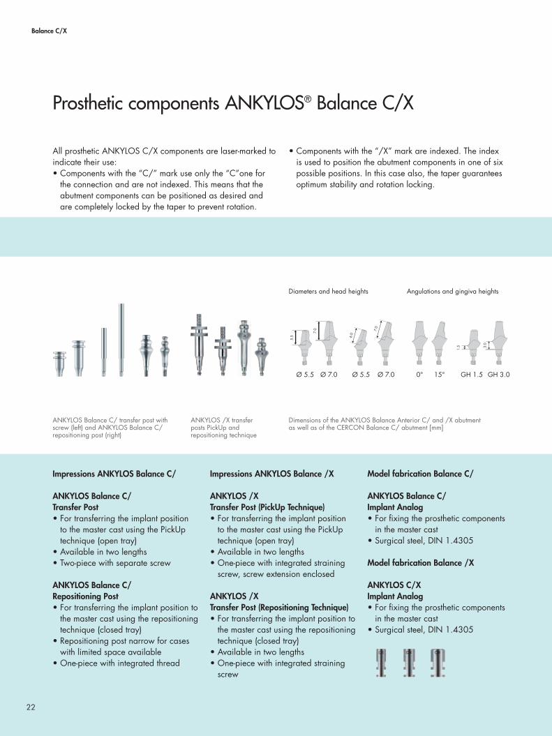
All prosthetic ANKYLOS C/X components are laser-marked to indicate their use:• Components with the “C/” mark use only the “C”one for
the connection and are not indexed. This means that the abutment components can be positioned as desired and are completely locked by the taper to prevent rotation.
• Components with the “/X” mark are indexed. The index is used to position the abutment components in one of six possible positions. In this case also, the taper guarantees optimum stability and rotation locking.
Impressions ANKYLOS Balance C/
ANKYLOS Balance C/ Transfer Post• For transferring the implant position
to the master cast using the PickUp technique (open tray)
• Available in two lengths• Two-piece with separate screw
ANKYLOS Balance C/ Repositioning Post• For transferring the implant position to
the master cast using the repositioning technique (closed tray)
• Repositioning post narrow for cases with limited space available
• One-piece with integrated thread
Impressions ANKYLOS Balance /X
ANKYLOS /X Transfer Post (PickUp Technique)• For transferring the implant position
to the master cast using the PickUp technique (open tray)
• Available in two lengths• One-piece with integrated straining
screw, screw extension enclosed
ANKYLOS /X Transfer Post (Repositioning Technique)• For transferring the implant position to
the master cast using the repositioning technique (closed tray)
• Available in two lengths• One-piece with integrated straining
screw
Model fabrication Balance C/ ANKYLOS Balance C/ Implant Analog• For fixing the prosthetic components
in the master cast• Surgical steel, DIN 1.4305
Model fabrication Balance /X
ANKYLOS C/XImplant Analog• For fixing the prosthetic components
in the master cast• Surgical steel, DIN 1.4305
Prosthetic components ANKYLOS® Balance C/X
ANKYLOS Balance C/ transfer post with screw (left) and ANKYLOS Balance C/repositioning post (right)
ANKYLOS /X transfer posts PickUp and repositioning technique
Dimensions of the ANKYLOS Balance Anterior C/ and /X abutment as well as of the CERCON Balance C/ abutment [mm]
Diameters and head heights Angulations and gingiva heights
Ø 5.5 Ø 7.0 Ø 5.5 Ø 7.0 0° 15° GH 1.5 GH 3.0
5.5
7.0
1.5 3.
0
6.0
7.0
5.5
7.0
1.5 3.
0
6.0
7.0
5.5
7.0
1.5 3.
0
6.0
7.0
5.5
7.0
1.5 3.
0
6.0
7.0

23
Instruments
ANKYLOS Laboratory Screwdriver 1.0 mm Hexagon• Reduced torque 10 Ncm• Prevents stripping the straining screw
ANKYLOS Handle for Implant Analogs and Abutments• For improved management of prosthetic components during
laboratory machining• Prevents damage to the cast
Prosthetic restoration
ANKYLOS Balance Anterior C/ or /X Abutment• For esthetically demanding crowns
and bridges in the anterior region• With indexing (/X) or freely position-
able (C/)• one-piece with integrated straining
screw• Easily adaptable to the clinical situation
with two diameters (large and small), two gingival heights (1.5 and 3.0 mm) and two angulations (0° and 15°)
• Can be customized by grinding• Cementable or laterally screw-retained
with M 1.4 fi xation screw lateral hexagon (red, order no. 3105 6301)
• Cannot be cast, cannot be fi red• Titanium alloy Ti6Al4V, ISO 5832-3
ANKYLOS CERCON Balance C/ Abutment• For all-ceramic crowns with the highest
tooth analogy in the anterior region• Manufactured of zirconium oxide for
the highest stability• Easily adaptable to the clinical situation
with two diameters (large and small), two gingival heights (1.5 and 3.0 mm) and two angulations (0° and 15°)
• Large abutment can be customized by grinding, small abutment cannot be further reduced
• Two shades of white: neutral and dentine
• Superior esthetics due to brilliant light dynamics
• Cementable• Cannot be fi red
The indication for CERCON abutments is limited to single tooth restorations in the anterior region.
ANKYLOS M 1.4 Lateral Hex Fixation Screw• For fabricating laterally screw-retained
crowns and bridges on ANKYLOS Regular C/ and /X abutments
• Order no. 3105 6301 (red)• Permador cast-to horizontal
screw seat available (order no. 3105 6304)
ANKYLOS Balance Anterior C/ abutment made of titanium alloy
Indexed ANKYLOS Balance Anterior /X abutment made of titanium alloy
ANKYLOS CERCON Balance C/ abutment made of zirconium oxide

24
Balance C/X | Crowns and bridges
In as far as prosthetic restoration is planned on ANKYLOS Balance Anterior C/ or CERCON Balance C/ abutments, the impression is performed on the patient with ANKYLOS Balance C/ transfer posts PickUp (open tray) or reposition. The ANKYLOS Balance C/ implant analogs are fixated in these.
Only ANKYLOS /X transfer abutments are used for restora-tions on ANKYLOS Balance Anterior /X abutments, as only these can transfer the index position. In this case the indexed ANKYLOS C/X implant analogs are used.
Fixing the implant analog and preparing mucosa mask
Screw the implant analogs to the transfer posts fixed in the impression. Use ANKYLOS Balance C/ analog implants if non-indexed transfer abutments were used. The ANKYLOS C/X analog implant is used for indexed transfer abutments. The fit of the corresponding analog implant to the transfer abutment in the connection taper and, if given, the index, must be ensured. Insulate the impression with silicone lubricant prior to casting and coat the area surrounding the implant analog with gingiva casting material. Observe the manufacturer’s directions.
Casting the model
Prepare the master cast using dental stone class IV. Here, ensure adequate height such that the implant analog is covered with plaster.Then, loosen the transfer screw and remove the impression.
Selection of prosthetic abutment
Select suitable ANKYLOS Balance Anterior C/ or /X or CERCON Balance C/ abutment respectively.
For selecting the abutments, Balance C/ temporary abutments may be used as try-in abutments and will provide impor-tant information in terms of angulation and height.
Step-by-step:Preparing the cast and selection of the abutments
ANKYLOS Balance Anterior C/ + CERCON Balance C/
ANKYLOS Balance Anterior /X
Please note:If the gingiva former is smaller than the abutment to be selected, the mucosa mask can affect the fit. In this case, adjust the mucosa mask after selecting the abutment and advise the practitioner.

25
Remove mucosa mask. Fix the ANKYLOS Balance Anterior /X abut-ment in the desired position in the index. When using the freely positionable Balance Anterior C/ or CERCON Balance C/ abutments, align these through free rotation in 360°. Screw abutments into the model using the laboratory screwdriver 1.0 mm hex with 10 Ncm torque and align to desired position.
When using zirconium oxideANKYLOS CERCON Balance C/ abut-ments, please proceed as described starting on page 28.
Customizing the ANKYLOS Balance Anterior C/ and /X abutment
Grind the ANKYLOS Balance Anterior C/ or /X abutment to adjust it to the individual situation. The prefabricated taper surfaces must not be processed. Grinding the abutment in the ANKYLOS handle for implant analogs and abutments makes them easier to handle and prevents damage to the master cast.
Ensure a consistent insertion direction for bridge constructions when grinding the abutments.
Transfer key for ANKYLOS Balance Anterior C/
Prepare a transfer key to retrieve the selected position on the cast and later on in the mouth using the customized ANKYLOS Balance Anterior C/ abut-ment.
For bridge constructions, connect the bridge sections with a prefabricated plastic or metal bar in order to reduce shrinkage due to polymerization. For larger reconstructions, the transfer key should be in sections.
The transfer key is handed over to the dental practice together with the com-pleted prosthetic restoration.
ANKYLOS Balance Anterior C/
ANKYLOS Balance Anterior /X
ANKYLOS Balance Anterior C/
Please note:Do not damage the straining screw during grinding. Ensure an adequate wall thickness also, and an adequate abut-ment height for cemented suprastructures. Do not grind the lateral thread hole, particularly in screw-retained supra-structures. To avoid stripping the straining screw, use the blue laboratory screwdriver with torque (10 Ncm). Enlarge the access channel for the screwdriver as the hexagonal torque insert applied in the patient’s mouth is slightly wider.

26
Balance C/X | Crowns and bridges
Both cemented and laterally screw-retained suprastructures can be prepared on ANKYLOS Balance Anterior C/ and /X abutments.
Cemented suprastructure on ANKYLOS Balance Anterior C/X
For cemented suprastructures, block the screw channel and the lateral hole of the ANKYLOS Balance Anterior C/ or /X abutments and wax up the crown as usual.
The framework and veneering corres-pond with the current dental procedures for metal-ceramic or all-ceramic supra-structures. Cleanable interdental spaces are desirable in bridge constructions.Please observe the manufacturers’ pro-cessing directions.
Screw-retained suprastructure on ANKYLOS Balance Anterior C/X
The suprastructure can also be laterally screw-retained, if preferred. For this, attach the red M 1.4 lateral hex fixation screw (order no. 3105 6301) prior to wax-up using the laboratory screw-driver.
Step-by-step: Crowns and bridges with ANKYLOS® Balance Anterior C/X
ANKYLOS Balance Anterior C/
ANKYLOS Balance Anterior /X

27
When waxing up with the cast-to hori-zontal screw seat for the M 1.4 fi xation screw (order no. 3105 6304), observe the processing directions for the cast-on of dental alloys.
The framework and veneering corres-pond with the current dental procedures for metal-ceramic or all-ceramic supra-structures. Cleanable interdental spaces are desirable in bridge constructions.Please observe the manufacturers’ pro-cessing directions.
Ensure that no ceramic particles fi nd their way into the screw channel of the abutment when applying and grinding the ceramic.
Patient-specifi c ATLANTIS abutments
Along with the use of prefabricated ANKYLOS Balance Anterior C/ and /X or CERCON Balance C/ abutments, patient-specifi c ATLANTIS CAD/CAM abutments are available.
Using the patented ATLANTIS VAD software, abutments are uniquely designed from the fi nal tooth shape for a more natural esthetic result. The unique process offers unlimited possi-bilities and patient-specifi c solutions for single, multiple and full arch units.
Optimized 3D scanning of the models generates an exact virtual image. This allows each ATLANTIS abutment to be individually designed and produced for its specifi c space and in relation to the surrounding teeth.
After defi ning your design parameters in ATLANTIS WebOrder, the fi nal design is checked for fi t and occlusal clearance in a virtual environment. Before manufacturing, you can view, ask for modifi cations and/or approve the fi nal design. Then, the abutments are manufactured, using state-of-the-art precision milling processes to ensure the highest precision and quality.
27
Please note:The transfer key should be handed over to the practitioner with the completed crown.

28
Balance C | All-ceramic crowns
Regardless of whether a prosthetic restoration on ANKYLOS Balance Anterior C/ or /X titanium alloy abutments or on ANKYLOS CERCON Balance C/ abutments is planned, the
patient impression is made with the identical transfer postPickUp (open tray) or repositioning post with the C/ marking. ANKYLOS Balance C/ implant analogs are fixed in these.
The preparation of the cast for process-ing the ANKYLOS CERCON Balance abutment C/ and the selection of the abutments is similar to that described for ANKYLOS Balance Anterior C/ (page 24).
Customizing the ANKYLOS CERCON Balance C/ abutment
Prior to grinding, block the screw chan-nel of the large ANKYLOS CERCON Balance C/ abutment. Customize the abutment using diamond burs. In order to prevent damage to the abutment, use only water cooling during this process. Grinding the abutment in the ANKYLOS handle for implant analogs and abut-ments allows easier management and prevents damage to the cast.
Please always observe the following guidelines for the preparation and the manufacturer’s information for the sys-tem used for all-ceramic restorations:
• Grind down the coronal area of the abutment maximally to the size of the small CERCON Balance abutment. Do not prepare the contact surfaces up to 1 mm above the taper connection.
• Do not go below a minimum wall thickness of 0.5 mm when grinding.
• A marked channel or a step with an internally rounded edge can be prepared, if preferred.
• A circular step depth of one milli-meter is desirable. All transitions from the axial to the occlusal or incisal surfaces should be rounded.
For grinding we recommend using the ceramic-line diamond grinding sets by DeguDent GmbH.
Step-by-step: All-ceramic crowns with ANKYLOS® CERCON® Balance C/
Please note:For reasons of stability, the small ANKYLOS CERCON Balance C/ abutment must not be further reduced in the region of the head.
ANKYLOS CERCON Balance C/

29
Transfer key
Prepare a transfer key to retrieve the selected position on the cast and later on in the mouth using the customized ANKYLOS CERCON Balance C/ abutment. This is handed over to the practitioner together with the completed crown.
Preparing the all-ceramic crown
Crowns on the ANKYLOS CERCON Balance C/ abutment must always be cemented in.
The crown can be prepared convention-ally or CAD/CAM-assisted. For this, we recommend the Cercon system by DeguDent. This enables the preparation of the crown by means of the CAD/CAM-technique.
Information on the procedure is always to be found in the manufacturers‘ instructions.
Please note:To avoid stripping the straining screw, use the blue laboratory screwdriver with torque (10 Ncm). Enlarge the access channel for the screwdriver as the hexagonal torque insert applied in the pa-tient’s mouth is slightly wider.
Please note:Do not damage the straining screw during grinding. Ensure an adequate wall thickness of at least 0.5 mm and for cemented suprastructures an adequate abutment height.Do not grind the lateral thread hole, particularly in screw-retained suprastructures. Due to its construction with a central straining screw, the ANKYLOS CERCON Balance C/ abutment is not suitable for direct firing.

30
The ANKYLOS Regular C/X prosthetic range enables the fabrication of functionally and esthetically appealing reconstructions for edentulous gaps and free ends with single crowns or an implant-supported bridge. With their convex sulcus design, ANKYLOS Regular C/X abutments have been optimized for the posterior region.
Choose between two options:the tapered TissueCare connection, with freely positionable components, or components with the tapered TissueCare con-nection and additional indexing as an aid to positioning.
Regu
lar
C/X
31
Crowns and bridges on ANKYLOS® Regular C/X
Classic ANKYLOS® Regular C/X procedure
• For esthetically demanding results• Transfer the implant position for the laboratory with the
transfer post• Selection of the prosthetic abutment made from titanium
alloy Ti6Al4V in the dental laboratory• The suprastructure is fabricated on the original abutments• Can be customized• Cemented or screw-retained suprastructures
Simplified procedure using ANKYLOS® Regular C/X 3-in-1 cap
• Not changing abutment components means simplified handling and optimal patient comfort
• Less irritation of the soft tissues • Selection of the prosthetic abutment at the chairside• The impression of the abutment position for the laboratory
is taken via the 3-in-1 cap• The suprastructure is fabricated on the 3-in-1 cap• Cannot be customized• Cemented suprastructures only• Provisional restoration at the chairside is also simplified for
the patient via the 3-in-1 cap
CAD/CAM prosthetic solutions
As an individual alternative to the prefabricated ANKYLOS Regular C/ and /X abutments, two solutions for patient-specific CAD/CAM-fabricated abutments are available:• ANKYLOS TitaniumBase for the fabrication of esthetically
high-quality ceramic abutments with prefabricated titanium core
• ATLANTIS abutments made of titanium, gold-shaded titanium or zirconia, the patient-specific one-piece solution for crowns.*
With the flexibility of patient-specific abutments, your restora-tions persuade with even more esthetics and functionality.
* Available at: www.atlantisweborder.com

32
Regular C/X
All prosthetic ANKYLOS C/X components are laser-marked to indicate their use:• Components with the “C/” mark use only the “C”one for
the connection and are not indexed. This means that the abutment components can be positioned as desired and are completely locked by the taper to prevent rotation.
• Components with the “/X” mark are indexed. The index is used to position the abutment components in one of six possible positions. In this case also, the taper guarantees optimum stability and rotation locking.
• Components with the C/X mark are used for indexed or non-indexed prosthetics.
Regardless of whether a prosthetic res-toration on indexed ANKYLOS Regular /X abutments or on the freely position-able ANKYLOS Regular C/ abutments is planned, the identical components with the C/X marking are used for contouring the soft tissues and for the impression.
Impressions
ANKYLOS /X Transfer Post (PickUp Technique)• For transferring the implant position
to the master cast using the PickUp technique (open tray)
• Available in two lengths • One-piece with integrated straining
screw, screw extension enclosed
ANKYLOS /X Transfer Post (Repositioning Technique)• For transferring the implant position to
the master cast using the repositioning technique (closed tray)
• Available in two lengths • One-piece with integrated straining
screw
Model fabrication
ANKYLOS Regular C/X Implant Analog• For fixing the prosthetic components
in the master cast• Surgical steel, DIN 1.4305
Prosthetic components ANKYLOS® Regular C/X
ANKYLOS /X transfer post (PickUp technique), long and short
ANKYLOS /X transfer post (repositioning technique), long and short
C/ /X

33
Patient-specific ATLANTIS abutments As an alternative to the prefabricated ANKYLOS Regular C/ or /X abutments, patient-specific ATLANTIS abutments can be used. For more information see page 39.
Prosthetic restoration
ANKYLOS Regular /X orRegular C/ Abutment• With indexing (/X) or freely positio-
nable (C/) • One-piece with integrated straining
screw• Easily adaptable to the clinical
situation with four gingival heights (0.75/1.5/3.0/4.5 mm) and up to six angulations (0°/7.5°/15°/ 22.5°/30°/37.5°)*
• Can be customized by grinding• Cementable or laterally screw-retained
with ANKYLOS M 1.4 lateral hex fixation screw (red, order no. 3105 6301), 30° and 37.5° angulations also with occlusal screw-retention
• Cannot be cast, cannot be fired
ANKYLOS M 1.4 Lateral Hex Fixation Screw• For fabricating laterally screw-
retained crowns and bridges on ANKYLOS Regular C/ and /X abut-ments
• Order no. 3105 6301 (red)• Permador cast-to horizontal
screw seat available (order no. 3105 6304)
ANKYLOS Occlusal Retaining Screw, short • For occlusal screw retention of crowns
on ANKYLOS Regular C/ and /X abutments with 30°and 37.5° angulations
• Order no. 3105 6022 (blue)
ANKYLOS /X transfer post (repositioning technique), long and short
ANKYLOS Regular C/ or /X abutment dimensions [mm] ANKYLOS Regular C/ abuments straight (above) and angled (below). Also available indexed as Regular /X.
Angulations and head heights Gingival heights and diameters
0° 7.5° 15° 22.5° 30°* 37.5°* GH 0.75 GH 1.5 GH 3.0 GH 4.5
* GH 0.75 up to 37.5°, GH 1.5 up to 30°
0.75 1.5 3.
0 4.5
6.6 6.6 7.
4 7.7
8.0
7.0
0.75 1.5 3.
0 4.5
6.6 6.6 7.
4 7.7
8.0
7.0
6.6 6.6 7.
4 7.7
8.0
7.0
Ø 5.7 Ø 5.7 Ø 5.7 Ø 5.7 Ø 5.7 Ø 5.7

34
Regular C/X | Crowns and bridges
Simplified procedure on abutment levelThe ANKYLOS Regular C/X 3-in-1 cap is a quick and easy option for fabricating a prosthetic restoration using unground ANKYLOS Regular C/X abutments on the abutment level.
ANKYLOS Regular C/X 3-in-1 Cap
Impressions• For transferring the position of the
prosthetic abutment to the master cast when taking the impression over ANKYLOS Regular C/X abutments already located in the implant
Temporary restorations • For fabricating a temporary restora-
tion chairside with snap effect (on unground abutments only)
In the laboratory • As a wax-up coping on implant ana-
logs and unground abutments
ANKYLOS Regular C/X Abutment Analog
• For attaching the prosthetics compo-nents after taking impressions via the 3-in-1 cap
Instruments
ANKYLOS Laboratory Hex Screwdriver 1.0 mm • Reduced torque: 10 Ncm• Prevents stripping the straining screw
ANKYLOS Handle for Abutment Analogs and Abutments• For improved management of the
prosthetics components during labora-tory processing
• Prevent damage to the cast
Prosthetic components for ANKYLOS® Regular C/X
Lateral view
0° 7.5° 15° 22.5°
ANKYLOS Regular C/X 3-in-1 caps ANKYLOS laboratory hex screwdriver 1.0 mm (left), ANKYLOS handle for abutment analogs and abutments (right)
ANKYLOS Regular C/X abutment analogs
35
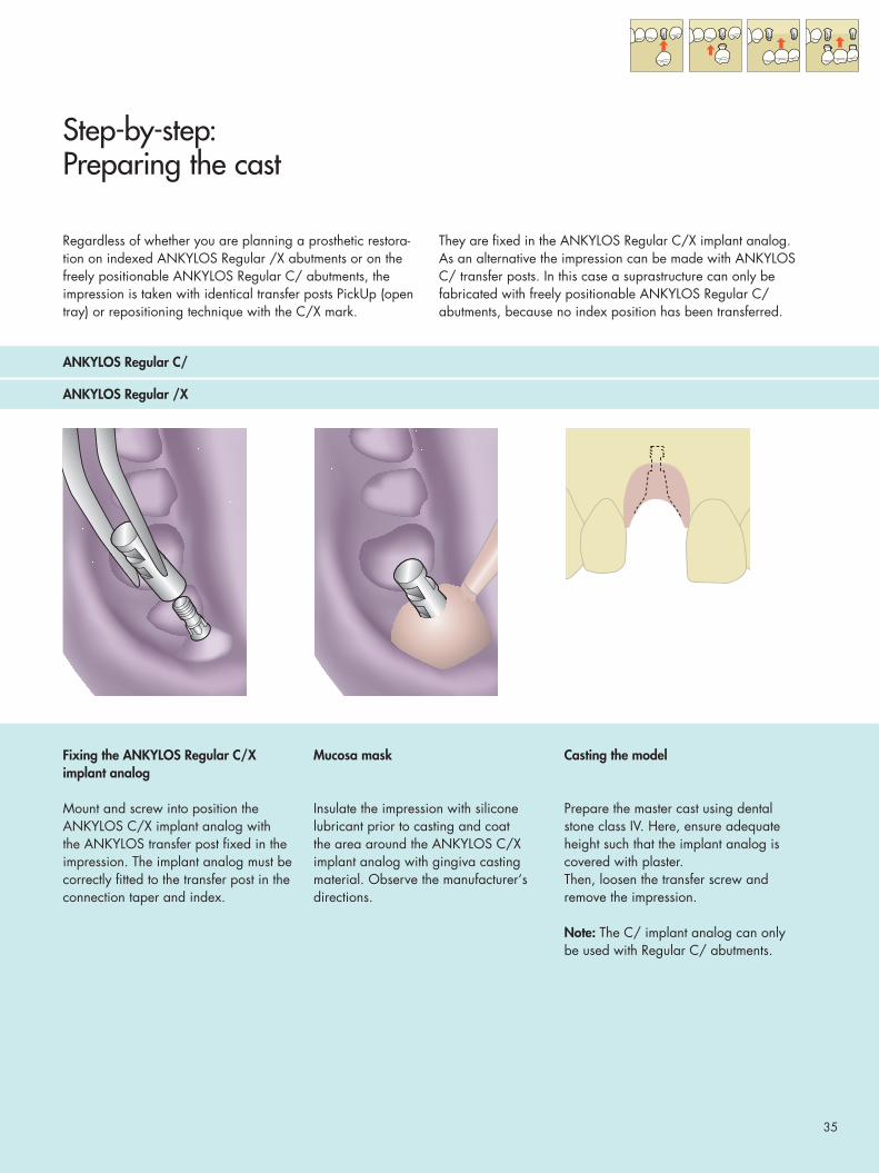
Regardless of whether you are planning a prosthetic restora-tion on indexed ANKYLOS Regular /X abutments or on the freely positionable ANKYLOS Regular C/ abutments, the impression is taken with identical transfer posts PickUp (open tray) or repositioning technique with the C/X mark.
They are fixed in the ANKYLOS Regular C/X implant analog. As an alternative the impression can be made with ANKYLOS C/ transfer posts. In this case a suprastructure can only be fabricated with freely positionable ANKYLOS Regular C/ abutments, because no index position has been transferred.
Fixing the ANKYLOS Regular C/X implant analog
Mount and screw into position the ANKYLOS C/X implant analog with the ANKYLOS transfer post fixed in the impression. The implant analog must be correctly fitted to the transfer post in the connection taper and index.
Mucosa mask
Insulate the impression with silicone lubricant prior to casting and coat the area around the ANKYLOS C/X implant analog with gingiva casting material. Observe the manufacturer‘s directions.
Casting the model
Prepare the master cast using dental stone class IV. Here, ensure adequate height such that the implant analog is covered with plaster.Then, loosen the transfer screw andremove the impression.
Note: The C/ implant analog can only be used with Regular C/ abutments.
Step-by-step: Preparing the cast
ANKYLOS Regular C/
ANKYLOS Regular /X

36
Regular C/X | Crowns and bridges
Depending on the proposed protocol indexed ANKYLOS Regular /X abutments or freely positionable Regular C/ abutments are selected according to the required gingival margin and angulation.
Placing the ANKYLOS Regular /X abutments
Fix the ANKYLOS Regular /X abutment in the desired position and screw it to the master cast with the ANKYLOS labo-ratory screwdriver with torque control.With a lateral retention screw align the lateral thread in a favorable insertion direction in the index.
Customizing the ANKYLOSRegular /X abutments
Grind the Regular /X abutment to adjust it to the individual situation. The pre-fabricated taper surfaces and the index must not be processed. Grinding the ANKYLOS Regular /X abutment in the ANKYLOS handle for abutment analogs and abutments makes them easier to handle and prevents damage to the master cast. Therefore, make sure to have placed a Regular C/X implant analog.
360°-accurate alignment of ANKYLOS Regular C/ Abutment
Align the ANKYLOS Regular C/ abutment by rotating it through 360° and fix it in the desired position on the master cast with the ANKYLOS labora-tory screwdriver with torque control. With a lateral fixation screw align the lateral thread in a favorable insertion direction in the taper.
Step-by-step: Crowns and bridges, cemented or laterally screw-retained
ANKYLOS Regular /X
ANKYLOS Regular C/
Please note: If the position of the Regular /X abutment is unfavorable because of the index, a non-indexed Regular C/ abutment can be used in consultation with the dentist.

37
Customizing the ANKYLOS Regular C/ abutments
Grind the Regular C/ abutment to adjust it to the individual situation. The prefabricated taper surfaces and the index must not be processed. Grinding the ANKYLOS Regular C/ abutment in the ANKYLOS handle for abutment analogs and abutments makes them easier to handle and prevents damage to the master cast.Therefore, make sure to have placed a Regular C/X implant analog.
Transfer key
Prepare a transfer key to retrieve the selected position on the cast and later on in the mouth over the customized ANKYLOS Regular C/ abutments (block out horizontal grooves).
The transfer key is handed over to the dental practice together with the com-pleted prosthetic restoration.
Please note:Do not damage the straining screw when grinding. Make sure that an adequate wall thickness of minimum 0.5 mm is retained, and make sure that the abut-ment height is adequate for cemented suprastructures. Do not grind the lateral threaded hole any thinner particularly with screw-retained suprastructures.

38
Regular C/X | Crowns and bridges
Crowns and bridges are fabricated on ANKYLOS Regular /X or Regular C/ abutments using the same procedure. Suprastructures can be cemented-in and laterally screw-retained.
ANKYLOS Regular /X and C/ Abutment – cemented
For cemented suprastructures block out the screw channel, the lateral hole and the side horizontal grooves for the transfer cap on the ANKYLOS Regular /X and C/ abutments and wax up the crown as usual.
In case the abutment head has not been customized, the ANKYLOS Regular C/X 3-in-1 cap can be used as aid for the wax-up (see page 41).
The framework and veneering corres- pond with the current dental procedures for metal-ceramic or all-ceramic supra-structures. Please observe the manufacturer‘s pro-cessing dirctions.
ANKYLOS Regular /X and C/ Abutment – screw-retained
The suprastructure can also be laterally screw-retained, if preferred. For this, attach the red M 1.4 lateral hex fixation screw (order no. 3105 6301) prior to wax-up using the laboratory screw-driver.
Step-by-step: Crowns and bridges, cemented or laterally screw-retained
ANKYLOS Regular C/
ANKYLOS Regular /X

39
When waxing with the cast-to horizon-tal screw seat for M 1.4 fixation screw (order no. 3105 6304) observe the processing directions for casting dental alloys.
The framework and veneering corres-pond with the current dental procedures for metal-ceramic or all-ceramic supra-structures. Please observe the manufacturer‘s pro-cessing directions.
When applying and grinding the ceramic, prevent ceramic particles from entering the screw channel of the abut-ment.
39
Please note:For crowns on ANKYLOS Regular C/ abutments the transfer key must be given to the dentist with the finished crown.
Patient-specific ATLANTIS abutments
Along with the use of prefabricated ANKYLOS Regular C/ or /X abutments, patient-specific ATLANTIS CAD/CAM abutments are available.
Using the patented ATLANTIS VAD software, abutments are uniquely designed from the final tooth shape for a more natural esthetic result. The unique process offers unlimited possi-bilities and patient-specific solutions for single, multiple and full arch units.
Optimized 3D scanning of the models generates an exact virtual image. This allows each ATLANTIS abutment to be individually designed and produced for its specific space and in relation to the surrounding teeth.
After defining your design parameters in ATLANTIS WebOrder, the final design is checked for fit and occlusal clearance in a virtual environment. Before manufacturing, you can view, ask for modifications and/or approve the final design. Then, the abutments are manufactured, using state-of-the-art precision milling processes to ensure the highest precision and quality.

40
Regular C/X | Crowns and bridges
In contrast to the procedure described above, where the prosthetic abutments are selected by the dental laboratory in cooperation with the practitioner, the selection and incorpo-ration of the abutments prior to taking the impression takes place directly at the chairside.
The impression is taken using ANKYLOS Regular C/X 3-in-1 caps, which remain in the impression. ANKYLOS Regular C/X abutment analogs are fixed in the caps.
Fixing the ANKYLOS Regular C/X abutment analog
Select the ANKYLOS Regular C/X abutment analog according to the abut- ment design or the angulation of the original abutment, position this in the ANKYLOS Regular C/X 3-in-1 cap and check for a firm fit. The geometry, angle and lateral thread of the ANKYLOS Regular C/X abutment analog corre-spond with the original abutment in the patient’s mouth.
Mucosa mask
Insulate the impression prior to casting using a silicone lubricant and coat the area around the ANKYLOS Regular C/X abutment analog with gingiva colored casting material. In doing so, observe the manufacturer’s directions.
Casting the model
Prepare the master cast using dental stone class IV. Here, ensure an adequate height such that the implant analog is covered with plaster.
Step-by-step: Simplified procedure on the abutment level
ANKYLOS Regular C/
ANKYLOS Regular /X

41
Wax-up with the ANKYLOS Regular C/X 3-in-1 cap
The ANKYLOS Regular C/X 3-in-1 cap can also be used as a wax-up coping.Select the cap according to the abut-ment design or the angulation of the original abutment, then smooth off the lateral horizontal grooves for the transfer and place the cap on the abut-ment. Remove the retention ring on the tapered section and roughen the cap prior to casting with wax or synthetic material.
Cemented suprastructure on ANKYLOS Regular /X and C/ abutment
For cemented suprastructures, wax up crown or bridge on the cap as usual.The framework and veneering correspond with the current dental pro-cedures for metal-ceramic or all-ceramic suprastructures. Please observe the manufacturer’s direc-tions. The cap can be fired out without leaving a residue.
Please note: Smooth off the lateral horizontal grooves.

42
With the ANKYLOS Balance Base Abutment C/ you will be able to provide your edentulous and partially edentulous patients with screw-retained bridges and removable overden-tures on bars.The suprastructure is manufactured conventionally in the den-tal laboratory or by means of the CAD/CAM milling process.
Rotationally symmetrical ANKYLOS Balance Base Abutments made of titanium alloy Ti6AlV are available with tapered con-nection geometry.Due to the rotational symmetry, indexing is not required.
Bala
nce
Base
Abu
tmen
t C/
43
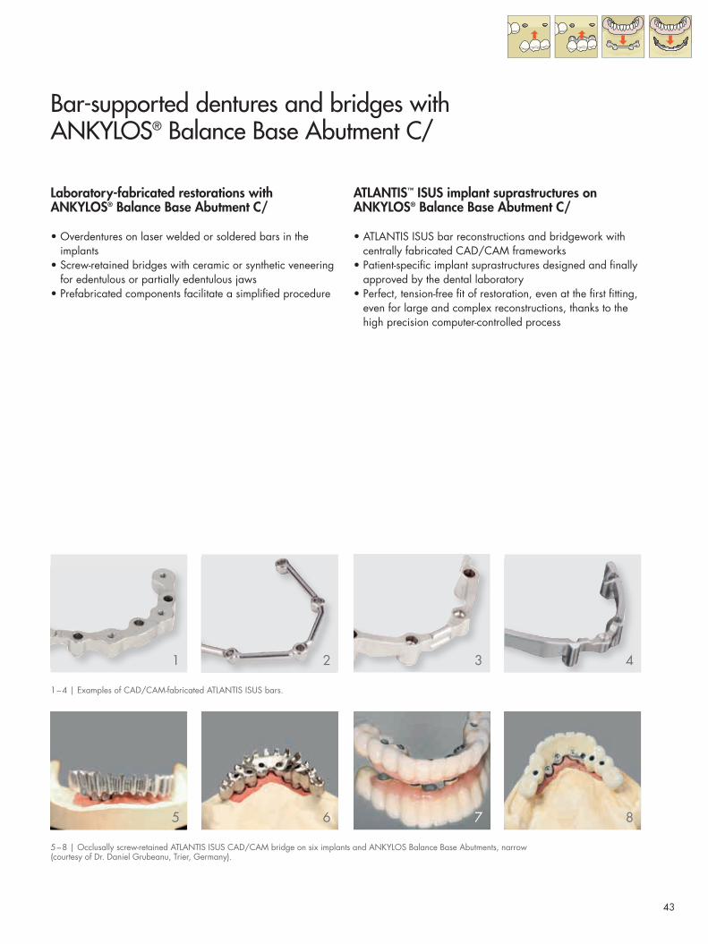
Bar-supported dentures and bridges with ANKYLOS® Balance Base Abutment C/
Laboratory-fabricated restorations with ANKYLOS® Balance Base Abutment C/
• Overdentures on laser welded or soldered bars in the implants
• Screw-retained bridges with ceramic or synthetic veneering for edentulous or partially edentulous jaws
• Prefabricated components facilitate a simplifi ed procedure
ATLANTIS™ ISUS implant suprastructures on ANKYLOS® Balance Base Abutment C/
• ATLANTIS ISUS bar reconstructions and bridgework with centrally fabricated CAD/CAM frameworks
• Patient-specifi c implant suprastructures designed and fi nally approved by the dental laboratory
• Perfect, tension-free fi t of restoration, even at the fi rst fi tting, even for large and complex reconstructions, thanks to the high precision computer-controlled process
1
5
2
6
3
7
4
8
5 – 8 | Occlusally screw-retained ATLANTIS ISUS CAD/CAM bridge on six implants and ANKYLOS Balance Base Abutments, narrow (courtesy of Dr. Daniel Grubeanu, Trier, Germany).
1 – 4 | Examples of CAD/CAM-fabricated ATLANTIS ISUS bars.

44
Balance Base Abutment C/
With a view towards an optimal functional and esthetic result for screw-retained bridges and bar solutions, the ANKYLOS Balance Base abutment range has been extended by a diameter-reduced variant.
There are two options available for the fabrication of prosthetic restorations:• On the implant level with selection of the prosthetic abut-
ments in the laboratory• On the abutment level with the patient’s early incorporation
of the abutments
Impressions on implant level
ANKYLOS Transfer Post(PickUp Technique)• For transferring the implant position
to the master cast using the PickUp technique (open tray)
• Available in two lengths• One piece with integrated straining
screw, screw extension included
ANKYLOS Transfer Post(Repositioning Technique)• For transferring the implant position
via repositing technique (closed tray)• Available in two lengths• One-piece, with integrated straining
screw
Impressions on abutment level
ANKYLOS Retention Coping for Balance Base Abutment narrow and Balance Base Abutment • For simplified impression-taking
on the abutment level, giving an increased precision for CAD/CAM prosthetics
• Screw retention with M 1.6 mm occlu-sal hex fixation screw (blue anodized)
• With extra long fixation screw (order no. 3105 6025) also for transferring abutment position using the open tray technique
Model fabrication
ANKYLOS Balance C/ Implant Analog• For attaching the prosthetic compo-
nents in the master cast• Surgical steel
ANKYLOS Analog for Balance Base Abutment narrow• For attaching the prosthetic copings
onto the master cast when working on the abutment level (after taking the impression with the retention coping)
• Surgical steel
Prosthetic components for Balance Base Abutment C/
ANKYLOS /X transfer post PickUp long and short (left) and ANKYLOS /X transfer posts for repositioning technique (right)
Retention copings for impression on abutment level for Balance Base Abutment narrow (left) and Balance Base Abutment (right)
From left to right: ANKYLOS Balance C/ implant analog, ANKYLOS analog for Balance Base Abutment narrow and ANKYLOS soldering post for Balance Base Abutment

45
ANKYLOS Soldering Post (model analog) for Balance Base Abutment• For attaching the bar construction on
the soldering model• Can be used for restorations on the
abutment level (after taking the impression with the retention coping) and as a model analog for the Balance Base Abutment C/
• Surgical steel
Prosthetic restoration
ANKYLOS Balance Base Abutment C/ narrow and Balance Base Abutment • For attaching overdentures on bars
and screw-retained bridges• Also for CAD/CAM bars and bridges• Four gingival heights allow adjust-
ment to the clinical situation• Only for occlusal screw retention• Screw retention with M 1.6 mm
occlusal hex fixation screw (order no. 3105 6022, blue anodized)
Balance Base Abutment C/ narrow: • Narrower emergence profile and
reduced head height compared with the classic Balance Base Abutment C/ for an optimal functional and esthetic result, even with a restricted oral cavity
• Especially suited for CAD/CAM structures
ANKYLOS Balance Base Abutment C/ narrow (above) and Balance Base Abutment C/ (below), M 1.6 mm occlusal hex fixation screw
Dimensions ANKYLOS Balance Base Abutment C/ [mm]
Diameters and head heights Gingival heights,head angle 15°
GH 0.75 GH 1.5 GH 3.0 GH 4.5Base Abutment C/ narrow
Base Abutment C/
Please note: Components for the ANKYLOS Balance Base Abutment and Balance Base Abutment narrow should always be used for the corresponding Base Abutment. The screws for attaching the copings for the respective abutments are compatible. Hence, please observe closely the directions for use for the respective components.
0.75 1.
5 3.0 4.5
2.4
1.3
Ø 4.2Ø 5.5
0.75 1.
5 3.0 4.5
2.4
1.3
Ø 4.2Ø 5.5
0.75 1.
5 3.0 4.5
2.4
1.3
Ø 4.2Ø 5.5
46
Balance Base Abutment C/
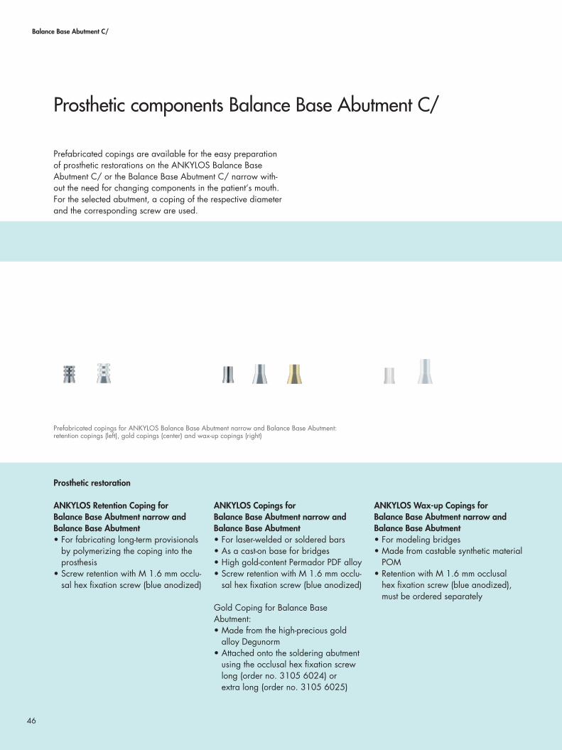
Prefabricated copings are available for the easy preparation of prosthetic restorations on the ANKYLOS Balance Base Abutment C/ or the Balance Base Abutment C/ narrow with-out the need for changing components in the patient‘s mouth. For the selected abutment, a coping of the respective diameter and the corresponding screw are used.
Prosthetic restoration
ANKYLOS Retention Coping for Balance Base Abutment narrow and Balance Base Abutment• For fabricating long-term provisionals
by polymerizing the coping into the prosthesis
• Screw retention with M 1.6 mm occlu-sal hex fixation screw (blue anodized)
ANKYLOS Copings for Balance Base Abutment narrow and Balance Base Abutment• For laser-welded or soldered bars• As a cast-on base for bridges• High gold-content Permador PDF alloy• Screw retention with M 1.6 mm occlu-
sal hex fixation screw (blue anodized)
Gold Coping for Balance Base Abutment: • Made from the high-precious gold
alloy Degunorm• Attached onto the soldering abutment
using the occlusal hex fixation screw long (order no. 3105 6024) or extra long (order no. 3105 6025)
ANKYLOS Wax-up Copings for Balance Base Abutment narrow and Balance Base Abutment• For modeling bridges• Made from castable synthetic material
POM• Retention with M 1.6 mm occlusal
hex fixation screw (blue anodized), must be ordered separately
Prosthetic components Balance Base Abutment C/
Prefabricated copings for ANKYLOS Balance Base Abutment narrow and Balance Base Abutment: retention copings (left), gold copings (center) and wax-up copings (right)

47
ANKYLOS Titanium Coping for Balance Base Abutment narrow • For laser welding• Cylindrical geometry• Manufactured from grade 4 titanium• Delivered without fixation screw
ANKYLOS M 1.6 mm Occlusal Hex Fixation Screw for Balance Base Abutment narrow • Available in three lengths• Short (order no. 3105 6022), blue
anodized• Long (order no. 3105 6024), locks
onto the cap• Extra long (order no. 3105 6025),
projects 5 mm out of the coping, can also be used with the retention cop-ing, for taking the impression of the abutment position with an open tray
Instruments
ANKYLOS Insert for Prosthetic Ratchet, 1.8 mm Hex • For screw-retaining the ANKYLOS
Balance Base Abutments C/ with the implant analog
• Torque: 25 Ncm
ANKYLOS 1.0 mm Hex Screwdriver• For screwing in the 1.6 mm occlusal
hex fixation screw• Reduced torque: 10 Ncm
ANKYLOS 1.6 mm Screwdriver, Blade Insert (without photo)• For screwing in the wax-up screw• Used with the handle for screwdriver
ANKYLOS Finisher for Balance Base Abutment• For elaborating the surface layers of
bridge constructions• One instrument each for Balance
Base Abutment C/ and Balance Base Abutment C/ narrow
ANKYLOS Finisher for Taper Occlusal Retention Screw• For smoothing the screw channel for
occlusally screw-retained structures
Titanium coping and fixation screws for Balance Base Abutment C/ narrow: ANKYLOS M 1.6 mm occlusal hex fixation screws, short, long and extra long
From left to right: ANKYLOS insert for prosthetic ratchet 1.8 mm hex, ANKYLOS 1.0 mm hex laboratory screwdriver and ANKYLOS screwdriver handle
ANKYLOS finisher for elaboration of the prosthetic restoration
Please note:Components for ANKYLOS Balance Base Abutment and Balance Base Abutment narrow should always be used for the corresponding Base Abutment. The screws for attaching the copings for the respective abut-ments are compatible. Hence, please observe closely the directions for use for the respective components.

48
Balance Base Abutment C/ | Bar-supported overdentures
Casting the model after taking the impression with the ANKYLOS Balance C/ transfer post The impressions for suprastructures on ANKYLOS Balance Base Abutments C/ are made on the implant level with ANKYLOS Balance transfer posts PickUp (open tray) or repo-sitioning technique with the C/ marking.
The impression and the components used, including the screws, are handed over to the laboratory. The components are attached onto ANKYLOS Balance C/ implant analogs. The model is then fabricated as usual.
Screwing in the ANKYLOS Balance Base Abutments
Screw the ANKYLOS Balance Base Abutments C/ or Base Abutments C/ narrow hand-tight into the implant ana-logs of the bar model using the 1.8 mm prosthetic hex ratchet.
If the impression has been taken using retention copings, this step is omitted. In this case, the position of the abutments is shown by the analogs (Balance Base Abutment narrow) or the soldering post (Balance Base Abutment) located in the model.
Attaching the gold copings
Fit the Permador PDF or Degunorm ANKYLOS gold copings for Balance Base Abutment to the abutments and attach using a corresponding screw (see page 46).
Adjusting the bars
Adjust the bars to the spaces between the gold copings. Keep gaps between the bar and the gold copings as narrow as possible.
The bar is manufactured by laser-welding (page 49) or soldering (page 50).
Step-by-step: Conventionally laboratory-fabricated bar restoration (laser-welded)
Bar – laser-welded
Bar – soldered
Please note: The Base Abutment must not be inserted with the 1.0 mm hex insert as this will damage the thread.
1.8 mm Hex
1.0 mm Hex

49
Casting the model after taking the impression with the retention coping As an alternative, an impression of the abutment position can be taken, using the ANKYLOS retention coping for Base Abutment or Base Abutment narrow. In this case, the ANKYLOS Balance Base Abutments C/ will have already
been fitted into the patient’s mouth. The model is made using ANKYLOS analogs (Balance Base Abutment narrow) or soldering posts, which also serve as analogs for Base Abutments with a diameter of 5.5 mm.
Bar – laser-welded
When laser-welding (e.g. DeguDent Connexion Laser), observe the laser welding parameters, e.g. for Permador or Degunorm.
Then, adjust the height of the gold copings.
Bar – laser-welded
Please note: A passive, tension-free fit should be ensured when manufacturing bar constructions, as otherwise, problems such as loosening or fracture of the screws may arise after the prosthesis has been worn for a certain period.

50
Balance Base Abutment C/ | Bar-supported overdentures
For the fabrication of soldered bars, it is necessary to produce a soldering model for attaching the bar during soldering. ANKYLOS soldering posts (for Balance Base Abutment) or analogs (for the Base Abutment narrow) are used in the soldering model.
Bar – soldered:Attaching the bars for soldering
Abrade the gold copings in situ to ob-tain a better bond when attaching the bar copings to the bars using modeling compound. Check the hygienic capa-bility of the construction.
Oxidizing the soldering posts (analogs)
Oxidize soldering posts or analogs by flame.
Screw-retaining soldering posts (analogs)
Detach the bar construction from the model and screw the soldering posts onto the structure using wax-up screws (order no. 3104 5211/short and 3104 5213/long). Analogs are used for restorations on Balance Base Abutment C/ narrow, to which the construction is screwed using M 1.6 mm occlusal hex fixation screws (order no. 3105 6022/24/25). The fixation screws for later use in the mouth must not be used for the soldering.
Step-by-step: Conventionally laboratory-fabricated bar restoration (soldered)
Bar – soldered
Please note: A passive, tension-free fit should be ensured when manufacturing bar constructions as otherwise, problems such as loosening or fracture of the screws may arise after the prosthesis has been worn for a certain period.

51
Fabrication of the soldering model
Fabricate the soldering model using investment compound (e.g. Deguvest L).The soldering model should be kept as small as possible.
Soldering the bar
Fire the modeling compound and intro-duce DS 1 or T soldering flux into the soldering gap. The flux must not make its way into the screw channel (solder for Degunorm, solder for HSL).
Try-in on the model
The soldered structure is pickled in the Neacid pickling unit, checked for accuracy of fit on the master cast and the height of the gold copings is adjusted.
The restoration is then elaborated and polished.

52
After the bar construction has been completed, the prosthesis is fabricated.
Wax-up
Wax up the teeth over the gold copings and bars, then check fit.
Adjust the bar slides
Trim the activatable bar slides appro-priately prior to completing the bar prosthesis. There should be a clearance of approximately 0.5 mm to the bar copings.
Splinting before completion
Splint the bar construction, leaving the retention section free.
Step-by-step: Conventionally laboratory-fabricated bar restoration
Balance Base Abutment C/ | Bar-supported overdentures
Bar – laser-welded
Bar – soldered

53
The completed bar prosthesis
Complete the bar prosthesis as usual. Activate or deactivate the bar slides according to the desired retentive force.For delicate prostheses, a metal rein-forcement is necessary to minimize the risk of breakage.
The original abutments are handed over to the practice, along with the bar construction and prosthesis.
New fixation screws should always be used to fit the ANKYLOS Balance Base Abutments into the mouth: order no. 3105 6022 (blue).
Please note the following directions for dental alloys:
Side effects: Both allergies to the metals in the alloys and electrochemical paresthesias may occur. Instances of systemic side effects of metals in the alloy have been reported.
Interaction: Avoid occlusal and approximal contact of different types of alloy.
Contraindications: Demonstrated hypersensitivity to a metal in the alloy.
In addition, please observe the manufacturer’s directions.
53

54
Balance Base Abutment C/ | Bridges
The impressions for suprastructures on ANKYLOS Balance Base Abutments C/ on the implant level are taken with ANKYLOS Balance transfer posts PickUp (open tray) or repositioning technique with the C/ marking. The impression and the components used incl. screws are handed over to the
laboratory. As an alternative, an impression of the abutment position can be taken using the ANKYLOS retention coping for the Base Abutment. For guidelines on this, see pages 46/47.
Fixing the implant analogs
Screw the ANKYLOS Balance C/ implant analogs into the transfer posts fixed in the impression by using the transfer screws. A removable mucosa mask will simplify correct modeling of the interdental spaces.
Casting the model
Fabricate the model using dental stone class IV (e.g. Duralit top rock). Here, ensure an adequate height, such that the implant analog covered with plaster.Then remove the transfer screws and the impression.
Screw in the ANKYLOS Balance Base Abutments C/
Screw ANKYLOS Balance Base Abut-ments C/ into the implant analogs by using the 1.8 mm hex insert for the prosthetic ratchet. The gingival height of the abutments is already simulated by the sulcus former.
If the impression has been taken using retention copings, this step is omitted. In this case, the position of the abutments is shown by the analogs (Balance Base Abutment narrow) or the soldering posts (Balance Base Abutment) located in the model.
Step-by-step: Conventionally laboratory-fabricated bridge (screw-retained)
Please note: The Base Abutment must not be in- serted with the 1.0 mm hex inser-tion as this will damage the thread.
1.8 mm Hex

55
Attaching the wax-up copings
Attach the ANKYLOS wax-up copings for the Balance Base Abutment C/ or Balance Base Abutment C/ narrow by using the blue occlusal fixation screw.
Adjusting the wax-up copings
Mark the model height on the screw channel. Using a thin cutting disk, trim the screw channel and check the height of the occlusion.
Alternative: Cast-on coping
As an alternative to the wax-up coping, the Permador PDF ANKYLOS gold coping can be used as a cast-on base. Here, please note the regulations for casting on.
Please note: Screw-retained restorations only may be produced on ANKYLOS Balance Base Abutments, since the abutment height of the heads does not provide adequate retention for cementing.
1.0 mm Hex 1.0 mm Hex

56
Balance Base Abutment C/ | Bridges
Wax-up
Wax up and invest the bridge as usual.Ensure adequate interdental spaces for hygienic capability.
Elaborationg the framework
Finishers are available for elaborating the inner surface of the taper and of the screw channel.
The supporting surfaces of the bridge construction on the ANKYLOS Balance Base Abutments are smoothed with the ANKYLOS finisher for Base Abutments 4.2 mm or 5.5 mm.
Use the ANKYLOS finisher for taper oclusal retention screw to remove rough areas in the screw channel.Insert the finisher into the screw channel and twist carefully, until the surface is shiny and smooth.
Step-by-step: Conventionally laboratory-fabricated bridge(screw-retained)
Please note: ANKYLOS Balance Base Abutments must not be ground or modified, these may have another alignment in the mouth.

57
Veneering
Veneer the bridge as usual and check the interdental spaces are adequate for hygienic capability.
The original abutments as well as the suprastructure are handed over to the practice. New fixation screws should always be used to fit the ANKYLOS Balance Base Abutments into the mouth: order no. 3105 6022 (blue).

58
Balance Base Abutment C/ | CAD/CAM suprastructures
The advantage of CAD/CAM-fabricated ATLANTIS ISUS implant suprastructures in comparison with cast structures is in the consistent quality of the metal framework. As a result, particularly for larger spans, an absolutely tension-free fi t is achieved.
Using the milled ATLANTIS ISUS implant suprastructures, restorations can be fabricated on narrow ANKYLOS Balance Base abutments C/ on between two and a maximum of ten implants. For ANKYLOS, the structures are always fabricated on abutment level and mounted with occlusal screws.
ATLANTIS ISUS offers a full range of implant suprastructures:• ATLANTIS ISUS 2-in-1 and bar
structures for removable prostheses• ATLANTIS ISUS bridge and hybrid
structures for fi xed prostheses
ATLANTIS ISUS implant suprastructures are designed and produced according to the dental technician’s specifi cation, using the latest developments in CAD/CAM technologies, and supported by computer based industrial and medical device expertise.
ATLANTIS ISUS step-by-step
1. OrderingAn implant/abutment level impression is taken by the clinical customer and sent to the laboratory with a request for ATLANTIS ISUS.
2. Entering An order is entered via ATLANTIS WebOrder and the stone model, together with the diagnostic tooth set-up, are sent to the ATLANTIS ISUS production unit.
3. Scanning The stone model and diagnostic tooth set-up are scanned in 3D at the produc-tion unit.
4. Designing The suprastructure is designed by the ATLANTIS ISUS CAD department using the latest digital technologies.
5. Viewing The design is reviewed and approved, by the customer, in ATLANTIS ISUS Viewer prior to manufacturing.
6. Manufacturing The suprastructure is milled at the production unit following an individual milling strategy.
CAD/CAM-fabricated suprastructures
A precise impression as a basis for the master cast is crucial for the precision of the restoration.
ATLANTIS ISUS implant suprastructures are milled only after review and fi nal approval of the CAD design in ATLANTIS ISUS Viewer.

59
7. Verifying The suprastructure is inspected and veri-fi ed at the production unit against the stone model and tooth set-up.
8. Shipping The fi nal suprastructure is shipped to the laboratory.
ATLANTIS ISUS implant suprastructures can be fabricated using a CoCr alloy or a pure titanium grade 4.
After design approval, the structure is milled at ATLANTIS according to a customized milling program.
After delivery of the milled structure, the dental laboratory fabricates the bar prosthesis or veneers the bridge framework.
Cobalt-chrome alloy Pure titanium
Composition In accordance with EN-ISO 22674 Type: Grade 4, ASTM B265
Cobalt 54.1%Chrome 20.0%Tungsten 16.4%Niobium 0.2%Iron 7.5%Silicon 1.5%Manganese 0.3%
TitaniumAs well asNitrogen 0.01%Carbon 0.02%Hydrogen 0.004%Iron 0.03%Oxygen max. 0.31% (total 100%)
Therm. Exp. Coeff. (25-500 °C) 14.6 10-6K-1 9.6 10-6K-1
Therm. Exp. Coeff. (25-600 °C) 14.9 10-6K-1 –
Melting range / melting point 1,390 °C – 1,410 °C 1,670 °C
Density 9.1 g/cm3 4.5 g/cm3
Vickers hardness 280 HV10 170 HV10
0,2% proof stress 550 N/mm2 493 – 499 N/mm2
Tensile strength 710 N/mm2 598 – 605 N/mm2
Breaking strain 12% 23 – 27%
Elasticity modulus 200 GPa 110 GPa

60
Balance Base Abutment C/ | CAD/CAM suprastructures
First consultation:Impression for situation model
The first impression is taken using the PickUp technique via retention caps. Subsequently, the gingiva forming components are again fitted until the second consultation, e.g. the ANKYLOS protective cap narrow.
The impression is handed over to the laboratory with all the components used.
In the dental laboratory:Fabrication of the situation model
A situation model is made from the impression. Depending on which com-ponents are used for impression taking, analogs (for retention copings) or implant analogs (for repositioning posts) are used. Balance Base Abutments C/ or Base Abutments C/ narrow are located in the analogs.
Individual tray
Based on this model, a customized tray for the pick-up technique is manufac-tured. Adequate space for the impres-sion material must be ensured while manu-facturing the tray.
Step-by-step: Impressions and model casting for CAD/CAM restorations
Dental practice
Dental laboratory
A precise stone model made in the laboratory, which repro-duces the clinical situation exactly, is crucial for the perfect fit of a CAD/CAM-fabricated ISUS implant suprastructure, even at the first fitting. An absolutely precise impression of the clini-cal situation is essential for this.
This should take place over several consultations and in close cooperation with the laboratory. To better illustrate the closely linked working steps between the practitioner and the dental technician, the procedures involved both in the dental prac-tice and the laboratory are depicted here.

61
Fabrication of primary splint
Retention copings matching the dia- meter of the abutment are used for manu- facturing the primary splints, which are attached to the analogs or the abut-ments with the respective screws: M 1.6 mm occlusal hex fixation screw, extra long (order no. 3105 6025) for retention copings, narrow, or wax-up screws (order no. 3104 5211/short and 3104 5213/long) for 5.5 mm diameter retention copings. The auto-polymer resin splinting (e.g. Integrity, DENTSPLY DeTrey) is divided into sepa-rate segments and is sent to the practice for intraoral splinting and impression.
Second consultation: Intraoral splinting of the synthetic elements
The practitioner attaches the separate synthetic primary splint segments delivered from the laboratory onto the Balance Base Abutments using the fixation retaining screws. By doing so, an adequate gap between the separate segments should be ensured. Where there is contact, grind off the synthetic material. Then, the tension-free synthetic segments are splinted intraorally using the same autopolymer used by the laboratory.
Splint impression
The impression is then taken on topof the now splinted retention copings using impression material (e.g. Aquasil Ultra, DENTSPLY DeTrey) and the customized tray.After the dental impression material has set, the fixation screws can be undone and the entire tray removed.
This high precision impression is sent to the laboratory to fabricate the master cast, and on it, the wax-up.
Dental practice
It is from this second impression of the intraoral splint that the laboratory fabricates the master cast, and on it, the wax-up.

62
Balance Base Abutment C/ | CAD/CAM suprastructures
In the dental laboratory:Producing the master cast
The laboratory produces the master cast based on the impression of the intra-orally splinted retention copings.This stone model is crucial for the subse-quent precise fit of the suprastructure.
Wax-up
A wax mock-up with tailored teeth is made on the master cast.
Preparing the transfer key
A transfer key is again manufactured from autopolymer (e.g. Integrity, DENTSPLY DeTrey) in order to be able to compare the implant positions in the master cast with the clinical situation. This key is finally splinted in the labora-tory.
The wax-up and the transfer key are sent to the dental practice for intraoral checking.
Step-by-step: Impressions and model castingfor CAD/CAM restorations
Dental laboratory

63
Third consultation:Try-in of wax-up and Sheffield Test
In the third consultation, the practitioner checks the wax mock-up with tailored teeth made by the laboratory on the master cast in the patient’s mouth in respect of function and esthetics and corrects it if necessary.The autopolymer transfer key made by the laboratory, which is used for com-parison of the implant position in the master cast with the clinical situation, is checked intraorally for a tension-free fit by means of the Sheffield Test.
Provided no fitting problems appear or these have been corrected, the laboratory will order the ATLANTIS ISUS implant suprastructure via www.atlantisweborder.com after appro-val of all components by the practice.
Dental practice
Sheffield Test
The Sheffield Test facilitates a simple check of the fit of a primary splinted mesiostructure on implants. After the structure has been positioned, each fixation screw is tightened separately while the other screws are not screwed in.Thus, the structure is only attached to one implant each time.
63
When a screw is tightened, a tension-free framework will remain resting on all of the implants.
If the structure is not tension-free, a gap will be formed between the implants not screw-retained and the structure or this will change.

64
Balance Base Abutment C/ | CAD/CAM suprastructures
ATLANTIS ISUS implant suprastuctures are ordered through the ATLANTIS WebOrder system:www.atlantisweborder.com
Ordering
After placing the order via ATLANTIS WebOrder, the stone model, together with the disgnostic tooth set-up, is sent to the ATLANTIS ISUS production unit.
CAD design proposal
The model and the wax-up are scanned in 3D at ATLANTIS using a state of the art industrial structured light scanner. A design proposal is prepared in accordance with your specifi cation, using the latest digital technologies that allow even the most complicated cases to be resolved with confi dence. There is almost no limit to the size, type and number of implants and attachments using this software.
Review using Viewer software
24 hours after receipt of the model at ATLANTIS you will receive your parti-cular construction proposal online. You will receive the free ATLANTIS ISUS Viewer software with the proposal, with which you will be able to evaluate the construction in 3D.
You can discuss potential requests for adjustment directly with the dental technicians at ATLANTIS, who will implement these directly.
Step-by-step: Planning and fabrication of the ATLANTIS ISUS implant suprastructure
Photo: Carsten Fischer, Sirius Ceramics

65
Planning the CAM milling strategy
After approval of the suprastructure design, the ATLANTIS ISUS engineers develop an individual milling strategy for each case. ATLANTIS ISUS milling strategies have been optimized to pro-duce a precise and tension-free fit.
Milling the structure
Then, depending on the material guide-lines, the titanium or cobalt-chrome construction is milled at the ATLANTIS ISUS manufacturing facilities. All milling machines are routinely quality controlled and inspected in accordance with quality systems regulations.Before being shipped to the laboratory, all suprastructures are verified and inspected.
ATLANTIS will send the milled structure to the dental laboratory, together with the master cast and the wax-up. The ANKYLOS occlusal fixation screws re-quired for attaching the bar construction or bridge in the mouth are included.
Processing in the dental laboratory
After delivery of the milled structure, the dental laboratory fabricates the bar prosthesis or veneers the bridge framework. The completed restora-tion, together with the fixation screws, is handed over to the practitioner for fitting.

66
A metal-reinforced prosthesis on ANKYLOS SynCone C/ 5° tapered crowns is an innovative solution for providing the prosthesis with a tension-free fit (passive fit). However, this can only be guaranteed by intraoral bonding of the compo-nents fabricated in the laboratory.
For the patient, the maximum possible reduction of the pros-thetic body provides highest wearing comfort and excellent hygienic capability.
SynC
one®
C/

67
Overdentures on ANKYLOS® SynCone® C/
1 – 5 | Metal-reinforced SynCone restoration of the edentulous mandible on healed implants(courtesy of dental laboratory Alt & Schmidt, Lünen/Germany).
ANKYLOS® SynCone® metal-reinforced prosthesis
A metal-reinforced prosthesis is fabricated for the fi nal restora-tion of the patient • As a replacement for the long-term temporary denture after
healing of the implants placed for immediate loading• As part of the two-stage procedure after submerged
implant healing The advantages:• Tension-free seating (passive fi t) with intraoral cementing
of the taper cap to the framework • Simplifi cation with prefabricated components for chairside
procedure • Prosthesis retention is superior to a bar milled by a time-
consuming process and also much more economical • Improved hygiene for patients
ANKYLOS® SynCone® long-term temporary denture
Within the context of an immediate restoration of the patient, a long-term temporary prosthesis can be fabricated chairside immediately after insertion of the implants. Therefore, an existing prosthesis is prepared accordingly by the dental laboratory (see page 71).
1 2 3
4 5

68
SynCone® C/
The tapered crown principle
ANKYLOS SynCone transfers the clinically proven stability of the tapered abutment connection to the abutment-prosthesis connection. This second tapered connection ensures that the final restoration is tightly seated minimizing gaps and micro-movement. Compared with bar restorations or other prefabri-cated connecting components, SynCone tapered crowns offer a stable and friction-locked connection that helps to eliminate problems often associated with edentulous jaws, such as:
• Pain of pressure of ill-fitting dentures • Atrophy as a result of inactivity or pressure • Continued bone loss requiring relining of existing denture • Design-related difficulties with the mesostructure
A connection with a tapered cone design serves as a retain-ing element where the tapered cap is retained on a tapered abutment by surface contact. When the retention is discon-nected, the prosthesis is released, allowing for easy removal. In contrast, a parallel-walled, telescopic design creates a friction throug.hout the complete path of insertion.
Patients find it easier to insert a prosthesis with tapered con-nection design, because the bottom diameter of the tapered caps connected to the denture is always larger than the top diameter of the abutments.
The synergy of the two tapers
The tapered TissueCare connection allows for free 360° alignment of the non-indexed abutments in any position. This enables aligning angled abutments by rotation until the inser-tion direction of the prosthesis has been reached (staggered-taper principle).
ANKYLOS SynCone abutments have an integrated, mobile straining screw so that the taper of the abutment head can be rotated in the connection taper of the implant as needed to form a common direction of insertion.
Advantages for patients
The tapered crown principle effectively makes the prosthesis into a removable bridge with:
• Very high stability• High chewing comfort • Reduced prosthesis base • Improved phonetics • Optimum hygiene capability
Simplified insertion and removal of the prosthesis with tapered abutments (left) in comparison with parallel-walled retaining elements (right)
Creation of a common direction of insertion for abutments with non-indexed, tapered connection
Abutment heads (1) can befreely rotated due to the connection taper (2).

69
The abutments for the ANKYLOS SynCone treatment con- cept are only available with non-indexed tapered connection geometry, as free positioning of the abutments is essential.
All ANKYLOS SynCone C/ components are laser-marked with a “C/” as in “C”onus according to their intended use.
Impressions
ANKYLOS Balance C/ Transfer Post• For transferring the implant position
to the master cast using the PickUp technique (open tray)
• Available in two lengths• Two-piece with separate screw
ANKYLOS Balance C/ Repositioning Post• For transferring the implant position to
the master cast using the repositioning technique (closed tray)
• Repositioning post narrow for cases with limited space available
• One-piece with integrated thread
Model fabrication
ANKYLOS Balance C/ Implant Analog • For fixing the prosthetic components
in the master cast• Surgical steel, DIN 1.4305
Prosthetic restoration
ANKYLOS SynCone C/ Abutment• For the restoration of the edentulous
mandible with an immediate or delayed loaded prosthesis on four prefabricated tapered abutments placed intraforaminally
• For the restoration of the edentulous maxilla on six osseointegrated implants*
• Abutments with 5° tapered angle, adaptable to the clinical situation via three gingival heights (1.5/3.0/ 4.5 mm) and five angulations (0°, 7.5°, 15°, 22.5° and 30°).
• Cover screw for straight 5° abutments must be ordered separately
• Optionally available with 4° and 6° tapered angles
Prosthetic components ANKYLOS® SynCone® C/
ANKYLOS SynCone C/ abut-ment 5°, straight and angled, cover screw for straight abutment
Dimensions ANKYLOS SynCone C/ abutment [mm]
* 5° tapered angle only
ANKYLOS Balance C/ transfer post with screw and ANKYLOS Balance C/ repositioning post
Diameters, angulations and head heights Gingival heights
0° 7.5° 15° 22.5° 30°* GH 1.5 GH 3.0 GH 4.5
1.5 3.
0 4.5 4.
0
Ø 4.0
4.0
Ø 4.0
4.0
Ø 4.0Ø 4.0
4.0
Ø 4.0
4.0
Ø 4.0
4.0
Ø 4.0
4.0
Ø 4.0
4.0
Ø 4.0
4.0
Ø 4.0
4.0
Ø 4.0
4.0
Ø 4.0
4.0
Ø 4.0
4.0
Ø 4.0
4.0
Ø 4.0
4.0
Ø 4.0
4.0
Ø 4.0
4.0
Ø 4.0
4.0
Ø 4.0
4.0
Ø 4.04.
0
Ø 4.0
4.0
Ø 4.0
4.0
Ø 4.0
4.0
Ø 4.0
4.0
Ø 4.04.
0
Ø 4.0
4.0
Ø 4.0
4.0
Ø 4.0
4.0
Abutment heads (1) can befreely rotated due to the connection taper (2).
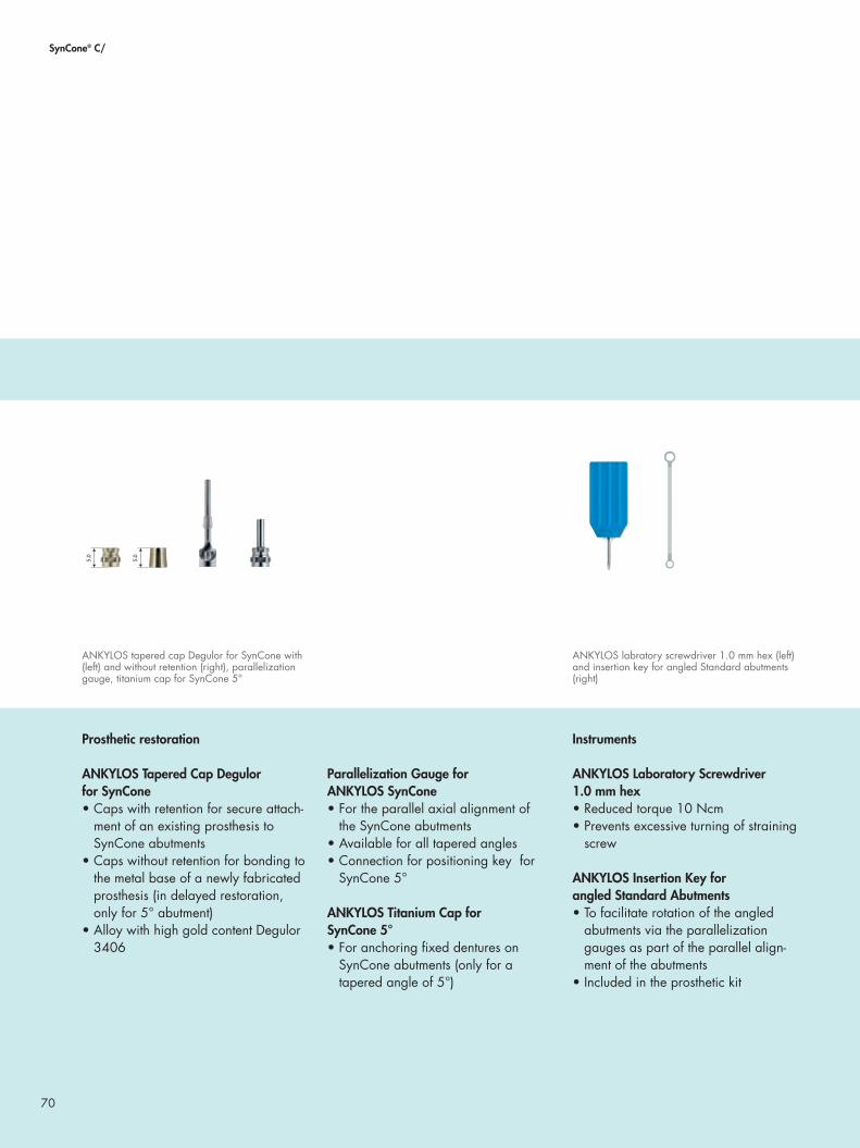
70
SynCone® C/
Prosthetic restoration
ANKYLOS Tapered Cap Degulor for SynCone• Caps with retention for secure attach-
ment of an existing prosthesis to SynCone abutments
• Caps without retention for bonding to the metal base of a newly fabricated prosthesis (in delayed restoration, only for 5° abutment)
• Alloy with high gold content Degulor 3406
Parallelization Gauge forANKYLOS SynCone • For the parallel axial alignment of
the SynCone abutments • Available for all tapered angles• Connection for positioning key for
SynCone 5°
ANKYLOS Titanium Cap for SynCone 5°• For anchoring fixed dentures on
SynCone abutments (only for a tapered angle of 5°)
Instruments
ANKYLOS Laboratory Screwdriver 1.0 mm hex• Reduced torque 10 Ncm • Prevents excessive turning of straining
screw
ANKYLOS Insertion Key for angled Standard Abutments • To facilitate rotation of the angled
abutments via the parallelization gauges as part of the parallel align-ment of the abutments
• Included in the prosthetic kit
ANKYLOS labratory screwdriver 1.0 mm hex (left) and insertion key for angled Standard abutments (right)
ANKYLOS tapered cap Degulor for SynCone with (left) and without retention (right), parallelization gauge, titanium cap for SynCone 5°

71
In case of an existing prosthesis with optimal fit and occlusion, a patient can be restored immediately with a temporary pros-thesis placed on four interforaminal implants and SynCone abutments. Therefore, the prosthesis is prepared by the dental technician prior to the surgical intervention.
The polymerization of the caps needed for attaching the pros-thesis is performed chairside. Then the prosthesis is finished as a long-term temporary.
Step-by-step: Immediate restoration with long-term temporary
Preparing the prosthesis
The prosthesis to be incorporated must be ground sufficiently to avoid imperfec-tions on the caps. The drilling guide can be used as an aid here. After wound closure, an alginate impression of the inserted abutments can be taken in or-der to grind the prosthesis accordingly after casting the model.
This procedure is highly recommended in case of metal-reinforced prostheses. At the same time, grinding should be kept to a bare minimum to avoid exces-sive polymerization shrinkage.
Shortening the functional margins
Due to the excellent retention capacity of the SynCone prosthesis on the tapered crowns, extended functional margins can be shortened to a mini-mum, thus achieving optimal wearing comfort for the patient.
Excess synthetic material on the prosthe-sis base as well as on the cap margins has to be removed.
Fabrication of the final prosthesiswith metal reinforcement
The resin of the prosthesis cannot com-pensate the forces transfered on the tapered caps on the long term. There-fore, a new, metal-reinforced prosthesis has to be fabricated after three to six months of immediately-loaded healing.The procedure for fabricating this laboratory-manufactured prosthesis is described on the following pages.
71

72
SynCone® C/ | Overdenture on tapered crowns
Casting the model after immediate loading If the prosthesis is fabricated as replacement for the long-term temporary denture made from the old prosthesis, after healing of the immediately loaded implants simplified impression with SynCone caps is possible directly via the already incor-
porated ANKYLOS SynCone abutments of the patient. The prerequisite for this, however, is that the SynCone abutments do not present any divergences or resulting parallel taper surfaces.
Casting the model
To fabricate the model, insulate the inner face of the ANKYLOS tapered caps for SynCone if necessary, fill with self-curing liquid plastic and fit a dowel pin. Then fill the impression with dental stone.
Check SynCone abutments
After casting the model based on the alginate impression, the replicas of the SynCone abutments are measured with a parallelometer to ensure a common direction of insertion.
Here it is to be insured that the abut-ments do not display any divergences or resulting parallel surfaces. After immediate loading or simplified impres-sion via the SynCone caps, the selection and attachment of the abutments given on pages 74 – 75 is omitted. The plastic stumps created during the fabrication of the model serve as place-holders for the abutments in the model.
Please continue directly with the fabrica-tion of the framework, see page 76.
Step-by-step: Model casting
After immediate loading
Please note: In the case of divergences and the resulting parallel tapered surfaces, a new impression has to be taken using ANKYLOS Balance C/ com-ponents according to the protocol for submerged healing.

73
Casting the model after submerged healingIf a prosthesis is fabricated following submerged healing, the components of the ANKYLOS Balance C/ prosthetic range, that is the PickUp (open tray) or repositioning transfer posts, are used for the impression.
These are fixed in the ANKYLOS Balance C/ implant analog.
Fixing the ANKYLOS Balance C/ implant analogs
Screw the implant analogs to the trans-fer abutments fixed in the impression using the transfer screws.
Mucosa mask
Insulate the impression with silicone lubricant prior to casting and coat the area surrounding the implant analogs with gingiva casting material. Observe the manufacturer‘s instructions for use.
Casting the model
Fabricate the model using dental stone class IV. Ensure sufficient height to cover the lower part of the implant analog with plaster. Then, undo the transfer screws and remove the impression.
Now the prosthetic abutments can be selected.
Following after healing
Please note: If the sulcus former is smaller than the abutment to be selected, the mucosa mask may impair the fit. In this case, fit the mucosa mask after selecting the abutment.
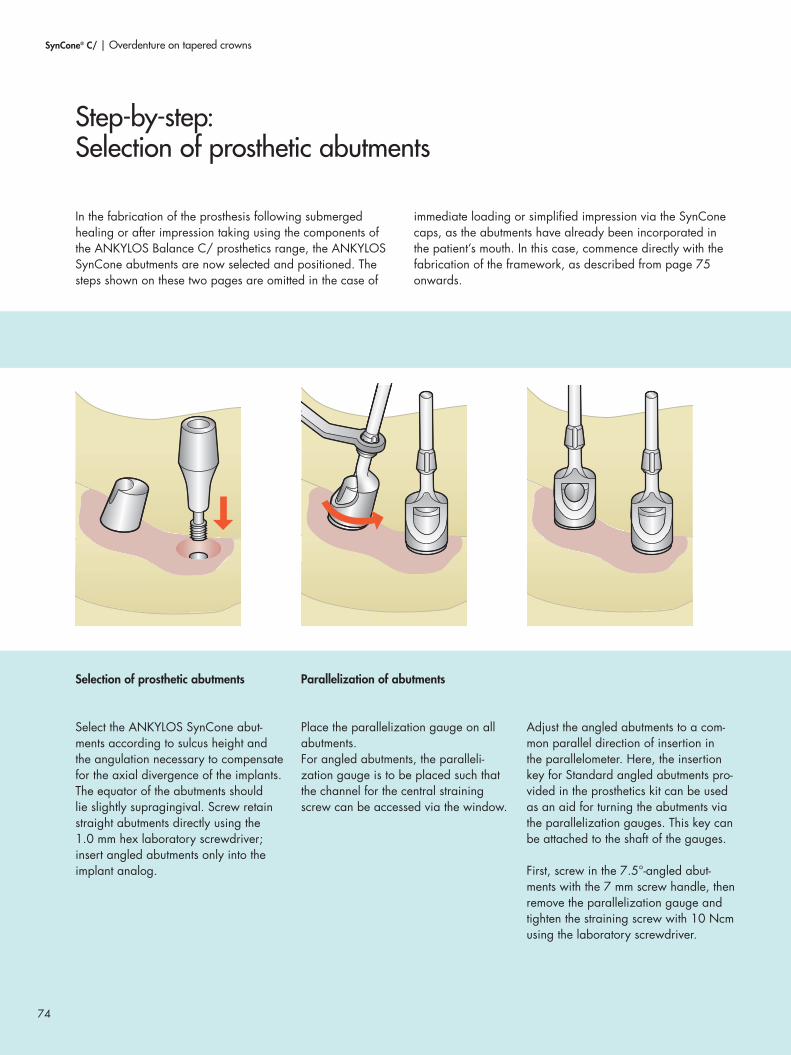
74
In the fabrication of the prosthesis following submerged healing or after impression taking using the components of the ANKYLOS Balance C/ prosthetics range, the ANKYLOS SynCone abutments are now selected and positioned. The steps shown on these two pages are omitted in the case of
immediate loading or simplified impression via the SynCone caps, as the abutments have already been incorporated in the patient’s mouth. In this case, commence directly with the fabrication of the framework, as described from page 75 onwards.
Selection of prosthetic abutments
Select the ANKYLOS SynCone abut-ments according to sulcus height and the angulation necessary to compensate for the axial divergence of the implants. The equator of the abutments should lie slightly supragingival. Screw retain straight abutments directly using the 1.0 mm hex laboratory screwdriver; insert angled abutments only into the implant analog.
Parallelization of abutments
Place the parallelization gauge on all abutments.For angled abutments, the paralleli-zation gauge is to be placed such that the channel for the central straining screw can be accessed via the window.
Adjust the angled abutments to a com-mon parallel direction of insertion in the parallelometer. Here, the insertion key for Standard angled abutments pro-vided in the prosthetics kit can be used as an aid for turning the abutments via the parallelization gauges. This key can be attached to the shaft of the gauges.
First, screw in the 7.5°-angled abut-ments with the 7 mm screw handle, then remove the parallelization gauge and tighten the straining screw with 10 Ncm using the laboratory screwdriver.
Step-by-step: Selection of prosthetic abutments
SynCone® C/ | Overdenture on tapered crowns

75
Screw-retention of the abutments, closing the screw channel Following parallelization, screw the angled abutments in via the window using the 1.0 mm hex laboratory screw-driver.For straight SynCone abutments with a 5° tapered angle, the screw channel hole can be sealed with the cover screw for SynCone C/ 5° abutments in the patient‘s mouth. For angled abutments, self-curing thermoplastics are used for this purpose.
Marking the abutments
SynCone 5° abutments are grooved at the occlusal margin to hold these securely in the transfer key.To avoid misidentification, further small grooves can be added individually to the occlusal margin.
Transfer key
Once the abutments have been aligned, attached and grooved, a transfer key is fabricated.This can be fabricated entirely from quick-curing synthetic material and, if necessary, provided with a metal reinforcement, which is adapted using synthetic material.
Please note:Only SynCone abutments with the same tapered angle may be used in a prosthesis.The prerequisite for a successful application of the SynCone concept is the common direction of inser-tion of the SynCone abutments.

76
Regardless of whether the prosthesis is fabricated following submerged healing or after immediate loading on ANKYLOS SynCone abutments already in situ in the patient’s mouth, all further steps for fabricating the framework and finishing the prosthesis are identical.
Attaching ANKYLOS tapered caps for SynCone
Place the Degulor tapered caps without retention on the abutments and cover with a 0.2 mm thick layer of wax as a placeholder.When using tapered caps with reten-tion, the retention section of the caps should be ground off beforehand.All undercut sections should be blocked for preparation of the duplicate model for making the cast.
Wax-up of metal framework
The metal reinforcement, represented in the illustration as an internal rein-forcement, is waxed up on the invest-ment model. A wax-up with matrix ensures the correct position of the metal framework, a rear cover plate can be fabricated as an option.
Ensure that the connections between the cap mountings and the retentions are stable. The framework must have a clearance of 1–2 mm to the basal mucosa and should be shorter than the caps.
Step-by-step: Fabrication of the metal framework
SynCone® C/ | Overdenture on tapered crowns

7777
Finishing the framework
After casting, devest and finish the framework. Small windows for checking the fit of the caps are placed in the occlusal edge of the caps. These allow the adhesive to escape easier during later bonding in the mouth.
Check of stability and fit
The stability of the metal framework is checked by applying pressure on both sides of the saddles. These should not bend under pressure.The finished metal reinforcement in the model is checked for a contact-free fit on the caps. To this purpose, the caps are placed gently on the stumps and must not come off when the framework is removed.
The metal framework is bonded to the tapered caps directly in the patient’s mouth to provide an optimal, tension-free prosthetic fit (passive fit). To this end, the dental laboratory will make the following preparations.
Preparations for intraoral bonding
The exterior of the tapered caps is roughened by abrasive blasting with aluminum oxide in preparation for intra-oral bonding. The caps and the frame-work are sent to the dental surgeon.
If the ANKYLOS SynCone abutments are selected in the dental laboratory, remove these from the model using the transfer key and also send them to the dental practice.

78
SynCone® C/ | Overdenture on tapered crowns
After intraoral bonding of the tapered caps and the metal framework, the dentist is to perform a bite registration and produce an overall impression for transferring the framework position in the patient’s mouth. Both are sent to the dental laboratory together with the metal framework bonded to the caps.
The SynCone abutments always remain in the patient’s mouth. The existing prosthesis should be ground out in the area of the abutments now remaining in the patient’s mouth and adapted to the altered situation using non-hardening relining material.
Casting the model
The dental laboratory creates a model from the overall impression sent by the dental practice, showing the exact position of the intraorally bonded metal framework in the patient’s mouth.To fabricate the model, first insulate the ANKYLOS SynCone caps, fill these with self-curing liquid plastic and provide with a dowel pin. Then fill the impres-sion with dental stone.
Dividing the tray
The tray must not be removed as usual after the stone has hardened, as this may cause the framework to bend. Instead, the synthetic tray is divided into segments and the impression is removed from the model and framework in sections.
Opaquing the framework
Pink opaquer is applied to the frame-work to complete the prosthesis.
Step-by-step: Finishing and delivery of the prosthesis

79
Completing the prosthesis Position the teeth and after fitting, finish the prosthesis with cold-curing resin. The prosthesis cannot be finished with hot-curing resin due to temperature de-velopment and the changes in position of the caps this may cause.After completion, inspect the interior of the caps for any excess synthetic sprue. This is removed if present.
Since the prosthesis is now mounted purely on implants, the margins of the prosthesis are shortened as far as pos-sible.The prosthesis can be designed similar to a bridge as there is no longer any soft tissue support. However, all margins need to be sealed. A maxillary prosthe-sis can be designed without a palate.
The finished prosthesis is sent to the dental practice for delivery on the ANKYLOS SynCone abutments already located in the patient’s mouth.

80
Snap Atta
chm
ent C
/

81
Prosthetic components for ANKYLOS Snap Attachment C/
ANKYLOS Snap Attachments are laser marked according to their use with the “C/” for “Cone” marking.Snap attachments allow for compensa-tion of divergences up to 20°.
Casting the model
ANKYLOS Implant Analog for Snap Attachment• Replica of the position of the attach-
ment head and the hex of the original abutment in the cast
Fabricating the suprastructure
ANKYLOS Matrix for Snap Attachment• For attaching the prosthesis to the
snap attachments incorporated in the mouth
• Manufactured from Permador pre-cious metal alloy
Instruments
Activator / Deactivator• For adjusting the prosthesis seat of
prostheses mounted on snap attach-ments
• Increases or reduces the friction of the ANKYLOS Snap Attachment C/ matrix
Mandibular prosthesis on two ANKYLOS Snap Attachments C/
Activator and deactivator for ANKYLOS Snap Attachment C/
ANKYLOS Implant Analog for Snap Attachment
ANKYLOS Snap Attachment C/ with matrix
Overdentures on ANKYLOS® Snap Attachments C/
ANKYLOS Snap Attachments C/ are used to attach overden-tures in the edentulous mandible simply and inexpensively. An existing prosthesis can be directly attached at the chair-side or an overdenture is fabricated in the laboratory.
ANKYLOS snap attachments are available with tapered connection geometry only.
Ø 2.7
4.0

82
Snap Attachment C/ | Attachment-retained overdentures
Attaching an overdenture on two implants in the mandible by means of the snap attachment is a very straightforward and economical restoration option for edentulous patients.
The impression for a restoration fabricated in the laboratory is made directly using the attachment head. The laboratory is given the impression without the snap attachment.
Inserting implant analog
Position the ANKYLOS implant analog for the snap attachment directly in the impression and check that the fit is firm.
The ANKYLOS implant analog for the snap attachment features a hex and an attachment head corresponding with the original abutment and has a stable retention region for anchorage in the stone model.
Casting the model
Fill the impression with dental stone class IV. The implant analogs for snap attachments are a one-piece units and are not designed to be removed from the cast.
Assembling the prosthesis
Attach the ANKYLOS matrices for snap attachments to the implant analog as a placeholder and prepare the prosthesis as for a complete denture. The prosthe-sis try-in, however, is made without the matrices.
Polymerizing the matrices
Position the ANKYLOS matrices for the snap attachments on the abutment. The attached silicone ring grips the hex of the snap attachment abutment at its bottom end and envelops the lamellae of the matrix at its top end. Hence, the silicone ring retains the matrix in axial alignment with the abutment.
The snap attachments are secured in the prosthesis using cold- or hot-curing resin. Ensure that no synthetic material makes its way between the lamellae. Observe the manufacturer’s directions for the polymerizate.
Step-by-step: Overdentures on ANKYLOS® Snap Attachments C/

83
Remove the silicone ring after poly-merization and check the movement of the activator.
The elaborated prosthesis, once finished, should be delivered to the practice for fitting.
Should the prosthesis be seated too firmly or too loosely on the snap attach-ments, the friction of the matrix lamellae can be adjusted using the activator or deactivator.
Activate (1): The inner cone of the instrument grips around the lamellae, compresses these and hence ensures an increased friction. The prosthesis fits more firmly.
Deactivate (2): The conical side of the instrument pushes the lamellae apart and hence ensures a decreased friction. The prosthesis fits less firmly.
Please note:Only the activator or deactivator should be used to adjust the friction. Never bend the matrix lamellae individually with a blade or similar. The resulting uneven strain will cause matrix breakage.
Please note: Delicate prostheses can be weaken-ed by the integration of the snap attachment matrix.In these cases, a customized lingual plate or an inserted model cast framework will ensure the durability of the prosthesis.
1
2

84
The ANKYLOS Standard C/ prosthetics range is an option for straightforward and economical reconstruction of edentulous gaps, free ends and edentulous jaws with single crowns, bridges and bar-supported prostheses.
ANKYLOS Standard C/ prosthetic abutments are only available with the tapered connection geometry without indexing.
Stan
dard
C/

85
Crowns, bridges and bar-supported overdentures on ANKYLOS® Standard C/
ANKYLOS Standard C/ prosthetic abutments are selected and incorporated right after contouring the gingiva, directly at the chairside. After this, the abutments remain in the pa-tient’s mouth.
ANKYLOS Standard C/ abutment• Not changing abutment components means simplified
handling and optimal patient comfort• The impression of the abutment position for the laboratory
is taken via the cap• Straightforward provision of a temporary denture for the
patient
6 – 8 | Bridge on two ANKYLOS Standard C/ abutments (DENTSPLY Implants).
1 – 5 | Laterally screw-retained crown on ANKYLOS Standard C/.
1 32
6 7 8
4 5

86
Standard C/
All ANKYLOS Standard C/ components are laser marked according to their use with the “C/” for “Cone“ marking.
Prosthetic abutments
ANKYLOS Standard C/ abutments are selected and incorporated prior to taking the impression at the chairside.After impression taking, the abutments remain in the patient’s mouth.
ANKYLOS Standard C/ Abutments, straight • Two diameters (a, 3.3 mm, and
b, 4.5 mm), four gingival heights (1.5, 3.0, 4.5 and 6.0 mm) and two abutment heights (4.0 and 6.0 mm) allow great flexibility
• One-piece with integrated thread• Chairside abutment selection; the abut-
ments remain in the patient‘s mouth• Simplified supragingival impression
taking and try-in of framework• Cemented or occlusally screw-
retained • Titanium alloy, Ti6Al4V
ANKYLOS Standard C/Abutments, angled• Angulation 15°; two diameters
(a, 3.3 mm, and b, 4.5 mm), two gingival heights (1.5 and 3.0 mm) and two abutment heights (4.0 and 6.0 mm) allow great flexibility
• One-piece with straining screw• Cemented or laterally screw-retained• Titanium alloy, Ti6Al4V
Prosthetic components ANKYLOS® Standard C/
ANKYLOS Standard C/ abutment, straight, diameter a (above) and b (below)
ANKYLOS Standard C/ abutment, angled, diameter a (above) and b (below)
Dimensions ANKYLOS Standard C/ abutment [mm]
Gingival heights
GH 1.5 GH 3.0 GH 4.5 GH 6.01.
5 3.0 4.5 6.
0 4.0 6.
0 4.0 6.
0
a b
1.5 3.0 4.5 6.
0 4.0 6.
0 4.0 6.
0
a b
1.5 3.0 4.5 6.
0 4.0 6.
0 4.0 6.
0
a b
1.5 3.0 4.5 6.
0 4.0 6.
0 4.0 6.
0
a b

87
Impressions
ANKYLOS Standard Transfer Cap• For transferring the position of the
prosthetic abutment to the master cast• Attachment to the abutment by reten-
tion, on straight abutments also using the wax-up screw, long, order no. 3104 5213 (impression with open tray)
• Color coding according to the abut-ment diameter and height
Model fabrication
ANKYLOS Standard Laboratory Analog • Placeholder for the implant and the
original abutment remaining in the patient’s mouth in the master cast
• Straight and angled, according to the abutment geometry
• One-piece• Also optionally as a two-piece analog
sleeve with pluggable abutment analog
ANKYLOS Standard transfer caps
ANKYLOS Standard laboratory analogs, one-piece (left) and two-piece (right)
Angulations and head heightsHead diameter
Ø a 3.3 Ø b 4.5 0° 0° 15° 15°
1.5 3.0 4.5 6.
0 4.0 6.
0 4.0 6.
0
a b
1.5 3.0 4.5 6.
0 4.0 6.
0 4.0 6.
0
a b
1.5 3.0 4.5 6.
0 4.0 6.
0 4.0 6.
0
a b
1.5 3.0 4.5 6.
0 4.0 6.
0 4.0 6.
0
a b
1.5 3.0 4.5 6.
0 4.0 6.
0 4.0 6.
0
a b
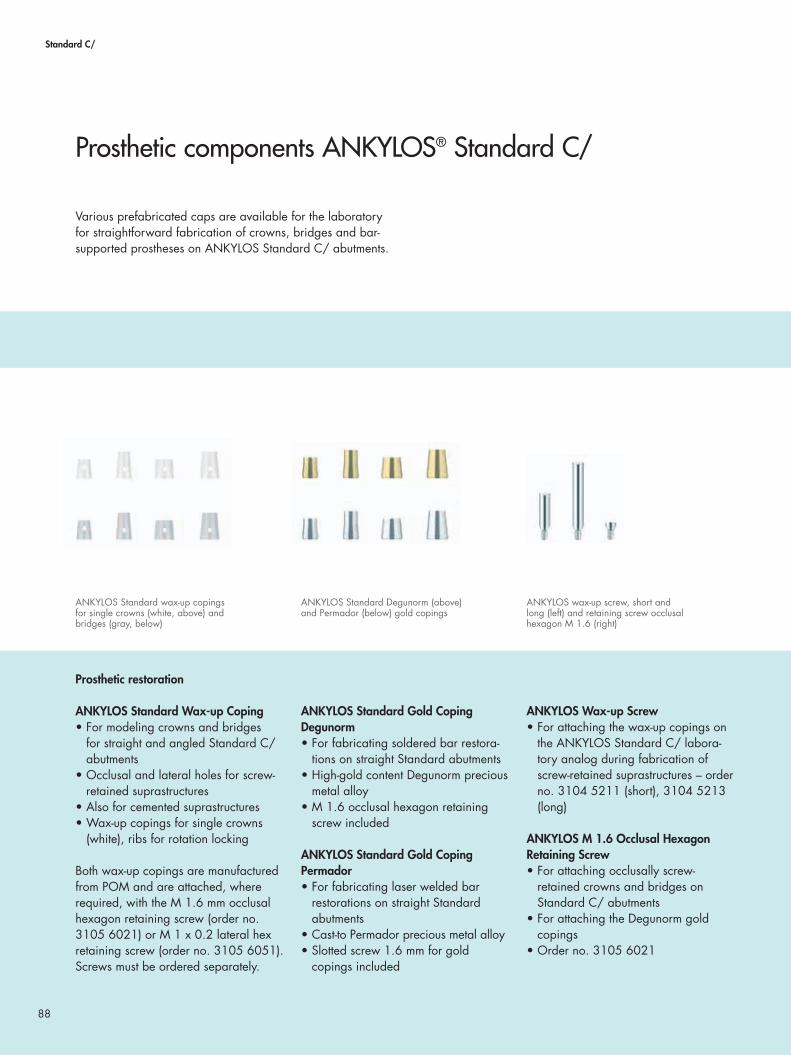
88
Standard C/
Various prefabricated caps are available for the laboratory for straightforward fabrication of crowns, bridges and bar-supported prostheses on ANKYLOS Standard C/ abutments.
Prosthetic restoration
ANKYLOS Standard Wax-up Coping• For modeling crowns and bridges
for straight and angled Standard C/ abutments
• Occlusal and lateral holes for screw-retained suprastructures
• Also for cemented suprastructures• Wax-up copings for single crowns
(white), ribs for rotation locking
Both wax-up copings are manufactured from POM and are attached, where required, with the M 1.6 mm occlusal hexagon retaining screw (order no. 3105 6021) or M 1 x 0.2 lateral hex retaining screw (order no. 3105 6051). Screws must be ordered separately.
ANKYLOS Standard Gold Coping Degunorm • For fabricating soldered bar restora-
tions on straight Standard abutments• High-gold content Degunorm precious
metal alloy• M 1.6 occlusal hexagon retaining
screw included
ANKYLOS Standard Gold Coping Permador• For fabricating laser welded bar
restorations on straight Standard abutments
• Cast-to Permador precious metal alloy• Slotted screw 1.6 mm for gold
copings included
ANKYLOS Wax-up Screw• For attaching the wax-up copings on
the ANKYLOS Standard C/ labora-tory analog during fabrication of screw-retained suprastructures – order no. 3104 5211 (short), 3104 5213 (long)
ANKYLOS M 1.6 Occlusal Hexagon Retaining Screw• For attaching occlusally screw-
retained crowns and bridges on Standard C/ abutments
• For attaching the Degunorm gold copings
• Order no. 3105 6021
Prosthetic components ANKYLOS® Standard C/
ANKYLOS Standard wax-up copings for single crowns (white, above) and bridges (gray, below)
ANKYLOS Standard Degunorm (above) and Permador (below) gold copings
ANKYLOS wax-up screw, short and long (left) and retaining screw occlusal hexagon M 1.6 (right)

89
ANKYLOS M 1 x 0.2 Lateral Hexagon Retaining Screw• For attaching laterally screw-retained
crowns and bridges on Standard C/ abutments
• Order no. 3105 6051• Cast on Permador sleeve for retain-
ing screw lateral hexagon available (Order no. 3105 6052)
ANKYLOS Screw for 1.6 mm Gold Copings (slotted)• For attaching the Permador gold
copings• Order no. 3105 6140
Instruments
ANKYLOS LaboratoryHex Screwdriver 1.0 mm• For inserting the 1.6 mm occlusal
hexagon retaining screw and the lateral retaining screw
• Reduced torque: 10 Ncm
ANKYLOS Handle for AbutmentAnalogs and Abutments• For improved management of the
prosthetic components during labora-tory processing
• A second analog is used when using one-piece laboratory analogs
• Prevents damaging the model
ANKYLOS 1.6 mm Blade Screwdriver Insert• For inserting the wax-up screw• Used with the handle for screwdriver
ANKYLOS Finisher• For elaborating the prosthetic restora-
tion• ANKYLOS finisher for tapered
occlusal retention screw and finisher for taper lateral retention screw for polishing the occlusal or lateral screw channel
ANKYLOS M 1 x 0.2 lateral hexagon retaining screw with sleeve for retaining screw lateral hexagon (left), ANKYLOS slotted screw for gold copings (right)
ANKYLOS 1.0 mm hex laboratory screwdriver (above) and handle for easier handling of the prosthetic components
ANKYLOS Finisher

90
Standard C/ | Crowns, bridges, bar-supported overdentures
The impression for suprastructures on ANKYLOS Standard C/ abutments is taken using an ANKYLOS Standard transfer cap over the ANKYLOS Standard C/ abutments already incor-porated in the patient’s mouth. By doing so, the abutment position is transferred.
The abutments remain in the mouth after the impression is taken using the repositioning technique. On straight abut-ments, an open tray impression can be taken as well, using the wax-up screw, long.
Repositioning of one-piece laboratory analogs
Position the ANKYLOS Standard labora-tory analog in the transfer cap and check for a firm fit.
Angled laboratory analogs
Angled ANKYLOS Standard C/ abut-ments feature a shortened groove for transferring the alignment of the 15° angle. The position of this groove in the transfer cap should be observed when inserting the laboratory analog.
Block the undercut neck area with wax prior to fabricating the model without a mucosa mask.
Mucosa mask
Insulate with silicone lubricant and inject gingiva casting material into the impression prior to casting. By doing so, observe the manufacturer’s direc-tions.
Step-by-step: Fabricating the model for purely implant-supported restorations

91
Model
The geometry and the occlusal or lateral thread of the laboratory analog match the original abutments in the patient’s mouth.
Please now continue with fabricating the bridge, as described on page 93.
Option: Two-piece laboratory analogs
As an alternative, two-piece laboratory analogs can also be used.
To protect the underside of the analog sleeve, seal this against incoming plas-ter with wax. The open sleeve allows simple cleaning.
Shortening two-piece laboratory analogs
For fabricating a saw-cut model, the analog sleeves can be shortened as far as the indentation.

92
Standard C/ | Crowns and bridges
ANKYLOS Standard C/ abutments enable the incorporation of prepared teeth into the suprastructure. Here, the following directions for fabricating the model should be observed.
Repositioning the laboratory analog (one-piece or two-piece)
Position the ANKYLOS Standard laboratory analog in the transfer cap and check for a firm fit. Dowel pins or arched pins should be mounted in the area of the prepared teeth and other al-veolar ridge sections or the fabrication process for a model with a synthetic base plate should be followed.
Mucosa mask
Insulate the impression with silicone lubricant and coat the laboratory ana-log with gingiva casting material prior to casting. By doing so, observe the manufacturer’s directions.
Cover the dental arch with dental stone class IV. By doing so, ensure an ad-equate height, such that the laboratory analog is covered with plaster.
In case pins are introduced subsequent-ly, the dental arch should be trimmed, drilled and the pins should be cemented in.
Sawing the model
Mount the dental arch on a plaster base and saw the model.Prepared tooth stumps should be so constructed as to be removable.
Step-by-step: Fabricating the model for tooth-/implant-supported restorations

93
Implant-supported crowns and bridges on ANKYLOS Standard C/ abutments can both be cemented and screw-retained. The fabrication of the suprastructure is shown using
the example of the restoration of an edentulous gap with a bridge. The same steps are performed in the procedure for fabricating a single crown.
Assembling the models in the articulator
Assemble the models by means of as-sembling the impression in the articula-tor as it would be positioned in the patient’s skull.
Remove mucosa mask
Remove the mucosa mask in order to have an unobstructed view of the struc-ture of the crown margins.
Attaching the wax-up copings
Attach suitably sized ANKYLOS Standard wax-up copings for bridges. Depending on the axial alignment, the wax-up copings for bridges (grey) with-out internal ribs are used. This can have advantages for the insertion alignment.
Wax-up copings with ribs for rota-tional locking (white) are available for fabricating single crowns.
Cemented suprastructure
Seal both holes in the wax-up copings with wax.
Wax up the bridge as usual. The framework is fabricated and veneered in accordance with the current dental method for metal-ceramic or full-ceramic suprastructures.
The occlusion is designed according to the “freedom in centric” principle. A purely incisal / cuspid guidance should be aimed for in lateral movements. Check the interdental spaces after the veneering for hygienic capability.
Step-by-step: Crown or bridge, cemented

94
Standard C/ | Crowns and bridges
Suprastructures are screw-retained occlusally on straight ANKYLOS Standard C/ abutments, and laterally on angled abutments.
Screw-retained suprastructure
Mount the wax-up copings with wax-up screws (order no. 3104 5211 / short or 3104 5213 / long) and mark the required length.
Shorten the wax-up screws corres-ponding to the occlusal proportions and, using a thin cutting disk, make a new slot. Then fix these in the labora-tory analogs.
Depending on the screw-retention type, seal the hole not required with wax. By doing so, ensure that no wax gets into the inside of the copings.
These directions show the fabrication of an occlusally screw-retained bridge. If lateral screw-retention is planned, please observe the directions on page 96/97.
Step-by-step: Crown or bridge, occlusally screw-retained

95
Wax up the bridge framework and create a cylindrical channel for the later retaining screw by using the wax-up screw. Adequately dimensioned inter-dental spaces should be ensured. If the wax-up copings are bonded with syn-thetic material, they must be roughened beforehand.
Invest the wax-up as usual (e.g. Deguvest). Too small an investment compound expansion should not be selected in this process, in order to avoid a frictional fit.
After molding, devesting and abrasion, the framework is fitted on the model where the occlusion is simultaneously checked.
The screw seating can be occlusally reworked for the taper with the ANKYLOS finisher.
The wax-up screw is used to protect the screw channel while the ceramic mate-rial is applied.
The completed suprastructure is sent to the practice for delivery.Where crowns or bridges are occlus-ally screw-retained, the screw holes are covered with wax or gutta-percha and sealed with composite after incorpora-tion.

96
Standard C/ | Crowns and bridges
The following example shows the somewhat more elaborate fabrication of a laterally screw-retained single tooth restora-tion on an angled ANKYLOS Standard C/ abutment. Where straight abutments with occlusal screw retention are used, proceed to the description on page 94/95 (bridge).
As a rule, single crowns are cemented on the abutments. In this case, the procedure also corresponds with that for fabri-cating bridges.
Fabricating the model
Fabricate the model for the single-tooth restoration with an angled abutment and mucosa mask, as described on page 92/93.
Wax-up coping and lateral retaining screw
Remove the mucosa mask and attach the wax-up coping for single crowns (white). Seal the occlusal hole in the coping not required with wax. Insert the gold-colored ANKYLOS M 1 x 0.2 lateral hexagon retaining screw (order no. 3105 6051) – if preferred, with the sleeve for lateral retaining screw.
The lateral screw and, if necessary, the sleeve should be well covered with wax.
Step-by-step: Crown or bridge, laterally screw-retained

97
Fabricating the model and the framework
Waxing up and fabricating the frame-work are in accordance with the current dental method. Observe the processing directions for cast-on sections for dental alloys during waxing.
For angled abutments, the screw seat can be laterally reworked with the finisher.
Veneering
Veneer and polish the crown as usual. Interdental spaces are designed for hygienic capability.The occlusal contact should be only minimal. Lateral contact points should be avoided.
97

98
Standard C/ | Bar-supported overdentures
The ANKYLOS Standard C/ prosthetics range also enables the straightforward fabrication of removable overdentures on bars.
Fabricating the model
Fabricate the model with ANKYLOS Standard implant analogs as described on page 92/93.
Attaching the gold copings
Depending on the scheduled processing technique, attach ANKYLOS Standard Degunorm (soldered) or Permador (laser welded) gold copings on the abutments and fix with the suitable occlusal screw (M 1.6 occlusal hexagon retaining screw, order no. 3105 6021, for Degunorm copings; 1.6 mm slotted screw, order no. 3105 6140, for Permador copings).
Adjusting the Bars
Fit the bars into the spaces between the gold copings. Keep the gaps between the bar and the gold copings as narrow as possible.
Step-by-step: Bar restoration (laser-welded or soldered)

99
Bar – laser-welded or soldered
Laser-welded or soldered bars are fabricated as described on pages 47 ff, for the ANKYLOS Balance Base Abut-ment. Likewise, the fabrication of the prosthesis.
99

DEN
TSPL
Y Im
plan
ts d
oes
not w
aive
any
rig
ht to
its
trade
mar
ks b
y no
t usi
ng th
e sy
mbo
ls ®
or ™
. 32
670
025
-USX
-141
1 ©
201
4 D
ENTS
PLY.
All
right
s re
serv
ed
www.dentsplyimplants.com
About DENTSPLY ImplantsDENTSPLY Implants offers comprehensive solutions for all phases of implant therapy, including ANKYLOS®, ASTRA TECH Implant System™ and XiVE® implant lines, digital technologies, such as ATLANTIS™ patient-specifi c CAD/CAM solutions and SIMPLANT® guided surgery, SYMBIOS® regenerative solutions, and professional and business development programs, such as STEPPS™. DENTSPLY Implants creates value for dental professionals and allows for predictable and lasting implant treatment outcomes, resulting in enhanced quality of life for patients.
About DENTSPLY InternationalDENTSPLY International Inc. is a leading manufacturer and distributor of dental and other healthcare products. For over 110 years, DENTSPLY’s commitment to innovation and professional collaboration has enhanced its portfolio of branded consumables and small equipment. Headquartered in the United States, the Company has global operations with sales in more than 120 countries.
Follow DENTSPLY Implants