Laboratory 1
275
University of Hail Laboratory Industrial Engineering Department Practical Exercise and Procedures of Computer Numerical Control (CNC) Laboratory 1
-
Upload
khangminh22 -
Category
Documents
-
view
1 -
download
0
Transcript of Laboratory 1

University of Hail
Laboratory
Industrial Engineering Department
Practical Exercise and Procedures of Computer Numerical
Control (CNC)
Laboratory 1

Fundamentals of CNC Machining & Practical Exercise Procedures
Table of Contents
Chapter 1: Introduction & CNC Process
Overview
Description ................................................................ 1-
Prerequisites .......................................................... 1-
Audience ................................................................ 1-
Course Design ........................................................ 1-
SRP vs. RP .................................................................. 1-
Prototype vs. Production Machining ......................... 1-
Required Tools and Equipment................................. 1-
Lessons and Appendices............................................ 1-
Instructional Resources ............................................. 1-
Recommended Use ................................................... 1-
Overview of CAD/CAM Process................................. 1-
Chapter 2: Shop Safety
Overview ................................................................... 2-
Safety Awareness ...................................................... 2-
Personal Conduct & Shop Etiquette.......................... 2-
Shop Clothing ............................................................ 2-
Proper Shop Attire Illustration............................... 2-
General Safety Practices............................................ 2-
CNC Safety Practices.................................................. 2-
Safety Contract.......................................................... 2-
Safety Contract Form ............................................. 2-
Chapter 3: CNC Tools
Overview ................................................................... 3-
End Mills .................................................................... 3-
Face Mill .................................................................... 3-
Corner Radius Mill ..................................................... 3-
Slot Mill/Slotting Saw ................................................ 3-
Center-Spot D ill........................................................ 3-
Twist Drill................................................................... 3-
Tap............................................................................. 3-
Reamer ...................................................................... 3-
Counterbore .............................................................. 3-
Cutting Tool Fundamentals ....................................... 3-
Rotational Direction............................................... 3-
Chip Formation ...................................................... 3-
Chip Load ............................................................... 3-
Climb vs. Conventional Milling............................... 3-
Cutting Speeds and Feeds Formulas........................ 3-
Speed Formula ..................................................... 3-
Feed Formula ....................................................... 3-
Tap Feed Formula ................................................ 3-
Speed/Feed Examples ............................................. 3-
Milling Speed/Feed Example................................ 3-
Drill Speed/Feed Example.................................... 3-
i

Fundamentals of CNC Machining & Practical Exercise Procedures Contents
Tap Speed/Feed Example..................................... 3-
Maximum Spindle Speed Example....................... 3-
Cutting Data............................................................. 3-
Best Practices Machining Parameters.................. 3-
Troubleshooting Speed/Feed Problems............... 3-
Chapter 4: Coordinate Systems
Overview ................................................................... 4-
Cartesian Coordinate System .................................... 4-
Number Line .......................................................... 4-
3D Cartesian Coordinate System ........................... 4-
Quadrants .............................................................. 4-
Units .......................................................................... 4-
Vertical Machining Center (VMC) Motion................. 4-
CNC Motion Control............................................... 4-
CNC Machine Coordinates ..................................... 4-
About Machine Home Position.............................. 4-
Work Coordinate System (WCS)................................ 4-
WCS Example- ...................................................... 4-
WCS Example- .................................................... 4-
WCS Example- .................................................... 4-
Machine and Tool Offsets ....................................... 4-
Machine Offset XY................................................ 4-
Machine Offset Z.................................................. 4-
Tool Lenght Offset (TLO)...................................... 4-
Chapter 5: CNC Programming Language
Overview ................................................................... 5-
CNC Language and Structure..................................... 5-
Program Format..................................................... 5-
CNC Editor ................................................................. 5-
Alphabetic & Special Character Address Codes......... 5-
Alphabetic Address Code Definitions..................... 5-
G&M Codes ............................................................... 5-
G-Codes.................................................................. 5-8
M-Codes................................................................. 5-
Select G-Code Defi itio s E pa ded ................... 5-
Canned Cycles.......................................................... 5-
Chapter 6: CNC Operation
Overview of CNC Setup and Operation..................... 6-
Machine and Tool Offsets ......................................... 6-
Fixture Offset XY .................................................... 6-
Fixture Offset Z ...................................................... 6-
Tool Length Offset (TLO)........................................ 6-
Haas Control Face...................................................... 6-
Haas Keyboard ....................................................... 6-
Start/Home Machine............................................... 6-
Load Tools ............................................................... 6-
Set Tool Length Offset (TLO) ................................... 6-
Set Fixture Offset XY................................................ 6-
ii

Contents Fundamentals of CNC Machining
Set Fixture Offset Z.................................................. 6-
Load CNC Program................................................... 6-
Run CNC Program.................................................... 6-
Adjusting Diameter (CDC) Offsets ........................... 6-
Shut Down CNC ....................................................... 6-
Chapter 7: 2D Milling Toolpaths
Overview ................................................................... 7-
2D/3D/4X/5X Defined................................................ 7-
2D (Prismatic) Parts................................................ 7-
3D Parts.................................................................. 7-
4-A is Pa ts ............................................................ 7-
Standard CAD Views vs. CAM Views.......................... 7-
CAD Features vs. Machining Features....................... 7-
Toolpaths by Type and Use ....................................... 7-
2D Machining Features Example............................ 7-
2D Toolpath Terminology.......................................... 7-
Facing ...................................................................... 7-
2D Contouring ......................................................... 7-
Cutter Diameter Compensation........................... 7-
Pocketing ................................................................. 7-
Slot Milling............................................................... 7-
Chamfer Milling ....................................................... 7-
Radius (Corner-Rou d Milli g ................................ 7-
Center Drill .............................................................. 7-
Drilling ..................................................................... 7-
Tapping.................................................................... 7-
Chapter 8: CNC Turning
Overview ................................................................... 8-
Lathe Components................................................. 8-
Spindle ................................................................... 8-
Turret ..................................................................... 8-
Lathe Coordinate System .......................................... 8-
Driven (Live) Tools..................................................... 8-
Imaginary Tool Tip ................................................... 8-
Part Datum .............................................................. 8-
Tools and Tool Holders............................................ 8-
Chip Breaker......................................................... 8-
Relief Angle .......................................................... 8-
Tool Cutting Angles .............................................. 8-
Rake Angle ........................................................... 8-
Insert Designations.................................................. 8-
Lathe Tool Types...................................................... 8-
Face/Turn Tools ................................................... 8-
Groove Tool.......................................................... 8-
Bore Tool.............................................................. 8-
Thread Tool .......................................................... 8-
Cutoff Tool ........................................................... 8-
Cutting Speeds and Feeds ....................................... 8-
Speed/Feed Example ........................................... 8-
Cutting Feed Example .......................................... 8-
Lathe Setup and Programming Example ................. 8-
Setup .................................................................... 8-
iii

Fundamentals of CNC Machining & Practical Exercise Procedures Contents
Face...................................................................... 8-
Rough ................................................................... 8-
Finish .................................................................... 8-
Groove ................................................................. 8-
Thread .................................................................. 8-
Drill....................................................................... 8-
Bore...................................................................... 8-
Cutoff ................................................................... 8-
Chapter 9: 3D Toolpaths
Overview ................................................................... 9-
3D Cutter Compensation........................................... 9-
Tolerances ................................................................. 9-
3D Toolpath Setups ................................................... 9-
3D Roughing .............................................................. 9-
Parallel Finish ............................................................ 9-
Scallop Height ........................................................ 9-
3D Scallop .................................................................. 9-
REST Milling ............................................................. 9-
Pencil Toolpaths ...................................................... 9-
Conceptualizing 3D Toolpaths................................. 9-
Chapter 10: Milling Setups
Overview ................................................................. 10-
Fixture Components ................................................ 10-
Subplates and Angle Plates................................... 10-
Clamps .................................................................. 10-
Shoulder Bolts and Dowel Pins................................ 10-
Vise Accessories ...................................................... 10-
Hard Jaws............................................................. 10-
Soft Jaws .............................................................. 10-
Appendix A: CNC Milling Work-Holdi g E a ples
Project 1 : Install Vise ................................................ A-
Project 2 : Install Vise Jaws........................................ A-
Project 3 : Square Block............................................. A-
Project 4 : Contour Square Step .............................. A-
Project 5 : Base........................................................ A-
Project 6 : Housing .................................................. A-
Project 7 : Fan Blades .............................................. A-
Project 8 : Clamp ..................................................... A-
Project 9 : Fixture Plate ........................................... A-
Project 10 : French Curve ........................................ A--
Project 11 : Honeycomb .......................................... A-
Project 12 : Bracket ................................................. A-
Project 13 : Microwave Housing.............................. A-
Project 14 : Geneva Gear......................................... A-
iv

Fundamentals of CNC Machining & Practical Exercise Procedures
Appendix B: Alternate Tool Setting Methods
List of Common Methods.......................................... B-
Using Paper ............................................................... B-
1- - Blo k o Fi ished Pa t Fa e.............................. B-
1- - Blo k a d Dial I di ato ................................... B-
Tool Probe ................................................................. B-
Appendix C: CNC Process Planning Form
CNC Process Planning Form................................ C- , C-
Appendix D: G-M Code Refere e
Milling G- Codes ........................................................ D-
Milling M-Codes ........................................................ D-
Lathe G-Codes ................................................... D- , D-
Lathe M-Codes .......................................................... D-
Appendix E: Glossary
Glossary .............................................................. E- , E-
Appendix F: Drill Chart
Drill Chart ........................................................... F- , F-
Inch Pipe Threads ...................................................... F-
Metric Taps................................................................ F-
v

Lesson 1
Introduction & CNC Process Overview
Upon successful completion of this lesson, you will be able to: Describe overall course goal, prerequisites, audienceand course design. Describe the difference between Subtractive Rapid Prototyping (SRP) and Rapid
Prototyping (RP) and the advantages and disadvantages of each. List the tools and equipment required for this course. List the major lesson topics covered by this course. List the major student resources available and the information found in course
appendices. Describe the recommended use of course materials to maximize the learning
experience. Describe in general the overall CAD/CAM/CNC process.
1-
Copyright 2014 Autodesk, Inc.
Lesson 1 Fundamentals of CNC Machining Introduction & CNC Process Overview
1.1 Course Description
The goal of this course is to teach persons with a technical background how to program and operate
Computer Numerical Control (CNC) mills and lathes.
This course bridges the gap between what persons with a technical education know and what they must
learn to begin using CNC machine tools. The types of parts, materials and machining operations that
engineers, innovators, and niche manufacturers often use are featured. Work holding techniques well suited
to prototype and short- u p odu tio a e detailed a d used as e a ples.
Prerequisites
The learner is expected to have the following: Engineering or other technical degree or equivalent experience. Knowledge of the proper use of basic hand tools and precision measuring instruments, including calipers
and micrometers. Some manual machining experience is helpful but not required. Knowledge of Solidworks® is a pre- e uisite o o- e uisite fo this ou se.
Audience
This course is designed for the following audiences: Working engineers and designers. Engineering undergraduates or graduate students. Manufacturing and design students. Scientists. Innovators. Niche manufacturers.
Course Design
CNC Machining is a very broad subject and there are many ways to do most things. Covering all options
would fill volumes and is beyond the scope of any one book or course.The goal of this course is not to turn
and engineer into a journeyman machinist. Rather, it is to show how to use CNC to make common types of
parts, teach DFM principles, and help engineers become better designers and managers.
This curriculum was created using an Instruction Design process. Engineering educators and students from
leading Universities, as well as practicing engineers in a variety of industries, were surveyed. This process
determined the types of parts and materials covered in this course. Parts that are easier made using Additive
Rapid Prototyping (RP) technologies were excluded.
By leveraging what anyone with a technical education knows, by focusing on the most common types of
parts and materials, and by presenting best practices for prototype machining, learning objectives are
narrowed considerably. Thus a remarkable amount can be achieved in a short time. For example, working
engineers using this course have been taught to set up, program, and operate a CNC mill in less than 24
hours of combined classroom/lab time; including instruction in HSMWorks.
This economy of instruction makes CNC accessible to almost anyone: from working engineers to students
involved in design/build competitions, to undergraduate engineering students as part of a Design for
Manufacturing (DFM) course or hand-o la . Copyright 2014 Autodesk, Inc. 1-

Fundamentals of CNC Machining Lesson 1 Introduction & CNC Process Overview
SRP vs. RP
This course emphasizes an approach to CNC machining referred to as Subtractive Rapid Prototyping (SRP).
SRP deals with small quantities of functional prototypes. Functional prototypes are made from materials like
aluminum, steel and polycarbonate that cannot be produced with widely available additive Rapid
Prototyping (RP) processes such as SLA (Stereolithography) or FDM (Fused Deposition Modeling).
SPR is not as simple to learn and use as RP. It takes more skill and often more time to apply. The main
advantage of SRP is in materials. Almost anything can be machined. SRP parts are not just visual aids, they are
structural components that can be tested and assembled as part of working machines.
Another advantage of SRP is that it teaches real manufacturing constraints typical of the aerospace,
biomedical, consumer goods, and electronics industries–all which use CNC for mass production, molds and
other tooling. RP does not reflect these constraints. A part that is easy to rapid prototype may be extremely
difficult, expensive, or even impossible to manufacture. SPR provides the designer with feedback about the
manufacturability of design that can save considerable time and money as a part moves from concept to
product.
Prototype vs. Production Machining
One of the biggest differences between making a few or many parts is in the design of work-holdi g fixtures. Prototype machining emphasizes quick, simple and cheap work holding solutions such as vises,
clamps, screws or even glue or double-sided tape. High p odu tio pa ts allo the ost of fi tu es to e amortized over larger quantities to justify the cost of more elaborate and efficient fixtures. This course
emphasized prototype fixturing.
1.2 Required Tools and Equipment
CNC Machine
To maximize learning, this course focuses on CNC machines made by Haas Automation, Inc. of Oxnard, CA.
Chapters 5 (CNC Programming Language) and 6 (CNC Operation) are written specifically for the Haas control.
Haas machines are highlighted for the following reasons: Haas Automation is the largest machine tool builder in thewestern world. Haas has donated or endowed many machines to colleges, universities, and technical schools, so they are
likely to be found in educationalinstitutes. All Haas machines use the same control, work similarly, and use industry standard programming.What is
learned is easily transferred to other make or model machines. Haas makes several small footprint CNC machines designed specifically for engineering, prototyping,
medical, jewelry, and niche manufacturing industries.
Warning: While this course covers the safety, setup and operation of the Haas CNC s, it is not a substitute
for the machine operator manuals or training by a qualified technician.
SolidWorks + HSMWorks
This course uses SolidWorks® CAD software and SolidWorks-I teg ated CAM Co pute -Aided Ma ufa tu i g software by Autodesk, Inc. for CNC programming. SolidWorks is widely used by both industry and education for
mechanical design. HSMWorks is completely and seamlessly integrated into SolidWorks, is very easy to learn and
use and is particularly well-suited to persons who know SolidWorks and 1- Copyright 2014 Autodesk, Inc.

Lesson 1 Fundamentals of CNC Machining Introduction & CNC Process Overview
are new to CNC programming. HSMWorks also stores all data in the SolidWorks Part or Assembly file which
makes file management simpler. If the learner already knows how to use SolidWorks they already know most
of what they need to use HSMWorks.
All of these attributes are essential for a streamlined course in CNC machining possible. They save the
substantial time takes to learn the completely separate interface and way of working required to use older
technology stand-alo e CAD/CAM software. Our experience has shown the distraction and time needed
to learn stand-alo e CAM is a ajo o sta le to lea i g CNCa d adds o alue to the lea i g e pe ie e. In short, stand-alo e CAM i this setti g is all pai and no gain.
HSMWorks cuts CAM learning time easily by 75% or more. This frees class time, reduces learner frustration
and focuses attention where it belongs: on how to set up, program and run CNC machinetools –rather than
how to learn a completely separate(and often quirky) stand-alo e CAD/CAM soft a e appli atio .
1.3 Lessons & Appendices
Lessons 1 – Overview/Resources
2 – Shop Safety
3 – Coordinate Systems
4 – CNC Programming Language
5 – CNC Tools
6 – CNC Operation
7 – 2D Milling Toolpaths
8 – CNC Turning
Appendices A – CNC Milling Work-Holdi g E a ples
B – Alternate Tool Setting Methods
C – CNC Process Planning Forms
D – G/M Code Reference
E – Glossary
F – Drill Chart
1.4 Instructional Resources
Instructor Resources: PowerPoint presentations for each lesson. Lesson Guides. Exercises: SolidWorks files with HSMWorks toolpaths completed. Videos with step- -step i st u tio s ho to o plete ea h e e ise. Assessment with solution for each lesson.
Student Resources Reading assignments for each lesson. Videos (SWF) for each lecture (PowerPoint). Videos with step- -step i st u tio s ho to o plete ea h e e ise. Exercises: SolidWorks files.
Copyright 2014 Autodesk, Inc. 1-

Fundamentals of CNC Machining Lesson 1 Introduction & CNC Process Overview
1.5 Recommended Use
To get the most from this course, proceed as follows:
Read the Reading Assignment for each lesson (PDF). Watch the video of each lecture, or attend a live lecture conducted by the instructor. Watch the video for the practical assignment. Complete the assignment using HSMWorks. Work through the assignment more than once if
possible. Make sure you understand each step and why you are doing what the assignment requires. Make the project parts on the CNC machine. Take the assessment for the lesson.
1.6 Overview of CAD/CAM Process
The general workflow to go from CAD model to machined CNC part is:
1. Begin with CAD model.
2. Establish Job parameters including CNC
coordinate system and stock shape/size.
3. Select CNC process.
4. Select cutting tool and machining parameters.
5. Select driving CAD geometry.
6. Verify toolpath.
7. Post Process.
8. Transfer G- ode p og a to CNC a hi e. 9. Set up and operate CNC machine to make part.
Copyright 2014 Autodesk, Inc.
%
O01001 (CNCFUN1.6-1 NAMEPLATE EXERCISE)
(T1 D=0.125 CR=0. - ZMIN= . - flat e d ill
G90 G94 G17
G20
N1 T1 M6
S5000 M3
G54
G0 X0.1504 Y- .
G43 Z1.434 H1
M8
Z0.1906
G1 Z0.1737 F13.333
G17 G3 X0.1501 Y- . Z . I . J- .
X0.1493 Y- . Z . I0.0476 J- .
X0.1469 Y- . Z . I . J- .
X0.1442 Y- . Z . I . J- .
X0.2514 Y- . Z . I . J- .
X0.1442 Y- . Z . I- . J .
X0.2514 Y- . Z . I . J- .
X0.1442 Y- . Z . I- . J .
X0.2514 Y- . Z . I . J- .
X0.1442 Y- . Z . I- . J .
X0.2514 Y- . Z . I . J- .
X0.1442 Y- . Z . I- . J .
X0.2514 Y- . Z . I . 36 J- .
X0.1442 Y- . Z . I- . J .
X0.2514 Y- . Z . I . J- .
X0.1442 Y- . Z . I- . J .
X0.2514 Y- . Z . I . J- .
X0.2543 Y- . Z . I- . J .
X0.1751 Y- .1133 I- . J- .
G2 X0.1827 Y- . I- . J- . F . X0.1871 Y- . I- . J- .
G3 X0.1951 Y- . I . J .
X0.1957 Y- . I- . J .


Fundamentals of CNC Machining
Lesson 2
Shop Safety
Upon successful completion of this lesson, you will be able to: Display an awareness of shop safety. Apply general shop safety rules. Select appropriate shop clothing. Demonstrate safe personal conduct in the shop. Apply additional safety precautions when running a new CNC program.
2-

Fundamentals of CNC Machining Lesson 2 Shop Safety
2- .

Lesson 2 Fundamentals of CNC Machining Shop Safety
Overview
This is the most important lesson of this course. Machine shops are inherently dangerous environments.
What you do not know can seriously injure you. The purpose of this lesson is to provide specific safety rules
and develop an overall attitude of safety awareness. This awareness will lead to wariness which is your best
defense against injury. Nurture this wariness until you develop a habit of always working in a thoughtful,
methodical and deliberate way. Never forget: No project or deadline is worth risking serious injury. Don t let a moment of inattention or
neglect adversely impact the rest of your life.
Safety First
2.1 – Safety Awareness
Most machinists go their entire career with no serious injury even though they work with many different
machines that expose them to risks. Machinists are, by nature and training, careful and methodical. They
learn from experience an attitude of safety awareness and respect for equipment. Knowing that ignorance
can hurt you is essential to cultivating an attitude of safety.
It is true that CNC machines are generally safer than manual machine tools. They are usually completely
enclosed, which reduces the risk of flying chips, debris from broken tools, or contact with a spinning tool. Yet
machine shops are inherently dangerous places that are unforgiving of any carelessness, ignorance, or
neglect. Cutting tools, and the chips they produce, are sharp. Chips ejected from the machine can cause eye injuries.
CNC machines can move over one foot in less than a second. Any physical contact with a spinning tool will
result in serious cuts or worse. Remember, if it can cut metal it can cut skin and bone just as easily. Here are some examples where a failure to know or apply shop safety rules caused injury: A person forgets to wear safety glasses and sustains an eye injury from a metal chip thrown over the
top cover of a CNC mill as they walk through the shop. A person leans against a bench where a cutting chip has fallen, resulting in a cut to their hand. A person wearing open sandal shoes has a chip fall between their foot and shoe, causing a cut. A person leaning over a machine suddenly raises their head and bumps into atool stored in the tool
changer, causing a severe cut. A person reaches into the machine to remove a part, gets distracted and rakes their arm against an end
mill. A person grinds a piece of aluminum on a bench grinder with a stone type wheel. The aluminum
embeds in the porous wheel and expands due to heating, causing the wheel to fail and throw off
fragments at high speed. Copyright 2014 Autodesk, Inc. 2-

Fundamentals of CNC Machining Lesson 2 Shop Safety
2.2 – Personal Conduct & Shop Etiquette It is important to follow strict of rules of personal conduct and etiquette in the shop. This will keep you and
your peers safe and promote a hospitable and professional environment:
Know where your hands are at all times. Move deliberately and always look where your hands are going. Always be aware of what could happen if your hand slip. For example, when tightening a bolt, think
about what would happen if the wrench slipped. Would your hand or arm contact a tool? A pile of
sharp chips? Always be aware of what could happen if you slipped and lost your footing. Would your center of
gravity cause you to fall into a sharp tool or other hazard? No horseplay or practical jokes are allowed in the shop. Be considerate. Do not engage in loud or unnecessarily talk. Do not interrupt someone working at the machine. This could cause them to make a mistake. Never borrow tools from a private tool box without first asking the owner. If they refuse, accept it
graciously. Respect professional Machinists. There is much you can learn from them. Do not make unreasonable demands ( I need it yesterday etc.). Clean up after yourself. Leave the machine and surrounding area at least as clean as you found it. Always put tools and equipment where you found them.
2.3 – Shop Clothing
Follow these rules of personal dress for the shop: Wear ANSI approved safety glasses or ANSI safety approved glasses with side shields. You must wear
safety glasses at all times in the shop, not just when at the machine. If machining operations are loud, use hearing protection. Do not wear flip flops or sandals. Leather shoes are best. Steel toe shoes are not necessary unless
handling heavy objects that would crush regular shoes. Do not wear long sleeve shirts because these could get caught in equipment. Wear short sleeves or
T-shi ts. Remove rings and watches when at the machine. Do not wear short pants. Wearsturdy long pants like blue jeans or work pants. Long hair should be tied back or under a hat to prevent it being caught in the machine spindle. Never wear gloves as they can be caught in the machine. Latex gloves are acceptable.
2- .

Lesson 2 Fundamentals of CNC Machining
Shop Safety
Figure 1: Proper Machine Shop Attire
Copyright 2014 Autodesk, Inc. 2-
Fundamentals of CNC Machining Lesson 2 Shop Safety
2.4 – General Safety Practices
Rules for a safe workplace: Never use any equipment which you have not been trained to operate by a qualified person. Never tamper with a machine safety guard or switch. Get into the habit of constantly tidying the work space. A clean workplace is safer. Random metal can
not only scratch and ruin finished parts, they can cause severe cuts. Use caution when handling cutting tools. They are very sharp. Never handle a tool by its cutting flutes. Never start or jog the machine until you have checked that the work area is clear. Never push the start button on the machine unless you are certain your setup is capable of safely
holding the part against all cutting forces during machining. Use caution when running a new program: especially at the start of program and after a tool change. Know where the emergency stop is on the machine and practice using it before you need it. Never run a machine alone or without other people within hearing distance. When working with someoneelse at the machine, clearly communicate who is running the machine. Never have one person touching the control while the other is working in the machine envelope. Use a paint brush to sweep away sharp chips. Never use your hands or a rag. Never use an air hose to clear chips from a machine. Flying chips are dangerous to you and others. Liquids spills are slipping hazards. Clean spills immediately. Dirty or oily rags must be stored in a fireproof canister. These can spontaneous combust and cause a
fire. Lift with your legs, not your back. Never lift anything more than you can comfortably handle. Get help handling heavy or bulky objects. At the end of the program, command the machine to position the part close to the operator so it can be
easily reached without leaning far into the CNC machine. Never leave a running machine untended. Before shutting the machine down, remove any tools from the spindle. Avoid contact with coolant. Water- ased oola t o tai s i o es that a ause i fe tio . Immediately treat and cover even minor cuts. Report any injuries immediately. Remain alert. Think safety in everything you do.
2.5 CNC Safety Practices
Use these extra precautions when running a CNC program for the first time: Use machine Rapid and Feed override controls to slow the machine down. A major cause of crashes is setting the tool or fixture offset incorrectly. Pay particular attention to
moves at the start of program and immediately after a tool change as the tool moves towards the part.
Use single- lo k ode to ad a e th ough the p og a o e li e at a ti e u til the tool is at utti g depth.
Remain at the machine with a hand on or near the emergency stop button. Stop machine motion at the first sign of trouble.
2- .

Lesson 2 Fundamentals of CNC Machining Shop Safety
2.5 Safety Contract
Training facilities should require everyone to pass a safety quiz and sign a safety contract before allowing
work in the shop. The safety contract makes clear the obligations and operating regulations of the facility.
Failure to abide by the terms of the contract is cause for dismissal from the shop. An example safety contract
is shown on the facing page.
Warning
What you don’t know CAN hurt you.
Never operate a machine that you have not
been properly trained to use by a qualified person.
Read the machine operator manuals
and follow all safety instructions.
THINK SAFETY FIRST in all you do. Copyright 2014 Autodesk, Inc. 2-

Fundamentals of CNC Machining Lesson 2 Shop Safety
Shop Safety Compliance Contract
Course Name/Number: Instructor:
Start Date:
You are not authorized to work in the shop area until you attend the Safety Orientation, pass the Safety Quiz,
and sign this contract. You may not use equipment without supervision available and without receiving
instruction in its use. By signing this contract, you agree to abide by the following guidelines. Failure to follow
safety guidelines is cause for dismissal from class.
Shop Regulations
Wear Safety Glasses – You must wear safety glasses AT ALL TIMES while in the shop area. You must wear
safety goggles over prescription glasses unless your glasses have side shields and are ANSI safety approved.
Use Hearing Protection – You will wear hearing protection when and if asked to do so by the instructor. No Jewelry – You will remove all rings, watches, necklaces, bracelets, and dangling earrings before operating
any machinery or tools.
Proper Attire - You will wear ankle-length pants. Loose hair and clothing are extremely dangerous. You must tuck in your shirt, roll up long sleeves, secure draw strings, tie back hair, etc… No Open-Toe Shoes – You must wear appropriate foot wear while in the shop. Shoes must be fully enclosed.
Inappropriate footwear includes: open-toe shoes, sandals, crocks, high heels, etc…
Clean-Up–Before leaving the shop area, you must assist in cleaning any mess (metal chips, splashed coolant)
that you produce. You must clean any spilled liquids immediately.
Return of Tools and Parts-You will return any tools, instruments, bits, etc. to their proper location after using them.
You will only operate equipment accompanied by an instructor. You must not use any equipment alone, or that
you have not been trained to use. You must follow proper operating procedures when using any machinery. You must be courteous to others in the shop. Do not engage in disruptive conversation. Your actions must not interfere with others or their work area. Do not use hand tools from any personal toolbox without permission of the owner.
You must not enter the shop area under the influence of drugs or alcohol. This includes prescription or over- the-counter drugs that include warnings against operating machinery. You must not consume alcohol within 8 hours of entering the shop area. You must never remove the guards or disable the safety equipment from machinery.
If the machine makes an unusual noise or acts in any suspicious manner, you must stop the machine and inform
the instructor immediately. You must immediately report ANY injury to the instructor. If an injury requires medical attention, call 911 immediately. Do not lift objects heavier than canbe easily manage without the aid of a lifting device or help. Watch for slippery conditions and clean up any spills immediately.
By my signature below, I certify that I have read and agree to comply with all of the above hops regulations. I
realize that I may be asked to leave the shop area for non-compliance with any of the above rules. If I am asked to leave, I will do so immediately and willingly. Name (Printed): Date:
Signature: Affiliation:
2-

Lesson 2 Fundamentals of CNC Machining Shop Safety
THINK SAFETY
Copyright 2014 Autodesk, Inc. 2-

Fundamentals of CNC Machining
Lesson 3
CNC Tools
Upon successful completion of this lesson, you will be able to: List the most commonly used CNC tools. Determine spindle rotational direction. Interpret a chip formation diagram. Define chip load. Distinguish between climb and conventional milling. Compute cutting speeds and feeds for a specified tool, material and operation
using reference tables.
3-

Fundamentals of CNC Machining Lesson 3 CNC Tools
3-
Lesson 3 Fundamentals of CNC Machining CNC Tools
Overview
A wide range of tool types and configurations are available for CNC milling machines. Discussing every type,
variation and use is beyond the scope of this course. This chapter introduces the most commonly used tools
for prototype and short run production machining. Any tool supply catalog will list many others.
End mills (Flat, Ball, Bull and Chamfer)Face mill Corner Rounding tools Slot Tools Spot-Ce te D ill Twist Drill Tap Reamer Counterbore
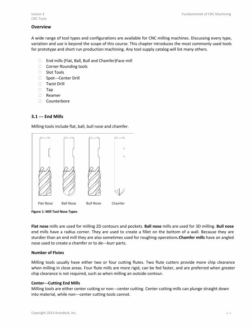
3.1 - E d Mills Milling tools include flat, ball, bull nose and chamfer.
Flat Nose Ball Nose Bull Nose Chamfer Figure 1: Mill Tool Nose Types
Flat nose mills are used for milling 2D contours and pockets. Ball nose mills are used for 3D milling. Bull nose
end mills have a radius corner. They are used to create a fillet on the bottom of a wall. Because they are
sturdier than an end mill they are also sometimes used for roughing operations.Chamfer mills have an angled
nose used to create a chamfer or to de- u pa ts. Number of Flutes
Milling tools usually have either two or four cutting flutes. Two flute cutters provide more chip clearance
when milling in close areas. Four flute mills are more rigid, can be fed faster, and are preferred when greater
chip clearance is not required, such as when milling an outside contour. Center-Cutti g E d Mills Milling tools are either center cutting or non- e te utti g. Ce te utti g ills a plu ge st aight do into material, while non- e te utting tools cannot.
Copyright 2014 Autodesk, Inc. 3-

Fundamentals of CNC Machining Lesson 3 CNC Tools
Figure 2 below shows the cutting end view of a center cutting and non- e te utti g e d ill. Noti e that the cutting edges of the center cutting end mill continues to the center of the tool. The center of the other
has a small hole at the center. Non- e te utti g e d ills e ui e a pilot hole, a pi g o heli al otio to plunge into material.
Cutting Edges
Center Cutting Non-Ce te Cutti g
Figure 2: End View of Center and Non-Ce ter Cutti g E d Mill
3.2 - Fa e Mill A face mill has cutting inserts that are replaced when worn. They are rigid, may have up to eight or more
cutting edges, and can remove material quickly. They are often used for the first machining operation to
quickly create a flat finished face on the part.
Carbide Insert
Figure 3: Face Mill
3-

Lesson 3 Fundamentals of CNC Machining CNC Tools
3.3 - Cor er Radius Tool
Corner radius (also called Corner Round) tools are used to place a fillet on the outside corner of a part. Figure 4: Corner Round Tool
3.4 - Slot Mill/Slotti g Sa
Slot mills include side milling cutters, slitting saws, and Woodruff keyset cutters. Slitting saws and side
milling cutters are installed on a special arbor. Woodruff cutters are single piece tools used for creating slots
and undercuts that can be held in a standard tool holder.
Slitting Saw Side Milling Cutter Woodruff Cutter Figure 5: Slot Tools
3.5 Hole-Maki g Tools
Center-Spot Drills
Center (spotting) drills are short and very rigid drills used to create a conic on the face of the part. Because
they come to a sharp point and resist bending, they locate the hole precisely. The conic helps prevent the
subsequent drill from wobbling and ensure the drill is located precisely and drills straight down. Countersink drills are used to create the conical face for a machine screw. Combined spotting- ou te si ks are used to create a screw clearance hole and countersink in one operation. Copyright 2014 Autodesk, Inc. 3-

Fundamentals of CNC Machining Lesson 3 CNC Tools
There are many different sizes and tip angles of center, countersink, and combined drills. Be sure the tip
angle of the countersink matches the included angle of the machine screw, and that the drill diameter is
greater than the screw head diameter.
Spotting Drill Countersink Combined
Figure 6: Countersink and Center Drill
Twist Drill
Twist drills are available in many diameters and lengths. Usually made of high speed steel, carbide, or cobalt,
they may also be coated with titanium nitride (TiN) for longer life. The tip angleof most twist drills is 118
degrees.
Tip Angle
Twist Drill
Figure 7: Twist Drill
Taps Cutting taps form threads by shearing material away. Form taps (roll taps) form the thread by forming the
metal to shape. Form taps produce no chips and are used for soft materials including aluminum, copper,
brass and plastics.
3-

Lesson 3 Fundamentals of CNC Machining
CNC Tools
Bottoming Tap Spiral Point Tap
Figure 8: Taps
Bottoming taps are used to tap blind holes. Spiral point taps push the chip ahead and out the bottom of a
through hole. Taps require a hole drilled to the correct size to ensure the thread is formed roperly. For example, a ¼- cutting tap requires drilling a .201 (#7) hole. Refer to the drill chart in Appendix A to find the correct drill size
for a specified thread size and fit. Most CNC Machines support rigid tapping, which means the tap can be held in a rigid holder. The tap is
advanced at a feed rate that matches the thread lead into the hole. The spindle then stops, reverses, and
backs out of the hole. Machines without rigid tapping require special tapping attachments. Always refer to the manufacturers
instructions as the speed, feed, and other machining parameters for tapping attachments may be different
that those for rigid tapping. Reamer
Use reamers to create holes of precise shape and excellent surface finish.Reamed holes are usually accurate
within .0002 inches diameter. For example, a reamer is used for holes used for ground pins and bushings. Reamers require a specific size hole be drilled before use. Cutting speeds and feeds are also important.
Remove too little or too much material and the hole will not be the correct size.
Reamer Figure 9: Reamer
Copyright 2014 Autodesk, Inc. 3-

Fundamentals of CNC Machining Lesson 3 CNC Tools
Counterbore
A counterbore looks similar to a end mill with a pilot in the center.It is used to spot face holes, and the pilot
ensures the spot face is centered onthe hole. Counterboring is not necessary when using a CNC machine. Rather, create a spot face using a pocket or circle
mill tool path. This saves having to buy and stock counterbore tools and pilots, and the time required to load
and set up the counterbore.
3.6 Cutting Tool Fundamentals Rotation Direction
All tools (except left-ha ded taps otate lo k ise M he ie ed f o the a hi e spi dle looki g down at the part.
Z+
X+
Y+
Figure 10: Clockwise Tool Rotation
Chip Formation
Cutting tools remove metal by shearing action as illustrated in Figure 11 below. As the tool advances into the
material it causes a small amount of the material to shear away, forming a chip.
ToolDirection
Shear Zone
Chip Tool
Workpiece
Figure 11: Chip Formation Diagram
3-

Lesson 3 Fundamentals of CNC Machining CNC Tools
Chip Load
The thickness of material sheared away by each cutting tooth is called the feed per tooth, or chip load.As the
chip is ejected from the work areait carries with it some of the heat generated by the shearing process.
Chip
Chip Load
Tool Rotation
Y+
X+ Figure 12: Chip Load
A methodology for calculating cutting speeds and feeds is presented later in this chapter. One of the best
ways to validate cutting speeds and feeds is to observe the chips created by the machining process. Chips
should be curled and may change color due to heating. After gaining some experience machinists are able to adjust cutting speeds and feeds based in part on the
size, shape, and color of chips and on the sound produced by the cutting process. Climb vs. Conventional Milling
Milling tools can advance through the material so that the cutting flutes engage the material at maximum
thickness and then decreases to zero. This is called Climb Milling. Cutting in the opposite direction causes the tool to scoopup the material, starting at zero thickness and
increasing to maximum. This is called Conventional Milling. Conventional milling is used often on manual machines because backlash in the machine lead screws causes
the tool to lurch when climb cutting. This is not a problem on CNC machines because they use ball screws. Conventional milling causes the tool to rub against the cutting surface, work hardening the material,
generating heat, and increasing tool wear. Raking chips across the finished surfacealso produces a poorer
surface finish. Unless specifically recommended by the tool manufacturer for the material being milled, always use climb
milling on a CNC. Climb milling produces far less cutting pressure and heat, leaves a better surface finish, and
results in longer tool life. Copyright 2014 Autodesk, Inc. 3-

Fundamentals of CNC Machining Lesson 3 CNC Tools
Cut Direction
Spindle Rotation
Climb Milling
Cut Direction
Spindle Rotation
Y+
Conventional Milling
X+ Figure 13: Climb vs. Conventional Milling
3.7 Cutting Speeds and Feeds Formulas
The tool moves through the material at a specified rotational speed, defined in revolutions per minute
(RPM), and feed rate, defined in inches per minute (IPM). Probably the most vexing problem for the
beginning CNC machinist is selecting proper cutting speeds and feeds. This selection is actually more difficult
on a CNC than a manual mill because, with a manual mill, the operator can feel the cutting pressure and alter
the feed based in part on the cutting force. CNC mills require calculating speeds and feeds in advance. These speeds and feeds can, and often are,
adjusted at the machine based on chip shape and color, cutting sound, and machine horsepower meter
readings. The best source of data about cutting speeds and feeds for a specific tool, application, and material is the
tool supplier. Much of this data is found on manufacturer s web sites or printed tooling catalogsTool. sales
representatives can be a valuable resource, so if you do a lot of machining, develop a good relationship with
a knowledgeable representative. Another source of speeds and feeds data is CAD/CAM software. These have become increasingly
sophisticated and often provide good cutting data. Yet even the best speed and feed data is just a starting point. Speeds and feeds require adjustment due to
many factors including the maximum spindle speed or horsepower of the machine, rigidity of work holding,
and the quality and condition of the machine tool itself. The following pages provide cutting data for the most commonly machined materials and amethodology for
calculating speeds and feeds. As always, use common sense. If the part is held by double sided tape, feeds
based on vise work holding are probably too high. If the tool is very long and thin, speeds and feeds will
likely require reduction. 3-

Lesson 3 Fundamentals of CNC Machining CNC Tools
Speed Formula
Milling machine cutting speeds are derived from the following formula:
=
Figure 14: Speed Formula
Speed is the rotational frequency of the tool (Spindle Speed) in revolutions per minute (RPM).
SFM (Surface Feet per Minute) is the speed at which the material moves past the cutting edge (outside
diameter) of the tool in feet per minute. SFM values depend on the tool type, tool material, and material
being machined. Circumference is the circumference of the cutting tool in feet.
How Speed Formula is Derived
Because cutting tools are defined by their diameter in inches, this formula is rewritten and simplified as
follows:
=
( )
=
( )
.
=
( )
Figure 15: Speed Formula (Simplified)
DIA is the tool diameter in inches. 3.82 is a constant derived from 12/ which converts the tool circumference in feet to diameter in inches.
Copyright 2014 Autodesk, Inc. 3-

Fundamentals of CNC Machining Lesson 3 CNC Tools
Feed Formula
Cutting feeds are in (IPM) and use the following formula:
=
Figure 16: Feed Formula
Feed is the linear feed of the tool through the material in inches per minute.
Speed is the result of the speed formula (Figure 15) in revolutions per minute.
CL is the chip load, or how much material each cutting edge of the tool removes per revolution.Chip load is
sometimes referred to as feed per tooth (FPT) or inches per rev (IPR).
NumFlutes is the number of cutting flutes. (For a twist drill, this value is one.)
Tap Feed Formula
For tapping operations, feed rate is based on the number of threads per inch and feedrate: =
Figure 17: Tap Feed Formula
Feed is the linear feed of the tool through the material in inches per minute.
Speed is the result of the previous formula in revolutions per minute.
TPI is the threads per inch of the tap. For example, the TPI of a ¼- tap is .
3-

Lesson 3 Fundamentals of CNC Machining CNC Tools
3.8 - Speed/Feed E a ples
Milling Speed/Feed Example
Problem: Calculate the cutting speed and feed for a milling operationgiven the following values:
Parameter Value
Tool Diameter .500in
NumFlutes 4
SFM 600ft/min
IPR .005in
Table 1: Mill Speed/Feed Example
Solution:
Step 1: Calculate RPM
(
) 3.82 min
(
) =
( ) ( ) = 600( ) 3.82
. 500
( ) = ( ) Step 2: Calculate IPM
=
.
= (
)
Note: Round off milling speeds and feeds to the nearest integer.
Copyright 2014 Autodesk, Inc. 3-

Fundamentals of CNC Machining Lesson 3 CNC Tools
Drill Speed/Feed Example Problem: Calculate the cutting speed and feed for adrill operation given the following values:
Parameter Value
Tool Diameter .201in
SFM 250ft/min
IPR .002in Table 2: Drill Speed/Feed Example
Solution:
Step 1: Calculate RPM
(
) 3.82 min
(
) =
( )
( ) = 250( ) 3.82 . 201
( ) = ( )
Step 2: Calculate IPM
=
= .
= .
Note: Round off drilling feeds to the first decimal point.

3- s Tap Speed/Feed Example
Problem: Calculate the cutting speed and feed for a¼- tap ope atio gi e the follo i g alues:
Parameter Value
Tool Diameter .25in
SFM 100ft/min
TPI 24 Table 3: Tap Speed/Feed Example
Solution:
Step 1: Calculate RPM
(
) 3.82 min
(
) =
( )
( ) = 100( ) 3.82 . 25
( ) = ( ) Step 2: Calculate IPM
( ) ( ) = min
1528(
min)
( ) = 24
= . (
) min
Note: Round off tapping feeds to three decimal points or the maximum number the machine allows.

Copyright 2014 Autodesk, Inc. 3-

Fundamentals of CNC Machining Lesson 3 CNC Tools
Maximum Spindle Speed Example
In cases where the calculated spindle speed exceeds the machine capabilities, program the maximum
spindle speed of the machine and use this value in the feed calculation.
Problem: Calculate the cutting speed and feed for a milling operation given the following values:
Parameter Value
Tool Diameter .125in
NumFlutes 2
SFM 300ft/min
IPR .003in/rev
Maximum RPM 7,500rev/min Table 4: Maximum Spindle Speed Example
Solution:
Step 1: Calculate RPM
(
) 3.82 min
(
) =
( )
( ) = 300( ) 3.82 . 125
(!"#!"#) = !"#
!"# = 7500 (!"#!"#)
Step 2: Calculate IPM
=
= .
=
3-

Lesson 3 Fundamentals of CNC Machining CNC Tools
3.9 – Cutting Data
Tables on the following pages provide basic speed, feed and cutting data for some of the materials
commonly used for prototypes. Use the tool manufacturer s data instead whenever it is available.
Mill Cutting Speeds (SFM) surface ft/min Material HSS Carbide
Aluminum 600 800
Brass 175 175
Delrin 400 800
Polycarbonate 300 500
Stainless Steel (303) 80 300
Steel (4140) 70 350 Table 5: Milling Speed Data (SFM)
Drill Cutting Speeds (SFM) surface ft/min
Material Drilling C-Si k Reamer Tap
Aluminum 300 200 150 100
Brass 120 90 66 100
Delrin 150 100 75 100
Polycarbonate 240 160 120 100
Stainless Steel (303) 50 35 25 35
Steel (4140) 90 60 45 35 Table 6: Drill Cycles Speed Data (SFM)
Tip: Never use tools that have been used to machine metal to cut plastic. The sharp edge of the tool will be compromised
and cutting performance and finish will suffer. A good practice is to keep two sets of tools: one for plastic and one for
metal.
Tip: High speed steel cutters work best for plastics. Carbide cutters work better for aluminum and other metals.
Cutting Feeds (IPR) in/rev Operation Tool Diameter Range (in)
<.125 .125-. 5 .25-.5 .5- . >1.
Milling
Aluminum .002 .002 .005 .006 .007
Brass .001 .002 .002 .004 .005
Delrin .002 .002 .005 .006 .007
Polycarbonate .001 .003 .006 .008 .009
Stainless Steel (303) .0005 .001 .002 .003 .004
Steel (4140) .0005 .0005 .001 .002 .003
Drilling .002 .004 .005 .010 .015
Reaming .005 .007 .009 .012 .015 Table 7: Feed Data (IPR)
Copyright 2014 Autodesk, Inc. 3-

Fundamentals of CNC Machining Lesson 3 CNC Tools
Best Practice Machining Parameters
Best practice machining parameters for prototype and short-p odu tio illi g a e diffe e t tha fo ass production. Production machining is obsessed with minimizing run time and maximizing tool life because
even small improvements per part can result in significant cost savings.
Prototype and short run production seeks to maximize reliability.Obviously, it does not make sense to risk
breaking a tool or scrapping a part trying to save a few seconds if only making a few parts.
Tables 8 and 9 on the following pages list recommended machining parameters for prototypes. The values
are relatively conservative and work well for materials and tool types listed on the previous pages.
For materials or tools not listed, consult cutting data from the tool manufacturer.
Recommended Machining Parameters Operation Parameter Value
All Clearance Height 1.0 inches
All Feed Height .1 inches
All Rapid Height As needed to clear
clamps and fixtures
Mill (Roughing) Stepover (XY) 50- % of tool dia.
Mill (Roughing) Stepdown (Z) 25- % of tool dia.
Drill Peck Increment .05 inches
Spot Drill Dwell .5 seconds Table 8: Machining Parameters
Stock Finish Allowances (Inches) Operation Tool Diameter Range (in)
<.125 .125-. 5 .25-.5 .5- . >1.
Milling (XY) .001 .005 .015 .020 .020
Milling (Z) .001 .002 .005 .005 .005
Reaming .005 .010 .012 .020 .030 Table 9: Stock Allowances
Troubleshooting Speed/Feed Problems
Do not make the mistake of thinking that the only option when encountering a machining problem is to
reduce feed rate. Sometimes that is the worst thing to do and decreasing speed and increasing feed may be a
better option. Be methodical. When a problem occurs, stop. Analyze what is happening, draw on all available resources,
and then devise a solution to correct the problem. The Machinery’s Handbook (Industrial Press Inc, 2008,
New York, NY, ISBN: 978- - - o tai s e te si e i fo atio a out diag osi g a d o e ti g cutting tool problems. This book is an essential reference for anyone using machine tools. 3-

Fundamentals of CNC Machining
Lesson 4
Coordinate System
Upon successful completion of this lesson, you will be able to: Identify the elements of the Cartesian coordinate system. Explain the purpose of the Work Coordinate System (WCS) and considerations
for its selection. List the major elements of a closed-loop se o o t ol e ha is . Identify the location and orientation of the machine coordinate system. Explain the purpose of the Fixture Offset XY. Explain the purpose of the Tool Length Offset and how to set it usinga scrap a 1-
- lock. Explain the purpose of the Fixture Offset Z and how it is set it using a 1- -
block and dial indicator. Name the two systems of units used in programming CNC machines
4-

Fundamentals of CNC Machining Lesson 4 Coordinate Systems
4-
Lesson 4 Fundamentals of CNC Machining Coordinate Systems
Overview
CNC motion is based on the Cartesian coordinate system. A CNC machine cannot be successfully operated
without an understanding of the how coordinate systems are defined in CAM and CNC machine and how the
systems work together.
This lesson begins with a review of the Cartesian coordinate system and then explains in detail how the
coordinate systems between CAM and the CNC machine are related to each other. It also describes how the
machine work coordinate system (WCS) is set on the CNC machine so the machine knows where the part is
located within the work space.
It concludes with a discussion of tool length and diameter offsets. Length offsets are required to account for
different tool lengths (how far a particular tool extends out of the holder). Diameter offsets are the key to highly
precise machining where part tolerances can be maintained to an accuracy of .005 inches or less.
4.1 – Cartesian Coordinate System
CNC motion is based on a 3D Cartesian coordinate system.
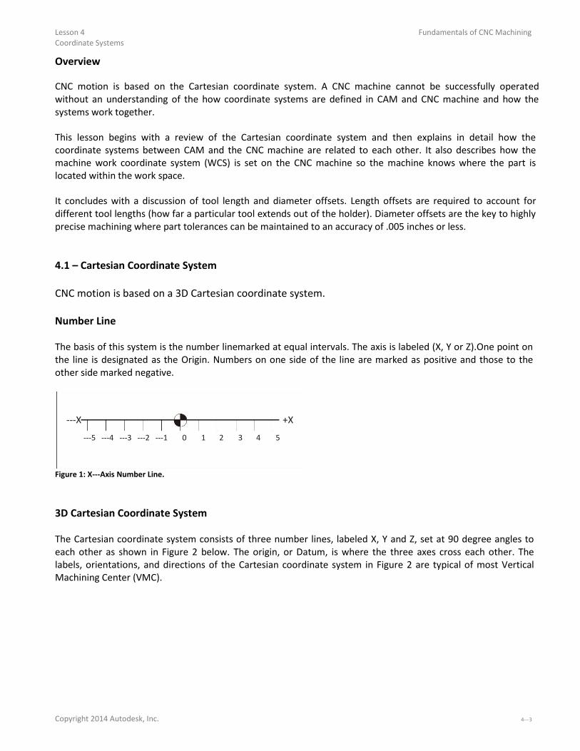
Number Line
The basis of this system is the number linemarked at equal intervals. The axis is labeled (X, Y or Z).One point on
the line is designated as the Origin. Numbers on one side of the line are marked as positive and those to the
other side marked negative.
-X +X
- - - - - 0 1 2 3 4 5
Figure 1: X-A is Nu er Li e.
3D Cartesian Coordinate System
The Cartesian coordinate system consists of three number lines, labeled X, Y and Z, set at 90 degree angles to
each other as shown in Figure 2 below. The origin, or Datum, is where the three axes cross each other. The
labels, orientations, and directions of the Cartesian coordinate system in Figure 2 are typical of most Vertical
Machining Center (VMC).
Copyright 2014 Autodesk, Inc. 4-

Fundamentals of CNC Machining Lesson 4 Coordinate Systems
+Z
+Y
-X
+X
-Y
-Z
Figure 2: 3D Cartesian Coordinate System
Quadrants
Any two axes form a plane.Planes are named by the axes that define them. For example, Figure 3 shows the XY
plane, which is the primary work plane for machining on a VMC.A plane can be divided into four quadrants,
labeled I, II, III and IV with axes designations as shown in the illustration below.
+Y
II I -X, +Y +X, +Y
-X +X
III IV -X, -Y +X, -Y
-Y Figure 3: Quadrants
4-

Lesson 4 Coordinate Systems
Fundamentals of CNC Machining
Units
CNC Programs can be written in either Inch or Metric units. The machine can be switched with a single code to
accept either.
In the United States, most programming is using inch units because most tooling is in inches and machinists are
more familiar with the inch measurement system. Even if the part is designed in metric, it is usually converted
to inch units for machining and metric tools are used only when no inch equivalent is available (for example
when creating metric tapped holes).
Table 1 lists the units and maximum precision for inch and metric data used by CNC machines.
Units and Precision
Data Type Inch Units Metric Units
Coordinate inches .0001 mm .001
Speed rev/min 1. rev/min 1.
Feed in/min 1. mm/min 1.
Tap Feed in/min .001 mm/min .01
4.2 Vertical Milling Center (VMC) Machine Motion
CNC machines use a 3D Cartesian coordinate system. Figure 4 shows a typical VMC with the sheet metal covers
removed to expose the movable parts. Material to be machined is fastened to the machine table. This table moves in the XY-Pla e. As the ope ato faces the machine, the X-A is o es the ta le left- ight. The Y-A is o es the ta le fo a d- a k a d. The machine column grips and spins the tool. The column controls the Z-a is a d o es up-do .
Column
(Z)
Table
(Y)
(X)
Figure 4: VMC Machine Motion
Copyright 2014 Autodesk, Inc. 4-

Fundamentals of CNC Machining Lesson 4 Coordinate Systems
CNC Motion Control
Most CNC machines can position each axis within .0002 inches or less overthe entire machining envelope. This
accuracy is achieved in part by the use of a closed-loop se o e ha is , illust ated i Figu e . The machine control sends a motion signal, via a controller board, toa servomotor attached to each machine
axis. This causes the servomotor to rotate a ball screw attached to thetable or column, causing it to move. The
actual position of the axis is continuously monitored and compared to the commanded positionwith feedback
from a servo transmitter attached to the ball screw.
Ball screws have almost no backlash, so when the servo reverses direction there is almost no lagbetween a
commanded reversing motion and corresponding change in table direction. CNC controls employ electronic
compensation to adjust for any minor backlash that may exist.
1. Command to
Servomotor 3. Table Motion
2. Rotate Ball Screw
4. Position Feedback
Figure 5: Closed Loop Servo Mechanism
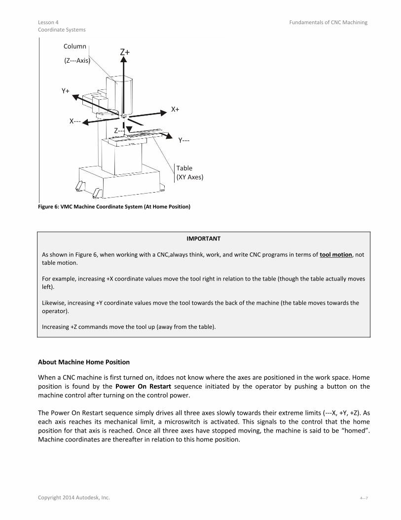
CNC Machine Coordinates
The CNC Machine Coordinate System is illustrated in Figure 6. The control point for the Machine Coordinate
System is defined as the center-fa e of the a hi e spi dle.
The Origin point for the machine coordinate system is calledMachine Home. This is the postion of the center- face of the machine spindle when the Z-a is is full et a ted a d the ta le is o ed to its li its ea the a k-
left o e .
4-
Lesson 4 Fundamentals of CNC Machining Coordinate Systems
Column
(Z-A is Z+
Y+
X+
X- Z-
Y-
Table (XY Axes)
Figure 6: VMC Machine Coordinate System (At Home Position)
IMPORTANT
As shown in Figure 6, when working with a CNC,always think, work, and write CNC programs in terms of tool motion, not
table motion.
For example, increasing +X coordinate values move the tool right in relation to the table (though the table actually moves
left).
Likewise, increasing +Y coordinate values move the tool towards the back of the machine (the table moves towards the
operator).
Increasing +Z commands move the tool up (away from the table).
About Machine Home Position When a CNC machine is first turned on, itdoes not know where the axes are positioned in the work space. Home
position is found by the Power On Restart sequence initiated by the operator by pushing a button on the
machine control after turning on the control power.
The Power On Restart sequence simply drives all three axes slowly towards their extreme limits (-X, +Y, +Z . As each axis reaches its mechanical limit, a microswitch is activated. This signals to the control that the home
position for that axis is reached. Once all three axes have stopped moving, the machine is said to be homed .
Machine coordinates are thereafter in relation to this home position.
Copyright 2014 Autodesk, Inc. 4-

Fundamentals of CNC Machining Lesson 4 Coordinate Systems
4.3 Work Coordinate System
Obviously it would be difficult to write a CNC program in relation to Machine Coordinates. Thehome position is
far away from the table, so values in the CNC program would be large and have no easily recognized relation to
the part model. To make programming and setting up the CNC easier, a Work Coordinate System (WCS) is
established for each CNC program.
The WCS is a point selected by the CNC programmer on the part, stock or fixture. While the WCS can be the
same as the part origin in CAD, it does not have to be. While it can be located anywhere in the machine
envelope, its selection requires careful consideration. The WCS location must be able to be found bymechanical means such as an edge finder, coaxial indicator
or part probe. It must be located with high precision: typically plus or minus .001 inches or less. It must be repeatable: parts must be placed in exactly the same position every time. It should take into account how the part will be rotated and moved as different sides of the part are
machined.
Top View Left View
Fixed Vise Jaw
Z+
For example, Figure 7 shows a part
gripped in a vise. The outside
dimensions of the part have already
been milled to size on a manual
machine before being set on the CNC
machine.
The CNC is used to make the holes,
pockets, and slot in this part. The
WCS is located in the upper-left corner of the block. This corner is
Y+
X+
easily found using an Edge Finder or Probe (Lesson 5).
Figure 7: Work Coordinate System (WCS)
WCS Example
The following example shows why and how the WCS is set up a typical part that is machined on multiple sides by
gripping in a vise. This is one of the most common ways to hold a part. Pay particular attention how the part is
rotated between jobs.
Job
The term, Job, means a unique machining setup on the machine. For example, a part that requires the part to be
moved or rotated three times on the CNC is said to be composed of three jobs; one for each setup.

4- Coordinate Systems WCS Example – Job 1
Figure 12 shows a part gripped in a six inch wide precision CNC vise. The outside shape of this part was machined
to size on a manual mill before being set on the CNC machine. The CNC is used to create the holes, pockets, and
slot on this block.
Fixed Vise Movable
Z+ Jaw Vise
Jaw
Y+ X+
Vise Stop
Figure 12: Tool Length Offset Example (Job 1)
Before clamping the part, the vise is aligned and bolted to the machine table. This assures the part WCS -Xa is is aligned with the machine X-a is.
Parallels (precision ground rails) are used to support the part. These ensure the XY-Pla e of the pa t is pa allel to the machine table XY-Pla e.
The left face of the part rests against a Vise Stop. The Vise Stop establishes the X-a is o igi . As e pa ts a e loaded into the vise, the operator slides them against the vise stop. This ensures all parts are loaded into the
exact same position each time. Because the edges of the block are already milled, the WCS XY location is easily found using an Edge Finder
(Lesson 6, Set Fixture Offset XY) or part probe.
The vise has two jaws; a fixed back jaw a front jaw that can close and open to grip or release the part. Because the
location of the moving jaw varies depending how much force the operator uses, it is best to locate the WCS in
reference to the fixed jaw. The fixed jaw position is not significantly affected by clamping force.
Notice that, because the fixed vise jaw does not move regardless of how tightly the vise is closed, the WCS -Y origin does not change. In other words, the Y-o igi is repeatable. The concept of repeatability is essential to
precision machining. If the datum shifts for any reason, it is impossible to make any two parts exactly alike.
When using a vise, locate the WCS so the part lies in the forth quadrant: resting the Y-datu XZ Pla e agai st the fixed vise jaw.
Copyright 2014 Autodesk, Inc. 4-

Fundamentals of CNC Machining Lesson 4 Coordinate Systems
WCS Example – Job 2
After the pocket, holes, and through round hole are machined on the first side of the part, the part is flipped over
in the vise to create the slot. Whether a new WCS must be defined, and how the part is flipped, depends on the
part geometry and type of setup.
As shown in Figure 13, because the outside dimensions of the part were established prior to machining, and
because the part is flipped 180 degrees, the location of the WCS does not change. Therefore, there is no need to
define a new WCS to machine the slot. Fixture Offset G54 can be used to machine both sides.
However, how the part is turned over does matter because of how a vise works. As mentioned earlier, a vise
exerts a tremendous amount of clamping force (up to 6,000 lbs or more) and so the actual position of the moving
vise jaw depends on how tightly the vise is closed.
This variability is so large that it is common practice to mark the closed position of the handle with a black marker
or use a torque wrench to ensure the clamping pressure is consistent between parts. Vise force can even
significantly deform thin parts if excessive force is applied.
Flip Part About Y-A is
Z+
X+
Y+
Figure 13: WCS (Job 2)
By flipping the part about the Y-axis, the same edge of the part (XZ Plane) rests against the fixed jaw. Since this
position does change based on clamping force, and because the vise stop is also unaffected by clamping force, the
WCS for Job 2 is also repeatable. 4-

Lesson 4 Fundamentals of CNC Machining Coordinate Systems WCS Example – Job 3
Drilling the hole in the side of the part means turning it again to stand on end, as shown in Figure 14. Again, rotate
the part about the Y-a is so that the Y-o igi of the WCS (XZ reference) plane does not shift or change based on
clamping force.
Notice that the WCS used in Job 1 and 2 cannot be used because the part standing on end is much taller.A new
Fixture Offset is defined (G55) to shift the datum to the point shown.
It is also worth noticing that, in order to increase gripping surface, the parallels have been removed. The vise
stop has also been lowered so the stylus contacts the face of the part, not the bottom of the pocket.
The best practice is to maintain as many reference surfaces as possible whenever the part is rotated. By turning
the part as shown in Figure 14, two of the reference planes are used. This helps ensure the hole will be located
precisely on the part side.
As a practical matter, the machinist could set up a second vise on the machine for this operation. If making many
parts without a second vise, they might choose to machine the top and bottom of all parts, then reconfigure the
vise as shown and make the hole in all parts.
Z+
Flip Part X+ About Y-A is
Y+ Figure 14: WCS (Job 3)
CNC machining typically involves tolerances of less than .005 inches, orabout twice the thickness of a human hair. Small
chips or even excess coolant under a part or vise can cause problems.Maintaining close machining tolerances requires
being fastidious and consistency of work.
Copyright 2014 Autodesk, Inc. 4-

Fundamentals of CNC Machining Lesson 4 Coordinate Systems
4.4 Machine and Tool Offsets
Machine Offsets
Because it is difficult to place a vise in the exact same position on the machine each time, the distance from Home
to the WCS is usually not known until the vise is set and aligned with the machine. Machine set up is best done
after the program is completely written, because it is expensive to keep a CNC machine idle waiting for the CNC
programming to be done. Besides, the programmer may change their mind during the CAM process, rendering
any pre-pla ed setup o solete.
To complicate matters further, different tools extend out from the machine spindle different lengths, also a value
difficult to determine in advance. For example, a long end mill extends further from the spindle face than a stub
length drill. If the tool wears or breaks and must be replaced, it is almost impossible to set it the exact length out
of the tool holder each time.
Therefore, there must be some way to relate the Machine Coordinate system to the part WCS and take into
account varying tool lengths. This is done using machine Tool and Fixture Offsets. There are many offsets
available on CNC machines. Understanding how they work and to correctly use them together is essential for
successful CNC machining.
Fixture Offset XY
Fixture offsets provide a way for the CNC control to know the distance from the machine home position and the
part WCS. In conjunction with Tool Offsets, Fixture Offsets allow programs to be written in relation to the WCS
instead of the Machine Coordinates. They make setups easier because the exact location of the part in the
machine envelop does not need to be known before the CNC program is written.
X+
Machine
Home Y-
Part Datum
As long as the part is positioned where
the tool can reach all machining
operations it can be located anywhere in
the machine envelope. Once the Fixture
Offset values are found, entered into the
control, and activated by the CNC
program, the CNC control works behind
the scene to translate program
coordinates to WCS coordinates.
Notice in Figure 8 how Fixture Offsets
(+X, -Y) are used to shift the centerline
of the machine spindle directly over the
WCS.
Figure 8: Fixture Offset Shifts Machine to WCS
4-

Lesson 4 Fundamentals of CNC Machining Coordinate Systems Fixture Offset Z
The Fixture Offset Z value is combined with the Tool Length offset to indicate to the machine how to shift the Z-
datu f o pa t ho e to the pa t Z-ze o, taki g i to a ou t the le gth of the tool. Fi tu e Offset Z a o may not be used, depending on how the machine is set up and operated.
Lesson 6 (CNC Operation) and Appendix B (Alternate Tool Setting Methods) describe the various ways that these
two values can be used. Follow the procedure in use at your facility or refer to your machine tool documentation
to determine which method to use.
Tool Length Offset (TLO)
Every tool loaded into the machine is a different length. In fact, if a tool is replaced due to wear or breaking, the
length of its replacement will likely change because it is almost impossible to set a new tool in the holder in
exactly the same place as the old one. The CNC machine needs some way of knowing how far each tool extends
from the spindle to the tip. This is accomplished using aTool Length Offset (TLO).
In its simplest use, the TLO is found by jogging the spindle with tool from the machine home Z-positio to the part Z-ze o positio , as sho o the fa left i Figu e elo . The tool is jogged to the pa t datu Z a d the distance travelled is measured. This value is entered in the TLO register for that tool. Problems with this method
include the need to face mill the part to the correct depth before setting tools. Also, if the Z-datu is ut a a (typical of 3D surfaced parts) it is impossible to set the datum should a tool break or wear and need to be
replaced. All tools must be reset whenever a new job is set up. When this method is used, the Fixture Offset Z is
not used, but set to zero.
The method shown in the center is much better and used in this book. All tools are set to a known -Zposition,
such the top of a precision 1- - lo k esti g o the a hi e ta le. This akes it e eas to eset tools if worn or broken.
A tool probe is very similar to the 1- - lo k ethod, e ept the a hi e uses a spe ial le to automatically find the TLO. It does this slowly lowering the tool until the tip touches the probe and then updates
the TLO register. This method is fast, safe and accurate but requires the machine be equipped with a tool probe.
Also, tool probes are expensive so care must be taken to never crash the tool into the probe.
Both the 2nd
and 3rd
methods also require the distance from the tool setting position (the top of the - - block or tool probe) to the part datum to be found and entered in the Fixture Offset Z. The machine adds the two
values together to determine the total tool length offset. A method for doing this is included in Lesson 6.
Copyright 2014 Autodesk, Inc. 4-

Fundamentals of CNC Machining Lesson 4 Coordinate Systems
Figure 9: Ways to Set TLO
4-

Fundamentals of CNC Machining
Lesson 5
CNC Programming Language
Upon successful completion of this lesson, you will be able to: Define CNC Program. List the sequence of operations in a typicalCNC program. List the most commonly used G- odes, thei ea i g, a d s ta . List the most commonly used M- odes, thei ea i g, a d s ta . List the most commonly used special characters in a CNC Program and their
purpose. Describe the organization, motion, and actions in a simple CNC program.
5-

Fundamentals of CNC Machining Lesson 5 CNC Programming Language
5-

Lesson 5 Fundamentals of CNC Machining CNC Programming Language
Overview
CNC machines are very accurate and powerful industrial robots developed jointly by Mr. John Parsons, IBM
and Massachusetts Institute of Technology Servomechanism Laboratory in the 1950 s. Most CNC machine tools use a language set by the Electronics Industry Association (EIA) in the 1960 s.The
official name of this language is RS- D, ut e e o e efe s it G- ode or G&M Code because many
of the words of this language begin with the letters G or M.
While many of the words used by different CNC machines are the same, there are differences between
makes and models. This is due in part to machines having different configurations and options. For example,
a machine with a chip conveyor will have words to turn the conveyor on and off, while a machine without a
conveyor does not. So, while RS- D is a sta da d, it is ot igid o e fo ed. Al a s efe to the a hi e documentation for the exact words and syntax for your CNC machine.
Most machines have a vocabulary of at least a hundred words, but only about thirty that are used often.
These thirty or so words are best memorized because they appear in almost every CNC program and
knowing them helps you work more efficiently.
The G- ode la guage as de eloped he a hi e o t ols had e little e o . It as the efo e designed to be as compact as possible. While at first this language may seem arcane, the modern machine
tool language is the safest and most efficient way yet devised to control machine tool motion. G&M codes,
along with coordinates and other parameters, comprise what is called aCNC program.
5.1 CNC Language and Structure
CNC programs list instructions to be performed in the order they are written. They read like a book, left to
right and top-do . Ea h se te e i a CNC p og a is itte o a sepa ate li e, alled aBlock. Blocks are
arranged in a specific sequence that promotes safety, predictability and readability, so it is important to
adhere to a standard program structure. Typically, blocks are arranged in the following order:
1) Program Start 2) Load Tool 3) Spindle On 4) Coolant On 5) Rapid to position above part 6) Machining operation 7) Coolant Off 8) Spindle Off 9) Move to safe position 10) End program
The steps listed above represent the simplest type of CNC program, where only one tool is used and one
operation performed. Programs that use multiple tools repeat steps two through nine for each. Table 1 and Table 2 on the next pages show the most common G and M codes that should be memorized if
possible.
Copyright 2014 Autodesk, Inc. 5-

Fundamentals of CNC Machining Lesson 5 CNC Programming Language
Like any language, the G- ode la guage has ules. Fo e a ple, so e odes a e odal, ea i g the do not have to be repeated if they do not change between blocks. Some codes have different meanings
depending on how and where there are used. While these rules are covered in this chapter, do not concern yourself with learning every nuance of the
language. It is the job of the job of the CAD/CAM software Post Processor to properly format and write the
CNC program. Program Format
The program in Figure 1 below machines a square contour and drills a hole.
Block Description Purpose
% Start of program. Start
O0001 (PROJECT1) Program number (Program Name). Program
(T1 0.25 END MILL) Tool description for operator. N1 G17 G20 G40 G49 G80 G90 Safety block to ensure machine is in safe mode.
Change N2 T1 M6 Load Tool #1. N3 S9200 M3 Spindle Speed 9200 RPM, On CW. Tool
N4 G54 Use Fixture Offset #1. Move
N5 M8 Coolant On. To
N6 G00 X- . Y- . Rapid above part. Position
N7 G43 Z1. H1 Rapid to safe plane, use Tool Length Offset #1. N8 Z0.1 Rapid to feed plane. N9 G01 Z- . F . Line move to cutting depth at 18 IPM.
Machine N10 G41 Y0.1 D1 F36. CDC Left, Lead in line, Dia. Offset #1, 36 IPM. N11 Y2.025 Line move. Contour
N12 X2.025 Line move. N13 Y- . Line move. N14 X- . Line move. N15 G40 X- . Turn CDC off with lead-out o e. N16 G00 Z1. Rapid to safe plane.
Change N17 M5 Spindle Off. N18 M9 Coolant Off. Tool
(T2 0.25 DRILL) Tool description for operator. N19 T2 M6 Load Tool #2. N20 S3820 M3 Spindle Speed 3820 RPM, On CW.
Move N21 M8 Coolant On. N22 X1. Y1. Rapid above hole. To
N23 G43 Z1. H2 Rapid to safe plane, use Tool Length Offset 2. Position
N24 Z0.25 Rapid to feed plane. Drill N25 G98 G81 Z- . R . F . Drill hole (canned) cycle, Depth Z-. , F .
N26 G80 Cancel drill cycle. Hole
N27 Z1. Rapid to safe plane. End N28 M5 Spindle Off.
N29 M9 Coolant Off. Program
N30 G91 G28 Z0 Return to machine Home position in Z. N31 G91 G28 X0 Y0 Return to machine Home position in XY. N32 G90 Reset to absolute positioning mode (for safety). N33 M30 Reset program to beginning. % End Program.
Figure 1: Simple CNC Program
5.2 - CNC Editor CNC programs are simple ASCII character text files that can be viewed or edited in any text editor.Refer to the
HSMWorks Editor Help files for specific instructions on how to use the Editor.
5-

Lesson 5 Fundamentals of CNC Machining CNC Programming Language
5.3 – Alphabetic & Special Character Address Codes
Every letter of the alphabet is used as a machine address code. In fact, some are used more than once, and
their meaning changes based on which G- ode appea s i the sa e lo k. Codes are either modal, which means they remain in effect until cancelled or changed, ornon- odal, which means they are effective only in the current block.
The table below lists the most common address codes. A complete list is included in Appendix B, G-M Code Reference.
Code Meaning
A Rotation about X-a is. B Rotation about Y-a is. C Rotation about Z-a is. D Cutter diameter compensation (CDC) offset address.
F Feed rate.
G G-Code p epa ato ode . H Tool length offset (TLO).
I Arc center X-vector, also used in drill cycles.
J Arc center Y- e to , also used i d ill les. K Arc center Z- e to , also used i d ill les. M M-Code is ella eous ode . N Block Number.
O Program Number.
P Dwell time.
Q Used in drill cycles.
R Arc radius, also used in drill cycles.
S Spindle speed in RPM.
T Tool number.
X X- oo di ate. Y Y- oo di ate. Z Z- oo di ate.
Table 3: Common Alphanumeric Address Codes
Alphabetic Address Code Definitions
Here are the most common alphabetic address code definitions, examples and restrictions of use. Most
modern machines use these codes.
A,B,C 4th
/5th
Axis Rotary Motion
Rotation about the X, Y or Z-a is espe ti el . The a gle is i deg ees a d up to th ee de i al pla es p e ision. G1 A30.513 B90.
D Tool Diameter Register Used to compensate for tool diameter wear and deflection. D is accompanied by an integer that is the same as the tool
number (T1 uses D1, etc). No decimal point is used. It is always used in conjunction with G41 or G42 and a XY move
(never an arc). When called, the control reads the register and offsets the tool path left (G41) or right (G42) by the value
in the register. G1 G41 X1. D1
Copyright 2014 Autodesk, Inc. 5-

Fundamentals of CNC Machining Lesson 5 CNC Programming Language
F Feed Rate Sets the feed rate when machining lines, arcs or drill cycles. Feed rate can be in Inches per Minute (G94 mode) or Inverse
Time (G93 mode). Feed rates can be up to three decimal places accuracy (for tap cycles) and require a decimal point.
G1 X1. Y0. F18.
G Preparatory Code Always accompanied by an integer that determines its meaning. Most G- odes a e odal. E pa ded defi itio s of G-
odes appea i the e t se tio of this chapter.
G2 X1. Y1. I.25 J0.
H Tool Length Compensation Register This code calls a tool length offset (TLO) register on the control. The control combines the TLO and Fixture Offset Z
values to know where the tool is in relation to the part datum. It is always accompanied by an integer (H1, H2, etc),
G43, and Z coordinate. G43 H1 Z1.
I Arc Center or Drill Cycle Data For arc moves (G2/G3), this is the incremental X-dista e f o the a sta t poi t to the a e te . Ce tai d ill les also use I as an optional parameter.
G2 X.1 Y2.025 I0. J0.125
J Arc Center or Drill Cycle Data For arc moves (G2/G3), this is the incremental Y-dista e f o the a sta t poi t to the a e te . Ce tai d ill les also use J as an optional parameter.
G2 X.1 Y2.025 I0. J0.125
K Arc Center or Drill Cycle Data For an arc move (G2/G3) this is the incremental Z-dista e f o the a sta t poi t to the a e te . I the G pla e, this is the incremental Z-dista e fo heli al o es. Ce tai d ill les also use J as an optional parameter. G18 G3 X.1 Z2.025 I0. K0.125
M Preparatory Code Always accompanied by an integer that determines its meaning. Only one M- ode is allo ed i ea h lo k of ode. Expanded definitions of M- odes appea late i this hapter. M8
N Block Number Block numbers can make the CNC program easier to read. They are seldom required for CAD/CAM generated programs
with no subprograms. Because they take up control memory most 3D programs do not use block numbers. Block
numbers are integers up to five characters long with no decimal point. They cannot appearbefore the tape start/end
character (%) and usually do not appear before a comment only block. N100 T2 M6
O Program Number Programs are stored on the control by their program number. This is an integer that is preceded by the letter O and has
no decimal places.
O0002 (PROJECT 1)
P Delay
Dwell (delay) in seconds. Accompanied by G4 unless used within certain drill cycles.
G4 P.1
5-

Lesson 5 Fundamentals of CNC Machining CNC Programming Language
Q Drill Cycle Optional Data The incremental feed distance per pass in a peck drill cycle. G83 X1. Y1. Z-. F . R. Q. P .
R Arc Radius or Drill Cycle Optional Data Arcs can be defined using the arc radius R or I,J,Kvectors. IJK s are more reliable than R s so it is recommended to use
them instead. R is also used by drill cycles as the return plane Z value. G83 Z-. F . R. Q. P .
S Spindle Speed Spindle speed in revolutions per minute (RPM). It is an integer value with no decimal, and always used in conjunction
with M3 (Spindle on CW) or M4 (Spindle on CCW).
S3820 M3
T Tool number Selects tool. It is an integer value always accompanied by M6 (tool change code). T1 M6
X X-Coordinate
Coordinate data for the X-a is. Up to four places after the decimal are allowed and trailing zeros are not used.
Coordinates are modal, so there is no need to repeat them in subsequent blocks if they do not change. G1 X1.1252
Y Y-Coordi ate Coordinate data for the Y-a is. G1 Y1.
Z Z-Coordi ate Coordinate data for the Z-a is. G1 Z-.
Special Character Code Definitions
The following is a list of commonly used special characters, their meaning, use, and restrictions.
% Program Start or End All programs begin and end with % on a block by itself. This code is called tape rewind character (a holdover from the
days when programs were loaded using paper tapes).
( ) Comments Comments to the operator must be all caps and enclosed within brackets. The maximum length of a comment is 40
characters and all characters are capitalized.
(T2: .375 END MILL)
/ Block Delete Codes after this character are ignored if the Block Delete switch on the control is on. / M0
Copyright 2014 Autodesk, Inc. 5-
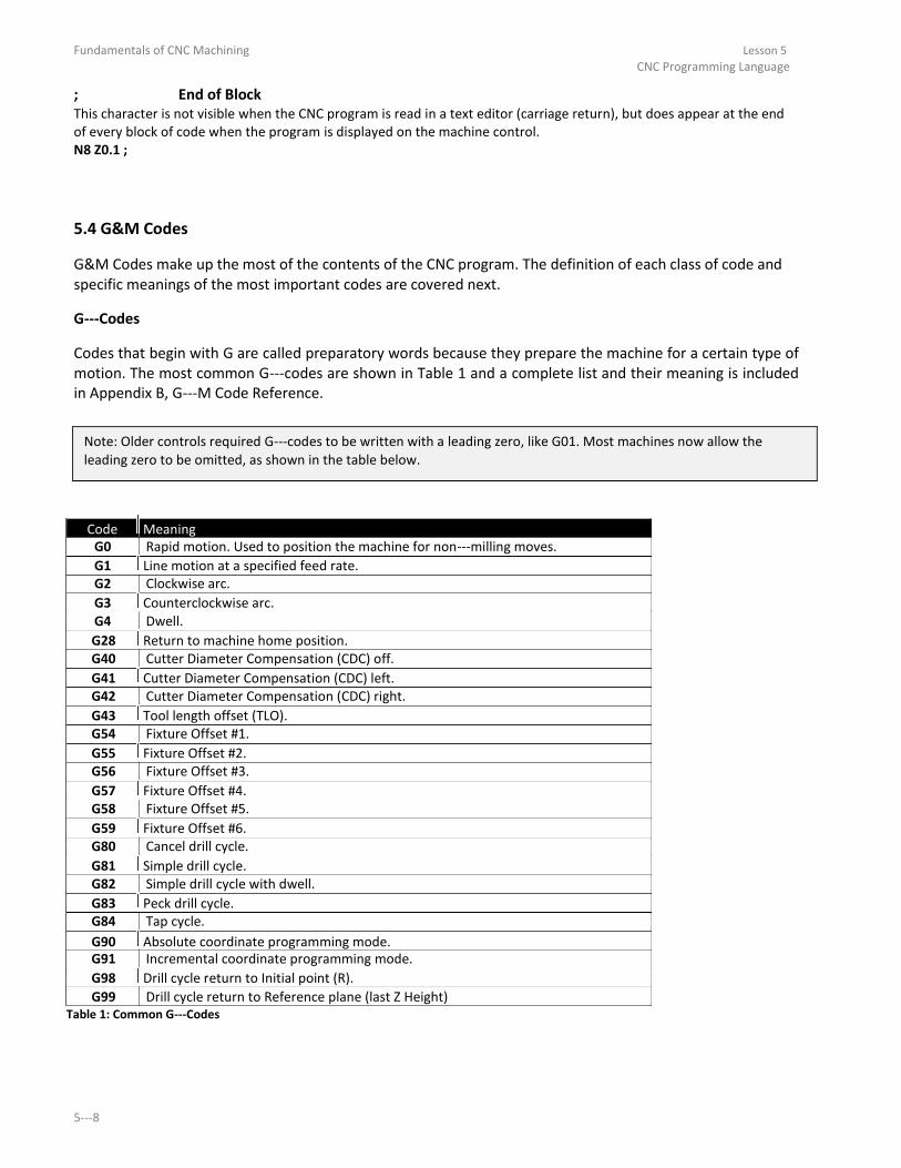
Fundamentals of CNC Machining Lesson 5 CNC Programming Language
; End of Block This character is not visible when the CNC program is read in a text editor (carriage return), but does appear at the end
of every block of code when the program is displayed on the machine control. N8 Z0.1 ;
5.4 G&M Codes
G&M Codes make up the most of the contents of the CNC program. The definition of each class of code and
specific meanings of the most important codes are covered next.
G-Codes
Codes that begin with G are called preparatory words because they prepare the machine for a certain type of
motion. The most common G- odes a e sho i Ta le a d a o plete list a d thei ea i g is i luded in Appendix B, G-M Code Refe e e.
Note: Older controls required G- odes to e itte ith a leadi g ze o, like G . Most a hi es o allo the leading zero to be omitted, as shown in the table below.
Code Meaning
G0 Rapid motion. Used to position the machine for non- illi g o es. G1 Line motion at a specified feed rate.
G2 Clockwise arc.
G3 Counterclockwise arc. G4 Dwell.
G28 Return to machine home position. G40 Cutter Diameter Compensation (CDC) off.
G41 Cutter Diameter Compensation (CDC) left. G42 Cutter Diameter Compensation (CDC) right.
G43 Tool length offset (TLO). G54 Fixture Offset #1.
G55 Fixture Offset #2. G56 Fixture Offset #3.
G57 Fixture Offset #4. G58 Fixture Offset #5.
G59 Fixture Offset #6. G80 Cancel drill cycle.
G81 Simple drill cycle. G82 Simple drill cycle with dwell.
G83 Peck drill cycle.
G84 Tap cycle.
G90 Absolute coordinate programming mode.
G91 Incremental coordinate programming mode.
G98 Drill cycle return to Initial point (R). G99 Drill cycle return to Reference plane (last Z Height)
Table 1: Common G-Codes
5-

Lesson 5 Fundamentals of CNC Machining CNC Programming Language
M-Codes
Codes that begin with M are called miscellaneous words. They control machine auxiliary options like coolant
and spindle direction. Only one M- ode a appea i ea h lo k of ode. The table below lists the most common M codes and their meaning. A complete list of M- odes is i luded in Appendix B, G-M Code Refe e e.
Code Meaning
M0 Program stop. Press Cycle Start button to continue.
M1 Optional stop. Only executed if Op Stop switch on the CNC control is turned ON.
M2 End of program.
M3 Spindle on Clockwise.
M4 Spindle on Counterclockwise.
M5 Spindle stop. M6 Change tool.
M8 Coolant on. M9 Coolant off.
M30 End program and press Cycle Start to run it again. Table 2: Common M-Codes
5.5 Select G-Code Defi itio s E pa ded
G0 Rapid Move This code commands the machine to move as fast as it can to a specified point. It is always used with a coordinate
position and is modal. Unlike G1, G0 does not coordinate the axes to move in a straight line. Rather, each axis moves at
its maximum speed until it is satisfied. This results in dogleg motion as shown inFigure 2, below. G0 X0. Y0.
Machine Home
Actual Path G54
G0 G54 X0 Y0
Figure 2: G0 Dogleg Motion
Caution: The rapid speed of some machines can exceed 1,000 IPM. A incorrect offset or coordinate move can crash the
machine faster than the operator can hit the emergency stop. Usethe rapid feed override on the machine when running
a program for the first time.
Copyright 2014 Autodesk, Inc. 5-

Fundamentals of CNC Machining Lesson 5 CNC Programming Language
G1 Linear Move This command moves the tool in a straight line at a programmedfeed rate. G1 X1. Y1.1255 F32.
G2/G3 CW/CCW Arc G2 commands clockwise arcs. G3 commands counterclockwise arcs. Arcs must exist on a plane (G17/G18/G19) and
include the coordinates of the arc end point and IJK vectors indicating the arc center location.
J
I
G2 X0. Y-. I . J-. G3 X-. Y . I-. J .
Figure 3: G2/G3 Arcs
G17/G18/G19 Plane Designation Arcs must exist on a plane designated by the command G17 (XY), G18 (XZ) or G19 (YZ). G17is the machine default.
Y+
G17 X+
Z+ Z+
Y+ G18 X+
Z+
X+ G19 Y+
Figure 4: Plane Designations
G40/G41/G42 Cutter Diameter Compensation (CDC)
CDC is a key to precision CNC machining, allowing the operator to compensate for tool wear and deflection by
commanding the machine to veer left (G41) or right (G42) from the programmed path. G40 cancels cutter
compensation. The amount of offset is entered in a CNC control D- egiste . The ea egiste a e thought of like a table that the control refers to with every move.
Tool Diameter Offset Value
D1 0.0020
D2 0.0000
D3 0.0000
D4 0.0000
D5 0.0000
D6 0.0000 Figure 5: Diameter Offset Register
5-

Lesson 5 Fundamentals of CNC Machining CNC Programming Language
The value in the D- egiste is al ulated the a hi e tool ope ato , ho o itors the finished size of part features,
compares them with the print, and enters the difference in the register as needed to keep the part within
specifications. If there is no deviation, the register is set to zero. G1 G41 D1 X1.0 Y.25 F36.
G43 Tool Length Compensation G43 activates tool length compensation. It isalways accompanied by an H- ode a d Z- o e, he e H is the tool length offset (TLO) register to read, and Z isthe height to go to in reference to the part datum.
The (TLO) can be thought of like a table on the control:
Tool Length Resister
H1 H2 H3 H4 H5 H6
Figure 6: Work Offsets
Z
12.6280 6.3582 9.7852 6.8943 10.5673 7.1258
The TLO is combined with the active fixture offset on the control so the machine knows where the tip of the tool is in
relation to the part datum. The process for finding the TLO detailed in Lesson 6, CNC Operation.
G43 H1 Z1.
G54 Work Offset
Work offsets are data registers in the CNC control that hold the distance from the machine home X, Y, Z position to the
part datum. These offsets can be thought of like a tableon the control:
Work Offset X Y Z
G54 14.2567 6.6597 2.0183
G55 0.0000 0.0000 0.0000
G56 0.0000 0.0000 0.0000
G57 0.0000 0.0000 0.0000
G58 0.0000 0.0000 0.0000
G59 0.0000 0.0000 0.0000 Figure 7: Work Offsets
Tip: G54 is usually used for the first machining setup. Additional offsets are used to
machine other sides of the part. The X and Y values represent the distance from the machine home to part datum XY. The Z value is the distance from
the tool reference point (for example, the top of a 1- - lo k a d the pa t Z-datu . The p o ess fo fi di g TLO and fixture offset Z is detailed in Lesson 6, CNC Operation.
G54 X0. Y0.
Copyright 2014 Autodesk, Inc. 5-

Fundamentals of CNC Machining Lesson 5 CNC Programming Language
5.6 Canned Cycles
Canned cycles are special codes that act like a macro. They are used for holemaking and allow one compact
block of code to command many moves. For example, a hole can be created using a peck drill cycle with two
lines of code (left column) whereas the same move would require maybe twenty or more lines of code if each
motion was commanded separately (right column).
Canned Cycle N70 G98 G83 X1. Y1. Z- . R . Q . P0 F9. N75 G80
Equivalent Motion: Expanded Code N70 Z0.06 N75 Z0.04
N80 G01 Z- . F . N85 G00 Z0.06
N90 Z- .
N95 G01 Z- .
N100 G00 Z0.06
N105 Z- .
N110 G01 Z- . . N115 G00 Z0.06
N120 Z- .
N125 G01 Z- . . N130 G00 Z0.06
N135 Z- .
N140 G01 Z- .
N145 G00 Z0.06
N150 Z- .
N155 G01 Z- . . N160 G00 Z0.06
N165 Z- .
N170 G01 Z- . . N175 G00 Z0.25
Figure 8: Canned Cycle vs. Expanded Code
G81 Simple Drill Cycle This cycle makes holes by feeding to depth at a programmed feed rate and then retracting at rapid rate. It is
accompanied by G98 or G99, XYZ coordinates, feed rate, and R. R is the feed plane and Z is final depth of the tool tip.
All drill cycles are accompanied by G98 or G99 that determine how high the tool retracts between holes. G0 Z1. G43 H1
G98 G81 X.5 Y.5 Z- . R. F9. 5-

Lesson 5 Fundamentals of CNC Machining
CNC Programming Language
Initial Rapid Height (Z1.0)
Feed Plane (R.1)
Z+
Depth (Z- .
X+ Figure 9: G81 Simple Drill Cycle
G82 Spot Drill Cycle This cycle is identical to G81 except it includes a dwell value, P (in seconds). P is used to pause the tool feed rate at the
final depth to create a clean countersink or counterbore finish.
G0 Z1. G43 H1
G98 G82 X.5 Y.5 Z-. 9 P. R . F9.
G83 Peck Drill A peck drill cycle is used on deep holes. The tool drills an incremental distance (Q) and then fully retracts from the hole.
This breaks the chip, clears material out of the hole, and allows coolant to cool the drill and flush out the hole, reducing
the chance of the tool breaking and producing a better quality hole. The simplest form of this cycle is shown in Figure 8.
Another version of this cycle, called a "deep drill cycle", uses I,J,K parameters to reduce the amount of peck as the hole
gets deeper. G0 Z1. G43 H1
G83 X.5 Y.5 Z- . R . Q. F9.
Copyright 2014 Autodesk, Inc. 5-

Fundamentals of CNC Machining Lesson 5
CNC Programming Language
Initial Rapid Height (Z1.0)
Feed Plane (R.1)
Peck Increment (Q.25)
Z+ Depth (Z- .
X+ Figure 10: G83 Peck Drill Cycle
G84 Tap Cycle Most modern machines support rigid tapping, which eliminates the need to use special tapping attachments. Rigid
tapping precisely coordinates the spindle speed and feed to match the lead of the thread. It then stops and reverses the
spindle at the bottom of the cycle to retract the tap. The parameters for the tap cycle are identical to simple drilling
(G81). G0 Z1. G43 H1
G84 X.5 Y.5 Z- . R . F .
G90 Absolute Positioning This code commands the machine to interpret coordinates as absolute position moves in the active Work Coordinate
System. All programs are written in absolute coordinates.
G90 G0 X1. Y1.
G91 Incremental Positioning This code commands the machine to interpret coordinates as incremental position moves. G91 is used by subprograms
but most programming done with CAD/CAMsoftware and does not use subprograms.
The only common use of G91 is in combination with G28 tosend the machine back to its home position at the end of
the program. The machine must be set back to G90 mode in the next blockas a safety measure. G91 G28 Z0.
G90
G98 Return to Initial Rapid Height This code is used in drill cycles to retract the tool to the clearance plane (set in the next previous block) between holes
to avoid clamps.
G0 Z1. G43 H1
G98 G81 Z- . R . F .
5-

Lesson 5 Fundamentals of CNC Machining
CNC Programming Language
Initial Rapid Height (Z1.0)
Feed Plane (R.1)
Z+
X+ Figure 11: G98 (Return to Clearance Plane)
G99 Return to R-Pla e
This code is used in drill cycles to retract the tool to the rapid plane (R) between holes. G99 mode is the machine
default and is used when clamp clearance between holes is not an issue. G0 Z1. G43 H1
G99 G81 Z- . R . F .
Initial Rapid Height (Z1.0)
Feed Plane (R.1)
Z+
X+ Figure 12: G99 Motion (Return to R-Pla e
Copyright 2014 Autodesk, Inc. 5-

Fundamentals of CNC Machining Lesson 5 CNC Programming Language
5-

Fundamentals of CNC Machining
Lesson 6
CNC Operation
Upon successful completion of this lesson, you will be able to: List the steps to set up and operate a CNC mill. Identify the location and purpose of the operating controls on the Haas CNC Mill
control. Start and home a CNC machine. Load tools into tool carousel. Set Tool Length Offsets. Set Fixture Offsets. Load a CNC program into the machine control. Safely run a new CNC program. Adjust offsets to account for tool wear and deflection. Shut down a CNC machine correctly.
6-

Fundamentals of CNC Machining Lesson 6 CNC Operation
6-

Lesson 6 CNC Operation Introduction & CNC Process Overview
6.1 Overview of CNC Setup and Operation
CNC machine setup and operation follows theprocess shown in Figure 1:
Pre-Sta t
Start/Home
Load Tools
Set Tool Length Offsets
Set Fixture Offset XY
Set Fixture Offset Z
Load CNC Program
Run Program
Adjust Offsets as Required
Shut Down Figure 1: CNC Process
Copyright 2014 Autodesk, Inc. 6-

Fundamentals of CNC Machining Lesson 6 CNC Operation
1 Pre-Start
Before starting the machine, check to ensure oil and coolant levels are full. Check the machine
maintenance manual if you are unsure about how to service it. Ensure the work area is clear of any
loose tools or equipment. If the machine requires an air supply, ensure the compressor is on and
pressure meets the machine requirements.
2 Start/Home Turn power on the machine and control. The main breaker is located at the back of the machine. The
machine power button is located in the upper-left o e o the o t ol fa e.
3 Load Tools Load tools into the tool carousel in the orderlisted in the CNC program tool list.
4 Set Tool Length Offsets For each tool used, jog the machine to find and then set the TLO.
5 Set Fixture Offset XY Once the vise or other fixture is properly installed and aligned on the machine, set the fixture offset to
locate the part XY datum.
6 Set Fixture Offset Z Use a dial indicator and 1- - lo k to fi d a d set the fi tu e offset Z.
7 Load CNC Program Download the CNC program from your computer to the machine control using RS- communications, USB flash memory, or floppy disk.
8 Run Program
Run the program, using extra caution until the program is proven to be error-f ee.
9 Adjust Offsets as Required Check the part features and adjust the CDC or TLO registers as needed to ensure the part is within
design specifications.
10 Shut Down
Remove tools from the spindle, clean the work area, and properly shut down the machine.Be sure to
clean the work area and leave the machine and tools in the location and condition you found them.
Warning Never operate a CNC machine or any shop equipment
unless you have been properly trained on its use.
Observe extreme caution at all times.
Follow all safety rules. 6-

Lesson 6 CNC Operation Introduction & CNC Process Overview
6.2 Machine and Tool Offsets
Fixture Offset XY
Figure 2 shows a plan view of how the Fixture Offset XY works. The CNC operator finds the fixture offset
values by jogging (moving) the machine from the machine at its home position the CNC program datum. This
can be any point on the part, stock, or fixture, as long as it can be found by mechanical means such as an
edge finder or part probe.
The incremental X and Y distances moved between points is recorded and entered into aFixture Offset
Register on the CNC control. Think of the Offset registers like a table in a spreadsheet. The CNC control
references these values in the table each time a motion is commanded, adding or subtracting them from
coordinates in the CNC program. In other words, Fixture XY offsetsconvert Machine Coordinates into WCS
coordinates. Most machine controls support at least six fixture offsets, labeled G54 thru G59. Multiple registers are needed
because most parts use a different fixture offset for each side of the part machined.
Fixture Offset Table Offset X Y Z
G54 10.5431 - . 0.0000
G55 0.00000 0.0000 0.0000
G56 0.00000 0.0000 0.0000
Machine Part Home
Datum X+
Y-
Y+
X+ Figure 3: Fixture Offset Plan View
The Fixture Offset Z- oo di ate is ot used to shift the Ma hi e Z. Use of the Fixture Offset Z is covered in the next topic.
Copyright 2014 Autodesk, Inc. 6-

Fundamentals of CNC Machining Lesson 6 CNC Operation
Fixture Offset Z
The purpose of the Fixture Offset Z is to record the incrementaldistance from a tool setting position to the
part datum. The tool set position can be a tool probe or, as shown in Figure 10, the top of a precision - -
lo k set o the a hi e ta le. The app oa h sho i Figu e i ol es usi g a dial i di ato a d hist process is detailed in Lesson 6 (CNC Operation: Set Fixture Offset Z).
The CNC control adds the Fixture Offset Z and Tool Length Offset for the active tool together to calculate the
distance from the tip of each tool at Home to the Z-datu o the pa t. Figure 10: Fixture Offset Z
There are many ways to set tool and fixture offsets. The method described here and detailed in Lesson 6, CNC Operation,
is precise, compatible with tool probe systems, and easy to understand and use once tried just a few times. Another
advantage is that the TLO can be reset easily, even if the part datum has been machined away, which is common with 3D
parts.
Appendix-E: Alte ate Tool Setti g Methods des i es th ee othe ethods that a e used to set up the machinetool length offsets.
To use the method described in this lesson on Haas Automation machines, machine control parameter 64 (T OFS USES
WORK) must be set to OFF. Refer to the Haas Programming and Operation manual for instructions on set this parameter. 6-

Lesson 6 CNC Operation Introduction & CNC Process Overview
Tool Length Offset (TLO)
Every tool loaded into the machine is a different length. In fact, if a tool is replaced due to wear or breaking,
the length of its replacement will likely change because it is almost impossible to set a new tool in the holder
in exactly the same place as the old one. The CNC machine needs some way of knowing how far each tool
extends from the spindle to the tip. This is accomplished using aTool Length Offset (TLO).
The TLO is found by jogging the spindle with tool from the machine home Z-positio to the tool setti g point on the machine. This can be the top of a tool probe, or as shown in Figure 11, the top of a - - block resting on the machine table. The distance travelled from home to the top of the block is recorded, and
the value entered into the TLO register for that tool (called an H- egiste , e ause it is p e eded the letter H in the CNC program).
If a tool wears or breaks, it can be replaced, the H- egiste eset to the e tool tou hi g off agai o the 1- - lo k, a d the p og a o ti ued ith o othe ha ges.
Tool Length Offset Table
H-Offset Z
H1 - .
H2 - .
H3 - .
ToolTipat Machine Home
Tool Length Part
Offset Z- Datu
Z+ 1- - Block
X+ Figure 11: Tool Length Offset
Copyright 2014 Autodesk, Inc. 6-

Fundamentals of CNC Machining Lesson 6 CNC Operation
Haas Control
The Haas control is shown in Figures 2 and 3. Familiarize yourself with the location of buttons and controls. Detailed instructions on the following pages show how to operate the control.
POWER ON POWER OFF
EMERGENCY STOP
HANDLE
- +
CYCLE START FEED HOLD
Figure 2: Haas CNC Mill Control
DISPLAY UP CHANGER EDIT INSERT ALTER DELETE UNDO
RESET
POWER TOOL
RESTORE
RESTART PRGRM
POSIT OFFSET
CURRENT
CONVRS COMDS SINGLE DRY OPT BLOCK
F1
F2
F3
F3
MEM BLOCK RUN STOP DELETE
ALARM PARAM SETNC HELP
MESGS DGNOS GRAPH CALC MDI COOLNT ORIENT ATC ATC
TOOL
NEXT
TOOL
PART
DNC SPINDLE FWD REV
OFSET TOOL RELEASE ZERO
MESUR SET
HOME PAGE HANDLE .0001 .001 .01 .1
UP JOG .1 1. 10. 100.
CHIP +B CLNT FWD
+A
+Z
-Y UP
CURSOR
SET
AXES AXIS ZERO AUTO
ORIGIN ZERO
HOME
ALL SINGL G28
CHIP +X
JOG -X
CLNT
STOP
LOCK DOWN
END
PAGE
LIST
SELECT SEND RECV ERASE
DOWN PROG PROG Rs232 Rs232 PROG
CHIP +Y -Z -A AUX
REV
-B CLNT
SHIFT A B C D E 7 8 9 OVERRIDES -10 100% +10 CONTROL
HANDLE
F
G
H
I
J K
4 5 6 FEEDRATE
FEEDRATE
FEEDRATE
FEEDRATE
-10 100% +10 CONTROL
HANDLE
L
M N
O
P Q
1 2 3 SPINDLE
SPINDLE
SPINDLE
SPINDLE
CW STOP CCW SPINDLE R S T U V W - 0
5% 25% 50% 100%
X
Y
Z
EOB ( )
CANCEL SPACE
WRITE
RAPID RAPID RAPID RAPID ENTER
6-

Co
py
righ
t 20
14
Au
tod
esk
, Inc.
6-
Figu
re
RESET POWER TOOL
UP
RESTORE
CHANGER
CN
CH
aa
s
RESTART
F1
F2
F3
F3
Co
ntro
l
TOOL
NEXT
TOOL
PART
Buttons
OFSET TOOL RELEASE ZERO
MESUR SET
CHIP
+B CLNT
+A
+Z
-Y
FWD UP
STOP +X
JOG -X DOWN
CHIP CLNT
LOCK
CHIP +Y -Z -A AUX
REV -B CLNT
OVERRIDES
-10 100% +10 CONTROL
HANDLE
FEEDRATE FEEDRATE FEEDRATE FEEDRATE -10 100% +10 CONTROL
HANDLE
SPINDLE SPINDLE SPINDLE SPINDLE
CW STOP CCW SPINDLE
5% 25% 50% 100%
RAPID RAPID RAPID RAPID
DISPLAY
EDIT INSERT
PRGRM POSIT
OFFSET
CURRENT
CONVRS
COMDS
SINGLE
MEM
BLOCK
ALARM PARAM SETNC HELP MESGS DGNOS GRAPH CALC
MDI COOLNT DNC
HOME
PAGE HANDLE .0001
UP
JOG .1
CURSOR
ZERO AUTO
ALL
SET AXES
END
PAGE LIST SELECT
DOWN PROG PROG
SHIFT A B C D E
F G H I J K
L M N O P Q
R S T U V W
X Y Z EOB ( )
ALTER DELETE UNDO
DRY OPT BLOCK
RUN STOP DELETE
ORIENT ATC ATC
SPINDLE FWD REV
.001 .01 .1
1. 10. 100.
ORIGIN
ZERO HOME
SINGL
G28
AXIS
SEND RECV ERASE
Rs232 Rs232 PROG
7 8 9
4 5 6
1 2 3
- 0
CANCEL SPACE WRITE
ENTER
In
trod
uctio
n
6Le
sson
O
ve
rvie
wP
roce
ssCN
C&
CN
C O
pe
ratio
n

Fundamentals of CNC Machining Lesson 6 CNC Operation
Start/Home Machine
Check List 1 Work Area: Clear
2 Air Supply: On/Correct Haas requires at least 70PSI for
toolchanger to operate.
3 Main Breaker: On 4 POWER ON: Press
Ensure Emergency Stop is not
tripped.If it is, twist red knob right to
release.
Wait until message102 SERVOS
OFFappears before proceeding.
5 RESET: Press
6 Power On Restart: Press Ensure doors are closed and work areais
clear. Allow all machine axes to home
beforeproceeding.
Buttons POWER ON
RESET
POWER
UP RESTART
POWER ON POWER OFF
4 EMERGENCY STOP
56U PCHANGER
DISPLAY EDIT INSERT ALTER DELETE UNDO
HANDLE
RESET POWER TOO L
RESTART RESTORE
- + PRGRM
POSIT OFFSET
CURRENT CONVRS COMDS SINGLE DRY OPT BLO CK
F1 F2
F3 F3 MEM BLO CK RUN STOP DELETE
ALARM PARAM SETNC HELP MESGS DGNOS GRAPH CA LC
ORIENT
MDI COO LNT ATC ATC
SPINDLE FWD REV TOOL NEX T TOOL PART DNC
OFSET TOO L RELEASE ZERO
MESUR SET
HOME
PAGE HA NDLE .0001 .001 .01 .1
UP JOG .1 1. 10. 100.
CHIP
+B CLNT
+A
FWD
+Z -Y UP
CURSOR SET
AUTO
ORIGIN
ZERO G28 AXES AXIS
ZERO ALL SINGL HOME
CHIP
+X JOG
-X CLNT
STOP LOCK D OW N
END
PAGE LIST SELECT SEND RECV ERASE
-A DOWN PROG PROG Rs232 Rs232 PROG
CHIP +Y -Z AUX REV -B CLNT
OVERRIDES
SHIFT A B C D E 7 8 9
-10 100% +10 CONTRO L HANDLE
F G H I J K 4 5 6 FEE DRA TE FEEDRATE FEEDRATE
FEEDRATE
-10 100% +10 CONTRO L
CYCLE START FEED HOLD HANDLE
L M N O P Q 1 2 3 SPINDLE SPINDLE SPINDLE SPINDLE
CW STOP CCW SPINDLE R S T U V W - 0
5% 25%
50% 100%
X Y Z EOB ( ) CANCEL SPACE
WRITE
RAPID RAPID
RAPID RAPID ENTER
Start/Home Sheet 1 of 1
6-
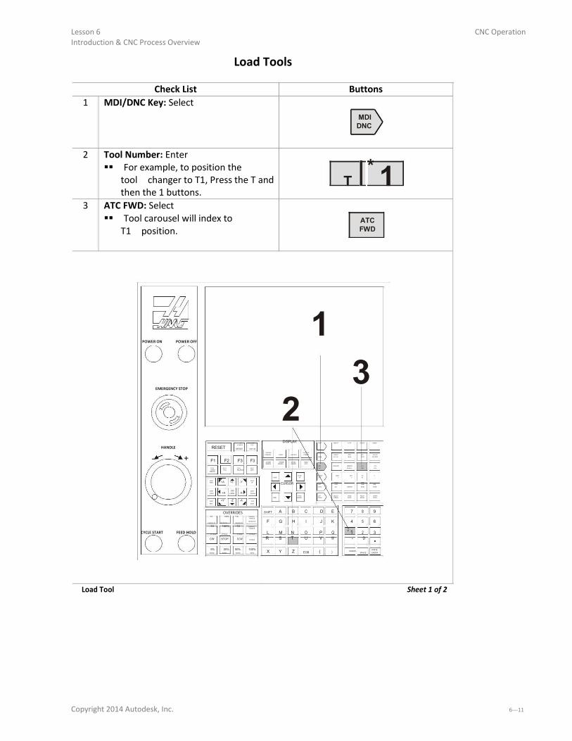
Lesson 6 Introduction & CNC Process Overview
Load Tools
Check List 1 MDI/DNC Key: Select
2 Tool Number: Enter For example, to position the
toolchanger to T1, Press the T and
then the 1 buttons. 3 ATC FWD: Select
Tool carousel will index to
T1position.
CNC Operation
Buttons
MDI DNC
T *
1
ATC FWD
POWER ON POWER OFF 1
EMERGENCY STOP
2 3
UP CHANGER
DISPLAY EDIT INSERT A LT ER DELETE UNDO
HANDLE RESET POWER TOO L
RESTART RESTO RE
- + PRGRM
POSIT OFFSET
CURRE NT CONVRS COMDS SINGLE DRY OPT BLO CK
F1 F2
F3 F3 MEM BLO CK RUN STOP DELETE
ALARM PARAM SETNC HELP MESGS DGNOS GRAPH CA LC
ORIENT
MDI COOLNT ATC ATC
TOOL NEX T TOOL PART DNC SPINDLE FWD REV OFSET TOO L RELEASE ZERO MESUR
SET
HOME
PAGE HA NDLE .0001 .001 .01 .1
UP JOG .1 1. 10. 100.
CHIP
+B CLNT
+A +Z -Y
AUTO
ZERO
FWD UP CURSOR SET AXES AXIS G28
ZERO ALL ORIGIN SINGL HOME
CHIP
+X JOG
-X CLNT
STOP LOCK DOWN
END
PAGE LIST SELECT SEND RECV ERASE
-A DOWN PROG PROG Rs232 Rs232 PROG
CHIP +Y -Z AUX REV -B CLNT
OVERRIDES
SHIFT A B C D E 7 8 9
-10 100% +10 CONTRO L HA NDLE
F G H I J K 4 5 6 FEEDRATE FEE DRA TE FEEDRATE
FEE DRA TE
-10 100% +10 CONTRO L
* 1
CYCLE START FEED HOLD HA NDLE
L M N O P Q 2 3 SPINDLE SPINDLE
SPINDLE SPINDLE
CW STOP CCW SPINDLE R S T U V W - 0
5% 25%
50% 100%
X Y Z EOB ( ) CANCEL SPACE
WRITE
RAPID RAPID
RAPID RAPID ENTER
Load Tool Sheet 1 of 2
Copyright 2014 Autodesk, Inc. 6-
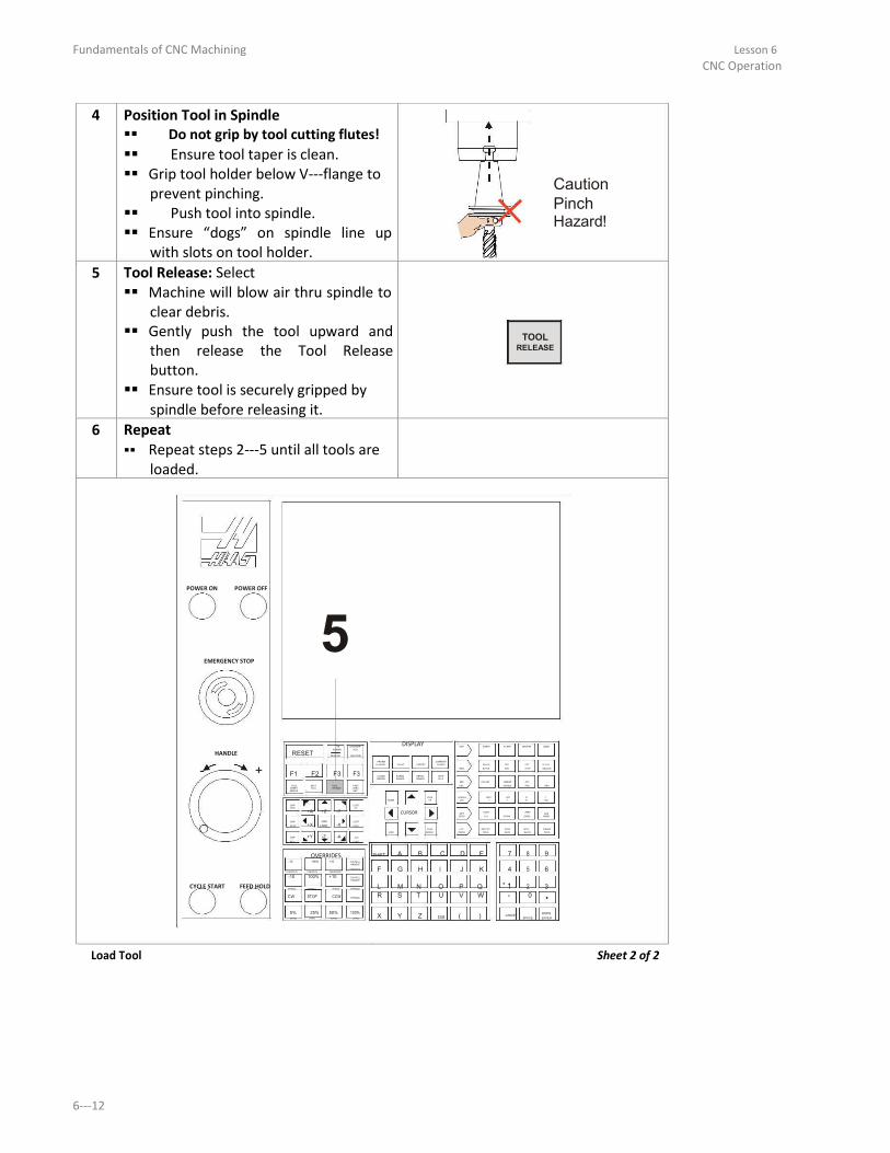
Fundamentals of CNC Machining Lesson 6 CNC Operation
4
5
6
Position Tool in Spindle Do not grip by tool cutting flutes! Ensure tool taper is clean.
Grip tool holder below V-fla ge to prevent pinching.
Push tool into spindle.
Ensure dogs on spindle line up
with slots on tool holder. Tool Release: Select Machine will blow air thru spindle to
clear debris.
Gently push the tool upward and
then release the Tool Release
button. Ensure tool is securely gripped by
spindle before releasing it. Repeat Repeat steps 2- u til all tools a e
loaded.
Caution Pinch Hazard!
TOOL
RELEASE
POWER ON POWER OFF
EMERGENCY STOP
5
UP CHANGER DISPLAY EDIT INSERT ALTER DELETE UNDO
HANDLE
RESET POWER TOO L
RESTART RESTORE
- + PRGRM
POSIT OFFSET
CURRENT CONVRS COMDS SINGLE DRY OPT BLO CK
F1 F2
F3 F3 MEM BLO CK RUN STOP DELETE
ALARM PARAM SETNC HELP MESGS DGNOS GRAPH CA LC
ORIENT
MDI COO LNT ATC ATC
TOOL NEX T TOOL PART DNC SPINDLE FWD REV OFSET TOO L RELEASE ZERO
MESUR SET
HOME
PAGE HA NDLE .0001 .001 .01 .1
UP JOG .1 1. 10. 100.
CHIP
+B CLNT
+A
FWD
+Z -Y UP
CURSOR SET
AUTO
ORIGIN
ZERO G28 AXES AXIS
ZERO ALL SINGL HOME
CHIP
+X JOG
-X CLNT
STOP LOCK D OW N
END
PAGE LIST SELECT SEND RECV ERASE
-A DOWN PROG PROG Rs232 Rs232 PROG
CHIP +Y -Z AUX REV -B CLNT
OVERRIDES
SHIFT A B C D E 7 8 9
-10 100% +10 CONTRO L HANDLE
F G H I J K 4 5 6 FEE DRA TE FEEDRATE FEEDRATE
FEEDRATE
-10 100% +10 CONTRO L
* 1
CYCLE START FEED HOLD HANDLE
L M N O P Q 2 3 SPINDLE SPINDLE
SPINDLE SPINDLE
CW STOP CCW SPINDLE R S T U V W - 0
5% 25%
50% 100%
X Y Z EOB ( ) CANCEL SPACE
WRITE
RAPID RAPID
RAPID RAPID ENTER
Load Tool Sheet 2 of 2
6-

Lesson 6 CNC Operation Introduction & CNC Process Overview
Set Tool Length Offset (TLO)
1
2
3
Check List Handle Jog Mode: Select This sets machine to be controlled by
the hand wheel.
Jog Increment: .01 This sets the job increment so each
click of the hand wheel moves the
tool .01 inches in the jog direction. Jog Direction: Z
This sets the tool to move in Z when
the jog handle is moved.
Buttons
HANDLE JOG
.01 10.
Z
POWER ON POWER OFF 1
EMERGENCY STOP
3 2
UP CHANGER DISPLAY EDIT INSERT ALTER DELETE UNDO
HANDLE
RESET POWER TOO L
RES TA RT RESTO RE
- + PRGRM
POSIT OFFSET
CURRE NT CONVRS COMDS SINGLE DRY OPT BLOCK
F1 F2
F3 F3 MEM BLO CK RUN STOP DELETE
ALARM PARAM SETNC HELP MESGS DGNOS GRAPH CA LC
ORIENT
MDI COOLNT ATC ATC
TOO L NEXT TOOL PART DNC SPINDLE FWD REV OFSET TOOL RELEASE ZERO MESUR
SET
HOME
PAGE HA NDLE .0001 .001 .01 .1
UP JOG .1 1. 10. 100.
CHIP
+B CLNT
+A +Z -Y
AUTO
ZERO
FWD UP CURSOR
SET AXES AXIS G28
ZERO ALL ORIGIN SINGL HOME
CHIP
+X JOG
-X CLNT
STOP LOCK DOWN
END
PAGE LIST SELECT SEND RECV ERASE
-A DOWN PROG PROG Rs232 Rs232 PROG
CHIP +Y -Z AUX REV -B CLNT
OVERRIDES
SHIFT A B C D E 7 8 9
-10 100% +10 CONTRO L HA NDLE
F G H I J K 4 5 6 FEE DRA TE FEE DRA TE FEEDRATE
FEE DRA TE
-10 100% +10 CONTRO L
* 1
CYCLE START FEED HOLD HA NDLE
L M N O P Q 2 3 SPINDLE SPINDLE
SPINDLE SPINDLE
CW STOP CCW SPINDLE R S T U V W - 0
5% 25%
50% 100%
X Y Z EOB ( ) CANCEL SPACE
WRITE
RAPID RAPID
RAPID RAPID ENTER
Note: Machine parameter 64 (T OFS MEAS USES WORK) must be set to OFF to use this method.
Set TLO Sheet 1 of 4
Copyright 2014 Autodesk, Inc. 6-

Fundamentals of CNC Machining Lesson 6
CNC Operation
4 Offsets: Select Press this button until the Tool
OFSET
Offset page displays.
5 Cursor Arrows: Align for active tool
Use the Up-D cursor keys (if needed) to move the highlighted bar
CURSOR on the graphics display over the
offset values for the currently active
tool.
OFFSET
COOLANT -----LENGTH----- -----DIAMETER----- TOOL POSITION GEOMETRY WEAR GEOMETRY WEAR
1 0. 0. 0. 0.
2 0. 0. 0. 0.
POWER ONPOWER OFF3 0. 0. 0. 0.
EMERGENCY STOP 4 5
UP CHANGER
DISPLAY EDIT INSERT ALTER DELETE UNDO
HANDLE
RESET POWER TOO L
RESTART RESTO RE
- + PRGRM
POSIT OFSET
CURRE NT CONVRS COMDS SINGLE DRY OPT BLO CK
F1 F2
F3 F3 MEM BLO CK RUN STOP DELETE
ALARM PARAM SETNC HELP MESGS DGNOS GRAPH CA LC
ORIENT
MDI COO LNT ATC ATC
SPINDLE FWD REV TOOL NEXT TOOL PART DNC
OFSET TOOL RELEASE ZERO
MESUR SET
HOME
PAGE HA NDLE .0001 .001 .01 .1
UP JOG .1 1. 10. 100.
CHIP
+B CLNT
+A
FWD
+Z -Y UP
CURSOR SET
AUTO
ORIGIN
ZERO G28 AXES AXIS
ZERO ALL SINGL HOME
CHIP
+X JOG
-X CLNT
STOP LOCK DOWN
END
PAGE LIST SELECT SEND RECV ERASE
-A D OW N PROG PROG Rs232 Rs232 PROG
CHIP +Y -Z AUX REV -B CLNT
OVERRIDES
SHIFT A B C D E 7 8 9
-10 100% +10 CONTROL HA NDLE
F G H I J K 4 5 6 FEE DRA TE FEEDRATE FEEDRATE
FEE DRA TE
-10 100% +10 CONTROL
CYCLE START FEED HOLD HA NDLE
L M N O P Q 1 2 3 SPINDLE SPINDLE SPINDLE SPINDLE
CW STOP CCW SPINDLE R S T U V W - 0
5% 25%
50% 100%
X Y Z EOB ( ) CANCEL SPACE
WRITE
RAPID RAPID
RAPID RAPID ENTER
Set TLO Sheet 2 of 4
6-

Lesson 6 CNC Operation Introduction & CNC Process Overview
6
7
8
Use 1- - Blo k to Set Tool Le gth Jog so tool is below top block.
Apply slight pressure to block against
tool. Use Jog Wheel to raise tool
until the block just slides
underneath it. Move block out of way and then
move tool back down .01 inches
below top of block. Jog Increment: .001 Reduce jog increment and use jog
handle to raise tool in .001
increments until it just slides under
the block again. Tool Offset Measure: Select This causes the control to enter the
current position of the tool in the
length offset register. Make sure the tool length number
updates before proceeding.
Slowly Light
Raise
Pressure Tool
.001 1.
TOOL OFSET MESUR
OFFSET COOLANT -----LENGTH----- -----DIAMETER----- TOOL POSITION GEOMETRY WEAR GEOMETRY WEAR
1 -- 0. - 0. 0. 2 0. 0. 0. 0.
POWER ON POWER OFF 3 0. 0. 0. 0.
EMERGENCY STOP
8 7
UP CHANGER
DISPLAY EDIT INSERT ALTER DELETE UNDO
HANDLE
RESET POWER TOO L
RESTART RESTO RE
- + PRGRM
POSIT OFSET
CURRE NT CONVRS COMDS SINGLE DRY OPT BLO CK
F1 F2
F3 F3 MEM BLO CK RUN STOP DELETE
ALARM PARAM SETNC HELP
6 MESGS DGNOS GRAPH CA LC
ORIENT
MDI COO LNT ATC ATC
SPINDLE FWD REV TOO L NEX T TOOL PART DNC
OFS ET TOO L RELEASE ZERO
MESUR SET
HOME
PAGE HA NDLE .0001 .001 .01 .1
UP JOG .1 1. 10. 100.
CHIP +B
CLNT
+A
FWD
+Z -Y UP
CURSOR SET
AUTO
ORIGIN
ZERO G28 AXES AXIS
ZERO ALL SINGL HOME
CHIP
+X JOG
-X CLNT
STOP LOCK DOWN
END
PAGE LIST SELECT SEND RECV ERASE
+Y -Z
D OW N PROG PROG Rs232 Rs232 PROG
REV -B CLNT
CHIP -A AUX
OVERRIDES
SHIFT A B C D E 7 8 9
-10 100% +10 CONTROL HA NDLE
F G H I J K 4 5 6 FEEDRATE FEE DRA TE FEEDRATE
FEE DRA TE
-10 100% +10 CONTROL
CYCLE START FEED HOLD HA NDLE
L M N O P Q 1 2 3 SPINDLE SPINDLE SPINDLE SPINDLE
CW STOP CCW SPINDLE R S T U V W - 0
5% 25%
50% 100%
X Y Z EOB ( ) CANCEL SPACE
WRITE
RAPID RAPID
RAPID RAPID ENTER
Set TLO Sheet 3 of 4
Copyright 2014 Autodesk, Inc. 6-

Fundamentals of CNC Machining Lesson 6 CNC Operation
9 Next Tool: Select
This causes the current tool to
beput away and the next tool to
be loaded.
Repeat steps 1 thru 9 until all
toolsare set.
NEXT TOOL
POWER ON POWER OFF
EMERGENCY STOP 9
UP CHANGER
DISPLAY EDIT INSERT ALTER DELETE UNDO
HANDLE RESET POWER TOO L
RESTART RESTO RE
- + PRGRM
POSIT OFSET
CURRE NT CONVRS COMDS SINGLE DRY OPT BLO CK
F1 F2
F3 F3 MEM BLO CK RUN STOP DELETE
ALARM PARAM SETNC HELP MESGS DGNOS GRAPH CA LC
ORIENT
MDI COO LNT ATC ATC
SPINDLE FWD REV TOO L NEXT TOOL PART DNC
OFS ET TOOL RELEASE ZERO
MESUR SET
HOME
PAGE HA NDLE .0001 .001 .01 .1
UP JOG .1 1. 10. 100.
CHIP
+B CLNT
+A
FWD
+Z -Y UP
CURSOR SET
AUTO
ORIGIN
ZERO G28 AXES AXIS
ZERO ALL SINGL HOME
CHIP
+X JOG
-X CLNT
STOP LOCK DOWN
END
PAGE LIST SELECT SEND RECV ERASE
-A D OW N PROG PROG Rs232 Rs232 PROG
CHIP +Y -Z AUX REV -B CLNT
OVERRIDES
SHIFT A B C D E 7 8 9
-10 100% +10 CONTROL HA NDLE
F G H I J K 4 5 6 FEE DRA TE FEEDRATE FEEDRATE
FEE DRA TE
-10 100% +10 CONTROL
CYCLE START FEED HOLD HA NDLE
L M N O P Q 1 2 3 SPINDLE SPINDLE SPINDLE SPINDLE
CW STOP CCW SPINDLE R S T U V W - 0
5% 25%
50% 100%
X Y Z EOB ( ) CANCEL SPACE
WRITE
RAPID RAPID
RAPID RAPID ENTER
Tips
Do not press any buttons between steps 8- o NEXT TOOL button will not load
next tool. If you should press any buttons and interrupt this process, load the next tool by
selecting the ATC FWD button, followed by HANDLE JOG.
Set TLO Sheet 4 of 4
WARNING: Setting tools requires manually jogging the machine with hands in the machine work envelope. Use extreme caution and observe the following rules:
The spindle must be off. Never place your hand between the tool and the 1- - lo k. Ensure the correct axis and jog increment are set before jogging. Move the handle slowly and deliberately. Keep your eyes on your hands and the tool position at all times. Never allow anyone else to operate the control when your hand is in the work area.
6-

Lesson 6 CNC Operation
Introduction & CNC Process Overview
Set Fixture Offset XY
Checklist Buttons 1 MDI/DNC Key: Select
Erase Prog: Select (to clear any
commands)
2 Erase Prog: Select (to clear any
commands)
MDI DNC
ERASE PROG
3 Spindle Speed: S1100
S1100 M3: Input S 1 1 0 0
Write/Enter: Select
M 3 WRITE
ENTER
4 Cycle Start: Select Spindle will start CW at 1100 RPM CYCLE START
PROGRAM (MDI)
S1100 M3;
1
POWER ON POWER OFF
EMERGENCY STOP 3 2
UP CHANGER
DISPLAY EDIT INSERT A LT ER DELETE UNDO
HANDLE RESET POWER TOO L
RESTART RESTO RE
- + PRGRM
POSIT OFFSET
CURRE NT CONVRS COMDS SINGLE DRY OPT BLOCK
F1 F2
F3 F3 MEM BLO CK RUN STOP DELETE
ALARM PARAM SETNC HELP MESGS DGNOS GRAPH CA LC
ORIENT
MDI COOLNT ATC ATC
TOO L NEX T TOOL PART DNC SPINDLE FWD REV OFS ET TOO L RELEASE ZERO
MESUR SET
HOME
PAGE HA NDLE .0001 .001
.01 .1
UP JOG .1 1. 10. 100.
CHIP
+B CLNT
+A
FWD
+Z -Y UP
CURSOR SET
AUTO
ORIGIN
ZERO G28
AXES AXIS
ZERO ALL SINGL HOME
CHIP
+X JOG
-X CLNT
STOP LOCK DOWN
END
PAGE LIST SELECT SEND RECV ERASE
-A DOWN PROG PROG Rs232 Rs232 PROG
CHIP +Y -Z AUX REV -B CLNT
OVERRIDES
SHIFT A B C D E 7 8 9
-10 100% +10 CONTRO L HA NDLE
F G H I J K
4 5 6 FEE DRA TE FEE DRA TE FEEDRATE
FEE DRA TE
-10 100% +10 CONTRO L
START FEED HOLD HA NDLE
L M N O P Q
1 2 3 SPINDLE SPINDLE SPINDLE SPINDLE
CYCLE4 CW STOP CCW
* SPINDLE
R S T U V W - 0
5% 25% 50% 100% X Y Z EOB ( ) CANCEL
SPACE
WRITE
RAPID RAPID
RAPID RAPID ENTER
Fixture Offset XY Sheet 1 of 4
Copyright 2014 Autodesk, Inc. 6-

Fundamentals of CNC Machining Lesson 6 CNC Operation
5
6
7
Handle Jog: Select Jog Increment: .01
Jog Handle: As Needed Select jog direction and use handle
as required to place edge finder
stylus alongside the left part edge.
Jog Increment: .001 Move edge finder slowly until it just
trips off center as shown below.
This places the center of the spindle
exactly .100 from the part edge.
HANDLE .01
JOG 10.
+B - +
+A+Z -Y +X
JOG -X
LOCK +Y -Z -A
-B
.001 1.
POWER ON POWER OFF
EMERGENCY STOP
6
5 7
UP CHANGER
DISPLAY EDIT INSERT A LT ER DELETE UNDO
HANDLE RESET POWER TOO L
RESTART RESTORE
- + PRGRM
POSIT OFSET
CURNT CONVRS COMDS
MEM
SINGLE DRY OPT BLOCK
F1 F2
F3 F3 BLO CK RUN STOP DELETE
ALARM PARAM SETNC HELP MESGS DGNOS GRAPH CA LC
MDI
ORIENT
ATC COOLNT ATC
TOOL NEX T TOOL PART DNC SPINDLE FWD REV OFSET TOO L RELEASE ZERO
MESUR SET
HOME
PAGE HA NDLE .0001 .001 .01 .1
UP JOG .1 1. 10. 100.
CHIP
+B CLNT
+A
FWD
+Z -Y UP
CURSOR SET
AUTO
ORIGIN
ZERO G28
AXES AXIS
ZERO ALL SINGL HOME
CHIP
+X JOG
-X CLNT
STOP LOCK D OW N
END
PAGE LIST SELECT SEND RECV ERASE
-Z -A DOWN PROG PROG Rs232 Rs232 PROG
CHIP +Y AUX REV -B CLNT
OVERRIDES
SHIFT A B C D E 7 8 9
-10 100% +10 CONTRO L HA NDLE
F G H I J K 4 5 6 FEE DRA TE FEEDRATE FEEDRATE
FEE DRA TE
-10 100% +10 CONTRO L
* 1
CYCLE START FEED HOLD
HA NDLE
L M N O P Q 2 3 SPINDLE SPINDLE
SPINDLE SPINDLE
CW STOP CCW SPINDLE R S T U V W - 0
5% 25%
50% 100%
X Y Z EOB ( ) CANCEL SPACE
WRITE
RAPID RAPID
RAPID RAPID ENTER
Fixture Offset XY Sheet 2 of 4
6-

Lesson 6 CNC Operation Introduction & CNC Process Overview
8
9
10
11
Jog Handle: Retract in Z Jog straight upward in Z until edge
finder is above part and jog handle
reads zero on the dial. Jog Handle: Set jog direction to +X and
rotate handle one full turn clockwise. Since the control is in .001 increment
mode, rotating the dial exactly one full
turn places the center of the spindle
directly over the left part edge. Offset Page: Select Select Offset button and PgUp/PgDn
buttons until Work Zero Offset page
appears. Use Arrow keys to highlight
G54 (or whatever fixture offset is to be
set). Part Zero Set: Select This sets the G54 X value to the current
spindle position.
- +
0
+Z
- +
+X
0
PAGE
UP
OFFSET PAGE
DOWN
PART ZERO SET
FIXTURE OFFSET
TOOL X Y Z G52 0. 0. 0.
G54 8.1257 0. 0. POWER ON POWER OFF G55 0. 0. 0.
11
EMERGENCY STOP 8 9 10
UP CHANGER
DISPLAY EDIT INSERT A LT ER DELETE UNDO
HANDLE RESET POWER TOO L
RESTART RESTO RE
- + PRGRM
POSIT OFSET
CURNT CONVRS COMDS
MEM
SINGLE DRY OPT BLOCK
F1 F2
F3 F3 BLO CK RUN STOP DELETE
ALARM PARAM SETNC HELP MESGS DGNOS GRAPH CA LC
MDI
ORIENT
ATC COOLNT ATC
TOO L NEX T TOOL PART DNC SPINDLE FWD REV OFS ET TOO L RELEASE ZERO
MESUR SET
HOME
PAGE HA NDLE .0001 .001 .01 .1
UP JOG .1 1. 10. 100. +B
CLNT
CHIP +A +Z -Y
AUTO
ZERO
FWD UP CURSOR
SET AXES AXIS G28
ZERO ALL ORIGIN SINGL HOME
CHIP
+X JOG
-X CLNT
STOP LOCK DOWN
END
PAGE LIST SELECT SEND RECV ERASE
-Z -A DOWN PROG PROG Rs232 Rs232 PROG
CHIP +Y AUX REV -B CLNT
OVERRIDES
SHIFT A B C D E 7 8 9
-10 100% +10 CONTRO L HA NDLE
F G H I J K 4 5 6 FEE DRA TE FEE DRA TE FEEDRATE
FEE DRA TE
-10 100% +10 CONTRO L
* 1
CYCLE START FEED HOLD HA NDLE
L M N O P Q 2 3 SPINDLE SPINDLE
SPINDLE SPINDLE
CW STOP CCW SPINDLE R S T U V W - 0
5% 25%
50% 100%
X Y Z EOB ( ) CANCEL SPACE
WRITE
RAPID RAPID
RAPID RAPID ENTER
Tips To shift the datum RIGHT in relation to the machine operator,ADD a shift amount to
the offset X- alue. Fo e a ple, to shift X+. , i put .1 WRITE/ENTER. To shift the datum CLOSER to the machine operator,SUBTRACT a shift amount from
the offset Y- alue. For example, to shift Y-. , i put -. WRITE/ENTER. Copyright 2014 Autodesk, Inc. 6-

Fundamentals of CNC Machining Lesson 6
CNC Operation
Fixture Offset XY Sheet 3 of 4 The following instructions repeat steps 4- but for setting the Y-axis.
12 Jog Handle: As Needed
Select jog direction and use
handleas required to place edge
finder stylus alongside the back part
edge.
13 Jog Increment: .001 Move edge finder slowly until it
justtrips off center.
This places the center of the
spindleexactly .100 from the part
edge. 14 Jog Handle: Retract in Z
Jog straight upward in Z until
edgefinder is above part and jog
handle reads zero on the dial.
15 Jog Handle: Set jog direction to -Y a d
rotate handle one full turn clockwise.
Since the control is in
.001increment mode, rotating the
dial exactly one full turn places the
center of the spindle directly over
the back part edge. 16 Offset Page: Use arrow keys to highlight
G54 field (or whichever fixture offset you
are setting).
17 Part Zero Set: Select This sets the G54 Y value to
thecurrent spindle position.
18 Spindle Stop: Select
+B - +
+A+Z -Y +X
JOG -X
LOCK +Y -Z -A
-B
.001 1.
- + 0
+Z
- + 0
-Y
OFFSET
PART ZERO SET
STOP
Fixture Offset XY Sheet 4 of 4
6- .

Lesson 6 CNC Operation
Introduction & CNC Process Overview
Set Fixture Offset Z
Check List Buttons 1 Prepare: Ensure tip angle of dial indicator
isat about 15 degrees.
Ensure gauge block is flat on
table,no chips underneath, and
not floating on coolant.
Set Tip About 15 Deg From Vertical
Dial Indicator 1- - Blo k
2 MDI Mode: Select Ensure machine is in MDI Mode MDI
DNC
3 Handle: As Needed
Select jog direction and use handle +B - +
+A +Z -Y as required to place dial indicator +X LOCK -X
stylus on top of gauge block and JOG
+Y -Z -B
-A
the dial reads zero.
POWER ON POWER OFF
EMERGENCY STOP 3 2
UP CHANGER
DISPLAY EDIT INSERT ALTER DELETE UNDO
HANDLE RESET POWER TOOL
RESTART RESTO RE
- + PRGRM
POSIT OFSET
CURNT CONVRS COMDS
MEM
SINGLE DRY OPT BLO CK
F1 F2
F3 F3 BLO CK RUN STOP DELETE
ALARM PARAM SETNC HELP MESGS DGNOS GRAPH CA LC
MDI
ORIENT
ATC COO LNT ATC
TOOL NEXT TOOL PART DNC SPINDLE FWD REV OFSET TOO L RELEASE ZERO
MESUR SET
HOME
PAGE HA NDLE .0001 .001 .01 .1
UP JOG .1 1. 10. 100.
CHIP
+B CLNT
+A
FWD
+Z -Y UP
CURSOR SET
AUTO
ORIGIN
ZERO G28 AXES AXIS
ZERO ALL SINGL HOME
CHIP
+X JOG
-X CLNT
STOP LOCK DOWN
END
PAGE LIST SELECT SEND RECV ERASE
-Z -A DOWN PROG PROG Rs232 Rs232 PROG
CHIP +Y AUX REV -B CLNT
OVERRIDES
SHIFT A B C D E 7 8 9
-10 100% +10 CONTROL HA NDLE
F G H I J K 4 5 6 FEE DRA TE FEEDRATE FEEDRATE
FEE DRA TE
-10 100% +10 CONTROL
* 1
CYCLE START FEED HOLD HA NDLE
L M N O P Q 2 3 SPINDLE SPINDLE
SPINDLE SPINDLE
CW STOP CCW SPINDLE R S T U V W - 0
5% 25%
50% 100%
X Y Z EOB ( ) CANCEL SPACE
WRITE
RAPID RAPID
RAPID RAPID ENTER
Note: Machine parameter 64 (T OFS MEAS USES WORK) must be set to OFF to use this method.
Fixture Offset Z Sheet 1 of 3
Copyright 2014 Autodesk, Inc. 6-

Fundamentals of CNC Machining Lesson 6 CNC Operation
4 Posit Button: Press
POSIT
5 Operator Screen: Select Use PG DN Button (5 times) until PAGE
POS-OPER s ee appea s. DOWN
6 Origin: Set Press Origin button to set Z- alue
on operator screen to zero. ORIGIN
7 Handle: As Needed Select jog directio n and use handle +A +Z -Y
+ +B
-
as required to place dial indicator +X LOCK -X
stylus on top of part stock and the JOG
+Y
-Z
-B
-A
dial reads zero.
POS-OPER
X - .
POWER ON POWER OFF Y - .
Z 0.0000
EMERGENCY STOP
7
4 5
6
UP CHANGER
DISPLAY EDIT INSERT ALTER DELETE UNDO
HANDLE RESET
POWER TOO L
RESTART RESTO RE
- + PRGRM
POSIT OFFSET
CURRE NT CONVRS COMDS SINGLE DRY OPT BLO CK
F1 F2
F3 F3 MEM BLO CK RUN STOP DELETE
ALARM PARAM SETNC HELP MESGS DGNOS GRAPH CA LC
ORIENT
MDI COO LNT ATC ATC
TOOL NEXT TOOL PART DNC SPINDLE FWD REV OFS ET TOOL RELEASE ZERO
MESUR SET
HOME
PAGE HA NDLE .0001 .001 .01 .1 UP JOG .1 1. 10. 100.
CHI P
+B CLNT
+A
FWD
+Z -Y UP
CURSOR SET
AUTO
ORIGIN
ZERO G28
AXES AXIS
ZERO ALL SINGL HOME
CHI P
+X JOG
-X CLNT
STOP LOCK DOWN
END
PAGE LIST SELECT SEND RECV ERASE
-A D OW N PROG PROG Rs232 Rs232 PROG
CHI P +Y -Z AUX
REV -BCLNT
OVERRIDES SHIFT A B C D E 7 8 9
-10 100% +10 CONTRO L HA NDLE
F G H I J K 4 5 6
FEE DRA TE FEEDRATE FEEDRATE
FEE DRA TE
-10 100% +10 CONTRO L
* 1
CYCLE START FEED HOLD HA NDLE
L M N O P Q 2 3
SPINDLE SPINDLE
SPINDLE SPINDLE
CW STOP CCW SPINDLE R S T U V W - 0
5% 25%
50% 100%
X Y Z EOB ( ) CANCEL SPACE
WRITE
RAPID RAPID
RAPID RAPID ENTER
Fixture Offset Z Sheet 2 of 3
6-

Lesson 6 CNC Operation Introduction & CNC Process Overview
8
9
10
11
Operator Z Value: Read Read the operator Z value from the graphic
area. This is the incremental distance
between the top of the 1- - lo k a d the top of the part. Ex: 2.2080
Offset Page: Set G54 Z Value Press Offset button twice to get to Offsets
Page
Numeric Keypad: Enter Z Value Input the value using the numeric
keyboard.
To set Z below the part face, reduce the
value by the amount of material removed
by the face cut. F1 Button: Press Select the F1 button to enter the value
input in Step #7 into the Z offset field.
OFFSET
7 8 9 4 5 6 1 2 3 - 0
F1
POS-OPER
X - .
POWER ON POWER OFF Y - . 8 Z 2.2080
EMERGENCY STOP
11 9 10
UP CHANGER
DISPLAY EDIT INSERT A LT ER DELETE UNDO
HANDLE RESET POWER TOO L
RESTART RESTO RE
- + PRGRM
POSIT OFSET
CURNT CONVRS COMDS SINGLE DRY OPT BLO CK
F1 F2
F3 F3 MEM BLO CK RUN STOP DELETE
ALARM PARAM SETNC HELP MESGS DGNOS GRAPH CA LC
ORIENT
MDI COOLNT ATC ATC
TOO L NEX T TOOL PART DNC SPINDLE FWD REV OFS ET TOO L RELEASE ZERO
MESUR SET
HOME
PAGE HA NDLE .0001 .001 .01 .1
UP JOG .1 1. 10. 100.
CHIP
+B CLNT
+A
FWD
+Z -Y UP
CURSOR SET
AUTO
ORIGIN
ZERO G28
AXES AXIS
ZERO ALL SINGL HOME
CHIP
+X JOG
-X CLNT
STOP LOCK DOWN
END
PAGE LIST SELECT SEND RECV ERASE
-A DOWN PROG PROG Rs232 Rs232 PROG
CHIP +Y -Z AUX REV -B CLNT
OVERRIDES
SHIFT A B C D E 7 8 9
-10 100% +10 CONTRO L HA NDLE
F G H I J K 4 5 6 FEE DRA TE FEE DRA TE FEEDRATE
FEE DRA TE
-10 100% +10 CONTRO L
CYCLE START FEED HOLD HA NDLE
L M N O P Q 1 2 3 SPINDLE SPINDLE SPINDLE SPINDLE
CW STOP CCW SPINDLE R S T U V W - 0
5% 25%
50% 100%
X Y Z EOB ( ) CANCEL SPACE
WRITE
RAPID RAPID
RAPID RAPID ENTER
Tip
Shift the datum DOWN by an incremental distancefrom the
top of the part to remove stock from the top-fa e subtracting the amount of stock to remove from the Fixture
Offset Z Value.
Example: To set the datum to Z-. elo
the top of the part:
Z2.2080 -.
= 2.1880
Fixture Offset Z Sheet 3 of 3
Copyright 2014 Autodesk, Inc. 6-

Fundamentals of CNC Machining Lesson 6 CNC Operation
Load CNC Program
1
2
3
Check List Memory: Select
List Programs: Select
USB Device: Select Use the DN arrow to highlight USB
Device on the graphics screen. (This
sets the program list to display files
on the USB Device). Select F4 button.
Buttons
MEM
LIST
PROG
CURSOR F4
Device USB Directory O00001
Memory O00015
O01000
POWER OFF
POWER ON O01100
USB Device
O11975
O12345
USB Media O23456
Present
3 1 2
EMERGENCY STOP
UP CHANGER
DISPLAY EDIT INSERT ALTER DELETE UNDO
HANDLE RESET POWER TOO L
RESTART RESTO RE
- + PRGRM
POSIT OFSET
CURNT CONVRS COMDS SINGLE DRY OPT BLO CK
F1 F2
F3 F3 MEM BLO CK RUN STOP DELETE
ALARM PARAM SETNC HELP MESGS DGNOS GRAPH CA LC
ORIENT
MDI COO LNT ATC ATC
TOOL NEXT TOOL PART DNC SPINDLE FWD REV OFSET TOOL RELEASE ZERO MESUR SET
HOME
PAGE HA NDLE .0001 .001 .01 .1
UP JOG .1 1. 10. 100.
CHIP
+B CLNT
+A
FWD
+Z -Y UP
CURSOR SET
AUTO
ORIGIN
ZERO G28
AXES AXIS
ZERO ALL SINGL HOME
CHIP
+X JOG
-X CLNT
STOP LOCK DOWN
END
PAGE LIST SELECT SEND RECV ERASE
-A D OW N PROG PROG Rs232 Rs232 PROG
CHIP +Y -Z AUX REV -B CLNT
OVERRIDES
SHIFT A B C D E 7 8 9
-10 100% +10 CONTROL HA NDLE
F G H I J K 4 5 6 FEE DRA TE FEEDRATE FEEDRATE
FEE DRA TE
-10 100% +10 CONTROL
CYCLE START FEED HOLD HA NDLE
L M N O P Q 1 2 3 SPINDLE SPINDLE SPINDLE SPINDLE
CW STOP CCW SPINDLE R S T U V W - 0
5% 25%
50% 100%
X Y Z EOB ( ) CANCEL SPACE
WRITE
RAPID RAPID
RAPID RAPID ENTER
Load CNC Program Sheet 1 of 2
6-

Lesson 6 Introduction & CNC Process Overview
Checklist
4 Program Name: Highlight Use RT button to move highlighted bar
overUSB Directory List
Use the DN arrow keys to highlight
theprogram to read.
5 Write To Device (Memory):Select
Press the Left arrow key and then the
Uparrow key to move the highlight bar
back over the Memory option in the
Devicelist.
6 F2: Select Press the F2 button to copy the
programfrom the USB Device to Memory.
If the program already exists, select (Y)
whenprompted to overwrite.
CNC Operation
Buttons
CURSOR Write
Enter
HOME
PAGE
UP
CURSOR
END PAGE
DOWN
F2
Device USB Directory
O00001
Memory O00015
O01000 POWER ON POWER OFF
O01100
USB Device O11975
O12345
USB Media O23456 Present
EMERGENCY STOP
6 4,5
UP CHANGER DISPLAY EDIT INSERT A LT ER DELETE UNDO
HANDLE
RESET POWER TOO L
RES TA RT RESTORE
- + PRGRM
POSIT OFSET
CURNT CONVRS COMDS SINGLE DRY OPT BLOCK
F1 F2
F3 F3 MEM BLO CK RUN STOP DELETE
ALARM PARAM SETNC HELP MESGS DGNOS GRAPH CA LC
ORIENT
MDI COOLNT ATC ATC
TOOL NEXT TOOL PART DNC SPINDLE FWD REV OFSET TOOL RELEASE ZERO
MESUR SET
HOME
PAGE HA NDLE .0001 .001 .01 .1
UP JOG .1 1. 10. 100.
CHIP
+B CLNT
+A
FWD
+Z -Y UP
CURSOR SET
AUTO
ORIGIN
ZERO G28 AXES AXIS
ZERO ALL SINGL HOME
CHIP
+X JOG
-X CLNT
STOP LOCK DOWN
END
PAGE LIST SELECT SEND RECV ERASE
-A DOWN PROG PROG Rs232 Rs232 PROG
CHIP +Y -Z AUX REV -B CLNT
OVERRIDES
SHIFT A B C D E 7 8 9
-10 100% +10 CONTRO L HA NDLE
F G H I J K 4 5 6 FEE DRA TE FEE DRA TE FEEDRATE
FEE DRA TE
-10 100% +10 CONTRO L
CYCLE START FEED HOLD HA NDLE
L M N O P Q 1 2 3 SPINDLE SPINDLE SPINDLE SPINDLE
CW STOP CCW SPINDLE R S T U V W - 0
5% 25%
50% 100%
X Y Z EOB ( ) CANCEL SPACE
WRITE
RAPID RAPID
RAPID RAPID ENTER
Note: All programs must begin with the letter O (NOT the number zero). Theprogram name
must be an integer up to five digits long. No decimal point, letters, or special characters are
allowed. Load CNC Program Sheet 2 of 2

Copyright 2014 Autodesk, Inc. 6-

Fundamentals of CNC Machining Lesson 6 CNC Operation
Run CNC Program
This is the preferred process for running a new program. Once a program is proven, all
feed rates can be set to 100% and single block modecan be set to off.
1
2
Check List
Pre-Start Ensure vise or fixture is secure and
that you have a safe setup.
There should be no possibility that
the work holding will fail to perform
as required. Remove vise handles.
Clear the work area of any tools or
other objects.
Close the machine doors.
TurnSingle BlockMode On.
Press Rapid Feedrate - button
eight times to set rapid Feed Rate
Override to 20% of maximum. Start Place one hand on Feed Hold
button and be ready to press it in
case there are any problems. Press Cycle Start Button.
Buttons
SINGLE BLOCK
OVERRIDES
-10 100% +10 CONTROL
HANDLE
FEEDRATE FEEDRATE FEEDRATE FEEDRATE
CYCLE START FEED HOLD
POWER ON POWER OFF
EMERGENCY STOP
1
UP CHANGER DISPLAY
EDIT INSERT ALTER DELETE UNDO
HANDLE RESET POWER TOO L
RESTART RESTO RE
- + PRGRM
POSIT OFSET
CURNT CONVRS COMDS SINGLE DRY OPT BLO CK
F1 F2
F3 F3 MEM BLO CK RUN STOP DELETE
ALARM PARAM SETNC HELP MESGS DGNOS GRAPH CA LC
ORIENT
MDI COO LNT ATC ATC
TOOL NEX T TOOL PART DNC SPINDLE FWD REV OFSET TOO L RELEASE ZERO
MESUR SET
HOME
PAGE HA NDLE .0001 .001 .01 .1
UP JOG .1 1. 10. 100.
CHIP
+B CLNT
+A +Z -Y
AUTO
ZERO
FWD UP CURSOR SET AXES AXIS G28
ZERO ALL ORIGIN SINGL HOME
CYCLE START
2FEED HOLD
CHIP JOG
-X
CLNT
STOP
+XLOCK DOWN
END
PAGE LIST SELECT SEND RECV ERASE
-Z -A DOWN PROG PROG Rs232 Rs232 PROG
CHIP +Y AUX REV -B CLNT
OVERRIDES
SHIFT A B C D E 7 8 9
-10 100% +10 CONTROL HA NDLE
F G H I J K 4 5 6 FEE DRA TE FEE DRA TE FEEDRATE FEE DRA TE
-10 100% +10 CONTROL HA NDLE
L M N O P Q 1 2 3 SPINDLE SPINDLE
SPINDLE SPINDLE
CW STOP CCW SPINDLE R S T U V W - 0
5% 25%
50% 100%
X Y Z EOB ( ) CANCEL SPACE
WRITE
RAPID RAPID
RAPID RAPID ENTER
Run CNC Program Sheet 1 of 1
6-

Lesson 6 CNC Operation Introduction & CNC Process Overview
Caution: A common error is setting the Fixture or Tool Length offset incorrectly. When
running a program for the first time, set the machine to Single block mode. Reduce
rapid feed rate to 25%, and proceed with caution. Once the tool is cutting, turn off
single block mode and let the program run. Do not leave the machine unattended, and
keep one hand on the feed hold button. Listen, watch chip formation, and be ready to
adjust cutting feed rates to suite cutting conditions.
Adjusting CDC Offsets
Machining operations that use Cutter Diameter Compensation (CDC: G41/G42) can be
adjusted to account for tool wear and deflection. Measure across a finished feature on
part and compare it with the desired value. Subtract the Actual from the Target sizes and
enter the difference into the CDC register on the control for that tool.For example:
Target Feature Size: 1.0000 Actual Feature Size: 1.0120 Wear Value: - . *
The tool path will now be compensated for the size difference. Running the same
operation again should result in the feature being exactly the targetsize.
Wear compensation is used only on contour passes. It is not used for face milling, 3D
milling, or drill cycles. Select the Wear Compensation option in your CAD/CAM software
and, if needed, set a Tool Diameter Wear value as shown above. When used, the wear
value is always a negative number.
Always set Tool Diameter Geometry to zero for all tools since CAD/CAM software
already accounts for the tool diameter by programming the tool center line path.
1
2
Check List Offset Page: Select
Adjust Diameter Offset
Pg Up/Dn to highlight the tool to be
adjusted.
Enter a value using the numeric
keypad.
Select
Buttons
OFFSET
HOME PAGE
UP
CURSOR
END PAGE
DOWN
Adjusting Offsets Sheet 1 of 2
Copyright 2014 Autodesk, Inc. 6-

Fundamentals of CNC Machining Lesson 6
CNC Operation
OFFSET COOLANT -----LENGTH----- -----DIAMETER-----
TOOL POSITION GEOMETRY WEAR GEOMETRY WEAR
1 - .4203 0. 0. 2 0. 0. 0. 0.
3 0. 0. 0. 0. POWER ONPOWER OFF
EMERGENCY STOP 1 2
UP CHANGER
DISPLAY EDIT INSERT ALTER DELETE UNDO
HANDLE
RESET POWER TOO L
RESTART RESTO RE
- + PRGRM
POSIT OFSET
CURRENT CONVRS COMDS SINGLE DRY OPT BLO CK
F1 F2
F3 F3 MEM BLO CK RUN STOP DELETE
ALARM PARAM SETNC HELP MESGS DGNOS GRAPH CA LC
ORIENT
MDI COO LNT ATC ATC
SPINDLE FWD REV TOOL NEX T TOOL PART DNC
OFSET TOO L RELEASE ZERO
MESUR SET
HOME
PAGE HANDLE .0001 .001 .01 .1
UP JOG .1 1. 10. 100.
CHIP
+B CLNT
+A
FWD
+Z -Y UP
CURSOR SET
AUTO
ORIGIN
ZERO G28 AXES AXIS
ZERO ALL SINGL HOME
CHIP
+X JOG
-X CLNT
STOP LOCK D OW N
END
PAGE LIST SELECT SEND RECV ERASE
-A DOWN PROG PROG Rs232 Rs232 PROG
CHIP +Y -Z AUX REV -B CLNT
OVERRIDES
SHIFT A B C D E 7 8 9
-10 100% +10 CONTRO L HA NDLE
F G H I J K 4 5 6 FEE DRA TE FEEDRATE FEEDRATE
FEE DRA TE
-10 100% +10 CONTRO L
CYCLE START FEED HOLD HA NDLE
L M N O P Q 1 2 3 SPINDLE SPINDLE SPINDLE SPINDLE
CW STOP CCW SPINDLE R S T U V W - 0
5% 25%
50% 100%
X Y Z EOB ( ) CANCEL SPACE
WRITE
RAPID RAPID
RAPID RAPID ENTER
Adjusting Offsets Sheet 2 of 2
6-

Lesson 6 CNC Operation Introduction & CNC Process Overview
Shut Down CNC
1
2
3
Check List Remove tool from spindle: Enter the number of an empty tool
carousel.
Select ATC FWD Jog Machine to Safe Area: Select Jog
Shut Down Button: Press
Buttons
ATC FWD
POWER OFF
Post Power-Do Che klist: Wipe spindle with a soft clean rag to remove coolant and prevent rusting.
Put away tools.
Clean up work area.
Always leave the machine, tools, and equipment in the same or better condition
than when you found them. Shut Down CNC Sheet 1 of 1
Note: It is important to clean the machine after each use to prevent corrosion, promote a safe
work environment, and as a professional courtesy to others. Allow at least 15- i utes at the end of each day for cleaning. At the very least, put away all unused tools and tooling, wash
down the machine with coolant, remove standing coolant from the table, and run the chip
conveyor.
Copyright 2014 Autodesk, Inc. 6-

Fundamentals of CNC Machining Lesson 6 CNC Operation
6-

Fundamentals of CNC Machining
Lesson 7
2D Milling Toolpaths
Upon successful completion of this lesson, you will be able to: Explain the difference between 2- / D, D, a d -a is a hi ed pa ts. Explain the difference between common CAD and CAM graphics views Identify 2D machining features based on part geometry and your knowledge of
tools and 2D toolpaths. Identify commonly used machining parameters for 2D tool path operations. Explain the purpose, general parameters, and use of facing toolpaths. Explain the purpose, general parameters, and use of 2D contour toolpaths. Explain the purpose and rules for using Cutter Diameter Compensation (CDC). Explain the purpose, general parameters, and useof pocketing toolpaths. Explain the rules for slot milling toolpaths. Explain the rules for chamfer milling toolpaths. Explain the rules for radius milling toolpaths. Explain the rules for drilling and peck drilling toolpaths. Explain the rules for tapping toolpaths.
7-

Fundamentals of CNC Machining Lesson 7 2D Milling Toolpaths
7-

Lesson 7 Fundamentals of CNC Machining 2D Milling Toolpaths
Overview
CNC milling toolpaths are broadly classified as either 2D, 3D, 4-a is, a d -a is, depe di g o the number of axes involved and how they move. The term, 2D, is a bit of a misnomer because all modern CNC
machines control at least three axis and all three axes move at one time or another for every2D machining
operation. A more accurate term, 2- / D, is o o l used i CNC a ufa tu i g.
7.1 - D/ D/ X/ X Defi ed 2D (Prismatic) Parts
2- / D illi g toolpaths a hi e o l i the XY pla e. The Z a is is used o l to positio the tool at depth. The move to the cutting plane is a straight down feed, rapid, ramp or helical feed move.
The term, Prismatic, is a term commonly used in engineering used to describe 2- / D pa ts. The e a e, however, prismatic parts that require 4
th or 5-A is machining, so the term is used in machining only to
describe parts where all machined faces lie normal to the machine tool spindle. Because 2- / D is a lu s term this book uses Prismatic and 2D interchangeably to describe parts just described, on a CNC mill with
three controllable axes (XYZ). The XY axes are normal to the machine spindle and Z is used only to position
the tool to depth (either in a feed or rapid motion). Figure 1 shows a prismatic part. All machined features lie parallel to the XY plane. Each Z-le el a e machined by positiong the tool at a fixed Z-le el a d the o i g the XY a es to e o e ate ial. machining. Every feature can be reached with the tool approaching either from the Front or Bottom views.
There are several cutting planes in this example, includingthe model top (1), top of the face where the holes
start (2), the bottom of the pocket (3) where the slots begin, the bottom of the slots (4), and the bottom of
the hole through the center (5).
Figure 1: Prismatic Part (Orientation in CAD)
Copyright 2014 Autodesk, Inc. 7-

Fundamentals of CNC Machining Lesson 7 2D Milling Toolpaths
3D Parts
3D refers to non-p is ati pa ts, i ludi g olds a d o ple o ga i shapes. Most o su e goods, fo example, include 3D features. Figure 3 shows half of a stamping die. This part is typical in that it includes
both 3D and 2D features. The 2D features arethe top face (1) , and the outside contour (2).
3D features, like the revolved surfaces (3) and fillet (4), require more complex machine motion. The revolved
surfaces require XZ tool motion. The fillet requires XYZ tool motion. Even the flat (5) and cavity roughing
(though technically planar) require 3D toolpaths because the adjacent revolved surfaces and fillet must be
considered to prevent gouging the part. The calculations required to calculate these toolpaths are highly
complex and the subject of the next lesson, 3D Toolpaths (Chapter9).
Figure 3: 3D Part
4-A is Parts
4th
axis toolpaths require an auxiliary rotary axis 4th
installed on the CNC machine parallel to either the X
or Y-a is. th axis toolpaths fall into two categories: 4
th Axis Substitution and Simultaneous 4
th Axis.
Axis substitution paths are illustrated in Figure 4.The most common setup is with the rotary axis mounted
parallel to the CNC X-a is. With a is su stitutio a hi i g, the tool a is e te li e al a s poi ts towards the centerline of the rotational axis (no Y- otio he illi g. The tool feeds to depth Z a d then only up to two axes can move at once (X-A to ake the feature. The name substitution comes from how these pathswere defined before CAD was widely used. Geometry
was draw flat (XY) and then the Y-a is alues e e o e ted to A- otatio al alues, ased o the cylinder radius. In other words, the flat geometry was wrapped around a constant diameter cylinder;
similar to how the SolidWorks© Wrap function works. 7-

Lesson 7 Fundamentals of CNC Machining 2D Milling Toolpaths
Figure 4: 4th
Axis Substitution (X-A
Simultaneous 4th
axis machining allows all 4 axes to move at once (XYZA). This type of motion is very complex
and is actually a sub- atego of Si ulta eous -a is a hi i g. th Axis parts require all 5 machine axes
to move at once (XYZAB).
Simultaneous 4th
and 5th
axis machining is beyond the scope of this course.
Copyright 2014 Autodesk, Inc. 7-

Fundamentals of CNC Machining Lesson 7 2D Milling Toolpaths
7.2 - Sta dard CAD Vie s s. CAM Vie s Figure 1 shows the part oriented as it is modeled in the mechanical CAD software. For CAM, it is helpful to
display the part in the same orientation as viewed while sitting on the CNC machine. For a Vertical Machining
Center (VMC) this requires updating standard views to look like those shown in Figure 2. The -G ode file is generated in relation to the Work Coordinate System (WCS), so changing views is not required for CNC
programming. It simply helps visualize CNC machining processes when using CAM.
In SolidWorks to switch views from CAD space (Figure 1) to CAM space (Figure 2)to the following: 1. Open the View Orientation dialog and select Front (view) so the part displays as shown in Figure 1.
2. Highlight the option Top.
3. Select Update Standard Views. Figure 2: Prismatic Part (Orientation in CAM)
7.3 – CAD Features vs. Machining Features Parts designed in SolidWorks© are composed of features, including Extruded Cuts, Fillets, Chamfers, and
Holes. A CNC milling machine creates these features using machining operations like Face, 2D Contour, 2D
Pocket, and various Drilling operations. Knowing which machining operation to use to make which feature is sometimes obvious. For example, the
slots in Figure 3 are created using a Slot Mill pocketing operation, the large extruded cut using 2D Pocket,
and the Chamfer using Chamfer milling.
However, sometimes these decisions are not so obvious. For example, the hole through the part center
could be created using Drill, 2D Contour, 2D Pocket or Circular Pocket milling. You may wonder, is the large
flat (where the holes begin) a 2D Contour or 2D Pocket? Furthermore, which features on this part should be
machined from the Top and which from the bottom?
7-

Lesson 7 Fundamentals of CNC Machining 2D Milling Toolpaths
The operations the CNC programmer chooses and their sequence depends on a bewildering number of
factors, including feature size, tool used, capabilities of the machine, feature tolerance and how the part is
gripped. The rest of this chapter will introduce how to begin looking at 2D parts and begin making CNC
process decisions.
To begin with, in most cases you want to first machine the side of a 2D part that has the most features;
finishing as much of the part as possible with the first CNC setup. This is often the Front view of a part
designed in SolidWorks. In this example, that means machining the side with the slots first (Front CAD view)
rather than the opposite side.
7.4 Toolpaths By Type and Use
Before going further, it is helpful to understand how 2D toolpaths are classified in most CAM software. Table
1 lists the common 2D toolpaths by type and common use. For example, 2D contour, chamfer, and fillet
toolpaths are often accomplished using the 2D Contour menu selection. Of course, where each function is
located will be slightly different depending on the CAM product, but this list is appropriate to most modern
CAM.
Type
F
ac
e
2D
Co
nto
ur
Po
ck
et
D
rill
Toolpath
Face Island Facing
Contour
Chamfer
Fillet
Slot Mill
Drill
Circular
Pocket Milling Thread Mill
Common Uses
Finish face of part. Finish face with open sides
and bosses. Loops. Partial loops. Single edges. Stick (single point) fonts. Create dovetail, keyset, or
saw cut. Create chamfer using
tapered mill or center drill. De- u i g. Creating fillet using
Corner Round tool. Remove excess material. Machining TrueType
(outlined) fonts and logos. Straight slot. Arc slot. Create spot drill, drill, tap,
bore or reamed hole. Making holes greater than
.75in diameter. Create ID threads over
.75in diameter. Create milled OD threads of
any size. Table 1: 2D Toolpaths and Common Uses
Copyright 2014 Autodesk, Inc. 7-

Fundamentals of CNC Machining Lesson 7 2D Milling Toolpaths
It is probably obvious to you now that manufacturing is an exceedingly complex process. Many factors
influence every decision and often more than one solution to any problem. Manufacturing is also a win/lose
game. Either the part is right (within tolerance) or not.Don t be overwhelmed by the choicesfor now. Some
knowledge and experience will help you settle many of these variables and greatly simplify the job of
planning CNC processes.
7.5 - D Ma hi i g Features E a ple Figure 5 and Table 2 shows theoperations and machining sequence to CNC mill this part.
Figure 3: 2D Machining Features Example
Op. Toolpath Notes
1 Face It is common practice that the first machining operation roughs and finishes to the highest flat
surface of the part. Face paths overlap the sides of the loop selected.
2 2D Machine outside loop.
Contour 3 2D Machine outside of boss.
Contour
4 2D Pocket Use Pocket to rough and finish enclosed loops.
5 Slot Mill Mill slots.
6 Circular Machine the center hole through. You could also use a Drill operation to make this hole, but would
Pocket Mill center-d ill the hole fi st. 7 Chamfer Use 2D Contour, Chamfer function and a chamfer tool (or center drill) to make this 45 degree

7- Milling Toolpaths
8 9
10 11
chamfer.
Fillet Use 2D Contour, fillet function and a corner round tool to make this fillet feature.
Spot Drill Spot drill all holes to:
1. Ensure subsequent drill does not wobble and thus is located precisely.
2. Create chamfer for this hole.
Drill Drill to make hole. Do this before the Circular Pocket Mill so the Spot Drill conic still exists.
Circular Create counterbore.
Pocket Mill Table 2: 2D Features Example
7.6 - D Toolpath Ter i olog
Though the terminology and ways of working vary widely, all CAD/CAM software needs the same basic
information to function. Figure 4 shows parameters common to 2D tool paths. Figure 4: 2D Tool Path Terminology
Clearance Height is the first height the tool rapids to on its way to the start of the tool path. It is usually set
1.000in above the top of stock because this makes it easier to see if the tool length offset register was set
properly.
Rapid Height is the second height the tool rapids to, and the height the tool retracts to between moves
(unless set higher to clear clamps). It is usually set to .250in above the top of the finished part face. Feed Height is the last height the tool rapids to before starting to feed into the cut. It is usually set to
.1000in above top of stock. No rapid motion occurs below this height. Top of Stock is the top of the finished face of the part. This value is used as the reference plane for depths.
Stepdown is the depth of material removed with each cutting pass. This illustration shows one pass, but for
deeper cuts or harder materials, many passes may be required to cut to the final depth. Depth is the final cutting depth of the machining operation.
Stepover sets how much material the tool removes with each pass in the XY direction.
Copyright 2014 Autodesk, Inc. 7-
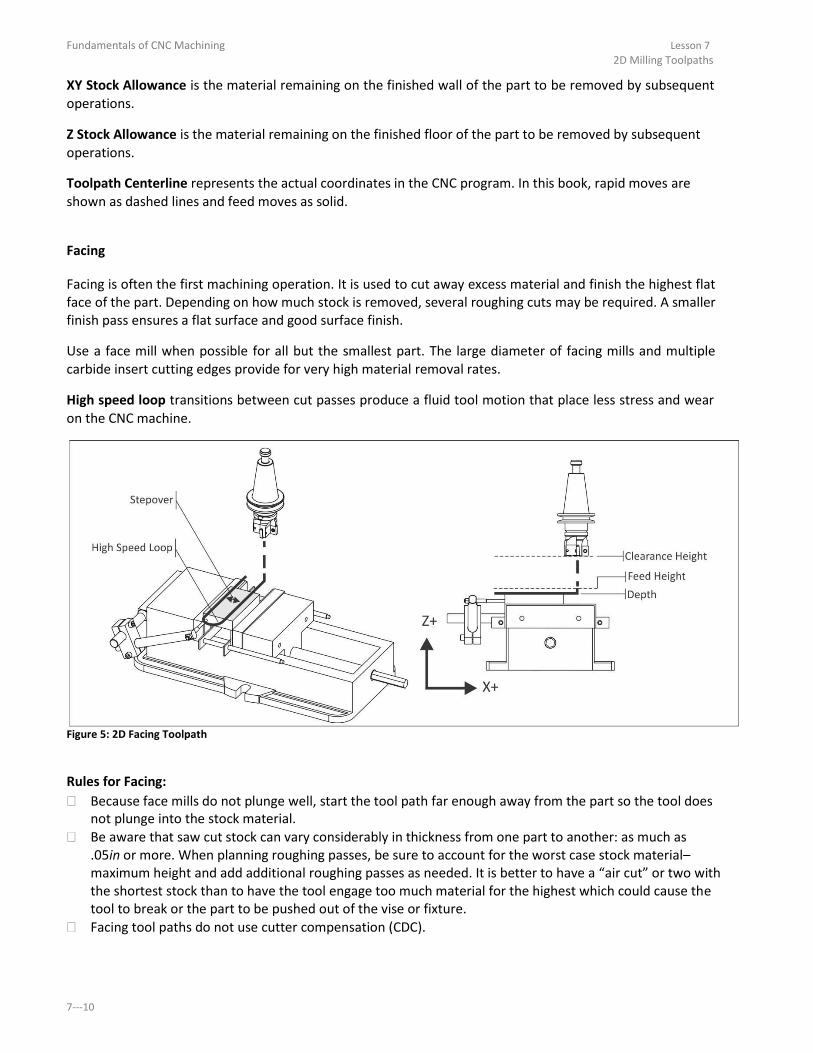
Fundamentals of CNC Machining Lesson 7 2D Milling Toolpaths
XY Stock Allowance is the material remaining on the finished wall of the part to be removed by subsequent
operations. Z Stock Allowance is the material remaining on the finished floor of the part to be removed by subsequent
operations. Toolpath Centerline represents the actual coordinates in the CNC program. In this book, rapid moves are
shown as dashed lines and feed moves as solid.
Facing
Facing is often the first machining operation. It is used to cut away excess material and finish the highest flat
face of the part. Depending on how much stock is removed, several roughing cuts may be required. A smaller
finish pass ensures a flat surface and good surface finish. Use a face mill when possible for all but the smallest part. The large diameter of facing mills and multiple
carbide insert cutting edges provide for very high material removal rates. High speed loop transitions between cut passes produce a fluid tool motion that place less stress and wear
on the CNC machine.
Figure 5: 2D Facing Toolpath
Rules for Facing: Because face mills do not plunge well, start the tool path far enough away from the part so the tool does
not plunge into the stock material. Be aware that saw cut stock can vary considerably in thickness from one part to another: as much as
.05in or more. When planning roughing passes, be sure to account for the worst case stock material–
maximum height and add additional roughing passes as needed. It is better to have a air cut or two with
the shortest stock than to have the tool engage too much material for the highest which could cause the
tool to break or the part to be pushed out of the vise or fixture.
Facing tool paths do not use cutter compensation (CDC).
7-

Lesson 7 Fundamentals of CNC Machining 2D Milling Toolpaths
2D Contour
Contour operations are used to rough and finish outside part walls as shown in Figure 6. Use Cutter
Diameter Compensation (CDC) on high tolerance features so the tool path can be adjusted at the machine if
needed to account for tool wear and deflection.
Figure 6: 2D Contour Tool Path
Rules for Contouring: Only use CDC when needed. If using new tools and conservative machining parameters, features will
likely be within .005 inches of the programmed path without adjustment. Start the tool path off the part to allow CDC to be fully in effect for the entire operation.The combined
line-a lead-i /out o es sho i Figu e o k fo ost o tou s. The li e is fo activating/deactivating compensation, and the arcs blend the path into the part wallsmoothly.
Set a rapid height value to clear all clamps or other obstacles between cuts. Rough the walls and leave a constant thickness of material for the finish operation. This ensures even
cutting pressure on the finish pass and thus a more accurate part. Extend the cut depth of full walls slightly below the bottom of the wall, but be careful not to cut into the
machine table or vise hard jaws! This way, when the part if flipped over to face the other side, no
flashing will be left on the bottom of the walls. Mill tools cut well in the XY direction, but not as well when plungingin Z. When possible, plunge the tool
away from the part to avoid Z- o es i to the sto k ate ial. When taking multiple depths of cut, make the last pass at full depth to remove any marks left by
previous depth cuts. For tall walls, consider taking one additional finish pass. This so- alled spring pass follows the same
path twice to ensure the walls are perfectly straight and not slightly tapered due to cutting pressure
which causes the tool tobend.
Copyright 2014 Autodesk, Inc. 7-

Fundamentals of CNC Machining Lesson 7 2D Milling Toolpaths
Cutter Diameter Compensation
Cutter Diameter Compensation provides a way for tool paths to be adjusted at the machine to compensate
for tool wear and deflection. Figure 5 shows how CDC Right (G41) causes the tool to veer to the right of the
programmed path. The compensation value is found by measuring the part feature and subtracting the actualdimension from
the desired dimension. The difference is entered in the control CDC register for the tool. The next time
program is run, the tool will be offset by this value.
Programmed
Path Planned Size
CDC Path
Actual Size
CDC
Lead In Line Activated
Figure 7: Cutter Diameter
CDC must be turned on or off with a line move, never an arc. Commanding G40/G41/G42 with an arc move will cause
a diameter compensation error that will stop the program.
CDC is activated at the end of the line on which it is called, as shown in Figure 5. Notice how the tool moves
at an angle from the start to end of the lead-i li e. A ti ate CDC hile the tool is a a f o the pa t so this angle move happens away from the finished part surfaces. The line-a moves shown in Figure 4
provide ample clearance for the tool for this purpose.
7-

Lesson 7 Fundamentals of CNC Machining 2D Milling Toolpaths
Pocketing
Pocket tool paths are used to remove excess material. An example of a spiral pocket with helical entry is
shown in Figure 6. CDC is not active during the roughingcuts, but may be used for finish passes on walls.
Figure 8: Pocketing
Rules for Pocketing: Rough passes should leave a constant thickness of material on the walls and floor of the pocket to be
removed by the finish passes. Consider using a roughing end mill to remove most of the material.These serrated mills can remove
material at a far faster rate than finish endmills. They do leave a poor finish on the floors and wallsthat
must be finished with a separate finish tool and operation. Helical moves are a good method for entering a pocket. If space does not allow a helical entry, use a
center- utti g e d ill o plu ge the tool th ough an existing hole, or a pilot hole created for this
purpose. The pilot hole must be at least 50% of the tool diameter. Spiral pocketing paths that start near the center of the pocket and move outward in a counter-
lo k ise di e tio a e est e ause they cause the tool to continually climb cut. Use CDC only on finish passes.
Copyright 2014 Autodesk, Inc. 7-
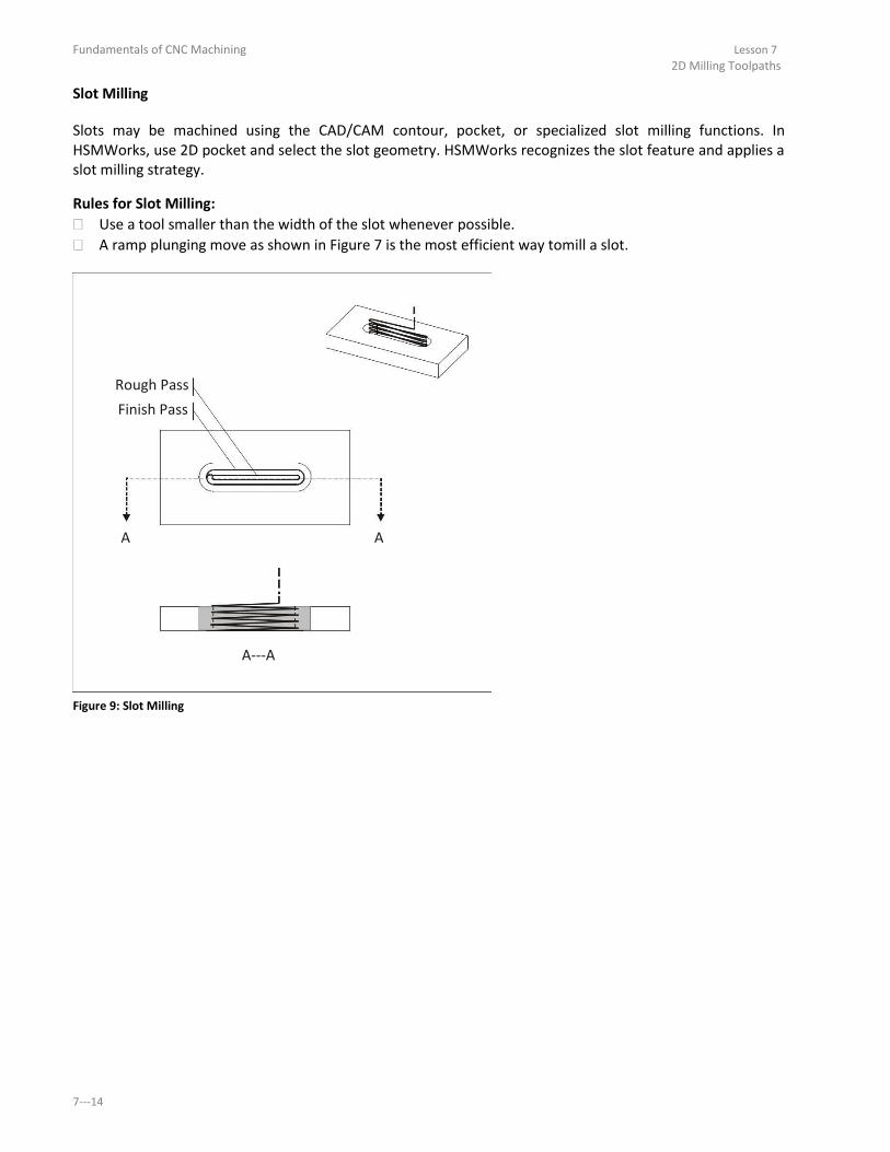
Fundamentals of CNC Machining Lesson 7 2D Milling Toolpaths
Slot Milling
Slots may be machined using the CAD/CAM contour, pocket, or specialized slot milling functions. In
HSMWorks, use 2D pocket and select the slot geometry. HSMWorks recognizes the slot feature and applies a
slot milling strategy. Rules for Slot Milling: Use a tool smaller than the width of the slot whenever possible. A ramp plunging move as shown in Figure 7 is the most efficient way tomill a slot.
Rough Pass
Finish Pass
A A
A-A Figure 9: Slot Milling
7-

Lesson 7 Fundamentals of CNC Machining 2D Milling Toolpaths
Chamfer Milling
Chamfer is a type of 2D contour milling. Chamfer mills are of various tip angles are in high speed steel,
carbide, or as insert type tools. Rules for Chamfer Milling: Because the tip of a chamfer mill is not a sharp point the width of the chamfer may be wider than
expected if you set the tool like an end mill. To prevent cutting too deep, consider raising the TLO about.010 inches after setting it. Then machine the chamfer, check its size, and adjust the TLO down as
needed to produce the correct width chamfer. Offset the chamfer mill as shown in the magnified view below to move the tool tip is away from the
bottom of the chamfer. This ensures a cleanbottom edge and, because tool rotational velocity increases
with tool diameter, is a more efficientto use the tool. Chamfer with a spot drill to precision de- u sha p o e s.
Z+
X+ Figure 10: Chamfer Milling
Copyright 2014 Autodesk, Inc. 7-

Fundamentals of CNC Machining Lesson 7 2D Milling Toolpaths
Radius (Corner-Rou d Milli g
Radius milling is a form of contour milling. Corner round tools are available in high speed steel, carbide, or
insert type tools.
Z+
X+ Figure 11: Radius Milling
Rules for Radius Milling: The horizontal and vertical cutting edges of a radius mill are sloped slightly to blend the radius into the
walls. Take two finish passes to improve surface finish. Another way to form a corner radius is to use a ball mill and 3D contour tool path. Thismethod saves
purchasing a radius mill and is suitably efficient for prototype and small production manufacturing. 7- .

Lesson 7 Fundamentals of CNC Machining 2D Milling Toolpaths
Center Drill
Center drills create a conical cut on the face of the part. This helps prevent subsequent drill tools from
wobbling and thus ensures they will be positioned precisely.
Z+
X+ Figure 12: Center Drilling
Rules for Center Drilling: A good rule of thumb is to use a tip depth equal to the radius of the subsequent drill hole. Use a combination center-spotti g d ill fo spot faced holes.
Copyright 2014 Autodesk, Inc. 7-

Fundamentals of CNC Machining Lesson 7 2D Milling Toolpaths
Drilling
Holes that are less than the diameter of the drill can be created with a single plunge move. Deeper holes use a
Peck Drill cycle where the tool is retracted after removing a small amount of material (typically .050 inches).
Shoulder Depth Breakthrough
Z+ Feed Height
X+ Tip Depth
Figure 13: Drilling
Rules for Drilling: Center drill all holes to ensure they are located precisely. Peck drill (G83) holes that are deeper than the diameter of the drill. Full retract peck drill cycles take
more time than partial retracts,but minimize the chance of tool breakage. CNC Programs control the tip of the tool. Be sure to provide additional depth to compensate for the tool
tip and include a breakthrough allowance to prevent a flange or burr on the bottom.
7-

Lesson 7 Fundamentals of CNC Machining 2D Milling Toolpaths
Tapping
Tap cycles are similar to simple drill cycles except the feed and speed are coordinated to properly match the
thread lead. CAD/CAM software calculates the feed according to the cutting speed and threads per inch (TPI)
of the tap.
Feed Height
Z+ Shoulder Depth
Tip Depth
Breakthrough
X+ Figure 14: Tapping
Rules for Tapping: Use the drill chart in Appendix A to find the correct drill diameter for cutting taps. Use the
manufacturers recommended drill size for form taps. Consider brushing on tapping fluid instead of using coolant for small tapped holes to help prevent the
tap from breaking. Tapped holes smaller than about #8 can be difficult to create on the machine without breaking the tap.
Consider tapping these holes by handrather than on the CNC. If the machine does not support Rigid Tapping, a floating tap holder is required to tap. Refer to the
tapping head documentation for proper use. Be sure to specify a tip depth sufficient to account for the tip and initial taper of the tap. Older machines may require a larger feed height to allow the machinespindle to reach full speed before
the thread engages the material.
Copyright 2014 Autodesk, Inc. 7-

Fundamentals of CNC Machining Lesson 7 2D Milling Toolpaths
7-

Fundamentals of CNC Machining
Lesson 8
CNC Turning
Upon successful completion of this lesson, you will be able to: Identify the elements of the Lathe coordinate system. Identify common lathe work holding. List the most commonly used Lathe tools. Calculate lathe speeds and feeds. Describe Constant Surface Speed (CSS) speed control. Explain the purpose, general parameters, and use of lathe tool paths, including
face, turn, groove, cut off, thread, and drill cycles. Explain the purpose and general configuration of live tools.
8-

Fundamentals of CNC Machining Lesson 8 CNC Turning
8-

Lesson 8 Fundamentals of CNC Machining CNC Turning
Overview
Milling machines work by moving a spinning tool over a stationary part.Lathes work by spinning the part and
moving the tool, making them ideal for round parts like shafts, pins and pulleys.
ToolTurns
Milling
Part Turns
Turning Figure 1: Milling vs. Turning
There are many different configurations of CNC lathes. Some have two spindles, some two tool turrets, and
some even integrate milling or grinding in the same machine. There is also variation between similar
machines. Horsepower, the size of stock that can be gripped, and how tools are held vary greatly between
lathes. Discussing every lathe configuration is beyond the scope of this book. This chapter discusses one of the most
common lathe configurations, called a Turning Center, withone spindle and tool turret.
Copyright 2014 Autodesk, Inc. 8-
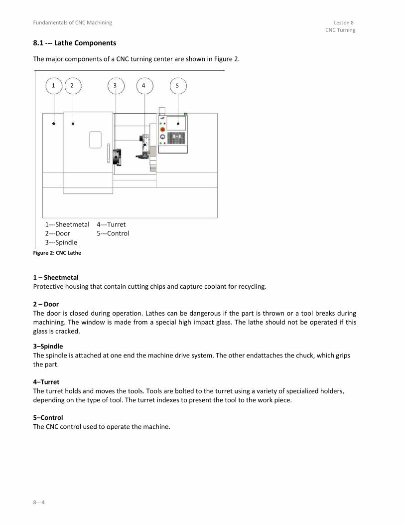
Fundamentals of CNC Machining Lesson 8 CNC Turning
8.1 - Lathe Co po e ts The major components of a CNC turning center are shown in Figure 2.
1 2 3 4 5
1-Sheet etal 4-Tu et 2-Doo 5-Co t ol 3-Spi dle
Figure 2: CNC Lathe
1 – Sheetmetal Protective housing that contain cutting chips and capture coolant for recycling.
2 – Door The door is closed during operation. Lathes can be dangerous if the part is thrown or a tool breaks during
machining. The window is made from a special high impact glass. The lathe should not be operated if this
glass is cracked. 3–Spindle The spindle is attached at one end the machine drive system. The other endattaches the chuck, which grips
the part.
4–Turret The turret holds and moves the tools. Tools are bolted to the turret using a variety of specialized holders,
depending on the type of tool. The turret indexes to present the tool to the work piece.
5–Control The CNC control used to operate the machine. 8-

Lesson 8 Fundamentals of CNC Machining CNC Turning
Spindle
The spindle turns the chuck. The chuck grips the part using hard jaws, soft jaws, or collet. The most common
configuration is the three jaw chuck, shown in Figure 3. The chuck requires air pressure to open and close
the jaws, and set the gripping force. Pressure must be high enough to securely hold the part, but not so
great as to deform fragile parts.
1 2 3 4
1-Spi dle 3-Ja s 2-Chu k 4-Pa t
Figure 3: Spindle Detail
Copyright 2014 Autodesk, Inc. 8-

Fundamentals of CNC Machining Lesson 8 CNC Turning
Turret
Tool holders bolt to either the front or perimeter of the turret.Tool changes are made by the machine
indexing the turret to place the appropriate tool closest to the part.
The method by which the tools are attached to the turret, and the direction the tool faces in relation to the
part, vary depending on the tool, operation, and cut direction. For example, a facing tool is oriented radially
to the part, to maximize tool rigidity and work envelope. A boring bar is oriented axiallyto allow the bar to
enter and exit the bore.
1
2
3
4
5
6
7
8
1-Tool Statio 5-Tu et
2-Tool Blo k 6-Bo i g Ba Tool 3-Fa e/Tu Tool 7-Li e Tool Radial Mou t 4-Fa e G oo e Tool 8-Li e Tool A ial Mou t
Figure 4: Turret Detail
8-

Lesson 8 Fundamentals of CNC Machining CNC Turning
1 – Tool Station The turret is divided into stations evenly spaced around the perimeter. Most lathes with tool turrets have
about 10 tool stations. Tools are connected to the turret by a tool holder and tool block. The tool holder and
block used depend on the type of tool and mount direction.
2 –Tool Block Tool blocks act as the interface between the tool holder and the turret.They bolt to the face or perimeter of
the turret. Different blocks are used depending on the type of tool and orientation.
3-Tur Tool Turning tools, which includes face, OD rough and finish, groove and cutoff, are usually mounted radially with
respect to the part. The cutting tool is usually a ceramic insert mounted in a tool post designed for the
specific shape and size insert.
4-Fa e Groo e Tool Face groove tools are mounted axially from the part.
5-Turret The turret holds and moves the tools. To change tools, the turret unlocks, rotates to present the active tool
to the work piece, and then locks again. Care must be taken that the turret is away from the part so that
none of the tools collide with the part as the turret indexes.
6-Bori g Bar A boring bar is used to create a precision size and finish hole through the bore of the part.These are
mounted axially with the spindle
7-Li e Tool Radial Mou t A live tool is a tool that rotates, being driven by a mechanism in the holder.Radially mounted live tools are
used for cross drilling or milling on the diameter of the part.
8-Li e Tool A ial Mount) Axial mounted live tools mill or drill on the face of the part.
Copyright 2014 Autodesk, Inc. 8-

Fundamentals of CNC Machining Lesson 8 CNC Turning
8.2 – Lathe Coordinate System
Most lathes are 2D machines based on a Z-X Coo di ate S ste . As sho i Figu e , the Z-a is is parallel to the machine spindle and the X-a is is pe pe di ula to the spi dle. No al spi dle otatio is counter- lo k ise, though di e tio a e e e sed fo left-ha ded th eads just like with a mill by
commanding the proper G- ode. Notice how the turret is set at an incline from horizontal. This so- alled slant bed configuration keeps
cutting chips from accumulating on flat surfaces inside the machine. Also notice that the tool approaches from the top of the part. This is known as an upper-tu et configuration, and requires the tool be placed in the holder upside-do as sho i the i set ie i Figure 5.
+X
+Z -Z
-X
CCW Tool
Upside-Do
Figure 5: Lathe Coordinate System 8-
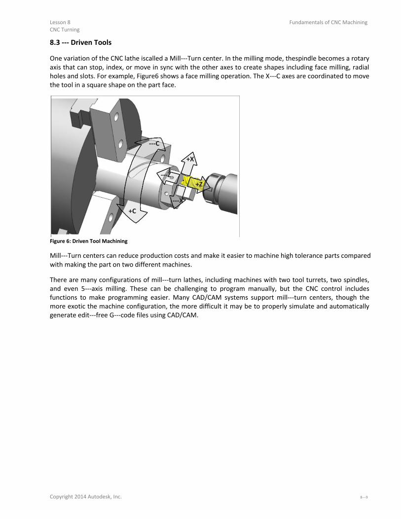
Lesson 8 Fundamentals of CNC Machining CNC Turning
8.3 - Dri e Tools
One variation of the CNC lathe iscalled a Mill-Tu e te . I the illi g ode, thespi dle e o es a ota axis that can stop, index, or move in sync with the other axes to create shapes including face milling, radial
holes and slots. For example, Figure6 shows a face milling operation. The X-C a es a e oo di ated to o e the tool in a square shape on the part face.
-C
+X
-Z +Z
-X
+C
Figure 6: Driven Tool Machining
Mill-Tu e te s a edu e p odu tio osts a d ake it easie to a hi e high tole a e pa ts o pa ed with making the part on two different machines.
There are many configurations of mill-tu lathes, i ludi g a hi es ith t o tool tu ets, t o spi dles, and even 5-a is illi g. These a e halle gi g to p og a a uall , ut the CNC o t ol i ludes functions to make programming easier. Many CAD/CAM systems support mill-tu e te s, though the more exotic the machine configuration, the more difficult it may be to properly simulate and automatically
generate edit-f ee G- ode files usi g CAD/CAM.
Copyright 2014 Autodesk, Inc. 8-9

Fundamentals of CNC Machining Lesson 8 CNC Turning
8.4 Imaginary Tool Tip The corners of lathe tools are radii. The imaginary tool tip is where vertical and horizontal lines tangent to the
cutting edge of the tool intersect. This point is found by touching off the tool in the Z and X directions on the
part or using a tool probe. Because the imaginary tool tip can be found with great precision, it is used to control the tool. That is, all the
Z-X oo di ates i the G- ode p og a a e i efe e e to this poi t. Tool positio s a e eas to al ulate parallel to the machine axes, but more complex for arcs and chamfers. However, since almost everyone programs using CAD/CAM software or an on- o t ol p og a i g utilit , you won t have to calculate complex lathe tool paths. The programmer inputs the part profile geometry, and
the control or software does all the calculations. Let the CAD/CAM software or control do this work.
Datu
ToolX-Datu
Imaginary Tool Tip
Figure 7: Imaginary Tool Tip
When programming a lathe, think in termsof motion of the imaginary tool tip. As shown in Figure 8, more
positive Z- alues o e the tool to the ight. Mo e positi e X- alues o e the tool a a f o the pa t.
+X
+Z
Figure 8: Tool Motion 8-

Lesson 8 CNC Turning
Fundamentals of CNC Machining
8.5 - Part Datu The part datum is usually set as the center-fa e of the fi ished pa t, as sho i Figu e elo .
G54
+X
+Z Figure 9: Part Datum
Lathe tools have two tool offsets: Z and X, which is the distance from the imaginary tool tip at home position
to the part datum. There are two ways to set lathe tool offsets. The first involves making a small cut (try cut)
on the OD and face of the stock material. The diameter is measured and entered in the controlfor the X-
a is offset. Subsequent tool offsets are found in reference to these faces. Many lathes now include a tool probe as standard or optional equipment. Please refer to your machine
documentation for specific instructions about your machine and its options.
Virtual Tool Tip
Tool Offset X
Tool
Offset Z
Figure 10: Tool Offsets
Copyright 2014 Autodesk, Inc. 8-

Fundamentals of CNC Machining Lesson 8 CNC Turning
8.6 – Tools and Tool Holders
While lathes use some of the same toolsthat mills use, including spot drills, drills, and taps, most turning is
done using carbide inserts. Inserts are gripped in holders, which in turn are bolted to the lathe turret (see
Fig. 4). Figure 11 shows a typical insert-holde o i atio . This is a left-handed holder, because the tool
cutting edge points to the left when viewing the holder from the top as shown in Figure 12.
Holder
Clamp
Screw
Insert
Figure 11: Typical Lathe Tool Holder
Carbide inserts employ highly engineered composite structures, coatings, and geometry features to achieve
great accuracy and high material removal rates. Some inserts can be indexed to use other edges when one
becomes worn. Inserts are quickly and easily replaced at the machine.
I.C.
Shape
Hole
Nose Angle Nose Radius
Figure 12: Insert Terms
Chip Breaker A chip breaker is a feature in the face of the insert that disrupts the flow of chips uchs that they break into
short segments, rather than forming a long, stringy chip.
Chip Breaker
Figure 14: Chip Breaker 8-

Lesson 8 CNC Turning
Fundamentals of CNC Machining
Relief Angle Most inserts have drafted faces on the walls. This is called Relief Angle. Relief prevents the walls of the insert
from rubbing against the part.
Nose Radius
Drafted Faces
Iso
Relief Angle Front Figure 13: Relief Angle
Tool Cutting Angles
The edge of the tool in the cut direction forms an angle with aline perpendicular to the cut direction. This is
called Side Cutting Angle. The angle formed by the trailing edge and parallel to the cut direction is called the
End Cutting Angle.
The purpose of these angles is to provide proper clearance between thetool and work piece. For example,
the 80 degree insert shown in Figure 16 is rigid and has enough side and end cutting angle for facing and
rough turning operations. However, complex contours may require a 55 or 30 degree insert to provide tool
side and end clearance for the tool and holder.Very steep or vertical walls may require a round or slot tool to
carve.
Figure 16: Cutting Angles
Copyright 2014 Autodesk, Inc. 8-

Fundamentals of CNC Machining Lesson 8 CNC Turning
Rake Angle
Rake angle is set by the tool holder. Rake angle helps control the direction of the chip and cuttingpressure. Angle is measured from face of the insert to the Z-X pla e of the a hine.
Spindle Direction
Feed
Direction
Neutral
Negative
Positive
Rake Angle
Figure 17: Rake Angle
8-

Lesson 8 CNC Turning
Fundamentals of CNC Machining
8.7 Insert Designations Carbide inserts use a coding system of numbers and letters to describe their shape, dimensions, and
important parameters. For example, the designation of the insert shown in Figures 11- is a CNMG- .
CNMG
-
433
Shape Clearance Angle NoseRadius
Tolerance
Thickness
Hole/Chip Breaker I.C. Size
Figure 15: Carbide Insert Designation
Shape (CNMG- There are at least 18 different shapes of carbide inserts. The most commonly used are shown in Table 1 with
their letter designation. The angle in this designation refers to the included nose angle at the cutting radius
of the tool.
Shape
T
Triangle
S
Square
C
80 degree diamond
D
55 degree diamond
V
35 degree diamond
R
Round
Table 1: Common Insert Shape Codes
Clearance Angle (CNMG- Clearance angle is the draft on the face(s) of the insert that contact material during machining.More about
insert angles a little later.
Designation Clearance Angle
N 0 Degrees (No Draft)
A 3 Degrees
B 5 Degrees
C 7 Degrees
P 11 Degree Table 2: Common Insert Clearance Angles
Copyright 2014 Autodesk, Inc. 8-
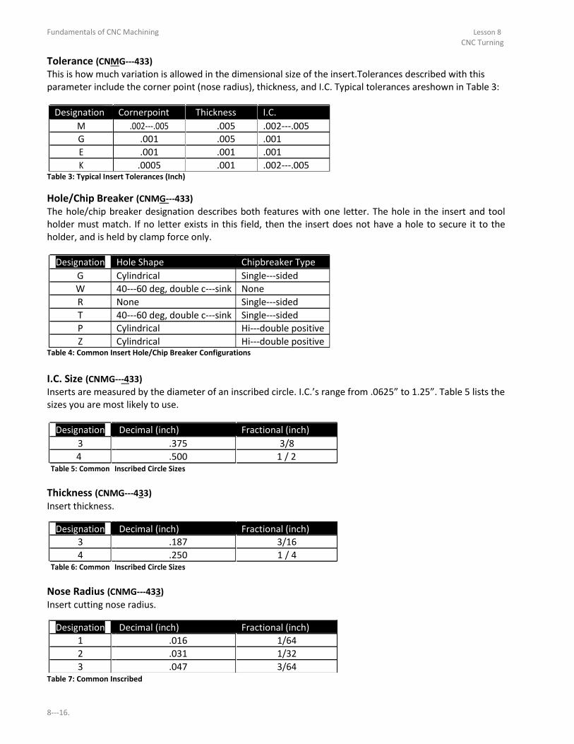
Fundamentals of CNC Machining Lesson 8 CNC Turning
Tolerance (CNMG- This is how much variation is allowed in the dimensional size of the insert.Tolerances described with this
parameter include the corner point (nose radius), thickness, and I.C. Typical tolerances areshown in Table 3:
Designation Cornerpoint Thickness I.C.
M .002-. .005 .002-.
G .001 .005 .001
E .001 .001 .001
K .0005 .001 .002-. Table 3: Typical Insert Tolerances (Inch)
Hole/Chip Breaker (CNMG- The hole/chip breaker designation describes both features with one letter. The hole in the insert and tool
holder must match. If no letter exists in this field, then the insert does not have a hole to secure it to the
holder, and is held by clamp force only.
Designation Hole Shape Chipbreaker Type
G Cylindrical Single-sided
W 40- deg, dou le -si k None
R None Single-sided
T 40- deg, double c-si k Single-sided
P Cylindrical Hi-dou le positi e
Z Cylindrical Hi-dou le positi e Table 4: Common Insert Hole/Chip Breaker Configurations
I.C. Size (CNMG-- 33) Inserts are measured by the diameter of an inscribed circle. I.C. s range from .0625 to 1.25 . Table 5 lists the
sizes you are most likely to use.
Designation Decimal (inch) Fractional (inch)
3 .375 3/8
4 .500 1 / 2
Table 5: Common Inscribed Circle Sizes
Thickness (CNMG- 33) Insert thickness.
Designation Decimal (inch) Fractional (inch)
3 .187 3/16
4 .250 1 / 4 Table 6: Common Inscribed Circle Sizes
Nose Radius (CNMG- 3) Insert cutting nose radius.
Designation Decimal (inch) Fractional (inch)
1 .016 1/64
2 .031 1/32
3 .047 3/64 Table 7: Common Inscribed
8- .

Lesson 8 Fundamentals of CNC Machining CNC Turning
The insert shapes, sizes, and designations in these tables are just of few of what is available.Any lathe tool
catalog or manufacturers web site will show many more. It is not important to memorize every tool shape or designation scheme.It is important to know insert terms
and specifications to understand insert recommendations from the tool representative or technical resource
to select the correct insert for the application.
8.8 Lathe Tool Types The following is a list of the most common lathe-spe ifi tool t pes. While these a e the ost o o types you are likely to use, they represent only asmall number of the tools that are available.
Note: For illustration purposes, the tools shown on the following pages are left-ha ded. Uppe tu et a hi es mostly use right-ha ded tools.
Face/Turn For facing and rough turning, use a more rigid tool such as a round, square, or 80 degree diamond. Finishing
may require a more versatile tool, such as a 55 or 35 degree diamond. These provide more side andend
cutting angle relief to reach and contour part details. Inserts must match the tool holder, and that means
the right type, size, shape, and clamping feature(s).
Iso View
Control Point
TopView Figure 18: Face/Turn Tool (Left Hand)
Copyright 2014 Autodesk, Inc. 8-

Fundamentals of CNC Machining Lesson 8 CNC Turning
Groove
Groove tools are classified in part by their width and corner radii. Though used mostly for making groove
features, such as O- i g o s ap- i g uts, e e ge e atio s of these tools can be used for rough and
finish contouring operations. While not the best choice for all roughing and finishing, theywork well in areas
where a diamond or other shape cannot easily fit. Besides there being many types of groove tools, there are many types of holders, depending mostly on the
cut direction for the tool. For example, there are groove holders for OD, ID, and Face grooves, and these are
all available in Left Hand or Right Hand models.
Iso View
Control Point
TopView Figure 19: Groove Tool (Left Hand)
8-

Lesson 8 Fundamentals of CNC Machining CNC Turning
Bore
Precision holes are often finished with a boring tool. Boring bar tools are mounted parallel to the machine
spindle. They require a hole in the part large enough to allow the bar to safely enter and exit the bore.
Iso View
Control Point
TopView Figure 20: Boring Bar (Left Hand)
Copyright 2014 Autodesk, Inc. 8-

Fundamentals of CNC Machining Lesson 8 CNC Turning
Thread
Tapped holes at the center of part, up to about one inch diameter, can be made using a form or cutting tap,
just like on a mill. Larger ID threads and all ID threads use a thread insert. Thread tools are set to the tip of the thread point in Z and X. Z is set by touching off on the edge of the part,
and then taking into account the distance from this edge to the tip of the thread point, a distance included in
the insert documentation. Often a thread gage is used to check threads, and the X-offset fo the th ead tool adjusted to a hie e the proper size and fit (Thread Class.
Iso View
Control Point
TopView Figure 21: OD Thread Tool (Left Handed)
8-
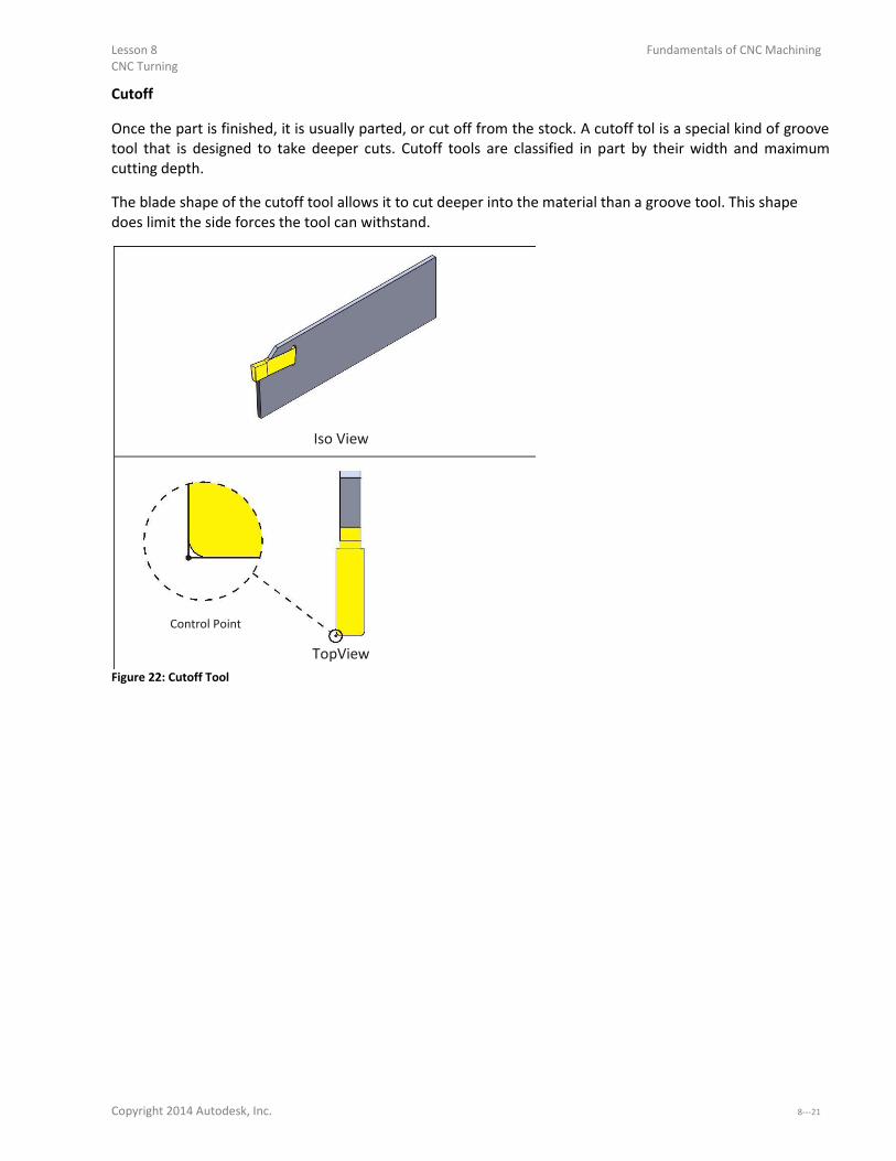
Lesson 8 Fundamentals of CNC Machining CNC Turning
Cutoff
Once the part is finished, it is usually parted, or cut off from the stock. A cutoff tol is a special kind of groove
tool that is designed to take deeper cuts. Cutoff tools are classified in part by their width and maximum
cutting depth. The blade shape of the cutoff tool allows it to cut deeper into the material than a groove tool. This shape
does limit the side forces the tool can withstand.
Iso View
Control Point
TopView
Figure 22: Cutoff Tool
Copyright 2014 Autodesk, Inc. 8-

Fundamentals of CNC Machining Lesson 8 CNC Turning
8.9 Cutting Speeds and Feeds Speeds and feeds are calculated based on the maximum work diameter for the tool. Use the same speed
formulas as for mills.
.
=
Figure 23: Speed Formula (Simplified)
Speed is the machine spindle RPM (how fast the part turns).
SFM is the Surface Feet per Minute based on the insert manufacturers recommendation for the material
and cutting conditions.
3.82 is a constant that relates the surface feet per minute to work piece diameter.
Dia is the diameter of the tool when it first engages the material.
Dia (in)
Figure 24: Facing Tool Engaging Material
Cut Direction
8-

Lesson 8 Fundamentals of CNC Machining CNC Turning
Speed/Feed Example
Problem:
Calculate the cutting speed for a facing operation given the following values:
Parameter Value
Part Diameter 2.0in
SFM 500ft/min
Table 8: Drill Speed/Feed Example
Solution:
(
) 3.82 min
(
) =
( ) ( ) = 500( ) 3.82
2.0
( ) = ( ) Constant Surface Speed (CSS)
Notice that as the tool moves down the face of the part, the diameter where the cutting edge contacts the
part gets smaller.
Dia (in)
Cut
Direction
Figure 25: Decreasing Cut Diameter As Tool Nears Center
To maintain a constant rate of material removal as the cutting diameter decreases, most CNC machines
automatically speed up the spindle, based on how far the tool moves towards center. This constantly
variable spindle control is called Constant Surface Speed (CSS) mode. It is commanded on most machines
using G96 to activate, and G97 to de-a ti ate. G96 is preceded by some important codes, as shown in the following example:
Copyright 2014 Autodesk, Inc. 8-

Fundamentals of CNC Machining Lesson 8
CNC Turning
Block Description
G50 S2000 G50 sets the maximum spindle speed for this tool. G97 S1200 T101 M03 G97 cancels CSS so the spindle speed does
not change as the turret rapids to
position. G00 X2.1 Z0. Tool moves to start of cut. M08 Coolant ON. G96 S1200 CSS mode on, Spindle begins at 1200
RPM. G01 X-. Face part. As tool moves from a diameter
of 2.1 inches to X-. , the spi dle will increase speed up to the limit of S2000 RPM.
Table 9: Lathe Program Using CSS
When invoked, you will hear the lathe spindle increase as the tool moves from the perimeter of the cut to the
part center. The G50 command is important because it keeps the spindle from over-speedi g.
Warning: All lathe chucks have speed limits based on the weight of the part and how far it extends from the face
of the chuck. Do not exceed these limits. Ensure chuck clamping pressure is sufficient to grip the part based on
cutting forces. Use G50 when using CSS mode to limit the speed of the spindle.
CSS does not apply where the tool does not change its position along X. For example, don t use CSS mode for
drilling or tapping on part centerline. Feed is based on the speed and manufacturer recommended Feed Per Revolution (FPR) of the tool.
Cutting Feeds Example Problem: Calculate the cutting feed for tool with the following parameters.
Parameter Value
Speed 955rpm
IPR .015in/rev Table 10: Lathe Feed Example
Solution:
=
=
.
= .
8-

Lesson 8 Fundamentals of CNC Machining CNC Turning
8.10 Lathe Setup & Programming Example The following turned part is used on the following pages to introduce lathe tool paths.This example deals
with processes in general, so material and dimensions are not important now.
Figure 26: Example Lathe Part and Features
1 – Face Facing is usually the first lathe operation.It provides a known location to set the Z-offset of othe tools a d a flat surface for face drilling. Because sawed stock can vary in length, it is a common practice to take at least
one roughing and finish facing pass.
2 – Rough/Finish The goal of lathe roughing is to remove excess material as efficiently as possible, ideally leaving a constant
thickness of material for the finish tool. Finish tool paths determine the final size and surface finish.
3 – Groove Grooves have many configurations, but most have straight walls and radii at the bottom and top that is
formed with the groove tool.
4 – Thread Threads on a lathe are usually machined with a special thread tool. Small diameter threads through the
center of the part may be cut with a tap, just like on a mill.
5 – Bore Clearance holes in the bore may be drilled. Small bore holes may be reamed, but are usually finished with a
boring bar tool.
6 – Cutoff The final operation is the cutoff. This may also put a chamfer or radius on the outside edge of the part. Once
cut away from the stock, the part is allowed to simply fall into the bottom of the machine, though many
Copyright 2014 Autodesk, Inc. 8-

Fundamentals of CNC Machining Lesson 8 CNC Turning
lathes include a part catcher chute that extends during cutoff. The part falls onto this chute and rolls into
cage for the operator to retrieve.
Setup The part is gripped in hard jaws, soft jaws, or collet. Part datum is usually thecenter-fa e of the fi ished pa t. Provide enough excess stock to securely grip the part. The back side of the part should be as close to the jaws
as possible while providing clearance for the cutoff tool. Figure 27: Typical Lathe Setup
1 – Jaws If using soft ways, machine them to fit the OD of the part. Jaws must have sufficient clamping pressure to
hold the part. There is a limit to how far the jaws can be safely extended. This information is found in the
chuck documentation.
2–Chuck The chuck secures the jaws. A hole in the chuck allows bar material to extend through the chuck. This is useful
for production runs. After a part is cut away, the jaws are opened, the stock drawn out further, and then the
jaws are closed. This saves cutting the stock to length and wasted material.
Warning: There is a limit to how far the stock can extend out of the chuck without supporting the other end. Check your
machine and chuck documentation for this and other operating limits.
3–Stock Stock needs to be over-sized i Z a d X so the fa e a d fi ish tools e o e ate ial all a ou d, i ludi g the cutoff.
4–Grip/Cutoff Stock Ensure the back side of the part is far enough away from the jaws to provide cutoff tool clearance. Lathes are
extremely powerful and any collision between the tool and rotating jaws is dangerous.

8- CNC Turning
5– Part Datum The part datum for lathe parts is usually the center-fa e of the fi ished pa t.
6–Extra Stock for Facing Sawed stock is uneven and has a poor finish. Ensure the stock extends slightlybeyond the finished face of the
part so the face pass removes material.
Face
Facing is usually the first operation of any turning job.
1
Cut
2 Direction
1-Sta t Cut 2-Pull Off
Figure 28: Face Toolpath
Rules for Facing Start away from the OD of the stock, keeping in mind that rough stock diameter varies. Face straight down until the contact point of the tool is at X0 and then pull away. Consider taking one rough and one finish pass. Use a rigid tool, such as a 80 degree diamond.

Copyright 2014 Autodesk, Inc. 8-

Fundamentals of CNC Machining Lesson 8 CNC Turning
Rough
Rough the part leaving stock in Z and X for finish paths.
2
1
Cut
Direction
1-Sta t Cut 2-Pull Off
Figure 29: Roughing
Rules for Roughing Start away from the face of the part. A common practice is to use the same tool for both facing and OD roughing when possible. Leave a constant thickness of material over the part for the finishing operation. Skip over grooves and other features that will be rough or finished with other tools and operations. Consider moving the tool vertically at the end of each path to remove scallops. Extend the path past the back of the part for cutoff tool clearance.
8-

Lesson 8 Fundamentals of CNC Machining CNC Turning
Finish
Finish the part. Choose the largest and most rigid tool that will make all the features. Watch the back
clearance of the tool to ensure the tool and holder do not collide with the part.
2
1
Cut Directions
Section Part 1-Sta t Cut
2-Pull Off View
Figure 30: Finish
Rules for Finishing Start away from the part face. Use a tool, such as a 35 or 55 degree diamond, with sufficient side and end cutting angles to provide tool
clearance. Use a tool with a nose radius equal, or preferably smaller, than the smaller ID radius in the profile. Consider taking a pre-fi ish pass fi st so the fi al pass e o es a o sta t thi k ess of ate ial. Skip over features, such as grooves, that will be machined using other tools and operations. For threads, finish at the major diameter of the thread.
Copyright 2014 Autodesk, Inc. 8-

Fundamentals of CNC Machining Lesson 8 CNC Turning
Groove
Most grooves have radii at the top and bottom. Groove tool paths are actually quite complexThe. following
sequence is often used to create a groove that is accurate and with no tool marks. A common groove operation is shown in the Details view in Figure 31: A) The tool is usually plunged near the
center of the groove to rough. B) Other plunge moves as required to remove excess material. C) One
contouring path, starting outside and moving inward, creating radii and contour. D) One contouring path,
starting from the other side and moving inward finishing the other side.
Cut
Directions
c a b d
Details Figure 31: Groove
Rules for Grooving Use a groove tool narrower than the groove and with a radius equal or less than the finished radius. Use CAD/CAM or lathe control groove cycles to program the grooves.
8- .

Lesson 8 Fundamentals of CNC Machining CNC Turning
Thread
Lathes are capable of creating any form thread, including tapered pipe threads, OD, ID, and multi-sta t. Most threading on a lathe is done with an insert. Several roughing passes that decrease in depth with each
cut are followed by one or more finish passes that remove a small amount of material to form a thread that is
accurate and smooth. The motion of the tool and spindle are coordinated by the CNC control so that each time the tool begins the
cut pass at the same rotational position.
2
1
Cut
Direction
1-Sta t Cut 2-Pull Off
Figure 32: Thread
Rules for Threading Use the insert manufacturers recommendations for thread parameters. Use the CAD/CAM software or lathe control thread canned cycles. These work much like a mill drill cycle
to program all the motion required for form the thread with just a few blocks of G- ode. Start well away from the thread to give the spindle time to reach full speed before engaging the thread.
Copyright 2014 Autodesk, Inc. 8-

Fundamentals of CNC Machining Lesson 8 CNC Turning
Drill
Lathes support common drill G- ode les, i ludi g G .
Cut Direction
Section Part View
Figure 33: Drill
Rules for Drilling Spot drill holes. Consider using progressively larger drills to make a large hole. Peck drill deeper holes. Use a canned cycle when possible. If programming using line and rapid moves, be sure to extract the tool
completely from the bore before changing tools. Use the shortest drill possible to reduce tool chatter and produce a more accurate hole. 8-
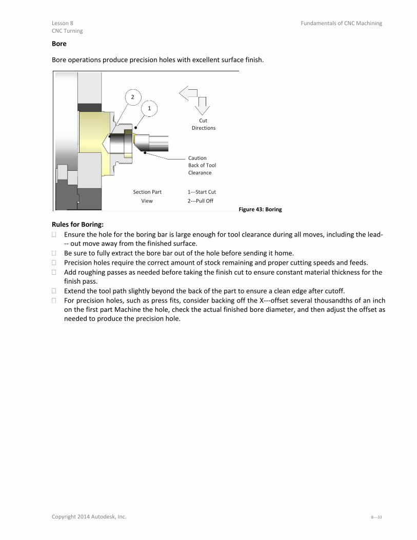
Lesson 8 Fundamentals of CNC Machining CNC Turning
Bore
Bore operations produce precision holes with excellent surface finish.
2
1
Cut
Directions
Caution
Back of Tool
Clearance
Section Part 1-Sta t Cut
View 2-Pull Off Figure 43: Boring
Rules for Boring: Ensure the hole for the boring bar is large enough for tool clearance during all moves, including the lead-
out o e a a f o the fi ished su fa e. Be sure to fully extract the bore bar out of the hole before sending it home. Precision holes require the correct amount of stock remaining and proper cutting speeds and feeds. Add roughing passes as needed before taking the finish cut to ensure constant material thickness for the
finish pass. Extend the tool path slightly beyond the back of the part to ensure a clean edge after cutoff. For precision holes, such as press fits, consider backing off the X-offset se e al thousa dths of a i h
on the first part Machine the hole, check the actual finished bore diameter, and then adjust the offset as
needed to produce the precision hole.
Copyright 2014 Autodesk, Inc. 8-
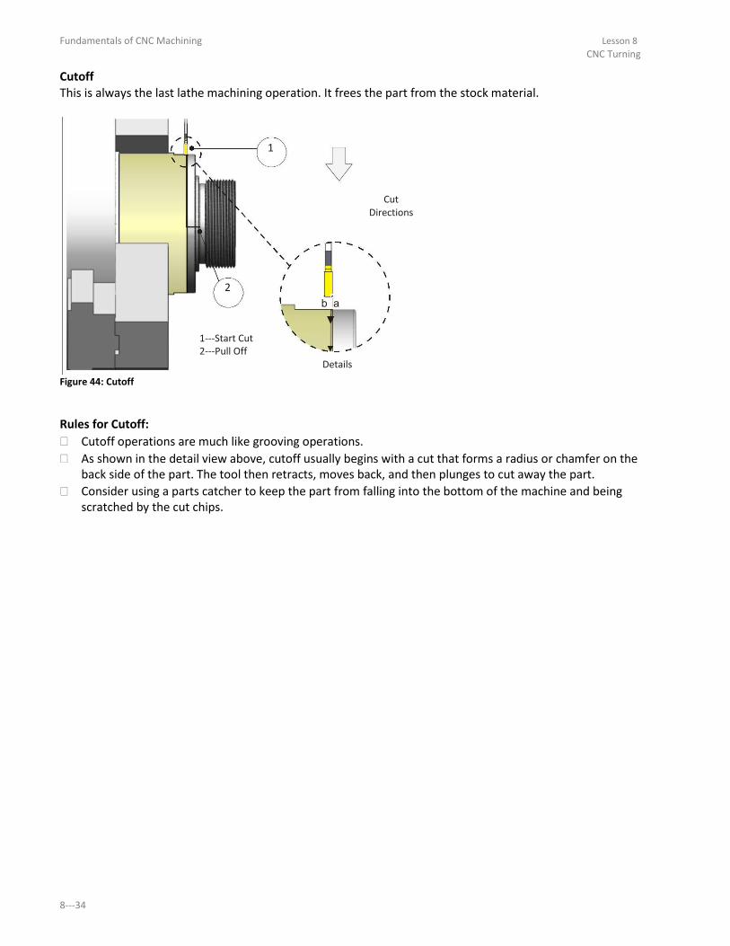
Fundamentals of CNC Machining Lesson 8 CNC Turning
Cutoff This is always the last lathe machining operation. It frees the part from the stock material.
1
Cut Directions
2
b a
1-Sta t Cut
2-Pull Off Details
Figure 44: Cutoff
Rules for Cutoff: Cutoff operations are much like grooving operations. As shown in the detail view above, cutoff usually begins with a cut that forms a radius or chamfer on the
back side of the part. The tool then retracts, moves back, and then plunges to cut away the part. Consider using a parts catcher to keep the part from falling into the bottom of the machine and being
scratched by the cut chips. 8-

Fundamentals of CNC Machining
Lesson 9
3D Toolpaths
Upon successful completion of this lesson, you will be able to: Explain how 3D tool compensation is calculated. Describe 3D cut tolerances. Identify geometric features common to 3D tool paths. Explain the purpose, general parameters, and use of common 3D roughing tool
paths. Explain the purpose, general parameters, and use of common 3D finishing tool
paths. Explain the purpose, general parameters, and use of REST mill tool paths. Explain the purpose, general parameters, and use of Pencil mill tool paths.
9-

Fundamentals of CNC Machining Lesson 9 3D Toolpaths
9-

Lesson 9 Fundamentals of CNC Machining 3D Toolpaths
Overview 3D tool paths are used to machine non-p is ati pa ts su h as olds, dies, a d o ga i all shaped consumer products. These parts may be composed of hundreds or thousands of faces.
CAD/CAM software creates 3D tool paths by first triangulazing the model,as shown in Figure 1 (though the
mesh is far finer than shown in this illustration). This mesh is used to calculate the tool path based on tool
size and shape. 3D tool paths are calculation intensive in part because of the extensive checking required toensure the tool
does not gouge the part as it moves across the topography of part faces.
Figure 1: 3D Tool Path Calculation
9.1 – 3D Cutter Compensation 3D paths control the center-tip of the tool. Figure 1 shows and compares how the tool path changesbased
on tool shape
Copyright 2014 Autodesk, Inc. 9-

Fundamentals of CNC Machining Lesson 9
3D Toolpaths
End Mill
Ball Mill Path
End Mill Path
Z+
Ball Mill
Y+
Figure 2: 3D Cutter Compensation
Cutter Diameter Compensation (G41/G42) is not supported for 3D tool paths by most CNC controls. The only
way to compensate for a worn 3D finishing tool is to replace it.
9.2 – Tolerances
3D tool paths are much about tradeoffs between quality and cost. As cut tolerances shrink, calculation time,
file size, and run times balloon. Excessively fine tolerances may result in hundreds or thousands of blocks of
code to move a short distance. This notonly takes longer to calculate, it causes problems at the machine. It is
therefore important to understand all tolerances involved with 3D tool paths, choose values appropriate to
the task, and take actions to reduce CNC program file size while maintaining design intent. CNC programs with unnecessarily fine tolerances should be avoided. CNC controls can only process a finite
number of blocks of code per second. This processing speed, called theblock execution time, varies
between machines. Modern machines may be capable of processing several thousand blocks of code each
second while older controls may be limited to less than a hundred.
If the number of blocks per second exceeds the machine capacity to process, a phenomenon known as
data starving can occur: the control is overwhelmed with data and must pause after each move to wait for
the next. This abrupt stopping and starting may happen hundreds of times per second.
9-

Lesson 9 Fundamentals of CNC Machining 3D Toolpaths
Due to the mass of the machine components, theresult is an effect similar to alternately pushing the
accelerator then brake in a car. The machine may physically shake and shudder, a phenomenon called
bumping . The actual feed rate of the machine may be a fraction of the programmed feed rate. Data starving causes excessive CNC machine wear, poor surface finish, and excessive program run times.
One solution at the machine is to use the machine manual feed rate override to feed rate until the
shuddering stops. Some machines allow the control acceleration/deceleration function to be disabled or
modified. Much can be done at the CNC programming stage to avoid or correct this problem. Choose machining
tolerances wisely. Use the CAD/CAM software tool path filtering function. Filtering works by analyzing the
cut path and fitting long lines or tangent arcs where possible to replace short line moves. This may
significantly reduce program size (by as much as 90%) while increasing the span of each move. One consideration when choosing a tool path strategy is how well it will filter. Paths parallel to a CNC work
plane (G17/G18/G19) filter far better than paths that are not. Cut tolerance, illustrated in Figure 3, controls how closely the tool path follows a theoretically perfect path
along the surface. Cut tolerance is a plus or minus value, so the total cut tolerance band is twice the
tolerance value.
Total Tolerance
Tolerance
Perfect Toolpath
Finished
Z+ Part
Y+
Figure 3: Cut Tolerance
Cut tolerance and filter tolerances are additive. For instance, a cut tolerance of .0005 and filter tolerance of
.001 means the tool path can vary from the theoretically perfect path by as much as .0015 inches to either
side of the planned path.
Copyright 2014 Autodesk, Inc. 9-
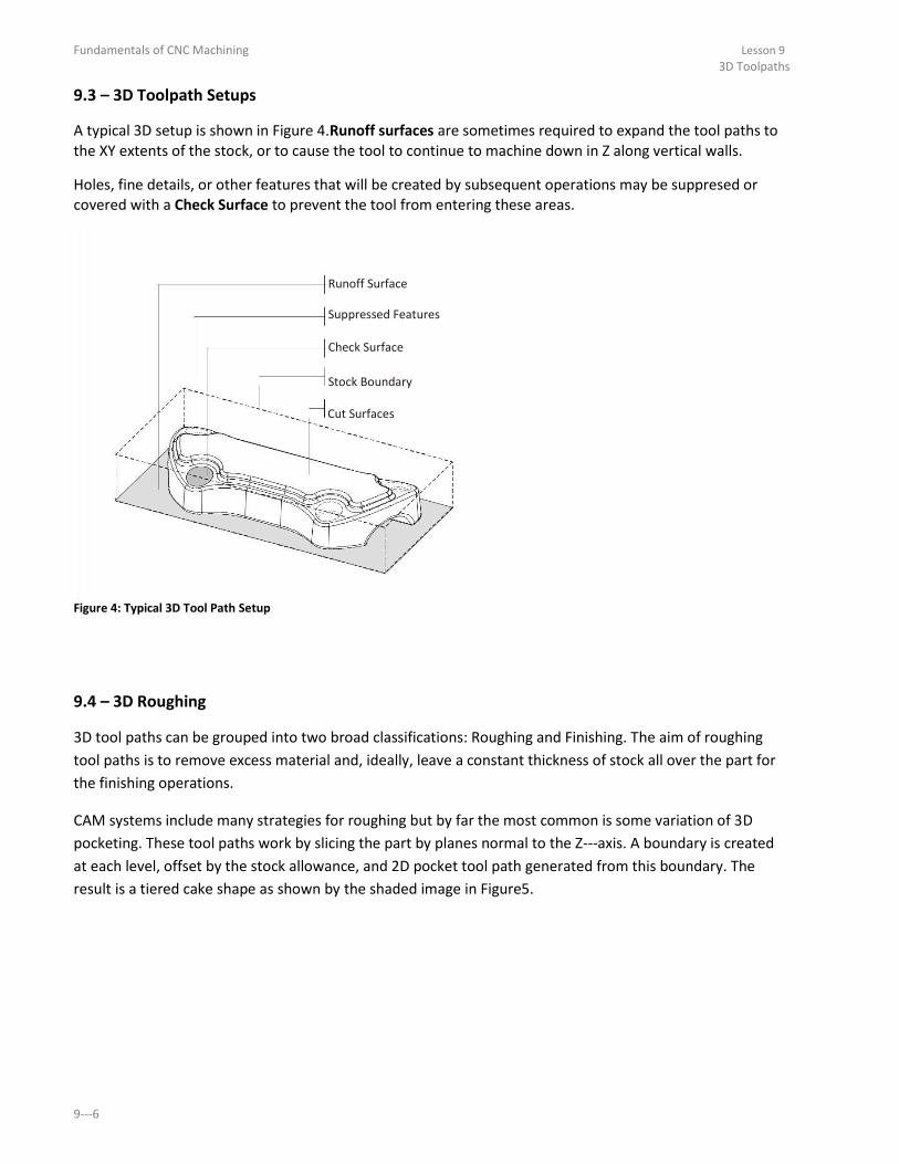
Fundamentals of CNC Machining Lesson 9 3D Toolpaths
9.3 – 3D Toolpath Setups A typical 3D setup is shown in Figure 4.Runoff surfaces are sometimes required to expand the tool paths to
the XY extents of the stock, or to cause the tool to continue to machine down in Z along vertical walls. Holes, fine details, or other features that will be created by subsequent operations may be suppresed or
covered with a Check Surface to prevent the tool from entering these areas.
Runoff Surface
Suppressed Features
Check Surface
Stock Boundary
Cut Surfaces
Figure 4: Typical 3D Tool Path Setup
9.4 – 3D Roughing 3D tool paths can be grouped into two broad classifications: Roughing and Finishing. The aim of roughing
tool paths is to remove excess material and, ideally, leave a constant thickness of stock all over the part for
the finishing operations.
CAM systems include many strategies for roughing but by far the most common is some variation of 3D
pocketing. These tool paths work by slicing the part by planes normal to the Z-a is. A ou da is eated at each level, offset by the stock allowance, and 2D pocket tool path generated from this boundary. The
result is a tiered cake shape as shown by the shaded image in Figure5.
9-

Lesson 9 Fundamentals of CNC Machining 3D Toolpaths
Toolpath Slice
3D Pocket Rough
Figure 5: 3D Pocket Rough
9.5 – Parallel Finish The goal of 3D finishing tool paths is to remove material left by roughing paths and produce a part that
meets design requirements for dimensional accuracy and surface finish.
A commonly used finish path is Parallel, shown in Figure 6. Parallel gets its name because, when viewed
from above, tool paths appear parallel to each other.
Parallel tool paths calculate quickly and are reliable. However, they usually require additional finish passes
to clean up heavy scallops (cusps). Scallops can be seen Figure 7 and are most prominent on the closest wall. Small tool path step over values
produce smaller scallops. Notice how scallop height changes depending on the topography of the part.
Copyright 2014 Autodesk, Inc. 9-

Fundamentals of CNC Machining Lesson 9 3D Toolpaths
Parallel Toolpaths
TopView
Result Figure 6: 3D Parallel Tool Path
Parallel tool paths tend to produce large scallops on steep walls roughly parallel to the path direction. As the
tool steps to the next pass, the path drops down farther in Z on these walls compared with flat areas of the
part. One approach to machining away these scallops is to create an additional parallel finish path rotated 90
degrees to the first. Of course this increases total program run time substantially.
Stepover
Scallop Height
Z+
Y+
Figure 7: Scallop Height 9-

Lesson 9 Fundamentals of CNC Machining 3D Toolpaths
9.6 – 3D Scallop Scallop tool paths, when viewed from the top, appear similar to 2D spiral pocket tool paths. Scallop paths
continually change the stepover distance to maintain a constant scallop height over the entire part. Scallop tool paths are calculation intensive and may not work on all shapes, and produce very large CNC
programs with many short moves. Yet, when applied properly, they work very well and produce a superior surface finish.
Scallop Toolpaths
TopView
ISO View Figure 8: Scallop Tool Path
Copyright 2014 Autodesk, Inc. 9-

Fundamentals of CNC Machining Lesson 9 3D Toolpaths
9.7 – REST Milling Rest Milling is an acronym forREmaining STock machining. Rest tool paths only remove material left by
previous machining operations. They do this by calculating what stock has been previously removed and
comparing it against the finished model. This is far more efficient than re- a hi i g the e ti e pa t ith a small tool just to create a few small features.
REST paths are calculation intensive. A good practice whenever possible is to use a tool whose diameter is
slightly smaller than the smallest feature to be machined. This makes the REST calculations simpler and
more effective.
Y+
X+
Finished Wall
Remachining Areas
Area Machined by Previous Operation(s)
Figure 9: REST Milling
9-
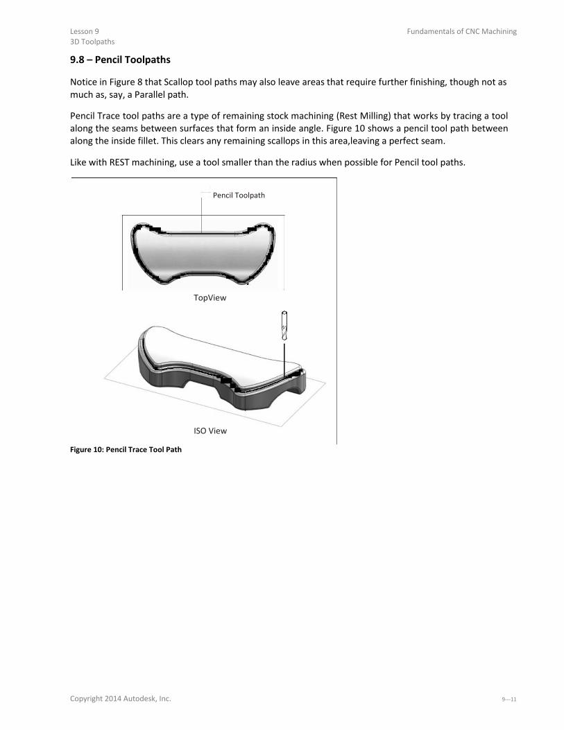
Lesson 9 Fundamentals of CNC Machining 3D Toolpaths
9.8 – Pencil Toolpaths Notice in Figure 8 that Scallop tool paths may also leave areas that require further finishing, though not as
much as, say, a Parallel path. Pencil Trace tool paths are a type of remaining stock machining (Rest Milling) that works by tracing a tool
along the seams between surfaces that form an inside angle. Figure 10 shows a pencil tool path between
along the inside fillet. This clears any remaining scallops in this area,leaving a perfect seam. Like with REST machining, use a tool smaller than the radius when possible for Pencil tool paths.
Pencil Toolpath
TopView
ISO View Figure 10: Pencil Trace Tool Path
Copyright 2014 Autodesk, Inc. 9-
Fundamentals of CNC Machining Lesson 9 3D Toolpaths
9.9 – Conceptualizing 3D Toolpaths There is a story about a man admiring an artist cuttingthe sculpture of a bear from a log. Impressed and
amazed by the artist s ability, the man inquired how he was able to create such realism. The artist replied,
It s easy, I just cut away anything that does not look like a bear! 3D machining is a similar mindset. You begin with a block of material and cut away anything that does not
belong. Begin by getting rid of excess material as quickly and efficiently as possible. Try to leave a constant
thickness of material for finish operations. Finish as much of the part as possible using the largest tools
possible. Then finish machine finer features and details using Parallel or Scallop paths contained by 2D
profiles, or REST and Pencil tool paths. 3D machining can be very challenging, but in many cases it is easier than many 2D parts. Some 2D parts
involve scores of machining operations that require considerable forethought and work. Most 3D parts
require fewer operations and these are largely automated by CAD/CAM software functions. The key to success is planning ahead and preparing the model before creating tool paths. In the case of 3D
machining, perhaps 50- % of the ti e p og a i g is a tuall CAD- elated, getti g the odel ead for tool paths: creating runoff surfaces, suppressing features, creating check surfaces, and the like. Don t begin making tool paths until you have a credible plan. If your planning is thorough and the CAD model
is simplified so only those features to be machined are displayed, creating tool paths is far easier and
outcomes better. To aid planning, use the forms in Appendix C, CNC Planning Forms. 9-

Fundamentals of CNC Machining
Lesson 10
Milling Setups
Upon successful completion of this lesson, you will be able to: Explain Identify commonly used CNC work holding components. Identify the parts and accessories of a CNC vise. Explain the difference between vise hard jaws, step jaws and soft jaws.
10-

Fundamentals of CNC Machining Lesson 10 Milling Setups
10-
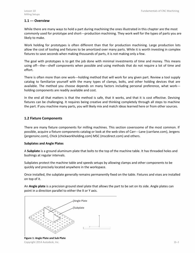
Lesson 10 Milling Setups
Fundamentals of CNC Machining
1.1 - O er ie
While there are many ways to hold a part during machining the ones illustrated in this chapter are the most
commonly used for prototype and short-p odu tio a hi i g. The o k ell fo the t pes of pa ts ou a e likely to make.
Work holding for prototypes is often different than that for production machining. Large production lots
allow the cost of tooling and fixtures to be amortized over many parts. While it is worth investing in complex
fixtures to save seconds when making thousands of parts, it is not making only a few. The goal with prototypes is to get the job done with minimal investments of time and money. This means
using off-the-shelf o po e ts he possi le a d usi g ethods that do ot e ui e a lot of ti e a d effort.
There is often more than one work-holdi g ethod that ill o k fo a gi e pa t. Re ie a tool supply
catalog to familiarize yourself with the many types of clamps, bolts, and other holding devices that are
available. The method you choose depends on many factors including personal preference, what work- holding components are readily available and cost.
In the end all that matters is that the method is safe, that it works, and that it is cost effective. Devising
fixtures can be challenging. It requires being creative and thinking completely through all steps to machine
the part. If you machine many parts, you will likely mix and match ideas learned here or from other sources.
1.2 Fixture Components
There are many fixture components for milling machines. This section coverssome of the most common. If
possible, acquire a fixture components catalog or look at the web sites of Carr-La e a la e. o , Je ge s (jergensinc.com), Chick (chickworkholding.com) MSC (mscdirect.com) and others.
Subplates and Angle Plates
A Subplate is a ground aluminum plate that bolts to the top of the machine table. It has threaded holes and
bushings at regular intervals. Subplates protect the machine table and speeds setups by allowing clamps and other components to be
quickly and precisely located anywhere in the workspace. Once installed, the subplate generally remains permanently fixed on the table. Fixtures and vises are installed
on top of it. An Angle plate is a precision ground steel plate that allows the part to be set on its side. Angle plates can
point in a direction parallel to either the X or Y axis.
Angle Plate
Subplate
Figure 1: Angle Plate and Sub Plate
Copyright 2014 Autodesk, Inc. 10-

Fundamentals of CNC Machining Lesson 10 Milling Setups
Clamps There are literally thousands of types, styles, and sizes ofclamps available. They are inexpensive, reusable,
and versatile. You tool cabinet should include many types and sizes of clamps and accessories.
Strap Clamp
TogglePliers
Step Clamp
Step Block ToeClamp
Figure 2: Clamps and Accessories
Strap Clamps exert downward pressure on the part. They are usually secured to the table by a special bolt
that can be positioned anywhere along the T-slots i the ta le. O e e d of the la p ests o the pa t, a d the other on a step block. To prevent galling an aluminum part, place a pad of aluminum between the clamp and part. Step blocks have grooves that allow them to be stacked to different heights. Step blocks are used to support
one end of the strap clamp. Step Clamps are similar to Strap clamps, but include grooves that interlock with a single step block. Toe Clamps bolt to the machine table. The nose of the clamp includes grooves to grip the part. It is extended
by turning a screw, forcing the clamp against the partand downward. Toggle Pliers are similar to hardware store vise grip pliers.
10-

Lesson 10 Fundamentals of CNC Machining Milling Setups
Shoulder Bolts and Dowel Pins
Dowel pins are used to precisely locate a part. They include a small chamfer to make insertion easier.
Shoulder bolts both locate and grip the part. The ground shoulder on the bolt slides into a counterbore in the
fixture.
Part
Fixture Plate
Dowel Pin Shoulder Bolt Using Shoulder Bolt
Figure 3: Dowel Pin and Shoulder Bolt
Vise and Accessories
The CNC vise is precision engineered and manufactured with components ground flat and perpendicular to
within .0002 inches. The most common is referred to as a six inch vise, because the width of the jaws is six
inches. Once the vise is bolted to the table and aligned, parts are loaded into the vise and clamped by closing the
jaws. The vise can exert tremendous force, so care is taken not to over-tighte the ise a d defo f agile parts. Vise pressure must be appropriate to the part being held and expected cutting forces.
Vise Stop
Fixed Jaw
Jaw Insert
Moving Jaw Hard Jaw
Parallel Step Jaw
Vise Handle
Standard 6-I h Vise Soft Jaw
Figure 4: Vise and Accessories
The Fixed Jaw remains stationary. The Moving Jaw opens when the Vise Handle is turned. It is a good
practice to remove the vise handle after the jaws are closed and before running the program. This is done by
simply sliding the handle off. A Vise Stop is a device that allows the parts to be loaded into the vise precisely. This image shows a style of
vise stop that is particularly useful because it is adjustable up-do a d left- ight. Copyright 2014 Autodesk, Inc. 10-

Fundamentals of CNC Machining Lesson 10 Milling Setups
Hard Jaws are made of hardened steel and precision ground on all sides. They are usually used along with
parallels. Parallels are thin steel plates, available in various widths, used to set the grip length of the vise jaws.
Grip Length
Parallel
Hard Jaw
Figure 5: Hard Jaws
Step jaws are similar to hard jaws but include a step feature that eliminates the need for parallels.
Step
Detail
Figure 6: Step Jaws
Soft jaws are blanks of aluminum used to grip parts that cannot be held using hard jaws. A cutout the same
shape as the part is machined into the soft jaws to grip irregular shapes. When machining the cutout, place a bar between the jaws to set the orrect spacing. Use a torque wrench or
mark the vise so it can be closed with the exact same pressure each time a new part is loaded. Remove the
spacer before clamping the part.
10-

Lesson 10 Fundamentals of CNC Machining Milling Setups
Mark Vise in
Closed Position
Part
Cutout
Use Spacer When Machining Cutout
Note: Remove Spacer Before Clamping Part
Figure 7: Machining Soft Jaws
Copyright 2014 Autodesk, Inc. 10-

Fundamentals of CNC Machining Lesson 10 Milling Setups
10-

Fundamentals of CNC Machining
Appendix A
CNC Milling Work-Holding Examples
Upon successful completion of this lesson, you will be able to: Explain how to properly align a CNC vise. Explain how to machine a block of stock material into a perfect rectangular
prism. Machine a simple 2D contour applying cutter diameter compensation. List the types of vise jaws and their use. Install and align a CNC vise jaws. Use a vise to grip a part during machining. Make and use vise soft jaws to machine a 3D part. Machine multiple parts from a single piece of bar stock. Construct and use a fixture plate. Use clamps and bolts as a work-holdi g s ste . Machine a thin walled part. Set up and use an angle plate to machine a multi-sided part. Use shoulder bolts and dowel pins to machine a two-sided plate pa t. Use double-sided tape as a o k-holdi g s ste .
A-

Fundamentals of CNC Machining Appendix A CNC Milling Work-Holdi g E a ples
Project 1: Install Vise Before using a vise it must be aligned with the machine X-a is. This is a good p a ti e efo e sta ti g a new job to check vise alignment to ensure it is parallel to the machine axis. 1 Prepare Work Area Jog the spindle out of the way and remove any tool to prevent accidentallybumping into it while working.
Clean the machine table and bottom of vise to ensure there are no chips or debris between the table and
vise.
2 Plan Vise Location Locate the vise where all features on the part can be reached by the tool without exceeding the machine
travel limits. Include overrun for lead in/out moves.
Before installing bolts, jog the machine to ensure the vise cannot contact any machine sheet metal
throughout its travel.
3 Pre-Tighte Bolts Insert bolts in T-slots. Firmly tighten the left bolt. This bolt will act as a pivot for the vise to rotate about during alignment.Lightly
tighten the right bolt.
Firmly Tighten Lightly Tighten
Left Bolt Right Bolt
Y+
X+ Figure 8: Pre Tighten Bolts
3 Align Vise With X-A is
Install a dial indicator. Jog the machine until the dial stylus is along the fixed vise jaw. Jog the machine left to
right along the vise jaw. Lightly tap the vise with a rubber mallet, causing it to rotate about the left bolt, until
the indicator remains stable.
A- .
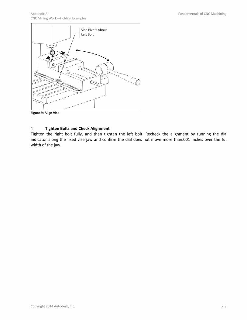
Appendix A Fundamentals of CNC Machining CNC Milling Work-Holdi g E a ples
Vise Pivots About Left Bolt
Figure 9: Align Vise
4 Tighten Bolts and Check Alignment Tighten the right bolt fully, and then tighten the left bolt. Recheck the alignment by running the dial
indicator along the fixed vise jaw and confirm the dial does not move more than.001 inches over the full
width of the jaw.
Copyright 2014 Autodesk, Inc. A-

Fundamentals of CNC Machining Appendix A CNC Milling Work-Holdi g E a ples
Project 2: Install Vise Jaws Once the vise is bolted and aligned with the machine, vise jaws are installed using cap screws. Follow these
steps to install vise jaws: 1 Clean Vise and Jaws Ensure there are no chips on any ground surfaces of the vise or the vise jaws.
2 Install Bolts Install Cap screws to secure the vise and Hand-tighte oth olts.
3 Tap Down Jaws Use a rubber mallet to tap down the vise jaws so there are no air gaps between the jaws and the vise face.
4 Fully Tighten Bolts In Correct Order Tighten the bolts in the order shown, ensuring the jaws do not lift as the bolts are firmly tightened.
5 Check Work Any slippage of the jaws is not acceptable. Ensure all bolts are very tight before using the vise.Try sliding a
piece of paper or feeler gage between vise jaws and vise to ensure there is no space due to the jaw lifting.
TapDownJaws 2 3
1 4
Bolt Tightening
Sequence
Figure 10: Installing Vise Jaws
A-

Appendix A Fundamentals of CNC Machining CNC Milling Work-Holdi g E a ples
Project 3: Square Block For some prismatic shapes it is preferable begin by machining a block of material to a specific size. This can
be done by jogging the machine using the hand wheel on the control. The process of squaring a block is also
helpful for understanding concepts of flat, square and parallel as they relate to the CNC machine axes. 1 Prepare part for machining Begin with sawed raw material large enough to be machined on all sides: usually at least .050 inches over- sized in each dimension.
Stock walls must be sufficiently flat and opposite sides parallel to be safely gripped by the vise. Use common
sense; if the part can be moved by hand in the vise, it will loosen under cutting pressure and could move or
be ejected from the vise.
Faces are machined in the sequence shown in Figure11 below. Figures on the following pages indicate the
Top face in color grey, making it easier to see how the part is flipped for each operation.
Saw Cut
Stock
3-Botto
2-Ba k
5-Left 1-Top 6-Right
4-F o t
Figure 11: Saw Cut Stock and Machining Sequence
2 Set Tool Position The machine spindle must be off. Manually jog the tool so it is about one inch above the Top face. Move the
machine down in Z in .1 inch increments. After each move carefully slide a 1- - lo k et ee the top surface and the tool, until the block makes contact.
Switch the jog increment to .001 and raise the tool until theblock just slides underneath. This sets the tool
exactly 1.00 inch above the face of the stock.
Copyright 2014 Autodesk, Inc. A-

Fundamentals of CNC Machining Appendix A CNC Milling Work-Holdi g E a ples
1- - Blo k
Stock Material
Slide Block to
Set Tool Location
Figure 12: Set Tool Position
3 Machine Top Surface Estimate the amount of material to remove with the first cut, and then jog the machine down 1.00inches
plus this value. For instance, to remove about .010 inches of material, jog the machine down 1.010 inches.
Set the jog control to the X-a is, tu o the spi dle CW, a d use the ha d o t ol to a hi e the top fa e. When complete, turn the spindleoff and move the tool clear of the work area.
A-
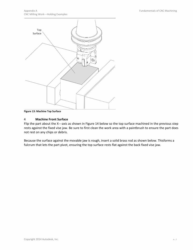
Appendix A Fundamentals of CNC Machining CNC Milling Work-Holdi g E a ples
Top
Surface
Figure 13: Machine Top Surface
4 Machine Front Surface Flip the part about the X-a is as sho i Figu e elo so the top su fa e a hi ed i the p e ious step rests against the fixed vise jaw. Be sure to first clean the work area with a paintbrush to ensure the part does
not rest on any chips or debris.
Because the surface against the movable jaw is rough, insert a solid brass rod as shown below. Thisforms a
fulcrum that lets the part pivot, ensuring the top surface rests flat against the back fixed vise jaw.
Copyright 2014 Autodesk, Inc. A-

Fundamentals of CNC Machining Appendix A CNC Milling Work-Holdi g E a ples
Front Surface
Brass
Rod
Z+
Y+ Figure 14: Machine Front Surface
A-

Appendix A Fundamentals of CNC Machining CNC Milling Work-Holdi g E a ples
5 Machine Bottom Surface Flip the part about the X-a is as sho i Figu e pla i g the top su fa e agai st the floo of the ise o parallels. Again use the brass rod to ensure part lays flat against the fixed jaw, clear chips, and ensure there is
no small gap between the top face and vise floor. Rough and finish the bottom side as required to establish the finish dimension between the top and bottom
faces.
Bottom Surface
Brass
Rod
Finish Dimension
Z+
Y+
Figure 15: Machine Bottom Surface
Copyright 2014 Autodesk, Inc. A-

Fundamentals of CNC Machining Appendix A CNC Milling Work-Holdi g E a ples
6 Machine Back Surface Flip the part about the X-a is as sho i Figu e so the top su fa e o ests agai st the o i g ja . Do not use the brass rod. Clear all chips and tap down the part. Rough and finish this side as required to establish the finish dimension between the front and back faces.
Back Surface
Finish
Dimension
Z+
Y+
Figure 16: Machine Back Surface
A-

Appendix A Fundamentals of CNC Machining CNC Milling Work-Holdi g E a ples
7 Machine Left Surface Next, rotate the part counterclockwise about the machine Y-a is sta di g it o e d. Use a a hi ist s
square to set the machined surface perpendicular to the vise base.
Left
Surface
Machinists Square
Z+
Y+ Figure 17: Machine Left Surface
Copyright 2014 Autodesk, Inc. A-

Fundamentals of CNC Machining Appendix A CNC Milling Work-Holdi g E a ples
8 Machine Right Surface Finally, rotate the part again about the machine Y-a is deg ees so that the left surface is now against the
machine base. Clear chips and tap down the part. Machine the right face to establish the finish dimension
between the left and right part faces. The part is now the precise size and all sides are flat, square, and parallel.
Right
Surface
Rotate Part 180 Degrees
From Previous
Finish
Dimension
Z+
Y+
Figure 18: Machine Right Surface
A-

Appendix A Fundamentals of CNC Machining CNC Milling Work-Holdi g E a ples
Project 4: Contour Square Step
This exercise teaches how to do the following: Set the fixture offset. Set tool length offset (TLO). Adjust cutter diameter compensation (CDC).
The fixture offset is a point on the part that can be easily and accuratelyfound by mechanical means. For
example, in Figure 19, the upper-left o e of the sto k a e lo ated usi g a edge fi de . The fi tu e offset (G54) is located at this point. If it were not, the datum could be shifted from this reference point by
changing the G54 XYZ- alues o the a hi e o t ol.
G54
.100
.100
Material: Aluminum 2.000 x 2.000 x 3.000
Figure 19: Contour Block
It is common to choose the upper-left o e of the sto k as the fi tu e offset fo the fi st operation. If the stock is
sawed, ensure there is sufficient stock allowance around the part so finish operations remove material all around.
For subsequent operations the fixture offset is set from features machined in previous operations.
1 Square Block Begin with a finish machined 2x2x3in block (created in Project 3).
2 Find Fixture Offset XY Use an edge finder to locate the upper-left o e of the lo k sho the la k dot i Figu e .
3 Set Fixture Offset A Set the fixture offset Z (G54) to the top of the block.
4 Program Contour Tool Path Create a contour tool path to mill a .100x.100 step around the part as shown above. Use Wear compensation,
line/arc lead in/out moves, and the correct cutting speed and feed for the tool. Use a finish pass of XY .010
and Z.005 to ensure the wall and floor are dimensionally accurate and have a good surface finish.
Copyright 2014 Autodesk, Inc. A-
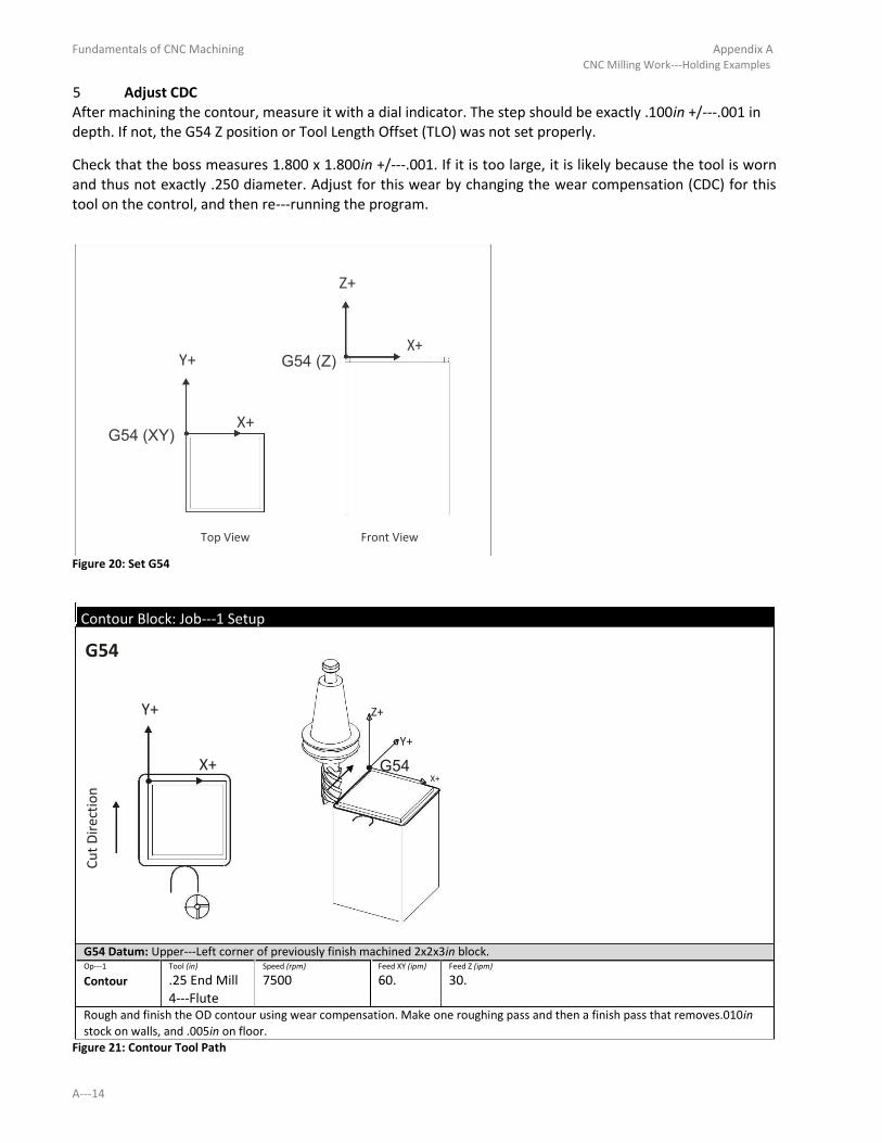
Fundamentals of CNC Machining Appendix A CNC Milling Work-Holdi g E a ples
5 Adjust CDC After machining the contour, measure it with a dial indicator. The step should be exactly .100in +/-. i depth. If not, the G54 Z position or Tool Length Offset (TLO) was not set properly. Check that the boss measures 1.800 x 1.800in +/-. . If it is too la ge, it is likely because the tool is worn
and thus not exactly .250 diameter. Adjust for this wear by changing the wear compensation (CDC) for this
tool on the control, and then re- u i g the p og a .
Z+
Y+ G54 (Z) X+
G54 (XY) X+
Top View Front View
Figure 20: Set G54
Contour Block: Job- Setup
G54
Y+ Z+
Y+
X+ G54 X+
Cu
t D
ire
ctio
n
G54 Datum: Upper-Left o e of p e iousl fi ish a hi ed in block. Op- Tool (in) Speed (rpm) Feed XY (ipm) Feed Z (ipm)
Contour .25 End Mill 7500 60. 30.
4-Flute Rough and finish the OD contour using wear compensation. Make one roughing pass and then a finish pass that removes.010in
stock on walls, and .005in on floor.
Figure 21: Contour Tool Path
A- 4
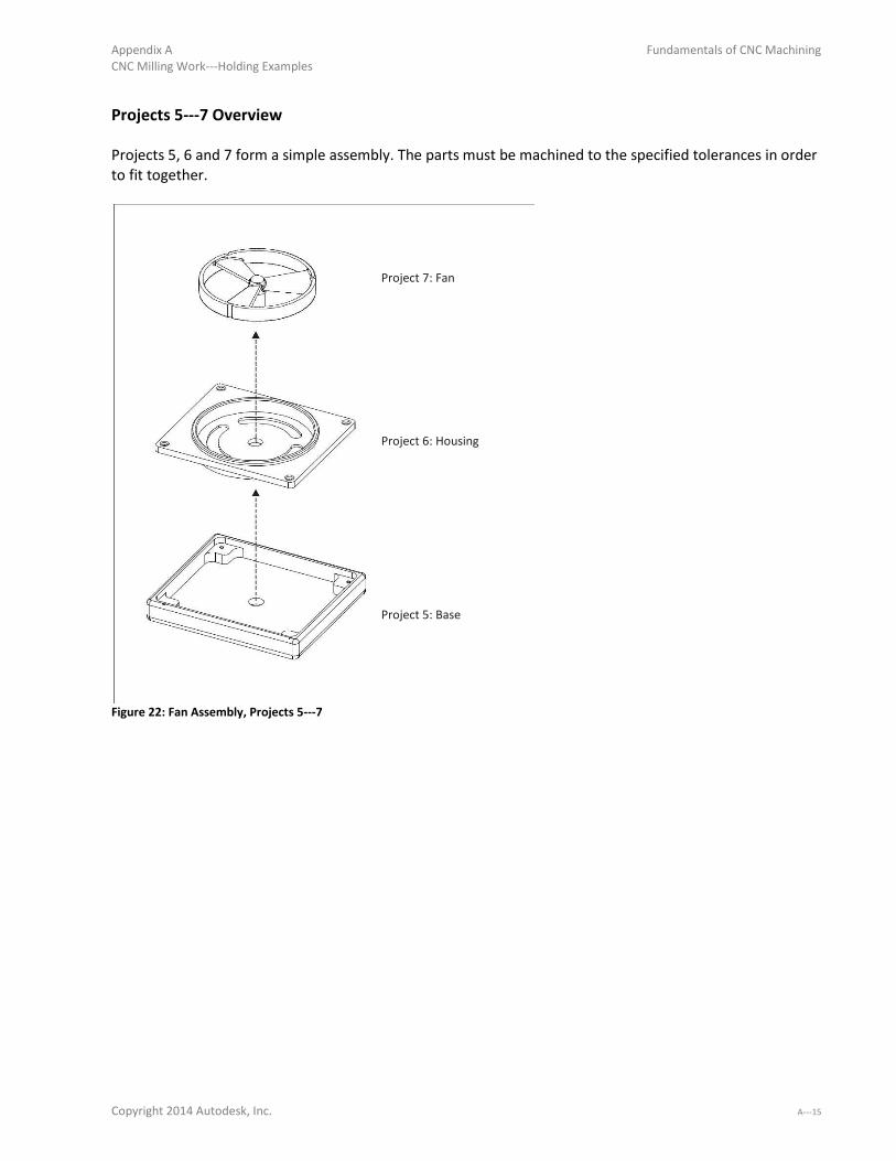
Appendix A Fundamentals of CNC Machining CNC Milling Work-Holdi g E a ples
Projects 5- O er ie
Projects 5, 6 and 7 form a simple assembly. The parts must be machined to the specified tolerances in order
to fit together.
Project 7: Fan
Project 6: Housing
Project 5: Base
Figure 22: Fan Assembly, Projects 5-
Copyright 2014 Autodesk, Inc. A-

Fundamentals of CNC Machining Appendix A CNC Milling Work-Holdi g E a ples
Project 5: Base
This project teaches the following skills: Face milling. Drilling. Contour. Pocket. Flip part in vise and pick up second datum.
Top Right
Bottom Material: Aluminum 6061
Min. Stock Size: 4.25 x 3.75 x .75
Figure 23: Project- , Base
1 Job 1 Setup Grip the sawed stock as shown in Figure 24. Set the XY-datu f o the uppe -left o e of the sto k. Make sure there is sufficient stock so that finish tool paths remove material all around the part (typically .01-
. i hes from the stock corner). Set the Z-datu so that the fa i g ope atio e o es ate ial f o the face of the part (typically .01 below the face of the sawed stock).
2 Job 1 Operations Machine the part using the processes and parameters in Figure24. If needed, select tools, speeds and feeds
compatible with your machine.
Base: Job- Setup
G54 Z+
Y+
Job 1 Datum X+
G54 Datum: Upper-Left o e of sa ed sto k. A-

Appendix A Fundamentals of CNC Machining
CNC Milling Work-Holdi g E a ples
Op- Tool (in) Speed (rpm) Feed XY (ipm) Feed Z (ipm)
Face .375 End Mill 8150 33. 15. 2-Flute
Use a stubby end mill to reduce chatter (flute length=.625). Stepover=.20, Take a Z finish pass of .005 to ensure a good surface
finish. Op- Tool (in) Speed (rpm) Feed XY (ipm) Feed Z (ipm)
2D Contour .375 End Mill 8150 33. 15.
2-Flute Contour OD. Rough Stepover =.2, Stepdown=.2. Finish XY=.01, No Finish Z needed. Number of rough passes depends on stock
size. Op- Tool (in) Speed (rpm) Feed XY (ipm) Feed Z (ipm)
2D Pocket .375 End Mill 8150 33. 15.
2-Flute Rough and finish pocket with islands. Rough Stepover =.2, Stepdown=.2. Finish XY=.01, Finish Z=.005 Op- Tool (in) Speed (rpm) Feed XY (ipm) Feed Z (ipm)
2D Contour .375 End Mill 8150 33. 10.
2-Flute Contour the hole in the center of the pocket with helical entry. Finish XY=.01, Finish Z -. elo otto so o flashi g is left after facing opposite side. Op- Tool (in) Speed (rpm) Feed XY (ipm) Feed Z (ipm)
2D Contour .125 Center 5000 40. 20.
Drill, 90Deg De- u top edges eati g a . ha fe . Use li e/a lead i /out. Op- Tool (in) Speed (rpm) Feed XY (ipm) Feed Z (ipm)
CTR Drill .125 Center 6100 N/A 12.
Drill, 90Deg Center drill the four #2- holes. D ell . se o ds. Op- Tool (in) Speed (rpm) Peck Inc.(in) Feed Z (ipm)
Peck Drill Drill .07 Dia. 10000 .035 20.
(#50) Peck drill four #2- holes. Op- Tool (inch) Speed (rpm) Peck Inc. Feed Z (ipm)
Rigid Tap #2- Tap 4300 N/A 76.786 Tap four holes to depth Z-. elo top of oss. If ou a hi e does ot suppo t igid tappi g, tap ha d afte jo is complete. Op- Tool (in) Speed (rpm) Feed XY (ipm) Feed Z (ipm)
Contour .115x.093 6640 40. 20.
Radius Mill Use corner round tool to create a fillet on outside of the part. Take two finish passes (one spring pass) to produce a very good
surface finish. Figure 24: Base, Top Side Machining Parameters
3 Job 2 Find XY Datum The XY datum for Job 2 could be set at the center of the through hole using a coaxial indicator, dial indicator,
or machine part probe. The method illustrated here shows how to set the datum using avise stop and 1- -
lo k.
Program X0 is found using an edge finder to locate the left edge of the 1- - lo k YZ Data Refe e e Frame). Set the Fixture Offset X- ale as the e te li e of the left - - lo k edge.
Program Y0 is found using an edge finder to locate the fixed vise jaw (XZ Data Reference Frame). Set the
Fixture Offset Y- alue as the e te li e a k - - lo k edge.
Step- -step i st u tio s fo setti g the Fi tu e Offset XY usi g a edge fi de a e fou d i Chapter 6, CNC
Operation: Set Fixture Offset XY.
Copyright 2014 Autodesk, Inc. A-

Fundamentals of CNC Machining Appendix A CNC Milling Work-Holdi g E a ples
Many CNC machines are now equipped with a Part Probe. This instrument is gripped in machine spindle and
communicates with CNC control when the probe stylus touches against a surface.
Part probes greatly speed and simplify setting fixture offsets. To learn more refer to the documentation included with
your part probe or search YouTube© for videos on the topic.
Edge Finder
G54 XY X-Z
Vise Plane
Stop 1- -
Block
Y-Z Plane
Figure 25: Set G54 XY Using A 1- - Blo k
4 Find Program Z Datum G54 Z could be set at the top of the vise parallels. If using this method, set the tool rapid andclearance
heights sufficient to avoid colliding with the part, vise, and fixture.
The approach described here sets G54 Z to the value of the face of the finished part for Job 2. To find the
distance from the top of a 1- - lo k to the top of the fi ishedpa t use this fo ula:
Fixture Offset Z = (A – 1.0 + B)
As illustrated in Figure 25, A is the incremental distance from the top of a 1- - lo k esti g o the ta le to the top of a 1- - lo k set i the ise. B is the finished thickness of the part. The value 1.0 is the
thickness of the 1- - lo k.
Stated as a word problem, this formula reads, The Fixture Offset Z is the distance from tool setting point to
the bottom of the 1- - lo k, plus the thickness of the finished part.
The process of setting the fixture offset is described in detail inLesson 6, CNC Operation. A-
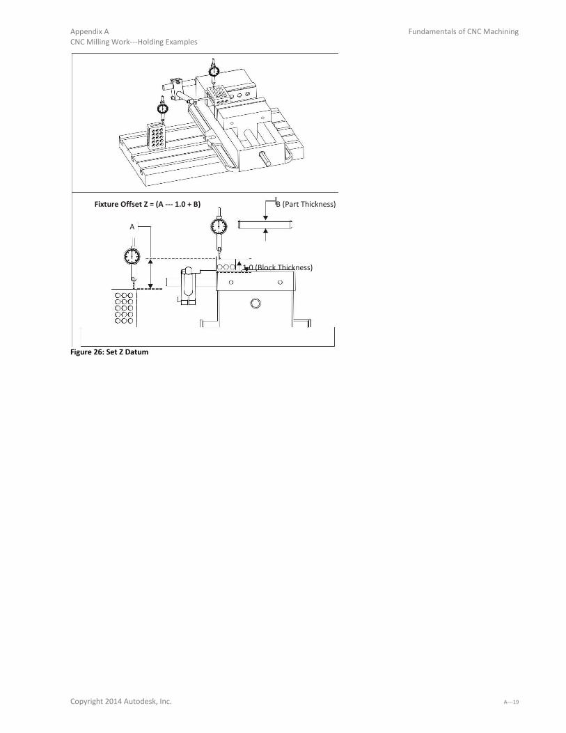
Appendix A Fundamentals of CNC Machining CNC Milling Work-Holdi g E a ples
Fixture Offset Z = (A - . + B
B (Part Thickness)
A
1.0 (Block Thickness)
Figure 26: Set Z Datum
Copyright 2014 Autodesk, Inc. A-

Fundamentals of CNC Machining Appendix A CNC Milling Work--Holdi g E a ples
5 Job 2 Operations
Clean the work area and set the part finished upside-do i the ise. Slide the pa t left- ight a d appl pressure so it rests firmly against the fixed vise jaw and vise stop as shown in Figure 27 and close the vise
jaws firmly. This establishes the XY datum. Next, tap the part down with a rubber mallet to ensure it is flat
against the parallels and close the jaws tightly.
When making multiple parts, mark the vise with marker or use a torque wrench to ensure each part is gripped
with the same vise force.
Base: Job- Setup
G55 Z+
Y+
X+
G54 Datum: Upper-left o e of fi ished pa t fa e. Op- Tool (inch) Speed (rpm) Feed XY (ipm) Feed Z (ipm)
2D Contour .375 End Mill 9800 68. 30.
2-Flute Contour OD leaving .010in XY Stock. This cut is used to clear excess material from the part so the corner round tool will not
engage an excessive amount of material. Op- Tool (inch) Speed (rpm) Feed XY (ipm) Feed Z (ipm)
Face .375 End Mill 9800 68. 30.
2-Flute Face part using a stepover = .20in and stepdown =.10in . The number of Z- oughi g passes e ui ed depe ds o the a ou t of material remaining on part. Finish pass should be no greater than .005in to yield a good finish. Op- Tool (inch) Speed (rpm) Feed XY (ipm) Feed Z (ipm)
2D Contour .115x.093 5000 40. 20.
Radius Mill Use corner round tool to create fillet on outside of part.Take two finish passes to produce a very good surface finish. Op- Tool (inch) Speed (rpm) Feed XY (ipm) Feed Z (ipm)
2D .25 Spot Drill 8900 40. 10.
Contour 100 degree Engrave lettering. Depth=Z-. i
Figure 27: Base, Bottom Side Machining Parameters
A-
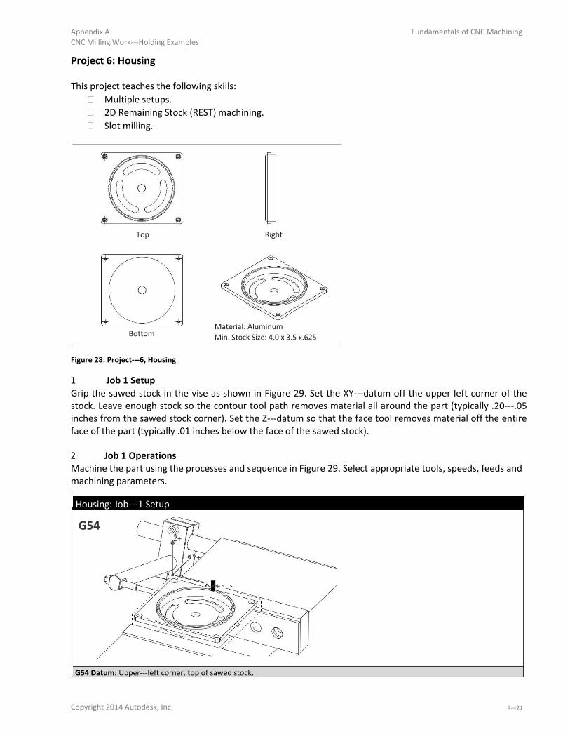
Appendix A Fundamentals of CNC Machining CNC Milling Work-Holdi g E a ples
Project 6: Housing
This project teaches the following skills: Multiple setups. 2D Remaining Stock (REST) machining. Slot milling.
Top Right
Bottom Material: Aluminum
Min. Stock Size: 4.0 x 3.5 x.625
Figure 28: Project- , Housi g
1 Job 1 Setup Grip the sawed stock in the vise as shown in Figure 29. Set the XY-datu off the uppe left o e of the stock. Leave enough stock so the contour tool path removes material all around the part (typically .20-. inches from the sawed stock corner). Set the Z-datu so that the fa e tool e o es ate ial off the e ti e face of the part (typically .01 inches below the face of the sawed stock).
2 Job 1 Operations Machine the part using the processes and sequence in Figure 29. Select appropriate tools, speeds, feeds and
machining parameters.
Housing: Job- Setup
G54 Z+
Y+
X+
G54 Datum: Upper-left o e , top of sa ed sto k.
Copyright 2014 Autodesk, Inc. A-

Fundamentals of CNC Machining Appendix A CNC Milling Work-Holdi g E a ples
Op-
Face part. Face
Op-
Rough and finish OD of part (rectangle shape). Be sure to machine below the bottom of the OD so no flashing will Contour OD remain after Job 2, but don t collide with the vise hard jaws.
Op-
Rough and finish OD of round boss. Contour OD
Op-
Rough and finish pocket to top of slots. Pocket
Op--
Rough and finish slots. Slot Mill
Op-
Rough and finish hole through center. Be sure to break through bottom by .01.This hole must be completely through Pocket the stock because it will be used to set the G54 XY for Job 2.
Op-
Spot and chamfer four holes. Spot Drill
Op-
Drill clearance holes for #2- so ket head ap s e s. Drill
Op-
Counterbore with 3/16 (.188) end mill for socket head cap screw. Counterbore
Op-
De- u all edges ha fe illi g ith a center drill or chamfer mill. Chamfer
Figure 29: Housing, Top Side Machining Operations
3 Job 2 Setup Flip the part about the Y-a is a d g ip the fi ished alls of the pa t.Set the G XY f o the e te of the through hole created in Job 1. De- u the hole efo e lo ati g its e te usi g dial i di ato , oa ial indicator, or part probe. Set G54 Z the same way as Base, Job 2 (using 1- - lo ks to the top of the finished face of the part bottom.
4 Job 2 Operations Machine the part using the processes and sequence in Figure 30. Select appropriate tools, speeds, feeds and
machining parameters.
Housing: Job- Setup
G55
Z+
Y+
X+
G55 Datum: X0Y0 is the center of the hole created in Job 1. Z0 is set at the face of the finished bottom side (Z.500(in) from top of
parallels). Op- Finish part to thickness. Use light cuts to prevent part from being pulled out of vise. Face
Op- Rough and finish OD of round boss. Contour OD
Op- De- u all edges. Chamfer Mill
Figure 30: Housing, Bottom Side Machining Parameters

A-

Appendix A Fundamentals of CNC Machining CNC Milling Work-Holdi g E a ples
Project 7: Fan Blades
This project teaches the following skills: Making and using soft jaws. Create feature to locate part for subsequent operation. 3D Roughing. 3D Finishing.
Top Right
Bottom Material: Delrin
Min. Stock Size: 3.0 Dia x 1.4 Length
Figure 31: Project- , Fa
1 Create Job- Soft Ja s Fi ture Cut a pocket into the aluminum jaws as shown in Figure 32. This is used to grip the sawed raw stock while
machining the top side (G54).
Soft jaws for this part require advanced planning. Round stock is usually slightly larger than the size ordered,
so either first turn it down on to the desired size on a lathe, or cut the jaws to match the actual material size.
The jaws have to be cut deep enough to grip the part securely during machining. Cutting forces in Delrinare
small, so a grip depth of .30 inches is adequate to secure this part.
A-

Fundamentals of CNC Machining Appendix A CNC Milling Work-Holdi g E a ples
G54 Y+
Z+
Y+
X+
X+
Figure 32: Job- Soft Ja s
The XY datum is established by the pocket machined into the jaws. In other words; soft jaws both grip and
set the datum for the part.
Before machining the jaws, place a bar (a vise hard jaw works well) between the vise jaws about 2.00 inches
wide. This stabilizes the jaws during machining and sets the grip width.
One way to find the approximate location of the pocket center is to mark the center of the stock with a
pencil, and set the stock on the top of the jaws.Load a small drill in the tool holder and jog the machine over
the XY center of the stock and set this as the G54 X0Y0 position.
Machine the pocket using a spring pass to ensure the walls are straight. De- u the top edge of the po ket by creating a .05 chamfer.
2 Set G54 Z Position It is safest to shift the G54 Z upward so all rapid moves are +Z values. Becausesawed stock varies in length
typically by .02-. in, set the G54 position to the top surface of the shortest stock material to be machined.
3 Machine Job 1 (Top Side) Tighten the jaws firmly with a toque wrench, or mark the vise handle locationafter closing so the vise can
always be tightened to the same pressure.Machine the blade using the processes inFigure 33.

Appendix A Fundamentals of CNC Machining
CNC Milling Work-Holdi g E a ples
Fan: Job- Setup
Stock Material
G54
Locating Hole
Z+
(For Op2)
Y+ G54
X+
G54 Datum: XY Same as soft jaw pocket center. Set G54 about .01 below the top of the shortest length of sawed stock. Op- Tool (inch) Speed (rpm) Feed XY (ipm) Feed Z (ipm)
Face .375 End 4100 40. 20.
Mill Finish part to thickness. Use light cuts to prevent part from being pulled out of vise. Include enough rough passes to
accommodate the tallest piece of stock to be machined. Op- Tool (inch) Speed (rpm) Feed XY (ipm) Feed Z (ipm)
Drill .125 Drill 4600 N/A 18.
Drill the three holes around the perimeter of the fan ring, and the locating hole for Op2.The locating hole will be used to set the
part orientation for Job 2 so that the top and bottom fan blades surfaces match precisely. Op- Tool (in) Speed (rpm) Feed XY (ipm) Feed Z (ipm)
3D Rough .188 (3/16) 8100. 80. 40.
End Mill Rough the outside and inside surfaces of the fan ring to a depth of Z-. . Lea e stock of .005 on all surfaces. Op- Tool (in) Speed(rpm) Feed XY (ipm) Feed Z (ipm)
3D Finish .125 (1/8) 8. 8. 4.
Ball Mill Pre-fi ish the i side su fa es of the fa to e o e all s allop steps. Use a spi al o i ula path a d a stepo er of .09. Leave.005
stock on all surfaces. Op- Tool (in) Speed (rpm) Feed XY (ipm) Feed Z (ipm)
3D Finish .093 (3/32) 10,000 75. 30.
Ball Mill Finish the inside surfaces of the fan. Use a spiral or circular path and a stepover of .01. Op-6 Tool (in) Speed (rpm) Feed XY (ipm) Feed Z (ipm)
3D Pencil .093 (3/32) 10,000 75. 30.
Ball Mill Pencil mill the inside surfaces to remove any scallops remaining on the inside corners. Use a stepover of .01(in). Op- Tool (in) Speed (rpm) Feed XY (ipm) Feed Z (ipm)
2D Contour .188 (3/16) 8100. 80. 40.
End Mill Finish the OD of the part to a depth ofZ-. . Op- Tool (in) Speed (rpm) Feed XY (ipm) Feed Z (ipm)
2D .25 Center 6000. 24. 12.
Chamfer Drill Create the chamfers on the top of the ring.Use line/arc lead in/out and take two passes. Figure 33: Fan, Job 1 Toolpaths
Copyright 2014 Autodesk, Inc. A-

Fundamentals of CNC Machining Appendix A CNC Milling Work-Holdi g E a ples
4 Create Job- Soft Jaws Fixture Replace the soft jaws with new blanks or re- ut the p e ious ja s. Set up a d ut the ja po kets fo Jo -
e a tl like fo Jo - . De- u the top edge of the po ket eati g a . in chamfer.
These jaws include a .125in diameter hole used to set the rotary index position of the part for the second
operation. This hole should extend about .25in into the soft jaw step.
G55 Z+
Align Hole
Y+
Y+
.944in X+
X+
Figure 34: Soft Jaws for Job-
5 Set G55 Z Position
Set the G55 Z Position off the floor of the soft jaw pocket, then shift it upward .944in above this surface
(Distance from face of fan ring to bottom of the part).
G55 Z could be set to the face of the soft jaw pocket as long as the top face of the ring is set as the G55 datum in the CAM
system. Just be sure to set the clearance, rapid, and feed heights so the tools clear the part and stock during machining.
6 Load Part into Job- Fi ture Lightly tighten the vise jaws so part still rotates in fixture.
Next, insert a .125in diameter gage pin (or a 1/8in drill upside-do th ough the lo ati g hole i the sto k (drilled in Job 1), and into the hole in the fixture. Use this to align the part so thesurfaces machined in Job 1
line up perfectly with the surfaces machine in Job 2. Securely clamp the jaws. Remove the pin or drill before
machining. A-

Appendix A Fundamentals of CNC Machining CNC Milling Work-Holdi g E a ples
Align Hole
Procedure
1 - I se t Pa t, Top--Do 2 - Lightl Tighte Vise
3 - Alig ith D ill o Gage Pi
4 - Tighte Vise
5 - Re o e Pi
6 - Ma hi e Jo -
Remove Alignment Pin Before Machining
Figure 35: Use Drill or gage pin to Align Part
Copyright 2014 Autodesk, Inc. A-

Fundamentals of CNC Machining Appendix A CNC Milling Work-Holdi g E a ples
7 Machine Job- Botto Machine the bottom of the fan using the operations listed in Figure 37. Select the appropriate tools and
machining parameters.
G55 Locating Hole
Stock Material
Z+
Y+
X+
Figure 36: Job 2 Setup, Fan
Fan: Job- Setup
G55 Datum: XY Same as soft jaw pocket center. Set G55 from bottom of pocket to top of finished part(Z+.994 inches). Op- Finish part to thickness. Use light cuts to prevent part from being pulled out of vise.
Face Op- Peck drill hole in center of spindle. Drill
Op- Rough the bottom of the part leaving stock for finish passes. 3D Rough
Op- Finish the OD of spindle. 2D Contour
Op- Pre-fi ish the otto lade su fa es lea i g sto k fo fi ish a hi i g. 3D Finish
Op- Finish the bottom blade surfaces. 3D Finish
Op- Use a ball mill to machine the slot in the spindle. 2D Contour
Op- Finish the bottom of the blade shroud. 2D Contour
Op- Pencil mill to remove scallops in the fillets betweenthe blades and housing and spindle. 3D Pencil
Op- Create the chamfers on the edges of the housing. Chamfer Mill
Figure 37: Fan, Job 2 Toolpaths
A-

Appendix A Fundamentals of CNC Machining CNC Milling Work-Holdi g E a ples
Project 8: Clamp
Clamps are a very common work holding device. Many sizes and styles of clamps are commercially available.
This project shows how to machine custom size aluminum clamps that will be used to hold the part in
Project 9. This project teaches the following skills:
How to create a custom clamp. How to create multiple parts from a single piece of stock. How to use 3D machining to create 2D features instead of using corner rounding tools.
Figure 38 shows a typical custom clamp. The pivot rests on the fixture plate and allows the clamp to freely
rotate. The slot is slightly wider than the bolt used to secure the clamp and allows the clamp to be
positioned. The pad that rests on the stock is offset by the thickness of the material to be gripped.
If the part being held by the clamps is aluminum, use aluminum clamps to reduce marring of the part. If
using steel clamps to hold softer metals, consider inserting an aluminum pad between the pad and the part.
Stock Slot
Thickness
3D View
Pivot Pad
Side View
Top Material: Aluminum 6061-T
Figure 38: Custom Clamp Features
1 Job 1 Setup Figure 39 below shows how all clamps can be machined from a single bar of stock. Machine the pivot radius
using a corner round tool, or 3D surface machine it with a flat cutter. Copyright 2014 Autodesk, Inc. A-

Fundamentals of CNC Machining Appendix A CNC Milling Work-Holdi g E a ples
2 Job 1 Operations Once the part has been completed as shown in this illustration, flip it over in the vise and machine the top
surface to free the parts.
Fan: Job- Setup
G54
Z+
Y+ X+
3D Machine Radius
Datum: Upper-left o e of sto k. Op-
Face top of pad, slot and radii. Face
Op-
Cut around perimeter of all parts. 2D Contour
Op-
Machine slots. Slot Mill
Op-
3D finish the radii. Surface finish is not important. 3D Mill
Op-
Flip part over and face to free all clamps from bar stock. Face Figure 39: Clamps, Bottom Side Machining Parameters

A-

Appendix A Fundamentals of CNC Machining CNC Milling Work-Holdi g E a ples
Project 9: Fixture Plate
This project teaches the following skills: How to create a fixture plate. How to use clamps. Counterboring.
A fixture plate is a work holding device used to hold thin parts that cannot be clamped in a vise. In
prototyping, the plate is usually made of aluminum and is resurfaced and reused.Small fixture plates can be
held in a vise and larger plates are bolted or clamped to the table.
Figure 40 below shows an aluminum plate fastened directly to the machine table with a toe clamp: a low
profile clamp that grips the edge of the plateand pushes it against the table. Once the plate is fastened to
the table, face mill the plate to ensure it is flat.
ToeClamp
Fixture Plate
Figure 40: Fixture Plate
Use caution when drilling holes in the fixture plate to not drill into the machine table.
Tips for Fixture Plates:
After the plate is secured, machine the face flat to ensure it is parallel with the machine table. If the plate
is reused, the face will likely have to be machined again. It is almost impossible to re-alig a fi tu e plate afte it has ee e o ed f o the ise o a hi e
table. If you need to reuse the plate to make the same parts, machine all sides flat and square first, and
note the datum location on the plate by engraving or stamping letters indicating the datum values on the
plate. Eventually threads in aluminum plates will wear, so use a steel or Helicoil® insert for higher production
plates. Never rely on threads alone to locate a part precisely. Use dowel pins or shoulder bolts to ensure
accurate location when machining operations on the opposite side. Be creative. Use the components above in whatever combination works best for the job. This project
shows moving clamps between operations and installing bolts in areas that will be later cut away. Both
are techniques that are often used in work-holdi g. Copyright 2014 Autodesk, Inc. A-

Fundamentals of CNC Machining Appendix A CNC Milling Work-Holdi g E a ples
Figure 41 shows a fixture plate used to make Project 10: French Curve. This example includes many of the
components used in fixture plates. Clamps hold the plate down. Clamps are versatile, and can be moved between operations to grip the partin
different places for different machining paths. Dowel pins are used to precisely locate the stock or part. To ease pin removal, grind a small flaton the side of
the pin. This allows air to fill the hole as the pin is extracted. Without a vent, the pinwill be difficult or
impossible to remove once installed. Bolts are used to hold down the part after it is clamped and drilled.
Fixture Plate: Job- Setup
G54
Grind
Dowel
Flat
Pin Bolts
Clamp
Z+
Y+
X+
Datum: Op-
CTR Drill Op- Drill
Op-
Drill
Upper-left o e of fi tu e plate. Center drill all holes.
Drill .25 holes (3X) for dowel pins. Drill these just deep enough so the dowel pins extend about .25 inches
above the plate face. Drill the holes for the #6- olts that ill e used to hold the pa t do hile the OD is a hi ed.
Op- Drill the holes for the ¼- olts used to se u e the usto la ps. Drill
Op- Tap the #6- holes. Tap
Op- Tap the ¼- holes. Tap
Figure 41: Fixture Plate Machining Parameters
A-
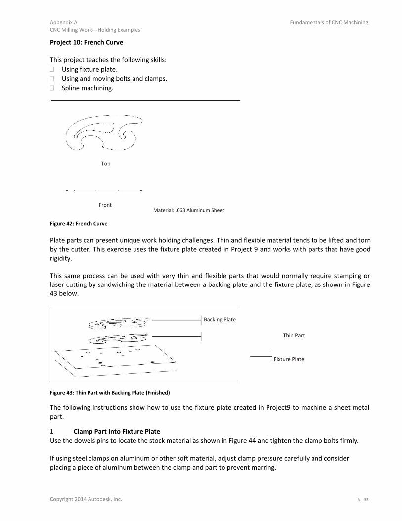
Appendix A Fundamentals of CNC Machining CNC Milling Work-Holdi g E a ples
Project 10: French Curve
This project teaches the following skills: Using fixture plate. Using and moving bolts and clamps. Spline machining.
Top
Front
Figure 42: French Curve
Material: .063 Aluminum Sheet
Plate parts can present unique work holding challenges. Thin and flexible material tends to be lifted and torn
by the cutter. This exercise uses the fixture plate created in Project 9 and works with parts that have good
rigidity.
This same process can be used with very thin and flexible parts that would normally require stamping or
laser cutting by sandwiching the material between a backing plate and the fixture plate, as shown in Figure
43 below.
Backing Plate
Thin Part
Fixture Plate
Figure 43: Thin Part with Backing Plate (Finished)
The following instructions show how to use the fixture plate created in Project9 to machine a sheet metal
part. 1 Clamp Part Into Fixture Plate Use the dowels pins to locate the stock material as shown in Figure 44 and tighten the clamp bolts firmly.
If using steel clamps on aluminum or other soft material, adjust clamp pressure carefully and consider
placing a piece of aluminum between the clamp and part to prevent marring.
Copyright 2014 Autodesk, Inc. A-
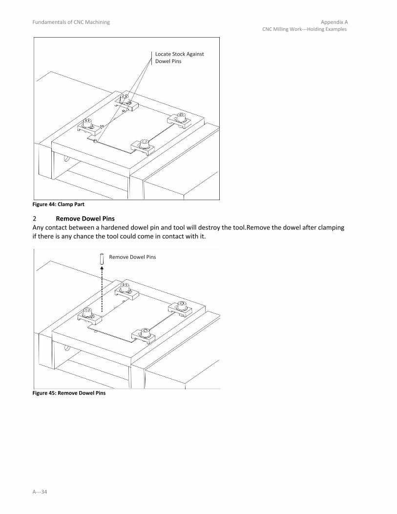
Fundamentals of CNC Machining Appendix A CNC Milling Work-Holdi g E a ples
Locate Stock Against Dowel Pins
Figure 44: Clamp Part
2 Remove Dowel Pins Any contact between a hardened dowel pin and tool will destroy the tool.Remove the dowel after clamping
if there is any chance the tool could come in contact with it.
Remove Dowel Pins
Figure 45: Remove Dowel Pins
A-

Appendix A CNC Milling Work-Holdi g E a ples
Fundamentals of CNC Machining
3 Drill Hold-Do Holes Drill Holes for the #6- s e s that ill se u e the pa t afte the stock being gripped by the clamps is cut
away. The drill depth should be just enough so the shoulder clears the bottom of the part, but doesnot cut
deep into the threads in the fixture plate.
French Curve: Job- Setup
G54
Z+
Y+
X+
Datum: Use same datum as fixture plate. Op- Tool (in) Speed (rpm) Feed XY (ipm) Feed Z (ipm)
CTR Drill .25 Ctr Drill 1800 18.0 9.0 Rough XY(in) Rough Z(in) Feed XY (ipm) Finish Z(in)
1.0 .25 1.0 .005 Op- Tool (in) Speed(rpm) Feed XY (ipm) Feed Z (ipm)
Drill .156 (5/32) 3200 36.0 18.0
Drill Figure 46: Fixture Plate Job 1
4 Install Hold Down Bolts Install bolts. Remove the clamps if the tool will contact them, otherwise leave them in place so the scrap
material is gripped securely afteras it is cut away.
Figure 47: Install Bolts
Copyright 2014 Autodesk, Inc. A-
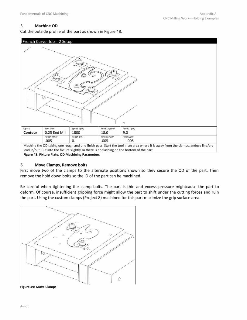
Fundamentals of CNC Machining Appendix A CNC Milling Work-Holdi g E a ples
5 Machine OD Cut the outside profile of the part as shown in Figure 48.
French Curve: Job- Setup
Op- Tool (inch) Speed (rpm) Feed XY (ipm) Feed Z (ipm)
Contour 0.25 End Mill 1800 18.0 9.0 Rough XY(in) Rough Z(in) Finish XY (in) Finish Z(in)
.005 0. .005 -. Machine the OD taking one rough and one finish pass. Start the tool in an area where it is away from the clamps, anduse line/arc
lead in/out. Cut into the fixture slightly so there is no flashing on the bottom of the part. Figure 48: Fixture Plate, OD Machining Parameters
6 Move Clamps, Remove bolts First move two of the clamps to the alternate positions shown so they secure the OD of the part. Then
remove the hold down bolts so the ID of the part can be machined.
Be careful when tightening the clamp bolts. The part is thin and excess pressure mightcause the part to
deform. Of course, insufficient gripping force might allow the part to shift under the cutting forces and ruin
the part. Using the custom clamps (Project 8) machined for this part maximize the grip surface area.
Figure 49: Move Clamps
A-

Appendix A Fundamentals of CNC Machining CNC Milling Work-Holdi g E a ples
7 Machine ID Machine the ID Profile to complete the part.
French Curve: Job- Setup
Op- Tool (in) Speed (rpm) Feed XY (ipm) Feed Z (ipm)
Contour 0.25 End Mill 1800 18.0 9.0 Rough XY(in) Rough Z(in) Feed XY (ipm) Finish Z(in)
1.0 .25 1.0 .005 Stock to Leave XY(in) Stock to Leave Z(in)
0.0 0.0 Figure 50: Fixture Plate, ID Machining Parameters
To observe the effects of data starvation, set the tool length offset so the tool runs above the part. Run the program,
increasing feed rate until the machine begins to shudder. Notice that the actual machine feed rate is less than the
programmed feed rate.
The feed rate at which this occurs depends on the block execution time of the machine tool. Reduce or eliminate
data starving by reducing the feed rate at the machine, or by using the tool path filter function in the CAD/CAM
software. Copyright 2014 Autodesk, Inc. A-

Fundamentals of CNC Machining Appendix A CNC Milling Work-Holdi g E a ples
Project 11: Honeycomb
This project teaches the following skills: Thin wall machining.
Small corner radii machining.
TopView Right View
Bottom View Material: Brass
Figure 51: Honeycomb
1 Clamp Part In Vise
Clamp the sawed stock in vise as shown in Figure52. Set the G54 datum off the upper left corner of the stock.
Be sure to leave enough stock so the face and outside perimeter tool paths remove material.
Honeycomb: Job- Setup
G54 Z+
X+
Y+
Datum: Upper-left o e of sto k. Op- Tool (inch) Speed (rpm) Feed XY (ipm) Feed Z (ipm)
Face 0.25 End Mill 1800 18.0 9.0 Rough XY Rough Z Finish XY Finish Z
1.0 .25 1.0 .005 Stock to Leave XY 0.0
Stock to Leave Z 0.0
A-

Appendix A CNC Milling Work-Holdi g E a ples
Op- Tool (in) Speed (rpm) Feed XY (ipm)
Ctr Drill 0.25 Ctr Drillll 1800 18.0 Op- Tool (in) Speed (rpm) Feed XY (ipm)
Drill 0.25 Drill 1800 18.0 Op- Tool (inch) Speed (rpm) Feed XY (ipm)
Pocket 0.25 End Mill 1800 18.0 Rough XY(in) Rough Z(in) Finish XY(in)
1.0 .25 1.0 Stock to Leave XY(in) Stock to Leave Z(in)
0.0 0.0 Op- Tool (in) Speed (rpm) Feed XY (ipm)
Pocket 0.25 End Mill 1800 18.0 Rough XY(in) Rough Z(in) Finish XY(in)
1.0 .25 1.0 Stock to Leave XY(in) Stock to Leave Z(in)
0.0 0.0 Op- Tool (in) Speed (rpm) Feed XY (ipm)
Remachine 0.25 End Mill 1800 18.0 Rough XY(in) Rough Z(in) Finish XY(in)
1.0 .25 1.0 Stock to Leave XY(in) Stock to Leave Z(in)
0.0 0.0 Figure 52: Honeycomb, Top Side Machining Parameters
Fundamentals of CNC Machining
Feed Z (ipm) 9.0 Feed Z (ipm) 9.0 Feed Z (ipm) 9.0 Finish Z(in) .005 Feed Z (ipm) 9.0 Finish Z(in) .005 Feed Z (ipm) 9.0 Finish Z(in) .005
2 Flip Part In Vise Flip part about Y-a is, a d set the datu as the uppe -left o e of the fi ished otto fa e. Use the
method described in Project 5 (Steps 3- to set G fo this pa t.
Honeycomb: Job- Setup
G55 Z+
X+
Y+
Datum: Upper-left o e of fi ished top fa e. Op- Tool (inch) Speed (rpm) Feed XY (ipm) Feed Z (ipm)
Face 0.25 End Mill 1800 18.0 9.0 Rough XY(in) Rough Z(in) Finish XY(in) Finish Z(in)
1.0 .25 1.0 .005 Stock to Leave XY(in) 0.0
Stock to Leave Z(in) 0.0
Op- Tool (inch) Speed (rpm) Feed XY (ipm) Feed Z (ipm)
Contour 0.25 End Mill 1800 18.0 9.0 Rough XY(in) Rough Z(in) Finish XY(in) Finish Z(in)
1.0 .25 1.0 .005 Stock to Leave XY(in) 0.0
Stock to Leave Z(in) 0.0
Figure 53: Honeycomb Job 2
Copyright 2014 Autodesk, Inc. A-

Fundamentals of CNC Machining Appendix A CNC Milling Work-Holdi g E a ples
Project 12: Bracket
This project teaches the following skills: How to use various types of clamps. How to rearrange clamps to avoid machining operations. How to use an angle plate. Planning ahead taking into consideration part geometry and changes in rigidity as material is removed.
Almost every part presents unique work holding challenges. Part geometry, material type, wall thickness,
and features all influence work holding.
Parts like this present multiple challenges. Like a chess player,a machinist has to think ahead several moves
to visualize what the part will look like each step of the way. Before starting this project, it is important to
consider machining methods, sequencing, work holding, and potential problems.
Top Right
Front
Material: 6061 Aluminum
Figure 54: Project- , Bra ket
1 Clamp Part to Table Use clamps to secure the part to the table as shown in Figure 55 below. Flanges will be cut on the ends of
the stock to hold and locate the part in subsequent operations. Plan ahead. Use stock thick enough to form
rigid flanges and face the part on both sides. Locate clamps clear of tool paths and set rapid heights to easily
clear the clamps.
Many styles of clamps are available. The type shown here use Step Blocks to set the clamp at the same level
as the top of stock. Machining on this side of the part produces significant cutting pressures. Because the
clamps rest on material that will be later cut away, there is no problem with marringthe finished part, so the
bolts can be tightened very securely to prevent the part from slipping.
Once the part is clamped to the table, it mustnot be moved until all machining on this sideare complete.
A-
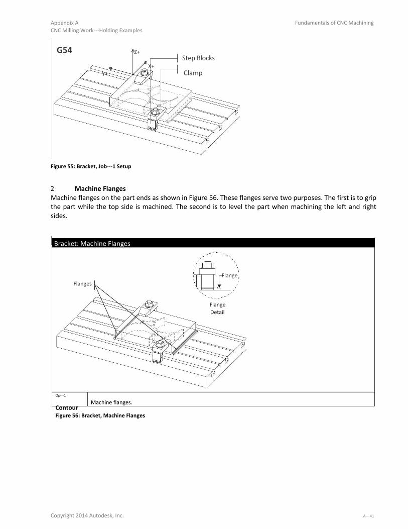
Appendix A Fundamentals of CNC Machining
CNC Milling Work-Holdi g E a ples
G54 Z+ Step Blocks
X+
Y+ Clamp
Figure 55: Bracket, Job- Setup
2 Machine Flanges
Machine flanges on the part ends as shown in Figure 56. These flanges serve two purposes. The first is to grip
the part while the top side is machined. The second is to level the part when machining the left and right
sides.
Bracket: Machine Flanges
Flange
Flanges
Flange Detail
Op-
Machine flanges. Contour Figure 56: Bracket, Machine Flanges
Copyright 2014 Autodesk, Inc. A-
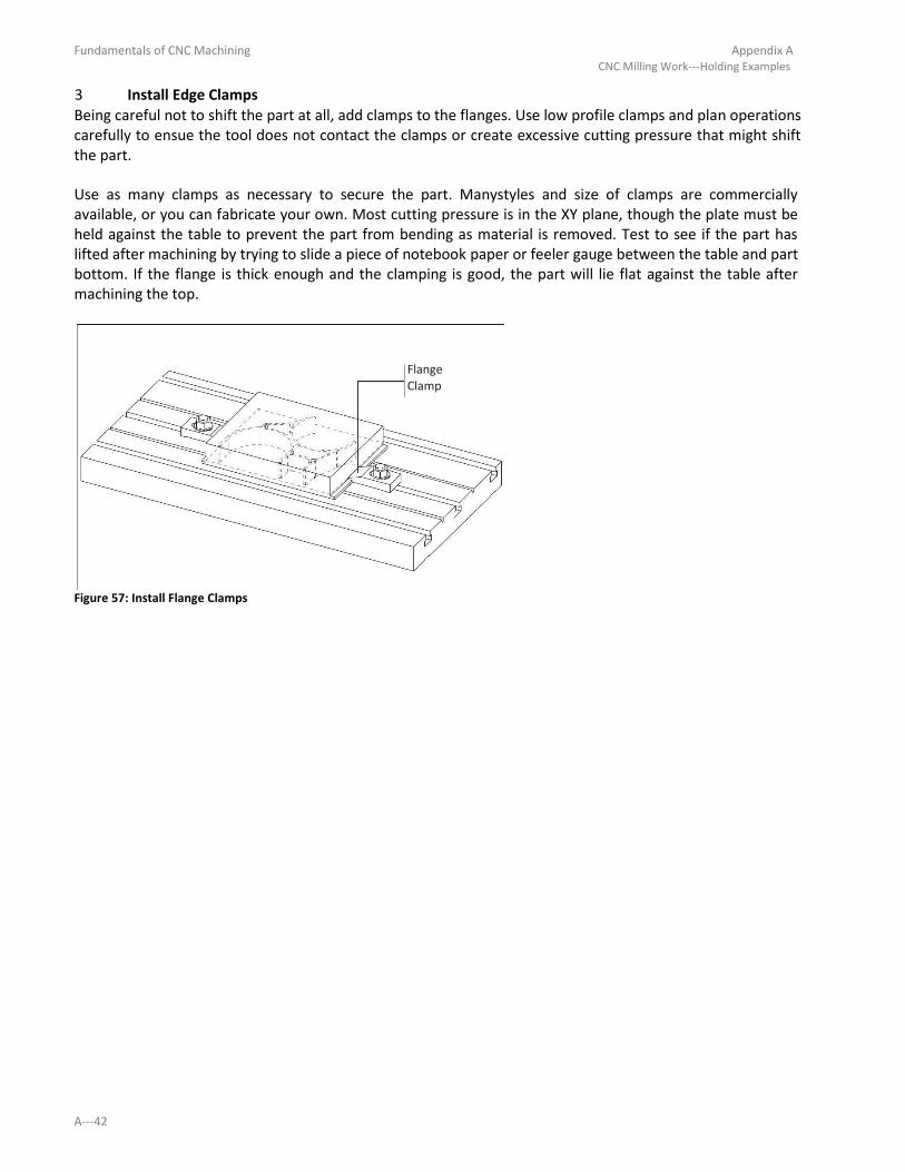
Fundamentals of CNC Machining Appendix A CNC Milling Work-Holdi g E a ples
3 Install Edge Clamps Being careful not to shift the part at all, add clamps to the flanges. Use low profile clamps and plan operations
carefully to ensue the tool does not contact the clamps or create excessive cutting pressure that might shift
the part.
Use as many clamps as necessary to secure the part. Manystyles and size of clamps are commercially
available, or you can fabricate your own. Most cutting pressure is in the XY plane, though the plate must be
held against the table to prevent the part from bending as material is removed. Test to see if the part has
lifted after machining by trying to slide a piece of notebook paper or feeler gauge between the table and part
bottom. If the flange is thick enough and the clamping is good, the part will lie flat against the table after
machining the top.
Flange Clamp
Figure 57: Install Flange Clamps
A-

Appendix A Fundamentals of CNC Machining CNC Milling Work-Holdi g E a ples
4 Machine Top Face, pocket, and finish this side complete. Cut the perimeter of the part .010 inches below the profile to
ensure no flashing remains after the bottom side of the part is faced off in the last operations.
Bracket: Job 1
G54 Z+
Y+
X+
Datum: Same as part datum. Op-
Face part. Face Op-
Rough and finish OD of part. Machine at least .005 below the bottom profile. Avoid clamps. 2D
Contour Op-
Rough and finish pockets. Pocket
Figure 58: Bracket, Machine Top Side
Copyright 2014 Autodesk, Inc. A-

Fundamentals of CNC Machining Appendix A CNC Milling Work-Holdi g E a ples
5 Set Up Angle Plate An angle plate is a sturdy precision ground plate that is used to set parts onedge.
The next operation machines the holes and fillets on the right side. (This is done before finishing the bottom
so the material helps support the part from bending whilemachining the ends.)
Bolt and align the angle plate to thetable. Secure the part with toggle clamps and use a Machinists Square to
level the part. Check by running a dial indicator across the flange as shown. This angle is critical, so make the
part as level as possible.
The XY Datum can be found by picking up the reference point shown in Figure 59. Notice that the Y-datu is established by locating the finished part top against the angle plate.
G55 Dial Indicate This Edge to Level Part
Angle Plate
Toggle Clamps G55 Figure 59: Angle Plate Setup
A-

Appendix A Fundamentals of CNC Machining CNC Milling Work-Holdi g E a ples
6 Machine Clearance For Job 2 Cuts Carefully machine (or cut on a band saw) the part stock as shown in Figure 60 to provide tool clearance for
the next operations. Use light cuts because heavy cuts could cause the part to shift. The edge being cut away
is thin and not firmly supported —a situation prone to resonance. If the tool starts to chatter, slow feed rate
and spindle speed.
The setup shown here is a tradeoff between tool clearance and work rigidity. The less the part hangs off the
angle plate the more rigid the setup, but this reduces tool clearance needed to machine the radii.
As always, do not run the program unless certain the setup is stable and safe. Use the simulation and collision
checking features of the CAD/CAM software and check for tool and holder interference with the remaining
stock and angle plate.
This part is a good illustration of the difference between prototype and production manufacturing. Large production
quantities might justify the cost of more complex fixturesthat would allow the part to be easily clamped.
A rotary 4th
axis might be used so that the part could be automatically reposition –eliminating several setups and
improving the accuracy of the holes.
Machine or Saw Away This Area For Tool Clearance
Figure 60: Bracket, Machine Tool Clearance
Copyright 2014 Autodesk, Inc. A-

Fundamentals of CNC Machining Appendix A CNC Milling Work-Holdi g E a ples
7 Drill Holes, Cut Radii Center drill and drill the holes in the ears, and then contour the radii. Take small cuts and use the smallest
recommended chip load to prevent tool chatter or deforming the part.
Bracket: Job 2
G55
Z+
Y+ Detail
X+
Datum: See Figure 59. G55 XY is corner formed by Job 1. G55 Z is top surface of this flange. Op--
Center Drill Top Hole. Center Drill Op- Drill Op- 2D Contour
Center Drill Top Holes.
Rough and finish top radii.
Figure 61: Bracket, Right Side
A-

Appendix A Fundamentals of CNC Machining CNC Milling Work-Holdi g E a ples
8 Drill Holes, Cut Radii, Left Side Rotate the part 180 degrees about the Y-a is as sho i Figu e elo . Use the sa e p o edu es as i Steps 5 thru 7 to level the part, find the datum, remove material for tool and holder clearance, and then
machine the hole and radius.
This is a tricky setup because the piece is flipped, has deformed during machining, and the hole must be located
precisely to align with the holes created in the previous operation. Do your best work and check yourdatum carefully.
Scrapping the part at this step would be costly.
Bracket: Job-
G56
Z+
Y+ Detail
X+
Datum: Pick up G56 XY from corner of flange as in Step 7, Figure 61. Op- Center Drill Top Hole. Center Drill Op- Drill Op- 2D Contour
Center Drill Top Holes.
Rough and finish top radii.
Figure 62: Bracket, Left Side
Copyright 2014 Autodesk, Inc. A-

Fundamentals of CNC Machining Appendix A CNC Milling Work-Holding Examples
9 Face Bottom Ends Set the part on the table face side down. Clamp in the center as shown in Figure 63.
Bracket: Job 4, Face Ends
G57
Machine Ends
Clamp Center Section
Z+
Y+
G57
X+
Datum: Set G57 XY as shown. This is the only edge on the part where the XY datum can be set accurately. The XY datum can be
set +/- . in because this is a facing operation only. Set Z from surface of table to establish part thickness. Op-
Rough and finish ends of part avoiding clamps. Face
Figure 63: Bracket, Face Ends
10 Face Center Area Install on the ends of the part as shown in Figure 64. Place aluminum pads under the clamps so they won t
scratch or damage the part. Machine the center section to complete thepart.
Bracket: Job 4 , Face Center
G57
Aluminum Pads
Machine Center Section
Under Clamps
Clamp Ends
Datum: Same as Figure 63. Op-
Rough and finish ends of part avoiding clamps. Face
Figure 64: Bracket, Face Center
A-

Appendix A Fundamentals of CNC Machining CNC Milling Work-Holdi g E a ples
Project 13: Microwave Housing
This project teaches the following skills: Machining ramps. 2D REST Milling. Clamping direct to the table or sub plate. Using flange to support part during machining. Using dowel pins or shoulder bolts to precisely locate part.
This project is designed with features on the top and bottom that must match perfectly. Careful planning
and setup is required to machine the part correctly, and avoid drilling into the table. Large plate parts like this are usually clamped to the table because they will not fit in a standard vise, and vise
pressure may cause the part to deform as material is removed. Clamping downward, rather than squeezing in
a vise, prevents warping.
Top Right
Front
Bottom Material: 6061 Aluminum
Figure 65: Microwave Housing
Copyright 2014 Autodesk, Inc. A-

Fundamentals of CNC Machining Appendix A CNC Milling Work-Holdi g E a ples
1 Clamp Stock to Table Clamp the part directly to the table or sub plate.Add stock to create a flange. This is used to locate and hold
the part when machining the bottom.
Dowel Pin Hole 4X
Figure 66: Microwave Housing, Top Side Setup
Figure 67 shows how the part looks after this operation, and how the dowel and shoulder bolt holes extend
beyond the bottom of the part, but do not drill into the sub plate or table.
Shoulder Bolt Hole
Dowel Hole
Flange
Step Clamp
Step
Part Block
Sub Plate or Table
Figure 67: Front View - After Ma hi i g
A--

Appendix A Fundamentals of CNC Machining CNC Milling Work-Holdi g E a ples
2 Machine Top Complete
Machine the top complete.
Microwave Housing: Job 1
G54 Z+
Y+
X+
Datum: Upper-left o e of sto k. Op-
Face Part avoiding clamps. Face Op- 2D Rough Op- 2D Rough Op- 2D Finish Op- 2D Finish Op- 3D Rough Op- 3D Finish Op- 2D Pocket Op- Ctr Drill Op- Drill Op- Drill Op- Drill
Rough OD avoiding clamps.
Rough pocket.
Finish OD. Finish the part after roughing both the inside and outside so the part will stress relieve.
Finish pocket.
3D rough ramps.
3D finish ramps.
Rough and finish pockets in bottom of pocket.
Center drill all holes.
Drill holes in flange for dowel pins used to locate the part for Job 2.
Drill holes in flange.
Drill holes in top face of part
Figure 68: Microwave, Top Side
Copyright 2014 Autodesk, Inc. A-

Fundamentals of CNC Machining Appendix A CNC Milling Work-Holding Examples
2 Machine Fixture Plate Figure 69 shows a fixture plate used to machine the second side. The fixture has a cavity that the part fits
into and the part is held by strap clamps on the flange. Four dowel pin holes locate the part precisely. Notice the dowels cannot protrude above the finished
thickness of the flange, so a facing tool can pass over without colliding (which would destroy the tool). Four counter- o ed holes at h holes i the pa t. Afte fa i g, these holes a e e posed, allo i g shoulder
bolts to be installed. These locate and clamp the part while the excess flange is cut away.Be sure to make the
counterbore deep enough so the shoulder bolt will grip the part when tightened.
Shoulder Bolt
Hole Detail
A - A
A
A
Figure 69: Fixture Plate Detail
A-

Appendix A Fundamentals of CNC Machining CNC Milling Work-Holdi g E a ples
3 Machine Fixture Plate Machine the fixture plate given the parameters below.
Microwave Housing: Fixture Plate
G55
Z+
Y+
G55
X+
Datum: G55 XY is located at the center-fa e of do el pi hole. Fi d this lo atio pi ki g up a o e of the fi tu e plate sto k, and then shifting G55 XY. This is important because this hole is used to precisely locate the Microwave Housing when it is
fastened to this fixture. Op- Face Op- 2D Pocket Op- Ctr Drill Op- Drill Op- Drill
Op- Drill Op- Tap
Face fixture plate avoiding clamps.
Rough and finish pocket.
Center drill all holes.
Drill holes for dowel pins.
Drill holes for shoulder bolt threads. De- u these holes so the ha fe ed edge ill help guide the shoulder bolt so it slides into the hole and does not get hung on thesharp edge. Drill holes for shoulder bolt ground shoulder.
Tap holes for shoulder bolts.
Figure 70: Microwave Housing, Fixture Plate 4
Copyright 2014 Autodesk, Inc. A-

Fundamentals of CNC Machining Appendix A CNC Milling Work-Holdi g E a ples
5 Clamp Part to Fixture Install dowel pins and then place part face down on the fixture. Ensure the dowel pins do not extend higher
than the thickness of the part flange. Make sure the part isoriented properly so the features on the bottom
mate with features on the top. Use Strap clamps to hold the part by the flange. Tap the part down with a
rubber mallet, and use a feeler gauge to check for gaps between the fixture and face of the part.
Place Part Top Side Down On Fixture
Secure With Strap Clamps
Figure 71: Locate Part on Fixture.
A-
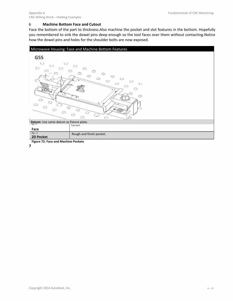
Appendix A Fundamentals of CNC Machining CNC Milling Work-Holdi g E a ples
6 Machine Bottom Face and Cutout Face the bottom of the part to thickness.Also machine the pocket and slot features in the bottom. Hopefully
you remembered to sink the dowel pins deep enough so the tool faces over them without contacting.Notice
how the dowel pins and holes for the shoulder bolts are now exposed.
Microwave Housing: Face and Machine Bottom Features
G55
Z+
Y+
X+
Datum: Use same datum as fixture plate. Op- Face part.
Face Op- Rough and finish pocket. 2D Pocket
Figure 72: Face and Machine Pockets
7 Copyright 2014 Autodesk, Inc. A-

Fundamentals of CNC Machining Appendix A CNC Milling Work-Holdi g E a ples
8 Install Shoulder Bolts and Cut Away Flange Install the shoulder bolts that are used to secure the part while the flange is cut away. You will probably have
to de- u the holes to get the olts to slide i . Che k to e su e the shoulde olts a tuall g ip the pa t. If not, then you did not make the counterbore deep enough(Step 3) and will need a washer. Cut away the excess flange to finish the part.Leave all clamps in place during this operation to the flange will
not lift during machining. Notice how close the tool passes to the dowel pins.
Microwave Housing: Job- Setup
G55
Cut Away Flange
Z+
Y+
X+
Datum: Use same datum as fixture plate. Op-
Rough and finish OD of part to cut flange away. Contour
Figure 73: Cut Away Flange
A-

Appendix A Fundamentals of CNC Machining CNC Milling Work-Holdi g E a ples
Project 14: Geneva Gear
This project teaches the following skills: Work holding using double-sided tape.
Some parts can be held using double-sided tape. This eli i ates the eed fo aki g a o ple fi tu ea d works quite well if cutting pressures are low and surface area is large enoughto form a sufficient bond.
Aluminum and Medium Density Fiberboard (MDF) are commonly used fixture plate materials. Prepare an
aluminum plate by clamping it to the table and facing it smooth and flat to form a good surface to bond to.
Don t use coolant because its residue will inhibit good bonding. To ensure a good bond with thetape, a good practice is to place a heavy weight on the part and let it set for
at least 15 minutes after taping. The longer this weight is in place, the better the bond, so leave it for several
hours or overnight if possible.
Top Material: .063 Aluminum
Figure 74: Geneva Gear
Copyright 2014 Autodesk, Inc. A-

Fundamentals of CNC Machining Appendix A CNC Milling Work-Holdi g E a ples
Geneva Gear: Machine Complete G54
Part
Double-Sided Tape
Z+ Fixture
Y+
G54
X+
Datum: G54 XY is at the approximate center of stock. G54 Z is top of stock material. Op- Tool (inch) Speed (rpm) Feed XY (ipm) Feed Z (ipm)
Contour .25 End Mill 1800 18.0 9.0 Rough XY(in) Rough Z(in) Finish XY (in) Finish Z(in)
1.0 .25 1.0 .005 Stock to Leave XY(in) 0.0
Stock to Leave Z(in) 0.0
Figure 75: Geneva Gear Setup
Tips for Using Double-Sided Tape: Use a high quality industrial quality double-sided tape. A oid usi g old tape e ause o di g st e gth
decreases with shelf life. Avoid using coolant because it will loosen the tape. Weigh down the part with a heavy object to improve bonding. Use light cutting forces to keep the part from moving or coming completely loose during machining. Removing the part after machining without deforming it can be a challenge. Methods used depend on
the material, but can include the use of heat or a solvent like WD- ©. A-

Appendix B Fundamentals of CNC Machining Alternate Tool Setting Methods
Objectives
Upon successful completion of this lesson, you will be able to: Set tool length offset using a scrap of notebook paper. Set tool length offset using a 1- - Blo k f o the fi ished fa e of the pa t. Set the tool length offset using a Tool Probe.
1.1 - O er ie
One of the most confusingthings about CNC s is how to set tool length offsets and how they relate to machine
fixture offsets. Lessons 4 and 6 detailed one method of using Tool and Length offsets.While this is one of the
most flexible and useful methods it is not easyfor beginners to understand and has other disadvantages.
This chapter shows three other methods of setting tool lengths. To summarize, here is a table that lists all four
methods described in this course:
Method 1
2
3
4
Description Use scrap of notebook paper.
Use 1- - Block on
finished face of part.
Use 1- - Blo k a d dial indicator (Method described
in Lessons 3 and 6).
Use tool probe.
Advantages
Easy to understand. Easy to use. Does not require using Fixture
Offset Z. Safe. Very accurate. Easier to understand than
method requiring use of dial
indicator.
Very accurate. If Z-datu is illed a a ,
tools can be reset easily in
case of broken or worn tool.
Easy to use. Very fast. Accurate. Easy to understand.
Disadvantages Not as accurate as other
methods. Requires part to be
manually face milled
before setting tools. Not as safe as paper or
tool probe method. Requires part to be face
milled before using. Requires also setting
Fixture Offset Z. If Z-datu is illed
away, tools cannot be
reset easily. Can be difficult to
understand for beginners. Not as safe as paper or
tool probe method. Requires also setting
Fixture Offset Z. Requires machine
equipped with tool probe.
Copyright 2014 Autodesk, Inc. B-

Fundamentals of CNC Machining Appendix B Alternate Tool Setting Methods
1.2 – Using Piece of Notebook Paper
Notebook paper is remarkably consistent in thickness. This method takes advantage of this for setting tools.
With this method you will place a piece of scrap paper on the finished face of the part and then jog the tool
while spinning until it just contacts the paper.Contact of the tool with the paper is indicated when the paper
begins spinning. The tool length offset is set to at position.
1 Face Mill Part Begin by installing an end mill or face mill in the spindle. Follow all safety precautions. Start the spindle, and
manually jogging the tool close to the top of the rough stock. Reduce the job increment to .001 inches per pulse
and slowly move the tool down until it just contacts the face of the part. Then move the tool off to the side of
the part and then lower the tool by the amount of the face cut (usually .005-. i hes . I ease the jog increment to .01inches per pulse and move the tool in XY as necessary to create a flat surface on the face of the
part.
2 Stop the spindle Stop the spindle before proceeding! Jog the tool well out of the way so you do not bump it with your hand or
head.
3 Place Paper on Face of Part Tear a piece of common notebook paper larger than the diameter of the tool. Place the paper so it lies flat on
the face of the part.
4 Restart spindle Follow all safety precautions to restart the spindle.
5 Move tool over scrap of paper Manually jog the machine until the spindle is centered over the piece of paper.
6 Jog tool down until it contacts paper Jog the tool close to the paper, and then reduce the job amount to .001 per pulse. Slowly jog the tool down .001
at a time until the tool just contacts the paper. The paper will usually begin spinning with the tool.
7 Stop the spindle Stop the spindle but do not yet jog the machine.
8 Set the Tool Length register value Set the Tool Length Offset register at this value. This is done on the Haas by pressing the TOOL OFFSET MESUR
button (beneath F1). Other machines may require you write down the Z- alue eadi g o the CNC o t ol and then enter this value in the tool length register for this tool.
9 Adjust Tool Length register for paper thickness (optional) If exact tolerances are required then the tool must be lowered by the thickness of the paper. Do this by ADDING
the thickness of the paper (.003-. t pi al to the Tool Le gth egiste .
B-
Appendix B Fundamentals of CNC Machining Alternate Tool Setting Methods
1.3 – Use 1- - Blo k o Fi ished Fa e of Part.
This approach is similar to the method described in Lessons 3 & 6. You must have a clean part face to begin with.
1 Face Mill Part Begin by installing an end mill or face mill in the spindle. Follow all safety precautions. Start the spindle, and
manually jogging the tool close to the top of the rough stock. Reduce the job increment to .001 inches per pulse
and slowly move the tool down until it just contacts the face of the part. Then move the tool off to the side of the
part and then lower the tool by the amount of the face cut (usually .005-. i hes . I ease the jog i e e t to .01inches per pulse and move the tool in XY as necessary to create a flat surface on the face of the part.
4 Stop the spindle Stop the spindle before proceeding! Jog the tool well out of the way so you do not bump it with your hand or
head.
5 Place 1- - Blo k o Fa e of Part Make sure there is no coolant or chips on the face of the part.Place the 1- - lo k o the fa e of thepart.
6 Jog Tool Alongside 1- - Blo k With the spindle OFF, carefully jog the tool until it isalong the side of the 1- - lo k.
7 Raise Spindle While Pressing Block Against Tool While applying SLIGHT pressure against the side of the tool,slowly raise the spindle in .001inch increments until
the tool JUST slips between the top of the part and the end of the tool. You must set the tool length based on
the longest tool flute, so move the block out of the way, rotate so the next flute is pointing towards the block,
and then try to slide the block underneath it. If the flute is longer than the others and the block does not slide
beneath using slight pressure, raise the spindle in .001inch increments until it does. It is not uncommon for
flutes to vary in length .005inches or more. Repeat until all cutting flutes have been checked.
8 Set the Tool Length Register Value
Set the Tool Length Offset register at this value. This is done on the Haas by pressing the TOOL OFFSET MESUR
button (beneath F1). Other machines may require you write down the Z- alue eadi g o the CNC o t ol and then enter this value in the tool length register for this tool.
9 Adjust For the Length of the 1- - Blo k Since all tools are set 1, 2 or 3 inches (depending on which side of the 1- - lo k used all offsets ust be lowered by this amount to adjust them downward to the top of the finished part. There are two ways
to accomplish this: a. Adjust all tool length offset down individually.
b. Set the Fixture Offset (Usually G54) register to the value. For example, setting G54 to 1.000 would
drop the datum for all tools used 1.000 inches.This is the preferred method. It must be done AFTER
setting all tool lengths.
Copyright 2014 Autodesk, Inc. B-

Fundamentals of CNC Machining Appendix B Alternate Tool Setting Methods
1.4 – Use 1- - Blo k a d Dial I di ator
This method is covered in detail in Lessons 3 and 6. Please refer to these lessons for more information.
1.5 – Use Tool Probe A Tool Probe is usually an optional piece of equipment on a CNC machine. It may consist of a laser (non- contact reading) or a Probe that the machine will movethe tool down to touch. Tool probes allow fast,
accurate, safe, and easy tool setting and are the preferred method: if you machine is equipped with a probe.
Because of the wide variety of tool probe types it is not possible to provide specific instructions in their use
here. Please have your instructor or shop supervisor show you how to use the probe on your machine.
Caution: Tool and part probes are expensive. Crashing the tool or part probe can cost hundreds or
thousands of dollars. Do not attempt to use these accessories without proper instruction.
B-

Fundamentals of CNC Machining Appendix C CNC Process Planning Form
CNC Process Planning Form Job Name:
Page: _____ of
_____
Part Number: Rev: Stock Size: X: Y: Z:
Programmer: Material:
G5_____ Fixture Offset
Y+
X+
View:
Operation Tool Diameter Corner Radius Tool Type Number Flutes Flute Length Shoulder Length
Speed Cutting Feed Entry Feed Ramp Feed Plunge Feed
Stepover XY Finish XY Stepdown Z Finish Z XY Stock Z Stock Max Depth
Allowance Allowance
Operation Notes
Operation Tool Diameter Corner Radius Tool Type Number Flutes Flute Length Shoulder Length
Speed Cutting Feed Entry Feed Ramp Feed Plunge Feed
Stepover XY Finish XY Stepdown Z Finish Z XY Stock Z Stock Max Depth
Allowance Allowance
Operation Notes
Copyright 2014 Autodesk, Inc. C-

Appendix C Fundamentals of CNC Machining CNC Process Planning Form
Page:
_____ of _____ Operation Tool Diameter Corner Radius Tool Type Number Flutes Flute Length Shoulder
Length
Speed Cutting Feed Entry Feed Ramp Feed Plunge Feed
Stepover XY Finish XY Stepdown Z Finish Z XY Stock Z Stock Allowance Max
Allowance Depth
Operation Notes
Operation Tool Diameter Corner Radius Tool Type Number Flutes Flute Length Shoulder
Length
Speed Cutting Feed Entry Feed Ramp Feed Plunge Feed
Stepover XY Finish XY Stepdown Z Finish Z XY Stock Z Stock Allowance Max
Allowance Depth
Operation Notes
Operation Tool Diameter Corner Radius Tool Type Number Flutes Flute Length Shoulder
Length
Speed Cutting Feed Entry Feed Ramp Feed Plunge Feed
Stepover XY Finish XY Stepdown Z Finish Z XY Stock Z Stock Allowance Max
Allowance Depth
Operation Notes
Operation Tool Diameter Corner Radius Tool Type Number Flutes Flute Length Shoulder
Length
Speed Cutting Feed Entry Feed Ramp Feed Plunge Feed
Stepover XY Finish XY Stepdown Z Finish Z XY Stock Z Stock Allowance Max
Allowance Depth
Operation Notes
C-

Appendix D Fundamentals of CNC Machining
G-M Code Refe e e
Milling G-Codes
G00 Rapid Positioning Motion (X,Y,Z,A,B)
G01 Linear Interpolation Motion (X,Y,Z,A,B,F)
G02 Circular Interpolation Motion CW (X,Y,Z,A,I,J,K,R,F)
G03 Circular Interpolation Motion CCW (X,Y,Z,A,I,J,K,R,F)
G04 Dwell (P) (P=Seconds)
G09 Exact Stop, Non-Modal
G17 Circular Motion XY Plane Selection (G02 or G03)
G18 Circular Motion ZX Plane Selection (G02 or G03)
G19 Circular Motion YZ Plane Selection (G02 orG03)
G20 Inch Coordinate Positioning
G21 Metric Coordinate Positioning
G28 Machine Zero Return Thru Ref. Point (X,Y,Z,A,B)
G29 Move to Location Through G28 Ref. Point (X,Y,Z,A,B)
G40 Cutter Comp Cancel
G41 2D Cutter Compensation, Left (X,Y,D)
G42 2D Cutter Compensation, Right (X,Y,D)
G43 Tool Length Compensation + (H,Z)
G49 Tool Length Compensation Cancel G43/G44/G43
G52 Work Offset Positioning Coordinate
G53 Machine Positioning Coordinate, Non-Modal X,Y,Z,A,B
G54 Work Offset Positioning Coordinate #1
G55 Work Offset Positioning Coordinate #2
G56 Work Offset Positioning Coordinate #3
G57 Work Offset Positioning Coordinate #4
G58 Work Offset Positioning Coordinate #5
G59 Work Offset Positioning Coordinate #6
G73 HS Peck Drilling Canned Cycle (X,Y,A,B,Z,I,J,K,Q,P,R,L,F)
G74 Reverse Tapping Canned Cycle (X,Y,A,B,Z,J,R,L,F)
G76 Fine Boring Canned Cycle (X,Y,A,B,Z,I,J,P,Q,R,L,F)
G77 Black Bore Canned Cycle (X,Y,A,B,Z,I,J,Q,R,L,F)
G80 Cancel Canned Cycle
G81 Drill Canned Cycle (X,Y,A,B,Z,R,L,F)
G82 Spot Drill / Counterbore Canned Cycle (X,Y,A,B,Z,P,R,L,F)
G83 Peck Drill Deep Hole Canned Cycle (X,Y,A,B,Z,I,J,K,Q,P,R,L,F)
G84 Tapping Canned Cycle (X,Y,A,B,Z,J,R,L,F)
G85 Bore In ~ Bore Out Canned Cycle (X,Y,A,B,Z,R,L,F)
G86 Bore In ~ Stop ~ Rapid Out Canned Cycle (X,Y,A,B,Z,R,L,F)
G87 Bore In ~ Manual Retract Canned Cycle (X,Y,A,B,Z,R,L,F)
G88 Bore In ~ Dwell ~ Manual Retract Canned Cycle (X,Y,A,B,Z,P,R,L,F)
G89 Bore In ~ Dwell ~ Bore Out Canned Cycle (X,Y,A,B,Z,P,R,L,F)
G90 Absolute Positioning Command
G91 Incremental Positioning Command
G92 Global Work Coordinate System
G93 Inverse Time Feed Mode ON
G94 Inverse Time Feed OFF / Feed Per Minute ON
G98 Canned Cycle Initial Point Return
G99 Canned Cycle R Plane Return Table 1: Mill G-Codes
Copyright 2014 Autodesk, Inc. D-

Fundamentals of CNC Machining Appendix D G & M Codes Reference
Milling M-Codes
M00 Program Stop
M01 Optional Program Stop
M02 Program End
M03 Spindle ON Clockwise (S)
M04 Spindle ON Counterclockwise (S)
M05 Spindle Stop
M06 Tool Change (T)
M08 Coolant ON
M09 Coolant OFF
M30 Program End and Reset
M31 Chip Auger Forward
M33 Chip Auger Stop
M34 Coolant Spigot Position Down, Increment
M35 Coolant Spigot Position Up, Decrement
M36 Pallet Part Ready
M41 Spindle Low Gear Override
M42 Spindle High Gear Override
M50 Execute Pallet Change
M83 Auto Air Jet ON
M84 Auto Air Jet OFF
M88 Coolant Through Spindle ON
M97 Local Sub-P og a Call P,L
M98 Sub-P og a Call P,L M99 Sub-P og a / Routi e Retu of Loop P
Table 2: Mill M-Codes
Note: Only one M-Code a appea i ea h lo k of ode. D-

Appendix D G-M Code Refe e e
Fundamentals of CNC Machining
Lathe G-Codes
G00 Rapid Positioning Motion
G01 Linear Interpolation Motion
G02 Circular Interpolation Motion CW G03 Circular Interpolation Motion CCW
G04 Dwell (P) (P=Seconds)
G09 Exact Stop, Non-Modal
G18 Circular Motion ZX Plane Selection (G02 or G03)
G20 Inch Coordinate Positioning
G21 Metric Coordinate Positioning G28 Machine Zero Return Thru Ref. Point
G29 Move to Location Through G28 Ref. Point
G32 Threading
G40 Tool Nose Compensation Cancel
G41 Tool Nose Compensation, Left
G42 Tool Nose Compensation, Right G43 Tool Length Compensation
G49 Tool Length Compensation Cancel G43/G44/G43
G50 Spindle Speed Clamp/Set Global Coor. Offset
G51 Cancel Offset (Yasnac)
G52 Set Local Coordinate System (Fanuc)
G53 Machine Coordinate Selection
G54 Work Offset Positioning Coordinate #1
G55 Work Offset Positioning Coordinate #2
G56 Work Offset Positioning Coordinate #3
G57 Work Offset Positioning Coordinate #4
G58 Work Offset Positioning Coordinate #5
G59 Work Offset Positioning Coordinate #6
G61 Exact Stop Modal
G64 G61 Cancel
G70 Finishing Cycle
G71 OD/ID Stock Removal Cycle
G72 Face Stock Removal Cycle
G73 Irregular Path Stock Removal Cycle
G74 Face Grooving Cycle, Peck Drilling
G75 OD/ID Grooving Cycle, Peck Drilling
G76 Threading Cycle, Multiple Pass
G80 Cancel Canned Cycle
G81 Drill Canned Cycle
G82 Spot Drill / Counterbore Canned Cycle
G83 Peck Drill Deep Hole Canned Cycle
G84 Tapping Canned Cycle
G85 Bore In ~ Bore Out Canned Cycle
G86 Bore In ~ Stop ~ Rapid Out Canned Cycle
G87 Bore In ~ Manual Retract Canned Cycle
G88 Bore In ~ Dwell ~ Manual Retract Canned Cycle
G89 Bore In ~ Dwell ~ Bore Out Canned Cycle
G90 OD/ID Turning Cycle, Modal Table 3: Lathe G-Codes
Copyright 2014 Autodesk, Inc. D-

Fundamentals of CNC Machining Appendix D
G & M Codes Reference
G92 Threading Cycle, Modal
G94 End Facing Cycle, Modal
G95 Subspindle Rigid Tap
G96 Constant Surface Speed (CSS) On
G97 Constant Surface Speed Cancel
G98 Feed Per Minute
G99 Feed Per Revolution Table 3 (Cont): Lathe G-Codes
Lathe M-Codes
M00 Program Stop
M01 Optional Program Stop
M02 Program End
M03 Spindle ON Clockwise (Forward)
M04 Spindle ON Counterclockwise (Reverse)
M05 Spindle Stop
M08 Coolant ON
M09 Coolant OFF
M10 Clamp Chuck
M11 Unclamp Chuck
M12 Auto Air Jet On
M13 Auto Air Jet Off
M14 Clamp Main Spindle
M15 Unclamp Main Spindle
M19 Orient Spindle with P value
M21 Tailstock Forward
M22 Tailstock Reverse
M23 Thread Chamfer On
M24 Thread Chamfer Off
M30 Program End and Reset
M31 Chip Auger Forward
M33 Chip Auger Stop
M36 Parts Catcher Up
M37 Parts Catcher Down
M41 Low Gear
M42 High Gear
M88 High Pressure Coolant On
M89 High Pressure Coolant Off
M133 Live Tool Drive Forward
M134 Live Tool Drive Reverse
M135 Live Tool Drive Stop Table 4: Lathe M-Codes
Note: Only one M-Code a appea i ea h lo k of ode. D-

Appendix E Fundamentals of CNC Machining Glossary
Glossary
1- - Blo k — A precision ground block that is
1x2x3 inches. Useful for helping set up the machine.
2D — A prismatic part of constant thickness.
2- / D — A prismatic part with multiple thicknesses. All planes are parallel to each other.
3D — A part that is not completely prismatic, including molds and organically shaped parts.
Burr — A sharp edge or flashing.
Block — A line of code in a CNC program.
CAD — Computer Aided Design
CAM — Computer Aided Manufacturing.
CDC — Cutter Diameter Compensation.
CNC — Computer Numerical Control.
Chip Load — The amount of material removed with each pass of a tool cutting edge.
Datum — Point on the part from which all coordinates are referenced.
Drill Chart — A table that shows drill sizes, their decimal equivalent, and what size drill to use for a
specified tap.
Feed — The linear speed at which a tool advances through material.
First Article — The first part machined with a new program and setup.
G-M Code — The CNC machine tool language.
Gouge — An error that causes an overcut on the part.
High Speed Machining (HSM) — Toolpath strategies that minimize machining time and tool breaking. Includes
several technologies such as Adaptive Roughing that
maintain a constant amount of tool engagement.
Home — Location of machine after it is turned on and moved to its start position.
ID — Inside diameter or contour, like a pocket.
Insert — Carbide composite cutting tool used extensively for turning operations.
Job — A sequential list of one or more machining operations that share the same setup and fixture offset.
Machine Coordinate System — Coordinates in reference to the machine Home position.
Mill — A machine tool that removes material by spinning a tool and moving it in relation to the part.
OD — Outside diameter or contour.
Overcut — Describes a machined feature is too big because not enough material was removed during
machining.
Post Processor — The part of a CAD/CAM system that actually creates and formats the CNC program for a
specific machine and control.
Rapid — The fastest linear feed rate at which a machine tool can move.
Reference Point — Some point on the part that can be found reliably by mechanical means.
Rigid Tapping — The capability of a CNC machine to control a tap without the use of a special tapping
attachment.
Scallop — Ridges left on the part, usually from a ball or bull nose end mill on a 3Dsculpted surface.
Setup— A complete set of work holding to machine one side of a part.
Speed — How fast a tool turns in RPM.
Spindle — Part of CNC machine that grips and spins the cutting tool.
Stepdown — Distance the tool moves down in Z between machining passes.
Copyright 2014 Autodesk, Inc. E-

Fundamentals of CNC Machining Appendix E Glossary
Stepover — Distance the tool moves over in the XY plane between machining passes.
Stock Allowance — Amount of material left after a machining operation or pass to be removed by a finish pass.
Spring Pass — Two or more machining passes that follows the exact same path. Used to straighten walls and improve surface finish.
TLO — Tool Length Offset. Used to tell CNC machine the length of a tool.
Tool Changer — A device on a CNC machine that automatically takes tools from a carousel and places them in the machine spindle.
T-Slot — A slot in the machine table into which a special T- ut a e i se ted. Used to faste
clamps or parts to the machine table.
Turret — Lathe assembly that attaches the lathe tool holder to the machine.
Undercut — Describes a machined feature is too small because too much material was removed during machining.
E-

Appendix F Fundamentals of CNC Machining Drill Chart
Decimal Drill mm
Equivalent Size
.0059 97 0.150
.0063 96 0.160
.0067 95 0.170
.0071 94 0.180
.0075 96 0.191
.0079 92 0.201
.0083 91 0.211
.0087 90 0.221
.0091 89 0.231
.0095 88 0.241
.0100 87 0.254
.0105 86 0.267
.0110 85 0.279
.0115 84 0.292
.0120 83 0.305
0.318 .0125 82
.0130 81 0.330
.0135 80 0.343
.0145 79 0.368
0.397 .0156 1/64
.0160 78 0.406
.0180 77 0.457
.0200 76 0.508
.0210 75 0.533
.0225 74 0.572
.0240 73 0.610
.0250 72 0.635
.0260 71 0.660
.0280 70 0.711
.0292 69 0.742
.0310 68 0.787
.0313 1/32 0.794
.0320 67 0.813 Table 1: Inch Drill and Tap Sizes
Decimal Equivalent Chart Tap Decimal Drill
mm Size Equivalent Size
.0330 66 0.838
.0350 65 0.889
.0360 64 0.914
.0370 63 0.940
.0380 62 0.965
.0390 61 0.991
.0400 60 1.016
.0410 59 1.041
.0420 58 1.067
.0430 57 1.092
.0465 56 1.181
.0469 3/64 1.191
.0520 55 1.321
.0550 54 1.397
.0595 53 1.511
.0625 1/16 1.588
.0635 52 1.613
.0670 51 1.702
.0700 50 1.778
.0730 49 1.854
.0760 48 1.930
.0781 5/64 1.984
.0785 47 1.994
.0810 46 2.057
.0820 45 2.083
.0860 44 2.184
.0890 43 2.261
.0935 42 2.375
.0938 3/32 2.381
.0960 41 2.438
.0980 40 2.489
.0995 39 2.527
.1015 38 2.578
Tap Size
#0-
#1- #1-
#2- #2-
#3-
#3-
#4- #4-
#5-
Copyright 2014 Autodesk, Inc. F-

Fundamentals of CNC Machining Appendix F G & M Codes Reference
Decimal Drill Mm
Equivalent Size
.1040 37 2.642
.1065 36 2.705
.1094 7/64 2.778
.1100 35 2.794
.1110 34 2.819
.1130 33 2.870
.1160 32 2.946
.1200 31 3.048
.1250 1/8 3.175
.1285 30 3.264
.1360 29 3.454
3.569 .1405 28
.1406 9/64 3.572
.1440 27 3.658
.1470 26 3.734
.1495 25 3.797
.1520 24 3.861
.1540 23 3.912
.1563 5/32 3.969
.1570 22 3.988
.1590 21 4.039
.1610 20 4.089
.1660 19 4.216
.1695 18 4.305
.1719 11/64 4.366
.1730 17 4.394
.1770 16 4.496
.1800 15 4.572
.1820 14 4.623
.1850 13 4.699
.1875 3/16 4.763
.1890 12 4.801
.1910 11 4.851
.1935 10 4.915 Table 1: Inch Drill and Tap Sizes
Decimal Equivalent Chart Tap Decimal Drill
mm Size Equivalent Size
#5- .1960 9 4.978
#6- .1990 8 5.055
.2010 7 5.105
.2031 13/64 4.159
.2040 6 5.182
#6- .2055 5 5.220
.2090 4 5.309
.2130 3 5.410
.2188 7/32 5.556
.2210 2 5.613 #8-
.2280 1 5.791 #8-
.2340 A 5.944
.2344 15/64 5.953
.2380 B 6.045
.2420 C 6.147
.2460 D 6.248
.2500 ¼ & E 6.350
.2570 F 6.528
.2610 G 6.629
.2656 17/64 6.747
#10- .2660 H 6.756
.2720 I 6.909
.2770 J 7.036
.2810 K 7.137
.2813 9/32 7.144
.2900 L 7.366
.2950 M 7.493
.2969 19/64 7.541
.3020 N 7.671
.3125 5/16 7.938
#12- .3160 O 8.026
.3230 P 8.204
.3281 21/64 8.334
.3320 Q 8.433
Tap Size
¼-
1/4-
5/16-
5/16- 5/16-
3/8-
3/8-
F-

Appendix F Fundamentals of CNC Machining Drill Chart
Decimal Drill
Equivalent Size
.3390 R
.3438 11/32
.3480 S
.3580 T
.3594 23/64
.3680 U
.3750 3/8
.3770 V
.3860 W
.3906 25/64
.3970 X
.4040 Y
.4063 13/32
.4130 Z
.4219 27/64
.4375 7/16
.4531 29/64
.4688 15/32
.4844 31/64
.5000 ½
.5156 33/64
.5313 17/32
.5469 35/64
.5625 9/16
.5781 37/64
.5938 19/32 Table 1: Inch Drill and Tap Sizes
Decimal Equivalent Chart
mm Tap Decimal Drill
mm Size
Equivalent
Size
8.611
.6094 39/64 15.478
8.731 3/8- .6250 5/8 15.875
8.839 .6406 41/64 16.272
9.093
.6563 31/32 16.669
9.128 .6719 41/64 17.066
9.347 7/16-
.6875 11/16 17.462 14
9.525
.7031 45/64 17.859
9.576 .7188 23/32 18.256
9.804 .7344 47/64 18.653
9.922 7/16-
.7500 ¾ 19.050 20
10.084 .7656 49/64 19.447
10.262 7/16-
.7813 25/32 19.844 28
10.319
.7969 51/64 20.241
10.490 .8125 13/16 20.637
10.716 ½- .8281 53/64 21.034
11.113 .8138 27/32 21.431
11.509 ½- .8594 55/64 21.828
11.906 ½- .8750 7/8 22.225
12.303 9/16-
.8906 57/64 22.622 12
12.700 9/16-
.9063 29/32 23.019 18
13.097 9/16-
.9219 59/64 23.416 24
13.494
5/8- .9375 15/16 23.813
13.891 .9531 61/64 24.209
14.288 5/8- .9688 31/32 24.606
14.684 5/8- .9844 63/64 25.003
15.081 1.000 1 25.400
Tap
Size 11/16- 11/16- 11/16-
¾-
¾-
¾- 13/16-
13/16- 13/16- 7/8-
7/8-
7/8- 15/16- 15/16-
1.0- 15/16-
1.0-
1.0-
Copyright 2014 Autodesk, Inc. F-

Fundamentals of CNC Machining Appendix F
G & M Codes Reference
Inch Pipe Thread Taps
Tap Approximate Approximate
Thread Inside Outside Tap Drill
Size Diameter Diameter
1/8- ¼ 3/8 11/32
¼- 3/8 17/32 7/16
3/8- ½ 11/16 37/64
½- 5/8 13/16 23/32
¾- 13/16 1 59/64
1- ½ 1 1/16 1 5/16 1 - /
1 ¼- ½ 1 3/8 1 5/8 1 ½
1 ½- ½ 1 5/8 1 7/8 1 - /
2- ½ 2 1/16 2 3/8 2 - /
2 ½- 2 9/16 2 7/8 2 - / Table 2: Pipe Thread Taps
F-

Appendix F Fundamentals of CNC Machining Drill Chart
Decimal Drill Size Equivalent
(Inches) (mm)
.0492 1.25
.0571 1.45
.0630 1.6
.0689 1.75
.0748 1.9
.0807 2.05
.0846 2.15
.0984 2.5
.1142 2.9
.1299 3.3
.1476 3.75
.1654 4.2
.1969 5
.2067 5.25
.2362 6
.2657 6.75
.2756 7
.3051 7.75
.3346 8.5
.3445 8.75
.3543 9
.3740 9.5 Table 3: Metric Taps
Metric Taps
Decimal Drill Size Tap Size Equivalent
(Inches) (mm)
M1.6X0.35 .3937 10
M1.8X0.35 .4134 10.5
M2X0.4 .4724 12
M2.2X0.45 .4921 12.5
M2.3X0.4 .5118 13
M2.5X0.45 .5512 14
M2.6X0.45 .5709 14.5
M3X0.5 .6102 15.5
M3.5X0.6 .6299 16
M4X0.7 .6890 17.5
M4.5X0.75 .7087 18
M5X0.8 .7283 18.5
M6X1 .7677 19.5
M6X0.75 .7874 20
M7X1 .8071 20.5
M8X1.25 .8268 21
M8X1.00 .8661 22
M9X1.25 .8858 22.5
M10X1.5 .9449 24
M10X1.25 .9843 25
M10X1.00 1.0433 26.5
M11X1.50 1.024 28
Tap Size
M12X1.75 M12X1.25
M14X2 M14X1.5
M14X1.25
M16X2 M16X1.5
M18X2.5
M18X2.0
M20X2.5
M20X2.0
M20X1.5
M22X2.5
M22X2.0
M22X1.5
M24X3
M24X2
M24X1.5
M27X3
M27X2
M30X3.5
M30X2
Copyright 2014 Autodesk, Inc. F-

Fundamentals of CNC Machining Appendix F G & M Codes Reference
F-

Appendix G Fundamentals of CNC Machining Formative Assessment #1: Safety Quiz
CNC Shop Safety Quiz
Name: Instructor:
Affiliation: Date:
Rating Standards A perfect score or instructor sign-off is required on the Safety Quiz before working in the shop. If you get any questions wrong, your instructor will review them with you. Make sure you understand this material before working in the shop.Once the instructor is confident you understand any missed question, they will sign-off on each by initialing next to that question in the Instructor Sign-Off column. You can only work in the shop after if items on this form are correct or signed off.
Answer
No
Question
A B C D Instructor
Sign-Off
When should safety glasses be worn in the shop?
1 A. Only when actually operating the machine. B. At all times.
C. When the CNC is not enclosed.
2
3
4
5
6
7
8
9
10
D. Only when using a hammer. When is it OK to use equipment you have not been trained to use?
A. If it is not computer controlled. B. If it is under .50 Horsepower.
C. Never D. If it is computer- o t olled.
What are some hazards associated with compressedair? A. Can cause chips to be blown into eyes.
B. Can enter the bloodstream and cause an embolism. C. Neither of the above. D. Both of the above.
What should be done with oily rags?
A. Store in fireproof canister. B. Throw them away. C. Store them together in an open trashcan for ventilation. D. No special care need be taken.
What kinds of shoes can be worn in the shop? A. Flip-flops. B. Open Toe Sandals. C. Leather shoes. D. Any kind of shoe.
What kind of shirt can be worn in the shop?
A. Long sleeve only. B. Short sleeve only. C. Either long or short sleeve. D. None of the above.
What precaution should be used if your hair is long? A. Tie it back and under back of shirt. B. Tuck it under a hat.
C. Either (a) or (b). D. No special precautions are required.
When running a new un-p o e CNC P og a , hat p e autio s should e applied? A. Use feed rate override.
B. Use rapid feed override. C. Use single block mode. D. All of the above.
A machine crash is often due to: A. Improperly set Tool Offset or Fixture offset. B. Electrical failure of machine.
C. Bad CNC post processor. D. Lack of operator attention.
What should you do at the first sign of trouble in a CNC program? A. Press the Feed Hold or Emergency Stop buttons.
B. Call for help. C. Turn machine power off. D. Move away from the machine immediately.
THINK SAFETY
CNC Safety Quiz Form-Ne Ge CAM. o 2012 Form
Copyright 2014 Autodesk, Inc. F-

Appendix G Fundamentals of CNC Machining Formative Assessment #1: Safety Quiz
CNC Safety Quiz Form- 2012 Form F-

Appendix H Fundamentals of CNC Machining
Shop Safety Compliance Contract
Course Name/Number: Instructor:
Start Date:
You are not authorized to work in the shop area until you attend the Safety Orientation, pass the Safety Quiz, and sign this contract. You may not use equipment withoutsupervision available and without receiving instruction in its use. By signing this contract, you agree to abide by the following guidelines. Failure to follow safety guidelines is cause for dismissal from class.
Shop Regulations Safety Glasses – You must wear safety glasses AT ALL TIMES while in the shop area. You must wear
safety goggles over prescription glasses unless your glasses have side shields and are ANSI safety approved.
Hearing Protection – You will wear hearing protection when and if askedto do so by the instructor. Jewelry – You will remove all rings, watches, necklaces, bracelets, and dangling earrings before
operating any machinery or tools. Proper Attire- You will wear ankle-length pants. Loose hair and clothing are extremely dangerous. You must tuck in your shirt, roll up long sleeves, secure draw strings, tie back hair, etc… No Open-Toe Shoes – You must wear appropriate foot wear while in the shop. Shoes must be fully
enclosed. Inappropriate footwear includes: open-toe shoes, sandals, crocks, high heels, etc… Clean-Up –Before leaving the shop area, you must assist in cleaning any mess (metal chips, splashed
coolant) that you produce. You must clean any spilled liquids immediately. Return of Tools and Parts-You will return any tools, instruments, bits, etc. to their proper location
after using them. You will only operate equipment accompanied by an instructor. You must not use any equipment alone,
or that you have not been trained to use. You must follow proper operating procedures when using any machinery.
You must be courteous to others in the shop. o Do not engage in disruptive conversation. o Your actions must not interfere with others or their work area. o Do not use hand tools from any personal toolbox without permission of the owner.
You must not enter the shop area under the influence of drugs or alcohol. This includes prescription or over-the-counter drugs that include warnings against operating machinery. You must not consume alcohol within 8 hours of entering the shop area.
You must never remove the guards or disable the safety equipment from machinery. If the machine makes an unusual noise or acts in any suspicious manner, you must stop the machine and
inform the instructor immediately. You must immediately report ANY injury to the instructor. If an injury requires medical attention, call 911 immediately. Do not lift objects heavier than can be easily manage without the aid of a lifting device or help. Watch for slippery conditions and clean up any spills immediately. By my signature below, I certify that I have read and agree to comply with all of the above shop regulations. I realize that I may be asked to leave the shop area for non-compliance with any of the above rules. If I am asked to leave, I will do so immediately and willingly. Name (Printed): Date:
Signature: Affiliation:
THINK SAFETY
Shop Safety Compliance 2012 Form


CNC Machining
Intro to CNC Machining
CNC stands for computer numeric controlled. It refers to any
machine tool (i.e. mill, lathe, drill press, etc.) which uses a computer
to electronically control the motion of one or more axes on the
machine.
The development of NC machine tools started from a task supported
by the US Air Force in the early 1950’s, involving MIT and several
machine-tool manufacturing companies. The need was recognized
for machines to be able to manufacture complex jet aircraft parts.
As computer technology evolved, computers replaced the more
inflexible controllers found on the NC machines; hence the dawn of
the CNC era.
CNC machine tools use software programs to provide the instructions
necessary to control the axis motions, spindle speeds, tool changes
and so on.
CNC machine tools allow multiple axes of motion simultaneously,
resulting in 2D and 3D contouring ability.
CNC technology also increases productivity and quality control by
allowing multiple parts to be produced using the same program and
tooling.

Basics of CNC Programming
There are two ways to program modern CNC machine tools.
1. Conversational Programming. This is the simpler of the two
methods. In effect, this is a macro programming language used to
instruct the machine to perform pre-programmed cycles (i.e.
facing, drilling holes in arrays, etc.). When writing a
conversational program, you simply enter the appropriate
parameters associated with each machining cycle. This is
analogous to using the polar array function in SolidWorks or
Pro/E; you don’t have to do the layout or trig to find the location
of the features; you just specify the essential parameters and the
software does the rest for you.
2. CAM Programming. This is the more powerful of the two
methods. Using this method, you import your part model into a
CAM (computer aided manufacturing) program and define the
parameters associated with each and every machined feature on the
part. These parameters include tool diameter and length, depth of
cut, tool path geometry, etc.

Conversational CNC Programming
The following cycles are typical of the machining operations available
when programming a 3-axis CNC milling machine.
Position. Used to move the XYZ coordinates at rapid feedrate.
Drill_one. Used to position the tool at a specific XYZ coordinate
position in order to automatically drill a hole. The automatic drill cycles
allow for simple drilling, peck drilling, spot-facing and bore cycles.
Drill_pattern. Used to define polar or rectangular hole arrays for
automatic drilling.
Line. Used to cut straight lines along an axis or a diagonal at the desired
feedrate.
Arc. Used to cut a circle or partial circle that is part of a series of cuts
that usually includes lines as well.
Face. Used to define a rectangular zig-zag pattern used to clean off a
part surface.
Pocket. Used to clear the material out of a rectangle, circle or polygon.
Frame. Used to cut the inside or outside outline of a rectangle, circle or
polygon.
Tool. Used to enter tool parameters, machine function parameters and
program pause/stop codes.
Scale/mirror. Used to scale and/or mirror other part features.
Rotate. Used to repeat other part features around a specific center of
rotation.

Conversational CNC Programming Example #1
Drill Pattern Bolt Circle Variables (G121):
X = X center
Y = Y center
R = Radius
A = Start angle (absolute)
N = # of holes
H = # of holes to drill

Conversational CNC Programming Example #2
Arcs and Lines (dashed line is tool path for 1/8” diameter endmill)

Conversational CNC Programming Example #2 (con’t)
Below is the actual tool path code for the previous example. After the
user enters the basic parameters, this is the program that is generated by
the conversational interface to run on the CNC.
An analogy to software programming is that conversational
programming is similar to programming using a compiler (ie C, Fortran,
VB, etc.) and the actual tool path code generated is equivalent to the
final compiled machine code or instructions.
G90 G0 X0 Y-0.75 Z1 F5 [G90=absolute; G0=rapid; F=XY feed]
Z0 M3 [M3=spindle on, CW]
G1 Z-0.1 E2 [G1=linear motion; E=Z feedrate]
Y-0.5625
G2 J0.5625 X0 Y0.5625 [G2=CW circular motion]
G1 X0.6507 [G1=linear motion]
X1.5625 Y0.03608
Y-0.3 G2 I-0.2625 X1.3 Y-0.5625 [G2=CW circular motion]
G1 X0 [G1=linear motion]
G0 Y-0.75 Z1 [G0=rapid]
M30 [M30=end of program/rewind]

CNC CAM Programming
Once the part has been designed using conventional mechanical design
methods (structural analysis, FEA, fatigue study, etc.), the part is
manufactured using the following method.
1. Create a solid 3D model of the part to be produced. Any standard
CAD format is acceptable.
2. Import the solid model into the CAM (computer aided
manufacturing) software. (this demonstration uses MasterCAM)
3. Input the raw material stock size and set the part’s coordinate
origin.
4. Input the necessary information for each tool used in machining
the part features. Typically, a tool library will exist, which is
simply a database of tools and their related parameters.
5. For each part feature, select the appropriate tool from the library
and set the parameters necessary for machining that feature.
Typical parameters include spindle speed, depth of cut, feedrate,
number of passes, tool path pattern, etc.
6. Verify the programmed tool path(s) by running the CAM
software’s virtual machining cycle.

Figure 1. Inventor CAD model of example part (mirrored for clarity).

Figure 2. CAM part setup and coordinate zeroing.

Figure 3. Tool library showing database of previously used tools.

Figure 4. Tool parameters stored for each cutting tool used.

Figure 5. CAM parameters for cutting one feature (pocket) in the part.

Figure 6. CAM roughing and finishing parameters.

Figure 7. CAM operations list showing all cutting operations & tools.

Figure 8. Virtual verification cycle used to catch errors before cutting.

Figure 9. Final program ready to be processed by the CNC machine.

Final Facts about CNC Machining
CNC manufacturing offers advantages on two types of parts: (1) simple parts that are mass produced
and/or (2) complex parts with features requiring multiple axes of simultaneous motion. For simple
parts in low quantity, it is often quicker to produce the parts on manual machines (as in lab).
CNC does not inherently imply increased part accuracy. An old CNC with a lot of hours of use will
produce less accurate features than a new quality manual machine and vise-versa; so don’t
automatically associate higher accuracy with CNC machines. (Accuracy has more to do with machine
design, component selection and mechanical wear.)
Modern CNC machines offer increased productivity due to stiffer machine and spindle designs, more
powerful motors, high pressure coolant (up to 1000 psi) that floods the cutting zone, automatic tool
changers, digital workpiece and tool probing, and/or horizontally mounted spindles.
Downsides to CNC machines are higher initial cost, larger space and electrical requirements, increased
maintenance cost, required programming skillset and their inherent complexity means there’s a higher
probably of component failure during the useful lifespan.
SOURCE
http://www2.mae.ufl.edu/designlab/Lab%20Assignments/EML2322L-CNC%20Machining.pdf