Structured remote laboratory development
6
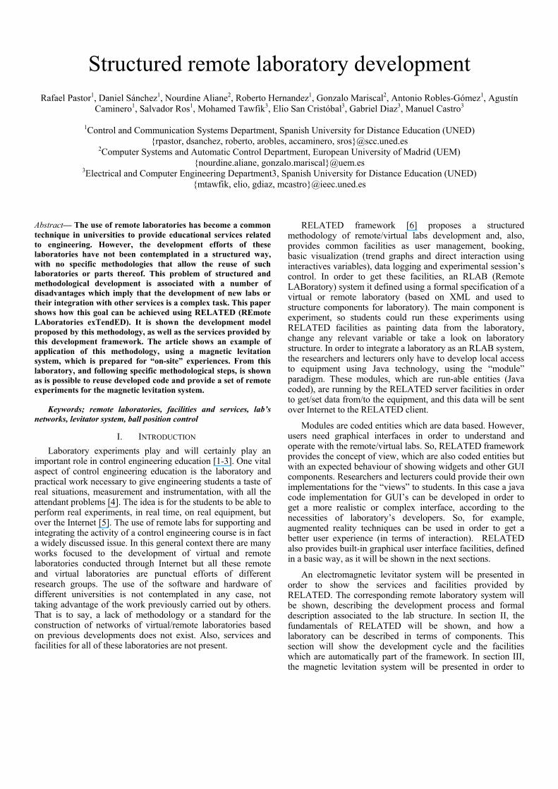
Structured remote laboratory development Rafael Pastor 1 , Daniel Sánchez 1 , Nourdine Aliane 2 , Roberto Hernandez 1 , Gonzalo Mariscal 2 , Antonio Robles-Gómez 1 , Agustín Caminero 1 , Salvador Ros 1 , Mohamed Tawfik 3 , Elio San Cristóbal 3 , Gabriel Diaz 3 , Manuel Castro 3 1 Control and Communication Systems Department, Spanish University for Distance Education (UNED) {rpastor, dsanchez, roberto, arobles, accaminero, sros}@scc.uned.es 2 Computer Systems and Automatic Control Department, European University of Madrid (UEM) {nourdine.aliane, gonzalo.mariscal}@uem.es 3 Electrical and Computer Engineering Department3, Spanish University for Distance Education (UNED) {mtawfik, elio, gdiaz, mcastro}@ieec.uned.es Abstract— The use of remote laboratories has become a common technique in universities to provide educational services related to engineering. However, the development efforts of these laboratories have not been contemplated in a structured way, with no specific methodologies that allow the reuse of such laboratories or parts thereof. This problem of structured and methodological development is associated with a number of disadvantages which imply that the development of new labs or their integration with other services is a complex task. This paper shows how this goal can be achieved using RELATED (REmote LAboratories exTendED). It is shown the development model proposed by this methodology, as well as the services provided by this development framework. The article shows an example of application of this methodology, using a magnetic levitation system, which is prepared for “on-site” experiences. From this laboratory, and following specific methodological steps, is shown as is possible to reuse developed code and provide a set of remote experiments for the magnetic levitation system. Keywords; remote laboratories, facilities and services, lab’s networks, levitator system, ball position control I. INTRODUCTION Laboratory experiments play and will certainly play an important role in control engineering education [1-3]. One vital aspect of control engineering education is the laboratory and practical work necessary to give engineering students a taste of real situations, measurement and instrumentation, with all the attendant problems [4]. The idea is for the students to be able to perform real experiments, in real time, on real equipment, but over the Internet [5]. The use of remote labs for supporting and integrating the activity of a control engineering course is in fact a widely discussed issue. In this general context there are many works focused to the development of virtual and remote laboratories conducted through Internet but all these remote and virtual laboratories are punctual efforts of different research groups. The use of the software and hardware of different universities is not contemplated in any case, not taking advantage of the work previously carried out by others. That is to say, a lack of methodology or a standard for the construction of networks of virtual/remote laboratories based on previous developments does not exist. Also, services and facilities for all of these laboratories are not present. RELATED framework [6] proposes a structured methodology of remote/virtual labs development and, also, provides common facilities as user management, booking, basic visualization (trend graphs and direct interaction using interactives variables), data logging and experimental session’s control. In order to get these facilities, an RLAB (Remote LABoratory) system it defined using a formal specification of a virtual or remote laboratory (based on XML and used to structure components for laboratory). The main component is experiment, so students could run these experiments using RELATED facilities as painting data from the laboratory, change any relevant variable or take a look on laboratory structure. In order to integrate a laboratory as an RLAB system, the researchers and lecturers only have to develop local access to equipment using Java technology, using the “module” paradigm. These modules, which are run-able entities (Java coded), are running by the RELATED server facilities in order to get/set data from/to the equipment, and this data will be sent over Internet to the RELATED client. Modules are coded entities which are data based. However, users need graphical interfaces in order to understand and operate with the remote/virtual labs. So, RELATED framework provides the concept of view, which are also coded entities but with an expected behaviour of showing widgets and other GUI components. Researchers and lecturers could provide their own implementations for the “views” to students. In this case a java code implementation for GUI’s can be developed in order to get a more realistic or complex interface, according to the necessities of laboratory’s developers. So, for example, augmented reality techniques can be used in order to get a better user experience (in terms of interaction). RELATED also provides built-in graphical user interface facilities, defined in a basic way, as it will be shown in the next sections. An electromagnetic levitator system will be presented in order to show the services and facilities provided by RELATED. The corresponding remote laboratory system will be shown, describing the development process and formal description associated to the lab structure. In section II, the fundamentals of RELATED will be shown, and how a laboratory can be described in terms of components. This section will show the development cycle and the facilities which are automatically part of the framework. In section III, the magnetic levitation system will be presented in order to
-
Upload
independent -
Category
Documents
-
view
0 -
download
0
Transcript of Structured remote laboratory development
Structured remote laboratory development
Rafael Pastor1, Daniel Sánchez1, Nourdine Aliane2, Roberto Hernandez1, Gonzalo Mariscal2, Antonio Robles-Gómez1, Agustín Caminero1, Salvador Ros1, Mohamed Tawfik3, Elio San Cristóbal3, Gabriel Diaz3, Manuel Castro3
1Control and Communication Systems Department, Spanish University for Distance Education (UNED)
{rpastor, dsanchez, roberto, arobles, accaminero, sros}@scc.uned.es 2Computer Systems and Automatic Control Department, European University of Madrid (UEM)
{nourdine.aliane, gonzalo.mariscal}@uem.es 3Electrical and Computer Engineering Department3, Spanish University for Distance Education (UNED)
{mtawfik, elio, gdiaz, mcastro}@ieec.uned.es
Abstract— The use of remote laboratories has become a common technique in universities to provide educational services related to engineering. However, the development efforts of these laboratories have not been contemplated in a structured way, with no specific methodologies that allow the reuse of such laboratories or parts thereof. This problem of structured and methodological development is associated with a number of disadvantages which imply that the development of new labs or their integration with other services is a complex task. This paper shows how this goal can be achieved using RELATED (REmote LAboratories exTendED). It is shown the development model proposed by this methodology, as well as the services provided by this development framework. The article shows an example of application of this methodology, using a magnetic levitation system, which is prepared for “on-site” experiences. From this laboratory, and following specific methodological steps, is shown as is possible to reuse developed code and provide a set of remote experiments for the magnetic levitation system.
Keywords; remote laboratories, facilities and services, lab’s networks, levitator system, ball position control
I. INTRODUCTION
Laboratory experiments play and will certainly play an important role in control engineering education [1-3]. One vital aspect of control engineering education is the laboratory and practical work necessary to give engineering students a taste of real situations, measurement and instrumentation, with all the attendant problems [4]. The idea is for the students to be able to perform real experiments, in real time, on real equipment, but over the Internet [5]. The use of remote labs for supporting and integrating the activity of a control engineering course is in fact a widely discussed issue. In this general context there are many works focused to the development of virtual and remote laboratories conducted through Internet but all these remote and virtual laboratories are punctual efforts of different research groups. The use of the software and hardware of different universities is not contemplated in any case, not taking advantage of the work previously carried out by others. That is to say, a lack of methodology or a standard for the construction of networks of virtual/remote laboratories based on previous developments does not exist. Also, services and facilities for all of these laboratories are not present.
RELATED framework [6] proposes a structured methodology of remote/virtual labs development and, also, provides common facilities as user management, booking, basic visualization (trend graphs and direct interaction using interactives variables), data logging and experimental session’s control. In order to get these facilities, an RLAB (Remote LABoratory) system it defined using a formal specification of a virtual or remote laboratory (based on XML and used to structure components for laboratory). The main component is experiment, so students could run these experiments using RELATED facilities as painting data from the laboratory, change any relevant variable or take a look on laboratory structure. In order to integrate a laboratory as an RLAB system, the researchers and lecturers only have to develop local access to equipment using Java technology, using the “module” paradigm. These modules, which are run-able entities (Java coded), are running by the RELATED server facilities in order to get/set data from/to the equipment, and this data will be sent over Internet to the RELATED client.
Modules are coded entities which are data based. However, users need graphical interfaces in order to understand and operate with the remote/virtual labs. So, RELATED framework provides the concept of view, which are also coded entities but with an expected behaviour of showing widgets and other GUI components. Researchers and lecturers could provide their own implementations for the “views” to students. In this case a java code implementation for GUI’s can be developed in order to get a more realistic or complex interface, according to the necessities of laboratory’s developers. So, for example, augmented reality techniques can be used in order to get a better user experience (in terms of interaction). RELATED also provides built-in graphical user interface facilities, defined in a basic way, as it will be shown in the next sections.
An electromagnetic levitator system will be presented in order to show the services and facilities provided by RELATED. The corresponding remote laboratory system will be shown, describing the development process and formal description associated to the lab structure. In section II, the fundamentals of RELATED will be shown, and how a laboratory can be described in terms of components. This section will show the development cycle and the facilities which are automatically part of the framework. In section III, the magnetic levitation system will be presented in order to
apply the development cycle using RELATED methodology (shown in section IV). Finally, conclusions will be presented in section V.
II. RELATED FUNDAMENTALS
RELATED provides a structured way of developing remote and virtual laboratories, focusing in lab definition and built-in facilities. To achieve this objective, these are the steps which are defined in the methodology:
A. Defining laboratory structure
Structuring the lab is one of the main tasks a developer/teacher must do in order to get a full laboratory description [7]. There are three main components which are necessary to describe the laboratory:
a) Modules. They are the basic part of development process and provides virtual/physycal access to lab data. They are “black boxed” used to decribe the component as a set of input/output variables. This paradigm allows the interconnection of modules, being possible to flow data between a module and others. Developers must provide read/write functions to get/set data for these variables.
b) Views. They provides the visual information to the final user (students, teachers, etc.). So, graphical interface can be included in these views in order to get a better user experiences. These views use data from modules to update the experiments state, and it is possible to send to modules values changed in the GUI (Graphical User Interface).
c) Experiments. They define the behavior expected from the lab, so one or more experiments can be defined on the lab. Basically, it is possible to define an experiment by stating the set of modules and views that will be used in the experiment. Any convenient combination of modules and views can be used as an experiment.
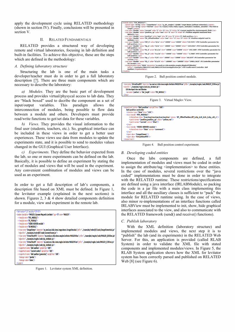
In order to get a full description of lab’s components, a description file based on XML must be defined. In Figure 1, the levitator example (explained in the next sections) is shown. Figures 2, 3 & 4 show detailed components definition for a module, view and experiment in the remote lab.
Figure 1. Levitator system XML definition.
Figure 2. Ball position control module.
Figure 3. Virtual Maglev View.
Figure 4. Ball position control experiment.
B. Developing coded entities
Once the labs components are defined, a full implementation of modules and views must be coded in order to assign the attribute/tag <implementation> to these entities. In the case of modules, several restrictions over the “java coded” implementations must be done in order to integrate with the RELATED runtime. These restrictions/specifications are defined using a java interface (IRLABModule), so packing the code in a jar file with a main class implementing this interface and all the auxiliary classes is sufficient to “pack” the module for RELATED runtime using. In the case of views, also minor re-implementations of an interface functions called IRLABView must be implemented to init, show, hide graphical interfaces associated to the view, and also to communicate with the RELATED framework (send() and receive() functions).
C. Publish laboratory
With the XML definition (laboratory structure) and implemented modules and views, the next step it is to “publish” the lab (and its experiments) in the RELATED Web Server. For this, an application is provided (called RLAB System) in order to validate the XML file with stated components and implemented modules/views. In Figure 5, the RLAB System application shows how the XML for levitator system has been correctly parsed and published on RELATED Web [8] (see Figure 6).

Figure 5. RLAB Publish Application.
Figure 6. RELATED Web Sercer: laboratory list for an user.
Once the laboratory is registered on main server, the lab is available to registered users in the RELATED Web Server. Not all users can access to the laboratory, only those are authorized to use it. Managers of laboratories can add permissions of use to the registered users in the RELATED web server, using authorization system (see Figure 7) associated to every laboratory published.
Figure 7. Remote/virtual laboratories available for an user in the RELATED
Web Server.
D. Run experiments
Finally, registered users with privileges can access the laboratory (managed by role). The RELATED Web Server can be used to run the experiments (defined in the XML specification for the lab), simply clicking the experiment name. A JWS (Java Web Start) application will be downloaded in the client computer (configured with the laboratory’s network parameters). If the Internet navigator is properly configured, then the JWS application will start automatically and it will be show the login control facility (see Figure 8). User login data must be filled in order to show the experiment control panel (see Figure 9)
Figure 8. User login in the client application.
Figure 9. Experiment control panel.
The experiment control panel provides automatically some facilities as:
- Booking slot time. For every experiment which can be carried out, a slot time is assigned to avoid multiples concurrent users. This slot time can be set using the booking system provided by RELATED, so a start and a finish date is assigned to the running experiment and the user. This slot time is represented on the upper left corner of the experiment control, using a three colour state clock which also presents the start and finish dates/times (see Figure 10). Green colour represents free time for using experiment, where as yellow indicates less than 10% of booking time and red colour is used to indicate the finishing of slot time.
Figure 10. Booking clock on experiment panel.
- Experiment time. Values of experiment starting time and actual time are presented to users in order to know time evolution for its experiment.

- Graphical trends. It is possible to get trend information about variables in the modules which are included in the experiment definition. It is very useful when the graphical interface do not include that feature (for example, for test purposes) or simply the built-in trend graphs are sufficient for the experiment. In order to add this feature, simply it has to be added a special <paint> tag in the experiment definition, indicating the variables to be painted. Also, it is possible to add several <paint> tags to group some variables which are related to some functionality (for example, a measured value with its referenced set point). Every group is presented in the experiment control panel as a tab in the lower left part (see Figure 9).
- Interactive variables. Usually a view is used to change some variables in one or more modules, but in simple experiments it is possible to define a set of interactive variables to be set on the experiment control panel. To do this, another special tag can be included in the experiment definition (tag <interactives>) in order to get a graphical interface for these variables in the experiment control panel. On the lower right part of the experiment control panel shows the set of interactives variables (usually associated with a module, one tab by module) as it can be seen on Figure 9. Every variable in this set can be modified using a built-in editor for the type of the variable (double, boolean, string, etc.).
Once the experiment control panel it is shown, to run an experiment users has to press the start experiment button and the experiment will be running in the remote labs, updating automatically the views, trends graphs, and set of interactive variables. The experiment will stop when user press again the stop button or if the time assigned to the experiment is finished.
In the next section, an overview of the development process for a levitator system will be presented in order to demonstrate the features of RELATED.
III. LEVITATOR ON-SITE LABORATORY
Quanser [9] has on-site didactical equipment called MAGLEV (MAGnetic LEVitation system) [10], see Figure 11 (a). The MAGLEV system provides a magnetic field in order to get an air steel ball levitating. The MAGLEV can be described by three distinct sections encased in a rectangular enclosure. First, the upper section contains an electromagnet, made of a solenoid coil with a steel core. Second, the middle section consists of an inside chamber where the magnetic ball suspension actually takes place. One of the electromagnet poles faces the top of a black post upon which a one-inch steel ball rests. The ball elevation from the post top is measured using a photo-sensitive sensor embedded in the post. The post is designed in such a way that when the ball rests on top of it, the air gap between the ball’s top hemisphere and the electromagnet pole face is 14 mm. The post also provides repeatable initial conditions for control system performance evaluation. Finally, the bottom section of the MAGLEV apparatus houses the system’s conditioning circuitry needed, for example, by the light intensity position sensor. Also, both offset and gain potentiometers of the ball position sensor are readily available for proper calibration. A current sense resistor
is also included in the design in order to provide for coil current measurement if necessary.
Figure 11. MAGLEV system: real (a) and virtual (b).
The MAGLEV system provides two experiments to be carried out: coil current control and ball position control. Both of that are based on the assumption that students will run these experiments in the same “location” as the equipment is laid. So, for this, QUANSER provides software called QUARC which allows to student interact with the MAGLEV system using Matlab/Simulink [11]. In a first step, a Simulink model is built to access to the MAGLEV system. Then, this model is used to generate a pseudo-real time (in Windows) program which run in a specific QUANSER usb card (Q2). Finally the model is uploaded in the usb card and executed from this card. From the point of view of an on-site experience is very simple to carry out the experiments, but from a “remote lab” perspective some modifications must be done in order to get a real remote lab.
In the next section will be show how it is the MAGLEV
reconfigured and the control software is reused using the RELATED framework.
IV. LEVITATOR REMOTE LAB
In order to reconfigure the on-site lab hardware, the first step is to avoid manual procedures associated with the on-site experiences. The main problem associate with on-site experiences is due to the steel ball falls outside the post when the coil is down (set to 0). So, MAGLEV equipment was to be reconfigured, surrounding the post with a plastic cylinder. Using this hardware reconfiguration, the steel ball never falls out and no manual procedures are required.
The next step is to define MAGLEV laboratory and to reconfigure software procedures, as it is explained in the next sub-sections.
(a) (b)
A. Laboratory specificaction
The MAGLEV system, as it was mention before, allows two types of control experiences, so in this case two modules for the laboratory must be defined:
a) PI_MODULE. Coil current control experience which has several variables: current command set point, measured values from the MAGLEV (voltage, coil current, ball position, and measured current set point, in order to check current comand set point changes), PI controller parameters (named Kc_p and Kp_i) and a boolean value to use a built-in osccilator included in the module. This module will allow to change current command set point, Kc_p, Kc_i and oscillator values.
b) PIV_MODULE. Ball position control experience. For this experience, a feed forward controller on the position ball is applied and the coil current PI control is also used (in order to stabilize the internal loop for current).Variables associated to this module are similar to the PI_MODULE, but also include the controller parameters for the feedforward controller: Kff_b, Kp_b, Ki_b and Kv_b. Of course, a setpoint on the ball position variable is included but is an offset of the air gap defined for the ball position (the air gap is 9 mm). In Figure 2, the XML definition for this module is shown.
Also, two auxiliar modules are used: one associate to a signal generator for setpoints (SG_MODULE) and another associated to the video streaming (VIDEO SERVER module) which allows to get a real time image of the MAGLEV system).
Also, to get a more detailed view of the remote MAGLEV system, two views are defined: one to represent the MAGLEV system (MAGLEV Virtual View, shown in Figure 11 (b)) and another to view a real time image of steel ball (ImageViewer, see the XML definition on Figure 3). This last view (combined with the video server module) is used in several laboratories, as the QET motor.
Finally, a set of experiments can be defined using these last modules and views:
a) Current control. This experiment represents the coil current control experiences and its definition include the use of the PI_MODULE, the VIDEO SERVER module and the two views (ImageViewer and MAGLEV Virtual View).
b) Ball position. Ball position controlled experience. In this case, the modules which are used are the PIV_MODULE and the VIDEO SERVER module. The views are the same included in the Currrent control experiment (see the XML definition on Figure 4).
c) Ball position (generator). It is similar to the above experiment, but also include the SG_MODULE module in order to use the signal generator for the ball position.
In Figure 1, it is shown the components defined with XML for the MAGLEV system (with no details about components).
B. Modules development
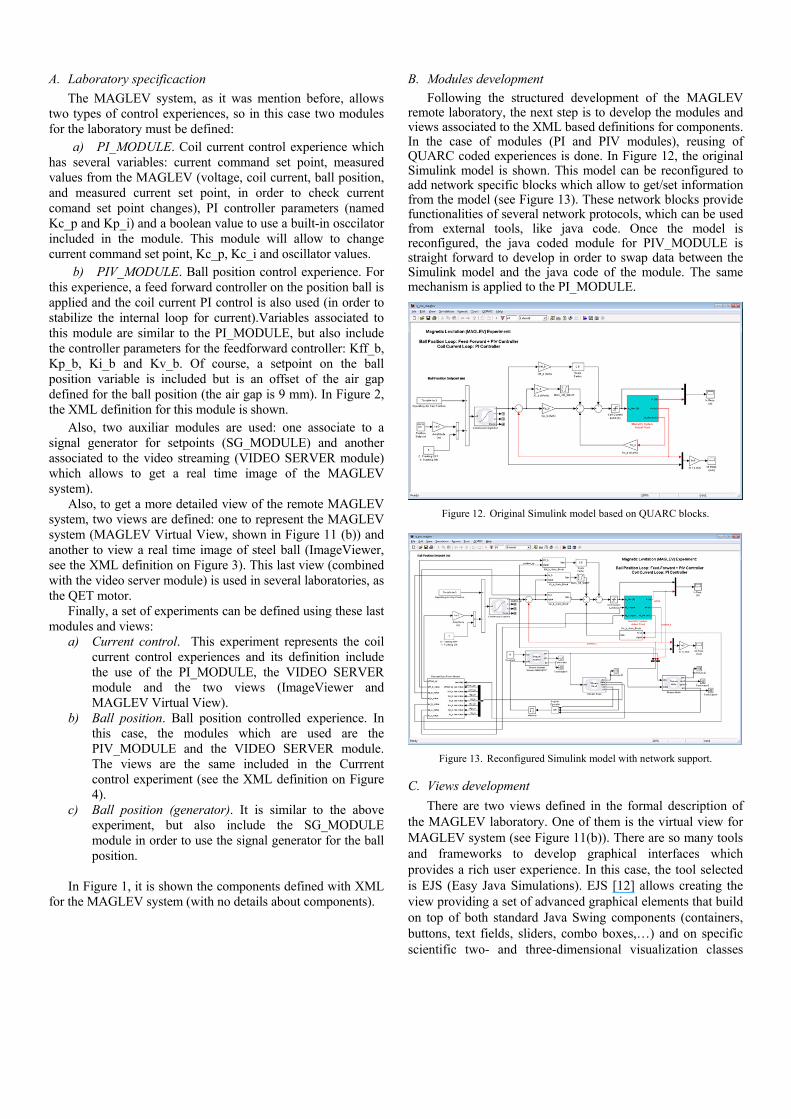
Following the structured development of the MAGLEV remote laboratory, the next step is to develop the modules and views associated to the XML based definitions for components. In the case of modules (PI and PIV modules), reusing of QUARC coded experiences is done. In Figure 12, the original Simulink model is shown. This model can be reconfigured to add network specific blocks which allow to get/set information from the model (see Figure 13). These network blocks provide functionalities of several network protocols, which can be used from external tools, like java code. Once the model is reconfigured, the java coded module for PIV_MODULE is straight forward to develop in order to swap data between the Simulink model and the java code of the module. The same mechanism is applied to the PI_MODULE.
Figure 12. Original Simulink model based on QUARC blocks.
Figure 13. Reconfigured Simulink model with network support.
C. Views development
There are two views defined in the formal description of the MAGLEV laboratory. One of them is the virtual view for MAGLEV system (see Figure 11(b)). There are so many tools and frameworks to develop graphical interfaces which provides a rich user experience. In this case, the tool selected is EJS (Easy Java Simulations). EJS [12] allows creating the view providing a set of advanced graphical elements that build on top of both standard Java Swing components (containers, buttons, text fields, sliders, combo boxes,…) and on specific scientific two- and three-dimensional visualization classes
from the Open Source Physics project (particles, vectors, images, vector and scalar fields,…). These elements are used in a simple drag-and-drop way to build the interface. EJS generate a set of classes which can be reused in the code representening the view, so minor modifications must be set in the “view” code before include these classes. Following this procedure, it is very simple to develop virtual views and include them as graphical interfaces in a remote laboratory, not only in this case but in so meny more.
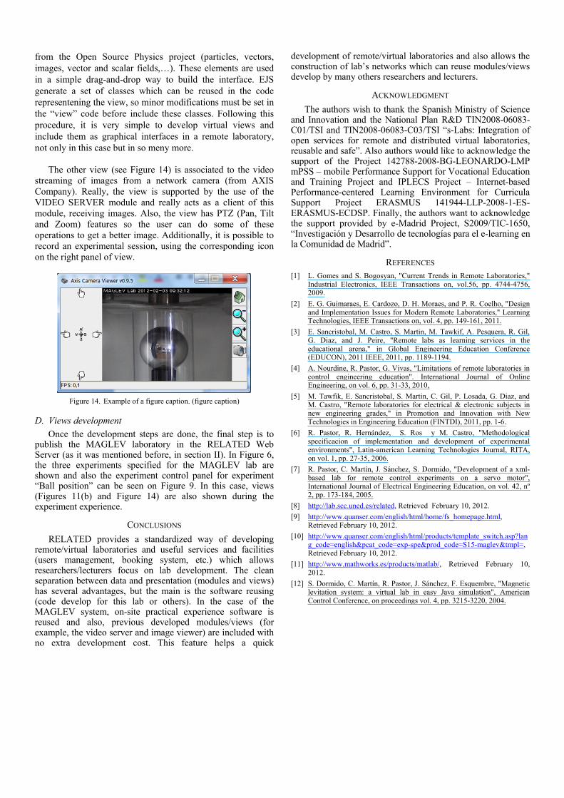
The other view (see Figure 14) is associated to the video
streaming of images from a network camera (from AXIS Company). Really, the view is supported by the use of the VIDEO SERVER module and really acts as a client of this module, receiving images. Also, the view has PTZ (Pan, Tilt and Zoom) features so the user can do some of these operations to get a better image. Additionally, it is possible to record an experimental session, using the corresponding icon on the right panel of view.
Figure 14. Example of a figure caption. (figure caption)
D. Views development
Once the development steps are done, the final step is to publish the MAGLEV laboratory in the RELATED Web Server (as it was mentioned before, in section II). In Figure 6, the three experiments specified for the MAGLEV lab are shown and also the experiment control panel for experiment “Ball position” can be seen on Figure 9. In this case, views (Figures 11(b) and Figure 14) are also shown during the experiment experience.
CONCLUSIONS
RELATED provides a standardized way of developing remote/virtual laboratories and useful services and facilities (users management, booking system, etc.) which allows researchers/lecturers focus on lab development. The clean separation between data and presentation (modules and views) has several advantages, but the main is the software reusing (code develop for this lab or others). In the case of the MAGLEV system, on-site practical experience software is reused and also, previous developed modules/views (for example, the video server and image viewer) are included with no extra development cost. This feature helps a quick
development of remote/virtual laboratories and also allows the construction of lab’s networks which can reuse modules/views develop by many others researchers and lecturers.
ACKNOWLEDGMENT
The authors wish to thank the Spanish Ministry of Science and Innovation and the National Plan R&D TIN2008-06083-C01/TSI and TIN2008-06083-C03/TSI “s-Labs: Integration of open services for remote and distributed virtual laboratories, reusable and safe”. Also authors would like to acknowledge the support of the Project 142788-2008-BG-LEONARDO-LMP mPSS – mobile Performance Support for Vocational Education and Training Project and IPLECS Project – Internet-based Performance-centered Learning Environment for Curricula Support Project ERASMUS 141944-LLP-2008-1-ES-ERASMUS-ECDSP. Finally, the authors want to acknowledge the support provided by e-Madrid Project, S2009/TIC-1650, “Investigación y Desarrollo de tecnologías para el e-learning en la Comunidad de Madrid”.
REFERENCES [1] L. Gomes and S. Bogosyan, "Current Trends in Remote Laboratories,"
Industrial Electronics, IEEE Transactions on, vol.56, pp. 4744-4756, 2009.
[2] E. G. Guimaraes, E. Cardozo, D. H. Moraes, and P. R. Coelho, "Design and Implementation Issues for Modern Remote Laboratories," Learning Technologies, IEEE Transactions on, vol. 4, pp. 149-161, 2011.
[3] E. Sancristobal, M. Castro, S. Martin, M. Tawkif, A. Pesquera, R. Gil, G. Diaz, and J. Peire, "Remote labs as learning services in the educational arena," in Global Engineering Education Conference (EDUCON), 2011 IEEE, 2011, pp. 1189-1194.
[4] A. Nourdine, R. Pastor, G. Vivas, "Limitations of remote laboratories in control engineering education". International Journal of Online Engineering, on vol. 6, pp. 31-33, 2010,
[5] M. Tawfik, E. Sancristobal, S. Martin, C. Gil, P. Losada, G. Diaz, and M. Castro, "Remote laboratories for electrical & electronic subjects in new engineering grades," in Promotion and Innovation with New Technologies in Engineering Education (FINTDI), 2011, pp. 1-6.
[6] R. Pastor, R. Hernández, S. Ros y M. Castro, "Methodological specificacion of implementation and development of experimental environments", Latin-american Learning Technologies Journal, RITA, on vol. 1, pp. 27-35, 2006.
[7] R. Pastor, C. Martín, J. Sánchez, S. Dormido, "Development of a xml-based lab for remote control experiments on a servo motor", International Journal of Electrical Engineering Education, on vol. 42, nº 2, pp. 173-184, 2005.
[8] http://lab.scc.uned.es/related, Retrieved February 10, 2012.
[9] http://www.quanser.com/english/html/home/fs_homepage.html, Retrieved February 10, 2012.
[10] http://www.quanser.com/english/html/products/template_switch.asp?lang_code=english&pcat_code=exp-spe&prod_code=S15-maglev&tmpl=, Retrieved February 10, 2012.
[11] http://www.mathworks.es/products/matlab/, Retrieved February 10, 2012.
[12] S. Dormido, C. Martín, R. Pastor, J. Sánchez, F. Esquembre, "Magnetic levitation system: a virtual lab in easy Java simulation", American Control Conference, on proceedings vol. 4, pp. 3215-3220, 2004.