LAB MANUAL - JECRC Foundation
97
JAIPUR ENGINEERING COLLEGE AND RESEARCH CENTRE JECRC Campus, Shri Ram Ki Nangal, Via-Vatika, Jaipur LAB MANUAL Lab Name : Vibration Engineering Lab Lab Code : 6ME4-22 Branch : Mechanical Engineering Year : 3 rd Year Department of Mechanical Engineering Jaipur Engineering College and Research Center, Jaipur (Rajasthan Technical University, KOTA)
-
Upload
khangminh22 -
Category
Documents
-
view
0 -
download
0
Transcript of LAB MANUAL - JECRC Foundation

JAIPUR ENGINEERING COLLEGE AND RESEARCH CENTRE
JECRC Campus, Shri Ram Ki Nangal, Via-Vatika, Jaipur
LAB MANUAL
Lab Name : Vibration Engineering Lab
Lab Code : 6ME4-22
Branch : Mechanical Engineering
Year : 3rd Year
Department of Mechanical Engineering
Jaipur Engineering College and Research Center, Jaipur
(Rajasthan Technical University, KOTA)

JAIPUR ENGINEERING COLLEGE AND RESEARCH CENTRE
JECRC Campus, Shri Ram Ki Nangal, Via-Vatika, Jaipur
i
INDEX
S.NO CONTENTS PAGE
NO.
1 VISION/MISION III
2. PROGRAM EDUCATIONAL OBJECTIVES (PEOs) IV
3. PROGRAM OUTCOMES (POs) V
4. COURSE OUTCOMES (COs) VI
5. MAPPING OF COs with POs
VII
6. SYLLABUS VIII
7. BOOKS X
8. INSTRUCTIONAL METHODS XI
9. LEARNING MATERIALS XII
10. ASSESSMENT OF OUTCOMES XIII
11 INSTRUCTIONS SHEET XIV
Exp:- 1 Objectives :- To verify relation T = 2π (l/g)1/2 for a simple pendulum. 1
Exp:- 2 Objectives :- To determine radius of gyration of compound pendulum. 6
Exp:-3 Objectives :- To determine the radius of gyration of given bar by using trifilar
suspension.
10
Exp:-4 Objectives: - To determine natural frequency of a spring mass system. 14

JAIPUR ENGINEERING COLLEGE AND RESEARCH CENTRE
JECRC Campus, Shri Ram Ki Nangal, Via-Vatika, Jaipur
ii
Exp:-5 Objectives: - Study of equivalent spring mass system. 19
Exp:-6 Objectives: - To determine natural frequency of free torsional vibrations of
single rotor system.
i. Horizontal rotor
ii. Vertical rotor
23
Exp:-7 Objectives: - To verify the Dunkerley’s rule. 29
Exp:-8 Objectives: - Performing the experiment to find out damping co-efficient in
case of free damped torsional vibration.
34
Exp:-9 Objectives: - To conduct experiment of trifler suspension. 37
Exp:-10 Objectives: - Harmonic excitation of cantilever beam using electro-dynamic
shaker and determination of resonant frequencies
41
Exp:- 11 Objectives: - Study of Vibration measuring instruments.
44
Exp:- 12 Objectives:- Perform study of the following using Virtual Lab
http://www.vlab.co.in/
49
Exp:- 13 Objectives:- Forced Vibration of a Cantilever Beam with a Lumped Mass at
Free End:To calculate the natural frequency and damping ratio for forced
vibration of a single DOF cantilever beam system, experimentally; and
compare the results with theoretical values.
51
Exp:- 14 Objectives:- Harmonicaly Excited Forced Vibration of a Single DOF System:
To analyze the forced vibration response of a single DOF system at different
damping ratio and frequency ratio.
54
Exp:- 15 Objectives:-Perform study of the following using Virtual Lab
http://www.vlab.co.in/
58

JAIPUR ENGINEERING COLLEGE AND RESEARCH CENTRE
JECRC Campus, Shri Ram Ki Nangal, Via-Vatika, Jaipur
iii
Exp:- 16 Objectives:- Forced Vibration of a Cantilever Beam with a Lumped Mass at
Free End:
To calculate the natural frequency and damping ratio for forced vibration
of a single DOF cantilever beam system, experimentally; and compare
the results with theoretical values.
60
Exp:- 17 Objectives:- Harmonicaly Excited Forced Vibration of a Single DOF System:
To analyze the forced vibration response of a single DOF system at different
damping ratio and frequency ratio.
63
1. VISION & MISSION
VISION:
➢ The Mechanical Engineering Department strives to be recognized globally for
outcome based technical knowledge and to produce quality human resource, who can
manage the advance technologies and contribute to society.
MISSION:
1. To impart quality technical knowledge to the learners to make them globally competitive
mechanical engineers.
2. To provide the learners ethical guidelines along with excellent academic environment for a
long productive career.
3. To promote industry-institute relationship.

JAIPUR ENGINEERING COLLEGE AND RESEARCH CENTRE
JECRC Campus, Shri Ram Ki Nangal, Via-Vatika, Jaipur
iv
2. PROGRAM EDUCATIONAL OBJECTIVES
1. To provide students with the fundamentals of Engineering Sciences with more
emphasis in Mechanical Engineering by way of analyzing and exploiting engineering
challenges.
2. To train students with good scientific and engineering knowledge so as to
comprehend, analyze, design, and create novel products and solutions for the real life
problems.
3. To inculcate professional and ethical attitude, effective communication skills,
teamwork skills, multidisciplinary approach, entrepreneurial thinking and an ability to
relate engineering issues with social issues.
4. To provide students with an academic environment aware of excellence, leadership,
written ethical codes and guidelines, and the self-motivated life-long learning needed
for a successful professional career.
5. To prepare students to excel in Industry and Higher education by Educating Students
along with High moral values and Knowledge.

JAIPUR ENGINEERING COLLEGE AND RESEARCH CENTRE
JECRC Campus, Shri Ram Ki Nangal, Via-Vatika, Jaipur
v
3. PROGRAM OUTCOMES
1. Engineering knowledge: Apply the knowledge of mathematics, science, engineering
fundamentals, and an engineering specialization to the solution of complex engineering
problems.
2. Problem analysis: Identify, formulate, research literature, and analyze complex engineering
problems reaching substantiated conclusions using first principles of mathematics, natural
sciences, and engineering sciences.
3. Design/development of solutions: Design solutions for complex engineering problems and
design system components or processes that meet the specified needs with appropriate
consideration for the public health and safety, and the cultural, societal, and environmental
considerations.
4. Conduct investigations of complex problems: Use research-based knowledge and research
methods including design of experiments, analysis and interpretation of data, and synthesis of
the information to provide valid conclusions.
5. Modern tool usage: Create, select, and apply appropriate techniques, resources, and modern
engineering and IT tools including prediction and modeling to complex engineering activities
with an understanding of the limitations.
6. The engineer and society: Apply reasoning informed by the contextual knowledge to assess
societal, health, safety, legal and cultural issues and the consequent responsibilities relevant to
the professional engineering practice.
7. Environment and sustainability: Understand the impact of the professional engineering
solutions in societal and environmental contexts, and demonstrate the knowledge of, and need
for sustainable development.
8. Ethics: Apply ethical principles and commit to professional ethics and responsibilities and
norms of the engineering practice.
9. Individual and team work: Function effectively as an individual, and as a member or leader
in diverse teams, and in multidisciplinary settings.
10.Communication: Communicate effectively on complex engineering activities with the
engineering community and with society at large, such as, being able to comprehend and write
effective reports and design documentation, make effective presentations, and give and receive
clear instructions.
11. Project management and finance: Demonstrate knowledge and understanding of the
engineering and management principles and apply these to one’s own work, as a member and
leader in a team, to manage projects and in multidisciplinary environments.

JAIPUR ENGINEERING COLLEGE AND RESEARCH CENTRE
JECRC Campus, Shri Ram Ki Nangal, Via-Vatika, Jaipur
vi
12. Life-long learning: Recognize the need for, and have the preparation and ability to engage
in independent and life-long learning in the broadest context of technological change.
4. COURSE OUTCOMES
Vibration Engineering Lab [6ME4-22]
Class: 6th Sem. B.Tech. 3rd Year Branch: Mechanical Engineering
Schedule per Week Practical Hrs.: 2 Examination Time = 2 Hours
Maximum Marks = [Sessional/Mid-term (45 ) & End-term (30 )]
On successful completion of this course the students will be able to:
CO-1 To determine the natural frequency of vibration problems that contains single and multi-
degree of freedom systems.
CO-2 To calculate the damping coefficient of single and multi-degree of freedom systems.

JAIPUR ENGINEERING COLLEGE AND RESEARCH CENTRE
JECRC Campus, Shri Ram Ki Nangal, Via-Vatika, Jaipur
vii
5. MAPPING OF COs with POs
2
COURSE
OUTCOMES
PROGRAM OUTCOMES
1 2 3 4 5 6 7 8 9 10 11 12
I 3 3 2 0 2 1 0 0 2 1 2 2
II 3 3 1 2 3 2 1 1 2 1 3 1

JAIPUR ENGINEERING COLLEGE AND RESEARCH CENTRE
JECRC Campus, Shri Ram Ki Nangal, Via-Vatika, Jaipur
viii
6. SYLLABUS
6ME10A: VIBRATION ENGINEERING LAB
Class: 6th Sem. B. Tech. 3rs year Evaluation
Branch: ME
Schedule per week
Practical Hrs: (2 )
Examination Time=Two ( 2) Hours
Maximum Marks = 75
[Sessional/Mid-term (45 ) & End-term(30 )]
S.N. NAME OF EXPERIMENT
Exp:- 1 Objectives :- To verify relation T = 2π (l/g)1/2 for a simple pendulum.
Exp:- 2 Objectives :- To determine radius of gyration of compound pendulum.
Exp:-3 Objectives :- To determine the radius of gyration of given bar by using bifilar
suspension.
Exp:-4 Objectives: - To determine natural frequency of a spring mass system.
Exp:-5 Objectives: - Study of equivalent spring mass system.
Exp:-6 Objectives: - To determine natural frequency of free torsional vibrations of single
rotor system.
i. Horizontal rotor
ii. Vertical rotor
Exp:-7 Objectives: - To verify the Dunkerley’s rule.
Exp:-8 Objectives: - Performing the experiment to find out damping co-efficient in case of
free damped torsional vibration.
Exp:-9 Objectives: - To conduct experiment of trifler suspension.

JAIPUR ENGINEERING COLLEGE AND RESEARCH CENTRE
JECRC Campus, Shri Ram Ki Nangal, Via-Vatika, Jaipur
ix
Exp:-10 Objectives: - Harmonic excitation of cantilever beam using electro-dynamic shaker
and determination of resonant frequencies
Exp:- 11 Objectives: - Study of Vibration measuring instruments.
Exp:- 12 Objectives:- Perform study of the following using Virtual Lab http://www.vlab.co.in/
Exp:- 13 Objectives:- Forced Vibration of a Cantilever Beam with a Lumped Mass at Free
End:To calculate the natural frequency and damping ratio for forced vibration of a
single DOF cantilever beam system, experimentally; and compare the results with
theoretical values.
Exp:- 14 Objectives:- Harmonicaly Excited Forced Vibration of a Single DOF System: To
analyze the forced vibration response of a single DOF system at different
damping ratio and frequency ratio.
Exp:- 15 Objectives:-Perform study of the following using Virtual Lab http://www.vlab.co.in/
Exp:- 16 Objectives:- Forced Vibration of a Cantilever Beam with a Lumped Mass at Free
End: To calculate the natural frequency and damping ratio for forced vibration of a
single DOF cantilever beam system, experimentally; and compare the results with
theoretical values.
Exp:- 17 Objectives:- Harmonicaly Excited Forced Vibration of a Single DOF System: To
analyze the forced vibration response of a single DOF system at different damping
ratio and frequency ratio.

JAIPUR ENGINEERING COLLEGE AND RESEARCH CENTRE
JECRC Campus, Shri Ram Ki Nangal, Via-Vatika, Jaipur
x
7. BOOKS
7.1 Text books:-
1) G.K. Grover “Mechanical Vibrations”Nem Chand & Bros
7.2 Reference Books:-
1.) Rattan S.S.: Theory of Machines, Tata McGraw Hill
2.) Kewal Pujara: Vibrations & Noise control, Dhanpat Rai & Co
8. INSTRUCTIONAL METHODS
8.1. Direct Instructions:
I. Black board presentation.
II. Power point presentation.
8.2. Interactive Instruction:
I. Practical on respective equipment.
II. Practical Examples.
8.3. Indirect Instructions:
I. Problem solving

JAIPUR ENGINEERING COLLEGE AND RESEARCH CENTRE
JECRC Campus, Shri Ram Ki Nangal, Via-Vatika, Jaipur
xi
9. LEARNING MATERIALS
9.1. Lab Manual
9.2. Reference Books
10. ASSESSMENT OF OUTCOMES
10.1 End term Practical exam (Conducted by RTU, KOTA)
10.2 Quiz
10.3 Daily Lab interaction.

JAIPUR ENGINEERING COLLEGE AND RESEARCH CENTRE
JECRC Campus, Shri Ram Ki Nangal, Via-Vatika, Jaipur
xii
11. INSTRUCTIONS SHEET
We need your full support and cooperation for smooth functioning of the lab.
DO’s
1. Please switch off the Mobile/Cell phone before entering lab.
2. Intimate the lab incharge whenever you are incompatible in using the system or
in case machine get infected.
3. Arrange all the peripheral and seats before leaving the lab.
4. Properly shutdown the experimental set up before leaving the lab.
5. Keep the bag outside in the racks.
6. Enter the lab on time and leave at proper time.
7. Maintain the decorum of the lab.
8. Utilize lab hours in the corresponding experiment..
DON’TS
1. Don’t mishandle the Machine.
2. Don’t leave the machine ON for long time when in not in use.
3. Don’t bring any external material in the lab.
4. Don’t make noise in the lab.
5. Don’t bring the mobile in the lab. If extremely necessary then keep ringers off.
6. Don’t enter in the lab without permission of lab Incharge.
7. Don’t carry any lab equipments outside the lab.
BEFORE ENTERING IN THE LAB
1. All the students are supposed to prepare the theory regarding the next experiment
2. Students are supposed to bring the practical file and the lab copy.
3. Previous practical should be written in the practical file.
4. Any student not following these instructions will be denied entry in the lab.
WHILE WORKING IN THE LAB
1. Adhere to experimental schedule as instructed by the lab incharge.
2. Get the previously executed program signed by the instructor.
3. Get the output of the current program checked by the instructor in the lab copy.
4. Each student should work on his/her assigned computer at each turn of the lab.

JAIPUR ENGINEERING COLLEGE AND RESEARCH CENTRE
JECRC Campus, Shri Ram Ki Nangal, Via-Vatika, Jaipur
xiii
5. Take responsibility of valuable accessories.
6. Concentrate on the assigned practical and do not play games.
7. If anyone caught red handed carrying any equipment of the lab, then he will have to
face serious consequences

JAIPUR ENGINEERING COLLEGE AND RESEARCH CENTRE
JECRC Campus, Shri Ram Ki Nangal, Via-Vatika, Jaipur
1
Experiment No. 1
AIM:
To Verify the relation of simple pendulam.
T= 2 π
Where T = Periodic time in sec.
L = Length of pendulum in cm.
APPARATUS:
A steel ball, a massless string, a scale, a stopwatch.

JAIPUR ENGINEERING COLLEGE AND RESEARCH CENTRE
JECRC Campus, Shri Ram Ki Nangal, Via-Vatika, Jaipur
2
Figure 1.1: SIMPLE PENDULUM

JAIPUR ENGINEERING COLLEGE AND RESEARCH CENTRE
JECRC Campus, Shri Ram Ki Nangal, Via-Vatika, Jaipur
3
Figure 1.2: Experimental Set up of Simple Pendulum
DESCRIPTION:
For conduction the experiment, a ball is supported by nylon thread into a chuck. It is possible
to change the length of pendulum. This makes it possible to study the effect of variation of
length on periodic time. A small ball may be substituted by large ball to illustrate that period
of oscillation is independent of the mass of ball.
Simple pendulum
By equilibrium of forces we have;

JAIPUR ENGINEERING COLLEGE AND RESEARCH CENTRE
JECRC Campus, Shri Ram Ki Nangal, Via-Vatika, Jaipur
4
mg = T cos dθ ≈ T ……..(1)
By S.H.M equation we have;
T sin dθ = mω2 x ……..(2)
we have; x = l sin dθ
Hence eqn.(2) becomes
T sin dθ = mω2 l sin dθ
T = mω2 l ……..(3)
From (1) and (3)
mg = mω2 l
ω2 = (g / l) ;ω = √(g/l)
We have ; ω = 2 π / T
Hence, T = 2π √(l/g)
PROCEDURE:
1. Attach the ball to one end of the thread.
2. Allow ball to oscillate and determine the periodic time T by knowing the time for say
10 oscillations.
3. Repeat the experiment by changing the length.
4. Complete the observation table given below
STANDARD DATA:
Weight of small ball = 32 gms.
Weight of big ball = 102.34 gms.
Acceleration due to gravity, g = 9.81 m / s².
FORMULAE:

JAIPUR ENGINEERING COLLEGE AND RESEARCH CENTRE
JECRC Campus, Shri Ram Ki Nangal, Via-Vatika, Jaipur
5
1. Time Period, TActual = t / n sec.
2. Time Period, T Theo. = 2 π sec.
Where,
t = Time taken by ‘n ’ oscillations.
n = Nos. of oscillation.
L = Length of the pendulum.
OBSERVATION & CALCULATION TABLE:
Sr. No. Weight of
Ball
L cms. No. of Osc.
‘n’
Time for n Osc.
‘t’ sec.
T sec.
(Expt.) t/n
T sec.
(Theo.)
1.
2.
3.
4.
RESULT:
Plot the graph of T ² Vs. L. It should yield the straight line.
PRECAUTIONS:

JAIPUR ENGINEERING COLLEGE AND RESEARCH CENTRE
JECRC Campus, Shri Ram Ki Nangal, Via-Vatika, Jaipur
6
1. Do not run the motor at low voltage i.e. less than 180 volts.
2. Do not increase the speed at once.
3. Damper is always in perpendicular direction.
4. A motor bolts is properly tightly with weight.
5. A beam is proper tight in bearing with bolt.
6. Always keep the apparatus free from dust.
APPLICATIONS
The pendulum swings back and forth at exact intervals determined by the length at which
thependulum is suspended. To measure time accurately, a pendulum clock must remain
stationary
EXPECTED OUTCOME:
COMMENT BY STUDENT:
VIVA VOCE
1. Define transverse and longitudinal wave?

JAIPUR ENGINEERING COLLEGE AND RESEARCH CENTRE
JECRC Campus, Shri Ram Ki Nangal, Via-Vatika, Jaipur
7
2. Define sound wave in air?
3. Define the frequency?
4. Define dB and dBm?
5. Define noise?

JAIPUR ENGINEERING COLLEGE AND RESEARCH CENTRE
JECRC Campus, Shri Ram Ki Nangal, Via-Vatika, Jaipur
8
Experiment No. 2
AIM:
To determine the radius of gyration 'k' of a given compound pendulum.
T = 2π
Where,
T = Periodic time in sec.
k = Radius of gyration about the C.G. in cm.
OG = Distance of C.G. of the rod from support.
L = Length of suspended pendulum.
APPARATUS:
A compound pendulum, a scale, a stopwatch.

JAIPUR ENGINEERING COLLEGE AND RESEARCH CENTRE
JECRC Campus, Shri Ram Ki Nangal, Via-Vatika, Jaipur
9
Fig. 2 Experimental set up for compound pendulam
DESCRIPTION:
The compound pendulum consists of a steel bar. The bar is supported by knife edge. Two
pendulum of different lengths are provided with the set-up.
PROCEDURE:
1. Support the rod on knife -edge.
2. Note the length of suspended pendulum and detennine OG.
3. Allow the bar to oscillate and determine T by knowing the time for say 10 oscillations.
4. Repeat the experiment with different length of suspension.

JAIPUR ENGINEERING COLLEGE AND RESEARCH CENTRE
JECRC Campus, Shri Ram Ki Nangal, Via-Vatika, Jaipur
10
5. Complete the observation table given below.
STANDARD DATA:
Length of compound pendulum (1) = 80 cm.
Length of compound pendulum (2) = 60 cm.
FORMULAE:
1. Actual time period, T act = t/n
2. Actual radius of gyration, k act from the equation
T = 2π
3. Theoretical radius of gyration, ktheo =
OBSERVATION & CALCULATION TABLE:
Length of the compound pendulum = ------- cm.
Sr. No. L cm. OG No. of Ocn. Time for Osc. T Expt. k Expt. k

JAIPUR ENGINEERING COLLEGE AND RESEARCH CENTRE
JECRC Campus, Shri Ram Ki Nangal, Via-Vatika, Jaipur
11
n' theoretical
1
2
3
RESULT:
Radius of gyration is calculated and found to match with the relation T = 2π
hence experiment is verified.
PRECAUTIONS:
1. Do not run the motor at low voltage i.e. less than 180 volts.
2. Do not increase the speed at once.
3. Damper is always in perpendicular direction.
4. A motor bolts is properly tightly with weight.
5. A beam is proper tight in bearing with bolt.
6. Always keep the apparatus free from dust.
APPLICATIONS
The compound pendulum is a standard topic in most intermediate physics courses and this
article describes its use to determine the gyradius and center of mass position of Olympic
class sailboat hulls by measuring the oscillation period on two pivot points a known distance
apart.

JAIPUR ENGINEERING COLLEGE AND RESEARCH CENTRE
JECRC Campus, Shri Ram Ki Nangal, Via-Vatika, Jaipur
12
EXPECTED OUTCOME:
COMMENT BY STUDENT:
VIVA VOCE
1. Define vibration?
2. Define degree of freedom?
3. Define damped free vibration and force vibration?
4. Explain spring stiffness?
5. Define damping constant?
6. How is moment of inertia of a rod of uniform section can be found?
7. Why is it important to find moment of inertia of a body of irregular shape (e.g. an
oscillating link of irregular shape used in a mechanism of a machine)?

JAIPUR ENGINEERING COLLEGE AND RESEARCH CENTRE
JECRC Campus, Shri Ram Ki Nangal, Via-Vatika, Jaipur
13
8. Write the formula that relates period of oscillation of a compound pendulum and its
moment of inertia and dimensions.
9. Why do we use a triangular peg resembling a knife-edge as support for suspension of the
connecting rod rather than an object of any other shape? - To minimize friction and to ensure
purely oscillating motion
10.List three sources of errors that can occur during conduct of the real experiment (in real
laboratory situation).

JAIPUR ENGINEERING COLLEGE AND RESEARCH CENTRE
JECRC Campus, Shri Ram Ki Nangal, Via-Vatika, Jaipur
14
Experiment No. 3
AIM:
To determine the radius of gyration of given bar by using Bi-Filar suspension.
APPARATUS:
A uniform rectangular section bar, strings, a scale, a stop watch.
Figure 3: Experimetal set up
DESCRIPTION:

JAIPUR ENGINEERING COLLEGE AND RESEARCH CENTRE
JECRC Campus, Shri Ram Ki Nangal, Via-Vatika, Jaipur
15
A uniform rectangular section bar is suspended from the pendulum support frame by two
parallel cords. Top ends of the cords pass through the two small chucks fitted at the top.
Other ends are secured in the bifilar bar. It is possible to adjust the length of the cord by
loosening the chucks. The suspension may be used to determine the radius of gyration of any
body. In this case the body under investigation is bolted to the centre. Radius of gyation of
the combined bar and body is then determined.
PROCEDURE:
1. Suspend the bar from chuck, and adjust the length of the cord 'L' conveniently. Note the
suspension length of each cord must be same . .
2. Allow the bar to oscillate about the vertical axis passing through through centre and
Measure the periodic time T by knowing the time for say 10 oscillations.
3. Repeat the experiment by mounting the weights at equal distance from centre.
4. complete the observation table given below.
STANDARD DATA:
Distance between two rods = 46 cm.
FORMULAE:
1. Actual time period, T act = t/n sec.
2. Actual radius of gyration, k act from the equation
T = 2π
3. Theoretical radius of gyration, k theo =

JAIPUR ENGINEERING COLLEGE AND RESEARCH CENTRE
JECRC Campus, Shri Ram Ki Nangal, Via-Vatika, Jaipur
16
Where,
t = Time taken by ‘ n ’ oscillations.
n = Nos. of oscillation.
L = Length of the suspended string.
2a = Distance between the two string.
g = Acceleration due to gravity.
k = Radius of gyration of Bi-Filler suspension.
OBSERVATION & CALCULATION TABLE :
S. No. L in cm. a in cm. Tact kact ktheo
1.
2.
3.
RESULT:
1. As length of cord decreases the radius of gyration decreases.
2. Differences in the theoretical ‘k’ experimental values of ‘k’ are due to error in nothing
down the time period.

JAIPUR ENGINEERING COLLEGE AND RESEARCH CENTRE
JECRC Campus, Shri Ram Ki Nangal, Via-Vatika, Jaipur
17
PRECAUTIONS :
1. Tight the drill chucks properly.
2. Length of each cord should be equal.
APPLICATIONS
The bifilar suspension is a technique used to determine the moment of inertia of any type of
object about any point on the object.
EXPECTED OUTCOME:
COMMENT BY STUDENT:

JAIPUR ENGINEERING COLLEGE AND RESEARCH CENTRE
JECRC Campus, Shri Ram Ki Nangal, Via-Vatika, Jaipur
18
VIVA VOCE
1. Define radius of gyration?
2. Define resonance?
3. Define amplitude?
4. Define pack value?
5. Define single degree of vibration?

JAIPUR ENGINEERING COLLEGE AND RESEARCH CENTRE
JECRC Campus, Shri Ram Ki Nangal, Via-Vatika, Jaipur
19
Experiment No. 4
AIM:
To determine natural frequency of a spring mass system.
.'APPARATUS:
A spring mass system, a stop watch, a scale.
Figure 4: Experimetal set up
DESCRIPTION:
One end of open coil spring is fixed to the nut having a hole which itself is mounted on a MS
strip fixed on one side of the main frame. The lower end of the spring is attached to the

JAIPUR ENGINEERING COLLEGE AND RESEARCH CENTRE
JECRC Campus, Shri Ram Ki Nangal, Via-Vatika, Jaipur
20
platform carrying the weights. The stiffness of the spring can be find out by varying the
weights on the platform and by measuring the deflection of the spring. The time period of
vibrations can be calculated by measuring the nos. of oscillation and time taken by them.
PROCEDURE:
1. Fix one end of the helical spring to upper screw.
2. Determine free length.
3. Put some weight to platform and note down the deflection.
4. Stretch the spring through some distance and release.
5. Count the time required in Sec. for say 10, 20 oscillations.
6. Determine the actual period.
7. Repeat the procedure for different weights.
STANDARD DATA:
1. Length of spring. =
2. Mean dia. of spring. =
3. Wire dia. =
.
FORMULAE:
1. Stiffness, k = kg / cm.
2. Mean Stiffness, = kg / cm.
3. Theoretical time period, Ttheo = 2π

JAIPUR ENGINEERING COLLEGE AND RESEARCH CENTRE
JECRC Campus, Shri Ram Ki Nangal, Via-Vatika, Jaipur
21
4. Therotical frequency, ftheo = Hz
5. Experimental time period, T expt. = sec
6. Experimental frequency, f expt. = Hz
Where,
K = Stiffness of the spring
W = Weight applied
δ = Deflection of the spring.
= Mean Stiffness
g = Acceleration due to gravity = 9.81 m/s²
n = No. of oscillations.
t = Time taken by ‘n’ oscillation
OBSERVATION & CALCULATION TABLE - 1
Sr. No. Wt. Attached, Deflection in spring Stiffness Mean Stiffness
W kg δ cm k kg/cm Km kg/cm

JAIPUR ENGINEERING COLLEGE AND RESEARCH CENTRE
JECRC Campus, Shri Ram Ki Nangal, Via-Vatika, Jaipur
22
OBSERVATION & CALCULATION TABLE - 2
Sr. No.
Wt.
Attached, No. of Osc.
Time reqd.
For T theo
T
expt f theo f expt
W kg n' n osc. (sec) (sec) (Hz) (Hz)
t sec
RESULT:
The difference in F exp & F theoretical is due to
1] Observation human error
2] Damping effect of air.
PRECAUTIONS :
1. Tight the drill chucks properly.
2. Length of each cord should be equal.

JAIPUR ENGINEERING COLLEGE AND RESEARCH CENTRE
JECRC Campus, Shri Ram Ki Nangal, Via-Vatika, Jaipur
23
EXPECTED OUTCOME:
COMMENT BY STUDENT:
VIVA VOCE
1. What are the common types of damping?
2. Define centre of percussion?
JAIPUR ENGINEERING COLLEGE AND RESEARCH CENTRE
JECRC Campus, Shri Ram Ki Nangal, Via-Vatika, Jaipur
24
3. Define damping ratio?
4. What is critical damping?
5. What is SHM?

JAIPUR ENGINEERING COLLEGE AND RESEARCH CENTRE
JECRC Campus, Shri Ram Ki Nangal, Via-Vatika, Jaipur
25
Experiment No.5
AIM:-
Equivalant spring mass system.
APPARATUS:
The general arrangement of experiment setup. It’s consist of fixed support of which there is
hole where spring can be attached through the hook.
Figure 5: Experimetal set up
DECCRIPTION:

JAIPUR ENGINEERING COLLEGE AND RESEARCH CENTRE
JECRC Campus, Shri Ram Ki Nangal, Via-Vatika, Jaipur
26
The equipment is designed to study free damped and undamped vibrations. It consists of
M.S. rectangular beam supported at one end by a trunion pivoted in ball bearing. The bearing
housing is fixed to the side member of the frame. The other end of beam issupported by the
lower end of helical spring, upper end of the spring is attached to screw which engage with
screwed hand wheel. The screw can be adjusted vertically in any convenient position and can
be clamped with the help of lock nut.The exciter unit can be mounted at any position along
the beam. Additional known weights may be added to the weight platform under side exciter.
PROCEDURE:
1. First the tension spring is attached is attached to the support with load no attached to it and
its length is measure (pitch).
2. Then dead wt is attached to that spring with the help of hook and again length is measured.
3. Same procedure is applied for the spring 2 of different stiffness.
4. Then spring i.e spring 1 and spring 2 connected in series and length is measured then dead
wt. is attached to spring and length is measured.
FORMULAE:
1. Time Period, T (Theoretical) = 2π
2. Equivalent mass at the spring, = m
3. m =
4. Actual Time period, Tact =

JAIPUR ENGINEERING COLLEGE AND RESEARCH CENTRE
JECRC Campus, Shri Ram Ki Nangal, Via-Vatika, Jaipur
27
Where,
W = Weight of exciter assembly along with wt. platform = 13.2 kg.
w = Weight attached on exciter assembly.
= Distance of w from pivot.
k = Stiffness of spring.
L = Distance of spring from pivot = Length of beam = 94 cm.
m = Mass of exciter assembly along with wt. platform.
g = 9.81
OBSERVATION TABLE & CALCULATION TABLE:
wt. L1 No. of Osc. Time for n Osc. Periodic Time (expt.) Natural Freq. fn (expt.)
N T = t/n
RESULTS
The theoretical and experimental value of equivalent stiffness were found to almost equal.
PRECAUTIONS:
1. Do not run the motor at low voltage i.e. less than 180 volts.
2. Do not increase the speed at once.

JAIPUR ENGINEERING COLLEGE AND RESEARCH CENTRE
JECRC Campus, Shri Ram Ki Nangal, Via-Vatika, Jaipur
28
3. Damper is always in perpendicular direction.
4. A motor bolts is properly tightly with weight.
5. A beam is proper tight in bearing with bolt.
6. Always keep the apparatus free from dust.
APPLICATIONS
To this end, a technique to replace each two‐dof spring–mass system by a set of rigidly
attached equivalent masses is presented, so that the free vibration characteristics of a loaded
beam can be predicted from those of the same beam carrying multiple rigidly attached
equivalent masses.
EXPECTED OUTCOME:
COMMENT BY STUDENT:

JAIPUR ENGINEERING COLLEGE AND RESEARCH CENTRE
JECRC Campus, Shri Ram Ki Nangal, Via-Vatika, Jaipur
29
VIVA VOCE
1. Define the term magnification factor?
2. Define peak amplitude and resonant amplitude?
3. Why is viscous damping used in most cases?
4. Define displacement transmissibility?
5. Define vibration isolation?

JAIPUR ENGINEERING COLLEGE AND RESEARCH CENTRE
JECRC Campus, Shri Ram Ki Nangal, Via-Vatika, Jaipur
30
Experiment No.6
AIM:
To study the Torsional Vibrations (Undamped) of Single Rotor Shaft System.
A. Horizontal rotor
B. Vertical rotor
APPARATUS:
A single rotor shaft system, a scale, a stop watch.
Figure 6.1: Experimental set up for Single Rotor Shaft Horizontal System

JAIPUR ENGINEERING COLLEGE AND RESEARCH CENTRE
JECRC Campus, Shri Ram Ki Nangal, Via-Vatika, Jaipur
31
Figure 6.1: Experimental set up for Single Rotor Shaft Vertical System
DESCRIPTION:
Figure shows the general arrangement for carrying out the experiments. One end of the shaft
is gripped in the chuck & heavy flywheel free to rotate in ball bearing is fixed at the other end
of the shaft. The bracket with fixed end of the shaft can be clamped at any convenient
position along lower beam. Thus length of the shaft can be varied during the experiments.
The ball bearing support to the flywheel provides negligible damping during experiment. The
bearing housing is fixed to side member of the main frame.
PROCEDURE:
1 . Fix the bracket at convenient position along the lower beam.

JAIPUR ENGINEERING COLLEGE AND RESEARCH CENTRE
JECRC Campus, Shri Ram Ki Nangal, Via-Vatika, Jaipur
32
2. Grip one end of the shaft at the bracket by chuck.
3. Fix the rotor on the other end of shaft.
4. Twist the rotor through some angle & release.
5. Note down the time required for 10,20 oscillations.
6. Repeat the procedure for different length of shaft.
7. Make the following observations:-
STANDARD DATA:
1. Shaft Dia. = 3 mm.
2. Dia. of Disc, D = 225 mm.
3. Wt. of the Disc, w = 3 kg.
4. Modulus of rigidity for shaft = 0.8 × kg/
FORMULAE:
1. Torsional stiffness, =
2. Theoretical Time period, Ttheo = 2
3. Moment of Inertia of disc, I = ×
4. Experimental Time period, Texp =
5. Theoretical Frequency, ftheo =
6. Experimental Frequency, fexp =
Where,
L = Length of shaft
= Polar M.I. of shaft =

JAIPUR ENGINEERING COLLEGE AND RESEARCH CENTRE
JECRC Campus, Shri Ram Ki Nangal, Via-Vatika, Jaipur
33
d = Dia. of shaft.
G = Modulus of rigidity of shaft = 0.8 × kg/cm2
w = weight of the disc in kg.
D = Diameter of disc.
OBSERVATION TABLE:
S. No. Length of shaft No. of Osc. Time for n Osc Periodic
Time
L cm. n t sec T= t/n
(expt.)
CALCULATION TABLE:
S. No. Length of shaft kt Ttheo Texp. ftheo fexp
L cm. Sec sec Hz Hz

JAIPUR ENGINEERING COLLEGE AND RESEARCH CENTRE
JECRC Campus, Shri Ram Ki Nangal, Via-Vatika, Jaipur
34
RESULTS
PRECAUTIONS:
1. Do not run the motor at low voltage i.e. less than 180 volts.
2. Do not increase the speed at once.
3. Damper is always in perpendicular direction.
4. A motor bolts is properly tightly with weight.
5. A beam is proper tight in bearing with bolt.
6. Always keep the apparatus free from dust.
APPLICATIONS
In ideal power generation, or transmission, systems using rotating parts, not only
the torques applied or reacted are "smooth" leading to constant speeds, but also the rotating
plane where the power is generated (or input) and the plane it is taken out (output) are the
same. In reality this is not the case. The torques generated may not be smooth (e.g., internal
combustion engines) or the component being driven may not react to the torque smoothly
(e.g., reciprocating compressors), and the power generating plane is normally at some
distance to the power takeoff plane. Also, the components transmitting the torque can
generate non-smooth or alternating torques (e.g., elastic drive belts, worn gears, misaligned
shafts). Because no material can be infinitely stiff, these alternating torques applied at some
distance on a shaft cause twisting vibration about the axis of rotation.

JAIPUR ENGINEERING COLLEGE AND RESEARCH CENTRE
JECRC Campus, Shri Ram Ki Nangal, Via-Vatika, Jaipur
35
EXPECTED OUTCOME:
COMMENT BY STUDENT:
VIVA VOCE
1. Define principal models of vibration?

JAIPUR ENGINEERING COLLEGE AND RESEARCH CENTRE
JECRC Campus, Shri Ram Ki Nangal, Via-Vatika, Jaipur
36
2. Define first and second mode of oscillation?
3. What is the function of a vibration isolator?
4. What is a vibration absorber?
5. What is the difference between a vibration isolator and a vibration absorber?

JAIPUR ENGINEERING COLLEGE AND RESEARCH CENTRE
JECRC Campus, Shri Ram Ki Nangal, Via-Vatika, Jaipur
37
Experiment No. 7
AIM: To verify the Dunkerley's Rule.
= =
Where,
F = Natural frequency of given beam (considering the weight of beam) with central load
W.
= Natural frequency of given beam (neglecting the weight of beam) with central load
W.
F =
Where,
W = Central load of the beam, OR weight attached.
L = Length of the beam.
= Natural frequency of the beam.

JAIPUR ENGINEERING COLLEGE AND RESEARCH CENTRE
JECRC Campus, Shri Ram Ki Nangal, Via-Vatika, Jaipur
38
FIGURE 7: Experimental set for Dunkerley's Rule.
DESCRIPTION:
Figure shows the general arrangement for carrying out the experiment. A rectangular bar is
supported in trunion fitting at each end. Each trunion is pivoted in a ball bearing carried in
housing. Each bearing housing is fixed to the vertical frame member. The beam carries at its
centre a weight platform.
PROCEDURE:
1. Arrange the set up as shown in fig. 10 with some weight W clamped to weight
platform.
2. Pull the platform & release it to set the system in to natural vibrations.
3. Find periodic time T & frequency of vibrations F by measuring time for some
oscillations.
4. Repeat experiment by putting additional masses on weight platform.

JAIPUR ENGINEERING COLLEGE AND RESEARCH CENTRE
JECRC Campus, Shri Ram Ki Nangal, Via-Vatika, Jaipur
39
5. Plot graph of vs. W
STANDARD DATA:
1. Length of beam = L =105 cm.
2. Weight per cm of the beam = w = W/ L .
3. Section of the beam = Small - 2.5 x 0.6 cm. Big 2.5 x 1.2 cm.
4. Weight of the beam. = Small-1.12 kg. Big- 2.45
FORMULAE:
1. Natural frequency of the beam, =
2. Moment of Inertia of beam section, I =
3. Experimental Time Period, =
4. Experimental frequency, =
5. Plot the graph of Vs. intercept of the graph with W = 0 gives the value of
frequency of the beam.
6. Compare the values of natural frequency of the beam obtained by using theoretical
expression and obtained from graph.
To verify Dunkerley's Rule proceed as follows:
Find ‘ ’ from expression given above.
1. Find ‘ ’ by using formula given above.
2. Find' F' by using Dunkerley's equation.
3. Compare this with experimental values of F.
Where,
JAIPUR ENGINEERING COLLEGE AND RESEARCH CENTRE
JECRC Campus, Shri Ram Ki Nangal, Via-Vatika, Jaipur
40
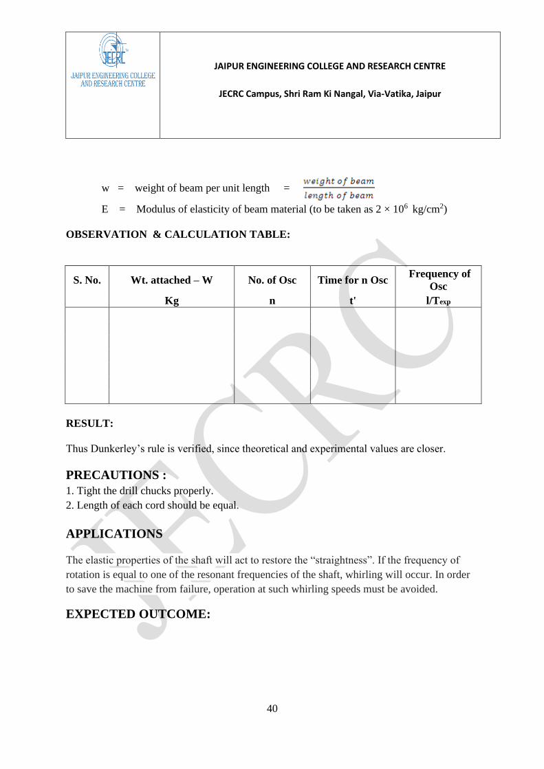
w = weight of beam per unit length =
E = Modulus of elasticity of beam material (to be taken as 2 × 10⁶ kg/cm2)
OBSERVATION & CALCULATION TABLE:
S. No. Wt. attached – W No. of Osc Time for n Osc Frequency of
Osc
Kg n t' l/Texp
RESULT:
Thus Dunkerley’s rule is verified, since theoretical and experimental values are closer.
PRECAUTIONS :
1. Tight the drill chucks properly.
2. Length of each cord should be equal.
APPLICATIONS
The elastic properties of the shaft will act to restore the “straightness”. If the frequency of
rotation is equal to one of the resonant frequencies of the shaft, whirling will occur. In order
to save the machine from failure, operation at such whirling speeds must be avoided.
EXPECTED OUTCOME:

JAIPUR ENGINEERING COLLEGE AND RESEARCH CENTRE
JECRC Campus, Shri Ram Ki Nangal, Via-Vatika, Jaipur
41
COMMENT BY STUDENT:
VIVA VOCE
1. Define longitudinal vibration?
2. Define torsional vibration?
3. Define multi degree of freedom?
4. What is the unit of damping coefficient?
5. Define pendulum?

JAIPUR ENGINEERING COLLEGE AND RESEARCH CENTRE
JECRC Campus, Shri Ram Ki Nangal, Via-Vatika, Jaipur
42
EXPERIMENT No. 8
AIM: Performing the experiment to find out damping co-efficient in case of free damped
torsional vibration
APPARATUS:
Spring mass system, damper, exciter unit, voltage regulator and strip recorder.
THEORY:
The vibration that the system executes under damping system is known as damped vibrations.
In general all the physical systems are associated with one or the other type of damping. In
certain cases amount of damping may be small in other case large. In dam a reduction in
amplitude over every cycle of vibration. This is due to the fact that a certain amount of
energy possessed by the vibrating system is always dissipated in overcoming frictional
resistances to the motion. The rate at w upon the type and amount of damping in the system.
Damped vibrations can be free vibrations or forced vibrations. Shock absorber is an example
of damped vibration. Mainly the following two aspects are important while studying damped
free vibrations: 1. The frequency of damped free vibrations and 2. The rate of decay.
FIGURE:

JAIPUR ENGINEERING COLLEGE AND RESEARCH CENTRE
JECRC Campus, Shri Ram Ki Nangal, Via-Vatika, Jaipur
43
PROCEDURE:
1. Connect the exciter to D.C. motor.
2. Start the motor and allow the system to vibrate.
3. Wait for 3 to 5 minuets for the amplitude to build for particular forcing frequency.
4. Adjust the position of strip chart
5. Take record by changing forcing frequency.
6. Repeat the experiment for different damping. Damping can be changed adjusting the
position of the exciter.
7. Plot the graph of amplitude Vs frequency for each damping condition.

JAIPUR ENGINEERING COLLEGE AND RESEARCH CENTRE
JECRC Campus, Shri Ram Ki Nangal, Via-Vatika, Jaipur
44
Sr. No. Number of
oscillations, n
Time
required for
n oscillations,
t
Periodic
Time, T
Forcing
frequency, f
= 1/T
Amplitude,
mm
CONCLUSION:
1. From the graph it can be observed that the amplitude of vibration decreases with time.
2. Amplitude of vibration is less with damped system as compared to undamped system.
Result: The frequency of damped forced vibration is………
PRECAUTIONS:
1. Do not run the motor at low voltage i.e. less than 180 volts.
2. Do not increase the speed at once.
3. Damper is always in perpendicular direction.
4. A motor bolts is properly tightly with weight.
5. A beam is proper tight in bearing with bolt.
6. Always keep the apparatus free from dust.
EXPECTED OUTCOME:

JAIPUR ENGINEERING COLLEGE AND RESEARCH CENTRE
JECRC Campus, Shri Ram Ki Nangal, Via-Vatika, Jaipur
45
COMMENT BY STUDENT:
Viva-Voce:
1. Define vibration absorbers?
2. Define loudness and its unit?
3. What is the major source of noise?
4. What are the noise control sources?
5. Define decibel scale?

JAIPUR ENGINEERING COLLEGE AND RESEARCH CENTRE
JECRC Campus, Shri Ram Ki Nangal, Via-Vatika, Jaipur
46
Experiment no. 9
AIM:
To conduct experiment of trifler suspension.
APPARATUS REQUIRED: Main frame, Trifler suspension, Weights, Stopwatch, and
Thread.
DESCRIPTION:
The set up consists of a disc having a weight W is suspended by three long parallel flexible
chord of length ‘l’. The three strings being placed symmetrically about the centre of gravity
‘G’ at a radius ‘r’ and disposed at 120º to each other. When the disc is twisted through a
small angle θ about a vertical axis through the center of gravity ‘G’, it will vibrate with
simple harmonic motion in a horizontal plane.
Figure 9: Experimental set up for trifler suspension.

JAIPUR ENGINEERING COLLEGE AND RESEARCH CENTRE
JECRC Campus, Shri Ram Ki Nangal, Via-Vatika, Jaipur
47
FORMULAE:
1. Radius of gyration, k =
2. Mass moment of inertia of body about a vertical axis =
STANDARD DATA:
1. Weight of the disc, W = 2.26 kg
2. Weight of Ring = 0.988 kg
3. Weight of block = 0.454 kg
4. Radius of disc = 11.2 cm
OBSERVATION TABLE:
S.
No.
Wt. attached
– W
No. of
Osc
Length of
cord
Time
required
Frequency
n=t/n
Radius of
gyration
Kg n Cm t cm osc/sec k(cm)
PRECAUTIONS:
1. Tight the drill chucks properly.

JAIPUR ENGINEERING COLLEGE AND RESEARCH CENTRE
JECRC Campus, Shri Ram Ki Nangal, Via-Vatika, Jaipur
48
2. Length of each cord should be equal.
RESULT:
APPLICATIONS
The trifilar suspension is a technique used to determine the moment of inertia of any type of
object about any point on the object.
EXPECTED OUTCOME:
COMMENT BY STUDENT:

JAIPUR ENGINEERING COLLEGE AND RESEARCH CENTRE
JECRC Campus, Shri Ram Ki Nangal, Via-Vatika, Jaipur
49
VIVA-VOCE
1. How is the moment of inertia of a solid body of regular shape (e.g. a disc or a
cylinder) found?
2. How will you recommend the length of wire compared to the size of the base
of the trifiliar suspension to be? – longer or shorter. Why?
3. Why do we need to find moment of inertia of solid bodies of irregular shapes
in real life?
4. Write the formula that relates dimensions of a trifiliar suspension, MI of the
oscillating base and period of oscillation of the trifiliar suspension.
Explain the meaning of terms used in the formula.
5. What will be the effect of increasing or decreasing the length of suspension
and MI of base on the period of oscillation of the trifiliar suspension?
JAIPUR ENGINEERING COLLEGE AND RESEARCH CENTRE
JECRC Campus, Shri Ram Ki Nangal, Via-Vatika, Jaipur
50
Experiment No. 10
AIM: Harmonic excitation of cantilever beam using electro-dynamic shaker and
determination of resonant frequencies.
INTRODUCTION
The passive vibration absorber is an important device used for vibration reduction in
structures. The linear vibration absorber is limited in that it reduces vibration over a very
narrow frequency range. This range is not enough to correspond to changes in speed for a
rotating unbalanced source due to load, motor power supply or source variations. A technical
benefit of the NDVA has been hypothesized that they can operate efficiently over a broader
range of forcing frequencies.
APPRATUS
The schematic diagram of the experimental setup is shown in Figure 8. The electro-dynamic
shaker was driven by a signal generator producing a stepped-sine signal. The accelerometers
(PCB type 352C22) were attached to the support structure and to the mass of the absorber,
while the oscilloscope was used to observe the system response.

JAIPUR ENGINEERING COLLEGE AND RESEARCH CENTRE
JECRC Campus, Shri Ram Ki Nangal, Via-Vatika, Jaipur
51
Figure 10 : Photograph of the actual experimental system consisting of a nonlinear absorber
attached to a cantilever beam excited by an electro-dynamic shaker.
ERXPERIMENTAL PROCEEDURE
1. The cantilever beam was made of aluminium with a total length L = 0.09 m , cross-
sectional area A = 0.04 m=0.004 m , density =2700 kg/m3 , and Young’s modulus E
= 70 GN/m2 . In addition, the circular plate was made of brass with thickness 0.2103
m , area A =0.0262 m2 , density =8500 kg/m3 , and Young’s modulus E =110
GN/m2 .
2. The parameters for the systems tested were required in order to compare the
experimental results with the model predictions. These parameters ( s m , s c , s k , m ,
c , 1 k , 3 k ) were measured independently and were estimated as follows.
3. The Frequency Response Function (FRF) of the support frame attached to the
cantilever beam without the absorber was measured using pseudo random force
measurements. It is noted that the system was designed such that by simply adjusting
the thickness of the plate, in the vibration absorber, the nonlinear stiffness and natural
frequency of the absorber could be varied.

JAIPUR ENGINEERING COLLEGE AND RESEARCH CENTRE
JECRC Campus, Shri Ram Ki Nangal, Via-Vatika, Jaipur
52
OBSEVATION TABLE
Equivalent non-dimensional system parameters for the model predictions.
Amplitute
Results: It was found that the frequency response curve of the NDVA has the effect of
moving the second resonant peak to a higher frequency away from the tuned frequency, so
that the device is robust to mistuning.
PRECAUTIONS:
1. Do not run the motor at low voltage i.e. less than 180 volts.
2. Do not increase the speed at once.
3. Damper is always in perpendicular direction.
4. A motor bolts is properly tightly with weight.
5. A beam is proper tight in bearing with bolt.
6. Always keep the apparatus free from dust.
EXPECTED OUTCOME:

JAIPUR ENGINEERING COLLEGE AND RESEARCH CENTRE
JECRC Campus, Shri Ram Ki Nangal, Via-Vatika, Jaipur
53
COMMENT BY STUDENT:
VIVA-VOCE
1. What are beats?
2. Define spring mass system?
3. Define dynamic coupling?
4. Define the number of degrees of freedom of a vibration system?

JAIPUR ENGINEERING COLLEGE AND RESEARCH CENTRE
JECRC Campus, Shri Ram Ki Nangal, Via-Vatika, Jaipur
54
EXPERIMENT NO.11
AIM:
Study of Vibration measuring instruments.
DESCRIPTION:
The primary purpose of vibration measuring instruments is to give an output signal which
represents, as closely as possible, the vibration phenomenon. This phenomenon may be
displacement , velocity or acceleration of the vibratin system and accordingly the instruments
which reproduce signals proportional to these are called vibrometers, velocity pickups
(Techometer) or accelerometers.
Figure shows the schematic of a seismic instrument which is used to
measure any of the vibration phenomenon. It consists of aframe in which the seismic mass m
is supported by means of spring k and dashpot C . The frame is mounted on a vibrating body,
vibrates along with it. This system reduces to a spring mass dashpot system having base or
support excitation.
Consider the vibrating body (base) to have a sinusoidal motion
y = γ sinωt
Then the steady state relative amplitude z of the seismic mass with respect to the frame is
obtained from equation,
=
and phase difference between exciting motion & relative motion is given by
Φ= tan-1
Imagine that a scale is fixed on the frame and a pointer on the seismic mass. Then the
amplitude of the motion of mass over the scale represents the relative motion z having
amplitude z. This motion is also harmonic. Plot of equation 1 and 2 for relative response &
phase shift in figure 2 and 3.

JAIPUR ENGINEERING COLLEGE AND RESEARCH CENTRE
JECRC Campus, Shri Ram Ki Nangal, Via-Vatika, Jaipur
55
1. Vibrometers:
If input motion y in figure 1 is harmonic then relative motion z that can be recorded by means
of a secondary strainsensing transducer, is also harmonic. The ratio of recorded motion to
exciting motion is given by equation 1 and plot by figure 2
if in equation 1, >> 1
then tends to unity irrespective of the value of damping. This is also seen in figure 2.
The ratio = 1 means that the relative amplitude recorded z, is equal to excitation amplitude
Y or the amplitude of vibrating system. Thus, provided is large, the amplitude
recorded is approximately equal to the amplitude of the vibrating body.
It can also seen from figure 2, if damping factor about 0.7 or a little lower, it is possible to
have a better approximation of relation ( ) over a larger range of frequency ratio.
In most vibrometers damping is kept as small as possible (for reason of reduced distortion),
but is lage enough to ensure that the recorded motion is a good approximation of
input motion. The ratio of can be made large by having the instruments of low
natural frequency, the average value of which may be about 4Hz.
We have seen that if vibrating body has a harmonic motion of a frequency such that then the amplitude recorded is a good approximation of the amplitude of
vibrating body. However, output signal is not in phase with the input motion and so, there is
some time delay depending upon the time of damping in the system. But that is immaterial as
long as output signal is a true representation of input signal.
Now consider that vibrating bidy has a non-harmonic periodic motion of fundamental
frequency ω such that then the fundamental will be transmitted with the same
accuracy as before any higher harmonic has a higher frequency than the fundamental and will
be recorded still more precisely. But if we look back to phase angle plot of figutr4, we see the
phase shift for different values of is different.

JAIPUR ENGINEERING COLLEGE AND RESEARCH CENTRE
JECRC Campus, Shri Ram Ki Nangal, Via-Vatika, Jaipur
56
This will mean that although each harmonic separately, is recorded accurately it has different
phase angle relationship with the fundamental in the recorded motion than what it had in the
input motion.
The result is that the output motion will be distorted motion and not a true representation of
input motion. This can be seen in figure 4 , where the fundamental in the recorded wave has
suffered a log of Φ3 .The final output wave is distorted.
This difficulty can be overcome by making the damping in the system to be zero. Under this
condition , the phase difference is 180˚ whatever the frequency ratio. So each
harmonic motion , seperatly apart from being recorded accurately is also transmitted with the
same phase angle relationship. The resulting output signal is a true reproduction of the input
signal.
2. Velocity Pickups:
The relative motion z could be measured by means of secondary strain sensing
transducer. We can have a velocity sensing secondary transducer of the type of a magnet
rigidly fixed to the seismic mass moving in a coil fixed to the frame, then the output
voltage at two ends of the coil will be proportional to the relative velocity since the output
voltage is proportional to the rate at which the lines of force are cut. The relative velocity
is equal to the input velocity of the support of the vibrating system at large values of
.
Hence the instruments behaves as a ‘ velocity pick up ’.
3. Accelerometers:
The instrument in figure1 can also behave as an accelerometer under certain conditions.
In equation 1 if << 1 ; then
≈
or z ≈
The expression in the above equation is equal to the acceleration amplitude of the
body vibrating with frequency ω and having a displacement Y. Hence the amplitude
recorded z, under these conditions is proportional to the acceleration of the vibrating

JAIPUR ENGINEERING COLLEGE AND RESEARCH CENTRE
JECRC Campus, Shri Ram Ki Nangal, Via-Vatika, Jaipur
57
body. Since is a constant of the instrument actually represents the accelerations at
various frequencies.
The ratio can be made small by having large as possible.
The natural frequency of the accelerometer should be at least twice as high as the highest
frequency of the acceleration to be recorded.
There is a possibility of some difficulty in case of non-harmonic periodic vibrations
where the harmonics of higher frequency may not be recorded accuretly unless is
much higher than the highest frequencies of harmonics. For this reason the natural
frequency of most of the good accelerometer is above 10,000 Hz , much above the range
of frequency of mechanical vibrations.
4. Frequency Measurement instrument s or Techometer:
(Frahm’s Reed Techometer)
It consists of a system having a no. of reeds fixed over it in the form of cantilevers
carrying small masses at their free end, as shown in figure. The natural frequencies of the
set of these reeds is adujested to give a definite series of known frequencies. When this
instrument is attached to the body where frequency of vibration is to be measuired the
reed whose natural frequency is nearest to the excitation frequency vibrates near resonate
condition and has a large amplitude of vibration. The frequency of the vibrating body is
then given by the known frequency of reed vibrating with maximum amplituide.
The accuracy of instrument depends upon the difference between the natural frequencies
of the successive reeds. The smaller the difference, more accurate is the instruments and
vice-versa . Of course with a more accurate instrument of this type, the range of
frequencies that can be measured , will be smaller.
RESULT:
We have studied about Vibrometer, Velocity pickup, Accelerometer and Techometer.
APPLICATIONS

JAIPUR ENGINEERING COLLEGE AND RESEARCH CENTRE
JECRC Campus, Shri Ram Ki Nangal, Via-Vatika, Jaipur
58
The information about ground vibrations due to earthquakes, fluctuating wind velocities on
structures, random variation of ocean waves, and road surface roughness are important in the
design of structures, machines, oil platforms, and vehicle suspension systems.
EXPECTED OUTCOME:
COMMENT BY STUDENT:
VIVA VOCE
1. What are vibratometers?

JAIPUR ENGINEERING COLLEGE AND RESEARCH CENTRE
JECRC Campus, Shri Ram Ki Nangal, Via-Vatika, Jaipur
59
2. Define Frahm’s Reed Techometer?
3. Define dynamic coupling?
4. Define the number of degrees of freedom of a vibration system?

JAIPUR ENGINEERING COLLEGE AND RESEARCH CENTRE
JECRC Campus, Shri Ram Ki Nangal, Via-Vatika, Jaipur
60
Experiment No. 12
AIM: Perform study of the following using Virtual Lab http://www.vlab.co.in/
Objectives of the Virtual Labs:
To provide remote-access to Labs in various disciplines of Science and Engineering. These
Virtual Labs would cater to students at the undergraduate level, post graduate level as well
as to research scholars.
To enthuse students to conduct experiments by arousing their curiosity. This would help
them in learning basic and advanced concepts through remote experimentation.
To provide a complete Learning Management System around the Virtual Labs where the
students can avail the various tools for learning, including additional web-resources, video-
lectures, animated demonstrations and self evaluation.
To share costly equipment and resources, which are otherwise available to limited number
of users due to constraints on time and geographical distances
Welcome to Vibration and Acoustics!
In this lab vibration related techniques are demonstrated like MI of connecting rod, force
response and free response of SDOF, Trifiliar suspension, tuned vibration absorber and many
more
APPLICATIONS
A concept and a structure of a Virtual Laboratory for technical engineering education that
relies on self-directed, directed and collaborative learning methods has been developed.

JAIPUR ENGINEERING COLLEGE AND RESEARCH CENTRE
JECRC Campus, Shri Ram Ki Nangal, Via-Vatika, Jaipur
61
EXPECTED OUTCOME:
COMMENT BY STUDENT:
VIVA VOCE
1.What is virtual lab
2.What the role of virtual in vibration lab

JAIPUR ENGINEERING COLLEGE AND RESEARCH CENTRE
JECRC Campus, Shri Ram Ki Nangal, Via-Vatika, Jaipur
62

JAIPUR ENGINEERING COLLEGE AND RESEARCH CENTRE
JECRC Campus, Shri Ram Ki Nangal, Via-Vatika, Jaipur
63
Experiment No.13
AIM: Forced Vibration of a Cantilever Beam with a Lumped Mass at Free End: To calculate
the natural frequency and damping ratio for forced vibration of a single DOF cantilever beam
system, experimentally; and compare the results with theoretical values.
DESCRIPTION:
Figure shows the general set up. Slightly heavy rectangular section bar than used in Expt. no.
10 is supported at both ends in trunnion fittings. Exciter unit with the weight platform can be
clamped at any convenient position along the beam. Exciter unit is connected to the damper
which provides the necessary damping.
PROCEDURE :
1. Arrange the setup as shown in Figure.
2. Connect the exciter Motor to control panel.
3. Start the Motor and allow the system to vibrate.
4. Wait for 5 minuts for amplitude to build up for particular forcing frequency.
5. Adjust the position of strip chart recorder. Take the record of amplitude Vs. time on
strip chart recorder by starting recorder motor.
6. Take record by changing forcing frequency.
7. Repeat the experiment for different dampng.

JAIPUR ENGINEERING COLLEGE AND RESEARCH CENTRE
JECRC Campus, Shri Ram Ki Nangal, Via-Vatika, Jaipur
64
8. Plot the graph of amplitude Vs. frequency for each damping.
OBSERVATION TABLE:
Forcing frequency Amplitude
SAMPLE CALCULATION:
OBSERVATION TABLE:
Forcing frequency Amplitude

JAIPUR ENGINEERING COLLEGE AND RESEARCH CENTRE
JECRC Campus, Shri Ram Ki Nangal, Via-Vatika, Jaipur
65
RESULT:
PRECAUTIONS:
1. Do not run the motor at low voltage i.e. less than 180 volts.
2. Do not increase the speed at once.
3. Damper is always in perpendicular direction.
4. A motor bolts is properly tightly with weight.
5. A beam is proper tight in bearing with bolt.
6. Always keep the apparatus free from dust.
EXPECTED OUTCOME:
COMMENT BY STUDENT:

JAIPUR ENGINEERING COLLEGE AND RESEARCH CENTRE
JECRC Campus, Shri Ram Ki Nangal, Via-Vatika, Jaipur
66
VIVA VOCE
1. Define longitudinal vibration?
2. Define torsional vibration?
3. Define multi degree of freedom?
4. What is the unit of damping coefficient?
5. Define pendulum?

JAIPUR ENGINEERING COLLEGE AND RESEARCH CENTRE
JECRC Campus, Shri Ram Ki Nangal, Via-Vatika, Jaipur
67
Experiment No.14
AIM:
Harmonicaly Excited Forced Vibration of a Single DOF System: To analyze the forced
vibration response of a single DOF system at different damping ratio and frequency ratio
DESCRIPTION:
Figure shows the general set up. Slightly heavy rectangular section bar than used in Expt. no.
10 is supported at both ends in trunnion fittings. Exciter unit with the weight platform can be
clamped at any convenient position along the beam. Exciter unit is connected to the damper
which provides the necessary damping.
PROCEDURE :
1. Arrange the setup as shown in Figure.
2. Connect the exciter Motor to control panel.
3. Start the Motor and allow the system to vibrate.
4. Wait for 5 minuts for amplitude to build up for particular forcing frequency.
5. Adjust the position of strip chart recorder. Take the record of amplitude Vs. time on
strip chart recorder by starting recorder motor.
6. Take record by changing forcing frequency.
7. Repeat the experiment for different dampng.
8. Plot the graph of amplitude Vs. frequency for each damping.

JAIPUR ENGINEERING COLLEGE AND RESEARCH CENTRE
JECRC Campus, Shri Ram Ki Nangal, Via-Vatika, Jaipur
68
OBSERVATION TABLE:
Forcing frequency Amplitude
SAMPLE CALCULATION:
OBSERVATION TABLE:
Forcing frequency Amplitude

JAIPUR ENGINEERING COLLEGE AND RESEARCH CENTRE
JECRC Campus, Shri Ram Ki Nangal, Via-Vatika, Jaipur
69
RESULT:
PRECAUTIONS:

JAIPUR ENGINEERING COLLEGE AND RESEARCH CENTRE
JECRC Campus, Shri Ram Ki Nangal, Via-Vatika, Jaipur
70
1. Do not run the motor at low voltage i.e. less than 180 volts.
2. Do not increase the speed at once.
3. Damper is always in perpendicular direction.
4. A motor bolts is properly tightly with weight.
5. A beam is proper tight in bearing with bolt.
6. Always keep the apparatus free from dust.
EXPECTED OUTCOME:
COMMENT BY STUDENT:

JAIPUR ENGINEERING COLLEGE AND RESEARCH CENTRE
JECRC Campus, Shri Ram Ki Nangal, Via-Vatika, Jaipur
71
VIVA VOCE
1. Define longitudinal vibration?
2. Define torsional vibration?
3. Define multi degree of freedom?
4. What is the unit of damping coefficient?
5. Define pendulum?

JAIPUR ENGINEERING COLLEGE AND RESEARCH CENTRE
JECRC Campus, Shri Ram Ki Nangal, Via-Vatika, Jaipur
72
Experiment No. 15
AIM: Perform study of the following using Virtual Lab http://www.vlab.co.in/
Objectives of the Virtual Labs:
To provide remote-access to Labs in various disciplines of Science and Engineering. These
Virtual Labs would cater to students at the undergraduate level, post graduate level as well
as to research scholars.
To enthuse students to conduct experiments by arousing their curiosity. This would help
them in learning basic and advanced concepts through remote experimentation.
To provide a complete Learning Management System around the Virtual Labs where the
students can avail the various tools for learning, including additional web-resources, video-
lectures, animated demonstrations and self evaluation.
To share costly equipment and resources, which are otherwise available to limited number
of users due to constraints on time and geographical distances
Welcome to Vibration and Acoustics!
In this lab vibration related techniques are demonstrated like MI of connecting rod, force
response and free response of SDOF, Trifiliar suspension, tuned vibration absorber and many
more
EXPECTED OUTCOME:
COMMENT BY STUDENT:

JAIPUR ENGINEERING COLLEGE AND RESEARCH CENTRE
JECRC Campus, Shri Ram Ki Nangal, Via-Vatika, Jaipur
73
VIVA VOCE
1.What is virtual lab
2.What the role of virtual in vibration lab

JAIPUR ENGINEERING COLLEGE AND RESEARCH CENTRE
JECRC Campus, Shri Ram Ki Nangal, Via-Vatika, Jaipur
74
JAIPUR ENGINEERING COLLEGE AND RESEARCH CENTRE
JECRC Campus, Shri Ram Ki Nangal, Via-Vatika, Jaipur
75
Experiment No.16
AIM: Forced Vibration of a Cantilever Beam with a Lumped Mass at Free End: To calculate
the natural frequency and damping ratio for forced vibration of a single DOF cantilever beam
system, experimentally; and compare the results with theoretical values.
DESCRIPTION:
Figure shows the general set up. Slightly heavy rectangular section bar than used in Expt. no.
10 is supported at both ends in trunnion fittings. Exciter unit with the weight platform can be
clamped at any convenient position along the beam. Exciter unit is connected to the damper
which provides the necessary damping.
PROCEDURE :
1. Arrange the setup as shown in Figure.
2. Connect the exciter Motor to control panel.
3. Start the Motor and allow the system to vibrate.
4. Wait for 5 minuts for amplitude to build up for particular forcing frequency.
5. Adjust the position of strip chart recorder. Take the record of amplitude Vs. time on
strip chart recorder by starting recorder motor.
6. Take record by changing forcing frequency.
7. Repeat the experiment for different dampng.

JAIPUR ENGINEERING COLLEGE AND RESEARCH CENTRE
JECRC Campus, Shri Ram Ki Nangal, Via-Vatika, Jaipur
76
8. Plot the graph of amplitude Vs. frequency for each damping.
OBSERVATION TABLE:
Forcing frequency Amplitude
SAMPLE CALCULATION:
OBSERVATION TABLE:
Forcing frequency Amplitude

JAIPUR ENGINEERING COLLEGE AND RESEARCH CENTRE
JECRC Campus, Shri Ram Ki Nangal, Via-Vatika, Jaipur
77
RESULT:
PRECAUTIONS:
1. Do not run the motor at low voltage i.e. less than 180 volts.
2. Do not increase the speed at once.
3. Damper is always in perpendicular direction.
4. A motor bolts is properly tightly with weight.
5. A beam is proper tight in bearing with bolt.
6. Always keep the apparatus free from dust.
EXPECTED OUTCOME:
COMMENT BY STUDENT:

JAIPUR ENGINEERING COLLEGE AND RESEARCH CENTRE
JECRC Campus, Shri Ram Ki Nangal, Via-Vatika, Jaipur
78
VIVA VOCE
1. Define transverse and longitudinal wave?
2. Define sound wave in air?
3. Define the frequency?
4. Define dB and dBm?
5. Define noise?

JAIPUR ENGINEERING COLLEGE AND RESEARCH CENTRE
JECRC Campus, Shri Ram Ki Nangal, Via-Vatika, Jaipur
79
Experiment No.17
AIM:
Harmonicaly Excited Forced Vibration of a Single DOF System: To analyze the forced
vibration response of a single DOF system at different damping ratio and frequency ratio
DESCRIPTION:
Figure shows the general set up. Slightly heavy rectangular section bar than used in Expt. no.
10 is supported at both ends in trunnion fittings. Exciter unit with the weight platform can be
clamped at any convenient position along the beam. Exciter unit is connected to the damper
which provides the necessary damping.
PROCEDURE :
1. Arrange the setup as shown in Figure.
2. Connect the exciter Motor to control panel.
3. Start the Motor and allow the system to vibrate.
4. Wait for 5 minuts for amplitude to build up for particular forcing frequency.
5. Adjust the position of strip chart recorder. Take the record of amplitude Vs. time on
strip chart recorder by starting recorder motor.
6. Take record by changing forcing frequency.
7. Repeat the experiment for different dampng.
8. Plot the graph of amplitude Vs. frequency for each damping.

JAIPUR ENGINEERING COLLEGE AND RESEARCH CENTRE
JECRC Campus, Shri Ram Ki Nangal, Via-Vatika, Jaipur
80
OBSERVATION TABLE:
Forcing frequency Amplitude
SAMPLE CALCULATION:
OBSERVATION TABLE:
Forcing frequency Amplitude
JAIPUR ENGINEERING COLLEGE AND RESEARCH CENTRE
JECRC Campus, Shri Ram Ki Nangal, Via-Vatika, Jaipur
81
RESULT:
PRECAUTIONS:
1. Do not run the motor at low voltage i.e. less than 180 volts.
2. Do not increase the speed at once.
3. Damper is always in perpendicular direction.
4. A motor bolts is properly tightly with weight.
5. A beam is proper tight in bearing with bolt.
6. Always keep the apparatus free from dust.

JAIPUR ENGINEERING COLLEGE AND RESEARCH CENTRE
JECRC Campus, Shri Ram Ki Nangal, Via-Vatika, Jaipur
82
EXPECTED OUTCOME:

JAIPUR ENGINEERING COLLEGE AND RESEARCH CENTRE
JECRC Campus, Shri Ram Ki Nangal, Via-Vatika, Jaipur
83
COMMENT BY STUDENT:
VIVA VOCE
1. Define transverse and longitudinal wave?
2. Define sound wave in air?
3. Define the frequency?
4. Define dB and dBm?
5. Define noise?