Academic Programme July 2019 - JECRC University
238
School of Engineering Department of Electrical Engineering Syllabi and Course Structure B. Tech. (Electrical Engineering) (2019-2023) M. Tech (i) Power System and Automation (ii) Electrical Devices and Power Electronics Academic Programme July 2019
-
Upload
khangminh22 -
Category
Documents
-
view
1 -
download
0
Transcript of Academic Programme July 2019 - JECRC University

School of Engineering
Department of Electrical Engineering
Syllabi and Course Structure
B. Tech. (Electrical Engineering)
(2019-2023)
M. Tech (i) Power System and Automation
(ii) Electrical Devices and Power Electronics
Academic Programme
July 2019

2

3

4
B. Tech. (EE) Program Educational Objective (PEO’s):
A graduate of the Electrical Engineering Program should:
PEO- I
Students should be in position to solve the real time problems related to Electrical machine,
power system and its relevant equipments depending upon the present day demand based on
effectiveness innovation.
PEO- II
Students should be capable enough to formulate the design problem based on the customize
demand of the country and citizen.
PEO- III
Students should be in position to demonstrate the skill set developed related to field of
electrical engineering.
PEO- IV
After learning the basic skills through the B. Tech. Electrical engineering course, student
should have spark and intention to learn and explore more on its favorite field of interest.
Program Outcome (PO’s)
A graduate of the Electrical Engineering Program will demonstrate:
PO1. Engineering knowledge: Apply the knowledge of mathematics, science, engineering
fundamentals, and an engineering specialization to the solution of complex engineering
problems.
PO2. Problem analysis: Identify, formulate, research literature, and analyze complex
engineering problems reaching substantiated conclusions using first principles of mathematics,
natural sciences, and engineering sciences.
PO3. Design/development of solutions: Design solutions for complex engineering problems
and design system components or processes that meet the specified needs with appropriate
consideration for the public health and safety, and the cultural, societal, and environmental
considerations.
PO4. Conduct investigations of complex problems: Use research-based knowledge and
research methods including design of experiments, analysis and interpretation of data, and
synthesis of the information to provide valid conclusions.
PO5. Modern tool usage: Create, select, and apply appropriate techniques, resources, and
modern engineering and IT tools including prediction and modelling to complex engineering
activities with an understanding of the limitations.

5
PO6. The engineer and society: Apply reasoning informed by the contextual knowledge to
assess societal, health, safety, legal and cultural issues and the consequent responsibilities
relevant to the professional engineering practice.
PO7. Environment and sustainability: Understand the impact of the professional engineering
solutions in societal and environmental contexts, and demonstrate the knowledge of, and need
for sustainable development.
PO8. Ethics: Apply ethical principles and commit to professional ethics and responsibilities
and norms of the engineering practice.
PO9. Individual and team work: Function effectively as an individual, and as a member or
leader in diverse teams, and in multidisciplinary settings.
PO10. Communication: Communicate effectively on complex engineering activities with the
engineering community and with society at large, such as, being able to comprehend and write
effective reports and design documentation, make effective presentations, and give and receive
clear instructions.
PO11. Project management and finance: Demonstrate knowledge and understanding of the
engineering and management principles and apply these to one’s own work, as a member and
leader in a team, to manage projects and in multidisciplinary environments.
PO12. Life-long learning: Recognize the need for, and have the preparation and ability to
engage in independent and life-long learning in the broadest context of technological change.
Program Specific Outcome:
PSO 1: Able to apply the knowledge gained during the course of the program from
Mathematics, Basic Computing, and Basic Sciences in general and all electrical courses in
particular to identify, formulate and solve real life problems faced in industries and/or during
research work.
PSO 2: Able to provide socially acceptable technical solutions to complex electrical
engineering problems with the application of modern and appropriate techniques for
sustainable development.
PSO 3: Able to apply the knowledge of ethical and management principles required to work in
a team as well as to lead an industry.
6
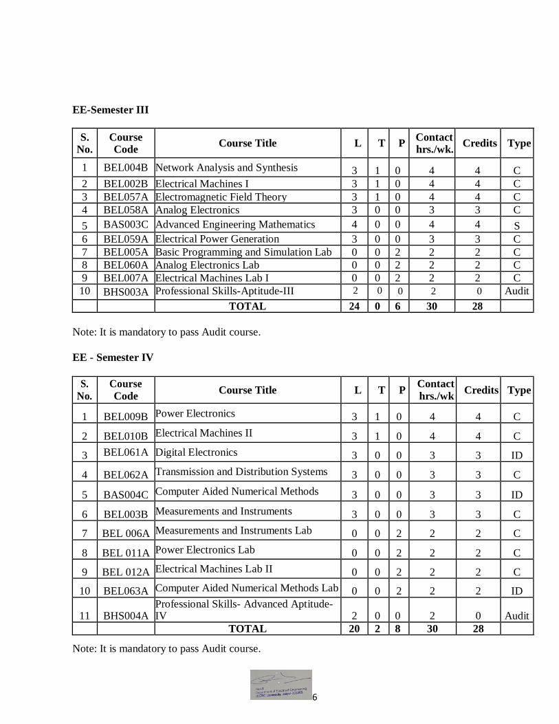
EE-Semester III
S. No.
Course Code
Course Title L T P Contact hrs./wk.
Credits Type
1 BEL004B Network Analysis and Synthesis 3 1 0 4 4 C
2 BEL002B Electrical Machines I 3 1 0 4 4 C
3 BEL057A Electromagnetic Field Theory 3 1 0 4 4 C
4 BEL058A Analog Electronics 3 0 0 3 3 C
5 BAS003C Advanced Engineering Mathematics 4 0 0 4 4 S
6 BEL059A Electrical Power Generation 3 0 0 3 3 C
7 BEL005A Basic Programming and Simulation Lab 0 0 2 2 2 C
8 BEL060A Analog Electronics Lab 0 0 2 2 2 C
9 BEL007A Electrical Machines Lab I 0 0 2 2 2 C
10 BHS003A Professional Skills-Aptitude-III 2 0 0 2 0 Audit
TOTAL 24 0 6 30 28
Note: It is mandatory to pass Audit course.
EE - Semester IV
S.
No.
Course
Code Course Title L T P
Contact
hrs./wk Credits Type
1 BEL009B Power Electronics 3 1 0 4 4 C
2 BEL010B Electrical Machines II 3 1 0 4 4 C
3 BEL061A Digital Electronics 3 0 0 3 3 ID
4 BEL062A Transmission and Distribution Systems 3 0 0 3 3 C
5 BAS004C Computer Aided Numerical Methods 3 0 0 3 3 ID
6 BEL003B Measurements and Instruments 3 0 0 3 3 C
7 BEL 006A Measurements and Instruments Lab 0 0 2 2 2 C
8 BEL 011A Power Electronics Lab 0 0 2 2 2 C
9 BEL 012A Electrical Machines Lab II 0 0 2 2 2 C
10 BEL063A Computer Aided Numerical Methods Lab 0 0 2 2 2 ID
11 BHS004A Professional Skills- Advanced Aptitude-IV 2 0 0 2 0 Audit
TOTAL 20 2 8 30 28 Note: It is mandatory to pass Audit course.
7
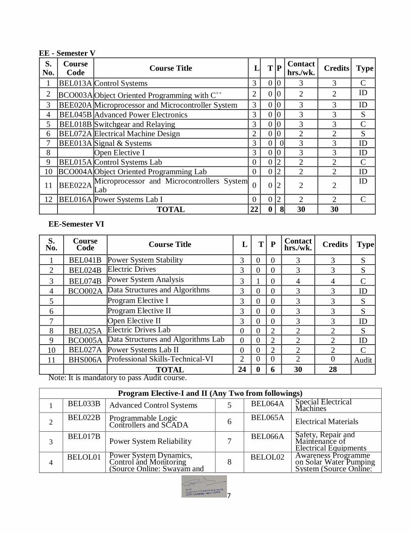
EE - Semester V
S. No.
Course Code
Course Title L T P Contact hrs./wk.
Credits Type
1 BEL013A Control Systems 3 0 0 3 3 C
2 BCO003A Object Oriented Programming with C++ 2 0 0 2 2 ID
3 BEE020A Microprocessor and Microcontroller System 3 0 0 3 3 ID
4 BEL045B Advanced Power Electronics 3 0 0 3 3 S
5 BEL018B Switchgear and Relaying 3 0 0 3 3 C
6 BEL072A Electrical Machine Design 2 0 0 2 2 S
7 BEE013A Signal & Systems 3 0 0 3 3 ID
8 Open Elective I 3 0 0 3 3 ID
9 BEL015A Control Systems Lab 0 0 2 2 2 C
10 BCO004A Object Oriented Programming Lab 0 0 2 2 2 ID
11 BEE022A Microprocessor and Microcontrollers System Lab
0 0 2 2 2 ID
12 BEL016A Power Systems Lab I 0 0 2 2 2 C
TOTAL 22 0 8 30 30
EE-Semester VI
S. No.
Course Code Course Title L T P Contact
hrs./wk. Credits Type
1 BEL041B Power System Stability 3 0 0 3 3 S
2 BEL024B Electric Drives 3 0 0 3 3 S
3 BEL074B Power System Analysis 3 1 0 4 4 C
4 BCO002A Data Structures and Algorithms 3 0 0 3 3 ID
5 Program Elective I 3 0 0 3 3 S
6 Program Elective II 3 0 0 3 3 S
7 Open Elective II 3 0 0 3 3 ID
8 BEL025A Electric Drives Lab 0 0 2 2 2 S
9 BCO005A Data Structures and Algorithms Lab 0 0 2 2 2 ID
10 BEL027A Power Systems Lab II 0 0 2 2 2 C
11 BHS006A Professional Skills-Technical-VI 2 0 0 2 0 Audit
TOTAL 24 0 6 30 28 Note: It is mandatory to pass Audit course.
Program Elective-I and II (Any Two from followings)
1 BEL033B Advanced Control Systems 5 BEL064A Special Electrical Machines
2 BEL022B Programmable Logic
Controllers and SCADA 6 BEL065A
Electrical Materials
3 BEL017B
Power System Reliability 7 BEL066A Safety, Repair and
Maintenance of Electrical Equipments
4 BELOL01 Power System Dynamics,
Control and Monitoring (Source Online: Swayam and
8 BELOL02 Awareness Programme
on Solar Water Pumping System (Source Online:

8
NPTEL) Swayam)
EE-Semester VII
S.
No.
Course
Code Course Title L T P
Contact
hrs./wk. Credits Type
1 BEL034B High Voltage Engineering 3 0 0 3 3 S
2 BEL040B EHV AC/DC Transmission 3 0 0 3 3 S
3 BEL067A Power System Economics 3 0 0 3 3 S 4 BEL021A Energy Auditing 3 0 0 3 3 S
5 Program Elective III 3 0 0 3 3 S
6 Program Elective IV 3 0 0 3 3 S
7 Open Elective III 3 0 0 3 3 ID
8 BEL073A CAD of Electrical Machines 0 0 2 2 2 S
9 BEL038A Advanced Simulation Lab 0 0 2 2 2 S
10 BEL039A Project Work 0 0 4 4 4 C
11 BEL050A Seminar 0 0 1 1 1 S
TOTAL 21 2 7 30 30
Program Elective- III and IV (Any Two from followings)
1 BEL068A Recent Trends in Electric
Power Generation
5 BEL043A Excitation of Synchronous
Machines and their Control
2 BEL037A Power System Security and
Smart Grid
6 BEL029A FACTS (Flexible AC Transmission
Systems)
3 BEL036A Utilization of Electrical
Energy and Electric Traction
7 BEL070A Power System Instrumentation
4 BEL069A Basics of Soft Computing
EE-Semester VIII
S.
No.
Course
Code Course Title L T P
Contact
hrs./wk. Credits Type
1 BEL046A Industrial Project and Dissertation 0 0 28 28 28 C
TOTAL 0 0 28 28 28

9
OPEN ELECTIVE SUBJECTS OFFERED BY DEPARTMENT OF ELECTRICAL
ENGINEERING
S.
No.
Course
No. Course Title
Hrs/Wk Credits
Semester L: T: P
1 BEL075A Energy Studies 3: 0: 0 3 V
2 BEL051A Knowledge Management 3: 0: 0 3 V
3 BEL022A Programmable Logic Controllers and
SCADA 3: 0: 0 3 V
4 BEL021A Energy Auditing 3: 0: 0 3 VI
5 BEL030A Indian Electricity Standards and their
Applications 3: 0: 0 3 VI
6 BEL071A Industrial Safety 3: 0: 0 3 VII
7 BEL035A Non Conventional Energy Sources and
Applications 3: 0: 0 3 VII
8 BEL069A Basics of Soft Computing
3: 0: 0 3 VII

10
School of Engineering B.Tech (Common to all)– Semester I/II
Contact Hrs per week (L-T-P): 3-0-0
Course Outlines
BES005C: Basic Electrical Engineering
OBJECTIVE:
The objective of this course is to provide the students with an introductory treatment of the field
of Electrical Engineering. Unit 1: DC Circuit & Theorems – Ohm’s law, KCL & KVL, Voltage & Current Sources, Star-Delta and Delta-Star transformations, Nodal & Mesh Analysis, Superposition Theorem, Thevenin’s Theorem, Norton’s Theorem, Maximum Power Transfer Theorem (only independent sources). Unit 2: Single Phase Circuits - Definition of average value, root mean square value, form factor and peak factor of sinusoidal voltage and current and phasor representation of alternating quantities; Analysis with phasor diagrams of R, L, C, RL, RC and RLC circuits; Real power, reactive power, apparent power and power factor, series, parallel and series- parallel circuits. Unit 3: Three Phase AC Circuits: Necessity and Advantages of three phase systems, Generation of three phase power, definition of Phase sequence, balanced supply and balanced load; Relationship between line and phase values of balanced star and delta connections. Unit 4: Transformers - Principle of operation and construction of single phase transformers (core and shell types). EMF equation, losses, efficiency and voltage regulation Unit 5: Rotating Electrical Machines – Construction & Working principle of DC machine as a generator and a motor; EMF equation of DC generator; torque equation of DC motor. Back EMF of DC Motor. Applications of dc machines and single phase induction motors.
Course Outcome (CO):
CO1. To understand and analyze basic electrical circuits
CO2. To connect the electrical circuits with various components and calculate desired outputs.
CO3. To understand working and applications of different electrical machines (AC and DC).
CO4. To identify the type of electrical machine used for that particular application.

11
MAPPING COURSE OUTCOMES LEADING TO THE ACHIEVEMENT OF PROGRAM
OUTCOMES AND PROGRAM SPECIFIC OUTCOMES: Course
Outcome
Program Outcome Program Specific
Outcome
PO1 PO2 PO3 PO4 PO5 PO6 PO7 PO8 PO9 PO10 PO11 PO12 PSO1 PSO2 PSO3
CO1 H L H M H
CO2 M H H M M
CO3 M H H M M
CO4 H H M M H
H = Highly Related, M = Medium, L = Low
Text Books:
1. Nagsarkar and Sukhija, Basic Electrical Engineering,Oxford Uni. Press.
2. Abhijeet Chakrabarti, Sudipta Debnath and Chandan Kumar Chanda “Basic Electrical
Engineering” Mc Graw Hill Education.
Reference Book:
1. Nagrath I.J. and D. P. Kothari (2001), Basic Electrical Engineering, TMH
2. Kulshreshtha DC (2009), Basic Electrical Engineering, Tata McGraw Hill 3. Rajendra Prasad (2009), Fundamentals of Electrical Engineering, Prentice Hall, India 4. Hughes, E. 2005), Electrical Technology. Pearson
5. BL Theraja, A textbook of electrical technology, Vol- II, S.Chand & Co. LTD.

12
School of Engineering B. Tech. (Common to all) – Semester I/II
Contact Hrs per week (L-T-P): 0-0-2
Course Outlines
BES008C: Basic Electrical Engineering Lab OBJECTIVE: To provide exposure to the students with hands on experience on various basic
engineering practices in Electrical Engineering.
List of experiments (Perform any 10).
1. Familiarization with (a) Electrical Symbols (b) Electrical Abbreviations (c) Electrical
Tools
2. Familiarization with (a) Various Electrical Components (b) Electrical Measuring
Instruments
3. To study the various Electrical Lamps Viz. Halogen Lamps, Fluorescent Tube & CFL,
Sodium Vapour lamp, Neon Lamps, Incandescent Lamps and LED bulbs & Tubes
4. To make house wiring for a lamp operated from two different positions (or two way
switching).
5. To make house wiring including Earthling for 1- Phase Energy meter, MCB, Ceiling Fan,
Tube light, 3 Pin Plug & Socket.
6. To verify transformation ratio by measuring primary and secondary side voltages of
single phase transformer
7. To measure voltage of primary and secondary sides of 3-phase transformer for different
configurations (star-delta).
8. To study the construction & working of Ceiling fan
9. To run the single phase induction motor at varying speeds by using autotransformer.
10. To run the 3-pahse phase induction motor at varying speeds by using 3-phase auto
transformer.
11. (a) To measure Power in 3-phase load by one-wattmeter method.
(b) To measure Power in 3-phase load by three-wattmeter method.
12. To measure Power and Power factor in 3-phase load by two-wattmeter method.
OUTCOMES:
CO1. Students can now become familiar with various electrical symbols, abbreviations, tools
and measuring instruments and practically connect the electrical circuits.

13
CO2. The ability to conduct testing and experimental procedures on different types of electrical
machines.
CO3. The ability to select a suitable measuring instrument for measuring electrical and non
electrical quantities for a given application. They will now be in position to learn
different testing procedure of transformers and induction motors.
MAPPING COURSE OUTCOMES LEADING TO THE ACHIEVEMENT OF PROGRAM
OUTCOMES AND PROGRAM SPECIFIC OUTCOMES:
Course
Outcome
Program Outcome Program Specific
Outcome
PO1 PO2 PO3 PO4 PO5 PO6 PO7 PO8 PO9 PO10 PO11 PO12 PSO1 PSO2 PSO3
CO1 M H H M H
CO2 H M H H M
CO3 H M M H H
H = Highly Related, M = Medium, L = Low

14
School of Engineering B. Tech. in Electrical Engineering – Semester III
Contact Hrs per week (L-T-P): 3-1-0
Course Outlines
BEL004B- Network Analysis and Synthesis
OBJECTIVES: In this course one can understand
Various laws and equations with respect to electric and magnetic fields.
In its second part one can learn various network theorems and transient response under
different excitation.
Unit-1: Introduction: Introduction to circuit elements and their characteristics. Resonance,
selectivity & Q-factor in ac circuits. Graph Theory: Graph for given network, classification of
graph and sub graphs, incidence, tie set and cut set matrices, terminology used in Network
Graph, properties of tree in a graph, variable solution of network using graph theory and matrix
from the concept of network function. Unit-2: Network Theorems: Thevenis’s, Norton's, Superposition, Reciprocity, Compensation,
Millman's theorem Tellegen’s, Maximum power transfer and Miller`s theorems in DC & AC
Circuits (for dependent sources).
Unit-3: Transient Analysis of Networks: Network elements, Transient response of R-L, R-C,
R-L-C for DC and sinusoidal excitation,Response of networks to step, ramp, impulse, pulse and
sinusoidal inputs. Time domain analysis of circuits; Shifting theorem, initial and final value
theorems. Unit-4: Two-Port Network: Introduction, different parameters and relationship between
different parameters, inter-connections of two port networks, open circuit and short-circuit
impedances and ABCD constants, image impedance, image parameters.\
Unit-5: Network Synthesis: Hurwitz polynomial, positive real functions, reactive networks.
Separation property for reactive networks. The four-reactance function forms, specification for
reactance function. Foster form of reactance networks; Cauer form of reactance networks.
Synthesis of R-L and R-C networks in Foster and Cauer forms.
OUTCOMES:
CO1. Students can now apply the knowledge to solve different networks involving electric
and/or magnetic field.

15
CO2. Also with the knowledge of different circuit theorem one can calculate the drop or power
consumed/supplied by the load or source etc.
CO3. Calculate parameters of various two port power or communication networks.
CO4. Determine driving point and transfer functions of various networks, their poles and zeros
and also their time response.
MAPPING COURSE OUTCOMES LEADING TO THE ACHIEVEMENT OF PROGRAM
OUTCOMES AND PROGRAM SPECIFIC OUTCOMES:
Course
Outcome
Program Outcome Program Specific
Outcome
PO1 PO2 PO3 PO4 PO5 PO6 PO7 PO8 PO9 PO10 PO11 PO12 PSO1 PSO2 PSO3
CO1 H H M H H M M
CO2 M M H M H H H
CO3 H M M M H H H
CO4 M M H M H M M
H = Highly Related, M = Medium; L = Low
TEXT BOOKS:
1. M S Sukhija, T K Nagsarkar “Circuits & Networks: Analysis, Design and Synthesis” Oxford
University Press. 2. Engineering Circuit Analysis by W. H. Hayt and J.E. Kemmerly, “McGraw Hill”.
RECOMMENDED BOOKS:
1. A Course in Electrical Circuit Analysis by Soni and Gupta, “Dhanpat Rai & Sons”.
2. Modern Network Synthesis by M. E. Van Vallkenburg, “Wiley Eastern”.
3. Electronic devices and Circuit theory by R.L. Boylestad and L. Nashelesky, “PHI”

16
School of Engineering B.Tech. in Electrical Engineering – Semester III
Contact Hrs per week (L-T-P): 3-1-0
Course Outlines
BEL002B- Electrical Machines I
OBJECTIVES:
The working principles of electrical machines using the concepts of electromechanical
energy conversion principles.
Derive expressions for generated voltage and torque developed in various Electrical
Machines. Unit 1: Electromechanical Energy Conversion: Conservation of energy, physical phenomenon involved in conversion, energy balance, energy stored in magnetic field. Unit 2: Transformers: Principle, construction with cooling methods and operation of single phase transformers, phasor diagram, equivalent circuit, voltage regulation, losses and efficiency. Open and short circuit tests, Polarity test, Sumpner’s test, Separation of hysteresis and eddy
current losses. Autotransformers: Construction, Principle, Applications and Comparison with two winding transformer.
Unit 3: Three Phase Transformer: Construction, various types of connection and their comparative features. Parallel operation of single phase and three phase transformers. Phase conversion-Scott connections, three phase to six phase conversion. Tap changing Transformers- No load and on load tap changing of transformers. Excitation phenomenon in transformers,
Harmonics in single phase and three phase transformers, Suppression of harmonics.
Unit 4: DC Machines-I:Working principle, construction and methods of excitation. Armature Winding- Detailed study of simple lap and wave windings. emf equation, torque equation and classifications of DC Machines. Armature reaction, effect of brush shift and compensating winding. Commutation: Causes of bad commutation, Methods of improvement. Unit 5: DC Machine-II: Characteristics of DC shunt, series and compound generators and motors, applications of various DC machines. Starting of DC motors: three point and four point starters. Losses and efficiency, speed control of DC shunt and series motors. Direct and regenerative methods to test DC motors.
OUTCOMES:
CO1. Apply the knowledge about the machines in the field
CO2. Students can now apply the knowledge of transformer and DC machines in testing them
for the study of speed control, efficiency calculation and their various characteristics.
CO3. can used Modern tools for control.
CO4. machine based problems can be solved.

17
MAPPING COURSE OUTCOMES LEADING TO THE ACHIEVEMENT OF PROGRAM
OUTCOMES AND PROGRAM SPECIFIC OUTCOMES:
Course
Outcome
Program Outcome Program Specific
Outcome
PO1 PO2 PO3 PO4 PO5 PO6 PO7 PO8 PO9 PO10 PO11 PO12 PSO1 PSO2 PSO3
CO1 M H M M H H M H H
CO2 H H H H M M
CO3 H M M L H M H
CO4 M M M M H L M M
H = Highly Related, M = Medium, L = Low
Text Books:
1. PS Bimbhra, “Electrical Machinery”, Khanna Publishers. 2. I.J. Nagrath and D.P. Kothari, “Electric Machines”, Tata McGraw Hill, Fifth edition.
Reference Books:
1. George Mcphersion ,”An Introduction to Electrical Machines and Transformers”, John
Wiley and Sons, NY 2. BL Theraja, A textbook of electrical technology, Volume- II, S.Chand and Company.
LTD.
3. Fitzgerald. A.E., Charles Kingsely Jr, Stephen D.Umans, ‘Electric Machinery’, Sixth
edition, Tata McGraw Hill Books Company, 2003. 4. MG Say, Theory, Performance and Design of AC Machines, CBS Publishers.
5. Clayton. A.E., “Performance and Design of Direct Current Machines” UBS Publishers.
6. Irving L. and Kosow, “Electric Machinery and Transformers”, PHI

18
School of Engineering B.Tech. in Electrical Engineering – Semester III
Contact Hrs per week (L-T-P): 3-1-0
Course Outlines
BEL057A- Electromagnetic Field Theory
OBJECTIVES: In this course one can understand
Various laws and equations with respect to electric and magnetic fields.
Unit 1: Vector Analysis: Vector Relation in rectangular, cylindrical, spherical and general
curvilinear coordinate system. Concept and physical interpretation of gradient, Divergence and
curl, Green’s Stoke’s and Helmholz theorems
Unit-2:Electrostatic Fields: Coulomb’s law, electric field intensity from point charges, Electric
field due to continuous field distribution of charges, gauss’s law, electric displacement and
displacement density, potential functions, potential field of a charge, Laplace’s and Poisson’s
equation, capacitance and electrostatic energy.
Unit-3:Magnetostatics:Magnetic field vector: Magnetic field intensity, flux density &
magnetization, Bio-Savart’s law, Ampere’s law, Magnetic scalar and vector potential, self &
mutual inductance. Energy stored in magnetic field, Boundary conditions, Analogy between
electric and magnetic field, Field mapping and concept of field cells
Unit-4:Time Varying Fields: Faraday’s law, Displacement currents and equation of continuity.
Maxwell’s equations, Uniform plane wave in free space, dielectrics and conductors, skin effect
sinusoidal time variations, reflections, refraction & polarization of UPW, standing wave ratio.
Pointing vector and power considerations
Unit-5:Transmission Lines: The high-frequency circuit. LCR ladder model. The transmission
Line equation. Solution for loss-less lines. Wave velocity and wave impedance. Reflection and
Transmission coefficients at junctions.
OUTCOMES:
CO1. To differentiate different types of coordinate systems and use them for solving the
problems of electromagnetic field theory.
CO2. To describe static electric and magnetic fields, their behavior in different media,
associated laws, boundary conditions and electromagnetic potentials.
CO3. To apply numerical methods for the estimation of electromagnetic field quantities.
CO4. To calculate capacitances, inductances and to solve the Laplace and Poisson’s equations
for electric potential.

19
MAPPING COURSE OUTCOMES LEADING TO THE ACHIEVEMENT OF PROGRAM
OUTCOMES AND PROGRAM SPECIFIC OUTCOMES:
Course
Outcome
Program Outcome Program Specific
Outcome
PO1 PO2 PO3 PO4 PO5 PO6 PO7 PO8 PO9 PO10 PO11 PO12 PSO1 PSO2 PSO3
CO1 H H M H H M M
CO2 M M H M H H H
CO3 H M M M H H M
CO4 M M H M H M H
H = Highly Related, M = Medium, L = Low
TEXT BOOKS:
1. Electromagnetics - William H. Hayt, Jr. Fifth Edition. TMH.1999.
2. Electro-Magnetics. Krauss J.DF; Mc Graw Hill.
REFERENCE BOOKS:
1. Electro-magnetic Waves and Radiating System: Jordan & Balmain, PHI.
2. Electromagnetic field theory: PV Gupta

20
School of Engineering B.Tech. in Electrical Engineering – Semester III
Contact Hrs per week (L-T-P): 3-0-0
Course Outlines
BEL058A- Analog Electronics
OBJECTIVES
1. To analyze electric networks and circuits.
2. Knowledge of linear and large signal models of MOS and BJTs, and ability to use these
models in basic amplifier circuits.
Unit-1: Diodes: Open-circuited p-n junction and space charge region. The biased p-n junction,
volt-ampere characteristics, cutin voltage and effect of temperature on V-I characteristics.
Minority carrier density distribution in (i) a forward biased junction and (ii) a reverse biased
junction, diode capacitances, junction diode switching times and characteristics.Applications of
diodes in rectifier, clipping, clamping circuits and voltage multipliers
Unit-2: Transistors: P-N-P and N-P-N transistors, transistor current components, common base
(CB) and common emitter (CE) configurations: input & output characteristics, current Gains:
alpha & beta, transistor operating regions: active region, saturation region and cutoff region,
common collector configuration.
Unit-3: Field Effect Transistors: Construction, working, V-I characteristics and transfer
characteristics of JFET. MOSFET: Enhancement type and depletion type: construction, working,
V-I characteristics, and transfer characteristics. DC analysis of FETs. FET as a voltage variable
resistor. FET small signal models. FET as a switch.
Unit-4: OP-AMP: Operational amplifier: inverting and non-inverting modes. Characteristics of
ideal op-amp. Offset voltage and currents. Basic op-amp applications. Differential Amplifier and
common mode rejection ratio. Differential DC amplifier and stable ac coupled amplifier.
Integrator and differentiator. Analog computation, comparators, sample and hold circuits,
logarithmic & antilog Amplifiers and Analog multipliersActive filters: Low pass, high pass, band
pass and band stop, design guidelines.
Unit-5:Oscillators:Classification of oscillators and Criterion for oscillation. RC-phase shift,
Hartley, Colpitts, tuned collector, Wein Bridge and crystal oscillators. Astable, monostable and
bistable multivibrators. Schmitt trigger
OUTCOMES:
CO1. To understand and analyze the different biasing techniques used in BJTs and FETs.
CO2. To analyze and design filters, analog to digital and digital to analog Converters,
Comparators, adders, subtractors, Integrators and differentiators using OPAMP.
21
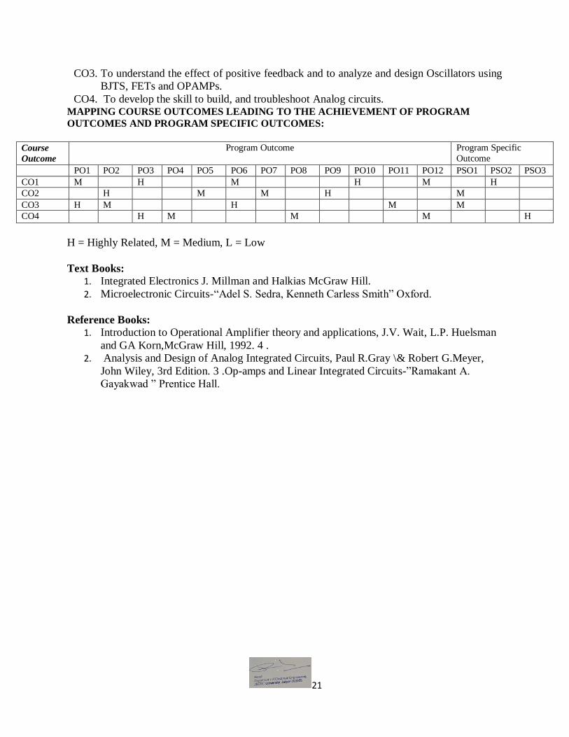
CO3. To understand the effect of positive feedback and to analyze and design Oscillators using
BJTS, FETs and OPAMPs.
CO4. To develop the skill to build, and troubleshoot Analog circuits. MAPPING COURSE OUTCOMES LEADING TO THE ACHIEVEMENT OF PROGRAM
OUTCOMES AND PROGRAM SPECIFIC OUTCOMES:
Course
Outcome
Program Outcome Program Specific
Outcome
PO1 PO2 PO3 PO4 PO5 PO6 PO7 PO8 PO9 PO10 PO11 PO12 PSO1 PSO2 PSO3
CO1 M H M H M H
CO2 H M M H M
CO3 H M H M M
CO4 H M M M H
H = Highly Related, M = Medium, L = Low
Text Books: 1. Integrated Electronics J. Millman and Halkias McGraw Hill.
2. Microelectronic Circuits-“Adel S. Sedra, Kenneth Carless Smith” Oxford.
Reference Books:
1. Introduction to Operational Amplifier theory and applications, J.V. Wait, L.P. Huelsman
and GA Korn,McGraw Hill, 1992. 4 .
2. Analysis and Design of Analog Integrated Circuits, Paul R.Gray \& Robert G.Meyer,
John Wiley, 3rd Edition. 3 .Op-amps and Linear Integrated Circuits-”Ramakant A.
Gayakwad ” Prentice Hall.

22
School of Engineering B. Tech. in Electrical Engineering – Semester III
Contact Hrs per week (L-T-P): 4-0-0
Course Outlines BAS003C - Advanced Engineering Mathematics
OBJECTIVES:
This course aims at providing the necessary basic concepts of a few numerical methods
and give procedures for solving numerically different kinds of problems occurring in
engineering and technology.
Unit 1: Vectors covering, laws of vector algebra, operations- dot, cross, triple products; Vector
function – limits, continuity and derivatives, geometric interpretation; Gradient, divergence
and curl formulae.
Unit 2: Complex Analysis including limits and continuity, derivatives; Analytic Functions;
Cauchy Riemann Equations; Integrals, Cauchy theorem and Cauchy integral formulae;
Taylor’s series, Singular points and poles, Residues, Residue Theorem.
Unit 3 : Evaluation of definite integrals, Conformal mapping, The complex inverse formula,
the Bromwich contour, the use of Residue theorem in finding Laplace transforms; A
sufficient condition for the integral around T to approach zero; The case of infinitely many
singularities.
Unit 4: Mathematical Statistics, Sample space, Events, Random Variables; Definitions of
probability, conditional Probability, expectation and higher order moments, distributions,
examples of (discrete and continuous).
Unit 5: Normal, Poisson, Binomial distributions. Characteristic functions (mean and standard
deviation); Correlation and Regression, Curve Fitting (Linear, Parabolic and Exponential).
OUTCOMES:
CO1. The students will have a clear perception of the power of numerical techniques, ideas
and would be able to demonstrate the applications of these techniques to problems
drawn from industry, management and other engineering fields.
CO2. Expand important mathematical functions in power series and their applications.
CO3. Understand the theory of functions of several variables and its applications .
CO4. Express real life problems into mathematical models using differential equations and
analyse their solutions.

23
MAPPING COURSE OUTCOMES LEADING TO THE ACHIEVEMENT OF PROGRAM
OUTCOMES AND PROGRAM SPECIFIC OUTCOMES:
Course
Outcome
Program Outcome Program Specific
Outcome
PO1 PO2 PO3 PO4 PO5 PO6 PO7 PO8 PO9 PO10 PO11 PO12 PSO1 PSO2 PSO3
CO1 M H H M H H L
CO2 M H M H M M
CO3 M M L H H M H
CO4 L L L M L M
H = Highly Related, M = Medium, L = Low
Text Books:
1. Advance Engineering Mathematics by Erwin Kreyszig, Wiley India.
Reference Book:
1. Advance Engineering Mathematics by H. K Das, S.Chand.
2. Higher Engineering Mathematics by B.V Ramana, MGH.

24
School of Engineering B.Tech. in Electrical Engineering – Semester III
Contact Hrs per week (L-T-P): 3-0-0
Course Outlines
BEL059A- Electrical Power Generation
Unit-1: Conventional Energy Generation Methods-I: (i) Thermal Power plants: Basic
schemes and working principle. (ii) Gas Power Plants: open cycle and closed cycle gas turbine
plants, combined gas & steam plants-basic schemes.
Unit-2: Conventional Energy Generation Methods-II (i) Hydro Power Plants: Classification of
hydroelectric plants. Basic schemes of hydroelectric and pumped storage plants. (ii) Nuclear
Power Plants: Nuclear fission and Nuclear fusion. Fissile and fertile materials. Basic plant
schemes with boiling water reactor, heavy water reactor and fast breeder reactor. Efficiencies of
various power plants.
Unit-3: Non Conventional Energy Generation: Geothermal power plants, Electricity from
biomass, Direct energy conversion systems, Thermo-Electric conversion system, Fuel Cells,
Magneto Hydrodynamic system.
Unit-4: Load Curves: Types of load, chronological load curve, load duration curve, energy load
curve and mass curve. Maximum demand, demand factor, load factor, diversity factor, capacity
factor and utilization. Power factor improvement: Causes and effects of low power factor and
advantages of power factor improvement. Power factor improvement using shunt capacitors and
synchronous condensers.
Unit-5: Tariffs: Objectives of tariffs. General tariff form. Flat demand rate, straight meter rate,
block meter rate. Two part tariff, power factor dependent tariffs, three-part tariff. Spot (time
differentiated) pricing. Selection of Power Plants: Comparative study of thermal, hydro, nuclear
and gas power plants. Base load and peak load plants. Size and types of generating units, types of
reserve and size of plant. Selection and location of power plants.
OUTCOMES:
CO1. Have the knowledge of various types of conventional power plants and their
working, different equipments and instruments used for trouble free operation and
maintenance.
CO2. Various types of storage batteries and their field of applications.
CO3. Know about various types of lamps their working principle, construction, field of
application.
CO4. Design the Fuel Cells & MHDS for various applications.

25
MAPPING COURSE OUTCOMES LEADING TO THE ACHIEVEMENT OF PROGRAM
OUTCOMES AND PROGRAM SPECIFIC OUTCOMES:
Course
Outcome
Program Outcome Program Specific
Outcome
PO1 PO2 PO3 PO4 PO5 PO6 PO7 PO8 PO9 PO10 PO11 PO12 PSO1 PSO2 PSO3
CO1 H M H L L M L
CO2 M H L M H M
CO3 H H L H
CO4 M M H M M L M
H = Highly Related, M = Medium, L = Low
TEXT BOOKS
1. A Course in Electrical power by Soni, Gupta, Bhatnagar.
2. Elements of Electrical Power Station Design by M.V.Deshpande.
RECOMMENDED BOOKS
1. Power station Engineering and Economics by Strotzky and Uopat

26
School of Engineering B.Tech. in Electrical Engineering – Semester III
Contact Hrs per week (L-T-P): 0-0-2
Course Outlines
BEL005A Basic Programming and Simulation Lab
OBJECTIVES:
To expose the students to learn programming and simulation on MATLAB / Sci Lab
software.
List of experiments (Perform any 10):
1. Introduction to simulation software for e.g. MATLAB, Sci Lab, including its installation,
applications, opening of software, extensions used for programming and simulation,
storage of file in hard disk, heaviness of file, saving and running the files, role of
different colours reflected in programs, error identification and rectification etc.
2. To learn and calculate the results using different mathematical functions in command
window.
3. Write a program to calculate the area of triangle and rectangle using definite input values
in the program made in editor window.
4. Write a program to calculate the area of triangle and rectangle using input values from
command window.
5. Write a program using the knowledge of DC machine in such a manner that there is
graphical output plotting between two parameters of DC machine (for e.g. speed control
of DC machine), thereby learning graphic window functions.
6. Write a program to calculate the efficiency of the transformer using the knowledge of
open circuit and short circuit test.
7. Simulate using MATLAB software to learn the application of different mathematical
blocks.
8. Simulate using MATLAB software to learn the application of different control system
blocks.
9. Simulate using MATLAB software to learn the application of different measurement
blocks.
10. Simulate half wave rectifier (uncontrolled) using MATLAB software with R Load.
11. Simulate half wave rectifier (controlled) using MATLAB software with R Load.
12. Simulate half wave rectifier (uncontrolled) using MATLAB software with RL Load.
13. Simulate half wave rectifier (controlled) using MATLAB software with RL Load.
14. Simulate half wave rectifier (uncontrolled) using MATLAB software with RLC Load.
15. Simulate half wave rectifier (controlled) using MATLAB software with RLC Load.
Course Outcome (CO):

27
CO1. Students can now use programming skills to get output on any mathematical objective
function.
CO2. Students can also simulate the electric circuit by connecting different components and
tools available in different block sets.
CO3. To develop their own program to solve their own problems and use this program to solve
similar problems later on.
CO4. Students will get the knowledge about simulink models of the different electrical
systems.
MAPPING COURSE OUTCOMES LEADING TO THE ACHIEVEMENT OF PROGRAM
OUTCOMES AND PROGRAM SPECIFIC OUTCOMES:
Course
Outcome Program Outcome Program Specific Outcome
PO1 PO2 PO3 PO4 PO5 PO6 PO7 PO8 PO9 PO10 PO11 PO12 PSO1 PSO2 PSO3
CO1 M H M H M L M H M
CO2 H M M H H H M
CO3 H M H M H M H
CO4 H M M H L M M M
H = Highly Related, M = Medium, L = Low

28
School of Engineering B.Tech. in Electrical Engineering – Semester III
Contact Hrs per week (L-T-P): 0-0-2
Course Outlines
BEE060A Analog Electronics Lab
List of experiments (Perform any 10):
1. Design a voltage amplifier using BJT in common emitter mode and
(a) Plot I/P vs. O/P voltage and calculate voltage gain.
(b) Draw gain-frequency response and determine band width.
2. Design a voltage amplifier using BJT in common base mode and
(a) Plot I/P vs. O/P voltage and calculate voltage gain.
(b) Draw gain-frequency response and determine band width.
3. Design a voltage amplifier using BJT in common collector mode and
(a) Plot I/P vs. O/P voltage and calculate voltage gain.
(b) Draw gain-frequency response and determine band width.
4. Design voltage series feedback amplifier using BJT / FET. Plot I/P vs. O/P voltage graph.
5. Design a class B Push-pull amplifier.
6. Design and verify adder and substractor circuit using OP-AMP(IC-741).
7. Design and verify differentiator and integrator circuit using OP-AMP(IC-741).
8. Design the square wave oscillator using OP-AMP (IC-741). Find frequency of oscillation.
9. Design of RC phase shift oscillator. Find frequency of oscillation.
10. Design of Wien bridge oscillator. Find frequency of oscillation.
11. Design of Hartley oscillator. Find frequency of oscillation.
12. Design of Colpitts oscillator. Find frequency of oscillation.
13. Design of band pass and band stop filter using OP-AMP(IC-741). Draw frequency response. Find
lower cut-off frequency (FL) and higher cut-off frequency (FH).
14. Design and verify 4 bit analog to digital converter.
15. Design and verify 4 bit digital to analog converter.
Course Outcome (CO):

29
CO1. Understand the characteristics of diodes and transistors
CO2. Design and analyze various rectifier and amplifier circuits
CO3. Design sinusoidal and non-sinusoidal oscillators
CO4. Understand the functioning of OP-AMP and design OP-AMP based circuits.
MAPPING COURSE OUTCOMES LEADING TO THE ACHIEVEMENT OF PROGRAM
OUTCOMES AND PROGRAM SPECIFIC OUTCOMES:
Course
Outcome Program Outcome
Program Specific Outcome
PO1 PO2 PO3 PO4 PO5 PO6 PO7 PO8 PO9 PO10 PO11 PO12 PSO1 PSO2 PSO3
CO1 H M M L M L
CO2 H M M L M
CO3 M M L M M
CO4 L M M H L M
H = Highly Related, M = Medium, L = Low

30
School of Engineering B.Tech. in Electrical Engineering – Semester III
Contact Hrs per week (L-T-P): 0-0-2
Course Outlines
BEL007A- Electrical Machines Lab I OBJECTIVES:
To expose the students to the operation of DC machines and transformers and give them
experimental skill.
List of experiments (Perform any 10):
1. Speed control of D.C. shunt motor by (a) Field current control method & plot the curve for speed vs
field current. (b) Armature voltage control method & plot the curve for speed vs armature voltage.
2. Speed control of a D.C. Motor by Ward Leonard method and to plot the curve for speed vs applied
armature voltage.
3. To determine the efficiency of D.C. Shunt motor by loss summation (Swinburne’s) method.
4. To determine the efficiency of two identical D.C. Machine by Hopkinson’s regenerative test.
5. To perform O.C. and S.C. test on a 1-phase transformer and to determine the parameters of its
equivalent circuit its voltage regulation and efficiency.
6. To perform back-to-back test on two identical 1-phase transformers and find their efficiency &
parameters of the equivalent circuit.
7. To perform parallel operation of two 1-phase transformers and determine their load sharing.
8. To determine the efficiency and voltage regulation of a single-phase transformer by direct loading.
9. To perform OC & SC test on a 3-phase transformer & find its efficiency and parameters of its
equivalent circuit.
10. To perform parallel operation of two 3-phase transformers and determine their load sharing.
11. To study the performance of 3-phase transformer for its various connections, i.e. star/star star/delta,
delta/star and delta/delta and find the magnitude of 3rd harmonic current.
Course Outcome (CO):
CO1. Students can now analyze the efficiency and characteristics of different electrical
machines.

31
CO2. Students will develop the ability to perform different testing methods of transformer and
DC Machines.
CO3. Students will get the knowledge of various parts of a transformer and DC Machines.
CO4. Students Will able to design and solve experimental problem of DC Machines and
transformers.
MAPPING COURSE OUTCOMES LEADING TO THE ACHIEVEMENT OF PROGRAM
OUTCOMES AND PROGRAM SPECIFIC OUTCOMES:
Course
Outcome Program Outcome
Program Specific
Outcome
PO1 PO2 PO3 PO4 PO5 PO6 PO7 PO8 PO9 PO10 PO11 PO12 PSO1 PSO2 PSO3
CO1 H L M M L M L
CO2 M M M M L M H
CO3 L H H H M M H
CO4 M L L H H H M
H = Highly Related, M = Medium, L = Low

32
School of Engineering
B.Tech. in Electrical Engineering – Semester IV
Contact Hrs per week (L-T-P): 3-1-0
Course Outlines
BEL009B- Power Electronics OBJECTIVES:
To be familiar with the working, characteristics and applications of different power
electronic devices.
Unit 1: Power Semiconductor Devices: Construction, Principle of operation, Characteristics and Switching behaviour of various solid-state devices i.e. Power Diodes, SCR, TRIAC, DIAC, GTO, Power MOSFET, IGBT, MCT and Power BJT.
Unit 2: Silicon Control Rectifier: Two-transistor analogy of SCR, triggering circuits of SCR: R, RC, UJT relaxation oscillators& its gate characteristics, SCR ratings & Protection of SCR: Protection against over voltage, over current, dv/dt, di/dt, Gate protection. Methods of SCR Commutation, Series & Parallel operation of SCR.
Unit 3: Phase Control Rectifiers: Single phase half, full and semi converters with R, Rl & RLE load and their performance parameters. Power factor improvement-Extinction angle control, symmetrical angle control, pulse width modulation control and sinusoidal pulse width modulation control.
Unit 4: Three Phase Rectifiers: Three phase half wave, full wave and half wave controlled rectifiers and their performance parameters. Effect of source impedance on the performance of single phase and three phase controlled rectifiers. Single-phase and three phase Dual Converter. Unit 5: Choppers: Introduction of choppers, principle of operation of choppers, classification of choppers (Type A chopper, Type B chopper, Type C chopper and Type D chopper,) and applications of choppers.
OUTCOMES:
CO1. Articulate the basics of power electronic devices
CO2. Students can now apply the knowledge of working of different power electronic
devices to control electrical and electronic systems.
CO3. Ability to express communication methods.
CO4. Ability to express characteristics of SCR, BJT, MOSFET and IGBT.
MAPPING COURSE OUTCOMES LEADING TO THE ACHIEVEMENT OF PROGRAM
OUTCOMES AND PROGRAM SPECIFIC OUTCOMES: Course Outcome Program Outcome Program Specific Outcome
PO1 PO2 PO3 PO4 PO5 PO6 PO7 PO8 PO9 PO10 PO11 PO12 PSO1 PSO2 PSO3
CO1 M H L H M H M L
CO2 L M M H H M H
CO3 M L L H M M L M
CO4 L H M M H
33
H = Highly Related, M = Medium, L = Low
Text Books:
1. PS Bhimbra. “Power Electronics”, Khanna Publishers.
2. M.H. Rashid,“Power Electronics: Circuits, Devices & Applications”, Prentice Hall of
India Ltd.
Reference Book:
1. AK Gupta and LP Singh, “Power Electronics”, Dhanpat Rai Publishing Co. 2. Rama Reddy, “Fundamental of Power Electronics”, Narosa Publishing.
3. MD Singh and KB Khanchandani, “Power Electronics” TMH Edition.
4. G.K. Dubey and C.R. Kasarbada “Power Electronics and Drives”, Tata McGraw-Hill

34
School of Engineering
B. Tech. in Electrical Engineering – Semester IV
Contact Hrs per week (L-T-P): 3-1-0
Course Outlines
BEL010B- Electrical Machines II
OBJECTIVES:
To study the working principles of electrical machines using the concepts of
electromechanical energy conversion principles.
Derive expressions for generated voltage and torque developed in various AC Machines. Unit 1: Basic concepts of AC Electrical Machines: Introduction, Idea of rotating magnetic field, mmf of concentrated Coil, mmf of distributed winding ,Winding factors, Generated emf. Unit 2: Induction Machines: Principle of Operation Construction: cage and wound rotors, Equivalent circuit, Performance analysis, Torque-slip characteristics, Testing-Running light and blocked rotor test, load test, Effect of rotor resistance, Deep bar and double cage induction motor, Starting- Starting methods of squirrel cage and wound rotor induction motor, Speed Control- Various methods of speed control of squirrel cage and wound rotor induction motor, Effects of space harmonics, application.
Unit 3: Single phase Induction Motors: Constructional features, double revolving field theory, equivalent circuit, determination of parameters. Split phase starting methods and applications.
Unit 4: Synchronous Generator: Introduction, Construction, advantages of rotating field, types of rotors, emf equation, excitation systems, equivalent circuit and their phasor diagrams, voltage regulation, synchronous impedance method, mmf method. Zero power factor method, two reaction theory of salient pole rotor, phasor diagram, power developed and power angle characteristics of salient pole machine, determination of Xd and Xq, synchronization, synchronizing power and torque, parallel operation application. Unit 5: Synchronous Motors: Introduction, construction, principal of operation, starting of synchronous motor, equivalent circuit and phasor diagrams, power and torque, performance calculation, speed torque characteristics, power factor control-effect of change of excitation. V-curve and inverted V-curve, synchronous condenser and reactors, synchronous phase modifiers, hunting-causes and remedies, applications, synchronous motor application.
OUTCOMES:
CO1. Students can now apply the knowledge of AC machines in testing them for the study of
speed control, efficiency calculation and their various characteristics.
CO2. Can design and develop new machines
CO3. Design the machines for environmental friendly
CO4. Can used Modern tools for control

35
MAPPING COURSE OUTCOMES LEADING TO THE ACHIEVEMENT OF PROGRAM
OUTCOMES AND PROGRAM SPECIFIC OUTCOMES:
Course
Outcome Program Outcome
Program Specific
Outcome
PO1 PO2 PO3 PO4 PO5 PO6 PO7 PO8 PO9 PO10 PO11 PO12 PSO1 PSO2 PSO3
CO1 M L L M H H L L
CO2 L H H H H M
CO3 M H M L H M M M H
CO4 L H M M H
H = Highly Related, M = Medium; L = Low
Text Books:
1. PS Bhimbra, “Electrical Machinery”, Khanna Publishers.
2. Ashfaq Husain : Electric Machines, Dhanpat Rai & Co.(Pvt) Ltd , 2nd Edition 2006
Reference Book:
1. Nagrath and Kothari,” Electric Machines” TMH
2. BL Theraja, A textbook of electrical technology, Vol-II, S. Chand & Co. LTD.
3. Fitzgerald and Kingsley, “Electric Machinery” McGraw Hill
4. Alexander S. Langsdorf, “AC Machines”, Tata McGraw Hill.
5. MG Say, “Theory Performance and Design of AC Machines” CBS Publisher
36
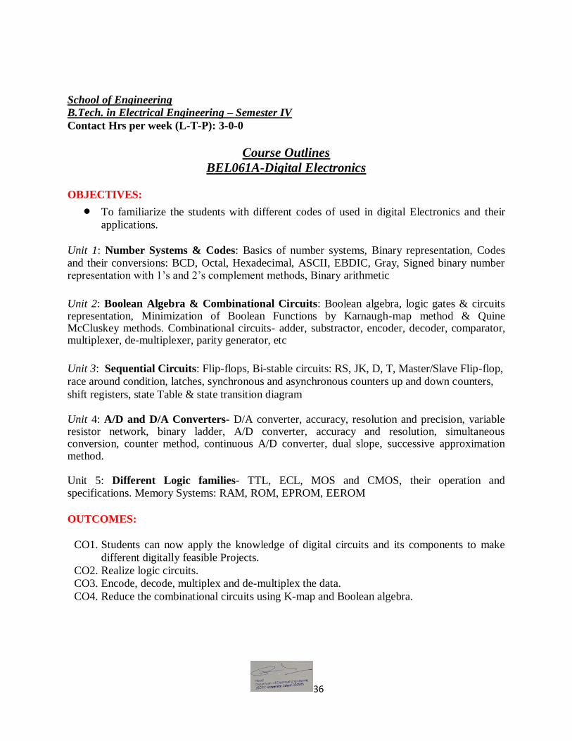
School of Engineering
B.Tech. in Electrical Engineering – Semester IV
Contact Hrs per week (L-T-P): 3-0-0
Course Outlines
BEL061A-Digital Electronics
OBJECTIVES:
To familiarize the students with different codes of used in digital Electronics and their
applications.
Unit 1: Number Systems & Codes: Basics of number systems, Binary representation, Codes and their conversions: BCD, Octal, Hexadecimal, ASCII, EBDIC, Gray, Signed binary number representation with 1’s and 2’s complement methods, Binary arithmetic
Unit 2: Boolean Algebra & Combinational Circuits: Boolean algebra, logic gates & circuits representation, Minimization of Boolean Functions by Karnaugh-map method & Quine McCluskey methods. Combinational circuits- adder, substractor, encoder, decoder, comparator, multiplexer, de-multiplexer, parity generator, etc
Unit 3: Sequential Circuits: Flip-flops, Bi-stable circuits: RS, JK, D, T, Master/Slave Flip-flop,
race around condition, latches, synchronous and asynchronous counters up and down counters,
shift registers, state Table & state transition diagram Unit 4: A/D and D/A Converters- D/A converter, accuracy, resolution and precision, variable resistor network, binary ladder, A/D converter, accuracy and resolution, simultaneous conversion, counter method, continuous A/D converter, dual slope, successive approximation method. Unit 5: Different Logic families- TTL, ECL, MOS and CMOS, their operation and specifications. Memory Systems: RAM, ROM, EPROM, EEROM
OUTCOMES:
CO1. Students can now apply the knowledge of digital circuits and its components to make
different digitally feasible Projects.
CO2. Realize logic circuits.
CO3. Encode, decode, multiplex and de-multiplex the data.
CO4. Reduce the combinational circuits using K-map and Boolean algebra.
37
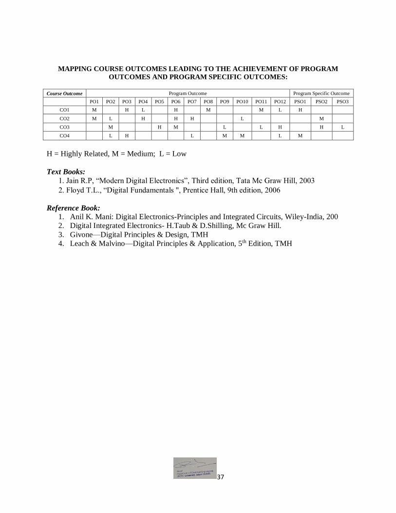
MAPPING COURSE OUTCOMES LEADING TO THE ACHIEVEMENT OF PROGRAM
OUTCOMES AND PROGRAM SPECIFIC OUTCOMES:
Course Outcome Program Outcome Program Specific Outcome
PO1 PO2 PO3 PO4 PO5 PO6 PO7 PO8 PO9 PO10 PO11 PO12 PSO1 PSO2 PSO3
CO1 M H L H M M L H
CO2 M L H H H L M
CO3 M H M L L H H L
CO4 L H L M M L M
H = Highly Related, M = Medium; L = Low
Text Books:
1. Jain R.P, “Modern Digital Electronics”, Third edition, Tata Mc Graw Hill, 2003
2. Floyd T.L., “Digital Fundamentals ", Prentice Hall, 9th edition, 2006
Reference Book:
1. Anil K. Mani: Digital Electronics-Principles and Integrated Circuits, Wiley-India, 200
2. Digital Integrated Electronics- H.Taub & D.Shilling, Mc Graw Hill.
3. Givone—Digital Principles & Design, TMH
4. Leach & Malvino—Digital Principles & Application, 5th Edition, TMH

38
School of Engineering
B.Tech. in Electrical Engineering – Semester IV
Contact Hrs per week (L-T-P): 3-0-0
Course Outlines
BEL062A-Transmission and Distribution Systems
OBJECTIVE:
To make the students understand the concepts of generation, transmission and
distribution of power.
Unit 1: Distribution Systems- DC 2–wire & 3–wire systems, AC single phase, 3 ph & 4-wire systems, Distribution Systems: primary and secondary distribution systems, concentrated and uniformly distributed loads on distributors fed at one and both ends, ring distribution, sub-mains and tapered mains, voltage drop and power loss calculations, voltage regulators.
Unit 2: Neutral Grounding: Necessity of neutral grounding, Effectively Grounded System,
Ungrounded System, Methods of Neutral Grounding: Resonant Grounding, Generator Neutral
Breaker, Grounding Practices, Earthing transformer. Insulators: Pin, shackle, suspension, post
and strain insulators. Voltage distribution across an insulator string, grading and methods of
improving string efficiency.
Unit 3: Overhead Transmission Lines- Types of Conductors, Line parameters; calculation of inductance and capacitance of single and double circuit transmission lines, three phase lines with stranded and bundle conductors, Generalized ABCD constants &performance of short, medium and long lines, Regulation and efficiency of long lines, Ferranti effect ,Surge impedance loading Unit 4: Mechanical Design of Transmission Lines- Conductor material and types of conductor.
Conductor arrangements and spacing. Calculation of sag and tension, supports at different levels,
effect of wind and ice loading, stringing chart and sag template. Conductor vibrations and
vibration dampers. Unit 5: Underground Cables :Insulation, insulating materials, Extra high voltage cables, grading of cables, insulation resistance, Capacitance of a single core and three core cables, Overhead lines versus underground cables, types of cables, Dielectric loss, heating of cables.
Course Outcome (CO):
CO1. Students can able to understand with various factors which can affect power generation.
CO2. Students now know able to identify the performance of Transmission & distribution
network used.
CO3. To identify the efficiency of distribution & Transmission lines as well as its efficiency
under various operating conditions.
CO4. To understand Mechanical design of Transmission & distribution depending upon the
requirement.

39
MAPPING COURSE OUTCOMES LEADING TO THE ACHIEVEMENT OF PROGRAM
OUTCOMES AND PROGRAM SPECIFIC OUTCOMES:
Course Outcome Program Outcome Program Specific Outcome
PO1 PO2 PO3 PO4 PO5 PO6 PO7 PO8 PO9 PO10 PO11 PO12 PSO1 PSO2 PSO3
CO1 L H L H M H H
CO2 H M L L M M M
CO3 L L H H M H L H L M L
CO4 M M L H M
H = Highly Related, M = Medium, L = Low
Text books:
1. Wadhwa, C.L., “Electric Power Systems”, Second Edition, Wiley Eastern Limited
2. Nagrath, I.J. and Kothari, D.P., “Power System Engineering”, TMH.
Reference Books:
1. Grainger John, J. and Stevenson, Jr. W.D., “Power System Analysis”, McGraw Hill,
2. Harder Edwin, I., “Fundamentals of Energy Production”, John Wiley and Sons
3. Deshpande, M.V., “Elements of Electric Power Station Design”, A.H. Wheeler and Co.
Allahabad
4. BR Gupta, “Power System Analysis and Design”, S. Chand.

40
School of Engineering
B.Tech. in Electrical Engineering – Semester IV
Contact Hrs per week (L-T-P): 3-0-0
Course Outlines
BAS004C Computer Aided Numerical Methods
OBJECTIVES:
Numerical methods are that branch that deals with the approximate solution formations of
various mathematical models.
Unit-1: Approximation in numerical computation, Truncation and rounding errors; Interpolation:
Lagrange’s Interpolation, Newton forward & backward differences Interpolation, Newton
divided difference.
Unit- 2: Numerical Integration: Trapezoidal, Rule, Simson’s 1/3 Rule, Weddle’ Rule; Numerical
Solution of a system of linear equation ; Gauss elimination method, Matrix Inversion, LU
Factorization method, Gauss Jacobi method, Gauss Seidel method
Unit- 3: Algebraic Equation: Bisection method, Secant method, Regular- Falsi method, Solution
of polynomial and transcendental equations by Newton- Raphson method.
Unit- 4: Numerical solution of ordinary differential equation: Taylor’s series method, Euler’s
method, 4th order Runge - Kutta method, and Predictor-Corrector method.
Unit 5: Introduction to Finite Element Method for solving field problems. Stress and
Equilibrium. Boundary conditions. Strain — Displacement relations. Stress — strain relations for
2-D and 3-D Elastic problems.
OUTCOMES:
CO1. After completing this course the student must demonstrate the knowledge and ability to
solve these mathematical models by - analytical, graphical, or approximations.
CO2. Be familiar with numerical integration and differentiation
CO3. Be familiar with numerical solution of ordinary differential equations
CO4. Be familiar with calculation and interpretation of errors in numerical methods,

41
MAPPING COURSE OUTCOMES LEADING TO THE ACHIEVEMENT OF PROGRAM
OUTCOMES AND PROGRAM SPECIFIC OUTCOMES:
Course Outcome Program Outcome Program Specific Outcome
PO1 PO2 PO3 PO4 PO5 PO6 PO7 PO8 PO9 PO10 PO11 PO12 PSO1 PSO2 PSO3
CO1 H H M L H M M L
CO2 L L M H H M M H
CO3 M L H H M L M
CO4 M L H L H H H
H = Highly Related, M = Medium; L = Low
Text Books:
1. Numerical Methods (Problems and Solution) by Jain, Iyengar , & Jain
2. Numerical Analysis – Rao G.S., New Age International
Reference Books:
1. Numerical Analysis & Algorithms, Pradeep Niyogi, TMH, 1st ed.
2. Numerical Mathematical Analysis by J.B.Scarborough
3. Balagurusamy: Numerical Methods
4. Numerical Methods (Problems and Solution) by Jain, Iyengar , & Jain
5. Numerical Methods In Computer Applications – P.U.Wayse. EPH
6. Numerical Solutions of Differential Equations – Jain M.K.,New Age
7. Numerical Analysis – Rao G.S.,New Age International
8. Discrete Mathematical Structures – Rao G.S., New Age International
9. Foundations of Discrete Mathematics – Joshi K.D., New Age International

42
School of Engineering
B.Tech. in Electrical Engineering – Semester IV
Contact Hrs per week (L-T-P): 3-0-0
Course Outlines
BEL003B- Measurements and Instruments
OBJECTIVES:
To introduce the students to the standards which are available for measurement of
different physical quantities.
To introduce the students to the instruments which are available for measurement of
different physical quantities.
Unit 1: Units, Standards and Errors: Absolute standards (International, Primary, and
Secondary Standards), True Value, Errors (Gross, Systematic, Random); Static Characteristic of
Instruments (Accuracy, Precision, Sensitivity, Resolution and threshold). Measuring
Instruments: Moving coil, moving iron, electrodynamic and induction instruments-construction,
operation, torque equation and errors.
Unit 2: Instrument transformer: Construction and operation of current transformer, potential
transformer and CVT; Testing of CTs and PTs. Applications of CTs and PTs for the
measurement of current, voltage, power and energy.Energy Meter:Applications of instruments
for measurement of current, voltage, single-phase power and singlephase energy. Testing and
calibration of single-phase energy meter by phantom loading.
Unit 3: Potentiometers: Construction, operation and standardization of DC potentiometers–
slide wire and Crompton potentiometers. Use of potentiometer for measurement of resistance
and voltmeter and ammeter calibrations. Power Factor And Frequency Meters: Construction,
operation, principle, Torque equation, Advantages and disadvantages of Single phase power
factor meters (Electrodynamic and Moving Iron types) and Frequency meters (Electrical
Resonance Type). Unit 4: Resistance Measurement: Introduction, sensitivity and limitations of Wheatstone
bridge; Kelvin’s double bridge method, Difficulties in high resistance measurements,
Measurement of high resistance by direct deflection, loss of charge method, Megohm bridge and
Megger.
Unit 5: AC Bridges: General balance equation; circuit diagram, Phasor diagram, Advantages,
disadvantages and applications of Maxwell’s bridge, Hays bridge & Anderson bridge for self
inductance, Heaviside’s bridge for mutual inductance, De-Sauty’s bridge for capacipance
measurement, Wien’s bridges for frequency measurement and Schering bridge. .

43
Course Outcome (CO):
CO1. Students can now select different instruments (based on type, range and accuracy) to
measure different physical quantities.
CO2. Understand the measurement standards and analyze the measurement errors.
CO3. Also they can compare different instruments to ascertain which is best for a particular
condition and requirement.
CO4. Suggest the kind of instruments and instrumentation schemes suitable for typical
measurements.
MAPPING COURSE OUTCOMES LEADING TO THE ACHIEVEMENT OF PROGRAM
OUTCOMES AND PROGRAM SPECIFIC OUTCOMES: Course Outcome Program Outcome Program Specific Outcome
PO1 PO2 PO3 PO4 PO5 PO6 PO7 PO8 PO9 PO10 PO11 PO12 PSO1 PSO2 PSO3
CO1 H M H M M M H
CO2 M H M M H H M H
CO3 M H M H M
CO4 H H M L M H L M H
H = Highly Related, M = Medium, L = Low
Text Books:
1. A.K. Sawhney, “Electrical and Electronic Measurement and Instrument”, Dhanpat Rai and
Sons
Reference Books:
1. Rajendra Prasad, “Electrical Measurement and Measuring Instrument” Khanna
Publications.
2. EW Golding and F.C. Widdis, “Electrical Measurement and Measuring Instrument”, AH
Wheeler and Co. India.
3. Forest K. Harries,“Electrical Measurement”,Willey Eastern Pvt. Ltd. India .
4. M.B. Stout ,“Basic Electrical Measurement” Prentice hall of India.
5. W.D. Cooper,” Electronic Instrument & Measurement Technique“Prentice Hall
International.

44
School of Engineering B.Tech. in Electrical Engineering – Semester III
Contact Hrs per week (L-T-P): 0-0-2
Course Outlines
BEL006A- Measurements and Instruments Lab
OBJECTIVES:
To introduce the basic functional elements of instrumentation and to learn the comparison
between various measurements techniques and display devices.
List of Experiments (Perform any 10):
1. To perform the working of CRO and to learn to take readings of frequency, unknown
voltage etc using divisions method and using plotting paper method.
2. To perform the working of a) Megger to calculate unknown high resistance, b) Tong-
tester to calculate unknown and c) pf meter to calculate unknown pf.
3. To perform the working of single phase energy meter and take readings at unknown load.
4. To measure power and power factor by three voltmeter method.
5. To measure power and power factor by three ammeter method.
6. To calibrate an ammeter using DC slide wire potentiometer.
7. To calibrate a voltmeter using Crompton potentiometer.
8. To measure low resistance by Crompton potentiometer.
9. To measure Low resistance by Kelvin's double bridge.
10. To measure earth resistance using fall of potential method.
11. To measure resistance using Wheatstone bridge.
12. To measure inductance by Maxwell’s bridge.
13. To measure unknown inductance by Hay’s bridge.
14. To measure self-inductance using Anderson's bridge.
15. To measure capacitance using De Sauty Bridge.
16. To measure frequency using Wien’s bridge.
17. To measure frequency using vibrating reed type frequency meter. Course Outcome (CO):
CO1: Students can now use the above instruments to measure unknown quantity or verify the
given known physical quantity.
CO2: Students should be able to know performance of various electrical circuits, ac bridges,
instruments, measurement procedures.

45
CO3: Students can use different measuring instruments and their practical aspects including
accuracy and calibration of these instruments.
CO4: Students are able to understand the measurement techniques used for industrial purpose.
MAPPING COURSE OUTCOMES LEADING TO THE ACHIEVEMENT OF PROGRAM
OUTCOMES AND PROGRAM SPECIFIC OUTCOMES:
Course
Outcome Program Outcome
Program Specific
Outcome
PO1 PO2 PO3 PO4 PO5 PO6 PO7 PO8 PO9 PO10 PO11 PO12 PSO1 PSO2 PSO3
CO1 H M H M H M M M
CO2 H M H H H M H
CO3 M H H H M L H
CO4 H H M H L H M L
H = Highly Related, M = Medium, L = Low

46
School of Engineering B.Tech. in Electrical Engineering – Semester IV
Contact Hrs per week (L-T-P): 0-0-2
Course Outlines
BEL011A Power Electronics Lab
OBJECTIVES:
To enable the students to verify the behavior of power electronics devices based on
experimentation.
List of Experiments (Perform any 10):
1. To perform the comparison of following power electronics devices regarding ratings,
performance characteristics and applications: Power Diode, Power Transistor, Thyristor,
DIAC, TRIAC, GTO, MOSFET, MCT and SIT.
2. To plot V-I characteristics of SCR and measure forward breakdown voltage, latching and
holding currents.
3. To plot the V-I characteristics of TRIAC and DIAC.
4. To draw output characteristics of MOSFET and IGBT.
5. To draw transfer characteristics of MOSFET and IGBT.
6. To draw UJT static emitter characteristics and study the variation in peak point and valley
point.
7. To test firing circuits for SCR-R, RC and UJT firing circuits.
8. To test three phase diode bridge rectifier with R and RL loads.
9. To obtain waveforms of single-phase half wave controlled rectifier with and without
Filters and also find the variation of output voltage with respect to firing angle.
10. To obtain waveforms of single-phase half controlled bridge rectifier with R and RL loads.
To test the effect of freewheeling diode.
11. To obtain waveforms of single-phase full controlled bridge converter with R and RL
loads.
12. To perform the rectification and inversion operations on single-phase full controlled
bridge converter with R and RL loads with and without a freewheeling diode.
13. To control the speed of a DC motor using single-phase half controlled bridge rectifier and
full controlled bridge rectifier and plot armature voltage versus speed characteristics.
14. To perform the forced commutation circuits of SCR.
15. To perform the experiment on protection circuits of SCR: (i) dv/dt (ii) di/dt (iii) Over
voltage (iv) Over current.
16. To perform the firing circuit of SCR using ramp-comparator scheme.
17. To perform the firing circuit of SCR using cosine-wave scheme.
18. To perform the firing circuit of SCR using Op-amps and Gates.
19. To perform the digital firing circuit of SCR.

47
Course Outcomes (CO):
CO1. Students can now compare the effect of different power electronic devices on the basis of
their applications and performance characteristics.
CO2. To implement the phase controlled switching using DIAC and TRIAC.
CO3. To realize different type of triggering circuits for particular applications.
CO4. Students will able to understand the basics of different power electronic devices for
industrial applications.
MAPPING COURSE OUTCOMES LEADING TO THE ACHIEVEMENT OF PROGRAM
OUTCOMES AND PROGRAM SPECIFIC OUTCOMES:
Course Outcome Program Outcome Program Specific Outcome
PO1 PO2 PO3 PO4 PO5 PO6 PO7 PO8 PO9 PO10 PO11 PO12 PSO1 PSO2 PSO3
CO1 H H M H L H L
CO2 L H L M H M H
CO3 M H M M L H M M M M
CO4 L H M H M M
H = Highly Related, M = Medium, L = Low

48
School of Engineering B.Tech. in Electrical Engineering – Semester IV
Contact Hrs per week (L-T-P): 0-0-2
Course Outlines
BEL012A- Electrical Machines Lab II
OBJECTIVES:
To expose the students to the operation of transformers, synchronous machines and
induction motors and give them experimental skill.
List of experiments (Perform any 10):
1. Separation of transformer core losses and to determine the hystersis and eddy current losses
at rated voltage and frequency.
2. To plot the O.C.C. & S.C.C. of an alternator and to determine its regulation by synchronous
impedance method.
3. To synchronize an alternator across the infinite bus (RSEB) & summarize the effects of
variation of excitation on load sharing.
4. To plot the V-curve for a synchronous motor for different values of loads.
5. To perform sumpner’s back-to- back test on 3 phase transformers, find its efficiency &
parameters for its equivalent circuits.
6. To perform the heat run test on a delta/delta connected 3-phase transformer and determine
the parameters for its equivalent circuit.
7. To perform no load and blocked rotor test on a 3 phase induction motor and to determine
the parameters of its equivalent circuits. Draw the circle diagram and compute the following
(i) Max. Torque (ii) Current (iii) slip (iv) p.f. (v) Efficiency.
8. To perform the load test on a 3-phase induction motor and determine its performance
characteristics (a) Speed vs load curve (b) p.f. vs load curve (c) Efficiency vs load curve (d)
Speed vs torque curve
9. Determination of losses and efficiency of an alternator.
10. To find Xd and Xq of a salient pole synchronous machine by slip test.
Course Outcomes (CO):
CO1. Students can now analyze the efficiency and characteristics of different electrical
machines.
CO2. To understand the constructional details of various machines.
CO3. To compare the obtained characteristics with the theoretical one.
CO4. To understand various method of speed control of motors. MAPPING COURSE OUTCOMES LEADING TO THE ACHIEVEMENT OF PROGRAM
OUTCOMES AND PROGRAM SPECIFIC OUTCOMES: Course Outcome Program Outcome Program Specific Outcome
PO1 PO2 PO3 PO4 PO5 PO6 PO7 PO8 PO9 PO10 PO11 PO12 PSO1 PSO2 PSO3
CO1 L M H L H M M L
CO2 L H M H H M M H
CO3 H L M H M L M
CO4 M M H L H H H
H = Highly Related, M = Medium; L = Low

49
School of Engineering B.Tech. in Electrical Engineering – Semester IV
Contact Hrs per week (L-T-P): 0-0-2
Course Outlines
BEL063A- Computer Aided Numerical Method Lab
List of Experiments (Perform any 10):
1. To deduce error involved in polynomial equation.
2. To Find out the root of the Algebraic and Transcendental equations using Bisection
method.
3. To Find out the root of the Algebraic and Transcendental equations using Regula-Falsi
method.
4. To Find out the root of the Algebraic and Transcendental equations using Newton-
Raphson method.
5. To Find out the root of the Algebraic and Transcendental equations using Iterative
method.
6. To implement Numerical Integration using Trapezoidal rule.
7. To implement Numerical Integration using Simpson 1/3 rule.
8. To implement Numerical Integration Simpson 3/8 rule.
9. To implement Newton‟s Forward Interpolation formula.
10. To implement Newton‟s Backward Interpolation formula.
11. To implement Gauss Forward Interpolation formula.
12. To implement Gauss Backward Interpolation formula.
13. To implement Bessel‟s Interpolation formula.
14. To implement Sterling‟s Interpolation formula.
15. To implement Newton‟s Divided Difference formula.
16. To implement Langrange‟s Interpolation formula.
17. To implement Numerical Differentiations.
18. To implement Least Square Method for curve fitting.
Course Outcomes (CO):
CO1. Students can now analyze the algebraic and transcendental equations with different
method.
CO2. To understand the gauss interpolation formula.
CO3. To implement Numerical Integration techniques.
CO4. To compare among different numerical techniques. MAPPING COURSE OUTCOMES LEADING TO THE ACHIEVEMENT OF PROGRAM
OUTCOMES AND PROGRAM SPECIFIC OUTCOMES: Course Outcome Program Outcome Program Specific Outcome
PO1 PO2 PO3 PO4 PO5 PO6 PO7 PO8 PO9 PO10 PO11 PO12 PSO1 PSO2 PSO3
CO1 H M M M L M
CO2 M L L H
CO3 H L M M M L
CO4 M H M L M

50
H = Highly Related, M = Medium; L = Low
School of Engineering B.Tech. in Electrical Engineering – Semester V
Contact Hrs per week (L-T-P): 3-0-0
Course Outlines
BEL013A Control Systems
OBJECTIVE:
The objective of any design problem is a statement of what the final system is to achieve,
and this applies to control system design as well.
This course deals with techniques to meet out above objective.
Unit 1: Introduction to Control Systems- Concept of control, control system terminology,
classification of Control Systems. Mathematical Models of Systems- Differential equations of
physical systems, transfer function of linear systems, block diagram models, signal flow graph.
Unit2: Time Response Analysis- Time response analysis - First Order Systems – Impulse,
Ramp and Step Response analysis of second order systems - Steady state errors – P, PI, PD and
PID Compensation.
UNIT 3:Frequency Response Analysis- Frequency Response - Bode Plot, Polar Plot, Nyquist
Plot - Frequency Domain specifications from the plots - Constant M and N Circles - Nichol‟s
Chart - Use of Nichol‟s Chart in Control System Analysis. Series, Parallel, series-parallel
Compensators - Lead, Lag, and Lead Lag Compensators.
UNIT 4:Stability Analysis- Stability, Routh-Hurwitz Criterion, Root Locus Technique,
Construction of Root Locus, Stability, Dominant Poles, Application of Root Locus Diagram -
Nyquist Stability Criterion - Relative Stability.
Unit5: State Variable Models- State variables of a dynamic system, state equation, transfer
function from the state equation and vice-versa. Ackerman’s formula, limitations of state
variable feedback.Introduction to P/I/D and ON-OFF control actions.
Course Outcome (CO):
CO1. Students can able to understand control circuits with various components and get
desired outputs.
CO2. Students now know the working and applications different control feedback & its
performance.
CO3. To identify the stability conditions of control circuits used for that particular
application.
CO4. To design any control controller depending upon the requirement.

51
MAPPING COURSE OUTCOMES LEADING TO THE ACHIEVEMENT OF PROGRAM
OUTCOMES AND PROGRAM SPECIFIC OUTCOMES:
Course Outcome Program Outcome Program Specific Outcome
PO1 PO2 PO3 PO4 PO5 PO6 PO7 PO8 PO9 PO10 PO11 PO12 PSO1 PSO2 PSO3
CO1 H H M L H M M L
CO2 L L M H H M M H
CO3 M L H H M L M
CO4 M L H L H H H
H = Highly Related, M = Medium; L = Low
Text books:
1. I.J Nagrath and M.Gopal, “Control System Engg”, TMH
2. BS Manke, “Linear control systems”, Khanna Publishers.
Reference Books:
1 M.Gopal, “Control Systems: Principles and Design”, TMH
2 BC Kuo, “Automatic Control System”, PHI
3 Ogata, “Control System Engg”, PHI
4 RC Dorf and RH Bishop, “Modern Control Systems”, Addison-Wesley Publishers

52
School of Engineering B.Tech. in Electrical Engineering – Semester V
Contact Hrs per week (L-T-P): 2-0-0
Course Outlines
BCO003A Object Oriented Programming with C++
OBJECTIVE: To perform object oriented programming solution and develop solutions to problems
demonstrating usage of control structure, modularity, classes, I/O and the scope of the
class members
To demonstrate adeptness of object oriented programming in developing solution to
problems demonstrating usage of data abstraction, encapsulation and inheritance
To demonstrate ability to implement one or more patterns involving dynamic binding and
utilization of polymorphism in the solution of problems
To learn syntax and features of exception handling Unit 1: C++ Overview, C++ Characteristics, Object-Oriented Terminology, Polymorphism, encapsulation ,inheritance, Object-Oriented Paradigm, Abstract Data Types, I/O Services, Standard Template Library, Standards Compliance, Functions and Variables. Declaration and Definition Unit 2: Variables: Dynamic Creation and Derived Data, Arrays and Strings in C++,Classes in C++, Defining Classes in C++, Classes and Encapsulation, Member Functions, Instantiating and Using Classes. Friend function ,Inline function Unit 3: Using Constructors, Multiple Constructors and Initialization Lists, Using Destructors to Destroy Instances, Using Destructors to Destroy Instances, Operator Overloading: operator overloading of unary and binary operator, Function Overloading, Working with Overloaded Operator Methods, Initialization and Assignment, Initialization vs. Assignment.
Unit 4: Constant and Static Class Members, Inheritance, Overview of Inheritance, Defining Base
and Derived Classes, Single, Multiple, multilevel, hybrid hierarchical inheritance. Constructor
and Destructor Calls in inheritance, virtual function, virtual base class,
Unit 5: Input and Output in C++ Programs, Standard Streams, Manipulators, Unformatted Input and Output. Working with files.
Course Outcome (CO):
CO1. Understand object-oriented programming features in C++,
CO2. Apply these features to program design and implementation,
CO3. Understand object-oriented concepts and how they are supported by C++,

53
CO4. Gain some practical experience of C++.
MAPPING COURSE OUTCOMES LEADING TO THE ACHIEVEMENT OF PROGRAM
OUTCOMES AND PROGRAM SPECIFIC OUTCOMES:
Course Outcome Program Outcome Program Specific Outcome
PO1 PO2 PO3 PO4 PO5 PO6 PO7 PO8 PO9 PO10 PO11 PO12 PSO1 PSO2 PSO3
CO1 H M M M M H
CO2 M L M M M
CO3 H L M H M
CO4 M M L M H L
H = Highly Related, M = Medium; L = Low
Text Books:
1. Let Us C: Bala Guruswamy, TATA McGraw Hill.
2. Programming with C, C++: Yashwant Kanetkar
Reference Books:
1. C++: The Complete Reference.
2. The C++ Programming Language: Bjarne Stroustrup

54
School of Engineering B.Tech. in Electrical Engineering – Semester V
Contact Hrs per week (L-T-P): 3-0-0
Course Outlines
BEE020A Microprocessor and Microcontroller System
OBJECTIVE:
The course emphasizes on basic structure, programming and advancement in the field of
microprocessor and microcontrollers. Unit 1:Evolution of microprocessors, technological trends in microprocessordevelopment. The Intel family tree. CISC Versus RISC. Applications of Microprocessors. 8086 Block diagram; description of data registers, address registers,pointer and index registers, PSW, Queue, BIU and EU. 8086 Pin diagram descriptions. Microprocessor BUS types and buffering techniques, 8086 minimum mode and maximum mode CPU module. Instruction formats, addressing modes. Unit 2: Data transfer instructions, string instructions, logical instructions, arithmetic instructions, transfer of control instructions, process control instructions; Assembler directives. Writing assembly Language programs for logical processing, arithmetic processing, timing delays; loops, data conversions. Writing procedures, Data tables, modular programming, Macros. Unit 3:8086 Interrupt types and interrupt vector table. DOS interrupt INT 21 h functions. INT 10h and INT 16h functions. Intel 8086 bus cycles, instruction queue, 8086 CPU Read/Write timing diagrams in minimum mode and maximum mode, reset operation, wait state, halt state, hold state, lock operation, interrupt processing. Address decoding techniques. Unit 4:Intel’s 8255 description, 8255 different modes operation and interfacing with 8086.
Interfacing ADC(0808/0809),DAC-(0808) using 8255. Wave form generation. Intel’s 8251
description and operation. Intel’s 8259. DMA operation. Intel’s 8237. Intel’s 8279. Intel’s 8253.
Introduction to i3,i5,i7 processors.
Unit 5:8051 microcontroller pin diagram, Block diagram, Flag, RAM configuration, Register Banks, addressing modes, instruction set, 8051 programming and interfacing.
Course Outcome (CO):
CO1. Students will be able to verify assembly-language instructions which are used in
microprocessor, cache memories, and parallel execution
CO2. Students now know able to understand the parts of a computer and the workings of each
part buses and memories.
CO3. To distinguish and analyze the properties of Microprocessors & Microcontroller.

55
CO4. To understand illustrate how the different peripherals (8255, 8253 etc.) are interfaced
with Microprocessor
MAPPING COURSE OUTCOMES LEADING TO THE ACHIEVEMENT OF PROGRAM
OUTCOMES AND PROGRAM SPECIFIC OUTCOMES: Course Outcome Program Outcome Program Specific Outcome
PO1 PO2 PO3 PO4 PO5 PO6 PO7 PO8 PO9 PO10 PO11 PO12 PSO1 PSO2 PSO3
CO1 H H M L H M M L
CO2 L L M H H M M H
CO3 M L H H M L M
CO4 M L H L H H H
H = Highly Related, M = Medium; L = Low
Text Books:
1. Douglas Hall Microprocessors Interfacing, Tata McGraw Hill, 1991.
2. The 8051 Microcontroller and Embedded systems by Muhammad Ali Mazidi Pearson Education Asia. Reference Books:
1. Computer Organization and Design, The hardware and software interface by D. A. Patterson and J H
Hennessy, Morgan Kaufman Publishers.
2. The 8051 Microcontroller Architecture, programming and Applications by Kenneth Ayala, Penram International.

56
School of Engineering B.Tech. in Electrical Engineering – Semester V
Contact Hrs per week (L-T-P): 3-0-0
Course Outlines
BEL045B-Advanced Power Electronics
Unit 1:Inverters:Principle of Operation, Single-phase bridge inverters. Three phase bridge
Inverters: 180 and 120 degree of conduction. VSI and CSI. Voltage control of Single Phase and
Three Phase Inverters, Harmonic analysis, harmonic reduction techniques, Pulse width
modulation techniques.
Unit-2:Resonant Pulse Inverter: Series resonant inverter with unidirectional switches, parallel
resonant inverter, class E resonant inverter, L-type and M-type ZCS resonant converter, ZVS
resonant converter.
Unit-3:AC Voltage Controllers: Regulators: Principle of On-Off Control, Principle of Phase
control, Single Phase Bi-directional Controllers with Resistive Loads, Single Phase Controllers
with Inductive Loads, Three Phase full wave AC controllers, AC Voltage Controller with PWM
Control. Cyclo-converters: Basic principle of operation, single phase to single phase, three-
phase to three-phase and three-phase to single phase cyclo-converters. Output equation, Control
circuit.
Unit-4:Non-isolated DC-DC Converters: Buck, Boost, Buck-boost, Cuk and SEPIC converters
– operations in CCM and DCM, non-idealities. Isolated DC-DC Converters: Flyback, Forward
and Push-pull topologies.
Unit-5Power Supplies: Switched Mode DC Power Supplies, fly-back converter, forward
converter, half and full bridge converter, resonant DC power supplies, bi-directional power
supplies. Resonant AC power supplies, bidirectional AC power supplies. Multistage conversions,
Control Circuits: Voltage Mode Control, Current Mode Control
Course Outcome (CO):
CO1. Students can now apply the knowledge of these converters to make different power
electronic models and applications.
CO2. Students can be known the current state-of-the-art technological development and
application of these converters.
CO3. Realize advanced power electronic circuits for particular application.

57
MAPPING COURSE OUTCOMES LEADING TO THE ACHIEVEMENT OF PROGRAM
OUTCOMES AND PROGRAM SPECIFIC OUTCOMES:
Course Outcome Program Outcome Program Specific Outcome
PO1 PO2 PO3 PO4 PO5 PO6 PO7 PO8 PO9 PO10 PO11 PO12 PSO1 PSO2 PSO3
CO1 H M H H L H M
CO2 M H M H M H H M
CO3 M H H M H H H
CO4 H M L M M M M H
H = Highly Related, M = Medium, L = Low
References:
1. R. Erickson and D. Maksimovic, “ Fundamentals of Power Electronics,” 2nd Edition
2001, Springer International Edition.
2. Ned Mohan, Tore M, Undelnad, William P, Robbins (3 Edition), “ Power Electronics:
Converters, Applications and Design,” Wiley 2002.
3. Philip T Krein: Elements of Power Electronics; published by Oxford University Press.
4. M H Rashid, Power Electronics - Circuits, Devices and Applications; PHI, New Delhi.
5. L. Umanad, Power Electronics - Essentials and Applications; Wiley India Pvt. Ltd

58
School of Engineering B.Tech. in Electrical Engineering – Semester V
Contact Hrs per week (L-T-P): 3-0-0
Course Outlines
BEL018B- Switchgear and Relaying
OBJECTIVE:
This course helps in understanding the principle and working of protective schemes, equipments used and various faults in the power system.
Unit 1: Relays: Introduction, basic requirements, operating principles and characteristics of electromagnetic type over-current, differential, impedance and admittance relays. Detail of protection against abnormal conditions for alternators, transformers, feeders transmission lines, and bus-bars. Carrier current protection for long lines. Unit 2: Circuit Breakers- Introduction, functions of a circuit breaker, contacts separation and arc phenomenon, theory of arc formation and its extinction, recovery voltage, re-striking voltage, interruption of capacitive and inductive currents, resistance switching, double frequency transients, circuit breaker ratings, clearing time, reclosing time.
Unit 3: Classification of circuit breakers: Classification of circuit breakers, detailed principle, working, advantages and disadvantages of oil, air-blast, vacuum and SF6 circuit breakers.
Unit 4: Static Relays: Introduction, comparison with electromagnetic relays, working of instantaneous, definite time, inverse time and directional over current relays, introduction to digital relays.
Unit 5: Sub-Stations: Types of sub-stations, sub-station equipments and outdoor yard layout, types of bus-bars, key diagrams and bus-bar arrangements. Fuse: Definition and its types, construction of HRC fuse. Lightening Arrestors and isolators.
Course Outcome (CO):
CO1. Students will be able to identify the main components and features of a protection scheme . . CO2. Students now know able to understand fault clearing phenomena under abnormal
conditions in different type of circuit breakers
CO3. To analyze the acquire skill to design the feasible protection systems needed for each
main part of a power system
CO4. To illustrate apply conventional and numerical relays to the protection of rotating
machines, busbars, transformers, transmission lines and distribution network.

59
MAPPING COURSE OUTCOMES LEADING TO THE ACHIEVEMENT OF PROGRAM
OUTCOMES AND PROGRAM SPECIFIC OUTCOMES: Course Outcome Program Outcome Program Specific Outcome
PO1 PO2 PO3 PO4 PO5 PO6 PO7 PO8 PO9 PO10 PO11 PO12 PSO1 PSO2 PSO3
CO1 H H M L H M M L
CO2 L L M H H M M H
CO3 M L H H M L M
CO4 M L H L H H H
H = Highly Related, M = Medium; L = Low
Text Books:
1. Badriram and DN Vishwakarma, “Power System Protection and Switchgear”, TMH
2. Ravindra P Singh, “Switchgear and Power System Protection”, PHI Learning
Reference Books:
1. CL Wadhwa, “Electric Power Systems”, Wiley Eastern Limited.
2. IJ Nagrath and DP Kothari,”Power System Engineering” Tata McGraw-Hill.
3. Sunil S. Rao, “Switchgear, Protection and Power Systems”, Khanna Publishers.
4. JBGUPTA: Switchgear protection. Kataria Publications, New Delhi.
(c)

60
School of Engineering B.Tech. in Electrical Engineering – Semester V
Contact Hrs per week (L-T-P): 2-0-0
Course Outlines
BEL072A-Electrical Machines Design
Objectives: To provide sound knowledge about constructional details and design of various electrical machines. UNIT 1: INTRODUCTION: Major considerations in Electrical Machine Design – Insulating Materials – Space factor –Choice of Specific Electrical and Magnetic loadings - Thermal considerations - Heat flow –Temperature rise - Rating of machines – Standard specifications. UNIT 2: DC MACHINES: Output Equations – Main Dimensions - Magnetic circuit calculations – Carter’s Coefficient – Net length of Iron –Real & Apparent flux densities – Selection of number of poles – Design of Armature –Design of commutator and brushes – performance prediction using design values. UNIT 3: TRANSFORMERS: Output Equations – Main Dimensions - KVA output for single and three phase transformers –Window space factor – Overall dimensions – Operating characteristics – Regulation – No load current – Temperature rise in Transformers – Design of Tank - Methods of cooling of Transformers. UNIT 4: INDUCTION MOTORS: Output equation of Induction motor – Main dimensions – Length of air gap- Rules for selecting rotor slots of squirrel cage machines – Design of rotor bars & slots – Design of end rings – Design of wound rotor -– Magnetic leakage calculations – Leakage reactance of poly-phase machines-Magnetizing current - Short circuit current – Circle diagram - Operating characteristics.
OUTCOMES:
CO1. To design armature and field systems for D.C. machines. CO2. To design core, yoke, windings and cooling systems of transformers. CO3. To design stator and rotor of induction machines.
CO4. Students will now be able to design an electrical machine for specified output.
MAPPING COURSE OUTCOMES LEADING TO THE ACHIEVEMENT OF PROGRAM
OUTCOMES AND PROGRAM SPECIFIC OUTCOMES:
Course Outcome Program Outcome Program Specific Outcome
PO1 PO2 PO3 PO4 PO5 PO6 PO7 PO8 PO9 PO10 PO11 PO12 PSO1 PSO2 PSO3
CO1 H H M H H M M
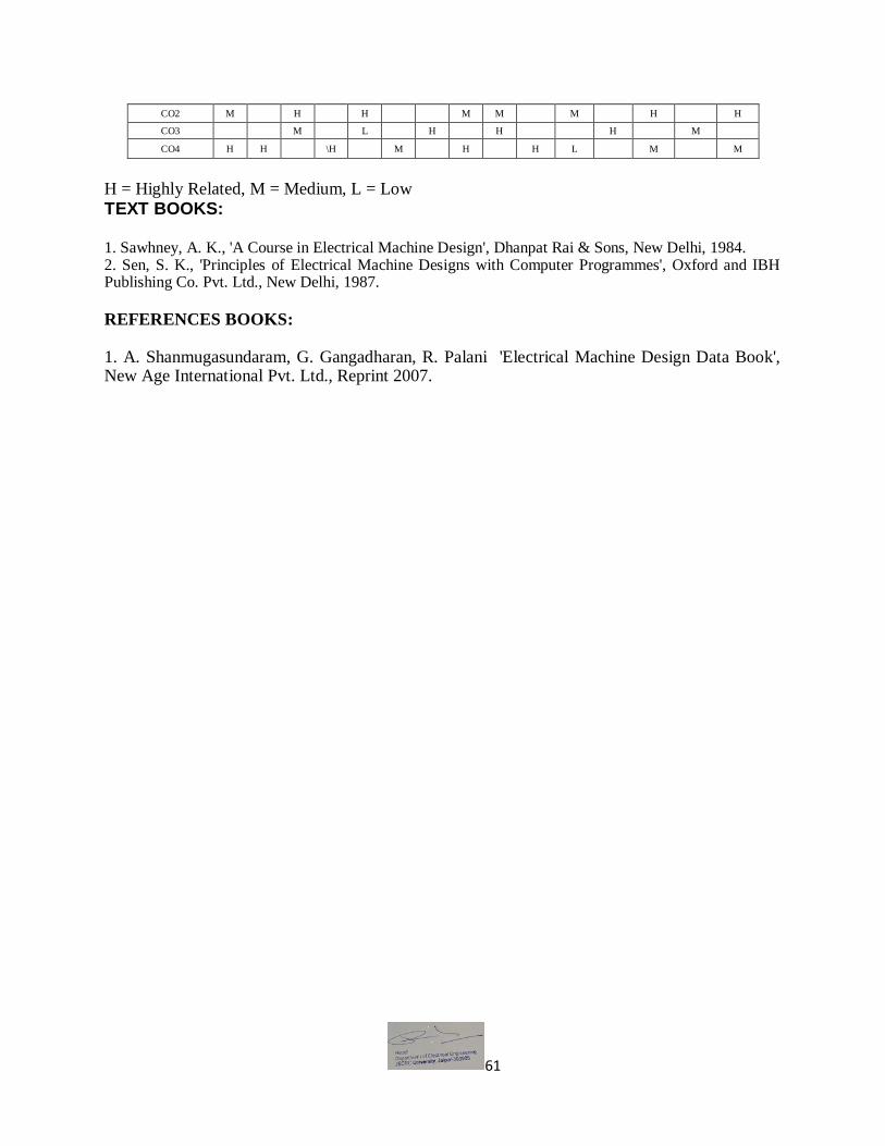
61
CO2 M H H M M M H H
CO3 M L H H H M
CO4 H H \H M H H L M M
H = Highly Related, M = Medium, L = Low
TEXT BOOKS: 1. Sawhney, A. K., 'A Course in Electrical Machine Design', Dhanpat Rai & Sons, New Delhi, 1984. 2. Sen, S. K., 'Principles of Electrical Machine Designs with Computer Programmes', Oxford and IBH Publishing Co. Pvt. Ltd., New Delhi, 1987.
REFERENCES BOOKS: 1. A. Shanmugasundaram, G. Gangadharan, R. Palani 'Electrical Machine Design Data Book', New Age International Pvt. Ltd., Reprint 2007.

62
School of Engineering B.Tech. in Electrical Engineering – Semester V
Contact Hrs per week (L-T-P): 3-0-0
Course Outlines
BEE013A -SIGNALS AND SYSTEMS Objectives:
1. To develop an understanding of the fundamental tools and concepts used in the analysis of signals and the analysis and design of linear shift-invariant systems.
2. To develop an understanding of their application in a broad range of areas, including electronics & electrical networks, telecommunications, signal-processing and automatic control.
Unit 1: Signals: Definition, types of signals and their representations: continuous-time/discrete-time, periodic/non-periodic, even/odd, energy/power, deterministic/ random, one-dimensional/multi-dimensional; commonly used signals: unit impulse, unit step, unit ramp, exponential, rectangular pulse, sinusoidal; operations on continuous-time and discrete-time signals. Systems: Definition, types of systems: linear and non-linear, time invariant and time varying, Deterministic and Stochastic, Casual and non causal, Analog and Discrete/Digital, memory and memoryless. Unit 2: Linear Time-Invariant Systems: Introduction, Continuous –time and Discrete-Time LTI Systems ,The Convolution Integral, Properties of the Convolution Integral, The Convolution sum, Properties of the Convolution sum, Properties of Linear Time-Invariant Systems, Relationship between LTI system properties and the Impulse response.System representation through differential equations and difference equations. Unit 3: Fourier Analysis for Continuous-Time Signals and Systems: Introduction, The Response of Continuous-Time LTI Systems to Complex Exponentials, Representation of Periodic Signals: The Continuous-Time Fourier Series, Properties of Continuous-Time Fourier Series, Approximation of Periodic Signals Using Fourier Series and the Convergence of Fourier Series. Representation of Aperiodic Signals : The Continuous -Time Fourier Transform, Properties of the Continuous –Time Fourier Transform. Fourier Analysis for Discrete-Time Signals and Systems: Introduction, Properties of Discrete Fourier series, Fourier Transform and Properties of Discrete Fourier Transform. Unit 4: The Laplace-Trasform: Introduction, The Laplace-Transform, The Region of Convergence for the Laplace-Transform, Properties of Laplace-Transform, Inverse Laplace-Transform, Application & Characteristics of LTI System Using Laplace- Transform. Unit 5: The Z-Transform: Introduction, The Z-Transform, The Region of Convergence for the Z-Transform, Properties of Z-Transform, The Inverse z-Transform, Application & Characteristics of LTI System Using Z Transform.

63
Sampling: Introduction, Representation of a Continuous- Time Signal by Its Samples , The Sampling Theorem, Reconstruction of a signal from its Samples, The Effect of Under sampling : Aliasing.
OUTCOMES:
CO1. Analyze different types of signals CO2. Represent continuous and discrete systems in time and frequency domain using different
transforms CO3. Investigate whether the system is stable CO4. Sampling and reconstruction of a signal
MAPPING COURSE OUTCOMES LEADING TO THE ACHIEVEMENT OF PROGRAM
OUTCOMES AND PROGRAM SPECIFIC OUTCOMES:
Course Outcome Program Outcome Program Specific Outcome
PO1 PO2 PO3 PO4 PO5 PO6 PO7 PO8 PO9 PO10 PO11 PO12 PSO1 PSO2 PSO3
CO1 M H M M L H L M
CO2 H M M H L H
CO3 M L H H H H L
CO4 M L L H M M M
H = Highly Related, M = Medium, L = Low
Text Book:
A.V. Oppenheim, A.S. Willsky and I.T. Young, "Signals and Systems", Prentice Hall, 1983.
Reference Books:
1.R.F. Ziemer, W.H. Tranter and D.R. Fannin, "Signals and Systems - Continuous and
Discrete", 4th edition, Prentice Hall, 1998. 2. B.P. Lathi, "Signal Processing and Linear Systems", Oxford University Press, c1998. 3. Douglas K. Lindner, "Introduction to Signals and Systems", Mc-Graw Hill International
Edition: c1999. 4. Simon Haykin, Barry van Veen, "Signals and Systems", John Wiley and Sons (Asia) Private
Limited, c1998. 5. M. J. Roberts, "Signals and Systems - Analysis using Transform methods and MATLAB",
TMH, 2003. 6. I. J. Nagrath, S. N. Sharan, R. Ranjan, S. Kumar, "Signals and Systems", TMH New Delhi,
2001.

64
School of Engineering B.Tech. in Electrical Engineering – Semester V
Contact Hrs per week (L-T-P): 0-0-2
Course Outlines
BEL015A- Control Systems Lab
OBJECTIVE:
To learn the different order systems in controls circuits, plotting different steady state and
transient responses.
Study the frequency response of different damping networks.
List of Experiments (Perform any 10):
1 Introduction to MATLAB Computing Control Software for programming and simulation.
2 Defining Systems in TF, ZPK form.
(a) Plot step response of a given TF and system in state-space. Take different values of
damping ratio and ωn natural undamped frequency. (b) Plot ramp response.
3 For a given 2nd order system plot step response and obtain time response specification.
4 To design 1st
order R- C circuits and observe its response with the following inputs and
trace the curve. (a) Step (b) Ramp (c) Impulse
5 To design 2nd
order electrical network and study its transient response for step input and
following cases. (a) Under damped system (b) Over damped System. (c) Critically
damped system.
6 To Study the frequency response of following compensating Networks, plot the graph
and final out corner frequencies. (a) Lag Network (b) Lead Network (c) Lag-lead
Network.
7 To draw characteristics of AC servomotor.
8 To perform experiment on Potentiometer error detector.
9 Check for the stability of a given closed loop system.
10 Plot bode plot for a 2nd order system and find GM and PM.
11 Error detector characteristics and control applications of the following. (i) LVDT (ii)
Potentiometer.
12 Performance analysis of thermal system and design using PID/Relay control.
13 To obtain the position control performance of DC Servo Motor.
14 Comparisons of different Control Action (P/I/D/Relay) on Industrial Process (Pneumatic/
Simulated System.)
Course Outcome (CO):
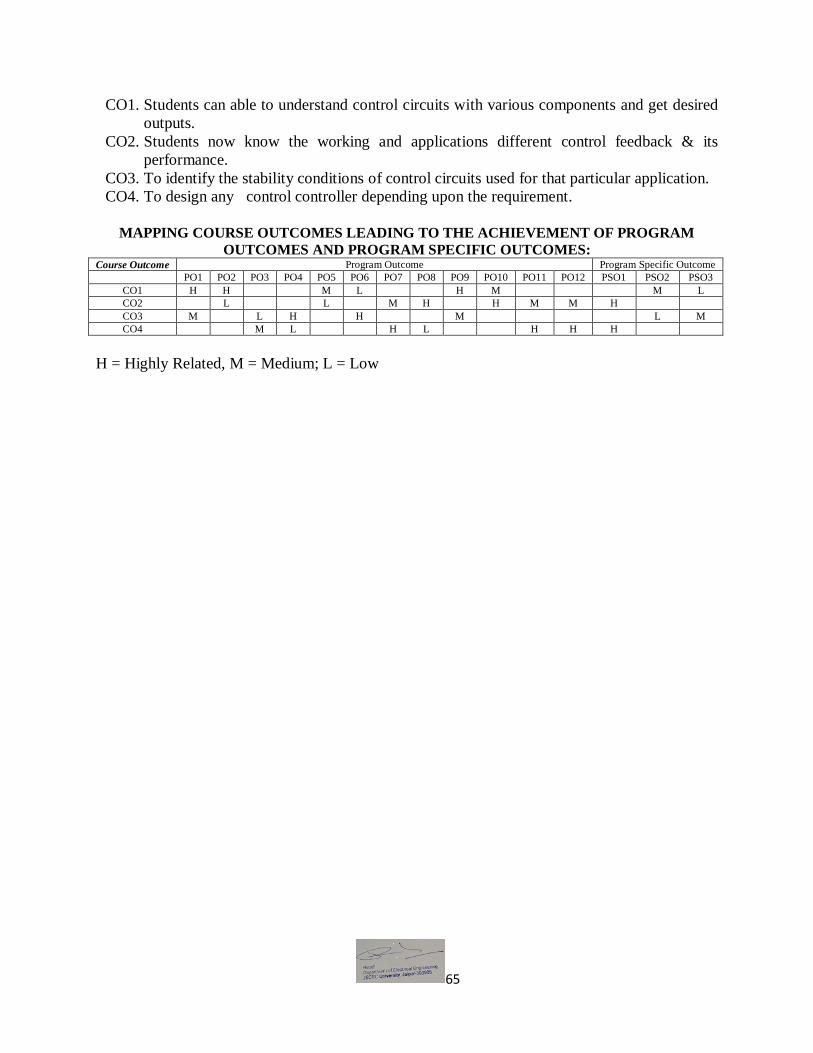
65
CO1. Students can able to understand control circuits with various components and get desired
outputs.
CO2. Students now know the working and applications different control feedback & its
performance.
CO3. To identify the stability conditions of control circuits used for that particular application.
CO4. To design any control controller depending upon the requirement.
MAPPING COURSE OUTCOMES LEADING TO THE ACHIEVEMENT OF PROGRAM
OUTCOMES AND PROGRAM SPECIFIC OUTCOMES: Course Outcome Program Outcome Program Specific Outcome
PO1 PO2 PO3 PO4 PO5 PO6 PO7 PO8 PO9 PO10 PO11 PO12 PSO1 PSO2 PSO3
CO1 H H M L H M M L
CO2 L L M H H M M H
CO3 M L H H M L M
CO4 M L H L H H H
H = Highly Related, M = Medium; L = Low

66
School of Engineering B.Tech. in Electrical Engineering – Semester V
Contact Hrs per week (L-T-P): 0-0-2
Course Outlines
BCO004A - Object Oriented Programming Lab
List of Experiments:
1.a) Study of Unix/Linux general purpose utility command list: man,who,cat, cd, cp, ps, ls, mv,
rm, mkdir, rmdir, echo, more, date, time, kill, history, chmod, chown, finger, pwd, cal, logout,
shutdown.
b) Study of vi editor.
c) Study of Bash shell, Bourne shell and C shell in Unix/Linux operating system.
d) Study of Unix/Linux file system (tree structure).
e) Study of .bashrc, /etc/bashrc and Environment variables.
2. Write a C program that makes a copy of a file using standard I/O, and system calls
3. Write a C program to emulate the UNIX ls –l command.
4. Write a C program that illustrates how to execute two commands concurrently with a
command pipe. Ex: - ls –l | sort
5. Write a C program that illustrates two processes communicating using shared memory
6. Write a C program to simulate producer and consumer problem using semaphores
7. Write C program to create a thread using pthreads library and let it run its function.
8. Write a C program to illustrate concurrent execution of threads using pthreads library.
Extra Programs
1. Write a shell script that accepts a file name, starting and ending numbers as arguments and
displays all the lines between the given line numbers.

67
2. Write a shell script that displays a list of all files in the current directory to which the user has
read, write and execute permissions.
Course Outcome (CO):
CO1. Understand object-oriented programming features in C++,
CO2. Apply these features to program design and implementation,
CO3. Understand object-oriented concepts and how they are supported by C++,
CO4. Gain some practical experience of C++.
MAPPING COURSE OUTCOMES LEADING TO THE ACHIEVEMENT OF PROGRAM
OUTCOMES AND PROGRAM SPECIFIC OUTCOMES:
Course Outcome Program Outcome Program Specific Outcome
PO1 PO2 PO3 PO4 PO5 PO6 PO7 PO8 PO9 PO10 PO11 PO12 PSO1 PSO2 PSO3
CO1 H M M M M H
CO2 M L M M M
CO3 H L M H M
CO4 M M L M H L
H = Highly Related, M = Medium; L = Low

68
School of Engineering B.Tech. in Electrical Engineering – Semester V
Contact Hrs per week (L-T-P): 0-0-2
Course Outlines
BEE022A: Microprocessor and Microcontroller System Lab
OBJECTIVE: To understand the internal organization of INTEL 8086 Microprocessors, 8051 microcontroller
and Assembly Language Programs using the instruction sets of processors and to study the
interfacing of the processor with various peripheral devices.
List of Experiments (Perform any 10):
1. a) Write a program using Microprocessor 8086 to add two 8 bits numbers.
b) Write a program using Microprocessor 8086 to subtract two 8 bits numbers.
c) Write a program using Microprocessor 8086 to add two 16 bits numbers.
d) Write a program using Microprocessor 8086 to add ten 16 bits numbers with carry.
2. (a) Write an assembly language program to find whether the given number is even or
odd.
(b) Write an assembly language program to find the number of even and odd numbers
from given series of 16 bit numbers.
(c) Write an assembly language program to find the number of 1’s in a given number.
(d) Write an assembly language program to find whether the given number has even
parity or odd parity.
3. (a) Write an assembly language program to find the largest number from an array of 16
bit numbers.
(b) Write an assembly language program to find the smallest number from an array of 16
bit numbers.
(c) Write an assembly language program to arrange the given array of 16 bit numbers in
ascending order.
(d) Write an assembly language program to arrange the given array of 16 bit numbers in
descending order.
4. (a) Write an assembly language program to find the number of +ve and -ve numbers from
given series of 16 bit numbers.
(b) Write an assembly language program to perform 1 byte BCD addition
(c) Write an assembly language program to perform addition, subtraction, Multiplication
and Division of given operands. Perform BCD addition and subtraction.

69
(d) Write an assembly language program to move 16 bytes from the offset 0200H to
0300H.
5. (a) Write an assembly language program to find whether the given byte is present in the
string or not.
(b) Write an assembly language program to compare two given strings.
(c) Write an assembly language program to find square of the given number.
(d) Write an assembly language program to find square of the given array of 16 bit
number.
6. (a) Display a message “ very large scale integration”
(b) Write an assembly language program to convert BCD number 0 to 9 to their 7
segment codes, using look up table.
(c) Write an ALP for (i) addition and (ii) Multiplication of two 3x3 Matrices.
7. a) Write a program to calculate squares of BCD number 0 to 9 and store then sequentially
from 2000H offset onward in the current data segment. The number and their square are
in BCD format. Write a subroutine for the calculation of square of number.
b) Write a program to change a sequence of 16 two byte number from ascending to
descending order and store them in same data segment.
8. a) Write a program to generate a delay of 100ms using an 8086 system that runs on
10MHz frequency.
(b) Write a program to generate delay of 1Minutes.
9. (a) Write a program in 8051
(i) to clear the accumulator and add 3 to accumulator 10 times.
(ii) to load accumulator with the value 55H and complement the accumulator 700Times.
(b) Write a program to toggle all the bits of port1. put a time delay in between each issuing of
data to port 1.
10. (a) Write a program to generate a delay of 1µsec. assuming that crystal frequency is 11.05
MHz.
(b) Write a program in 8051 to perform the following
(i) Keep monitoring the port P2.2 bit until it becomes high
(ii) When it becomes high write a value 45H to port 0 send a high to low pulse to
P3.3.
11. (a) Write a program to get X value from P1 and send X2 to P2 continuously.
(b) Assume P1 is I/P port and connected to a temperature sensor. Write a program to read
the temperature and test it for the value 75. according to test result place the temperature
value into the registers indicated by the following
If T = 75 then A = 75
If T < 75 then R1 = T
If T > 75 then R2 = T
12. (a) Write a program to find number of 1’s in given number.
(b) Write a program tfor conversion of packed BCD to ASCII
13. Write a program to Interface 7-segment LED displays to a microprocessor and displaying a
real-time clock.
14. Write a program for the implementation of a traffic signal controller.
15. Write a program for implementation of a programmable frequency synthesizer using timers.

70
16. Write a program to interfacing ADC & DAC -capturing a waveform from signal generator
and CRO display.
17. Write a program to interfacing a stepper motor to a 8051 microcontroller.
Course Outcomes (CO):
CO1. Students will be able to verify assembly-language programme using Microprocessor 8086
applicable for various arithmetic operation.
CO2. Students now know able to understand Interface 7-segment LED displays to a
microprocessor
CO3. To distinguish and analyze the properties of Microprocessors & Microcontroller to
interfacing ADC & DAC.
CO4. To understand illustrate how the different peripherals (8255, 8253 etc.) are interfaced
with Microprocessor
MAPPING COURSE OUTCOMES LEADING TO THE ACHIEVEMENT OF PROGRAM
OUTCOMES AND PROGRAM SPECIFIC OUTCOMES: Course Outcome Program Outcome Program Specific Outcome
PO1 PO2 PO3 PO4 PO5 PO6 PO7 PO8 PO9 PO10 PO11 PO12 PSO1 PSO2 PSO3
CO1 H M H L M H M M L
CO2 L M H H M M H
CO3 M M H H M L M
CO4 M H M L H H H
H = Highly Related, M = Medium; L = Low

71
School of Engineering B.Tech. in Electrical Engineering – Semester V
Contact Hrs per week (L-T-P): 0-0-2
Course Outlines
BEL016A- Power Systems Lab I
OBJECTIVE:
The power system laboratory is responsible for getting the line parameters and other power
system quantities using hardware, panels and simulated results.
List of Experiments (Perform any 10):
1 To perform various test on transmission line hardware / software model, to determine the
ABCD parameters. 2 To perform various test on transmission line hardware / software model, to determine the
surge impedance load. 3 To perform various test on transmission line hardware / software model, to determine the
efficiency at various load. 4 Write a program in MATLAB to calculate sending end voltage and regulation in a short
transmission line. 5 Write a program in MATLAB to apply Kelvin’s law to determine the economic cross-
section of the conductor of over head transmission line. 6 To measure (PPS and NPS) sequence components of supply voltages by segregating
networks and verify graphically using hardware / software. 7 To determine negative and zero sequence reactance’s of an alternator using software
programming tool such as MATLAB. 8 To test the given AC energy meter by phantom loading at (i). Unity power factor (ii). 0.8
power factor lagging (iii). 0.8 power factor leading. 9 To find the string efficiency (i). Without the guard ring (ii). With guard ring using
hardware or software programming tool such as MATLAB. 10 To study the negative phase sequence protection scheme on testing kit or using software
programming tool such as MATLAB. 11 To find the zero sequence impedance of a given three phase transformer using software
programming tool such as MATLAB. 12 Write a MATLAB program for sag calculation with supports at same level. 13 Write a MATLAB program for sag calculation with supports at different level. 14 Write a MATLAB program for sag calculation with supports at same level considering

72
the ice and wind load (given the wind velocity in km/hr).
Course Outcome (CO):
CO1. Students can able to will be able to verify the principle of protective schemes and various
faults in the power system using MATLAB.
CO2. Students now know able to perform various testing on transmission line hardware /
software model, to determine the efficiency at various load using MATLAB.
CO3. To identify the string efficiency using guard ring using hardware or software
programming tool such as MATLAB. .
CO4. To understand phase sequence protection scheme on testing kit or using software
programming tool such as MATLAB.
MAPPING COURSE OUTCOMES LEADING TO THE ACHIEVEMENT OF PROGRAM
OUTCOMES AND PROGRAM SPECIFIC OUTCOMES:
Course
Outcome Program Outcome
Program Specific Outcome
PO1 PO2 PO3 PO4 PO5 PO6 PO7 PO8 PO9 PO10 PO11 PO12 PSO1 PSO2 PSO3
CO1 H H M L H M M L
CO2 M L M H H M M H
CO3 M M H H M L M
CO4 H L H L H H H
H = Highly Related, M = Medium L = Low

73
School of Engineering B.Tech. in Electrical Engineering – Semester VI
Contact Hrs per week (L-T-P): 3-0-0
Course Outlines
BEL041B- Power Systems Stability
OBJECTIVE:
This course helps in modeling of synchronous machine. It also gives information
regarding various stabilities methods.
Unit :1 Modelling of synchronous machines: Modeling of cylindrical rotor salient pole
synchronous machines, flux linkage equations, voltage equations, Park's transformation, various
inductances and time constraints of synchronous machines, vector diagrams for steady state and
transient conditions, power angle curves.
Unit-2: Power Angle equations and curves: Power angle equations and power angle curves
under steady state, and transient conditions. Rotor dynamics and swing equation (solution of
swing equation not included), synchronizing power coefficient. Machine Systems: Steady state
stability of single machine connected to an infinite bus by the method of small oscillations. Two
machine systems. Coherent and non-coherent machines.
Unit3: Equal Area Criterion: Equal area criterion and its application to transient stability
studies under basic disturbances: Sudden loss of one parallel line, sudden change in mechanical
input and reclosure, critical clearing angle and critical clearing time.
Unit :4 Study of various stability methods: Solution of Swing equation by step by step
method.Euler's Method and Runga-Kutta Method, Application of Computers in the study of
transient stability using these methods. Methods of improving steady state and transient stability.
Unit:5 Voltage Stability: Introduction, Comparison of angel and voltage stability, Reactive
power flow and Voltage collapser, Mathematical formulation of voltage stability problems,
Voltage stability analysis, prevention of voltage collapse.
OUTCOMES:
CO1. Students can get the design and modeling methodologies of synchronous machines.

74
CO2. Students will now be able to compare different stabilities methods to find the best for a
particular situation.
CO3. Students will able to solve numerical problems for power system stability assessment.
CO4. To perform stability analysis and stability criteria of multi machine systems.
MAPPING COURSE OUTCOMES LEADING TO THE ACHIEVEMENT OF PROGRAM
OUTCOMES AND PROGRAM SPECIFIC OUTCOMES:
Course Outcome Program Outcome Program Specific Outcome
PO1 PO2 PO3 PO4 PO5 PO6 PO7 PO8 PO9 PO10 PO11 PO12 PSO1 PSO2 PSO3
CO1 H H L H M
CO2 M H M L H H M M
CO3 M M H M H M H H H
CO4 H L L M M M M H
H = Highly Related, M = Medium, L = Low
Text book:
1. P. Kundur, “Power System Stability and Control”, Mc Graw Hill.
Reference Books:
1. P.S.R. Murty, “Operation and control in Power Systems” B.S. Publications. 2. J. Wood and B.F. Wollenburg,“ Power Generation, Operation and Control “ John Wiley
3. CL Wadhwa, Electrical power system. New Age international publishers.

75
School of Engineering B.Tech. in Electrical Engineering – Semester VI
Contact Hrs per week (L-T-P): 3-0-0
Course Outlines
BEL024B- Electric Drives
OBJECTIVE:
This course helps in explaining the design, function, operation and control of all major components of a typical electric vehicle power train / drives (AC and DC both).
Unit 1: Introduction- Classifications of Electric Drives, components of electric drives, advantages of electric drives, Review of characteristics and speed control of DC and AC motors. Dynamics of Electric Drives:- Fundamental torque equation, speed-torque conventions and multi-quadrant operation, equivalent values of drive parameters, components of load torques, nature and classification of load torques, calculation of time and energy-loss in transient operations, criteria for steady state stability, load equalization. Unit2: Rectifier Control of DC Drives- Controlled rectifier circuits, 1-phase fully controlled rectifier-fed separately excited DC motor, 1-phase half-controlled rectifier-fed separately excited DC motor, 3-phase fully controlled rectifier-fed separately excited DC motor, multi quadrant operation of fully-controlled rectifier-fed DC motor. Unit 3: Chopper Control of DC Drives- Principle of operation and control techniques, motoring operation of separately excited and series excited motors, multi quadrant control of chopper-fed motors. Unit4: Induction Motor (IM) Drives:- 3-phase AC voltage controller-fed IM drive, voltage source inverter (VSI) and current source inverter (CSI) variable frequency drives, comparison of VSI and CSI drives, cyclo-converter-fed IM drive, static rotor resistance control of 3-phase slipring IM Synchronous Motor Drives- VSI drive, CSI drive, CSI drive with load commutation, cyclo-converter drive. Unit 5: Braking methods- Various methods of braking DC and AC motors, regenerative braking of DC motors during chopper control, static Scherbius drive, commutatorless Kramer drive. Introduction to Microprocessor Control of Electric Drives.
COURSE OUTCOMES:

76
CO1: Students will now be able to describe the structure of electric drive systems and their role
in various applications.
CO2: Students will able to use power electronics devices as controllers for different drives.
CO3: Ability is developed to understand the relation between torque, speed and braking system
of motor and beyond conventional methods some efficient methods will understand.
CO4: Develop an ability to differentiate between current source and voltage source converters.
MAPPING COURSE OUTCOMES LEADING TO THE ACHIEVEMENT OF PROGRAM
OUTCOMES AND PROGRAM SPECIFIC OUTCOMES:
Course Outcome Program Outcome Program Specific Outcome
PO1 PO2 PO3 PO4 PO5 PO6 PO7 PO8 PO9 PO10 PO11 PO12 PSO1 PSO2 PSO3
CO1 H H H H M H H
CO2 M M M M H L H H
CO3 H M H M M L M M M
CO4 H M M L M L
H = Highly Related, M = Medium; L = Low
Text Books:
1. GK Dubey, “Fundamentals of Electrical Drives” Narosa Publishing House, 1995.
Reference Books:
1. V. Subrahmanyam, “ Electric Drives: Concepts and Applications”, TMH 1994.
2. GK Dubey, “ Power Semiconductor Controlled Drives, Prentice Hall.
3. EL- Sharkawi & A Mohamad “Fundamental of Electric Drive”, Vikas Pub. House
4. SK Pillai, “A First course on Electrical Drives” Wiley Eastern Ltd.

77
School of Engineering B.Tech. in Electrical Engineering – Semester VI
Contact Hrs per week (L-T-P): 3-1-0
Course Outlines
BEL074A- Power Systems Analysis
OBJECTIVE:
This course helps in formulating a single line, impedance and reactance diagram of power system network with the help of per unit system which helps in calculating the power system components during faulty and healthy conditions.
It also gives information about load flow studies. Unit 1: Representation of Power System Components- Synchronous machines, Transformers, Transmission lines, one line diagram, Impedance and reactance diagram, per unit. Symmetrical Fault Analysis: Transient on a transmission line, calculation of 3-phase short circuit current and reactance of synchronous machine on no-load and load condition, Equivalent circuits of synchronous machine under sub transient, transient and steady state conditions, Analysis of three-phase faults.
Unit 2: Symmetrical components- Symmetrical components of unbalanced phasors, power in terms of symmetrical components, sequence impedances and sequence networks of synchronous machine, transformer and transmission line, Construction of sequence network of power system.
Unit3: Unsymmetrical faults-Analysis of single line to ground fault, line-to-line fault and Double Line to ground fault on an unloaded generators and power system network with and without fault impedance. Unit 4: Impedance Model: Bus admittance and impedance matrices, Direct determination of Z bus. Modification of an exciting bus. Analysis of an unsymmetrical faults using bus impedance matrix method.
Unit 5: Load Flow- Introduction, bus classifications, development of load flow equations, load flow solution using Gauss Siedel and Newton Raphson method, approximation to N-R method, decoupled and fast decoupled method. Comparison of load flow methods.

78
OUTCOMES:
CO1. Students will now be able to design different power system network using different
representations.
CO2. Understand the various power system components.
CO3. Students shall learn how to analyze power system performance during fault
CO4. Also they can select as to which load flow method is suited for which condition.
MAPPING COURSE OUTCOMES LEADING TO THE ACHIEVEMENT OF PROGRAM
OUTCOMES AND PROGRAM SPECIFIC OUTCOMES:
Course Outcome Program Outcome Program Specific Outcome
PO1 PO2 PO3 PO4 PO5 PO6 PO7 PO8 PO9 PO10 PO11 PO12 PSO1 PSO2 PSO3
CO1 L H M M M M H
CO2 L M H M M L L M
CO3 M H M L M H
CO4 M L M L H M M L
H = Highly Related, M = Medium L = Low
Text Books:
1. T.K Nagsarkar and M.S. Sukhija, “Power System Analysis” Oxford University Press,2007
2. BR Gupta, “Power System Analysis and Design”, S.Chand.
Reference Books:
1. CL Wadhwa, “Electrical Power System”, New Age International.
2. W.D. Stevenson, Jr. “Elements of Power System Analysis”, McGraw Hill. 3. L. P. Singh; “Advanced Power System Analysis and Dynamics”, New Age International 4. Hadi Sadat; “Power System Analysis”, Tata McGraw Hill.
5. Stagg and El-Abiad, “Computer Methods in Power System Analysis” Tata Mc Graw Hill
6. Kothari and Nagrath, “Modern Power System Analysis” Tata McGraw Hill.
79
School of Engineering B.Tech. in Electrical Engineering – Semester VI
Contact Hrs per week (L-T-P): 3-0-0
Course Outlines
BCO002A - Data Structures And Algorithms
OBJECTIVE:
To study various data structure concepts like Stacks, Queues, Linked List, Trees and Files
To overview the applications of data structures.
To be familiar with utilization of data structure techniques in problem solving.
Unit -1: Introduction: Notions of data type, abstract data type and data structures. Importance of
algorithms and data structures in programming. Notion of Complexity covering time complexity,
space complexity, Worst case complexity & Average case complexity. BigOh Notation, Omega
notation, Theta notation. Examples of simple algorithms and illustration of their complexity.
Sorting- Bubble sort, selection sort, insertion sort, Quick sort; Heap sort; Merge sort; Analysis of
the sorting methods. Selecting the top k elements. Lower bound on sorting.
Unit-2: Stack ADT, Infix Notation, Prefix Notation and Postfix Notation. Evaluation of Postfix
Expression, conversion of Infix to Prefix and Postfix Iteration and Recursion- Problem solving
using iteration and recursion with examples such as binary search, Fibonacci numbers, and
Hanoi towers. Tradeoffs between iteration and recursion.
Unit3: List ADT. Implementation of lists using arrays and pointers. Stack ADT. Queue ADT.
Implementation of stacks and queues. Dictionaries, Hash tables: open tables and closed tables.
Searching technique- Binary search and linear search, link list- single link list, double link list,
Insertion and deletion in link list.
Unit-4: Binary Trees- Definition and traversals: preorder, post order, in order. Common types
and properties of binary trees. Binary search trees: insertion and deletion in binary search tree
worst case analysis and average case analysis. AVL trees. Priority Queues -Binary heaps: insert
and delete min operations and analysis.
Unit-5: Graph: Basic definitions, Directed Graphs- Data structures for graph representation.
Shortest path algorithms: Dijkstra (greedy algorithm) and Operations on graph, Worshall’s
algorithm , Depth first search and Breadth-first search. Directed acyclic graphs. Undirected

80
Graphs, Minimal spanning trees and algorithms (Prims and Kruskal) and implementation.
Application to the travelling salesman problem.
OUTCOMES:
CO1. Show the understanding of various data structure concepts like Stacks, Queues,
Linked List, Trees and Files
CO2. Understand the applications of data structures.
CO3. Understand with utilization of data structure techniques in problem solving.
CO4. Use comprehensive knowledge of data structures and algorithm with asymptotic
analysis of algorithm. MAPPING COURSE OUTCOMES LEADING TO THE ACHIEVEMENT OF PROGRAM
OUTCOMES AND PROGRAM SPECIFIC OUTCOMES:
Course Outcome Program Outcome Program Specific Outcome
PO1 PO2 PO3 PO4 PO5 PO6 PO7 PO8 PO9 PO10 PO11 PO12 PSO1 PSO2 PSO3
CO1 M L M L M M M
CO2 M L M H L M
CO3 H M M M H
CO4 H M M M L
H = Highly Related, M = Medium, L = Low
Text Books:
1. Data Structures and Algorithms by Alfred V. Aho, Jeffrey D. Ullman and John E.
Hopcroft , Addison-Wesley Series (1983)
Reference Books:
1. T.H. Cormen, C.E. Leiserson, and R.L. Rivest. Introduction to Algorithms.The MIT
Press and
2. McGraw-Hill Book Company, Cambridge, Massacusetts, 1990 (Available in Indian
Edition).
3. Steven S. Skiena. The Algorithm Design Manual.Springer, Second Edition, 2008.
4. Data Structures and Algorithm Analysis in Java (3rd Edition) by Mark Allen Weiss,
Addison Wesley(2011).

81
School of Engineering B.Tech. in Electrical Engineering – Semester VI
Contact Hrs per week (L-T-P): 3-0-0
Course Outlines
BEL033B - Advanced Control Systems
OBJECTIVE:
This subject provides an introduction to modern control theory with a particular focus on state-space analysis of continuous system, analysis of discrete system and stability concerns of control system.
Unit 1: State Space Analysis: State Space Representation, Solution of State Equation, State Transition Matrix, Canonical Forms –Controllable Canonical Form, Observable Canonical Form, Jordan Canonical Form.
Unit 2: Controllability and Observability: Tests for controllability and observability for
continuous time systems – Time varying case, minimum energy control, time invariant case,
Principle of Duality, Controllability and observability form Jordancanonical form and other
canonical forms.
Unit 3: Analysis of Discrete System: Discrete system and discrete time signals, state variable model and transfer function model of discrete system, conversion of state variable model to transfer function model and vice-versa, modelling of sample hold circuit, solution of state difference equations, steady state accuracy, stability on the z-plane and Jury stability criterion, bilinear transformation Unit 4: Stability: Lyapunov’s stability theorems for continuous and discrete systems, methods for generating Lyapunov function for continuous and discrete system, Popov’s criterion. Unit 5: Optimal Control: Introduction - Time varying optimal control – LQR steady state optimal control – Solution of Ricatti’s equation – Application examples and modal reference adaptive control systems.
Course Outcomes (CO):

82
CO1. Student should be able to apply fundamental state-space techniques in the analysis and
design of linear feedback control systems, as they arise in a variety of contexts.
CO2. Students can now formulate and control of engineering problems in terms of optimizing
an objective function subject to different constraints.
CO3. Use software tools to simulate and design the linear control systems.
CO4. To enhance an ability to non-linear system on the phase plane & its application.
MAPPING COURSE OUTCOMES LEADING TO THE ACHIEVEMENT OF PROGRAM
OUTCOMES AND PROGRAM SPECIFIC OUTCOMES:
Course Outcome Program Outcome Program Specific Outcome
PO1 PO2 PO3 PO4 PO5 PO6 PO7 PO8 PO9 PO10 PO11 PO12 PSO1 PSO2 PSO3
CO1 H M H M H M M
CO2 M H M M M H M H M
CO3 H M H H H
CO4 M M \ M H H L H L H
H = Highly Related, M = Medium, L = Low
Text Books:
1. M.Gopal, “Digital Control and State variable Methods”, Tata Mc Graw Hill.
Reference Books:
1. D. Landau, “Adaptive Control”, Marcel Dekker Inc. 2. S.Rajasekaran and G.A.VjayalakshmiPai, “Neural Networks, Fuzzy Logic and Genetic Alogorithms:
Synthesis and Applications” Prentice Hall of India
3. Donald E. Kiv, “Optimal Control Theory: An Introduction” Prentice Hall
4. B.C. Kuo, “Digital Control Systems” Sounders College Publishing
5. CH Houpis and G.B.Lamont, “Digital Control Systems: Theory, Hardware, Software”, MGH
6. Ajit K.Madal, “Introduction to Control Engineering: Modelling, Analysis and Design” New Age
International.

83
School of Engineering B.Tech. in Electrical Engineering – Semester VI
Contact Hrs per week (L-T-P): 3-0-0
Course Outlines
BEL022A- Programmable Logic Controllers and SCADA OBJECTIVE:
This course helps in understanding the various instructions, components and
programming of PLC and features and applications of SCADA systems.
Unit 1: Programmable Logic Introduction: programmable Logic structures Programmable
Logic Arrays (PLAs), Programmable Array Logic (PALs), Programmable Gate Arrays (PGAs),
Field Programmable Gate Arrays (FPGAs) Sequential network design with Programmable Logic
Devices (PLDs) Design of sequential networks using ROMs and PLAs Traffic light controller
using PAL.
Unit 2: Programmable Logic Controllers: (PLCs) Introduction Parts of PLC Principles of
operation PLC sizes PLC hardware components I/O section Analog I/O section Analog I/O
Units, digital I/O Units CPU Processor memory Unit Programming devices Diagnostics of PLCs
with Computers.
Unit 3: PLC programming: Simple instructions Programming EXAMINE ON and EXAMINE
OFF instructions Electromagnetic control relays Motor starters Manually operated switches
Mechanically operated and Proximity switches Output control devices Latching relays PLC
ladder diagram Converting simple relay ladder diagram in to PLC relay ladder diagram.
Unit 4: Timer instructions& Application: ON DELAY timer and OFF DELAY timer counter
instructions Up/Down counters Timer and Counter applications program control instructions
Data manipulating instructions math instructions. Simple materials handling applications
Automatic control of warehouse door Automatic lubricating oil supplier Conveyor belt motor
control Automatic car washing machine Bottle label detection Process control application, PID
control of continuous processes.
Unit 5: SCADA: Introduction to Supervisory Control and Data Acquisition, SCADA Functional
requirements and Components, General features, Functions and Applications, Benefits,

84
Configurations of SCADA, RTU (Remote Terminal Units) Connections, Power Systems
SCADA and SCADA in Power System Automation.
Course Outcomes (CO):
CO1: Students will able to understand the complex networks and perform different
experiments.
CO2: Get the knowledge about timer instruments.
CO3: Students will able to understand new information and techniques for SCADA / PLC
project.
CO4: Students will able to do projects on PLC/SCADA.
MAPPING COURSE OUTCOMES LEADING TO THE ACHIEVEMENT OF PROGRAM
OUTCOMES AND PROGRAM SPECIFIC OUTCOMES:
Course Outcome Program Outcome Program Specific Outcome
PO1 PO2 PO3 PO4 PO5 PO6 PO7 PO8 PO9 PO10 PO11 PO12 PSO1 PSO2 PSO3
CO1 H M M H M H M
CO2 H H H M H H M M
CO3 H L M H M M M L H H
CO4 M M L H M
H = Highly Related, M = Medium; L = Low
TextBooks:
1. William I. Fletcher, An Engineering Approach to Digital Design, PHI Ltd., ND (1999).
Reference Books:
1. Chareles H. Roth, Jr, Fundamentals of Logic Design, 4th Ed., Jaico Pub. House (1999).
2. Siemens, PLC Handbook.
3. Frank D. Petruzella, Programmable Logic Controllers, McGraw- Hill (1989).
4. Wood, AJ & Wollenberg, BF, Power Generation Operation & Control, 2nd Ed. John
Wiley.

85
School of Engineering B.Tech. in Electrical Engineering – Semester VI
Contact Hrs per week (L-T-P): 3-0-0
Course Outlines
BEL017B:Power System Reliability
OBJECTIVE:
This course covers power system planning, operation and management issues as well as
reliability in a regulated and deregulated environment.
Unit 1: System Reliability: Introduction, definition of reliability, failure, probability, concepts,
power quality variation, reliability measurements, power supply quality survey, Reliability aids,
and recent development.
Unit 2: Reliability Concepts: Measure of reliability rules for combining probabilities,
Mathematical expectation. Distributions, reliability theory series and parallel systems, Markov
processes.Static generating capacity reliability.
Unit 3: Outage Reliability: Loss of load probability methods, loss of energy probability method.
Load forecast, System Design and planning, Strategies for generation, Transmission and
Distribution networks. Transmission system reliability evaluation-Average interruption rate
method.The frequency and duration method.
Unit 4: Interconnected System Reliability: Generating capacity reliability evaluation
introduction. The loss of load approach, reliability evaluation in two and more than two
interconnected systems, Interconnection benefits.
Unit 5: Load Forecasting: Necessity short-term forecasting by preliminary analysis control,
medium term forecasting by field survey method, and long-time forecasting by statistical
method. Regression analysis.Analysis of time series.Factors in power system loading.
Course Outcome (CO):

86
CO1. Students will be able to the student shall be able to model and analyse electric power
systems with respect to reliability of supply. .
CO2. Students now know able to understand Measure of reliability rules for combining
probabilities & reliability theory.
CO3. To analyze the reliability condition in case of Outage i.e Loss of load , Generation.
CO4. To illustrate how the interconnected systems are interfaced under reliability condition.
MAPPING COURSE OUTCOMES LEADING TO THE ACHIEVEMENT OF PROGRAM
OUTCOMES AND PROGRAM SPECIFIC OUTCOMES:
Course Outcome Program Outcome Program Specific Outcome
PO1 PO2 PO3 PO4 PO5 PO6 PO7 PO8 PO9 PO10 PO11 PO12 PSO1 PSO2 PSO3
CO1 H H M L H M M L
CO2 L L M H H M M H
CO3 M L H H M L M
CO4 M L H L H H H
H = Highly Related, M = Medium L = Low
Text Books:
1. A.S. Pabla-Electric power distribution. (Text Book).
2. Roy Billinton and Ronald N.Allan-Reliability Evaluation of Power System volume-I
Reference Books:
1. Roy Billinton and Ronald N.Allan-Reliability Evaluation of Power System volume-II
2. J Endreny- Reliability Modelling in Electric Power System.

87
School of Engineering
B.Tech. in Electrical Engineering – Semester VI
Contact Hrs per week (L-T-P): 3-0-0
Course Outlines
BEL064A-Special Electrical Machines
OBJECTIVES:
The objective of this course is to get knowledge regarding principle, working and application of
special motors viz. Brushless DC motors, Universal motors etc.
Unit 1: AC Series Motors: Construction, Principle of operation, Phase diagrams and
Characteristics of Single phase and Three Phase AC Series motors, Simple and compensated
motors, Universal motors and their Applications.
Unit 2: Single Phase Synchronous Motors: Reluctance Motors: Construction, principle of
operation, Torque-Speed Characteristic production, modes of operation & its drive circuits,
Hysteresis motors: Constructions, Operation, Torque-speed Characteristic, Applications.
Unit 3: Special Motors-I: Stepper motors :Construction, Operation, Types : Variable Reluctance
Type, Permanent Magnet Type, Hybrid Type and its application, Permanent magnet DC motors : Construction, Operation, application, Concept of Brushless DC motor.
Unit 4 Special Motors -II: Servo Motors: DC Servomotors, AC Servomotors: Two Phase AC
Servomotors, Three Phase AC Servomotors, Constructions, Torque-speed Characteristics, Controlling and Applications.
Unit 5: Special Motors –III: Schrage Motor: Constructions, Principle of operation, Speed and
Power factor control, Applications, Linear Induction Motors: Construction, principle of operation, linear force and applications.
OUTCOMES:
CO1. Students can now apply the knowledge of these machines to make different power
electronic models and applications.
CO2. Understand the construction and performance characteristics of electrical machines.
CO3. Understand the various factors which influence the design: electrical, magnetic and
thermal loading of electrical machines

88
CO4. Understand the principles of electrical machine design and carry out a basic design of an
ac machine.
MAPPING COURSE OUTCOMES LEADING TO THE ACHIEVEMENT OF PROGRAM
OUTCOMES AND PROGRAM SPECIFIC OUTCOMES:
Course
Outcome Program Outcome
Program Specific Outcome
PO1 PO2 PO3 PO4 PO5 PO6 PO7 PO8 PO9 PO10 PO11 PO12 PSO1 PSO2 PSO3
CO1 H M M H L M
CO2 M L M H M M H L
CO3 L M M L H
CO4 L M H H M
H = Highly Related, M = Medium L = Low
Text Books:
1. P.S. Bimbhra: Generalized Theory of Electrical Machines, Khanna Pub. 1997.
2. D.P. Kothari and I.J. Nagarath: Electric Machines: Tata McGraw-Hill Pub., Third Edn,
2004.
3. Ashfaq Husain : Electric Machines ,Dhanpat Rai & Co.(Pvt) Ltd , 2nd Edition 2006
Reference Books:
1. A.E. Fitzgerald, Charles Kingsley and Stepen D. Umans: Electric Machinery, Tata McGraw-Hill
Pub, Sixth Edition, 2002.
2. P.S. Kenjo and S. Nagamori: Permanent Magnet DC motors, Clarendon Press, Oxford, 1985.
3. J.B. Gupta: Theory and Performance of Electrical Machines, S. K. Kataria & Sons, Fourteenth
Edn, 2006.
4. Jacob, Michael Power Electronics: Principles and Application, Vikas Pub. House

89
School of Engineering B.Tech. in Electrical Engineering – Semester VI
Contact Hrs per week (L-T-P): 3-0-0
Course Outlines
BEL065A-Electrical Materials Unit1: Conductors Classification: High conductivity, high resistivity materials, fundamental requirements of high conductivity materials and high resistivity materials, mobility of electron in metals, commonly used high conducting materials, copper, aluminum, bronze brass, properties, characteristics, constantan, platinum, nichrome, properties, characteristics and applications, materials used for contacts. Unit 2: Semi-Conductors: General concepts, energy bands, types of semiconductors, Fermi Dirac distribution, intrinsic Semi-conductors, extrinsic Semi-conductors, hall effect, drift, mobility, diffusion in Semiconductors, Semi-conductors and their applications, superconductors. Unit 3: Dielectrics And Insulators Properties of gaseous, liquid and solid dielectric, dielectric as a field medium, electric conduction in gaseous, liquid and solid dielectric, breakdown in dielectric materials, mechanical and electrical properties of dielectric materials, effect of temperature on dielectric materials, polarization, loss angle and dielectric loss, petroleum based insulating oils, transformer oil, capacitor oils, properties, solid electrical insulating materials, fibrous, paperboards, yarns, cloth tapes, sleeving wood, impregnation, plastics, filling and bounding materials, fibrous, film, mica, rubber, mica based materials, ceramic materials. Unit 4: Magnetic Materials Soft and hard magnetic materials, diamagnetic, paramagnetic and ferromagnetic materials, electric steel, sheet steel, cold rolled grain oriented silicon steel, hot rolled grain oriented silicon steel, hot rolled silicon steel sheet, hystersis loop, hystersis loss, magnetic susceptibility, coercive force, curie temperature, magneto-striction. Unit 5: Optical Materials: Properties of Solids Photo emission, photo emission materials, electro luminescence junction diode, photo emitters, photo transistor, photo resistors, injunction lasers, optical properties of semiconductors, application of photo sensitive materials (CRT, Tube light, photo panels etc.).
Course Outcomes (CO):
CO1. Students will now be able to use the properties and behavior of different materials. CO2. Apply the knowledge about the Electrical Engineering Materials to use them more

90
effectively. CO3. Become familiar with the dielectric behavior in static as well as varying field and
polarization mechanisms. CO4. Fulfill the demand of the industry about the analysis and construction of Electrical
Engineering Materials.
MAPPING COURSE OUTCOMES LEADING TO THE ACHIEVEMENT OF PROGRAM
OUTCOMES AND PROGRAM SPECIFIC OUTCOMES: Course
Outcome Program Outcome
Program Specific Outcome
PO1 PO2 PO3 PO4 PO5 PO6 PO7 PO8 PO9 PO10 PO11 PO12 PSO1 PSO2 PSO3
CO1 L H M L H M M L
CO2 L L M H H M M H
CO3 M L H H M L M
CO4 M L H L H H H
H = Highly Related, M = Medium; L = Low Text Books: 1. “Electrical Engineering Materials”, Dekker, PHI Pbs. 2. “Electrical Engineering Materials”, Indulkar, S. Chand Reference Books: 1. “Electrical Engineering Materials”, Tareev 2. “Electrical Engineering Materials”, Yu. Koritsky. 3. “Electrical Engineering Materials”, R K.Rajput, Laxmi Pbs.

91
School of Engineering B.Tech. in Electrical Engineering – Semester VI
Contact Hrs per week (L-T-P): 3-0-0
Course Outlines
BEL066A: Safety, Repair and Maintenance Of Electrical Equipments
OBJECTIVES:
The objective is to familiarize the students with the evolution in time of the maintenance
strategies, the classification of strategies maintenance by the criterion of fault occurrence
and also the current trend through passing from time-based preventive maintenance
(especially time criterion) to condition-based maintenance.
Unit-1: Electrical Safety: Electric Shock-Introduction, its effect, Precaution, cure, Electric
Safety-Introduction, classification, safety precaution for indoor and outdoor installation, fast aid
practice.
Unit-2: Maintenance of DC batteries: Classification of dc batteries, initial charging, battery
capacity, efficiency of lead-acid battery, methods of recharging, common fault & remedies,
Maintenance Checklist, battery charging equipment and SCR controller.
Unit-3: Maintenance of Transformer: Introduction, transformer failure, condition monitoring,
Transformer maintenance, breakdown voltage test of transformer oil, partial discharge detection,
drying out of the transformer, filtration& dehydration of transformer oil. Preventive maintenance
for transformer, reactor, potential transformer, current transformer
Unit-4: Maintenance of Electric Motors: Introduction, faults in electric motors, periodical
checks, Maintenance test, installation test of electric motor, visual inspection of machine,
insulation resistance measurement of the winding.
Unit-5:Earthing: Equipments to be connected to earth, selection of earthing conductor,
definitions, factors affecting the value of earth electrode resistance, methods of reducing earth
resistance, precaution to be taken while installing earth conductor, Preventive maintenance

92
schedule for bus bar, lightening arrestor, jumpers, transmission lines, earth switches, circuit
breaker.
Course Outcomes (CO):
CO1. Students will now be able to about Electrical Safety. CO2. Become familiar with the Maintenance of DC batteries. CO3. Become familiar with the Maintenance of Electric Motors. CO4. Become familiar with the different Earthing.
MAPPING COURSE OUTCOMES LEADING TO THE ACHIEVEMENT OF PROGRAM
OUTCOMES AND PROGRAM SPECIFIC OUTCOMES:
Course
Outcome Program Outcome
Program Specific Outcome
PO1 PO2 PO3 PO4 PO5 PO6 PO7 PO8 PO9 PO10 PO11 PO12 PSO1 PSO2 PSO3
CO1 M H L M L L L
CO2 M L M H H M
CO3 M L M H H M
CO4 H M M L M L L H
H = Highly Related, M = Medium; L = Low
TEXT BOOK:
1. Electrical Workshop: Safety, Commissioning and Maintenance by R.P. Singh, I.K
International Publishers
REFERENCES:
1. “Testing, Commissioning, Operation and Maintenance of Electrical Equipments” S. Rao
Khanna Publishers.

93
School of Engineering B.Tech. in Electrical Engineering – Semester VI
Contact Hrs per week (L-T-P): 3-0-0
Course Outlines
BELOL01: Power System Dynamics, Control and Monitoring
OBJECTIVES:
To introduce and explain the concepts of synchronous machine modeling, reference
frame transformation, automatic voltage regulation, power system stabilizer, transient
stability for multi-machine system, automatic generation control under deregulated
environment, state estimation, eigenvalue and participation factor analysis.
COURSE LAYOUT:
Week 1 : Basic concepts of power system stability and synchronous machine
Week 2 : Synchronous machine modeling
Week 3 : Synchronous machine modeling in d-q reference frame
Week 4 : Per unit system for Synchronous machine
Week 5 : Steady state analysis : Voltage, current and flux linkage relationships
Week 6 : Generator representation by classical model, swing equation and block diagram
development
Week 7 : Automatic voltage regulator (AVR) and Power system stabilizer (PSS)
Week 8 : Eigenvalue and participation factor analysis
Week 9 : Transient stability analysis
Week 10 : AGC under deregulated environment
Week 11 : AGC under deregulated environment
Week 12 : State Estimation
SUGGESTED READING MATERIALS:
1. Power System Stability and Control by P Kundur

94
2. Advanced Power System Analysis and Dynamics
3. Power System Stability by E.W. Kimbark
4. Power System Dynamics, Stability and Control by K.R. Padiyar.
School of Engineering B.Tech. in Electrical Engineering – Semester VI
Contact Hrs per week (L-T-P): 3-0-0
Course Outlines
BELOL02: AWARENESS PROGRAMME ON SOLAR WATER
PUMPING SYSTEM
OBJECTIVES:
The programme provides a conceptual understanding of water pumps including solar PV water
pumping system. The major components of solar PV water pumping system are also described.
A solar PV water pumping system requires very little operation and maintenance. However, the
programmes give the basic elements of operation and maintenance (O&M) at farm level. The
common precautions and safety measures to be taken during operation are also described.
COURSE LAYOUT:

95
School of Engineering B.Tech. in Electrical Engineering – Semester VI
Contact Hrs per week (L-T-P): 0-0-2
Course Outlines
BEL025A- Electric Drives Lab
OBJECTIVE:
This course helps in practically explaining the design, function, operation and control of
all major components of a typical electric vehicle power train / drives (AC and DC both).
List of Experiments (Perform any 10):
1. Perform the speed control of separately excited DC motor by varying armature voltage using
single-phase fully controlled bridge converter. 2. Perform the speed control of separately excited DC motor by varying armature voltage using
single phase half controlled bridge converter. 3. Perform the speed control of self excited DC motor by varying armature voltage using single-

96
phase fully controlled bridge converter. 4. Perform the speed control of self excited DC motor by varying armature voltage using single
phase half controlled bridge converter. 5. Perform the speed control of separately excited DC motor using GTO. 6. Perform the speed control of separately excited DC motor using single phase dual converter
(Static Ward-Leonard Control) 7. Perform the speed control of separately excited dc motor using MOSFET/IGBT chopper.
8. Perform the speed control of fan using DIAC or TRIAC.
9. Perform the speed control of separately excited DC generator using MOSFET/IGBT chopper.
10. Perform the closed loop control of separately excited DC motor. 11. Perform the speed control of single phase induction motor using single phase AC voltage
controller. 12. Perform the speed control of three phase induction motor using three phase AC voltage
controller 13. Perform the speed control of three phase induction motor using three phase current
source inverter 14. Perform the speed control of three phase induction motor using three phase voltage
source inverter Course Outcomes (CO): CO1: Students will able to control the speed of DC drives using different power electronic
controllers. CO2: Students will able to control the speed of AC drives using different power electronic
controllers. CO3: Students will able to operate the drives in all four quadrants. CO4: Students will understand the structure of controllers and their on-off methodology.
MAPPING COURSE OUTCOMES LEADING TO THE ACHIEVEMENT OF PROGRAM
OUTCOMES AND PROGRAM SPECIFIC OUTCOMES:
Course Outcome Program Outcome Program Specific Outcome
PO1 PO2 PO3 PO4 PO5 PO6 PO7 PO8 PO9 PO10 PO11 PO12 PSO1 PSO2 PSO3
CO1 H H H H H H M
CO2 M M H H H M H
CO3 M M M H M H L L M L M
CO4 M M M H M
H = Highly Related, M = Medium; L = Low

97
School of Engineering B.Tech. in Electrical Engineering – Semester VI
Contact Hrs per week (L-T-P): 0-0-2
Course Outlines
BCO005A: Data Structure And Algorithms Lab
List of Experiments (Perform any 10):
1.Write a program to implement following searching algorithms using array data structure
1.1 Matrix Addition and Subtraction
1.2 Matrix Multiplication and Transpose
2.Write a program to implement following searching algorithms using array data structure
2.1. Linear Search
2.2. Binary Search
3. Write a program to implement following searching algorithms using array data structure
3.1. Insertion Sort
3.2 Bubble Sort

98
4. Write a program to implement following searching algorithms using array data structure
4.1. Selection Sort
4.2 Quick Sort
5. Write a program to implement following operations on stack using array data structure.
5.1 Traversing
5.2 Push
5.3 POP
6. Write a program to implement following examples of recursion
6.1 Fibonacci Series
6.2 Factorial Function
6.3 Tower of Hanoi
7. Write a program to implement Merge Sort.
8. Write a program to implement following operations on Queue using array data structure.
8.1 Insertion 8.2 Deletion 8.3 Traversing
9. Write a program to implement Postfix evaluation.
10. Write a program to implement Infix to Postfix Notation.
11. Write a program to implement following operations on Link List data structure.
11.1 Insertion at beginning
11.2 Insertion at last
11.3 Insertion at any location
12. Write a program to implement following operations on Link List data structure.
12.1 Deletion at beginning
12.2 Deletion at last
12.3 Deletion at any location
13. Write a program to implement Doubly Link List
13.1 Insertion 13.2 Traversing
14. Write a program to implement Breadth First Search Algorithm.
15. Write a program to implement Depth First Search Algorithm.
Course Outcomes (CO):
CO1. Show the understanding of various data structure concepts like Stacks, Queues, Linked
List, Trees and Files
CO2. Understand the applications of data structures.
CO3. Understand with utilization of data structure techniques in problem solving.
CO4. Use comprehensive knowledge of data structures and algorithm with asymptotic
analysis of algorithm.
MAPPING COURSE OUTCOMES LEADING TO THE ACHIEVEMENT OF PROGRAM
OUTCOMES AND PROGRAM SPECIFIC OUTCOMES:
Course Outcome Program Outcome Program Specific Outcome
PO1 PO2 PO3 PO4 PO5 PO6 PO7 PO8 PO9 PO10 PO11 PO12 PSO1 PSO2 PSO3
CO1 M L M L M M M
CO2 M L M H L M
CO3 H M M M H

99
CO4 H M M M L
H = Highly Related, M = Medium, L = Low
School of Engineering B.Tech. in Electrical Engineering – Semester VI
Contact Hrs per week (L-T-P): 0-0-2
Course Outlines
BEL027A- Power Systems Lab II
OBJECTIVE:
This course helps in formulating a reactance diagram of power system network with the
help of per unit system and to calculate different types of faults.
List of Experiments (Perform any 10):
1. To determine direct and sub transient axis reactance (Xd) of a salient pole alternator using hardware/panel/model or simulate using MATLAB.
2. To determine quadrature axis reactance (Xq) of a salient pole alternator using hardware/panel/model or simulate using MATLAB.
3. To determine negative and zero sequence reactance of an alternator.

100
4. To determine fault current for L-G faults at the terminals of an alternator at very low excitation using hardware/panel or simulate using MATLAB.
5. To determine fault current for L-L faults at the terminals of an alternator at very low excitation using hardware/panel or simulate using MATLAB.
6. To determine fault current for L-L-G faults at the terminals of an alternator at very low excitation using hardware/panel or simulate using MATLAB.
7. To determine fault current for L-L-L faults at the terminals of an alternator at very low excitation using hardware/panel or simulate using MATLAB.
8. To study the IDMT over current relay and determine the time current characteristics using
electrical panels. 9. To study percentage differential relay, Impedance, MHO and Reactance type distance relays
using electrical panels. 10. To determine location of fault in a cable using cable fault locator. 11. To study Ferranti effect and voltage distribution in HV long transmission line using
transmission line model or using programming or simulation tool of MATLAB/similar software.
12. To obtain steady state, transient and sub-transient short circuit currents in an alternator
using programming or simulation tool of MATLAB/similar software.
13. To obtain formation of Y-bus and perform load flow analysis using Gauss-Siedel method
using programming or simulation tool of MATLAB/similar software.
14. To perform symmetrical and unsymmetrical fault analysis in a power system using
programming or simulation tool of MATLAB/similar software.
15. Write a program for a load flow solution in a power system problem using Gauss Siedel
method.
16. Write a program for a load flow solution in a power system problem using Newton
Raphson method.
17. Write a program for a load flow solution in a power system problem using Fast
decoupled method.
Course Outcomes (CO):
CO1. Students will now be able to practically verify the different fault calculations and
different load flow solution methods. CO2. Simulate and calculate the transmission line parameters for various network
configurations.
CO3. Study of steady-state stability limit of a transmission line.
CO4. To study the effects of various line loading and line lengths on power system parameters.
MAPPING COURSE OUTCOMES LEADING TO THE ACHIEVEMENT OF PROGRAM
OUTCOMES AND PROGRAM SPECIFIC OUTCOMES:
Course Outcome Program Outcome Program Specific Outcome
PO1 PO2 PO3 PO4 PO5 PO6 PO7 PO8 PO9 PO10 PO11 PO12 PSO1 PSO2 PSO3
CO1 M H H H M M M M H

101
CO2 H M H H M M
CO3 M M M H H H H
CO4 H M L M H H L L
H = Highly Related, M = Medium, L = Low
School of Engineering B.Tech. in Electrical Engineering – Semester VII
Contact Hrs per week (L-T-P): 3-0-0
Course Outlines
BEL034B – High Voltage Engineering OBJECTIVES:
Introduction to conduction and breakdown of solids, liquids and gases.
It also gives information regarding process and application with respect to generation of high (AC and DC) voltages.
Unit 1: Conduction and Breakdown in Gases, Liquid and Solid Dielectrics: Ionization process in gases, Townsend’s current growth equation. Townsend’s First and Second ionization coefficients. Townsend criterion for breakdown. Streamer theory of breakdown. Paschen’s law of gases. different types of breakdown in liquids and different types of breakdown in solids.
Unit 2: Generation of High Voltages and Currents: Generation of high DC, AC, impulse voltage and impulse currents. Tripping and control of impulse generators; Measurement of High

102
Voltages and Currents: Measurement of high DC, AC (Power frequency and high frequency) voltages, various types of potential dividers, generating voltmeter, peak reading AC voltmeter, Digital peak voltmeter, electrostatic voltmeter. Sphere gap method, factors influencing the spark voltage of sphere gaps. Unit 3: Measurement of High Voltages and High Currents -High Resistance with series ammeter – Dividers, Resistance, Capacitance and Mixed dividers - Peak Voltmeter, Generating Voltmeters - Capacitance Voltage Transformers, Electrostatic Voltmeters – Sphere Gaps - High current shunts- Digital techniques in high voltage measurement. Unit 4: High Voltage Testing of Electrical Apparatus: Testing of insulators, bushings, circuit breakers power capacitors and power transformers.
Unit 5: Over voltage Phenomenon and Insulation Co-ordination: Theory of physics of lightning flashes and strokes. Insulation co-ordination, volt-time and circuit time characteristics. Horn gap, single diverters, ground wires, surge absorbers.
Course Outcomes (CO):
CO1. To learn the fundamental concept of electric breakdown in liquids, gases, and solids.
CO2. To learn generation of high voltage ac, dc, impulse voltages and currents in testing
laboratories.
CO3. To learn about high voltage measuring and testing techniques.
CO4. Students know how ill effects of over voltages and lightening strokes can be averted by
suitably installing the required equipments
MAPPING COURSE OUTCOMES LEADING TO THE ACHIEVEMENT OF PROGRAM
OUTCOMES AND PROGRAM SPECIFIC OUTCOMES:
Course Outcome Program Outcome Program Specific Outcome
PO1 PO2 PO3 PO4 PO5 PO6 PO7 PO8 PO9 PO10 PO11 PO12 PSO1 PSO2 PSO3
CO1 H H H H M M H
CO2 M M M H M M H
CO3 H H H L M H M H
CO4 M \H M H H H H H
H = Highly Related, M = Medium, L = Low
Text Books:
1. M. S. Naidu and V. Kamaraju, “High Voltage Engineering, TMH.
Reference Books:

103
1. CL. Wadhwa, “High Voltage Engineering”, Wiley Eastern Ltd.
2. E. Kuffel and W. S. Zacngal, High Voltage Engineering”, Pergamon Press.
3. M.P Chaurasia , “High Voltage Engineering”, Khanna Publishers
4. R. S. Jha, “High Voltage Engineering”, Dhanpat Rai and sons
5. M. Khalifa, ‟ High Voltage Engineering Theory and Practice”, Marcel Dekker.
School of Engineering B.Tech. in Electrical Engineering – Semester VII
Contact Hrs per week (L-T-P):3-0-0
Course Outlines
BEL040B - EHV AC/DC Transmission
OBJECTIVE:
This course explains the need and application of EHV AC and DC transmission, load
frequency control (and its methods) and voltage control.
Unit 1: EHV AC Transmission: Advantages of EHV transmission lines, power handling capacity
and surge impedance loading. Problems of EHV transmission, Bundled Conductors: geometric

104
mean radius of bundle, properties of bundle conductors. Electrostatic fields of EHV lines and their
effects, corona effects: Corona loss, audio and radio noise.
Unit2: Load Frequency Control: Introduction to control of active and reactive power flow, turbine
speed governing system. Speed governing characteristic of generating unit and load sharing between
parallel operating generators.
Unit3: Method of Load Frequency Control: Flat frequency, flat tie line and tie line load bias
control. Automatic generation control. Load frequency control with generation rate constraints.
Speed Governor dead band and its effect on AGC. Decentralized control.
Unit4: Voltage Control: No load receiving end voltage and reactive power generation. Methods of
voltage control. Synchronous phase modifier, shunt capacitors and reactors, saturable reactors,
Thyistorised static VAR compensators- TCR, FC-TCR and TSC- TCR.
Unit5: HVDC Transmission: Types of DC links, advantages and disadvantages of HVDC
transmission. Basic scheme and equipment of converter station.Ground return. Basic principles of
DC link control and basic converter control characteristics. Application of HVDC transmission.
Course Outcomes (CO):
CO1. Students will now be able to compare EHV AC and DC transmission and its applications.
CO2. They will also be in position to realizing the problems and precautions associated with
EHV transmission.
CO3. Students will get the awareness about different FACTS devices with their utilizations.
CO4. To know the applications of HVDC transmission system in real world.
MAPPING COURSE OUTCOMES LEADING TO THE ACHIEVEMENT OF PROGRAM
OUTCOMES AND PROGRAM SPECIFIC OUTCOMES:
Course Outcome Program Outcome Program Specific Outcome
PO1 PO2 PO3 PO4 PO5 PO6 PO7 PO8 PO9 PO10 PO11 PO12 PSO1 PSO2 PSO3
CO1 H M L H L H M
CO2 M H M L H H M
CO3 M H H M H H H
CO4 H M L M L M M M M H
H = Highly Related, M = Medium, L = Low
Text Books:
1. R.D. Begamudre- EHV AC Transmission Engineering.
2. K.R. Padiyar- HVDC Power Transmission System

105
Reference Books:
1. J.J Grainger and W.D. Stevenson-Power system analysis.
2. B.R Gupta-Generation of Electrical Engineering.
School of Engineering
B.Tech. in Electrical Engineering – Semester VII
Contact Hrs per week (L-T-P): 3-0-0
Course Outlines
BEL067A-Power System Economics
OBJECTIVES:
To learn to optimized allocation of generating unit to a load centre and controlling of real and
reactive power of generator.
Unit 1: Cost of Power Generation: Power Generation Cost - Thermal, Hydro & Nuclear;
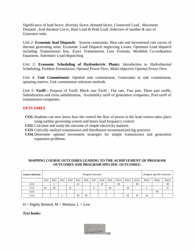
106
Significance of load factor, diversity factor, demand factor, Connected Load , Maximum
Demand , load duration Curve, Base Load & Peak Load ,Selection of number & size of
Generator units
Unit 2: Economic load Dispatch: System constraints, Heat rate and incremental rate curves of
thermal generating units, Economic Load Dispatch neglecting Losses, Optimum Load dispatch
including Transmission loss, Exact Transmission Loss Formula, Modified Co-ordination
Equations, Automatic Load dispatching
Unit 3: Economic Scheduling of Hydroelectric Plants: Introduction to Hydrothermal
Scheduling, Problem Formulation, Optimal Power Flow, Multi-objective Optimal Power Flow
Unit 4: Unit Commitment: Optimal unit commitment, Constraints in unit commitment,
spinning reserve, Unit commitment solutions methods
Unit 5: Tariff : Purpose of Tariff, Block rate Tariff , Flat rate, Two part, Three part tariffs,
Subsidization and cross subsidization, Availability tariff of generation companies, Pool tariff of
transmission companies.
OUTCOMES:
CO1. Students can now know how the control the flow of power to the load centres takes place
using turbine governing system and hence load frequency control.
CO2. Calculate and study the outcome of simple electricity markets.
CO3. Critically analyze transmission and distribution investment/pricing practices
CO4. Determine optimal investment strategies for simple transmission and generation
expansion problems.
MAPPING COURSE OUTCOMES LEADING TO THE ACHIEVEMENT OF PROGRAM
OUTCOMES AND PROGRAM SPECIFIC OUTCOMES:
Course Outcome Program Outcome Program Specific Outcome
PO1 PO2 PO3 PO4 PO5 PO6 PO7 PO8 PO9 PO10 PO11 PO12 PSO1 PSO2 PSO3
CO1 L H H M M M
CO2 M M H L M M L H
CO3 M
CO4 L M M M H M
H = Highly Related, M = Medium, L = Low
Text books:

107
1. C. L. Wadhwa “Electrical Power Systems”, 6th Edition, New Age International
2. D. P. Kothari, I.J. Nagrath, “Modern Power System Analysis”4th Edition, TMH
Reference Books:
1. B. R.Gupta: “Power system Analysis and Design”, S.Chand.
2. S. Sivanagaraju, G Sreenivasan, “Power System Operation & Control” 1st ed., Pearson
Pub.
School of Engineering B.Tech. in Electrical Engineering – Semester VII Contact Hrs per week (L-T-P): 3-0-0
Course Outlines
BEL021A- Energy Auditing
OBJECTIVE:
This course helps in understanding the components and process involved in energy
auditing.

108
Unit 1: Introduction to Audit: Introduction to industrial energy auditing, definition of energy
auditing, Objectives , Types of energy audits, Preparation, audit criteria, audit scope, Selection
of audit team, Audit plan, Preparing an audit checklist.
Unit 2: Survey: Conducting the initial walk-through visit, Collecting energy bills and available
data and information, Conducting the preliminary analysis, Analyzing energy bills, Electricity
bills, Natural gas bills, Coal and fuel oil bills.
Unit 3: Inventory and production patterns: Electrical load inventory, Thermal energy use
inventory, Energy balance, Analyzing energy use, Load profile, Scatter diagram for energy-
production relationship, Interpretation of energy-production on a scatter diagram, Energy
performance analysis, Energy efficiency and energy cost reduction.
Unit 4: Analysis of data: Electrical demand control, Cross-cutting energy-efficiency
improvement options, Energy-efficiency improvement opportunities in electric motors,
compressed air systems, pumping systems, fan systems, lighting system, steam systems, process
heating systems, Cost-benefit analysis of energy-efficiency , Life-cycle cost analysis, Life cycle
cost method, Net present value method, Internal rate of return method, Simple payback period
method.
Unit 5: Audit preparation: Preparing an energy audit report, Post-audit activities, Create
Conversion factors, Energy audit instruments, Safety considerations, Measuring electrical
parameters, Temperature measurement, Flow measurements, Exhaust gas measurements,
Measurement of the speed of rotating equipment.
Course Outcomes (CO):
CO1: Students will be able to understand the role of Engineers in auditing.
CO2: Students will able to understand the methods of survey and ability is developed to apply
best auditing method for primary fulfillments.
CO3: Students will able to represent large data’s in graphical shape to easily understand.
CO4: Students are able to analysis the large data through suitable methods and interoperate the
results.
MAPPING COURSE OUTCOMES LEADING TO THE ACHIEVEMENT OF PROGRAM
OUTCOMES AND PROGRAM SPECIFIC OUTCOMES:
Course Outcome Program Outcome Program Specific Outcome
PO1 PO2 PO3 PO4 PO5 PO6 PO7 PO8 PO9 PO10 PO11 PO12 PSO1 PSO2 PSO3
CO1 H M M H H M H H
CO2 H H H M M H H M
CO3 M H H H H H H
CO4 H M M L H H M
H = Highly Related, M = Medium L = Low

109
Text Books:
1. Energy Conservation Hand Book, Bureau of Energy Efficiency, Ministry of
Power, Govt. of India.
2. Industrial Energy Audit Guidebook: Guidelines for Conducting an Energy Audit
in Industrial Facilities, Ali Hasanbeigi, Lynn Price, China Energy Group, Energy
Analysis Department., Environmental Energy Technologies Division.
School of Engineering B.Tech. in Electrical Engineering – Semester VII
Contact Hrs per week (L-T-P): 3-0-0
Course Outlines
BEL068A: Recent Trends In Electrical Power Generation
OBJECTIVES:
To know how various energy sources (renewable and nonrenewable) are generated and to
enhance their contribution to the socio-economic development.
Awareness of different treaties, energy scenario and Energy policy related to India.

110
Unit-1: Physics of Wind Power: History of wind power, Indian and Global statistics, Wind
physics, Betz limit, Tip speed ratio, stall and pitch control, Wind speed statistics-probability
distributions, Wind speed and power-cumulative distribution functions.
Unit-2: Wind generator topologies: Review of modern wind turbine technologies, Fixed and
Variable speed wind turbines, Induction Generators, Doubly-Fed Induction Generators and their
characteristics, Permanent-Magnet Synchronous Generators, Power electronics converters.
Generator-Converter configurations, Converter Control.
Unit-3: The Solar Resource: Introduction, solar radiation spectra, solar geometry, Earth Sun
angles, observer Sun angles, solar day length, Estimation of solar energy availability.
Unit-4: Solar photovoltaic: Technologies-Amorphous, mono crystalline, polycrystalline; V-I
characteristics of a PV cell, PV module, array, Power Electronic Converters for Solar Systems,
Maximum Power Point Tracking (MPPT) algorithms. Converter Control.
Unit-5: Biomass energy: Photosynthesis process, usable forms of biomass ,biomass conversion
technology, urban waste to energy conversion, biomass gasification, liquification, biomass
production from waste biomass, energy scenario of biomass energy India and world.
COURSE OUTCOMES:
CO1. Understand the energy scenario and the consequent growth of the power generation from
renewable energy sources.
CO2. Understand the basic physics of wind and solar power generation.
CO3. Understand the power electronic interfaces for wind and solar generation.
CO4. Understand the issues related to the grid-integration of solar and wind energy systems.
MAPPING COURSE OUTCOMES LEADING TO THE ACHIEVEMENT OF PROGRAM
OUTCOMES AND PROGRAM SPECIFIC OUTCOMES:
Course Outcome Program Outcome Program Specific Outcome
PO1 PO2 PO3 PO4 PO5 PO6 PO7 PO8 PO9 PO10 PO11 PO12 PSO1 PSO2 PSO3
CO1 H M H H H M H
CO2 M M M M M H M
CO3 H H H M L L H M
CO4 H \H M H H H H H
H = Highly Related, M = Medium, L = Low
Text Books:
111
1. BH Khan, “Non Conventional Energy Resources” TMH.
2. G. M. Masters, “Renewable and Efficient Electric Power Systems”, John Wiley and Sons,
2004.
Reference Books:
1. Energy Conservation Hand Book, Bureau of Energy Efficiency, Ministry of Power, Govt. of
India.
2. T. Ackermann, “Wind Power in Power Systems”, John Wiley and Sons Ltd., 2005.
3. S. P. Sukhatme, “Solar Energy: Principles of Thermal Collection and Storage”, McGraw
Hill, 1984.
School of Engineering
B.Tech. in Electrical Engineering – Semester VII
Contact Hrs per week (L-T-P): 3-0-0
Course Outlines
BEL037A-Power System Security and Smart Grid
OBJECTIVES:
The objective of this course is to give knowledge about power system security, voltage
112
stability.
It also gives information as to how smart grid is helpful in present scenario. Unit 1: Power system Security: Introduction to power system security, System state classification, Security analysis, Contingency analysis, Sensitivity factors and power system voltage stability. Unit 2: Voltage Stability I: Introduction to voltage stability, Comparison of angle and voltage stability, Reactive power flow and voltage collapse, Difficulties with reactive power Flow, HVDC operation Unit 3:Voltage Stability II: Mathematical formulation of voltage stability problem, Voltage stability analysis: P-Curve, Prevention of voltage collapse, State of the art, future trends and challenges. Unit 4: State estimation of Power systems: An introduction to state estimation of power systems, least squares estimation, static state estimation of power systems, Computational consideration, and External system equivalency, Treatment of bad data, Network observability and Pseudo measurements. Unit 5: Smart Grid: Introduction about smart grid, Aims of the smart grid, Pathways to a smart grid, Components of a smart grid, Optimizing grid operation and application, Optimizing grid infrastructure, Information and communication technologies. New market places, users and energy efficiency, Micro grid and smart micro grid.
Course Outcomes (CO):
CO1. Student should be able to detect the contingencies associated with power system security.
CO2. Students get awareness about voltage collapse and hence how these can be prevented.
CO3. Students can able to know how optimized grid structure can be established.
CO4. Students will able to understand smart Grid properties with detailed in real life.
MAPPING COURSE OUTCOMES LEADING TO THE ACHIEVEMENT OF PROGRAM
OUTCOMES AND PROGRAM SPECIFIC OUTCOMES:
Course Outcome Program Outcome Program Specific Outcome
PO1 PO2 PO3 PO4 PO5 PO6 PO7 PO8 PO9 PO10 PO11 PO12 PSO1 PSO2 PSO3
CO1 M M L H M H
CO2 H H M M M M H M
CO3 L M H H M L L H M
CO4 L M H L H H H
H = Highly Related, M = Medium, L = Low
Text Books:

113
1. Modern Power System Analysis by DP Kothari and IJ Nagrath, 4th Ed.TMH.
2. CL Wadhwa “Electrical Power Systems”, 6th Edition, New Age International, 2012
Reference Books:
1. BR Gupta, “Power System Analysis and Design”, S.Chand. 2. P.S.R. Murty, “Operation and control in Power Systems” B.S. Publications.
3. J. Wood and B.F. Wollenburg,“ Power Generation, Operation and Control “ John Wiley
4. P. Kundur, “Power System Stability and Control Mc Graw Hill.
5. T.K Nagsarkar and M.S. Sukhija, “Power System Analysis” Oxford Uni. Press.
School of Engineering B.Tech. in Electrical Engineering – Semester VII
Contact Hrs per week (L-T-P): 3-0-0
Course Outlines
BEL036A – Utilization of Electrical Energy and Electric Traction
OBJECTIVES:
This course provides information regarding working and applications of different sources of illumination, electric heating and electrolytic processes.

114
It also in looks the characteristics and control of DC and AC traction motors. Unit 1: Illumination- Nature of light, important definitions, laws of illumination, principle of production of light- discharge through gases under pressure – incandescence/sources of light-filament lamp, halogen lamp-discharge lamp-sodium discharge lamp, high pressure mercury discharge lamp, dual lamps, fluorescent lamps, lamp efficiency, requirements of good lighting, illumination level, absence of contrasts, shadows, glare, colour rendering-lamp fittings. Lighting schemes, design of indoor and outdoor lighting system-street lighting, flood lighting, photometers.
Unit 2: Electric Heating- Advantages of electric heating, classification of heating methods, detailed study of resistance heating, arc heating, electron bombardment heating, induction heating and dielectric heating and their control. Unit 3: Electrolytic Processes- Fundamentals of electro deposition-laws of electrolysis applications of electrolysis, electro deposition, manufacture of chemicals, anodizing, electro-polishing, electro-cleaning, electro-parting, electrometallurgy, electric supply.
Unit 4: Train Mechanics- Types of services, characteristics of each type of service, speed time curve, simplified speed time curve, average speed, schedule speed, factors affecting schedule speed, tractive effort for propelling a train, power of the traction motor, specific energy output, specific energy consumption, factors affecting specific energy consumption, mechanics of train movement, coefficient of adhesion, factors affecting slip.
Unit 5: Electric Traction- DC and AC traction motors, their characteristics Traction Motor Control: Starting and speed control of DC series motors, shunt transition, bridge transition, drum controller employing shunt transition, energy saving with series parallel starting, multiple unit control, braking of traction motors.
Course Outcomes (CO):
CO1. Student should be able to verify why a particular illumination source is chosen for
lighting industrial, commercial and residential premises.
CO2. Students able know how different traction motors operate.
CO3. Students can able to understand Electrolytic Processes done in the different application.
CO4. Students can get the knowledge of controlling methods for trains.
MAPPING COURSE OUTCOMES LEADING TO THE ACHIEVEMENT OF PROGRAM
OUTCOMES AND PROGRAM SPECIFIC OUTCOMES:
Course Outcome Program Outcome Program Specific Outcome
PO1 PO2 PO3 PO4 PO5 PO6 PO7 PO8 PO9 PO10 PO11 PO12 PSO1 PSO2 PSO3
CO1 M H H H H H H H
CO2 H M H M H M M M
CO3 M M M H L H L

115
CO4 H H H H M H M
H = Highly Related, M = Medium; L = Low
Text Books:
1. H. Partap, “Art and Science of Utilization of Electrical Energy”.
2. BL Theraja Vol-III, S. Chand Publishers.
Reference Books:
1. B.R. Sharma, “Utilization of Electrical. Energy”.
2. E. Openshan Taylor, “Utilization of Electric Energy”, Orient Longmans.
3. N.V. Suryanarayana, “Utilization of Electric Power”.
4. AT Dover, “Electric Traction”, Pitman.
School of Engineering B.Tech. in Electrical Engineering – Semester VII
Contact Hrs per week (L-T-P): 3-0-0
Course Outlines
BEL069A- Basics of Soft Computing OBJECTIVES:
To cater the knowledge of Neural Networks and Fuzzy Logic Control and use these for
controlling real time systems.
Unit-1: Artificial Neural Networking-I: Structure of Human brain. Artificial Neural Networks
(ANN) - Single layer and multi layer. Fundamental models of ANN-Mcculloch- Pitts, Hebbian,

116
Delta, Boltzman, Adalin and Madalin Learning - Supervised and unsupervised, competitive
learning ,Learning Rules.
Unit-2: Artificial Neural Networking-II: Perceptrons Back propagation, Hopfield networks.
Radial basis function. Associative memory networks – Hetero associative memories, Auto
Associative,Bi-directional associative memory. Applications of neural network in Electrical
engineering including Power system control and electric drive.
Unit-3: Fuzzy Logic: Introduction, Probability vs Possibility theory, classic sets and fuzzy sets,
Fuzzy set operations: intersection, union, complementary, fuzzy arithmetic’s. Fuzzy Relations,
fuzzy compositions: Max-Min, Max-Star, Max-Product, Max-Average composition. fuzzy logic
applications.
Unit-4: Genetic Algorithms: Introduction, Procedure of genetic algorithms: genetic
representations, selection, genetic operators, mutation and natural inheritance operators. Working
of GA’s: binary or discrete, real or continuous with applications.
Unit-5: Swarm Intelligent System: Introduction, Ant colony system: biological, artificial,
working, probabilistic transition rules, pheromone updating, solution evaluation. Ant colony
optimization. Artificial BEE colony system, Cuckoo search.
Fuzzy rule based control systems: simple fuzzy logic controllers. Introduction to Genetic
Algorithm.
Course Outcomes (CO):
CO1. Understand importance of soft computing.
CO2. Understand different soft computing techniques like Genetic Algorithms, Fuzzy Logic,
Neural Networks and their combination.
CO3. Implement algorithms based on soft computing.
CO4. Apply soft computing techniques to solve engineering or real life problems.
MAPPING COURSE OUTCOMES LEADING TO THE ACHIEVEMENT OF PROGRAM
OUTCOMES AND PROGRAM SPECIFIC OUTCOMES:
Course
Outcome Program Outcome
Program Specific
Outcome
PO1 PO2 PO3 PO4 PO5 PO6 PO7 PO8 PO9 PO10 PO11 PO12 PSO1 PSO2 PSO3
CO1 M L H M H L
CO2 M L M H L H M
CO3 L H M M M M H
CO4 M H H M L H
H = Highly Related, M = Medium, L = Low

117
TEXT BOOKS:
1. N.P. Padhy & S.P. Simon “Soft Computing with MATLAB Programming”, Oxford
University Press.
2. Tomthy Ross,Fuzzy Logic and Engineering Application, TMH
3. C++ Neural Networks and Fuzzy Logic by Rao & Rao.
RECOMMENDED BOOKS:
1. Neural computing Theory and Practice by P. D. Wasserman (Auza Research Inc.)
2. Neural Networks, Fuzzy Logic and Genetic Algorithm-Synthesis and Applications,
Rajajsekharan and Vijayalakshmi Pai, Prentice Hall of Private Limited, New Delhi.
School of Engineering
B.Tech. in Electrical Engineering – Semester VII
Contact Hrs per week (L-T-P): 3-0-0
Course Outlines
BEL043A- Excitation of Synchronous Machines and their Control
OBJECTIVES: Students will understand the principle, operation, control and characteristics of
different excitation systems of synchronous machines.

118
Unit 1: Excitation Systems: Principle Controls of a generating unit. Arrangement of excitation
components, voltage response-ratio. Excitation specifications. Ceiling voltage, time constant and
response of excitation systems. Requirements of excitation systems: Classification of excitation
systems.
Unit 2: DC Excitation Systems: configuration of DC excitation system with main and pilot
exciters. Amplidyne and magnetic amplifier. Automatic voltage regulator with magnetic
amplifier and Amplidyne. Limitation and problems of DC excitation systems. Improvement in
DC excitation system.
Unit 3: AC Shunt Excitation Systems (Static Rectifier Excitation Systems): Static thyristor
rectifier schemes. Transient Response during fault condition. Use of booster transformer.
Application for shunt excitation systems.
Unit 4: AC Separately Excitation Systems. (Alternator- Rectifier Excitation System):
Scheme of alternator-rectifier excitation system with (i) Diode rectifier and (ii) Thyristor
rectifier. Comparison and Application of these schemes. Harmful effects of static excitation
systems or system machine components, means of prevention.
Unit 5: Brushless Excitation Systems: Brush-slip ring problem. Scheme of Brushless excitation
system with rotating diode. Control, protection and monitoring of Brushless excitation system.
Introduction to brushless excitation system with rotating thyristors. Introduction to
Superconducting Exciter.
Course Outcomes (CO):
CO1. Students can now compare different excitation systems of synchronous machines.
CO2. Students will able to design and differentiate the AC/DC excitation system.
CO3. Students can able to design and develop new machines.
CO4. Students will solve the numerical problem in real world environment.
MAPPING COURSE OUTCOMES LEADING TO THE ACHIEVEMENT OF PROGRAM
OUTCOMES AND PROGRAM SPECIFIC OUTCOMES:
Course Outcome Program Outcome Program Specific Outcome
PO1 PO2 PO3 PO4 PO5 PO6 PO7 PO8 PO9 PO10 PO11 PO12 PSO1 PSO2 PSO3
CO1 H L H L H M
CO2 M H M L H H M
CO3 M H H M H H H
CO4 H M L M L M M M M H

119
H = Highly Related, M = Medium, L = Low
Text book:
1. AE Fitzgerald, Charles Kingsley, & SD Umans, Electrical Machinery, 4th Ed., MGH Pub.
Reference books:
1. MG Say, Theory, Performance and Design of AC Machines, CBS Publishers.
2. C V Jones Unified Theory of Electrical Machines, Butterworths, London 1967
3. Clayton. A.E., “Performance and Design of Direct Current Machines” UBS Publishers.
School of Engineering B.Tech. in Electrical Engineering – Semester VII
Contact Hrs per week (L-T-P): 3-0-0
Course Outlines
BEL029A- FACTS (Flexible AC Transmission Systems)
OBJECTIVES:

120
The objective of this course is to introduce participants to the transmission challenges of
modern electrical power systems.
The course will present the basic concepts, principles and operation of fast high power
electronic controllers known as Flexible AC Transmission Systems (FACTS) that
enhance power system stability and effectively increase transmission capacity thus
yielding significantly higher flexibility of operation.
Unit 1: Introduction to AC transmission systems: Problems of AC transmission systems, power
flow in parallel paths and meshed system, factors limiting loading capability, stability
consideration. Power flow control of an AC transmission line. Basic types of facts controllers.
Advantages of FACTS technology.
Unit2: Static Shunt Compensators: Mid-point and end point voltage regulation of transmission
line, and stability improvement. Basic operating principle of Static Synchronous Compensators
(STATCOM).Comparison between STATCOM and SVC.
Unit3: Static Series Compensators: Concept of series capacitive compensation, voltage and
transient stabilities, power oscillation and sub synchronous oscillation damping. Introduction to
thyristor switched series capacitor (TSSC), thyristor controlled series capacitor (TCSC), and
static synchronous series compensator, - operation, characteristics and applications.
Unit4: Static Voltage and Phase Angle Regulators: (i) Voltage and phase angle regulation.
Power flow control and improvement of stability by phase angle regulator. Introduction to
thyristor controlled voltage and phase angle regulators (TCVR and TCPAR) (ii) Introduction to
thyristor controlled braking resistor and thyristor controlled voltage limiter.
Unit5: UPFC and IPFC: Unified Power Flow Controller (UPFC), basic operating principles,
conventional transmission control capabilities. Comparison of UPFC to series compensators and
phase angle regulator. Applications of UPFC.
IPFC: Interline Power Flow Controller (IPFC), basic operating principles and characteristics.
Applications of IPFC.
COURSE OUTCOMES:
CO1. Students will now know in depth the problems associated with AC transmission system which
limits its loading capacity and stability.
CO2. Understand the monitoring and control of a power system. CO3. To know the transmission challenges of modern electrical power systems.
CO4. To know how the enhance power system stability and effectively increase transmission capacity.

121
MAPPING COURSE OUTCOMES LEADING TO THE ACHIEVEMENT OF PROGRAM
OUTCOMES AND PROGRAM SPECIFIC OUTCOMES:
Course Outcome Program Outcome Program Specific Outcome
PO1 PO2 PO3 PO4 PO5 PO6 PO7 PO8 PO9 PO10 PO11 PO12 PSO1 PSO2 PSO3
CO1 M H M H M H M M
CO2 M H M H H M M H
CO3 H M M H M H H
CO4 M \ M H H L L H
H = Highly Related, M = Medium, L = Low
Text Books:
1. Narain G. Hingorani: Understanding FACTS: Concepts and Technology of Flexible AC
Transmission Systems 2. D. P. Kothari, I. J. Nagrath: Modern Power System Analysis
Reference Books: 1. Yong-Hua Song, Allan Johns: Flexible AC Transmission Systems (FACTS).
School of Engineering B. Tech. in Electrical Engineering – Semester VII
Contact Hrs per week (L-T-P): 3-0-0
Course Outlines
BEL070A-Power System Instrumentation

122
Unit 1: Theory of Errors: Accuracy and precision, systematic and random errors, limits of
error, probable error and standard deviation. Gaussian error curves, combination of errors.
Unit 2: Transducers: Construction & Operating Characteristics of active and digital transducers,
Measurement of temperature, pressure, displacement, acceleration, noise level.
Unit 3: Signal Conditioning: Instrumentation amplifiers, isolation amplifiers, analog
multipliers, analog dividers, function generators, timers, sample and hold, optical and magnetic
isolators.
Unit 4: Measurement of voltage, current, phase angle, frequency, active power and reactive
power in power plants. Energymeters and multipart tariff meters and Basic idea of LT & HT
panel’s
Unit 5: Tap Changing transformer, phase angle control and phase shifting transformer. Series
compensation of transmission lines, location and protection of series capacitors, advantages and
problems Current Transformers for measurement and protection.
Course Outcomes (CO): CO1. To analyze the errors during measurements.
CO2. To specify the requirements in the calibration of sensors and instruments.
CO3. To design and set up measurement systems and do the studies.
CO4. To construct Instrumentation/Computer Networks.
MAPPING COURSE OUTCOMES LEADING TO THE ACHIEVEMENT OF PROGRAM
OUTCOMES AND PROGRAM SPECIFIC OUTCOMES:
Course Outcome Program Outcome Program Specific Outcome
PO1 PO2 PO3 PO4 PO5 PO6 PO7 PO8 PO9 PO10 PO11 PO12 PSO1 PSO2 PSO3
CO1 M L H M H L M
CO2 H L M H M M M
CO3 H M M L H L
CO4 M L M L M M H
H = Highly Related, M = Medium, L = Low
Text Books:
1 RH Cerni and L. E. Foster: Instrumentation for Engineering Measurements, JohnWiley and
Sons. (1962).
2 Curtis and D. Hohnson: Process Control Instrumentation Technology, John Wiley and Sons.
(2013)
Reference Books:

123
1. R. Morrison: Instrumentation Fundamentals and Applications, John Wiley and Sons. (1984)
2. AK. Sawhney: Advanced Measurements & Instrumentation, Dhanpat Rai & Sons. (1994)
3. EO. Decblin: Measurement System– Application & design, MGH. (1975)
4. WD. Cooper and A.P. Beltried: Electronics Instrumentation and Measurement Techniques,
Prentice Hall International. (1987)
5 AS Moris: Principles of Measurement & Instrumentation, Prentice Hall, 1993.
School of Engineering B.Tech. in Electrical Engineering – Semester VII
Contact Hrs per week (L-T-P): 0-0-2
Course Outlines
BEL073A- CAD of Electrical Machines

124
OBJECTIVE:
This course helps in learning the tools associated with different software and hardware available in the market for computer aided design to help them solve different design issues.
Perform any 10 experiments.
Design of transformer 1 Write a program to design the rating of a single phase transformer in kVA using various
physical parameters. 2 Write a program to design the out equation for voltage per turn of a single phase
transformer using various physical parameters. 3 Write a program to design the ratio of iron losses to copper losses of a single phase
transformer using various physical parameters. 4 Write a program to design the relation between core area and weight of iron and copper
of a single phase transformer using various physical parameters. 5 Write a program to design a single phase transformer for minimum cost using various
physical parameters. 6 Write a program to design a single phase transformer for minimum loss using various
physical parameters. 7 Write a program to design window width of a single phase transformer for optimum
output using various physical parameters. 8 Write a program for yoke design and overall dimensions of a single phase transformer
for optimum output using various physical parameters. Design of DC Machine
9 Write a program to design the output equation of a DC machine using various physical parameters.
10 Write a program to design the maximum permissible core length of a DC machine using various physical parameters.
11 Write a program to design the minimum permissible core diameter of a DC machine using various physical parameters.
12 Write a program to design the minimum number of coils required for a DC machine using various physical parameters.
Design of rotating AC Machine 13 Write a program to design the output equation of a AC machine using various physical
parameters. 14 Write a program to design a 3 phase squirrel cage induction motor (calculating its main
dimensions, turns per phase, number of stator slots and winding details) using various physical parameters.
Course Outcomes (CO):
CO1. To develop analytical skills for step by step solution for algorithms.
CO2. Students will now be able to make different computer aided design projects related to
electrical machines.
CO3. Students will able to solve power system problems through programming.

125
CO4. To enhance an ability for step by step solution for algorithms the output equation of a AC
machine.
MAPPING COURSE OUTCOMES LEADING TO THE ACHIEVEMENT OF PROGRAM
OUTCOMES AND PROGRAM SPECIFIC OUTCOMES:
Course Outcome Program Outcome Program Specific Outcome
PO1 PO2 PO3 PO4 PO5 PO6 PO7 PO8 PO9 PO10 PO11 PO12 PSO1 PSO2 PSO3
CO1 H M M H M H M
CO2 H H H M H H M M
CO3 H L M H M M M L H H
CO4 M M L H M
H = Highly Related, M = Medium, L = Low
School of Engineering B.Tech. in Electrical Engineering – Semester VII
Contact Hrs per week (L-T-P):0-0-2
Course Outlines
BEL038A - Advanced Simulation Lab

126
OBJECTIVE:
To expose the students to learn programming and simulation on MATLAB / Sci
Lab software to realize electrical and electronic circuits.
List of Experiments (Perform any 10):
1. Perform various commands of PSPICE/MATLAB/Sci Lab.
2. Determine node voltages and branch currents in a resistive network.
3. Obtain Thevenin’s equivalent circuit of a resistive network.
4. Obtain Norton’s equivalent circuit of a resistive network. 5. Obtain transient response of a series R-L-C circuit for step voltage and current input and for
alternating square voltage waveform. 6. Obtain transient response of a parallel R-L-C circuit for step voltage and current input and
for alternating square voltage waveform. 7. Obtain frequency response of a series R-L-C circuit for sinusoidal voltage input.
8. Obtain frequency response of a parallel R-L-C circuit for sinusoidal voltage input. 9. Determine line and load currents in a three phase delta circuit connected to a 3-phase
balanced AC supply. 10. Determine z, y, g, h and transmission parameters of a two part network. 11. Obtain transient response of output voltage in a single phase half wave rectifier circuit using
capacitance filter. 12. Obtain output characteristics of CE NPN transistor.
13. Obtain frequency response of a R-C coupled CE amplifier.
14. Obtain frequency response of an op-Amp integrator circuit.
15. Verify truth tables of NOT, AND or OR gates implemented by NAND gates by plotting their
digital input and output signals. Course Outcomes (CO):
CO1. Students can now use programming / simulation skills to get output on any electrical and
electronic circuits. CO2. Students can now programming with the help of PSPICE/MATLAB software. CO3. To know and verify the outcomes of different electronic circuits
CO4. Students are able to simulate different power electronic circuits.
MAPPING COURSE OUTCOMES LEADING TO THE ACHIEVEMENT OF
PROGRAM OUTCOMES AND PROGRAM SPECIFIC OUTCOMES:
Course Outcome Program Outcome Program Specific Outcome
PO1 PO2 PO3 PO4 PO5 PO6 PO7 PO8 PO9 PO10 PO11 PO12 PSO1 PSO2 PSO3
CO1 H M H H H M H
CO2 M M M M M H M

127
CO3 H H H M L L H M
CO4 H \H M H H H H H
H = Highly Related, M = Medium, L = Low
School of Engineering and Technology B.Tech. in Electrical Engineering – Semester V
Contact Hrs per week (L-T-P):3-0-0
Course Outlines
BEL075A - Energy Studies

128
OBJECTIVES:
To know how various energy sources (renewable and nonrenewable) are generated and to
enhance their contribution to the socio-economic development.
Awareness of different treaties, energy scenario and Energy policy related to India.
Unit 1:Energy Sources: Fossil fuels, Nuclear fuels, hydel, solar, wind and bio fuels in India, Energy conservation, Nuclear energy through fission and fusion processes.
Unit 2: Energy Conversion: Energy conversion from source to utility, Solar, Nuclear, Geothermal, Tide and Wind Energies.
Unit 3: Global Energy Scenario: Role of energy in economic development and social transformation, Overall energy demand, availability and consumption, Depletion of energy resources and its impact on economy, Non proliferation of nuclear energy. International energy policies of G-8, G-20, OPEC and European Union Countries.
Unit 4: Indian Energy Scenario: Commercial and non-commercial forms of energy, Utilization pattern in the past, present and also future prediction, Sector wise energy consumption.
Unit 5: Energy Policy: Energy policy issues at global level, national level and state level, Energy conservation act 2001, Electricity act 2003, Energy pricing and its impact on global variations.
COURSE OUTCOMES:
CO1. Knowing the various generation processes, energy demand and energy policy;
everyone is more inclined to energy conservation and can contact different
government agencies for energy projects.
CO2. To know the Energy policy issues at global level.
CO3. To know Indian Energy Scenario- Commercial and non-commercial forms of energy.
CO4. Understand the methods to handle the Energy Sources in a productive way.
MAPPING COURSE OUTCOMES LEADING TO THE ACHIEVEMENT OF PROGRAM
OUTCOMES AND PROGRAM SPECIFIC OUTCOMES:
Course
Outcome
Program Outcome Program Specific
Outcome
PO1 PO2 PO3 PO4 PO5 PO6 PO7 PO8 PO9 PO10 PO11 PO12 PSO1 PSO2 PSO3
CO1 H L M M L H M
CO2 H M L M M M M
CO3 H H H L M H

129
CO4 H M M L M M M L
H = Highly Related, M = Medium, L = Low
Text Book:
1. BH Khan, “Non Conventional Energy Resources” TMH.
Reference Books:
1. Bukhootsow, B., Energy Policy and Planning, PHI New Delhi, 2003.
2. Dr. A.N Mathur- Non Conventional resources of Energy. 3. International Energy Outlook, EIA Annual Publication, 2011.
4. Charles E. Brown, World Energy Resources, Springer Publication, New York, 2002.
5. Culp, A.W., Principles of Energy Conversion, McGraw Hill New York, 2004.
School of Engineering
B.Tech. – Semester V
Contact Hrs per week (L-T-P): 3-0-0
Course Outlines
BEL051A: Knowledge Management

130
OBJECTIVE: This course mainly deals with the planning and process involved in knowledge
creation and implementing management in organization.
Unit 1: Introduction: Definition, evolution, need, drivers, scope, approaches in Organizations,
strategies in organizations, components and functions, understanding knowledge; Learning
organization: five components of learning organization, knowledge sources, and documentation.
Unit 2: Essentials of Knowledge Management: Knowledge creation process, knowledge
management techniques, systems and tools.
Unit 3: Organizational knowledge management: Architecture and implementation strategies,
building the knowledge corporation and implementing knowledge management in organization.
Unit 4: Knowledge management system: Knowledge management system life cycle, managing
knowledge workers, knowledge audit, and knowledge management practices in organizations,
few case studies.
Unit 5: Futuristic KM: Knowledge Engineering, Theory of Computation, Data Structure.
Course Outcomes (CO):
CO1. One can now effectively plan a systematised approach in identifying, creating and
retaining knowledge workers using modern practices.
CO2. To analyze the essentials of knowledge management.
CO3. To gain the components and functions of knowledge management.
CO4. To analyze the futuristic knowledge management.
MAPPING COURSE OUTCOMES LEADING TO THE ACHIEVEMENT OF PROGRAM
OUTCOMES AND PROGRAM SPECIFIC OUTCOMES:
Course Outcome Program Outcome Program Specific Outcome
PO1 PO2 PO3 PO4 PO5 PO6 PO7 PO8 PO9 PO10 PO11 PO12 PSO1 PSO2 PSO3
CO1 M L M M M L H
CO2 M H M M M H
CO3 L M M H M L M
CO4 M M M M L M L
H = Highly Related, M = Medium, L = Low
Text Books:
1. Knowledge Management – a resource book – A Thohothathri Raman, Excel, 2004.
2. Knowledge Management- Elias M. Awad Hasan M. Ghazri, Pearson Education.
Reference Books:
1. The KM Toolkit – Orchestrating IT, Strategy & Knowledge Platforms, Amrit Tiwana,

131
2. Pearson, PHI, II Edn.
3. The Fifth Discipline Field Book – Strategies & Tools for Building A learning
Organization –
4. Peter Senge et al. Nicholas Brealey 1994 .
5. Knowledge Management – Sudhir Warier, Vikas publications
6. Leading with Knowledge, Madan Mohan Rao, Tata Mc-Graw Hill.
School of Engineering B.Tech. in Electrical Engineering – Semester VI
Contact Hrs per week (L-T-P): 3-0-0
Course Outlines
BEL030A- Indian Electricity Standards and their Applications
OBJECTIVE:
132
The objective of this course is to give knowledge about various standards and rules associated in power system (transmission and distribution) in India.
Unit 1: Introduction: Various definitions used in Indian electricity rule 1956 i.e., appointment and
authority of Inspectors and officers under government, license and contents of draft license. Service lines
and apparatus on consumer’s premises. Cut-out on consumer’s premises, Identification of earthed and
earthed neutral conductors and position of switches and cut-outs, Earthed terminal on consumer’s premises, Accessibility of bare conductors, Danger Notices, Handling of electric supply lines and
apparatus, Cables for portable or transportable apparatus, Cables protected by bituminous materials,
Street boxes, Distinction of different circuits, Accidental charge, Provisions applicable to protective
equipment, Instructions for restoration of persons suffering from electric shock, Precautions to be adopted by consumers, Periodical inspection and testing of consumer’s installation.
Unit 2: General Conditions Relating To Supply And Use Of Energy: Testing of consumer’s
installation, Precautions against leakage before connection, Leakage on consumer’s premises, Supply and
use of energy, Provisions applicable to medium, high or extra-high voltage installations, Cost of
inspection and test of consumer’s installation, Declared voltage of supply to consumer, Declared frequency of supply to consumer, Sealing of meters, and cut-outs, Precautions against failure of supply:
Notice of failures.
Unit 3: Electric Supply Lines, Systems And Apparatus For Low And Medium Voltages:
Test for resistance of insulation, Connection with earth.
Unit 4: Electric Supply Lines, Systems And Apparatus For High And Extra-High Voltages: Approval by Inspector, Use of energy at high and extra-high voltage, Testing, Operation and Maintenance, Metal sheathed electric supply lines, Connection with earth, General conditions as to
transformation and control of energy, Supply to X-ray and high frequency installation.
Unit 5: Overhead Lines, Under Ground Cables And Generating Stations: Material and strength,
Maximum stresses, Clearance above ground of the lowest conductor, Clearance between conductors and
trolley wires, Clearances from buildings of low and medium voltage lines and service lines, Clearances from buildings of high and extra-high voltage lines, Conductors at different voltages on same supports,
Erection of or alternation to buildings, structures, flood banks and elevation of roads, Clearances, Routes,
Maximum interval between supports, Conditions to apply where telecommunication lines and power lines
are carried on same supports, Lines crossing or approaching each other, Service-lines from Overhead lines, Earthing, Safety and protective devices, Protection against lightning, Unused overhead lines.
Additional rules for electric traction, Introduction to electric supply in mines and oil fields.
Course Outcome (CO):
CO1. To know various definitions used in Indian electricity rules CO2. Students will now know how to get a new connection and enhancement or reduction of
load, recovery of electricity charges and intervals for billing of electricity charges,
disconnection, reconnection and restoration of supply of electricity. CO3. Authority and responsibility associated with power inspectors.

133
CO4. Students can educate others about the safety precautions which a common man
should take care of while usage of electrical appliances, cables etc. in and around
their houses.
MAPPING COURSE OUTCOMES LEADING TO THE ACHIEVEMENT OF PROGRAM
OUTCOMES AND PROGRAM SPECIFIC OUTCOMES:
Course Outcome Program Outcome Program Specific Outcome
PO1 PO2 PO3 PO4 PO5 PO6 PO7 PO8 PO9 PO10 PO11 PO12 PSO1 PSO2 PSO3
CO1 H H H M H M M
CO2 H M H H M H M H
CO3 M M M H H L H M
CO4 H \ M M H L M L
H = Highly Related, M = Medium, L = Low
Text Books:
1. Indian Electricity Rules, 1956, Manak Bhavan, New Delhi.
2. Substation Design and Practice, P.S. Satnam, Dhanpat Rai and Sons
School of Engineering B.Tech. in Electrical Engineering – Semester VII
Contact Hrs per week (L-T-P): 3-0-0
Course Outlines
BEL071A- Industrial Safety
OBJECTIVE: This course will help students to know how about the safety of human beings,
machineries, buildings and related properties of the industry.

134
Unit-1: Concepts and statutory requirements: Introduction electrostatics, electro magnetism, stored energy, energy radiation and
electromagnetic interference, Working principles of electrical equipment-Indian electricity act
and rules, statutory requirements from electrical inspectorate-international standards on electrical
safety -first aid-cardio pulmonary resuscitation (CPR).
Unit 2: Electrical hazard: Primary and secondary hazards-shocks, burns, scalds, falls-human safety in the use of electricity.
Energy leakage-clearances and insulation-classes of insulation-voltage classifications-excess
energy- current surges-Safety in handling of war equipments-over current and short circuit current-heating effects of current-electromagnetic forces-corona effect-static electricity-
definition, sources, hazardous conditions, control, electrical causes of fire and explosion-
ionization, spark and arc ignition energy-national electrical safety code ANSI. Lightning,
hazards, lightning arrestor, installation–earthing, specifications, earth resistance, earth pit maintenance.
UNIT 3: Protection systems
Fuse, circuit breakers and overload relays-protection against over voltage and under voltage-safe
limits of amperage-voltage-safe distance from lines-capacity and protection of conductor-joints-and connections, overload and short circuit protection-no load protection-earth fault protection.
insulation and continuity test-system grounding-equipment grounding-earth leakage circuit
breaker (ELCB)-cable wires-maintenance of ground-ground fault circuit interrupter-use of low
voltage-electrical guards-Personal protective equipment- safety in handling hand held electrical appliances tools and medical equipments.
UNIT 4: Selection, installation, operation and maintenance: Role of environment in
selection-safety aspects in application-protection and interlock-self diagnostic features and fail
safe concepts-lock out and work permit system-discharge rod and earthing devices- safety in the use of portable tools-cabling and cable joints-preventive maintenance.
UNIT 5: Hazardous zones: Classification of hazardous zones-intrinsically safe and explosion
proof electrical apparatus-increase safe equipment-their selection for different zones-temperature classification-grouping of gases-use of barriers and isolators-equipment certifying agencies.
Course Outcomes (CO):
CO1. Student can learn electrical hazard
CO2. Student can learn protection systems for safety purpose.
CO3. Students will now know the role of environment in selection-safety aspects.
CO4. To know various hazardous zones with explosion proof electrical apparatus.

135
MAPPING COURSE OUTCOMES LEADING TO THE ACHIEVEMENT OF PROGRAM
OUTCOMES AND PROGRAM SPECIFIC OUTCOMES:
Course Outcome Program Outcome Program Specific Outcome
PO1 PO2 PO3 PO4 PO5 PO6 PO7 PO8 PO9 PO10 PO11 PO12 PSO1 PSO2 PSO3
CO1 H M L M H M M
CO2 M M L H L H
CO3 L M M H M L M
CO4 M L M M L M
H = Highly Related, M = Medium, L = Low
TEXT BOOK:
1. Fordham Cooper, W., “Electrical Safety Engineering” Butterworth and Company,
London, 1986.
REFERENCES:
1. ”Accident prevention manual for industrial operations”, N.S.C., Chicago, 1982.
2. Indian Electricity Act and Rules, Government of India. 3. Power Engineers – Handbook of TNEB, Chennai, 1989.
4. Martin Glov Electrostatic Hazards in powder handling, Research Studies Pvt.LTd.,
England.
School of Engineering B.Tech. in Electrical Engineering – Semester VII
Contact Hrs per week (L-T-P): 3-0-0
Course Outlines
BEL035A– Non Conventional Sources of Energy and applications

136
OBJECTIVE:
This course provides information regarding working and applications of different non conventional sources of energy.
Unit 1: Introduction: Limitations of conventional energy sources, need and growth of alternate energy sources, basic schemes and applications of direct energy conversion.
Unit 2: MHD Generators and Solar energy: Basic principles and Hall Effect, generator and motor effect, different types of MHD generators, conversion effectiveness. Practical MHD generators, applications and economic aspects. Solar Energy: Photovoltaic effect, characteristics of photovoltaic cells, conversion efficiency, solar batteries and applications. Solar energy in India, solar collectors, solar furnaces and applications.
Unit 3: Wind Energy and Thermo-electric Generators: History of wind power, wind generators, theory of wind power, characteristics of suitable wind power sites, scope in India, advantages and limitations. Thermo-electric Generators: Seeback effect, peltier effect, Thomson effect, thermoelectric convertors, brief description of the construction of thermoelectric generators, applications and economic aspects.
Unit 4: Fuel Cells: Principle of action, Gibbs free energy, general description of fuel cells, types, construction, operational characteristics and applications.
Unit 5: Miscellaneous Sources: Geothermal system, characteristics of geothermal resources, choice of generators, electric equipment and precautions. Low head hydro plants, definition of low head hydro power, choice of site and turbines.
Course Outcomes (CO):
CO1. To identify renewable energy sources.
CO2. To understand the mechanism of solar, wind and ocean energy sources.
CO3. Student will be aware of the energy crisis gripping the world and how non conventional
energy sources are helpful in meeting that demand.
CO4. Students can also now compare different sources of energy with respect to output,
availability of raw material, installing and running cost etc.
MAPPING COURSE OUTCOMES LEADING TO THE ACHIEVEMENT OF PROGRAM
OUTCOMES AND PROGRAM SPECIFIC OUTCOMES:
Course Outcome Program Outcome Program Specific Outcome
PO1 PO2 PO3 PO4 PO5 PO6 PO7 PO8 PO9 PO10 PO11 PO12 PSO1 PSO2 PSO3
CO1 H M H L H M

137
CO2 L M H M L H H L
CO3 M H H M L L M
CO4 M \ M H M L M M L
H = Highly Related, M = Medium, L = Low
Text Books:
1. B H. Khan, “Non Conventional Energy Resources” TMH.
Reference Books:
1. D S Chauhan, “Non Conventional Energy Resources” New Age Publication.
2. G D Rai, “Non-conventional energy sources”, Khanna Publishers.
3. HP Garg and Jai Prakash, “Solar Energy Fundamentals and Applications”, TMH

138
School of Engineering
Department of Electrical Engineering
Course Structure and Syllabi
M. Tech
(iii) Power System and Automation
(iv) Electrical Devices and Power Electronics
Academic Programme
July 2019
M.Tech (Power System and Automation)
Program Educational Objective (PEO’s)
A post graduate of the M.Tech. (Power System and Automation), Electrical Engineering
Program should:

139
PEO- I
To enable the Post Graduate (PG) students to be competent enough to tackle any
problems related to their profession, be it in industry or in higher studies and research.
(Preparation)
PEO- II
To provide the PG students with solid foundation in mathematics, science and engineering to
solve engineering problems and also to pursue research in the appropriate technological context.
(Core competence)
PEO- III
To prepare the PG students with strong scientific and engineering temperament to work
individually as well as in teams to comprehend, analyze, design and create acceptable
solutions for the real life problems. (Breadth)
PEO- IV
To provide an academic ambience that allows to improve the hard and soft skills and to grow the
habit of self learning so as to engage in lifelong learning for a successful professional carrier.
(Learning Environment).
Program Outcome (PO’s)
A graduate of the Electrical Engineering Program will demonstrate:
PO1: The ability to apply knowledge of mathematics, science, and engineering in solving
real life engineering problems.
PO2: The ability to design a component, system or process related to Power and Energy
Systems (PES) for a defined objective and conduct experiments, as well as to analyze and
interpret the data. The ability to design and perform experiments based on electrical machines,
circuit and power system. (Designing and learning of a problem)
PO3: The ability to function on multidisciplinary tasks and with multidisciplinary teams.
PO4: The ability to perform literature survey to identify, formulate and solve power
system problems using modern engineering tools (software’s and hardware’s).
PO5: The ability to analyze the impact of engineering solutions in global, economic,
environmental and social perspectives.
PO6: Graduates will be good citizens with sense of responsibility.
Program Specific Outcome:

140
PSO 1: Inculcate the ability to apply power system concepts and practices into engineering
systems for the betterment of industry as well as society.
PSO 2: Develop the ability to explore, analyze and decipher complex engineering problems in
power system and electrical industries.
PSO 3: Apply appropriate techniques and modern engineering tools in core areas to engage in
lifelong learning.
School of Engineering M.Tech (Power System and Automation)

141
Course Structure Semester I
Subject
Code Subjects
Contact
Hrs
L-T-P
Credits
Domain
MEL001A Morden Power System Analysis 3-1-0 4 C
MEL002A
Computer Applications to Power System
Analysis 3-1-0 4
C
MEL003A Power Quality Analysis 3-1-0 4 C
Elective I 3-1-0 4 S
MEL007A
Computer Application to Power System
Analysis Laboratory 0-0-2 2
C
MEL008A Advanced Power System Laboratory 0-0-2 2 C
MEL041A Seminar 0-0-2 2 C
Total 12-4-6 22
Electives-I
Subject Code Subjects
MEL004A Distribution Automation
MEL005A Generation And Measurement of High Voltages
MEL006A Power Conditioning
School of Engineering

142
M.Tech (Power System and Automation
Course Structure
Semester II
Subject
Code Subjects
Contact Hrs
L-T-P Credits
Domain
MEL009A Power System Optimization & Control 3-1-0 4 C
MEL010A Deregulation of Power System 3-1-0 4 S
MES001A Research Methodology & Technical
Communication 3-0-0 3
ID
Elective II 3-1-0 4 S
MEL014A
Power System Optimization & Control
Laboratory 0-0-2 2
C
MEL015A Electrical System Simulation Laboratory 0-0-2 2 S
MES002A
Quantitative Techniques & Computer
Applications Lab 0-0-2 1
ID
MEL042A Seminar 0-0-2 2 C
Total 12-4-6 22
Electives –II
Subject Code Subjects
MEL011A Advanced Circuit Analysis and Design.
MEL012A Modern Control Theory.
MEL013A Power System & Instrumentation.
MELOL02 Awareness Programme on Solar Water Pumping System (Source
Online: SWAYAM Portal)

143
School of Engineering M.Tech (Power System and Automation)
Course Structure Semester III
Subject
Code Subjects
Contact Hrs
L-T-P Credits
Domain
MEL016A Special Machines and Their Controllers 3-1-0 4 S
MEL017A Power System State Estimation 3-1-0 4 C
MEL018A Distributed Generation and Micro-Grid
3-1-0 4 C
MEL019A AI Application to Power Systems
3-1-0 4 S
MEL020A Dissertation Part-I 0-0-0 12 C
Total 12-4-0 28
School of Engineering M.Tech (Power System and Automation)
Teaching Scheme Semester IV
Subject
Code Subjects
Contact
Hrs
L-T-P
Credits
Domain
MEL021A Dissertation Part-II 0-0-0 28 C
Total 0-0-0 28
School of Engineering M.Tech (Power Systemand Automation) Semester-I
Contact Hours (L-T-P): 3-1-0
Course Outlines

144
MEL001A-Morden Power System Analysis
OBJECTIVE: 1. To introduce fundamental concepts relating to the design, analysis, economics and
management of modern electrical power systems.
2. To gain analytical and numerical skills for handling particular problems.
Unit 1: Basic Components of a power system - Per Phase Analysis Generator model -
Transformer model - line model. The per unit system -Change of base Analysis of shunt, series
and simultaneous faults.
Unit2: Unbalanced Operation of 3-phase Induction Motors: Characteristics with application of
unbalanced voltage to a balanced motor and with application of balanced voltage to a motor
having unbalanced impedances in the rotor circuit.
Unit3: Linear Graph Theory: Study of linear graph theory, incidence, Cut-set and Tie-set
matrices and their interpretation. Calculation of Z-bus, Y-bus, Z-branch and Y loop matrices by
singular and non-singular transformations. Algorithm for the calculation of Y-bus and Z-bus.
Fault calculations using Z-bus.
Unit4: Contingencies Analysis: Importance of contingency analysis - addition / removal of one
line - construction of a column of bus impedance matrix from the bus admittance matrix -
calculation of new bus voltages due to addition / removal of one line - calculation of new bus
voltages due to addition / removal of two lines.
Unit5:Representation of transformers - Fixed tap setting transformer, Tap changing under load
transformers, Phase shifting transformers, Tie line control, Comparison of methods for load flow.
OUTCOMES: CO1. Students will be able to handle design, analysis, economics and management of modern
electrical power systems.
CO2. Students will be able to understand basic concepts of linear graph theory and load flow
analysis.
CO3. Formulate and solve load flow problems using various techniques as per the requirements
of complexity, computational time and accuracy.
CO4. Calculate power losses in power system and develop economical power system operation
scheme.
MAPPING COURSE OUTCOMES LEADING TO THE ACHIEVEMENT OF PROGRAM
OUTCOMES AND PROGRAM SPECIFIC OUTCOMES:
Course Program Outcome Program Specific

145
Outcome Outcome
PO1 PO2 PO3 PO4 PO5 PO6 PSO1 PSO2 PSO3
CO1 H L L
CO2 L M H
CO3 M L M
CO4 M H H
H = Highly Related; M = Medium L = Low
Text Books: 1. Grainger J.D., Power System Analysis, McGraw-Hill, Inc, Singapore.
Reference Books:
1. Glover J.D. and Sarma, Power System Analysis & Design, PWS Publishing Company,
Boston, USA.
2. Wood A.J. and Wollenberg B.F., Power Generation, Operation and Control, John Wiley
& Sons, New York, USA.
School of Engineering
M.Tech (Power System and Automation) Semester-I
146
Contact Hours (L-T-P): 3-1-0
Course Outlines
MEL002A-Computer Applications to Power System Analysis
OBJECTIVES:
1. The objective of this course is to give an overview of power systems analysis in a wide
sense, including optimal power flow, power system security using computer.
2. To develop the skill among the students to imbibe the fundamentals of computational
numerical methods for analysis and solution of the power system issue at broader
prospective.
Unit 1: Overview: Computer based analysis of modelling of power system components,
formulation and modifications of the Impedance and Admittance matrices, storage techniques,
and Transformation methods for balanced and unbalanced faults.
Unit2: Optimal power flow: Computer based analysis of load flow with and without tap
changing and phase shifting transformer, load flow for radial (distribution) systems, optimal
power flow (OPF) problem formulation and solution techniques.
Unit3: Power system security: Computer based analysis Factors affecting security, Contingency
analysis, Network sensitivity using load flow, correcting the generation dispatch by using
sensitivity method and linear programming.
Unit4: State estimation in power systems: Computer based analysis Method of least-squares,
State estimation of AC network, Detection and identification of bad measurements, Network
observability and pseudo measurements, Application of power system state estimation.
Unit5: Laboratory: Simulation and Development of programs for Load Flow Studies, fault
Studies, Optimal Power Flow, generation Dispatch and State Estimation using MATLAB or any
other application software. Use of Application Specific software ETAPS, PSCAD.
OUTCOMES:
1. Students will be able to understand the use of Computers in power system analysis.
2. Students will be able to understand basic concepts of optimal power flow and power
system security.
3. Differentiate various types of fault and calculate the associated fault values for
symmetrical and unsymmetrical faults.
4. To development of programs for Load Flow Studies for industry.
MAPPING COURSE OUTCOMES LEADING TO THE ACHIEVEMENT OF PROGRAM
OUTCOMES AND PROGRAM SPECIFIC OUTCOMES:
Course Program Outcome Program Specific

147
Outcome Outcome
PO1 PO2 PO3 PO4 PO5 PO6 PSO1 PSO2 PSO3
CO1 H L L
CO2 L L M H
CO3 M M
CO4 M L H H
H = Highly Related; M = Medium L = Low
Text Books:
1. Grainger J.D., Power System Analysis, McGraw-Hill, Inc, Singapore.
Reference Books:
1. Glover J.D. and Sarma, Power System Analysis & Design, PWS Publishing Company,
Boston, USA.
2. Wood A.J. and Wollenberg B.F., Power Generation, Operation and Control, John Wiley
& Sons, New York, USA.
School of Engineering M.Tech (Power System and Automation) Semester-I
Contact Hours (L-T-P): 3-1-0

148
Course Outlines
MEL003A-Power Quality Analysis OBJECTIVES:
1. To understand the various power quality characterizations, sources of issues, their
mitigation and monitoring.
2. To understand the effects of various power quality phenomena in various equipments.
Unit 1: Introduction: Introduction of the Power Quality (PQ) problem, Terms used in PQ:
Voltage, Sag, Swell, Surges, Harmonics, over voltages, spikes, Voltage fluctuations, Transients,
Interruption, overview of power quality phenomenon, Remedies to improve power quality,
power quality monitoring.
Unit 2: Long & Short Interruptions: Interruptions – Definition – Difference between failures,
outage, Interruptions – causes of Long Interruptions – Origin of Interruptions – Limits for the
Interruption frequency – Limits for the interruption duration – costs of Interruption.
Unit 3: 1 & 3-Phase Voltage Sag Characterization: Voltage sag – definition, causes of voltage
sag, voltage sag magnitude, and monitoring, theoretical calculation of voltage sag magnitude,
voltage sag calculation in non-radial systems, meshed systems, and voltage sag duration.
Unit 4: Power Quality Considerations in Industrial Power Systems: Voltage sag – equipment
behavior of Power electronic loads, induction motors, synchronous motors, computers, consumer
electronics, adjustable speed AC drives and its operation. Mitigation of AC Drives, adjustable
speed DC drives and its operation, mitigation methods of DC drives.
Unit 5: Mitigation of Interruptions & Voltage Sags Overview of mitigation methods – from fault
to trip, reducing the number of faults, reducing the fault clearing time changing the power
system, installing mitigation equipment, improving equipment immunity, different events and
mitigation methods.
OUTCOMES: CO1. The students will understand effects of various power quality phenomena in various
equipments.
CO2. Interpret the ill effects of all power quality problems in distribution system.
CO3. Solve wiring and grounding problems.
CO4. Analyze the mitigation of Interruptions & Voltage Sags in distribution system with
modeling and simulation
MAPPING COURSE OUTCOMES LEADING TO THE ACHIEVEMENT OF PROGRAM
OUTCOMES AND PROGRAM SPECIFIC OUTCOMES:
Course Program Outcome Program Specific

149
Outcome Outcome
PO1 PO2 PO3 PO4 PO5 PO6 PSO1 PSO2 PSO3
CO1 M H L L
CO2 L M H
CO3 M M M
CO4 L M H H
H = Highly Related; M = Medium L = Low
Text Books: 1. Math H J Bollen, Understanding Power Quality Problems, IEEE Press.
Reference Books: 1. R. SastryVedam, S. Mulukutla, Power Quality VAR Compensation in Power Systems,
Sarma,CRC Press.
2. R.C. Dugan, M.F. McGranaghan, S. Santoso, H.W. Beaty, Electrical Power Systems
Quality, Tata McGraw Hill Education Private Ltd.
Elective I
School of Engineering M.Tech (Power System and Automation) Semester-I

150
Contact Hours (L-T-P): 3-1-0
Course Outlines
MEL004A-Distribution Automation
OBJECTIVES:
1. To develop the understanding of Distribution Automation.
2. This course will also motivate the students to embrace the technical benefits and Methods
for evaluation of DA.
Unit 1: DISTRIBUTION AUTOMATION AND THE UTILITY SYSTEM: Introduction to
Distribution Automation (DA), control system interfaces, control and data requirements,
centralized (Vs) decentralized control, DA System (DAS), DA Hardware, DAS software.
Unit 2: DISTRIBUTION AUTOMATION FUNCTIONS: DA capabilities, Automation system
computer facilities, management processes, Information management, system reliability
management, system efficiency management, voltage management, Load management.
Unit 3: COMMUNICATION SYSTEMS FOR DA: DA communication requirements,
Communication reliability, Cost effectiveness, Data rate Requirements, Two way capability,
Ability to communicate during outages and faults.
Unit 4: TECHNICAL BENEFITS: DA benefit categories, Capital deferred savings, Operation
and Maintenance savings, Interruption related savings, Customer related savings, Operational
savings, improved operation, Function benefits.
Unit 5: ECONOMIC EVALUATION METHODS: Development and evaluation of alternate
plans, Select study area, Select study period, Project load growth, Develop Alternatives,
Calculate operating and maintenance costs, Evaluate alternatives.
OUTCOMES: CO1. The students will understand the basic concept of Distribution Automation. CO2. The students will understand the Communication systems and Evaluation
methods for DA. CO3. Understand concepts of automation with energy management system. CO4. Understand actual practices in Rural/Urban distribution system with economic
evaluation.
MAPPING COURSE OUTCOMES LEADING TO THE ACHIEVEMENT OF PROGRAM
OUTCOMES AND PROGRAM SPECIFIC OUTCOMES:
Course Program Outcome Program Specific

151
Outcome Outcome
PO1 PO2 PO3 PO4 PO5 PO6 PSO1 PSO2 PSO3
CO1 H L L
CO2 L L M H
CO3 H M
CO4 M M H
H = Highly Related; M = Medium L = Low
Text Books: 1. Control and Automation of Electrical Distribution Systems, James. Northcote –
GreenRobert Wilson, CRC Press.
Reference Books: 2. Electric Power Distribution Automation, Dr. M. K. Khedkar, Dr. G.M.Dhole, University
Science press.
School of Engineering M.Tech (Power System and Automation) Semester-I

152
Contact Hours (L-T-P): 3-1-0
Course Outlines
MEL005A-Generation And Measurement of High Voltages
OBJECTIVES:
1. This course explores various aspects and components of the high voltage Generation.
2. This course will also cover the various Method of high voltage Measurement.
Unit 1: ELECTROSTATIC FIELDS AND FIELD STRESS CONTROL
Electric fields in homogeneous Isotropic materials and in multi dielectric media – Simple
configurations – field stress control. Methods of computing electrostatic fields, conductive
analogues, Impedance networks.
Unit 2: GENERATION OF HIGH VOLTAGES AND CURRENTS: Direct Voltages: AC to DC
conversion methods, electrostatic generators – Cascaded Voltage Multipliers, Alternating
Voltages: Testing transformers. Impulse Currents: Generation of high impulse currents and high
current pulses.
Unit 3: MEASUREMENT OF HIGH VOLTAGES Measurement of high DC Voltages: Series
resistance meters, voltage dividers and generating voltmeters. Measurement of high AC
Voltages: Series impedance meters, electrostatic voltmeters.
Unit 4: MEASUREMENT OF PEAK VOLTAGE: potential transformers and CVTS –voltage
dividers and their applications. Sphere gaps, uniform field gaps, rod gaps. Chubbs – Fortesuere
methods. Passive and active rectifier circuits for voltage dividers.
Unit 5: MEASUREMENT OF IMPULSE VOLTAGES & CURRENTS Measurement of Impulse
Voltage: Voltage dividers and impulse measuring systems –generalized voltage measuring
circuits – transfer characteristics of measuring circuits.
OUTCOMES:
CO1. The students will understand the components of the high voltage Generation.
CO2. The students will also understand various Method of high voltage Measurement.
CO3. Understand high voltage breakdown phenomena in insulating materials.
CO4. Analyze the test procedures as per the standards.

153
MAPPING COURSE OUTCOMES LEADING TO THE ACHIEVEMENT OF PROGRAM
OUTCOMES AND PROGRAM SPECIFIC OUTCOMES:
Course
Outcome
Program Outcome Program Specific
Outcome
PO1 PO2 PO3 PO4 PO5 PO6 PSO1 PSO2 PSO3
CO1 H L H
CO2 M L H
CO3 M L
CO4 H H M
H = Highly Related; M = Medium L = Low
Text Books:
1. High Voltage engineering E Kuffel and W.S.Zaengl. Pergamon press, Canada Ltd., 1984.
Reference Books: 1. High voltage engineering M.S.Naidu and V.Kamaraju, Tata Mcgraw Hill Book Co., New
Delhi, 3nd edition 2004.
2. High voltage technology – LL Alston,Oxford University press, 1968
3. High voltage Measuring Techniques – A Schwab, MIT press Cambridge, USA 1972
School of Engineering

154
M.Tech (Power System and Automation) Semester-I
Contact Hours (L-T-P): 3-1-0
Course Outlines
MEL006A-Power Conditioning
OBJECTIVES:
1. With significant increase in electrical power demand in previous few decades the
conditioning of electrical power became utmost important concern.
2. This course deals with the various key concept associated with Power conditioning.
Unit1: Overview: Concepts of non-liner loads and power conditioning, unity power factor
rectifier, STATCOM (Static Compensator). The voltage sag and voltage swell, the causes of
voltage sag and swell, indices to classify voltage sag, the countermeasures.
Unit2: Power Supply and Applications: Analysis, design and control of SMPS, UPS on line
and off line, Power supplies in telecommunication, power supplies in auto-mobiles, linear series
and shunt voltage regulators, IC voltage regulators, switching regulators.
Unit3:Introduction and objective of heating High frequency induction heating, dielectric heating,
microwave heating, electronic ballast, high power factor electronic ballast and applications.
Unit4: Multilevel Converters and control: modelling and analysis of advance static VAR
compensation, multi-level inverters, harmonic elimination method, ASVC structure, and power
converter control using state space average models, SMC, fuzzy logic control.
Unit5:Filters: Passive and active filters for harmonic and reactive power compensation in two
wire, three wire and four wire AC systems, harmonics standard, power quality, surge
suppressors, compensation of arc furnaces and traction loads. Case studies using DSP control
techniques in active filters and power supplies.
OUTCOMES:
CO1. The course explore basic concept of power system conditioning which includes
heating, multilevel converter their control and filters for harmonic disorder.
CO2. Understand concepts of power conditioning and power supply.
CO3. Understand the basics of Multilevel Converters and used in the industries.
CO4. Understand the case studies using DSP control techniques in active filters

155
MAPPING COURSE OUTCOMES LEADING TO THE ACHIEVEMENT OF PROGRAM
OUTCOMES AND PROGRAM SPECIFIC OUTCOMES:
Course
Outcome
Program Outcome Program Specific
Outcome
PO1 PO2 PO3 PO4 PO5 PO6 PSO1 PSO2 PSO3
CO1 H L L
CO2 L M
CO3 M M H
CO4 L H M
H = Highly Related; M = Medium L = Low
Text Books:
1. Erickson J., Handbook of Electrical Heating for Industry, IEEE Press
Reference Books:
1. Bollen M.H.J., Understanding Power Quality and Voltage Sag, IEEE Press.
2. Rashid M.H., Power Electronics Handbook, Elsevier Press (Academic Press series)
School of Engineering

156
M.Tech (Power System and Automation) Semester-I
Contact Hrs per week (L-T-P) : 0-0-2
Course Outlines
MEL007A-Computer Application to Power System Analysis
Laboratory
OBJECTIVES: 1. The primary objective of course is to explore characteristic of various component of
power system.
2. The course consists of a large project assignment in which the course participants are
required to implement power system functions on Computer software.
List of Experiments
1. Simulate Swing Equation in Simulink.
2. Modelling of Synchronous Machine.
3. Modelling of Induction Machine.
4. Simulate simple circuits using Circuit Maker.
5. (a) Modelling of Synchronous Machine with PSS (b) Simulation of Synchronous Machine
with FACTS device.
6. (a) Modelling of Synchronous Machine with FACTS device (b) Simulation of Synchronous
Machine with FACTS devices.
7. FACTS Controller designs with FACT devices for SMIB system.
8. Load flow analysis by using Newton’s method on digital computer.
9. Optimal Power flow analysis by Newton’s method.
10. AC-DC load flow analysis on digital computer.
11. Analysis of various types of faults on digital computer.
12. Steady state analysis of synchronous machine using SIMULINK as a linear model.
13. Steady state Analysis of synchronous machine connected to infinite bus using SIMULINK.
14. Steady state analysis of excitation control systems using SIMULINK.
15. FIR low pass filter design using Kaiser Window.

157
OUTCOMES:
CO1. The students will be able to independent their knowledge of power system using
Simulink software available.
CO2. To know the modelling of different machine.
CO3. To understand the system stability in real world.
CO4. To analysis of excitation control systems with different software’s.
MAPPING COURSE OUTCOMES LEADING TO THE ACHIEVEMENT OF PROGRAM
OUTCOMES AND PROGRAM SPECIFIC OUTCOMES:
Course
Outcome
Program Outcome Program Specific
Outcome
PO1 PO2 PO3 PO4 PO5 PO6 PSO1 PSO2 PSO3
CO1 H L L
CO2 L M H
CO3 M H
CO4 L H M
H = Highly Related; M = Medium L = Low
School of Engineering

158
M.Tech (Power System and Automation) Semester-I
Contact Hrs per week (L-T-P) : 0-0-2
Course Outlines
MEL008A-Advanced Power System Laboratory
OBJECTIVES:
1. The objective of this lab is to provide a platform to students to implement their
theoretical knowledge to a practical device. List of Experiments
1. Find the burden effect on the performance of CT and measure ratio error.
2. Find out the sequence components of currents in three 1-Phase transformers and 3-Phase
transformer and compare their results.
3. Draw the current-time characteristic of an over current relay for TMS=1.0& 0.5 and
PSM=1.25 & 1.0.
4. Plot the characteristics of a percentage bias differential relay for 20%, 30% and 40%
biasing.
5. Perform testing of gas actuated Buchholz relay.
6. Perform testing of under frequency relay and check it’s setting experimentally.
7. Design a HV transmission line.
8. Design a typical grid substation.
9. Design plane for earthing of power station, substation and building
10. Determine Load – frequency dynamics of single area power systems.
11. Determine Load – frequency dynamics of two area power systems.
12. Perform Transient and small signal stability analysis – single machine infinite bus
system.
13. Perform Transient stability analysis – multi machine infinite bus system.
14. Show the Economic dispatches in power systems.
15. Load forecasting in power systems.
OUTCOMES:
CO1. The students will be able to understand the practical aspect of power system
design analysis, and modelling. Students will also understand the concept of
HD transmission.
CO2. Apply symmetrical components concepts in fault analysis.
CO3. Analyze different faults in power system.
CO4. Appreciate concepts of transient stability.

159
MAPPING COURSE OUTCOMES LEADING TO THE ACHIEVEMENT OF PROGRAM
OUTCOMES AND PROGRAM SPECIFIC OUTCOMES:
Course
Outcome
Program Outcome Program Specific
Outcome
PO1 PO2 PO3 PO4 PO5 PO6 PSO1 PSO2 PSO3
CO1 H L M
CO2 L M H
CO3 M M
CO4 H H H
H = Highly Related; M = Medium L = Low

160
School of Engineering M.Tech (Power System and Automation) Semester-II
Contact Hours (L-T-P): 3-1-0
Course Outlines
MEL009A-Power System Optimization & Control
OBJECTIVE:
1. To acquaint the students with various optimization techniques that can be applied to
power system operations.
2. To introduce load frequency control and voltage control in powers systems.
Unit1: Introduction to power system optimization and control. Characteristics of generation
units, economic dispatch of thermal plants.
Unit2: Real Power Frequency Control Basics: of speed governing mechanism and modelling
speed load characteristics load sharing between two synchronous machines in parallel. Control
area concept LFC control of a single area system. Unit commitment, hydro-thermal coordination.
Unit3:Automatic generation control -Review of LFC and Economic Dispatch control (EDC)
using the three modes of control viz. Flat frequency – tie-line control and tie-line bias control –
AGC implementation – AGC features - static and dynamic response of controlled two area
system.
Unit4: Voltage control: Automatic Voltage Regulators (generators), Shunt Compensation,
SVC Introduction to Power Flow Control: HVDC, FACTS Load Curves Unit Commitment
Introduction to the use of Optimization Methods.
Unit5: Optimal power flow, security constrained optimization, interchange evaluation. Levels of
power system control, AGC, SCADA and computer control.
OUTCOMES:
CO1. Student will be able to learn the role of optimization in power systems.
CO2. A large variety of optimization will be discussed. Students will be able to
understand the voltage control and automatic generation control.
CO3. Understand rural power distribution system.
CO4. To study the optimal power flow with SCADA application in real world.

161
MAPPING COURSE OUTCOMES LEADING TO THE ACHIEVEMENT OF PROGRAM
OUTCOMES AND PROGRAM SPECIFIC OUTCOMES:
Course
Outcome
Program Outcome Program Specific
Outcome
PO1 PO2 PO3 PO4 PO5 PO6 PSO1 PSO2 PSO3
CO1 H L L
CO2 H M H
CO3 L M M
CO4 M H H
H = Highly Related; M = Medium L = Low
Text Books: 1. Glover J.D. and Sarma, Power System Analysis & Design, PWS Publishing Company,
Boston, USA.
Reference Books: 1. Grainger J.D., Power System Analysis, McGraw-Hill, Inc, Singapore.
2. Wood A.J. and Wollenberg B.F., Power Generation, Operation and Control, John Wiley
&Sons, New York, USA

162
School of Engineering M.Tech (Power System and Automation) Semester-II
Contact Hours (L-T-P): 3-1-0
Course Outlines
MEL010A- Deregulation of Power System
OBJECTIVE:
1. To introduce the restructuring of power industry and market models.
2. To impart knowledge on fundamental concepts of congestion management.
3. To analyse the concepts of location marginal pricing and financial transmission rights.
Unit 1: Introduction: Deregulation of power industry, restructuring process, Issues involved in
deregulation, Deregulation of various power systems – Fundamentals of Economics: Consumer
behaviour, Supplier behaviour, Market equilibrium, Short and long run costs.
Unit 2: TRANSMISSION CONGESTION MANAGEMENT: Definition of Congestion, reasons
for transfer capability limitation, Importance of congestion management, Features of congestion
management – Classification of congestion management methods – Calculation of ATC.
Unit 3: LOCATIONAL MARGINAL PRICES: Mathematical preliminaries: -Location marginal
pricing– Lossless DCOPF model for LMP calculation – Loss compensated DCOPF model for
LMP calculation – ACOPF model for LMP calculation – Financial Transmission.
Unit 4: ANCILLARY SERVICE MANAGEMENT: Introduction of ancillary services – Types
of Ancillary services – Classification of Ancillary services – Load generation balancing related
services – Voltage control and reactive power support devices – Black start capability service..
Unit 5: - REFORMS IN INDIAN POWER SECTOR: Introduction – Framework of Indian power
sector – Reform initiatives - Availability based tariff – Electricity act 2003 – Open access issues,
Power exchange – Reforms in the near future.
OUTCOMES:
CO1. At the end of the course the student would be able to understandrestructuring
of power industry and market models.
CO2. The students will also be able to understand concepts of congestion
management.
CO3. Use various models for electrical supply such as central pool model,
independent model etc.
CO4. Use benefits of deregulation for efficient energy management.
CO5. Converse with the concept of power exchanges for trading arrangement.

163
MAPPING COURSE OUTCOMES LEADING TO THE ACHIEVEMENT OF
PROGRAM OUTCOMES AND PROGRAM SPECIFIC OUTCOMES:
Course
Outcome
Program Outcome Program Specific
Outcome
PO1 PO2 PO3 PO4 PO5 PO6 PSO1 PSO2 PSO3
CO1 H L L
CO2 M M H
CO3 M L M
CO4 H H
CO5 M H L M
H = Highly Related; M = Medium L = Low
Text Books: 1. Mohammad S., Muwaffaq A., Marcel Dekker, “Restructured electrical power systems:
operation, trading and volatility” Pub., 2001.
Reference Books: 1. K. Bhattacharya, J. E. Daadler, H.J. Boolen, “Operation of restructured power systems”,
Kluwer Academic Pub., 2001.
2. S. Hunt, “Making competition work in electricity”, John Willey and Sons Inc. 2002.
School of Engineering
164
M.Tech (Power System and Automation) Semester-II Contact Hours (L-T-P): 3-1-0
Course Outlines
MES001A-Research Methodology & Technical Communication
OBJECTIVE:
To enhance the ability of writing and presentation of research work.
Unit 1: Research: Meaning & Purpose, Review of literature, Problem definition/Formulation of
research problem, Research proposal, Variables, Hypothesis, types, construction of hypothesis
Unit 2: Classification of research: Quantitative research: Descriptive Research, Experimental
Research Qualitative research: Observational studies, Historical research, Focus group
discussion, Case study method,
Unit 3: Sources of data collection: Primary and Secondary Data Collection, Sample and
Sampling technology, Non-probability and Probability Sampling
Unit 4: Tools for data collection: Tests, Interview, Observation, Questionnaire/ Schedule,
Characteristics of a good test, Statistics: Descriptive and Inferential Statistics.Data Analysis,
Report Writing, Results and References,
Unit 5: Thesis Writing and Journal Publications: Writing thesis, Writing journal and
conference papers, IEEE and Harvard style of referencing, Effective presentation, Copyrights,
and Avoid plagiarism.
OUTCOMES:
CO1. The student will be able to write and present their research work efficiently.
CO2. To know the descriptive and inferential statistics.data analysis.
CO3. To know the writing journal and conference papers.
CO4. To know how the problem definition/Formulation of research problem. MAPPING COURSE OUTCOMES LEADING TO THE ACHIEVEMENT OF PROGRAM
OUTCOMES AND PROGRAM SPECIFIC OUTCOMES:
Course
Outcome
Program Outcome Program Specific
Outcome
PO1 PO2 PO3 PO4 PO5 PO6 PSO1 PSO2 PSO3
CO1 H L L
CO2 L M L
CO3 M M
CO4 M H H
H = Highly Related; M = Medium L = Low

165
Text Books:
1. Borth, Wayne C, et. Al., The Craft of Research: Chicago Guides to Writing Edition and
Publishing.
Reference Books: 1. Meyer, P.L., Introduction to Probability & Statistical, Applications: Oxford, IBH.
2. Hogg, R.V. & Craig, A.T., Introduction to Mathematical Statistics, MacMillan.
3. Goon, A.M., Gupta, M.K. & Dasgupta, Fundamentals of Statistics, Vol. I: World Press.
4. Gupta, S.C. & Kapoor, V.K., Fundamentals of Mathematical Statistics, Sultan Chand &
Sons.
Electives II

166
School of Engineering M. Tech (Power System and Automation) Semester-II
Contact Hours (L-T-P): 3-1-0
Course Outlines
MEL011A-Advanced Circuit Analysis and Design
OBJECTIVE:
1. This includes an in -depth study of state-equation formulations and methods to obtain
them from a circuit’s graph.
2. Extensive use of the Laplace Transform for the analysis of linear time invariant networks
will be taught.
Unit1: Network Topology: Network geometry, incidence matrix, tie-set matrix and loop currents,
cut-set matrix, and node pair potentials. Properties of cut-set and tie set matrices, f–cut set
Analysis, f-circuit Analysis, Node-pair Analysis. Duality, planner and non-planner networks.
Branch parameters matrices. Kirchhoff's equilibrium equations on loop basic.
Unit2: Elements of Reliability: Driving point functions, Brune's positive real functions,
properties of positive real functions. Testing driving point functions An application of the
maximum modulus theorem, properties of hurwitz polynomials, the computation of residues,
even & odd functions, Sturm's theorem.
Unit3: RC and RL Networks: Properties of RC network functions, foster form of RC networks,
faster form of RL networks. The cauer form of RC and RL networks, RLC one Terminal-Pairs:
Minimum positive real functions. Brune’s method of RLC synthesis.
Unit4: Active RC filters: Realisable approximation to Ideal filter, constant time delay &
Thompson filter, frequency transformation, Active RC filter, Multi amplifier Biquad realization.
Fixed capacitor filter.
Unit5: Computer Application: Network solution by matrix Inversion- Gauss Elimination
Method, Computer Programme for plotting transient response, Computer Programme for finding
roots of polynomial equations.
OUTCOMES: CO1. The students will be able to write the equations for power system application.
CO2. They will be able to write the equation for RC, RL network. They will also understand the use of active filters.
CO3. Know Active RC filters characteristic.
CO4. Know RC and RL Networks in real world application.
MAPPING COURSE OUTCOMES LEADING TO THE ACHIEVEMENT OF PROGRAM
OUTCOMES AND PROGRAM SPECIFIC OUTCOMES:

167
Course
Outcome
Program Outcome Program Specific
Outcome
PO1 PO2 PO3 PO4 PO5 PO6 PSO1 PSO2 PSO3
CO1 H L L
CO2 H M
CO3 M M
CO4 L H M
H = Highly Related; M = Medium L = Low
Text Books:
1. Hayt & Kemmerly: Engineering circuit Analysis, TMH
Reference Books:
1. B.R.Gupta & V. Singhal- Fundamentals of electrical Networks, Wheeler's Publication.
2. J Edminster & M. Nahvi: Theory& Problems of electric circuits, Schaum's series.
School of Engineering

168
M.Tech (Power System and Automation) Semester-II
Contact Hours (L-T-P): 3-1-0
Course Outlines
MEL012A-Modern Control Theory
OBJECTIVE:
1. In this course profound analysis of Modern Control system will present with
contemporary practical research point of view.
2. To understand concept of Manipulators in non-linear control system and Optimal Control
System.
Unit1: MANIPULATOR DYNAMICSL: Introduction, Acceleration of a rigid body, Mass
distribution. Closed form, an example of closed form dynamic equations, the structure of the
Manipulator dynamic equations, Lagrangian Formulation of manipulator Dynamics.
Unit2: NON - LINEAR CONTROL OF MANIPULATORS: Introduction, Nonlinear and time,
varying systems, multi - input, Multi-output control systems, the control problem for
manipulators, Practical considerations, Present industrial robot control systems.
Unit3: FORCE CONTROL OF MANIPULATOR: Introduction - Application of Industrial
robots to assembly tasks - A frame work for control in partially constrained tasks - The hybrid
position, force control problem. Present industrial robot control scheme.
Unit4: OPTIMAL CONTROL THEORY: Optimal control law, the principal of optimality,
application of their optimality principle to decision making, an optimal control system.
Recurrence relation of dynamic programming.
Unit5: Discrete linear regulator problem. Hamilton-jocobi-bellman equation. Continuous linear
regulator problems, necessary and sufficient conditions examples. The calculus of variations &
Pontrygin’sminimum principle.
OUTCOME:
CO1. The students will be able to understand Manipulators in non-linear control
system.
CO2. The concept of Optimal Control System will be discussed.
CO3. Differentiate different types of controllers and design them for specific
applications.
CO4. Fulfill the demands of the industry about the analysis and control of the
dynamic systems.

169
MAPPING COURSE OUTCOMES LEADING TO THE ACHIEVEMENT OF PROGRAM
OUTCOMES AND PROGRAM SPECIFIC OUTCOMES:
Course
Outcome
Program Outcome Program Specific
Outcome
PO1 PO2 PO3 PO4 PO5 PO6 PSO1 PSO2 PSO3
CO1 H L H
CO2 L M L
CO3 H M M
CO4 M H H
H = Highly Related; M = Medium L = Low
Text Books:
1. D.S. Naidu, Optimal control systems, CRC Press, First edition, 2002.
2. Mark W. Sponge, Sethhutchinson and M. Vidyasagar Robot modeling and Control,
Wiley student Edition, 2006.
Reference Books:
1. Tsuneo Yoshikawa, Foundations of Robotics –Analysis and Control, Eatern economy
Edition,1990

170
School of Engineering M.Tech (Power System and Automation) Semester-II
Contact Hours (L-T-P): 3-1-0
Course Outlines
MEL013A-Power System Instrumentation
OBJECTIVE:
1. To introduce the basics of the transducers incorporated with various measuring
instruments and their operating principle.
2. To make the students familiar with the rudiments of telemetry.
Unit1: Transducer Instrumentation: Primary sensors, voltage and current generating analogue
Transducers, variable parameter analogue Transducers, Frequency generating and Digital
Transducers, transducer selection factors.
Unit2:Digital Instrumentation: Introduction, Basic measurement system. Digital voltage
measurement, Frequency measurement, Time measurement, Digital phase meter, digital
multimeter. Digital displays.
Unit3:Telemetry System: Introduction to Information Transmission. Basic ideas of Telemetry
System. Basic working principle of Telemetry System.
Unit4:Point to Point Telemetering: Basic principles, pneumatic and electrical system, voltage
and current telemetry, impulse codal telemetry.
Unit5:Radio Telemetering: Basic principles of Radio Telemetering. Basic principles and
working of AM systems. Basic principles and working of FM systems.
OUTCOME:
CO1. Basic concept of power system instrumentation is discussed with the students.
CO2. Concept of Telemetering is explored to the students.
CO3. Know the operations of electronic instrumentation.
CO4. Grasp the working of industrial metering.
MAPPING COURSE OUTCOMES LEADING TO THE ACHIEVEMENT OF PROGRAM
OUTCOMES AND PROGRAM SPECIFIC OUTCOMES:
Course
Outcome
Program Outcome Program Specific
Outcome
PO1 PO2 PO3 PO4 PO5 PO6 PSO1 PSO2 PSO3
CO1 M H L L
CO2 L H M H
CO3 M M
CO4 M H L H

171
H = Highly Related; M = Medium L = Low
Text Books:
1. A.K. Sawhney: Electrical and electronic measurements and measuring instruments,
DhanpatRai & Sons.
Reference Books:
1. A.V Bakshi U.A. Bakshi: Electrical Measurements.
2. K.A. Bakshi A.V Bakshi: Electrical Measurements.
3. E.W. Golding: Electrical Measurements.

172
School of Engineering M.Tech (Power System and Automation) Semester-II
Contact Hours (L-T-P): 3-1-0
Course Outlines
MELOL02: AWARENESS PROGRAMME ON SOLAR WATER
PUMPING SYSTEM
OBJECTIVES:
The programme provides a conceptual understanding of water pumps including solar PV water
pumping system. The major components of solar PV water pumping system are also described.
A solar PV water pumping system requires very little operation and maintenance. However, the
programmes give the basic elements of operation and maintenance (O&M) at farm level. The
common precautions and safety measures to be taken during operation are also described.
COURSE LAYOUT:

173
School of Engineering
School of Engineering M.Tech (Power System and Automation) Semester-II
Contact Hrs per week (L-T-P) : 0-0-2
Course Outlines
MEL014A-Power System Optimization & Control Laboratory
OBJECTIVE: 1. To provide a platform to the students to implement their optimization knowledge to
power system.
2. To understand the concept of power system control.
List of Experiments
1. Fault analysis (for 3 bus) and verify the results using MATLAB or any available software
for LG Fault.
2. Fault analysis (for 3 bus) and verify the results using MATLAB or any available software
for LLG Fault.
3. Fault analysis (for 3 bus) and verify the results using MATLAB or any available software
for LL Fault.
4. Fault analysis (for 3bus) and verify the results using MATLAB or any available software
for 3-Phase Fault.
5. Fault analysis (for 6bus) and verify the results using MATLAB or any available software
for LG Fault.
6. Fault analysis (for 6bus) and verify the results using MATLAB or any available software
for LLG Fault.
7. Fault analysis (for 6bus) and verify the results using MATLAB or any available software
for LL Fault.
8. Fault analysis (for 6 bus) and verify the results using MATLAB or any available software
for 3-Phase Fault.
9. Load flow analysis for a given system (for 3 to 6 bus) using Gauss Seidal.
10. Load flow analysis for a given system (for 3 to 6 bus) using Newton Raphson.
11. Fast Decoupled Method and verify results using MATLAB or any available software
12. Perform the voltage security analysis for power system.
13. Perform overload security analysis and obtain results for the given problem using
MATLAB or any software.
14. Perform economic load dispatch problem with different methods.
15. Perform transient stability analysis using MATLAB/ETAP Software
OUTCOME: CO1. At the end of the course, the student will be able to use optimization technique and
control technique to power system.
CO2. Apply symmetrical components concepts in fault analysis.
CO3. Study the Load flow analysis for realistic system.

174
CO4. To know the concept of power system control.
MAPPING COURSE OUTCOMES LEADING TO THE ACHIEVEMENT OF PROGRAM
OUTCOMES AND PROGRAM SPECIFIC OUTCOMES:
Course
Outcome
Program Outcome Program Specific
Outcome
PO1 PO2 PO3 PO4 PO5 PO6 PSO1 PSO2 PSO3
CO1 M H L L
CO2 L M H
CO3 M H M
CO4 L H H
H = Highly Related; M = Medium L = Low
175
School of Engineering M.Tech (Power System and Automation) Semester-II
Contact Hrs per week (L-T-P) : 0-0-2
Course Outlines
MEL015A-Electrical System Simulation Laboratory OBJECTIVE:
1. The primary objective of this laboratory is to provide the students with a basic foundation
for analysis design and control of Electrical System.
List of Experiments
1. Write program and simulate dynamical system of following models:
a) I/O Model
b) State variable model
Also identify time domain specifications of each.
2. Obtain frequency response of a given system by using various methods:
(a) General method of finding the frequency domain specifications.
(b) Polar plot
(c) Bode plot
Also obtain the Gain margin and Phase margin.
3. Determine stability of a given dynamical system using following methods.
a) Root locus
b) Bode plot
c) Nyquist plot
d) Liapunov stability criteria
4. Transform a given dynamical system from I/O model to state variable model and vice-versa.
5. Obtain model matrix of a given system, obtain it’s diagonalize form if exists or obtain Jordon
Canonical form of system.
6. Write a program and implement linear quadratic regulator
7. Design a compensator for a given systems for required specifications.
8. Conduct a power flow study on a given power system.
9. Design a PID controller.
10. Conduct a power flow study on a given power system network using Guass-Seid eliterative
method.
11. Develop a program to solve Swing Equation.
12. Develop a Simulink model for a single area load frequency problem and simulate the same.
13. Develop a Simulink model for a two-area load frequency problem and simulate the same.
14. Design a PID controller for two-area power system and simulate the same.
15. PSPICE Simulation of Single phase full converter using RL and E loads.
16. PSPICE Simulation of Three phase full converter using RL and E loads.
17. PSPICE Simulation of Single phase AC Voltage controller using RL load.
18. PSPICE Simulation of Three phase inverter with PWM controller.
19. PSPICE Simulation of resonant pulse commutation circuit.
20. PSPICE Simulation of impulse commutation circuit.

176
OUTCOMES:
CO1. Know basics of non-linear system.
CO2. The students learn about the analysis design and control of Electrical System.
CO3. Understand concepts of different control model.
CO4. Simulate the state variable analysis.
MAPPING COURSE OUTCOMES LEADING TO THE ACHIEVEMENT OF PROGRAM
OUTCOMES AND PROGRAM SPECIFIC OUTCOMES:
Course
Outcome
Program Outcome Program Specific
Outcome
PO1 PO2 PO3 PO4 PO5 PO6 PSO1 PSO2 PSO3
CO1 L H M H
CO2 L M H
CO3 M H M
CO4 M M H
H = Highly Related; M = Medium L = Low

177
School of Engineering M.Tech (Power System and Automation) Semester-III
Contact Hours (L-T-P): 3-1-0
Course Outlines
MEL016A-Special Machines and Their Controllers
OBJECTIVE:
1. To know about the constructional features, principle of operation and mode of excitation
of various special machines.
2. To acquire the knowledge of Permanent Magnet Machines.
Unit 1: SYNCHRONOUS RELUCTANCE MOTORS: Constructional features – Types – Axial
and radial air gap motors – Operating principle – Reluctance – Phasor diagram – Characteristics
Vernier motor.
Unit 2: STEPPING MOTORS: Constructional features – Principle of operation – Variable
reluctance motor – Hybrid motor – Single and multi-stack configurations – Theory of torque
predictions – Linear and non-linear analysis.
Unit 3: SWITCHED RELUCTANCE MOTORS: Constructional features – Principle of
operation – Torque prediction – Power controllers, Non-linear analysis, and Microprocessor
based control – speed –torque Characteristics – Computer control.
Unit 4: PERMANENT MAGNET BRUSHLESS D.C. MOTOR: Difference between mechanical
and electronic Commutators, Hall sensors, Optical sensors, Square – Wave permanent magnet
brushless motor drives, torque and EMF equation.
Unit 5: PERMANENT MAGNET SYNCHRONOUS MOTOR: Principle of operation – EMF
and torque equations – Reactance – Phasor diagram – Power controllers – Converter – Volt-
ampere requirements. – Torque speed characteristics.
OUTCOMES: CO1. Grasp the operation of basic electrical machines.
CO2. The student will be able to understand theory related to Special machines and their
control.
CO3. Appreciate the operational principle of three phase and single SR motor.
CO4. To Know the PMSM characteristics with their applications.

178
MAPPING COURSE OUTCOMES LEADING TO THE ACHIEVEMENT OF PROGRAM
OUTCOMES AND PROGRAM SPECIFIC OUTCOMES:
Course
Outcome
Program Outcome Program Specific
Outcome
PO1 PO2 PO3 PO4 PO5 PO6 PSO1 PSO2 PSO3
CO1 H L L
CO2 M M L H
CO3 L M M
CO4 H M H L
H = Highly Related; M = Medium L = Low
Text Books:
1. Miller. T. J. E., "Brushless Permanent Magnet and Reluctance Motor Drives", Clarendon
Press, Oxford, 1989.
Reference Books:
1. B.R.Gupta-Fundamentals of electrical machines, New Age International publishers
2. Kenjo. T and Nagamori. S, "Permanent Magnet and Brushless DC Motors", Clarendon
Press, Oxford, 1986.
3. R. Krishnan, ‘Brushless permanent magnet and reluctance motor drives’, Clarendon
Press, Oxford, 1989.

179
School of Engineering
M.Tech (Power System and Automation)– Semester II
Contact Hours per week: 2 hrs
Course Outlines
MES002A-Quantitative Techniques & Computer Applications Lab
Various Methods and Uses of Advance Excel Formulas: Vlookup, Hlookup, Sumif, Sumifs,
Sumproduct, Dsum, Countif, Countifs, If, Iferror, Iserror, Isna, Isnumber, Isnontext, Isblank,
Istext, Getpivotdata, Dcount, Dcounta, Or, And, Search, Index, Match Etc
Various Methods and Uses of IF Conditions: When should use the "IF" Conditions?, Creation
of Multiple IF Conditions in One Cell,Use the IF Conditions with the Other Advance Functions,
How to use nested IF statements in Excel with AND, OR Functions
ADVANCED EXCEL OPTIONS :Various Methods of Filter and Advance Filter options,
Creating and Updating Subtotals, Various Methods of Text to Column options, Uses of Data
Grouping and Consolidation options, Uses of Goal Seek and Scenarios Manager, Various
Method of Sorting Data, Creating, Formatting and Modifying Chart, Data Validation, Creating
drop down lists using different data sources, Linking Workbooks and Uses of Edit Link options,
Excel Options, Customizing the Quick Access Tool Bar, Formula Auditing features and Trace
formula error
Pivot Tables & Charts :Various Methods and Options of Pivot Table, Using the Pivot Table
Wizard, Changing the Pivot Table Layout, Subtotal and Grand total Options, Formatting,
Grouping Items, Inserting Calculated Fields, Pivot Table Options, Calculation in Pivot Table,
Display and Hide Data in Field, Select, Move & Clear Pivot Data, Creating and Modifying Pivot
Chart
Advance Use of Function: Mixing Function to get Various MIS Outputs, Creating Data Table,
Advance Data Validation, Using conditional formatting with Formulas and Function, Using
Name Manager, Array Formulas
Importing Data from External Sources: Macros, What is a Macro?, Creating Excel Macro,
Running Macros and Editing, Automating Tasks with Macro
(A) SPSS Package
An Overview of SPSS : Mouse and keyboard processing, frequently –used dialog boxes,
Editing output, Printing results, Creating and editing a data file
Managing Data: Listing cases, replacing missing values, computing new variables, recording
variables, exploring data ,selecting cases, sorting cases, merging files
Graphs: Creating and editing graphs and charts

180
Frequencies: Frequencies, bar charts, histograms, percentiles
Descriptive Statistics: measures of central tendency, variability, deviation from normality, size
and stability, Cross Tabulation and chi-square analyses, The means Procedure
Bivariate Correlation: Bivariate Correlation, Partial, Correlations and the correlation matrix
The T-test procedure: Independent –samples, paired samples, and one sample tests
The one way ANOVA procedure: One way analysis of variance
General Linear model: Two –way analysis of variance
General Linear model: three –way analysis of variance and the influence of covariates,
Simple Linear Regression, Multiple regression analysis, Multidimensional scaling, Factor
analysis, Cluster analysis
OUTCOMES: CO1. Grasp the ADVANCED EXCEL Software.
CO2. The student will be able to understand theory related to general linear model and their
control.
CO3. Appreciate the operational principle of regression analysis.
CO4. To Know the T-test procedure with their applications.
MAPPING COURSE OUTCOMES LEADING TO THE ACHIEVEMENT OF PROGRAM
OUTCOMES AND PROGRAM SPECIFIC OUTCOMES:
Course
Outcome
Program Outcome Program Specific
Outcome
PO1 PO2 PO3 PO4 PO5 PO6 PSO1 PSO2 PSO3
CO1 H M L H
CO2 L H L L
CO3 M M M
CO4 M H H M
H = Highly Related; M = Medium L = Low
Text Book: Research Methodology – Methods & Techniques by C. R. Kothari, New age
International Publisher
Notes for Examiner / Paper Setter:
1. 1st Question shall be of 16 marks and compulsory for all. It may consist of Multiple
Choice Questions (MCQ) of one mark each and short answer questions of one or two
marks.
2. One question of 14 marks shall be set from each Unit which may have parts including
numericals. Paper setter may give internal choice, if required.
3. Students will be required to attempt all questions compulsorily.
181
School of Engineering M.Tech (Power System and Automation) Semester-III
Contact Hours (L-T-P): 3-1-0
Course Outlines
MEL017A-Power System State Estimation
OBJECTIVE:
1. To introduce the state estimation on DC network.
2. To impart in-depth knowledge on power system state estimation.
3. To gain knowledge on bad data deduction and identification.
Unit 1: INTRODUCTION TO STATE ESTIMATION: Need for state estimation –
Measurements – Noise - Measurement functions - Measurement Jacobian – Weights - Gain
matrix - State estimation as applied to DC networks - Comparison of Power flow and State
Estimation problems - Energy Management System.
Unit 2: WEIGHTED LEAST SQUARE ESTIMATION: Modelling of transmission lines - Shunt
capacitors and reactors - Tap changing and phase shifting transformers - loads and generators -
Building network models - Maximum likelihood estimation.
Unit 3: ALTERNATIVE FORMULATION OF WLS STATE ESTIMATION: Weakness of
normal equation formulation, Orthogonal factorization, Hybrid method, Method of Peters and
Wilkinsons, Equality constraints WLS State estimation.
Unit 4: NETWORK OBSERVABILITY ANALYSIS: Network and graphs, Network matrices,
loop equations, Methods Observability analysis, Numerical Method based on Nodal Variable
formulation and branch variable formulation.
Unit 5: Properties of measurement residuals - Classification of measurements - Bad data
detection and identification using Chi-squares distribution and normalized residuals - Bad data
identification - Largest normalized residual test and Hypothesis testing identification.
OUTCOMES:
CO1. The students will be to understand the state estimation on DC network.
CO2. Bad data deduction and identification will be discussed in detail.
CO3. Apply various algorithms for estimation of sinusoidal signals.
CO4. To know network observability analysis with Power System State Estimation.
MAPPING COURSE OUTCOMES LEADING TO THE ACHIEVEMENT OF PROGRAM
OUTCOMES AND PROGRAM SPECIFIC OUTCOMES:

182
Course
Outcome
Program Outcome Program Specific
Outcome
PO1 PO2 PO3 PO4 PO5 PO6 PSO1 PSO2 PSO3
CO1 H L H
CO2 L M L
CO3 H H M
CO4 M H H
H = Highly Related; M = Medium L = Low
Text Books:
1. Ali Abur and Antonio Gomez Exposito,“Power System State Estimation Theory and
Implementation”, Marcel Dekker, Inc., New York . Basel, 2004.
Reference Books: 1. J J Grainger and W D Stevension, “Power System Analysis”, McGraw-Hill, Inc., 1994.
School of Engineering

183
M.Tech (Power System and Automation) Semester-III
Contact Hours (L-T-P): 3-1-0
Course Outlines
MEL018A-Distributed Generation And Micro-Grid
OBJECTIVE:
1. To illustrate the concept of distributed generation.
2. To study concept of Micro-grid and its configuration
3. To analyze the impact of grid integration.
Unit 1: INTRODUCTION: Conventional power generation: advantages and disadvantages,
Energy crises, Non-conventional energy (NCE) resources: review of Solar PV, Wind Energy
systems, Fuel Cells, micro-turbines, biomass, and tidal sources.
Unit 2: DISTRIBUTED GENERATIONS: Concept of distributed generations, topologies,
selection of sources, regulatory standards. DG installation classes, security issues in DG
implementations. Energy storage elements: Ultra-capacitors, flywheels. Captive power plants.
Unit 3: IMPACT OF GRID INTEGRATION: Requirements for grid interconnection, limits
on operational parameters,: voltage, frequency, THD, response to grid abnormal operating
conditions, islanding issues. Impact of grid integration with NCE sources on existing power
system: reliability, stability and power quality issues.
Unit 4: MICROGRIDS: Concept and definition of micro-grid, micro-grid drivers and benefits,
review of sources of micro-grid, typical structure and configuration of a micro-grid, AC and DC
micro-grid, Power Electronics interfaces in DC and AC micro-grid, communication
infrastructure, modes of operation and control of micro-grid: grid connected and islanded mode.
Unit 5: POWER QUALITY ISSUES IN MICROGRIDS: Power quality issues in micro-grid-
Modelling and Stability analysis of micro-grid, regulatory standards, micro-grid economics, Introduction
to smart micro-grid.
OUTCOMES: CO1. The students will be able to understand the concept of distributed generation.
CO2. The students will also be able to understand Micro grid and its configuration.
CO3. Know working of micro-grid energy generation scheme.
CO4. Know the power quality issues in MICROGRIDS.

184
MAPPING COURSE OUTCOMES LEADING TO THE ACHIEVEMENT OF PROGRAM
OUTCOMES AND PROGRAM SPECIFIC OUTCOMES:
Course
Outcome
Program Outcome Program Specific
Outcome
PO1 PO2 PO3 PO4 PO5 PO6 PSO1 PSO2 PSO3
CO1 M H L L
CO2 L M H
CO3 M M
CO4 H H
H = Highly Related; M = Medium L = Low
Text Book
Amirnaser Yezdani, and Reza Iravani, “Voltage Source Converters in Power Systems: Modeling,
Control and Applications”, IEEE John Wiley Publications, 2009.
Reference Books
Dorin Neacsu, “Power Switching Converters: Medium and High Power”, CRC Press, Taylor &
Francis, 2006.

185
School of Engineering M.Tech (Power System and Automation) Semester-III
Contact Hours (L-T-P): 3-1-0
Course Outlines
MEL019A-AI Application to Power Systems
OBJECTIVE: 1. To understand the role of artificial intelligence in power system.
2. To understand the concept of artificial neural network and pattern recognition. Unit 1: Introduction to AI: Definition, Applications, Components of an AI program; production
system. Problem Characteristics. Overview of searching techniques. Knowledge representation :
Knowledge representation issues; and overview. Representing knowledge using rules; procedural
versus declarative knowledge. Logic programming, forward versus backward reasoning,
matching. Control knowledge.
Unit 2: Statistical Reasoning: Probability and Daye's theorem. Certainty factor and rule based
systems. Baysian Networks, Dampster Shafer theorem. Semantic nets and frames, Scripts.
Examples of knowledge based systems.
Unit 3: Pattern Recognition: Introduction, automatic pattern recognition scheme. Design
Concepts, Methodologies, Concepts of Classifier, concept of feature selection. Feature selection
based on means and covariance’s. Statistical classifier design algorithms; increment-correction
and LMSE algorithms, Applications.
Unit 4:Artificial Neural Networks: Biological Neuron, Neural Net, use of neural 'nets,
applications, Perception, idea of single layer and multilayer neural nets, back propagation,
Hopfield nets, supervised and unsupervised learning.
Unit 5: Expert Systems : Introduction. Study of some popular expert systems, Expert System
building tools and Shells, Design of Expert Systems.
OUTCOMES:
CO1. The role of artificial neural network to power system is discussed.
CO2. The students will be able to use the concept of artificial intelligence to power
system. CO3. Study of Artificial Intelligence Optimization Techniques applied to Active Power
Loss Minimization CO4. Study the Pattern Recognition in power system with AI techniques.

186
MAPPING COURSE OUTCOMES LEADING TO THE ACHIEVEMENT OF PROGRAM
OUTCOMES AND PROGRAM SPECIFIC OUTCOMES:
Course
Outcome
Program Outcome Program Specific
Outcome
PO1 PO2 PO3 PO4 PO5 PO6 PSO1 PSO2 PSO3
CO1 M L H
CO2 H M L
CO3 L M M
CO4 M H H M
H = Highly Related; M = Medium L = Low
Text Books 1. Glover J.D. and Sarma, Power System Analysis & Design, PWS Publishing Company,
Boston, USA.
Reference Books: 1. Grainger J.D., Power System Analysis, McGraw-Hill, Inc, Singapore.
2. Wood A.J. and Wollenberg B.F., Power Generation, Operation and Control, John Wiley
& Sons, New York, USA.
3. Stagg G. W. and Elabiad A. H., Computer Methods in Power System Analysis, McGraw
Hill, New York.

187
School of Engineering M.Tech (Power System and Automation), Semester IV
DISSERTATION
Course Outcome (CO) :
CO1. To enhance the learning of present industrial demands, ability to use the techniques
necessary for engineering practices.
CO2. To gain experience being involved in a large project and to develop research and problem-
solving skills.
CO3. To understand innovation & research steps, do research survey in Modern Power system.
CO4. To understand & adopt research methodology recent power system development.
MAPPING COURSE OUTCOMES LEADING TO THE ACHIEVEMENT OF PROGRAM
OUTCOMES AND PROGRAM SPECIFIC OUTCOMES:
Course
Outcome
Program Outcome Program Specific
Outcome
PO1 PO2 PO3 PO4 PO5 PO6 PSO1 PSO2 PSO3
CO1 H H M
CO2 M H H
CO3 M M H
CO4 H H M
H = Highly Related; M = Medium; L = Low

188
School of Engineering
Department of Electrical Engineering
Course Structure and Syllabi
M. Tech
(Electrical Devices & Power Electronics)
Academic Programme
July, 2019

189
M. Tech (Electrical Devices & Power Electronics)
Program Educational Objective (PEO’s)
A post graduate of the M.Tech. (Electrical Devices & Power Electronics), Electrical Engineering
Program should:
PEO- I
To enable the Post Graduate (PG) students to be competent enough to tackle any
problems related to their profession, be it in industry or in higher studies and research.
(Preparation)
PEO- II
To provide the PG students with solid foundation in mathematics, science and engineering to
solve engineering problems and also to pursue research in the appropriate technological context.
(Core competence)
PEO- III
To prepare the PG students with strong scientific and engineering temperament to work
individually as well as in teams to comprehend, analyze, design and create acceptable
solutions for the real life problems. (Breadth)
PEO- IV
To provide an academic ambience that allows to improve the hard and soft skills and to grow the
habit of self learning so as to engage in lifelong learning for a successful professional carrier.
(Learning Environment).
Program Outcome (PO’s)
A graduate of the Electrical Engineering Program will demonstrate:
PO1: The ability to apply knowledge of mathematics, science, and engineering in solving
real life engineering problems.
PO2: The ability to design a component, system or process related to Power and Energy
Systems (PES) for a defined objective and conduct experiments as well as to analyze and
interpret the data. The ability to design and perform experiments based on electrical machines,
circuit and power system. (Designing and learning of a problem)
PO3: The ability to function on multidisciplinary tasks and with multidisciplinary teams.
PO4: The ability to perform literature survey to identify, formulate and solve power
system problems using modern engineering tools (software’s and hardware’s).

190
PO5: The ability to analyze the impact of engineering solutions in global, economic,
environmental and social perspectives.
PO6: Graduates will be good citizens with sense of responsibility.
Program Specific Outcome:
PSO 1: Ability to evaluate and analyze problems related to Power Electronic Systems and
incorporate the principles in the state of art systems for further improvement. It will also help to
develop appropriate power converters for sustainable energy technologies
PSO 2: Able to identify optimal solutions for improvising power conversion and transfer
capability, enhancing power quality and reliability through PE based solutions.
PSO 3: Able to be a responsible professional with intellectual integrity, code of conduct and
ethics of research, being aware of the research outcomes and serve towards the sustainable
development of the society.

191
School of Engineering M.Tech (Electrical Devices and Power Electronics)
Course Structure Semester I
Subject
Code Subjects
Contact Hrs
L-T-P Credits
Domain
MEL022A Power Electronic Converters 3-1-0 4 C
MEL023A Electric Drives I 3-1-0 4
C
MEL024A Neural Network & Fuzzy Systems 3-1-0 4
S
Elective I 3-1-0 4 S
MEL028A Power Electronic Converters
Laboratory 0-0-2 2
C
MEL029A Neural and Fuzzy Laboratory 0-0-2 2
C
MEL0410 Seminar 0-0-2 2
C
Total 12-4-6 22
Electives-I
Subject Code Subjects
MEL025A HVDC Transmission
MEL026A Digital Signal Processing
MEL027A Digital Controllers in Power Electronics Applications
MELOL02 Awareness Programme on Solar Water Pumping System (Source Online:
SWAYAM Portal)

192
School of Engineering M.Tech (Electrical Devices and Power Electronics)
Course Structure Semester II
Subject
Code Subjects
Contact Hrs
L-T-P Credits
Domain
MEL030A Control Techniques in Power
Electronics for AC Drives. 3-1-0 4
C
MEL031A Electric Drives II 3-1-0 4 ID
MES001A Research Methodology & Technical
Communication 3-0-0 3
ID
Elective II. 3-1-0 4 S
MEL035A
Computer &Microprocessor
Controlled Electric Drives
Laboratory
0-0-2 2
C
MEL036A Electric Drives Laboratory 0-0-2 2 C
MES002A
Quantitative Techniques &
Computer Applications Lab 0-0-2 1
ID
MEL042A Seminar 0-0-2 2 C
Total 12-3-8 22
Electives-II
Subject Code Subjects
MEL032A Modern Power Electronics
MEL033A Solid State Power Controllers
MEL034A Nonlinear Phenomena in Switching Systems

193
School of Engineering M. Tech (Electrical Devices & Power Electronics)
Course Structure
Semester III
Subject
Code Subjects
Contact Hrs
L-T-P Credits
Domain
MEL037A High-Frequency Magnetic
Components 3-1-0 4
C
MEL038A Switched Mode Power Supply 3-1-0 4 C
MEL039A Industrial Electronics 3-1-0 4 S
MEL040A Microcontroller Based System
Design 3-1-0 4
S
MEL020A Dissertation I. 0-0-0 12 C
Total 12-4-0 28
School of Engineering M.Tech. (Electrical Devices & Power Electronics)
Course Structure Semester IV
Subject
Code Subjects
Contact Hrs
L-T-P Credits
Domain
MEL021A Dissertation II. 0-0-0 28 C
Total 0-0-0 28

194
School of Engineering M.Tech in (Electrical Devices & Power Electronics) (Electrical Engineering) – Semester I
Contact Hrs per week (L-T-P) : 3-1-0
Course Outlines
MEL022A- Power Electronic Converters
OBJECTIVE:
1. To develop students with an understanding of the switching behaviour and design of
power electronics circuits such as PWM Inverters, RPI.
2. To introduce to students the principles and operation Multi level Inverters.
Unit1: PWM INVERTERS Principle of operation – performance parameters – single phase
bridge inverter – evaluation of output voltage and current with resistive, inductive and capacitive
loads – Voltage control of single phase inverters – single PWM – Multiple PWM – sinusoidal
PWM – modified PWM – phase displacement Control.
Unit2: THREE PHASE INVERTERS – analysis of 180 degree condition for output voltage
And current with resistive, inductive loads – analysis of 120 degree Conduction – voltage control
of three phase inverters – sinusoidal PWM – Third Harmonic PWM – 60 degree PWM – space
vector modulation. Comparison of PWM techniques – harmonic reductions – Current Source
Inverter – variable DC link inverter – buck and boost inverter – inverter circuit design –
advantage applications –numerical problems.
Unit 3: RESONANT PULSE INVERTERS Resonant pulse inverters – series resonant inverters
– series resonant inverters with unidirectional switches – series resonant inverters with
bidirectional Switches – analysis of half bridge resonant inverter - evaluation of currents and
Voltages of a simple resonant inverter – analysis of half bridge and full bridge resonant inverter
with bidirectional switches.
Unit4: RESONANT CONVERTERS: Resonant converters – Zero current switching resonant
converters Ltype ZCS resonant converter – M type ZCS resonant converter – zero voltage
Switching resonant converters – comparison between ZCS and ZVS resonant Converters – Two
quadrant ZVS resonant converters – resonant de-link Inverters – evaluation of L and C for a zero
current switching inverter – Numerical problems.
Unit5: MULTI LEVEL INVERTERS Introduction, Multilevel Concept, Types of Multilevel
Inverters- Diode-Clamped Multi level Inverter, Principle of Operation, Features of Diode-
Clamped Inverter, and Improved Diode-Clamped Inverter.

195
Course Outcome (CO):
CO5. To develop all major power electronics concepts, from both systems and components
perspectives.
CO6. To present major design considerations for switching power conversion.
CO7. To develop an ability to apply ac-dc/dc-ac converters to various alternative energy applications.
CO8. Ability to develop & simulate power electronic converters and their control scheme.
MAPPING COURSE OUTCOMES LEADING TO THE ACHIEVEMENT OF PROGRAM
OUTCOMES AND PROGRAM SPECIFIC OUTCOMES:
Course
Outcome
Program Outcome Program Specific
Outcome
PO1 PO2 PO3 PO4 PO5 PO6 PSO1 PSO2 PSO3
CO1 H L L
CO2 L M H
CO3 M M
CO4 H H
H = Highly Related; M = Medium L = Low
TEXTBOOKS
1. Power Electronics-Md. H. Rashid –Pearson Education Third Edition- First Indian
Reprint- 2008
REFERENCE BOOKS
1. Power Electronics- Ned Mohan, Tore M. Undelan and William P. Robbins –John Wiley
& Sons -2nd Edition.

196
School of Engineering M.Tech in (Electrical Devices & Power Electronics) (Electrical Engineering) – Semester I
Contact Hrs per week (L-T-P): 3-1-0
Course Outlines
MEL023A-Electric Drives –I
OBJECTIVE:
1. To introduce to students regarding the DC Drives and AC Drives and develop them with
an understanding of the switching behavior
2. To design the power electronics drives with DC/DC and DC/AC converters.
Unit1: CONVERTER CONTROLLED DC MOTOR DRIVES Steady state analysis of the
single and three phase fully controlled converter fed series and separately excited D.C motor
drives: Continuous and discontinuous conduction mode, control of output voltage by sequence
and sector control, reduction of harmonic using multiple-pulse control.
Unit2: CHOPPER CONTROLLED DC MOTOR DRIVES Principle of operation of the
chopper – Four quadrant chopper circuit – Chopper for inversion– Chopper with other power
devices – model of the chopper –input to the chopper – Steady state analysis of chopper.
Unit3: VOLTAGE SOURCE INVERTER FED INDUCTION MOTOR DRIVES Scalar
control- Voltage fed Inverter control-Open loop volts/Hz control-Speed control with slip
regulation-Speed control with torque and Flux control-Current controlled voltage fed Inverter
Drive
Unit4: CURRENT SOURCE INVERTER FED INDUCTION MOTOR DRIVES Current-
Fed Inverter control-Independent current and frequency control-Speed and flux control in
Current-Fed Inverter drive-Volts/Hz control of Current-Fed Inverter drive-Efficiency
optimization control by flux program.
Unit5: ROTOR SIDE CONTROL OF INDUCTION MOTOR Rotor resistance control- fixed
resistance control, variable resistance control-converter controlled rotor resistance control, Slip
power recovery schemes.
Course Outcome (CO):
CO1. To apply their undergraduate fundamentals to solve complex engineering problems
in the field of Power Electronics and Drives.
CO2. To develop Ability to work on various Medium and High Power Drives.
CO3. Ability to develop power electronic converters and their application in electrical
motor drives.
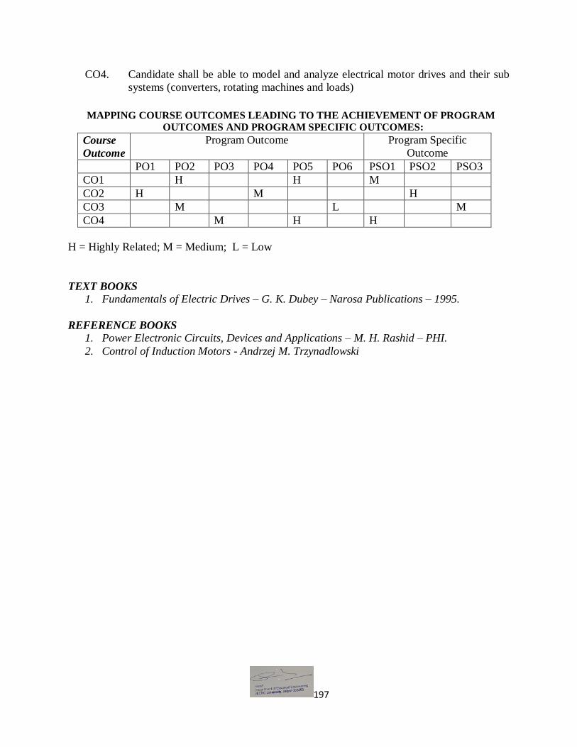
197
CO4. Candidate shall be able to model and analyze electrical motor drives and their sub
systems (converters, rotating machines and loads)
MAPPING COURSE OUTCOMES LEADING TO THE ACHIEVEMENT OF PROGRAM
OUTCOMES AND PROGRAM SPECIFIC OUTCOMES:
Course
Outcome
Program Outcome Program Specific
Outcome
PO1 PO2 PO3 PO4 PO5 PO6 PSO1 PSO2 PSO3
CO1 H H M
CO2 H M H
CO3 M L M
CO4 M H H
H = Highly Related; M = Medium; L = Low
TEXT BOOKS
1. Fundamentals of Electric Drives – G. K. Dubey – Narosa Publications – 1995.
REFERENCE BOOKS
1. Power Electronic Circuits, Devices and Applications – M. H. Rashid – PHI.
2. Control of Induction Motors - Andrzej M. Trzynadlowski

198
School of Engineering M.Tech in (Electrical Devices & Power Electronics) (Electrical Engineering) – Semester I
Contact Hrs per week (L-T-P) : 3-1-0
Course Outlines
MEL024A-Neural Network & Fuzzy Systems
OBJECTIVE: 1. Biological motivation to design intelligent systems and control.
2. The study of control-theoretic foundations such as stability and robustness in the frame
work of intelligent control.
3. Computer simulation of intelligent control systems to evaluate the performance.
Unit 1: Introduction to Neural Networks Introduction, Humans and Computers, Organization
of the Brain, Biological Neuron, Biological and Artificial Neuron Models, Hodgkin-Huxley
Neuron Model, Integrate-and-Fire Neuron Model, Spiking Neuron Model, Characteristics of
ANN, McCulloch-Pitts Model, Historical Developments.
Unit 2: Feed Forward Neural Networks Introduction, Perceptron Models: Discrete, Continuous
and Multi-Category, Training Algorithms: Discrete and Continuous Perceptron Networks,
Perceptron Convergence theorem, Limitations of the Perceptron Model, Applications.
Unit 3: Associative Memories Paradigms of Associative Memory, Pattern Mathematics,
Hebbian Learning, General Concepts of Associative Memory (Associative Matrix, Association
Rules, Hamming Distance, The Linear Associate, Matrix Memories.
Unit 4: Self-Organizing Maps (SOM) and Adaptive Resonance Theory (ART) Introduction,
Competitive Learning, Vector Quantization, Self-Organized Learning Networks, Kohonen
Networks, Training Algorithms, Linear Vector Quantization, Stability- Plasticity Dilemma, Feed
forward competition, Feedback Competition.
Unit 5: Applications Neural network applications: Process identification, Fraction
Approximation, Control and Process Monitoring, Fault diagnosis and Load forecasting. Fuzzy
logic control and Fuzzy classification.
Course Outcome (CO) :
CO1. To develop an ability to solve the simple practical problems in an efficient manner using
either neural network or fuzzy system.
CO2. To develop ability to work on various Design and optimization of discrete and continuous neural networks.
CO3. Identify the difference between Biological and Artificial neuron models and their learning strategies.
CO4. Measure the fuzziness involved in various systems and applies fuzzy set theory knowledge in
solving problems.

199
MAPPING COURSE OUTCOMES LEADING TO THE ACHIEVEMENT OF PROGRAM
OUTCOMES AND PROGRAM SPECIFIC OUTCOMES:
Course
Outcome
Program Outcome Program Specific
Outcome
PO1 PO2 PO3 PO4 PO5 PO6 PSO1 PSO2 PSO3
CO1 H M M
CO2 H M H
CO3 H L M
CO4 H M H H
H = Highly Related; M = Medium; L = Low
TEXT BOOKS
1. Neural Netwroks, Fuzylogic ,Gnenetic algorithms: synthesis and applications by
Rajasekharan and Rai- PHI Publication.
REFERENCE BOOKS
1. Neural Netwroks – James A Freeman and Davis Skapura, Pearson, 2002
2. Neural Netwroks – Simon Hykins, Pearson Education.
3. Neural Engineering by C. Eliasmith and CH. Anderson, PHI
4. Neural Netwroks and Fuzzy Logic System by BrokKosko, PHI Publications

200
School of Engineering M.Tech. in (Electrical Devices & Power Electronics) (Electrical Engineering)-Semester I
Contact Hrs per week (L-T-P): 3-1-0
Course Outlines
MEL025A-HVDC Transmission
OBJECTIVE:
1. To provide an in-depth understanding of the different aspects of Extra High Voltage A.C.
and D.C. Transmission system design and Analysis.
Unit 1: Introduction to HVDC- General Consideration, Power Handling Capabilities of HVDC
Lines Basic Conversion principles, static converter configuration.
Unit 2: Static Power Converters- 3-pulse, 6-pulse, and 12-pulse converters, converter station
and Terminal equipment, commutation process, Rectifier and inverter operation, equivalent
circuit for converter – special features of converter transformers. Harmonics in HVDC Systems,
Harmonic elimination, AC and DC filters.
Unit 3: Control of HVDC Converters AND Systems- Constant current, constant extinction
angle and constant ignition angle control Individual phase control and equidistant firing angle
control DC power flow control. Interaction between HV AC and DC systems – Voltage
interaction Harmonic instability problems and DC power modulation.
Unit 4: MTDC Systems &Over Voltages- Series parallel and series parallel systems their
operation and control. Over voltages due to disturbances on DC side, over voltages due to DC
and AC side line faults.
Unit 5: Converter Faults & Protection- Converter faults, over current protection – valve group,
and DC line protection over voltage protection of converters, surge arresters.
Course Outcome (CO) :
CO1. To develop an ability to understand the importance of Transmission power through
HVDC.
CO2. To develop ability to work on ability to control reactive power through HVDC.
CO3. Analyze different converters i.e. 3, 6 and 12 pulse converter.
CO4. AC/DC system interactions and know the operation and control of various MTDC
systems.

201
MAPPING COURSE OUTCOMES LEADING TO THE ACHIEVEMENT OF PROGRAM
OUTCOMES AND PROGRAM SPECIFIC OUTCOMES:
Course
Outcome
Program Outcome Program Specific
Outcome
PO1 PO2 PO3 PO4 PO5 PO6 PSO1 PSO2 PSO3
CO1 M H H
CO2 H M M
CO3 H L M
CO4 H M H
H = Highly Related; M = Medium; L = Low
Text Books:
1. E.W. Kimbark: Direct current Transmission, Wiely Inter Science – New York.
Reference Books:
1. KR Padiyar : High Voltage Direct current Transmission WielyEsatern Ltd New Delhi –
1992.
2. E. Uhlman : Power Transmission by Direct Current , Springer Verlag, Berlin Helberg-
1985.

202
School of Engineering M.Tech in (Electrical Devices & Power Electronics) (Electrical Engineering)-Semester I
Contact Hrs per week (L-T-P) : 3-1-0
Course Outlines
MEL026A-Digital Signal Processing
OBJECTIVE:
1. To understand the basic function of digital signal processing and to explore the features
of digital filters to the students.
2. To understand the discrete Fourier transform and fast Fourier transform for signal
processing.
Unit1: Introduction to Signal Processing: Review of Laplace transform, Z transform, Fourier
transform. Discrete Fourier transform, Fast Fourier transform, Algorithms and complexity,
Unit 2: Classification of filter design- Design of IIR filters, bilinear transformation technique,
Impulse invariance method – Step invariance method FIR filter design, Fourier series method,
Window function technique, Finite Word Length Effects
Unit 3: Digital Filter: Definition and anatomy of a digital filter, Frequency domain description of
signals and systems, typical application of digital filters, Replacing analogue filters with digital
filters, Filter categories: recursive and non-recursive.
Unit4: Digital Filter Structures: The direct form I and II structures, Cascade combination of
second order sections, Parallel combination of second order sections, Linear- phase FIR filter
structures, Frequency sampling structure for the FIR filter.
Unit 5: Effect of Word Length: Round off error, Truncation error, Quantization error, Limit
cycle Introduction to DSP Hardware: Application of DSP in control system and instrumentation.
Course Outcome (CO):
CO1. Able to use discrete Fourier transform and fast Fourier transform for signal processing
application.
CO2. To develop ability to realize different structures of FIR & IIR Filters. CO3. Ability to understand the use Filter implementation techniques and explain numerical round-
off effects.
CO4. To develop ability to Design IIR & FIR filters using different techniques.

203
MAPPING COURSE OUTCOMES LEADING TO THE ACHIEVEMENT OF PROGRAM
OUTCOMES AND PROGRAM SPECIFIC OUTCOMES:
Course
Outcome
Program Outcome Program Specific
Outcome
PO1 PO2 PO3 PO4 PO5 PO6 PSO1 PSO2 PSO3
CO1 H H M
CO2 H M H
CO3 H M M
CO4 H H M
H = Highly Related; M = Medium; L = Low
TEXT BOOKS
1. J. C. Proakis, and D. G. Maniolakis, Digital Signal Processing: Principles, Algorithms
and Applications, Prentice Hall.
REFERENCE BOOKS
1. Oppenheim, and R. W. Shaffer, Discrete Time Signal Processing, Prentice Hall, 1992.
2. J. Johnson, Digital Signal Processing, Prentice Hall.
3. B. Venkata Ramani, and M. Bhaskar, Digital Signal Processors, New Delhi: Tata
McGraw Hill
204
School of Engineering M.Tech in (Electrical Devices & Power Electronics) (Electrical Engineering)-Semester I
Contact Hrs per week (L-T-P) : 3-1-0
Course Outlines
MEL027A-Digital Controllers in Power Electronics Applications OBJECTIVE:
1. To introduce the Digital Controllers in the Field of Power Electronics.
2. To understand the working of Multiplexer & use of HDL Programming.
Unit 1: Introduction to the C2xx DSP core and code generation, The components of the C2xx
DSP core, Mapping external devices to the C2xx core, peripherals and Peripheral Interface,
System configuration registers, Memory, Types of Physical Memory , memory Addressing
Modes , Assembly Programming using C2xx DSP, Instruction Set, Software Tools.
Unit 2: Pin Multiplexing (MUX) and General Purpose I/O Overview, Multiplexing and General
Purpose I/O Control Registers. Introduction to Interrupts, Interrupt Hierarchy, Interrupt Control
Registers, Initializing and Servicing Interrupts in Software.
Unit 3: ADC Overview , Operation of the ADC in the DSP , Overview of the Event manager
(EV) , Event Manager Interrupts , General Purpose (GP) Timers , Compare Units, Capture Units
And Quadrature Enclosed Pulse (QEP) Circuitry, General Event Manager Information.
Unit 4: Introduction to Field Programmable Gate Arrays – CPLD Vs FPGA – Types of FPGA,
Xilinx XC3000 series, Configurable logic Blocks (CLB), Input/output Block Programmable
Interconnect Point (PIP) – Xilinx 4000 series.
Unit 5: HDL programming –overview of Spartan 3E and Virtex II pro FPGA boards- case study.
Controlled Rectifier, Switched Mode Power Converters, PWM Inverters, DC motor control,
Induction Motor Control.
Course Outcome (CO) :
CO1. Able to understand use of Digital Controllers in the Field of Power Electronics.
CO2. To develop ability understands the working of Multiplexer & Various Interrupts.
CO3. Ability to understand Operation of the ADC in the DSP, Event Manager Interrupt
CO4. To understand the HDL programming –overview of Spartan 3E and Virtex II pro
FPGA boards

205
MAPPING COURSE OUTCOMES LEADING TO THE ACHIEVEMENT OF PROGRAM
OUTCOMES AND PROGRAM SPECIFIC OUTCOMES:
Course
Outcome
Program Outcome Program Specific
Outcome
PO1 PO2 PO3 PO4 PO5 PO6 PSO1 PSO2 PSO3
CO1 H M M
CO2 M H M
CO3 H M L
CO4 M L H
H = Highly Related; M = Medium; L = Low
TEXT BOOKS
1. Hamid.A.Toliyat and Steven G.Campbell “ DSP Based Electro Mechanical Motion
Control “ CRC Press New York , 2004
REFERENCE BOOKS
1. XC 3000 series datasheets ( version 3.1). Xilinx,Inc.,USA, 1998
2. XC 4000 series datasheets ( version 1.6). Xilinx,Inc.,USA, 1999
3. Wayne Wolf,” FPGA based system design “, Prentice hall, 2004.

206
School of Engineering M.Tech in (Electrical Devices & Power Electronics) (Electrical Engineering) – Semester I
Contact Hrs per week (L-T-P) : 0-0-2
Course Outlines
MEL028A-Power Electronic Converters Laboratory
OBJECTIVE:
1. TO enhance the practical knowledge of students.
2. To explain the use of Power Electronic Converters.
List of Experiments
1. Speed Measurement and closed loop control using PMDC motor.
2. Thyristorised drive for PMDC Motor with speed measurement and closed Loop control.
3. IGBT used single 4 quadrant chopper drive for PMDC motor with speed measurement
and closed loop control.
4. Thyristorised drive for 1Hp DC motor with closed loop control.
5. 3-Phase input, thyristorised drive, 3 Hp DC motor with closed loop
6. 3-Phase input IGBT, 4 quadrant chopper drive for DC motor with closed Loop control
equipment.
7. Cycloconverter based AC Induction motor control equipment.
8. Speed control of 3 phase wound rotor Induction motor.
9. Single-phase fully controlled converter with inductive load.
10. Single phase half wave controlled converter with inductive load.
11. DC to DC converters of various configurations using SCRs, IGBTs, power transistors and
power MOSFETs.
12. DC to AC converters of various configurations using SCRs, IGBTs, power transistors and
power MOSFETs.
13. AC to AC converters of various configurations using SCRs, IGBTs, power transistors and
power MOSFETs.
14. Practical implementation of control techniques for voltage control, speed control and
harmonic minimization.
15. Practical converter design considerations- Snubber design, gate and base drive circuits.
Course Outcome (CO) :
CO1. Ability to understand the working of different types of Power electronic converters
CO2. To understand Operation of DC to DC converters of various configurations using
SCRs, IGBTs, power transistors etc.
CO3. To understand DC to AC converters of various configurations using SCRs, IGBTs,
power transistors etc.
CO4. Ability to understand control techniques for voltage control, speed control and
harmonic minimization etc.

207
MAPPING COURSE OUTCOMES LEADING TO THE ACHIEVEMENT OF PROGRAM
OUTCOMES AND PROGRAM SPECIFIC OUTCOMES:
Course
Outcome
Program Outcome Program Specific
Outcome
PO1 PO2 PO3 PO4 PO5 PO6 PSO1 PSO2 PSO3
CO1 M H H
CO2 H L M
CO3 H M L
CO4 M L H
H = Highly Related; M = Medium; L = Low

208
School of Engineering M.Tech in (Electrical Devices & Power Electronics) (Electrical Engineering) – Semester I
Contact Hrs per week (L-T-P) : 0-0-2
Course Outlines
MEL029A-Neural and Fuzzy Laboratory
OBJECTIVE: 1. To explain the use of neural and fuzzy logic in Engineering application.
2. To design speed controller for different electric motors.
List of Experiments
1. Programming on Supervised Learning Using NN Matlab Toolbox.
2. Define one sample: inputs and outputs.
3. Create Network to Define and custom network.
4. Programming to define topology and transfer function.
5. Programming to configure network.
6. Programming to Train net and calculate neuron output.
7. Design a Hebb net as a gate traffic controller across the road to control the accidents
occurring on the roads regularly. The gate across the road will come down across when
the traffic light is red & pedestrian light is green. Also plot classification line and
input/output target vectors.
8. Consider the surface described by z= sin(x) cos(y) defined on a square -3≤x≤ 3, -3≤y≤
3Plot the surface z as function of x & y and design a neural network which will fit the
data. Hint: Use 25, 25 numbers of neurons in first layer, show 50, 0.05 learning rate, 1e-3
goal and 300 epochs before training network.
9. To implement fuzzy controller for temperature control of an oven.
10. To implement fuzzy controller for water level control of a single and two tank coupled
system
11. To implement fuzzy controller for speed control of DC Motor.
12. To implement fuzzy controller for speed control of Stepper Motor.
13. To implement fuzzy controller on second order system
14. To implement fuzzy controller on Third order system
15. To implement fuzzy controller for measuring pressure of hydraulic system
16. To implement fuzzy controller for measuring pressure of pneumatic system
17. To implement fuzzy controller for vector control of induction motor.
Course Outcome (CO) :
CO1. Ability to understand the different types of fuzzy controllers for speed control.
CO2. Able to work on various Design and optimization of discrete & continuous neural networks
CO3. To design a fuzzy controller for various Engineering application etc.

209
CO4. To understand to design fuzzy controller for second and third order systems.
MAPPING COURSE OUTCOMES LEADING TO THE ACHIEVEMENT OF
PROGRAM OUTCOMES AND PROGRAM SPECIFIC OUTCOMES:
Course
Outcome
Program Outcome Program Specific
Outcome
PO1 PO2 PO3 PO4 PO5 PO6 PSO1 PSO2 PSO3
CO1 H M M
CO2 M M H
CO3 H M M
CO4 M M H
H = Highly Related; M = Medium; L = Low

210
School of Engineering M.Tech (Electrical Devices & Power Electronics) Semester-I
Contact Hours (L-T-P): 3-1-0
Course Outlines
MELOL02: AWARENESS PROGRAMME ON SOLAR WATER
PUMPING SYSTEM
OBJECTIVES:
The programme provides a conceptual understanding of water pumps including solar PV water
pumping system. The major components of solar PV water pumping system are also described.
A solar PV water pumping system requires very little operation and maintenance. However, the
programmes give the basic elements of operation and maintenance (O&M) at farm level. The
common precautions and safety measures to be taken during operation are also described.
COURSE LAYOUT:

211
School of Engineering M.Tech in (Electrical Devices & Power Electronics) (Electrical Engineering) – Semester II
Contact Hrs per week (L-T-P) : 3-1-0
Course Outlines
MEL030A-Control Techniques in Power Electronics for AC Drives
OBJECTIVE:
1. To equip the students with the knowledge of average modeling of converters.
2. To know about digital control techniques of converters and different type of power
supplies for different applications.
Unit1: AC Voltage Controllers: Principle of On-Off Control, Principle of Phase control, Single
Phase Bi-directional Controllers with Resistive Loads, Single Phase Controllers with Inductive
Loads, Three Phase full wave AC controllers, AC Voltage Controller with PWM Control.
Unit2: Cycloconverter: Basic principle of operation, single phase to single phase, three-phase to
three phase and three phase to single phase Cycloconverter. Output equation; Control circuit.
Unit3: DC Power Supplies: Switched Mode DC Power Supplies, fly back converter, forward
converter, half and full bridge converter, resonant DC power supplies, bi-directional power
supplies.
Unit4: AC Power Supplies: Switched mode power supplies and its application, Resonant AC
power supplies, bidirectional AC power supplies: working principle and its application.
Unit5: Multistage converter, process of conversion. Control Circuits: working of control
circuit. Types of control: Voltage Mode Control, Current Mode Control.
Course Outcome (CO) :
CO1. Enhancing the ability to understand & analyze the power converters and drives for various
applications and problem solving.
CO2. Ability to design the modern control circuits for specific application.
CO3. To Understand control techniques of converters and different type of power supplies
for different applications.
CO4. To develop an ability to design controller and implement them in simulation.

212
MAPPING COURSE OUTCOMES LEADING TO THE ACHIEVEMENT OF
PROGRAM OUTCOMES AND PROGRAM SPECIFIC OUTCOMES:
Course
Outcome
Program Outcome Program Specific
Outcome
PO1 PO2 PO3 PO4 PO5 PO6 PSO1 PSO2 PSO3
CO1 H H H
CO2 M H M
CO3 M H H M
CO4 H M H
H = Highly Related; M = Medium; L = Low
Text Books:
1. M.H Rashid: Power Electronics, circuits devices and applications, PHI,1988.
Reference Books: 1. P.C. Sen: Power Electronics Tata McGraw-Hill 1987
2. CW Lander: Power electronics, 2nd edition, McGrawHill 1987
3. P.S Bimbhra: Power electronics, 2nd Ed. Khanna Publishers,1987
4. M.D. Singh and K.B. Khanchandani: Power electronics, TMH,1998
5. V Subrahmanyam: Power electronics, New Age Inc.Publishers, New Delhi,1996

213
School of Engineering
M.Tech in (Electrical Devices & Power Electronics) (Electrical Engineering) – Semester II
Contact Hrs per week (L-T-P): 3-1-0
Course Outlines
MEL031A-Electric Drives-II
OBJECTIVE: 1. To understand the speed control of advanced electrical drives.
2. To show the different type of torque characteristic of different type of electrical motors.
Unit 1: VECTOR CONTROL OF INDUCTION MOTOR: Principles of vector control,
Direct vector control, derivation of indirect vector control, implementation – block diagram;
estimation of flux, flux weakening operation.
Unit 2: SENSORLESS VECTOR CONTROL OF INDUCTION MOTOR: Slip and Speed
Estimation at Low performance, Rotor Angle and Flux‐linkage Estimation at high performance
‐rotor Speed Estimation Scheme.
Unit3: CONTROL OF SYNCHRONOUS MOTOR DRIVES: Synchronous motor and its
characteristics- Control strategies-Constant torque angle control power factor control, constant
flux control, flux weakening operation.
Unit4: CONTROL OF SWITCHED RELUCTANCE MOTOR DRIVES: SRM Structure-
Stator Excitation-techniques of sensor less operation-convertor topologies- SRM Waveforms-
SRM drive design factors-Torque controlled SRM-Torque Ripple.
Unit5: CONTROL OF BLDC MOTOR DRIVES: principle of operation of BLDC Machine,
Sensing and logic switching scheme, BLDM as Variable Speed Synchronous motor-methods of
reducing Torque pulsations -Three-phase full wave Brushless dc motor.
Course Outcome (CO) :
CO1. To develop an ability to use vector theory to study and analyze the behavior of induction
machines.
CO2. To Understand control techniques of different type of motors used for various
applications
CO3. To develop an ability to design controller and implement them in simulation.
CO4. Enhancing an ability to Select suitable motor and drive according to the application.
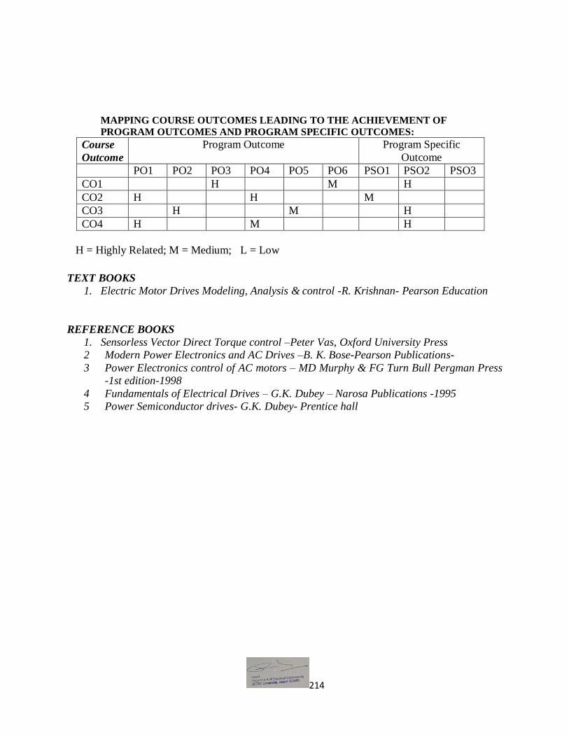
214
MAPPING COURSE OUTCOMES LEADING TO THE ACHIEVEMENT OF
PROGRAM OUTCOMES AND PROGRAM SPECIFIC OUTCOMES:
Course
Outcome
Program Outcome Program Specific
Outcome
PO1 PO2 PO3 PO4 PO5 PO6 PSO1 PSO2 PSO3
CO1 H M H
CO2 H H M
CO3 H M H
CO4 H M H
H = Highly Related; M = Medium; L = Low
TEXT BOOKS
1. Electric Motor Drives Modeling, Analysis & control -R. Krishnan- Pearson Education
REFERENCE BOOKS
1. Sensorless Vector Direct Torque control –Peter Vas, Oxford University Press
2 Modern Power Electronics and AC Drives –B. K. Bose-Pearson Publications-
3 Power Electronics control of AC motors – MD Murphy & FG Turn Bull Pergman Press
-1st edition-1998
4 Fundamentals of Electrical Drives – G.K. Dubey – Narosa Publications -1995
5 Power Semiconductor drives- G.K. Dubey- Prentice hall

215
School of Engineering
M.Tech (Electrical Devices & Power Electronics) (Electrical Engineering) – Semester II
Contact Hrs per week (L-T-P) :3-1-0
Course Outlines
MES001A-Research Methodology & Technical Communication
OBJECTIVE:
1. To enhance the ability of writing and presentation of research work.
Unit 1: Research: Meaning & Purpose, Review of literature, Problem definition/Formulation of
research problem, Research proposal, Variables, Hypothesis, types, construction of hypothesis
Unit 2: Classification of research: Quantitative research: Descriptive Research, Experimental
Research Qualitative research: Observational studies, Historical research, Focus group
discussion, Case study method,
Unit 3: Sources of data collection: Primary and Secondary Data Collection, Sample and
Sampling technology, Non-probability and Probability Sampling
Unit 4: Tools for data collection: Tests, Interview, Observation, Questionnaire/ Schedule,
Characteristics of a good test, Statistics: Descriptive and Inferential Statistics.Data Analysis,
Report Writing, Results and References,
Unit 5: Thesis Writing and Journal Publications: Writing thesis, Writing journal and
conference papers, IEEE and Harvard style of referencing, Effective presentation, Copyrights,
and Avoid plagiarism.
Course Outcome (CO) :
CO1. Designed to help you develop a thorough understanding of the fundamental theoretical
ideas and logic of research.
CO2. To develop an ability to choose strategies and methods in concordance with research-
or investigation questions
CO3. To develop an ability to write and present their research work efficiently.
CO4. Enhancing an ability to formulate purpose statements & to achieve the learning
outcome

216
MAPPING COURSE OUTCOMES LEADING TO THE ACHIEVEMENT OF
PROGRAM OUTCOMES AND PROGRAM SPECIFIC OUTCOMES:
Course
Outcome
Program Outcome Program Specific
Outcome
PO1 PO2 PO3 PO4 PO5 PO6 PSO1 PSO2 PSO3
CO1 H M M
CO2 H H H
CO3 M M H
CO4 H H M
H = Highly Related; M = Medium; L = Low
Text Books:
1. Borth, Wayne C, et.Al., The Craft of Research: Chicago Guides to Writing Edition and
Publishing.
Reference Books: 1. Meyer, P.L., Introduction to Probability & Statistical, Applications: Oxford, IBH.
2. Hogg, R.V. & Craig, A.T., Introduction to Mathematical Statistics, MacMillan.
3. Goon, A.M., Gupta, M.K. &Dasgupta, Fundamentals of Statistics, Vol.I: World Press.
4. Gupta, S.C. & Kapoor, V.K., Fundamentals of Mathematical Statistics, Sultan Chand &
Sons.
217
Electives-II
School of Engineering M.Tech (Electrical Devices & Power Electronics) (Electrical Engineering) – Semester II
Contact Hrs per week (L-T-P) : 3-1-0
Course Outlines
MEL032A-Modern Power Electronics
OBJECTIVE: 1. To understand the working of resonant inverters and resonant converter.
2. To explore various multilevel inverter to the students.
Unit 1: Modern power semiconductor devices Modern power semiconductor devices- MOS
Turn Off Thyristor (MTO) – Emitter Turn Off Thyristor (ETO) – Integrated Gate – Commutated
thyristor (IGCTs) – MOS – controlled thyristors (MCTs) – Static induction Thyristors (SITHs) –
Power integrated circuits (PICs) – Symbol, structure and equivalent circuit- comparison of their
features.
Unit 2: Resonant pulse inverters Resonant pulse inverters – series resonant inverters- series
resonant inverters with unidirectional switches – series resonant inverters with bidirectional
switches- analysis of half bride resonant inverter- evaluation of currents and Voltages of a simple
resonant inverter.
Unit 3: Resonant Converters Resonant converters- zero current switching resonant converters –
L type ZCS resonant converter- M type ZCS resonant converter – zero voltage Switching
resonant converters – comparison between ZCS and ZVS resonant converters.
Unit 4: Multilevel Inverters Multilevel concept- Classification of multilevel inverters Diode
clamped Multilevel inverter- Principle of operation – main features- improved diode clamped
inverter – principle of operation – Flying capacitors multilevel inverter – principle of operation,
main features.
Unit 5: Power conditioners and Uninterruptible Power Supplies Introduction- power line
disturbances – power conditioners- uninterruptible power supplies applications.
Course Outcome (CO) :
CO1. To develop an ability to thorough understanding of the Modern power semiconductor
devices.
CO2. Ability to analyze and synthesize power electronic converters and systems.
CO3. Enhancing ability to select various convertor & Multilevel Inverters.
CO4. To apply advanced knowledge and analysis techniques to design and critically assess
key aspects of power converters such as ZVS converters and AC-DC inverters etc.

218
MAPPING COURSE OUTCOMES LEADING TO THE ACHIEVEMENT OF
PROGRAM OUTCOMES AND PROGRAM SPECIFIC OUTCOMES:
Course
Outcome
Program Outcome Program Specific
Outcome
PO1 PO2 PO3 PO4 PO5 PO6 PSO1 PSO2 PSO3
CO1 H M H
CO2 M H M
CO3 H M L
CO4 H M M
H = Highly Related; M = Medium; L = Low
TEXT BOOKS:
1. Power Electronics: Mohammed H. Rashid-Pearson Education- Third Edition –first Indian
reprint-2004
REFERENCE BOOKS
1. Power Electronics – Ned Mohan, Tore M. Undeland and William P. Robbind – John wiley & Sons – Second Edition.
2. Power Electronics , P.S Bimbhara, Khanna Publishers, Delhi, Sixth Edition

219
School of Engineering M.Tech in (Electrical Devices & Power Electronics) (Electrical Engineering)-Semester II
Contact Hrs per week (L-T-P) : 3-1-0
Course Outlines
MEL033A-Solid State Power Controllers OBJECTIVE:
1. To understand the FACTS concepts and to equip with the knowledge of static voltage and
phase angle regulators.
2. To study the power quality problems in distribution side and its mitigation techniques.
Unit 1: FACTS Concepts, Electrical Transmission Network – Necessity – Power Flow in AC
System – Power Flow and Dynamic stability considerations of a transmission interconnection –
relative importance of controllable parameter – opportunities for FACTS.
Unit 2: Static VAR Compensation: Need for compensation – introduction to shunt and series
compensation – objectives of shunt and series compensation – configuration and operating
characteristics – Thyristor Controlled Reactor (TCR) – Thyristor Switched Capacitor (TSC).
Unit 3: Series Compensators: Commutation in DC motors, difference between mechanical and
electronic Commutators, Hall sensors, Optical sensors, Multiphase Brushless motor, Square –
Wave permanent magnet brushless motor drives, torque and EMF equation, torque – speed
characteristics of Permanent Magnet Brush less DC Motors – controllers PM DC Motor.
Unit 4: Static Voltage and Phase Angle Regulators: Objectives of voltage and phase angle
regulators – approaches to Thyristor – Controlled Voltage and Phase Angle Regulator,
Construction and principle of operation of Linear Induction Motor, Universal Motor.
Unit 5: Power Quality: Power Quality problems in distribution systems, harmonics, harmonics
creating loads, modelling, harmonic propagation, Series and parallel resonances, harmonic power
flow.
Course Outcome (CO) :
CO1. To develop an understanding the power system control through various power electronic
controllers including state of art FACTS controllers. CO2. Ability to analyse real and reactive power control capability in power system, their
integration in power flow analysis CO3. Enhancing ability to develop an idea over Power Quality problems in distribution
systems.
CO4. To understand the effectiveness of voltage regulators in system for harmonic mitigation,
modeling.

220
MAPPING COURSE OUTCOMES LEADING TO THE ACHIEVEMENT OF
PROGRAM OUTCOMES AND PROGRAM SPECIFIC OUTCOMES:
Course
Outcome
Program Outcome Program Specific
Outcome
PO1 PO2 PO3 PO4 PO5 PO6 PSO1 PSO2 PSO3
CO1 M H H
CO2 H H M
CO3 H M M
CO4 H M H
H = Highly Related; M = Medium; L = Low
TEXT BOOKS
1. Narain G. Hingorani and Laszlo Gyugyi, “Understanding FACTS – Concepts and
Technology of Flexible AC Transmission Systems”, Standard Publishers, New Delhi,
2001.
REFERENCE BOOKS
1. Narain G. Hingorani, “Flexible AC Transmission”, IEEE Spectrum, April 1993, pp 40 –
45
2. T.J.E. Miller, Static Reactive Power Compensation, John Wiley & Sons, New York, 1982.
3. R. Mohan Mathur and Rajiv K. Varma, “Thyristor Based FACTS Controller for
Electrical Transmission Systems”, Wiley Interscience Publications, 2002

221
School of Engineering M.Tech in (Electrical Devices & Power Electronics) (Electrical Engineering) – Semester II
Contact Hrs per week (L-T-P) : 3-1-0
Course Outlines
MEL034A- Nonlinear Phenomena in Switching Systems
OBJECTIVE: 1. To understand the concept of non-linearity in switching system.
2. To investigate the non-linearity phenomena in converters.
3. To understand the control of chaos.
Unit1: Basics of Nonlinear Dynamics: System, state and state space model, Vector field-
Modelling of Linear, nonlinear and Linearized systems, Attractors , chaos, Poincare map,
Dynamics of Discrete time system, Lyapunov Exponent.
Unit2: Techniques for investigation of nonlinear Phenomena: Techniques for experimental
investigation, Techniques for numerical investigation, Computation of averages under chaos,
Computations of spectral peaks, computation of the bifurcation and analysing stability.
Unit3: Nonlinear Phenomena in DC-DC Converters: Border collision in the Current Mode
controlled Boost Converter, Bifurcation and chaos in the Voltage controlled Buck Converter
with latch.
Unit4: Nonlinear Phenomena in Drives: Nonlinear Phenomenon in Current controlled and
voltage controlled DC Drives, Nonlinear Phenomenon in PMSM Drives. Nonlinear phenomenon
in the inverter under tolerance band control.
Unit5: Control of Chaos: Hysteresis control, Sliding mode and switching surface control, OGY
Method, Pyragas method, Time Delay control. Application of the techniques to the Power
electronics circuit and drives.
Course Outcome (CO) :
CO1. To understand the Nonlinear Phenomena of Discrete time system as well as DC-DC
Converters. CO2. Ability to analyse Nonlinear Phenomenon in Current controlled and voltage controlled
DC Drives. CO3. To enhance an ability to develop an idea over Control of Chaos, Hysteresis control.
CO4. To understand Vector field- Modelling of Linear, nonlinear and Linearzed systems,
Attractors.

222
MAPPING COURSE OUTCOMES LEADING TO THE ACHIEVEMENT OF PROGRAM
OUTCOMES AND PROGRAM SPECIFIC OUTCOMES:
Course
Outcome
Program Outcome Program Specific
Outcome
PO1 PO2 PO3 PO4 PO5 PO6 PSO1 PSO2 PSO3
CO1 H M H
CO2 H M L
CO3 H M M
CO4 M H H
H = Highly Related; M = Medium; L = Low
TEXT BOOKS
1. S Banerjee, Dynamics for Engineers, Jhon Wiley
REFERENCE BOOKS
1. S Banerjee, Nonlinear Phenomena in Power Electronics, IEEE Press
2. Steven H Strogatz, Nonlinear Dynamics and Chaos, Westview Press

223
School of Engineering M.Tech in (Electrical Devices & Power Electronics) (Electrical Engineering) – Semester II
Contact Hrs per week (L-T-P) : 0-0-2
Course Outlines
MEL035A-Computer & Microprocessor Controlled Electric Drives
Laboratory
OBJECTIVE: 1. To provide a platform to the students for speed control of drives using microprocessor.
2. To understand the controlling of special purpose electrical drives.
List of Experiments
1. Speed control of Converter fed DC motor.
2. Speed control of Chopper fed DC motor.
3. Voltage control of single phase induction motor.
4. Voltage control of three phase induction motor.
5. Frequency control of single phase induction motor.
6. Frequency control of three phase induction motor.
7. Micro controller based speed control of Stepper motor.
8. Speed control of BLDC motor.
9. DSP based speed control of SRM motor.
10. Simulation of Four quadrant operation of three-phase induction motor.
11. Simulation of three-phase Synchronous Generator.
12. Micro controller based speed control of Synchronous motor.
13. Reprogrammable Logic devices and Programming
14. Micro controller based speed control of induction motor.
15. Programming
(a) VHDL programming
(b) Verilog HDL programming
Course Outcome (CO) :
CO1. To understand the speed control of various Motors using microprocessor CO2. Ability to analyse the Simulation of Four quadrant operation of three-phase induction
motor. CO3. Ability to develop an idea over Reprogrammable Logic devices and Programming.
CO4. To enhance an ability to understands VHDL programming , Verilog HDL
programming

224
MAPPING COURSE OUTCOMES LEADING TO THE ACHIEVEMENT OF PROGRAM
OUTCOMES AND PROGRAM SPECIFIC OUTCOMES:
Course
Outcome
Program Outcome Program Specific
Outcome
PO1 PO2 PO3 PO4 PO5 PO6 PSO1 PSO2 PSO3
CO1 M M H
CO2 H M M
CO3 M H M
CO4 M H H
H = Highly Related; M = Medium; L = Low

225
School of Engineering M.Tech in (Electrical Devices & Power Electronics) (Electrical Engineering) – Semester II
Contact Hrs per week (L-T-P) : 0-0-2
Course Outlines
MEL036A-Electric Drives Laboratory
OBJECTIVE:
1. The primary objective of this course is to provide a platform to the students where they
can use their theoretical knowledge.
2. To control the speed of electrical motors using various power electronic equipment’s.
List of Experiments
1. Perform the testing of firing circuit of three phase half controlled bridge converter.
2. Obtain waveforms of three phase half controlled bridge converter with R and RL loads.
3. Perform the testing of firing circuit of three-phase full controlled bridge converter.
4. Obtain waveforms of three-phase full controlled bridge converter with R and RL loads.
5. Perform the testing of 3-phase AC voltage regulator.
6. Control speed of dc motor using 3-phase half controlled bridge converter. Plot armature
voltage versus speed characteristic.
7. Control speed of dc motor using 3-phase full controlled bridge converter. Plot armature
voltage versus speed characteristic.
8. Control speed of a 3-phase induction motor in variable stator voltage mode using 3-
phase AC voltage regulator.
9. Control speed of universal motor using AC voltage regulator.
10. Demonstrate the working of three-phase dual converter.
11. Perform speed control of dc motor using 3-phase dual converter.
12. Demonstrate the working of three-phase Cycloconverter and speed control of
synchronous motor using a Cycloconverter.
13. Control of 3-Phase Induction Motor in variable frequency V/f constant mode using 3-
phase inverter.
14. To control the given 3,phase induction motor using inverter module and SCR AC
regulator module with PC interface.
15. To determine the speed, torque characteristics of single, phase AC motor using
thyristorised AC voltage controller with open loop and closed loop control.
Course Outcome (CO):
CO1. To Enhance an ability the speed control of Control speed of dc motor using 3-phase
full controlled bridge converter CO2. Ability to understand the Control speed of universal motor using AC voltage
regulator

226
CO3. Ability to ddemonstrate an speed control of synchronous motor using a
Cycloconverter.
CO4. To develop an ability to control the 3-ph induction motor using inverter module and
AC regulator module with PC interface
MAPPING COURSE OUTCOMES LEADING TO THE ACHIEVEMENT OF PROGRAM
OUTCOMES AND PROGRAM SPECIFIC OUTCOMES:
Course
Outcome
Program Outcome Program Specific
Outcome
PO1 PO2 PO3 PO4 PO5 PO6 PSO1 PSO2 PSO3
CO1 H M L
CO2 M M H
CO3 H H M
CO4 M H H
H = Highly Related; M = Medium; L = Low

227
School of Engineering
M.Tech in (Electrical Devices & Power Electronics) (Electrical Engineering) – Semester II
Contact Hours per week: 2 hrs
Course Outlines
MES002A-Quantitative Techniques & Computer Applications Lab
Various Methods and Uses of Advance Excel Formulas: Vlookup, Hlookup, Sumif, Sumifs,
Sumproduct, Dsum, Countif, Countifs, If, Iferror, Iserror, Isna, Isnumber, Isnontext, Isblank,
Istext, Getpivotdata, Dcount, Dcounta, Or, And, Search, Index, Match Etc
Various Methods and Uses of IF Conditions: When should use the "IF" Conditions?, Creation
of Multiple IF Conditions in One Cell,Use the IF Conditions with the Other Advance Functions,
How to use nested IF statements in Excel with AND, OR Functions
ADVANCED EXCEL OPTIONS :Various Methods of Filter and Advance Filter options,
Creating and Updating Subtotals, Various Methods of Text to Column options, Uses of Data
Grouping and Consolidation options, Uses of Goal Seek and Scenarios Manager, Various
Method of Sorting Data, Creating, Formatting and Modifying Chart, Data Validation, Creating
drop down lists using different data sources, Linking Workbooks and Uses of Edit Link options,
Excel Options, Customizing the Quick Access Tool Bar, Formula Auditing features and Trace
formula error
Pivot Tables & Charts :Various Methods and Options of Pivot Table, Using the Pivot Table
Wizard, Changing the Pivot Table Layout, Subtotal and Grand total Options, Formatting,
Grouping Items, Inserting Calculated Fields, Pivot Table Options, Calculation in Pivot Table,
Display and Hide Data in Field, Select, Move & Clear Pivot Data, Creating and Modifying Pivot
Chart
Advance Use of Function: Mixing Function to get Various MIS Outputs, Creating Data Table,
Advance Data Validation, Using conditional formatting with Formulas and Function, Using
Name Manager, Array Formulas
Importing Data from External Sources: Macros, What is a Macro?, Creating Excel Macro,
Running Macros and Editing, Automating Tasks with Macro
(B) SPSS Package
An Overview of SPSS: Mouse and keyboard processing, frequently –used dialog boxes, Editing
output, Printing results, Creating and editing a data file
Managing Data: Listing cases, replacing missing values, computing new variables, recording
variables, exploring data ,selecting cases, sorting cases, merging files
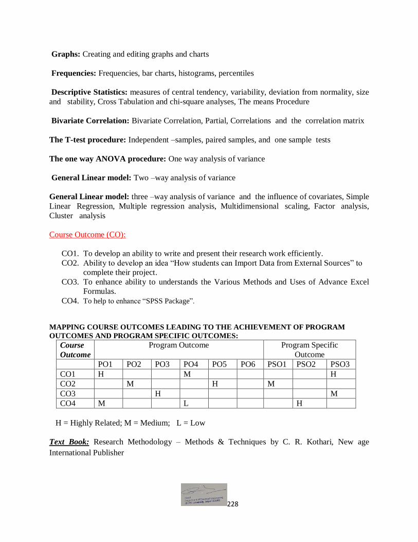
228
Graphs: Creating and editing graphs and charts
Frequencies: Frequencies, bar charts, histograms, percentiles
Descriptive Statistics: measures of central tendency, variability, deviation from normality, size
and stability, Cross Tabulation and chi-square analyses, The means Procedure
Bivariate Correlation: Bivariate Correlation, Partial, Correlations and the correlation matrix
The T-test procedure: Independent –samples, paired samples, and one sample tests
The one way ANOVA procedure: One way analysis of variance
General Linear model: Two –way analysis of variance
General Linear model: three –way analysis of variance and the influence of covariates, Simple
Linear Regression, Multiple regression analysis, Multidimensional scaling, Factor analysis,
Cluster analysis
Course Outcome (CO):
CO1. To develop an ability to write and present their research work efficiently. CO2. Ability to develop an idea “How students can Import Data from External Sources” to
complete their project.
CO3. To enhance ability to understands the Various Methods and Uses of Advance Excel
Formulas.
CO4. To help to enhance “SPSS Package”.
MAPPING COURSE OUTCOMES LEADING TO THE ACHIEVEMENT OF PROGRAM
OUTCOMES AND PROGRAM SPECIFIC OUTCOMES:
Course
Outcome
Program Outcome Program Specific
Outcome
PO1 PO2 PO3 PO4 PO5 PO6 PSO1 PSO2 PSO3
CO1 H M H
CO2 M H M
CO3 H M
CO4 M L H
H = Highly Related; M = Medium; L = Low
Text Book: Research Methodology – Methods & Techniques by C. R. Kothari, New age
International Publisher

229
Notes for Examiner / Paper Setter:
4. 1st Question shall be of 16 marks and compulsory for all. It may consist of Multiple
Choice Questions (MCQ) of one mark each and short answer questions of one or two
marks.
5. One question of 14 marks shall be set from each Unit which may have parts including
numerical. Paper setter may give internal choice, if required.
6. Students will be required to attempt all questions compulsorily.

230
School of Engineering M.Tech in (Electrical Devices & Power Electronics) (Electrical Engineering) – Semester III
Contact Hrs per week (L-T-P) : 3-1-0
Course Outlines
MEL037A- High-Frequency Magnetic Components
OBJECTIVE: 1. To understand the Working of High frequency Magnetic Component.
2. To show the different type of System Design.
Unit 1: Fundamentals of Magnetic Devices: Introduction, Magnetic Relationships, Magnetic
Circuits, Magnetic Laws, Eddy Currents, Core Saturation, Volt-Second Balance, Inductance,
Inductance Factor, Magnetic Energy, Self-Resonant Frequency, Classification of Power Losses
in Magnetic Components, Non-inductive Coils.
Unit 2: Skin Effect & Proximity Effect: Introduction, Magnet Wire, Wire Insulation, Skin
Depth, Ratio of AC-to-DC Winding Resistance, Skin Effect in Long Single Round Conductor.
Skin Effect on Single Rectangular Plate. Proximity and Skin Effects in Two Parallel Plates, Anti-
proximity and Skin Effects in Two Parallel Plates, Proximity Effect in Multiple-Layer Inductor,
Appendix: Derivation of Proximity Power Loss.
Unit 3: Winding Resistance at High Frequencies: Introduction, Winding Resistance, Square
and Round Conductors, Winding Resistance of Rectangular Conductor, Winding Resistance of
Square Wire, Winding Resistance of Round Wire, Leakage Inductance, Solution for Round
Conductor Winding in Cylindrical Coordinates, Litz Wire, Winding Power Loss for Inductor
Current with Harmonics.
Unit 4: Design of Transformers: Introduction, Area Product Method, Optimum Flux Density,
and Transformer Design for Fly-back Converter in CCM, Transformer Design for Fly-back
Converter in DCM, Transformer Design for Fly-back Converter in CCM, Transformer Design
for Fly-back Converter in DCM.
Unit 5: Design of Inductors: Introduction, Restrictions on Inductors, Window Utilization
Factor, Temperature Rise of Inductors, Mean Turn Length of Inductors, Area Product Method,
AC Inductor Design, and Inductor Design for Buck Converter in CCM, Inductor Design for
Buck Converter in DCM method.
Course Outcome (CO) :
CO1. To develop an ability to understand “Working of High frequency Magnetic
Component”.
CO2. To enhance an idea Skin Effect & Proximity Effect applicable to Transmission line.
CO3. To enhance ability to understands the Transformer Design for Fly back converter for
DCM, CCM etc.
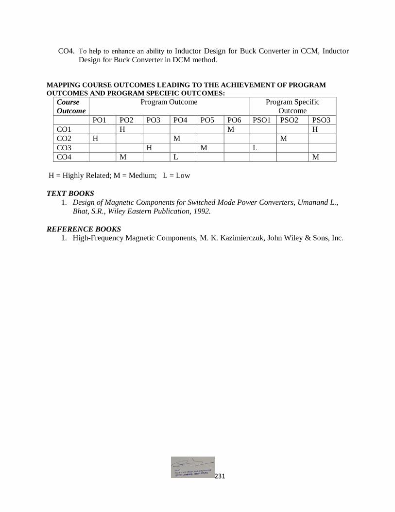
231
CO4. To help to enhance an ability to Inductor Design for Buck Converter in CCM, Inductor
Design for Buck Converter in DCM method.
MAPPING COURSE OUTCOMES LEADING TO THE ACHIEVEMENT OF PROGRAM
OUTCOMES AND PROGRAM SPECIFIC OUTCOMES:
Course
Outcome
Program Outcome Program Specific
Outcome
PO1 PO2 PO3 PO4 PO5 PO6 PSO1 PSO2 PSO3
CO1 H M H
CO2 H M M
CO3 H M L
CO4 M L M
H = Highly Related; M = Medium; L = Low
TEXT BOOKS
1. Design of Magnetic Components for Switched Mode Power Converters, Umanand L.,
Bhat, S.R., Wiley Eastern Publication, 1992.
REFERENCE BOOKS
1. High-Frequency Magnetic Components, M. K. Kazimierczuk, John Wiley & Sons, Inc.

232
School of Engineering M.Tech in (Electrical Devices & Power Electronics) (Electrical Engineering) – Semester III
Contact Hrs per week (L-T-P): 3-1-0
Course Outlines
MEL038A-Switched Mode Power Supply
OBJECTIVE: 1. To understand the construction working and design of different type of switched mode
power supplies.
2. To show the time response of different type of switched mode power supplies.
Unit 1: SINGLE-SWITCH ISOLATED CONVERTERS: Requirement for isolation in the
switch-mode converters, transformer connection, Forward and fly back converters, power circuit
and steady-state analysis.
Unit2: ISOLATED BRIDGE CONVERTERS: Half bridge and full-bridge converters, Power
circuit and steady-state analysis, utilization of magnetic circuits and comparison with previous
topologies.
Unit 3: DYNAMIC ANALYSIS OF DC-DC CONVERTERS: Formulation of dynamic
equation of buck and boost converters, averaged circuit models, linearization technique, small-
signal model and converter transfer functions.
Unit 4: CONTROLLER DESIGN: Review of frequency-domain analysis of linear time-
invariant systems, concept of bode plot, phase and gain margins, bandwidth, controller
specifications, proportional (P), proportional plus integral (PI), proportional plus integral plus
integral controller (PID), selection of controller parameters.
Unit 5: RESONANT CONVERTERS: Classification of Resonant converters-Basic resonant
circuits- Series resonant circuit-parallel resonant circuits- Resonant switches. Concept of Zero
voltage switching, principle of operation, analysis of M-type and L-type Buck or boost
Converters.
Course Outcome (CO) :
CO1. To develop an ability to understand the steady state analysis of isolated bridge
converters, switch mode converter .
CO2. To help the students to understand the dynamic analysis of dc-dc converters .
CO3. Ability to understand the design various controller for specific purpose , selection of
controller parameters.
CO4. To help to enhance an ability to understand Concept of Zero voltage switching, resonant
converter.

233
MAPPING COURSE OUTCOMES LEADING TO THE ACHIEVEMENT OF PROGRAM
OUTCOMES AND PROGRAM SPECIFIC OUTCOMES:
Course
Outcome
Program Outcome Program Specific
Outcome
PO1 PO2 PO3 PO4 PO5 PO6 PSO1 PSO2 PSO3
CO1 H M M
CO2 M H H
CO3 H M M
CO4 H L M
H = Highly Related; M = Medium; L = Low
TEXT BOOKS
1. Fundamentals of Power Electronics – Robert Erickson and Dragon Maksivimovic,
Springer.
REFERENCE BOOKS
1. Elements of Power Electronics - Philip T.Krein – Oxford University Press
2. Power Electronics, L. Umanand, Tata Mc-Graw Hill
3. Publications.Power Electronics–IssaBatarseh- John Wiely

234
School of Engineering M.Tech (Electrical Devices & Power Electronics) (Electrical Engineering),Semester III
Contact Hrs per week (L T P): 3-1-0
Course Outlines
MEL039A- Industrial Electronics OBJECTIVE:
1. To understand the working of Industrial devices.
2. To study the storage and heating system for Industries.
Unit 1: Stabilized Power Supplies: Uninterrupted power supplies, online UPS, offline UPS,
high frequency online UPS, programmable logic controllers, Voltage stabilizers-servo
mechanism, single phase & three phase servo voltage stabilizers.
Unit 2: Amplifiers in Industrial Electronic Circuits & Industrial Timing Circuits:
Introduction, Direct coupled amplifiers (DCA)-basic & special, differential amplifier as DCA,
chopper stabilized DCA, differential DCA using Op-Amp, Timers-classification, thermal,
electromechanical, electronic timers, transistor control with relay load control, SCR delay timer,
IC electronic timer.
Unit 3: Optoelectronics & Optical Fiber: Introduction, photo emitters, lasers, and liquid crystal
displays, photoconductive sensors, photodiodes, phototransistors, LASCRs/photo SCRs, opt
couplers, solid state relays (light operated relays), optical fiber.
Unit 4: Storage Systems: Introduction, Energy Storage Parameters, Lead–Acid Batteries-
Constructional Features, Battery Charge–Discharge Cycles, Ultra capacitors-Double-Layer Ultra
capacitors, High-Energy Ultra capacitors, Applications of Ultra capacitors, Flywheels-Advanced
Performance of Flywheels, Applications of Flywheels.
Unit 5: Heating & Welding Control : Induction heating, Effects of supply frequency & source
voltage on induction heating, Dielectric heating, Effect of variation of supply voltage &
frequency on dielectric heating, Welding, Resistance welding-theory & classification, scheme of
AC resistance welding, Ignitron-heat control by change of firing angles in Ignitrons, complete
control in resistance welding by a sequence timer.
Course Outcome (CO) :
CO1. To develop an ability to understand UPS System, role of photoconductive Sensors, LASCR SCR, Solid state relay.
CO2. To understand storage systems i.e. Battery, Ultra Capacitor & its applications in
industries.
CO3. To help to enhance an ability to understand Concept of Heating system applicable in
industries.
CO4. An ability to use the techniques, skills, and modern engineering tools necessary for engineering
practice.

235
MAPPING COURSE OUTCOMES LEADING TO THE ACHIEVEMENT OF PROGRAM
OUTCOMES AND PROGRAM SPECIFIC OUTCOMES:
Course
Outcome
Program Outcome Program Specific
Outcome
PO1 PO2 PO3 PO4 PO5 PO6 PSO1 PSO2 PSO3
CO1 M H M
CO2 H H H
CO3 M H M
CO4 H L M
H = Highly Related; M = Medium; L = Low
TEXT BOOKS
Industrial and Power Electronics by G.K.Mithal and Dr.Maneesha Gupta.
REFERENCE BOOKS
Industrial Electronics and control by Biswanath Paul

236
School of Engineering M.Tech (Electrical Devices & Power Electronics) (Electrical Engineering),Semester III
Contact Hrs per week (L T P): 3-1-0
Course Outlines
MEL040A-Microcontroller Based System Design
OBJECTIVE: 1. The main objective of this course is to provide the student with the basic understanding
of embedded systems design.
2. This includes system requirements specifications, architectural and detailed design, and
implementation, focusing on real time applications.
Unit 1: Introduction – embedded systems and their characteristics, review of microprocessors,
MPU design options, Instruction sets – CISC and RISC – instruction pipelining, the
microcontroller – its applications and environment.
Unit2: Introduction to 16 bit microcontroller – Intel 8096 CPU structure, register file assembly
language overview – addressing modes – Instruction set – simple programs.
Unit3: PIC microcontrollers PIC 16 C6x/7x, architecture, register file structure and addressing
modes, Instruction set, simple programs Peripheral functions of PIC 16C6x/7x , Interrupts ,
Interrupts constraints – Interrupt servicing – Critical regions – External Interrupts .
Unit4: Use of Timers in interrupt Handling – Compare and capture mode – PWM outputs I/O
port expansion – Synchronous serial port module – State machines and key switches LCD
display – I2C bus operations and subroutine – serial EEPROM.
Unit5: Analog to Digital converter: Characteristics and use UART: Initialization – Data
Handling circuitry and USE Special Features of PIC – Reset Alternatives Low power operation –
Serial programming – parallel slave port
Course Outcome (CO) :
CO1. To able to enhance the ability to understand the embedded systems and their
characteristics.
CO2. To understand Intel 8096 CPU structure, PIC microcontrollers PIC 16 C6x/7x,
Interrupts.
CO3. To help to enhance an ability to understand Concept of Timers in Interrupt ,serial EEPROM
.
CO4. To enhancing the learning of Analog to Digital converter, ability to use the techniques
necessary for engineering practice.

237
MAPPING COURSE OUTCOMES LEADING TO THE ACHIEVEMENT OF PROGRAM
OUTCOMES AND PROGRAM SPECIFIC OUTCOMES:
Course
Outcome
Program Outcome Program Specific
Outcome
PO1 PO2 PO3 PO4 PO5 PO6 PSO1 PSO2 PSO3
CO1 H H M
CO2 M H H
CO3 H M H
CO4 M H M
H = Highly Related; M = Medium; L = Low
TEXT BOOKS
1. John B. Peatman, “Design with PIC Microcontrollers”, Pearson Education Asia, 2000.
REFERENCE BOOKS
1. John B. Peatman, “Design with Microcontrollers”, McGraw Hill, 1995.
2. B.B. Brey, The Intel Microprocessor,8086/8088, 80186,80286, 80386, 80486, Pentium,
Architecture, Programming, PHI
3. Douglas V. Hall, Microprocessors &Interfacing,Programming& hardware, TMH

238
School of Engineering M.Tech. (Electrical Devices & Power Electronics) (Electrical Engineering),Semester III
DISSERTATION
Course Outcome (CO)
CO1. To enhance the learning of present industrial demands, ability to use the techniques
necessary for engineering practices.
CO2. To gain experience being involved in project and to develop research and problem-
solving skills
CO3. To understand innovation & research steps in Power Electronics & Electric Drives.
CO4. To study & do research survey of advanced topics in Power Electronics & Electric
Drives.
.
MAPPING COURSE OUTCOMES LEADING TO THE ACHIEVEMENT OF PROGRAM
OUTCOMES AND PROGRAM SPECIFIC OUTCOMES:
Course
Outcome
Program Outcome Program Specific
Outcome
PO1 PO2 PO3 PO4 PO5 PO6 PSO1 PSO2 PSO3
CO1 H H M
CO2 M H H
CO3 M M H
CO4 H H M
H = Highly Related; M = Medium; L = Low