L Series Service Manual - Locks and Safes
193
L Series Service manual
-
Upload
khangminh22 -
Category
Documents
-
view
0 -
download
0
Transcript of L Series Service Manual - Locks and Safes

L SeriesService manual

ii • Schlage • L Series service manual
Contents5 Introduction8 Dot charts
8 Changes and additions
9 Lock assembly drawing index
19 Lock assembly drawing index
28 Trim assemblies29 L400 Series deadbolt trim31 L9000 Series single dummy trim32 L9000 Series double dummy trim33 Passage latch trim35 Exit trim37 Exit trim with cylinder39 Exit trim with three-point latch41 Emergency button x turn trim43 Privacy x turns both sides trim45 Coin turn outside x turn trim47 Cylinder x turn trim49 Double cylinder trim51 Double cylinder storeroom trim53 Cylinder outside trim55 Electrically locked/unlocked outside trim57 Electrically locked/unlocked both sides trim61 Electrically locked/unlocked both sides trim, single
cylinder63 Electrically locked/unlocked outside trim, double
cylinder65 Electrically locked/unlocked both sides trim, double
cylinder67 Active double dummy trim69 Single dummy with case trim71 Double dummy with case trim73 Deadbolt trim75 Deadbolt with fixed double dummy trim77 Fixed outside x turn trim79 Institution deadbolt trim81 Prison lock trim83 Hotel with indicator trim85 Passage and electrically locked/unlocked, two-point
latch trim87 Outside lever only, two-point latch trim89 Cylinder x turn, two-point latch trim91 Outside cylinder and electrically locked/unlocked
outside cylinder, two-point latch trim93 Double cylinder and electrically locked/unlocked
outside cylinder, two-point latch trim
95 Lock case assemblies96 L460, L462, L463, L464, L480, L49697 L901098 L9025
99 L9026100 LM9310, LM9325101 L9040, L9040 x XL11-446, L9044102 LV9040, LV9040 x XL11-446, LV9044103 L9050, L9060, L9066 x XL11-897, L9070, L9071104 LV9050, LV9060, LV9070, LV9071105 LM9350, LM9370, LM9371106 LMV9350, LMV9370, LMV9371107 L9056108 LV9056109 L9076, L9077110 LV9076, LV9077111 L9080112 LV9080113 LM9380114 LMV9380115 L9082116 LV9082117 L9090EL/EU, L9092EL/EU, L9094EL/EU118 LV9090EL/EU, LV9092EL/EU, LV9094EL/EU119 L9091 EL/EU, L9093 EL/EU, L9095 EL/EU120 LV9091 EL/EU, LV9093 EL/EU, LV9095 EL/EU121 L9492 EL/EU, L9494 EL/EU122 LV9492 EL/EU, LV9494 EL/EU123 L9493 EL/EU, L9495 EL/EU124 LV9493 EL/EU, LV9495 EL/EU125 L9110 x XL11-741126 L9175127 L9176128 L9440, L9444129 LV9440, LV9444130 L9453131 LV9453132 L9456, L9457, L9496133 LV9456, LV9457, LV9496 134 L9458135 LV9458136 L9460, L9462, L9463, L9464137 L9460 x XL11-635138 L9460, L9462, and L9464 x XL11-886139 L9465, L9466, L9473140 L9480, L9485, L9486, L9486 x L583-375,
L9412 x XL11-907141 LV9480, LV9485, LV9486, LV9486 x L583-375142 L9482 x XL11-543143 LV9482 x XL11-543144 L9485 x XL11-557145 LM9210, LM9225146 LM9256147 LM9250, LM9270, LM9271, LM9280148 LM9290 EL/EU, LM9292 EL/EU, LM9294 EL/EU149 LM9291 EL/EU, LM9293 EL/EU, LM9295 EL/EU

150 Lock case assembly compatibility
151 Assembly of lock case parts
153 Trim options153 Cast or forged levers, standard lever designs
154 Decorative trim154 Decorative levers154 Decorative roses
155 M collection levers
156 Wrought knob designs
156 Tactile warning (knurling) levers and knobs
157 Rose trim A, B, or C
158 L escutcheon trim
160 N escutcheon trim
161 Indicator trim options161 Indicator faceplate dimensions161 Indicator kits162 Indicator parts162 09-611 Occupancy indicators
163 Additional trim options163 Thumbturn for rose (sectional) trim163 Thumbturn for escutcheon trim164 Cylinder turn164 Coin turn164 Privacy turn
165 Trim assembly parts
168 Armor fronts
169 Strikes
170 Cylinders170 How to measure cylinder lengths170 L Series, LV Series cylinder and length requirements171 Full face cylinders172 Concealed cylinders173 Full size interchangeable core cylinders175 Small format interchangeable core cylinders176 Special cylinder applications
177 Indicator cylinders
178 Blocking and compression rings
179 Special options179 Ligature resistant trim180 High security ligature resistant (HSLR) trim
182 Installation tools and kits
184 Door and lock monitoring
185 Electrified locks
186 LM9200 Series two point lock
187 LM9300 Series multipoint lock
188 Lubrication specifications
190 Door handing190 Changing the lock hand190 Changing cylinder turn hand
191 Ordering procedures
192 Finishes
192 Installation instructions and door templates
193 Limited warranty

4 • Schlage • L Series service manual
Introduction
IntroductionThis manual contains a complete listing of parts and assemblies for L, LV, and LM Series mortise locks manufactured by Schlage Lock Company. This edition lists components of L Series locks manufactured after June, 2001. All lock case covers are labeled with the date of manufacture. Example: 8/15/13 = August 15, 2013.
Exploded views of each lock function chassis and trim assembly are provided with accompanying charts to identify parts for replacement purposes. Exploded views of trim are shown with parts for standard size doors. In addition, this manual provides lock trim ordering procedures, cylinder length charts by door range, and all auxiliary components of the L9000/LV9000, LM9200, LM9300/LMV9300 and L400-Series mortise locks.
Standard features (Locks are furnished with standard features unless otherwise specified)
Certifications L/LV9000: ANSI/BHMA A156.13-2017 Series 1000, Grade 1 Operational and Security. UL Listed for 3-hour fire door (except L9076 and L9077). With FSIC Interchangeable Core Cylinders: Grade 2 Security. With SFIC Interchangeable Core Cylinders: Grade 3 Security. UL 10C and CAN/ULC-S1 listed for 3 hour fire door. Electrified functions UL/ULC Listed for single-point locking applications. Miami-Dade NOA and Florida Building Commission Listings.
LM9200: ANSI/BHMA A156.37-2014 Grade 1 Operational and Security. Wood door application: UL listed for 60 minute fire door with two-point latch or 20 minute fire door with top latch only. (Does not meet Canada UL 20 minute wood door requirement). Hollow metal door application: UL Listed for 90 minute fire door with two-point latch, one-point latch or double egress with astragal.
LM/LMV9300: ANSI/BHMA A156.37-2014 Grade 1 Operational and Security. With FSIC interchangeable cylinders, Grade 2 Security. With SFIC interchangeable core cylinders, Grade 3 Security. Florida Building Commission Listings. UL approved to FEMA 361 and FEMA 320, and ICC 500 tornado shelter guidelines when paired with Steelcraft® Paladin™ doors and frames.
L400: ANSI/BHMA Certified A156.36-2010, Grade 1, UL Listed for 3 hour fire door.
Case size L/LV9000 and LM9300/LMV9300: 4M\zn" x 6Z\zn" x 1" L400: 4M\zn" x 3B\," x 1" LM9200: 4M\zn" x 12Z>\cx" x 1"
Armor front L/LV9000 and LM9300/LMV9300: 1Z\v" x 8" L400: 1Z\v" x 5>\zn" LM9200: 1Z\v" x 15BB\nv"
Deadbolt 1" Throw stainless steel Latchbolt L/LV9000, LM/LMV9300: C\v" Throw stainless steel with anti-friction tongue
Latchbolt L/LV9000, LM/LMV9300: C\v" Throw stainless steel with anti-friction tongue
Strike L/LV9000, LM/LMV9300: 1Z\v" x 4M\,", Square corner, 1C\zn" lip, box; L400: 1Z\," x 3B\,", Square corner, box
Backset 2C\v" Door range 1C\v" and up
Cylinder 6-Pin solid brass, keyed 6-pin, S123 keyway, keyed different (KD).
Keys Two nickel silver cut keys per lock, 6-pin, S123 section*
* Items specified in C keyway will be furnished with cylinders keyed 5-pin and with 5-pin keys unless otherwise specified.
Strike
1¹⁄₄" (32)or
1¹⁄₁₆" (27)1¹⁄₄"(32)
1³⁄₁₆"(30)
⁵⁄₈"(16)
³⁄₈"(10)
³⁄₈"(10)
⁵⁄₈"(16)
³⁄₈"(10)
⁵⁄₃₂"(4)
3"(76) 2⁹⁄₆₄"
(54)
1²³⁄₃₂"(44)
Cylindercut-out
HeightLine
2²³⁄₃₂"(69)
¹⁵⁄₁₆"(24)
1¹⁄₈"(29)
⁷⁄₃₂"(6)
1" (25)Bevel ¹⁄₈" in 2" (3 in 51)
Backset2³⁄₄" (70)
4⁷⁄₁₆" (113)
⁵⁄₈"(16)
³⁄₄"(19)
³⁄₄"(19)
⁵⁄₈"(16)
LockFront
CL¹⁷⁄₃₂"(14)
MountingHoles
Knob or LeverCut-out
Turn PieceandOccupancyIndicator
3⁵⁵⁄₆₄"(98)
3"(76)
4"(102)
4⁷⁄₈"(124)
⁷⁄₈"(22)
⁷⁄₈"(22)
CL
³⁄₈"(10) CL
4"(102)
CL
CL
3³⁄₈"(86)
(Standard)
(Optional)

Introduction
Schlage • L Series service manual • 5
Strike
1¹⁄₄" (32)1¹⁄₈"
(29)
¹⁵⁄₁₆"(16)
⁹⁄₁₆"(14)
¹⁄₂"(13)
¹⁄₂"(13)
⁵⁄₃₂"(4)
⁵⁄₃₂"(4)
1¹³⁄₁₆"(46)
2 ²⁵⁄₃₂"(142)
¹⁵⁄₁₆"(24)
1¹⁄₈"(29)
⁷⁄₃₂"(6)
1" (25)
Bevel ¹⁄₈" in 2" (3 in 51)
2³⁄₄" (70)Backset
4⁷⁄₁₆" (113)
¹⁵⁄₁₆"(16)
LockFront
HeightLineCL
1¹³⁄₁₆"(46)
3¹⁄₂"(89)
⁷⁄₈"(22)
⁷⁄₈"(22)
CL
³⁄₈"(10) CL
5 ¹⁹⁄₃₂"(142)
CL
CL
#12-24FHMS(M6)
1 ⁹⁄₆₄"(29)
²⁷⁄₃₂"(21)
Turn Pieceand
OccupancyIndicator
CylinderCut-Out
³⁄₈"(10)
L400 shown

6 • Schlage • L Series service manual
Introduction
Cylinder cut-out
Escutcheonhole
Escutcheonhole
1" (25)
1"(25)
Mounting holes
Lever cut-out
Thumb turn hole
³⁄₈"(10)
³⁄₄" (19)
For EL/EU functions2⁵⁄₈" (67)
³⁄₄" (19)Top cable routing
3¹⁷⁄₆₄"(83)
6⁵⁄₃₂"(156)
15⁵⁵⁄₆₄"(403)
1²³⁄₃₂"(44)
1¹⁄₂"(38)
1⁹⁄₆₄"(36)
¹⁷⁄₃₂"(14)
2⁹⁄₆₄"(54)
2⁵⁄₈"(67)
1⁵⁄₈"(41)
6⁷⁄₁₆"(163)
¹⁷⁄₃₂"(14)
3⁹⁄₃₂"(83.3)
Top Strike
Top Latch
3¹³⁄₃₂" (87)
1¹⁄₄"(32) 1¹⁄₄" (32)
2³⁄₄" (70)Backset
4²⁹⁄₆₄" (113)
1"(25)
³⁄₄" (19) Bottom cable routing(exclude for LBL application)
BottomLatch
BottomStrike
3¹³⁄₃₂" (87)
1⁹⁄₆₄"(36)
2³⁄₄" (70)
1⁴⁵⁄₆₄"(43)
LM9200 shown

Changes and additions since last publication
Schlage • L Series service manual • 7
Dot charts• = (1) Part 2 = (2) Parts
Example:
P/N Description
L90
60
LV9
06
0
L90
71
LV9
071
LM9
371
LMV
937
1
L90
77
LV9
077
L90
82
LV9
08
2
L945
7
LV9
457
L945
8
LV9
458
L94
62
xXL1
1-8
86
L94
66
DD L583-195 Compression spring 2 2 2 2 2 2 2 2 2 2 2 2 2 2 2 2
EEL583-212 Mounting posts, L 2 2 2 2 2 2 2 2 2L583-497 Mounting posts, LV 2 2 2 2 2 2 2
HH L583-321 Inside knob mounting plate • • • • • • • • •ii L583-322 Outside lever spacer 2 •
All parts shown in dot charts are standard. Additional options may be available. See current Schlage Commercial Price Book for available options, pricing and ordering procedures.
Changes and additions since last publication• Vandlgard® chassis assemblies (LV Series) have several new parts. Lock case, lock case cover, and lock handing screw.
The retractor lever assembly is replaced by a retractor catch, retractor lever, locker, and pusher pin.• Mechanical Vandlgard products manufactured after July 1, 2019 may be rehanded in the field.• Electrified Vandlgard functions are reintroduced:
LV9090EL/EU LV9091EL/EU LV9092EL/EU LV9093EL/EU LV9094EL/EU LV9095EL/EU LV9492EL/EU LV9493EL/EU LV9494EL/EU LV9495EL/EU
• Effective December 2019, locks requiring a thumbturn will ship standard with a new ADA thumbturn design. The design and new part numbers are shown on all thumbturn functions. Previously available thumbturn designs will continue to be available as an option. See page 162 for additional details and exceptions.
• A list of functions available with door and latch monitoring features has been added on page 183.

8 • Schlage • L Series service manual
Lock assembly drawing index
Lock assembly drawing indexThe lock assembly drawing index provides representations and descriptions of available functions. Page numbers for full trim and chassis drawings are referenced.
Outside Inside
Emergency Turn
Latchbolt
Coin Turn
Deadbolt
Thumbturn
CylinderAuxiliary
Latch
Electrified
Cylinder
Cylinder Turn
Legacy OccupancyIndicator (09-611)
Two-piece SpindleSolid SpindleOne-piece Outside Spindle
DO NOT DISTURB
RX
Messagingindicatoravailable
Messagingindicatoravailable
LOCKED LOCKED
L9000 FUNCTIONSANSI/BHMA A156.13-2017, Series 1000, Grade 1 Operational and SecurityNon-keyed locks
Trim assembly page no.
Lock assembly page no.
Lock case part no.
L LV L LVSCHLAGE ANSI Description
L0170 Half dummy trim• Knob/lever on one side is fixed by mounting bar.
• DO NOT use on hollow core wood doors.
• All metal door applications require reinforcement.
• Available with sectional and N escutcheon trim only. (For similar function with L escutcheon, see L9175 function on page 9).
30 – –
L0172 Full dummy trim• Knob/lever on both sides is fixed by mounting bar.
31 – –
L9010 F01 Passage latch• Latchbolt is always retracted by knob/lever from
either side.
• Inside knob/lever always free for immediate egress.
32 96 – L283-131 –
L9025 F31 Exit lock • No outside trim. Inside knob/lever only.
• Aux latch.
• Inside knob/lever always free for immediate egress.
34 97 – L283-750 –

Lock assembly drawing index
Schlage • L Series service manual • 9
L9000 FUNCTIONSANSI/BHMA A156.13-2017, Series 1000, Grade 1 Operational and SecurityNon-keyed locks
Trim assembly page no.
Lock assembly page no.
Lock case part no.
L LV L LVSCHLAGE ANSI Description
L/LV9040 F22
LOCKED
Bath/bedroom privacy lock• Latchbolt is retracted by knob/lever from either side
unless outside is locked by inside thumbturn.
• Rotating inside knob/lever, or closing door unlocks outside knob/lever.
• To unlock from outside, remove emergency button, insert emergency thumbturn in access hole and rotate.
• Inside knob/lever is always free for immediate egress.
• Vandlgard (LV) function allows exterior lever to rotate freely down while remaining securely locked.
40 100 103 L283-132 L283-171
L/LV9040 x XL11-446 Privacy with turns both sides• Latchbolt is retracted by knob/lever from either side
• Rotating inside or outside thumbturn locks outside knob/lever.
• Turning inside knob/lever, closing door, or rotating either thumbturn unlocks outside knob/lever.
• Specify per XL11-446.
• Vandlgard (LV) function allows exterior lever to rotate freely down while remaining securely locked.
42 100 101 L283-132 L283-171
L/LV9044
LOCKED
Privacy with coin turn outside• Latchbolt is retracted by knob/lever from either side
unless outside is locked by inside thumbturn or outside coin turn.
• Operating inside knob/lever, closing door, or rotating inside thumbturn or outside coin turn unlocks outside knob/lever.
• Available with rose and N escutcheon trim only.
• Specify per L283-056 for Torx® screws.
• (Previously XL11-868).
• Vandlgard (LV) function allows exterior lever to rotate freely down while remaining securely locked.
44 100 101 L283-132 L283-171
L9110 x XL11-741 Full dummy with active trim• Knob/lever is always active on both sides.
• Includes lock case and armor front.
• Specify XL11-741.
• For optional armor front design with cutout to receive deadbolt, specify XL11-743.
66 123 – –
L9175 Half dummy with lock case• Fixed knob/lever on one side is inoperable.
• Includes lock case and blank armor front.
68 125 – L283-144 –
L9176 Full dummy with lock case• Fixed knobs/levers on both sides are inoperable.
• Includes lock case and blank armor front. For optional armor front with cutout to receive deadbolt, specify XL11-743.
• For double door application where dummy is used as the strike, order 10-091 armor strike separately.
70 126 – L283-145 –

10 • Schlage • L Series service manual
Lock assembly drawing index
L9000 FUNCTIONSANSI/BHMA A156.13-2017, Series 1000, Grade 1 Operational and SecurityNon-keyed locks
Trim assembly page no.
Lock assembly page no.
Lock case part no.
L LV L LVSCHLAGE ANSI Description
L/LV9440 F19
LOCKED
Privacy with deadbolt• Latchbolt is retracted by knob/lever from either side.
• Deadbolt is thrown or retracted by inside thumbturn.
• Throwing deadbolt locks outside knob/lever.
• Rotating inside knob/lever simultaneously retracts deadbolt and latchbolt, and unlocks outside knob/lever.
• To unlock from outside, remove emergency button, insert thumbturn in access hole and rotate.
• Inside knob/lever only always free for immediate egress.
• Vandlgard (LV) function allows exterior lever to rotate freely down while remaining securely locked.
• (Previously XL11-761).
40 127 128 L283-062 L283-181
L/LV9444
LOCKED
Privacy with deadbolt and coin turn outside• Latchbolt is retracted by knob/lever from either side.
• Deadbolt is thrown or retracted by inside thumbturn or outside coin turn.
• Throwing deadbolt locks outside knob/lever.
• Rotating inside knob/lever simultaneously retracts deadbolt and latchbolt, and unlocks outside knob/lever.
• Rotating outside coin turn retracts deadbolt and unlocks outside knob/lever.
• Inside knob/lever only always free for immediate egress.
• Available with rose and N escutcheon trim only.
• Specify per L283-056 for Torx® screws.
• Vandlgard (LV) function allows exterior lever to rotate freely down while remaining securely locked.
• (Previously XL11-868).
44 127 128 L283-062 L283-181

Lock assembly drawing index
Schlage • L Series service manual • 11
L9000 FUNCTIONSANSI/BHMA A156.13-2017, Series 1000, Grade 1 Operational and SecurityKeyed locks
Trim assembly page no.
Lock assembly page no.
Lock case part no.
L LV L LVSCHLAGE ANSI Description
L9026 Exit lock with cylinder• No outside trim.
• Outside cylinder retracts latchbolt.
• Auxiliary latch deadlocks latchbolt when door is locked.
• Inside knob/lever always free for immediate egress.
• Available with rose and L escutcheon trim only.
36 98 – L283-134 –
L/LV9050 F04
LOCKED
Entrance/office and inner entry lock• Latchbolt is retracted by knob/lever from either side
unless outside is locked by key outside, or by inside thumbturn.
• When outside is locked, latchbolt is retracted by key or by inside knob/lever.
• Outside knob/lever remains locked until unlocked by thumbturn, or by key.
• Auxiliary latch deadlocks latchbolt when door is closed.
• Inside knob/lever is always free for immediate egress.
• Vandlgard (LV) function allows exterior lever to rotate freely down while remaining securely locked.
46 102 103 L283-133 L283-170
L/LV9056
LOCKED
L9050 with automatic unlocking• Latchbolt is retracted by knob/lever from either side
unless outside is locked by key, or by inside thumbturn.
• When outside is locked, latchbolt is retracted by key or by rotating inside knob/lever.
• Auxiliary latch deadlocks latchbolt when door is closed.
• Inside knob/lever is always free for immediate egress.
• Vandlgard (LV) function allows exterior lever to rotate freely down while remaining securely locked.
• (Previously XL11-776).
46 106 107 L283-126 L283-180
L/LV9060 F09
LOCKED
Apartment entrance lock• Latchbolt is retracted by knob/lever from either side
unless outside is locked by key from inside.
• When locked, latchbolt is retracted by key outside or knob/lever inside.
• Auxiliary latch deadlocks when door is closed.
• Inside knob/lever is always free for immediate egress.
• Vandlgard (LV) function allows exterior lever to rotate freely down while remaining securely locked.
48 102 103 L283-133 L283-170
L9066 x XL11-897 Storeroom lock with double cylinders*• Either key locks or unlocks both knobs/levers.
• When locked, latchbolt is retracted by key from either side.
• Specify per XL11-897.
• Vandlgard (LV) function allows exterior lever to rotate freely down while remaining securely locked.
50 102 – L283-133 –
◊ Locks with holdback feature are not UL listed. Installation should be in accordance with existing codes only.* Caution: Double cylinder locks on residences–or on any door in any structure which are used for egress–are a life safety hazard
in times of emergency, and their use is not recommended. Installation should be in accordance with existing codes only.

12 • Schlage • L Series service manual
Lock assembly drawing index
L9000 FUNCTIONSANSI/BHMA A156.13-2017, Series 1000, Grade 1 Operational and SecurityKeyed locks
Trim assembly page no.
Lock assembly page no.
Lock case part no.
L LV L LVSCHLAGE ANSI Description
L/LV9070 F05
LOCKED
Classroom lock• Latchbolt is retracted by knob/lever from either side
unless outside is locked by key.
• Unlocked from outside by key.
• Auxiliary latch deadlocks latchbolt when door is closed.
• Inside knob/lever is always free for immediate egress.
• Vandlgard (LV) function allows exterior lever to rotate freely down while remaining securely locked.
52 102 103 L283-133 L283-170
L/LV9071 F32
LOCKED
Classroom security lock• Latchbolt is retracted by knob/lever from either side
unless outside is locked by key from either side.
• When locked, latchbolt is retracted by outside key or inside knob/lever.
• Auxiliary latch deadlocks latchbolt when door is closed.
• Inside knob/lever is always free for immediate egress.
• Vandlgard (LV) function allows exterior lever to rotate freely down while remaining securely locked.
48 102 103 L283-133 L283-170
L/LV9076 F06
LOCKED
Classroom holdback lock ץ Latchbolt is retracted by knob/lever from either side
unless outside is locked by key.
• When locked, latchbolt is retracted by outside key or inside knob/lever.
• Auxiliary latch deadlocks latchbolt when door is closed.
• Turn inside knob or depress inside lever and turn key 360° for holdback feature.
• Inside knob/lever is always free for immediate egress.
• Vandlgard (LV) function allows exterior lever to rotate freely down while remaining securely locked.
52 108 109 L283-039 L283-172
L/LV9077
LOCKED
Classroom security holdback lock ץ Latchbolt is retracted by knob/lever from either side
unless locked by key from either side.
• When locked, latchbolt is retracted by outside key or inside knob/lever.
• Auxiliary latch deadlocks latchbolt when door is closed.
• Turn inside knob or depress inside lever and turn key 360° for holdback feature.
• Inside knob/lever is always free for immediate egress.
• Vandlgard (LV) function allows exterior lever to rotate freely down while remaining securely locked.
48 108 109 L283-039 L283-172
L/LV9080 F07 Storeroom lock • Latchbolt is retracted by outside key or by inside
knob/lever.
• Outside knob/lever is always inoperative.
• Auxiliary latch deadlocks latchbolt when door is closed.
• Inside knob/lever is always free for immediate egress.
• Vandlgard (LV) function allows exterior lever to rotate freely down while remaining securely locked.
52 110 111 L283-134 L283-173
◊ Locks with holdback feature are not UL listed. Installation should be in accordance with existing codes only.* Caution: Double cylinder locks on residences–or on any door in any structure which are used for egress–are a life safety hazard
in times of emergency, and their use is not recommended. Installation should be in accordance with existing codes only.

Lock assembly drawing index
Schlage • L Series service manual • 13
L9000 FUNCTIONSANSI/BHMA A156.13-2017, Series 1000, Grade 1 Operational and SecurityKeyed locks
Trim assembly page no.
Lock assembly page no.
Lock case part no.
L LV L LVSCHLAGE ANSI Description
L/LV9080EL Electrically locked (fail safe)• Discontinued December 2014. Replaced by L9092EL.
See page 19.
– – –
L/LV9080EU Electrically unlocked (fail secure)• Discontinued December 2014. Replaced by L9092EU.
See page 19.
– – –
L/LV9082 F30 Institution lock*• Latchbolt is retracted by key on either side.
• Knob/lever on both sides always inoperative.
• Auxiliary latch deadlocks latchbolt when door is closed.
• Vandlgard (LV) function allows exterior lever to rotate freely down while remaining securely locked.
48 114 115 L283-146 L283-182
L9082EL Electrically locked (fail safe) both sides *• Discontinued December 2014. Replaced by L9095EL.
See page 20.
– – –
L9082EU Electrically unlocked (fail secure) both sides *• Discontinued December 2014. Replaced by L9095EU.
See page 20.
– – –
L9412 x XL11-907 Exit lock with deadbolt• Latchbolt is retracted by inside knob/lever.
• Outside knob/lever is always fixed.
• Deadbolt is thrown or retracted by inside thumbturn.
• Turning inside knob/lever retracts both the deadbolt and the latchbolt simultaneously.
• Auxiliary latch deadlocks latchbolt when door is locked.
• Available with escutcheon trim only. If rose trim is required, order L9480 with rose trim less outside cylinder.Specify per XL11-907.
76 139 – L283-141 –
◊ Locks with holdback feature are not UL listed. Installation should be in accordance with existing codes only.* Caution: Double cylinder locks on residences–or on any door in any structure which are used for egress–are a life safety hazard
in times of emergency, and their use is not recommended. Installation should be in accordance with existing codes only.

14 • Schlage • L Series service manual
Lock assembly drawing index
L9000 FUNCTIONSANSI/BHMA A156.13-2017, Series 1000, Grade 1 Operational and SecurityKeyed locks
Trim assembly page no.
Lock assembly page no.
Lock case part no.
L LV L LVSCHLAGE ANSI Description
L/LV9453 F20 Entrance/office lock with deadbolt• Latchbolt is retracted by knob/lever from either side
unless outside is locked by 20° rotation of thumbturn.
• Deadbolt is thrown or retracted by 90° rotation of thumbturn.
• When locked outside key or inside knob/lever retracts deadbolt and latchbolt simultaneously.
• Outside knob/lever remains locked until thumbturn is returned to vertical position.
• Throwing deadbolt automatically locks outside knob/lever.
• Auxiliary latch deadlocks latchbolt when door is closed.
• Inside knob/lever is always free for immediate egress.
• Vandlgard (LV) function allows exterior lever to rotate freely down while remaining securely locked.
46 129 130 L283-137 L283-176
L/LV9456 F13
LOCKED
Corridor lock with deadbolt• Latchbolt is retracted by knob/lever from either side.
• Deadbolt is operated by outside key or inside thumbturn.
• Throwing deadbolt locks outside knob/lever.
• Rotating inside knob/lever simultaneously retracts deadbolt and latchbolt and unlocks outside knob/lever.
• Inside knob/lever is always free for immediate egress.
• Vandlgard (LV) function allows exterior lever to rotate freely down while remaining securely locked.
46 131 132 L283-138 L283-177
L/LV9457 F33
LOCKED
Classroom security lock with deadbolt• Latchbolt is retracted by knob/lever from either side.
• Deadbolt is operated by key from either side.
• Throwing deadbolt locks outside knob/lever.
• Rotating inside knob/lever simultaneously retracts deadbolt and latchbolt and unlocks outside knob/lever.
• Inside knob/lever is always free for immediate egress.
• Vandlgard (LV) function allows exterior lever to rotate freely down while remaining securely locked.
48 131 132 L283-138 L283-177
L/LV9458 F34
LOCKED
Classroom security lock with auxiliary latch and deadbolt• Latchbolt is operated by knob/lever from either side.
• When door is locked by key from inside or outside knob/lever is inoperative.
• Deadbolt is thrown or retracted by key from inside or outside.
• Operating inside knob/lever retracts deadbolt and latchbolt, and unlocks outside knob/lever.
• Auxiliary latch deadlocks the latchbolt when door is closed.
• Inside lever is always free for immediate egress. Vandlgard (LV) function allows exterior lever to rotate freely down while remaining securely locked.
48 133 134 L283-310 L283-311
◊ Locks with holdback feature are not UL listed. Installation should be in accordance with existing codes only.* Caution: Double cylinder locks on residences–or on any door in any structure which are used for egress–are a life safety hazard
in times of emergency, and their use is not recommended. Installation should be in accordance with existing codes only.

Lock assembly drawing index
Schlage • L Series service manual • 15
L9000 FUNCTIONSANSI/BHMA A156.13-2017, Series 1000, Grade 1 Operational and SecurityKeyed locks
Trim assembly page no.
Lock assembly page no.
Lock case part no.
L LV L LVSCHLAGE ANSI Description
L9465
LOCKED
Closet/storeroom lock• Latchbolt is operated by knob/lever from either side.
• Deadbolt is operated by outside key.
• Inside lever does not retract the deadbolt.
52 138 – L283-140 –
L9466 F14
LOCKED
Storeroom/utility room lock*• Latchbolt is operated by knob/lever from either side.
• Deadbolt is operated by key from either side.
• Inside lever does not retract the deadbolt.
48 138 – L283-140 –
L9473 F21
LOCKED
Dormitory/bedroom lock• Latchbolt is operated by knob/lever from either side.
• Deadbolt is operated by outside key or inside thumbturn.
• Inside lever does not retract the deadbolt.
46 138 – L283-140 –
L/LV9480
LOCKED
Storeroom lock with deadbolt• Latchbolt is operated by outside key or by inside
knob/lever.
• Outside knob/lever is always fixed.
• Deadbolt is operated by outside key or inside thumbturn.
• Rotating inside knob/lever simultaneously retracts both deadbolt and latchbolt.
• Auxiliary latch deadlocks latchbolt when door is closed.
• Inside knob/lever is always free for immediate egress.
• Vandlgard (LV) function allows exterior lever to rotate freely down while remaining securely locked.
• (Previously XL11-591).
76 139 140 L283-141 L283-178
L/LV9482 x XL11-543 Institution lock with deadbolt*• Latchbolt is operated by key from either side.
• Knob/lever on both sides are always inoperative.
• Deadbolt is operated by key on either side.
• Auxiliary latch deadlocks latchbolt when door is closed.
• Specify per XL11-543.
• Vandlgard (LV) function allows exterior lever to rotate freely down while remaining securely locked.
78 141 142 –
◊ Locks with holdback feature are not UL listed. Installation should be in accordance with existing codes only.* Caution: Double cylinder locks on residences–or on any door in any structure which are used for egress–are a life safety hazard
in times of emergency, and their use is not recommended. Installation should be in accordance with existing codes only.

16 • Schlage • L Series service manual
Lock assembly drawing index
L9000 FUNCTIONSANSI/BHMA A156.13-2017, Series 1000, Grade 1 Operational and SecurityKeyed locks
Trim assembly page no.
Lock assembly page no.
Lock case part no.
L LV L LVSCHLAGE ANSI Description
L/LV9485
LOCKED
Faculty restroom lock with deadbolt• Latchbolt is retracted by outside key or by inside
knob/lever.
• Outside knob/lever is always fixed.
• Deadbolt is thrown or retracted by inside thumbturn.
• When deadbolt is thrown, all keys become inoperative except emergency and display keys.
• Rotating inside knob/lever simultaneously retracts both deadbolt and latchbolt.
• Auxiliary latch deadlocks latchbolt when door is closed.
• Inside lever is always free for immediate egress.
• Not available with SFIC or Everest SL cylinder.
• Vandlgard (LV) function allows exterior lever to rotate freely down while remaining securely locked.
76 139 140 L283-141 L283-178
L9485 x XL11-557 Prison lock• Available with knob trim only.
• Latchbolt is retracted by key outside or by knob inside.
• Outside knob is always free spinning.
• Deadbolt is thrown or retracted only by guard’s key.
• Inside knob becomes fixed when deadbolt is thrown.
• Prisoner’s key only retracts latchbolt.
• Furnished with tamper-resistant Torx® screws.
• Specify per XL11-557.
80 143 – –
L/LV9486 F15
DO NOT DISTURB
L/LV9485 with 09-611 "Do not disturb" indicator• (Note: This is the "old style" indicator, not the 180
degree indicator available on other indicator functions.)
• Latchbolt is retracted by outside key or by inside knob/lever.
• Outside knob/lever is always fixed.
• Deadbolt is thrown or retracted by inside thumbturn.
• When deadbolt is thrown, all keys become inoperative except emergency and display keys, and indicator sign is displayed.
• Rotating inside knob/lever simultaneously retracts both deadbolt and latchbolt.
• Auxiliary latch deadlocks latchbolt when door is closed.
• Inside lever is always free for immediate egress.
• Vandlgard (LV) function allows exterior lever to rotate freely down while remaining securely locked.
82 139 140 L283-141 L283-178
L/LV9486 x L583-375
OCCUPIED
L/LV9485 with 09-611 "Occupied" indicator• L/LV9486 (Pr with "Occupied" indicator sign.
• Specify per L583-375.
• (Previously XL11-580.)
• Vandlgard (LV) function allows exterior lever to rotate freely down while remaining securely locked.
82 139 140 L283-141 L283-178
◊ Locks with holdback feature are not UL listed. Installation should be in accordance with existing codes only.* Caution: Double cylinder locks on residences–or on any door in any structure which are used for egress–are a life safety hazard
in times of emergency, and their use is not recommended. Installation should be in accordance with existing codes only.

Lock assembly drawing index
Schlage • L Series service manual • 17
L9000 FUNCTIONSANSI/BHMA A156.13-2017, Series 1000, Grade 1 Operational and SecurityKeyed locks
Trim assembly page no.
Lock assembly page no.
Lock case part no.
L LV L LVSCHLAGE ANSI Description
L/LV9496
OCCUPIED
L/LV9456 with "Occupied" indicator• (Note: This is the "old style" indicator, not the 180
degree indicator available on other indicator functions.)
• Latchbolt is retracted by knob/lever from either side.
• Deadbolt is thrown or retracted by outside key or inside thumbturn.
• When deadbolt is thrown outside lever is locked and indicator sign is displayed.
• Rotating inside knob/lever simultaneously retracts both deadbolt and latchbolt, and unlocks outside lever.
• Inside lever is always free for immediate egress.
• Vandlgard (LV) function allows exterior lever to rotate freely down while remaining securely locked.
• (Previously XL11-885.)
82 131 132 L283-138 L283-177
◊ Locks with holdback feature are not UL listed. Installation should be in accordance with existing codes only.* Caution: Double cylinder locks on residences–or on any door in any structure which are used for egress–are a life safety hazard
in times of emergency, and their use is not recommended. Installation should be in accordance with existing codes only.

18 • Schlage • L Series service manual
Lock assembly drawing index
Lock assembly drawing indexL9000 FUNCTIONS ANSI/BHMA A156.13-2017, Series 1000, Grade 1 Operational and SecurityKeyed L9000-Series deadbolts
Trim assembly page no.
Lock assembly page no.
Lock case part no.
SCHLAGE ANSI Description
L9460 F17
LOCKED
Cylinder by thumbturn lock• Deadbolt is operated by key outside or thumbturn inside.
72 135 L283-139
L9462 F16
LOCKED
Double cylinder lock*• Deadbolt is operated by key on either side.
72 135 L283-139
L9463 F29
LOCKED
Classroom lock• Deadbolt is operated by key on outside.
• Inside cylinder turn retracts deadbolt but cannot extend it.
72 135 L283-139
L9464 F18
LOCKED
Cylinder lock• Deadbolt is operated by key on one side.
• No trim on opposite side.
72 135 L283-139
L9460 x XL11-635
LOCKED
L9460 with fixed dummy trim• Knob/lever is always fixed on both sides.
• Deadbolt is operated by outside key or inside thumbturn.
• Specify per XL11-635.
74 136 –
L9460 x XL11-886
LOCKED
Deadbolt with retraction by inside knob/lever• Deadbolt is operated by outside key or inside turn.
• Inside knob/lever is active when deadbolt is extended.
• Rotating inside knob/lever retracts deadbolt.
• Outside knob/lever is always fixed.
• Specify per XL11-886.
76 137 –
L9462 x XL11-886
LOCKED
Double cylinder deadbolt* with retraction by inside knob/lever• Deadbolt is operated by key on either side.
• Inside knob/lever is active when deadbolt is extended.
• Rotating inside knob/lever retracts deadbolt.
• Outside knob/lever is always fixed.
• Specify per XL11-886.
48 137 –
L9464 x XL11-886
LOCKED
Single cylinder deadbolt with retraction by inside knob/lever• Deadbolt is operated by outside key.
• Inside knob/lever is active when deadbolt is extended.
• Rotating inside knob/lever retracts deadbolt.
• Outside knob/lever is always fixed.
• Specify per XL11-886.
52 137 –
* Caution: Double cylinder locks on residences–or on any door in any structure which are used for egress–are a life safety hazard in times of emergency, and their use is not recommended. Installation should be in accordance with existing codes only.

Lock assembly drawing index
Schlage • L Series service manual • 19
L909X Electrified functionsANSI/BHMA A156.13-2017 Operational and SecurityNon-keyed locks
Trim assembly page no.
Lock assembly page no.
Lock case part no.
L LV L LVSCHLAGE Description
L/LV9090 EL/EU Electrically locking and unlocking outside lever (no cylinder)• Outside knob/lever continuously locked (EL) or unlocked
(EU) by 12 or 24V DC.
• EL is fail safe (power failure allows outside knob/lever to retract latchbolt).
• EU is fail secure (power failure locks outside knob/lever).
• Latchbolt is retracted by outside knob/lever unless electrically locked, or at any time by inside knob/lever.
• Auxiliary latch deadlocks latchbolt when door is closed.
• Inside knob/lever is always free for immediate egress.
• Vandlgard (LV) function allows exterior lever to rotate freely down while remaining securely locked.
54 116 117 L283-347 L283-597
L/LV9091 EL/EU Electrically locking and unlocking both levers (no cylinder)• Both sides knob/lever continuously locked (EL) or
unlocked (EU) by 12 or 24V DC.
• EL is fail safe (power failure allows outside knob/lever to retract latchbolt).
• EU is fail secure (power failure locks outside knob/lever).
• Latchbolt is retracted by inside or outside knob/lever unless electrically locked.
• Auxiliary latch deadlocks latchbolt when door is closed.
• Inside knob/lever is always free for immediate egress.
• Vandlgard (LV) function allows exterior lever to rotate freely down while remaining securely locked.
56 118 119 L283-395 L283-598
L909X Electrified functionsANSI/BHMA A156.13-2017 Operational and SecurityKeyed Locks
Trim assembly page no.
Lock assembly page no.
Lock case part no.
L LV L LVSCHLAGE Description
L/LV9092 EL/EU Electrically locking and unlocking outside lever (outside cylinder)• Outside lever continuously locked (EL) or unlocked (EU)
by 12 or 24V DC.
• EL is fail safe (power failure allows outside knob/lever to retract latchbolt).
• EU is fail secure (power failure locks outside knob/lever).
• Latchbolt is retracted by outside knob/lever unless electrically locked, or at any time by inside knob/lever.
• Auxiliary latch deadlocks latchbolt when door is closed.
• Inside knob/lever is always free for immediate egress.
• Vandlgard (LV) function allows exterior lever to rotate freely down while remaining securely locked.
58 116 117 L283-347 L283-597
* Caution: Double cylinder locks on residences–or on any door in any structure which are used for egress–are a life safety hazard in times of emergency, and their use is not recommended. Installation should be in accordance with existing codes only.

20 • Schlage • L Series service manual
Lock assembly drawing index
L909X Electrified functionsANSI/BHMA A156.13-2017 Operational and SecurityKeyed Locks
Trim assembly page no.
Lock assembly page no.
Lock case part no.
L LV L LVSCHLAGE Description
L/LV9093 EL/EU Electrically locking and unlocking both levers (outside cylinder)• Both sides knob/lever continuously locked (EL) or
unlocked (EU) by 12 or 24V DC.
• EL is fail safe (power failure allows outside knob/lever to retract latchbolt).
• EU is fail secure (power failure locks outside knob/lever).
• Latchbolt is retracted by inside or outside knob/lever unless electrically locked, or by keyed cylinder.
• Auxiliary latch deadlocks latchbolt when door is locked.
• Vandlgard (LV) function allows exterior lever to rotate freely down while remaining securely locked.
60 118 119 L283-395 L283-598
L/LV9094 EL/EU Electrically locking and unlocking outside lever (inside and outside cylinders)*• Outside lever continuously locked (EL) or unlocked (EU)
by 12 or 24V DC.
• EL is fail safe (power failure allows outside knob/lever to retract latchbolt).
• EU is fail secure (power failure locks outside knob/lever).
• Latchbolt is retracted by outside knob/lever unless electrically locked, or at any time by inside knob/lever, or by keyed cyinder on either side.
• Inside knob/lever is always free for immediate egress.
• Auxiliary latch deadlocks latchbolt when door is locked.
• Vandlgard (LV) function allows exterior lever to rotate freely down while remaining securely locked.
62 116 117 L283-347 L283-597
L/LV9095 EL/EU Electrically locking and unlocking both levers (inside and outside cylinders)*• Both sides knob/lever continuously locked (EL) or
unlocked (EU) by 12 or 24V DC.
• EL is fail safe (power failure allows outside knob/lever to retract latchbolt).
• EU is fail secure (power failure locks outside knob/lever).
• Latchbolt retracted by knob/lever on either side when both sides are electrically unlocked, or by keyed cylinder on either side.
• Auxiliary latch deadlocks latchbolt when door is closed.
• Vandlgard (LV) function allows exterior lever to rotate freely down while remaining securely locked.
64 118 119 L283-395 L283-598
* Caution: Double cylinder locks on residences–or on any door in any structure which are used for egress–are a life safety hazard in times of emergency, and their use is not recommended. Installation should be in accordance with existing codes only.
Lock assembly drawing index
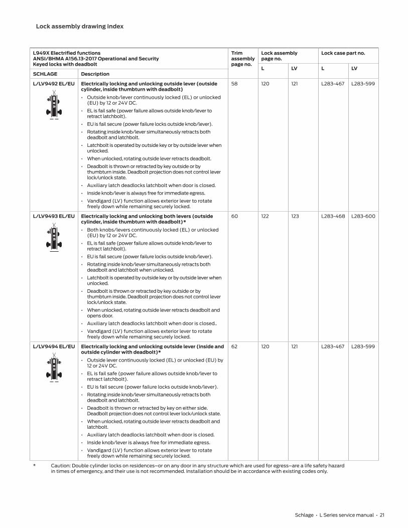
Schlage • L Series service manual • 21
L949X Electrified functionsANSI/BHMA A156.13-2017 Operational and SecurityKeyed locks with deadbolt
Trim assembly page no.
Lock assembly page no.
Lock case part no.
L LV L LVSCHLAGE Description
L/LV9492 EL/EU Electrically locking and unlocking outside lever (outside cylinder, inside thumbturn with deadbolt)• Outside knob/lever continuously locked (EL) or unlocked
(EU) by 12 or 24V DC.
• EL is fail safe (power failure allows outside knob/lever to retract latchbolt).
• EU is fail secure (power failure locks outside knob/lever).
• Rotating inside knob/lever simultaneously retracts both deadbolt and latchbolt.
• Latchbolt is operated by outside key or by outside lever when unlocked.
• When unlocked, rotating outside lever retracts deadbolt.
• Deadbolt is thrown or retracted by key outside or by thumbturn inside. Deadbolt projection does not control lever lock/unlock state.
• Auxiliary latch deadlocks latchbolt when door is closed.
• Inside knob/lever is always free for immediate egress.
• Vandlgard (LV) function allows exterior lever to rotate freely down while remaining securely locked.
58 120 121 L283-467 L283-599
L/LV9493 EL/EU Electrically locking and unlocking both levers (outside cylinder, inside thumbturn with deadbolt)*• Both knobs/levers continuously locked (EL) or unlocked
(EU) by 12 or 24V DC.
• EL is fail safe (power failure allows outside knob/lever to retract latchbolt).
• EU is fail secure (power failure locks outside knob/lever).
• Rotating inside knob/lever simultaneously retracts both deadbolt and latchbolt when unlocked.
• Latchbolt is operated by outside key or by outside lever when unlocked.
• Deadbolt is thrown or retracted by key outside or by thumbturn inside. Deadbolt projection does not control lever lock/unlock state.
• When unlocked, rotating outside lever retracts deadbolt and opens door.
• Auxiliary latch deadlocks latchbolt when door is closed..
• Vandlgard (LV) function allows exterior lever to rotate freely down while remaining securely locked.
60 122 123 L283-468 L283-600
L/LV9494 EL/EU Electrically locking and unlocking outside lever (inside and outside cylinder with deadbolt)*• Outside lever continuously locked (EL) or unlocked (EU) by
12 or 24V DC.
• EL is fail safe (power failure allows outside knob/lever to retract latchbolt).
• EU is fail secure (power failure locks outside knob/lever).
• Rotating inside knob/lever simultaneously retracts both deadbolt and latchbolt.
• Deadbolt is thrown or retracted by key on either side. Deadbolt projection does not control lever lock/unlock state.
• When unlocked, rotating outside lever retracts deadbolt and latchbolt.
• Auxiliary latch deadlocks latchbolt when door is closed.
• Inside knob/lever is always free for immediate egress.
• Vandlgard (LV) function allows exterior lever to rotate freely down while remaining securely locked.
62 120 121 L283-467 L283-599
* Caution: Double cylinder locks on residences–or on any door in any structure which are used for egress–are a life safety hazard in times of emergency, and their use is not recommended. Installation should be in accordance with existing codes only.

22 • Schlage • L Series service manual
Lock assembly drawing index
L949X Electrified functionsANSI/BHMA A156.13-2017 Operational and SecurityKeyed locks with deadbolt
Trim assembly page no.
Lock assembly page no.
Lock case part no.
L LV L LVSCHLAGE Description
L/LV9495 EL/EU Electrically locking and unlocking both levers (inside and outside cylinder with deadbolt)*• Both knobs/levers continuously locked (EL) or unlocked
(EU) by 12 or 24V DC.
• EL is fail safe (power failure allows outside knob/lever to retract latchbolt.
• EU is fail secure (power failure locks outside knob/lever).
• Latchbolt is retracted by key from either side, or rotating inside or outside knob/lever when unlocked.
• Rotating inside knob/lever retracts both deadbolt and latchbolt when unlocked.
• Deadbolt is thrown or retracted by key on either side. Deadbolt projection does not control lever lock/unlock state.
• Auxiliary latch deadlocks latchbolt when door is closed.
• Vandlgard (LV) function allows exterior lever to rotate freely down while remaining securely locked.
64 121 123 L283-468 L283-600
* Caution: Double cylinder locks on residences–or on any door in any structure which are used for egress–are a life safety hazard in times of emergency, and their use is not recommended. Installation should be in accordance with existing codes only.

Lock assembly drawing index
Schlage • L Series service manual • 23
LM9200 Two-point functions**ANSI/BHMA A156.13-2017 Operational and SecurityNon-keyed locks
Trim assembly page no.
Lock assembly page no.
Lock case part no.
SCHLAGE Description
LM9210 Passage lock two-point latch• Both levers retract latchbolt at all times.
• Inside lever is always free for immediate egress.
84 144 24759599
LM9225 Exit lock two-point latch• Inside lever only, no outside trim.
• Inside lever retracts latchbolt.
• Inside lever is always free for immediate egress.
86 144 24759599
LM9200 Multipoint functions**ANSI/BHMA A156.13-2017 Operational and SecurityKeyed Locks
Trim assembly page no.
Lock assembly page no.
Lock case part no.
SCHLAGE Description
LM9250 Office, entry lock two-point latch• Both levers retract latchbolt unless outside is made inoperative by outside key
or by turning inside thumbturn.
• Outside lever is unlocked by thumbturn or by outside key.
• When locked, outside key and lever retract latchbolt.
• Inside lever is always free for immediate egress.
88 146 24759623
LM9256 LM9250 Office, entry with automatic unlocking two-point latch• Both levers retract latchbolt unless outside is made inoperative by outside key
or by turning inside thumbturn.
• Outside lever is unlocked by inside thumbturn, or by outside key, or by rotating inside lever.
• When locked, outside key and lever retract latchbolt.
• Inside lever is always free for immediate egress.
88 145 24616914
LM9270 Classroom lock two-point latch• Both levers retract latchbolt unless outside is made inoperative by outside key.
• Outside lever is locked and unlocked by outside key.
• When locked, outside key and lever retract latchbolt.
• Inside lever is always free for immediate egress.
90 146 24759623
LM9271 Classroom security lock two-point latch *• Both levers retract latchbolt unless outside is made inoperative by outside
either key.
• Outside lever is locked and unlocked by inside or outside key.
• When locked, outside key and lever retract latchbolt.
• Inside lever is always free for immediate egress.
92 146 24759623
LM9280 Storeroom lock two-point latch• Latchbolt retracted by outside lever after key is inserted and rotated 280°, or
anytime by inside lever.
• Inside lever is always free for immediate egress.
90 146 24759623
* Caution: Double cylinder locks on residences–or on any door in any structure which are used for egress–are a life safety hazard in times of emergency, and their use is not recommended. Installation should be in accordance with existing codes only.
** Requires doors specifically designed for two-point latch system.

24 • Schlage • L Series service manual
Lock assembly drawing index
LM9200 Multipoint functions**ANSI/BHMA A156.13-2017 Operational and SecurityKeyed Locks
Trim assembly page no.
Lock assembly page no.
Lock case part no.
SCHLAGE Description
LM9290 EL/EU Electrically locking/unlocking outside lever lock, two-point latch (no cylinder)• Outside lever continuously locked (EL) or unlocked (EU) by 12 or 24V DC.
• EL is fail safe (power failure allows outside lever to retract latch).
• EU is fail secure (power failure locks outside lever).
• Latchbolt retracted by outside lever when unlocked, or anytime by inside lever.
• Inside lever is always free for immediate egress.
84 147 24759656
LM9291 EL/EU Electrically locking/unlocking both levers lock, two-point latch (no cylinder) *• Both levers continuously locked (EL) or unlocked (EU) by 12 or 24V DC.
• EL is fail safe (power failure allows outside lever to retract latch).
• EU is fail secure (power failure locks outside lever).
• Latchbolt retracted by outside or inside lever when unlocked.
84 148 24759664
LM9292 EL/EU Electrically locking/unlocking outside lever lock, two-point latch (outside cylinder)• Outside lever continuously locked (EL) or unlocked (EU) by 12 or 24V DC.
• EL is fail safe (power failure allows outside lever to retract latch).
• EU is fail secure (power failure locks outside lever).
• Latchbolt retracted by outside key and lever, by electrically unlocking door and rotating outside lever, or anytime by inside lever.
• Inside lever is always free for immediate egress.
90 147 24759656
LM9293 EL/EU Electrically locking/unlocking both levers lock two-point latch (outside cylinder)• Both levers continuously locked (EL) or unlocked (EU) by 12 or 24V DC.
• EL is fail safe (power failure allows outside lever to retract latch).
• EU is fail secure (power failure locks outside lever).
• Latchbolt retracted by outside key and lever, by electrically unlocking door and rotating either lever.
90 148 24759664
LM9294 EL/EU Electrically locking/unlocking outside lever lock two-point latch (inside and outside cylinder) *• Outside lever continuously locked (EL) or unlocked (EU) by 12 or 24V DC.
• EL is fail safe (power failure allows outside lever to retract latch).
• EU is fail secure (power failure locks outside lever).
• Latchbolt retracted by outside key and lever, by electrically unlocking door and rotating outside lever, or anytime by inside lever.
• Inside lever is always free for immediate egress.
92 147 24759656
LM9295 EL/EU Electrically locking/unlocking both levers lock two-point latch (inside and outside cylinder) *• Both levers continuously locked (EL) or unlocked (EU) by 12 or 24V DC.
• EL is fail safe (power failure allows outside lever to retract latch).
• EU is fail secure (power failure locks outside lever).
• Latchbolt retracted by outside key and lever, by inside key and lever, or by electrically unlocking door and rotating either lever.
92 148 24759664
* Caution: Double cylinder locks on residences–or on any door in any structure which are used for egress–are a life safety hazard in times of emergency, and their use is not recommended. Installation should be in accordance with existing codes only.
** Requires doors specifically designed for two-point latch system.

Lock assembly drawing index
Schlage • L Series service manual • 25
LM9300 Multipoint functions**ANSI/BHMA A 156.37-2014 Grade 1 Operational and SecurityNon-keyed locks
Trim assembly page no.
Lock assembly page no.
Lock case part no.
SCHLAGE Description
LM9310 Passage latch with three-point latch• Latchbolt retracted by knob/lever from either side at all times.
• Auxiliary latch deadlocks latchbolt when door is closed.
• Inside and outside knob/lever are always free for immediate egress.
32 99 L283-314
LM9325
Exit lock function with three-point latch• Latchbolt retracted by inside knob/lever at all times.
• No outside trim.
• Auxiliary latch deadlocks latchbolt when door is closed.
38 99 L283-314
LM9300 Multipoint functions**ANSI/BHMA A 156.37-2014 Grade 1 Operational and SecurityKeyed Locks
Trim assembly page no.
Lock assembly page no.
Lock case part no.
L LV L LVSCHLAGE Description
LM/LMV9350
LOCKED
Office and inner entry lock with three-point latch• Latchbolt is retracted by knob/lever from either side
unless outside is made inoperative by key outside or inside thumbturn.
• When outside is locked, latchbolt is retracted by key and knob/lever outside or by knob/lever inside.
• Outside knob/lever remains locked until thumbturn is returned to vertical position or unlocked by key.
• Auxiliary latch deadlocks latchbolt when door is closed.
• Inside knob/lever is always free for immediate egress.
• Vandlgard (LV) function allows exterior lever to rotate freely down while remaining securely locked.
46 104 105 L283-316 L283-317
LM/LMV9370
LOCKED
Classroom lock with three-point latch• Latchbolt is retracted by knob/lever from either side
unless outside is locked by key.
• When outside is locked, latchbolt is retracted by key and knob/lever outside or by knob/lever inside.
• Inside knob/lever is always free for immediate egress.
• Auxiliary latch deadlocks latchbolt when door is closed.
• Vandlgard (LV) function allows exterior lever to rotate freely down while remaining securely locked.
52 104 105 L283-316 L283-317
LM/LMV9371LOCKED
Classroom security lock with three-point latch• Latchbolt is retracted by knob/lever from either side
unless locked by key from either side.
• When outside is locked, latchbolt is retracted by key and knob/lever outside or knob/lever inside.
• Inside knob/lever is always free for immediate egress.
• Auxiliary latch deadlocks latchbolt when door is closed.
• Vandlgard (LV) function allows exterior lever to rotate freely down while remaining securely locked.
48 104 105 L283-316 L283-317
LM/LMV9380 Storeroom lock with three-point latch• Latchbolt is retracted by outside knob/lever after key is
inserted and rotated 280°, or anytime by inside knob/lever.
• Auxiliary latch deadlocks latchbolt when door is closed.
• Inside knob/lever is always free for immediate egress.
• Vandlgard (LV) function allows exterior lever to rotate freely down while remaining securely locked.
52 112 113 L283-316 L283-317
** Specify handing (LM9300 handing is not field reversible). Available for 1C\v" door thickness. For use only with MultiPoint Lock Tornado, Tornado Shutter, Hurricane, or Security solution. Solution requires door and rod set sold through Steelcraft®.

26 • Schlage • L Series service manual
Lock assembly drawing index
L400 FUNCTIONSANSI/BHMA A156.36-2010, Grade 1Keyed L400-Series
Trim assembly page no.
Lock assembly page no.
Lock case page no.
SCHLAGE ANSI
L460 E06071
LOCKED
Cylinder by thumbturn lock• Deadbolt is operated by outside key outside or inside thumbturn.
28 95 L283-099
L462 E06061
LOCKED
Double cylinder lock*• Deadbolt is operated by key on either side.
28 95 L283-099
L463 E06091
LOCKED
Classroom lock• Deadbolt is operated by key on outside.
• Inside cylinder turn retracts deadbolt but cannot extend it.
28 95 L283-099
L464 E06081
LOCKED
Cylinder lock• Deadbolt is operated by key on one side.
• No trim on opposite side.
28 95 L283-099
L496 Deadbolt lock with "occupied" indicator• Deadbolt is operated by key outside or thumbturn inside.
• Furnished with 09-611 per L583-375 indicator.
• When deadbolt is thrown, "Occupied" plate is displayed.
• Available with rose trim only.
• (Previously XL11-911)
28 95 L283-099
L400 FUNCTIONSANSI/BHMA A156.36-2010, Grade 1Non-keyed L400-Series
Trim assembly page no.
Lock assembly page no.
Lock case page no.
SCHLAGE ANSI Description
L480 F14
LOCKED
Door bolt• Deadbolt is operated by thumbturn on one side.
• No trim on opposite side.
28 95 L283-099
* Caution: Double cylinder locks on residences–or on any door in any structure which are used for egress–are a life safety hazard in times of emergency, and their use is not recommended. Installation should be in accordance with existing codes only.

27 • Schlage • L Series service manual
29 L400 Series deadbolt trim31 L9000 Series single dummy trim32 L9000 Series double dummy trim33 Passage latch trim35 Exit trim37 Exit trim with cylinder39 Exit trim with three-point latch41 Emergency button x turn trim43 Privacy x turns both sides trim45 Coin turn outside x turn trim47 Cylinder x turn trim49 Double cylinder trim51 Double cylinder storeroom trim53 Cylinder outside trim55 Electrically locked/unlocked outside trim57 Electrically locked/unlocked both sides trim61 Electrically locked/unlocked both sides trim, single
cylinder63 Electrically locked/unlocked outside trim, double
cylinder65 Electrically locked/unlocked both sides trim, double
cylinder67 Active double dummy trim69 Single dummy with case trim71 Double dummy with case trim73 Deadbolt trim75 Deadbolt with fixed double dummy trim77 Fixed outside x turn trim79 Institution deadbolt trim81 Prison lock trim83 Hotel with indicator trim85 Passage and electrically locked/unlocked, two-point
latch trim87 Outside lever only, two-point latch trim89 Cylinder x turn, two-point latch trim91 Outside cylinder and electrically locked/unlocked
outside cylinder, two-point latch trim93 Double cylinder and electrically locked/unlocked
outside cylinder, two-point latch trim
Trim assemblies

28 • Schlage • L Series service manual
Trim assemblies
L400 Series deadbolt trim
L460, L462, L463, L464, L480, L496
K
R
Q
O
BBF
DD
M
T2
2
BB
P
PQ
M
O
K
R
Q
ODD
DD
M
2L462P
BB
P
L
K
R
Q
ODD
M
DD
BB
KQ
O
MR2
BB
K
F
R2
FBB
K
R
H
Q
M
DD
O
L460P
L463P L464P
L496L480
T2
T2
2
T2
T2
2
T2
Notes: Standard full face mortise cylinder shown. Available with 180° messaging indicator trim.

29 • Schlage • L Series service manual
Trim assemblies
P/N Description
L46
0
L46
2
L46
3
L46
4
L48
0
L49
6
F 09-544 Inside thumbturn • • •H 09-611 Occupancy Indicator •K 09-717 L400 Series 1Z\v" armor front x Schlage logo, deadbolt • • • • • •L 09-905 Classroom turn and 1Z\," blocking ring •M 30-001 Full face cylinder with compression ring and spring, clover leaf cam • 2 • • •O 30-021 Full face cylinder with compression spring, clover leaf cam • 2 • • •P 36-082 Blocking ring 2 •Q 36-083 Compression ring and spring • 2 • • •R C203-736 Case mounting screw pack • • • • • •T K110-020 Armor screw pack • • • • • •BB L283-099 Assembled lock case, L400 deadbolt • • • • • •DD L583-195 Compression spring • 2 • • •

30 • Schlage • L Series service manual
Trim assemblies
L9000 Series single dummy trim
L0170
B
C
Y II
AA
GGB
S
B
SI CC
V
GGAA
HH
CB
I
CC
V
Levers
Knobs
2
2
22
P/N DescriptionB 09-402 Inside knob and leverC 09-403 Inside roseI 09-632 Inside escutcheon for knob/lever, N x blankS L583-133 N escutcheon thru-bolts/screws (quantity – 2)V K510-320 Dummy mounting plugY L283-031 Inside lever mounting plateAA L283-065 Spindle and spring, single dummy
CCMounting plate screws (quantity – 2)L583-290 Wood/metal door x rose/escutcheon x leverL583-291 Wood/metal door x rose/escutcheon x knob
GG L583-286 Dummy mounting barHH L583-321 Inside knob mounting plateII L583-322 Outside lever spacer
Notes: Reinforcement required for metal door applications. See template at www.allegion.com/us. L0170 not available with L escutcheon.
31 • Schlage • L Series service manual
Trim assemblies
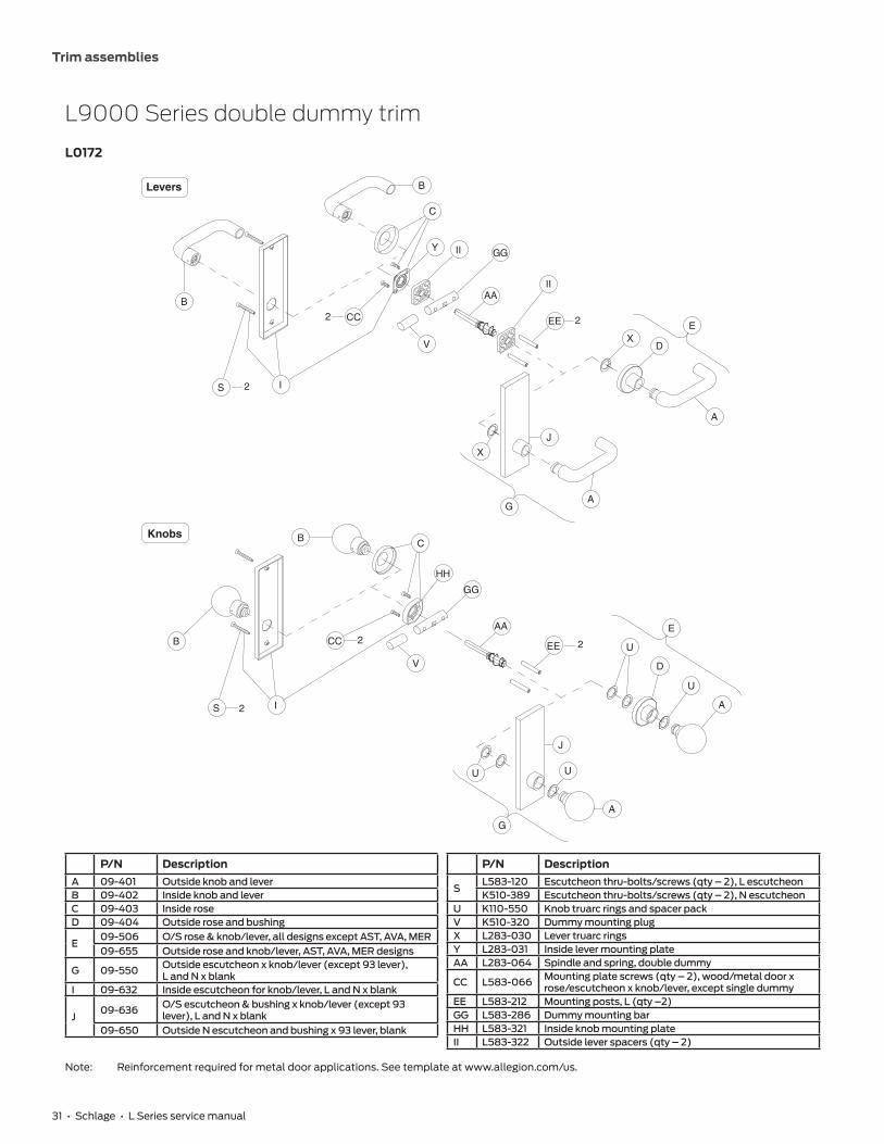
L9000 Series double dummy trim
L0172
B
S I
CC
V
B
C
Y II GG
AAII
EE
XD
A
E
A
J
X
G
B
B
S I
CC
GG
AA
EE U
E
D
U
A
A
U
G
J
U
C
HH
2
2 2
2
2 2
Levers
Knobs
V
P/N DescriptionA 09-401 Outside knob and leverB 09-402 Inside knob and leverC 09-403 Inside roseD 09-404 Outside rose and bushing
E09-506 O/S rose & knob/lever, all designs except AST, AVA, MER09-655 Outside rose and knob/lever, AST, AVA, MER designs
G 09-550 Outside escutcheon x knob/lever (except 93 lever), L and N x blank
I 09-632 Inside escutcheon for knob/lever, L and N x blank
J09-636 O/S escutcheon & bushing x knob/lever (except 93
lever), L and N x blank09-650 Outside N escutcheon and bushing x 93 lever, blank
P/N Description
SL583-120 Escutcheon thru-bolts/screws (qty – 2), L escutcheonK510-389 Escutcheon thru-bolts/screws (qty – 2), N escutcheon
U K110-550 Knob truarc rings and spacer packV K510-320 Dummy mounting plugX L283-030 Lever truarc ringsY L283-031 Inside lever mounting plateAA L283-064 Spindle and spring, double dummy
CC L583-066 Mounting plate screws (qty – 2), wood/metal door x rose/escutcheon x knob/lever, except single dummy
EE L583-212 Mounting posts, L (qty –2)GG L583-286 Dummy mounting barHH L583-321 Inside knob mounting plateII L583-322 Outside lever spacers (qty – 2)
Note: Reinforcement required for metal door applications. See template at www.allegion.com/us.
32 • Schlage • L Series service manual
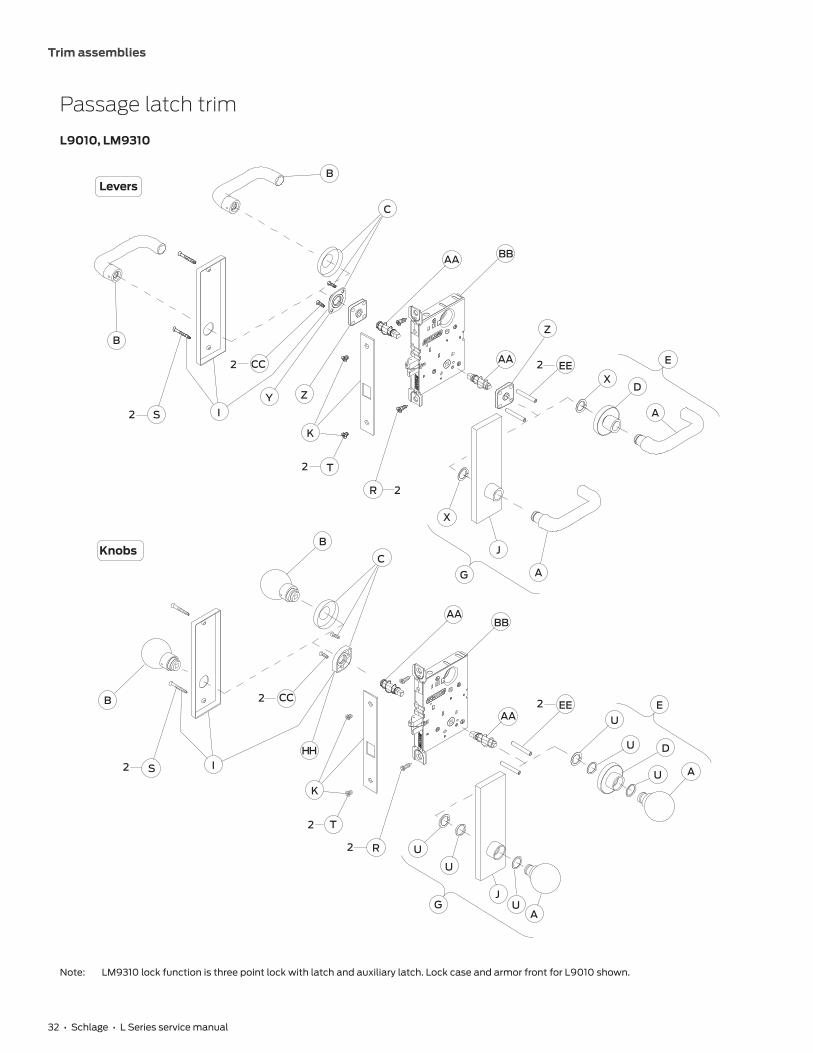
Trim assemblies
Passage latch trim
L9010, LM9310
B
C
AA BB
Z
AA EEX
E
D
A
B
2
2
2
2
2
2
I
CC
Y
S
Z
K
T
R
X
J
AGC
B
AABB
EEAA
E
U
U
D
U A
B
I
CC
HH
S
K
T
R U
U
JU
AG
Levers
Knobs
2
2
2
2
Note: LM9310 lock function is three point lock with latch and auxiliary latch. Lock case and armor front for L9010 shown.

33 • Schlage • L Series service manual
Trim assemblies
P/N Description
L90
10
LM9
310
A 09-401 Outside knob and lever • •B 09-402 Inside knob and lever • •C 09-403 Inside rose • •D 09-404 Outside rose and bushing • •
EOutside rose and knob/lever:09-506 All designs except AST, AVA, MER • •09-655 AST, AVA, MER • •
G 09-550 Outside escutcheon x knob/lever (except 93 lever) L and N x blank • •I 09-632 Inside escutcheon for knob/lever, L and N x blank • •
J09-636 Outside escutcheon and bushing by knob/lever except 93 lever, L and N x blank • •09-650 Outside N escutcheon and bushing x 93 lever x blank • •
K 09-662 1Z\v" armor front x Schlage logo, latch • •R C203-736 Case mounting screw pack • •
SEscutcheon thru-bolts/screws:K510-389 N escutcheon 2 2L583-120 L escutcheon 2 2
T K110-020 Armor screw pack • •U K110-550 Knob truarc rings and spacer pack • •X L283-030 Lever truarc rings • •Y L283-031 Inside lever mounting plate • •Z L283-040 Lever spring cage 2 2AA L283-060 Spindle and spring 2 2
BBAssembled lock case:L283-131 Passage •L283-314 Passage/exit x multipoint •
CC L583-066 Mounting trim screws, wood/metal door x rose/escutcheon x knob/lever except single dummy 2 2EE L583-212 Mounting post 2 2HH L583-321 Inside knob mounting plate • •

34 • Schlage • L Series service manual
Trim assemblies
Exit trim
L9025
KK
CC
CB
AABB
Y Z
K
T
R
BBAA
CB
2
2
CC
HH
R
Levers
Knobs
2
2
2
KK
K
T2

35 • Schlage • L Series service manual
Trim assemblies
P/N Description
B 09-402 Inside knob and leverC 09-403 Inside roseK 09-663 1Z\v" armor front x Schlage logo, latch and auxiliary latchR C203-736 Case mounting screw packT K110-020 Armor screw packY L283-031 Inside lever mounting plateZ L283-040 Lever spring cageAA L283-060 Spindle and springBB L283-750 Assembled lock case, exitCC L583-066 Mounting trim screws, wood/metal door x rose x knob/lever except single dummyHH L583-321 Inside knob mounting plateKK L283-151* Mounting plate
* L283-151 part number for reference only. To order mounting plate, order by part number L283-150.

36 • Schlage • L Series service manual
Trim assemblies
Exit trim with cylinder
L9026
KK
B
CC
C
B
AABB
SI
Y Z
R
BBAA
C
B
B
SI
2 CC
HH
R
Levers
Knobs
2
2
2
2
2
KK
ODD
Q
M
J
O
DDQ
M
ODD
ODD
J
K
T2
K
T2

37 • Schlage • L Series service manual
Trim assemblies
P/N Description
B 09-402 Inside knob and leverC 09-403 Inside roseI 09-632 Inside escutcheon L and N x blankJ 09-614 Outside escutcheon and bushing L x cylinderK 09-662 1Z\v" armor front x Schlage logo, latch and auxiliary latchM 30-001 Full face cylinder with compression ring and spring – clover leaf camO 30-021 Full face cylinder with compression spring – clover leaf camQ 36-083 Compression ring and springR C203-736 Case mounting screw pack
SL583-120 Escutcheon thru-bolts/screws (qty – 2), L escutcheonL583-133 Escutcheon thru-bolts/screws (qty – 2), N escutcheon
T K110-020 Armor screw packY L283-031 Inside lever mounting plateZ L283-040 Lever spring cageAA L283-060 Spindle and springBB L283-134 Assembled lock case, exit with cylinderCC L583-066 Mounting trim screws, wood/metal door x rose/escutcheon x knob/lever except single dummyDD L583-195 Compression springHH L583-321 Inside knob mounting plateKK L283-151* Mounting plate
* L283-151 part number for reference only. To order mounting plate, order by part number L283-150.

38 • Schlage • L Series service manual
Trim assemblies
Exit trim with three-point latch
LM9325
B
C
AA
KK
BB2
2
2
2
CCY
Z
K
T
R
C
B
AA
HH
K
T
Levers
Knobs
BB
2R
KK

39 • Schlage • L Series service manual
Trim assemblies
P/N Description
B 09-402 Inside knob and leverC 09-403 Inside roseK 09-663 1Z\v" armor front x Schlage logo –latch and auxiliary latchR C203-736 Case mounting screw packT K110-020 Armor screw packY L283-031 Inside lever mounting plateZ L283-040 Lever spring cageAA L283-060 Spindle and springBB L283-314 Assembled lock case, passage/exit x multipointCC L583-066 Mounting trim screws, wood/metal door x rose/escutcheon x knob/lever (except single dummy) (qty 2)HH L583-321 Inside knob mounting plateKK L283-151* Mounting plate
* L283-151 part number for reference only. To order mounting plate, order by part number L283-150.

40 • Schlage • L Series service manual
Trim assemblies
Emergency button x turn trim
L9040, LV9040, L9440, LV9440
B
F
W
FF
FF
C
AA BB
Z
AA
X
E
D
A
B
I
CC
S
2
2
22
2
ZY
K
T R
X
J
AG
C
B AA BB
EEAAE
U
U
UD
A
A
B
I
CC
HHS
K
TR
U
U
JUG
W
W
W
F
FF
FF
Levers
Knobs
2
2
2
EE2
2
2
Notes: L9440 and LV9440 lock functions have latch and deadbolt. Lock case and armor front shown with latch only. Available with 180° messaging indicator trim.

41 • Schlage • L Series service manual
Trim assemblies
P/N Description
L90
40
LV9
04
0
L94
40
LV9
44
0
A 09-401 Outside lever • • • •B 09-402 Inside lever • • • •C 09-403 Inside rose • • • •D 09-404 Outside rose and bushing • • • •
EOutside rose lever:09-506 All designs except AST, AVA, MER • • • •09-655 AST, AVA, MER • • • •
F 09-544 Thumbturn • • • •G 09-551 Outside escutcheon x lever (except 93 lever), L and N x emergency button • • • •
I09-548 Inside escutcheon for lever, L x thumbturn • • • •09-642 Inside escutcheon for lever, N x thumbturn • • • •
J09-637 Outside escutcheon and bushing x lever (except 93 lever), L and N x emergency button • • • •09-651 Outside N escutcheon and bushing x 93 lever x emergency button • • • •
K1Z\v" armor front x Schlage logo09-662 Latch • •09-664 Latch and deadbolt • •
R C203-736 Case mounting screw pack • • • •
SEscutcheon thru-bolts/screws:K510-389 N escutcheon 2 2 2 2L583-120 L escutcheon 2 2 2 2
T K110-020 Armor screw pack • • • •U K110-550W K510-330 Emergency button • • • •X L283-030 Lever truarc rings • • • •Y L283-031 Inside lever mounting plate • • • •Z L283-040 Lever spring cage 2 2 2 2AA L283-060 Spindle and spring 2 2 2 2
BB
Assembled lock case:L283-132 Privacy, L •L283-171 Privacy, LV •L283-062 Privacy with deadbolt, L •L283-181 Privacy with deadbolt, LV •
CC L583-066 Mounting trim screws, wood/metal door x rose/escutcheon x lever except single dummy 2 2 2 2
EEL583-212 Mounting posts, L 2 2L583-497 Mounting posts, LV 2 2
FF L583-691 Emergency turn • • • •HH L583-321 Inside knob mounting plate • •
Note: Emergency turn L583-691 available only in 458 finish.

42 • Schlage • L Series service manual
Trim assemblies
Privacy x turns both sides trim
L9040 x XL11-446, LV9040 x XL11-446
B
FC
AA BB
Z
AAEE
XE
F
D
A
B
I
2
2
CC
S
ZY
K
TR
X
J
AG
CB
AA BB
EEAA
E
F
U
U
U
D
A
A
B
I
CC
HH
S
K
UU
JUG
F
Levers
Knobs
2
2
2
RT
2
2
2
2
Notes: Available with 180° messaging indicator trim. Not available with N escutcheon.

43 • Schlage • L Series service manual
Trim assemblies
P/N Description
L90
40
x X
L11-
44
6
LV9
04
0 x
XL1
1-4
46
A 09-401 Outside lever • •B 09-402 Inside lever • •C 09-403 Inside rose • •D 09-404 Outside rose and bushing • •
EOutside rose and lever:09-506 All designs except AST, AVA, MER • •09-655 AST, AVA, MER • •
F 09-544 Thumbturn (qty 2) • •G 09-550/XL11-446 Outside escutcheon x lever (except 93 lever), L x thumbturn ‡ • •I 09-548 Inside escutcheon for lever, L x thumbturn • •J 09-639/XL11-446 Outside escutcheon and bushing x lever (except 93 lever), L x thumbturn ‡ • •K 09-662 1Z\v" armor front x Schlage logo, latch • •R C203-736 Case mounting screw pack • •S L583-120 Escutcheon thru-bolts/screws, L escutcheon 2 2T K110-020 Armor screw pack • •U K110-550 Knob truarc rings and spacer pack • •X L283-030 Lever truarc rings • •Y L283-031 Inside lever mounting plate • •Z L283-040 Lever spring cage 2 2AA L283-060 Spindle and spring 2 2
BBAssembled lock case:L283-132 Privacy, L •L283-171 Privacy, LV •
CC L583-066 Mounting trim screws, wood/metal door x rose/escutcheon x lever except single dummy 2 2
EEL583-212 Mounting posts, L 2L583-497 Mounting posts, LV 2
HH L583-321 Inside knob mounting plate •‡ Not sold separately as a part.

44 • Schlage • L Series service manual
Trim assemblies
Coin turn outside x turn trim
L9044, LV9044, L9444, LV9444
B
C
F
AABB
F
Z
AA
CC
YZ
K
T R
EE
B
C
F
AA BBF
CC
HH
K
T
2
2
2
2
R
EE
AA
EU
D
U
U
A
2
2
2
2
Levers
Knobs
EX
D
A
B
IS2
X
J
AG
B
A
U
U
J
UG
IS2
Notes: L9444 and LV9444 lock functions have latch and deadbolt. Lock case and armor front shown with latch only. Available with 180° messaging indicator trim.

45 • Schlage • L Series service manual
Trim assemblies
P/N Description
L90
44
LV9
04
4
L94
44
LV9
44
4
A 09-401 Outside lever • • • •B 09-402 Inside lever • • • •C 09-403 Inside rose • • • •D 09-404 Outside rose and bushing • • • •
EOutside rose and knob/lever:09-506 All designs except AST, AVA, MER • • • •09-655 AST, AVA, MER • • • •
F09-544 Inside thumbturn • • • •L283-124 Coin turn outside • • • •
G 09-553 Outside escutcheon x knob/lever (except 93 lever), N x coin turn • • • •I 09-633 Inside escutcheon for knob/lever, N x thumbturn • • • •J 09-639 Outside escutcheon and bushing x knob/lever (except 93 lever), N x coin turn • • • •
K1Z\v" armor front x Schlage logo09-662 Latch • •09-664 Latch and deadbolt • •
R C203-736 Case mounting screw pack • • • •T K110-020 Armor screw pack • • • •U K110-550 Knob truarc rings and spacer pack • • • •X L283-030 Lever truarc rings • • • •Y L283-031 Inside lever mounting plate • • • •Z L283-040 Lever spring cage 2 2 2 2AA L283-060 Spindle and spring 2 2 2 2
BB
Assembled lock case:L283-132 Privacy, L •L283-171 Privacy, LV •L283-062 Privacy with deadbolt, L •L283-181 Privacy with deadbolt, LV •
CC L583-066 Mounting trim screws, wood/metal door x rose/escutcheon x lever (except single dummy) 2 2 2 2
EEL583-212 Mounting posts, L 2 2L583-497 Mounting posts, LV 2 2
HH L583-321 Inside knob mounting plate • •

46 • Schlage • L Series service manual
Trim assemblies
Cylinder x turn trim
L9050, LV9050, LM9350, LMV9350, L9056, LV9056, L9453, LV9453, L9456, LV9456, L9473
B
FC
AA BB
Z
AA EE
X E
O DD
Q
M
O DD
D
A
B
I
2
2
2
2
2
CC
S
Z Y
K
T
R
X
J
A G C B
AA BB
AAE
U
U
D U
A
A
B
I
CC
HH
S
K
T
R U
U
J U G
F
O
DD Q
M
O DD
2
2
2
EE 2
2
Levers
Knobs
Notes: L9456, LV9456, and L9473 lock functions have a latch and deadbolt. Lock case and armor front shown with latch and auxiliary latch. L/LV9453 lock functions have a latch, auxiliary latch, and deadbolt. Lock case and armor front shown with latch and auxiliary latch only. Standard full face mortise cylinder shown. LM9350 and LMV9350 lock functions are three point lock with latch and auxiliary latch. Lock case and armor front for L/LV functions shown. L/LV9050, LM/LMV9350, L/LV9056, L/LV9456 and L9473 available with 180° indicator trim.

47 • Schlage • L Series service manual
Trim assemblies
P/N Description
L90
50
LV9
050
LM9
350
LMV
935
0
L90
56
LV9
056
L94
53
LV9
453
L94
56
LV9
456
L947
3
A 09-401 Outside knob and lever • • • • • • • • • • •B 09-402 Inside knob and lever • • • • • • • • • • •C 09-403 Inside rose • • • • • • • • • • •D 09-404 Outside rose and bushing • • • • • • • • • • •
EOutside rose and knob/lever:09-506 All designs except AST, AVA, MER • • • • • • • • • • •09-655 AST, AVA, MER • • • • • • • • • • •
F 09-544 Thumbturn • • • • • • • • • • •G 09-553 Outside escutcheon x knob/lever (except 93 lever), L and N x full face cylinder • • • • • • • • • • •
I09-548 Inside escutcheon for knob/lever, L x thumbturn • • • • • • • • • • •09-642 Inside escutcheon for knob/lever, N x thumbturn • • • • • • • • • • •
J09-639 Outside escutcheon and bushing x knob/lever (except 93 lever), L and N x
full face cylinder • • • • • • • • • • •
09-652 Outside N escutcheon and bushing x 93 lever, full face cylinder • • • • • • • • • • •
K
1Z\v" armor front x Schlage logo09-663 Latch and auxiliary latch • • • • • •09-664 Latch and deadbolt • • •09-666 Latch, auxiliary latch and deadbolt • •
M 30-001 Full face cylinder with compression ring and spring – clover leaf cam • • • • • • • • • • •O 30-021 Full face cylinder with compression spring – clover leaf cam • • • • • • • • • • •Q 36-083 Compression ring and spring • • • • • • • • • • •R C203-736 Case mounting screw pack • • • • • • • • • • •
SEscutcheon thru-bolts/screws:K510-389 N escutcheon 2 2 2 2 2 2 2 2 2 2 2L583-120 L escutcheon 2 2 2 2 2 2 2 2 2 2 2
T K110-020 Armor screw pack • • • • • • • • • • •U K110-550 Knob truarc rings and spacer pack • • • • • • • • • • •X L283-030 Lever truarc rings • • • • • • • • • • •Y L283-031 Inside lever mounting plate • • • • • • • • • • •Z L283-040 Lever spring cage 2 2 2 2 2 2 2 2 2 2 2AA L283-060 Spindle and spring 2 2 2 2 2 2 2 2 2 2 2
BB
Assembled lock case:L283-126 Office with simultaneous retraction •L283-133 Office, classroom, apartment security •L283-137 Entrance •L283-138 Corridor, classroom security x deadbolt •L283-140 Closet, storeroom and dormitory •L283-170 Office, classroom, apartment security, LV •L283-176 Entrance, LV •L283-177 Corridor, classroom security x deadbolt, LV •L283-180 Office with simultaneous retraction, LV •L283-316 Office, inner entry x multipoint •L283-317 Office, inner entry x multipoint, LV •
CC L583-066 Mounting trim screws, wood/metal door x rose/escutcheon x knob/lever (except single dummy) 2 2 2 2 2 2 2 2 2 2 2
DD L583-195 Compression spring • • • • • • • • • • •
EEL583-212 Mounting posts, L 2 2 2 2 2 2L583-497 Mounting posts, LV 2 2 2 2 2
HH L583-321 Inside knob mounting plate • • • • • •

48 • Schlage • L Series service manual
Trim assemblies
Double cylinder trim
L9060, LV9060, L9071, LV9071, LM9371, LMV9371, L9077, LV9077, L9082, LV9082, L9457, LV9457, L9458, LV9458, L9462 x XL11-886, L9466
E
U
U
D U
A
M
O
Q
P
O
R
A
U
U
J UG
O DD
CC
AA
AA
DD
BB
HH
DD
B C O
Q P
M
K
I
S
B
XE
O
DD
DD
DD
BB AA
Q M
D
A Z
O B
I
2
2 2 CC S
Y
T
X
G
J A
EE AA
Z
DD O
C
IIO
Q
M
P
II P
K
R 2
2
EE 2
2
2 2
2 T
Levers
Knobs
DD
Notes: L9457, LV9457, and L9466 lock functions have a latch and deadbolt. Lock case and armor front shown with latch and auxiliary latch. L9458 and LV9458 lock functions have a latch, auxiliary latch and deadbolt. Lock case and armor front shown with latch and auxiliary latch. L9462 x XL11-886 lock function has deadbolt only. Lock case and armor front shown with latch and auxiliary latch. Standard full face mortise cylinder shown. LM9371 and LMV9371 lock functions are three point lock with latch and auxiliary latch. Lock case and armor front for L/LV functions shown. L/LV9060, L/LV9071, LM/LMV9371, L/LV9457, L/LV9458, L9462 x XL11-886 and L9466 available with 180° messaging indicator trim.

49 • Schlage • L Series service manual
Trim assemblies
P/N Description
L90
60
LV9
06
0
L90
71
LV9
071
LM9
371
LMV
937
1
L90
77
LV9
077
L90
82
LV9
08
2
L945
7
LV9
457
L945
8
LV9
458
L94
62
xXL1
1-8
86
L94
66
A 09-401 Outside knob and lever • • • • • • • • • • • • • • • •B 09-402 Inside knob and lever • • • • • • • • • • • • • • • •C 09-403 Inside rose • • • • • • • • • • • • • • • •D 09-404 Outside rose and bushing • • • • • • • • • • • • • • • •
EOutside rose and knob/lever:09-506 All designs except AST, AVA, MER • • • • • • • • • • • • • • • •09-655 AST, AVA, MER •
G 09-553 Outside escutcheon x knob/lever (except 93 lever), L and N x full face cylinder • • • • • • • • • • • • • • • •
I 09-635 Inside escutcheon for knob/lever, L and N x full face cylinder • • • • • • • • • • • • • • • •
J09-639 Outside escutcheon and bushing x knob/lever (except 93 lever),
L and N x full face cylinder • • • • • • • • • • • • • • • •
09-652 Outside escutcheon and bushing x 93 lever, full face cylinder • • • • • • • • • • • • • • •
K
1Z\v" armor front x Schlage logo:09-663 Latch and auxiliary latch • • • • • • • •09-664 Latch and deadbolt • • •09-665 Deadbolt •09-666 Latch, auxiliary latch and deadbolt • •09-713 Latch, auxiliary latch less UL stamp • •
MFull face cylinder with compression ring and spring:20-001 Straight cam • •30-001 Clover leaf cam • • 2 2 2 2 2 2 2 2 2 2 2 2 2 2
OFull face cylinder with compression spring:26-021 Straight cam • •30-021 Clover leaf cam • • 2 2 2 2 2 2 2 2 2 2 2 2 2 2
P 36-082 Blocking ring 2 2 2 2 2 2 2 2 2 2 • • • • 2 2Q 36-083 Compression ring and spring 2 2 2 2 2 2 2 2 2 2 2 2 2 2 2 2R C203-736 Case mounting screw pack • • • • • • • • • • 2 2 2 2 • •
SEscutcheon thru-bolts/screws:K510-389 N escutcheon 2 2 2 2 2 2 2 2 2 2 2 2 2 2 2 2L583-120 L escutcheon 2 2 2 2 2 2 2 2 2 2 2 2 2 2 2 2
T K110-020 Armor screw pack • • • • • • • • • • • • • • • •U K110-550 Knob truarc rings and spacer pack • • • • • • • • • • • • • • • •X L283-030 Lever truarc rings • • • • • • • • • • • • • • • •Y L283-031 Inside lever mounting plate • • • • • • • • • • • • • • • •Z L283-040 Lever spring cage 2 2 2 2 2 2 2 2 2 2 2 2 2 • 2AA L283-060 Spindle and spring 2 2 2 2 2 2 2 2 2 2 2 2 2 2 2 2
BB
Assembled lock case:L283-039 Classroom holdback •L283-133 Office, classroom, apartment security • •L283-138 Corridor, classroom security x deadbolt •L283-139 Deadbolt retract x inside knob/lever •L283-140 Closet, storeroom and dormitory •L283-146 Institution •L283-170 Office, classroom, apartment security, LV • •L283-172 Classroom holdback, LV •L283-177 Corridor, classroom security x deadbolt, LV •L283-182 Institution, LV •L283-310 Classroom security with auxiliary latch x deadbolt •L283-311 Classroom security with auxiliary latch x deadbolt, LV •L283-316 Office, inner entry x multipoint •L283-317 Office, inner entry x multipoint, LV •
CC L583-066 Mounting trim screws, wood/metal door x rose/escutcheon x knob/lever 2 2 2 2 2 2 2 2 2 2 2 2 2 2 2 2DD L583-195 Compression spring 2 2 2 2 2 2 2 2 2 2 2 2 2 2 2 2
EEL583-212 Mounting posts, L 2 2 2 2 2 2 2 2 2L583-497 Mounting posts, LV 2 2 2 2 2 2 2
HH L583-321 Inside knob mounting plate • • • • • • • • •ii L583-322 Outside lever spacer 2 •

50 • Schlage • L Series service manual
Trim assemblies
Double cylinder storeroom trim
L9066 x XL11-897
E
U
U
D U
A
M
O
Q
P
O
R
A
U
U
J UG
O DD
CC
DD
BB
HH
DD
B C O
Q P
M
K
I
S
B
XE
O
DD
DD
DD
BB AA
Q M
D
A Z
O B
I
2
2 2 CC S
Y
T
X
G
J A
EE
Z
DD O
C
IIO
Q
M
P
II P
K
R 2
2
EE 2
2
2 2
2 T
Levers
Knobs
DD
AA
Note: Standard full face mortise cylinders shown.

51 • Schlage • L Series service manual
Trim assemblies
P/N Description
A 09-401 Outside knob and leverB 09-402 Inside knob and leverC 09-403 Inside roseD 09-404 Outside rose and bushingE 09-506 Outside rose and knob/lever, all designs except AST, AVA, MERG 09-553 Outside escutcheon x knob/lever (except 93 lever), L and N x full face cylinderI 09-635 Inside escutcheon for knob/lever, L and N x full face cylinder
J09-639 Outside escutcheon and bushing x knob/lever (except 93 lever), L and N x full face cylinder09-652 Outside escutcheon and bushing x 93 lever), full face cylinder
K 09-663 1 Z\v" armor front x Schlage logo, latch and auxiliary latch M 30-001 Full face cylinder with compression ring and spring: clover leaf cam (qty 2)O 30-021 Full face cylinder with compression spring, clover leaf cam (qty 2)P 36-082 Blocking ring (qty 2)Q 36-083 Compression ring and spring (qty 2)R C203-736 Case mounting screw pack
SEscutcheon thru-bolts/screws:K510-389 N escutcheon (qty 2)L583-120 L escutcheon (qty 2)
T K110-020 Armor screw packU K110-550 Knob truarc rings and spacer packX L283-030 Lever truarc ringsY L283-031 Inside lever mounting plateZ L283-040 Lever spring cage (qty 2)AA L283-064 Spindle and springBB L283-133 Assembled lock case: office, classroom, apartment securityCC L583-066 Mounting trim screws, wood/metal door x rose/escutcheon x knob/lever (qty 2)DD L583-195 Compression spring (qty 2)EE L583-212 Mounting post (qty 2)HH L583-321 Inside knob mounting plate
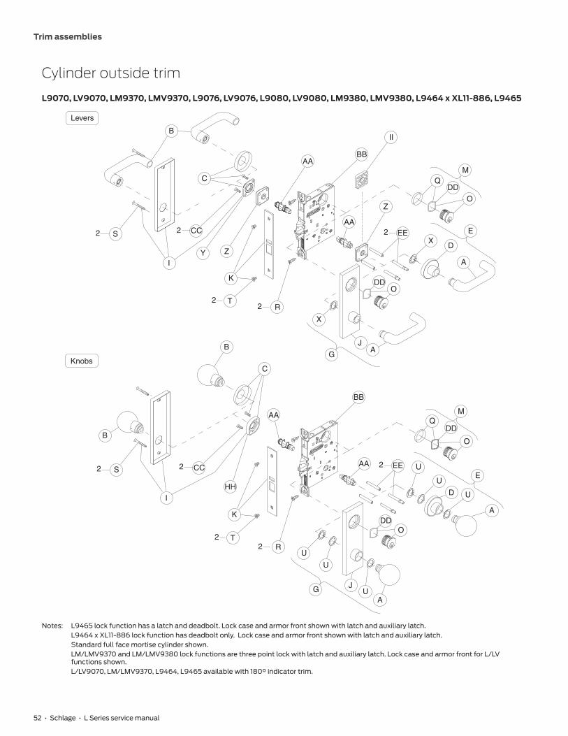
52 • Schlage • L Series service manual
Trim assemblies
Cylinder outside trim
L9070, LV9070, LM9370, LMV9370, L9076, LV9076, L9080, LV9080, LM9380, LMV9380, L9464 x XL11-886, L9465
EU
U
D U
A
M
O
Q
O
R T
A
U
U
J U G
CC
AA
AA
DD
DD
BB
HH
B
C
K
I
2
2 2
2
S
B
X E
O
DD
BBAA
Q M
D
A Z
B
I
CC S
Y
X
G
J A
EE AA
Z
DD O
C
II
K
R
Levers
Knobs
2
2
2
2
EE 2
T 2
Notes: L9465 lock function has a latch and deadbolt. Lock case and armor front shown with latch and auxiliary latch. L9464 x XL11-886 lock function has deadbolt only. Lock case and armor front shown with latch and auxiliary latch. Standard full face mortise cylinder shown. LM/LMV9370 and LM/LMV9380 lock functions are three point lock with latch and auxiliary latch. Lock case and armor front for L/LV
functions shown. L/LV9070, LM/LMV9370, L9464, L9465 available with 180° indicator trim.

53 • Schlage • L Series service manual
Trim assemblies
P/N Description
L90
70
LV9
070
LM9
370
LMV
937
0
L90
76
LV9
076
L90
80
LV9
08
0
LM9
380
LMV
938
0
L94
64
x X
L11-
88
6
L94
65
A 09-401 Outside knob and lever • • • • • • • • • • • •B 09-402 Inside knob and lever • • • • • • • • • • • •C 09-403 Inside rose • • • • • • • • • • • •D 09-404 Outside rose and bushing • • • • • • • • • • • •
EOutside rose and knob/lever:09-506 All designs except AST, AVA, MER • • • • • • • • • • • •09-655 AST, AVA, MER • • • • • • • • •
G 09-553 Outside escutcheon x knob/lever (except 93 lever), L and N x full face cylinder • • • • • • • • • • • •I 09-632 Inside escutcheon for knob/lever, L and N x blank • • • • • • • • • • • •
J09-639 Outside escutcheon and bushing x knob/lever (except 93 lever),
L and N x full face cylinder • • • • • • • • • • • •
09-652 Outside N escutcheon and bushing x 93 lever, full face cylinder • • • • • • • • • • •
K
1Z\v" armor front x Schlage logo:09-663 Latch and auxiliary latch • • • • • • • •09-664 Latch and deadbolt •09-665 Deadbolt •09-713 Latch, auxiliary latch less UL stamp • •
M30-000 Full face cylinder with compression ring and spring , clover leaf cam • •30-001 Full face cylinder with compression ring and spring , clover leaf cam • • • • • • • • • •
O30-019 Full face cylinder with compression spring , clover leaf cam • •30-021 Full face cylinder with compression spring , clover leaf cam • • • • • • • • • •
Q 36-083 Compression ring and spring • • • • • • • • • • • •R C203-736 Case mounting screw pack • • • • • • • • • • • •
SEscutcheon thru-bolts/screws:K510-389 N escutcheon 2 2 2 2 2 2 2 2 2 2 2 2L583-120 L escutcheon 2 2 2 2 2 2 2 2 2 2 2 2
T K110-020 Armor screw pack • • • • • • • • • • • •U K110-550 Knob truarc rings and spacer pack • • • • • • • • • • • •X L283-030 Lever truarc rings • • • • • • • • • • • •Y L283-031 Inside lever mounting plate • • • • • • • • • • • •Z L283-040 Lever spring cage 2 2 2 2 2 2 • 2 2 2 • 2AA L283-060 Spindle and spring 2 2 2 2 2 2 2 2 2 2 2 2
BB
Assembled lock case:L283-039 Classroom holdback •L283-133 Office, classroom, apartment security •L283-134 Storeroom •L283-139 Deadbolt retract x inside knob/lever •L283-140 Closet, storeroom and dormitory •L283-142 Electrically lockedL283-143 Electrically unlockedL283-170 Office, classroom, apartment security, LV •L283-172 Classroom holdback, LV •L283-173 Storeroom, LV •L283-174 Electrically locked, LVL283-175 Electrically unlocked, LVL283-316 Office, inner entry x multipoint • •L283-317 Office, inner entry x multipoint, LV • •
CC L583-066 Mounting trim screws, wood/metal door x rose/escutcheon x knob/lever 2 2 2 2 2 2 2 2 2 2 2 2DD L583-195 Compression spring • • • • • • • • • • • •
EEL583-212 Mounting posts, L 2 2 2 2 2 2 2L583-497 Mounting posts, LV 2 2 2 2 2
HH L583-321 Inside knob mounting plate • • • • • • •II L583-322 Outside lever spacer • •

54 • Schlage • L Series service manual
Trim assemblies
Electrically locked/unlocked outside trim
L9090EL/EU, LV9090EL/EU
B
CCS
I
22
2
2
2
Y Z
K
T
R
C
BB
E
DXEE
Z
AA
X
G
JA
B C
BB
E
AU
DU
UEE
AA
CC
HH
S
I
2
2
2
2
2
K
T
R U
U
GJ
UA
Levers
Knobs
A

55 • Schlage • L Series service manual
Trim assemblies
P/N Description
L90
90
EL/
EU
LV9
09
0 E
L/EU
A 09-401 Outside knob and lever • •B 09-402 Inside knob and lever • •C 09-403 Inside rose • •D 09-404 Outside rose and bushing • •
EOutside rose and knob/lever:09-506 All designs except AST, AVA, MER • •09-655 AST, AVA, MER • •
G 09-550 Outside escutcheon x knob/lever (except 93 lever), L and N x blank • •I 09-632 Inside escutcheon for knob/lever, L and N x blank • •
J09-636 Outside escutcheon and bushing x knob/lever (except 93 lever), L and N x blank • •09-652 Outside escutcheon and bushing x 93 lever, full face cylinder • •
K 09-663 1Z\v" armor front x Schlage logo, latch and auxiliary latch • •R C203-736 Case mounting screw pack • •
SEscutcheon thru-bolts/screws:K510-389 N escutcheon 2 2L583-120 L escutcheon 2 2
T K110-020 Armor screw pack • •U K110-550 Knob truarc rings and spacer pack • •X L283-030 Lever truarc rings • •Y L283-031 Inside lever mounting plate • •Z L283-040 Lever spring cage 2 2AA L283-060 Spindle and spring 2 2
BBL283-347 Assembled lock case, electrically locked or unlocked one side •L283-597 Assembled lock case, electrically locked or unlocked one side, LV •
CC L583-066 Mounting trim screws, wood/metal door x rose/escutcheon x knob/lever 2 2
EEL583-212 Mounting posts, L 2L583-497 Mounting posts, LV 2
HH L583-321 Inside knob mounting plate • •
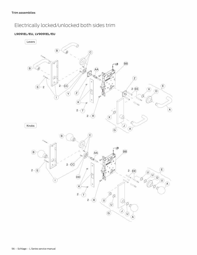
56 • Schlage • L Series service manual
Trim assemblies
Electrically locked/unlocked both sides trim
L9091EL/EU, LV9091EL/EU
B
CCS
I
22
2
2
2
Y Z
K
T
R
C
BB
E
A
DXEE
Z
AA
X
G
JA
C
BB
E
AU
DU
UEE
AA
CC
HH
S
I
2
2
2
2
2
K
T
R U
U
GJ
UA
Levers
Knobs
B
B
B

57 • Schlage • L Series service manual
Trim assemblies
P/N Description
L90
91 E
L/EU
LV9
09
1 EL/
EE
A 09-401 Outside knob and lever • •B 09-402 Inside knob and lever • •C 09-403 Inside rose • •D 09-404 Outside rose and bushing • •
EOutside rose and knob/lever:09-506 All designs except AST, AVA, MER • •09-655 AST, AVA, MER • •
G 09-550 Outside escutcheon x knob/lever (except 93 lever), L and N x blank • •I 09-632 Inside escutcheon for knob/lever, L and N x blank • •
J09-636 Outside escutcheon and bushing x knob/lever (except 93 lever), L and N x blank • •09-652 Outside escutcheon and bushing x 93 lever, full face cylinder • •
K 09-663 1Z\v" armor front x Schlage logo, latch and auxiliary latch • •R C203-736 Case mounting screw pack • •
SEscutcheon thru-bolts/screws:K510-389 N escutcheon 2 2L583-120 L escutcheon 2 2
T K110-020 Armor screw pack • •U K110-550 Knob truarc rings and spacer pack • •X L283-030 Lever truarc rings • •Y L283-031 Inside lever mounting plate • •Z L283-040 Lever spring cage 2 2AA L283-064 Spindle and spring • •
BBL283-395 Assembled lock case, electrically locked or unlocked both sides, L •L283-597 Assembled lock case, electrically locked or unlocked one side, LV •
CC L583-066 Mounting trim screws, wood/metal door x rose/escutcheon x knob/lever 2 2
EEL583-212 Mounting posts, L 2L583-497 Mounting posts, LV 2
HH L583-321 Inside knob mounting plate • •

58 • Schlage • L Series service manual
Trim assemblies
Electrically locked/unlocked outside trim, single cylinderL9092EL/EU, LV9092EL/EU, L9492EL/EU, LV9492EL/EU
B
CCS
I
22
2
2
2
Y Z
K
T
R
C
BB M
DDQ
O
E
DXEE
Z
AA
DD
O
X
G
JA
DDO
B C
BB
P
MQ
DD
O
E
AU
DU
UEEAA
CC
HH
S
I
2
2
2
2
2
K
T
R U
U
GJ
UA
O
DD
Levers
Knobs
P
A
Notes: L9492, LV9492 lock function has a latch, auxiliary latch, deadbolt and inside thumb turn. Lock case and armor front shown with latch and auxiliary latch.
Standard full face mortise cylinder shown.

59 • Schlage • L Series service manual
Trim assemblies
P/N Description
L90
92
EL/E
U
LV9
09
2 EL
/EU
L949
2 EL
/EU
LV9
492
EL/E
U
A 09-401 Outside knob and lever • • • •B 09-402 Inside knob and lever • • • •C 09-403 Inside rose • • • •D 09-404 Outside rose and bushing • • • •
EOutside rose and knob/lever:09-506 All designs except AST, AVA, MER • • • •09-655 AST, AVA, MER • • • •
F 09-544 Thumbturn • •G 09-553 Outside escutcheon x knob/lever (except 93 lever), L and N x full face cylinder • •
IInside escutcheon for knob/lever:09-633 L and N x thumbturn • •09-632 L and N x blank • •
J09-639 Outside escutcheon and bushing x knob/lever (except 93 lever), L and N x full face cylinder • • • •09-652 Outside escutcheon and bushing x 93 lever, full face cylinder • • • •
K1Z\v" armor front x Schlage logo:09-663 Latch and auxiliary latch • •09-666 Latch, auxiliary latch and deadbolt • •
M 30-001 Full face cylinder with compression ring and spring , clover leaf cam • • • •O 30-021 Full face cylinder with compression spring , clover leaf cam • • • •P 36-082 Blocking ring • • • •Q 36-083 Compression ring and spring • • • •R C203-736 Case mounting screw pack • • • •
SEscutcheon thru-bolts/screws:K510-389 N escutcheon 2 2 2 2L583-120 L escutcheon 2 2 2 2
T K110-020 Armor screw pack • • • •U K110-550 Knob truarc rings and spacer pack • • • •X L283-030 Lever truarc rings • • • •Y L283-031 Inside lever mounting plate • • • •Z L283-040 Lever spring cage 2 2 2 2AA L283-060 Spindle and spring 2 2 2 2
BB
Assembled lock caseL283-347 Electrically locked or unlocked one side, L •L283-467 Electrically locked or unlocked one side with deadbolt, L •L283-597 Electrically locked or unlocked one side, LV •L283-599 Electrically locked or unlocked one side with deadbolt, LV •
CC L583-066 Mounting trim screws, wood/metal door x rose/escutcheon x knob/lever 2 2 2 2DD L583-195 Compression springs • • • •
EEL583-212 Mounting posts, L 2 2L583-497 Mounting posts, LV 2 2
HH L583-321 Inside knob mounting plate • • • •

60 • Schlage • L Series service manual
Trim assemblies
Electrically locked/unlocked both sides trim, single cylinder
L9093EL/EU, LV9093EL/EU, L9493EL/EU, LV9493EL/EU
B
CCS
I
22
2
2
2
Y Z
K
T
R
C
BBM
DDQ
O
E
A
DX
EE
Z
DDO
X
G
JA
C
BB
P
MQ
DD
O
E
AU
DU
U
EECC
HH
S
I
2
2
2
22
K
T
R U
U
GJ
UA
ODD
Levers
Knobs
P
B
B
B
Notes: L9493, LV9493 lock function has a latch, auxiliary latch, deadbolt and inside thumb turn. Lock case and armor front shown with latch and auxiliary latch.
Standard full face mortise cylinder shown.

61 • Schlage • L Series service manual
Trim assemblies
P/N Description
L90
93
EL/E
U
LV9
09
3 EL
/EU
L949
3 EL
/EU
LV9
493
EL/E
U
A 09-401 Outside knob and lever • • • •B 09-402 Inside knob and lever • • • •C 09-403 Inside rose • • • •D 09-404 Outside rose and bushing • • • •
EOutside rose and knob/lever:09-506 All designs except AST, AVA, MER • • • •09-655 AST, AVA, MER • • • •
F 09-544 Thumbturn • •G 09-553 Outside escutcheon x knob/lever (except 93 lever), L and N x full face cylinder • • • •
IInside escutcheon for knob/lever:09-633 L and N x thumbturn • •09-632 L and N x blank • •
J09-639 Outside escutcheon and bushing x knob/lever (except 93 lever), L and N x full face cylinder • • • •09-652 Outside escutcheon and bushing x 93 lever, full face cylinder • • • •
K1Z\v" armor front x Schlage logo:09-663 Latch and auxiliary latch • •09-666 Latch, auxiliary latch and deadbolt • •
M 30-001 Full face cylinder with compression ring and spring , clover leaf cam • • • •O 30-021 Full face cylinder with compression spring , clover leaf cam • • • •P 36-082 Blocking ring • • • •Q 36-083 Compression ring and spring • • • •R C203-736 Case mounting screw pack • • • •
SEscutcheon thru-bolts/screws:K510-389 N escutcheon 2 2 2 2L583-120 L escutcheon 2 2 2 2
T K110-020 Armor screw pack • • • •U K110-550 Knob truarc rings and spacer pack • • • •X L283-030 Lever truarc rings • • • •Y L283-031 Inside lever mounting plate • • • •Z L283-040 Lever spring cage 2 2 2 2AA L283-064 Spindle and spring • • • •
BB
Assembled lock case,L283-395 Electrically locked or unlocked both side, L •L283-468 Electrically locked or unlocked both sides with deadbolt, L •L283-598 Electrically locked or unlocked both side, LV •L283-600 Electrically locked or unlocked both sides with deadbolt, LV •
CC L583-066 Mounting trim screws, wood/metal door x rose/escutcheon x knob/lever 2 2 2 2DD L583-195 Compression springs • • • •
EEL583-212 Mounting posts, L 2 2L583-497 Mounting posts, LV 2 2
HH L583-321 Inside knob mounting plate • • • •

62 • Schlage • L Series service manual
Trim assemblies
Electrically locked/unlocked outside trim, double cylinder
L9094EL/EU, LV9094EL/EU, L9494EL/EU, LV9494EL/EU
ODD
B
CCS
I
22
2
2
2
Y Z
K
T
R
C
BB M
DDQ
O
E
A
DXEE
Z
AA
DDO
X
G
JA
DDO
B C
BBP
MQ
DD
O
E
AU
DU
UEEAA
CC
HH
S
I
2
2
2
2
2
K
T
R U
U
GJ
UA
ODD
Levers
Knobs
P
ODD
QP
M
P
M
ODD
Q
Notes: L9494 lock function has a latch, auxiliary latch, deadbolt and inside thumb turn. Lock case and armor front shown with latch and auxiliary latch.
Standard full face mortise cylinder shown.

63 • Schlage • L Series service manual
Trim assemblies
P/N Description
L90
94
EL/
EU
LV9
09
4 E
L/EU
L949
4 E
L/EU
LV9
494
EL/
EU
A 09-401 Outside knob and lever • • • •B 09-402 Inside knob and lever • • • •C 09-403 Inside rose • • • •D 09-404 Outside rose and bushing • • • •
EOutside rose and knob/lever:09-506 All designs except AST, AVA, MER • • • •09-655 AST, AVA, MER • • • •
F 09-544 Thumbturn • •G 09-553 Outside escutcheon x knob/lever (except 93 lever), L and N x full face cylinder • • • •
IInside escutcheon for knob/lever:09-633 L and N x thumbturn • •09-635 L and N x full face cylinder • •
J09-639 Outside escutcheon and bushing x knob/lever (except 93 lever), L and N x full face cylinder • • • •09-652 Outside escutcheon and bushing x 93 lever, full face cylinder • • • •
K1Z\v" armor front x Schlage logo:09-663 Latch and auxiliary latch • •09-666 Latch, auxiliary latch and deadbolt • •
M 30-001 Full face cylinder with compression ring and spring , clover leaf cam • • • •O 30-021 Full face cylinder with compression spring , clover leaf cam • • • •P 36-082 Blocking ring • • • •Q 36-083 Compression ring and spring • • • •R C203-736 Case mounting screw pack • • • •
SEscutcheon thru-bolts/screws:K510-389 N escutcheon 2 2 2 2L583-120 L escutcheon 2 2 2 2
T K110-020 Armor screw pack • • • •U K110-550 Knob truarc rings and spacer pack • • • •X L283-030 Lever truarc rings • • • •Y L283-031 Inside lever mounting plate • • • •Z L283-040 Lever spring cage 2 2 2 2AA L283-060 Spindle and spring 2 2 2 2
BB
Assembled lock case:L283-347 Electrically locked or unlocked one side, L •L283-467 Electrically locked or unlocked one side with deadbolt, L •L283-597 Electrically locked or unlocked one side, LV •L283-599 Electrically locked or unlocked one side with deadbolt, LV •
CC L583-066 Mounting trim screws, wood/metal door x rose/escutcheon x knob/lever 2 2 2 2DD L583-195 Compression springs • • • •
EEL583-212 Mounting posts, L 2 2L583-497 Mounting posts, LV 2 2
HH L583-321 Inside knob mounting plate • • • •

64 • Schlage • L Series service manual
Trim assemblies
Electrically locked/unlocked both sides trim, double cylinder
L9095EL/EU, LV9095EL/EU, L9495EL/EU, LV9495EL/EU
ODD B
CCS
I
22
2
2
2
Y Z
K
T
R
C
BB M
DDQ
O
E
A
DX
EE
Z
DDO
X
G
JA
DDO
C
BB
P
MQ
DD
O
E
AU
DU
U
EECC
HH
S
I
2
2
2
22
K
T
R U
U
GJ
UA
ODD
Levers
Knobs
P
P
M
O
DD Q
ODD
Q
P
M
B
B
B
Notes: L9495 lock function has a latch, auxiliary latch, deadbolt and inside thumb turn. Lock case and armor front shown with latch and auxiliary latch.
Standard full face mortise cylinder shown.

65 • Schlage • L Series service manual
Trim assemblies
P/N Description
L90
95
EL/E
U
LV9
09
5 EL
/EU
L949
5 EL
/EU
LV9
495
EL/E
U
A 09-401 Outside knob and lever • • • •B 09-402 Inside knob and lever • • • •C 09-403 Inside rose • • • •D 09-404 Outside rose and bushing • • • •
EOutside rose and knob/lever:09-506 All designs except AST, AVA, MER • • • •09-655 AST, AVA, MER • • • •
F 09-544 Thumbturn • •G 09-553 Outside escutcheon x knob/lever (except 93 lever), L and N x full face cylinder • • • •
IInside escutcheon for knob/lever:09-633 L and N x thumbturn • •09-635 L and N x full face cylinder • •
J09-639 Outside escutcheon and bushing x knob/lever (except 93 lever), L and N x full face cylinder • • • •09-652 Outside escutcheon and bushing x 93 lever, full face cylinder • • • •
K1Z\v" armor front x Schlage logo:09-663 Latch and auxiliary latch • •09-666 Latch, auxiliary latch and deadbolt • •
M 30-001 Full face cylinder with compression ring and spring , clover leaf cam • • • •O 30-021 Full face cylinder with compression spring , clover leaf cam • • • •P 36-082 Blocking ring • • • •Q 36-083 Compression ring and spring • • • •R C203-736 Case mounting screw pack • • • •
SEscutcheon thru-bolts/screws:K510-389 N escutcheon 2 2 2 2L583-120 L escutcheon 2 2 2 2
T K110-020 Armor screw pack • • • •U K110-550 Knob truarc rings and spacer pack • • • •X L283-030 Lever truarc rings • • • •Y L283-031 Inside lever mounting plate • • • •Z L283-040 Lever spring cage 2 2 2 2AA L283-064 Spindle and spring • • • •
BB
Assembled lock case,L283-395 Electrically locked or unlocked both sides, L •L283-468 Electrically locked or unlocked both sides with deadbolt, L •L283-598 Electrically locked or unlocked both sides, LV •L283-600 Electrically locked or unlocked both sides with deadbolt, LV •
CC L583-066 Mounting trim screws, wood/metal door x rose/escutcheon x knob/lever 2 2 2 2DD L583-195 Compression springs • • • •
EEL583-212 Mounting posts, L 2 2L583-497 Mounting posts, LV 2 2
HH L583-321 Inside knob mounting plate • • • •
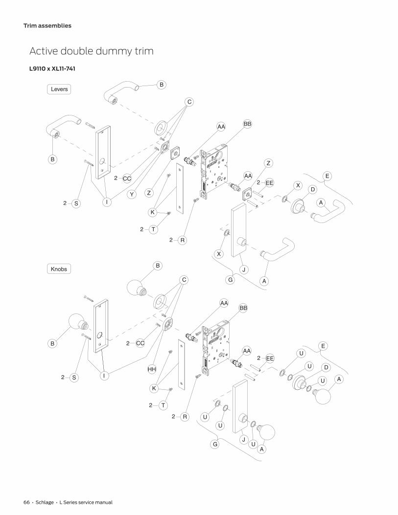
66 • Schlage • L Series service manual
Trim assemblies
Active double dummy trim
L9110 x XL11-741
B
CC
C
B
AA BB
Z
E
X EE AA
D
A S IY Z
K
T
R
X
J
A G
BB AA
C
B
B
S I
2
2
2
CC
HH
K
T
R U
U
G J
U A
AA EE
E U
U
U A
D
Levers
Knobs
2 2
2
2
2
2
2

67 • Schlage • L Series service manual
Trim assemblies
P/N Description
A 09-401 Outside knob and leverB 09-402 Inside knob and leverC 09-403 Inside roseD 09-404 Outside rose and bushing
EOutside rose and knob/lever:09-506 All designs except AST, AVA, MER09-655 AST, AVA, MER
G 09-550 Outside escutcheon x knob/lever (except 93 lever) L and N x blankI 09-632 Inside escutcheon for knob/lever, L and N x blankJ 09-636 Outside escutcheon and bushing by knob/lever except 93 lever, L and N x blankK 09-661 1Z\v" armor front x Schlage logo, blankR C203-736 Case mounting screw pack
SEscutcheon thru-bolts/screws (qty 2 each):K510-389 N escutcheonL583-120 L escutcheon
T K110-020 Armor screw packU K110-550 Knob truarc rings and spacer packX L283-030 Lever truarc ringsY L283-031 Inside lever mounting plateZ L283-040 Lever spring cage (qty 2)AA L283-060 Spindle and spring (qty 2)BB XL11-741 Assembled lock case, double dummy with active knob/lever ‡CC L583-066 Mounting plate screws (qty 2), wood/metal door x rose/escutcheon x knob/lever except single dummyEE L583-212 Mounting posts (qty 2)HH L583-321 Inside knob mounting plate
‡ Not sold separately as a part.

68 • Schlage • L Series service manual
Trim assemblies
Single dummy with case trim
L9175, L9177 (discontinued)
B
S I
CC
B
C
Y II
AA BB
R K
JJ
B
C
AA BB HH
CC
B
S I
K
T
T
R
For discontinued function L9177 orderL9175 and armor strike separatelyand specify hand of inactive door.Mount in place of blank armor.
For discontinued function L9177 orderL9175 and armor strike separatelyand specify hand of inactive door.Mount in place of blank armor.
2
Levers
Knobs
2
2
2
2
2
2
2
JJ

69 • Schlage • L Series service manual
Trim assemblies
P/N Description
L917
5
L917
7
B 09-402 Inside knob and lever • •C 09-403 Inside rose • •I 09-632 Inside escutcheon for knob/lever, L and N x blank • •K 09-661 1Z\v" armor front x Schlage logo, blank • •R C203-736 Case mounting screw pack • •
SEscutcheon thru-bolts/screws:L583-133 N escutcheon 2 2L583-287 L escutcheon 2 2
T K110-020 Armor screw pack • •Y L283-031 Inside lever mounting plate • •AA L283-060 Spindle and spring • •BB L283-144 Assembled lock case, single dummy with case • •
CCMounting plate screws:L583-290 Wood/metal door x rose/escutcheon x lever 2 2L583-291 Wood/metal door x rose/escutcheon x knob 2 2
HH L583-321 Inside knob mounting plate • •II L583-322 Outside lever spacer • •JJ 10-091 Armor strike •

70 • Schlage • L Series service manual
Trim assemblies
Double dummy with case trim
L9176, L9178 (discontinued)
B
S
Y
CC
I
2
2
2
2
II AA
C
B
BB
AAII
EE XD
A
E
A
JG
X
R
T
K
JJ
B
B
S I
CC
HHAA BB
AAEE
EU
UD
UA
AU
JG
U
U
R
T
K
JJ
C
For discontinued function L9178order L9176 and armor strike separatelyand specify hand of inactive door.Mount in place of blank armor.
For discontinued function L9178order L9176 and armor strike separatelyand specify hand of inactive door.Mount in place of blank armor.
2
2
2
2
2
2
Levers
Knobs

71 • Schlage • L Series service manual
Trim assemblies
P/N Description
L917
6
L917
8
A 09-401 Outside knob and lever • •B 09-402 Inside knob and lever • •C 09-403 Inside rose • •D 09-404 Outside rose and bushing • •E 09-506 Outside rose and knob/lever: All designs except AST, AVA, MER • •G 09-550 Outside escutcheon x knob/lever except 93 lever, L and N x blank • •I 09-632 Inside escutcheon for knob/lever, L and N x blank • •
J09-636 Outside escutcheon and bushing x knob/lever except 93 lever, L and N x blank • •09-650 Outside escutcheon and bushing x 93 lever, blank • •
K 09-661 1Z\v" armor front x Schlage logo, blank • •R C203-736 Case mounting screw pack • •
SEscutcheon thru-bolts/screws:L583-133 N escutcheon 2 2L583-287 L escutcheon 2 2
T K110-020 Armor screw pack • •U K110-550 Knob truarc rings and spacer pack • •X L283-030 Lever truarc rings • •Y L283-031 Inside lever mounting plate • •AA L283-060 Spindle and spring 2 2BB L283-145 Assembled lock case, double dummy with case • •CC L583-066 Mounting plate screws: Wood/metal door x rose/escutcheon x knob/lever except single dummy 2 2EE L583-212 Mounting posts 2 2HH L583-321 Inside knob mounting plate 2 2II L583-322 Outside lever spacer 2 2JJ 10-091 Armor strike •

72 • Schlage • L Series service manual
Trim assemblies
Deadbolt trim
L9460, L9462, L9463, L9464
F
BB
Q DD
O
M R
K
M
DD
O
Q P
BB
P
P
Q DD
O
M R
K
T
L BB
K
T
R M
Q DD
O
K
T
R M
Q DD
O
BB
T
2
L9463P
2
2
2
2
2
2
2
L9464P
L9460P L9462P
Notes: Standard full face mortise cylinder shown. Available with 180° indicator trim.

73 • Schlage • L Series service manual
Trim assemblies
P/N Description
L94
60
L94
62
L94
63
L94
64
F 09-544 Thumbturn •K 09-665 1Z\v" armor front x Schlage logo, deadbolt • • • •L 09-905 Classroom turn and 1Z\," blocking ring •M 30-001 Full face cylinder with compression ring and spring , clover leaf cam • 2 • •O 30-021 Full face cylinder with compression spring , clover leaf cam • 2 • •P 36-082 Blocking ring 2 •Q 36-083 Compression ring and spring • 2 • •R C203-736 Case mounting screw pack • • • •T K110-020 Armor screw pack • • • •BB L283-139 Assembled lock case, L946X deadbolt • • • •CC L583-066 Mounting trim screws, wood/metal door x rose/escutcheon x knob/lever 2 2 2 2DD L583-195 Compression springs • 2 • •

74 • Schlage • L Series service manual
Trim assemblies
Deadbolt with fixed double dummy trim
L9460 x XL11-635
B
CC
C
B
AA BB
II
E X EE
AA
D
A
O DD
M
Q
O DD
F
S
I Y II
K
T
R X
J
A G
AA BB
F
C
B
B
S
I
CC
HH
K
T
R U U
G
J
U A
AA E U
U
U A
O DD
M
Q
O DD
D
2
2
2
2
2
2
2
2
2
Levers
Knobs
EE 2
Notes: Standard full face mortise cylinder shown. Available with 180° indicator trim.

75 • Schlage • L Series service manual
Trim assemblies
P/N Description
A 09-401 Outside knob and leverB 09-402 Inside knob and leverC 09-403 Inside roseD 09-404 Outside rose and bushing
EOutside rose and knob/lever:09-506 All designs except AST, AVA, MER09-655 AST, AVA, MER
F 09-544 ThumbturnG 09-553 Outside escutcheon x knob/lever (except 93 lever), L and N x full face cylinder
I09-548 Inside escutcheon for knob/lever: L x thumbturn09-642 Inside escutcheon for knob/lever: N x thumbturn
J 09-639 Outside escutcheon and bushing x knob/lever (except 93 lever), L and N x full face cylinderK 09-665 1Z\v" armor front x Schlage logo, deadboltM 30-001 Full face cylinder with compression ring and spring , clover leaf camO 30-021 Full face cylinder with compression spring , clover leaf camQ 36-083 Compression ring and springR C203-736 Case mounting screw pack
SEscutcheon thru-bolts/screws (qty 2 each):K510-389 N escutcheonL583-120 L escutcheon
T K110-020 Armor screw packU K110-550 Knob truarc rings and spacer packX L283-030 Lever truarc ringsY L283-031 Inside lever mounting plateAA L283-060 Spindle and spring (qty 2)BB XL11-661 Assembled lock case, deadbolt with fixed trim ‡CC L583-066 Mounting trim screws, wood/metal door x rose/escutcheon x knob/lever (qty 2)DD L583-195 Compression springEE L583-212 Mounting posts, (qty 2)HH L583-321 Inside knob mounting plateII L583-322 Outside lever spacer (qty 2)
‡ Not sold separately as a part.

76 • Schlage • L Series service manual
Trim assemblies
Fixed outside x turn trim
L9412-XL11-907, L9460 x XL11-886, L9480, LV9480, L9485, LV9485
EE 2
EE 2
EE 2
EE 2
B
S
I
CC
Y Z
K
T
R X
G
J
A B
AA BB
CC B
S
I HH
K
T
AA
M
DD Q
O
E U U
D U
A
O DD
R U U
J
U AG
O DD
AAII
X D
E
A
O DD
Q M
BBAA
F
F
C
C
B
2
2
2
2
2
2
2
2
Levers
Knobs
Notes: L9460 x XL11-886 lock function has a deadbolt only. Lock case and armor front shown with latch, auxiliary latch, and deadbolt. Standard full face mortise cylinder shown. L9460 x XL11-886 and L/LV9485 available with 180° indicator trim. LV9480 available with lever x lever trim only. L9412 x XL11-907 lock function has a blank outside escutcheon.
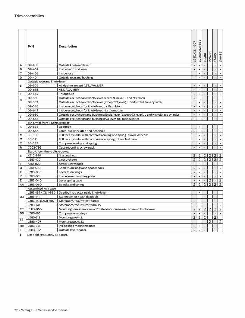
77 • Schlage • L Series service manual
Trim assemblies
P/N Description
L94
12/X
L11-
90
7
L94
60
/XL1
1-8
86
L94
80
LV9
48
0
L94
85
LV9
48
5
A 09-401 Outside knob and lever • • • • • •B 09-402 Inside knob and lever • • • • • •C 09-403 Inside rose • • • • •D 09-404 Outside rose and bushing • • • • •
EOutside rose and knob/lever:09-506 All designs except AST, AVA, MER • • • • • •09-655 AST, AVA, MER • • • • • •
F 09-544 Thumbturn • • • • • •
G09-550 Outside escutcheon x knob/lever except 93 lever, L and N x blank •09-553 Outside escutcheon x knob/lever (except 93 lever), L and N x full face cylinder • • • • •
I09-548 Inside escutcheon for knob/lever, L x thumbturn • • • • • •09-642 Inside escutcheon for knob/lever, N x thumbturn • • • • • •
J09-639 Outside escutcheon and bushing x knob/lever (except 93 lever), L and N x full face cylinder • • • • • •09-652 Outside escutcheon and bushing x 93 lever, full face cylinder • • • • •
K1Z\v" armor front x Schlage logo:09-665 Deadbolt •09-666 Latch, auxiliary latch and deadbolt • • • • •
M 30-001 Full face cylinder with compression ring and spring , clover leaf cam • • • • •O 30-021 Full face cylinder with compression spring , clover leaf cam • • • • •Q 36-083 Compression ring and spring • • • • •R C203-736 Case mounting screw pack • • • • • •
SEscutcheon thru-bolts/screws:K510-389 N escutcheon 2 2 2 2 2 2L583-120 L escutcheon 2 2 2 2 2 2
T K110-020 Armor screw pack • • • • • •U K110-550 Knob truarc rings and spacer pack • • • • • •X L283-030 Lever truarc rings • • • • • •Y L283-031 Inside lever mounting plate • • • • • •Z L283-040 Lever spring cage • • • 2 • 2AA L283-060 Spindle and spring 2 2 2 2 2 2
BB
Assembled lock case,L283-139 x XL11-886 Deadbolt retract x inside knob/lever ‡ •L283-141 Storeroom lock with deadbolt • •L283-141 x XL11-907 Storeroom/faculty restroom ‡ •L283-178 Storeroom/faculty restroom, LV • •
CC L583-066 Mounting trim screws, wood/metal door x rose/escutcheon x knob/lever 2 2 2 2 2 2DD L583-195 Compression springs • • • • • •
EEL583-212 Mounting posts, L 2 2 2 2L583-497 Mounting posts, LV 2 2
HH L583-321 Inside knob mounting plate • • • •II L583-322 Outside lever spacer • • • •‡ Not sold separately as a part.

78 • Schlage • L Series service manual
Trim assemblies
Institution deadbolt trim
L9482 x XL11-543, LV9482 x XL11-543
EE 2
Levers
Knobs
O DD B
CC S
I Y II
AA
AA
K
T
R
C
M
O
DD Q
P
BBP
M
DD Q
O
E
A
D X
II
DD O
X
G
J A
DD O
B CO
DD Q
P
BB
P
M Q
DD
O
E
AU
DU
UEE
CC
HH
S
I
K
T
R U
U
GJ
UA
ODD
M
AA
AA 2
2
2
2
2
2
2
2 2
Note: Standard full face mortise cylinder shown.

79 • Schlage • L Series service manual
Trim assemblies
P/N Description
L94
82/
XL1
1-54
3
L V
94
82/
XL1
1-54
3
A 09-401 Outside knob and lever • •B 09-402 Inside knob and lever • •C 09-403 Inside rose • •D 09-404 Outside rose and bushing • •
EOutside rose and knob/lever:09-506 All designs except AST, AVA, MER • •09-655 AST, AVA, MER • •
G 09-553 Outside escutcheon x knob/lever (except 93 lever), L and N x full face cylinder • •I 09-635 Inside escutcheon for knob/lever, L and N x full face cylinder • •J 09-639 Outside escutcheon and bushing x knob/lever (except 93 lever), L and N x full face cylinder • •K 09-666 1Z\v" armor front x Schlage logo, latch, auxiliary latch and deadbolt • •M 30-001 Full face cylinder with compression ring and spring , clover leaf cam 2 2O 30-021 Full face cylinder with compression spring , clover leaf cam 2 2P 36-082 Blocking ring 2 2Q 36-083 Compression ring and spring • •R C203-736 Case mounting screw pack • •
SEscutcheon thru-bolts/screws:K510-389 N escutcheon 2 2L583-120 L escutcheon 2 2
T K110-020 Armor screw pack • •U K110-550 Knob truarc rings and spacer pack • •X L283-030 Lever truarc rings • •Y L283-031 Inside lever mounting plate • •Z L283-040 Lever spring cage 2AA L283-060 Spindle and spring 2 2
BBAssembled lock case,L283-146 x XL11-543 Institution deadbolt ‡ •L283-183 x XL11-543 Institution deadbolt ‡ •
CC L583-066 Mounting trim screws, wood/metal door x rose/escutcheon x knob/lever 2 2DD L583-195 Compression springs 2 2
EEL583-212 Mounting posts, L 2L583-497 Mounting posts, LV 2
HH L583-321 Inside knob mounting plate • •II L583-322 Outside lever spacer 2‡ Not sold separately as a part.

80 • Schlage • L Series service manual
Trim assemblies
Prison lock trim
L9485 x XL11-557
B
C
AA M
O DD
Q
BB
AA EE
E U
U D
U A
RT
K
CC
HH
2
2 2
2
Notes: Standard full face mortise cylinder shown. Available with knob x rose trim only. Furnished with tamper-resistant Torx® screws.

81 • Schlage • L Series service manual
Trim assemblies
P/N Description
A 09-401 Outside knob and leverB 09-402 Inside knob and leverC 09-403 Inside roseD 09-404 Outside rose and bushingE 09-506 Outside rose and knob/lever: All designs except AST, AVA, MERK 09-666 1Z\v" armor front x Schlage logo, latch, auxiliary latch and deadboltM 30-002 Full face cylinder with compression ring and spring , clover leaf cam, hotel (handed)O 30-022 Full face cylinder with compression spring , clover leaf cam, hotel (handed)Q 36-083 Compression ring and springR C203-736 Case mounting screw packT K110-020 Armor screw packU K110-550 Knob truarc rings and spacer pack
AAL283-060 Spindle and springXL11-766 Free spinning spindle and spring (inside) ‡
BB XL11-557 Prison ‡CC L583-066 Mounting trim screws, wood/metal door x rose/escutcheon x knob/lever (qty 2)DD L583-195 Compression springEE L583-212 Mounting posts, L (qty 2)HH L583-321 Inside knob mounting plate
‡ Not sold separately as a part.

82 • Schlage • L Series service manual
Trim assemblies
Hotel with indicator trim
L9486, LV9486, L9486 x L583-375, LV9486 x L583-375, L9496, LV9496
B
AA
F
BB
Q
M
DD
O
EE
H
AAX
D
E
A
B
F
AA BB M
Q DD
O
EU
UD
UA
H
EE
AA
C
CC
HH
K
T
R
RT
K
Z
CC
Y
2
22
2
2
2
2
2
EE2
EE2
C
Knobs
Levers
Z
II
Notes: L9496 and LV9496 lock functions have a latch and deadbolt. Lock case and armor front shown with latch, auxiliary latch, and deadbolt. Standard full face mortise cylinder shown.

83 • Schlage • L Series service manual
Trim assemblies
P/N Description
L94
86
LV9
48
6
L949
6
LV9
496
A 09-401 Outside knob and lever • • • •B 09-402 Inside knob and lever • • • •C 09-403 Inside rose • • • •D 09-404 Outside rose and bushing • • • •
EOutside rose and knob/lever:09-506 All designs except AST, AVA, MER • • • •09-655 AST, AVA, MER • •
F 09-544 Thumbturn • • • •
K09-664 1Z\v" armor front x Schlage logo, latch and deadbolt • •09-666 1Z\v" armor front x Schlage logo, latch, auxiliary latch and deadbolt • •
M30-001 Full face cylinder with compression ring and spring , clover leaf cam • •30-002 Full face cylinder with compression ring and spring , hotel (handed) • •
O30-021 Full face cylinder with compression spring , clover leaf cam • •30-022 Full face cylinder with compression spring , hotel (handed) • •
Q 36-083 Compression ring and spring • • • •R C203-736 Case mounting screw pack • • • •T K110-020 Armor screw pack • • • •U K110-550 Knob truarc rings and spacer pack • • • •X L283-030 Lever truarc rings • • • •Y L283-031 Inside lever mounting plate • • • •Z L283-040 Lever spring cage • 2 2 2AA L283-060 Spindle and spring 2 2 2 2
BB
Assembled lock case,L283-138 Corridor, classroom security x deadbolt •L283-141 Storeroom/faculty restroom •L283-177 Corridor, classroom security x deadbolt, LV •L283-178 Storeroom/faculty restroom, LV •
CC L583-066 Mounting trim screws, wood/metal door x rose/escutcheon x knob/lever 2 2 2 2DD L583-195 Compression spring • • • •
EEL583-212 Mounting posts, L 2 2L583-497 Mounting posts, LV 2 2
HH L583-321 Inside knob mounting plate • • • •II L583-322 Outside lever spacer • Available with "occupied" indicator option. Specify 09-611 x L583-375.
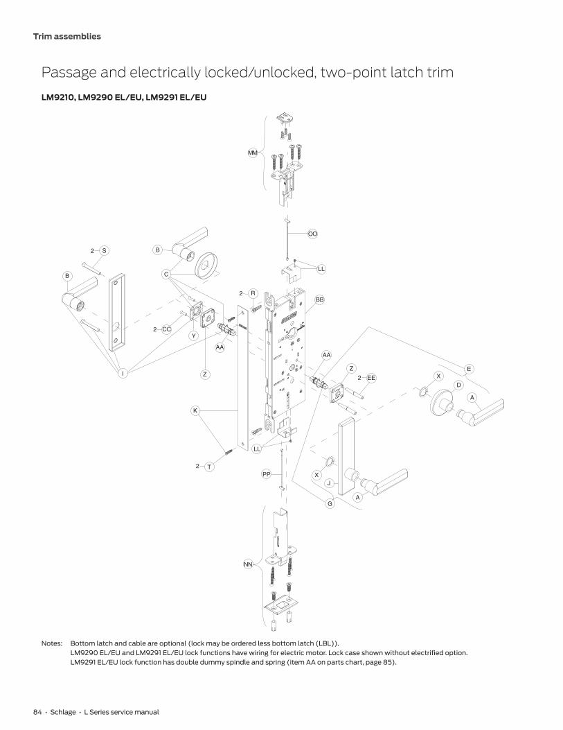
84 • Schlage • L Series service manual
Trim assemblies
Passage and electrically locked/unlocked, two-point latch trim
LM9210, LM9290 EL/EU, LM9291 EL/EU
XE
D
A
X
G
J
A
R2
EE
Z
2
AAAA
BB
LL
2 T
K
Z
2 CCY
C
B
B
2 S
I
LL
MM
OO
PP
NN
Notes: Bottom latch and cable are optional (lock may be ordered less bottom latch (LBL)). LM9290 EL/EU and LM9291 EL/EU lock functions have wiring for electric motor. Lock case shown without electrified option. LM9291 EL/EU lock function has double dummy spindle and spring (item AA on parts chart, page 85).

85 • Schlage • L Series service manual
Trim assemblies
P/N Description
LM9
210
LM9
290
EL/
EU
LM9
291 E
L/EU
A 09-401 Outside lever • • •B 09-402 Inside lever • • •C 09-403 Inside rose • • •D 09-404 Outside rose and bushing • • •
EOutside rose and lever:09-506 All designs except AST, AVA, MER • • •09-655 AST, AVA, MER • • •
G 09-550 Outside escutcheon x lever (except 93 lever) L and N x blank • • •I 09-632 Inside escutcheon for lever, L and N x blank • • •J 09-636 Outside escutcheon and bushing x lever except 93 lever, L and N x blank • • •K 24771248 1Z\v" armor front x Schlage logo • • •R C203-736 Case mounting screw pack • • •
SEscutcheon thru-bolts/screws:K510-389 N escutcheon 2 2 2L583-120 L escutcheon 2 2 2
T K110-020 Armor screw pack • • •X L283-030 Lever truarc rings • • •Y L283-031 Inside lever mounting plate • •Z L283-040 Lever spring cage 2 2 2
AAL283-060 Spindle and spring 2 2L283-064 Spindle and spring double dummy •
BB
Assembled lock case:24759599 Passage for two point latch •24759656 Electrically locked or unlocked outside, for two point latch •24759664 Electrically locked or unlocked both sides, for two point latch •
CC L583-066 Mounting trim screws, wood/metal door x rose/escutcheon x lever except single dummy 2 2 2EE L583-212 Mounting posts 2 2 2LL 24871584 Latch cover (qty 2) • • •MM 24721714 Top latch assembly • • •NN 24721722 Bottom latch assembly • • •OO 24691750 Top cable, door range 6'8" - 7'0" * • • •PP 24647265 Bottom cable • • • * For additional door range options , see "LM9200 Series two point lock" on page 185.

86 • Schlage • L Series service manual
Trim assemblies
Outside lever only, two-point latch trim
LM9225
R2
AA
BB
LL
2 T
K
Z
2 CCY
C
B
B
2 S
I
LL
MM
OO
PP
NN
Note: Bottom latch and cable are optional (lock may be ordered less bottom latch (LBL)).

87 • Schlage • L Series service manual
Trim assemblies
P/N Description
B 09-402 Inside leverC 09-403 Inside roseK 24771248 1Z\v" armor front x Schlage logoR C203-736 Case mounting screw packT K110-020 Armor screw packY L283-031 Inside lever mounting plateZ L283-040 Lever spring cageAA L283-060 Spindle and springBB 24759599 Assembled lock case, passage/exit for two point latchCC L583-066 Mounting trim screws, wood/metal door x rose/escutcheon x lever (except single dummy) (qty 2)LL 24871584 Latch cover (qty 2)MM 24721714 Top latch assemblyNN 24721722 Bottom latch assemblyOO 24691750 Top cable, door range 6'8" - 7'0" **PP 24647265 Bottom cableQQ L283-151* Mounting plate
* L283-151 part number for reference only. To order mounting plate, order by part number L283-150.
** For additional door range options , see "LM9200 Series two point lock" on page 185.

88 • Schlage • L Series service manual
Trim assemblies
Cylinder x turn, two-point latch trim
LM9250, LM9256
XE
D
A
X
G
J
A
R2
EE
Z
2
AA
AA
BB
LL
2 T
K
Z2 CC
Y
B
B
2 S
MM
OO
PP
NN
C
F
I
ODD
Q
M
ODD
LL
Note: Bottom latch and cable are optional (lock may be ordered less bottom latch (LBL)).
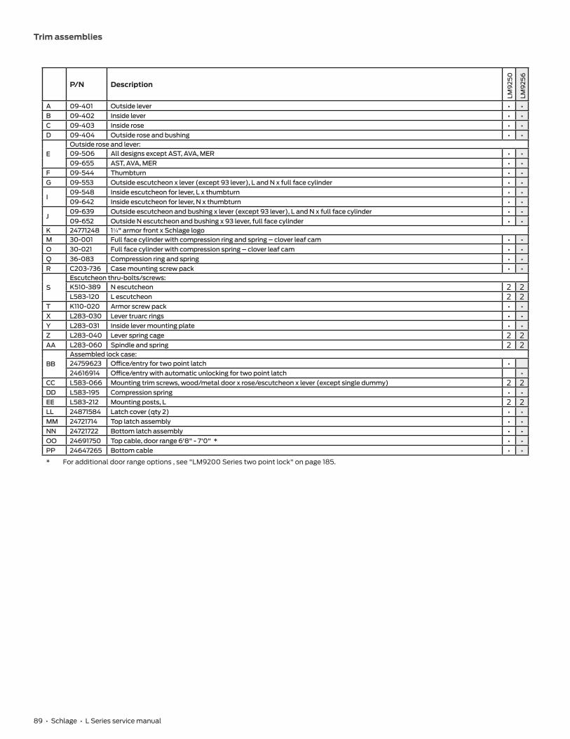
89 • Schlage • L Series service manual
Trim assemblies
P/N Description
LM9
250
LM9
256
A 09-401 Outside lever • •B 09-402 Inside lever • •C 09-403 Inside rose • •D 09-404 Outside rose and bushing • •
EOutside rose and lever:09-506 All designs except AST, AVA, MER • •09-655 AST, AVA, MER • •
F 09-544 Thumbturn • •G 09-553 Outside escutcheon x lever (except 93 lever), L and N x full face cylinder • •
I09-548 Inside escutcheon for lever, L x thumbturn • •09-642 Inside escutcheon for lever, N x thumbturn • •
J09-639 Outside escutcheon and bushing x lever (except 93 lever), L and N x full face cylinder • •09-652 Outside N escutcheon and bushing x 93 lever, full face cylinder • •
K 24771248 1Z\v" armor front x Schlage logoM 30-001 Full face cylinder with compression ring and spring – clover leaf cam • •O 30-021 Full face cylinder with compression spring – clover leaf cam • •Q 36-083 Compression ring and spring • •R C203-736 Case mounting screw pack • •
SEscutcheon thru-bolts/screws:K510-389 N escutcheon 2 2L583-120 L escutcheon 2 2
T K110-020 Armor screw pack • •X L283-030 Lever truarc rings • •Y L283-031 Inside lever mounting plate • •Z L283-040 Lever spring cage 2 2AA L283-060 Spindle and spring 2 2
BB Assembled lock case:24759623 Office/entry for two point latch •24616914 Office/entry with automatic unlocking for two point latch •
CC L583-066 Mounting trim screws, wood/metal door x rose/escutcheon x lever (except single dummy) 2 2DD L583-195 Compression spring • •EE L583-212 Mounting posts, L 2 2LL 24871584 Latch cover (qty 2) • •MM 24721714 Top latch assembly • •NN 24721722 Bottom latch assembly • •OO 24691750 Top cable, door range 6'8" - 7'0" * • •PP 24647265 Bottom cable • •* For additional door range options , see "LM9200 Series two point lock" on page 185.

90 • Schlage • L Series service manual
Trim assemblies
Outside cylinder and electrically locked/unlocked outside cylinder, two-point latch trim
LM9270, LM9280, LM9292 EL/EU, LM9293 EL/EU
XE
D
A
X
G
J
A
R2
EE
Z
2
AA
AA
BB
LL
2 T
K
Z2 CC
Y
B
B
2 S
MM
OO
PP
NN
C
I
ODD
Q
M
ODD
LL
Notes: Bottom latch and cable are optional (lock may be ordered less bottom latch (LBL)). LM9292 EL/EU and LM9293 EL/EU lock functions have wiring for electric motor. Lock case shown without electrified option. LM9293 EL/EU lock function has double dummy spindle and spring (item AA on parts chart, page 91).

91 • Schlage • L Series service manual
Trim assemblies
P/N Description
LM9
270
LM9
280
LM9
292
EL/E
U
LM9
293
EL/E
U
A 09-401 Outside lever • • • •B 09-402 Inside lever • • • •C 09-403 Inside rose • • • •D 09-404 Outside rose and bushing • • • •
EOutside rose and lever:09-506 All designs except AST, AVA, MER • • • •09-655 AST, AVA, MER • • • •
G 09-553 Outside escutcheon x lever (except 93 lever), L and N x full face cylinder • • • •i 09-632 Inside escutcheon for lever, L and N x blank • • • •
J09-639 Outside escutcheon and bushing x lever (except 93 lever), L and N x full face cylinder • • • •09-652 Outside escutcheon and bushing x 93 lever, full face cylinder • • • •
K 24771248 1Z\v" armor front x Schlage logo • • • •
M30-000 Full face cylinder with compression ring and spring , clover leaf cam •30-001 Full face cylinder with compression ring and spring , clover leaf cam • • •
O30-019 Full face cylinder with compression spring , clover leaf cam •30-021 Full face cylinder with compression spring , clover leaf cam • • •
P 36-082 Blocking ring • • • •Q 36-083 Compression ring and spring • • • •R C203-736 Case mounting screw pack • • • •
SEscutcheon thru-bolts/screws:K510-389 N escutcheon 2 2 2 2L583-120 L escutcheon 2 2 2 2
T K110-020 Armor screw pack • • • •X L283-030 Lever truarc rings • • • •Y L283-031 Inside lever mounting plate • • • •Z L283-040 Lever spring cage 2 2 2 2
AAL283-060 Spindle and spring 2 2 2L283-064 Spindle and spring double dummy •
BB
Assembled lock case:24759623 Classroom/storeroom for two point latch • •24759656 Electrically locked or unlocked outside, cylinder one side, for two point latch •24759664 Electrically locked or unlocked both sides, cylinder one side, for two point latch •
CC L583-066 Mounting trim screws, wood/metal door x rose/escutcheon x lever 2 2 2 2DD L583-195 Compression springs • • • •EE L583-212 Mounting posts 2 2 2 2LL 24871584 Latch cover (qty 2) • • • •MM 24721714 Top latch assembly • • • •NN 24721722 Bottom latch assembly • • • •OO 24691750 Top cable, door range 6'8" - 7'0" * • • • •PP 24647265 Bottom cable • • • •* For additional door range options , see "LM9200 Series two point lock" on page 185.

92 • Schlage • L Series service manual
Double cylinder and electrically locked/unlocked outside cylinder, two-point latch trim
LM9271, LM9294 EL/EU, LM9295 EL/EU
XE
D
A
X
G
J
A
R2
EE
Z
2
AA
AA
BB
LL
2 T
K
Z
2 CC
Y
B
B
2 S
MM
OO
PP
NN
C
ODD
P
M
O
DD Q
I
ODD
Q
M
ODD
LL
Notes: Bottom latch and cable are optional (lock may be ordered less bottom latch (LBL)). LM9294 EL/EU and LM9295 EL/EU lock functions have wiring for electric motor. Lock case shown without electrified option. LM9295 EL/EU lock function has double dummy spindle and spring (item AA on parts chart, page 93).
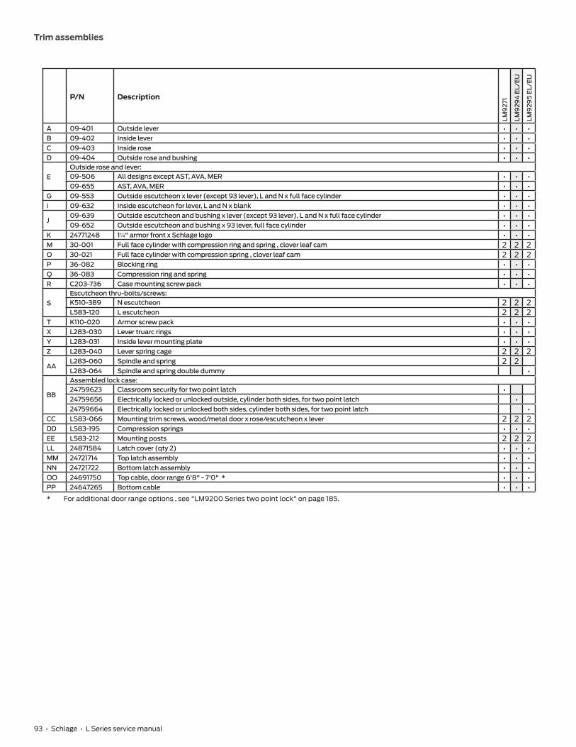
93 • Schlage • L Series service manual
Trim assemblies
P/N Description
LM9
271
LM9
294
EL/
EU
LM9
295
EL/E
U
A 09-401 Outside lever • • •B 09-402 Inside lever • • •C 09-403 Inside rose • • •D 09-404 Outside rose and bushing • • •
EOutside rose and lever:09-506 All designs except AST, AVA, MER • • •09-655 AST, AVA, MER • • •
G 09-553 Outside escutcheon x lever (except 93 lever), L and N x full face cylinder • • •i 09-632 Inside escutcheon for lever, L and N x blank • • •
J09-639 Outside escutcheon and bushing x lever (except 93 lever), L and N x full face cylinder • • •09-652 Outside escutcheon and bushing x 93 lever, full face cylinder • • •
K 24771248 1Z\v" armor front x Schlage logo • • •M 30-001 Full face cylinder with compression ring and spring , clover leaf cam 2 2 2O 30-021 Full face cylinder with compression spring , clover leaf cam 2 2 2P 36-082 Blocking ring • • •Q 36-083 Compression ring and spring • • •R C203-736 Case mounting screw pack • • •
SEscutcheon thru-bolts/screws:K510-389 N escutcheon 2 2 2L583-120 L escutcheon 2 2 2
T K110-020 Armor screw pack • • •X L283-030 Lever truarc rings • • •Y L283-031 Inside lever mounting plate • • •Z L283-040 Lever spring cage 2 2 2
AAL283-060 Spindle and spring 2 2L283-064 Spindle and spring double dummy •
BB
Assembled lock case:24759623 Classroom security for two point latch •24759656 Electrically locked or unlocked outside, cylinder both sides, for two point latch •24759664 Electrically locked or unlocked both sides, cylinder both sides, for two point latch •
CC L583-066 Mounting trim screws, wood/metal door x rose/escutcheon x lever 2 2 2DD L583-195 Compression springs • • •EE L583-212 Mounting posts 2 2 2LL 24871584 Latch cover (qty 2) • • •MM 24721714 Top latch assembly • • •NN 24721722 Bottom latch assembly • • •OO 24691750 Top cable, door range 6'8" - 7'0" * • • •PP 24647265 Bottom cable • • •* For additional door range options , see "LM9200 Series two point lock" on page 185.

94 • Schlage • L Series service manual
96 L460, L462, L463, L464, L480, L49697 L901098 L902599 L9026100 LM9310, LM9325101 L9040, L9040 x XL11-446, L9044102 LV9040, LV9040 x XL11-446, LV9044103 L9050, L9060, L9066 x XL11-897, L9070, L9071104 LV9050, LV9060, LV9070, LV9071105 LM9350, LM9370, LM9371106 LMV9350, LMV9370, LMV9371107 L9056108 LV9056109 L9076, L9077110 LV9076, LV9077111 L9080112 LV9080113 LM9380114 LMV9380115 L9082116 LV9082117 L9090EL/EU, L9092EL/EU, L9094EL/EU118 LV9090EL/EU, LV9092EL/EU, LV9094EL/EU119 L9091 EL/EU, L9093 EL/EU, L9095 EL/EU120 LV9091 EL/EU, LV9093 EL/EU, LV9095 EL/EU121 L9492 EL/EU, L9494 EL/EU122 LV9492 EL/EU, LV9494 EL/EU123 L9493 EL/EU, L9495 EL/EU124 LV9493 EL/EU, LV9495 EL/EU125 L9110 x XL11-741126 L9175127 L9176128 L9440, L9444129 LV9440, LV9444130 L9453131 LV9453132 L9456, L9457, L9496133 LV9456, LV9457, LV9496 134 L9458135 LV9458136 L9460, L9462, L9463, L9464137 L9460 x XL11-635138 L9460, L9462, and L9464 x XL11-886139 L9465, L9466, L9473140 L9480, L9485, L9486, L9486 x L583-375,
L9412 x XL11-907141 LV9480, LV9485, LV9486, LV9486 x L583-375142 L9482 x XL11-543143 LV9482 x XL11-543144 L9485 x XL11-557145 LM9210, LM9225
146 LM9256147 LM9250, LM9270, LM9271, LM9280148 LM9290 EL/EU, LM9292 EL/EU, LM9294 EL/EU149 LM9291 EL/EU, LM9293 EL/EU, LM9295 EL/EU150 Lock case assembly compatibility
Lock case assemblies

Lock case assemblies
Schlage • L Series service manual • 95
L460, L462, L463, L464, L480, L496
Assembled Lock Case L283-099
Number Description Part Number
3 Deadbolt L283-00310 Cylinder Plate & Screw L283-05514 L400 Lock Case L283-12827 Turn Hub L583-02930 Turn Hub Spring L583-03551 1Z\v" Faceplate Tab L583-42652 Case Cover Screws L583-45453 Cylinder Retainer Screw L583-48155 Cylinder Retainer L583-49056 Screw Plate L583-49257 Lock Case Cover L583-494
57
3 52
55
10
51
1451
3
27
30
56
53

96 • Schlage • L Series service manual
Lock case assemblies
L9010
Assembled Lock Case L283-131
Number DescriptionPart Number
6 Latchbolt L283-00813 L9000 Lock Case L283-11217 Retractor Hub L583-74818 Hub Spacer L583-02019 Retractor Lever L583-02120 Retractor Rocker L583-02221 Blocking Plate L583-02322 Retractor Link L583-02423 Retractor Crank L583-02524 Hub Spring L583-02625 Fire Door Fuse L583-02726 Fire Door Catch L583-02831 Auxiliary Bar Guide L583-03851 1Z\v" Faceplate Tab L583-42652 Case Cover Screws L583-45458 Lock Case Cover L583-496
524
58
5113
25
26
24
17
19
22
23
18
21
20
17
6
51
31
**
** See "Assembly of lock case parts" on page 153.

Lock case assemblies
Schlage • L Series service manual • 97
L9025
Assembled Lock Case L283-750
25
26
24
17
19
22
23
18
21
20
17
6
51
51
**
5
33
50
13
524
58
41
34
54
Number DescriptionPart Number
5 Auxiliary Latchbolt L283-0066 Latchbolt L283-00813 L9000 Lock Case L283-11217 Retractor Hub L583-74818 Hub Spacer L583-02019 Retractor Lever L583-02120 Retractor Rocker L583-02221 Blocking Plate L583-02322 Retractor Link L583-02423 Retractor Crank L583-02524 Hub Spring L583-02625 Fire Door Fuse L583-02726 Fire Door Catch L583-02833 Stop Spring L583-04434 Locking Catch L583-04541 Catch Pin L583-05650 Auxiliary Stop L583-19651 1Z\v" Faceplate Tab L583-42652 Case Cover Screws L583-74754 Lock Handing Screw L583-48558 L9000 Lock Case Cover L583-496
** See "Assembly of lock case parts" on page 153.

98 • Schlage • L Series service manual
Lock case assemblies
L9026
Assembled Lock Case L283-134
Number DescriptionPart Number
5 Auxiliary Latchbolt L283-0066 Latchbolt L283-00810 Cylinder Plate & Screw L283-05513 L9000 Lock Case L283-11215 Standoff Post L583-00417 Retractor Hub L583-74818 Hub Spacer L583-02019 Retractor Lever L583-02120 Retractor Rocker L583-02221 Blocking Plate L583-02322 Retractor Link L583-02423 Retractor Crank L583-02524 Hub Spring L583-02625 Fire Door Fuse L583-02726 Fire Door Catch L583-02833 Stop Spring L583-04434 Locking Catch L583-04539 Transfer Lever L583-05141 Catch Pin L583-05650 Auxiliary Stop L583-19651 1Z\v" Faceplate Tab L583-42652 Case Cover Screws L583-45453 Cylinder Retainer Screw L583-48154 Lock Handing Screw L583-48555 Cylinder Retainer L583-49056 Screw Plate L583-49258 Lock Case Cover L583-496
544
58
52
26
41
34
24
17
19
22
23
18
21
20
17
33
50
25
39
55
10
6
15
56
53
5
51
5113
**
** See "Assembly of lock case parts" on page 153.

Lock case assemblies
Schlage • L Series service manual • 99
LM9310, LM9325
Assembled Lock Case L283-314
Number DescriptionPart Number
5 Auxiliary Latchbolt L283-0066 Latchbolt L283-32417 Retractor Hub L583-74818 Hub Spacer L583-02019 Retractor Lever L583-02120 Retractor Rocker L583-02221 Blocking Plate L583-02322 Retractor Link L583-02423 Retractor Crank L583-02524 Hub Spring L583-02625 Fire Door Fuse L583-02726 Fire Door Catch L583-02833 Stop Spring L583-04450 Auxiliary Stop L583-19651 1Z\v" Faceplate Tab L583-42652 Case Cover Screws L583-74766 LM9000 Lock Case L283-31267 LM9000 Lock Case Cover L583-49168 Locking Link L583-50569 Lifter L583-506
528
67
25
26
24
17
19
22
23
18
21
20
17
6
51
51
**
5
33
50
68
66
69
** See "Assembly of lock case parts" on page 153.

100 • Schlage • L Series service manual
Lock case assemblies
L9040, L9040 x XL11-446, L9044
Assembled Lock Case L283-132
Number DescriptionPart Number
6 Latchbolt L283-00813 L9000 Lock Case L283-11217 Retractor Hub L583-74818 Hub Spacer L583-02019 Retractor Lever L583-02120 Retractor Rocker L583-02221 Blocking Plate L583-02322 Retractor Link L583-02423 Retractor Crank L583-02524 Hub Spring L583-02625 Fire Door Fuse L583-02726 Fire Door Catch L583-02827 Turn Hub L583-02930 Turn Hub Spring L583-03531 Auxiliary Bar Guide L583-03834 Locking Catch L583-04536 Locking Link L583-04838 Link Pin L583-05043 Simultaneous Retractor L583-05851 1Z\v" Faceplate Tab L583-42652 Case Cover Screws L583-45454 Lock Handing Screw L583-48558 Lock Case Cover L583-496
25
26
43
38
36
34
31
30
27
24
17
19
22
23
18
21
20
17
6
51
13
51
54
58
524
(couple beforeassembly)
**
**
** See "Assembly of lock case parts" on page 153.

Lock case assemblies
Schlage • L Series service manual • 101
LV9040, LV9040 x XL11-446, LV9044
Assembled Lock Case L283-602
25
26
43
38
31
30
22
6
51
13
1351
524
24
61
62
63
27
36
(couple beforeassembly)
64
**
**
75
76
77
78
54
Number DescriptionPart Number
6 Latchbolt L283-00813 L9000 Lock Case L283-59422 Retractor Link L583-02424 Hub Spring L583-02625 Fire Door Fuse L583-02726 Fire Door Catch L583-02827 Turn Hub L583-02930 Turn Hub Spring L583-03531 Auxiliary Bar Guide L583-03836 Locking Link L583-04838 Link Pin L583-05043 Simultaneous Retractor L583-05851 1Z\v" Faceplate Tab L583-42652 Case Cover Screws L583-45454 Lock Handing Screw L583-90261 Crank Retractor L583-38362 Bottom Hub L583-76563 Top Hub L583-76764 Retractor Catch L583-76975 Lever, Retractor L583-76876 Spring, Compression L583-38877 Locker L583-76478 Pin, Pusher L583-778
** See "Assembly of lock case parts" on page 153.

102 • Schlage • L Series service manual
Lock case assemblies
L9050, L9060, L9066 x XL11-897, L9070, L9071
Assembled Lock Case L283-133
Number DescriptionPart Number
5 Auxiliary Latchbolt L283-0066 Latchbolt L283-00810 Cylinder Plate & Screw L283-05513 L9000 Lock Case L283-11217 Retractor Hub L583-74818 Hub Spacer L583-02019 Retractor Lever L583-02120 Retractor Rocker L583-02221 Blocking Plate L583-02322 Retractor Link L583-02423 Retractor Crank L583-02524 Hub Spring L583-02625 Fire Door Fuse L583-02726 Fire Door Catch L583-02827 Turn Hub L583-02930 Turn Hub Spring L583-03533 Stop Spring L583-04434 Locking Catch L583-04536 Locking Link L583-04838 Link Pin L583-05039 Transfer Lever L583-05147 Transfer Lifter L583-15650 Auxiliary Stop L583-19651 1Z\v" Faceplate Tab L583-42652 Case Cover Screws L583-45453 Cylinder Retainer Screw L583-48154 Lock Handing Screw L583-48555 Cylinder Retainer L583-49056 Screw Plate L583-49258 Lock Case Cover L583-49671 Post, Standoff L583-004
26
30
27
24
17
19
22
23
18
21
20
33
50
25
39
55
10
6
47
56
53
5
51
51
(couple beforeassembly)
13
71
(couple beforeassembly)
34
36
38
17
**
**
**
4 52
58
54
Note: L9066 x XL11-897 chassis does not include blocking plate, part number L583-023. ** See "Assembly of lock case parts" on page 153.

Lock case assemblies
Schlage • L Series service manual • 103
LV9050, LV9060, LV9070, LV9071
Assembled Lock Case L283-601
64
36
62
61
63
27
(couple beforeassembly)
38
26
30
22
33
50
25
39
55
10
6
47
56
53
5
51
51
(couple beforeassembly)
13
24
**
**
**
13
524
75
76
77
78
54
Number DescriptionPart Number
5 Auxiliary Latchbolt L283-0066 Latchbolt L283-00810 Cylinder Plate & Screw L283-05513 L9000 Lock Case L283-59422 Retractor Link L583-02424 Hub Spring L583-02625 Fire Door Fuse L583-02726 Fire Door Catch L583-02827 Turn Hub L583-02930 Turn Hub Spring L583-03533 Stop Spring L583-04436 Locking Link L583-04838 Link Pin L583-05039 Transfer Lever L583-05147 Transfer Lifter L583-15650 Auxiliary Stop L583-19651 1Z\v" Faceplate Tab L583-42652 Case Cover Screws L583-45453 Cylinder Retainer Screw L583-48154 Lock Handing Screw L583-90255 Cylinder Retainer L583-49056 Screw Plate L583-49261 Crank Retractor L583-38362 Bottom Hub L583-38663 Top Hub L583-38764 Retractor Catch L583-34575 Lever, Retractor L583-76876 Spring, Compression L583-38877 Locker L583-76478 Pin, Pusher L583-778
** See "Assembly of lock case parts" on page 153.

104 • Schlage • L Series service manual
Lock case assemblies
LM9350, LM9370, LM9371
Assembled Lock Case L283-316
Number DescriptionPart Number
5 Auxiliary Latchbolt L283-0066 Latchbolt L283-33610 Cylinder Plate & Screw L283-05517 Retractor Hub L583-74818 Hub Spacer L583-02019 Retractor Lever L583-02120 Retractor Rocker L583-02221 Blocking Plate L583-02322 Retractor Link L583-02423 Retractor Crank L583-02524 Hub Spring L583-02625 Fire Door Fuse L583-02726 Fire Door Catch L583-02827 Turn Hub L583-02930 Turn Hub Spring L583-03533 Stop Spring L583-04434 Locking Catch L583-04538 Link Pin L583-05050 Auxiliary Stop L583-19651 1Z\v" Faceplate Tab L583-42652 Case Cover Screws L583-74753 Cylinder Retainer Screw L583-48154 Lock Handing Screw L583-48555 Cylinder Retainer L583-49056 Screw Plate L583-49266 LM9000 Lock Case L283-31267 LM9000 Lock Case Cover L583-49168 Locking Link L583-50569 Lifter L583-506
26
30
27
24
17
19
22
23
18
21
20
33
50
25
55
10
6
56
53
5 (couple beforeassembly)
34
68
38
17
**
**
69
528
67
51
5166
** See "Assembly of lock case parts" on page 153.

Lock case assemblies
Schlage • L Series service manual • 105
LMV9350, LMV9370, LMV9371
Assembled Lock Case L283-614
26
30
27
24
22
33
50
25
55
10
6
56
53
5 (couple beforeassembly)
64
68
38
**
**
69
62
61
63
75
76
77
78
54
528
66
51
5166
Number DescriptionPart Number
5 Auxiliary Latchbolt L283-0066 Latchbolt L283-33610 Cylinder Plate & Screw L283-05522 Retractor Link L583-02424 Hub Spring L583-02625 Fire Door Fuse L583-02726 Fire Door Catch L583-02827 Turn Hub L583-02930 Turn Hub Spring L583-03533 Stop Spring L583-04438 Link Pin L583-05050 Auxiliary Stop L583-19651 1Z\v" Faceplate Tab L583-42652 Case Cover Screws L583-74753 Cylinder Retainer Screw L583-48154 Lock Handing Screw L583-90255 Cylinder Retainer L583-49056 Screw Plate L583-49260 Retractor Lever Assy L283-14761 Crank Retractor L583-38362 Bottom Hub L583-76563 Top Hub L583-76764 Retractor Catch L583-76966 LM9000 Lock Case L283-61368 Locking Link L583-50569 Lifter L583-50675 Lever, Retractor L583-76876 Spring, Compression L583-38877 Locker L583-76478 Pin, Pusher L583-778
** See "Assembly of lock case parts" on page 153.

106 • Schlage • L Series service manual
Lock case assemblies
L9056
Assembled Lock Case L283-126
Number DescriptionPart Number
5 Auxiliary Latchbolt L283-0066 Latchbolt L283-00810 Cylinder Plate & Screw L283-05513 L9000 Lock Case L283-11217 Retractor Hub L583-74818 Hub Spacer L583-02019 Retractor Lever L583-02120 Retractor Rocker L583-02221 Blocking Plate L583-02322 Retractor Link L583-02423 Retractor Crank L583-02524 Hub Spring L583-02625 Fire Door Fuse L583-02726 Fire Door Catch L583-02827 Turn Hub L583-02930 Turn Hub Spring L583-03533 Stop Spring L583-04434 Locking Catch L583-04536 Locking Link L583-04838 Link Pin L583-05039 Transfer Lever L583-05143 Simultaneous Retractor L583-05847 Transfer Lifter L583-15650 Auxiliary Stop L583-19651 1Z\v" Faceplate Tab L583-42652 Case Cover Screws L583-45453 Cylinder Retainer Screw L583-48154 Lock Handing Screw L583-48555 Cylinder Retainer L583-49056 Screw Plate L583-49258 Lock Case Cover L583-49671 Post Standoff L583-004
(couple beforeassembly)
51
51
13
5
34
36
71
38
17
20
21
18
23
22
(couple before assembly)
19
17
39
24
26
50
3343
30
55
1056
53
27
6
47
25
**
**
**4 52
58
54
** See "Assembly of lock case parts" on page 153.

Lock case assemblies
Schlage • L Series service manual • 107
LV9056
Assembled Lock Case L283-608
62
61
63
64
52
(couple beforeassembly)**
51
51
13
25
5
36
38
22
39
24
26
5033
43
30
55
1056
53
27
6
47
(couple beforeassembly)**
**
75
76
77
78
13
4
71
54
Number DescriptionPart Number
5 Auxiliary Latchbolt L283-0066 Latchbolt L283-00810 Cylinder Plate & Screw L283-05513 L9000 Lock Case L283-59422 Retractor Link L583-02424 Hub Spring L583-02625 Fire Door Fuse L583-02726 Fire Door Catch L583-02827 Turn Hub L583-02930 Turn Hub Spring L583-03533 Stop Spring L583-04436 Locking Link L583-04838 Link Pin L583-05039 Transfer Lever L583-05143 Simultaneous Retractor L583-05847 Transfer Lifter L583-15650 Auxiliary Stop L583-19651 1Z\v" Faceplate Tab L583-42652 Case Cover Screws L583-45453 Cylinder Retainer Screw L583-48154 Lock Handing Screw L583-90255 Cylinder Retainer L583-49056 Screw Plate L583-49261 Crank Retractor L583-38362 Bottom Hub L583-38663 Top Hub L583-38764 Retractor Catch L583-76971 Post Standoff L583-00475 Lever, Retractor L583-76876 Spring, Compression L583-38877 Locker L583-76478 Pin, Pusher L583-778
** See "Assembly of lock case parts" on page 153.
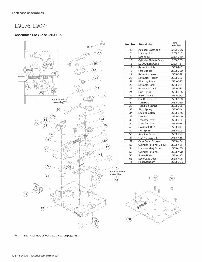
108 • Schlage • L Series service manual
Lock case assemblies
L9076, L9077
Assembled Lock Case L283-039
Number DescriptionPart Number
5 Auxiliary Latchbolt L283-0067 Locking Link L283-0108 Latchbolt L283-04910 Cylinder Plate & Screw L283-05513 L9000 Lock Case L283-11217 Retractor Hub L583-74818 Hub Spacer L583-02019 Retractor Lever L583-02120 Retractor Rocker L583-02221 Blocking Plate L583-02322 Retractor Link L583-02423 Retractor Crank L583-02524 Hub Spring L583-02625 Fire Door Fuse L583-02726 Fire Door Catch L583-02827 Turn Hub L583-02930 Turn Hub Spring L583-03533 Stop Spring L583-04434 Locking Catch L583-04538 Link Pin L583-05039 Transfer Lever L583-05147 Transfer Lifter L583-15648 Holdback Dog L583-17449 Dog Spring L583-19250 Auxiliary Stop L583-19651 1Z\v" Faceplate Tab L583-42652 Case Cover Screws L583-45453 Cylinder Retainer Screw L583-48154 Lock Handing Screw L583-48555 Cylinder Retainer L583-49056 Screw Plate L583-49258 Lock Case Cover L583-49671 Post Standoff L583-004
33
**26
483849
30
27
24
17
19
22
23
18
21
20
17
50
25
39
55
10
8
47
56
53
5
71
51
51
7
34
(couple beforeassembly)**
(couple beforeassembly)**
13
52
58
544
** See "Assembly of lock case parts" on page 153.

Lock case assemblies
Schlage • L Series service manual • 109
LV9076, LV9077
Assembled Lock Case L283-603
61
64
(couple beforeassembly)**
51
51
13
25
5 7
38
22
39
24
26
50
33
30
55
1056
53
27
8
47
(couple beforeassembly)**
48
49
**
13
524
75
76
77
78
62
63
71
54
Number DescriptionPart Number
5 Auxiliary Latchbolt L283-0067 Locking Link L283-0108 Latchbolt L283-04910 Cylinder Plate & Screw L283-05513 L9000 Lock Case L283-59422 Retractor Link L583-02424 Hub Spring L583-02625 Fire Door Fuse L583-02726 Fire Door Catch L583-02827 Turn Hub L583-02930 Turn Hub Spring L583-03533 Stop Spring L583-04438 Link Pin L583-05039 Transfer Lever L583-05147 Transfer Lifter L583-15648 Holdback Dog L583-17449 Dog Spring L583-19250 Auxiliary Stop L583-19651 1Z\v" Faceplate Tab L583-42652 Case Cover Screws L583-45453 Cylinder Retainer Screw L583-48154 Lock Handing Screw L583-90255 Cylinder Retainer L583-49056 Screw Plate L583-49261 Crank Retractor L583-38362 Bottom Hub L583-38663 Top Hub L583-38764 Retractor Catch L583-76971 Post, Standoff L583-00475 Lever, Retractor L583-76876 Spring, Compression L583-38877 Locker L583-76478 Pin, Pusher L583-778
** See "Assembly of lock case parts" on page 153.

110 • Schlage • L Series service manual
Lock case assemblies
L9080
Assembled Lock Case L283-134
Number DescriptionPart Number
5 Auxiliary Latchbolt L283-0066 Latchbolt L283-00810 Cylinder Plate & Screw L283-05513 L9000 Lock Case L283-11215 Standoff Post L583-00417 Retractor Hub L583-74818 Hub Spacer L583-02019 Retractor Lever L583-02120 Retractor Rocker L583-02221 Blocking Plate L583-02322 Retractor Link L583-02423 Retractor Crank L583-02524 Hub Spring L583-02625 Fire Door Fuse L583-02726 Fire Door Catch L583-02833 Stop Spring L583-04434 Locking Catch L583-04539 Transfer Lever L583-05141 Catch Pin L583-05650 Auxiliary Stop L583-19651 1Z\v" Faceplate Tab L583-42652 Case Cover Screws L583-45453 Cylinder Retainer Screw L583-48154 Lock Handing Screw L583-48555 Cylinder Retainer L583-49056 Screw Plate L583-49258 Lock Case Cover L583-496
544
58
52
26
41
34
24
17
19
22
23
18
21
20
17
33
50
25
39
55
10
6
15
56
53
5
51
5113
**
** See "Assembly of lock case parts" on page 153.

Lock case assemblies
Schlage • L Series service manual • 111
LV9080
Assembled Lock Case L283-604
64
61
4
58
52
26
41
24
22
33
50
25
39
55
10
6
56
53
5
51
51
13
15
**
75
76
77
78
62
63
54
Number DescriptionPart Number
5 Auxiliary Latchbolt L283-0066 Latchbolt L283-00810 Cylinder Plate & Screw L283-05513 L9000 Lock Case L283-59415 Standoff Post L583-00422 Retractor Link L583-02424 Hub Spring L583-02625 Fire Door Fuse L583-02726 Fire Door Catch L583-02833 Stop Spring L583-04439 Transfer Lever L583-05141 Catch Pin L583-05650 Auxiliary Stop L583-19651 1Z\v" Faceplate Tab L583-42652 Case Cover Screws L583-45453 Cylinder Retainer Screw L583-48154 Lock Handing Screw L583-90255 Cylinder Retainer L583-49056 Screw Plate L583-49261 Crank Retractor L583-38362 Bottom Hub L583-76563 Top Hub L583-76764 Retractor Catch L583-76975 Lever, Retractor L583-76876 Spring, Compression L583-38877 Locker L583-76478 Pin, Pusher L583-778
** See "Assembly of lock case parts" on page 153.

112 • Schlage • L Series service manual
Lock case assemblies
LM9380
Assembled Lock Case L283-316
Number DescriptionPart Number
5 Auxiliary Latchbolt L283-0066 Latchbolt L283-33610 Cylinder Plate & Screw L283-05517 Retractor Hub L583-74818 Hub Spacer L583-02019 Retractor Lever L583-02120 Retractor Rocker L583-02221 Blocking Plate L583-02322 Retractor Link L583-02423 Retractor Crank L583-02524 Hub Spring L583-02625 Fire Door Fuse L583-02726 Fire Door Catch L583-02827 Turn Hub L583-02930 Turn Hub Spring L583-03533 Stop Spring L583-04434 Locking Catch L583-04538 Link Pin L583-05050 Auxiliary Stop L583-19651 1Z\v" Faceplate Tab L583-42652 Case Cover Screws L583-74753 Cylinder Retainer Screw L583-48154 Lock Handing Screw L583-48555 Cylinder Retainer L583-49056 Screw Plate L583-49266 LM9000 Lock Case L283-31267 LM9000 Lock Case Cover L583-49168 Locking Link L583-50569 Lifter L583-506
54
528
66
26
30
27
24
17
19
22
23
18
21
20
33
50
25
55
10
6
56
53
5 (couple beforeassembly)
34
68
38
17
**
**
69
51
5166
** See "Assembly of lock case parts" on page 153.

Lock case assemblies
Schlage • L Series service manual • 113
LMV9380
Assembled Lock Case L283-614
26
30
27
24
22
33
50
25
55
10
6
56
53
5 (couple beforeassembly)
64
68
38
**
**
69
62
61
63
75
76
77
78
54
528
66
51
5166
Number DescriptionPart Number
5 Auxiliary Latchbolt L283-0066 Latchbolt L283-32410 Cylinder Plate & Screw L283-05522 Retractor Link L583-02424 Hub Spring L583-02625 Fire Door Fuse L583-02726 Fire Door Catch L583-02827 Turn Hub L583-02930 Turn Hub Spring L583-03533 Stop Spring L583-04438 Link Pin L583-05050 Auxiliary Stop L583-19651 1Z\v" Faceplate Tab L583-42652 Case Cover Screws L583-74753 Cylinder Retainer Screw L583-48154 Lock Handing Screw L583-90255 Cylinder Retainer L583-49056 Screw Plate L583-49260 Retractor Lever Assy L283-14761 Crank Retractor L583-38362 Bottom Hub L583-76563 Top Hub L583-76764 Retractor Catch L583-76966 LM9000 Lock Case L283-61368 Locking Link L583-50569 Lifter L583-50675 Lever, Retractor L583-76876 Spring, Compression L583-38877 Locker L583-76478 Pin, Pusher L583-778
** See "Assembly of lock case parts" on page 153.

114 • Schlage • L Series service manual
Lock case assemblies
L9082
Assembled Lock Case L283-146
Number DescriptionPart Number
5 Auxiliary Latchbolt L283-006
6 Latchbolt L283-00810 Cylinder Plate & Screw L283-05513 L9000 Lock Case L283-11215 Standoff Post L583-00433 Stop Spring L583-04439 Transfer Lever L583-05142 Spindle Anchor L583-05750 Auxiliary Stop L583-19651 1Z\v" Faceplate Tab L583-42652 Case Cover Screws L583-45453 Cylinder Retainer Screw L583-48155 Cylinder Retainer L583-49056 Screw Plate L583-49258 Lock Case Cover L583-496
51
5
15
6
53
5610
55
33
50
39
42
5113
52
58
4

Lock case assemblies
Schlage • L Series service manual • 115
LV9082
Assembled Lock Case L283-610
Number DescriptionPart Number
5 Auxiliary Latchbolt L283-0066 Latchbolt L283-00810 Cylinder Plate & Screw L283-05513 L9000 Lock Case L283-59415 Standoff Post L583-00433 Stop Spring L583-04439 Transfer Lever L583-05150 Auxiliary Stop L583-19651 1Z\v" Faceplate Tab L583-42652 Case Cover Screws L583-45453 Cylinder Retainer Screw L583-48155 Cylinder Retainer L583-49056 Screw Plate L583-49262 Bottom Hub L583-76563 Top Hub L583-76765 Spacer L583-346
62
65
63
51
5
15
6
53
5610
55
33
50
39
51
13
52
13
4
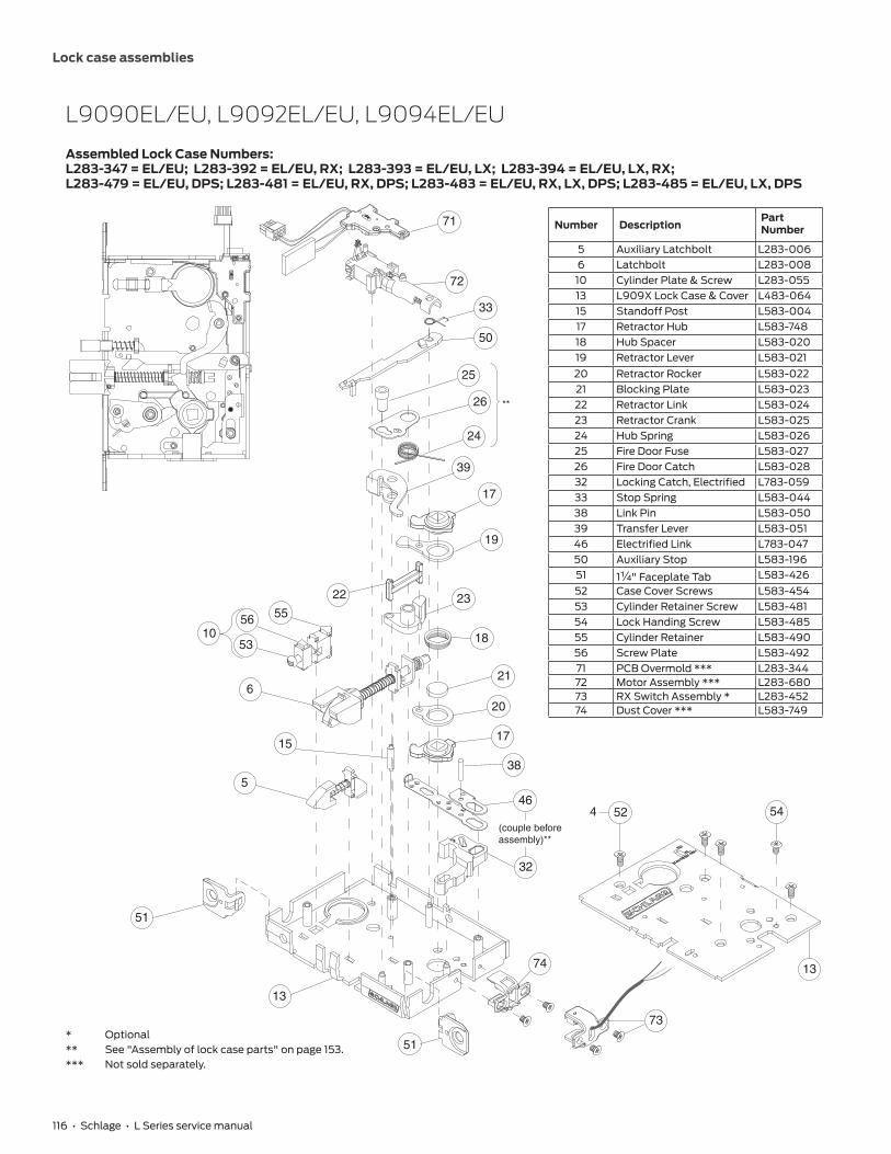
116 • Schlage • L Series service manual
Lock case assemblies
L9090EL/EU, L9092EL/EU, L9094EL/EU
Assembled Lock Case Numbers: L283-347 = EL/EU; L283-392 = EL/EU, RX; L283-393 = EL/EU, LX; L283-394 = EL/EU, LX, RX; L283-479 = EL/EU, DPS; L283-481 = EL/EU, RX, DPS; L283-483 = EL/EU, RX, LX, DPS; L283-485 = EL/EU, LX, DPS
26
24
50
25
33
**
72
71
39
17
19
22
55
1056
53
23
18
21
20
17
46
6
538
32
(couple beforeassembly)**
13
51
13
544 52
51
15
74
73
Number DescriptionPart Number
5 Auxiliary Latchbolt L283-0066 Latchbolt L283-00810 Cylinder Plate & Screw L283-05513 L909X Lock Case & Cover L483-06415 Standoff Post L583-00417 Retractor Hub L583-74818 Hub Spacer L583-02019 Retractor Lever L583-02120 Retractor Rocker L583-02221 Blocking Plate L583-02322 Retractor Link L583-02423 Retractor Crank L583-02524 Hub Spring L583-02625 Fire Door Fuse L583-02726 Fire Door Catch L583-02832 Locking Catch, Electrified L783-05933 Stop Spring L583-04438 Link Pin L583-05039 Transfer Lever L583-05146 Electrified Link L783-04750 Auxiliary Stop L583-19651 1Z\v" Faceplate Tab L583-42652 Case Cover Screws L583-45453 Cylinder Retainer Screw L583-48154 Lock Handing Screw L583-48555 Cylinder Retainer L583-49056 Screw Plate L583-49271 PCB Overmold *** L283-34472 Motor Assembly *** L283-68073 RX Switch Assembly * L283-45274 Dust Cover *** L583-749
* Optional** See "Assembly of lock case parts" on page 153.*** Not sold separately.

Lock case assemblies
Schlage • L Series service manual • 117
LV9090EL/EU, LV9092EL/EU, LV9094EL/EU
Assembled Lock Case L283-597
26
24
50
25
33
**
72
71
39
63
22
55
1056
53
61
62
46
6
5
75
38
64
(couple beforeassembly)**
13
51
13
4 52
51
15
76
77
78
54
* Optional** See "Assembly of lock case parts" on page 153.*** Not sold separately.
Number DescriptionPart Number
5 Auxiliary Latchbolt L283-0066 Latchbolt L283-00810 Cylinder Plate & Screw L283-05513 L909X Lock Case & Cover L483-06415 Standoff Post L583-00422 Retractor Link L583-02424 Hub Spring L583-02625 Fire Door Fuse L583-02726 Fire Door Catch L583-02833 Stop Spring L583-04438 Link Pin L583-05039 Transfer Lever L583-05146 Electrified Link L783-04750 Auxiliary Stop L583-19651 1Z\v" Faceplate Tab L583-42652 Case Cover Screws L583-45453 Cylinder Retainer Screw L583-48154 Lock Handing Screw L583-90255 Cylinder Retainer L583-49056 Screw Plate L583-49261 Retractor Crank L583-38362 Bottom Hub L583-76563 Top Hub L583-76764 Locking Catch L583-76971 PCB Overmold L283-34472 Motor Assembly L283-68075 Retractor Lever L583-76876 Compression Spring L583-38877 Locker 4727411978 Pusher Pin 47274169

118 • Schlage • L Series service manual
Lock case assemblies
L9091 EL/EU, L9093 EL/EU, L9095 EL/EU
Assembled Lock Case Numbers: L283-395 = EL/EU; L283-396 = EL/EU, RX; L283-397 = EL/EU, LX; L283-398 = EL/EU, LX, RX; L283-480 = EL/EU, DPS; L283-482 = EL/EU, RX, DPS; L283-484 = EL/EU, RX, LX, DPS; L283-486 = EL/EU, LX, DPS
26
24
50
25
33
**
39
17
19
22
55
1056
53
23
18
20
17
46
6
15
38
32
(couple beforeassembly)**
51
13
51
72
71
5
13
544 52
73
74
Number DescriptionPart Number
5 Auxiliary Latchbolt L283-0066 Latchbolt L283-00810 Cylinder Plate & Screw L283-05513 L909X Lock Case & Cover L483-06415 Standoff Post L583-00417 Retractor Hub L583-74818 Hub Spacer L583-02019 Retractor Lever L583-02120 Retractor Rocker L583-02222 Retractor Link L583-02423 Retractor Crank L583-02524 Hub Spring L583-02625 Fire Door Fuse L583-02726 Fire Door Catch L583-02832 Locking Catch, Electrified L783-05933 Stop Spring L583-04438 Link Pin L583-05039 Transfer Lever L583-05146 Electrified Link L783-04750 Auxiliary Stop L583-19651 1Z\v" Faceplate Tab L583-42652 Case Cover Screws L583-45453 Cylinder Retainer Screw L583-48154 Lock Handing Screw L583-48555 Cylinder Retainer L583-49056 Screw Plate L583-49271 PCB Overmold *** L283-34472 Motor Assembly *** L283-68073 RX Switch Assembly * L283-45274 Dust Cover *** L583-749
* Optional** See "Assembly of lock case parts" on page 153.*** Not sold separately.

Lock case assemblies
Schlage • L Series service manual • 119
LV9091 EL/EU, LV9093 EL/EU, LV9095 EL/EU
Assembled Lock Case L283-598
Number DescriptionPart Number
5 Auxiliary Latchbolt L283-0066 Latchbolt L283-00810 Cylinder Plate & Screw L283-05513 L909X Lock Case & Cover L283-59515 Standoff Post L583-00422 Retractor Link L583-02424 Hub Spring L583-02625 Fire Door Fuse L583-02726 Fire Door Catch L583-02833 Stop Spring L583-04438 Link Pin L583-05039 Transfer Lever L583-05146 Electrified Link L783-04750 Auxiliary Stop L583-19651 1Z\v" Faceplate Tab L583-42652 Case Cover Screws L583-45453 Cylinder Retainer Screw L583-48154 Lock Handing Screw L583-90255 Cylinder Retainer L583-49056 Screw Plate L583-49261 Retractor Crank L583-38362 Bottom Hub L583-76563 Top Hub L583-76764 Locking Catch L583-76971 PCB Overmold L283-34472 Motor Assembly L283-68075 Retractor Lever L583-76876 Compression Spring L583-38877 Locker 4727411978 Pusher Pin 47274169
26
24
50
25
33
**
39
22
55
1056
53
46
6
15
38
(couple beforeassembly)**
51
13
51
72
71
5
13
4 52
63
61
62
75
64
76
77
78
54
* Optional** See "Assembly of lock case parts" on page 153.*** Not sold separately.

120 • Schlage • L Series service manual
Lock case assemblies
L9492 EL/EU, L9494 EL/EU
Assembled Lock Case Numbers: L283-467 = EL/EU; L283-469 = EL/EU, RX; L283-471 = EL/EU, DM; L283-473 = EL/EU, RX, DM; L283-475 = EL/EU, RX, LX, DM; L283-477 = EL/EU, LX, DM; L283-487 = EL/EU, LX; L283-489 = EL/EU, RX, LX
* Optional** See "Assembly of lock case parts" on page 153.*** Not sold separately.
26
24
50
25
33
**
72
71
39
17
19
22
5510
56
53
23
18
21
20
17
46
6
5
38
32
(couple beforeassembly)**
13
13
544 52
3
27
51
51
73
40
30
(couple beforeassembly)**
74
Number DescriptionPart Number
3 Deadbolt Assembly L283-6765 Auxiliary Latchbolt L283-0066 Latchbolt L283-00810 Cylinder Plate & Screw L283-05513 L909X Lock Case & Cover L483-06417 Retractor Hub L583-74818 Hub Spacer L583-02019 Retractor Lever L583-02120 Retractor Rocker L583-02221 Blocking Plate L583-02322 Retractor Link L583-02423 Retractor Crank L583-02524 Hub Spring L583-02625 Fire Door Fuse L583-02726 Fire Door Catch L583-02827 Turn Hub L283-02930 Turn Hub Spring L583-03532 Locking Catch, Electrified L783-05933 Stop Spring L583-04438 Link Pin L583-05039 Transfer Lever L583-05140 Simultaneous retractor L583-05346 Electrified Link L783-04750 Auxiliary Stop L583-19651 1Z\v" Faceplate Tab L583-42652 Case Cover Screws L583-45453 Cylinder Retainer Screw L583-48154 Lock Handing Screw L583-48555 Cylinder Retainer L583-49056 Screw Plate L583-49271 PCB Overmold *** L283-34472 Motor Assembly *** L283-68073 RX Switch Assembly * L283-45274 Dust Cover *** L583-749

Lock case assemblies
Schlage • L Series service manual • 121
LV9492 EL/EU, LV9494 EL/EU
Assembled Lock Case L283-599
26
24
50
25
33
**
72
71
39
22
5510
56
53
46
6
5
38
(couple beforeassembly)**
13
13
4 52
3
27
51
51
77
62
63
61
75
64
76
78
30
(couple beforeassembly)**
54
* Optional** See "Assembly of lock case parts" on page 153.*** Not sold separately.
Number DescriptionPart Number
3 Deadbolt L283-6765 Auxiliary Latchbolt L283-0066 Latchbolt L283-00810 Cylinder Plate & Screw L283-05513 L909X Lock Case & Cover L283-59522 Retractor Link L583-02424 Hub Spring L583-02625 Fire Door Fuse L583-02726 Fire Door Catch L583-02827 Turn Hub L283-02930 Turn Hub Spring L583-03533 Stop Spring L583-04438 Link Pin L583-05039 Transfer Lever L583-05146 Electrified Link L783-04750 Auxiliary Stop L583-19651 1Z\v" Faceplate Tab L583-42652 Case Cover Screws L583-45453 Cylinder Retainer Screw L583-48154 Lock Handing Screw L583-90255 Cylinder Retainer L583-49056 Screw Plate L583-49261 Retractor Crank L583-38362 Bottom Hub L583-76563 Top Hub L583-76764 Locking Catch L583-76971 PCB Overmold L283-34472 Motor Assembly L283-68075 Retractor Lever L583-76876 Compression Spring L583-38877 Locker 4727411978 Pusher Pin 47274169

122 • Schlage • L Series service manual
Lock case assemblies
L9493 EL/EU, L9495 EL/EU
Assembled Lock Case Numbers: L283-468 = EL/EU; L283-470 = EL/EU, RX; L283-472 = EL/EU, DM; L283-474 = EL/EU, RX, L283-476 = EL/EU, RX, LX, DM; L283-478 = EL/EU, LX, DM; L283-488 = EL/EU, LX; L283-490 = EL/EU, RX, LX
* Optional** See "Assembly of lock case parts" on page 153.*** Not sold separately.
Number DescriptionPart Number
3 Deadbolt Assembly L283-6765 Auxiliary Latchbolt L283-0066 Latchbolt L283-00810 Cylinder Plate & Screw L283-05513 L909X Lock Case & Cover L483-06417 Retractor Hub L583-74818 Hub Spacer L583-02019 Retractor Lever L583-02120 Retractor Rocker L583-02222 Retractor Link L583-02423 Retractor Crank L583-02524 Hub Spring L583-02625 Fire Door Fuse L583-02726 Fire Door Catch L583-02827 Turn Hub L283-02932 Locking Catch, Electrified L783-05933 Stop Spring L583-04438 Link Pin L583-05039 Transfer Lever L583-05140 Simultaneous Retractor L583-05346 Electrified Link L783-04750 Auxiliary Stop L583-19651 1Z\v" Faceplate Tab L583-42652 Case Cover Screws L583-45453 Cylinder Retainer Screw L583-48154 Lock Handing Screw L583-48555 Cylinder Retainer L583-49056 Screw Plate L583-49271 PCB Overmold *** L283-34472 Motor Assembly *** L283-68073 RX Switch Assembly * L283-45274 Dust Cover *** L583-749
26
24
50
25
33
**
72
71
39
17
19
22
5510
56
53
23
18
20
17
46
6
5
38
32
(couple beforeassembly)**
13
51
13
544 52
51
3
27
73
40
74

Lock case assemblies
Schlage • L Series service manual • 123
LV9493 EL/EU, LV9495 EL/EU
Assembled Lock Case L283-600
26
24
50
25
33
**
72
71
39
22
5510
56
53
46
6
5
38
(couple beforeassembly)**
13
51
13
4 52
51
3
2762
63
61
75
64
76
78
30
(couple beforeassembly)**
77
54
54
* Optional** See "Assembly of lock case parts" on page 153.*** Not sold separately.
Number DescriptionPart Number
3 Deadbolt L283-6765 Auxiliary Latchbolt L283-0066 Latchbolt L283-00810 Cylinder Plate & Screw L283-05513 L909X Lock Case & Cover L283-59522 Retractor Link L583-02424 Hub Spring L583-02625 Fire Door Fuse L583-02726 Fire Door Catch L583-02827 Turn Hub L283-02930 Turn Hub Spring L583-03533 Stop Spring L583-04438 Link Pin L583-05039 Transfer Lever L583-05146 Locking Link L783-04750 Auxiliary Stop L583-19651 1Z\v" Faceplate Tab L583-42652 Case Cover Screws L583-45453 Cylinder Retainer Screw L583-48154 Lock Handing Screw L583-90255 Cylinder Retainer L583-49056 Screw Plate L583-49261 Retractor Crank L583-38362 Bottom Hub L583-76563 Top Hub L583-76764 Locking Catch L583-76971 PCB Overmold L283-34472 Motor Assembly L283-68075 Retractor Lever L583-76876 Compression Spring L583-38877 Locker 4727411978 Pusher Pin 47274169

124 • Schlage • L Series service manual
Lock case assemblies
L9110 x XL11-741
Assembled Lock Case XL11-741
Number DescriptionPart Number
13 L9000 Lock Case L283-11217 Retractor Hub L583-74818 Hub Spacer L583-02019 Retractor Lever L583-02120 Retractor Rocker L583-02221 Blocking Plate L583-02322 Retractor Link L583-02423 Retractor Crank L583-02524 Hub Spring L583-02625 Fire Door Fuse L583-02726 Fire Door Catch L583-02851 1Z\v" Faceplate Tab L583-42652 Case Cover Screws L583-45458 Lock Case Cover L583-496
17
19
22
24
26
25
23
18
21
20
17
51
51
13
4
58
52
**
** See "Assembly of lock case parts" on page 153.

Lock case assemblies
Schlage • L Series service manual • 125
L9175
Assembled Lock Case L283-144
Number DescriptionPart Number
11 Spindle Anchor Single L583-46813 L9000 Lock Case L283-11251 1Z\v" Faceplate Tab L583-42652 Case Cover Screws L583-45458 Lock Case Cover L583-496
4
58
52
51
11
13
51

126 • Schlage • L Series service manual
Lock case assemblies
L9176
Assembled Lock Case L283-145
Number DescriptionPart Number
13 L9000 Lock Case L283-11242 Spindle Anchor L583-05751 1Z\v" Faceplate Tab L583-42652 Case Cover Screws L583-45458 Lock Case Cover L583-496
4
58
52
42
51
5113

Lock case assemblies
Schlage • L Series service manual • 127
L9440, L9444
Assembled Lock Case L283-062
Number DescriptionPart Number
3 Deadbolt L283-0036 Latchbolt L283-00810 Cylinder Plate & Screw L283-05513 L9000 Lock Case L283-11217 Retractor Hub L583-74818 Hub Spacer L583-02019 Retractor Lever L583-02120 Retractor Rocker L583-02221 Blocking Plate L583-02322 Retractor Link L583-02423 Retractor Crank L583-02524 Hub Spring L583-02625 Fire Door Fuse L583-02726 Fire Door Catch L583-02827 Turn Hub L583-02930 Turn Hub Spring L583-03531 Auxiliary Bar Guide L583-03834 Locking Catch L583-04536 Locking Link L583-04838 Link Pin L583-05039 Transfer Lever L583-05143 Simultaneous Retractor L583-05851 1Z\v" Faceplate Tab L583-42652 Case Cover Screws L583-45453 Cylinder Retainer Screw L583-48154 Lock Handing Screw L583-48555 Cylinder Retainer L583-49056 Screw Plate L583-49258 Lock Case Cover L583-496
(couple beforeassembly)**
26
38
36
34
30
24
17
19
22
23
18
21
20
17
55
31
39
3
51
6
56
53
51
(couple beforeassembly)**
13
43
27
10
**
25
4 52
58
54
** See "Assembly of lock case parts" on page 153.

128 • Schlage • L Series service manual
Lock case assemblies
LV9440, LV9444
Assembled Lock Case L283-609
25
26
43
38
36
31
39
22
6
51
13 51
(couple beforeassembly)**
24
64
61
62
63
27
55
1056
53
3
(couple beforeassembly)**
30
**
13
524
75
76
77
78
54
Number DescriptionPart Number
3 Deadbolt L283-0036 Latchbolt L283-00810 Cylinder Plate & Screw L283-05513 L9000 Lock Case L283-59422 Retractor Link L583-02424 Hub Spring L583-02625 Fire Door Fuse L583-02726 Fire Door Catch L583-02827 Turn Hub L583-02930 Turn Hub Spring L583-03531 Auxiliary Bar Guide L583-03836 Locking Link L583-04838 Link Pin L583-05039 Transfer Lever L583-05143 Simultaneous Retractor L583-05851 1Z\v" Faceplate Tab L583-42652 Case Cover Screws L583-45453 Cylinder Retainer Screw L583-48154 Lock Handing Screw L583-48555 Cylinder Retainer L583-49056 Screw Plate L583-49261 Crank Retractor L583-38362 Bottom Hub L583-38663 Top Hub L583-38764 Retractor Catch L583-76975 Retractor Lever L583-76876 Compression Spring L583-38877 Locker L583-76478 Pusher Pin L583-778
** See "Assembly of lock case parts" on page 153.

Lock case assemblies
Schlage • L Series service manual • 129
L9453
Assembled Lock Case L283-137
Number DescriptionPart Number
4 Entrance Deadbolt L283-0045 Auxiliary Latchbolt L283-0066 Latchbolt L283-00810 Cylinder Plate & Screw L283-05513 L9000 Lock Case L283-11217 Retractor Hub L583-74818 Hub Spacer L583-02019 Retractor Lever L583-02120 Retractor Rocker L583-02221 Blocking Plate L583-02322 Retractor Link L583-02423 Retractor Crank L583-02524 Hub Spring L583-02625 Fire Door Fuse L583-02726 Fire Door Catch L583-02828 Entrance Hub L583-03029 Cam Follower L583-03130 Turn Hub Spring L583-03533 Stop Spring L583-04434 Locking Catch L583-04535 Catch Spring L583-04737 Entrance Link L583-04938 Link Pin L583-05039 Transfer Lever L583-05140 Simultaneous Retractor L583-05350 Auxiliary Stop L583-19651 1Z\v" Faceplate Tab L583-42652 Case Cover Screws L583-45453 Cylinder Retainer Screw L583-48154 Lock Handing Screw L583-48555 Cylinder Retainer L583-49056 Screw Plate L583-49258 Lock Case Cover L583-496
544
58
52
26
38
37
25
34
30
24
17
19
22
23
18
21
20
17
55
10
5039
40
33
35
4
28
29
51
6
56
53
5 (couple beforeassembly)**
13
(couple beforeassembly)**
**
51
** See "Assembly of lock case parts" on page 153.

130 • Schlage • L Series service manual
Lock case assemblies
LV9453
Assembled Lock Case L283-605
62
75
63
61
33
50
39
(couple beforeassembly)**
30
26
24
38
37
64
2255
10
35
4
28
29
51
6
56
53
5
51
(couple beforeassembly)**
13
40
**
25
13
524
76
77
78
54
Number DescriptionPart Number
4 Entrance Deadbolt L283-0045 Auxiliary Latchbolt L283-0066 Latchbolt L283-00810 Cylinder Plate & Screw L283-05513 L9000 Lock Case L283-59422 Retractor Link L583-02424 Hub Spring L583-02625 Fire Door Fuse L583-02726 Fire Door Catch L583-02828 Entrance Hub L583-03029 Cam Follower L583-03130 Turn Hub Spring L583-03533 Stop Spring L583-04435 Catch Spring L583-04737 Entrance Link L583-04938 Link Pin L583-05039 Transfer Lever L583-05140 Simultaneous Retractor L583-05350 Auxiliary Stop L583-19651 1Z\v" Faceplate Tab L583-42652 Case Cover Screws L583-45453 Cylinder Retainer Screw L583-48154 Lock Handing Screw L583-90255 Cylinder Retainer L583-49056 Screw Plate L583-49258 Lock Case Cover L583-49661 Crank Retractor L583-38362 Bottom Hub L583-38663 Top Hub L583-38764 Retractor Catch L583-76975 Retractor Lever L583-76876 Compression Spring L583-38877 Locker L583-76478 Pusher Pin L583-778
** See "Assembly of lock case parts" on page 153.

Lock case assemblies
Schlage • L Series service manual • 131
L9456, L9457, L9496
Assembled Lock Case L283-138
Number DescriptionPart Number
3 Deadbolt L283-0036 Latchbolt L283-00810 Cylinder Plate & Screw L283-05513 L9000 Lock Case L283-11217 Retractor Hub L583-74818 Hub Spacer L583-02019 Retractor Lever L583-02120 Retractor Rocker L583-02221 Blocking Plate L583-02322 Retractor Link L583-02423 Retractor Crank L583-02524 Hub Spring L583-02625 Fire Door Fuse L583-02726 Fire Door Catch L583-02827 Turn Hub L583-02930 Turn Hub Spring L583-03531 Auxiliary Bar Guide L583-03834 Locking Catch L583-04536 Locking Link L583-04838 Link Pin L583-05039 Transfer Lever L583-05140 Simultaneous Retractor L583-05351 1Z\v" Faceplate Tab L583-42652 Case Cover Screws L583-45453 Cylinder Retainer Screw L583-48154 Lock Handing Screw L583-48555 Cylinder Retainer L583-49056 Screw Plate L583-49258 Lock Case Cover L583-496
26
38
36
34
30
24
17
19
22
23
18
21
20
17
55
10
27
31
25
39
40
3
51
6
56
53
51
(couple beforeassembly)**
13
(couple beforeassembly)**
**
4 52
58
54
** See "Assembly of lock case parts" on page 153.
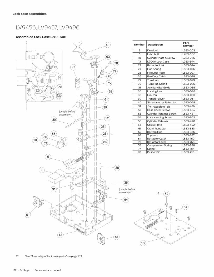
132 • Schlage • L Series service manual
Lock case assemblies
LV9456, LV9457, LV9496
Assembled Lock Case L283-606
3
31
62
61
63
(couple beforeassembly)**
51
51
13
25
38
22
39
24
26
30
55
1056
53
27
6
(couple beforeassembly)**
40
64
36
**
13
524
75
76
77
78
54
Number DescriptionPart Number
3 Deadbolt L283-0036 Latchbolt L283-00810 Cylinder Plate & Screw L283-05513 L9000 Lock Case L283-59422 Retractor Link L583-02424 Hub Spring L583-02625 Fire Door Fuse L583-02726 Fire Door Catch L583-02827 Turn Hub L583-02930 Turn Hub Spring L583-03531 Auxiliary Bar Guide L583-03836 Locking Link L583-04838 Link Pin L583-05039 Transfer Lever L583-05140 Simultaneous Retractor L583-05851 1Z\v" Faceplate Tab L583-42652 Case Cover Screws L583-45453 Cylinder Retainer Screw L583-48154 Lock Handing Screw L583-90255 Cylinder Retainer L583-49056 Screw Plate L583-49261 Crank Retractor L583-38362 Bottom Hub L583-38663 Top Hub L583-38764 Retractor Catch L583-76975 Retractor Lever L583-76876 Compression Spring L583-38877 Locker L583-76478 Pusher Pin L583-778
** See "Assembly of lock case parts" on page 153.

Lock case assemblies
Schlage • L Series service manual • 133
L9458
Assembled Lock Case L283-310
Number DescriptionPart Number
3 Deadbolt L283-0035 Auxiliary Latchbolt L283-0066 Latchbolt L283-00810 Cylinder Plate & Screw L283-05513 L9000 Lock Case L283-11217 Retractor Hub L583-74818 Hub Spacer L583-02019 Retractor Lever L583-02120 Retractor Rocker L583-02221 Blocking Plate L583-02322 Retractor Link L583-02423 Retractor Crank L583-02524 Hub Spring L583-02625 Fire Door Fuse L583-02726 Fire Door Catch L583-02827 Turn Hub L583-02930 Turn Hub Spring L583-03533 Stop Spring L583-04434 Locking Catch L583-04536 Locking Link L583-04838 Link Pin L583-05039 Transfer Lever L583-05140 Simultaneous Retractor L583-05350 Auxiliary Stop L583-19651 1Z\v" Faceplate Tab L583-42652 Case Cover Screws L583-45453 Cylinder Retainer Screw L583-48154 Lock Handing Screw L583-48555 Cylinder Retainer L583-49056 Screw Plate L583-49258 Lock Case Cover L583-496
4
58
52
51
5113
25
26
24
**
30
39
(couple beforeassembly)**
40
33
50
17
19
22
23
18
21
20
173
6
5
27
55
1056
53
34
36
(couple beforeassembly)**
38
54
** See "Assembly of lock case parts" on page 153.

134 • Schlage • L Series service manual
Lock case assemblies
LV9458
Assembled Lock Case L283-612
62
63
61
64
75
76
77
78
51
13
25
26
24
**
30
39
(couplebefore
assembly)**
40
33
50
22
3
6
5
27
55
1056
53
36
(couple beforeassembly)**
38
54
13
524
Number DescriptionPart Number
3 Deadbolt L283-0035 Auxiliary Latchbolt L283-0066 Latchbolt L283-00810 Cylinder Plate & Screw L283-05513 L9000 Lock Case L283-59422 Retractor Link L583-02424 Hub Spring L583-02625 Fire Door Fuse L583-02726 Fire Door Catch L583-02827 Turn Hub L583-02930 Turn Hub Spring L583-03533 Stop Spring L583-04436 Locking Link L583-04838 Link Pin L583-05039 Transfer Lever L583-05140 Simultaneous Retractor L583-05350 Auxiliary Stop L583-19651 1Z\v" Faceplate Tab L583-42652 Case Cover Screws L583-45453 Cylinder Retainer Screw L583-48154 Lock Handing Screw L583-90255 Cylinder Retainer L583-49056 Screw Plate L583-49261 Crank Retractor L583-38362 Bottom Hub L583-38663 Top Hub L583-38764 Retractor Catch L583-76975 Retractor Lever L583-76876 Compression Spring L583-38877 Locker L583-76478 Pusher Pin L583-778
** See "Assembly of lock case parts" on page 153.

Lock case assemblies
Schlage • L Series service manual • 135
L9460, L9462, L9463, L9464
Assembled Lock Case L283-139
Number DescriptionPart Number
3 Deadbolt L283-00310 Cylinder Plate & Screw L283-05513 L9000 Lock Case L283-11216 Latchbolt Guide L583-01527 Turn Hub L583-02930 Turn Hub Spring L583-03531 Auxiliary Bar Guide L583-03851 1Z\v" Faceplate Tab L583-42652 Case Cover Screws L583-45453 Cylinder Retainer Screw L583-48155 Cylinder Retainer L583-49056 Screw Plate L583-49258 Lock Case Cover L583-49630
31
16
27
55
10
3
51
56
53
51
13
4
58
52

136 • Schlage • L Series service manual
Lock case assemblies
L9460 x XL11-635
Assembled Lock Case XL11-661
Number DescriptionPart Number
3 Deadbolt L283-00310 Cylinder Plate & Screw L283-05513 L9000 Lock Case L283-11216 Latchbolt Guide L583-01527 Turn Hub L583-02930 Turn Hub Spring L583-03531 Auxiliary Bar Guide L583-03842 Spindle Anchor L583-05751 1Z\v" Faceplate Tab L583-42652 Case Cover Screws L583-45453 Cylinder Retainer Screw L583-48155 Cylinder Retainer L583-49056 Screw Plate L583-49258 Lock Case Cover L583-496
4
58
52
27
55
10
3
51
42
16
31
56
53
51
13
30

Lock case assemblies
Schlage • L Series service manual • 137
L9460, L9462, and L9464 x XL11-886
Assembled Lock Case XL11-886
Number DescriptionPart Number
3 Deadbolt L283-00310 Cylinder Plate & Screw L283-05513 L9000 Lock Case L283-11216 Latchbolt Guide L583-01517 Retractor Hub L583-74818 Hub Spacer L583-02019 Retractor Lever L583-02120 Retractor Rocker L583-02221 Blocking Plate L583-02322 Retractor Link L583-02423 Retractor Crank L583-02524 Hub Spring L583-02625 Fire Door Fuse L583-02726 Fire Door Catch L583-02827 Turn Hub L583-02930 Turn Hub Spring L583-03531 Auxiliary Bar Guide L583-03834 Locking Catch L583-04539 Transfer Lever L583-05140 Simultaneous Retractor L583-05341 Catch Pin L583-05651 1Z\v" Faceplate Tab L583-42652 Case Cover Screws L583-45453 Cylinder Retainer Screw L583-48154 Lock Handing Screw L583-48555 Cylinder Retainer L583-49056 Screw Plate L583-49258 Lock Case Cover L583-496
58
4 52 54
26
41
27
25
55
17
24
19
22
23
18
21
20
17
10
40
16
3431
3
51
56
53
51
13
30
39
(couple beforeassembly)**
**
** See "Assembly of lock case parts" on page 153.
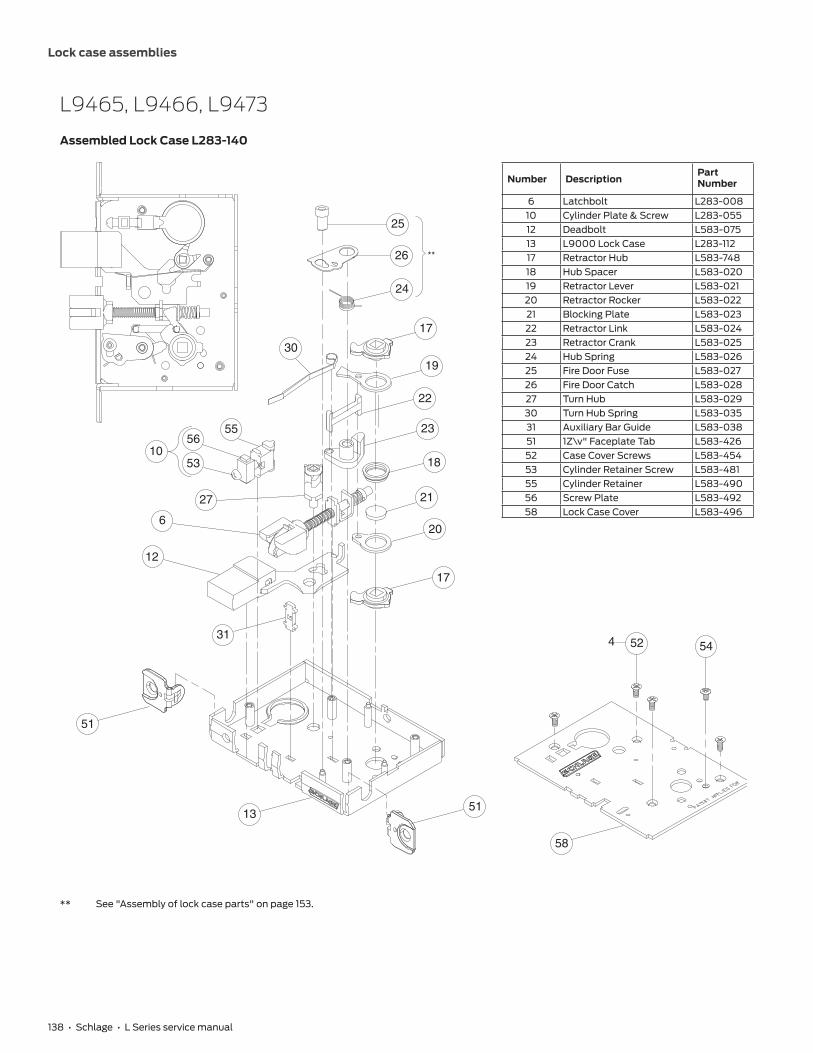
138 • Schlage • L Series service manual
Lock case assemblies
L9465, L9466, L9473
Assembled Lock Case L283-140
Number DescriptionPart Number
6 Latchbolt L283-00810 Cylinder Plate & Screw L283-05512 Deadbolt L583-07513 L9000 Lock Case L283-11217 Retractor Hub L583-74818 Hub Spacer L583-02019 Retractor Lever L583-02120 Retractor Rocker L583-02221 Blocking Plate L583-02322 Retractor Link L583-02423 Retractor Crank L583-02524 Hub Spring L583-02625 Fire Door Fuse L583-02726 Fire Door Catch L583-02827 Turn Hub L583-02930 Turn Hub Spring L583-03531 Auxiliary Bar Guide L583-03851 1Z\v" Faceplate Tab L583-42652 Case Cover Screws L583-45453 Cylinder Retainer Screw L583-48155 Cylinder Retainer L583-49056 Screw Plate L583-49258 Lock Case Cover L583-496
30
25
26
24
27
31
17
19
22
23
18
21
20
17
55
10
12
6
56
53
51
5113
4
58
52
**
54
** See "Assembly of lock case parts" on page 153.
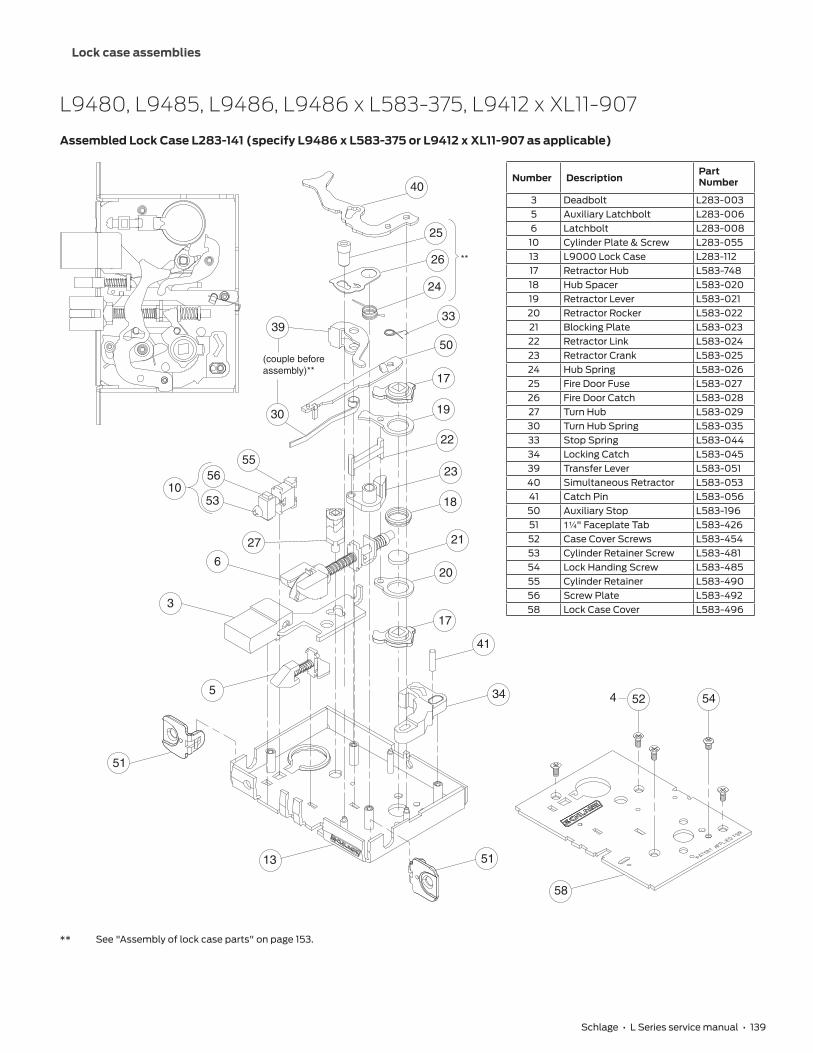
Lock case assemblies
Schlage • L Series service manual • 139
L9480, L9485, L9486, L9486 x L583-375, L9412 x XL11-907
Assembled Lock Case L283-141 (specify L9486 x L583-375 or L9412 x XL11-907 as applicable)
Number DescriptionPart Number
3 Deadbolt L283-0035 Auxiliary Latchbolt L283-0066 Latchbolt L283-00810 Cylinder Plate & Screw L283-05513 L9000 Lock Case L283-11217 Retractor Hub L583-74818 Hub Spacer L583-02019 Retractor Lever L583-02120 Retractor Rocker L583-02221 Blocking Plate L583-02322 Retractor Link L583-02423 Retractor Crank L583-02524 Hub Spring L583-02625 Fire Door Fuse L583-02726 Fire Door Catch L583-02827 Turn Hub L583-02930 Turn Hub Spring L583-03533 Stop Spring L583-04434 Locking Catch L583-04539 Transfer Lever L583-05140 Simultaneous Retractor L583-05341 Catch Pin L583-05650 Auxiliary Stop L583-19651 1Z\v" Faceplate Tab L583-42652 Case Cover Screws L583-45453 Cylinder Retainer Screw L583-48154 Lock Handing Screw L583-48555 Cylinder Retainer L583-49056 Screw Plate L583-49258 Lock Case Cover L583-496
26
41
34
27
25
55
24
17
19
22
23
18
21
20
17
10
40
33
3
51
6
56
53
5
51
13
30
50
39
(couple beforeassembly)**
544
58
52
**
** See "Assembly of lock case parts" on page 153.

140 • Schlage • L Series service manual
Lock case assemblies
LV9480, LV9485, LV9486, LV9486 x L583-375
Assembled Lock Case L283-607
3
62
61
64
63
51
51
13
25
22
39
24
26
30
55
1056
53
27
6
(couple beforeassembly)**
40
41
5
33
50
**
13
524
75
76
77
78
54
Number DescriptionPart Number
3 Deadbolt L283-0035 Auxiliary Latchbolt L283-0066 Latchbolt L283-00810 Cylinder Plate & Screw L283-05513 L9000 Lock Case L283-59422 Retractor Link L583-02424 Hub Spring L583-02625 Fire Door Fuse L583-02726 Fire Door Catch L583-02827 Turn Hub L583-02930 Turn Hub Spring L583-03533 Stop Spring L583-04439 Transfer Lever L583-05140 Simultaneous Retractor L583-05341 Catch Pin L583-05650 Auxiliary Stop L583-19651 1Z\v " Faceplate Tab L583-42652 Case Cover Screws L583-45453 Cylinder Retainer Screw L583-48154 Lock Handing Screw L583-90255 Cylinder Retainer L583-49056 Screw Plate L583-49261 Crank Retractor L583-38362 Bottom Hub L583-38663 Top Hub L583-38764 Retractor Catch L583-76975 Retractor Lever L583-76876 Compression Spring L583-38877 Locker L583-76478 Pusher Pin L583-778
** See "Assembly of lock case parts" on page 153.

Lock case assemblies
Schlage • L Series service manual • 141
L9482 x XL11-543
Assembled Lock Case L283-146 x XL11-543
Number DescriptionPart Number
3 Deadbolt L283-0035 Auxiliary Latchbolt L283-0066 Latchbolt L283-00810 Cylinder Plate & Screw L283-05513 L9000 Lock Case L283-11227 Turn Hub L583-02930 Turn Hub Spring L583-03533 Stop Spring L583-04439 Transfer Lever L583-05142 Spindle Anchor L583-05750 Auxiliary Stop L583-19651 1Z\v" Faceplate Tab L583-42652 Case Cover Screws L583-45453 Cylinder Retainer Screw L583-48155 Cylinder Retainer L583-49056 Screw Plate L583-49258 Lock Case Cover L583-496
4
58
52
55
10
51
6
56
53
51
13
425
3
27
30
39
50
33
(couple beforeassembly)**
** See "Assembly of lock case parts" on page 153.
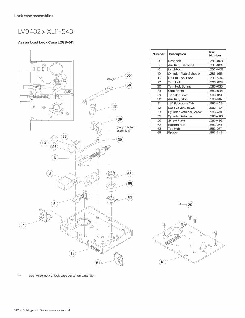
142 • Schlage • L Series service manual
Lock case assemblies
LV9482 x XL11-543
Assembled Lock Case L283-611
65
3
62
63
51
5
6
53
5610
55
33
50
39
51
13
27
30
(couple beforeassembly)**
13
524
Number DescriptionPart Number
3 Deadbolt L283-0035 Auxiliary Latchbolt L283-0066 Latchbolt L283-00810 Cylinder Plate & Screw L283-05513 L9000 Lock Case L283-59427 Turn Hub L583-02930 Turn Hub Spring L583-03533 Stop Spring L583-04439 Transfer Lever L583-05150 Auxiliary Stop L583-19651 1Z\v" Faceplate Tab L583-42652 Case Cover Screws L583-45453 Cylinder Retainer Screw L583-48155 Cylinder Retainer L583-49056 Screw Plate L583-49262 Bottom Hub L583-76563 Top Hub L583-76765 Spacer L583-346
** See "Assembly of lock case parts" on page 153.

Lock case assemblies
Schlage • L Series service manual • 143
L9485 x XL11-557
Assembled Lock Case XL11-557
Number DescriptionPart Number
3 Deadbolt L283-0035 Auxiliary Latchbolt L283-0066 Latchbolt L283-00810 Cylinder Plate & Screw L283-05513 L9000 Lock Case L283-11217 Retractor Hub L583-74818 Hub Spacer L583-02019 Retractor Lever L583-02120 Retractor Rocker L583-02221 Blocking Plate L583-02322 Retractor Link L583-02423 Retractor Crank L583-02524 Hub Spring L583-02625 Fire Door Fuse L583-02726 Fire Door Catch L583-02827 Turn Hub L583-02930 Turn Hub Spring L583-03533 Stop Spring L583-04434 Locking Catch L583-04536 Locking Link L583-04838 Link Pin L583-05039 Transfer Lever L583-05150 Auxiliary Stop L583-19651 1Z\v" Faceplate Tab L583-42652 Case Cover Screws L583-45453 Cylinder Retainer Screw L583-48154 Lock Handing Screw L583-48555 Cylinder Retainer L583-49056 Screw Plate L583-49258 Lock Case Cover L583-496
58
54
4 52
26
25
38
27
55
24
17
19
22
23
18
21
20
34
36
17
10
33
3
51
6
56
53
5
51
13
(couple before assembly)**
30
50
39
(couple before assembly)**
**
** See "Assembly of lock case parts" on page 153.

144 • Schlage • L Series service manual
Lock case assemblies
LM9210, LM9225
Assembled Lock Case 24759599
Number DescriptionPart Number
13 LM9200 Lock Case 2465391716 Latchbolt Guide L583-01517 Retractor Hub L583-74818 Hub Spacer L583-02019 Retractor Lever L583-02120 Retractor Rocker L583-02221 Blocking Plate L583-02322 Retractor Link L583-02423 Retractor Crank L583-02524 Hub Spring 2462489251 1Z\v" Faceplate Tab LM9200 2486505752 Case Cover Screws L583-45474 Lock Case Cover 2462566775 Link Assembly 2465392576 Link, Top, Bell Crank 2461692277 Link, Bottom, Bell Crank 2461693078 Spool Assembly 2451108179 Tilting Link 2462571780 Compression Spring 24683542
51
51
13
527
74
7816
79
78
77
80
75
23
76
24
22
17
20
18
21
19
17
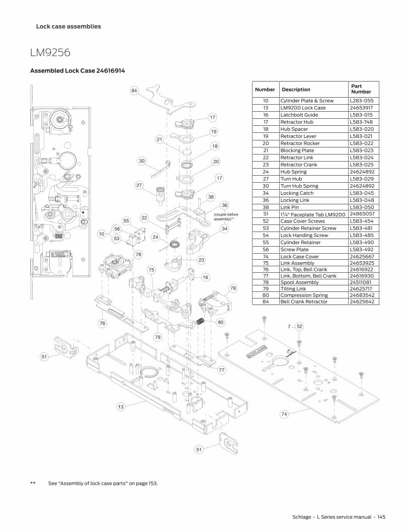
Lock case assemblies
Schlage • L Series service manual • 145
LM9256
Assembled Lock Case 24616914
Number DescriptionPart Number
10 Cylinder Plate & Screw L283-05513 LM9200 Lock Case 2465391716 Latchbolt Guide L583-015 17 Retractor Hub L583-74818 Hub Spacer L583-02019 Retractor Lever L583-02120 Retractor Rocker L583-02221 Blocking Plate L583-02322 Retractor Link L583-02423 Retractor Crank L583-02524 Hub Spring 2462489227 Turn Hub L583-02930 Turn Hub Spring 2462489234 Locking Catch L583-04536 Locking Link L583-04838 Link Pin L583-05051 1Z\v" Faceplate Tab LM9200 2486505752 Case Cover Screws L583-45453 Cylinder Retainer Screw L583-48154 Lock Handing Screw L583-48555 Cylinder Retainer L583-49056 Screw Plate L583-49274 Lock Case Cover 2462566775 Link Assembly 2465392576 Link, Top, Bell Crank 2461692277 Link, Bottom, Bell Crank 2461693078 Spool Assembly 2451108179 Tilting Link 2462571780 Compression Spring 2468354284 Bell Crank Retractor 24625642
51
51
13
527
74
78
16
79
77
80
75
23
76
24
30
36
38
34
27
22
17
20
18
84
21
19
17
55
1056
53
78
(couple beforeassembly)**
** See "Assembly of lock case parts" on page 153.

146 • Schlage • L Series service manual
Lock case assemblies
LM9250, LM9270, LM9271, LM9280
Assembled Lock Case 24759623
51
51
13
527
74
78
16
79
77
80
75
23
76
24
30
36
38
34
27
22
17
20
18
21
19
17
5510
56
53
78
(couple beforeassembly)**
Number DescriptionPart Number
10 Cylinder Plate & Screw L283-05513 LM9200 Lock Case 2465391716 Latchbolt Guide L583-01517 Retractor Hub L583-74818 Hub Spacer L583-02019 Retractor Lever L583-02120 Retractor Rocker L583-02221 Blocking Plate L583-02322 Retractor Link L583-02424 Hub Spring 2462489227 Turn Hub L583-02930 Turn Hub Spring 2464171434 Locking Catch L583-04536 Locking Link L583-04838 Link Pin L583-05051 1Z\v" Faceplate Tab LM9200 2486505752 Case Cover Screws L583-45453 Cylinder Retainer Screw L583-48154 Lock Handing Screw L583-48555 Cylinder Retainer L583-49056 Screw Plate L583-49274 Lock Case Cover 2462566775 Link Assembly 2465392576 Link, Top, Bell Crank 2461692277 Link, Bottom, Bell Crank 2461693078 Spool Assembly 2451108179 Tilting Link 2462571780 Compression Spring 24683542
** See "Assembly of lock case parts" on page 153.

Lock case assemblies
Schlage • L Series service manual • 147
LM9290 EL/EU, LM9292 EL/EU, LM9294 EL/EU
Assembled Lock Case 24759656
72
71
83
13
78
16
79
77
80
75
23
76
24
30
46
38
81
22
17
20
18
21
19
17
51
51
55
1056
53
78
527
54
74
(couple beforeassembly)**
82
Number DescriptionPart Number
10 Cylinder Plate & Screw L283-05513 LM9200 Lock Case 2465391716 Latchbolt Guide L583-01517 Retractor Hub L583-74818 Hub Spacer L583-02019 Retractor Lever L583-02120 Retractor Rocker L583-02221 Blocking Plate L583-02322 Retractor Link L583-02423 Retractor Crank L583-02524 Hub Spring 2462489230 Turn Hub Spring 2464171438 Link Pin L583-05046 Electrified Link 2486989351 1Z\v" Faceplate Tab LM9200 2486505752 Case Cover Screws L583-45453 Cylinder Retainer Screw L583-48154 Lock Handing Screw L583-48555 Cylinder Retainer L583-49056 Screw Plate L583-49271 PCB Overmold L283-34472 Motor Assembly L283-68074 Lock Case Cover 2462566775 Link Assembly 2465392576 Link, Top, Bell Crank 2461692277 Link, Bottom, Bell Crank 2461693078 Spool Assembly 2451108179 Tilting Link 2462571780 Compression Spring 2468354281 Electrified Catch 2430296082 Electrified Hub 2486990183 Capacitor Holder 49001704
** See "Assembly of lock case parts" on page 153.

148 • Schlage • L Series service manual
Lock case assemblies
LM9291 EL/EU, LM9293 EL/EU, LM9295 EL/EU
Assembled Lock Case 24759664
Number DescriptionPart Number
10 Cylinder Plate & Screw L283-05513 LM9200 Lock Case 2465391716 Latchbolt Guide L583-01517 Retractor Hub L583-74818 Hub Spacer L583-02019 Retractor Lever L583-02120 Retractor Rocker L583-02222 Retractor Link L583-02423 Retractor Crank L583-02524 Hub Spring 2462489230 Turn Hub Spring 2464171438 Link Pin L583-05046 Electrified Link 2486989351 1Z\v" Faceplate Tab LM9200 2486505752 Case Cover Screws L583-45453 Cylinder Retainer Screw L583-48154 Lock Handing Screw L583-48555 Cylinder Retainer L583-49056 Screw Plate L583-49271 PCB Overmold L283-34472 Motor Assembly L283-68074 Lock Case Cover 2462566775 Link Assembly 2465392576 Link, Top, Bell Crank 2461692277 Link, Bottom, Bell Crank 2461693078 Spool Assembly 2451108179 Tilting Link 2462571780 Compression Spring 2468354281 Electrified Catch 2430296082 Electrified Hub 2486990183 Capacitor Holder 49001704
72
71
83
13
78
16
79
77
80
75
23
76
24
30
46
38
81
82
22
17
20
18
19
17
51
51
527
54
74
55
1056
53
78
(couple beforeassembly)**
** See "Assembly of lock case parts" on page 153.

Lock case assemblies
Schlage • L Series service manual • 149
Lock case assembly compatibilityUse this table to determine compatibility between parts for lock manufactured in 1994.
L28
3-0
05
Cyl
inde
r Anc
hor A
ssem
bly
L58
3-0
46
Lock
Han
ding
Scr
ew
L58
3-0
46
Face
plat
e Ta
b S
crew
L58
3-0
06
, L58
3-0
07
Face
plat
e Ta
b
L58
3-4
52Lo
ck C
ase
Cov
er
L28
3-0
80
Lock
Cas
e
L58
3-4
80
/48
1/4
82
Cyl
inde
r Ret
aine
r Ass
embl
y
L58
3-4
85
Lock
Han
ding
Scr
ew
L58
3-4
26, L
583-
427
Face
plat
e Ta
b
L58
3-4
84
Lock
Cas
e C
over
L28
3-13
0Lo
ck C
ase
(A
pril
1, 19
94
)
L28
3-13
0Lo
ck C
ase
(Ju
ly 15
, 19
94
)
L283-005
Cylinder Anchor Assembly
• •
L583-046
Lock Handing Screw• •
L583-046
Faceplate Tab Screw• • •
L583-006
L583-007
Faceplate Tab
• • •
L583-452
Lock Case Cover• • •
L283-080
Lock Case• • • • •
L583-480/481/482
Cylinder Retainer Assembly
• • •
L583-485
Lock Handing Screw• • •
L583-426
L583-427
Faceplate Tab
•
L583-484
Lock Case Cover• • • •
L283-130
Lock Case (4-1-94)• • • • •
L283-130
Lock Case (7-15-94)• • • •

150 • Schlage • L Series service manual
Assembly of lock case parts
Assembly of lock case partsTurn hub spring and transfer lever
Transfer Lever
Turn Hub Spring Auxiliary Bar Guide
Locking catch/retractor catch and locking link
Locking Link
Locking Catch

Assembly of lock case parts
Schlage • L Series service manual • 151
L functions only: fire door fuse, fire door catch and hub spring
a b
short end of hub spring
c
Fire Door Fuse
d
LV functions only: fire door fuse, fire door catch and hub spring
ab
c
d
e
f
g

152 • Schlage • L Series service manual
Trim options
Trim options
Cast or forged levers, standard lever designsStandard levers are available in forged brass or bronze, and cast stainless steel. Levers are shown with rose trim A or B. Also available with L or N escutcheon. See escutcheon options on pages 157-159.
01
2¹¹⁄₁₆"
2¹⁄₁₆"
2¹⁄₁₆"
3⁷⁄₈"
02
2¹³⁄₁₆"
1¹³⁄₁₆"
1¹³⁄₁₆"
4³⁄₄"
03
4³⁄₄"
2¹³⁄₁₆"
2"
¹⁄₂" Dia.¹¹⁄₁₆" 05
2⁷⁄₈"
3³⁄₄"2⁹⁄₃₂"
2⁹⁄₃₂"
06
2¹⁄₂"
¹⁄₂"
4⁵⁄₈"2"
07
2⁷⁄₈"
4⁵⁄₈"2³⁄₈"
1³¹⁄₃₂" 12
3¹⁄₁₆"max.
2"
2"
4⁵⁄₈"
Specify hand
17¹⁄₂"
3"
4³⁄₄"
2¹⁄₈"
2¹⁵⁄₁₆"
18
2¹¹⁄₁₆"
2¹⁄₃₂"
2¹⁄₃₂"
4⁷⁄₈"
OME³⁄₈"
2³⁄₁₀" 5¹⁄₁₆"
3⁵⁄₁₆"
93 Bent extruded bar lever design
Note: The 93 lever design is discontinued.
5"
3¹⁄₈"
2⁹⁄₃₂"
⁷⁄₁₆" Dia. ¹¹⁄₁₆"
Inside lever assembly Outside lever assembly
Notes: See Schlage Commercial Price Book for available finishes.

153 • Schlage • L Series service manual
Decorative trim
Decorative trim
Decorative levers
Asti lever (AST) Merano lever (MER) Accent lever (ACC)
Specify hand
2.6”
4.0”
2.0”
Specify hand
3.13”
4.0”
2.0”
Specify hand
3.13”
4.13”
2.0”
Latitude (LAT) Longitude (LON)
2.9”
4.6”
2.0”
2.9”
4.9”0.5”
Decorative roses
Avanti rose (AVA) (AST lever only)
Merano rose (MER) (MER lever only)
2B\," diameter 2B\," diameter
Note: See Schlage Commercial Price Book for available finishes.

154 • Schlage • L Series service manual
M collection levers
M collection leversM collection levers are available in solid brass and solid stainless steel. Levers are shown with rose trim A. Also available with L or N escutcheon. See escutcheon options on pages 157-159.
M51
4.5”
3.2”
2.4” M52
4.5”
3”
2.2” M53
3.2”
2.55”
4.35”
M54
4.35”2.3”
2.75”
2.13”
M55
4.3”
3”
2.1” M56
2.4” 4.5”
3”
2” M57
2.9”
2.1”
4.5”
M61
4.5”
2.3”
1.2”
M62
4.5”
2.6”
1.9” M63
4.5”
3.15”
2” M81
4.8”
0.4”
2.9”
2.1”
M82
2.2”4.8”
2.85”
0.4”
M83
4.6”
2.85”
0.4”M84
5”
3”
0.4”
M85
5”
3.3”
0.3”
ME1
3.0”
5.5”0.4”
ME2
2.8”
5.2”0.4”
ME3
3.2”
5.1”0.4”
Inside lever assembly Outside lever assembly09-402 09-401
Bushing attached at factory. Furnished with spanner wrench.
Furnished with retainer seating tool.
Note: See Schlage Commercial Price Book for available finishes.

155 • Schlage • L Series service manual
Wrought knob designs
Wrought knob designsKnobs shown with rose trim A or B. Also available with L or N escutcheons.
See escutcheon options on pages 157-159.
41 (PLY)
2¹⁄₄"
2³⁄₄"
42 (ORB)
2¹⁄₈"
2³⁄₄"
Inside knob assembly Outside knob assembly09-402 09-401
Note: See Schlage Commercial Price Book for available finishes.
Tactile warning (knurling) levers and knobsApplied to outside knob/lever only unless otherwise specified. Available on 01, 02, 03, 05, 06, 07, 12, 17, 18, M51, M52, M81, ME1, ME2, and ME3 lever designs, and 41 and 42 knob designs.
Milling pattern for backside of 01, 06, 07, 17, and 18 levers.
Knurling pattern for 02 lever. Knurling pattern for 03 lever.
Milling pattern for backside of 05 lever. Milling pattern for underside of 12 lever. Specify door hand.
Knurling pattern for 42 knob.
Notes: When ordering trim parts, specify the complete design and finish (e.g. 09-633-03L 605). See Schlage Commercial Price Book for available finishes. To specify knurling, place the number 8 in front of the lever design code (e.g. 801 for lever design 01 with knurling).

156 • Schlage • L Series service manual
Rose trim A, B, or C
Rose trim A, B, or CA B C
2Z\," diameter 2>\zn" diameter 2B\," diameter
Inside rose Blank outside rose
09-403 09-508
Rose design A– 2Z\," dia. x ZC\cx"
Rose design B– 2>\zn" dia. x ZC\cx"
Rose design C– 2B\," dia. x ZC\cx"
Rose design A– 2Z\," dia. x ZC\cx"
Rose design B– 2>\zn" dia. x ZC\cx"
Rose design C– 2B\," dia. x ZC\cx"
Furnished with mounting plate and screws. For decorative trim, see page 153.
Furnished with mounting plate, screws, and plug. Used to mount inside rose trim on doors prepared for trim both sides. Not available in MER or AVA designs.
Outside rose with bushing dimensions09-404 or 09-506 with knob or lever. Bushing is attached at factory.
41, 42 01, 02, 03, 05, 06, 07, 12, 17, 18, ACC, LAT, LON, OME, STA
AST, MER, M51, M52, M53, M54, M55, M56, M57, M61, M62, M63, M81, M82, M83, M84, M85
1Z\,"
>\zn"
1"
M\,"
All rose designs ZC\cx"
C\v"
M\,"
2Z\," Design A 2>\zn" Design B

157 • Schlage • L Series service manual
L escutcheon trim
L escutcheon trimOutside escutcheon dimensions
Knob/lever design: 7ZB\zn" x 1C\v" x M\zn" cold forged brass, bronze, or stainless steel base material. Bushing is attached at factory.
41, 42 01, 02, 03, 05, 06, 07, 12, 17, 18, ACC, LAT, LON, OME, STA
ACC, AST, MER, OME, STA, M51, M52, M53, M54, M55, M56, M57, M61, M62, M63, M81, M82, M83, M84, M85
1Z\,"
>\zn" M\,"
1"
M\,"
C\v"
Outside escutcheons
09-636 Outside blank x knob/lever
09-637 Emergency turn x knob/lever
09-638 Concealed cylinder x knob/lever
09-639 Full face cylinder x knob/lever
Specify 09-636 or 09-550 with knob/lever.
Specify 09-637 or 09-551 with knob/lever.
Specify 09-638 or 09-552 with knob/lever.
Specify 09-639 or 09-553 with knob/lever.
Xl11-636 Blank outside 09-636 x Xl11-446 outside with thumbturn x knob/lever
09-614 outside with full face cylinder
09-615 outside with concealed cylinder
Specify XL11-636 OOL. For L9040 x XL11-446 function. Not sold separately.
For L9026 function. For L9026 function.

158 • Schlage • L Series service manual
L escutcheon trim
Inside Escutcheons
09-632 Blank x knob/Lever 09-633 Thumbturn x knob/Lever 09-634 Thumbturn x blank
Specify door thickness: 1C\," or 1C\v" Available with EZ Turn (ADA). See "Additional trim options" on page 162.
Specify door thickness: 1C\," or 1C\v" Available with EZ Turn (ADA). See "Additional trim options" on page 162.
09-635 Full face cylinder x Knob/Lever L583-187 Concealed cylinder x knob/lever XL11-634 Blank inside
Notes: When ordering trim parts, specify the complete design and finish (e.g. 09-632 01L 605). See Schlage Commercial Price Book for available finishes.

159 • Schlage • L Series service manual
N escutcheon trim
N escutcheon trimOutside escutcheon dimensionsKnob/lever design: 7M\," x 2Z\x" x M\zn" heavy wrought reinforced brass, bronze, or stainless steel base material. Bushing is attached at factory.
41, 42 01, 02, 03, 05, 06, 07, 12, 17, 18, ACC, OME, STA AST, MER, M51, M52, M53, M54, M55, M56, M57, M61, M62, M63, M81, M82, M83, M84, M85
1¹⁄₂”
⁹⁄₁₆”
1”
⁷⁄₈”
³⁄₄”
⁷⁄₈”
Outside escutcheons
09-636 Outside blank x knob/lever
09-637 Emergency turn x knob/lever
09-639 Full face cylinder x knob/lever
Xl11-636 Blank outside
Specify 09-636 or 09-550 with knob/lever.
Specify 09-637 or 09-551 with knob/lever.
Specify 09-639 or 09-553 with knob/lever.
Specify XL11-636 00N and finish.
Inside escutcheons
(Includes two (2) screws and mounting plate)
09-632 Blank x knob/lever 01, 02, 03, 05, 06, 07, 12, 17, 18 ACC, AST, MER, OME, STA
1¹⁄₂”
⁹⁄₁₆”
1”
⁷⁄₈”
³⁄₄”
⁷⁄₈”
Notes: When ordering trim parts, specify the complete design and finish (e.g. 09-402 03N 605). See Schlage Commercial Price Book for available finishes.
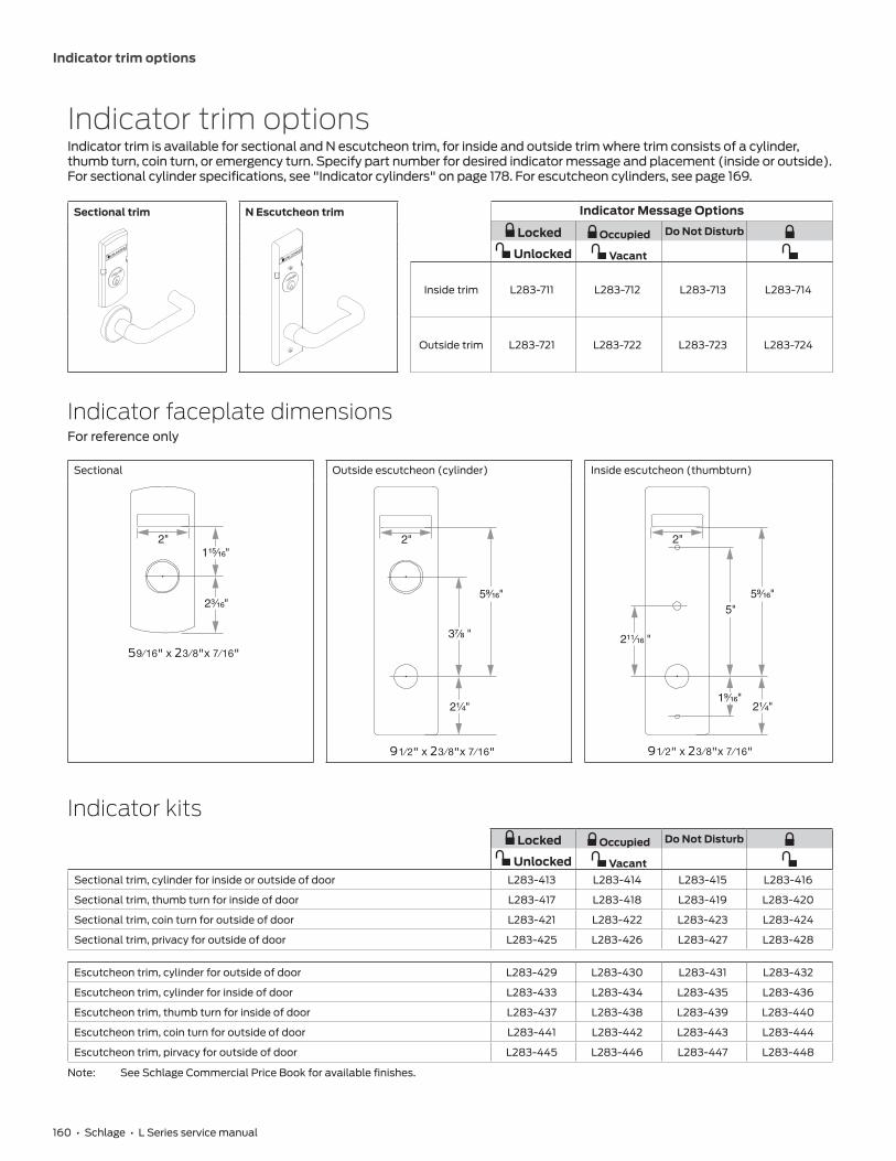
160 • Schlage • L Series service manual
Indicator trim options
Indicator trim optionsIndicator trim is available for sectional and N escutcheon trim, for inside and outside trim where trim consists of a cylinder, thumb turn, coin turn, or emergency turn. Specify part number for desired indicator message and placement (inside or outside). For sectional cylinder specifications, see "Indicator cylinders" on page 178. For escutcheon cylinders, see page 169.
Sectional trim N Escutcheon trim Indicator Message Options
Locked Occupied Do Not Disturb
Unlocked Vacant
Inside trim L283-711 L283-712 L283-713 L283-714
Outside trim L283-721 L283-722 L283-723 L283-724
Indicator faceplate dimensionsFor reference only
Sectional Outside escutcheon (cylinder) Inside escutcheon (thumbturn)
59\16" x 23 \ 8"x 7\16"
2"1¹⁵⁄₁₆"
2³⁄₁₆"
91\2" x 23 \ 8"x 7\16"
2"
5⁹⁄₁₆"
3⁷⁄₈ "
2¹⁄₄"
2"
5⁹⁄₁₆"5"
2¹¹⁄₁₆ "
2¹⁄₄"1⁹⁄₁₆"
91\2" x 23 \ 8"x 7\16"
Indicator kits Locked Occupied Do Not Disturb
Unlocked VacantSectional trim, cylinder for inside or outside of door L283-413 L283-414 L283-415 L283-416
Sectional trim, thumb turn for inside of door L283-417 L283-418 L283-419 L283-420
Sectional trim, coin turn for outside of door L283-421 L283-422 L283-423 L283-424
Sectional trim, privacy for outside of door L283-425 L283-426 L283-427 L283-428
Escutcheon trim, cylinder for outside of door L283-429 L283-430 L283-431 L283-432
Escutcheon trim, cylinder for inside of door L283-433 L283-434 L283-435 L283-436
Escutcheon trim, thumb turn for inside of door L283-437 L283-438 L283-439 L283-440
Escutcheon trim, coin turn for outside of door L283-441 L283-442 L283-443 L283-444
Escutcheon trim, pirvacy for outside of door L283-445 L283-446 L283-447 L283-448
Note: See Schlage Commercial Price Book for available finishes.

161 • Schlage • L Series service manual
Indicator trim options
Indicator parts
Part number Description
L583-709 Message sign, locked/unlocked for 180° indicator
L583-710 Message sign, occupied/vacant for 180° indicator
L583-711 Message sign, do not disturb/blank for 180° indicator
L583-712 Message sign, symbols only for 180° indicator
L283-561 Cam kit, 180° indicator (includes cam and C\," retaining ring) cylinder and privacy indicators
L583-736 Screw pack: 2 each: L583-579 Mounting Plate Screws, L583-899 Mounting Plate Screws, and L583-755 Trim Screws (specify finish)
Part number Description
L583-705 Cam, 180° indicator, thumb turn and coin turn indicators
L283-629 Cam kit, 180° indicator (includes cam and C\," retaining ring), thumb turn and coin turn indicators
L583-579 Screw, top, sectional mounting plate
L583-899 Screw, bottom, sectional mounting plate
L583-717 Sectional mounting plate, cylinder indicator
L583-752 Sectional mounting plate, coin/privacy/thumbturn indicator
09-611 Occupancy indicators"Old style" for sectional (rose) trimAvailable for functions L/LV9486 and L/LV9496 only. Specify finish.
09-611, Do not disturb* 09-611 x L583-375, Occupied* 09-611 x XL11-986, Locked*
DO NOT DISTURB
OCCUPIED
LOCKED
* Includes driver bar L583-245.
L583-245, Occupancy indicator breakaway driver bar
Breakaway driver bars, all door ranges. L496, L/LV9486 and L/LV9496 functions.

162 • Schlage • L Series service manual
Additional trim options
Additional trim options
Thumbturn for rose (sectional) trim09-544 Standard ADA turn* 09-509 Basic turn (optional) 09-509 per L583-363, large ADA turn
1³⁄₄"⁷⁄₁₆"
1¹¹⁄₃₂"
Thumbturn for deadbolt functions and privacy locks with rose trim.
09-544 is standard thumbturn for all orders unless otherswise specified.
Optional thumbturn for deadbolt functions and privacy locks with rose trim.
Not available for L463 or L9463 functions.
Thumbturn for escutcheon trim
09-548 Standard ADA turn for L escutcheon
09-642 Standard ADA turn for N escutcheon
09-633 Large ADA turn x knob/lever L or N escutcheon per L583-363
09-634 Large ADA turn x blank L escutcheon per L583-363
L N
* Not available in 612 or 613 finishes. For 612 or 613 finishes, order large ADA thumbturn 09-500 x L583-363. For thick door applications, specify 09-509 x L583-363.

163 • Schlage • L Series service manual
Additional trim options
Cylinder turnXB11-720 Cylinder with ADA compliant thumbturn
09-900 Cylinder turn 09-487 Cylinder coin turn
Available with L463 and L9463 locks. Specify per XB11-720, and door hand. If handing is not required, specify NH (non-handed). When ordered alone, specify either 09-900, 09-904, 09-905 or 09-907 per XB11-720.
09-900 through 09-907 Cylinder classroom turns are furnished with L463 and L9463 locks. Specify dimension and door hand. If handing is not required, specify NH. See handing instructions on page 189.
Specify dimension and door hand. If handing is not required, specify NH (non-handed).
Notes: Specify door thickness. When ordering trim parts, specify the complete design and finish (e.g. 09-633-03L 605). See Schlage Commercial Price Book for available finishes.
Coin turnL283-124 Coin turn, standard, L9044 and L9444
L283-056 Coin turn with torx screws, L9044 and L9444
Privacy turnL583-691 Emergency turn tool, for L9040 and L9440
K510-330 Emergency button, L9040 and L9440
Specify 458 finish.
Notes: Specify door thickness. Emergency turn tool L583-691 will not operate privacy indicator. When ordering trim parts, specify the complete design and finish (e.g. 09-633-03L 605). See Schlage Commercial Price Book for available finishes.
03 lever for Folger Adam Co.� Lever Trak™
503 lever design
Modified inside and outside 03 lever. Specify lever design as 503. Available for rose trim only. Lever Trak is not included.

164 • Schlage • L Series service manual
Trim assembly parts
Trim assembly partsEscutcheon thru-bolt/screwsTwo required per lock
Part number Specify finish
Description Door thickness
L583-119 •
L escutcheon thru-bolts/screws
1C\,"
L583-120 • 1C\v"
L583-121 • 2"
L583-122 • 2Z\v"
L583-123 • 2Z\x"
K510-389 •N escutcheon thru-bolts/screws
1C\v"
K510-390 • 2–2Z\v"
L583-287 • L escutcheon thru-bolts/screws, L0170 single –
L583-133 • N escutcheon thru-bolts/screws, L0170 single –
Standard screw packs
Part number Specify finish
Description Contents
C203-736 455 Lock case mounting screws (2) C603-256, #12-24 WMS PFH
C203-736 • Strike screws (2) C603-256, #12-24 WMS PFH
K110-020 • Armor mounting screws (2) K510-210, #8-32 x Z\v" PFHMS
K110-947 • Rose trim thumbturn screws (2) K510-445, #4 x Z\x" POH AB
L283-100 Trim mounting screws and posts, 1C\v" doors (2) L583-066, #8-32 x B\," PFH (2) L583-212, 1C\v" ferrule
L283-101 • L escutcheon thru-bolts, 1C\v" doors (2) L583-120
Tamper resistant Torx� screw packs
Part number Specify finish
Description Contents
L283-121 • Rose trim without thumbturn (2) Armor screws, L583-370, #8-32 x Z\v" (T-15) (2) Strike screws, L583-371, #12-24 x Z\x" (T-20)
L283-123 • L escutcheon trim for 1C\v" doors (2) Armor screws, L583-370, #8-32 x Z\v" (T-15) (2) Strike screws, L583-371, #12-24 x Z\x" (T-20) (2) Escutcheon mounting screws, L583-373, Z\v-28 x 2Z\," (T-30)
L283-122 • Rose trim with thumbturn (2) Armor screws, L583-370, #8-32 x Z\v" (T-15) (2) Strike screws, L583-371, #12-24 x Z\x" (T-20) (2) Thumbturn screws, L583-372, #4 x 2Z\x" (T-8)
XL11-848 • N escutcheon trim for 1C\v" doors (2) Armor screws, L583-370, #8-32 x Z\v" (T-15) (2) Strike screws, L583-371, #12-24 x Z\x" (T-20) (2) Escutcheon mounting screws, XL11-841, #8-32 x 1Z\x" (T-20)
Note: Torx® screw packs are furnished with appropriate T-xx installation tools.

165 • Schlage • L Series service manual
Trim assembly parts
Mounting postsTwo required per lock
L Functions LV Functions
Part number Door thickness Part number Door thickness
L583-211 1C\," N/A 1C\,"
L583-212 1C\v" L583-497 1C\v"
L583-213 2" L583-498 2"
L583-214 2Z\v" L583-499 2Z\v"
L583-215 2Z\x" L583-500 2Z\x"
L583-216 2C\v" L583-501 2C\v"
L583-217 3" L583-502 3"
L583-218 3Z\v" L583-503 3Z\v"
L583-219 3Z\x" L583-504 3Z\x"
Spindles and springs
Part number Description
L283-060 Spindle and spring for 1C\,"–1M\," doors (two required per lock)
L283-061 Spindle and spring for 2"–3Z\x" doors (two required per lock)
L283-064 Spindle and spring for L0172 double dummy, L9091 EL/EU, L9093 EL/EU, L9095 EL/EU, L9493 EL/EU, L9495 EL/EU (one required per lock)
L283-065 Spindle and spring for L0170 single dummy (one required per lock)
L283-198 Spindles and springs kit (two each) for 1C\,"–1M\," doors
L283-199 Spindles and springs kit (two each) for 2"–3Z\x" doors

166 • Schlage • L Series service manual
Trim assembly parts
Mounting plate for trim one side onlyL283-150 Mounting plate and posts for rose trim on one side of door. For lever, use with mounting plate L283-031. For knob, use with mounting plate L583-321.
DOOR DETAILFor location of cylinder and/or thumbturn holes, as well as all
other dimensions, see appropriate lock function template.Measure backset from CL of door edge.
CL
OUTSIDE OFLH DOOR
INSIDE OFLH DOOR
DOOR EDGE
3¹⁄₂" (89 mm)Min. Wooddoors only
1⁹⁄₁₆" (40 mm)Min. Wooddoors only
LOCKFRONT
1¹⁄₈" (29 mm)Min. clearance
NOTE: Prepare door for rose trim on one side of door only.
1.718"(44 mm)
0.11"3 mm
1.76"45 mm
Mounting Plate
Mortise door for proper fit of mounting plate.
L-Series Installation InstructionsMounting plate for trim one side
© Allegion 2014P513-301 Rev. 01/14
ANSI A115.1 1990 Hollow steel door installations
Spacers
Spring cage(lever applications)ORMounting plate(knob applications)
L283-029 For 1C\v" thick hollow steel doors prepared per ANSI A115.1, 1990.
Install two spacers between the spring cage (or knob mounting plate) and lock as chassis shown. Spacers are required for both the inside and outside escutcheons.
Note: L escutcheon designs are not applicable for ANSI A115.1 door preparations.
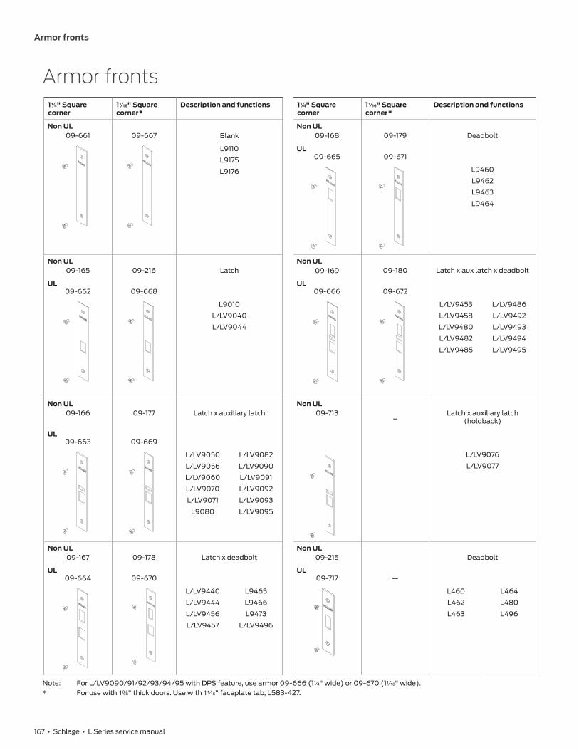
167 • Schlage • L Series service manual
Armor fronts
Armor fronts1Z\v" Square corner
1Z\zn" Square corner*
Description and functions 1Z\v" Square corner
1Z\zn" Square corner*
Description and functions
Non UL09-661 09-667 Blank
Non UL09-168 09-179 Deadbolt
L9110
L9175
L9176
UL09-665 09-671
L9460
L9462
L9463
L9464
Non UL09-165 09-216 Latch
Non UL09-169 09-180 Latch x aux latch x deadbolt
UL09-662 09-668
UL09-666 09-672
L9010
L/LV9040
L/LV9044
L/LV9453
L/LV9458
L/LV9480
L/LV9482
L/LV9485
L/LV9486
L/LV9492
L/LV9493
L/LV9494
L/LV9495
Non UL09-166 09-177 Latch x auxiliary latch
Non UL09-713
–Latch x auxiliary latch
(holdback)
UL09-663 09-669
L/LV9076
L/LV9077
L/LV9050
L/LV9056
L/LV9060
L/LV9070
L/LV9071
L9080
L/LV9082
L/LV9090
L/LV9091
L/LV9092
L/LV9093
L/LV9095
Non UL09-167 09-178 Latch x deadbolt
Non UL09-215 Deadbolt
UL09-664 09-670
UL09-717 —
L/LV9440
L/LV9444
L/LV9456
L/LV9457
L9465
L9466
L9473
L/LV9496
L460
L462
L463
L464
L480
L496
Note: For L/LV9090/91/92/93/94/95 with DPS feature, use armor 09-666 (1Z\v" wide) or 09-670 (1Z\zn" wide).* For use with 1C\," thick doors. Use with 1Z\zn" faceplate tab, L583-427.
168 • Schlage • L Series service manual
Strikes
StrikesSquare corner 10-072 Square corner 10-072 Square corner 10-073 Square corner 10-075
Standard 1C\zn" Lip
Size: 4M\," x 1Z\v"
M\,'', 1'', 1Z\x'', 1C\v'' or 2'' Lip
Size: 4M\,'' x 1Z\v''
Deadbolt Strike, No Lip
Size: 4M\," x 1Z\v"
Z\x' Rabbeted, No Lip
Size: 4M\," x 1"
Square corner 10-078 Square corner 10-079 Square corner 10-091 Door frame reinforcer 37-015
L400 Series No Lip
Size: 4M\," x 1Z\v"
L400 Series, Standard
No Lip
Size: 3Z\x" x 1Z\,"
L and RR or R and LR (Armor strike) 1C\zn" Lip
Specify handing
Size: 8" x 1Z\v"
L9000 Series Z\v" Radius Round Corner
Size: 4M\," x 1Z\v"
Square corner 10-144 Square corner 10-145 Strike box K510-066
L and RR 1C\zn" Lip
Size: 4M\," x 1Z\v"
R and LR 1C\zn" Lip
Size: 4M\," x 1Z\v"
Size: 4ZC\zn" x 1Z\v" x ZB\zn"
Strike dimensions and components
Part number Lip Lock series Door range Strike box Screws (2 ea)
10-072* 1" L9010 to L9496 — K510-066 C603-256
1C\zn" 1C\,"–1M\," K510-066 C603-256
1Z\x" 1M\,"–2Z\," K510-066 C603-256
1C\v" 2Z\,"–2B\," K510-066 C603-256
2" 2B\,"-3Z\," K510-066 C603-256
M\," — K510-066 C603-256
10-073 — — K510-066 C603-256
10-075** — L9000 Series — — C603-256
10-078 — L400 Series — K510-066 C603-256
10-079 — — K510-053 C603-256
10-091** 1C\zn" L9175, L9176 1C\,"–1M\," — K510-210
10-144, 10-145 1C\zn" SK1, SL1 and HSLR trim 1C\v" K510-066 C203-736
37-015 — L9000 — — —
* Specify lip length.** For 1C\," thick doors use 1Z\zn" wide armor fronts. For 1C\v" thick and up doors, use 1Z\v" wide armor fronts.Note: Strike boxes and screws can be ordered as parts.

169 • Schlage • L Series service manual
Cylinders
Cylinders
How to measure cylinder lengths
Full face and interchangeable core Concealed Cylinder length Dimension
LENGTH LENGTH 1Z\,’’ 118
1Z\v’’ 114
1C\,’’ 138
1Z\x’’ 112
1B\,’’ 158
1C\v’’ 134
L Series, LV Series cylinder and length requirementsIncludes 180° indicators with escutcheon trim. For 180° indicators with sectional trim, see page 176.
Function Trim Cylinder Door Thickness
1C\,’’ 1C\v’’ 2” 2Z\v”
Dimension
L9050, L9056, L9070, L9076, L9080, L9453, L9456, L9460 per XL11-635, L9460 per XL11-886, L9464 per XL11-886, L9465, L9473, L9480
Rose 30-001 118 118 118 118
Escutcheon 30-021 118 114 138 112
Concealed 30-004 118 114 138 112
LM9280, LM9380 Rose 30-000 118 114 — —
Escutcheon 30-019 118 114 — —
L9485 Rose 30-002 — 118 118 118
Escutcheon 30-022 — 114 138 112
Concealed 30-005 — 114 138 112
L9486 Rose 30-002 114 138 112 158
Escutcheon 30-022 118 114 138 112
Concealed 30-005 118 114 138 112
L9496 Rose 30-001 114 138 112 158
Escutcheon 30-021 118 114 138 112
Concealed 30-004 118 114 138 112
L9060 inside, L9071, L9077, L9082, L9457, L9458, L9462 per XL11-886, L9464, L9466, L9482
Rose 30-001 118 118 118 118
Escutcheon 30-001 114 — — —
30-021 — 118 114 138
Concealed 30-004 — 118 114 118
L9060 outside Rose 20-001 118 118 118 118
Escutcheon 20-001 114 — — —
26-021 — 118 114 138
Concealed 26-023 — 118 114 138
L460, L462, L463, L464, L496, L9460, L9462, L9463, L9464 Rose trim only 30-001 118 118 118 118
Note: Blocking ring and/or compression rings may be required and must be ordered separately. See page 177 for details.

170 • Schlage • L Series service manual
Cylinders
Full face cylinders
Cylinder front Cylinder back Cylinder only
Cylinder with compression ring and spring
Face plate and front cover
Cylinder plug assembly
Back housing
Screws
Cam screw
Cam
L Series, LV Series (except L9060/LV9060 outside and LM9280, LM9380/LMV9380)
Description Cylinder mechanism Complete cylinder
Cylinder only: L and N escutcheons
Conventional 30-021Primus� controlled access 20-793Primus XP controlled access 20-793-XPPrimus UL437 20-593Primus XP UL437 20-593-XPHotel function 30-022*
Cylinder with compression ring and spring: Rose trim
Conventional 30-001Primus controlled access 20-787Primus XP controlled access 20-787-XPPrimus UL437 20-587Primus XP UL437 20-587-XPPrimus lockout 20-717Primus XP lockout 20-717-XPPrimus UL437 lockout 20-517Primus XP UL437 lockout 20-517-XPHotel function 30-002*Everest 29 SL 91-062Everest 29 SL Primus XP 91-757-XP
Traditional cams Modular cams
L583-254 Classic conventional
L583-474 1Z\,", 1C\,", 1B\," length
L583-800 Everest 29 SL 1Z\," length
L583-153 Everest� and Primus�
L583-475 1Z\v", 1Z\x", 1C\v" length
L583-801 Everest 29 SL 1Z\v" length
L9060/LV9060 outside
Description Cylinder mechanism Complete cylinder
Cylinder only: L and N escutcheons
Conventional 26-021Primus controlled access 20-701Primus XP controlled access 20-701-XPPrimus UL437 20-501Primus XP UL437 20-501-XP
Cylinder with compression ring and spring: Rose trim
Conventional 20-001Primus controlled access 20-700Primus XP controlled access 20-700-XPPrimus UL437 20-500Primus XP UL437 20-500-XPPrimus lockout 20-715Primus XP lockout 20-715-XPPrimus UL437 lockout 20-515Primus XP UL437 lockout 20-515-XPEverest 29 SL 91-051Everest 29 SL Primus XP 91-751-XP
Cylinder with compression ring and Z\,’’ blocking ring
Conventional (available in 1Z\," only)
20-002
Traditional cams Modular cams
B502-191 Conventional
L583-476 1Z\,", 1C\,", 1B\," length
L583-802 Everest 29 SL 1Z\," length
B502-948 Everest and Primus
L583-477 1Z\v", 1Z\x", 1C\v" length
L583-803 Everest 29 SL 1Z\v" length
* Specify hand for hotel function cylinders. Not available in Primus. Furnished 0-bitted; emergency keys must be ordered separately.Notes: Lockout keys are not furnished with cylinders and must be ordered separately. Lockout cylinders will not be master-keyed by Schlage.

171 • Schlage • L Series service manual
Cylinders
LM9280 and LM9380/LMV9380 Full face cylinders
Description Cylinder mechanism Complete cylinder Modular Cams
Cylinder only: L and N escutcheons Conventional (specify handing) 30-019 L583-475Cylinder only: Rose 30-000 L583-474 or L583-475Cylinder only: L and N escutcheons Everest 29 SL 91-130 L583-801Cylinder only: Rose 91-129 L583-800
Note: Refer to modular cam illustrations on previous page.
Concealed cylindersCylinder front Cylinder back Cylinder only
Shell
Cylinder plug assembly
Screw
Cam
Cylinder
plug
Cam
L Series, LV Series (except L9060/LV9060 outside)
Description Cylinder mechanism Complete cylinder Cams
Cylinder only: L escutcheon
Conventional 30-004 L583-254 Conventional
L583-153 Everest� and Primus�
Primus� controlled access 20-789
Primus XP controlled access 20-789-XP
Primus UL437 20-589
Primus XP UL437 20-589-XP
Hotel function 30-005*
L Series, LV Series L9060/LV9060 outside
Description Cylinder mechanism Complete cylinder Cams
Cylinder only: L escutcheon
Conventional 26-023 B502-191 Conventional
B502-948 Everest and Primus
Primus controlled access 24-767
Primus XP controlled access 24-767-XP
Primus UL437 24-567
Primus XP UL437 24-567-XP
* Specify hand for hotel function cylinders. Not available in Primus® . Emergency keys must be ordered separately.Notes: 1) Everest hotel function cylinders are available in 1Z\,’’, 1Z\v’’, and 1C\,’’ only. 2) 1Z\,’’ (Dim=118) cylinders are furnished unless otherwise specified. Cylinder length depends on function, trim and door thickness. 3) Finishes: 606 and 626. 4) Specify LKB if 0-bitted Primus cylinders are required less key blanks. 5) Extended lengths are available.

172 • Schlage • L Series service manual
Cylinders
Full size interchangeable core cylinders
Cylinder front Cylinder back Cylinder only
Cylinder with compression ring and spring
Cylinder with blocking ring
Shell
Cylinder plug assembly
Screw
Cam1¹⁄₂"1¹⁄₂"1¹⁄₂"
1¹⁄₂"1¹⁄₂"
L /LV/LM/LMV-Series (except L9060 /LV9060 outside and LM9280, LM9380/LMV9380)
Description Cylinder mechanism Complete cylinder Cam
Cylinder only: L and N escutcheons Housing less core 30-016 L583-255Cylinder with compression ring and spring: L and N escutcheons Conventional core 30-008*
Everest SL core 91-163Primus� core 20-798Primus XP core 20-798-XPEverest SL Primus XP core 91-863-XPHotel function 30-010**Housing less core 30-007
Cylinder with compression ring, compression spring and C\,” blocking ring: rose trim
Conventional core 30-138*Everest SL core 91-169Primus core 20-776Primus XP core 20-776-XPEverest SL Primus XP core 91-869-XPHotel function core 30-140**Housing less core 30-137
L, LV Series L9060 /LV9060 outside
Description Cylinder mechanism Complete cylinder Cam
Cylinder only: L and N escutcheons Housing less core 30-032 K510-680Cylinder with compression ring and spring: L and N escutcheons Conventional core 30-030*
Everest SL core 91-165Primus core 20-782Primus XP core 20-782-XPEverest SL Primus XP core 91-865-XP
Cylinder with compression ring, compression spring and Z\x” blocking ring: rose trim***
Primus core 20-783Primus XP core 20-783-XP
LM, LMV-Series LM9280 and LM9380 /LMV9380
Description Cylinder mechanism Complete cylinder Cam
Cylinder with compression ring and spring
FSIC housing and core (specify handing) 26-101* L583-509 (RH) L583-589 (LH)
FSIC housing less core (specify handing) 26-102
FSIC housing less logo core (specify handing) 26-103
* Can be ordered with construction core.** Specify hand for hotel function cylinders. Not available in Primus®. Emergency key must be ordered separately.*** For this configuration with conventional core, order 30-030 cylinder and 36-082-050 blocking ring.

173 • Schlage • L Series service manual
Cylinders
Assembled full size interchangeable cores
Part number Description
23-030 Conventional core 23-030
23-031 Conventional core less logo
91-161 Everest SL core (B, R keyways only)
91-162 Everest SL core less logo (B, R keyways only)
20-740 Primus� core
20-740-XP Primus XP core
20-741 Primus core less logo 23-031
20-741-XP Primus XP core less logo
91-861-XP Everest SL Primus XP core (B, R keyways only)
91-862-XP Everest SL Primus XP core less logo (B, R keyways only)
30-120* Hotel function conventional core for L9485 and L9486
30-121* Hotel function conventional core, less logo, for L9485 and L9486
Full size core parts
Part number Description
C503-115 Cap pin spring (order in multiples of 100)
C503-118 Retainer cap (order in multiples of 25)
C603-827 Cap pin (order in multiples of 100)
C603-956 Actuating ring
C603-964 Actuating pin (control top pin)
C603-967 Control bottom pin (order in multiples of 100)
* Specify hand for hotel function cores. Emergency keys must be ordered separately.** For cores manufactured before November 1997.Notes: 1) Control keys must be ordered separately. 2) Finishes: 606 and 626. 3) Full size cores, conventional and Primus�, can be integrated into any Schlage key system with compatible Everest� or Classic keyways. 4) Primus® cores can be integrated into any Schlage 6-pin key system with compatible Primus keyways. 5) Primus® cores are Controlled Access. Specify LKB if 0-bitted Primus cores are required less key blanks.

174 • Schlage • L Series service manual
Cylinders
Small format interchangeable core cylinders
Cylinder front Cylinder back Cylinder only
Cylinder with compression ring and spring
Cylinder with blocking ring
Shell
Cylinder plug assembly
Screw
Cam
Driver
1³⁄₈"1³⁄₈"1³⁄₈"
1³⁄₈"1³⁄₈"
L /LV/LM/LMV-Series (except L9060 /LV9060 outside and LM9280, LM9380/LMV9380)
Description Cylinder mechanism Complete cylinder Cam
Cylinder with compression ring and spring: L and N escutcheons
Everest� and Everest 29™ restricted combinated core (B, R keyways only)
80-308 L583-255
Construction core Disposable 80-115
Keyed 80-138
Housing less core 80-108
Cylinder with compression ring, compression spring and Z\v’’ blocking ring: rose trim
Everest and Everest 29 restricted combinated core (B, R keyways only)
80-301
Construction core Disposable 80-109
Keyed 80-131
Housing less core 80-101
L, LV Series L9060 /LV9060 outside
Description Cylinder Mechanism Complete Cylinder Cam
Cylinder with compression ring and spring: L and N escutcheons*
Everest and Everest 29 restricted combinated core (B, R keyways only)
80-304 K510-680
Construction core Disposable 80-112
Keyed 80-134
Housing less core 80-104
LM, LMV-Series LM9280 and LM9380/LMV9380
Description Cylinder Mechanism Complete Cylinder Cams
Cylinder with compression ring and spring
SFIC housing (specify handing) 26-104 L583-509 (RH) L583-589 (LH)
SFIC housing and temporary core (specify handing) 26-105
SFIC housing and core (specify handing) 26-106
Other straight cam applications
Description Cylinder mechanism Complete cylinder Cam
Cylinder with compression ring, compression spring and Z\v’’ blocking ring
Everest and Everest 29 restricted combinated core
80-302 K510-730
Construction core Disposable 80-110
Keyed 80-132
Housing less core 80-102
* For rose trim also order 36-082-050 blocking ring.

175 • Schlage • L Series service manual
Cylinders
Everest� and Everest 29™ patented small format interchangeable keyway cores
Part number Description 80-036, 80-037
80-037 Everest combinated core, includes master keying
80-036 Everest uncombinated core (does not include keys, pins or springs)
Notes: 1) Finishes: 606, 613, and 626. 2) Everest® B-family keyways are restricted. 3) Key symbol must be specified for combinated cores. 4) Control keys must be ordered separately. 5) Specify 80-035 for construction cores.
Special cylinder applications
“X” Number Description
XB03-418 Extended mortise cylinder (20-001, 30-001 or 30-004), 1M\,’’–5’’ long, Classic or Everest®
XB11-475* Full size IC extended mortise cylinder (26-091 or 30-008), 2Z\v’’–5’’ long, Classic or Everest®
Primus® full size IC extended mortise cylinder (20-763 or 20-798), 2Z\v’’–5’’ long
Full size IC mortise cylinder housing less core (20-059 or 30-007) 2Z\v’’–5’’ long
XB11-638 Primus® mortise cylinder (20-700, 20-787, or 20-789), 1M\,’’–5’’ long
* Available in Z\v” increments. Order collars or blocking rings separately to fill gaps.Notes: 1) Specify complete cylinder as required, then “X” number (e.g. 20-001-118-P per XB11-475). 2) Primus cylinders are Controlled Access. Specify LKB if 0-bitted Primus® cylinders are required less key blanks. 3) Specify finish and dim code.
176 • Schlage • L Series service manual
Indicator cylinders
Indicator cylindersThese tables apply to 180° indicator locks with sectional trim only. Escutcheon indicator cylinders are the same as non-indicator applications. For escutcheon trim indicator cylinders, refer to page 169.
INSIDE INDICATOR, sectional, double cylinder
Cylinder type Door Thickness
1C\,’’ 1C\v’’ 2” 2Z\v”
Cylinder/Dimension
Sectional 30-001 114 30-021 118 30-021 114 30-021 138
RD, JD N/A See "Blocking rings, FSIC"
BD, BDC, GD, HD N/A See "Blocking rings, SFIC"
Cylinder turn (L463, L9463)* N/A 09-900 118 09-900 114 09-900 138
Blocking rings, FSIC N/A 36-082 012 N/R N/R
Blocking rings, SFIC N/A N/R N/R N/R
*Use cylinder spring, L583-195N/A = not applicableN/R = not requiredNote: Substitute inside cylinder/cylinder turn or inside blocking ring only. Applies to sectional, double cylinder functions only.
OUTSIDE INDICATOR, sectional, single cylinder
Cylinder type Door Thickness
1C\,’’ 1C\v’’ 2” 2Z\v”
Cylinder/Dimension
Sectional 30-021 118 30-021 114 30-021 138 30-021 112
RD, JD See "Blocking rings, FSIC"
BD, BDC, GD, HD See "Blocking rings, SFIC"
Blocking rings, FSIC 36-082 025 36-082 012 N/R N/R
Blocking rings, SFIC N/R N/R N/R N/R
OUTSIDE INDICATOR, sectional, double cylinder
Cylinder type Door Thickness
1C\,’’ 1C\v’’ 2” 2Z\v”
Cylinder/Dimension
Sectional except L9060 30-001 114 30-021 118 30-021 114 30-021 138
Sectional L9060 20-001 114 26-021 118 26-021 114 26-021 138
RD, JD N/A See "Blocking rings, FSIC"
BD, BDC, GD, HD N/A See "Blocking rings, SFIC"
Blocking rings, FSIC N/A 36-082 012 N/R N/R
Blocking rings, SFIC N/A N/R N/R N/R
N/A = not applicableN/R = not requiredNote: Substitute outside cylinder or ouside blocking ring only. Applies to sectional, double cylinder functions only.

177 • Schlage • L Series service manual
Blocking and compression rings
Blocking and compression rings36-079 Blocking ring 36-082 Blocking ring 36-083 compression ring and
cylinder springL583-195 Cylinder spring
1¹⁄₂" diameter
1C\,” diameter 1Z\x” diameterSpecify dimension DO NOT use with 36-083
Specify dimension Use with 36-083
Specify dimension
Dimensions for blocking rings
Blocking ring length Dimension Blocking ring length Dimension
Z\,’’ 012 C\,’’ 037
C\zn’’ 018 M\zn’’ 043
Z\v’’ 025 Z\x’’ 050
B\zn’’ 031
Full size core blocking ring requirements, L Series, LV Series
Function Trim Door Thickness1C\,’’ 1C\v’’ 2” 2Z\v”Dimension
L9050, L9056, L9070, L9076, L9080, L9453, L9456, L9460 per XL11-635 or XL11-886, L9464 per XL11-886, L9465, L9473, L9480
Rose 050 037 025 025
Escutcheon 025 012 N/R N/R
L9485 per XL11-557 Rose — 037 025 025
Escutcheon — 012 N/R N/R
L9486, L9496 Rose 012 N/R N/R N/R
Escutcheon 025 012 N/R N/R
L9060, L9071, L9077, L9082, L9457, L9458, L9462 per XL11-886, L9466, L9482 (Two (2) blocking rings required)
Rose — 050 043 031
Escutcheon 025 012 N/R N/R
L460, L464, L496, L9460, L9464 Rose 050 037 025 025
L462, L463, L9462, L9463 (Two (2) blocking rings required) Rose — 050 043 031
SFIC blocking ring requirements, L Series, LV Series
Function Trim Door Thickness1C\,’’ 1C\v’’ 2” 2Z\v”Dimension
L9050, L9056, L9070, L9076, L9080, L9453, L9456, L9460 per XL11-886 or XL11-635, L9464 per XL11-886, L9465, L9473, L9480
Rose 037 025 012 N/R
Escutcheon N/R N/R N/R N/R
L9060, L9071, L9077, L9082, L9457, L9458, L9462 per XL11-886, L9464, L9466, L9482 (two (2) blocking rings required)
Rose — 050 037 025
Escutcheon 018 N/R N/R N/R
L9496 Rose 025 012 N/R N/R
Escutcheon N/R N/R N/R N/R
L460, L464, L496, L9460, L9464 Rose 037 025 012 N/R
L462, L463, L9462, L9463 (two (2) blocking rings required) Rose — 050 037 025
N/R = none required

178 • Schlage • L Series service manual
Special options
Special options
Ligature resistant trimLigature resistant knob trimSK1
Ligature resistant lever trimSL1
Ligature resistant thumbturn
Specify SK1 trim per XL11-000 Specify SL1 trim per XL12-482 Included with lever/knob as appropriate
Ligature resistant conversion kits
Knob Lever Kit contents Knob or lever functions
09-155 09-138 (2) ligature resistant knob or lever assembly (2) ligature resistant blocking ring (2) trim ferrules (lever kit only)
L9010, L9060, L9070, L9071, L9076, L9077, L9080, L9082, L9092EL/EU, L9095EL/EU, L9176, L9457, L9458, L9465, L9466, L9482
09-156 09-139 (2) ligature resistant knob or lever assembly (1) ligature resistant blocking ring (1) ligature resistant thumbturn assembly (2) trim ferrules (lever kit only)
L9050, L9056, L9412, L9453, L9456, L9460 with pull, L9473, L9480, L9485
09-159 09-189 (2) ligature resistant knob or lever assembly (1) ligature resistant thumbturn assembly (1) emergency ADA turn (1) emegency button (2) trim ferrules (lever kit only)
L9040, L9440
Deadbolt Kit contents Deadbolt functions
09-157 (2) ligature resistant blocking ring L462, L464, L9462, L9464
09-158 (1) ligature resistant blocking ring (1) ligature resistant thumbturn assembly
L460, L480, L9460
Notes: 1) For 1C\v’’ doors only. 2) For sectional trim only. 3) Available finishes: 630 (satin stainless steel) or 630AM (satin stainless steel with anti-microbial coating). 4) Specify cylinder type: "P" for (P) type, "R" for (R, J, F, T) types, and "BD" for (BD, BDC, GD, HD) types, following the part number. 5) Not available with "L" (lock less cylinder) option.

179 • Schlage • L Series service manual
Special options
High security ligature resistant (HSLR) trimRecommended for high-risk applications.
HSLR trim HSLR Passage HSLR Emergency turn x thumbturn
6.00" x 13.17" x 2.27" L9010 L9044, L9444
HSLR Single cylinder HSLR Cylinder x thumbturn HSLR Double cylinder
L9070, L9080, L9465, L9050, L9056, L9071, L9082, L9457, L9466,L9092EL/EU, L9093EL/EU L9453, L9456, L9473, L9480, L9485, L9094EL/EU, L9095EL/EU
L9492EL/EU, L9493EL/EU
Notes: 1) For 1C\v’’ doors only. 2) Available finish: 630 (satin stainless steel). 3) Specify cylinder type: "P" for (P) type, "R" for (R, J, F, T) types, and "BD" for (BD, BDC, GD, HD) types, following the part number. 4) Not available with "L" (lock less cylinder) option.

180 • Schlage • L Series service manual
Special options
Solid latchbolt XL11-422
Armor front (deadbolt) XL11-743
L9000 lead lining XL11-515
L400 lead lining XL12-216
.125 ± .015 .125 ± .015
For use with electric strikes. The anti-friction tongue is replaced by a nylon insert to prevent interference with the strike gate.
Armor front with deadbolt hole for use with dummy functions or inactive doors. Specify dummy function per XL11-743.
Lead plate installed on case cover. Buyer should verify that the preparation meets local installation requirements or regulations. Specify door hand.

Installation tools and kits
Schlage • L Series service manual • 181
Installation tools and kits40-054 Maintenance kit
Maintenance kit contents:
# Part No. Desc. Qty
Top P509-491 Sheet, Parts 11 C603-256 Screws, Mounting 6
L583-035 Spring, Turn Hub 6L583-053 Retractor, Simultaneous 3L283-040 Spring, Cage 6L583-058 Retractor, Simultaneous 3
2 L583-321 Plate, Mounting, IS, Knob 3L283-031 Plate, Mounting, IS, Lever 3
3 L583-454 Screw, Case 124 L583-049 Link, Entrance 2
L583-051 Lever, Transfer 35 L583-056 Pin, Catch 36 L583-050 Pin, Link 37 K110-020-455 Screw Pack 1
K110-020-637 Screw Pack 1K110-020-640 Screw Pack 1
8 L583-144 Washer, Lever 259 L583-066 Screws, Mounting Post 6
L583-212 Mounting Post 134 Door 610 L583-029 Hub, Turn 311 L283-030 Truarc® Ring 112 L583-214 Mounting Post 613 L583-020 Spacer 3
L583-021 Lever, Retractor 3L583-022 Rocker, Retractor 3L583-023 Plate, Blocking 3
14 L583-748 Hub, Retractor 615 L283-101-639 Bolts, Esc. 1
L283-101-640 Bolts, Esc. 1L283-101-652 Bolts, Esc. 1
16 L583-196 Stop, Deadlatch 3L583-044 Spring, Stop 3
# Part No. Desc. Qty
17 L583-481 Screw, Retainer 3L583-492 Plate, Screw 2L583-490 Retainer 2
18 L583-485 Screw, Catch 6L583-047 Spring, Catch 2
19 L583-038 Guide, Aux. Bar 3L283-006 Latch, Aux. 3
20 L583-026 Spring, Hub 3L583-027 Fuse, Fire Door 3L583-028 Catch, Fire Door 3
21 L583-024 Link, Retractor 3L583-025 Crank, Retractor 3
22 L583-030 Hub, Entrance 2L583-031 Cam, Follower 2
23 K110-953-455 Screw Pack, Mounting, Esc. 3K110-953-498 Screw Pack, Mounting, Esc. 3K110-953-613 Screw Pack, Mounting, Esc. 3
24 K510-310 Truarc Ring, Knob 25K510-239 Washer, Thrust 50
25 K110-550 Truarc Ring and Spacer 1226 L583-322 Spacer, Lever 6
Bot
tom
L583-032 Deadbolt 3L583-033 Bar, Deadbolt 1L583-034 Bar, Entrance 1L583-146 Bar, Deadbolt 1L583-426 Faceplate, Tab 1Z\v" 2L583-427 Faceplate, Tab 1Z\zn" 2L583-048 Link, Locking 2L583-045 Catch, Locking 3L283-060 Spindles 640-053 Kit, Trim, Replacement 440-127 Truarc Plier 1

182 • Schlage • L Series service manual
Installation tools and kits
Part number Description
40-158 Mortise pocket filler (edge)
40-160 Mortise lock jig
Includes 1 each: Case, jig, long boring shaft, M\," wood cutter bit, 1" wood cutter bit, 1Z\v" wood cutter bit, instruction booklet
40-227 L Series installation templates
40-286 Universal clamp
PR
O-L
O
K
47278471 L9000 HSLR installation template
L9000 HSLR
������
������
��������
�������
���
����
TO
Part Number Description
40-161 B\," Wood cutter bit
40-162 ZZ\zn" Wood cutter bit
40-163 C\v" Wood cutter bit
40-164 ZC\zn" Wood cutter bit
40-165 M\," Wood cutter bit
Part Number Description
40-166 ZB\zn" Wood cutter bit
40-167 1" Wood cutter bit
40-168 1Z\zn" Wood cutter bit
40-169 1Z\v" Wood cutter bit
40-170 Long boring shaft (for locks up to 6")
Installation tools and kits
Schlage • L Series service manual • 183
Door and lock monitoringRequest-to-exitA microswitch inside the lock case detects rotation of the inside knob/lever. The switch then signals the use of the opening to the security system. The RX is a removable module located on the bottom edge of the lock chassis. The module must be properly positioned to detect inside knob/lever rotation. If not properly positioned, the lock and/or microswitch may be damaged. Electrical rating: 3 A, 125 V AC; 2 A, 30 V DC.
Order RX switch assembly by L283-452.
Note: RX is not applicable for LM929X Series locks.
Deadbolt monitoringDeadbolt Monitor (DM) identifies the status of the deadbolt (extended or retracted). Normally open, normally closed, and common connections are provided. Electrical rating: 3 A, 125 V AC; 2 A, 30 V DC.
Latchbolt monitoringLatchbolt Monitor (LX) identifies the status of the latchbolt (extended or retracted). Normally open, normally closed, and common connections are provided. Electrical rating: 3 A, 125 V AC; 2 A, 30 V DC.
Door position switchDoor Position Sensor (DPS) detects the position of the door, open or closed, by utilizing a sensor in the mortise lock to detect a magnet located in the door strike. Normally open, normally closed, and common connections are provided. Maximum voltage 175 VDC, max current 0.250 A.
Available mechanical and electrified functions
Request-to-exit (RX) Deadbolt monitoring (DM) Latchbolt monitoring (LX) Door position switch (DPS)
Mechanical Electrified Mechanical Electrified Mechanical Electrified Mechanical Electrified
L/LV9010
L/LV9050
L/LV9056
L/LV9070
L/LV9071
L/LV9080
L/LV9453
L/LV9456
L/LV9458
L/LV9465
L/LV9466
L/LV9480
L/LV9485
L/LV9090
L/LV9091
L/LV9092
L/LV9093
L/LV9094
L/LV9095
L/LV9492
L/LV9493
L/LV9494
L/LV9495
L9453
L9456
L9457
L9458
L9480
L9485
L9486
L9496
L/LV9492
L/LV9493
L/LV9494
L/LV9495
L9010
L9050
L9056
L9070
L9071
L9080
L9082
L9453
L9456
L9465
L9466
L9480
L9485
L9090
L9091
L9092
L9093
L9094
L9095
L9492
L9493
L9494
L9495
L9010
L9080
L9082
L9090
L9091
L9092
L9093
L9094
L9095

184 • Schlage • L Series service manual
Electrified locks
Electrified locksAll electrified locks feature automatic detection and operation with 12V or 24V DC, and a case-mounted switch allowing customer selection of EL (fail safe) or EU (fail secure) operation. Specify lock function as EL or EU for default switch position. Locks are furnished with Allegion Connect molex connector with 3-inch lead. Allegion Connect system allows rapid installation of locks when used with Allegion Connect harnesses and hinges. The molex connector can be cut off to allow for installation by splicing.
L/LM Series EL, electrically locked (fail safe)Outside knob/lever or both outside and inside knobs/levers (depending on function) will lock when power is applied. In the event of power failure, the opening will be unlocked.
L/LM Series EU, electrically unlocked (fail secure)Outside knob/lever or both outside and inside knobs/levers (depending on function) will unlock when power is applied. In the event of power failure, the opening will be locked.
CylindersSpecify locks with the required cylinder code, e.g. L9090PEL (code P) for classic and full size Everest cylinders. For a complete list of order codes, see "Ordering procedures" on page 190.
Electrical requirementsThe L909X, L949X and LM929X Series electrified locks are powered by DC power only. Do not use AC power.Voltage: 12 or 24V DC (max. 26.4V, min. 10.8V) Operating temperature: -22°F to 140°F (-30°C to 60°C)Peak current: 0.4 amps Holding current: 0.010 amps
Typical installationAll installations should be in accordance with local electrical codes and National Electrical Code NFPA 70. Damage to locks may occur if connected to a supply circuit that also contains electromagnetic devices. The transient voltage must be suppressed at the equipment producing it before connecting the locks to a circuit. Electrified hinge/
EPT (not furnished)
12 or 24 V DCSwitch (not
furnished)
Power supply 12 or 24 V DC (not furnished)
Lock to hinge/EPT harness
(not furnished)
L909X
LM929X
Mode select switch
For full descriptions of electrified lock functionality, see the index section beginning on page 19.

LM9200 Series two point lock
Schlage • L Series service manual • 185
LM9200 Series two point lockThe Schlage LM9200 Series is a two-point latch solution for pairs of doors where both leaves are active. The LM9200 utilizes concealed vertical cables for simple installation and maintenance. The LM9200 is compatible with sectional (rose) trim and escutcheon trim, and offers 13 functions (mechanical and electrical).
Automatically deadlatching top and bottom latches, and a top latch with greater than 90 degree strike engagement, work together to ensure the opening is robust and secure. The LM9200 Series is also available without the bottom latch (LBL) for top latch only applications.
Indicator N escutcheon trim is available on inside LM9250, LM9256, and LM9271 functions, or on outside LM9250, LM9256, LM9270, and LM9271 functions. The indicator option is available either inside or outside of door. Indicator trims require additional door preparation. See Schlage Commercial Price Book for available finishes.
All lever designs suite with the L mortise lock, LT tubular lock, and Von Duprin exit devices. The lock is compatible with non-fire rated doors from 6’8’’ to 10’0’’ (203 –305 cm) and fire rated doors from 6’8” to 8’0” (203 –244 cm).
Wood doors, available UL Listed for 60 minute fire door with two-point latch, or 20 minute fire door with top latch only.
Hollow metal doors, available UL listed for 90-minute fire door with two-point latch, one-point latch, or double egress with astragal.
Armor fronts
Non UL
24594970
UL Two-point latch
24865776
UL One-point latch (LBL)
49021793
Hollow metal door
47249340
Note: UL armor fronts are available only when ordered with the lock. Not sold separately.
StrikesStrike kits include strike assembly, shims and screwpack.
CablesSpecify top cable length.
Top strike
24665002
(VD part #23945223)
Bottom strike
24664997
(VD part #24664997)
Part Number Description
24647265 Bottom cable
24691750 Top cable, 6' 8" –7' 0" doors (203 –213 cm)
24691768 Top cable, 7' 1" –8' 0" doors (216 –244 cm)
24691776 Top cable, 8' 1" –9' 0" doors (246 –274 cm)
24691784 Top cable, 9' 1" –10' 0" doors (277 –305 cm)
Fire-rated components
Part Number Description
24750408 Fire barrier
24756504 Intumescent for fire barrier
24792558 Intumescent for armor front
48968887 Fire pin kit –includes fire pin, fire pin sleeve, fire pin strike, and screws

186 • Schlage • L Series service manual
LM9300 Series multipoint lock
LM9300 Series multipoint lockThe LM9300 three-point locking chassis is a component in the Schlage Multipoint Lock product. The Multipoint Lock is an integrated assembly which includes the LM9300 three point locking chassis, a specialized Steelcraft door with a concealed vertical rod assembly, and a specialized Steelcraft frame. The LM9300 chassis interfaces with the concealed vertical rod assembly and provides control of all three latches.
The Multipoint lock is a solution-specific product, with tornado-shelter and high-security options available. When paired with the appropriate Steelcraft Paladin door the product meets the ICC500 standard, and FEMA 320/361 guidelines for protection in tornadoes. Alternately, the product can be used in high-security applications (non- tornado) when paired with a Steelcraft L or B door.
The LM9300 series chassis is a direct replacement for the LM9000 series. However, the latches (sold separately when ordered as replacement parts) are different between the two series. Please note the original installation and order only the appropriate replacement top/bottom latch components.
Multipoint is available with the following functions: Passage, Exit, Office/Entry, Office/Entry with Automatic Unlock, Classroom, Classroom Security, and Storeroom.
Multipoint lock top/bottom latch components
LM9000 parts Description Package contents
900264-XX LM9000 aux package (specify finish) 304L bottom strike, 114141, top soffit latch package, screws, 900262-XX, ratchet release, screws
114313-XX LM9000 rodset LM9000 rodset and latches for 6' 8" - 8' 0" doors
LM9300 parts Description Package contents
24353625 LM9300 strike package Top and bottom strikes, floor anchors, screws
24358830 LM9300 rodset 6' 8" - 8' 0" doors LM9300 rodset and latches for 6' 8" - 8' 0" doors, 39ZB\zn" centerline
24457715 LM9300 rodset 4' 0" - 5' 11" doors LM9300 rodset and latches for 4' 0" - 5' 11" doors, 26" centerline
24457723 LM9300 rodset 3' 1" - 3' 11" doors LM9300 rodset and latches for 3' 1" - 3' 11" doors, 15" centerline

Lubrication specifications
Schlage • L Series service manual • 187
Lubrication specificationsL9000, LM9300 Series
Lock Function Lock case lubrication areas Subassembly and component lubricationL9010, L9025, L9026, LM9310, LM9325, L9080, LV9080, L9082, LV9082
A Lock case and case cover: Apply 150 mg minimum at each applicable area.
B B
A
CC
C
A
A
A
AA
C
CC
Lock case
B B
A
CC
C
A
A
A
AA
C
CC
Lock case cover
Latchbolt:
Apply 100 mg minimum
Apply 50 mg minimum
Components shown below must be barrel lubricated to obtain approximately 3 mm film
L583-748L460, L462, L463, L480, L496, L9460, L9462, L9463, L9464
B
L9465, L9466, L9473 A, B
L9040, LV9040, L9050, LV9050, LM9350, LMV9350, L9060, LV9060, L9066 (XL11-897), L9071, LV9071, LM9371, LMV9371, L9076, LV9076, L9077, LV9077, L9080, LV9080, LM9380, LMV9380, L9090EL/EU, L9091EL/EU, L9092EL/EU, L9492EL/EU, L9093EL/EU, L9493EL/EU, L9094EL/EU, L9494EL/EU, L9095EL/EU, L9495EL/EU
A, C L583-020
Lever retractor assembly:
Barrel lubricate to obtain approximately 3 mm film
L583-024
L583-025
Auxiliary latchbolt:
Apply 100 mg L583-029
Holdback dog (L/LV9076, L/LV9077 only) bottom view:
Apply 150 mg
L583-030
L9440, LV9440, L9444, LV9444, L9453, LV9453, L9456, LV9456, L9457, LV9457, L9458, LV9458, L9482 (XL11-543), L9485, LV9485, L9486, LV9486, LV9496, LV9496
A, B, C
Components shown below must be barrel lubricated to obtain approximately 3 mm film
L583-346
L583-031
L583-383
L583-045
L583-765
L583-767
L583-051
L583-769

188 • Schlage • L Series service manual
Lubrication specifications
LM9200 Series
Lock case lubrication areas Subassembly and component lubrication
Lock case and case cover: Apply lubrication at shaded areas. Top link: Apply lubricant at shaded areas indicated.
Tilting link: Apply lubricant at shaded areas indicated.
Bottom link: Apply lubricant at shaded areas indicated.
Link subassembly: Apply lubricant at shaded areas indicated.
After assembly of top link, bottom link and tilting link in the lock case, brush lubricant to fill slots as shown.
Electrified locks only: DO NOT lubricate this area.
Retractor (LM9256 only): Apply lubricant at shaded areas indicated.
Spool subassemblies: Apply lubricant at shaded areas indicated.
Apply lubricant to lobes as specified.
Lubricate lobes.
Use 5/32" hex key to rotate part 180°.Then, lubricate the opposite side.
DO NOT lubricate this area.

Door handing
Schlage • L Series service manual • 189
Door handingThe hand of a door refers to the position of the lock relative to the side and direction of the door hinge.
There are four possible ‘handings’ based on whether the hinge is on the right or left side of the door and whether it swings to the inside or outside (see diagram).
Changing the lock handThere are two steps to changing the hand of any L Series lock:
1. With the lock case removed from the door, pull the latchbolt away from the lockcase and rotate 180°.
2. Remove the lock handing screw from one side of the chassis and install it on the opposite side. The lock handing screw should always be on the interior side of the door.
Note: Handing screw location differs between the L Series and LV Series.
MoveHandingScrew
MoveHandingScrew
LV Series chassis L Series chassis
Rotate180˚
Pull
1.
2.
LHLe� Hand
LRBLe� HandReverse Bevel
RHRight Hand
RRBRight Hand
Reverse Bevel
INSIDE
INSIDE
OUTSIDE
OUTSIDE
Changing cylinder turn hand1. Remove cam.
2. Move ball and spring to appropriate hole.
Ball and Spring
Hole forright-handed
Hole forle -handed
Hole fornon-handed
09-900 cylinder turn

190 • Schlage • L Series service manual
Ordering procedures
Ordering proceduresTo order Schlage products, descriptive data should be in the same sequence as shown:
Line Item
Qty Product Outside Inside Hand Latch Strike DR THK
EXT DIM Additional Details
DES FIN DES FIN
1 2 3 4 5 6 7 8 9 10 11 12 13 14
1. Line Item: Line item number
2. Qty: Quantity
3. Product: Complete lock product or part number
4. Outside DES: Outside design code
5. Outside FIN: Outside finish code
6. Inside DES: Inside design code: Leave blank if same as outside design code.
7. Inside FIN: Inside finish code: Leave blank if same as outside finish code.
8. Hand: Hand of door: Only one hand allowed per line item. Example: RH=Right Hand, LH=Left Hand, RR=Right Reverse, LR=Left Reverse
9. Latch: Latch: Leave blank for standard or specify part number if non-standard latch is required. LLL=Less Latch.
10. Strike: Strike: Leave blank for standard or specify part number if non-standard strike is required. LLL=Less Strike.
11. DR THK: Door thickness: Enter door thickness if non-standard. Example: 138=1C\,’’, 214=2Z\v’’, 212=2Z\x’’.
12. EXT: Extension: Enter one of the following when doors 2’’ thick or greater are specified: EE=Extended Equally, EI=Extended Inside, EO=Extended Outside, ED=Extended Differently. EI or EO assumes the latch will be centered on a 1C\v’’ door, to which material has been added.
13. DIM: Dimension: Enter dimension for non-standard strike lip length and mortise cylinder or blocking ring length.
012 = Z\,” 037 = C\,” 118 = 1Z\,” 158 = 1B\,”
018 = C\zn” 050 = Z\x” 114 = 1Z\v” 134 = 1C\v”
025 = Z\v” 078 = M\,” 138 = 1C\,” 200 = 2”
031 = B\zn” 100 = 1” 112 = 1Z\x” 400 = 4”
14. Additional Details: Enter detail for keying information and for special requirements.
15. Examples:
Line Item
Qty Product Outside Inside Hand Latch Strike DRTHK
EXT DIM Additional Details
DES FIN DES FIN
One mortise cylinder, 1Z\v” long, which will operate a Von Duprin exit device.
17 1 20-001 626 114
One hotel function L Series lock with 17B trim in 625 for left hand door.
18 1 L9485P 17B 625 LH 114
Five replacement inside L escutcheons with large ADA thumbturn, in satin stainless steel, to be used with 06 lever on 1C\v” doors.
19 5 09-633 06L 630 134 with large ADA turn per L583-363

Finishes
Schlage • L Series service manual • 191
FinishesSchlage Lock products are available in a range of durable, top quality finishes. Most are available with a clear coating that protects against damaging environmental factors, including sea air, high humidity, or corrosive vapors.
The anti-microbial coating on Schlage lock hardware works to protect the hardware's surface by inhibiting the growth of bacteria, mold and mildew. The coating is made using ionic silver (AG+), a single atom that is missing one orbital electron that interacts with the bonding sites on the microbe surface. The result is that silver ions surround bacterial cells, blocking food and respiration supply, and slowing bacterial growth.
Cleaning and care varies by finish. Clear-coated or oil rubbed finishes can be cleaned periodically with a mild non-abrasive soap and buffed lightly with a clean cloth. Non-clear coated finishes should not be cleaned with soaps or solvents. They require cleaning with a clean, soft, damp cloth.
Finishes are coded according to the Builders Hardware Manufacturers Association (BHMA). The nearest old U.S. equivalent code designations are shown in parentheses.
Finish Codes and Descriptions
Code Description Code Description
605 (US 3) Bright brass, clear coated 625 (US 26) Bright chromium plated, no coating
606 (US 4) Satin brass, clear coated 626 (US 26D) Satin chromium plated, no coating
609 (US 5) Antique brass, clear coated 626AM Satin chromium plated, anti-microbial coating
612 (US 10) Satin bronze, clear coated 629 (US 32) Bright stainless steel, no coating
613 (US 10B) Oil rubbed bronze, no coating 630 (US 32D) Satin stainless steel, no coating
619 (US 15) Satin nickel, clear coated 630AM Satin stainless steel, anti-microbial coating
622 (US 19) Matte black 643e (US 11) Aged bronze
For finish availability refer to Schlage Commercial Price Book.
Installation instructions and door templatesInstruction sheets and door templates can be downloaded from the Allegion website document library at us.allegion.com.

192 • Schlage • L Series service manual
Limited warranty
Limited warrantyCommercial application
3-Year Limited WarrantySchlage Lock Company (the "Company") extends a three-year limited warranty from the orginal date of purchase to the Original User of the products manufactured by the Company (the "Product") against defects in material and workmanship. Certain Products contain restrictions to this limited warranty, additional warranties or different warranty periods. Please see below for specific Product warranty information.
The provisions of this warranty do not apply to Products: (i) used for purposes for which they are not designed or intended; (ii) which have been subjected to alteration, abuse, misuse, negligence or accident; (iii) which have been improperly stored, installed, maintained or operated; (iv) which have been used in violation of written instructions provided by Schlage; (v) which have been subjected to improper temperature, humidity or other environmental conditions (i.e., corrosion); or (vi) which, based on Schlage's examination, do not disclose to Schlage's satisfaction non-conformance to the warranty. Additionally, Schlage will not warrant ANSI A 156.2 Grade 2 lever Product installed in educational and student housing.
Specific product warranty restrictions/additional warrantiesSmall Format Interchangeable Core (SFIC) warranty: This limited warranty also applies to Schlage locks and housings when used with another manufacturer's cores, or to Schlage cores (i.e., SFIC) when used in another manufacturer's locks and housings. The use of unauthorized cylinder cams or other components with the Products shall void this warranty.
Everest®, Primus® limited lifetime key breakage warranty: A limited lifetime warranty is provided to the Original User against key breakage, subject to the restrictions of this limited warranty.

Allegion (NYSE: ALLE) creates peace of mind by pioneering safety and security. As a $2 billion provider of security solutions for homes and businesses, Allegion employs more than 7,800 people and sells products in more than 120 countries across the world. Allegion comprises 23 global brands, including strategic brands CISA®, Interflex®, LCN®, Schlage® and Von Duprin®.
For more, visit www.allegion.com.
About Allegion
© 2020 Allegion006500, Rev. 03/20us.allegion.com