Knowledge the way it was meant to be—free.
327
Knowledge the way it was meant to be—free. News: There is no news for this release. Group Information: This is a new release, courtesy of The eBook Hoard. We are a group dedicated to releasing high-quality books in mainly academic realms. Right now, we are only releasing PDFs, but eventually, other formats may be on the way. We do accept requests. Also, we aren’t perfect. Occasionally, an error may slip by (duplicated page, typo, whatever) so please notify us if you find an error so that we can release a corrected copy. Signed PDFs: The question of why we sign our books has been raised. This is mainly for two purposes: first, to prevent modifications after release; and second, more importantly, to protect the authenticity of the release. When you get a signed TeH book, it is guaranteed to be a copy that we have looked over to minimize mistakes. If you find a book with an error, please verify the signature before reporting it to us. Group Contact: E-Mail: [email protected] Website: None Release Information: Title: 3D for the Web: Interactive 3D animation using 3ds max, Flash and Director Author: Carol MacGillivray and Anthony Head Publisher: Focal Press Publication: November 30, 2004 ISBN: 0240519108 Release Date: March 6, 2006 File Type: PDF File Size: 10 MB Respect: LotB, DDU, DEMENTiA, EEn, LiB, YYePG, BBL, TLFeBook, and any other groups that have provided the quality scene releases that got us started. Thanks, you all. People that share the books for the world to read: Wayne, jazar, NullusNET (even though the admins suck), and everyone who puts a little something up through RapidShare or a similar service. Keep up the good work. Tracking Details: Release: TeH-0005-01-06-00006 Upcoming Releases: - Principles of Horticulture
-
Upload
khangminh22 -
Category
Documents
-
view
1 -
download
0
Transcript of Knowledge the way it was meant to be—free.

Knowledge the way it was meant to be—free.
News: There is no news for this release. Group Information: This is a new release, courtesy of The eBook Hoard. We are a group dedicated to releasing high-quality books in mainly academic realms. Right now, we are only releasing PDFs, but eventually, other formats may be on the way. We do accept requests. Also, we aren’t perfect. Occasionally, an error may slip by (duplicated page, typo, whatever) so please notify us if you find an error so that we can release a corrected copy. Signed PDFs: The question of why we sign our books has been raised. This is mainly for two purposes: first, to prevent modifications after release; and second, more importantly, to protect the authenticity of the release. When you get a signed TeH book, it is guaranteed to be a copy that we have looked over to minimize mistakes. If you find a book with an error, please verify the signature before reporting it to us. Group Contact: E-Mail: [email protected] Website: None Release Information:
Title: 3D for the Web: Interactive 3D animation using 3ds max, Flash and Director Author: Carol MacGillivray and Anthony Head
Publisher: Focal Press Publication: November 30, 2004
ISBN: 0240519108 Release Date: March 6, 2006
File Type: PDF File Size: 10 MB
Respect: LotB, DDU, DEMENTiA, EEn, LiB, YYePG, BBL, TLFeBook, and any other groups that have provided the quality scene releases that got us started. Thanks, you all. People that share the books for the world to read: Wayne, jazar, NullusNET (even though the admins suck), and everyone who puts a little something up through RapidShare or a similar service. Keep up the good work. Tracking Details: Release: TeH-0005-01-06-00006 Upcoming Releases:
- Principles of Horticulture


3D for the Web
Prelims.qxd 8/12/04 14:57 Page i

Focal Press Visual Effects and Animation
Debra Kaufman, Series Editor
3D for the Web: Interactive 3D animation using 3ds max, Flash and DirectorCarol MacGillivray and Anthony Head
Stop Motion: Craft Skills for Model AnimationSusannah Shaw
Producing Independent 2D Animation: Making & Selling a Short FilmMark Simon
Essential CG Lighting TechniquesDarren Brooker
Animation in the Home Digital Studio: Creation to DistributionSteven Subotnick
A Guide to Computer Animation: for TV, Games, Multimedia & WebMarcia Kuperberg
Digital Compositing for Film and VideoSteve Wright
Producing AnimationCatherine Winder and Zahra Dowlatabadi
The Animator’s Guide to 2D Computer AnimationHedley Griffin
Visit focalpress.com to purchase any of our titles.
Prelims.qxd 8/12/04 14:57 Page ii

3D for the WebInteractive 3D animation using3ds max, Flash and Director
Carol MacGillivray and Anthony Head
IllustrationsCarol MacGillivray and Anthony Head
AMSTERDAM • BOSTON • HEIDELBERG • LONDON • NEW YORK • OXFORD •
PARIS • SAN DIEGO • SAN FRANCISCO • SINGAPORE • SYDNEY • TOKYO
Focal Press is an imprint of Elsevier
Prelims.qxd 8/12/04 14:57 Page iii

Focal PressAn imprint of ElsevierLinacre House, Jordan Hill, Oxford OX2 8DP30 Corporate Drive, Burlington, MA 01803
First published 2005
Copyright © 2005, Carol MacGillivray and Anthony Head. All rights reserved
The right of Carol MacGillivray and Anthony Head to be identified as the authors of this work have been asserted in accordance with the Copyright, Designs and Patents Act 1988
No part of this publication may be reproduced in any material form (including photocopying or storing in any medium by electronic means and whether or not transiently or incidentally to some other use of this publication) without the written permission of the copyright holder except in accordance with the provisions of the Copyright, Designs and Patents Act 1988 or under the terms of a licence issued by the Copyright Licensing Agency Ltd, 90 Tottenham Court Road London, England W1T 4LP. Applications for the copyright holder’s written permission to reproduce any part of this publication should be addressed to the publisher
Permissions may be sought directly from Elsevier’s Science and Technology Rights Department in Oxford, UK: phone: (�44) 1865 843830, fax: (�44) 1865 85333, e-mail: [email protected]. You may also complete your request on-line via the Elsevier homepage (http://www.elsevier.com), by selecting ‘Customer Support’ and then ‘Obtaining Permissions’
British Library Cataloguing in Publication DataA catalogue record for this book is available from the British Library
Library of Congress Cataloguing in Publication DataA catalogue record for this book is available from the Library of Congress
ISBN 0 240 51910 8
Typeset by Charon Tec Pvt. Ltd, Chennai, Indiawww.charontec.comPrinted and bound in Italy
For information on all Focal Press publications visit our websiteat www.focalpress.com
Prelims.qxd 8/12/04 14:57 Page iv

Contents
Introduction 1
Chapter 1 – 3D for beginners: basic buttons 5Why we all love buttons 5Introduction to modeling in 3D: building blocks 6How to make a simple 3D button 7Preparing a button for the Web 16Bitmap graphic formats 19Get your button on the Web 21Exercise: making the turtle button 30How to animate a turtle button 36Converting our turtle into an animated button 40Interview with Mach-Parat 44
Chapter 2 – Interface design for 3D websites 53Website issues 53Creating a product-based 3D website 54Exercise: a realistic approach to 3D 55Exercise: the fun approach to 3D 64Creating the ‘wow’ factor – sexy graphics 68Making a website in Flash 69Creating a multi-page website 71Finishing off a Flash website 77Designing 3D websites 79Interview with Who’s We Studios 82
Chapter 3 – An introduction to real time 3D 89Working in 3D 893D engines 90Maintaining a frame rate 90Creating content for real time 3D 91Exporting to Shockwave 99Putting the knowledge into practice – creating a sound toy 100Exercise: making the sound toy 101Introduction to Macromedia Director 107The important parts of the Director interface 107
Prelims.qxd 8/12/04 14:57 Page v

Making our sound toy move 112Interview with Eduardo Carrillo 117
Chapter 4 – Designing and making characters 123Animation – the chores and the charms 123Character design 125Modeling in 3D 127The eyes have it 128Creating a quirky character for Flash 134Creating the Hitme character 135Forward and Inverse Kinematics 137Applying the Skin modifier 140Animating the Hitme character 143Making the animation interactive 147Interview with Neostream 152
Chapter 5 – Making characters for Shockwave 159Deciding how to model and animate 159Animating and exporting using linked hierarchies 160Making a single mesh character 164UVW mapping 171Material mapping the Keystone character 173The Unwrap UVW map modifier 176Interview with Electric Puppet 184
Chapter 6 – Animating for 3D interactivity 191A live-action movie 191Biped 192Using Physique to attach your mesh 197Animating the Biped for a game 201The waiting game 201Walk cycles 205Exporting our character 206Importing into Director 212Adding a camera 218Interview with Titoonic 220
Chapter 7 – Building virtual environments 229A real and a virtual world 229Terrains 231Terrain building in a 3D application 233Terrain building in Director 235Trees 237Water 245Sky, clouds and backgrounds 252Creating a new world 259Interview with Ezone 261
vi Contents
Prelims.qxd 8/12/04 14:57 Page vi

Chapter 8 – Making a 3D game 269A generic approach 269Marketing and financing 269Planning 270Game design 271Physical point of view 272Avoiding objects (collision detection) 278Making a game world 287Assembling a game 299The future for 3D on the Web 308
Appendix 311
Index 313
Contents vii
Prelims.qxd 8/12/04 14:57 Page vii

This page intentionally left blank

Introduction
This is a book about bringing high quality 3D animations to the Web. It isa much needed book in a market that is shifting rapidly. The advent ofbroadband has increased the viability of using 3D to seduce, entertain andinform on the Web. This is a unique book that deals with making 3D arti-facts, specifically designed for Web delivery. You will be shown how tomake stunning interactive 3D animations that will elevate your website tocutting-edge status.
The book is aimed at Web designers new to 3D, students, 3D modelers andanimators and all Digital Artists. Whatever your current skill level, from begin-ner to advanced user, there will be something for you in this book. If you area novice to the world of 3D then this book will teach you the basics and guideyou through to an advanced level. If you are already knowledgeable in 3Dthen there are plenty of tips and tricks to further hone your skills and createcomplex and believable animations, games and environments.
To those of you who have picked up this book and are new to 3D, you prob-ably have one big question: ‘What’s so special about 3D?’
My reply would be that 3D has immediate appeal far beyond that of a 2Dgraphic representation.
To see how attractive 3D is, try this simple test. If you were visiting a web-site and wanted to search for a book. Which icon would you rather click on?My guess is the one on the right.
Introduction.qxd 8/12/04 15:24 Page 1

2 3D for the Web
Even though the actual information on the 3D object is smaller and less legible,it is somehow friendlier and more accessible. You are also able to see muchmore visual information about the shape of the object, by seeing more thanone dimension.
3D has an immediate appeal. It can reflect the world we know and live in.Clicking on the 3D icon feels more like browsing through a bookshop.
Now let us think about 3D that moves. How about a button, which one doyou want to push?
I think you will agree that the 3D button is more likely to get hit. It is alsolikely to respond in a typical way. We would expect the middle part todepress and the collar to stay where it is. It also looks like it might producea satisfying clunk when hit. The other button might do that too, but we haveno expectation. How great is it to see the button move, have an idea of itstexture and hear its re-assuring sound? 3D delivers the world as we know it,enabling us to understand what we see faster and more easily.
So if you wanted to sell something on a website 3D is clearly a better wayof showing the goods, but it is also the best way of entertaining and seducinga visitor to your site. This is why games have graduated to 3D. Why playAsteroids in 2D when you can add a whole new dimension? 2D is the silentblack and white movie to 3D’s Technicolor Surround sound.
Okay, I hope I have convinced you, now let’s get to the inevitable next ques-tion; how do I learn it? This book is going to give you all the knowledge youneed. You will acquire the techniques and skills to produce high quality 3Dfor the Web. But it is more than a manual; each chapter is divided into twoparts. The first part is tutorial based, and is meant to be used alongside yourcomputer. You will get step-by-step instructions on how to create everythingfrom simple 3D buttons, to fully fledged interactive character animations. The second part consists of interviews with award winning, internationallyacclaimed companies and individuals who use 3D as a major componentin their websites. You will get hands-on technical instruction and an under-standing of how it fits into real projects. There is also a CD full of examplesand tutorial files.
Introduction.qxd 8/12/04 15:24 Page 2

‘High quality’ – what is it and how doyou achieve it?Defining high quality is a subjective topic – how do you quantify good designand good taste. Surely quality is in the eye of the beholder. A high qualitywebsite for me is a link I want to send to friends saying, ‘Have a look at this‘, not for the information the site holds, but for the idea behind it and thevisual ‘wow’ factor. Now admittedly, I work in Animation and Design, andso do a lot of my friends, but you would be amazed by the buzz a goodwebsite makes – news travels the way it does for a sleeper hit movie or anew electronic game. You have experienced something good and you wantto share that enjoyment with others. Before you know it, chat rooms arebuzzing with people discussing your site. Away from the Internet, this sortof buzz is called ‘word-of-mouth’, on the Internet it has the rather unfortunatename of ‘Viral Marketing’, but do not be put off by the name, achieving thesort of publicity where your site is recommended by individuals can lead toan exponential growth in the number of visitors you get. Creating a highquality and entertaining website that stands out from the others is going to get you noticed. Whether you use 3D for the interface design or in the creation of computer games, this book will show how to get that com-petitive edge.
The people we have chosen to interview are successful and have that com-petitive edge, their websites are a joy to behold. There is a lot to learn fromthe interviews. Factors such as character design, lighting, sound, timing,economy and good ideas have played a lot in their success. We cannot giveyou good ideas on a plate, but we can show you the path to recognizing thegood ideas you have and realizing these ideas in 3D on the Web.
Using the softwareTo anyone new to 3D, there may well seem a bewildering array of soft-ware. You will need to use different pieces of software to achieve great 3Dresults, from modeling and animation to interactivity, game creation andWeb publishing. Although some pieces of software do cover most of theseareas, in this book we are using the most popular packages in the Web andGame industry. The modeling and animation tutorials in this book were writ-ten in Discreet’s 3D Studio Max 5.1 with Character Studio, but should workequally well on earlier and later versions. Macromedia’s Flash (MX 2004)and Director (MX) are the most widely used packages for delivering inter-active content on the Web and the tutorials take you through the essentialskills needed for 3D interactivity. 96% of Internet computers have the Flashplayer on and 85% have the Director Shockwave player, making them indus-try standards. Macromedia Dreamweaver (MX 2004) is the most popular
Introduction 3
Introduction.qxd 8/12/04 15:24 Page 3

web page authoring package and using this in combination with the otherprograms will give you the depth of knowledge you need. All of these pro-grams are available as demos from their respective websites (www.dis-creet.com and www.macromedia.com). The chances are that you willalready have access to one or more of these packages and by using thismulti-stage approach, you will gain the flexibility you need to be a success-ful 3D Web designer.
This book is written in user-friendly and accessible language. It is intendedto inspire you, and help you unleash your ambitions in the wonderful worldof 3D.
4 3D for the Web
Introduction.qxd 8/12/04 15:24 Page 4

Chapter 1
3D for beginners:basic buttons
• Why we all love buttons• Introduction to modeling in 3D: building blocks• How to make a simple 3D button• Preparing a button for the Web• Bitmap graphic formats• Get your button on the Web• Exercise: making the turtle button• How to animate a turtle button• Converting our turtle into an animated button• Interview with Mach-Parat
ChapterSummary
Why we all love buttonsAs anyone who has been to the Science Museum with a kid knows, seeinga button creates an irresistible urge to press it. Indeed, young kids often skipfrom one exhibit to another pressing buttons as they go and not even wait-ing to see the effect the button has. Adults do it too. Have you ever pressedthe button at a pedestrian traffic light even though the wait light is showing,as if it will make the little red man turn green faster? Or pumped an eleva-tor button to make the lift hurry up?
So how does this translate to a website? Websites consist of buttons, graph-ics and text. The idea of a button or hyperlink is crucial to all website navi-gation. This button could be a text or a graphic. It is important that allvisitors to your site can first identify what a button is, and that having found it,they are motivated to click on that button to get through to further informa-tion on your site.
Chap-01.qxd 8/12/04 14:58 Page 5

As we have already indicated, a 3D button oozes appeal. There is no troublerecognizing it, as it looks like a button from the real world, and on a websitewe have an added advantage in helping the visitor hit that button. Website but-tons inherently have three states. First, the dormant state of the button waitingto be noticed. Secondly, the ‘rollover’ state as the mouse hovers over it, will thevisitor succumb to the urge? Thirdly, the mouse ‘click’ on the button. Hurrah,your audience is snared; they are traveling deeper into your website.
So let us start by building a simple button in 3D. This is an easy exercise toget you going, but it provides the stepping stone to so much more.
Open your 3D package and you will see a shocking amount of interface –even the simplest 3D software program is ‘deep’. It has to be; this is inessence the same sort of software that brought you Toy Story and the effectsin The Matrix. Do not panic, you have to start somewhere, once we haveguided you through the tutorials in this book; you will have accumulated alot of knowledge.
Whatever 3D software you have, you are likely to have the default four win-dows. Three of these windows give the orthographic (non-perspective) viewof anything you build in them. Typically your interface will have a front ele-vation, side elevation and top view. The fourth window will allow you tomove your view of on object in an isometric or Perspective view.
If you are a beginner, when you create an object and manipulate it, it isbest to use the orthographic views, as the Perspective view is more for look-ing around your object and checking you like it from all angles.
Working in a 3D environment, every point in space can be mapped usingcoordinates on three axes: x, y and z. A virtual object is created by joiningpoints or vertices in this space.
It takes a while to get used to moving around between these windows, so if youare completely new to the software, try this simple exercise to get warmed up.
Introduction to modeling in 3D: buildingblocksCreate two separate standard primitive boxes in the top viewport, any size,and stack one on top of the other.
What to do
Click Create � Standard Primitives � Box. Click and drag in the top view-port to create a rectangle, then drag again (three dimensions, remember).
6 3D for the Web
Chap-01.qxd 8/12/04 14:58 Page 6

You will not see anything happen in the top viewport, but if you look at theothers, you will see a new height dimension being added. Make anotherbox. Put one box on top of the other by using the Select and Move icon inthe Tool Bar. Try this first of all in the perspective viewport, and you will dis-cover how hard it can be to manipulate in freeform 3D space, but if you usethe three orthographic views, it is a simple matter to arrange a stack ofboxes by sticking to two axes at a time (Figure 1.1). Try and develop anease with looking and moving from one window to another, and check theresult in your perspective viewport. (Incidentally, it is always good practiceto start creating any object in the top viewport.)
Chapter 1 – 3D for beginners: basic buttons 7
Figure 1.1 Stacking Boxes. The four views in 3D Studio Max
How to make a simple 3D buttonUse simple primitive objects to make a realistic button.
What to do
This button is made from two standard primitives. First the button itself ismade from a cylinder. Create a cylinder that looks suitably proportioned inthe top viewport. Notice that as you make your cylinder there are different
Chap-01.qxd 8/12/04 14:58 Page 7

parameter counters on the screen. All cylinders are defined by their radiusand height. If you are a precise person, you can type values in here to makesure the button is the correct proportion for you. The other options you aregiven are whether the cylinder is capped top and bottom, how many heightsegments it has, and how many sides make up the perimeter. You can seein this perspective view that this cylinder has 5 height segments and 18sides. It also has two cap segments (Figure 1.2).
8 3D for the Web
Figure 1.2 Standard Primitive � Cylinder (shown as Smooth � Highlights withEdged Faces on)
Top TipIt is usual to keep the three orthographic views as showing objects inWireframe, and the perspective viewport showing Smooth �Highlights. It is often helpful to tick Edged Faces, so you can see themodel and the structure together. You can change from one mode toanother by R-clicking in the top-left of a viewport over the named view,and selecting what you wish from the drop down menu. (AlternativelyF3 will toggle between Wireframe and Smooth � Highlights, and F4toggles Edged Faces on and off.)
Note Whenever you set out to build anything in 3D, it is a good idea tothink about these extra parameters, as they are the key to the all imp-ortant face count when transferring to Shockwave. More of this later.Because your button will end up as a still at this at this stage, we canbe as generous as we like with our face count.
Chap-01.qxd 8/12/04 14:58 Page 8

Now comes the fun bit. We want the cylinder to look more realistic and puta dimple in the middle. To do this we have to tweak it at Sub-Object level,and this means converting it to an Editable Mesh. In 3D Studio Max this isdone by selecting the object and R-clicking in a viewport, a drop down menuappears and you choose Convert to � Editable Mesh. When you do this themodifier stack for your cylinder will have a new label: Editable Mesh.
Note The modifier stack allows you to travel up and down an object’s his-tory. Because the program reads the stack from the bottom to the top,you can change parameters from the beginning of an object’s history.In 3D Studio Max, converting the object to an Editable Mesh collapsesthe stack; i.e. You can no longer change the cylinder’s mesh parame-ters. In more complex modeling, it is a good idea to save versions ofyour work before you commit to this action.
Editable Meshes have a drop down menu for Sub-Object manipulation. Openit out and have a look. This is the heart of all modeling in 3D (Figure 1.3).
Chapter 1 – 3D for beginners: basic buttons 9
Figure 1.3 Sub-Object mode. Text and icons
• A vertex is a single point on your model.
• An edge is the line between two vertices.
• A face is a planar triangular surface.
• A polygon is made from two faces, and is the plane between four vertices.
• The element is the whole object.
Click on each and select some to see what you get. If you select vertex, thenall the points show up in blue, selected points are red.
Chap-01.qxd 8/12/04 14:58 Page 9

In Sub-Object mode we can manipulate each individual vertex, or groupsof them. Pick the middle vertex at the top of your cylinder and move it upand down. If you have selected from the top viewport, you may find youhave picked up the middle vertex at the bottom too. Turn on IgnoreBackfacing, and select it again. Pulling the vertex down creates a dip, butrather a harsh one. Undo (Control � Z) and return the vertices to their orig-inal position. We are going to ease the harshness of the dimple in the but-ton by using Soft Selection. With the center vertex still selected, open outSoft Selection and tick it on. Crank the Falloff slider up until the inner ring ofvertices turn yellow. Now tweak the center vertex down to create a smoothdip in the top of your button (Figure 1.4).
10 3D for the Web
Figure 1.4 Creating a dip in the button
Our button still looks a bit jagged, and so all that remains is to smooth it.We do this by sub-dividing the polygons. In 3D Studio Max this is done by adding a Meshsmooth modifier. (Other programs such as Maya call itSub-Division.)
Top TipYou can toggle on and off locking your selection by hitting the spacebar. This can be very useful if you are moving from one viewport toanother a lot.
Chap-01.qxd 8/12/04 14:58 Page 10

Leave Sub-Object mode, and with your cylinder selected, look down theModifier List to find the Meshsmooth modifier. Add it to the cylinder’s stack.You will see a box marked ‘Iterations’ make the value of this 1. The poly-gons on your button will increase by approximately fourfold. Your buttonwill now look smooth and attractive.
Note It is worth noting at this point that at the moment polygon count is notan issue for us – if it were we could achieve a smoother model withfewer polygons by slightly more complex methods. For now let us revelin the liberation of being able to use as many polygons as we want.
Now to make the collar around the button. This is made from another stan-dard primitive; the torus. Click on Create and select a Torus. Make this inthe top viewport, if you start by centering it on the center of your cylinder,then you will end up with it in the correct position. You will notice that thereare two separate radius parameters for your torus or donut, so you candecide on the width of the collar, you can also change the number of seg-ments to make it smoother. As we are being generous, let us make it 48 seg-ments to give an even, smooth look, as the finished object will be metallic.Now convert your torus to an Editable Mesh, just as you did the cylinder.
Choose polygons in Sub-Object mode, tick off Ignore Backfacing and selectall the polygons in the lower half of your torus (Figure 1.5).
Chapter 1 – 3D for beginners: basic buttons 11
Figure 1.5 Deleting the lower half of the torus
Chap-01.qxd 8/12/04 14:58 Page 11

Now press Delete. To make our button collar more realistic, it would be niceto flatten it a bit. To do this leave Sub-Object mode and select Melt from theModifier List. Add it to the torus stack. Experiment with this modifier. Thereare different settings which make the Mesh of an object relax and mimicmelting. I found an amount of 4 on the default Ice Melt to be about right.
Note One of the confusing things to a beginner is how 3D programs givedifferent modifiers widely varied parameters’ scales; some slider set-tings are increments of 0.01 and others go up to tens of thousands. It isoften worth moving the slider about a bit first so you can get a feel forthe effect it is having.
Make sure your collar and button fit together snugly. You can do this byexamining it in the perspective viewport. When you are happy, hit QuickRender (the green teapot on the top tool bar. If you cannot see it, drag thetool bar to the left with the hand icon) and take a look at your button.Looking good, now let us give it some materials.
Select your button and open the Material Editor (Figure 1.6). You will see anumber of sample gray slots containing spheres. Select one and click on thebox next to Diffuse. A color chart pops up and you can select a red colorfor your button. We want the button to be a bit shiny, so increase theSpecularity and Glossiness until the sample slot material looks suitable.Apply it to your button by either dragging and dropping or using the AssignMaterial to Selection button. Your button will go red as it takes on theassigned material.
Note This is the most basic way materials can be used, simply assigning acolor and light absorbency to an object. When we need to exportmaterials using Shockwave, we can only use relatively simple materi-als like this, or enhance them by using materials created by us as bit-maps. Often this is enough to create great graphics, but the materialoptions for ordinary export are manifold. No material can be treatedin isolation, it is dependant on a huge number of influences like light-ing, atmosphere and proximity of reflected objects. There are any num-ber of ways of achieving the desired look and lighting and materialsare an art in their own right.
Now to give the collar a metallic look: select the collar and choose anothermaterial sample slot. The default gray can remain the same, but increasethe Specular level to about 75 to make the ring shiny, and use your judg-ment on how glossy it should be (I opted for 20). Now scroll down to the MapsRollout and open it. You will see a whole lot of extra parameters available.
12 3D for the Web
Chap-01.qxd 8/12/04 14:58 Page 12

If you click in the box labeled ‘None’ next to Reflect, a Map Browser willpop up that offers you a lot of options for different maps to use with yourmaterial. The identifying symbol for a map is a green square. ChooseRaytrace from the Browser by double-clicking it (Figure 1.7).
Set the amount to 25. The sample slot will not change, because Raytraceinstructs the software to calculate reflections from the scene, any Raytracingwill only be revealed when we render. Assign the metallic material to thecollar in the scene and we will add some lights to make the object morerealistic.
Chapter 1 – 3D for beginners: basic buttons 13
Figure 1.6 The Material Editor (Accessed by hotkey ‘M’ on the keyboard)
Chap-01.qxd 8/12/04 14:58 Page 13

Note The default lighting in a 3D program is ambient. Ambient light meansa flat uniform light emanating from each object, regardless of the lightsource. It is fine for general purposes, but fatal to bringing any qualityof light in a scene. There are three basic lights in most 3D programs:spotlights, directional lights and omnis. Direct lights mimic distantspotlights like the sun, producing parallel shadows. Omnis are morelikely to be fill lights, but can also be used as highlighters along withtarget spotlights. The look of a 3D scene is not as intuitive as live actionis for a Lighting Photographer. We cannot see the light, as it is virtual,but have to check it by rendering previews. Lighting is 5% setting upand 95% revisions and adjustments.
14 3D for the Web
Figure 1.7 Material/Map Browser
Chap-01.qxd 8/12/04 14:58 Page 14

Choose an Omni light; this is a light that shines all around equally, ratherthan directionally as a Target Spot. The default brightness is 1 (Called Multiplierin 3D Studio Max) and this will be our highlighter. Place the light above andto the right of your button, at an angle of approximately 45 degrees. Createanother Omni and position it to the left of your button, and slightly lower,this will be our ‘fill’ light. Change the Multiplier to about 0.5 so it is half asbright. Now render from your perspective viewport. The collar should bereflecting the red of the button and you should have some pleasing high-lights on the finished surfaces (Figure 1.9).
Chapter 1 – 3D for beginners: basic buttons 15
Figure 1.8 Creating lights in 3D Studio Max
Figure 1.9 The rendered button
Now all that remains is to get your button ready for the Web.
Click on Create � Lights (Figure 1.8).
Chap-01.qxd 8/12/04 14:58 Page 15

Preparing a button for the WebThe language of the Web is HTML, and it has its limitations with regards tolinks. The effect of a button is to change the mouse pointer when yourollover it, thus indicating to the user that it is a button. However, with theaddition of the Javascript language you can create a rollover state. Thismeans that the graphic used to display the button can be swapped whenthe mouse is on top of it, giving you the opportunity to create a more inter-esting result. It is possible to create more complicated buttons than this,using Macromedia Flash and we will talk about this later. First we shouldanimate our button in our 3D program in order to create our rollover states.
Exercise: animating the button in 3DAn introduction to the simplest animation you can do.
What to do
To animate the button being pressed is very simple. Along the bottom ofyour program is a frame counter. Below it there is a button called Auto Key.Switch Auto Key on (in earlier versions of 3ds max this was less confusinglycalled the ‘animate’ button) and the surrounding viewport box will turn red,this reminds you that you are now in Animation mode. The first thing weneed to do is set a Keyframe for the button in its normal position. To do this,select your button and from the top right panel select Motion. Under PRSParameters, Click on the Create Key � Position. A key will appear on thetimeline at 0 (Figure 1.10).
This Keyframe sets our button at that time, in that position. To animate, movethe slider on the timeline on to frame 8, and in a side viewport move yourbutton down to look as if it has been pressed. A Keyframe will automaticallyappear. You can play your animation now and the button will go down.That is all the animation you need to do for actually moving the button. Thebutton will be taking rather a long time to get pressed, eight frames is theequivalent of a third of a second and a bit too slow for our purposes, sonow by moving the Keyframes, we will get the button’s timing right andbring it back up again. Start by sliding the Keyframe from frame 0 to frame5, that gives us three frames of animation, which looks and feels better. Toreturn the button to its normal state, duplicate the first key, by Shift-clickingand dragging on it. A new key will appear that carries the same propertiesas the first key. Put this key at frame 14. If you play your animation now, youwill see the button bob down and straight back up again. To make it morerealistic, copy your second Keyframe (from frame 8) and drag it to frame 11.
16 3D for the Web
Chap-01.qxd 8/12/04 14:58 Page 16

Now the button will stay down for three frames. Play your animation again(Figure 1.11).
Chapter 1 – 3D for beginners: basic buttons 17
Figure 1.10 PRS Parameters. Creating keys
Figure 1.11 Button down
Chap-01.qxd 8/12/04 14:58 Page 17

Now our button moves we have created the rollover states that we require.We need to render two frames of our animation, one frame in the up stateand one frame in the down state. To do this select the Rendering � RenderMenu (Figure 1.12).
18 3D for the Web
Figure 1.12 The Render Menu. 3D Studio Max
There are a few important points to be aware of here, one is the image size.The size of the image is going to have a direct effect on the downloadspeed of your site. Although broadband is becoming more and more pop-ular you should still always try to keep your graphics down to the minimumsize they need to be. Although you can resize a button in HTML, you do notwant to have to, as there is no point in downloading a full screen image thatis only going to appear in a tiny section of your website. We need to decidewhat size our buttons need to be, and this would be done in the planningstage of your web page design. In this particular case we will decide thatwe want our buttons to be nice and big, so I suggest a size of 100 pixelswide and 60 pixels high, as this roughly matches the shape of the button.On a screen this will be approximately an inch across, although it verymuch depends on the monitor size and the screen resolution. So set theRender Scene palette to the settings in Figure 1.12 or change them to suityour own needs. You may need to reposition the button on the screen using thePan tool (the hand) and the Zoom tool (the magnifying glass), in order tomake the button fit properly on the rendered image. Test it by pressing the
Chap-01.qxd 8/12/04 14:58 Page 18

Render button and when you are happy, save the image by clicking on theDisk icon of the resulting image. Select JPEG as the image format and usea quality level of 80. Render and save frame 1 and frame 10.
The other point to remember is the background color. As part of your web-site design, you should have already decided upon a background color.You can choose your background color to match whatever backgroundcolor you are going to use in your web page by going to the menuRendering � Environment � Background Color. The next section willexplain why this is a good idea.
Bitmap graphic formatsThere are three graphic formats used on the Web, each with different prop-erties and pros and cons. They are the graphics interchange format (GIF),pronounced like ‘gift’, but without the ‘t’; the joint photographic experts group(JPEG), pronounced ‘jay-peg’ and the portable network graphic (PNG), pronounced ‘ping’.
GIF
GIF files have been around since the beginning of the Web and have asimple form of compression that means that if the images have large areasof plain color, then they will compress to quite a small size. The main issuewith GIFs is that they can only be made out of 256 colors at the most, notfull color (16 million). They can be less (in powers of two, like 4, 8, 16, 32,etc.), which helps the overall file size. Generally it is not usual to use GIFs forphotographic images, as they can look poor quality and have a very largefile size. They are more commonly used for graphic styles like cartoon.
There are a few versions of GIF files that allow other features. You can selecta color to be invisible, usually the background, which can be handy forplacing your buttons and images over backgrounds of different colors.Another version is the animated GIF, which as the name describes allowsyou to have multiple frames in a graphic. However, you should be wary ofusing this for large animations as there is no inter-frame compression, so aGIF with 100 frames in is the same as loading 100 images just for one object,which could take a long time on a normal modem if the graphic is large.
JPEG
The JPEG is the choice format for photographic or highly detailed and col-orful imagery. It uses a variable compression technique, meaning that the
Chapter 1 – 3D for beginners: basic buttons 19
Chap-01.qxd 8/12/04 14:58 Page 19

image quality is affected when severely compressed. However, you havethe choice of varying the amount of compression you want, often specifiedby image quality (low, medium or high) or by a numerical scale (0–100 or0–10). In brief, the higher the value, the larger the image, the lower thesmaller. I tend to find a compromise between size and quality at mediumcompression (5 or 50).
JPEGs do not have the option for background transparency so your back-ground needs to match the web page background.
JPEGs can be progressive, which means that they load in three or sophases, the first being very low resolution, the last being the final resolution.This means that users can get an idea of what the image looks like beforeits completely loading up, as opposed to appearing normally from the topdownward.
PNG
PNGs are an improvement on the GIF standard; they use a similar methodfor compression. However, they are not restricted by the color depth andcan be full color. Another great advantage is that they can contain an alphachannel. This is like an extra color layer to the red, green and blue that makeup the images. The alpha channel is 256 shades of transparency, which meansthat your graphics can have clear backgrounds, smooth edges (anti-aliasing)or semi-transparent areas. Although GIF can have a clear background, theedges can look pixilated or blocky, but having anti-aliased edges is the perfect solution (Figure 1.13).
20 3D for the Web
GIF JPEG PNG
Figure 1.13 Enlarged view of a button saved as GIF format (with clear back-ground) on the left, as low quality JPEG (with a white background) in the center, andas a PNG (with alpha-transparency) on the right
With our particular images, the quality of the inner part of the image is notparticularly affected between the GIF and the PNG, but the edge is signifi-cantly different. As a higher quality JPEG, the compression would be barelynoticeable, but of course you have to be certain of your background.
Chap-01.qxd 8/12/04 14:58 Page 20

The major problem with the PNG format is not one of quality but one ofbrowser support. The most popular Web browser, Microsoft InternetExplorer does not fully support PNGs. This means that they will display onyour page, but the alpha transparency is not supported, i.e. the best thingabout PNGs. Hopefully one day this will be rectified. There are methods forgetting round this, involving javascript, but they are relatively complicatedcompared to the issue being solved by Microsoft.
Get your button on the WebOkay, you have been very patient whilst reading through all the differentgraphics issues, now to make our two images into a button.
For the purpose of this exercise we will be using Macromedia DreamweaverMX. The Dreamweaver program is very popular amongst Web designersand is relatively easy to understand. If you have not used it before then Isuggest you practice by running through some of the tutorials supplied withthe program. At this stage we will not be delving deeply into it. There areplenty of other web page authoring programs that you could use, and youcan even assemble web pages online. To do this you would need to getsome web space.
Getting some web space
There are various companies on the Web that offer free web space, inreturn for displaying advertisements on your page. You can search for theseon the Web and you will often find that they will have an option to buildyour own website using pre-defined templates. It is also possible to uploadyour graphics into them and create links. From a skills and flexibility pointof view though, it is going to be better for you to learn to use a properauthoring program, like Dreamweaver, in combination with your webspace.
Note Uploading means sending files to a remote computer, as opposed todownloading, which means receiving files from a remote computer.
If you have got some free web space, then you will be given an address thatwill be yours to upload web pages and graphics to. If you use a web pageauthoring program then you will upload your files via file transfer protocol(FTP). The Web Host company should tell you what your FTP address will bein their instructions. You will put this information into Dreamweaver, alongwith your password, when you set up a site.
Chapter 1 – 3D for beginners: basic buttons 21
Chap-01.qxd 8/12/04 14:58 Page 21

You might have web space provided with your Internet service provider(ISP). As with free web space, you should be able to find out from themwhat your FTP address will be. It is likely that your password will be thesame as the one used every time you log on to the Internet. Often an FTPaddress is on the lines of ftp.ispcompanyname.com, and you would berequired to use your Internet log on name and password to access your webspace. Your resulting web page address might be www.ispcompanyname.com/yourname/.
Note Web space refers to having an amount of data area on a hard driveof an ISP’s computer, known as a server. Often this is a reserved spacefor you and might be 5, 10, 50 megabytes of data or more. Howmuch space you need depends on how big your web pages are; withgraphics generally taking up the most space. A small site with a dozenor so pages should easily fit into 5 megabytes of web space. Youalways want to try and make your websites as small in data size aspossible, as people have to download your pages and you do notwant them to have to wait ages for this to happen.
Domain name
If you want to have a more personalized address for your website then youcould register your own domain name, e.g. www.yourname.com orwww.yourname.net. There are lots of companies that sell web space (with-out advertising) and you can usually register a domain name at the sametime. Another option you have is just to register a domain name through acompany that will link it to your current web space. This can save youmoney if you already have free space and is a process known as ‘Webforwarding.’
There are many extensions you can have to finish your domain name with,e.g. .com, .org, .net, .tv, .info, .co.uk. The first few are general, but Webaddresses often end with letters representing different countries. It is up toyou what type of address you get, as long as no one else is using it, but theyare often priced at different rates. You can own a domain name for a mini-mum of one year (two years for .info), but you always have the first rights torenew you ownership of the name.
Setting up a website
We are going to create a rollover button in a web page, but before you startthis, you need to make sure you have set up your website via Site�New Sitemenu of Dreamweaver. It is here that you will enter all your details. If you
22 3D for the Web
Chap-01.qxd 8/12/04 14:58 Page 22

select the Basic tab, you will be asked to specify a site title and your local file directory and then how you want to connect. Select FTP and thenenter your FTP address. You may not need to use a remote folder as yourname and password might direct you straight to your folder. It should create a page called ‘index.htm’, this is always the initial page of a direc-tory in a website, the home page. If you were to type in a domain name ina browser, e.g. www.3dfortheWeb.info, then the page it actually opens upis www.3dfortheWeb.info/index.htm. Once you have set up your site thenyou have created a web page, so it is time to create your rollover buttonfrom your rendered graphics.
Creating the rollover
First of all, set the background color of your page to white, or whatever coloryou have decided on, by selecting the Modify � Page Properties menu andchanging the background color.
Now select the Insert � Interactive Images � Rollover Image menu and findyour two button images. If you have not done so already then you’ll beprompted to save them inside a folder within your website. It is usual practiceto have an Images folder where you keep all your images (Figure 1.14).
Chapter 1 – 3D for beginners: basic buttons 23
Figure 1.14 The Insert Rollover window in Dreamweaver
You will see from Figure 1.14 that you can name the button and type in thepage that the button will link to. The Alternate Text is used by text onlybrowsers but is particularly important for people with visual disabilities asthis text can be read by text-to-speech software.
Press ‘OK’ when you have filled it all in and preview your page in yourWeb browser (F12 in Dreamweaver). You will see you have a fully working
Chap-01.qxd 8/12/04 14:58 Page 23

button with a rollover effect. You can insert more buttons or even copy andpaste this one, changing the links to make them point to different pages.
Well done, you have created your first rollover button. To make it more inter-esting, you could add sound or add more animation, but rollovers withJPEGs only allow for two states and no sound. To get sound and animationinto your button you need to use Macromedia Flash MX. Here you can eas-ily create animated buttons from rendered image sequences and addsounds. You can also have many more rollover states like Rollout, Press andRelease.
Creating a Flash button
Macromedia Flash is by far the most popular plug-in for Internet browsers.Approximately 97% of all Internet users have the Flash plug-in. This is goodnews, because Flash is a much more powerful way to create your sites thanusing HTML. You will note that we did not actually have to do any codingto create a button in Dreamweaver, it created the code for us. As withDreamweaver I am going to assume that you have made yourself familiarwith the Flash interface and gone through at least some of the tutorials. Weare going to jump straight into creating an animated button from the animation that we have already created.
First of all go back into your 3D program and render four frames, from thepoint where the button is up to when it is down. This should be frames 5 to 8,but might vary if you did not follow the tutorial strictly. You need to set thefile type to be PNG 24-bit this time, at a resolution of 100 wide and 60high. From now we will always output as PNG when we are going to put ourfiles into Flash. Flash utilizes the alpha transparency layer which will becomevery useful in later chapters.
You will notice that when you output these four images they will have beenautomatically numbered with an extension 0005, 0006, 0007, 0008, etc.This is very useful as Flash will recognize these as a sequence and if we areimporting hundreds of frames we will save a lot of time.
Now load up Flash and open the Modify � Document Properties menu(Figure 1.15). Change the size to match our graphic: 100 pixels wide and60 pixels high. Because our button has a transparent background you canset the background color to anything you like. I have selected white as thismatches the rest of the 3D for the Web website. If you set the frame rate to30 frames per second (fps), from the standard 12 fps then your button willmove nice and smoothly. We will talk about frame rates in Chapter 2, asthey have an effect on file size and downloading time.
24 3D for the Web
Chap-01.qxd 8/12/04 14:58 Page 24

Now you have set up your document we need to create a button, this isdone by creating what Flash calls ‘symbols’. Symbols are a way to use thesame graphic many times without have to reload a copy of it. Select theInsert � New Symbol menu (Figure 1.16). Type in a name, like ‘3D Button’and select the Button option, then press OK.
Chapter 1 – 3D for beginners: basic buttons 25
Figure 1.15 The Flash Document Properties window
Figure 1.16 The Create New Symbol window
You will see that you have been put inside the button symbol. The timelinehas changed from showing normal frames to showing four button states,Up, Over, Down and Hit (Figure 1.17).
What we want to achieve is the animation that we had in our 3D program,i.e. when we place the mouse over the button it smoothly presses down andwhen we move the mouse out it smoothly goes back up. I will add at thispoint that you do not have to do this; you might want the button to go downwhen you press down on it, the ‘Down’ option. This is entirely up to you, butfor the purposes of this demonstration, R-click in the timeline on the ‘Over’
Chap-01.qxd 8/12/04 14:58 Page 25

frame and select Insert Keyframe, or choose the Insert � Keyframe menuafter clicking into that frame (Figure 1.18).
26 3D for the Web
Figure 1.17 Inside a button symbol
Figure 1.18 Inserting a Keyframe
Chap-01.qxd 8/12/04 14:58 Page 26

Now we have created a new Keyframe we need to add another symbol intothat frame. Make sure the frame is highlighted and select Insert � NewSymbol menu. This time we want to create a Movie Clip instead of a buttonso select that option. A Movie Clip is a series of frames, such as an anima-tion; these can be labeled and called in Flash’s Action Script language.Give it a name like ‘Button Down’ and press ‘OK’. You will see that youhave been put back into a normal timeline. What you have to remember isthat we are inside our Button Down symbol, which is going to be inside our3D Button symbol, which will be in the main timeline. It is a hierarchicalthing, you see.
Go to the File � Import menu and double-click your first picture,‘Button0005.png’ or whatever you called it, once you have found the folderthat the file is in. Flash will realize that it is part of an image sequence, soselect ‘Yes’ when prompted by the image sequence question. This will loadin the four files into your timeline. If you press Return or Enter on the key-board you will see the button animate.
Now when this is exported as a Flash .swf file, this animation will play andcontinuously loop. So we are going to make this stop happening, by doinga small bit of coding! There is nothing to type though, just pressing things.
R-click on the last frame in the timeline and select Actions. This should bringup the Actions – Frame window on the screen. Click once on Movie Controland then double-click on stop. This will make the play head stop in the ani-mation when it reaches this point. That is all the coding you need to do forthis bit! (Figure 1.19).
Chapter 1 – 3D for beginners: basic buttons 27
Figure 1.19 Frame Actions window
Chap-01.qxd 8/12/04 14:58 Page 27

We have created the Over state of our button, but now we need to showwhat happens when the mouse is not over the button. We need to createanother Movie Clip symbol, via the Insert � New Symbol menu, calling it‘Button Up’. This time instead of importing the bitmap files, we are going touse the ones we have already imported. To find them go to Window �Library menu option. This brings up a list of all the symbols and graphics wehave so far, including our four bitmap images (Figure 1.20).
28 3D for the Web
Figure 1.20 Library palette
We are going to drag three of these images into our page, but before wedo this we need to create three Keyframes on the timeline. Click in frame 2and select Insert � Keyframe, and repeat it for frame 3. This Movie Clip isgoing to be the reverse of the button going down, but we do not need allthe ‘down’ pictures. If the reason is not clear, then carry on and hopefullyyou will see what is going on. Click into frame 1 on the timeline and thendrag your second-to-last bitmap file (3Dbutton0007.png) onto the page.Zoom in using the Zoom tool (magnifying glass) so that your image is niceand big. Select the Snap to Pixels option from the view menu, this will helpyou align the image. Now position the picture so that the box’s top-left cor-ner fits just inside the little cross in the middle of the page. Then select frame2 and drag and position picture 0006 and finally put picture 0005 in framethree. If you have done this right then when you play the animation the but-ton will not move about, otherwise you will need to adjust the positions,using the cursor keys to nudge them (Figure 1.21).
Chap-01.qxd 8/12/04 14:58 Page 28

When you are happy you have got the positions correct, click on the last frameand insert a stop command in action script, as you did before. When you havedone that double-click on the ‘3D Button’ button in the Library palette. This willtake you back to the button timeline. Now select the first frame and drag your‘Button Up’ symbol onto page and position it in the same way as before, withtop-left of the box aligning with the cross. Select the Over frame and drag andalign the ‘Button Down’ symbol. That’s our button symbol created.
Giving the button a sound
We will now introduce a simple sound to our button, to enhance the tactilenature of it. Select the menu Window – Common Libraries � Sound; thisbrings up a choice of default sounds. You can insert your own sounds, byimporting them first. To use a library sound, click on the ‘Over’ frame andthen find the plastic button sound and drag it onto the graphic on the page.This applies the sound which will play when you rollover the button.
The only task remaining now in Flash is to use the button. Press on Scene 1to get you back to the main page and drag your 3D Button symbol onto it,
Chapter 1 – 3D for beginners: basic buttons 29
Figure 1.21 Positioning the 3D button
Chap-01.qxd 8/12/04 14:58 Page 29

aligning so that it fits neatly. You can now test the button by selecting theControl � Test Movie menu. You should see that it moves down when yourollover and moves back up when you rollout. Close down the test windowand select File � Export Movie to save your Flash Player button. You canleave all the export settings that appear as they are and press OK.
Now to see the button in action. Go back to Dreamweaver and load upyour index page. Delete some or all of your old buttons if you wish andselect the Insert � Media � Flash menu. If you select the Flash graphic thatappears, the Properties window should be visible. If not then you can showit from the Window menu. In the Properties window there is a space labeled‘src’. You can type in the address of your link in this space, so your buttonwill link successfully. Finally preview your finished Flash button in yourbrowser (F12) or upload it to your Internet host.
Exercise: making the turtle buttonLet us build on what we have learned to make a turtle button. This little chapwill pop out of his shell when the mouse hovers over him, and when themouse is clicked, turn into road kill.
What to do
The turtle is pretty easy to build using the Sub-Object mode. It also intro-duces a few ideas about Materials in 3D. Like so many 3D objects we willstart by creating a Box. Create a Box with four segments in every direction.
Note We could build the turtle from half a sphere but there are three thingsI wish to demonstrate by modeling from a box. Firstly that by goodmanipulation at Sub-Object mode, round objects can be created, sec-ondly that the topology of your finished mesh can be crucial for mate-rials, and thirdly it is good practice to keep the polygon count down,and the pole of a sphere has far too many polygons for our needs.
Convert your box to an Editable Mesh and choose Vertex Selection. The ver-tices will light up blue. By marquee-selecting vertices, we are going to startcreating the turtle shell. In front or side view, select the top layer of verticesand use the Scale tool to pull them together. Now use the top view to bringin the corners to something more like an egg shape. Keep moving the vertices till you have a good-looking hemisphere (Figure 1.22).
30 3D for the Web
Chap-01.qxd 8/12/04 14:58 Page 30

Now we will pull up the bottom of the hemisphere to create a shell for theturtle. Select the whole bottom layer of vertices from a side view, and usethe Scale tool to bring them closer together, now pull these vertices up tocreate a rounded lip to the shell. Tweak up some vertices to create room forhead, legs and tail (Figure 1.23).
Chapter 1 – 3D for beginners: basic buttons 31
Figure 1.22 Making a turtle shell from a box
Top TipThis is a great tip for smoothing low polygonal meshes. Select polygonin Sub-Object mode and either ‘Control � A’, or marquee-select themall, so they all turn red. Scroll down to the very bottom of the R-handmenu to Surface Properties and a box called Auto Smooth. The defaultfor Auto Smooth is 45, but it can be cranked up to 180. Type in 180and hit the Auto Smooth button, the shell will become rounded andsmoother, without adding any more polygons.
Figure 1.23 The finished shell with gaps for the turtle’s body
To make the head, again start with a box, this time with height and widthsegments of 2 � 2, and with five segments along the length. Once again,tweak the vertices to make a simple head shape. To make the legs, duplicate
Chap-01.qxd 8/12/04 14:58 Page 31

the head by Shift � Moving it. Use the Uniform Scale tool to resize this suit-ably to serve as a leg, and then duplicate it three further times. Position thelegs and the head under the shell and make a tail from a cone with eightsides and two height segments. Put the tail in place too (Figure 1.24).
32 3D for the Web
Figure 1.24 Positioning the turtle’s body
To create the mouth, we need to use the edge selection in Sub-Object mode.Select the head and in edge selection choose the four edges around wherethe mouth will be. In Edit Geometry in the R-hand menu, select Chamfer andcrank it up a few increments. Each edge will divide into two parallel edges,creating a new polygon between them. Switch to polygon selection, andselect all the new polygons (there will be four and the two new triangularfaces at the corner vertices). Click on Extrude in Edit Geometry. To pull thepolygons backwards, you must use a negative amount. Keep the polygonsselected and use the Non-Uniform Scale tool to pull them inside the head. (Hint:Pressing the space bar locks and unlocks your selection) (Figure 1.25).
Figure 1.25 The turtle’s mouth
Chap-01.qxd 8/12/04 14:58 Page 32

Now the turtle is looking pretty good, but it needs eyes and a tongue. For atongue make a slim box and move the vertices to a good rounded tongueshape, pop it in the turtle’s mouth. Make one eyeball from a sphere with 12 segments. We will duplicate this to make the other eye, but before we dothat, we will use another great material tool, the Multi/Sub-Object Material.
Open the Material Editor and select a sample slot, click on Diffuse and setthe material to a white or off-white shade, these will be our eyeballs. At thetop right of this material’s parameters is a box labeled Standard, click onthis and a Material/Map Browser will pop up. Select Multi/Sub-Object anda Replace Material box will appear. We want to keep our basic white as aSub-Material, click ‘OK’ and you will see a number of material option slotshave appeared. The default is 10, but you can have as many or as few asyou like. The Multi/Sub-Object Material is represented by colored segmentson the sample sphere. Choose another sample slot and make it black (forthe pupils). Drag and drop that onto the second material slot in theMulti/Sub-Object Material (Figure 1.26).
To translate the material appropriately to the eyeball you have made, selectyour eyeball and convert it to an Editable Mesh. Choose polygon selectionand select all of the polygons, scroll down to the bottom of the R-hand menuto Surface Properties and under Material ID, type 1 to correspond to thewhite material slot number. Now select the polygons at the top segment andturn the material ID up to 2 for the black pupil. Leave Sub-Object mode andassign your Multi/Sub-Object Material to the sphere. The white will beassigned just to those polygons that you selected and gave the ID 1, and theblack will be assigned just to the polygons given the ID 2.
Note Multi/Sub-Object Materials can be crucial in exporting things withsophisticated materials to Shockwave 3D, and we will be coveringthat later in the book. Multi/Sub-Object Materials are one of the fewsupported material types alongside standard Blinn shaders that willexport properly. This is one reason why some thought must be given tothe underlying mesh of anything you build for export. The polygonsmust be positioned to enable a Multi/Sub-Object Material to beassigned correctly.
Now duplicate your eyeball (Shift � Move) to make a copy and positionboth eyes on the head.
Next we will apply a material to the turtle using a Bump map and UVW map-ping. Materials can only be fitted for export to the Web using UVW mapping.
I made a Bump map of a tortoise shell spiral in Photoshop, saved it as a .jpg.A Bump map is typically a gray-scale image that simulates mesh displacement
Chapter 1 – 3D for beginners: basic buttons 33
Chap-01.qxd 8/12/04 14:58 Page 33

without changing the mesh. When you render an object with a Bump-mapped material, the impression is given of white areas protruding, andblack areas receding.
To bring your map into the Material Editor, select a sample slot, and changethe basic material to green, then scroll down to the Maps Roll Out. double-click on the ‘None’ button by Bump map and select bitmap from theMaterial/Map Browser. You can now browse for your .jpg bitmap. Open it inthe Bump map slot, and crank up the Amount to almost as high as it can go.
34 3D for the Web
Figure 1.26 Multi/Sub-Object Material
Chap-01.qxd 8/12/04 14:58 Page 34

You should see it changing in the sample slot. (Hint: Double-clicking on asample slot brings it up in a larger window for inspection) (Figure 1.27).
Chapter 1 – 3D for beginners: basic buttons 35
Figure 1.27 Grayscale Bump map. Bump map applied as a material
We want to assign this material to the turtle, to give it an interesting shell.We will do this by combining our knowledge of Multi/Sub-Object Materialswith a UVW map. Scroll down the Modifier List and add UVW map to theshell’s stack. The UVW map modifier controls how materials appear on thesurface of an object by applying mapping coordinates to an object. Thesecoordinates specify how bitmaps are projected onto an object. The UVWcoordinate system is similar to the XYZ coordinate system. The U and V axesof a bitmap correspond to the X and Y axes. The W-axis, which corre-sponds to the Z-axis, is rarely used. Under Parameters for UVW mapping,you will see different ways of fitting your map onto your selected object. Inthis case, we are going to select Face. This will assign our material to eachpolygon in our object’s structure. (If we had visible edges between the pairsof faces that make up a polygon, the material would be assigned to eachtriangular face.) Select Face, and assign the turtle-shell material to it. (Youwill not be able to view the effect of the Bump map unless you render.) Youcan see how important it is that the underlying mesh works for this tech-nique. A Sphere would have given us the wrong topology.
There is still one more thing to do to make the shell look good; anyone whohas kept a turtle knows that whilst the top of the shell is ridged, the bottomof the shell is lighter in color and smoother. Select a new slot in yourMaterial Editor and make a suitable material for the underside of the turtleshell. Go back to the original green material and Click on Standard to bringup the Material Browser. Make this material a Multi/Sub-Object Materialjust as you did for the eyes, keeping your shell material as a Sub-Material.Drag and drop the under-shell material into the second Sub-Material slot.
Chap-01.qxd 8/12/04 14:58 Page 35

Enter Sub-Object mode, select all the polygons in the shell and give them anID of 1. Now select the polygons on the underside of the turtle. Give theman ID of 2, and the underside will take on the correct material. Choose anice color or material for the legs, tail and head, and color the tongue in.
It is good practice to label each part of your finished model, as it is hard toidentify one box from another, later on. You can re-label any mesh by high-lighting the text and typing in a new label (Figure 1.28).
36 3D for the Web
Figure 1.28 Finished turtle and list of scene contents
Your turtle is finished and just needs animating. In this case we will stay withthe default lighting, to keep the turtle looking cartoony and child-friendly.
How to animate a turtle buttonFor the purposes of creating the simplest button animation, we will need tohave our turtle in three states: dormant in his shell, out ready for action andsquashed. Now is a good time to set up a camera, as we want to ‘lock off’the scene so it will animate smoothly when the three stills are put onto theWeb, and unlike the button, we will probably need to use the perspectiveviewport to animate.
Click on Create � Camera. You will see there are two sorts, Free and Target.Select the Target Camera as they allow you more control as you can posi-tion the camera and the target. Click and drag in the top viewport to createa camera and its target. Obviously the target needs to be on your turtle, but
Chap-01.qxd 8/12/04 14:58 Page 36

you can position your camera anywhere that gives a nice angle on yoursubject. (Hint : If you click in a viewport and type ‘c’ it will become a view-port of the camera. Typing ‘p’ will return you to perspective.)
Although most of our turtle can be animated freely, just as the button, thereis one thing we should do to ensure that the eyeballs stay with the head. Inthe top tool bar there is tool called ‘Select and Link’ (Figure 1.29).
Chapter 1 – 3D for beginners: basic buttons 37
Figure 1.29 The Select and Link tool in 3D Studio Max
Click on it and pick an eyeball. Link it to the turtle’s head by dragging theline and clicking on the head. Do the same to the other eyeball. Now if youMove, Rotate or Scale the head, the eyeballs will inherit the same parameters.
Note By linking one object to another, you create a parent–child relation-ship, or hierarchy. Transformations applied to the parent are alsotransmitted to the child object. By linking more objects to both parentand child objects, you can create complex hierarchies. Chains can becreated to include ancestors (parents’ parents) and descendants (chil-dren’s children). All complex animation uses the same technique. It isa way of animating called Forward Kinematics.
We need three states for our turtle, and currently it should be in a good posi-tion for the second state, apart from the tongue. So turn on the Auto Keyand let us start animating. Move the slider to frame 15 and position thetongue inside the shell. Click on each leg, in turn and under Motion, Clickon Position to create a Key. Do the same for the tail. Create a Position keyfor the tongue hidden inside the body. Now go to frame 20 and create ahead Position and Rotation key. When you choose the eyeballs createPosition, Rotation and Scale keys at frame 20, and click on the shell andcreate a Scale key.
Put the time slider at frame 0. In the top viewport, slide all the limbs and the tail back into the turtle’s shell, so none can be seen. Do the same to thehead – the eyeballs will go with it. Because Auto Key is still on, you havenow created your first two button states.
Chap-01.qxd 8/12/04 14:58 Page 37

Now move the time slider to frame 30. We are going to make that turtleroad kill! Pull out the legs, tail and head a bit more. Slide the tongue intothe mouth. Rotate the eyeballs inwards to make the turtle cross-eyed, anduse Uniform Scale to make one larger and more popped out. For the crum-pled shell, stay in Auto Key and with the shell selected at the Editable Meshstage, go to Sub-Object mode � vertices. Make sure that ‘Ignore Backfacing’is checked and also ‘Soft Selection’. Select the six or so vertices at the topof the shell. (Hint: pressing Control adds vertices to a selection and pressingAlt takes them away without losing those you have already chosen.) Adjustthe slider in Soft Selection so that its range picks up the surrounding vertices(they will turn orange/yellow). In a side view pull the selected vertices downto create a dip in the turtle’s shell.
Now by rendering frames 0, 20 and 30 you have created your three but-ton states for export and Dreamweaver (Figure 1.30).
38 3D for the Web
Figure 1.30 The finished three states for Dreamweaver
If we want to render the whole animation to get in-betweens and a smootheranimation to export as a series of PNGs, we will have to refine this anima-tion a bit. The PNGs get converted to JPGs in Flash, but we might want tokeep the alpha transparency at the moment.
Note Because I come from a traditional animation background, I think of ani-mation at the 16 mm filmic rate of 24 fps, or PAL rate (25 fps) or NTSC(30 fps). At 24 fps each 100 frames is roughly equal to 4 seconds. Lateron in the book we will be talking about cutting down on file sizes,which will mean reducing the frame rate.
Because 3D animation data are represented by Bezier curves, unless wecontrol the Keyframes, the animation will float from one Keyframe to the next.Fortunately there are some easy tools to control this. Select a leg from theturtle. You should have created 3 Keyframes at 0, 15 and 30. Take the middleKeyframe at 15 and slide it back to frame 10. Use the Key Mode toggle tomake sure you are on the Keyframe and click the Motion button, so you canview the PRS Parameters in the R-hand menu. Under Position and Key Info(basic) you will see two Bezier tangents. These have rollouts to different Keycontrollers, each representing graph lines of movement (Figure 1.31).
Chap-01.qxd 8/12/04 14:58 Page 38

The default is always Bezier, but for this particular Keyframe we want theleg to ease in to a hold (Step).
Chapter 1 – 3D for beginners: basic buttons 39
Figure 1.31 Keyframe Controllers � Position Keys. Default and with applied controllers
Top TipThese Keyframe controllers can seem very confusing to someone newto animation. The simplest way to look at it is: The more vertical agraph line is; the faster the movement. And the more horizontal; theslower the movement. So a horizontal line is a hold, and a vertical linerepresents a sudden transition from one frame to the next.
Duplicate this key by Shift-moving it and drag the new key to frame 20.Change the Controllers to Step and Linear. That means the leg will hold itsposition until frame 20, then speed into the next key (Figure 1.32).
Now play your animation again and you will see that the leg you have con-trolled will have a much more realistic feel to its motion. Do the same to allthe other limbs and the tail. In my animation, I have staggered the legs com-ing out, so that there is a gap of two frames as they emerge. It is often effec-tive to stagger motion in this way, as we seldom move synchronistically.
The main point here is to add a Keyframes to give holds to animation and usethe controllers to give it snap and realism. I added in some more RotationKeyframes to the head to make it scoop out of the shell and give the
Chap-01.qxd 8/12/04 14:58 Page 39

eyeballs room. You can view the finished animation on the website and thefile is on the CD.
Note The Rotation and Scale keys have the same controllers in Max 5. Allprograms have some way of controlling the animation, and it is impos-sible to avoid using some sort of control if you want to achieve goodmovement. Later tutorials in this book will take you a bit deeper intohow to control animation. Animation is a massive subject, and I amonly skimming the surface here with some basic skills. All animation isa matter of timing and observation; there are many excellent books onthe subject if you are interested in honing your skills.
Render your finished animation at a size of 120 pixels wide and 100 pix-els high, position the turtle to fill up the screen by adjusting the Camera thatyou previously created. Save the image sequences as PNGs.
Converting our turtle into an animated buttonWe have already made an animated button in Flash, this time we are goingto use a slightly different method to achieve the same result. The reason for
40 3D for the Web
Figure 1.32 Applied controllers for the new key at frame 20
Chap-01.qxd 8/12/04 14:59 Page 40
this is to make a better introduction to Action Scripting. The more compli-cated the interactivity is going to be, the more you will have to do somescripting, it is unavoidable, but very useful. Hopefully you will find thismethod simpler than the previous one.
In Flash, create a New Symbol, a Movie Clip (not a button) and name it ‘tur-tle button’. You will jump straight into it on the timeline. Then import all ofthe frames that we created as PNGs in our 3D package. You just need todouble-click on the first one for you to be prompted to import the range. Youmight need to import the second range of frames separately if the numbersdid not run on consecutively. Now the frames are in, create stop commandson the first, ‘middle’ and last frames. If you cannot remember, click on theframe, get the Action window up, select Actions � Movie Control and double-click on Stop. The middle frame refers to the frame where the turtle’shead has popped out and settled down, not the middle of the time line.
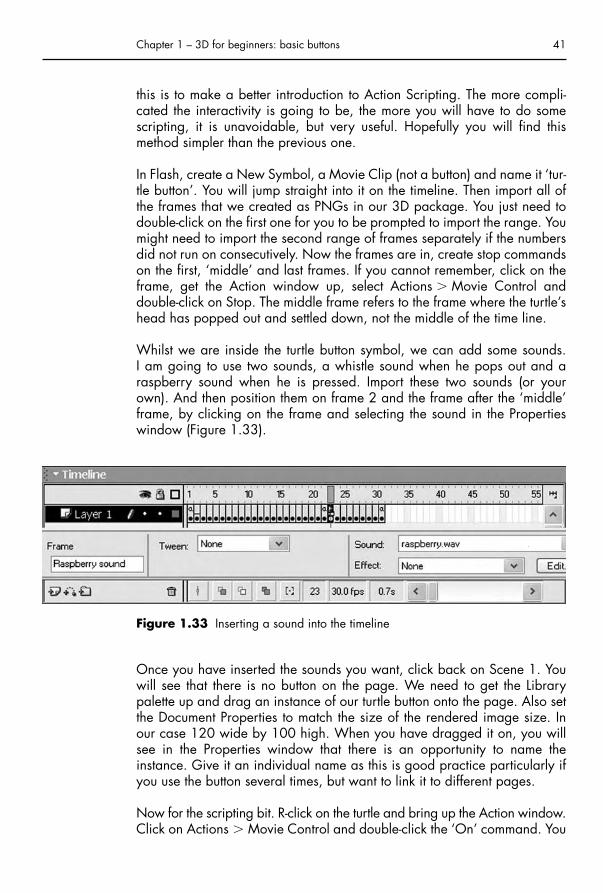
Whilst we are inside the turtle button symbol, we can add some sounds. I am going to use two sounds, a whistle sound when he pops out and araspberry sound when he is pressed. Import these two sounds (or yourown). And then position them on frame 2 and the frame after the ‘middle’frame, by clicking on the frame and selecting the sound in the Propertieswindow (Figure 1.33).
Chapter 1 – 3D for beginners: basic buttons 41
Figure 1.33 Inserting a sound into the timeline
Once you have inserted the sounds you want, click back on Scene 1. Youwill see that there is no button on the page. We need to get the Librarypalette up and drag an instance of our turtle button onto the page. Also setthe Document Properties to match the size of the rendered image size. Inour case 120 wide by 100 high. When you have dragged it on, you willsee in the Properties window that there is an opportunity to name theinstance. Give it an individual name as this is good practice particularly ifyou use the button several times, but want to link it to different pages.
Now for the scripting bit. R-click on the turtle and bring up the Action window.Click on Actions � Movie Control and double-click the ‘On’ command. You
Chap-01.qxd 8/12/04 14:59 Page 41

will see a list of options appear with the Release option checked, uncheck itand check Roll Over. Then double-click on Play, this will insert in under thetext in the script window. This will start your animation when the mouse rollsover the turtle.
Click on line 3 and then double-click the On command. Uncheck theRelease option and check the Press option, then double-click the Gotooption. Make sure Goto and Play is checked and change the frame numberto 23 (the frame after the ‘middle’ frame). This will make sure that the turtlewill squash, no matter what the state of the animation is.
Click on line 6 and double-click the On command. Uncheck the Releaseoption and check the Roll Out option. Double-click the Goto option. Makesure Goto and Stop is checked and make sure the frame number is at 1.This will reset the animation when the mouse leaves the button. Figure 1.34shows you the end result of this piece of programming. You can now test thebutton to see it move when you rollover and squash when you press on it.
42 3D for the Web
Figure 1.34 Scripting the button
Chap-01.qxd 8/12/04 14:59 Page 42

In our previous attempt at creating a button we made it into a link usingDreamweaver. This time we will do it in Flash. Make sure you are clickedon line 9. Double-click the On command as before, but leave the Releaseoption checked. Now click on Browser/Network, below the Movie Controlcommand, you will see a command called getURL. Double-click getURL andtype in the address of the page you want to link to, e.g. http://www.3dfortheWeb.info. You can select below that, whether you want it toreplace the current window (_self) or create a new window (_blank) toplace the page in (Figure 1.35).
Chapter 1 – 3D for beginners: basic buttons 43
Figure 1.35 Making the button into a hyperlink
And that’s it, when you import your file in Dreamweaver you do not need tomake it into a link as it is already one. Of course this might not prove to beyour preferred method, but if your site is entirely in Flash, and not just aFlash button, then this is the obvious method to choose.
That’s it for the turtle as a button, but do not worry, he will be back in laterchapters.
Chap-01.qxd 8/12/04 14:59 Page 43

Interview with Mach-Parathttp://www.mach-parat.de
Company profile
Mach-Parat is a young, innovative German company that specializes inFlash-based games. They started in August 2002, and had already won thegames category at the Online Flash Film Festival OFFF03 in Barcelona lessthan a year later. Mach-Parat’s team consists of Volker Neumann, Jan-PhilippBehrens and Sebastian Deimann.
44 3D for the Web
I first encountered Mach-Parat through their very different looking ‘In theWoods’ game and have had opportunity to enjoy their clever ideas ingames and viral marketing ever since, including their rather wonderfulEaster idea for self promotion, The Pixel Egg, which is as a very elegantpiece of viral marketing.
Chap-01.qxd 8/12/04 14:59 Page 44
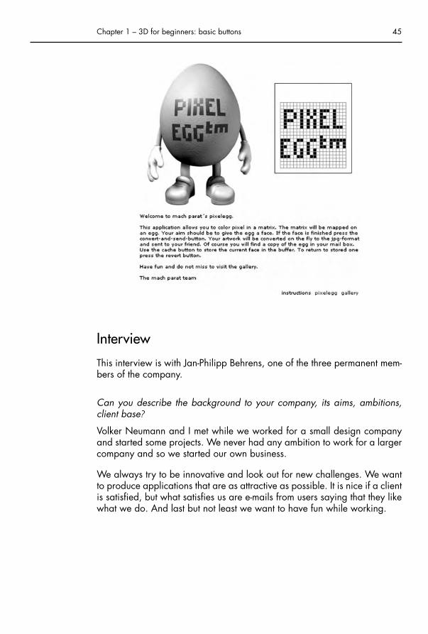
Interview
This interview is with Jan-Philipp Behrens, one of the three permanent mem-bers of the company.
Can you describe the background to your company, its aims, ambitions,client base?
Volker Neumann and I met while we worked for a small design companyand started some projects. We never had any ambition to work for a largercompany and so we started our own business.
We always try to be innovative and look out for new challenges. We wantto produce applications that are as attractive as possible. It is nice if a clientis satisfied, but what satisfies us are e-mails from users saying that they likewhat we do. And last but not least we want to have fun while working.
Chapter 1 – 3D for beginners: basic buttons 45
Chap-01.qxd 8/12/04 14:59 Page 45

Typically how many people would work on a project?
Most of the time all three of us are involved, although we do sometimesdraw from a small pool of freelancers. There have been some jobs with onlytwo people involved, but there is no meeting without all three of us, becausecommunication is an important point of our work. There are a lot of cross-over skills between us, that does not mean that everyone is as good as theother, but it is important for our work that everybody knows what is possi-ble to realize and what is not. We are not specialists, but generalists.
General design and 3D
How did you get started working in 3D Flash games?
It was the time when everybody was working with Flash and Freehand vec-tor style. Vector illustrations were used on every magazine cover and inmany TV commercials. That was the point we decided to start with 3D. Itwas learning by doing. We began to mix 3D style with vector style andwhat we got was a cute little surrounding that had much more toy appealthan all the others we did before. It was a toy world like LEGO or Playmobilthat said, ‘Play with me’. Especially for games, it is necessary to create suchan attractive surrounding.
How do you come up with the different ideas for your games?
Some of the game ideas are influenced by our clients. The challenge here isto find the right game genre including a solid and convincing story and agraphic style that fits best to the company’s corporate design. A helpful toolto come up with ideas and concepts is to build a large archive of differentstyles and game engines. Internet research helps a lot and it is useful to havea look at the games of the 1980s home computers like the Commodore C64.There are a lot of simple but addictive games waiting to be modified.
Good-looking 3D has an immediate appeal. Do you see it as the way for-ward in Web design, or just another tool?
3D is just another tool in Web design and at the moment a really strong one,because a new one. And sure it got advantages over the 2D applicationson the Web, because it can create spaces which seem to be more realistic.The reason why 3D in the Web is getting bigger and bigger is the result offaster online connections. These allow everybody to be part of the 3D vir-tual reality. Faster connections are the gigantic step forward for the Web.They offer new ways to spread information. And 3D is one of those ways.
How important do you think interactivity is to your work?
Interactivity is the most important part of your productions. We are notreally into linear movies and stories. Interactivity is what fills the user with
46 3D for the Web
Chap-01.qxd 8/12/04 14:59 Page 46

enthusiasm and what makes a product attractive. Little interactive gimmicksand small interactive tools have to be in all of our productions.
On average how long do you spend developing your games and howmuch of that time is pre-production?
The process of developing a game takes between 2 and 6 weeks, dependingon the complexity. A serious pre-production takes at least 20% of the work.
How important is sound in your games and who handles that?
The sound is a very important part of a game for two reasons. On one handit creates the atmosphere and on the other hand it gives a response to theplayer.
Every game takes place in a little virtual world. To make the world easy tounderstand you need to build a specific atmosphere. Is it a dangerousworld or is it a friendly one. The atmospheric sound supports the story andthe graphics.
And the other point is the response. A usual computer has no chance to givea haptic response, so the user often does not know if he has pressed a but-ton already or not. That is the reason why most buttons play a specificsound when they are clicked. In games we have to handle the same prob-lem. In a fast game the player often does not realize if he has collected anitem already or not and he does not know how much time he has left to com-plete the level. The sound offers him the information he needs without break-ing the game flow. Try to play a game and turn off the sound and you willsee that it is more difficult to succeed.
The sound makes the little virtual world look more realistic, makes it easierto understand its rules and supports the feeling of being part of the game.
A lot of the sounds for our games are recorded and done by SebastianDeimann.
What aspect of development would you say is the most time consuming?
The most time consuming part of the game development is the graphic andanimation, in some cases it takes up to 50% of the whole process.
Your past and future work
Your games reflect a number of different graphic styles who/what are yourinfluences?
We are influenced by a lot of things and people: Der Bauer, Star Wars,Rodney Mathews, C 64 and old video game consoles, Mad Magazin, JohnMaeda, Gorillaz Video, fairy tales, LEGO, Eboy, Lobo, Toy Story and Chalet.
Chapter 1 – 3D for beginners: basic buttons 47
Chap-01.qxd 8/12/04 14:59 Page 47

Out of all the 3D Flash games you have created which was your most chal-lenging, and why?
The most challenging 3D game we did is ‘In the Woods’. Actually it wasproduced as an interactive greeting card for Christmas we send out to com-panies and friends. We did not want to do anything with Santa Clauses orred nosed reindeers and we came up with a story with little fairies.
The application shows a large old gnarled tree surrounded by glitteringsnow. Small lights are flying around the tree like fire flies and some of themare heading towards the ‘camera’ and you recognize that they are fairies.The User has got the possibility to take a short movie of the scenery and towatch it afterwards in ‘Super 8’ Movie style.
48 3D for the Web
Chap-01.qxd 8/12/04 14:59 Page 48

The challenge here was not the 3D elements themselves or the ‘movie-engine’ but to create a mystic, fascinating and realistic surrounding whichwas a mixture of different software exports.
If you work with a mixture of different graphic parts, e.g. Photoshop works,3D modeling and Flash animations the challenge is to bring those partstogether in the right way so that they fit. Often it takes a while to synchro-nize 3D elements and programming. For example, it took us hours andhours to synchronize the Flash-ants on the turning 3D trunk for the game‘Antburner’.
What awards have you won and have they made a difference?
We were nominated as a finalist at the Flash Forward Flash Film Festival inSan Francisco in March 2003 and we have won the games category atOnline Flash Film Festival OFFF03 in Barcelona in May 2003.
And yes, the awards made a difference. An award shows that your work isinnovative. For some clients it is important to know what other clients youhave worked for to see if you are serious. But that does not say anythingabout innovation. An award does. An award is a good argument to getcommissions. It is nice to have the official award icons on our website. A
Why are your games so important to clients and their websites?
The production of online games is booming in contrast to all other Webproductions. The main reasons are that a game makes a website moreattractive and people do stay longer on the sites. The games are for freeand offer fun, so that the player consumes the advertising for a product ora company of his own accord. On the radio or on TV people have nochance to decide if they want to hear or see commercials or not. Here theyhave and that has a good effect on the company appearance and builds upan emotional relationship between the player and the company. The possi-bility of recommending the game to another person with a ‘Tell-A-Friend’function spreads out the game and company profits of the so-called viralmarketing.
If you add up all these facts and compare it with the costs of other kinds ofadvertising the production of a Web game is very cheap.
Any special future projects using 3D?
A future project in a soccer game for a large sports Web portal in Germany.It will be again a mixture of different software exports. The characters willbe 3D modeled and then animated in Poser.
The user can set his team strategy and challenge others via e-mail. We’vealready started on this project. Watch out for Microsoccer.
Chapter 1 – 3D for beginners: basic buttons 49
Chap-01.qxd 8/12/04 14:59 Page 49

Technique
Why did you choose to use Flash?
Flash has got one big advantage over other software. The plug-in is smalland widely used. That is an important fact for the clients, because they wantpeople to enter their website without having to download anything beforethey can access it. This is although the reason why all our productions runin the Flash 5 Player.
What other software do you use for creating your games?
The main software we use is Photoshop, Cinema 4D, Poser and Swift 3D.Most of our games are done with them. Sometimes we use Freehand butFlash has got strong graphic tools too.
Were there any specific problems you had to overcome?
We have to take care of a small file size and good performance.
Does it vary from project to project?
Yes, one time the file size makes the problems and the other time it is the per-formance A. There is rarely a production without one of the two problems.
50 3D for the Web
Chap-01.qxd 8/12/04 14:59 Page 50

How much programming do you use and do you view it as an importantskill for designers to have?
We do progam a lot, for us it is a very important skill. There is no interac-tivity without programming. The programming sometimes takes the half timeof one job.
I think everybody who has anything to do with Web design should knowwhat is possible on the Web and with which conditions. I am talking aboutthe old story about graphic designers and programmers: The graphicdesigner asks if it is possible to launch the Web concept he made. And theprogrammer says that it is possible, because nearly everything is possible,but not with the small budget of the job. What I want to say is that it is anadvantage when the skills cross-over, because Web design goes hand inhand with programming.
How does creating 3D games for the Web differ from creating standardcommercial computer games?
One big difference is the file size. We do not want people to load morethan 1 megabyte large games. Even if the connections are getting faster.One reason why Web games are so popular is that the users have to waitjust a few seconds and then they can have fun, so it is important. The mostdifficult part of our work to find the right combination of small file size,good-looking graphics and a good performance.
In contrast to standard computer games an online game has to be low incomplexity and simple to understand. The user should look at it the first timeand immediately he should know the aim of the game and how to play it.Online games are made for the short fun during the day. Nobody wants tofool around with difficult key combinations or wants to read instructions thatare longer than 20 lines.
How do you integrate 3D elements into your Flash games?
Most of the 3D elements are fake: short picture sequences, modeled andrendered with any 3D software often including alpha channel and importedinto Flash.
The challenge is to combine all the different parts in Flash so that it looksnatural. Does the light come from the right place, are the proportions okayand do all animations fit together like we wanted them to fit?
Insights
Which technology do you think will be the leader for 3D on the Web? (Forexample, Shockwave, Flash, Pulse 3D, Virtools, Anark)
In my opinion Flash is the leading one right now, because of the largespreading of the small size plug-in. Most of 3D elements on the Web are
Chapter 1 – 3D for beginners: basic buttons 51
Chap-01.qxd 8/12/04 14:59 Page 51

done with Flash. But Flash has a very big disadvantage: It has nearly nothingto do with 3D. There is no 3D engine like Shockwave has got. To competein the future 3D Web market Flash will need such an engine, otherwise Flashwill be pseudo 3D software for ever, and will lose its big share of market.
In future I think Shockwave will be the leading technology for 3D on theWeb. The spreading of its plug-in is making good progress. The Shockwave3D engine is a strong tool. We already started to get into Director. I amlooking forward to the first Mach-Parat Shockwave release.
Do you have any advice for students of 3D Web design?
Everything is possible. Look for the biggest challenge you can imagine forthe specific production.
Work so long on one project till you hate it. One month after the project isfinished you will love it.
And most of all have fun.
3D has almost taken over the games industry do you think it will becomemore predominant in Web games?
3D is growing on the Web. It is an enormous element of the so-calledimmersion (describes the phenomenon that people leave reality and diveinto a virtual space). Immersion is the most important reason why 3D hasovertaken the games industry.
52 3D for the Web
Chap-01.qxd 8/12/04 14:59 Page 52

Chapter 2
Interface design for3D websites
• Website issues• Creating a product-based 3D website• Exercise: a realistic approach to 3D• Exercise: the fun approach to 3D• Creating the ‘wow’ factor – sexy graphics• Making a website in Flash• Creating a multi-page website• Finishing off a Flash website• Designing 3D websites• Interview with Who’s We Studios
ChapterSummary
Website issuesSo far we have established how to make some buttons for your web page.Hopefully you have experimented and come up with some interesting but-tons of your own, after all, it is your creativity that will make an impressivewebsite. We have said that web pages are basically just buttons and infor-mation, whether that is text, pictures or audio. Of course, this is the basis ofInternet communication, the idea of the hyperlink where pages of text arejoined to other pages by means of an addressed link. The Web is a non-linear construction, unlike books, so when creating websites there need notalways be a beginning, middle and end. Although you may have an initialpage to your site, it is always possible for people to jump in at any point,thanks to the automatic trawling of search engines. This is one of uniquethings about the Web, it can be difficult to control the user’s actions. In filmsand books, although you could skip back and forth, people are going tostart at the beginning and work their way through to the end. In designingwebsites you have to be aware that people might join halfway through, so
Chap-02.qxd 8/12/04 15:00 Page 53

you need to give them clear opportunities to work out what to do. This mightbe using an obvious button that allows people to go back to the beginning ofthe site. If you do not feel that they need to do this then you need to have acontinuity of design throughout your site and an interface that is easy tounderstand and intuitive.
We will get on with a large practical exercise and then talk more about theinterface and 3D representation towards the end of this chapter.
Creating a product-based3D websiteThere are ways of using 3D on the Web where you can employ all the bellsand whistles of your favorite 3D package. You can create some great 3Dgraphics or recreate realistic products. For the purposes of the next exer-cise, we have created a hypothetical product: MacHead’s One Dose, solu-ble aspirin. We are going to use a variety of interesting graphics andanimations that will help sell the product to the user and explain its purpose.The ideas are the main thing here, and you are unlikely to want to createthe same sort of animations, so the explanations of the 3D work will bemore general than before.
Let us imagine that we have been given a current product package. Thechallenge is to get this product across in a website using 3D to sell it. Theproduct looks like Figure 2.1 and a single tablet like Figure 2.2.
54 3D for the Web
Figure 2.1 MacHead’s package design
Chap-02.qxd 8/12/04 15:00 Page 54

Before we do anything, it is important to think about the web page colorand the color scheme in general. The actual package is designed in blue,white and gold. It makes sense to borrow the color scheme from the pack-aging, and use white as a background. White gives a nice, clean clinicalfeel, suitable for a medicine. First let us deal with the most obvious idea.
Exercise: a realistic approach to 3DRecreate the product package and make a realistic simulation of the tabletdropping into a glass of water and dissolving, using 3D.
What to do
The product package was created from an Extended Primitive �Chamferbox. This is like an ordinary 3D box with chamfered edges.The reason for having chamfered edges is that no surface in real life hassuch sharp corners as your 3D program. Look around you now and youshould see that table edges, book spines and the keys on your keyboard allcatch a soft light at their edges. We want the package to look realistic, andso the edges need softening to mimic reality. Naturally the proportions ofthe chamferbox must match the proportions of the real packet. The graphicwas made in Photoshop, but could be scanned from a real product (or forbetter resolution, digitally photographed) and saved as a TIFF file. It isimportant that you create a map that incorporates the top and side views ofthe package.
To bring the graphic into 3D Studio Max, open the Material Editor, choosea sample slot and click ‘None’ in the Maps Rollout next to Diffuse Color.Select bitmap from the pop-up menu and browse for your graphic. Yourgraphic will appear as a map at 100% in the Diffuse Channel. Select theBump map channel, click on ‘None’ and select Noise. The Map Parameterswill appear in the Material Editor. (Hint: You can travel up and down thelayers of the Material Editor via the ‘Show End Result’ and ‘Go to Parent’buttons (Figure 2.3).)
Chapter 2 – Interface design for 3D websites 55
Figure 2.2 The product
Chap-02.qxd 8/12/04 15:00 Page 55

Tile the noise map in all directions by a factor of 10. Click on ‘Go to Parent’and take the Bump map amount down to 5. This should just take the edgeoff the graphic’s crispness and imitate the cardboard quality of the real life box.
To apply the material to the chamferbox, add a UVW map to its modifierstack and fit the material as a Box map to a good position on the face ofthe box. Remember that you need to adjust the map to fit at the bottom rightso the front of the box will look correct, but the edge faces will need workto make them fit. We will only see three sides of the box, so will ignore theback faces. Add a Mesh Select modifier from the Modifier List and select theside polygons and the small polygons created by the chamfer above it. Addanother UVW map and open it out to use the Gizmo to fit the same map tothe side (Figure 2.4). The selected faces will turn red and the Gizmo can bescaled, positioned and rotated just as any other object. Match the pattern
56 3D for the Web
Figure 2.3 The Show End Result and Go to Parent buttons
Figure 2.4 The selected faces and Gizmo for fitting the side map
Chap-02.qxd 8/12/04 15:00 Page 56

so that it matches the front graphic, and then add another Mesh Select andUVW map to do the same for the top of the box (remembering to add thesmaller polygons created by the chamfer to your selection).
This can be quite fiddly, but persevere; the box should now be seamlesslymapped to match the package.
Note Those of you who are lucky enough to have the most up-to-date softwarewill have another modifier that could help in fitting materials: the UnwrapUVW modifier. We will be using this later on in the book.
R-click at the top of the modifier stack and choose Collapse All. This will lockthe UVW mapping. Save the package scene, and File � Reset to start anew scene.
Now we will create the rest of our realistic scene and the animation. (Wewill bring the box into this scene later.) The first thing to do is make a tablet.This is made from a mesh smoothed cylinder with a slot cut into it usingCompound objects � Boolean. Booleans are operators used to subtract,intersect or add surfaces, in this case, a slim box with a ‘V’ at one end issubtracted from the cylinder (Figure 2.5).
Chapter 2 – Interface design for 3D websites 57
Figure 2.5 Creating a channel in the tablet using Boolean
Materials for realistic simulation are very important. The tablet is white witha tiled noise map in the Bump map channel. This gives the tablet a slightlygranular effect. There is no shine to the tablet as soluble pills have no sugarcoating.
I have decided to keep the glass simple, as I do not want to detract from thetablet dissolving. There are any number of ways of modeling such a simple
Chap-02.qxd 8/12/04 15:00 Page 57

glass. I have drawn half the glass as a spline, and used the Lathe modifierto bring it into three dimensions (Figure 2.6).
58 3D for the Web
Figure 2.6 Using the Lathe modifier to create the glass
Meshsmooth the finished model twice, and Shift-Move to create a copy.Turn the copy into an Editable Mesh and eliminate the outside to create thewater. Collapse the top layer of vertices and use the Uniform Scale to scaledown the water a tiny amount so it will fit snugly into your glass.
There are several methods by which you can create the appearance ofglass, the most realistic is to use the Raytrace material. Go to Rendering �Material Editor to bring up the materials if they are not already visible.Select a blank material and click the button that says Standard. Change itto Raytrace from the list then shown. Change the Diffuse Color to a paleblue. This will help the glass be seen against the white background, and ismore for effect than reality. Also deselect the Transparency check box andthen change the Transparency value to 95. This will make it almost com-pletely transparent, but with a pale blue color.
Make sure the index of refraction value is set to 1.5, which roughly matchesthe amount that glass refracts light. Click the Reflect check box until it reads‘Fresnel’, which mimics the reflection quality of glass. Still in the glass mate-rial, open the Raytracer controls panel and make sure that Raytraced reflec-tion and refraction anti-aliaser to switched on. This will give a better qualityresult inside the reflections and refractions, as the pixels will be smoothed.
The material for the water is going to be pretty much the same as for theglass, but change the index of refraction to 1.33. As the water is thickerthan the glass, it will have a much greater distortion even though it has alower index of refraction.
Chap-02.qxd 8/12/04 15:00 Page 58

Note Using Raytrace does considerably slow down the rendering time of youranimation, but it is worth it for the quality of result you get.
With so many shiny, transparent surfaces, lighting is a crucial factor in mak-ing your scene look the way you want it. Make the environment (back-ground) color white, to match with the white web page. This will allow thegraphic to float cleanly on site. Keep on making test renders until you havethe look you desire. I have added a plane as a floor and used aMatte/Shadow material on it so that the shadow will be visible, but theplane will not. This will help delineate the glass on the page. Position a cam-era in the scene to look at the glass and change the perspective viewport tothat camera’s viewpoint (Figure 2.7).
Chapter 2 – Interface design for 3D websites 59
Figure 2.7 The rendered glass
Animate the tablet falling into the glass. (Hint: It will be slowed and redirectedby the water.) From the Modifier List, add Melt to the stack. Use the GlassMelt effect and animate your tablet melting away. By adding a Visibility ani-mation key to this, we can get a good effect of the tablet dissolving.
To add a Visibility track, R-click the object in the viewport and pick CurveEditor. A new window will pop up: this is the Curve Editor.
Note The Curve Editor or Track view represents all the animated parametersyou have given an object in graph form. It is like an expansion of thetimescale slide rule which runs along the bottom of your screen, andoffers alternate ways of adjusting any animation keys in your scene.Adjusting the Key Interpolation here will change the curve of your ani-mation. The Visibility track is a simple way into understanding this com-plex tool, which is at the heart of animation control.
Chap-02.qxd 8/12/04 15:00 Page 59

From the Tracks drop down in the menu bar, pick Visibility track � Add.A Visibility track will appear below your object (Figure 2.8).
60 3D for the Web
Figure 2.8 Adding a Visibility track in the Curve Editor
Select Add keys and create two keys for your tablet, one for when you want it to start disappearing and one for it to have dissolved completely.(Because we are using this in combination with the Melt modifier, we do notwant the tablet to disappear too soon.)
When you first assign a Visibility track to an object, a Bezier float controlleris automatically assigned as the default controller. By R-clicking on the keys,you can change the interpolation of the Visibility keys (just as you did for theturtle’s PRS keys in Chapter 1).
We want to hold the tablet’s Visibility, and then ease into it disappearing. R-click on the first key you created and type in the value 1. (For Visibility,1 � Fully visible and 0 � Vanished.) Select the ‘Step’ (hold) tangency foryour first interpolation and an ‘Ease Out’ for the second (Figure 2.9). Youshould see the curve of your animation in the Curve Editor change. Advance
Figure 2.9 Interpolations for the first Visibility key
Chap-02.qxd 8/12/04 15:01 Page 60

to the second Visibility key and this time choose an ‘Ease In’ and a ‘Step Out’interpolation, at value 0. (Your curve should resemble that of Figure 2.8.)
Next we will add some Particle Clouds (PClouds) to simulate the tablet dis-persing. Create � Particle Systems � PCloud. Choose a Cylinder emitter andClick and drag in the top viewport to create the cylinder that will containyour PCloud. (Hint: You may also choose any mesh object as your emitter,e.g. your tablet, but in this case, we want more control of the bubbles as wedo not want them floating through the glass!)
There are a lot of different parameters for particles, but if you work throughthem methodically, they are quite logical and many can be ignored. Theparticle parameters I have chosen are Particle Type � Standard Sphere,I have assigned the icon a suitable material, and timed the particle animation.(Hint: If your computer is not very powerful, it is often better to use a ‘ParticleTotal’ rather than ‘Rate’ as it allows you more control and stops your com-puter crashing; rates can multiply alarmingly.) The only other parameter thatneeds to be altered is the particles’ direction vector (Figure 2.10).
I have animated the emitting cylinder’s size during the animation, andcopied it to add two more PClouds with slight variation in material and size.
Chapter 2 – Interface design for 3D websites 61
Figure 2.10 The PCloud particle generation rollout
Chap-02.qxd 8/12/04 15:01 Page 61

62 3D for the Web
Top TipAdding extra versions with small variations can help particle systemsseem more random and less digitally generated.
Again, the only way of checking that the look you are achieving is correctis to keep on rendering and checking. There are too many factors at workhere for the viewport to give you an accurate picture. Figure 2.11 shows arendered still of the final shot.
Figure 2.11 The tablet dissolving
Note I have used an advertising trick to add subtly to the product’s enhance-ment. By adding an Omni Light inside the glass and increasing the lightwithin the glass as the tablet effervesces, I have lent it a slightly magicaledge. There are other additions one could make in the interests of magicor realism. For instance, adding a splash and ripples. Anything is possi-ble in 3D.
Adding ripples
To add a ripple to the water, select it and use the Ripple modifier. Set AutoKey on, and go to the frame where the pill hits the water. Change the phasevery slightly and change it back to 0. This will create two keys, one onframe 0 and one on the frame you are on. Then move on three or fourframes and change the amplitude 1 and 2 values to around 100 and 80 orwhatever value you think correctly approximates a splash. Then go to frame90 or so and change the phase to 7, still with Auto Key on. Change theamplitudes to 0 now. This will stop your water appearing to ripple. Youmight want to put another key in between the third and fourth to better
Chap-02.qxd 8/12/04 15:01 Page 62

represent your ripple/splash. You should see your water splash and ripplenow, and settle down. The settling down is important if you want your animation to loop.
Merging the box and glass
Now let us merge the previous MacHead’s package into the scene. Fromthe Top menu choose File � Merge. A browse window will pop up, find thepackage scene and select the chamferbox. Click ‘OK’ and the box willappear in your scene. It will not necessarily be at the correct size and willcertainly need rotating and positioning. You may well wish to re-adjust yourcamera and will need to add lights and move existing lights to make thebox look good. This is where Raytracing can really help add to the sceneas now the glass and water have something to reflect and refract. The lightsI have used in my scene have Shadow Mapped shadows. They are rela-tively quick to render and have soft edges, making them look fairly natural.There are other types of shadows possible, and also the idea of GlobalIllumination (where light that bounces off objects is calculated). This canimprove the realism of your scene, but has the downside of being processorintensive, and hence slowing down the rendering time.
When you are happy with the look of your scene then you are ready to ren-der it. Choose Save File from the Render Scene window and select portablenetwork graphic (PNG) for the save option, make sure the default 24-bitoption is selected. Render all 100 or so frames. These will be imported intoFlash in order to create your web page (Figure 2.12).
Chapter 2 – Interface design for 3D websites 63
Figure 2.12 The finished scene
Of course the reason that a realistic approach is the most obvious approachis because it interprets the instructions on the packet to illustrate how the
Chap-02.qxd 8/12/04 15:01 Page 63

product is used. It has a classical look drawn from television advertising, andusefully means that a visitor can understand it regardless of text. There areother ways of approaching the product depending on how we wish to getit across. Let us suppose for instance that we want a web page that showswhat a fun company MacHead’s is, and at the same time implants knowl-edge of how great and effective ‘One Dose’ is. For this sort of identity, itseems like a good idea might be to have a character and a game. So meetHeadache Jake and his dancing pills.
Exercise: the fun approach to 3DCreating a character and designing an animated sequence for a simplegame or activity.
What to do
I have created Jake from a polygonal modeling. Believe it or not, like thetortoise, he started as a box. He was made by me for a previous animation,where he had lots of hair, but it is easier for this exercise if he is practicallybald as in Figure 2.13. You can use the file of Jake from the CD, or make ahead of your own.
64 3D for the Web
Figure 2.13 Headache Jake
Chap-02.qxd 8/12/04 15:01 Page 64

Note If, like many others, intricate modeling is difficult for you, then there areways to access models made by others via the Internet, Poser or modelsthat come with your package. These models can be brought into yourprogram and adjusted to suit your needs. There are some sources listedat the end of this book. When using models other than your own, it isessential that you regard the laws of copyright and do not infringe themin any way. There are a lot of generous people on the Web, but it willonly stay like that if we do not abuse it.
Jake looks a bit hung-over and ripe for a headache, doesn’t he? Thinkingabout the brief for a fun page and how to graphically depict a headache,I have decided to create an animation where Jake appears, gets a wince-inducing headache in the form of a gold band around his brow and thenshakes it off. The main new animation tool we are going to use is theMorpher modifier. This is a wonderful way of smoothly animating facialexpressions including lip sync but can be used for so much more.
Jake is an Editable Mesh, and before we add the Morpher modifier we willcreate four duplicates of him that we will use as Morph targets. Wheneverthe Morpher modifier is used, the topology of the targets must be the sameas that of the original, so we cannot animate Jake by changing the numberof vertices or polygons he has.
Select Jake’s head and Shift-Move to create four more copies of him, thesewill be our targets. Now use soft selection to start giving him a headache.Furrow his brows and start squeezing his brow by band selecting the ver-tices and uniform scaling them in. Move on to the next target and make himreally suffer. Now let us give him a surprised look as relief hits, and for thefinale a happy smile of relief (Figure 2.14).
Chapter 2 – Interface design for 3D websites 65
Figure 2.14 The 5 Jakes. One original and four targets for the Morpher modifier
When moving the vertices it is a good idea to mimic the facial expressionsand check what happens to your features in a mirror. See how eyes andeyebrows are affected. He looks pretty strange right now, partly because
Chap-02.qxd 8/12/04 15:01 Page 65

the eyeballs are linked to the original, so the targets look like masks. Selectthe original and add the Morpher modifier to its stack.
Click on Load Multiple Targets and choose all the Jakes apart from the original.Click ‘Load’ and they will appear in the Morph Channel List (Figure 2.15).
66 3D for the Web
Figure 2.15 The Morph Channel List for Jake
Now select all the target Jakes, R-click in a viewport and select HideSelection; we do not need them any more. Center your viewports on theoriginal Jake and have a play with the sliders in the Channel List. Noticethat you can combine the Morph targets to get some groovy expressions.Check that the eyeballs are not pushing through the mesh in any of the com-binations, if they are, pull them back inwards a bit. I have also made somerudimentary teeth out of a cylinder and linked it to Jake’s head along withthe eyeballs. Otherwise when he smiles, you can see there is no back to hishead! I have used noise maps in Multi-Sub-Object Materials to give Jakeeyebrows, lips and a 5 o’clock shadow.
Now make a smooth band to go round his head (from the top viewport).Give it 40 sides as we need it to be metallic and smooth, and those extravertices will come in useful. Assign a gold metallic material to the band andcopy the tube by Shift-Moving it. Turn the new gold band into an EditableMesh. Select a jagged half of it at vertex level and click on ‘Detach’ to cre-ate a new object. This will make the broken headband for Jake when hisheadache goes (Figure 2.16).
Figure 2.16 Jake’s broker headband
Chap-02.qxd 8/12/04 15:01 Page 66

I have also created a white box and used a number of Omnis to light it andnot the rest of the scene, so it disappears into the background. (Hint: Youcan include or exclude objects from a light’s influence, under the LightParameters.) Jake is going to rise up from the box, get his headache whenthe ring descends and then shake it off.
Turn on the Auto Key (Animate Button) and animate the basic movementfor the gold band and Jake’s position first. The gold band will need to bereplaced by the broken Headband using the Visibility track in Step Mode.Do not forget to Ease Jake into his new Position and Hold him there withthe Key Controllers. Now animate the Morph expressions. Remember thatthey too are Bezier, so you need to put in 0 value keys to control thespeed the expressions take hold. Any movement of the sliders creates akey, even if you scroll it up and back to 0. (Hint: You can use Key Controlsfor Morpher by R-clicking on the keys in the Curve Editor. I prefer themore hands-on approach of the sliders in Morpher, so tend to use justthose.)
You will find that the gold band does not quite fit Jake’s head (unless youare very lucky) so tweak it around until it does. We do not care what it lookslike from the back as that will not be seen. The only really important thingto remember is to align the original headband with the broken one whenthey swap over in Visibility. Animate the eyes by rotating them to anticipatethe headache and return to normal at the end (Figure 2.17).
Chapter 2 – Interface design for 3D websites 67
Figure 2.17 Jake shakes off his tension headache
Have fun! This is not an exact science, all animation is subjective. Have youany idea how many different walk cycles there are? I added in a momentfor Jake to say ‘Yesss’ with relief, as I thought it would be fun. When it looksgood, render it as single frames, in PNG 24-bit format as before. We willbe integrating them into a multiple page website later on.
Chap-02.qxd 8/12/04 15:01 Page 67

Creating the ‘wow’ factor – sexygraphicsBecause 3D is so attractive, it is not unusual for a client to want a sexygraphic, or even a new logo created in 3D. These briefs are great fun asthey are an opportunity to look at the product as a whole, and think side-ways to come up with something with that ‘wow’ factor. This is where play-ing with your software pays off. All those accidental buttons pressed andthe ‘I wonder what this thing does?’ moments can be drawn on, and com-bined with your marvelous graphic skills, to make wonderful things andcover yourself in glory.
In the case of MacHead’s One Dose, I was much taken by the gold ‘O’ of‘One’. The choice of gold for a color was obvious, as it represents a seal ofapproval. It also looks a bit like a target, and remembering Jake’s head-band, I thought it would be fun to combine all three elements. What I amafter here is to represent the ‘feel’ of the product. I also decided to loop thegraphic as clients love their logo, and a looped graphic is more adaptable.
Exercise: creating a sexy graphic
Creating a small, short looped graphic that will wow the client.
What to do
This is more a step-by-step analysis of the thought processes than a tutorial.Time to use your imagination.
The starting point for this animation was to recreate the gold rings that makeup the ‘O’ of ‘One Dose’. They were created in 3D by Shift-Scaling a Torusseven times. Having made the rings (and knowing I wanted to loop them), butnot knowing yet what I would create, I set Position, Rotation and Scale Keysat the front and end of the animation. Looking at the rings, I wanted to rotatethem, so I started by pushing each alternate ring in a different direction. Thatlooked too prissy so I randomized their rotations, just so it looked fairlychaotic and made a nice silhouette. I created a strong shadow plane as Ithought the shadow might be fun and played with transparency and color.
Now I wanted something to generate the disturbance in the rings and chosea Particle Ray to shoot at the center of the rings like it was a target. (BecauseMacHead’s One Dose is renowned for its pain targeting qualities.) Forthis, I used a SuperSpray and gave it a blue color to match the package (Figure 2.18).
68 3D for the Web
Chap-02.qxd 8/12/04 15:01 Page 68

But looking at this it was all a bit messy and unstreamlined. I decided to jet-tison the shadow as it made the graphic take an uncomfortable shape, losethe color and stick to gold to keep it streamlined, and look for somethingthat might just indicate the tight headband of pain.
I grouped the rings and added a Spherify modifier. With just three keys itmade each ring push out to a flat band shape and then return to a torus. Itreally helped the easing back to the original logo, a sort of equilibriumrestored. Remembering the effervescing tablet, and mindful of potentialsound I added a PCloud bubble fizz just as we did for the dissolving tablet.
The finished graphic is elegant and simple (Figure 2.19). The reflectivemetallic rings and particles take advantage of the 3D environment, withoutshouting out ‘Hey lookee here’, and MacHead’s have a potential new logo.All in all the client is delighted – which is just as well, as in this case, theclient is me.
Making a website in FlashWe have created three elements for the website for our imaginary medi-cine, three styles of approach to our advertisement. The first version beinga direct and straightforward advertisement, the second, a fun view, whichcould be interactive and the third being a more symbolic and showy
Chapter 2 – Interface design for 3D websites 69
Figure 2.18 First attempt at graphic
Chap-02.qxd 8/12/04 15:01 Page 69

metaphor. It is time to turn them into a Web-deliverable format, and we willuse Flash to collect together all our animated frames. You could converteach movie as a Flash movie file and place it on an HTML page, but this isnot the most efficient method. The main reason is to do with streaming.
Streaming
Streaming is the idea of not loading a whole movie at once, before playingit, but starting to play it as soon as a small portion is downloaded, allowingthe movie to play and download at the same time. If this works well thenthere are no pauses in the playback of the movie (this applies to digitalvideo as well). So the user does not have to wait minutes before the anima-tion starts. Another idea for streaming in Flash is that you can load a wholesection of a movie, e.g. one of our MacHead’s versions. This can be play-ing whilst the other parts of the movie load in the background. If the otherversions are on different pages then they will already be loaded when welink to them. Normally when you link to an HTML page, you then have towait for it to load. Streaming can remove the frustration out of Web brows-ing, giving a more professional look to your website.
So the best way to set up a heavily animated site would be to create it eithermostly or entirely in Flash to ensure that it will play back in the most efficientmanner.
70 3D for the Web
Figure 2.19 The finished graphic for MacHead’s One Dose soluble aspirin
Chap-02.qxd 8/12/04 15:01 Page 70

Creating a multi-page websiteAt this stage in our chapter we have gone through various techniques to cre-ate some interesting graphics for our website. ‘MacHead’s One Dose’ is, of course, a fictional product, but we want to create a website that has acorporate feel and has a reasonable amount of entertainment. We need totake advantage of the factor that distinguishes the Web from other media,like television and magazines. That factor is interactivity and in our previouschapter we made buttons, which we could use for web page navigation.The fact that they reacted to our mouse made them more exciting. Makinga simple advert more exciting and interesting should help enhance anybrand. How you do this is entirely up to you (and the sales and marketingdepartment, if you have one!). For our MacHead’s product, we have cre-ated animations and it would be interesting if we could trigger them in ourwebsite. This makes our website more than just an animated advert, theinteractivity should help visitors remember, and use, the product.
As we have several sections to our site we want to display them in the mostinteresting and efficient manner. We have already discussed streaming, butwe do not necessarily want just a page-by-page website. It would be goodif the brand identity was constantly on display. So we need to have a pageset-up that has perhaps two halves, one with the brand title and the othershowing our animations. We also need to include buttons in order to navi-gate between the interactive animations.
Issues affecting the display of websites
There has always been a major issue when designing web pages, and thatis the platform that the web page is being displayed in, i.e. the browser,screen resolution and fonts. The most widely used browser by far is MicrosoftInternet Explorer, but there are many browsers in existence. While they all dothe same thing, they each have individual quirks. We have already talkedabout Internet Explorer and PNG files, which display fine in NetscapeNavigator. Other issues they have are to do with the gaps between the HTMLpage and the browser edge (the margins). They also display frames differ-ently (frames are web pages within web pages). They each have differentamounts of graphics on their interfaces. This is why most pages scroll, andtext wraps around to accommodate different screen sizes. In traditional printdesign, this multitude of display formats is not an issue, generally a designermight design two or three layouts for different shapes of paper or advertspace, and these would be stretch proportionately to fit the different sizes of output.
Having a scrolling page is not ideal as you do not get to see the whole pageat once and this might well affect the subtle messages of your advertising
Chapter 2 – Interface design for 3D websites 71
Chap-02.qxd 8/12/04 15:01 Page 71

design, let alone design issues of balance and weight. Using Flash enablesus to overcome most of these issues. We can stretch a Flash movie to fill abrowser page, or keep it a size that will display on all screens.
The letterbox format
A popular aspect ratio to use for Flash pages is the letterbox format. Thismeans having a Flash movie that is similar to a cinema projection orwidescreen TV in shape. You will find that this will comfortably fit on nearlyall users’ browsers. The only issue is whether you make your movie stretchto fit the browser window or not. Why is stretching an issue? Well, the extraissue which Flash brings up is the frame rate. Ideally we want our movies toplay back at 25–30 fps (frames per second). This may not happen if themovie stretches by too large an amount as slower computers may not beable to display the movie at that speed. There is not a perfect answer to thisissue, apart from testing your movie on many computers. The compromiseis to decide on a minimum standard of computer setup that a majority ofusers will have and then make our movie fit that. Although most moderncomputers can display many different screen resolutions, the minimum thata majority of users will have will be 800 pixels wide by 600 pixels deep.Because the browser will take up a fair amount of space, this will leave anarea of approximately 760 � 350 pixels. So this is the space we have toput our movie in, the minimum. We could have it stretch if we want to, butthis is a decision we would make when we publish our movie.
The MacHead’s website
The following is a general description of how the MacHead’s website wasput together. As you may not have followed the previous tutorials exactly,what you want may be different. In fact I hope it is different as it is your cre-ativity that is important, aided by the skills you learn in this book. However,all the original files can be found on the accompanying CD, for you to analyze in greater detail.
For our Flash movie I went for a size of 720 � 350 pixels, by setting the doc-ument size. This fitted into our possible sizes and had an aspect ratio thatI found appealing. As my animation sequences have white backgrounds,I also set the document’s background color to white. I then incorporated thevarious graphics that were created for the package design for our product.This could have been done in various ways, e.g. completely creating thewhole page in Macromedia Fireworks or in Adobe PhotoShop. But Idecided to import each element separately as a PNG file, so that I couldadjust my layout in Flash.
72 3D for the Web
Chap-02.qxd 8/12/04 15:01 Page 72

I then used Guides, to help line up the elements. It is also helpful to have theGrid setting on as this also enables better alignment. Figure 2.20 shows thepage layout, with some new text written on the right hand side. There was noneed to import this as a graphic, as it was easy to type in the text directly. I setthe paragraph style to be justified (straight-edged on both sides).
Chapter 2 – Interface design for 3D websites 73
Figure 2.20 Layout for MacHead’s website first page
The last thing to add to my page was the four buttons used for navigation.The first button indicated the above page, the introduction or Home pageas it is generally known. The second page linked to the Pill, Glass and Boxanimation that we made. The third and fourth buttons are for our ‘sexygraphic’ and our ‘Headache Jake’ animations.
Note When talking about Flash pages, do not confuse them with HTML pages.The Flash document will contain many frames, each one could be calleda page. For our website, we will only have one HTML page, which willhold the Flash movie, the .SWF file that contains all our Movie Clips (ouranimations).
For the buttons, I rendered the pill spinning on its axis. This animation wasonly 16 frames long and, as usual, was imported as PNG files. The bestway to do this is to create a Movie Clip symbol (Insert � New Symbol) andthen import the animation frames. Using similar techniques to the latter partof Chapter 1, I made the animation into a rollover button. Instead of con-verting the symbol to a button, I kept it as a Movie Clip and added a scriptto it, as shown in Figure 2.21. The script shows that if the mouse rolls overthe button then it will play the animation of the spinning pill. It also shows
Chap-02.qxd 8/12/04 15:01 Page 73

74 3D for the Web
Figure 2.21 Script for a button on the MacHead’s website
that if the mouse is pressed, then the main movie (the _root) is told to navi-gate to frame 3.
The timeline for the Flash website looks fairly complicated and it is best toanalyze the file yourself by opening it up. Figure 2.22 shows how many dif-ferent layers were used for each graphic. I labeled them, to make it easierto work out what is what. You will see that the whole movie is only 10frames long. This is because the first three sections are each two frameslong and the last section, four frames. The reason to have each section twoframes long is so that the movie can continue to play, whilst appearingnot to. For example, the script on frame 2 tells the movie to go back to frame1, ‘gotoAndPlay(1)’. It is sometimes helpful to keep a movie playing likethis, so that you can use ‘Enterframe’ events, however, I will not go into thatin a deep way at this stage. The last section is four frames because it hastwo parts to it, the ‘Before One Dose’ and the ‘After One Dose’ sections.
Note One thing to remember about layers is that if you have two graphics ontop of each other, then you will only be able to select the graphic on thetop layer. To get around this it is necessary to hide the top layer, bypressing the little eye picture whilst having the layer that you want hidden, selected.
Although the movie is 10 frames long, I did not want all of my graphics toappear all the time. Only the graphics on the left hand side remain through-out the length of the movie, the others appear only when they are needed.For example, only the Pill and Glass animation is visible on frames 3 and 4.These Movie Clips for the middle two sections were also turned into Buttons,using ActionScript. Quite simply, the animations were triggered when themouse rolls over them, by using a rollover script as in Figure 2.21. Each
Chap-02.qxd 8/12/04 15:01 Page 74

Movie Symbol was also made to stop playing, using a ‘stop( )’ frame scripton the first frame.
Chapter 2 – Interface design for 3D websites 75
Figure 2.22 Screenshot of the MacHead’s Flash timeline
Top TipWhen you import your animation frames into a Movie Clip symbol youwill need to drag the symbol from the Library to the Stage. Normallythis is a quick process, but when the symbol contains large amounts ofgraphics there is a significant pause to process this action. Be patientand your computer will catch up. This pause also happens wheneveryou extend the number of frames for that symbol, however moving thesymbol around the Stage does not cause this problem.
Chap-02.qxd 8/12/04 15:01 Page 75

76 3D for the Web
The most complicated part of the MacHead’s site is the fourth section, as it has two parts (Figure 2.23). The Headache Jake Movie Clip starts auto-matically. Looking inside the Movie Clip for the animation you will see thatthere is a frame script which tells it to stop, this happens when the band is
Figure 2.23 Screenshot of the soothing section of the MacHead’s website
Figure 2.24 Screenshot of the MacHead’s Flash timeline
Back in the main movie, there is a script on frame 10 in the ‘After OneDose’ layer. This script checks to see what frame the Jake animation is on.If it is less than frame 105 then the main movie loops around frames 9 and10, otherwise it will loop around frames 7 and 8. This way there is a cleardifference between the ‘before’ and ‘after’ states.
Loading screens
Most of the Flash movie has now been described but there is one importantissue that has not been dealt with. The graphical content of our website is
tightly around Jake’s head, on frame 35. This allows you to restart the anima-tion by rolling over the Pill button. You will see in Figure 2.24 that the frame60 has been extended and that there is another layer on top, which carrieson to frame 143. These are there to add pauses in the animation. It wasunnecessary to include these pauses in the original rendering of the animation.
Chap-02.qxd 8/12/04 15:01 Page 76

very high, as we are relying on the increasing usage of broadband Internet.We have already talked about streaming and how Flash utilizes it, but if we can access all parts of our site at any time, what happens if the MovieClips haven’t loaded yet? The answer is nothing; you will get a blank spacewhere the graphic is waiting to appear. So we need something to tell the user that the graphic is still downloading. This could be a ‘progress bar’,a graphical representation of the amount of data that has downloaded, orjust a graphic informing you that the section is loading. In this case I chosethe second option. When the movie jumps to frame 3 for the beginning of the Soluble section, two spinning pills and the word ‘loading’ appears.These will load very quickly. The movie will not progress now until all of the‘Pill and Glass’ Movie Clip has loaded, where upon the loading graphics(which have been converted to a Movie Clip) are told be disappear, usingthe ‘_visible’ Movie Clip command contained in the frame 4 script.
Finishing off a Flash website
Sound
Although many people have the speakers on their computer switched offmuch of the time, particularly if they are at work, sound can add an extralevel of immersion to your site. In the case of MacHead’s One Dose wecould add plopping and fizzing sounds for the ‘Soluble’ section, a magicalsound for the ‘Fast Acting’ section and have Jake sighing with relief for the‘Soothing’ section.
You could have a whole soundtrack playing, but this would have to be goodas it would add to the download time. Generally, music is reduced down toshort clips that loop. However, if done badly then music could be moreannoying than it is helpful to the promotion of your site. So you should useit wisely and appropriately, likewise with the incidental sounds.
Optimizing the Flash file
Now the Flash file has been described there are a few things to mentionabout the final outputting of the movie. The file is big, approximately 2 megabytes, and it should be optimized further by cropping of graphicswherever we can, using layers and rendering only the parts of the anima-tions that change. This always takes a long time but is generally worth it inthe end. You should check your imported frames and remove any repeats.As interest in your website depends on people having the patience to viewit; you do not want to keep them waiting too long.
Chapter 2 – Interface design for 3D websites 77
Chap-02.qxd 8/12/04 15:01 Page 77

A simple way to reduce the file size is in the publishing options in Flash. Here you can set the JPEG compression that will be applied to yourmovie. However, if you compress it too much then you will lose image quality, so you need to find a balance between file size and quality. JPEGcompression settings of around 70–80 usually result in a satisfactory compromise.
When you preview a Flash file, by using the Control � Test Movie menuoption, you can select the View � Bandwidth Profiler option to see how afile will load on various connection speeds. You can then see how long itwould take to load on a frame-by-frame basis. Using this enables you toadjust your movie, perhaps by making your title screen load up in parts, ormaking sure that the complicated graphics start to load early. You want totry and make the loading a smooth and hopefully invisible experience.Ideally you will give your audience something to look at straight away,something other than a loading bar. Then you will have made your site successfully streamlined.
Instead of using animated images, the latest few versions of Flash allowyou to import video files directly into it. These can be QuickTime Movies(*.mov) or Video for Windows files (*.avi) and many other video types.Flash has its own methods of re-compressing these files. Because of this, itis best not to have them too compressed to start with, so that Flash does notfurther reduce the quality. This is actually a simpler than using an imagesequence, but older versions of Flash do not support this method.
Centering a Flash file
When you publish your movie, it will automatically create an HTML page foryou. You could use this web page unaltered or you might want to amend it.The default HTML page will place the Flash movie in the top-left corner ofthe Web browser. But it would be nicer if it was in the middle of our screen.The best way to do this is to create a table, with three rows in. You can dothis in Dreamweaver with a blank page. If you set the tables height and width to be 100% then it will stretch to fill the screen. Make sure theborder size is set to 0 so that the table edges do not show. Then import your Flash file into the middle row and make it centered, by changing theproperties.
In the case of MacHead’s website, I also changed the background color ofthe HTML page to match the dark blue used in the packaging design. Thisacts as a picture frame to our design, increasing its strength and prominence.Finally the page was uploaded to our web space. If you do the same thenyou should have a good-looking site with interactivity and some stunninggraphics! (Figure 2.25).
78 3D for the Web
Chap-02.qxd 8/12/04 15:01 Page 78

Chapter 2 – Interface design for 3D websites 79
Figure 2.25 Screenshot of the MacHead’s finished website
Designing 3D websitesWe touched on designing interfaces at the beginning of the chapter. Therehave been many writers on the subject of interface design and Web interfacesand this book does not pretend to deal exhaustively with this subject. Here is abrief overview of some principles to keep in mind as we plan and build sites.
Signs and symbols
As we have established, buttons are a major aspect of websites. The sim-plest buttons are just text, but be aware that not everybody on the netspeaks your language, and they might still want to appreciate your grandcreation. The best way around is to use a symbol or icon to represent waysto navigate your site. Commonly a picture of a house represents a site’shome page, and triangle symbols are used to indicate traveling forwardand backward in the site. All text and pictures that have meaning are signsand it is important to realize what the symbolism in your website means, notjust to you, but what it is likely to mean to others. If you use metaphors thatare familiar to Web users then you can be fairly certain that they will beunderstood, otherwise there may not be any point using them at all. Somelevel of meaning will have to be transferred through the imagery you use, ifyou want your site to be truly international.
Chap-02.qxd 8/12/04 15:01 Page 79
One way in which to make your links meaningful could be to contain themin a familiar device or object that could be understood. A common way oflaying out a site is to give it tab dividers as in a paper folder. You couldemploy the idea of a remote control, with the idea of changing channels.People could accept this metaphor if it is related to your site correctly. So ifI was designing a site selling pies, I might make a button shaped like a pie.If it was travel site; a stop/go signal, and a website that deals with philo-sophical ideas might draw on thought bubbles, light bulbs or Rodin’s iconicsculpture, ‘The Thinker’, as inspiration.
Generally if you are using 3D for your buttons you will want to have aninteresting character or themed objects that react to the mouse, along withthe text to describe them.
Establishing the site’s message
The Internet is a communication medium, concerned with the transmission ofinformation. How you present that information is your message and the styleof delivery is the creative challenge that you have. The style of your site isgoing to affect how the user perceives you, your company or the companywhose site you are creating, so it is important to get this right from the outset.
You need to establish who you want to visit your site and what kind of expe-rience you want them to have when they are there. You also need to decideif integrating 3D will enhance it. If the site’s purpose is to impart masses oftext information, then 3D may not enhance it at all. However, if you aredescribing a product for sale then a 360 degree view of it might save youa thousand words of description and be much more useful. A major con-sideration in creating an impressive site would be to attract visitors and to make them aware of your brand. Attracting visitors must rank as one ofthe most important results from creating a website. The website you makeneeds to stand out from the crowd and the only way to do that is to keeppushing the boundaries of current practice and invent something new.Remember, your website is always an advertisement for your skills and sotaking care over the design is imperative if you want to make a lastingimpression.
Often the role of designer includes educating the client, showing them whatis possible, and showcasing is an excellent way to do this. Making someimpressive work at your own expense can be the best form of advertising,and be the difference between you getting the clients or your rivals. A 3Dinteractive makeover of an existing or new site can encourage people tovisit, stick with and remember your site. Perhaps the inclusion of a computergame can lead to viral marketing via the powerful medium of word-of-mouth. Maybe there is a new technique that you have invented that you
80 3D for the Web
Chap-02.qxd 8/12/04 15:01 Page 80

want to show off to prospective clients. In short, you must offer your visitorclarity, hooks and entertainment.
The interface
If your interface resembles familiar objects or other types of interfaces then you can be reasonably sure that most people will know what to do.However you want to push the boundaries, so I suggest that you start sim-ple and ease people into your site. Keep the style of buttons the samethroughout your site. Navigation is one of the most important elements andpeople need to be guided through your site. If a button reacts to beingrolled over by the mouse pointer then people realize that it is going to dosomething. If a message pops up when you rollover it then they are likely toknow exactly what it is going to do. If you can make your buttons and inter-face do interesting things then you are entertaining the user and keepingthem on your site, which has got to be a good thing! You do not have to puteverything on the home page though, you can bring elements in throughoutthe site, which stops the user becoming bored. You are rewarding them forexploring, luring them into other important areas of your website.
It is always a temptation when you have spent weeks or months working ona grand design to keep adding more and more elements. Whilst you arelearning new software you can get carried away with what you just foundout and be determined to include it. Always be careful about this, your web-site can become over complicated, with too much happening, or worse, beimpossible to navigate. The attention span of the average Web user is veryshort, particularly if they cannot work out what to do. Frustration will be amajor turn-off with an over-complicated site. When you design your inter-face, test it thoroughly on different people who know nothing about it. Youmust never do your own testing as you know too much about your work. Getfeedback as to what people like and do not like and observe them using it,so you can see where they might struggle. You will be amazed how yourguinea pigs cannot find something that you may have thought blindinglyobvious!
Good planning is the key to creating an amusing or impressive site, com-bined with good design and technical skills. The companies interviewed inthis book offer plenty of advice. These companies are practitioners at thetop of their field and reading these interviews and checking out their web-sites should help you become a great Web designer.
Chapter 2 – Interface design for 3D websites 81
Chap-02.qxd 8/12/04 15:01 Page 81

Interview with Who’s We Studioshttp://www.whoswestudios.com
82 3D for the Web
Company profile
Who’s we is an elite design studio based in Frisco, Texas. The six designersfeel passionate about pushing the boundaries in graphic design. They havewon numerous awards and their work and website are at the cutting edgeof 3D on the Web.
Chap-02.qxd 8/12/04 15:01 Page 82

I first came across them when two different students (one from 3DAnimation, one from Digital Arts) showed me their site, and in my turn, Ihave shown their site to many others.
Chapter 2 – Interface design for 3D websites 83
The site is awesome; slick and funny, combining great lighting and soundwith a neat interface. Clearly these guys have watched a lot of movies.
Chap-02.qxd 8/12/04 15:01 Page 83

Interview
Can you describe the background to your company, its aims, ambitions, client base?
Our company was founded on drive, determination and pure passion. We aim to get bigger every year. Our ambitions are carrying us into video production for the entertainment industry and possibly high-end 3Danimation.
We like to get almost everyone involved, but typically, there are usuallythree main contributors to each project. We get everyone involved in thebrainstorming sessions and then usually split the workload by availability.
Do you have separate 3D animators, Flash animators and programmers, ordo the skills cross-over?
Everyone here must be fluent in Flash, except for our 3D modelers/animators.3D applications are very time consuming to allow the typical 3D artist toalso delve into Flash. As for programmers, we have one main programmerand two others who are not as fluent, but are strong Flashers, but for themost part, everyone has a double specialty.
Who handles the sound and what impact does sound bring to your sites?
The sound is handled by two people here in our sound studio. Ninety percentof all of our audio is made from scratch. Whether you need custom soundeffects, or a complete soundtrack in almost any genre, we can deliver. Thereare many tracks we have laid down on many of our projects, namely theHandheldgames.com piece which we ended up doing a few mixes for the whole site.
General design and 3D
What is your background? How did you get started in Web design?
Most of us attended art schools. Before Who’s We, some of us worked forlocal print shops and other design companies and marketing firms. Wehave all been interested in the Web since the late 1990s when it reallybegan to take off.
What do you think is the essence of good Web design? Can you give any general tips?
The essence of good Web design is having a strong foundation in designitself. I would strongly recommend taking a few design classes, as well ascolor theory classes to strengthen your fundamental knowledge in design.
84 3D for the Web
Chap-02.qxd 8/12/04 15:01 Page 84

Without these, your skills may never progress. You must have complete control of your colors, space, composition, aesthetics and usability.
Good-looking 3D has an immediate appeal. Do you see it as the way forwardin Web design, or just another tool?
After we leaked out into the design scene, we have noticed some design studios making this movement on building 3D departments. Good 3D willalways seem to captivate the masses. If used right, I believe we may beginto see it as the next level of design, the fusion between the two and makingit a bit more mainstream.
What/who are your inspirations for 3D?
Our inspirations for 3D are everywhere. It seems as if they are gettingyounger and younger. Schools all over the world are producing some really good talent, but our biggest inspirations come from the big moviehouses with big budgets to really push the envelope when they release theirnext film.
What is a typical timescale for making a website?
A typical timescale for making a website can be anywhere from a week toa month, but the timescale for a website involving 3D can double that time,sometimes more. Because 3D was so new for us when we created our ownsite, the constant test rendering and bugs extended our production time tocollectively, 5–6 months. Now, with the use of our render farm, we can com-plete 3D sites in a fraction of the time, but in the end, it all depends on theclient and how ‘crazy’ they want to get.
How much of that time is pre-production and planning?
Pre-production and planning can take anywhere from a couple of days to a few months. Take our Infinium Labs project, it took several months to plan and pre-produce certain elements that were later used on the site.Sometimes, good design must not be rushed.A
What aspect of development would you say is the most time consuming?
Conceptualization and creative are by far the most time consuming aspectsof development. Since we are a creative studio and not a Web design com-pany, our clients pay us to come up with fresh ideas and angles. Thisprocess can become very time consuming when a lot of money is at stake.Everything must be methodically structured and PERFECT.
Chapter 2 – Interface design for 3D websites 85
Chap-02.qxd 8/12/04 15:01 Page 85

Your past and future work
The Who’s We website is very inventive and entertaining. How did you comeup with the ideas for it?
For the most part, all ideas came from a typical brainstorming session at theinitialization stage of the project. We basically sit at a round table and pitchideas back and forth, dispute a little, then come to a finalization where weare all happy with the results.
In your opinion what advantages does 3D technology have when creating aseamless interactive interface?
Aesthetics. There is nothing like a nice, clean interface.
How often would you offer clients a 3D solution?
We offer 3D solutions when we feel the client can benefit from them. Not all of our work promotes 3D. Sometimes, good ol’ 2D work is more thanenough. Some 3D can be very trendy, in which the client will specificallyask for a 3D piece similar to something he has already seen. It is all aboutgiving the client what they want.
What awards have you won and do they make a difference?
We have won several Favourite website Awards, a Flash Forward award,an Ultrashock Bombshock award … the list goes on, but at the end of theday, what makes a difference is having your passion and working in thefield you really love.
Any special future projects using 3D?
The next version of our site will definitely outdo our first one. It will be aninnovative concept that you all will have to look out for. A
What software did you use to create the Who’s We website?
We used two different 3D platforms and about 10 other design applica-tions. You just have to know what combinations of software to use to renderthe best results.
Does it vary from project to project?
Yes … but for the most part, Photoshop, Flash and Soundforge typically endup at the top of the list.
86 3D for the Web
Chap-02.qxd 8/12/04 15:01 Page 86

How much programming/action scripting do you use in creating your website?
It all depends on the project. If a database is included in the project, thatwill increase your programming workload. Today, new software releasesare making all of the programming much easier to manage your data.
Were there any specific problems you had to overcome?
Yes … many. We had to learn how to optimize 3D and learn how to render it at its optimal settings for the Web. It is much more different than3D for video production and especially for print. We had to overcome allof these.
Why have you chosen a highly rendered look as opposed to the more famil-iar vector shaped 3D?
We feel that the raster-based renders can be more impressive since vectorshaped 3D is limited to colors and overall impression. The only drawbackto not rendering out in vector 3D is ending up with a much larger file size.
Which technology do you think will be the leader for 3D on the Web?
I believe Flash will maintain its lead because of its overall capabilities interms of interactivity.
Insights
Do you have any advice for students of 3D Web design?
Yes … 3D and Web are often not promoted together in schools. After all,you will never see a 3D student go to school just so they can learn 3D forthe Web. It is just not going to happen. If you truly want to learn Webdesign but still develop the 3D skill set, good luck. Non-vector 3D applica-tions take a very long time to learn. The best advice I can give is to spendmost of your time in school developing your design skills. Having a strongfoundation in design will help develop every other skill you wish to pursuein the future. Please … trust me on this! A
3D has almost taken over the games industry, do you think it will become predominant in Web design?
I think it still has a long way to go, simply because funding a 3D departmentfor a Web studio is very expensive and time consuming. Successful designstudios typically must invest in a render farm which is basically a separatenetwork of computers which sole purpose are to render out the images fromthe 3D applications where everything is modeled and animated.
Chapter 2 – Interface design for 3D websites 87
Chap-02.qxd 8/12/04 15:01 Page 87

Does current Web technology allow you to achieve all of your creative ideas,what improvements would you like to see from software?
Faster engines and bigger pipelines so we can go crazy on our ideas.Bandwidth limitation is primarily our biggest stint in creativity.
Parts of your site have a lot of data to download. Do you see this as an issuewith the rise of broadband?
No … we love big files. A And for everyone that says big files are baddesign practice. Please upgrade into the 21st century and get broadband.Remember, there IS a market for broadband users.
88 3D for the Web
Chap-02.qxd 8/12/04 15:01 Page 88

Chapter 3
An introduction toreal time 3D
• Working in 3D• 3D engines• Maintaining a frame rate• Creating content for real time 3D• Exporting to Shockwave• Putting the knowledge into practice – creating a
sound toy• Exercise: making the sound toy• Introduction to Macromedia Director• The important parts of the Director interface• Making our sound toy move• Interview with Eduardo Carrillo
ChapterSummary
Working in 3DUp to this point in the book we have been looking at rendering 3D objectsin order to create a single picture or animations. When we were in our 3Dpackage we had full control over where we looked, we could move allaround the space and view the object from any angle. After just a shortwhile you were able to imagine that that space was part of reality. Workingin three dimensions is the natural thing to do as we live in a 3D world, butour resulting output was flat and 2D. It showed an illusion of three dimen-sions that is convincing because, as humans, we are conditioned to seeingthings that way.
We have introduced some interactivity to rendered animations, by using themouse to trigger their playing. In theory these animations could be very
Chap-03.qxd 8/12/04 15:03 Page 89

scene they are watching is believable, more so than accuracy of rendering.A good example would be to take a car racing game. These have beenaround for the last 20 years, and the graphics involved has improved all thetime. These games are always high in action and rely on giving the impres-sion of a fast moving world. To convince the human that what they are see-ing is a smooth motion and not a series of images, the frame rate needs tobe high, that is greater than around 20 fps. Once a frame rate is lower than20 fps then the motion seems jerky. Although traditional cell animation isoften lower than this, you ignore this fact because it is the story and actionthat is governing your interest. With a racing game there is not going to bemuch story and the action is dictated by simulating a real driving experi-ence. Ideally a racing game will play at 50–60 fps. This is twice as muchas is necessary for smooth animation but ideal as your television is display-ing graphics at twice 30 fps due to the way television pictures are made upin two fields, two half-resolution images per frame of video.
Creating content for real time 3DWe have said already that you will not achieve the same quality in real timeapplications than you will with rendered animation, so let us discuss whatyou can and cannot do. In theory you can have the same quality, but thiswould require computers thousands of times faster than present day ones,so we need to simplify our scenes in order to attain a decent frame rate.
There are many factors to take into consideration when creating content forinteractive 3D, the most important of which is the audience your piece isaimed for and, in particular, the computers they are using. There is a gen-eral law about the speed of computer processors called Moore’s law. Itactually relates to the number of transistors on microchips but is generallyused to say that the speed and capacity of computers will double every 18 months. Roughly speaking, this has proved itself to be true over the last 25 years. But how does that help us? You need to decide at what level ofcomputer power you are aiming your project. If it is aimed at the fastest ofcomputers, with the best graphics cards, then you will deny most of the pop-ulation a chance to use it properly. However, if you make it for the lowest com-mon denominator then it may not be very impressive. You have to find acompromise between impressing and annoying.
Another issue that you need to be aware of is that you will not be creating3D work that runs through a highly optimized engine, such as a dedicatedgames engine. If you had the power of the latest consoles then you couldgo for a lot of detail and complexity that simply is not available on mostPCs. It is likely that you will be using another software package to createyour work in, such as Macromedia Director (as used in this book), DiscreetPlasma, Cult 3D or one of several others. There is always some speed trade-off
Chapter 3 – An introduction to real time 3D 91
Chap-03.qxd 8/12/04 15:03 Page 91

with these programs in favor of a more user-friendly approach. Althoughthis could be seen as a handicap, the benefits of ease-of-use outweigh thedrawbacks. The skills that you are learning in this book are transferable to the games industry. In effect, we are trying to bring the games industry to the Web.
The more complex your scenes are then the more likely it is going to slowdown the performance; so you need to adopt efficient practices when cre-ating your models and worlds. Efficient modeling can be done in manyways and the following section describes what aspects slow your graphicsdown and what can be done to maintain as much quality as possible, with-out compromising the frame rate. Exactly what your project is will affectwhere you need to make the most efficiency saving, but generally a com-bination of the following concepts is going to be usual.
Number of objects
In a real time 3D scene, the positions, lighting and materials of objects areactually calculated one a time. When they are all worked out, the computerdisplays them. This happens so quickly that the impression is given that ithappens simultaneously, in an instant. However, every object in your sceneslows your computer down by a fraction of a second. This may not be obvi-ously until you have hundreds of objects but object count is one of thebiggest factors in performance of real time graphics.
If you want to test this speed issue out then create a few hundred cubes inyour animation program. You can create a few, then select them and clonethat group, etc. in order to achieve this more quickly. When you try androtate your views you will see how much slower things are, compared towhen you had just one cube on screen. You might find that your programchanges the objects to wireframe boxes when you rotate the view, which isits way of maintaining a frame rate. Naturally, we do not want this to hap-pen if we are creating an application or game. The object count issuebecomes more important when combined with the next issue, polygon count.
Polygon count and face count
All CG cards create objects by connecting points together, creating faces.The simplest shape is a triangle, known as a face. Triangles can be tiledtogether to make any other shape. So when graphics are displayed in realtime (e.g. in a computer game, or in the viewport of your 3D modeling pro-gram), the computer is actually displaying hundreds of triangles. It will thenuse techniques to smooth the view of these triangles, so your objects lookless computerized.
92 3D for the Web
Chap-03.qxd 8/12/04 15:03 Page 92

As was mentioned in Chapter 1 of this book, in computer modeling pro-grams a polygon is two triangle faces placed together, to form a square.Because the square is a flat shape, this is often confused with a face, andwhy polygon count and face count are often used interchangeably. In termsof real time 3D graphics, it is the triangle count which is important, as thatis what the graphics card actually deals with.
Simple shapes, like cubes, may only have a few polygons. In real life wewould consider a cube to have six sides, but in CG terms, it is made out of12 triangle faces. However, there is nothing to stop each flat side of thecube being made out of a mesh with hundreds of triangles, arranged in agrid. This may not appear to be an issue, but more complicated CG shapes,like human figures can have thousands of triangles. Each triangle that is visible on screen needs to be displayed, so if you have hundreds of humansrunning about, that will dramatically slow things down. This is particularlyso for animated objects, like characters as there is more to calculate, likethe new positions of each triangle on the object.
Whole scenes can consist of hundreds of thousands of polygons, if youhave created it for a pre-rendered animation. But for real time graphics weneed to optimize the detail of your objects, wherever possible in order toreduce the polygon count.
There is another aspect to face count which is possibly confusing. Manufacturersof graphics cards will talk about being able to display millions of faces persecond and performing thousands of trillions of calculations per second.That sounds a lot, but 3D graphics are exceedingly processor intensive. Thelatest 3D cards claim to be able to draw around 50 million triangles persecond. But, if you wanted a 50 fps frame rate, then this is a million triangles per frame, or 500,000 polygons per frame. Excellent, you mightthink, but that is the optimal rate, for the latest graphics cards, which mostpeople will not have.
Other factors affect the speed of your real time application, other calcula-tions that you might be performing in your game or application. A computergame will have many different processes occurring simultaneously, so youalways need to be trying to optimize every process. The greater the numberof other processes going on then the more you will need to optimize thegraphics. This book uses the Shockwave 3D engine, which is part of theMacromedia Director application. Versatile as it is, it is not the fastest 3Dengine in the world, as it is not specialized just for games. Because of this Irecommend aiming for a total of 25,000 polygons at most. This might evenhave to be lower, if there is a lot of movement in your scene. An animatedobject will take longer to display than a still one. In 3ds max you can checkthe number of triangles in your scene by going to the File � Summary Infomenu option.
Chapter 3 – An introduction to real time 3D 93
Chap-03.qxd 8/12/04 15:03 Page 93

Texture size
There are two types of memory in your computer, the main system memoryand the graphics memory. Generally speaking, these are independent ofeach other, but some PC’s use the system memory for graphics (known asshared memory). The graphics memory is used for displaying the wholescreen, displaying any 3D content, using textures in 3D objects and the qual-ity of the textures. Typical graphics cards have between 32 and 128megabytes of memory. Displaying the screen will take up more memory athigher resolutions and can take up to around 10 megabytes. Textures at fullcolor will take any amount from 12 kilobytes for a 64 � 64 pixel texture to768 kilobytes for a 512 � 512 pixel texture and a 1024 � 1024 pixel tex-ture will take 3 megabytes of memory. If you include an alpha channel inyour texture then it will add another 33% to the file size. All these numbersmight seem a little baffling and off-putting, but it is important to keep track ofit as you design your scene. So what happens when you run out of graphicsmemory in your scene? Your application will run very slowly as it tries to useyour main system memory as graphics memory, which is a much more inef-ficient process. So, as you can see, if you want your piece to work well on a32 megabytes graphics card then you cannot have many large textures.Another issue with this is that the graphics card will grab memory dependingon the power of two that the dimensions of the texture fit into (Figure 3.1).This means that, if your texture measured 304 � 413 pixels, it will take upas much memory as a 512 � 512 texture, so you might as well make it thatsize, or reduce it down to 256 � 256, to be more efficient.
Working all these figures out can seem very laborious, but it is best to keeptrack of these as you go along. The best thing to do is to test your producton a computer that you know is not top of the range. If it works on that thenyou can be fairly certain it will work on most computers.
It is always a good idea to use textures that tile where ever you can. Anexample of this would be brickwork. Although in reality no two bricks areexactly the same, they are approximately, so you can select a square froma photograph of bricks and make them tile. This means you could have avery small texture, e.g. 64 � 64 and repeat it a hundred times to have ahighly detailed large brick wall. The point to remember here is that it is thesize of the individual texture that uses up memory, and not the amount ofarea it covers.
Animating textures
You might have a situation where you want a texture to be animated, e.g.a television set. This can be done in a couple of ways, either by having asequence of images or using a video file. Either way the texture has to be
94 3D for the Web
Chap-03.qxd 8/12/04 15:03 Page 94
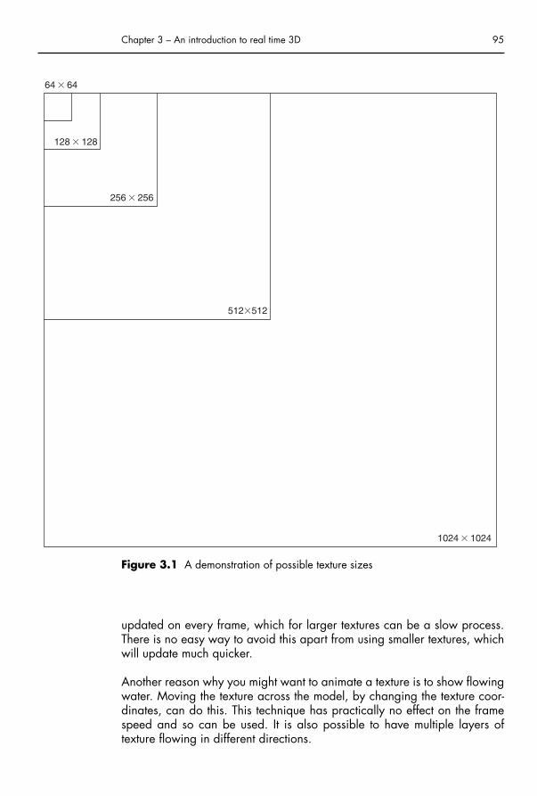
updated on every frame, which for larger textures can be a slow process.There is no easy way to avoid this apart from using smaller textures, whichwill update much quicker.
Another reason why you might want to animate a texture is to show flowingwater. Moving the texture across the model, by changing the texture coor-dinates, can do this. This technique has practically no effect on the framespeed and so can be used. It is also possible to have multiple layers of texture flowing in different directions.
Chapter 3 – An introduction to real time 3D 95
64 � 64
128 � 128
256 � 256
512�512
1024 � 1024
Figure 3.1 A demonstration of possible texture sizes
Chap-03.qxd 8/12/04 15:03 Page 95

An important point to raise here is that in both of these types of texture animation, you have to do it in Director, with Lingo programming. It doesnot take a lot of code, just a few lines, but you cannot export this type of animation using the Shockwave W3D exporter.
Shadows
Shadows are great for that added touch of realism and in real life we takethem for granted. Without them objects seem to float on top of the ground.The trouble with shadows is that they can be very complicated to achieve.True shadows are calculated by Raytracing, which is the idea of followinga line from a light source to the object and then creating an outline on theground. This is the most accurate form of shadow creation, but also by farthe slowest.
Another much simpler technique is to place a soft edged shape below thecharacter or object, if it is moving around the scene. This idea has longbeen used by computer games and works well enough from a convincingpoint of view. The black soft edged shape can be placed on a plane, usingalpha transparency to fade it into the ground below, this plane is then set tofollow the character as it moves around the ground. See Chapter 8 for anexplanation of this.
A third method is particularly useful for room environments, where none ofthe objects is going to move. The idea is that you set your scene up in your3D software and then render it with all the shadows and illumination thatyou want. The trick is to render it from the top view down and then from thefour side views of your room. These rendered images become your textures,each with various shadows falling upon them. This technique works verywell on the photorealistic front, but does mean that you can end up withlarge textures, which as we have already discussed, can be a problem. Itmeans that you have to keep an eye on the texture size. You could load upall the textures just for that room and remove them when you leave it. Thisway you could create a large house, with lots of textures. This is discussedin more detail in Chapter 8 of this book.
There are other techniques for real time shadows, that computer game com-panies use. These make use of the graphics card’s ability to cast shadows.The Shockwave 3D engine, although being hugely popular, does not cur-rently support true shadows, and so advanced tricks are required to createaccurate shadows. These are unfortunately processor intensive, which leads to the frame rate slowing down. This is why these second and thirdtechniques are often used.
96 3D for the Web
Chap-03.qxd 8/12/04 15:03 Page 96

Reflections
This is quite a special case, as you often will not need reflections in yourscenes. However, if you do have a pane of glass, a garden pond or ametallic object, you will probably want to have reflections in order to addthat touch of realism. There are several ways to do this.
As with shadows, the best way is to use Raytracing, but this time tracing apath from the camera to the object and reflecting off until it meets anotherobject. This needs to be done for every pixel on the screen that has a reflec-tion material on it. This is even more time consuming than shadow Raytracing,and is pretty much impossible to do in real time, particularly because theShockwave 3D engine does not support it.
The simplest, and effective solution, is to use a reflection map, this is a stillpicture, which might be a rendered view taken from the object. A reflectionmap moves around the object as your view of it changes. It gives the illusionof a reflection as you can often see the sky and surroundings in the object.This works best for complicated objects, such as an android, but does notwork very well for flat planes as the result can be confusing. Its main advan-tage is that it is a fast solution.
The next option is probably the best quality, but is still fairly slow. It involvesdynamically taking snapshots from a camera point, behind the mirror orreflected surface, every frame. The image is projected onto the reflectingobject. The problem here is that this technique uses the computer processoras opposed to the graphics processor. As your computer processor is prob-ably doing many other things, your frame rate could be dramaticallyreduced. In short you are unlikely to use this technique apart from for verysmall reflected surfaces.
Deforming objects
Deforming objects are any objects that change shape, Morph or are ani-mated with stretchy skin. This could be a running character, where you havealready worked out the walk cycle in your 3D package and exported theanimation. If the object has a large number of triangle faces then theamount of time it takes to calculate each new face position is increased.Characters typically have to be as low in triangle count as possible in orderto attain a smooth animation. A character with more than 1000 faces mayappear to be low in detail, but is already getting large for the purposes of Shockwave 3D and you should try and remove as many unnec-essary faces whilst still retaining the look of your character. You could havea higher face count, if there is not much else in your application. But if you
Chapter 3 – An introduction to real time 3D 97
Chap-03.qxd 8/12/04 15:03 Page 97

have many characters or a complicated game, you will always have tocompromise here.
The trick to creating detail in your objects is to use bitmap images to give theappearance of 3D detail. For example, heads of people should be mainlymade up out of these bitmap textures as opposed to thousands of trianglefaces for details like ears and eyes. Of course, if sticky out ears are essentialto your character then you will put them in. The trick is to reduce polygoncount in areas that do not deform in your character, and other flat areas.
Reducing polygon count is discussed later in this chapter, where 3ds max’sOptimize modifier is used. Chapter 5 takes you through low-polygon char-acter modeling, meaning modeling deliberately to keep the triangle countlow. It is always most important to optimize the face count of objects thatchange shape.
When you are preparing content for the Shockwave Exporter there are somerestrictions that you need to be aware of. You cannot do standard Morphing(changing the form of an object from one state to another) or even Sub-Object deforming (like the pressing down of the turtle’s back that was cov-ered in Chapter 1). You have to export these objects in each of their differentstates and then you would use program Lingo code to do the Morphing.Lingo is the programming language of the Macromedia Director application.
The Metamorphosis kinetic sculpture seen in Figure 3.2 was created entirelyin Director, by programming and is an example of a Morphing object.
98 3D for the Web
Figure 3.2 Six screenshots of ‘Metamorphosis’, an interactive morphing sculpture,by Anthony Head
Chap-03.qxd 8/12/04 15:03 Page 98

In Director you can create primitive objects, such as cubes, cylinders andspheres. The Metamorphosis sculptures, involve the deformation of a sphereinto two states. The deformed sphere then pulsates between the two statesin a smooth manner, depending upon programmed properties, such as elasticity and friction. The project actually involves six sculptures, each withdifferent properties.
The kind of Morphing objects involved in the Metamorphosis projects cannot be exported from 3ds max to Director. You would simply get theoriginal shape, with no animation. However, it is possible to achieve aMorphing animation using bones, giving your objects an internal skeletonstructure. 3ds max has two types of system for this, one is called ‘bones’and the other is Character Studio Biped. Both can be used for characteranimation, where your skeletons are ‘skinned’ by the character object. Theinformation that gets exported is the bone animation as well as the mesh.Shockwave dynamically calculates the deforming of the mesh as the char-acter moves around the scene. This means that it is possible to merge boneanimations together, e.g. changing from a running motion to a jumpingmotion, as the information required for movement is just the bones and theobject vertices relation to those bones, that is how strongly their position is affected by the bone movement. This concept forms several chapters ofthis book.
Exporting to ShockwaveWe have talked now about how to prepare your 3D models and objects in order to get them into a 3D engine program, in our case MacromediaDirector. You will be exporting a file with an extension .w3D and this filewill be imported into Director. From Director we will export a Shockwavefile (with the .DCR extension) for use on the Internet. The W3D file youexport from your 3D program will not work as it is, it has got to be editedand re-exported in Director.
We have covered a lot of detail that might not seem relevant at this stage,after all we have not made any interactive 3D environments as yet. Even ifyou only skimmed through it, you can use the information as a reference asyou continue. The main thing we have not covered so far is what kind ofmaterials we can successfully export to Shockwave, because unfortunatelyit is not all of them.
Most of the time when you are creating a model you will probably use abitmap texture to cover it. This method gives you great flexibility, as you cancreate your own from photographs or scans. Bitmap textures are what theShockwave engine understands and uses. However, many of the materialmaps in 3ds max are not bitmap based, they use procedural textures.
Chapter 3 – An introduction to real time 3D 99
Chap-03.qxd 8/12/04 15:03 Page 99

Procedural textures are created using algorithms that create repeating pat-terns. As you need to keep textures fairly small, you need to be able to usetiling patterns wherever you can. There are two types of procedural maps:2D and 3D. The 3D maps are more powerful but are not supported byDirector, so you can only use the 2D ones, such as checker and swirl. Thetable below shows some of the 3ds max maps that are compatible withDirector. All the maps should be applied as Diffuse maps to appear normallyon the model that you have created.
Map name Extra options Notes
Bitmap Noise Can be most types of imported image,including alpha transparent bitmaps
Checker Noise, soften Checker can be a mix of two other mapsGradient Noise A way to blend up to three different mapGradient ramp Noise, gradient types (four Only mixes colors, not other maps
corners, box, diagonal, lighting,linear, mapped, normal, pong, radial, spiral, sweep, tartan)
Swirl Twist, contrast, intensity Mixes only color
Note There is an issue with transparency in Director which means thatobjects that have semi-transparent materials do not intersect correctly.This is due to the Z-buffer, which is the aspect of 3D rendering, whichcalculates how near and far objects are. Most of the materials above(apart from bitmap) end up including a level of transparency. To getround this deselect materials when using the W3D exporter.
Putting the knowledge into practice – creating a sound toyTo take us through creating some 3D that will be interactive and real time,it will help to have a practical example to deal with. We want to makesomething that is interesting and appealing to the user and, for the sake ofdemonstration, an artifact that will show something of what is possible with-out being too technically difficult at this stage. Obviously you want to makeimpressive websites, but there is no replacement for creativity, you need to draw on as many influences as you can and extract them into your ownideas. The following tutorial is very loosely based from the point of view of
100 3D for the Web
Chap-03.qxd 8/12/04 15:03 Page 100

3D modeling as I hope that everyone who follows it will come up with hisor her own version of its topic, a sound toy.
Sound toys are a type of Digital Art and come in many shapes and forms,but essentially refer to any interactive computer generated artifact that dealswith sound and more often than not, vision. The basic idea behind a sound toyis that they encourage the participant to play, and that is a good thing for anywebsite. Fun things give your website traffic, which is surely the aim of any-one wanting a website, to get people to visit and keep visiting. Creating a toyor a game is a popular way to attract people to your website. We will coverconcepts involved in game creation later in the book, but first, we now willmake a wobbly, stretchy, elastic sound toy that you control with the keyboard.
Exercise: making the sound toyThere are two phases to this exercise, the first is creating some 3D modelsand placing them in an environment and the second will be applyingmotions to the objects in Macromedia Director. You already have somemodeling knowledge and this section is a chance for you to explore your3D package without having to worry about accuracy of modeling. The sec-ond stage will be your introduction to Director, which has many powerfulfeatures that usually rely on knowledge of its programming language Lingo.To make life easier at this stage, the programming has been done for youand you will be able to select actions and sounds for your objects, whilstfamiliarizing yourself with the Director interface. Finally you will be able topublish your movie as a Shockwave file for use on the Web. Figure 3.3shows the sound toy included on this CD with this book.
The modeling
It does not matter much which methods you use to create your objects as theyare going to end up as fixed meshes. You will not be doing any animation inyour 3D program. The objects you create can be as complicated as youlike, but you have to be aware of face count, about which we have justtalked. I recommend going for an abstract approach as the objects you create will move, but not in an animal-like way, but vibrate and distort. Theywill have properties of elasticity and friction, combined with differentactions like spin and stretch.
You might want to create standard musical instruments, but this is the worldof your imagination that we are dealing in so your objects can be anything.You can use this chance to explore some of your 3D packages options formodel creation, exploring various modifiers or going crazy with polygonalmodeling.
Chapter 3 – An introduction to real time 3D 101
Chap-03.qxd 8/12/04 15:03 Page 101

Polygonal modeling
You have already done this in Chapter 1 when you created the turtle andChapter 2 when you created the head character. By creating a box andconverting it to an editable mesh, you can Extrude and Bevel polygons(make sure you are in Polygon Sub-Object mode). You can either work to a design from paper or just Extrude and Bevel away at your will. I have created an abstract shape that you can see in Figure 3.4 and then appliedthe Mesh Smooth modifier to make it aesthetically more pleasing.
Mesh Smooth
Using the Mesh Smooth option often improves the look of your creations,making them more organic in shape. Any object that has unwanted sharpedges can be smoothed off with this modifier. The issue with Mesh Smoothis the resulting face count, so do not increase the iterations too much.
102 3D for the Web
Figure 3.3 A simple example of the kind of sound toy that you could create
Chap-03.qxd 8/12/04 15:03 Page 102

Optimize
In 3ds max you can use the Optimize modifier to reduce your face count,by adjusting the Face Thresh parameter. This can sometimes lead to unde-sirable outcomes in your models though, particularly if they are compli-cated, so use it with caution and judge for yourself if you have tried toreduce the face count too far. Figure 3.4 also shows the result of optimizingthe shape, there is a significant reduction in face count with only a slightdeterioration in the quality of the model. Note that the reduction is more significant on flatter areas.
Another issue with the Optimize modifier is when creating objects whichuse the Multi-Sub-Object Material. You will use this later in the book to maptextures onto a character. The problem with optimize is that it reduces theface count mathematically and not by aesthetics. This means that faces thatyou might want to stay unchanged can be removed, making it difficult toplace the textures where you want them. It can also cause problems if you useit on an animated character as it can stop the mesh bending in the correctplaces. However, if you are only simply applying a material over the wholeobject and is not animated then this may not be an issue for you.
Chapter 3 – An introduction to real time 3D 103
Polygonal Model90 Faces
Mesh Smoothed736 Faces
Optimized486 Faces
Figure 3.4 A polygonal model with Mesh Smoothing and Optimization
Chap-03.qxd 8/12/04 15:03 Page 103

Note For our sound toy we will only be having a few objects in the scene,and hence we can get away with relatively large face counts for eachobject. If we were making a computer game with possibly hundreds ofobjects then we would be a lot more thorough in reducing the count,with careful modeling.
Other modifiers
Your 3D package probably has many ways in which you can create anddistort objects. 3ds max has modifiers, such as melt, stretch, spherify, ripple,relax, noise, taper and twist. In Figure 3.3 the left hand shape was createdby melting a cylinder, which had many height sections, and twisting it. Thesix upper floating shapes were just created from spheres that were stretchedand tapered. The bottom right hand shape is a Tube primitive that has beenMesh Smoothed and the middle shape is a polygonal model.
Mapping
On the shapes in my scene I have used a number of maps taken from thelist in Figure 3.2. To make my objects more interesting, I have used a reflec-tion map. The map should be one that matches the environment, in my casea checkered box room. So I used the same map on these shapes as theroom. The effect of this is best when you see it in real time 3D, when youexport your creation as a W3D file. The idea behind the reflection map isthat it always faces the camera, and then moves around the object. Thisgives the illusion of a reflective surface. I set the reflection amount down to 10% as I wanted it to mix with the Diffuse map that I had selected. As I mentioned earlier, reflection mapping works best on curved shapes.
Exporting to W3D
When you are happy that you have created an interesting setup for yoursound toy, with some interesting shapes and objects, it will be time to exportthem. If you have not done so already, make sure that all your objects arenamed in a way that makes sense to you. You can only export the scene ifyou have the Shockwave Exporter installed on your computer. This is a gen-erally free plug-in that can be found on your 3D application’s website. Theexporter window is different for each 3D application but Figure 3.5 showsthe 3ds max version. You will see the kind of features that you can export.
You export by going to the File-Export menu and selecting Shockwave 3DScene Export (*.w3D). The Export window will appear after you have chosen a file name for your scene. There are several options on the windowthat will be already selected for you.
104 3D for the Web
Chap-03.qxd 8/12/04 15:03 Page 104

Preview options
This option is very handy as it will show you how your scene will look afteryou have exported it. You can rotate around the scene by holding themouse button down and dragging.
Compression settings
These options allow you to reduce the size of the exported file. Experimentingwith these can be very useful if your scene is large. You want your file to be
Chapter 3 – An introduction to real time 3D 105
Figure 3.5 The Shockwave Exporter panel in 3ds max
Chap-03.qxd 8/12/04 15:03 Page 105

as small as possible so that end users can download it quickly. Be wary oflowering these numbers too much as they could have unwanted side effectson your scene. Compression settings lower than 50% are likely to have afairly dramatic effect on the quality.
Texture size limits
This is handy to set if you have used bitmaps where you have not edited theirsize already. It is always best to keep textures at a size that is a power of 2as mentioned earlier, but these options will resize them. Be aware that if youhave a large bitmap, that reducing the size will reduce the quality, but that ispart of the compromising you have to make when creating real time content.
Shockwave resources to export
Generally you can keep all of these options checked. If there is no anima-tion in your scene, then none will be exported. There is an issue withShockwave that makes objects not intersect properly if there is transparencyin them. The maps other than bitmap, e.g. swirl, etc., do contain trans-parency. If you use these maps then uncheck the material resources box.This will not make an obvious difference to your file, but means you will notbe able to have semi-transparent objects if they intersect with other objects.
Animation options
In our sound toy, we are not going to do any animation in your 3D package(although there is nothing stopping you experimenting with it). Animationfiles are generally quite small and so I recommend you keep Sampling to 1which means the same number of keyframes as you put in. Make sure thatthe range covers the full length of your animation if you have any.
Additional options
You might as well keep these objects checked as they can give you infor-mation about your export. You will probably always get messages indicat-ing that things are wrong, e.g. you will be warned that you have used anon-Blinn shader. However, if it does not look wrong, it is not and you willfind that this error appears if you have the Blinn shader selected in yourmaterials.
Now you have set the options it is time to make our scene interactive, usingMacromedia Director.
106 3D for the Web
Chap-03.qxd 8/12/04 15:03 Page 106

Introduction to Macromedia DirectorDirector is a multimedia production program and our chosen platform to createour interactive sound toy. Director is responsible for creating Shockwavemovies that you find on the Web, often computer games. There is sometimesconfusion between Director Shockwave movies and Flash movies. These twoprograms are similar in what they do and are made by the same company.Traditionally, Director was aimed at creating CD-ROM applications, e.g.educational software with video content and Flash aimed at the Web ani-mation market. There are, in essence, two main differences between thesetwo programs. Flash has superior vector graphic capabilities and Directorhas superior 3D capabilities. Director is better at incorporating other media,such as various video formats and QuickTime (including QuickTime VR). It isalso possible to embed a Flash file into Director, but not vice versa.
We are going to use Director for its 3D capabilities and this is best donewith the use of some programming. Where Flash uses a programming language called ActionScript, Director has its own language called Lingo.As this is just an introduction, I have done all the programming for you, butif you are already familiar with Lingo then you will be able to look at andadapt the Lingo scripts for your own uses. Above all this whole exercise hasbeen designed to be flexible and provide a wide variety of results.
The important parts of the Director interfaceThere is a lot to Director and many ways to use it. As we are only going tobe delving into the 3D aspect of this program, we will skip somewhat thedetail about all the options and concentrate on the relevant aspects. Figure 3.6is an enlarged view of the important control buttons you will need to befamiliar with in order to navigate easily through the different windows of theapplication.
Chapter 3 – An introduction to real time 3D 107
Figure 3.6 A section from Director’s top tool bar
The first section is the control panel, with the Rewind, Stop and Play options.It is often important to rewind a movie before you play it and so it is a good
Chap-03.qxd 8/12/04 15:03 Page 107

habit to always do this. The next contains the buttons for the Stage window,the Cast window, the Score window, Properties Inspector and Librarypalette.
The Stage
As the name suggests, this is the window where the action takes place.Macromedia Director, for the most part, uses Theater terminology as a wayto make its components easier to understand for users. What you see in thiswindow is what the end users will see in the Shockwave movie that you willcreate from this exercise (Figure 3.7).
The Cast
The Cast is where all the objects reside that you are using, e.g. graphics,sounds and Lingo scripts (Figure 3.8). This is similar to the Library inMacromedia Flash. There are many types of media that can be imported intoDirector, but we shall deal with just a few, the Shockwave 3D (.w3D) file,some sound files (.MP3’s or .WAVs) and also some Lingo scripts (Director’sprogramming language) which will be explained later in this chapter.
Certain objects (like graphics) can be dragged on to the stage, creating aninstance of that object. When a graphic is on the Stage it is known as aSprite. Sprites can be controlled through Lingo or by using keyframes in theScore. In our case we will Drag the W3D Cast Member on to the stage, butwe will not be moving it about.
108 3D for the Web
Figure 3.7 The Stage window
Chap-03.qxd 8/12/04 15:03 Page 108

Chapter 3 – An introduction to real time 3D 109
Figure 3.8 The Cast window
The Score
The Score is similar to Flash’s timeline. It shows two counters, the one goingacross is the Frame number and the one counting downwards is the SpriteChannel number (Figure 3.9). You could create a Sprite and it would appear
Figure 3.9 The Score window
Chap-03.qxd 8/12/04 15:03 Page 109

in Sprite Channel 1 on frame 1. You could then make it last until frame 20,and move it, creating a keyframe. This would be animating in a similar wayto Flash and 3ds max. However, for 3D work, we will not use Director thisway, our 3D sprite will stay in frame 1 and will not move about the Stage. It is within the 3D sprite that all the action will take place, using Lingo.
The Property Inspector
The Property Inspector displays important information on settings for yourDirector project (Figure 3.10). If you click on the Stage and then select the
Property Inspector you are able to view the Movie properties. It is here thatyou can set the movie size, which is the pixel size of the Stage. Bear in mindthat this has to fit on most people’s Web browsers. However, it is possibleto set up your movie to stretch to fit the area of the Web browser window,as it is with Flash.
For our purposes the other important feature in the Property Inspector is thePreferred Renderer option. The graphics card inside your computer containshardware to calculate the display of your 3D content and the PreferredRenderer option will choose from a few different methods that it can do this,namely DirectX, OpenGL and Software. DirectX and OpenGL are graphicsstandards that programmers use to instruct the graphics card on how to cre-ate the 3D display. In the case of Director it is the programming language
110 3D for the Web
Figure 3.10 The Property Inspector, showing the movie information
Chap-03.qxd 8/12/04 15:03 Page 110

Lingo that we use and this is converted to DirectX or OpenGL code auto-matically. The other option of Software is to let the computer’s processor cal-culate the 3D display. This is always slower than allowing a graphics cardto do the job, as the central processing unit (CPU) is not dedicated to graph-ics calculations. Generally selecting Auto will allow the user’s computer todecide whether to use DirectX or OpenGL. In simplistic terms, there is not alot of difference between the two, but try to avoid selecting Software modeas it is by far the slowest method.
Note If your 3D scene contains many complicated objects and large texturesthen you could reach the limit of the graphics card memory (which mightbe 32 or 128 megabytes). If this is exceeded Director might automati-cally switch into Software mode and be very slow. This is why you needto consider texture size when creating your scene in your 3D package.
The Behavior Inspector
The little picture of a gear cog displays the Behavior Inspector. This containsone of the methods you can use to add scripts to your 3D world to controlobjects within it (Figure 3.11). You can use Lingo scripting to change theposition of objects, alter the textures that are mapped on to them, move thecamera position, create new objects from scratch as well as more compli-cated functions. New objects have to be primitive shapes, e.g. cubes,
Chapter 3 – An introduction to real time 3D 111
Figure 3.11 The Behavior Inspector showing how to select a behavior or createa new one
Chap-03.qxd 8/12/04 15:03 Page 111

spheres and cylinders which is why we have created our objects in a 3Dpackage. It is a lot easier to create interesting objects this way and getaway from the basic shapes.
A behavior is a script that contains commands and calculations to controlobjects. You would normally have to type this in by hand and learn manycommands. For the tutorial described soon and at this early stage in our useof Director we have adopted a simpler method for you to use, where youonly have to apply the settings of an already written script.
Making our sound toy moveThis tutorial will allow you to animate your static scene, based on physicalproperties, such as elasticity and friction. Changing these properties oneach object will make it move in a different manner. The movement will betriggered by keystrokes. As well as animating your scene, we will importsounds which can be used to correspond to your objects. The process ofcompleting this tutorial will help you familiarize yourself with Director inaddition to the creation of your own unique piece of work.
First of all load up the SoundToyNew director file from the CD. This is essen-tially a blank file but it contains the scripts that we need to use. If you lookat the Cast window you will see them listed in cast positions 2, 3 and 4(Figure 3.12). You will see that each script Cast Member contains a title, anicon and a snippet of the actual code that it contains. The second two scripts
contain the cog icon that we are now familiar with. They are behaviors andwill only work when they are applied to the Score. The first script, calledPrepare Movie, has a different icon and is not a Score Behavior script, it isa Movie Behavior script. Movie scripts are generally used to create actions
112 3D for the Web
Figure 3.12 The Cast window showing a Movie script and two Behavior scripts
Chap-03.qxd 8/12/04 15:03 Page 112

that can be accessed by any other script, or for setting up conditions at thebeginning of the movie. In our case it finds out which member is the 3DShockwave one (which we have yet to import) and then carries out someactions on that Cast Member (to fix the transparency issue if you have usedprocedural textures in your scene).
Importing the Shockwave 3D .w3D file
At the moment our movie will not work, if you tried to run it (by pressing thePlay button) it will error. This is because the Prepare Movie script is trying to apply commands to an object that does not exist, that is, the 3D Shock-wave member. So you need to import it. There are a couple of ways to do this, one is to select the space where Cast Member 1 would be (in theCast window). Right click and select import from the menu. Then find your.w3d file that you exported and press import. It will now be in Cast Member1 and you will see a thumbnail image of it, along with a Shockwave 3D icon.
Now you have imported it you need to bring up the Stage window anddrag the Shockwave 3D member on to the stage. It is now an instance ofthe Cast Member, referred to as a Sprite in Director. It is at this point, if not before, that we need to decide how big we want our movie to be. Wementioned earlier that the resulting Shockwave Movie can stretch to fill theBrowser window, but you may not want to do this, so I suggest a size of700 pixels wide and 350 pixels high. This should fit on most browsers, but choose any size that you want, bearing in mind what else you mightwant on your web page, other than the 3D Shockwave movie. You couldhave your movie open in a new window or completely fill the screen. Youwould do this by using JavaScript commands in your HTML editor, such asDreamweaver.
Once you have set the movie size, using the Property Inspector you need toposition and stretch the Shockwave 3D member to fill the stage area. Youcan check with the Property Inspector that it fits correctly by adjusting thesettings, which will now refer to the 3D sprite that you have selected.
Using the Score
Now we have our 3D sprite on our stage we need to use the Score to tidyup our movie and make the play head loop around one frame. Make theStage window visible by pressing its icon on the top tool bar. You will seethat in Sprite Channel 1, the 3D sprite is represented by a long bar. Grab the right hand end of the bar and drag it back to frame one. The results in
Chapter 3 – An introduction to real time 3D 113
Chap-03.qxd 8/12/04 15:03 Page 113

the Sprite being only visible for one frame, but this frame will be looped sothat the 3D sprite is always visible.
Using a Frame Behavior
The next step is to make the movie loop around the first frame. This is a sim-ple Lingo command, ‘Go to frame 1’ and it occurs every time the play headexits the frame. This command is contained in the ‘Rotate scene and loopframe’ behavior, but it will not work until it is dragged onto the Score. Thecorrect place to drag it is into the frame square above Sprite Channel one.You will see that there is a Script icon on this row. When you drag theFrame Behavior in it will always be one frame in length, which is what wewant (Figure 3.13).
114 3D for the Web
Figure 3.13 The Score window showing the Tempo, Frame Script and 3D sprite
This behavior also has other functions, if you play the movie, by pressingthe Play icon, you will see that the 3D scene rotates. This is actually the cam-era orbiting around the middle of the world. You will also see that moving
Chap-03.qxd 8/12/04 15:03 Page 114

the mouse up and down changes the Camera’s height. Obviously quite abit is happening here and if you are already familiar with Lingo then youcan look at the script to see how it is done.
Making your objects interactive
Now is the time to make our scene more interesting by bringing it to life.First of all we need to import some sounds. It is generally preferable to cre-ate your own sounds. You can use Windows Sound Recorder as a verybasic recorder, but there is plenty of Audio Software available. If you do notwant to record your own sounds then you can always buy sound sampleCDs or download sounds from the Internet. As a starter we have includedsounds on the CD with this book, so you can start by importing them fromthe Chapter 3 folder. Just right click on an empty Cast Member and selectimport. Then find the sounds (various sound file formats are acceptableincluding .wav and .mp3), add them to the File List and press import. Yoursounds will now appear in the cast. If you imported more than one theneach sound will become a Cast Member.
The next stage is to use the script that controls the motions, sounds and trig-gering. Drag the Cast Member ‘Move an object’ from the Cast window tothe stage, dropping it onto the 3D sprite. A new window should appearshowing many parameters as in Figure 3.14.
Chapter 3 – An introduction to real time 3D 115
Figure 3.14 The ‘Move an Object’ Behavior window
Chap-03.qxd 8/12/04 15:03 Page 115

The script for this behavior controls many different properties. All you needto do is select which object in your scene that you want to move, which keyyou want to trigger the movement and what type of movement you want itto have. You can then select how much motion you want in the three differ-ent axes x, y and z. The amount of elasticity and friction will determine thespeed and physics of the motion. Finally you can choose a sound and setthe volume of that sound. There does not need to be a science to how youchoose this, just experiment with different settings. Setting the elastic andfriction properties to extremes can have pretty wild outcomes, but it isentirely up to you what you do. Once you are happy with your settingspress OK.
When you play your scene the key that you selected will trigger your move-ment and play the selected sound. If you decide that you are not happy withyour settings and want to change them then, making sure you have the 3Dsprite selected on the stage, go to the Behavior Inspector and double-clickon the behavior. This will bring up the options for you to change.
To make more objects move, just drag another instance of the behavior fromthe Cast onto the 3D sprite and create settings for another object. Some ofthe sounds supplied on the CD are musical notes, enabling you to make amore melodic sound toy.
116 3D for the Web
Chap-03.qxd 8/12/04 15:03 Page 116

Interview with Eduardo Carrillohttp://www.locombia.net/eduardo/
Profile
Eduardo Carrillo is an independent Web Artist, originally from Columbia; henow lives and works in the UK. I first met Eduardo in 2000, when he was res-ident artist at London Guildhall, and I have since followed his artistic careerwith interest. Eduardo relies on funding from Arts bodies to create his Webartifacts. His work ranges from creating films from naïve drawings by refugeechildren to creating symphonic sound-and-vision ‘scapes’ in collaborationwith the London Sinfonietta. A dedicated fan of all things Web, Eduardo hasshown with his Javadance piece that 1 day choreographers and dancers willbe able to study a library of dance interactively from any angle.
Interview
How do you describe yourself, professionally?
I am a Digital Artist.
Do you collaborate with other 3D animators, Flash animators and pro-grammers, or do your skills cross-over?
Yes, I work a lot with Lingo programmers. I have to work with producers onmany of the projects and I like to involve musicians in the early stages of theprocess.
Chapter 3 – An introduction to real time 3D 117
Chap-03.qxd 8/12/04 15:03 Page 117

General design and 3D
How did you get started in digital design?
First I studied television in Columbia, and then after working for 3 years Idecided to study something where I could be more creative. I came toEngland, and studied for an MA in computer animation. My work is morethan just digital design; I am also an animator who creates digital environ-ments and worlds.
What are your inspirations design-wise?
I admire a lot of video games, like ‘Black and White’ and ‘Mist’. These aregames that are not just shoot-’em-ups or racing cars, but games that giveyou experiences when you are playing.
What do you think is the essence of good 3D design? Can you give anygeneral tips?
I believe your work has to be simple and the user must not get lost in thedesign. Be faithful to the universe that you are creating. The important thingis not to try to impress but to be practical and simple.
How important do you think interactivity is to your work?
I believe that the Internet is a synonymy of interactivity. I cannot imagine, inthe future, web pages without interactivity. One of the intrinsic characteristics
118 3D for the Web
Chap-03.qxd 8/12/04 15:03 Page 118

about the Internet and video games is interactivity. This will be the future ofour art, which will develop around interactivity. You really have to thinkabout the user and how they are going to react with your piece of work.
What aspect of development would you say is the most time consuming?
For me, to get the right idea is the most time consuming part … it is a lot oftrial and error. Once you have conceived the right idea, then it is more orless easy to develop your project.
In your opinion does 3D technology have any advantages over 2D whencreating websites?
Yes, it gives the users more possibilities, you can see an object from all the points of view, and also you can immerse the user in a world which youcannot do in 2D. 3D gives you the sense of feeling part of the world.
What are your thoughts on the use of interactive 3D in art?
Interactive 3D in art is at its birth, it will take some time to start to developits own language. We are just the pioneers of this. It is like video games,now we are starting to see intelligent games, not just shooting and racing.But it took several years to start to develop in different way.
Your past and future work
What awards have you won and do they make a difference?
For me the grants are more important than awards because the grants helpyou to realize your vision, they give you the money to be free. I was givena grant to make 3D Music, by the Arts Council and The Getty Foundation
Chapter 3 – An introduction to real time 3D 119
Chap-03.qxd 8/12/04 15:03 Page 119

gave us the funding for the Java dance project. It really makes the differencebecause without their money it would have been impossible to make theseprojects.
How did the concept for 3D Music website come about?
We really worked together with the musician, we met once a week andtalked about ideas and concepts and then we developed the work alone.For example we worked with the idea of the Arctic pole and isolation andthen we created the room called ‘forest glass’ in 3D Music. One week laterwe would meet again and change the work little by little until we felt confi-dent with the universe we created, and so on. It was very organic, the waywe worked together.
120 3D for the Web
What are your thoughts on collaboration with other artists?
For me it is very important to work with other disciplines, as I say a goodmovie is not just the director’s work, but the actors, the composers, the artdirector, the photographer, etc. A good piece of work is not about one per-son but a group of talented people working together for a vision, the direc-tor’s or producer’s vision. So I always try to involve people from differentdisciplines in my projects.
Any special future projects using 3D?
I am developing a project in 3D with Amnesty international in which thereis a world with interviews of people talking about their personal and tragicexperiences.
Chap-03.qxd 8/12/04 15:03 Page 120

I am also continuing my work experimenting with dance using motion capture with Roehampton University.
Technique
Can you explain your use of motion capture for your dance examples?
I made 3D scans of sculptures from the 4th century, after having these sculp-tures in digital form, we worked with a dancer to perform a Javanesedance. We captured his movement and then put in the model that wealready had as a 3D scan.
How easy is it to implement motion capture into a 3D project?
One of the big problems of motion capture is the creation of a lot of keyframes for the movement. You can, of course, optimize these movements.However, a dancer really sees the difference and to them it is quite impor-tant, even though to an animator there is not much change. So you reallyhave to have big files instead of small files.
Are there any specific problems with using motion capture?
You would think using motion capture would be straightforward and youcould apply the capture files to the models and everything will worksmoothly. This is not the case, you really have to convert the files, and mostof the files are quite big. So you really need a super computer or you needto work with movements of no longer than 45 seconds. Then you can tidythe information you have of all the movements together. The other difficultyI found is that motion capture is very good for extreme movements, jumping,running stretching, but it does not work well for gentle movements near tothe body, sometimes the sensors do not pick up this gentle movement andtreat it like a corrupted file (I am talking about affordable motion captureand not thousands-of-pounds motion capture systems).
Chapter 3 – An introduction to real time 3D 121
Chap-03.qxd 8/12/04 15:03 Page 121

Which technology do you think will be the leader for 3D on the Web?(For example, Shockwave, Flash, Pulse 3D, Virtools and VRML)
I believed it will be Shockwave, not necessarily because it is the best butbecause it has a big company behind this technology; Macromedia.
Do you prefer vector 3D or highly rendered 3D?
I prefer Shockwave that is like vector 3D, it takes less time to downloadingand like I say above it will be the future.
Insights
Do you have any advice for students of 3D Web Design?
Just to keep with simple ideas, the simple ideas are the best ones. Instead oftrying to explore new technologies try to say something, look for gooddesigners and try to imitate them and then you can add your own voice.
How do you get commissions for 3D work?
Just meeting people, and showing your work to all the people you think canhelp you. Meeting people is a key factor in the industry, sometimes theclients do not have the time to look for the best one, but for the handiest per-son. Going to seminars, master classes and meeting with people.
3D has almost taken over the games industry; do you think it will becomepredominant in Web Design?
Yes, Yes and Yes! I will put my hand on fire over that. When broadband iscommon in households I believe 3D design will explode. It will be greatbecause then the only limit will be the sky and beyond that, because wewon’t have to worry about the size of files.
Does current Web technology allow you to achieve all of your creativeideas, what improvements would you like to see from software?
I would like there to be improvements in how sound is handled and for thereto be better rendering, a better quality in picture. It would be great if youcould use all your particle systems translated into 3D software.
122 3D for the Web
Chap-03.qxd 8/12/04 15:03 Page 122

Chapter 4
Designing andmaking characters
• Animation – the chores and the charms• Character design• Modeling in 3D• The eyes have it• Creating a quirky character for Flash• Creating the Hitme character• Forward and Inverse Kinematics• Applying the Skin modifier• Animating the Hitme character• Making the animation interactive• Interview with Neostream
ChapterSummary
Animation – the chores and the charmsLet us face it animation is hard work, there is so much to think of, and evenwith all the digital tricks that a computer brings to the party, it takes time. I once added up all the different hats a student needs to wear to make ashort animated film. It is quite a list:
• Starting with the Producer who has an idea …• The Writer creates the story and dialog.• Casting Agent. The 3D modeler models the characters.• Make-up and Costumes. Then chooses materials and maps them onto the
characters.
Chap-04.qxd 8/12/04 15:04 Page 123

• Sound records the necessary tracks and times them.• The Director decides how best to tell the story in terms of location, shots,
transitions, compositions and overall style.• The Actors and/or Animal Wranglers work out the performance action,
timing and delivery.• The Photographer chooses the best camera angle, lens and any camera
moves.• The Lighting Cameraman places lights to illuminate the scene and create
the right mood.• The Set Designer and Props will decide what needs to be in shot and
what does not, the age, style and entire look of the set.• The Special Effects Designer is consulted for any 2D to be added after-
wards or projected now, and works out any explosions or particle systems.• The Compositor grades the film, matching shots to create an overall
smoothness and composites the elements together.• The Offline Editor matches shot to shot with the sound, adding new tracks
and pacing the film.• The Online Editor formats the film, adding titles, credits and removing
glitches.
And throughout, the Producer budgets for equipment you can afford to doall this on, and timetables the work while selling the film for distribution.
That is up to 17 jobs all with different hats. Oh, and you have to self-catertoo. Many of these jobs are staffed by people with decades of experience intheir craft. As far as 3D student film making goes, it is worth rememberingthat the filmmaker’s role is not only that of the Director, but also the entirepre-production, production and post-production crew. Feeling daunted?
If animation is such hard work, why undertake the sheer hard graft of it all?Because its magic, that’s why.
It is human instinct to communicate, to tell stories and share experiences.Animation has a way of communicating at a most fundamental level. Achild walking into a room where a cartoon is playing on television will stopand watch as if drawn by a magnet; the attraction is immediate. That is whycartoon characters are used to endorse products. This same instant appealis why we have The Jolly Green Giant and the Frostie’s Tiger.
I have a pet theory that all animators are anarchists. They have looked at the world and said ‘Preeety good going, God, but what’s with the camel?
124 3D for the Web
Chap-04.qxd 8/12/04 15:04 Page 124

You could not decide one hump or two? And, not to get too heavy, but gravity, couldn’t you just have made life just a bit more, well, bouncy?
Come on I can do better than that! What if we took an armadillo andadded it to a kangaroo – Now you are talking! And while we are on thesubject, get a move on with those Aliens; we need some new blood aroundhere!’
You, as an animator get the chance to play God; a chance to create yourown Adam and Eve and put them through their paces.
So here we are. We want to play God, and we want to tell a story. The firstthing we need to think about is making a character. As animation is suchhard work; you would better love your character, you will be spending a lot of time with them! And this is particularly relevant in 3D because youhave to pay a lot of attention to not just how the character looks, but how itis constructed.
Character designWhen deciding to cast your animation, the first thing you should think aboutis your audience. Is your character going to interact with the real world orbe part of a kid’s game? Realism versus caricature, or entirely imaginary?Always design so that your characters are exceedingly appealing to youraudience.
The approach you have decided upon will dictate the proportions of yourcharacter. Realistic humanoids are roughly six heads high. Cartoon char-acters are four heads for more natural looking characters, and two-and-a-half to three heads high for classic cartoon proportions. This is becausetwo-and-a-half heads high is a child’s proportion which is naturally appeal-ing – E.T. was not the shape he was for nothing. Most animation is madewith a target audience of 6–14 year olds. For the Web, you will have nocontrol over your audience, but you should know whom you want to appealto most; that demographic is whom you are aiming for.
How to design a character in 3D
Many people prefer to design a character on paper first, and that is cer-tainly what most teachers would advocate in character design. Although Ihave noticed more and more students today like to roll up their sleeves andbuild straight into 3D – it depends on your experience.
Chapter 4 – Designing and making characters 125
Chap-04.qxd 8/12/04 15:04 Page 125

There are certain cartoon shorthands that can be used:
• Bigger eyes, smaller size � More goofy.• Small eyes, taller � More intelligent.• Fat � Lazy.• Spectacles � Boffin.• Large Breasts � Foxy woman (no design of a nuclear physicist would
include massive mammaries).• String of Pearls � Domestic woman (Wilma Flintstone, Marge Simpson).• Baby proportions � Innocence.
Another way of looking at cartoon shorthands is to read them as prejudices.They can (and perhaps should) be subverted. Lisa Simpson’s a boffin, butshe does not wear glasses. Pinky and the Brain reverse the look for smartand stupid. These are shorthands and not rules. Let us have a look at a specific example.
In Figure 4.1, I have designed an archetypical Bully on paper. What are thereasons behind my design? He is almost Neanderthal, with a heavy browand his knuckles almost reach the ground. He is designed with a big, pug-nacious jaw, low center of gravity, and a massive, awesome chest. I havegiven him small eyes to remove appeal, and an aggressive (but not offen-sive) logo on his chest. I left the Bully character deliberately square with nomesh smoothing apart from his head. I wanted him to look like a walkingcrate. The finished model is shown in Figure 4.2.
I have lit him with a massive, scary shadow to make him more daunting.And put a flower in his hand to subvert stereotypes!
126 3D for the Web
Figure 4.1 Bully designed on paper (three-and-a-half heads high)
Chap-04.qxd 8/12/04 15:04 Page 126

Modeling in 3DOne way of modeling from a drawing is to scan your drawings and put them into the 3D environment so you can work from them. To do this,create two planes at right angles to each other. Bring in your front and side drawings as bitmaps and assign them as color (diffuse) maps to theplanes. Click on the ‘Show Map in viewport’ icon for each material andadjust their position using UVW mapping. You can then create a box(3 � 4 � 3 segments is usual), convert it to an Editable Mesh and fit thevertices to the drawing outlines in the side and front (orthogonal) viewports(Figure 4.3).
Chapter 4 – Designing and making characters 127
Figure 4.2 The finished Bully model
Figure 4.3 How to build a character from a projected drawing in 3D
Chap-04.qxd 8/12/04 15:04 Page 127

Note For animation purposes, it is customary to build a character in ‘starpose’ (standing with their arms out and their legs apart). The reasonfor this is that if the mesh is to be animated using deformation tech-niques (i.e. bones or biped), it is very useful to keep the spheres ofinfluence as separate as possible.
The finished Bully is made from separate boxes for the legs, arms and chestand a tapered oiltank for the head. His hair is a cylinder (Figure 4.4).
The eyes have itWatch any close-up of a lead actor in a movie, and see how their eyes glint.We register and read all emotions in our eyes; they are the window to oursouls. Most characters you build in 3D will have eyes, in fact adding eyesto just about anything, makes it a character. In 3D there are two things youwant from eyes; that they look great, and are easy to control. This tutorialshows a way of building eyes with lots of character that are fun to animate.
Create a sphere that has 32 segments. Label it R-eyeball. Select the spherewith the Uniform Scale tool and Shift-drag to create a second slightly larger
128 3D for the Web
Figure 4.4 The completed polygonal mesh
Chap-04.qxd 8/12/04 15:04 Page 128

sphere. Set the hemisphere spinner to 0.5. Call this R-eyelid. Convert thishemisphere to an Editable Mesh to tweak the eyelid vertices at the edge intoa nice, perky shape for definition.
Select the original R-eyeball with the Scale tool and clone a third sphere,mid-size between the two others for the pupil. Set the hemisphere spinner toabout 0.85 and rotate the pupil so it looks at you from the front viewport.Label this R-pupil. Link the pupil to the eyeball using the ‘Link’ tool from themain toolbar.
Assign suitable materials to each object, such as a white shiny eyeball,black pupil, etc. Select all three Modified Spheres and copy them to theright to make the left eye. Re-label these ‘L’ (Figure 4.5).
Now we are going to add controllers for blinking and orientating the pupils.
First we are going to add a Dummy to control blinking. A Dummy, helperobject is a wireframe cube with a pivot point at its geometric center thatdoes not render. You can create a Dummy by going to the Helpers paneland choosing Dummy (Figure 4.6).
Create the Dummy by Click-dragging midway between the two eyes in thetop viewport. Adjust its orientation so that it is aligned on the Y- and Z-axis
Chapter 4 – Designing and making characters 129
Figure 4.5 Two basic eyes
Top TipFor this to work correctly it is essential that the pivot points of all thespheres remain aligned. The pivot point (which represents an object’slocal center and its place in the local coordinate system) on any objectis where the Gizmo is positioned when an object is selected. It is typi-cally in the center of a sphere or cube when first created. To align (orre-align) pivot points use the ‘Align’ tool in the main toolbar. Select the object you wish to align, click on the tool (which will highlight inyellow) and select the object you wish to align to.
Chap-04.qxd 8/12/04 15:04 Page 129

with the pivot points of the eyeballs. Link the two eyelids to the Dummy.Select the Dummy and select ‘Local’ from the Reference Coordinate Systemin the main toolbar (where it reads ‘View’, next to the Scale tool). This willmake sure that the Dummy will rotate on the same axis whichever viewportyou use. Rotate the Dummy on the X-axis, to check that the eyelids make asmooth blink. (If they do not, then re-align your objects.) Label the Dummy‘Blink-Dummy’.
Now let us add a Dummy to control where the pupils look. In the top view-port create a Dummy that sits in front of the eyes, and some distance away.(This is where the eyes will look at, so imagine a character sitting directlyopposite.) Rename this Dummy, ‘Lookat Dummy’.
Select the R-pupil and hit the Motion Panel button. In Parameters � AssignController, select ‘Rotation’, click on the ‘?’ button, and select the ‘LookAtConstraint’ from the Assign Controller menu (Figure 4.7).
Under LookAt Constraint, click on Add LookAt Target, and choose theLookat Dummy you have created. Your pupil will probably flip to the back of the eyeball. Select the LookAt axis Z, and the pupil will return,there should be a blue line heading away from the pupil towards theDummy. (If the pupil still does not point the right way, click on ResetOrientation and rotate it into the correct position.) Do the same for the Lpupil. Check it is all working by moving the Lookat Dummy and seeing if thepupils follow.
130 3D for the Web
Figure 4.6 The Helpers panel
Chap-04.qxd 8/12/04 15:04 Page 130

Note If you think you will need to move the pupils separately at some point,create two Lookat Dummies, one for each eye and group them afteradding the LookAt Constraint. If you want your character to wink, youwill have to unlink one eyelid, or if it has a nervous tic, make two blinkDummies.
These two Dummy Helpers will really speed things up when animating eyes,now let us concentrate on making them look great. We are going to add aSpace Warp to give the eyes character.
Click on the ‘Create’ button and choose Space Warps � Geometric/Deformable. In the top viewport create an FFD box big enough to encom-pass the R-eyeball and Eyelid. Position the FFD Space Warp to fit over theR-eye. It will look like a lattice with 4 � 4 � 4 control points. It is a goodidea, under the Space Warp Parameters � Deform, to click on ‘All vertices’here, so none accidentally escapes the FFD lattice (Figure 4.8).
Name this R-eye-FFD box.
Next use the ‘Bind to Space Warp’ tool from the top menu bar, to bind theRight eyeball, eyelid and pupil to the FFD Space Warp. (As it binds, thecontrol vertices of the FFD Space Warp flash white.)
Create another FFD Space Warp and do the same to the left eye.
Chapter 4 – Designing and making characters 131
Figure 4.7 The Assign Controller menu
Chap-04.qxd 8/12/04 15:05 Page 131

132 3D for the Web
Figure 4.8 The Create � Space Warps panel
Chap-04.qxd 8/12/04 15:05 Page 132

Select the Right-eye-FFD box and under the modify panel open the Sub-Object rollout to select ‘Control Points’. By selecting and moving the controlpoints of each FFD Box, you can change the shape of each eye (Figure 4.9).
The eyes should not only look good and expressive, but still animate fluidlyusing the Dummy controllers, because 3ds max works through the ModifierStack from the bottom up. (You can hide the FFD boxes when animating, asthey get in the way of seeing the expressions.)
It just remains to make sure all the links are correct and to link the whole lotto a Dummy so that the eyes are easy to move around en masse. Create alarge Dummy over the eyes and call it Eyes-MasterDummy. This will be ourMaster Dummy.
Because the Blink-Dummy is already controlling the eyelids, and the eye-balls already control the pupils, you should link everything but the eyelidsand pupils to the Master Dummy (Figure 4.10).
Chapter 4 – Designing and making characters 133
Figure 4.9 Here’s looking at you, kid
Top TipYou may also want to create a Target Spotlight for your eyes to givethem that lead actor glint. You can link this to the Master Dummy aswell, so the eyes will always have a keylight.
Chap-04.qxd 8/12/04 15:05 Page 133

Note The eyes can be tricky to resize, so try and resize your character to theeyes rather than the other way around. Also remember that althoughthese eyes look great, they are heavy on polygons.
Creating a quirky character for FlashA single character can be fun on the Web. You can make a visitor interactby running looped films in Flash. The visitor can often be fooled into think-ing they are interacting far more than they actually are, and you can man-age to keep wonderful lighting and high polygon counts in your renderedfilms. The Who’s We and Neostream sites are great examples of this.
In this next exercise, I built the Hitme character specifically for this purpose.He is animated using hierarchical links with bones for deformation, andsports the same eyes that we have just made. I started by making a sketchof the Hitme character (Figure 4.11).
The idea behind the Hitme character, as the name suggests, is that the Webvisitor can amuse themselves by tormenting him. When designing the charac-ter, I knew that I wanted something that would be fun to animate in extremes.Because I had no restrictions on materials, lighting or polygons, I have usedRaytrace materials and a lot of Mesh Smooths giving a high poly count.
134 3D for the Web
Figure 4.10 The object subtree, showing the linked hierarchy of the eyes
Chap-04.qxd 8/12/04 15:05 Page 134

I have given the character a spherical body for bounce and expressivehands for waving around; the white gloves will make his hand movementsregister more (A trick Disney used for Mickey Mouse). I decided against thewriting on his stomach, as I want him to appeal globally, instead I havegiven him glossy stripes that emphasize his roundness, and are reminiscentof Uderzo’s Obelix or Tenniel’s version of Tweedledum and Tweedledee.The feet are large, as he needs a stable base and will not be walking around.Having built the character in 3D, I thought his throat looked kind of vulner-able and needed breaking up, so I also gave him a red bowtie. Also, I mustconfess that red bowties have the same effect on me as red rags to a bull; I invariably feel like hitting anyone who wears them. Perhaps my audiencefeels the same, and if not, hey, I can indulge myself – it is my character!
Creating the Hitme characterMost of the character is made from simple spheres and cylinders. The feet,hands and head are made with polygonal modeling from boxes, and thenadding a Mesh Smooth modifier (Figure 4.12).
Before linking and fitting bones to the character, I moved the pivot points onsome objects so that the centers of rotation would be in the right place foranimation. As shown when you aligned the eyes, the pivot point can bemoved to anywhere you want, which is a helpful tool particularly for ani-mating rotations. To move a pivot point, select the object, go to ‘Hierarchy’
Chapter 4 – Designing and making characters 135
Figure 4.11 The original sketch for the Hitme character, and the finished article
Chap-04.qxd 8/12/04 15:05 Page 135

and click on ‘Affect Pivot Only’ (Figure 4.13). Now you can move the pivotpoint to any new desired position in a viewport. Click off ‘Affect Pivot Only’.
Note It is essential that any adjustments to pivot points are made before ani-mating, as it is not a parameter that is animatable.
I dropped the pivot point for the character’s body to the bottom of thesphere, and moved the pivot points on his feet to where his ankles wouldbe. The arms pivot from the joints and the lower mandible from the hingethrough his jaw (Figure 4.14).
136 3D for the Web
Figure 4.12 Making the head from a polygonal box, before adding a MeshSmooth modifier
Figure 4.13 Moving the pivot point
Chap-04.qxd 8/12/04 15:05 Page 136

Before we add some bones for mesh deformation and link it all up, let meexplain how linked hierarchies animate in 3D.
Forward and Inverse KinematicsWhen you create a linked hierarchy, you are in effect making a series ofparent–child links, where the parent drives the child. If you imagine thisseries of links as tree branches spreading from a single trunk: the trunk is par-ent to the boughs, the boughs are parents to the branches, and the branchesare parents to the twigs. In Forward Kinematics the last link in the chain, thetwig, will inherit any rotations you make to any of the parents. Similarly mov-ing the last link, the twig, will not affect any other part of the tree.
In Inverse Kinematics, as the name indicates, the situation is reversed and thechild drives the parents. This makes it a wonderful tool for animating walksand allowing characters to interact with objects. For instance, it would be dif-ficult for a character to point to a place on a map if you started by rotatingthe shoulder joint, then worked your way down the hierarchy to the finger.Inverse Kinematics allows you to move the finger to the correct position and
Chapter 4 – Designing and making characters 137
Figure 4.14 Positioning the new pivot points
Chap-04.qxd 8/12/04 15:05 Page 137

it solves how the other joints or parents move. I will talk more about this in Chapter 6. We will be animating the Hitme character using ForwardKinematics, because he does not need to walk or interact with any object.
Select the mesh for the hands and the head and lower mandible and freezeit by R-clicking in a viewport and choosing ‘Freeze Selection’. The mesh willturn a uniform gray. Freezing the mesh stops us selecting it while we createand adjust the bones. Bones are found under the Create Panel � Systems(Figure 4.15).
Note Bones are a jointed, hierarchical system that can be used to deformmesh objects with the addition of a ‘Skin’ or ‘Physique’ modifier. Theyoffer a quicker solution to animating using Forward or Inverse Kinem-atics as you can apply ready solvers in the program.
Click on ‘Bones’ and, in a side viewport, create a row of three bones trav-eling from the bottom of the head to the jaw-bolt by Click-dragging.Continue following the line of the head and upper jaw with a further sixbones. (R-click to stop creating bones.) Now click back on the head of thethird bone, and you will be able to create another chain of bones for thelower mandible, emanating from the same jaw-bolt pivot.
Note The first click in a viewport defines the start of a bone, and the secondclick defines the start of the second bone. Visually it will look like youhave created only one bone, as the bones drawn are merely visualaids defining a linked hierarchy between pivot points. Each new bonecreated is a ‘child’ of the previous bone.
138 3D for the Web
Figure 4.15 Creating bones
Chap-04.qxd 8/12/04 15:05 Page 138

Now create the bones for the hand as shown in Figure 4.16.
Make sure that you check the position of the bones from the other viewportstoo, the better they fit now, the easier it will be to fit and manipulate the mesh.
Now let us link the whole character together. Typically all characters arelinked to a parent that starts at the hip. In the Hitme’s character that meanslinking the feet to the body and linking the neck sphere to the body.Everything else is linked in sequence to the ‘Neck’ sphere. The bonesalready have a linked hierarchy, and you only need to link the three parentbones at the wrists and the neck to the next bone in the hierarchy. Thus each
Chapter 4 – Designing and making characters 139
Figure 4.16 Positioning the bones
Top TipPosition hands, or any object that is to be boned, so that the mesh runsparallel to a viewport. Then create all of the bones in that viewport.
Top TipThe first bone (in this case at the bones in the wrists and neck) are‘Parents’. Each subsequent bone is in a Parent � Child chain. Whencreating chains of bones, try and connect them in natural chains so the program will label them in sequence and they will be easier toidentify later.
Chap-04.qxd 8/12/04 15:05 Page 139

wrist bone is linked to the lower arms, then the lower arms to the elbows,the elbows to the upper arms and the upper arms to the neck. Link the hairand the eye Master Dummy to the nearest bone so they do not get leftbehind (Figure 4.17).
Note that we do not link the mesh for the hands and the head, as they willbe bonded automatically to the bones when we have added the ‘Skin’ or‘Physique’ modifier.
Applying the Skin modifierThere are two ways of fitting a mesh to bones in 3ds max: ‘Skin’ and‘Physique’.
Note Physique is a modifier that comes with Max’s Character Studio and Idescribe fitting a Mesh with that in the following chapter. I find thePhysique interface more adaptable and faster to use, it can be usedfor bones or biped and exports more easily to Shockwave. However,here we will use the Skin modifier as we do not need to worry aboutexporting to Shockwave.
140 3D for the Web
Figure 4.17 The Hitme head hierarchy
Chap-04.qxd 8/12/04 15:05 Page 140

Unfreeze the mesh and add a Skin modifier to the left hand mesh. Click onParameters � Add, and select the relevant bones from the Selection List. Inthis case the bones required are Bones 35–52 (Figure 4.18).
Now click on ‘Edit Envelopes’ which will highlight in yellow. Click some ofyour selected bones, one at a time and observe what happens in your view-ports. Each bone comes equipped with two default envelopes, an inner,bright red one and an outer dark red one. All vertices that fall inside the innerenvelope will be 100% influenced by that particular bone, with a falloff inthe outer envelope. If you click on the ‘Weight Table’ you will see that eachvertex has been assigned a weight by the Skin modifier and that Weight cor-responds to particular bones. For a vertex to be influenced 100% by a bone,it will be given a value of one. A value of zero means there is no influence.
Chapter 4 – Designing and making characters 141
Figure 4.18 Adding the Skin modifier to the left hand
Chap-04.qxd 8/12/04 15:05 Page 141

The reason the Skin modifier deforms a mesh is typically because the envel-opes of adjoining bones overlap causing the vertices in the mesh to be influ-enced by more than one bone. You can change the weights by typing indifferent values in the table (but that is rather too labor intensive for our uses).There are several other ways of fitting these envelopes and adjusting weights.Select vertices and the middle bone of the middle finger (Figure 4.19).
You should be able to see that while the inner envelope is only affecting therelevant vertices in the finger, the falloff in the outer envelope also meansthat the bone is influencing vertices in the adjacent fingers. We could bringthe outer envelope in by selecting its cross-sections and scaling theminwards with the Scale tool or changing the radius, but fitting hands tobones is about as fiddly as it gets when using the Skin modifier, and franklyit is easier to change these settings at vertex level, bone by bone.
Marquee-select all the vertices in the adjoining fingers (it does not matter ifyou pick up more than were being influenced) and click on the buttonmarked ‘Exclude Verts’. They will lose their color and turn into black out-lined squares, this means they are now excluded from the bone’s influence.
142 3D for the Web
Figure 4.19 Bone 41 with Select � Vertices on
Top TipLining up your hand with the grid in the viewport will make it mucheasier to marquee-select vertices when fitting the Skin modifier.
Chap-04.qxd 8/12/04 15:05 Page 142

Select each bone in turn and eliminate any unwanted influences fromnearby bones inside the mesh, so the mesh for each finger is only influencedby the bones running through it. The hand bones can stay as they are, asyou want them to assist the finger bones. If you make a mistake, you canselect any vertex and assign it to a bone with the ‘Include Verts’ button.
Check the bones are deforming the mesh well by selecting some bones and rotating them. Now go through the same process with the other hand. (It is not possible to copy or mirror a mesh with bones attached inStudio Max 5.)
You can use the same method for fitting the bones in the head of the charac-ter, or adjust the envelope size as suggested earlier. The bones should fit alot more effectively anyway and there is no problem of unwanted overlap-ping influence as the jaw mesh has its own set of separate bones. The mostlikely problem, if any, is that some vertices escape having any bone influ-encing them at all. To correct this, it is necessary to adjust the size of the envel-ope. To do this, again select ‘Edit Envelopes’, select the bone and this timeclick in one of the red squares of a cross-section in the viewport. The cross-section will highlight in pink and the Envelope Properties � Radius spinner ismade operable. Crank the spinner up until you have captured any stray ver-tices that had escaped. This can be done interactively whilst you view theeffect in the viewport.
Fit the jaw in the same way, and check everything is working properly.
Animating the Hitme characterPose your character in a good starting position and save it as your basiccharacter (Figure 4.20). Select every part of the character and each boneand create a Key at frame 0. (You can do this by selecting everything andclicking on the Set Keys button in the bottom timeline menu bar.)
Chapter 4 – Designing and making characters 143
Top TipWhen building a character and setting it up, you must always have anidea of how you will want to animate it. It will not always be the samefor every animation you want to do, so it is important to save a versionof your character with the hierarchy intact, and keep that file clean.This is even more important if you are creating looped animations aswe are here. Make sure you have set up a camera to a position thatwill allow you to include all of your animations in the frame. (Do notforget to leave room for shadows if you have them.)
Chap-04.qxd 8/12/04 15:05 Page 143

I have created a number of animations designed for pseudo interactivity.Each is created in a separate file from the basic character. That way, I knowthat there will be no jerkiness or movement between the different movieswhen they are played.
There is not enough room in this book to go into all the details of animationand it is well worth investing in one of the books recommended in theappendix if you want to study animation in any depth. However, as a broad‘quickie’ introduction let us look at an animation whose file is on the CD.
Open the basic character file and save a new version called ‘Dodge’. Setthe timeline frame count to 50 frames. Check that you are running at the PALrate of 25 frames per second (fps). I have positioned the Hitme character ina three-quarter profile because he looks best this way. There would howeverbe some advantage in filming a symmetrical character head on, as thiswould enable any motion to be flipped and save time in animation.
The Hitme character is posed with his hands resting on his rounded stomachand gazing stage right. The intention in the animation is to make himquickly dodge backwards and away, and then return to rest.
The first movement in the animation is to get the character to look towardscamera. Select the Lookat Dummies and set a key at frame 6. In the Motion
144 3D for the Web
Figure 4.20 The basic Hitme character awaiting animation
Top TipI have added a blink to the basic character file, as I know I will needthe character to blink in every scenario and I can move it to an appro-priate place in any animation, or copy it for more blinks. This saveshaving to create a new blink in every file. If my character had anyother consistent tics/traits, I would also add them to the basic file.
Chap-04.qxd 8/12/04 15:05 Page 144

Panel � Key Info (Basic) make this Key a ‘Hold In’ and ‘Ease Out’. Go toframe 8, move the Dummies to make the character look at camera and setanother key, this time with an Ease In and a Hold Out. Without addingthese extra interpolations to the keys, the eyeballs would slide around underthe influence of the default Bezier controllers. (Animation hint: all eye move-ments tend to be fast with holds at the end.)
At frame 14 select the body and again set a key with a Hold In. This is thebeginning of the character jerking backwards. Move to frame 19 and rotatethe body backwards. Set keys for the first three bones of the neck at 14 aswell. These bend backwards with a delay of one frame traveling up the body.(Animation hint: this ripple effect is called ‘follow through’ in animation, whereall movements start from the hips and travel outwards, ending at the extrem-ities.) I have also rotated the neck to the character’s right as it helps accentuatethe movement from the camera angle I have chosen (Figure 4.21).
As you can see from Figure 4.21, I have balanced this sudden movementbackwards by rotating the lower arms forward so his hands help balancehim and lifting his left foot. This is a fast movement and he is at full stretchat frame 19. I have held him there for three frames before returning him to his upright position. The hands go back to rest by frame 30 and 31.(Animation hint: a staggered movement looks more natural.) At frame 35,the character blinks and looks away, back to where he started. The blinkcombined with looking up is a classic ‘Tch’ expression – it has an exasper-ated ‘don’t be so childish’ feel to it. The blink is created with a slight bounceto the eyelid so that the eyes open wider as the lids come up, and then settle into the normal pose. By copying the keys from the beginning of therest pose for each part of the body by Shift-dragging in the timeline, I canguarantee that the character has return to his original position. The hold atthe end is to allow time for the hair to stop moving as the Flex modifier finishes animating it (Figure 4.22).
Chapter 4 – Designing and making characters 145
Figure 4.21 Hitme dodging (frame 19)
Chap-04.qxd 8/12/04 15:05 Page 145

146 3D for the Web
Figure 4.22 The animated Hitme dodge
Chap-04.qxd 8/12/04 15:05 Page 146

This animation is the shortest and simplest of the examples on the website.The other animations that you will find are for twanging the Hitme’s bowtie,making him laugh, and a giant belch. I could have done any number ofthings to the character: the only limits are your imagination and the file sizes.
Making the animation interactiveBy now you will have created some interesting animations for our Hitmecharacter. This is very nice, but how do we actually hit him? He needs to beinteractive if he is going to have the desired effect of being an engagingand entertaining character. Essentially, he is going to be an animated button. He will interact with the mouse, which will trigger different anima-tions. It makes sense that pressing the mouse button on parts of Hitme’sbody makes him perform certain actions, or he could even respond if wejust passed the pointer over him.
We are going to use Macromedia Flash to make our Hitme character inter-active. There are essentially two ways to output your files as high qualityrenders. One is to save that animation as a video file, e.g. QuickTime orAVI, the other is to save individual frames. Up until now we have renderedall our animations as individual frames. This had some advantages, in thatwe could composite layers in Flash, using PNGs with transparent back-ground. Another reason for this was animation quality and compressionissues with rendered video. However, the world of animation and Web cre-ation is ever changing and what could not be done well one year, can bedone well the next. Such is the case for us. It is now possible to import digital video files and edit them (with regards to where the clips start andstop), adjust the compression and output them at a decent quality with man-ageable file sizes. What we did with the turtle button was a useful tech-nique, but now we can output files as digital video.
Rendering your animations
With an ever-watchful eye on file sizes, we want to render our animations inthe most efficient manner. In the Render Scene window, select the Files but-ton and choose MOV QuickTime File as the Save File type. Click ‘Setup’ toset the compression options. It should default to animation as a compressionstyle, but you will see that there are many more options available. In short,they are all different ways of compressing files. Some are good for fullscreen video, some are best for imagery that gradually changes, some havevery good compression (Figure 4.23). Sticking to animation at ‘Best’ qual-ity should be fine for our purposes though, as Flash will re-compress the fileswhen we import them into it. Make the motion setting at 25 fps or 30 fps ifthat is your desired frame rate.
Chapter 4 – Designing and making characters 147
Chap-04.qxd 8/12/04 15:05 Page 147

Render all your animations in this way. You will need as many animationsas you have movements and each movement will go back to the originalposition of Hitme. We cannot blend animations on-the-fly using this method(we will cover this in a later chapter). We have to go back to the initial statebefore we can play a new animation. The animations were looped toensure that our character’s different movements merge seamlessly.
Importing the animations
Flash MX 2004 has some improvements when it comes to importing video.As well as adjusting the compression of the imported movie, you can edit itfor length. Start a new Flash movie and import your QuickTime Movies, oneat a time on to separate layers. Make sure you select the ‘Embed video inMacromedia Flash document’ option. The next window will allow you toimport the entire movie, or edit it first. And the final window will ask youwhat compression you would like, choose DSL/Cable 512 kilobytes persecond (Figure 4.24).
Once you have imported your animations, align them along the timeline so that when one finishes, the next one starts. An example would be LayerOne – frames 1–40, Layer Two – frames 41–97, Layer Three – frames98–160 (Figure 4.25).
When you play the Flash movie, all the animations should play smoothly.You may need to adjust the positions of them if they did not all appear inthe same place. Just select the appropriate keyframe, click on the animationand nudge the frames around with the arrow keys.
148 3D for the Web
Figure 4.23 The compression settings for a QuickTime movie
Chap-04.qxd 8/12/04 15:05 Page 148

Chapter 4 – Designing and making characters 149
Figure 4.24 The QuickTime editing window in Macromedia Flash MX 2004
Figure 4.25 The Macromedia Flash timeline for the Hitme animated character
Chap-04.qxd 8/12/04 15:05 Page 149

Note You may want to create guidelines to help you align your animations.Go the View � Rulers menu option. You can then drag guides downand across from the ruler bars that appear. You can adjust the guide-lines by selecting and dragging them.
The next stage will be to add frame actions to make the animations jumpback to frame one when they reach the end. Create a new Layer and insertkeyframes at the end of each animation. In the Actions window add a‘gotoAndStop(1);’ command. This will make sure the character’s position isreset allowing the user to select a new animation (a new movement).
Triggering the movements
So how do we get our Hitme guy to react to the mouse? The simplest answeris to use hotspots. Hotspots are just buttons, which will appear over the char-acter. The buttons will be invisible and so become ‘hot’ or ‘interactive’ areasof the screen. You will need to have a hotspot to trigger each of your ani-mations. I have simply used a rectangle shape, which has been turned intoa Movie Clip symbol. I dragged a few instances of this onto the Hitme char-acter, making sure they appear in four new layers. Scaling and positioningthese instances allowed me to specify exactly where the animations couldbe triggered (Figure 4.26).
The next thing to do is to decide how to trigger the animations. The mainoptions are rolling over the hotspot (on rollover) or pressing the mouse but-ton when over the hotspots (on press). In the featured Hitme character, thereare four movements. A Dodge and a Tickle are operated by a rollover com-mand and the Burp is triggered by a Press command (Figure 4.27).
The fourth animation, the bowtie, is slightly more complicated. To add to thetension of the animation, you can hold down the mouse button, which pulls
150 3D for the Web
Figure 4.26 The hotspots over the Hitme character
Chap-04.qxd 8/12/04 15:05 Page 150

Chapter 4 – Designing and making characters 151
Figure 4.27 The action to trigger the dodge movement
Figure 4.28 Twanging the bowtie
out the bowtie (Figure 4.28). There is a stop command on the frame where thebowtie is fully extended. Then there is a play command twice, in an on releaseaction and an on releaseOutside action. This way whether the user drags thebowtie or just holds the mouse down, the animation should play successfully.This technique is slightly more interactive than just a simple press.
Chap-04.qxd 8/12/04 15:05 Page 151

Interview with Neostreamhttp://www.neostream.com
Company profile
Neostream is a company that sets new standards in interactive Web design.Originally located in Sydney, Australia, the company was established in1998, and swiftly started raking in awards including the World best web-sites Gold award for their impressive home site. In 2001 they opened abranch in Korea, and have continued their pursuit of excellence as theyexpand into game development, and character animation for Web, TV andcommercials.
It was seeing Neostream’s home site that really confirmed for me that I wantedto write the book you are reading now. Their solid design principles back upan excellent, elegant and totally appealing introduction to the company. I think their character ‘Shockboy’ is the best example I have seen on the Webof a company’s brand being personified. Visit this site, you will love it!
152 3D for the Web
Chap-04.qxd 8/12/04 15:05 Page 152

Interview
This interview is with Johnny Choi, their Director of Planning andCommunications.
What is your role at Neostream?
Apart from management operations, my primary role at Neostream is to man-age and control project communications and oversee project management.
Can you describe the background to your company, its aims, ambitions andclient base?
Neostream was established in Australia originally by three founding memberswho are still actively driving the company. Our ambitions are clear and simple.To be the elite source in providing multimedia services. Although we are muchcloser to fulfilling that ambition than when we started, there is still much toachieve and barriers to overcome. Our client base is spread throughout theworld ranging from large corporations to small start-up companies.
Chapter 4 – Designing and making characters 153
Chap-04.qxd 8/12/04 15:05 Page 153

How many people work at Neostream?
Apart from management and administration staff, there are currently nineproduction members at Neostream.
Typically how many people would work on a project?
Although it depends on the scale of the project, typically a project is comprisedof about five people – A project manager (communications and task manage-ment), creative director, developer, Flash developer and creative designer.
Could you describe your typical work process?
We usually spend at least half a project’s overall time in Pre-production,meeting the clients and establishing a project’s objective.
Each project is carefully planned before production, so we have identifiedthe key tasks, goals and deliverables. All intelligence and content is gathered, organized and analyzed, then a strategic plan is developed forproduction to follow. In pre-production we also create a site storyboard andtest any design samples that have been developed.
Prior to launch the site is thoroughly tested for overall usability, creativeappeal, adherence to project goals and satisfaction of technical requirements.
Do you have separate 3D animators, Flash animators and programmers, ordo the skills cross-over?
The main production staff at Neostream each has their primary roles.Although minor tasks can cross-over where it is more efficient, essentiallytheir input towards a project is based on their specialization.
154 3D for the Web
Chap-04.qxd 8/12/04 15:05 Page 154

Who handles the sound and what impact does sound bring to your sites?
Sound is usually handled by our local sound production agency. Not allprojects include sound production and its feasibility is decided during initialscope and ideation sessions. Where fit, sound certainly adds impact to theoverall creative theme and enhances appeal to the viewer.
On your website, you are selling some of your Flash script and sound effectsis this for commercial or educational reasons?
The main reason we are offering some scripts and sound loops are due toan overwhelming request from industry fellows and students. There are cur-rent plans to develop and release much more items of this nature. We aretrying to offer products that are actually useful to students and industry fel-lows and we are putting a reasonable price tag basically to re-coup devel-opment costs and to minimize public duplication.
Technique
What software did you use for creating the Neostream website?
Apart from the usual graphic editing, drawing and Web development soft-ware, the main softwares used were Flash MX and 3ds max.
Does it vary from project to project?
Although the main graphic tools and Web authoring software do notchange often, 3D programs, sound editing programs and plug-ins are useddepending on the requirements and specs set.
Chapter 4 – Designing and making characters 155
Chap-04.qxd 8/12/04 15:05 Page 155

Why did you use Flash for your website?
For several reasons. Firstly, it is now a widely accepted Web developmentsoftware. It was the most feasible means of delivering our website conceptfor people to see conveniently. Probably the biggest reason is our accumu-lated knowledge of Flash. We have been familiar with Flash and haveexperimented with its capabilities ever since we started. Not only do weknow what it can do, more importantly, we know what it cannot do.
How much programming/action scripting do you use in creating your website?
In terms of programming, our website involved some unique action scripting.Apart from standard scripting involved in site navigation, scripts were custom developed, tested and adjusted to be applied in bringing the char-acter to life and enhancing user interaction.
156 3D for the Web
Chap-04.qxd 8/12/04 15:05 Page 156

Were there any specific problems you had to overcome?
Most of what can be seen and experienced at Neostream’s website isunique. As with everything else, the main barrier that needed to be over-come was actually making what we had mentally visualized. Characterinteraction timing issues, optimization and animation sequence timingswere the main technical challenge. However, the most difficult problem wasto adhere and stick to the site concept and actually deliver the intendedvisual through the character and animations.
What was the most challenging aspect of bringing the concept of Shockboyto life?
Shockboy was just a 2D metaphor, a symbol and a concept. The main chal-lenge was to induce life into the character and add attributes. Not only thecharacter needed to reflect the characteristics of Neostream, it needed tohave a body and soul of its own. We try not to think of Shockboy as just acompany mascot but a lively character that will grow with the company.
Chapter 4 – Designing and making characters 157
Chap-04.qxd 8/12/04 15:05 Page 157

Chap-04.qxd 8/12/04 15:05 Page 158
This page intentionally left blank

Chapter 5
Making charactersfor Shockwave
• Deciding how to model and animate• Animating and exporting using linked hierarchies• Making a single mesh character• UVW mapping• Material mapping the Keystone character• The Unwrap UVW map modifier• Interview with Electric Puppet
ChapterSummary
Deciding how to model and animateDeciding on the look of your character is only half the problem. When makinga character for export to Shockwave, the first thing to decide is how you wantyour character to animate. You can use linked hierarchies as with the turtle, ordeformable meshes, which use ‘Bones’ or ‘Biped’, but you cannot use bothcombined as we did with the Hitme character. Either way if you want to exportyour character via Shockwave, you will need to keep the polygon count low.
If you are modeling for an interactive character for export to the Web, youmust use polygonal modeling.
Note There are other modeling techniques beside polygonal, such as Nurbs(Non-Uniform Rational B-Splines) and Patch modeling. Both can be usedfor character modeling: Nurbs modeling relies on joining curved Splinesin space to create a smooth surface. It is quite a popular technique forcharacter modeling in Maya, and it does take most modifiers, particu-larly the Morpher modifier well. Patch modeling is where you createpatches, which are a bit like squares of material. Figures are built bystitching these patches together rather like making clothes from a
Chap-05.qxd 8/12/04 15:15 Page 159

pattern. This is a great modeling tool for cloth simulation. Both Nurbsand Patch models tend to be harder to Texture map. In terms of animat-ing for the Web, Shockwave only supports Polygonal modeling, so it isessential that your character is either made this way, or converted to apolygonal mesh before animation.
Animating and exporting using linked hierarchiesTo demonstrate a linked hierarchy that will export, let us return to the turtleof Chapter 1. He is fairly low in polygons, and needs only a simple changein mapping to work.
We cannot export a Bump map, so I have created a new bitmap (TIFF)image in a drawing program to give the turtle a texture. By importing thatbitmap as a Diffuse map and mapping it to UVW Map � Face, I have giventhe turtle an exportable shell texture (Figure 5.1).
160 3D for the Web
Figure 5.1 The new turtle shell with its bitmap
Check you have a camera set up and put the turtle in a start pose.
Note You cannot export linked animation unless each individual component ofyour character is first grouped. Do this by selecting each mesh in turnand selecting ‘Group’ from the top menu bar. Nothing discernable hap-pens to your mesh, but you will need to re-label each body part, and itwill show up in bold type when selected, and with square bracketsaround it in the ‘Select by Name’ list (Figure 5.2).
Before we animate we have to make sure that all the pivot points are in thecorrect place and that we have linked our turtle parts into an animatable
Chap-05.qxd 8/12/04 15:15 Page 160

hierarchy. Move all the pivot points on the limbs, head and tail to a goodposition for rotation, i.e. where they meet the shell, and rotate the pivots tomake the Y-axis run along the legs. Then use the Select and Link tool to linkeach limb and tail to the shell. Link the eyeballs and the tongue to the head,and link that to the shell too. Tick ‘Display Subtree’ in the ‘Select by Name’list to check how it looks (Figure 5.3).
Chapter 5 – Making characters for Shockwave 161
Figure 5.2 The Select Object box with each turtle part grouped
Figure 5.3 The hierarchy with Display Subtree ticked
Chap-05.qxd 8/12/04 15:15 Page 161

Great, everything is now set up for animation. Try exporting the turtle now,just to check it looks fine.
Make sure that you have either your Camera viewport operative, or aPerspective viewport. Go to File � Export and select the Shockwave 3DScene Exporter, name your file and export your turtle as a .w3D file. Keepthe Exporter options as the default and your turtle should appear in a win-dow. You should be able to move around the turtle to see it at any anglewith the left mouse button depressed.
To exit this window you have to click on the Top right ‘X’ button. Anotherwindow will appear showing a pie chart (Figure 5.4). This indicates whattook the most time for the Exporter to compute. We have no animation asyet, so the biggest file size is the geometry of the turtle.
162 3D for the Web
Figure 5.4 The Shockwave Exporter pie chart
Click ‘OK’ and another window will crop up. This is entitled ‘PossibleProblems’ and is much scarier. But do not panic, this box is never empty. Therewill be a long list of Shaders saying that they will not be shaded the way theyare in Max. However, because we have been careful with our shaders usingonly UVW bitmaps and Standard Blinn Shaders the Shockwave picture wereceived was a good approximation of the Max rendering (Figure 5.5).
Chap-05.qxd 8/12/04 15:15 Page 162

We are going to animate a simple (non-realistic), walk cycle over 7 frames.Set the Time-scale to 7 frames at 25 frames per second.
With the Time slider at 0 frames, click each object in turn and make a rota-tion Key with the positions at one extreme of the animation. Select ‘Local’from the Reference Coordinate System (where it reads ‘View’, next to theScale tool). These mean that the ‘Y’-axis will run along the feet as we haverepositioned the pivot point.
Rotate the right front foot and the left back foot up, and left front foot andright back foot down. Rotate the head to the left and the tail to the right.Give each key an Ease-in and an Ease-out at the Key Info (Basic) rollout forRotational Keys.
Shift – Click each Key after you have made it, and slide a copied Key up toframe 7. It is important do this as the animation must loop. Now move theTime slider to frame 4, and create new Keys by moving each object to theother extreme (i.e. the right front foot and left back foot down, and the left
Chapter 5 – Making characters for Shockwave 163
Figure 5.5 The Possible Problems window – you will grow to love this beast
Chap-05.qxd 8/12/04 15:15 Page 163

Play the animation to check it looks good, and then Export it to .w3D format. Your turtle should be waggling along, ready for manipulation inDirector. The turtle is about 1300 polygons, and because the animation issimple, it does not take long to export. But notice that still the vast majorityof the pie chart is devoted to geometry. One thousand three hundred poly-gons is just about an acceptable amount for a main character on the Web,but the sort of count one should be aiming for, according to standards setby games companies is to try and keep the count below 1000 polygons.The major problem for the turtle is not just the polygon count, but also thenumber of separate meshes that make up the figure; this really slows downthe Shockwave player. The two main ways of circumventing these problemsare to create a single mesh character and use careful mapping to distin-guish the character.
Making a single mesh characterA single mesh character is desirable for any interactivity. It speeds things upin Director and makes for fast animation. It is important to make every poly-gon count, so you must have a firm idea of what you intend to model beforeyou start. Even if you do not draw it, keep reference material to hand andtry to visualize the end result. I intend to make a Keystone Cop, as I think hewill be fun to animate, and the helmet and moustache should give him astrong silhouette. Later in the book we will put him in our game chapter asthe main character (Figure 5.7).
We start with making a box in the Top viewport. The segments should be3 � 4 � 3. Convert the box to an Editable Mesh. In the Top viewport selectall the vertices to the right of the centerline and press ‘Delete’.
Select the remaining half and choose the Mirror tool from the main tool bar. A pop-up box will appear called ‘Mirror Screen Coordinates’. The mirror
164 3D for the Web
Figure 5.6 The turtle at his extreme positions (frame 0, frame 3 and frame 7)
front foot and right back foot up. Rotate the head to the right and the tail tothe left). Give each new Key an Ease-in and an Ease-out also (Figure 5.6).
Chap-05.qxd 8/12/04 15:15 Page 164

Click on your original object, to make it operative and the mirror object willnow highlight. Because this mirrored object is an ‘Instance’, whatever wedo to our original will be mirrored by the new object. Now we only have tobuild half a person!
Chapter 5 – Making characters for Shockwave 165
Figure 5.7 Reference drawing for the Keystone Cop
Figure 5.8 The Mirror tool and Pop-up in 3D Studio Max
axis should be on X and you need to select ‘Instance’. You should see a mir-ror image of your object appear in the viewports. Click ‘OK’ (Figure 5.8).
Chap-05.qxd 8/12/04 15:15 Page 165

When extruding the neck, be aware that you are creating extra polygonsinside the neck. It will be necessary for us to delete these later, as we willwant hollow shells like two halves of an Easter egg.
Adjust vertices to make a torso that suits the character by squeezing in awaist, for example. Try to keep the central vertices on a line so that the mir-rored object joins the object you are working on.
Still using the same tools (Extrude and Bevel) it is possible to create an entirebody. Do not forget that you can angle the Polygons you Extrude using Rotate,and can Select and Move or Scale them if you wish without creating morepolygons. (Remember to click on ‘Ignore Backfacing’ if you are selecting
166 3D for the Web
Top TipBecause we are modeling with a view to animating our finished char-acter, it is always a good idea to create more detail where the jointswill be, so Extrude just a bit twice at the shoulder, and then Extrudeagain to make the upper arm. It is hard to make a character deformproperly unless there are extra polygons created at each crease forarmpits, elbows, knees and thighs (Figure 5.9).
Figure 5.9 Extruded arms and neck
At Sub-Object level, select the polygon that is in the top-middle of the sideof your half box. We will extrude this to make an arm.
You can use the Extrude intuitively by clicking and dragging on the slider orby typing in values. As you Extrude, notice that the mirrored object grows asymmetrical right arm to match what you do to the left. Using the Bevel toolin conjunction with Extrude, it is possible to create an arm shape.
Chap-05.qxd 8/12/04 15:15 Page 166

Make feet with the ‘Extrude’, ‘Scale’ and ‘Bevel’. Pick the top polygon andextrude that to give him nice bulbous toecaps. Create a head from a sepa-rate box, with just two segments so that it will have the same number of ver-tices and will attach easily to the neck. It is easier to make a head wholerather than in two halves as it tends to have more features, but you couldmake it using the Mirror tool as you did the body.
The nose was made by choosing a single vertex on his face, and using the‘Chamfer’ tool to create an extra polygon. Then this new polygon wasselected and extruded (Figure 5.11).
Now we will join both halves of the body together. Select the right half (eitherwould do) and delete it. Examine this half and check you have a clean edge inthe middle; any internal polygons in the middle must be eradicated. (You oftenmake them at the crotch and neck, as you Extrude your original box. Deletethem to make a clean edge.) Select your remaining half, and using the Mirrortool, this time create a Copy. It should look just like the Instance you havereplaced, but will no longer be affected by what you do to the original mesh.
Chapter 5 – Making characters for Shockwave 167
Figure 5.10 The hand from the top view
vertices or polygons from the top or bottom, or you may end up creating aleg when you are working on the neck!)
Model the arms down to the wrists, Extrude and Bevel inwards to push theselected polygons back to create sleeves. Then Non-Uniform Scale the poly-gons to flatten them into the right proportions for a hand. Remember to add insome extra polygons so the mesh can tolerate deformation later. The handsare made like mittens with only one joint in the fingers. Fingers use up a lot ofpolygons and one hand will be permanently welded to his truncheon anyway(Figure 5.10).
Chap-05.qxd 8/12/04 15:15 Page 167

Go to Sub-Object � Vertex level on this new mesh, and click on the button‘Attach’. It will turn yellow. Now click on your original half of the body. Itwill show its vertices too. Click off the ‘Attach’ button. Your body is now oneobject, but it is necessary to ‘sew-up’ the seam along its middle.
The easiest way to do this is to select each pair of vertices where they meetand click on the ‘Collapse’ button. This will collapse the selected verticesinto one single vertex. (Be very careful you get all the vertices on the seamand check ‘Ignore Backfacing’ to avoid stitching your character’s belly button to the small of his back.)
Attach the head by the same method, making sure that you delete the poly-gons at the bottom of the head and the top of the neck to make a clean shell.I then added some ears and the moustache. The ears were made by extrud-ing and beveling a polygon on each side of the head, and the moustache byextruding, beveling and rotating the ‘nostril’ polygons (Figure 5.12).
168 3D for the Web
Figure 5.11 Time to join everything up
Chap-05.qxd 8/12/04 15:15 Page 168

It is generally acknowledged that square, i.e. four-sided polygons takedeformation best. One should also try and make sure that there are no cor-ners in the mesh that do not lead to an Edge. There will be some areas inyour Polygonal mesh where this occurs. In Figure 5.13 you can see that
Chapter 5 – Making characters for Shockwave 169
Figure 5.12 Ears and moustache
Figure 5.13 A corner that does not lead to an Edge at the shoulder. Invisible Edgehighlighted
Chap-05.qxd 8/12/04 15:15 Page 169

such a corner has occurred where the mesh has been pulled down at theback to create the shoulder line. It is still part of a four-sided polygon, butthe polygon itself is a large ungainly shape that could be improved.
In Sub-Object � Edge mode check for any areas that have such corners. Theeasiest way to rectify them is to find the invisible Edge that runs diagonallythrough the polygon. Click on the polygon till you find it, it will highlight as ared dotted line. If it does not travel to the corner, as in the illustration, it can beturned to run through the opposite diagonal. Click on the ‘Turn’ button, whichwill highlight as yellow, and click on the invisible Edge again. It will turn to theopposite diagonal, running to the corner. Now turn off the ‘Turn’ button byclicking it again (it is easy to forget to do this), scroll down the Edge menu andfind the ‘Visible’ and ‘Invisible’ buttons under Surface Properties. With theEdge still selected, click ‘Visible’. The Edge will become a white line.
170 3D for the Web
Figure 5.14 The Keystone model before mapping. Total of 990 faces
Top TipVisible Edges have the effect of ‘plumping out’ a mesh and it is oftenworthwhile to go over a newly built model paying some attention tothe edges and turning some Invisible edges to Visible.
Now create a truncheon for his right hand by extruding polygons from hispalm. This can be a bit fiddley, but try and be economical with those polygons.
Select all the polygons and see how many you have. My Keystone charac-ter finished at 990 faces, with a moustache and truncheon thrown in, so heshould fit sweetly into Shockwave. Finally use ‘Autosmooth’ on all the poly-gons at a value of 180 to round off your figure. He is now ready for mapping (Figure 5.14).
Chap-05.qxd 8/12/04 15:15 Page 170

UVW mappingI have read a lot of tutorials about UVW mapping and Unwrap UVW mappingin my time, and to be honest they are very hard to follow. This is complex stuff,and the tools (particularly the Unwrap UVW) are less than intuitive. So beforewe map the Keystone figure, I want to just take a bit of time to talk about map-ping in general. If you create a complex shape in a 3D program, UVW map-ping is the only way of getting a bitmap material positioned correctly. But thecontrols for how to fit that bitmap are not good enough for complex shapes.
Figure 5.15 shows a fairly complex shape, to which I have applied aCheckered bitmap (tiled 10 times), using a Box map. It does not look so bad, but the checks are not square, which would mean that any mapwould be stretched. This is because the default Box fitting is to create a Gizmothat fits the object, and the dimensions of the underlying mesh are not square.This is easily solved by typing in the bitmap dimensions you have chosen. Inthis case I have put in a value of 256 in all dimensions (Figure 5.16).
Chapter 5 – Making characters for Shockwave 171
Figure 5.15 Checkered bitmap. UVW Box mapping
Figure 5.16 Bit map size 256
Chap-05.qxd 8/12/04 15:15 Page 171

172 3D for the Web
Figure 5.17 Checkered bitmap. UVW Box mapping, before resizing the Gizmo
Figure 5.18 Checkered bitmap. UVW Box mapping. 256 bitmap and resizedGizmo
Now I have entered in a measurement that is equal for all dimensions, themap looks like this, which is kind of psychedelic, because the Gizmo is nowmuch smaller than the object, so the checks are coming out very small(Figure 5.17).
The size of the checks can easily be changed by opening the UVW map-ping modifier in the stack and resizing the Gizmo using the Uniform Scale.Now the checks are square, and the bitmap size is 256 (Figure 5.18).
A lot of tutorials suggest that Cylindrical mapping is the best. So let us seewhat our object looks like using a Cylindrical map (Figure 5.19).
Chap-05.qxd 8/12/04 15:15 Page 172

Whichever way round I turn the Gizmo there is a lot of distortion.Cylindrical mapping does have uses, but it is impossible to control howsquare the map is except by eye. For this reason, and for this demonstra-tion, I have chosen to use Box mapping. Box mapping has its own inherentproblems; the pattern appears on all sides of the ‘Box’ and so on all sidesof the object you are mapping. This was the problem we encountered with the MacHead’s package in Chapter 2. We got around it there by using Mesh Select and UVW mapping different sides of the box with dif-ferent maps. We are going to do a similar thing with the Keystone figure,but are going to use Multi/Sub-Object to select areas for mapping andUnwrap UVW map to adjust the unwanted mapping around the back and sides.
Material mapping the Keystone characterTo begin with, we will use a Multi/Sub-Object Material. We need to desig-nate all the different areas that need mapping. I have seven Sub-Materialslots chosen: uniform top, uniform trousers, boots, skin, helmet, moustacheand truncheon. Select the relevant polygons for each area and give them adesignated Material ID. (For example, all moustache polygons are giventhe Material ID of 3.) For demonstration purposes, Figure 5.20 shows howthe Keystone looks with a checkered map.
Assign a UVW map modifier to Your Editable Mesh figure, and type in 256for the length, width and height. Re-adjust the Gizmo so that it approxi-mately fits the figure. (It does not really matter as we will be fine-tuning this later.)
Chapter 5 – Making characters for Shockwave 173
Figure 5.19 Checkered bitmap. UVW Cylindrical mapping
Chap-05.qxd 8/12/04 15:15 Page 173

Now we need to create some materials for the character. I have made allthe materials in Photoshop at 256 pixels square. The helmet badge and but-tons were made in 3D, rendered and then incorporated into the designs inPhotoshop. I have given the uniform a bit of texture to mimic cloth, added ashine highlight for the boots and drawn eyes for his face (Figure 5.21).
174 3D for the Web
Figure 5.20 Keystone with Checkered bitmap. UVW Planar mapping, UVW Boxmapping and UVW Box mapping with 256 bitmap and resized Gizmo
Figure 5.21 Materials created for Keystone model at 256 � 256 pixels
Chap-05.qxd 8/12/04 15:15 Page 174

Chapter 5 – Making characters for Shockwave 175
Figure 5.22 Bringing bitmaps into the Material Editor
Figure 5.23 The Show Map in viewport button
The keystone model and the materials are on the CD that accompanies the book.
Label and keep all these materials in a folder neatly, as if you ever transferyour 3D file to another machine, you need to take the maps with it so it canfind them and apply them.
Now let us bring the materials into the Material Editor. The easiest way todo this is to select a sample slot for each one and click on the tiny box nextto the Diffuse Color (Figure 5.22).
This brings up the Material/Map Browser and you can choose bitmap andbrowse for your materials. Click on the Show Map in viewport button foreach slot, it will highlight when on (Figure 5.23).
The next thing to do is put all these Materials into the vacant Multi/Sub-Object Material slots. Open the Multi/Sub-Object Material slot you haveassigned to the Keystone character and drag and drop the Materials intothe Channels (Figure 5.24).
The materials should now all appear on your model; they should beassigned to the correct areas, but not fitted at all. Frankly the figure probablylooks a mess! But fear not, as now, by using the Unwrap UVW we will fiteach one snugly to our figure. Let us start with the helmet.
Chap-05.qxd 8/12/04 15:15 Page 175

The Unwrap UVW map modifierPosition the Gizmo for the UVW map on the helmet so that the badge is ina good position and size from the front (Figure 5.25).
Looks great doesn’t it? But if we look at the back in Figure 5.26, it is a different story.
Because we are using Box mapping, the badge is also appearing at thesides and back of the helmet. We need to get rid of these, and will do thisusing the Unwrap UVW modifier. Add Unwrap UVW to the stack aboveUVW mapping and click on Edit under Parameters. One of the scariest win-dows you have ever seen will pop up – the Edit UVW window (Figure 5.27).
176 3D for the Web
Figure 5.24 All the Materials in Multi/Sub-Object Material
Chap-05.qxd 8/12/04 15:15 Page 176

You can zoom in and out using the middle mouse wheel, and might just beable to detect an approximation of what a wireframe of your model looks likewhen run over by a steamroller. Do not panic. This is the whole model, andfor now we only want the helmet and the material we have chosen for it.
At the Top right of the window is a material number (sometimes this is kindenough to call your materials by name, and sometimes it is not, do not ask me
Chapter 5 – Making characters for Shockwave 177
Figure 5.25 The helmet badge fitted from the front, using the UVW map Gizmo
Figure 5.26 The back view
Chap-05.qxd 8/12/04 15:15 Page 177

why, it is a glitch) keep flipping through these until you get your helmet materialas a background. If it is not there (another glitch), you can use Pick Texture tobring your map into the window. It is identical to the one in the Material Editor.At the bottom of the window is a window that says ‘All IDs’ open this andchoose the Multi/Sub-Object Material slot ID for your helmet. In my case it isslot 2. A lot of white lines will disappear; we now are looking at only the hel-met UVW polygons. Again it might be almost identifiable (Figure 5.28).
178 3D for the Web
Figure 5.27 The Edit UVW window
Chap-05.qxd 8/12/04 15:15 Page 178

This window represents all the polygons of your helmet and which bit of theUVW map they have been assigned. It does not look too logical. If youwere hoping your model would unfold like an Origami box, think again,sometimes it maps half a polygon in one place and the other face miles away. But do not despair, once you get your head around it, UVW mappingis great, particularly for low-poly models, because it gives you total controlof how each polygon is mapped.
Click on ‘Options’ in the menu bar of the Edit UVW window, choose‘Advanced Options’ and tick the boxes besides ‘Constant Update In
Chapter 5 – Making characters for Shockwave 179
Figure 5.28 The Edit UVW window with only the helmet selected (ID 2)
Chap-05.qxd 8/12/04 15:15 Page 179

Open out Unwrap UVW in the Modifier stack and click on ‘Select Face’.Select a Polygon at the side of the helmet, where the badge is showing (andyou do not want it). Now click on the triangular Face icon at the bottom ofthe Edit UVW window. You should now see just one polygon in the window.It is the one that you have selected and you can see which part of theMaterial map it is picking up. Better yet, if you click off Select Face in theModifier stack, you can move this polygon in the Edit UVW window andsee what is happening in the viewport. You move the whole polygonaround the map by making sure all four vertices are highlighted and usingthe Move icon in the center of the polygon. To Scale it you choose a CornerVertex, and you rotate it from the middle of an edge. (You can also use thetools on the menu bar but then you have to position the mouse over a ver-tex to get control.) (Figure 5.30)
It is now an easy matter to move the polygon to a safe place on the mapwhere there is no badge showing. Do this to all the polygons that are show-ing a badge apart from the front two. (You have to keep clicking back on to
180 3D for the Web
Figure 5.29 Advanced options in the Edit UVW window
Viewports’ and ‘Highlight Selected Vertices’. This will make it a little easierfor us to view the interaction between the polygons and vertices in the win-dow and those on our model (Figure 5.29).
Chap-05.qxd 8/12/04 15:15 Page 180

Select Face, or the window will disappear and you have to open it up againwith the Edit button in Parameters.) You can select as many faces as youwant. Figure 5.31 shows the helmet completely mapped.
Once you have done the entire helmet and you are happy with it, Collapsethe stack below the Unwrap UVW map back to an Editable Mesh to lockthe UVW mapping. Do this by R-clicking on UVW map in the Modifier stackand choosing ‘Collapse To’. You should now have an Editable Mesh belowthe Unwrap UVW in the Modifier stack.
Now we are going to adjust each map to each part of the mesh, one at atime, just as we did the helmet. One of the great things about this is you cankeep on making adjustments at any time, even if you Collapse the Stackdown to Editable Mesh, and then find you have missed a bit, or want tochange anything, you can always add an Unwrap UVW map modifier tothe stack and move things around again. Also, because the maps are takenfrom the originals as Instances, you can go back into your drawing program and change them and they will automatically update.
Chapter 5 – Making characters for Shockwave 181
Figure 5.30 One polygon selected in the Edit UVW window
Chap-05.qxd 8/12/04 15:15 Page 181

182 3D for the Web
Figure 5.31 The helmet completely mapped
The hardest thing to fit is the uniform. This is because it is relatively big andneeds a lot of scaling down. You can do this easily by selecting all the ver-tices in the window and using the Scale tool (Figure 5.32).
When you get used to the controls, it is fun to be able to play with the map-ping. The polygons at the hem of the uniform needed straightening out sothat the hemline was even. This was achieved by selecting those polygonsand moving the relevant vertices to the right place on the map. I also rotatedthe polygons on the moustache individually so that the hair growth wasalways in the right direction. As you get more fluent with the tools, a lot ofpossibilities open up for fine manipulation of how a material can bemapped (Figure 5.33).
Chap-05.qxd 8/12/04 15:15 Page 182

Chapter 5 – Making characters for Shockwave 183
Figure 5.33 The finished model
Figure 5.32 The Uniform Unwrapped and the model completely mapped
Chap-05.qxd 8/12/04 15:15 Page 183

Their company website, where a robot called ‘sniff’ leads the viewer to different worlds was commended in the Big 3D Flash Web contest.
184 3D for the Web
Interview with Electric Puppethttp://www.electricpuppet.com
Company profile
Electric Puppet is a small, but expanding Web design company based inGermany. It was started by three friends: Andy, Jo and Martin.
Chap-05.qxd 8/12/04 15:15 Page 184

The animation of ‘sniff’ is a delight; these guys have an obvious love ofgood character animation. Their clever use of giving the viewer little moviesto watch as the different segments download is a great example of how toovercome download issues with elegance.
Interview
How did you three get started in Web design?
Andy: I started with my private page www.aliendy.de – as a kind of businesscard for me and my work. Later I made the design and the underwater photosfor a diving website in Mexico: www.divetulum.com. We three were all 3Dfreelance artists and friends for a long time before setting up Electric Puppet.
Jo: A friend who was a music composer and jazz musician needed a web-site including sound examples. I knew that Flash had the possibility to imple-ment sound and to fix the look of the page, so I started to learn this programauto-didactically. Before I started working as 3D artist I studied architecture,so that gave me a good foundation for 3D.
Martin: This site was my first real experience with Web design and espe-cially with Flash, before this I only played around a little bit, but did notupload anything.
General design and 3D
What do you think is the essence of good Web design?
Andy: Clear design! The visitor has to be led by the designer. He should beable to find the way easily to the important links (there can be also some‘hidden’ links, but only for funny things). The design should look like it ismade from one hand. Do not use too much text – nobody reads much texton the Web. I like it if you do not have too much information on one site.
Jo: Be clear; promote play instinct and investigation. Give the visitor some-thing to remind them of you and try to make them want to come back again.
Martin: First of all a website has to be functional, so the visitor can easilyreach all the information that the site offers. The rules for graphic design arepretty much the same as in other media.
Why did you decide to use 3D in your web page?
Andy: I have been working in 3D for 10 years now. For the last year I havebeen rendering 3D scenes in Flash files, so I got the idea to show my skills ina web page with a 3D character. Character animation is my favorite work!
Jo: Our real world, the world we are used to seeing is in 3D, and theInternet is partly a copy of the ideas, news and products in our world. With
Chapter 5 – Making characters for Shockwave 185
Chap-05.qxd 8/12/04 15:15 Page 185

How did you come up with the idea for Electric Puppet site?
Andy: I had the idea to animate a story with a 3D character a long timebefore it was possible to render it in Flash. But now I also had for the firsttime the possibility to make the story interactive through the Internet! Iwanted to show my skills and put my knowledge into a little story. The visi-tor should be taken by our robot into different worlds – he is the actor, thevisitor shows him the way. Somehow like a reduced version of a game.
Jo: Andy and Martin told me about the idea of a self promoting website in3D with a robot leading through the menus. Then we took a day, in the
186 3D for the Web
a 3D web page you create a platform more accustomed for the human wayof seeing things.
Martin: My daily work is 3D – so, for me Flash was the new tool.
Who or what are your inspirations?
Andy: Comics – for sure (Frank Miller!), I like the reduced design very much.But also the big movies, the effects give me a wonderful illusion!
Jo: Most ideas come to me when I take a walk through nature letting mymind float.
Martin: Comics and cartoons. I like the cartoons because of the animation,e.g. the old version of Tom and Jerry or Tex Avery.
Good comics are like films – but not a finished film, more like a storyboard,so there is more space for your own imagination. Films are also very impor-tant, e.g. the work of Pixar is always inspirational.
Chap-05.qxd 8/12/04 15:15 Page 186

Good-looking 3D has an immediate appeal. Do you see it as the way forwardin Web design, or just another tool?
Andy: Sure – you can use it just as a tool – but I think it opens up a newworld of design to the visitor. I don’t want to say it is better, but that it is dif-ferent to the 2D-stuff.
Jo: It offers another aspect to the observer. At the moment it is very interest-ing because of the lack of 3D web pages. 3D is fascinating to people, butit depends on what you do with it; just the fact you are using 3D doesn’tlead to a good web page.
Your past and future work
What sort of clients would you like to attract?
Andy: All companies, who need 3D or better 3D characters for their webpage. 3D is for children as well as for adults.
Jo: People who need 3D animation and special fx for film, television orInternet. This can range from company or product presentations, feature filmto architectural visualizations and interactive buildings.
Martin: Anyone who needs animation and effects. It does not matter, if it’sfor the Web, television or cinema …
Chapter 5 – Making characters for Shockwave 187
green, thinking about the main structure of the page. To send ‘sniff’ ourrobot on a journey to different worlds turned out to be the leading idea. Thismade it easy to split the work and to enlarge the web page in the future.Also a lot of ideas came up during the project.
Chap-05.qxd 8/12/04 15:15 Page 187

Any special future projects using 3D?
Andy: We would like to continue our page with more worlds … we alreadyhave some ideas, also for a little game with our Electric Puppet robot ‘sniff’.
Jo: Expanding the possibility of 3D usage and interactivity in the Web.
Martin: Right now you can visit four worlds with the robot ‘sniff’. We hadsome ideas for other worlds, that we could not build, because of the dead-line of the contest, but they will come. A Web game is also planned. Itwould also be interesting to build a complete new character. So there are alot of things to do.
Technique
What software did you use for creating the website?
Andy: Softimage XSI, Flash 5 and Adobe PhotoShop.
How much programming/action scripting do you use in creating your website?
Jo: To combine all the animations and interactivity programming is inalien-able. So there is also a lot of programming to do.
Martin: All interactive layers are scripted, the rest are background layers,sometimes with scrolling. So, it’s more like a jump- and run-game on C64.
Were there any specific problems you had to overcome?
Jo: One of the biggest problems was to get the control over the animationloops in the right time, for Flash programming you sometimes have to thinkaround the corner.
Martin: We had to cut down our ideas, to keep the download time low.
Why did you use Flash for your website?
Andy: For me it’s the most powerful tool for bringing 3D to the Web.
Jo: As I worked on web pages with Flash earlier I was already familiar withthe usage of Flash. This helped a lot for the programming of the page.
Martin: Flash is a very powerful and quite easy tool. It offers a lot of pro-gramming tools and it was the best way to compose all the elements fromthe swift rendering. Additionally, most people have the Flash player on theircomputer. So they do not have to download a plug-in before they can visitthe site.
Do you use any special plug-in for rendering your 3D animation in?
Martin: All 3D elements are rendered with the Swift plug-in for XSI. It is stillnot perfect but the best thing right now to connect the two worlds.
188 3D for the Web
Chap-05.qxd 8/12/04 15:15 Page 188

Insights
Do you have any advice for students of 3D Web design?
Andy: Don’t spend too much time on super-special-effects. Solid animationis a basic requirement. Try to lead the visitor with your animation. A cleardesign is better than the most overfilled-websites are showing us – more isnot always better.
Compositing skills are also very important – you can only make good (andfor Internet: small) scenes, if you know, which layers you need only one time(backgrounds) and what you need in the foreground more often. Flash is, ina totally 3D page, only the compositing tool.
Jo: Don’t care too much about what tool you use, tools change. Keep look-ing around other web pages and try to find what you like about them andwhat not. In 3D Web design many things work together and only in combi-nation can they create a good web page. Therefore, it is a good idea tofind friends to help you to achieve the aim together.
Broadband and the future: will size always matter?
Andy: Size never matters (Godzilla showed us the truth, no?)
Jo: One limitation is the file size. Our contribution has a total file size of 7.6megabytes and it takes about 19 minutes with a 56 kilobytes modem todownload it completely. That is hard at the limit. But we divided it intosmaller pieces and give the visitor something to look at during loadingtimes. Broadband will give us more liberty to use animation on the Web. But
Chapter 5 – Making characters for Shockwave 189
Chap-05.qxd 8/12/04 15:16 Page 189

you still have to keep in mind that not everybody in the world has a fastInternet connection or the right plug-in. So it is a good concept to offer moreways to get the information.
Martin: It will always matter, because when the download time decreases,the file size will increase. I think you will always wait too long.
190 3D for the Web
Chap-05.qxd 8/12/04 15:16 Page 190

Chapter 6
Animating for 3Dinteractivity
• A live-action movie• Biped• Using Physique to attach your mesh• Animating the Biped for a game• The waiting game• Walk cycles• Exporting our character• Importing into Director• Adding a camera• Interview with Titoonic
ChapterSummary
A live-action movieThis chapter is about taking your character model and animating him or herfor use in an interactive 3D world. Its main use is for computer games, but itcould equally be used for a character on a website that is interactive andresponds to the user’s actions. Where this differs from the earlier chapters isthat we will be creating it for use in Shockwave 3D. Macromedia Director’sShockwave 3D allows the creation of virtual worlds and all the interaction andmotion, which is implicated by that. Director has had 3D capabilities for a fewyears, but it is only recently proving to be popular. The main issue is that notenough developers know how to harness its power. This chapter will get youwell under way, and the following two chapters will put you in a strong posi-tion to create your own real time 3D interactive content and games.
First of all we will animate our character, and then we will import him intoDirector applying pre-written behaviors that will allow you to control him in
Chap-06.qxd 8/12/04 15:17 Page 191

a simple world. In a sense, you will be creating a live-action movie, whereyou are the camera operator and Director of the action.
BipedThe simplest way to deform a single mesh character built-in 3D Studio Maxis by using ‘Biped’ in the Character Studio Plug-in. Biped is a sophisticatedanimation controller that gives us a ready made bone structure. We can fita Biped to our model and use ‘Physique’ to attach the mesh. There are sev-eral advantages of this over using bones when it comes to ShockwaveExport, but the main ones are these:
• Biped enables you to save any animation as a .bip file. This means youcould create a dance sequence for say a Biped fitted to ballerina mesh,and transfer that data to any other Biped like one fitted to a hippo or ababy mesh. This ability to separate the animation from the character is afantastic tool for anyone animating for Director, as it enables the Exporterto stream the mesh and animation separately.
• Physique is far easier to fit and lock down than the Skin modifier. (TheSkin modifier does not export in all versions of 3D Studio Max.)
• Bipeds are very easy to set up, with their own built-in Inverse Kinematics(IK). The joints have built-in constraints so knees bend, but cannot twist.They also cannot bend the wrong way. This means there is no chance ofsuffering bones’ dreaded gimbal lock.
• Biped has a built-in footsteps creator for animators that are new to ani-mating. This means you can throw down footsteps like choreographeddance steps for your character to stick to. It is also a superb way of deal-ing with motion capture data, allowing you to lock feet to the ground andnot slide.
• Although Biped delivers a humanoid skeleton, it is more adaptable thanyou might think. There are options for how many fingers and toes, andhow many joints they have, and whether your character needs a tail or aponytail. The Biped can be adapted to make four-legged creatures too,so it can be adapted to animate most things (apart from jellyfish andmulti-legged insects).
To create a Biped, click on the Systems panel � Biped; the button will turnyellow (Figure 6.1).
Click and drag in the front viewport to make a box roughly the same heightas your mesh. On release you will find the full Biped skeleton.
192 3D for the Web
Chap-06.qxd 8/12/04 15:17 Page 192

Chapter 6 – Animating for 3D interactivity 193
Figure 6.1 Creating a Biped
A default biped is shown in Figure 6.2, we will now modify it to fit ourmodel. Your Biped will be called Bip01, and will have a structural list below
Top TipRemember to click the Biped button off after creation. It is very easy tostart clicking away at your Biped immediately, accidentally creatinglittle Bipeds, which may be invisible in your scene. These will slow yourworkstation to a standstill and confuse you later.
Figure 6.2 The default Biped
Chap-06.qxd 8/12/04 15:17 Page 193

the Root name. With the Biped root still selected, click on the ‘Motion’ panelbutton. This is where you will find all the controls for your Biped.
Note Biped controls only appear in the Motion panel if a part of the bipedis selected in the viewports.
Click on the little chap that means ‘Figure mode’. You must be in Figuremode for fitting the Biped to your mesh (Figure 6.3).
Open the Structure rollout and use the sliders to change the settings to fit theKeystone character. He only needs two fingers with two links, and one toewith one link. Two Spine links is enough, and very importantly, two pony-tails with two links each. These will serve to animate his moustache.
Freeze your mesh by selecting it, R-clicking in a viewport and selectingFreeze Selection. This stops you accidentally picking it up when you are fittingthe Biped. Stay in Figure mode and position your Biped inside the mesh.Start with aligning the hips, i.e. the pelvis and the Center of Mass whichlooks like a small blue diamond in the pelvis. The Center of Mass is thewhole body controller and root of the Biped. Position the Center of Masslow in the hips of your figure and then start fitting everything else. You canuse Non-Uniform Scale to adjust the size and length of the bones, androtate the bones to follow your mesh (Figure 6.4).
194 3D for the Web
Figure 6.3 Figure mode in Biped
Chap-06.qxd 8/12/04 15:17 Page 194

It is important that the Biped joints align with the joints you have created atthe arms and legs in your mesh. Also pay particular attention to where theymeet the torso.
There are two buttons that are of great help in making sure that the left andright sides of your Biped match; they are the opposite and symmetrical but-tons in Track Selection. If you choose the left foot and click on symmetrical,you will also have selected the right foot. Because we built our Keystone
Chapter 6 – Animating for 3D interactivity 195
Figure 6.4 The Keystone character with a fitted Biped
Top TipThe closer you Biped fits your figure, the easier it will be to fit to themesh. It will also be a lot easier to animate, if the Biped mass approx-imates the mass of your character. Time spent here will save you timelater.
Chap-06.qxd 8/12/04 15:17 Page 195

character symmetrically, this means you can fit the Biped on one side andthe other side will also fit (Figure 6.5).
Make sure the soles of the Biped’s feet align with the soles of your mesh andmake the Head bigger than the Keystone’s whole head and helmet. Thismeans it will be easy to select when animating. Move the Ponytail Links inBiped to a suitable place for the moustache (Figure 6.6). Although they arecalled ‘ponytails’, they can be positioned anywhere on the head and provevery useful for lots of secondary animation. (Ears, quiffs, etc.)
Fit the hands in the top viewport. You can position the fingers just as you didthe ponytails. Align the left thumb with the mesh and scale the other finger intoa large block to act for all the fingers. (Because the Keystone mesh is effec-tively wearing mittens.) On the right hand, use one finger to be the front of the
196 3D for the Web
Figure 6.6 Fitted ponytail links for animating the moustache
Figure 6.5 The body (Center of Mass) controllers and the opposite and symmetri-cal buttons in Biped
Chap-06.qxd 8/12/04 15:17 Page 196
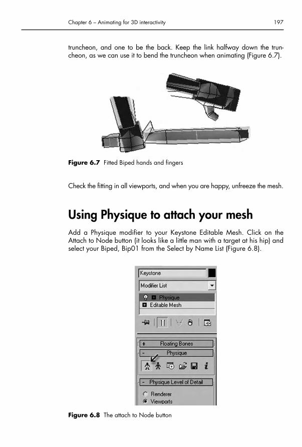
truncheon, and one to be the back. Keep the link halfway down the trun-cheon, as we can use it to bend the truncheon when animating (Figure 6.7).
Check the fitting in all viewports, and when you are happy, unfreeze the mesh.
Using Physique to attach your meshAdd a Physique modifier to your Keystone Editable Mesh. Click on theAttach to Node button (it looks like a little man with a target at his hip) andselect your Biped, Bip01 from the Select by Name List (Figure 6.8).
Chapter 6 – Animating for 3D interactivity 197
Figure 6.7 Fitted Biped hands and fingers
Figure 6.8 The attach to Node button
Chap-06.qxd 8/12/04 15:17 Page 197

The Physique Initialization box will appear, Click Initialize, and the Physiquemodifier is applied with the default Envelopes that will control your mesh.
Note This would also work for a series of different meshes. A character canbe made of segments and you can still use the Physique modifier.When it comes to Initialization the same rules apply for each segment.Do not attach the head mesh to the Bip01 Head, and the mesh’s R-footto the Bip01 R-foot, etc. as there should be only one Root Node foryour character.
Now comes the fun bit, making sure that your Biped and mesh are a per-fect fit. Many people have a lot of problems with this, but actually it is veryeasy if you do it the old-fashioned way – by vertex.
The Physique modifier has a rollout that lists five sub-selections: Envelope,Link, Bulge, Tendons and Vertex. Because you have fitted your Biped skeletonwell, the default Envelopes should already be in good shape. In WireframeView, Select Envelope and click on a link such as the Bip01 Upper Arm. Youwill observe two envelopes controlled by that link: an inner, red one and anouter purple one.
The envelopes in ‘Physique’ work much as the envelopes do in ‘Skin’ modi-fier described in Chapter 4. Any vertices that lie within the inner, red enve-lope will be 100% controlled by that link, the outer purple envelope denotesa level of influence that falls away to nothing. Click on few more links andyou will observe that the purple envelopes overlap; this allows the Physiquemodifier to share the influence of the links in the skeleton to achieve smoothdeformation. Thus the Bicep is typically controlled by one link, the Forearmby another and the elbow has a shared influence between the two links.(Because our mesh is very simple, we do not have any need to think aboutBulges and Tendons, these are ways of distributing a link’s influence to simulate actual flesh.)
Now go into Sub-Object � Vertex mode. Click on ‘Select’ (it will highlightin yellow) and marquee-select all the vertices in your figure. Most of themwill light up as either red or dark red. A few may light up as blue (Figure6.9). Red vertices are within an inner envelope, dark red are in an outerenvelope, i.e. have more than one link influencing them and blue verticesare unattached. If you were to animate your character now, the vertices col-ored blue would be left behind.
Zoom in on your figure and check for blue vertices, if there is one, select itand click on ‘Assign to Link’. Click on the link you wish the vertex to attachto, and it will turn red. Do this for any blue vertices you have, if you havefitted the Biped skeleton well, you really should have very few or none at all.
198 3D for the Web
Chap-06.qxd 8/12/04 15:17 Page 198

Now all the vertices are attached, you may want to fine-tune their adjust-ments, or your character may be working just fine already! To test how themesh is deforming under the Biped’s influence, we will put him through hispaces by throwing down some footsteps. This only means pressing threebuttons! (This is simply a test for how the mesh works we will deal with ani-mating the Biped properly in the next chapter. Another way of testing would
Chapter 6 – Animating for 3D interactivity 199
Figure 6.9 Selecting all the vertices in Physique’s Vertex Sub-Object mode
Chap-06.qxd 8/12/04 15:17 Page 199

be to load an animated BIP file from the Character Studio Plug-in and seehow the character responds.)
Select part of your Biped and open the Motion panel. Click out of Figuremode, by clicking on Footstep Mode next to it. The two Footprints will high-light in yellow (Figure 6.10).
Under Footstep Creation, click on Create Multiple Footsteps and ‘OK’ onthe pop-up menu for a default four steps. You will see some white footprintsappear before your character. The icon for Create Keys for Inactive Footstepswill light up in Footstep Operations. Click on it. Your Biped will jump to
200 3D for the Web
Figure 6.10 Creating Multiple Footsteps for a Biped
Chap-06.qxd 8/12/04 15:17 Page 200

attention. Play the animation and he will walk. He will walk like Frankenstein’smonster, or Arnie in Terminator One, but he will walk! To see how the meshis really behaving click off the Object icon in the Display rollout below, thishides the Biped and allows you to view your mesh cleanly.
Your mesh may look marvelous, or you may see some strange anomalies init. These are easily adjustable, and can be done with your Biped in anyposition; you do not have to return to Figure mode to sort him out, but youmay prefer to, as this is a good ‘splayed’ position for selecting vertices.
Suppose when your Keystone walks, the Biped left thigh link is influencingvertices on the right thigh. This will result in an unhappy mesh deformation.To fix it, select your mesh and return to Physique’s Vertex Sub-Object Mode.Click on ‘Select by Link’, and choose Bip01 L Thigh, all the vertices influ-enced by this link will be selected, if there are any in the right leg, click on‘Select’ and select these, then click on ‘Remove from Link’ and click on theBip01 L Thigh Link again. It will look like nothing is happening, but if youchoose ‘Select by Link’ again and choose Bip01 L Thigh, you will see thatthese vertices are no longer being picked up by that link.
Go over your mesh in Vertex Sub-Object Mode checking each link for suchanomalies. When you are happy with everything, select all the vertices andclick on ‘Lock Assignments’. Your Biped will now deform the Keystone mesh,and even better, any animation will Export beautifully to Shockwave, solong as you remember to ‘Group’ everything.
Animating the Biped for a gameNow your Biped is looking good, it is time to decide what your character willneed to do in your game. Almost inevitably you will need your character toget about, and that probably means walking or running (although obviouslyif your character is a kangaroo or a skateboarder you would be aiming tomove them in a different way). Your character will also spend some time wait-ing, while the person controlling it gives thought to their next move. It isalways helpful to create at least one or more ‘waiting’ actions to give yourcharacter life. In real life no one stands totally still unless they are a mimestatue or a shop window dummy, and we want the player to identify withyour character, not admire it from a distance. In addition, your character willneed to perform any other actions that would suit your game. In the case ofthe Keystone, I have also created a bashing motion and a jumping motion.
The waiting gameWaiting actions are an opportunity for the animator to add personality totheir character and if you look at any character-led games you will often be
Chapter 6 – Animating for 3D interactivity 201
Chap-06.qxd 8/12/04 15:17 Page 201

rewarded with some great animation, simply by doing nothing. If you waittoo long with Rayman he takes off his head and bounces it like a basketball,and Mario falls into an exaggerated slumber. Waiting motions work best ifyou choose motions that seem appropriate for the character’s personality.
There are two ‘waiting’ modes for the Keystone. First he looks around, andsecond he taps his truncheon in his left hand. These fit his ever vigilant,briskly officious personality.
Before you begin animating your Biped, either Hide or Freeze the deformingmesh, so you cannot accidentally pick it up when choosing joints to ani-mate. The Biped looks pretty ugly, but you have to keep remembering thatyou are animating for your character, and not for the Biped (Figure 6.11).The proportions of a well-fitted Biped should help, but sometimes movingone of these clodhoppers around to create movement for a delicate etherealcharacter is hard to imagine. (Character Studio 4 has some alternativelooks for the Biped, but whichever way you slice it, they all look like theyhave fought the ugly stick and lost.)
Animating using IK
Character Studio’s Biped has built-in IK solvers. This means that the charac-ter’s hands and feet can be moved and locked down and the biped will
202 3D for the Web
Figure 6.11 The Keystone Biped, he may be an ugly critter, but he is ready to animate
Chap-06.qxd 8/12/04 15:17 Page 202
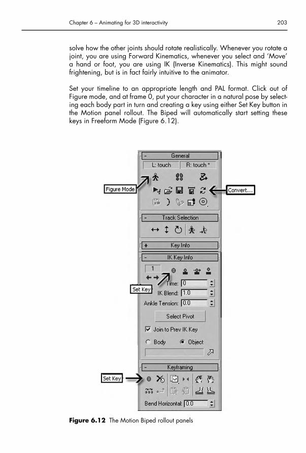
solve how the other joints should rotate realistically. Whenever you rotate ajoint, you are using Forward Kinematics, whenever you select and ‘Move’a hand or foot, you are using IK (Inverse Kinematics). This might soundfrightening, but is in fact fairly intuitive to the animator.
Set your timeline to an appropriate length and PAL format. Click out ofFigure mode, and at frame 0, put your character in a natural pose by select-ing each body part in turn and creating a key using either Set Key button inthe Motion panel rollout. The Biped will automatically start setting thesekeys in Freeform Mode (Figure 6.12).
Chapter 6 – Animating for 3D interactivity 203
Figure 6.12 The Motion Biped rollout panels
Chap-06.qxd 8/12/04 15:17 Page 203

Save your file and keep this clean version of your character to load upbefore you start animating. We want to loop most of these actions, andkeeping a set of clean keys at the beginning means we can copy these to theend to make sure the character loops properly.
When animating your character, first decide whether the feet are going tomove. In this case, they are going to remain still, so I have locked themdown using the Set Planted Key in the IK Info Panel. (Try to avoid using the‘Anchor Keys’, the graphic is misleading as they only fix a hand or foot temporarily and do not change the IK blend.)
If you select the Body Vertical button under Track Selection, you will see thatif you pull your character down, it will now bend from the knees and keepits feet in place. Having sorted out the feet, always try and animate from the Hips traveling upwards. All joints in the Biped body are moved withRotation tool, apart from the hands which are moved with the Select andMove tool, allowing the IK to sort out the rest of the arm joints.
Note The fact that IK will solve hand and foot motions for the rest of thejoints is a wonderful thing, but do try and remember to keep the char-acter’s body moving in arcs. Nothing looks as stilted and wooden ashands moving in only one plane. All body movement is created by ourbones moving in arcs. Even a simple head turn should have a dip orrise in the middle of the movement.
Be prepared to take some time on the animation, and try to spread anymovements as far as they can go to bring an air of fluidity and naturalnessto the motion. For instance, although the Keystone character is tapping histruncheon in his hand, I have spread the movement to his knees to make themotion livelier. The best way to animate is to act out the action again andagain, isolating each part of your body as you do, and translating that tothe character.
When you are happy with the motion, copy each Key from the beginningof your animation to the end, to create a seamless loop in the action. Check
204 3D for the Web
Top TipUnless you have Set Keys for your character’s feet using the SetPlanted Key in the IK Info Panel, you will not be able to convert toFootstep Mode (it will be grayed out). But if you have used the SetPlanted Keys then the IK blend will have a value of 1.0 and when youconvert modes, a footstep will be created at every Planted Key. Youcan convert back and forth from Footstep to Freeform Mode as oftenas you like.
Chap-06.qxd 8/12/04 15:17 Page 204

it is not jumping by playing the animation in a loop and examining it fromall sides in the perspective window.
Now unhide (or unfreeze) your mesh, and hide the Biped by clicking off‘Objects’ in the Display panel. Play your animation again and enjoy yourcharacter coming to life. When you are entirely happy with the motion,bring back the Biped and save the motion as a .bip file. This means that youhave the capability of applying that motion to a different character andallowing you to tweak it for individuality.
Group the Biped with the mesh, name the group (and make sure you namethe group consistently for all animations) and export using Shockwave.
Walk cyclesThe walk cycle for your character is a critical piece of animation as anyplayer will be seeing a lot of it, and it is really a very short piece of loopedaction so every key must count. The walk cycle I have created for theKeystone is only 19 frames long at 25 frames per seconds (fps). An averagewalking pace is usually 12 frames long, or a second for one looped cycle,so the Keystone is walking rather more briskly than most, which is in keep-ing with his character. He is also looking around a bit as he is ever vigilantfor things to bash.
Because we are going to loop the animation and the feet will have to slideback to their starting position, we will be working in ‘Freeform’ animation.Always start a walk cycle from the midpoint of a pace (called the passingposition) where one foot is firmly planted, and the other is halfway throughits pace. This is where the body is at its greatest height, and the hands arepassing mid-cycle.
I recommend that you look up in a good animation book how a standardwalk cycle should be animated and then add variations that give it extracharacter, such as Mickey Mouse’s double-bounce walk. (There are a num-ber recommended at the end of the book.) Do not forget that the hips andshoulders also swing from the front view – the hips following the leading legand the shoulders tilting the other way to compensate (Figure 6.13).
Chapter 6 – Animating for 3D interactivity 205
Top TipAlways check your animation from every angle; it is all too easy tocreate a walk in a side view, only to find it is disastrous when viewedfrom the front.
Chap-06.qxd 8/12/04 15:17 Page 205

Getting a smooth slide into the feet is difficult. It goes against the grain foran animator to make the feet slide on purpose; we spend most of our timemaking certain that they are locked down tight. One way that works is tocreate two Dummies (one for each foot), and have them slide against thegrid in the side viewport so they are even, then make the feet follow. Thusin this walk cycle the left foot Dummy travels back for six frames and six gridsquares from the starting point (it is halfway through the pace, remember),and right foot Dummy travels back for 12 frames across 12 grid frames.This allows you to position the feet to follow the Dummies without making akeyframe on every frame. When you are happy the animation is goingsmoothly, you can delete the Dummy helpers. (Note that you do not link theBiped feet in any way to the Dummies, as your Biped needs to be in worldspace to export to Shockwave.)
You can view and dissect the finished walk cycle as a Max file on the CDalong with the other animations for the Keystone character.
Exporting our characterBuilding a simple world
Now the animation is complete we need to export our character intoDirector. Before we do this, we should give him a ground to stand on. Thesimple way to do this will be to create a plane in the top view that is bigenough for our character to walk around on. The ground plane is there togive the character a sense of scale and position. Without it he may as wellbe floating or treading water. As our character should be about 170 units
206 3D for the Web
Figure 6.13 Frames from the Biped 19 frame walk cycle
Chap-06.qxd 8/12/04 15:17 Page 206

tall we need to make our ground plane an appropriate size; 25,000 by25,000 units should be sufficient, we are only making it for demonstrationpurposes (Chapter 7 is where we will be investigating world creation indetail). Make sure you name the plane clearly, e.g. ‘ground’. Otherwise itwill have default name like Plane01, which could be confusing if there aremany other planes in your scene.
Once you have created our ground plane, we might as well give it a tex-ture. You could choose one of the standard materials, bearing in mind thatthey do not all export well (see Chapter 3). Perhaps create a grass materialfrom a photo, or a concrete one. It is best to make your texture a tiling one.The size of the bitmap used is very important and there are restrictions, sogenerally tiling is the best solution. Apply a UVW map modifier and changethe U and V tiling settings to 20. This is how many times the image willrepeat. If your material looks too repetitive then decrease the tiling value,until you are happy with it (Figure 6.14).
Chapter 6 – Animating for 3D interactivity 207
Figure 6.14 UVW mapping settings for a simple ground plane
Chap-06.qxd 8/12/04 15:17 Page 207

Note There is no need to tile in the W direction as the plane is only a 2Dshape. In fact, most materials only map in two dimensions, even if theywrap around a 3D object. Some materials, e.g. the Wood material,are 3D. They give you the ability to take chunks out of an object andsee how the grain looks inside. The other materials are in effect ‘skins’that are stretched over an object.
If you want, you can add some other objects to your scene to help improve thesense of motion, when he is walking about. The character will not collide intothese though, he will walk straight through them. Collision is something we willdeal with in Chapter 8, where we will be assembling a game. For now we arejust making our character controllable in real time, using the keyboard.
Creating a control box
You have already grouped your character and he has his animation setup.Make a note of the name of the group, in our case ‘Keystone’. This will bethe name of the model that we are looking to animate in Director. The nextthing to do will be to create a control box, this acts like the Master Dummyused in 3ds max for the eyes, and will be the object that is actually moved.Create a normal box shape starting in the top view that fits the shape andsize of our character and in the same position. He will turn around the center point of this box, so make sure its center lines up with the character’scenter axis.
It is essential that you create the control box in the top view, looking downon the character. This ensures that the axes match with the axes expectedby the Director file, which you will be using. If you make this box differentlythen the character will not walk and turn correctly. This is a compromisesolution, allowing you to control a character without you having to do anyprogramming (Figure 6.15).
Create a material that has zero opacity and apply it to the box. Link the‘Keystone’ group to this box. Press the Link tool, selecting your ‘Keystone’group and dragging the mouse over the edge of the box. Releasing the mousebutton here will briefly highlight the box, indicating that it has been linked.
The purpose of the control box is twofold. The first reason is to provide a stable object that we can move around. As our character walks he moves from
208 3D for the Web
Figure 6.15 The ‘Link’ and ‘Unlink’ buttons in the main tool bar
Chap-06.qxd 8/12/04 15:17 Page 208

side to side, and the rotation of his axes change. This means that when wemove him (using Director’s Translate command) he would move in a wobblymanner. We want him to move in straight lines, and to turn correctly. Ineffect he does not walk anywhere, but will stay in treadmill mode, whilst itis the box that he is in that is moved around the environment. This may seema bit awkward, but it works and the control box has another useful purpose;for collision detection. We will talk about this in Chapter 8, but in essence,the simpler the object that you are testing collisions for, the simpler the cal-culation is to do this. We always need to be aware of the frame rate so any-thing we can do to improve time is worthwhile. When creating a game, aswe will later, it is not just the character we have to take into consideration,but every computationally expensive element (like collisions, other objectmovements, scoring system, etc.). As we do not want to see the box, wehave made it transparent, but it will export correctly (Figure 6.16).
Chapter 6 – Animating for 3D interactivity 209
Figure 6.16 The box surrounding the Keystone character, with zero opacityshown in the Materials window
Chap-06.qxd 8/12/04 15:17 Page 209

Although you will have created several files for your animation, you onlyneed to put the box on to one of them. This is the file that you will use for allyour environment modeling, the other files are only needed for the anima-tion information.
Exporting from your 3D package
You should have five 3D files, a ‘master’ file, which will be your 3D world, con-taining your character, control box and any other objects that you have cre-ated (e.g. ground plane). The other four files need only contain the character.
Open the ‘master’ file and make sure the perspective viewport is selected.Go to File � Export and choose Shockwave 3D (.w3d). For this file youneed to export all the 3D resources (including animation). However, youonly need to set the range to start and end to frame 0. This way the bonestructure and mesh deformation information is exported but not the actualanimation (Figure 6.17).
210 3D for the Web
Figure 6.17 The Shockwave 3D Export window, with settings for exporting a still scene
Chap-06.qxd 8/12/04 15:17 Page 210

If you have selected the ‘View w3D scene after export’ option you will be able to preview your character. When you are happy that it hasexported correctly you can open one of the files that you have used for your animation. Once again, make sure the perspective viewport isselected before exporting. This is good practice and stops an Orthographiccamera being used. In the Export Options window, you can deselect all the resources except for the animations. Make sure the animation range is set to last as long as your animation and keep the sampling inter-val at 1 and the animation quality at 100.0. Ideally you do not want your animations to be compressed, unless they were really large files (Figure 6.18).
Chapter 6 – Animating for 3D interactivity 211
Figure 6.18 The Shockwave 3D Export window, with settings for exporting justthe animation
Chap-06.qxd 8/12/04 15:17 Page 211

Make sure you give your .w3d files clearly understandable names like‘walk motion’ or ‘standing motion’. You do not want to get confused later bytrying to remember what file does what motion. There will be nothing to pre-view when you export just the animation, only the background color will bevisible. This is perfectly fine and should not worry you. Looking at theexporter’s report will show you a file size indicated for animation, probablyaround 8 kilobytes in size. This means the animation data has exported andyou can confidently repeat the process with the other motion files. If the sizeis zero then something has gone wrong. Make sure you did choose ‘Exportselected’ and that you have selected the correct options in the export window.
Importing into DirectorThat should be it for now in your 3D package, but if your computer has enoughmemory, keep it loaded and load up Director. It can be quite handy to havethese two programs open at once, in order to quickly alter your scene, but ifyour computer slows down too much then quit your 3D application.
From the 3D for the Web disk open up the tutorial file ‘ControlCharacter.dir’in Chapter 6 folder. This is a nearly blank Director file. It contains just threebehaviors, which will enable you to move your character around the simpleworld that you have created and view it.
Stage 1 – Looping the Director movie
If you have been working through this book chapter by chapter, then it hasprobably been a while since you have used Director. It is good practice tomake sure the playhead of the movie loops around one frame. To do thisfirst open up the Score and the Cast windows from the Window menu. Thenselect the ‘Loop Frame’ behavior from the cast and drag it into the framescript window (above the timeline bar and next to the Script icon) and inframe position one. It should only be one frame in length (Figure 6.19).
Stage 2 – Setting up the Shockwave 3D files
Now go to the File � Import menu and import all five of your W3D files (thescene and the four motion files). You should see that the main file has asmall image of your ground and character, whereas the other four areblank. Open up the Stage window from the Window menu and drag yourscene file (in our case it is called Keystone) onto the Stage. Make sure yourmovie is at a suitable size, Window � Property Inspector � Movie. I suggest
212 3D for the Web
Chap-06.qxd 8/12/04 15:17 Page 212

you set it to 640 by 480 for now, as we will not be exporting it for the Web as yet. Stretch your 3D sprite on the Stage to fill the whole window(Figure 6.20).
Check the Score window, you should see the 3D sprite in Sprite Channel 1.It will probably be more than one frame long but this will not matter as theplayhead will loop around only frame one.
Chapter 6 – Animating for 3D interactivity 213
Figure 6.19 Director’s Score and Cast windows, showing the position of the LoopFrame behavior
Chap-06.qxd 8/12/04 15:17 Page 213

Applying the Character Control behavior
If you play your movie at this stage, nothing will happen, as we need to usethe Character Control behavior that I have made up for you to use. There isa lot of programming in this behavior but you should not have to worryabout it. I have incorporated a degree of customization, giving you optionsto select, which will be explained in a moment. There are always pros andcons in creating a standard, one size fits all, piece of code. They are fairlyeasy to use, but troubleshooting can be awkward if there are problems. Ifyou are familiar with Lingo coding then you are welcome to adapt thisbehavior for your own uses. In essence it is a part of a block-by-blockmethod for creating a game. This will be achieved in Chapter 8, but fornow we will get on with just controlling our character.
Drag the Control Character behavior from the Cast to the Stage windowand drop it on our 3D scene sprite. A pop-up window should appear withmany options (Figure 6.21).
214 3D for the Web
Figure 6.20 Resizing the 3D sprite to fill the Stage window
Chap-06.qxd 8/12/04 15:17 Page 214

Select the control box object as the object that you want to control. Youshould have linked the character to this object, so moving it around meansthat the character follows it. In other words the character actually stays onthe spot and it is the box that moves around.
The character to animate will be our Keystone group that you should havealready named. This selection affects the motion settings later on, as thebehavior looks for motions that have the same name as the animated char-acter. I should point out that if you select the wrong object, playing yourmovie will cause an error. The object you select must be the one you ani-mated previously. If you get an error, then cancel it and go to the BehaviorInspector, then select the correct object to animate.
Choosing the ground object is important as this dictates the vertical positionof our character. As he jumps up, the behavior checks for the objects that
Chapter 6 – Animating for 3D interactivity 215
Figure 6.21 The Parameters pop-up window for the Control Character behavior
Chap-06.qxd 8/12/04 15:17 Page 215
are below and makes sure that the control box object does not fall downbelow the ground object. This works even for bumpy terrains (these are dis-cussed in the next chapter). There is a gravity value that forces the charac-ter to stick to the ground.
The walking speed is adjustable so that you can closely match the speed ofhis/her footsteps with the distance that the control box is moved everyframe. This figure is in world units and defaults to a value that will be roughlyright. If your character appears to be sliding on the ground then you canchange this value later, by selecting the behavior in the Behavior Inspector.
The next four options allow you to choose the motions that you should haveset up and imported already. These motions have been set up to be trig-gered by pressing the appropriate keys. When you select the forward key,not only does the control box move forward, the walk motion animation istold to start playing and to loop. This will continue until the key is released.Then the previous animation will play. The previous animation is the stand-ing motion that also loops, but works only when a key is not pressed. Whenyou press the ‘walk backwards’ key, then the animation is told to play inreverse.
Animation blending
A good thing about Director is that these animations do not just stop andstart they blend smoothly from one to the other, known as animation blend-ing. This is a very useful feature, as it will make our character look a lotmore believable than if there was an abrupt, unnatural change between thetwo motions. Blending also happens when the bash motion is played,whereupon the control box is told not to move forward.
The main advantage of blending is that you may have a motion that finishesin a slightly different body motion to the next motion’s start position, but itwill not be noticeable. Also a motion does not have to be finished playingfor it to blend into the next motion. So you can quickly and smoothly changebetween bashing, jumping and walking (Figure 6.22).
Note Animation blending does not occur at the point where a looped ani-mation jumps back to the beginning. It only occurs between two dif-ferent motions. This means that any looped animations you create inyour 3D application must repeat smoothly. You may have done this bycareful adjustment of the keyframes, or by copying the first keys to thelast frame of the loop. If you did the latter, then you do not need toexport the last frame.
216 3D for the Web
Chap-06.qxd 8/12/04 15:17 Page 216

As the bashing is not looped, it will only play once and return to the previ-ous motion. However, if you keep the bash key held down it does, in effect,loop. What is actually happening here is that the bash animation is beingtold to play again.
You have a few choices of keys to control the movement, the defaults are thecursor (or arrow) keys. These are the most commonly used keys for movingcharacters forward, backwards, left and right. You can also select keys tocontrol the bash motion and the jump motion. There is no key to trigger thestanding motion as it is triggered by not pressing a key.
The final two options in the pop-up window are to control how the charac-ter behaves when he is jumping and falling. This is why we have created ajumping animation that does not actually jump. (See example file on the CD).
Chapter 6 – Animating for 3D interactivity 217
Figure 6.22 The Keystone character waiting and tapping his truncheon
Chap-06.qxd 8/12/04 15:17 Page 217

With these two controls we can adjust the height of his jump and by chang-ing the gravity setting we can simulate other environments like being on themoon or being in water (particularly if you had created a swimming anima-tion). Also the strength of gravity affects the relative scale of the character.You want him to appear to fall with believable acceleration. You can prob-ably leave these values at their default settings, but you can change them ifyou want your character to jump higher, or fall in a heavier manner.
Adding a cameraWell, we have finally got an interactive character, which is controllable andmoves around a simple 3D world. But, at the moment, if you play theDirector file, he will walk off the screen. Not much use to us. We need to beable to see him and using one or more cameras does this.
By default, when you exported your animations you selected the perspec-tive window. This uses a camera, and this camera is exported with the restof the file information. Without a camera you would not see anything, sothere is always a default camera. You can in fact have multiple camerasand either switch between them or have them displayed on the screen atonce. An example use of this might be in a racing car game, where youwant a split screen effect, allowing two simultaneous players, or a rear viewmirror. Alternatively you might have cameras set up in certain positions andthe screen displays the nearest character to that camera.
Good camera work is essential, as you do not want to make your game-player dizzy by spinning around a camera too much, or by the view of yourcharacter being blocked by objects. As this is quite a big subject we willstudy it in detail in the last chapter where we will be studying the issuesinvolved in building a 3D computer game. For now we will use the behav-ior provided in the example file to allow us to view our character.
In the cast you will see the Assign Camera behavior, drag it onto the Stage,which brings up the Parameters window as shown in Figure 6.23.
You will see that there is a choice of camera type, either First or Third per-son. The difference between these is fairly self-explanatory, either the viewis from the character’s eyes, or from another person’s view, i.e. the cameraoperator. Select Third, otherwise you will not actually see your character.
Then select your control box object to look at. If you have selected theKeystone object, then you will find that the camera does not follow it prop-erly. This is because the character’s position changes relative to its parentobject, which is the control box. Essentially the Keystone does not moveanywhere relative to the control box, so the camera would stay still if it used
218 3D for the Web
Chap-06.qxd 8/12/04 15:17 Page 218

that coordinate information. Make it follow the control box, whose parentobject is the ‘world’, which means everything.
The camera will now look at the axis of the control box, this is located at the bottom of the box, but we would normally want to look at eye level. Soset the ‘height above ground that you want the camera to look at’ to the eyeheight of the character, probably about 180 units.
The reason for selecting the ground object is that the Assign Camera behav-ior knows not to travel through the ground, which is generally unwanted. Soyou select the ground object and then set the minimum height that you wantthe camera to travel to. If you want the camera to be higher than the char-acter then set it above 200 units, perhaps at 300.
There are three choices of camera movement style – manual, simple andcomplicated. Select any of these to view your character, swapping betweenthem will demonstrate the difference. The ‘manual’ setting allows you to usethe mouse to view around the character and the other two methods travel toa position behind the character. They always point at the selected object.
The last option is the camera angle. A 45 degree setting gives a perspectivethat is roughly equivalent to that of the human eye, and so feels most natural.Feel free to experiment with this though, to view extreme perspectives.
Now you are free to make your character run around the simple checkeredworld, and the camera will follow him. We will make good use of this inChapter 8, by combining your character with a game world.
Chapter 6 – Animating for 3D interactivity 219
Figure 6.23 The parameters pop-up window for the Assign Camera behavior
Chap-06.qxd 8/12/04 15:17 Page 219

Interview with Titoonicwww.titoonic.dk
Company profile
Titoonic is a creative game developer and Web production company situ-ated in Copenhagen, Denmark. The company was founded in August 2000by Peter Holm and Tomas Landgreen. Titoonic produces lively content for theWeb and also own Sporkle, an online entertainment service marketed in the Nordic region in partnership with MSN. The owner group and the cre-ative team come from a background in classical animation and graphic storytelling – and eat games for breakfast.
I came across them when I was looking for sites that used Flash in an inter-esting way. That first visit was one of many as Titoonic creates wonderfullysatisfying games combined with excellent character design.
Interview
The interview is with Tomas Landgreen, one of the founders of the company.
What is your role at Titoonic?
I have many different roles at Titoonic. I take part in setting our company’sgeneral goals, deciding on strategy, and other ‘big’ decisions, etc. Apart fromthat I spend my time on anything from programming, animation (2D/3D),painting and concepts to budgets.
Can you describe the background of your company, its aims, ambitions,client base?
Most of the core employees of Titoonic come from the animation business.When we started, our aim was to do animated characters for the Web.
220 3D for the Web
Chap-06.qxd 8/12/04 15:18 Page 220

Almost all of our first jobs involved games in some shape, and very quicklyour focus began to shift towards games. Ninety-five percent of our projectsnow are games.
Our ambition is to make entertaining quality games. The more characters,unique universes, beautiful settings and storytelling we can cram into them,the happier we are.
How many people work at Titoonic?
We are 14 at the moment.
Typically how many people would work on a project?
On a typical Web-game production we would have three to five peopleinvolved in the process from concept to final game.
Do you have separate 3D animators, Flash animators and Programmers, ordo the skills cross-over?
We have both. It’s hard to come by people with these cross-over skills.When it comes to games-programming I think that cross-over skills is what
Chapter 6 – Animating for 3D interactivity 221
Chap-06.qxd 8/12/04 15:18 Page 221

can make the difference between an ‘okay’ game and an exceptionalgame. It can also do wonders for the production time of small Web games.If one man can do it all, you save a lot of time on having meetings and com-municating this and that back and forth.
Do you ever bring in specialist freelancers?
Not very often, but we do occasionally use freelance animators or design-ers/background painters.
How important is sound in your games and websites and who handles that?
Sound is very important, unfortunately we don’t have enough work to havean ‘in-house’ soundman, but we have two that we use on a regular basis,for creating music, music loops, special effects, etc. (We also have a fewplaces on the Web where we download sounds. Most of our smaller clientprojects, and game skins have no budget for custom recorded or createdsound.) Final sound implementation is done by our flash-guys, program-mers, as well as designers.
General design and 3D
How did you get started in creating 3D for the Web?
I was heading up the 3D department at A-Film in Copenhagen, working on3D commercials and 3D elements for animated features when I startedmessing with 3D for the Web. It had an instant appeal to me.
‘Normal’ 3D work for films and commercials was starting to bore me. Wealways spend most of our time trying to satisfy a client’s need for realisticrendering, cloth animation, hair and other technical difficulties. These werethings that were easily solved in any of the large 3D houses, but took a lotof hard work for a small department like ours, and it didn’t leave us muchtime to do the fun parts: the concept, the character designs, the animationand the storytelling.
Because of the bandwidth limitation, realistic rendering was out of the ques-tion for ‘3D for the Web’. Simple character designs and simple renderingwill keep the file size down. Focus is on the animation and the storytelling.
How do you come up with the different ideas for your characters andgames?
When it comes to me, the idea for a game will often come from a funnysketch of a character, or from a bit of code that I’m trying to put together.For client projects we will often have a ‘brainstorming’ at Titoonic to comeup with ideas. We also have a writer on the regular staff.
222 3D for the Web
Chap-06.qxd 8/12/04 15:18 Page 222

How do you decide whether to use 3D in a project?
It depends a lot on the type of project, on the look and style needed and ofcourse on production time and budget issues.
If the project doesn’t have a look or graphic style that require a specific animation type, it will typically be the amount of animation (and characters)that decides it. 3D animation is best suited for projects that have largeamounts of animation. 3D animation also has unique possibilities for reuse.For example, if you have a game where five characters have the same ani-mations (stand, walk, run, jump, shoot, etc.), it is a lot cheaper to do it in3D since you can reuse/modify the animations for each character.
Also most of our licensable games that have characters in them (like thesnowboard game) use 3D characters, because it makes it very cheap tooffer the client the chance to modify, recolor or exchange the character foranother one, since the animation can be reused on the new character.
Good-looking 3D has an immediate appeal. Do you see it as the way forward in Web characters?
Well it is definitely one-way forward. I also think that good-looking 2D hasan immediate appeal U. A well-animated, funny, appealing character, willbe a success whether it is done in 3D or chiseled in stone.
How important do you think interactivity is to your work?
It’s very important. We haven’t done any non-interactive work!
We do have some characters and universes that may very well evolve into‘wepisodes’, but I don’t think that we will ever make ‘wepisodes’ like theyare seen mostly: non-interactive. Web-content ends up on a computerscreen, and the computer is an active media, unlike television which is a
Chapter 6 – Animating for 3D interactivity 223
Chap-06.qxd 8/12/04 15:18 Page 223

‘lean-back-and-enjoy’ media. I don’t think it wise to try to compete with television-series, without using the strengths of the PC: the possibility forinteraction.
On average how long do you spend developing your animations andgames and how much of that time is pre-production?
Its very difficult to generalize here, since our projects range in productiontime from 1 to 24 weeks. Maybe 5–10% is pre-production. A typical cus-tom made Flash game, will take 8–10 weeks to produce, and 2 weeks ofthat would be spent on the concept and pre-production.
What aspect of development would you say is the most time consuming?
I would definitely say budgets, but this is subjective and misleading … Ireally hate making budgets and consequently it seems to take forever, andI can hear every tick of the clock as I type in my wildly inaccurate estimates,as soon as I start animating and programming, time flies.
On most of our games 80% of the work is finished in 20% of the time wehave. The rest of the time is often spent testing and adjusting gameplay,
224 3D for the Web
Chap-06.qxd 8/12/04 15:18 Page 224

putting the finishing touches, dotting the i’s and crossing the t’s. Adding allthe extra touches that (hopefully) will make this game stand out and beentertaining and memorable.
Your past and future work
Your games reflect a number of different graphic styles who/what are yourinfluences?
We try to use and take advantage of the individual styles of each of ouremployees, as much as possible. The characters of Pixar have always beena great inspiration to me.
Many of your websites consist of cell-shaded 3D, what is your motivationbehind using cartoon style graphics?
We love the look, and it does wonders for the file size when comparing itto rendered bitmap style 3D.
Chapter 6 – Animating for 3D interactivity 225
Chap-06.qxd 8/12/04 15:18 Page 225

How important is storytelling in a website/game and how do you come upwith story ideas?
Again it’s really hard to generalize here. Some ‘abstract’ games like Tetris,do not need a storyline or character of any kind. In many other games astory can add the extra touch. Everybody loves to hear a good and well-presented story. The problem is often how to integrate it into the gameplayso it doesn’t feel forced or annoying.
We had some good experiences with the adventure style games we did forLEGO. They are for a younger audience, and they really liked the format.Adventures, told in animated sequences, with three or four games.
I think it is often quite easy to come up with games to integrate into a goodstory: much more difficult to have a good game and come up with a story.We have an in-house writer that does the dirty work, but we often start withbrainstorming meetings to give him something to go on.
Why are your games important to clients and their websites?
Games make the client customers stay longer at their website, therebyexposing them for a longer time to the brand, messages, etc. And moreimportantly it can make them come back, and make them send their friendsto have a look also.
What awards have you won and have they made a difference?
We won the flashForward Awards for best game and it gave us an oppor-tunity to see NY. And also gave us a lot of free PR. It’s hard exactly to guesswhat clients we wouldn’t have had if we hadn’t won, but I‘m sure there are a few.
Technique
What software do you use for creating websites, animations and games?
3ds max, Flash, Director, Dreamweaver, Photoshop and UltraEdit.
How much programming do you use and do you view it as an importantskill for designers to have?
We use a lot of programming, and the more the designers know about pro-gramming the easier the communication is. It is even more important tohave programmers with animation skills. When programming games a lotof animation is ‘programmed’ so a games programmer needs to have agood sense of timing and movement to create an entertaining game.
What is the most challenging aspect of 3D Web design?
I think generally, that the most challenging aspect is to get as much content/animation/graphics as possible within the bandwidth limitations.
226 3D for the Web
Chap-06.qxd 8/12/04 15:18 Page 226

Why do you prefer to use Flash for your cartoons?
It’s a very fast production environment, with a lot of ways to reuseresources, and the file size of vectorized content is minimal.
What frame rate do you typically work at for games and animations?
For Flash games or animation we normally work in 25 fps (the same asVHS, the European television format).
Your high quality rendered animation is of a very impressive quality but con-trasts a lot in style to most of your websites. Is this because of the limitationsof Web design and do you want to incorporate more of this type of 3D workinto your websites?
Yes, that’s true. As bandwidth increases (or we move on to producing down-load games and small boxed CD-ROM games) we will probably use thisstyle more often.
Chapter 6 – Animating for 3D interactivity 227
Chap-06.qxd 8/12/04 15:18 Page 227

Chap-06.qxd 8/12/04 15:18 Page 228
This page intentionally left blank

Chapter 7
Building virtualenvironments
• A real and a virtual world• Terrains• Terrain building in a 3D application• Terrain building in Director• Trees• Water• Sky, clouds and backgrounds• Creating a new world• Interview with Ezone
ChapterSummary
A real and a virtual worldIn films you might composite computer generated characters into a real worldenvironment that has already been filmed. Likewise the opposite might bedone with human actors being superimposed onto a virtual set, using blue orgreen screen techniques. Of course, there are also the films where everythingis generated by computer. You could use these compositing ideas for yourwebsite, but it only really works well for pre-recorded films or pre-renderedanimations. The key to our Web creations is interactivity, which means that wewant the ability to change camera angles in real time and for our charactersto be controllable. We require our environment to have some life and for usto have the ability to explore it.
We have dealt with characters and controlling them already in this book, sonow we will deal with the world in which they reside. Whether your Webproject requires an interactive map or a computer game that will lure in thevisitors, you will need to know how to create an environment for that. If youare making a 3D game, you will need to create the whole world, whether it isa city, a race track or a building.
Chap-07.qxd 8/12/04 15:19 Page 229

The main issue with creating an environment is complexity. 3D graphics are allabout geometry and the geometry of nature is very complicated. Making dirtand rubble is one of the easiest things to do in real life, but needs an amazinglevel of complexity to be created in computer graphics (CG). Representingnature accurately is very time consuming. Creating a blade of grass is not ahighly complex task on its own, but simulating a field with millions of blades,will take a lot of computing power to display, especially if we want them in realtime (Figure 7.1). Also, it takes a lot of time to design and create thousandsof objects.
230 3D for the Web
Figure 7.1 A blade of grass
Designing for a game is different from designing for an animation. We needto be able to move around our environment in real time, so we have toemploy tricks and illusions to get as near as we can to some sort of realism.You want the scenery of your game to be believable so that the users do notspend their time finding fault, but become engrossed in the experience.
This chapter is all about achieving effects to simulate outdoor environments.We will be covering techniques to create landscapes, trees and water. To
Chap-07.qxd 8/12/04 15:19 Page 230

further enhance our landscape we will look at different approaches to skiesand clouds, and the overall shape of the environment.
TerrainsIf you are creating an environment for use in interactive 3D then you couldhave just a flat ground; a plane with a texture on it. This is fine of course ifyour scene is interior, with a hard floor of stone or carpet, but outdoor scenesare more complicated. A natural landscape is rarely flat, but ranges from thatof a desert to rolling hills and mountains, full of lumps and bumps (Figure 7.2).This section looks at how the creation of a believable terrain can be achievedand the issues involved. We will explore the level of realism we can expectand what techniques can be employed to make artificial landscape creationinto a straightforward operation.
Achieving a landscape or terrain does not have to be a difficult task and thereare several ways to achieve it (Figure 7.3). The main concern, as always with
Chapter 7 – Building virtual environments 231
Figure 7.2 A real landscape terrain, Corfe Castle, Dorset, UK
Figure 7.3 An interpreted virtual terrain: Purbeck Light Years, interactive artinstallation of a virtual painting, by Jeremy Gardiner and Anthony Head. CorfeCastle is in the middle of the picture
Chap-07.qxd 8/12/04 15:19 Page 231

any real time 3D application, is the polygon and object count. That will be thedeciding factor as to how your environment will perform. With a flat planethere is no need to have many polygons, which in turn means that most computers will be able to play the piece at a decent frame rate of around 30 frames per second. A flat plane need only consist of two triangle polygons(put together to make a square), but a terrain is going to consist of thousandsto tens of thousands of triangles. How do you decide how many your land-scape needs when there is such a range in the power of computers? Theanswer is, perhaps unsatisfactorily, trial and error testing and compromise.Ideally, your terrain is going to be made of millions of polygons, with minutedetail, but this is not practically possible. All you can do is test it on severalspeeds of computer, unless you are happy to let it work only on the latest graph-ics cards. As a guide a terrain of around 8000 polygons is going to be fairlydetailed, and will work on older graphics cards. If there are hundreds of otherobjects in your scene then your frame rate will decrease and a high frame rateis part of the key to believability in interactive 3D. It has to feel real more thanlook real.
So, we are going to create a landscape of around 8000 triangles. We willassume it is a square shape, although it could be a rectangle. A grid of64 � 64 squares will contain 4096 squares, which in turn means 8192 tri-angular polygons (Figure 7.4). Although working in powers of 2, i.e. 2, 4, 8,
232 3D for the Web
Figure 7.4 A wireframe view of Purbeck Light Years, showing the terrain meshwith 4096 squares
Chap-07.qxd 8/12/04 15:19 Page 232

16 … 64 is not essential when dealing with polygons, it is important for tex-tures. To this end it is handy to use a 64 � 64 grid for the terrain mesh, we caneasily double it if we need to.
Note A texture is the bitmap image that can be mapped onto any shape. Inreal time 3D you are limited by the fact that you cannot easily createBump mapping effectively. This means that all ‘textures’ are smooth,using only visual information to give the illusion of surface quality. A texture is a property of a shader. A shader is equivalent to aMaterial in 3ds max, and it controls and describes how an object’ssurface will look, e.g. the shininess, the image, the color, the positionof the image, etc.
Edge of the world
So we are going to make a grid of 64 rows and columns into a landscape,but that is not realism. What happens when we reach the end of that area?You do not want people to be able to walk up to the edge of your ‘world’so you will have to find ways of stopping them. You can do this by creatingwalls or limiting the ability to walk near the edge of the world. You shouldview this restriction as a way to focus the user into the scene that you havecreated.
There are several methods of terrain creation and we will discuss a few ofthem. All of the examples talked about are included as files on the CD suppliedwith the book. They will allow you to use and enhance the results of thesetechniques.
Terrain building in a 3D applicationUsing modifiers
The simplest method to create a terrain would be to use a 3D package. You could create a mesh and apply a Noise modifier (Figures 7.5 and 7.6)or better still a Terrain modifier. This would give you a landscape, with highpoints and low points. The workings of this involve fractal mathematics andrandom numbers to create the look of the landscape. This is great for build-ing islands and rolling landscapes but has the major drawback of not allow-ing the user to specify exactly where or how they create the features of thesurface. You cannot usually say that you want a hill here and there; you relyon trial and error to choose the correct seed (the random number used forthe calculations). This can be fine, but if you have a specific purpose or planfor your world, it is unsatisfactory. A more personalized solution is needed.
Chapter 7 – Building virtual environments 233
Chap-07.qxd 8/12/04 15:19 Page 233

Displacement mapping
Using a displacement map on your plane is a method that gives you muchmore control over your landscape design. The idea is that you have an imagethat represents the heights of the land that you want simulated. This could becreated by hand in a paint program or could use real satellite data. Heightor terrain maps are usually color coded in gray scale, with white being thehighest height and black being the lowest. Exactly what heights are repre-sented is unimportant in a virtual world, what matters are that they are cor-rect relative to the scale of your other objects and the size of the world. Forthis purpose, it is advisable to have a height map that uses the full range of256 shades of gray (Figure 7.7).
The terrain map should always be the same aspect ratio as your grid, in ourcase 1:1 or square. As a bitmap it needs to be only the same size as our grid,i.e. in image resolution of 64 � 64. When you edit this image you will seethat this is very small, but it is as detailed as our landscape. If it makes lifeeasier you can work on a higher resolution image and scale it down when
234 3D for the Web
Figure 7.5 A fractal Noise modified plane, with another plane indicating water
Figure 7.6 A close-up view of the fractal Noise modified plane
Chap-07.qxd 8/12/04 15:19 Page 234

you are happy with it. What you need to remember is that this image is notwhat is going to be seen. This image is only used to change the heights ofthe vertices in the mesh, to displace it. What you will see in your finishedterrain is the Diffuse map, which is the bitmap image of your landscape(perhaps an overhead photograph, or a tiled picture of grass).
Terrain building in DirectorAs download size is always a concern when creating Shockwave moviesfor the Web, another way to create your terrain is to generate it entirely inDirector. This is not as complicated as you may think and you can apply thesame principles as for the displacement map previously described. Theexample Director file creates a landscape and applies a map to it (Figure 7.8).The processes involved are:
1. Create a plane with a 64 square resolution (or greater, if required).2. Find the terrain image and check the gray-scale value of each pixel on the
image (row by row) and move the y position of the corresponding vertexin the map, multiplied by a vertical scale.
3. Apply a landscape image for color.
Chapter 7 – Building virtual environments 235
Figure 7.7 The displacement terrain map use for Purbeck Light Years
Chap-07.qxd 8/12/04 15:19 Page 235

The vertical scale that the map is multiplied by is calculated by decidingwhat you want the maximum height of your land to be, in world units. Thisdepends on the scale of your whole world, if a tree is 20 units high then youmight want a mountain to be a few thousand units high. The scale is up toyou, you just need to remember that you will be navigating over it.
Once you have created a terrain you need to work out what you want onit. Of course, if you are planning a game or interactive environment then youshould have already decided this. After all, everything in your world needsto be there for a reason, whether that be esthetic or practical. Also, if you wanta character to walk around it then you cannot practically have incrediblysteep hills, as this will not be very believable, and can be awkward from atechnical point of view. A vertical slope would be something you want tocollide with, and a gentle slope something to walk over. Gentle slopes lookbetter as severe changes in heights emphasize the triangular nature of themesh sides, whereas in gentle elevations the mesh appears smooth and notfaceted. CG cards have built-in capabilities to help smooth meshes, but this isjust a visual trick and does not mean that the mesh has any more polygons.
Fractal terrains
Landscapes can be created using fractal math. This might sound compli-cated but there are many software applications that can create terrains inthis way. The most popular is Corel Bryce, where you add objects, cloudsand weather to your landscapes. The following section provides a descrip-tion of how mathematical terrains are created.
There are many fields in the study of fractal mathematics, but the fundamentalsimilarity is the concept of iterations. Simply put, iterating means repeating
236 3D for the Web
Figure 7.8 A terrain created with the Terrain Generator program, with its terrain map
Chap-07.qxd 8/12/04 15:19 Page 236

the same calculation again and again. The fractal element means that theseiterations occur at finer and finer levels of detail, in a fraction of the space.
Briefly speaking, a terrain map is created by having a grid of four squares,of random color values. This is then sub-divided, smoothed and decreasinglyrandomized until the required resolution is reached. Figure 7.9 illustrates thiswith a terrain map being generated using random fractal generation andsmoothing in eight stages.
Chapter 7 – Building virtual environments 237
Figure 7.9 A fractal terrain map being formed. Each stage being divided andreplaced with squares half the size with a random variation in tone
The example Terrain Map Generator program allows you to create a terrainmap, for use in your own projects. However, as I mentioned earlier whendescribing the terrain mesh generator in 3ds max, you do not have any con-trol over where the peaks and troughs, the hills and valleys, are located. Itis a random process. Often, you might use a random terrain map as a startand then edit the bitmap to create the desired shape of landscape.
Another use for terrain maps of this kind is to make cloud maps. It is a curi-ous quirk that a bit of tweaking of the code for the Terrain Generator makesmany varieties of cloud formations. I will leave that to the more Lingo knowl-edgeable amongst you to adapt the program to do that, and we will discussmaking clouds later on in the chapter with other techniques.
TreesNow we have built a landscape, the next thing to do will be to populate itwith some objects. Of course, if we build objects then we need to make sure
Chap-07.qxd 8/12/04 15:19 Page 237

we do not crash into them when we are moving around the world. This isessential for any interactive game where you control a character or yourselfaround the world. We will discuss this in the next chapter, but first we will buildsome trees. Making trees is a handy way to describe several useful modelingand texturing tips.
In the real world there are many thousands of varieties of trees, and if you wantmore than one tree in your project, then you will probably want more thanone variety. There are several methods for creating trees, each one havingits own pros and cons. The methods do not depend on the type of tree youwant, but concern how the trees are made. They vary in complexity, bothfrom a creation point of view as well as an aesthetic point of view.
The single plane method
This is a classic technique in the world of game design, and the simplestway to create a believable looking tree. The principle is that simple objectsmake for fast frame rates and photographic textures make for realisticscenes. So if you place a photograph of an object on a plane, with a trans-parent border, you can make a reasonably convincing object. The audiencedoes not see a square plane, but the irregular outline of the object on a see-through background, e.g. the shape of the tree. This concept has long beenused in 3D games, particularly racing games where trees, spectators andbillboards rush past the car. The technique does not stand up to closescrutiny, but when you are rushing past scenery, your brain happily believesthe realism of the objects.
Note As a plane is obviously a flat shape, you might expect this techniqueto look very odd, as you could walk around an object, and it wouldappear to be flat. This is overcome by having the objects always facethe camera, so that you always see the front (unless the object is meantto be flat). So it works well for trees because they are complicatedimages that are not particularly recognizable, that is all the leaveslook the same, so you are less likely to notice the issue of it always facing you.
To start this concept you need to get hold of a picture of a tree. It is alwaysbest to take your own photographs so you will not have to worry aboutcopyright issues. The next step will be to scan it, if it is not a digital photo,and get it into a photo-editing package. You should then crop the picturedown so that only the tree you want is left in view (Figure 7.10). Do notworry too much if there are other trees visible right behind the one you wantas you will create what is known as an alpha channel in which you willmake everything you do not want to see invisible. By making your picture
238 3D for the Web
Chap-07.qxd 8/12/04 15:19 Page 238

partially transparent, you are in effect erasing the unwanted parts. The fol-lowing description uses Adobe PhotoShop to achieve this, but it should beachievable in other image-editing packages.
Chapter 7 – Building virtual environments 239
Figure 7.10 A cropped photograph of a tree
The simplest method is to use tools such as Color Selection and Quick Mask.This will select an area and allow us to remove it from our picture. First ofall, we need to make our image into a floating layer. In the Layers paletteyou should see that your picture has just one layer and it has a closed padlock icon next to it. This is because it is the background layer and hencecannot be masked in the way we would like. You need to select DuplicateLayer and then remove the background layer by selecting and pressing thetrashcan icon at the bottom of the palette. Now you have a floating layercalled Layer 1, unless you have renamed it (Figure 7.11). This means thatwhen you erase parts of the image, the alpha transparency is revealedunderneath.
Note Any color in CG is made up of 256 shades of red, green and blue(RGB channels). But you can also have another channel, known asalpha (RGBA). The alpha channel is 256 shades of transparency, fromtransparent to opaque. This is very useful in the world of compositingand masking. We are using an alpha channel to be a mask, so that wecan essentially composite just the tree into our 3D scene.
Chap-07.qxd 8/12/04 15:19 Page 239

Now you can select Color Range from the Select menu of PhotoShop. Youwill see your tree represented in Black and White only. Pressing down onyour image will select different color ranges and holding down the Shift keywill add to a selection (the Alt key does the opposite). You need to select thecolors in your image that are not in the tree, i.e. not the green leaves. Whenyou accept this selection you will see a moving dashed line surrounding yourselected areas. This is unlikely to be perfect and parts of your tree might beselected. This is why we use the Quick Mask tool.
Pressing the Edit in Quick Mask button (near the bottom of the tool palette),converts the selection to a red and orange tint. Everything that is orange or red will be protected and everything else will form part of the selection.It is here that you can neaten up your selection by painting black onto yourtree. It is probable that the trunk did not get selected properly, so use a finebrush and paint over these areas. You will see that the dark trunk appearsred. This shows that it will not be part of the selection. Figure 7.12 showsa black and white image of a cleaned up mask image. Everything thatis black will be transparent, and white, solid. The gray areas will appearsemi-transparent.
240 3D for the Web
Figure 7.11 The Layers palette with the background layer
Chap-07.qxd 8/12/04 15:20 Page 240

Chapter 7 – Building virtual environments 241
Figure 7.12 A mask created from the photograph
Figure 7.13 The tree showing the transparent background
When you are happy with your mask, go back to Edit in Standard mode andthen press the Delete key to remove the selection. You will see a checkeredpattern where your image will be invisible (Figure 7.13). This is the alpha layer.Your image is now ready to save.
Chap-07.qxd 8/12/04 15:20 Page 241

You should resize your image to a suitable texture size; I suggest 256 � 256pixels. Then select File � Save for Web in PhotoShop. You will be presentedwith a new screen. Select portable network graphic (PNG)-24 as the file type(the default option is graphics interchange format (GIF)). PNG-24 includesthe alpha channel information we need. Save the file as TreeFinal.png
There is an example file on the CD called Tree Generator. If you open thisup and import your file into it your tree will appear in a simple scene. Feelfree to adjust the settings but this is just a file for example purposes.
This method is a compromise, it is the simplest way to create a realistic tree,but is not at all convincing if you rotate it. From a front-on view it looks fine,but when you see it from the side, it is thin, bordering on invisible. This iswhy the Tree Generator program makes the tree rotate when you move around(using the cursor keys). The trees are always facing you. This technique hasbeen used for a long time in 3D games, and only feels strange when you arevery close to the tree (Figure 7.14).
242 3D for the Web
Figure 7.14 The tree mapped onto planes and put into a simple scene, using theTree Generator program
Chap-07.qxd 8/12/04 15:20 Page 242

Two and three plane trees
An advance on this method for tree creation would be to create either oneor two copies of the tree plane, and rotate them. If there are two planes intotal, then rotate the second one by 90 degrees; if there are three in total, thenrotate the second and third by 60 and 120 degrees, respectively. This methodgets around the cardboard nature of the plane method, but has one majordrawback in Shockwave: it does not render correctly. Normally when youhave two objects intersecting, you cannot see behind them, but when analpha channel is used, the transparency information is rendered after all themodels are, often resulting in an visually confusing scene. This is hopefullyan issue that will be solved in future versions of Shockwave 3D engine, butas yet remains a problem. Another drawback of this method is that you areincreasing the number of objects in your scene, and if you have hundreds oftrees this will slow down the frame rate.
Using an image plane is useful on two points; from the realism issue it usesphotographs that are obviously generated from nature. The other issue isgeometry. This method uses a low number of faces, meaning that you canhave many trees in your scene without compromising the speed of thegraphics card. However, this may not be the style you want, so we willexplore a different type of tree.
A solid tree
If you do not need hundreds of trees in your project then there are other morestylistic ways to create trees. One method would be to use the polygonalmodeling methods that you have used so far in this book. You could start witha simple box for the trunk. Then apply the Edit Mesh modifier and reshapeit, extruding the polygons to create branches. The foliage could be madewith another box that can be reshaped to fit the branches (Figure 7.15).
If you use the Mesh Smooth modifier on each object the look is more naturaland with the addition of the UVW map modifier and some appropriate mate-rials, you will have a stylized tree (Figure 7.16). One point to make here isthat you do not need to create the branches if you have solid foliage, youjust need to create the trunk. However, if you are making a wintry world,then you do not need the foliage, but would need to enhance the branchstructure.
This method certainly looks good from the point of view of quality, but itdoes use a lot of polygons and so it is not advised for large forests. However,if you only have a few trees and you do not want photorealism then thismight be the ideal approach to take. Also, remember that geometry adds to
Chapter 7 – Building virtual environments 243
Chap-07.qxd 8/12/04 15:20 Page 243

244 3D for the Web
Figure 7.15 A polygon extruded trunk and reshaped box foliage
Figure 7.16 The tree after Mesh Smoothing and the application of appropriatematerials
Chap-07.qxd 8/12/04 15:20 Page 244

the download time of a Web game, so you would probably only create onetree and use it to clone new ones when your game is loaded. This idea willbe discussed in the last chapter.
Forests
It is all very well creating a few trees, but you might want more of a foresteffect. There are a few ways to do this easily. The slowest method would beto place each model in your scene, one by one. Naturally, this could takeyou quite a while if you have lots of trees. There is a plug-in for 3ds maxcalled Forest Lite which enables you to quickly and easily build forests using‘plane’ trees, but it is not compatible with Shockwave (this is often the casewith third party plug-ins which may save you time if you are creating ani-mations for rendering, but are not supported for Shockwave 3D). You couldadapt the Tree Generator program supplied with this book instead.
If you need to simulate a whole forest and you wanted to be able to view it (withthousands of trees) then you could create large long planes with bitmap textureswith lots of trees on them. You could create this by adding lots of tree picturestogether, or finding the edge of a real forest and using that as an image foryour texture. You could then position these planes in rows to create your forest.
The Tree Generator program places trees in random positions, but it is possibleto place them precisely by using a map. This idea is used in the last chapterfor positioning objects in your scene in an efficient manner.
WaterThe depiction of water in an environment can take many forms: whether youare trying to simulate a bucket of water, a sink, a pond, a river, a lake, a sea,a waterfall, a hose pipe, rain fall, ice, steam, condensation and so on. Eachtype of water has many different properties to consider, e.g. color, refraction,opacity, form, reflectivity and motion. It is through the combination of theseproperties that you can create a believable surface. In the next few sectionswe will talk about the techniques that you can use to achieve the desiredeffect for your various forms of water.
Ocean Wave Generator
This technique is not necessarily practical for a game, due to the amount of processing involved, but it might have a use as a sequence or a special effect.
Chapter 7 – Building virtual environments 245
Chap-07.qxd 8/12/04 15:20 Page 245

To make convincing waves, e.g. ocean waves, then you need to employ atechnique called Mesh Deformation. The main issue with waves is that theymove, as opposed to a terrain, which is fixed. You could make an undulat-ing surface and place it in your scene, but it would look unconvincing andplastic. We need to create a wave pattern dynamically that animates in anatural manner.
The example file, Ocean Wave Generator, does what it says but has manylimitations; it is slow and works on small meshes (Figure 7.17). The followingparagraphs describe how the program works. It does get quite technical,but this is necessary if you really want to understand this method for creatingwaves. There are other methods to achieve this, but this would be turningwave making into a specialist subject and you may not ever need to use them.
Making waves
We first create a plane which has a grid resolution of 32 units. This will be thesurface that we will undulate. Now we need to understand the mathematicsof waveforms and the control we can have over them.
246 3D for the Web
Figure 7.17 Six screenshots of the Ocean Wave Generator
Chap-07.qxd 8/12/04 15:20 Page 246

You can use straightforward math to create simple waves effects, adding a fewsine waves together creates a more complex pattern which move when thetime variable is incremented.
Figure 7.18 shows three sine waves, which have different wavelengths (the distance that the wave repeats) and different amplitudes (the height ofthe wave). When these are added together a more complex waveform iscreated.
Chapter 7 – Building virtual environments 247
Figure 7.18 Three sine waves and the result of adding them together
The diagram actually describes one point moving over time. We have cre-ated a mesh that has a resolution of 32, meaning 932 � 32 grid of points.We want to animate all of them, with a sine wave that is offset (so that theydo not all move up and down at the same time). We can use the coordinateof each vertex as the offset for our sine wave.
The description below shows the principle as an equation (written in short-ened English and then in Lingo code). When calculating sine values Lingo
Chap-07.qxd 8/12/04 15:20 Page 247

requires radians to be used. This is often a bit difficult for people to under-stand, as they are more used to working in degrees. Therefore, it is easier tothink in degrees and then convert to radians. However, it does take a fractionof a second longer to calculate.
Key:
57.2958 � the number to divide by when converting degrees to radians
wave height equals sine ((time step plus the coordinate) divided by 57.2958)times by the maximum wave height.
Lingo:
waveheight � sine((time � coordinate)/57.2958) � maxwaveheight.
In simplified terms, all you need to do is create sine waves in the x- and z-axis of your mesh and change the y-axis (the height) to the resulting ampli-tude at each coordinate. The sine waves depend on the coordinates toform. You can then shift this by adding an incremental value to the coordinate,i.e. time.
This creates a simple wave pattern, if you want more complexity then all youneed to do is add another sine wave on and adjust the variables. For simplic-ity change the 57.2958 number to 20. This has the effect of shortening thewavelength, increasing the number will lengthen the wave. If you have two sinewaves added together, one with a short wavelength and the other a long wavethen you end up with the effect of waves on top of waves. Change the timevariable by dividing it by 4 will reduce the wave speed to a quarter, so youcould have a fast wave on top of a slow wave. Take apart the Ocean WaveGenerator program to decipher more details from this.
This is a fairly naturalistic approach to creating waves for an ocean scene.The major drawback is the computer processing time. Our mesh only contains1024 vertices and trying to process this is a significant drain on your com-puter’s power. This may already appear slow on your computer. If you increasethe resolution of your mesh, then it will slow down even more. This is why itis not particularly suitable for inclusion in a game. You can speed things up bypre-calculating the sine values, but I recommend use this technique sparingly,on small objects.
One reason why this technique is slow is because the program creates anddeletes a mesh every frame. It has to do this in order to Generate Normals.Normals are descriptions of the directions that each face is pointing. Thedescription is a vector direction, e.g. vector(0.34, �0.29, 0.87). The vectoris an X, Y and Z value between �1 and 1. Without going any further intoVector Math here, the reason why this information needs to be calculated isso that light will shine properly on to the object, and faces will be in shadow
248 3D for the Web
Chap-07.qxd 8/12/04 15:20 Page 248

if they are not pointing at the light. This is why you can see light and darkareas on the six images taken from the Ocean Wave Generator. This was usedin the Terrain Generator as well.
Flags
A great use for this method is for flags. Flags ripple in a very similar mannerto water waves and obviously do not require a mesh anywhere near as big asan ocean. See the Flag program for a simple demonstration (Figure 7.19).It is possible to improve these techniques by including interaction. Instead ofa time element creating the waveform, the wind could be variable and gravityand tension could be added to the material of the flag. If the waveform isslower then the substance of the Flag, or liquid is effected. A thick substancelike honey would behave in a very different way to water.
Chapter 7 – Building virtual environments 249
Figure 7.19 A still from the naturally waving flag example
Properties of water
One obvious property of water is its ability to reflect light, like a semi-transparent mirror. Any glossy surface will contain reflections, showing theother objects in a scene. However, true reflection is not an inherent propertyof the Shockwave engine and overcoming this can be a difficult challenge.I will explain some of the methods that should help you on your way toachieving this effect.
Chap-07.qxd 8/12/04 15:20 Page 249

Let us first isolate exactly what properties a reflected image has, compared toa normal image, so that we can try to apply these properties. One aspect is itsbrightness. As we are dealing with reflections on water, the reflected image isgoing to be darker than the original view, due to the fact that some of the lightis absorbed. As well as being darker the image will be affected by the colorof the water. But be careful here, most water is not colored unless it is dirty. Thesea is blue because it reflects the sky, which is blue. Seaweed and algae canmake it look green. Generally the color of your sea will be black but fairlytransparent, a puddle or a bowl of water will be completely transparent, butthe reflections will affect it. Because it is transparent, the objects below it willshow through, this will also affect the apparent color of the water, e.g. sand.
Rippled reflections
If your water is rippled or wavy then this is going to affect and distort thereflected image. This is probably the most difficult effect to achieve convinc-ingly and is not likely to be achievable if you have a large surface of water.It would involve creating our reflected image and texture-mapping it onto ourwater, which is a mesh being deformed via the methods we covered earlier.It is possible, but may not be a practical solution, as you have to take a screengrab of the image to be reflected and then map it onto the reflecting object(the water or mirror). This process is relatively slow and if the water is movingthen the frame rate will probably become unacceptably slow.
As well as the reflected image we would also expect to see light sourceshighlighting the water, known as specular light. In Director this is the shini-ness property of the shader and is a value between 0 and 100. Note thatwith this property, zero has the widest area for the specular highlight and thisproperty changes dramatically between zero and one. After one, the shininessgradually decreases, giving a more satin and eventually matte effect.
Reflection map
A simple method to achieve a reflective type of surface is to use the Reflectionmap property of the Standard Shader in Director. With this property youcan select a texture that is used as the reflected surface on the object thatthe shader is applied to. This gives it a reflective feel but it does not actuallyreflect, in the Raytracing sense of the word, it is not a real mirror. This worksquite well for metallic surfaces, but is probably not convincing enough forwater if there are other objects in the scene. However, it should be alright ifyou are just reflecting the sky, assuming it has plenty of clouds. You coulduse the same texture for the reflected image as you have used for the sky.This technique was used with 3ds max in Chapter 3 for the sound art piece.A Bitmap was used in the Reflection map property.
250 3D for the Web
Chap-07.qxd 8/12/04 15:20 Page 250

Chapter 7 – Building virtual environments 251
The Reflection map works by keeping the mapping coordinates of a texture inthe same position as your view of a model as it changes position or shape.This gives the illusion of a reflective surface and works best with shapes thatare not just flat planes, but are more complicated, e.g. a kettle. So if the wateris rippled, the effect should be reasonably convincing (Figure 7.20).
Figure 7.20 A sky texture mapped as a Reflection map (top and left) and a planarmap (middle and right), with specular light
Chap-07.qxd 8/12/04 15:20 Page 251
252 3D for the Web
Reflections through cloning
If you decide not to use the Reflection map, and your water is meant to becalm, then there is a simple way to achieve perfect reflections. You coulduse the Mirror function in 3ds max to create a duplicate of all the models in your scene. They need then to be placed below the surface of the water,as far away as they were above the water. This will create a perfect mirrorimage of your world. The water can then just be a semi-transparent planethat cuts through this, with an amount of shininess which could simulate thesun reflecting the surface. As the water Plane should have a dark color to it,this makes the underwater objects look darker, hence making a convincingreflection effect. This is theoretically, a fairly simple solution, but it doeshave drawbacks. If your scene already has a lot of geometry then doublingit could slow your whole project down to an unacceptable speed. Also, thiseffect does not take into account refraction and how that will affect animage. Another problem is that if you want to see other objects below thesurface of the water then the mirrored objects are going to interfere withthem, getting in the way. Having said this, depending on your own project,this might be the straightforward answer you need.
Sky, clouds and backgroundsIf you are creating an artificial world then there are going to be limitations toyour design. You cannot create a real planet with as much detail and objectsas you find on Earth, you have to make compromises. The main issue iswhere the ground ends and the sky begins, but in a virtual world the Earthis flat! If we treated the sky as a flat plane then it would never reach the hori-zon, there would be a gap between the ground and sky.
Note In reality the ground does not reach the sky. You could mimic this byhaving a Sphere for the ground and an outer Sphere for the sky,instead of using distorted planes. This would be fine if we did not havea polygon count issue. To make a believable globe you would needbillions of polygons all around it to allow for hills and valleys, farbeyond the scope of real time 3D.
This is why terrains are usually based on planes. You need to decide howto restrict the user from getting too near the edge of your world. Perhapsyou use natural barriers like mountain ranges, or artificial ones like houses.
So, given that we have a finite plane for our land, the sky must be createdto look natural and believable. There are several methods that can be used
Chap-07.qxd 8/12/04 15:20 Page 252
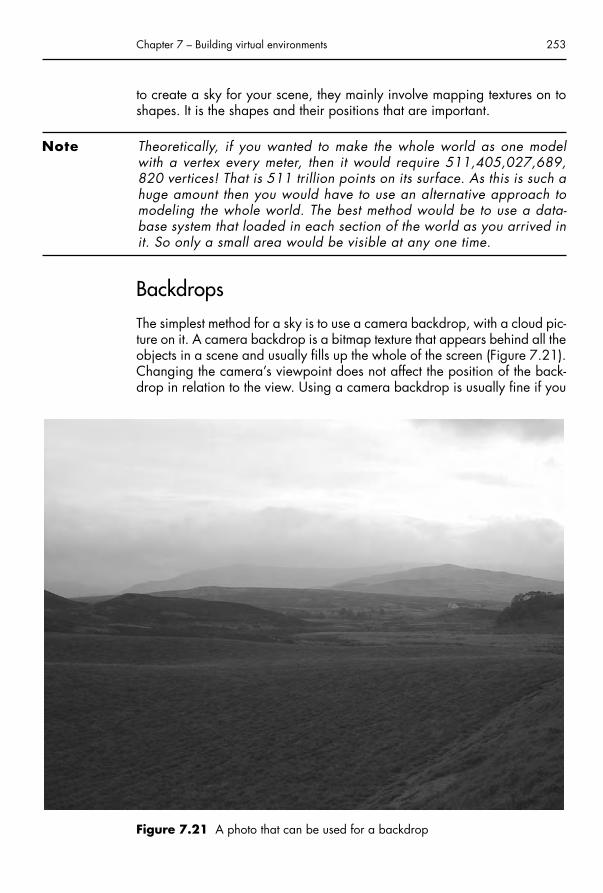
to create a sky for your scene, they mainly involve mapping textures on toshapes. It is the shapes and their positions that are important.
Note Theoretically, if you wanted to make the whole world as one modelwith a vertex every meter, then it would require 511,405,027,689,820 vertices! That is 511 trillion points on its surface. As this is such ahuge amount then you would have to use an alternative approach tomodeling the whole world. The best method would be to use a data-base system that loaded in each section of the world as you arrived init. So only a small area would be visible at any one time.
Backdrops
The simplest method for a sky is to use a camera backdrop, with a cloud pic-ture on it. A camera backdrop is a bitmap texture that appears behind all theobjects in a scene and usually fills up the whole of the screen (Figure 7.21).Changing the camera’s viewpoint does not affect the position of the back-drop in relation to the view. Using a camera backdrop is usually fine if you
Chapter 7 – Building virtual environments 253
Figure 7.21 A photo that can be used for a backdrop
Chap-07.qxd 8/12/04 15:20 Page 253

254 3D for the Web
Figure 7.22 The backdrop used with a terrain
have just a plain blue sky, but begins to look unnatural if you use a photo-graph of clouds as a texture. Because the backdrop always stays in the sameposition, moving around the scene does not move the view of the clouds,making your environment look odd and unreal. Generally speaking, back-drops are only useful for abstract worlds or environments where the camera’s viewpoint does not change (Figure 7.22).
Haze or atmospheric perspective
Another issue in the real world is haze. The picture that has been used in thediagram (Figure 7.22) has a significant amount of haze in it. Haze iscaused by air pollution and water vapor. As you look further and furtherinto the distance the saturation of color decreases until the land eventuallydisappears into the sky. This natural effect is actually helpful to our perceptionof the world and is known as atmospheric perspective. Because we knowthat air desaturates our real world we can get a sense of scale in a virtualworld if haze effect is simulated (Figure 7.23). Without it your scene just willnot feel real or rather it will feel small.
Chap-07.qxd 8/12/04 15:20 Page 254
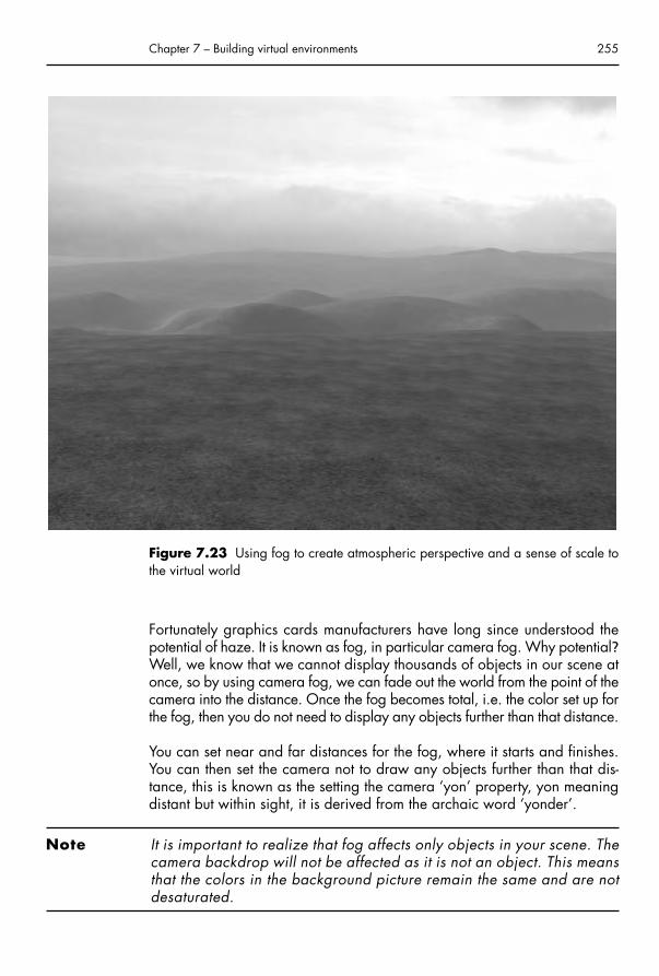
Fortunately graphics cards manufacturers have long since understood thepotential of haze. It is known as fog, in particular camera fog. Why potential?Well, we know that we cannot display thousands of objects in our scene atonce, so by using camera fog, we can fade out the world from the point of thecamera into the distance. Once the fog becomes total, i.e. the color set up forthe fog, then you do not need to display any objects further than that distance.
You can set near and far distances for the fog, where it starts and finishes.You can then set the camera not to draw any objects further than that dis-tance, this is known as the setting the camera ‘yon’ property, yon meaningdistant but within sight, it is derived from the archaic word ‘yonder’.
Note It is important to realize that fog affects only objects in your scene. Thecamera backdrop will not be affected as it is not an object. This meansthat the colors in the background picture remain the same and are notdesaturated.
Chapter 7 – Building virtual environments 255
Figure 7.23 Using fog to create atmospheric perspective and a sense of scale tothe virtual world
Chap-07.qxd 8/12/04 15:20 Page 255

Texture on a background plane, cylinderand sphere
An alternative to the camera backdrop is to place a texture on an object thatis positioned at the back of your scene. In old computer games (particularlycar racing games) this used to be a flat plane that scrolled right and left andas you turned left and right. This gave the illusion that you had a 360 degreepanorama. A better way to deal with this is to use a cylinder that completelyencircles your world. You can wrap a texture on the inside of this shape. Youcould take photographs and use a panorama-stitching program to createyour own photorealistic textures to use in this way. The important point is thatyour texture needs to match at each end as the left side will meet the right.One restriction of using a cylinder arises from looking upwards. You cannotget away with this method if you need to look up above you as there will bea hole in the sky! But your project may not require looking up, so this couldwell be the solution you need.
If you are able to look up above you in your world, then you could use asphere object that has a spherical projection map wrapped on it. You wouldactually only use a dome part of the sphere, the rest of it being below ground.When creating a texture map for this you have to be careful where the texturemeets as it wraps around the sphere (remember that all textures are squarein shape). You could use an image-editing program with a polar-coordinatedistorting filter. This could turn a texture into a distorted round shape thatyou could map on your sphere.
Note This method also causes issues with the fog technique described ear-lier. As the plane, cylinder or sphere is an object, it will be affected bythe color of the fog. This is probably not the result you desire. It is pos-sible to stop the object being affected by fog, but it has problems andinvolves understanding how z-buffer works. The z-buffer is used to cal-culate how to draw all the objects in a scene so that they overlap cor-rectly for the distance they are from the camera. This is starting to getinto graphics programming territory that this book is not intended tocover. If you are interested, then there are hundreds of articles, papersand books available on graphics programming, a quick search on theInternet will get you started.
Sky plane
A simple alternative to a cylinder is to have a plane that completely coversthe sky, parallel to the ground. This plane could have a cloud texture on itwhich could even be animated showing the traveling of clouds across the sky.Logically the plane is rectangular and any texture you place on it will also
256 3D for the Web
Chap-07.qxd 8/12/04 15:20 Page 256

be rectangular, so it will fit well. There are a few issues involved with this kindof sky. The height above the ground is important. If it is too low and you couldliterally walk into it whereas if it is too high then you could see the edges ofit, forming an unconvincing square in the sky. The higher the sky plane isthen the larger it needs to be to cover your world. It will almost certainly needto be bigger than your world.
The main issue is seeing the edge of the plane and if you are near the edgeof your world you do not want that to happen. If your sky is large enough thenyou can use the technique described earlier, camera fog, or distance fog tohide the edge of your sky. You can set where the camera fog starts (i.e. nofog) and where it ends (solid color). The distance is always measured awayfrom the camera and any object in that range will be colored by an amountdependent upon its position from the camera. Using distance fog in this way,usefully hides the edge of the sky plane and works on a sub-conscious levelto make us believe that your artificial world is as big as the real world,because of the atmospheric dulling (Figure 7.24).
Chapter 7 – Building virtual environments 257
Figure 7.24 Using a flat plane to create a sky
Chap-07.qxd 8/12/04 15:20 Page 257

Although this effect works it is not ideal because the sky appears flat, whereasa real sky has a curvature to it. An improvement on this version would be tobend the plane so that it arcs across the sky in a concave manner. This is abit like a dome, which could be used as an alternative. The important thingwould be for the texture to be mapped in a planar manner. If you do not dothis then you will end up with unwanted and unnatural distortions on it.These distortions are even more exaggerated if you decide to use a Sphereas your sky world.
Making clouds
You can use various techniques to create convincing cloud formations for asky plane. One option would be to use a program like Bryce, which has acloud generator in it where you can specify the type of clouds you want, e.g.cirrus or cumulus. But Bryce does not refer to a library of sky photographs,it calculates the clouds using fractal mathematics, in the same manner as wedid with the Terrain Map Generating program. PhotoShop has a render cloudsfunction, and using this in conjunction with layers, and other filters can produce very believable cloud formations.
It is worth experimenting when making clouds. You could scan paintings, ortake close-up photos of grounds. Then by blurring, adjusting the contrast, orselecting different areas, you can build up a cloud image. Of course, youcould photograph real clouds. Another useful thing to do is make the imagetileable, like the cloud image shown in Figure 7.25. This way you canrepeat the clouds when you map them (by changing the scale of the texture)and you could even animate the texture in Director, to give the appearanceof the clouds moving. This does not mean creating hundreds of cloud images,but translating the coordinates of the image map.
Skybox
One last option for skies is to make a skybox. This technique can only reallybe achieved using a 3D package such as Bryce. The idea is that you cancreate a complete representation of a world from one point of view andproject that onto a cube. The cube has six faces and each one has a viewfrom the camera projected onto it. The idea is to use a 90 degree lens andtake snapshots at 90 degree intervals in a panoramic fashion. Then youtake a vertical snapshot of the sky in line with one of the other sides. Youcould create a ground image, but you will almost certainly be creating aground using a mesh. Mapping these five or six pictures onto the sides of
258 3D for the Web
Chap-07.qxd 8/12/04 15:20 Page 258

the cube may make you think that there will be distortions where they meet.But this technique actually works because of that distortion. The sides matchup perfectly to give an illusion of a spherical world. However, when you arein the 3D environment that you have created you have to bear in mind thatthe skybox works only for one point of view. This means that you need thebox to move with the camera, so that you never approach the edge of it, butremain at its center.
Creating a new worldNow we have covered most of the ways to create a world, we might as wellcombine the various elements to see a complete environment. The final fig-ure in this chapter (Figure 7.26) adds together the Terrain Generator, TreeGenerator, and Sky and Water Generator to make a landscape, withatmospheric perspective. The sun moves around this world and casts achanging light, whilst the clouds roll by.
Chapter 7 – Building virtual environments 259
Figure 7.25 The texture map used for the sky in Figure 7.24
Chap-07.qxd 8/12/04 15:20 Page 259

260 3D for the Web
Figure 7.26 A new world, ready to be explored
Chap-07.qxd 8/12/04 15:20 Page 260

Interview with Ezonehttp://www.ezone.com/
Company profile
Ezone is a games company that specializes in Web games. It consists of twoAustralian brothers, Simon and Jamie Edis, pictured here with an imaginarythird brother in their Lenny Loosejocks creation.
The Edis brothers started Ezone in 1996, while living in San Francisco, USA,but they moved back to Australia in 2000, taking Lenny with them. Their repu-tation is built on solid game-writing skills and they are relative newcomers to 3D.But as you can see from such games as ‘SpaceWombat’, working in 3D has notdamaged their quirky sense of humor and brilliant use of sound. When I firsthappened upon Lenny, I was, like many others, drawn by the weird name, butI stayed and played a lot of games because they are such fun. I am convincedthat this is Ezone’s secret ingredient; they obviously love their work, and theirsense of fun comes through in the spontaneous nature of all their games.
Chapter 7 – Building virtual environments 261
Chap-07.qxd 8/12/04 15:20 Page 261

Interview
When did you start creating games for the Web?
Ezone.com started off as a Web development/hosting company but werealized that it wouldn’t be long before that market was saturated. Westarted making Web games pretty much right when Macromedia Shockwavecame out around 1996. Jamie had worked with a program called MacromindDirector 1.0 during Film school in Perth, and thought it was a great tool sowe got a copy and started experimenting. After a few really basic gameswe started putting more complex game play and detail into them.
Can you describe the genesis of Ezone? Your complimentary skills as broth-ers must help!
Each game that we developed we learned something new and the gamesjust kept getting better and better, so much better in fact that clients becameinterested in our games.
Simon’s engineering background made him the perfect programmer. Heknows and understands numbers, physics and just general ‘technical’ stuff youneed to program good games. Jamie’s skill in drawing, animation, charactervoices, sound design and music made him perfect for the ‘creative’ stuff.Combined with a similar bizarre sense of humor, it makes for a very com-plimentary game-making partnership.
Typically how many people would work on a game project?
On most games just the two of us.
As a small company it takes a long time to develop a game. Do you thinkthere are advantages of being a small outfit?
Actually it’s probably faster being a small company, as a lot of people usuallyequals a lot of meetings and the ‘too many cooks’ syndrome.
We can remember when we were doing some client work for one of the bigstudios down in L.A., and Jamie would get frustrated when they wanted usfor a meeting. In the time it takes for us to fly down there, drive to the studioand meet with them I could have had all the animation and sounds for thegame done.
How long do you spend developing your games and how much of that timeis pre-production?
We usually just jump straight into a game and see what works. Although weprobably should spend more time planning, Jumping straight in allows forfaster development of games. Sometimes you can over plan a project; the
262 3D for the Web
Chap-07.qxd 8/12/04 15:20 Page 262

Chapter 7 – Building virtual environments 263
lack of planning can often translate into spontaneous ideas and more freedom.Of course some projects do require and benefit from a good amount of plan-ning. Our games can take anywhere from a week to many months to develop.
How many games will you work on at once?
We usually have at least two going at a time, sometimes more that are inearly development phases.
Game design and production
How do you come up with the ideas for your games?
Sometimes they just pop into our heads, other times we look at what type ofgames we’d like to do and that are missing from our site and develop anidea to fill that gap.
Can you tell us something about Lenny Loosejocks and how it felt adaptinghim to 3D?
On the one hand it was great to see a 3D model of Lenny walking around,but on the other he’s little ‘clumsy’ to translate into 3D. He’s very tall and
Chap-07.qxd 8/12/04 15:20 Page 263

skinny and his usual rubbery 2D cartoony moves are difficult to translateinto a low-poly 3D character. We may overcome this problem in the future.Meanwhile, stumpy characters such as the Space Wombat seem to suit thecurrent 3D arena that we are working in quite well.
264 3D for the Web
The animation quality and sound in your games is always very good, howimportant do you think it is?
It’s pretty much everything.
The Internet has for many years been used as a vehicle for multi-playergames, and for several years as 3D multi-player games. How do you seethis area affecting the game market in the future?
Multi-player is great in that it adds a new dimension to games, and alsoraises the replayability factor because of the random human element.
From a playing perspective, what are the most important aspects of a3D game?
Control. You have to have good control. The player has to feel like theon-screen object is responding instantly to the inputs.
For example, in one of the earliest 3D games we did, you were a turkeyand you had to run around pecking control boxes well, we can’t even playit now because the controls seem so bad.
What aspects of 3D programming are the most constraining, e.g. texturesize, model count, face count and effects? What enhancements would youlike to see in 3D graphics technology?
As computers and video cards get faster and faster the technical limitationsbecome less of a factor.
Chap-07.qxd 8/12/04 15:20 Page 264

Good-looking 3D has an immediate appeal. Do you see it as the way for-ward in Web design, or just another tool?
We see it more as a tool. There are many applications where 3D is great,but it is not the answer to everything. For example, on our site we thoughtabout having a 3D interface for visitors to decide which game they want toplay, but at the end of the day a more traditional approach of just a simpletext list is the way to go.
What aspect of development would you say is the most time-consuming?
The finishing touches on a game. Whether it is a client game, or an in-housegame, it always seems to take forever to polish it up and package it.
Your future work
Where do you see Ezone going?
No plans to build the company any bigger, just increase revenue! Short-term goal is to find a major site sponsor so we can spend all our time devel-oping great 3D games for the site.
Chapter 7 – Building virtual environments 265
Chap-07.qxd 8/12/04 15:20 Page 265

How often do you plan to release a game?
Now that our game engine is pretty solid we would like to release at leastone game a month (including client games).
Technique and production
Did you find it hard adapting your 2D animation skills to 3D?
It was a little difficult, as 3D takes a different way of thinking.
But like any new application, spending time with the program (3ds max),pulling apart sample models and just experimenting helped to adapt.
The biggest challenge with the 3D models is keeping the poly count low. Atypical character model is around 1000–1500 polys and a terrain we try andkeep at around 5000–10,000.
On average how many animations/walk cycles do you make for a character?
Usually at least 7: idle, walk, run, jump, drive, win/happy, lose/sad, how-ever other actions can include: swim, slide, swing, shuffle, push, falldown,surf, etc.
From a technical perspective, what’s more important, high quality graphics,or fast frame rate?
Depends a lot on the gameplay. For example, a racing game that looks sharp,but has a slow frame rate and no sense of speed, is not going to appeal agameplayer. We try to get a good balance.
What software do you use for creating your games?
3ds max for creating the models, Photoshop for the textures, Director foranimated sprites, Soundedit for the soundfx and music mixing and 3DGroove GX to put it all together.
Were there any specific problems you had to overcome during the productionprocess?
Probably the biggest challenge is working with cutting edge and beta software.Because 3D on the Web is still at the early adopter stage there are alwaysgoing to be teething problems. However, when you are involved in a betaprogram you can be sure when the final version is released, all your gamesare going to work on it!
266 3D for the Web
Chap-07.qxd 8/12/04 15:20 Page 266

Insights
Do you have any advice for students of 3D game design?
Keep games simple. If you can’t explain the game concept in one sentence,then it is too complicated. Make it intuitive so players can start off without anyinstructions, and then introduce challenges once you have hooked the player.But be careful, probably the hardest thing to judge is the pace of challengeand reward. If a Web game is too challenging players will just give up it’snot like a console game where they have invested $50 and they want value.
The bigger the audience your game appeals to the better.
The amount of decent 3D Web games on the Web is still few and far between(excluding large download offline games and demos). Assuming this is justfor technical reasons do you envisage there being a more integrated 3DWeb presence than there currently is?
3D is only going to get bigger. It is almost like the web space is two or threegenerations behind what is happening in the console world, but we arecatching up quickly.
Chapter 7 – Building virtual environments 267
Chap-07.qxd 8/12/04 15:20 Page 267

Chap-07.qxd 8/12/04 15:20 Page 268
This page intentionally left blank

Chapter 8
Making a 3D game
• A generic approach• Marketing and financing• Planning• Game design• Physical point of view• Avoiding objects (collision detection)• Making a game world• Assembling a game• The future for 3D on the Web
ChapterSummary
A generic approachThe last several chapters have dealt with topics that can be used in 3D gameproduction. We have covered character building and interaction, imple-mented keyboard controls and built an environment, using a variety of meth-ods. This chapter builds further on this by introducing a variety of advancedtechniques and tips that will aid the development of high-quality 3D games forWeb usage. Creating a game is a very specific and individual task. Your gameidea will be unique, as will the combination of methods you need to makeit. This chapter takes a generic approach, by providing many options andtechniques covering the various issues involved in game design and devel-opment. Practical examples, referred to by this chapter, are provided on thisbook’s accompanying CD. You can take apart these examples and use themfor your own games. On the book’s website, www.3dfortheweb.info, you willsee some of these examples as Shockwave files, integrated into the website.The website will also feature a full game, which this chapter refers to. It includesthe characters from this book and many of the techniques discussed.
Marketing and financingYou will have read the interviews in this book, many of which are from com-panies who view games as an important aspect to their website portfolio.
Chap-08.qxd 8/12/04 15:22 Page 269

Games are a very useful marketing tool but can also be very complicatedto create. Web games generally tend to be fairly simple games, akin toarcade games. Theoretically, there is no reason why they cannot be asgood as any professionally created game. The main obstacle is develop-ment time and expense. Time is money and the cost of development has tobe balanced against the reward for making it. Many Web games are notsold, but given away, with the intention of retaining visitors to the site. It isthe advertising money that finances these projects.
There are other ideas for the financing of the games, e.g. subscription. Youcould create the first level of a game and get your customers to purchase further levels. Alternatively you might make the game available only by paying a subscription and they would have to log on to play it. The maindifference between this concept and that of purchasing the whole game isthat the game could be fed to the player in parts. Each part of the world isonly downloaded when they approach it, or when they have the password.
There are many factors involved in making a game, not least of which isindividuality. It is not our intention to see thousands of clones of one gameappearing on websites, so it is not the aim of this chapter to take youthrough the creation of one game. The purpose is to cover many of the tech-nical principles concerning 3D game development, incorporating the gameelements supplied with the CD. This game will also appear on the book’swebsite in its finished form (www.3dfortheweb.info).
PlanningPlanning is a most important aspect of game design. Indeed, this holds truefor any project where money is being spent on production. Assuming some-one is paying for your time, you will have to plan for the games develop-ment. You need to know whether you are capable of creating the wholegame yourself, or whether you need a team of people to do it. You mightneed a separate graphic designer, programmer, 3D modeler and animator.In the game industry, it is often the case that the programmer does not do the modeling and set design, but works in a team of such people. Thebudgets for Web games are almost certainly going to be smaller, so youmight not be able to afford to have a large team. This means that you needto be multi-skilled in order to complete the project.
If you have the skills to create a game completely by yourself, you will stillneed to plan your time. As a rough guide there are three stages to consider,the design, the development and the testing. The game design stage isimportant as it is here that you will work out all the elements needed for yourgame, the characters, genre, storyline, scenario, interaction, aims, etc. This
270 3D for the Web
Chap-08.qxd 8/12/04 15:22 Page 270

will enable you to confidently develop the game without unexpected hitches.Once developed you will need time for testing; in a short project this mighteasily be a quarter of the time required for the games development. Neverunderestimate the importance of testing, as it is the chance to iron out all thebugs that your game will have. If you have a complex game then there willbe many areas, such as object interactions, where errors can occur. Noamount of planning can stop errors occurring in the first place, so you justneed to allow time to fix them.
Only experience will help you plan properly, a game could take a few daysto make, or many months. You will always improve your development timewith the more games you make, speed and quality being the benefits ofexperience. Often with commercial projects there might be a time limit fordelivery. This will influence you as to how complicated your game can beand how detailed the arena or world is. As long as you are aware of all theelements in your game and the experience of your team, then you will be ina good position to estimate the time needed, and hence the cost.
Game designThorough game design will help you develop the game without encounteringunexpected issues. You should be able to give your game design documentto another team and for them to create the game without needing to ask anymore questions. The likelihood is that the team will be involved from the outset and this is good that you want to get other people’s opinions involved.It is the blueprint and it contains every little detail needed for production.Team members with different skills will pick up in different points.
There are various theories on what should go into a game design docu-ment. We will include some of them during the course of explaining all thetechnical elements needed to create your 3D game.
Genre
There are many genres relating to 3D games like shooter, simulation, adven-ture, sport, role-playing, flying, racing, strategy, puzzle, etc. They often crosswith each other, e.g. a role-playing shooter. Most of these genres will havesimilarities like having to control a character. That character might not behuman, it might be a car, a duck or a plastic toy, and may not be controlledby the player, but by the computer. Computer controlled characters (CCCs)are also known as mobiles. They may have a degree of artificial intelligence,all of which has to be programmed, with behaviors such as how they dealwith object collisions, whether they react to you, the game player, etc.
Chapter 8 – Making a 3D game 271
Chap-08.qxd 8/12/04 15:22 Page 271

Pacing in a game is often genre specific. A racing game needs to be non-stop action, but a shooter will create tension by having periods of low action,interspersed with shooting mayhem as all the aliens or bad guys try toattack you. All this needs to be planned. Building up tension during a gamemight be as simple as increasing the number of enemies that come to attack,or shortening the time limit to complete a task or adding degrees of complication as you progress through the game.
Physical point of viewTo see your game you need to have a virtual camera. By default, just havingthe 3D view creates a camera. For a game you need to control that view,otherwise your character might run off the screen! There are a few ways todescribe physical points of view, namely first person and third person.
First person view is where you become the character, as if you see throughhis or her eyes. Turning and running around moves the camera as if it ishead mounted. There is not much complication involved in using a first person view. There is no need to model a character in this situation, but youmight show the arms, or the weapon, if it is a run around and shoot game.
Third person view is also known as over-the-shoulder. Here you are an observer of your character, as well as probably being the controller. You see the character in all its detail with all of its movements and anima-tions. It is perhaps easier to identify with your character if you can see them and you can add many different movements to make them interesting(Figure 8.1).
Using a third person view creates the significant issue of where to positionthe camera. The following section describes different ways to position thecamera for this kind of view.
Fixed camera view
When deciding your camera style you should make reference to the use ofcameras in film making. Terms such as panning, zooming, wide-angle,close-up and tracking are just as relevant in games as they are in films. Youmight use a combination of camera movements and techniques to give yourgame a cinematic quality. It is possible to set up your camera to changeposition depending on where your character is. You can then make yourcamera follow an object as it moves across the scene. In film terms thiswould be panning (turning the camera from side to side) and tilting (point
272 3D for the Web
Chap-08.qxd 8/12/04 15:22 Page 272

the up and down). Following an object is easy in computer 3D. There aregraphics commands to allow you to do this. In Director, the Lingo commandis PointAt. You use this command by specifying which object you want thecamera to follow.
Chapter 8 – Making a 3D game 273
Figure 8.1 A third person point of view
Top TipDirectly following an object with a camera is not very natural. No realcameraman can keep up exactly with a person or object’s movement.There is always a slight delay, which we accept as being natural.Likewise, no self-respecting cameraman changes the direction of theircamera with sharp movements, but they would use smooth motions.You can achieve this effect by using a dummy object. A dummy objectis an invisible object. It is possible to make the dummy constantlytravel towards your target object.
Using the Lingo command InterpolateTo, you can make an object move towardsanother object. It is calculated in percentages, i.e. every frame of movement thedummy object would move towards its target object by 10% or whatever per-centage set. You then set the camera to follow the dummy object (Figure 8.2).
Chap-08.qxd 8/12/04 15:22 Page 273

Multiple cameras
When you use a fixed camera there is an obvious limitation that your char-acter might move too far away for it to be seen. So you need to set up manycameras in positions that allow you to view the action in the best way. This doesnot mean that you have to actually create many cameras; all you need to dois make a list of the positions of all the cameras. Then as the character gets nearto that position the camera jumps to that position and then continues to follow it.
You could achieve this camera swapping by measuring the comparative dis-tances of camera to object and then always making sure that the cameramoves to the nearest position. Calculations like these are quick to do, thereis even a Lingo command, DistanceTo which does the measuring for you.Otherwise you would have to use trigonometric math to work out the distance from the world position coordinates of the cameras and object.
This method sounds fine in principle, and is if there are no objects in yourscene that are blocking your view. Just because a camera happens to benearest to your main character, does not necessarily mean that it has thebest view. There is, however, another method you could use.
274 3D for the Web
Dummy object (not normally visible)
Figure 8.2 A camera tracking a dummy, which is following a game character.Inset with the camera view
Chap-08.qxd 8/12/04 15:22 Page 274

You could create a map of your environment that is color coded to showwhich camera you want to use when the character is over certain areas. Itis then possible to test the color of the map depending on the position of thecharacter. For example, if the character is over the blue area then this couldrelate to the first camera, and red might mean camera two. You can use asimple rule like this to create a complicated camera setup that appears tointelligently select which camera to use. The color-coded map should takeinto account the camera angle and the amount that the camera can pan(Figure 8.3). In the figure below black is used to indicate the objects in the
Chapter 8 – Making a 3D game 275
Figure 8.3 A camera position map, showing three cameras and their color codes,a character (marked by an x) and obstacles in black
Top TipIn films there is a camerawork rule known as ‘crossing the line’. Youwill notice in Figure 8.3 that the cameras are all positioned on one side of the stage. This is done purposely, so the viewer is not disoriented by camera’s swapping sides and, in essence, changingaround your left and right. It is a good idea to try and abide by filmmaking concepts, unless you feel you need to break the rules, or thatyou have no choice due to the game circumstances.
Single camera
The most commonly used camera setup is just to have one camera thattracks your character. Computers allow us to have a much more complicated
scene. There need not be a rule to say what happens when the characterwalks over these areas. It should be impossible, as the character shouldbump into them. This is discussed in the collision section of the book.
Chap-08.qxd 8/12/04 15:22 Page 275

system for a single camera than can be achieved in real life, so it is slightlyironic that this book is recommending following film camerawork methods.In a computer set a camera is not restricted by physics and can fly around,even passing through objects! Of course this is impossible in a real film set,but Directors have always tried to get as much flexibility out of a camera aspossible, using cameras mounted on cranes, dollies and steadicams. In acomputer game we do not need to set these up, but can make our camerafollow our character, tracking through the environment.
There are a few particularly useful methods to achieve camera tracking inyour 3D environment. When you use them in combination with each othera fairly sophisticated result can be achieved. The simplest method is to havethe camera fixed to a position behind your target object and for it to be ori-ented towards that target. As the target object rotates, then the cameraswings around with it. Likewise as the target object moves around the envir-onment the camera follows it. However, this result is very dizzying. It doesnot take long to spin your character completely around which makes thecamera swing around too. This method also means that you are alwayspositioned exactly behind your character and hence cannot see what theyare doing.
Note This amount of camera movement is basically uncomfortable. Comfortis important when playing a game and if it is any good, people will beplaying it for hours, so there is no need to give them a headache! Thiscomfort factor is not just about eyestrain though, it is about helping theplayer accept the reality of the game situation. The more they acceptit, due to good camera work, then the more they will play.
The way to overcome this swinging is to use more dummies. If you have adummy immediately behind your character then you can make the cameratravel toward (interpolate to) that dummy object. This way, the camera is notspinning around all the time, but smoothly tracking over your scene. Thismethod can also be improved, as was the multiple cameras method, by ori-enting towards a dummy that is traveling towards the object you are controlling (Figure 8.4).
Note The dummy object in Lingo does not need to be a physical object. Itcan just be a transform. A transform is a list of the coordinates for position and orientation. This means that using dummy transformsdoes not negatively affect the performance of your game.
It is possible to increase the subtlety of camera movement. You may notwant the camera to always be moving towards the character. For example,if he or she is running towards you, it would be better to track the camera
276 3D for the Web
Chap-08.qxd 8/12/04 15:22 Page 276

backwards. You use a dummy that is positioned between you and the targetobject but it is always a set distance away from the target. You then tell yourcamera to travel towards this object as well as the dummy that is behind thecharacter (Figure 8.5).
Chapter 8 – Making a 3D game 277
Camera points at Dummy 1
Dummy 1 (travels towards character)
Dummy 2 (fixed behind character)
Camera travels towards Dummy 2
Figure 8.4 Tracking camera using dummies as targets
Final position of camera
Dummy 3 (a fixed distance away from the character and in a line with the camera)
Dummy 2 (fixed behind character)
Camera travels towardsDummy 2 and Dummy 3
Dummy 1
Figure 8.5 A tracking camera system that prevents the camera from getting toonear the target
Chap-08.qxd 8/12/04 15:22 Page 277

Avoiding objects (collision detection)Now we have made our cameras fly around our game world, we need totake into consideration the other objects in the scene, which are likely to getin our way. The two issues here are objects that obscure our view andobjects that the camera might bash into. Using the multiple camera idea canget around the objects obscuring our view, but it is not an answer to mov-ing cameras. We need to devise a system that can take into account thepositions of objects and allow the camera to navigate around them; this isreally collision avoidance.
Collision detection is a fundamental part of 3D game creation. Without it,your game will not feel solid, its plausibility will diminish and players willget bored far too quickly. Clearly you do not want your players to be ableto make your character walk through walls, unless they have a magicpower or they are a ghost! Collisions can take place between movingobjects or between a moving and stationary object. It is possible for non-moving objects to ‘collide’ if one object is positioned in the same place as another. This might happen if you are creating a world with randomlypositioned objects.
278 3D for the Web
Top TipYou do not have to keep your camera moving all the time, particularlyif you are only turning the character around. You could include a timedelay, so the camera only tracks to a new position when the characterhas been stationary for a few seconds. Another idea is to only makethe camera track towards the dummy object when the target is a cer-tain distance away, or only when it is moving forward. Combining theabove camera systems with the multiple camera concepts can lead toa great degree of sophistication. This adaptable and controlled sys-tem, if done well, can make the player feel that the game has a goodstandard cinematography. You could even create your game to be inwide-screen format for a cinematic feel.
To get your dummy to be in line with you and the target you should start bygiving it the same coordinates as the target (duplicating its transform). Thenorientate it towards the camera (using the PointAt command in Lingo) andfinally move it forward by the desired amount of units (using the Translatecommand).
Chap-08.qxd 8/12/04 15:22 Page 278

There is not really a difference between collision detection and avoidance.To make an object avoid a collision you need to know if it is going to col-lide with another object. This involves making a collision test which can bedone either before the object has moved or afterwards. It is important toremember that your objects do not move smoothly, they move in steps.These steps are changes in position that occur every frame, every time thescreen is updated. The steps appear to be a smooth motion when the framerate is high enough at approximately 25 frames per second or more.
There are many ways to detect when collisions have taken place but first we will deal with the moving camera and collision avoidance. This willintroduce principles that we can reuse for other collision situations.
Coordinate collisions
The simplest of scenarios is that you have a rectangular arena, perhaps afootball pitch and you want your characters to avoid running off the pitch.As you can easily track their coordinates in world space you can provideconstraints to their positions. An example would be to have a pitch that was1000 units wide, 2000 units long and positioned in the center of yourworld. This means that one pitch ‘wall’ is located at the coordinate minus500 in the X-axis and the opposite wall positioned at positive 500. So youcan make a rule that states: If your object has moved to an X coordinate lessthan � 500 then changes its X position to � 500. This works for the oppos-ite wall by making the X position change to 500 if it is already greater than 500 units. Likewise for the other two walls your rule would use the Zpos-itions � 1000 and 1000 as the walls are further away.
Casting a ray
A very common situation is where you want to have an object follow a terrain. In the case of our camera, we would want it to always be above the ground, and not to crash into it. This is not a problem if our ground isflat, but if it is a terrain, as in the previous chapter, then our camera couldeasily move into the side of a hill. We can stop this happening by firing animaginary line from the camera’s position vertically downwards (Figure 8.6).
In Director there is a Lingo command for this called ‘ModelsUnderRay’. Thiscommand makes a list of the objects that are in the path of the ray. If noobjects are in the path of the ray then the list is empty. But as we are assum-ing the ground will be beneath the camera, there should always be at leastone object in the list. The ModelsUnderRay command does not just tell youthat an object is in its path, it provides you with details such as the point onthe model (in world coordinates) that the line intersected and the distance
Chapter 8 – Making a 3D game 279
Chap-08.qxd 8/12/04 15:22 Page 279

between that point and the ray’s origin. It can also tell you the face numberand the normal (the direction of the face is pointing). This can be used toprovide a rebound direction if you want to bounce of the object.
In the case of our camera and the ground, we are only interested in the dis-tance from the origin of the ray. If we decide that we want our camera to be300 units above the ground then we can cast a ray downwards, to get the vertical position of the terrain at the point of contact, and then add 300 units in the vertical direction (Y-axis) to that position.
Other uses for ray casting
Ray casting is not just restricted to cameras and fixed distances. For a startyou can use it to keep your character at a set distance above the ground.
280 3D for the Web
Ray is cast downwards
Point of intersectionwith the ground
Figure 8.6 Casting a ray vertically down to keep a camera above ground
Top TipIf you create objects in Director using Lingo, then it treats the Y-axis asbeing up. This is not the case for 3ds max which treats the Z directionas up. You need to be aware of this, otherwise your ray will not bepointing in the right direction. If you have a terrain that has been cre-ated in 3ds max then fire your ray with a direction vector of (0, 0, �1),this means negatively in the Z direction, as opposed to (0, �1, 0).
Chap-08.qxd 8/12/04 15:22 Page 280

The Director example files supplied on this book’s accompanying CD usethis method, at a slightly more complicated level. Instead of just keeping theKeystone Cop at a fixed distance above the ground, the character is kept ata height no less than that distance. The subtle difference is important as itallows the Keystone character to jump up in air and land, with his feetapparently on the ground, as if they have collided.
The idea of having a minimum height above ground is also useful for anyflying simulation, where you can have the freedom to fly an airplane orspaceship in all directions, unless it is too near the ground. In a futuristic racing game, you could combine this idea with the traveling towards thepoint of contact plus a fixed distance. If your object is too low then, insteadof jumping straight to the required height, you use the InterpolateTo com-mand to make it move towards it, perhaps by 30% at a time. This wouldhave the appearance of a soft bounce, or an anti-magnetic response. Thefurther that you had gone past the distance limit then the more you wouldbe propelled back towards it, the greater the repulsion force.
Understanding vectors
You can cast a ray in any direction you like. This is not done using angles,but using a normalized vector. A vector coordinate might look somethinglike vector (60, 20, �80). This corresponds to the x, y and z positions inworld space, where vector (0, 0, 0) is the center of the world, also knownas the origin. If you drew a line from the origin to the vector coordinate thenit would have a length, this is also known as the magnitude. The magnitudeof vector (60, 20, �80) is 102 units.
Normalizing a vector means making its magnitude equal to 1. The resultingvector then describes its direction only. So the above vector normalizedgives the result vector (0.59, 0.20, �0.78). Having a normalized vectorallows you to do math on it, like finding the angles between two vectors,which is one reason it is useful.
So a position can be described in coordinates (x, y, z) or as a normalizedvector (x, y, z) and a magnitude (any number). In the above case, the pos-ition vector (60, 20, �80) is equivalent to vector (0.59, 0.20, �0.78)with a magnitude of 102.
Horizontal rays for collisions
In simple terms, in a 3D scene, if your camera view is aligned with theworld axes, then the vector (�1, 0, 0) is a direction pointing left and (1, 0, 0) is pointing right. Likewise (0, 0, 1) would be pointing away from
Chapter 8 – Making a 3D game 281
Chap-08.qxd 8/12/04 15:22 Page 281

the camera and (0, 0, �1) would be pointing towards the camera. Theseare all vectors in horizontal directions and we can use them to detectwhether our camera (or other object) is going to collide with other objectsin our scene. In addition to firing a ray downwards, if you fire a ray in thefour horizontal directions then they will possibly intersect with other objects. You should set the ray lengths to be a particular number of units, perhaps as long as our Keystone Cop’s arm, then you will know whether it has hit an object or not. If it has then you can tell the character (or camera) to move in the opposite direction by the amount that it has overlapped(Figure 8.7).
282 3D for the Web
Rays are cast in four directions
Character’s final direction of travelif too close to wall
If the character’s distance froma wall is below the minimum thenthe character is moved backto that distance
Figure 8.7 Casting four horizontal rays to keep a character from walking throughwalls
Chap-08.qxd 8/12/04 15:22 Page 282

Note Setting the length of a ray with the ModelsUnderRay is not possible inversions of Macromedia Director previous to MX 2004. If you have anearlier version then you will have to use the distance measurement inthe resulting list.
You could actually just use one ray pointing in the direction that your char-acter (or camera) is facing. When it hits a wall or object, you could use thedirection of the intersected face to adjust your rotation. Firing another ray inthe opposite direction to the wall’s face would allow you to measure thenearest distance from the wall. If you are too close then you could makesure you are a fixed distance away from the wall, perhaps 20 units.
Simple detection
Ray casting, as described above, is a very useful method to detect whetheryour objects are going to collide. It works particularly well for games whichfeature straight sides, like games that are set inside buildings, as there areonly likely to a few directions that the walls might be facing. This methodcan cause problems when you are trying to stop more complicated objectsfrom colliding, e.g. spherical or irregularly shaped objects.
There is a method that works for collisions with cylindrical objects, like trees.Instead of casting a ray, you just need to measure the distance from yourcharacter to the cylindrical object. If that distance is less than your desiredamount, you move your character away from the object by the difference indistance. This works particularly well when two spherical or cylindricalobjects collide, e.g. pool balls.
To make this concept work you need to check the distances from your charac-ter (or camera) and all cylindrical objects. This is done best by making a list ofthese objects and cycling through that list, to see if any objects are too close.
The result of this collision detection method is that your moving object willsmoothly move around the colliding object, whilst maintaining its previoustrajectory (Figure 8.8).
Mesh collisions
Perhaps the most accurate collision detection system is that of a mesh colli-sion. This is where the mesh of one object is compared to the mesh ofanother object and, if any parts of the mesh intersect, action is taken. In
Chapter 8 – Making a 3D game 283
Chap-08.qxd 8/12/04 15:22 Page 283

Director the Collision modifier takes care of this, by being assigned to yourobjects that you want to be treated this way. A straightforward use of thismodifier is to ‘resolve’ the collision. This means that if both objects are mov-ing and they are set to be resolved, they are moved back to their last pos-ition before the collision took place. If only one of your objects is movablethen you would only need to set this one to be resolved.
There are several properties that you can set with the Collision modifier. Youdo not have to resolve collisions via the shape of the mesh. It is possible toset it to detect collisions by a bounding sphere or bounding box. These arequicker methods than detecting proper mesh collisions, as there are fewercalculations to perform. If you are using the mesh mode for your collisionsthen detecting between two detailed meshes can significantly slow downyour games frame rate performance. Using the bounding sphere is a bit likethe simple detection method discussed in the previous section.
Usually, once a collision has taken place you will tell the object to performan action. This could be based on the normal of the face of the object thatit hit, e.g. moving the object in the direction of the normal.
284 3D for the Web
Distances are measured tocentres of all objects
Center of cylinder
Character is positioned awayfrom object if too close
Character continues to move inits direction of travel, but from a new position
Figure 8.8 Measuring the distances to objects, for cylindrical shaped collisiondetection
Chap-08.qxd 8/12/04 15:22 Page 284

Note It is not really advisable to use the mesh method for collisions on ani-mated complicated objects, such as moving characters. The performanceof your game will slow down and you will have the added complica-tion of not necessarily wanting to move your whole character if just his hand has hit an object. It would be better to use a bounding box inthis case.
Collision meshes
It is quite possible that you have a very complicated object in your scenethat you want other objects to interact with it. As complicated meshes, withlots of vertices and faces slow down collision detection, one idea is to cre-ate a collision mesh. This is essentially a very low polygon version of yourmodel that will be invisible (have a blend value of 0). This can be groupedwith your complicated object or linked as a child of it.
If you have a lot of objects requiring collision meshes then it is advisable totry and reduce the number of objects needed. If these objects are stationaryand positioned on the ground then you could create a mesh that covers allof them, as if they are shrink-wrapped. Remember that it is the number ofobjects in your world that has the biggest effect on the frame rate, so doub-ling the number by creating individual collision meshes may not be bene-ficial. Your computer actually runs through the whole list of objects everyframe in order to detect collisions.
Collision maps
One method of collision does not involve 3D at all. You could create a 2D map of your scene, in a similar manner to the camera position map. Thisworks particularly well for games with simple layouts, like rooms, corridorsand buildings. In fact any object that is made from straight lines, e.g.parked cars in a street. The concept works by sampling the color of the
Chapter 8 – Making a 3D game 285
Top TipOnce you attach an object as the child of another (the parent), then itoperates in local coordinates relative to that object and not in worldcoordinates. Moving child objects can be confusing if you have notrealized this but you can force the object to move in world coordi-nates. In fact, the World is a parent of all objects so when you reposi-tion an object you are in fact moving it in its parent’s coordinates, i.e.the world coordinates.
Chap-08.qxd 8/12/04 15:22 Page 285
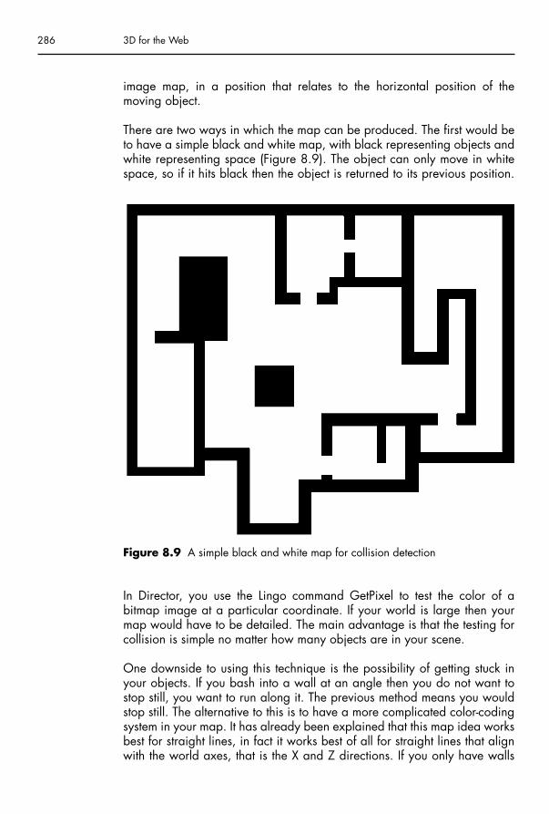
image map, in a position that relates to the horizontal position of the moving object.
There are two ways in which the map can be produced. The first would beto have a simple black and white map, with black representing objects andwhite representing space (Figure 8.9). The object can only move in whitespace, so if it hits black then the object is returned to its previous position.
286 3D for the Web
Figure 8.9 A simple black and white map for collision detection
In Director, you use the Lingo command GetPixel to test the color of abitmap image at a particular coordinate. If your world is large then yourmap would have to be detailed. The main advantage is that the testing forcollision is simple no matter how many objects are in your scene.
One downside to using this technique is the possibility of getting stuck inyour objects. If you bash into a wall at an angle then you do not want tostop still, you want to run along it. The previous method means you wouldstop still. The alternative to this is to have a more complicated color-codingsystem in your map. It has already been explained that this map idea worksbest for straight lines, in fact it works best of all for straight lines that alignwith the world axes, that is the X and Z directions. If you only have walls
Chap-08.qxd 8/12/04 15:22 Page 286

that are at right angles to each other then we know that their Normals canonly be facing one of four directions, analogous to north, south, east andwest. You can color code your map so that a north-facing wall is blue, aneast-facing wall, yellow, etc.
Having color-coded walls means that when your object collides with it, youneed only move it back in one axis direction. For example, if east–west corres-ponds to the X-axis, hitting an east-facing wall would mean you return back toyour X position, but your Z coordinate stays at its new one. If you walked intothe wall at an angle then your object would start to move along it (Figure 8.10).
Making a game worldAfter discussing the various ways in which you can detect collisions, youshould have many different ideas as to how to navigate around physical
Chapter 8 – Making a 3D game 287
East-facing wall
West-facing wall
South-facing wall
North-facing wall
Figure 8.10 A grayscale-coded map for collision detection
Chap-08.qxd 8/12/04 15:22 Page 287

objects in your game. This means it is time to place these objects in ourgame. We need to design our world, devising what needs to be in it andwhere to put it. The previous chapter of this book covered many of the tech-niques needed to create an environment, but we did not cover accuratepositioning of objects or some of the techniques required for buildings.
Naturally, what goes in your game world depends on what your game isabout and where it is set. Perhaps you need some small village huts andstone walls for a fantasy adventure, or you might require many tall buildingscombining to form a futuristic city. Either way we need to devise some effi-cient techniques in order to make our game suitable for the Web.
Do I need a world or an arena?
Answering this question is a crucial step in the approach we need to takefor our game development. As you are probably aware, making games forthe Web brings us certain limitations, mainly to do with file size. A full con-sole or PC game will be delivered on CD, or now DVD, and will often be a huge game taking hundreds of hours to complete. As such it can measurehundreds of megabytes in amount of data. All this data includes the pro-gramming, the textures, sounds and music, 3D models, and video clips (cut-scenes).
A game of this size might take hours to download (even with a Broadbandconnection) and what you want is a game that loads in minutes or better stillseconds. You cannot expect your site visitors to wait around for ages whilsta game loads, unless you already have a reputation that your games areworth the wait. This leaves us with a few options. Either we have a smallgame, set in an arena, or a larger game that loads gradually. A largergame might contain many small levels, as you complete one you wait forthe next to load. Your players will hopefully be happy to wait, as they arelured deeper and deeper into your playing experience. Alternatively, youmight have a large world that you will need to load up gradually as thegame player explores it. This might involve pauses in the game play, or thegame might actually load all the time, whilst it is being played.
If you decide to have a single level arena then you will need to decide whatkind of arena it will be. If you have martial arts fighting game then it mightonly be a small area of land, or a boxing ring. You might need some sur-rounding buildings, and objects setting the scene, perhaps an alleywaywith trashcans, and a burnt-out vehicle. In this situation you are not talkingabout hundreds of objects and there is unlikely to be any cloning needed. Itmakes sense to create this scene entirely in your 3D package, and then importit in to Director to create the interaction, setting up the collision detection.
288 3D for the Web
Chap-08.qxd 8/12/04 15:22 Page 288

Game object creation
In the chapter on building a character for a Shockwave; the Keystone Cop,you have covered probably the most complicated build for a game. A char-acter is going to be scrutinized more than any other object in your scene. It is he (or she) that you will be looking at for the most time, so a careful balance between complexity of design and simplicity of building is needed.
Overall we need to make our objects as simple as possible, in order tomaintain a decent frame rate, whilst making them believable. Maintaininga frame rate involves low-poly modeling, and making them believablemeans good quality textures. You will use textures to imply physical detailwhere there is only really a flat triangle. For example, in our Keystone Copcharacter, his eyes are not separate objects, but created with the texture that covers his whole head. If the textures are created well then your playerswill not even think about the illusion you have created.
A common object in a game would be a wall. Indeed, these form part of theset in classic shooting games like Doom, Quake, etc. It will be a useful exer-cise to create a simple walled building layout, a dungeon or castle perhaps.
Making a walled dungeon
The first stage of building a set for a game should be to draw some kind ofdiagram, a map or blueprint. This is best done on graph paper or in an illus-tration program with grids turned on. This can be done simply at first, byblocking out rooms and corridors, assuming that that is what you want in yourgame (Figure 8.11). You might find this easier to do in a program like AdobeIllustrator. You can import the vector shapes from Illustrator into 3ds max and
Chapter 8 – Making a 3D game 289
Top TipPitching your game to the right level of computer is a crucial issue. Ifyou make it so that it can only run on the latest and greatest computerthen you will be alienating a majority of your audience. You need tobe efficient in your use of textures and number of objects, withoutcompromising on quality. Be aware of the objects in your scene anddecide a minimum specification of computer that you want the gameto work well on and test it on that computer. Older graphics cardsneed a lot more consideration than the latest with tons of memoryavailable and super-fast rendering capabilities. Minimum specifica-tion changes all the time, so if you are not sure what specifications togo for then look at the back of computer games packaging. That willgive you the best guide to what the professionals currently think isacceptable.
Chap-08.qxd 8/12/04 15:22 Page 289

use them to create your building. Alternatively you can use your 3D packagesSpline drawing options. This will enable us to use a simple structure for ourbuilding. Ideally, we create our building as one object, with relatively fewpolygons. This will be very useful from the frame rate efficiency aspect and wecan always increase the complexity by adding details with other objects.
290 3D for the Web
Figure 8.11 An Adobe Illustrator sketch for a dungeon blueprint
Top TipAlthough our map is rough, there are some points to note about it thatare important. There is always a gap between each room; this is set tothe size of the grid, as the rectangles are snapping to the grid. Thisgap is important, as the walls will only be visible on one side. This isa real time rendering issue as any plane can be rendered on bothsides or just the front or back. Rendering on just the front means thathalf the amount of triangle needs to be rendered, hence it is twice asquick to complete the task.
Chap-08.qxd 8/12/04 15:22 Page 290

Our map is at a sketch stage. You can manipulate the rooms until you havea desired layout. When you are satisfied it is time to make the actual walls.Remember that we want to create the whole building out of one object. Youcan do this by tracing two lines around the shapes of your rooms, this resultsin a shape that we can use as a template in 3ds max (Figure 8.12). It is rec-ommended that you save your Illustrator file as a Version 8.0 file as this ismore compatible with 3ds max. When you import it, make sure you selectSingle Object, and not Multiple. You should then scale it up until it fits acoordinate scale that you are happy with, perhaps equivalent to 40 metersacross or 4000 units.
Chapter 8 – Making a 3D game 291
Figure 8.12 An Adobe Illustrator map made out of two vector shapes
Note Getting your scale correct is essential at this stage, as everything inyour world will relate to this. I recommended that you align your ‘blue-print’ to the grid in your 3D package. This should make it easier toplace objects and make sure they align with the walls, without gaps. Astaircase would be one such example.
Chap-08.qxd 8/12/04 15:22 Page 291

Now you have an outline of your building, all you need to do is import itinto your 3D program and use the Extrude modifier to make the walls theheight that you require. Of course this is a very simple structure, and youmight want a more complicated design. Perhaps you want windows or dif-ferent thicknesses of walls. It is at this stage that you should implement thesedesign details.
Making windows
This is not a very difficult task to do, particularly when you should have alreadymodeled a character earlier in the book. Essentially, all you need to do is markoff where you want the windows and then extrude them into your wall.
Select the Spline shape that you have imported and open up the ModifierStack to select vertex editing. Then choose the Refine button. This will allowyou plot extra vertices on your Spline shape. You need to place them oneither side of where you want window to be or on both sides of the wall(Figure 8.13). Make sure that the outer wall vertices align with the innerwall vertices.
Once you have marked all the windows you need, you can add the Extrude modifier. When you do so, make sure you have at least three
292 3D for the Web
Figure 8.13 Adding four vertices at the bottom of your Spline shape in prepar-ation for creating a window
Chap-08.qxd 8/12/04 15:22 Page 292

segments selected, but not many more as you do not need the extra poly-gons. Now add an Edit Mesh modifier and select Polygon from its sub-menu. Click on your window polygon and extrude it negatively, punching a hole in the wall. Only extrude it as far back as the wall is thick (Figure 8.14).
To finish it off, you should delete the polygon that you have extruded andthe one on the outer wall. Then select Edit Mesh � Vertex and align theloose vertices from the inner wall window with the four corners of the outerwall window. When they are aligned you can choose Weld � Selectedfrom the Edit Geometry menu to join them together. This will fix any gaps inthe geometry of your wall.
Now we have made our simple dungeon, you can start to make it look moreinteresting. Add a floor and a ceiling using planes that cover the entire areaof your building. You could start to add more details, such as more objectsin your rooms. Exactly what you need depends entirely on what kind ofbuilding you have, perhaps a dungeon, a futuristic building, an office
Chapter 8 – Making a 3D game 293
Figure 8.14 Extruding a window out of the mesh
Chap-08.qxd 8/12/04 15:22 Page 293

block, etc. When building your objects keep them simple; it is in the texturesthat the details will show.
If you have more than one floor in your building then use a box for eachfloor as you will need the thickness. You will then have the issue of how totravel from floor to floor. Perhaps you will have a lift to travel up or perhapsa staircase on the outside of your building. Most likely, your stairs will be inone of the rooms, so you will have to punch a hole in the floor to let yourcharacters go through. Make sure you allow for this by creating enough vertices in your floor mesh, so that you can extrude a hole.
Making a texture
Now you have made your building you need to give it a convincing mater-ial. It is always best to make up your own textures, (although it is possibleto buy them or download them for free on the Internet). These might comefrom photographs, as discussed in the previous chapter. In the case of ourdungeon, we require a stone wall. The chances of you finding a suitabledungeon style wall are slim, but you could use your 3D package to createthe texture you require, e.g. stone bricks. One advantage to making upyour own texture is that you can have accurate control over the lighting sothat you get a decent depth to your texture; also you get to decide the size,shape and color of your bricks.
To make a wall you need some brick shapes, so you should start a new file,as you are only doing this exercise in order to create a texture. These canbe as complicated as you like, but I recommend you to choose a chamferedbox shape, as opposed to a normal box. This is important as you will get ahighlight on the edges when the box is chamfered, this adds to the realism.In real life most edges are always rounded, just look around you to seewhat I mean. If you want your bricks to be irregular then add a Noise modi-fier or Mesh Edit to them. You may not want to do this though, as we aregoing to make up a repeating pattern for use on our walls and your irregu-lar bricks might stand out as they become part of a pattern.
Assemble your wall to your desired brick or tile pattern. You might want topush some of the bricks slightly backward and forward, if you want an oldstyle wall (Figure 8.15). Now attach them together as one object using the‘Connect’ compound object. This will treat the object as one so that you canapply a texture to the whole set of bricks and not just to each individualbrick. This way all of your bricks can appear slightly different, as if theyhave been weathered or had moss growing on them.
If you want your bricks to appear chiseled, use a Noise modifier as a Bumpmap and set the size of the Noise to a low value. If you want a more natural
294 3D for the Web
Chap-08.qxd 8/12/04 15:22 Page 294

looking stone then use another Noise map for the Diffuse Channel, andchoose some texture bitmaps for the Noise colors. In the Figure 8.15 twodifferent photographs were used and blended together by using them as theNoise colors. Ideally you could find some stone and take a photograph;perhaps you could even go to your local carpet store and use some marbleeffect patterns. If you want your bricks to appear slightly damp then adjustthe specular and glossiness curves to give them a slight shine.
When you are happy with your stone material, place a light that pointsdown, to simulate the most common type of light that will appear on thebuilding. Do not use an Omni or Point light, but use a directional light asthis will give you an even spread of light. Make sure you turn the shadowson, as this will provide the depth you require.
Finally, render your picture in the front view and not the perspective. Thiswill give you a flat image that you can use for tiling (Figure 8.16). You mightwant to add in another box to represent the mortar in between the bricks.The next stage would be to use a program like Adobe PhotoShop to cut outyour rendered image and making it into an image that can be tiled.
Chapter 8 – Making a 3D game 295
Figure 8.15 An assembled brick wall, made from chamfered boxes
Chap-08.qxd 8/12/04 15:22 Page 295
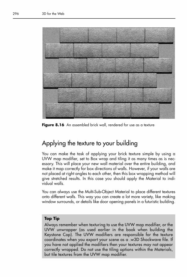
Applying the texture to your building
You can make the task of applying your brick texture simple by using aUVW map modifier, set to Box wrap and tiling it as many times as is nec-essary. This will place your new wall material over the entire building, andmake it map correctly for box directions of walls. However, if your walls arenot placed at right angles to each other, then this box wrapping method willgive stretched results. In this case you should apply the Material to indi-vidual walls.
You can always use the Multi-Sub-Object Material to place different texturesonto different walls. This way you can create a lot more variety, like makingwindow surrounds, or details like door opening panels in a futuristic building.
296 3D for the Web
Figure 8.16 An assembled brick wall, rendered for use as a texture
Top TipAlways remember when texturing to use the UVW map modifier, or theUVW unwrapper (as used earlier in the book when building theKeystone Cop). The UVW modifiers are responsible for the texturecoordinates when you export your scene as a .w3D Shockwave file. Ifyou have not applied the modifiers then your textures may not appearcorrectly wrapped. Do not use the tiling options within the Materials,but tile textures from the UVW map modifier.
Chap-08.qxd 8/12/04 15:23 Page 296

Shadows
In a real time game environment shadows are very complex thing to calcu-late. This in turn will reduce your frame rate to unacceptably low levels. Realtime shadows are possible in commercial games as they can take advan-tage of new technologies in graphics cards, but the Shockwave engine cannot do this, as yet.
Another issue with real time shadows is that they tend to be hard edgedwhich is not always the desired effect. In real life, the shadow from a lightbulb is not going to be hard edged, but will be softer the further the shadowis from the object. This effect can be achieved in a properly rendered sceneusing area shadows or shadow mapping, and it would be good to incorp-orate subtle lighting into our building. This will lend a greater sense of realismto our rooms.
Chapter 8 – Making a 3D game 297
Top TipIt is still a good idea to have a shadow on your character in yourgame. This of course, is a moving shadow. A simple and effective technique is to have a Plane object that is set to follow the ground atthe feet of your character. This plane can be oriented to match thedirection of the face of the ground that it is on. If this plane has soft,round texture applied to it (with alpha transparency) then you get theappearance of a soft, round shadow. This is not perfect, but does helpprovide solidity to your character. Figure 8.1 shows a shadow underthe Keystone character.
Texture baking
Texture baking is used to create materials that appear to have lightingeffects like shadows on them. Essentially it involves rendering the scene inyour 3D package, with all the lighting, shadows and material effects set.This rendering is only done on the objects that you want baked.
3ds max has a texture baking option under the Rendering � Render toTexture menu. This enables you to render complicated shapes and store theTexture Coordinates automatically. This can be a very useful feature as youcan have effects like Raytraced reflections on objects that you would not beable to achieve in a real time situation.
In the case of our Dungeon, first of all make sure you have set up all thelighting that you want in your scene. This will be as many lights as you
Chap-08.qxd 8/12/04 15:23 Page 297

would expect to have in all of your rooms. Then you just need to select yourfloor (or wall or ceiling) and choose the Render to Texture option. Next youadd the maps that you want to render. For simplicity, choose to render theComplete Map. This will create a texture that you can use to replace thefloor material that you previously had. This material will have all the shadowsand lighting changes that you require. You can then repeat the concept forany other objects that you want to be shadow mapped. This works best onflat planes but applies to more modeled objects as well. You have to remem-ber that you will lose some detail on your floor texture if it was made froma previously tiled material. Now your texture will cover the entire floor(Figure 8.17).
Rendering to a texture automatically generates UVW coordinates, so it isnot necessary to apply a UVW map modifier.
298 3D for the Web
Figure 8.17 A texture baked floor with lighting and shadows
Chap-08.qxd 8/12/04 15:23 Page 298

Exporting your world
When you export your building you might have some large textures createdfrom texture baking. It is here that you will have to compromise betweendetail and overall file size. You can set the compression value of textures inthe Export window. This uses JPEG compression and so it can significantlyreduce the size but it is at the expense of quality, so a balance will have tobe found through experimentation.
The finished building can be imported into Director and then used in conjunction with your collision routines to create a navigable experience(Figure 8.18).
Assembling a gameGames are not just about a virtual reality tour, they have to have a purpose,a reason for playing them. Obviously your game needs an aim, e.g. shootas many monsters as you can, or collect all the parts of a golden talisman.Your game might have a scoring system, or it might be a race against timeor a combination of both. There might be objects to collect that aid you onyour way to completing the game, objects that restore your health or giveyou greater weapons. Either way we need to include other objects in thegame, and we also want to keep in mind the fact that it is for Web publi-cation, hence keeping an eye on download size.
Chapter 8 – Making a 3D game 299
Top TipWhen you render to texture, select Map Channel 1 before you actuallyrender (in the Render to Texture palette). The problem with Render toTexture is that it creates a Shell material, which cannot be exported toShockwave. To get your new baked texture to work, you should createa new material with the Diffuse map set to be the bitmap that theRender to Texture function has created. You will be able find this in theMaterial Editor list, when you set the Diffuse map. You have to selectMap Channel 1 when rendering in order for this new material to work,when exported to Shockwave. The default value (map channel 3) doesnot work (bear in mind that this process was not designed just forShockwave 3D). Also as your texture has lighting on it, you can set theMaterials Self-Illumination value to 100. This will mean it will be prop-erly visible and will not rely on lighting when you have exported it.
Chap-08.qxd 8/12/04 15:23 Page 299

Using a map to generate objects
We have already used graphical maps to plan and create our worlds. Wecan also use them as a way to position objects in our world. This is usefulin situations where you might have an object that is repeated a lot, e.g. thepower pills in a 3D Pacman game. Ideally, when you create your environ-ment in your 3D package, you only create one of each object. You can thenclone them many times in Director, in runtime. This was done in the previouschapter to create trees, but in that case they were positioned randomly. Wecan use a map to mark the positions of objects using color coding.
All you need to do is have a scale map of your environment and mark ondifferent colors to represent the positions of your objects. In the case ofFigure 8.19, the map shows an Island with the dark pixels representing thepositions of coconuts. In this case they are actually red pixels, or in Lingoterms, the colors red, green and blue (RGB) (255,0,0). When you set up thegame, the program scans the map image row by row, using the LingoGetPixel command. If it finds a red pixel it positions coconut in the world at
300 3D for the Web
Figure 8.18 The dungeon in Shockwave form with baked textures on the floorand ceiling
Chap-08.qxd 8/12/04 15:23 Page 300

a point relative to the map, scaled up. Each coconut is actually positionedwell above the ground and a ModelsUnderRay command is used to checkthe height of the ground below it. Then each coconut is moved to the appro-priate height position.
The coconuts are intended to be collected or drunk by being bashed by theKeystone Cop’s truncheon. As well as positioning you can set these objectsto be responsive to collisions.
Bashing
Shooting something is very common in games, but in this case, we bashwith the truncheon instead of shooting. Usually shooting involves conceptsof firing a ray from the position of the character and checking to see if it hashit another character. This is actually quite a straightforward task; it is the
Chapter 8 – Making a 3D game 301
Figure 8.19 A 128 by 128 pixel map (enlarged), for positioning objects
Chap-08.qxd 8/12/04 15:23 Page 301

same principle as keeping the camera and other objects above the ground,or as used in collision detection. However, the process is different in thecase of the Keystone character. We require a very specific collision, that ofhis truncheon and a coconut.
In the case of our Keystone guy, his truncheon has been made to be part ofthe single mesh that makes him up. This is fine for him, but if you have acharacter that needs to change weapons or items then this is not appropri-ate. Another issue this leaves us with is that we cannot detect whether anobject has hit just the truncheon, we can only detect collisions with thewhole mesh. To overcome this you can attach objects to the bones of thecharacter.
Attaching an object to the bones system is not like grouping it or adding theobject as a child of the bone. The bone system is part of the Bonesplayermodifier in Director. As such you cannot add a child object to it, but you canfind out the positions of the bones. Their positions are relative to the meshobject, so then it is just a case of taking into consideration the position ofthe mesh. If you do this test each frame, you can get an up-to-date transform(the transform being the position and direction) for a specific bone and thenmake your object’s transform the same as the result.
In the case of our Keystone Cop, we have attached a box to his truncheon(Figure 8.20). This is what is used to collide with the coconuts. Although visible in the picture, this box’s Shader Blend value will be set to zero in thegame. That way, you cannot see it, but it is still doing its job.
Exploding
In most games, after you shoot or bash something you want to see a reac-tion, otherwise it is not satisfying. If you fire a laser at an oncoming space-ship then you want to see it explode. This can be achieved by playing ashort animation of an explosion: a few dozen frames each with alpha trans-parent backgrounds, so that the flames and smoke merge into the back-ground. Another, more versatile, concept is to use a particle system.
Particle systems in real time graphics are actually primitive objects (like thebox, sphere, cylinder), but they do not operate in the same manner. They aremade out of Planes (as many as you set up) which always face the camera.They are motion objects in that you set up how they move (e.g. directionand speed) and how forces affect them, like gravity and drag (friction). Youcan make the motions follow paths or cover an area, but the usual use for them is to have a stream of particles emanating from a point. The twooptions are a Stream motion or a Burst motion. The Stream option is used to
302 3D for the Web
Chap-08.qxd 8/12/04 15:23 Page 302

simulate flowing, like a waterfall, or smoke rising from a campfire and eventhe fire itself. The Burst option is what we want with our coconuts, an explo-sion of particles lasting for a short while and flying out from a single point.
To achieve the effect of an exploding coconut, we need to first detect the collision between the truncheon and coconut. Then create a particle systemin the coconut’s position and delete the coconut object. The particle systemneeds to have a texture set for it (with an alpha transparent background to hide the square shape of the particle) and the speed, size, gravity, angle of particle emission values set. To add a bit of variety, two particlesystems have been created to give two different broken coconut shapes(Figure 8.21).
Chapter 8 – Making a 3D game 303
Figure 8.20 A box attached to the truncheon for collision detection with thecoconuts
Chap-08.qxd 8/12/04 15:23 Page 303

304 3D for the Web
Figure 8.21 The particle system used for a coconut explosion
Scoring and overlays
Scoring is a very important part of any game as it is probably the main motivation for playing it more than once. You may want your gameplayers to come back and improve their score; this creates more visits toyour website, which will hopefully lead to more revenue. You might evenoffer an extra incentive to play, like a prize for the highest score by a certain date.
In programming, a score is stored in a variable, which is increased orreduced as time passes or events happen, such as collecting items. Displayingthe score, or time, for your game can be achieved through several methods.You could just use a text field that is positioned above or below your 3Dwindow. This method is fine but you probably want to make your 3D experi-ence all encompassing, perhaps even filling up the whole screen.
Note You cannot display anything over the top of your 3D window withoutsubstantially reducing the frame rate of your game. 3D graphics are dis-played in a hardware mode that means normal graphics like picturesand text are handled separately. You would have to use a softwaremode if you wanted to overlay graphics in this manner, which means thededicated 3D hardware in your graphics card would not be used.
Chap-08.qxd 8/12/04 15:23 Page 304

Another method would be to use 3D text. You can create 3D text using anyfont, and then display that in your 3D window. Position the text by using thecamera screen coordinates, this will allow you to keep the score’s charac-ters’ positions relative to the 3D window dimensions, positioning in 2D. Youcould texture 3D text to give it the look you want.
The last method would be to use camera overlays. This is the only way toincorporate bitmap images over the top of your 3D scene. You can use it fortext by image copying from a set of characters to another bitmap, and thenusing that bitmap as an overlay texture. Using overlays does not have to befor text alone, you could use it to give your game an irregular border, oradd other graphics such as maps to it (Figure 8.22).
Chapter 8 – Making a 3D game 305
Figure 8.22 Using overlays for the score and a map
Chap-08.qxd 8/12/04 15:23 Page 305

Computer controlled characters
Computer controlled characters (CCCs) have only been mentioned brieflyso far, but are an integral part of nearly all games. A CCC can be any kindof object or character that does something in your game but is not underyour control. It could be argued that the coconuts are computer controlled.Indeed they are positioned by the program and then react to the KeystoneCop’s truncheon, by way of exploding. However, this interaction is verysimple and they do not move.
A more useful definition of a CCC would be a character that is trying toobstruct you in your game task. Ten years ago you could have used bitmapsto make these characters, as was successfully done in games like Doom,using the same techniques we have for trees. If you have hundreds of char-acters then you might still have to use this technique. One thing you coulddo to make your characters look better would be to animate the texture usedfor the plane. That way you could achieve the appearance of motion, e.g.flailing arms for zombies.
It would be fair to say that today’s game player will not be impressed by 2Dcharacters in your 3D world, unless it suited the game. Perhaps it has a car-toon style, as if the characters are paper cutouts. This would lend itself very wellto bitmaps. Other than that, you will probably have to create 3D characters.Of course this will have an effect on your development time, but you couldalways use the same character in different clothes, or, more correctly, dif-ferent textures. Indeed, once you have created one character, it does notmean you have to start from scratch to make more.
Using 3D CCCs in your game has a lot of similarities with your main gamecharacter. In fact, the only conceptual difference will be the decision mak-ing for where he or she moves. Other than that you will have the sameissues to deal with inside your game, namely the collision and animationhandling.
Controlling the characters
On of the simplest methods to control your CCCs would be to make themfollow a repeating path, like the spaceships in the classic Space Invadersgame, or a more complicated path. Perhaps your character is an enemysoldier guarding a gate; you could set up a list of positions for him to
306 3D for the Web
Chap-08.qxd 8/12/04 15:23 Page 306

follow. When it reached one position it turned towards the next one andwalks towards it. This sounds quite simple, but you still would have to takeinto account the animation for that character. The main issue with it is thatthe movement will be predictable. This might be a good thing, as it allowsyou a chance to run past the character. There might only be a small windowof opportunity, too late or too early and your character is killed.
Another simple method would be to control the direction the CCC is point-ing, either slightly every frame, or by deliberate amounts at certain inter-vals. In essence, this is same as following a path. But you could add someunpredictability by having the direction changes occur at random times oramounts. This might work for an open arena type of game, but will prob-ably only create an increase in the difficulty level, where you have so manycharacters that avoiding them takes great skill.
Using rules to control the characters
You can build up a sophisticated type of control through the combination ofrules. We already have rules for our main character, he can walk and jump,depending on keystrokes. We make the decisions for that, but other ruleshave an effect on him, like gravity and collisions. These rules make the char-acter come down to earth when he is jumping and stop him falling throughthe ground. If you give our CCCs these rules, then you are on the way tobuilding a type of artificial intelligence. The next rule to make would be themotivation for moving. We have talked about paths, but you could makeyour CCCs home in on your main character, by pointing towards him andmoving forward. You could make this happen only when they within a certain range of the main character.
Combining rules together, results in your computer controlled charactersbehaving in a seemingly natural manner, and possibly even giving the illu-sion of making decisions. If you increased the complexity of the rules thenthey actually could make decisions, although whether they are intelligent isdebatable. You could add a rule that took into account where you are trav-eling and the CCC could get there first to block you from your goal, ananticipatory behavior.
Figure 8.23 shows the Keystone Cop in action, being chased by a computer controlled turtle. You can play the full game on the websitewww.3dfortheweb.info. Have fun!
Chapter 8 – Making a 3D game 307
Chap-08.qxd 8/12/04 15:23 Page 307

308 3D for the Web
Figure 8.23 The Keystone Cop being chased by a determined turtle
The future of 3D on the Web
By the time you get to this final stage of the book, you should be brimmingwith ideas and have the confidence to explore them, to create interactive ele-ments, layouts and games for your websites. All this would be intended fortoday’s audience on today’s computers. But what of the future of 3D on theWeb? The answer is linked inextricably to the future of the internet itself. Theinternet is still young with the World Wide Web starting in the early nineties.In the time since then it has developed in its sophistication, but is not much dif-ferent in terms of what it shows in a browser – text, link buttons and graphics(and sometimes sound). So if the concept has not changed much, then whathas? Well, for a start, the net is diversifying. No longer do you have to sit ata computer to view a web page. You can look at it on your mobile phone orPDA. The mobile use of the Web is a crucial subject, and one which brings itsown design challenges. For a start, screen resolutions are much lower on
Chap-08.qxd 8/12/04 15:23 Page 308

these devices than on a desktop monitor. 3D may not be very popular yet onmobiles, but bandwidth is more of an issue, so being able to display real-time3D graphics could be a much better way to advertise a product.
The way people use the Web is changing our lives, after all, how many people booked holidays online ten years ago, compared to now? Today,you know you can find a bargain online, so it is the first place to visit. Youcan even buy a home through the Web. There are so many opportunities for3D to enhance a Web situation. 3D could easily come to dominate the netmarket in the way that it has for television graphics.
As broadband becomes more standard and machines more powerful weshould see 3D for the Web follow the way of 3D in commercials and fea-tures. When this happens, my hope is that designers and clients will not betempted to pursue the holy grail of realistic rendering, but will instead keepsearching for creative solutions to the interactive format. Tomas Landgreen,co-founder of Titoonic, tells how he was instantly attracted to interactive 3D,rather than the high-end world of the big 3D houses. He wanted to ‘do thefun parts: the concept, the character designs, the animation and the story-telling.’ He is pointing out a crucial difference the current restrictions makeon the designer: They actually force designers to be more creative.
I have a reputation amongst my students for wearily dumping on their realis-tic renders by saying, ‘Yeah, yeah. It’s great, but why bother to animate it?’As I said before: Animation is hard work, it is also magic. Why throw awaythe fun stuff? With animation and design there are well established principlesdrawn from centuries of other art forms. If a theatre designer needs to evokea wood for Midsummer Night’s Dream he or she will happily suggest thelover’s forest with some lights and a gobo. The audience does not expect orwant an Athenian Wood to be shipped in and put on stage. It is more fun tosolve problems creatively than to throw money at a poor imitation of life.David Hockney said that ‘A painting gives you so much more than a photo-graph’. He is right. Just because interactive 3D is an immersive media, doesnot mean we have to try and recreate the world Matrix-style. I truly believethat for 3D on the Web, less is more.
One of the questions we asked several of the companies in this book waswhich technology do they think is best for 3D. Although they all gave answers,perhaps the question should not be which is best, but which is the most popu-lar. Take the old Betamax versus VHS situation in the early days of homevideo. Betamax was considered to be a better format, a better picture, butVHS was the best distributed, had the most rental movies. It won the contestdue to better marketing. This is probably the case for Macromedia andShockwave. Whether it is the best for 3D, or not, is perhaps irrelevant. Thepoint is that it is the most popular and best marketing platform for displaying3D, whether through its Flash player or the Shockwave player. Macromedia’sdominance has left other companies struggling to get a foot hold on the Web
Chapter 8 – Making a 3D game 309
Chap-08.qxd 8/12/04 15:23 Page 309

market. Whichever software dominates, you need to be flexible enough toadapt with the times. Which software you use is not important; it is the ideasyou have that will help you gain work and recognition as a 3D Web master.
So don’t just run through the exercises in this book, make up your own. Addyour own ideas and explore the possibility of 3D. It is with you that thefuture of 3D on the Web lies, so go and create it.
310 3D for the Web
Chap-08.qxd 8/12/04 15:23 Page 310

Appendix
SoftwareTo use this book successfully you’ll need software. You might already have this,but if not you can download free trial versions from the following websites.
www.discreet.com for the latest version of 3ds max (including Character Studio)
Be sure to get the free Shockwave exporter (it will say it’s for version 4) fromthe following link.
http://www.discreet.com/products/3dsmax/exporter/register/
You can also download free trial versions of Director, Flash, DreamWeaverand other Macromedia Software from www.macromedia.com
Information on Adobe products, such as PhotoShop is available fromwww.adobe.com.
BooksTwo excellent books on traditional animation.
Frank Thomas and Ollie Johnston. Illusion of Life: Disney Animation. DisneyEditions 1995
Richard Williams. The Animator’s Survival Kit, Faber and Faber 2002
I recommend these two books for digital animators.
George Maestri Digital Character Animation 2, Volume 1: EssentialTechniques. New Riders 1999
Steve Roberts, Character Animation in 3D. Focal Press 2004
For further reading on Flash and Director, I recommend these books. TheDirector one, in particular goes into great depth on programming 3D in Lingo.
Appendix 8/12/04 15:26 Page 311

Leon Cych, Benjamin J Mace and Glen Rhodes. Macromedia Flash MXExpress. Wrox Press 2002
Paul Catanese. Director’s Third Dimension: Fundamentals of 3D Programmingin Director 8.5. Que 2001
Useful websitesA highly useful discussion list for Shockwave 3D is the Dir3D Mailing List. Ithas help and advice for beginners and experts alike.
http://nuttybar.drama.uga.edu/mailman/listinfo/dir3d-l
Flask Kit contains hundreds of resources for Flash, including tutorials,sounds and loops, graphics.
http://www.flashkit.com/
To make texture files for your games and 3D models try Texture Maker, acommercial texture making software.
http://www.i-tex.de/
A great resource for articles, tutorials, reviews on game design and devel-opment can be found at Gamasutra.
www.gamasutra.com
For animation news and discussion go to the Animation World Network atwww.awn.com/
For links and animation help then I would visit Angie Jones’ Spicy Cricketsite at www.spicycricket.com
The Designers Network is an international forum of designers, includingweb designers.
http://designers-network.com
Our websiteFor many other links, tips and advice on 3D animation, you must visitwww.3dfortheweb.info
312 Appendix
Appendix 8/12/04 15:26 Page 312

3Darena 264character 125–7, 185–7, 223, 264, 306engine 52, 90, 93, 96, 99, 243graphics 54, 230, 264, 309program 16, 24, 55, 155, 171, 264
ActionScript 74, 107getURL 43gotoAndPlay 74Play 42, 107rollOut 12, 24, 55, 133, 163, 194rollOver 6, 23–4, 74
Animationanimation blending 216–18Auto Key 16, 37–8, 67Create Key 16, 200Keyframe 16, 26, 27, 28, 38–9, 106Keyframe Controllers 39Key Interpolation 59PRS Parameters 16, 38
Aspect ratio 72, 234Assign Controller 130Attach 168, 197Autosmooth 170
Bandwidth 78, 88, 222, 226, 227, 309Behavior script 112Behavior Inspector 111–12, 116, 215,
216Bezier 38, 39, 60, 67, 145Biped 192–7, 200, 201, 203, 204, 205
BIP file 192, 200, 205Center of Mass 194Figure mode 194, 200, 201, 203Footstep mode 200, 204Freeform mode 203–4
IK blend 204Multiple Footsteps 200Ponytail Links 196Set Planted Key 204
Bitmaps 19–21GIF 19JPEG 19–20PNG 19, 20–1
Bones 99, 138, 140, 159Boolean 57Box 6, 7, 30, 31, 33, 55, 56, 63, 64, 173Broadband 1, 18, 77, 88, 122, 189, 288,
309Browser 13, 21, 23–4, 33–5, 43, 71, 113,
308Buttons 5–6
rollover 6, 22, 23–4, 29–30, 73
Camerabackdrop 253–4movement 219overlay 304–5panning 272setup 275tracking 272, 276, 277view 272–4zooming 90, 272
Cartoon shorthands 126Cast window 108, 112, 115, 212CD-ROM 107, 227Cloud 252–8Collision 278
detection 278–9map 285–7mesh 285modifier 284
Compression 20, 105–6, 147, 148, 299Copyright 65, 238
Index
Index.qxd 8/12/04 15:24 Page 313

CPU 111Curve Editor 59–60, 67
Deformationenvelopes 141, 143, 198Physique modifier 140, 197, 198Skin modifier 140–2, 192
Deforming objects 97–9DirectX 110–11Design
character design 125–7web page design 18
Document properties 24, 41Dummy 129, 130, 133, 140, 206, 208, 273
Editable Mesh 9, 11, 30, 33, 38, 58, 65, 66,102, 127, 129, 164, 173, 181, 197
Export Movie 30Eyes 128–34
Financing 269–70Fog 255, 257Forest 245Forward Kinematics 137–40, 203Fractal 233, 236–7, 258Frame Rate 90–1Frame Script 75–6, 212Freeze Selection 138, 194FTP address 21–2, 23
Games 2, 3, 46, 47–8, 49, 50, 51, 52, 91,107, 118, 299–300
3D Flash 46, 483D games 51–2, 238, 242, 264, 265,
269, 271computer 3, 51, 96, 107, 191, 256flash-based 44handheld 84multi-player 264online 49, 51video 118, 119web 51–2, 222, 261, 262, 267, 270
Geometry 32, 162, 164, 230, 243, 252,293
Gizmo 56–7, 129, 171–3, 176Grass 207, 230, 235Group 160, 201
Hide 66, 202HTML 16, 18, 24, 70, 71, 77, 78, 113Hyperlink 5, 53
Ignore Backfacing 10–11, 38, 166, 168Instance 165, 167, 181Interface 53, 81, 107–108Inverse Kinematics 137–40, 192, 203
KeysAdd 60Anchor 204Create 200Cursor 28, 217, 242Planted 204Position 16, 37–8, 68Rotation 37, 68, 163Scale 37, 68Set 143, 145, 204Visibility 59, 60, 61
Landscape 231, 233, 234, 235, 236, 237,259
Letterbox format 72Lighting 14, 59, 124, 134, 297–8
ambient 14directional 14, 295global illumination 63omni 14–15, 67, 295point 295spotlight 14, 133
Lingo 101, 108, 110–11, 247–8, 273–4,286
Bonesplayer 302DistanceTo 274GetPixel 286, 300ModelsUnderRay 279, 301
LookAt constraint 130Looping
Director movie 212
Marketing 269–70viral marketing 3, 44, 49, 80
Material Editor 12–13, 33–5, 55, 174blinn shaders 162bump map 33–4, 55–7checker 100, 104
314 Index
Index.qxd 8/12/04 15:24 Page 314

diffuse 12, 33, 55, 58, 75glossiness 12gradient 100gradient ramp 100map browser 13, 33–4, 175maps rollout 12, 55matte/shadow material 59multi/sub-object material 33, 35, 173, 175,
178noise map 57, 66, 295raytrace 13, 58reflection map 97, 104, 250–1specularity 12swirl 100tile 56–7
Modeling 49, 69, 92–3, 98, 101face count 92–3, 103polygon count 92–3triangle count 93, 97
Modifier Stack 56, 180–1, 292Extrude modifier 292Flex modifier 145Lathe modifier 58Melt modifier 60Meshsmooth modifier 10–11Morpher modifier 65–6Optimize modifier 98, 103Physique modifier 140, 197–8Ripple modifier 62Spherify modifier 69Skin modifier 140–3Unwrap UVW map modifier 176–83UVW mapping 171–3
Morphing 98–9Movie clip 27–28, 41, 73, 74, 76, 77, 150Movie script 112–13Multi-page website 71–7
Navigation 5, 71, 73, 81, 156New site 22, 80
OpenGL 110–11
Particle systems 61–2, 122, 302–3Particle Ray 68Pcloud 61, 69
Pivot Point 129, 130, 135, 160–1, 163Pixel 28, 44, 58, 97, 110, 113, 235
Plane 232, 238, 243, 245, 252, 256Polygon count 92–3, 98, 134, 159, 164Property Inspector 110–11, 113, 212
Quick mask 239–40
Ray casting 280–1, 283Raytracing 13, 63, 96–7, 250Rendering
frames per second 38, 90real time 91, 296resolution 71, 72
RGB 239, 300RGBA 239Ripple 62–3, 250
Score window 108, 213Scoring 299, 304–5Shader 102, 162, 233Shadow 59, 63, 96, 297Single mesh character
mirror tool 164, 167turn edge 170vertices 168visible edges 170
Sky 252–9Snap to Pixels 28Soft Selection 10, 38, 65Software
Adobe Illustrator 289Adobe PhotoShop 72, 188, 239, 295Character Studio 3, 99, 192, 200, 202Discreet 3D Studio max 3Macromedia Director (MX) 3, 91, 98, 99,
107, 117Macromedia Dreamweaver (MX2004) 3, 21Macromedia Flash 16, 24, 108, 147–8Macromedia Shockwave 262, 309QuickTime 78, 107, 148, 147
Sound 3, 29, 47, 77, 84, 100, 222Space Warp 131Sphere 99, 129, 135, 256, 258Step mode 67Streaming 70Sub-Object level
edge 9, 32, 170polygons 9, 11, 31, 33, 102, 166vertex 9, 10, 168, 198, 201
Symbol 25, 79–80
Index 315

Target 36, 65, 66Tempo 114Terrain 231–3, 235, 236Test Movie 30, 78Texture
animating 94–6baking 297–9size 94
Timeline 16, 25, 27, 41, 74, 143Tools 47, 50, 155, 166, 171, 188
Align 129Bevel 102, 166, 167Chamfer 167Extrude 102, 166, 167Mirror 164, 165, 167Non-Uniform Scale 32, 167, 194Position 16, 37, 39, 40, 68Rotation 37, 39, 40, 68, 130, 163, 204Scale 30, 32, 37, 68, 128, 130, 142, 167Select and Link 37, 161Uniform Scale 32, 38, 58, 128
Track view 59Tree 237–45
UVW Mapping 33, 57, 127, 159, 171, 176,179, 181
Edit UVW window 176, 179–80
Vectors 281–2Viewports 180
edged faces 8orthographic 6, 7, 8perspective 7, 8, 12, 15, 36, 59, 162,
210–11Smooth � Highlights 8wireframe 8, 198
Viral Marketing 3, 44, 49, 80Virtual 47, 52, 191, 229–67Visibility track 59–60, 67
Waitinggame 191, 201–5animation 3, 116, 123, 201–2, 147
Walking 126, 201, 205, 208, 263walk cycle 97, 205–6
Water 245–52Wave 245, 248–50
sine wave 247–8wavelength 248
Web page authoring 4, 21Web space 78, 21–2
Z-buffer 100, 256Zoom 18, 28
316 Index
Index.qxd 8/12/04 15:24 Page 316

Focal Press www.focalpress.com
Join Focal Press onlineAs a member you will enjoy the following benefits:
• browse our full list of books available
• view sample chapters
• order securely online
Focal eNewsRegister for eNews, the regular email service from Focal Press, to receive:
• advance news of our latest publications
• exclusive articles written by our authors
• related event information
• free sample chapters
• information about special offers
Go to www.focalpress.com to register and the eNews bulletin will soon bearriving on your desktop!
USA Europe and rest of worldTricia Geswell Lucy Lomas-WalkerEmail: [email protected] Email: [email protected]: �1 781 313 4739 Tel: �44 (0) 1865 314438
CatalogueFor information on all Focal Press titles, our full catalogue is available onlineat www.focalpress.com, alternatively you can contact us for a free printedversion:
USA Europe and rest of worldEmail: [email protected] Email: [email protected]: �1 781 313 4721 Tel: �44 (0) 1865 314220
Potential authorsIf you have an idea for a book, please get in touch:
USA Europe and rest of [email protected] [email protected]