Kinetic structure of intermediate shocks: Implications for the magnetopause
23
JOURNAL OF GEOPHYSICAL RESEARCH, VOL. 100, NO. A7, PAGES 11,957-11,979, JULY 1, 1995 Kinetic structure of intermediate shocks: Implications for the magnetopause H. Karimabadi, D. Krauss-Varban, andN. Omidi 1 Department of Electrical and Computer Engineering, Universityof California, San Diego, La Jolla Abstract. A general study of the structure and stability of intermediate shocks (IS) in an isotropic plasma is presented using a hybrid as well as a resistive Hall MHD code. Special emphasisis put on the question of whether the rotational layers observed at the magnetopause can be intermediate shocks. The shocks are formed dynamically by the interaction between a flowing plasma and a stationary piston.Coplanar ISs (both strong and weak)arefound to be stable in a collisionless plasma. The existence of slow shocks in a high beta plasma is also established for the first time. NoncoplanarISs are found to be time-dependent,evolving toward a rotationaldiscontinuity (RD) after some characteristic time r whichcan be quite long (1000•2 -1, where •2 is the iongyrofrequency). The value r is larger the closer the rotation angle is to 180 ø . Since the jumps in plasma parameters are larger across a strongIS than a weakIS, the time evolution into an RD is usually, but not always,longer for a strongIS. During the course of this evolution,the scale length of the rotational layer remains fixed, but the jumpsin the magnetic field, density and temperature across the shockdecrease in time. Rotations larger than 180 ø are foundto be unstable, decaying into a state of minimum shear (i.e., rotation angle less than 180ø).There are various lengthscales associated with an IS in the kinetic regime. The shortestscaleis found to be the length scaleover which rotation of the transverse component of the magneticfield takes place. This scalecan have a half width as small asone ion inertial length (c/cop) for electron sense rotations and 3c/wp for ion sense rotations, for an upstream ionbeta of unity. Both of these scales are consistent with the observed thickness at the magnetopause and identical to the corresponding RD scales. A generalfeature of ISs is the presence of backstreaming ions consisting of both shock-reflected ions and plasma leakage from downstream. The highest density of backstreaming ionsis typicallyin the rangeof 10 - 20% of the far upstream plasma for strong ISs and 2- 6% for the weakISs. Higher density of backstreaming ionsis possible if upstream ion beta is larger than unity and/or there is a change in the anisotropy across the discontinuity. The relative streaming betweenthe backstreaming ions and the incomingplasma can lead to excitation of Alfv6nion cyclotron waves (A/IC). The interaction of these waves with the shock can result in cyclic shock reformation and leads to significantwave turbulence downstream.A detailedstudy of the mode conversion of the A/IC waves across both slow and intermediate shocks and the resultingdownstream wave spectrum are presented. The possibility that the large number of reflected ionsobserved at the magnetopause may be due to the presence of strong ISs is considered.The identification of strong ISs and their distinctionfrom RDs shouldbe possible in observations due to significant differences that exist between jump conditions and overall structure of the two discontinuities. The jumps in the plasma parameters across a weak IS are typically small. This together with the fact that th.e weak ISs and RDs have very similar thickness and other overall properties makes the distinction between weak ISs and RDs in the vbservations largelyinconsequential. 1 Alsoat California Space Institute,University of California, San Diego, L a Jolla, California. Copyright 1995 by the American Geophysical Union. Paper number 94JA03035. 0148-0227/95/94JA-03035505.00 11,957
Transcript of Kinetic structure of intermediate shocks: Implications for the magnetopause

JOURNAL OF GEOPHYSICAL RESEARCH, VOL. 100, NO. A7, PAGES 11,957-11,979, JULY 1, 1995
Kinetic structure of intermediate shocks:
Implications for the magnetopause
H. Karimabadi, D. Krauss-Varban, and N. Omidi 1 Department of Electrical and Computer Engineering, University of California, San Diego, La Jolla
Abstract. A general study of the structure and stability of intermediate shocks (IS) in an isotropic plasma is presented using a hybrid as well as a resistive Hall MHD code. Special emphasis is put on the question of whether the rotational layers observed at the magnetopause can be intermediate shocks. The shocks are formed dynamically by the interaction between a flowing plasma and a stationary piston. Coplanar ISs (both strong and weak) are found to be stable in a collisionless plasma. The existence of slow shocks in a high beta plasma is also established for the first time. Noncoplanar ISs are found to be time-dependent, evolving toward a rotational discontinuity (RD) after some characteristic time r which can be quite long (1000•2 -1, where •2 is the ion gyrofrequency). The value r is larger the closer the rotation angle is to 180 ø . Since the jumps in plasma parameters are larger across a strong IS than a weak IS, the time evolution into an RD is usually, but not always, longer for a strong IS. During the course of this evolution, the scale length of the rotational layer remains fixed, but the jumps in the magnetic field, density and temperature across the shock decrease in time. Rotations larger than 180 ø are found to be unstable, decaying into a state of minimum shear (i.e., rotation angle less than 180ø). There are various length scales associated with an IS in the kinetic regime. The shortest scale is found to be the length scale over which rotation of the transverse component of the magnetic field takes place. This scale can have a half width as small as one ion inertial length (c/cop) for electron sense rotations and 3c/wp for ion sense rotations, for an upstream ion beta of unity. Both of these scales are consistent with the observed thickness at the magnetopause and identical to the corresponding RD scales. A general feature of ISs is the presence of backstreaming ions consisting of both shock-reflected ions and plasma leakage from downstream. The highest density of backstreaming ions is typically in the range of 10 - 20% of the far upstream plasma for strong ISs and 2- 6% for the weak ISs. Higher density of backstreaming ions is possible if upstream ion beta is larger than unity and/or there is a change in the anisotropy across the discontinuity. The relative streaming between the backstreaming ions and the incoming plasma can lead to excitation of Alfv6n ion cyclotron waves (A/IC). The interaction of these waves with the shock can result in cyclic shock reformation and leads to significant wave turbulence downstream. A detailed study of the mode conversion of the A/IC waves across both slow and intermediate shocks and the resulting downstream wave spectrum are presented. The possibility that the large number of reflected ions observed at the magnetopause may be due to the presence of strong ISs is considered. The identification of strong ISs and their distinction from RDs should be possible in observations due to significant differences that exist between jump conditions and overall structure of the two discontinuities. The jumps in the plasma parameters across a weak IS are typically small. This together with the fact that th.e weak ISs and RDs have very similar thickness and other overall properties makes the distinction between weak ISs and RDs in the vbservations largely inconsequential.
1 Also at California Space Institute, University of California, San Diego, L a Jolla, California.
Copyright 1995 by the American Geophysical Union.
Paper number 94JA03035. 0148-0227/95/94JA-03035505.00
11,957

11,958 KARIMABADI ET AL ß KINETIC STRUCTURE OF INTERMEDIATE SHOCKS
However, ai large noncoplanarity angles the weak IS approaches the RD limit in a relatively short time • 100• -•. Thus, magnetopause rotations with large noncoplanarity angles are most likely either RDs or strong ISs. Finally, direct comparisons between fluid (resistive Hall MHD) and kinetic simulations show that fluid theory is not applicable to study of ISs in a collisionless plasma.
1. Introduction
Based on fluid theory, intermediate shocks (IS) lead to a transition from super-Alfvdnic to sub-Alfvdnic flow and are different from slow and fast shocks in that an
IS rotates the component of the magnetic field tangent to the shock plane by c• - 180 ø. Since a rotational discontinuity (RD) can also rotate the tangential com- ponent of the magnetic field, it has become a matter of considerable debate as to whether the observed field ro-
tations at the magnetopause are RDs or ISs. The obser- vation by Gosling et al. [1991] that the magnetosheath plasma is bulk-heated across the magnetopause current layer (i.e., where most of the rotation takes place) has been cited as evidence for ISs but this is by no means a unique interpretation. From a theoretical point of view, existence of ISs and their relation to RDs have been hotly debated over the years. Two different and in some ways complementary lines of research have been taken. In one approach fluid equations have been solved in studying ISs and RDs. The hope has been that the simpler form of the equations (compared to full set of ki- netic equations) would yield some physical insight into the underlying physics.
Wu [1987, 1988] has shown that, in resistive MHD, ISs exist and are stable whereas an RD evolves into an
IS in the presence of dissipation. Wu thus suggested that the magnetopause structure during reconnection events [e.g., Sonnerup et al., 1987] is more likely an IS rather than an RD. More recently, Hau and Sonnerup [1992] examined the thickness of intermediate shocks using a two-fluid theory (resistive Hall MHD) and for parameters commonly observed at the magnetopause. They found that resistive Hall MHD model leads to weak IS thicknesses that are greater ( •> 20 ion inertial length) than those observed at the magnetopause [e.g., Berchem and Russell, [1982]. However, Hau and Son- nerup [1992] noted that inclusion of finite ion Lapmop radius effect in the Hall MHD equations may reduce the thickness of weak ISs to acceptable values for the magnetopause.
In the absence of dissipation, fluid theory predicts several types of behavior for RDs, depending on what terms are kept in the equations. Within the context of ideal MHD an RD has an arbitrary thickness and plasma quantities are constant within the entire layer. This is because there is no plasma scale length in ideal MHD. The addition of the ion inertia effects (i.e., Hall term) leads to an RD with infinite thickness [Hau and $onnerup, 1990]. However, Hau and $onnerup [1991] showed that by including gyroviscous terms RDs with a thickness of' an order of a few ion inertial lengths can be obtained. Although Hau and Sonnerup [1991]
found only electron sense RDs, a more careful analysis shows that both types of RDs are possible within the context of the nondissipativ e gyroviscous two-fluid the- ory [Krauss-Vatban et al., this issue, hereafter paper 2]. The predicted changes in the plasma quantities within the layer are, however, mostly inconsistent with kinetic solutions of RDs.
The above studies highlight the two main problems with the application of fluid theory to RDs and ISs. First, the existence and/or structure of the solutions can vary dramatically depending on what terms are kept in the fluid equations. Secondly, fluid theory is not expected to be applicable to the collisionless high-beta (/3 -- plasma pressure/magnetic pressure) conditions at the magnetopause.
The above considerations have motivated several ki-
netic studies of ISs and RDs using the hybrid code (fluid electrons, kinetic ions). Lee et al. [1989] reported that none of the four types of ISs are stationary, whereas RDs with 1800 rotation are generally stable. On the other hand, Wu and Hada [1991a, b] found that not only can a stable IS be formed by the wave steepening but an RD is unstable and evolves to a weak IS. One rea-
son for the large discrepancy between the above studies may be the entirely different shock formation methods used by Lee et al. [1989] and Wu and Hada [1991a]. This suggested a need for a reliable method of shock formation. To this end Karimabadi and Omidi [1992] used the piston method to study ISs in the low-beta regime and in an isotropic plasma. This method has the advantage that the discontinuity is formed dynam- ically and thus no a priori assumptions regarding its structure are made. This is particularly important in studies of RDs, which have no unique thickness [Krauss- Vatban, 1993], and strong ISs where the transition from upstream to downstream states is not unique [e.g., Hau and Sonnerup, 1989].
Karimabadi and Omidi [1992] found that coplanar ISs do exist and are stable in a collisionless plasma. The recent detection of an IS in interplanetary space [Chao et al., 1993] lends further support to the existence of ISs. There is a smooth transition from an IS to an RD
as the upstream flow speed is reduced to the normal Alfvdn speed [Karimabadi and Omidi, 1992]. As such, in the coplanar case an RD can be thought of as a spe- cial type of shock which leaves the plasma unchanged except for the rotation of the magnetic field [Hudson, 1971]. The main distinction between an RD and IS comes about in the noncoplanar cases where the mag- netic field downstream of the Shock is not in the same
plane as the upstream magnetic field. MHD jump rela- tions show that in an isotropic plasma, all three shocks (fast, intermediate, and slow) must obey the coplanarity

KARIMABADI ET AL.' KINETIC STRUCTURE OF INTERMEDIATE SHOCKS 11,959
theorem, according to which the rotation angle of the magnetic field (c•) is either 0 ø or 180 ø. The coplanarity theorem does not apply to RDs, and c• can be arbitrary across an RD. Consistent with the above expectation, Karimabadi and Omidi [1992] found that the noncopla- nat ISs are in general time dependent and evolve into an RD.
In this and in the accompanying paper (paper 2) we use the piston method to study the kinetic structure and stability of ISs and RDs, respectively. One of the main goals of the two papers is to clarify the relation between RDs and ISs and to determine possible obser- vational signatures that may be used to distinguish be- tween them.
In this paper we extend the work of Karimabadi and Omidi [1992] to a wider parameter space with partic- ular emphasis on the parameters relevant to the mag- netopause. The solution to the Riemann problem, in general, and the structure of the IS, in particular, are found to depend strongly on dissipation. In one extreme case multiple discontinuities are formed if the dissipa- tion is small and a single IS is formed if the dissipation is large.
There are various scales associated with a kinetic IS.
One scale, which is also the smallest, corresponds to that of the field rotation. We find that in contrast to
the fluid result, the rotational thickness of weak ISs and most strong ISs are consistent with the observed thick- ness of the rotational layer at the magnetopause ( •< 10 ion inertial length) [e.g., Berchem and Russell, 1982; $onnerup and Ledle•t, 1979]. Another important finding in regards to the relevance of ISs to the magnetopause is the large number of backstreaming ions associated with strong ISs. The possibility that a strong IS may be the cause of the large number of reflected ions observed at the magnetopause is discussed.
The paper is organized as follows. We give a brief ex- planation of the MHD classification of ISs in section 2. Section 3 contains a discussion of the simulation codes, effect of boundary conditions on the solution, and the method of shock formation used in this paper. Since the structure of ISs are expected to depend on the dis- sipation, we examine the effect of varying the resistivity on the solutions in section 4. Simulations of coplanar and noncoplanar weak ISs in high-beta plasmas are pre- sented in sections 5.1 and 5.2, respectively. The exis- tence of strong ISs in high-beta plasmas is established in section 6.1 and examples of noncoplanar strong ISs and their time evolution are presented in section 6.2. In a related but somewhat tangent topic to the discussion of ISs, we examine the question of existence of slow shocks in high-/? plasmas in section 7. This question is of great interest for at least two reasons. First, the switch-off slow shock is the limit of the strongest IS and it is important to know whether there is a continuous transition from the switchoff limit to the strong IS so- lutions. Secondly, the large damping of the slow mode was thought to preclude the existence of the slow shock in high-/3 plasmas. Section 8 contains a detailed study of mode conversion at slow and intermediate shocks in
cases where the shock is reforming in time. Finally, a summary of the properties of ISs, their implications for the field rotations at the magnetopause, and several observational signatures which may be used to distin- guish between strong and weak ISs and l•Ds is given in section 9.
2. MHD Classification of Intermediate Shocks
Intermediate shocks lead to a transition from super- Alfvdnic to sub-Alfvdnic flow. There are in general four types of ISs [e.g., Kantrowitz and Petschek, 1966; Wu, 1988; Hau and $onnerup, 1989; Kennel et al., 1990] characterized by the relationship of the normal compo- nent of the flow speed V to the fast CF, intermediate C•, and slow Cs MHD characteristic speeds. Using the standard nomenclature, we call a state type i if plasma flow V is greater than or equal to CF; type 2, if C'F _> V _> C'•; type 3, if (7• >_ V >_ Cs; and type 4, if Cs >_ V. Then, the four types oflSs are 1-• 3, 1 -• 4, 2 -• 3, and 2 -• 4. Note that unlike the fast and slow shock, the fluid velocity can jump over more than one characteristic speed across an intermediate shock (e.g., 1 -• 4). The first two types of ISs occur only for quasi-parallel propagation [e.g., Kennel et al., 1990] and are thus not relevant to the typical conditions at the magnetopause during reconnection events where the propagation angle is large [e.g., Sonnerup and Ledle•l, 1979]. The 2 -• 3 and 2 -• 4 are referred to as subfast weak and subfast strong IS, respectively. The change in flow speed is smaller across a weak IS than a strong IS, leading to smaller changes in magnetic field and density. The limit of the weakest IS is an RD, and the limit of the strongest IS is a switch-off slow shock.
3. Simulation Model and Boundary Conditions
Two codes are used in this paper; one is a one- dimensional (I-D) electromagnetic hybrid code [Winske and Omidi, 1993] with kinetic ions and fluid (adiabatic) electrons. The other is a 1-D two-fluid code (resistive Hall MHD) which uses a time-centered leapfrog algo- rithm with velocity calculated at one-half time steps and density, and magnetic field and pressure calculated at full time steps. In both the simulations as well as the Rankine-Hugoniot solutions we use the adiabatic model for electrons 7 = 5/3. Since electrons are treated as a fluid in the hybrid code, one of the equations to solve is the electron momentum equation:
v,) - 0 - + x The left-hand side is zero because we are taking elec-
trons to be massless (rn, -0). Here V, and q are the electron flow speed and resistivity, respectively. The re- sistivity in the hybrid code comes in two forms. One

11,960 KARIMABADI ET AL.: KINETIC STRUCTURE OF INTERMEDIATE SHOCKS
is through the kinetic interaction of ions with the fields (anomalous resistivity) and the other is a fluid resistiv- ity imposed through equation (1). In studies of shocks one is generally interested in the dissipation provided by ion kinetics and thus 7 is typically chosen to be zero. Although setting 7 to a finite value is not necessary for shock formation in the hybrid code, it is sometimes instructive to artificially change the amount of resistiv- ity. This can be done by assigning a finite value to 7. One such example will be shown in the next section. Since the structure of an IS depends strongly on the dissipation, one can examine the effect of change in the resistivity on the solution by varying 7. However, in most of the hybrid runs in this paper we take 7 to be zero. In the fluid code there is clearly no kinetic effects and dissipation necessary to form a shock is introduced through 7- The value of 7 in the fluid case is typically chosen so that a single shock with a thickness closest to the minimum possible thickness is obtained.
Due to the one-dimensionality of the two codes, only spatial variations in the x direction are allowed, but all three components of velocity and field are kept. The piston method is used to form the shock, where the plasma is injected from the left end and reflected from the right end of the simulation box. The simulation frame corresponds to the downstream rest frame (in the x direction). The normalization and geometry are cho- sen to be the same in the two codes with x and time
normalized to c/cop and f•, respectively. Here c is the speed of light, cop is the proton plasma frequency, and f• is the nonrelativistic proton gyrofrequency. Resistivity 7 is normalized to 47r/cop. The upstream magnetic field lies in the x-z plane and makes an angle 0B,• with the x axis.
The field boundary conditions are set as follows. The electric field is set on the left wall to correspond to that consistent with the plasma inflow speed. There are four options for setting the field boundary condition on the right wall: (1) set By and Bz; (2) set By and Ey; (3)set Bz and E•; and (4) set Ey and E•. The value of each field component is chosen according to the Rankine- Hugoniot conditions. While all of the four boundary conditions above are physically equivalent, there can be differences in the level of initial perturbation that is generated on the right wall depending on which one of the options one chooses. For instance, setting Ey and E• allows for the magnetic field components to fluctu- ate about the Rankine-Hugøniøt values, with the fluc- tuations attaining their largest amplitude in the initial phases of the simulation where the discontinuity has not decoupled from the piston. The initial fluctuations in the magnetic field can affect the solution in the follow- ing way. For coplanar IS or RD, both senses of rotation are possible, with one sense of rotation being favored. If magnetic fluctuations at the piston are large enough, the solution can change its sense of rotation from the favored state to the less-favored rotational state during the initial stages of the simulation. Once the change in the solution has occurred, it remains on that solution and fluctuations decay away as the discontinuity decou-
pies from the piston. We have used this fact to simulate coplanar ISs and RDs with both senses of rotation.
One of the key quantities associated with a shock is its length scale. There are many options as to how to define the length scale of a discontinuity. We define the gradient scale length /? as the scale over which a given quantity changes by 4-1/4 of its asymptotic value around its center value. This definition provides an un- biased and quantitative measure of the gradient scale length.
4. Single versus Multiple Discontinuities: Effect of Resistivity
Since the structure of ISs are expected to depend on the dissipation, we examine the effect of varying the resistivity on the solutions in this section. For this pur- pose we have performed simulations of a 1 -• 3 IS. The parameters for this example are not appropriate for the magnetopause but it serves as a useful exam- ple of how dissipation can affect the formation of an IS. The parameters used for the hybrid simulation in this section are cop/f• = 4000, 0•s• = 20 ø, /?i = 0.06, /?• = 0.4, and an expected intermediate Mach number (M• = V•/Va cos 0•s,•) of 1.1067. Here V• is the in- coming flow speed and Va is the Alfvdn speed. For the sake of convenience we use the Alfvdnic Mach number
Ma to specify the shock throughout the paper where MA ---- M• x cos 0•s,. For the present case, MA -- 1.04. The simulation box is 1400c/cop with 2800 cells and a time step of 0.05Ft -t. The resistivity 7 is set to 5 x 10 -4 from Ftt -• 500 and to zero from then on. The plasma and shock parameters for the various runs discussed in this paper are tabulated in Table 1. The present case corresponds to run I in Table 1.
The stack plot of the B• field component is shown in Figure 1. Initially, a stable weak IS of the type I -• 3, having an S-shaped electron sense rotation, is formed. This shock maintains itself until 7 is changed to zero at Ftt= 500. The change in the resistivity results in the break up of the IS into three discontinuities (Fig- ure 1). While the fast shock and the 2 -• 3 IS are clearly discernible in Figure 1, the slow shock, which is quite weak, is better seen through its density and total magnetic field signatures. Thus, we show in Fig- ure 2 the spatial variations of the two transverse field component, total magnetic field and density at two dif- ferent times, corresponding to the two values of resis- tivity. The structure at Ftt- 330 consist of a single discontinuity, that is, a 1 -• 3 IS. The gradient scale length of Bz is ,-. 11c/cop which is larger than the re- sistive scale length (At -- 7c2/copV) of 1.8c/cop. Here, 7 is the resistivity normalized to 47r/Wp, V is the normal component of the flow speed and c/cop is the ion inertial length. Since the upstream flow is superfast, the shock has some properties similar to that of a fast shock, for example, the magnetic field increases across the shock (Figure 2c).
Figures 2e-2h show the formation of three discontinu- ities as a result of change in 7. The ordering of shocks is
KARIMABADI ET AL.: KINETIC STRUCTURE OF INTERMEDIATE SHOCKS 11,961
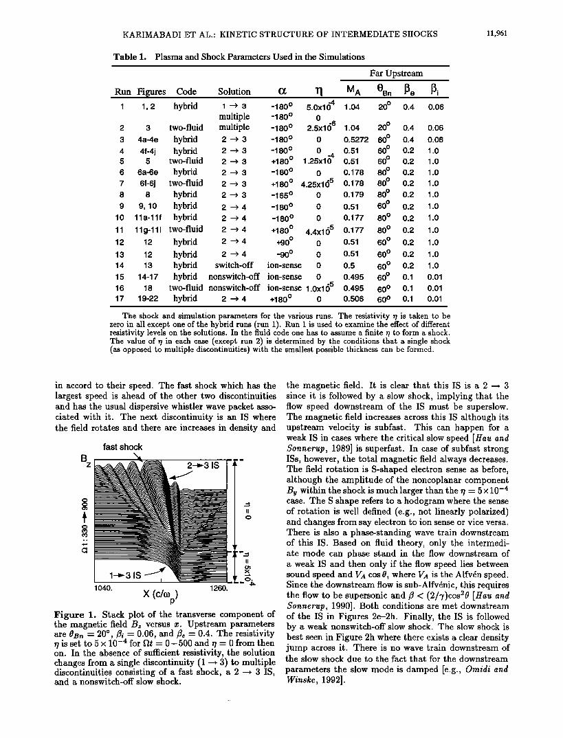
Table 1. Plasma and Shock Parameters Used in the Simulations
Run Figures Code Solution (g T l MA I 1, 2 hybrid I ---> 3 -180 ø 5.0x164 1.04
multiple -180 o 0 2 3 two-fluid multiple -180 ø 2.5x166 1.04 20 ø 0.4 0.06 3 4a-4e hybrid 2 -• 3 -180 ø 0 0.5272 60 ø 0.4 0.06 4 4f-4j hybrid 2 -• 3 -180 ø 0 -4 0.51 60 ø 0.2 1.0 5 5 two-fluid 2 -• 3 +180 ø 1.25x10 0.51 60 ø 0.2 1.0 6 6a-6e hybrid 2 -• 3 -180 ø 0 O. 178 80 ø 0.2 1.0 7 6f-6j two-fluid 2 -• 3 +180ø 4.25x165 0.178 80 ø 0.2 1.0 8 8 hybrid 2 -• 3 -165 ø 0 O. 179 80 ø 0.2 1.0 9 9, 10 hybrid 2 -• 4 -180 ø 0 0.51 60 ø 0.2 1.0
10 11a-11f hybrid 2 -• 4 -180 ø 0 0.177 80 ø 0.2 1.0 11 11g-111 two-fluid 2 -• 4 +180 ø 4.4x1155 0.177 80 ø 0.2 1.0 12 12 hybrid 2 -• 4 +90 ø 0 0.51 60 ø 0.2 1.0 13 12 hybrid 2 -• 4 -90 ø 0 0.51 60 ø 0.2 1.0 14 13 hybrid switch-off ion-sense 0 0.5 60 ø 0.2 1.0 15 14-17 hybrid nonswitch-off ion-sense 0 0.495 60 ø 0.1 0.01 16 18 two-fluid nonswitch-off ion-sense 1.0x165 0.495 60 ø 0.1 0.01 17 19-22 hybrid 2 -• 4 +180ø 0 0.506 60 ø O. 1 0.01
Far Upstream
OBn •e •i 20 ø 0.4 0.06
The shock and simulation parameters for the various runs. The resistivity r/is taken to be zero in all except one of the hybrid runs (run 1). Run 1 is used to examine the effect of different resistivity levels on the solutions. In the fluid code one has to assume a finite r/to form a shock. The value of r/in each case (except run 2) is determined by the conditions that a single shock (as opposed to multiple discontinuities) with the smallest possible thickness can be formed.
in accord to their speed. The fast shock which has the largest speed is ahead of the other two discontinuities and has the usual dispersive whistler wave packet asso- ciated with it. The next discontinuity is an IS where the field rotates and there are increases in density and
B
fast shock
2-•3 IS
1040. 1260.
X
II
0
Figure 1. Stack plot of the transverse component of the magnetic field B, versus x. Upstream parameters are OBn -- 20 ø, /•i -- 0.06, and/•, - 0.4. The resistivity r/is set to 5 x 10 -4 for •t = 0- 500 and r/- 0 from then on. In the absence of sufficient resistivity, the solution changes from a single discontinuity (1 -+ 3) to multiple discontinuities consisting of a fast shock, a 2 -+ 3 IS, and a nonswitch-off slow shock.
the magnetic field. It is clear that this IS is a 2 -+ 3 since it is followed by a slow shock, implying that the flow speed downstream of the IS must be superslow. The magnetic field increases across this IS although its upstream velocity is subfast. This can happen for a weak IS in cases where the critical slow speed [ttau and $onnerup, 1989] is superfast. In case of subfast strong ISs, however, the total magnetic field always decreases. The field rotation is S-shaped electron sense as before, although the amplitude of the noncoplanar component B v within the shock is much larger than the •/= 5 x 10 -4 case. The S shape refers to a hodogram where the sense of rotation is well defined (e.g., not linearly polarized) and changes from say electron to ion sense or vice versa. There is also a phase-standing wave train downstream of this IS. Based on fluid theory, only the intermedi- ate mode can phase stand in the flow downstream of a weak IS and then only if the flow speed lies between sound speed and V•t cos0, where V•t is the Alfvdn speed. Since the downstream flow is sub-Alfvdnic, this requires the flow to be supersonic and/3 < (2/?)cos20 [ttau and $onnerup, 1990]. Both conditions are met downstream of the IS in Figures 2e-2h. Finally, the IS is followed by a weak nonswitch-off slow shock. The slow shock is best seen in Figure 2h where there exists a clear density jump across it. There is no wave train downstream of the slow shock due to the fact that for the downstream
parameters the slow mode is damped [e.g., Oraidi and Winske, 1992].

11,962 KARIMABADI ET AL.' KINETIC STRUCTURE OF INTERMEDIATE SHOCKS
Hybrid Simulations
0.7 (a) 1'1 = 5xl (•4 (e) 1'1 = 0
I I I I I
fl t = 330 fit = 900
(b)
Bø'7 t z
(c)
B 1'2 f tot ß
0.9
1.7
0.9
(f)
' ' ' ' -I •'••1-3,S tt -'' •-•2-3,S
' ' ql- ' 4
(d)
fast shock
Figure 2. The spatial profile of the shock solutions for two values of resistivity for the same parameters as in Figure 1. The two transverse components of the magnetic field, the total magnetic field, and the plasma density are shown as a function of x. All quantities are normalized to their value far upstream. The slow shock is best seen through its signature in density (N).
The question that naturally arises is whether the formation of the multiple discontinuities is a byprod- uct of the breakup of the i -• 3 IS or the favored state that would form if we start the simulation with
a small resistivity. To address this question, we have performed both a two-fluid and a hybrid simulation for the same parameters as in Figure 2 except that now r/- 2.5 x 10 -6 during the entire run. The hybrid run with this resistivity is identical to that in Figures 2e-2h and is not shown.
The results of the fluid simulation are shown in Fig- ure 3 (run 2 in Table 1). The inertial scale length is much larger (a factor of 110) than the resistive scale length and the solution is dominated by dispersion ef- fects with slowly damped wave trains. The fluid so- lution shows a striking resemblance to the kinetic run in Figure 2 with r/ - 0. Note that the upstream ion beta is very small (0.06). The similarity between the r/= 0 hybrid simulation and the fluid simulation with r/ - 2.5 x 10 -6 shows that the effective resistivity in the two cases is very similar. The only major difference is the presence of a phase-standing wave train down- stream of the slow shock in the fluid solution while the
wave train is Landau damped in the kinetic case [Omidi and Winske, 1992]. This is due to the absence of a Landau-damping mechanism in the fluid code.
From the above it is clear that whether a single or multiple discontinuities are formed depends on the amount of dissipation (either generated kinetically or imposed through r/) present in the system. Another important implication of the above simulations is the fact that the Riemann problem as posed in the piston method is not unique. In other words, the downstream
state in the low- and high-r/cases are not the same. In the high-r/case the downstream flow speed is superslow while in the low-r/case the downstream corresponds to that of a slow shock and is thus subslow. Note that in
Two-Fluid Simulation -6
(a) rl = 2.5x10 •t = 550
0.7 (b)• , , , " 2-3 IS
z
-0.7 ,,A•.-- -
tot
0.9 •
0.9
x (c/%) Figure 3. The formation of multiple discontinuities using the two-fluid code for the same parameters as in Figure i except that r/- 2.5 x 10 -6 throughout the run. The main difference between the kinetic (Figures 2a- 2d) and the fluid solution is the absence of the coherent wave train downstream of the slow shock in the kinetic case.
KARIMABADI ET AL.: KINETIC STRUCTURE OF INTERMEDIATE SHOCKS 11,963
the usual Riemann problem all plasma quantities in the upstream and downstream are specified whereas in the piston method only the two transverse components of the magnetic field are set at the piston. Although the upstream condition is fixed and the magnetic field at the piston is set to the same value in the above simu- lations, the speed of the solution(s) is not imposed in the simulation. It is this degree of freedom that can re- sult in formation of different discontinuities for the same
boundary conditions (but different resistivity) imposed in the piston method.
5. Weak Intermediate Shock
In this section we examine the stability and structure of both coplanar and noncoplanar weak ISs within the context of both kinetic and two-fluid theories.
5.1. Coplanar
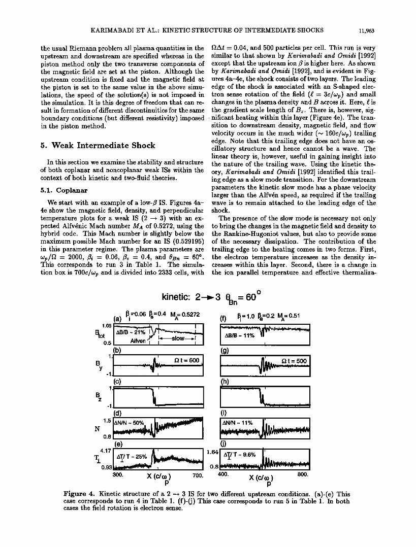
We start with an example of a low-/? IS. Figures 4a- 4e show the magnetic field, density, and perpendicular temperature plots for a weak IS (2 -• 3) with an ex- pected Alfv•nic Mach number M,• of 0.5272, using the hybrid code. This Mach number is slightly below the maximum possible Mach number for an IS (0.529195) in this parameter regime. The plasma parameters are wp/• = 2000, /•i = 0.06, fie = 0.4, and OB,• = 60 o . This corresponds to run 3 in Table 1. The simula- tion box is 700c/wp and is divided into 2333 cells, with
flat = 0.04, and 500 particles per cell. This run is very similar to that shown by Karimabadi and Omidi [1992] except that the upstream ion/? is higher here. As shown by Karimabadi and Omidi [1992], and is evident in Fig- ures 4a-4e, the shock consists of two layers. The leading edge of the shock is associated with an S-shaped elec- tron sense rotation of the field (œ = 3c/wp) and small changes in the plasma density and B across it. Here, œ is the gradient scale length of Bz. There is, however, sig- nificant heating within this layer (Figure 4e). The tran- sition to downstream density, magnetic field, and flow velocity occurs in the much wider (~ 160c/•p) trailing edge. Note that this trailing edge does not have an os- ciliatory structure and hence cannot be a wave. The linear theory is, however, useful in gaining insight into the nature of the trailing wave. Using the kinetic the- ory, Karimabadi and Omidi [1992] identified this trail- ing edge as a slow mode transition. For the downstream parameters the kinetic slow mode has a phase velocity larger than the Alfv•n speed, as required if the trailing wave is to remain attached to the leading edge of the shock.
The presence of the slow mode is necessary not only to bring the changes in the magnetic field and density to the Rankine-Hugoniot values, but also to provide some of the necessary dissipation. The contribution of the trailing edge to the heating comes in two forms. First, the electron temperature increases as the density in- creases within this layer. Second, there is a change in the ion parallel temperature and effective thermaliza-
1.05
Btot 0.5
1
B
kinetic: 3 0Bn
N
600
(c)
_ _
AN/N-50% , f (d)
(f) • = 1.o I•e--0.2 MA= 0.51
zXB/B ~ 11ø/• I
(g) flt = 500
1.5
(e) 4.171 ' •' I
T. IAT',IT ~ 25ø/ø J'[.,•.•d••.... ..... I
300. X (C/Q)) 700. p
(h)
o) J z•l/U- 11% r,
d) 1.64
0.8
400. 800. x (c/a))
p
l•igure 4. Kinetic structure of a 2 -• 3 IS for two different upstream conditions. (a)-(e) This case corresponds to run 4 in Table 1. (f)-(j) This case corresponds to run 5 in Table 1. In both cases the field rotation is electron sense.

11,964 KARIMABADI ET AL.: KINETIC STRUCTURE OF INTERMEDIATE SHOCKS
tion of the plasma due to the slow mode. The ion dis- tribution function immediately behind and ahead of the leading edge of the shock is bi-Maxwellian (not shown), with no appreciable change in the parallel temperature. However, the distribution function evolves toward a sin- gle Maxwellian as one moves downstream of the leading edge and within the trailing edge. Immediately after the trailing edge the distribution function is a Maxwellian with a thermal spread larger than its upstream value and close to that required by the Rankine-Hugoniot condition. Thus, the dissipation process in the shock occurs in two steps. The leading edge heats the plasma in the perpendicular direction and the slow mode trail- ing edge heats the plasma in the parallel direction. The fact that there is only parallel heating associated with the trailing edge is consistent with the linear theory re- sult that the slow mode is Landau damped.
The presence of the bi-Maxwellian distribution, con- sisting of backstreaming ions and the incoming plasma, gives rise to the generation of wave activity upstream of the shock by the electromagnetic ion/ion cyclotron in- stability [Winske and Omidi, 1992]. In the present case these waves have very small amplitudes and are barely noticeable in Figure 4b. Another effect of the back- streaming ions is to reduce the shock speed (0.495- 0.5VA) to below that expected from Rankine-Hugoniot relations (0.5272VA). As a result, the shock speed alone cannot always be used to distinguish between the vari- ous shocks in kinetic plasmas [Karimabadi and Omidi, 1•].
The presence of a wave train downstream of the weak IS in Figure 4b may at first seem puzzling. The down- stream/3 is 1.7 which clearly violates the fluid condition /3 < (2/?)cos20 [e.g. Hau and $onnerup, 1990] for the presence of a wave train downstream of a weak IS. In order to resolve this issue let us recall the two conditions
necessary for a wave to phase stand in the flow. One is that the wave phase speed must be equal to the plasma flow speed. The other condition is that the group ve- locity be larger than the phase velocity if the wave is standing at the upstream edge or the group velocity be smaller than the phase speed if the wave is stand- ing at the downstream edge [e.g., Kennel et al., 1985]. In Hall MHD the ratio of group to phase velocity for the intermediate mode changes from smaller than one to larger than one depending on whether /3 is smaller or larger than (2/?)cos20 [e.g., Krauss-Varban et al., 1994, equation (A37)]. In kinetic theory, however, the mode properties are quite different from those in Hall MHD. We have checked the kinetic dispersion of the A/IC mode (Alfvdn ion cyclotron) downstream of the weak IS in Figure 4b and have found that its group ve- locity is indeed smaller than the phase velocity at the observed wavelength.
One of the important shock quantities is its width and, in case of ISs, the scale length over which rota- tion of the magnetic field occurs. The latter scale is of special importance as it can be compared with the measured thickness of the rotation layer at the magne- topause. The gradient scale length (œ) of Bz for the
above IS was found to be 3c/wp with no measureable change in time. In fact, aside from a small spread in the trailing wave, the structure as a whole is time sta- tionary. Also, there appears to be no separation of the two transition regions even after ftt= 600.
The fact that the above IS consists of two layers raises the question of whether it can be thought of a single dis- continuity or is it more like the multiple solution shown in Figures i and 2. Let us first consider the latter pos- sibility. Given that slow shocks can be quite broad in a high-/3 plasma, it may seem plausible that the leading edge of the shock is a weak IS and the trailing edge is a slow shock analogous to the multiple solution in Fig- ures i and 2. There is, however, one important differ- ence between the multiple solutions in Figure i and the solution in Figures 4a-4e. The former does not satisfy the Rankine-Hugoniot condition for a single IS, whereas the latter does. Furthermore, we have made several runs similar to that in Figures 4a-4e but with finite values of ?. As ? is increased, the only major change is that the slow mode transition layer becomes thinner and eventually disappears. But the downstream state remains the same, in sharp contrast to that in Figure 1. This also indicates that the presence of the slow mode is necessary because the Alfv•nic leading edge cannot pro- vide enough dissipation in a collisionless plasma. Note that for the parameters of Figure 1, the downstream slow speed is slower than the Alfv•n speed at all wave- lengths. Thus, a solution similar to that in Figures 4a- 4e, where a slow mode transition layer stays attached to the Alfv•nic leading edge, is not possible for parameters of Figure 1, resulting in formation of multiple disconti- nuities. Finally, there exists a deHoffman-Teller frame where the electric field both upstream and downstream of the discontinuity in Figures 4a-4e is zero.
We thus conclude that the discontinuity inFigures 4a- 4e is a time stationary weak IS, with the reservation that the downstream flow speed is below the slow speed based on kinetic theory (but above the MHD slow speed).
Figures 4f-4j show the weak IS for a higher plasma /3, a larger ratio of ion to electron temperature and a smaller Mach number. The maximum Mach number
for an IS changes from 0.529195 for parameters of Fig- ures 4a-4e to 0.516921 for the present case. We have chosen a Mach number below the maximum to make
sure we are not too close to the strong IS solution. The jumps in density, temperature and magnetic field are smaller than the low-/3 case, consistent with the lower Mach number in this case. Note the absence of the
slow mode transition region in this case. The upstream- generated waves are also absent, but the Alfv•nic down- stream wave train is now much more pronounced. The condition for the formation of wave trains in a kinetic
plasma is discussed below. The sense of rotation is elec- tron sense (S-shaped) and the gradient scale of Bz is 3c/wp, which is the same as that for the low-/3i case in Figures 4a-4e. Thus, the gradient scale length of the ro- tational layer has not changed even though the plasma /3 is a factor of 2.6 larger and the ion/3 is larger by a

KARIMABADI ET AL.: KINETIC STRUCTURE OF INTERMEDIATE SHOCKS 11,965
Two-Fluid Simulation
2--• 3 M = 0.51 OBn = 60 ø (a) A
1.0 f Btot 0.5
(b)
- f• t = 600
By -1.
(c)
-1.
(d)
N 1'5 l ' 0.8
1090. X (c / •p) 1320. FJgure 5. •wo-•uid so]ufio• of
the co•es•o•di• •J•efic so]ufio• i• YJ•u•es 4f-4j.
factor of 16. This is in sharp contrast to the predictions of fluid theory where the shock thickness is a sensitive function of plasma/3 [e.g., ttau and $onnerup, 1992]. The measured Mach number is-,• 0.45- 0.46, which is smaller than that expected from Rankine-Hugoniot condition (0.51). The reason is the presence of back- streaming ions which carry energy and momentum away from the shock. We have also made a run for the same
parameters as those in run 4 but with an ion sense of ro-
tation. Since the solution is very similar to that shown in Figures 4f-4j, we will not show it here.
The fluid counterpart (run 5) to the kinetic solution of run 4 (Figures 4f-4j) is shown in Figure 5. The re- sistivity is r/ = 1.25 x 10 -4, which implies a resistive length comparable to the ion inertial scale. Although the jumps in the plasma parameters are almost identical in the two cases, there are important differences in the structure of the fluid versus the kinetic solution. The
shock speed is faster (0.51 compared to 0.45), the un- dershoot in/3tot is larger, and the size of/3y within the shock is much smaller than the kinetic case. In addition, the gradient scale length of/3z is 13 in the fluid solution, which is much larger than that in the kinetic solution (3c/wp). Some of the other differences between the ki- netic and fluid solutions are related to the wave activity downstream. There exists no downstream wave train in
Figure 5. As we mentioned earlier, in fluid theory there can be no phase-standing wave train downstream of a weak IS unless the flow speed lies between sound speed and vA cos0, that is, /3 < (2/7)cos20. This condition is clearly not satisfied in this case where downstream plasma/3 is 1.9. The absence of the wave train up- stream of the IS in Figure 5 is due to the relatively large resistivity used here. Due to the many differences between kinetic and fluid solutions, we conclude that fluid theory is not valid in this regime.
Since the typical OBn at the magnetopause is in the range of 750 to 850 [e.g., Paschmann et al., 1986], we have also performed several simulations at 0•n = 80 ø. Figures 6a-6e show the kinetic solution for a 2 -• 3 IS, with an expected Mach number of MA = 0.178, 0• = 80 ø, fii = 1, /3• = 0.2, and wp/i2 = 4000. This case corresponds to run 6 in Table 1. The simulation
2--•3 M=0.178 A
o 0 = 80
Bn
t
(a) Kinetic
1.1 o.1
(b)
By 1. '1.
(c)
-1.
(d)
N 1.5 0.5
(e)
680. X (c / COp) 775.
Two-Fluid (f)
(g)
i i i
(h)
i I i
o)
i i i
•)
1310. X (c / (Op) 1410. Figure 6. Comparison of kinetic and two-fluid solutions of a 2 -• 3 IS for parameters of runs 6 and 7 in Table 1.

11,966 KARIMABADI ET AL- KINETIC STRUCTURE OF INTERMEDIATE SHOCKS
box is 900c/wp and is divided into 1800 cells with 600 particles per cell. The time step is flat - 0.02.
The gradient scale length of Bz is 1.5C/Wp which is to be compared with 3C/Wp at OBn -- 60 ø. The field rota- tion has also changed from a S-shaped electron sense hodogram at OBn - 600 to a simple electron sense field rotation plus an overshoot. After Bz has changed sign and By has become zero, the field continues rotat- ing with B• going through 0 one more time before fi- nally settling down to its downstream value (Figure 6c). There is a wave train upstream of the shock, whereas the wave train is downstream at 0is• - 60 ø. The pres- ence of the wave train and whether it is upstream or downstream is an intricate function of the kinetic mode
properties and the shock speed, both of which are af- fected by the presence of backstreaming ions. This makes the predictions regarding the wave train difficult in a kinetic plasma. The linear kinetic theory can, how- ever, be a useful guide and provides a limited predictive power.
Figures 7a and 7b show the variation of the normal component of group velocity and the phase velocity, re- spectively, of the A/IC mode with the wavenumber, at two values of propagation angle and for fii - 1.0, /•e - 0.2, and wp/f] - 4000. The range in k values cor- responds to the typical wavelength of the wave trains seen in the weak IS solutions (Figures 4 and 6). At 0 - 60 ø, both the phase and (normal component of) group velocities of the A/IC mode are smaller than V•t cos 0. Furthermore, the group velocity is smaller than the phase velocity. The increase in the group ve- locity beyond k ~ 0.75 is in the region where damping of the A/IC mode is starting to become large. Thus, there cannot be an Alfvdnic wave train upstream of an IS in this case. The dispersion changes dramatically at
V•x VACOSO
Vph VACOSO
1.2
1.0
0.5
1.1
1.0
0.7
(a)
O=6(f• I I I
(b)
- I I I I O. ck/• 1.
P
Figure 7. Dispersion properties of A/IC mode at two different propagation angles. /•i = 1., /•e - 0.2, and wp/[2 = 4000. (a) Normal component of the group ve- loc.ity versus wavenumber. (b) Phase velocity versus wavenumber.
0 - 800 where the A/IC mode has anomalous disper- sion (group velocity is larger than the phase velocity) and both the group and phase velocities are larger than V,• cos 0. Thus, we expect the wave train to be down- stream at 0- 60 o and upstream at 0- 80 ø, consistent with the simulation results (Figures 4g and 6b). The wave train in Figure 6b is very close to, but not ex- actly, phase standing. We attribute this to the fact that as apparent from Figure 7b, the phase velocity for the observed wavenumber of the wave train (k ,-, 0.75) in Figure 6b is slightly above V,• cos 0. On the other hand, the shock speed is actually slightly less (0.17- 0.174) than V,• cos0 due to the presence of the backstream- ing ions. This leads to a very small difference in phase speed between the shock and the wave train. Linear kinetic theory can also be used to explain the presence and properties of the wave trains at RDs. We refer the reader to paper 2 for a detailed discussion of wave trains at RDs.
Figures 6f-6j show the two-fluid solution (run 7 in Table 1) for the same parameters as in the kinetic run in Figures 6a-6e. The simulation box is 1500c/03p and is divided into 3000 cells with •/ - 4.25 x 10 -5. As in the OBn -- 600 case, there are large differences be- tween the fluid and kinetic solutions. One of the most
important differences is in the scale length over which the field rotates. The fluid solution has a gradient scale length of 10C/Wp which is much larger than the typical magnetopause thickness. This is consistent with ear- lier findings of Hau and Sonnerup [1992], but at variant with the scale length of 1.5c/O3p predicted by the kinetic solution. Thus the possibility that the field rotations at the magnetopause may be ISs cannot be ruled out based on the thickness of ISs. Another point to note in Figure 6 is that while the small jumps in density (N2/N1 - 1.124) and magnetic field (B2/B1 - 0.7847) across the IS can be measured in our simulations, they may be too small to measure in the observations. We emphasize that aside from these small jumps, the sig- natures of the ISs shown in Figures 4f-4j and 6 are very similar to the corresponding RDs (see Figures 8 and 9 in paper 2). From our point of view, in the coplunar cases an RD can be thought of as a limiting case of a weak IS. Since both RDs and ISs are stable and a weak
IS solution goes smoothly into an RD as the interme- diate Much number is reduced to unity, the question of whether the coplunar rotations at the magnetopause are RDs or ISs becomes a moot point. The real distinc- tion between RDs and ISs comes into full play in the noncoplanar cases where RDs are stable and ISs are expected to be time dependent.
5.2. Noncoplanar
It is well known that when the magnetic fields up- stream and downstream of a shock are noncoplanar, there can be no time-independent shock solutions, that is, the Rankine-Hugoniot relations cannot be satisfied. On the other hand, the above coplanarity theorem does not apply to RDs, across which the rotation of the com- ponent of the magnetic field tangent to the shock front
KARIMABADI ET AL.' KINETIC STRUCTURE OF INTERMEDIATE SHOCKS 11,967
can be arbitrary. It was thus argued by Kantrowitz and Petschek [1966] that the intermediate shock is an iso- lated Rankine-Hugoniot solution with no neighboring solution and they would disintegrate into an RD in the presence of small perturbations away from coplanarity. However, Wu [1988] showed, using resistive MHD the- ory, that there exists a new class of time-dependent shocklike structures (the so called time-dependent in- termediate shock) which do not obey RH conditions since they violate coplanarity. They are the neigh- boring states of the coplanar intermediate shocks. Be- cause of their existence, the argument of Kantrowitz and Petschek [1966] does not apply. The time-dependent ISs were shown to evolve self-similarly in time, with their strength decreasing as 1/(t) •/2 and its width increasing as (t) •/• [e.g., Wu and Kennel, 1993], approaching the RD limit at large time.
The properties of noncoplanar ISs in a collisionless plasma are of great interest for two reasons. First, the existence of coplanar ISs is ultimately tied to the presence of noncoplanar neighboring solutions as ar- gued above. Secondly, the magnetic field rotation at the magnetopause is generally less than 180 ø, and thus the existence of time-dependent ISs is of direct relevance to the understanding of the magnetopause.
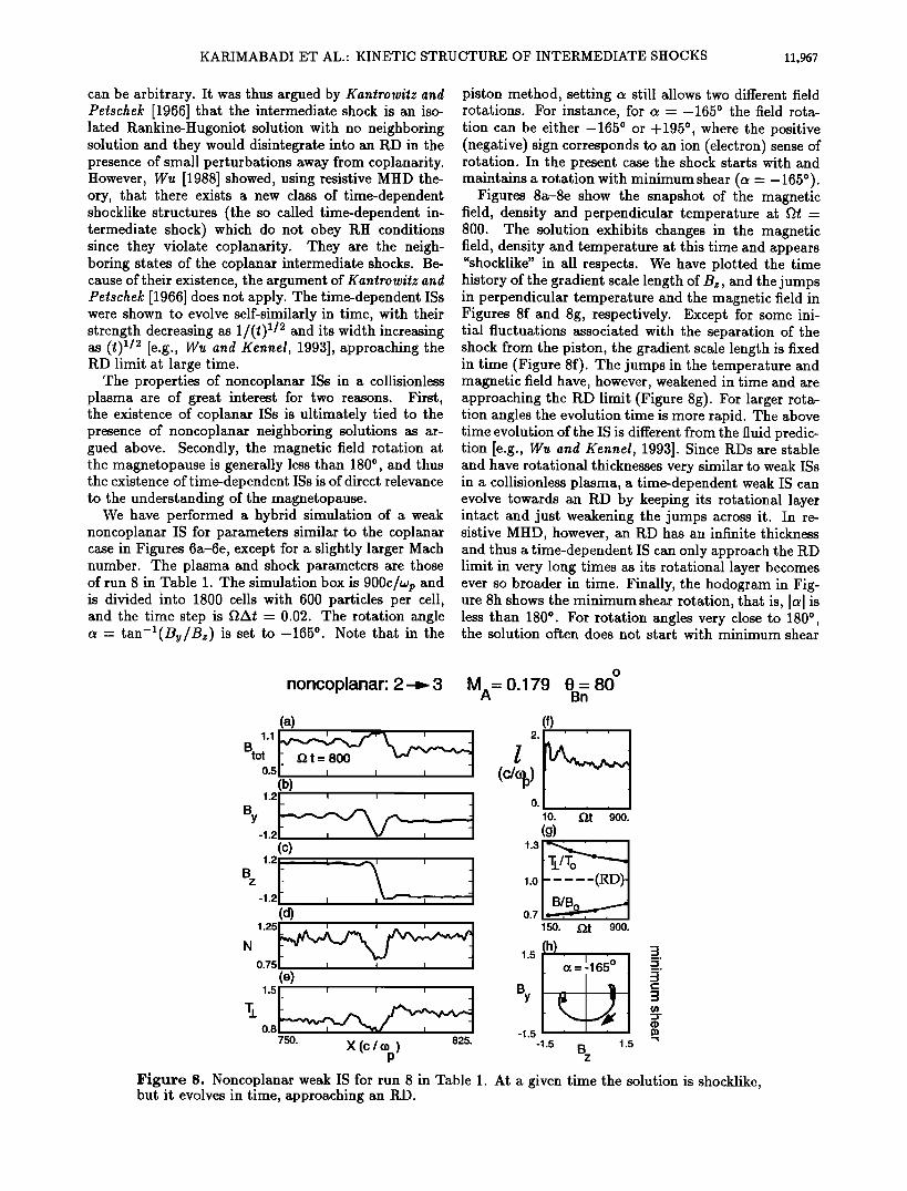
We have performed a hybrid simulation of a weak noncoplanar IS for parameters similar to the coplanar case in Figures 6a-6e, except for a slightly larger Mach number. The plasma and shock parameters are those of run 8 in Table 1. The simulation box is 900C/Wp and is divided into 1800 cells with 600 particles per cell, and the time step is •At = 0.02. The rotation angle c• = tan-i(By/Bz) is set to -165 ø. Note that in the
piston method, setting c• still allows two different field rotations. For instance, for c• = -1650 the field rota- tion can be either -1650 or +1950 , where the positive (negative) sign corresponds to an ion (electron) sense of rotation. In the present case the shock starts with and maintains a rotation with minimum shear (c• - - 165 ø).
Figures 8a-8e show the snapshot of the magnetic field, density and perpendicular temperature at •t - 800. The solution exhibits changes in the magnetic field, density and temperature at this time and appears "shocklike" in all respects. We have plotted the time history of the gradient scale length of Bz, and the jumps in perpendicular temperature and the magnetic field in Figures 8f and 8g, respectively. Except for some ini- tial fluctuations associated with the separation of the shock from the piston, the gradient scale length is fixed in time (Figure 8f). The jumps in the temperature and magnetic field have, however, weakened in time and are approaching the RD limit (Figure 8g). For larger rota- tion angles the evolution time is more rapid. The above time evolution of the IS is different from the fluid predic- tion [e.g., Wu and Kennel, 1993]. Since RDs are stable and have rotational thicknesses very similar to weak ISs in a collisionless plasma, a time-dependent weak IS can evolve towards an RD by keeping its rotational layer intact and just weakening the jumps across it. In re- sistive MHD, however, an RD has an infinite thickness and thus a time-dependent IS can only approach the RD limit in very long times as its rotational layer becomes ever so broader in time. Finally, the hodogram in Fig- ure 8h shows the minimum shear rotation, that is, Ic•l is less than 180 ø. For rotation angles very close to 180 ø, the solution often does not start with minimum shear
noncoplanar: 2 3 o
MA= 0.179 0 - 80 Bn
(a) (0 ,
1.1 L,,-,•'• • ' / 2. ' ' '
0'5(b ) (C/Oi•) By 0. 10. glt 900.
-1. (g)
(c) ,.o I Tj.To 1.2• •, • • , .
(d) 0.• B/•Bø•
1.a•• 1•0. •t •00, N 1.• •h) 0.75
1.5••.•/•, ,//.•.,•• By 0.8
-1.5
750. X (C ! O)p) 825. _.
(x = 65 ø
i i
.5 B 1.5 z
Figure 8. Noncoplanar weak IS for run 8 in Table 1. At a given time the solution is shocklike, but it evolves in time, approaching an RD.

11,968 KARIMABADI ET AL ß KINETIC STRUCTURE OF INTERMEDIATE SHOCKS
but in all cases that we have examined such solutions are not stable and evolve to a minimum shear state in
a short timescale ( • 100f•- •). This explains why rota- tions at the magnetopause always satisfy the minimum shear condition (see also the discussion in paper 2).
6. Strong Intermediate Shock
One peculiarity of ISs is that for the same upstream conditions an IS can have two different downstream
states. In one case the downstream flow velocity is be- low the slow speed (2 -• 4) and is referred to as a strong IS. In the other case the flow is superslow, correspond- ing to a weak IS (2 -• 3). In this section we examine the structure and stability of strong ISs for both coplanar and noncoplanar rotations.
6.1. Coplanar
The resistive structure of a subfast strong IS is not unique and is bounded by two extreme cases [e.g., Ha•, and $onnerup, 1989]. At one extreme it consists of • weak IS followed by a slow shock. At the other extrem• it has By -- 0 throughout the transition layer. The infinite number of possible shock solutions make the piston method advantageous over a relaxation method where the shock structure has to be initialized in the simulations.
Figure 9 shows the magnetic field, density and per- pendicular temperature of a strong IS at f•t -- 500 from a hybrid run. The parameters correspond to run 9 in Table 1. The simulation box is 800c/wp and is divided into 1600 cells, with 800 particles per cell and a timestep of f•At -- 0.02. Note that the weak IS in Figures 9f-9j has the same upstream condition.
There are fairly monochromatic waves upstream of the shock which are clearly visible in By (Figure 9b) but not in Bz (Figure 9c). We have verified, using linear ki- netic theory, that these waves fall on the A/IC branch and are generated by the relative streaming between backstreaming ions and the incoming plasma. There is also some wave activity downstream but the waves are much less coherent. We will discuss the origin of these waves below. Another peculiar behavior of this shock is the fact that there is almost no change in By within the shock (Figure 9b). The jumps in density (Figure 9d) and perpendicular temperature (Figure 9e) are quite sharp and occur where Bz changes sign. The small in- crease in density from the upstream value starting at ~ 430c/wp to right before where the proper jump in density occurs is due to the backstreaming ions (Figure 9d). These ions also lead to a long foot in the magnetic field (Figure 9a). Figures 9f-9h show the ion distribu- tion function represented as grey scale as well as contour levels (0.1, 0.3, 0.5, and 0.7) at several regions marked with I, II, and III and shaded in Figure 9a, accordingly. The two axes are the parallel velocity and the compo- nent of the perpendicular velocity in the x-z plane. Since the distribution function is gyrotropic we do not show the ion distribution as a function of the second
component of perpendicular velocity. Far upstream (re-
o
2--•4 MA=0.51 0B;60 (a) I II III
tot 0.51 •
(b) 1, Alfven
-1. • t = 500. (c)
(d)
0.8 (e)
0.86
X (c / 800. I (g) II (h) III
•l • ' - .... • .... ":•':• ••••:••" -•. _ , . ...............................................................
-2. 2. -2. 2. -2. 2.
figure 9, Strong IS for run 9 in Table 1. The upstream conditions are the same • the weak IS in Figures 4f-4j.
gion I) the ion distribution consists of two distinct pop- ulation of an incoming plasma and the backstreaming (both shock-reflected and leaked from downstream) ions (Figure 9f). The parallel velocity of the backstreaming ions is close to 2VA. Closer to the shock (region II), the relative •umber of backstreaming ions to the incom-
jing plasma increases (Figure 9g) and the mean paral- lel velocity of the backstreaming ions becomes smaller than 2VA. Immediately after the shock (region III), the plasma becomes thermalized (Figure 9h). The dis- tribution functions in Figures 9f-9h show some resem- blance to the observed distribution function at the mag- netopause [e.g., Fuselief, 1994]. In particular, the large number of backstreaming ions is consistent with the ob- servation of ~ 30% reflected ions and a substantial ion
heat flow away from the magnetopause current layer [e.g., Paschmann, 1984; Fuselief, 1994]. Although the qualitative agreement between the simulated and ob- served distributions is suggestive that the origin of the reflected ions may be linked to the presence of a strong IS at the magnetopause, additional studies are required to fully test this idea.
One important consequence of the backstreaming ions is the generation of upstream waves which are then convected back into the shock. This is shown in Fig-
KARIMABADI ET AL.: KINETIC STRUCTURE OF INTERMEDIATE SHOCKS 11,969
4 M A- 0.51 0 - 60 Bn
(a)
(b) ._ -. %. ......
'
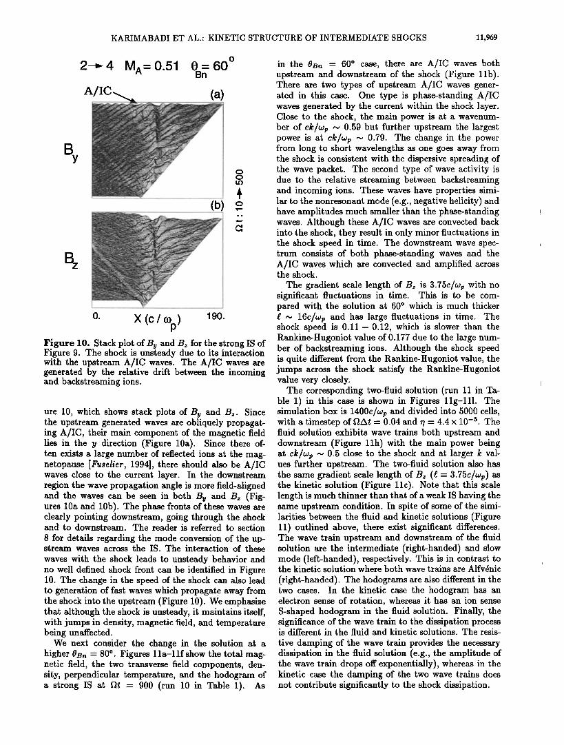
,, 0. x (c / %) Figure 10, Stack plot of B• and Bz for the strong IS of Figure 9. The shock is unsteady due to its interaction with the upstream A/IC waves. The A/IC waves are generated by the relative drift between the incoming and backstreaming ions.
ure 10, which shows stack plots of Bu and Bz. Since the upstream generated waves are obliquely propagat- ing A/IC, their main component of the magnetic field lies in the y direction (Figure 10a). Since there of- ten exists a large number of reflected ions at the mag- netopause [Fuselief, 1994], there should also be A/IC waves close to the current layer. In the downstream region the wave propagation angle is more field-aligned and the waves can be seen in both Bu and Bz (Fig- ures 10a and 10b). The phase fronts of these waves are clearly pointing downstream, going through the shock and to downstream. The reader is referred to section
8 for details regarding the mode conversion of the up- stream waves across the IS. The interaction of these
waves with the shock leads to unsteady behavior and no well defined shock front can be identified in Figure 10. The change in the speed of the shock can also lead to generation of fast waves which propagate away from the shock into the upstream (Figure 10). We emphasize that although the shock is unsteady, it maintains itself, with jumps in density, magnetic field, and temperature being unaffected.
We next consider the change in the solution at a higher 0B• = 80 ø. Figures 1 la-1 if show the total mag- netic field, the two transverse field components, den- sity, perpendicular temperature, and the hodogram of a strong IS at fit = 900 (run 10 in Table 1). As
in the 0B• = 60 ø case, there are A/IC waves both upstream and downstream of the shock (Figure lib). There are two types of upstream A/IC waves gener- ated in this case. One type is phase-standing A/IC waves generated by the current within the shock layer. Close to the shock, the main power is at a wavenum- ber of ck/wp ... 0.59 but further upstream the largest power is at ck/wp ... 0.79. The change in the power from long to short wavelengths as one goes away from the shock is consistent with the dispersive spreading of the wave packet. The second type of wave activity is due to the relative streaming between backstreaming and incoming ions. These waves have properties simi- lar to the nonresonant mode (e.g., negative helicity) and have amplitudes much smaller than the phase-standing waves. Although these A/IC waves are convected back into the shock, they result in only minor fluctuations in the shock speed in time. The downstream wave spec- trum consists of both phase-standing waves and the A/IC waves which are convected and amplified across the shock.
The gradient scale length of B• is 3.75c/wp with no significant fluctuations in time. This is to be com- pared with the solution at 60 ø which is much thicker œ ... 16c/wp and has large fluctuations in time. The shock speed is 0.11- 0.12, which is slower than the Rankine-Hugoniot value of 0.177 due to the large num- ber of backstreaming ions. Although the shock speed is quite different from the Rankine-Hugoniot value, the jumps across the shock satisfy the Rankine-Hugoniot value very closely.
The corresponding two-fluid solution (run 11 in Ta- ble 1) in this case is shown in Figures 11g-111. The simulation box is 1400c/wp and divided into 5000 cells, with a timestep of fiat = 0.04 and • = 4.4 x 10 -3. The fluid solution exhibits wave trains both upstream and downstream (Figure 11h) with the main power being at ck/wp ,-,., 0.5 close to the shock and at larger k val- ues further upstream. The two-fluid solution also has the same gradient scale length of Bz (œ = 3.75c/wp) as the kinetic solution (Figure 11c). Note that this scale length is much thinner than that of a weak IS having the same upstream condition. In spite of some of the simi- larities between the fluid and kinetic solutions (Figure 11) outlined above, there exist significant differences. The wave train upstream and downstream of the fluid solution are the intermediate (right-handed) and slow mode (left-handed), respectively. This is in contrast to the kinetic solution where both wave trains are Alfvdnic
(right-handed). The hodograms are also different in the two cases. In the kinetic case the hodogram has an electron sense of rotation, whereas it has an ion sense S-shaped hodogram in the fluid solution. Finally, the significance of the wave train to the dissipation process is different in the fluid and kinetic solutions. The resis-
tive damping of the wave train provides the necessary dissipation in the fluid solution (e.g., the amplitude of the wave train drops off exponentially), whereas in the kinetic case the damping of the two wave trains does not contribute significantly to the shock dissipation.
11,970 KARIMABADI ET AL.' KINETIC STRUCTURE OF INTERMEDIATE SHOCKS
o
2-4 M^=0.177 0B=n80
Btot
B Y
B
(a) kinetic
(b)
' ' ß
(c) 1.2.L
(d)
1.45 0.8
(e)
150. X (c / r•p) 400. (f) , ,
y Y •) • i i
B B z z
(g) Two-Fluid
(h)
0)
(J)
1150. X (c / e)p) 1400. (I)
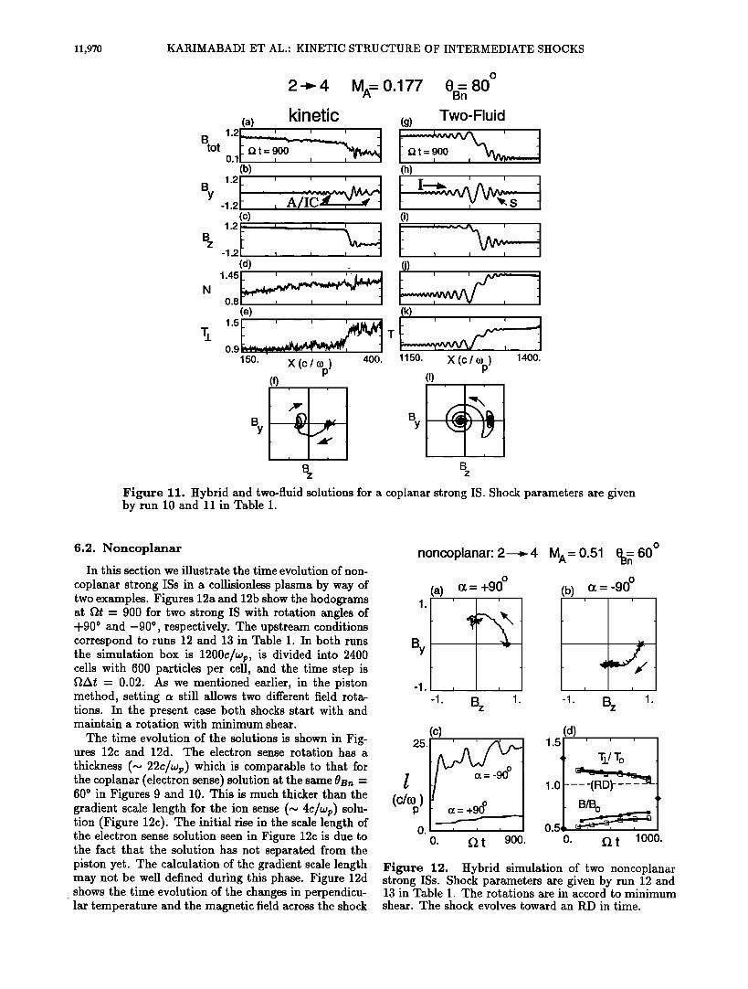
Figure 11. Hybrid and two-fluid solutions for a coplanar strong IS. Shock parameters are given by run 10 and 11 in Table 1.
6.2. Noncoplanar
In this section we illustrate the time evolution of non-
coplanar strong ISs in a collisionless plasma by way of two examples. Figures 12a and 12b show the hodograms at •t = 900 for two strong IS with rotation angles of -t-900 and -900 , respectively. The upstream conditions correspond to runs 12 and 13 in Table 1. In both runs the simulation box is 1200c/wp, is divided into 2400 cells with 600 particles per cell, and the time step is [2At = 0.02. As we mentioned earlier, in the piston method, setting c• still allows two different field rota- tions. In the present case both shocks start with and maintain a rotation with minimum shear.
The time evolution of the solutions is shown in Fig- ures 12c and 12d. The electron sense rotation has a
thickness (~ 22c/wp) which is comparable to that for the coplanar (electron sense) solution at the same OBn = 600 in Figures 9 and 10. This is much thicker than the gradient scale length for the ion sense (~ 4c/wp) solu- tion (Figure 12c). The initial rise in the scale length of the electron sense solution seen in Figure 12c is due to the fact that the solution has not separated from the piston yet. The calculation of the gradient scale length may not be well defined during this phase. Figure 12d shows the time evolution of the changes in perpendicu- lar temperature and the magnetic field across the shock
noncoplanar: 2---,- 4
By
-1.
(a) 0• = +90 ø i i
MA= 0.51 OS•60 ø (b) a = '90ø
-1. Bz 1l -1. Bz 1.
25.
l
O,
(c)
O• = +90 ø
o. • t 900.
(d)
[ B/B o
o. ½z t lOOO.
Figure 12. Hybrid simulation of two noncoplanar strong ISs. Shock parameters are given by run 12 and 13 in Table 1. The rotations are in accord to minimum shear. The shock evolves toward an P•D in time.

KARIMABADI ET AL.' KINETIC STRUCTURE OF INTERMEDIATE SHOCKS 11,971
as normalized to their upstream values, for both ion (marked with squares) and electron sense (marked with filled-in circles) rotations. The two diamond charac- ters on the y axis (Figure 12d) at fit - 0 indicate the Rankine-Hugoniot values for changes in Tñ and Btot across the shock. The diamond character on the far
right indicates the drop in the total magnetic field that occurs in the foot (before the proper jump in Btot at the shock) due to the presence of back•treaming ions. Since particles are injected from the left wall and re- flected from the right wall (piston), there will always be backstreaming ions in the present setup. Thus when the solution goes into an RD, the change in B normalized to the upstream value will be as shown by the diamond but the jump in B across the RD will be zero. The exact temporal scaling of the shock strength is very difficult to determine in the kinetic case. Figures 12c and 12d are, however, useful in demonstrating the tendencies of the solution toward an RD. We have also performed several simulations (not shown) for values of ct interme- diary between 4-180 o and 4-90 o . We found that as in case of noncoplanar weak IS, the evolution time toward an RD becomes longer the closer ct is to the coplanar limit of 180 ø . f•
From the foregoing, the following scenario for the time evolution of the strong IS emerges. The noncopla- nat strong IS is generally time-dependent. The thick- ness of the rotational layer remains the same but the changes in the plasma quantities across it decrease in time, approaching the RD limit after some character- istic time r,. The exact value of rc depends on the parameters, but can be quite long (~ 1000fl -•) even for a - 4-90 ø. Given the same upstream conditions, no significant differences in rc were found between electron and ion senses of rotation (e.g., Figure 12d).
7. Slow Shocks in High-fi Regime
Switch-off slow shock is the limit of the strongest possible IS. In this section we present the first kinetic simulation of a switch-off slow shock in the high (up- stream) /3 regime. The question of existence of slow shocks in this regime is of particular importance since heavy damping of the slow mode in a high-/3 regime has been used as an argument against the existence of slow shocks in such cases. Figure 13 shows the results of the hybrid simulation of a switchoff slow shock at f•t = 600. The shock parameters are given by run 14 in Table 1. The simulation box is 800c/wp, is divided into 1600 cells, with 500 particles per cell, and the time step is f•At - 0.02. There are well defined jumps in the mag- netic field (Figure 13a) and perpendicular temperature (Figure 13e) across the shock. The presence of a large number of backstreaming ions, which have a significant density even at distances as large as ~ 50c/wp from the shock, is evident in Figure 13d. The backstreaming ions lead to excitation of A/IC waves at the shock which are then convected back into the shock, disrupting the co- herent wave train downstream (Figures 12b and 12c).
Switchoff Slow Shock: MA= 0.5 !9 = 60 ø Bn
(a)
B = 6oo. tot
0.51 • , wta/t•-I
(b)
By _ . (c)
(d)
N 1.5 ,• 0.8
(e)
0.86
350. X (C / (,0p) 800. Figure 13. Hybrid simulation of a switch-off slow shock in a high-/3 plasma. Shock parameters are given by run 14 in Table 1.
The shock speed is 0.39VA, which is much slower than the Rankine-Itugoniot value of 0.5VA.
Comparison of the slow shock solution in Figure 13 with the strong IS solution at a slightly higher Mach number of 0.51 in Figure 10 shows many similarities between the two solutions. Both are unsteady, have a large number of backstreaming ions, a long foot in the magnetic field, and well-defined jumps in Btot and Tñ. The gradient scale length of Bz is, however, thicker (~ 37.5c/wp) for the switch-off shock as compared to ~ 16c/wp for the strong IS. It is interesting to note that the gradient scale length of Bz in the two-fluid simulation of the above slow shock with •/= 4.4 x 10 -• (not shown) is 4.5c/•p which is much smaller than the kinetic case.
We have also verified the existence of nonswitchoff
shocks for the same upstream conditions as that in Fig- ure 13 but with smaller values of Ma. The complete pa- rameter space for which slow shocks can exist in high-/3 plasmas is beyond the scope of this paper. What we have shown here is at least one example where the slow shock can exist in a high-/3 plasma.
8. Mode Conversion at Slow and Intermediate Shocks
In this section we examine in detail the process of mode conversion of upstream generated waves as they convect downstream. We also demonstrate the close connection between slow and intermediate shocks.
We start with a supersonic nonswitch-off slow shock having a Mach number of M• = 0.495, 0B• = 60 ø,/3i = 0.01, /3, = 0.1, and wp/f• = 2000 (run 15 in Table 1). The simulation box is 1300c/wp in size, is divided into

11,972 KARIMABADI ET AL.' KINETIC STRUCTURE OF INTERMEDIATE SHOCKS
Nonswitchoff Slow Shock
(a)
B
q-
B
(b)
o. X (c/O)p) 300. Figure 14. Stack plot of the two transverse compo- nents of the magnetic field for a nonswitch-off shock with parameters given by run 15 in Table 1. The shock is unsteady and changes its speed a number of times during the simulation. Here F + (A +) refers to a fast (Alfv•n) mode with its plasma rest frame direction of propagation pointing upstream.
4632 cells with 50 particles per cell, and the time step is 0.049 -•. The total integration time is 12009 -•.
Figure 14 shows the stack plot of the two transverse components of the magnetic field in a frame moving with 0.21 VA (the Rankine-Hugoniot value) with re- spect to the simulation frame. There is clearly a sig- nificant level of wave activity both upstream and down- stream of the shock. Here F and A stand for fast and
Alfvdn mode, respectively. The minus (plus) super- script corresponds to the mode with its plasma rest frame direction of propagation pointing downstream (upstream). Figure 14a shows the presence of waves upstream of the shock with phase fronts clearly inter- secting the shock. These waves are A/IC waves gen- erated via the ion/cyclotron instability [Winske and Omidi, 1992; Omidi and Winske, 1992] between the backstreaming and incoming ions. Since these waves are obliquely propagating, their polarization is mostly out of the plane and hence they show up more clearly in By than in Bz. It is also interesting to note that each time the shock changes its speed, fast waves (with
polarization mainly in the plane) that propagate up- stream are generated (Figure 14b). The shock goes through at least three stages of evolution. It is initially propagating at 0.39VA up to •t •0 240 beyond which it changes its speed to near the Rankine-Hugoniot value 0.49- 0.495V•. After some fluctuations in shock speed, it undergoes another change to 0.46VA at [2t •0 690. Fi- nally, at [2t •0 1100, the shock slows down even more to 0.4VA. The gradient scale length of Bz is •0 6c/wp with fluctuations of •0 20% in time. The above unsteady shock behavior is due to the convection of A/IC waves into the shock [Omidi and Winske, 1992].
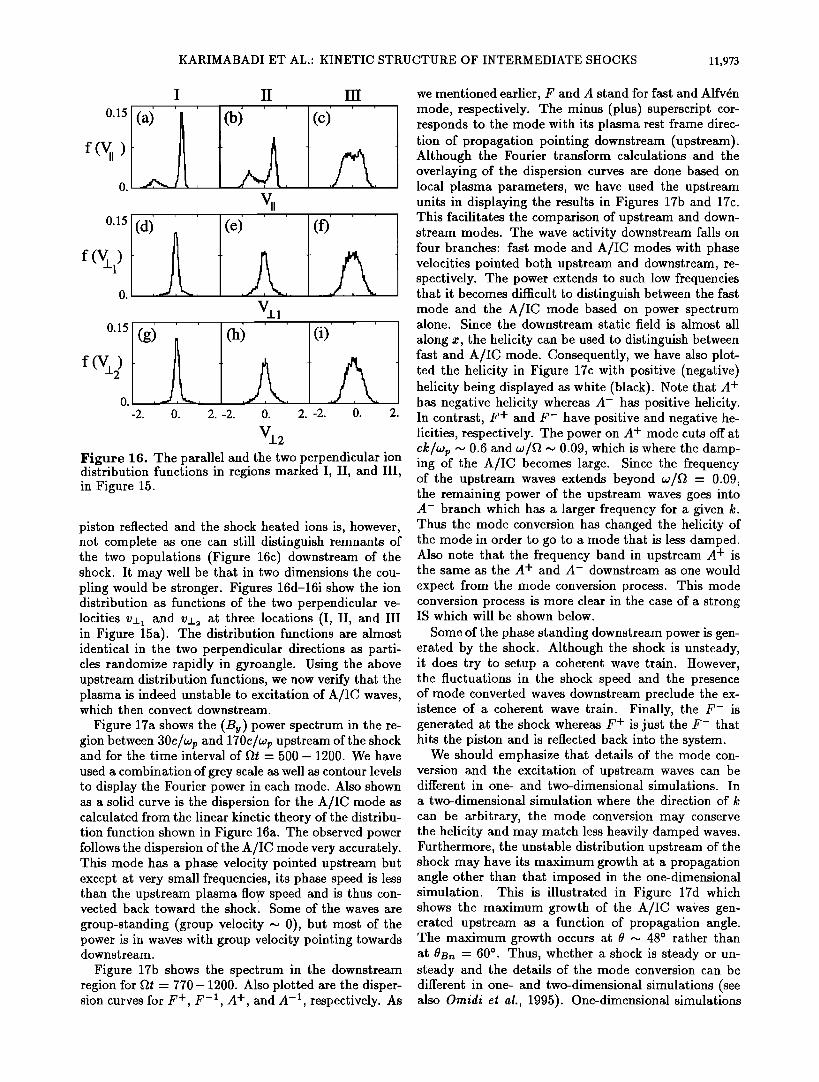
A snapshot of the shock at •t = 1200 is shown in Figure 15. In order to identify the unstable particle distribution and the resulting A/IC waves, we have iso- lated three regions in Figure 15a marked with I, II, and III, accordingly. The ion parallel velocity distribution function at these three locations are shown in Figure 16. Far upstream (region I) the ion distribution consists of two distinct populations of an incoming plasma and the backstreaming (both shock-reflected and leaked from downstream) ions (Figure 16a). The backstreaming ions are hotter in temperature and give rise to a wing in the perpendicular ion distribution. As one gets closer to the shock, the relative number of backstreaming ions to the incoming plasma increases (Figure 15d). This is due to the time-of-flight effect as particles with small but negative vii tend to stay closer to the shock whereas further upstream one sees only those backstreaming ions that have large negative Vll'S. Immediately after the shock, the incoming ions become thermalized (Fig- ure 16c) and the resulting distribution function has re- laxed towards a MaxwellJan. The coupling between the
(a) I II III
-0.5 I (b)
1.
B z
-0.6 I I I (c)
1.01 I I
Stot 0.5 I KL ••_ ..
(d) 3.
N
0.9
800. !3•.
X (c/•p ) Figure 15. Snapshot of the nonswitchoff slow shock at fit = 1200. The parameters are the same as those in Figure 14.
KARIMABADI ET AL.: KINETIC STRUCTURE OF INTERMEDIATE SHOCKS 11,973
I II III
0.15
f (V•l)
Vii
0.15 (g} ' (h ' (i)' ' '
f(Vñ) • -2. 0. 2. -2. 0. 2. -2. 0. 2.
V•2 Figure 16. The parallel and the two perpendicular ion distribution functions in regions marked I, IT, and liT, in Figure 15.
piston reflected and the shock heated ions is, however, not complete as one can still distinguish remnants of the two populations (Figure 16c) downstream of the shock. It may well be that in two dimensions the cou- pling would be stronger. Figures 16d-16i show the ion distribution as functions of the two perpendicular ve- locities vñ• and vñ• at three locations (T, TT, and III in Figure 15a). The distribution functions are almost identical in the two perpendicular directions as parti- cles randomize rapidly in gyroangle. Using the above upstream distribution functions, we now verify that the plasma is indeed unstable to excitation of A/IC waves, which then convect downstream.
Figure 17a shows the (By) power spectrum in the re- gion between 30C/Wp and 170C/Wp upstream of the shock and for the time interval of f•t = 500- 1200. We have
used a combination of grey scale as well as contour levels to display the Fourier power in each mode. Also shown as a solid curve is the dispersion for the A/IC mode as calculated from the linear kinetic theory of the distribu- tion function shown in Figure 16a. The observed power follows the dispersion of the A/IC mode very accurately. This mode has a phase velocity pointed upstream but except at very small frequencies, its phase speed is less than the upstream plasma flow speed and is thus con- vected back toward the shockl Some of the waves are group-standing (group velocity ~ 0), but most of the power is in waves with group velocity pointing towards downstream.
Figure 17b shows the spectrum in the downstream region for f•t = 770- 1200. Also plotted are the disper- sion curves for F +, F- •, A +, and A- •, respectively. As
we mentioned earlier, F and A stand for fast and Alfvdn mode, respectively. The minus (plus) superscript cor- responds to the mode with its plasma rest frame direc- tion of propagation pointing downstream (upstream). Although the Fourier transform calculations and the overlaying of the dispersion curves are done based on local plasma parameters, we have used the upstream units in displaying the results in Figures 17b and 17c. This facilitates the comparison of upstream and down- stream modes. The wave activity downstream falls on four branches: fast mode and A/IC modes with phase velocities pointed both upstream and downstream, re- spectively. The power extends to such low frequencies that it becomes difficult to distinguish between the fast mode and the A/IC mode based on power spectrum alone. Since the downstream static field is almost all
along x, the helicity can be used to distinguish between fast and A/IC mode. Consequently, we have also plot- ted the helicity in Figure 17c with positive (negative) helicity being displayed as white (black). Note that A + has negative helicity whereas A- has positive helicity. In contrast, F + and F- have positive and negative he- licities, respectively. The power on A + mode cuts off at ck/wp • 0.6 and w/f• • 0.09, which is where the damp- ing of the A/IC becomes large. Since the frequency of the upstream waves extends beyond w/f• = 0.09, the remaining power of the upstream waves goes into A- branch which has a larger frequency for a given k. Thus the mode conversion has changed the helicity of the mode in order to go to a mode that is less damped. Also note that the frequency band in upstream A + is the same as the A + and A- downstream as one would
expect from the mode conversion process. This mode conversion process is more clear in the case of a strong IS which will be shown below.
Some of the phase standing downstream power is gen- erated by the shock. Although the shock is unsteady, it does try to setup a coherent wave train. However, the fluctuations in the shock speed and the presence of mode converted waves downstream preclude the ex- istence of a coherent wave train. Finally, the F- is generated at the shock whereas F + is just the F- that hits the piston and is reflected back into the system.
We should emphasize that details of the mode con- version and the excitation of upstream waves can be different in one- and two-dimensional simulations. In a two-dimensional simulation where the direction of k
can be arbitrary, the mode conversion may conserve the helicity and may match less heavily damped waves. Furthermore, the unstable distribution upstream of the shock may have its maximum growth at a propagation angle other than that imposed in the one-dimensional simulation. This is illustrated in Figure 17d which shows the maximum growth of the A/IC waves gen- erated upstream as a function of propagation angle. The maximum growth occurs at 0 .-• 48 o rather than at OB• : 60 ø. Thus, whether a shock is steady or un- steady and the details of the mode conversion can be different in one- and two-dimensional simulations (see also Omidi et al., 1995). One-dimensional simulations
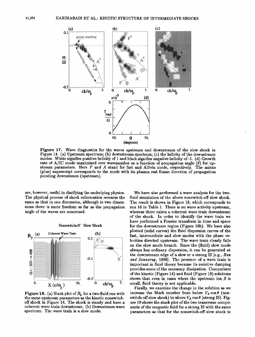
11,974 KARIMABADI ET AL.- KINETIC STRUCTURE OF INTERMEDIATE SHOCKS
0.1
-0.3
(a) .... i .... i .... i ....
g;up standing ...
+ .
.... i .... i .... i o. ck/co 2.
p
max
(b)
0. ck/co 1. p
-3 x10 (d)
I I I
I I I
0 70. (degrees)
Figure 17. Wave diagnostics for the waves upstream and downstream of the slow shock in Figure 14. (a) Upstream spectrum; (b) downstream spectrum; (c) the helicity of the downstream modes. White signifies positive helicity of I and black signifies negative helicity of-1. (d) Growth rate of A/IC mode maximized over wavenumber as a function of propagation angle (0) for up- stream parameters. Here F and A stand for fast and Alfv6n mode, respectively. The minus (plus) superscript corresponds to the mode with its plasma rest frame direction of propagation pointing downstream (upstream).
are, however, useful in clarifying the underlying physics. The physical process of shock reformation remains the same as that in one dimension, although in two dimen- sions there is more freedom as far as the propagation angle of the waves are concerned.
Nonswitchoff Slow Shock
By (a) Coherent Wave-Train
..
_
0. x (c/%) 70.
0.1
-0.1
-0.3
(b) -i-
0. ck/(Dp 2. Figure 18. (a) Stack plot of By for a two-fluid run with the same upstream parameters as the kinetic nonswitch- off shock in Figure 14. The shock is steady and have a coherent wave train downstream. (b) Downstream wave spectrum. The wave train is a slow mode.
We have also performed a wave analysis for the two- fluid simulation of the above nonswitch-off slow shock.
The result is shown in Figure 18, which corresponds to run 16 in Table 1. There is no wave activity upstream, whereas there exists a coherent wave train downstream
of the shock. In order to identify the wave train we have performed a Fourier transform in time and space for the downstream region (Figure 18b). We have also plotted (solid curves) the fluid dispersion curves of the fast, intermediate and slow modes with the phase ve- locities directed upstream. The wave train clearly falls on the slow mode branch. Since the (fluid) slow mode always has ordinary dispersion, it can be generated at the downstream edge of a slow or a strong IS [e.g., Hau and Sonnerup, 1990]. The presence of a wave train is important in fluid theory because its resistive damping provides some of the necessary dissipation. Comparison of the kinetic (figure lq) and fluid (figure 18) solutions shows that even in cases where the upstream ion/3 is small, fluid theory is not applicable.
Finally, we examine the change in the solution as we increase the Mach number from below VA cos0 (non- switch-off slow shock) to above VA cos 0 (strong IS). rig- ure 19 shows the stack plot of the two transverse compo- nents of the magnetic field for a strong IS with the same parameters as that for the nonswitch-off slow shock in

KARIMABADI ET AL ß KINETIC STRUCTURE OF INTERMEDIATE SHOCKS 11,975
Supersonic 2 -• 4
Af (a)
B
B
(b)
0. X (c/(Op) 400. Figure 19. Stack plot of the two transverse compo- nents of the magnetic field for a strong IS with param- eters given by run 17 in Table 1. The shock is unsteady but the changes in its speed are not as dramatic as the slow shock in Figure 14.
Figure 14 except that MA = 0.506. The upstream con- ditions are those given by run 17 in Table 1. The stack plot shows waves crashing into the shock and continuing downstream as was the case for the nonswitch-off slow
shock (Figure 14). However, the changes in the shock speed are not as dramatic as in Figure 14. A snapshot of the shock at •t - 1200 is shown in Figure 20. The shock profile is very similar to the slow shock (Figure 15) ex- cept that Bz is negative downstream (Figure 20b).
In order to identify the unstable particle distribution and the resulting A/IC waves, we have again isolated three regions in Figure 20a marked with I, II, and III, accordingly. The ion parallel velocity distribution func- tion at these three locations are shown in Figure 21. As before, far upstream (region I) the ion distribu- tion consists of two distinct populations of an incom- ing plasma and the backstreaming (both shock-reflected and leaked from downstream) ions (Figure 21a). As one gets closer to the shock, the relative number of back- streaming ions to the incoming plasma increases (Fig- ures 20d and 21b). Immediately after the shock, the in- coming ions become thermalized (Figure 21c). The very
(a) I II III
, ............ h .,_,, _1 •,,•./•.,J
-0.5 I ;• I• .'• I
1.
-0.6 (e)
1.01 I
O.S I .•.• ......
a.
0.9
oo. X oo. •i•u•e •0. S•p•No• o• •Ne •o• IS • • - i•00.
similar magnetic profiles and particle distribution func- tions for the nonswitch-off slow shock and the strong IS demonstrate the close connection between the two types of shocks. The particle distribution function shown in
II III
0.15 ' (b) ' ' (ci ' '
f(Vl' ) • • o , !
Vii o.•5 (di ' (ei ' ' (
f
o.•5 (g (h (i)' ' '
f(Vñ2 ) O. , -2. 0. 2. -2. 0. 2. -2. 0. 2.
Figure 21. The parallel and the two perpendicular ion distribution functions in regions marked I, II, and III, in Figure 19.

11,976 KARIMABADI ET AL.: KINETIC STRUCTURE OF INTERMEDIATE SHOCKS
0.1
-0.3
(a) (b) (c)
0. ck/½0 2. p
1. 0. 1. 0. ck/c0 ck/c0 p p
Figure 22. Wave diagnostics for the waves upstream and downstream of the strong IS in Figure 20. (a) Upstream spectrum; (b) downstream spectrum; (c) the helicity of the downstream modes. White signifies positive helicity of 1 and black signifies negative helicity of-1.
Figure 21 is representative of all slow and strong in- termediate shocks we have simulated. For both types of shocks, there is always a population of backstream- ing ions consisting of both shock reflected and leaked plasma upstream of the shock. Generally, the stronger the shock is, the larger the density of the backstreaming ions becomes.
Finally, we have analyzed the wave spectrum both upstream and downstream of the strong IS. Figure 22a shows the power spectrum in the region between 56c/wp and 192c/%, upstream of the shock and for the time interval of fit = 500- 1200. We have used a combi-
nation of grey scale as well as contour levels to display the Fourier power in each mode. Also shown as a solid curve is the dispersion for the A/IC mode as calculated from the linear kinetic theory for the distribution func- tion in Figure 21a. All the power on this branch has a phase velocity pointing downstream. The mode con- version of this mode across the shock gives rise to the power in both A + and A- downstream (Figure 22b) in a similar process to the nonswitch-off shock as de- scribed above. The helicity of the wave power down- stream (Figure 22c) is also consistent with the modes being on the A/IC branch. There is also power at very small but positive frequencies in Figure 22b. Since fre- quency is conserved in the mode conversion process and there is no power in the positive frequency range up- stream, the presence of these waves may at first seem puzzling. We have verified, however, that these waves are generated by the shock. The shock is trying to set- up phase-standing waves, but the speed of the shock is changing in time, • 0.45- 0.47Va. Thus if the shock speed changes during the time interval over which we perform our Fourier analysis, the phase-standing waves would be at a slightly finite frequency. We have per- formed a similar wave analysis as in Figure 22b but for a shorter time interval so that the shock speed was more nearly constant. The waves were found to be phase standing in that case.
O. Summary and Conclusion
In this paper, we presented a detailed study of inter- mediate shocks and their relations to slow shocks and
rotational discontinuities. Our goals are to clarify the kinetic properties of ISs in an isotropic plasma and to determine whether field rotations at the Earth's mag- netopause can be intermediate shocks.
9.1. General Properties of Intermediate Shocks
Regarding the kinetic aspects of ISs, we established that coplanar strong and weak ISs exist and are sta- ble, whereas noncoplanar ISs are time-dependent. Al- though ISs exhibit a variety of solutions, differing in shock thickness, types of hodogram, etc., the following general comments can be made regarding their struc- ture.
1. There is leakage of downstream plasma. The leaked plasma, in addition to the particles reflected from the shock, comprise a population of ions that travel up- stream. The density of these backstreaming ions is high- est for strong ISs (10-20% of the density far upstream) and lowest for weak ISs (2- 6%). Larger densities of backstreaming ions are possible if the upstream ion fi is larger than unity. The backstreaming ions lead to a reduction in shock speed and a long foot in the total magnetic field. Depending on the parameters, the rela- tive streaming between the backstreaming ions and the incoming plasma can lead to excitation of A/IC waves. These waves typically have maximum growth at oblique propagation angles. If the A/IC waves are convected back into the shock and have a large enough amplitude, the shock can become unsteady, with considerable wave activity downstream.
2. The thinnest part of the shock structure is asso- ciated with the field rotation. We found the rotational layer thickness to be in the range of i- 4c/wp for the weak ISs and 4- 20c/wp for the strong ISs.

KARIMABADI ET AL.: KINETIC STRUCTURE OF INTERMEDIATE SHOCKS 11,977
3. The strongest IS is the switch-off slow shock. We showed that switch-off shocks do exist, are stable (but usually unsteady) and go smoothly into a strong IS as MA is increased above cos 0.
4. The weak ISs connect smoothly to RDs (paper 2) as MA is lowered toward cos 0. The internal signatures and the widths of weak ISs and RDs are nearly identical in high-/? plasmas.
5. The presence and properties of wave trains for weak and strong ISs can be explained based on linear kinetic theory of Alfvdn waves. The conditions neces- sary for a wave to phase stand in the flow are (1) wave phase speed must be equal to the plasma flow speed, and (2) the group velocity must be larger than the phase ve- locity if the wave is phase standing at the upstream edge or the group velocity be smaller than the phase speed if the wave is standing at the downstream edge. Since the kinetic dispersion properties of the plasma waves are considerably different from those predicted by Hall MHD, we used linear kinetic theory to determine the conditions under which an Alfvdn mode can phase stand downstream or upstream of an IS. We stress that these two conditions are necessary but not sufficient criteria for the presence of a coherent wave train. For instance, no coherent wave train is formed if the shock is unsteady and/or the mode is heavily damped.
6. Noncoplanar ISs are time-dependent and approach the RD limit after some characteristic time r. The exact value of r is highly parameter dependent, but is always longer the closer the rotation angle is to coplanarity. During this evolution, the thickness of the rotational layer remains the same but the jumps in the plasma and field become smaller in time.
7. Rotations larger than 1800 are unstable and always evolve into a minimum shear configuration.
8. We showed that predictions of resistive Hall MHD are generally at variance with our kinetic results. Calcu- lations based on such a fluid theory lead to gross inaccu- racies in regards to shock thickness, stability properties, and wave activity.
9.2. Relevance to the Magnetopause
One ofthe puzzling issues regarding themagnetopause has been the observation [Gosling et al., 1991] that the magnetosheath plasma is bulk-heated across the mag- netopause current layer (i.e., where most of the rotation takes place). Since the current layer is typically mod- eled as an RD and RDs are known to be dissipationless in isotropic plasmas, the question of dissipation across the current layer becomes an issue. One possibility is that the observed temperature change at the magne- topause is associated with an RD due to anisotropy in the magnetosheath. The other possibility is that the current layer is not an RD but an IS. What is clearly needed are signatures that can be used to make an un- ambiguous distinction between ISs and RDs in the ob- servational data.
We first address the problem of distinguishing be- tween strong ISs and RDs/weak ISs. Two of the most
promising observational diagnostics for identifying a strong IS are the large number of backstreaming ions (10-20%) and the resulting Alfvdnic wave activity both upstream and downstream of the shock. The upstream-generated Alfvdn waves have typically max- imum growth at oblique angles and thus may be distin- guishable from Alfvdn waves generated by the anisotro- pic distribution of the magnetosheath. Furthermore, strong ISs are typically unsteady in a high-• plasma. The heating and the jumps in the plasma parameters are also sufficiently large and different from those for weak ISs or RDs that may be used to make an unam- biguous identification. We emphasize that in measuring the amount of heating in the observations, it is best to use the perpendicular temperature. The presence of a large number of backstreaming ions makes a unique measurement of parallel temperature more difficult.
Our prediction that there exists a large number of backstreaming ions (and heat flux directed upstream) associated with strong IS but not with weak ISs or RDs (paper 2) has relevance to understanding of the reflec- tion process at the magnetopause. We stress that ob- servations have revealed the presence of magnetosheath ion reflection in the magnetosheath boundary layer at low latitudes [e.g., Sonnerup et al., 1981; Gosling et al., 1990; Fuselief et al., 1991] and at high latitudes [Gosling et al., 1991]. Previous models of the reflection and transmission at the magnetopause [e.g., Cowley, 1982; Sonnerup et al., 1981] have described the ion mo- tion upon reflection or transmission without specifying rates for these processes. In such models the magne- topause is assumed to be a one-dimensional RD and
the reflection and transmission coefficients are free pa- rameters. The large observed number of reflected ions (.-, 30% of the total density) at the magnetopause [Fuse- lief, 1994, and references therein], is consistent with the interpretation of the current layer as a strong IS. How- ever, more work is required before this interpretation can be verified or ruled out. For instance, the inclusion of upstream ion anisotropy, which is neglected here and in paper 2, can result in a dramatic increase in the num- ber of ions reflected from an RD [Karimabadi, 1995], which can in turn excite waves upstream of the RD. In addition, the observation of reflected ions at the mag- netopause are typically limited to crossings where the component of the aleHoffman-Teller frame speed paral- lel to the magnetic field is larger than the thermal speed of the magnetosheath population [Fuselief, 1994]. For lower speeds, the incident and reflected distributions merge and can be misinterpreted as parallel heating in the boundary layer. Thus, weak ISs and RDs with a small number of reflected ions are not ruled out by ob- servations.
The distinction between weak ISs and RDs in the ob- servations is more difficult due to similarities in their overall structure and the small jumps in the quanti- ties associated with weak ISs in a high-• plasma. Hau and $onnerup [1992] recently calculated the thickness of subfast weak ISs using the two-fluid theory (resis-
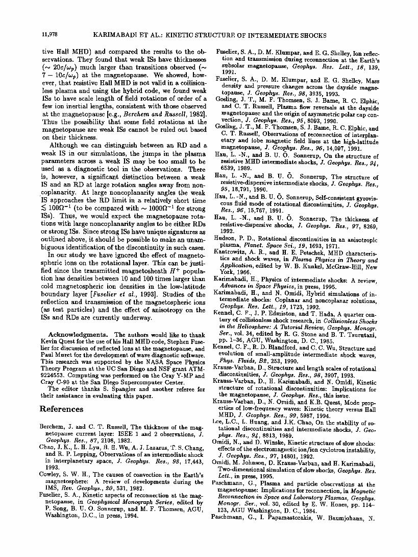
11,978 KARIMABADI ET AL.' KINETIC STRUCTURE OF INTERMEDIATE SHOCKS
tive Hall MHD) and compared the results to the ob- servations. They found that weak ISs have thicknesses (~ 20c/ozp) much larger than transitions observed (~ 7- 10c/•Op) at the magnetopause. We showed, how- ever, that resistive Hall MHD is not valid in a collision- less plasma and using the hybrid code, we found weak ISs to have scale length of field rotations of order of a few ion inertial lengths, consistent with those observed at the magnetopause [e.g., Berchem and Russell, 1982]. Thus the possibility that some field rotations at the magnetopause are weak ISs cannot be ruled out based on their thickness.
Although we can distinguish between an RD and a weak IS in our simulations, the jumps in the plasma parameters across a weak IS may be too small to be used as a diagnostic tool in the observations. There is, however, a significant distinction between a weak IS and an RD at large rotation angles away from non- coplanarity. At large noncoplanarity angles the weak IS approaches the RD limit in a relatively short time •< 100f• -• (to be compared with ~ 1000f• -• for strong ISs). Thus, we would expect the magnetopause rota- tions with large noncoplanarity angles to be either RDs or strong ISs. Since strong ISs have unique signatures as outlined above, it should be possible to make an unam- biguous identification of the discontinuity in such cases.
In our study we have ignored the effect of magneto- spheric ions on the rotational layer. This can be justi- fied since the transmitted magnetosheath H + popula- tion has densities between 10 and 100 times larger than cold magnetospheric ion densities in the low-latitude boundary layer /Fuselief et al., 1993]. Studies of the reflection and transmission of the magnetospheric ions (as test particles) and the effect of anisotropy on the ISs and RDs are currently underway.
Acknowledgments. The authors would like to thank Kevin Quest for the use of his Hall MHD code, Stephen Fuse- lief for discussion of reflected ions at the magnetopause, and Paul Muret for the development of wave diagnostic software. This research was supported by the NASA Space Physics Theory Program at the UC San Diego and NSF grant ATM- 9224553. Computing was performed on the Cray Y-MP and Cray C-90 at the San Diego Supercomputer Center.
The editor thanks S. Spangler and another referee for their assistance in evaluating this paper.
References
Berchem, J. and C. T. Russell, The thickness of the mag- netopause current layer: ISEE 1 and 2 observations, J. Geophys. Res., 87, 2108, 1982.
Chao, J. K., L. H. Lyu, B. H. Wu, A. J. Lazarus, T. S. Chang, and R. P. Lepping, Observations of an intermediate shock in interplanetary space, J. Geophys. Res., 98, 17,443, 1993.
Cowley, S. W. H., The causes of convection in the Earth's magnetosphere: A review of developments during the IMS, Rev. Geophys., œ0,531, 1982.
Fuselief, S. A., Kinetic aspects of reconnection at the mag- netopause, in Geophysical Monograph Series, edited by P. Song, B. U. O. Sonnerup, and M. F. Thomsen, AGU, Washington, D.C., in press, 1994.
Fuselief, S. A., D. M. Klumpar, and E.G. Shelley, Ion reflec- tion and transmission during reconnection at the Earth's subsolar magnetopause, Geophys. Res. Lett., 18, 139, 1991.
Fuselief, S. A., D. M. Klumpar, and E.G. Shelley, Mass density and pressure changes across the dayside magne- topause, J. Geophys. Res., 98, 3935, 1993.
Gosling, J. T., M. F. Thomsen, S. J. Bame, R. C. Elphic, and C. T. Russell, Plasma flow reversals at the dayside magnetopause and the origin of asymmetric polar cap con- vection, J. Geophys. Res., 95, 8093, 1990.
Gosling, J. T., M. F. Thomsen, S. J. Bame, R. C. Elphic, and C. T. Russell, Observations of reconnection of interplan- etary and lobe magnetic field lines at the high-latitude magnetopause, J. Geophys. Res., 96, 14,097, 1991.
Hau, L.-N., and B. U. •. Sonnerup, On the structure of resistive MHD intermediate shocks, J. Geophys. Res., 9J, 6539, 1989.
Hau, L.-N., and B. U. •). Sonnerup, The structure of resistive-dispersive intermediate shocks, J. Geophys. Res., 95, 18,791, 1990.
Hau, L.-N., and B. U. •). Sonnerup, Self-consistent gyrovis- cous fluid mode of rotational discontinuities, J. Geophys. Res., 96, 15,767, 1991.
Hau, L.-N., and B. U. •). Sonnerup, The thickness of resistive-dispersive shocks, J. Geophys. Res., 97, 8269, 1992.
Hudson, P. D., Rotational discontinuities in an anisotropic plasma, Planet. Space Sci., 19, 1693, 1971.
Kantrowitz, A. R., and H. E. Petschek, MHD characteris- tics and shock waves, in Plasma Physics in Theory and Application, edited by W. B. Kunkel, McGraw-Hill, New York, 1966.
Karimabadi, H., Physics of intermediate shocks: A review, Advances in Space Physics, in press, 1995.
Karimabadi, H., and N. Omidi, Hybrid simulations of in- termediate shocks: Coplanar and noncoplanar solutions, Geophys. Res. Lett., 19, 1723, 1992.
Kennel, C. F., J.P. Edmiston, and T. Hada, A quarter cen- tury of collisionless shock research, in Collisionless Shocks in the Hellosphere: A Tutorial Review, Geophys. Monogr. Set., vol. 34, edited by R. G. Stone and B. T. Tsurutani, pp. 1-36, AGU, Washington, D.C., 1985.
Kennel, C. F., R. D. Blandford, and C. C. Wu, Structure and evolution of small-amplitude intermediate shock waves, Phys. Fluids, Bœ, 253, 1990.
Krauss-Varban, D., Structure and length scales of rotational discontinuities, J. Geophys. Res., 98, 3907, 1993.
Krauss-Varban, D., H. Karimabadi, and N. Omidi, Kinetic structure of rotational discontinuities: Implications for the magnetopause, J. Geophys. Res., this issue.
Krauss-Varban, D., N. Omidi, and K.B. Quest, Mode prop- erties of low-frequency waves: Kinetic theory versus Hall MHD, J. Geophys. Res., 99, 5987, 1994.
Lee, L.C., L. Huang, and J.K. Chao, On the stability of tational discontinuities and intermediate shocks, J. Geo- phys. Res., 94, 8813, 1989.
Omidi, N., and D. Winske, Kinetic structure of slow shocks: effects of the electromagnetic ion/ion cyclotron instability, J. Geophys. Res., 97, 14801, 1992.
Omidi, M. Johnson, D. Krauss-Varban, and H. Karimabadi, Two-dimensional simulation of slow shocks, Geophys. Res. Lett., in press, 1995.
Paschmann, G., Plasma and particle observations at the magnetopause: Implications for reconnection, in Magnetic Reconnection in Space and Laboratory Plasmas, Geophys. Monogr. Set., vol. 30, edited by E. W. Hones, pp. 114- 123, AGU Washington, D.C., 1984.
Paschmann, G., I. Papamastorakis, W. Baumjohann, N.

KARIMABADI ET AL.: KINETIC STRUCTURE OF INTERMEDIATE SHOCKS 11,979
Sckopke, C.W. Carlson, B.U.O. Sonnerup, and H. Luhr, The magnetopause for large magnetic shear: AMPTE/IRM observations, J. Geophys. Res., 91, 11,099, 1986.
Sonnerup, B. U. •, and B.G. Ledley, Ogo 5 magnetopause structure and classical reconnection, J. Geophys. Res., 84{, 399, 1979.
Sonnerup, B. U. •., G. Paschmann, I. Papamastorakis, N. Sckopke, G. Haerendel, S. J. Bame, J. R. Asbridge, J. T. Gosling, and C. T. Russell, Evidence for magnetic field reconnection at the Earth's magnetopause, J. Geophys. Res., 86, 10,049, 1981.
Sonnerup, B. U. •., I. Papamastorakis, G. Paschmann, and H. Luhr, Magnetopause properties from AMPTE/IRM observations of the convection electric field: Method de- velopment, J. Geophys. Res., 9œ, 12,137, 1987.
Winske, D., and N. Omidi, Electromagnetic ion/ion cy- clotron instability: Theory and simulations, J. Geophys. Res., 97, 14,779, 1992.
Winske, D., and N. Omidi, Hybrid codes: Methods and ap- plication, in Computer Space Plasma Physics: Simulation Techniques and Software, edited by H. Matsumoto and Y. Omura, p. 103, Terra Scientific, Tokyo, 1993.
Wu, C. C., On MHD intermediate shocks, Geophys. Res. Lett., 1•, 668, 1987.
Wu, C. C., The MHD intermediate shock interaction with an intermediate wave: Are intermediate shocks physical?, J. Geophys. Res., 90 ø, 987, 1988.
Wu, C. C., and T. Hada, Formation of intermediate shocks in both two-fluid and hybrid models, J. Geophys. Res., 96, 3769, 1991a.
Wu, C. C., and T. Hada, On rotational discontinuities in both two-fluid and hybrid models, J. Geophys. Res., 96, 3755, 1991b.
Wu, C. C., and C. F. Kennel, The small amplitude mag- netohydrodynamic Riemann problem, Phys. Fluids, BS, 2877, 1993.
H. Karimabadi, D. Krauss-Varban, and N. Omidi, De- partment of Electrical and Computer Engineering, Univer- sity of California at San Diego, La Jolla, CA 92093-0407. (e-mail: [email protected])
(Received August 10, 1994; revised November 1, 1994; accepted November 17, 1994.)