Kinetic theory of collisionless tearing at the magnetopause
16
Kinetic theory of collisionless tearing at the magnetopause William Daughton 1 Department of Physics and Astronomy, University of Iowa, Iowa City, Iowa, USA H. Karimabadi Department of Electrical and Computer Engineering, University of California, San Diego, La Jolla, California, USA Received 16 August 2004; revised 21 December 2004; accepted 7 January 2005; published 22 March 2005. [1] This paper is the first in a series of three with the aim of addressing one of the controversial issues at the magnetopause, namely the location where reconnection first occurs during periods of a large interplanetary magnetic field B y . In this first paper, the linear properties of the collisionless tearing mode are reexamined as a function of the guide field B y using a formally exact approach for computing the nonlocal Vlasov stability of a current layer. Three distinct parameter regimes are identified depending on the degree to which electron orbits are modified by the guide field in the central region of the current layer. In the limit of both weak and strong guide field, the fastest-growing tearing mode has a wave vector k x perpendicular to the direction of the current, in agreement with previous theoretical treatments. However, for intermediate values of the guide field where the electrons begin to transition to magnetized orbits, the fastest-growing modes have a finite wave vector k y in the direction of the current. In this newly discovered regime, the so-called drift tearing modes have finite real frequency and propagate in the direction of the electron diamagnetic drift with growth rates 10–50% larger than the conventional tearing instability. Maximum growth occurs for a propagation angle in the range q = tan 1 (k y /k x ) 6–10°. These new predictions are confirmed using fully kinetic particle-in-cell simulations. The structure of the out-of-plane magnetic field perturbation predicted by nonlocal Vlasov theory is examined as a function of guide field. In the limit of a neutral sheet, the quadrupole structure has a characteristic scale near the electron meandering width and shows significant differences with the predictions of linear Hall MHD. The addition of a guide field strongly distorts the quadrupole structure and compresses the spatial extent. In the strong guide field limit, the width of the out-of-plane magnetic field perturbation is reduced to the electron gyroscale in the guide field. During the onset phase, these structures represent a distinct signature of the collisionless tearing mode that is significantly different than the typical ion-scale quadrupole pattern from fast reconnection. Finally, we note that the tearing mode maintains a significant growth rate over a large range of guide field so that component merging cannot be ruled out based on linear theory. Citation: Daughton, W., and H. Karimabadi (2005), Kinetic theory of collisionless tearing at the magnetopause, J. Geophys. Res., 110, A03217, doi:10.1029/2004JA010751. 1. Introduction [2] Magnetic reconnection is now recognized as the dominant transport mechanism at the magnetopause during periods of southward IMF [Baumjohann and Paschmann, 1987]. However, there exist important gaps in our under- standing of the details of how and where reconnection occurs. One of the critical issues is to identify where the reconnection line on the dayside magnetopause is formed during periods of a large interplanetary magnetic field B y (the so-called guide field). Two competing models have been proposed. The antiparallel merging model [Crooker, 1979; Luhmann et al., 1984] predicts that reconnection would occur where the magnetic shear across the magneto- pause is largest and predicts no reconnection in the subsolar region when the IMF B y is large. This is to be contrasted with the component merging model [Sonnerup, 1974; Gonzalez and Mozer, 1974], which predicts that the recon- nection line passes through the subsolar point and has an orientation that is controlled by the IMF. Observations of JOURNAL OF GEOPHYSICAL RESEARCH, VOL. 110, A03217, doi:10.1029/2004JA010751, 2005 1 Also at Los Alamos National Laboratory, Los Alamos, New Mexico, USA. Copyright 2005 by the American Geophysical Union. 0148-0227/05/2004JA010751$09.00 A03217 1 of 16
Transcript of Kinetic theory of collisionless tearing at the magnetopause

Kinetic theory of collisionless tearing at the
magnetopause
William Daughton1
Department of Physics and Astronomy, University of Iowa, Iowa City, Iowa, USA
H. KarimabadiDepartment of Electrical and Computer Engineering, University of California, San Diego, La Jolla, California, USA
Received 16 August 2004; revised 21 December 2004; accepted 7 January 2005; published 22 March 2005.
[1] This paper is the first in a series of three with the aim of addressing one ofthe controversial issues at the magnetopause, namely the location where reconnectionfirst occurs during periods of a large interplanetary magnetic field By. In this firstpaper, the linear properties of the collisionless tearing mode are reexamined as afunction of the guide field By using a formally exact approach for computing thenonlocal Vlasov stability of a current layer. Three distinct parameter regimes areidentified depending on the degree to which electron orbits are modified by the guidefield in the central region of the current layer. In the limit of both weak and strongguide field, the fastest-growing tearing mode has a wave vector kx perpendicular tothe direction of the current, in agreement with previous theoretical treatments.However, for intermediate values of the guide field where the electrons begin totransition to magnetized orbits, the fastest-growing modes have a finite wave vector kyin the direction of the current. In this newly discovered regime, the so-called drifttearing modes have finite real frequency and propagate in the direction of theelectron diamagnetic drift with growth rates 10–50% larger than the conventionaltearing instability. Maximum growth occurs for a propagation angle in the rangeq = tan1(ky/kx) 6–10. These new predictions are confirmed using fullykinetic particle-in-cell simulations. The structure of the out-of-plane magnetic fieldperturbation predicted by nonlocal Vlasov theory is examined as a function of guidefield. In the limit of a neutral sheet, the quadrupole structure has a characteristic scalenear the electron meandering width and shows significant differences with thepredictions of linear Hall MHD. The addition of a guide field strongly distorts thequadrupole structure and compresses the spatial extent. In the strong guide field limit,the width of the out-of-plane magnetic field perturbation is reduced to the electrongyroscale in the guide field. During the onset phase, these structures represent adistinct signature of the collisionless tearing mode that is significantly different than thetypical ion-scale quadrupole pattern from fast reconnection. Finally, we note that thetearing mode maintains a significant growth rate over a large range of guide field so thatcomponent merging cannot be ruled out based on linear theory.
Citation: Daughton, W., and H. Karimabadi (2005), Kinetic theory of collisionless tearing at the magnetopause, J. Geophys. Res.,
110, A03217, doi:10.1029/2004JA010751.
1. Introduction
[2] Magnetic reconnection is now recognized as thedominant transport mechanism at the magnetopause duringperiods of southward IMF [Baumjohann and Paschmann,1987]. However, there exist important gaps in our under-standing of the details of how and where reconnection
occurs. One of the critical issues is to identify where thereconnection line on the dayside magnetopause is formedduring periods of a large interplanetary magnetic field By
(the so-called guide field). Two competing models havebeen proposed. The antiparallel merging model [Crooker,1979; Luhmann et al., 1984] predicts that reconnectionwould occur where the magnetic shear across the magneto-pause is largest and predicts no reconnection in the subsolarregion when the IMF By is large. This is to be contrastedwith the component merging model [Sonnerup, 1974;Gonzalez and Mozer, 1974], which predicts that the recon-nection line passes through the subsolar point and has anorientation that is controlled by the IMF. Observations of
JOURNAL OF GEOPHYSICAL RESEARCH, VOL. 110, A03217, doi:10.1029/2004JA010751, 2005
1Also at Los Alamos National Laboratory, Los Alamos, New Mexico,USA.
Copyright 2005 by the American Geophysical Union.0148-0227/05/2004JA010751$09.00
A03217 1 of 16

the magnetopause have yielded contradictory interpreta-tions. For instance, Gosling et al. [1990] used observationsof events at low latitude and in one case for a magneticshear as small as 60 to argue against antiparallel mergingand in favor of component merging. More recent evidencein favor of component merging has also been reported [Kimet al., 2002; Moore et al., 2002; Sonnerup et al., 2004].These studies are to be contrasted with those of Newell et al.[1995, and references therein], which concluded that localmagnetic shear and not location is most important indetermining whether merging occurs.[3] Although theoretical studies of reconnection at the
magnetopause have focused on the collisionless tearingmode [Coppi et al., 1966; Laval et al., 1966; Biskampand Schindler, 1971; Sonnerup, 1974] as the onset mech-anism, the results have been inconclusive. The linearproperties of the tearing mode for neutral sheet geometryand with the addition of a guide field have been consideredby numerous authors [Drake and Lee, 1977; Galeev andZelenyi, 1978; Quest and Coroniti, 1981a, 1981b; Gladd,1990; Ding et al., 1992]. In particular, Quest and Coroniti[1981b] compared the growth rate to the magnetosheathflow time from the nose of the magnetopause to theequatorward edge of the polar cusp. This provides ameasure of the tearing efficiency as for longer times thewave will be convected to the nightside before growingappreciably. They concluded that only thin magnetopausecurrent sheets can satisfy the criterion that the tearinggrowth time is much less than the flow time. Furthermore,they showed that the presence of a guide field can reducethe growth rate by as much as an order of magnitude ormore. Considering thicker sheets, Gladd [1990] concludedthat the tearing mode growth rate is too small by 1–2 ordersof magnitude and reiterated Galeev et al.’s [1986] sugges-tion that other mechanisms such as anomalous resistivitymay be required to obtain substantially larger growth rates.Chen and Palmadesso [1984] showed that an ion temper-ature anisotropy, which is often observed in the magneto-sheath, could also enhance the tearing mode growth rate andthat for relatively thick current layers the ion anisotropy canincrease the growth rate by 1–2 orders of magnitude[Burkhart and Chen, 1989].[4] The nonlinear evolution of the collisionless tearing
mode is less well understood than the linear theory. Earlytheoretical studies ruled out component-merging as a pos-sibility. Nonlinear theories of the tearing mode in thepresence of a guide field [Drake and Lee, 1977; Coronitiand Quest, 1984] showed that the tearing mode saturates atminute amplitudes (50 m), much smaller than the magne-topause current layer thickness of 50–200 km. We refer thereader to Karimabadi et al. [2005a, hereinafter referred to asPaper II] for a review of these theories.[5] The above studies have been hampered by several
factors. Analytical calculations of the tearing mode arenotoriously difficult due to the complex particle orbits,and the approximations break down in the limit of thincurrent sheets often observed at the magnetopause. Particlesimulations of the tearing mode, which are used to study thenonlinear evolution and saturation amplitude, are also verydifficult to perform. These simulations need to to beperformed with high resolution and in a regime where thesingular layer thickness is well separated from other scales
in the problem (e.g., the sheet thickness, debye length, iongyroradius, etc.). As it turns out, these requirements arecomputationally challenging and even the more recentstudies of guide field tearing have bypassed the issue ofnonlinear saturation by imposing an initial, large pertur-bation in the problem to avoid the onset phase and proceedto fully developed fast reconnection [Hesse et al., 2002].[6] Recognizing the above limitations, we have taken a
new approach. In this series of three papers, the linear andnonlinear evolution of the tearing instability is examined fora range of guide fields relevant to the magnetopause. In thefirst paper, a novel approach for computing the Vlasovstability of thin current sheets is used to reexamine thelinear properties of the tearing mode as a function of theguide field. This approach allows one to compute formallyexact eigenmodes of the Vlasov-Maxwell system withapproximations arising only in the discretization of theequations. Our second paper [Karimabadi et al., 2005a,hereinafter referred to as Paper II] deals with the nonlinearevolution and saturation mechanism of a single tearingmode, while the third paper [Karimabadi et al., 2005b,hereinafter referred to as Paper III] deals with the nonlinearevolution in the presence of multiple modes with a detaileddiscussion of the results in terms of reconnection onset atthe magnetopause.[7] The main new results in this manuscript are (1) the
identification of a new regime of collisionless tearing withproperties intermediate between the zero and strong guidefield limits. In this new regime, the fastest-growing modeshave a finite wave vector ky in the direction of the current.This unexpected result is verified using fully kinetic simu-lation to examine the evolution of the tearing mode in thelinear regime. These so-called drift tearing modes propagatein the direction of the electron diamagnetic drift withgrowth rates 10–50% larger than the conventional tearinginstability. Maximum growth occurs for a propagation anglein the range q = tan1 (ky/kx) 6–10, giving rise to acomplex resonance structure in three dimensions. (2) Thenonlocal linear Vlasov approach is used to compute the out-of-plane magnetic field perturbation in the linear regime. Inthe zero guide field limit the perturbation has a quadrupolestructure, but with the introduction of a guide field thepattern is highly distorted and the spatial scale is reduced tothe electron gyroscale. (3) The linear growth rate remainscompetitive to the antiparallel case even for relatively largevalues of the guide field. The relevance of this finding inregard to viability of component merging will be exploredin more detail in Paper II.[8] The manuscript is organized as follows. Section 2
describes the equilibrium used in this study, while section 3describes the linear Vlasov code that is used for all nonlocallinear calculations. The results are presented in section 4,and the conclusions are summarized in section 5.
2. Equilibrium
[9] The Harris [1962] equilibrium is considered with theaddition of a uniform guide field
By ¼ Byo;
Bx ¼ Bxo tanhz
L
;
ð1Þ
A03217 DAUGHTON AND KARIMABADI: KINETIC THEORY OF COLLISIONLESS TEARING
2 of 16
A03217
where L is the half thickness of the current sheet. Themagnetic field component Bx(z) is produced self-consis-tently by the current within the sheet
Jy ¼cBxo
4pLsech2
z
L
;
while the By component of the magnetic field is externallyapplied.[10] The equilibrium distributions are
fs ¼n zð Þ
p3=2v3thsexp
v2x þ vy Us
2þv2z
v2ths
" #; ð2Þ
where s = i,e for ions and electrons, vths (2Ts/ms)1/2 is the
thermal velocity, Us is the fluid velocity in the y-direction,Ts is the temperature, ms is the mass, and the density profileis
n zð Þ nosech2 z
L
: ð3Þ
The equilibrium force balance imposes the constraint
no Te þ Tið Þ ¼ B2xo
8p; ð4Þ
and to enforce charge neutrality, one must require Ui/Ti =Ue/Te. The drift velocities are chosen to be thediamagnetic drifts resulting from the two-fluid description
Us ¼2cTs
qsBoL: ð5Þ
[11] In this manuscript the parameters characterizing theequilibrium are given in terms of dimensionless parameters.The Harris equilibrium with a guide field is characterized bythe five dimensionless parameters
riL;
mi
me
;Ti
Te;
Byo
Bxo
;wpe
Wce
;
where ri = vthi/Wci is an ion gyroradius, vthi = (2Ti/mi)1/2 is
the ion thermal speed, Wcs = eBxo/(msc) is thegyrofrequency computed from the asymptotic field Bxo,and wpe = (4pnoe
2/me)1/2 is the electron plasma
frequency calculated from the central density no. Theratio of the ion fluid to thermal velocity may be expressas Ui/vthi = ri/L and the constraint (4) permits theelectron thermal velocity to be written as vthe/c =[
ffiffiffiffiffiffiffiffiffiffiffiffiffiffiffiffiffiffiffi1þ Ti=Te
p(wpe/Wce)]
1. A comprehensive study exam-ining variations in all of these equilibrium parameters isbeyond the scope of the present manuscript andfurthermore is largely unnecessary since many of thebasic dependencies are well known. Instead, the focus isdirected toward the basic properties of the tearing modeas a function of the guide field Byo/Bxo. For this
purpose, four of the dimensionless equilibrium param-eters are held fixed for most of the results presented
riL¼ 1;
mi
me
¼ 1836;Ti
Te¼ 1;
wpe
Wce
¼ 5; ð6Þ
which implies vthe/c 0.14 is also held fixed.
3. Linear Vlasov Theory
[12] The linear properties of the tearing mode are calcu-lated using the formally exact approach described in thework of Daughton [1999]. This method employs a normalmode stability calculation using a full Vlasov descriptionfor both ions and electrons. The orbit integrals arising fromthe linear Vlasov theory are treated numerically using theexact unperturbed particle orbits and including the form ofthe perturbation inside the integral. Both electromagneticand electrostatic contributions to the field perturbation areretained and resulting system of integro-differential equa-tions is solved using a basis function expansion of the theeigenfunction. As discussed by Daughton [2003], the addi-tion of a guide field introduces a few important complica-tions, but the method remains formally exact. The results
0
0.01
0.02
0.03
0.04
0.05
0.06
0.07
0.08
0 0.2 0.4 0.6 0.8 1
γ/Ω
ci
kx L
kyL=0.00
0.02kyL=0.15
kyL=0.10
0.080.060.04
0
0.1
0.2
0.3
0.4
0.5
0 0.2 0.4 0.6 0.8 1
ω/ω
*e
kx L
kyL=0.02
0.04
0.06
0.08
0.10
kyL=0.15
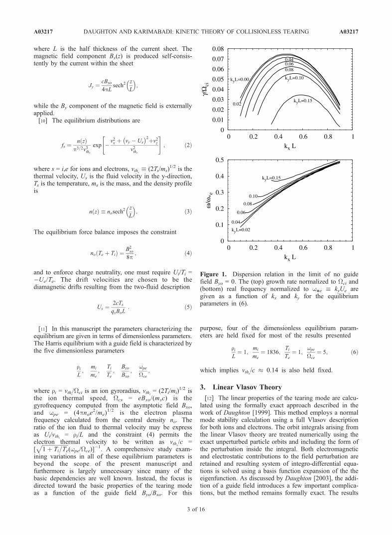
Figure 1. Dispersion relation in the limit of no guidefield Byo = 0. The (top) growth rate normalized to Wci and(bottom) real frequency normalized to w
*e kyUe are
given as a function of kx and ky for the equilibriumparameters in (6).
A03217 DAUGHTON AND KARIMABADI: KINETIC THEORY OF COLLISIONLESS TEARING
3 of 16
A03217

presented in this manuscript were calculated using the linearVlasov code described by Daughton [2003] and we referinterested readers to this reference for a detailed description.The basic strategy involves a normal mode calculation forperturbations of the form
f ¼ ~f zð Þ exp iwt þ ikyyþ ikxx
;
A ¼ ~A zð Þ exp iwt þ ikyyþ ikxx
;
ð7Þ
where the complex functions f, A are the perturbedelectrostatic and vector potentials. For a given Vlasovequilibrium and for a given choice of wave vector (kx, ky),the code computes the real frequency, growth rate (real andimaginary part of w), and the complex eigenfunctions ~f(z)and ~A(z) which describe the mode structure. The resultingelectric and magnetic field perturbations are computed from
E ¼ rf 1
c
@A
@t
B ¼ r A:
[13] The eigenvalue problem is solved with a finiteelement expansion of the eigenfunction. Typical solutionspresented in this manuscript employ 256 finite elementsacross the sheet to represent the eigenfunction. To evaluatethe orbit integral, each particle trajectory is followed for a
single period tp using a time step Dt = tp/40. The velocityspace grid is 1000 40 40 with the finer resolution in thevx direction to fully resolve the perturbed distributionfunction in the vicinity of the resonance. The resultspresented in this manuscript have been carefully checkfor numerical convergence and sensitivity to theseparameters.
4. Results
[14] In this section, the linear properties of the tearingmode are examined as a function of the guide field. Beforediscussing these new results, it is worth reviewing the basicproperties of the tearing mode as a function of the dimen-sionless parameters (6) which are held fixed in this study.The variation of the growth rate with the mass ratio mi/me,sheet thickness ri/L, and temperature ratio Ti/Te have beenstudied in previous work for a Harris sheet [Daughton,1999]. Both the growth rate and the wavelength of thefastest-growing mode are very weakly dependent on themass ratio mi/me. This allows fairly realistic kinetic simu-lations of tearing to be conducted at artificial values of mi/me without significantly altering the linear properties of theinstability. For thicker current layers (smaller ri/L) thegrowth rate is rapidly reduced and the fastest-growing modeshifts to slightly longer wavelength kxL 0.3, while forthinner sheets the growth rate is increased and the fastest-
-0.1
-0.08
-0.06
-0.04
-0.02
0
0.02
-8 -6 -4 -2 0 2 4 6 8
Ax
0
0.2
0.4
0.6
0.8
1
-8 -6 -4 -2 0 2 4 6 8
Ay
-0.02
-0.01
0
0.01
0.02
-8 -6 -4 -2 0 2 4 6 8
Az
z/L
-2
-1
0
1
-8 -6 -4 -2 0 2 4 6 8
φ* x 1
0-3
z/L
Figure 2. Example eigenfunction for a tearing mode in the limit of no guide field Byo = 0 withequilibrium parameters in (6). The solid and dashed lines denote the real and imaginary parts of ~Ax, ~Ay, ~Az
and f* ~f(wpe/Wce). The wave vector is kxL = 0.50, kyL = 0 and the growth rate is g/Wci = 0.075.
A03217 DAUGHTON AND KARIMABADI: KINETIC THEORY OF COLLISIONLESS TEARING
4 of 16
A03217

growing mode is very near kxL 0.5. The growth rate is afairly strong function of the electron temperature and issignificantly reduced when the electron temperature is lessthan the ion temperature Ti/Te > 1. The growth rate, realfrequency, and electromagnetic contribution to the eigen-function ~A are to a very good approximation independentof the ratio wpe/Wce. However, the magnitude of theelectrostatic contribution to the eigenmode scales linearlywith this dimensionless parameter. Therefore in this manu-script, the electrostatic contribution to the eigenfunction ispresented in terms of the rescaled potential
f* zð Þ ~f zð Þ wpe
Wce
: ð8Þ
Presented in this form, all aspects of the linear theory areindependent of wpe/Wce. This remains true for all values ofthe guide field. The only regime in which significantdeviations are observed is for wpe < Wce, which correspondsto relativistic electrons. Since the linear theory is based onthe nonrelativistic Vlasov equation, this regime is notconsidered in the present manuscript.[15] Although the tearing mode has been thoroughly
examined in the limit of very strong guide field, thetransitional regime between a neutral sheet with meandering
electron orbits and the strong guide field limit with helicalelectron orbits has not been carefully examined. As onemight expect, the properties of the tearing mode are largelydetermined by the degree electron orbits are modified by thepresence of the guide field. In a neutral sheet with By = 0,the electrons in the central region undergo meanderingorbits with spatial extent de =
ffiffiffiffiffiffiffiffiffi2reL
pwhere re = vthe/Wce
is a thermal electron gyroradius computed with Bxo. In theopposite limit of strong guide field, the electrons are fullymagnetized and undergo helical trajectories with weakguiding center drifts due to the field inhomogeneity. Arough estimate for the magnetic field required to magnetizethe electrons in the central region is determined by settingde reG, where reG is a thermal electron gyroradius inthe guide field. This simple estimate results in a charac-teristic guide field
By*
Bxo
1ffiffiffi2
p riL
1=2 Teme
Timi
1=4
; ð9Þ
for which the trajectory of a thermal electron is significantlymodified. In this manuscript, the regime Byo < By* isreferred to as the weak guide field limit, since the electrontrajectories are still primarily influenced by the Harris fieldBx(x). The opposite limit Byo By* is referred to as thestrong guide field regime, since the electrons are fullymagnetized by the guide field. In addition, there is anintermediate range of guide fields corresponding to thetransitional regime between the unmagnetized and fullymagnetized electron trajectories. The simple estimate (9)corresponds roughly to the magnetic field required tomagnetize an electron travelling at a thermal speed vthe. Inorder to strongly magnetize all the electrons in thedistribution, a magnetic field 2–3 times larger than By* isrequired. Therefore we adopt the following nomenclature todescribe the strength of the guide field:
Byo < By* ! Weak;
By* < Byo < 3By* ! Intermediate;
Byo > 3By* ! Strong:
ð10Þ
The numerical value of ‘‘3’’ in the above designation isof course somewhat arbitrary. However, as discussed insection 4.4, the behavior of the tearing mode growth rate asa function of the guide field does indeed break into threedistinct regimes consistent with the designation in (10). Inthe following three subsections, the mode structure anddispersion relation are discussed for each of these regimes.
4.1. Weak Guide Field
[16] The dispersion relation of the tearing mode in thelimit of zero guide field is shown in Figure 1 for theparameters in (6). The fastest-growing mode occurs forapproximately kxL 0.46 and kyL = 0. For parameterregimes in which tearing is less strongly driven (thickersheet, colder electrons), the fastest-growing mode shifts tosomewhat longer wavelength. Regardless of the otherequilibrium parameters, in the limit of weak guide fieldthe fastest-growing tearing mode always has ky ! 0. As
0
0.01
0.02
0.03
0 0.2 0.4 0.6 0.8 1
γ/Ω
ci
kx L
kyL=0.00
0.020.04
0.06
0.08
kyL=0.10
kyL=0.15
0.4
0.5
0.6
0.7
0.8
0.9
0 0.2 0.4 0.6 0.8 1
ω/ω
*e
kx L
kyL=0.02
kyL=0.04
kyL=0.06
0.080.10
kyL=0.15
Figure 3. Dispersion relation in the limit of strong guidefield Byo/Bxo = 0.5. The (top) growth rate normalized to Wci
and (bottom) real frequency normalized to w*e
kyUe aregiven as a function of kx and ky for the equilibriumparameters in (6).
A03217 DAUGHTON AND KARIMABADI: KINETIC THEORY OF COLLISIONLESS TEARING
5 of 16
A03217

shown in Figure 1, the addition of finite ky introduces alinear coupling to the drift mode which reduces the growthrate and causes the mode to propagate in the direction ofelectron drift Ue with frequency of order we* kyUe, theelectron diamagnetic drift frequency. Therefore in thismanuscript it is convenient to normalize the real frequencyto we*
, while retaining the more standard normalization forthe growth rate in terms of the ion cyclotron frequency Wci
based on the lobe field.[17] A typical eigenfunction for the case of no guide
field is shown in Figure 2. Although most theoreticaltreatments include only the ~Ay component of the pertur-bation, the tearing mode actually perturbs all threecomponents of the vector potential as well as the elec-trostatic potential. Each component of the eigenfunction isof definite symmetry, with ~Ax, ~Ay and ~f of even parityand ~Az of odd parity. As discussed in section 4.7,the subdominant component of the electromagnetic per-turbation gives rise to an out-of-plane magnetic fieldperturbation, which is an important signature of thecollisionless tearing instability.[18] The electrostatic contribution is important in accu-
rately computing the growth rate for ion scale current sheets[Hoshino, 1987] but is less important for thicker currentlayers. The electrostatic contribution to the tearing eigen-
function in Figure 2 is rescaled by the dimensionlessparameter wpe/Wce as defined in (8). Presented in thisfashion, the function f*(z) is independent of wpe/Wce. Therelative importance of the electrostatic to electromagneticperturbation may be estimated directly from Figure 2. In thismanuscript, the normalizations employed for the tearingeigenfunction is the same as standard PIC units, where timeis normalized to the electron plasma frequency wpe andlength is normalized to the electron skin depth c/wpe. Thusto compare the electrostatic to electromagnetic contributionsto the perturbed electric field ~Ex, one would compare (kxc/wpe)~f to (w/wpe) ~Ax. For the example in Figure 2, the wavevector is kxc/wpe 0.017 and jwj/wpe 8.2 106, whichimplies that ~Ex is dominated by the electrostatic contribu-tion. Likewise, ~Ez is also dominated by the electrostaticcontribution. Furthermore, it is easy to show this result isindependent of the ratio wpe/Wce for both ~Ex and ~Ez. Withthis in mind, the ratio of the magnetic field to electric fieldperturbation is ~Bz/~Ex = ~Ay/~f, which is directly proportionalto wpe/Wce. Thus the relative magnitude of the electrostaticperturbation is significantly reduced in the physicallyrelevant parameter regime for magnetospheric plasmaswpe/Wce 8. This may have implications for the nonlinearsaturation of the tearing mode even though the linear growthrate is independent of wpe/Wce.
-0.1
-0.08
-0.06
-0.04
-0.02
0
-8 -6 -4 -2 0 2 4 6 8
Ax
0
0.2
0.4
0.6
0.8
1
-8 -6 -4 -2 0 2 4 6 8
Ay
-0.01
0
0.01
-8 -6 -4 -2 0 2 4 6 8
Az
z/L
-4
-2
0
2
4
-2 -1 0 1 2
φ* x 1
0-3
z/L
Figure 4. Example eigenfunction for a tearing mode with strong field Byo/Bxo = 0.5 and equilibriumparameters in (6). The solid and dashed lines denote the real and imaginary parts of ~Ax, ~Ay, ~Az andf* ~f (wpe/Wce). The wave vector is kxL = 0.40, kyL = 0 and the growth rate is g/Wci = 0.031. Therange of z/L displayed in f* figure is expanded to better show the rapid transition across the resonantsurface at z/L = 0.
A03217 DAUGHTON AND KARIMABADI: KINETIC THEORY OF COLLISIONLESS TEARING
6 of 16
A03217

4.2. Strong Guide Field
[19] An example dispersion relation for the strong guidefield regime is shown in Figure 3 for the equilibriumparameters in (6). The wave vector of the fastest-growingmode is approximately kxL 0.4. The addition of finite kyreduces the growth rate as predicted by a large body ofprevious work on drift tearing modes for strong guide field[Catto et al., 1974; Coppi et al., 1979; Galeev, 1983;Kuznetsova and Zelenyi, 1985; Gladd, 1990]. With theaddition of finite ky, the phase velocity of the mode is inthe direction of the electron drift with a real frequency oforder w
*e. The resulting growth rate for the drift tearing
mode is significant over a fairly broad range of anglesextending to q 15. This is a broader range than previousresults reported by Gladd [1990] for drift tearing. However,this previous work considered much thicker current sheetsri/L = 0.1 and the approach involved a large number ofapproximations.[20] A typical tearing eigenfunction for the limit of strong
guide field is shown in Figure 4 for the fastest-growingmode in Figure 3. The symmetry properties are complicatedby the presence of a guide field but are not destroyedentirely. Each component of the eigenfunction is a super-position of even and odd parity contributions which are 90
out of phase. Of course, one may decompose any arbitrarycomplex function into even and odd parity contributions;however, if the function lacked any symmetry properties,both parities would contain both real and imaginary parts. Incontrast, for each component in Figure 4, both the real andimaginary parts are of definite parity.[21] The dominant component of the tearing eigenfunc-
tion ~Ay is even parity and gives rise to the formation of themagnetic island. This part of the tearing mode structure isvery similar to the case of zero guide field in Figure 2. Incontrast, the structure of the mode arising from the threesubdominant components of the eigenfunction is noticeablydifferent than the zero guide field case. The relative mag-nitude of the electrostatic contribution is considerably largerand is dominated by an odd parity contribution which variesrapidly across the resonance layer and gives rise to a muchstronger perturbation in ~Ez. The characteristic scale of thisstructure is a few reG. In addition, the subdominant electro-magnetic perturbation ~Ax and ~Az are composed of both oddand even parity terms. As discussed in section 4.7, this hasimportant implications for the out-of-plane magnetic fieldperturbation.
4.3. Intermediate Guide Field
[22] An example dispersion relation for an intermediateguide field is shown in Figure 5 for the parameters in (6). Incontrast to either the weak or strong guide field regimes, thefastest-growing instability is an obliquely propagating drifttearing mode. For these parameters, the maximum growthrate g/Wci 0.05 occurs approximately for kxL 0.45, kyL 0.05, corresponding to an oblique angle of q = tan1(ky/kx) 6.3. This is nearly 40% faster than the conventionaltearing mode with ky = 0, which has a growth rate g/Wci 0.035 for this example. For larger oblique angles kyL > 0.05,the growth rate of the drift tearing mode is reduced andshifts to somewhat shorter wavelength. The growth rate ofthe drift tearing mode is approximately equal to the standardtearing mode near kyL 0.14 corresponding to an obliqueangle of q 16.[23] A typical eigenfunction for the tearing mode in the
intermediate guide field regime is shown in Figure 6 forthe wave vector kxL = 0.40 and kyL = 0. The basicfeatures are quite similar to the strong guide field case inFigure 4, although the relative amplitudes between thevarious components are a bit different. The symmetryproperties for this case are identical to the precedingdiscussion for Figure 4.[24] With the addition of finite ky, the properties of the
eigenfunction are dramatically altered. The tearing instabil-ity localizes about the resonant surfaces within the currentsheet where k B = 0. For the equilibrium magnetic field in(1), the resonant surfaces are located at
z
L¼ tanh1 kyByo
kxBxo
kyByo
kxBxo
; ð11Þ
where the approximate expression is the lowest-orderexpansion assuming kyByo kxBxo. For the drift tearingmode, the y-component of the wave vector is always in thedirection of the electron drift Ue which is the negativey-direction. The x-component of the wave vector kx may beeither positive or negative. For the case of a neutral sheet
0
0.01
0.02
0.03
0.04
0.05
0 0.2 0.4 0.6 0.8 1
γ/Ω
ci
kx L
kyL=0.15
0.10
0.080.06
0.04
0.02kyL=0
0.3
0.4
0.5
0.6
0.7
0.8
0.9
1
0 0.2 0.4 0.6 0.8 1
ω/ω
*e
kx L
kyL=0.02
kyL=0.04
kyL=0.060.080.10
kyL=0.15
Figure 5. Dispersion relation in the limit of intermediateguide field Byo/Bxo = 0.2. The (top) growth rate normalizedto Wci and (bottom) real frequency normalized to w
*e
kyUe are given as a function of kx and ky for the equilibriumparameters in (6).
A03217 DAUGHTON AND KARIMABADI: KINETIC THEORY OF COLLISIONLESS TEARING
7 of 16
A03217

Byo = 0, there is a single resonant surface at z = 0 andconsequently a single location for tearing to go unstableregardless of the magnitude of ky. Since the mode remainslocalized at z = 0, the resulting eigenfunction retains clearsymmetry properties. With the addition of a guide field, afinite ky component destroys all symmetry in the problem.For a given wave vector, there are two resonant surfaceslocated on opposite sides of the current sheet and thereforetwo spatial locations where tearing modes can exist. Thetearing mode with positive kx is localized about the resonantsurface on the z > 0 side of the sheet, while the tearingmode with negative kx is localized about the resonantsurface on the z < 0 side. Both the real frequency andgrowth rate for these two modes are exactly the same, butthe localization, spatial mode structure, and direction ofpropagation are different. In the limit ky ! 0, the resonantsurfaces on each side of the sheet approach z ! 0 and thesetwo modes become one in the same. To emphasize thispoint, the eigenfunction for a drift tearing mode localizedon the z > 0 side of the layer is shown in Figure 7, whilethe eigenfunction for the corresponding mode localized onthe z < 0 side of the layer is shown in Figure 8.
4.4. Maximum Growth Versus Guide Field
[25] The maximum growth rate of the tearing mode as afunction of the guide field is shown in Figure 9 for theequilibrium parameters in (6). The solid line was computedby scanning over a range of kx while holding ky = 0 in order
to locate the maximum growth rate for each value of theguide field. The dashed line was computed by scanningover both kx and ky in order to locate the maximum. Thevertical lines correspond to B*y and 3B*y so that one mayeasily infer the weak, intermediate, and strong guide fieldregimes based on the criteria in (10). As already discussed,the fastest-growing modes for both the weak and strongguide field occurs for ky = 0, while the fastest-growingmodes in the intermediate guide field regime occur atfinite ky.[26] Note that changing the guide field from 0 to a value
equal to the main field changes the growth rate by a factorof 3.75. This indicates that component merging (finiteguide field) at the magnetopause remains competitive to theantiparallel regime (zero guide field) for relatively largevalues of guide field. We will discuss this in more detail inPaper III.[27] The physics responsible for the shift of the maximum
growth to oblique angles in the intermediate regime is notwell understood. We have verified that it is not due to thenonadiabatic contribution of ions, as the maximum growthremains oblique even when we turn off the nonadiabatic ioncontribution in the linear code. So this shift has to do withthe properties of electron orbits. The growth rate of thecollisionless tearing instability is determined in part by thenature of the resonant interaction between the electrons andthe mode. In the intermediate guide field regime, thereexists a mixture of electron orbits, those that execute
-0.08
-0.04
0
0.04
0.08
-8 -6 -4 -2 0 2 4 6 8
Ax
0
0.2
0.4
0.6
0.8
1
-8 -6 -4 -2 0 2 4 6 8
Ay
-0.02
0
0.02
0.04
0.06
0.08
-8 -6 -4 -2 0 2 4 6 8
Az
z/L
-2
-1
0
1
-8 -6 -4 -2 0 2 4 6 8
φ* x 1
0-3
z/L
Figure 6. Example eigenfunction for a tearing mode at intermediate guide field Byo/Bxo = 0.2 withequilibrium parameters in (6). The solid and dashed lines denote the real and imaginary parts of ~Ax, ~Ay, ~Az
and f* ~f(wpe/Wce). The wave vector is kxL = 0.40, kyL = 0 and the growth rate is g/Wci = 0.035.
A03217 DAUGHTON AND KARIMABADI: KINETIC THEORY OF COLLISIONLESS TEARING
8 of 16
A03217

complicated meandering orbits as in the zero guide fieldlimit and those that are magnetized as in the strong guidefield limit. This mixture of electron orbits leads to a modethat has properties intermediate between the two regimes ofzero and strong guide field.
4.5. Comparison With Analytic Theory
[28] One question of interest is the accuracy of previousapproximate linear theories for collisionless tearing. Al-though there are analytic theories for both the neutral sheetand strong guide field limits, there does not appear to be anypublished analytic linear theory for the intermediate regime.In addition, previous analytic theories still involve a largenumber of approximations that become less accurate in thelimit of a thin current layer. In Figure 9, the analytic growthrate is compared against the formally exact linear Vlasovcode as a function of guide field and holding kxL = 0.4 fixedwithin the analytic calculation. The flat part of this curve inthe weak guide field regime corresponds to the growth ratepredicted by the analytic model for a neutral sheet (seeequation (A24) in paper III), while the decreasing portion ofthe curve corresponds to the analytic result for a strongguide field (see equation (A23) in paper III). Thus the curvelabelled ‘‘analytic model’’ in Figure 9 is the intersection ofthese two separate theories. In both cases, the analytictheory is larger than the prediction from the linear Vlasov
code, which is to be expected since the analytic theoriesneglect the contribution from resonant ions and furthermoreneglect the electrostatic contribution to the mode. Presently,there is no analytic model that goes continuously throughthe intermediate regime. In the following two paragraphs,the analytic theories are compared for the weak and strongguide field limits as a function of the sheet thickness.[29] Figure 10a shows a comparison for the growth rate
predicted by analytic theory with the formally exact linearVlasov code for the zero guide field limit. Since the effect ofresonant ions are typically ignored in the analytic theory, wealso show the result obtained from the linear Vlasov codewith the resonant ion contribution removed (i.e., onlyinclude the adiabatic term for the ions). As explained inPaper III, one can derive two analytical theories, a simpli-fied version that leads to a closed form solution (seeequation (A24) in paper III) and a more complete treatmentwhich requires a partial numerical solution (see equation(A27) in paper III). The simplified version does not predictthe maximum kx, whereas the more complete versionpredicts kxL = 0.36 as compared with 0.44 from the linearVlasov code. In Figure 10a, we have used kxL = 0.4 tocompute the growth rate curve for the analytical results.Other parameters in this comparison include Ti/Te = 5 andmi/me = 1836. The simple analytical expression then yieldsg 0.0364(ri/L)
2.5 (dashed green line), whereas the semi-
-0.2
-0.15
-0.1
-0.05
0
0.05
0.1
-8 -6 -4 -2 0 2 4 6 8
Ax
0
0.2
0.4
0.6
0.8
1
-8 -6 -4 -2 0 2 4 6 8
Ay
-0.02
0
0.02
0.04
0.06
-8 -6 -4 -2 0 2 4 6 8
Az
z/L
-3
-2
-1
0
1
2
3
4
-8 -6 -4 -2 0 2 4 6 8
φ* x 1
0-3
z/L
Figure 7. Example eigenfunction for a drift tearing mode at intermediate guide field Byo/Bxo = 0.2 withequilibrium parameters in (6). The solid and dashed lines denote the real and imaginary parts of ~Ax, ~Ay, ~Az
and f* ~f(wpe/Wce). The wave vector is kL = (0.45x 0.06y), the growth rate is g/Wci 0.049 and thereal frequency is w/Wci 0.039 which corresponds to w/w
*e 0.82. The resonant surface where k B = 0
is at z/L 0.027 for this mode.
A03217 DAUGHTON AND KARIMABADI: KINETIC THEORY OF COLLISIONLESS TEARING
9 of 16
A03217

analytical result (dashed blue line) yields g 0.049(ri/L)2.39
for ri/L = 0.1 ! 1. These results are to be compared withg 0.0352(ri/L)
2.28 fit to the exact linear result (black line)and g 0.046(ri/L)
2.38 when the resonant ion terms areturned off in the linear code (red line). From this comparison,it is clear that the semianalytical result is in very goodagreement with the formally exact linear Vlasov code whenthe resonant ion contribution is removed. Turning off the ionterm leads to larger growth rates as expected with the ioncontributions becoming larger for thinner sheets (a 35%effect). The semianalytical theory provides a good estimateof the growth rate in the absence of the resonant ion effects.Comparison of the simple analytical expression with theexact results (when ions are turned off) appears to becomeless accurate for thicker sheets. This is counterintuitive, aswe would have expected the agreement with analyticaltheory to improve for thicker sheets. It is possible that forthicker sheets with ri/L 0.1, the analytical theory becomesa better approximation to the exact linear theory. However,with the existing Vlasov code, calculations become verydifficult for these thick current layers, since one must resolvethe singular thickness in physical space as well as theresonance in velocity space. Near marginal stability as thepole approaches the real axis, the direct numerical solutionbecomes extremely difficult. This regime is not interesting in
-0.1
-0.05
0
0.05
0.1
0.15
0.2
-8 -6 -4 -2 0 2 4 6 8
Ax
0
0.2
0.4
0.6
0.8
1
-8 -6 -4 -2 0 2 4 6 8
Ay
-0.06
-0.04
-0.02
0
0.02
-8 -6 -4 -2 0 2 4 6 8
Az
z/L
-3
-2
-1
0
1
2
3
4
-8 -6 -4 -2 0 2 4 6 8
φ* x 1
0-3
z/L
Figure 8. Example eigenfunction for a drift tearing mode at intermediate guide field Byo/Bxo = 0.2 withequilibrium parameters in (6). The solid and dashed lines denote the real and imaginary parts of ~Ax, ~Ay, ~Az
and f* ~f(wpe/Wce). The wave vector is kL = (0.45x 0.06y), the growth rate is g/Wci 0.049 and thereal frequency is w/Wci 0.039 which corresponds to w/w
*e 0.82. The resonant surface where k B = 0
is at z/L 0.027 for this mode.
0
0.02
0.04
0.06
0.08
0.1
0 0.2 0.4 0.6 0.8 1
γ/Ω
ci
Byo/Bxo
By* 3By
*
Analytic Model
Vlasov Code
Figure 9. Maximum growth rate of tearing (solid) anddrift tearing (dashed) as a function of guide field for realisticmass ratio mi/me = 1836 (see parameters in (6)). For thesolid line, ky = 0 is held fixed and kx is varied to find themaximum while for the dashed line both kx and ky are variedto find the maximum. In the weak and strong guide fieldregimes, the maximum growth occurs for ky = 0 while in theintermediate regimes maximum growth occurs for finite ky.The analytic model for the growth rate (dashed-dot)was computed with kxL = 0.4, ky = 0 and is discussed insection 4.5.
A03217 DAUGHTON AND KARIMABADI: KINETIC THEORY OF COLLISIONLESS TEARING
10 of 16
A03217

magnetospheric physics, since the growth rates are far toosmall to be of significance.[30] Next consider a comparison for the strong guide field
limit shown in Figure 10b for Byo = Bxo. In this case, thepredicted growth rate from the full linear Vlasov calculationis well fit by g 0.00632 (ri/L)
2.9 (black line) and when theresonant ion contribution is removed this becomes g 0.00715 (ri/L)
3.0 (red line). The latter is in reasonableagreement with analytic theory (see equation (A23) in paperIII), which for kxL = 0.25 yields g 0.00624(ri/L)
3.0. Thusthe analytic theory provides a reasonable estimate of thegrowth rate, even for thin sheets. Turning off the ion termleads to larger growth rates but the effect is less pronouncedthan in the zero guide field case.
4.6. Verification Using Kinetic Simulation
[31] The two-dimensional (2-D) kinetic simulation codeis based on a well-known explicit electromagnetic algorithm
[Morse and Nielson, 1971; Forslund, 1985]. In this full-Maxwell approach, the fields are advanced using the scalarand vector potentials. Working in the Coulomb gauge, thescalar potential is computed directly from Poisson’s equa-tion, while the vector potential is advanced in time using asimple explicit algorithm [Morse and Nielson, 1971]. Theparticle trajectories are advanced using the leapfrog tech-nique, and particle moments are accumulated with areaweighting. To run on a parallel computer, the code is writtenusing domain decomposition with calls to the MPI library.The boundary conditions for the particles and fields areperiodic in the x direction. Conducting boundary conditionsare imposed for the fields at the z boundaries, whilereflecting boundary conditions are used for the particles.[32] Even with the fastest available computers, it would
be extremely difficult to simulate the development of atearing mode for the equilibrium parameters in (6). Fortu-nately, the linear properties of tearing are only weaklydependent on the mass ratio mi/me and the growth rate iscompletely independent of wpe/Wce. Since the computationalcost is a strongly increasing function of these two param-eters, the simulations were performed with reduced values
riL¼ 1;
mi
me
¼ 100;Ti
Te¼ 1;
wpe
Wce
¼ 3: ð12Þ
[33] For these simulation parameters, the maximumgrowth rate as function of guide field is shown inFigure 11. The solid line is the maximum growth ratewith ky = 0, while the dashed line was obtained byscanning over both ky and kx. The vertical lines correspondto B*y and 3B*y for the simulation parameters in (12). Theartificial mass ratio mi/me = 100 in Figure 11 results inapproximately a 30% increase in the growth rate relative tothe results at the physical mass ratio in Figure 9. Asexpected from (9), a larger By is required to transition
γ / Ω
ci
0.001
0.01
0.05
ρ / Li
0.2 0.4 0.6 0.8 1.0
no resonant ions
analytic
no resonant ions
ρ / Li
0.5 0.6 0.8 0.9 1.0
0.001
0.01
0.7
γ / Ω
ci
(a)
(b)
B = Byo xo
B = 0yo
semi-analytic
exact
dashed: analyticsolid: linear code
exact
analytic
Figure 10. Comparison of maximum tearing mode growthrates as a function of sheet thickness ri/L for (a) neutralsheet By = 0 and (b) for strong guide field Byo = Bxo. Thesolid black lines corresponds to the formally exact solutionfrom the linear Vlasov code while the solid red lines wereobtained by turning off the contribution from resonant ionswithin the calculation. The dashed green lines are fromclosed form analytic theory (see equation (A23)–(A24) inpaper III), while the dashed blue line in the upper figure is amore complete semianalytic calculation (equation (A27) inpaper III). Parameters in this comparison are mi/me = 1836and Ti/Te = 5.
0
0.02
0.04
0.06
0.08
0.1
0.12
0 0.2 0.4 0.6 0.8 1
γ/Ω
ci
Byo/Bxo
By* 3By
*
Figure 11. Maximum growth rate of tearing (solid) anddrift tearing (dashed) as a function of guide field for theartificial mass ratio mi/me = 100 (parameters in (12)). Forthe solid line, ky = 0 is held fixed and kx is varied to find themaximum while for the dashed line both kx and ky are variedto find the maximum. In the weak and strong guide fieldregimes, the maximum growth occurs for ky = 0 while in theintermediate regime maximum growth occurs for finite ky.
A03217 DAUGHTON AND KARIMABADI: KINETIC THEORY OF COLLISIONLESS TEARING
11 of 16
A03217

between the weak, intermediate, and strong guide fieldregimes. All of the basic features in Figure 11 are verysimilar to the physical mass ratio results in Figure 9. Thelargest difference in growth rate occurs for a guide field ofByo/Bxo 0.4. The tearing mode with kxL = 0.5 and ky = 0has a predicted rate of g/Wci 0.071, while the drifttearing mode with kxL = 0.50 and kyL = 0.05 has apredicted growth rate g/Wci 0.083.[34] There is an advantage in using 2-D simulations to
verify the new linear predictions, since the simulation planemay be reoriented to permit or exclude the development ofany particular mode. By orienting the simulation in the z-xplane, only the standard tearing mode with ky = 0 ispermitted to grow. Reorienting the simulation at an angleq = tan1(ky/kx) relative to the z-x plane will permit drifttearing modes with finite ky but will exclude the standardky = 0 mode. Of course in reality all of these modes areunstable and will grow up simultaneously in a 3-D simu-lation. However, the limited goal of these 2-D simulationsis to verify the new linear Vlasov predictions, and for thispurpose it is desirable to exclude nonlinear interactionsbetween the various unstable modes. The 2-D nonlinearevolution of tearing is considered extensively in Papers IIand III.[35] In order to verify the essential predictions in
Figure 11, four simulations were performed over a rangeof guide fields. As shown in Table 1, one simulation is inthe weak regime (case 1), one is in the strong regime(case 4), and two simulations are in the intermediate regime(case 2 and 3). In each case, the box size was 4pL 4pL,which permits a single tearing island near maximum growthkxL = 0.5. The spatial grid was 512 512 spatial grid and30 106 computational particles were employed for eachspecies. The time step was DtWce = 0.04. The linear growthrates shown in Table 1 were computed from a least squaresregression over the linear phase. These simulation resultsconfirm the predicted scaling of collisionless tearing as afunction of the guide field and confirm drift tearing modeshave a larger growth rate in the intermediate guide fieldregime.
4.7. Out-of-Plane Magnetic Perturbation
[36] In the linear phase of collisionless tearing, theeigenfunction contains important information on the struc-ture of the out-of-plane perturbation. The subdominantcomponents of the eigenfunction (~Ax and ~Az) give rise tothe out-of-plane magnetic field perturbation ~By. In thelimit of weak guide field, the perturbation has a quadrupolestructure, as predicted from Hall MHD [Sonnerup, 1979]. Inrecent years, this quadrupole structure has been identified asa key signature of the Hall effect in fully nonlinear fastreconnection. Terasawa [1983] examined the properties ofthe out-of-plane magnetic perturbation for a neutral sheetwith a linear eigenmode analysis of resistive Hall MHD.
The out-of-plane magnetic perturbation is also predicted bylinear Vlasov theory, but as we now demonstrate, thecharacteristic structure is significantly different than in HallMHD.[37] The eigenfunctions resulting from linear Vlasov
theory are used to examine how the structure of the out-of-plane perturbation varies as a function of the equilibriumguide field. In the limit of equal mass, the quadrupolestructure disappears. Given this dependency on themass ratio, we consider two cases, one with mi/me = 100(Figure 12) and the other with mi/me = 1836 (Figure 13). Onthe left-hand side of each figure, the magnetic perturbation~By computed from the eigenfunctions is shown for threedifferent values of the guide field, corresponding to the limitof weak (Figure 2), intermediate (Figure 6), and strongguide field (Figure 4). In order to better visualize thepredicted spatial structure, these solutions for ~By are usedto construct the contour plots shown on the right-hand sidesof Figures 12–13. Linear theory does not provide a predic-tion of the amplitude of the perturbation relative to thebackground field and only relative amplitudes and phasesare physically meaningful. However, since in both obser-vations and simulations of reconnection, it is the total By
that is usually plotted, we show in Figures 12–13 contoursof By(x, z) = xReal[By(x, z)] +Byo. Here x is the amplitude ofthe linear perturbation relative to the background field.Linear theory does not provide an estimate for x nor doesit take into account nonlinear addition of the imposed guidefield on the underlying structure of ~By, which may becomeimportant in the nonlinear regime [Karimabadi et al., 1999].Note that the choice of x only affects the values of thecontours (i.e., the range of contour levels in the color bar)not the shape of the contours. However, it is still construc-tive to plot By, as it provides insight as to what the structureof the out-of-plane magnetic field would look like beyondthe linear phase. Here we assume that the linear perturbationhas grown to 60% of the background field.[38] For the case of zero guide field, the real part of ~By is
zero while the odd parity imaginary part gives rise to aquadrupolar structure. However, with the addition of a finiteguide field the ~By perturbation is composed of both odd andeven parity contributions, resulting in a distortion to thequadrupole structure. This distortion is most dramatic in theintermediate guide field regime (see middle panel), wherethe even parity contribution to ~By is larger than the oddparity term. For strong guide field, the odd parity term isagain dominant and the spatial structure is compressedtoward the electron scales. Thus the presence of the guidefield both distorts and compresses the magnetic perturbation~By. Another interesting point is that in both the intermediateand strong guide field limit in Figure 12, By has becomepositive everywhere. This is clearly a function of how largethe linear perturbation grows relative to the initial guidefield [Karimabadi et al., 1999].[39] Next consider the out-of-plane magnetic perturbation
at realistic mass ratio mi/me = 1836 in Figure 13. ComparingFigure 12 with Figure 13, several points are immediatelyobvious: (1) The extent of the core field in z is reducedsignificantly for realistic mass ratio in all cases, but the peakvalues of ~By remain almost the same. (2) The structure of ~By
(or equivalently By) is considerably different at realisticmass ratio, as the double peaked (blue) structure in the
Table 1. Comparison Between Kinetic Simulations and Linear
Growth Rate Predictions in Figure 11
Case Byo/Bxo q g/Wci Theory g/Wci Simulation
1 0.0 0 0.11 0.102 0.4 0 0.071 0.0653 0.4 5.7 0.083 0.0874 0.8 0 0.062 0.064
A03217 DAUGHTON AND KARIMABADI: KINETIC THEORY OF COLLISIONLESS TEARING
12 of 16
A03217

intensity plot of By has been replaced by a single peak in thecentral region.[40] In the published literature, there are two physical
mechanisms that contribute to the generation of the quad-rupole structure. One is due to the Hall effect arising from
the difference in the electron and ion velocities [Sonnerup,1979; Terasawa, 1983] and the other is due to ion kinetics[Karimabadi et al., 2004]. The latter effect leads to quad-rupole structures that can extend several ion inertial lengths,whereas Hall MHD produces thinner structures typically on
-1.0 1.0Z / L
0.0
0.8
0.3
1.4
-0.3
0.3
1.0Z / L-1.0
B / B = 0.0yo xo
B / B = 0.4yo xo
B / B = 0.8yo xo
-1.0
1.0
0.0By
-1.0
1.0
0.0By
-1.0
1.0
0.0By
0
12
X /
L
0
12
X /
L
0
12
X /
L
B / B = 0.0yo xo
B / B = 0.4yo xo
B / B = 0.8yo xo
Figure 12. Linear Vlasov prediction for the out-of-plane magnetic field perturbation in the limit of (top)weak, (center) intermediate, and (bottom) strong guide field for mass ratio of 100. On the left-hand side,the solid and dashed lines denote the real and imaginary part of ~By(z) resulting from nonlocallinear Vlasov theory. On the right-hand side, the resulting contours of By(x, z) = Byo +x(cos(kxx)Real[~By(z)] sin(kxx)Imag[~By(z)]) are used to visualize the predicted linear structure (wherex = 0.6). The equilibrium parameters are given in (6).
A03217 DAUGHTON AND KARIMABADI: KINETIC THEORY OF COLLISIONLESS TEARING
13 of 16
A03217

the order of ion inertial length. It is important to emphasizethat the out-of-plane structures resulting from nonlocallinear Vlasov theory in Figure 13 are significantly smallerthan the ion inertial length. For the neutral sheet limit, thespatial extent of the first peak in ~By is comparable to thescale de 0.22L for crossing electron trajectories.
[41] It is instructive to compare these results with theprediction of resistive Hall MHD. In the Hall MHD eigen-mode analysis [Terasawa, 1983] there are three relevantscales within the layer: an outer region where ideal MHDholds, an intermediate ion-inertial scale region where theHall term becomes important, and finally the inner resonant
-1.0 1.0Z / L
-1.0
1.0
0.0
-1.0
1.0
0.0
-1.0
1.0
0.0
1.0Z / L-1.0
1.0
0.0
-1.0
By
-1.0
1.0
0.0By
-1.0
1.0
0.0By
B / B = 0.0yo xo
B / B = 0.2yo xo
B / B = 0.5yo xo
0
12
X /
L
0
12
X /
L
0
12
X /
L
B / B = 0.0yo xo
B / B = 0.2yo xo
B / B = 0.5yo xo
+ +
+ +
Figure 13. Same as Figure 12 except for realistic mass ratio mi/me = 1836 with equilibrium parametersin (6).
A03217 DAUGHTON AND KARIMABADI: KINETIC THEORY OF COLLISIONLESS TEARING
14 of 16
A03217

layer determined by the resistivity imposed within thecalculation. When comparing against the eigenmode resultsfrom nonlocal Vlasov theory, one would expect the first tworegions to be similar, but the scale of the resonant layer isdetermined by the electron kinetic physics instead of resis-tivity. In the Hall MHD results [Terasawa, 1983], therelative magnitude of the out-of-plane component of theperturbation ~By/~Bx is predicted to be of order c/(wpiL) 1.4.In contrast, the Vlasov theory predicts a somewhat smallerratio ~By/~Bx 0.6 (not shown). In the Hall MHD theory, thepeak in ~By is near the thickness of the resistive layerfollowed by a slower decrease extending outward to theion inertial length. However, in the linear Vlasov treatmentfor a neutral sheet, the location of the peak value in ~By is setby the size of the electron meandering orbit followed by aslowly decreasing structure which can extend out to the ioninertial scale. Although the Hall effect plays an importantrole in the generation of the quadrupole structure, HallMHD does not provide an adequate description of theout-of-plane structure, since it cannot properly describethe inner layer for a collisionless plasma.[42] Although Terasawa [1983] did not consider the
effect of a guide field, it is clear that Hall MHD cannotaccurately describe the resonant layer in this regime either.For example, the intermediate regime identified in thismanuscript is purely the result of electron kinetic effectsand does not exist in Hall MHD or any plasma model withfluid electrons. Furthermore, in the strong guide fieldregime shown in Figure 13, the spatial extent of the firstpeak in ~By is reduced to approximately the electron gyro-radius in the guide field reG 0.047L, indicating large finiteelectron gyroradius effects even in the presence of a strongguide field. Given this scaling, it would appear that reducedkinetic descriptions such as the gyrokinetic approach cannotfully describe this aspect of collisionless tearing even in thelimit of very large guide field.[43] For a collisionless tearing mode in the linear regime,
both the characteristic form and spatial scale of the out-of-plane magnetic field perturbation are significantly differentthan predicted by previous researchers for fully developedfast reconnection. As reconnection proceeds to large ampli-tude, the spatial scale of these linear perturbations willbe broadened due to (1) ion motion and (2) the expansionof the fields lines as one moves in a cone away from thex-point. Thus the linear theory provides the minimum scalelength of the out-of-plane magnetic field in the vicinity of thex-line during the onset phase. These linear structures arequite difficult to compute with particle-in-cell kinetic simu-lations due to large statistical noise, and furthermore thelinear regime is often bypassed by employing a large initialperturbation. However, in the magnetosphere these struc-tures may perhaps provide an observable signature ofcollisionless tearing during the onset phase which is dis-tinctly different than the much larger-scale out-of-planestructures observed during fast reconnection.
5. Conclusions
[44] The nonlocal kinetic theory of the collisionlesstearing mode was reexamined as a function of guidefield strength using a formally exact linear Vlasov code.Three distinct parameter regimes were identified as
function of the guide field. In the limit of weak guidefield By < B*y, the electron trajectories are similar to aneutral sheet and the growth rate and properties of theeigenfunction are nearly independent of the guide field.For strong guide field By > 3B*y, the growth rate oftearing falls off approximately as Byo
2/3. For both thestrong and weak guide field limits, the fastest-growingtearing modes have zero real frequency and are perpen-dicular to the current (ky = 0). However, in theintermediate guide field regime B*y < By < 3B*y, thefastest-growing tearing modes have a finite component ofthe wave vector in the direction of the current. Thesedrift tearing modes propagate in the direction of theelectron drift with real frequency comparable to theelectron drift frequency. For a given ky in the directionof the electron drift, there are two unstable drift tearingmodes corresponding to ±kx, which are localized aboutresonant surfaces on opposite sides of the sheet. Thus toinclude the full spectrum of unstable drift tearing modeswill require 3-D simulations. Nevertheless, the basicpredictions from the linear Vlasov theory have beenverified with 2-D fully kinetic simulations.[45] The out-of-plane magnetic field perturbation pre-
dicted by linear Vlasov theory was examined in these threedistinct regimes. In the limit of a neutral sheet, the familiarquadrupole structure is predicted, but the width and therelative amplitude are different than the Hall MHD predic-tion. The spatial scale of the peak value of ~By is of order decorresponding to a crossing electron orbit. Finite ion Larmorradius effects can lead to further broadening of the out-of-plane magnetic field perturbation in later stages of recon-nection, leading to quadrupole structures extending overseveral ion inertial lengths [Karimabadi et al., 2004]. Theaddition of a guide field complicates the out-of-planeperturbation and compresses the spatial width down to theelectron gyroscale. One question that is left for future workis the extent in which the structures predicted in lineartheory may survive into the nonlinear regime. However, twofeatures predicted by linear theory, namely the quadrupolestructure in the zero guide field limit and the asymmetricstructure for strong guide field, remain intact in the nonlin-ear stage, although the scale of the structures are typicallylarger than predicted by linear theory. Thus it may well bethat the morphology of By as predicted by linear theory ispreserved in the nonlinear regime, and as such linear theorywould provide the minimum length scale for By. The factthat the scale length of By in the nonlinear regime would belarger than the linear theory prediction is not surprising,since linear theory does not take into account the cone angleof the reconnection layer around a x-point which leads tobroadening of By away from the x-point, nor does it includeion scale effects [Karimabadi et al., 2004]. Finally, thegrowth rate of the tearing mode is not a strong function ofthe guide field, changing by a factor of 3.75 when theguide field changes from 0 to 1. The relevance of thisfinding and its implication for onset of reconnection at themagnetopause will be explored in detail in Paper III.
[46] Acknowledgments. The research of W. Daughton was supportedby the Los Alamos National Laboratory Directed Research and Develop-ment program (LDRD), the NASA Geospace Science program, and anIGPP grant. The research of H. Karimabadi was supported by NASA SEC
A03217 DAUGHTON AND KARIMABADI: KINETIC THEORY OF COLLISIONLESS TEARING
15 of 16
A03217
Theory Program NAG5-11754, NSF grant ATM-9901665, and an IGPPgrant. Authors acknowledge useful conversation with K. B. Quest.[47] Shadia Rifai Habbal thanks two referees for their assistance in
evaluating this paper.
ReferencesBaumjohann, W., and G. Paschmann (1987), Solar wind-magnetospherecoupling: Processes and observations, Phys. Scr. T, 18, 61.
Biskamp, D., and K. Schindler (1971), Instability of two dimensional col-lisionless plasmas with neutral points, Plasma Phys., 13, 1013.
Burkhart, G. R., and J. Chen (1989), Collisionless tearing instability of abi-maxwellian neutral sheet: An integrodifferential treatment with exactparticle orbits, Phys. Fluids B, 8, 1578.
Catto, P., A. E. Nadi, C. Liu, and M. Rosenbluth (1974), Stability of afinite-b inhomogeneous plasma in a sheared magnetic field, Nucl. Fusion,14, 405.
Chen, J., and P. Palmadesso (1984), Tearing instability properties of ananisotropic neutral sheet, Phys. Fluids, 27, 1198.
Coppi, B., G. Laval, and R. Pellat (1966), Dynamics of the geomagnetictail, Phys. Rev. Lett., 16, 1207.
Coppi, B., J.-K. Mark, and L. Sugiyama (1979), Reconnecting modes incollisionless plasmas, Phys. Rev. Lett., 42, 1058.
Coroniti, F., and K. Quest (1984), Nonlinear evolution of magnetopausetearing modes, J. Geophys. Res., 89, 137.
Crooker, N. (1979), Dayside mergin and cusp geometry, J. Geophys. Res.,84, 951.
Daughton, W. (1999), The unstable eigenmodes of a neutral sheet, Phys.Plasmas, 6, 1329.
Daughton, W. (2003), Electromagnetic properties of the lower-hybrid driftinstability in a thin current sheet, Phys. Plasmas, 10, 3103.
Ding, D., L. Lee, and C. Kennel (1992), The beta-dependence of the col-lisionless tearing instability at the dayside magnetopause, J. Geophys.Res., 97, 8257.
Drake, J., and Y. Lee (1977), Kinetic theory of tearing instabilities, Phys.Fluids, 20, 1341.
Forslund, D. (1985), Fundmentals of plasma simulation, in Space PlasmaSimulations, edited by M. Ashour-Abdalla and D. Dutton, pp. 425–439,Springer, New York.
Galeev, A. (1983), Plasma processes within the magnetosphere boundaries,Space Sci. Rev., 34, 213.
Galeev, A. A., and L. Zelenyi (1978), Magnetic Reconnection in a SpacePlasma, 93 pp., Int. Atom. Energy Agency, Vienna.
Galeev, A., M. Kuznetsova, and L. Zelenyi (1986), Magnetopause stabilitythreshold for patchy reconnection, Space Sci. Rev., 44, 1.
Gladd, N. (1990), Collisionless drift-tearing modes in the magnetopause,J. Geophys. Res., 95, 20,889.
Gonzalez, W., and F. Mozer (1974), A quantitative model for the potentialresulting from reconnection with an arbitrary interplanetary magneticfield, J. Geophys. Res., 79, 4186.
Gosling, J., M. Thomsen, S. Bame, and C. Russell (1990), Plasma flowreversals at the dayside magnetopause and the origin of asymmetric polarcap convection, J. Geophys. Res., 95, 8073.
Harris, E. G. (1962), On a plasma sheath separating regions of one direc-tional magnetic field, Nuovo Cimento, 23, 115.
Hesse, M., M. Kuznetsova, and M. Hoshino (2002), The structure of thedissipation region for component reconnection: Particle simulations, Geo-phys. Res. Lett., 29(12), 1563, doi:10.1029/2001GL014714.
Hoshino, M. (1987), The electrostatic effect for the collisionles tearingmode, J. Geophys. Res., 92, 7368.
Karimabadi, H., D. Krauss-Varban, N. Omidi, and H. X. Vu (1999), Mag-netic structure of the reconnection layer and core field generation inplasmoids, J. Geophys. Res., 104, 12,313.
Karimabadi, H., J. Huba, D. Krauss-Varban, and N. Omidi (2004), On thegeneration and structure of the quadrupole magnetic field in the recon-nection process: Comparative simulation study, Geophys. Res. Lett., 31,L07806, doi:10.1029/2004GL019553.
Karimabadi, H., W. Daughton, and K. Quest (2005a), Physics of saturationof collisionless tearing modes as a function of guide field, J. Geophys.Res., A03214, doi:10.1029/2004JA010749.
Karimabadi, H., W. Daughton, and K. Quest (2005b), Anti-parallelversus component merging at the magnetopause: Current bifurcationand intermittent reconnection, J. Geophys. Res., A03213, doi:10.1029/2004JA010750.
Kim, K.-H., N. Lin, C. A. Cattell, Y. Song, and D.-H. Lee (2002), Evidencefor component merging near the subsolar magnetopause: Geotail obser-vations, Geophys. Res. Lett., 29(6), 1080, doi:10.1029/2001GL014636.
Kuznetsova, M., and L. Zelenyi (1985), Stability and structure of the per-turbations of the magnetic transitional layers, Plasma Phys. ControlledFusion, 27, 363.
Laval, G., R. Pellat, and M. Vuillemin (1966), Electromagnetic instabilitiesin a collisionless plasma, in Plasma Physics and Controlled NuclearFusion, vol. 2, p. 259, Int. Atom. Energy Agency, Vienna.
Luhmann, J., R. Walker, C. Russell, N. Crooker, J. Spreiter, and S. Stahara(1984), Patterns of potential magnetic field merging sites on the daysidemagnetopuse, J. Geophys. Res., 89, 1739.
Moore, T., M. C. Fok, and M. Chandler (2002), The dayside reconnection xline, J. Geophys. Res., 107(A10), 1332, doi:10.1029/2002JA009381.
Morse, R., and C. Nielson (1971), Numerical simulation of the Weibelinstability in one and two dimemsions, Phys. Fluids, 14, 830.
Newell, P., D. G. Sibeck, and C. I. Meng (1995), Penetration of the inter-planetary magnetic field by and magnetosheath plasma into the magneto-sphere: Implications for the predominant magnetopause merging site,J. Geophys. Res., 100, 235.
Quest, K. B., and F. Coroniti (1981a), Linear theory of tearing in a high-bplasma, J. Geophys. Res., 86, 3299.
Quest, K. B., and F. Coroniti (1981b), Tearing at the dayside magnetopause,J. Geophys. Res., 86, 3289.
Sonnerup, B. (1974), Magnetopause reconnection rate, J. Geophys. Res.,79, 1546.
Sonnerup, B. (1979), Magnetic field reconnection, in Solar System PlasmaPhysics, edited by L. J. Lanzerotti, C. F. Kennel, and E. N. Parker, p. 46,Elsevier, New York.
Sonnerup, B., H. Hasegawa, and G. Paschmann (2004), Anatomy of a fluxtransfer, Geophys. Res. Lett., 31, L11803, doi:10.1029/2004GL020134.
Terasawa, T. (1983), Hall current effect on tearing mode stability, Geophys.Res. Lett., 10, 475.
W. Daughton, University of Iowa, Department of Physics and
Astronomy, Iowa City, IA 52242, USA. ([email protected])H. Karimabadi, Department of Electrical and Computer Engineering,
University of California, San Diego, 9500 Gilman Drive, La Jolla, CA92093-0407, USA. ([email protected])
A03217 DAUGHTON AND KARIMABADI: KINETIC THEORY OF COLLISIONLESS TEARING
16 of 16
A03217