KEY PARAMETERS AFFECTING CONCENTRATION RATIO OF A SOLAR CONCENTRATOR BASED ON LENS-LENS BEAM...
7
1 KEY PARAMETERS AFFECTING CONCENTRATION RATIO OF A SOLAR CONCENTRATOR BASED ON LENS- LENS BEAM GENERATOR CONFIGURATION Mohamed M. Tawfik Mansoura University, Faculty of Engineering, Mechanical Power Engineering Department Mansoura, Egypt [email protected] Mohamed S. Salem Mansoura University, Faculty of Engineering, Mechanical Power Engineering Department Mansoura, Egypt [email protected] ABSTRACT Lens-Lens Beam Generator (LLBG) is a concentrating system in which the solar beam is concentrated using two successive convex lenses. In this configuration, the front lens concentrates incident solar radiation at its focus which is coincident with the rear lens focus. LLBG is used to generate a concentrated beam of solar radiation. The generated beam direction can be fixed and controlled. Focal lengths of both front and rear lenses have a great effect on the maximum allowable concentration ratio (CR) of the LLBG. The melting point of the rear lens is an important parameter which affects severely the CR of the proposed configuration. In the present work, the relation between lenses focal lengths combination and CR of LLBG is investigated theoretically. In addition, a thermal simulation of the rear lens, which made of Calcium Fluoride (CaF 2 ), is carried out. The present study indicates the maximum allowable CR of the LLBG configuration with CaF 2 rear lens at standard operating conditions. KEYWORDS: solar concentration, lenses, concentration ratio, thermal simulation 1. INTRODUCTION In recent years, an enormous rise in energy demand occurred leading to a rapid depletion of fossil-fuel resources. Today, approximately 84.7% of the current world energy consumption is supplied by fossil fuels [1]. This depletion has necessitated an urgent search for alternative energy sources to meet our demands for the immediate future and for generations to come [2]. The sun is a unique inexhaustible energy source. Converting solar energy to electrical energy can be performed either directly, using photovoltaic systems, or indirectly by converting concentrated solar thermal power to electrical energy through a thermal engine. Current photovoltaic systems have higher conversion efficiency about 14 to 20% which may increase to about 23% by the year 2020 and 25% in the longer term [3]. Essig and Dimroth [4] measured the maximum new efficiency record of 44.7%. They investigated a four-junction solar cell using wafer bonding technology for terrestrial concentrator applications. On the other hand, using solar thermal energy to be converted into electrical energy can achieve higher conversion efficiencies by concentrating solar power. Concentration of solar radiation is achieved by reflecting or refracting the flux incident on an aperture area onto a smaller receiver/absorber area [5]. The ratio of the aperture to receiver areas is known as geometric concentration ratio (CR). Concentration of solar radiation is required to achieve high conversion efficiency, as thermal losses are proportional to the receiver area, A r . By decreasing A r , the thermal losses will be decreased and the thermal efficiency will be increased directly with CR value. Usually, reflective solar concentrators are used to attain the temperatures required for the operation of the thermodynamic cycles [6]. Central receiver system is one of these options. Ho and Iverson [7] investigated the effect of CR on central receiver thermal efficiency. They showed that increasing CR up to 1200 increases, theoretically, the thermal efficiency to 85% at receiver surface temperature of 800 ○ C. Other theoretical studies confirmed the same results, as [8, 9] indicated theoretical thermal efficiency ranging from 80 to 85%. While experimental studies on central receiver indicated much lower thermal efficiency. Amsbeck et al. [10] tested a central receiver, experimentally, and indicated achievement of maximum thermal efficiency of 44% at outlet temperature 803°C and a CR of 1356. Another option to concentrate solar power is the use of parabolic trough. Although parabolic trough technology currently accounts for 95% of the global installed CSP share [11], researchers study how to increases its thermal efficiency. Eck and Zarza [12] achieved a maximum thermal efficiency of 66.9% using direct steam generation in parabolic trough collectors for the first time. This value jumped to 73% by replacing glass mirror facets with high- reflectance silverized polymer film in the new design, called the SkyTrough, presented by SkyFuel Company
Transcript of KEY PARAMETERS AFFECTING CONCENTRATION RATIO OF A SOLAR CONCENTRATOR BASED ON LENS-LENS BEAM...

1
KEY PARAMETERS AFFECTING CONCENTRATION
RATIO OF A SOLAR CONCENTRATOR BASED ON LENS-
LENS BEAM GENERATOR CONFIGURATION
Mohamed M. Tawfik
Mansoura University,
Faculty of Engineering,
Mechanical Power Engineering Department
Mansoura, Egypt
Mohamed S. Salem
Mansoura University,
Faculty of Engineering,
Mechanical Power Engineering Department
Mansoura, Egypt
ABSTRACT
Lens-Lens Beam Generator (LLBG) is a concentrating
system in which the solar beam is concentrated using two
successive convex lenses. In this configuration, the front
lens concentrates incident solar radiation at its focus which
is coincident with the rear lens focus. LLBG is used to
generate a concentrated beam of solar radiation. The
generated beam direction can be fixed and controlled.
Focal lengths of both front and rear lenses have a great
effect on the maximum allowable concentration ratio (CR)
of the LLBG. The melting point of the rear lens is an
important parameter which affects severely the CR of the
proposed configuration. In the present work, the relation
between lenses focal lengths combination and CR of LLBG
is investigated theoretically. In addition, a thermal
simulation of the rear lens, which made of Calcium
Fluoride (CaF2), is carried out. The present study indicates
the maximum allowable CR of the LLBG configuration
with CaF2 rear lens at standard operating conditions.
KEYWORDS: solar concentration, lenses, concentration
ratio, thermal simulation
1. INTRODUCTION
In recent years, an enormous rise in energy demand
occurred leading to a rapid depletion of fossil-fuel
resources. Today, approximately 84.7% of the current
world energy consumption is supplied by fossil fuels [1].
This depletion has necessitated an urgent search for
alternative energy sources to meet our demands for the
immediate future and for generations to come [2]. The sun
is a unique inexhaustible energy source. Converting solar
energy to electrical energy can be performed either
directly, using photovoltaic systems, or indirectly by
converting concentrated solar thermal power to electrical
energy through a thermal engine. Current photovoltaic
systems have higher conversion efficiency about 14 to 20%
which may increase to about 23% by the year 2020 and
25% in the longer term [3]. Essig and Dimroth [4]
measured the maximum new efficiency record of 44.7%.
They investigated a four-junction solar cell using wafer
bonding technology for terrestrial concentrator
applications. On the other hand, using solar thermal energy
to be converted into electrical energy can achieve higher
conversion efficiencies by concentrating solar power.
Concentration of solar radiation is achieved by reflecting or
refracting the flux incident on an aperture area onto a
smaller receiver/absorber area [5]. The ratio of the aperture
to receiver areas is known as geometric concentration ratio
(CR). Concentration of solar radiation is required to
achieve high conversion efficiency, as thermal losses are
proportional to the receiver area, Ar. By decreasing Ar, the
thermal losses will be decreased and the thermal efficiency
will be increased directly with CR value.
Usually, reflective solar concentrators are used to attain the
temperatures required for the operation of the
thermodynamic cycles [6]. Central receiver system is one
of these options. Ho and Iverson [7] investigated the effect
of CR on central receiver thermal efficiency. They showed
that increasing CR up to 1200 increases, theoretically, the
thermal efficiency to 85% at receiver surface temperature
of 800○C. Other theoretical studies confirmed the same
results, as [8, 9] indicated theoretical thermal efficiency
ranging from 80 to 85%. While experimental studies on
central receiver indicated much lower thermal efficiency.
Amsbeck et al. [10] tested a central receiver,
experimentally, and indicated achievement of maximum
thermal efficiency of 44% at outlet temperature 803°C and
a CR of 1356.
Another option to concentrate solar power is the use of
parabolic trough. Although parabolic trough technology
currently accounts for 95% of the global installed CSP
share [11], researchers study how to increases its thermal
efficiency. Eck and Zarza [12] achieved a maximum
thermal efficiency of 66.9% using direct steam generation
in parabolic trough collectors for the first time. This value
jumped to 73% by replacing glass mirror facets with high-
reflectance silverized polymer film in the new design,
called the SkyTrough, presented by SkyFuel Company

2
[13]. Concentration ratios of this type of concentrators are
quite low, ranging from 10 to 80 [1, 14], as a result of
using two-dimensional tracking system.
In addition, Fresnel reflectors are similar to parabolic
troughs, but use a series of ground-based, flat or slightly
curved mirrors placed at different angles to concentrate the
sunlight onto a fixed receiver located above the mirror field
[15]. Although the optical efficiency of the Fresnel
reflector system is lower than that of the parabolic trough
system, their installation and manufacturing costs are lower
compared to parabolic trough system due to the relative
simplicity of the Fresnel reflector system. The average
peak solar efficiency of Fresnel reflectors plans are ranging
between 18% and 20% with concentration ratios higher
than 60 [16, 17, 18]. However, the largest plant using this
technology is the 30 MW solar thermal power plant, Puerto
Errado 2, which has a very high efficiency of 38%,
according to the operator, although this hasn’t been
confirmed by independent testing [19, 20, 21].
The solar parabolic dish system is an effective means to
concentrate and convert solar energy into usable forms
[22]. Parabolic dishes typically have CR values in the range
of 1000–3000 [23]. The highest recorded efficiency of
parabolic dish system was 91.7%, which presented by
Mancini [24], but for economic reasons, parabolic dish
concentrator systems are currently restricted to unit
capacities of about 25 kWe.
A new concentrating technology based on the use of lenses
to concentrate solar power was introduced by Salem et al.
[25]. They presented a configuration, called the Lens-Lens
Beam Generator (LLBG), in which two successive lenses
were used to generate a highly concentrated solar beam.
The thermal efficiency of such concentrator achieved
82.65%, experimentally. Their study was carried out using
a small scale LLBG with an aperture area of 1.96e-3 m2
which concentrated solar power on an insulated receiver
with a CR of 4. There was no investigation of parameters
affecting practically on CR value. These parameters
include focal lengths of front and rear lenses as well as the
maximum allowable temperature of the rear lens, which
receives a high solar thermal flux.
2. OPTICAL ANALYSIS
2.1 Acceptance Angle
The acceptance angle, 2θ, is defined as the angular range
over which all or most all of the rays are accepted without
moving the collector [26]. It is vital in the determination of
the rays acceptance and rejection, as it represents the
maximum angle at which in coming radiation is captured
by the collector [27]. The smaller acceptance angle requires
more precise concentrator tracking needs, or the receiver
will not capture the incoming sunlight. Therefore, it can be
considered as a measure of concentrator tracking error
tolerance.
2.2 Ideal Concentration Ratio
The most common definition of concentration ratio is the
geometric concentration ratio, CR, which is defined as the
ratio of the area of aperture to the area of the receiver:
ra A/ACR = (1)
This ratio has an upper limit which is known as ideal
concentration ratio, CRideal. Ideal concentration ratio
depends on whether the concentration is a two-dimensional
or a three-dimensional concentrator [28]. For a two-
dimensional concentrator the maximum possible
concentration is given by [28, 29]:
( )θsin/CRideal 1= (2)
and for three-dimensional concentrator [28, 29]
( )θsin/CRideal
21= (3)
where θ is the half-acceptance angle.
For a perfect collector and tracking system, CRideal depends
only on the sun’s disk which has a width of 0.53○ [28].
Therefore, the maximum possible concentration for two-
dimensional concentrator is:
( ) 216=5301= .sin/CRideal (4)
and for three-dimensional concentrator:
( ) 46747=5301= 2 .sin/CRideal (5)
3. FOCAL LENGTHS EFFECT
The working mechanism of the LLBG introduced by [25]
is based on using two successive convex lenses. Their focal
points are adjusted to be coincident on each other, as
shown in Fig. 1, so that the concentrated solar radiation at
the front lens focus can be transmitted through the rear lens
in the form of a concentrated beam with parallel rays.
A mathematical formula relating focal lengths of the front
and rear lenses with the front lens and beam diameters can
be driven from similarity of triangles as follows:
211 = LLB FFDD (6)
But,
( )2
1= BDDCR (7)
Then, a relation between focal lengths and CR can be
written as:
( )2
21= LL FFCR (8)
Equation (4) can be expressed in other form:
( )21= FLR/CR (9)

3
Fig. 1: Beam Generation Mechanism in the LLBG [25]
Where, FLR is the focal length ratio, a dimensionless
parameter expressing the ratio of the rear lens focal to the
front lens lengths.
4. REAR LENS MELTING POINT EFFECT
By increasing the CR value, the rear lens of LLBG exposed
to highly concentrated solar flux. Therefore, the physical
properties of the rear lens material generate a practical
restriction on the maximum allowable CR value.
4.1 Model Assumptions
Calcium Fluoride (CaF2) crystals are used in many optical
applications, including windows, lenses and prisms for
ultraviolet, visible and infrared frequencies. CaF2 crystals
have the transmission range from 0.19 to 7.2 µm [30]. The
CaF2 transmittance exceeds 0.9 for wavelengths ranges
from 0.3 to 6.4 µm. This means that more than 90% of IR
radiation, which have a bandwidth from 0.7 to 3 µm, can
be transmitted through CaF2. In this section, a thermal
simulation of the rear lens, which assumed to be made of
CaF2 with physical properties [31] listed in Table 1, is
carried out. The simulated lens is assumed to be a plano-
convex lens with a diameter of 25.4 mm. Other lens
dimensions are shown in Fig. 2 [32].
TABLE 1: CaF2 PHYSICAL PROPERTIES [31]
Density 3180 kg/m3
Melting Point 1360°C
Thermal Conductivity 9.71 W/m.K
Thermal Expansion 18.85 × 10⁻⁶
/°C
Specific Heat Capacity 854 J/Kg.K
Young's Modulus 75.8 GPa
Shear Modulus 33.77 GPa
Bulk Modulus 82.71 GPa
Poisson Ratio 0.26
In order to calculate solar insolation, the LLBG is assumed
to be in Egypt, at a latitude angle of 31°N, on June 21. To
deal with the maximum possible operating conditions, the
sky was assumed to be clear for all the day time and a 10%
of the calculated beam radiation at normal incidence, HBN,
is added as a safety factor in solar insolation calculation
step. According to these assumptions, the incident beam
radiation over the day time is plotted as shown in Fig. 3.
Fig. 2: Studied Rear Lens Dimensions
Changing CR was by assuming different front lens
diameter, which assumed to transmit 100% of the incident
insolation. The rear lens is assumed to be the same as
shown in Fig. 2 with a transmissivity of 90% and initial
temperature of 22°C.
Fig. 3: Design and Calculated Solar Insolation, on June 21,
Egypt, 31°N
The generated beam is assumed to have the same rear lens
diameter. The ambient temperature is assumed at standard
conditions, i.e. at 25°C. The emissivity of the lens front and
back surfaces are assumed to be 0.92 and the lens is
assumed to be exposed to the concentrated solar power
from sunrise to sunset time.
FL2 FL1
D1 DB
Rear Lens Front Lens
4
4.2 Mathematical Model
During the daytime, the rear lens exposed to different heat
transfer modes, as shown in Fig. 4. The concentrated beam
transmitted from the front lens acts as a heat flow coming
into the rear lens through its front face, Qin. It can be
determined by applying Eq. 10.
( ) 2
14×= DπHQ BNin (10)
Where, HBN is based on design insolation calculations.
Fig. 4: Heat Balance through the Rear Lens
According to rear lens transmissivity assumption, 90% of
this input heat will be transmitted as heat flow, Qout,
through the back face of the rear lens. Qout can be
calculated as follows:
inout Q.Q ×90= (11)
The absorbed heat will be transferred through the lens from
its front face to its back one by conduction, Qcond. The
governing equation for a non-linear three-dimensional
transient heat conduction problem with no heat generation,
in Cartesian coordinates, is given by consideration of the
first law of thermodynamics as applied to a differential
control volume yielding [33]:
Tαt/T 2∇=∂∂ (12)
Where, T is temperature which is spatial and time
dependent. (∂T/∂t) is the rate of temperature change at a
point with respect to time and α is the thermal diffusivity.
The absorbed heat also causes raising the surface
temperature, Ts, of both front and back faces of the lens
above the ambient temperature, T∞. This will lead to heat
loss by convection and radiation which can be determined
by Eq. 13 and Eq. 14, respectively.
( )∞
_= TThAQ sconv (13)
( )4
∞
_4= TTAεσQ srad (14)
Where, A is the lens front/back area, h is the convection
coefficient, ε is the surface emissivity and σ is the Stefan–
Boltzmann constant.
According to the assumption of exposing the lens to
standard conditions, the convective heat transfer is treated
as natural convection type. Calculating the natural
convection heat transfer coefficient is based on determining
the average Nusselt number, Nu. The empirical correlation
for Nu in natural convection is of the form [34]:
k/hLNu c= (15)
Where, Lc is the characteristic length and is assumed to be
equal to D2. The empirical correlation applied to determine
the average Nu for natural convection over a vertical
surface is [34]:
( ) ( )[ ]{ }227816961 4920+13870+8250=2
///
D Pr/.Ra..Nu (16)
Where, Ra is the Rayleigh number and Pr, is the Prandtl
number. Ra is determined from:
( )Pr
ν
DTTβgRa
_
s
D 2
3
2∞=
2 (17)
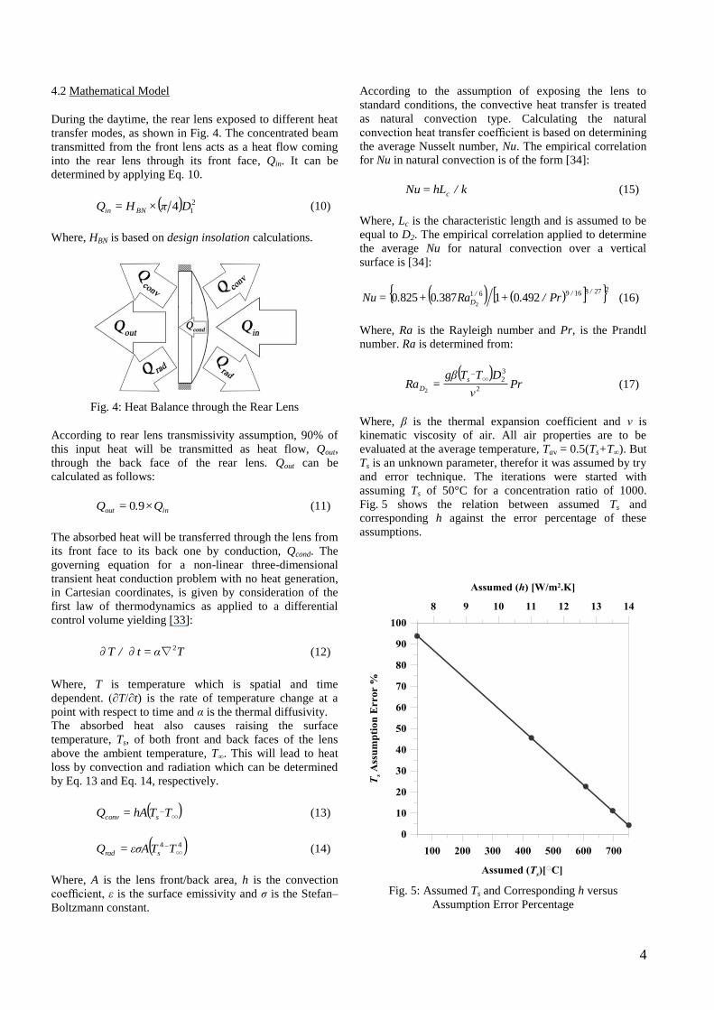
Where, β is the thermal expansion coefficient and ν is
kinematic viscosity of air. All air properties are to be
evaluated at the average temperature, Tav = 0.5(Ts+T∞). But
Ts is an unknown parameter, therefor it was assumed by try
and error technique. The iterations were started with
assuming Ts of 50°C for a concentration ratio of 1000.
Fig. 5 shows the relation between assumed Ts and
corresponding h against the error percentage of these
assumptions.
Fig. 5: Assumed Ts and Corresponding h versus
Assumption Error Percentage

5
Fig. 5 indicates that the convective heat transfer coefficient
can be assumed as constant at 14 W/m2.K, with an error of
4.3%, which can be considered as an acceptable error.
Although for higher CR values the average Ts is expected
to increase and consequently the convective heat transfer
coefficient, but it can be assumed to be constant at
14 W/m2.K to ensure being in the safe side.
5. RESULTS AND DISCUSSION
According to Eq. 9, the relation between CR and FLR
percentage can be illustrated as shown in Fig. 6.
It also shows that the LLBG can achieve, theoretically, the
ideal concentration ratio CRideal at a FLR% of 0.46%
without any obvious theoretical restrictions.
Fig. 6: CR versus FLR Percentage
Fig. 7 shows the variation in the maximum temperature of
the front surface of the rear lens throughout the day time at
different CR values.
From Fig. 7, it can be concluded that increasing CR causes
the increase of the front surface temperature of the rear
lens. This creates a practical restriction on specifying CR of
the LLBG design, as the melting point temperature of the
rear lens arises as a critical parameter in specifying the
maximum allowable concentration ratio, CRmax.
Fig. 7: Rear Lens Front Surface Temperature Variation
at different CR values
Fig. 8 illustrates the relation between the maximum
temperature of the rear lens, Tmax, versus different CR
values. It indicates that at a CR of 2290, the rear lens will
achieve a maximum temperature of 1359.7°C which
approximately equal to the CaF2 melting point as shown in
Table 1. Increasing CR above this critical point raises the
maximum lens temperature to higher values above its
melting point.
Fig. 8: Maximum Rear Lens Temperature, Tmax, versus CR

6
6. CONCLUSIONS
The LLBG is a promising configuration which can be used
in order to generate a concentrated beam of solar radiation.
Theoretically, it can achieve the CRideal of 46747 at a FLR
of 0.46%, but practically there are limitations on selecting
the maximum allowable concentration ratio, CRmax, of the
LLBG. The present study focused on the melting point of
the rear lens as a one of the most important parameters
restricting the CRmax.
It can be concluded that for a CaF2 convex lens in a LLBG
device located in Egypt, 31°N, the CRmax is 2290 at
standard operating conditions. Calculation of the CRmax in
the present study was based on the calculation of solar
insolation at Egypt on June 21. Therefore, The CRmax value
is not fixed, as it can be changed if the LLBG is located in
different location.
7. NOMENCLATURE
Aa Aperture area, m2
Ar Receiver area, m2
CR Geometric concentration ratio
CRideal Ideal concentration ratio
CRmax Maximum allowable concentration ratio
DB Beam diameter, mm
D1 Front convex lens diameter, mm
D2 Rear convex lens diameter, mm
FL1 Front convex lens focal length, mm
FL2 Rear convex lens focal length, mm
FLR Focal Length Ratio
h Convective heat transfer coefficient, W/m2.K
HBN Beam radiation at normal incidence, W/m2
Qcond Conduction heat transfer, W
Qconv Convection heat transfer, W
Qin Heat flow into the rear lens, W
Qout Heat flow out of the rear lens, W
Qrad Radiation heat transfer, W
T Temperature, ○C
Tmax Maximum rear lens temperature, ○C
Ts Surface temperature of the rear lens, ○C
T∞ Ambient temperature, ○C
α Thermal diffusivity, m2/s
β Thermal expansion coefficient, 1/K
ε Emissivity
θ Half-acceptance angle, degree
ν Kinematic viscosity, m2/s
REFERENCES
[1] Kumar, A. Improvements in Efficiency of Solar
Parabolic Trough. IOSR Journal of Mechanical and
Civil Engineering. 2013; 7(6): 63–75.
[2] Hsieh, J. Solar Energy Engineering. 1st ed.
Englewood Cliffs, NJ. Prentice-Hill; 1986.
[3] Chu, Y. and Meisen, P. Review and Comparison of
Different Solar Energy Technologies. Global Energy
Network Institute (GENI); 2011.
[4] Essig, S. and Dimroth, F. Fast Atom Beam Activated
Wafer Bonds between n-Si and n-GaAs with Low
Resistance. ECS Journal of Solid State Science and
Technology. 2013; 2(9): Q178–Q181.
[5] Newton, C. A Concentrated Solar Thermal Energy
System. Florida: The Florida State University; 2007.
[6] Mancini, T., Kolb, G., and Prairie, M. Solar Thermal
Power, Advances in Solar Energy: An Annual Review
of Research and Development. Karl W. Boer, ed.,
American Solar Energy Society, Boulder, CO.1997;
11: 135–151.
[7] Ho, C., and Iverson, B. Review of High-Temperature
Central Receiver Designs for Concentrating Solar
Power. Renewable and Sustainable Energy Reviews.
2014; 29, 835–846.
[8] Uhlig, R. Transient Stresses at Metallic Solar Tube
Receivers. In Proceedings of SolarPACES 2011,
Granada, Spain, 20–23 September, 2011.
[9] Kolb, G. An Evaluation of Possible Next-Generation
High-Temperature Molten-Salt Power Towers. Sandia
National Laboratories, Albuquerque, NM; 2011.
[10] Amsbeck, L., Denk, T., Ebert, M., Gertig, C., Heller,
P., Herrmann, P., Jedamski, J., John, J., Pitz-Paa, R.,
Prosinečki, T., Rehn, J., Reinalter, W., and Uhlig, T.,
Test of a Solar-hybrid Microturbine System and
Evaluation of Storage Deployment. In Proceedings of
SolarPACES 2010, Perpignan, France, 21–24
September, 2010.
[11] Parabolic Trough Report 2014: Cost, Performance
and Thermal Storage. CSP Today, October 2013.
[12] Eck, M., Zarza, E. Saturated Steam Process with
Direct Steam Generating Parabolic Troughs. Solar
Energy. 2006; 80(11): 1424−1433.
[13] Stancich, R. Parabolic Trough Technology:
Technical Advances Speed CSP toward Grid Parity.
CSP Today, Augustus 2011.
[14] Sukhatme, S. Principles of Thermal Collection and
Storage. New Delhi. McGraw Hill; 2007.
[15] IRENA Report: Concentrating Solar Power,
Technology Brief. January 2013.
[16] Kalogirou, S. Solar Energy Engineering: Processes
and Systems. 1st ed. Elsevier Inc.; 2009.
[17] IRENA Report: Cost Analysis of Concentrating Solar
Power. June 2012.

7
[18] Gianella, S. Porous Materials for High-Temperature
Solar Absorbers. In Proceedings of International
Symposium on High Temperature Solar Materials,
Yeungnam University, November 2012.
[19] Nixon, J. and Davies, P. Cost-Exergy Optimisation of
Linear Fresnel Reflectors. Solar Energy. 2012; 86:
147−156.
[20] Novatec Solar.
www.novatecsolar.com (accessed 20 May 2014).
[21] Candelaria, M. Concentrating Solar Power: Mirrors
or Fresnel Lenses. October 2013, available on:
http://www.novuslight.com/mirrors-vs-fresnel-lenses-
for-concentrating-solar-power_N1760.html (accessed
21 May 2014).
[22] Qianjun, M., Ming, X., Yong, S. and Yuan, Y. Study
on Solar Photo-Thermal Conversion Efficiency of a
Solar Parabolic Dish System. Environmental Progress
& Sustainable Energy. 2013. doi: 10.1002/ep.11914.
[23] Muller-Steinhagen, H., Tried, F., and Trieb, F.
Concentrating Solar Power − A review of the
technology. Ingenia, Royal Academy of Engineering.
2004. 18(43).
[24] Mancini, R. Analysis and Design of Two Stretched-
Membrane Parabolic Dish Concentrators. Journal of
Solar Energy Engineering. 1991; 113: 180−187.
[25] Salem, M., Tawfik, M., and Hamed, A. Analysis and
Performance of Solar Concentrating-Tracking
System. In Proceedings of 7th
General International
Engineering Conference, Mansoura/Sharm El-Sheikh,
Egypt, 23−28 March, 2010.
[26] Rabl, A. Active Solar Collectors and Their
Applications. New York. Oxford University Press;
1985.
[27] Abdullahi, B., AL-Dadah, R., and Mahmoud, S.
Effect of Acceptance angle on the design and
performance of a heat pipe based compound parabolic
collector at Kano, Nigeria. In Proceedings of
International Conference on Renewable Energies and
Power Quality, Bilbao, Spain, 20−22 March 2013.
[28] Duffie J., and Beckman W. Solar Engineering of
thermal Processes. 3rd
ed. Hoboken, NJ. John Wiley
and sons, Inc.; 2006.
[29] Kalogirou, S. Solar thermal collectors and
applications. Progress in Energy and Combustion
Science. 2004; 30: 231−295.
[30] Jacob, M., Mazierska, J., Ledenyov, D., and Krupka,
J. Microwave Characterisation of CaF2 at Cryogenic
Temperatures Using a Dielectric Resonator
Technique. Journal of the European Ceramic Society.
2003; 23: 2617−2622.
[31] Crystran Ltd. Calcium Fluoride (CaF2).
www.crystran.co.uk/optical-materials/calcium-
fluoride-caf2 (accessed 1 March 2014).
[32] CVI Laser Optics. PLCX-CFUV: CaF2 Plano-Convex
Lenses.
http://marketplace.idexop.com/store/IdexCustom/Part
Details?pvId=27882 (accessed 1 March 2014).
[33] Lei, Z., HongTae, K., Yonggang, L. Finite Element
Analysis for Transient Thermal Characteristics of
Resistance Spot Welding Process with Three Sheets
Assemblies. Procedia Engineering. 2011; 16:
622−631.
[34] Cengel, Y. Heat transfer: a practical approach. 2nd
ed. New Delhi. McGraw Hill; 2002.