KANTAKAPALLI STATION - East Coast Railway
115
EAST COAST RAILWAY WALTAIR DIVISION STATION WORKING RULES KANTAKAPALLI STATION
-
Upload
khangminh22 -
Category
Documents
-
view
0 -
download
0
Transcript of KANTAKAPALLI STATION - East Coast Railway

EAST COAST RAILWAY
WALTAIR DIVISION
STATION WORKING RULES
KANTAKAPALLI STATION

EAST COAST RAILWAY
WALTAIR DIVISION
TILARU (TIU) STATION
INDEX OF CORRECTION SLIPS
S No. Correction Slip No. Date of issue Rule No. Page Nos.

I N D E X
S No. Description Page Nos.
1. Station Working Rules 1-26
2. Appendix - A 27-39
3. Appendix - B 40-73
4. Appendix - C 74
5. Appendix - D 75-76
6. Appendix - E 77
7. Appendix - F 78-90
8. Appendix – G Booklet
SWR OF KANTAKAPALLI STATION (KPL) 1
(B.MADHU VENKATESWARLU) (K.GANESH KUMAR)
DSTE /WAT Sr.DOM/G/WAT
EAST COAST RAILWAY WALTAIR DIVISION
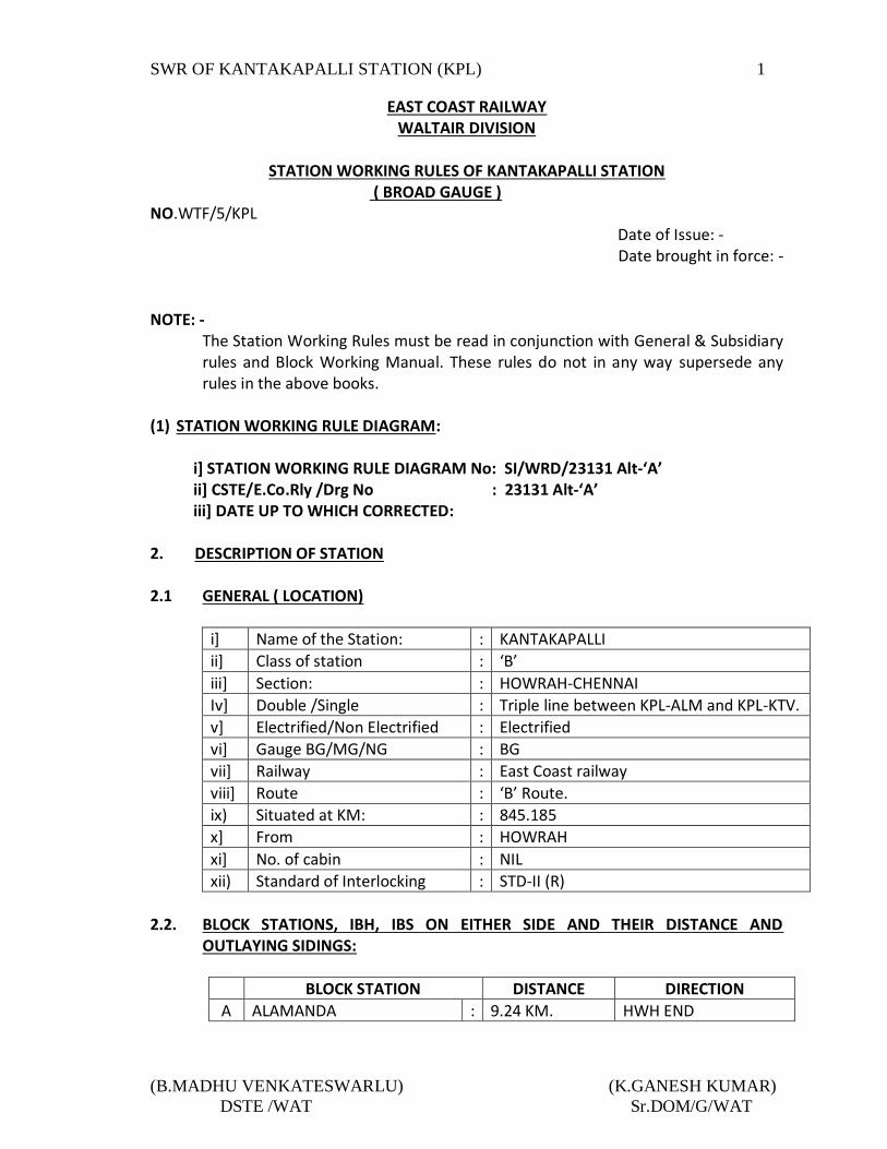
STATION WORKING RULES OF KANTAKAPALLI STATION
( BROAD GAUGE ) NO.WTF/5/KPL Date of Issue: -
Date brought in force: -
NOTE: -
The Station Working Rules must be read in conjunction with General & Subsidiary rules and Block Working Manual. These rules do not in any way supersede any rules in the above books.
(1) STATION WORKING RULE DIAGRAM: i] STATION WORKING RULE DIAGRAM No: SI/WRD/23131 Alt-‘A’ ii] CSTE/E.Co.Rly /Drg No : 23131 Alt-‘A’ iii] DATE UP TO WHICH CORRECTED:
2. DESCRIPTION OF STATION 2.1 GENERAL ( LOCATION)
i] Name of the Station: : KANTAKAPALLI
ii] Class of station : ‘B’
iii] Section: : HOWRAH-CHENNAI
Iv] Double /Single : Triple line between KPL-ALM and KPL-KTV.
v] Electrified/Non Electrified : Electrified
vi] Gauge BG/MG/NG : BG
vii] Railway : East Coast railway
viii] Route : ‘B’ Route.
ix) Situated at KM: : 845.185
x] From : HOWRAH
xi] No. of cabin : NIL
xii) Standard of Interlocking : STD-II (R)
2.2. BLOCK STATIONS, IBH, IBS ON EITHER SIDE AND THEIR DISTANCE AND
OUTLAYING SIDINGS:
BLOCK STATION DISTANCE DIRECTION
A ALAMANDA : 9.24 KM. HWH END

SWR OF KANTAKAPALLI STATION (KPL) 2
(B.MADHU VENKATESWARLU) (K.GANESH KUMAR)
DSTE /WAT Sr.DOM/G/WAT
B KOTTAVALASA : 7.755 KM. VSKP END
C Provision of IBS: : IBS provided between section KPL-ALM
DN line at KM.840.900 and UP line at KM.841.011.
D Automatic signals: : NIL
E D.K Stations/Outlaying; : NIL
2.3. BLOCK SECTION LIMITS ON EITHER SIDE OF THE STATION ON DIFFERENT
DIRECTIONS:
Between Stations The Point from which the ‘Block Section’ Commences
The Point at which the ‘Block Section ends.
KPL-KTV UP Direction From UP Advanced starter signal No 37 of KPL
Outermost facing point No 55A of KTV.
KPL-ALM DN Direction a) From DN LSS signal No.38 of KPL. b) From DN IB Home signal No. 42 of KPL.
a) 400 mtrs. Beyond DN IBS No. 42 of KPL. b) UP to Point no.52A of ALM.
KPL-KTV Middle line UP direction.
From UP Advanced starter signal No.39 of KPL on Middle line.
DN Advanced starter signal No.48 of KTV.
KPL-ALM middle line DN direction.
From UP Advanced starter signal No.39 of ALM on middle line.
DN Advanced starter signal No.40 of KPL.
2.4 GRADIENTS WITHIN STATION LIMITS: i) TOWARDS KTV END
From To Distance Gradient
CSB CH:1296M 1296.000 M 1 in 600 Raising.
CH: 1296M CH:2350M 1054.000 M 1 in 250 Raising.
CH: 2350M CH:2850M 0500.000 M Level.
CH:2850M CH:3940M 1090.000 M 1 in 200 Falling.
CH:3940M In to section --- 1 in 150 falling.
ii) TOWARDS ALM END (UP & MIDDLE LINE):
From To Distance Gradient
CSB CH: 368.000 M 368.000 M 1 In 600 Falling.
CH: 368.000M CH: 945.000M 577.000 M 1 in 424 Falling.
CH: 945.000M CH:1570.000M 0625.000 M 1 in 150 Falling.
CH: 1570.000M CH: 2853.000M 1283.000 M Level

SWR OF KANTAKAPALLI STATION (KPL) 3
(B.MADHU VENKATESWARLU) (K.GANESH KUMAR)
DSTE /WAT Sr.DOM/G/WAT
CH: 2853.000M CH: 5092.000M 2239.000 M 1 in 150 falling.
CH :5092.000M In to section --- 1 in 155 falling
i) TOWARDS ALM END (DN LINE):
From To Distance Gradient
CSB CH: 368.000 M 368.000 M 1 In 600 Falling.
CH: 368.000M CH: 945.000M 577.000 M 1 in 424 Falling.
CH: 945.000M CH:1076.000M 131.000 M 1 in 395 Falling.
CH: 1076.000M CH: 1844.000M 768.000 M 1 in 200 Falling.
CH: 1844.000M CH: 2853.000M 1009.000 M Level.
CH :2853.000M CH: 5092.000M 2239.000M 1 in 150 falling.
CH :5092.000M In to section. --- 1 in 155 falling.
2.5. Layout: (A) RUNNING LINES IN THE MAIN YARD.
Sl No.
Name of the line Electrified/ Non Electrified
Platforms with length
1 Line No.-1 ( DN Loop) Electrified Medium Level (350M)
2 Line No.-2 ( DN Line) Electrified Rail Level (353.2M)
3 Line No.3 ( Middle Line) Electrified Rail Level (354.2M)
4 Line No.4( UP Line) Electrified Rail Level (354.2M)
5 Line No.5 ( Common loop) Electrified Low Level (353.2M)
6 Line No.6 ( Common loop) Electrified Low Level (353.2M)
(B) SIDING:
Sl. No.
Name of the Siding Electrified/ Non Electrified
Platforms Isolation of Running Line
01 Engg. Siding Electrified ---
Isolated from Line No.1 by D/S 68.
02 Ballast Siding Electrified ---
By Hand Point.
2.5.1 RUNNING LINES, DIRECTION OF MOVEMENT AND HOLDING CAPACITY IN CSL:
Sl No.
Name of the lines Holding capacity in CSL
Direction of movements
1 Line No.1(DN loop) 819 M (STR to SS) (a)Trains coming from ALM and proceed 2 Line No.2 (DN line) 815 M (STR to SS)

SWR OF KANTAKAPALLI STATION (KPL) 4
(B.MADHU VENKATESWARLU) (K.GANESH KUMAR)
DSTE /WAT Sr.DOM/G/WAT
3 Line No.3 (Middle line)
726M (STR to STR) towards KTV are UP trains. (b) Trains coming from KTV and proceed towards ALM are DN trains.
4 Line No.4 (UP line) 725M (STR to SS)
5 Line No.5(Common loop)
735 M (STR to STR)
6 Line No.6 (Common loop)
727 M (STR to STR)
2.5.2. NON RUNNING LINES:
Sl.no Name
Holding capacity in CSL in mtrs
Electrified/ Non Electrified
1 Engineering Siding 133 M (SH-DE) Electrified
2 Ballast siding 350 M (FM-DE) Electrified
3 Shunting Neck 350M (SH-DE) Electrified
2.5.3 ANY SPECIAL FEATURES IN THE LAYOUT (A)
Sl.no Special Features Descriptions
1 ENGG. SIDING The Engg. Siding takes off from L/1 over run line towards KTV end of yard and terminates in a Dead end. The CSL of the siding is 133 Mtrs (SH to DE). The siding is an extension portion of over run line which is isolated by motor operated D/S point no.68.
2 BALLAST SIDING The Ballast siding takes off from the shunting neck of Line No.1 at ALM end. It is isolated by a hand point from shunting neck and terminates into a dead end. The CAL of siding is 350Mtrs (FM to DE).
(B) SPECIAL INSTRUCTIONS:
i. Line verification buttons are provided for berthing line No.6 in a sealed box kept outside SM’s office. After ensuring clearance of the loop line No.6 by SM physically, resetting of Axle counter can be done by SM.
ii. While receiving and sending trains to Ballast siding (Engg. Siding) SM has to ensure correct setting and locking of points.
2.6 LEVEL CROSSINGS: The details of L.C. Gates are given in Appendix ‘A’ of this SWR.

SWR OF KANTAKAPALLI STATION (KPL) 5
(B.MADHU VENKATESWARLU) (K.GANESH KUMAR)
DSTE /WAT Sr.DOM/G/WAT
3. SYSTEM AND MEANS OF WORKING: Trains are worked under Absolute Block System in accordance with GR Chapter VIII Rule No 8.01(1)(a)&(b), 8.01(2)(b), 8.03(1),Chapter-III Rule No 3.07(4)(5),3.08(4) Chapter-XIV and BWM Chapter V. SGE type Double Line Lock and Block Instruments are provided for UP & DN lines of KPL-ALM & KPL-KTV sections and token less daido handle type single line block instrument provided for middle line section KPL-KTV and KPL-ALM Section. The Block Instruments shall be operated by Station Master on duty and keys of the Block Instruments shall remain under personal custody of SM on duty. [Refer Chapter XIV of GR & SRs, Chapter–V of Block Working Manual and GR 14.08(a)].Telephones are provided in all block instruments and DN IB signal post at KM: 840.900.
4. SYSTEM OF SIGNALLING AND INTERLOCKING: 4.1 SYSTEM OF SIGNALLING AND INTERLOCKING:
1 Standard of Interlocking
Standard – II (R)
2 Type of Signaling MACLS
3 Mode of Operating the signals
Visual Display Unit (VDU)
4 Provision of Calling –On signals
Calling-on signals are provided below Home signals (i.e. in both UP & Down directions) as per GR.3.13 (1)(b), (2)(3)(4) & (6) (b). and below starter signal no.17,19,21,23 & 20,24,26,30,32.
5 Provision of Shunt signals
Independent Shunt signals SH 6H/B/C/D/E/F, SH 8A/B/C/D, SH10 and dependent shunt signals SH17A/B, SH 19A/B, SH 21A/B, SH 23A/B, SH 25, 29A/B are provided towards VSKP end Independent SH 5A/B/C/D/E, SH 7A/B/C/D/E/F, SH9 and dependent Shunt signal SH 20A/B, SH 24A/B, SH 26A/B, SH 28A/B, SH 30A/B, SH 32A/B are provided towards HWH end for shunting purpose.
6 Emergency cross over NIL
7 Track circuits All berthing portion of line No.1 to Line No.5 are track circuited where as berthing portion of Line No.6 i.e Coal common loop is monitored by analog axle counters.

SWR OF KANTAKAPALLI STATION (KPL) 6
(B.MADHU VENKATESWARLU) (K.GANESH KUMAR)
DSTE /WAT Sr.DOM/G/WAT
In addition there are short length track circuits in advance of Advanced Starter Signals and Home signal in both the directions are also provided. For Calling-on signals (Five Rail length) track circuits are also provided in rear of the Home signals in both directions. From last trailing point/fouling mark in either side of Yard to Advanced Starter Signals are also track circuited in UP middle line, UP line and Down lines respectively). Indications for the above track circuits/Axle Counters are available on VISUAL DISPLAY UNIT at SM’s office. White indication on the VISUAL DISPLAY UNIT indicates track clear and Red light indicates track occupied condition.
8 Axle counters Analog Axle Counters are provided on berthing portion for line No.6 i.e Common Loop, in the yard for counting Axles ‘IN’ and counting axles ‘OUT’ which indicate whether the concerned point zone/berthing track monitored by axle counters is clear or occupied. (ii)Entire Block Section between KPL-KTV and KPL-ALM
are provided with Digital axle counter. For section KPL-ALM A pair of Digital axle counter is provided between ALM-KPL(UP LVV ALM-KPL) on UP line, one just beyond UP IB signal No. 41 of ALM on 41T2 and another one on 1T2 track circuit beyond UP Home Signal No.1A/B/C/D of KPL for proving UPLVV for section KPL-ALM. Similarly a pair of Digital axle counter is provided between KPL-ALM (DN LVV KPL-ALM) on DN line, one beyond DN IB signal No.42 of KPL on 42T1 and another near DN BSLB of ALM for proving DN LVV for section KPL-ALM. A pair of Digital axle counter is provided between KPL-ALM on DN line, One just beyond DN Advanced starter signal No.38 of KPL and another one beyond DN IB signal No.42 of KPL on 42T2 for proving DN IB section between KPL-ALM. Similarly a pair of digital axle counter is provided between KPL-ALM on UP line one just beyond UP Advanced starter No.13 of ALM and another one beyond UP IB signal no.41

SWR OF KANTAKAPALLI STATION (KPL) 7
(B.MADHU VENKATESWARLU) (K.GANESH KUMAR)
DSTE /WAT Sr.DOM/G/WAT
of ALM on 41T1 for proving UP IB section between KPL-ALM. A pair of digital Axle counter is provided between KPL-ALM on middle line one just beyond Advanced starter signal no.40 on 3T and another beyond Home signal no.6T of ALM. FOR SECTION KPL-KTV A pair of digital Axle counter is provided between KPL-KTV on UP line one just beyond UP Advanced starter signal No.37 on track circuit No.37T and another beyond Signal No.1 of KTV on track circuit No.1T2 for proving UPLVV for section KPL-KTV. A pair of digital Axle counter is provided between KPL-KTV on Middle line one just beyond Advanced starter signal No.39 on 4T and another beyond Home signal No.3 on track circuit No.3Tof KTV. Another pair of Digital Axle counter is provided between KPL-KTV on DN line one just beyond DN Advanced starter signal No.50 on 50T track circuit and another near facing Point No.52A of KPL on track circuit No.2T2. The position of the Block section whether cleared or occupied are reflected in the VISUAL DISPLAY UNIT provided in the Station Master’s office which shows ‘GREEN’ when the Block Section is clear and ‘RED’ when occupied. Whenever a train enters in to the Block Section, “Block Section Clear” indication ‘GREEN’ for the particular block section disappears and ‘RED’ indication appears. After complete arrival of the train the ‘RED’ indication will disappear and ‘GREEN’ indication will appear. If after the complete arrival of the train the ’RED’ indication does not change to ‘GREEN’ it should be assumed as Block Instrument failure for the particular section and necessary action as per GR.14.13 is to be followed. The axle counters are interlocked with the respective block instruments for that section. If axle counter fails, Advanced Starter signal shall not come to OFF and the concerned instrument shall remain locked in last operated position. A resetting arrangement for resumption of the system in case of failure of axle counter has been provided in the SM office of the adjacent Block stations after being assured by both the SM that the last vehicle has arrived

SWR OF KANTAKAPALLI STATION (KPL) 8
(B.MADHU VENKATESWARLU) (K.GANESH KUMAR)
DSTE /WAT Sr.DOM/G/WAT
complete at the receiving station by exchanging Private Number then resetting to be complied with. (Details of resetting procedure given in this SWR). In case of failure of analog Axle Counter the re-setting of axle counter must be done as per the procedure given in this SWR. In the event of failure of Axle Counter/ Track circuit the clearance of loop lines and concerned point zone and main lines will be ensured by physical check by the SM on duty and train shall be admitted as per GR.3.69 and SR there to. NOTE: Before taking off reception and dispatch signals for UP and Down directions the SM on duty should ensure that the entire route including overlap and berthing portion is clear of all obstructions by observing the Track indication/Axle counter indication. The indication of track Axle counter will exhibit Red Light when track is occupied and White light when track is clear. There will be no track indication when any route is not set.
9 Crank handle When any point fails to operate normally by the Route Setting operation through Visual Display Unit it is inevitable to operate the points with crank handle. The SM on duty shall personally ensure clamping and padlocking of all facing and trailing points on the route. Crank handles are interlocked with signals and interlocking system. When points become defective, the signals controlling these points shall be considered defective and vice-versa and the procedure for use of crank handle for motor operated points shall be followed as per operating manual para-2.19 These crank handles are interlocked with the signaling and interlocking system at this station and normally locked inside the RKT instrument at the respective Crank Handles Locations. Crank handle keys can be taken out only when all signals are not taken ‘OFF’ and the route is not locked for whatever reasons. Crank Handle can be released by SM by tracking the mouse pointer on to the concerned crank handle button icon. This will enable two options to be displayed on the menu i.e. Crank handle Transmit control and Crank Handle Release control. To release the crank handle key, SM should click the Crank handle ‘TRANSMIT’ control option. After transmission the KEY IN indication will start flashing, now the key can be

SWR OF KANTAKAPALLI STATION (KPL) 9
(B.MADHU VENKATESWARLU) (K.GANESH KUMAR)
DSTE /WAT Sr.DOM/G/WAT
extracted from the EKT. After extracting the key from the EKT, the KEY IN indication will disappear. When the keys are taken out no signal can be taken “OFF” over the particular route on the points nominated by that Crank Handle. This key can be electrically transmitted at both ends locations of the yard for manual operation of the defective points. SM on duty shall personally ensure the clamping and padlocking of all facing and trailing points. An emergency Crank handle register shall be maintained by the SM on duty at the station as per Para 2.19 (j) of the Operating Manual. Correct setting, clamping and padlocking of the points devolve on the SM on duty. (Details use of Crank Handle as per Appendix-‘B’). The cases of failure of motor point, it should be promptly reported to the concerned signal maintainer/SSE (Signal) for immediate rectification.
10 Emergency Point operation:
Emergency point operation facility is provided to operate the point from the Visual Display Unit in case of failure of point controlling track circuit/Axle Counter. Before doing the emergency operation, the Emergency Point Operation Key is to be made “KEY IN” by clicking the KEY IN menu. The user name and password is be be logged in. The user name is ECOR and the password of this station is KPL. On clicking the concerned point icon, a pop-UP menu is displayed carrying four options: 1) Normal 2) Reverse 3) Emergency Normal 4) Emergency Reverse. For emergency operation of concerned point, drag the pointer to either emergency normal or emergency reverse whichever is desired. A normal or reverse flashing indication will appear and the indication will be steady after the point is set to Normal or reverse, whichever is desired. After the completion of Emergency point operation, the key is to be KEY OUT by clicking KEY OUT menu. The user name and password is to be given for KEY OUT also. This action will be recorded in a counter. All such operations will be registered in the emergency point operation counter Register. Each operation of emergency point operation shall be recorded in the station diary and in the register meant for this purpose.
11 Showing of Veedor Counters
One counter icon has been provided on the VDU. When selected a drop down menu will appear indicating the

SWR OF KANTAKAPALLI STATION (KPL) 10
(B.MADHU VENKATESWARLU) (K.GANESH KUMAR)
DSTE /WAT Sr.DOM/G/WAT
following counters. 1. Emergency Route Release. 2. Emergency Point Operation. 3. Emergency Crank handle release. 4. Emergency Gate release. 5. I.B. Axle counters resetting for section KBM-TIU UP line. 6. LVCD axle counters resetting for section KBM-TIU. 7. LVCD axle counters resetting for section TIU-ULM. When the pointing device is placed any one of the menu the latest counter number will pup-up on VDU
12 Emergency route release indication:
The Electronic interlocking is based on the principle of ‘DEAD APPROACH LOCKING’. As such when a route is set and signal is taken ‘OFF’ on the route, the route gets locked. Normally the route is released by the passage of the train over the route. When it becomes necessary to alter the route after the signal has been taken ‘OFF’ vide SR 3.36.02(a), click on the concerned signal. After clicking by the left button on the mouse a pop-UP menu will appear as shown above- Click on the cancellation menu (Main/Calling on) of the concerned signal, the signal will immediately go to ON aspect. After doing so slick on the route release menu, the route locked indication will start flashing for 120 second. After completion of 120 seconds, the White light along with the White strip of light will disappear suggesting the route has been released. This action will be recorded in a counter. The counter will increment the number for each and every such action. In case the route illumination (white strip lights) does not disappear, it suggests that the route is not released/cancelled. In such case the concerned S&T staff should be advised immediately to release the route. Each operation of emergency cancellation of route should be recorded in the emergency route release counter register by registering the next higher number. All such operations and the new number should be recorded in the station diary Veeder counter register and in the train signal register.

SWR OF KANTAKAPALLI STATION (KPL) 11
(B.MADHU VENKATESWARLU) (K.GANESH KUMAR)
DSTE /WAT Sr.DOM/G/WAT
4.2 CUSTODY OF RELAY ROOM KEY AND PROCEDURE FOR ITS HANDING OVER AND TAKING OVER BETWEEN STATION MASTER AND S&T MAINTENANCE STAFF: As per JPO/02/2012,Dt.29.8.2012 issued by COM and CSTE/ECoR, the following procedure shall be adopted for opening of Relay Room: The Relay room of station shall have double locking system of operating and S&T locks. One lock shall be provided on the door of Relay room by the Station Master. This lock is named as operating lock. The key shall be kept in the safe custody in the Key-box with the SM on duty. Likewise, one lock shall be provided on the door of Relay room by the Signal maintainer / Signal supervisor of the section. Name of the S&T staff authorized for opening of Relay room is to be entered in the first page of Relay room key register and jointly certified by SSE/Signal in charge and DTI incharge of the section. In emergency, if any S&T staff other than authorized wants to open Relay room, he must inform DSTE through Signal Fault Control. It shall convey the permission of DSTE to SS/SM by giving Signal Fault
Control number. {As per Operating Manual 13.16 (b)}. Whenever relay room is to be opened either for schedule maintenance or during failures or for other maintenance activities/construction works. The concerned Maintainer/Signal supervisor will verify his identity from the list of authorized S&T staff recorded in the first page of Relay Room key register or as advised by Signal Fault Control in emergency. SM shall give the key of pertaining lock to S&T staff, after the entry is made in Relay Room Key register and also with Red ink in TSR. Relay room key shall not be handed over by SM on duty to any Group-D staff of S&T department. On completion of work, the concerned Signal Maintainer/Signal supervisor shall properly closed Relay Room door and lock it with both the locks and then return the key of operating lock to the SM on duty making the entry in the Relay room key register. When the key of Operating Lock is returned by S&T staff to SM on duty, he shall verify the Relay Room for proper locking and then keep the key in safe custody and acknowledge it on the Relay Room key register. If the relay room key is handed over to the signal staff regarding the interference in safety gears the train shall be pilot in and out. For attending Failures of S&T gears within relay room, the following steps shall be taken: Entry to be made in S&T failure register by SM on duty and failure memo has to be issued to S&T staff. S&T staff shall not take the Relay room key for attending

SWR OF KANTAKAPALLI STATION (KPL) 12
(B.MADHU VENKATESWARLU) (K.GANESH KUMAR)
DSTE /WAT Sr.DOM/G/WAT
failures and 0pen the Relay room unless the failure is recorded in Signal failure register. If disconnection is required, Disconnection memo has to be given by S&T staff to SM on duty. Failure memo should be acknowledged and entry in relay room key registers to be made by S&T staff before obtaining station masters key. Relay room key for schedule maintenance shall be taken once in a calendar month during monthly inspection by Sectional Supervisor. Relay room can be opened by following above procedure for special maintenance activities like cable insulation testing, Block/disconnecting memos, selection table testing maintenance work inside relay room by Electrical and Engineering staff, during failures, E.I resetting and inspection by Divisional and Headquarter officials, works required by Constructing & Open line staff for preparatory works and during commissioning. In each such case, the construction staff shall follow the detailed guidelines issued regarding working on signaling gears under the charge of open line. In case of emergencies such as fire, flood, earthquake etc. Open line Section Engineer (Signal)/Signal Maintainer & SS/SM shall jointly decide the need for opening the Relay room. Section Engineer (signal)/HQs at Divisional Control office and Section controller shall be advised respectively. In case of communication failure during such emergencies, Open line Signal Maintainer/Supervisors and SS/SM on duty shall jointly decide the need for opening the Relay room and communicate later to respective controls. In case key is lost/misplaced, it shall be reported to S&T control as well as section control for either lock. In normal course the spare key respective custodians shall be used. In emergency situation, lock may be broken under advice to Section Control as well as S&T control. New lock shall be procured and provided. In case SS/SM on duty comes to know that Relay room opening by authorized means or by unauthorized person or by any Group-D staff, the signaling system shall be suspended by him and matter immediately reported to Section Controller for necessary action will check the station records of Relay room opening during their inspections and cross check it with data logger if provided. Discrepancy, if any shall be immediately inquired into and advised to Sr.DSTE & Sr.DOM by numbered control message from the station immediately for further action.
4.3 POWER SUPPLY: (i) Auto change over CLS panel is provided in the Station Master’s Office with the three power supplies viz., UP AT, Down AT and Local, for changing the switch to the required Supply position. A luminous indicator above the circuit breaker for each Supply indicates the availability of the Supply. (ii) Normally the switch will be kept towards UP AT or DN AT position. Whenever power block is to be given on the line, the on duty SM must ascertain that power is available on the other AT. Eg: If power block is to be given on the UP line, Down AT must be available and
vice-versa.

SWR OF KANTAKAPALLI STATION (KPL) 13
(B.MADHU VENKATESWARLU) (K.GANESH KUMAR)
DSTE /WAT Sr.DOM/G/WAT
(iii) In case of failure of one of the AT Supply without any power block, the on duty
SM. has to check whether the circuit breaker has tripped. (Three circuit breakers are provided in the changeover switch board, one for each Supply and their normal position is down and when tripped it goes UP.) In case of failure of both AT supplies, the Local Supply shall be utilized by operating the switch. If the circuit breaker is tripping even after resetting, no attempt shall be made to hold it by any other mean and a message shall be given to the AEE and CTFO/PSI for prompt rectification.
(iv) For IPS system that provides power supply to the signaling installation 230V AC is taken from the selection output of the Auto change Over Panel in SM Office. There is a remote monitoring ASM box provided at the station to monitor the health of IPS.
REMOTE MONITORING ASM BOX:
Remote monitoring SM Box gives alarm to the SM for the following fault conditions:-
(a) 50% depth of discharge (DOD) of battery. In this condition audio/visual alarm comes, which can be acknowledged with audio cut-off.
(b) 60% DOD, which warns for emergency. The alarm for this condition is same as for condition 1.
(c) 70% DOD, which signals system, shut-down. In this condition signal feed is cut-off and all DC-DC converters continue working. Audio alarm continues till power Supply is restored.
(d) Any of the module fails, which calls for ‘call S&T’. (e) Whenever there is a failure of power Supply in one AT the SM shall take prompt
action to inform to all concerned for the rectification. The SM himself, during his daily checks, shall test the availability of power Supply on both AT’s and make an entry in the Station Diary duly initiating action for rectification of failure, if any.
5. TELECOMMUNICATIONS: a) The Station is connected to VSKP -PSA Main line Control Circuit. b) Telephone attached to SGE type Lock and Block Instruments for sections KPL-ALM
and KPL-KTV and telephone attached to TLBI section KPL-KTV & KPL-ALM. c) Railway Auto telephone is provided at the station. d) Hot line communication is provided between KPL-ALM and KPL- KTV stations. e) Telephone communication is provided between Station Master and UP CH locations and to DN CH Locations. f) Telephone attached to L.C.Gate No.M/L-477 at Km, 845/21-23 g) The station is connected to VSKP – PSA traction power control circuit. h) The station is provided with BSNL/CUG Telephone.

SWR OF KANTAKAPALLI STATION (KPL) 14
(B.MADHU VENKATESWARLU) (K.GANESH KUMAR)
DSTE /WAT Sr.DOM/G/WAT
i) Telephone is provided with DN IBS Post at KM.840.900. j) VHF set is provided at the station. 6.1 DUTIES OF TRAIN WORKING STAFF:
The duties of the train working operational staff in detail is described in Appendix ‘D’ of this SWR.
6.1.1 TRAIN WORKING STAFF IN EACH SHIFT:
STAFF IN EACH SHIFT
SS/SM 1
PM-‘A’ / ‘B’ 1
Traffic Gateman 1
The above staff shall work as per roster issued from time to time by Divisional Railway Manager (P) and these rosters shall be conspicuously displayed in the Station Master’s office and in Gate lodge for traffic gate man (details duties are given in APPENDIX-‘D’).
6.1.2. RESPONSIBILITY FOR ASCERTAINING CLEARANCE OF LINES AND ZONES OF
RESPONSIBILITY: The SS/SM on duty is responsible to ascertain the clearance of the nominated line between BSLB/first facing point and advanced starter signal in each direction.
6.1.3. ASSURANCE OF THE STAFF IN THE ASSURANCE REGISTER: Any staff before taking of independent charge of duties connected to train Working or any staff who is away from his duty for a period of 15 days or more
shall sign in the assurance register as token of having under stood the contents. However in the event of any corrections or modification in the SWR is involved the assurance of all staff who ever is entrusted the work of train passing duty shall be obtained a fresh in the assurance register by the in charge of the station before they are allowed to work vide SR-5.01.02.
6.2 CONDITION FOR GRANTING LINE CLEAR: a) The train is worked under Absolute Block system with double line & single line
working and MACL signaling vide GR 8.03. b) Adequate distance for reception of trains at KPL.
Line No. For UP Trains For DN Trains
FROM TO FROM TO
Line No.1 (COMMON LOOP)
- - DN STR.SIG No.20A/B
DS No.67 on OVERRUN LINE (OR)
DN ADV STR SIG No.38
Line No.2 (DN MAIN)
- - DN MAIN STR.SIG. No.24A/B
DN ADV.STR SIG. No.38 (OR)
DN ADV.STR.SIG. No.40 MID LINE

SWR OF KANTAKAPALLI STATION (KPL) 15
(B.MADHU VENKATESWARLU) (K.GANESH KUMAR)
DSTE /WAT Sr.DOM/G/WAT
Line No.3 (MIDDLE LINE)
UP MAIN STR.SIG.No.23A/B
UP ADV.STR.SIG.No.39 (MIDDLE LINE) (OR)
DN MAIN STR.SIG. No.26A/B
DN ADV.STR.SIG.No.38 (OR)
UP ADV.STR.SIG. No.37
DN ADV.STR.SIG.No.40 (MIDDLE LINE)
Line No.4 (UP MAIN)
UP STR.SIG.No.21A/B
UP ADV.STR.SIG.No.37 (OR)
- -
UP ADV.STR.SIG.No.39 (MIDDLE LINE)
Line No.5 (COMMON LOOP)
UP STR.SIG.No.19A/B
END OF OVER RUN LINE (OR)
DN STR.SIG No.30A/B
END OF OVER RUN LINE (OR)
UP ADV.STR.SIG. No.37 (OR)
DN ADV.STR SIG. No.38 (OR)
UP ADV.STR.SIG.No.39 (MIDDLE LINE)
DN ADV.STR.SIG. No.40 MID LINE
Line No.6 (GOODS COAL LOOP)
UP STR.SIG.No.17A/B
END OF OVER RUN LINE (OR)
DN STR.SIG No.32A/B
END OF OVER RUN LINE (OR)
UP ADV.STR.SIG. No.37 (OR)
DN ADV.STR SIG. No.38 (OR)
UP ADV.STR.SIG.No.39 (MIDDLE LINE)
DN ADV.STR.SIG. No.40 MID LINE
6.2.1 ANY SPECIAL CONDITIONS TO BE OBSERVED WHILE RECEIVING OR
DESPACTHING A TRAIN: 6.2.1.1 SETTING OF POINTS AGAINST BLOCK LINE When a running line is blocked by stabled load wagon, vehicle or by a train
which is to cross or give precedence to another train or immediately after the arrival of a train at the station, the points in rear should be immediately set against the blocked line except when shunting or any other movement is required to be done on that line vide GR 3.51.06. Safety Point Alarm Unit (SPAU): A safety point alarm is provided on the panel board with different indications:
1. On complete arrival of a train at the station, the SM has to set the points immediately against the occupied line.
2. In case the SM forgets to alter the points, after a time lag of 02 minutes, an audible buzzer will be heard from this instrument along with the ‘RED” indication of the line on which the train has arrived.
3. The SM shall then press ‘ACK’ button to mute the buzzer, and immediately set the required points against the line on which the train has arrived.

SWR OF KANTAKAPALLI STATION (KPL) 16
(B.MADHU VENKATESWARLU) (K.GANESH KUMAR)
DSTE /WAT Sr.DOM/G/WAT
4. On setting the points against the occupied line, the RED indication will disappear.
5. In case SM fails to set the required points against the occupied line a fault message will be triggered SMS will be sent to concerned station mobile and all concerned staff. Action will be taken against. If all the lines of a station happen to be blocked when line clear has
been granted to a train the safety point alarm will not work and the point should be set for the line occupied by a stable load or a goods train by SM on duty in that order so that, in case of mishap, the chance of causalities minimized. In case of all the lines are occupied by passenger trains points should be set for a loop line to negotiate which the speed of incoming train would be reduced which in turn would minimize the consequences/causalities vide SR 3.51.06(b). These precautions shall be taken in addition to the observance of other precautions as contained in SR 5.04.01 and SR 5.23.01. Block collars to be placed on the concerned button of blocked line.
6.2.1.2 RECEPTION OF A TRAIN ON BLOCKED LINE:
Whenever trains are to be admitted on an obstructed line it is necessary that the trains are piloted IN on a written authority T/509 given by the SM on duty and delivered by a competent Railway servant to the Loco pilot of the train. [Refer GR 5.09 & SRs there to].Calling on signal where provided may be taken OFF.
6.2.1.3 RECEPTION OF TRAIN ON NON-SIGNALLED LINE: -NIL- 6.2.1.4 DESPATCH OF TRAIN FROM NON-SIGNALLED LINE. -NIL- 6.2.1.5 DESPATCH OF TRAIN FROM LINE PROVIDED WITH COMMON STARTER SIGNAL:
-NIL-.
6.2.1.6. ANY OTHER SPECIAL CONDITIONS: -NIL- 6.3 CONDITIONS FOR TAKING “OFF” APPROACH SIGNALS:-
The SM on duty shall nominate a clear line not only up to the starter but also for an adequate distance beyond it for reception of trains. [Refer GR 3.36, 3.38, 3,40, 4.17 and SR 3.36. 01, 3.36.02, 3.36.04, 3.40.01, 3.40.02, 3.47.01, 4.17.02, and Block Working Manual].

SWR OF KANTAKAPALLI STATION (KPL) 17
(B.MADHU VENKATESWARLU) (K.GANESH KUMAR)
DSTE /WAT Sr.DOM/G/WAT
6.3.1 RESPONSIBILITY OF STATION MASTER FOR RESTORATION OF SIGNALS TO “ON”:
Station Master should ensure that the signal is put back to ‘ON’ after passage of train as per GR 3.36 and SRs there to.
6.4 SIMULTANEOUS RECEPTION/DESPACTH, CROSSING AND PRECEDANCE OF TRAINS: The following simultaneous reception and dispatch facilities are provided at this station.
1. While Receiving a DN train on line No.1 from DN line set to over run line.
Receiving of a DN train on line No.2 or 3 or 5 or 6 to DN line from middle line.
2. While receiving a DN train from DN line to line no.2 set to DN line.
Dispatch of a DN train from line no.3 or 5 or 6 to DN middle line.
3. While Receiving a DN train from DN line to line No.3 set to middle line.
Dispatch a DN train from line no.1 or 2 to DN line. OR
4. While Receiving of a DN train from Middle line no.1 to set to ORL.
Dispatch DN Train from L/2 to DN line or Middle line and L/3 to middle line or DN line.
5. While Receiving of an DN train from middle line on line No.2 to set DN line.
Dispatch of a DN train on line No.3 or 5 or 6 to DN Middle line.
6. While receiving an UP train on line no.6 set to ORL.
Dispatching an UP train from line no.3 or 4 or 5.
7. While receiving an UP train on line no.5 set to ORL.
Dispatching up train from L-4
8. While receiving an UP train from middle line on line no.6 set to ORL.
Diapatching an UP train from line no.3 or 4 or 5.
9. While receiving an UP train from middle line on line no.5 set to ORL.
Dispatching an UP train from line no.3 or 4.
10. While receiving an UP train from/ middle line on line no.5 set to UP main line.
Dispatching an UP train from line no.3 to middle line.
11. While receiving an UP train from/ middle line on line no.4 set to UP main line.
Dispatching an UP train from line no.3 to middle line.
12. While receiving an UP train from/ middle line on line no.3 set to UP line.
Receiving a UP train on line no.(5 or 6) set to ORL or set to UP main line.

SWR OF KANTAKAPALLI STATION (KPL) 18
(B.MADHU VENKATESWARLU) (K.GANESH KUMAR)
DSTE /WAT Sr.DOM/G/WAT
ADEQUATE DISTANCE:
To take off the Home signals for admission of a train, the adequate distance (overlap) as mentioned in 6.2(b) shall be kept clear. [Refer GR.3.40 and SR thereto].
6.5 COMPLETE ARRIVAL OF TRAINS: The entire block section between KPL-ALM and KPL-KTV on both UP and Down Lines are monitored by axle counter system and the position of the block section whether ‘Occupied’ or ‘Clear’ is indicated on VISUAL DISPLAY UNIT at SM’s office. As soon as train enters in to that block section the RED indication appears on VISUAL DISPLAY UNIT. After whole train clears the block section GREEN indication appears on the VISUAL DISPLAY UNIT. This confirms the complete arrival of train and the SM on duty shall give ‘Train out of Block Section’ report on seeing the section clear indication GREEN on the VISUAL DISPLAY UNIT. In case of failure of Axle counter the SM on duty shall obtain Complete Arrival Certificate from the guard of the train in the Complete Arrival Register (T/1410) maintained at the station for stopping train. For through passing train the SM on duty shall satisfy himself the complete arrival of the train by verification of the Last Vehicle Indicator vide SR 4.16.05 that the train arrived complete. In case a train passes incomplete, action shall be taken as per SR.4.17.02, he “Train out of Block Section” report shall be withheld to the station in rear until Complete Arrival Certificate is received from the station in advance supported by a private number. Train passing on adjacent line shall be stopped and Guard and Loco pilot shall be issued with caution Order to proceed cautiously and stop short of any obstruction as per SR. 4.17.03. On occasions when motor trolley follows a train the points shall not be operated until the following motor trolley is admitted on the same line. In the event of motor trolley is delayed in the section the SM on duty shall take action in terms of SR.15.25.03(b)(vi).
6.6 DESPATCH OF TRAINS:
To dispatch a train, the Station master on duty having obtained line clear for that train, shall set the route for the outgoing train correctly and satisfy himself by observing the visual indication on the VISUAL DISPLAY UNIT. He shall suspend all non-isolated shunting and the Station Master will ensure that the Level crossing Gate is closed against road traffic and then shall take “OFF” the concerned routing starter and advanced starter signal. The ‘OFF’ aspect of the routing

SWR OF KANTAKAPALLI STATION (KPL) 19
(B.MADHU VENKATESWARLU) (K.GANESH KUMAR)
DSTE /WAT Sr.DOM/G/WAT
starter and advanced starter is the authority to proceed into the block section. [Refer GR 3.38, 3.42, SR 3.36.04(b), 3.42.01(a) ,3.42.04 and BWM 2.07.5(a)]
The Station Master on duty shall watch the safe passage of the train with its last vehicle indicator. After the train passes the advanced starter complete, he shall send the train entering block section signal to the station in advance. If a train worked without Guard or Brake Van the instruction laid down in Subsidiary Rule shall be followed. The Station Master shall ensure about the closure of level crossing gate against road traffic before dispatching of trains. [Refer SR.4.23.02 & 4.25.02]. IBS : The block section between KPL and ALM has been split into two block sections by providing Intermediate Block Stop signals at KM 840.900 [controlled by KPL station] for DN line and on up line at KM 841.00 [controlled by ALM station]. Details are shown in Appendix-F.
6.7 TRAINS RUNNING THROUGH:
a) The provision of GR 3.4, 4.17, 4.42 with relevant SRs and SR 3.42.02 (a)(iv) and other relevant provision of BWM shall be observed.
b) The sequence for taking ‘OFF’ signals for run through trains is governed by SR 3.42.02 (a).
c) In every case in which trains are permitted to run through on a non isolated line, all shunting shall be stopped and no vehicle unattached to an engine or not properly secured in accordance with rule 5.23 may be kept standing on a connected line which is not isolated from through line vide SR 4.11 (2).
d) The SS/SM on duty is responsible to see that a train passes complete with its last vehicle indicator. If a train passes without last vehicle indicator or its authorized substitute, action shall be taken as per General and Subsidiary Rule. [ Ref. GR 3.42,4.17,4.42 and SR 4.42.02 (b) (i),(ii).
6.8 WORKING IN CASE OF FAILURE:
PROCEDURE TO BE FOLLOWED FOR WORKING OF TRAINS DURING FAILURE /SUSPENSION OF INTERLOCKING /SIGNALS/ POINTS:
A TRACK CIRCUITS: In case of failure of track circuits, the clearance of the concerned line should be ensured physically before a train is piloted.

SWR OF KANTAKAPALLI STATION (KPL) 20
(B.MADHU VENKATESWARLU) (K.GANESH KUMAR)
DSTE /WAT Sr.DOM/G/WAT
B. AXLE COUNTER: In case of failure of axle counter in the station yard, the clearance of the concerned line should be ensured physically before a train is piloted. If the axle counter fails between the block sections, resetting procedure will be adopted as per Para 13.8 A of SWR (APP-B). if the axle counter indication does not appear ‘Green & continues to show ‘RED’ condition after resetting, the concerned block section shall be suspended & failure intimation to be given to sectional signal Maintainer /JE/SE (signal ) for rectification.
C. BLOCK INSTRUMENTS
In the event of partial/total failure of block instrument the concerned block instrument shall be suspended till its rectification and trains shall work as per GR. [Refer SR 6.02.03 & 6.02.06) During this period of time the authority will be T/369(3b) with identification number and Private Number issued from the station in advance written both in figure and words.
D RECEPTION OF TRAIN ON OBSTRUCTED LINE:
Whenever trains are to be admitted on an obstructed line it is necessary that the trains are piloted IN on a written authority given by the SM on duty and delivered by a competent Railway servant to the Loco pilot of the train. [Refer GR 5.09 & SRs there to].
E. RECEIPTION OF A TRAIN ON NON-SIGNALLED LINE: -NIL-
. F. DEFECTIVE SIGNALS:
When signals become defective, the procedure laid down in GR & SR shall be followed. A signal in the OFF position is the final indication that the points are correctly set for the route for which it applies and if it is found impossible to take OFF a signal, the setting of points on the route to which it applies shall be inspected by the Station Master on duty before the signal is declared as defective irrespective of what is indicated by the position of the route, [Refer GR 3.68 to 3.71, 3.80, 3.81 and SR 3.68.01 (c)]. In case of disconnection of signal and interlocking for repairs and maintenance, procedure laid down in GR and relevant SRs shall be followed. In the event of signal showing no lights, Station Master on duty shall before giving line clear initiate action in accordance with the procedure prescribed in GR and the relevant SRs. [Refer GR 3.51, 3.69, 3.49 (4), 3.68 to 3.77]

SWR OF KANTAKAPALLI STATION (KPL) 21
(B.MADHU VENKATESWARLU) (K.GANESH KUMAR)
DSTE /WAT Sr.DOM/G/WAT
G. INSPECTION OF POINTS BEFORE DECLARING THEM DEFECTIVE: However, before declaring a point is defective, the setting of the point on the route to which it applies shall be inspected by the Station Master irrespective of the position of the switches point laid down in GR with relevant SRs shall be followed. [Refer GR 3.68, 3.70 & SR 3.77.01(b)]
Initiate action in accordance with the procedure prescribed in GR and relevant Subsidiary Rules there to. [Refer GR 3.49(4) and 3.68, 3.77]
H. DEFECTIVE INTERLOCKING
When interlocking becomes defective the SM on duty shall be responsible for correct setting, clamping and padlocking of points for admission of train. [Refer SR 3.69.03(b) (i)].
I. DEFECTIVE/DAMAGED POINTS
When any point fails to operate normally by the route setting operation through VISUAL DISPLAY UNIT it is inevitable to operate the points with crank handle. The SM on duty shall personally ensure clamping and padlocking of all facing and trailing points on the route. Crank handles are interlocked with signals and interlocking system. When points become defective, the signals controlling these points shall be considered defective and vice-versa and the procedure for use of crank handle. For motor operated points shall be followed as per operating manual para-.
6.9 PROVISIONS FOR WORKING OF TROLLIES/ MOTOR TROLLIES/MATERIAL LORRIES ETC” Motor trolleys shall be worked as per GR 15.25 and SRs there to and BWM 5.11(2), 5.12, 5.13 and 5.14(2)(b).Material Lorries shall be worked in accordance withGR.15.27 and SRs there to and BWM 5.11(2),5.13 and 5.13(2)(b) .Trolleys, Motor Trolleys, Lorries which are not insulated shall not be allowed to run except on Line clear.
i) Motor Trolleys/Tower Wagon/material Lorries are not likely to actuate the Axle Counter correctly.
ii) In all other respects the Working of a light motor trolley shall conform to the rules laid down for ordinary trolleys while running without block protection and to those laid down for motor trolleys while running under block protection or following another light motor trolley.
7 BLOCKING OF THE LINES: Whenever a running line is blocked either by loose vehicles or by stabling train or by a train which is to cross or give precedence to another train, the points at either end should immediately be set against the blocked line except during

SWR OF KANTAKAPALLI STATION (KPL) 22
(B.MADHU VENKATESWARLU) (K.GANESH KUMAR)
DSTE /WAT Sr.DOM/G/WAT
shunting movement. ‘Line Block’ is to be activated on VISUAL DISPLAY UNIT by SS/SM on duty following procedures as laid down in Para no. 6.2.2. A clear remark in ‘RED’ ink shall be made immediately in the train signal register and a record shall be made in the Station Master’s diary also. Stable load register is also to be maintained. The stable load or loose vehicles are to be secured to prevent rolling down of vehicles. [Refer SR 3.36.3(b), GR 5.23, SR5.04.01(a) and SR 5.23.01(a)]
A. SECURING OF VEHICLES: - As far as practical, loose vehicle shall not be allowed to stand on the running line. However under unavoidable circumstances, if it is necessary to detach vehicle from a train or to stable a train and leave them standing on the running line, the SM on duty shall be responsible to secure the vehicle/stable loads to prevent rolling down of vehicles and arrest obstruction and fouling. NOTE Special care should be taken to secure special type vehicles fitted with roller bearing while standing in siding or in running lines. [Refer GR 5.23 & SR 5.23.01]
8. SHUNTING 8.1 GENERAL PRECAUTION:- (i) The rules laid down in GR 3.46, 3.52 to 3.56, 5.13 to 5.23, 8.05(2) (3), 8.06 and
8.14, 8.15 (c) with relevant SRs and OM 7.01, 7.07 and 7.08 shall be observed. All shunt moment shall be supervised by Guard/SS/SM, point man on duty vide SR 5.13.03 as the case may be.
(ii) In the event of any non-signaled movement has taken place, SS/SM on duty
shall ensure physical verification of the clearance of the cross over points.
8.2 SHUNTING IN FACE OF AN APPROACHING TRAIN:. Shunting in face of an approaching train is governed by GR 8.09 and relevant SR’s thereto.
8.3 PROHIBITION OF SHUNTING ANY SPECIAL FEATURES IF ANY: [a] Hand shunting /Fly shunting is prohibited at both ends of the yard.
8.4 SHUNTING ON SINGLE LINE:
Not applicable. 8.5 SHUNTING ON DOUBLE LINE: (i) When the line clear has been given no shunting shall be permitted in the block
section in rear Vide GR 8.06 (1).

SWR OF KANTAKAPALLI STATION (KPL) 23
(B.MADHU VENKATESWARLU) (K.GANESH KUMAR)
DSTE /WAT Sr.DOM/G/WAT
(ii) Shunting or obstruction for any other purpose shall not be permitted in the block
section in rear unless it is clear and is blocked back Vide GR 8.06(2) and BWM 5.15[I][b].
(iii) Shunting or obstruction for any other purpose shall not be permitted in the block
section in advance unless it is clear and is blocked forward Vide GR 8.06(3)and BWM 5,15[2][b].
8.6 SHUNTING IN THE SIDING TAKING OFF FROM THE STATION YARD:
While performing shunting in the sidings it should be authorized by issuing T/806 clearly mentioning the limits UP to which shunting is permitted as also the lines, occupied in shunting. The relevant provisions of GR 5.14 and SR thereto shall be meticulously followed.
8.6.1 SHUNTING OUTSIDE STATION SECTION:- (i) Shunting shall not be permitted in block section (i.e., in the block section in rear)
unless it is clear and is blocked back. (ii) Shunting shall not be permitted in block section in advance unless it is clear and is
block forward. (iii) When line clear is been given, no shunting shall be permitted in the block section
rear vide GR. 8.05[2]. (iv) The line outside the station section and UP to the Home Signal shall not be
obstructed unless a Railway servant specially appointed in his behalf by the SS/SM who is in-charge of the operations, and unless – The block section into which the shunting is to take place is clear of an approaching train and all relevant and necessary signals are kept “ON” position
(b) SHUNTING WITHIN STATION SECTION : If the necessary signals are kept at “ON”, shunting may be carried on within the station section vide GR 8.05[2].
9.0 ABNORMAL CONDITION: (a) THE RULES TO BE OBSERVED IN THE EVENT OF ABNORMAL CONDITIONS: - (i) PARTIAL FAILURE: -
In the event of suspension of Lock and Block Instrument and during partial failure of other available means of communication, the procedures detailed below shall be followed for working of trains in different situations.(Refer BWM 5.16,5.23 and SR 6.02.06).
ii) THE AUTHORITY TO PROCEED IN OCCUPIED BLOCK SECTION IN CASE OF OBSTRUCTION OF LINE OR ACCIDENT:

SWR OF KANTAKAPALLI STATION (KPL) 24
(B.MADHU VENKATESWARLU) (K.GANESH KUMAR)
DSTE /WAT Sr.DOM/G/WAT
Rules and regulations for working trains on an obstructed line in case of obstruction or accident on the authority of block ticket (T/A-602) when communications are available shall be followed in accordance with the provision. [Refer SR 6.02.05]
iii) TRAINS DELAYED IN BLOCK SECTIONS If a train carrying passenger does not arrive with in 10 minutes OR if a goods train
does not arrive within 20 minutes after allowing for its normal running time from the station in rear, the SM at the station in advance shall immediately advise the station in rear and the control this fact. There after SMs at either end of the Block section shall immediately stop all trains proceeding in to the block section on adjacent line in either direction and warn the Loco pilots and Guards of such trains by issue of suitable Caution Orders. [Refer GR 6.04 & SRs thereto]
iv) FAILURE OF AXLE COUNTER BLOCK/BPAC – Procedure to be followed as detailed
in Para No. 4.1 item No.8, 9 & 10 of General Portion of SWR.
b) PROCEDURE FOR EMERGENCY OPERATION OF POINTS BY CRANK HANDLE:-
(i) The detailed Procedure for emergency operation of points by Crank Handle of
motor operated points are given in Para No.4.1 (9 &10) (Main body).
(ii) Procedure for emergency operation of points with point zone axle counter/Track circuits failure and emergency route release.[GR 3.39 and GR 3.77]
(c) CERTIFICATION OF CLEARANCE OF TRACK BEFORE CALLING –ON SIGNAL OPERATION IN INITIATED- Before taking off Calling –On signal during failure of track circuit/axle counter, the route and the clearance of the track over which train would pass to be verified by SS/SM.
(d) REPORTING OF FAILURE OF POINTS, TRACK CIRCUITS/AXLE COUNTER AND INTERLOCKING: Whenever there is a failure of points, Track circuits/axle counter or any interlocking gear at station, the failure should be reported by SM on duty to the concerned Signaling Maintenance Staff on duty responsible for attending to the failure and only after receipt of the written memo from the Signaling Maintainer for rectification of the fault, SM should restore the normal working. The entries in failure register to be done with message to the section controller.

SWR OF KANTAKAPALLI STATION (KPL) 25
(B.MADHU VENKATESWARLU) (K.GANESH KUMAR)
DSTE /WAT Sr.DOM/G/WAT
9.1 TOTAL FAILURE OF COMMUNICATION: - a) In the event of total failure of communications train shall be worked in
Accordance with provision of SR 6.02.03. b) During partial interruption of communication the rules laid down in SR 6.02.06
shall be followed.
9.2 TEMPORARY SINGLE LINE WORKING ON DOUBLE LINE SECTION: During temporary single line working on on double line either between KPL-KTV and KPL-ALM, trains shall be worked as per the procedure of SR 6.02.02.
9.3 DESPATCH OF TRAINS UNDER AUTHORITY TO PROCEED WITHOUT LINE CLEAR OR TO ASSIST THE CRIPPLED TRAIN: Rules and regulations for working trains on an obstructed line in case of obstruction or accident on the authority of block ticket (T/A-602) when communications are available shall be followed in accordance with the provisions of GR 6.09 and SRs thereto.
10. VISIBILITY TEST OBJECT: The signal lights of UP Starter Signal No.29 and DN Starter Signal No.20/A & B of Common loop line No.1 are the visibility test object vide SR 3.61.01(a)(b).
11. ESSENTIAL EQUIPMENT AT THE STATION:
(Details are given in Appendix-‘E’)
12 STATION DETONATOR REGISTER (OPT/124): Placing of detonators is dispensed with since the station is equipped with the provision of double distant signaling vide SR.3.61.01 (d) note (ii).
13 APPENDICES
APPENDIX-A : WORKING OF LEVEL CROSSING GATES
APPENDIX-B : SYSTEM OF SIGNALLING AND INTERLOCKING AND
COMMUNICATION ARRANGEMENTS AT THE STATION.
APPENDIX-C : ANTI COLLISION DEVICE ( RAKSHA KAVACH)
APPENDIX-D : DUTIES OF TRAIN PASSING STAFF AND STAFF IN EACH SHIFT

SWR OF KANTAKAPALLI STATION (KPL) 26
(B.MADHU VENKATESWARLU) (K.GANESH KUMAR)
DSTE /WAT Sr.DOM/G/WAT
APPENDIX-E : LIST OF ESSENTIAL EQUPMENTS PROVIDED AT THE STATION
APPENDIX-F : RULES OF WORKING OF DK STATION, HALTS, IBH, IBS AND
OUTLYING SIDINGS
APPENDIX-G : RULES FOR WORKING OF TRAINS IN ELECTRIFIED SECTIONS
CERTIFICATE:
NOTHING IN THESE RULES SHALL BE READ AS CANCELLING AMENDING OR MODIFYING ANY GENERAL RULES AND SUBSIDIARY RULES. BLOCK WORKING MANUAL AND OPERATING MANUAL. THESE RULES CANCEL ALL PREVIOUS STATION WORKING RULES OF KANTAKAPALLI STATION.

SWR-KANTAKAPALLI (KPL) APPENDIX-A 27
(B.MADHU VENKATESWARLU) (PRADEEP YADAV) (K.GANESH KUMAR)
DSTE/WAT Sr.DEN(SOUTH)/WAT Sr.DOM/(G)/WAT
APPENDIX ’A’ TO STATION WORKING RULES OF KANTAKAPALLI STATION LEVEL CROSSING GATE NO.ML-477
1. GENERAL 1.1 DESCRIPTION OF THE LEVEL CROSSING GATE :
Following details shall be maintained at all manned level crossing gates:
Sl.no Description Remarks
1 Number of Level Crossing Gate: ML-477
2 Engineering or Traffic Gate: Traffic gate (B -2 class)
3 Under control of Station Master/Permanent Way inspector:
SM/KPL
4 Location at KM: 845/21-23
5 At Station KPL
6 In between station KPL-KTV
7 BG/MG/NG: BG
8 Signal line/Double line/Multiple line Multiple line
9 Normal Position: Open to Road Traffic
10 Inter Locked/Non-Interlocked: Interlocked
11 Means of interlocked: Electrical key transmission by control no. 96
12 Provision of Gate signal at Kms: 1. UP line: Station signal 2. DN line: Station signal
13 Signaling arrangement: --
14 Means of communication-Telephone/Bell etc: Telephone connected with KPL station.
15 Width of level crossing gate: 7.5mtrs
16 Type of road {NH/SH/Other}: Others
17 Name of road: --
18 Metalled /Non-Metalled: Non metalled
19 Approach road: Non metalled
20 Width of the road: 5.5mtrs.
21 Angle of road crossing {In case of the skew gates}: 900
22 Road gradients {If any}: 1. North/East side: Level. 2. South/East side: Level.
23 Road alignment {Straight/Curve}: 1. North/East side: Straight
24 Provision of height gauge: 2. South West side: Curve.
25 Type of Barriers Couple Lifting Barriers & Sliding boom barrier.
26 Length of check rail: 9.5mtrs.
27 Road surface in L-Xing gate: Level C.C Blocks
28 Length of Rumble strip /speed breakers: 5.5mtrs
29 Road signs: Provided
SWR-KANTAKAPALLI (KPL) APPENDIX-A 28
(B.MADHU VENKATESWARLU) (PRADEEP YADAV) (K.GANESH KUMAR)
DSTE/WAT Sr.DEN(SOUTH)/WAT Sr.DOM/(G)/WAT
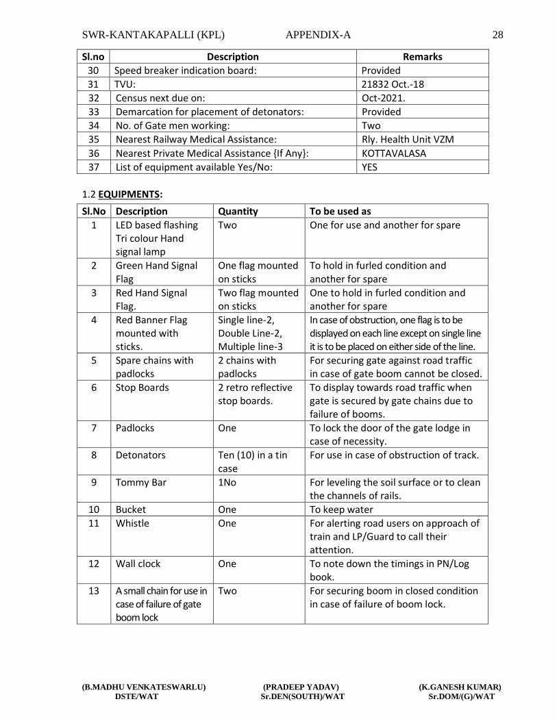
Sl.no Description Remarks
30 Speed breaker indication board: Provided
31 TVU: 21832 Oct.-18
32 Census next due on: Oct-2021.
33 Demarcation for placement of detonators: Provided
34 No. of Gate men working: Two
35 Nearest Railway Medical Assistance: Rly. Health Unit VZM
36 Nearest Private Medical Assistance {If Any}: KOTTAVALASA
37 List of equipment available Yes/No: YES
1.2 EQUIPMENTS:
Sl.No Description Quantity To be used as
1 LED based flashing Tri colour Hand signal lamp
Two One for use and another for spare
2 Green Hand Signal Flag
One flag mounted on sticks
To hold in furled condition and another for spare
3 Red Hand Signal Flag.
Two flag mounted on sticks
One to hold in furled condition and another for spare
4 Red Banner Flag mounted with sticks.
Single line-2, Double Line-2, Multiple line-3
In case of obstruction, one flag is to be displayed on each line except on single line it is to be placed on either side of the line.
5 Spare chains with padlocks
2 chains with padlocks
For securing gate against road traffic in case of gate boom cannot be closed.
6 Stop Boards 2 retro reflective stop boards.
To display towards road traffic when gate is secured by gate chains due to failure of booms.
7 Padlocks One To lock the door of the gate lodge in case of necessity.
8 Detonators Ten (10) in a tin case
For use in case of obstruction of track.
9 Tommy Bar 1No For leveling the soil surface or to clean the channels of rails.
10 Bucket One To keep water
11 Whistle One For alerting road users on approach of train and LP/Guard to call their attention.
12 Wall clock One To note down the timings in PN/Log book.
13 A small chain for use in case of failure of gate boom lock
Two For securing boom in closed condition in case of failure of boom lock.

SWR-KANTAKAPALLI (KPL) APPENDIX-A 29
(B.MADHU VENKATESWARLU) (PRADEEP YADAV) (K.GANESH KUMAR)
DSTE/WAT Sr.DEN(SOUTH)/WAT Sr.DOM/(G)/WAT
1.3 RECORDS TO BE KEPT AT GATE LODGE: In addition to the above equipment, following records shall also be kept at the gate lodge.
1. Gate Working Instructions in Hindi/English. 2. Gate Working Instructions in Local vernacular language. 3. Gateman Rule Book in Local vernacular language. 4. List for tools and books. 5. Duty registers. 6. Certificate for working as gateman. 7. Bio-data particulars of Gateman, including date of passing vision test, Initial/refresher
course, safety camp etc., 8. Accident Register. 9. Records of last census of road traffic at level crossing gate. 10. Public Complaint Book. 11. Inspection Book. 1.4 MODE OF OPERATION: Gate shall normally be kept open to road traffic, whenever it is required to close the gate Station Master on duty shall inform the Gateman about the direction and description of the train intended to receive/dispatch shall insure clearance of road traffic, close and lock the gate. Thereafter transmit the control to the Station Master on duty as per the following procedure:
(i) Barrier-1 & Barrier-2 switches are provided for individual operation of barriers if required.
(ii) Red and Green buttons are provided on gate panel for closing and opening of L.C gate respectively.
(iii) (iv)
The push button RED pressed, till the gate is closed and locked. Key 'Y' is extracted from EKT-1 after the gate is closed and locked.
(v) Key 'Y' thus extracted from EKT-1, is inserted in EKT-2 and transmitted electrically to SM in conjunction with switch 'GS' reversed to take off concerned signals.
(vi) (vii)
For opening the gate SM transmits control 96, to extract key ‘Y’ from EKT-2 and insert in EKT-1, the push button ‘Green’ is pressed till the gate is open. Key GS is provided in gate lodge to put back concerned signals to danger in case of emergency.
(viii) Emergency Crank Handle welded with EKT key is kept in the sealed Red box for emergency operation when normal system of working fails.
(viii) On complete arrival of the train and after the route is released, locked 'Red' indication will disappear on VDU.
(ix) SM on duty shall click ‘Transmit Control’ (96) for transmitting the key back to gate man for operating the LC gate.
(x) After transmission, the key in indication starts flashing on VDU suggesting that the key is transmitted to L.C gate.
(xi) An indication will appear near RKT at gate lodge suggesting the key can be extracted from the RKT. Key will then be extracted by the gate man by pushing button provided near RKT for operating of the gate.

SWR-KANTAKAPALLI (KPL) APPENDIX-A 30
(B.MADHU VENKATESWARLU) (PRADEEP YADAV) (K.GANESH KUMAR)
DSTE/WAT Sr.DEN(SOUTH)/WAT Sr.DOM/(G)/WAT
(xii) (xiii)
Flashing white indication on VDU will disappear suggesting that the key is taken out from RKT for operation of LC gate. Emergency Crank handle welded with EKT key is kept in the sealed box for emergency operation when normal system of working fails.
EMERGENCY RELEASE OF GATE KEY: In the event of gate locked (Red) indication persists on SM’s panel even after train movement is completed or when it is required to open the gate due to emergency in gate locked condition on panel the following procedure shall be adopted by both Station Master on duty and gate man. 1) Station Master on duty shall first cancel the signal by signal cancellation control of the
relevant signal. 2) Station Master on duty then shall click on the ‘Emergency gate release control’ in the
gate popup menu. 3) The ‘Red’ locked indication will flash for 120 seconds and after the time has elapsed
the ‘Red” indication will disappear. 4) Station Master on duty then shall transmit ‘Gate Control’ by clicking ‘Transmit control’
(28). 5) The ‘Key In’ indication (white) starts flashing suggesting the key is transmitted to Gate
man. 6) At gate lodge an indication will appear near RKT suggesting that the key can be
released from the RKT for opening of the LC gate. 7) Seeing the indication gate man on duty shall extract the key from RKT and operate the
gate. 8) On release of key from RKT flashing indication will disappear.
Any failure regarding transmission / extraction of gate key shall be intimated to the S&T officials for proper rectification. Till such time the failure is rectified the Station Master on duty shall pass the trains by P/IN or by P/OUT as the case may be.
WORKING OF SLIDING BARRIER IN CASE OF BREAKAGE OF ELECTRICAL LIFTING BARRIER
1) Sliding Barrier (L/1 side) will be rolled across the road till the locking end rests on lock post. Inserting & turning the key-1 (Which is chained with sliding barrier) releases the lock plunger, sliding barrier gets locked and releases the Key No.2.
2) Similarly sliding barrier (line no.6) will be rolled across the Road till the locking end rests on lock post. Inserting & turning Key-2 (which is released from line no.1 side barrier) release the lock plunger. Then by sliding the lock plunger barrier gets locked & releases key no.3.
3) Key No.3 is inserted in sliding barrier Key (SKB) RKT No.3 and transmitted electrically to SM/KPL in conjunction with ‘GS’ reversed to take OFF concerned signal.
4) For opening of sliding boom the SM/KPL will transmit electrically control 96 to extract SBK from RKT no.3. SBK Key is inserted in lock No.3 at line No.6 side sliding boom lock post release the lock plunger and Key No.2 Sliding boom will be rolled across the road till the clearance of road.

SWR-KANTAKAPALLI (KPL) APPENDIX-A 31
(B.MADHU VENKATESWARLU) (PRADEEP YADAV) (K.GANESH KUMAR)
DSTE/WAT Sr.DEN(SOUTH)/WAT Sr.DOM/(G)/WAT
5) Key No.2 inserted in lock No.2 at L-1 side sliding boom lock post, releases the lock plunger and Key No.1. Sliding boom will be rolled across the road till clearance of road.
6) Switch GS is provided in gate lodge to put back concerned signals to danger in case of emergency.
1.5 DUTIES OF GATEMEN:
[1] ALERTNESS: The gate man shall be alert and be prepared to take immediate action, should danger be apprehended, Keys of the gate shall be in his personal custody. [2] POSITION DURING PASSAGE OF TRAINS: During passage of trains, gate man will stand in the manner indicated below: -
i. Gate man will stand attentively in front of the gate-lodge facing the approaching train.
ii. In daytime, gateman shall hold red and green flags furled up on separate Sticks in right and left hands respectively.
iii. In night time, gateman shall hold lighted hand signal lamp with white light facing the track.
iv. He shall keep the whistle slung around his neck from a cord. [3]. ROUTINE DUTIES OF GATEMAN:
1) Gateman shall ensure that gate lamps and lamps of all gate signals are lighted and kept burning continuously from sunset to sunshine.
2) Gateman shall perform his duties strictly according to the duty roster and shall not leave the gate unless reliever arrive and takes charge of it. However, if it is necessary to leave the gate in an emergency, he must close and lock the gates against road traffic, before leaving the gate.
3) Expect where otherwise prescribed under special instructions, he shall observe all passing trains and be prepared to take such action as may be necessary to ensure safety of trains.
4) Gateman shall watch all passing trains and keep sharp look out for any unusual like hot axle, handing chains, hanging battery, brake beams, safety bracket, vacuum cylinder or any other situation endangering safe running of trains.
5) Gateman shall also be prepared to repeat any signal which guard may give to loco pilot on walkie-talkie or in any other way.
6) If lifting barriers get damages or becomes out of order, the gateman shall use sliding boom barrier to close the gate. Gate man shall report to the station master, gang mate or permanent way inspector any defect in his gate or apparatus pertaining to it, as soon as possible.
7) In the event of gate signal becoming defective the gateman shall maintain the signal in the ‘ON’ position even by disconnecting the signal or the wire if necessary.
8) At the gate whose signal has become defective the Gateman shall close and lock the lifting barrier/Sliding boom on sighting a train and hand signal or pilot the train

SWR-KANTAKAPALLI (KPL) APPENDIX-A 32
(B.MADHU VENKATESWARLU) (PRADEEP YADAV) (K.GANESH KUMAR)
DSTE/WAT Sr.DEN(SOUTH)/WAT Sr.DOM/(G)/WAT
past the defective signal. In such case he should inform the Loco pilot report the defect at the next station.
9) Gateman shall were badge and prescribed uniform while on duty at level Crossing gate.
10) Gateman shall ensure that he is having competency certificate in his possession while on duty.
11) Gateman shall work the gate as per gate working instructions and remain well conversant with this instruction.
12) Gateman shall ensure that equipment supplies at the gate are in good order and ready for immediate use.
13) Gateman shall see that the channel for the flange of the wheel is kept clean. 14) Gateman shall keep the road surface well watered and rammed in case of un
metalled roads. 15) Gateman must be vigilant to see that inconvenience to road users due to closure
of gates should be to the minimum possible extent. 16) Gateman on electrified section shall watch that road vehicles/animals passing from
gate are within the height loading gauge provided on either side of the level crossing gate.
17) Gateman shall prevent tress passing by persons or cattle to the maximum extent.
4. ACTION IN CASE OF UNUSUAL OCCURRENCE ON TRAIN:
In case gateman observes any thing unusual with a passing train, he shall take following action: a) He shall take prompt action to warm the loco pilot/guard of the passing train by
showing red flags by day and red light by night. b) He shall simultaneously try to draw the attention of the loco pilot/guard by whistling
continuously, shouting, gesticulating, throwing ballast on the brake van or by any other means.
c) If loco pilot/guard falls to take notice, gateman shall immediately inform the station master, on telephone, to take appropriate action under exchange of private number.
d) In case of trains parting, gateman shall not show stop hand signal to the loco pilot, but shall endeavour to attract the attention of the LP and the Guard by shouting gesticulating or other means.
e) He shall endeavor to attract the attention of the loco pilot/guard by whistling continuously, shouting, gesticulating and by raising both hands vertically above, quickly parting then and bringing them together in repeated Up and Dn motion as height and as low as possible.
f) In case of trains does not stop, gate shall immediately inform the station master, on telephone, to take appropriate action under exchange of private number
5. ACTION IN AN EMERGENCY AT THE LEVEL CROSSING:
a) In case of an observation at the level crossing gates,. Gateman shall maintain the gate signals, if any in the ‘ON’ position.

SWR-KANTAKAPALLI (KPL) APPENDIX-A 33
(B.MADHU VENKATESWARLU) (PRADEEP YADAV) (K.GANESH KUMAR)
DSTE/WAT Sr.DEN(SOUTH)/WAT Sr.DOM/(G)/WAT
b) Thereafter, if he is unable to remove the observation, gateman shall immediately advice the station master on duty, on telephone, regarding the defects/observations at the gate, under exchange of private number.
c) If there is no response from the station master after two or three attempts, he shall first protect the gate and then inform on phone.
The gateman shall protect the line as under:
A] ON DOUBLE LINE SECTION:
I. In the both lines are obstructed The Gateman shall plant a rd banner flag by day and the red light by night 5 meters away on posts duty provided for the purpose. He shall first protect the line on which a train is executive to arrive first.
II. Then he will similarly plant the other red banner flag by day and the red light by night 5 meters away from the site of observation.
III. Gateman shall then proceed to protect the gate along with detonators, fuses and red flags by day and red hand signal lamp by night.
IV. Gateman shall proceed in haste exhibiting red flags by day and red light by night on the line on which a train is excepted to arrive first, to a point 600 Mtrs and place one detonator on the line. Thereafter he shall proceed to a distance of 1200 Mtrs from the level crossing gate and place 3 detonators on the track 10 Mtrs apart. Having thus protected the line shall return to the level crossing gate picking up the intermediate detonator on this way back.
V. Thereafter he shall proceed on the other line, showing red hand signal, similarly place the detonators as described in Para (4) about and return to the site of obstruction, picking up the intermediate detonator on this way back.
VI. Having returned to the gate, he must then take steps to remove the obstruction mobilizing any assistance locally available and warn the loco pilot of the approaching train.
VII. In case the gateman observes or hears a train approaching when he is still on his way to protect and before he reaches the stipulated distance to place detonators, he shall place detonators on the line at the distance as far away as he can go.
B] On single line section: i) Gateman shall plant a red banner flag by day and a red light by night
5 meters away on posts duly provided for the purpose. He shall first protect the direction from which a train is expected to arrive first.
ii) Then he will similarly plant the other red banner flag by day and red light by night towards the other direction 5 meters away from the site of obstruction.
iii) Gateman shall then proceed to protect the gate along with detonators and red flag by day and red hand signal lamp by night.

SWR-KANTAKAPALLI (KPL) APPENDIX-A 34
(B.MADHU VENKATESWARLU) (PRADEEP YADAV) (K.GANESH KUMAR)
DSTE/WAT Sr.DEN(SOUTH)/WAT Sr.DOM/(G)/WAT
iv) Gateman shall proceed exhibiting red flag by day and red hand signal lamp by night towards the direction from which a train is expected to arrive first, to a point 600 meters and place one detonator on the line. Thereafter he shall proceed to a distance 1200 meters from the level crossing gate and place 3 detonators on the track 10 meters apart. Having thus protected the line he shall return to the level crossing gate picking up the intermediate detonator on his way back.
v) Thereafter, he shall proceed towards the other direction, showing
red hand signal, similarly place detonators as described in para (iv) above and return to the site of obstruction, picking up the intermediate detonator on his way back.
vi) Having returned to the gate, he must then take steps to remove the
obstruction and warn the Loco Pilot of the approaching train. (c)
vii) In case the gateman observes or hears a train approaching when he is still on his way to protect and before he reaches the stipulated distance to place detonators, he shall place detonators on the line at a distance as far away as he can go. ON MULTIPLE LINES AND PARALLEL SINGLE LINE: The procedure for protection shall be as indicated in sub rule (a) or (b) above as applicable, duly amplified by local instructions as may be warranted in each case. Banner flags shall be planted and detonators placed on each of the obstructed lines in the direction from which trains of likely to approach.
(d) Other action to be taken by Gateman: i) At night Gateman shall light two hand signal lamps and take action to
exhibit red light and protect the lines as described in sub paras (a) and (b) above.
ii) If the gate is broken by a road vehicle which is fouling the track, or if
lifting barriers or any other part of the gate foul the track, or if there is any other obstruction at the gate, the gateman shall take immediate action.
iii) He shall note down the particulars of the road vehicle, vehicle
number, name of the Driver, owner and relay these details to the nearest Station Master or SSE(P-Way) regarding the particulars and obstructions at the level crossing gate, through messenger or through means available.

SWR-KANTAKAPALLI (KPL) APPENDIX-A 35
(B.MADHU VENKATESWARLU) (PRADEEP YADAV) (K.GANESH KUMAR)
DSTE/WAT Sr.DEN(SOUTH)/WAT Sr.DOM/(G)/WAT
1.6 ENGINEERING ITEMS: Please see Para 916, 918, 919 of IRPWM for visibility requirements
at level crossings, provision of speed breakers on the approaching roads of level crossings and census of traffic at level crossings.
ANNEXURE – II
WORKING INSTRUCTIONS FOR TRAFFIC LEVEL CROSSING GATES INTERLOCKED WITH STOP SIGNALS OF THE STATION, PROVIDED WITH TELEPHONE, WITH NORMAL POSITION “OPEN
TO ROAD TRAFFIC” AT KM 845/21-23(ML-477) IN KANTAKAPALLI YARD
(General Instructions are common for all types of Level Crossing Gates) 1.0 MODE OF OPERATION: As described in 1.4 of Appendix-A. Exchange of Private Number: i) Before taking off reception/departure signals SS/SM shall inform the gateman,
the number, description and direction of the train. ii) The gateman shall close the gate and transfer the key to the Station Master. iii) The reception/departure signals will then be taken ‘OFF’ by SM on duty. iv) In order to ensure that road traffic is not held up for a long time, the Station
Master man must ensure that the train is ready for departure in all respects before he advises the gateman for closing the gate.
v) When a train has to be piloted to and from the station yard or any shunting
movement is to be done, the staff deputed to pilot the train or to perform the shunting across the gate shall be personally responsible to ensure that the gate is closed against road traffic before allowing any movement across the gate.
2.0 Failure of Telephonic Communication: When Telephonic Communication fails or it does not get any response from the
Gateman despite 2 or 3 attempts, the following procedure should be adopted:
(i) Station Master on duty shall send written advice to the gateman through the porter with full details of number, description and direction of the train.

SWR-KANTAKAPALLI (KPL) APPENDIX-A 36
(B.MADHU VENKATESWARLU) (PRADEEP YADAV) (K.GANESH KUMAR)
DSTE/WAT Sr.DEN(SOUTH)/WAT Sr.DOM/(G)/WAT
(ii) Gateman on receipt of such advice shall close the gate and transmit the key to the Station Master which will enable them to take ‘OFF’ reception / departure signals.
(iii) When sufficient time is not available because of greater frequency of train service Station Master will issue written authority to the train Loco Pilot to pass the signal at ‘ON’ position.
(iv) In addition Station Master shall also issue a caution order advising the Loco Pilot to whistle continuously and approach the gate cautiously.
(v) The train Loco Pilot shall be instructed to pass the gate cautiously, on being hand
signalled by the gateman. If hand signal is not seen, Loco Pilot should be prepared to stop short of the gate and ensure that gate is closed following GR 3.73(2)(b).
(vi) In case of an approaching train, the Station Master shall advise the Station Master at
the despatching end, under exchange of Private Number that the telephone at the gate has failed.
(vii) The Station Master at the despatching end shall then issue a caution order to the LP
before despatching a train in the block section from his end. (viii) He should also advise S&T staff responsible for maintenance of the telephone to
rectify the defect at the earliest. (ix) Normal working will be resumed only after S&T staff rectify the telephone and issue
reconnection / fit memo for the same. 3.0 Failure of Lifting Barriers : (i) When the gate cannot be closed due to failure of Electrical operation of lifting
barriers, gate man will immediately inform the SM on duty under exchange of private number and ensure the lifting barriers do not foul the track.
(ii) He shall immediately fix red banner flag by day and red light by night on the post at
that end first from which the train is approaching and then at the other end. (iii) Gateman shall secure the gate against road traffic by means of safety chains and
padlocks. (iv) After securing the gate against road traffic, gateman shall show green hand signal
flag by day and green light by night to the Loco Pilot of the approaching train. (v) Station Master on duty shall issue a caution order to the Loco Pilot of a departing
train. (vi) He shall also advise the Station Master at the despatching end, under exchange of

SWR-KANTAKAPALLI (KPL) APPENDIX-A 37
(B.MADHU VENKATESWARLU) (PRADEEP YADAV) (K.GANESH KUMAR)
DSTE/WAT Sr.DEN(SOUTH)/WAT Sr.DOM/(G)/WAT
private number, to similarly issue a caution order to the Loco Pilot before despatching a train the block section from his end.
(vii) Station Master will advise maintenance staff responsible for maintenance of lifting
barriers to repair the defect at the earliest. (viii) Normal working will resumed only after maintenance staff repair the barrier and
issue reconnection / fit memo for the same. Note:
(a) In case of failure of lifting barriers sliding boom barrier to be used.
(b) Authority to pass signals at ‘ON’ position as per rules shall also be issued to the Loco Pilot of both departing and arriving trains.
4.0 Failure of the Gate Key with the gate in closed position when Gate Key cannot be
extracted for opening the gate: (i) If the gate key cannot be extracted from EKT-1 on gate panel in closed position of the
gate, the gate man must immediately inform SM on duty over telephone under exchange of private number.
(ii) If Emergency Key is available at he gate lodge, Gateman will take it out from the
sealed box by breaking the seal and open the gate for road traffic. (iii) The record of the date and time of breaking the sealed cover of Emergency Key Box
shall be recorded and signed with reasons. (iv) Thereafter, the gate must be treated as non-interlocked and procedure for reception
/ despatch of trains as prescribed for non-interlocked gates, should be adopted. (v) Station Master on duty shall issue a caution order to the Loco Pilot of a departing
train. (vi) He shall also advise the Station Master at the dispatching end, under exchange of
private number, to similarly issue a caution order to the Loco Pilot before dispatching a train in the block section from his end.
(vii) Station master will advice S&T staff responsible for electrical key transmitter to
rectify the defect at the earliest. (viii) Normal working will be resumed only after S&T staff repairs the electrical key
transmitter and reconnection/fit memo for the same. (ix) After rectification, the Emergency Key shall be replaced in the Emergency Key Box

SWR-KANTAKAPALLI (KPL) APPENDIX-A 38
(B.MADHU VENKATESWARLU) (PRADEEP YADAV) (K.GANESH KUMAR)
DSTE/WAT Sr.DEN(SOUTH)/WAT Sr.DOM/(G)/WAT
and resealed by the S&T maintainer. 5.0 Failure of the Gate Key, with the gate in open condition: (i) If the gate key cannot be extracted from EKT-2 on gate panel in open position of the
gate, the gate man must immediately inform SM on duty over exchange of private number.
(ii) Thereafter, the gate must be treated as non-interlocked and procedure for reception
/ dispatch of trains as prescribed for non-interlocked gates should be adopted. (iii) Gateman shall secure the gate against road traffic by means of chains and padlocks
and pass the trains on hand signals. (iv) Station Master on duty shall issue caution order to the Loco Pilot of a departing train. (v) He shall also advise the Station Master at the dispatching end under exchange of
private number to similarly issue a caution order to the Loco Pilot before dispatching a train in the block section from his end.
(vi) Station master will advice S&T staff responsible for electrical key transmitter to
rectify the defect at the earliest. (vii) Normal working will be resumed only after S&T staff repairs the electrical key
transmitter and reconnection/fit memo for the same. (viii) After rectification, the Emergency Key shall be replaced in the Emergency Key Box
and released by the S&T maintainer. 6.0 Obstruction at the Gate: (i) If the gate is broken by a road vehicle which is fouling the track, or if lifting barriers
or any other part of the gate foul the track, or if there is any other obstruction at the gate, the gateman shall immediately fix red banner flag by day and red lamp by night on posts provided at both ends of the gate, for this purpose.
(ii) Immediately after this, the gateman shall advise the Station Master on duty,
regarding the defects / obstruction at the gate, under exchange of private number. (iii) Station Master on duty shall be advised to put the reception / departure signals back
to ‘ON’ position, if taken ‘OFF’ for a train. (iv) If there is no response from the Station Master after two or three attempts, he shall
first protect the gate and then inform on phone.

SWR-KANTAKAPALLI (KPL) APPENDIX-A 39
(B.MADHU VENKATESWARLU) (PRADEEP YADAV) (K.GANESH KUMAR)
DSTE/WAT Sr.DEN(SOUTH)/WAT Sr.DOM/(G)/WAT
(v) Gateman shall then rush with detonators, and red flag by day and red hand signal lamp by night in the direction of the approaching train and protect the gate as stipulated in General Instruction for duties of gateman under item no.1.5(5).
(vi) There he shall protect the gate from the other direction also. (vii) He shall note down the particulars of the road vehicle, name of the Driver, owner
and relay these details to the Station Master who shall not start the train unless he has been assured by the gateman that the road vehicle or the lifting barriers are not fouling the track.
(viii) The Station Master shall also inform the Station Master at the dispatching end, under exchange of private number, asking him not to dispatch any train in the block section from his end, until the track has been cleared of all obstructions.
(ix) After the track has been cleared of all obstructions the gateman shall inform the Station Master accordingly, under exchange of private number.
(x) Station Master shall then issue a caution order to Loco Pilot of all train to proceed cautiously, and pass the reception / departure signal at ‘ON’ position on green hand signal of the gateman, of the gate is broken, but is clear of any obstruction.
(xi) Gateman shall secure the gate against road traffic by means of safety chains and padlocks and there after exhibit green hand signal, if the gate is not obstructed.
(xii) Station Master shall advise maintenance staff responsible for maintaining the lifting barriers to repair same at the earliest.
(xiii) Normal working will be resumed only after maintenance staff rectify the defective lifting barriers and issue reconnection / fit memo for the same.
7. Obstruction on the Track near Level Crossing:
If there is a rail fracture or obstruction on the track due to failing of a tree, fouling by road vehicle or derailment which is visible to the gateman, the gateman and Station Master will adopt the procedure given under item No.7 above. If the obstruction fouls the Level Crossing Gate, gateman must keep the gates closed against road traffic till the track is cleared of the obstruction.
[B] OTHER ACTION TAKEN BY GATE MAN :
[I]. At night gate man shall light two hand signal lamps and take action to exhibit red light and protect the lines as per described in sub para [A] above.
[ii] If the gate is broken by the road vehicle which is fouling by track, or if lifting barrier or any other part of the gate found the track, or it there is any other obstruction at the gate, the gate man shall take immediate action.
[iii] He shall note down the particulars of road vehicle, vehicle number, name of the driver, owner and relay these details to the nearest Station Master,

SWR-KANTAKAPALLI (KPL) APPENDIX-A 40
(B.MADHU VENKATESWARLU) (PRADEEP YADAV) (K.GANESH KUMAR)
DSTE/WAT Sr.DEN(SOUTH)/WAT Sr.DOM/(G)/WAT
SSE/P.way regarding the particulars and obstructions at the level crossing gate, through messenger or other means available.
8. ENGINEERING ITEMS:
Please Para 916, 918, 919 of IRPWM for visibility requirement at level crossings, provision of speed breakers on the approach roads of level crossing and senses of traffic at level crossings.

SWR – KANTAKAPALLI (KPL) APPENDIX ‘B’ 40
(B.MADHU VENKATESWARLU) (K.GANESH KUMAR)
DSTE/WAT Sr.DOM/G/WAT
APPENDIX ‘B’ TO STATION WORKING RULES OF KANTAKAPALLI STATION
DETAIL DESCRIPTION OF SIGNALLING AND INTERLOCKING INSTALLATIONS, INSTRUCTIONS FOR WORKING THEM NORMALLY AND IN EMERGENCIES ETC. INCLUDING POWER SUPPLY ARRANGEMENTS.
1. BRIEF DESCRIPTION OF THE SIGNALLING AND INTERLOCKING INSTALLATIONS:
This is a ‘B’ class station provided with Standard –II(R) interlocking. The station is provided with Route setting type Electronic Interlocking between points, signals, track circuits and other signalling gears. The Station is equipped with Multiple Aspect Colour Light Signalling. All points and Signals etc. are power operated through a central Visual Display Unit (VDU) with a standby installed in the SS/SM’s Office.
2.0 DESCRIPTION OF OPERATOR CONSOLE CUM VISUAL DISPLAY UNIT (VDU):
The Operator Console cum Visual Display Unit (VDU) is provided for operation of Signals, Points, L.C Gates, Crank Handles, Siding & other controls etc. A Mimic yard diagram based on SI plan no.SI/23131 Alt-A will be displayed on the VDU. The VDU is used for controlling and monitoring the station. Indications on the Station yard mimic diagram of VDU will be dynamically updated.
2.1 SYSTEM OVERVIEW: An Operator Console consisting of a VDU (colour monitor), with keyboard and pointing device (mouse) connected with a computer (CPU) is provided. The CPU is connected to the Electronic Interlocking (E.I) equipment to exchange control and indication messages. The system is programmed to display the Station Yard Mimic VDU diagram on the VDU and that it allows access to all functions through pop-up menus. When a particular function is selected, an appropriate Menu will appear on the screen. A function (clearance of Signal or cancellation, Route release, Point operation, Gate release etc.) can be executed through selecting the required operation by clicking the Left button of the pointing device (mouse) on the desired function.
2.2 An additional VDU connected with a computer is provided as standby Arrangement in case of failure of the working operator console. In case of failure of the working operator console the system shall switch over to the stand by VDU automatically.

SWR – KANTAKAPALLI (KPL) APPENDIX ‘B’ 41
(B.MADHU VENKATESWARLU) (K.GANESH KUMAR)
DSTE/WAT Sr.DOM/G/WAT
2.3. ICONS AND INDICATIONS PROVIDED ON THE VDU In addition to mimic yard diagram including signal, points, track circuit, Axle counters, L.C.gates, sidings as indicated in the WRD, various other ICONS and indications have been provided on the VDU. A brief description of the same are described below.
SL. NO.
ICONS INDICATIONS FUNCTIONS REMARKS
1 SS/SM’s Key
Yellow light when key is ‘IN’
Ensures operation of VDU by authorized person
Protected by pass word
2. --- Emergency Route release - UP & DN
Flashing indication appears when Emergency route release operation is initiated.
3. --- Emergency Gate release
Flashing indication appears when Emergency gate release operation is initiated.
4.
Emergency Point operation key
Yellow light when key is ‘IN’
Ensures emergency point operation by authorized person
For each operation concerned counter shall register one count higher.
5. ---
System indication Central – On/Off
Indicates System ‘A’ or ‘B’ is in working mode
6. --- System indication End – On/Off
Indicates EI system is in working mode or not.
7. Point failure Ack. button
Yellow
Flashing indication appears when any point fails. SS/SM has to left click on the icon to acknowledge.
Buzzer will sound. On acknowledgement buzzer stops. After

SWR – KANTAKAPALLI (KPL) APPENDIX ‘B’ 42
(B.MADHU VENKATESWARLU) (K.GANESH KUMAR)
DSTE/WAT Sr.DOM/G/WAT
verification at site inform S&T staff Immediately.
8. Signal failure Ack. button
Yellow
Flashing indication appears when any signal fails. SS/SM has to left click on the icon to acknowledge.
Buzzer will sound. On acknowledgement buzzer stops. Inform S&T staff Immediately.
9.
CH-1, CH-2, CH-3 and CH-4 buttons
Yellow lamp indicates ‘KEY IN’. Red lamp indicates ‘ CH LOCKED’
In normal condition yellow lamp will be lit. Whenever the crank handle is locked in route or otherwise red indication will glow.
--
10.
DN Reset key and button (ALM end)
Yellow-Power on Green-prep reset
SS/SM has to follow ‘Key In’ procedure followed by left click on the button icon to reset LVCD Axle counter.
This operation is required for Resetting of LVCD Axle Counter of Concerned Section. For each operation concerned counter shall register one count higher.
11.
MIDDLE LINE Reset key and button (ALM & KTV end)
Yellow-Power on Green-prep reset
12.
UP Reset key and button (KTV end)
Yellow-Power on Green-prep reset
13.
DN Reset key and button (KTV end)
Yellow-Power on Green-prep reset
14.
UP Reset key and button (ALM end)
Yellow-Power on Green-prep reset

SWR – KANTAKAPALLI (KPL) APPENDIX ‘B’ 43
(B.MADHU VENKATESWARLU) (K.GANESH KUMAR)
DSTE/WAT Sr.DOM/G/WAT
15.
‘DN Train Entering Section’ muting button
Yellow -acknowledged
On getting alarm/buzzer SS/SM shall left click on the button icon to acknowledge it.
16.
‘UP Train Entering Section’ muting button
Yellow -acknowledged
On getting alarm/buzzer SS/SM shall left click on the button icon to acknowledge it.
17.
Middle line Train Entering Section’ muting button (UP&DN)
18. UP Block release button
Yellow –Prepared for Block release.
On getting indication SS/SM shall left click on the button icon which shall release Block Handle.
After complete arrival of train this will be activated
19 DN Block release button
Yellow –Prepared for Block release.
20
Middle Line Block release button(UP & DN)
21 L.C.Gate control-96 button
Yellow lamp indicates ‘Gate Closed’. Red lamp indicates ‘Gate LOCKED’.
SS/SM shall right click on the button icon to select menu to Transmit / Receive/ emergency operation of gate as required.
In case of emergency operation ‘Emergency gate release’ indication will appear. For each operation concerned counter shall register one count higher.

SWR – KANTAKAPALLI (KPL) APPENDIX ‘B’ 44
(B.MADHU VENKATESWARLU) (K.GANESH KUMAR)
DSTE/WAT Sr.DOM/G/WAT
22 Counter -
As and when required SS/SM shall point the curser on the counter icon and right click on it. A drop down menu will appear indicating all the counters available in the system. SS/SM shall select the required counter on the menu and can read the latest counter reading.
--
23 Line Block Red when blocked
SS/SM shall point the curser on the icons provided on the berthing track and right click. One drop menu will appear indicating line blocked and un-blocked, SS/SM has to select the required menu.
When line block is selected the concerned berthing portion of track will appear as thick Red line.
24
DN IB axle counter reset key and button (ALM end)
Yellow-power on Green-prep. Reset.
SS/SM has to follow ‘Key in’ procedure followed by left click on the button icon to re-set IB axle counter.
For each such operation,concerned counter shall register one count higher.
22
Permission received from ALM ack. button
Yellow permission received.
To acknowledge SS/SM has to left click on the ack. button
--
23
Permission granted to ALM ack. button
Yellow permission granted.
To grant permission for resetting. SS/SM has to left click on the permission granting button.
--
24 DN train run away in IB
Yellow—acknowledged.
On getting Alarm/Buzzer, SS/SM has to left click on the
--

SWR – KANTAKAPALLI (KPL) APPENDIX ‘B’ 45
(B.MADHU VENKATESWARLU) (K.GANESH KUMAR)
DSTE/WAT Sr.DOM/G/WAT
section muting button (section ALM-KPL)
button icon to acknowledge the inside
3.0. OPERATIONAL PROCEDURE THROUGH VDU AND INDICATIONS:
In addition to the mimic yard diagram various other indications will be available on the VDU. The implications of different indications provided and the operational procedure for different functions shall be strictly followed as per the following description.
3.1 ELECTRONIC INTERLOCKING (E.I) SYSTEM INDICATIONS:
Electronic Interlocking Equipment (E.I) at the center can work in either of the two modes i.e, System-‘A’ or System-‘B’. On the VDU (Computer), there are two system indications in which Green indication mentioning the On-line system and the Red indication mentioning that the system is in power off condition.
3.2 OPERATION PROCEDURE OF SS/SM’s KEY :
To prevent the unauthorized operation by any person other than SS/SM on duty this facility is provided on VDU. On duty SS/SM needs to track the pointer to the “SS/SM KEY” icon and click the ‘KEY IN’ menu by the clicking left button of the mouse, by this a Password window will appear. SS/SM on duty needs to enter the password and press the ‘OK’ Button provided on the Password window. This will allow operating all the controls e.g., Signals, Points, and Crank handles Etc. through VDU. In case incorrect password or user name is entered, no operation can be made. In such cases the same procedure is to be repeated till correct password is entered.

SWR – KANTAKAPALLI (KPL) APPENDIX ‘B’ 46
(B.MADHU VENKATESWARLU) (K.GANESH KUMAR)
DSTE/WAT Sr.DOM/G/WAT
Enter the USER NAME and PASSWORD and click the OK button. Now the OP VDU is ready for use & the entire yard can be controlled from the VDU. Similarly select the KEY OUT when the Station Master to Prevent the Unauthorized Operation with User name and password.
3.3 OPERATION AND INDICATION OF POINT:
To Operate the Point the SS/SM/ASS/SM needs to track the mouse pointer to concerned point’s Normal/Reverse indications on the VDU, after clicking by the left button on the mouse a pop-up menu will appear as below:
3.3.1 REVERSE TO NORMAL OPERATION:
Track the pointer to NORMAL menu and click. A Normal flashing indication will appear and the indication will be steady after the point is set to Normal.
3.3.2 NORMAL TO REVERSE OPERATION:
Track the pointer to REVERSE menu and click. A Reverse flashing indication will appear and the indication will be steady after the point is set to reverse.
3.3.3 POINT INDICATIONS
When the point is free a steady strip of light will appear in the point zone (In case of cross-over at both ends) indicating the point is in normal/reverse condition. When the point is operated the same strip of light starts flashing till the point is set and becomes steady when the point is set and detected. When the point is engaged in a route a yellow light will appear near the point indicating that the point is locked and cannot be operated now.
PIONT 51 Normal
Reverse
Emergency Normal
Emergency Reverse

SWR – KANTAKAPALLI (KPL) APPENDIX ‘B’ 47
(B.MADHU VENKATESWARLU) (K.GANESH KUMAR)
DSTE/WAT Sr.DOM/G/WAT
3.4 PROCEDURE FOR SETTING OF ROUTES AND TAKING OFF SIGNALS: To Take-Off a Signal on the desired route the SS/SM on duty needs to track the mouse pointer over the concerned Signal on the VDU, after clicking by the left button of the mouse a pop-up menu will appear as below:
SS/SM on duty will select the route as per the requirement by moving the mouse pointer on the appropriate menu & left clicking on the menu. It will set the route and clear the signal provided all the conditions required to clear the signal is satisfied. Similarly by following the similar procedure operation of other signals can be done.
3.4.1 SETTING A ROUTE AND ITS INDICATIONS: To set a route of a signal, click on a possible route of the signal, after doing so the route gets initiated & Red-flashing indication will appear on the replacement track of the signal. Point operation is initiated as per the requirement of the desired route and Normal/ Reverse set indications will starts flashing if favorable point detection is not available. After setting of points in the route, overlap & isolation flashing indication will be replaced. By steady indication and a complete yellow ‘Route set’ indication will appear from the replacement track of the signal to the last track of overlap section of the route. Also the points lock indication will appear. A Point locked can be ensured from the Red Steady indication will appear near the point. Finally a Route locked Yellow Steady indication will appear on the immediate rear of the signal. Now the signal will be Taken-off. The yellow route set indication will turn to red when different track circuit portion within the route is occupied during passage of a train.
SIGNAL S1 S1 – S17
S1 – S19
S1 – S21
S1 – S23
C1 – S17
C1 – S21
C1 – S23
MAIN SIGNAL CANCEL
MAIN ROUTE RELEASE
CALLING ON SIGNAL CANCEL
CALLING ON ROUTE RELEASE

SWR – KANTAKAPALLI (KPL) APPENDIX ‘B’ 48
(B.MADHU VENKATESWARLU) (K.GANESH KUMAR)
DSTE/WAT Sr.DOM/G/WAT
3.4.2 SHUNT SIGNAL OPERATION:
The same procedure as main signal has to be followed as explained above. To set the signal route for shunt signals SS/SM on duty shall put the pointing device on the Shunt signal icon and left click on the same. A drop down menu will appear indicating different actions that can be selected. After selecting the desired route SS/SM on duty shall left click on it. Desired will be initiated and the Shunt signal will be taken off.
3.4.3 CALLING ON SIGNAL OPERATION: The same procedure as main signal has to be followed as explained above. To set the signal route for CALLING ON signals SS/SM on duty shall select the desired route and left click on the same after a train occupies the approach track circuit in immediate rear of the stop signal. The signal is cleared after a lapse of 120 seconds provided other conditions are fulfilled.
3.5 CRANK HANDLE CONTROL OPERATION:
Normally a ‘KEY IN’ (Yellow) indication will appear on the VDU indicating that the crank handle is free. To Transmit or Receive control of the Crank Handle, click on the crank handle control button icon provided like the following on VDU.
The appearing pop-up menu gives details of the possible commands on the Crank Handle
To Transmit the Crank Handle KEY to the field personnel SS/SM on duty has to click transmit control menu. After transmission the ‘KEY IN’ indication will starts flashing, now the KEY can be extracted from the RKT at site. After extracting the key from the RKT, the ‘KEY IN’ indication will disappear. When the Manual point operation is over, after putting the Siding control key in the RKT, ‘KEY IN’ flashing indication will appear on the VDU, Now the SS/SM on duty has to Release the control for the Steady indication by clicking release control menu.
CRANK HANDLE CH1
Transmit Control
Release Control

SWR – KANTAKAPALLI (KPL) APPENDIX ‘B’ 49
(B.MADHU VENKATESWARLU) (K.GANESH KUMAR)
DSTE/WAT Sr.DOM/G/WAT
A Crank handle locked indication (Red) will appear when the particular point is on the signal route set over it or engaged in route setting in any other way.
3.6 LEVEL CROSSING GATE OPERATION:
To Transmit or Release control of the Level crossing gate, click on the Level crossing control button icon provided like the following button on the VDU.
The appearing pop-up menu gives details of the possible commands on the Level crossing gate.
Normally no indication will be available on the VDU indicating that the gate control key is out and gate is open. When it is required to close the gate SS/SM on duty shall intimate the gate man to close the gate supported by exchanging PN. Upon instructed by the SS/SM on duty the gate man shall close and lock the gate and after reversing the concerned slot lever he shall transmit the gate control key to station by inserting and transmitting the key in the RKT. A flashing yellow indication will appear on the VDU seeing which SS/SM on duty receive the control by clicking on the L.C. Gate control button icon and select ‘Receive’. The flashing indication shall become steady. When the key is required to be transmitted to the Gate man, SS/SM on duty has to transmit the control by clicking, after transmission the KEY IN indication will starts flashing, now the KEY can be extracted from the RKT. When the gate has been closed, locked & slot lever is in reverse position, After putting the key in the RKT, A KEY IN flashing indication will appear on the VDU. Now the SS/SM has to release the control for the steady indication. The locked indication will appear when the LC Gate has locked by initiation of any of the possible signal routes.
LEVEL CROSSING CH1
Transmit Control
Release Control
Emergency Gate Release

SWR – KANTAKAPALLI (KPL) APPENDIX ‘B’ 50
(B.MADHU VENKATESWARLU) (K.GANESH KUMAR)
DSTE/WAT Sr.DOM/G/WAT
3.7 OVERLAP TIME RELEASE (WHITE LIGHT): Separate indications (White Light) for each overleap is provided near the starter signal to indicate the free or locked condition of overlap. This indication light will glow when overlap is locked by any Home Signal route and there will be no light when overlap is free. The locked indication starts flashing when the approaching train clears the rear end point zone track and occupies the berthing track. After a time release of 120 seconds the white flashing light will disappear indicating concerned overlap is free.
4.0 EMERGENCY OPERATIONS: To carry out different emergency operations the following procedures are to be followed.
4.1 CANCELING A ROUTE/ EMERGENCY ROUTE RELEASE:
To cancel a signal route when the route is set and the signal in taken-off, click on the signal. After clicking by the left button on the mouse a pop-up menu will appear as shown in Para 3.4 above. Click on the cancellation menu (Main/ Calling on) of the concerned signal, the signal will immediately go to ‘ON’ aspect, after doing so click on the Route release menu the route locked indication will starts flashing for 120 sec & the Emergency Route Release Indication (UP / DN as the case may be) will flash for the entire time interval. After the completion of 120 sec, the locked route will be released. This action will be recorded in a counter. The counter will increment the number for each and every such action and also, this number should be recorded by the SS/SM on duty who shall record the details of the Route cancellation along with the latest counter no. in a register.
4.2 EMERGENCY NORMAL OPERATION OF POINTS: When the Point zone Track circuits/ Axle counters failed without any Point lock condition by any signal routes, a point can be operated by the Emergency Point operation. Note: Before resorting to this operation SS/SM on duty shall verify that the point zone is clear of any vehicle occupying the track section and the same is clear of any obstruction.
4.2.1 NORMAL OPERATION Before doing the emergency operation the Emergency Point Operation Key is to be made "KEY IN" by clicking the ‘KEY IN’ menu. The user name and password is to be logged in. The user name of this station is ‘ECOR’ and password of this station is KPL. Track the pointer to ‘EMERGENCY NORMAL’ menu and click. A

SWR – KANTAKAPALLI (KPL) APPENDIX ‘B’ 51
(B.MADHU VENKATESWARLU) (K.GANESH KUMAR)
DSTE/WAT Sr.DOM/G/WAT
Normal flashing indication will appear and the indication will be steady after the point is set to Normal. This action will be recorded in a counter. The counter will increment the number for each and every such action and also, this number should be recorded by the SS/SM on duty who shall record the details of the Emergency Point Operation along with the latest counter no. in a register. After the completion of the Emergency point operation, the Key to be ‘KEY OUT’ by clicking ‘KEY OUT’ menu. The user name and password is to be given for "KEY OUT" also.
4.2.2 EMERGENCY REVERSE OPERATION OF POINTS:
Before doing the emergency operation an Emergency Point Operation Key is to be made ‘KEY IN’ by clicking the ‘KEY IN’ menu. The user name and password is to be logged in. The user name of this station is ‘ECOR’ and password of this station is KPL. Emergency reverse menu to be clicked. Track the pointer to ‘EMERGENCY REVERSE’ menu and click. A Reverse flashing indication will appear and the indication will be steady after the point is set to reverse. The counter will increment the number for each and every such action and also, this number should be recorded by the SS/SM on duty who shall record the details of the Emergency Point Operation along with the latest counter no. in a register.
After the completion of the Emergency point operation, the Key to be ‘KEY OUT’ by clicking ‘KEY OUT’ menu. The user name and password is to be given for ‘KEY OUT’ also.
4.2.3 EMERGENCY CRANK HANDLE RELEASE OPERATION:
When a crank handle is locked due to route set earlier is not released or otherwise to Transmit or Release control of the Crank Handle, SS/SM on duty shall cancel the relevant signal first and then click on the crank handle control button icon provided like the following on the VDU.
On clicking, the appearing pop-up menu gives details of the possible commands on the Crank Handle

SWR – KANTAKAPALLI (KPL) APPENDIX ‘B’ 52
(B.MADHU VENKATESWARLU) (K.GANESH KUMAR)
DSTE/WAT Sr.DOM/G/WAT
For Transmitting the Crank Handle KEY to the field personnel SS/SM on duty has to click transmit control menu. After transmission the ‘KEY LOCKED’ (Red) indication will start to flash for 120 seconds & ‘KEY IN’ remains steady. After a lapse of 120 seconds the ’KEY LOCKED’ indication will vanish & ‘KEY IN’ indication will start to FLASH. After extracting the key from the RKT, the ‘KEY IN’ indication will disappear. When the Manual point operation is over, after putting the emergency crank handle key in the RKT, flashing ‘KEY IN’ indication will appear on the VDU, now the SS/SM on duty shall Release the control for the Steady indication by clicking ‘RELEASE CONTROL’ menu. The counter will increment the number for each and every such action and also, this number should be recorded by the SS/SM on duty who shall record the details of the Emergency Crank Handle Operation along with the latest counter no. in a register.
4.3 EMERGENCY GATE OPERATION: L.C. Gate control can be released and the gate can be opened by this operation when LC gate control remains in locked condition due to setting of any of the signal routes over it or otherwise. For releasing the gate by the Emergency operation the SS/SM on duty has to cancel the signal by signal cancellation control of the relevant signal. Then he has to click the Emergency Gate release control in the Gate pop-up menu. Now the ‘LOCKED’ (Red) indication will flash for 120 seconds & after the time has elapsed the ‘LOCKED’ (Red) indication will vanish. Now the SS/SM on duty shall transmit the ‘GATE CONTROL’ in this condition and ‘KEY IN’ indication starts flashing. Now the KEY can be extracted from the RKT at Gate Lodge and gate can be opened. This action will be recorded in a counter. The counter will increment the number for each and every such action and also, this number should be recorded by the SS/SM manually in a register. The counter will increment the number for each and every such action and also, this number should be recorded by the SS/SM on duty who shall record the details of the Emergency Gate Operation along with the latest counter no. in a register.
CRANK HANDLE CH1
Transmit Control
Release Control

SWR – KANTAKAPALLI (KPL) APPENDIX ‘B’ 53
(B.MADHU VENKATESWARLU) (K.GANESH KUMAR)
DSTE/WAT Sr.DOM/G/WAT
4.4 LINE BLOCK AND UNBLOCK (REMINDER COLLAR): When SS/SM on duty requires demarcating a berthing/stabling line as BLOCKED / FREE line he shall adopt the following procedure:
4.4.1 LINE BLOCK:
To set the ‘LINE BLOCKED’, the SS/SM on duty shall select “L. No.___ BLOCK” command using the left mouse button, after selecting the Line Block that particular line will be blocked for all the possible Track circuit section on that particular line. The ‘TRACK BLOCK’ yellow colour indication will be displayed after the successful application of such a blocking process on the VDU.
4.4.2 LINE UNBLOCK:
To release the set block of any particular line, the SS/SM should select “L. No.___ UNBLOCK” command using the left mouse button. After selecting the “L. No.___ UNBLOCK” that particular line will be available for the train movement leading to all the possible L1 Track circuit section.
5.0 PROCEDURE FOR RESETTING OPERATION OF LVCD (DIGITAL) AXLE COUNTER IN SECTION KPL-ALM AND KPL-KPL. 5.1 Digital Axle Counters are provided on both UP, DN & Middle Block sections
between KPL-ALM and KPL-KTV. The occupation and clearance of the axle counter section are indicated on VDU by RED & GREEN light respectively. When after arrival of a train the LVCD Axle counter does not show clear indication and the ‘Section Occupied’ indication continues to glow SS/SM on duty shall initiate resetting procedure for the LVCD Axle Counter, monitoring the Block section. Before initiating Resetting procedure SS/SM on duty shall ensure that the train which has left arrived completely at receiving station and block section is clear [free] of trains. If the track indication of that particular block section is showing ‘Red” then the following actions is to be performed by the SS/SM on duty.
The SS/SM on duty at KANTAKAPALLI Station shall verify with on duty SS/SM at receiving station over phone, to ensure the complete arrival of the train in his station.

SWR – KANTAKAPALLI (KPL) APPENDIX ‘B’ 54
(B.MADHU VENKATESWARLU) (K.GANESH KUMAR)
DSTE/WAT Sr.DOM/G/WAT
For Resetting of Digital Axle Counter Cooperation is necessary from adjacent station.
On duty SS/SM shall track the pointer to the “Axle Counter Reset key” icon and click left button of the mouse and select “KEY IN” option.
Move the Cursor pointer near to the Axle Counter Reset push button icon, and click left button of the mouse and select “Reset”. In VDU VDU ‘Power on’ indication will appear above the reset push button and it will remain for 10 sec. This action will be recorded in a counter. The counter will increment the number for each and every such action and also, this number should be recorded by the SS/SM manually in a register.
The on duty SS/SM shall inform the SS/SM on duty at adjacent to carryout aforesaid resetting procedure. After completing reset operation in both side “PREP RESET “indication will appear above the reset push button icon.

SWR – KANTAKAPALLI (KPL) APPENDIX ‘B’ 55
(B.MADHU VENKATESWARLU) (K.GANESH KUMAR)
DSTE/WAT Sr.DOM/G/WAT
The Piloting In or out is mandatory for completion of Axle counter reset operation.
Number changed for resetting, shall be recorded in the TSR and in the register provided for this purpose. One train should be P/O after resetting of Axle Counter without fail for normalizing the system. After the of said train if the system is not normalized than Signal Maintainer/SSE (Signal) is to be intimated for rectification of failure.
5.3.1 RESETTING OPERATION FOR LOOP LINE AXLE COUNTER ON LINE NO 6 Analog Axle counter are provided to prove clearance/occupancy of berthing portion line No: 6. The occupation/clearance of the axle counter section is indicated on the VDU by RED & GREEN indications respectively.
5.3.2 When after clearing of a train or due to any failure, if the berthing zone axle counters of L/6 does not show clear indication and section occupied indication continue to glow on VDU, SS/SM on duty shall initiate resetting procedure. Before initiating resetting on duty SS/SM at KPL Station shall send operating staffs who in turn, verify that the concern loop line is clear of all obstruction and open the respective verification line verification box and press the verification button provided in the line verification box near SMs office.
On obtaining verification indication which is indicated by glow of light on the VDU below the verification indication, DY. SS / SM shall click the respective option for resetting the concerned axle counter and the same will be reset by this operation and concerned VDU counter will change to the next higher number.
Number thus changed due to resetting shall be recorded in the TSR and in the reset register provided for this purpose.

SWR – KANTAKAPALLI (KPL) APPENDIX ‘B’ 56
(B.MADHU VENKATESWARLU) (K.GANESH KUMAR)
DSTE/WAT Sr.DOM/G/WAT
6.0 MAIN SIGNAL LAMP FAILURE INDICATION AND BUZZER ACKNOWLEDGMENT:
LED signal lamps are provided for main signals at this station. In case failure of LED signals will be indicated by the appearance of ‘RED’ light on VDU along with audible buzzer, which can be acknowledged and muted by pressing the ‘SIGNAL FAILURE ACKNOWLEDGEMENT’ button icon. However the RED light will continue to glow until the LED lamp is replaced by a new lamp. For rectification of failure SS/SM on duty should inform the concerned S&T staff about the group which has failed. For the purpose of giving main filament failure indication the following groups are formed on either side.
6.1 POINT FAILURE INDICATION (RED), POINT FAILURE BUZZER AND POINT
FAILURE ACKNOWLEDGEMENT: Whenever there is failure of point due to non-setting, point failure indication flashing light appears near the point button icon along with point failure Buzzer. The buzzer stops when the point failure acknowledgement button icon is pressed, but the flashing light above the ACK button shall continue to glow. The flashing light at the concerned point zone can identify the defective point. After the failure is rectified, the flashing light above the ‘POINT FAILUR ACK’ button will disappear.
6.2 TRAIN RUN AWAY INDICATION AND BUZZER ACKNOWLEDGEMENT:
The train run away buzzer is provided to ensure passing of a train through IBS at ‘ON’ When the train hits the IBS track circuit, the audible buzzer will ring as well as red indication will appear in VDU to above the runaway muting button. The buzzer can be silenced by pressing of acknowledgement button icon.3
6.3 SHOWING OF COUNTERS:
One counter icon has been provided on the VDU. When selected a drop down menu will appear indicating the following counters. 1. Emergency Route Release. 2. Emergency Point Operation. 3. Emergency Crank handle release. 4. Emergency Gate release. 5. Axle counter resetting for line No: 6. .
6. LVCD axle counter resetting for section KPL-KTV. 7. LVCD axle counter resetting for section KPL-ALM.
8. IB axle counter resetting for section KPL-ALM on DN line. When the pointing device is placed any one of the menu the latest counter number will pop-up on VDU.

SWR – KANTAKAPALLI (KPL) APPENDIX ‘B’ 57
(B.MADHU VENKATESWARLU) (K.GANESH KUMAR)
DSTE/WAT Sr.DOM/G/WAT
7.0 TRACK CIRCUITS: All lines are track circuited from Home signal to advanced starter signals at either direction of the yard. Coal Common loop line is provided with Axle Counter. Approach Track Circuit (5 Rail lengths) for Calling-on signal are also provided in rear of the Home signals in both directions. In addition there are (5 Rail length) track circuits beyond Advanced starter Signals in both the directions for replacement of Last Stop Signal. Indications for the above track circuits are available on VDU at SS/SM’s office. Yellow strip on VDU indicates ‘ROUTE IS SET AND TRACK CLEAR’ and Red strip indicates ‘TRACK OCCUPIED CONDITION’.
7.1 On account of the doubtful operation of any track circuit by a light vehicle including self-propelled vehicle such as motor trolley or light engine or tower wagon etc., indicating the occupancy/clearance of track, it is necessary that the Station Master on duty satisfies himself that the said vehicle has cleared the point zone track circuits/Axle Counter by observing the track indications of the track on either side of the crossovers by positively checking the ‘entrance’ and ‘exit’ track circuits/Axle Counter are showing occupancy and clearance in accordance with the train movement.
8.0 AXLE COUNTER: (i) Analog Axle Counters are provided on berthing portion for Line No.6 ( UP goods
Loop line) for counting Axles ‘IN’ and counting axles ‘OUT’ which indicate whether the concerned Sdg. point zone / berthing track monitored by axle counters is clear or occupied.
(ii) Entire Block Section between KPL-KTV and KPL-ALM are provided with Digital Axle Counters.
SECTION KPL- ALM: A pair of Digital axle counter is provided between ALM-KPL (UP LVV ALM – KPL) on UP line, one just beyond UP IB signal no.41 of ALM on 41T1 and another one on 1T2 track circuit beyond UP Home signal no.1 A/B/C/D/E of KPL for proving UPLVV for section KPL-ALM. Similarly a pair of Digital Axle counter is provided between KPL-ALM (DN LVV KPL-ALM) on DN line, one beyond DN IB signal no.42 of KPL on 42 T1 and another near DN BSLB of ALM for proving DN LVV for section KPL-ALM. A pair of Digital axle counter is provided between KPL-ALM on DN line, one just beyond DN advanced starter signal no.38 of KPL and another one beyond DN IB signal no.42 of KPL on 42T2 for proving DN IB section between KPL-ALM.

SWR – KANTAKAPALLI (KPL) APPENDIX ‘B’ 58
(B.MADHU VENKATESWARLU) (K.GANESH KUMAR)
DSTE/WAT Sr.DOM/G/WAT
Similarly a pair of digital axle counter is provided between KPL-ALM on UP line one just beyond UP advanced starter no.13 of ALM and another one beyond UP IB signal no.41 of ALM on 41T1 for proving UP IB section between KPL-ALM. A pair of digital axle counter is provide between KPL-ALM on middle line one just beyond advanced starter signal no.40 on 3T and another beyond Home signal no.6 on track circuit no.6T of ALM.
SECTION KPL-KTV: A pair of Digital axle counter is provided between KPL - KTV on UP line one just
beyond UP Advanced starter signal no.37 on track circuit 37T and another beyond signal no.1 of KTV on track circuit no.1T2 for proving UPLVV for section KPL-KTV.
A pair of digital Axle counter is provided between KPL-KTV on middle line one
just beyond Advanced starter signal no.39 on 4T and another beyond Home signal no.3 on track circuit no.3T of KTV.
Another pair of digital axle counter is provided between KPL-KTV on DN line one
just beyond DN advanced starter signal no.50 on 50T track circuit and another near facing point no.52A of KPL on track circuit no.2T2.
The position of the block section whether cleared or occupied are reflected in
the VDU diagram provided in the Station Masters office which shows ‘GREEN’ when the block section is clear and ‘RED’ when occupied. Whether a train enters into the Block Section. “Block Section Clear” indication ‘GREEN’ for the particular block section disappears and ‘RED’ indication appears.
After complete arrival of the train the ‘RED’ indication will disappear and ‘GREEN’ indication will appear. If after the complete arrival of a train the ’RED’ indication does not change to ‘GREEN’ it should be assumed as Block Instrument failure for the particular section and necessary action as per GR.14.13 is to be followed. The axle counters are interlocked with the respective block instruments for that section. If Axle Counter fails, Advanced Starter signal shall not come to ‘OFF’ and the concerned instrument shall remain locked in last operated position for section KPL – ALM and KPL – KTV.
A resetting arrangement for resumption of the system, in case of failure of Axle Counter, has been provided in the SS/SM office of the adjacent Block stations. After being assured by both the SS/SM that the last vehicle has arrived completely at the receiving station, the resetting procedure shall be initiated after exchanging Private Number vide G&SR 4.17, 4.17.01.

SWR – KANTAKAPALLI (KPL) APPENDIX ‘B’ 59
(B.MADHU VENKATESWARLU) (K.GANESH KUMAR)
DSTE/WAT Sr.DOM/G/WAT
NOTE: Before taking off reception and dispatch signals for UP and DN directions the SS/SM on duty should ensure that the entire route including overlap and berthing portion is clear of all obstructions by observing the Track indication/Axle counter indication. The indication of track circuit / Axle counter shall exhibit Red Light when track is occupied and Yellow light when track is clear and route is set. There will be no track indication when any route is not set.
9.0 TAKING OFF CALLING-ON SIGNAL:
Miniature colour light Calling-on signal is provided below the UP & DN Home signals and below UP & DN starters in terms of GR.3.13 (6)(b). A Calling-on signal shows no light in the ‘ON’ position. A Calling-on signal is taken ‘OFF’ for reception of a train when the Home signal above it cannot be taken ‘OFF’ for admission of train on blocked line or due to failure of main signal due to any other reason.
9.1 To take off Calling-on signal the train must come to stop at the foot of the home
signal, occupying the track circuit (1AT, 2AT,3AT,4AT, berthing track circuit for starter as the case may be) in rear of the Home signal and Starter signal. When a train occupies the track circuit, a RED light strip will appear on the VDU. The particular route on which the train is intended to be received shall be set by selecting and setting desired route through VDU by SS/SM on duty. After a lapse of 120 seconds, the Calling-on signal clears i.e. white light glows at the concerned Calling-on signal on the VDU.
9.2 RELEASE/CANCELLATION OF ROUTE: Normally when a train is received on any route or dispatched, the route illumination will disappear automatically after passage of the train suggesting that the route is released. When the route is not released automatically after passage of train over it or when SM on duty intends to cancel the route set by him shall follow procedure for cancellation of route described in Para 4.1 of APPENDIX-B above.
NOTE:
UP and DN Calling-on signals and UP and DN Advanced starters are to be manually cancelled after the passage of the train to release the route.
9.3 REPLACEMENT OF SIGNALS TO ‘ON’:
Signals are replaced to ‘ON’ automatically by the passage of a train beyond the signal. It will not be possible to re-clear the signal again unless the due process

SWR – KANTAKAPALLI (KPL) APPENDIX ‘B’ 60
(B.MADHU VENKATESWARLU) (K.GANESH KUMAR)
DSTE/WAT Sr.DOM/G/WAT
for clearing the signal is repeated again. For replacement of any signal to ‘ON’ position manually, the SS/SM shall follow Para no. 3.4 of APPENDIX-B.
9.4 INTERLOCKING OF SIGNALS:
DN IB Home signal is interlocked with DLBI of section KPL – ALM and UP advanced starter signal is interlocked with Block instrument of section KPL – KTV in Line Clear position.
DN middle line Advance starter is interlocked with TLBI of KPL-ALM and UP middle line Advance starter is interlocked with TLBI of KPL-KTV. The Block Instrument cannot be made normal unless the respective Home signal is put back to ‘ON’ and the respective Block Section monitored by Axle Counter is clear of trains. Signals once taken ‘OFF’ can be put back to danger in case of emergency by following Para no. 3.4 of APPENDIX-B even when the SM’s Key is withdrawn from VDU.
DN Advance Starter signal is interlocked with the clearance of IB section i.e.,
clearance of section up to 400mtrs. Beyond DN IB Home which is controlled by IB zone Axle Counter.
9.5 PILOTING OF TRAINS IN TO STATION YARD.
Whenever Home signal becomes defective, trains can be admitted by taking off Calling-on signal. Whenever both Home signal and Calling-on signal failed, all trains will be piloted in vide SR. [Refer SR 3.69.03(a) & (c)].
The SS/SM on duty shall nominate a clear line and shall advise the TPM on duty at station to set the nominated route with the help of crank handle if the points cannot be set from the VDU. Then the TPM shall set the facing and trailing points and clamp and padlock the same under the supervision of SS/SM on duty. The SS/SM on duty shall then hand over the written authority (T/369(3b) to the TPM for piloting the train. While going towards Home signal the TPM shall check the points and satisfy him self that the route is correctly set. After the train has brought to a dead stop at the Home signal the TPM shall hand over the pilot memo to the Loco pilot, board the engine and display proceed hand signal to pass the Home signal. NOTE:
(i) The Station Master on duty shall personally supervise the correct setting, clamping and padlocking of the facing points, if any and ensure clearance on the nominated route vide SR [Ref. SR 3.69.03(c)].

SWR – KANTAKAPALLI (KPL) APPENDIX ‘B’ 61
(B.MADHU VENKATESWARLU) (K.GANESH KUMAR)
DSTE/WAT Sr.DOM/G/WAT
(ii) The keys of padlock of the clamps put ON to the points on the route for piloting In or piloting OUT shall be in the personally custody of the SS/SM on duty or any other authorized operating officials till such time the train / engine / vehicle has utilized the route or alternatively such movement is cancelled.
9.6 PILOTING OF TRAINS - OUT OF STATION YARD: When the starter signal has become defective, the Station Master on duty shall advise the on duty TPM to set all points correctly for the outgoing trains. Then he shall clamp and padlock the same under the supervision of SS/SM on duty. Then the SS/SM on duty shall hand over the pilot memo T/369(3b) (along with the other authority if necessary) to the on duty TPM. The TPM on duty shall hand over the authority to the Loco pilot of the train and display proceed hand signal at the foot of the starter vide SR. [Refer SR 3.70.01].
In case the advanced starter signal has become defective, such signal shall be passed on the written authority on the form T/369(3b). The TPM shall hand over the pilot memo in form T/369(3b) to the Loco pilot after the train stopped. [Refer SR 3.70.02]
9.7 SHUNTING:
Caution aspect of starter signals for shunting up to Advance Starter. For back shunting individual shunt signals are provided at either side of the yard for shunting back to the station yard in desired direction. Refer 4.1 (5) of general body of the SWR.
10 VERIFICATION OF LINE CLEARANCE BY STATION MASTER ON DUTY FOR
RECEPTION OF TRAIN INTO STATION YARD: In the Station yard, a route on the running line comprises of entrance, berthing and dispatch portion of the yard shall be kept clear of any obstruction for the passages of any train or for any other movements. The clearance of the route including overlap must be ensured by the SS/SM on duty personally through VDU indications and/or physical verification of track before any movement of trains are permitted on the concerned route subject to the other conditions such as locking of the point’s etc.
11 CRANK HANDLING/EMERGENCY OPERATION OF POINTS:
Crank handle operation is interlocked with the Signalling and interlocking system at this station. Key for Crank handles are normally locked inside the RKT instrument inside Location boxes in the yard and can be taken out only when all the signals leading are in the ‘normal’ position and the route is not locked for whatever reasons. Crank handle can be transmitted or released by following procedure as laid down in Para no.3.5 of Appendix-‘B’. When this key is taken

SWR – KANTAKAPALLI (KPL) APPENDIX ‘B’ 62
(B.MADHU VENKATESWARLU) (K.GANESH KUMAR)
DSTE/WAT Sr.DOM/G/WAT
out, no signal to the concerned point can be taken ‘OFF’ in the yard. This key can be electrically transmitted at both ends of the yard.
12. OBSERVATION OF TRACK CIRCUIT AFTER STABLING OF TRAINS ON RUNNING LINES: When a train is stabled on a running line for a duration exceeding ten hours, the use of the said running line for passing the trains ‘IN’ ‘THROUGH’ or ‘OUT’ at the station shall be done with a lot of care and diligence. Station Master on duty shall meticulously observe the proper functioning of the relevant track circuits (occupancy/clearance) while admitting a train. Such observance should continue for a minimum of four to five trains thereafter. If the Station Master on duty is not satisfied with the proper functioning of the track circuits on which the train was earlier stabled, the signals leading on the line shall be suspended and the S & T maintenance staff to be informed for rectification of failure.
13. LOCKING OF RELAY ROOM:
As per JPO/02/2012, the following procedure shall be adopted for opening of Relay room. The Relay Room at the station is provided with double locking system of operating and S&T locks. One lock shall be provided on the door of Relay room by the Station Master. This lock is named as operating lock. The key shall be kept in the safe custody in the Key-box with the SM on duty. Likewise, one lock shall be provided on the door of Relay room by the Signal Maintainer/Signal supervisor of the section. Names of the S&T staff authorized for opening of Relay room is to be entered in the first page of Relay room Key register and jointly certified by SSE/Signal in charge and DTI in-charge of the section. In emergency, if any S&T staff other than authorized wants to open Relay room, he must inform DSTE through Signal SS/SM by giving Signal Fault Control order number. Whenever relay room is to be opened either for schedule maintenance activities/construction works. The concerned maintainer / Signal Supervisor will inform SM on duty for opening of Relay Room with reason. SM on duty will verify his identity from the list of authorized S&T staff, after the entry is made in Relay room key register and also with Red ink in TSR. Relay Room Key shall not be handed over by SM on duty to any Group-D staff of S&T department. On completion of work, the concerned Signal Maintainer/Signal Supervisor shall properly closed Relay Room door and lock it with both the locks and then return the key of operating lock to the SM on duty making the entry in the Relay room key register.

SWR – KANTAKAPALLI (KPL) APPENDIX ‘B’ 63
(B.MADHU VENKATESWARLU) (K.GANESH KUMAR)
DSTE/WAT Sr.DOM/G/WAT
When the Key of Operating Lock is returned by S&T staff to SM on duty, he shall verify the Relay Room for proper locking and then keep the key in safe custody and acknowledge it on the Relay Room key register. If the relay room key is handed over to the Signal staff regarding the interference in safety gears the train shall be piloted in and out. For attending failures of S&T gears within relay room, the following steps shall be taken: Entry to be made in S&T failure register by SM on duty and failure Memo has to be issued to S&T staff. The staff shall not take the Relay room key for attending failures and open the Relay room unless the failure in recorded in signal failure register. If disconnection is required, Disconnection Memo has to be given by S&T staff to SM on duty. Failure memo should be acknowledged and entry in relay room key register to be made by S&T staff before obtaining station master’s key. Relay room key for schedule maintenance shall be taken once in a calendar month during monthly inspection by Sectional Supervisor. Relay room can be opened by following above procedure for special maintenance activities like cable insulation testing, Block/disconnection memos, section table testing, maintenance work inside relay room by Electrical and Engineering staff, during failures, E.I resetting and inspection by Divisional and Headquarter officials, works required by Construction & Open line staff for preparatory works and during commissioning. In each such case, the construction staff shall follow the detailed guidelines issued regarding working on signaling gears under the charge of open line. In case of emergencies such as fire, flood, earth quake etc. open line Section Engineer (Signal)/Signal Maintainer & SS/SM shall jointly decide the need for opening the Relay room. Section Engineer (Signal)/HQ at Divisional Control office and section controller shall be advised respectively. In case of communication failure during such emergencies, Open line signal Maintainer/Supervisors and SS/SM on duty shall jointly decide the need for opening the Relay room and communicate later to respective controls. In case key is lost/misplaced, it shall be reported to S&T control as well as section control for either lock. In normal courses the spare key with respective custodians shall be used. In emergency situation, lock may be broken under advice to Section Control as well as S&T control. New lock shall be procured and provided. In case SS/SM on duty comes to know that Relay room opening by unauthorized means or by unauthorized person or by any group-D staff, the signaling system shall be suspended by him and matter immediately reported to Section controller for necessary action. Senior section engineer (signal) & DTI of the

SWR – KANTAKAPALLI (KPL) APPENDIX ‘B’ 64
(B.MADHU VENKATESWARLU) (K.GANESH KUMAR)
DSTE/WAT Sr.DOM/G/WAT
respective section will check the station records of Relay room opening during their inspections and cross check it with data logger if provide. Discrepancy, if any shall be immediately inquired into and advised to Sr.DSTE & Sr.DOM by numbered control message from the station immediately for further action.
14. MAINTENANCE OF S&T INSTALLATION AND ADHERENCE TO MAINTENANCE
SCHEDULES: Regular maintenance of the S&T installations, adherence to schedules of
maintenance testing of points, track circuits, level crossing gates, associated interlocking apparatus cables and the interlocking functional tests is must for safe and satisfactory working of these installations at this station.
The tests, checks and replacements etc., shall confirm to the schedules of
maintenance as indicated in the Signal Engineering Manual as also as per the current and extant instructions/circulars on the subject.
15. PROCEDURE TO BE FOLLOWED INCASE OF FAILURE OF AN INTERLOCKING
GEAR: In case of failure of any interlocking gear at the station, the failure report should
be communicated by the Station Master to the sectional Maintainer, the SSE(Signal) of the section and others through a memo as per GR and SR 3.51.04 and 3.68.04 and document all such transactions.
16. INSPECTION OF POINTS BEFORE DECLARING THEM DEFECTIVE:
Before declaring a point as defective, the setting of the point on the route to which it applies shall be inspected by the Station Master on duty irrespective of the position of the buttons.
17. RECTIFICATION AND CHECK BEFORE RESUMING NORMAL WORKING:
After receipt of the failure information, the sectional Maintainer shall attend to the failure after giving a ‘Disconnection Memo’. After rectification of the fault, the Sectional Maintainer shall give ‘Reconnection Memo’ detailing the rectification. Thereafter the Station Master on duty shall personally check this defective apparatus. After satisfying him self that the gear is in good and proper working order, he shall resume the normal working of the said defective apparatus in terms of SR.3.68.04 (C) and (D).
18 PROCEDURE FOR CARRYING OUT PLANNED MAINTENANCE WORK:
Whenever any normal maintenance or special works for major renewals etc., are involved, the Signal and Telecom department should preplan these works. Field staff and the Inspector of the section should give to the Station master in writing ‘Advance Intimation’ about this work in terms of G and SR.15.08.01.

SWR – KANTAKAPALLI (KPL) APPENDIX ‘B’ 65
(B.MADHU VENKATESWARLU) (K.GANESH KUMAR)
DSTE/WAT Sr.DOM/G/WAT
19. EMERGENCIES:
Notwithstanding, anything contained in the aforesaid Para as when equipment is found defective and unsafe for passage of trains, the Signal and Telecom staff must at once suspend the working of the equipment and associated installations and issue ‘Suspension Memo’ explaining the seriousness of the defect or damage to the interlocking installation to the Station master and take the Station Master’s acknowledgement. After this, the usual practice of exchange of disconnection memo and reconnection memo can follow. The Station Master must act promptly on such messages and take adequate precaution treating the S&T installation as defective and pass trains over the affected interlocking equipment’s according to extant instructions as contained in GR and SR.3.77.
20. PROCEDURE TO BE FOLLOWED IN CASE OF FAILURE OF SIGNAL POINTS AND USE OF EMERGENCY CRANK HANDLE: 20.1 Whenever a Signal or a Point becomes defective any movements over the Points
on the running lines should be made after clamping and padlocking both the facing and trailing Points by Station Master on duty personally for all trains at the Station.
20.2 In case of failure of Signal or a Point and in case the Point can not be operated
from the Panel, the emergency Crank Handle which is Interlocked with the system has to be extracted and the following procedure has to be observed.
20.3 One common emergency Crank Handle is provided for all the Motor operated
Points. This is mechanically riveted to the Key of RKT. This Key along with Crank Handle can be released from the RKT by pressing the Common RKT Push Button after cutting the seal between RKT and the Crank Handle. The Station Master on duty in case of Point Motor failure will take out the Crank Handle set the Point manually by inserting Crank Handle on the Motor.
20.4 When the Crank Handle is removed from RKT for operation of the defective
Motor Operated Points, the responsibility for its safe custody re-sets with the SM on duty till it is replaced back in RKT and sealed by Signal Maintainer.
20.5 The case of failure of Motor Operated Points should be promptly reported to the
concerned SSE(Signal)/ESM for immediate rectification. 20.6 Whenever an emergency Crank Handle is required to be used by a Signal Official
for maintenance work or attending to failure, the Signal Official will give a disconnection memo to the Station Master on duty and after making necessary

SWR – KANTAKAPALLI (KPL) APPENDIX ‘B’ 66
(B.MADHU VENKATESWARLU) (K.GANESH KUMAR)
DSTE/WAT Sr.DOM/G/WAT
entries in the emergency Crank Handle register, the Station Master on duty will obtain acknowledgement of the Signal Official in the emergency Crank Handle Register and than handover to him the emergency Crank Handle for the Points concerned. All the Points will be treated as defective till the Emergency Crank Handle is returned back to Station Master on duty.
20.7 Before parting with the Emergency Crank Handle either for attending failure or
for Maintenance work by Signal Maintenance Officials, the Station Master on duty will ensure that the reception and departure Signals are put back to on position. The Points of all the lines should be treated as Non-interlocked and the Station Master on duty is responsible for introduction of Non-interlocked working and the trains will piloted IN and OUT duly clamping and Padlocking the Points, both in facing and trailing directions over which the train is to pass, as per GR 3.69 and 3.70 with relevant SR’s. The Station Master on duty will be personally responsible for setting and locking of Points, for reception and dispatch of all trains.
21.0 The Emergency Crank Handle Register is to be maintained in the following Performa by the Station Master on duty wherein the particulars of usage of the Emergency Crank Handle must be recorded:
1. Date: 2. Point Number which failed or required to be tested: 3. Time failure: 4. Disconnection memo number received from S&T Staff: 5. Signature of SM/Signal Official to whom the Emergency Crank Handle is
handed over: 6. Time Emergency Crank Handle is sent out: 7. Individual Point numbers and Line number nominated for admission of
dispatch for which Points are set, Clamped and Padlocked: 8. Train number to be admitted or dispatched: 9. Signature of the Station Master on duty to ensure correct setting,
Clamping and Padlocking of the Points: 10. Date and Time fault rectified. 11. Time of Emergency Crank Handle received back by SM on duty: 12. Signature and Designation of the Signal Official who rectified the fault.
IMPORTANT NOTE:
When performing shunting operations in the sidings it must be clearly noted that the siding Points are interlocked with the system in the NORMAL position of the Points and in REVERSED position they are not interlocked. The Official responsible for shunting operation must clamp the Points at the both ends before permitting any movement.

SWR – KANTAKAPALLI (KPL) APPENDIX ‘B’ 67
(B.MADHU VENKATESWARLU) (K.GANESH KUMAR)
DSTE/WAT Sr.DOM/G/WAT
22.0 INTERLOCKING OF SIGNALS WITH BLOCK INSTRUMENTS: 22.1 INTERLCOKING WITH HOME SIGNALS:
All the UP and DOWN HOME Signals are Electrically interlocked with the respective DLBI & TLBI, so that before the handle of the Block Instrument can be turned from TRAIN COMING FROM position to LINE CLOSED position of UP or DOWN direction as the case may be must be in their NORMAL position.
22.2 The DN IB Home Signal is Electrically interlocked with Block Instrument of section
KPL-ALM so that this Signal can not be taken OFF until the Handle of the concerned Block Instrument is in’ LINE CLEAR’ position.
22.3 The UP advanced starter signal is controlled and interlocked with Double Line Block Instruments of section between KPL-KTV & KPL-ALM. The UP & DN advanced starter signal of Middle line are controlled and interlocked with Block Instruments of section between KPL-KTV & KPL-ALM. Signals cannot be taken OFF until the Handle of the concerned Block Instrument is in’ TRAIN GOING TO ’position.
22.4 SUSPENSION OF LAST STOP SIGNALS :-
When the DLBI & TLBI for section KANTAKAPALLI-ALAMANDA is suspended with its handle in any position for whatever reason the concerned Last Stop Signal controlled by the Block Instruments must be treated as suspended and trains shall be Piloted Out. When the DLBI & TLBI instrument for section KPL-KTV/KPL-ALM is suspended with its handle in any position for whatever reason the concerned Last stop Signal controlled by the DLBI & TLBI must be treated as suspended and trains shall be Piloted Out/PLCT.
23. NORMALISATION OF THE BLOCK AXLE COUNTER AND OF BLOCK WORKING BY
RESETTING FEATURE: 23.1 Digital Axle Counters are provided on both Up, Down and Middle line Block
Sections between KPL-KTV and KPL-ALM. 23.2 The occupation and clearance of the axle counter section are indicated on the
VDU by ‘RED’ and ‘GREEN’ light.
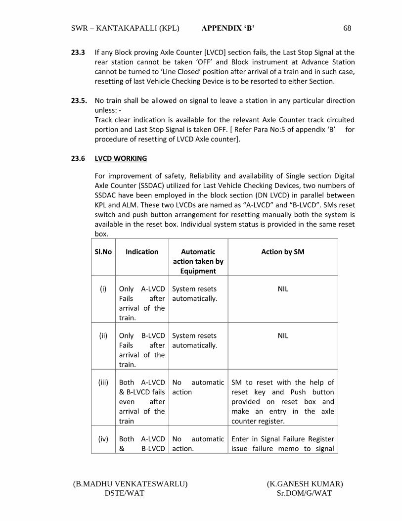
SWR – KANTAKAPALLI (KPL) APPENDIX ‘B’ 68
(B.MADHU VENKATESWARLU) (K.GANESH KUMAR)
DSTE/WAT Sr.DOM/G/WAT
23.3 If any Block proving Axle Counter [LVCD] section fails, the Last Stop Signal at the rear station cannot be taken ‘OFF’ and Block instrument at Advance Station cannot be turned to ‘Line Closed’ position after arrival of a train and in such case, resetting of last Vehicle Checking Device is to be resorted to either Section.
23.5. No train shall be allowed on signal to leave a station in any particular direction
unless: - Track clear indication is available for the relevant Axle Counter track circuited portion and Last Stop Signal is taken OFF. [ Refer Para No:5 of appendix ‘B’ for procedure of resetting of LVCD Axle counter].
23.6 LVCD WORKING
For improvement of safety, Reliability and availability of Single section Digital Axle Counter (SSDAC) utilized for Last Vehicle Checking Devices, two numbers of SSDAC have been employed in the block section (DN LVCD) in parallel between KPL and ALM. These two LVCDs are named as “A-LVCD” and “B-LVCD”. SMs reset switch and push button arrangement for resetting manually both the system is available in the reset box. Individual system status is provided in the same reset box.
Sl.No Indication Automatic action taken by
Equipment
Action by SM
(i) Only A-LVCD Fails after arrival of the train.
System resets automatically.
NIL
(ii) Only B-LVCD Fails after arrival of the train.
System resets automatically.
NIL
(iii) Both A-LVCD & B-LVCD fails even after arrival of the train
No automatic action
SM to reset with the help of reset key and Push button provided on reset box and make an entry in the axle counter register.
(iv) Both A-LVCD & B-LVCD
No automatic action.
Enter in Signal Failure Register issue failure memo to signal

SWR – KANTAKAPALLI (KPL) APPENDIX ‘B’ 69
(B.MADHU VENKATESWARLU) (K.GANESH KUMAR)
DSTE/WAT Sr.DOM/G/WAT
Fails even after Reset by SMs of both the end
technician. Procedure to be adopted is same as laid down in SWR Para 23.
(v) Either A-LVCD or B-LVCD fails continuously for long time.
-- Report to Signal staff without entering in Signal Failure register.
23.7 LVCD WORKING FOR DUAL LVCD OPERATION:
Single section Digital Axle counter (SSDAC) utilized for UP Last Vehicle Checking Devices, two numbers of SSDAC have been employed in the block section (UP LVCD) in parallel between KPL & KTV. These two LVCDs are named as “A-LVCD” and “B-LVCD”. SMs reset switch and push button arrangement for resetting manually both the system is available in the reset box. Individual system status is provided in the same reset box.
Sl.No Indication Automatic action taken by Equipment
Action by SM
(i) Only A-LVCD fails after arrival of the train.
System resets automatically.
NIL
(ii) Only B-LVCD fails after arrival of the train.
System resets automatically.
NIL
(iii) Both A-LVCD & B-LVCD fails after arrival of the train.
No automatic action.
SM to Reset with the help of Reset key and Push button provide on reset box and make an entry in the axle counter register.
(iv) Both A-LVCD & B-LVCD fails even after reset by SMs of both the end.
No automatic action.
Enter in Signal Failure Register. Issue failure

SWR – KANTAKAPALLI (KPL) APPENDIX ‘B’ 70
(B.MADHU VENKATESWARLU) (K.GANESH KUMAR)
DSTE/WAT Sr.DOM/G/WAT
memo to Signal Technician. Procedure to be adopted in same as laid down in SWR Para: 23
(v) Either A-LVCD or B-LVCD fails continuously for long time.
--- Report to signal staff without entering in Signal Failure Register.
24.0 ANALOG AXLE COUNTER and DESCRIPTION OF RESETTING EQUIPMENT (WITH
STATION YARD): Coal common loop is provided with analog axle counter as L6AXT. Whenever Axle counter zone is occupied or failed, a visual ‘RED’ indication appears on the VDU at station and when verified for clearance and initiated for resetting, an ‘YELLOW’ indication appears in the VDU and when once the resetting is completed, then appears ‘GREEN’ indication and the ‘YELLOW’ indication extinguishes. A VDU with indications, Veeder counter for each Axle counter zone, SS/SM’s Common reset key along with one individual push button for loop lines for resetting is installed at station to indicate the occupation/clearance of Axle counters of the full yard.
25.0 TELECOMMUNICATIONS: [a] The Station is connected to VSKP-PSA Control Circuit. [b] Telephone attached to SGE type Lock and Block Instruments for sections
KPL - KTV and KPL - ALM.Telephone attached with TLBI for section KPL-KTV.
[c] Railway Auto telephone is provided at this station. [d] Hot line communication is provided between SS/SM at station with
adjacent stations. [e] Telephone communication is provided between SS/SM on duty to UP &
DN Crank Handle locations. [f] Telephone attached to L.C. Gate No.ML/477 at Km.845/21-23 [g] The station is connected to VSKP-PSA traction power control circuit.
[h] VHF set is provided at the station. [i] BSNL/CUG telephone is provided. [j] Telephone is provided with DN IB post at KM: 840.900.

SWR – KANTAKAPALLI (KPL) APPENDIX ‘B’ 71
(B.MADHU VENKATESWARLU) (K.GANESH KUMAR)
DSTE/WAT Sr.DOM/G/WAT
26.0 POWER SUPPLY ARRANGEMENT FOR SIGNALLING INSTALLATIONS Power signaling and interlocking installations and the ancillary field units are fed from the following sources of power supply. i] Normal supply from UP AT/ DN AT connected to OHE traction distribution.
[230V 50HZ]. ii] Stand by supply – From AP Transco [Single-phase 230V-50 HZ].
Normal power supply [Single-phase 230V-50 HZ]. to the signalling and interlocking installation at the station is drawn from the traction power sources. Whenever traction power supply fails the CLS Auto change over panel switch to available as stand by supply. SS/SM on duty shall operate the change over switch provided in the SM’s office connecting the power supply from the healthy sources to the installation. The SS/SM on duty however maintain the record of power failures either of the traction supply or local supply and he must promptly report the failure of any one or both the power sources immediately through the section controller and to the concerned Elect. Staff and S&T maintenance staff. [i]. A Auto change over CLS Panel is provided in the SM’s office with the three
power supplies viz., UP AT , DN AT and local for the changing the CLS Panel to the required supply. The availability of the supply is indicated by luminous indicator above the circuit breaker for each supply.
[ii] Normally the switch will be kept towards UP AT/DN AT position. Whenever power block is to be given on the line the on duty SS/SM on duty must ascertain that power is available on the other AT and change over the switch to the desired position.
NOTE: If power block is to be given on the UP line DN AT must be available
and vice versa. [iii]. In case of failure of one of the AT supply without any power block the on duty
SS/SM has to check whether the circuit breaker has tripped [Three circuit breakers are provided in the change over switch board, one for each supply and their normal position is down and when tripped it goes UP.]
In case of failure of both AT supplies without any power block the local supply shall be utilized by operating the change over switch. If the circuit breaker is tripping even after resetting, no attempt shall be made to hold it by any means and a message shall be given to concerned SSE[Elect.] and SSE/PSI[OHE] for prompt rectification.

SWR – KANTAKAPALLI (KPL) APPENDIX ‘B’ 72
(B.MADHU VENKATESWARLU) (K.GANESH KUMAR)
DSTE/WAT Sr.DOM/G/WAT
[iv] Whenever there is failure of power supply in one AT the SS/SM on duty shall
take prompt action to inform to all concerned for rectification. The on duty SS/SM himself during each shift shall check & test the availability of power supply on both ATs and make an entry in the station dairy duly initiating for rectification of failure if any.
27.0 WORKING OF INTEGRATED POWER SUPPLY [IPS, INDICATIONS & ACTION TO BE
TAKEN BY SS/SM ON DUTY:
Power supply to the signalling installation is fed through Integrated Power Supply System [IPS] installed in the S&T power supply room. The IPS is normally fed through UP AT/Down AT traction power selected SS/SM on duty. Standby power supply is through AP TRANSCO local supply. One change over switch is provided in the SM’s room for selection of out put of either traction power supply or local power supply. The available traction/local supply is fed to the IPS through auto-change over switch provided in IPS.
The IPS system is connected with battery as a backup power source for safe working during transition of power and in case no 230 AC supply is available due to any reason.
In the event of failures all the sources of 230V 50HZ AC supply, the signalling
system shall be fed by power generated by backup battery bank connected to IPS for a limited power of 8 to 10 hours. The health of the battery bank is monitored through one IPS Monitoring Panel provided in the SM’s room which shall display the voltage of 110 V.DV battery bank provided as backup source of power supply. Depending up on the health of the battery bank and the system the following indications/alarm will appear on the remote monitoring panel. The indications/alarm, their implications and action to be taken by SS/SM on duty is tabulated below:
Sl.No
Instruction
Health of Battery Bank/Equipment.
Visual Indication
Audio Indication
Action to be taken by SS/Dy.
SS on duty
A - 50% DOD Red Alarm
Alarm shall be acknowledged by SM on duty.
B - 60% DOD Red Alarm -do-
C System shutdown
70% DOD Red Alarm
Signal feed cut off and all DC-DC converters to Work. Audio alarm will continue till Power Supply is restored.

SWR – KANTAKAPALLI (KPL) APPENDIX ‘B’ 73
(B.MADHU VENKATESWARLU) (K.GANESH KUMAR)
DSTE/WAT Sr.DOM/G/WAT
D Call S&T staff.
Equipment fault.
Red Alarm
Failure of any module will give the alarm in ASM’s panel. Alarm shall be acknowledged by SM on duty for audio cut off.
On duty SS/SM in each shift shall check and record the readings, indications, etc. in the station dairy duly initiating rectification of failures of IPS System, if any. In the event of failure of Remote monitoring ASM console due to any reason when both traction power and local power failed the SM on duty shall inform concerned Electrical staff immediately. In case ‘ call S&T staff ‘ or ‘system shut down‘ indication appear on the remote monitoring panel of IPS and/ or mal functioning of the remote monitoring panel SM on duty shall inform the same to concerned S&T staff immediately. NOTE: [i] DOD indicates depth of discharge of battery bank of IPS
[ii] In case of failure of all AC supply sources IPS battery bank can provide power supply maximum up to 8 to 10 hours before system shut down indication of APS.

SWR- KANTAKAPALLI STATION (KPL) APPENDIX-‘C’ 74
(B.MADHU VENKATESWARLU) (K.GANESH KUMAR) DSTE/WAT Sr.DOM/G/WAT
APPENDIX ‘C’ TO STATION WORKING RULES O F KANTAKAPALLI STATION
ANTI COLLISION DEVICE [[RAKSHA KAVACH]
-NIL-

SWR- KANTAKAPALLI STATION (KPL) APPENDIX-‘D’ 75
(B.MADHU VENKATESWARLU) (K.GANESH KUMAR) DSTE/WAT Sr.DOM/G/WAT
APPENDIX-‘D’ TO STATION WORKING RULES OF KANTAKAPALLI STATION The following staffs are concerned with the movement of the trains whose duties are given below:
The following staff are concerned with the movement of the trains whose duties are given below: 1. STATION MASTER (IN CHARGE):
i) He is responsible for trains passing during his shift. ii) He is responsible for the general and satisfactory working of the station and for the
efficient discharge of duties by staff working under him. iii) He shall keep all Rule books, Registers, Files and documents neat and up to date. iv) He shall ensure that all equipment, apparatus, and instruments including signaling
and interlocking gears and fittings are kept clean and oiled by S&T officials. v) His special attention is drawn to Chapter-II of G&SR and GR 5.01 to 5.08 with
relevant SRs and O.M. Chapter-2. vi) He shall follow the instructions laid down in SR.3.68.01 © and (d) and SR 14.07.01
and B.W.M.2.09 (e). vii) He shall promptly attend to accidents and report them. viii) He shall supervise the work of safe working staff and conduct night inspections and
report lapses of staff working under him. 2. STATION MASTER:
i) He is responsible for trains passing during his shift. ii) He shall promptly bring to the notice of SM incharge all irregularities and accidents
in course of his shift duties. iii) During the absence of SM I/C, the duties of the Station Master will devolve on him. iv) He shall follow SR 3.68.01(c) and (d) SR 14.07.l and OM Chapter-2. v) His special attention is drawn to Chapter-2 of G&SR 1976 and GR 5.01 to 5.08 with
relevant SRs. vi) As an assistant to SM I/C, he shall carry out the instructions given from time to time.
3. TRAFFIC POINTS MAN :
i. He shall work under the orders SM on duty. ii. He shall couple and uncouple vehicles under the supervision of SM. iii. He shall watch and guard the packages and other Railway property lying in the
Station premises. iv. He shall report any irregularities coming to his notice. v. He shall do loading and unloading of parcels, smalls and Guard’s boxes. He shall do
piloting IN and OUT.

SWR- KANTAKAPALLI STATION (KPL) APPENDIX-‘D’ 76
(B.MADHU VENKATESWARLU) (K.GANESH KUMAR) DSTE/WAT Sr.DOM/G/WAT
vi. He shall deliver any official message to the proper person/office. He shall carry out any other duties entrusted to him by the SM on duty.
vii. He shall follow OM Chapter-2.
4. TRAFFIC GATE MAN:
i. He is responsible to operate L.C. Gate at his end. ii. He shall attend to the call of SM on duty and do the work entrusted by the SM on
duty connected to gate operation. iii. He shall promptly report any abnormality to SM on duty. iv. He shall also protect the gate when required as given in gate working rules. v. He shall do all necessary functions related to gate working as stated in gate working
rules. vi. He shall follow OM Chapter-2(g).
NB: - All staff should be in uniform while on duty and fallow their rosters issued by
DPO/WAT from time to time.
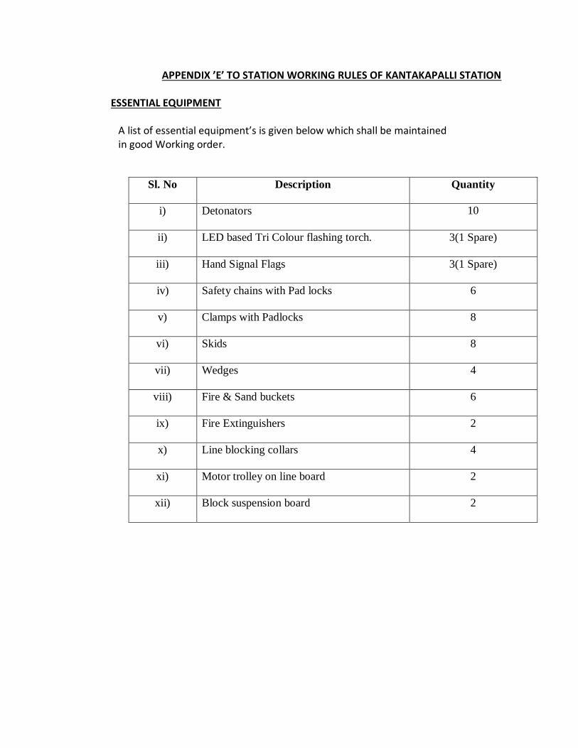
APPENDIX ’E’ TO STATION WORKING RULES OF KANTAKAPALLI STATION
ESSENTIAL EQUIPMENT
A list of essential equipment’s is given below which shall be maintained in good Working order.
Sl. No Description Quantity
i) Detonators 10
ii) LED based Tri Colour flashing torch. 3(1 Spare)
iii) Hand Signal Flags 3(1 Spare)
iv) Safety chains with Pad locks 6
v) Clamps with Padlocks 8
vi) Skids 8
vii) Wedges 4
viii) Fire & Sand buckets 6
ix) Fire Extinguishers 2
x) Line blocking collars 4
xi) Motor trolley on line board 2
xii) Block suspension board 2

SWR-KANTAKAPALLI STATION (KPL) APPENDIX-F 78
(B.MADHU VENKATESWARLU) (K.GANESH KUMAR) DSTE/WAT Sr.DOM/G/WAT
APPENDIX ‘F’ TO STATION WORKING RULS OF KANTAKAPALLI STATION RULES OF WORKING OF DK STATION, HALTS, IBH, AND OUTLYING SIDINGS
RULES FOR WORKING INTERMEDIATE BLOCK SIGNALLING BETWEEN KANTAKAPALLI AND ALAMANDA STATIONS.
The block section between Kantakapalli and Alamanda has been split into two block sections by providing Intermediate Block Stop signals at KM 840.900 [controlled by KPL station] for DN line and on up line at KM 841.00 [controlled by ALM station]. Intermediate Block stop signals are controlled through double line lock and block instruments at the respective receiving ends.
a] The Block working for section between Kantakapalli and Alamanda on DN and UP lines is controlled by the provision of Double line Lock and Block Instruments (SGE type) and are provided at Kantakapalli station and at Alamanda Station. The Down LSS signal No.38 of Kantakapalli station and UP LSS signal No.13 of Alamanda station are controlled by the clearance of IB section through respective IB section monitoring axle counters and the IB Home signal are controlled in turn through the line clear position of respective Double line lock and block instruments at the receiving stations.
b] Trains between intermediate block signal to respective Home signal of Station in advance in both the sides are worked by means of SGE type lock block instrument vide 4.09, 5.07, 14.01 to 14.14 of the G & SR and chapter V of BWM.
c] Last stop signal to the intermediate block stop signal in both the sides are controlled by Digital Axle counter and are worked under absolute block system in terms of G & SR 14.01, 14.13. Indications on VDU provided at Kantakapalli and at Alamanda stations.
1 INDICATIONS PROVIDED ON VDU FOR I.B. SECTION.
The indications of signals, IB and Block sections in both up and down directions are shown in the following table:

SWR-KANTAKAPALLI STATION (KPL) APPENDIX-F 79
(B.MADHU VENKATESWARLU) (K.GANESH KUMAR) DSTE/WAT Sr.DOM/G/WAT
SECTION: KPL - ALM
SlNo
Signal Aspect[S-38]
IB Section Indication [38A XT]
IB Home Aspect [S-42]
Block Section Indication
Remarks.
1 Green Yellow illuminated When train enters in to the section RED illuminated.
- - LSS No:38 is taken off to dispatch a train up to IB Home.
2 Red Red illuminated. - - IB Section is occupied.
3 - - Green Yellow illuminated. When rain enters the section, RED illuminated
IB Home taken off for train up to Home signal of ALM
4 - - Red Red
illuminated.
Block section is occupied or IB Home signal passed at danger.
IB SECTION: ALM-KPL
SlNo
Signal Aspect [S-37]
IB Section Indication [37 AXT]
IB Home Aspect [S-15]
Block Section
Indication
Remarks.
1 1 Green. Yellow Illuminated.
- - LSS No. 37 is taken off to dispatch a train up to IB Home.
2 Red. Red
Illuminated.
- - IB section occupied.

SWR-KANTAKAPALLI STATION (KPL) APPENDIX-F 80
(B.MADHU VENKATESWARLU) (K.GANESH KUMAR) DSTE/WAT Sr.DOM/G/WAT
3 - - Green Yellow illuminated. When train enters the section, RED illuminated
IB Home taken off for train up to home of KPL.
4 - - Red Red
Illuminated.
Block section is occupied or IB Home passed at danger.
i] Buzzer/Bell:
One audio buzzer is provided in the SS/SM room at KPL to detect train Entering section for out going trains. After train passes the intermediate block stop signal, the buzzer/bell will start ringing at KPL station. On hearing the buzzer/bell the SS/S.M must acknowledge the same by pressing on train entering section [TES] muting button to stop the buzzer/bell and then send train entering section report to the SS/S.M of the station in advance who shall turn commutator of the Double Line Lock and Block Instrument from the Line Clear position to ‘Train On Line position’ and acknowledge train entering section following the procedures laid down vide Block Working Manual.
ii] In the event of failure of I.B. track circuit [i.e. track clear indication not available] which shall not permit taking ‘OFF’ last stop signal, it should be ensured by SS/S.M on duty at the dispatching station through exchange of private number with the SS/S.M of the receiving station that the last train that passed the last stop signal of his station has fully arrived at receiving station, before allowing the next train to enter in to the section, such permission to the next train shall be granted and the section KPL-ALM shall be treated as single section.
iii] By issuing the pilot memo when normalization of the system is not possible. In such case, line clear has to be taken on lock and block instrument. Trains are to be dispatched from the station only after obtaining line clear till such time track circuit is last stop signal is restored to normal.

SWR-KANTAKAPALLI STATION (KPL) APPENDIX-F 81
(B.MADHU VENKATESWARLU) (K.GANESH KUMAR) DSTE/WAT Sr.DOM/G/WAT
2 NORMALIZATION OF THE TRACK CIRCUIT AND OF BLOCK WORKING BY RESETTING FEATURE:
I] No train should be allowed to leave station in any particular direction unless I.B. track clear indication is available for the relevant track circuited portion of I.B. section and last stop signal can not be taken off.
DN IB AXLE COUNTER (DUAL) WORKING FOR OPERATION:
Single Section Digital Axle counter (SSDAC) utilized for DN IB Axle counter, two numbers of SSDAC have been employed in the block section (LVCD) in parallel between KANTAKAPALLI and ALAMANDA. These two LVCDs are named as “SSDAC-1” and ”SSDAC-2”. The status of both systems are provided as indications beside of the operating VDUs.
Sl.No Indication Automatic action taken by Equipment
Action by SM
(i) Only SSDAC-1 Fails after arrival of the train.
System resets automatically.
NIL
(ii) Only SSDAC-2 Fails after arrival of the train.
System resets automatically.
NIL
(iii) Both SSDAC-1 & SSDAC-2 Fails after arrival of the train. (or) for any reason.
No automatic action.
Both side SM’s to reset the system as procedure laid down in SWR para 4.1 (8) general body and make an entry in the axle counter register.
(iv) Both SSDAC-1 & SSDAC-2 fails even after Reset by SMs of both the end.
No automatic action.
Enter in Signal Failure Register issue failure memo to Signal Technician. Procedure to be adopted is same as laid down in SWR Para :2
(v) Either SSDAC-1 or SSDAC-2 fails continuously for long time.
-- Report to Signal staff without entering in Signal Failure register.

SWR-KANTAKAPALLI STATION (KPL) APPENDIX-F 82
(B.MADHU VENKATESWARLU) (K.GANESH KUMAR) DSTE/WAT Sr.DOM/G/WAT
ii] A Resetting arrangement for the resumption of I.B. Axle counter under failure condition through co-operative features of both the SS/ SM on duty at either end station of the Block section is provided, which should only be resorted to after the train that was lastly sent arrives fully at the receiving station and is certified in this respect by the SS/S.M at the receiving station through exchange of private number.
iii] For monitoring of I.B. section working & re-setting of I.B. Axle counters, Track Indications and Re-setting arrangements are provided with buttons on the VDU at ALM & KPL stations. Counters are also provided for the purpose of recording the re-settings for the I.B. Axle Counters in case of failures in IB section.
iv] The SS/S.M on duty at both the station shall maintain a separate register for use of resetting at IB Axle Counters wherein every operation of the resetting button shall be recorded giving details of date of use, train, number, time, number registered in the counter on VDU and reasons for resetting and initial each such entry.
v] The procedure for resetting of the I.B. Axle counters in terms of clause viii (b) above shall be as follows:
SECTION; - ALAMANDA - KANTAKAPALLI ON UP LINE:
DISPATCHING STATION [ALM]
RECEIVING STATION
[KPL]
1 SS/S.M on duty shall call the attention of SS/SM of KPL station through Telephone for re-setting I.B. Axle counter zone giving details of last train left the station into the section.
1 SS/SM on duty at KPL after verifying that the said dispatched train arrives fully, shall exchange private number with SS/S.M on duty at ALM and gives permission to re-set by clicking the ‘Permission Granting’ icon provided on the VDU.After clicking of push button, a popup menu will appear consists of “Permission granting” and “ Permission restore”. Click “Permission granting” options/SM will find a “Yellow” color indication above the push button.

SWR-KANTAKAPALLI STATION (KPL) APPENDIX-F 83
(B.MADHU VENKATESWARLU) (K.GANESH KUMAR) DSTE/WAT Sr.DOM/G/WAT
For each such operation the permission granting counter provided in the VDU shall increase by one digit.
SS/SM on duty shall make an entry of changed permission granting counter number in counter register.
2 On getting permission to reset from KPL, a flashing indication will appear on VDU ( Permission received from KPL) above permission acknowledgement button which shall be acknowledged by SS/SM on duty by clicking “Permission received from KPL acknowledgement push button and flashing indication will become steady.
On duty SS/SM at ALM will then enable IB reset key option by giving user name and pass word options. After entering user name and pass word options, the key will turn, from Red to Green in colour. Then the SS/SM will click the IB reset push button appearing on the VDU for getting IB axle counter to be reset.
After applying resetting on doing the above process for resetting of the IB axle counter first has to be piloted. On passing of the first
2 SS/SM on duty at KPL shall shall withdraw the permission by clicking the “ permission granting” push button provided on the VDU.After clicking of push button, a popup menu will appear consist of:
‘Permission Granting’ and “permission restore”.
Click “permission restore” option the yellow colour indication above the push button will goes blank.

SWR-KANTAKAPALLI STATION (KPL) APPENDIX-F 84
(B.MADHU VENKATESWARLU) (K.GANESH KUMAR) DSTE/WAT Sr.DOM/G/WAT
piloted train IB axle counter will get reset.
In case train passed at danger, the aforesaid resetting procedure is to be carried out and no need of first train piloting.
For each such operation the IB reset counter provided in the VDU shall increase by one digit.
SS/SM on duty shall make an of changed resetting counter number in resetting register.
SECTION;-KPL -ALM ON DN LINE:
DISPATCHING STATION [KPL]
RECEIVING STATION [ALM]
1 SS/SM on duty shall call the attention of SS/SM of ALM station through Telephone for Permission granting to resetting IB axle counter zone as well as train passed signal with danger (train run away condition) giving details of last train left the station in to the section.
1 SS/SM on duty at ALM after verifying that the said dispatched train arrives fully, shall exchange private number with SS/S.M on duty at ALM and gives permission to re-set by clicking the ‘Permission Granting’ icon provided on the VDU.After clicking of push button, a popup menu will appear consists of “Permission granting” and “ Permission restore”. Click “Permission granting” option, SS/SM will find a “Yellow” color indication above the push button.
For each such operation the permission granting counter provided in the VDU shall increase by one digit.
SS/SM on duty shall make an entry of changed permission

SWR-KANTAKAPALLI STATION (KPL) APPENDIX-F 85
(B.MADHU VENKATESWARLU) (K.GANESH KUMAR) DSTE/WAT Sr.DOM/G/WAT
granting counter number in counter register.
2 On getting permission to reset from ALM, a flashing indication will appear on VDU (Permission received from ALM) above permission acknowledgement button which shall be acknowledged by SS/SM on duty by clicking “Permission received from KPL acknowledgement push button and flashing indication will become steady.
On duty SS/SM at KPL will then enable IB reset key option by giving user name and pass word options. After entering user name and pass word options, the key will turn, from Red to Green in colour.Then the SS/SM will click the IB reset push button appearing on the VDU for getting IB axle counter to be reset.
After applying resetting on doing the above process for resetting of the IB axle counter first has to be piloted. On passing of the first piloted train IB axle counter will get reset.
In case train passed at danger, the aforesaid resetting procedure is to be carried out and no need of first train piloting.
For each such operation the IB reset counter provided in the VDU shall increase by one digit.
SS/SM on duty shall make an of changed resetting counter number in resetting register.
2 SS/SM on duty at ALM shall withdraw the permission by clicking the “ permission granting” push button provided on the VDU.After clicking of push button, a popup menu will appear consist of:
‘Permission Granting’ and “permission restore”.
Click “permission restore” option the yellow colour indication above the push button will goes blank

SWR-KANTAKAPALLI STATION (KPL) APPENDIX-F 86
(B.MADHU VENKATESWARLU) (K.GANESH KUMAR) DSTE/WAT Sr.DOM/G/WAT
DN AXLE COUNTER (DUAL) WORKING FOR OPERATION:
2.1 Single Section Digital Axle Counter (SSDAC) utilized for DN IB Axle counter, two numbers of SSDAC have been employed in the block section (DN IB Axle counter) in parallel between KANTAKAPALLI and ALAMANDA. These two LVCDs are named as SSDAC-1 and SSDAC-2. The status of both systems are provided as indications beside of the operating VDUs.
SL.NO.
indication Automatic action taken by Equipment
Action by SM
1 Only SSDAC-1 fails after arrival of the train
System resets automatically
NIL
2 Only SSDAC-2 fails after arrival of the train
System resets automatically
NIL
3 Both SSDAC-1 & 2 Fails after arrival of the train (or)for any reason
No automatic action Both side SM’s to reset the system as procedure laid down in SWR para 4.1 (8) general body and make an entry in the axle counter register.
4 Both SSDAC-1 & 2 Fails even after reset by SMs of both the end
No automatic action Enter in Signal Failure
Register issue failure memo to signal technician. Procedure to be adopted is same as laid down in SWR

SWR-KANTAKAPALLI STATION (KPL) APPENDIX-F 87
(B.MADHU VENKATESWARLU) (K.GANESH KUMAR) DSTE/WAT Sr.DOM/G/WAT
para:2
5 Either SSDAC-1 or SSDAC-2 fails continuously for long time
-------- Report to signal staff without entering in signal failure
3. DISPATCH OF TRAINS:
Dispatch of trains is governed by the provision of G & SR 3.42, 3.70 and Block working manual rules.
a) From KANTAKAPALLI Towards ALAMANDA
Trains will be dispatched in accordance with the General Rules 3.42, 3.70., 3.75, 4.35 and 8.01 and subsidiary Rules thereto.
b) KANTAKAPALLI TO IBS ON UP AND DOWN LINES:
The SS/SM on duty shall ensure that the portion of line between LSS and 400Mtrs beyond IBS at their respective ends is clear of obstruction and indication to this effect is available in the VDU and Panel and shall also ensure any non-isolated shunting at their respective ends suspended and shunting authority issued if any is with drawn and kept in his custody.
Advise the Station Master at the station in advance, of the train No. and description of such intended train to be dispatched and shall take his assent supported by Private Number and shall then set and lock the route and take off the Starter and Advanced Starter.
c) IBS SIGNAL TO THE STATION IN ADVANCE:
The SS/S.M on duty shall obtain line clear over lock & Block instruments from the station in advance to dispatch a train past the IBS signal at the respective ends and shall take off the IBS signal by means of taking of signal No.15 of ALAMANDA on UP line and signal No.42 of KPL on DN line for section KPL-ALM.
After the train passes the intermediate Block Stop signal of KPL a buzzer will ring in the VDU. On hearing the buzzer/bell the SS/SM must acknowledge the same by clicking train entering section [TES] muting button to stop the buzzer/bell and then send train entering section report to the SS/S.M of the station in advance who in turn will turn commutator of the Double line Lock and Block Instrument from the line clear position to Train On Line position and acknowledge train entering section. After dispatch of a train from KPL into the Block section between KPL and intermediate Block Post in case when the intermediate stop signal is not taken ‘off’ but the buzzer has started ringing, this may be either due to

SWR-KANTAKAPALLI STATION (KPL) APPENDIX-F 88
(B.MADHU VENKATESWARLU) (K.GANESH KUMAR) DSTE/WAT Sr.DOM/G/WAT
the train passing intermediate Block stop signal at ‘ON’ position or due to failure of the track circuit in advance of that intermediate Block Signal and shall exchange Private Number with the SS/S.M of the advance station indicating the occurrence and the number of the train. On getting the information from the SS/S.M supported by Private Number, the SS/SM on duty at ALM in turn will then inform the matter to SCR on duty and concerned S&T official. The procedure must be rigidly followed irrespective of the fact whether line clear for train has been received from station in advance or not and this must be recorded in the Train Register and SS/SM’s diary book of both the Stations. d) (i) Dispatch of trains towards ALM station. In case of failure of the DN Advanced Starter signal at KPL Station due to failure of “Axle Counter” device or otherwise. If the failure of the Advanced starter of KPL due to the failure of axle counting device or the indication lamp (repeated by indication lamp) showing ‘Red’ light either due to power failure or due to any other causes, the re-setting “Push Button” provided with Veeder counter at the SS/SM office for resorting the normal function of the signal, should be operated accordingly to the following instruction whenever the DN Advanced starter signal of KPL is found defective by the Station Master and the following procedure shall be adopted. On receipt of this information, the SS/SM on duty after ensuring that all trains which had left his Block Station had arrived complete and intact at ALM station (by exchange Private Number with the SS/ SM ALM confirming this), shall press the resetting button of the axle counter. When the resetting is successful, it shall be indicated by a green light in the resetting panel provided in the SS/SM office at KPL. The use of this resetting button is registered on the veeder Counter and the SS/SM should record this giving the details of the occasion with timings in the Veeder Counter register kept in the station. If it is not possible to restore normal working of the counter by use of the resetting button, the ESM-in-charge of the section shall be served with a written memo to attend the defective signal and rectify the same. The ESM-in-charge of the section on being served with a memo by the SS/S.M shall attend the failure and rectify the fault. The ESM after ensuring that all S&T gears relating to defective signal have been attended to and are in working order except the axle counter which needs re-setting shall establish communication with SS/S.M concerned and ask him to reset the axle counter by pressing the reset push button. There after the SS/S.M on duty, after ensuring that all the trains which had left his Block Station had arrived complete and intact at ALM (by exchanging of P.N with SS/S.M of KPL confirming this) shall press the resetting button provided in the VDU at KPL station and resume the normal working.
4. ACTION TO BE TAKEN IN CASE OF FAILURE OF INTERMEDIATE BLOCK STOP SIGNAL:

SWR-KANTAKAPALLI STATION (KPL) APPENDIX-F 89
(B.MADHU VENKATESWARLU) (K.GANESH KUMAR) DSTE/WAT Sr.DOM/G/WAT
During the failure of Intermediate block stop signal GR 3.75 and SRs thereto shall be followed.
INDICATION CUM RESETTING PROVISION IN THE VDU AT ALAMANDA: The VDU provided for following light indications: a) Yellow indications for the track- circuited portion by Axle Counter, which remain
normally lit to indicate that the track is clear. These lamps extinguish no sooner the train passes the last stop signal and their place two red indications are lit to indicate that the track is occupied.
b) Red indications for the last stop signal replacement track circuit which remain lit so long this track- circuit is occupied or in under failure condition.
c) Red indication ahead of the IBS Signal, which are lit if the train passes the side signal in “ON” Position. These indications continue to glow till such time the lock and block working is resumed through emergence re-setting feature.
d) Red indications just ahead of IBS Signal for the IBS signal replacement track circuit. These indications normally remain dark and are lit either during occupation by a train or during failure of this track circuit.
e) Yellow indications for the block section for receiving trains. These indications shall normally remain no indications and shall be lit only when the incoming train passes the IBS signal. It remains lit till such time train arrives fully and Block Instrument is normalized.
f] For resetting of I.B. Axle counter please refer Para No 2 of Appendix ‘B’ of this SWR. Every Case of re-setting shall be entered in a register in the following proforma.
Date and time
Train No. Last entered
the block section
Private No. of station ahead for Complete Arrival of the train Under
Col.2
Veeder Counter No
Before resetting operation completed
Train No. Entering
Block section Immediately
after the resetting operation
Remarks
Signature of SS/SM
1
2
3
4
5
6
7
g] If resetting is not possible under item as mentioned above, the system should be treated as failed and train will work treating the entire section up to the Block Station immediately ahead of the IBS Post as one block section as per GR 3.75(4).
RUNNING OF MOTOR TROLLIES ON IBS ZONE: i) While allowing motor trolly/4 wheeler tower wagon/material trolley etc., entire section between KPL-ALM shall be treated as one block section and shall be issued T-369 [3B] for passing IBS at “ON” position.

SWR-KANTAKAPALLI STATION (KPL) APPENDIX-F 90
(B.MADHU VENKATESWARLU) (K.GANESH KUMAR) DSTE/WAT Sr.DOM/G/WAT
ii) After the complete arrival of the said Motor Trolly/4 wheeler tower wagon/material trolley etc., at the station ahead, Station Master at adjacent station shall exchange Private Number in token of complete arrival and then shall resume normal working by resetting the Axle Counter as stated in the SWR. iii) Motor Trolleys shall not be allowed on following line clear. NOTE: -Backing of train on the portion of line after passing the intermediate Block Stop
signal normally shall not be allowed, however, if it becomes inevitable to back, such backing may be done with great caution as mentioned in SR 3.75.04.
5. SIGNAL POST TELEPHONE:
A telephone socket (RE Type portable telephone kept with loco pilot with a RED Press button at the bottom is provided at the foot of each IB signal and is meant for loco pilot to contact the SS/SM in rear by pressing the RED button. The loco pilot of the train encountering the IB signal at ‘ON’ position shall contact the station in rear to find out the occupancy or otherwise of the block section ahead.
6 NORMAL POWER SUPPLY TO IBS GOOMTY AT KM 766/7 Km
Normal power supply to the Signaling and Interlocking installation at the IBS goomties is drawn from the traction power sources (230V-50 HZ, AT1 and AT2) with auto-change over arrangement in IB Goomty through a panel. When ever any traction power supplies fails, the auto-change over unit will automatically connected to the other available AT supply.
EAST COAST RAILWAY
WALTAIR DIVISION
APPENDIX- ‘G’
TO
SWR
OF
KANTAKAPALLI
(DRG. No. WAT/TRD/SWR/KPL/307/16)

APPENDIX-G
STATION WORKING RULES FOR 25 KV A.C ELECTRIC TRACTION
KANTAKAPALLI STATION
1. GENERAL & SUBSIDIARY RULES : i) The rules applicable to Electrified Section have been given in Chapter XVII of the General
Rules and in the Subsidiary rules made hereunder for Electric traction. The General principles governing operation and maintenance of Traction Overhead Equipment, Electric Locomotives, Signal & Telecommunications installations have been given in the A.C. Traction Manual. These rules books and an extract of the relevant paras of A.C. Traction Manual, shall be kept in each station and yard office and all the staff dealing with safe working shall make themselves thoroughly familiar with the same (GR 17.01).
ii) Brief reference to important rules required to be followed by Station / Yard staff in their day to day work has been given in this Appendix. These are, however, illustrative and not exhaustive.
2. GENERAL SAFETY PRECAUTIONS : i) All staff are warned that contact with or very near (within 2 meters, unless protected by a
screen as per rules) to live portion of the 25 KV Traction Overhead Equipment is dangerous and shall be strictly avoided.
ii) No work on overhead lines or in the zones within two meters, of any live equipment shall be carried out unless a regular ‘permit to work’ is obtained from the authorized Traction staff and line is made dead and earthed as per rules (GR 17.04) ACTM 20600 to 20619 Vol.II Pt.I.
3. SECTIONING DIAGRAM (Station Working Rules Diagram for Electric Traction) i) A Diagram No. WAT/TRD/SWR/KPL/307/16 indicating schematically the lines which have
been equipped with for Electric traction is exhibited. The diagram also indicates different electrical stations (Sectors, Sub-Sectors or Elementary sections) the Controlling Switches (Isolator Switches or Interrupters) Insulated Over laps and Section Insulators where the over head equipment is electrically separated. The limits of an Electrical section (Sub-Sector or Elementary Section) and are indicated by relevant section. A copy of this diagram is also enclosed with these special working rules and will form part of the same.
ii) For all purposes connected with train movements and power blocks, this diagram is the only authorized document to be referred to. The normal position of various switches is indicated on the diagram.
4. UNWIRED TRACKS : No electric locomotive with pantograph raised shall under any circumstances be taken to an un wired section. 5. OPERATION OF SWITCHES : I) All switching operations shall be carried out in accordance with the instructions of the
Traction Power Controller except in respect of Switching operations for local blocks, which may be carried out by authorized traction staff, after they have been granted local block by the Station Master or Assistant Station Master accordance with GR 17.04.09 and ACTM 20600,20601, Vol.II Pt.I.
II) "In case of emergency, Authorized and trained station staff may open Isolator switches under specific instructions of the Traction Power Controller (GR.17.04.14-B) with exchanging of Private Nos. to perform the operations of the following isolator switches as well as any other isolators within the station limits".
Sl. No. Isolator No. Loc. No. Sl. No. Isolator No. Loc. No.
1 SM-232 845/40A 7 SM-238 844/16
2 SM-233 845/39 8 SM-239 844/4N
3 SM-234 845/34 9 SS-200 KPL/1101
4 SM-235 845/27 10 SS-200A KPL/1137
5 SM-236 845/18A 11 SS-201 SDG/10
6 SM-237 844/27 6. POSITION OF SWITCH HANDLES : When a switch is in the closed position, the operating handle of the Switch is at the top.
Sr.DOM/WAT DEE/TRD/WAT

7. LOCATION OF KEYS OF SWITCHES : The keys for the padlocks of various isolator switches are kept in the ASM’s Office in a box with a glass mounted cover (GR 17.04.13). The Station Master shall daily check the locks on switches within the station limits and report any defect or deficiency to the Traction Power Controller. 8. PROCEDURE AND PRECAUTIONS FOR OPERATING ISOLATORS : The procedure for Operation of Isolator Switches have been given in and GR 17.04.15 and SR 17.04.14 (b) which must be rigidly observed. Isolator switches may be opened only after ensuring : - A) If the Isolator switch is on the main line that the adjacent interrupters on either end of
Isolators switch have been opened. B) If the Isolator switch is controlling supply to yard lines, that either the Elementary Section
controlled by the Isolator switch is free of raised pantographs of Electric Locomotives, on the Interrupters controlling the supply to the yard lines in question are open (GR.17.04.15).
9. POWER BLOCKS : i) The detailed procedure for obtaining Power Block has been given in (GR.17.04.02, 17.04.03
& 17.04.04) ACTM 20603, 20604, 20611, 20612 & 20613 which must be rigidly followed except in case of emergency.
ii) The sequence of switching operations for granting and canceling the Power block for particular section, are included in the Annexure. These shall be strictly followed by all staff. Failure to follow the sequence indicated, is likely to lead to dangerous consequences. When any isolator switch is changed from its normal position, for staff to work in over head equipment, a danger board shall be exhibited on the switch with the caption “DANGER MEN WORKING”. An adequate number or such Danger Boards have been provided at each stations.
10. PROTECTION AT THE TIME OF POWER BLOCK : i) All sections over which a power block has been granted shall be protected against the entry
of Electric Locomotives with pantograph raised from either end during the period (GR 17.04) and ACTM 20620, 20621 to 20627 Vol.II Pt.I strict enforcement of longitudinal and transverse, protection as per the Annexure attached shall be ensured before imposing power block. If there is / are locomotive on the section over which the power block to be given, the Loco Pilot of such, locomotives shall be given a memo by the Station Master on duty or authorized Traction staff to lower the pantograph and not to raise it until further instructions and an acknowledgement shall be obtained. The Loco Pilots shall not be given instructions to raise the pantograph still the power block is cancelled.
ii) Station master or station staff conducting shunting operation with electric locomotive will ensure that under no circumstances any electric locomotive approaches near the traction structure limiting electrical sections power with the power block may be granted. Limits of each electrical section at a station are shown in the station sectioning diagram.
11. SECTION INSULATORS : In order to insulate main and loop lines on different grid in the yard, cross over / turn out connecting main and loop lines or different grids of the yard are provided with section insulators, so that, when one line / or grid is made electrically dead and there be any fault on the same, the other line / grid is not affected. The speed of the electric locomotives with pantograph raised over such section insulators shall not exceed 50 KMPH subject to an other speed restriction which may be in force. When one of two sections separated by a Section Insulator is dead, the pantograph of the electric locomotive on the live section shall not proceed closer than 30 feet (10 meters) towards the section insulator marking the end of the dead section.
Sr.DOM/WAT DEE/TRD/WAT
12. BREAK DOWNS OF TRACTION OVER HEAD EQUIPMENTS : All the break downs or defects noted or reported on the Traction Overhead Equipment or any other traction equipment including bonding, shall immediately be reported to the Traction Power Controllers (GR 17.03.02) ACTM 20605 Vol.II Pt.I. Necessary caution order should be issued to the Loco Pilot concerned as directed by the Traction Power Controller observing the existing rules regarding issue of Caution Orders. 13. REGISTER OF MESSAGES : All messages relating to faults on the Traction over head equipment, operation of switches custody of keys of out-door switches and other important communications in connection with the operation and maintenance of Traction Overhead Equipment shall be recorded serially in a register by both the sender and the receiver indicating the time at which the messages are received of exchanged (GR 17.04.12) ACTM 20610 Vol.II Pt.I. 14. MOVEMENT OF DIESEL ENGINES OR TRAINS HAULED BY SUCH ENGINES Goods or Passenger trains hauled by other than electric locomotives may be allowed to pass through the dead section subject to the following conditions :- (a) This has not been prohibited specifically in the power block message. (b) Other than Electric trains hauled by such engines shall be brought to a stand at the station preceding the station/section at which power block is granted and the Station Master or this station shall satisfy himself by personal inspection that there is no electric locomotive in the train. (c) He shall also give a Caution Order to the Loco Pilot of such engine or train, warning him of the power block ahead and instructing him to watch for hand signals and observe them. (d) No Station Master shall give line clear or lower signals for a train to run over a section under power block unless he has received an assurance (supported by Private Number) from the Station Master of the preceding station that there is no electric locomotive or Inspection Car with pantograph raised in the train. (ACTM 20627 Vol.II Pt.I.) Note : For purpose of this Rule a Dead Electric Engine dispatched as a vehicle shall not be considered as a Electric Locomotive. 15. ELECTRIC LOCOMOTIVE : Provisions included in A.C. Traction Manual must be completed with in case of double heading or banking by electric locomotive and precautions indicated therein must be complied with when dispatching locomotive ACTM 30636 Vol.III. 16. ESM : Any direct contact or close proximity to 25 KV line conductors is dangerous, the station Lamp man/ESM climbing up the Signal post for removing or fixing or cleaning the signal lamp should not carry any long article which may accidentally touch or come in close proximity to live conductors. The ESM shall also be warned against bringing any part or body near live conductors. 17. CRANES: No crane shall be worked on or near Traction over head equipment, unless such equipment is first made dead and earthed and authorized representative of the OHE section is present (SR. 17.04.17(a) & (b)) 18. WORK ON ROOF OF ROLLING STOCK : No person shall climb on to the top of engine or tenders or on the roofs of carriages or wagons, when these vehicles are located beneath, overhead equipment except, when a regular ‘ permit to work’ has been obtained from authorized traction staff and the overhead equipment is dead and earthed (GR 17.05 (02), at ACTM 10402 & 10403 Vol.I ) 19. BLOCK INSTRUMENTS OR ANY OTHER ELECTRICAL,SIG.EQUIPMENT: The Station Master or cabin man on duty must always watch for any unusual working in the Block Instrument or any other Signaling equipment which may arise due to voltage induced from the Traction system. The block instrument or the signaling equipment must be suspended whenever there is any signs of unusual working and the nearest Signal & Telecom Maintenance Inspector contacted to inspect and certify the same. In the event of break of catenary, the Station Master must immediately check up whether all block and Morse signaling equipment are working normal before permitting any train movement
Sr.DOM/WAT DEE/TRD/WAT

20. TELECOMMUNICATION CIRCUITS : The details of the Telecommunication facilities available on the electrified sections and the use of the same have been given to ACTM 10213, 10429 VolI, 20703 Vol .II Pt.I 21. ELECTRIC SHOCK : The Station Masters shall exhibit prominently the instructions issued regarding the treatment to persons suffering from Electric Shock. In the Station, he shall ensure that all class-III staff are familiar with these instructions. 22. F I R E : Regarding Fire on or adjacent to any Electrical equipment refer GR 6.10 & SR there to 23. Nothing in these rules amends or supersedes any general or subsidiary Rules or instructions included in A.C. Traction Manual. These working rules shall be read as supplement to the aforesaid Rule books and also to the existing station working rules of the station. 24. AMENDMENTS FOR SUPPLEMENTARY CORRECTION SLIPS : Any amendment to these working rules or any of the Annexure will be notified by Correction slip to the Station Working Rules. The correction slip will be serially numbered and it is the responsibility of SM in charge of a station to bring the contents to the notice of the staff concerned and take their acknowledgement. 25. CONTINUOUS WATCH BY INSPECTING STAFF : The inspecting staff of operating, Telecommunication and Traction Department , shall make regular checks at all points to which these special working rules are supplied to ensure that the rules corrected up to date and the staff concerned are fully conversant with the rules and abide by them. NOTE : Whenever the codes “GR” and “SR” appear in these special working Rules please refer to the General and Subsidiary Rules for 25 KV A.C. Electric Traction, Chapter-XIX.
Sr.DOM/WAT DEE/TRD/WAT
OPERATING STATION WORKING ON A.C. TRACTION AREA. DO(s) AND DON’T(s)
A) FOR ALL STAFF : (a) DO(s) : 1. In case of fire on Electric Traction equipment or wires
i) Inform Traction Power Controller. ii) Extinguish Fire by Special extinguishers if available. iii) Ensure no water jet is used under any circumstances.
2. Anything unusual on Traction wires or electric locomotives inform Traction Power Controller of
nearest Station Master. 3. In any emergency speak to Traction Power Controller on emergency Telephone system (Sockets
for connecting emergency Telephone) are provided at interval of approximately every Kilometer and defection to nearest socket is indicated on OHE Mast.
(b) DON’T(s) : 1. Do not approach within a range of 2 meters (Approx. 7 feet of any traction wires on line
equipment) 2. Do not work on or near Traction wires or any line equipment unless they are made dead, earthed
and ‘Permit to Work’ obtained from an authorized traction staff. 3. Do not permit unauthorized persons to operate any equipment even if it be for making it dead. 4. Do not disturb any earthing bonding’ or tractions wires. 5. Do not enter any switching station or remote control center unless specially permitted and
accompanied by authorized Traction staff. 6. Do not attempt to turn the person in contact with live traction wire either by touching him or with
the help of wooden bamboo pole or by grabbing his clothing or with the help of rubber gloves if or any other means. Under such conditions contact the TPC switch off the power supply and remove the person in contact with the live traction wire by using wooden bamboo pole on by grabbing his clothes or with rubber gloves if available only after ensuring from TPC that the power supply has been switched off.
7. Do not forget to give artificial respiration to the victim. B. FOR RUNNING STAFF : (A) DO(s)
1. Avoid slipping of wheels 2. Load coal or oil in loose outside the electrified zone only. 3. Keep a safe distance of two meters (7 feet) from Traction wires while working on the
locomotives. (B) DON’T (s) :
1. Do not lift or raise your tools towards traction wires, (keep the tools in their respective position immediately after use).
2. Do not load coal on the engine tender to a height more than 4 mtrs. above rail level. 3. Do not take electric locomotive with raised pantograph to any unwired line, power block
working limit or near the section insulators at the end of section under power block. 4. Do not climb on the locomotive ( of any type) on the engine tender for any purpose, while
under traction wire unless power is cut-off and permit to work obtained (for watering, use the water column from the ground with the special device provided for this purpose and open tank over by the special device provided).
5. Do not place a steam locomotive with chimney directly opposite a traction mast or under any insulator or under bridge.
6. Do not allow long articles like fixing rod, shovel or any other thing to protrude above the engine while on electrified tracks.
7. Do not direct any jet or spray towards the traction wires (Jets of water, if necessary may be used horizontally of size the safety zone of 2 Mtrs (7 feet).
Sr.DOM/WAT DEE/TRD/WAT

C) FOR STATION MASTER : (A) DO (s) : 1. Ensure all staff are conversant with safety precautions. 2. Report defects in traction wires or any electric locomotives of Electric Multiple Unit promptly
to the traction power controller. 3. Keep sufficient number of button collars and ensure safety understand their use. 4. Ensure fitting of button collars to the points and signal buttons which give access to
selection under power block. 5. Observe procedure given in Station Working Rules for 25 KV A.C. Electric Traction while
operating Isolator switches. 6. Ensure safe custody of isolator switch keys. 7. Ensure that traction power staff protect sections from all directions by banner flag during
power block 8. Suspend working of block and signals if single of unusual working are noticed always check
block instruments and signaling equipment seen by breakdown in traction wires occurs. (B) DON’T (s) : 1. Do not permit an electric locomotive or multiple unit with raised pantograph to approach
any section under power block beyond (Power block) working limit or near section insulators.
2. Do not permit any crane to work adjacent to live with traction wires. 3. Do not permit your staff to approach live traction wires within the danger zone of 2 mtrs.
(approximately 7 feet) 4. Do not permit electric locomotive with raised pantograph to enter any unwired section. 5. Do not take off signals for direct reception for any electric engine or train, if there is a power
block within the adequate distance of the signal.
NOTE : This Appendix-G supersedes the previous appendix-G. Sr.DOM/WAT DEE/TRD/WAT

Description ofElectrified Section
Longitudinal Protection1 2 3A SECTOR
B SUB SECTORS
EAST COAST RAILWAY
STATION WORKING RULES FOR 25 KV AC ELECTRIC TRACTION FOR
1. These rules shall be read along with the main working rules and appendices.2. These rules apply only to Electric Trains or Electric Engines considered as such & indicate the protection required to prevent them from entering a SECTOR, SUB-SECTOR OR ELEMENTARY SECTION over which a Power Block exist.
2 Sector between Vizianagaram/TSS to Kantakapalli/SP on Up Line, Down Line and Middle Line between Alamanda to Kantakapalli/SP.
1)Ensure that no Electric Train / Loco with its panto raised position in the yard. 2)Line clear shall not be granted / obtained to / from Kottavalasa for Electric Trains / Locos on Up Line, Middle Line and Down Line. 3)Line clear shall not be granted / obtained to / from Alamanda for Electric Trains / Locos on Up Line, Middle Line and Down Line. 4)Concerned Reception, Dispatch and Shunt Signals shall be kept at 'ON'.
S. No
Steps or Precautions to be taken during Power BockHauling Trains or running Light or Standing with Pantograph raised
I Sector between Simhachalam North/TSS to Kantakapalli/SP on Up Line, Middle Line & Down Line and to Kottavalasa/SP on KK Line
1)Line clear shall not be granted / obtained to / from Kottalavalasa for Electric Trains / Locos on Up Line, Middle Line and Down Line. 2)Concerned Reception and Dispatch Signals shall be kept at 'ON'.

1 Up Sub-sector from Alamanda/SSP to Kantakapalli/SP (i.e. E/Sections 23501, 23503, 23505, 23507 & X-200)
1)Ensure that no Electric Train / Loco with its panto raised position on Line Nos. 4,5&6. 2)Line clear shall not be granted to Alamanda for Electric Trains / Locos on Up Line. 3)Line clear shall not be obtained from Kottavalasa for Electric Trains / Locos on Up Line. 4)No shunting is allowed from Line-4,5&6 to Line-3 and vice versa on both ends of the yard. 5)Concerned Reception, Despatch and Shunt Signals shall be kept at 'ON'.
2 Middle Line Sub-sector from- Alamanda/SSP to Kantakapalli/SP (i.e. E/Section 23601 23602, 23603)
1)Ensure that no Electric Train / Loco with its panto raised position on Line No. 3. 2)Line clear shall not be obtained/granted from/to Alamanda for Electric Trains / Locos on Middle Line. 3)Line clear shall not be granted/obtained to/from Kottavalasa for Electric Trains / Locos on Middle Line. 4)No shunting is allowed from Line-3 to Line-2 & 4 and vice versa on both ends of the yard. 5)Concerned Reception, Despatch and Shunt Signals shall be kept at 'ON'.
3 Down Line Sub-sector from Alamanda/SSP to Kantakapalli/SP (i.e. E/Section 23802, 23804, 23806, 23808 & X-201)
1)Ensure that no Electric Train / Loco with its panto raised position on Line No.1& 2. 2)Line clear shall not be obtained from Alamanda for Electric Trains / Locos on Down Line. 3)Line clear shall not be granted to Kottavalasa for Electric Trains / Locos on Down Line. 4)No shunting is allowed from Line-1&2 to Line-3 and vice versa on both ends of the yard.
4 Up Sub-sector from Pendurti/SSP to Kantakapalli/SP (i.e. E/Sections 21501, 21503, 21505)
1)Line clear shall not be granted / obtained to / from Kottalavalasa for Electric Trains / Locos on Up Line. 2)Concerned Dispatch Signals shall be kept at 'ON'.
5 Middle Line Sub-sector from Pendurti/SSP to Kantakapalli/SP (i.e. E/Sections 21701, 21702, 21703, 21704, 21705, 21706)
1)Line clear shall not be granted / obtained to / from Kottalavalasa for Electric Trains / Locos on Middle Line. 2)Concerned Reception and Dispatch Signals shall be kept at 'ON'.

6 Down Line Sub-sector from Pendurti/SSP to Kantakapalli/SP (i.e.E/Sections 22002, 22004, 22006, 22008, 22010)
1)Line clear shall not be granted to Kottalavalasa for Electric Trains / Locos on Down Line. 2)Concerned Reception Signals shall be kept at 'ON'.
C
1 UP Line E/Section 23501 between Alamanda/SSP to SM/237 at Loc. 844/27 at Kantakapalli Yard (E/section X-200 also gets blocked).
1)Ensure that no Electric Train / Loco with its panto raised position on Line Nos.5&6. 2)Admission/Despatch of Electric Trains/Locos on Line Nos.5&6 is prohibited. 3)No shunting is allowed from Line-4 to Line-5&6 and vice versa on both ends of the yard. 4)Concerned Reception, Despatch and Shunt Signals shall be kept at 'ON'.
2 Up Line E/Section 23503 between SM/237 at Loc. 844/27 and SM/235 at Loc. 845/27 at Kantakapalli Yard.
1)Ensure that no Electric Train / Loco with its panto raised position on Line No. 4. 2)Admission/Despatch of Electric Trains/Locos on LineNo.4 is prohibited. 3)No shunting is allowed from Line-4 to Line-3&5 and vice versa on both ends of the yard. 4)Concerned Despatch and Shunt Signals shall be kept at 'ON'.
ELEMENTARY SECTIONS.

3 Up Line E/Section 23505 between SM/235 at Loc No.845/27 to SM/233 at LocNo.845/39 at Kantakapalli Yard
1)Line clear shall not be obtained from Kottavalasa for Electric Trains / Locos on Up Line. 2)Despatch of Electric Trains/Locos from Line Nos.4,5&6 to Kottavalasa is prohibited.3)Reception of Electric Trains/Locos on Line Nos.5&6 from Kottavalasa is prohibited. 4)No shunting is allowed from Line-4 to Line-3&5 and vice versa on south end of the yard. 5)Concerned Despatch and Shunt Signals shall be kept at 'ON'.
4 Up Line E/Section 23507 between SM/233 at Loc No.845/39 of Kantakapalli Yard to Kantakapalli/SP.
1)Line clear shall not be obtained from Kottavalasa for Electric Trains / Locos on Up Line. 2)Despatch of Electric Trains/Locos from Line Nos.4,5&6 to Kottavalasa via. Up line is prohibited. 3)No shunting is allowed beyond locationNo.845/35 on UP line towards south end of the yard. 4)Concerned Despatch and Shunt Signals shall be kept at 'ON'.
5 Up Goods Coal Common Loop E/Section X-200 between SS/200 at Loc. KPL/1101 and SS/200A at loc.KPL/1137 of Kantakapalli Yard.
1)Admission/Despatch of Electric Trains/Locos on Line No. 6 i.e. Up Goods Coal Loop is prohibited. 2)Ensure that no Electric Train / Loco with its panto raised position on Line No. 6 i.e. Coal common loop. 3)No shunting is allowed from Line-6 to Line- 5 and vice versa on both ends of the yard. 4)Concerned Reception, Despatch and Shunt Signals shall be kept at 'ON'.
6 UP E/Section 21505 between Kantakapalli/SP and SM/221 at loc.No.852/9A of Kottavalasa Yard.
1)Line clear shall not be granted / obtained to / from Kottalavalasa for Electric Trains / Locos on Up Line. 2)Concerned Dispatch Signals shall be kept at 'ON'.

7 Middle Line E/Section 23601 between Alamanda/SSP and SM/239 at Loc. 844/4N at Kantakapalli Yard.
1)Line clear shall not be obtained/granted from/to Alamanda for Electric Trains / Locos on Middle Line. 2)Concerned Reception, Despatch and Shunt Signals shall be kept at 'ON'.
8 Middle Line E/Section 23602 between SM/239 at Loc. 844/4N at Kantakapalli Yard and SM/234 at Loc. 845/34 at Kantakapalli Yard
1)Line clear shall not be obtained/granted from/to Alamanda for Electric Trains / Locos on Middle Line. 2)Admission/Despatch of Electric Trains/Locos on Line No.3 is prohibited. 3)No shunting is allowed from Line-3 to Line- 2&4 and vice versa on both ends of the yard. 4)Concerned Reception, Despatch and Shunt Signals shall be kept at 'ON'.
9 Middle Line E/Section 23603 between SM/234 at Loc. 845/34 at Kantakapalli Yard and Kantakapalli/SP.
1)Line clear shall not be obtained/granted from/to Kottavalasa for Electric Trains / Locos on Middle Line. 2)No shunting is allowed from Line-3 to Line- 2&4 and vice versa on south end of the yard. 3)Concerned Reception, Despatch and Shunt Signals shall be kept at 'ON'.
10 Middle Line E/Section 21706 between Kantakapalli/SP and SM/224 at loc.No.851/32A of Kottavalasa Yard.
1)Line clear shall not be granted / obtained to / from Kottalavalasa for Electric Trains / Locos on Middle Line. 2)Concerned Reception and Dispatch Signals shall be kept at 'ON'.

11 Down Line E/Section 23802 between Alamanda/SSP and SM/238 at Loc. 844/16 of Kantakapalli Yard.
1)Line clear shall not be obtained from Alamanda for Electric Trains / Locos on Down Line. 2)No shunting is allowed from Line-2 to Line- 1 and vice versa on North end of the yard. 3)Concerned Despatch & Shunt Signals shall be kept at 'ON'.
12 Down Line E/Section 23804 between SM/238 at Loc. 844/16 and SM/236 at loc.No.845/18A of Kantakapalli Yard on Line-2
1)Admission/desptach of Electric Trains / Locos is prohibited on Line No.2. 2)Dispatch of Electric Trains / Locos to Alamanda from Line No.1 is prohibited 3)No shunting is allowed from Line-2 to Line- 1 and vice versa on North end of the yard. 4)Concerned Reception, Despatch & Shunt Signals shall be kept at 'ON'.
13 Down Line E/Section 23806 between SM/236 at loc.No.845/18A and SM/232 at loc.No.845/40A of Kantakapalli yard Line-1&2 (E/Section X-201 on Engineering siding also gets blocked)
1)Ensure that no Electric Train / Loco with its panto raised position on Line No.1 & Engineering Siding.2)Admission of Electric Trains/Locos is prohibited on Line Nos. 1&2. 3)Dispatch of Electric Trains/Locos from Line No.1 is prohibited. 4)No shunting is allowed from Line-2 to Line- 1 and vice versa on both ends of the yard. 5)Concerned Reception, Despatch & Shunt Signals shall be kept at 'ON'.
14 Down Line E/Section 23808 between SM/232 at loc.No.845/40A and Kantakapalli/SP
1)Line clear shall not be granted to Kottavalasa for Electric Trains / Locos on Down Line. 2)No shunting is permitted beyond loc.No.845/36A on Down line of south end. 3)Concerned Reception & Shunt Signals shall be kept at 'ON'.

15 Down Line E/Section 22010 between Kantakapalli/SP and SM/225 at loc.No.851/30A at Kottavalasa.
1)Line clear shall not be granted to Kottavalasa for reception of Electric Trains / Locos on Down Line. 2)Concerned Reception Signals shall be kept at 'ON'.
16 E/Section X-201 of Ballast Siding (HWH end) at Kantakapalli Yard.
1)Ensure that no Electric Train / Loco with its panto raised position on ballast siding. 2)Admission/Despatch of Electric Trains/Locos to/from Ballast siding is prohibited. 3)Concerned Reception and Shunt Signals shall be kept at 'ON'.
Note:i)
ii)
iii)
iv)
Point leading to unwired tracks shall not be used for the movement of Electrical Locos with Panto graph raised.
Refer Traction Working Rule Drawing No. WAT/TRD/SWR/KPL/307/16.
This Appendix-G supersedes earlier Appendix-G Traction Working Rule Drawing No. WAT/TRD/SWR/KPL/288/14.
For any unusual movement of Electric Locomotives, the Station Master on duty must referenergising the section where Power Block has been granted.

APPENDIX-'G'
Sequence of SwitchingOperation for grantingPower Block
Sequence ofSwitching Operationfor Restoring Power
Transverse Protection4 5 6
9)Open CB/92 at Simhachalam North/TSS.
9)Close CB/92 at Simhachalam North/TSS.
2)Open CB-94 at Vizianagaram/TSS.
2)Close CB-94 at Vizianagaram/TSS.
EAST COAST RAILWAY
STATION WORKING RULES FOR 25 KV AC ELECTRIC TRACTION FOR KANTAKAPALLI STATION
2. These rules apply only to Electric Trains or Electric Engines considered as such & indicate the protection required to prevent them from entering a SECTOR,
Nil 1)Ensure BM-226, BM-227 are in open position at Kantakapalli/SP.
1)Ensure BM-226, BM-227 are in open position at Kantakapalli/SP. 2)Ensure BM/01 is in open position at Kottavalasa/SP. 3)Ensure SM/85 at Loc. 870/27A at Simhachalam North Yard is in open position. 4)Ensure SM/40 at Loc. 870/24A at Simhachalam North Yard is in open position. 5)Ensure SS/112 at Loc. 869/46X at Simhachalam North Yard is in open position. 6)Ensure SS/101 at Loc. 868/1001 at Simhachalam North Yard is in open position. 7)Ensure SM/180 at Loc. 869/1001A at Simhachalam North Yard is in open position. 8)Ensure SS/170 at Loc. RY/27 at Reception Yard of Waltair Marshalling Yard is in open position.
Bock in respect of Electric LocosHauling Trains or running Light or Standing with Pantograph raised
Nil

1)Point Nos. 55A&B, 57A&B, 62 A&B and 56A&B shall be kept in Normal Position.
1)Open BM-235 at Alamanda/SSP. 2)Open BM/229 at Kantakapalli/SP.
1)Close BM-235 Alamanda/SSP. 2)Close BM/229 at Kantakapalli/SP.
1)Point Nos. 53A&B, 55A&B, 57A&B, 63A&B, 62A&B, 56A&B, 54A&B and 52A&B shall be kept in Normal Position.
1)Open BM-236 at Alamanda/SSP. 2)Open BM/231 at Kantakapalli/SP.
1)Close BM-236 at Alamanda/SSP. 2)Close BM/231 at Kantakapalli/SP.
1)Point Nos.53A&B, 63A&B, 52A&B and 54A&B shall be kept in Normal Position.
1)Open BM-238 at Alamanda/SSP. 2)Open BM/232 at Kantakapalli/SP.
1)Close BM-238 at Alamanda/SSP. 2)Close BM/232 at Kantakapalli/SP.
Nil 1)Open BM-215 atPendurti/SSP. 2)Open BM/225 atKantakapalli/SP.
1)Close BM-215 atPendurti/SSP. 2)Close BM/225 atKantakapalli/SP.
Nil 1)Open BM-217 at Pendurti/SSP. 2)Open BM/223 at Kantakapalli/SP.
1)Close BM-217 at Pendurti/SSP. 2)Close BM/223 at Kantakapalli/SP.

Nil 1)Open BM-220 at Pendurti/SSP. 2)Open BM/222 at Kantakapalli/SP.
1)Close BM-220 at Pendurti/SSP. 2)Close BM/222 at Kantakapalli/SP.
1)Open BM-235 at Alamanda/SSP. 2)Open BM/229 at Kantakapalli/SP. 3)Open SM/237 at Loc. 844/27 at Kantakapalli Yard. 4)Close BM-229 at Kantakapalli/SP.
1)Close BM-235 at Alamanda/SSP. 2)Close SM/237 at Loc. 844/27 at Kantakapalli Yard. .
1)Point No. 59A&B shall be kept in reversal position.
1)Open BM-235 at Alamanda/SSP. 2)Open BM/229 at Kantakapalli/SP. 3)Open SM/237 at Loc. 844/27 at Kantakapalli Yard. 4)Open SM/235 at Loc. 845/27 at Kantakapalli Yard. 5)Close BM-235 at Alamanda/SSP. 6)Close BM/229 at Kantakapalli/SP.
1)Close SM/235 at Loc. 845/27 at Kantakapalli Yard. 2)Close SM/237 at Loc. 844/27 at Kantakapalli Yard.
1)Point Nos. 55A&B, 57A&B and 58A&B shall be kept in Normal Position.

1)Point Nos. 62A&B, 58A&B and 56A&B shall be kept in Normal Position.
1)Open BM-235 at Alamanda/SSP. 2)Open BM/229 at Kantakapalli/SP. 3)Open SM/235 at Loc. 845/27 at Kantakapalli Yard. 4)Open SM/233 at Loc. 845/39 at Kantakapalli Yard. 5)Close BM-235 at Alamanda/SSP. 6)Close BM/229 at Kantakapalli/SP.
1)Close SM/235 at Loc. 845/27 at Kantakapalli Yard. 2)Close SM/233 at Loc. 845/39 at Kantakapalli Yard.
Nil 1)Open BM-235 at Alamanda/SSP. 2)Open BM/229 at Kantakapalli/SP. 3)Open SM/233 at Loc. 845/39 at Kantakapalli Yard. 4)Close BM-235 at Alamanda/SSP. .
1)Close BM/229 at Kantakapalli/SP. 2)Close SM/233 at Loc. 845/39 at Kantakapalli Yard. .
1)Point Nos. 61A&B, 60A&B shall be kept in Normal Position.
1)First Open SS/200 at Loc. KPL/1101 at Kantakapalli Yard. 2)Then open SS/200A at Loc. KPL/1137 at Kantakapalli yard.
1)First close SS/200A at Loc. KPL/1137 at Kantakapalli Yard. 2)Then close SS/200 at Loc. KPL/1101 at Kantakapalli Yard.
Nil 1)Open BM-215 at Pendurti/SSP. 2)Open BM/225 at Kantakapalli/SP. 3)Open SM/221 at Loc.No.852/9A of Kottavalasa yard. 4)Close BM-215 at Pendurti/SSP
1)Close BM/225 at Kantakapalli/SP. 2)Close SM/221 at Loc.No.852/9A of Kottavalasa yard.

Nil 1)Open BM-236 at Alamanda/SSP. 2)Open BM/231 at Kantakapalli/SP. 3)Open SM/239 at Loc. 844/4N at Kantakapalli Yard. 4)Close BM/231 at Kantakapalli/SP.
1)Close BM/236 at Alamanda/SSP 2)Close SM/239 at Loc. 844/4N at Kantakapalli Yard.
1)Point Nos. 53A&B, 55A&B, 57A&B, 63A&B and 62A&B shall be kept in Normal Position.
1)Open BM-236 at Alamanda/SSP. 2)Open BM/231 at Kantakapalli/SP. 3)Open SM/239 at Loc. 844/4N at Kantakapalli Yard. 4)Open SM/234 at loc.No.845/34 at Kantakapalli yard 5)Close BM/231 at Kantakapalli/SP. 6)Close BM/236 at Alamanda/SSP.
1)Close SM/239 at Loc. 844/4N at Kantakapalli Yard. 2)Close SM/234 at loc.No.845/34 at Kantakapalli yard.
1)Point Nos. 56A&B, 54A&B and 52A&B shall be kept in Normal Position.
1)Open BM-236 at Alamanda/SSP. 2)Open BM/231 at Kantakapalli/SP. 3)Open SM/234 at Loc. 845/34 at Kantakapalli Yard. 4)Cose BM/236 at Alamanda/SSP
1)Close BM/231 at Kantakapalli/SP. 2)Close SM/234 at Loc. 845/34 at Kantakapalli Yard.
Nil 1)Open BM-217 at Pendurti/SSP. 2)Open BM/223 at Kantakapalli/SP. 3)Open SM/224 at Loc.No.851/32A of Kottavalasa yard. 4)Close BM-217 at Pendurti/SSP
1)Close BM/223 at Kantakapalli/SP. 2)Close SM/224 at Loc.No.851/32A of Kottavalasa yard.

1)Point No. 53A&B shall be kept in Normal Position.
1)Open BM-238 at Alamanda/SSP. 2)Open BM/232 at Kantakapalli/SP. 3)Open SM/238 at Loc. 844/16 at Kantakapalli Yard. 4)Cose BM/232 at Kantakapalli/SP
1)Close BM/238 at Alamanda/SSP. 2)Close SM/238 at Loc. 844/16 at Kantakapalli Yard.
1)Point Nos. 65A&B and 63A&B shall be kept in Normal Position.
1)Open BM-238 at Alamanda/SSP. 2)Open BM/232 at Kantakapalli/SP. 3)Open SM/238 at Loc. 844/16 at Kantakapalli Yard. 4)Open SM/236 at loc.No.845/18A at Kantakapalli yard. 5)Close BM/232 at Kantakapalli/SP 6)Cose BM/238 at Alamanda/SSP
1)Close SM/238 at Loc. 844/16 at Kantakapalli Yard. 2)Close SM/236 at Loc. 845/18A at Kantakapalli Yard.
1)Point Nos. 54A&B and 65A&B shall be kept in Normal Position.
1)Open BM-238 at Alamanda/SSP. 2)Open BM/232 at Kantakapalli/SP. 3)Open SM/236 at Loc. 845/18A at Kantakapalli Yard. 4)Open SM/232 at loc.No.845/40A at Kantakapalli yard. 5)Close BM/232 at Kantakapalli/SP 6)Cose BM/238 at Alamanda/SSP
1)Close SM/236 at Loc. 845/18A at Kantakapalli yard. 2)Close SM/232 at Loc. 845/40A at Kantakapalli Yard.
1)Point No. 52A&B shall be kept in Normal Position.
1)Open BM-238 at Alamanda/SSP. 2)Open BM/232 at Kantakapalli/SP. 3)Open SM/232 at Loc. 845/40A at Kantakapalli Yard. 4)Cose BM/238 at Alamanda/SSP
1)Close BM/232 at Kantakapalli/SP 2)Close SM/232 at Loc. 845/40A at Kantakapalli Yard.

Nil 1)Open BM-220 at Pendurti/SSP. 2)Open BM/222 at Kantakapalli/SP. 3)Open SM/225 at Loc. 851/30A at Kottavalasa Yard. 4)Cose BM/220 at Pendurti/SSP
1)Close BM/222 at Kantakapalli/SP 2)Close SM/225 at Loc. 851/30A at Kottavalasa Yard.
1)Point No. 67 shall be set against entry of trains on Ballast siding.
1)Open SS/201 at Loc. SDG/10 at kantakapalli Yard.
1) Close SS/201 at Loc. SDG/10 at kantakapalli Yard.
Point leading to unwired tracks shall not be used for the movement of Electrical Locos with Panto graph raised.
This Appendix-G supersedes earlier Appendix-G Traction Working Rule Drawing No. WAT/TRD/SWR/KPL/288/14.
refer to the Working Rules, Diagrams of his station and ensure that there is no chance of