SEISMIC ASSESSMENT OF THE MILANO CENTRALE RAILWAY STATION
19
International Journal of Architectural Heritage, 7: 609–627, 2013 Copyright © Taylor & Francis Group, LLC ISSN: 1558-3058 print / 1558-3066 online DOI: 10.1080/15583058.2012.654894 SEISMIC ASSESSMENT OF THE MILANO CENTRALE RAILWAY STATION Luca Pelà, 1 Andrea Benedetti, 2 Alessandra Aprile, 3 and Enrico Mangoni 4 1 Department of Construction Engineering, Technical University of Catalonia (UPC), Barcelona, Spain 2 Department of Civil, Chemical, Environmental and Materials Engineering, University of Bologna, Bologna, Italy 3 Department of Engineering, University of Ferrara, Ferrara, Italy 4 Department of Civil and Environmental Engineering, University of Florence, Florence, Italy This study of the Milano Centrale railway station aimed at assessing the seismic vulnerability of the monumental building. The work was carried out on the occasion of a big project to refurbish the station, including both the restoration of certain areas of high artistic value and the improvement of functionality with the current railway services. The seismic analysis is focused on the monumental part of the building, including the Coaches Gallery, the Tickets Hall, and the Head Gallery. The safety level of the structure was assessed on the basis of comprehensive historical investigation, survey, testing, and finite element analysis. The issue of checking the seismic safety of a large number of members is addressed using a step-by-step verification strategy. The results of the study show that the overall safety level of the structure is acceptable, although some local structural deficiencies need to be handled with a proper strengthening design. KEY WORDS: concrete, steel truss, monumental building, finite element (FE) analy- sis, equivalent frame model, spectral response analysis, step-by-step verification strategy, fiber-reinforced polymer (FRP) strengthening, restoration 1. INTRODUCTION The seismic assessment of historical monumental buildings is a very important issue in structural engineering. Many difficulties are related to complex geometry, unknown inter- nal morphology of members, variable mechanical properties of materials, and elaborate interpretation of structural arrangement. Strategic structures built in the early 20th century, such as railway stations, are still in service, although they were designed following old standards based on design criteria very different from modern ones. The approach to the problem cannot ignore the specific performances of materials used in the past (Verderame et al. 2001a; 2001b). The study of such structures has to be made with reference to the codes in force, the available handbooks, and the current practice at the time of construction (Vona Received August 11, 2011; accepted January 2, 2012. Address correspondence to Luca Pelà, Department of Construction Engineering, Technical University of Catalonia (UPC), Jordi Girona 1-3, 08034 Barcelona, Spain. E-mail: [email protected] 609
Transcript of SEISMIC ASSESSMENT OF THE MILANO CENTRALE RAILWAY STATION

International Journal of Architectural Heritage, 7: 609–627, 2013Copyright © Taylor & Francis Group, LLCISSN: 1558-3058 print / 1558-3066 onlineDOI: 10.1080/15583058.2012.654894
SEISMIC ASSESSMENT OF THE MILANO CENTRALERAILWAY STATION
Luca Pelà,1 Andrea Benedetti,2 Alessandra Aprile,3
and Enrico Mangoni41Department of Construction Engineering, Technical University of Catalonia(UPC), Barcelona, Spain2Department of Civil, Chemical, Environmental and Materials Engineering,University of Bologna, Bologna, Italy3Department of Engineering, University of Ferrara, Ferrara, Italy4Department of Civil and Environmental Engineering, University of Florence,Florence, Italy
This study of the Milano Centrale railway station aimed at assessing the seismic vulnerabilityof the monumental building. The work was carried out on the occasion of a big project torefurbish the station, including both the restoration of certain areas of high artistic value andthe improvement of functionality with the current railway services. The seismic analysis isfocused on the monumental part of the building, including the Coaches Gallery, the TicketsHall, and the Head Gallery. The safety level of the structure was assessed on the basis ofcomprehensive historical investigation, survey, testing, and finite element analysis. The issueof checking the seismic safety of a large number of members is addressed using a step-by-stepverification strategy. The results of the study show that the overall safety level of the structureis acceptable, although some local structural deficiencies need to be handled with a properstrengthening design.
KEY WORDS: concrete, steel truss, monumental building, finite element (FE) analy-sis, equivalent frame model, spectral response analysis, step-by-step verification strategy,fiber-reinforced polymer (FRP) strengthening, restoration
1. INTRODUCTION
The seismic assessment of historical monumental buildings is a very important issuein structural engineering. Many difficulties are related to complex geometry, unknown inter-nal morphology of members, variable mechanical properties of materials, and elaborateinterpretation of structural arrangement. Strategic structures built in the early 20th century,such as railway stations, are still in service, although they were designed following oldstandards based on design criteria very different from modern ones. The approach to theproblem cannot ignore the specific performances of materials used in the past (Verderameet al. 2001a; 2001b). The study of such structures has to be made with reference to the codesin force, the available handbooks, and the current practice at the time of construction (Vona
Received August 11, 2011; accepted January 2, 2012.Address correspondence to Luca Pelà, Department of Construction Engineering, Technical University of
Catalonia (UPC), Jordi Girona 1-3, 08034 Barcelona, Spain. E-mail: [email protected]
609
610 L. PELÀ ET AL.
and Masi 2004). The sole structural analysis, even though it is based on the most powerfulcomputational methods (Roca et al. 2010), would be meaningless without a detailed his-torical investigation, thorough inspection and testing. The study of a monumental buildingshould be planned carefully by integrating different approaches (ICOMOS/ISCARSAHCommittee 2003).
This article presents the seismic analysis of the Milano Centrale Railway station,Italy. The monumental building was investigated on the basis of exhaustive historicalresearch, optimized experimental activity, and survey. This approach provided a sufficientlevel of knowledge preliminary to the structural analysis and the safety check of membersunder vertical and seismic actions.
2. MILANO CENTRALE RAILWAY STATION
2.1. Historical Research
Milano Centrale is one of the main European railway stations (Figure 1), with anannual total of 120 million passengers using approximately 600 trains daily. It is a railwayterminal officially inaugurated in 1931 to replace the old (1864) transit station designedby the French architect Louis-Jules Bouchot that had become inadequate due to growthof railway traffic. The contest for its construction was won by the Italian architect UlisseStacchini in 1912. Due to economic crisis during World War I, construction proceededvery slowly. Several years later the work was re-established and the construction started in1927. The majestic station was completed in only 5 years, becoming one of the principalmonuments wanted by Benito Mussolini to represent the power of the fascist regime. At thattime, Milano Centrale was among the largest railway stations of Europe.
Figure 1. Photograph of bird’s eye view of Milano Centrale railway station (Angeleri and Columba 1985) (colorfigure available online).
INTERNATIONAL JOURNAL OF ARCHITECTURAL HERITAGE 7(6): 609–627
SEISMIC ASSESSMENT OF MILANO CENTRALE 611
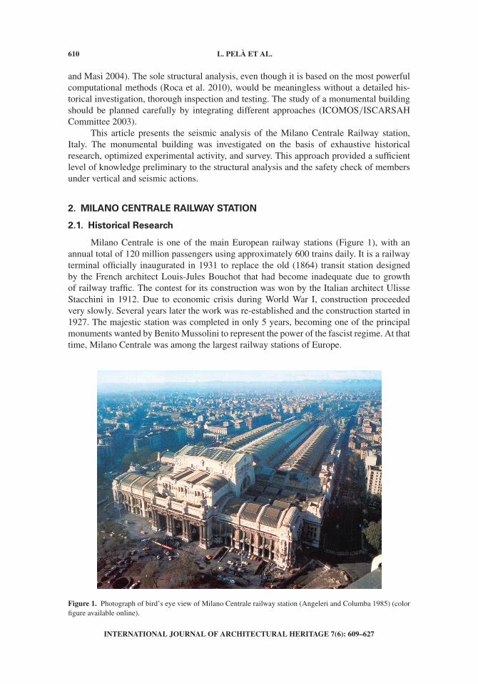
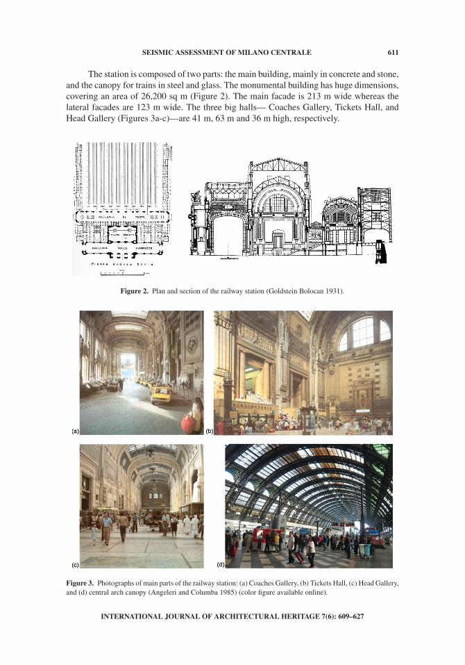
The station is composed of two parts: the main building, mainly in concrete and stone,and the canopy for trains in steel and glass. The monumental building has huge dimensions,covering an area of 26,200 sq m (Figure 2). The main facade is 213 m wide whereas thelateral facades are 123 m wide. The three big halls— Coaches Gallery, Tickets Hall, andHead Gallery (Figures 3a-c)—are 41 m, 63 m and 36 m high, respectively.
Figure 2. Plan and section of the railway station (Goldstein Bolocan 1931).
Figure 3. Photographs of main parts of the railway station: (a) Coaches Gallery, (b) Tickets Hall, (c) Head Gallery,and (d) central arch canopy (Angeleri and Columba 1985) (color figure available online).
INTERNATIONAL JOURNAL OF ARCHITECTURAL HERITAGE 7(6): 609–627
612 L. PELÀ ET AL.
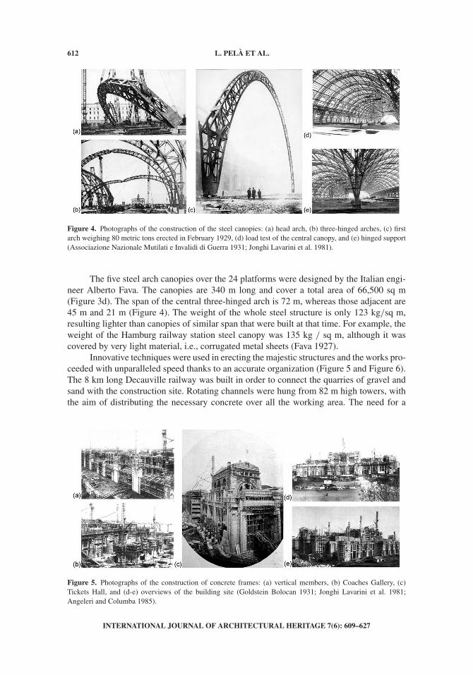
Figure 4. Photographs of the construction of the steel canopies: (a) head arch, (b) three-hinged arches, (c) firstarch weighing 80 metric tons erected in February 1929, (d) load test of the central canopy, and (e) hinged support(Associazione Nazionale Mutilati e Invalidi di Guerra 1931; Jonghi Lavarini et al. 1981).
The five steel arch canopies over the 24 platforms were designed by the Italian engi-neer Alberto Fava. The canopies are 340 m long and cover a total area of 66,500 sq m(Figure 3d). The span of the central three-hinged arch is 72 m, whereas those adjacent are45 m and 21 m (Figure 4). The weight of the whole steel structure is only 123 kg/sq m,resulting lighter than canopies of similar span that were built at that time. For example, theweight of the Hamburg railway station steel canopy was 135 kg / sq m, although it wascovered by very light material, i.e., corrugated metal sheets (Fava 1927).
Innovative techniques were used in erecting the majestic structures and the works pro-ceeded with unparalleled speed thanks to an accurate organization (Figure 5 and Figure 6).The 8 km long Decauville railway was built in order to connect the quarries of gravel andsand with the construction site. Rotating channels were hung from 82 m high towers, withthe aim of distributing the necessary concrete over all the working area. The need for a
Figure 5. Photographs of the construction of concrete frames: (a) vertical members, (b) Coaches Gallery, (c)Tickets Hall, and (d-e) overviews of the building site (Goldstein Bolocan 1931; Jonghi Lavarini et al. 1981;Angeleri and Columba 1985).
INTERNATIONAL JOURNAL OF ARCHITECTURAL HERITAGE 7(6): 609–627

SEISMIC ASSESSMENT OF MILANO CENTRALE 613
Figure 6. (a-e) Photographs of the construction of Head Gallery steel roofing: polycentric arch trusses, invertedarch trusses and purlins (Fava 1929; Angeleri and Columba 1985).
Figure 7. (a) Photographs of 1:1 scale model in plaster of decorative facing, (b-c) placing of covering pre-fabricated blocks, and (d-e) façade decorative elements (Jonghi Lavarini et al. 1981; Angeleri and Columba1985).
quick completion of the works led to place all the formworks of the building at the sametime, resulting in a multitude of wood props and planks. It was possible to cast more than400 cubic meters of concrete in a single workday (8 hours). Enormous quantities of materi-als were employed for the construction: 43,500 metric tons of cement and 2,000 metric tonsof reinforcing steel for concrete structures, 16,000 cubic meters of masonry, 14,000 cubicmeters of stone for coverings and 2,500 metric tons of steel for truss structures. Three typesof cement were adopted: standard Portland cement, high strength Portland cement, andwhite cement Bianco Alzano for decorative facings (Goldstein Bolocan 1931; Angeleri andColumba 1985).
The great amount of artistic ornaments is impressive, including 133,000 square m ofdecorated walls, as well as statues, friezes, bas-reliefs, mosaics, painted tiles, and chande-liers. The decor shows through details the will of monumental design. It is interesting tonote that 1:1 scale models in plaster were used during the construction of some members,such as portals and facings (Figure 7a). Different materials were used for architectural dec-orative elements, such as marble, travertine, Nabresina stone, white concrete and plaster(Figures 7b-e).
The ambitious structural conception and the attention to every single detail ledfamous architects such as Frank Lloyd Wright to call the Milano Centrale railway stationone of the most beautiful in the world (Mari et al. 2008).
INTERNATIONAL JOURNAL OF ARCHITECTURAL HERITAGE 7(6): 609–627
614 L. PELÀ ET AL.
2.2. Survey Activity, In Situ Investigation, and Testing
A survey activity was necessary to define the structural layout, the member geom-etry, and the materials properties. Additional information and drawings were providedby handbooks and journals published at the time of the construction (Fava 1927; 1929;Associazione Nazionale Mutilati e Invalidi di Guerra 1931; Goldstein Bolocan 1931) andby recent studies (Jonghi Lavarini et al. 1981; Angeleri and Columba 1985; Finazzer Flory2005).
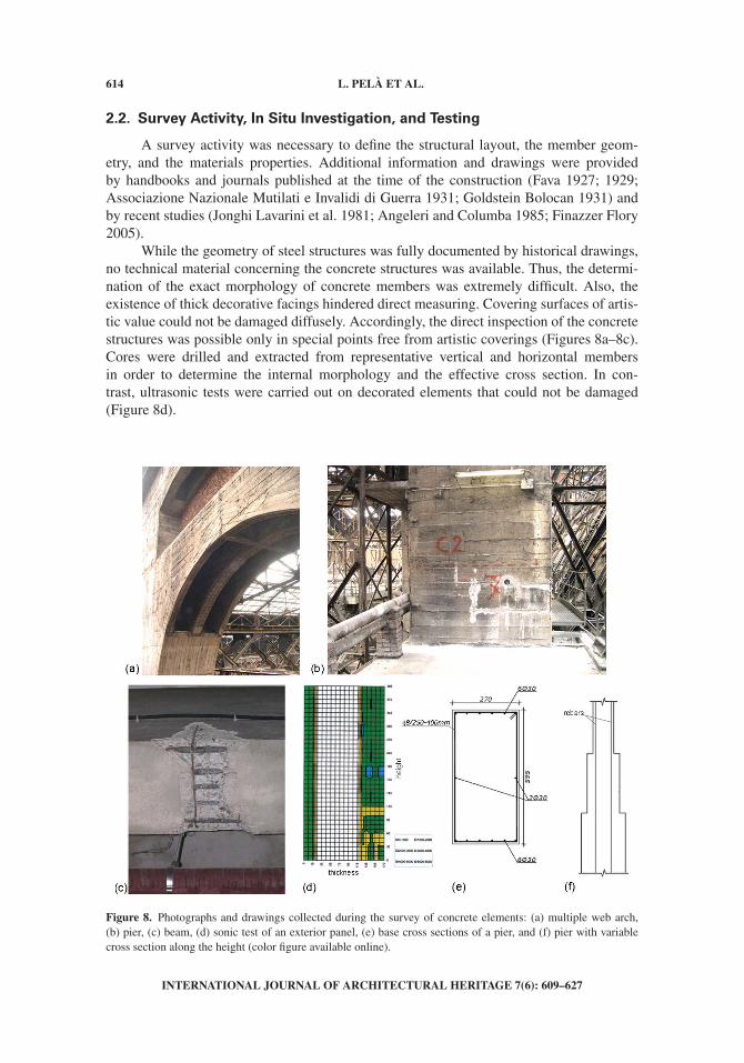
While the geometry of steel structures was fully documented by historical drawings,no technical material concerning the concrete structures was available. Thus, the determi-nation of the exact morphology of concrete members was extremely difficult. Also, theexistence of thick decorative facings hindered direct measuring. Covering surfaces of artis-tic value could not be damaged diffusely. Accordingly, the direct inspection of the concretestructures was possible only in special points free from artistic coverings (Figures 8a–8c).Cores were drilled and extracted from representative vertical and horizontal membersin order to determine the internal morphology and the effective cross section. In con-trast, ultrasonic tests were carried out on decorated elements that could not be damaged(Figure 8d).
Figure 8. Photographs and drawings collected during the survey of concrete elements: (a) multiple web arch,(b) pier, (c) beam, (d) sonic test of an exterior panel, (e) base cross sections of a pier, and (f) pier with variablecross section along the height (color figure available online).
INTERNATIONAL JOURNAL OF ARCHITECTURAL HERITAGE 7(6): 609–627
SEISMIC ASSESSMENT OF MILANO CENTRALE 615
The skeleton of the building is constituted by parallel concrete frames of multi-webbeams and solid or hollow columns. The reinforcement of piers is given by few internal steelbars (Figures 8b and 8e). The concrete cover of rebars is quite thick in vertical members.Some piers do not present any reinforcing steel. Several piers present variable cross sectiondecreasing along the height, with rebars aligned with the edges of the top cross section.As a result, the concrete cover is 30 mm at the top section, but it can be up to 300 mm atthe base cross section (Figure 8f). The beams are reinforced with large diameter mild steelbars (Figure 8c). The shear reinforcement of piers is given by few small diameter stirrups,whereas beams present both stirrups and 45 degrees folded rebars. It was observed that theflexural and shear steel reinforcements of vertical concrete elements is almost equal to theminimum quantity prescribed by the historical Italian standards in force at the constructiontime (R.D.L. 1927; 1928; 1929; 1930).
A distinctive characteristics of the construction is the use of prefabricated shellsfor the finishing of vertical surfaces and ceilings (Figure 7). All the vertical membersare covered on the exterior surfaces with 20–40 cm thick decorative panels of stoneor concrete (Figure 8d), that are fixed with hooks and fasteners and interleaved withthin regularization mortar layers. The lower part of the interior panels is covered with10 cm thick marble slabs, whereas the upper interior surfaces are finished in decorativecement.
The three galleries of the main building are covered by prefabricated vaulted ceilingsfinished with external stone layers. The thickness of concrete is approximately 10 cm andthe steel reinforcement is constituted by a 150 × 150 mm2 net of 6-mm diameter bars.Such precast elements are hung from the intrados of steel truss arches with span up to35 m (Figure 9a). The fasteners are 14 mm mild steel ties sometimes badly inserted in theconcrete layer of the vault elements or bad anchored (Figure 9b and 9c).
All the steel members are laminated profiles connected with rivets. The steel trussesare connected at the supports to the concrete frames by means of hinges and rollers. Theroofs of the Coaches Gallery and Tickets Hall are sustained by a second order of steeltrusses with glass or plastic sheets that allow the light to enter the galleries. The roof of theHead Gallery is supported by the extrados of the polycentric arch trusses from which thevaulted ceilings are hung (Figure 2).
The foundations of the concrete frames are unreinforced concrete footings of8 × 8 × 4 m3. Their considerable thickness is such that the sole concrete can resist thestresses induced by the actions transferred by the frames. In fact, steel rebars were only
Figure 9. (a) Photographs of steel trusses over the Tickets Hall and (b-c) fastening sustaining the vaulted ceilings(color figure available online).
INTERNATIONAL JOURNAL OF ARCHITECTURAL HERITAGE 7(6): 609–627

616 L. PELÀ ET AL.
used to provide connection between concrete layers poured in subsequent phases. Thefoundation soil is constituted by deposits of dense sand and gravel. This information wasprovided by exploratory drillings and continuous standard penetration tests. The ultimatebearing capacity of the foundation soil under the footings was estimated at 1350 kPa.
The mechanical parameters of the materials were estimated through destructivelaboratory tests on small specimens extracted from the structures. Small specimens ofsteel laminate were subject to tensile stress, providing ultimate strengths ranging between360 MPa and 450 MPa. The cylindrical compressive strength of 74 mm diameter concretecores ranged between 20 MPa and 32 MPa, whereas the tensile stress derived from split-ting tests ranged between 1.5 MPa and 2.2 MPa. The mild steel rebars gave tensile ultimatestrengths between 380 MPa and 450 MPa. The obtained strength values were comparedwith the recommendations from the standards in force at the construction time (R.D.L.1927; 1928; 1929; 1930). Table 1 lists strength values from the historical Italian standardsand the corresponding allowable stresses for working stresses verifications.
The materials were well preserved and the structural elements of the constructionwere in an overall good condition. The thick decorative facings contributed to the main-tenance of the concrete structural members. The thick cover in concrete elements withoutfacing prevented the depassivation of rebars. In another respect, the need emerged for clean-ing and restoration of the covering surfaces of artistic value. Only some local shortcomingswere observed, such as the bad condition of some fasteners connecting the prefabri-cated vaults to the steel trusses, the locking of some support devices (hinges, rollers) insteel trusses, the carbonation of the cover and the corrosion of rebars in some concreteelements.
2.3. Structural System Conception
The structural framework of the construction is clearly characterized by the use ofsimple and statically determinate systems, both for the main building and the canopystructure. The adoption of massive vertical elements led to a behavior similar to that ofunreinforced concrete or masonry structures. The pursuit of limiting the horizontal thrustsacting on vertical members is also evident.
The five steel canopies constitute a statically determinate system, since each of themis a three-hinged arch. There is no continuity between adjacent arches, being the hingeof the minor arch placed on the major arch rather than on the ground. Concrete frames
Table 1. Nominal strength values and allowable stresses for concrete and reinforcing steel from historical Italianstandards (R.D.L. 1927; 1928; 1929; 1930)
Concrete
28-daystrength(MPa)
Allowablestress(MPa)
ReinforcingSteel
Failurestrength(MPa)
Allowablestress(MPa)
Elongationat failure
(%)
Compression 16.0 4.0 – – – –Flexure/Compression 20.0 5.0 Tension 380–500 120 27–21Shear
(unreinforced members)– 0.2 – – – –
Shear(reinforced members)
– 1.4
INTERNATIONAL JOURNAL OF ARCHITECTURAL HERITAGE 7(6): 609–627

SEISMIC ASSESSMENT OF MILANO CENTRALE 617
fixed at the base were planned initially for the whole structure of the Tickets Gallery(Goldstein Bolocan 1931). Such solution was later discarded since it would have produced aconsiderable horizontal thrust at a height of 35 m. Also, being the height of piers larger thanthe span of each frame, the efficiency of the base restraint would have been limited and dif-ficult to evaluate during the solution of the statics problem. In addition, the construction ofbig concrete frames would have led to large thermal deformations, with the consequent needfor expansion joints that are difficult to reconcile with aesthetics. Accordingly, a systemcomposed by steel trusses supported by concrete vertical members was employed finally.The support devices for each truss are a hinge and a roller.
Also the choice of non-structural vaulted ceilings, hanging from steel trusses, wasconceived in order to limit the horizontal thrusts. In one regard, this improves the seismicbehavior of the vertical concrete structures. In another regard, the role of steel fasteners inanchoring such heavy voussoirs is crucial under earthquake actions.
3. STRUCTURAL ANALYSIS
A big refurbishment project of the Milano Centrale building was commenced inrecent times with the aim of exploiting the commercial potential and improving the func-tionality (Grandi Stazioni 2006. Restoration and functional refurbishment project of MilanoCentrale Railway Station. Private Communication). The general plan consisted in providingaccess to underground floors accommodating shops and new railway services. Meanwhile,the Italian seismic standard was updated and the city of Milan was classified in a low seis-micity area (Norme Tecniche per le Costruzioni 2008). A seismic analysis of the buildingwas necessary in order to understand the feasibility of the planned modifications. The studyis limited to the monumental part of the building, including the Coaches Gallery, the TicketsHall, and the Head Gallery. The steel arch canopies over the platforms were not analyzedin the present work. The study of this huge and complex building turned out to be com-plicated. The information about the morphology and dimensions of concrete members waslimited. As discussed previously, the survey and inspection activity provided helpful infor-mation only about a representative number of elements. This issue made the developmentof the structural model quite difficult.
The seismic assessment of the building consisted in the following stages. Firstly, thegeometry and the material properties of the structural elements were defined by surveyresults or, eventually, formulating realistic assumptions. Secondly, a finite element (FE)model of the construction was developed in order to simulate the response of the differentparts of the structure. Due to complex nature of the building and to low seismicity of thesite, a modal response spectrum analysis was preferred to nonlinear static/dynamic analy-ses (Pelà et al. 2009; Roca et al. 2010). The capacity of the structural system to dissipateenergy in the nonlinear range was taken into account by reducing the response spectrumwith a proper behavior factor. Finally, the seismic safety of the different elements waschecked by means of a step-by-step verification strategy. This approach accounts for theunavoidable uncertainties related to the definition of structures morphology, geometry, andproperties.
3.1. Resisting Frames Evaluation
An important stage of the study, preliminary to the development of a FE modelfor the numerical analysis, was the evaluation of the resisting frames and the sections of
INTERNATIONAL JOURNAL OF ARCHITECTURAL HERITAGE 7(6): 609–627
618 L. PELÀ ET AL.
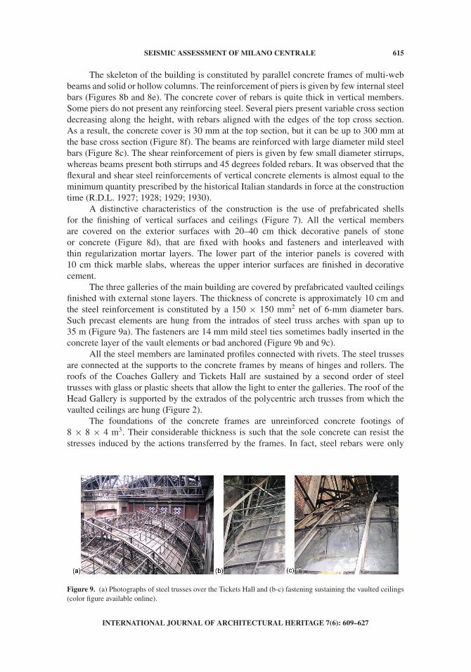
Figure 10. Drawings explaining the procedure adopted to determine the section of concrete members not directlyinspected: (a) inscribed rectangle, (b) clearing of covering, and (c) obtained net cross section.
Figure 11. (a) Drawings representing the identification of the resisting frames: façade, (b) Coaches Gallery,(c) Tickets Hall, (d) Head Gallery, (e) interior perpendicular frame, and (f) lateral façade (color figure availableonline).
the structural elements. Since many concrete members were not directly inspected dur-ing the survey activity, a procedure was followed to determine their net cross sections(Figure 10). Firstly the inscribed rectangle was drawn, secondly the decorative coveringwas cleared and finally the net cross section was obtained. The thickness of the removedcoverings ranges between 20 cm for small secondary elements and 40 cm for large ele-ments. The effective resisting concrete frames considered for FE discretization are shown inFigure 11.
3.2. Finite Element Analysis
A FE model of the monumental building was prepared considering an equivalentframe discretization, see Figure 12. Many approximations were introduced in order to keepthe model as simple as possible. However, the model required approximately 60,000 nodesand 28,000 elements. One-dimensional beam elements were adopted for discretization. Dueto large cross sections of concrete members, the rigid connections between vertical andhorizontal finite elements were properly modeled at each sheared node. Rigid floors weremodeled when it was possible (e.g. new floors of the refurbishment project), otherwise theoriginal beams supporting the flexible floors were discretized. Appropriate boundary con-ditions were assumed to model the interaction between the analyzed part of the station and
INTERNATIONAL JOURNAL OF ARCHITECTURAL HERITAGE 7(6): 609–627
SEISMIC ASSESSMENT OF MILANO CENTRALE 619
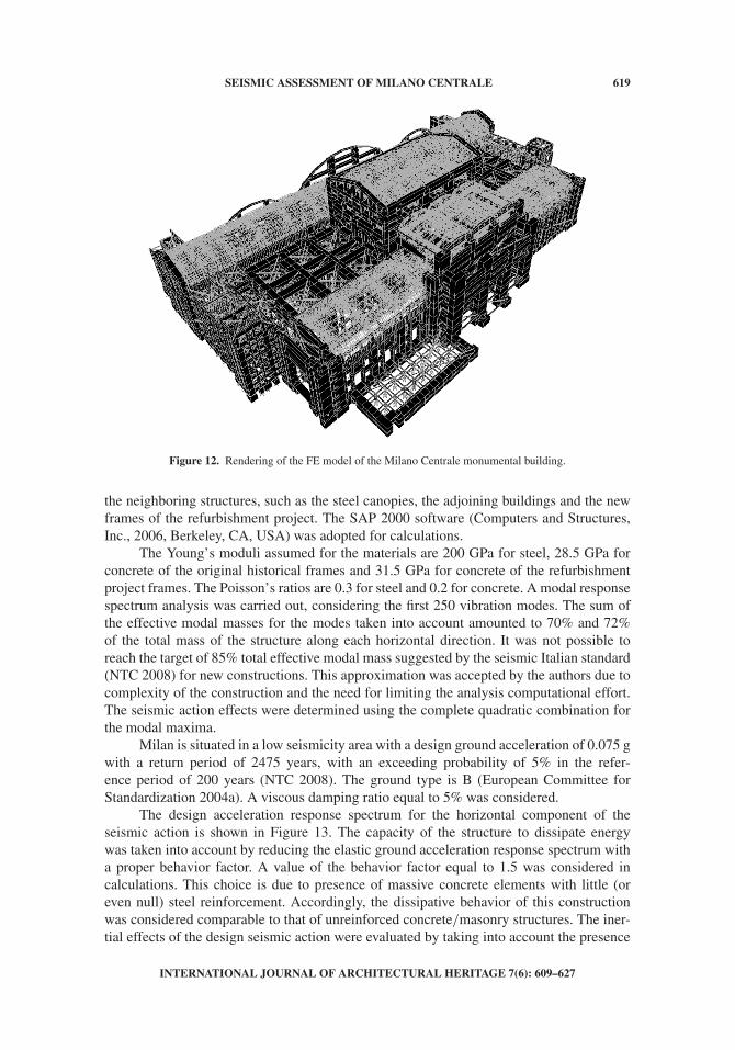
Figure 12. Rendering of the FE model of the Milano Centrale monumental building.
the neighboring structures, such as the steel canopies, the adjoining buildings and the newframes of the refurbishment project. The SAP 2000 software (Computers and Structures,Inc., 2006, Berkeley, CA, USA) was adopted for calculations.
The Young’s moduli assumed for the materials are 200 GPa for steel, 28.5 GPa forconcrete of the original historical frames and 31.5 GPa for concrete of the refurbishmentproject frames. The Poisson’s ratios are 0.3 for steel and 0.2 for concrete. A modal responsespectrum analysis was carried out, considering the first 250 vibration modes. The sum ofthe effective modal masses for the modes taken into account amounted to 70% and 72%of the total mass of the structure along each horizontal direction. It was not possible toreach the target of 85% total effective modal mass suggested by the seismic Italian standard(NTC 2008) for new constructions. This approximation was accepted by the authors due tocomplexity of the construction and the need for limiting the analysis computational effort.The seismic action effects were determined using the complete quadratic combination forthe modal maxima.
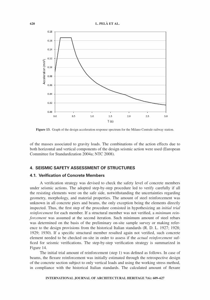
Milan is situated in a low seismicity area with a design ground acceleration of 0.075 gwith a return period of 2475 years, with an exceeding probability of 5% in the refer-ence period of 200 years (NTC 2008). The ground type is B (European Committee forStandardization 2004a). A viscous damping ratio equal to 5% was considered.
The design acceleration response spectrum for the horizontal component of theseismic action is shown in Figure 13. The capacity of the structure to dissipate energywas taken into account by reducing the elastic ground acceleration response spectrum witha proper behavior factor. A value of the behavior factor equal to 1.5 was considered incalculations. This choice is due to presence of massive concrete elements with little (oreven null) steel reinforcement. Accordingly, the dissipative behavior of this constructionwas considered comparable to that of unreinforced concrete/masonry structures. The iner-tial effects of the design seismic action were evaluated by taking into account the presence
INTERNATIONAL JOURNAL OF ARCHITECTURAL HERITAGE 7(6): 609–627
620 L. PELÀ ET AL.
Figure 13. Graph of the design acceleration response spectrum for the Milano Centrale railway station.
of the masses associated to gravity loads. The combinations of the action effects due toboth horizontal and vertical components of the design seismic action were used (EuropeanCommittee for Standardization 2004a; NTC 2008).
4. SEISMIC SAFETY ASSESSMENT OF STRUCTURES
4.1. Verification of Concrete Members
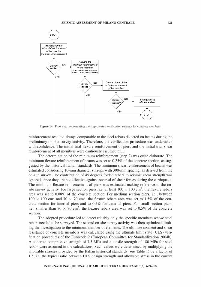
A verification strategy was devised to check the safety level of concrete membersunder seismic actions. The adopted step-by-step procedure led to verify carefully if allthe resisting elements were on the safe side, notwithstanding the uncertainties regardinggeometry, morphology, and material properties. The amount of steel reinforcement wasunknown in all concrete piers and beams, the only exception being the elements directlyinspected. Thus, the first step of the procedure consisted in hypothesizing an initial trialreinforcement for each member. If a structural member was not verified, a minimum rein-forcement was assumed at the second iteration. Such minimum amount of steel rebarswas determined on the basis of the preliminary on-site sample survey or making refer-ence to the design provisions from the historical Italian standards (R. D. L. 1927; 1928;1929; 1930). If a specific structural member resulted again not verified, such concreteelement needed to be checked on-site in order to assess if the actual reinforcement suf-ficed for seismic verifications. The step-by-step verification strategy is summarized inFigure 14.
The initial trial amount of reinforcement (step 1) was defined as follows. In case ofbeams, the flexure reinforcement was initially estimated through the retrospective designof the concrete section subject to only vertical loads and using the working stress method,in compliance with the historical Italian standards. The calculated amount of flexure
INTERNATIONAL JOURNAL OF ARCHITECTURAL HERITAGE 7(6): 609–627
SEISMIC ASSESSMENT OF MILANO CENTRALE 621
Figure 14. Flow chart representing the step-by-step verification strategy for concrete members.
reinforcement resulted always comparable to the steel rebars detected on beams during thepreliminary on-site survey activity. Therefore, the verification procedure was undertakenwith confidence. The initial trial flexure reinforcement of piers and the initial trial shearreinforcement of all members were cautiously assumed null.
The determination of the minimum reinforcement (step 2) was quite elaborate. Theminimum flexure reinforcement of beams was set to 0.25% of the concrete section, as sug-gested by the historical Italian standards. The minimum shear reinforcement of beams wasestimated considering 10-mm diameter stirrups with 300-mm spacing, as derived from theon-site survey. The contribution of 45 degrees folded rebars to seismic shear strength wasignored, since they are not effective against reversal of shear forces during the earthquake.The minimum flexure reinforcement of piers was estimated making reference to the on-site survey activity. For large section piers, i.e. at least 100 × 100 cm2, the flexure rebarsarea was set to 0.08% of the concrete section. For medium section piers, i.e., between100 × 100 cm2 and 70 × 70 cm2, the flexure rebars area was set to 1.5% of the con-crete section for internal piers and to 0.5% for external piers. For small section piers,i.e., smaller than 70 × 70 cm2, the flexure rebars area was set to 0.5% of the concretesection.
The adopted procedure led to detect reliably only the specific members whose steelrebars needed to be surveyed. The second on-site survey activity was then optimized, limit-ing the investigation to the minimum number of elements. The ultimate moment and shearresistance of concrete members was calculated using the ultimate limit state (ULS) veri-fication procedures of the Eurocode 2 (European Committee for Standardization 2004b).A concrete compressive strength of 7.5 MPa and a tensile strength of 180 MPa for steelrebars were assumed in the calculations. Such values were determined by multiplying theallowable stresses provided by the Italian historical standards (see Table 1) by a factor of1.5, i.e. the typical ratio between ULS design strength and allowable stress in the current
INTERNATIONAL JOURNAL OF ARCHITECTURAL HERITAGE 7(6): 609–627
622 L. PELÀ ET AL.
Italian standards (NTC 2008). In this way, the verifications were carried out using themodern ULS approach as if the structure was new, but making reference to the strengthvalues suggested by the historical Italian standards. This approach was preferred to con-sidering the experimental strength values since it proved to be on the safe side. In fact,the experimental tests on materials provided compressive strengths of 20 MPa for concreteand 380 MPa for reinforcing steel; the design strengths could be calculated accordingly byusing the safety factors suggested by the current Italian standards (NTC 2008), resulting11 MPa and 240 MPa. It is worth noticing the similarity between strength values in Table 1and those obtained from materials tests.
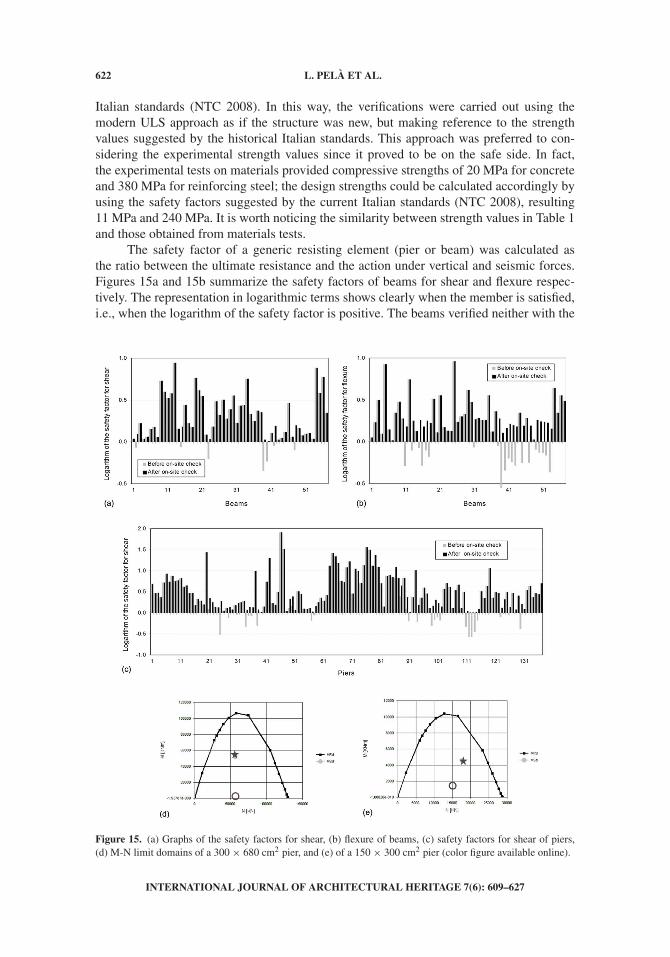
The safety factor of a generic resisting element (pier or beam) was calculated asthe ratio between the ultimate resistance and the action under vertical and seismic forces.Figures 15a and 15b summarize the safety factors of beams for shear and flexure respec-tively. The representation in logarithmic terms shows clearly when the member is satisfied,i.e., when the logarithm of the safety factor is positive. The beams verified neither with the
Figure 15. (a) Graphs of the safety factors for shear, (b) flexure of beams, (c) safety factors for shear of piers,(d) M-N limit domains of a 300 × 680 cm2 pier, and (e) of a 150 × 300 cm2 pier (color figure available online).
INTERNATIONAL JOURNAL OF ARCHITECTURAL HERITAGE 7(6): 609–627

SEISMIC ASSESSMENT OF MILANO CENTRALE 623
initial trial reinforcement nor with the minimum amount of reinforcement, were checkedon-site by determining the actual reinforcement. As shown by black bars, the amount ofsteel reinforcement in all of the surveyed critical elements was generally larger than thatrequired for seismic verifications. Figure 15c summarizes the safety factors of piers forshear. As shown, all of the piers resulted verified against shear at the end of the step-by-stepverification strategy.
The flexure/compression resistance of piers was evaluated drawing the M-N (bend-ing moment versus axial load) limit domain of each section. For the sake of brevity, it isnot possible to report all of the M-N limit domains of the piers. Figures 15d and 15e showthe domains of two representative piers of 300 × 680 cm2 and 150 × 300 cm2. The circlecorresponds to the ULS due to vertical loads after the refurbishment project of the sta-tion. As shown, the large-size pier is practically uniformly compressed, being the bendingmoment negligible. The dot and the star correspond to the ULS due to seismic action afterand before the refurbishment project of the station. They are practically coinciding, show-ing that the new constructions inside the station will not compromise the seismic behaviorof the existing members. The points related to seismic ULS are considerably shifted ifcompared with the ones related to vertical loads ULS. This stresses the importance of theseismic analysis of the monumental building. The increase in flexure demand can be con-siderable in some members (Figure 15d), whereas the increase in vertical compression isgenerally limited (not more than 20%, see Figure 15e).
4.2. Verification of Steel Trusses
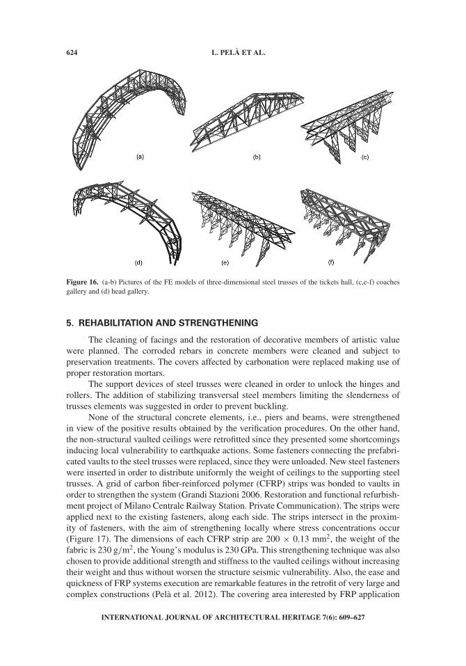
The safety assessment was carried out of the steel trusses supporting roofs and vaultedprefabricated ceilings of the monumental building. A simplified approach was followed byisolating each structure from the neighboring elements but taking into account their stiffnessthrough appropriate boundary conditions. The analysis of these substructures could showstraightforwardly the possible shortcomings. The obtained results were more on the safeside than ones of the global model presented previously .
The steel structure system is composed of three-dimensional trusses (see Figure 6),able to resist both horizontal and vertical seismic actions. Such elements are con-nected with two-dimensional trusses (see Figure 9a) able to resist only vertical seismicactions. Accordingly, the relevant seismic actions were considered in the structuralanalyses.
The FE discretization of the steel trusses (Figure 16) was carried out using again theSAP 2000 software (Computers and Structures Inc. 2006). The elastic parameters assumedfor steel are: Young’s modulus 200 GPa and Poisson’s ratio 0.3. Modal response spec-trum analyses were carried out, considering the elastic acceleration spectrum since the steeltrusses are unable to dissipate energy under seismic actions.
The resistance of trusses elements was calculated using the ultimate limit state(ULS) verification procedures of the Eurocode 3 (European Committee for Standardization2004c). The yield strength of steel was assumed equal to 235 MPa. The strength verifica-tions gave positive results on the whole. The elements of some trusses had a slendernessratio higher than the limit suggested by recent standards provisions (e.g., 200 in NTC 2008).Nevertheless, the verifications were carried out anyway, since this problem is due to designrules in force at the construction time. The joints of the trusses were verified as the steelmembers were connected by rivets able to resist high forces by friction.
INTERNATIONAL JOURNAL OF ARCHITECTURAL HERITAGE 7(6): 609–627
624 L. PELÀ ET AL.
Figure 16. (a-b) Pictures of the FE models of three-dimensional steel trusses of the tickets hall, (c,e-f) coachesgallery and (d) head gallery.
5. REHABILITATION AND STRENGTHENING
The cleaning of facings and the restoration of decorative members of artistic valuewere planned. The corroded rebars in concrete members were cleaned and subject topreservation treatments. The covers affected by carbonation were replaced making use ofproper restoration mortars.
The support devices of steel trusses were cleaned in order to unlock the hinges androllers. The addition of stabilizing transversal steel members limiting the slenderness oftrusses elements was suggested in order to prevent buckling.
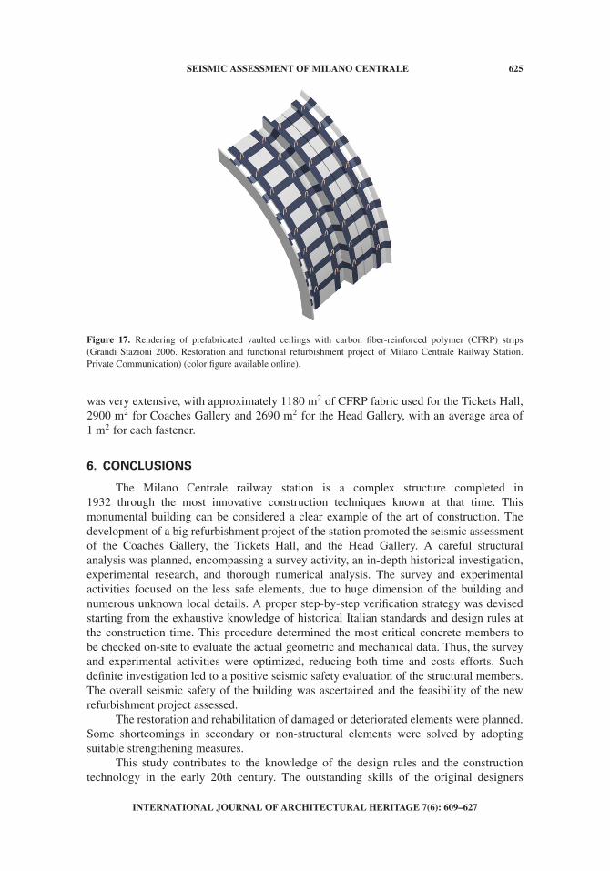
None of the structural concrete elements, i.e., piers and beams, were strengthenedin view of the positive results obtained by the verification procedures. On the other hand,the non-structural vaulted ceilings were retrofitted since they presented some shortcomingsinducing local vulnerability to earthquake actions. Some fasteners connecting the prefabri-cated vaults to the steel trusses were replaced, since they were unloaded. New steel fastenerswere inserted in order to distribute uniformly the weight of ceilings to the supporting steeltrusses. A grid of carbon fiber-reinforced polymer (CFRP) strips was bonded to vaults inorder to strengthen the system (Grandi Stazioni 2006. Restoration and functional refurbish-ment project of Milano Centrale Railway Station. Private Communication). The strips wereapplied next to the existing fasteners, along each side. The strips intersect in the proxim-ity of fasteners, with the aim of strengthening locally where stress concentrations occur(Figure 17). The dimensions of each CFRP strip are 200 × 0.13 mm2, the weight of thefabric is 230 g/m2, the Young’s modulus is 230 GPa. This strengthening technique was alsochosen to provide additional strength and stiffness to the vaulted ceilings without increasingtheir weight and thus without worsen the structure seismic vulnerability. Also, the ease andquickness of FRP systems execution are remarkable features in the retrofit of very large andcomplex constructions (Pelà et al. 2012). The covering area interested by FRP application
INTERNATIONAL JOURNAL OF ARCHITECTURAL HERITAGE 7(6): 609–627
SEISMIC ASSESSMENT OF MILANO CENTRALE 625
Figure 17. Rendering of prefabricated vaulted ceilings with carbon fiber-reinforced polymer (CFRP) strips(Grandi Stazioni 2006. Restoration and functional refurbishment project of Milano Centrale Railway Station.Private Communication) (color figure available online).
was very extensive, with approximately 1180 m2 of CFRP fabric used for the Tickets Hall,2900 m2 for Coaches Gallery and 2690 m2 for the Head Gallery, with an average area of1 m2 for each fastener.
6. CONCLUSIONS
The Milano Centrale railway station is a complex structure completed in1932 through the most innovative construction techniques known at that time. Thismonumental building can be considered a clear example of the art of construction. Thedevelopment of a big refurbishment project of the station promoted the seismic assessmentof the Coaches Gallery, the Tickets Hall, and the Head Gallery. A careful structuralanalysis was planned, encompassing a survey activity, an in-depth historical investigation,experimental research, and thorough numerical analysis. The survey and experimentalactivities focused on the less safe elements, due to huge dimension of the building andnumerous unknown local details. A proper step-by-step verification strategy was devisedstarting from the exhaustive knowledge of historical Italian standards and design rules atthe construction time. This procedure determined the most critical concrete members tobe checked on-site to evaluate the actual geometric and mechanical data. Thus, the surveyand experimental activities were optimized, reducing both time and costs efforts. Suchdefinite investigation led to a positive seismic safety evaluation of the structural members.The overall seismic safety of the building was ascertained and the feasibility of the newrefurbishment project assessed.
The restoration and rehabilitation of damaged or deteriorated elements were planned.Some shortcomings in secondary or non-structural elements were solved by adoptingsuitable strengthening measures.
This study contributes to the knowledge of the design rules and the constructiontechnology in the early 20th century. The outstanding skills of the original designers
INTERNATIONAL JOURNAL OF ARCHITECTURAL HERITAGE 7(6): 609–627

626 L. PELÀ ET AL.
and builders of the Milano Centrale railway station have been fully appreciated after thedevelopment of this research based on modern structural analysis.
ACKNOWLEDGMENTS
The authors wish to thank the helpful collaboration of Grandi Stazioni staff andconsultants, in particular Engineers Massimo Antonelli, Stefano Bernini, Paola Pezza andCarlo Pierdominici.
REFERENCES
Angeleri, G., and Columba, C. 1985. Milano Centrale: Storia di una Stazione Rome, Italy: Abete.Associazione Nazionale Mutilati e Invalidi di Guerra. 1931. La Stazione Centrale di Milano
inaugurata l’anno IX E. F. Milan, Italy: Officina d’Arte Grafica A. Lucini & C.Computers and Structures, Inc. (CSI). 2006. SAP2000 linear and nonlinear static and dynamic anal-
ysis and design of three–dimensional structures. In Basic Analysis Reference Manual. Berkeley,CA: CSI.
European Committee for Standardization. 2004a. EN 1998-1. Eurocode 8: Design of structures forearthquake resistance. Part 1: General rules, seismic actions and rules for buildings. Brussels,Belgium: European Committee for Standardization.
European Committee for Standardization. 2004b. EN 1992-1-1. Eurocode 2: Design of concretestructures. Part 1: General rules and rules for buildings. Brussels, Belgium: European Committeefor Standardization.
European Committee for Standardization. 2004c. EN 1993-1-1. Eurocode 3: Design of steel struc-tures. Part 1: General rules and rules for buildings. Brussels, Belgium: European Committee forStandardization.
Fava, A. 1927. La grande tettoia viaggiatori della nuova stazione di Milano (in Italian). RivistaTecnica delle Ferrovie Italiane 32(6):241–48.
Fava, A. 1929. Le costruzioni in ferro della nuova stazione viaggiatori di Milano. L’Ingegnere3:434–437.
Finazzer, F. M., 2005. La Stazione Centrale di Milano: Il viaggio e l’immagine. Milan, Italy: Skira.Goldstein Bolocan, A. 1931. L’Edificio della Nuova Stazione di Milano. Il Cemento Armato 7:73–75.ICOMOS/ISCARSAH Committee. 2003. Recommendations for the analysis, conservation and
structural restoration of architectural heritage. www.icomos.org (accessed January 2, 2012)Jonghi Lavarini, G. M., Saporito, P., and Magnani, F. 1981. La Stazione Centrale di Milano. Mostra
del Cinquantenario Ferrovie dello Stato–Comune di Milano. Milan, Italy: Di Baio.Mari, M., Vitali, V. 2008. Milano fantasma [in Italian]. Torino, Italy: EDT.Norme Tecniche per le Costruzioni (NTC). 2008, January 14. Norme Tecniche per le Costruzioni
[Italian Technical Code for Constructions]. Gazzetta Ufficiale, February 4, 2008, n◦ 29.Pelà, L., Aprile, A., and Benedetti, A. 2009. Seismic assessment of masonry arch bridges.
Engineering Structures 31(8):1777–88.Pelà, L., Aprile, A., and Benedetti, A. 2012. Experimental study of retrofit solutions for damaged
concrete bridge slabs. Composites Part B: Engineering 43:2471–2479.R. D. L. 1927, Settembre 4, n◦ 1981. Nuove norme per l’accettazione degli agglomerati idraulici
e l’esecuzione delle opere in conglomerato cementizio semplice ed armato (in Italian). GazzettaUfficiale, 11 Novembre 1927, n◦ 261.
R. D. L. 1928, Giugno 7, n◦1431. Prescrizioni per l’accettazione degli agglomerati idraulici e perl’esecuzione delle opere in conglomerato cementizio. Gazzetta Ufficiale, 6 Luglio. 1928, n◦ 156.
R. D. L. 1929, Aprile 4, n◦ 592. Norme per l’accettazione dei cementi speciali. Gazzetta Ufficiale,30 Aprile 1929, n◦ 101.
INTERNATIONAL JOURNAL OF ARCHITECTURAL HERITAGE 7(6): 609–627
SEISMIC ASSESSMENT OF MILANO CENTRALE 627
R. D. L. 1930, Luglio 18, n ◦1133. Norme per le prove d’accettazione degli agglomerati idraulici e perl’esecuzione delle opere in conglomerato cementizio. Gazzetta Ufficiale, 30 Agosto 1930, n◦ 203.
Roca, P., Cervera, M., Gariup, G., and Pelà, L. 2010. Structural analysis of masonry historical con-structions: Classical and advanced approaches. Archives of Computational Methods in Engineering17:299–325.
Verderame, G. M., Manfredi, G., and Frunzio, G. 2001a. Mechanical properties of concrete used inRC structures constructed in the sixties [in Italian]. In Proceedings of the 10th ANIDIS (ItalianNational Association of Earthquake Engineering) National Conference. September 9–13, 2001.Potenza, Italy: University of Basilicata, pp. 1–11.
Verderame, G. M., Stella, A., and Cosenza, E. 2001b. Mechanical properties of steel used in RCstructures constructed in the sixties [in Italian]. In Proceedings of the 10th ANIDIS (Italian NationalAssociation of Earthquake Engineering) National Conference. September 9–13, 2011. Potenza,Italy: University of Basilicata, pp. 1–12.
Vona, M., and Masi A. 2004. Seismic strength of RC frames designed with the RD2229/39[in Italian]. In Proceedings of the 11th ANIDIS (Italian National Association of EarthquakeEngineering) National Conference. January 25–29, 2004. Genova, Italy: University of Genova,pp. 1–13.
INTERNATIONAL JOURNAL OF ARCHITECTURAL HERITAGE 7(6): 609–627