Juki DLU-5490N, -7 Engineer's Manual.pdf
42
aUKI ® 1-NEEDLE,BOOM & VARIABLE TOP FEED LOCKSTITCH MACHINE DLU-5490N 1-NEEDLE,BOOM & VARIABLE TOP FEED LOCKSTITCH MACHINE WITH AN AUTOMATIC THREAD TRIMMER DLU-5490N 7 ENGINEER'S MANUAL No. 1-45 1995.4
-
Upload
khangminh22 -
Category
Documents
-
view
4 -
download
0
Transcript of Juki DLU-5490N, -7 Engineer's Manual.pdf
a.lUKI®
1-NEEDLE,BOTTOM & VARIABLE TOP FEED LOCKSTITCH MACHINE
DLU-5490N 1-NEEDLE,BOTTOM & VARIABLE TOP FEED LOCKSTITCH MACHINE WITH AN AUTOMATIC THREAD TRIMMER
DLU-5490N 7
ENGINEER'S MANUAL
No. 1-45
1995.4
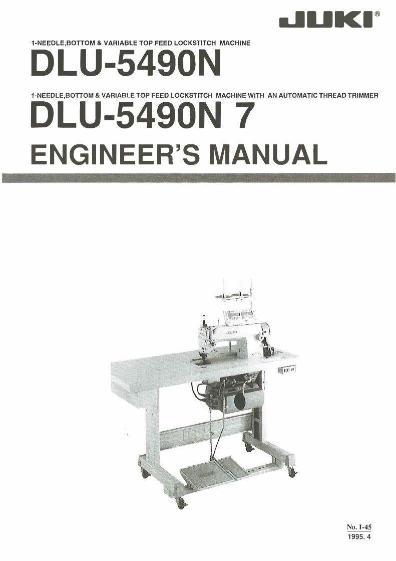
Preface
This Engineer's Manual mainly consists of three sections; "Standard adjustment", "How to
adjust", and "Results of improper adjustment". All technical personnel who are responsible for
the maintenance and repair of the DLU-5490N and DLU-5490N-7 should carefully read
especially "Standard adjustment".Please read this manual carefully before using the units
in order to get the most out of them and to enjoy using them for a long time.
CAUTION
1. K~ep your hands away from the needle \'>'hen the powN switch is tumed ON or while the machine is opuatmg.
4. Ourin9 operation, be cardul not tO allow your or any other per!on's head or lunds to_ come close to tha handwhul, V belt, bobbin winder or mator. Al1o, do not pl~ce anything dose to them. Doing so mly Ia dangerous. .
BEFORE OPERATION
2. Do not put your lingen into the 1hnad take-up co•er v.hile the mil<:hine is operating
5. II your "'•chine is pro>ided with a belt covor, finger g\Jard or any <>Iller prot~to,, do not operate your machine with any of them removed.
• Don't run the machine before filling the oil reservoir.
3. Be sure to tur~ the powtr switch OFF befora tihing the m•chine had or rema•lng the Vbelt
• After setting up your machine, make sure that it runs in the correct direction; lower the needle by turning the handwheel and watch the handwheel's revolution by momentarily switching the power "on" (correct rotational direction of the handwheel: counterclockwise when viewed from the handwheel's end). Run the newly installed machine at a speed of 4,000 s.p.m. or lower for the one month. Confirm the ratings of your power source by the machine plate stuck on the motor (power voltage, phase etc.)
Do not wipe the surface of the machine head with lacquer thinner.
From the Library of Superior Sewing Machine & Supply LLC
CONTENTS
1. SPECIFICATIONS ................................•.................•......
2. APPLICATIONS . . . . . . . . . . . . . . . . . . . . . . . • . . . . . . . . . . . . . . . . . . . . . • . . . . . . . . . . . . 2
3. STANDARD ADJUSTMENT . . . . . . . . . . . • . • . • • . . . . • . . . • . . . . • . . . . . . . . . . . . . . . . • . • 3
( 1) Height of the needle bar ........ : ...... , . . . . . . . . . . . . . . . . . . . . . . . . . . . . . . . . . . 3
(2) Timing between the needle and the hook, . , . . . . . . . . . . . . . . . . . . . . . . . . . . . . . . . . . . . . 3
(3) Height of the feed dog . . . . . . . . . . . . . . . . . . . . . . . . . . . . . . . . . . . . . . . . . • . . . . . . . . . 3
(4) Feed .timing . . . . . . . . . . . . . . . . . . . . . . . . . . . . . . . . . . . . . . . . . . . . . . . . . . . . . . . . . 3
(5) Tilt of the feed dog ........................... , ....................... , . 5
(6) Walking foot pressure and presser foot pressure . . . . . . . . . . . . . . . . . . . . . . . . . . . . . . . . . . 5
(7) Relationship between the walking foot graduation plate . . . . • . . . . • . • . . . . . . . . . . . . . . . . . 7
(8) Top feed vertical timing ................................. ·. . . . . . . . . . . . . . . . . 7
(9) Top feed horizontal timing . . . . . . . . . . . . . . . . . . . . . . . . . . . . . . . . . . . . . . . . . . . . . . . . 9
( 1 0) Longitudinal position of the walking foot . . . . . . . . . . . . . . . . . . . . . . . . . . . . . . . . . . . . . . 9
( 11) Normal and reverse feed pitches ...... , ................. , . . . . . . . . . . . . . . . . . . . 11
( 12) Position of the reverse feed solenoid ..................................... , . . . . 11
( 13) Position of the wiper . . . . . . . . . . . . . . . . . . . . . . . . . . . . . . . . . . . . . . . . . . . . . . . . . . . . 13
(14) Position of the PF-6 partial shirring stopper .......... , ............... , .. , ...... , 13
4. DISASSEMBLING AND REASSEMBLING PROCEDURES ........................... ,,. 15
(1) Disassembling and reassembling the face and top feed components...................... 15
(2} Disassembling and reassembling the top feed drive mechanism ......... , . . . . . . . . . . . . . . . 19
5. HOW TO REMOVE PLAY........... . . . . . . . . . . . . . . . . . . . . . . . . . . . . . . . . . . . . . . . . . 24
( 1) How to remove play from the walking foot rock shaft . . . . . . . . . . . . . . . . . . . . . . . . . . . . . . 24
(2) How to remove play from the walking foot adjusting link .................. , •..... , . . 24
(3) How to remove play from the reverse feed control lever . . . . . . . . . . . . . . . . . . . . . . . . . . . . . 25
(4) How to remove play from the reverse feed control lever shaft ........ , . . . . . . . . . . . . . . . . 25
6. HOW TO ADJUST THE TOP FEED DRIVE MECHANISM .......... , .... , ..... , ... , .. ,.. 26
(1) Trajectory of walking foot .....•.. · ............•............ , ... •. . . . . . . . . . . 26
(2) Position of the roller . . . . . . . . . . . . . . . . . . . . . . . . . . . . . . . . • . . . . . . . . . . . . . . . . . . . 27
7. REPLACING THE MOVING KNIFE ............ , .......................... , .... , 28
8. INSTALLING AND ADJUSTING THE PARTIAL SHIRRING DEVICE (PF·6) ..... , . . . . . . . . . . . • 29
( 1) Description of the PF·6 partial shirring device . . . . . . . . . . . . . . . . . . . . . . . . . . . . . . . . . . . 29
(2) Installing the stand other than JUKI Z·type stand . . . . . . . . . . . . . . . . • . . . . . . . . . • . • . . . . 29
(3) PF·6 pedal components .................•............. , . . . . . . . . . . . . . . . . . . 30 ·
9. TROUBLES AND CORRECTIVE MEASURES .•...•.......•..•............... :. . . . . 31
10. HOW TO USE GAUGES ......................... , .................... , . . . . . 35
11. PARTS LIST . . . . . . . . . . . . . . . . . . . . . . . . . . . . . . . . . . . . . . . . . . . . . . . . . . . . . . . . . . . . 37
12. TABLE DIMENSIONS . . . . . . . . . . . . . . . . . . . . . . . . . . . . . . . . . . . . . . . . . . . . . . . . . . . . . • . . . . . . . 38
From the Library of Superior Sewing Machine & Supply LLC
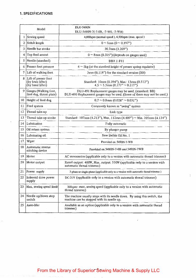
1. SPECIFICATIONS
Model DLU-5490N DLU-5490N-7(-7-0B, -7-WO, -7-WB)
I Sewing speed 4,000spm (normal speed), 4,500spm (max. speed)
2 Stitch length o- 5mm (0- 0.197")
3 Needle bar stroke 30.7mm (1.209")
4 Top feed amout 0- 8mm (0.315") (depends on gauges used)
5 Needle (standard) DBX I #II
6 Presser foot pressure 4- 5kg (at the standard height of presser spring regulator)
7 Lift of walking foot 3mm (0.118") for the standard version (BB)
8 Lift of presser foot (by knee lifter) Standard: I Omm (0.394"), Max: 13mm (0.512"} (by hand lifter) 4.5- 5 .5mm (0.177"- 0.217")
9 Gauges (Walking foot, DLU-491 Replacement gauges may be used. (standard: BB) feed dog, throat plate) DLU-490 Replacement gauges may be used. (Some of them may not be used.)
10 Height of feed dog 0.7- 0.8mm (0.028"- O.o31")
II Feed system Commonly known as "swing" system
12 Thread take-up Link type
13 Thread take-up stroke Standard: 107mm (4.213"), Max. 112mm (4.409")- Min. 105mm (4.134")
14 Lubrication Fully automatic
15 Oil return system By plunger pump .
16 Lubricating oil New Defrix Oil No. I
17 Wiper Provided on 5490N-7-WB
18 Automatic reverse Provided on 5490N-7-0B and 5490N-7WB stitching device
19 Motor AC servomotor (applicable only to a version with automatic thread trimmer)
20 Motor output Rated output: 400W, Max. output: 55 0W (applicable only to a version with automatic thread trimmer)
21 Power supply 3-phase or single-phase (applicable only to a version with automatic thread trimmer)
22 Solenoid drive power DC-3!V (applicable only to a version with automatic thread trimmer) supply
23 Max. sewing speed limit 200spm- max. sewing speed (applicable only to a version with automatic thread trimmer)
24 Needle up/down stop The machine usually stops with its needle down. By using this switch, the switch machine can be stopped with its needle up.
25 Auto-lifer Available as an option (applicable only to a version with automatic thread trimmer)
-]-From the Library of Superior Sewing Machine & Supply LLC
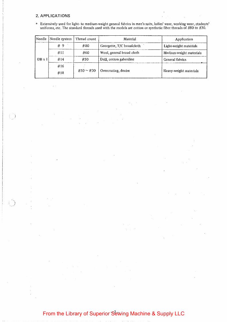
2. APPLICATIONS
* Extensively used for light· to medium-weight general fabrics in men's suits, ladies' wear, working wear, students' uniforms, etc. The standard threads used with the models are cotton or synthetic fiber threads of #80 to #30.
Needle Needle system Thread count Material Application
# 9 #80 Georgette, T/C broadcloth Light-weight mate.rials
#II #60 Wool, general broad cloth Medium-weight materials
DBx I #14 #50 Drill, cotton gaberdine General fabrics --#16
#18 #50-#30 Overcoating, denim Heavy-weight materials
-2-From the Library of Superior Sewing Machine & Supply LLC
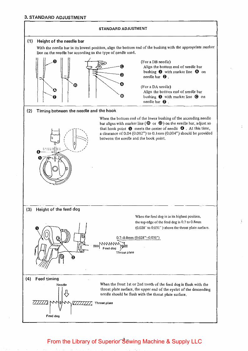
3. STANDARD ADJUSTMENT
STANDARD ADJUSTMENT
(1) Height of the needle bar
With the needle bar in its lowest position, align the bottom end of the bushing with the appropriate marker line on the needle bar according to the type of needle used.
~® I ~o
€l
(For a DB needle) Align the bottom end of needle bar bushing ~ with marker line fi.) on needle bar f) .
(For aDA needle) Align the bottom end of needle bar bushing ~ with marker line @ on needle bar f) .
(2) Timing between the needle and the hook
(3) Height of the feed dog
(4) Feed timing Needle
When the bottom end of the lower bushing of the ascending needle bar aligns with marker line (@ or ®) on the needle bar, adjust so that hook point 0 meets the center of needle 0 . At this time, a clearance of0.04 (0.002") to O.lmm (0.004") should be provided between the needle and the hook point.
When the feed dog is in its highest position,
the top edge of the feed dog is 0.7 to 0.8mm
(0.028" to 0,031" ) above the throat plate surface.
0.7-0.8mm (0.028'"-0.031 ")
=~~ Throat plate
When the front 1st or 2nd tooth of the feed dog is flush with the throat plate surface, the upper end of the eyelet of the descending needle should be flush with the throat plate surface.
I/777/J V/Z//1//, Throat plate
Feed dog
-3-From the Library of Superior Sewing Machine & Supply LLC
HOW TO ADJUST RESULTS OF IMPROPER ADJUSTMENT
o Loosen the needle bar clamp screw to perform adjustment. o Changing the needle bar height disturbs the feed and hook timings. So, avoid altering the needle bar height unless the type of needle has been changed.
0 Loosen the three hook setscrews to perform adjustment. 0 If the clearance between the needle
(A version without the automatic thread trimmer has two and hook blade point is too large, stitch setscrews.) skipping or thread breakage may
frequently occur. o If the clearance between the needle
and hook blade point is too small, the
needle may scratch the hook blade point. o If the hook timing is advanced,
tighter stitches will be produced, but stitch skipping may often occur.
o A delayed hook timing is effective for preventing balloon stitches and stitch skipping.
o For a version without the auto· rna tic thread trimmer, use the lowest marker line to make adjust-rnent.
0 Loosen screw f) , and move driving forked crank 0 to make o If the feed dog is too high, the adjustment. needle may sway and possible bend
(The distance betwce> the top and bottom ends of a tooth of th) or break. standard feed dog (81613-450-AOO) is about 0.8mm (0.031"). On the contrary, if the feed dog is So, this may be used for easier adjustment. too low, insufficient feed power
may result, often causing stitch jam. Increasing the feed dog height adds to feed power, but at the same time, chances of puckering may also increase.
o Loosen the two setscrews of the feed eccentric cam. o If the feed dog descending timing is advanced, chances of thread splitting, balloon stitches will be reducect;ho~ever, stitches will be loose.
-4-From the Library of Superior Sewing Machine & Supply LLC
STANDARD ADJUSTMENT
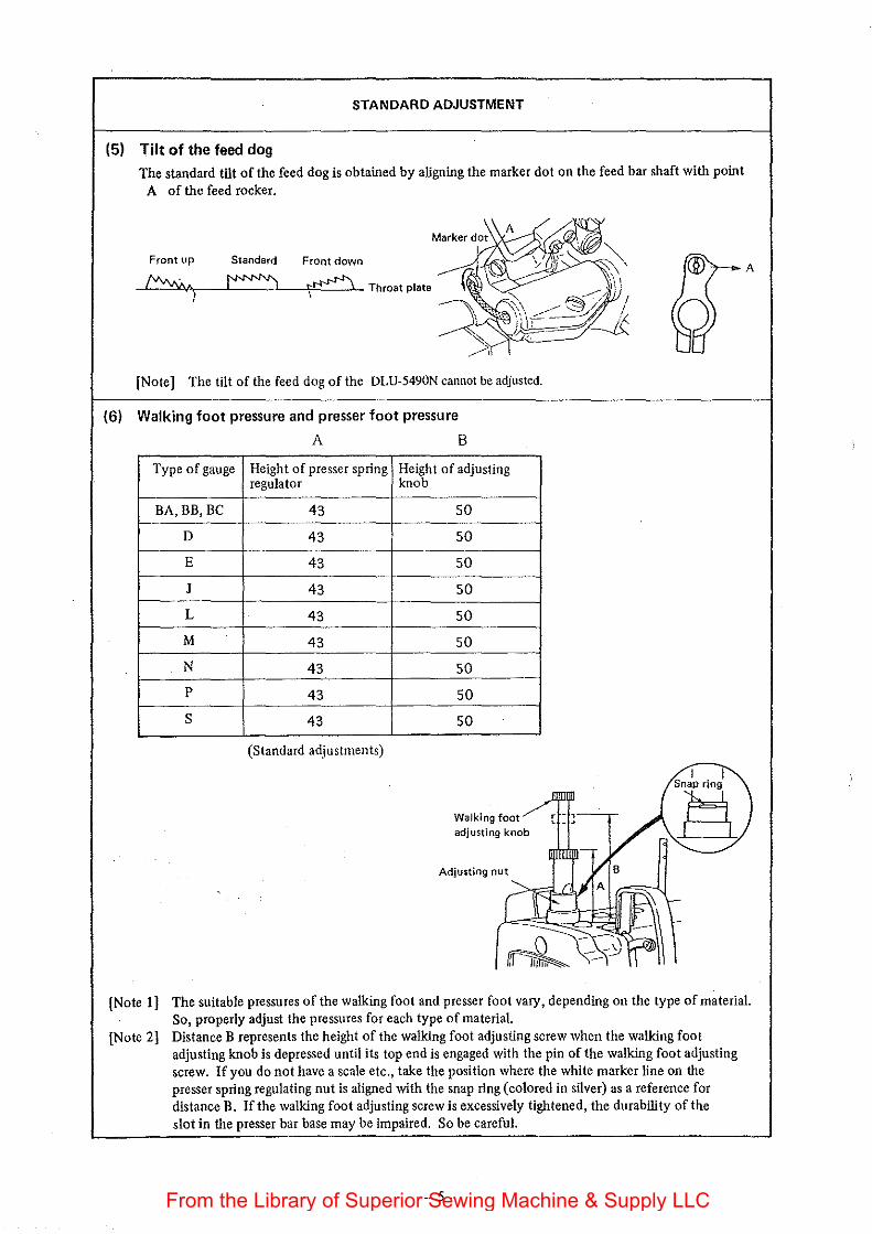
(5) Tilt of the feed dog The standard tilt of the feed dog is obtained by aligning the marker dot on the feed bar shaft with point
A of the feed rocker.
Front up Standard Front down
_,_fvvvv,__:_=· .A•1,--_:_f"""""JL__. _ __i_---'i~£!.:_j..L Throat plate
[Note] The tilt of the feed dog of the DLU-5490N cannot be adjusted.
(6) Walking foot pressure and presser foot pressure
A B
Type of gauge Height of presser spring Height of adjusting regulator knob
BA, BB, BC 43 50
D 43 50
E 43 50
J 43 50
L 43 50
M 43 50
N 43 50
p 43 50
s 43 50
(Standard adjustments)
I
R Adjusting nut
A
[Note I] The suitable pressures ofthewalking foot and presser foot vary, depending on the type of material. So, properly adjust the pressures for each type of material.
[Note 2] Distance B represents the height of the walldng foot adjusting screw when the walldng foot adjusting knob is depressed until its top end is engaged with the pin of the walking foot adjusting screw. If you do not have a scale etc., take the position where the white marker line on the presser spring regulating nut is aligned with the snap ring (colored in silver) as a reference for distance B. If the walking foot adjusting screw is excessively tightened, the durability oft he slot in the presser bar base may be impaired. So be careful.
-5-From the Library of Superior Sewing Machine & Supply LLC
HOW TO ADJUST RESULTS OF IMPROPER ADJUSTMENT
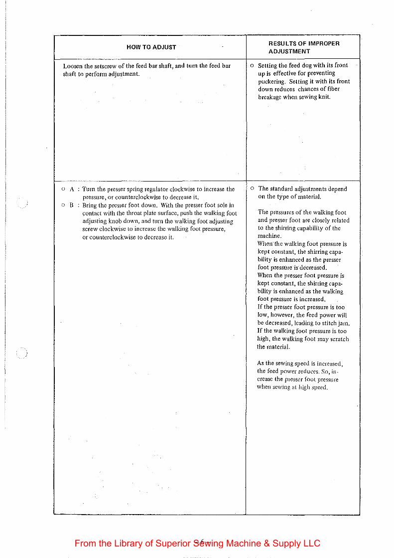
Loosen the setscrew of the feed bar shaft, and tum the feed bar 0 Setting the feed dog with its front
shaft to perform adjustment. up is effective for preventing puckering. Setting it with its front down reduces chances of fiber breakage when sewing knit.
0 A : Turn the presser spring regulator clockwise to iilcrease the o The standard adjustments depend pressure, or counterclockwise to decrease it. on the type of material.
0 B : Bring the presser foot down. With the presser foot sole in contact with the throat plate surface, push the walking foot The pressures of the walking foot
adjusting knob down, and turn the walking foot adjusting and presser foot are closely related
screw clockwise to increase the walking foot pressure, to the shirring capability of the
or counterclockwise to decrease it. machine. When· the walking foot pressure is kept constant, the shirring capa-bility is enhanced as the presser foot pressure' is-decreased. When the presser foot pressure is kept constant, the shirring capa-bility is enhanced as the walking foot pressure is increased. If the presser foot pressure is too low, however, the feed power will be decreased, leading to stitch jam. If the walking foot pressure is too high, the walking foot may scratch the material.
As the sewing speed is increased, the feed power reduces. So, in-crease the presser foot pressure when sewing at high speed.
-6-From the Library of Superior Sewing Machine & Supply LLC
STANDARD ADJUSTMENT
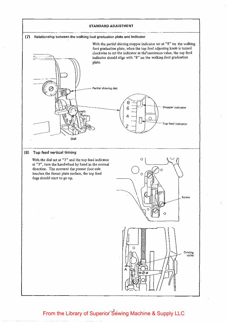
(7) Relationship between the walking foot graduation plate and indicator
With the partial shirring stopper indicator set at "8" on the walking foot graduation plate, when the top feed adjusting knob is turned clockwise to set the indicator at the'maximum value, the top feed indicator should align with "8" on the walking foot graduation plate.
Partial shirring dial
Dial
(8) Top feed vertical timing
With. the dial set at "3" and the top feed indicator at "3", turn the hand wheel by hand in the normal direction. The moment the presser foot sole touches the throat plate surface, the top feed dogs should start to go up.
-7-
0
Stopper indicator
Top feed indicator
Screw
Driving roller
From the Library of Superior Sewing Machine & Supply LLC
HOW TO ADJUST RESULTS OF IMPROPER ADJUSTMENT
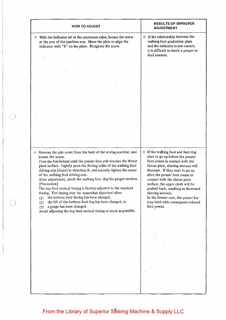
0 With the indicator set at the maximum value, loosen the screw, 0 If the relationship between the at the rear of the machine arm. Move the plate to align the walking foot graduation plate indicator with "8" on the plate. Retighten the screw. and the indicator is not correct,
it is difficult to know a proper to feed amount.
o Remove the side cover from the back of the sewing machine, and o If the walking foot and feed dog loosen the screw. start to go up before the presser Tum the handwheel until the presser foot sole touches the throat foot comes in contact with the plate surface. Lightly press the driving roller of the walking foot throat plate, shirring amount will driving arm (front) in direction A, and securely tighten the screw decrease. If they start to go up of the walking foot driving arm. after the presser foot comes in After adjustment, check the walking foot dog for proper motion. contact with the throat plate [Precaution] surface, the upper cloth will be The top feed vertical timing is factory-adjusted to the standard pushed back, resulting in decreased timing. The timing may be somewhat disturbed when shirring amount. (I) the bottom feed timing has been changed, In the former case, the presser bar (2) the lift of the bottom feed dog has been changed, or may bind with consequent reduced (3) a gauge has been changed. feed power. Avoid adjusting the top feed vertical timing as much as possible.
-8-From the Library of Superior Sewing Machine & Supply LLC
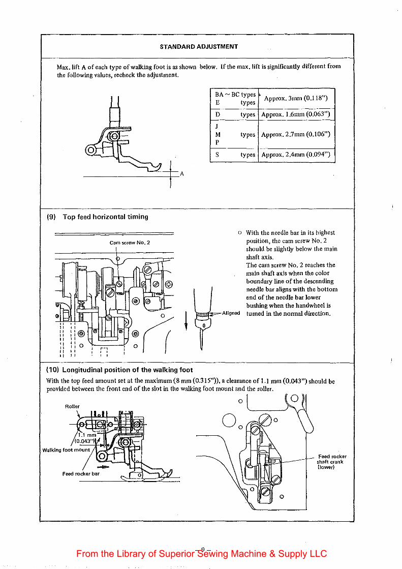
STANDARD ADJUSTMENT
Max. lift A of each type of walking foot is as shown below. If the max. lift is significantly different from the following values, recheck the adjustment.
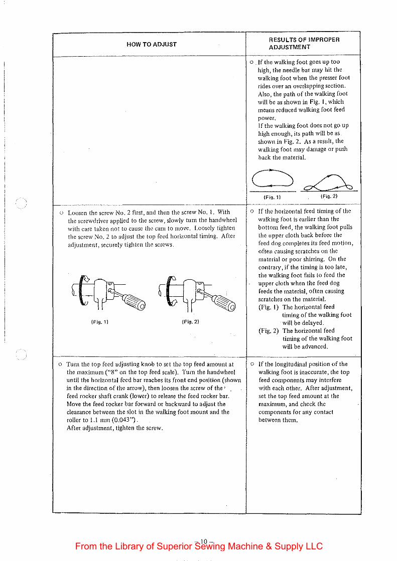
(9) Top feed horizontal timing
Cam screw No.2
( 1 0) Longitudinal position of the walking foot
BA- BC types Approx. 3mm (0.118") E
D
J M p
s
types
types Approx. 1.6mm (0.063")
types Approx. 2.7mm (0.106")
types Approx. 2.4mm (0.094")
o With the needle bar in its highest position, the cam screw No.2 should be slightly below the main shaft axis. The cam screw No.2 reaches the main shaft axis when the color boundary line of the descending needle bar aligns with the bottom end of the needle bar lower bushing when the handwheel is
)mziiiif.:=-Aiigned turned in the nonnal direction.
0
With the top feed amount set at the maximum (8 mm (0.315")), a clearance of Ll mm (0.043") should be provided between the front end of the slot in the walking foot mount and the roller.
Roller
Feed rocker bar
-9-
Feed rocker shaft crank (lower)
From the Library of Superior Sewing Machine & Supply LLC
HOW TO ADJUST
o Loosen the screw No.2 first, and then the screw No. l. With the screwdriver applied to the screw, slowly turn the hand wheel with care taken not to cause the cam to move. Loosely tighten the screw No.2 to adjust the top feed horizontal timing. After adjustment, securely tighten the screws.
(Fig, 1) (Fig, 2)
o Turn the top feed adjusting knob to set the top feed amount at the maximum ("8" on the top feed scale). Turn the handwheel until the horizontal feed bar reaches its front end position (shown in the direction of the arrow), then loosen the screw of the' feed rocker shaft crank (lower) to release the feed rocker bar. Move the feed rocker bar forward or backward to adjust the clearance between the slot in the walking foot mount and the roller to 1.1 mm (0.043"). After adjustment, tighten the screw.
- 10-
RESULTS OF IMPROPER ADJUSTMENT
o If the walking foot goes up too high, the needle bar may hit the walking foot when the presser foot rides over an overlapping section. Also, the path of the walking foot will be as shown in Fig. I, which means reduced walking foot feed power. If the walking foot does not go up high enough, its path will be as shown in Fig. 2. As a result, the walking foot may damage or push back the material.
(Fig, 1) (Fig. 2)
o If the horizontal feed timing of the walking foot is earlier than the bottom feed, the walking foot pulls the upper cloth back before the feed dog completes its feed motion, often causing scratches on the material or poor shirring. On the contrary, if the timing is too late, the walking foot fails to feed the upper cloth when the feed dog feeds the material, often causing scratches on the materiaL (Fig. I) The horizontal feed
timing of the walking foot will be delayed.
(Fig. 2) The horizontal feed timing of the walking foot will be advanced.
o If the longitudinal position of the walking foot is inaccurate, the top feed components may interfere with each other. After adjustment, set the top feed amount at the maximum, and check the components for any contact between them.
From the Library of Superior Sewing Machine & Supply LLC
STANDARD ADJUSTMENT
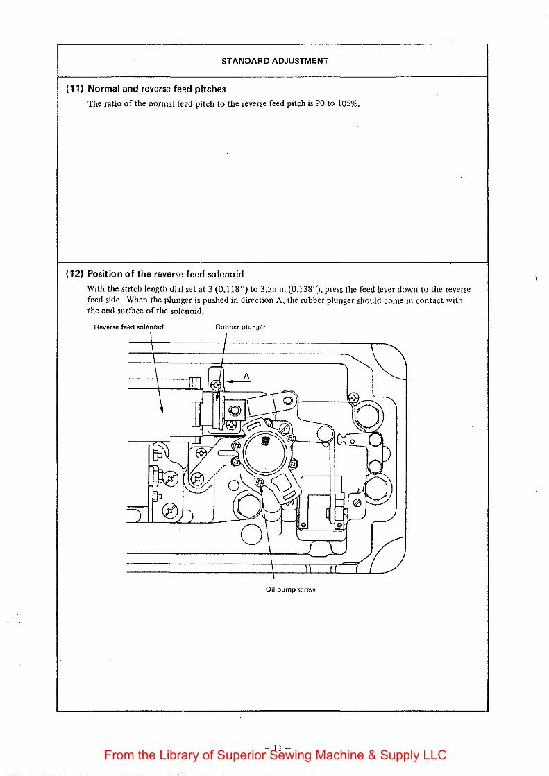
(11) Normal and reverse feed pitches
The ratio of the nonnal feed pitch to the reverse feed pitch is 90 to 105%.
(12) Position of the reverse feed solenoid
With the stitch length dial set at 3 (0.118") to 3.5mm (0.138"), press the feed lever down to the reverse feed side. When the plunger is pushed in direction A, the rubber plunger should come in contact with the end surface of the solenoid.
Reverse feed solenoid Rubber plunger
Oil pump screw
-II-From the Library of Superior Sewing Machine & Supply LLC
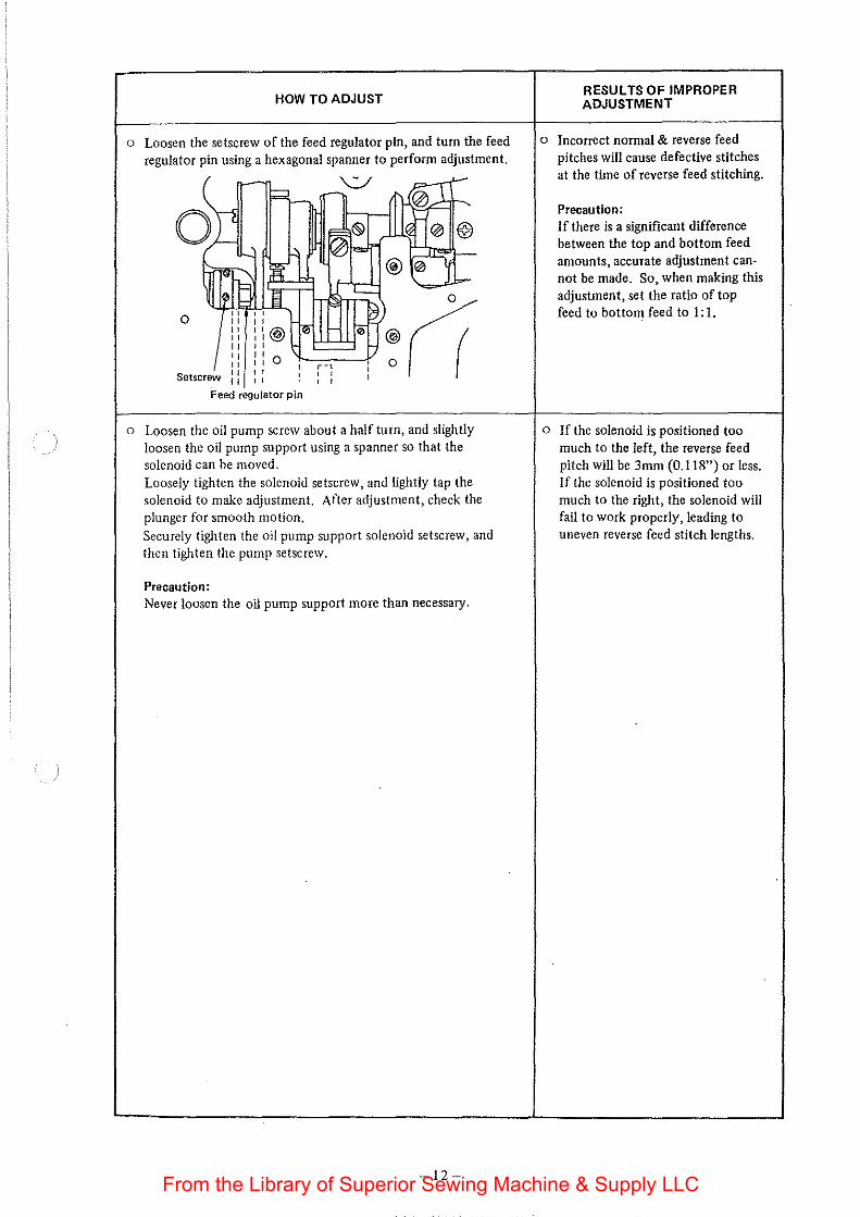
HOW TO ADJUST
o Loosen the setscrew of the feed regulator pin, and turn the feed regulator pin using a hexagonal spanner to perform adjustment.
0
Feed regulator pin
o Loosen the oil pump screw about a half turn, and slightly loosen the oil pump support using a spanner so that the solenoid can be moved. Loosely tighten the solenoid setscrew, and lightly tap the solenoid to make adjustment. After adjustment, check the plunger for smooth motion. Securely tighten the oil pump support solenoid setscrew, and then tighten the pump setscrew.
Precaution: Never loosen the oil pump support more than necessary.
-12-
RESULTS OF IMPROPER ADJUSTMENT
o Incorrect nonnal & reverse feed pitches will cause defective stitches at the time of reverse feed stitching.
Precaution: If there is a significant difference between the top and bottom feed amounts, accurate adjustment cannot be made. So, when making this adjustment, set the ratio of top feed to bottom feed to 1: 1.
o If the solenoid is positioned too much to the left, the reverse feed pitch will be 3mm (0.118") or less. If the solenoid is positioned too much to the right, the solenoid will fail to work properly, leading to uneven reverse feed stitch lengths.
From the Library of Superior Sewing Machine & Supply LLC
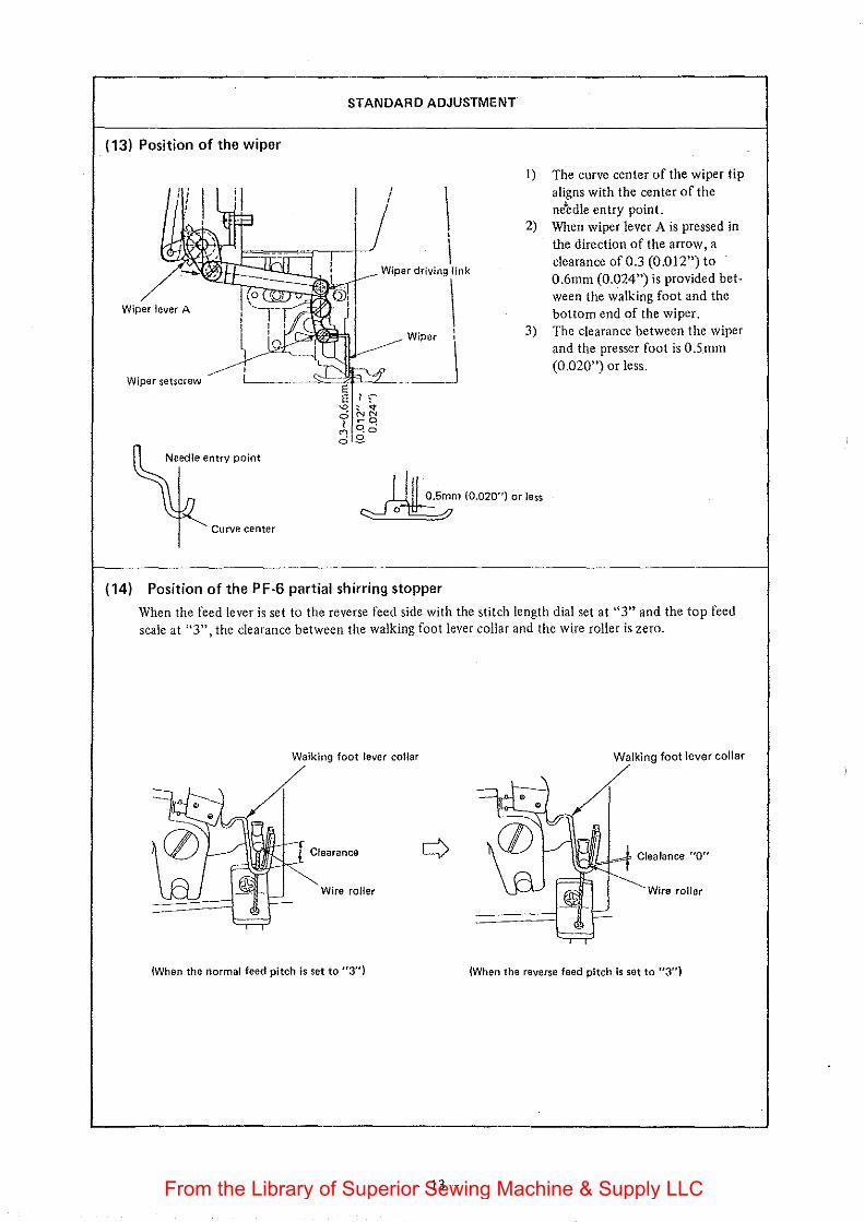
(13) Position of the wiper
'. '' ' '
Wiper lever A
Wiper setscrew
Needle entry point
Curve center
STANDARD ADJUSTMENT
I) The curve center of the wiper tip aligns with the center of the ne"edle entry point.
2) When wiper lever A is pressed in the direction of the arrow, a clearance of 0.3 (0.012") to 0.6mm (0.024") is provided between the walking foot and the bottom end of the wiper.
3) The clearance between the wiper and the presser foot is O.S_mm (0.020") or less.
~m (O.D20") or less
(14) Position of the PF-6 partial shirring stopper
When the feed lever is set to the reverse feed side with the stitch length dial set at "3" and the top feed scale at 11 3", the clearance between the walking foot lever collar and the wire roller is zero.
Walking foot lever collar Walking foot lever collar
Clearance
roller Wire roller
(When the normal feed pitch is set to "3") (When the reverse feed pitch ls set to "3")
-13-From the Library of Superior Sewing Machine & Supply LLC
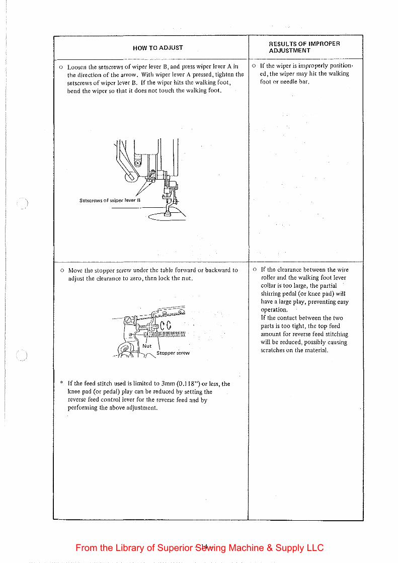
HOW TO ADJUST
o Loosen the setscrews of wiper lever B, and press wiper lever A in the direction of the arrow. With wiper lever A pressed, tighten the setscrews of wiper lever B. If the wiper hits the walking foot, bend the wiper so that it does not touch the walking foot.
' \
~~ Setscrews of wiper lever B '
c -= '
o Move the stopper screw under the table forward or backward to adjust the clearance to zero, then lock the nut.
-em d)l lllcmm ''"' C (J
-"f--li JtU&ItummttiiiW
~Nut {~,, ~Stopper screw
* If the feed stitch used is limited to 3mm (0.118") or less, the knee pad (or pedal) play can be reduced by setting the reverse feed control lever for the reverse feed and by perfom1ing the above adjustment.
-14-
RESULTS OF IMPROPER ADJUSTMENT
o If the wiper is improperly position· ed, the wiper may hit the walking foot or needle bar.
o If the clearance between the wire roller and the walking foot lever collar is too large, the partial shirring pedal (or knee pad) will have a large play, preventing easy operation. If the contact between the two parts is too tight, the top feed amount for reverse feed stitching will be reduced, possibly causing scratches on the material.
From the Library of Superior Sewing Machine & Supply LLC
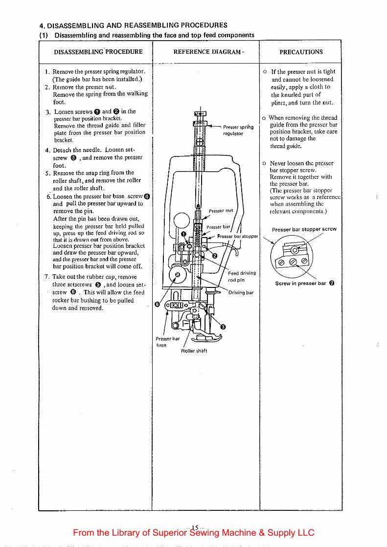
4. DISASSEMBLING AND REASSEMBLING PROCEDURES (1) Disassembling and reassembling the face and top feed components
DISASSEMBLING PROCEDURE
I. Remove the presser spring regulator. {The guide bar has been installed.)
2. Remove the presser nut. Remove the spring from the walking foot.
3. Loosen screws 0 and@ in the presser bar position bracket. Remove the thread guide and filler plate from the presser bar position bracket.
4. Detach the needle. Loosen setscrew @') , and remove the presser foot.
5. Remove the snap ring from the roller shaft, and remove the roller and the roller shaft.
REFERENCE DIAGRAM-
'l!F-H!r'--. Presser sprihg
'l regulator
PRECAUTIONS
o If the presser nut is tight and cannot be loosened easily, apply a cloth to the knurled part of pliers, and turn the nut.
o When removing the thread guide from the presser bar position bracket, take care not to damage the thread guide.
o Never loosen the presser bar stopper screw. Remove it together with the presser bar. (The presser bar stopper screw works as a reference when assembling the
6. Loosen the presser bar base screw 0 and pull the presser bar upward to remove the pin. Presser nut relevant components.) After the pin has been drawn out, keeping the presser bar held pulled up, press up the feed driving rod so that it is drawn out from above. Loosen presser bar position bracket and draw the presser bar upward, and the presser bar and the presser bar position bracket will come off.
7. Take out the rubber cap, remove three setscrews 0 , and loosen set. screw (j) . This will allow the feed rocker bar bushing to be pulled down and removed.
base Roller shaft
-15-
Presser bar stopper screw
Screw in presser bar f)
bar
From the Library of Superior Sewing Machine & Supply LLC
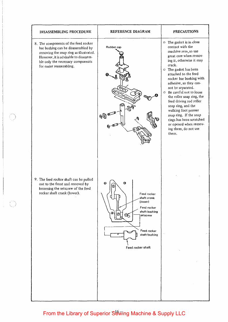
DISASSEMBLING PROCEDURE REFERENCE DIAGRAM
8. The components of the feed rocker bar bushing can be disassembled by removing the snap ring as illustrated. However, it is advisable to disassemble only the necessary components for easier reassembling.
9. The feed rocker shaft can be pulled out to the front and removed by loosening the setscrew of the feed rocker shaft crank (lower).
-16-
Feed rocker shaft crank (lower)
Feed rocker
shaft bushing
Feed rocker shaft bushing
Feed rocker shaft
PRECAUTIONS
o The gasket is in close contact with the machine arm, so use great care when removing it, otherwise it may crack.
o The gasket has been attached to the feed rocker bar bushing with adhesive, so they cannot be separated.
o Be careful not to loose the roller snap ring, the feed driving rod roller snap ring, and the walking foot presser snap ring. If the snap rings has been scratched or opened when removing them, do not use them.
From the Library of Superior Sewing Machine & Supply LLC
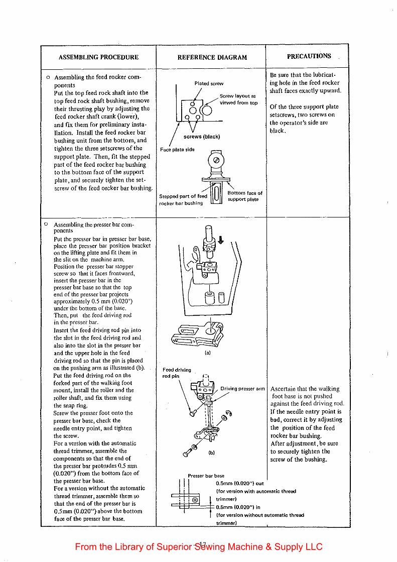
ASSEMBLING PROCEDURE
o Assembling the feed rocker components Put the top feed rock shaft into the top feed rock shaft bushing, remove their thrusting play by adjusting the feed rocker shaft crank (lower), and fix them for preliminary installation. Install the feed rocker bar bushing unit from the bottom, and tighten the three setscrews of the support plate. Then, fit the stepped part of the feed rocker bar bushing to the bottom face of the support plate, and securely tighten the setscrew of the feed orcker bar bushing.
o Assembling the presser bar components Put the presser bar in presser bar base, place the presser bar position bracket on the lifting plate and fit them in the slit on the machine arm. Position the presser bar stopper screw so that it faces frontward, insert the presser bar in the presser bar base so that the top end of the presser bar projects approximately 0.5 mm (0.020") under the bottom of the base. Then, put the feed driving rod in the presser ~ar. Insert the feed driving rod pin into the slot in the feed driving rod and also into the slot in the presser bar and the upper hole in the feed driving rod so that the pin is placed on the pushing arm as illustrated (b). Put the feed driving rod on the forked part of the walking foot mount, install the roller and the roller shaft, and nx them using the snap ring. Screw the presser foot onto the presser bar base, check the needle entry point, and tighten the screw. For a version with the automatic thread trimmer, assemble the components so that the end of the presser bar protrudes 0.5 mrn (0.020") from the bottom face of the presser bar base. For a version without the automatic thread trimmer, assemble them so that the end of the presser bar is 0.5mm (0.020") above the bottom face of the presser bar base.
REFERENCE DIAGRAM
Plated screw
screws {black)
Face plate side
rocker bar bushing
qf \~ Feed driving rod pin
(a)
(b)
Presser bar base
support plate
J 0.5mm (0.020") out
PRECAUTIONS
Be sure that the lubricat· ing hole in the feed rocker shaft faces exactly upward.
Of the three support plate setscrews, two screws on the operator's side are black.
Ascertain that the walking foot base is not pushed
against the feed driving rod. If the needle entry point is bad, correct it by adjusting
the position of the feed rocker bar bushing. After adjustment, be sure to securely tighten the screw of the bushing.
(for version with automatic thread
trimmer)
-17-
0.5mm {0.020") in
(for version without automatic thread
trimmer)
From the Library of Superior Sewing Machine & Supply LLC
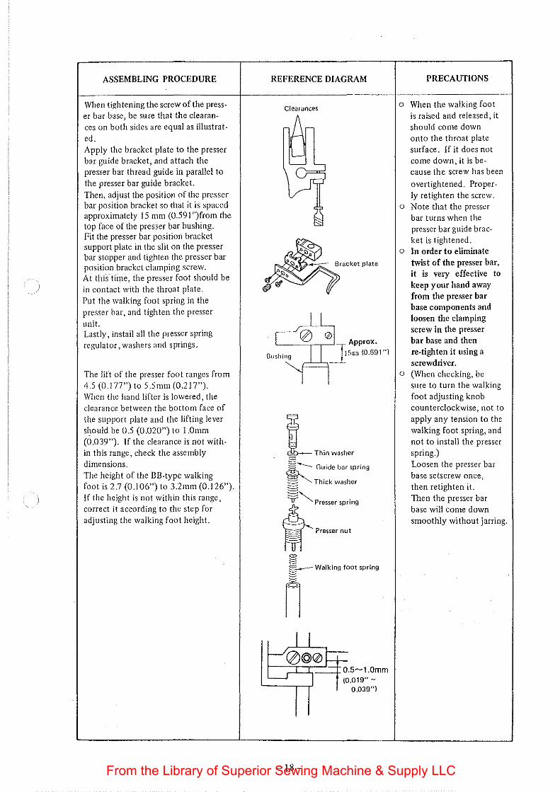
ASSEMBLING PROCEDURE
When tightening the screw of the press· er bar base, be sure that the clearances on both sides are equal as illustrated. Apply the bracket plate to the presser bar guide bracket, and attach the presser bar thread guide in parallel to the presser bar guide bracket. Then, adjust the position of the presser bar position bracket so that it is spaced approximately 15 mm (0.591 ")from the top face of the presser bar bushing. Fit the presser bar position bracket support plate in the slit on the presser bar stopper and tighten the presser bar position bracket clamping screw. At thiS-tline, the presser foot should be in contact with the throat plate. Put the walking foot spring in the presser bar, and tighten the presser unit. Lastly, install all the presser spring regulator, washers and springs.
The lift of the presser foot ranges from 4.5 (0 .177") to 5 .5 mm (0 .217"). When the hand lifter is lowered, the clearance between the bottom face of the support plate and the lifting lever should be 0.5 (0.020") to l.Omm (0.039"). If the clearance is not within this range, check the assembly dimensions. The height of the BB-type walking foot is 2.7 (0 .l 06") to 3.2mm (0 .126"). If the height is not within this range, correct it according to the step for adjusting the walking foot height.
REFERENCE DIAGRAM
Clearances
:K
l Th;n washer
1....---- Guide bar spring
§ "'Thick washer
~Presser spdng
M -Presser nut
-18-
PRECAUTIONS
o When the walking foot is raised and released, it should come down onto the throat plate surface. If it does not come down, it is because the screw has been
overtightened. Properly retighten the screw.
o Note that the presser bar turns when the presser bar guide bracket is tightened.
o In order to eliminate twist of the presser bar, it is very effective to keep your hand away from the presser bar base components and loosen the clamping screw in the presser bar base and then re-tighten it using a screwdriver.
o (When checking, be sure to turn the walking foot adjusting knob counterclockwise, not to apply any tension to the walking foot spring, and not to install the presser spring.) Loosen the presser bar base setscrew once, then retighten it. Then the presser bar base will come down smoothly without jarring.
From the Library of Superior Sewing Machine & Supply LLC
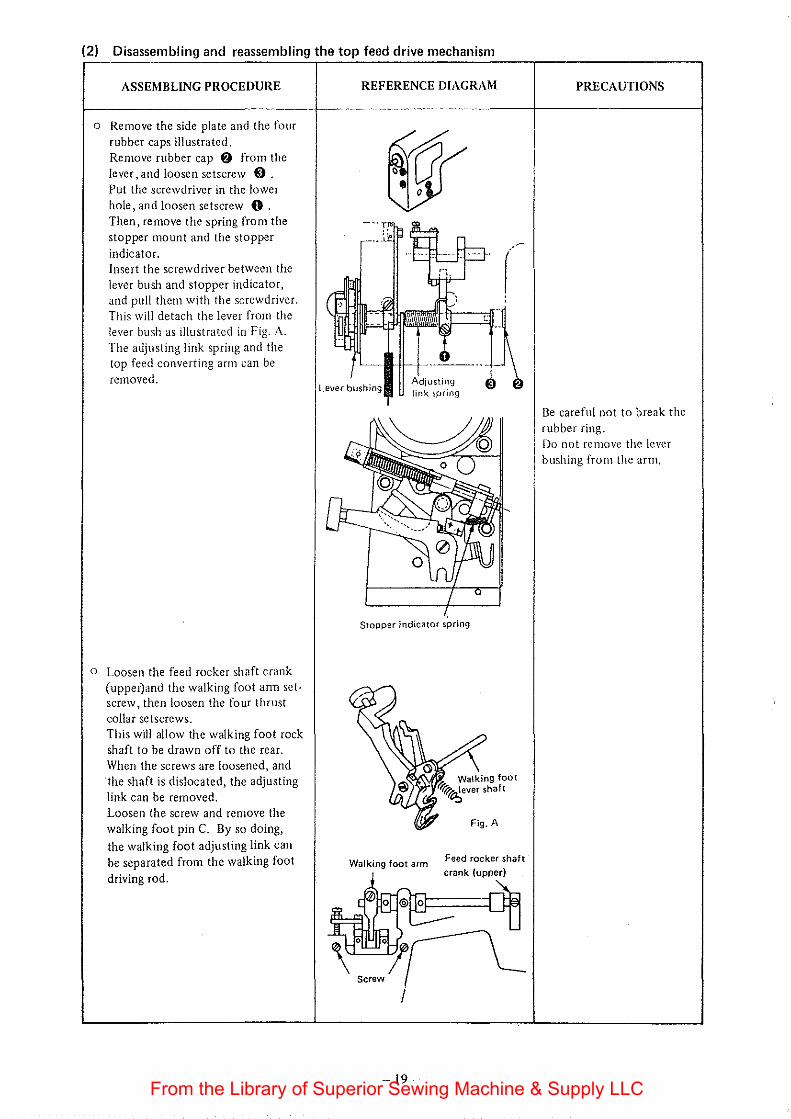
(2) Disassembling and reassembling the top feed drive mechanism
ASSEMBLING PROCEDURE
o Remove the side plate and the four rubber caps illustrated. Remove rubber cap f) from the lever, and loosen setscrew e) . Put the screwdriver in the lower hole, and loosen setscrew 0 . Then, remove the spring from the stopper mount and the stopper indicator. Insert the screwdriver between the lever bush and stopper indicator, and pull them with the screwdriver. This will detach the lever from the lever bush as illustrated in Fig. A. The adjusting link spring and the top feed converting arm can be removed.
o Loosen the feed rocker shaft crank (upper)and the walking foot ann setscrew, then loosen the four thrust collar setscrews. This will allow the walking foot rock shaft to be drawn off to the rear. When the screws are loosened, and the shaft is dislocated, the adjusting link can be removed. Loosen the screw and remove the walking foot pin C. By so doing, the walking foot adjusting link can be separated from the walking foot driving rod.
REFERENCE DIAGRAM
(
Stopper indicator spring
Walking foot arm
I
-19-
Feed rocker shaft
crank (upper)
PRECAUTIONS
Be careful not to break the rubber ring. Do not remove the lever bushing from the arm.
From the Library of Superior Sewing Machine & Supply LLC
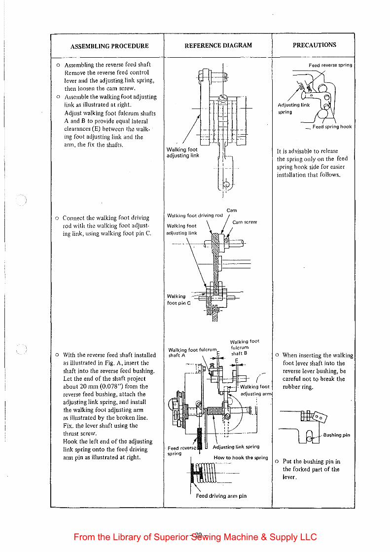
ASSEMBLING PROCEDURE
o Assembling the reverse feed shaft Remove the reverse feed control lever and the adjusting link spring, then loosen the cam screw.
o Assemble the walking foot adjusting link as illustrated at right.
Adjust walking foot fulcrum shafts A and B to provide equal lateral clearances (E) between the walking foot adjusting link and the ann, the fix the shafts.
o Connect the walking foot driving rod with the walking foot adjusting link, using walking foot pin C.
o With the reverse feed shaft installed as illustrated in Fig. A, insert the shaft into the reverse feed bushing. Let the end of the shaft project about 20 mm (0.078") from the reverse feed bushing, attach the adjusting link spring, and install the walking foot adjusting arm as illustrated by the broken line. Fix. the lever shaft using the thrust screw. Hook the left end of the adjusting link spring onto the fee<) driving ann pin as illustrated at right.
REFERENCE DIAGRAM
Walking foot adjusting link
I,
Walking foot driving rod
Walking foot
Walking
Walking foot tuiC"""'shafi A
Cam
Cam screw
Walking foot fulcrum shaft B
(
spring
~~ <o "oo" h<.
Feed driving arm pin
-20-
PRECAUTIONS
Feed reverse spring
_ Feed spring hook
It is advisable to release the spring only on the feed spring hook side for easier installation that follows.
o When inserting the walking foot lever shaft into the reverse lever bushing, be careful not to break the rubber ring.
Bushing pin
o Put the bushing pin in the forked part of the lever.
From the Library of Superior Sewing Machine & Supply LLC
ASSEMBLING PROCEDURE
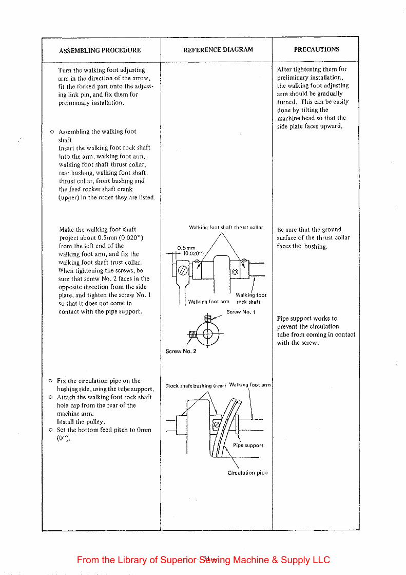
Turn the walking foot adjusting arm in the direction of the arrow, fit the forked part onto the adjusting link pin, and fix them for preliminary installation.
o Assembling the walking foot
shaft Insert the walking foot rock shaft
into the am1, walking foot ann, walking foot shaft thrust collar, rear bushing, walking foot shaft thrust collar, front bushing and the feed rocker shaft crank (upper) in the order they are listed.
Make the walking foot shaft project about O.Smm (0.020") from the left end of the walking foot ann, and fix the walking foot shaft trust collar. When tightening the screws, be sure that screw No.2 faces in the opposite direction from the side plate, and tighten the screw No. 1 so that it does not come in contact with the pipe support.
o Fix the circulation pipe on the bushing side, using the tube support.
o Attach the walking foot rock shaft hole cap from the rear of the machine arm. Install the pulley.
o Set the bottom feed pitch to Omm (0").
REFERENCE DIAGRAM
Walking foot shaft thrust cottar
0.5mm 1tl0.020'') ~
[ ®IL-ujL-1 1----'@\&>-.s c Walk;L foot
Walking foot arm rock shaft
Rock shaft bushing (rear) Walking foot arm
/' 7
,..L -
,y{,. .... " -'---
\ Circulation pipe
-21-
PRECAUTIONS
After tightening them for preliminary installation, the walking foot adjusting arm should be gradually turned. This can be easily done by tilting the machine head so that the side plate faces upward.
Be sure that the ground surface of the thrust .::ollar
faces the bushing.
Pipe support works to prevent the circulation tube from coming in contact with the screw.
From the Library of Superior Sewing Machine & Supply LLC
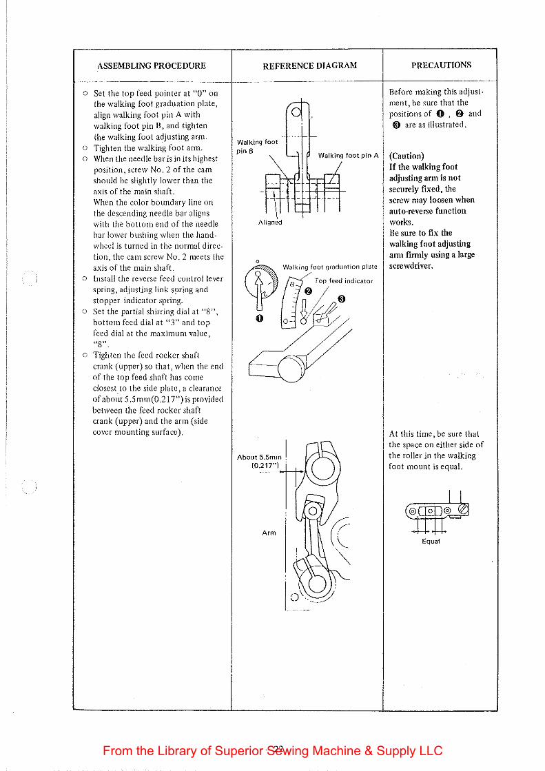
ASSEMBLING PROCEDURE
o Set the top feed pointer at "0" on the walking foot graduation plate, align walking foot pin A with walking foot pin B, and tighten the walking foot adjusting ann.
o Tighten the walking foot ann. o When the needle bar is in its highest
position, screw No.2 of the cam should be slightly lower than the axis of the main shaft. When the color boundary line on the descending needle bar aligns with the bottom end of the needle bar lower bushing when the handwheel is turned in the nonnnl direction, the cam screw No.2 meets the axis of the main shaft.
o Install the reverse feed control lever spring, adjusting link spring and stopper indicator spring.
o Set the partial shirring dial at "8", bottom feed dial at "3" and top feed dial at the maximum value, "8".
o Tighten the feed rocker shaft crank (upper) so that, when the end of the top feed shaft has come closest to the side plate, a clearance of abo;It 5.5mm(0.217") is provided between the feed rocker shaft crank (upper) and the arm (side cover mounting surface).
REFERENCE DIAGRAM
Walking foot pin B
Aligned
Walking foot pin A
Walking foot graduation plate
0
About 5.5mm I
-22-
PRECAUTIONS
Before making this adjust· ment, be sure that the positions of 0 , f) and €} are as illustrated.
(Caution) If the walking foot adjusting arm is not securely fixed, the screw may loosen when auto-reverse function works. Be sure to fix the walking foot adjusting ann fim1ly using a large screwdriver.
At this time, be sure that the space on either side of the roller in the walking foot mount is equal.
(®11°1 t~ Equal
From the Library of Superior Sewing Machine & Supply LLC
ASSEMBLING PROCEDURE
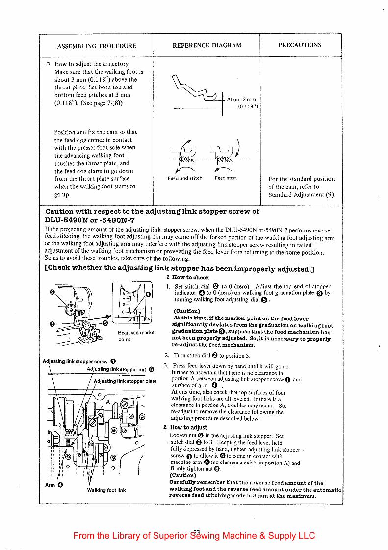
o How to adjust the trajectory Make sure that the walking foot is about 3 mm (0.118") above the throat plate. Set both top and bottom feed pitches at 3 mm (0.1 18"). (See page 7-(8))
Position and fix the cam so that the feed dog comes in contact with the presser foot sole when the advancing walking foot touches the thr.oat plate, and the feed dog starts to go down from the throat plate surface when the walking foot starts to go up.
REFERENCE DIAGRAM
'-~-j- About 3 mm
------+--10.118")
~ );2) ~ ~
Feei::l and stitch Feed start
PRECAUTIONS
For the standard position of the cam, refer to Standard Adjustment (9).
Caution with respect to the adjusting link stopper screw of DLU-5490N or -5490N-7 If the projecting amount of the adjusting link stopper screw, when the DLU-5490N or-5490N-7 performs reverse feed stitching, the walking foot adjusting pin may come off the forked portion of the walking foot adjusting arm or the walking foot adjusting arm may interfere with the adjusting link stopper screw resulting in failed adjustment of the walking foot mechanism or preventing the feed lever from returning to the home position. So as to avoid these troubles, take care of the following.
[Check whether the adjusting link stopper has been improperly adjusted.]
Adjusting link stopper screw 0
Arm 0
c
' ,
Adjusting link stopper nut 0
0
Walking foot link
1 How to check
I. Set stitch.dial {!) to 0 (zero). Adjust the top end of stopper indicator ·G to 0 (zero) on walking foot graduation plate ·0 by turning walking foot adjusting ~dial0 .
(Caution) At this time, it the marker point on the feed lever significantly deviates from the graduation on walking foot graduation plate€), suppose that the feed mechanism has not been properly adjusted. So, it is necessary to properly re-adjust the feed mechanism.
2. Turn stitch dial 6 to position 3.
3. Press feed lever down by hand until it will go no further to ascertain that there is no clearance in portion A between adjusting link stopper screw 0 and surface of arm 0 . At this time, also check that top surfaces of four walking foot links are all leveled. If there is a clearance in portion A, troubles may occur. So, re-adjust to remove the clearance following the adjusting procedure described below.
2 How to adjust Loosen nut@ in the adj~sting link stopper. Set stitch dial{!) to 3. Keeping the feed lever held fully depressed by hand, tighten adjusting link stopper . screw 0 to allow it 0 to come in contact with machine arm 0(no clearance exists in portion A) and firmly tighten nut@. (Caution) Carefully remember that the reverse feed amount of the walking foot and the reverse feed amount under the automatic reverse feed stitching mode is 3 mm at the maximum.
-23-From the Library of Superior Sewing Machine & Supply LLC
5. HOW TO REMOVE PLAY
To assure smooth operation of the sewing machine, it is necessary to remove any excess- play from components. Remove play according to the following procedure.
HOW TO REMOVE PLAY
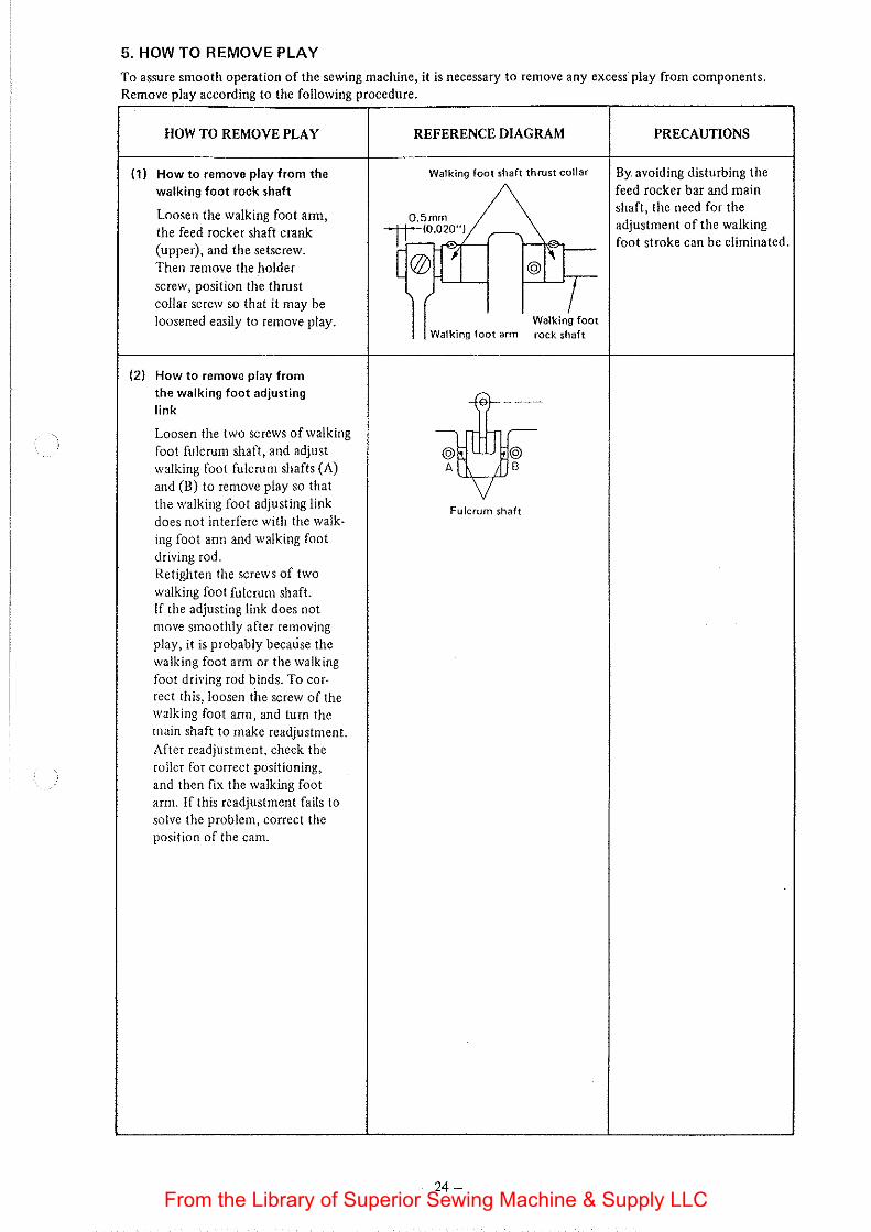
(1) How to remove play from the walking foot rock shaft
Loosen the walking foot arm, the feed rocker shaft crank (upper), and the setscrew. Then remove the holder
screw, position the thrust collar screw so that it may be loosened easily to remove play.
(2} How to remove play from the walking foot adjusting link
Loosen the two screws of walking foot fulcrum shaft, and adjust walking foot fulcrum shafts (A) and (B) to remove play so that the walking foot adjusting link does not interfere with the walking foot am1 and walking foot driving rod. Retighten the screws of two
walking foot fulcrum shaft. If the adjusting link does not move smoothly after removing play, it is probably because the walking foot arm or the walking foot driving rod binds. To correct this, loosen the screw of the walking foot ann, and turn the main shaft to make readjustment. After readjustment, check the roller for correct positioning, and then fix the walking foot arm. If this readjustment fails to solve the problem, correct the position of the cam.
REFERENCE DIAGRAM
Walking foot shaft thrust collar
0.5mm 1t(0.020") ,--..
t @0'1 ~@''f.,__
Walking foot arm Walking foot rock shaft
-;1tJ;-A B
v Fulcrum shaft
-24-
PRECAUTIONS
By. avoiding disturbing the feed rocker bar and main shaft, the need for the adjustment of the walking foot stroke can be eliminated.
From the Library of Superior Sewing Machine & Supply LLC
HOW TO REMOVE PLAY
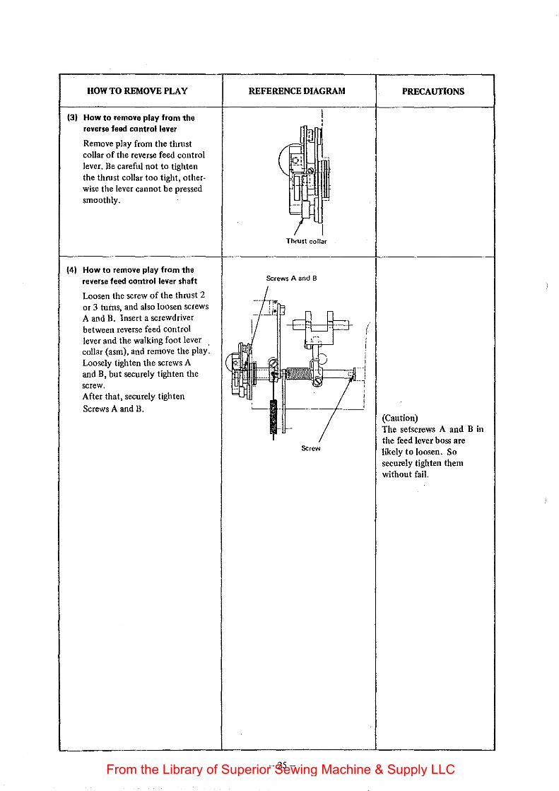
(31 How to remove play from the reverse feed control lever
Remove play from the thrust collar of the reverse feed control lever. Be careful not to tighten the thrust collar too tight, other· wise the lever cannot be pressed smoothly.
(41 How to remove play from the reverse feed control lever shaft
Loosen the screw of the thrust 2 or 3 turns, and also loosen screws A and B. Insert a screwdriver between reverse feed control lever and the walking foot lever . collar (asm), and remove the play. Loosely tighten the screws A and B, but securely tighten the screw. After that, securely tighten
Screws A and B.
REFERENCE DIAGRAM
Thrust collar
Screws A and 8
&:rew
-25-
PRECAUfiONS
(Caution) The setscrews A and B in the feed lever boss are likely to loosen. So securely tighten them without fail.
From the Library of Superior Sewing Machine & Supply LLC
6. HOW TO ADJUST THE TOP FEED DRIVE MECHANISM
Be sure to check th.e following after disassembling, assembling or removing play:
CHECK ITEM
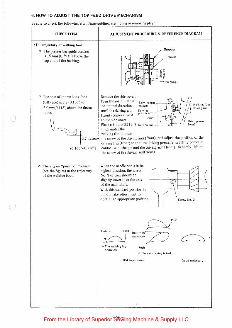
(1) Trajectory of walking foot
o The presser bar guide bracket is 15 mm (0.591 ")above the top end of the bushing.
O The sole of the walking foot
(BB type) is 2.7 (0.106') to
3.0mm(O.ll8') above the throat
plate.
-------+=12..?-3.0mm
(0. '""'·"·' '""'
o There is no "pu.sh" or "return" (see the figure) in the trajectory of the walking foot.
ADJUSTMENT PROCEDURE & REFERENCE DIAGRAM
Remove the side cover. Turn the main shaft in the normal direction until the driving am1
(front) comes closest to the side cover. Place a 3 mm (0.118") thick under the walking foot, loosen
Stopper
Bracket
Bushing
Driving arm ~1-+-JA (front) Walking foot
driving rod
the screw of the driving amr (front), and adjust the position of the driving arm (front) so that the driving presser arm lightly comes in contact with the pin and the driving arm (front). Securely tighten
the screw of the driving arm( front).
When the needle bar is in its highest position, the screw No.2 of cam should be slightly lower than the axis of the main shaft.
With this standard position in mind, make adjustment to obtain the appropriate position.
Return Push
~ush
Returnin 7} trajectory /-----/
o The walking foot Push is too low,
o The cam timing is bad,
Bad trajectories
-26-
Screw No.2
Good trajectory
From the Library of Superior Sewing Machine & Supply LLC
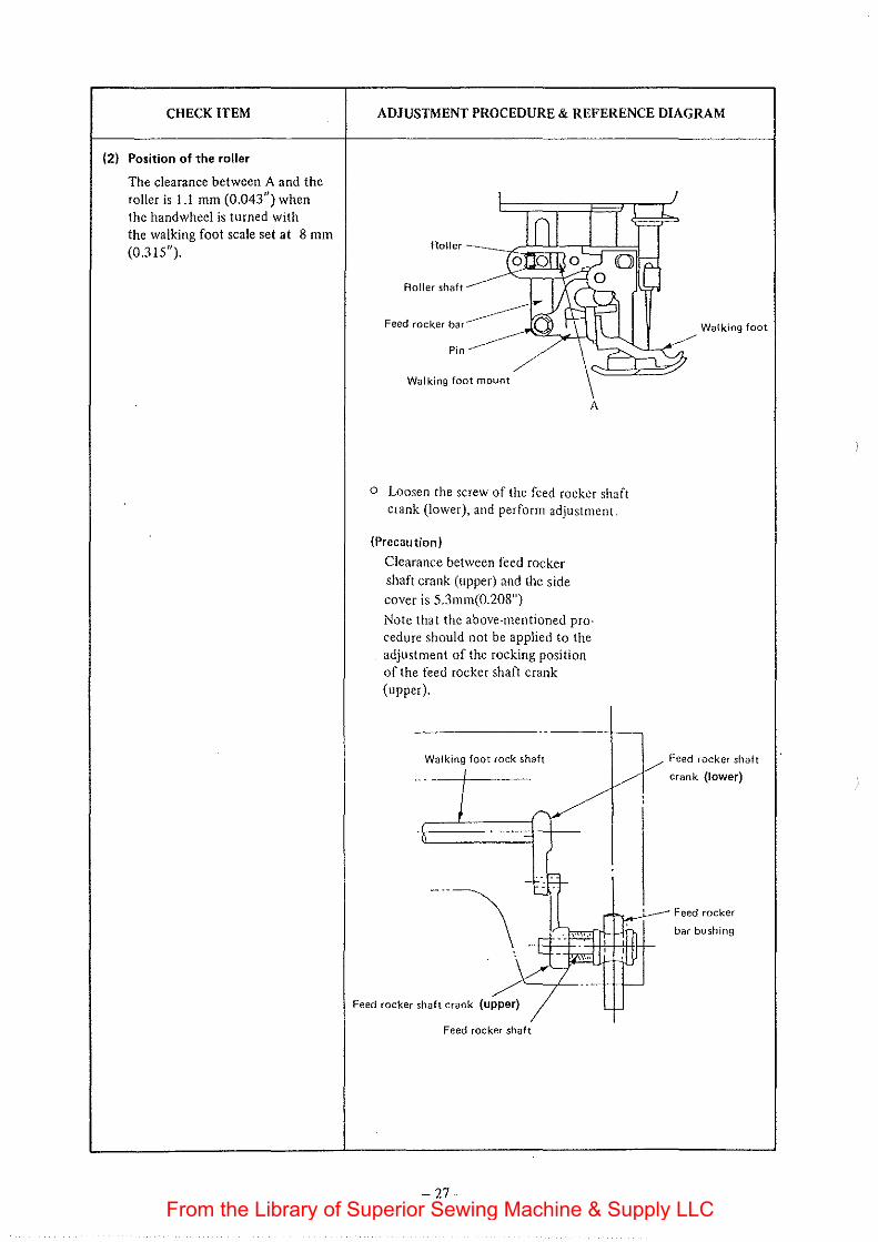
CHECK ITEM
(2) Position of the roller
The clearance between A and the roller is 1.1 mm (0.043") when the handwheel is turned with the walking foot scale set at 8 mm (0.315").
ADJUSTMENT PROCEDURE & REFERENCE DIAGRAM
Roller
Roller shaft
Feed rocker bar
Pin
Walking foot mount
A
o Loosen the screw of the feed rocker shaft crank (lower), and perform adjustment.
{Precaution)
Clearance between feed rocker shaft crank (upper) and the side cover is 5.3mm(0.208")
Note that the above·mentioned pro· cedure should not be applied to the adjustment of the rocking position of the feed rocker shaft crank (upper).
Walking foot rock shaft
Feed rocker shaft crank (upper)
Feed rocker shaft
-27-
Walking foot
Feed rocker shaft
crank {lower)
Feed rocker
bar bushing
From the Library of Superior Sewing Machine & Supply LLC
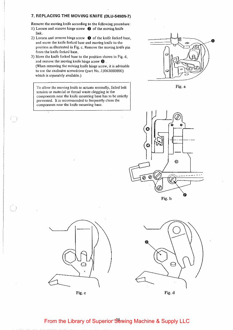
7. REPLACING THE MOVING KNIFE (DLU·5490N-7)
Remove the moving knife according to the following procedure: I). Loosen and remove hinge screw f) of the moving knife
link. 2) Loosen and remove hinge screw 0 of the knife forked base,
and move the knife forked base and moving knife to the position as illustrated in Fig. c. Remove the moving knife pin from the knife forked base.
3) Move the knife forked base to the position shown in Fig. d, and remove the moving knife hinge screw 8 . (When removing the mOving knife hinge screw, it is advisable to use the exclusive screwdriver (part No.11063000000) which is separately available.)
To allow the moving knife to actuate normally, failed belt tension or material or thread waste clogging in the components near the knife mounting base has to be strictly prevented. It is recommended to frequently clean the components near the knife mounting base.
Fig. c
-28-
Fig. a
Fig. b
Fig. d
From the Library of Superior Sewing Machine & Supply LLC
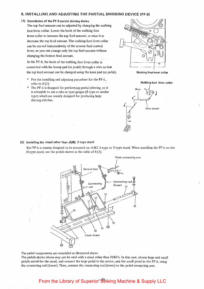
8. INSTALLING AND ADJUSTING THE PARTIAL SHIRRING DEVICE (PF-6)
(1) Description of the PF-6 partial shirring device
The top feed amount can be adjusted by changing the walking
foot lever collar. Lower the hook of the walking foot
lever collar to increase the top feed amount, or raise it to
decrease the top feed amount. The walking foot lever collar
can be moved indeoendently of the reverse feed control
lever, so you can change only the top feed amount without
changing the bottom feed amount.
In the PF-6, the hook of the walking foot lever collar is
connected with the kneep pad (or pedal) through a wire so that
the top feed amount can be changed using the knee pad (or pedal).
* For the installing and adjusting procedure for the PF-6, refer to 8-(2).
* The PF-6 is designed for performing partial shirring, so it is advisable to use a rake-in type gauges (B type or similar type) which are mainly designed for producing large shirring stitches.
(2) Installing the stand other than JUKI Z·type stand
Walking foot lever collar
Walking foot lever collar
(rt I~
Wire sheath
~
The PF-6 is mainly designed to be mounted on JUKI Z-type or T-typ·e stand. When installing the PF-6 on the H-type stand, use the pedals shown in the table of 8-(3).
Pedal connecting arm
---~ , !-~ ®"""
(<)
(.G)
The pedal components are assembled as illustrated above. The pedals shown above may not be used with a stand other than JUKI's. In this case, obtain large and small pedals suited for the stand, and connect the large pedal to the motor, and the small pedal to the PF-6, using the connecting rod (lower). Then, connect the connecting rod (lower) to the pedal connecting arm.
-29-From the Library of Superior Sewing Machine & Supply LLC
(3) PF-6 pedal components
Description Z type stand Q'ty H type stand Q'ty
Pedal shaft GPFOI016000 I -
Liner plate GPF060 17000 I . -Pedal (small) GPF060600AO I 88101232000 I
Pedal adjusting plate GPF06080000 I 88125280000 I Pedal (large) I 1158805 I -
Pedal mat 11158904 I -Pedal adjusting plate 11158706 I 88104012000 I Pedal bushing D8!13555BOO 4 -Liner plate 11159001 2 -
Screws SM9082023SE 2 SM9061203SE 9 WS0861410KR 2 l\'l\1606000 I SE 5 IVP0871602SE 4 -
NM6080721 SE 2 -
SM9061·203SE 4 -
\VS062121 OKR 4 WS0621210KR 5 IVP0671 0 16SE 4 WP0671 016SE 5
Pedal support arm - 88125012000 4
If you install the PF-6 unit on a machine table other than the one which is specially designed for JUKI machine with
thread trimmer and PF-6, make a recess in the table as show below to fix the wire sheath guide to it.
-30-From the Library of Superior Sewing Machine & Supply LLC
w
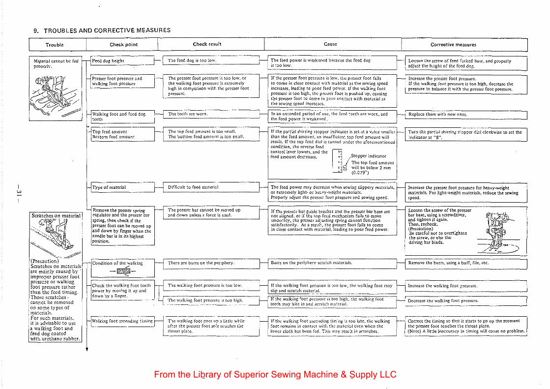
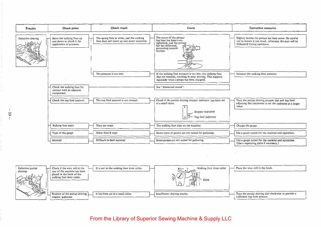
9. TROUBLES AND CORRECTIVE MEASURES
Trouble
Ma.terial cannot be fed prooerlv.
a /" :..----:; ;:::; ~-. 1'~'---~
Scratches on material
GJ~·~ . . ' . '"~~;,.:;_.,
... ,_:;,;, ·, ::<.. """::...: \ \.._ . '
~ .. / (Precaution) Scratches on materials are mainly caused by improper presser foot pressure or walking foot pressure rather than the feed timing. Those scratches· cannot be removed on some types of materials. For such materials. it is advisable to usc a walking foot and feed dog coated with urethane rubber.
Check point I Check result L Feed dog height The feed dog is too low.
Cause
The feed power is weakened been usc the feed dog is too low.
I Corrective measures
Loosen the screw of feed forked base, and properly adjust the height of the feed dog.
Presser foot pressure <1nd walking foot pressure
The presser foot pressure is too low, or the walking foot pressure is extremely high in eompmison with the presser foot pressure.
H If the presser foot pressure is low, the presser foot fails H Increase the presser foot pressure.
Walking foot and feed dog teeth
The teeth arc worn.
to come in close cont<~ct with material as the sewing speed increases, leading to poor feed power. If the walking foot pressure is too high, the pre~scr foot is pushed up, causing tl;te presser foot to come in poor contact with material as the sewing speed increases.
In <~n extended period of liSe, the feed teeth arc worn, and the feed power is weakened.
If the walking foot pressure is too high, decrease the pressure to balance it with the presser foot pressure.
Replace them with new ones.
Top feed amount Bottom feed amount
The top feed amount is too small. The bottom feed amount is too small.
If the partial shirring stopper indicator is set at a vuluc smaller Turn the partial shirring stopper dial clockwise to set the than the feed amount, an insufficient top feed amount will L-i~n0d~i'''ct0oc'"'ct_"_,S,_"c· _______________ _J result. If the top feed din! is turned under the aforementioned
HTypc of material
Remove the presser spring regulator and the presser bar spring, then check if the presser foot can be moved up and down by finger when the needle bar is in its highest position.
rJCondition of the W<~lking /
-ml'ml-.__
Difficult to feed material
The presser bar cannot be moved up <~nd down unless a force is used.
H- There arc burrs on the periphery.
condition, the reverse feed control lever Jowers, ::tnd the fejt •
feed amount decreases. [ 4i /Stopper indicator
U•j The top feed amount
b will be below 2 mm (0.079")
The feed power may decrease when sewing slippery materials, t-or extremely light- or he:~vy-weight materials. Properly adjust the presser foot pressure and sewing speed.
If the presser b<~r guide bracket and the presser bar base arc not aligned, or if the top feed mechanism fails to move smoothly, the presser adjusting spring cannot function satisfactorily. As a result, the presser foot fails to come in close contact with material, leading to poor feed power.
Burrs on the periphery scr<~tch materials.
f-
Check the walking foot teeth The walking foot pressure is too low. If the walking foot pressure is too low, the walking foot may
power by mov;ng it up and ':i'i'li~p~'cn0d0'~'~'~"~'~"~'~"='~"="':=''::'::· ::::~c:::::=;:::::::::::::=:;;=::::::;:::::==:i down by i1 finger. -- r . ' --- . . L __ _:_ _ _c:.._______ The walking foot pressure is too high. If the walkmg foot pre%urc IS too l11gh, the wa!kmg foot
... _ teeth may bite in r~nd scratch material. .:c:__ ___ __j
HWalking foot ascending ti;:_~ing The \~lki~~j~~;g~~:· up a little while nfter the presser foot sole touches the throat plate.
H If the walking foot aS<.:cnding timing is too late, the walking foot remains in contad with the material even when the lower cloth hils been fed. This mny result in scratches. L _______ _
f-
Increase the presser foot pressure for heavy-weight materials. For light-weight materials, reduce the sewing speed.
Loosen the screw of the presser bar base, using a screwdriver, and tighten it again. Then, recheck. {Precaution} Be careful not to overtighten the screw, or else the driving bar binds.
~ ~l -~~~-, ......./.::: ., .... ";;">____....-
Remove the burrs, using a buff, file, etc.
Increase the walking foot pressure.
Decrease the walking foot pressure.
Correct the timing so that it starts to go up the moment the presser foot touches the throat plate. (Note) A little inaccur::~cy in timing will c:lUse no problem.
From the Library of Superior Sewing Machine & Supply LLC
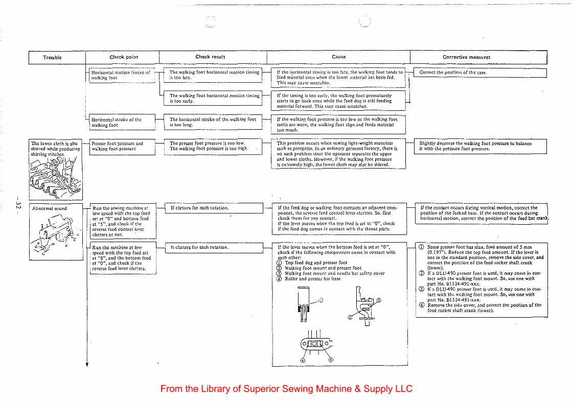
w N
I
Trouble
The lower cloth is also shirred while producing
shirring ~~~s-[,r'). "11 •. V •
~~ -""" h 30~1~ lt' }"""'
Abnormal sound
/'~ ~··' ~;r~~' zft ::,
, ........ -y-'·
Check point Check result I H Hodwnt•l motion tm::Jrt
walking foot The walking foot horizont~-1 motion timing r is too late.
The walking foot horizontal motion timing ~ is too early.
~ Horizontal stroke of the walking foot
The horizontal stroke of the walking foot ~ is too long.
H Presser foot pressure and The presser foot pressure is too low. I walking foot pressure The walking foot pressure is too high.
Run the sewing machine at H If clatters for each rotation. r-low speed with the top feed set at "0" and bottom feed at "5", and check if the reverse feed control lever clatters or not.
Run the machine at low H It clatters for each rotation. t-speed with the top feed set at "8", and the bottom feed at "0", and check if the reverse feed lever clatters.
Cause I Corrective measures
If the horizontal timing is too btc, the walking foot tends to M Correct the position of the cam. I feed m:itcria! even when the lower motcrial has been fed. This may cause scratches.
If the timing is too early, the walking foot prematurely starts to go back even while the feed dog is still feeding material forward. This may cause scratches.
If tho w•lking foot P"""" ;, too low ot tho w•lking foot I teeth are worn, the walking foot slips and feeds material too much.
This problem occurs when sewing light-weight materials H Slightly decrease the walking foot pressure to balance such as georgette. In an ordinary garment factory, there is it with the pressure foot pressure. no such problem since the operator scpar:1tes the upper and lower cloths. However, if the walking foot pressure is extremely high, the lower cloth m:iy also be shirred.
If the feed dog or walking foot contacts an adjacent com- 1- If the contact occurs during vertical motion, correct the J ponent, the reverse feed control lever clatters. So, fust position of the forked base. If the contact occurs during check them for any contact. horizontal motion, correct the position of the feed bar cran\ If the lever moves when the top feed is set at "0", check if the feed dog comes in contact with the throat plate.
If the lever moves when the bottom feed is set at "0", f- CD Some presser foot has riiax. feed amount of S mm check if the fol!owing components come in contact with (0.197"). Reduce the top feed amount. If the lever is each other: not in the standard position, remove the side cover, and ~ Top food dog 'nd P""" foot correct the position of the feed rocker shaft crank
Walking foot mount and presser foot (lower). Walking foot mount and needle bar safety cover d) If a DLU-490 presser foot is used, it may come in con-RoUer and presser bar base tact with the walking foot mount. So, use one with
part No. B1524-491-xxx.
~ )f G) If a DLU-490 presser foot is used, it may come in con-
tact with the wr.dking foot mount. So, use one with part No. 81524-491-xxx.
@ Remove the side cover, and correct the position of the feed rocker shaft crank (!ower).
~ ' --
From the Library of Superior Sewing Machine & Supply LLC
w w I
Defective partial shirring
Check point
Move the walking foot up and down to check it for application of pressure.
Check the walking foot for contact with an adjacent component.
Check if the wire roll at the rear of the machine has been
~ V I pbood In tho hook oftho
~ ... ~~. -'"-'"'"··-~
~~~ . "' : 1 Po,ltion oftho put!•! 'hutl0g __..- stopper indicator.
·-- ·····--
Check result
The spring fails to work, and the walking foot docs not move up and down smoothly.
H It is not in the walking foot lever collar.
It has been set at a small value.
f-
Cause
The screw of the presser bar base has been over-tightened, and the bar has deformed, preventing smooth motion.
If the walking foot pressure is too low, the walking foot slips on material, resulting in poor shirring. This happens especially when a gauge has been changed.
Check if the partial shirring stopper indicator has been set at a smatl value.
D Stopper indic::~tor
g::: Top feed indicator
~"''"''" "' "" ~ . Hook
Insufficient shirring resu!ta.
Corrective measures
Slightly loosen the presser bar b::~se screw. Be careful not to loosen it too much, otherwise the part will be dislocated during operation.
Turn the partial shirring stopper dial and top feed adjusting dial clockwise to set the indicator at a larger value.
Use a gauge suited for the material and operation. (Use a separating plate if necessary.)
H Place the wire roll in the hook.
Turn the partial shirring dial clockwise to provide a sufficient top feed amount.
I
I
I
From the Library of Superior Sewing Machine & Supply LLC
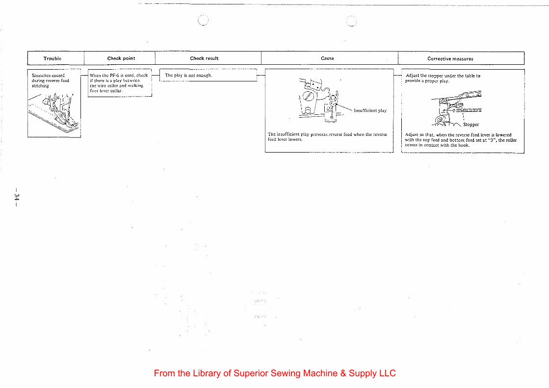
w ..,. I
Trouble I Scratches caused r-during reverse feed stitching
~(~t\0~/~· . · .. ·~
~ '
Check point I Check result I
When the PF--6 i~ used, check ~ The play is not enough. ~ if there is a play between the wire roller and wa!kinJ;. foot lever collar.
Cause I Corrective measures
f- Adjust the stopper under the table to
~Jj~L provide a proper play.
~ ... ,. o./\ $ ~ z· 'l \ ) "'''t''' ~~ r .. wrr.oloot pby ~ . ~<wmtillttlliiW
==-=1 J, \- 0 I ~ ~ "10- Stoppor
The insufficient play prevents reverse feed when the reverse Adjust so that, when the reverse feed lever is lowered feed lever lowers. with the top feed and bottom feed set at "'3", the roller
comes in contact with the hook.
From the Library of Superior Sewing Machine & Supply LLC
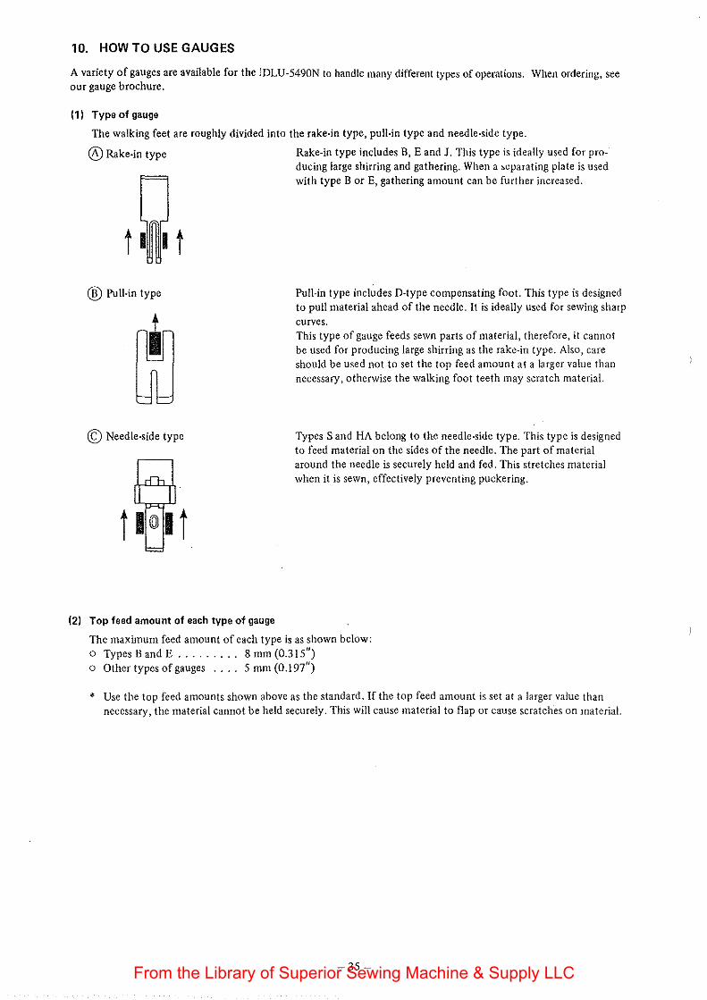
10. HOW TO USE GAUGES
A variety of gauges are available for the lDLU-5490N to handle many different types of operations. When ordering, see our gauge brochure.
(1) Type of gauge
The walking feet are roughly divided into the rake-in type, pull-in type and needle-side type.
®Rake-in type Rake-in type includes B, E and J. This type is ideally used for producing large shirring and gathering. When a ~eparating plate is used with type BorE, gathering amount can be further increased.
® Pull-in type
© Needle-side type
(2) Top feed amount of each type of gauge
Pull-in type includes D-type compensating foot. This type is designed to pull material ahead of the needle. It is ideally used for sewing sharp curves. This type of gauge feeds sewn parts of material, therefore, it cannot be used for producing large shirring as the rake-in type. Also, care should be used not to set the top feed amount at a larger value than necessary, otherwise the walking foot teeth may scratch material.
Types Sand HA belong to the needle-side type. This type is designed to feed material on the sides of the needle. The part of material around the needle is securely held and fed. This stretches material when it is sewn, effectively preventing puckering.
The maximum feed amount of each type is as shown below: o Types Band E ......... 8 mm (0.315") o Other types of gauges .... 5 mm (0.197")
* Use the top feed amounts shown above as the standard. If the top feed amount is set at a larger value than necessary, the material cannot be held securely. This will cause material to flap or cause scratches on material.
-35-From the Library of Superior Sewing Machine & Supply LLC
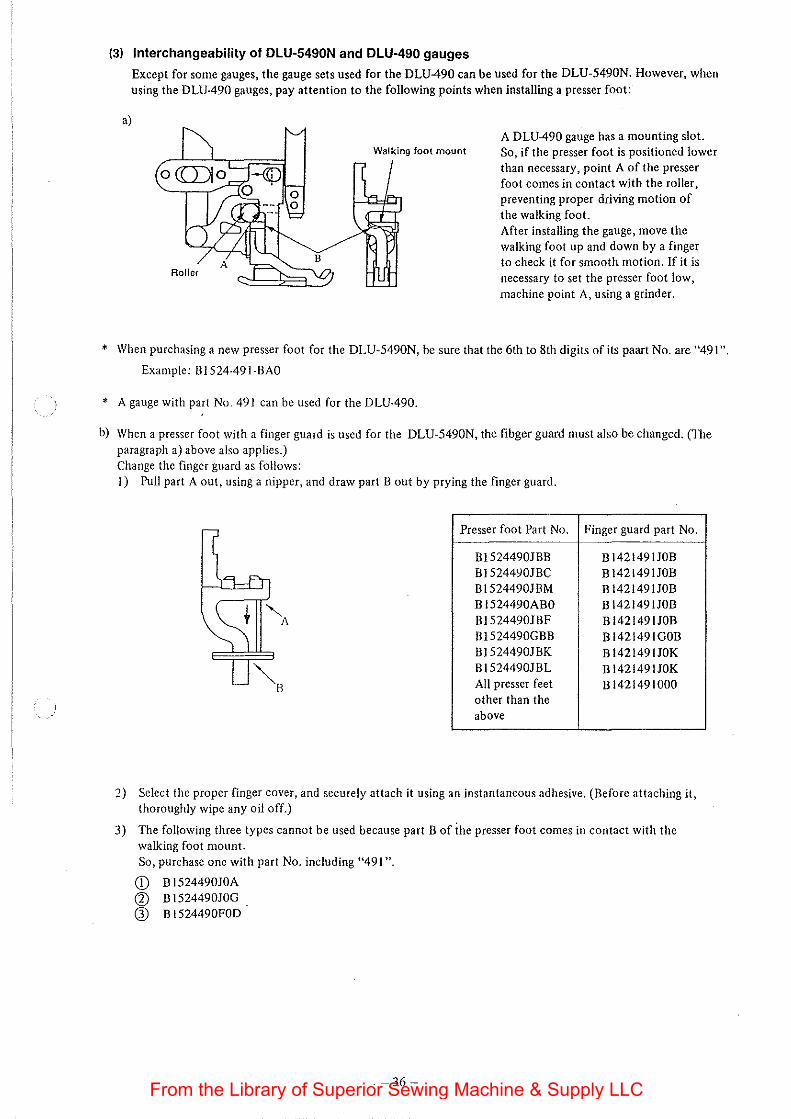
(3) Interchangeability of DLU·5490N and DLU-490 gauges
Except for some gauges, the gauge sets used for the DLU-490 can be used for the DLU-5490N. However, when using the DLU-490 gauges, pay attention to the following points when installing a presser foot:
a)
Walking foot mount A DLU-490 gauge has a mounting slot. So, if the presser foot is positioned lower than necessary, point A of the presser foot comes in contact with the roller, preventing proper driving motion of the walking foot. After installing the gauge, move the walking foot up and down by a finger to check it for smooth motion. If it is necessary to set the presser foot low, machine point A, using a grinder.
• When purchasing a new presser foot for the DLU-5490N, be sure that the 6th to 8th digits of its paart No. are "491 ".
Example: 81524-491-BAO
* A gauge with part No. 491 can be used for the DLU-490.
b) When a presser foot with a finger guard is used for the DLU-5490N, the fibger guard must also be changed. (The paragraph a) above also applies.) Change the finger guard as follows: 1) Pull part A out, using a nipper, and draw part 8 out by prying the finger guard.
Presser foot Part No. Finger guard part No.
81524490188 BI421491JOB BI5244YOJBC B 1421491JOB B1524490JBM BI421491JOB B 1524490ABO BI421491JOB 815244901BF Bl421491JOB 8 J524490G88 Bl421491GOB B J524490J BK BI421491JOK B1524490JBL BI421491JOK All presser feet 81421491000 other than the above
2) Select the proper finger cover, and securely attach it using an instantaneous adhesive. (Before attaching it, thoroughly wipe any oil off.)
3) The following three types cannot be used because part 8 of the presser foot comes in contact with the walking foot mount. So, purchase one with part No. including "491".
CD B 1524490JOA G) BI524490JOG CD B 1524490FOD
-36-From the Library of Superior Sewing Machine & Supply LLC
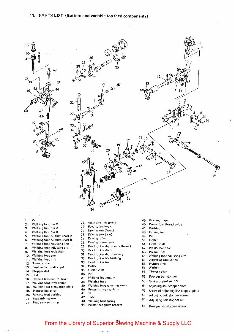
11. PARTS LIST (Bottom and variable top feed components)
39-
1Q9
60
5716 ~[J 17 • ~-
19 -' .)~'' • '~, ~~~::- '"' 18 - tp ~
~~ ~ ~ ~
~II? 54
~ 23 I 22
4U 14
24
45 Bracket plate 1. Cam 23 Adjusting link spring 46 Presser bar thread guide 2. Walking foot pin C 24 Feed spring hook 47 Bushing 3. Walking foot pin A 25 Driving arm (front) 48 Driving bar 4. Walking foot pin B 26 Driving arm {read 49 Pin 5. Walking foot fulcrum shaft A 27 Driving roller 50 Roller 6. Walking foot fulcrum shaft B 28 Driving presser arm 51 Roller shaft 7. Walking foot adjusting link 29 Feed rocker shaft crank (lower) 52 Presser bar base 8. Walking foot adjusting pin 30 Feed rocker shaft 53 Presser foot 9. Walking foot rock shaft 31 Feed rocker shaft bushing 54 Walking foot adjusting arm 10. Walking foot arm 32 Feed ro~ker bar bushing 55 Adjusting link spring 11. Walking foot link 33 Feed rocker bar 56 Rubber ring 12 Thrust collar 34 Roller 57 Washer 13. Feed rocker shaft crank
14. Stopper dial 35 Roller shaft 58 Thrust collar 36 Pin
59 Presser bar stopper 15. Dial 37 Walking foot mount
60 Screw of presser bar 16. Reverse feed control lever
38 Walking foot
Adjusting link stopper plate 17. Walking foot lever collar
39 Walking foot adjusting knob 61 18. Walking foot graduation plate 40 Presser spring regulator 62 Screw of adjusting link stopper plate 19. Stopper indicator 41 Nut 63 Adjusting link stopper screw 20. Reverse feed bushing 42 Cap
64 Adjusting link stopper nut 21 Feed driving arm 43 Walking foot spring
22 Feed reverse spring 44 Presser bar guide bracket 65 Presser bar stopper screw
-37-From the Library of Superior Sewing Machine & Supply LLC
w 00
I
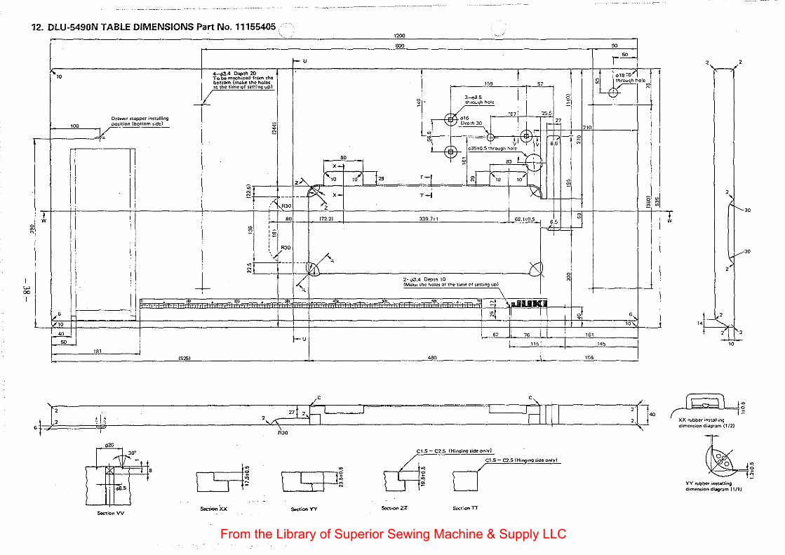
12. DLU-5490N TABLE DIMENSIONS Part No. 11155405 ··-800 90
t-u ,.....-
", 4-<t>J.4 01l!)th 20 Tobo machined from tho @L ¢>1810,....
~~~~~.1n;:a;r s~~~~~~~) "' " ~hole~
- k' ~' 3.....p8,5 ;j through hole
Drawct •tOJ)per installing " v.16 "' 255
H>O PQ$ition (bottom side) • ' r:;. Depth 30 tE ;; -----... 1:\ "0
·P ~
g t 1'=1/ v ~
r~ " "'
6.5 N
<:>35±0.5 through hole
80 \;;1 §
I x- I 80
zA f'7o w'] !" T-j ~J 1\, ,; ~
~t ~x- r-J )( ~
-, :'' --
RJO 0 ~
' ~ :z
~ : 80 !72.2) m
339.hl 68.1±0.5 ~
6.5 , ~ ~ § T
RJO
'< ·-- ---V, ~ X N
I< 0
- f-2-</>3.4 Depth 10
~
~ (Make the hoi<>S at the timti ol setting up)
\ 0 ' 0 ' :..-.
• ro ~I LIII.IIK -"6 ~~ ~ 6
"' "' -"'-~
1-u " 76 787
7" 7<5
787 (525) oso 795
1;: ~ 2v\ 21j2,5 I I I lrll[l :0'"
6 -
i'H I ' I' ~~ \ I I l I
Slrctlon Xx Sec>:ion vv
Section YY
Ct.S-C25 / . '"'"''" ,,. '"'"only)
t ; ~~ ~S-CZSIH ~ L_j . '"''"""' '""'
Section ZZ Sc<::tion TT
T
2 2
2
30
30
2
"l=S f 2_.;1 1"2
"'
~3 XX n.tbber inm>lling dimension diagr:~m (1 /2)
~ ~ _j5 YY robber installing dimension di"9ram (1/1)
From the Library of Superior Sewing Machine & Supply LLC
I
"' "' I
!
J, i t ~
l
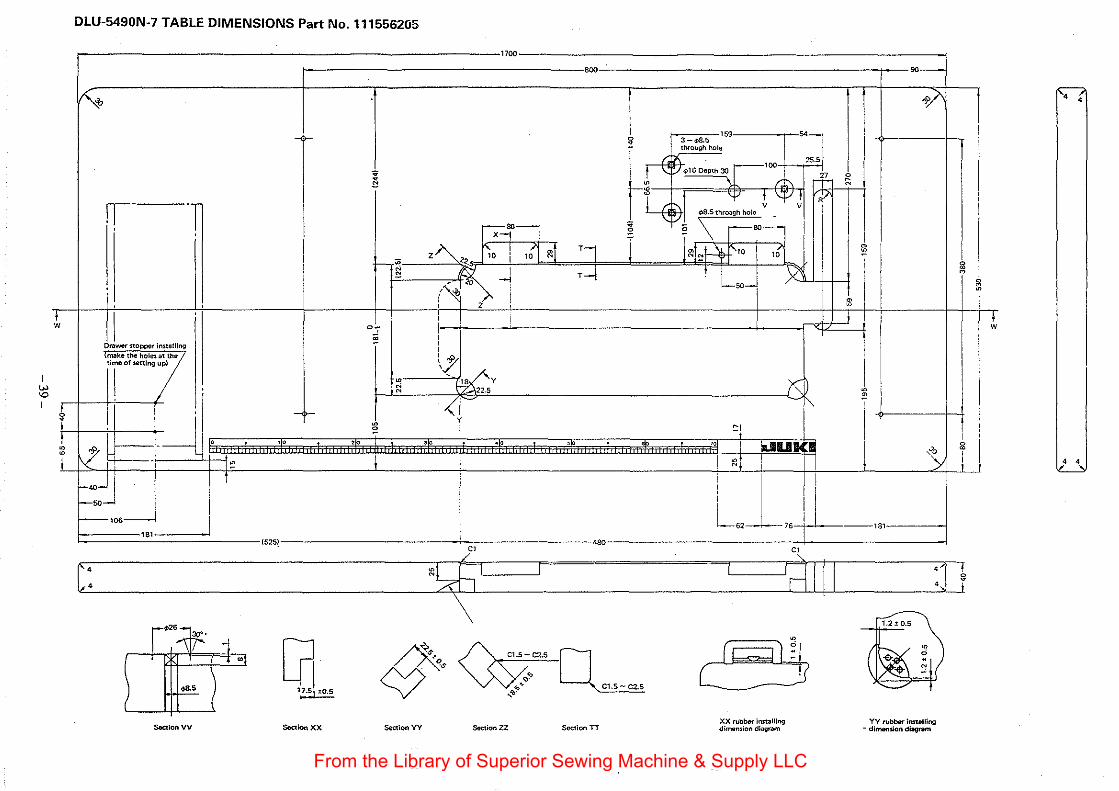
DLU-5490N-7 TABLE DIMENSIONS Part No. 111556205
~
fl- -T
I Drawer stOpPQr lnstu!llng
l~ko<h< hoi~~ 'T'' '""'"' ,,
~ -1--r~~j f-so f-----106
181
c:
Seer:lotiVV
1700
800 eo-
o/' 159 54-
T ~ 3-~5
I ~ '""--r·· ., " .t \.::/4!1SOcpth30 27 ~ • • !'. -r-" $ 1 't" t_ " :; .;/' I I L$1 .a.s "''"h holo V _ V I
I I x--1'- ~ § \ -so- I I
I z~<<. ~, I ,: ~I T1 r j rob!-4-:'" ,{ l m I
r--~ g E (t::i I T--1 t : : ).2'1 ~
~~>o _, I
...--50---:
' z ' m I
I I I I 07
~ I - ' I \:( I
I I
~ ~ ~y K I I ~ 5
f l <~ ~ ' 01 i' I e I
! I
~~~~~ 1 1 I 111 11 ·1~1 ~~~~~~~~~~~~ ~~~~ ~~~~~~~~~~~~~ ~~~~~~~~ di 1 111 1t 1111 11 1 ~~~~~~~~ 11 11 1111 ~ 11 ~~~~I~~~ 11 r~ ru~ I 0
>o ~
~l ':> I ~ l 1
(5251
• [f~ Soaionxx
I I I I i ! ; l!l
IS1-d I ! I i I
-L62 76 II I o80 m m
/ ' I -1 --,~, Hill l1
~ . ,·
0 •, I ~n V¥~ ~ e1
'
Scc11on YY Section ZZ SuC'Iion TT XX rubblll' Installing dimension diagram
YY rubber irmvl/lng - dimension diDgntm
., '
t
' '
From the Library of Superior Sewing Machine & Supply LLC