Journal of Alloys and Compounds - Eprints@NML
6
Journal of Alloys and Compounds 480 (2009) 765–770 Contents lists available at ScienceDirect Journal of Alloys and Compounds journal homepage: www.elsevier.com/locate/jallcom Corrosion resistance of electrodeposited Ni–B and Ni–B–Si 3 N 4 composite coatings K. Krishnaveni a , T.S.N. Sankara Narayanan a,∗ , S.K. Seshadri b a National Metallurgical Laboratory, Madras Centre CSIR Complex, Taramani, Chennai 600 113, India b Department of Metallurgical and Materials Engineering, Indian Institute of Technology, Chennai 600 036, India article info Article history: Received 4 June 2008 Received in revised form 1 February 2009 Accepted 13 February 2009 Available online 27 February 2009 Keywords: Nanostructures Surfaces and interfaces Nanofabrications X-ray diffraction Electrochemical reactions abstract Corrosion resistance of electrodeposited (ED) and electroless (EL) composite coatings have been a debat- able issue in the published literature. The present paper aims to compare the corrosion resistance of ED Ni–B–Si 3 N 4 composite coating with its plain counter part. The ED Ni–B coatings were prepared using Watt’s nickel bath modified with the addition of dimethylamine borane and the ED Ni–B–Si 3 N 4 com- posite coatings were prepared using the same bath in which Si 3 N 4 particles (mean diameter: 0.80 m) were dispersed in it. The structural and morphological characteristics of ED Ni–B and Ni–B–Si 3 N 4 com- posite coatings were determined using X-ray diffraction (XRD) measurements and scanning electron microscopy (SEM). The corrosion resistances of ED Ni–B and Ni–B–Si 3 N 4 composite coatings, both in as- plated and heat treated conditions, in 3.5% NaCl, were evaluated by potentiodynamic polarization and electrochemical impedance spectroscopy (EIS) studies. The study reveals that the extent of shift in cor- rosion potential (E corr ) towards the noble direction, decrease in corrosion current density (i corr ), increase in charge transfer resistance (R ct ) and decrease in double layer capacitance (C dl ) values with the incor- poration of Si 3 N 4 particles in the ED Ni–B matrix is not appreciable, both in as-plated and heat-treated conditions. The occurrence of the second phase angle maximum suggests penetration of the electrolyte via the pores/micro-pores in these coating to create another interface, namely, the electrolyte/substrate. Unlike the nanosized particles, the micron size Si 3 N 4 particles (mean diameter: 0.80 m) used in this study is not capable of completely filling all the pores in the coating and allowed diffusion of chloride ions along the interface. The marginal improvement in corrosion resistance observed for ED Ni–B–Si 3 N 4 composite coatings compared to its plain counterpart could have resulted from the decrease in effective metallic area prone to corrosion. © 2009 Elsevier B.V. All rights reserved. 1. Introduction The idea of codepositing various second phase particles in elec- trodeposited (ED) and electroless (EL) metal matrix and thereby taking advantage of their desirable qualities, such as high hardness, excellent wear and abrasion resistance, improved corrosion resis- tance, etc. has led to the development of composite coatings with a wide range of possible combination and properties [1–6]. A number of oxides, carbides and nitrides were used as second phase parti- cles to produce ED or EL composite coatings. Silicon nitride (Si 3 N 4 ) is a very hard ceramic material, which retains its room temperature strength up to 1200 ◦ C and possesses excellent dimensional stabil- ity and oxidation resistance. The Si 3 N 4 particles were successfully codeposited in ED Ni, ED Ni–P, ED Ni–Co and EL Ni–P matrix by dis- ∗ Corresponding author. Tel.: +91 44 2254 2077; fax: +91 44 2254 1027. E-mail addresses: [email protected], [email protected] (T.S.N.S. Narayanan). persing them in the respective plating baths [6–14]. Codeposition of Si 3 N 4 particles in ED Ni matrix has also been shown possible by brush plating technique [15]. The incorporation of Si 3 N 4 particles in ED or EL Ni or Ni alloy matrix enables an increase in the hard- ness and improvement in the tribological behaviour [6–14]. The use of ED and EL Ni–P–Si 3 N 4 composite coating has been explored for a variety of industrial components [8,11]. Wang et al. [8] have reported that ED Ni–P–Si 3 N 4 composite coated aluminium piston skirt offers moderate scuffing and wear resistance when subjected to rubbing against an aluminum cylinder bore. Das et al. [11] have reported that EL Ni–P–Si 3 N 4 composite coated SAE 52100 bearing steel offers significant improvement in wear resistance under water lubricated conditions and recommend their use for ferrous based bearings for water lubricated applications. However, it is important to note that the type of metal matrix in which the second phase particles are incorporated also plays a vital role in achieving the desired performance. Xinmin and Zonggang [16] have suggested that the metal matrix should be capable of supporting the second phase particle to achieve better wear resistance, both in as plated 0925-8388/$ – see front matter © 2009 Elsevier B.V. All rights reserved. doi:10.1016/j.jallcom.2009.02.053
-
Upload
khangminh22 -
Category
Documents
-
view
0 -
download
0
Transcript of Journal of Alloys and Compounds - Eprints@NML
Cc
Ka
b
a
ARRAA
KNSNXE
1
ttetwocisic
(
0d
Journal of Alloys and Compounds 480 (2009) 765–770
Contents lists available at ScienceDirect
Journal of Alloys and Compounds
journa l homepage: www.e lsev ier .com/ locate / ja l l com
orrosion resistance of electrodeposited Ni–B and Ni–B–Si3N4
omposite coatings
. Krishnavenia, T.S.N. Sankara Narayanana,∗, S.K. Seshadrib
National Metallurgical Laboratory, Madras Centre CSIR Complex, Taramani, Chennai 600 113, IndiaDepartment of Metallurgical and Materials Engineering, Indian Institute of Technology, Chennai 600 036, India
r t i c l e i n f o
rticle history:eceived 4 June 2008eceived in revised form 1 February 2009ccepted 13 February 2009vailable online 27 February 2009
eywords:anostructuresurfaces and interfacesanofabrications-ray diffractionlectrochemical reactions
a b s t r a c t
Corrosion resistance of electrodeposited (ED) and electroless (EL) composite coatings have been a debat-able issue in the published literature. The present paper aims to compare the corrosion resistance of EDNi–B–Si3N4 composite coating with its plain counter part. The ED Ni–B coatings were prepared usingWatt’s nickel bath modified with the addition of dimethylamine borane and the ED Ni–B–Si3N4 com-posite coatings were prepared using the same bath in which Si3N4 particles (mean diameter: 0.80 �m)were dispersed in it. The structural and morphological characteristics of ED Ni–B and Ni–B–Si3N4 com-posite coatings were determined using X-ray diffraction (XRD) measurements and scanning electronmicroscopy (SEM). The corrosion resistances of ED Ni–B and Ni–B–Si3N4 composite coatings, both in as-plated and heat treated conditions, in 3.5% NaCl, were evaluated by potentiodynamic polarization andelectrochemical impedance spectroscopy (EIS) studies. The study reveals that the extent of shift in cor-rosion potential (Ecorr) towards the noble direction, decrease in corrosion current density (icorr), increasein charge transfer resistance (Rct) and decrease in double layer capacitance (Cdl) values with the incor-poration of Si3N4 particles in the ED Ni–B matrix is not appreciable, both in as-plated and heat-treated
conditions. The occurrence of the second phase angle maximum suggests penetration of the electrolytevia the pores/micro-pores in these coating to create another interface, namely, the electrolyte/substrate.Unlike the nanosized particles, the micron size Si3N4 particles (mean diameter: 0.80 �m) used in thisstudy is not capable of completely filling all the pores in the coating and allowed diffusion of chlorideions along the interface. The marginal improvement in corrosion resistance observed for ED Ni–B–Si3N4composite coatings compared to its plain counterpart could have resulted from the decrease in effectiverosio
metallic area prone to cor. Introduction
The idea of codepositing various second phase particles in elec-rodeposited (ED) and electroless (EL) metal matrix and therebyaking advantage of their desirable qualities, such as high hardness,xcellent wear and abrasion resistance, improved corrosion resis-ance, etc. has led to the development of composite coatings with aide range of possible combination and properties [1–6]. A number
f oxides, carbides and nitrides were used as second phase parti-les to produce ED or EL composite coatings. Silicon nitride (Si3N4)
s a very hard ceramic material, which retains its room temperaturetrength up to 1200 ◦C and possesses excellent dimensional stabil-ty and oxidation resistance. The Si3N4 particles were successfullyodeposited in ED Ni, ED Ni–P, ED Ni–Co and EL Ni–P matrix by dis-∗ Corresponding author. Tel.: +91 44 2254 2077; fax: +91 44 2254 1027.E-mail addresses: [email protected], [email protected]
T.S.N.S. Narayanan).
925-8388/$ – see front matter © 2009 Elsevier B.V. All rights reserved.oi:10.1016/j.jallcom.2009.02.053
n.© 2009 Elsevier B.V. All rights reserved.
persing them in the respective plating baths [6–14]. Codepositionof Si3N4 particles in ED Ni matrix has also been shown possible bybrush plating technique [15]. The incorporation of Si3N4 particlesin ED or EL Ni or Ni alloy matrix enables an increase in the hard-ness and improvement in the tribological behaviour [6–14]. Theuse of ED and EL Ni–P–Si3N4 composite coating has been exploredfor a variety of industrial components [8,11]. Wang et al. [8] havereported that ED Ni–P–Si3N4 composite coated aluminium pistonskirt offers moderate scuffing and wear resistance when subjectedto rubbing against an aluminum cylinder bore. Das et al. [11] havereported that EL Ni–P–Si3N4 composite coated SAE 52100 bearingsteel offers significant improvement in wear resistance under waterlubricated conditions and recommend their use for ferrous basedbearings for water lubricated applications. However, it is important
to note that the type of metal matrix in which the second phaseparticles are incorporated also plays a vital role in achieving thedesired performance. Xinmin and Zonggang [16] have suggestedthat the metal matrix should be capable of supporting the secondphase particle to achieve better wear resistance, both in as plated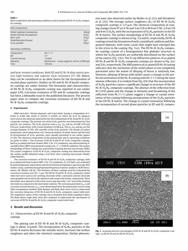
766 K. Krishnaveni et al. / Journal of Alloys an
Table 1Bath composition and operating conditions used to prepare ED Ni–B–Si3N4 compos-ite coatings.
Bath composition
Nickel sulphate hexahydrate 240 g/lNickel chloride hexahydrate 45 g/lBoric acid 30 g/lDimethylamine borane 3 g/lSi3N4 powder 50 g/l
Operating conditions
Temperature 45 ± 1 ◦CpH 3.5CAT
astsiophpN
2
0wcp0apo[abrmTtL
ibsmcmaeecTtTTc
3
3c
iEr
Ni (2 0 0) plane and the change in intensity and broadening of thereflection from Ni (1 1 1) plane suggest a change in crystal orien-tation of the coating following incorporation of the Si3N4 particlesin the ED Ni–B matrix. The change in crystal orientation followingthe incorporation of second phase particles in ED and EL compos-
urrent density 1 A/dm2
gitation Mechanical – using magnetic stirrer at 600 rpmime 120 min
nd heat-treated conditions. Both ED and EL Ni–B alloy matrix pos-ess high hardness and superior wear resistance [17–19]. Hence,hey can be considered as an ideal choice for the incorporation ofecond phase particles. Studies on ED and EL Ni–B based compos-te coatings are rather limited. The formation and characteristicsf ED Ni–B–Si3N4 composite coating was reported in our earlieraper [20]. Corrosion resistance of ED and EL composite coatingsas been a debatable issue in the published literature. The presentaper aims to compare the corrosion resistance of ED Ni–B andi–B–Si3N4 composite coatings.
. Experimental
Mild steel discs (30 mm diameter and 5 mm thick, having a composition of C:.16%; Si: 0.18%; Mn: 0.62%; P: 0.012%; S: 0.016%; Cr: 0.01%; Ni: 0.1%; Fe: balance)ere used as the substrate material for the electrodeposition of Ni–B and Ni–B–Si3N4
omposite coatings. The particle size of the Si3N4 particles was determined by Cilasarticle size analyzer. The Si3N4 particles have a d10, d50 and d80 of 0.08, 0.39 and.92 �m, respectively, with a mean diameter of 0.80 �m. The d10, d50 and d80 are theverage diameter of 10%, 50% and 80% of the Si3N4 particles. The details of surfacereparation, electrodeposition cell, chemical analysis of nickel, boron and the levelf incorporation of Si3N4 particles, were already presented in our earlier papers17,20]. The chemical composition of the plating bath and its operating conditionsre given in Table 1. The structure of ED Ni–B and Ni–B–Si3N4 composite coatings,oth in as-plated and heat treated (400 ◦C for 1 h) conditions, was determined by X-ay diffraction (XRD) measurements using Cu K� (� = 1.5418 Å) radiation. The surfaceorphology of these coating was assessed by scanning electron microscopy (SEM).
he surface roughness of ED Ni–B–Si3N4 composite coating was determined fromhe surface profile obtained using a Carl Zeiss laser scanning microscope (Model,SM5 PASCAL).
The corrosion resistance of ED Ni–B and Ni–B–Si3N4 composite coatings, bothn as-plated and heat treated (400 ◦C for 1 h) conditions, in 3.5% NaCl, was evaluatedy potentiodynamic polarization and electrochemical impedance spectroscopy (EIS)tudies using a potentiostat/galvanostat/frequency response analyzer (ACM Instru-ents, UK; Model: Gill AC). The thickness of these coatings used for evaluating the
orrosion resistance was 20 ± 1 �m. The ED Ni–B and Ni–B–Si3N4 composite coatedild steel were used as the working electrode while a saturated calomel electrode
nd a graphite rod served as the reference and counter electrodes, respectively. Theselectrodes were placed in a flat cell in such a way that only 1 cm2 area of the workinglectrode was exposed to the electrolyte solution. The corrosion potential (Ecorr) andorrosion current density (icorr) were determined from the polarization curves usingafel extrapolation method. Both Nyquist and Bode plots were used to understandhe corrosion behaviour of ED Ni–B and Ni–B–Si3N4 composite coated mild steel.he impedance values of the coatings were calculated from Bode impedance plots.he Bode phase angle plots were also analyzed to understand the mechanism oforrosion of ED Ni–B and Ni–B–Si3N4 composite coated mild steel.
. Results and discussion
.1. Characteristics of ED Ni–B and Ni–B–Si3N4 compositeoatings
The plating rate of ED Ni–B and Ni–B–Si3N4 composite coat-ngs is about 12 �m/h. The incorporation of Si3N4 particles in theD Ni–B matrix decreases the metallic lustre, increases the surfaceoughness and alters the chemical composition. Similar phenom-
d Compounds 480 (2009) 765–770
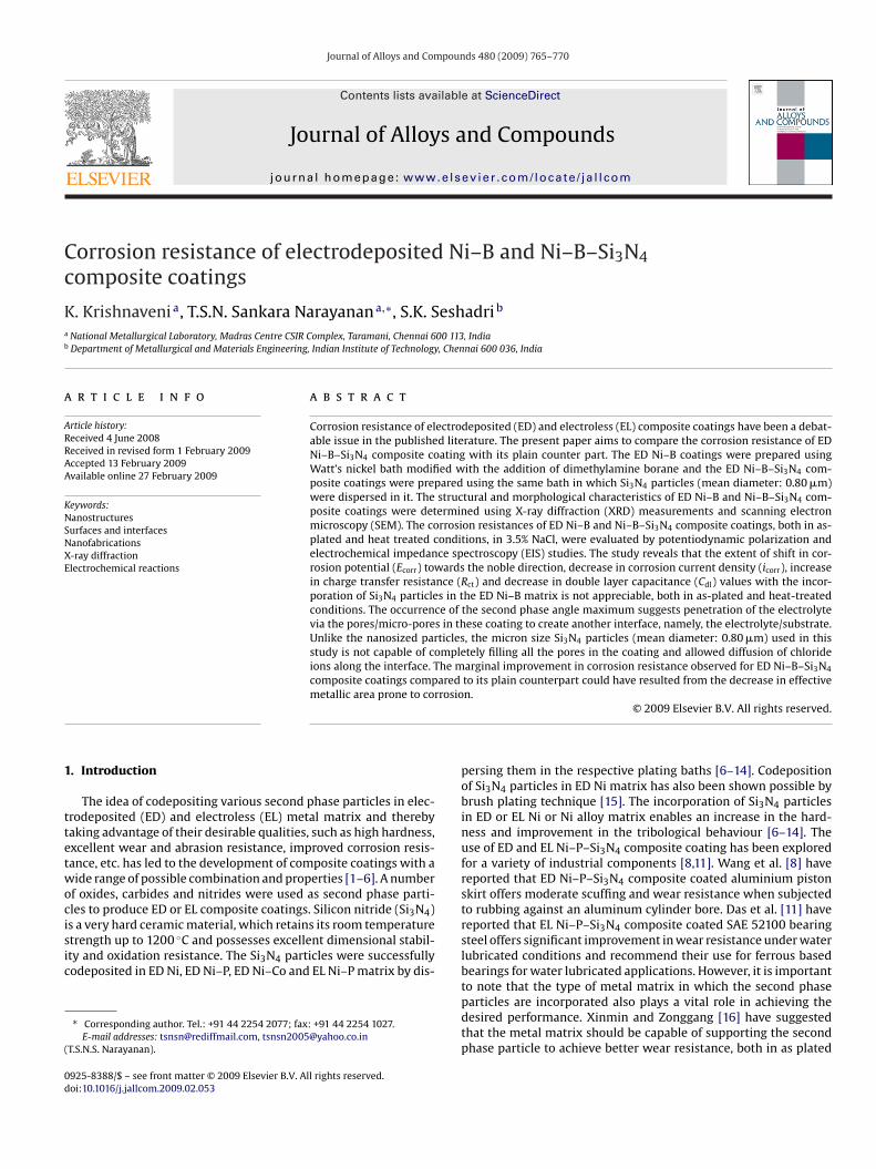
ena were also observed earlier by Muller et al. [21] and Novakovicet al. [22]. The average surface roughness (Ra) of ED Ni–B–Si3N4composite coatings is 1.17 �m. The chemical composition of coat-ing changes from 97 wt.% Ni and 3 wt.% B to 89.6 wt.% Ni; 2.4 wt.% Band 8 wt.% Si3N4 with the incorporation of Si3N4 particles in the EDNi–B matrix. The surface morphology of ED Ni–B and Ni–B–Si3N4composite coatings is shown in Fig. 1(a and b), respectively. ED Ni–Bcoatings reveal the formation of well-crystallized, uniform and fine-grained deposits, with some cracks that might have emerged dueto the stress in the coating (Fig. 1(a)). The ED Ni–B–Si3N4 compos-ite coatings consist of a homogeneous fine globular structure inwhich the Si3N4 particles are uniformly distributed on the surfaceof the matrix (Fig. 1(b)). The X-ray diffraction patterns of as-platedED Ni–B and Ni–B–Si3N4 composite coatings are shown in Fig. 2(a)and 2(b), respectively. The XRD pattern of as-plated ED Ni–B coatingindicates that the nucleation of the nickel phase in not completelyprevented since the extent of alloying of boron is relatively low.However, alloying of boron with nickel causes a change in the pre-ferred orientation of the Ni–B coating with Ni (1 1 1) being the mostintense reflection. It is evident from Fig. 2(b) that the incorporationof Si3N4 particles causes a significant change in structure of the EDNi–B–Si3N4 composite coatings. The absence of the reflection from
Fig. 1. Scanning electron micrographs of ED Ni–B and Ni–B–Si3N4 composite coat-ings: (a) ED Ni–B and (b) ED Ni–B-Si3N4.
K. Krishnaveni et al. / Journal of Alloys and Compounds 480 (2009) 765–770 767
Fc
iTiaffctrifiotiNa
3c
NhccTaaH4−v
in the Nyquist plot appear to be similar with respect to their shape,they differ considerably in their size. This indicates that same fun-damental processes must be occurring on both the as-plated andheat-treated Ni–B and Ni–B–Si3N4 composite coatings but over adifferent effective area in each case. The formation of a single semi-
Table 2Corrosion resistance of ED Ni–B and ED Ni–B–Si3N4 composite coatings in theiras-plated and heat-treated conditions in 3.5% NaCl evaluated by potentiodynamicpolarization and electrochemical impedance (EIS) studies.
Type of coating Ecorr (mVvs. SCE)
icorr (�A/cm2) Rct (� cm2) Cdl (�F/cm2)
ED Ni–B coatingas-plated
−584 12.31 2100 116
ED Ni–B coatingheat-treated(400 ◦C/1 h)
−680 24.10 1370 160
ED Ni–B–Si3N4
composite coating−560 10.92 2020 98
ig. 2. X-ray diffraction patterns of as-plated ED Ni–B and Ni–B–Si3N4 compositeoatings: (a) ED Ni–B; and (b) ED Ni–B–Si3N4.
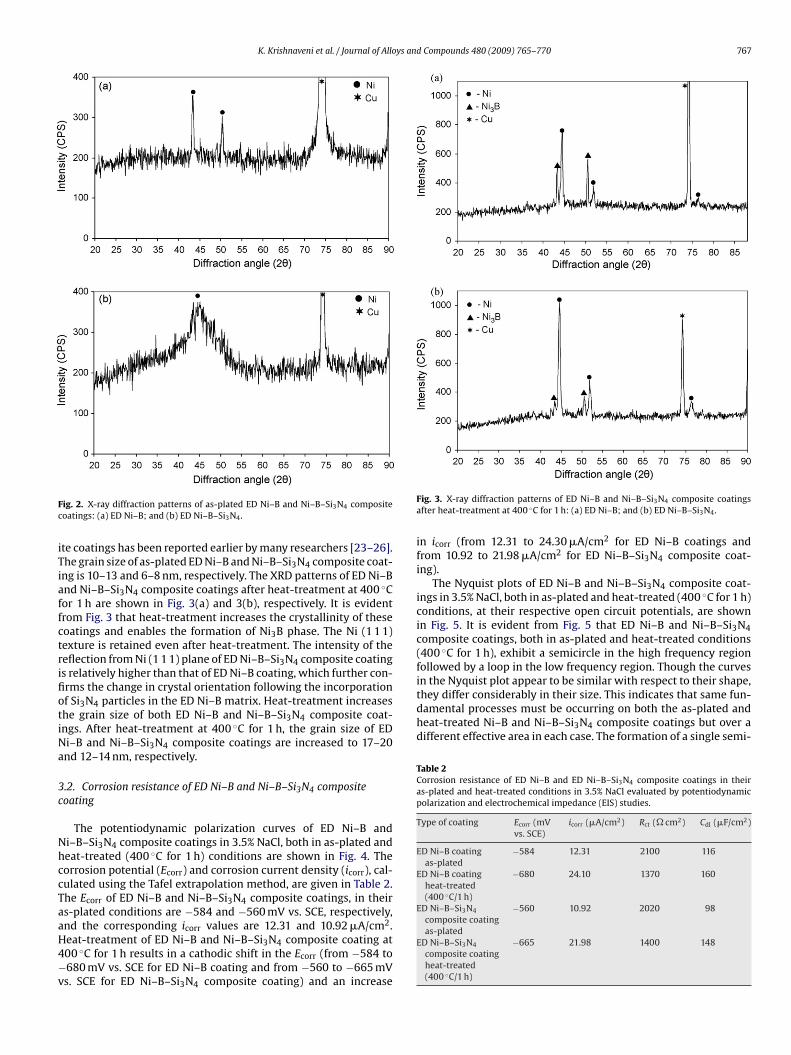
te coatings has been reported earlier by many researchers [23–26].he grain size of as-plated ED Ni–B and Ni–B–Si3N4 composite coat-ng is 10–13 and 6–8 nm, respectively. The XRD patterns of ED Ni–Bnd Ni–B–Si3N4 composite coatings after heat-treatment at 400 ◦Cor 1 h are shown in Fig. 3(a) and 3(b), respectively. It is evidentrom Fig. 3 that heat-treatment increases the crystallinity of theseoatings and enables the formation of Ni3B phase. The Ni (1 1 1)exture is retained even after heat-treatment. The intensity of theeflection from Ni (1 1 1) plane of ED Ni–B–Si3N4 composite coatings relatively higher than that of ED Ni–B coating, which further con-rms the change in crystal orientation following the incorporationf Si3N4 particles in the ED Ni–B matrix. Heat-treatment increaseshe grain size of both ED Ni–B and Ni–B–Si3N4 composite coat-ngs. After heat-treatment at 400 ◦C for 1 h, the grain size of EDi–B and Ni–B–Si3N4 composite coatings are increased to 17–20nd 12–14 nm, respectively.
.2. Corrosion resistance of ED Ni–B and Ni–B–Si3N4 compositeoating
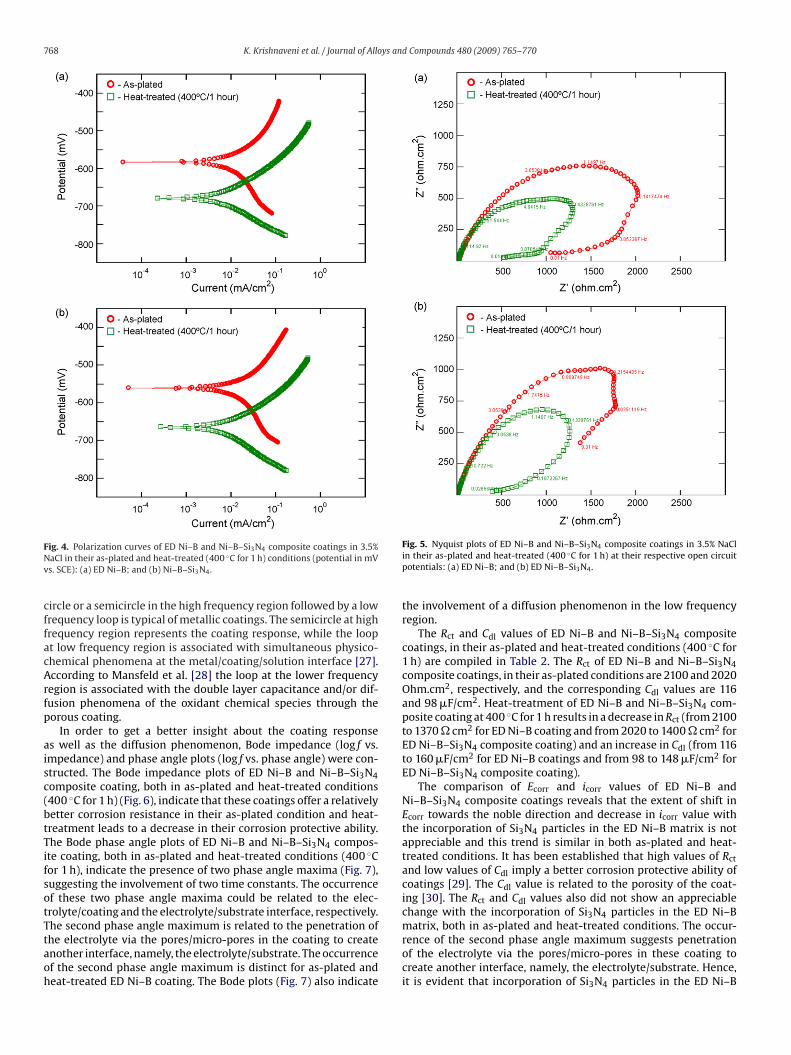
The potentiodynamic polarization curves of ED Ni–B andi–B–Si3N4 composite coatings in 3.5% NaCl, both in as-plated andeat-treated (400 ◦C for 1 h) conditions are shown in Fig. 4. Theorrosion potential (Ecorr) and corrosion current density (icorr), cal-ulated using the Tafel extrapolation method, are given in Table 2.he Ecorr of ED Ni–B and Ni–B–Si3N4 composite coatings, in theirs-plated conditions are −584 and −560 mV vs. SCE, respectively,
2
nd the corresponding icorr values are 12.31 and 10.92 �A/cm .eat-treatment of ED Ni–B and Ni–B–Si3N4 composite coating at00 ◦C for 1 h results in a cathodic shift in the Ecorr (from −584 to680 mV vs. SCE for ED Ni–B coating and from −560 to −665 mVs. SCE for ED Ni–B–Si3N4 composite coating) and an increaseFig. 3. X-ray diffraction patterns of ED Ni–B and Ni–B–Si3N4 composite coatingsafter heat-treatment at 400 ◦C for 1 h: (a) ED Ni–B; and (b) ED Ni–B–Si3N4.
in icorr (from 12.31 to 24.30 �A/cm2 for ED Ni–B coatings andfrom 10.92 to 21.98 �A/cm2 for ED Ni–B–Si3N4 composite coat-ing).
The Nyquist plots of ED Ni–B and Ni–B–Si3N4 composite coat-ings in 3.5% NaCl, both in as-plated and heat-treated (400 ◦C for 1 h)conditions, at their respective open circuit potentials, are shownin Fig. 5. It is evident from Fig. 5 that ED Ni–B and Ni–B–Si3N4composite coatings, both in as-plated and heat-treated conditions(400 ◦C for 1 h), exhibit a semicircle in the high frequency regionfollowed by a loop in the low frequency region. Though the curves
as-platedED Ni–B–Si3N4
composite coatingheat-treated(400 ◦C/1 h)
−665 21.98 1400 148
768 K. Krishnaveni et al. / Journal of Alloys and Compounds 480 (2009) 765–770
FNv
cffacArfp
aisc(btTifsotTtaoh
ig. 4. Polarization curves of ED Ni–B and Ni–B–Si3N4 composite coatings in 3.5%aCl in their as-plated and heat-treated (400 ◦C for 1 h) conditions (potential in mVs. SCE): (a) ED Ni–B; and (b) Ni–B–Si3N4.
ircle or a semicircle in the high frequency region followed by a lowrequency loop is typical of metallic coatings. The semicircle at highrequency region represents the coating response, while the loopt low frequency region is associated with simultaneous physico-hemical phenomena at the metal/coating/solution interface [27].ccording to Mansfeld et al. [28] the loop at the lower frequencyegion is associated with the double layer capacitance and/or dif-usion phenomena of the oxidant chemical species through theorous coating.
In order to get a better insight about the coating responses well as the diffusion phenomenon, Bode impedance (log f vs.mpedance) and phase angle plots (log f vs. phase angle) were con-tructed. The Bode impedance plots of ED Ni–B and Ni–B–Si3N4omposite coating, both in as-plated and heat-treated conditions400 ◦C for 1 h) (Fig. 6), indicate that these coatings offer a relativelyetter corrosion resistance in their as-plated condition and heat-reatment leads to a decrease in their corrosion protective ability.he Bode phase angle plots of ED Ni–B and Ni–B–Si3N4 compos-te coating, both in as-plated and heat-treated conditions (400 ◦Cor 1 h), indicate the presence of two phase angle maxima (Fig. 7),uggesting the involvement of two time constants. The occurrencef these two phase angle maxima could be related to the elec-rolyte/coating and the electrolyte/substrate interface, respectively.he second phase angle maximum is related to the penetration of
he electrolyte via the pores/micro-pores in the coating to createnother interface, namely, the electrolyte/substrate. The occurrencef the second phase angle maximum is distinct for as-plated andeat-treated ED Ni–B coating. The Bode plots (Fig. 7) also indicateFig. 5. Nyquist plots of ED Ni–B and Ni–B–Si3N4 composite coatings in 3.5% NaClin their as-plated and heat-treated (400 ◦C for 1 h) at their respective open circuitpotentials: (a) ED Ni–B; and (b) ED Ni–B–Si3N4.
the involvement of a diffusion phenomenon in the low frequencyregion.
The Rct and Cdl values of ED Ni–B and Ni–B–Si3N4 compositecoatings, in their as-plated and heat-treated conditions (400 ◦C for1 h) are compiled in Table 2. The Rct of ED Ni–B and Ni–B–Si3N4composite coatings, in their as-plated conditions are 2100 and 2020Ohm.cm2, respectively, and the corresponding Cdl values are 116and 98 �F/cm2. Heat-treatment of ED Ni–B and Ni–B–Si3N4 com-posite coating at 400 ◦C for 1 h results in a decrease in Rct (from 2100to 1370 � cm2 for ED Ni–B coating and from 2020 to 1400 � cm2 forED Ni–B–Si3N4 composite coating) and an increase in Cdl (from 116to 160 �F/cm2 for ED Ni–B coatings and from 98 to 148 �F/cm2 forED Ni–B–Si3N4 composite coating).
The comparison of Ecorr and icorr values of ED Ni–B andNi–B–Si3N4 composite coatings reveals that the extent of shift inEcorr towards the noble direction and decrease in icorr value withthe incorporation of Si3N4 particles in the ED Ni–B matrix is notappreciable and this trend is similar in both as-plated and heat-treated conditions. It has been established that high values of Rct
and low values of Cdl imply a better corrosion protective ability ofcoatings [29]. The Cdl value is related to the porosity of the coat-ing [30]. The Rct and Cdl values also did not show an appreciablechange with the incorporation of Si3N4 particles in the ED Ni–Bmatrix, both in as-plated and heat-treated conditions. The occur-
rence of the second phase angle maximum suggests penetrationof the electrolyte via the pores/micro-pores in these coating tocreate another interface, namely, the electrolyte/substrate. Hence,it is evident that incorporation of Si3N4 particles in the ED Ni–B
K. Krishnaveni et al. / Journal of Alloys and Compounds 480 (2009) 765–770 769
FNp
mt
phtscitiitrcErcieciiiar
ap
ig. 6. Bode impedance plots of ED Ni–B and Ni–B–Si3N4 composite coatings in 3.5%aCl in their as-plated and heat-treated (400 ◦C for h) at their respective open circuitotentials: (a) ED Ni–B; and (b) ED Ni–B–Si3N4.
atrix enables only a marginal improvement in corrosion resis-ance.
Several factors, which include, coating thickness, porosity, com-osition of the coating, grain size, structure, surface features andeterogeneity of the coating, could influence the corrosion resis-ance of electro- and electroless plated deposits. In the presenttudy, the coating thickness of both ED Ni–B and Ni–B–Si3N4omposite coatings used for evaluating the corrosion resistances 20 ± 1 �m and they are uniform. Hence, contribution fromhickness and uniformity is expected to be minimal. With thencorporation of Si3N4 particles in the ED Ni–B matrix, the chem-cal composition of coating changes from 97 wt.% Ni and 3 wt.% Bo 89.6 wt.% Ni; 2.4 wt.% B and 8 wt.% Si3N4. XRD measurementseveal that incorporation of Si3N4 particles in the ED Ni–B matrixauses a change in crystal orientation. The grain size of as-platedD Ni–B and Ni–B–Si3N4 composite coatings are 10–13 and 6–8 nm,espectively. Scanning electron micrographs of the ED Ni–B–Si3N4omposite coating reveal uniform distribution of the Si3N4 particlesn the ED Ni–B matrix and the cracks in the coating are consid-rably reduced (Fig. 1). Heat-treatment (400 ◦C for 1 h) inducesrystallinity of the ED Ni–B and ED Ni–B–Si3N4 composite coat-ng, leading to the formation of crystalline Ni and Ni3B phases andncreases their grain size to 17–20 and 12–14 nm, respectively. Thencrease in grain boundaries following heat-treatment becomes thective sites for corrosion attack and causes a decrease in corrosion
esistance.The improvement or impairment of corrosion resistance of EDnd EL composite coatings depends on the chemical stability of thearticle, effective metallic area prone to corrosion, structural state
Fig. 7. Bode phase angle plots of ED Ni–B and Ni–B–Si3N4 composite coatings in3.5% NaCl in their as-plated and heat-treated (400 ◦C for h) at their respective opencircuit potentials: (a) ED Ni–B; and (b) ED Ni–B–Si3N4.
or microstructural feature of the coating, porosity or defect size ofthe coating, ability to prevent diffusion of chloride ions along theinterface between the metal and the particle, the ability of the par-ticle to prevent the corrosive pits from growing up, etc. The Si3N4particles are chemically stable in 3.5% NaCl. The incorporation ofSi3N4 particles in the ED Ni–B matrix would decrease the effectivemetallic area prone to corrosion. The structural and morphologi-cal features (Figs. 1 and 2) indicate a change in microstructure andreduction in defects such as cracks and voids with the incorporationof Si3N4 particles in the ED Ni–B matrix. However, only a marginalimprovement in the corrosion resistance of ED Ni–B–Si3N4 com-posite coatings compared to its plain counterpart is observed inthis study. This could be due to the fact that unlike the nanosizedparticles, the micron size Si3N4 particles (mean diameter: 0.80 �m)used in this study is not capable of completely filling all the poresin the coating and allowed diffusion of chloride ions along theinterface. The occurrence of a loop in the low frequency regionin the Nyquist plot and the second phase angle maximum is theBode phase angle plot confirms penetration of the chloride ionsand creation of the electrolyte-substrate interface in both ED Ni–Band Ni–B–Si3N4 composite coatings. The marginal improvement incorrosion resistance observed for ED Ni–B–Si3N4 composite coat-ings compared to its plain counterpart could have resulted from thedecrease in effective metallic area prone to corrosion.
4. Conclusions
The study aims to compare the corrosion resistance of ED Ni–Band Ni–B–Si3N4 composite coatings, both in as-plated and heat-
7 ys an
tpmf
dat
irb
pc
ic
Epp
A
taDs
R
[
[
[[
[[
[
[26] N.S. Qu, D. Zhu, K.C. Chan, Scripta Mater. 54 (2006) 1421.[27] A. Contreras, C. Leon, O. Jimenez, E. Sosa, R. Perez, Appl. Surf. Sci. 253 (2) (2006)
70 K. Krishnaveni et al. / Journal of Allo
reated (400 ◦C for 1 h) conditions, in 3.5% NaCl. The characteristicroperties, structural and morphological features were also deter-ined to correlate the corrosion behaviour. The study leads to the
ollowing conclusions:The incorporation of Si3N4 particles in the ED Ni–B matrix
ecreases the metallic lustre, increases the surface roughness andlters the chemical composition, causes a change in crystal orien-ation of the matrix and reduces the cracks in the coating.
The extent of shift in Ecorr towards the noble direction, decreasen icorr, increase in Rct and decrease in Cdl values with the incorpo-ation of Si3N4 particles in the ED Ni–B matrix is not appreciable,oth in as-plated and heat-treated conditions.
The occurrence of second phase angle maximum confirms theenetration of the electrolyte via the pores/micro-pores in theseoating.
The micron size Si3N4 particles (mean diameter: 0.80 �m) usedn this study is not capable of completely filling all the pores in theoating and allowed diffusion of chloride ions along the interface.
The marginal improvement in corrosion resistance observed forD Ni–B–Si3N4 composite coatings compared to its plain counter-art could have resulted from the decrease in effective metallic arearone to corrosion.
cknowledgements
Financial support given to this work by the Council of Scien-ific and Industrial Research (CSIR), New Delhi, India was gratefullycknowledged. The authors are thankful to Prof. S.P. Mehrotra,irector, National Metallurgical Laboratory, Jamshedpur for his con-
tant support and encouragement to carry out this research work.
eferences
[1] M. Musiani, Electrochim. Acta 45 (20) (2000) 3397.
[[[
d Compounds 480 (2009) 765–770
[2] R.C. Agarwala, V. Agarwala, Sadhana 28 (3–4) (2003) 474.[3] J.N. Balaraju, T.S.N. Sankara Narayanan, S.K. Seshadri, J. Appl. Electrochem. 33
(2003) 807.[4] C.T.J. Low, R.G.A. Wills, F.C. Walsh, Surf. Coat. Technol. 201 (1–2) (2006) 371.[5] M. Sarret, C. Müller, A. Amell, Surf. Coat. Technol. 201 (2006) 389.[6] J.N. Balaraju, Electroless nickel composite coatings: Preparation and surface
characterization, Ph.D. Thesis, Indian Institute of Technology-Madras, Chennai,2000.
[7] C.S. Ramesh, S.K. Seshadri, Wear 255 (2003) 893.[8] Y. Wang, S.C. Tung, Wear 225–229 (1999) 1100.[9] Y. Xia, S. Sasaki, T. Murakami, M. Nakano, L. Shi, H. Wang, Wear 262 (2007)
765.[10] L. Shi, C.F. Sun, F. Zhou, W.M. Liu, Mater. Sci. Eng. A. 397 (2005) 190.[11] C.M. Das, P.K. Limaye, A.K. Grover, A.K. Suri, J. Alloys Compd. 436 (1–2) (2007)
328.12] J.N. Balaraju, T.S.N. Sankara Narayanan, S.K. Seshadri, Mater. Res. Bull. 41 (4)
(2006) 847.[13] J.N. Balaraju, K.S. Rajam, Int. J. Electrochem. Sci. 2 (2007) 747.[14] J.N. Balaraju, K.S. Rajam, J. Alloys Compd. 459 (1–2) (2008) 311.[15] L. Du, B. Xu, S. Dong, H. Yang, W. Tu, Wear 257 (2004) 1058.[16] H. Xinmin, D. Zonggang, Plat. Surf. Finish. 80 (2) (1993) 62.[17] K. Krishnaveni, T.S.N. Sankara Narayanan, S.K. Seshadri, Mater. Chem. Phys. 99
(2006) 300.[18] T.S.N. Sankara Narayanan, S.K. Seshadri, J. Alloys Compd. 165 (2004) 197.[19] K. Krishnaveni, T.S.N. Sankara Narayanan, S.K. Seshadri, Surf. Coat. Technol. 190
(2005) 115.20] K. Krishnaveni, T.S.N. Sankara Narayanan, S.K. Seshadri, J. Alloys Compd. 466
(1–2) (2008) 412.21] C. Muller, M. Sarret, M. Benballa, Surf. Coat. Technol. 162 (2002) 49.22] J. Novakovic, P. Vassiliou, Kl. Samara, Th. Argyropoulos, Surf. Coat. Technol. 201
(2006) 895.23] B. Bozzini, C. Martini, P.L. Cavallotti, E. Lanzoni, Wear 225–229 (1999) 806.24] A.G. McCormack, M.J. Pomeroy, V.J. Cunnane, J. Electrochem. Soc. 150 (5) (2003)
C356.25] G. Cˆarˆac, L. Benea, C. Iticescu, T. Lampke, S. Steinh¨auser, B. Wielage, Surf. Eng.
20 (5) (2004) 353.
592.28] F. Mansfeld, M. Kending, S. Tsai, Corrosion 38 (1982) 478.29] E.T. van Der Kouwe, Electrochim. Acta 38 (14) (1993) 2093.30] F.B. Growcock, R.J. Jasinski, J. Electrochem. Soc. 136 (8) (1989) 2310.