
Joint bandwidth allocation, element assignment and scheduling for wireless mesh networks with MIMO...
13
Joint bandwidth allocation, element assignment and scheduling for wireless mesh networks with MIMO links Jun Wang a,b,c, * , Peng Du a,b,c , Weijia Jia b,c , Liusheng Huang a,c , Huan Li d a Department of Computer Science, University of Science and Technology of China, 96#, Jinzhai Road, Hefei, Anhui 230026, China b Department of Computer Science, City University of Hong Kong, Hong Kong, China c Joint Research Lab, CityU-USTC Advanced Research Institute, Suzhou, China d Department of Computer Science, Beihang University, Beijing, China Available online 5 February 2008 Abstract With the unique features of spatial multiplexing and interference suppression, Multiple Input Multiple Output (MIMO) techniques have great potential in the improvement of network capacity over conventional antenna technologies. In order to exploit the benefit of simultaneous transmissions provided by MIMO, researchers have proposed a number of cross-layer optimizations and MAC layer designs to increase the throughput of wireless mesh or ad hoc networks, where the number of elements in the antenna arrays are pre- allocated or evenly assigned to the routers. In this paper, we argue that using the same number of elements in each antenna array in all routers is not a necessary condition for the improvement of system performance. This is because the requirement for the number of elements is quite different for each router. Especially at those critical routers that have huge aggregate traffic toward the gateway, more elements are needed not only for the traffic relay but also for the interference suppression. Based on this observation, we define the joint problem of bandwidth allocation, element assignment and scheduling to characterize the throughput benefits of cross-layer optimiza- tions. We propose a Cost-Aware Element Assignment (CAEA) technique to minimize the total number of the antenna elements when still achieving the optimal bandwidth allocation. In addition, to verify the efficiency of the CAEA assignment, a heuristic Traffic-aware Stream-controlled Link Scheduling (TSLS) algorithm is proposed to provide a schedulable bandwidth allocation. We demonstrate through extensive simulations that our solutions (CAEA, TSLS) not only effectively save the total cost on antenna elements but also perform close to optimal on the average. Ó 2008 Elsevier B.V. All rights reserved. Keywords: Wireless mesh networks; MIMO; Bandwidth allocation; Element assignment; Scheduling 1. Introduction Recent years, Wireless Mesh Networks (WMNs) [1] have emerged as a promising technology that provides wireless broadband accessibility and thus, extends the Internet connectivity at the edge and improves the network coverage and economy efficiency. A typical deployment of a multi-hop infrastructure-based WMN consists of three major components: base station (or so called gateway), a set of mesh routers and mesh clients. The base station is presented that is wired to a larger network (e.g., the Inter- net); a set of mesh routers integrate traffic flows for local (one hop) clients and relay communication through wire- less channel in order to transfer data to or from the Inter- net through the gateways; a large number of mesh clients can be any of the mobile devices such as laptops, PDAs and smartphones. Mesh routers are normally stationary and therefore, have less topology change, node failure and energy constraints. However, the use of WMN as a backbone for large wireless access networks imposes high bandwidth requirements. At the same time, the interference 0140-3664/$ - see front matter Ó 2008 Elsevier B.V. All rights reserved. doi:10.1016/j.comcom.2008.01.053 * Corresponding author. Address: Department of Computer Science, University of Science and Technology of China, 96#, Jinzhai Road, Hefei, Anhui 230026, China. Tel.: +86 512 87161297; fax: +86 512 87161381. E-mail addresses: [email protected] (J. Wang), [email protected] du.cn (P. Du), [email protected] (W. Jia), [email protected] (L. Huang), [email protected] (H. Li). www.elsevier.com/locate/comcom Available online at www.sciencedirect.com Computer Communications 31 (2008) 1372–1384
Transcript of Joint bandwidth allocation, element assignment and scheduling for wireless mesh networks with MIMO...
Available online at www.sciencedirect.com
www.elsevier.com/locate/comcom
Computer Communications 31 (2008) 1372–1384
Joint bandwidth allocation, element assignment and schedulingfor wireless mesh networks with MIMO links
Jun Wang a,b,c,*, Peng Du a,b,c, Weijia Jia b,c, Liusheng Huang a,c, Huan Li d
a Department of Computer Science, University of Science and Technology of China, 96#, Jinzhai Road, Hefei, Anhui 230026, Chinab Department of Computer Science, City University of Hong Kong, Hong Kong, China
c Joint Research Lab, CityU-USTC Advanced Research Institute, Suzhou, Chinad Department of Computer Science, Beihang University, Beijing, China
Available online 5 February 2008
Abstract
With the unique features of spatial multiplexing and interference suppression, Multiple Input Multiple Output (MIMO) techniqueshave great potential in the improvement of network capacity over conventional antenna technologies. In order to exploit the benefit ofsimultaneous transmissions provided by MIMO, researchers have proposed a number of cross-layer optimizations and MAC layerdesigns to increase the throughput of wireless mesh or ad hoc networks, where the number of elements in the antenna arrays are pre-allocated or evenly assigned to the routers. In this paper, we argue that using the same number of elements in each antenna array inall routers is not a necessary condition for the improvement of system performance. This is because the requirement for the numberof elements is quite different for each router. Especially at those critical routers that have huge aggregate traffic toward the gateway, moreelements are needed not only for the traffic relay but also for the interference suppression. Based on this observation, we define the jointproblem of bandwidth allocation, element assignment and scheduling to characterize the throughput benefits of cross-layer optimiza-tions. We propose a Cost-Aware Element Assignment (CAEA) technique to minimize the total number of the antenna elements whenstill achieving the optimal bandwidth allocation. In addition, to verify the efficiency of the CAEA assignment, a heuristic Traffic-awareStream-controlled Link Scheduling (TSLS) algorithm is proposed to provide a schedulable bandwidth allocation. We demonstratethrough extensive simulations that our solutions (CAEA, TSLS) not only effectively save the total cost on antenna elements but alsoperform close to optimal on the average.� 2008 Elsevier B.V. All rights reserved.
Keywords: Wireless mesh networks; MIMO; Bandwidth allocation; Element assignment; Scheduling
1. Introduction
Recent years, Wireless Mesh Networks (WMNs) [1]have emerged as a promising technology that provideswireless broadband accessibility and thus, extends theInternet connectivity at the edge and improves the networkcoverage and economy efficiency. A typical deployment of
0140-3664/$ - see front matter � 2008 Elsevier B.V. All rights reserved.
doi:10.1016/j.comcom.2008.01.053
* Corresponding author. Address: Department of Computer Science,University of Science and Technology of China, 96#, Jinzhai Road, Hefei,Anhui 230026, China. Tel.: +86 512 87161297; fax: +86 512 87161381.
E-mail addresses: [email protected] (J. Wang), [email protected] (P. Du), [email protected] (W. Jia), [email protected] (L.Huang), [email protected] (H. Li).
a multi-hop infrastructure-based WMN consists of threemajor components: base station (or so called gateway), aset of mesh routers and mesh clients. The base station ispresented that is wired to a larger network (e.g., the Inter-net); a set of mesh routers integrate traffic flows for local(one hop) clients and relay communication through wire-less channel in order to transfer data to or from the Inter-net through the gateways; a large number of mesh clientscan be any of the mobile devices such as laptops, PDAsand smartphones. Mesh routers are normally stationaryand therefore, have less topology change, node failureand energy constraints. However, the use of WMN as abackbone for large wireless access networks imposes highbandwidth requirements. At the same time, the interference
J. Wang et al. / Computer Communications 31 (2008) 1372–1384 1373
among simultaneous transmissions may dramatically causecapacity reduction [2]. The ability of using Multiple InputMultiple Output (MIMO) antenna technology in the wire-less transmission is one of the major techniques to alleviatethe problem, and thus improve throughput substantially[3,4].
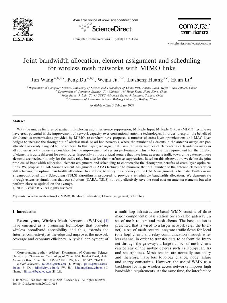
In a typical MIMO transmission system as shown inFig. 1, the transmitter and the receiver are equipped withmultiple antenna elements. The data are first encodedand mapped to complex modulation symbols (such asQPSK, M-QAM) which produce several separate symbolstreams. Each stream is then mapped onto one of the multi-ple transmitting antenna elements. After upward frequencyconversion, filtering and amplification, the signals arelaunched into the wireless channel. At the receiver, the sig-nals are captured by multiple receiving antenna elementsand demodulation and demapping operations are per-formed to recover the data. The presence of multiple ele-ments at both ends of a link creates multiple independentsimultaneous transmissions, and thus achieve higherthroughput over conventional communication systems.The MIMO links have the following characteristics:
1. Spatial multiplexing: Multiple independent data streamscan be transmitted simultaneously to one or more receiv-ers to provide extremely high spectral efficiencies(increase in capacity) at the cost of no extra bandwidthor power [5].
2. Interference suppression: MIMO link can suppress inter-ference from neighboring links as long as the total num-ber of useful streams and interfering streams are nogreater than that of receiving antenna elements [6].
3. Half-duplex: The antenna array cannot be in the modeof transmission and reception at the same time, althoughit can communicate in multiple streams with more thanone node.
4. Diversity: Dependent streams can be transmitted onmultiple elements to achieve transmitting diversity gain[7]. This diversity gain can provide us with range exten-sion (a larger transmission range) or power minimiza-tion, or better link reliability as desired.
Due to above properties, the MIMO technology has agreat potential to improve the throughput in traffic-inten-sive wireless networks. Recent years, advances in MIMOlinks have become extremely popular and made their wayinto the WLAN (IEEE 802.11n), WIMAX (802.16) and
Space-time coding
Modulation
Mapping
Demapping
Demodulation
Decoding
1
2
M
1
2
N
data data
Fig. 1. MIMO wireless transmission system.
3G networks. Several vendors such as Sohoware are alsowell motivated to offer MIMO equipments for commercialuse in daily life.
In order to fully exploit this new technology,researchers have done great work on the throughputoptimization problems from routing, scheduling andMAC protocol design aspects. However, most of thempre-assume each router has been equipped with equalnumber of elements that is called k-element architecture.In this paper, we argue that evenly assigning the ele-ments to every node may not be necessary or effectiveto satisfy the whole network traffic on demand. Thisis because not only the peer-to-peer wireless interference,but also the element assignment on each node will influ-ence the WMN capacity [2,3]. If we want to achieve theperformance in both throughput and fairness, mean-while minimize the total number of elements, the prob-lem becomes much harder and thus novel techniques arerequired.
In this paper, we study the problems and relationshipsbetween bandwidth allocation, element assignment andscheduling with the objective of optimizing the throughputand fairness and meanwhile minimizing the total cost onthe antenna elements in WMNs with MIMO links. Here,element assignment means specifying a certain number ofelements for each node. The major contributions of thispaper are as follows.
� We analyze and formulate all kinds of system con-straints on the traffic flows and element assignment forWMNs/MIMO. We well define the bandwidth alloca-tion, element assignment and scheduling problems aswell as the in-deep relationships among them.� We show that the problems of bandwidth allocation, ele-
ment assignment and scheduling can be analyzed andprocessed in an interactive way. In addition to the opti-mal solutions (by formulating the linear programmingproblem), we propose novel efficient heuristics toaddress those problems. We demonstrate through exten-sive experiments the proposed heuristics can achieve aperformance close to optimal solutions.� To the best of our knowledge, this paper for the first
time investigates the element assignment problemtogether with the bandwidth allocation problem forWMNs with MIMO links.
The rest of the paper is organized as follows. We statethe system model in Section 2. We present detailed problemdefinitions in Section 3. We describe our optimal solutionsfor bandwidth allocation in Section 4 and element assign-ment in Section 5. To verify and further guarantee the fea-sibility of our solutions, we provide a heuristic schedulingalgorithm in Section 6. The implementation issues of theproposed solutions are discussed in Section 7. Section 8shows the simulation results. We present related work inSection 9. Finally, we draw our conclusions and discussfuture work in Section 10.

a b
c
d
e
fGateway nodeNon-gateway nodeIndependent streamInterfereneceAntenna element
1
23
1 2 3
12
3
Fig. 2. A topology example with three antenna elements in each node.
1374 J. Wang et al. / Computer Communications 31 (2008) 1372–1384
2. System model
In this section, we present background information andassumptions on MIMO-based network architecture andthe system model we will use for the rest of the paper.
2.1. Network architecture
The system is considered as a multi-hop InfrastructureWireless Mesh Network (IWMN) that consists of severalfixed wireless mesh routers. The routers provide networkconnectivity to end-user mobile clients within their cover-age area. The wireless mesh routers themselves form amulti-hop wireless backbone for relaying the traffic toand from the clients. One router together with all its clientsis considered as one node in this paper. Some of the wire-less mesh routers are designated as gateways that providefunctionality to enable direct connection to a large networksuch as the Internet. We model the backbone of thisIWMN as a directed graph G ¼ ðV ;EÞ; where V representsthe set of nodes in the network and E represents the set ofdirected links (transmissions). The set of gateway nodes isrepresented as V 1 and we denote the non-gateway nodesby the set V 2ðV ¼ V 1 [ V 2Þ.
We suppose all the traffic within the mesh is either fromthe user devices to the outer network or vice versa. Here,we abstract the outer network as a super node (sink orsource) which connects all the gateways of the WMN.Because the traffic is relayed to or from the super node,the paths taken by the traffic flows are likely to form a treestructure in which the super node is the ‘‘root” and the userdevices are the ‘‘leaves”. Here, we can simply use theBreadth-First Search (BFS) to construct a Minimum Span-ning Tree (MST) T for the new graph G0 with the supernode. Then we remove the super node from the resultingMST T. At the end of this process, we will obtain severalnon-intersect routing trees, in which different gatewaysare different roots.
For each node except the gateways, the traffic can beseparated as uplink and downlink flows. For ease of expo-sition, in this paper, we will address the problems for alluplink flows, and this can be extended to bidirectional linkeasily if we consider the uplink and downlink separately.And this technique has been applied to the MAC layerdesign of 802.16 protocols.
In the rest of the paper, if a transmission is from node u
to node v, then v is called the parent node of u, denoted asPARðuÞ; and the children set of node u is represented asCHIðuÞ. Also, we denote T ðuÞ as the sub tree of T with rootof node u.
2.2. Wireless transmission and interference model
To accomplish a transmission, the receiver has to bewithin the transmission range of the sender, using a com-mon channel assigned to their antenna elements. Two pairsof nodes using the same channel may interfere with each
other if they stand within the interference range of oneanother. In this paper, we assume all transmission ranges(denoted as RT) are same and the interference range isgreater than transmission range. Suppose all interferenceranges are same and denoted as RI, we say node v is nodeu’s ‘‘neighbor” if node v is in the interference range of nodeu. The set of neighbors of node u is defined as NEIðuÞ.
2.3. Abstraction of MIMO links
We use the following abstraction and assumptions forthe physical layer in our work. Each node u (u 2 V ) beingcapable of forming MIMO links with its neighbors mayhave multiple antenna elements, denoted as IðuÞ(1 6 IðuÞ 6 k). Here, k is the maximum possible numberof elements for each node. A node with IðuÞ antenna ele-ments is also referred to as a node with IðuÞ Degree of Free-
doms (DOFs). In a MIMO link, a transmitter u can use upall its available DOFs to send at most IðuÞ independentstreams to one or more receivers simultaneously. This con-straint is called Transmission DOF Constraint. At the recei-ver end, a receiver v can isolate and decode all the incomingstreams successfully as long as the total number of receiv-ing streams (n) including the interference is less than orequal to its DOFs (n 6 IðvÞ). On the other hand, if the totalreceiving streams overwhelm the DOFs at the receiver(n > IðvÞ), it will not be possible to decode any of thedesired signal streams. This is called Reception DOF Con-
straint. Here, we do not consider partial interference sup-pression [8] whereby fewer degree of freedoms are neededif the interference is low. This is because in the 802.11 set-tings, partial suppression does not perform well [9].
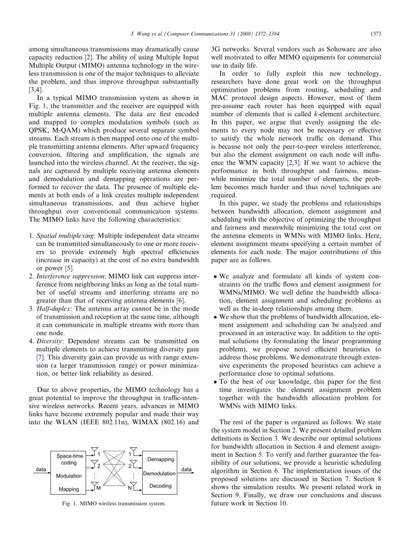
Since not all streams have the same capacity [10], we putthe streams from the same node in a non-increasing order,for instance, stream1 P stream2 P � � �P streamk. Wedenote by Cðu; iÞ the capacity for link u! PARðuÞ, trans-mitting on stream i. Take the network in Fig. 2 for exam-ple, we assume the capacity set C ¼ fCðu; 1Þ ¼1; Cðu; 2Þ ¼ 0:8; Cðu; 3Þ ¼ 0:6ju 2 fa; c; egg and the elementassignment is fIðuÞ ¼ 3; u 2 fa; b; c;d; e; f gg. Since the linksinterfere with each other, the total number of streamstransmitted simultaneously cannot be greater than three.If the links are scheduled in a TDMA fashion (i.e., nodesa, c and e transmit in turn), then the total throughput is
J. Wang et al. / Computer Communications 31 (2008) 1372–1384 1375
2.4. However, if the best stream is selected for transmissionfrom each link (MIMO), then the total throughput is 3.Here, how to select streams for transmission is also calledStream Control [11].
3. Constraints and problem definitions
In this section, we first study the details of transmissionfrom the aspect of link scheduling. Then we abstract theconstraints on the traffic flows that characterize MIMOlinks. Based on these constraints, we formalize the problemdefinitions with the goal of cross-layer optimization on thebandwidth allocation and element assignment.
3.1. Constraints
In order to address the relationship between traffic flowand link scheduling, we assume all nodes are synchronizedand will transmit packets in time slots according to a cen-tralized scheduling. We introduce two indicators X u;i;s andY u;i;s. Let X u;i;s be 1 if node u transmits in time slot s onstream i, otherwise 0; in the same way, let Y u;i;s be 1 if nodeu receives packets in time slot s on stream i, otherwise 0.
We use f ðuÞ to denote the outgoing traffic rate for nodeu, and f ðu; iÞ the traffic rate on stream i, so for node u, the
utilization ratio for stream i is f ðu;iÞCðu;iÞ. We can also compute
the utilization ratio from a microscopic view. In a scheduleof S time slots, the stream i can be used for transmission intotal of
P16s6SX u;i;s time slots, then the utilization ratio isP
16s6SX u;i;s
S . Hence, the relationship between link scheduling
and traffic flow is represented as:P16s6SX u;i;s
S¼ f ðu; iÞ
Cðu; iÞ ð1Þ
Since MIMO link is half-duplex, a node cannot transmitand receive packets at the same time. For the ease of expla-nation, we assume that each node receives and transmitsalternatively. That is, if node u transmits packets at timeslot s, then it should be in the mode of reception at timeslot sþ 1; meanwhile, nodes in set PARðuÞ [ CHIðuÞ receiveat time slot s and then are allowed to transmit at time slotsþ 1. This assumption is reasonable since most nodes inWMN are routers to relay the traffic and the transmissionand reception time are almost equal in the long term. Tothis end, at one time slot, a node is receiving or transmit-ting can be pre-determined by the number of hops fromits gateway. Here, we define the number of hops from nodeu to its gateway node as hopðuÞ.
As we mentioned before, for each node u, differentstreams have different capacities and we assume the capac-ity for stream i ð1 6 i 6 kÞ is Cðu; iÞ with a non-increasingorder. That is Cðu; iÞP Cðu; iþ 1Þ, and we assumeCðu; iÞ ¼ 0 if IðuÞ < i 6 k.
Due to the half-duplex constraint, for a node u, at mosthalf of the total time slots can be used for transmission,
that isP
16s6SX u;i;s 6S2. After introducing this constraint
to traffic flow according to Eq. (1), we obtain the Stream
Capacity Constraint:
f ðu; iÞ 6 1
2Cðu; iÞ; 8u 2 V 2; 1 6 i 6 k ð2Þ
Now let us consider the DOF constraints. First, we definethe set of interfering nodes as INT ðuÞ, when node u isreceiving packets. Any node v in INT ðuÞ must satisfy twoconditions: (1) node v is in the interference range of nodeu, that is, v 2 NEIðuÞ; (2) when node u is in reception, nodev is in the transmission mode: ðhopðvÞ � hopðuÞÞmod2 ¼ 1.So we have:
INT ðuÞ ¼ fvjv 2 NEIðuÞ; ðhopðvÞ � hopðuÞÞmod2 ¼ 1g ð3Þ
When arranged to transmit packets at time slot s, a node ucan send at most IðuÞ independent streams simultaneouslyðP
16i6kX u;i;s 6 IðuÞ); and at the same time it cannot receive
any packets:P
16i6kY u;i;s ¼P
v2CHIðuÞP
16i6kX v;i;s ¼ 0.
According to our definition of INT ðuÞ, the nodes inINT ðuÞ are in reception when node u is transmitting. Sothere is no stream sent from these nodes. We have:P
v2INT ðuÞP
16i6kX v;i;s ¼ 0. If we denote the set of time slots
as ST (jST j ¼ 12S) in which node u is allowed to transmit,
we have:
Ps2ST
Pv2CHIðuÞ[INT ðuÞ
P16i6k
X v;i;s
!¼ 0
Ps2ST
P16i6k
X u;i;s 612S � IðuÞ
8>>><>>>:
ð4Þ
Similarly, when a node u is receiving, the total number ofincoming streams from its children and interference nodesshould not be greater than IðuÞ ð
Pv2CHIðuÞ[INT ðuÞP
16i6kX v;i;s 6 IðuÞÞ, and node u cannot transmit at thesame time (X u;i;s ¼ 0Þ. If we denote SR (jSRj ¼ 1
2S) as the
set of time slots in which node u is in the mode of reception,we have:
Ps2SR
Pv2CHIðuÞ[INT ðuÞ
P16i6k
X v;i;s
!6
12S � IðuÞ
Ps2SR
P16i6k
X u;i;s ¼ 0
8>>><>>>:
ð5Þ
From Eqs. (4) and (5), in a schedule of S time slots, the to-tal number of streams from node u should not be greaterthan 1
2S � IðuÞ, that is:X
16s6S
X16i6k
X u;i;s ¼Xs2ST
X16i6k
X u;i;s þXs2SR
X16i6k
X u;i;s
61
2S � IðuÞ ð6Þ
Now, according to Eq. (1), we can deduce the TransmissionDOF Constraint on the traffic flow:X16i6k
f ðu; iÞCðu; iÞ 6
1
2IðuÞ; 8u 2 V 2 ð7Þ
1376 J. Wang et al. / Computer Communications 31 (2008) 1372–1384
Also from Eqs. (4) and (5), in total S time slots, the numberof streams from nodes in set CHIðuÞ [ INT ðuÞ should notbe greater than 1
2S � IðuÞ:
X16s6s
Xv2CHIðuÞ[INT ðuÞ
X16i6k
X v;i;s
!6
1
2S � IðuÞ ð8Þ
Change Eq. (8) to constraint on traffic flow, we have theReception DOF Constraint:
Xv2CHIðuÞ[INT ðuÞ
X16i6k
f ðv; iÞCðv; iÞ 6
1
2IðuÞ; 8u 2 V ð9Þ
For each non-gateway node u, the total incoming trafficplus the traffic from the clients of this node must equal tothe total outgoing traffic. We denote gðuÞ as the total allo-cated bandwidth to the clients of node u. Then we haveFlow Balance Constraint:X16i6k
Xv2CHIðuÞ
f ðv; iÞ þ gðuÞ ¼X
16i6k
f ðu; iÞ; 8u 2 V 2 ð10Þ
Here, the system throughput is:P
u2V 2gðuÞ.
Table 1 summarizes all constraints on the traffic flow wediscussed before. In the rest of the paper, we will use theindex number of those constraints instead of naming thedetailed constraints.
Table 2Notations
Notations Meanings
V Set of nodes in the WMNV1 Set of gateway nodes in the WMNV2 Set of non-gateway nodes in the WMNPAR(u) Parent of node u
CHI(u) Children of node u
NEI(u) Neighbors of node u
T(u) Sub tree with the root of node u
3.2. Problem definitions
In this section, we will consider three closely correlatedproblems: bandwidth allocation, element assignment andscheduling:
1. Bandwidth allocation: If given an element assignmentfIðuÞ; u 2 V g, how to allocate the bandwidth can maxi-mize the total throughput meanwhile achieving fairnessfor each node?
2. Element assignment: If given a bandwidth allocation foreach node, what is minimum requirement for the totalnumber of antenna elements, in another word, how tospecify the number of elements in each node can savethe cost most and satisfy the bandwidth allocation?
3. Scheduling: Given a bandwidth allocation and an ele-ment assignment for each node, how to obtain a feasibleschedule for the allocated bandwidth?
Based on the abstraction on the constraints (1–4), thesethree kinds of problems can be formally defined as follows.
Table 1Constraints definitions
Index Description Formulation
Constraint (1) Stream Capacity Constraint Eq. (2)Constraint (2) Transmission DOF Constraint Eq. (7)Constraint (3) Reception DOF Constraint Eq. (9)Constraint (4) Flow Balance Constraint Eq. (10)
Problem Definition 1. Feasible Bandwidth Allocation Prob-
lem (FBAP): For each node u, given an EA (ElementAssignment) fIðuÞ; u 2 V g, if the allocated bandwidthfgðuÞ; u 2 V 2g can satisfy Constraints (1), (2), (3) and (4),then we can achieve feasible traffic flows for each node; thebandwidth allocation problem is called FBAP; the band-width allocation we obtained fgðuÞ; u 2 V 2g is called aFBA. We define the guaranteed bandwidth of this FBA asGuarBW(FBA), which is:
GuarBW ðFBAÞ ¼ minfgðuÞ; u 2 V 2g ð11Þ
Problem Definition 2. Feasible Element Assignment Problem
(FEAP): For each non-gateway node u, given a FBA
fgðuÞ; u 2 V 2g, we should decide the element number IðuÞfor each node so that we can achieve a feasible traffic flowsthat satisfy Constraints (1), (2), (3) and (4). This problem iscalled FEAP. The element assignment we obtainedfIðuÞ; u 2 V g is called a FEA. If we define the cost of thisFEA as costðFEAÞ, then we have:
costðFEAÞ ¼Xu2V
IðuÞ ð12Þ
Problem Definition 3. Schedulable Bandwidth Allocation
Problem (SBAP): For each node u, if given the elementnumber IðuÞ and the allocated bandwidth gðuÞ, the prob-lem of how to schedule the bandwidth requests in each timeslots is called SBAP. Assume there are M time slots per sec-ond. If bandwidth allocation fgðuÞ; u 2 V 2g can be sched-uled in a period of S time slots, then we can obtain aSchedulable Bandwidth Allocation (SBA) fgðuÞ0 ¼ kgðuÞ;u 2 V 2g, in which k ¼ M
S :
Problem Definition 4. Maximum Guaranteed Feasible Band-
width Allocation Problem (MGFBAP): A bandwidth alloca-tion fgðuÞ; u 2 V 2g is a MGFBA if and only if it satisfiestwo conditions: (1) fgðuÞ; u 2 V 2g is a FBA; (2)minfgðuÞ; u 2 V 2g ¼ maxfGuarBW ðFBAÞ; 8FBAg:
INT(u) Set of nodes whose transmission will interfere node u’sreception
req(u) Bandwidth request from node u’s end clientsg(u) Bandwidth allocation to node u’s end clientsf(u) Total traffic out from node u to its parentf(u,i) Traffic out from node u to its parent on stream i
I(u) Number of elements assigned for node u
k Maximum number of elements for node u
c(u,i) Capacity on stream i from node u
J. Wang et al. / Computer Communications 31 (2008) 1372–1384 1377
Problem Definition 5. Minimum Cost Feasible Element Assign-
ment Problem (MCFEAP): An element assignmentfIðuÞ; u 2 V g is a MCFEA if and only if it satisfies (1) fIðuÞ;u 2 V g is a FEA; (2)
Pu2V IðuÞ ¼ minfcostðFEAÞ; 8FEAg:
The notations used in this paper are listed in Table 2.
4. Bandwidth allocation
In this section, we will solve the problem of bandwidthallocation in WMNs with MIMO links. We consider twofairness modes: max–min fairness and proportional fair-ness. The former tries to provide maximum bandwidthguarantees for all users in the WMNs, which is very impor-tant for those real-time multimedia applications [12]; whilethe latter achieves proportional bandwidth allocation withrespect to the user’s requests. The benefit for proportionalfairness model can be found in [13], for which we will notdiscuss any more. In the following subsections, we first for-mulate the bandwidth allocation problem into two LinearProgramming (LP) problems [14] under the two fairnessmodes, respectively. Then we can find the optimal solutionby solving the LP formulas. How to solve the LP problemshave been thoroughly studied in the literature. The compu-tational complexity of such problems is shown to be poly-nomial [15]. In addition, we provide a heuristic solution forthe bandwidth allocation in Section 6 with a time complex-ity of Oðn4Þ (n is number of nodes in WMN).
4.1. Max–min fair allocation
In this fairness mode, we try to find a MGFBA asdefined in Section 3 where Constraints (1), (2), (3) and(4) should be satisfied with a maximum guaranteed band-width for each node. The related LP formulation isdepicted in LP1. Given an element assignmentfIðuÞj1 6 IðuÞ 6 k; u 2 V g, LP1 provides a tight upperbound of the guaranteed bandwidth.
LP1 for MGFBA problem :
Max a
Subject to :
gðuÞP a; 8u 2 V 2
f ðu; iÞ 6 1
2Cðu; iÞ; 8u 2 V 2; 1 6 i 6 k
X16i6k
f ðu; iÞCðu; iÞ 6
1
2IðuÞ; 8u 2 V 2
Xv2CHIðuÞ[INT ðuÞ
X16i6k
f ðv; iÞCðv; iÞ 6
1
2IðuÞ; 8u 2 V
Xv2CHIðuÞ
X16i6k
f ðv; iÞ þ gðuÞ ¼X
16i6k
f ðu; iÞ; 8u 2 V 2
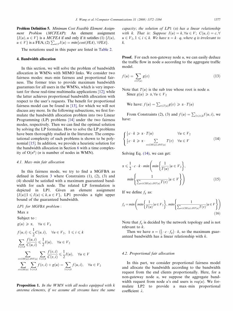
Proposition 1. In the WMN with all nodes equipped with kantenna elements, if we assume all streams have the same
capacity; the solution of LP1 (a) has a linear relationship
with k. That is: Suppose IðuÞ ¼ k; 8u 2 V ; Cðu; iÞ ¼ c; 8u 2 V 2; 1 6 i 6 k. We have a ¼ k � q, where q is irrelevant to
k.
Proof. For each non-gateway node u, we can easily deducethe traffic flow in node u according to the aggregate trafficmodel.
f ðuÞ ¼X
v2T ðuÞgðvÞ ð13Þ
Note that T ðuÞ is the sub tree whose root is node u.Since gðuÞP a; 8u 2 V 2
We have: f ðuÞ ¼P
v2T ðuÞgðvÞP a � T ðuÞ
From Constraints (2), (3) and f ðuÞ ¼P
16i6kf ðu; iÞ, wehave:
12c � k P a � T ðuÞ 8u 2 V 2
12c � k P a �
Pv2CHIðuÞ[INT ðuÞ
T ðvÞ 8u 2 V
8<: ð14Þ
Solving Eq. (14), we can get:
a 61
2� c � k �min
min
1
T ðuÞ ju 2 V 2
� �;
min1P
v2CHIðuÞ[INT ðuÞT ðvÞju 2 V
( )!ð15Þ
If we define fg as:
fg ¼min min1
T ðuÞ ju2 V 2
� �; min
1Pv2CHIðuÞ[INT ðuÞT ðvÞ
ju2 V
( ) !
ð16Þ
Note that fg is decided by the network topology and is notrelevant to k.
Then we have a ¼ 12 � c � fg� �
� k, so the maximum guar-anteed bandwidth has a linear relationship with k.
4.2. Proportional fair allocation
In this part, we consider proportional fairness modeland allocate the bandwidth according to the bandwidthrequest from the end clients proportionally. Here, for anon-gateway node u, we suppose the aggregate band-width request from node u’s end users is reqðuÞ. We for-mulate LP2 to provide a max–min proportionalcoefficient k.
1378 J. Wang et al. / Computer Communications 31 (2008) 1372–1384
LP2 for maximum proportional fair bandwidth allocation :
Max k
Subject to :
gðuÞP k � reqðuÞ; 8u 2 V 2
f ðu; iÞ 6 1
2Cðu; iÞ; 8u 2 V 2; 1 6 i 6 k
X16i6k
f ðu; iÞCðu; iÞ 6
1
2IðuÞ; 8u 2 V 2
Xv2CHIðuÞ[INT ðuÞ
X16i6k
f ðv; iÞCðv; iÞ 6
1
2IðuÞ; 8u 2 V
Xv2CHIðuÞ
X16i6k
f ðv; iÞ þ gðuÞ ¼X
16i6k
f ðu; iÞ; 8u 2 V 2
Proposition 2. In the WMN with all nodes equipped with kantenna elements, if we assume all the streams have the same
capacity; then the result k of LP2 has a linear relationship
with k. That is: Suppose IðuÞ ¼ k; 8u 2 V ;
Cðu; iÞ ¼ c; 8u 2 V 2; 1 6 i 6 k. We have k ¼ k � p, where p
is irrelevant with k.
Proof. (We use the same method as in the proof of Propo-sition 1, and here we omit the details).
5. Antenna element assignment
In this section, we will focus on the element assignmentproblem. According to the analysis on the traffic and inter-ference model, we propose a Cost-Aware Element Assign-ment (CAEA) algorithm to provide an optimal MCFEAwhich gives a tight lower bound of the total number of ele-ments in the WMN.
5.1. An optimal solution of element assignment problem
When the topology of the WMN has been settled, firstwe suppose all nodes are evenly assigned with k elements.Since k is the maximum possible number of elementsequipped for each node, this k-element assignment providethe upper bound of all FBA under the conditions of differ-ent FEAs. Then we can calculate this optimal FBA by solv-ing LP1 or LP2 according to different fairness model. Weuse this FBA as an input to find the MCFEA.
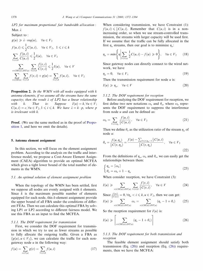
5.1.1. The DOF requirement for transmission
First, we consider the DOF requirement for transmis-sion in which we try to use as fewer streams as possibleto fully allocate the outgoing traffic. Given a FBA asfgðuÞ; u 2 V 2g, we can calculate the traffic for each non-gateway node u in the following way:
f ðuÞ ¼X
v2T ðuÞgðvÞ ¼
X16i6k
f ðu; iÞ ð17Þ
When considering transmission, we have Constraint (1):f ðu; iÞ 6 1
2Cðu; iÞ. Remember that Cðu; iÞ is in a non-
increasing order, so when we use stream-controlled trans-mission, the streams with larger capacity will be used first.If we assume that the traffic can be fully allocated in thefirst gu streams, then our goal is to minimize gu:
gu ¼ min gX
16i6g
1
2Cðu; iÞ � f ðuÞP 0
�����( )
; 8u 2 V 2 ð18Þ
Since gateway nodes can directly connect to the wired net-work, we have
gu ¼ 0; 8u 2 V 1 ð19ÞThen the transmission requirement for node u is:
IðuÞP gu; 8u 2 V ð20Þ
5.1.2. The DOF requirement for reception
Before analyzing the DOF requirement for reception, wefirst define two new notations xu and hu, where xu repre-sents the DOF requirement to suppress the interferencefrom node u and can be defined as:
xu ¼X
16i6gu
f ðu; iÞ12Cðu; iÞ ; 8u 2 V 2 ð21Þ
Then we define hu as the utilization ratio of the stream gu ofnode u:
hu ¼f ðu; guÞ
12Cðv; guÞ
¼f ðuÞ �
P16i6gu�1
12Cðu; iÞ
12Cðv; guÞ
; 8u 2 V 2
ð22ÞFrom the definitions of gu, xu and hu, we can easily get therelationships between them:
gu ¼ dxuehu ¼ xu þ 1� gu
�ð23Þ
When consider reception, we have Constraint (3):
IðuÞPX
v2CHIðuÞ[INT ðuÞ
X16i6k
f ðv; iÞ12Cðv; iÞ ; 8u 2 V ð24Þ
Since f ðu;iÞ12 Cðu;iÞ ¼ 0; 8gu < i 6 k; u 2 V 2, then we can get:
IðuÞPX
v2CHIðuÞ[INT ðuÞxv ¼
Xv2CHIðuÞ[INT ðuÞ
ðgv � 1þ hvÞ ð25Þ
So the reception requirement for IðuÞ is:
IðuÞPX
v2CHIðuÞ[INT ðuÞðgv � 1þ hvÞ
& ’ð26Þ
5.1.3. The DOF requirement for both transmission and
reception
The feasible element assignment should satisfy bothtransmission (Eq. (20)) and reception (Eq. (26)) require-ments, then we have the MCFEA:
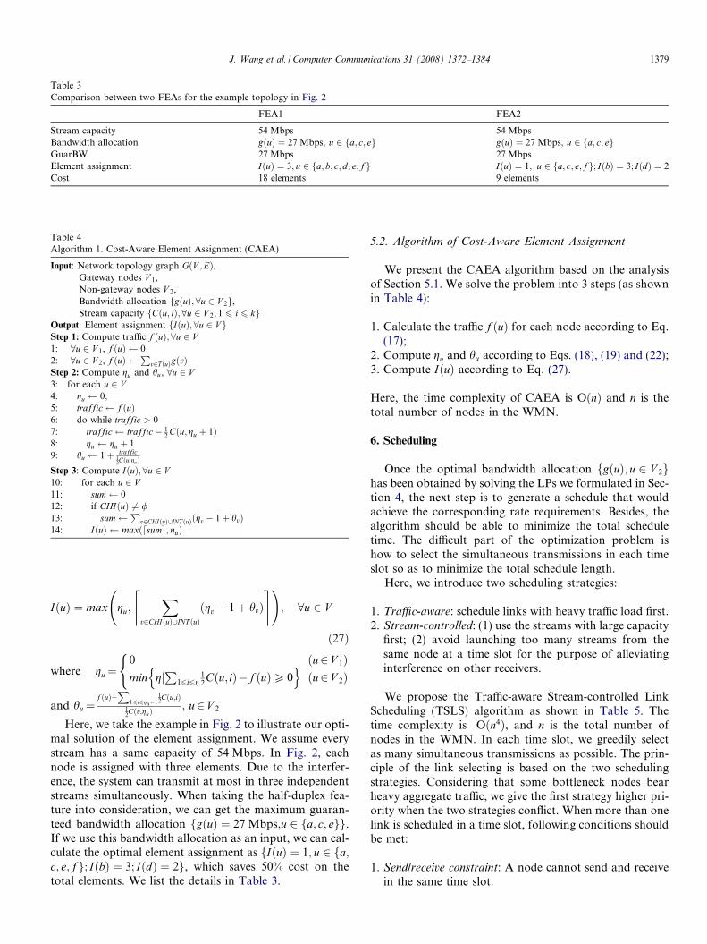
Table 3Comparison between two FEAs for the example topology in Fig. 2
FEA1 FEA2
Stream capacity 54 Mbps 54 MbpsBandwidth allocation gðuÞ ¼ 27 Mbps; u 2 fa; c; eg gðuÞ ¼ 27 Mbps; u 2 fa; c; egGuarBW 27 Mbps 27 MbpsElement assignment IðuÞ ¼ 3; u 2 fa; b; c; d; e; f g IðuÞ ¼ 1; u 2 fa; c; e; fg; IðbÞ ¼ 3; IðdÞ ¼ 2Cost 18 elements 9 elements
Table 4Algorithm 1. Cost-Aware Element Assignment (CAEA)
Input: Network topology graph GðV ;EÞ,Gateway nodes V 1,Non-gateway nodes V 2,Bandwidth allocation fgðuÞ;8u 2 V 2g,Stream capacity fCðu; iÞ;8u 2 V 2; 1 6 i 6 kg
Output: Element assignment fIðuÞ; 8u 2 V gStep 1: Compute traffic f ðuÞ;8u 2 V1: 8u 2 V 1, f ðuÞ 02: 8u 2 V 2, f ðuÞ
Pv2T ðuÞgðvÞ
Step 2: Compute gu and hu, 8u 2 V3: for each u 2 V4: gu 0;5: traffic f ðuÞ6: do while traffic > 07: traffic traffic� 1
2 Cðu; gu þ 1Þ8: gu gu þ 19: hu 1þ traffic
12Cðu;guÞ
Step 3: Compute IðuÞ; 8u 2 V10: for each u 2 V11: sum 012: if CHIðuÞ 6¼ /13: sum
Pv2CHIðuÞ[INT ðuÞðgv � 1þ hvÞ
14: IðuÞ maxðdsume; guÞ
J. Wang et al. / Computer Communications 31 (2008) 1372–1384 1379
IðuÞ ¼ max gu;X
v2CHIðuÞ[INT ðuÞðgv � 1þ hvÞ
& ’ !; 8u 2 V
ð27Þ
where gu¼0 ðu2 V 1Þmin gj
P16i6g
12Cðu; iÞ� f ðuÞP 0
n oðu2 V 2Þ
(
and hu¼f ðuÞ�
P16i6gu�1
12Cðu;iÞ
12Cðv;guÞ
; u2 V 2
Here, we take the example in Fig. 2 to illustrate our opti-mal solution of the element assignment. We assume everystream has a same capacity of 54 Mbps. In Fig. 2, eachnode is assigned with three elements. Due to the interfer-ence, the system can transmit at most in three independentstreams simultaneously. When taking the half-duplex fea-ture into consideration, we can get the maximum guaran-teed bandwidth allocation fgðuÞ ¼ 27 Mbps;u 2 fa; c; egg.If we use this bandwidth allocation as an input, we can cal-culate the optimal element assignment as fIðuÞ ¼ 1; u 2 fa;c; e; f g; IðbÞ ¼ 3; IðdÞ ¼ 2g, which saves 50% cost on thetotal elements. We list the details in Table 3.
5.2. Algorithm of Cost-Aware Element Assignment
We present the CAEA algorithm based on the analysisof Section 5.1. We solve the problem into 3 steps (as shownin Table 4):
1. Calculate the traffic f ðuÞ for each node according to Eq.(17);
2. Compute gu and hu according to Eqs. (18), (19) and (22);3. Compute IðuÞ according to Eq. (27).
Here, the time complexity of CAEA is OðnÞ and n is thetotal number of nodes in the WMN.
6. Scheduling
Once the optimal bandwidth allocation fgðuÞ; u 2 V 2ghas been obtained by solving the LPs we formulated in Sec-tion 4, the next step is to generate a schedule that wouldachieve the corresponding rate requirements. Besides, thealgorithm should be able to minimize the total scheduletime. The difficult part of the optimization problem ishow to select the simultaneous transmissions in each timeslot so as to minimize the total schedule length.
Here, we introduce two scheduling strategies:
1. Traffic-aware: schedule links with heavy traffic load first.2. Stream-controlled: (1) use the streams with large capacity
first; (2) avoid launching too many streams from thesame node at a time slot for the purpose of alleviatinginterference on other receivers.
We propose the Traffic-aware Stream-controlled LinkScheduling (TSLS) algorithm as shown in Table 5. Thetime complexity is Oðn4Þ, and n is the total number ofnodes in the WMN. In each time slot, we greedily selectas many simultaneous transmissions as possible. The prin-ciple of the link selecting is based on the two schedulingstrategies. Considering that some bottleneck nodes bearheavy aggregate traffic, we give the first strategy higher pri-ority when the two strategies conflict. When more than onelink is scheduled in a time slot, following conditions shouldbe met:
1. Send/receive constraint: A node cannot send and receivein the same time slot.
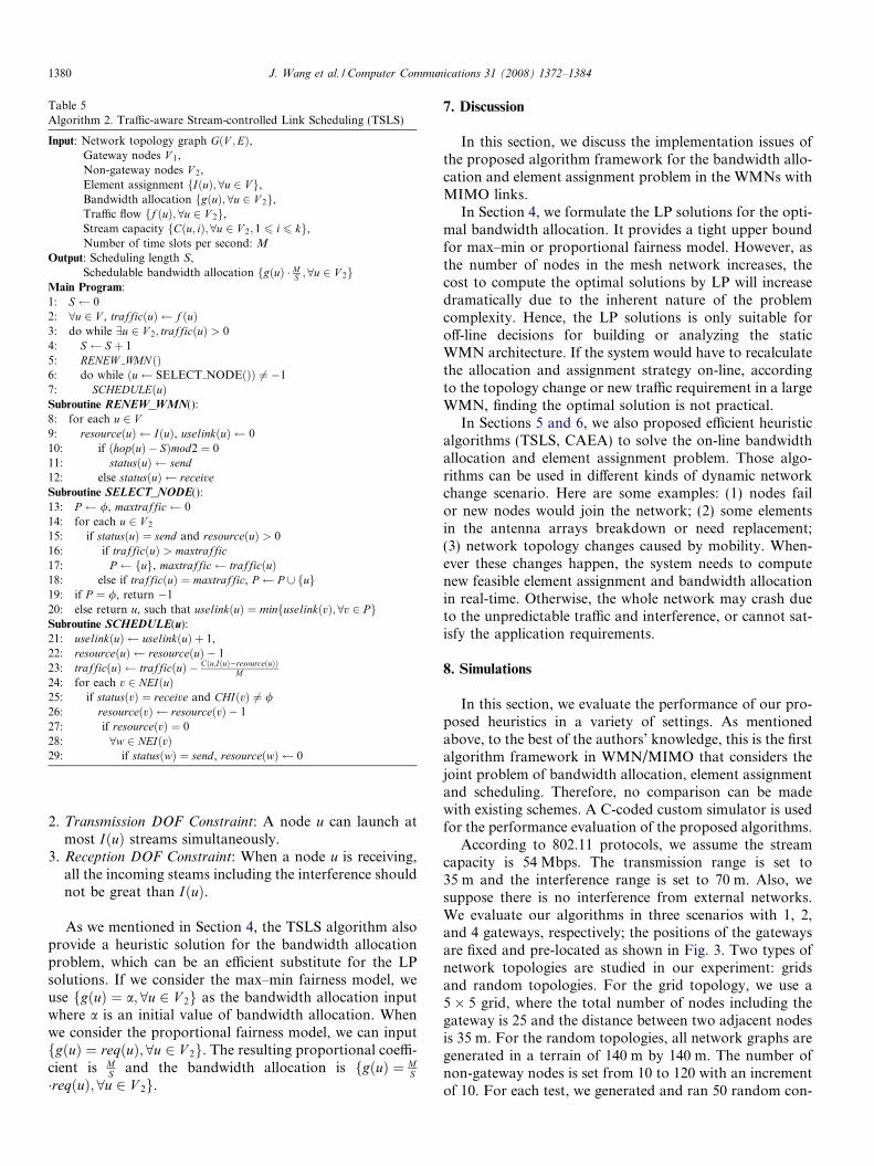
Table 5Algorithm 2. Traffic-aware Stream-controlled Link Scheduling (TSLS)
Input: Network topology graph GðV ;EÞ,Gateway nodes V 1,Non-gateway nodes V 2,Element assignment fIðuÞ;8u 2 V g,Bandwidth allocation fgðuÞ; 8u 2 V 2g,Traffic flow ff ðuÞ; 8u 2 V 2g,Stream capacity fCðu; iÞ;8u 2 V 2; 1 6 i 6 kg,Number of time slots per second: M
Output: Scheduling length S,Schedulable bandwidth allocation fgðuÞ � M
S ;8u 2 V 2gMain Program:1: S 02: 8u 2 V , trafficðuÞ f ðuÞ3: do while 9u 2 V 2; trafficðuÞ > 04: S S þ 15: RENEW WMNðÞ6: do while ðu SELECT NODEðÞÞ 6¼ �17: SCHEDULEðuÞSubroutine RENEW_WMN():8: for each u 2 V9: resourceðuÞ IðuÞ, uselinkðuÞ 010: if ðhopðuÞ � SÞmod2 ¼ 011: statusðuÞ send12: else statusðuÞ receiveSubroutine SELECT_NODE():13: P /, maxtraffic 014: for each u 2 V 2
15: if statusðuÞ ¼ send and resourceðuÞ > 016: if trafficðuÞ > maxtraffic17: P fug, maxtraffic trafficðuÞ18: else if trafficðuÞ ¼ maxtraffic, P P [ fug19: if P ¼ /, return �120: else return u, such that uselinkðuÞ ¼ minfuselinkðvÞ;8v 2 PgSubroutine SCHEDULE(u):21: uselinkðuÞ uselinkðuÞ þ 1,22: resourceðuÞ resourceðuÞ � 123: trafficðuÞ trafficðuÞ � Cðu;IðuÞ�resourceðuÞÞ
M24: for each v 2 NEIðuÞ25: if statusðvÞ ¼ receive and CHIðvÞ 6¼ /26: resourceðvÞ resourceðvÞ � 127: if resourceðvÞ ¼ 028: 8w 2 NEIðvÞ29: if statusðwÞ ¼ send, resourceðwÞ 0
1380 J. Wang et al. / Computer Communications 31 (2008) 1372–1384
2. Transmission DOF Constraint: A node u can launch atmost IðuÞ streams simultaneously.
3. Reception DOF Constraint: When a node u is receiving,all the incoming steams including the interference shouldnot be great than IðuÞ.
As we mentioned in Section 4, the TSLS algorithm alsoprovide a heuristic solution for the bandwidth allocationproblem, which can be an efficient substitute for the LPsolutions. If we consider the max–min fairness model, weuse fgðuÞ ¼ a; 8u 2 V 2g as the bandwidth allocation inputwhere a is an initial value of bandwidth allocation. Whenwe consider the proportional fairness model, we can inputfgðuÞ ¼ reqðuÞ; 8u 2 V 2g. The resulting proportional coeffi-cient is M
S and the bandwidth allocation is fgðuÞ ¼ MS
�reqðuÞ; 8u 2 V 2g.
7. Discussion
In this section, we discuss the implementation issues ofthe proposed algorithm framework for the bandwidth allo-cation and element assignment problem in the WMNs withMIMO links.
In Section 4, we formulate the LP solutions for the opti-mal bandwidth allocation. It provides a tight upper boundfor max–min or proportional fairness model. However, asthe number of nodes in the mesh network increases, thecost to compute the optimal solutions by LP will increasedramatically due to the inherent nature of the problemcomplexity. Hence, the LP solutions is only suitable foroff-line decisions for building or analyzing the staticWMN architecture. If the system would have to recalculatethe allocation and assignment strategy on-line, accordingto the topology change or new traffic requirement in a largeWMN, finding the optimal solution is not practical.
In Sections 5 and 6, we also proposed efficient heuristicalgorithms (TSLS, CAEA) to solve the on-line bandwidthallocation and element assignment problem. Those algo-rithms can be used in different kinds of dynamic networkchange scenario. Here are some examples: (1) nodes failor new nodes would join the network; (2) some elementsin the antenna arrays breakdown or need replacement;(3) network topology changes caused by mobility. When-ever these changes happen, the system needs to computenew feasible element assignment and bandwidth allocationin real-time. Otherwise, the whole network may crash dueto the unpredictable traffic and interference, or cannot sat-isfy the application requirements.
8. Simulations
In this section, we evaluate the performance of our pro-posed heuristics in a variety of settings. As mentionedabove, to the best of the authors’ knowledge, this is the firstalgorithm framework in WMN/MIMO that considers thejoint problem of bandwidth allocation, element assignmentand scheduling. Therefore, no comparison can be madewith existing schemes. A C-coded custom simulator is usedfor the performance evaluation of the proposed algorithms.
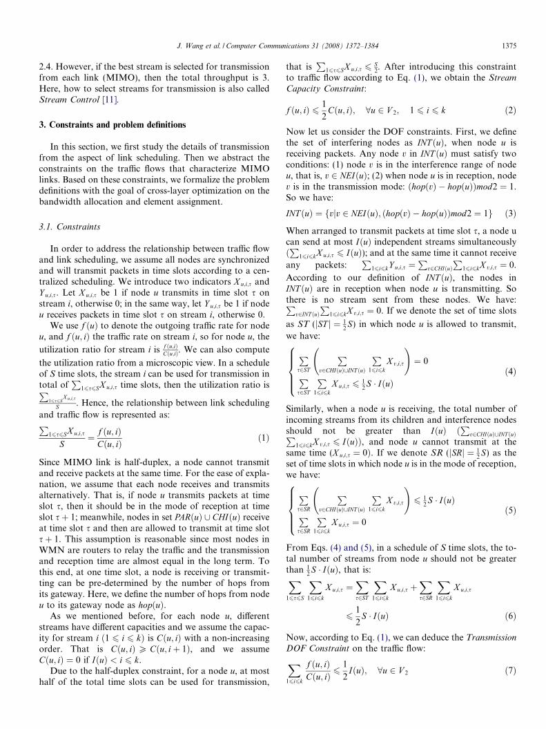
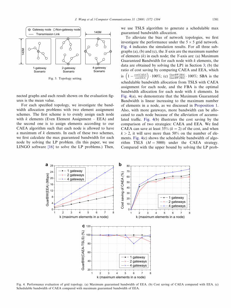
According to 802.11 protocols, we assume the streamcapacity is 54 Mbps. The transmission range is set to35 m and the interference range is set to 70 m. Also, wesuppose there is no interference from external networks.We evaluate our algorithms in three scenarios with 1, 2,and 4 gateways, respectively; the positions of the gatewaysare fixed and pre-located as shown in Fig. 3. Two types ofnetwork topologies are studied in our experiment: gridsand random topologies. For the grid topology, we use a5� 5 grid, where the total number of nodes including thegateway is 25 and the distance between two adjacent nodesis 35 m. For the random topologies, all network graphs aregenerated in a terrain of 140 m by 140 m. The number ofnon-gateway nodes is set from 10 to 120 with an incrementof 10. For each test, we generated and ran 50 random con-
140M
140MGateway node Non-gateway node
Transmission Link
1-gatewayScenario
2-gatewayScenario
4-gatewayScenario
Fig. 3. Topology setting.
J. Wang et al. / Computer Communications 31 (2008) 1372–1384 1381
nected graphs and each result shown on the evaluation fig-ures is the mean value.
For each specified topology, we investigate the band-width allocation problems with two element assignmentschemes. The first scheme is to evenly assign each nodewith k elements (Even Element Assignment – EEA) andthe second one is to assign elements according to ourCAEA algorithm such that each node is allowed to havea maximum of k elements. In each of these two schemes,we first calculate the max guaranteed bandwidth for eachnode by solving the LP problem. (In this paper, we useLINGO software [16] to solve the LP problems.) Then,
1 2 3 4 5 6 7 80
4
8
12
16
20
24
28
Gua
rBW
(EEA
) (M
bps)
k (maximum elements in a node)
1 gateway 2 gateways 4 gateways
1 2 3 420
40
60
80
100
120
Gua
rBW
(CAE
A-TS
LS) (
%)
k (maximum ele
a b
c
Fig. 4. Performance evaluation of grid topology. (a) Maximum guaranteedSchedulable bandwidth of CAEA compared with maximum guaranteed bandw
we use TSLS algorithm to generate a schedulable maxguaranteed bandwidth allocation.
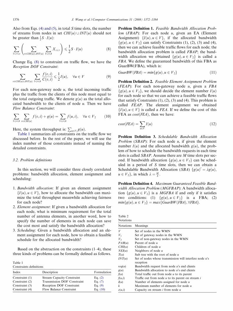
To alleviate the bias of network topologies, we firstinvestigate the performance under the 5� 5 grid network.Fig. 4 indicates the simulation results. For all three sub-graphs (a), (b) and (c), the X-axis are the maximum numberof elements (k) in each node; the Y-axis are: (a) MaximumGuaranteed Bandwidth for each node with k elements, thedata are obtained by solving the LP1 in Section 3; (b) theratio of cost saving by comparing CAEA and EEA, which
is 1� costðCAEAÞcostðEEAÞ
� �� 100%; (c) GuarBW ðSBAÞ
GuarBW ðFBAÞ � 100%: SBA is the
schedulable bandwidth allocation from TSLS with CAEAassignment for each node, and the FBA is the optimalbandwidth allocation for each node with k elements. InFig. 4(a), we demonstrate that the Maximum GuaranteedBandwidth is linear increasing to the maximum numberof elements in a node, as we discussed in Proposition 1.Also, with more gateways, more bandwidth can be allo-cated to each node because of the alleviation of accumu-lated traffic. Fig. 4(b) illustrates the cost saving by thecomparison of two strategies: CAEA and EEA. We findCAEA can save at least 35% (k ¼ 2) of the cost, and whenk > 2, it will save more than 50% on the number of ele-ments. Fig. 4(c) shows the schedulable bandwidth of algo-rithm TSLS (M ¼ 5000) under the CAEA strategy.Compared with the upper bound by solving the LP prob-
1 2 3 4 5 6 7 80
10
20
30
40
50
60
70
80
1 gateway 2 gateways 4 gatewaysC
ost s
avin
g of
CAE
A (%
)
k (maximum elements in a node)
5 6 7 8
1 gateway 2 gateways 4 gateways
ments in a node)
bandwidth of EEA. (b) Cost saving of CAEA compared with EEA. (c)idth of EEA.
1382 J. Wang et al. / Computer Communications 31 (2008) 1372–1384
lem, in most cases, the TSLS can achieve a schedulablebandwidth allocation up to 92% of the optimal.
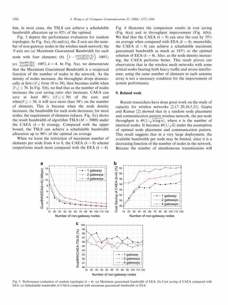
Fig. 5 depicts the performance evaluation for randomtopologies. In Fig. 5(a), (b) and (c), the X-axis are the num-ber of non-gateway nodes in the wireless mesh network; theY-axis are (a) Maximum Guaranteed Bandwidth for each
node with four elements; (b) 1� costðCAEAðk¼4ÞÞcostðEEAðk¼4ÞÞ
� �� 100%;
(c). GuarBW ðSBAÞGuarBW ðFBAÞ � 100%; k ¼ 4. In Fig. 5(a), we demonstrate
that the Maximum Guaranteed Bandwidth is a reciprocalfunction of the number of nodes in the network. As thedensity of nodes increases, the throughput drops dramati-cally at first (jV 2j from 10 to 30), then becomes stable whenjV 2j > 70. In Fig. 5(b), we find that as the number of nodesincreases the cost saving ratio also increases. CAEA cansave at least 48% (jV 2j 6 30) of the cost, andwhenjV 2j > 30, it will save more than 54% on the numberof elements. This is because when the node densityincreases, the bandwidth for each node decreases; for mostnodes, the requirement of elements reduces. Fig. 5(c) showsthe result bandwidth of algorithm TSLS (M ¼ 5000) underthe CAEA (k ¼ 4) strategy. Compared with the upperbound, the TSLS can achieve a schedulable bandwidthallocation up to 96% of the optimal on average.
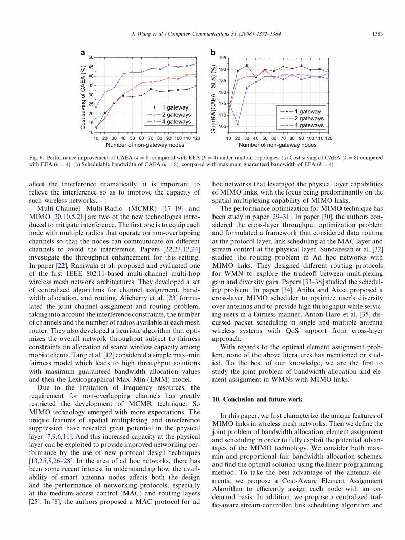
When we loose the restriction of maximum number ofelements per node from 4 to 8, the CAEA (k = 8) schemeoutperforms much more compared with the EEA (k ¼ 4).
10 20 30 40 50 60 70 80 90 100 110 1200
2
4
6
8
10
12
14 1 gateway 2 gateways 4 gateways
Gua
rBW
(EEA
(k=4
)) (M
bps)
Number of non-gateway nodes
10 20 30 40 50 6090919293949596979899
100
Gua
rBW
(CAE
A-TS
LS) (
%)
Number of non-g
a b
c
Fig. 5. Performance evaluation of random topologies (k ¼ 4). (a) MaximumEEA. (c) Schedulable bandwidth of CAEA compared with maximum guarant
Fig. 6 illustrates the comparison results in cost saving(Fig. 6(a)) and in throughput improvement (Fig. 6(b)).We find that the CAEA (k ¼ 8) can save the cost by 35%on average when compared with EEA (k ¼ 4); meanwhile,the CAEA (k ¼ 8) can achieve a schedulable maximumguaranteed bandwidth as much as 185% to the optimalsolution of EEA (k ¼ 4). Also, as the node density increas-ing, the CAEA performs better. This result proves ourobservation that in the wireless mesh networks with somecritical nodes bearing both heavy traffic and severe interfer-ence, using the same number of elements in each antennaarray is not a necessary condition for the improvement ofsystem performance.
9. Related work
Recent researchers have done great work on the study ofcapacity for wireless networks [2,17–20,10,5,21]. Guptaand Kumar [2] showed that in a random node placementand communication pattern wireless network, the per-nodethroughput is Hð1=
ffiffiffiffiffiffiffiffiffiffiffiffiffin log n
pÞ, where n is the number of
identical nodes. It becomes Hð1= ffiffiffinp Þ under the assumption
of optimal node placement and communication pattern.This result suggests that in a very large deployment, theavailable bandwidth per node may be limited, since it is adecreasing function of the number of nodes in the network.Because the number of simultaneous transmissions will
10 20 30 40 50 60 70 80 90 100 110 120
48
50
52
54
56
58
60
62
1 gateway 2 gateways 4 gateways
Cos
t Sav
ing
of C
AEA
(k=4
) (%
)
Number of non-gateway nodes
70 80 90 100 110 120
1 gateway 2 gateways 4 gateways
ateway nodes
guaranteed bandwidth of EEA. (b) Cost saving of CAEA compared witheed bandwidth of EEA.
10 20 30 40 50 60 70 80 90 100 110 12010
15
20
25
30
35
40
45
50
1 gateway 2 gateways 4 gateways
Cos
t sav
ing
of C
AEA
(%)
Number of non-gateway nodes 10 20 30 40 50 60 70 80 90 100 110 120
165
170
175
180
185
190
195
1 gateway 2 gateways 4 gateways
Gua
rBW
(CAE
A-TS
LS) (
%)
Number of non-gateway nodes
a b
Fig. 6. Performance improvement of CAEA (k ¼ 8) compared with EEA (k ¼ 4) under random topologies. (a) Cost saving of CAEA (k ¼ 8) comparedwith EEA (k ¼ 4). (b) Schedulable bandwidth of CAEA (k ¼ 8), compared with maximum guaranteed bandwidth of EEA (k ¼ 4).
J. Wang et al. / Computer Communications 31 (2008) 1372–1384 1383
affect the interference dramatically, it is important torelieve the interference so as to improve the capacity ofsuch wireless networks.
Multi-Channel Multi-Radio (MCMR) [17–19] andMIMO [20,10,5,21] are two of the new technologies intro-duced to mitigate interference. The first one is to equip eachnode with multiple radios that operate on non-overlappingchannels so that the nodes can communicate on differentchannels to avoid the interference. Papers [22,23,12,24]investigate the throughput enhancement for this setting.In paper [22], Raniwala et al. proposed and evaluated oneof the first IEEE 802.11-based multi-channel multi-hopwireless mesh network architectures. They developed a setof centralized algorithms for channel assignment, band-width allocation, and routing. Alicherry et al. [23] formu-lated the joint channel assignment and routing problem,taking into account the interference constraints, the numberof channels and the number of radios available at each meshrouter. They also developed a heuristic algorithm that opti-mizes the overall network throughput subject to fairnessconstraints on allocation of scarce wireless capacity amongmobile clients. Tang et al. [12] considered a simple max–minfairness model which leads to high throughput solutionswith maximum guaranteed bandwidth allocation valuesand then the Lexicographical Max–Min (LMM) model.
Due to the limitation of frequency resources, therequirement for non-overlapping channels has greatlyrestricted the development of MCMR technique. SoMIMO technology emerged with more expectations. Theunique features of spatial multiplexing and interferencesuppression have revealed great potential in the physicallayer [7,9,6,11]. And this increased capacity at the physicallayer can be exploited to provide improved networking per-formance by the use of new protocol design techniques[13,25,8,26–28]. In the area of ad hoc networks, there hasbeen some recent interest in understanding how the avail-ability of smart antenna nodes affects both the designand the performance of networking protocols, especiallyat the medium access control (MAC) and routing layers[25]. In [8], the authors proposed a MAC protocol for ad
hoc networks that leveraged the physical layer capabilitiesof MIMO links, with the focus being predominantly on thespatial multiplexing capability of MIMO links.
The performance optimization for MIMO technique hasbeen study in paper [29–31]. In paper [30], the authors con-sidered the cross-layer throughput optimization problemand formulated a framework that considered data routingat the protocol layer, link scheduling at the MAC layer andstream control at the physical layer. Sundaresan et al. [32]studied the routing problem in Ad hoc networks withMIMO links. They designed different routing protocolsfor WMN to explore the tradeoff between multiplexinggain and diversity gain. Papers [33–38] studied the schedul-ing problem. In paper [34], Aniba and Aissa proposed across-layer MIMO scheduler to optimize user’s diversityover antennas and to provide high throughput while servic-ing users in a fairness manner. Anton-Haro et al. [35] dis-cussed packet scheduling in single and multiple antennawireless systems with QoS support from cross-layerapproach.
With regards to the optimal element assignment prob-lem, none of the above literatures has mentioned or stud-ied. To the best of our knowledge, we are the first tostudy the joint problem of bandwidth allocation and ele-ment assignment in WMNs with MIMO links.
10. Conclusion and future work
In this paper, we first characterize the unique features ofMIMO links in wireless mesh networks. Then we define thejoint problem of bandwidth allocation, element assignmentand scheduling in order to fully exploit the potential advan-tages of the MIMO technology. We consider both max–min and proportional fair bandwidth allocation schemes,and find the optimal solution using the linear programmingmethod. To take the best advantage of the antenna ele-ments, we propose a Cost-Aware Element AssignmentAlgorithm to efficiently assign each node with an on-demand basis. In addition, we propose a centralized traf-fic-aware stream-controlled link scheduling algorithm and
1384 J. Wang et al. / Computer Communications 31 (2008) 1372–1384
demonstrate that it provides a schedulable bandwidth allo-cation which is close to the optimal solution.
For future work, we would like to investigate the impactof different routing strategies on the performance ofthroughput and element assignment in WMN with MIMOsupport.
Acknowledgements
This work is supported by grants from the ResearchGrants Council of the Hong Kong Special AdministrativeRegion, China (Project No. CityU 113906), CityU Strate-gic Research Grant (SRG) (Project Nos. 7002217 and7002102) and the National Basic Research Program of Chi-na (973 Program) under Grant No.2006CB303006.
References
[1] I. Akyildiz, X. Wang, A survey on wireless mesh networks, IEEECommunications Magazine 43 (2005) 23–30.
[2] P. Gupta, P.R. Kumar, The capacity of wireless networks, IEEETransactions on Information Theory 46 (2) (2000) 388–404.
[3] D. Gesbert, M. Shafi, D. Shiu, P.J. Smith, A. Naguib, From theory topractice: an overview of MIMO space-time coded wireless systems,IEEE Journal of Selected Areas in Communications 21 (2003) 281–302.
[4] A.J. Paulraj, D.A. Gore, R.U. Nabar, H. Bolcskei, An overview ofMIMO communications – a key to gigabit wireless, in: Proceedings ofIEEE, vol. 92, February 2004, pp. 198–218.
[5] D. Shiu, G.J. Foschini, M.J. Gans, J.M. Kahn, Fading correlationand its effect on the capacity of multiple-element antennas, IEEETransactions on Communications 48 (2000).
[6] E. Baccarelli, M. Biagi, C. Pelizzoni, N. Cordeschi, F. Garzia,Interference suppression in MIMO systems for throughput enhance-ment and error reduction, in: Proceedings of ACM IWCMC, July2006, pp. 611–616.
[7] L. Zheng, D.N.C. Tse, Diversity and multiplexing: a fundamentaltradeoff in multiple-antenna channels, IEEE Transactions on Infor-mation Theory 49 (2003) 1073–1096.
[8] K. Sundaresan, R. Sivakumar, M.A. Ingram, T.Y. Chang, A fairmedium access control protocol for ad-hoc networks with MIMO links,in: Proceedings of IEEE INFOCOM, vol. 4, 2004, pp. 2559–2570.
[9] M.F. Demirkol, M.A. Ingram, Control using capacity constraints forinterfering MIMO links, in: Proceedings of IEEE PIMRC, vol. 3,September 2002, pp. 1032–1036.
[10] J.B. Anderson, Antenna arrays in mobile communications: gain,diversity, and channel capacity, IEEE Antennas and PropagationMagazine 42 (2000) 12–16.
[11] S. Gaur, J.S. Jiang, M.A. Ingram, M.F. Demirkol, Interfering MIMOlinks with stream control and optimal antenna selection, in:Proceedings of IEEE GLOBECOM, vol. 5, 2004, pp. 3138–3142.
[12] J. Tang, G. Xue, W. Zhang, Maximum throughput and fairbandwidth allocation in multi-channel wireless mesh networks, in:Proceedings of IEEE INFOCOM, 2006, pp. 1–10.
[13] T. Nandagopal, T.E. Kim, X. Gao, V. Bhargavan, Achieving MAClayer fairness in wireless packet networks, in: Proceedings of ACMMOBICOM, 2000.
[14] M.S. Bazaraa, J.J. Jarvis, H.D. Sherali, Linear programming andnetwork flows, third ed., John Wiley & Sons, 2005.
[15] L.G. Khachiyan, A polynomial algorithm for linear programming,Doklady Akademiia Nauk SSSR 244 (1979) 1093–1096.
[16] Lingo software. Available from: <http://www.lindo.com/>.[17] K. Jain, J. Padhye, V.N. Padmanabhan, L. Qiu, Impact of interfer-
ence on multi-hop wireless network performance, in: Proceedings ofACM MOBICOM, 2003, pp. 66–80.
[18] P. Kyasanur, N.H. Vaidya, Capacity of multi-channel wirelessnetworks: impact of number of channels and interfaces, in: Proceed-ings of ACM MOBICOM, 2005, pp. 43–57.
[19] M. Kodialam, T. Nandagopal, Characterizing achievable rates inmulti-hop wireless mesh networks with orthogonal channels, IEEE/ACM Transactions on Networking 13 (2005) 868–880.
[20] A. Goldsmith, S.A. Jafar, N. Jindal, S. Vishwanath, Capacity limitsof MIMO channels, IEEE Journal of Selected Areas in Communi-cations 21 (2003) 684–702.
[21] J.S. Jiang, M.F. Demirkol, M.A. Ingram, Measured capacities at5.8 GHz of indoor MIMO systems with MIMO interference, in:Proceedings of IEEE VTC-Fall, vol. 3, October 2003, pp. 1573–1577.
[22] A. Raniwala, K. Gopalan, T. Chiueh, Centralized channel assignmentand routing algorithms for multi-channel wireless mesh networks,ACM Mobile Computing and Communications Review 8 (2004) 50–65.
[23] M. Alicherry, R. Bhatia, L.E. Li, Joint channel assignment androuting for throughput optimization in multi-radio wireless meshnetworks, in: Proceedings of ACM MOBICOM, 2005, pp. 58–72.
[24] A.H.M. Rad, V.W.S. Wong, Joint channel allocation, interfaceassignment and MAC design for multi-channel wireless meshnetworks, in: Proceedings of IEEE INFOCOM, 2007, pp. 1469–1477.
[25] M. Zorzi, J. Zeidler, A.L. Anderson, B.D. Rao, J. Proakis, A.L.Swindlehurst, M.A. Jensen, S.V. Krishnamurthy, Cross-layer issues inMAC protocol design for MIMO ad hoc networks, IEEE WirelessCommunications (2006) 62–76.
[26] T. Tang, M. Park, R.W. Heath Jr., S.M. Nettles, A joint MIMO-OFDM transceiver and MAC design for mobile ad hoc networking,in: Proceedings of IEEE IWWAN, June 2004, pp. 315–319.
[27] M. Park, S.H. Choi, S.M. Nettles, Cross-layer MAC design forwireless networks using MIMO, in: Proceedings of IEEE GLOBE-COM, vol. 5, 2005, pp. 2870–2874.
[28] D. Wang, U. Tureli, Joint MIMO-OFDM and MAC design forbroadband multihop ad hoc networks, EURASIP Journal onWireless Communications and Networking (2006) 1–9.
[29] K.K. Wong, R. Murch, K. Letaief, Performance enhancement ofmultiuser MIMO wireless communication systems, IEEE Transac-tions on Communications 50 (2002) 1960–1970.
[30] R. Bhatia, L.E. Li, Throughput optimization of wireless meshnetworks with MIMO links, in: Proceedings of IEEE INFOCOM,May 2007, pp. 2326–2330.
[31] J. Liu, T.Y. Park, Y.T. Hou, Y. Shi, H.D. Sherali, Cross-layeroptimization of MIMO-based mesh networks under orthogonalchannels, in: Proceedings of IEEE WCNC, 2007, pp. 49–54.
[32] K. Sundaresan, R. Sivakumar, Routing in ad-hoc networks withMIMO links, in: Proceedings of IEEE ICNP, 2005.
[33] B. Han, W. Jia, L. Lin, Performance evaluation of scheduling in IEEE802.16 based wireless mesh networks, Elsevier Computer Communi-cations 30 (2007) 782–792.
[34] G. Aniba, S. Aissa, Adaptive scheduling for MIMO wirelessnetworks: cross-layer approach and application to HSDPA, IEEETransactions on Wireless Communications 6 (2007) 259–268.
[35] C. Anton-Haro, P. Svedman, M. Bengtsson, A. Alexiou, A. Gameiro,Cross-layer scheduling for multi-user MIMO systems, IEEE Com-munications Magazine (2006) 39–45.
[36] G. Sharma, R.M. Ravi, B.S. Ness, On the complexity of scheduling inwireless networks, in: Proceedings of ACM MOBICOM, 2006, pp.227–238.
[37] G. Brar, D.M. Blough, P. Santi, Computationally efficient schedulingwith the physical interference model for throughput improvement inwireless mesh networks, in: Proceedings of ACM MOBICOM, 2006,pp. 2–13.
[38] W. Wang, X.Y. Li, O. Frieder, Y. Wang, W.Z. Song, Efficientinterference-aware TDMA link scheduling for static wireless net-works, in: Proceedings of ACM MOBICOM, 2006, pp. 262–273.