JETIR Research Journal
8
© 2019 JETIR May 2019, Volume 6, Issue 5 www.jetir.org (ISSN-2349-5162) JETIRBZ06059 Journal of Emerging Technologies and Innovative Research (JETIR) www.jetir.org 377 DESIGN AND FABRICATION OF AUTOMATIC GEAR SYSTEM USING ELECTROMAGNETIC VALVES Rahul Pattar 1 , Shubham Angadi 2 , Dileep Kumar 3 , Jummanna Bhangi 4 , Srinivas S 5 School of Mechanical Engineering REVA University Rukmini Knowledge Park, Kattigenahalli Yelahanka, Bangalore, India Abstract: - Vehicles are commonly used around the world particularly in INDIA. The gear shifting mechanism of the motor-cycle is used manual. This work covers development of an indigenous gear shifting /changing system for all methods of motorcycle. By this system the mechanical gear shifting will remain unchanged because an additional electromagnetic valves system is placed on top of the lever, to shift the gear and automatically control the clutch. Electromagnetic valves made up of solid copper wire. By using this system accurate control of the vehicle is achieved by varying the speeds. A wiper motor is used to control the position of the clutch. Hardware, Software and testing of the electromagnetic valve are verified. System is flexible and can be used with any motorcycle having manual transmission system. In this work the expected force for each electromagnetic valve was found to be 38.423 N. The effectiveness in gear operation between manual and electromagnetic valve were exactly the same and hence this reduced the human effort. Keyword: - Electromagnetic valves, Wiper motor, Relay, Speed sensor, Gear etc ….. I. INTRODUCTION There are already some inventions done on gear box for motorcycle to transmit the torque from engine crankshaft to the rear wheel of the motorcycle. The gear box is used to vary the torque as per the different driving conditions. The gearbox increases the required torque for starting the vehicle. After the start or the running of the motorcycle there is no need of high torque, so now gear box will transmit the optimum torque to the rear wheel at high speed. For the operation of gearbox and shifting the gear there is need of some effort by the driver of motorcycle. A foot lever is used to shift the gears in a motorcycle. Also, a clutch is placed between the engine and the transmission in order to engage and disengage the flywheel with the transmission. So for smooth driving of motorcycle there is need to time these two operations perfectly. This gear shifting becomes a tiresome process for most new drivers. This can also help in reducing accidents. An electronic gear-shifting system is a method of changing gears on a bike, which enables riders to shift with electronic switches instead of using conventional control levers and mechanical cables. The switches have been connected by wires to a battery pack and to a small electric motor that drives the derailleur, switching the chain from electrical to mechanical stem is to change gears faster, and because the system does not use boden cables and can calibrate itself, it may require less maintenance. In automatic gear changing we are going to use the electromagnetic valves to shift the gear .when the front electromagnetic valve pulls the gear will shift to upper gear and when the rear electromagnetic valve pulls the gear shift to lower gear . It is controlled by the microcontroller and relay which is connected to the 12V 7Amph battery. The IR sensor is fixed to rear wheel which senses the speed from the wheel and sends signals through microcontroller to control the speed of vehicle. 2 GENERAL COMPONENTS 2.1 Electromagnetic valve It is used to store the rotation kinetic energy. An electromagnet coil is formed when insulated solid copper wire is wound around a core or form to create magnetic field it has primary coil and secondary coil were in due to the variation of charges in electromagnetic coil EMF is generated. Its works on henrys law of mutual induction. Fig 1: Electromagnetic valves
-
Upload
khangminh22 -
Category
Documents
-
view
0 -
download
0
Transcript of JETIR Research Journal

© 2019 JETIR May 2019, Volume 6, Issue 5 www.jetir.org (ISSN-2349-5162)
JETIRBZ06059 Journal of Emerging Technologies and Innovative Research (JETIR) www.jetir.org 377
DESIGN AND FABRICATION OF
AUTOMATIC GEAR SYSTEM USING
ELECTROMAGNETIC VALVES
Rahul Pattar1 , Shubham Angadi2 , Dileep Kumar3 , Jummanna Bhangi4 , Srinivas S5
School of Mechanical Engineering REVA University
Rukmini Knowledge Park, Kattigenahalli Yelahanka, Bangalore, India
Abstract: - Vehicles are commonly used around the world particularly in INDIA. The gear shifting mechanism of the motor-cycle
is used manual. This work covers development of an indigenous gear shifting /changing system for all methods of motorcycle. By
this system the mechanical gear shifting will remain unchanged because an additional electromagnetic valves system is placed on
top of the lever, to shift the gear and automatically control the clutch. Electromagnetic valves made up of solid copper wire. By
using this system accurate control of the vehicle is achieved by varying the speeds. A wiper motor is used to control the position of
the clutch. Hardware, Software and testing of the electromagnetic valve are verified. System is flexible and can be used with any
motorcycle having manual transmission system. In this work the expected force for each electromagnetic valve was found to be 38.423 N. The effectiveness in gear operation between manual and electromagnetic valve were exactly the same and hence this
reduced the human effort.
Keyword: - Electromagnetic valves, Wiper motor, Relay, Speed sensor, Gear etc …..
I. INTRODUCTION
There are already some inventions done on gear box for motorcycle to transmit the torque from engine crankshaft to the
rear wheel of the motorcycle. The gear box is used to vary the torque as per the different driving conditions. The gearbox increases
the required torque for starting the vehicle. After the start or the running of the motorcycle there is no need of high torque, so now
gear box will transmit the optimum torque to the rear wheel at high speed. For the operation of gearbox and shifting the gear there
is need of some effort by the driver of motorcycle. A foot lever is used to shift the gears in a motorcycle. Also, a clutch is placed
between the engine and the transmission in order to engage and disengage the flywheel with the transmission. So for smooth driving of motorcycle there is need to time these two operations perfectly. This gear shifting becomes a tiresome process for most new
drivers. This can also help in reducing accidents.
An electronic gear-shifting system is a method of changing gears on a bike, which enables riders to shift with electronic switches
instead of using conventional control levers and mechanical cables. The switches have been connected by wires to a battery pack
and to a small electric motor that drives the derailleur, switching the chain from electrical to mechanical stem is to change gears
faster, and because the system does not use boden cables and can calibrate itself, it may require less maintenance.
In automatic gear changing we are going to use the electromagnetic valves to shift the gear .when the front electromagnetic valve pulls the gear will shift to upper gear and when the rear electromagnetic valve pulls the gear shift to lower gear . It is controlled by
the microcontroller and relay which is connected to the 12V 7Amph battery. The IR sensor is fixed to rear wheel which senses the
speed from the wheel and sends signals through microcontroller to control the speed of vehicle.
2 GENERAL COMPONENTS
2.1 Electromagnetic valve It is used to store the rotation kinetic energy. An electromagnet coil is formed when insulated solid copper wire is wound
around a core or form to create magnetic field it has primary coil and secondary coil were in due to the variation of charges in
electromagnetic coil EMF is generated. Its works on henrys law of mutual induction.
Fig 1: Electromagnetic valves
© 2019 JETIR May 2019, Volume 6, Issue 5 www.jetir.org (ISSN-2349-5162)
JETIRBZ06059 Journal of Emerging Technologies and Innovative Research (JETIR) www.jetir.org 378
2.2 Electronic speed sensor
The IR speed sensor was initially used to replace the mechanical linkage from the road wheels to the speedometer
eliminating cable breakage and simplifying the gauge construction (elimination all moving parts except for the needle/spring
assembly) the sensor also provided wheel peed data to the controllers to assist the operator in maintaining control of the vehicle.
The vehicle Speed sensor is also used for the proper shifting up of gears for the vehicle maintenance. It senses the speed from the
rear wheel and sends to the microcontroller to change the speed.
Fig 2: IR sensor
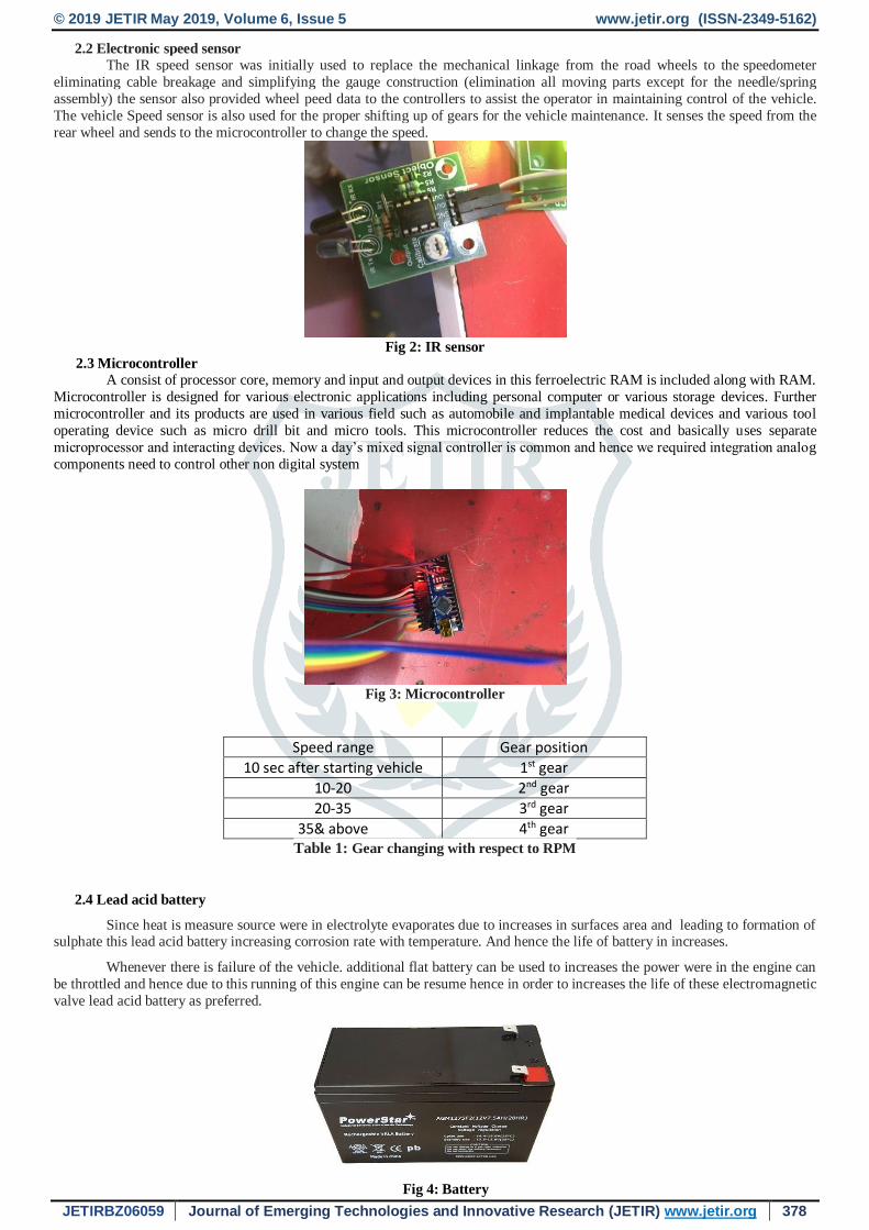
2.3 Microcontroller
A consist of processor core, memory and input and output devices in this ferroelectric RAM is included along with RAM.
Microcontroller is designed for various electronic applications including personal computer or various storage devices. Further
microcontroller and its products are used in various field such as automobile and implantable medical devices and various tool
operating device such as micro drill bit and micro tools. This microcontroller reduces the cost and basically uses separate
microprocessor and interacting devices. Now a day’s mixed signal controller is common and hence we required integration analog
components need to control other non digital system
Fig 3: Microcontroller
Speed range Gear position
10 sec after starting vehicle 1st gear
10-20 2nd gear
20-35 3rd gear
35& above 4th gear Table 1: Gear changing with respect to RPM
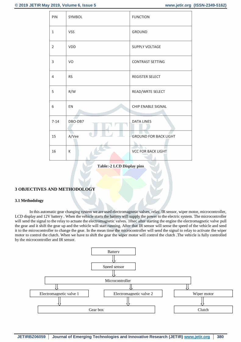
2.4 Lead acid battery
Since heat is measure source were in electrolyte evaporates due to increases in surfaces area and leading to formation of sulphate this lead acid battery increasing corrosion rate with temperature. And hence the life of battery in increases.
Whenever there is failure of the vehicle. additional flat battery can be used to increases the power were in the engine can
be throttled and hence due to this running of this engine can be resume hence in order to increases the life of these electromagnetic
valve lead acid battery as preferred.
Fig 4: Battery

© 2019 JETIR May 2019, Volume 6, Issue 5 www.jetir.org (ISSN-2349-5162)
JETIRBZ06059 Journal of Emerging Technologies and Innovative Research (JETIR) www.jetir.org 379
2.5 Wiper motor
Wiper motors are devices in the wiper system that functions on a power supply in order to move the wiper blades in a
smooth motion. Like other motors, the wiper motor rotates continuously in one direction which is converted into a back and forth
motion.
The circuit maintains power to the wipers until they are parked at the bottom of the windshield, and then cuts the power to
the motor. This circuit also parks the wipers between wipes when they are on their intermittent setting
Fig 5: Wiper motor
2.6 Relay
Is basically used to operate a switch by using an electromagnetic. It is used control circuit by low power signal or several
such low signals by single control relay. Relays are used in telegraph circuit as amplifies in present work we are using four relay
out of which two relay are used for clutch and other two relay for gears
.
Fig 6: Relays
2.7 LCD Display
A liquid-crystal display is a flat-panel display or other electronic visual display that uses the light-modulating properties of liquid
crystals do not emit light directly. The LCD display is used in this system is to display the speed and gear shifting in the vehicle. It
displays the RPM and gear.
Fig 7: LCD Display
© 2019 JETIR May 2019, Volume 6, Issue 5 www.jetir.org (ISSN-2349-5162)
JETIRBZ06059 Journal of Emerging Technologies and Innovative Research (JETIR) www.jetir.org 380
PIN SYMBOL FUNCTION
1 VSS GROUND
2 VDD SUPPLY VOLTAGE
3 VO CONTRAST SETTING
4 RS REGISTER SELECT
5 R/W READ/WRTE SELECT
6 EN CHIP ENABLE SIGNAL
7-14 DBO-DB7 DATA LINES
15 A/Vee GROUND FOR BACK LIGHT
16 K VCC FOR BACK LIGHT
Table:-2 LCD Display pins
3 OBJECTIVES AND METHODOLOGY
3.1 Methodology
In this automatic gear changing system we are used electromagnetic valves, relay, IR sensor, wiper motor, microcontroller,
LCD display and 12V battery . When the vehicle starts the battery will supply the power to the electric system. The microcontroller
will send the signal to the relay to actuate the electromagnetic valves. 10sec after starting the engine the electromagnetic valve pull
the gear and it shift the gear up and the vehicle will start running. After that IR sensor will sense the speed of the vehicle and send
it to the microcontroller to change the gear. In the mean time the microcontroller will send the signal to relay to activate the wiper motor to control the clutch. When we have to shift the gear the wiper motor will control the clutch .The vehicle is fully controlled
by the microcontroller and IR sensor.
Battery
Speed sensor
Electromagnetic valve 1 Electromagnetic valve 2 Wiper motor
Gear box Clutch
Microcontroller

© 2019 JETIR May 2019, Volume 6, Issue 5 www.jetir.org (ISSN-2349-5162)
JETIRBZ06059 Journal of Emerging Technologies and Innovative Research (JETIR) www.jetir.org 381
3.2 Objectives:
To control the position of the clutch and gear system using electromagnetic valves
To calculate the required mechanical force to be applied for the electromagnetic valves
To program the entire operation using Ardinuo software for microcontroller
3.3 Literature review
1. Muttu raj, bharat kirupahar (1) worked on button operated electromagnetic gear changer for two wheeler four stroke
petrol engine. In his field of work they have used sealed lead acid battery, spring air pilot solenoid actuator and energy dissipator.
It uses two electromagnetic coils which are fixed to the gear shaft of two ends. One end is used to shift the gear in upward direction
and another one for downward direction these two coils are operated depending upon the speed of vehicle. In this work they have
obtained a smooth operation with minimal cost. The disadvantage was regarding the cost of equipment and hence new technology
has been implemented.
2. Mr.Mayuresh N.Pote (2) has worked on automated gear transmission in two wheelers using embedded system. In this system they have used proximity sensor, LCD display, relay, microcontroller and stepped DC motor. By using this kind of system
he was able to get a comfortable and a better control gear changing system.
3. Ambar gupta and Kundan kumar [3] worked on automatic gear shifting mechanism in two wheelers. In this they have
used sensor, actuators, servo motors and linear punching actuators. By using this setup and conducting the experiment they have
concluded that there is assembly of automatic gear box and the cost of installation is less.
4 MANUFACTURING AND DESIGN
4.1 ELECTROMAGNETIC VALVES AND PEDAL
The electromagnetic valves are coupled with the gear pedal by using nut and bolts by using spanner which is used to shift the gear
upward or downward by supplying the power the 12V battery.
4.2 ELECTRONIC CIRCUIT
In this system electric circuit is down by using relay, IR sensor, microcontroller, electromagnetic valves and battery. Four relay are
connected to microcontroller to change the gear and control the clutch which is operated by the 12V battery. The LCD display is
used to display the RPM and the gear which is connected to the microcontroller. The electronic components are fixed on the board
and it is fixed to the vehicle.
5 Experimental works
Fig 8: Experimental setup
The two electromagnetic valves are used to shift the gear. One is fixed to shift the gear to increase the speed. Another one is fixed
to shift the gear to reduce the speed. These two valves are operated depends upon the speed of the vehicle this is automatically
operated by electromagnetic valves to change the gear in two wheeler.
To perform an automatic gear changing system of a two wheeler and a method to controlling such apparatus. A power output of an
internal combustion engine is connected to drive wheels of the automobile. The microcontroller is connected to the electromagnetic
valves via relay. When the speed is increased the sensor will sense the speed and send to the microcontroller. Hence the microcontroller will change the gear as per the required speed. The clutch is operated by the wiper motor. When the speed of vehicle
is wearied hence the microcontroller will operate the wiper motor to pull the clutch via relay. Hence vehicle is operated fully
automatically.

© 2019 JETIR May 2019, Volume 6, Issue 5 www.jetir.org (ISSN-2349-5162)
JETIRBZ06059 Journal of Emerging Technologies and Innovative Research (JETIR) www.jetir.org 382
SR. NO COMPONENTS
1 Voltage regulator 12V to 5V
2 LCD Display
3 Microcontroller
4 2 Relay to shift gears
5 2 Relay to control clutch
Table-3: Components in the circuit
6 RESULTS
In this project we are going to show that how the Automatic and manual gears are changed as per the required speed of
the vehicle. In manual gear changing system we are checking the speed of vehicle to change the gears. But in the
automatic gear changing system we are fixing the IR sensor to the rear wheel to sense the speed of the vehicle. For changing the first gear is automatically without sensing any speed. After first gear we are going to sense the speed of
vehicle and it is automatically changed the gear by using electromagnetic valves. Microcontroller will change the gear
as per the required speed of the vehicle. This is the working principle of the Automatic gear changing system using electromagnetic valves. The result is shown in the table 6.1 and 6.2 above.
6.1 For shifting gear to higher speed:
Field test result
SR no Initial gear Manual gear
Changing
Automatic gear changing Gear changing
Pulses in sec Speed in km/hr From To
1 FIRST 15 14 13 1ST 2ND
2 SECOND 25 25 22 2ND 3RD
3 THIRD 32 33 30 3RD 4TH
4 FOURTH No shifting 38 35 NO SHIFTING
Table-4: Shifting gear to higher speed

© 2019 JETIR May 2019, Volume 6, Issue 5 www.jetir.org (ISSN-2349-5162)
JETIRBZ06059 Journal of Emerging Technologies and Innovative Research (JETIR) www.jetir.org 383
6.2 For shifting gear to lower speed
Field test result
SR no Initial gear Manual gear
Changing
Automatic gear changing Gear changing
Pulses in sec Speed in km/hr From To
1 FOURTH 30 30 28 4TH 3RD
2 THIRD 25 22 20 3RD 2ND
3 SECOND 15 14 12 2ND 1ST
4 FIRST No shifting 8 1 NO SHIFTING
Table-4: Shifting gear to lower speed
7 CONCLUSIONS
1. This project is made with preplanning that provides a lot of practical knowledge regarding, planning, purchasing,
assembling and machining.
2. The application of electromagnetic produces smooth operation and operated electromagnetic gear shifting system it is very
much useful for two wheeler, car owner.
3. By using more techniques this design can be modified and developed according to application .this system is flexible and
can be implemented on a motor cycle available INDIAN market without any modification.
4. It working condition performed by the programmed embedded C codes in the microcontroller were optimized and were
the key source for changing gear system.
5. The motivation of this work is to implement this idea in clutch featured bikes with suitable clutch is controlled.
6. This project also helped us to know the periodic steps in completing a project work. And let to know the strength of team
work.

© 2019 JETIR May 2019, Volume 6, Issue 5 www.jetir.org (ISSN-2349-5162)
JETIRBZ06059 Journal of Emerging Technologies and Innovative Research (JETIR) www.jetir.org 384
8 References
1) “Muthu raj. M ” Design and fabrication of button operated electromagnetic gear changer for four stroke petrol engine
two wheeler vehicle” Vol-2 Issue-3 2016
2) “Mr. Mayuresh N. Pote” “Automated Gear Transmission in Two Wheelers Using “Embedded System” Volume: 05 Issue:
08 | Aug 2018
3) “Ambar Gupta” “Automatic gear changing mechanism in two wheelers” Volume 4 – No.2, April 2017
4) “Vishnu P R” “Pneumatic gear transmission for two wheeler” Volume 21 Issue1-April 2016
5) “Abhijath B” “Automated manual transmission for two wheeler” Volume5 Issue3-march2016
6) “Vrushabh Arun Kitukale” “Automatic transmission system for motor cycle” Volume5 Issue3-march2017
7) “S Vijaykumar” “Fabrication of pneumatic gear changer”Volume4 Issue3-Jun2014
8) “Abu Osama” “Semi Automatic gear shifter based on pneumatic”ISSN (e):2250-3021, ISSN (p):2278-8719
9) “A.A.Jagtap” “Automated manual transmission for two wheeler” Issue2 ISSN 2395-1621, Nov 2015
10) “Abhishek Borse” “Automatic gear transmission system” Volume4 Issue2-Feb2016