JCAR350225-08 1 8507r01 - Illinois Pollution Control Board
287
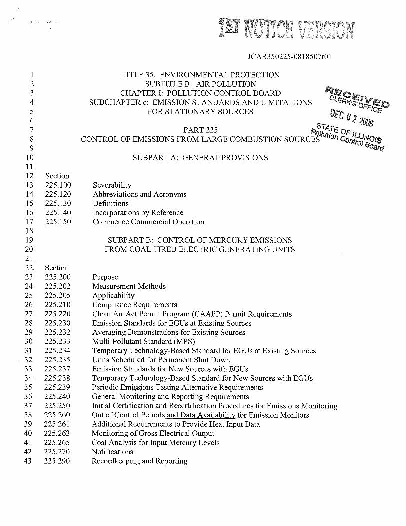
. JCAR350225-08 1 8507r01 1 TITLE 35: ENVIRONMENTAL PROTECTION 2 SUBTITLE B: AIR POLLUTION 3 CHAPTER I: POLLUTION CONTROL BOARD 4 SUBCHAPTER c: EMISSION STANDARDS AND LIMITATIONS 5 FOR STATIONARY SOURCES 6 P 011 Op,, 8 CONTROL OF EMISSIONS FROM LARGE COMBUSTION SOURCES 1Con’$JNOIs 9 10 SUBPART A: GENERAL PROVISIONS 11 12 Section 13 225.100 Severability 14 225.120 Abbreviations and Acronyms 15 225.130 Definitions 16 225.140 Incorporations by Reference 17 225.150 Commence Commercial Operation 18 19 SUBPART B: CONTROL OF MERCURY EMISSIONS 20 FROM COAL-FIRED ELECTRIC GENERATING UNITS 21 22 Section 23 225.200 Purpose 24 225 .202 Measurement Methods 25 225.205 Applicability 26 225.210 Compliance Requirements 27 225 .220 Clean Air Act Permit Program (CAAPP) Permit Requirements 28 225.230 Emission Standards for EGUs at Existing Sources 29 225 .232 Averaging Demonstrations for Existing Sources 30 225.233 Multi-Pollutant Standard (MPS) 31 225.234 Temporary Technology-Based Standard for EGUs at Existing Sources 32 225.23 5 Units Scheduled for Permanent Shut Down 33 225 .237 Emission Standards for New Sources with EGUs 34 225.23 8 Temporary Technology-Based Standard for New Sources with EGUs 35 225.239 Periodic Emissions Testing Alternative Requirements 36 225.240 General Monitoring and Reporting Requirements 37 225.250 Initial Certification and Recertification Procedures for Emissions Monitoring 38 225 .260 Out of Control Periods and Data Availability for Emission Monitors 39 225 .261 Additional Requirements to Provide Heat Input Data 40 225.263 Monitoring of Gross Electrical Output 41 225 .265 Coal Analysis for Input Mercury Levels 42 225.270 Notifications 43 225.290 Recordkeeping and Reporting
-
Upload
khangminh22 -
Category
Documents
-
view
1 -
download
0
Transcript of JCAR350225-08 1 8507r01 - Illinois Pollution Control Board
.
JCAR350225-08 1 8507r01
1 TITLE 35: ENVIRONMENTAL PROTECTION2 SUBTITLE B: AIR POLLUTION3 CHAPTER I: POLLUTION CONTROL BOARD4 SUBCHAPTER c: EMISSION STANDARDS AND LIMITATIONS5 FOR STATIONARY SOURCES6
P011 Op,,8 CONTROL OF EMISSIONS FROM LARGE COMBUSTION SOURCES 1Con’$JNOIs9
10 SUBPART A: GENERAL PROVISIONS1112 Section13 225.100 Severability14 225.120 Abbreviations and Acronyms15 225.130 Definitions16 225.140 Incorporations by Reference17 225.150 Commence Commercial Operation1819 SUBPART B: CONTROL OF MERCURY EMISSIONS20 FROM COAL-FIRED ELECTRIC GENERATING UNITS2122 Section23 225.200 Purpose24 225 .202 Measurement Methods25 225.205 Applicability26 225.210 Compliance Requirements27 225 .220 Clean Air Act Permit Program (CAAPP) Permit Requirements28 225.230 Emission Standards for EGUs at Existing Sources29 225 .232 Averaging Demonstrations for Existing Sources30 225.233 Multi-Pollutant Standard (MPS)31 225.234 Temporary Technology-Based Standard for EGUs at Existing Sources32 225.23 5 Units Scheduled for Permanent Shut Down33 225 .237 Emission Standards for New Sources with EGUs34 225.23 8 Temporary Technology-Based Standard for New Sources with EGUs35 225.239 Periodic Emissions Testing Alternative Requirements36 225.240 General Monitoring and Reporting Requirements37 225.250 Initial Certification and Recertification Procedures for Emissions Monitoring38 225 .260 Out of Control Periods and Data Availability for Emission Monitors39 225 .261 Additional Requirements to Provide Heat Input Data40 225.263 Monitoring of Gross Electrical Output41 225 .265 Coal Analysis for Input Mercury Levels42 225.270 Notifications43 225.290 Recordkeeping and Reporting
JCAR350225-08 1 8507r01
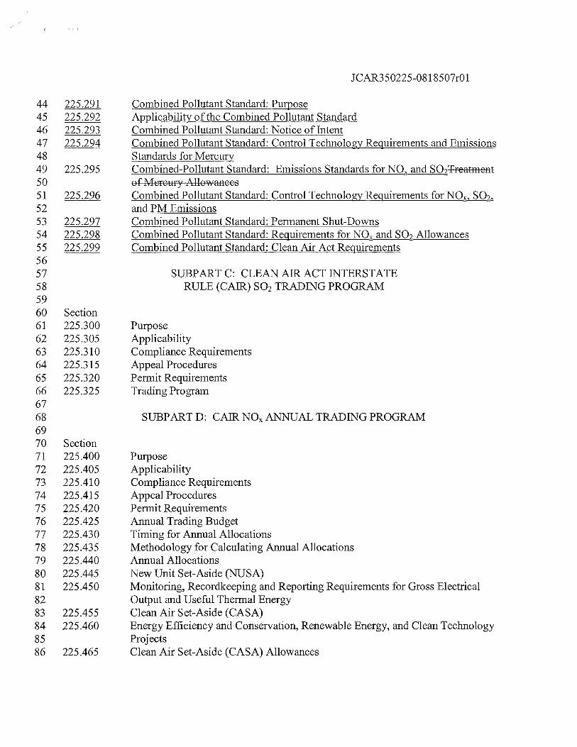
44 225.291 Combined Pollutant Standard: Purpose45 225.292 Applicability of the Combined Pollutant Standard46 225.293 Combined Pollutant Standard: Notice of Intent47 225.294 Combined Pollutant Standard: Control Technology Requirements and Emissions48 Standards for Mercury49 225.295 Combined-Pollutant Standard: Emissions Standards for NO and SO2Treatment50 of Mercury Allowances51 225.296 Combined Pollutant Standard: Control Technology Requirements for NON, SO52 and PM Emissions53 225.297 Combined Pollutant Standard: Permanent Shut-Downs54 225.298 Combined Pollutant Standard: Requirements for NO and SO2 Allowances55 225.299 Combined Pollutant Standard: Clean Air Act Requirements5657 SUBPART C: CLEAN AIR ACT INTERSTATE58 RULE (CAR) SO2 TRADING PROGRAM5960 Section61 225.300 Purpose62 225.305 Applicability63 225.3 10 Compliance Requirements64 225.315 Appeal Procedures65 225.320 Permit Requirements66 225.325 Trading Program6768 SUBPART D: CAR NO ANNUAL TRADING PROGRAM6970 Section71 225 .400 Purpose72 225.405 Applicability73 225 .410 Compliance Requirements74 225.415 Appeal Procedures75 225 .420 Permit Requirements76 225 .425 Annual Trading Budget77 225.43 0 Timing for Annual Allocations78 225.435 Methodology for Calculating Annual Allocations79 225 .440 Annual Allocations80 225 .445 New Unit Set-Aside (NUSA)81 225 .450 Monitoring, Recordkeeping and Reporting Requirements for Gross Electrical82 Output and Useful Thermal Energy83 225.455 Clean Air Set-Aside (CASA)84 225 .460 Energy Efficiency and Conservation, Renewable Energy, and Clean Technology85 Projects86 225.465 Clean Air Set-Aside (CASA) Allowances
JCAR350225-081 8507r01
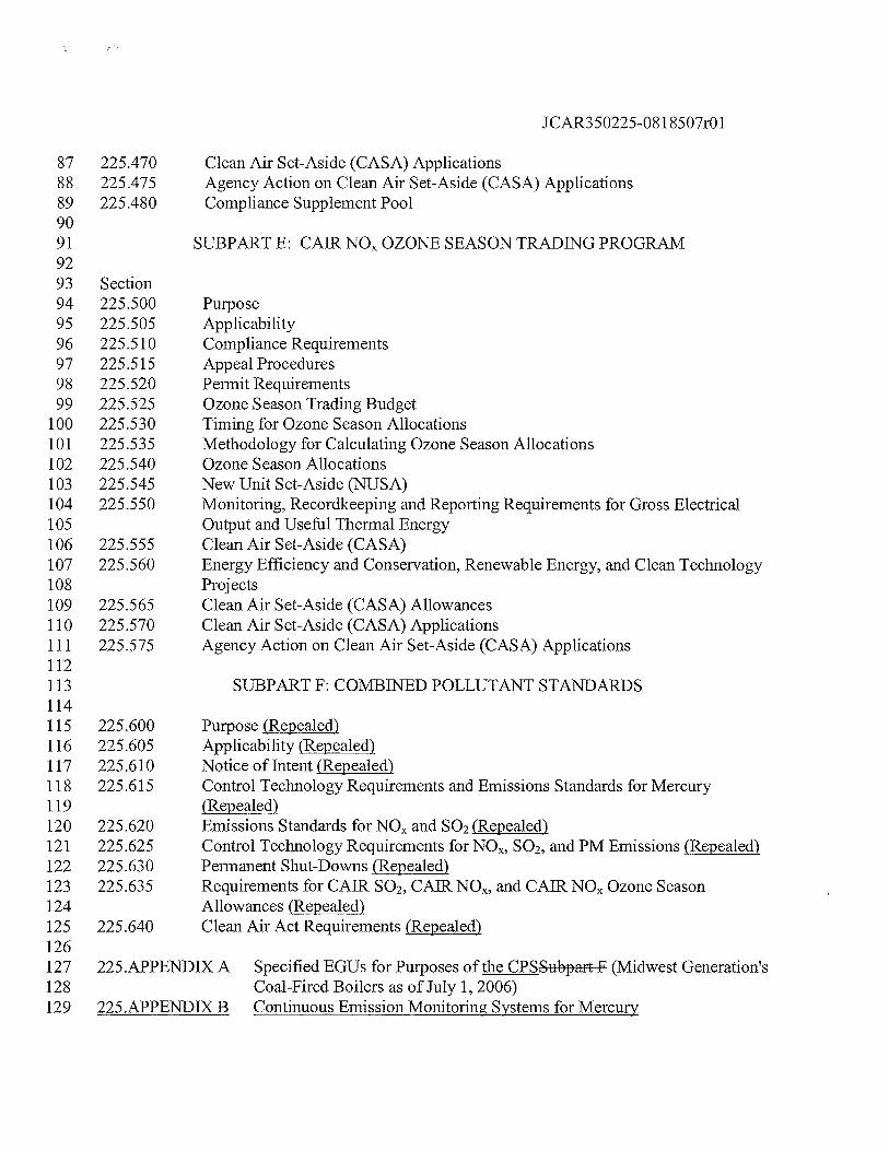
87 225 .470 Clean Air Set-Aside (CASA) Applications88 225.475 Agency Action on Clean Air Set-Aside (CASA) Applications89 225.480 Compliance Supplement Pool9091 SUBPART E: CAR NO OZONE SEASON TRADING PROGRAM9293 Section94 225.500 Purpose95 225.505 Applicability96 225.5 10 Compliance Requirements97 225.515 Appeal Procedures98 225.520 Permit Requirements99 225.525 Ozone Season Trading Budget
100 225.530 Timing for Ozone Season Allocations101 225.535 Methodology for Calculating Ozone Season Allocations102 225.540 Ozone Season Allocations103 225.545 New Unit Set-Aside (NUSA)104 225.550 Monitoring, Recordkeeping and Reporting Requirements for Gross Electrical105 Output and Useful Thermal Energy106 225.555 Clean Air Set-Aside (CASA)107 225.560 Energy Efficiency and Conservation, Renewable Energy, and Clean Technology108 Projects109 225.565 Clean Air Set-Aside (CASA) Allowances110 225.570 Clean Air Set-Aside (CASA) Applications111 225.5 75 Agency Action on Clean Air Set-Aside (CASA) Applications112113 SUBPART F: COMBINED POLLUTANT STANDARDS114115 225.600 Purpose (Repealed)116 225.605 Applicability (Repealed)117 225.6 10 Notice of Intent (Repealed)118 225.615 Control Technology Requirements and Emissions Standards for Mercury119 (Repealed)120 225.620 Emissions Standards for NO and SO2 (Repealed)121 225.625 Control Technology Requirements for NOR, SO2, and PM Emissions (Repealed)122 225.630 Permanent Shut-Downs (Repealed)123 225.63 5 Requirements for CAR SO2,CAR NOR, and CAIR NO Ozone Season124 Allowances (Repealed)125 225.640 Clean Air Act Requirements (Repealed)126127 225.APPENDIX A Specified EGUs for Purposes of the CPS Subpart F (Midwest Generation’s128 Coal-Fired Boilers as of July 1, 2006)129 225.APPENDIX B Continuous Emission Monitoring Systems for Mercury
JCAR350225-081 8507r01
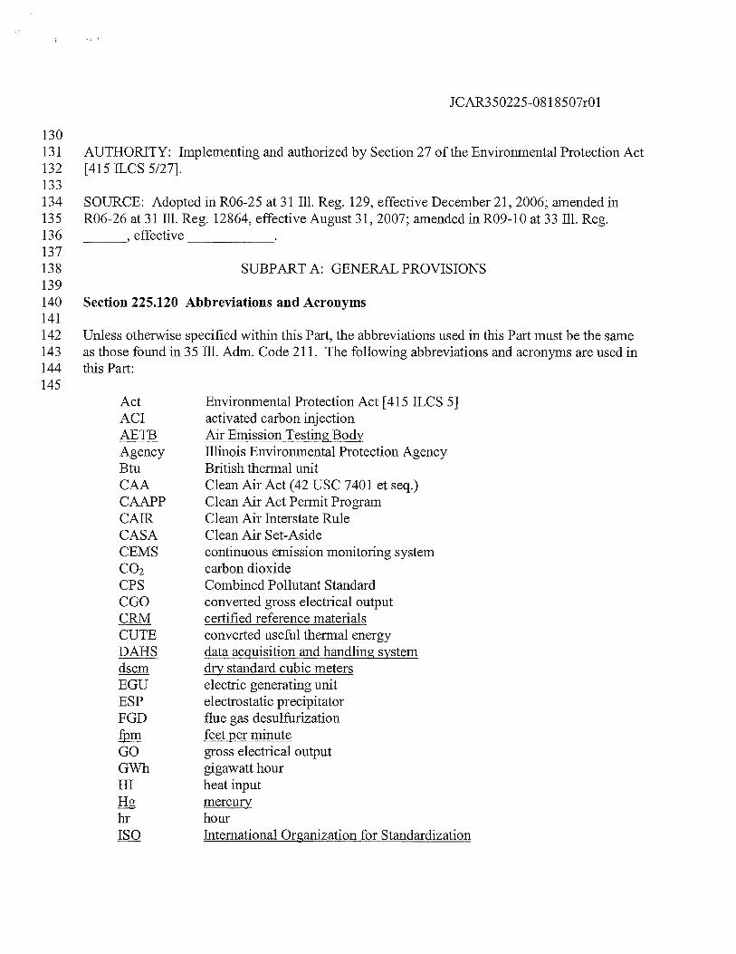
130131 AUTHORITY: Implementing and authorized by Section 27 of the Environmental Protection Act132 [415 ILCS 5/27].133134 SOURCE: Adopted in R06-25 at 31111. Reg. 129, effective December 21, 2006; amended in135 R06-26 at 31111. Reg. 12864, effective August 31, 2007; amended inRO9-10 at 33111. Reg.136 , effective137138 SUBPART A: GENERAL PROVISIONS139140 Section 225.120 Abbreviations and Acronyms141142 Unless otherwise specified within this Part, the abbreviations used in this Part must be the same143 as those found in 35 Ill. Adm. Code 211. The following abbreviations and acronyms are used in144 this Part:145
Act Environmental Protection Act [415 ILCS 5]ACT activated carbon injectionAETB Air Emission Testing BodyAgency Illinois Environmental Protection AgencyBtu British thermal unitCAA Clean Air Act (42 USC 7401 et seq.)CAAPP Clean Air Act Permit ProgramCA1R Clean Air Interstate RuleCASA Clean Air Set-AsideCEMS continuous emission monitoring systemCO2 carbon dioxideCPS Combined Pollutant StandardCGO converted gross electrical outputCRM certified reference materialsCUTE converted useful thermal energyDAHS data acquisition and handling systemdscm dry standard cubic metersEGU electric generating unitESP electrostatic precipitatorFGD flue gas desulfurization
feet per minuteGO gross electrical outputGWh gigawatt hourHI heat input
mercuryhr hourISO International Organization for Standardization
JCAR350225-08 1 8507r01
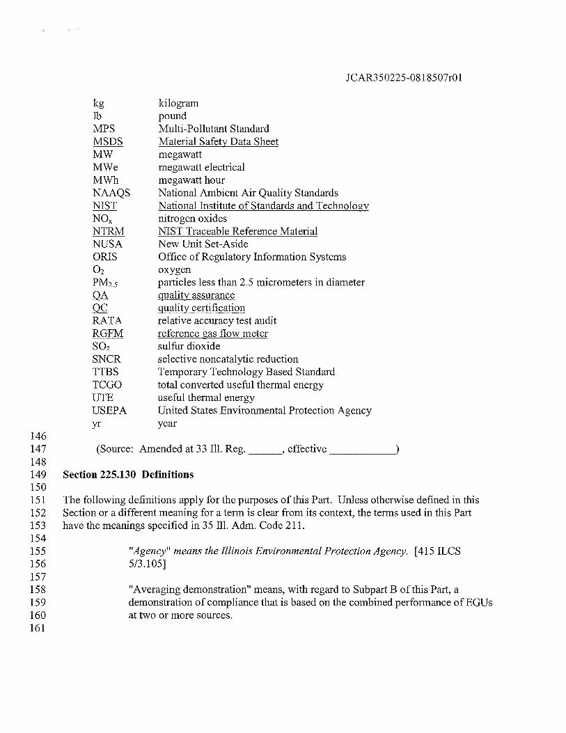
kg kilogramlb poundMPS Multi-Pollutant StandardMSDS Material Safety Data SheetMW megawattMWe megawatt electricalMWh megawatt hourNAAQS National Ambient Air Quality StandardsNIST National Institute of Standards and TechnologyNO nitrogen oxidesNTRM NIST Traceable Reference MaterialNUSA New Unit Set-AsideORIS Office of Regulatory Information Systems02 oxygenPM2.5 particles less than 2.5 micrometers in diameter
quality assurancequality certification
RATA relative accuracy test auditRGFM reference gas flow meterSO2 sulfur dioxideSNCR selective noncatalytic reductionTTBS Temporary Technology Based StandardTCGO total converted useful thermal energyUTE useful thermal energyUSEPA United States Environmental Protection Agencyyr year
146147 (Source: Amended at 33 Ill. Reg.
_______,
effective
______________
148149 Section 225.130 Definitions150151 The following definitions apply for the purposes of this Part. Unless otherwise defined in this152 Section or a different meaning for a term is clear from its context, the terms used in this Part153 have the meanings specified in 35 Ill. Adm. Code 211.154155 “Agency” means the Illinois Environmental Protection Agency. [415 ILCS156 5/3.105]157158 “Averaging demonstration” means, with regard to Subpart B of this Part, a159 demonstration of compliance that is based on the combined performance of EGUs160 at two or more sources.161
JCAR350225-08 1 8507r01
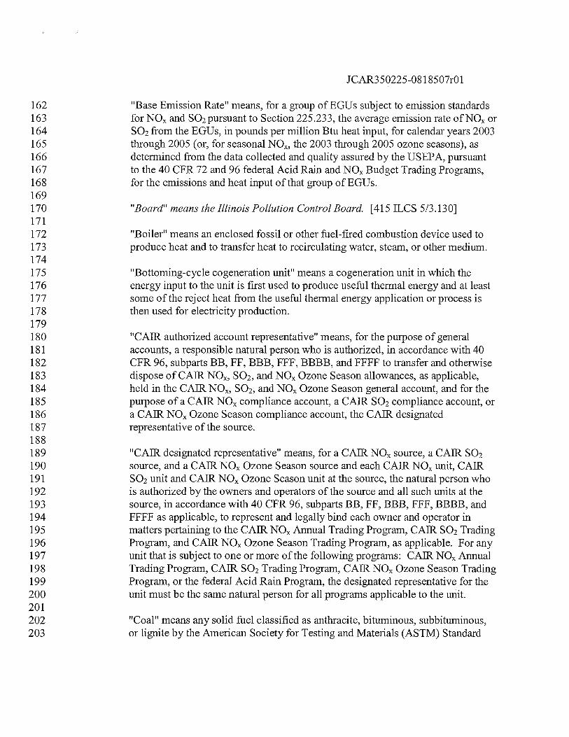
162 “Base Emission Rate?! means, for a group of EGUs subject to emission standards163 for NO and SO2pursuant to Section 225.233, the average emission rate ofNO or164 SO2 from the EGUs, in pounds per million Btu heat input, for calendar years 2003165 through 2005 (or, for seasonal NOR, the 2003 through 2005 ozone seasons), as166 determined from the data collected and quality assured by the USEPA, pursuant167 to the 40 CFR 72 and 96 federal Acid Rain and NO Budget Trading Programs,168 for the emissions and heat input of that group of EGUs.169170 “Board” means the Illinois Pollution Control Board. [415 ILCS 5/3.130]171172 “Boiler” means an enclosed fossil or other fuel-fired combustion device used to173 produce heat and to transfer heat to recirculating water, steam, or other medium.174175 “Bottoming-cycle cogeneration unit” means a cogeneration unit in which the176 energy input to the unit is first used to produce useful thermal energy and at least177 some of the reject heat from the useful thermal energy application or process is178 then used for electricity production.179180 “CAJR authorized account representative” means, for the purpose of general181 accounts, a responsible natural person who is authorized, in accordance with 40182 CFR 96, subparts BB, FF, BBB, FFF, BBBB, and FFFF to transfer and otherwise183 dispose of CAR NON, SO2, and NO Ozone Season allowances, as applicable,184 held in the CAR NOR, SO2, and NO Ozone Season general account, and for the185 purpose of a CAR NO compliance account, a CAR SO2 compliance account, or186 a CAR NO Ozone Season compliance account, the CAR designated187 representative of the source.188189 “CAR designated representative” means, for a CAR NO source, a CAR SO2190 source, and a CAR NO Ozone Season source and each CAIR NO unit, CAR191 SO2 unit and CAR NO Ozone Season unit at the source, the natural person who192 is authorized by the owners and operators of the source and all such units at the193 source, in accordance with 40 CFR 96, subparts BB, FF, BBB, FFF, BBBB, and194 FFFF as applicable, to represent and legally bind each owner and operator in195 matters pertaining to the CAR NO Annual Trading Program, CAR SO2 Trading196 Program, and CAR NO Ozone Season Trading Program, as applicable. For any197 unit that is subject to one or more of the following programs: CAR NO Annual198 Trading Program, CAR SO2 Trading Program, CAR NO Ozone Season Trading199 Program, or the federal Acid Rain Program, the designated representative for the200 unit must be the same natural person for all programs applicable to the unit.201202 “Coal” means any solid fuel classified as anthracite, bituminous, subbituminous,203 or lignite by the American Society for Testing and Materials (ASTM) Standard
JCAR350225-08 1 8507r01
204 Specification for Classification of Coals by Rank D388-77, 90, 91, 95, 98a, or 99205 (Reapproved 2004).206207 “Coal-derived fuel” means any fuel (whether in a solid, liquid or gaseous state)208 produced by the mechanical, thermal, or chemical processing of coal.209210 “Coal-fired” means:211212 For purposes of SubpartSubparts B and F, or for purposes of allocating213 allowances under Sections 225.435, 225.445, 225.535, and 225.545,214 combusting any amount of coal or coal-derived fuel, alone or in215 combination with any amount of any other fuel, during a specified year;216217 Except as provided above, combusting any amount of coal or coal-derived218 fuel, alone or in combination with any amount of any other fuel.219220 “Cogeneration unit” means, for the purposes of Subparts C, D, and E, a stationary,221 fossil fuel-fired boiler or a stationary, fossil fuel-fired combustion turbine of222 which both of the following conditions are true:223224 It uses equipment to produce electricity and useful thermal energy for225 industrial, commercial, heating, or cooling purposes through the sequential226 use of energy; and227228 It produces either of the following during the 12-month period beginning229 on the date the unit first produces electricity and during any subsequent230 calendar year after that in which the unit first produces electricity:231232 For a topping-cycle cogeneration unit, both of the following:233234 Useful thermal energy not less than five percent of total235 energy output; and236237 Useful power that, when added to one-half of useful238 thermal energy produced, is not less than 42.5 percent of239 total energy input, if useful thermal energy produced is 15240 percent or more of total energy output, or not less than 45241 percent of total energy input if useful thermal energy242 produced is less than 15 percent of total energy output; or243244 For a bottoming-cycle cogeneration unit, useful power not less245 than 45 percent of total energy input.246
JCAR350225-08 1 8507r01
247 “Combined cycle system” means a system comprised of one or more combustion248 turbines, heat recovery steam generators, and steam turbines configured to249 improve overall efficiency of electricity generation or steam production.250251 “Combustion turbine” means:252253 An enclosed device comprising a compressor, a combustor, and a turbine254 and in which the flue gas resulting from the combustion of fuel in the255 combustor passes through the turbine, rotating the turbine; and256257 If the enclosed device described in the above paragraph of this definition258 is combined cycle, any associated duct burner, heat recovery steam259 generator and steam turbine.260261 “Commence commercial operation” means, for the purposes of SubpartSubparts B262 and F of this Part, with regard to an EGU that serves a generator, to have begun to263 produce steam, gas, or other heated medium used to generate electricity for sale or264 use, including test generation. Such date must remain the unit’s date of265 commencement of operation even if the EGU is subsequently modified,266 reconstructed or repowered. For the purposes of Subparts C, D and E,267 “commence commercial operation” is as defined in Section 225.150.268269 “Commence construction” means, for the purposes of Section 225.460(f),270 225.470, 225.560(f), and 225.570, that the owner or owner’s designee has271 obtained all necessary preconstruction approvals (e.g., zoning) or permits and272 either has:273274 Begun, or caused to begin, a continuous program of actual on-site275 construction of the source, to be completed within a reasonable time; or276277 Entered into binding agreements or contractual obligations, which cannot278 be cancelled or modified without substantial loss to the owner or operator,279 to undertake a program of actual construction of the source to be280 completed within a reasonable time.281282 For purposes of this definition:283284 “Construction” shall be determined as any physical change or285 change in the method of operation, including but not limited to286 fabrication, erection, installation, demolition, or modification of287 projects eligible for CASA allowances, as set forth in Sections288 225.460 and 225.560.289
JCAR350225-08 1 8507r01
290 “A reasonable time” shall be determined considering but not291 limited to the following factors: the nature and size of the project,292 the extent of design engineering, the amount of off-site293 preparation, whether equipment can be fabricated or can be294 purchased, when the project begins (considering both the seasonal295 nature of the construction activity and the existence of other296 projects competing for construction labor at the same time, the297 place of the environmental permit in the sequence of corporate and298 overall governmental approval), and the nature of the project299 sponsor (e.g., private, public, regulated).300301 “Commence operation”, for purposes of Subparts C, D and E, means:302303 To have begun any mechanical, chemical, or electronic process, including,304 for the purpose of a unit, start-up of a unit’s combustion chamber, except305 as provided in 40 CFR 96.105, 96.205, or 96.305, as incorporated by306 reference in Section 225.140.307308 For a unit that undergoes a physical change (other than replacement of the309 unit by a unit at the same source) after the date the unit commences310 operation as set forth in the first paragraph of this definition, such date will311 remain the date of commencement of operation of the unit, which will312 continue to be treated as the same unit.313314 For a unit that is replaced by a unit at the same source (e.g., repowered),315 after the date the unit commences operation as set forth in the first316 paragraph of this definition, such date will remain the replaced unit’s date317 of commencement of operation, and the replacement unit will be treated as318 a separate unit with a separate date for commencement of operation as set319 forth in this definition as appropriate.320321 “Common stack” means a single flue through which emissions from two or more322 units are exhausted.323324 “Compliance account” means:325326 For the purposes of Subparts D and E, a CAR NO Allowance Tracking327 System account, established by USEPA for a CAIR NO source or CAR328 NO Ozone Season source pursuant to 40 CFR 96, subparts FF and FFFF329 in which any CAR NO allowance or CAR NO Ozone Season330 allowance allocations for the CAR NO units or CAR NO Ozone331 Season units at the source are initially recorded and in which are held any332 CAR NO or CAR NO Ozone Season allowances available for use for a

JCAR350225-081 8507r01
333 control period in order to meet the source’s CAR NO or CAIR NO334 Ozone Season emissions limitations in accordance with Sections 225 .410335 and 225.5 10, and 40 CFR 96.154 and 96.354, as incorporated by reference336 in Section 225.140. CAIR NO allowances may not be used for337 compliance with the CAIR NO Ozone Season Trading Program and338 CAR NO Ozone Season allowances may not be used for compliance339 with the CAR NO Annual Trading Program; or340341 For the purposes of Subpart C, a “compliance account” means a CAR342 SO2 compliance account, established by the USEPA for a CAR SO2343 source pursuant to 40 CFR 96, subpart FFF, in which any SO2 units at the344 source are initially recorded and in which are held any SO2 allowances345 available for use for a control period in order to meet the source’s CAIR346 SO2 emissions limitations in accordance with Section 225.3 10 and 40 CFR347 96.254, as incorporated by reference in Section 225.140.348349 “Control period” means:350351 For the CAIR SO2 and NO Annual Trading Programs in Subparts C and352 D, the period beginning January 1 of a calendar year, except as provided353 in Sections 225.3 10(d)(3) and 225.410(d)(3), and ending on December31354 of the same year, inclusive; or355356 For the CAIR NO Ozone Season Trading Program in Subpart E, the357 - period beginning May 1 of a calendar year, except as provided in Section358 225.5 10(d)(3), and ending on September 30 of the same year, inclusive.359360 “Designated representative” means, for the purposes of Subpart B of this Part, the361 natural person as defined in 40 CFR 60.4 102, and is the same natural person as362 the person who is the designated representative for the CAR trading and Acid363 Rain programs.364365 “Electric generating unit” or “EGU” means a fossil fuel-fired stationary boiler,366 combustion turbine or combined cycle system that serves a generator that has a367 nameplate capacity greater than 25 MWe and produces electricity for sale.368369 “Flue” means a conduit or duct through which gases or other matter is exhausted370 to the atmosphere.371372 “Fossil fuel” means natural gas, petroleum, coal, or any form of solid, liquid, or373 gaseous fuel derived from such material.374375 “Fossil fuel-fired” means the combusting of any amount of fossil fuel, alone or in
JCAR350225-08 1 8507r01
376 combination with any other fuel in any calendar year.377378 uGenerator means a device that produces electricity.379380 “Gross electrical output” means the total electrical output from an EGU before381 making any deductions for energy output used in any way related to the382 production of energy. For an EGU generating only electricity, the gross electrical383 output is the output from the turbine/generator set.384385 “Heat input” means, for the purposes of Subparts C, D, and E, a specified period386 of time, the product (in mmBtu/hr) of the gross calorific value of the fuel (in387 Btu!lb) divided by 1,000,000 BtulmmBtu and multiplied by the fuel feed rate into388 a combustion device (in lb of fuelltime), as measured, recorded and reported to389 USEPA by the CAR designated representative and determined by USEPA in390 accordance with 40 CFR 96, subpart HH, HHH, or HHHH, if applicable, and391 excluding the heat derived from preheated combustion air, recirculated flue gases,392 or exhaust from other sources.393394 “Higher heating value” or “HHV” means the total heat liberated per mass of fuel395 burned (Btu/lb), when fuel and dry air at standard conditions undergo complete396 combustion and all resultant products are brought to their standard states at397 standard conditions.398399 “Input mercury” means the mass of mercury that is contained in the coal400 combusted within an EGU.401402 “Integrated gasification combined cycle” or “IGCC” means a coal-fired electric403 utility steam generating unit that burns a synthetic gas derived from coal in a404 combined-cycle gas turbine. No coal is directly burned in the unit during405 operation.406407 “Long-term cold storage” means the complete shutdown of a unit intended to last408 for an extended period of time (at least two calendar years) where notice for long-409 term cold storage is provided under 40 CFR 75.6 1(a)(7).410411 “Nameplate capacity” means, starting from the initial installation of a generator,412 the maximum electrical generating output (in MWe) that the generator is capable413 of producing on a steady-state basis and during continuous operation (when not414 restricted by seasonal or other deratings) as of such installation as specified by the415 manufacturer of the generator or, starting from the completion of any subsequent416 physical change in the generator resulting in an increase in the maximum417 electrical generating output (in MWe) that the generator is capable of producing418 on a steady-state basis and during continuous operation (when not restricted by
JCAR350225-081 8507r01
419 seasonal or other deratings), such increased maximum amount as of completion as420 specified by the person conducting the physical change.421422 “NIST traceable elemental mercury standards” means either:423424 j) Compressed gas cylinders having known concentrations of425 elemental mercury, which have been prepared according to the426 “EPA Traceability Protocol for Assay and Certification of Gaseous427 Calibration Standards”; or428429 Calibration gases having known concentrations of elemental430 mercury, produced by a generator that fully meets the performance431 requirements of the “EPA Traceability Protocol for Qualification432 and Certification of Elemental Mercury Gas Generators.”433434 “NIST traceable source of oxidized mercury” means a generator that is capable of435 providing known concentrations of vapor phase mercuric chloride (HgCI2), and436 that fully meets the performance requirements of the “EPA Traceability Protocol437 for Qualification and Certification of Oxidized Mercury Gas Generators.”438439 “Oil-fired unit” means a unit combusting fuel oil for more than 15.0 percent of the440 annual heat input in a specified year and not qualifying as coal-fired.441442 “Output-based emission standard” means, for the purposes of Subpart B of this443 Part, a maximum allowable rate of emissions of mercury per unit of gross444 electrical output from an EGU.445446 “Potential electrical output capacity” means 33 percent of a unit’s maximum design447 heat input, expressed in mmBtulhr divided by 3.4 13 mmBtulMWh, and multiplied448 by 8,760 hr/yr.449450 “Project sponsor” means a person or an entity, including but not limited to the451 owner or operator of an EGU or a not-for-profit group, that provides the majority452 of funding for an energy efficiency and conservation, renewable energy, or clean453 technology project as listed in Sections 225 .460 and 225.560, unless another454 person or entity is designated by a written agreement as the project sponsor for the455 purpose of applying for NO allowances or NO Ozone Season allowances from456 the CASA.457458 “Rated-energy efficiency” means the percentage of thermal energy input that is459 recovered as useable energy in the form of gross electrical output, useful thermal460 energy, or both that is used for heating, cooling, industrial processes, or other461 beneficial uses as follows:
JCAR350225-08 1 8507r01
462463 For electric generators, rated-energy efficiency is calculated as one464 kilowatt hour (3,413 Btu) of electricity divided by the unit’s design heat465 rate using the higher heating value of the fuel, and expressed as a466 percentage.467468 For combined heat and power projects, rated-energy efficiency is469 calculated using the following formula:470
REE = ((GO + UTE)/HI) x 100471472 Where:473
REE = Rated-energy efficiency, expressed as percentage.GO = Gross electrical output of the system expressed in Btu/hr.
UTE = Useful thermal output from the system that is used forheating, cooling, industrial processes or other beneficialuses, expressed in Btu/hr.
HI = Heat input, based upon the higher heating value of fuel, inBtulhr.
474475 “Repowered” means, for the purposes of an EGU, replacement of a coal-fired476 boiler with one of the following coal-fired technologies at the same source as the477 coal-fired boiler:478479 Atmospheric or pressurized fluidized bed combustion;480481 Integrated gasification combined cycle;482483 Magnetohydrodynamics;484485 Direct and indirect coal-fired turbines;486487 Integrated gasification fuel cells; or488489 As determined by the USEPA in consultation with the United States490 Department of Energy, a derivative of one or more of the technologies491 under this definition and any other coal-fired technology capable of492 controlling multiple combustion emissions simultaneously with improved493 boiler or generation efficiency and with significantly greater waste494 reduction relative to the performance of technology in widespread495 commercial use as of January 1, 2005.496
JCAR350225-081 8507r01
497 “Rolling 12-month basis” means, for the purposes of SubpartSubparts B and F of498 this Part, a determination made on a monthly basis from the relevant data for a499 particular calendar month and the preceding 11 calendar months (total of 12500 months of data), with two exceptions. For determinations involving one EGU,501 calendar months in which the EGU does not operate (zero EGU operating hours)502 must not be included in the determination, and must be replaced by a preceding503 month or months in which the EGU does operate, so that the determination is still504 based on 12 months of data. For determinations involving two or more EGUs,505 calendar months in which none of the EGUs covered by the determination506 operates (zero EGU operating hours) must not be included in the determination,507 and must be replaced by preceding months in which at least one of the EGUs508 covered by the determination does operate, so that the determination is still based509 on 12 months of data.510511 “Total energy output” means, with respect to a cogeneration unit, the sum of512 useful power and useful thermal energy produced by the cogeneration unit.513514 “Useful thermal energy” means, for the purpose of a cogeneration unit, the515 thermal energy that is made available to an industrial or commercial process,516 excluding any heat contained in condensate return or makeup water:517518 Used in a heating application (e.g., space heating or domestic hot water519 heating); or520521 Used in a space cooling application (e.g., thermal energy used by an522 absorption chiller).523524 (Source: Amended at 33 Ill. Reg.
_______,
effective
______________
525526 Section 225.140 Incorporations by Reference527528 The following materials are incorporated by reference. These incorporations do not include any529 later amendments or editions.530531 a) Appendix A, Subpart A, and Performance Specifications 2 and 3 of Appendix B532 of 40 CFR 60, 60.17, 60.45a, 60.49a(k)(1) and (p), 60.50a(h), and 60.4170533 through 60.4176 (2005).534535 }) 40 CFR 72.2 (2005).536537 th) 40 CFR 75.4, 75.11 through 75.14, 75.16 through 75.19, 75.30, 75.34 through538 75.37, 75.40 through 75.48, 75.53(e), 75.57(c)(2)(i) through 75.57(c)(2)(vi),539 75.60 through 75.67, 75.71, 75.74(c), Sections 2.1.1.5, 2.1.1.2, 7.7, and 7.8 of
JCAR350225-08 1 8507r01
540 Appendix A to 40 CFR 75, Appendix C to 40 CFR 75, Section 3.3.5 of Appendix541 F to 40 CFR 75 (2006)40 CFR 75 (2006).542543 de) 40 CFR78 (2006).544545 e4) 40 CFR 96, CARSO2Trading Program, subparts AAA (excluding 40 CFR546 96.204 and 96.206), BBB, FFF, GGG, and HHH (2006).547548 fe) 40 CFR 96, CAR NO Annual Trading Program, subparts AA (excluding 40549 CFR 96.104, 96.105(b)(2), and 96.106), BB, FF, GG, and HH (2006).550551 g4) 40 CFR 96, CAR NO Ozone Season Trading Program, subparts AAAA552 (excluding 40 CFR 96.304, 96.305(b)(2), and 96.306), BBBB, FFFF, GGGG, and553 HHHH (2006).554555 hg) ASTM. The following methods from the American Society for Testing and556 Materials, 100 Barr Harbor Drive, P.O. Box C700, West Conshohocken PA557 19428-2959, (610) 832-9585:558559 1) ASTM D388-77 (approved February 25, 1977), D388-90 (approved560 March 30, 1990), D388-91a (approved April 15, 1991), D388-95561 (approved January 15, 1995), D388-98a (approved September 10, 1998),562 or D388-99 (approved September 10, 1999, reapproved in 2004),563 Classification of Coals by Rank.564565 2) ASTM D3173-03, Standard Test Method for Moisture in the Analysis566 Sample of Coal and Coke (Approved April 10, 2003).567568 3) ASTM D3684-01, Standard Test Method for Total Mercury in Coal by the569 Oxygen Bomb CombustionlAtomic Absorption Method (Approved570 October 10, 2001).571572 4 ASTM D4840-99, Standard Guide for Sampling Chain-of-Custody573 Procedures (Reapproved 2004).574575 54) ASTM D5865-04, Standard Test Method for Gross Calorific Value of576 Coal and Coke (Approved April 1, 2004).577578 65) ASTM D6414-01, Standard Test Method for Total Mercury in Coal and579 Coal Combustion Residues by Acid Extraction or Wet OxidationlCold580 Vapor Atomic Absorption (Approved October 10, 2001).581
JCAR350225-08 1 8507r01
582 76) ASTM D6784-02, Standard Test Method for Elemental, Oxidized,583 Particle-Bound and Total Mercury in Flue Gas Generated from Coal-Fired584 Stationary Sources (Ontario Hydro Method) (Approved April 10, 2002).585586 ) ASTM D691 1-03. Standard Guide for Packaging and Shipping587 Environmental Samples for Laboratory Analysis.588589 2) ASTM D7036-04, Standard Practice for Competence of Air Emission590 Testing Bodies.591592 ih) Federal Energy Management Program, M&V Guidelines: Measurement and593 Verification for Federal Energy Projects, US Department of Energy, Office of594 Energy Efficiency and Renewable Energy, Version 2.2, DOE/GO-102000-0960595 (September 2000).596597 (Source: Amended at 33 Iii. Reg.
_______,
effective
______________
598599 SUBPART B: CONTROL OF MERCURY EMISSIONS600 FROM COAL-FIRED ELECTRIC GENERATING UNITS601602 Section 225.202 Measurement Methods603604 Measurement of mercury must be according to the following:605606 a) Continuous emission monitoring pursuant to Appendix B to this Part or an607 alternative emissions monitoring system, alternative reference method for608 measuring emissions, or other alternative to the emissions monitoring and609 measurement requirements of Sections 225.240 through 225.290, if such610 alternative is submitted to the Agency in writing and approved in writing by the611 Manager of the Bureau of Air’s Compliance Section.40 CFR 75 (2005).612613 b) ASTM D3173-03, Standard Test Method for Moisture in the Analysis Sample of614 Coal and Coke (Approved April 10, 2003), incorporated by reference in Section615 225.140.616617 c) ASTM D3684-01, Standard Test Method for Total Mercury in Coal by the618 Oxygen Bomb CombustionlAtomic Absorption Method (Approved October 10,619 2001), incorporated by reference in Section 225.140.620621 d) ASTM D5865-04, Standard Test Method for Gross Calorific Value of Coal and622 Coke (Approved April 1, 2004), incorporated by reference in Section 225.140.623
JCAR350225-081 8507r01
624 e) ASTM D6414-01, Standard Test Method for Total Mercury in Coal and Coal625 Combustion Residues by Acid Extraction or Wet Oxidation/Cold Vapor Atomic626 Absorption (Approved October 10, 2001), incorporated by reference in Section627 225.140.628629 f) ASTM D6784-02, Standard Test Method for Elemental, Oxidized, Particle-Bound630 and Total Mercury in Flue Gas Generated from Coal-Fired Stationary Sources631 (Ontario Hydro Method) (Approved April 10, 2002), incorporated by reference in632 Section 225.140.633634 g) Emissions testing pursuant to Appendix A of 40 CFR 60.635636 (Source: Amended at 33 Iii. Reg.
_______,
effective
______________
637638 Section 225.210 Compliance Requirements639640 a) Permit Requirements.641 The owner or operator of each source with one or more EGUs subject to this642 Subpart B at the source must apply for a CAAPP permit that addresses the643 applicable requirements of this Subpart B.644645 b) Monitoring and Testing Requirements.646647 1) The owner or operator of each source and each EGU at the source must64.8 comply with either the monitoring requirements of Sections 225.240649 through 225 .290 of this Subpart B, the periodic emissions testing650 requirements of Section 225.23 9 of this Subpart B, or an alternative651 emissions monitoring system, alternative reference method for measuring652 emissions, or other alternative to the emissions monitoring and653 measurement requirements of Sections 225.240 through 225.290, if such654 alternative is submitted to the Agency in writing and approved in writing655 by the Manager of the Bureau of Air’s Compliance Section.656657 2) The compliance of each EGU with the mercury requirements of Sections658 225.230 and 225.237 of this Subpart B must be determined by the659 emissions measurements recorded and reported in accordance with either660 Sections 225.240 through 225.290 of this Subpart B, Section 225.239 of661 this Subpart B, or an alternative emissions monitoring system, alternative662 reference method for measuring emissions, or other alternative to the663 emissions monitoring and measurement requirements of Sections 225.240664 through 225.290, if such alternative is submitted to the Agency in writing665 and approved in writing by the Manager of the Bureau of Air’s666 Compliance Section.
JCAR350225-08 1 8507r01
667668 c) Mercury Emission Reduction Requirements669 The owner or operator of any EGU subject to this Subpart B must comply with670 applicable requirements for control of mercury emissions of Section 225.230 or671 Section 225.237 of this Subpart B.672673 d) Recordkeeping and Reporting Requirements674 Unless otherwise provided, the owner or operator of a source with one or more675 EGUs at the source must keep on site at the source each of the documents listed in676 subsections (d)(1) through (d)(3) of this Section for a period of five years from the677 date the document is created. This period may be extended, in writing by the678 Agency, for cause, at any time prior to the end of five years.679680 1) All emissions monitoring information gathered in accordance with681 Sections 225.240 through 225.290 and all periodic emissions testing682 information gathered in accordance with Section 225.239.683684 2) Copies of all reports, compliance certifications, and other submissions and685 all records made or required or documents necessary to demonstrate686 compliance with the requirements of this Subpart B.687688 3) Copies of all documents used to complete a permit application and any689 other submission under this Subpart B.690691 e) Liability.692693 1) The owner or operator of each source with one or more EGUs must meet694 the requirements of this Subpart B.695696 2) Any provision of this Subpart B that applies to a source must also apply to697 the owner and operator of such source and to the owner or operator of698 each EGU at the source.699700 3) Any provision of this Subpart B that applies to an EGU must also apply to701 the owner or operator of such EGU.702703 f) Effect on Other Authorities. No provision of this Subpart B may be construed as704 exempting or excluding the owner or operator of a source or EGU from705 compliance with any other provision of an approved State Implementation Plan, a706 permit, the Act, or the CAA.707708 (Source: Amended at 33 Ill. Reg.
_______,
effective
______________
709
JCAR350225-081 8507r01
710 Section 225.220 Clean Air Act Permit Program (CAAPP) Permit Requirements711712 a) Application Requirements.713714 1) Each source with one or more EGUs subject to the requirements of this715 Subpart B is required to submit a CAAPP permit application that716 addresses all applicable requirements of this Subpart B, applicable to each717 EGU at the source.718719 2) For any EGU that commenced commercial operation:720721 A) on or before December 31, 2008, the owner or operator of such722 EGUs must submit an initial permit application or application for723 CAAPP permit modification that meets the requirements of this724 Section on or before December 31, 2008.725726 B) after December 31, 2008, the owner or operator of any such EGU727 must submit an initial CAAPP permit application or application for728 CAAPP modification that meets the requirements of this Section729 not later than 180 days before initial startup of the EGU, unless the730 construction permit issued for the EGU addresses the requirements731 of this Subpart B.732733 b) Contents of Permit Applications.734 In addition to other information required for a complete application for CAAPP735 permit or CAAPP permit modification, the application must include the following736 information:737738 1) The ORIS (Office of Regulatory Information Systems) or facility code739 assigned to the source by the U.S. Department of Energy, Energy740 Information Administration, if applicable.741742 2) Identification of each EGU at the source.743744 3) The intended approach to the monitoring requirements of Sections745 225 .240 through 225.290 of this Subpart B, or, in the alternative, the746 applicant may include its intended approach to the testing requirement of747 Section 225 .239 of this Subpart B.748749 4) The intended approach to the mercury emission reduction requirements of750 Section 225.230 or 225.237 of this Subpart B, as applicable.751752 c) Permit Contents.
JCAR350225-081 8507r01
753754 1) Each CAAPP permit issued by the Agency for a source with one or more755 EGUs subject to the requirements of this Subpart B must contain federally756 enforceable conditions addressing all applicable requirements of this757 Subpart B, which conditions must be a complete and segregable portion of758 the source’s entire CAAPP permit.759760 2) In addition to conditions related to the applicable requirements of this761 Subpart B, each such CAAPP permit must also contain the information762 specified under subsection (b) of this Section.763764 (Source: Amended at 33 Ill. Reg.
_______,
effective
______________
765766 Section 225.230 Emission Standards for EGUs at Existing Sources767768 a) Emission Standards.769770 1) Except as provided in Sections 225.230(b) and (d), 225 .232 through771 225.234, 225.239, and 225.29 1 through 225.299 of this Subpart B,772 beginningBeginning July 1, 2009, the owner or operator of a source with773 one or more EGUs subject to this Subpart B that commenced commercial774 operation on or before December 31, 2008, must comply with one of the775 following standards for each EGU on a rolling 12-month basis:776777 A) An emission standard of 0.0080 lb mercury/GWh gross electrical778 output; or779780 B) A minimum 90-percent reduction of input mercury.781782 2) For an EGU complying with subsection (a)(1)(A) of this Section, the783 actual mercury emission rate of the EGU for each 12-month rolling period,784 as monitored in accordance with this Subpart B and calculated as follows,785 must not exceed the applicable emission standard:786
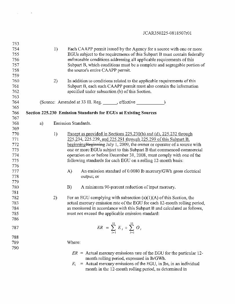
787 ER=E1÷O1
788789 Where:790
ER = Actual mercury emissions rate of the EGU for the particular 12-month rolling period, expressed in lbIGWh.
E = Actual mercury emissions of the EGU, in ibs, in an individualmonth in the 12-month rolling period, as determined in
JCAR350225-08 1 8507r01
accordance with the emissions monitoring provisions of thisSubpart B.
O = Gross electrical output of the EGU, in GWh, in an individualmonth in the 12-month rolling period, as determined inaccordance with Section 225.263 of this Subpart B.
791792 3) For an EGU complying with subsection (a)(1)(B) of this Section, the793 actual control efficiency for mercury emissions achieved by the EGU for794 each 12-month rolling period, as monitored in accordance with this795 Subpart B and calculated as follows, must meet or exceed the applicable796 efficiency requirement:797
798 CE=100x{1—(>ZE1÷I1)}
799800 Where:801
CE = Actual control efficiency for mercury emissions of the EGU forthe particular 12-month rolling period, expressed as a percent.
E Actual mercury emissions of the EGU, in ibs, in an individualmonth in the 12-month rolling period, as determined inaccordance with the emissions monitoring provisions of thisSubpart B.
I, = Amount of mercury in the fuel fired in the EGU, in lbs, in anindividual month in the 12-month rolling period, as determinedin accordance with Section 225.265 of this Subpart B.
802803 b) Alternative Emission Standards for Single EGUs.804805 1) As an alternative to compliance with the emission standards in subsection806 (a) of this Section, the owner or operator of the EGU may comply with the807 emission standards of this Subpart B by demonstrating that the actual808 emissions of mercury from the EGU are less than the allowable emissions809 of mercury from the EGU on a rolling 12-month basis.810811 2) For the purpose of demonstrating compliance with the alternative emission812 standards of this subsection (b), for each rolling 12-month period, the813 actual emissions of mercury from the EGU, as monitored in accordance814 with this Subpart B, must not exceed the allowable emissions of mercury815 from the EGU, as further provided by the following formulas:816817 E12A12
818
JCAR350225-08 1 8507r01
819 E12=E1
820
821 A12=A1
822823 Where:824
= Actual mercury emissions of the EGU for the particular12-month rolling period.
A12 = Allowable mercury emissions of the EGU for the particular12-month rolling period.
= Actual mercury emissions of the EGU in an individualmonth in the 12-month rolling period.
= Allowable mercury emissions of the EGU in an individualmonth in the 12-month rolling period, based on either theinput mercury to the unit ) or the electrical outputfrom the EGU ), as selected by the owner oroperator of the EGU for that given month.
= Allowable mercury emissions of the EGU in an individualmonth based on the input mercury to the EGU, calculatedas 10.0 percent (or 0.100) of the input mercury to the EGU.
= Allowable mercury emissions of the EGU in a particularmonth based on the electrical output from the EGU,calculated as the product of the output based mercury limit,i.e., 0.0080 lb/GWh, and the electrical output from theEGU, in GWh.
825826 3) If the owner or operator of an EGU does not conduct the necessary827 sampling, analysis, and recordkeeping, in accordance with Section828 225 .265 of this Subpart B, to determine the mercury input to the EGU, the829 allowable emissions of the EGU must be calculated based on the electrical830 output of the EGU.831832 c) If two or more EGUs are served by common stack4s and the owner or operator833 conducts monitoring for mercury emissions in the common stacks, as provided834 for by Sections 1.14 through 1.18 of Appendix B to this Part4O CFR 75, subpart I,835 such that the mercury emissions of each EGU are not determined separately,836 compliance of the EGUs with the applicable emission standards of this Subpart B837 must be determined as if the EGUs were a single EGU.838839 d) Alternative Emission Standards for Multiple EGUs.840
JCAR350225-08 1 8507r01
841 1) As an alternative to compliance with the emission standards of subsection842 (a) of this Section, the owner or operator of a source with multiple EGUs843 may comply with the emission standards of this Subpart B by844 demonstrating that the actual emissions of mercury from all EGUs at the845 source are less than the allowable emissions of mercury from all EGUs at846 the source on a rolling 12-month basis.847848 2) For the purposes of the alternative emission standard of subsection (d)(1)849 of this Section, for each rolling 12-month period, the actual emissions of850 mercury from all the EGUs at the source, as monitored in accordance with851 this Subpart B, must not exceed the sum of the allowable emissions of852 mercury from all the EGUs at the source, as further provided by the853 following formulas:854855 ESAS856
857 E3=E
858
859
860861 Where:862
Es = Sum of the actual mercury emissions of the EGUs at the source.A5 Sum of the allowable mercury emissions of the EGUs at the source.E = Actual mercury emissions of an individual EGU at the source, as
determined in accordance with subsection (b)(2) of this Section.A = Allowable mercury emissions of an individual EGU at the source, as
determined in accordance with subsection (b)(2) of this Section.n = Number of EGUs covered by the demonstration.
863864 3) If an owner or operator of a source with two or more EGUs that is relying865 on this subsection (d) to demonstrate compliance fails to meet the866 requirements of this subsection (d) in a given 12-month rolling period, all867 EGUs at such source covered by the compliance demonstration are868 considered out of compliance with the applicable emission standards of869 this Subpart B for the entire last month of that period.870871 (Source: Amended at 33 Iii. Reg.
_______,
effective
_____________
872873 Section 225.233 Multi-Pollutant Standards (MPS)
JCAR350225-081 8507r01
874875 a) General.876877 1) As an alternative to compliance with the emissions standards of Section878 225.230(a), the owner of eligible EGUs may elect for those EGUs to879 demonstrate compliance pursuant to this Section, which establishes880 control requirements and standards for emissions of NO and SO2, as well881 as for emissions of mercury.882883 2) For the purpose of this Section, the following requirements apply:884885 A) An eligible EGU is an EGU that is located in Illinois and which886 commenced commercial operation on or before December 31,887 2004; and888889 B) Ownership of an eligible EGU is determined based on direct890 ownership, by the holding of a majority interest in a company that891 owns the EGU or EGUs, or by the common ownership of the892 company that owns the EGU, whether through a parent-subsidiary893 relationship, as a sister corporation, or as an affiliated corporation894 with the same parent corporation, provided that the owner has the895 right or authority to submit a CAAPP application on behalf of the896 EGU.897898 3) The owner of one or more EGUs electing to demonstrate compliance with899 this Subpart B pursuant to this Section must submit an application for a900 CAAPP permit modification to the Agency, as provided in Section901 225.220, that includes the information specified in subsection (b) of this902 Section and which clearly states the owner’s election to demonstrate903 compliance pursuant to this Section 225.233.904905 A) If the owner of one or more EGUs elects to demonstrate906 compliance with this Subpart pursuant to this Section, then all907 EGUs it owns in Illinois as of July 1, 2006, as defined in908 subsection (a)(2)(B) of this Section, must be thereafter subject to909 the standards and control requirements of this Section, except as910 provided in subsection (a)(3)(B). Such EGUs must be referred to911 as a Multi-Pollutant Standard (MPS) Group.912913 B) Notwithstanding the foregoing, the owner may exclude from an914 MPS Group any EGU scheduled for permanent shutdown that the915 owner so designates in its CAAPP application required to be916 submitted pursuant to subsection (a)(3) of this Section, with
JCAR350225-081 8507r01
917 compliance for such units to be achieved by means of Section918 225.235.919920 4) When an EGU is subject to the requirements of this Section, the921 requirements apply to all owners or operators of the EGU, and to the922 designated representative for the EGU.923924 b) Notice of Intent.925 The owner of one or more EGUs that intends to comply with this Subpart B by926 means of this Section must notify the Agency of its intention by December 31,927 2007. The following information must accompany the notification:928929 1) The identification of each EGU that will be complying with this Subpart B930 by means of the multi-pollutant standards contained in this Section, with931 evidence that the owner has identified all EGUs that it owned in Illinois as932 of July 1, 2006 and which commenced commercial operation on or before933 December 31, 2004;934935 2) If an EGU identified in subsection (b)(1) of this Section is also owned or936 operated by a person different than the owner submitting the notice of937 intent, a demonstration that the submitter has the right to commit the EGU938 or authorization from the responsible official for the EGU accepting the939 application;940941 3) The Base Emission Rates for the EGUs, with copies of supporting data942 and calculations;943944 4) A summary of the current control devices installed and operating on each945 EGU and identification of the additional control devices that will likely be946 needed for the each EGU to comply with emission control requirements of947 this Section, including identification of each EGU in the MPS group that948 will be addressed by subsection (c)(1)(B) of this Section, with information949 showing that the eligibility criteria for this subsection (b) are satisfied; and950951 5) Identification of each EGU that is scheduled for permanent shut down, as952 provided by Section 225 .235, which will not be part of the MPS Group953 and which will not be demonstrating compliance with this Subpart B954 pursuant to this Section.955956 c) Control Technology Requirements for Emissions of Mercury.957958 1) Requirements for EGUs in an MPS Group.959
JCAR350225-08 1 8507r01
960 A) For each EGU in an MPS Group other than an EGU that is961 addressed by subsection (c)(1)(B) of this Section for the period962 beginning July 1, 2009 (or December 31, 2009 for an EGU for963 which an SO2 scrubber or fabric filter is being installed to be in964 operation by December 31, 2009), and ending on December 31,965 2014 (or such earlier date that the EGU is subject to the mercury966 emission standard in subsection (d)(1) of this Section), the owner967 or operator of the EGU must install, to the extent not already968 installed, and properly operate and maintain one of the following969 emission control devices:970971 i) A Halogenated Activated Carbon Injection System,972 complying with the sorbent injection requirements of973 subsection (c)(2) of this Section, except as may be974 otherwise provided by subsection (c)(4) of this Section, and975 followed by a Cold-Side Electrostatic Precipitator or Fabric976 Filter; or977978 ii) If the boiler fires bituminous coal, a Selective Catalytic979 Reduction (SCR) System and an SO2 Scrubber.980981 B) An owner of an EGU in an MPS Group has two options under this982 subsection (c). For an MPS Group that contains EGUs smaller983 than 90 gross MW in capacity, the owner may designate any such984 EGUs to be not subject to subsection (c)(1)(A) of this Section. Or,985 for an MPS Group that contains EGUs with gross MW capacity of986 less than 115 MW, the owner may designate any such EGUs to be987 not subject to subsection (c)(1)(A) of this Section, provided that988 the aggregate gross MW capacity of the designated EGUs does not989 exceed 4% of the total gross MW capacity of the MPS Group. For990 any EGU subject to one of these two options, unless the EGU is991 subject to the emission standards in subsection (d)(2) of this992 Section, beginning on January 1, 2013, and continuing until such993 date that the owner or operator of the EGU commits to comply994 with the mercury emission standard in subsection (d)(2) of this995 Section, the owner or operator of the EGU must install and996 properly operate and maintain a Halogenated Activated Carbon997 Injection System that complies with the sorbent injection998 requirements of subsection (c)(2) of this Section, except as may be999 otherwise provided by subsection (c)(4) of this Section, and
1000 followed by either a Cold-Side Electrostatic Precipitator or Fabric1001 Filter. The use of a properly installed, operated, and maintained1002 Halogenated Activated Carbon Injection System that meets the
JCAR350225-081 8507r01
1003 sorbent injection requirements of subsection (c)(2) of this Section1004 is defined as the “principal control technique.”10051006 2) For each EGU for which injection of halogenated activated carbon is1007 required by subsection (c)(1) of this Section, the owner or operator of the1008 EGU must inject halogenated activated carbon in an optimum manner,1009 which, except as provided in subsection (c)(4) of this Section, is defined as1010 all of the following:10111012 A) The use of an injection system designed for effective absorption of1013 mercury, considering the configuration of the EGU and its1014 ductwork;10151016 B) The injection of halogenated activated carbon manufactured by1017 Alstom, Norit, or Sorbent Technologies, or Calgon Carbon’s1018 FLUEPAC MC Plus, or the injection of any other halogenated1019 activated carbon or sorbent that the owner or operator of the EGU1020 has demonstrated to have similar or better effectiveness for control1021 of mercury emissions; and10221023 C) The injection of sorbent at the following minimum rates, as1024 applicable:10251026 i) For an EGU firing subbituminous coal, 5.0 lbs per million1027 actual cubic feet or, for any cyclone-fired EGU that will1028 install a scrubber and baghouse by December 31, 2012, and1029 which already meets an emission rate of 0.020 lbs1030 mercury/GWh gross electrical output or at least 75 percent1031 reduction of input mercury, 2.5 lbs per million actual cubic1032 feet;10331034 ii) For an EGU firing bituminous coal, 10.0 lbs per million1035 actual cubic feet for any cyclone-fired EGU that will install1036 a scrubber and baghouse by December 31, 2012, and which1037 already meets an emission rate of 0.020 lb mercury/GWh1038 gross electrical output or at least 75 percent reduction of1039 input mercury, 5.0 lbs per million actual cubic feet;10401041 iii) For an EGU firing a blend of subbituminous and1042 bituminous coal, a rate that is the weighted average of the1043 above rates, based on the blend of coal being fired; or1044
JCAR350225-081 8507r01
1045 iv) A rate or rates set lower by the Agency, in writing, than the1046 rate specified in any of subsections (c)(2)(C)(i),1047 (c)(2)(C)(ii), or (c)(2)(C)(iii) of this Section on a unit-1048 specific basis, provided that the owner or operator of the1049 EGU has demonstrated that such rate or rates are needed so1050 that carbon injection will not increase particulate matter1051 emissions or opacity so as to threaten noncompliance with1052 applicable requirements for particulate matter or opacity.10531054 D) For the purposes of subsection (c)(2)(C) of this Section, the flue1055 gas flow rate must be determined for the point of sorbent injection;1056 provided that this flow rate may be assumed to be identical to the1057 stack flow rate if the gas temperatures at the point of injection and1058 the stack are normally within 100°F, or the flue gas flow rate may1059 otherwise be calculated from the stack flow rate, corrected for the1060 difference in gas temperatures.10611062 3) The owner or operator of an EGU that seeks to operate an EGU with an1063 activated carbon injection rate or rates that are set on a unit-specific basis1064 pursuant to subsection (c)(2)(C)(iv) of this Section must submit an1065 application to the Agency proposing such rate or rates, and must meet the1066 requirements of subsections (c)(3)(A) and (c)(3)(B) of this Section, subject1067 to the limitations of subsections (c)(3)(C) and (c)(3)(D) of this Section:10681069 A) The application must be submitted as an application for a new or1070 revised federally enforceable operating permit for the EGU, and it1071 must include a summary of relevant mercury emission data for the1072 EGU, the unit-specific injection rate or rates that are proposed, and1073 detailed information to support the proposed injection rate or rates;1074 and10751076 B) This application must be submitted no later than the date that1077 activated carbon must first be injected. For example, the owner or1078 operator of an EGU that must inject activated carbon pursuant to1079 subsection (c)(1)(A) of this subsection must apply for unit-specific1080 injection rate or rates by July 1, 2009. Thereafter, the owner or1081 operator of the EGU may supplement its application; and10821083 C) Any decision of the Agency denying a permit or granting a permit1084 with conditions that set a lower injection rate or rates may be1085 appealed to the Board pursuant to Section 39 of the Act; and1086
JCAR350225-081 8507r01
1087 D) The owner or operator of an EGU may operate at the injection rate1088 or rates proposed in its application until a final decision is made on1089 the application, including a final decision on any appeal to the1090 Board.10911092 4) During any evaluation of the effectiveness of a listed sorbent, an1093 alternative sorbent, or other technique to control mercury emissions, the1094 owner or operator of an EGU need not comply with the requirements of1095 subsection (c)(2) of this Section for any system needed to carry out the1096 evaluation, as further provided as follows:10971098 A) The owner or operator of the EGU must conduct the evaluation in1099 accordance with a formal evaluation program submitted to the1100 Agency at least 30 days prior to commencement of the evaluation;11011102 B) The duration and scope of the evaluation may not exceed the1103 duration and scope reasonably needed to complete the desired1104 evaluation of the alternative control technique, as initially1105 addressed by the owner or operator in a support document1106 submitted with the evaluation program;11071108 C) The owner or operator of the EGU must submit a report to the1109 Agency no later than 30 days after the conclusion of the evaluation1110 that describes the evaluation conducted and which provides the1111 results of the evaluation; and11121113 D) If the evaluation of the alternative control technique shows less1114 effective control of mercury emissions from the EGU than was1115 achieved with the principal control technique, the owner or1116 operator of the EGU must resume use of the principal control1117 technique. If the evaluation of the alternative control technique1118 shows comparable effectiveness to the principal control technique,1119 the owner or operator of the EGU may either continue to use the1120 alternative control technique in a manner that is at least as effective1121 as the principal control technique, or it may resume use of the1122 principal control technique. If the evaluation of the alternative1123 control technique shows more effective control of mercury1124 emissions than the control technique, the owner or operator of the1125 EGU must continue to use the alternative control technique in a1126 manner that is more effective than the principal control technique,1127 so long as it continues to be subject to this subsection (c).1128
JCAR350225-08 1 8507r01
1129 5) In addition to complying with the applicable recordkeeping and1130 monitoring requirements in Sections 225.240 through 225.290, the owner1131 or operator of an EGU that elects to comply with this Subpart B by means1132 of this Section must also comply with the following additional1133 requirements:11341135 A) For the first 36 months that injection of sorbent is required, it must1136 maintain records of the usage of sorbent, the exhaust gas flow rate1137 from the EGU, and the sorbent feed rate, in pounds per million1138 actual cubic feet of exhaust gas at the injection point, on a weekly1139 average;11401141 B) After the first 36 months that injection of sorbent is required, it1142 must monitor activated sorbent feed rate to the EGU, flue gas1143 temperature at the point of sorbent injection, and exhaust gas flow1144 rate from the EGU, automatically recording this data and the1145 sorbent carbon feed rate, in pounds per million actual cubic feet of1146 exhaust gas at the injection point, on an hourly average; and11471148 C) If a blend of bituminous and subbituminous coal is fired in the1149 EGU, it must keep records of the amount of each type of coal1150 burned and the required injection rate for injection of activated1151 carbon, on a weekly basis.11521153 As an alternative to the CEMS monitoring, recordkeeping, and reporting1154 requirements in Sections 225.240 through 225.290, the owner or operator1155 of an EGU may elect to comply with the emissions testing, monitoring,1156 recordkeeping, and reporting requirements in Section 225.239(c), (d), (e),1157 (f)(1) and (2), (h)(2), (i)(3) and (4), and (j)(1).11581159 7é) In addition to complying with the applicable reporting requirements in1160 Sections 225.240 through 225.290, the owner or operator of an EGU that1161 elects to comply with this Subpart B by means of this Section must also1162 submit quarterly reports for the recordkeeping and monitoring conducted1163 pursuant to subsection (c)(5) of this Section.11641165 d) Emission Standards for Mercury.11661167 1) For each EGU in an MPS Group that is not addressed by subsection1168 (c)(1)(B) of this Section, beginning January 1, 2015 (or such earlier date1169 when the owner or operator of the EGU notifies the Agency that it will1170 comply with these standards) and continuing thereafter, the owner or
JCAR350225-0818507r01
1171 operator of the EGU must comply with one of the following standards on1172 a rolling 12-month basis:11731174 A) An emission standard of 0.0080 lb mercury/GWh gross electrical1175 output; or11761177 B) A minimum 90-percent reduction of input mercury.11781179 2) For each EGU in an MPS Group that has been addressed under subsection1180 (c)(1)(B) of this Section, beginning on the date when the owner or1181 operator of the EGU notifies the Agency that it will comply with these1182 standards and continuing thereafter, the owner or operator of the EGU1183 must comply with one of the following standards on a rolling 12-month1184 basis:11851186 A) An emission standard of 0.0080 lb mercury/GWh gross electrical1187 output; or11881189 B) A minimum 90-percent reduction of input mercury.11901191 3) Compliance with the mercury emission standard or reduction requirement1192 of this subsection (d) must be calculated in accordance with Section1193 225.230(a) or (d).11941195 4) Until June 30, 2012, as an alternative to demonstrating compliance with1196 the emissions standards in this subsection (d), the owner or operator of an1197 EGU may elect to comply with the emissions testing requirements in1198 Section 225.239(c), (d), (e), (f)(1) and (2), (h)(2), (i)(3) and (4), and (j)(1)1199 of this Subpart.12001201 e) Emission Standards for NO and SO2.
12021203 1) NO Emission Standards.12041205 A) Beginning in calendar year 2012 and continuing in each calendar1206 thereafter, for the EGUs in each MPS Group, the owner and1207 operator of the EGUs must comply with an overall NO annual1208 emission rate of no more than 0.11 lb/million Btu or an emission1209 rate equivalent to 52 percent of the Base Annual Rate ofNO1210 emissions, whichever is more stringent.12111212 B) Beginning in the 2012 ozone season and continuing in each ozone1213 season thereafter, for the EGUs in each MPS Group, the owner and
JCAR350225-08 1 8507r01
1214 operator of the EGUs must comply with an overall NO seasonal1215 emission rate of no more than 0.11 lb/million Btu or an emission1216 rate equivalent to 80 percent of the Base Seasonal Rate ofNO1217 emissions, whichever is more stringent.12181219 2) SO2 Emission Standards.12201221 A) Beginning in calendar year 2013 and continuing in calendar year1222 2014, for the EGUs in each MPS Group, the owner and operator of1223 the EGUs must comply with an overall SO2 annual emission rate1224 of 0.33 lb/million Btu or a rate equivalent to 44 percent of the Base1225 Rate of SO2 emissions, whichever is more stringent.12261227 B) Beginning in calendar year 2015 and continuing in each calendar1228 year thereafter, for the EGUs in each MPS Grouping, the owner1229 and operator of the EGUs must comply with an overall annual1230 emission rate for SO2 of 0.25 lbs/million Btu or a rate equivalent to1231 35 percent of the Base Rate of SO2 emissions, whichever is more1232 stringent.12331234 3) Compliance with the NO and SO2 emission standards must be1235 demonstrated in accordance with Sections 225.310, 225.410, and 225.510.1236 The owner or operator of EGUs must complete the demonstration of1237 compliance before March 1 of the following year for annual standards and1238 before November 1 for seasonal standards, by which date a compliance1239 report must be submitted to the Agency.12401241 f) Requirements for NO and SO2 Allowances.12421243 1) The owner or operator of EGUs in an MPS Group must not sell or trade to1244 any person or otherwise exchange with or give to any person NO1245 allowances allocated to the EGUs in the MPS Group for vintage years1246 2012 and beyond that would otherwise be available for sale, trade, or1247 exchange as a result of actions taken to comply with the standards in1248 subsection (e) of this Section. Such allowances that are not retired for1249 compliance must be surrendered to the Agency on an annual basis,1250 beginning in calendar year 2013. This provision does not apply to the use,1251 sale, exchange, gift, or trade of allowances among the EGUs in an MPS1252 Group.12531254 2) The owners or operators of EGUs in an MPS Group must not sell or trade1255 to any person or otherwise exchange with or give to any person SO21256 allowances allocated to the EGUs in the MPS Group for vintage years
JCAR350225-08 1 8507r01
1257 2013 and beyond that would otherwise be available for sale or trade as a1258 result of actions taken to comply with the standards in subsection (e) of1259 this Section. Such allowances that are not retired for compliance, or1260 otherwise surrendered pursuant to a consent decree to which the State of1261 Illinois is a party, must be surrendered to the Agency on an annual basis,1262 beginning in calendar year 2014. This provision does not apply to the use,1263 sale, exchange, gift, or trade of allowances among the EGUs in an MPS1264 Group.12651266 3) The provisions of this subsection (f) do not restrict or inhibit the sale or1267 trading of allowances that become available from one or more EGUs in a1268 MPS Group as a result of holding allowances that represent over-1269 compliance with the NO or SO2 standard in subsection (e) of this Section,1270 once such a standard becomes effective, whether such over-compliance1271 results from control equipment, fuel changes, changes in the method of1272 operation, unit shut downs, or other reasons.12731274 4) For purposes of this subsection (f), NO and SO2 allowances mean1275 allowances necessary for compliance with Subpart W of Section 217 (NOX1276 Trading Program for Electrical Generating Units)Sections 225.310,1277 225.4 10, or 225.5 10, 40 CFR 72, Subparts or subparts A through IA and1278 AAAA of 40 CFR 96, or any future federal NO or SO2 emissions trading1279 programs that include Illinois sources. This Section does not prohibit the1280 owner or operator of EGUs in an MPS Group from purchasing or1281 otherwise obtaining allowances from other sources as allowed by law for1282 purposes of complying with federal or state requirements, except as1283 specifically set forth in this Section.12841285 5) Before March 1, 2010, and continuing each year thereafter, the owner or1286 operator of EGUs in an MPS Group must submit a report to the Agency1287 that demonstrates compliance with the requirements of this subsection (f)1288 for the previous calendar year, and which includes identification of any1289 allowances that have been surrendered to the USEPA or to the Agency and1290 any allowances that were sold, gifted, used, exchanged, or traded because1291 they became available due to over-compliance. All allowances that are1292 required to be surrendered must be surrendered by August 31, unless1293 USEPA has not yet deducted the allowances from the previous year. A1294 final report must be submitted to the Agency by August 31 of each year,1295 verifying that the actions described in the initial report have taken place1296 or, if such actions have not taken place, an explanation of all changes that1297 have occurred and the reasons for such changes. If USEPA has not1298 deducted the allowances from the previous year by August 31, the final
JCAR350225-08 1 8507r01
1299 report must be due, and all allowances required to be surrendered must be1300 surrendered, within 30 days after such deduction occurs.13011302 g) Notwithstanding 35 Ill. Adm. Code 201 .146(hhh), until an EGU has complied1303 with the applicable emission standards of subsections (d) and (e) of this Section1304 for 12 months, the owner or operator of the EGU must obtain a construction1305 permit for any new or modified air pollution control equipment that it proposes to1306 construct for control of emissions of mercury, NOR, or SO2.13071308 (Source: Amended at 33 Ill. Reg.
_______,
effective
_____________
13091310 Section 225.234 Temporary Technology-Based Standard for EGUs at Existing Sources13111312 a) General.13131314 1) At a source with EGUs that commenced commercial operation on or1315 before December 31, 2008, for an EGU that meets the eligibility criteria in1316 subsection (b) of this Section, the owner or operator of the EGU may1317 temporarily comply with the requirements of this Section through June 30,1318 2015, as an alternative to compliance with the mercury emission standards1319 in Section 225.230, as provided in subsections (c), (d), and (e) of this1320 Section.13211322 2) An EGU that is complying with the emission control requirements of this1323 Subpart B by operating pursuant to this Section may not be included in a1324 compliance demonstration involving other EGUs during the period that is1325 operating pursuant to this Section.13261327 3) The owner or operator of an EGU that is complying with this Subpart B by1328 means of the temporary alternative emission standards of this Section is1329 not excused from any of the applicable monitoring, recordkeeping, and1330 reporting requirements set forth in Sections 225 .240 through 225.290.13311332 4 Until June 30, 2012, as an alternative to the CEMS monitoring,1333 recordkeeping, and reporting requirements in Sections 225 .240 through1334 225.290, the owner or operator of an EGU may elect to comply with the1335 emissions testing, monitoring, recordkeeping, and reporting requirements1336 in Section 225 .239(c), (d), (e), (f)(1) and (2), (h)(2), (i)(3) and (4), and1337 (j)(1).13381339 b) Eligibility.1340 To be eligible to operate an EGU pursuant to this Section, the following criteria1341 must be met for the EGU:
JCAR350225-081 8507r01
13421343 1) The EGU is equipped and operated with the air pollution control1344 equipment or systems that include injection of halogenated activated1345 carbon and either a cold-side electrostatic precipitator or a fabric filter.13461347 2) The owner or operator of the EGU is injecting halogenated activated1348 carbon in an optimum manner for control of mercury emissions, which1349 must include injection of Aistrom, Norit, Sorbent Technologies, Calgon1350 Carbon’s FLUEPAC MC Plus, or other halogenated activated carbon that1351 the owner or operator of the EGU has demonstrated to have similar or1352 better effectiveness for control of mercury emissions, at least at the1353 following rates set forth in subsections (b)(2)(A) through (b)(2)(D) of this1354 Section, unless other provisions for injection of halogenated activated1355 carbon are established in a federally enforceable operating permit issued1356 for the EGU, using an injection system designed for effective absorption1357 of mercury, considering the configuration of the EGU and its ductwork.1358 For the purposes of this subsection (b)(2), the flue gas flow rate must be1359 determined for the point of sorbent injection (provided, however, that this1360 flow rate may be assumed to be identical to the stack flow rate if the gas1361 temperatures at the point of injection and the stack are normally within1362 100° F) or may otherwise be calculated from the stack flow rate, corrected1363 for the difference in gas temperatures.13641365 A) For an EGU firing subbituminous coal, 5.0 lbs per million actual1366 cubic feet.13671368 B) For an EGU firing bituminous coal, 10.0 lbs per million actual1369 cubic feet.13701371 C) For an EGU firing a blend of subbituminous and bituminous coal,1372 a rate that is the weighted average of the above rates, based on the1373 blend of coal being fired.13741375 D) A rate or rates set on a unit-specific basis that are lower than the1376 rate specified above to the extent that the owner or operator of the1377 EGU demonstrates that such rate or rates are needed so that carbon1378 injection would not increase particulate matter emissions or1379 opacity so as to threaten compliance with applicable regulatory1380 requirements for particulate matter or opacity.13811382 3) The total capacity of the EGUs that operate pursuant to this Section does1383 not exceed the applicable of the following values:1384
JCAR350225-081 8507r01
1385 A) For the owner or operator of more than one existing source with1386 EGUs, 25 percent of the total rated capacity, in MW, of all the1387 EGUs at the existing sources that it owns or operates, other than1388 any EGUs operating pursuant to Section 225.235 of this Subpart B.13891390 B) For the owner or operator of only a single existing source with1391 EGUs (i.e., City, Water, Light & Power, City of Springfield, ID1392 167120AA0; Kincaid Generating Station, ID 021814AAB; and1393 Southern Illinois Power Cooperative/Marion Generating Station,1394 ID 199856AAC), 25 percent of the total rated capacity, in MW, of1395 the all the EGUs at the existing sources, other than any EGUs1396 operating pursuant to Section 225.235.13971398 c) Compliance Requirements.13991400 1) Emission Control Requirements.1401 The owner or operator of an EGU that is operating pursuant to this Section1402 must continue to maintain and operate the EGU to comply with the criteria1403 for eligibility for operation pursuant to this Section, except during an1404 evaluation of the current sorbent, alternative sorbents or other techniques1405 to control mercury emissions, as provided by subsection (e) of this1406 Section.14071408 2) Monitoring and Recordkeeping Requirements.1409 In addition to complying with all applicable monitoring and recordkeeping1410 reporting requirements in Sections 225 .240 through 225.290 or Section1411 225.239(c), (d), (e), (f)(1) and (2), (h)(2), and i(3) and (4), the owner or1412 operator of an EGU operating pursuant to this Section must also:14131414 A) Through December 31, 2012, it must maintain records of the usage1415 of activated carbon, the exhaust gas flow rate from the EGU, and1416 the activated carbon feed rate, in pounds per million actual cubic1417 feet of exhaust gas at the injection point, on a weekly average.14181419 B) Beginning January 1, 2013, it must monitor activated carbon feed1420 rate to the EGU, flue gas temperature at the point of sorbent1421 injection, and exhaust gas flow rate from the EGU, automatically1422 recording this data and the activated carbon feed rate, in pounds1423 per million actual cubic feet of exhaust gas at the injection point,1424 on an hourly average.14251426 C) If a blend of bituminous and subbituminous coal is fired in the1427 EGU, it must maintain records of the amount of each type of coal
JCAR350225-081 8507r01
1428 burned and the required injection rate for injection of halogenated1429 activated carbon, on a weekly basis.14301431 3) Notification and Reporting Requirements.1432 In addition to complying with all applicable reporting requirements in1433 Sections 225.240 through 225.290 or Section 225.239(f)(1), (f)(2), and1434 (j)(1), the owner or operator of an EGU operating pursuant to this Section1435 must also submit the following notifications and reports to the Agency:14361437 A) Written notification prior to the month in which any of the1438 following events will occur:14391440 i) The EGU will no longer be eligible to operate under this1441 Section due to a change in operation;14421443 ii) The type of coal fired in the EGU will change; the mercury1444 emission standard with which the owner or operator is1445 attempting to comply for the EGU will change; or14461447 iii) Operation under this Section will be terminated.14481449 B) Quarterly reports for the recordkeeping and monitoring or1450 emissions testing conducted pursuant to subsection (c)(2) of this1451 Section.14521453 C) Annual reports detailing activities conducted for the EGU to1454 further improve control of mercury emissions, including the1455 measures taken during the past year and activities planned for the1456 current year.14571458 d) Applications to Operate under the Technology-Based Standard14591460 1) Application Deadlines.14611462 A) The owner or operator of an EGU that is seeking to operate the1463 EGU pursuant to this Section must submit an application to the1464 Agency no later than three months prior to the date on which1465 compliance with Section 225.230 of this Subpart B would1466 otherwise have to be demonstrated. For example, the owner or1467 operator of an EGU that is applying to operate the EGU pursuant1468 to this Section on June 30, 2010, when compliance with applicable1469 mercury emission standards must be first demonstrated, must apply1470 by March 31, 2010 to operate under this Section.
JCAR350225-08 1 8507r01
14711472 B) Unless the Agency finds that the EGU is not eligible to operate1473 pursuant to this Section or that the application for operation1474 pursuant to this Section does not meet the requirements of1475 subsection (d)(2) of this Section, the owner or operator of the EGU1476 is authorized to operate the EGU pursuant to this Section1477 beginning 60 days after receipt of the application by the Agency.14781479 C) The owner or operator of an EGU operating pursuant to this1480 Section must reapply to operate pursuant to this Section:14811482 i) If it operated the EGU pursuant to this Section 225.2341483 during the period of June 2010 through December 2012 and1484 it seeks to operate the EGU pursuant to this Section1485 225.234 during the period from January 2013 through June1486 2015.14871488 ii) If it is planning a physical change to or a change in the1489 method of operation of the EGU, control equipment or1490 practices for injection of activated carbon that is expected1491 to reduce the level of control of mercury emissions.14921493 2) Contents of Application.1494 An application to operate an EGU pursuant to this Section 225 .234 must1495 be submitted as an application for a new or revised federally enforceable1496 operating permit for the EGU, and it must include the following1497 documents and information:14981499 A) A formal request to operate pursuant to this Section showing that1500 the EGU is eligible to operate pursuant to this Section and1501 describing the reason for the request, the measures that have been1502 taken for control of mercury emissions, and factors preventing1503 more effective control of mercury emissions from the EGU.15041505 B) The applicable mercury emission standard in Section 225 .230(a)1506 with which the owner or operator of the EGU is attempting to1507 comply and a summary of relevant mercury emission data for the1508 EGU.15091510 C) If a unit-specific rate or rates for carbon injection are proposed1511 pursuant to subsection (b)(2) of this Section, detailed information1512 to support the proposed injection rates.1513
JCAR350225-08 1 8507r01
1514 D) An action plan describing the measures that will be taken while1515 operating under this Section to improve control of mercury1516 emissions. This plan must address measures such as evaluation of1517 alternative forms or sources of activated carbon, changes to the1518 injection system, changes to operation of the unit that affect the1519 effectiveness of mercury absorption and collection, changes to the1520 particulate matter control device to improve performance, and1521 changes to other emission control devices. For each measure1522 contained in the plan, the plan must provide a detailed description1523 of the specific actions that are planned, the reason that the measure1524 is being pursued and the range of improvement in control of1525 mercury that is expected, and the factors that affect the timing for1526 carrying out the measure, together with the current schedule for the1527 measure.15281529 e) Evaluation of Alternative Control Techniques for Mercury Emissions.15301531 1) During an evaluation of the effectiveness of the current sorbent,1532 alternative sorbent, or other technique to control mercury emissions, the1533 owner or operator of an EGU operating pursuant to this Section need not1534 comply with the eligibility criteria for operation pursuant to this Section as1535 needed to carry out an evaluation of the practicality and effectiveness of1536 such technique, subject to the following limitations:15371538 A) The owner or operator of the EGU must conduct the evaluation in1539 accordance with a formal evaluation program that it has submitted1540 to the Agency at least 30 days prior to beginning the evaluation.15411542 B) The duration and scope of the formal evaluation program must not1543 exceed the duration and scope reasonably needed to complete the1544 desired evaluation of the alternative control technique, as initially1545 addressed by the owner or owner in a support document that it has1546 submitted with the formal evaluation program pursuant to1547 subsection (e)(1)(A) of this Section.15481549 C) Notwithstanding 35 Ill. Adm. Code 201.146(hhh), the owner or1550 operator of the EGU must obtain a construction permit for any new1551 or modified air pollution control equipment to be constructed as1552 part of the evaluation of the alternative control technique.15531554 D) The owner or operator of the EGU must submit a report to the1555 Agency, no later than 90 days after the conclusion of the formal
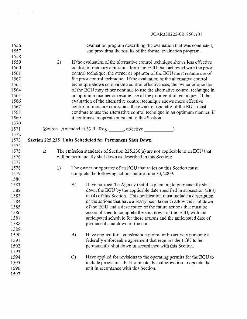
JCAR350225-081 8507r01
1556 evaluation program describing the evaluation that was conducted,1557 and providing the results of the formal evaluation program.15581559 2) If the evaluation of the alternative control technique shows less effective1560 control of mercury emissions from the EGU than achieved with the prior1561 control technique, the owner or operator of the EGU must resume use of1562 the prior control technique. If the evaluation of the alternative control1563 technique shows comparable control effectiveness, the owner or operator1564 of the EGU may either continue to use the alternative control technique in1565 an optimum manner or resume use of the prior control technique. If the1566 evaluation of the alternative control technique shows more effective1567 control of mercury emissions, the owner or operator of the EGU must1568 continue to use the alternative control technique in an optimum manner, if1569 it continues to operate pursuant to this Section.15701571 (Source: Amended at 33 Ill. Reg.
_______,
effective
______________
15721573 Section 225.235 Units Scheduled for Permanent Shut Down15741575 a) The emission standards of Section 225.230(a) are not applicable to an EGU that1576 will be permanently shut down as described in this Section:15771578 1) The owner or operator of an EGU that relies on this Section must1579 complete the following actions before June 30, 2009:15801581 A) Have notified the Agency that it is planning to permanently shut1582 down the EGU by the applicable date specified in subsection (a)(3)1583 or (4) of this Section. This notification must include a description1584 of the actions that have already been taken to allow the shut down1585 of the EGU and a description of the future actions that must be1586 accomplished to complete the shut down of the EGU, with the1587 anticipated schedule for those actions and the anticipated date of1588 permanent shut down of the unit.15891590 B) Have applied for a construction permit or be actively pursuing a1591 federally enforceable agreement that requires the EGU to be1592 permanently shut down in accordance with this Section.15931594 C) Have applied for revisions to the operating permits for the EGU to1595 include provisions that terminate the authorization to operate the1596 unit in accordance with this Section.1597
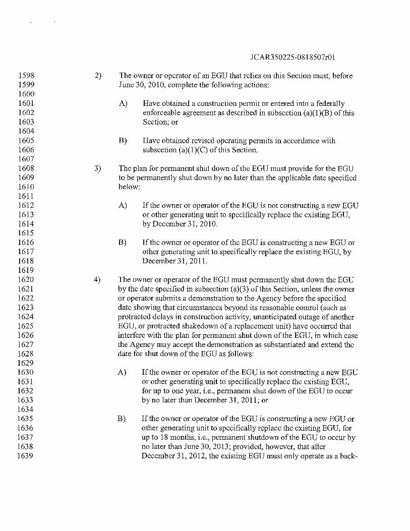
JCAR35022508 1 8507r01
1598 2) The owner or operator of an EGU that relies on this Section must, before1599 June 30, 2010, complete the following actions:16001601 A) Have obtained a construction permit or entered into a federally1602 enforceable agreement as described in subsection (a)(1)(B) of this1603 Section; or16041605 B) Have obtained revised operating permits in accordance with1606 subsection (a)(1)(C) of this Section.16071608 3) The plan for permanent shut down of the EGU must provide for the EGU1609 to be permanently shut down by no later than the applicable date specified1610 below:16111612 A) If the owner or operator of the EGU is not constructing a new EGU1613 or other generating unit to specifically replace the existing EGU,1614 by December31, 2010.16151616 B) If the owner or operator of the EGU is constructing a new EGU or1617 other generating unit to specifically replace the existing EGU, by1618 December3l,2011.16191620 4) The owner or operator of the EGU must permanently shut down the EGU1621 by the date specified in subsection (a)(3) of this Section, unless the owner1622 or operator submits a demonstration to the Agency before the specified1623 date showing that circumstances beyond its reasonable control (such as1624 protracted delays in construction activity, unanticipated outage of another1625 EGU, or protracted shakedown of a replacement unit) have occurred that1626 interfere with the plan for permanent shut down of the EGU, in which case1627 the Agency may accept the demonstration as substantiated and extend the1628 date for shut down of the EGU as follows:16291630 A) If the owner or operator of the EGU is not constructing a new EGU1631 or other generating unit to specifically replace the existing EGU,1632 for up to one year, i.e., permanent shut down of the EGU to occur1633 byno later than December31, 2011; or16341635 B) If the owner or operator of the EGU is constructing a new EGU or1636 other generating unit to specifically replace the existing EGU, for1637 up to 18 months, i.e., permanent shutdown of the EGU to occur by1638 no later than June 30, 2013; provided, however, that afler1639 December 31, 2012, the existing EGU must only operate as a back-
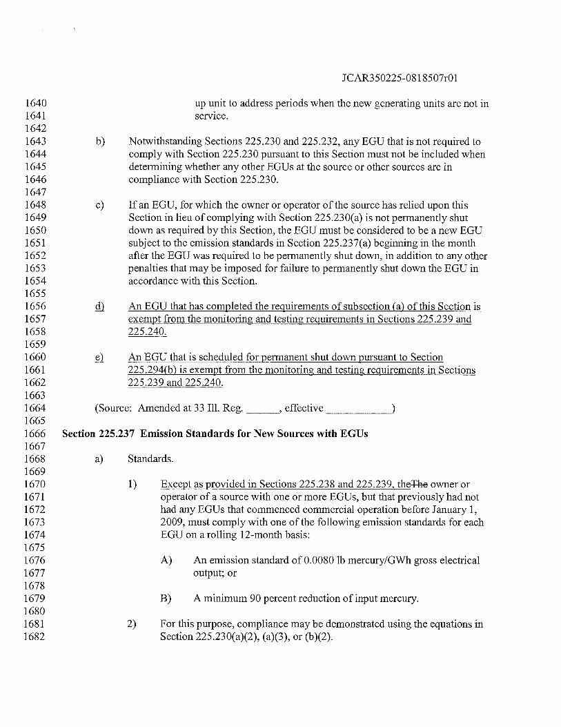
1CAR350225-081 8507r01
1640 up unit to address periods when the new generating units are not in1641 service.16421643 b) Notwithstanding Sections 225 .230 and 225.232, any EGU that is not required to1644 comply with Section 225.230 pursuant to this Section must not be included when1645 detennining whether any other EGUs at the source or other sources are in1646 compliance with Section 225.230.16471648 c) If an EGU, for which the owner or operator of the source has relied upon this1649 Section in lieu of complying with Section 225.230(a) is not permanently shut1650 down as required by this Section, the EGU must be considered to be a new EGU1651 subject to the emission standards in Section 225 .237(a) beginning in the month1652 after the EGU was required to be permanently shut down, in addition to any other1653 penalties that may be imposed for failure to permanently shut down the EGU in1654 accordance with this Section.16551656 çj An EGU that has completed the requirements of subsection (a) of this Section is1657 exempt from the monitoring and testing requirements in Sections 225 .239 and1658 225.240.16591660 An EGU that is scheduled for permanent shut down pursuant to Section1661 225.294(b) is exempt from the monitoring and testing requirements in Sections1662 225.239 and 225 .240.16631664 (Source: Amended at 33 Ill. Reg.
_______,
effective
_____________
16651666 Section 225.237 Emission Standards for New Sources with EGUs16671668 a) Standards.16691670 1) Except as provided in Sections 225.238 and 225.239, theThe owner or1671 operator of a source with one or more EGUs, but that previously had not1672 had any EGUs that commenced commercial operation before January 1,1673 2009, must comply with one of the following emission standards for each1674 EGU on a rolling 12-month basis:16751676 A) An emission standard of 0.0080 lb mercury/GWh gross electrical1677 output; or16781679 B) A minimum 90 percent reduction of input mercury.16801681 2) For this purpose, compliance may be demonstrated using the equations in1682 Section 225.230(a)(2), (a)(3), or (b)(2).
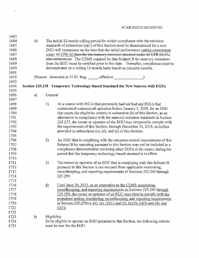
JCAR350225-08 1 8507r01
16831684 b) The initial 12-month rolling period for which compliance with the emission1685 standards of subsection (a)(1) of this Section must be demonstrated for a new1686 EGU will commence on the date that the initial performance testing commences1687 under 40 CFR 60.8test for the mercury emission standard under 40 CFR 60.45a1688 also commences. The CEMS required by this Subpart B for mercury emissions1689 from the EGU must be certified prior to this date. Thereafier, compliance must be1690 demonstrated on a rolling 12-month basis based on calendar months.16911692 (Source: Amended at 33 III. Reg.
_____,
effective
________________
16931694 Section 225.238 Temporary Technology-Based Standard for New Sources with EGUs16951696 a) General.16971698 1) At a source with EGUs that previously had not had any EGUs that1699 commenced commercial operation before January 1, 2009, for an EGU1700 that meets the eligibility criteria in subsection (b) of this Section, as an1701 alternative to compliance with the mercury emission standards in Section1702 225.237, the owner or operator of the EGU may temporarily comply with1703 the requirements of this Section, through December 31, 2018, as further1704 provided in subsections (c), (d), and (e) of this Section.17051706 2) An EGU that is complying with the emission control requirements of this1707 Subpart B by operating pursuant to this Section may not be included in a1708 compliance demonstration involving other EGUs at the source during the1709 period that the temporary technology-based standard is in effect.17101711 3) The owner or operator of an EGU that is complying with this Subpart B1712 pursuant to this Section is not excused from applicable monitoring,1713 recordkeeping, and reporting requirements of Sections 225.240 through1714 225.290.17151716 4 Until June 30, 2012, as an alternative to the CEMS monitoring,1717 recordkeeping, and reporting requirements in Sections 225 .240 through1718 225.290, the owner or operator of an EGU may elect to comply with the1719 emissions testing, monitoring, recordkeeping, and reporting requirements1720 in Section 225 .239(c), (d), (e), (f)(1) and (2), (h)(2), (i)(3) and (4), and1721 (j)(1).17221723 b) Eligibility.1724 To be eligible to operate an EGU pursuant to this Section, the following criteria1725 must be met for the EGU:
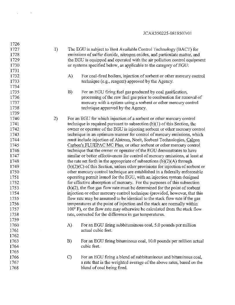
JCAR350225-08 1 8507r01
17261727 1) The EGU is subject to Best Available Control Technology (BACT) for1728 emissions of sulfur dioxide, nitrogen oxides, and particulate matter, and1729 the EGU is equipped and operated with the air pollution control equipment1730 or systems specified below, as applicable to the category of EGU:17311732 A) For coal-fired boilers, injection of sorbent or other mercury control1733 technique (e.g., reagent) approved by the Agency.17341735 B) For an EGU firing fuel gas produced by coal gasification,1736 processing of the raw fuel gas prior to combustion for removal of1737 mercury with a system using a sorbent or other mercury control1738 technique approved by the Agency.17391740 2) For an EGU for which injection of a sorbent or other mercury control1741 technique is required pursuant to subsection (b)(1) of this Section, the1742 owner or operator of the EGU is injecting sorbent or other mercury control1743 technique in an optimum manner for control of mercury emissions, which1744 must include injection of Aistrom, Norit, Sorbent Technologies, Calgon1745 CarbontsFLUEPAC MC Plus, or other sorbent or other mercury control1746 technique that the owner or operator of the EGU demonstrates to have1747 similar or better effectiveness for control of mercury emissions, at least at1748 the rate set forth in the appropriate of subsections (b)(2)(A) through1749 (b)(2)(C) of this Section, unless other provisions for injection of sorbent or1750 other mercury control technique are established in a federally enforceable1751 operating permit issued for the EGU, with an injection system designed1752 for effective absorption of mercury. For the purposes of this subsection1753 (b)(2), the flue gas flow rate must be determined for the point of sorbent1754 injection or other mercury control technique (provided, however, that this1755 flow rate may be assumed to be identical to the stack flow rate if the gas1756 temperatures at the point of injection and the stack are normally within1757 100° F), or the flow rate may otherwise be calculated from the stack flow1758 rate, corrected for the difference in gas temperatures.17591760 A) For an EGU firing subbituminous coal, 5.0 pounds per million1761 actual cubic feet.17621763 B) For an EGU firing bituminous coal, 10.0 pounds per million actual1764 cubic feet.17651766 C) For an EGU firing a blend of subbituminous and bituminous coal,1767 a rate that is the weighted average of the above rates, based on the1768 blend of coal being fired.
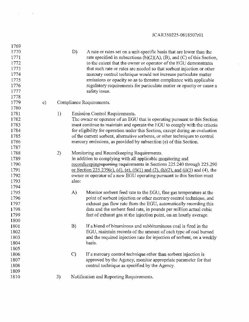
JCAR350225-081 8507r01
17691770 D) A rate or rates set on a unit-specific basis that are lower than the1771 rate specified in subsections (b)(2)(A), (B), and (C) of this Section,1772 to the extent that the owner or operator of the EGU demonstrates1773 that such rate or rates are needed so that sorbent injection or other1774 mercury control technique would not increase particulate matter1775 emissions or opacity so as to threaten compliance with applicable1776 regulatory requirements for particulate matter or opacity or cause a1777 safety issue.17781779 c) Compliance Requirements.17801781 1) Emission Control Requirements.1782 The owner or operator of an EGU that is operating pursuant to this Section1783 must continue to maintain and operate the EGU to comply with the criteria1784 for eligibility for operation under this Section, except during an evaluation1785 of the current sorbent, alternative sorbents, or other techniques to control1786 mercury emissions, as provided by subsection (e) of this Section.17871788 2) Monitoring and Recordkeeping Requirements.1789 In addition to complying with all applicable monitoring and1790 requirements in Sections 225.240 through 225.2901791 or Section 225.239(c), (d), (e), (f)(1) and (2), (h)(2), and (i)(3) and (4), the1792 owner or operator of a new EGU operating pursuant to this Section must1793 also:17941795 A) Monitor sorbent feed rate to the EGU, flue gas temperature at the1796 point of sorbent injection or other mercury control technique, and1797 exhaust gas flow rate from the EGU, automatically recording this1798 data and the sorbent feed rate, in pounds per million actual cubic1799 feet of exhaust gas at the injection point, on an hourly average.18001801 B) If a blend of bituminous and subbituminous coal is fired in the1802 EGU, maintain records of the amount of each type of coal burned1803 and the required injection rate for injection of sorbent, on a weekly1804 basis.18051806 C) If a mercury control technique other than sorbent injection is1807 approved by the Agency, monitor appropriate parameter for that1808 control technique as specified by the Agency.18091810 3) Notification and Reporting Requirements.
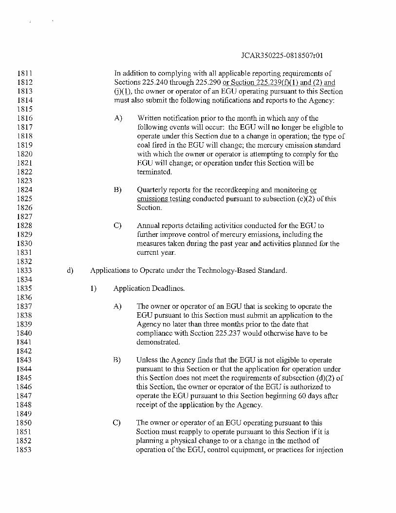
JCAR350225-081 8507r01
1811 Tn addition to complying with all applicable reporting requirements of1812 Sections 225.240 through 225.290 or Section 225.239(f)(1) and (2) and1813 (j)(1), the owner or operator of an EGU operating pursuant to this Section1814 must also submit the following notifications and reports to the Agency:18151816 A) Written notification prior to the month in which any of the1817 following events will occur: the EGU will no longer be eligible to1818 operate under this Section due to a change in operation; the type of1819 coal fired in the EGU will change; the mercury emission standard1820 with which the owner or operator is attempting to comply for the1821 EGU will change; or operation under this Section will be1822 terminated.18231824 B) Quarterly reports for the recordkeeping and monitoring or1825 emissions testing conducted pursuant to subsection (c)(2) of this1826 Section.18271828 C) Annual reports detailing activities conducted for the EGU to1829 further improve control of mercury emissions, including the1830 measures taken during the past year and activities planned for the1831 current year.18321833 d) Applications to Operate under the Technology-Based Standard.18341835 1) Application Deadlines.18361837 A) The owner or operator of an EGU that is seeking to operate the1838 EGU pursuant to this Section must submit an application to the1839 Agency no later than three months prior to the date that1840 compliance with Section 225.237 would otherwise have to be1841 demonstrated.18421843 B) Unless the Agency finds that the EGU is not eligible to operate1844 pursuant to this Section or that the application for operation under1845 this Section does not meet the requirements of subsection (d)(2) of1846 this Section, the owner or operator of the EGU is authorized to1847 operate the EGU pursuant to this Section beginning 60 days after1848 receipt of the application by the Agency.18491850 C) The owner or operator of an EGU operating pursuant to this1851 Section must reapply to operate pursuant to this Section if it is1852 planning a physical change to or a change in the method of1853 operation of the EGU, control equipment, or practices for injection
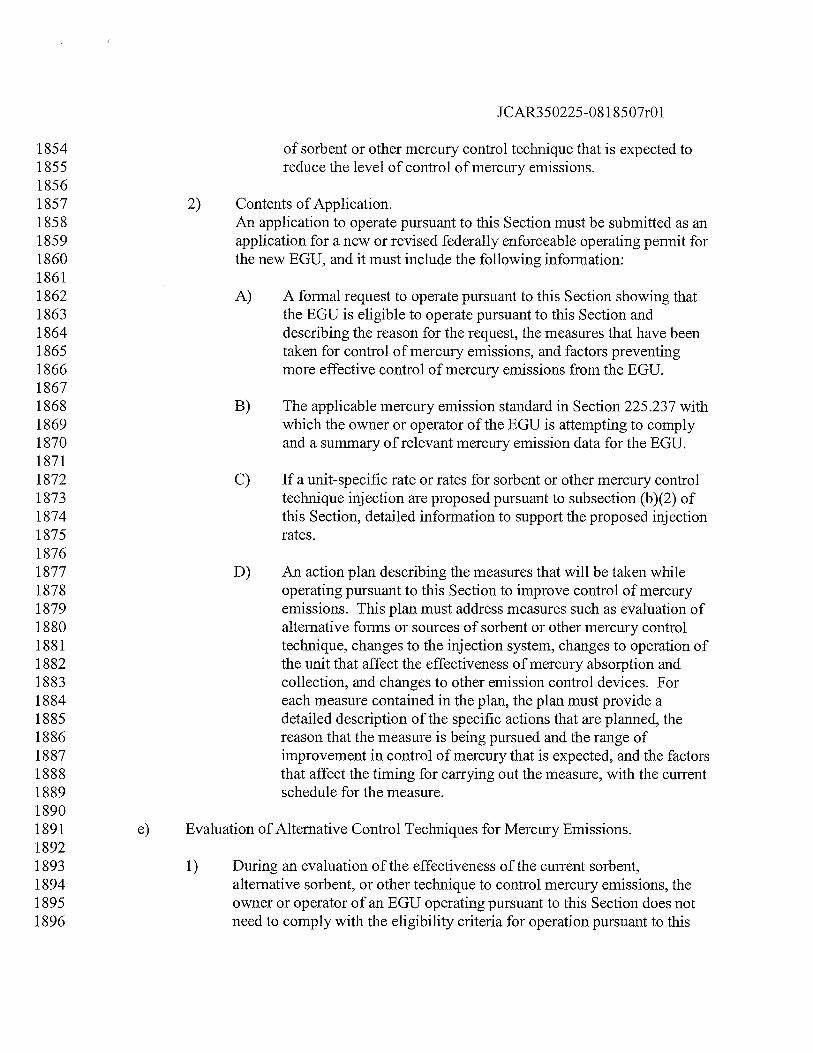
JCAR350225-08 1 8507r01
1854 of sorbent or other mercury control technique that is expected to1855 reduce the level of control of mercury emissions.18561857 2) Contents of Application.1858 An application to operate pursuant to this Section must be submitted as an1859 application for a new or revised federally enforceable operating permit for1860 the new EGU, and it must include the following information:18611862 A) A formal request to operate pursuant to this Section showing that1863 the EGU is eligible to operate pursuant to this Section and1864 describing the reason for the request, the measures that have been1865 taken for control of mercury emissions, and factors preventing1866 more effective control of mercury emissions from the EGU.18671868 B) The applicable mercury emission standard in Section 225.237 with1869 which the owner or operator of the EGU is attempting to comply1870 and a summary of relevant mercury emission data for the EGU.18711872 C) If a unit-specific rate or rates for sorbent or other mercury control1873 technique injection are proposed pursuant to subsection (b)(2) of1874 this Section, detailed information to support the proposed injection1875 rates.18761877 D) An action plan describing the measures that will be taken while1878 operating pursuant to this Section to improve control of mercury1879 emissions. This plan must address measures such as evaluation of1880 alternative forms or sources of sorbent or other mercury control1881 technique, changes to the injection system, changes to operation of1882 the unit that affect the effectiveness of mercury absorption and1883 collection, and changes to other emission control devices. For1884 each measure contained in the plan, the plan must provide a1885 detailed description of the specific actions that are planned, the1886 reason that the measure is being pursued and the range of1887 improvement in control of mercury that is expected, and the factors1888 that affect the timing for carrying out the measure, with the current1889 schedule for the measure.18901891 e) Evaluation of Alternative Control Techniques for Mercury Emissions.18921893 1) During an evaluation of the effectiveness of the current sorbent,1894 alternative sorbent, or other technique to control mercury emissions, the1895 owner or operator of an EGU operating pursuant to this Section does not1896 need to comply with the eligibility criteria for operation pursuant to this
JCAR350225-081 8507r01
1897 Section as needed to carry out an evaluation of the practicality and1898 effectiveness of such technique, further subject to the following1899 limitations:19001901 A) The owner or operator of the EGU must conduct the evaluation in1902 accordance with a formal evaluation program that it has submitted1903 to the Agency at least 30 days prior to beginning the evaluation.19041905 B) The duration and scope of the formal evaluation program must not1906 exceed the duration and scope reasonably needed to complete the1907 desired evaluation of the alternative control technique, as initially1908 addressed by the owner or operator in a support document that it1909 has submitted with the formal evaluation program pursuant to1910 subsection (e)(1)(A) of this Section.19111912 C) Notwithstanding 35 Ill. Adm. Code 201.146(hhh), the owner or1913 operator of the EGU must obtain a construction permit for any new1914 or modified air pollution control equipment to be constructed as1915 part of the evaluation of the alternative control technique.19161917 D) The owner or operator of the EGU must submit a report to the1918 Agency no later than 90 days after the conclusion of the formal1919 evaluation program describing the evaluation that was conducted1920 and providing the results of the formal evaluation program.19211922 2) If the evaluation of the alternative control technique shows less effective1923 control of mercury emissions from the EGU than was achieved with the1924 prior control technique, the owner or operator of the EGU must resume1925 use of the prior control technique. If the evaluation of the alternative1926 control technique shows comparable effectiveness, the owner or operator1927 of the EGU may either continue to use the alternative control technique in1928 an optimum manner or resume use of the prior control technique. If the1929 evaluation of the alternative control technique shows more effective1930 control of mercury emissions, the owner or operator of the EGU must1931 continue to use the alternative control technique in an optimum manner, if1932 it continues to operate pursuant to this Section.19331934 (Source: Amended at 33 Ill. Reg.
_______,
effective
_____________
19351936 Section 225.239 Periodic Emissions Testing Alternative Requirements19371938 General.1939
JCAR350225-081 8507r01
1940 jJ As an alternative to demonstrating compliance with the emissions1941 standards of Sections 225.230(a) or 225.237(a), the owner or operator of1942 an EGU may elect to demonstrate compliance pursuant to the emission1943 standards in subsection (b) of this Section and the use of quarterly1944 emissions testing as an alternative to the use of CEMS:19451946 ) The owner or operator of an EGU that elects to demonstrate compliance1947 pursuant to this Section must comply with the testing, recordkeeping, and1948 reporting requirements of this Section in addition to other applicable1949 recordkeeping and reporting requirements in this Subpart:19501951 The alternative method of compliance provided under this subsection may1952 only be used until June 30, 2012, after which a CEMS certified in1953 accordance with Section 225.250 of this Subpart B must be used.19541955 4 If an owner or operator of an EGU demonstrating compliance pursuant to1956 Section 225.230 or 225.237 discontinues use of CEMS before collecting a1957 full 12 months of CEMS data and elects to demonstrate compliance1958 pursuant to this Section, the data collected prior to that point must be1959 averaged to determine compliance for such period. In such case, for1960 purposes of calculating an emission standard or mercury control efficiency1961 using the equations in Section 225.230(a) or (b), the t?12?I in the equations1962 will be replaced by a variable equal to the number of full and partial1963 months for which the owner or operator collected CEMS data.19641965 }) Emission Limits.19661967 j) Existing Units: Beginning July 1, 2009, the owner or operator of a source1968 with one or more EGUs subject to this Subpart B that commenced1969 commercial operation on or before June 30, 2009, must comply with one1970 of the following standards for each EGU, as determined through quarterly1971 emissions testing according to subsections (c), (d), (e), and (f) of this1972 Section:19731974 ) An emission standard of 0.0080 lb mercury/GWh gross electrical1975 output: or19761977 ) A minimum 90-percent reduction of input mercury.19781979 ) New Units: Beginning within the first 2,160 hours after the1980 commencement of commercial operations, the owner or operator of a1981 source with one or more EGUs subject to this Subpart B that commenced1982 commercial operation after June 30, 2009, must comply with one of the
JCAR350225-081 8507r01
1983 following standards for each EGU, as determined through quarterly1984 emissions testing in accordance with subsections (c), (d), (e), and (f) of1985 this Section:19861987 An emission standard of 0.0080 lb mercury/GWh gross electrical1988 output; or19891990 A minimum 90-percent reduction of input mercury.19911992 c). Initial Emissions Testing Requirements for New Units. The owner or operator of1993 an EGU that commenced commercial operation after June 30, 2009, and that is1994 complying by means of this Section must conduct an initial performance test in1995 accordance with the requirements of subsections (d) and (e) of this Section within1996 the first 2,160 hours after the commencement of commercial operations.19971998 ) Emissions Testing Requirements19992000 Subsequent to the initial performance test, emissions tests must be2001 performed on a quarterly calendar basis in accordance with the2002 requirements of subsections (d), (e), and (f) of this Section;20032004 Notwithstanding the provisions in subsection (d)(1), owners or operators2005 of EGUs demonstrating compliance under Section 225.233 or Sections2006 225.29 1 through 225.299 must perform emissions testing on a semi-annual2007 calendar basis, where the periods consist of the months of January through2008 June and July through December, in accordance with the requirements of2009 subsections (d), (e), and (f)(1) and (2) of this Section;20102011 fl Emissions tests which demonstrate compliance with this Subpart must be2012 performed at least 45 days apart. However, if an emissions test fails to2013 demonstrate compliance with this Subpart or the emissions test is being2014 performed subsequent to a significant change in the operations of an EGU2015 under subsection (h)(2) of this Section, the owner or operator of an EGU2016 may perform additional emissions tests using the same test protocol2017 previously submitted in the same period, with less than 45 days in between2018 emissions tests;20192020 4 A minimum of three and a maximum of nine emissions test runs, lasting at2021 least one hour each, shall be conducted and averaged to determine2022 compliance. All test runs performed will be reported.20232024 If the EGU shares a common stack with one or more other EGUs, the2025 owner or operator of the EGU will conduct emissions testing in the duct to
JCAR350225-081 8507r01
the common stack from each unit, unless the owner or operator of theEGU considers the combined emissions measured at the common stack asthe mass emissions of mercury for the EGUs for recordkeeping andcompliance purposes.
) If an owner or operator of an EGU demonstrating compliance pursuant tothis Section later elects to demonstrate compliance pursuant to the CEMSmonitoring provisions in Section 225.240 of this Subpart, the owner oroperator must comply with the emissions monitoring deadlines in Section225.240(b)(4) of this Subpart.
ci Emissions Testing Procedures
j) The owner or operator must conduct a compliance test in accordance withMethod 29, 30A, or 30B of 40 CFR 60, Appendix A, as incorporated byreference in Section 225.140;
) Mercury emissions or control efficiency must be measured while theaffected unit is operating at or above 90% of peak load;
For units complying with the control efficiency standard of subsection(b)(1)(B) or (b)(2)(B) of this Section, the owner or operator must performcoal sampling as follows:
) in accordance with Section 225.265 of this Subpart at least onceduring each day of testing; and
) in accordance with Section 225 .265 of this Subpart, once eachmonth in those months when emissions testing is not performed;
4) For units complying with the output-based emission standard ofsubsection (b)(1’)(A) or (b)(2)(A) of this Section, the owner or operatormust monitor gross electrical output for the duration of the testing.
The owner or operator of an EGU may use an alternative emissions testingmethod if such alternative is submitted to the Agency in writing andapproved in writing by the Manager of the Bureau of Air’s ComplianceSection.
Notification Requirements
1) The owner or operator of an EGU must submit a testing protocol asdescribed in USEPA’s Emission Measurement Center’s Guideline
2026202720282029203020312032203320342035203620372038203920402041204220432044204520462047204820492050205120522053205420552056205720582059206020612062206320642065206620672068

JCAR350225-08 1 8507r01
2069 Document #42 to the Agency at least 45 days prior to a scheduled2070 emissions test, except as provided in Section 225.239(h)(2) and (h)(3).2071 Upon written request directed to the Manager of the Bureau of Air’s2072 Compliance Section, the Agency may, in its sole discretion, waive the 45-2073 day requirement. Such waiver shall only be effective if it is provided in2074 writing and signed by the Manager of the Bureau of Air’s Compliance2075 Section, or his or her designee;20762077 ) Notification of a scheduled emissions test must be submitted to the2078 Agency in writing, directed to the Manager of the Bureau of Air’s2079 Compliance Section, at least 30 days prior to the expected date of the2080 emissions test. Upon written request directed to the Manager of the Bureau2081 of Air’s Compliance Section, the Agency may, in its sole discretion,2082 waive the 30-day notification requirement. Such waiver shall only be2083 effective if it is provided in writing and signed by the Manager of the2084 Bureau of Air’s Compliance Section, or his or her designee. Notification of2085 the actual date and expected time of testing must be submitted in writing,2086 directed to the Manager of the Bureau of Air’s Compliance Section, at2087 least five working days prior to the actual date of the test:20882089 J For an EGU that has elected to demonstrate compliance by use of the2090 emission standards of subsection (b) of this Section, if an emissions test2091 performed under the requirements of this Section fails to demonstrate2092 compliance with the limits of subsection (b) of this Section, the owner or2093 operator of an EGU may perform a new emissions test using the same test2094 protocol previously submitted in the same period, by notifying the2095 Manager of the Bureau of Air’s Compliance Section or his or her designee2096 of the actual date and expected time of testing at least five working days2097 prior to the actual date of the test. The Agency may, in its sole discretion,2098 waive this five-day notification requirement. Such waiver shall only be2099 effective if it is provided in writing and signed by the Manager of the2100 Bureau of Air’s Compliance Section, or his or her designee;21012102 4 In addition to the testing protocol required by subsection (f)(1) of this2103 Section, the owner or operator of an EGU that has elected to demonstrate2104 compliance by use of the emission standards of subsection (b) of this2105 Section must submit a Continuous Parameter Monitoring Plan to the2106 Agency at least 45 days prior to a scheduled emissions test. Upon written2107 request directed to the Manager of the Bureau of Air’s Compliance2108 Section, the Agency may, in its sole discretion, waive the 45-day2109 requirement. Such waiver shall only be effective if it is provided in writing2110 and signed by the Manager of the Bureau of Air’s Compliance Section, or2111 his or her designee. The Continuous Parameter Monitoring Plan must
JCAR350225-08 1 8507r01
2112 detail how the EGU will continue to operate within the parameters2113 enumerated in the testing protocol and how those parameters will ensure2114 compliance with the applicable mercury limit. For example, the2115 Continuous Parameter Monitoring Plan must include coal sampling as2116 described in Section 225.239(e)(3) of this Subpart and must ensure that an2117 EGU that performs an emissions test using a blend of coals continues to2118 operate using that same blend of coal. If the Agency disapproves the2119 Continuous Parameter Monitoring Plan, the owner or operator of the EGU2120 has 30 days from the date of receipt of the disapproval to submit more2121 detailed information in accordance with the Agency’s request.21222123 gI Compliance Determination21242125 fl Each quarterly emissions test shall determine compliance with this2126 Subpart for that quarter, where the quarterly periods consist of the months2127 of January through March, April through June, July through September,2128 and October through December:21292130 J If emissions testing conducted pursuant to this Section fails to demonstrate2131 compliance, the owner or operator of the EGU will be deemed to have2132 been out of compliance with this Subpart beginning on the day after the2133 most recent emissions test that demonstrated compliance or the last day of2134 certified CEMS data demonstrating compliance on a rolling 12-month2135 basis, and the EGU will remain out of compliance until a subsequent2136 emissions test successfully demonstrates compliance with the limits of this2137 Section.21382139 ) Operation Requirements21402141 The owner or operator of an EGU that has elected to demonstrate2142 compliance by use of the emission standards of subsection (b) of this2143 Section must continue to operate the EGU commensurate with the2144 Continuous Parameter Monitoring Plan until another Continuous2145 Parameter Monitoring Plan is developed and submitted to the Agency in2146 conjunction with the next compliance demonstration, in accordance with2147 subsection (f)(4) of this Section.21482149 ) If the owner or operator makes a significant change to the operations of an2150 EGU subject to this Section, such as changing from bituminous to2151 subbituminous coal, the owner or operator must submit a testing protocol2152 to the Agency and perform an emissions test within seven operating days2153 of the significant change. In addition, the owner or operator of an EGU2154 that has elected to demonstrate compliance by use of the emission
JCAR350225-0818507r01
2155 standards of subsection (b) of this Section must submit a Continuous2156 Parameter Monitoring Plan within seven operating days of the significant2157 change.21582159 ) If a blend of bituminous and subbituminous coal is fired in the EGU, the2160 owner or operator of the EGU must ensure that the EGU continues to2161 operate using the same blend that was used during the most recent2162 successful emissions test. If the blend of coal changes, the owner or2163 operator of the EGU must re-test in accordance with subsections (d), (e),2164 (f), and (g) of this Section within 30 days of the change in coal blend,2165 notwithstanding the requirement of subsection (d)(3) of this Section that2166 there must be 45 days between emissions tests.21672168 recordkeeping21692170 j) The owner or operator of an EGU and its designated representative must2171 comply with all applicable recordkeeping and reporting requirements in2172 this Section.21732174 ) Continuous Parameter Monitoring. The owner or operator of an EGU2175 must maintain records to substantiate that the EGU is operating in2176 compliance with the parameters listed in the Continuous Parameter2177 Monitoring Plan, detailing the parameters that impact mercury reduction2178 and including the following records related to the emissions of mercury:21792180 For an EGU for which the owner or operator is complying with2181 this Subpart B pursuant to Section 225.239(b)(1)(B) or2182 225.239(b)(2)(B), records of the daily mercury content of coal2183 used (lbs/trillion Btu) and the daily and quarterly input mercury2184 (ibs).21852186 For an EGU for which the owner or operator of an EGU complying2187 with this Subpart B pursuant to Section 225.239(b)(1)(A) or2188 225.239b)(2)(A), records of the daily and quarterly oss2189 electrical output (MWh) on an hourly basis.:21902191 The owner or operator of an EGU using activated carbon injection must2192 also comply with the following requirements:21932194 Maintain records of the usage of sorbent, the exhaust gas flow rate2195 from the EGU, and the sorbent feed rate, in pounds per million2196 actual cubic feet of exhaust gas at the mi ection point, on a weekly2197 average
JCAR350225-08 1 8507r01
21982199 ) If a blend of bituminous and subbituminous coal is fired in the2200 EGU, keep records of the amount of each type of coal burned and2201 the required injection rate for injection of activated carbon, on a2202 weekly basis.22032204 41 The owner or operator of an EGU must retain all records required by this2205 Section at the source unless otherwise provided in the CAAPP permit2206 issued for the source and must make a copy of any record available to the2207 Agency promptly upon request.22082209 ) The owner or operator of an EGU demonstrating compliance pursuant to2210 this Section must monitor and report the heat input rate at the unit level.22112212 The owner or operator of an EGU demonstrating compliance pursuant to2213 this Section must perform and report coal sampling in accordance with2214 subsection 225.23 9(e)(3).22152216 Reporting Requirements22172218 1) An owner or operator of an EGU shall submit to the Agency a Final2219 Source Test Report for each periodic emissions test within 45 days afler2220 the test is completed. The Final Source Test Report will be directed to the2221 Manager of the Bureau of Air’s Compliance Section, or his or her2222 designee, and include at a minimum:22232224 ) A summary of results;22252226 A description of test methods, including a description of sampling2227 points, sampling train, analysis equipment, and test schedule, and a2228 detailed description of test conditions, including:22292230 j). Process information, including but not limited to modes of2231 operation, process rate, and fuel or raw material2232 consumption;22332234 li) Control equipment information (i.e., equipment condition2235 and operating parameters during testing);22362237 iiil A discussion of any preparatory actions taken (i.e.,2238 inspections, maintenance, and repair); and2239
JCAR350225-081 8507r01
2240 jy Data and calculations, including copies of all raw data2241 sheets and records of laboratory analyses, sample2242 calculations, and data on equipment calibration.22432244 ) The owner or operator of a source with one or more EGUs demonstrating2245 compliance with Subpart B in accordance with this Section must submit to2246 the Agency a Quarterly Certification of Compliance within 45 days2247 following the end of each calendar quarter. Quarterly certifications of2248 compliance must certify whether compliance existed for each EGTJ for the2249 calendar quarter covered by the certification. If the EGU failed to comply2250 during the quarter covered by the certification, the owner or operator must2251 provide the reasons the EGU or EGUs failed to comply and a full2252 description of the noncompliance (i.e., tested emissions rate, coal sample2253 data, etc.). In addition, for each EGU, the owner or operator must provide2254 the following appropriate data to the Agency as set forth in this Section.22552256 A list of all emissions tests performed within the calendar quarter2257 covered by the Certification and submitted to the Agency for each2258 EGU, including the dates on which such tests were performed.22592260 ) Any deviations or exceptions each month and discussion of the2261 reasons for such deviations or exceptions.22622263 c) All Quarterly Certifications of Compliance required to be2264 submitted must include the following certification by a responsible2265 official:22662267 I certify under penalty of law that this document and all2268 attachments were prepared under my direction or supervision in2269 accordance with a system designed to assure that qualified2270 personnel properly gather and evaluate the information submitted.2271 Based on my inquiry of the person or persons directly responsible2272 for gathering the information, the information submitted is, to the2273 best of my knowledge and belief, true, accurate, and complete. I2274 am aware that there are significant penalties for submitting false2275 information, including the possibility of fine and imprisonment for2276 knowing violations.22772278 Deviation Reports. For each EGU, the owner or operator must promptly2279 notify the Agency of deviations from any of the requirements of this2280 Subpart B. At a minimum, these notifications must include a description2281 of such deviations within 30 days after discovery of the deviations, and a
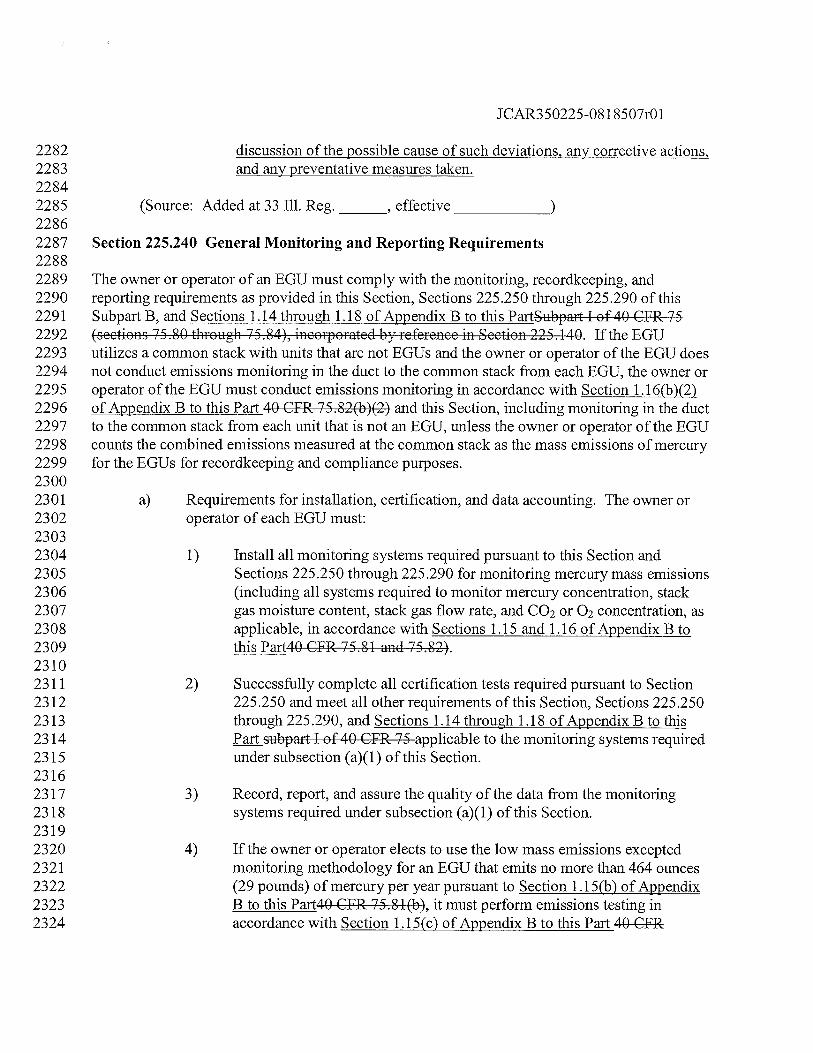
JCAR35O225O8 1 8507r01
2282 discussion of the possible cause of such deviations, any corrective actions,2283 and any preventative measures taken.22842285 (Source: Added at 33 Ill. Reg.
_______,
effective
______________
22862287 Section 225.240 General Monitoring and Reporting Requirements22882289 The owner or operator of an EGU must comply with the monitoring, recordkeeping, and2290 reporting requirements as provided in this Section, Sections 225.250 through 225.290 of this2291 Subpart B, and Sections 1.14 through 1.18 of Appendix B to this PartSubpart I of 40 CFR 752292 (sections 75.80 through 75.84), incorporated by reference in Section 225.140. If the EGU2293 utilizes a common stack with units that are not EGUs and the owner or operator of the EGU does2294 not conduct emissions monitoring in the duct to the common stack from each EGU, the owner or2295 operator of the EGU must conduct emissions monitoring in accordance with Section 1.1 6(b)(2)2296 of Appendix B to this Part 40 CFR 75.82(b)(2) and this Section, including monitoring in the duct2297 to the common stack from each unit that is not an EGU, unless the owner or operator of the EGU2298 counts the combined emissions measured at the common stack as the mass emissions of mercury2299 for the EGUs for recordkeeping and compliance purposes.23002301 a) Requirements for installation, certification, and data accounting. The owner or2302 operator of each EGU must:23032304 1) Install all monitoring systems required pursuant to this Section and2305 Sections 225.250 through 225.290 for monitoring mercury mass emissions2306 (including all systems required to monitor mercury concentration, stack2307 gas moisture content, stack gas flow rate, and CO2 or 02 concentration, as2308 applicable, in accordance with Sections 1.15 and 1.16 of Appendix B to2309 this Part4O CFR 75.81 and 75.82).23102311 2) Successfully complete all certification tests required pursuant to Section2312 225.250 and meet all other requirements of this Section, Sections 225.2502313 through 225.290, and Sections 1.14 through 1.18 of Appendix B to this2314 Part subpart I of 40 CFR 75 applicable to the monitoring systems required2315 under subsection (a)(1) of this Section.23162317 3) Record, report, and assure the quality of the data from the monitoring2318 systems required under subsection (a)( 1) of this Section.23192320 4) If the owner or operator elects to use the low mass emissions excepted2321 monitoring methodology for an EGU that emits no more than 464 ounces2322 (29 pounds) of mercury per year pursuant to Section 1.15(b) of Appendix2323 B to this Part4O CFR 75.8 1(b), it must perform emissions testing in2324 accordance with Section 1.15(c) of Appendix B to this Part 40 CFR
JCAR350225-08 1 8507r01
2325 75.81(c) to demonstrate that the EGU is eligible to use this excepted2326 emissions monitoring methodology, as well as comply with all other2327 applicable requirements of Section 1.15(b) through (f) of Appendix B to2328 this Part4O CFR 75.81(b) through (f). Also, the owner or operator must2329 submit a copy of any information required to be submitted to the USEPA2330 pursuant to these provisions to the Agency. The initial emissions testing2331 to demonstrate eligibility of an EGU for the low mass emissions excepted2332 methodology must be conducted by the applicable of the following dates:23332334 A) If the EGU has commenced commercial operation before July 1,2335 2008, at least by jpjyJanuary 1, 2009, or 45 days prior to relying2336 on the low mass emissions excepted methodology, whichever date2337 is later.23382339 B) If the EGU has commenced commercial operation on or after July2340 1, 2008, at least 45 days prior to the applicable date specified2341 pursuant to subsection (b)(2) of this Section or 45 days prior to2342 relying on the low mass emissions excepted methodology,2343 whichever date is later.23442345 b) Emissions Monitoring Deadlines. The owner or operator must meet the emissions2346 monitoring system certification and other emissions monitoring requirements of2347 subsections (a)(1) and (a)(2) of this Section on or before the applicable of the2348 following dates. The owner or operator must record, report, and quality-assure2349 the data from the emissions monitoring systems required under subsection (a)(1)2350 of this Section on and after the applicable of the following dates:23512352 1) For the owner or operator of an EGU that commences commercial2353 operation before July 1, 2008, by jyJanuary 1, 2009.23542355 2) For the owner or operator of an EGU that commences commercial2356 operation on or after July 1, 2008, by 90 unit operating days or 1802357 calendar days, whichever occurs first, after the date on which the EGU2358 commences commercial operation.23592360 3) For the owner or operator of an EGU for which construction of a new2361 stack or flue or installation of add-on mercury emission controls, a flue2362 gas desulfurization system, a selective catalytic reduction system, a fabric2363 filter, or a compact hybrid particulate collector system is completed after2364 the applicable deadline pursuant to subsection (b)(1) or (b)(2) of this2365 Section, by 90 unit operating days or 180 calendar days, whichever occurs2366 first, after the date on which emissions first exit to the atmosphere through2367 the new stack or flue, add-on mercury emission controls, flue gas
2368236923702371237223732374237523762377237823792380238123822383238423852386238723882389 2)23902391239223932394239523962397239823992400240124022403240424052406240724082409
JCAR350225-081 8507r01
desulfurization system, selective catalytic reduction system, fabric filter,or compact hybrid particulate collector system.
4 For an owner or operator of an EGU that originally elected to demonstratecompliance pursuant to the emissions testing requirements in Section225.239, by the first day of the calendar quarter following the lastemissions test demonstrating compliance with Section 225.239.
c) Reporting Data.
1) Except as provided in subsection (c)(2) of this Section, the owner oroperator of an EGU that does not meet the applicable emissionsmonitoring date set forth in subsection (b) of this Section for anyemissions monitoring system required pursuant to subsection (a)( 1) of thisSection must begin periodic emissions testing in accordance with Section225.239, for each such monitoring system,the maximum -
- fl-n-nm-n-n fltp
fldetermi, record, and reportnoten-‘ia1 (or, the minimum tial) values
for mercury concentration, the stack gas flow rate, the stack gas moisturecontent, d any other parameters required to deteine mercury massemissions in accordance with 40 CFR 75.80(g).
The owner or operator of an EGU that does not meet the applicableemissions monitoring date set forth in subsection (b)(3) of this Section forany emissions monitoring system required pursuant to subsection (a)(1) ofthis Section must begin periodic emissions testing in accordance withSection 225.239, for each such monitoring system, deteine, record, andreport substitute data using the applicable missing data procedures as setforth in 40 CFR 75.80(f), in lieu of the maximum potential (or, asappropriate, minimum potential) values for a parameter, if the owner oroperator demonstrates that there is continuity between the data streams for1,nf -nnrnmptpm pfyp nr1 nftr f1p ntrnrHn installation pursuant tosubsection(b)(3) of this Section.
d) Prohibitions.
1) No owner or operator of an EGU may use any alternative emissionsmonitoring system, alternative reference method for measuring emissions,or other alternative to the emissions monitoring and measurementrequirements of this Section and Sections 225.250 through 225.290, unlesssuch alternative is submitted to the Agency in writing and approved inwriting by the Manager of the Bureau of Air’s Compliance Section, or hisor her designeepromulgated by the USEPA and approved in writing by the
JCAR350225-0818507r01
2410 Agency, or the use of such alternative is approved in writing by the2411 Anc’v and USEPA.24122413 2) No owner or operator of an EGU may operate its EGU so as to discharge,2414 or allow to be discharged, mercury emissions to the atmosphere without2415 accounting for all such emissions in accordance with the applicable2416 provisions of this Section, Sections 225.250 through 225.290, and2417 Sections 1.14 through 1.18 of Appendix B to this Part, unless2418 demonstrating compliance pursuant to Section 225.239, as2419 applicablesubpart I of 40 CFR 75.24202421 3) No owner or operator of an EGU may disrupt the CEMS, any portion2422 thereof, or any other approved emission monitoring method, and thereby2423 avoid monitoring and recording mercury mass emissions discharged into2424 the atmosphere, except for periods of recertification or periods when2425 calibration, quality assurance testing, or maintenance is performed in2426 accordance with the applicable provisions of this Section, Sections2427 225.250 through 225.290, and Sections 1.14 through 1.18 of Appendix B2428 to this Partsubpart I of 40 CFR ‘75.24292430 4) No owner or operator of an EGU may retire or permanently discontinue2431 use of the CEMS or any component thereof, or any other approved2432 monitoring system pursuant to this Subpart B, except under any one of the2433 following circumstances:24342435 A) The owner or operator is monitoring emissions from the EGU with2436 another certified monitoring system that has been approved, in2437 accordance with the applicable provisions of this Section, Sections2438 225.250 through 225.290 of this Subpart B, and Sections 1.142439 through 1.18 of Appendix B to this Partsubpart I of 40 CFR 75, by2440 the Agency for use at that EGU and that provides emission data for2441 the same pollutant or parameter as the retired or discontinued2442 monitoring system; or24432444 B) The owner or operator or designated representative submits2445 notification of the date of certification testing of a replacement2446 monitoring system for the retired or discontinued monitoring2447 system in accordance with Section 225.250(a)(3)(A).24482449 The owner or operator is demonstrating compliance pursuant to the2450 applicable subsections of Section 225.239.24512452 e) Long-term Cold Storage.
JCAR350225-081 8507r01
2453 The owner or operator of an EGU that is in long-term cold storage is subject to2454 the provisions of 40 CFR 75.4 and 40 CFR 75.64, incorporated by reference in2455 Section 225.140, relating to monitoring, recordkeeping, and reporting for units in2456 long-term cold storage.24572458 (Source: Amended at 33 Ill. Reg.
_______,
effective
_____________
24592460 Section 225.250 Initial Certification and Recertification Procedures for Emissions2461 Monitoring24622463 a) The owner or operator of an EGU must comply with the following initial2464 certification and recertification procedures for a CEMS (i.e., a CEMS or an2465 excepted monitoring system (sorbent trap monitoring system) pursuant to Section2466 1.3 of Appendix B to this Part4O CFR 75.15, incorporated by reference in Section2467 225.140) required by Section 225.240(a)(1). The owner or operator of an EGU2468 that qualifies for, and for which the owner or operator elects to use, the low-mass-2469 emissions excepted methodology pursuant to Section 1.15(b) of Appendix B to2470 this Part4O CFR 75.8 1(b), incorporated by reference in Section 225.140, must2471 comply with the procedures set forth in subsection (c) of this Section.24722473 1) Requirements for Initial Certification. The owner or operator of an EGU2474 must ensure that, for each CEMS required by Section 225.240(a)(1)2475 (including the automated data acquisition and handling system), the owner2476 or operator successfully completes all of the initial certification testing2477 required pursuant to Section 1.4 of Appendix B to this Part4O CFR2478 75.80(d), incorporated by reference in Section 225.140, by the applicable2479 deadline in Section 225.240(b). In addition, whenever the owner or2480 operator of an EGU installs a monitoring system to meet the requirements2481 of this Subpart B in a location where no such monitoring system was2482 previously installed, the owner or operator must successfully complete the2483 initial certification requirements of Section 1.4 of Appendix B to this2484 Part4O CFR 75.80(d).24852486 2) Requirements for Recertification. Whenever the owner or operator of an2487 EGU makes a replacement, modification, or change in any certified2488 CEMS, or an excepted monitoring system (sorbent trap monitoring2489 system) pursuant to Section 1.3 of Appendix B to this Part4O CFR 75.15,2490 and required by Section 225 .240(a)(1), that may significantly affect the2491 ability of the system to accurately measure or record mercury mass2492 emissions or heat input rate or to meet the quality-assurance and quality2493 control requirements of Section 1.5 of Appendix B to this Part 40 CFR2494 75.21 or Exhibit B to Appendix B to this PartAppendix B to 40 CFR 75,2495 each incorporated by reference in Section 225.140, the owner or operator
JCAR350225-08 1 8507r01
2496 of an EGU must recertify the monitoring system in accordance with2497 Section 1.4(b) of Appendix B to this Part4O CFR 75.20(b), incorporated2498 by reference in Section 225.140. Furthermore, whenever the owner or2499 operator of an EGU makes a replacement, modification, or change to the2500 flue gas handling system or the EGU’s operation that may significantly2501 change the stack flow or concentration profile, the owner or operator must2502 recertify each CEMS, and each excepted monitoring system (sorbent trap2503 monitoring system) pursuant to Section 1.3 to Appendix B to this Part4O2504 CFR 75.15, whose accuracy is potentially affected by the change, all in2505 accordance with Section 1.4(b) to Appendix B to this Part4O CFR2506 75.20(b). Examples of changes to a CEMS that require recertification2507 include, but are not limited to, replacement of the analyzer, complete2508 replacement of an existing CEMS, or change in location or orientation of2509 the sampling probe or site.25102511 3) Approval Process for Initial Certification and Recertification. Subsections2512 (a)(3)(A) through (a)(3)(D) of this Section apply to both initial2513 certification and recertification of a CEMS required by Section2514 225.240(a)(1). For recertifications, the words “certification and “initial2515 certification” are to be read as the word “recertification”, the word2516 “certified” is to be read as the word “recertified”, and the procedures set2517 forth in Section 1.4(b)(5) of Appendix B to this Part 40 CFR 75.20(b)(5)2518 are to be followed in lieu of the procedures set forth in subsection2519 (a)(3)(E) of this Section.25202521 A) Notification of Certification. The owner or operator must submit2522 written notice of the dates of certification testing to the Agency2523 directed to the Manager of the Bureau of Air’s Compliance2524 Section, USEPA Region 5, and the Administrator of the USEPA2525 written notice of the dates of certification testing, in accordance2526 with Section 225 .270.25272528 B) Certification Application. The owner or operator must submit to2529 the Agency a certification application for each monitoring system.2530 A complete certification application must include the information2531 specified in 40 CFR 75.63, incorporated by reference in Section2532 225.140.25332534 C) Provisional Certification Date. The provisional certification date2535 for a monitoring system must be determined in accordance with2536 Section 1.4(a)(3) of Appendix B to this Part4O CFR 75.20(a)(3),2537 incorporated by reference in Section 225.140. A provisionally2538 certified monitoring system maybe used pursuant to this Subpart B
JCAR350225-08 1 8507r01
2539 for a period not to exceed 120 days after receipt by the Agency of2540 the complete certification application for the monitoring system2541 pursuant to subsection (a)(3)(B) of this Section. Data measured2542 and recorded by the provisionally certified monitoring system, in2543 accordance with the requirements of Appendix B to this Part4O2544 CFR 75, will be considered valid quality-assured data (retroactive2545 to the date and time of provisional certification), provided that the2546 Agency does not invalidate the provisional certification by issuing2547 a notice of disapproval within 120 days after the date of receipt by2548 the Agency of the complete certification application.25492550 D) Certification Application Approval Process. The Agency must2551 issue a written notice of approval or disapproval of the certification2552 application to the owner or operator within 120 days after receipt2553 of the complete certification application required by subsection2554 (a)(3)(B) of this Section. Tn the event the Agency does not issue a2555 written notice of approval or disapproval within the 120-day2556 period, each monitoring system that meets the applicable2557 performance requirements of Appendix B to this Part 40 CFR 752558 and which is included in the certification application will be2559 deemed certified for use pursuant to this Subpart B.25602561 i) Approval Notice. If the certification application is2562 complete and shows that each monitoring system meets the2563 applicable performance requirements of Appendix B to this2564 Part4O CFR 75, then the Agency must issue a written notice2565 of approval of the certification application within 120 days2566 after receipt.25672568 ii) Incomplete Application Notice. If the certification2569 application is not complete, then the Agency must issue a2570 written notice of incompleteness that sets a reasonable date2571 by which the owner or operator must submit the additional2572 information required to complete the certification2573 application. If the owner or operator does not comply with2574 the notice of incompleteness by the specified date, the2575 Agency may issue a notice of disapproval pursuant to2576 subsection (a)(3)(D)(iii) of this Section. The 120-day2577 review period will not begin before receipt of a complete2578 certification application.25792580 iii) Disapproval Notice. If the certification application shows2581 that any monitoring system does not meet the performance
JCAR350225-08 1 8507r01
2582 requirements of Appendix B to this Part4O CFR 75, or if2583 the certification application is incomplete and the2584 requirement for disapproval pursuant to subsection2585 (a)(3)(D)(ii) of this Section is met, the Agency must issue a2586 written notice of disapproval of the certification2587 application. Upon issuance of such notice of disapproval,2588 the provisional certification is invalidated, and the data2589 measured and recorded by each uncertified monitoring2590 system will not be considered valid quality-assured data2591 beginning with the date and hour of provisional2592 certification (as defined pursuant to Section 1 .4(a)(3) of2593 Appendix B to this Part4O CFR 75.20(a)(3)). The owner or2594 operator must follow the procedures for loss of certification2595 set forth in subsection (a)(3)(E) of this Section for each2596 monitoring system that is disapproved for initial2597 certification.
iv) Audit Decertification. The Agency may issue a notice ofdisapproval of the certification status of a monitor inaccordance with Section 225 .260(b).
E) Procedures for Loss of Certification. If the Agency issues a noticeof disapproval of a certification application pursuant to subsection(a)(3)(D)(iii) of this Section or a notice of disapproval ofcertification status pursuant to subsection (a)(3)(D)(iv) of thisSection, the owner or operator must fulfill the followingrequirements:
The owner or operator must substitute the following valuesfor each disapproved monitoring system and for each hourof EGU operation during the period of invalid dataspecified pursuant to 40 CFR 75.20(a(4)(iii) or 75.21(e),continuing until the applicable date and hour specifiedpursuant to 40 CFR 75.20(a(5)(i), each incorporated byreference in Section 225.140. For a disapproved mercurypollutant concentration monitor and disapproved flowmonitor, respectively, the maximum potential concentrationof mercury and the maximum potential flow rate, asdefined in sections 2.1.7.1 and 2.1.4.1 of appendix A to 40CFR 75, incorporated by reference in Section 225.140. Fora disapproved moisture monitoring system and disapproveddiluent gas monitoring system, respectively, the minimumpotential moisture percentage and either the maximum
259825992600260126022603260426052606260726082609261026112612261326142615261626172618261926202621262226232624
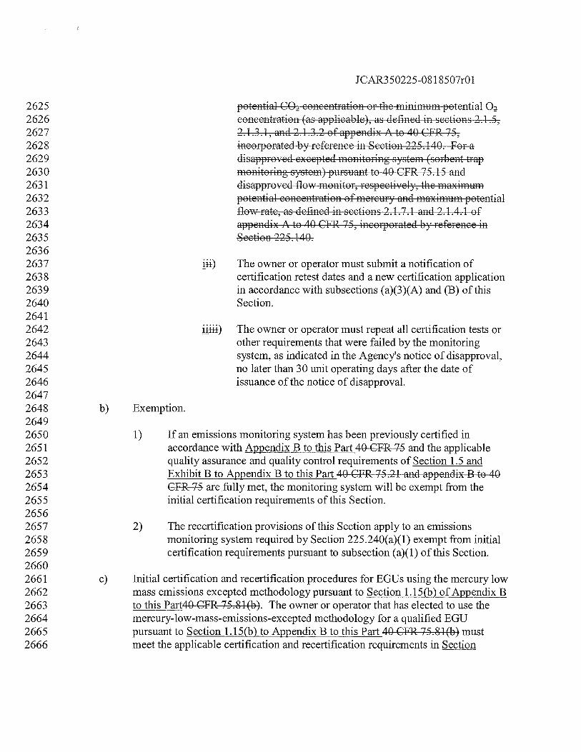
JCAR350225-08 1 8507r01
2625 potential CO concentration or the minimum potential O2626 concentration (as applicable), as defined in sections 2.1.5,2627 2.1.3.1, and 2.1.3.2 of appendix Ato 40 CFR 75,2628 incorporated by reference in Section 225.140. For a2629 disapproved excepted monitoring system (sorbent trap2630 monitoring system) pursuant to 40 CFR 75.15 and2631 disapproved flow monitor, respectively, the maximum2632 potential concentration of mercury and maximum potential2633 flow rate, as defined in sections 2.1.7.1 and 2.1.4.1 of2634 appendix A to 40 CFR 75, incorporated by reference in2635 Section 225.140.26362637 ii4) The owner or operator must submit a notification of2638 certification retest dates and a new certification application2639 in accordance with subsections (a)(3)(A) and (B) of this2640 Section.26412642 iii4) The owner or operator must repeat all certification tests or2643 other requirements that were failed by the monitoring2644 system, as indicated in the Agency’s notice of disapproval,2645 no later than 30 unit operating days after the date of2646 issuance of the notice of disapproval.26472648 b) Exemption.26492650 1) If an emissions monitoring system has been previously certified in2651 accordance with Appendix B to this Part 40 CFR 75 and the applicable2652 quality assurance and quality control requirements of Section 1.5 and2653 Exhibit B to Appendix B to this Part 40 CFR 75.21 and appendix B to 402654 CFR 75 are fully met, the monitoring system will be exempt from the2655 initial certification requirements of this Section.26562657 2) The recertification provisions of this Section apply to an emissions2658 monitoring system required by Section 225.240(a)(1) exempt from initial2659 certification requirements pursuant to subsection (a)(1) of this Section.26602661 c) Initial certification and recertification procedures for EGUs using the mercury low2662 mass emissions excepted methodology pursuant to Section 1.15(b) of Appendix B2663 to this Part4O CFR 75.8 1(b). The owner or operator that has elected to use the2664 mercury-low-mass-emissions-excepted methodology for a qualified EGU2665 pursuant to Section 1.15(b) to Appendix B to this Part 40 CFR 75.81(b) must2666 meet the applicable certification and recertification requirements in Section
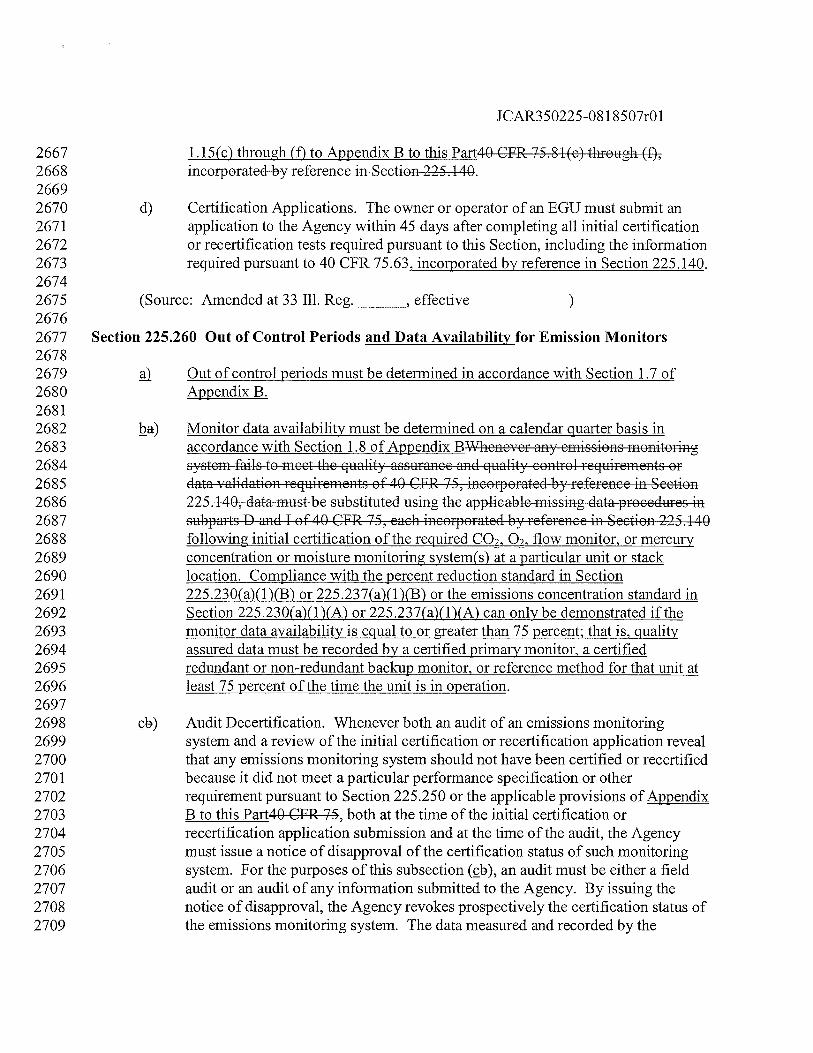
JCAR350225-081 8507r01
2667 1.15(c) through (f) to Appendix B to this Part4O CFR 75.81(c) through (,2668 incorporated by reference in Section 225.140.26692670 d) Certification Applications. The owner or operator of an EGU must submit an2671 application to the Agency within 45 days after completing all initial certification2672 or recertification tests required pursuant to this Section, including the information2673 required pursuant to 40 CFR 75.63, incorporated by reference in Section 225.140.26742675 (Source: Amended at 33 Ill. Reg.
_______,
effective26762677 Section 225.260 Out of Control Periods and Data Availability for Emission Monitors26782679 Out of control periods must be determined in accordance with Section 1.7 of2680 Appendix B.26812682 ha) Monitor data availability must be determined on a calendar quarter basis in2683 accordance with Section 1.8 of Appendix BWhenever any emissions monitoring2684 system fails to meet the quality assurance and quality control requirements or2685 data validation requirements of 40 CFR 75, incorporated by reference in Section2686 225.140, data must be substituted using the applicable missing data procedures in2687 subparts D and I of 40 CFR 75, each incorporated by reference in Section 225.1402688 following initial certification of the required CO2Q2,flow monitor, or mercury2689 concentration or moisture monitoring system(s) at a particular unit or stack2690 location. Compliance with the percent reduction standard in Section2691 225.230(a)(1)(B) or 225.237(a)(1)(B) or the emissions concentration standard in2692 Section 225.23 0(a)(1)(A) or 225 .237(a)(1)(A) can only be demonstrated if the2693 monitor data availability is equal to or greater than 75 percent; that is, quality2694 assured data must be recorded by a certified primary monitor, a certified2695 redundant or non-redundant backup monitor, or reference method for that unit at2696 least 75 percent of the time the unit is in operation.26972698 cb) Audit Decertification. Whenever both an audit of an emissions monitoring2699 system and a review of the initial certification or recertification application reveal2700 that any emissions monitoring system should not have been certified or recertified2701 because it did not meet a particular performance specification or other2702 requirement pursuant to Section 225.250 or the applicable provisions of Appendix2703 B to this Part4O CFR 75, both at the time of the initial certification or2704 recertification application submission and at the time of the audit, the Agency2705 must issue a notice of disapproval of the certification status of such monitoring2706 system. For the purposes of this subsection (cb), an audit must be either a field2707 audit or an audit of any information submitted to the Agency. By issuing the2708 notice of disapproval, the Agency revokes prospectively the certification status of2709 the emissions monitoring system. The data measured and recorded by the
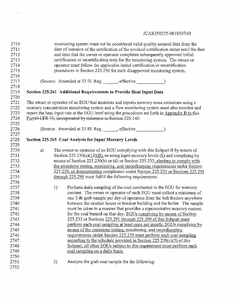
JCAR350225-081 8507r01
2710 monitoring system must not be considered valid quality-assured data from the2711 date of issuance of the notification of the revoked certification status until the date2712 and time that the owner or operator completes subsequently approved initial2713 certification or recertification tests for the monitoring system. The owner or2714 operator must follow the applicable initial certification or recertification2715 procedures in Section 225 .250 for each disapproved monitoring system.27162717 (Source: Amended at 33 Ill. Reg.
_______,
effective
_____________
27182719 Section 225.261 Additional Requirements to Provide Heat Input Data27202721 The owner or operator of an EGU that monitors and reports mercury mass emissions using a2722 mercury concentration monitoring system and a flow monitoring system must also monitor and2723 report the heat input rate at the EGU level using the procedures set forth in Appendix B to this2724 Part4O CFR 75, incorporated by reference in Section 225.140.27252726 (Source: Amended at 33 Iii. Reg.
_______,
effective
______________
27272728 Section 225.265 Coal Analysis for Input Mercury Levels27292730 a) The owner or operator of an EGU complying with this Subpart B by means of2731 Section 225.230(a)(12),-ef using input mercury levels (Ii) and complying by2732 means of Section 225.230(b) or (d) or Section 225.232, electing to comply with2733 the emissions testing, monitoring, and recordkeeping requirements under Section2734 225.239, or demonstrating compliance under Section 225.233 or Sections 225.2912735 through 225.299 must fulfill the following requirements:27362737 1) Perforni daily sampling of the coal combusted in the EGU for mercury2738 content. The owner or operator of such EGU must collect a minimum of2739 one 2-lb grab sample per day of operation from the belt feeders anywhere2740 between the crusher house or breaker building and the boiler. The sample2741 must be taken in a manner that provides a representative mercury content2742 for the coal burned on that day. EGUs complying by means of Section2743 225.233 or Sections 225.291 through 225.299 of this Subpart must2744 perform such coal sampling at least once per month; EGUs complying by2745 means of the emissions testing, monitoring, and recordkeeping2746 requirements under Section 225.239 must perform such coal sampling2747 according to the schedule provided in Section 225.239(e)(3) of this2748 Subpart; all other EGUs subject to this requirement must perform such2749 coal sampling on a daily basis.27502751 2) Analyze the grab coal sample for the following:2752
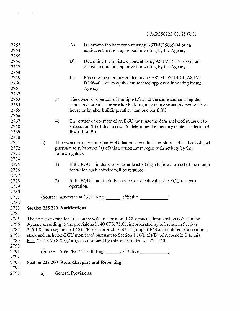
JCAR350225-08 1 8507r01
2753 A) Determine the heat content using ASTM D5865-04 or an2754 equivalent method approved in writing by the Agency.27552756 B) Determine the moisture content using ASTM D3173-03 or an2757 equivalent method approved in writing by the Agency.27582759 C) Measure the mercury content using ASTM D6414-01, ASTM2760 D3684-01, or an equivalent method approved in writing by the2761 Agency.27622763 3) The owner or operator of multiple EGUs at the same source using the2764 same crusher house or breaker building may take one sample per crusher2765 house or breaker building, rather than one per EGU.27662767 4) The owner or operator of an EGU must use the data analyzed pursuant to2768 subsection (b) of this Section to determine the mercury content in terms of2769 lbs/trillion Btu.27702771 b) The owner or operator of an EGU that must conduct sampling and analysis of coal2772 pursuant to subsection (a) of this Section must begin such activity by the2773 following date:27742775 1) If the EGU is in daily service, at least 30 days before the start of the month2776 for which such activity will be required.27772778 2) If the EGU is not in daily service, on the day that the EGU resumes2779 operation.27802781 (Source: Amended at 33 Ill. Reg.
_______,
effective
_____________
27822783 Section 225.270 Notifications27842785 The owner or operator of a source with one or more EGUs must submit written notice to the2786 Agency according to the provisions in 40 CFR 75.61, incorporated by reference in Section2787 225.140 (as a segment of 40 CFR 75), for each EGU or group of EGUs monitored at a common2788 stack and each non-EGU monitored pursuant to Section 1.16(b)(2)(B) of Appendix B to this2789 Part4O CFR 75.82b)(2)(ii), incorporated by reference in Section 225.140.27902791 (Source: Amended at 33 Ill. Reg.
_______,
effective
_____________
27922793 Section 225.290 Recordkeeping and Reporting27942795 a) General Provisions.
JCAR350225-08 1 8507r01
27962797 1) The owner or operator of an EGU and its designated representative must2798 comply with all applicable recordkeeping and reporting requirements in2799 this Section and with all applicable recordkeeping and reporting2800 requirements of Section 1.18 to Appendix B to this Part4O CFR 75.84,2801 incorporated by reference in Section 225.140.28022803 2) The owner or operator of an EGU must maintain records for each month2804 identifying the emission standard in Section 225 .230(a) or 225 .237(a) of2805 this Section with which it is complying or that is applicable for the EGU2806 and the following records related to the emissions of mercury that the2807 EGU is allowed to emit:28082809 A) For an EGU for which the owner or operator is complying with2810 this Subpart B by means of Section 225.230(a)(i2)ç or2811 225 .237(a)(1)(B) or using input mercury levels to determine the2812 allowable emissions of the EGU, records of the daily mercury2813 content of coal used (lbs/trillion Btu) and the daily and monthly2814 input mercury (ibs), which must be kept in the file pursuant to2815 Section 1.18(a) of Appendix B to this Part4O CFR 75.84(a).28162817 B) For an EGU for which the owner or operator of an EGU complying2818 with this Subpart B by means of Section 225.23 0(a)(1) or2819 225 .237(a)(1)(A) or using electrical output to determine the2820 allowable emissions of the EGU, records of the daily and monthly2821 gross electrical output (GWh), which must be kept in the file2822 required pursuant to Section 1.18(a) of Appendix B to this Part4O2823 CFR 75.84(a).28242825 3) The owner or operator of an EGU must maintain records of the following2826 data for each EGU:28272828 A) Monthly emissions of mercury from the EGU.28292830 B) For an EGU for which the owner or operator is complying by2831 means of Section 225.230(b) or (d) of this Subpart B, records of2832 the monthly allowable emissions of mercury from the EGU.28332834 4) The owner or operator of an EGU that is participating in an Averaging2835 Demonstration pursuant to Section 225.232 of this Subpart B must2836 maintain records identifying all sources and EGUs covered by the2837 Demonstration for each month and, within 60 days after the end of each2838 calendar month, calculate and record the actual and allowable mercury
JCAR350225-08 1 8507r01
2839 emissions of the EGU for the month and the applicable 12-month rolling2840 period.28412842 5) The owner or operator of an EGU must maintain the following records2843 related to quality assurance activities conducted for emissions monitoring2844 systems:28452846 A) The results of quarterly assessments conducted pursuant to2847 Sectionsection 2.2 of Exhibit B to Appendix B to this Partappendix2848 B of 40 CFR 75, incorporated by reference in Section 225.140; and28492850 B) Daily/weekly system integrity checks pursuant to Sectionseet4en2851 2.6 of Exhibit B to Appendix B to this Partappendix B of 40 CFR2852 75, incorporated by reference in Section 225.140.28532854 6) The owner or operator of an EGU must maintain an electronic copy of all2855 electronic submittals to the USEPA pursuant to Section 1.18(f) to2856 Appendix B to this Part4O CFR 75.84(f), incorporated by reference in2857 Section 225.140.28582859 7) The owner or operator of an EGU must retain all records required by this2860 Section at the source unless otherwise provided in the CAAPP permit2861 issued for the source and must make a copy of any record available to the2862 Agency upon request.28632864 b) Quarterly Reports. The owner or operator of a source with one or more EGUs2865 must submit quarterly reports to the Agency as follows:28662867 1) These reports must include the following information for operation of the2868 EGUs during the quarter:28692870 A) The total operating hours of each EGU and the mercury CEMS, as2871 also reported in accordance with Appendix B to this Part4O CFR2872 75, incorporated by reference in Section 225.140.28732874 B) A discussion of any significant changes in the measures used to2875 control emissions of mercury from the EGUs or the coal supply to2876 the EGUs, including changes in the source of coal.28772878 C) Summary information on the perfonnance of the mercury CEMS.2879 When the mercury CEMS was not inoperative, repaired, or2880 adjusted, except for routine zero and span checks, this must be2881 stated in the report.
JCAR350225-08 1 8507r01
28822883 D) If the CEMS downtime was more than 5.0 percent of the total2884 operating time for the EGU: the date and time identifying each2885 period during which the CEMS was inoperative, except for routine2886 zero and span checks; the nature of CEMS repairs or adjustments2887 and a summary of quality assurance data consistent with Appendix2888 B to this Part4O CFR 75, i.e., the dates and results of the Linearity2889 Tests and any RATAs during the quarter; a listing of any days2890 when a required daily calibration was not performed; and the date2891 and duration of any periods when the CEMS was out-of-control as2892 addressed by Section 225 .260.28932894 Recertification testing that has been performed for any CEMS and2895 the status of the results.28962897 2) The owner or operator must submit each quarterly report to the Agency2898 within 45 days following the end of the calendar quarter covered by the2899 report.29002901 c) Compliance Certification. The owner or operator of a source with one or more2902 EGUs must submit to the Agency a compliance certification in support of each2903 quarterly report based on reasonable inquiry of those persons with primary2904 responsibility for ensuring that all of the EGUs’ emissions are correctly and fully2905 monitored. The certification must state:29062907 1) That the monitoring data submitted were recorded in accordance with the2908 applicable requirements of this Section, Sections 225.240 through 225 .2702909 and Section 225.290 of this Subpart B, and Appendix B to this Part4O2910 CFR 75, including the quality assurance procedures and specifications;2911 and29122913 2) For an EGU with add-on mercury emission controls, a flue gas2914 desulfurization system, a selective catalytic reduction system, or a2915 compact hybrid particulate collector system and for all hours where2916 mercury data is missing thatare substituted in accordance with 40 CFR2917 75.34(a)(1):29182919 A That:29202921 4) The mercury add-on emission controls, flue gas desulfurization2922 system, selective catalytic reduction system, or compact hybrid2923 particulate collector system was operating within the range of2924 parameters listed in the quality assurance/quality control program
JCAR350225-081 8507r01
2925 pursuant to Exhibit B to Appendix B to this Partappendix B to 402926 CFR75;or29272928 i4) With regard to a flue gas desulfurization system or a selective2929 catalytic reduction system, quality-assured SO2 emission data2930 recorded in accordance with Appendix B to this Part 40 CFR 752931 document that the flue gas desulfurization system was operating2932 properly, or quality-assured NO emission data recorded in2933 accordance with Appendix B to this Part 40 CFR 75 document that2934 the selective catalytic reduction system was operating properly, as2935 applicable; and29362937 The substitute data values do not vstematically underestimate2938 mercury emissions.29392940 d) Annual Certification of Compliance.29412942 1) The owner or operator of a source with one or more EGUs subject to this2943 Subpart B must submit to the Agency an Annual Certification of2944 Compliance with this Subpart B no later than May 1 of each year and must2945 address compliance for the previous calendar year. Such certification2946 must be submitted to the Agency, Air Compliance and Enforcement2947 Section, and the Air Regional Field Office.29482949 2) Annual Certifications of Compliance must indicate whether compliance2950 existed for each EGU for each month in the year covered by the2951 Certification and it must certify to that effect. In addition, for each EGU,2952 the owner or operator must provide the following appropriate data as set2953 forth in subsections (d)(2)(A) through (d)(2)(E) of this Section, together2954 with the data set forth in subsection (d)(2)(F) of this Section:29552956 A) If complying with this Subpart B by means of Section2957 225 .230(a)(1 )(A) or 225.23 7(a)(1 )(A):29582959 i) Actual emissions rate, in lb/GWh, for each 12-month2960 rolling period ending in the year covered by the2961 Certification;29622963 ii) Actual emissions, in ibs, and gross electrical output, in2964 GWh, for each 12-month rolling period ending in the year2965 covered by the Certification; and2966
JCAR350225-081 8507r01
2967 iii) Actual emissions, in ibs, and gross electrical output, in2968 GWh, for each month in the year covered by the2969 Certification and in the previous year.29702971 B) If complying with this Subpart B by means of Section2972 225 .230(a)(1 )(B) or 225 .237(a)(1 )(B):29732974 i) Actual control efficiency for emissions for each 12-month2975 rolling period ending in the year covered by the2976 Certification, expressed as a percent;29772978 ii) Actual emissions, in lbs, and mercury content in the fuel2979 fired in such EGU, in ibs, for each 12-month rolling period2980 ending in the year covered by the Certification; and29812982 iii) Actual emissions, in ibs, and mercury content in the fuel2983 fired in such EGU, in ibs, for each month in the year2984 covered by the Certification and in the previous year.29852986 C) If complying with this Subpart B by means of Section 225.23 0(b):29872988 i) Actual emissions and allowable emissions for each 12-2989 month rolling period ending in the year covered by the2990 Certification; and29912992 ii) Actual emissions and allowable emissions, and which2993 standard of compliance the owner or operator was utilizing2994 for each month in the year covered by the Certification and2995 in the previous year.29962997 D) If complying with this Subpart B by means of Section 225.230(d):29982999 i) Actual emissions and allowable emissions for all EGUs at3000 the source for each 12-month rolling period ending in the3001 year covered by the Certification; and30023003 ii) Actual emissions and allowable emissions, and which3004 standard of compliance the owner or operator was utilizing3005 for each month in the year covered by the Certification and3006 in the previous year.30073008 E) If complying with this Subpart B by means of Section 225 .232:3009
JCAR350225-0818507r01
3010 i) Actual emissions and allowable emissions for all EGUs at3011 the source in an Averaging Demonstration for each 12-3012 month rolling period ending in the year covered by the3013 Certification; and30143015 ii) Actual emissions and allowable emissions, with the3016 standard of compliance the owner or operator was utilizing3017 for each EGU at the source in an Averaging Demonstration3018 for each month for all EGUs at the source in an Averaging3019 Demonstration in the year covered by the Certification and3020 in the previous year.30213022 F) Any deviations, data substitutions, or exceptions each month and3023 discussion of the reasons for such deviations, data substitutions, or3024 exceptions.30253026 3) All Annual Certifications of Compliance required to be submitted must3027 include the following certification by a responsible official:30283029 I certify under penalty of law that this document and all attachments were3030 prepared under my direction or supervision in accordance with a system3031 designed to assure that qualified personnel properly gather and evaluate3032 the information submitted. Based on my inquiry of the person or persons3033 directly responsible for gathering the information, the information3034 submitted is, to the best of my knowledge and belief, true, accurate, and3035 complete. I am aware that there are significant penalties for submitting3036 false information, including the possibility of fine and imprisonment for3037 knowing violations.30383039 4) The owner or operator of an EGU must submit its first Annual3040 Certification of Compliance to address calendar year 2009 or the calendar3041 year in which the EGU commences commercial operation, whichever is3042 later. Notwithstanding subsection (d)(2) of this Section, in the Annual3043 Certifications of Compliance that are required to be submitted by May 1,3044 2010, and May 1, 2011, to address calendar years 2009 and 2010,3045 respectively, the owner or operator is not required to provide 12-month3046 rolling data for any period that ends before June 30, 2010.30473048 e) Deviation Reports. For each EGU, the owner or operator must promptly notify3049 the Agency of deviations from requirements of this Subpart B. At a minimum,3050 these notifications must include a description of such deviations within 30 days3051 after discovery of the deviations, and a discussion of the possible cause of such3052 deviations, any corrective actions, and any preventative measures taken.
JCAR350225-08 1 8507r01
30533054 f) Quality Assurance RATA Reports. The owner or operator of an EGU must3055 submit to the Agency, Air Compliance and Enforcement Section, the quality3056 assurance RATA report for each EGU or group of EGUs monitored at a common3057 stack and each non-EGU pursuant to Section 1.16(b)(2)(B) of Appendix B to this3058 Part4O CFR 75.82(b)(2)(ii), incorporated by reference in Section 225.140, within3059 45 days after completing a quality assurance RATA.30603061 (Source: Amended at 33 Ill. Reg.
_______,
effective
_____________
30623063 Section 225.291 Combined Pollutant Standard: Purpose30643065 The purpose of Sections 225.29 1 through 225.299 (hereinafter referred to as the Combined3066 Pollutant Standard (CPS”)) is to allow an alternate means of compliance with the emissions3067 standards for mercury in Section 225.230(a) for specified EGUs through permanent shut-down,3068 installation of ACT, and the application of pollution control technology for NON, PM, and SO23069 emissions that also reduce mercury emissions as a co-benefit and to establish permanent3070 emissions standards for those specified EGUs. Unless otherwise provided for in the CPS,3071 owners and operators of those specified EGUs are not excused from compliance with other3072 applicable requirements of Subparts B, C, D, and E.30733074 (Source: Added at 33 Ill. Reg.
_______,
effective
______________
30753076 Section 225.292 Applicability of the Combined Pollutant Standard30773078 As an alternative to compliance with the emissions standards of Section3079 225.23 0(a), the owner or operator of specified EGUs in the CPS located at Fisk,3080 Crawford, Joliet, Powerton, Waukegan, and Will County power plants may elect3081 for all of those EGUs as a group to demonstrate compliance pursuant to the CPS,3082 which establishes control requirements and emissions standards for NO.fI,3083 SQ2, and mercury. For this purpose, ownership of a specified EGU is determined3084 based on direct ownership, by holding a majority interest in a company that owns3085 the EGU or EGUs, or by the common ownership of the company that owns the3086 EGU, whether through a parent-subsidiary relationship, as a sister corporation, or3087 as an affiliated corporation with the same parent corporation, provided that the3088 owner or operator has the right or authority to submit a CAAPP application on3089 behalf of the EGU.30903091 A specified EGU is a coal-fired EGU listed in Appendix A, irrespective of any3092 subsequent changes in ownership of the EGU or power plant, the operator, unit3093 designation, or name of unit.3094
JCAR35O225O8l 8507r01
3095 ç The owner or operator of each of the specified EGUs electing to demonstrate3096 compliance with Section 225.230(a) pursuant to the CPS must submit an3097 application for a CAAPP permit modification to the Agency, as provided for in3098 Section 225.220, that includes the information specified in Section 225.293 that3099 clearly states the owner’s or operator’s election to demonstrate compliance with3100 Section 225.230(a) pursuant to the CPS.31013102 ci If an owner or operator of one or more specified EGUs elects to demonstrate3103 compliance with Section 225.230(a) pursuant to the CPS, then all specified EGUs3104 owned or operated in Illinois by the owner or operator as of December 31, 2006,3105 as defined in subsection (a) of this Section, are thereafter subject to the standards3106 and control requirements of the CPS. Such EGUs are referred to as a Combined3107 Pollutant Standard (CPS) group.31083109 If an EGU is subject to the requirements of this Section, then the requirements3110 apply to all owners and operators of the EGU, and to the CAIR designated3111 representative for the EGU.31123113 (Source: Added at 33 Ill. Reg.
______,
effective
_____________
31143115 Section 225.293 Combined Pollutant Standard: Notice of Intent31163117 The owner or operator of one or more specified EGUs that intends to comply with Section3118 225.230(a) by means of the CPS must notify the Agency of its intention on or before December3119 31, 2007. The following information must accompany the notification:31203121 The identification of each EGU that will be complying with Section 225.23(3122 pursuant to the CPS, with evidence that the owner or operator has identified all3123 specified EGUs that it owned or operated in Illinois as of December 31, 2006, and3124 which commenced commercial operation on or before December 31, 2004;31253126 If an EGU identified in subsection (a) of this Section is also owned or operated by3127 a person different than the owner or operator submitting the notice of intent, a3128 demonstration that the submitter has the right to commit the EGU or authorization3129 from the responsible official for the EGU submitting the application; and31303131 A summary of the current control devices installed and operating on each EGU3132 and identification of the additional control devices that will likely be needed for3133 each EGU to comply with emission control requirements of the CPS.31343135 (Source: Added at 33 Ill. Reg.,_____ effective
________________
3136
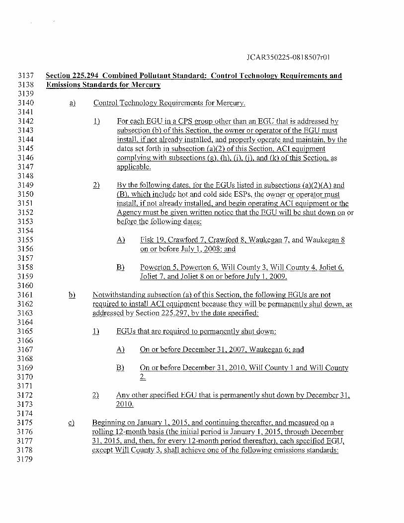
JCAR350225-08 1 8507r01
3137 Section 225.294 Combined Pollutant Standard: Control Technology Requirements and3138 Emissions Standards for Mercury31393140 Control Technology Requirements for Mercury.31413142 II For each EGU in a CPS group other than an EGU that is addressed by3143 subsection (b) of this Section, the owner or operator of the EGU must3144 install, if not already installed, and properly operate and maintain, by the3145 dates set forth in subsection (a)(2) of this Section, ACT equipment3146 complying with subsections (g), (h), (i), (I), and (k) of this Section, as3147 applicable.31483149 ) By the following dates, for the EGUs listed in subsections (a)(2)(A) and3150 (B), which include hot and cold side ESPs, the owner or operator must3151 install, if not already installed, and begin operating ACT equipment or the3152 Agency must be given written notice that the EGU will be shut down on or3153 before the following dates:31543155 Fisk 19, Crawford 7, Crawford 8, Waukegan 7, and Waukegan 83156 on or before July 1, 2008: and31573158 Powerton 5, Powerton 6, Will County 3, Will County 4, Joliet 6,3159 Joliet 7, and Joliet 8 on or before July 1,2009.31603161 Notwithstanding subsection (a) of this Section, the following EGUs are not3162 required to install ACI equipment because they will be permanently shut down, as3163 addressed by Section 225.297, by the date specified:31643165 D EGUs that are required to permanently shut down:31663167 On or before December 31, 2007, Waukegan 6; and31683169 ) On or before December 31, 2010, Will County 1 and Will County3170 2.31713172 Any other specified EGU that is permanently shut down by December 31,3173 2010.31743175 Beginning on January 1, 2015, and continuing thereafter, and measured on a3176 rolling 12-month basis (the initial period is January 1, 2015, through December3177 31, 2015, and, then, for every 12-month period thereafter), each specified EGU,3178 except Will County 3, shall achieve one of the following emissions standards:3179
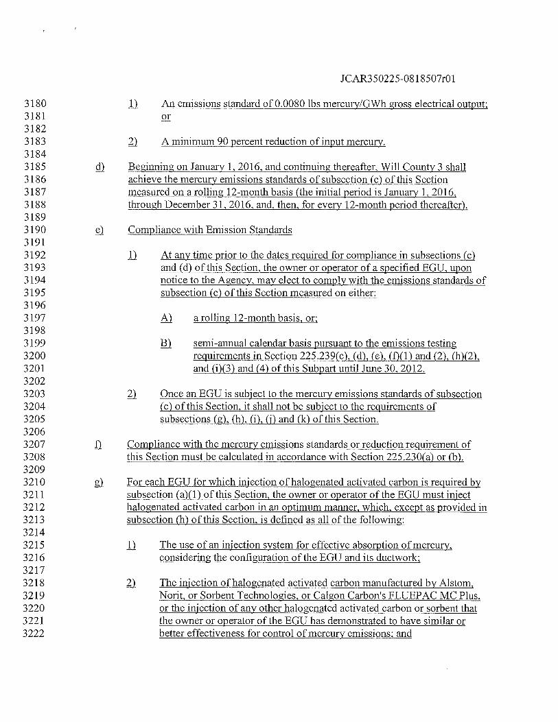
JCAR350225-08 1 8507r01
3180 II An emissions standard of 0.0080 lbs mercury/GWh gross electrical output:318131823183 ) A minimum 90 percent reduction of input mercury.31843185 Beginning on January 1, 2016, and continuing thereafter, Will County 3 shall3186 achieve the mercury emissions standards of subsection (c) of this Section3187 measured on a rolling 12-month basis (the initial period is January 1, 2016,3188 through December 31, 2016, and, then, for every 12-month period thereafter).31893190 Compliance with Emission Standards31913192 II At any time prior to the dates required for compliance in subsections (c)3193 and (d) of this Section, the owner or operator of a specified EGU. upon3194 notice to the Agency, may elect to comply with the emissions standards of3195 subsection (c) of this Section measured on either:31963197 a rolling 12-month basis, or:31983199 semi-annual calendar basis pursuant to the emissions testing3200 requirements in Section 225.239(c), (d), (e), (f)(1) and (2), (h)(2),3201 and (i)(3) and (4) of this Subpart until June 30, 2012.32023203 Once an EGU is subject to the mercury emissions standards of subsection3204 (c) of this Section, it shall not be subject to the requirements of3205 subsections (g), (h), (i), (i) and (k) of this Section.32063207 Compliance with the mercury emissions standards or reduction requirement of3208 this Section must be calculated in accordance with Section 225.230(a) or (b).32093210 g For each EGU for which injection of halogenated activated carbon is required by3211 subsection (a)(1) of this Section, the owner or operator of the EGU must inject3212 halogenated activated carbon in an optimum manner, which, except as provided in3213 subsection (h) of this Section, is defined as all of the following:32143215 fl The use of an injection system for effective absorption of mercury,3216 considering the configuration of the EGU and its ductwork:32173218 The injection of halogenated activated carbon manufactured by Aistom,3219 Norit, or Sorbent Technologies, or Calgon Carbon’s FLUEPAC MC Plus,3220 or the injection of any other halogenated activated carbon or sorbent that3221 the owner or operator of the EGU has demonstrated to have similar or3222 better effectiveness for control of mercury emissions: and
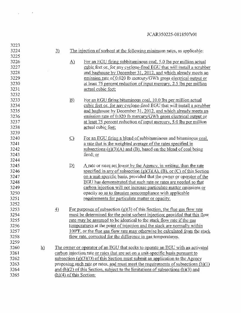
JCAR350225-08 1 8507r01
32233224 fl The injection of sorbent at the following minimum rates, as applicable:32253226 For an EGU firing subbituminous coal, 5.0 lbs per million actual3227 cubic feet or, for any cyclone-fired EGU that will install a scrubber3228 and baghouse by December 31, 2012, and which already meets an3229 emission rate of 0.020 lb mercury/GWh gross electrical output or3230 at least 75 percent reduction of input mercury, 2.5 lbs per million3231 actual cubic feet;32323233 For an EGU firing bituminous coal, 10.0 lbs per million actual3234 cubic feet or, for any cyclone-fired EGU that will install a scrubber3235 and baghouse by December 31, 2012, and which already meets an3236 emission rate of 0.020 lb mercury/GWh gross electrical output or3237 at least 75 percent reduction of input mercury, 5.0 lbs per million3238 actual cubic feet;32393240 c) For an EGU firing a blend of subbituminous and bituminous coal,3241 a rate that is the weighted average of the rates specified in3242 subsections (g)(3)(A) and (B), based on the blend of coal being3243 fired; or32443245 A rate or rates set lower by the Agency, in writing, than the rate3246 specified in any of subsection (g)(3)(A), (B), or (C) of this Section3247 on a unit-specific basis, provided that the owner or operator of the3248 EGU has demonstrated that such rate or rates are needed so that3249 carbon injection will not increase particulate matter emissions or3250 opacity so as to threaten noncompliance with applicable3251 requirements for particulate matter or opacity.32523253 4 For purposes of subsection (g)(3) of this Section, the flue gas flow rate3254 must be determined for the point sorbent injection; provided that this flow3255 rate maybe assumed to be identical to the stack flow rate if the gas3256 temperatures at the point of injection and the stack are normally within3257 100°F, or the flue gas flow rate may otherwise be calculated from the stack3258 flow rate, corrected for the difference in gas temperatures.32593260 The owner or operator of an EGU that seeks to operate an EGU with an activated3261 carbon injection rate or rates that are set on a unit-specific basis pursuant to3262 subsection (g)(3)(D) of this Section must submit an application to the Agency3263 proposing such rate or rates, and must meet the requirements of subsections (h)(1)3264 and (h)(2) of this Section, subject to the limitations of subsections (h)(3) and3265 (4) of this Section:
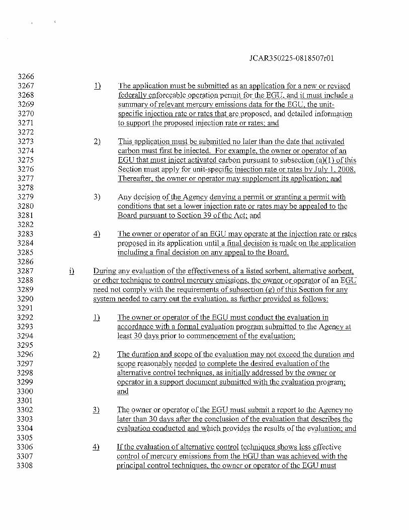
JCAR350225-08 1 8507r01
32663267 ) The application must be submitted as an application for a new or revised3268 federally enforceable operation permit for the EGU, and it must include a3269 summary of relevant mercury emissions data for the EGU, the unit-3270 specific injection rate or rates that are proposed, and detailed information3271 to support the proposed injection rate or rates; and32723273 This application must be submitted no later than the date that activated3274 carbon must first be injected. For example, the owner or operator of an3275 EGU that must inject activated carbon pursuant to subsection (a)(1) of this3276 Section must apply for unit-specific injection rate or rates by July 1, 2008.3277 Thereafier, the owner or operator may supplement its application; and32783279 ) Any decision of the Agency denying a permit or granting a permit with3280 conditions that set a lower injection rate or rates may be appealed to the3281 Board pursuant to Section 39 of the Act; and32823283 4 The owner or operator of an EGU may operate at the injection rate or rates3284 proposed in its application until a final decision is made on the application3285 including a final decision on any appeal to the Board.32863287 During any evaluation of the effectiveness of a listed sorbent, alternative sorbent,3288 or other technique to control mercury emissions, the owner or operator of an EGU3289 need not comply with the requirements of subsection (g) of this Section for any3290 system needed to carry out the evaluation, as further provided as follows:32913292 j) The owner or operator of the EGU must conduct the evaluation in3293 accordance with a formal evaluation program submitted to the Agency at3294 least 30 days prior to commencement of the evaluation;32953296 The duration and scope of the evaluation may not exceed the duration and3297 scope reasonably needed to complete the desired evaluation of the3298 alternative control techniques, as initially addressed by the owner or3299 operator in a support document submitted with the evaluation program;330033013302 The owner or operator of the EGU must submit a report to the Agency no3303 later than 30 days after the conclusion of the evaluation that describes the3304 evaluation conducted and which provides the results of the evaluation; and33053306 4 If the evaluation of alternative control techniques shows less effective3307 control of mercury emissions from the EGU than was achieved with the3308 principal control techniques, the owner or operator of the EGU must
JCAR350225-081 8507r01
3309 resume use of the principal control techniques. If the evaluation of the3310 alternative control technique shows comparable effectiveness to the3311 principal control technique, the owner or operator of the EGU may either3312 continue to use the alternative control technique in a manner that is at least3313 as effective as the principal control technique or it may resume use of the3314 principal control technique. If the evaluation of the alternative control3315 technique shows more effective control of mercury emissions than the3316 control technique, the owner or operator of the EGU must continue to use3317 the alternative control technique in a manner that is more effective than3318 the principal control technique, so long as it continues to be subject to this3319 Section.33203321 j) In addition to complying with the applicable recordkeeping and monitoring3322 requirements in Sections 225.240 through 225.290, the owner or operator of an3323 EGU that elects to comply with Section 225.230(a) by means of the CPS must3324 also comply with the following additional requirements:33253326 jj For the first 36 months that injection of sorbent is required, it must3327 maintain records of the usage of sorbent, the exhaust gas flow rate from3328 the EGU, and the sorbent feed rate, in pounds per million actual cubic feet3329 of exhaust gas at the injection point, on a weekly average;33303331 ) After the first 36 months that injection of sorbent is required, it must3332 monitor activated sorbent feed rate to the EGU, flue gas temperature at the3333 point of sorbent injection, and exhaust gas flow rate from the EGU,3334 automatically recording this data and the sorbent carbon feed rate, in3335 pounds per million actual cubic feet of exhaust gas at the injection point,3336 on an hourly average; and33373338 ) If a blend of bituminous and subbituminous coal is fired in the EGU, it3339 must keep records of the amount of each type of coal burned and the3340 required injection rate for injection of activated carbon on a weekly basis.33413342 In addition to complying with the applicable reporting requirements in Sections3343 225.240 through 225.290, the owner or operator of an EGU that elects to comply3344 with Section 225.23 0(a) by means of the CPS must also submit quarterly reports3345 for the recordkeeping and monitoring conducted pursuant to subsection ii) of this3346 Section.33473348 As an alternative to the CEMS monitoring, recordkeeping, and reporting3349 requirements in Sections 225.240 through 225.290, the owner or operator of an3350 EGU may elect to comply with the emissions testing, monitoring, recordkeeping,
JCAR350225-08 1 8507r01
3351 and reporting requirements in Section 225.239(c), (d), (e), (f)(1) and (2), (h)(2),3352 (i)(3) and (4), and (fl(1).33533354 (Source: Added at 33 Iii. Reg.
______,
effective
__________________
33553356 Section 225.295 Combined-Pollutant Standard: Emissions Standards for NOX and3357 SO2Trcatment of Mcrcury Allowances33583359 Any mercury allowances allocated to the Agency by the USEPA must be treated as follows:33603361 a No such allowances may be allocated to any owner or operator of an EGU or3362 other sources of mercury emissions into the atmosphere or discharges into the3363 waters of the State.33643365 b The Agency must hold all allowances allocated by the USEPA to the State. At3366 the end of each calendar year, the Agency must instruct the USEPA to retire3367 permanently all such allowances.33683369 Emissions Standards for NO and Reporting Requirements.33703371 jj Beginning with calendar year 2012 and continuing in each calendar year3372 thereafter, the CPS group, which includes all specified EGUs that have not3373 been permanently shut down by December 31 before the applicable3374 calendar year, must comply with a CPS group average annual NO3375 emissions rate of no more than 0.11 lbs/mmBtu.33763377 Beginning with ozone season control period 2012 and continuing in each3378 ozone season control period (May 1 through September 30) thereafter, the3379 CPS group, which includes all specified EGUs that have not been3380 permanently shut down by December 31 before the applicable ozone3381 season, must comply with a CPS group average ozone season NO3382 emissions rate of no more than 0.11 lbs/mmBtu.33833384 The owner or operator of the specified EGUs in the CPS group must file,3385 not later than one year after startup of any selective SNCR on such EGU, a3386 report with the Agency describing the NO emissions reductions that the3387 SNCR has been able to achieve.33883389 ! Emissions Standards for SO2. Beginning in calendar year 2013 and continuing in3390 each calendar year thereafter, the CPS group must comply with the applicable3391 CPS group average annual SO2 emissions rate listed as follows:33923393 lbs/nimBtu
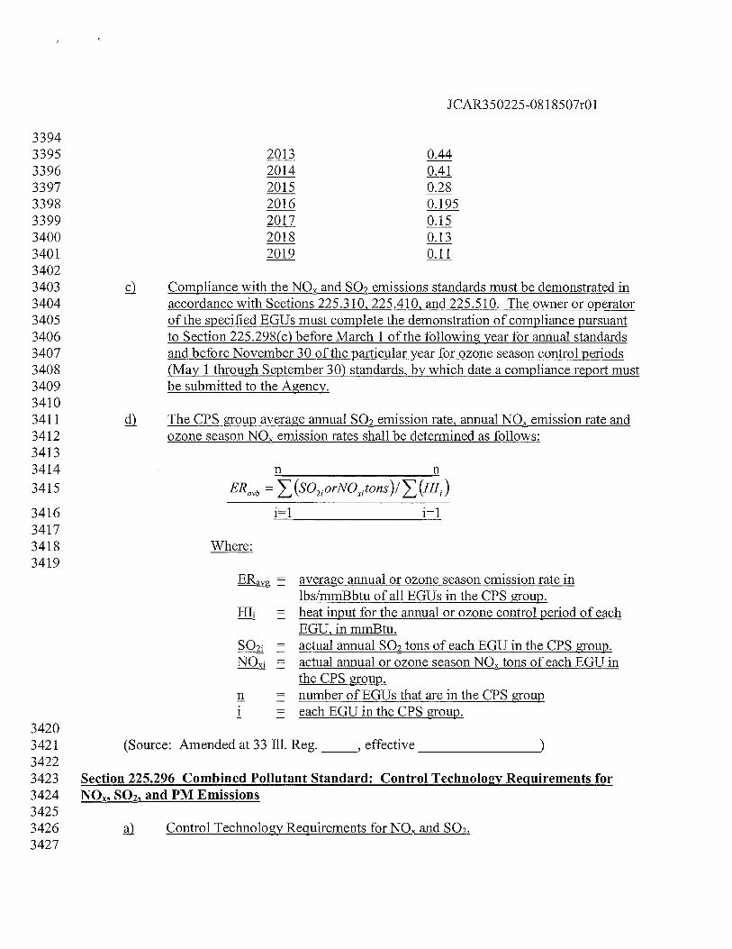
JCAR350225-08 1 8507r01
33943395 2013 0.443396 2014 0.413397 2015 0283398 2016 0.1953399 2017 0.153400 2018 0.133401 2019 0.1134023403 c) Compliance with the NO and SO2 emissions standards must be demonstrated in3404 accordance with Sections 225.310, 225.410, and 225.5 10. The owner or operator3405 of the specified EGUs must complete the demonstration of compliance pursuant3406 to Section 225 .298(c) before March 1 of the following year for annual standards3407 and before November 30 of the particular year for ozone season control periods3408 (May 1 through September 30) standards, by which date a compliance report must3409 be submitted to the Agency.34103411 The CPS group average annual SO2 emission rate, annual NO emission rate and3412 ozone season NO emission rates shall be determined as follows:34133414 n n3415 ERavb = (SO2orNOtons)/ (HI1)
3416 i=1 i=l34173418 Where:3419
ER = average annual or ozone season emission rate inlbs/mmBbtu of all EGUs in the CPS group.
HI, = heat input for the annual or ozone control period of eachEGU, in mmBtu.
= actual annual SO2 tons of each EGU in the CPS group.NQi = actual annual or ozone season NO tons of each EGU in
the CPS group.n = number of EGUs that are in the CPS groupi each EGU in the CPS group.
34203421 (Source: Amended at 33 Ill. Reg.
_____,
effective
___________________
34223423 Section 225.296 Combined Pollutant Standard: Control Technology Reiuirements for3424 QQ2, and PM Emissions34253426 Control Technology Requirements for NO and SO2.3427
JCAR350225-081 8507r01
3428 j) On or before December 31, 2013, the owner or operator must either3429 permanently shut down or install and have operational FGD equipment on3430 Waukegan 7;34313432 ) On or before December 31, 2014, the owner or operator must either3433 permanently shut down or install and have operational FGD equipment on3434 Waukegan 8;34353436 ) On or before December 31, 2015, the owner or operator must either3437 permanently shut down or install and have operational FGD equipment on3438 Fisk 19;34393440 4) If Crawford 7 will be operated after December 31, 2018, and not3441 permanently shut down by this date, the owner or operator must:34423443 ) On or before December 31, 2015, install and have operational3444 SNCR or equipment capable of delivering essentially equivalent3445 Q< reductions on Crawford 7; and34463447 j) On or before December 31, 2018, install and have operational FGD3448 equipment on Crawford 7;34493450 ) If Crawford 8 will be operated afier December 31, 2017 and not3451 permanently shut down by this date, the owner or operator must:34523453 ) On or before December 31, 2015, install and have operational3454 SNCR or equipment capable of delivering essentially equivalent3455 emissions reductions on Crawford 8; and34563457 j) On or before December 31, 2017, install and have operational FGD3458 equipment on Crawford 8.34593460 k) Other Control Technology Requirements for SO2. Owners or operators of3461 specified EGUs must either permanently shut down or install FGD equipment on3462 each specified EGU (except Joliet 5), on or before December 31, 2018, unless an3463 earlier date is specified in subsection (a) of this Section.34643465 Control Technology Requirements for PM. The owner or operator of the two3466 specified EGUs listed in this subsection that are equipped with a hot-side ESP3467 must replace the hot-side ESP with a cold-side ESP, install an appropriately3468 designed fabric filter, or permanently shut down the EGU by the dates specified.3469 Hot-side ESP means an ESP on a coal-fired boiler that is installed before the3470 boiler?s air-preheater where the operating temperature is typically at least 5 50°F,
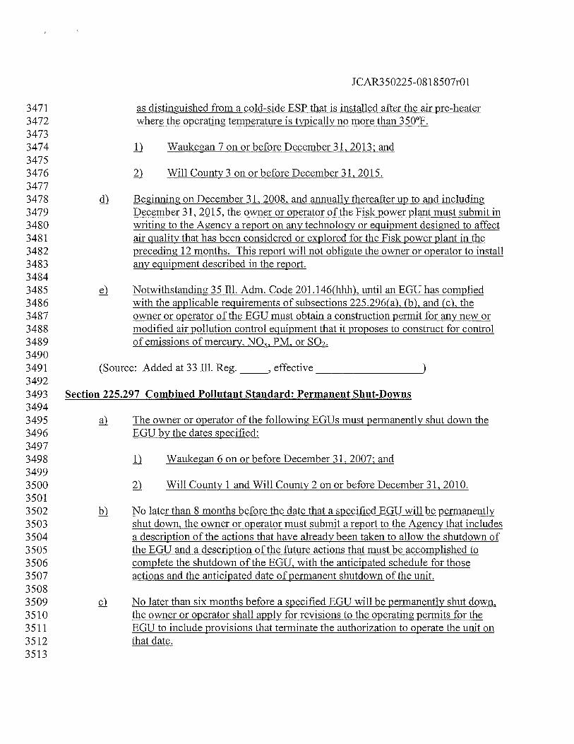
JCAR350225-08 1 8507r01
3471 as distinguished from a cold-side ESP that is installed after the air pre-heater3472 where the operating temperature is typically no more than 350°F.34733474 Waukegan 7 on or before December 31, 2013; and34753476 ) Will County 3 on or before December 31, 2015.34773478 Beginning on December 31, 2008, and annually thereafter up to and including3479 December 31, 2015, the owner or operator of the Fisk power plant must submit in3480 writing to the Agency a report on any technology or equipment designed to affect3481 air quality that has been considered or explored for the Fisk power plant in the3482 preceding 12 months. This report will not obligate the owner or operator to install3483 any equipment described in the report.34843485 Notwithstanding 35 Ill. Adm. Code 20l.146(hhh), until an EGU has complied3486 with the applicable requirements of subsections 225.296(a), (b), and (c), the3487 owner or operator of the EGU must obtain a construction permit for any new or3488 modified air pollution control equipment that it proposes to construct for control3489 of emissions of mercury, NOR, PM, or SO2.34903491 (Source: Added at 33 Ill. Reg.
_____,
effective
_____________________
34923493 Section 225.297 Combined Pollutant Standard: Permanent Shut-Downs34943495 The owner or operator of the following EGUs must permanently shut down the3496 EGU by the dates specified:34973498 Waukegan 6 on or before December 31, 2007; and34993500 ) Will County 1 and Will County 2 on or before December 31, 2010.35013502 j No later thasi 8 months before the date that a specified EGU will be permanently3503 shut down, the owner or operator must submit a report to the Agency that includes3504 a description of the actions that have already been taken to allow the shutdown of3505 the EGU and a description of the future actions that must be accomplished to3506 complete the shutdown of the EGU, with the anticipated schedule for those3507 actions and the anticipated date of permanent shutdown of the unit.35083509 ç). No later than six months before a specified EGU will be permanently shut down,3510 the owner or operator shall apply for revisions to the operating permits for the3511 EGU to include provisions that terminate the authorization to operate the unit on3512 that date.3513
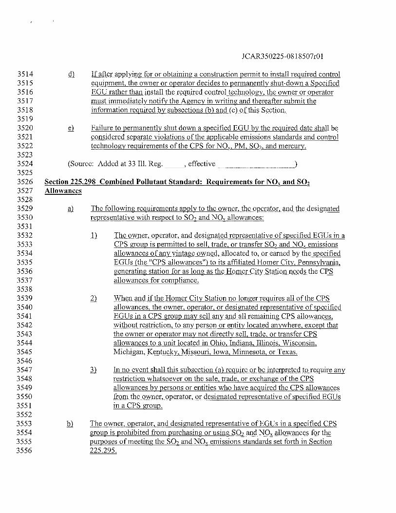
JCAR350225-08 1 8507r01
3514 If after applying for or obtaining a construction permit to install required control3515 equipment, the owner or operator decides to permanently shut-down a Specified3516 EGU rather than install the required control technology, the owner or operator3517 must immediately notify the Agency in writing and thereafter submit the3518 information required by subsections (b) and (c) of this Section.35193520 ç Failure to permanently shut down a specified EGU by the required date shall be3521 considered separate violations of the applicable emissions standards and control3522 technology requirements of the CPS for NON, PM, SO,, and mercury.35233524 (Source: Added at 33 Ill. Reg.
______,
effective
_______________________
35253526 Section 225.298 Combined Pollutant Standard: Requirements for NO and SO23527 Allowances35283529 The following requirements apply to the owner, the operator, and the designated3530 representative with respect to SO2 and NO allowances:35313532 j The owner, operator, and designated representative of specified EGUs in a3533 CPS group is permitted to sell, trade, or transfer SO, and NO emissions3534 allowances of any vintage owned, allocated to, or earned by the specified3535 EGUs (the “CPS allowances”) to its affiliated Homer City, Pennsylvania,3536 generating station for as long as the Homer City Station needs the CPS3537 allowances for compliance.35383539 ) When and if the Homer City Station no longer requires all of the CPS3540 allowances, the owner, operator, or designated representative of specified3541 EGUs in a CPS group may sell any and all remaining CPS allowances,3542 without restriction, to any person or entity located anywhere, except that3543 the owner or operator may not directly sell, trade, or transfer CPS3544 allowances to a unit located in Ohio, Indiana, Illinois, Wisconsin,3545 Michigan, Kentucky, Missouri, Iowa, Minnesota, or Texas.35463547 In no event shall this subsection (a) require or be interpreted to require any3548 restriction whatsoever on the sale, trade, or exchange of the CPS3549 allowances by persons or entities who have acquired the CPS allowances3550 from the owner, operator, or designated representative of specified EGUs3551 maCPS group.35523553 j The owner, operator, and designated representative of EGUs in a specified CPS3554 group is prohibited from purchasing or using SO2 and NO allowances for the3555 purposes of meeting the SO, and NO emissions standards set forth in Section3556 225.295.
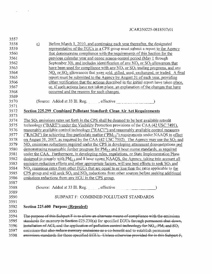
JCAR350225-08 1 8507r01
ç). Before March 1, 2010, and continuing each year thereafler, the designatedrepresentative of the EGUs in a CPS group must submit a report to the Agencythat demonstrates compliance with the requirements of this Section for theprevious calendar year and ozone season control period (May 1 throughSeptember 30), and includes identification of any NO or SO2 allowances thathave been used for compliance with any NO or SO2 trading programs, and any
or SQ allowances that were sold, gifted, used, exchanged, or traded. A finalreport must be submitted to the Agency by August 31 of each year, providingeither verification that the actions described in the initial report have taken place,or, if such actions have not taken place, an explanation of the changes that haveoccurred and the reasons for such changes.
(Source: Added at 33 Iii. Reg.
______,
effective•
Section 225.299 Combined Pollutant Standard: Clean Air Act Requirements
The SO2 emissions rates set forth in the CPS shall be deemed to be best available retrofittechnology(11BART”) under the Visibility Protection provisions of the CAA (42 USC 7491),reasonably available control technology (BRACT”) and reasonably available control measures(11RACM”) for achieving fine particulate matter (“PM”) requirements under NAAOS in effecton August 31, 2007, as required by the CAA (42 USC 7502). The Agency may use the SO, andNO emissions reductions required under the CPS in developing attainment demonstrations anddemonstrating reasonable further progress for PM and 8 hour ozone standards, as requiredunder the CAA. Furthermore, in developing rules, regulations, or State Implementation Plansdesigned to comply with PM and 8 hour ozone NAAOS, the Agency, taking into account allemission reduction efforts and other appropriate factors, will use best efforts to seek SO2 andNQ emissions rates from other EGUs that are equal to or less than the rates applicable to theCPS group and will seek SO2 and NO reductions from other sources before seeking additionalemissions reductions from any EGU in the CPS group.
(Source: Added at 33 Iii. Reg. effective
SUBPART F: COMBiNED POLLUTANT STANDARDS
Section 225.600 Purpose (Repealed)
The puose of this Subpart F is to allow an alternate means of compliance with the emissionsstandards for mercury in Section 225.23 0(a) for specified EGUs through permanent shut down,installation of ACT, and the application of pollution control technology for NON, PM, and SOemissions that also reduce mercury emissions as a co benefit and to establish permanentemissions standards for those specified EGUs. Unless othevise provided for in this Subpart F,
355735583559356035613562356335643565356635673568356935703571357235733574357535763577357835793580358135823583358435853586358735883589359035913592359335943595359635973598
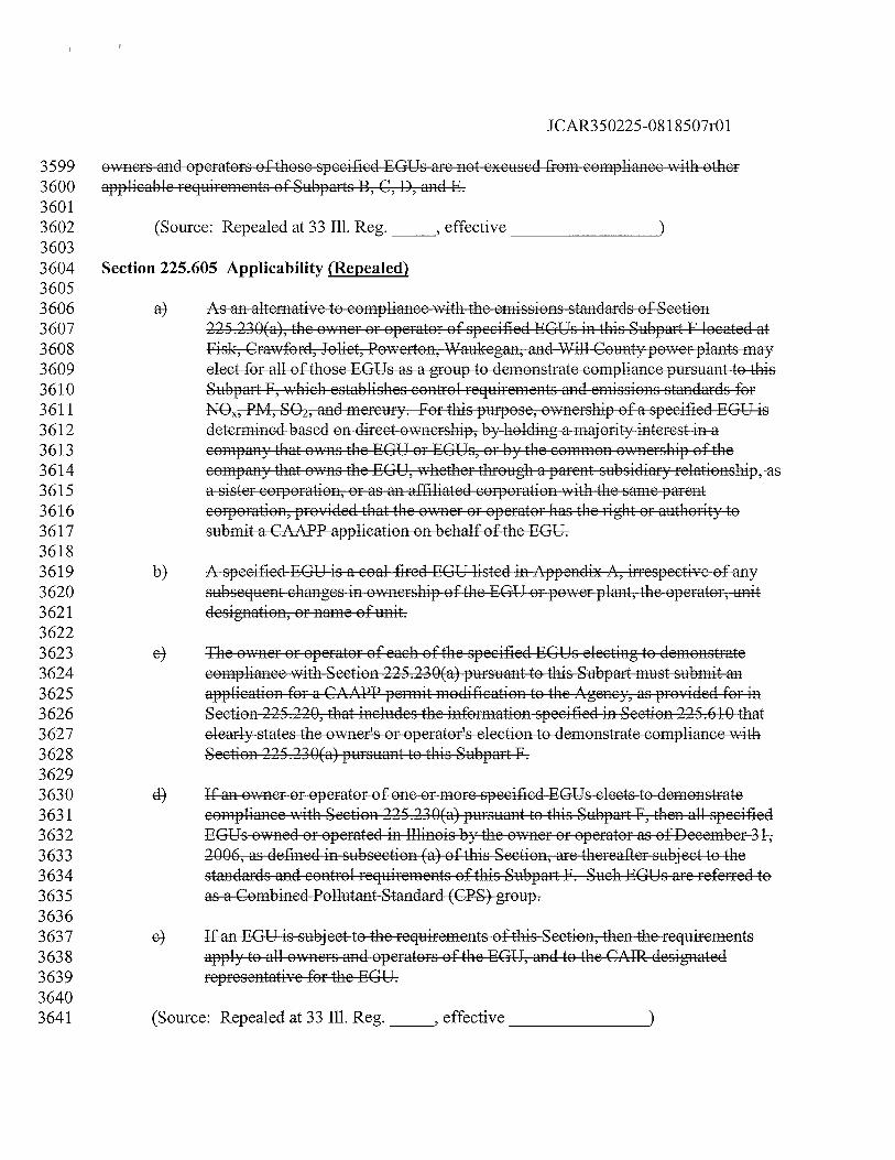
t.C ( C
)JF
OC
N
jD C
H1
(ID
© (‘I
lCD Iz I— lCD
C C C F C (1
F. F
.r C
LC C C
)LS
Ci)
:
)C
-F -F I.
3-.
+ +
3-.
+
(/D 0 C) CD CD CD CD C—
cQ
C
CC
-C
C C F ( C C C C C
Cl ‘3 rj -F. 3-’ -F
) r-C C
3 C(
CC
;- 4) 3C
CF
< 3C
3C
-C 3F
)F
FJ
3F
+F C
•C C C C
h C.
+ -3 2 3
CC
3--
.
3-F
-F
. [1 C‘It ( C C
F) C. Cl -F. 1-. F -F
-F)
+ 3-.
‘-3 +
F-)
-F
rj
‘3C C
rc
‘3F C
- 3F
r
F
.F
.3
F C Ft
C
H >‘.
-C
).
‘34)
+ C_F 0 C C C C
C F- C F-C
4) C C C Ft
5-.
+ 3-4 -t 3 + F)
-C 3 + C r F-
> +3
‘-C
--.
-F-
C.-) I
+ 3-’ +
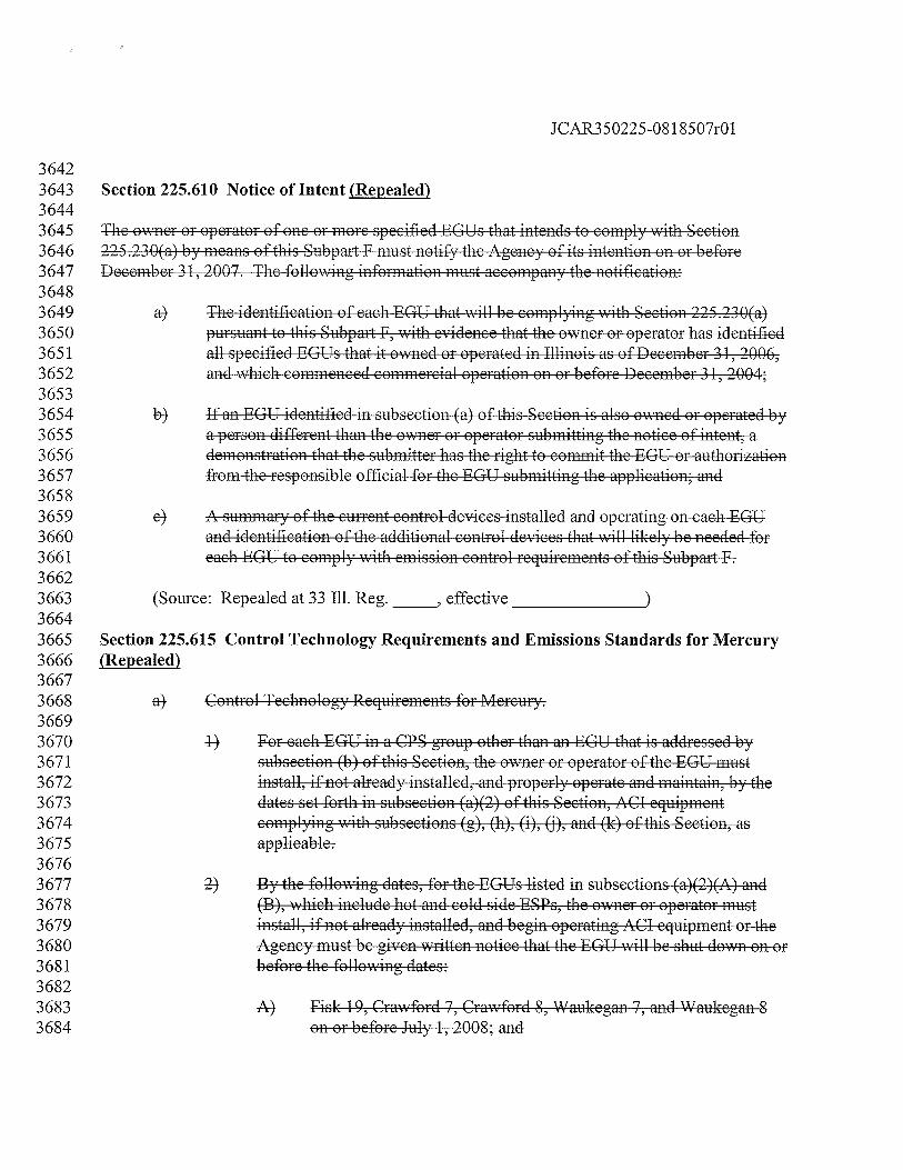
ON
ON
ON
CN U
24.4
J-c”coo
NO
NO
NO
NO
N
4)
Itj
r +
C
.l( C
)
rj-j C CD CD CD p CD CD I
.4-
2 2
-31’
;)CD CD C CD CD C CD lCD lCD
()c)
ON
ON
ON
ON
ON
L
lCD
CI
‘I lk
-J C - C CD CD F
C C C C!
ci
0 -4
ci C C C C C
rj -4 ID
C C
.4 N N N t. C C C C C C
4- C. iC •
C1 C
t
t + (N •1
> t) 4- e ti -4 -4
C
.) ) ) —I -3 r N N
ci
•.
2 2 N
c C
H + +
C C
C C C C C 4. 4. C C C C C C C C
3 .4 4- ‘N 4- + r
CC
Ct C
)C
IC
CC
D DC
-3 3- N D .4 N 0 + N
.4 C C 4. C C
N.4 ri F:-C 4, C C 4- C C
-4 -4
.4) ci r -1
C C -C:
‘—4 4—
.4 C ‘-4 C C 4. C
4- C) I
r ‘N .4-
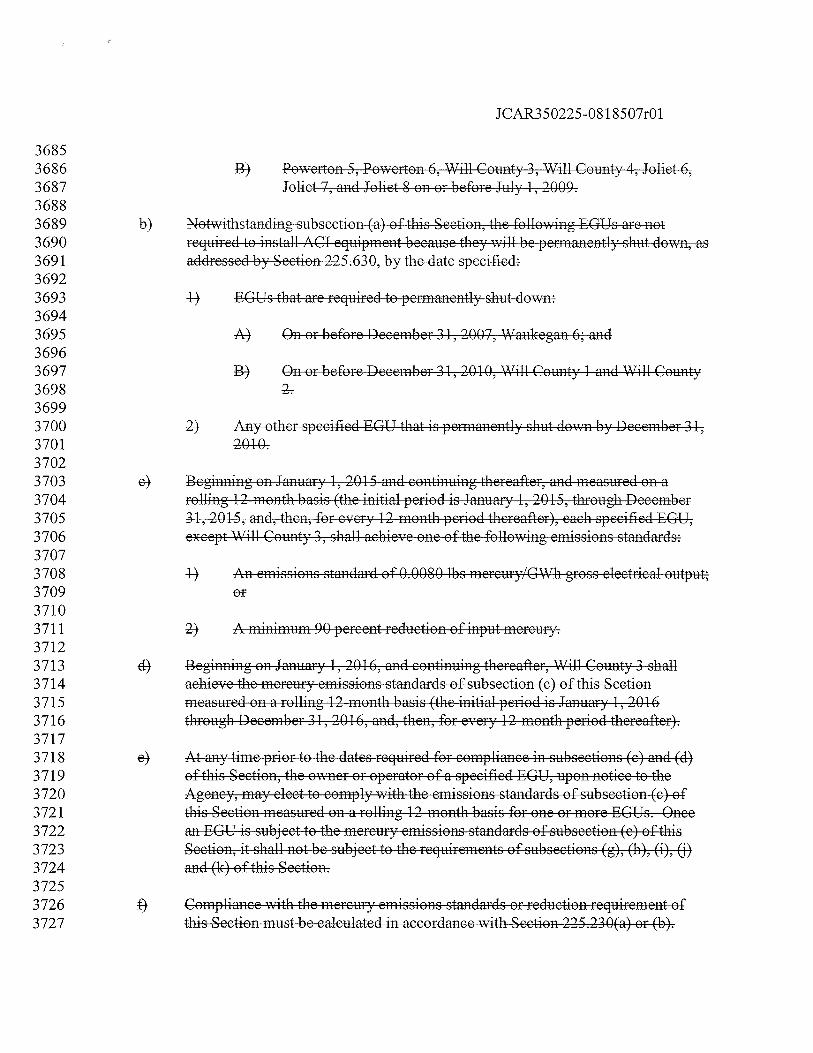
1- 5.’
>
) )
cccccccooQ
oQ
ooooo
z
) 11 D r
+ p.)
CD D D 0 ) r
H) I
—. 1’
(2 I
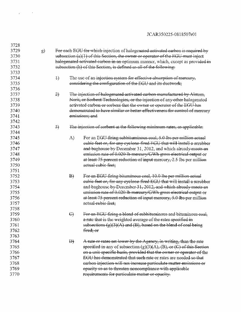
2 F’ -
C
CC
CC
C00
[1
-3 F’
N N 2 N
-3
I F’ L. 2
C (
t)
cr
1. N
*7 -f F’
2 F’ p
4 4
a -iC’
C
F’
+
‘-I C—)
C E\J
C 00
4—’
00 C 4-I C 4-’
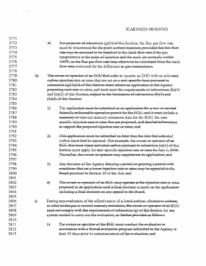
(I
(1(.
) iI
rj
d ) -I
4.r
)c+
3- *
1.
( 4- C C C C 4-
+ +
H 4-4
.
34
4’.
i-i
+ .3
+4
+ 3- + 3
+ 34
3C
3- +3
4
3
C C 6 C 4. C C 7- 7. 6
+
0000000000
—--7
---—
j4—
4- 5-
>C
‘3.4-
’4.
;..
I C.
cc
-C
- .) 4-.
‘3C
4.) C-.
C
4.‘,
4-.
‘3C
4. + 5-cc
‘3.
4- 4-
C C C C C
H
j .) 4- 5- 4. 4- . 4)
..
4
-) -3 ‘I —‘3 .3
.D - ii’. -4 + 2c
-C
C-4
r
4- 1-.
.4.
4-
34
3- +3
‘3 ‘3 -1 -4
C C 4.
4..
‘3 ‘3 ‘3 ‘3 4- 4-
C
+ ‘3
7- C
4-
.4-C
r 3 DC
3-6 C C
4.C
‘3- . ‘3- ‘3C
‘3 ‘3 z1
+ -.4:
LI t.._
C
5- + + 3-
‘3 ‘3-’
‘3 3- ‘3 3- ‘3 ‘3 ‘3 ‘3 + ‘3
cc C
C C C
+4
4,
2’
.4-4
‘3-,
‘.3
+ .4. :3-
3- + C-’ 4-)
÷ :3- +
C) r1
‘31)
4-. 4.-
C C
C C C C
4- 3-
4- C) I
C C 7. C
c
)
Cl) C CD CD CD CD CD CD
c000 C,) © rd,
0 rj) C,) C C Cf) C frD
+
00
00
00
00
00
I
D
C
j C’
4
C
)
4
LII
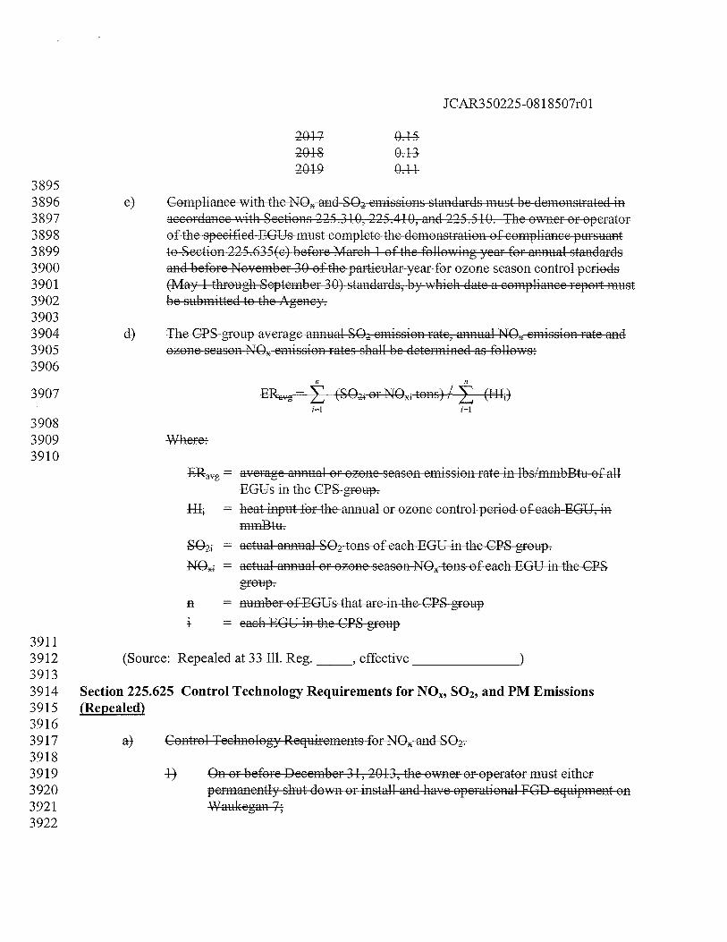
(.J
ccD
coo
ccc
C/)
0 CD CD CD CD CD
[
0cc
-4-
_C
N(J4
IDriI IC
D (J
UI
- •— 0
4.)
CI) C
-:2rJ
) C
4.
C
) 4-) J D 4-)
4.
.4.
.4.
+
c”000 I.,
) 0ooooooO
oG
oo
00
00
00
0D
C”O
0’D
:2C
0O
OC
NM
+jj a—
1_I_
I
) 4. 2 ) -4 -4 .4- r 0
4.)
.2 -:2 4-) ) .2 .2
4. -:2 4. •2 N 44 N C’ 4.) 1-) 4.)
f-C
Ci’
NC
-<
1..
.’ cC
4-2
C C C C
4-
C C
1 )
—4
C) I
4 r
C
C C
N
.4 L
C
) r0
j + 4
C CC C
L 0
)C
4
r
IC
f,(ii
-1
r V C 4
.4
I4
-C D 4
) 0 .4
C C 4‘C C
I r .) -.
Irj
I
‘-I
C\C
Oo
Cl)
0 CD CD CD ci
CD C
t.
NL
t4
i.1 I
(
J
III
LI
D
(Th I
.—
——
——
CC
—C
4’c0
0
rj -4 -4
-4 -4 r
+ 4.
4. C
D 4) ) + z -
4. 1. 4.
(1 ‘-4
CC
CC
CC
CC
CC
CC
CC
CC
CC
CC
CC
CC
CC
CC
CcC
JJJ
CC
CJC
— © rj
•••
C
z
-4.
C I
C.. -4 -4 -4 -4.
4-
iii
4.
C C C C C
4)4
+
a
4)C:4.t 3 4)
t
.4-C -C
+
‘4+
4
) 4)4
4) +4
DO
4)..
4)..
ii -4 -4 r C
—
.4 C C.
4) 2
4. 4)—
‘-?: Ii
If)
C -t C) CD CD p CD CD L
(4)
CD 4+’-. CD
‘-4
4- .4 C C
‘-4
C
r
D 2 2
C.D
C
-C.
C C.
.4 4)
C
c C C
+4)4
.4.4
C
.4.
H
C
‘-4 51
-4) ri -4 -4
j 4.
+4)
+
C C C C C 4. C C C C
4- 4- C. C C 4. C
-4.
+ +
3C
.4.
—‘-4
4)C
4)C
-CC
4)4
C C 4. C. C C
4)..
.1
C C‘-
4 C
‘-4
c—I
C C’.)
00
-a 00
C -C C 4.-
.
coo
coo
If r :1 D -
444
Cl)
C C) CD CD çz CD CD
C,)
CD CD CD CD CD CD lCD ID frD
Cli C CD CD CD CD CD CD C)
tn C) -I
LC-
) I
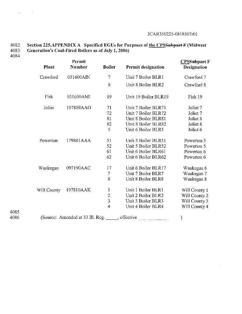
JCAR350225-08 1 8507r01
4082 Section 225.APPENDIX A Specified EGUs for Purposes of the CPSSubpart F (Midwest4083 Generation’s Coal-Fired Boilers as of July 1, 2006)4084
PlantPermit
Number
Crawford 031 600AIN
Boiler Permit designation
7 Unit 7 Boiler BLR1
8 Unit 8 Boiler BLR2
çSubpar-tFDesignation
Crawford 7
Crawford 8
19 Unit 19 Boiler BLR19
71 Unit 7 Boiler BLR7172 Unit 7 Boiler BLR7281 Unit 8 Boiler BLR8182 Unit 8 Boiler BLR825 Unit 6 Boiler BLR5
Powerton 179801AAA 51 Unit 5 Boiler BLR5 152 Unit 5 Boiler BLR5261 Unit 6 Boiler BLR6162 Unit 6 Boiler BLR62
Powerton 5Powerton 5Powerton 6Powerton 6
Waukegan 097190AAC 17 Unit 6 Boiler BLR177 Unit 7 Boiler BLR78 Unit 8 Boiler BLR8
Waukegan 6Waukegan 7Waukegan 8
4085
Will County 19781 OAAK 1234
Unit 1 Boiler BLR1Unit 2 Boiler BLR2Unit 3 Boiler BLR3Unit 4 Boiler BLR4
Will County 1Will County 2Will County 3Will County 4
Fisk 031600AM1
Joliet 197809AA0
Fisk 19
Joliet 7Joliet 7Joliet 8Joliet 8Joliet 6
4086 (Source: Amended at 33 Ill. Reg.
______,
effective
JCAR350225-081 8507r01
4087 Section 225.APPENDIX B Continuous Emission Monitoring Systems for Mercury40884089 Section 1.1 Applicability40904091 The provisions of this Appendix apply to sources subject to 35 Iii. Adm. Code 225 mercury (Hg)4092 mass emission reduction program.40934094 Section 1.2 General Operating Requirements40954096 Primary Equipment Performance Requirements. The owner or operator must4097 ensure that each continuous mercury emission monitoring system required by this4098 Appendix meets the equipment, installation and performance specifications in4099 Exhibit A to this Appendix and is maintained according to the quality assurance4100 and quality control procedures in Exhibit B to this Appendix.41014102 Heat Input Rate Measurement Requirement. The owner or operator must4103 determine and record the heat input rate, in units of mmBtu/hr, to each affected4104 unit for every hour or part of an hour any fuel is combusted following the4105 procedures in Exhibit C to this Appendix.41064107 Primary Equipment Hourly Operating Requirements. The owner or operator must4108 ensure that all continuous mercury emission monitoring systems required by this4109 Appendix are in operation and monitoring unit emissions at all times that the4110 affected unit combusts any fuel except during periods of calibration, quality4111 assurance, or preventive maintenance, performed pursuant to Section 1.5 of this4112 Appendix and Exhibit B to this Appendix, periods of repair, periods of backups of4113 data from the data acquisition and handling system, or recertification performed4114 pursuant to Section 1.4 of this Appendix.41154116 fl The owner or operator must ensure that each continuous emission4117 monitoring system is capable of completing a minimum of one cycle of4118 operation (sampling, analyzing and data recording) for each successive 15-4119 minute interval. The owner or operator must reduce all volumetric flow,4120 çQ2 concentration, 02 concentration and mercury concentration data4121 collected by the monitors to hourly averages. Hourly averages must be4122 computed using at least one data point in each 15 minute quadrant of an4123 hour, where the unit combusted fuel during that quadrant of an hour.4124 Notwithstanding this requirement, an hourly average may be computed4125 from at least two data points separated by a minimum of 15 minutes4126 (where the unit operates for more than one quadrant of an hour) if data are4127 unavailable as a result of the performance of calibration, quality assurance,4128 or preventive maintenance activities pursuant to Section 1.5 of this4129 Appendix and Exhibit B to this Appendix, or backups of data from the
JCAR350225-08 1 8507r01
4130 data acquisition and handling system, or recertification, pursuant to4131 Section 1.4 of this Appendix. The owner or operator must use all valid4132 measurements or data points collected during an hour to calculate the4133 hourly averages. All data points collected during an hour must be, to the4134 extent practicable, evenly spaced over the hour.41354136 ) Failure of a CO2 or 02 emissions concentration monitor, mercury4137 concentration monitor, flow monitor or a moisture monitor to acquire the4138 minimum number of data points for calculation of an hourly average in4139 subsection (c)(1) of this Section must result in the failure to obtain a valid4140 hour of data and the loss of such component data for the entire hour. For a4141 moisture monitoring system consisting of one or more oxygen analyzers4142 capable of measuring 02 on a wet-basis and a dry-basis, an hourly average4143 percent moisture value is valid only if the minimum number of data points4144 is acquired for both the wet-and dry-basis measurements.41454146 Optional Backup Monitor Requirements. If the owner or operator chooses to use4147 two or more continuous mercury emission monitoring systems, each of which is4148 capable of monitoring the same stack or duct at a specific affected unit, or group4149 of units using a common stack, then the owner or operator must designate one4150 monitoring system as the primary monitoring system, and must record this4151 information in the monitoring plan, as provided for in Section 1.10 of this4152 Appendix. The owner or operator must designate the other monitoring systems as4153 backup monitoring systems in the monitoring plan. The backup monitoring4154 systems must be designated as redundant backup monitoring systems, non-4155 redundant backup monitoring systems, or reference method backup systems, as4156 described in Section 1.4(d) of this Appendix. When the certified primary4157 monitoring system is operating and not out-of-control as defined in Section 1.7 of4158 this Appendix, only data from the certified primary monitoring system must be4159 reported as valid, quality-assured data. Thus, data from the backup monitoring4160 system may be reported as valid, quality-assured data only when the backup is4161 operating and not out-of-control as defined in Section 1.7 of this Appendix (or in4162 the applicable reference method in appendix A of 40 CFR 60, incorporated by4163 reference in Section 225.140) and when the certified primary monitoring system4164 is not operating (or is operating but out-of-control). A particular monitor may be4165 designated both as a certified primary monitor for one unit and as a certified4166 redundant backup monitor for another unit.41674168 Minimum Measurement Capability Requirement. The owner or operator must4169 ensure that each continuous emission monitoring system is capable of accurately4170 measuring, recording and reporting data, and must not incur an exceedance of the4171 full scale range, except as provided in Section 2.1.2.3 of Exhibit A to this4172 Appendix.
JCAR350225-081 8507r01
41734174 fi Minimum Recording and Recordkeeping Requirements. The owner or operator4175 must record and the designated representative must report the hourly, daily,4176 quarterly and annual information collected under the requirements as specified in4177 subpart G of 40 CFR 75, incorporated by reference in Section 225.140, and4178 Section 1.11 through 1.13 of this Appendix.41794180 Section 1.3 Special Provisions for Measuring Mercury Mass Emissions Using the Excepted4181 Sorbent Trap Monitoring Methodology41824183 For an affected coal-fired unit under 35 Iii. Adm. Code 225, if the owner or operator elects to use4184 sorbent trap monitoring systems (as defined in Section 225.130) to quantify mass emissions, the4185 guidelines in subsections (a) through (1) of this Section must be followed for this excepted4186 monitoring methodology:41874188 For each sorbent trap monitoring system (whether primary or redundant backup),4189 the use of paired sorbent traps, as described in Exhibit D to this Appendix, is4190 required;41914192 Each sorbent trap must have a main section, a backup section and a third section4193 to allow spiking with a calibration gas of known mercury concentration, as4194 described in Exhibit D to this Appendix;41954196 A certified flow monitoring system is required;41974198 Correction for stack gas moisture content is required, and in some cases, a4199 certified 07 or CO2 monitoring system is required (see Section 1.15(a)(4));42004201 Each sorbent trap monitoring system must be installed and operated in accordance4202 with Exhibit D to this Appendix. The automated data acquisition and handling4203 system must ensure that the sampling rate is proportional to the stack gas4204 volumetric flow rate.42054206 At the beginning and end of each sample collection period, and at least once in4207 each unit operating hour during the collection period, the gas flow meter reading4208 must be recorded.42094210 g After each sample collection period, the mass of mercury adsorbed in each4211 sorbent trap (in all three sections) must be determined according to the applicable4212 procedures in Exhibit D to this Appendix.42134214 The hourly mercury mass emissions for each collection period are determined4215 using the results of the analyses in conjunction with contemporaneous hourly data
JCAR350225-081 8507r01
4216 recorded by a certified stack flow monitor, corrected for the stack gas moisture4217 content. For each pair of sorbent traps analyzed, the average of the 2 mercury4218 concentrations must be used for reporting purposes under Section 1.18(f) of this4219 Appendix. Notwithstanding this requirement, if, due to circumstances beyond the4220 control of the owner or operator, one of the paired traps is accidentally lost,4221 damaged or broken and cannot be analyzed, the results of the analysis of the other4222 trap may be used for reporting purposes, provided that the other trap has met all of4223 the applicable quality-assurance requirements of this Part.42244225 All unit operating hours for which valid mercury concentration data are obtained4226 with the primary sorbent trap monitoring system (as verified using the quality4227 assurance procedures in Exhibit D to this Appendix) must be reported in the4228 electronic quarterly report under Section 1.18(f) of this Appendix. For hours in4229 which data from the primary monitoring system are invalid, the owner or operator4230 may, in accordance with Section 1.4(d) of this Appendix, report valid mercury4231 concentration data from: a certified redundant backup CEMS or sorbent trap4232 monitoring system a certified non-redundant backup CEMS or sorbent trap4233 monitoring system: or an applicable reference method under Section 1.6 of this4234 Appendix.42354236 Initial certification requirements and additional quality-assurance requirements4237 for the sorbent trap monitoring systems are found in Section 1 .4(c)(7), in Section4238 6.5.6 of Exhibit A to this Appendix, in Sections 1.3 and 2.3 of Exhibit B to this4239 Appendix, and in Exhibit D to this Appendix.42404241 ç) During each RATA of a sorbent trap monitoring system, the type of sorbent4242 material used by the traps must be the same as for daily operation of the4243 monitoring system. A new pair of traps must be used for each RATA run.4244 However, the size of the traps used for the RATA may be smaller than the traps4245 used for daily operation of the system.42464247 Whenever the type of sorbent material used by the traps is changed, the owner or4248 operator must conduct a diagnostic RATA of the modified sorbent trap4249 monitoring system within 720 unit or stack operating hours after the date and hour4250 when the new sorbent material is first used. If the diagnostic RATA is passed,4251 data from the modified system may be reported as quality-assured, back to the4252 date and hour when the new sorbent material was first used. If the RATA is4253 failed, all data from the modified system must be invalidated, back to the date and4254 hour when the new sorbent material was first used, and data from the system must4255 remain invalid until a subsequent RATA is passed. If the required RATA is not4256 completed within 720 unit or stack operating hours, but is passed on the first4257 attempt, data from the modified system must be invalidated beginning with the4258 first operating hour after the 720 unit or stack operating hour window expires, and
JCAR350225-0818507r01
4259 data from the system must remain invalid until the date aid hour of completion of4260 the successful RATA.42614262 Section 1.4 Initial Certification and Recertification Procedures42634264 Initial Certification Approval Process. The owner or operator must ensure that4265 each continuous mercury emission monitoring system required by this Appendix4266 meets the initial certification requirements of this Section. fri addition, whenever4267 the owner or operator installs a continuous mercury emission monitoring system4268 in order to meet the requirements of Section 1.3 of this Appendix and 40 CFR4269 sections 75.11 through 75.14 and 75.16 through 75.18, incorporated by reference4270 in Section 225.140, where no continuous emission monitoring system was4271 previously installed, initial certification is required.42724273 ]j Notification of initial certification test dates. The owner or operator or4274 designated representative must submit a written notice of the dates of4275 initial certification testing at the unit as specified in 40 CFR 75.6 1(a)(1),4276 incorporated by reference in Section 225.140.42774278 Certification application. The owner or operator must apply for4279 certification of each continuous mercury emission monitoring system.4280 The owner or operator must submit the certification application in4281 accordance with 40 CFR 75.60, incorporated by reference in Section4282 225.140, and each complete certification application must include the4283 infonnation specified in 40 CFR 75.63, incorporated by reference in4284 Section 225.140.42854286 ) Provisional approval of certification (or recertification) applications. Upon4287 the successful completion of the required certification (or recertification)4288 procedures of this Section, each continuous mercury emission monitoring4289 system must be deemed provisionally certified (or recertified) for use for a4290 period not to exceed 120 days following receipt by the Agency of the4291 complete certification (or recertification) application under subsection4292 (a)(4) of this Section. Data measured and recorded by a provisionally4293 certified (or recertified) continuous emission monitoring system, operated4294 in accordance with the requirements of Exhibit B to this Appendix, will be4295 considered valid quality-assured data (retroactive to the date and time of4296 provisional certification or recertification), provided that the Agency does4297 not invalidate the provisional certification (or recertification) by issuing a4298 notice of disapproval within 120 days of receipt by the Agency of the4299 complete certification (or recertification) application. Note that when the4300 conditional data validation procedures of subsection (b)(3) of this Section4301 are used for the initial certification (or recertification) of a continuous
JCAR350225-081 8507r01
4302 emissions monitoring system, the date and time of provisional certification4303 (or recertification) of the CEMS may be earlier than the date and time of4304 completion of the required certification (or recertification) tests.43054306 Certification (or recertification) application formal approval process. The4307 Agency will issue a notice of approval or disapproval of the certification4308 (or recertification) application to the owner or operator within 120 days4309 after receipt of the complete certification (or recertification) application. In4310 the event the Agency does not issue such a notice within 120 days after4311 receipt, each continuous emission monitoring system that meets the4312 performance requirements of this Part and is included in the certification4313 (or recertification) application will be deemed certified (or recertified) for4314 use under 35 Ill. Adm. Code 225.43154316 Approval notice. If the certification (or recertification) application4317 is complete and shows that each continuous emission monitoring4318 system meets the performance requirements of this Part, then the4319 Agency will issue a notice of approval of the certification (or4320 recertification) application within 120 days after receipt.43214322 Incomplete application notice. A certification (or recertification)4323 application will be considered complete when all of the applicable4324 information required to be submitted in 40 CFR 75.63,4325 incorporated by reference in Section 225.140, has been received by4326 the Agency. If the certification (or recertification) application is4327 not complete, then the Agency will issue a notice of4328 incompleteness that provides a reasonable timeframe for the4329 designated representative to submit the additional information4330 required to complete the certification (or recertification)4331 application. If the designated representative has not complied with4332 the notice of incompleteness by a specified due date, then the4333 Agency may issue a notice of disapproval specified under4334 subsection (a)(4)(C) of this Section. The 120day review period4335 will not begin prior to receipt of a complete application.43364337 Disapproval notice. If the certification (or recertification)4338 application shows that any continuous emission monitoring system4339 does not meet the performance requirements of this Part, or if the4340 certification (or recertification) application is incomplete and the4341 requirement for disapproval under subsection (a)(4)(B) of this4342 Section has been met, the Agency must issue a written notice of4343 disapproval of the certification (or recertification) application4344 within 120 days after receipt. By issuing the notice of disapproval,
JCAR350225-08 1 8507r01
4345 the provisional certification (or recertification) is invalidated by the4346 Agency, and the data measured and recorded by each uncertified4347 continuous emission or opacity monitoring system must not be4348 considered valid quality-assured data as follows: from the hour of4349 the probationary calibration error test that began the initial4350 certification (or recertification) test period (if the conditional data4351 validation procedures of subsection (b)(3) of this Section were4352 used to retrospectively validate data); or from the date and time of4353 completion of the invalid certification or recertification tests (if the4354 conditional data validation procedures of subsection (b)(3) of this4355 Section were not used). The owner or operator must follow the4356 procedures for loss of initial certification in subsection (a)(5) of4357 this Section for each continuous emission or opacity monitoring4358 system that is disapproved for initial certification. For each4359 disapproved recertification, the owner or operator must follow the4360 procedures of subsection (b)(5) of this Section.43614362 ) Procedures for loss of certification. When the Agency issues a notice of4363 disapproval of a certification application or a notice of disapproval of4364 certification status (as specified in subsection (a)(4) of this Section), then:43654366 ) Until such time, date and hour as the continuous mercury emission4367 monitoring system can be adjusted, repaired or replaced and4368 certification tests successfully completed (or, if the conditional4369 data validation procedures in subsections (b)(3)(B) through (I) of4370 this Section are used, until a probationary calibration error test is4371 passed following corrective actions in accordance with subsection4372 (b)(3)(B) of this Section), the owner or operator must perform4373 emissions testing pursuant to Section 225 .239.43744375 The designated representative must submit a notification of4376 certification retest dates as specified in Section 225.250(a)(3)(A)4377 and a new certification application according to the procedures in4378 Section 225.250(a)(3)(B): and43794380 The owner or operator must repeat all certification tests or other4381 requirements that were failed by the continuous mercury emission4382 monitoring system, as indicated in the Agency’s notice of4383 disapproval, no later than 30 unit operating days after the date of4384 issuance of the notice of disapproval.43854386 Recertification Approval Process. Whenever the owner or operator makes a4387 replacement, modification or change in a certified continuous mercury emission
JCAR350225-08 1 8507r01
4388 monitoring system that may significantly affect the ability of the system to4389 accurately measure or record the gas volumetric flow rate, mercury concentration,4390 percent moisture, or to meet the requirements of Section 1.5 of this Appendix or4391 Exhibit B to this Appendix, the owner or operator must recertify the continuous4392 mercury emission monitoring system, according to the procedures in this4393 subsection. Examples of changes that require recertification include: replacement4394 of the analyzer; change in location or orientation of the sampling probe or site;4395 and complete replacement of an existing continuous mercury emission monitoring4396 system. The owner or operator must also recertify the continuous emission4397 monitoring systems for a unit that has recommenced commercial operation4398 following a period of long-term cold storage as defined in Section 225.130. Any4399 change to a flow monitor or gas monitoring system for which a RATA is not4400 necessary will not be considered a recertification event. In addition, changing the4401 polynomial coefficients or K factors of a flow monitor will require a 3-load4402 RATA, but is not considered to be a recertification event; however, records of the4403 polynomial coefficients or K factors currently in use must be maintained on-site4404 in a format suitable for inspection. Changing the coefficient or K factors of a4405 moisture monitoring system will require a RATA, but is not considered to be a4406 recertification event; however, records of the coefficient or K factors currently in4407 use by the moisture monitoring system must be maintained on-site in a format4408 suitable for inspection. In such cases, any other tests that are necessary to ensure4409 continued proper operation of the monitoring system (e.g., 3-load flow RATAs4410 following changes to flow monitor polynomial coefficients, linearity checks,4411 calibration error tests, DAHS verifications, etc.) must be performed as diagnostic4412 tests, rather than as recertification tests. The data validation procedures in4413 subsection (b)(3) of this Section must be applied to RATAs associated with4414 changes to flow or moisture monitor coefficients, and to linearity checks, 7-day4415 calibration error tests and cycle time tests when these are required as diagnostic4416 tests. When the data validation procedures of subsection (b)(3) of this Section are4417 applied in this manner, replace the word “recertification” with the word4418 “diagnostic”.44194420 jj Tests required. For all recertification testing, the owner or operator must4421 complete all initial certification tests in subsection (c) of this Section that4422 are applicable to the monitoring system, except as otherwise approved by4423 the Agency. For diagnostic testing after changing the flow rate monitor4424 polynomial coefficients, the owner or operator must complete a 3-level4425 RATA. For diagnostic testing after changing the K factor or mathematical4426 algorithm of a moisture monitoring system, the owner or operator must4427 complete a RATA.44284429 ) Notification of recertification test dates. The owner, operator or designated4430 representative must submit notice of testing dates for recertification under
JCAR350225-081 8507r01
4431 this subsection as specified in 40 CFR 75.61(a)(l)(ii), incorporated by4432 reference in Section 225.140, unless all of the tests in subsection (c) of this4433 Section are required for recertification, in which case the owner or4434 operator must provide notice in accordance with the notice provisions for4435 initial certification testing in 40 CFR 75.61(a)(l)(i), incorporated by4436 reference in Section 225.140.44374438 Recertification test period requirements and data validation. The data4439 validation provisions in subsections (b)(3)(A) through (I) of this Section4440 will apply to all mercury CEMS recertifications and diagnostic testing.4441 The provisions in subsections (b)(3)(B) through (I) of this Section may4442 also be applied to initial certifications (see Sections 6.2(a), 6.3.1(a),4443 6.3.2(a), 6.4(a) and 6.5(f) of Exhibit A to this Appendix) and may be used4444 to supplement the linearity check and RATA data validation procedures in4445 Sections 2.2.3(b) and 2.3.2(b) of Exhibit B to this Appendix.44464447 The owner or operator must report emission data using a reference4448 method or another monitoring system that has been certified or4449 approved for use under this Part, in the period extending from the4450 hour of the replacement, modification or change made to a4451 monitoring system that triggers the need to perform recertification4452 testing, until either: the hour of successful completion of all of the4453 required recertification tests; or the hour in which a probationary4454 calibration error test (according to subsection (b)(3)(B) of this4455 Section) is performed and passed, following all necessary repairs,4456 adjustments or reprogramming of the monitoring system. The first4457 hour of quality-assured data for the recertified monitoring system4458 must either be the hour after all recertification tests have been4459 completed or, if conditional data validation is used, the first4460 quality-assured hour must be determined in accordance with4461 subsections (b)(3)(B) through (I) of this Section. Notwithstanding4462 these requirements, if the replacement, modification or change4463 requiring recertification of the CEMS is such that the historical4464 data stream is no longer representative (e.g., where the mercury4465 concentration and stack flow rate change significantly after4466 installation of a wet scrubber), the owner or operator must estimate4467 the mercury emissions over that time period and notify the Agency4468 within 15 days after the replacement, modification or change4469 requiring recertification of the CEMS.44704471 Once the modification or change to the CEMS has been completed4472 and all of the associated repairs, component replacements,4473 adjustments, linearization and reprogramming of the CEMS have
JCAR350225-08 1 8507r01
4474 been completed, a probationary calibration error test is required to4475 establish the beginning point of the recertification test period. In4476 this instance, the first successful calibration error test of the4477 monitoring system following completion of all necessary repairs,4478 component replacements, adjustments, linearization and4479 reprogramming must be the probationary calibration error test. The4480 probationary calibration error test must be passed before any of the4481 required recertification tests are commenced.44824483 c) Beginning with the hour of commencement of a recertification test4484 period, emission data recorded by the mercury CEMS are4485 considered to be conditionally valid, contingent upon the results of4486 the subsequent recertification tests.44874488 L’) Each required recertification test must be completed no later than4489 the following number of unit operating hours (or unit operating4490 days) after the probationary calibration error test that initiates the4491 test period:44924493 For a linearity check and/or cycle time test, 1684494 consecutive unit operating hours, as defined in 40 CFR4495 72.2, incorporated by reference in Section 225.140, or, for4496 CEMS installed on common stacks or bypass stacks, 1684497 consecutive stack operating hours, as defined in 40 CFR4498 72.2;44994500 I) For a RATA (whether normal-load or multiple-load), 7204501 consecutive unit operating hours, as defined in 40 CFR4502 72.2, incorporated by reference in Section 225.140, or, for4503 CEMS installed on common stacks or bypass stacks, 7204504 consecutive stack operating hours, as defined in 40 CFR4505 72.2; and45064507 jjjj For a 7-day calibration error test, 21 consecutive unit4508 operating days, as defined in 40 CFR 72.2, incorporated by4509 reference in Section 225.140.45104511 All recertification tests must be performed hands-off. No4512 adjustments to the calibration of the mercury CEMS, other than the4513 routine calibration adjustments following daily calibration error4514 tests as described in Section 2.1.3 of Exhibit B to this Appendix,4515 are permitted during the recertification test period. Routine daily4516 calibration error tests must be performed throughout the
Ot;
j•
CD
0
0•C
DH
Q
0CD
-
CD
CC
D
CD
:-
C)
C)C
)
CD
CD
•C
D
C)
C)
0C
)C
)
C)c
ci
Hii
CDCD
CDC
)CD
..
-+
—0•0
0
—.
-
00
C)
0CD
0•C
DC
)
CD—
•
—)
Cl)
CDCD
CD
CD
C)C
D”
-
C)
0<
0
—.—
.
CD
C)O
OC
D—
-CD
0c,
0C
D
CD—
.
CD-
-C
DC
D
o2
—0
0-i
CD—
•C
DC
”
C,)C
,D
CD
CD
CD
-C
)C
)C
)0
*0
-
—•O
r-+
.-
CD
0•
--
CD—
.
C) C Co
00
C C
JCAR350225-08 1 8507r01
4560 (or stack) operating hours. The new recertification test4561 sequence must not be commenced until all necessary4562 maintenance activities, adjustments, linearization and4563 reprogramming of the CEMS have been completed;45644565 jj) If a linearity check, RATA or cycle time test is failed or4566 aborted due to a problem with the mercury CEMS, all4567 conditionally valid emission data recorded by the CEMS4568 are invalidated, from the hour of commencement of the4569 recertification test period to the hour in which the test is4570 failed or aborted, except for the case in which a multiple-4571 load flow RATA is passed at one or more load levels, failed4572 at a subsequent load level, and the problem that caused the4573 RATA failure is corrected without re-linearizing the4574 instrument. In that case, data invalidation will be4575 prospective, from the hour of failure of the RATA until the4576 commencement of the new recertification test period. Data4577 from the CEMS remain invalid until the hour in which a4578 new recertification test period is commenced, following4579 corrective action, and a probationary calibration error test is4580 passed, at which time the conditionally valid status of4581 emission data from the CEMS begins again;45824583 jjj If a 7-day calibration error test is failed within the4584 recertification test period, previously-recorded4585 conditionally valid emission data from the mercury CEMS4586 are not invalidated. The conditionally valid data status is4587 unaffected, unless the calibration error on the day of the4588 failed 7-day calibration error test exceeds twice the4589 performance specification in Section 3 of Exhibit A to this4590 Appendix, as described in subsection (b)(3)(G)(iv) of this4591 Section.45924593 jy) If a daily calibration error test is failed during a4594 recertification test period (i.e., the results of the test exceed4595 twice the performance specification in Section 3 of Exhibit4596 A to this Appendix), the CEMS is out-of-control as of the4597 hour in which the calibration error test is failed. Emission4598 data from the CEMS will be invalidated prospectively from4599 the hour of the failed calibration error test until the hour of4600 completion of a subsequent successful calibration error test4601 following corrective action, at which time the conditionally4602 valid status of data from the monitoring system resumes.
JCAR350225-08 1 8507r01
4603 Failure to perform a required daily calibration error test4604 during a recertification test period will also cause data from4605 the CEMS to be invalidated prospectively, from the hour in4606 which the calibration error test was due until the hour of4607 completion of a subsequent successful calibration error test.4608 Whenever a calibration error test is failed or missed during4609 a recertification test period, no further recertification tests4610 must be performed until the required subsequent calibration4611 error test has been passed, re-establishing the conditionally4612 valid status of data from the monitoring system. If a4613 calibration error test failure occurs while a linearity check4614 or RATA is still in progress, the linearity check or RATA4615 must be re-started.46164617 y) Trial gas injections and trial RATA runs are permissible4618 during the recertification test period, prior to commencing a4619 linearity check or RATA, for the purpose of optimizing the4620 performance of the CEMS. The results of such gas4621 injections and trial runs will not affect the status of4622 previously-recorded conditionally valid data or result in4623 termination of the recertification test period, provided that4624 they meet the following specifications and conditions: for4625 gas injections, the stable, ending monitor response is within4626 ± 5 percent or within 5 ppm of the tag value of the4627 reference gas; for RATA trial runs, the average reference4628 method reading and the average CEMS reading for the run4629 differ by no more than ± 10% of the average reference4630 method value or ± 15 ppm, or + 1.5% H20 or ± 0.024631 lb/mmBtu from the average reference method value, as4632 applicable; no adjustments to the calibration of the CEMS4633 are made following the trial injections or runs, other than4634 the adjustments permitted under Section 2.1.3 of Exhibit B4635 to this Appendix and the CEMS is not repaired, re4636 linearized or repro-ammed (e.g., changing flow monitor4637 polynomial coefficients, linearity constants or K-factors)4638 after the trial injections or runs.46394640 y If the results of any trial gas injections or RATA runs are4641 outside the limits in subsection (b)(3)(G)(v) of this Section4642 or if the CEMS is repaired, re-linearized or reprogrammed4643 after the trial injections or runs, the trial injections or runs4644 will be counted as a failed linearity check or RATA4645 attempt. If this occurs, follow the procedures pertaining to
JCAR350225-081 8507r01
4646 failed and aborted recertification tests in subsections4647 (b)(3)(G)(i) and (ii) of this Section.46484649 ff If any required recertification test is not completed within its4650 allotted time period, data validation must be done as follows. For a4651 late linearity test, RATA or cycle time test that is passed on the4652 first attempt, data from the monitoring system will be invalidated4653 from the hour of expiration of the recertification test period until4654 the hour of completion of the late test. For a late 7-day calibration4655 error test, whether or not it is passed on the first attempt, data from4656 the monitoring system will also be invalidated from the hour of4657 expiration of the recertification test period until the hour of4658 completion of the late test. For a late linearity test, RATA or cycle4659 time test that is failed on the first attempt or aborted on the first4660 attempt due to a problem with the monitor, all conditionally valid4661 data from the monitoring system will be considered invalid back to4662 the hour of the first probationary calibration error test that initiated4663 the recertification test period. Data from the monitoring system4664 will remain invalid until the hour of successful completion of the4665 late recertification test and any additional recertification or4666 diagnostic tests that are required as a result of changes made to the4667 monitoring system to correct problems that caused failure of the4668 late recertification test.46694670 If any required recertification test of a monitoring system has not4671 been completed by the end of a calendar quarter and if data4672 contained in the quarterly report are conditionally valid pending4673 the results of tests to be completed in a subsequent quarter, the4674 owner or operator must indicate this by means of a suitable4675 conditionally valid data flag in the electronic quarterly report, and4676 notification within the quarterly report pursuant to Section4677 225 .290(b)(1’)(E), for that quarter. The owner or operator must4678 resubmit the report for that quarter if the required recertification4679 test is subsequently failed. If any required recertification test is not4680 completed by the end of a particular calendar quarter but is4681 completed no later than 30 days after the end of that quarter (i.e.,4682 prior to the deadline for submitting the quarterly report under 404683 CFR 75.64, incorporated by reference in Section 225.140), the test4684 data and results may be submitted with the earlier quarterly report4685 even though the test dates are from the next calendar quarter. In4686 such instances, if the recertification tests are passed in accordance4687 with the provisions of subsection (b)(3) of this Section,4688 conditionally valid data may be reported as quality-assured, in lieu
JCAR350225-08 1 8507r01
4689 of reporting a conditional data flag. In addition, if the owner or4690 operator uses a conditionally valid data flag in any of the four4691 quarterly reports for a given year, the owner or operator must4692 indicate the final status of the conditionally valid data (i.e.,4693 resolved or unresolved) in the annual compliance certification4694 report required under 40 CFR 72.90 for that year. The Agency may4695 invalidate any conditionally valid data that remains unresolved at4696 the end of a particular calendar year.46974698 4) Recertification application. The designated representative must apply for4699 recertification of each continuous mercury emission monitoring system.4700 The owner or operator must submit the recertification application in4701 accordance with 40 CFR 75.60, incorporated by reference in Section4702 225.140, and each complete recertification application must include the4703 information specified in 40 CFR 75.63, incorporated by reference in4704 Section 225.140.47054706 ) Approval or disapproval of request for recertification. The procedures for4707 provisional certification in subsection (a)(3) of this Section apply to4708 recertification applications. The Agency will issue a notice of approval,4709 disapproval or incompleteness according to the procedures in subsection4710 (a)(4) of this Section. Data from the monitoring system remain invalid4711 until all required recertification tests have been passed or until a4712 subsequent probationary calibration error test is passed, beginning a new4713 recertification test period. The owner or operator must repeat all4714 recertification tests or other requirements, as indicated in the Agency’s4715 notice of disapproval, no later than 30 unit operating days after the date of4716 issuance of the notice of disapproval. The designated representative must4717 submit a notification of the recertification retest dates, as specified in 404718 CFR 75.61(a)(1)(ii), incorporated by reference in Section 225.140, and4719 must submit a new recertification application according to the procedures4720 in subsection (b)(4) of this Section.47214722 Initial Certification and Recertification Procedures. Prior to the applicable4723 deadline in 35 Ill. Adm. Code 225 .240(b), the owner or operator must conduct4724 initial certification tests and in accordance with 40 CFR 75.63, incorporated by4725 reference in Section 225.140, the designated representative must submit an4726 application to demonstrate that the continuous emission monitoring system and4727 components of the system meet the specifications in Exhibit A to this Appendix.4728 The owner or operator must compare reference method values with output from4729 the automated data acquisition and handling system that is part of the continuous4730 mercury emission monitoring system being tested. Except as otherwise specified4731 in subsections (b)(1), (d) and (e) of this Section, and in Sections 6.3.1 and 6.3.2 of
JCAR350225-08 1 8507r01
4732 Exhibit A to this Appendix, the owner or operator must perform the following4733 tests for initial certification or recertification of continuous emission monitoring4734 systems or components according to the requirements of Exhibit B to this4735 Appendix:47364737 LI For each mercury concentration monitoring system:47384739 A 7-day calibration error test;47404741 ) A linearity check, for mercury monitors, perform this check with4742 elemental mercury stmdards;47434744 A relative accuracy test audit must be done on a ig!scm basis;47454746 A bias test;47474748 A cycle time test;47494750 For mercury monitors a 3-level system integrity check, using a4751 NIST-traceable source of oxidized mercury, as described in4752 Section 6.2 of Exhibit A to this Appendix. This test is not required4753 for a mercury monitor that does not have a converter.47544755 For each flow monitor:47564757 j A 7-day calibration error test;47584759 Relative accuracy test audits, as follows:47604761 A single-load (or single-level) RATA at the normal load (or4762 level), as defined in Section 6.5.2.1(d) of Exhibit A to this4763 Appendix, for a flow monitor installed on a peaking unit or4764 bypass stack, or for a flow monitor exempted from4765 multiple-level RATA testing under Section 6.5.2(e) of4766 Exhibit A to this Appendix;47674768 jI For all other flow monitors, a RATA at each of the three4769 load levels (or operating levels) corresponding to the three4770 flue gas velocities described in Section 6.5.2(a) of Exhibit4771 A to this Appendix;47724773 A bias test for the single-load (or single-level) flow RATA4774 described in subsection (c)(2)(B)(i) of this Section; and
JCAR350225-0818507r01
47754776 ) A bias test (or bias tests) for the 3-level flow RATA described in4777 subsection (c)(2)(B)(ii) of this Section, at the following load or4778 operational levels:47794780 j) At each load level designated as normal under Section4781 6.5.2.1(d) of Exhibit A to this Appendix, for units that4782 produce electrical or thermal output, or47834784 ) At the operational level identified as normal in Section4785 6.5.2.1(d) of Exhibit A to this Appendix, for units that do4786 not produce electrical or thermal output.47874788 ) For each diluent gas monitor used only to monitor heat input rate:47894790 ) A 7-day calibration error test;47914792 ) A linearity check;47934794 c) A relative accuracy test audit, where, for an 02 monitor used to4795 determine CO7 concentration, the CO2 reference method must be4796 used for the RATA; and47974798 j.) A cycle-time test.47994800 4) For each continuous moisture monitoring system consisting of wet- and4801 dry-basis 02 analyzers:48024803 ) A 7-day calibration error test of each 02 analyzer;48044805 ]) A cycle time test of each 02 analyzer;48064807 c) A linearity test of each 02 analyzer; and48084809 j) A RATA directly comparing the percent moisture measured by the4810 monitoring system to a reference method.48114812 For each continuous moisture sensor: A RATA directly comparing the4813 percent moisture measured by the monitor sensor to a reference method.48144815 ) For a continuous moisture monitoring system consisting of a temperature4816 sensor and a data acquisition and handling system (DAHS) software4817 component programmed with a moisture lookup table: A demonstration
JCAR350225-0818507r01
4818 that the correct moisture value for each hour is being taken from the4819 moisture lookup tables and applied to the emission calculations. At a4820 minimum, the demonstration must be made at three different temperatures4821 covering the normal range of stack temperatures from low to high.48224823 7) For each sorbent trap monitoring system, perform a RATA, on a jig!dscrn4824 basis, and a bias test.48254826 ) For the automated data acquisition and handling system, tests designed to4827 verify the proper computation of hourly averages for pollutant4828 concentrations, flow rate, pollutant emission rates and pollutant mass4829 emissions.48304831 ) The owner or operator must provide adequate facilities for initial4832 certification or recertification testing that include:48334834 ) Sampling ports adequate for test methods applicable to such4835 facility, such that:48364837 j) Volumetric flow rate, pollutant concentration and pollutant4838 emission rates can be accurately determined by applicable4839 test methods and procedures; and48404841 jj) A stack or duct free of cyclonic flow during performance4842 tests is available, as demonstrated by applicable test4843 methods and procedures.48444845 ) Basic facilities (e.g., electricity) for sampling and testing4846 quipment.48474848 ci) Initial Certification and Recertification and Quality Assurance Procedures for4849 Optional Backup Continuous Emission Monitoring Systems.48504851 D Redundant backups. The owner or operator of an optional redundant4852 backup CEMS must comply with all the requirements for initial4853 certification and recertification according to the procedures specified in4854 subsections (a), (b) and (c) of this Section. The owner or operator must4855 operate the redundant backup CEMS during all periods of unit operation,4856 except for periods of calibration, quality assurance, maintenance or repair.4857 The owner or operator must perform upon the redundant backup CEMS all4858 quality assurance and quality control procedures specified in Exhibit B to4859 this Appendix, except that the daily assessments in Section 2.1 of Exhibit4860 B to this Appendix are optional for days on which the redundant backup
JCAR350225-08 1 8507r01
4861 CEMS is not used to report emission data under this Part. For any day on4862 which a redundant backup CEMS is used to report emission data, the4863 system must meet all of the applicable daily assessment criteria in Exhibit4864 B to this Appendix.48654866 ) Non-redundant backups. The owner or operator of an optional non-4867 redundant backup CEMS or like-kind replacement analyzer must comply4868 with all of the following requirements for initial certification, quality4869 assurance, recertification and data reporting:48704871 Except as provided in subsection (d)(2)(E) of this Section, for a4872 regular non-redundant backup CEMS (i.e., a non-redundant backup4873 CEMS that has its own separate probe, sample interface and4874 analyzer), or a non-redundant backup flow monitor, all of the tests4875 in subsection (c) of this Section are required for initial certification4876 of the system, except for the 7-day calibration error test.48774878 For a like-kind replacement non-redundant backup analyzer (i.e., a4879 non-redundant backup analyzer that uses the same probe and4880 sample interface as a primary monitoring system), no initial4881 certification of the analyzer is required.48824883 Each non-redundant backup CEMS or like-kind replacement4884 analyzer must comply with the daily and quarterly quality4885 assurance and quality control requirements in Exhibit B to this4886 Appendix for each day and quarter that the non-redundant backup4887 CEMS or like-kind replacement analyzer is used to report data, and4888 must meet the additional linearity and calibration error test4889 requirements specified in this subsection. The owner or operator4890 must ensure that each non-redundant backup CEMS or like-kind4891 replacement analyzer passes a linearity check (for mercury4892 concentration and diluent gas monitors) or a calibration error test4893 (for flow monitors) prior to each use for recording and reporting4894 emissions. When a non-redundant backup CEMS or like-kind4895 replacement analyzer is brought into service, prior to conducting4896 the linearity test, a probationary calibration error test (as described4897 in subsection (b)(3)(B) of this Section), which will begin a period4898 of conditionally valid data, may be performed in order to allow the4899 validation of data retrospectively as follows. Conditionally valid4900 data from the CEMS or like-kind replacement analyzer are4901 validated back to the hour of completion of the probationary4902 calibration error test if the following conditions are met: if no4903 adjustments are made to the CEMS or like-kind replacement
JCAR350225-081 8507r01
4904 analyzer other than the allowable calibration adjustments specified4905 in Section 2.1.3 of Exhibit B to this Appendix between the4906 probationary calibration error test and the successful completion of4907 the linearity test; and if the linearity test is passed within 168 unit4908 (or stack) operating hours of the probationary calibration error test.4909 However, if the linearity test is performed within 168 unit or stack4910 operating hours but is either failed or aborted due to a problem4911 with the CEMS or like-kind replacement analyzer, then all of the4912 conditionally valid data are invalidated back to the hour of the4913 probationary calibration error test, and data from the non-4914 redundant backup CEMS or from the primary monitoring system4915 of which the like-kind replacement analyzer, is a part remain4916 invalid until the hour of completion of a successful linearity test.4917 Notwithstanding this requirement, the conditionally valid data4918 status may be re-established after a failed or aborted linearity4919 check, if corrective action is taken and a calibration error test is4920 subsequently passed. However, in no case will the use of4921 conditional data validation extend for more than 168 unit or stack4922 operating hours beyond the date and time of the original4923 probationary calibration error test when the analyzer was brought4924 into service.49254926 For each parameter monitored (i.e.,QQ2,Hg or flow rate) at4927 each unit or stack, a regular non-redundant backup CEMS may not4928 be used to report data at that affected unit or common stack for4929 more than 720 hours in any one calendar year (in accordance with4930 40 CFR 75.74(c), incorporated by reference in Section 225.140),4931 unless the CEMS passes a RATA at that unit or stack. For each4932 parameter monitored at each unit or stack, the use of a like-kind4933 replacement non-redundant backup analyzer (or analyzers) is4934 restricted to 720 cumulative hours per calendar year, unless the4935 owner or operator redesignates the like-kind replacement analyzers4936 as components of regular non-redundant backup CEMS and each4937 redesignated CEMS passes a RATA at that unit or stack.49384939 For each regular non-redundant backup CEMS, no more than eight4940 successive calendar quarters must elapse following the quarter in4941 which the last RATA of the CEMS was done at a particular unit or4942 stack, without performing a subsequent RATA. Otherwise, the4943 CEMS may not be used to report data from that unit or stack until4944 the hour of completion of a passing RATA at that location.4945
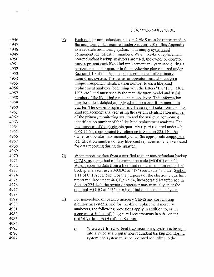
JCAR350225-0818507r01
4946 ) Each regular non-redundant backup CEMS must be represented in4947 the monitoring plan required under Section 1.10 of this Appendix4948 as a separate monitoring system, with unique system and4949 component identification numbers. When like-kind replacement4950 non-redundant backup analyzers are used, the owner or operator4951 must represent each like-kind replacement analyzer used during a4952 particular calendar quarter in the monitoring plan required under4953 Section 1.10 of this Appendix as a component of a primary4954 monitoring system. The owner or operator must also assign a4955 unique component identification number to each like-kind4956 replacement analyzer, beginning with the letters “LK” (e.g., LK1,4957 LK2, etc.) and must specify the manufacturer, model and serial4958 number of the like-kind replacement analyzer. This information4959 may be added, deleted or updated as necessary, from quarter to4960 quarter. The owner or operator must also report data from the like-4961 kind replacement analyzer using the system identification number4962 of the primary monitoring system and the assied component4963 identification number of the like-kind replacement analyzer. For4964 the purposes of the electronic quarterly report required under 404965 CFR 75.64, incorporated by reference in Section 225.140, the4966 owner or operator may manually enter the appropriate component4967 identification numbers of any like-kind replacement analyzers used4968 for data reporting during the quarter.49694970 ) When reporting data from a certified regular non-redundant backup4971 CEMS, use a method of determination code (MODC) of”02”.4972 When reporting data from a like-kind replacement non-redundant4973 backup analyzer, use a MODC of ??17H (see Table 4a under Section4974 1.11 of this Appendix). For the purposes of the electronic quarterly4975 report required under 40 CFR 75.64, incorporated by reference in4976 Section 225.140, the owner or operator may manually enter the4977 required MODC of” 17” for a like-kind replacement analyzer.49784979 ifi For non-redundant backup mercury CEMS and sorbent trap4980 monitoring systems, and for like-kind replacement mercury4981 analyzers, the following provisions apply in addition to, or. in4982 some cases, in lieu of, the general requirements in subsections4983 (d)(2)(A) through (H) of this Section:49844985 j) When a certified sorbent trap monitoring system is brought4986 into service as a regular non-redundant backup monitoring4987 system, the system must be operated according to the
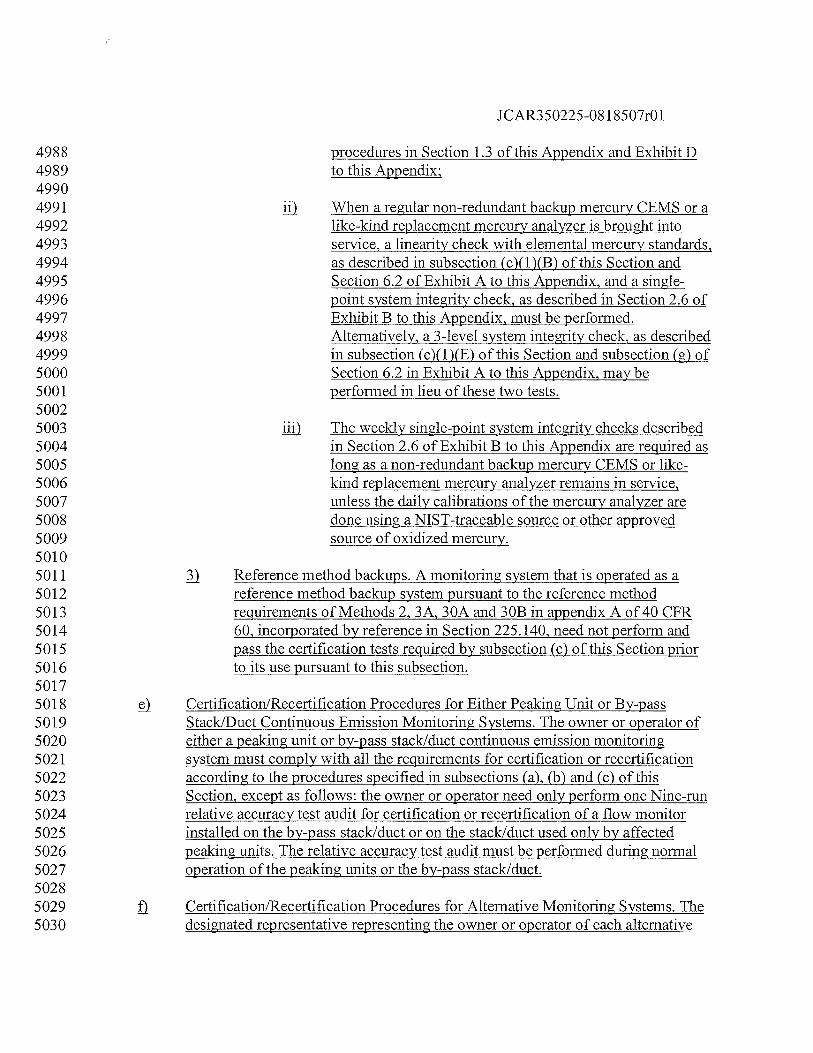
JCAR350225-081 8507r01
4988 procedures in Section 1.3 of this Appendix and Exhibit D4989 to this Appendix;49904991 When a regular non-redundant backup mercury CEMS or a4992 like-kind replacement mercury analyzer is brought into4993 service, a linearity check with elemental mercury standards,4994 as described in subsection (c)(1)(B) of this Section and4995 Section 6.2 of Exhibit A to this Appendix, and a single-4996 point system integrity check, as described in Section 2.6 of4997 Exhibit B to this Appendix, must be performed.4998 Alternatively, a 3-level system integrity check, as described4999 in subsection (c)(1)(E) of this Section and subsection (g) of5000 Section 6.2 in Exhibit A to this Appendix, may be5001 performed in lieu of these two tests.50025003 liii The weekly single-point system integrity checks described5004 in Section 2.6 of Exhibit B to this Appendix are required as5005 long as a non-redundant backup mercury CEMS or like-5006 kind replacement mercury analyzer remains in service,5007 unless the daily calibrations of the mercury analyzer are5008 done using a NIST-traceable source or other approved5009 source of oxidized mercury.50105011 Reference method backups. A monitoring system that is operated as a5012 reference method backup system pursuant to the reference method5013 requirements of Methods 2, 3A, 30A and 30B in appendix A of 40 CFR5014 60, incorporated by reference in Section 225.140, need not perform and5015 pass the certification tests required by subsection (c) of this Section prior5016 to its use pursuant to this subsection.50175018 Certification/Recertification Procedures for Either Peaking Unit or By-pass5019 Stack/Duct Continuous Emission Monitoring Systems. The owner or operator of5020 either a peaking unit or by-pass stack/duct continuous emission monitoring5021 system must comply with all the requirements for certification or recertification5022 according to the procedures specified in subsections (a), (b) and (c) of this5023 Section, except as follows: the owner or operator need only perform one Nine-run5024 relative accuracy test audit for certification or recertification of a flow monitor5025 installed on the by-pass stack/duct or on the stack/duct used only by affected5026 peaking units. The relative accuracy test audit must be performed during normal5027 operation of the peaking units or the by-pass stack/duct.50285029 fi Certification/Recertification Procedures for Alternative Monitoring Systems. The5030 designated representative representing the owner or operator of each alternative
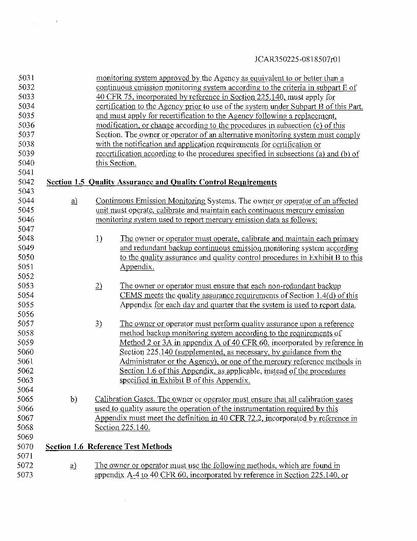
JCAR350225-081 8507r01
5031 monitoring system approved by the Agency as equivalent to or better than a5032 continuous emission monitoring system according to the criteria in subpart E of5033 40 CFR 75, incorporated by reference in Section 225.140, must apply for5034 certification to the Agency prior to use of the system under Subpart B of this Part,5035 and must apply for recertification to the Agency following a replacement,5036 modification, or change according to the procedures in subsection (c) of this5037 Section. The owner or operator of an alternative monitoring system must comply5038 with the notification and application requirements for certification or5039 recertification according to the procedures specified in subsections (a) and (b) of5040 this Section.50415042 Section 1.5 Quality Assurance and Quality Control Reiuirements50435044 Continuous Emission Monitoring Systems. The owner or operator of an affected5045 unit must operate, calibrate and maintain each continuous mercury emission5046 monitoring system used to report mercury emission data as follows:50475048 IJ The owner or operator must operate, calibrate and maintain each primary5049 and redundant backup continuous emission monitoring system according5050 to the quality assurance and quality control procedures in Exhibit B to this5051 Appendix.50525053 ) The owner or operator must ensure that each non-redundant backup5054 CEMS meets the quality assurance requirements of Section 1.4(d) of this5055 Appendix for each day and quarter that the system is used to report data.50565057 ) The owner or operator must perform quality assurance upon a reference5058 method backup monitoring system according to the requirements of5059 Method 2 or 3A in appendix A of 40 CFR 60, incorporated by reference in5060 Section 225.140 (supplemented, as necessary, by guidance from the5061 Administrator or the Agency), or one of the mercury reference methods in5062 Section 1.6 of this Appendix, as applicable, instead of the procedures5063 specified in Exhibit B of this Appendix.50645065 } Calibration Gases. The owner or operator must ensure that all calibration gases5066 used to quality assure the operation of the instrumentation required by this5067 Appendix must meet the definition in 40 CFR 72.2, incorporated by reference in5068 Section 225.140.50695070 Section 1.6 Reference Test Methods50715072 The owner or operator must use the following methods, which are found in5073 appendix A-4 to 40 CFR 60, incorporated by reference in Section 225.140, or
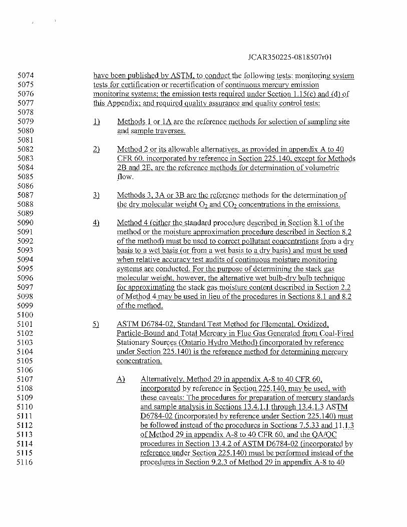
JCAR350225-08 1 8507r01
5074 have been published by ASTM, to conduct the following tests: monitoring system5075 tests for certification or recertification of continuous mercury emission5076 monitoring systems; the emission tests required under Section 1.15(c) and (d) of5077 this Appendix; and required quality assurance and quality control tests:50785079 jJ Methods 1 or 1A are the reference methods for selection of sampling site5080 and sample traverses.50815082 Method 2 or its allowable alternatives, as provided in appendix A to 405083 CFR 60, incorporated by reference in Section 225.140, except for Methods5084 2B and 2E, are the reference methods for determination of volumetric5085 flow.50865087 ) Methods 3, 3A or 3B are the reference methods for the determination of5088 the dry molecular weight 07 and CO2 concentrations in the emissions.50895090 4 Method 4 (either the standard procedure described in Section 8.1 of the5091 method or the moisture approximation procedure described in Section 8.25092 of the method) must be used to correct pollutant concentrations from a dry5093 basis to a wet basis (or from a wet basis to a dry basis) and must be used5094 when relative accuracy test audits of continuous moisture monitoring5095 systems are conducted. For the purpose of determining the stack gas5096 molecular weight, however, the alternative wet bulb-dry bulb technique5097 for approximating the stack gas moisture content described in Section 2.25098 of Method 4 may be used in lieu of the procedures in Sections 8.1 and 8.25099 of the method.51005101 ASTM D6784-02, Standard Test Method for Elemental, Oxidized,5102 Particle-Bound and Total Mercury in Flue Gas Generated from Coal-Fired5103 Stationary Sources (Ontario Hydro Method) (incorporated by reference5104 under Section 225.140) is the reference method for determining mercury5105 concentration.51065107 Alternatively, Method 29 in appendix A-8 to 40 CFR 60,5108 incorporated by reference in Section 225.140, may be used, with5109 these caveats: The procedures for preparation of mercury standards5110 and sample analysis in Sections 13.4.1.1 through 13.4.1.3 ASTM5111 D6784-02 (incorporated by reference under Section 225.140) must5112 be followed instead of the procedures in Sections 7.5.33 and 11.1.35113 of Method 29 in appendix A-8 to 40 CFR 60, and the OAJOC5114 procedures in Section 13.4.2 of ASTM D6784-02 (incorporated by5115 reference under Section 225.140) must be performed instead of the5116 procedures in Section 9.2.3 of Method 29 in appendix A-8 to 40
•,•
••‘
••
••,
-‘
-..
•••
•
_
••
••
——
——
——
——
——
——
——
——
——
CD
Cfl
C-<
Hp
CDCD
I1p ri
CD
—C
)C
DD
°
iz•_
ciC
D-“
_
-tCD
CD()
CD
_•
CD>
IC
DC
DbN
QC
ID
CD
CD
:°-
CC
CC
DC
)C
D-+
_C
)p
-+
CD
C)P
-C
D
N0
pQ
00
—.
.CD
atJ
C)C
DC
DC
D
T1pC
)—
‘•J
o.
CDC
CD
C2C
D1JJC
Jp
-O
”ci
-.
C)—
.L
’JC
)C
)C
D-”-C
DC
/)
L’J
C)•
CdD
pCD
C)
CD
—-t
cn-
CD
OC
Dci
CC
/)(_
)-t
H•
pC
-CD c1
QC
D.
CDcJ
CD
”O
CD
CDC
Dp
-_
CD
CC
CDC
)p
CC
DC
D•
CC
)C’
)
_•
cC
•
_•
CCD
CD0
0CD
EC4C
DC
C)JO
DC
D—
Sj
CDC
ci)
CN
CD
OP
CC
)CD
C)t
00
Cf)
_•
cg
C)g
_
(H
C)
g—
p()C
DC
DH
OC
CD
C’)
OC
D_
•P
CDC
PCD
4j
H2
2-
C)-i
CI)
0‘
CD0
CDCD
CDC
DCD
CD0
0I
JCAR350225-081 8507r01
5160 emission testing required under Section 1.15(c) and (d) of this5161 Appendix, locate the reference method test points according to5162 Section 8.1 of Method 30A, and if mercury stratification testing is5163 part of the test protocol, follow the procedures in Sections 8.1.35164 through 8.1.3.5 of Method 30A.51655166 j.) The owner or operator may use any of the following methods, which are found in5167 appendix A to 40 CFR 60, incorporated by reference in Section 225.140, or have5168 been published by ASTM, as a reference method backup monitoring system to5169 provide quality-assured monitor data:51705171 jJ Method 3A for determining 02 or CO2 concentration;51725173 ) Method 2, or its allowable alternatives, as provided in appendix A to 405174 CFR 60, incorporated by reference in Section 225.140, except for Methods5175 2B and 2E, for determining volumetric flow. The sample points for5176 reference methods must be located according to the provisions of Section5177 6.5.4 of Exhibit A to this Appendix.51785179 ) ASTM D6784-02, Standard Test Method for Elemental, Oxidized,5180 Particle-Bound and Total Mercury in Flue Gas Generated from Coal-Fired5181 Stationary Sources (Ontario Hydro Method) (incorporated by reference5182 under Section 225.140) for determining mercury concentration;51835184 4) Method 29 in appendix A-8 to 40 CFR 60, incorporated by reference in5185 Section 225.140, for determining mercury concentration;51865187 ) Method 30A for determining mercury concentration; and51885189 ) Method 30B for determining mercury concentration.51905191 Instrumental EPA Reference Method 3A in appendices A-2 and A-4 of 40 CFR5192 60, incorporated by reference in Section 225.140, must be conducted using5193 calibration gases as defined in Section 5 of Exhibit A to this Appendix.5194 Otherwise, performance tests must be conducted and data reduced in accordance5195 with the test methods and procedures of this Part unless the Agency:51965197 Specifies or approves, in specific cases, the use of a reference method with5198 minor changes in methodology;51995200 ) Approves the use of an equivalent method; or5201
JCAR350225-08 1 8507r01
5202 Approves shorter sampling times and smaller sample volumes when5203 necessitated by process variables or other factors.52045205 Section 1.7 Out-of-Control Periods and System Bias Testing52065207 If an out-of-control period occurs to a monitor or continuous emission monitoring5208 system, the owner or operator must take corrective action and repeat the tests5209 applicable to the out-of-control parameter as described in Exhibit B to this5210 Appendix.52115212 j For daily calibration error tests, an out-of-control period occurs when the5213 calibration error of a pollutant concentration monitor exceeds the5214 applicable specification in Section 2.1.4 of Exhibit B to this Appendix.52155216 ) For quarterly linearity checks, an out-of-control period occurs when the5217 error in linearity at any of three gas concentrations (low, mid-range and5218 high) exceeds the applicable specification in Exhibit A to this Appendix.52195220 For relative accuracy test audits, an out-of-control period occurs when the5221 relative accuracy exceeds the applicable specification in Exhibit A to this5222 Appendix.52235224 ) When a monitor or continuous emission monitoring system is out-of-control, any5225 data recorded by the monitor or monitoring system are not quality-assured and5226 must not be used in calculating monitor data availabilities pursuant to Section 1.85227 of this Appendix.52285229 When a monitor or continuous emission monitoring system is out-of-control, the5230 owner or operator must take one of the following actions until the monitor or5231 monitoring system has successfully met the relevant criteria in Exhibits A and B5232 of this Appendix as demonstrated by subsequent tests:52335234 jj Use a certified backup monitoring system or a reference method for5235 measuring and recording emissions from the affected units: or52365237 ) Adjust the gas discharge paths from the affected units with emissions5238 normally observed by the out-of-control monitor or monitoring system so5239 that all exhaust gases are monitored by a certified monitor or monitoring5240 system meeting the requirements of Exhibits A and B to this Appendix.52415242 When the bias test indicates that a flow monitor, a diluent monitoring system, a5243 mercury concentration monitoring system or a sorbent trap monitoring system is5244 biased low (i.e., the arithmetic mean of the differences between the reference
JCAR350225-081 8507r01
5245 method value and the monitor or monitoring system measurements in a relative5246 accuracy test audit exceed the bias statistic in Section 7 of Exhibit A to this5247 Appendix), the owner or operator must adjust the monitor or continuous emission5248 monitoring system to eliminate the cause of bias such that it passes the bias test.52495250 Section 1.8 Determination of Monitor Data Availability52515252 Following initial certification of the required C02Q2flow monitoring systems,5253 Hg concentration or moisture monitoring systems at a particular unit or stack5254 location (i.e., the date and time at which quality-assured data begins to be5255 recorded by CEMSs at that location), the owner or operator must begin5256 calculating the percent monitor data availability as described in subsection (a)(1)5257 of this Section, by means of the automated data acquisition and handling system,5258 and the percent monitor data availability for each monitored parameter.52595260 1) Following initial certification, the owner or operator must use Equation 85261 to calculate, hourly, percent monitor data availability for each calendar5262 quarter.52635264 Total unit operating hours for which quality-assured data Percent was5265 recorded for the calendar quarter monitor data = X 100 (Eq.8)5266 Availability Total unit operating hours for the calendar quarter52675268 When calculating percent monitor data availability using Equation 8, the5269 owner or operator must include all unit operating hours, and all monitor5270 operating hours for which quality-assured data were recorded by a5271 certified primary monitor; a certified redundant or non-redundant backup5272 monitor or a reference method for that unit.52735274 Section 1.9 Determination of Sorbent Trap Monitorin2 Systems Data Availability52755276 If a primary sorbent trap monitoring system has not been certified by the5277 applicable compliance date specified under Subpart B of this Part, and if quality-5278 assured mercury concentration data from a certified backup mercury monitoring5279 system, reference method or approved alternative monitoring system are5280 unavailable, the owner or operator must perform quarterly emissions testing in5281 accordance with Section 225.239 until such time the primary sorbent trap5282 monitoring system has been certified.52835284 For a certified sorbent trap system, a missing data period will occur in the5285 following circumstances, unless quality-assured mercury concentration data from5286 a certified backup mercury CEMS, sorbent trap system, reference method or5287 approved alternative monitoring system are available:
JCAR350225-08 1 8507r01
52885289 1) A gas sample is not extracted from the stack during unit operation (e.g.,5290 during a monitoring system malfunction or when the system undergoes5291 maintenance); or52925293 The results of the mercury analysis for the paired sorbent traps are missing5294 or invalid (as detennined using the quality assurance procedures in Exhibit5295 D to this Appendix). The missing data period begins with the hour in5296 which the paired sorbent traps for which the mercury analysis is missing5297 or invalid were put into service. The missing data period ends at the first5298 hour in which valid mercury concentration data are obtained with another5299 pair of sorbent traps (i.e., the hour at which this pair of traps was placed in5300 service), or with a certified backup mercury CEMS, reference method or5301 approved alternative monitoring system.53025303 c) Following initial certification of the sorbent trap monitoring system, begin5304 reporting the percent monitor data availability in accordance with Section 1.8 of5305 this Appendix.53065307 Section 1.10 Monitoring Plan53085309 The owner or operator of an affected unit must prepare and maintain a mercury5310 emissions monitoring plan.53115312 12) Whenever the owner or operator makes a replacement, modification or change in5313 the certified CEMS, including a change in the automated data acquisition and5314 handling system or in the flue gas handling system, that affects information5315 reported in the monitoring plan (e.g., a change to a serial number for a component5316 of a monitoring system), then the owner or operator must update the monitoring5317 plan, by the applicable deadline specified in 40 CFR 75.62, incorporated by5318 reference in Section 225.140, or elsewhere in this Appendix.53195320 Contents of Monitoring Plan for Specific Situations. The following additional5321 information must be included in the monitoring plan for the specific situations5322 described. For each monitoring system recertification, maintenance or other5323 event, the designated representative must include the following additional5324 information in electronic format in the monitoring plan:53255326 1) Component/system identification code;53275328 ) Event code or code for required test;53295330 ) Event begin date and hour;
JCAR350225-08 1 8507r01
53315332 4 Conditionally valid data period begin date and hour (if applicable)53335334 ) Date and hour that last test is successfully completed; and53355336 Indicator of whether conditionally valid data were reported at the end of5337 the quarter.53385339 Contents of the Mercury Monitoring Plan. The requirements of subsection (d) of5340 this Section must be met on and after July 1, 2009. Each monitoring plan must5341 contain the information in subsection (d)(1) of this Section in electronic format5342 and the information in subsection (d)(2) of this Section in hardcopy format.5343 Electronic storage of all monitoring plan information, including the hardcopy5344 portions, is permissible provided that a paper copy of the information can be5345 furnished upon request for audit purposes.53465347 fl Electronic53485349 The facility ORISPL number developed by the Department of5350 Energy and used in the National Allowance Data Base (or5351 equivalent facility ID number assigned by USEPA, if the facility5352 does not have an ORISPL number). Also provide the following5353 information for each unit and (as applicable) for each common5354 stack and/or pipe, and each multiple stack and/or pipe involved in5355 the monitoring plan:53565357 A representation of the exhaust configuration for the units5358 in the monitoring plan. Provide the ID number of each unit5359 and assign a unique ID number to each common stack,5360 common pipe, multiple stack and/or multiple pipe5361 associated with the units represented in the monitoring5362 plan. For common and multiple stacks and/or pipes,5363 provide the activation date and deactivation date (if5364 applicable) of each stack andlor pipe;53655366 ii) Identification of the monitoring system locations (e.g., at5367 the unit-level, on the common stack, at each multiple stack,5368 etc.). Provide an indicator (flag) if the monitoring location5369 is at a bypass stack or in the ductwork (breeching);53705371 jjj The stack exit height (ft) above ground level and ground5372 level elevation above sea level, and the inside cross5373 sectional area (ft2) at the flue exit and at the flow
JCAR350225-08 1 8507r01
5374 monitoring location (for units with flow monitors only).5375 Also use appropriate codes to indicate the materials of5376 construction and the shapes of the stack or duct cross-5377 sections at the flue exit and (if applicable) at the flow5378 monitor location;53795380 The types of fuels fired by each unit. Indicate the start and5381 (if applicable) end date of combustion for each type of fuel,5382 and whether the fuel is the primary, secondary, emergency5383 or startup fuel;53845385 y The types of emission controls that are used to reduce5386 mercury emissions from each unit. Also provide the5387 installation date, optimization date and retirement date (if5388 applicable) of the emission controls, and indicate whether5389 the controls are an original installation; and53905391 yjj Maximum hourly heat input capacity of each unit.53925393 ) For each monitored parameter (i.e., mercury concentration, diluent5394 concentration or flow) at each monitoring location, specify the5395 monitoring methodology for the parameter. If the unmonitored5396 bypass stack approach is used for a particular parameter, indicate5397 this by means of an appropriate code. Provide the activation5398 date/hour, and deactivation date/hour (if applicable) for each5399 monitoring methodology.54005401 ) For each required continuous emission monitoring system and each5402 sorbent trap monitoring system (as defined in Section 225.130),5403 identify and describe the major monitoring components in the5404 monitoring system (e.g., gas analyzer, flow monitor, moisture5405 sensor, DAHS software, etc.). Other important components in the5406 system (e.g., sample probe, PLC, data logger, etc.) may also be5407 represented in the monitoring plan, if necessary. Provide the5408 following specific information about each component and5409 monitoring system:54105411 j) For each required monitoring system, assign a unique, 3-5412 character alphanumeric identification code to the system;5413 indicate the parameter monitored by the system; designate5414 the system as a primary, redundant backup, non-redundant5415 backup, data backup or reference method backup system, as5416 provided in Section 1.2(d) of this Appendix: and indicate
JCAR350225-08 1 8507r01
5417 the system activation date/hour and deactivation date/hour5418 (as applicable).54195420 j) For each component of each monitoring system represented5421 in the monitoring plan, assign a unique, 3-character5422 alphanumeric identification code to the component;5423 indicate the manufacturer, model and serial number;5424 designate the component type; for gas analyzers, indicate5425 the moisture basis of measurement; indicate the method of5426 sample acquisition or operation, (e.g., extractive pollutant5427 concentration monitor or thermal flow monitor); and5428 indicate the component activation date/hour and5429 deactivation date/hour (as applicable).54305431 ) Explicit formulas, using the component and system identification5432 codes for the primary monitoring system, and containing all5433 constants and factors required to derive the required emission rates,5434 heat input rates, etc. from the hourly data recorded by the5435 monitoring systems. Formulas using the system and component ID5436 codes for backup monitoring systems are required only if different5437 formulas for the same parameter are used for the primary and5438 backup monitoring systems (e.g., if the primary system measures5439 pollutant concentration on a different moisture basis from the5440 backup system). Provide the equation number or other appropriate5441 code for each emissions formula (e.g., use code F-i if Equation F-i5442 in Exhibit C to this Appendix is used to calculate SO2 mass5443 emissions). Also identify each emissions formula with a unique5444 three character alphanumeric code. The formula effective start5445 date/hour and inactivation date/hour (as applicable) must be5446 included for each formula.54475448 For each parameter monitored with CEMS, provide the following5449 information:54505451 Measurement scale;54525453 Maximum potential value (and method of calculation);54545455 jjj Maximum expected value (if applicable) and method of5456 calculation;54575458 jy Span values and full-scale measurement ranges;5459
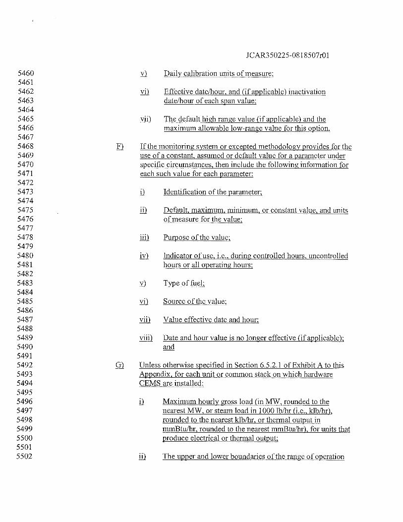
JCAR350225-081 8507r01
5460 y Daily calibration units of measure:54615462 y) Effective date/hour, and (if applicable) inactivation5463 date/hour of each span value:54645465 yj) The default high range value (if applicable) and the5466 maximum allowable low-range value for this option.54675468 ) If the monitoring system or excepted methodology provides for the5469 use of a constant, assumed or default value for a parameter under5470 specific circumstances, then include the following information for5471 each such value for each parameter:54725473 Identification of the parameter:54745475 jj Default, maximum, minimum, or constant value, and units5476 of measure for the value:54775478 iii) Purpose of the value:54795480 jy) Indicator of use, i.e., during controlled hours, uncontrolled5481 hours or all operating hours:54825483 y) Type of fuel:54845485 yj Source of the value:54865487 yjj) Value effective date and hour:54885489 yjji Date and hour value is no longer effective (if applicable):5490 and54915492 ) Unless otherwise specified in Section 6.5.2.1 of Exhibit A to this5493 Appendix, for each unit or common stack on which hardware5494 CEMS are installed:54955496 j) Maximum hourly gross load (in MW, rounded to the5497 nearest MW, or steam load in 1000 lb/hr (i.e., klb/hr),5498 rounded to the nearest klb/hr, or thermal output in5499 mmBtu/hr, rounded to the nearest mmBtulhr), for units that5500 produce electrical or thermal output:55015502 II) The upper and lower boundaries of the range of operation
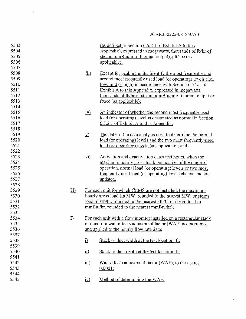
JCAR350225-0818507r01
5503 (as defined in Section 6.5.2.1 of Exhibit A to this5504 Appendix), expressed in megawatts, thousands of lb/hr of5505 steam, mrnBtu/hr of thermal output or ft/sec (as5506 applicable);55075508 jjfl Except for peaking units, identify the most frequently and5509 second most frequently used load (or operating) levels (i.e.,5510 low, mid or high) in accordance with Section 6.5.2.1 of5511 Exhibit A to this Appendix, expressed in megawatts,5512 thousands of lb/hr of steam, mmBtu/hr of thermal output or5513 fl/sec (as applicable);55145515 jy An indicator of whether the second most frequently used5516 load (or operating) level is designated as normal in Section5517 6.5.2.1 of ExhibitAto this Appendix;55185519 y The date of the data analysis used to determine the normal5520 load (or operating) levels and the two most frequently-used5521 load (or operating) levels (as applicable); and55225523 y) Activation and deactivation dates and hours, when the5524 maximum hourly gross load, boundaries of the range of5525 operation, normal load (or operating) levels or two most5526 frequently-used load (or operating) levels change and are5527 updated.55285529 fl For each unit for which CEMS are not installed, the maximum5530 hourly gross load (in MW, rounded to the nearest MW, or steam5531 load in klb/hr, rounded to the nearest klb/hr or steam load in5532 mmBtu/hr, rounded to the nearest mmBtu/hr);55335534 II For each unit with a flow monitor installed on a rectangular stack5535 or duct, if a wall effects adjustment factor (WAY) is determined5536 and applied to the hourly flow rate data:55375538 j) Stack or duct width at the test location, ft;55395540 jj) Stack or duct depth at the test location, ft;55415542 liii Wall effects adjustment factor (WAF). to the nearest5543 0.0001;55445545 jy Method of determining the WAY;
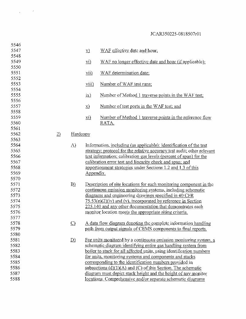
JCAR350225-081 8507r01
55465547 y WAF effective date and hour;55485549 yj) WAF no longer effective date and hour (if applicable):55505551 yjj) WAF determination date:55525553 yjji Number of WAF test runs;55545555 j) Number of Method 1 traverse points in the WAF test;55565557 ) Number of test ports in the WAF test; and55585559 Number of Method 1 traverse points in the reference flow5560 RATA.55615562 ) Hardcopy55635564 Information, including (as applicable): Identification of the test5565 strategy; protocol for the relative accuracy test audit; other relevant5566 test information; calibration gas levels (percent of span) for the5567 calibration error test and linearity check and span; and5568 apportionment strategies under Sections 1.2 and 1.3 of this5569 Appendix.55705571 ) Description of site locations for each monitoring component in the5572 continuous emission monitoring systems, including schematic5573 diagrams and engineering drawings specified in 40 CFR5574 75.53(e)(2)(iv) and (v), incorporated by reference in Section5575 225.140 and any other documentation that demonstrates each5576 monitor location meets the appropriate siting criteria.55775578 c) A data flow diagram denoting the complete information handling5579 path from output signals of CEMS components to final reports.55805581 For units monitored by a continuous emission monitoring system, a5582 schematic diagram identifying entire gas handling system from5583 boiler to stack for all affected units, using identification numbers5584 for units, monitoring systems and components and stacks5585 corresponding to the identification numbers provided in5586 subsections (d)(1)(A) and (C) of this Section. The schematic5587 diagram must depict stack height and the height of any monitor5588 locations. Comprehensive and/or separate schematic diagrams
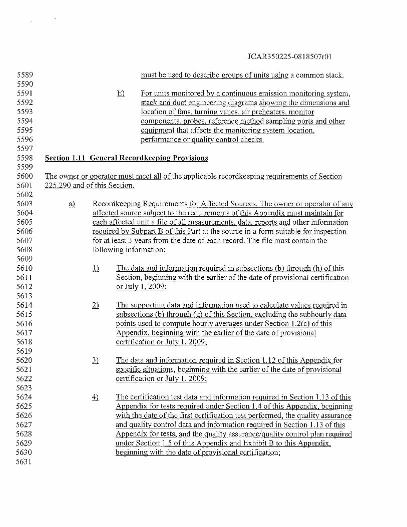
JCAR350225-08 1 8507r01
5589 must be used to describe groups of units using a common stack.55905591 ) For units monitored by a continuous emission monitoring system,5592 stack and duct engineering diagrams showing the dimensions and5593 location of fans, turning vanes, air preheaters, monitor5594 components, probes, reference method sampling ports and other5595 equipment that affects the monitoring system location,5596 performance or quality control checks.55975598 Section 1.11 General Recordkeepin2 Provisions55995600 The owner or operator must meet all of the applicable recordkeeping requirements of Section5601 225.290 and of this Section.56025603 ) Recordkeeping Requirements for Affected Sources. The owner or operator of any5604 affected source subject to the requirements of this Appendix must maintain for5605 each affected unit a file of all measurements, data, reports and other information5606 required by Subpart B of this Part at the source in a form suitable for inspection5607 for at least 3 years from the date of each record. The file must contain the5608 following information:56095610 The data and information required in subsections (b) through (h) of this5611 Section, beginning with the earlier of the date of provisional certification5612 or July 1, 2009;56135614 The supporting data and information used to calculate values required in5615 subsections (b) through (g) of this Section, excluding the subhourly data5616 points used to compute hourly averages under Section 1.2(c) of this5617 Appendix, beginning with the earlier of the date of provisional5618 certification or July 1, 2009;56195620 The data and information required in Section 1.12 of this Appendix for5621 specific situations, beginning with the earlier of the date of provisional5622 certification or July 1, 2009;56235624 4 The certification test data and information required in Section 1.13 of this5625 Appendix for tests required under Section 1.4 of this Appendix, beginning5626 with the date of the first certification test performed, the quality assurance5627 and quality control data and information required in Section 1.13 of this5628 Appendix for tests, and the quality assurance/quality control plan required5629 under Section 1.5 of this Appendix and Exhibit B to this Appendix,5630 beginning with the date of provisional certification;5631
JCAR350225-08 1 8507r01
5632 The current monitoring plan as specified in Section 1.10 of this Appendix,5633 beginning with the initial submission required by 40 CFR 75.62,5634 incorporated by reference in Section 225.140: and56355636 ) The quality control plan as described in Section 1 of Exhibit B to this5637 Appendix, beginning with the date of provisional certification.56385639 ) Operating Parameter Record Provisions. The owner or operator must record for5640 each hour the following information on unit operating time, heat input rate and5641 load, separately for each affected unit and also for each group of units utilizing a5642 common stack and a common monitoring system:56435644 II Date andhour;56455646 7) Unit operating time (rounded up to the nearest fraction of an hour (in5647 equal increments that can range from one hundredth to one quarter of an5648 hour, at the option of the owner or operator)):56495650 7) Hourly gross unit load (rounded to nearest MWge)56515652 4) Steam load in 1000 lbs/hr at stated temperatures and pressures, rounded to5653 the nearest 1000 lbs/hr.56545655 Operating load range corresponding to hourly gross load of 1 to 10, except5656 for units using a common stack, which may use up to 20 load ranges for5657 stack or fuel flow, as specified in the monitoring plan:56585659 ) Hourly heat input rate (mmBtulhr, rounded to the nearest tenth):56605661 7) Identification code for formula used for heat input as provided in Section5662 1.10 of this Appendix: and56635664 For Mercury CEMS units only, F-factor for heat input calculation and5665 indication of whether the diluent cap was used for heat input calculations5666 for the hour.56675668 c) Diluent Record Provisions. The owner or operator of a unit using a flow monitor5669 and an 02 diluent monitor to determine heat input, in accordance with Equation F5670 17 or F-18 of Exhibit C to this Appendix, or a unit that accounts for heat input5671 using a flow monitor and a CO2 diluent monitor (which is used only for heat input5672 determination and is not used as a CO2 pollutant concentration monitor) must5673 keep the following records for the 02 or CO2 diluent monitor:5674
JCAR350225-081 8507r01
5675 1) Component-system identification code as provided in Section 1.10 of this5676 Appendix;56775678 Date and hour;56795680 ) Hourly average diluent gas (Q2 or C02) concentration (in percent, rounded5681 to the nearest tenth);56825683 4). Percent monitor data availability for the diluent monitor (recorded to the5684 nearest tenth of a percent) calculated pursuant to Section 1.8 of this5685 Appendix; and56865687 Method of determination code for diluent gas (02 or C02) concentration5688 data using Codes 1-55 in Table 4a of this Section.56895690 ). Missing Data Records. The owner or operator must record the causes of any5691 missing data periods and the actions taken by the owner or operator to correct5692 such causes.56935694 Mercury Emission Record Provisions (CEMS’). The owner or operator must5695 record for each hour the information required by this subsection for each affected5696 unit using mercury CEMS in combination with flow rate, and (in certain cases)5697 moisture, and diluent gas monitors, to determine mercury concentration and (if5698 applicable) unit heat input under Subpart B of this Part.56995700 1) For mercury concentration during unit operation, as measured and5701 reported from each certified primary monitor, certified back-up monitor or5702 other approved method of emissions determination:57035704 ). Component-system identification code as provided in Section 1.105705 of this Appendix;57065707 ). Date and hour;57085709 c) Hourly mercury concentration (jig/scm, rounded to the nearest5710 tenth). For a particular pair of sorbent traps, this will be the flow-5711 proportional average concentration for the data collection period;57125713 j). Method of determination for hourly mercury concentration using5714 Codes 1-55 in Table 4a of this Section; and57155716 1). The percent monitor data availability (to the nearest tenth of a5717 percent) calculated pursuant to Section 1.8 of this Appendix.
JCAR350225-081 8507r01
57185719 For flue gas moisture content during unit operation (if required), as5720 measured and reported from each certified primary monitor, certified5721 back-up monitor or other approved method of emissions determination5722 (except where a default moisture value is approved under 40 CFR 75.66,5723 incorporated by reference in Section 225.140):57245725 ) Component-system identification code as provided in Section 1.105726 of this Appendix;57275728 Date and hour;57295730 J Hourly average moisture content of flue gas (percent, rounded to5731 the nearest tenth). If the continuous moisture monitoring system5732 consists of wet-and dry-basis oxygen analyzers, also record both5733 the wet- and dry-basis oxygen hourly averages (in percent O5734 rounded to the nearest tenth);57355736 Percent monitor data availability (recorded to the nearest tenth of a5737 percent) for the moisture monitoring system calculated pursuant to5738 Section 1.8 of this Appendix; and57395740 ) Method of determination for hourly average moisture percentage5741 using Codes 1-55 in Table 4a of this Section.57425743 For diluent gas (Q2 or C02) concentration during unit operation (if5744 required), as measured and reported from each certified primary monitor,5745 certified back-up monitor or other approved method of emissions5746 determination:57475748 Component-system identification code as provided in Section 1.105749 of this Appendix;57505751 ) Date and hour;57525753 Hourly average diluent gas (02 or C02) concentration (in percent,5754 rounded to the nearest tenth);57555756 Method of determination code for diluent gas (02 or CO5757 concentration data using Codes 1-55 in Table 4a of this Section;575857595760 The percent monitor data availability (to the nearest tenth of a
JCAR350225-08 1 8507r01
5761 percent) for the Q2 or CO2 monitoring system (if a separate O2or5762 cQ2 monitoring system is used for heat input detennination)5763 calculated pursuant to Section 1.8 of this Appendix.57645765 4,) For stack gas volumetric flow rate during unit operation, as measured and5766 reported from each certified primary monitor, certified back-up monitor or5767 other approved method of emissions determination, record the information5768 required under 40 CFR 75.5 7(c)(2)(i) through (vi), incorporated by5769 reference in Section 225.140.57705771 For mercury mass emissions during unit operation, as measured and5772 reported from the certified primary monitoring systems, certified5773 redundant or non-redundant back-up monitoring systems, or other5774 approved methods of emissions determination:57755776 ) Date and hour;57775778 ,) Hourly mercury mass emissions (ounces, rounded to three decimal5779 places);57805781 c) Identification code for emissions formula used to derive hourly5782 mercury mass emissions from mercury concentration, flow rate5783 and moisture data, as provided in Section 1.10 of this Appendix.57845785 fi Mercury Emission Record Provisions (Sorbent Trap Systems). The owner or5786 operator must record for each hour the information required by this subsection,5787 for each affected unit using sorbent trap monitoring systems in combination with5788 flow rate, moisture, and (in certain cases) diluent gas monitors, to determine5789 mercury mass emissions and (if required) unit heat input under this Part.57905791 1) For mercury concentration during unit operation, as measured and5792 reported from each certified primary monitor, certified back-up monitor or5793 other approved method of emissions determination:57945795 ) Component-system identification code as provided in Section 1.105796 of this Appendix;57975798 ,) Date and hour;57995800 Hourly mercury concentration (ig/dscm, rounded to the nearest5801 tenth). For a particular pair of sorbent traps, this will be the flow-5802 proportional average concentration for the data collection period;5803
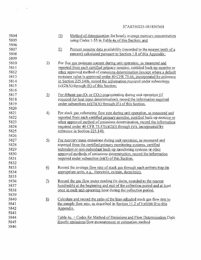
JCAR350225-081 8507r01
5804 ) Method of determination for hourly average mercury concentration5805 using Codes 1-55 in Table 4a of this Section; and58065807 j) Percent monitor data availability (recorded to the nearest tenth of a5808 percent) calculated pursuant to Section 1.8 of this Appendix;58095810 7) For flue gas moisture content during unit operation, as measured and5811 reported from each certified primary monitor, certified back-up monitor or5812 other approved method of emissions determination (except where a default5813 moisture value is approved under 40 CFR 75.66, incorporated by reference5814 in Section 225.140), record the information required under subsections5815 (e)(2)(A) through (E) of this Section;58165817 For diluent gas (02 or C02) concentration during unit operation (if5818 required for heat input determination), record the information required5819 under subsections (e)(3)(A) through (E) of this Section.58205821 4) For stack gas volumetric flow rate during unit operation, as measured and5822 reported from each certified primary monitor, certified back-up monitor or5823 other approved method of emissions determination, record the information5824 required under 40 CFR 75.57(c)(2)(i) through (vi), incorporated by5825 reference in Section 225.140.58265827 For mercury mass emissions during unit operation, as measured and5828 reported from the certified primary monitoring systems, certified5829 redundant or non-redundant back-up monitoring systems or other5830 approved methods of emissions determination, record the information5831 required under subsection (e)(5) of this Section.58325833 Record the average flow rate of stack gas through each sorbent trap (in5834 appropriate units, e.g., liters/mm, cc/mi dscmlmin).58355836 7) Record the gas flow meter reading (in dscm, rounded to the nearest5837 hundredth) at the beginning and end of the collection period and at least5838 once in each unit operating hour during the collection period.58395840 ) Calculate and record the ratio of the bias-adjusted stack gas flow rate to5841 the sample flow rate, as described in Section 11.2 of Exhibit D to this5842 Appendix.58435844 Table 4a. — Codes for Method of Emissions and Flow Determination Code5845 Hourly emissions/flow measurement or estimation method5846
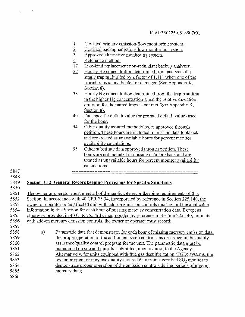
JCAR350225-0818507r01
1 Certified primary emission/flow monitoring system.2 Certified backup emission/flow monitoring system.3 Approved alternative monitoring system.4 Reference method.17 Like-kind replacement non-redundant backup analyzer.32 Hourly Hg concentration determined from analysis of a
single trap multiplied by a factor of 1.111 when one of thepaired traps is invalidated or damaged (See Appendix K,Section 8).
33 Hourly Hg concentration determined from the trap resultingin the higher Hg concentration when the relative deviationcriterion for the paired traps is not met (See Appendix K,Section 8).
40 Fuel specific default value (or prorated default value) usedfor the hour.
54 Other quality assured methodologies approved throughpetition. These hours are included in missing data lookbackand are treated as unavailable hours for percent monitoravailability calculations.
55 Other substitute data approved through petition. Thesehours are not included in missing data lookback and aretreated as unavailable hours for percent monitor availabilitycalculations.
584758485849 Section 1.12 General Recordkeeping Provisions for Specific Situations58505851 The owner or operator must meet all of the applicable recordkeeping requirements of this5852 Section. Tn accordance with 40 CFR 75.34, incorporated by reference in Section 225.140, the5853 owner or operator of an affected unit with add-on emission controls must record the applicable5854 information in this Section for each hour of missing mercury concentration data. Except as5855 otherwise provided in 40 CFR 75.34(d), incorporated by reference in Section 225.140, for units5856 with add-on mercury emission controls, the owner or operator must record:58575858 Parametric data that demonstrate, for each hour of missing mercury emission data,5859 the proper operation of the add-on emission controls, as described in the quality5860 assurance/quality control program for the unit. The parametric data must be5861 maintained on site and must be submitted, upon request, to the Agency.5862 Alternatively, for units equipped with flue gas desulfurization (FGD) systems, the5863 owner or operator may use quality-assured data from a certified SO2 monitor to5864 demonstrate proper operation of the emission controls during periods of missing5865 mercury data;5866
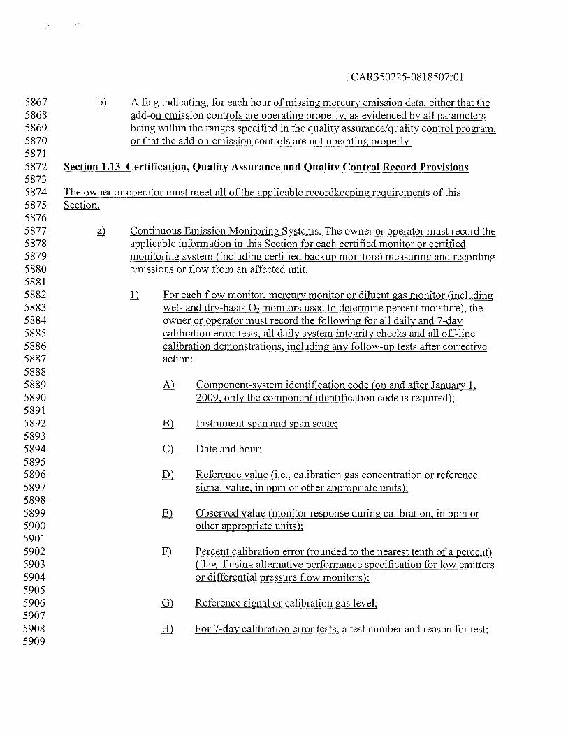
JCAR350225-081 8507r01
5867 ) A flag indicating, for each hour of missing mercury emission data, either that the5868 add-on emission controls are operating properly, as evidenced by all parameters5869 jffig within the ranges specified in the quality assurance/quality control program,5870 or that the add-on emission controls are not operating properly.58715872 Section 1.13 Certification, Quality Assurance and Quality Control Record Provisions58735874 The owner or operator must meet all of the applicable recordkeeping requirements of this5875 Section.58765877 Continuous Emission Monitoring Systems. The owner or operator must record the5878 applicable information in this Section for each certified monitor or certified5879 monitoring system (including certified backup monitors) measuring and recording5880 emissions or flow from an affected unit.58815882 1). For each flow monitor, mercury monitor or diluent gas monitor (including5883 wet- and dry-basis 02 monitors used to determine percent moisture), the5884 owner or operator must record the following for all daily and 7-day5885 calibration error tests, all daily system integrity checks and all off-line5886 calibration demonstrations, including any follow-up tests after corrective5887 action:58885889 Component-system identification code (on and after January 1,5890 2009, only the component identification code is required);58915892 i) Instrument span and span scale;58935894 Date and hour;58955896 L) Reference value (i.e., calibration gas concentration or reference5897 signal value, in ppm or other appropriate units);58985899 ) Observed value (monitor response during calibration, in ppm or5900 other appropriate units);59015902 Percent calibration error (rounded to the nearest tenth of a percent)5903 (flag if using alternative performance specification for low emitters5904 or differential pressure flow monitors);59055906 Reference signal or calibration gas level:59075908 For 7-day calibration error tests, a test number and reason for test;5909
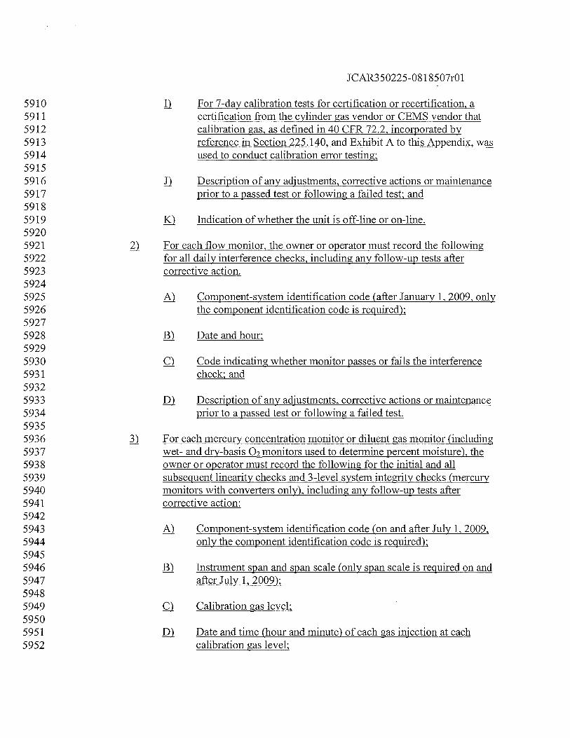
JCAR350225-081 8507r01
5910 II For 7-day calibration tests for certification or recertification, a5911 certification from the cylinder gas vendor or CEMS vendor that5912 calibration gas, as defined in 40 CFR 72.2, incorporated by5913 reference in Section 225.140, and Exhibit A to this Appendix, was5914 used to conduct calibration error testing;59155916 j) Description of any adjustments, corrective actions or maintenance5917 prior to a passed test or following a failed test; and59185919 ) Indication of whether the unit is off-line or on-line.59205921 For each flow monitor, the owner or operator must record the following5922 for all daily interference checks, including any follow-up tests after5923 corrective action.59245925 A) Component-system identification code (after January 1, 2009, only5926 the component identification code is required);59275928 ) Date and hour;59295930 ) Code indicating whether monitor passes or fails the interference5931 check; and59325933 ) Description of any adjustments, corrective actions or maintenance5934 prior to a passed test or following a failed test.59355936 For each mercury concentration monitor or diluent gas monitor (including5937 wet- and dry-basisQ2monitors used to determine percent moisture), the5938 owner or operator must record the following for the initial and all5939 subsequent linearity checks and 3-level system integrity checks (mercury5940 monitors with converters only), including any follow-up tests after5941 corrective action:59425943 A) Component-system identification code (on and after July 1, 2009,5944 only the component identification code is required);59455946 ) Instrument span and span scale (only span scale is required on and5947 after July 1, 2009);59485949 ) Calibration gas level;59505951 j) Date and time (hour and minute) of each gas injection at each5952 calibration gas level;
JCAR350225-08 1 8507r01
59535954 ) Reference value (i.e., reference gas concentration for each gas5955 injection at each calibration gas level, in ppm or other appropriate5956 units);59575958 f) Observed value (monitor response to each reference gas injection5959 at each calibration gas level, in ppm or other appropriate units);59605961 ) Mean of reference values and mean of measured values at each5962 calibration gas level;59635964 I) Linearity error at each of the reference gas concentrations (rounded5965 to nearest tenth of a percent) (flag if using alternative perfoance5966 specification);59675968 Test number and reason for test (flag if aborted test); and59695970 j) Description of any adjustments, corrective action or maintenance5971 prior to a passed test or following a failed test.59725973 4) For each differential pressure type flow monitor, the owner or operator5974 must record items in subsections (a)(4)(A) through (E) of this Section, for5975 all quarterly leak checks, including any follow-up tests after corrective5976 action. For each flow monitor, the owner or operator must record items in5977 subsections (a)(4)(F) and (G) of this Section for all flow-to-load ratio and5978 gross heat rate tests:59795980 ) Component-system identification code (on and after July 1, 2009,5981 only the system identification code is required).59825983 ) Date and hour.59845985 c) Reason for test.59865987 I) Code indicating whether monitor passes or fails the quarterly leak5988 check.59895990 Description of any adjustments, corrective actions or maintenance5991 prior to a passed test or following a failed test.59925993 ) Test data from the flow-to-load ratio or gross heat rate (GHR)5994 evaluation, including:5995
JCAR350225-081 8507r01
5996 Monitoring system identification cocj59975998 Calendar year and quarter;59996000 jjj) Indication of whether the test is a flow-to-load ratio or6001 gross heat rate evaluation;60026003 jy) Indication of whether bias adjusted flow rates were used:60046005 y) Average absolute percent difference between reference6006 ratio (or GHR) and hourly ratios (or GHR values):60076008 yj) Test result;60096010 yj) Number of hours used in final quarterly average;60116012 yjji Number of hours exempted for use of a different fuel type;60136014 j) Number of hours exempted for load ramping up or down;60156016 y) Number of hours exempted for scrubber bypass;60176018 çj) Number of hours exempted for hours preceding a normal-6019 load flow RATA;60206021 jj Number of hours exempted for hours preceding a6022 successful diagnostic test, following a documented monitor6023 repair or major component replacement;60246025 çjji Number of hours excluded for flue gases discharging6026 simultaneously thorough a main stack and a bypass stack;6027 and60286029 4y) Test number.60306031 ) Reference data for the flow-to-load ratio or gross heat rate6032 evaluation, including (as applicable):60336034 1) Reference flow RATA end date and time;60356036 jj) Test number of the reference RATA;60376038 jjj Reference RATA load and load level;
JCAR350225-081 8507r01
60396040 jy Average reference method flow rate during reference flow6041 RATA;60426043 y) Reference flow/load ratio;60446045 yj Average reference method diluent gas concentration during6046 flow RATA and diluent gas units of measure;60476048 yjj Fuel specific Fd-or Fe-factor during flow RATA and F6049 factor units of measure;60506051 yjji Reference gross heat rate value;60526053 j) Monitoring system identification code;60546055 Average hourly heat input rate during RATA;60566057 çj) Average gross unit load;60586059 jj Operating load level; and60606061 jji An indicator (flag) if separate reference ratios are6062 calculated for each multiple stack.60636064 ) For each flow monitor, each diluent gas (02 or C02)monitor used to6065 determine heat input, each moisture monitoring system, mercury6066 concentration monitoring system, each sorbent trap monitoring system and6067 each approved alternative monitoring system, the owner or operator must6068 record the following information for the initial and all subsequent relative6069 accuracy test audits:60706071 ) Reference methods used.60726073 Individual test run data from the relative accuracy test audit for the6074 flow monitor, CO2 emissions concentration monitor-diluent6075 continuous emission monitoring system, diluent gas (02 or CO6076 monitor used to determine heat input, moisture monitoring system,6077 mercury concentration monitoring system, sorbent trap monitoring6078 system or approved alternative monitoring system, including:60796080 Date, hour and minute of beginning of test run;6081
JCAR350225-08 1 8507r01
6082 j) Date, hour and minute of end of test run;60836084 lii) Monitoring system identification code;60856086 jy) Test number and reason for test;60876088 yl Operating level (low, mid, high or normal, as appropriate)6089 and number of operating levels comprising test;60906091 y Normal load (or operating level) indicator for flow RATAs6092 (except for peaking units);60936094 yjj) Units of measure;60956096 yjji Run number;60976098 Run value from CEMS being tested, in the appropriate6099 units of measure;61006101 Run value from reference method, in the appropriate units6102 of measure;61036104 j) Flag value (0, 1 or 9, as appropriate) indicating whether run6105 has been used in calculating relative accuracy and bias6106 values or whether the test was aborted prior to completion;61076108 çjj) Average gross unit load, expressed as a total gross unit6109 load, rounded to the nearest MWe, or as steam load,6110 rounded to the nearest 1000 lb/hr. except for units that do6111 not produce electrical or thermal output; and61126113 jji Flag to indicate whether an alternative performance6114 specification has been used.61156116 Calculations and tabulated results, as follows:61176118 j) Arithmetic mean of the monitoring system measurement6119 values of the reference method values, and of their6120 differences, as specified in Equation A—7 in Exhibit A to6121 this Appendix;61226123 Ii.1 Standard deviation, as specified in Equation A—8 in Exhibit6124 A to this Appendix;
JCAR350225-08 1 8507r01
61256126 jjj) Confidence coefficient, as specified in Equation A—9 in6127 Exhibit A to this Appendix;61286129 jy Statistical t value used in calculations;61306131 ) Relative accuracy test results, as specified in Equation A—6132 10 in Exhibit A to this Appendix. For multi-level flow6133 monitor tests the relative accuracy test results must be6134 recorded at each load (or operating) level tested. Each load6135 (or operating) level must be expressed as a total gross unit6136 load, rounded to the nearest MWe, or as steam load,6137 rounded to the nearest 1000 lb/hr. or as otherwise specified6138 by the Agency, for units that do not produce electrical or6139 thermal output;61406141 yj Bias test results as specified in Section 7.4.4 in Exhibit A to6142 this Appendix; and61436144 Description of any adjustment, corrective action or maintenance6145 prior to a passed test or following a failed or aborted test.61466147 j) For flow monitors, the equation used to linearize the flow monitor6148 and the numerical values of the polynomial coefficients or K6149 factors of that equation.61506151 For moisture monitoring systems, the coefficient or K factor or6152 other mathematical algorithm used to adjust the monitoring system6153 with respect to the reference method.61546155 j For each mercury concentration monitor, and each CO2 or 02 monitor6156 used to determine heat input, the owner or operator must record the6157 following information for the cycle time test:61586159 Component-system identification code (on and after July 1, 2009,6160 only the component identification code is required);61616162 Date:61636164 ) Start and end times;61656166 Upscale and downscale cycle times for each component;6167
JCAR350225-08 1 8507r01
6168 Stable start monitor value:61696170 Stable end monitor value:61716172 Reference value of calibration gases:61736174 ll Calibration gas level:61756176 Total cycle time:61776178 Reason for test: and61796180 j Test number.61816182 D In addition to the information in subsection (a)(5) of this Section, the6183 owner or operator must record, for each relative accuracy test audit,6184 supporting information sufficient to substantiate compliance with all6185 applicable Sections and Appendices in this Part. Unless otherwise6186 specified in this Part or in an applicable test method, the information in6187 subsections (a)(7)(A) through (H) of this Section may be recorded either6188 in hard copy format, electronic format or a combination of the two, and6189 the owner or operator must maintain this information in a format suitable6190 for inspection and audit purposes. This RATA supporting information6191 must include, but must not be limited to, the following data elements:61926193 For each RATA using Reference Method 2 (or its allowable6194 alternatives) in appendix A to 40 CFR 60, incorporated by6195 reference in Section 225.140, to determine volumetric flow rate:61966197 j) Information indicating whether or not the location meets6198 requirements of Method 1 in appendix A to 40 CFR 60,6199 incorporated by reference in Section 225.140: and62006201 jj Information indicating whether or not the equipment passed6202 the required leak checks.62036204 For each run of each RATA using Reference Method 2 (or its6205 allowable alternatives in appendix A to 40 CFR 60, incorporated6206 by reference in Section 225.140) to determine volumetric flow6207 rate, record the following data elements (as applicable to the6208 measurement method used):62096210 j) Operating level (low, mid, high or normal, as appropriate):
JCAR350225-08 1 8507r01
62116212 jj) Number of reference method traverse points;62136214 Average stack gas temperature (°F);62156216 jyj Barometric pressure at test port (inches of mercury);62176218 Stack static pressure (inches ofH7Q)j62196220 yj) Absolute stack gas pressure (inches of mercury);62216222 jj) Percent CO2 and O7in the stack gas, dry basis;62236224 yjji çQ2 and 02 reference method used;62256226 jç) Moisture content of stack gas (percent H7Q)62276228 ) Molecular weight of stack gas, dry-basis (lb/lb-mole);62296230 çj) Molecular weight of stack gas, wet-basis (lb/lb-mole);62316232 jj) Stack diameter (or equivalent diameter) at the test port (fi);62336234 jji Average square root of velocity head of stack gas (inches of6235 jO)fortherun;62366237 çjy) Stack or duct cross-sectional area at test port (fl2);62386239 çy) Average velocity (ft/sec);62406241 çyj) Average stack flow rate, adjusted, if applicable, for wall6242 effects (scfh, wet-basis);62436244 çyjjJ Flow rate reference method used;62456246 xviii) Average velocity, adjusted for wall effects;62476248 çj) Calculated (site-specific) wall effects adjustment factor6249 determined during the run, and, if different, the wall effects6250 adjustment factor used in the calculations; and62516252 p) Default wall effects adjustment factor used.6253
JCAR350225-08 1 8507r01
6254 ) For each traverse point of each run of each RATA using Reference6255 Method 2 (or its allowable alternatives in appendix A to 40 CFR6256 60, incorporated by reference in Section 225.140) to determine6257 volumetric flow rate, record the following data elements (as6258 applicable to the measurement method used):62596260 j) Reference method probe type;62616262 Ij Pressure measurement device type;62636264 IJj Traverse point ID;62656266 jy Probe or pitot tube calibration coefficient;62676268 y) Date of latest probe or pitot tube calibration;62696270 il Average velocity differential pressure at traverse point6271 (inches ofH20) or the average of the square roots of the6272 velocity differential pressures at the traverse point ((inches6273 ofH,O)”2);62746275 yjj T, stack temperature at the traverse point (°F);62766277 yjji Composite (wall effects) traverse point identifier;62786279 ç) Number of points included in composite traverse point;62806281 Yaw angle of flow at traverse point (degrees);62826283 j) Pitch angle of flow at traverse point (degrees);62846285 2c1i1 Calculated velocity at traverse point both accounting and6286 not accounting for wall effects (ft/see): and62876288 jji Probe identification number.62896290 For each RATA using Method 3A in appendix A to 40 CFR 60,6291 incorporated by reference in Section 225.140, to determine CO26292 Q2concentration:62936294 j) Pollutant or diluent gas being measured;62956296 jjj Span of reference method analyzer;
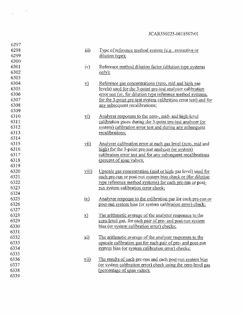
JCAR350225-081 8507r01
62976298 jj) Type of reference method system (e.g., extractive or6299 dilution type);63006301 jy) Reference method dilution factor (dilution type systems6302 only);63036304 y Reference gas concentrations (zero, mid and high gas6305 levels) used for the 3-point pre-test analyzer calibration6306 error test (or, for dilution type reference method systems,6307 for the 3-point pre-test system calibration error test) and for6308 any subsequent recalibrations;63096310 yj) Analyzer responses to the zero-, mid- and high-level6311 calibration gases during the 3-point pre-test analyzer (or6312 system) calibration error test and during any subsequent6313 recalibrations;63146315 yjfl Analyzer calibration error at each gas level (zero, mid and6316 high) for the 3-point pre-test analyzer (or system)6317 calibration error test and for any subsequent recalibrations6318 (percent of span value);63196320 yjji Upscale gas concentration (mid or high gas level) used for6321 each pre-run or post-run system bias check or (for dilution6322 type reference method systems) for each pre-run or post-6323 run system calibration error check;63246325 j Analyzer response to the calibration gas for each pre-run or6326 post-run system bias (or system calibration error) check;63276328 The arithmetic average of the analyzer responses to the6329 zero-level gas, for each pair of pre- and post-run system6330 bias (or system calibration error) checks;63316332 çj) The arithmetic average of the analyzer responses to the6333 upscale calibration gas for each pair of pre- and post-run6334 system bias (or system calibration error) checks;63356336 li) The results of each pre-run and each post-run system bias6337 (or system calibration error) check using the zero-level gas6338 (percentage of span value);6339
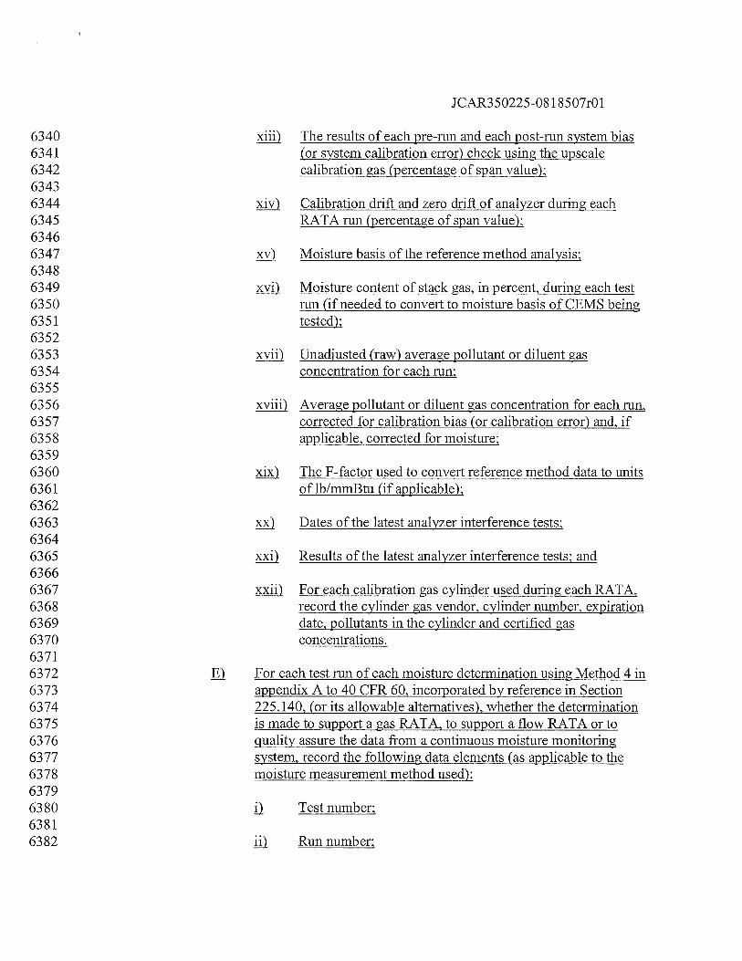
JCAR350225-08 1 8507r01
6340 jji The results of each pre-run and each post-run system bias6341 (or system calibration error) check using the upscale6342 calibration gas (percentage of span value);63436344 Calibration drift and zero drift of analyzer during each6345 RATA run (percentage of span value);63466347 çy) Moisture basis of the reference method analysis:63486349 çyj Moisture content of stack gas, in percent, during each test6350 run (if needed to convert to moisture basis of CEMS being6351 tested);63526353 yjj) Unadjusted (raw) average pollutant or diluent gas6354 concentration for each run:63556356 xviii) Average pollutant or diluent gas concentration for each run,6357 corrected for calibration bias (or calibration error) and, if6358 applicable, corrected for moisture:63596360 The F-factor used to convert reference method data to units6361 of lb/mmBtu (if applicable);63626363 ç) Dates of the latest analyzer interference tests;63646365 pçj) Results of the latest analyzer interference tests: and63666367 çjj) For each calibration gas cylinder used during each RATA,6368 record the cylinder gas vendor, cylinder number, expiration6369 date, pollutants in the cylinder and certified gas6370 concentrations.63716372 ) For each test run of each moisture determination using Method 4 in6373 appendix A to 40 CFR 60, incorporated by reference in Section6374 225.140, (or its allowable alternatives), whether the determination6375 is made to support a gas RATA, to support a flow RATA or to6376 quality assure the data from a continuous moisture monitoring6377 system, record the following data elements (as applicable to the6378 moisture measurement method used):63796380 Test number;63816382 jj Run number:
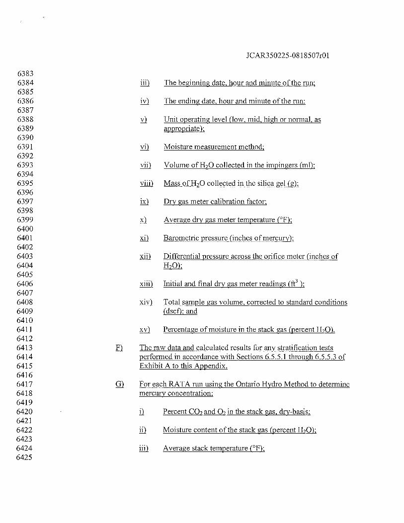
JCAR350225-08 1 8507r01
63836384 The beginning date, hour and minute of the run;63856386 jy The ending date, hour and minute of the run;63876388 y Unit operating level (low, mid, high or normal, as6389 appropriate);63906391 yj) Moisture measurement method;63926393 yjfl Volume ofH20 collected in the impingers (ml);63946395 yjji Mass ofH20 collected in the silica gel (g);63966397 jç) Dry gas meter calibration factor;63986399 ) Average dry gas meter temperature (°F);64006401 çj Barometric pressure (inches of mercury);64026403 jj) Differential pressure across the orifice meter (inches of640464056406 jji Initial and final dry gas meter readings (ft3);64076408 çjy) Total sample gas volume, corrected to standard conditions6409 (dscf); and64106411 çy) Percentage of moisture in the stack gas (percent H2Q)64126413 The raw data and calculated results for any stratification tests6414 performed in accordance with Sections 6.5.5.1 through 6.5.5.3 of6415 Exhibit A to this Appendix.64166417 For each RATA run using the Ontario Hydro Method to determine6418 mercury concentration:64196420 Percent CO2 and O2in the stack gas, dry-basis;64216422 jj Moisture content of the stack gas (percent H2Q)j64236424 jjjj. Average stack temperature (°F);6425
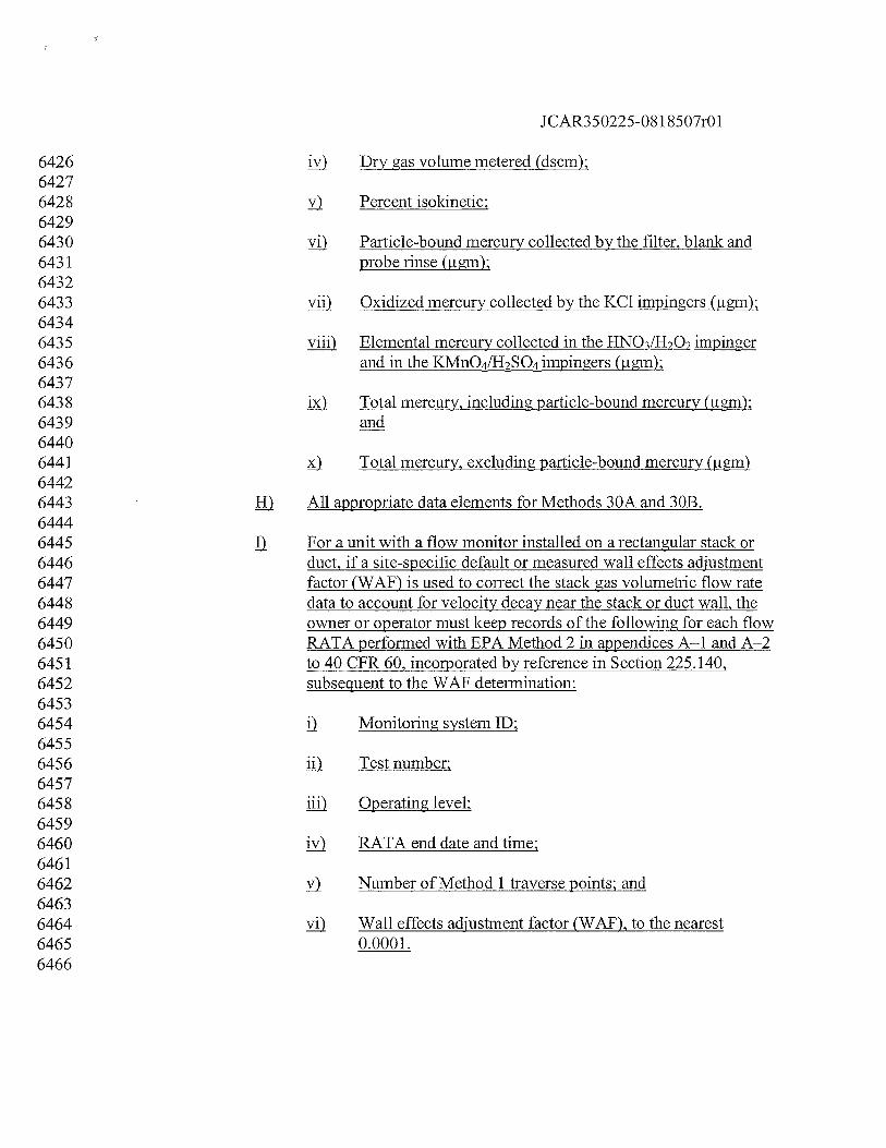
JCAR350225-081 8507r01
6426 jy Dry gas volume metered (dscm):64276428 y) Percent isokinetic;64296430 yj Particle-bound mercury collected by the filter, blank and6431 probe rinse (igm);64326433 yiIl Oxidized mercury collected by the KC1 impingers (igm);64346435 yjji Elemental mercury collected in the IINO3LH2O2impinger6436 and in the KMnO4/H2SO4impingers (igm);64376438 jç) Total mercury, including particle-bound mercury (igm);6439 and64406441 ) Total mercury, excluding particle-bound mercury ()64426443 All appropriate data elements for Methods 30A and 30B.64446445 For a unit with a flow monitor installed on a rectangular stack or6446 duct, if a site-specific default or measured wall effects adjustment6447 factor (WAF) is used to correct the stack gas volumetric flow rate6448 data to account for velocity decay near the stack or duct wall, the6449 owner or operator must keep records of the following for each flow6450 RATA performed with EPA Method 2 in appendices A—i and A—26451 to 40 CFR 60, incorporated by reference in Section 225.140,6452 subsequent to the WAF determination:64536454 Monitoring system ID;64556456 fl Test number:64576458 jJj) Operating level:64596460 jy RATA end date and time:64616462 y Number of Method 1 traverse points; and64636464 yj) Wall effects adjustment factor (WAF), to the nearest6465 0.0001.6466
JCAR350225-08 1 8507r01
6467 j) For each RATA run using Method 29 in appendix A—8 to 40 CFR6468 60, incorporated by reference in Section 225.140, to determine6469 mercury concentration:64706471 Percent CQ2 and O2in the stack gas, dry-basis;64726473 jj) Moisture content of the stack gas (percent H2Q)64746475 jjj) Average stack gas temperature (°F);64766477 j Dry gas volume metered (dscm);64786479 y Percent isokinetic;64806481 yj) Particulate mercury collected in the front half of the6482 sampling train, corrected for the front-half blank value6483 Qigm); and64846485 yji) Total vapor phase mercury collected in the back half of the6486 sampling train, corrected for the back-half blank value6487 fllgm).64886489 ) For each certified continuous emission monitoring system, excepted6490 monitoring system or alternative monitoring system, the date and6491 description of each event that requires certification, recertification or6492 certain diagnostic testing of the system and the date and type of each test6493 performed. If the conditional data validation procedures of Section6494 1 .4(b)(3) of this Appendix are to be used to validate and report data prior6495 to the completion of the required certification, recertification or diagnostic6496 testing, the date and hour of the probationary calibration error test must be6497 reported to mark the beginning of conditional data validation.64986499 2) Hardcopy relative accuracy test reports, certification reports,6500 recertification reports or semiannual or animal reports for gas or flow rate6501 CEMS, mercury CEMS or sorbent trap monitoring systems are required or6502 requested under 40 CFR 75.60(b)(6) or 75.63, incorporated by reference in6503 Section 225.140, the reports must include, at a minimum, the following6504 elements as applicable to the types of tests performed:65056506 l Summarized test results.65076508 ) DAHS printouts of the CEMS data generated during the calibration6509 error, linearity, cycle time and relative accuracy tests.
JCAR350225-081 8507r01
65106511 ) For pollutant concentration monitor or diluent monitor relative6512 accuracy tests at normal operating load:65136514 The raw reference method data from each run, i.e., the data6515 under subsection (a)(7)(D)(xvii) of this Section (usually in6516 the form of a computerized printout, showing a series of6517 one-minute readings and the run average);65186519 i1 The raw data and results for all required pre-test, post-test,6520 pre-run and post-run quality assurance checks (i.e.,6521 calibration gas injections) of the reference method6522 analyzers, i.e., the data under subsections (a)(7)(D)(v)6523 through (xiv) of this Section;65246525 jjj) The raw data and results for any moisture measurements6526 made during the relative accuracy testing, i.e., the data6527 under subsections (a)(7)(E)(i) through (xv) of this Section;6528 and65296530 Tabulated, final, corrected reference method run data (i.e.,6531 the actual values used in the relative accuracy calculations),6532 along with the equations used to convert the raw data to the6533 final values and example calculations to demonstrate how6534 the test data were reduced.65356536 For relative accuracy tests for flow monitors:65376538 j) The raw flow rate reference method data, from Reference6539 Method 2 (or its allowable alternatives) under appendix A6540 to 40 CFR 60, incorporated by reference in Section6541 225.140, including auxiliary moisture data (often in the6542 form of handwritten data sheets), i.e., the data under6543 subsections (a)(7)(B)(i) through (xx), subsections6544 (a)(7)(C)(i) through (xiii), and, if applicable, subsections6545 (a)(7)(E)(i) through (xv) of this Section; and65466547 jI The tabulated, final volumetric flow rate values used in the6548 relative accuracy calculations (determined from the flow6549 rate reference method data and other necessary6550 measurements, such as moisture, stack temperature and6551 pressure), along with the equations used to convert the raw
JCAR350225-081 8507r01
6552 data to the final values and example calculations to6553 demonstrate how the test data were reduced.65546555 Calibration gas certificates for the gases used in the linearity,6556 calibration error and cycle time tests and for the calibration gases6557 used to quality assure the gas monitor reference method data6558 during the relative accuracy test audit.65596560 ) Laboratory calibrations of the source sampling equipment. For6561 sorbent trap monitoring systems, the laboratory analyses of all6562 sorbent traps and information documenting the results of all leak6563 checks and other applicable quality control procedures.65646565 ) A copy of the test protocol used for the CEMS certifications or6566 recertifications, including narrative that explains any testing6567 abnormalities, problematic sampling, and analytical conditions that6568 required a change to the test protocol, andlor solutions to technical6569 problems encountered during the testing program.65706571 ) Diagrams illustrating test locations and sample point locations (to6572 verify that locations are consistent with information in the6573 monitoring plan). Include a discussion of any special traversing or6574 measurement scheme. The discussion must also confirm that6575 sample points satisfy applicable acceptance criteria.65766577 Names of key personnel involved in the test program, including6578 test team members, plant contacts, agency representatives and test6579 observers on site.65806581 IQ) Whenever reference methods are used as backup monitoring systems6582 pursuant to Section 1.4(d)(3) of this Appendix, the owner or operator must6583 record the following information:65846585 ) For each test run using Reference Method 2 (or its allowable6586 alternatives in appendix A to 40 CFR 60, incorporated by reference6587 in Section 225.140) to determine volumetric flow rate, record the6588 following data elements (as applicable to the measurement method6589 used):65906591 Unit or stack identification number;65926593 iii Reference method system and component identification6594 numbers;
JCAR350225-0818507r01
65956596 jjj) Run date and hour;65976598 iI The data in subsection (a)(7)(B) of this Section, except for6599 subsections (a)(7)(B)(i), (vi), (viii), (xii) and (xvii) through6600 (xx); and66016602 y) The data in subsection (a)(7)(C), except on a run basis.66036604 ) For each reference method test run using Method 6C, 7E or 3A in6605 appendix A to 40 CFR 60, incorporated by reference in Section6606 225.140, to determine SO2,N0, CO2 or 02 concentration:66076608 Unit or stack identification number;66096610 li) The reference method system and component identification6611 numbers;66126613 jjj Run number;66146615 jy) Run start date and hour;66166617 y) Run end date and hour;66186619 yj) The data in subsections (a)(7)(D)(ii) through (ix) and (xii)6620 through (xv); and (vii) Stack gas density adjustment factor6621 (if applicable).66226623 ) For each hour of each reference method test run using Method 6C,6624 7E or 3A in appendix A to 40 CFR 60, incorporated by reference6625 in Section 225.140, to determine SO2,N0, CO2. or 06626 concentration:66276628 j) Unit or stack identification number;66296630 jj) The reference method system and component identification6631 numbers;66326633 jjj) Run number;66346635 jy) Run date and hour;66366637 y) Pollutant or diluent gas being measured;
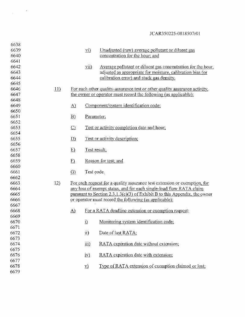
JCAR350225-081 8507r01
66386639 yj Unadjusted (raw) average pollutant or diluent gas6640 concentration for the hour; and66416642 XIi) Average pollutant or diluent gas concentration for the hour,6643 adjusted as appropriate for moisture, calibration bias (or6644 calibration error) and stack gas density.66456646 II) For each other quality-assurance test or other quality assurance activity,6647 the owner or operator must record the following (as applicable):66486649 ) Component/system identification code;66506651 Parameter;66526653 Test or activity completion date and hour;66546655 Test or activity description;66566657 j) Test result;66586659 Reason for test; and66606661 Test code.66626663 j For each request for a quality assurance test extension or exemption, for6664 any loss of exempt status, and for each single-load flow RATA claim6665 pursuant to Section 2.3.1.3(c)(3) of Exhibit B to this Appendix, the owner6666 or operator must record the following (as applicable):66676668 For a RATA deadline extension or exemption request:66696670 Monitoring system identification code;66716672 jj) Date of last RATA;66736674 jjj RATA expiration date without extension;66756676 i1 RATA expiration date with extension;66776678 y Type of RATA extension of exemption claimed or lost;6679
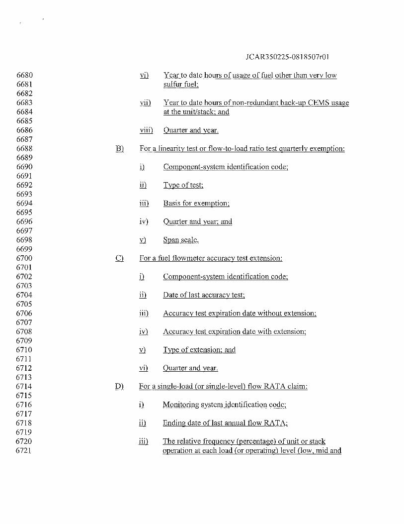
JCAR350225-08 1 8507r01
6680 yj Year to date hours of usage of fuel other than very low6681 sulfur fuel;66826683 yj Year to date hours of non-redundant back-up CEMS usage6684 at the unit/stack; and66856686 yjji Quarter and year.66876688 ) For a linearity test or flow-to-load ratio test quarterly exemption:66896690 Component-system identification code;66916692 jj) Type of test:66936694 jj) Basis for exemption:66956696 jy Quarter and year; and66976698 Span scale.66996700 ) For a fuel flowmeter accuracy test extension:67016702 Component-system identification code;67036704 jj Date of last accuracy test;67056706 Iji) Accuracy test expiration date without extension;67076708 jy) Accuracy test expiration date with extension;67096710 y Type of extension: and67116712 yj) Quarter and year.67136714 ) For a single-load (or single-level) flow RATA claim:67156716 j) Monitoring system identification code;67176718 ji) Ending date of last annual flow RATA;67196720 jjj The relative frequency (percentage) of unit or stack6721 operation at each load (or operating) level (low, mid and
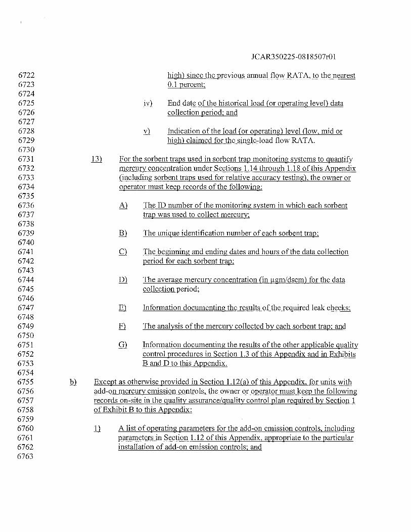
JCAR350225-0818507r01
6722 high) since the previous annual flow RATA, to the nearest6723 0.1 percent;67246725 jy End date of the historical load (or operating level) data6726 collection period; and67276728 y) Indication of the load (or operating) level (low, mid or6729 high) claimed for the single-load flow RATA.67306731 j For the sorbent traps used in sorbent trap monitoring systems to quantify6732 mercury concentration under Sections 1.14 through 1.18 of this Appendix6733 (including sorbent traps used for relative accuracy testing), the owner or6734 operator must keep records of the following:67356736 The ID number of the monitoring system in which each sorbent6737 trap was used to collect mercury;67386739 The unique identification number of each sorbent trap;67406741 ) The beginning and ending dates and hours of the data collection6742 period for each sorbent trap;67436744 I) The average mercury concentration (in igm1dscm) for the data6745 collection period;67466747 ) Information documenting the results of the required leak checks;67486749 ) The analysis of the mercury collected by each sorbent trap; and67506751 Information documenting the results of the other applicable quality6752 control procedures in Section 1.3 of this Appendix and in Exhibits6753 B and D to this Appendix.67546755 Except as otherwise provided in Section 1.12(a) of this Appendix, for units with6756 add-on mercury emission controls, the owner or operator must keep the following6757 records on-site in the quality assurance/quality control plan required by Section 16758 of Exhibit B to this Appendix:67596760 fl A list of operating parameters for the add-on emission controls, including6761 parameters in Section 1.12 of this Appendix, appropriate to the particular6762 installation of add-on emission controls; and6763
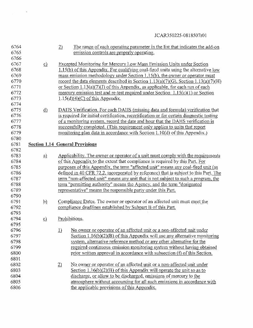
JCAR350225-08 1 8507r01
6764 The range of each operating parameter in the list that indicates the add-on6765 emission controls are properly operating.67666767 ç). Excepted Monitoring for Mercury Low Mass Emission Units under Section6768 1.15(b) of this Appendix. For qualifng coal-fired units using the alternative low6769 mass emission methodology under Section 1.15(b), the owner or operator must6770 record the data elements described in Section 1.13 (a)(7)(G), Section 1.1 3(a)(7)(H)6771 or Section 1.1 3(a)(7)(J) of this Appendix, as applicable, for each run of each6772 mercury emission test and re-test required under Section 1.15(c)(1) or Section6773 1.15(d)(4)(C) of this Appendix.67746775 ç DM15 Verification. For each DAHS (missing data and formula) verification that6776 is required for initial certification, recertification or for certain diagnostic testing6777 of a monitoring system, record the date and hour that the DAHS verification is6778 successfully completed. (This requirement only applies to units that report6779 monitoring plan data in accordance with Section 1.10(d) of this Appendix.)67806781 Section 1.14 General Provisions67826783 Applicability. The owner or operator of a unit must comply with the requirements6784 of this Appendix to the extent that compliance is required by this Part. For6785 purposes of this Appendix, the term “affected unit” means any coal-fired unit (as6786 defined in 40 CFR 72.2, incorporated by reference) that is subject to this Part. The6787 term “non-affected unit” means any unit that is not subject to such a program, the6788 term “permitting authority” means the Agency, and the term “designated6789 representative” means the responsible party under this Part.67906791 Compliance Dates. The owner or operator of an affected unit must meet the6792 compliance deadlines established by Subpart B of this Part.67936794 Prohibitions.67956796 fl No owner or operator of an affected unit or a non-affected unit under6797 Section 1.16(b)(2)(B) of this Appendix will use any alternative monitoring6798 system, alternative reference method or any other alternative for the6799 required continuous emission monitoring system without having obtained6800 prior written approval in accordance with subsection (f) of this Section.68016802 ) No owner or operator of an affected unit or a non-affected unit under6803 Section 1.16(b)(2)(B) of this Appendix will operate the unit so as to6804 discharge, or allow to be discharged, emissions of mercury to the6805 atmosphere without accounting for all such emissions in accordance with6806 the applicable provisions of this Appendix.
JCAR350225-081 8507r01
68076808 ) No owner or operator of an affected unit or a non-affected unit under6809 Section 1.16(b)(2)(B) of this Appendix will disrupt the continuous6810 emission monitoring system, any portion of the system, or any other6811 approved emission monitoring method, and thereby avoid monitoring and6812 recording mercury mass emissions discharged into the atmosphere, except6813 for periods of recertification or periods when calibration, quality assurance6814 testing or maintenance is performed in accordance with the provisions of6815 this Appendix applicable to monitoring systems under Section 1.15 of this6816 Appendix.68176818 4 No owner or operator of an affected unit or a non-affected unit under6819 Section 1.1 6(b)(2)(B) will retire or permanently discontinue use of the6820 continuous emission monitoring system, any component of the system, or6821 any other approved emission monitoring system under this Appendix,6822 except under any one of the following circumstances:68236824 During the period that the unit is covered by a retired unit6825 exemption that is in effect under this Part; or68266827 ) The owner or operator is monitoring mercury mass emissions from6828 the affected unit with another certified monitoring system6829 approved, in accordance with the provisions of Section 250 of this6830 Part; or68316832 ) The designated representative submits notification of the date of6833 certification testing of a replacement monitoring system in6834 accordance with Section 240(d) of this Part.68356836 ) Quality Assurance and Quality Control Requirements. For units that use6837 continuous emission monitoring systems to account for mercury mass emissions,6838 the owner or operator must meet the applicable quality assurance and quality6839 control requirements in Section 1.5 and Exhibit B to this Appendix for the flow6840 monitoring systems, mercury concentration monitoring systems, moisture6841 monitoring systems and diluent monitors required under Section 1.15 of this6842 Appendix. Units using sorbent trap monitoring systems must meet the applicable6843 quality assurance requirements in Section 1.3 of this Appendix, Exhibit D to this6844 Appendix, and Sections 1.3 and 2.3 of Exhibit B to this Appendix.68456846 Reporting Data Prior to Initial Certification. If, by the applicable compliance date6847 under this Part, the owner or operator of an affected unit has not successfully6848 completed all required certification tests for any monitoring systems, he or she6849 must determine, record, and report data prior to initial certification in accordance
JCAR350225-081 8507r01
6850 with Section 239 of this Part.68516852 fi Petitions.68536854 jJ The designated representative of an affected unit that is also subject to the6855 Acid Rain Program may submit a petition to the Agency requesting an6856 alternative to any requirement of Sections 1.14 through 1.18 of this6857 Appendix. Such a petition must meet the requirements of 40 CFR 75.66,6858 incorporated by reference in Section 225.140, and any additional6859 requirements established by Subpart B of this Part. Use of an alternative to6860 any requirement of Sections 1.14 through 1.18 of this Appendix is in6861 accordance with Sections 1.14 through 1.18 of this Appendix and with6862 Subpart B of this Part only to the extent that the petition is approved in6863 writing by the Agency.68646865 Notwithstanding subsection (f)(1) of this Section, petitions requesting an6866 alternative to a requirement concerning any additional CEMS required6867 solely to meet the common stack provisions of Section 1.16 of this6868 Appendix must be submitted to the Agency and will be governed by6869 subsection (f)(3) of this Section. Such a petition must meet the6870 requirements of 40 CFR 75.66, incorporated by reference in Section6871 225.140, and any additional requirements established by Subpart B of this6872 Part.68736874 ) The designated representative of an affected unit that is not subject to the6875 Acid Rain Program may submit a petition to the Agency requesting an6876 alternative to any requirement of Sections 1.14 through 1.18 of this6877 Appendix. Such a petition must meet the requirements of 40 CFR 75.66,6878 incorporated by reference in Section 225.140, and any additional6879 requirements established by Subpart B of this Part. Use of an alternative to6880 any requirement of Sections 1.14 through 1.18 of this Appendix is in6881 accordance with Sections 1.14 through 1.18 of this Appendix only to the6882 extent that it is approved in writing by the Agency.68836884 Section 1.15 Monitoring of Mercury Mass Emissions and Heat Input at the Unit Level68856886 The owner or operator of the affected coal-fired unit must:68876888 Meet the general operating requirements in Section 1.2 of this Appendix for the6889 following continuous emission monitors (except as provided in accordance with6890 subpart E of 40 CFR 75, incorporated by reference in Section 225.140):68916892 j) A mercury concentration monitoring system (consisting of a mercury
JCAR350225-08 1 8507r01
6893 pollutant concentration monitor and an automated DAHS, which provides6894 a permanent, continuous record of mercury emissions in units of6895 micrograms per standard cubic meter (jig/scm)) or a sorbent trap6896 monitoring system to measure the mass concentration of total vapor phase6897 mercury in the flue gas, including the elemental and oxidized forms of6898 mercury, in micrograms per standard cubic meter (pg/scm);68996900 ) A flow monitoring system;69016902 A continuous moisture monitoring system (if correction of mercury6903 concentration for moisture is required), as described in 40 CFR 75.11(b),6904 incorporated by reference in Section 225.140. Alternatively, the owner or6905 operator may use the appropriate fuel-specific default moisture value6906 provided in 40 CFR 75.11, incorporated by reference in Section 225.140,6907 or a site-specific moisture value approved by petition under 40 CFR 75.66,6908 incorporated by reference in Section 225.140; and69096910 4) If heat input is required to be reported under this Part, the owner or6911 operator must meet the general operating requirements for a flow6912 monitoring system and an 02 or CO2 monitoring system to measure heat6913 input rate.69146915 j) For an affected unit that emits 464 ounces (29 lb) of mercury per year or less, use6916 the following excepted monitoring methodology. To implement this methodology6917 for a qualifying unit, the owner or operator must meet the general operating6918 requirements in Section 1.2 of this Appendix for the continuous emission6919 monitors described in subsections (a)(2) and (a)(4) of this Section, and perform6920 mercury emission testing for initial certification and on-going quality-assurance,6921 as described in subsections (c) through (e) of this Section.69226923 c) To determine whether an affected unit is eligible to use the monitoring provisions6924 in subsections (b) of this Section:69256926 1) The owner or operator must perform mercury emission testing within 186927 months before the compliance date in Section 1.14(b) of this Appendix to6928 determine the mercury concentration (i.e., total vapor phase mercury) in6929 the effluent.69306931 ) The testing must be performed using one of the mercury reference6932 methods listed in Section 1.6(a)(5) of this Appendix, and must6933 consist of a minimum of 3 runs at the normal unit operating load,6934 while combusting coal. The coal combusted during the testing6935 must be representative of the coal that will be combusted at the
JCAR350225-081 8507r01
6936 start of the mercury mass emissions reduction program (preferably6937 from the same sources of supply).69386939 ) The minimum time per run must be 1 hour if Method 30A is used.6940 If either Method 29 in appendix A-8 to 40 CFR 60, incorporated6941 by reference, ASTM D6784-02 (the Ontario Hydro method)6942 (incorporated by reference under Section 225.140) or Method 30B6943 is used, paired samples are required for each test run and the runs6944 must be long enough to ensure that sufficient mercury is collected6945 to analyze. When Method 29 in appendix A-8 to 40 CFR 60,6946 incorporated by reference, or the Ontario Hydro method is used,6947 the test results must be based on the vapor phase mercury collected6948 in the back-half of the sampling trains (i.e., the non-filterable6949 impinger catches). For each Method 29 in appendix A-8 to 40 CFR6950 60, incorporated by reference, Method 30B or Ontario Hydro6951 method test run, the paired trains must meet the relative deviation6952 (RD) requirement specified in Section 1.6(a)(5) of this Appendix6953 or Method 30B, as applicable. If the RD specification is met, the6954 results of the two samples must be averaged arithmetically.69556956 ) If the unit is equipped with flue gas desulfurization or add-on6957 mercury emission controls, the controls must be operating6958 normally during the testing, and, for the purpose of establishing6959 proper operation of the controls, the owner or operator must record6960 parametric data or SO7 concentration data in accordance with6961 Section 1.12(a) of this Appendix.69626963 If two or more of units of the same type qualify as a group of6964 identical units in accordance with 40 CFR 75.19(c)(1)(iv)(B),6965 incorporated by reference in Section 225.140, the owner or6966 operator may test a subset of these units in lieu of testing each unit6967 individually. If this option is selected, the number of units required6968 to be tested must be determined from Table LM-4 in 40 CFR6969 75.19, incorporated by reference in Section 225.140. For the6970 purposes of the required retests under subsection (d)(4) of this6971 Section, it is strongly recommended that (to the extent practicable)6972 the same subset of the units not be tested in two successive retests,6973 and that every effort be made to ensure that each unit in the group6974 of identical units is tested in a timely manner.6975697669776978 Based on the results of the emission testing, Equation 1 of this
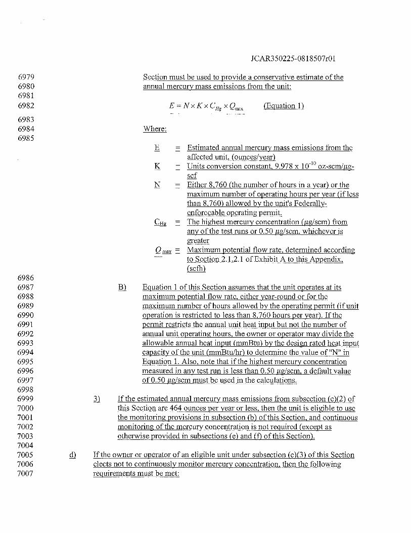
1CAR350225-08 1 8507r01
6979 Section must be used to provide a conservative estimate of the6980 annual mercury mass emissions from the unit:69816982 E=NXKXCHgXQmax (Equation 1)
69836984 Where:6985
B = Estimated annual mercury mass emissions from theaffected unit, (ounces/year)
K = Units conversion constant, 9.978 x 100 oz-scm/Iigscf
N = Either 8,760 (the number of hours in a year) or themaximum number of operating hours per year (if lessthan 8,760) allowed by the unit’s Federally-enforceable operating permit.The highest mercury concentration(1ug/scm) fromany of the test runs or 0.50 ,ug/scm, whichever isgreaterMaximum potential flow rate, determined according
— to Section 2.1.2.1 of Exhibit A to this Appendix,(scfh)
69866987 Equation 1 of this Section assumes that the unit operates at its6988 maximum potential flow rate, either year-round or for the6989 maximum number of hours allowed by the operating permit (if unit6990 operation is restricted to less than 8,760 hours per year). If the6991 permit restricts the annual unit heat input but not the number of6992 annual unit operating hours, the owner or operator may divide the6993 allowable annual heat input (mmBtu) by the design rated heat input6994 capacity of the unit (mmBtu/hr) to determine the value of “N” in6995 Equation 1. Also, note that if the highest mercury concentration6996 measured in any test run is less than 0.50 ftg/scm, a default value6997 of 0.50 pg/scm must be used in the calculations.69986999 If the estimated annual mercury mass emissions from subsection (c)(2) of7000 this Section are 464 ounces per year or less, then the unit is eligible to use7001 the monitoring provisions in subsection (b) of this Section, and continuous7002 monitoring of the mercury concentration is not required (except as7003 otherwise provided in subsections (e) and (f) of this Section).70047005 If the owner or operator of an eligible unit under subsection (c)(3) of this Section7006 elects not to continuously monitor mercury concentration, then the following7007 requirements must be met:
JCAR350225-081 8507r01
70087009 j) The results of the mercury emission testing performed under subsection7010 (c) of this Section must be submitted as a certification application to the7011 permitting authority, no later than 45 days after the testing is completed.7012 The calculations demonstrating that the unit emits 464 ounces (or less) per7013 year of mercury must also be provided, and the default mercury7014 concentration that will be used for reporting under Section 1.18 of this7015 Appendix must be specified in both the electronic and hard copy portions7016 of the monitoring plan for the unit. The methodology is considered to be7017 provisionally certified as of the date and hour of completion of the7018 mercury emission testing.70197020 Following initial certification, the same default mercury concentration7021 value that was used to estimate the unit’s annual mercury mass emissions7022 under subsection (c) of this Section must be reported for each unit7023 operating hour, except as otherwise provided in subsection (d)(4)(D) or7024 (d)(6) of this Section. The default mercury concentration value must be7025 updated as appropriate according to subsection (d)(5) of this Section.70267027 ) The hourly mercury mass emissions must be calculated according to7028 Section 4.1.3 in Exhibit C to this Appendix.70297030 4) The mercury emission testing described in subsection (c) of this Section7031 must be repeated periodically, for the purposes of quality-assurance, as7032 follows:70337034 If the results of the certification testing under subsection (c) of this7035 Section show that the unit emits 144 ounces (9 lb) of mercury per7036 year or less, the first retest is required by the end of the fourth QA7037 operating quarter (as defined in 40 CFR 72.2, incorporated by7038 reference) following the calendar quarter of the certification7039 testing; or70407041 ) If the results of the certification testing under subsection (c) of this7042 Section show that the unit emits more than 144 ounces of mercury7043 per year, but less than or equal to 464 ounces per year, the first7044 retest is required by the end of the second QA operating quarter (as7045 defined in 40 CFR 72.2, incorporated by reference) following the7046 calendar quarter of the certification testing; and70477048 ) Thereafter, retesting must be required either semiannually or7049 annually (i.e., by the end of the second or fourth QA operating7050 quarter following the quarter of the previous test), depending on
JCAR350225-08 1 8507r01
7051 the results of the previous test. To determine whether the next7052 retest is due within two or four QA operating quarters, substitute7053 the highest mercury concentration from the current test or 0.507054 jig/scm (whichever is greater) into the equation in subsection (c)(2)7055 of this Section. If the estimated annual mercury mass emissions7056 exceeds 144 ounces, the next test is due within two QA operating7057 quarters. If the estimated annual mercury mass emissions is 1447058 ounces or less, the next test is due within four OA operating7059 quarters.70607061 An additional retest is required when there is a change in the coal7062 rank of the primary fuel (e.g., when the primary fuel is switched7063 from bituminous coal to lignite). Use ASTM D388-997064 (incorporated by reference under Section 225.140) to determine the7065 coal rank. The four principal coal ranks are anthracitic, bituminous,7066 subbituminous and lignitic. The ranks of anthracite coal refuse7067 (cuim) and bituminous coal refuse (gob) must be anthracitic and7068 bituminous, respectively. The retest must be performed within 7207069 unit operating hours of the change.70707071 ) The default mercury concentration used for reporting under Section 1.187072 of this Appendix must be updated after each required retest. This includes7073 retests that are required prior to the compliance date in Section 1.14(b) of7074 this Appendix. The updated value must either be the highest mercury7075 concentration measured in any of the test runs or 0.50 jig/scm, whichever7076 is greater. The updated value must be applied beginning with the first unit7077 operating hour in which mercury emissions data are required to be7078 reported after completion of the retest, except as provided in subsection7079 (d)(4)(D) of this Section, where the need to retest is triggered by a change7080 in the coal rank of the primary fuel. In that case, apply the updated default7081 mercury concentration beginning with the first unit operating hour in7082 which mercury emissions are required to be reported after the date and7083 hour of the fuel switch.70847085 If the unit is equipped with a flue gas desulfurization system or add-on7086 mercury controls, the owner or operator must record the information7087 required under Section 1.12 of this Appendix for each unit operating hour,7088 to document proper operation of the emission controls.70897090 For units with common stack and multiple stack exhaust configurations, the use of7091 the monitoring methodology described in subsections (b) through (d) of this7092 Section is restricted as follows:7093
JCAR350225-08 1 8507r01
7094 jJ The methodology may not be used for reporting mercury mass emissions7095 at a common stack unless all of the units using the common stack are7096 affected units and the units’ combined potential to emit does not exceed7097 464 ounces of mercury per year times the number of units sharing the7098 stack, in accordance with subsections (c) and (d) of this Section. If the test7099 results demonstrate that the units sharing the common stack qualify as low7100 mass emitters, the default mercury concentration used for reporting7101 mercury mass emissions at the common stack must either be the highest7102 value obtained in any test run or 0.50 hg/scm, whichever is greater.71037104 ) The initial emission testing required under subsection (c) of this7105 Section maybe performed at the common stack if the following7106 conditions are met. Otherwise, testing of the individual units (or a7107 subset of the units, if identical, as described in subsection (c)(l)(D)7108 of this Section) is required:71097110 j) The testing must be done at a combined load corresponding7111 to the designated normal load level (low, mid or high) for7112 the units sharing the common stack in accordance with7113 Section 6.5.2.1 of Exhibit Ato this Appendix;71147115 jj All of the units that share the stack must be operating in a7116 normal, stable manner and at typical load levels during the7117 emission testing. The coal combusted in each unit during7118 the testing must be representative of the coal that will be7119 combusted in that unit at the start of the mercury mass7120 emission reduction program (preferably from the same7121 sources of supply);71227123 jjj If flue gas desulfurization andlor add-on mercury emission7124 controls are used to reduce the level of the emissions7125 exiting from the common stack, these emission controls7126 must be operating normally during the emission testing7127 and, for the purpose of establishing proper operation of the7128 controls, the owner or operator must record parametric data7129 or SO2 concentration data in accordance with Section7130 1.12(a) of this Appendix;71317132 jy When calculating E, the estimated maximum potential7133 annual mercury mass emissions from the stack, substitute7134 the maximum potential flow rate through the common stack7135 (as defined in the monitoring plan) and the highest7136 concentration from any test run (or 0.50 pig/scm, if greater)
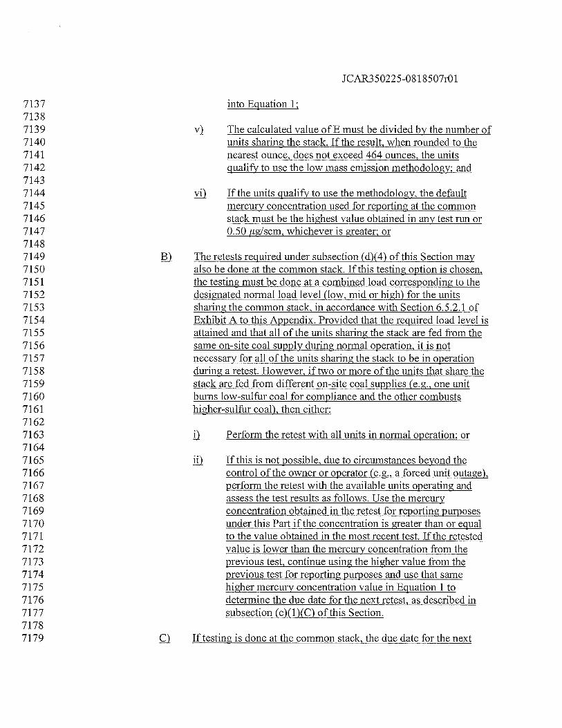
JCAR350225-081 8507r01
7137 into Equation 1;71387139 y) The calculated value of E must be divided by the number of7140 units sharing the stack. If the result, when rounded to the7141 nearest ounce, does not exceed 464 ounces, the units7142 qualify to use the low mass emission methodology; and71437144 yj If the units qualify to use the methodology, the default7145 mercury concentration used for reporting at the common7146 stack must be the highest value obtained in any test run or7147 0.50 pg/scm, whichever is greater; or71487149 The retests required under subsection (d)(4) of this Section may7150 also be done at the common stack. If this testing option is chosen,7151 the testing must be done at a combined load corresponding to the7152 designated normal load level (low, mid or high) for the units7153 sharing the common stack, in accordance with Section 6.5.2.1 of7154 Exhibit A to this Appendix. Provided that the required load level is7155 attained and that all of the units sharing the stack are fed from the7156 same on-site coal supply during normal operation, it is not7157 necessary for all of the units sharing the stack to be in operation7158 during a retest. However, if two or more of the units that share the7159 stack are fed from different on-site coal supplies (e.g., one unit7160 bums low-sulfur coal for compliance and the other combusts7161 higher-sulfur coal), then either:71627163 Perform the retest with all units in normal operation; or71647165 jj If this is not possible, due to circumstances beyond the7166 control of the owner or operator (e.g., a forced unit outage),7167 perform the retest with the available units operating and7168 assess the test results as follows. Use the mercury7169 concentration obtained in the retest for reporting purposes7170 under this Part if the concentration is greater than or equal7171 to the value obtained in the most recent test. If the retested7172 value is lower than the mercury concentration from the7173 previous test, continue using the higher value from the7174 previous test for reporting purposes and use that same7175 higher mercury concentration value in Equation 1 to7176 determine the due date for the next retest, as described in7177 subsection (e)(1)(C) of this Section.71787179 If testing is done at the common stack, the due date for the next
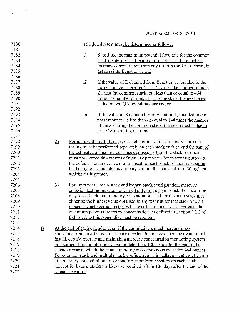
JCAR350225-08 1 8507r01
7180 scheduled retest must be determined as follows:71817182 Substitute the maximum potential flow rate for the common7183 stack (as defined in the monitoring plan) and the highest7184 mercury concentration from any test run (or 0.50 ,ug/scm, if7185 greater) into Equation 1 and71867187 jj) If the value of E obtained from Equation 1, rounded to the7188 nearest ounce, is greater than 144 times the number of units7189 sharing the common stack, but less than or equal to 4647190 times the number of units sharing the stack, the next retest7191 is due in two QA operating quarters or71927193 jjj) If the value of E obtained from Equation 1, rounded to the7194 nearest ounce, is less than or equal to 144 times the number7195 of units sharing the common stack, the next retest is due in7196 four QA operating quarters.71977198 ) For units with multiple stack or duct configurations, mercury emission7199 testing must be performed separately on each stack or duct, and the sum of7200 the estimated annual mercury mass emissions from the stacks or ducts7201 must not exceed 464 ounces of mercury per year. For reporting purposes,7202 the default mercury concentration used for each stack or duct must either7203 be the highest value obtained in any test run for that stack or 0.50 jig/scm,7204 whichever is greater.72057206 For units with a main stack and bypass stack configuration, mercury7207 emission testing must be performed only on the main stack. For reporting7208 purposes, the default mercury concentration used for the main stack must7209 either be the highest value obtained in any test run for that stack or 0.507210 jig/scm, whichever is greater. Whenever the main stack is bypassed, the7211 maximum potential mercury concentration, as defined in Section 2.1.3 of7212 Exhibit A to this Appendix, must be reported.72137214 At the end of each calendar year, if the cumulative annual mercury mass7215 emissions from an affected unit have exceeded 464 ounces, then the owner must7216 install, certify, operate and maintain a mercury concentration monitoring system7217 or a sorbent trap monitoring system no later than 180 days after the end of the7218 calendar year in which the annual mercury mass emissions exceeded 464 ounces.7219 For common stack and multiple stack configurations, installation and certification7220 of a mercury concentration or sorbent trap monitoring system on each stack7221 (except for bypass stacks) is likewise required within 180 days after the end of the7222 calendar year, if:
JCAR350225-081 8507r01
72237224 jJ The annual mercury mass emissions at the common stack have exceeded7225 464 ounces times the number of affected units using the common stack; or72267227 The sum of the annual mercury mass emissions from all of the multiple7228 stacks or ducts has exceeded 464 ounces; or72297230 ) The sum of the annual mercury mass emissions from the main and bypass7231 stacks has exceeded 464 ounces.72327233 g For an affected unit that is using a mercury concentration CEMS or a sorbent trap7234 system under Section 1.15(a) of this Appendix to continuously monitor the7235 mercury mass emissions, the owner or operator may switch to the methodology in7236 Section 1.15(b) of this Appendix, provided that the applicable conditions in7237 subsections (c) through (f) of this Section are met.72387239 Section 1.16 Monitorin2 of Mercury Mass Emissions and Heat Input at Common and7240 Multiple Stacks72417242 Unit Utilizing Common Stack with Other Affected Units. When an affected unit7243 utilizes a common stack with one or more affected units, but no non-affected7244 units, the owner or operator must either:72457246 1) Install, certify, operate and maintain the monitoring systems described in7247 Section 1.15(a) of this Appendix at the common stack record the7248 combined mercury mass emissions for the units exhausting to the common7249 stack. Alternatively, if, in accordance with Section 1.15(e) of this7250 Appendix, each of the units using the common stack is demonstrated to7251 emit less than 464 ounces of mercury per year, the owner or operator may7252 install, certify, operate and maintain the monitoring systems and perform7253 the mercury emission testing described under Section 1.15(b) of this7254 Appendix. If reporting of the unit heat input rate is required, determine the7255 hourly unit heat input rates either by:72567257 Apportioning the common stack heat input rate to the individual7258 units according to the procedures in 40 CFR 75.16(e)(3),7259 incorporated by reference in Section 225.140; or72607261 Installing, certifying, operating and maintaining a flow monitoring7262 system and diluent monitor in the duct to the common stack from7263 each unit; or72647265 Install, certify, operate and maintain the monitoring systems and (if
JCAR350225-081 8507r01
7266 applicable) perform the mercury emission testing described in Section7267 1.15(a) or Section 1.15(b) of this Appendix in the duct to the common7268 stack from each unit.72697270 J2) Unit Utilizing Common Stack with Nonaffected Units. When one or more7271 affected units utilizes a common stack with one or more nonaffected units, the7272 owner or operator must either:72737274 D Install, certify, operate and maintain the monitoring systems and (if7275 applicable) perform the mercury emission testing described in Section7276 1.15(a) or Section 1.15(b) of this Appendix in the duct to the common7277 stack from each affected unit; or72787279 Install, certify, operate and maintain the monitoring systems described in7280 Section 1.15(a) of this Appendix in the common stack; and72817282 Install, certify, operate and maintain the monitoring systems and (if7283 applicable) perform the mercury emission testing described in7284 Section 1.15(a) or (b) of this Appendix in the duct to the common7285 stack from each non-affected unit. The designated representative7286 must submit a petition to the Agency to allow a method of7287 calculating and reporting the mercury mass emissions from the7288 affected units as the difference between mercury mass emissions7289 measured in the common stack and mercury mass emissions7290 measured in the ducts of the non-affected units, not to be reported7291 as an hourly value less than zero. The Agency may approve such a7292 method whenever the designated representative demonstrates, to7293 the satisfaction of the Agency, that the method ensures that the7294 mercury mass emissions from the affected units are not7295 underestimated; or72967297 Count the combined emissions measured at the common stack as7298 the mercury mass emissions for the affected units, for7299 recordkeeping and compliance purposes, in accordance with7300 subsection (a) of this Section; or73017302 Submit a petition to the Agency to allow use of a method for7303 apportioning mercury mass emissions measured in the common7304 stack to each of the units using the common stack and for reporting7305 the mercury mass emissions. The Agency may approve such a7306 method whenever the designated representative demonstrates, to7307 the satisfaction of the Agency, that the method ensures that the7308 mercury mass emissions from the affected units are not
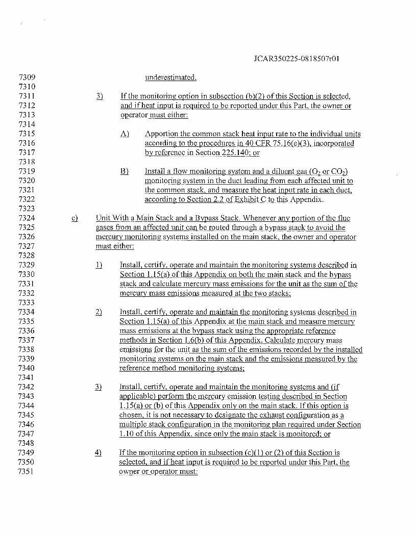
JCAR350225-081 8507r01
7309 underestimated.73107311 If the monitoring option in subsection (b)(2) of this Section is selected,7312 and if heat input is required to be reported under this Part, the owner or7313 operator must either:73147315 Apportion the common stack heat input rate to the individual units7316 according to the procedures in 40 CFR 75.16(e)(3), incorporated7317 by reference in Section 225.140; or73187319 Install a flow monitoring system and a diluent gas (02 or C07320 monitoring system in the duct leading from each affected unit to7321 the common stack, and measure the heat input rate in each duct,7322 according to Section 2.2 of Exhibit C to this Appendix.73237324 ç Unit With a Main Stack and a Bypass Stack. Whenever any portion of the flue7325 gases from an affected unit can be routed through a bypass stack to avoid the7326 mercury monitoring systems installed on the main stack, the owner and operator7327 must either:73287329 jj Install, certify, operate and maintain the monitoring systems described in7330 Section 1.15(a) of this Appendix on both the main stack and the bypass7331 stack and calculate mercury mass emissions for the unit as the sum of the7332 mercury mass emissions measured at the two stacks;73337334 Install, certify, operate and maintain the monitoring systems described in7335 Section 1.15(a) of this Appendix at the main stack and measure mercury7336 mass emissions at the bypass stack using the appropriate reference7337 methods in Section 1.6(b) of this Appendix. Calculate mercury mass7338 emissions for the unit as the sum of the emissions recorded by the installed7339 monitoring systems on the main stack and the emissions measured by the7340 reference method monitoring systems:73417342 Install, certify, operate and maintain the monitoring systems and (if7343 applicable) perform the mercury emission testing described in Section7344 1.15(a) or (b) of this Appendix only on the main stack. If this option is7345 chosen, it is not necessary to designate the exhaust configuration as a7346 multiple stack configuration in the monitoring plan required under Section7347 1.10 of this Appendix, since only the main stack is monitored; or73487349 4) If the monitoring option in subsection (c)(1) or (2) of this Section is7350 selected, and if heat input is required to be reported under this Part, the7351 owner or operator must:
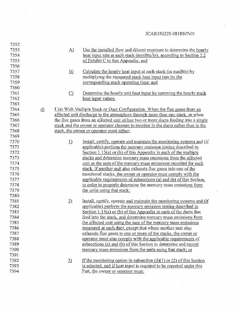
JCAR350225-08 1 8507r01
73527353 Use the installed flow and diluent monitors to determine the hourly7354 heat input rate at each stack (mmBtu/hr), according to Section 2.27355 of Exhibit C to this Appendix; and73567357 ) Calculate the hourly heat input at each stack (in mmBtu) by7358 multiplying the measured stack heat input rate by the7359 corresponding stack operating time; and73607361 Determine the hourly unit heat input by summing the hourly stack7362 heat input values.73637364 cD Unit With Multiple Stack or Duct Configuration. When the flue gases from an7365 affected unit discharge to the atmosphere through more than one stack, or when7366 the flue gases from an affected unit utilize two or more ducts feeding into a single7367 stack and the owner or operator chooses to monitor in the ducts rather than in the7368 stack, the owner or operator must either:73697370 1) Install, certify, operate and maintain the monitoring systems and (if7371 applicable) perform the mercury emission testing described in7372 Section 1.15(a) or (b) of this Appendix in each of the multiple7373 stacks and determine mercury mass emissions from the affected7374 unit as the sum of the mercury mass emissions recorded for each7375 stack. If another unit also exhausts flue gases into one of the7376 monitored stacks, the owner or operator must comply with the7377 applicable requirements of subsections (a) and (b) of this Section,7378 in order to properly determine the mercury mass emissions from7379 the units using that stack;73807381 ) Install, certify, operate and maintain the monitoring systems and (if7382 applicable) perform the mercury emission testing described in7383 Section 1.15(a) or (b) of this Appendix in each of the ducts that7384 feed into the stack, and determine mercury mass emissions from7385 the affected unit using the sum of the mercury mass emissions7386 measured at each duct, except that where another unit also7387 exhausts flue gases to one or more of the stacks, the owner or7388 operator must also comply with the applicable requirements of7389 subsections (a) and (b) of this Section to determine and record7390 mercury mass emissions from the units using that stack; or73917392 If the monitoring option in subsection (d)(1) or (2) of this Section7393 is selected, and if heat input is required to be reported under this7394 Part, the owner or operator must:
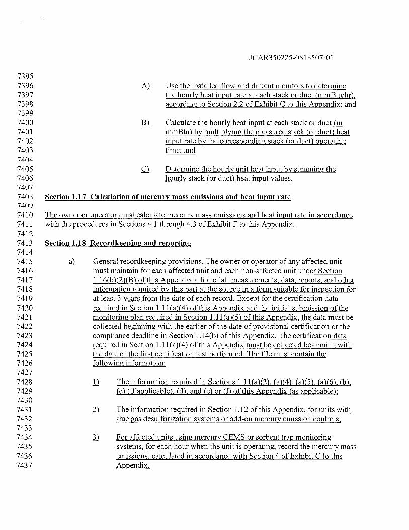
JCAR350225-08 1 8507r01
73957396 M Use the installed flow and diluent monitors to determine7397 the hourly heat input rate at each stack or duct (mmBtu/hr),7398 according to Section 2.2 of Exhibit C to this Appendix; and73997400 ]) Calculate the hourly heat input at each stack or duct (in7401 mmBtu) by multiplying the measured stack (or duct) heat7402 input rate by the corresponding stack (or duct) operating7403 time; and74047405 c) Determine the hourly unit heat input by summing the7406 hourly stack (or duct) heat input values.74077408 Section 1.17 Calculation of mercury mass emissions and heat input rate74097410 The owner or operator must calculate mercury mass emissions and heat input rate in accordance7411 with the procedures in Sections 4.1 through 4.3 of Exhibit F to this Appendix.74127413 Section 1.18 Recordkeepiug and reporting74147415 General recordkeeping provisions. The owner or operator of any affected unit7416 must maintain for each affected unit and each non-affected unit under Section7417 1.1 6(b)(2)(B) of this Appendix a file of all measurements, data, reports, and other7418 information required by this part at the source in a form suitable for inspection for7419 at least 3 years from the date of each record. Except for the certification data7420 required in Section 1.1 1(a)(4) of this Appendix and the initial submission of the7421 monitoring plan required in Section 1.11(a)(5) of this Appendix, the data must be7422 collected beginning with the earlier of the date of provisional certification or the7423 compliance deadline in Section 1.14(b) of this Appendix. The certification data7424 required in Section 1.1 1(a)(4) of this Appendix must be collected beginning with7425 the date of the first certification test performed. The file must contain the7426 following information:74277428 D The information required in Sections 1.11 (a)(2), (a)(4), (a)(5), (a)(6), (b),7429 (c) (if applicable), (d), and (e) or (f) of this Appendix (as applicable);74307431 The information required in Section 1.12 of this Appendix, for units with7432 flue gas desulfurization systems or add-on mercury emission controls;74337434 For affected units using mercury CEMS or sorbent trap monitoring7435 systems, for each hour when the unit is operating, record the mercury mass7436 emissions, calculated in accordance with Section 4 of Exhibit C to this7437 Appendix.
JCAR350225-081 8507r01
74387439 4) Heat input and mercury methodologies for the hour; and74407441 ) Formulas from the monitoring plan for total mercury mass emissions and7442 heat input rate (if applicable);74437444 j) Certification, quality assurance and quality control record provisions. The owner7445 or operator of any affected unit must record the applicable information in Section7446 1.13 of this Appendix for each affected unit or group of units monitored at a7447 common stack and each non-affected unit under Section 1.16(b)(2)(B) of this7448 Appendix.74497450 c) Monitoring plan recordkeeping provisions.74517452 jJ General provisions. The owner or operator of an affected unit must7453 prepare and maintain a monitoring plan for each affected unit or group of7454 units monitored at a common stack and each non-affected unit under7455 Section 1.16(b)(2)(B) of this Appendix. The monitoring plan must contain7456 sufficient information on the continuous monitoring systems and the use7457 of data derived from these systems to demonstrate that all the unit’s7458 mercury emissions are monitored and reported.74597460 ) Updates. Whenever the owner or operator makes a replacement,7461 modification, or change in a certified continuous monitoring system or7462 alternative monitoring system under 40 CFR 75, subpart E, incorporated7463 by reference in Section 225.140, including a change in the automated data7464 acquisition and handling system or in the flue gas handling system, that7465 affects information reported in the monitoring plan (e.g., a change to a7466 serial number for a component of a monitoring system), then the owner or7467 operator must update the monitoring plan.74687469 .) Contents of the monitoring plan. Each monitoring plan must contain the7470 information in Section 1.10(d)(1) of this Appendix in electronic format7471 and the information in Section 1.1 0(d)(2) in hardcopy format.74727473 ç General reporting provisions.74747475 II The designated representative for an affected unit must comply with all7476 reporting reciuirements in this Section and with any additional7477 requirements set forth in 35 Ill. Adm. Code 225.74787479 ) The designated representative for an affected unit must submit the7480 following for each affected unit or group of units monitored at a common
JCAR350225-081 8507r01
7481 stack and each non-affected unit under Section 1.1 6(b)(2)(B) of this7482 Appendix:74837484 Monitoring plans in accordance with subsection (e) of this Section;7485 and74867487 ) Quarterly reports in accordance with subsection (f) of this Section.74887489 Other petitions and communications. The designated representative for an7490 affected unit must submit petitions, correspondence, application fonns,7491 and petition-related test results in accordance with the provisions in7492 Section 1.14(f) of this Appendix.74937494 41 Quality assurance RATA reports. If requested by the Agency, the7495 designated representative of an affected unit must submit the quality7496 assurance RATA report for each affected unit or group of units monitored7497 at a common stack and each non-affected unit under Section 1.1 6(b)(2)(B)7498 of this Appendix by the later of 45 days after completing a quality7499 assurance RATA according to Section 2.3 of Exhibit B to this Appendix7500 or 15 days after receiving the request. The designated representative must7501 report the hardcopy information required by Section 1.1 3(a)(9) of this7502 Appendix to the Agency.75037504 ) Notifications. The designated representative for an affected unit must7505 submit written notice to the Agency according to the provisions in 40 CFR7506 75.61, incorporated by reference in Section 225.140, for each affected unit7507 or group of units monitored at a common stack and each non-affected unit7508 under Section 1.16(b)(2)(B) of this Appendix.75097510 Monitoring plan reporting.75117512 II Electronic submission. The designated representative for an affected unit7513 must submit to the Agency and USEPA, or an alternate Agency designee7514 if one is specified, a complete, electronic, up-to-date monitoring plan file7515 in a format specified by the Agency for each affected unit or group of7516 units monitored at a common stack and each non-affected unit under7517 Section 1.16(b)(2)(B) of this Appendix, as follows: No later than 21 days7518 prior to the commencement of initial certification testing; at the time of a7519 certification or recertification application submission; and whenever an7520 update of the electronic monitoring plan is required, either under Section7521 1.10 of this Appendix or elsewhere in this Appendix.75227523 1 Hardcopy submission. The designated representative of an affected unit
JCAR350225-0818507r01
7524 must submit all of the hardcopy information required under Section 1.107525 of this Appendix, for each affected unit or group of units monitored at a7526 common stack and each non-affected unit under Section 1.1 6(b)(2)(B) of7527 this Appendix, to the Agency prior to initial certification. Thereafter, the7528 designated representative must submit hardcopy information only if that7529 portion of the monitoring plan is revised. The designated representative7530 must submit the required hardcopy information as follows: no later than7531 21 days prior to the commencement of initial certification testing; with7532 any certification or recertification application, if a hardcopy monitoring7533 plan change is associated with the recertification event; and within 30 days7534 after any other event with which a hardcopy monitoring plan change is7535 associated, pursuant to Section 1.10(b) of this Appendix. Electronic7536 submittal of all monitoring plan information, including hardcopy portions,7537 is permissible provided that a paper copy of the hardcopy portions can be7538 furnished upon request.75397540 fi Quarterly reports.75417542 j) Electronic submission. Electronic quarterly reports must be submitted,7543 beginning with the calendar quarter containing the compliance date in7544 Section 1.14(b) of this Appendix, unless otherwise specified in 35 Ill.7545 Adm. Code 225. The designated representative for an affected unit must7546 report the data and information in this subsection (f)(1) and the applicable7547 compliance certification information in subsection (f)(2) of this Section to7548 the Agency and USEPA, or an alternate Agency designee if one is7549 specified, quarterly in a format specified by the Agency, except as7550 otherwise provided in 40 CFR 75.64(a), incorporated by reference in7551 Section 225.140, for units in long-term cold storage. Each electronic7552 report must be submitted to the Agency within 45 days following the end7553 of each calendar quarter. Except as otherwise provided in 40 CFR7554 75.64(a)(4) and (a)(5), incorporated by reference in Section 225.140, each7555 electronic report must include the date of report generation and the7556 following information for each affected unit or group of units monitored at7557 a common stack:75587559 j The facility information in 40 CFR 75.64(a)(3), incorporated by7560 reference in Section 225.140; and75617562 The information and hourly data required in subections (a) and (b)7563 of this Section, except for:75647565 j) Descriptions of adjustments, corrective action, and7566 maintenance;
JCAR350225-081 8507r01
75677568 jj) Information which is incompatible with electronic reporting7569 (e.g., field data sheets, lab analyses, quality control plan);75707571 jj) For units with flue gas desulfurization systems or with add-7572 on mercury emission controls, the parametric information7573 in Section 1.12 of this Appendix;75747575 jy) Information required by Section 1.11(d) of this Appendix7576 concerning the causes of any missing data periods and the7577 actions taken to cure those causes;75787579 y) Hardcopy monitoring plan information required by Section7580 1.10 of this Appendix and hardcopy test data and results7581 required by Section 1.13 of this Appendix;75827583 yj) Records of flow polynomial equations and numerical7584 values required by Section 1.13(a)(5)(E) of this Appendix;75857586 yjj) Stratification test results required as part of the RATA7587 supplementary records under Section 1.13(a)(7) of this7588 Appendix;75897590 yjji Data and results of RATAs that are aborted or invalidated7591 due to problems with the reference method or operational7592 problems with the unit and data and results of liney7593 checks that are aborted or invalidated due to operational7594 problems with the unit;75957596 jy) Supplementary RATA information required under Section7597 1.1 3(a)(7) of this Appendix, except that: the applicable data7598 elements under Section 1.13(a)(7)(B)(i) through (xx) of this7599 Appendix and under Section 1.13 (a)(7)(C)(i) through (xiii)7600 of this Appendix must be reported for flow RATAs at7601 circular or rectangular stacks (or ducts) in which angular7602 compensation for yaw and/or pitch angles is used (i.e.,7603 Method 2F or 2G in appendices A-i and A-2 to 40 CFR 60,7604 incorporated by reference in Section 225.140), with or7605 without wall effects adjustments; the applicable data7606 elements under Section 1.13(a)(7)(B)(i) through (xx) of this7607 Appendix and under Section 1.1 3(a)(7)(C)(i) through (xiii)7608 of this Appendix must be reported for any flow RATA run7609 at a circular stack in which Method 2 in appendices A-i
JCAR350225-08 1 8507r01
7610 and A-2 to 40 CFR 60, incorporated by reference in Section7611 225.140, is used and a wall effects adjustment factor is7612 determined by direct measurement; the data under Section7613 1.13(a)(7)(B)(xx) of this Appendix must be reported for all7614 flow RATAs at circular stacks in which Method 2 in7615 appendices A-i and A-2 to 40 CFR 60, incorporated by7616 reference in Section 225.140, is used and a default wall7617 effects adjustment factor is applied; and the data under7618 Section 1.1 3(a)(7)(I)(i) through (vi) must be reported for all7619 flow RATAs at rectangular stacks or ducts in which7620 Method 2 in appendices A-i and A-2 to 40 CFR 60,7621 incorporated by reference in Section 225.140, is used and a7622 wall effects adjustment factor is applied.76237624 ) For units using sorbent trap monitoring systems, the hourly7625 gas flow meter readings taken between the initial and final7626 meter readings for the data collection period; and76277628 j Ounces of mercury emitted during quarter and cumulative ounces7629 of mercury emitted in the year-to-date (rounded to the nearest7630 thousandth); and76317632 j) Unit or stack operating hours for quarter, cumulative unit or stack7633 operating hours for year-to-date; and76347635 ) Reporting period heat input (if applicable) and cumulative, year-to-7636 date heat input.76377638 ) Compliance certification.76397640 The designated representative must certify that the monitoring plan7641 information in each quarterly electronic report (i.e., component and7642 system identification codes, formulas, etc.) represent current7643 operating conditions for the affected units.76447645 The designated representative must submit and sign a compliance7646 certification in support of each quarterly emissions monitoring7647 report based on reasonable inquiry of those persons with primary7648 responsibility for ensuring that all of the unit’s emissions are7649 correctly and fully monitored. The certification must state that:76507651 The monitoring data submitted were recorded in7652 accordance with the applicable requirements of this
JCAR350225-08 1 8507r01
7653 Appendix, including the quality assurance procedures and7654 specifications; and76557656 j.fl With regard to a unit with an FGD system or with add-on7657 mercury emission controls, that for all hours where7658 mercury data is missing in accordance with Section 1.13(b)7659 of this Appendix, the add-on emission controls were7660 operating within the range of parameters listed in the7661 quality-assurance plan for the unit (or that quality-assured7662 Q2 CEMS data were available to document proper7663 operation of the emission controls).76647665 ) Additional reporting requirements. The designated representative must7666 also comply with all of the quarterly reporting requirements in 40 CFR7667 75.64(d), (f), and (g), incorporated by reference in Section 225.140.7668
JCAR350225-081 8507r01
7669 Exhibit A to Appendix B — Specifications and Test Procedures76707671 1. Installation and Measurement Location76727673 1.1 Gas and Mercury Monitors76747675 Following the procedures in Section 8.1.1 of Performance Specification 2 in Appendix B to 407676 CFR 60, incorporated by reference in Section 225.140, install the pollutant concentration7677 monitor or monitoring system at a location where the pollutant concentration and emission rate7678 measurements are directly representative of the total emissions from the affected unit. Select a7679 representative measurement point or path for the monitor probes (or for the path from the7680 transmitter to the receiver) such that the CO2Q2,concentration monitoring system, mercury7681 concentration monitoring system, or sorbent trap monitoring system will pass the relative7682 accuracy test (see Section 6 of this Exhibit).76837684 It is recommended that monitor measurements be made at locations where the exhaust gas7685 temperature is above the dew-point temperature. If the cause of failure to meet the relative7686 accuracy tests is determined to be the measurement location, relocate the monitor probes.76877688 1.1.1 Point Monitors76897690 Locate the measurement point (1) within the centroidal area of the stack or duct cross section, or7691 (2) no less than 1.0 meter from the stack or duct wall.76927693 1.2 Flow Monitors76947695 Install the flow monitor in a location that provides representative volumetric flow over all7696 operating conditions. Such a location is one that provides an average velocity of the flue gas flow7697 over the stack or duct cross section and is representative of the pollutant concentration monitor7698 location. Where the moisture content of the flue gas affects volumetric flow measurements, use7699 the procedures in both Reference Methods 1 and 4 of appendix A to 40 CFR 60, incorporated by7700 reference in Section 225.140, to establish a proper location for the flow monitor. The Illinois7701 EPA recommends (but does not require) performing a flow profile study following the7702 procedures in 40 CFR 60, appendix A, Method 1, Sections 11.5 or 11.4, incorporated by7703 reference in Section 225.140, for each of the three operating or load levels indicated in Section7704 6.5.2.1 of this Exhibit to determine the acceptability of the potential flow monitor location and to7705 determine the number and location of flow sampling points required to obtain a representative7706 flow value. The procedure in 40 CFR 60, appendix A, Test Method 1, Section 11.5, incorporated7707 by reference in Section 225.140, may be used even if the flow measurement location is greater7708 than or equal to 2 equivalent stack or duct diameters downstream or greater than or equal to V27709 duct diameter upstream from a flow disturbance. If a flow profile study shows that cyclonic (or7710 swirling) or stratified flow conditions exist at the potential flow monitor location that are likely7711 to prevent the monitor from meeting the performance specifications of this part, then the Agency
JCAR350225-08 1 8507r01
7712 recommends either (1) selecting another location where there is no cyclonic (or swirling) or7713 stratified flow condition, or (2) eliminating the cyclonic (or swirling) or stratified flow condition7714 by straightening the flow, e.g., by installing straightening vanes. The Agency also recommends7715 selecting flow monitor locations to minimize the effects of condensation, coating, erosion, or7716 other conditions that could adversely affect flow monitor performance.77177718 1.2.1 Acceptability of Monitor Location77197720 The installation of a flow monitor is acceptable if either (1) the location satisfies the minimum7721 siting criteria of Method 1 in appendix A to 40 CFR 60, incorporated by reference in Section7722 225.140 (i.e., the location is greater than or equal to eight stack or duct diameters downstream7723 and two diameters upstream from a flow disturbance; or, if necessary, two stack or duct7724 diameters downstream and one-half stack or duct diameter upstream from a flow disturbance), or7725 (2) the results of a flow profile study, if performed, are acceptable (i.e., there are no cyclonic (or7726 swirling) or stratified flow conditions), and the flow monitor also satisfies the performance7727 specifications of this part. If the flow monitor is installed in a location that does not satisfy these7728 physical criteria, but nevertheless the monitor achieves the performance specifications of this7729 part, then the location is acceptable, notwithstanding the requirements of this Section.77307731 1.2.2 Alternative Monitoring Location77327733 Whenever the owner or operator successfully demonstrates that modifications to the exhaust duct7734 or stack (such as installation of straightening vanes, modifications of ductwork, and the like) are7735 necessary for the flow monitor to meet the performance specifications, the Agency may approve7736 an interim alternative flow monitoring methodology and an extension to the required certification7737 date for the flow monitor.77387739 Where no location exists that satisfies the physical siting criteria in Section 1.2.1, where the7740 results of flow profile studies performed at two or more alternative flow monitor locations are7741 unacceptable, or where installation of a flow monitor in either the stack or the ducts is7742 demonstrated to be technically infeasible, the owner or operator may petition the Agency for an7743 alternative method for monitoring flow.77447745 2. Equipment Specifications77467747 2.1 Instrument Span and Range77487749 In implementing Sections 2.1.1 through 2.1.2 of this Exhibit, set the measurement range for each7750 parameter (COQ2,or flow rate) high enough to prevent full-scale exceedances from occurring,7751 yet low enough to ensure good measurement accuracy and to maintain a high signal-to-noise7752 ratio. To meet these objectives, select the range such that the majority of the readings obtained7753 during typical unit operation are kept, to the extent practicable, between 20.0 and 80.0 percent of7754 the full-scale range of the instrument.
JCAR350225-081 8507r01
77557756 2.1.1 CO2 and 02 Monitors77577758 For an 02 monitor (including 02 monitors used to measure CO2 emissions or percentage7759 moisture), select a span value between 15.0 and 25.0 percent 02. For a CO2 monitor installed on7760 a boiler, select a span value between 14.0 and 20.0 percent CO2. For a CO2 monitor installed on a7761 combustion turbine, an alternative span value between 6.0 and 14.0 percent CO1 may be used.7762 An alternative CQ2 span value below 6.0 percent may be used if an appropriate technical7763 justification is included in the hardcopy monitoring plan. An alternative 02 span value below7764 15.0 percent 02 may be used if an appropriate technical justification is included in the7765 monitoring plan (e.gQ2concentrations above a certain level create an unsafe operating7766 condition). Select the full-scale range of the instrument to be consistent with Section 2.1 of this7767 Exhibit and to be greater than or equal to the span value. Select the calibration gas concentrations7768 for the daily calibration error tests and linearity checks in accordance with Section 5.1 of this7769 Exhibit, as percentages of the span value. For 02 monitors with span values 21.0 percent O7770 purified instrument air containing 20.9 percent 02 may be used as the high-level calibration7771 material. If a dual-range or autoranging diluent analyzer is installed, the analyzer may be7772 represented in the monitoring plan as a single component, using a special component type code7773 specified by the USEPA to satisfy the requirements of 40 CFR 75.53(e)(1)(iv)(D), incorporated7774 by reference in Section 225.140.77757776 2.1.2 Flow Monitors77777778 Select the full-scale range of the flow monitor so that it is consistent with Section 2.1 of this7779 Exhibit and can accurately measure all potential volumetric flow rates at the flow monitor7780 installation site.77817782 2.1.2.1 Maximum Potential Velocity and Flow Rate77837784 For this purpose, determine the span value of the flow monitor using the following procedure.7785 Calculate the maximum potential velocity (MPV) using Equation A-3a or A-3b or determine the7786 MPV (wet basis) from velocity traverse testing using Reference Method 2 (or its allowable7787 alternatives) in appendix A to 40 CFR 60, incorporated by reference in Section 225.140. If using7788 test values, use the highest average velocity (determined from the Method 2 traverses) measured7789 at or near the maximum unit operating load (or, for units that do not produce electrical or thermal7790 output, at the normal process operating conditions corresponding to the maximum stack gas flow7791 rate). Express the MPV in units of wet standard feet per minute (fm). For the purpose of7792 providing substitute data during periods of missing flow rate data in accordance with 40 CFR7793 75.31 and 75.33 and as required elsewhere in this part, calculate the maximum potential stack7794 gas flow rate (MPF) in units of standard cubic feet per hour (scfh), as the product of the MPV (in7795 units of wet, standard fpm) times 60, times the cross-sectional area of the stack or duct (in ft2) at7796 the flow monitor location.7797
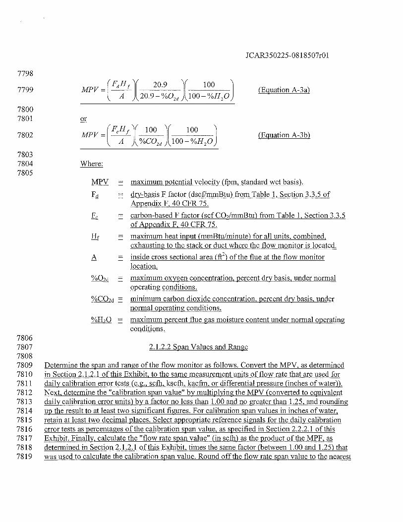
JCAR350225-081 8507r01
7798
(‘FdH Y 209 Y 1007799 MPV = I II II I (Equation A-3a)
A A20•9— %02d ,A\100 — %H2O)
78007801 or
7802 MPV =
100 100(Equation A-3b)
A J%CO2d,A\l00—%H2OJ
78037804 Where:7805
MPV maximum potential velocity (fpm, standard wet basis).
= dry-basis F factor (dscf/mmBtu) from Table 1, Section 3.3.5 ofAppendix F, 40 CFR 75.
F = carbon-based F factor (scfCO2/mmBtu) from Table 1, Section 3.3.5of Appendix F, 40 CFR 75.
Hf maximum heat input (mmBtu/minute) for all units, combined,exhausting to the stack or duct where the flow monitor is located.
A = inside cross sectional area (ft2) of the flue at the flow monitorlocation.
= maximum oxygen concentration, percent dry basis, under normaloperating conditions.
%CO = minimum carbon dioxide concentration, percent dry basis, undernormal operating conditions.
= maximum percent flue gas moisture content under normal operatingconditions.
78067807 2.1.2.2 Span Values and Range78087809 Determine the span and range of the flow monitor as follows. Convert the MPV, as determined7810 in Section 2.1 .2.1 of this Exhibit, to the same measurement units of flow rate that are used for7811 daily calibration error tests (e.g., scth, kscfh, kacfm, or differential pressure (inches of water)).7812 Next, determine the “calibration span value” by multiplying the MPV (converted to equivalent7813 daily calibration error units) by a factor no less than 1.00 and no greater than 1.25, and rounding7814 up the result to at least tvo significant figures. For calibration span values in inches of water,7815 retain at least two decimal places. Select appropriate reference signals for the daily calibration7816 error tests as percentages of the calibration span value, as specified in Section 2.2.2.1 of this7817 Exhibit. Finally, calculate the “flow rate span value” (in scth) as the product of the MPF, as7818 determined in Section 2.1.2.1 of this Exhibit, times the same factor (between 1.00 and 1.25) that7819 was used to calculate the calibration span value. Round off the flow rate span value to the nearest
JCAR350225-081 8507r01
7820 1000 scth. Select the full-scale range of the flow monitor so that it is greater than or equal to the7821 span value and is consistent with Section 2.1 of this Exhibit. Include in the monitoring plan for7822 the unit: calculations of the MPV, MPF, calibration span value, flow rate span value, and full-7823 scale range (expressed both in scth and, if different, in the measurement units of calibration).78247825 2.1.2.3 Adjustment of Span and Range78267827 For each affected unit or common stack, the owner or operator must make a periodic evaluation7828 of the MPV, span, and range values for each flow rate monitor (at a minimum, an annual7829 evaluation is required) and must make any necessary span and range adjustments with7830 corresponding monitoring plan updates, as described in subsections (a) through (c) of this7831 Section 2.1.2.3. Span and range adjustments may be required, for example, as a result of changes7832 in the fuel supply, changes in the stack or ductwork configuration, changes in the manner of7833 operation of the unit, or installation or removal of emission controls. In implementing the7834 provisions in subsections (a) and (b) of this Section 2.1.2.3, note that flow rate data recorded7835 during short-term, non-representative operating conditions (e.g., a trial burn of a different type of7836 fuel) must be excluded from consideration. The owner or operator must keep the results of the7837 most recent span and range evaluation on-site, in a format suitable for inspection. Make each7838 required span or range adjustment no later than 45 days after the end of the quarter in which the7839 need to adjust the span or range is identified.78407841 If the fuel supply, stack or ductwork configuration, operating parameters, or other7842 conditions change such that the maximum potential flow rate changes7843 significantly, adjust the span and range to assure the continued accuracy of the7844 flow monitor. A flsignificantH change in the MPV means that the guidelines of7845 Section 2.1 of this Exhibit can no longer bernet, as determined by either a7846 periodic evaluation by the owner or operator or from the results of an audit by the7847 Agency. The owner or operator should evaluate whether any planned changes in7848 operation of the unit may affect the flow of the unit or stack and should plan any7849 necessary span and range changes needed to account for these changes, so that7850 they are made in as timely a manner as practicable to coordinate with the7851 operational changes. Calculate the adjusted calibration span and flow rate span7852 values using the procedures in Section 2.1.2.2 of this Exhibit.78537854 ! Whenever the full-scale range is exceeded during a quarter, provided that the7855 exceedance is not caused by a monitor out-of-control period, report 200.0 percent7856 of the current full-scale range as the hourly flow rate for each hour of the full7857 scale exceedance. If the range is exceeded, make appropriate adjustments to the7858 flow rate span and range to prevent future full-scale exceedances. Calculate the7859 new calibration span value by converting the new flow rate span value from units7860 of scth to units of daily calibration. A calibration error test must be performed and7861 passed to validate data on the new range.7862
JCAR350225-08 1 8507r01
7863 Whenever changes are made to the MPV, full-scale range, or span value of the7864 flow monitor, as described in subsections (a) and (b) of this Section, record and7865 report (as applicable) the new full-scale range setting, calculations of the flow rate7866 span value, calibration span value, and MPV in an updated monitoring plan for7867 the unit. The monitoring plan update must be made in the quarter in which the7868 changes become effective. Record and report the adjusted calibration span and7869 reference values as parts of the records for the calibration error test required by7870 Exhibit B to this Appendix. Whenever the calibration span value is adjusted, use7871 reference values for the calibration error test that meet the requirements of Section7872 2.2.2.1 of this Exhibit, based on the most recent adjusted calibration span value.7873 Perform a calibration error test according to Section 2.1 .1 of Exhibit B to this7874 Appendix whenever making a change to the flow monitor span or range, unless7875 the range change also triggers a recertification under Section 1.4 of this Appendix.78767877 2.1.3 Mercury Monitors78787879 Determine the appropriate span and range values for each mercury pollutant concentration7880 monitor, so that all expected mercury concentrations can be determined accurately.78817882 2.1.3.1 Maximum Potential Concentration78837884 The maximum potential concentration depends upon the type of coal combusted in the unit. For7885 the initial MPC determination, there are three options:78867887 ]j Use one of the following default values: 9 igJscm for bituminous coal; 107888 1g/scm for sub-bituminous coal; 16 jig/scm for lignite, and 1 pig/scm for7889 waste coal, i.e., anthracite cuim or bituminous gob. If different coals are7890 blended, use the highest MPC for any fuel in the blend; or78917892 ) You may base the MPC on the results of site-specific emission testing7893 using one of the mercury reference methods in Section 1.6 of this7894 Appendix, if the unit does not have add-on mercury emission controls or a7895 flue gas desulfurization system, or if you test upstream of these control7896 devices. A minimum of 3 test runs are required at the normal operating7897 load. Use the highest total mercury concentration obtained in any of the7898 tests as the MPC: or78997900 You may base the MPC on 720 or more hours of historical CEMS data or7901 data from a sorbent trap monitoring system, if the unit does not have add7902 on mercury emission controls or a flue gas desulfurization system (or if7903 the CEMS or sorbent trap system is located upstream of these control7904 devices) and if the mercury CEMS or sorbent trap system has been tested7905 for relative accuracy against one of the mercury reference methods in
JCAR350225-081 8507r01
7906 Section 1.6 of this Appendix and has met a relative accuracy specification7907 of 20.0% or less.79087909 2.1.3.2 Maximum Expected Concentration79107911 For units with FGD systems that significantly reduce mercury emissions (including fluidized bed7912 units that use limestone injection) and for units equipped with add-on mercury emission controls7913 (e.g., carbon injection), determine the maximum expected mercury concentration (MEC) during7914 normal, stable operation of the unit and emission controls. To calculate the MEC, substitute the7915 MPC value from Section 2.1.3.1 of this Exhibit into Equation A-2 in Section 2.1.1.2 of appendix7916 A to 40 CFR 75, incorporated by reference in Section 225.140. For units with add-on mercury7917 emission controls, base the percent removal efficiency on design engineering calculations. For7918 units with FGD systems, use the best available estimate of the mercury removal efficiency of the7919 FGD system.79207921 2.1.3.3 Span and Range Values79227923 For each mercury monitor, determine a high span value, by rounding the MPC7924 value from Section 2.1.3.1 of this Exhibit upward to the next highest multiple of7925 10 jig/scm.79267927 ] For an affected unit equipped with an FGD system or a unit with add-on mercury7928 emission controls, if the MEC value from Section 2.1.3.2 of this Exhibit is less7929 than 20 percent of the high span value from subsection (a) of this Section, and if7930 the high span value is 20 jig/scm or greater, define a second, low span value of 107931 jig/scm.79327933 If only a high span value is required, set the full-scale range of the mercury7934 analyzer to be greater than or equal to the span value.79357936 ç) If two span values are required, you may either:79377938 fl Use two separate (high and low) measurement scales, setting the range of7939 each scale to be greater than or equal to the high or low span value, as7940 appropriate; or79417942 ) Quality-assure two segments of a single measurement scale.79437944 2.1.3.4 Adjustment of Span and Range79457946 For each affected unit or common stack, the owner or operator must make a periodic evaluation7947 of the MPC, MEC, span, and range values for each mercury monitor (at a minimum, an annual7948 evaluation is required) and must make any necessary span and range adjustments, with
JCAR350225-081 8507r01
7949 corresponding monitoring plan updates. Span and range adjustments may be required, for7950 example, as a result of changes in the fuel supply, changes in the manner of operation of the unit,7951 or installation or removal of emission controls. In implementing the provisions in subsections (a)7952 and (b) of this Section, data recorded during short-term, non-representative process operating7953 conditions (e.g., a trial burn of a different type of fuel) must be excluded from consideration. The7954 owner or operator must keep the results of the most recent span and range evaluation on-site, in a7955 format suitable for inspection. Make each required span or range adjustment no later than 457956 days after the end of the quarter in which the need to adjust the span or range is identified, except7957 that up to 90 days after the end of that quarter may be taken to implement a span adjustment if7958 the calibration gas concentrations currently being used for calibration error tests, system integrity7959 checks, and linearity checks are unsuitable for use with the new span value and new calibration7960 materials must be ordered.79617962 The guidelines of Section 2.1 of this Exhibit do not apply to mercury monitoring7963 systems.79647965 ) Whenever a full-scale range exceedance occurs during a quarter and is not caused7966 by a monitor out-of-control period, proceed as follows:79677968 L For monitors with a single measurement scale, report that the system was7969 out of range and invalid data was obtained until the readings come back7970 on-scale and, if appropriate, make adjustments to the MPC, span, and7971 range to prevent future full-scale exceedances; or79727973 For units with two separate measurement scales, if the low range is7974 exceeded, no further action is required, provided that the high range is7975 available and is not out-of-control or out-of-service for any reason.7976 However, if the high range is not able to provide quality assured data at7977 the time of the low range exceedance or at any time during the7978 continuation of the exceedance, report that the system was out-of-control7979 until the readings return to the low range or until the high range is able to7980 provide quality assured data (unless the reason that the high-scale range is7981 not able to provide quality assured data is because the high-scale range has7982 been exceeded; if the high-scale range is exceeded follow the procedures7983 in subsection (b)(1) of this Section).79847985 Whenever changes are made to the MPC, MEC, full-scale range, or span value of7986 the mercury monitor, record and report (as applicable) the new full-scale range7987 setting, the new MPC or MEC and calculations of the adjusted span value in an7988 updated monitoring plan. The monitoring plan update must be made in the quarter7989 in which the changes become effective. In addition, record and report the adjusted7990 span as part of the records for the daily calibration error test and linearity check7991 specified by Exhibit B to this Appendix. Whenever the span value is adjusted, use
JCAR350225-081 8507r01
7992 calibration gas concentrations that meet the requirements of Section 5.1 of this7993 Exhibit, based on the adjusted span value. When a span adjustment is so7994 significant that the calibration gas concentrations currently being used for7995 calibration error tests, system integrity checks and linearity checks are unsuitable7996 for use with the new span value, then a diagnostic linearity or 3-level system7997 integrity check using the new calibration gas concentrations must be performed7998 and passed. Use the data validation procedures in Section 1 .4(b)(3) of this7999 Appendix, beginning with the hour in which the span is changed.80008001 2.2 Design for Quality Control Testing80028003 2.2.1 Pollutant Concentration andQ2or 02 Monitors80048005 Design and equip each pollutant concentration and CO2 or 02 monitor with a8006 calibration gas injection port that allows a check of the entire measurement8007 system when calibration gases are introduced. For extractive and dilution type8008 monitors, all monitoring components exposed to the sample gas, (e.g., sample8009 lines, filters, scrubbers, conditioners, and as much of the probe as practicable) are8010 included in the measurement system. For in-situ type monitors, the calibration8011 must check against the injected gas for the performance of all active electronic8012 and optical components (e.g., transmitter, receiver, analyzer).80138014 ]) Design and equip each pollutant concentration or CO2 or 02 monitor to allow8015 daily determinations of calibration error (positive or negative) at the zero- and8016 mid- or high-level concentrations specified in Section 5.2 of this Exhibit.80178018 2.2.2 Flow Monitors80198020 Design all flow monitors to meet the applicable performance specifications.80218022 2.2.2.1 Calibration Error Test80238024 Design and equip each flow monitor to allow for a daily calibration error test consisting of at8025 least two reference values: Zero to 20 percent of span or an equivalent reference value (e.g.,8026 pressure pulse or electronic signal) and 50 to 70 percent of span. Flow monitor response, both8027 before and afler any adjustment, must be capable of being recorded by the data acquisition and8028 handling system. Design each flow monitor to allow a daily calibration error test of the entire8029 flow monitoring system, from and including the probe tip (or equivalent) through and including8030 the data acquisition and handling system, or the flow monitoring system from and including the8031 transducer through and including the data acquisition and handling system.80328033 2.2.2.2 Interference Check8034
JCAR350225-08 1 8507r01
8035 Design and equip each flow monitor with a means to ensure that the moisture8036 expected to occur at the monitoring location does not interfere with the proper8037 functioning of the flow monitoring system. Design and equip each flow monitor8038 with a means to detect, on at least a daily basis, pluggage of each sample line and8039 sensing port, and malfunction of each resistance temperature detector (RTD),8040 transceiver or equivalent.80418042 ]) Design and equip each differential pressure flow monitor to provide an automatic,8043 periodic back purging (simultaneously on both sides of the probe) or equivalent8044 method of sufficient force and frequency to keep the probe and lines sufficiently8045 free of obstructions on at least a daily basis to prevent velocity sensing8046 interference, and a means for detecting leaks in the system on at least a quarterly8047 basis (manual check is acceptable).80488049 c Design and equip each thermal flow monitor with a means to ensure on at least a8050 daily basis that the probe remains sufficiently clean to prevent velocity sensing8051 interference.80528053 ci) Design and equip each ultrasonic flow monitor with a means to ensure on at least8054 a daily basis that the transceivers remain sufficiently clean (e.g., back purging8055 system) to prevent velocity sensing interference.80568057 2.2.3 Mercury Monitors80588059 Design and equip each mercury monitor to permit the introduction of known concentrations of8060 elemental mercury and HgC12 separately, at a point immediately preceding the sample extraction8061 filtration system, such that the entire measurement system can be checked. If the mercury8062 monitor does not have a converter, the HgCl2 injection capability is not required.80638064 3. Performance Specifications80658066 3.1 Calibration Error80678068 The calibration error performance specifications in this Section apply only to 7-8069 day calibration error tests under Sections 6.3.1 and 6.3.2 of this Exhibit and to the8070 offline calibration demonstration described in Section 2.1 .1.2 of Exhibit B to this8071 Appendix. The calibration error limits for daily operation of the continuous8072 monitoring systems required under this part are found in Section 2.1.4(a) of8073 Exhibit B to this Appendix.80748075 j) The calibration error of a mercury concentration monitor must not deviate from8076 the reference value of either the zero or upscale calibration gas by more than 5.08077 percent of the span value, as calculated using Equation A-S of this Exhibit.
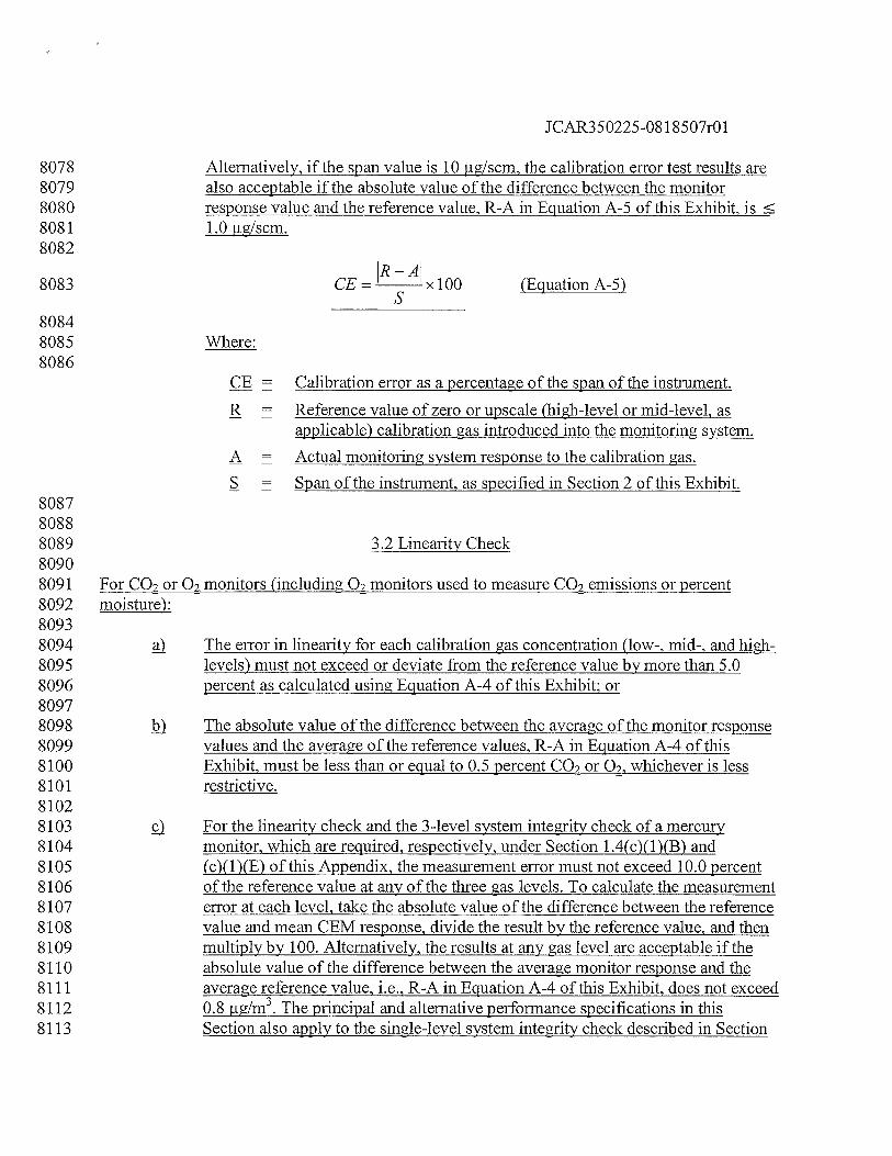
JCAR350225-08 1 8507r01
8078 Alternatively, if the span value is 10 fig/scm, the calibration error test results are8079 also acceptable if the absolute value of the difference between the monitor8080 response value and the reference value, R-A in Equation A-5 of this Exhibit, is8081 1.0 rig/scm.8082
8083 CE = x 100 (Equation A-5)
80848085 Where:8086
CE = Calibration error as a percentage of the span of the instrument.
R = Reference value of zero or upscale (high-level or mid-level, asapplicable) calibration gas introduced into the monitoring system.
A = Actual monitoring system response to the calibration gas.
S Span of the instrument, as specified in Section 2 of this Exhibit.808780888089 3.2 Linearity Check80908091 For CO2 or 02 monitors (including 02 monitors used to measure CO2 emissions or percent8092 moisture):80938094 The error in linearity for each calibration gas concentration (low-, mid-, and high-8095 levels) must not exceed or deviate from the reference value by more than 5.08096 percent as calculated using Equation A-4 of this Exhibit or80978098 The absolute value of the difference between the average of the monitor response8099 values and the average of the reference values, R-A in Equation A-4 of this8100 Exhibit, must be less than or equal to 0.5 percent CO2 or 02, whichever is less8101 restrictive.81028103 ç) For the linearity check and the 3-level system integrity check of a mercury8104 monitor, which are required, respectively, under Section 1 .4(c)( 1 )(B) and8105 (c)(1)(E) of this Appendix, the measurement error must not exceed 10.0 percent8106 of the reference value at any of the three gas levels. To calculate the measurement8107 error at each level, take the absolute value of the difference between the reference8108 value and mean CEM response, divide the result by the reference value, and then8109 multiply by 100. Alternatively, the results at any gas level are acceptable if the8110 absolute value of the difference between the average monitor response and the8111 average reference value, i.e., R-A in Equation A-4 of this Exhibit, does not exceed8112 0.8 .igJm3.The principal and alternative performance specifications in this8113 Section also apply to the single-level system integrity check described in Section
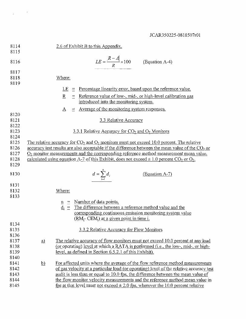
JCAR350225-08 1 8507r01
8114 2.6 of Exhibit B to this Appendix.8115
8116 LE=R
xlOO (EguationA-4)
81178118 Where:8119
LE = Percentage linearity error, based upon the reference value.
R = Reference value of low-, mid-, or high-level calibration gasintroduced into the monitoring system.
A Average of the monitoring system responses.81208121 3.3 Relative Accuracy81228123 3.3.1 Relative Accuracy for CO2 and 02 Monitors81248125 The relative accuracy for CO2 and 02 monitors must not exceed 10.0 percent. The relative8126 accuracy test results are also acceptable if the difference between the mean value of the CO2 or8127 Q2 monitor measurements and the corresponding reference method measurement mean value,8128 calculated using equation A-7 of this Exhibit, does not exceed ± 1.0 percent CO2 or 02.8129
8130 d = (Equation A-7)
81318132 Where:8133
n = Number of data points.The difference between a reference method value and thecorresponding continuous emission monitoring system value
CEM1)at a given point in time i.81348135 3.3.2 Relative Accuracy for Flow Monitors81368137 The relative accuracy of flow monitors must not exceed 10.0 percent at any load8138 (or operating) level at which a RATA is performed (i.e., the low-, mid-, or high-8139 level, as defined in Section 6.5.2.1 of this Exhibit).81408141 i) For affected units where the average of the flow reference method measurements8142 of gas velocity at a particular load (or operating) level of the relative accuracy test8143 audit is less than or equal to 10.0 fps, the difference between the mean value of8144 the flow monitor velocity measurements and the reference method mean value in8145 fps at that level must not exceed ± 2.0 fps, wherever the 10.0 percent relative
JCAR350225-08 1 8507r01
8146 accuracy specification is not achieved.81478148 3.3.3 Relative Accuracy for Moisture Monitoring Systems81498150 The relative accuracy of a moisture monitoring system must not exceed 10.0 percent. The8151 relative accuracy test results are also acceptable if the difference between the mean value of the8152 reference method measurements (in percent H20) and the corresponding mean value of the8153 moisture monitoring system measurements (in percent H20), calculated using Equation A-7 of8154 this Exhibit does not exceed ± 1.5 percent H20.81558156 3.3.4 Relative Accuracy for Mercury Monitoring Systems81578158 The relative accuracy of a mercury concentration monitoring system or a sorbent trap monitoring8159 system must not exceed 20.0 percent. Alternatively, for affected units where the average of the8160 reference method measurements of mercury concentration during the relative accuracy test audit8161 is less than 5.0 jig/scm, the test results are acceptable if the difference between the mean value of8162 the monitor measurements and the reference method mean value does not exceed 1.0 jig/scm, in8163 cases where the relative accuracy specification of 20.0 percent is not achieved.81648165 3.4 Bias81668167 3.4.1 Flow Monitors81688169 Flow monitors must not be biased low as determined by the test procedure in Section 7.4 of this8170 Exhibit. The bias specification applies to all flow monitors including those measuring an average8171 gas velocity of 10.0 fps or less.81728173 3.4.2 Mercury Monitoring Systems81748175 Mercury concentration monitoring systems and sorbent trap monitoring systems must not be8176 biased low as determined by the test procedure in Section 7.4 of this Exhibit.81778178 3.5 Cycle Time81798180 The cycle time for mercury concentration monitors, oxygen monitors used to determine percent8181 moisture, and any other monitoring component of a continuous emission monitoring system that8182 is required to perform a cycle time test must not exceed 15 minutes.81838184 4. Data Acquisition and Handling Systems81858186 Automated data acquisition and handling systems must read and record the full range ofpollutant8187 concentrations and volumetric flow from zero through span and provide a continuous, permanent8188 record of all measurements and required information as an ASCII flat file capable of
JCAR350225-08 1 8507r01
8189 transmission both by direct computer-to-computer electronic transfer via modem and EPA-8190 provided software and by an IBM-compatible personal computer diskette. These systems also8191 must have the capability of interpreting and converting the individual output signals from a flow8192 monitor, a CO2 monitor, an 02 monitor, a moisture monitoring system, a mercury concentration8193 monitoring system, and a sorbent trap monitoring system, to produce a continuous readout of8194 pollutant emission rates or pollutant mass emissions (as applicable) in the appropriate units (çg8195 lb/hr. lb/mmBtu, ounces/hr, tons/hr). These systems also must have the capability of interpreting8196 and converting the individual output signals from a flow monitor to produce a continuous8197 readout of pollutant mass emission rates in the units of the standard. Where CO2 emissions are8198 measured with a continuous emission monitoring system, the data acquisition and handling8199 system must also produce a readout of CO2 mass emissions in tons.82008201 Data acquisition and handling systems must also compute and record monitor calibration error,8202 any bias adjustments to mercury pollutant concentration data, flow rate data, or mercury emission8203 rate data.82048205 5. Calibration Gas82068207 5.1 Reference Gases82088209 For the purposes of this Appendix, calibration gases include the following:82108211 5.1.1 Standard Reference Materials (SRM)82128213 These calibration gases may be obtained from the National Institute of Standards and8214 Technology (NIST) at the following address: Quince Orchard and Cloppers Road, Gaithersburg,8215 MD 20899-0001.82168217 5.1.2 SRM-Equivalent Compressed Gas Primary Reference Material (PRM)82188219 Contact the Gas Metrology Team, Analytical Chemistry Division, Chemical Science and8220 Technology Laboratory of NIST, at the address in Section 5.1.1, for a list of vendors and8221 cylinder gases.82228223 5.1.3 NIST Traceable Reference Materials82248225 Contact the Gas Metrology Team, Analytical Chemistry Division, Chemical Science and8226 Technology Laboratory of NIST, at the address in Section 5.1.1, for a list of vendors and8227 cylinder gases that meet the definition for a NIST Traceable Reference Material (NTRM)8228 provided in 40 CFR 72.2, incorporated by reference in Section 225.140.82298230 5.1.4 EPA Protocol Gases8231
JCAR350225-08 1 8507r01
8232 An EPA Protocol Gas is a calibration gas mixture prepared and analyzed8233 according to Section 2 of the “EPA Traceability Protocol for Assay and8234 Certification of Gaseous Calibration Standards”, September 1997, EPA-600/R-8235 97/121 or such revised procedure as approved by the Administrator (EPA8236 Traceability Protocol).82378238 An EPA Protocol Gas must have a specialty gas producer-certified uncertainty8239 (95 percent confidence interval) that must not be greater than 2.0 percent of the8240 certified concentration (tag value) of the gas mixture. The uncertainty must be8241 calculated using the statistical procedures (or equivalent statistical techniques)8242 that are listed in Section 2.1.8 of the EPA Traceability Protocol.82438244 ci A copy ofEPA-600/R-97/121 is available from the National Technical8245 Information Service, 5285 Port Royal Road, Springfield VA, 703-605-6585 or8246 http ://www.ntis. gov, and from http ://www. epa. gov/ttnlemc/news.html or http ://8247 www.epa. gov/appcdwww/tsb/index.html.82488249 5.1.5 Research Gas Mixtures82508251 Research gas mixtures must be vendor-certified to be within 2.0 percent of the concentration8252 specified on the cylinder label (tag value), using the uncertainty calculation procedure in Section8253 2.1.8 of the “EPA Traceability Protocol for Assay and Certification of Gaseous Calibration8254 Standards”, September 1997, EPA-600/R-97/121. Inquiries about the RGM program should be8255 directed to: National Institute of Standards and Technology, Analytical Chemistry Division,8256 Chemical Science and Technology Laboratory, B-324 Chemistry, Gaithersburg MD 20899.82578258 5.1.6 Zero Air Material82598260 Zero air material is defined in 40 CFR 72.2, incorporated by reference in Section 225.140.82618262 5.1.7 NIST/EPA-Approved Certified Reference Materials82638264 Existing certified reference materials (CRMs) that are still within their certification period may8265 be used as calibration gas.82668267 5.1.8 Gas Manufacturer’s Intermediate Standards82688269 Gas manufacturer’s intermediate standards is defined in 40 CFR 72.2, incorporated by reference8270 in Section 225.140.82718272 5.1.9 Mercury Standards82738274 For 7-day calibration error tests of mercury concentration monitors and for daily calibration error
JCAR350225-08 1 8507r01
8275 tests of mercury monitors, either NIST-traceable elemental mercury standards (as defined in8276 Section 225.130) or a NIST-traceable source of oxidized mercury (as defined in Section8277 225.130) maybe used. For linearity checks, NIST-traceable elemental mercury standards must8278 be used. For 3-level and single-point system integrity checks under Section l.4(c)(l)(E) of this8279 Appendix, Sections 6.2(g) and 6.3.1 of this Exhibit, and Sections 2.1.1, 2.2.1 and 2.6 of Exhibit8280 B to this Appendix, a NIST-traceable source of oxidized mercury must be used. Alternatively,8281 other NIST-traceable standards may be used for the required checks, subject to the approval of8282 the Agency. Notwithstanding these requirements, mercury calibration standards that are not8283 NIST-traceable may be used for the tests described in this Section until December 31, 2009.8284 However, on and after January 1, 2010, only NIST-traceable calibration standards must be used8285 for these tests.82868287 5.2 Concentrations82888289 Four concentration levels are required as follows.82908291 5.2.1 Zero-level Concentration82928293 0.0 to 20.0 percent of span, including span for high-scale or both low- and high-scale for CO28294 and 02 monitors, as appropriate.82958296 5.2.2 Low-level Concentration82978298 20.0 to 30.0 percent of span, including span for high-scale or both low- and high-scale for CO28299 and 02 monitors, as appropriate.83008301 5.2.3 Mid-level Concentration83028303 50.0 to 60.0 percent of span, including span for high-scale or both low- and high-scale for CO28304 and 02 monitors, as appropriate.83058306 5.2.4 High-level Concentration83078308 80.0 to 100.0 percent of span, including span for high-scale or both low-and high-scale for CO28309 andQ2monitors, as appropriate.83108311 6. Certification Tests and Procedures83128313 6.1 General Requirements83148315 6.1.1 Pretest Preparation83168317 Install the components of the continuous emission monitoring system (i.e., pollutant
JCAR350225-08 1 8507r01
8318 concentration monitors, CO2 or 02 monitor, and flow monitor) as specified in Sections 1, 2, and8319 3 of this Exhibit, and prepare each system component and the combined system for operation in8320 accordance with the manufacturer’s written instructions. Operate the units during each period8321 when measurements are made. Units may be tested on non-consecutive days. To the extent8322 practicable, test the DAHS software prior to testing the monitoring hardware.83238324 6.1.2 Requirements for Air Emission Testing Bodies83258326 On and after January 1, 2009, any Air Emission Testing Body (AETB) conducting8327 relative accuracy test audits of CEMS and sorbent trap monitoring systems under8328 Part 225, Subpart B, must conform to the requirements of ASTM D7036-048329 (incorporated by reference in Section 225.140). This Section is not applicable to8330 daily operation, daily calibration error checks, daily flow interference checks,8331 quarterly linearity checks or routine maintenance of CEMS.83328333 j2) The AETB must provide to the affected sources certification that the AETB8334 operates in conformance with, and that data submitted to the Agency has been8335 collected in accordance with, the requirements of ASTM D7036-04 (incorporated8336 by reference in Section 225.140). This certification may be provided in the form8337 ofi83388339 jj A certificate of accreditation of relevant scope issued by a recognized,8340 national accreditation body; or83418342 A letter of certification signed by a member of the senior management8343 staff of the AETB.83448345 c The AETB must either provide a Qualified Individual on-site to conduct or must8346 oversee all relative accuracy testing carried out by the AETB as required in8347 ASTM D7036-04 (incorporated by reference in Section 225.140). The Oualified8348 Individual must provide the affected sources with copies of the qualification8349 credentials relevant to the scope of the testing conducted.83508351 6.2 Linearity Check (General Procedures)83528353 Check the linearity of each CO2.Hg, and 02 monitor while the unit, or group of units for a8354 common stack, is combusting fuel at conditions of typical stack temperature and pressure; it is8355 not necessary for the unit to be generating electricity during this test. For units with two8356 measurement ranges (high and low) for a particular parameter, perform a linearity check on both8357 the low scale and the high scale. For on-going quality assurance of the CEMS, perform linearity8358 checks, using the procedures in this Section, on the ranges and at the frequency specified in8359 Section 2.2.1 of Exhibit B to this Appendix. Challenge each monitor with calibration gas, as8360 defined in Section 5.1 of this Exhibit, at the low-, mid-, and high-range concentrations specified
JCAR350225-08 1 8507r01
8361 in Section 5.2 of this Exhibit. Introduce the calibration gas at the gas injection port, as specified8362 in Section 2.2.1 of this Exhibit. Operate each monitor at its normal operating temperature and8363 conditions. For extractive and dilution te monitors, pass the calibration gas through all filters,8364 scrubbers, conditioners, and other monitor components used during normal sampling and8365 through as much of the sampling probe as is practical. For in-situ te monitors, perform8366 calibration checking all active electronic and optical components, including the transmitter,8367 receiver, and analyzer. Challenge the monitor three times with each reference gas (see example8368 data sheet in Figure 1). Do not use the same gas twice in succession. To the extent practicable,8369 the duration of each linearity test, from the hour of the first injection to the hour of the last8370 injection, must not exceed 24 unit operating hours. Record the monitor response from the data8371 acquisition and handling system. For each concentration, use the average of the responses to8372 determine the error in linearity using Equation A-4 in this Exhibit. Linearity checks are8373 acceptable for monitor or monitoring system certification, recertification, or quality assurance if8374 none of the test results exceed the applicable performance specifications in Section 3.2 of this8375 Exhibit. The status of emission data from a CEMS prior to and during a linearity test period must8376 be determined as follows:83778378 For the initial certification of a CEMS, data from the monitoring system are8379 considered invalid until all certification tests, including the linearity test, have8380 been successfully completed, unless the conditional data validation procedures in8381 Section 1.4(b)(3) of this Appendix are used. When the procedures in Section8382 1 .4(b)(3) of this Appendix are followed, the words ‘initia1 certification’ apply8383 instead of11recertification”, and complete all of the initial certification tests by8384 January 1, 2009, rather than within the time periods specified in Section8385 1.4(b)(3)(D) of this Appendix for the individual tests.83868387 For the routine quality assurance linearity checks required by Section 2.2.1 of8388 Exhibit B to this Appendix, use the data validation procedures in Section 2.2.3 of8389 Exhibit B to this Appendix.83908391 When a linearity test is required as a diagnostic test or for recertification, use the8392 data validation procedures in Section 1.4 (b)(3) of this Appendix.83938394 For linearity tests of non-redundant backup monitoring systems, use the data8395 validation procedures in Section 1 .4(d)(2)(C) of this Appendix.83968397 For linearity tests performed during a grace period and after the expiration of a8398 grace period, use the data validation procedures in Sections 2.2.3 and 2.2.4,8399 respectively, of Exhibit B to this Appendix.84008401 For all other linearity checks, use the data validation procedures in Section 2.2.38402 of Exhibit B to this Appendix.8403
JCAR350225-08 1 8507r01
8404 g) For mercury monitors, follow the guidelines in Section 2.2.3 of this Exhibit in8405 addition to the applicable procedures in Section 6.2 when performing the system8406 integrity checks described in Section 1.4(c)(1)(E) and in Sections 2.1.1, 2.2.1, and8407 2.6 of Exhibit B to this Appendix.84088409 For mercury concentration monitors, if moisture is added to the calibration gas8410 during the required linearity checks or system integrity checks, the moisture8411 content of the calibration gas must be accounted for. Under these circumstances,8412 the dry basis concentration of the calibration gas must be used to calculate the8413 linearity error or measurement error (as applicable).84148415 6.3 7-Day Calibration Error Test84168417 6.3.1 Gas Monitor 7-day Calibration Error Test84188419 Measure the calibration error of each mercury concentration monitor and each CO2 or 028420 monitor while the unit is combusting fuel (but not necessarily generating electricity) once each8421 day for 7 consecutive operating days according to the following procedures. For mercury8422 monitors, you may perform this test using either elemental mercury standards or a NIST8423 traceable source of oxidized mercury. Also for mercury monitors, if moisture is added to the8424 calibration gas, the added moisture must be accounted for and the dry-basis concentration of the8425 calibration gas must be used to calculate the calibration error. (In the event that unit outages8426 occur after the commencement of the test, the 7 consecutive unit operating days need not be 78427 consecutive calendar days.) Units using dual span monitors must perform the calibration error8428 test on both high- and low-scales of the pollutant concentration monitor. The calibration error8429 test procedures in this Section and in Section 6.3.2 of this Exhibit must also be used to perform8430 the daily assessments and additional calibration error tests required under Sections 2.1.1 and8431 2.1.3 of Exhibit B to this Appendix. Do not make manual or automatic adjustments to the8432 monitor settings until after taking measurements at both zero and high concentration levels for8433 that day during the 7-day test. If automatic adjustments are made following both injections,8434 conduct the calibration error test such that the magnitude of the adjustments can be determined8435 and recorded. Record and report test results for each day using the unadjusted concentration8436 measured in the calibration error test prior to making any manual or automatic adjustments (i.e.,8437 resetting the calibration). The calibration error tests should be approximately 24 hours apart,8438 (unless the 7-day test is performed over non-consecutive days). Perform calibration error tests at8439 both the zero-level concentration and high-level concentration, as specified in Section 5.2 of this8440 Exhibit. Alternatively, a mid-level concentration gas (50.0 to 60.0 percent of the span value) may8441 be used in lieu of the high-level gas, provided that the mid-level gas is more representative of the8442 actual stack gas concentrations. Use only calibration gas, as specified in Section 5.1 of this8443 Exhibit. Introduce the calibration gas at the gas injection port, as specified in Section 2.2.1 of this8444 Exhibit. Operate each monitor in its normal sampling mode. For extractive and dilution type8445 monitors, pass the calibration gas through all filters, scrubbers, conditioners, and other monitor8446 components used during normal sampling and through as much of the sampling probe as is
JCAR350225-081 8507r01
8447 practical. For in-situ type monitors, perform calibration, checking all active electronic and8448 optical components, including the transmitter, receiver, and analyzer. Challenge the pollutant8449 concentration monitors and CO2 or 02 monitors once with each calibration gas. Record the8450 monitor response from the data acquisition and handling system. Using Equation A-5 of this8451 Exhibit, determine the calibration error at each concentration once each day (at approximately8452 24-hour intervals) for 7 consecutive days according to the procedures given in this Section. The8453 results of a 7-day calibration error test are acceptable for monitor or monitoring system8454 certification, recertification or diagnostic testing if none of these daily calibration error test8455 results exceed the applicable performance specifications in Section 3.1 of this Exhibit. The status8456 of emission data from a gas monitor prior to and during a 7-day calibration error test period must8457 be determined as follows:84588459 For initial certification, data from the monitor are considered invalid until all8460 certification tests, including the 7-day calibration error test, have been8461 successfully completed, unless the conditional data validation procedures in8462 Section 1.4(b)(3) of this Appendix are used. When the procedures in Section8463 1.4(b)(3) of this Appendix are followed, the words “initial certification” apply8464 instead of “recertification”, and complete all of the initial certification tests by8465 January 1, 2009, rather than within the time periods specified in Section8466 1 .4(b)(3)(D) of this Appendix for the individual tests.84678468 When a 7-day calibration error test is required as a diagnostic test or for8469 recertification, use the data validation procedures in Section 1 .4(b)(3) of this8470 Appendix.84718472 6.3.2 Flow Monitor 7-day Calibration Error Test84738474 Flow monitors installed on peaking units (as defined in 40 CFR 72.2, incorporated by reference8475 in Section 225.140) are exempted from the 7-day calibration error test requirements of this part.8476 In all other cases, perform the 7-day calibration error test of a flow monitor, when required for8477 certification, recertification or diagnostic testing, according to the following procedures.8478 Introduce the reference signal corresponding to the values specified in Section 2.2.2.1 of this8479 Exhibit to the probe tip (or equivalent), or to the transducer. During the 7-day certification test8480 period, conduct the calibration error test while the unit is operating once each unit operating day8481 (as close to 24-hour intervals as practicable). In the event that unit outages occur after the8482 commencement of the test, the 7 consecutive operating days need not be 7 consecutive calendar8483 days. Record the flow monitor responses by means of the data acquisition and handling system.8484 Calculate the calibration error using Equation A-6 of this Exhibit. Do not perform any corrective8485 maintenance, repair, or replacement upon the flow monitor during the 7-day test period other8486 than that required in the quality assurance/quality control plan required by Exhibit B to this8487 Appendix. Do not make adjustments between the zero and high reference level measurements on8488 any day during the 7-day test. If the flow monitor operates within the calibration error8489 performance specification (i.e., less than or equal to 3.0 percent error each day and requiring no
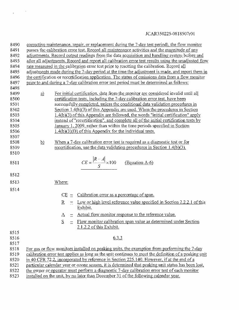
JCAR350225-081 8507r01
8490 corrective maintenance, repair, or replacement during the 7-day test period), the flow monitor8491 passes the calibration error test. Record all maintenance activities and the magnitude of any8492 adjustments. Record output readings from the data acquisition and handling system before and8493 after all adjustments. Record and report all calibration error test results using the unadjusted flow8494 rate measured in the calibration error test prior to resetting the calibration. Record all8495 adjustments made during the 7-day period at the time the adjustment is made, and report them in8496 the certification or recertification application. The status of emissions data from a flow monitor8497 prior to and during a 7-day calibration error test period must be determined as follows:84988499 For initial certification, data from the monitor are considered invalid until all8500 certification tests, including the 7-day calibration error test, have been8501 successfully completed, unless the conditional data validation procedures in8502 Section 1.4(b)(3) of this Appendix are used. When the procedures in Section8503 1 .4(b)(3) of this Appendix are followed, the words “initial certification” apply8504 instead of “recertification”, and complete all of the initial certification tests by8505 January 1, 2009, rather than within the time periods specified in Section8506 1 .4(b)(3)(D) of this Appendix for the individual tests.85078508 When a 7-day calibration error test is required as a diagnostic test or for8509 recertification, use the data validation procedures in Section 1 .4(b)(3).8510
8511 CE= xlOO (EquationA-6)
8512
8513 Where:
8514Calibration error as a percentage of span.
R = Low or high level reference value specified in Section 2.2.2.1 of thisExhibit.
A = Actual flow monitor response to the reference value.
S = Flow monitor calibration span value as determined under Section2.1.2.2 of this Exhibit.
85158516 6.3.385178518 For gas or flow monitors installed on peaking units, the exemption from performing the 7-day8519 calibration error test applies as long as the unit continues to meet the definition of a peaking unit8520 in 40 CFR 72.2, incorporated by reference in Section 225.140. However, if at the end of a8521 particular calendar year or ozone season, it is determined that peaking unit status has been lost,8522 the owner or operator must perform a diagnostic 7-day calibration error test of each monitor8523 installed on the unit, by no later than December 31 of the following calendar year.
JCAR350225-08 1 8507r01
85248525 6.4 Cycle Time Test85268527 Perform cycle time tests for each pollutant concentration monitor and continuous emission8528 monitoring system while the unit is operating, according to the following procedures. Use a zero-8529 level and a high-level calibration gas (as defined in Section 5.2 of this Exhibit) alternately. For8530 mercury monitors, the calibration gas used for this test may either be the elemental or oxidized8531 form of mercury. To determine the downscale cycle time, measure the concentration of the flue8532 gas emissions until the response stabilizes. Record the stable emissions value. Inject a zero-level8533 concentration calibration gas into the probe tip (or injection port leading to the calibration cell,8534 for in-situ systems with no probe). Record the time of the zero gas injection, using the data8535 acquisition and handling system (DAHS). Next, allow the monitor to measure the concentration8536 of the zero gas until the response stabilizes. Record the stable ending calibration gas reading.8537 Determine the downscale cycle time as the time it takes for 95.0 percent of the step change to be8538 achieved between the stable stack emissions value and the stable ending zero gas reading. Then8539 repeat the procedure, starting with stable stack emissions and injecting the high-level gas, to8540 determine the upscale cycle time, which is the time it takes for 95.0 percent of the step change to8541 be achieved between the stable stack emissions value and the stable ending high-level gas8542 reading. Use the following criteria to assess when a stable reading of stack emissions or8543 calibration gas concentration has been attained. A stable value is equivalent to a reading with a8544 change of less than 2.0 percent of the span value for 2 minutes, or a reading with a change of less8545 than 6.0 percent from the measured average concentration over 6 minutes. Alternatively, the8546 reading is considered stable if it changes by no more than 0.5 ppm, 0.5 ig/m3 (for mercury) for8547 two minutes. (Owners or operators of systems that do not record data in 1-minute or 3-minute8548 intervals may petition the Agency for alternative stabilization criteria). For monitors or8549 monitoring systems that perform a series of operations (such as purge, sample, and analyze),8550 time the injections of the calibration gases so they will produce the longest possible cycle time.8551 Refer to Figures 6a and 6b in this Exhibit for example calculations of upscale and downscale8552 cycle times. Report the slower of the two cycle times (upscale or downscale) as the cycle time8553 for the analyzer. On and after January 1, 2009, record the cycle time for each component8554 analyzer separately. For time-shared systems, perform the cycle time tests at each of the probe8555 locations that will be polled within the same 15-minute period during monitoring system8556 operations. To determine the cycle time for time-shared systems, at each monitoring location,8557 report the sum of the cycle time observed at that monitoring location plus the sum of the time8558 required for all purge cycles (as determined by the continuous emission monitoring system8559 manufacturer) at each of the probe locations of the time-shared systems. For monitors with dual8560 ranges, report the test results for each range separately. Cycle time test results are acceptable for8561 monitor or monitoring system certification, recertification or diagnostic testing if none of the8562 cycle times exceed 15 minutes. The status of emissions data from a monitor prior to and during a8563 cycle time test period must be determined as follows:85648565 For initial certification, data from the monitor are considered invalid until all8566 certification tests, including the cycle time test, have been successfully completed,
JCAR350225-08 1 8507r01
8567 unless the conditional data validation procedures in Section 1 .4(b)(3) of this8568 Appendix are used. When the procedures in Section 1.4(b)(3) of this Appendix8569 are followed, the words “initial certification” apply instead of “recertification”,8570 and complete all of the initial certification tests by January 1, 2009, rather than8571 within the time periods specified in Section 1.4(b)(3)(D) of this Appendix for the8572 individual tests.85738574 j) When a cycle time test is required as a diagnostic test or for recertification, use8575 the data validation procedures in Section 1 .4(b)(3) of this Appendix.85768577 6.5 Relative Accuracy and Bias Tests (General Procedures)85788579 Perform the required relative accuracy test audits (RATAs) as follows for each flow monitor,8580 each 02 or C0 diluent monitor used to calculate heat input, each mercury concentration8581 monitoring system, each sorbent trap monitoring system, and each moisture monitoring system.85828583 Except as otherwise provided in this subsection, perform each RATA while the8584 unit (or units, if more than one unit exhausts into the flue) is combusting the fuel8585 that is a normal primary or backup fuel for that unit (for some units, more than8586 one type of fuel may be considered normal, e.g., a unit that combusts gas or oil on8587 a seasonal basis). For units that co-fire fuels as the predominant mode of8588 operation, perform the RATAs while co-firing. For mercury monitoring systems,8589 perform the RATAs while the unit is combusting coal. When relative accuracy8590 test audits are performed on CEMS installed on bypass stacks/ducts, use the fuel8591 normally combusted by the unit (or units, if more than one unit exhausts into the8592 flue) when emissions exhaust through the bypass stack/ducts.85938594 Perform each RATA at the load (or operating) levels specified in Section 6.5.1 or8595 6.5.2 of this Exhibit or in Section 2.3.1.3 of Exhibit B to this Appendix, as8596 applicable.85978598 ç For monitoring systems with dual ranges, perform the relative accuracy test on the8599 range normally used for measuring emissions. For units with add-on mercury8600 controls that operate continuously rather than seasonally, or for units that need a8601 dual range to record high concentration “spikes” during startup conditions, the8602 low range is considered normal. However, for some dual span units (e.g., for units8603 that use fuel switching or for which the emission controls are operated8604 seasonally), provided that both monitor ranges are connected to a common probe8605 and sample interface, either of the two measurement ranges may be considered8606 normal; in such cases, perform the RATA on the range that is in use at the time of8607 the scheduled test. If the low and high measurement ranges are connected to8608 separate sample probes and interfaces, RATA testing on both ranges is required.8609
JCAR350225-08 1 8507r01
8610 ) Record monitor or monitoring system output from the data acquisition and8611 handling system.86128613 Complete each single-load relative accuracy test audit within a period of 1688614 consecutive unit operating hours, as defined in 40 CFR 72.2, incorporated by8615 reference in Section 225.140 (or, for CEMS installed on common stacks or bypass8616 stacks, 168 consecutive stack operating hours, as defined in 40 CFR 72.2,8617 incorporated by reference in Section 225.140). Notwithstanding this requirement,8618 up to 336 consecutive unit or stack operating hours may be taken to complete the8619 RATA of a mercury monitoring system, when ASTM 6784-02 (incorporated by8620 reference in Section 225.140) or Method 29 in appendix A-8 to 40 CFR 60,8621 incorporated by reference in Section 225.140, is used as the reference method. For8622 2-level and 3-level flow monitor RATAs, complete all of the RATAs at all levels,8623 to the extent practicable, within a period of 168 consecutive unit (or stack)8624 operating hours; however, if this is not possible, up to 720 consecutive unit (or8625 stack) operating hours may be taken to complete a multiple-load flow RATA.86268627 fi The status of emission data from the CEMS prior to and during the RATA test8628 period must be determined as follows:86298630 For the initial certification of a CEMS, data from the monitoring system8631 are considered invalid until all certification tests, including the RATA,8632 have been successfully completed, unless the conditional data validation8633 procedures in Section 1 .4(b’)(3) of this Appendix are used. When the8634 procedures in Section 1 .4(b)(3) of this Appendix are followed, the words8635 “initial certification” apply instead of”recertification”, and complete all of8636 the initial certification tests by January 1, 2009, rather than within the time8637 periods specified in Section 1.4(b)(3)(D) of this Appendix for the8638 individual tests.86398640 For the routine quality assurance RATAs required by Section 2.3.1 of8641 Exhibit B to this Appendix, use the data validation procedures in Section8642 2.3.2 of Exhibit B to this Appendix.86438644 For recertification RATAs, use the data validation procedures in Section8645 1 .4(b)(3).86468647 For quality assurance RATAs of non-redundant backup monitoring8648 systems, use the data validation procedures in Section 1 .4(d)(2)(D) and (B)8649 of this Appendix.86508651 For RATAs performed during and afier the expiration of a grace period,8652 use the data validation procedures in Sections 2.3.2 and 2.3.3,
JCAR350225-08 1 8507r01
8653 respectively, of Exhibit B to this Appendix.86548655 ) For all other RATAs, use the data validation procedures in Section 2.3.28656 of Exhibit B to this Appendix.86578658 g For each flow monitor, each CO2 or 02 diluent monitor used to determine heat8659 input, each moisture monitoring system, each mercury concentration monitoring8660 system, and each sorbent trap monitoring system, calculate the relative accuracy,8661 in accordance with Section 7.3 of this Exhibit, as applicable.86628663 6.5.1 Gas and Mercury Monitoring System RATAs (Special Considerations)86648665 Perform the required relative accuracy test audits for each CO or 02 diluent8666 monitor used to determine heat input, each mercury concentration monitoring8667 system, and each sorbent trap monitoring system at the normal load level or8668 normal operating level for the unit (or combined units, if common stack), as8669 defined in Section 6.5.2.1 of this Exhibit. If two load levels or operating levels8670 have been designated as normal, the RATAs may be done at either load level.86718672 For the initial certification of a gas or mercury monitoring system and for8673 recertifications in which, in addition to a RATA, one or more other tests are8674 required (i.e., a linearity test, cycle time test, or 7-day calibration error test), the8675 Agency recommends that the RATA not be commenced until the other required8676 tests of the CEMS have been passed.86778678 6.5.2 Flow Monitor RATAs (Special Considerations)86798680 Except as otherwise provided in subsection (b) or (e) of this Section, perform8681 relative accuracy test audits for the initial certification of each flow monitor at8682 three different exhaust gas velocities (low, mid, and high), corresponding to three8683 different load levels or operating levels within the range of operation, as defined8684 in Section 6.5.2.1 of this Exhibit. For a common stack/duct, the three different8685 exhaust gas velocities may be obtained from frequently used unit/load or8686 operating level combinations for the units exhausting to the common stack. Select8687 the three exhaust gas velocities such that the audit points at adjacent load or8688 operating levels (i.e., low and mid or mid and high), in megawatts (or in8689 thousands of lb/hr of steam production or in fl/sec. as applicable), are separated8690 by no less than 25.0 percent of the range of operation, as defined in Section8691 6.5.2.1 of this Exhibit.86928693 i For flow monitors on bypass stacks/ducts and peaking units, the flow monitor8694 relative accuracy test audits for initial certification and recertification must be8695 single-load tests, performed at the normal load, as defined in Section 6.5.2.1(d) of
JCAR350225-081 8507r01
8696 this Exhibit.86978698 Flow monitor recertification RATAs must be done at three load levels (or three8699 operating levels), unless otherwise specified in subsection (b) or (e) of this8700 Section or unless otherwise specified or approved by the Agency.87018702 ç) The semiannual and annual quality assurance flow monitor RATAs required8703 under Exhibit B to this Appendix must be done at the load levels (or operating8704 levels) specified in Section 2.3.1.3 of Exhibit B to this Appendix.87058706 For flow monitors installed on units that do not produce electrical or thermal8707 output, the flow RATAs for initial certification or recertification may be done at8708 fewer than three operating levels, if:87098710 j) The owner or operator provides a technical justification in the hardcopy8711 portion of the monitoring plan for the unit required under 40 CFR8712 75.53(e)(2), incorporated by reference in Section 225.140, demonstrating8713 that the unit operates at only one level or two levels during normal8714 operation (excluding unit startup and shutdown). Appropriate8715 documentation and data must be provided to support the claim of single-8716 level or two-level operation and87178718 ) The justification provided in subsection (e)(l) of this Section is deemed to8719 be acceptable by the permitting authority.87208721 6.5.2.1 Range of Operation and Normal Load (or Operating) Levels87228723 The owner or operator must determine the upper and lower boundaries of the8724 orange of operation” as follows for each unit (or combination of units, for8725 common stack configurations):87268727 II For affected units that produce electrical output (in megawatts) or thermal8728 output (in lb/hr of steam production or mmBtu/hr), the lower boundary of8729 the range of operation of a unit must be the minimum safe, stable loads for8730 any of the units discharging through the stack. Alternatively, for a group8731 of frequently operated units that serve a common stack, the sum of the8732 minimum safe, stable loads for the individual units may be used as the8733 lower boundary of the range of operation. The upper boundary of the8734 range of operation of a unit must be the maximum sustainable load. The8735 “maximum sustainable load” is the higher of either: the nameplate or rated8736 capacity of the unit, less any physical or regulatory limitations or other8737 deratings; or the highest sustainable load, based on at least four quarters of8738 representative historical operating data. For common stacks, the maximum
JCAR350225-08 1 8507r01
8739 sustainable load is the sum of all of the maximum sustainable loads of the8740 individual units discharging through the stack, unless this load is8741 unattainable in practice, in which case use the highest sustainable8742 combined load for the units that discharge through the stack. Based on at8743 least four quarters of representative historical operating data. The load8744 values for the units must be expressed either in units of megawatts of8745 thousands of lb/hr of steam load or mmBtu/hr of thermal output; or87468747 ) For affected units that do not produce electrical or thermal output, the8748 lower boundary of the range of operation must be the minimum expected8749 flue gas velocity (in ft/sec) during normal, stable operation of the unit. The8750 upper boundary of the range of operation must be the maximum potential8751 flue gas velocity (in ft/see) as defined in Section 2.1.2.1 of this Exhibit.8752 The minimum expected and maximum potential velocities may be derived8753 from the results of reference method testing or by using Equation A-3a or8754 A-3b (as applicable) in Section 2.1.2.1 of this Exhibit. If Equation A-3a or8755 A-3b is used to determine the minimum expected velocity, replace the8756 word “maximum” with the word “minimum” in the definitions of “MPV,”8757 i,” “%O”, and “%H2o” and replace the word “minimum” with the8758 word “maximum” in the definition of “COj”. Alternatively, 0.0 ft/sec may8759 be used as the lower boundary of the range of operation.87608761 The operating levels for relative accuracy test audits will, except for peaking8762 units, be defined as follows: the “low” operating level will be the first 30.08763 percent of the range of operation; the “mid” operating level will be the middle8764 portion (>30.0 percent, but 60.0 percent) of the range of operation; and the8765 “high” operating level will be the upper end (> 60.0 percent) of the range of8766 operation. For example, if the upper and lower boundaries of the range of8767 operation are 100 and 1100 megawatts, respectively, then the low, mid, and high8768 operating levels would be 100 to 400 megawatts, 400 to 700 megawatts, and 7008769 to 1100 megawatts, respectively.87708771 ç) Units that do not produce electrical or thermal output are exempted from the8772 requirements of this subsection (c). The owner or operator must identify, for each8773 affected unit or common stack, the “normal” load level or levels (low, mid or8774 high), based on the operating history of the units. To identify the normal load8775 levels, the owner or operator must, at a minimum, determine the relative number8776 of operating hours at each of the three load levels, low, mid and high over the past8777 four representative operating quarters. The owner or operator must determine, to8778 the nearest 0.1 percent, the percentage of the time that each load level (low, mid,8779 high) has been used during that time period. A summary of the data used for this8780 determination and the calculated results must be kept on-site in a format suitable8781 for inspection. For new units or newly affected units, the data analysis in this
JCAR350225-08 1 8507r01
8782 subsection may be based on fewer than four quarters of data if fewer than four8783 representative quarters of historical load data are available. Or, if no historical8784 load data are available, the owner or operator may designate the normal load8785 based on the expected or projected manner of operating the unit. However, in8786 either case, once four quarters of representative data become available, the8787 historical load analysis must be repeated.87888789 ci) Determination of normal load (or operating level)87908791 j) Based on the analysis of the historical load data described in subsection (c)8792 of this Section, the owner or operator must, for units that produce8793 electrical or thermal output, designate the most frequently used load level8794 as the normal load level for the unit (or combination of units, for common8795 stacks). The owner or operator may also designate the second most8796 frequently used load level as an additional normal load level for the unit or8797 stack. If the manner of operation of the unit changes significantly, such8798 that the designated normal loads or the two most frequently used load8799 levels change, the owner or operator must repeat the historical load8800 analysis and must redesignate the normal loads and the two most8801 frequently used load levels, as appropriate. A minimum of two8802 representative quarters of historical load data are required to document8803 that a change in the manner of unit operation has occurred. Update the8804 electronic monitoring plan whenever the normal load levels and the two8805 most frequently used load levels are redesignated.88068807 ) For units that do not produce electrical or thermal output, the normal8808 operating levels must be determined using sound engineering judgment,8809 based on knowledge of the unit and operating experience with the8810 industrial process.88118812 ç) The owner or operator must report the upper and lower boundaries of the range of8813 operation for each unit (or combination of units, for common stacks), in units of8814 megawatts or thousands of lb/hr or mniBtu/hr of steam production or fl/sec (as8815 applicable), in the electronic monitoring plan required under Section 1.10 of this8816 Appendix.88178818 6.5.2.2 Multi-Load (or Multi-Level) Flow RATA Results88198820 For each multi-load (or multi-level) flow RATA, calculate the flow monitor relative accuracy at8821 each operating level. If a flow monitor relative accuracy test is failed or aborted due to a problem8822 with the monitor on any level of a 2-level (or 3-level) relative accuracy test audit, the RATA8823 must be repeated at that load (or operating) level. However, the entire 2-level (or 3-level) relative8824 accuracy test audit does not have to be repeated unless the flow monitor polynomial coefficients
JCAR350225-081 8507r01
8825 or K-factors are changed, in which case a 3-level RATA is required (or, a 2-level RATA, for8826 units demonstrated to operate at only two levels, under Section 6.5.2(e) of this Exhibit).88278828 6.5.3 Calculations88298830 Using the data from the relative accuracy test audits, calculate relative accuracy and bias in8831 accordance with the procedures and equations specified in Section 7 of this Exhibit.88328833 6.5.4 Reference Method Measurement Location88348835 Select a location for reference method measurements that is (1) accessible; (2) in the same8836 proximity as the monitor or monitoring system location; and (3) meets the requirements of8837 Performance Specification 3 in appendix B of 40 CFR 60, incorporated by reference in Section8838 225.140, for CO2 or 02 monitors, or Method 1 (or 1A) in appendix A of 40 CFR 60, incorporated8839 by reference in Section 225.140, for volumetric flow, except as otherwise indicated in this8840 Section or as approved by the Agency.88418842 6.5.5 Reference Method Traverse Point Selection88438844 Select traverse points that ensure acquisition of representative samples of pollutant and diluent8845 concentrations, moisture content, temperature, and flue gas flow rate over the flue cross Section.8846 To achieve this, the reference method traverse points must meet the requirements of Section8847 8.1.3 of Performance Specification 2 (“PS No. 2”) in appendix B to 40 CFR 60, incorporated by8848 reference in Section 225.140 (for moisture monitoring system RATAs), Performance8849 Specification 3 in appendix B to 40 CFR 60, incorporated by reference in Section 225.140 (for8850 Q and C0 monitor RATAs), Method 1 (or 1A) (for volumetric flow rate monitor RATAs),8851 Method 3 (for molecular weight), and Method 4 (for moisture determination) in appendix A to8852 40 CFR 60, incorporated by reference in Section 225.140. The following alternative reference8853 method traverse point locations are permitted for moisture and gas monitor RATAs:88548855 For moisture determinations where the moisture data are used only to determine8856 stack gas molecular weight, a single reference method point, located at least 1.08857 meter from the stack wall, may be used. For moisture monitoring system RATAs8858 and for gas monitor RATAs in which moisture data are used to correct pollutant8859 or diluent concentrations from a dry basis to a wet basis (or vice-versa), single-8860 point moisture sampling may only be used if the 12-point stratification test8861 described in Section 6.5.5.1 of this Exhibit is performed prior to the RATA for at8862 least one pollutant or diluent gas, and if the test is passed according to the8863 acceptance criteria in Section 6.5.5.3(b) of this Exhibit.88648865 ] For gas monitoring system RATAs, the owner or operator may use any of the8866 following options:8867
JCAR350225-081 8507r01
8868 j At any location (including locations where stratification is expected), use a8869 minimum of six traverse points along a diameter, in the direction of any8870 expected stratification. The points must be located in accordance with8871 Method 1 in appendix A to 40 CFR 60, incorporated by reference in8872 Section 225.140.88738874 ) At locations where Section 8.1.3 of PS No. 2 allows the use of a short8875 reference method measurement line (with three points located at 0.4, 1.2,8876 and 2.0 meters from the stack wall), the owner or operator may use an8877 alternative 3-point measurement line, locating the three points at 4.4, 14.6,8878 and 29.6 percent of the way across the stack, in accordance with Method 18879 in appendix A to 40 CFR 60, incorporated by reference in Section8880 225.140.88818882 ) At locations where stratification is likely to occur (e.g., following a wet8883 scrubber or when dissimilar gas streams are combined), the short8884 measurement line from Section 8.1.3 of PS No. 2 (or the alternative line8885 described in subsection (b)(2) of this Section) may be used in lieu of the8886 prescribed “long” measurement line in Section 8.1.3 of PS No. 2, provided8887 that the 12-point stratification test described in Section 6.5.5.1 of this8888 Exhibit is performed and passed one time at the location (according to the8889 acceptance criteria of Section 6.5.5.3(a) of this Exhibit) and provided that8890 either the 12-point stratification test or the alternative (abbreviated)8891 stratification test in Section 6.5.5.2 of this Exhibit is performed and passed8892 prior to each subsequent RATA at the location (according to the8893 acceptance criteria of Section 6.5.5.3(a) of this Exhibit).88948895 4 A single reference method measurement point, located no less than 1.08896 meter from the stack wall and situated along one of the measurement lines8897 used for the stratification test, may be used at any sampling location if the8898 12-point stratification test described in Section 6.5.5.1 of this Exhibit is8899 performed and passed prior to each RATA at the location (according to the8900 acceptance criteria of Section 6.5.5.3(b) of this Exhibit).89018902 çj For mercury monitoring systems, use the same basic approach for traverse point8903 selection that is used for the other gas monitoring system RATAs, except that the8904 stratification test provisions in Sections 8.1.3 through 8.1.3.5 of Method 3 OA must8905 apply, rather than the provisions of Sections 6.5.5.1 through 6.5.5.3 of this8906 Exhibit.89078908 6.5.5.1 Stratification Test89098910 With the units operating under steady-state conditions at the normal load level (or
JCAR350225-081 8507r01
8911 normal operating level), as defined in Section 6.5.2.1 of this Exhibit, use a8912 traversing gas sampling probe to measure diluent (CO2 or 02) concentrations at a8913 minimum of 12 points, located according to Method 1 in appendix A to 40 CFR8914 60, incorporated by reference in Section 225.140.89158916 j Use Method 3A in appendix A to 40 CFR 60, incorporated by reference in8917 Section 225.140, to make the measurements. Data from the reference method8918 analyzers must be quality assured by performing analyzer calibration error and8919 system bias checks before the series of measurements and by conducting system8920 bias and calibration drift checks after the measurements, in accordance with the8921 procedures of Method 3A.89228923 c Measure for a minimum of 2 minutes at each traverse point. To the extent8924 practicable, complete the traverse within a 2-hour period.89258926 ) If the load has remained constant (± 3.0 percent) during the traverse and if the8927 reference method analyzers have passed all of the required quality assurance8928 checks, proceed with the data analysis.89298930 ç) Calculate the average CO2 (or 02) concentrations at each of the individual8931 traverse points. Then, calculate the arithmetic average CO2 (or 02) concentrations8932 for all traverse points.89338934 6.5.5.2 Alternative (Abbreviated) Stratification Test89358936 With the units operating under steady-state conditions at the normal load level (or8937 normal operating level), as defined in Section 6.5.2.1 of this Exhibit, use a8938 traversing gas sampling probe to measure the diluent (CO2 or 02) concentrations8939 at three points. The points must be located according to the specifications for the8940 long measurement line in Section 8.1.3 of PS No. 2 (i.e., locate the points 16.78941 percent, 50.0 percent, and 83.3 percent of the way across the stack). Alternatively,8942 the concentration measurements may be made at six traverse points along a8943 diameter. The six points must be located in accordance with Method 1 in8944 appendix A to 40 CFR 60, incorporated by reference in Section 225.140.89458946 Use Method 3A in appendix A to 40 CFR 60, incorporated by reference in8947 Section 225.140, to make the measurements. Data from the reference method8948 analyzers must be quality assured by performing analyzer calibration error and8949 system bias checks before the series of measurements and by conducting system8950 bias and calibration drift checks after the measurements, in accordance with the8951 procedures of Method 3A.89528953 c Measure for a minimum of 2 minutes at each traverse point. To the extent
JCAR350225-081 8507r01
8954 practicable, complete the traverse within a 1-hour period.89558956 If the load has remained constant (± 3.0 percent) during the traverse and if the8957 reference method analyzers have passed all of the required quality assurance8958 checks, proceed with the data analysis.89598960 Calculate the average CO2 (or 02) concentrations at each of the individual8961 traverse points. Then, calculate the arithmetic average CO2 (or 02) concentrations8962 for all traverse points.89638964 6.5.5.3 Stratification Test Results and Acceptance Criteria89658966 For each diluent gas, the short reference method measurement line described in8967 Section 8.1.3 of PS No. 2 maybe used in lieu of the long measurement line8968 prescribed in Section 8.1.3 of PS No. 2 if the results of a stratification test,8969 conducted in accordance with Section 6.5.5.1 or 6.5.5.2 of this Exhibit (as8970 appropriate see Section 6.5.5(b)(3) of this Exhibit), show that the concentration at8971 each individual traverse point differs by no more than ± 10.0 percent from the8972 arithmetic average concentration for all traverse points. The results are also8973 acceptable if the concentration at each individual traverse point differs by no more8974 than + Sppm or ± 0.5 percent CO2 (or 02) from the arithmetic average8975 concentration for all traverse points.89768977 For each diluent gas, a single reference method measurement point, located at8978 least 1.0 meter from the stack wall and situated along one of the measurement8979 lines used for the stratification test, may be used for that diluent gas if the results8980 of a stratification test, conducted in accordance with Section 6.5.5.1 of this8981 Exhibit, show that the concentration at each individual traverse point differs by no8982 more than ± 5.0 percent from the arithmetic average concentration for all traverse8983 points. The results are also acceptable if the concentration at each individual8984 traverse point differs by no more than ± 3 ppm or ± 0.3 percent CO2 (or 0) from8985 the arithmetic average concentration for all traverse points.89868987 The owner or operator must keep the results of all stratification tests on-site, in a8988 format suitable for inspection, as part of the supplementary RATA records8989 required under Section 1.1 3(a)(7) of this Appendix.89908991 6.5.6 Sampling Strategy89928993 Conduct the reference method tests so they will yield results representative of the8994 pollutant concentration, emission rate, moisture, temperature, and flue gas flow8995 rate from the unit and can be correlated with the pollutant concentration monitor,8996 CO2 or 02 monitor, flow monitor, and mercury CEMS measurements. The
JCAR350225-081 8507r01
8997 minimum acceptable time for a gas monitoring system RATA run or for a8998 moisture monitoring system RATA run is 21 minutes. For each run of a gas8999 monitoring system RATA, all necessary pollutant concentration measurements,9000 diluent concentration measurements, and moisture measurements (if applicable)9001 must, to the extent practicable, be made within a 60-minute period. For flow9002 monitor RATAs, the minimum time per run must be 5 minutes. Flow rate9003 reference method measurements may be made either sequentially from port to9004 port or simultaneously at two or more sample ports. The velocity measurement9005 probe may be moved from traverse point to traverse point either manually or9006 automatically. If, during a flow RATA, significant pulsations in the reference9007 method readings are observed, be sure to allow enough measurement time at each9008 traverse point to obtain an accurate average reading when a manual readout9009 method is used (e.g., a “sight-weighted” average from a manometer). Also, allow9010 sufficient measurement time to ensure that stable temperature readings are9011 obtained at each traverse point, particularly at the first measurement point at each9012 sample port, when a probe is moved sequentially from port-to-port. A minimum9013 of one set of auxiliary measurements for stack gas molecular weight9014 determination (i.e., diluent gas data and moisture data) is required for every clock9015 hour of a flow RATA or for every three test runs (whichever is less restrictive).9016 Alternatively, moisture measurements for molecular weight determination may be9017 performed before and after a series of flow RATA runs at a particular load level9018 (low, mid, or high), provided that the time interval between the two moisture9019 measurements does not exceed three hours. If this option is selected, the results of9020 the two moisture determinations must be averaged arithmetically and applied to9021 all RATA runs in the series. Successive flow RATA runs may be performed9022 without waiting in-between runs. If an02-diluent monitor is used as a CO29023 continuous emission monitoring system, perform a CO2 system RATA (i.e.,9024 measure CO2. rather than 02, with the reference method). For moisture9025 monitoring systems, an appropriate coefficient, “K” factor or other suitable9026 mathematical algorithm may be developed prior to the RATA, to adjust the9027 monitoring system readings with respect to the reference method. If such a9028 coefficient, K-factor or algorithm is developed, it must be applied to the CEMS9029 readings during the RATA and (if the RATA is passed), to the subsequent CEMS9030 data, by means of the automated data acquisition and handling system. The owner9031 or operator must keep records of the current coefficient, K factor or algorithm, as9032 specified in Section 1 .13(a)(5)(F) of this Appendix. Whenever the coefficient, K9033 factor or algorithm is changed, a RATA of the moisture monitoring system is9034 required. For the RATA of a mercury CEMS using the Ontario Hydro Method, or9035 for the RATA of a sorbent trap system (irrespective of the reference method9036 used), the time per run must be long enough to collect a sufficient mass of9037 mercury to analyze. For the RATA of a sorbent trap monitoring system, the type9038 of sorbent material used by the traps must be the same as for daily operation of9039 the monitoring system; however, the size of the traps used for the RATA maybe
JCAR350225-08 1 8507r01
9040 smaller than the traps used for daily operation of the system. Spike the third9041 section of each sorbent trap with elemental mercury, as described in Section 7.1.29042 of Exhibit D to this Appendix. Install a new pair of sorbent traps prior to each test9043 run. For each run, the sorbent trap data must be validated according to the quality9044 assurance criteria in Section 8 of Exhibit D to this Appendix.90459046 ) To properly correlate individual mercury CEMS data (in lb/mmBtu) and9047 volumetric flow rate data with the reference method data, annotate the beginning9048 and end of each reference method test run (including the exact time of day) on the9049 individual chart recorders or other pennanent recording devices.90509051 6.5.7 Correlation of Reference Method and Continuous Emission Monitoring System90529053 Confirm that the monitor or monitoring system and reference method test results are on9054 consistent moisture, pressure, temperature, and diluent concentration basis (e.g., since the flow9055 monitor measures flow rate on a wet basis, Method 2 test results must also be on a wet basis).9056 Compare flow-monitor and reference method results on a scfh basis. Also, consider the response9057 times of the pollutant concentration monitor, the continuous emission monitoring system, and the9058 flow monitoring system to ensure comparison of simultaneous measurements.90599060 For each relative accuracy test audit run, compare the measurements obtained from the monitor9061 or continuous emission monitoring system (in ppm, percent CO2. lb/mmBtu, or other units)9062 against the corresponding reference method values. Tabulate the paired data in a table such as the9063 one shown in Figure 2.90649065 6.5.8 Number of Reference Method Tests90669067 Perform a minimum of nine sets of paired monitor (or monitoring system) and reference method9068 test data for every required (i.e., certification, recertification, diagnostic, semiannual, or annual)9069 relative accuracy test audit. For 2-level and 3-level relative accuracy test audits of flow monitors,9070 perform a minimum of nine sets at each of the operating levels.90719072 6.5.9 Reference Methods90739074 The following methods are from appendix A to 40 CFR 60, incorporated by reference in Section9075 225.140, or have been published by ASTM, and are the reference methods for performing9076 relative accuracy test audits under this part: Method 1 or 1A in appendix A-i to 40 CFR 60 for9077 siting; Method 2 in appendices A-i and A-2 to 40 CFR 60 or its allowable alternatives in9078 appendix A to 40 CFR 60 (except for Methods 2B and 2E in appendix A-l to 40 CFR 60) for9079 stack gas velocity and volumetric flow rate; Methods 3, 3A or 3B in appendix A-2 to 40 CFR 609080 for 02 and CQ2;Method 4 in appendix A-3 to 40 CFR 60 for moisture; and for mercury, either9081 ASTM D6784-02 (the Ontario Hydro Method) (incorporated by reference under Section9082 225.140), Method 29 in appendix A-8 to 40 CFR 60, Method 30A, or Method 30B.
JCAR350225-08 1 8507r01
90839084 7. Calculations90859086 7.1 Linearity Check90879088 Analyze the linearity data for pollutant concentration monitors as follows. Calculate the9089 percentage error in linearity based upon the reference value at the low-level, mid-level, and high-9090 level concentrations specified in Section 6.2 of this Exhibit. Perform this calculation once during9091 the certification test. Use the following equation to calculate the error in linearity for each9092 reference value.9093
9094 LE= R
x 100 (Equation A-4)
90959096 Where:9097
LE = Percentage linearity error, based upon the reference value.
R = Reference value of low-, mid-, or high-level calibration gas introduced intothe monitoring system.
A = Average of the monitoring system responses.90989099 7.2 Calibration Error91009101 7.2.1 Pollutant Concentration and Diluent Monitors91029103 For each reference value, calculate the percentage calibration error based upon instrument span9104 for daily calibration error tests using the following equation:9105
jR-A
________
9106 CE= xlOO (EquationA-5)
91079108 Where:9109
Calibration error as a percentage of the span of the instrument.
R = Reference value of zero or upscale (high-level or mid-level, as applicable)calibration gas introduced into the monitoring system.
A = Actual monitoring system response to the calibration gas.
S = Span of the instrument, as specified in Section 2 of this Exhibit.91109111 7.2.2 Flow Monitor Calibration Error9112
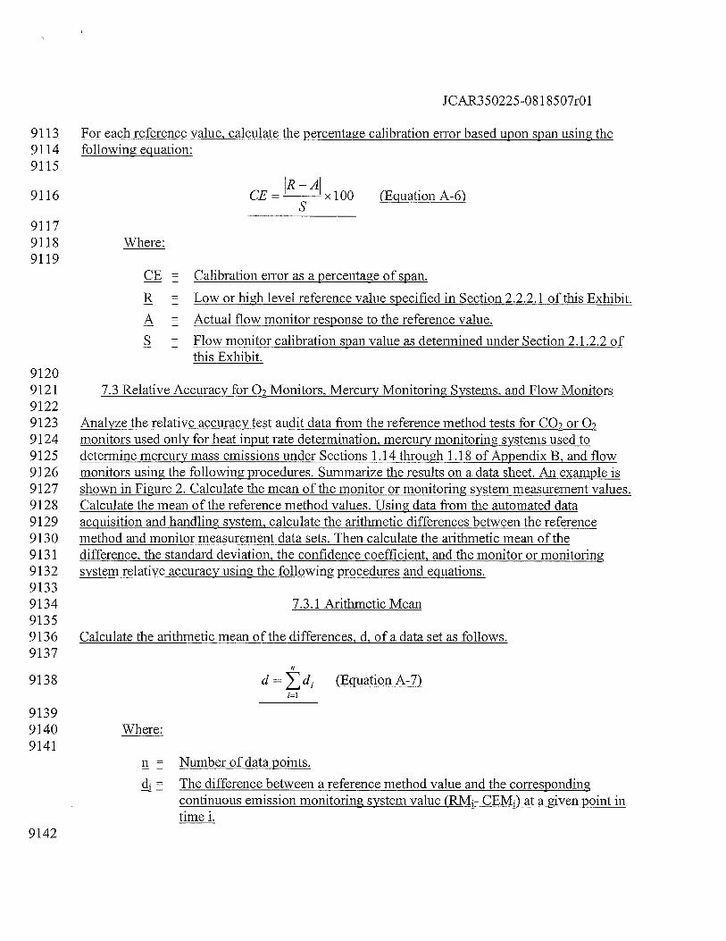
1CAR350225-08 1 8507r01
9113 For each reference value, calculate the percentage calibration error based upon span using the9114 following equation:9115
9116 CE= xlOO (EquationA-6)
91179118 Where:9119
CE = Calibration error as a percentage of span.
R Low or high level reference value specified in Section 2.2.2.1 of this Exhibit.
A = Actual flow monitor response to the reference value.
S = Flow monitor calibration span value as determined under Section 2.1.2.2 ofthis Exhibit.
91209121 7.3 Relative Accuracy for 02 Monitors, Mercury Monitoring Systems, and Flow Monitors91229123 Analyze the relative accuracy test audit data from the reference method tests for CO2 or 029124 monitors used only for heat input rate determination, mercury monitoring systems used to9125 determine mercury mass emissions under Sections 1.14 through 1.18 of Appendix B, and flow9126 monitors using the following procedures. Summarize the results on a data sheet. An example is9127 shown in Figure 2. Calculate the mean of the monitor or monitoring system measurement values.9128 Calculate the mean of the reference method values. Using data from the automated data9129 acquisition and handling system, calculate the arithmetic differences between the reference9130 method and monitor measurement data sets. Then calculate the arithmetic mean of the9131 difference, the standard deviation, the confidence coefficient, and the monitor or monitoring9132 system relative accuracy using the following procedures and equations.91339134 7.3.1 Arithmetic Mean91359136 Calculate the arithmetic mean of the differences, d, of a data set as follows.9137
9138 d=d1 (EquationA-7)
91399140 Where:9141
n Number of data points.
= The difference between a reference method value and the correspondingcontinuous emission monitoring system value (RM- CEMI) at a given point intime i.
9142
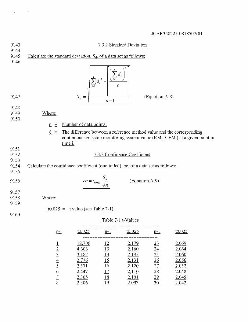
CN
ucju
1C
••
Cco
o
•-
4444
C.L
M4
I ILQ
-I
lCD
iii
iii
IF’
C-. C C CD c,)
CD CD H CD
CD
DD
”C
D•
__
•
Ul
uN
C-)
C) CD CD C) C CD C)
CD C) C CD
C) C) IICD
p 0
C DC-
)C
C)
C)
IH C (I
D
LJ’
9C
CO
oC
—C
CH
U1
——
——
——
——
I I—
__
JJ
C•
I-
•
_
:C
C4
:C
CU
1C
D
LI.)
t’J
t’J
t’J
tJ
JJJ
CC
CC
CC
CC
NC
NC
)C
NC
4C
H CD CD
C-)
C) CD -t CD C/)
— CD C C C,) CD Cl)
C
II
I IC I
C -‘C
D-t
—.
-t
CDC
)- C
(I)
CDIt)
CD
c-C
))
CD
-*
CDc
C.c
CD
C C CC
Dj•)
SQ C/D
C)
CD
-t
CD CD
--t
.C
CD
Q-
—T
jC
DQ
)
c)
CD
C) —iC 3
.C
CD C
LI.) cl)
CD C
C) I
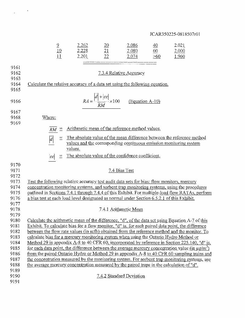
1CAR350225-081 8507r01
9 2.262 20 2.086 40 2.02110 2.228 21 2.080 60 2.00011 2.201 22 2.074 >60 1.960
91619162 7.3.4 Relative Accuracy91639164 Calculate the relative accuracy of a data set using the following equation.9165
9166 RA— xlOO (Equation A-b)RM
91679168 Where:9169
= Arithmetic mean of the reference method values.
= The absolute value of the mean difference between the reference methodvalues and the corresponding continuous emission monitoring systemvalues.
cc The absolute value of the confidence coefficient.
91709171 7.4 Bias Test91729173 Test the following relative accuracy test audit data sets for bias: flow monitors, mercury9174 concentration monitoring systems, and sorbent trap monitoring systems, using the procedures9175 outlined in Sections 7.4.1 through 7.4.4 of this Exhibit. For multiple-load flow RATAs, perform9176 a bias test at each load level designated as normal under Section 6.5.2.1 of this Exhibit.91779178 7.4.1 Arithmetic Mean91799180 Calculate the arithmetic mean of the difference, “d”, of the data set using Equation A-7 of this9181 Exhibit. To calculate bias for a flow monitor, I?dH is, for each paired data point, the difference9182 between the flow rate values (in scth) obtained from the reference method and the monitor. To9183 calculate bias for a mercury monitoring system when using the Ontario Hydro Method or9184 Method 29 in appendix A-8 to 40 CFR 60, incorporated by reference in Section 225.140, “d” is,9185 for each data point, the difference between the average mercury concentration value (in ig/m3)9186 from the paired Ontario Hydro or Method 29 in appendix A-8 to 40 CFR 60 sampling trains and9187 the concentration measured by the monitoring system. For sorbent trap monitoring systems, use9188 the average mercury concentration measured by the paired traps in the calculation of “d”.91899190 7.4.2 Standard Deviation9191
JCAR350225-08 1 8507r01
9192 Calculate the standard deviation, Sd, of the data set using Equation A-8.91939194 7.4.3 Confidence Coefficient91959196 Calculate the confidence coefficient, cc, of the data set using Equation A-9.91979198 7.4.4 Bias Test91999200 If, for the relative accuracy test audit data set being tested, the mean difference, d, is less than or9201 equal to the absolute value of the confidence coefficient, cc, the monitor or monitoring system
9202 has passed the bias test. If the mean difference, d, is greater than the absolute value of the9203 confidence coefficient, cc, the monitor or monitoring system has failed to meet the bias test
9204 requirement.92059206 7.5 Reference Flow-to-Load Ratio or Gross Heat Rate92079208 Except as provided in Section 7.6 of this Exhibit, the owner or operator must9209 determine R, the reference value of the ratio of flow rate to unit load, each time9210 that a passing flow RATA is performed at a load level designated as normal in9211 Section 6.5.2.1 of this Exhibit. The owner or operator must report the current9212 value of in the electronic quarterly report required under 40 CFR 75.64,9213 incorporated by reference in Section 225.140, and must also report the completion9214 date of the associated RATA. If two load levels have been designated as normal9215 under Section 6.5.2.1 of this Exhibit, the owner or operator must determine a9216 separate Rvalue for each of the normal load levels. The reference flow-to-load9217 ratio must be calculated as follows:9218
ref -59219 Rref___X1O (EquationA-13)avg
92209221 Where:9222
= Reference value of the flow-to-load ratio, from the most recentnormal-load flow RATA, scfhlmegawatts, scthll000 lb/hr of steam,or scthl (mmBtu/hr of steam output).
= Average stack gas volumetric flow rate measured by the referencemethod during the normal-load RATA, scth.
L = Average unit load during the normal-load flow RATA, megawatts,1000 lb/hr of steam, or mmBtu/hr of thermal output.
92239224 Tn Equation A-13, for a common stack, determine L by summing, for each
JCAR350225-08 1 8507r01
9225 RATA run, the operating loads of all units discharging through the common stack,9226 and then taking the arithmetic average of the summed loads. For a unit that9227 discharges its emissions through multiple stacks, either determine a single value9228 pfQ for the unit or a separate value of0 for each stack. In the former case,9229 calculate Q by summing, for each RATA run, the volumetric flow rates through9230 the individual stacks and then taking the arithmetic average of the summed RATA9231 run flow rates. In the latter case, calculate the value of O for each stack by9232 taking the arithmetic average, for all RATA runs, of the flow rates through the9233 stack. For a unit with a multiple stack discharge configuration consisting of a9234 main stack and a bypass stack (e.g., a unit with a wet SO2 scrubber), determine9235 Q separately for each stack at the time of the normal load flow RATA. Round9236 off the value ofR to two decimal places.92379238 In addition to determining Ror as an alternative to determine R, a reference9239 value of the gross heat rate (GHR) may be determined. In order to use this option,9240 quality assured diluent gas (Q2 or 02) must be available for each hour of the9241 most recent normal-load flow RATA. The reference value of the GHR must be9242 determined as follows:9243
HeatInput)9244 (GHR)reJ
= Lavg xl000 (Equation A-13a)
avg
92459246 Where:9247
(GHR = Reference value of the gross heat rate at the time of themost recent normal-load flow RATA, Btu/kwh, Btu/lbsteam load, or Btu heat input/mmBtu steam output.
(HeatInput) = Average hourly heat input during the normal-load flowRATA, as determined using the applicable equation inExhibit C to this Appendix, mmBtu/hr. For multiple stackconfigurations, if the reference GHR value is determinedseparately for each stack, use the hourly heat inputmeasured at each stack. If the reference GHR is determinedat the unit level, sum the hourly heat inputs measured at theindividual stacks.
= Average unit load during the normal-load flow RATA,megawatts, 1000 lb/hr of steam, or mmBtu/hr thermaloutput.
92489249 In the calculation of (HeatInput), use Q, the average volumetric flow rate9250 measured by the reference method during the RATA, and use the average diluent9251 gas concentration measured during the flow RATA (i.e., the arithmetic average of
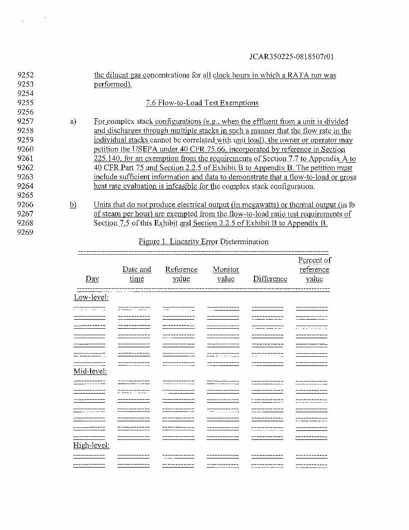
JCAR350225-08 1 8507r01
9252 the diluent gas concentrations for all clock hours in which a RATA run was9253 performed).92549255 7.6 Flow-to-Load Test Exemptions92569257 For complex stack configurations (e.g., when the effluent from a unit is divided9258 and discharges through multiple stacks in such a manner that the flow rate in the9259 individual stacks cannot be correlated with unit load), the owner or operator may9260 petition the USEPA under 40 CFR 75.66, incorporated by reference in Section9261 225.140, for an exemption from the requirements of Section 7.7 to Appendix A to9262 40 CFR Part 75 and Section 2.2.5 of Exhibit B to Appendix B. The petition must9263 include sufficient information and data to demonstrate that a flow-to-load or gross9264 heat rate evaluation is infeasible for the complex stack configuration.92659266 k Units that do not produce electrical output (in megawatts) or thermal output (in lb9267 of steam per hour) are exempted from the flow-to-load ratio test requirements of9268 Section 7.5 of this Exhibit and Section 2.2.5 of Exhibit B to Appendix B.9269
Figure 1. Linearity Error Dietermination
Percent ofDate and Reference Monitor reference
time value value Difference value
Low-level:
Mid-level:
High-level:
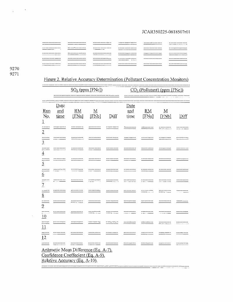
JCAR350225-081 8507r01
92709271
Figure 2. Relative Accuracy Determination (Pollutant Concentration Monitors)
SQ2 (ppm FFNc1) cQ2 (Pollutant) (ppm [FNc1)
Run and RM M and RM MNL time [FNa1 FFNb] Diff time [FNaJ FFNb1 Diff
1
2
3
4
5
6
7
8
9
10
11
12
Arthmetic Mean Difference (Eci. A-7).Confidence Coeffecient (Eq. A-9).Relative Accuracy (Eq. A-b).
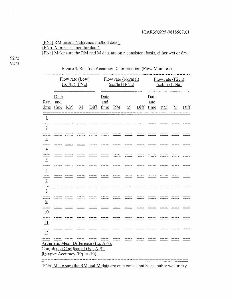
JCAR35O225O81 8507r01
FFNa1 RM means “reference method data”.FFNb1 M means “monitor data”.FFNc1 Make sure the RM and M data are on a consistent basis, either wet or dry.
92729273
Figure 3. Relative Accuracy Determination (Flow Monitors)
Flow rate (Low) Flow rate (Normal) Flow rate (High)(scf/hr) [FNa] (scflhr) [FNa] (scf/hr) [FNa]
Date Date Date
time time RM M Diff time RM M Diff time RM M Diff
1
2
3
4
5
6
7
8
9
10
11
12
Arthinetic Mean Difference (Eq. A-7).Confidence Coeffecient (Eq. A-9).Relative Accuracy (Eq. A-b).
[FNa1 Make sure the RM and M data are on a consistent basis, either wet or dry.
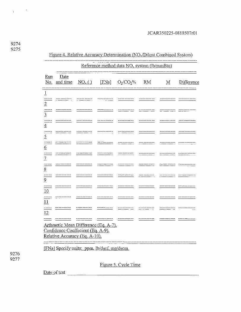
JCAR350225-081 8507r01
92749275
Figure 4. Relative Accuracy Determination (NO/Dilent Combined System)
Reference method data NO system (lb/mrnBtu)
Run DateN and time NQXQ [FNa] Q2/Q2% RM M Difference
1
2
3
4
5
6
7
8
9
10
11
12
Arthmetic Mean Difference (Eq. A-7).Confidence Coeffecient (Eq. A-9).Relative Accuracy (Eq. A- 10).
{FNa1 Specify units: ppm, lb/dscf, mgjdscm.92769277
Figure 5. Cycle Time
Date of test
____________________________________
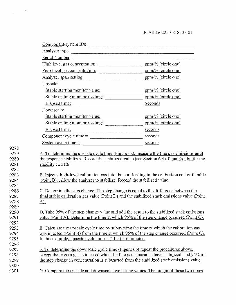
JCAR350225-08 1 8507r01
Component/system ID#:
_______________________________________________
Analyzer type
____________________________________________________________
Serial Number
____________________________________________________
High level gas concentration:
_____________________
ppml% (circle one)
Zero level gas concentration:
_____________________
ppm/% (circle one)
Analyzer span setting:
___________________________
ppm/% (circle one)
Upscale:
Stable starting monitor value:
___________________
ppml% (circle one)
Stable ending monitor reading:
__________________
ppm/% (circle one)
Elapsed time:
_______________________________
Seconds
Downscale:
Stable starting monitor value:
____________________
ppi% (circle one)
Stable ending monitor reading:
__________________
ppml% (circle one)
Elapsed time: seconds
Component cycle time = seconds
System cycle time seconds92789279 A. To detennine the upscale cycle time (Figure 6a), measure the flue gas emissions until9280 the response stabilizes. Record the stabilized value (see Section 6.4 of this Exhibit for the9281 stability criteria).92829283 B. Inject a high-level calibration gas into the port leading to the calibration cell or thimble9284 (Point B). Allow the analyzer to stabilize. Record the stabilized value.92859286 C. Determine the step change. The step change is equal to the difference between the9287 final stable calibration gas value (Point D) and the stabilized stack emissions value (Point928892899290 D. Take 95% of the step change value and add the result to the stabilized stack emissions9291 value (Point A). Determine the time at which 95% of the step change occurred (Point C).92929293 E. Calculate the upscale cycle time by subtracting the time at which the calibration gas9294 was injected (Point B) from the time at which 95% of the step change occurred (Point C).9295 In this example, upscale cycle time = (11-5) 6 minutes.92969297 F. To determine the downscale cycle time (Figure 6b) repeat the procedures above,9298 except that a zero gas is injected when the flue gas emissions have stabilized, and 95% of9299 the step change in concentration is subtracted from the stabilized stack emissions value.93009301 G. Compare the upscale and downscale cycle time values. The longer of these two times
9302 is the cycle time for the analyzer.9303
JCAR350225-081 8507r01
JCAR350225-081 8507r01
Develop and implement a quality assurance/quality control (QA/QC) program for the continuousemission monitoring systems and their components. At a minimum, include in each QA/QCprogram a written plan that describes in detail (or that refers to separate documents containing)complete, step-by-step procedures and operations for each of the following activities. Uponrequest from regulatory authorities, the source must make all procedures, maintenance records,and ancillary supporting documentation from the manufacturer (e.g., soflware coefficients andtroubleshooting diagrams) available for review during an audit. Electronic storage of theinformation in the OAIQC plan is permissible, provided that the information can be madeavailable in hardcopy upon request during an audit.
1.1 Requirements for All Monitoring Systems
1.1.1 Preventive Maintenance
Keep a written record of procedures needed to maintain the mnnitcrn a system in properoperating condition and a schedule for those procedures. This must, at a minimum, includeprocedures specified by the manufacturers of the equipment and, if applicable, additional oralternate procedures developed for the equipment.
1.1.2 Recordkeeping and Reporting
Keep a written record describing procedures that will be used to implement the recordkeepingand reporting requirements in subparts E and G of 40 CFR 75, incorporated by reference inSection 225.140, and Sections 1.10 through 1.13 of Appendix B, as applicable.
1.1.3 Maintenance Records
Keep a record of all testing, maintenance, or repair activities performed on any monitoringsystem or component in a location and format suitable for inspection. A maintenance log may beused for this purpose. The following records should be maintained: date, time, and description ofany testing, adjustment, repair, replacement, or preventive maintenance action performed on anymonitoring system and records of any corrective actions associated with a monitor’s outageperiod. Additionally, any adjustment that recharacterizes a system’s ability to record and reportemissions data must be recorded (e.g., changing of flow monitor or moisture monitoring systempolynomial coefficients, K factors or mathematical algorithms, changing of temperature andpressure coefficients and dilution ratio settings), and a written explanation of the procedures usedto make the adjustments must be kept.
Exhibit B to Appendix B — Quality Assurance and Quality Control Procedures
1. Quality Assurance/Quality Control Program
9304930593069307930893099310931193129313931493159316931793189319932093219322932393249325932693279328932993309331933293339334933593369337933893399340934193429343934493459346 1.1.4
JCAR350225-081 8507r01
The requirements in Section 6.1.2 of Exhibit A to this Appendix must be met by any AirEmissions Testing Body (AETB) performing the semiannual/annual RATAs described in Section2.3 of this Exhibit and the mercury emission tests described in Sections 1.1 5(c) and 1.15 (d)(4) ofAppendix B.
1.2 Specific Requirements for Continuous Emissions Monitoring Systems
1.2.1 Calibration Error Test and Linearity Check Procedures
Keep a written record of the procedures used for daily calibration error tests and linearity checks(e.g., how gases are to be injected, adjustments of flow rates and pressure, introduction ofreference values, length of time for mi ection of calibration gases, steps for obtaining calibrationerror or error in linearity, determination of interferences, and when calibration adjustmentsshould be made). Identify any calibration error test and linearity check procedures specific to thecontinuous emission monitoring system that vary from the procedures in Exhibit A to thisAppendix.
1.2.2 Calibration and Linearity Adjustments
Explain how each component of the continuous emission monitoring system will be adjusted toprovide correct responses to calibration gases, reference values, andlor indications ofinterference both initially and after repairs or corrective action. Identify equations, conversionfactors and other factors affecting calibration of each continuous emission monitoring system.
9372 1.2.3 Relative Accuracy Test Audit Procedures9373
Keep a written record of procedures and details peculiar to the installed continuous emissionmonitoring systems that are to be used for relative accuracy test audits, such as sampling andanalysis methods.
1.2.4 Parametric Monitoring for Units With Add-on Emission Controls
The owner or operator shall keep a written (or electronic) record including a list of operatingparameters for the add-on mercury emission controls, as applicable, and the range of eachoperating parameter that indicates the add-on emission controls are operating properly. Theowner or operator shall keep a written (or electronic) record of the parametric monitoring dataduring each mercury missing data period.
1.3 Requirements for Sorbent Trap Monitoring Systems
1.3.1 Sorbent Trap Identification and Tracking
9347934893499350935193529353935493559356935793589359936093619362936393649365936693679368936993709371
9374937593769377937893799380938193829383938493859386938793889389
JCAR350225-081 8507r01
9390 Include procedures for inscribing or otherwise permanently marking a unique identification9391 number on each sorbent trap for tracking purposes. Keep records of the ID of the monitoring9392 system in which each sorbent trap is used and the dates and hours of each mercury collection9393 period.93949395 1.3.2 Monitoring System Integrity and Data Quality93969397 Explain the procedures used to perform the leak checks when sorbent traps are placed in service9398 and removed from service. Also explain the other QA procedures used to ensure system integrity9399 and data quality, including, but not limited to, gas flow meter calibrations, verification of9400 moisture removal, and ensuring air-tight pump operation. In addition, the QA plan must include9401 the data acceptance and quality control criteria in Section 8 of Exhibit D to this Appendix. All9402 reference meters used to calibrate the gas flow meters (e.g., wet test meters) must be periodically9403 recalibrated. Annual, or more frequent, recalibration is recommended. If a NIST-traceable9404 calibration device is used as a reference flow meter, the QA plan must include a protocol for9405 ongoing maintenance and periodic recalibration to maintain the accuracy and NIST-traceability9406 of the calibrator.94079408 1.3.3 Mercury Analysis94099410 Explain the chain of custody employed in packing, transporting, and analyzing the sorbent traps9411 (see Sections 7.2.8 and 7.2.9 in Exhibit D to this Appendix.). Keep records of all mercury9412 analyses. The analyses must be performed in accordance with the procedures described in9413 Section 10 of Exhibit D to this Appendix.94149415 1.3.4 Laboratory Certification94169417 The QA Plan must include documentation that the laboratory performing the analyses on the9418 carbon sorbent traps is certified by the International Organization for Standardization (ISO) to9419 have a proficiency that meets the requirements of ISO 17025. Alternatively, if the laboratory9420 performs the spike recovery study described in Section 10.3 of Exhibit D to this Appendix and9421 repeats that procedure annually. ISO certification is not required.94229423 1.3.5 Data Collection Period94249425 State, and provide the rationale for, the minimum acceptable data collection period (e.g., one9426 day, one week, etc.) for the size of the sorbent trap selected for the monitoring. Include in the9427 discussion such factors as the mercury concentration in the stack gas, the capacity of the sorbent9428 trap, and the minimum mass of mercury required for the analysis.94299430 1.3.6 Relative Accuracy Test Audit Procedures94319432 Keep records of the procedures and details peculiar to the sorbent trap monitoring systems that
JCAR350225-08 1 8507r01
9433 are to be followed for relative accuracy test audits, such as sampling and analysis methods.94349435 2. Frequency of Testing94369437 A summary chart showing each quality assurance test and the frequency at which each test is9438 required is located at the end of this Exhibit in Figure 1.94399440 2.1 Daily Assessments94419442 Perform the following daily assessments to quality-assure the hourly data recorded by the9443 monitoring systems during each period of unit operation, or, for a bypass stack or duct, each9444 period in which emissions pass through the bypass stack or duct. These requirements are9445 effective as of the date when the monitor or continuous emission monitoring system completes9446 certification testing.94479448 2.1 .1 Calibration Error Test94499450 Except as provided in Section 2.1.1.2 of this Exhibit, perform the daily calibration error test of9451 each gas monitoring system (including moisture monitoring systems consisting of wet- and dry-9452 basis 02 analyzers) according to the procedures in Section 6.3.1 of Exhibit A to this Appendix,9453 and perform the daily calibration error test of each flow monitoring system according to the9454 procedure in Section 6.3.2 of Exhibit A to this Appendix. When two measurement ranges (low9455 and high) are required for a particular parameter, perform sufficient calibration error tests on9456 each range to validate the data recorded on that range, according to the criteria in Section 2.1.5 of9457 this Exhibit.94589459 For units with add-on emission controls and dual-span or auto-ranging monitors, and other units9460 that use the maximum expected concentration to determine calibration gas values, perform the9461 daily calibration error tests on each scale that has been used since the previous calibration error9462 test. For example, if the pollutant concentration has not exceeded the low-scale value (based on9463 the maximum expected concentration) since the previous calibration error test, the calibration9464 error test may be performed on the low-scale only. If, however, the concentration has exceeded9465 the low-scale span value for one hour or longer since the previous calibration error test, perform9466 the calibration error test on both the low- and high-scales.94679468 2.1 .1.1 On-line Daily Calibration Error Tests94699470 Except as provided in Section 2.1.1.2 of this Exhibit, all daily calibration error tests must be9471 performed while the unit is in operation at normal, stable conditions (i.e., ‘on-line”).94729473 2.1.1.2 0ff-line Daily Calibration Error Tests9474
JCAR350225-081 8507r01
9475 Daily calibrations may be performed while the unit is not operating (i.e., “off-line”) and may be9476 used to validate data for a monitoring system that meets the following conditions:94779478 1.) An initial demonstration test of the monitoring system is successfully completed9479 and the results are reported in the quarterly report required under 40 CFR 75.64,9480 incorporated by reference in Section 225.140. The initial demonstration test,9481 hereafter called the “off-line calibration demonstration”, consists of an off-line9482 calibration error test followed by an on-line calibration error test. Both the off-line9483 and on-line portions of the off-line calibration demonstration must meet the9484 calibration error performance specification in Section 3.1 of Exhibit A to9485 Appendix B. Upon completion of the off-line portion of the demonstration, the9486 zero and upscale monitor responses may be adjusted, but only toward the true9487 values of the calibration gases or reference signals used to perform the test and9488 only in accordance with the routine calibration adjustment procedures specified in9489 the quality control program required under Section 1 of this Exhibit. Once these9490 adjustments are made, no further adjustments may be made to the monitoring9491 system until after completion of the on-line portion of the off-line calibration9492 demonstration. Within 26 clock hours after the completion hour of the off-line9493 portion of the demonstration, the monitoring system must successfully complete9494 the first attempted calibration error test, i.e., the on-line portion of the9495 demonstration.94969497 ) For each monitoring system that has passed the off-line calibration demonstration,9498 off-line calibration error tests may be used on a limited basis to validate data, in9499 accordance with subsection (2) in Section 2.1.5.1 of this Exhibit.95009501 2.1.2 Daily Flow Interference Check95029503 Perform the daily flow monitor interference checks specified in Section 2.2.2.2 of Exhibit A to9504 this Appendix while the unit is in operation at normal, stable conditions.95059506 2.1.3 Additional Calibration Error Tests and Calibration Adjustments95079508 In addition to the daily calibration error tests required under Section 2.1.1 of this9509 Exhibit, a calibration error test of a monitor must be performed in accordance9510 with Section 2.1.1 of this Exhibit, as follows: whenever a daily calibration error9511 test is failed; whenever a monitoring system is returned to service following repair9512 or corrective maintenance that could affect the monitor’s ability to accurately9513 measure and record emissions data; or after making certain calibration9514 adjustments, as described in this Section. Except in the case of the routine9515 calibration adjustments described in this Section, data from the monitor are9516 considered invalid until the required additional calibration error test has been9517 successfully completed.
JCAR350225-081 8507r01
95189519 j) Routine calibration adjustments of a monitor are permitted after any successful9520 calibration error test. These routine adjustments must be made so as to bring the9521 monitor readings as close as practicable to the known tag values of the calibration9522 gases or to the actual value of the flow monitor reference signals. An additional9523 calibration error test is required following routine calibration adjustments where9524 the monitor’s calibration has been physically adjusted (e.g., by turning a9525 potentiometer) to verify that the adjustments have been made properly. An9526 additional calibration error test is not required, however, if the routine calibration9527 adjustments are made by means of a mathematical algorithm programmed into the9528 data acquisition and handling system. It is recommended that routine calibration9529 adjustments be made, at a minimum, whenever the daily calibration error exceeds9530 the limits of the applicable perfonnance specification in Exhibit A to this9531 Appendix for the pollutant concentration monitor, CO2 or 02 monitor, or flow9532 monitor.95339534 ç Additional (non-routine) calibration adjustments of a monitor are permitted prior9535 to (but not during) linearity checks and RATAs and at other times, provided that9536 an appropriate technical justification is included in the quality control program9537 required under Section 1 of this Exhibit. The allowable non-routine adjustments9538 are as follows. The owner or operator may physically adjust the calibration of a9539 monitor (e.g., by means of a potentiometer), provided that the post-adjustment9540 zero and upscale responses of the monitor are within the performance9541 specifications of the instrument given in Section 3.1 of Exhibit A to this9542 Appendix. An additional calibration error test is required following such9543 adjustments to verify that the monitor is operating within the performance9544 specifications at both the zero and upscale calibration levels.95459546 2.1.4 Data Validation95479548 An out-of-control period occurs when the calibration error of a CO2 or 02 monitor9549 (includingQ monitors used to measure CO2 emissions or percent moisture)9550 exceeds 1.0 percent CO2 or 02, or when the calibration error of a flow monitor or9551 a moisture sensor exceeds 6.0 percent of the span value, which is twice the9552 applicable specification of Exhibit A to this Appendix. Notwithstanding, a9553 differential pressure-type flow monitor for which the calibration error exceeds 6.09554 percent of the span value will not be considered out-of-control if —
9555 absolute value of the difference between the monitor response and the reference9556 value in Equation A-6 of Exhibit A to this Appendix, is < 0.02 inches of water.9557 For a mercury monitor, an out-of-control period occurs when the calibration error9558 exceeds 5.0% of the span value. Notwithstanding, the mercury monitor will not be9559 considered out-of-control if — in Equation A-6 does not exceed 1.0 fig/scm.
JCAR350225-081 8507r01
9560 The out-of-control period begins upon failure of the calibration error test and ends9561 upon completion of a successful calibration error test. Note, that if a failed9562 calibration, corrective action, and successful calibration error test occur within the9563 same hour, emission data for that hour recorded by the monitor after the9564 successful calibration error test may be used for reporting purposes, provided that9565 two or more valid readings are obtained as required by Section 1.2 of this9566 Appendix. Emission data must not be reported from an out-of-control monitor.95679568 i An out-of-control period also occurs whenever interference of a flow monitor is9569 identified. The out-of-control period begins with the hour of completion of the9570 failed interference check and ends with the hour of completion of an interference9571 check that is passed.95729573 2.1.5 Quality Assurance of Data With Respect to Daily Assessments95749575 When a monitoring system passes a daily assessment (i.e., daily calibration error test or daily9576 flow interference check), data from that monitoring system are prospectively validated for 269577 clock hours (i.e., 24 hours plus a 2-hour grace period) beginning with the hour in which the test9578 is passed, unless another assessment (i.e., a daily calibration error test, an interference check of a9579 flow monitor, a quarterly linearity check, a quarterly leak check, or a relative accuracy test audit)9580 is failed within the 26-hour period.95819582 2.1.5.1 Data Invalidation with Respect to Daily Assessments95839584 The following specific rules apply to the invalidation of data with respect to daily assessments:95859586 fl Data from a monitoring system are invalid, beginning with the first hour9587 following the expiration of a 26-hour data validation period or beginning9588 with the first hour following the expiration of an 8-hour start-up grace9589 period (as provided under Section 2.1.5.2 of this Exhibit), if the required9590 subsequent daily assessment has not been conducted.95919592 ) For a monitor that has passed the off-line calibration demonstration, a9593 combination of on-line and off-line calibration error tests may be used to9594 validate data from the monitor, as follows. For a particular unit (or stack)9595 operating hour, data from a monitor may be validated using a successful9596 off-line calibration error test if:95979598 An on-line calibration error test has been passed within the9599 previous 26 unit (or stack) operating hours; and96009601 ) the 26 clock hour data validation window for the off-line9602 calibration error test has not expired. If either of these conditions is
JCAR350225-08 1 8507r01
9603 not met, then the data from the monitor are invalid with respect to9604 the daily calibration error test requirement. Data from the monitor9605 must remain invalid until the appropriate on-line or off-line9606 calibration error test is successfully completed so that both9607 conditions in subsections (a) and (b) are met.96089609 For units with two measurement ranges (low and high) for a particular9610 parameter, when separate analyzers are used for the low and high ranges, a9611 failed or expired calibration on one of the ranges does not affect the9612 quality-assured data status on the other range. For a dual-range analyzer9613 (i.e., a single analyzer with two measurement scales), a failed calibration9614 error test on either the low or high scale results in an out-of-control period9615 for the monitor. Data from the monitor remain invalid until corrective9616 actions are taken and “hands-off’ calibration error tests have been passed9617 on both ranges. However, if the most recent calibration error test on the9618 high scale was passed but has expired, while the low scale is up-to-date on9619 its calibration error test requirements (or vice-versa), the expired9620 calibration error test does not affect the quality-assured status of the data9621 recorded on the other scale.96229623 2.1.5.2 Daily Assessment Start-Up Grace Period96249625 For the purpose of quality assuring data with respect to a daily assessment (i.e., a daily9626 calibration error test or a flow interference check), a start-up grace period may apply when a unit9627 begins to operate after a period of non-operation. The start-up grace period for a daily calibration9628 error test is independent of the start-up grace period for a daily flow interference check. To9629 qualify for a start-up grace period for a daily assessment, there are two requirements:96309631 D The unit must have resumed operation after being in outage for 1 or more9632 hours (i.e., the unit must be in a start-up condition) as evidenced by a9633 change in unit operating time from zero in one clock hour to an operating9634 time greater than zero in the next clock hour.96359636 For the monitoring system to be used to validate data during the grace9637 period, the previous daily assessment of the same kind must have been9638 passed on-line within 26 clock hours prior to the last hour in which the9639 unit operated before the outage. fri addition, the monitoring system must9640 be in-control with respect to quarterly and semi-annual or annual9641 assessments.96429643 If both of the above conditions are met, then a start-up grace period of up to 8 clock hours9644 applies, beginning with the first hour of unit operation following the outage. During the start-up9645 grace period, data generated by the monitoring system are considered quality-assured. For each
JCAR350225-08 1 8507r01
9646 monitoring system, a start-up grace period for a calibration error test or flow interference check9647 ends when either: (1) a daily assessment of the same kind (i.e., calibration error test or flow9648 interference check) is performed or (2) 8 clock hours have elapsed (starting with the first hour of9649 unit operation following the outage), whichever occurs first.96509651 2.1.6 Data Recording96529653 Record and tabulate all calibration error test data according to month, day, clock-hour, and9654 magnitude in either ppm, percent volume, or scth. Program monitors that automatically adjust9655 data to the corrected calibration values (e.g., microprocessor control) to record either: (1) the9656 unadjusted concentration or flow rate measured in the calibration error test prior to resetting the9657 calibration, or (2) the magnitude of any adjustment. Record the following applicable flow9658 monitor interference check data: (1) sample line/sensing port pluggage, and (2) malfunction of9659 each RTD, transceiver, or equivalent.96609661 2.2 Quarterly Assessments96629663 For each primary and redundant backup monitor or monitoring system, perform the following9664 quarterly assessments. This requirement applies as of the calendar quarter following the calendar9665 quarter in which the monitor or continuous emission monitoring system is provisionally certified.96669667 2.2.1 Linearity Check96689669 Unless a particular monitor (or monitoring range) is exempted under this subsection or under9670 Section 6.2 of Exhibit A to this Appendix, perform a linearity check, in accordance with the9671 procedures in Section 6.2 of Exhibit A to this Appendix, for each primary and redundant backup,9672 mercury, pollutant concentration monitor and each primary and redundant backup CO2 or 029673 monitor (including 02 monitors used to measure CO2 emissions or to continuously monitor9674 moisture) at least once during each QA operating quarter, as defined in 40 CFR 72.2,9675 incorporated by reference in Section 225.140. For mercury monitors, perform the linearity9676 checks using elemental mercury standards. Alternatively, you may perform 3-level system9677 integrity checks at the same three calibration gas levels (i.e., low, mid, and high), using a NIST9678 traceable source of oxidized mercury. If you choose this option, the performance specification in9679 Section 3.2(c) of Exhibit A to this Part must be met at each gas level. For units using both a low9680 and high span value, a linearity check is required only on the ranges used to record and report9681 emission data during the QA operating quarter. Conduct the linearity checks no less than 30 days9682 apart, to the extent practicable. The data validation procedures in Section 2.2.3(e) of this Exhibit9683 must be followed.96849685 2.2.2 Leak Check96869687 For differential pressure flow monitors, perform a leak check of all sample lines (a manual check9688 is acceptable) at least once during each QA operating quarter. For this test, the unit does not have
JCAR350225-081 8507r01
9689 to be in operation. Conduct the leak checks no less than 30 days apart, to the extent practicable.9690 If a leak check is failed, follow the applicable data validation procedures in Section 2.2.3(g) of9691 this Exhibit.96929693 2.2.3 Data Validation96949695 A linearity check must not be commenced if the monitoring system is operating9696 out-of-control with respect to any of the daily or semiannual quality assurance9697 assessments required by Sections 2.1 and 2.3 of this Exhibit or with respect to the9698 additional calibration error test requirements in Section 2.1.3 of this Exhibit.96999700 Each required linearity check must be done according to subsection (b)(l), (b)(2)9701 or (b)(3) of this Section:97029703 jj The linearity check may be done “cold”, i.e., with no corrective9704 maintenance, repair, calibration adjustments, re-linearization or9705 reprogramming of the monitor prior to the test.97069707 The linearity check may be done after performing only the routine or non-9708 routine calibration adjustments described in Section 2.1.3 of this Exhibit9709 at the various calibration gas levels (zero, low, mid or high), but no other9710 corrective maintenance, repair, re-linearization or reprogramming of the9711 monitor. Trial gas injection runs may be performed after the calibration9712 adjustments and additional adjustments within the allowable limits in9713 Section 2.1.3 of this Exhibit may be made prior to the linearity check, as9714 necessary, to optimize the performance of the monitor. The trial gas9715 injections need not be reported, provided that they meet the specification9716 for trial gas injections in Section 1.4(b)(3)(G)(v) of this Appendix.9717 However, if, for any trial injection, the specification in Section9718 1.4(b)(3)(G)(v) is not met, the trial injection must be counted as an aborted9719 linearity check.97209721 The linearity check may be done after repair, corrective maintenance or9722 reprogramming of the monitor. In this case, the monitor must be9723 considered out-of-control from the hour in which the repair, corrective9724 maintenance or reprogramming is commenced until the linearity check has9725 been passed. Alternatively, the data validation procedures and associated9726 timelines in Sections 1.4(b)(3)(B) through (I) of this Appendix maybe9727 followed upon completion of the necessary repair, corrective maintenance,9728 or reprogramming. If the procedures in Section 1.4(b)(3) are used, the9729 words “quality assurance” apply instead of the word “recertification”.97309731 Once a linearity check has been commenced, the test must be done hands-off.
JCAR350225-081 8507r01
9732 That is, no adjustments of the monitor are permitted during the linearity test9733 period, other than the routine calibration adjustments following daily calibration9734 error tests, as described in Section 2.1.3 of this Exhibit. If a routine daily9735 calibration error test is performed and passed just prior to a linearity test (or9736 during a linearity test period) and a mathematical correction factor is9737 automatically applied by the DAHS, the correction factor must be applied to all9738 subsequent data recorded by the monitor, including the linearity test data.97399740 ç) If a daily calibration error test is failed during a linearity test period, prior to9741 completing the test, the linearity test must be repeated. Data from the monitor are9742 invalidated prospectively from the hour of the failed calibration error test until the9743 hour of completion of a subsequent successful calibration error test. The linearity9744 test must not be conunenced until the monitor has successfully completed a9745 calibration error test.97469747 An out-of-control period occurs when a linearity test is failed (i.e., when the error9748 in linearity at any of the three concentrations in the quarterly linearity check (or9749 any of the six concentrations, when both ranges of a single analyzer with a dual9750 range are tested) exceeds the applicable specification in Section 3.2 of Exhibit A9751 to this Appendix) or when a linearity test is aborted due to a problem with the9752 monitor or monitoring system. The out-of-control period begins with the hour of9753 the failed or aborted linearity check and ends with the hour of completion of a9754 satisfactory linearity check following corrective action and/or monitor repair,9755 unless the option in subsection (b)(3) of this Section to use the data validation9756 procedures and associated timelines in Section 1.4(b)(3)(B) through (I) of this9757 Appendix has been selected, in which case the beginning and end of the out-of-9758 control period must be determined in accordance with Sections 1.4(b)(3)(G)(i)9759 and (ii). For a dual-range analyzer, “hands-off’ linearity checks must be passed on9760 both measurement scales to end the out-of-control period.97619762 fi No more than four successive calendar quarters must elapse after the quarter in9763 which a linearity check of a monitor or monitoring system (or range of a monitor9764 or monitoring system) was last performed without a subsequent linearity test9765 having been conducted. If a linearity test has not been completed by the end of the9766 fourth calendar quarter since the last linearity test, then the linearity test must be9767 completed within a 168 unit operating hour or stack operating hour “grace period”9768 (as provided in Section 2.2.4 of this Exhibit) following the end of the fourth9769 successive elapsed calendar quarter, or data from the CEMS (or range) will9770 become invalid.97719772 An out-of-control period also occurs when a flow monitor sample line leak is9773 detected. The out-of-control period begins with the hour of the failed leak check9774 and ends with the hour of a satisfactory leak check following corrective action.
1CAR350225-08 1 8507r01
97759776 ) For each monitoring system, report the results of all completed and partial9777 linearity tests that affect data validation (i.e., all completed, passed linearity9778 checks; all completed, failed linearity checks; and all linearity checks aborted due9779 to a problem with the monitor, including trial gas injections counted as failed test9780 attempts under subsection (b)(2) of this Section or under Section 1 .4(b)(3)(G)(vi)9781 of Appendix B), in the quarterly report required under 40 CFR 75.64,9782 incorporated by reference in Section 225.140. Note that linearity attempts that are9783 aborted or invalidated due to problems with the reference calibration gases or due9784 to operational problems with the affected units need not be reported. Such partial9785 tests do not affect the validation status of emission data recorded by the monitor.9786 A record of all linearity tests, trial gas injections and test attempts (whether9787 reported or not) must be kept on-site as part of the official test log for each9788 monitoring system.97899790 2.2.4 Linearity and Leak Check Grace Period97919792 When a required linearity test or flow monitor leak check has not been completed9793 by the end of the OA operating quarter in which it is due or if, due to infrequent9794 operation of a unit or infrequent use of a required high range of a monitor or9795 monitoring system, four successive calendar quarters have elapsed after the9796 quarter in which a linearity check of a monitor or monitoring system (or range)9797 was last performed without a subsequent linearity test having been done, the9798 owner or operator has a grace period of 168 consecutive unit operating hours, as9799 defined in 40 CFR 72.2, incorporated by reference in Section 225.140 (or, for9800 monitors installed on common stacks or bypass stacks, 168 consecutive stack9801 operating hours, as defined in 40 CFR 72.2) in which to perform a linearity test or9802 leak check of that monitor or monitoring system (or range). The grace period9803 begins with the first unit or stack operating hour following the calendar quarter in9804 which the linearity test was due. Data validation during a linearity or leak check9805 grace period must be done in accordance with the applicable provisions in Section9806 2.2.3 of this Exhibit.98079808 If, at the end of the 168 unit (or stack) operating hour grace period, the required9809 linearity testor leak check has not been completed, data from the monitoring9810 system (or range) will be invalid, beginning with the first unit operating hour9811 following the expiration of the grace period. Data from the monitoring system (or9812 range) remain invalid until the hour of completion of a subsequent successful9813 hands-off linearity test or leak check of the monitor or monitoring system (or9814 range). Note that when a linearity test or a leak check is conducted within a grace9815 period for the purpose of satisfying the linearity test or leak check requirement9816 from a previous OA operating quarter, the results of that linearity test or leak9817 check may only be used to meet the linearity check or leak check requirement of
JCAR350225-08 1 8507r01
9818 the previous quarter, not the quarter in which the missed linearity test or leak9819 check is completed.98209821 2.2.5 Flow-to-Load Ratio or Gross Heat Rate Evaluation98229823 Applicability and methodology. Unless exempted from the flow-to-load ratio test9824 under Section 7.8 to Appendix A to 40 CFR 75 , the owner or operator must, for9825 each flow rate monitoring system installed on each unit, common stack or9826 multiple stack, evaluate the flow-to-load ratio quarterly, i.e., for each OA9827 operating quarter (as defined in 40 CFR 72.2, incorporated by reference in Section9828 225.140). At the end of each QA operating quarter, the owner or operator must9829 use Equation B-i to calculate the flow-to-load ratio for every hour during the9830 quarter in which: the unit (or combination of units, for a common stack) operated9831 within ± 10.0 percent ofL, the average load during the most recent normal-load9832 flow RATA and a quality assured hourly average flow rate was obtained with a9833 certified flow rate monitor. Alternatively, for the reasons stated in subsections9834 (c)(1) through (6) of this Section, the owner or operator may exclude from the9835 data analysis certain hours within ± 10.0 percent of Land may calculate L,9836 values for only the remaining hours.9837
9838 Rh =-iO (EquationB-i)
98399840 Where:9841
Rh = Hourly value of the flow-to-load ratio, scfhlmegawatts, scffi/1000 lb/hrof steam, or scflul(mmBtu/hr thermal output).
= Hourly stack gas volumetric flow rate, as measured by the flow ratemonitor, scfh.
Lh = Hourly unit load, megawatts, 1000 lb/hr of steam, or mmBtulhrthermal output must be within + 10.0 percent ofL during the mostrecent normal-load flow RATA.
98429843 .11 In Equation B-i, the owner or operator may use either bias-adjusted flow9844 rates or unadjusted flow rates, provided that all of the ratios are calculated9845 the same way. For a common stack, Lh will be the sum of the hourly9846 operating loads of all units that discharge through the stack. For a unit that9847 discharges its emissions through multiple stacks or that monitors its9848 emissions in multiple breechings, Oh will be either the combined hourly9849 volumetric flow rate for all of the stacks or ducts (if the test is done on a9850 unit basis) or the hourly flow rate through each stack individually (if the9851 test is performed separately for each stack). For a unit with a multiple
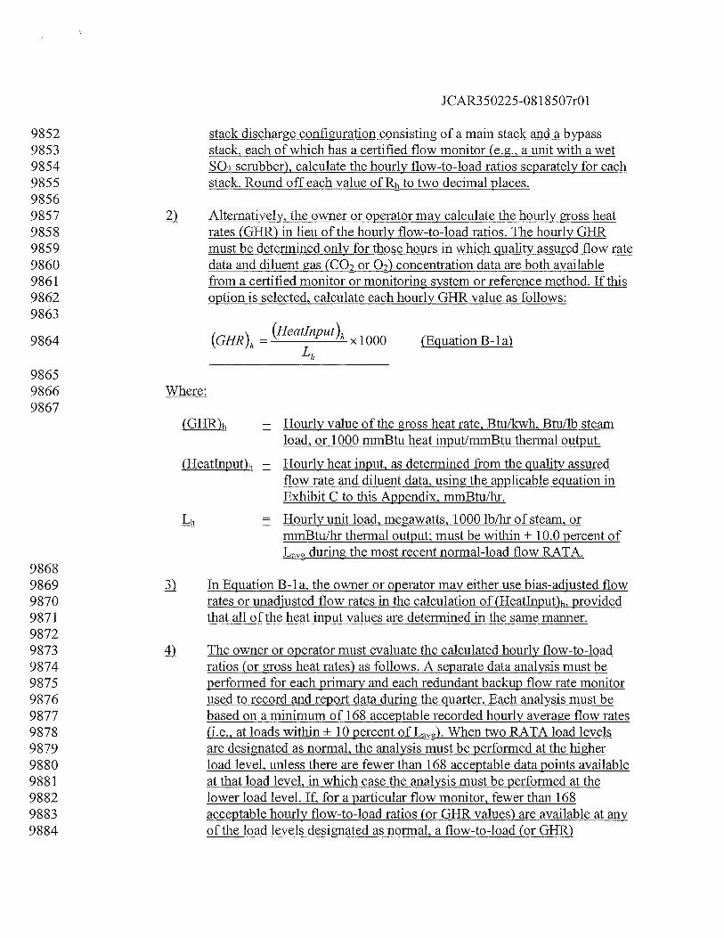
JCAR350225-08 1 8507r01
9852 stack discharge configuration consisting of a main stack and a bypass9853 stack, each of which has a certified flow monitor (e.g., a unit with a wet9854 SO2 scrubber), calculate the hourly flow-to-load ratios separately for each9855 stack. Round off each value of Rh to two decimal places.98569857 ) Alternatively, the owner or operator may calculate the hourly gross heat9858 rates (GHR) in lieu of the hourly flow-to-load ratios. The hourly GHR9859 must be determined only for those hours in which quality assured flow rate9860 data and diluent gas (CO2 or 02) concentration data are both available9861 from a certified monitor or monitoring system or reference method. If this9862 option is selected, calculate each hourly GHR value as follows:9863
9864 (GHR)h= (Heatlnput)h
x 1000 (Equation B-la)
98659866 Where:9867
(GHR)h = Hourly value of the gross heat rate, Btu/kwh, Btullb steamload, or 1000 mmBtu heat input/mmBtu thermal output.
(Heatlnput)h = Hourly heat input, as determined from the quality assuredflow rate and diluent data, using the applicable equation inExhibit C to this Appendix, mmBtu/hr.
Hourly unit load, megawatts, 1000 lb/hr of steam, ormmBtu/hr thermal output; must be within + 10.0 percent ofL during the most recent normal-load flow RATA.
98689869 In Equation B-la, the owner or operator may either use bias-adjusted flow9870 rates or unadjusted flow rates in the calculation of (Heatlnput)h, provided9871 that all of the heat input values are determined in the same manner.98729873 4 The owner or operator must evaluate the calculated hourly flow-to-load9874 ratios (or gross heat rates) as follows. A separate data analysis must be9875 performed for each primary and each redundant backup flow rate monitor9876 used to record and report data during the quarter. Each analysis must be9877 based on a minimum of 168 acceptable recorded hourly average flow rates9878 (i.e., at loads within + 10 percent ofL). When two RATA load levels9879 are designated as normal, the analysis must be performed at the higher9880 load level, unless there are fewer than 168 acceptable data points available9881 at that load level, in which case the analysis must be performed at the9882 lower load level. If, for a particular flow monitor, fewer than 1689883 acceptable hourly flow-to-load ratios (or GHR values) are available at any9884 of the load levels designated as normal, a flow-to-load (or GHR)
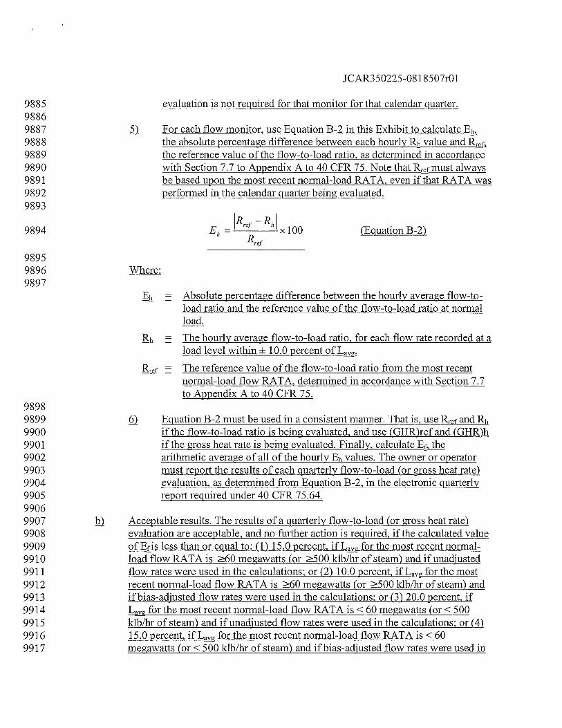
JCAR350225-08 1 8507r01
9885 evaluation is not required for that monitor for that calendar quarter.98869887 For each flow monitor, use Equation B-2 in this Exhibit to calculate Eh9888 the absolute percentage difference between each hourly Rh value and R9889 the reference value of the flow-to-load ratio, as detennined in accordance9890 with Section 7.7 to Appendix A to 40 CFR 75. Note that Rmust always9891 be based upon the most recent normal-load RATA, even if that RATA was9892 performed in the calendar quarter being evaluated.9893
R -R,
________
9894 Eh= rf
xlOO (EquationB-2)Rrei
98959896 Where:9897
= Absolute percentage difference between the hourly average flow-to-load ratio and the reference value of the flow-to-load ratio at normalload.
Rh = The hourly average flow-to-load ratio, for each flow rate recorded at aload level within ± 10.0 percent of L,.
= The reference value of the flow-to-load ratio from the most recentnormal-load flow RATA, determined in accordance with Section 7.7to Appendix A to 40 CFR 75.
98989899 Equation B-2 must be used in a consistent manner. That is, use R and Rh9900 if the flow-to-load ratio is being evaluated, and use (GHR)ref and (GHR)h9901 if the gross heat rate is being evaluated. Finally, calculate Efj9902 arithmetic average of all of the hourly Eh values. The owner or operator9903 must report the results of each quarterly flow-to-load (or gross heat rate)9904 evaluation, as determined from Equation B-2, in the electronic quarterly9905 report required under 40 CFR 75.64.99069907 i Acceptable results. The results of a quarterly flow-to-load (or gross heat rate)9908 evaluation are acceptable, and no further action is required, if the calculated value9909 of Ef is less than or equal to: (1) 15.0 percent, ifL for the most recent normal-9910 load flow RATA is 60 megawatts (or 500 klb/hr of steam) and if unadjusted9911 flow rates were used in the calculations; or (2) 10.0 percent, ifL for the most9912 recent normal-load flow RATA is 60 megawatts (or 500 klb/hr of steam) and9913 if bias-adjusted flow rates were used in the calculations; or (3) 20.0 percent, if9914 L for the most recent normal-load flow RATA is <60 megawatts (or < 5009915 klb/hr of steam) and if unadjusted flow rates were used in the calculations; or (4)9916 15.0 percent, ifL for the most recent normal-load flow RATA is <609917 megawatts (or < 500 klb/hr of steam) and if bias-adjusted flow rates were used in
JCAR350225-081 8507r01
9918 the calculations. If Ef is above these limits, the owner or operator must either:9919 implement Option 1 in Section 2.2.5.1 of this Exhibit; or perform a RATA in9920 accordance with Option 2 in Section 2.2.5.2 of this Exhibit; or re-examine the9921 hourly data used for the flow-to-load or GHR analysis and recalculate Ef, after9922 excluding all non-representative hourly flow rates. If Ef is above these limits, the9923 owner or operator must either: implement Option 1 in Section 2.2.5.1 of this9924 Exhibit: perform a RATA in accordance with Option 2 in Section 2.2.5.2 of this9925 Exhibit: or (if applicable) re-examine the hourly data used for the flow-to-load or9926 GHR analysis and recalculate Ef, after excluding all non-representative hourly9927 flow rates, as provided in subsection (c) of this Section.99289929 c Recalculation of Ef. If the owner or operator did not exclude any hours within ±
9930 10 percent ofL from the original data analysis and chooses to recalculate E9931 the flow rates for the following hours are considered non-representative and may9932 be excluded from the data analysis:99339934 fl Any hour in which the type of fuel combusted was different from the fuel9935 burned during the most recent normal-load RATA. For purposes of this9936 determination, the type of fuel is different if the fuel is in a different state9937 of matter (i.e., solid, liquid, or gas) than is the fuel burned during the9938 RATA or if the fuel is a different classification of coal (e.g., bituminous9939 versus sub-bituminous). Also, for units that co-fire different types of fuels,9940 if the reference RATA was done while co-firing, then hours in which a9941 single fuel was combusted may be excluded from the data analysis as9942 different fuel hours (and vice-versa for co-fired hours, if the reference9943 RATA was done while combusting only one type of fuel):99449945 ) For a unit that is equipped with an SO2 scrubber and which always9946 discharges its flue gases to the atmosphere through a single stack, any9947 hour in which the SO1 scrubber was bypassed;99489949 Any hour in which “ramping” occurred, i.e., the hourly load differed by9950 more than + 15.0 percent from the load during the preceding hour or the9951 subsequent hour;99529953 4 For a unit with a multiple stack discharge configuration consisting of a9954 main stack and a bypass stack, any hour in which the flue gases were9955 discharged through both stacks:99569957 If a normal-load flow RATA was performed and passed during the quarter9958 being analyzed, any hour prior to completion of that RATA; and99599960 ) If a problem with the accuracy of the flow monitor was discovered during
JCAR350225-081 8507r01
9961 the quarter and was corrected (as evidenced by passing the abbreviated9962 flow-to-load test in Section 2.2.5.3 of this Exhibit), any hour prior to9963 completion of the abbreviated flow-to-load test.99649965 D After identifying and excluding all non-representative hourly data in9966 accordance with subsections (c)(1) through (6) of this Section, the owner9967 or operator may analyze the remaining data a second time. At least 1689968 representative hourly ratios or GHR values must be available to perform9969 the analysis: otherwise, the flow-to-load (or GHR) analysis is not required9970 for that monitor for that calendar quarter.99719972 If, after re-analyzing the data, Ef meets the applicable limit in subsection9973 (b)(1), (b)(2), (b)(3), or (b)(4) of this Section, no further action is required.9974 If, however, Ef is still above the applicable limit, data from the monitor9975 will be declared out-of-control, beginning with the first unit operating9976 hour following the quarter in which Ef exceeded the applicable limit.9977 Alternatively, if a probationary calibration error test is performed and9978 passed according to Section 1.4(b)(3)(B) of this Appendix, data from the9979 monitor may be declared conditionally valid following the quarter in9980 which Ef exceeded the applicable limit. The owner or operator must then9981 either implement Option 1 in Section 2.2.5.1 of this Exhibit or Option 2 in9982 Section 2.2.5.2 of this Exhibit.99839984 2.2.5.1 Option 199859986 Within 14 unit operating days of the end of the calendar quarter for which the Ef value is above9987 the applicable limit, investigate and troubleshoot the applicable flow monitors. Evaluate the9988 results of each investigation as follows:99899990 If the investigation fails to uncover a problem with the flow monitor, a RATA9991 must be performed in accordance with Option 2 in Section 2.2.5.2 of this Exhibit.99929993 If a problem with the flow monitor is identified through the investigation9994 (including the need to re-linearize the monitor by changing the polynomial9995 coefficients or K factors), data from the monitor are considered invalid back to the9996 first unit operating hour after the end of the calendar quarter for which Ef was9997 above the applicable limit. If the option to use conditional data validation was9998 selected under Section 2.2.5(c)(8) of this Exhibit, all conditionally valid data will9999 be invalidated, back to the first unit operating hour after the end of the calendar
10000 quarter for which Ef was above the applicable limit. Corrective actions must be10001 taken. All corrective actions (e.g., non-routine maintenance, repairs, major10002 component replacements, re-linearization of the monitor, etc.) must be10003 documented in the operation and maintenance records for the monitor. The owner
JCAR350225-08 1 8507r01
10004 or operator then must either complete the abbreviated flow-to-load test in Section10005 2.2.5.3 of this Exhibit, or, if the corrective action taken has required10006 relinearization of the flow monitor, must perform a 3-load RATA. The10007 conditional data validation procedures in Section 1.4(b)(3)of this Appendix may10008 be applied to the 3-load RATA.1000910010 2.2.5.2 Option 21001110012 Perform a single-load RATA (at a load designated as normal under Section 6.5.2.1 of Exhibit A10013 to this Appendix) of each flow monitor for which Ef is outside of the applicable limit. If the10014 RATA is passed hands-off, in accordance with Section 2.3.2(c) of this Exhibit, no further action10015 is required and the out-of-control period for the monitor ends at the date and hour of completion10016 of a successful RATA, unless the option to use conditional data validation was selected under10017 Section 2.2.5(c)(8) of this Exhibit. In that case, all conditionally valid data from the monitor are10018 considered to be quality-assured, back to the first unit operating hour following the end of the10019 calendar quarter for which the Ef value was above the applicable limit. If the RATA is failed, all10020 data from the monitor will be invalidated, back to the first imit operating hour following the end10021 of the calendar quarter for which the Ef value was above the applicable limit. Data from the10022 monitor remain invalid until the required RATA has been passed. Alternatively, following a10023 failed RATA and corrective actions, the conditional data validation procedures of Section10024 1 .4(b)(3) of this Appendix may be used until the RATA has been passed. If the corrective actions10025 taken following the failed RATA included adjustment of the polynomial coefficients or K factors10026 of the flow monitor, a 3-level RATA is required, except as otherwise specified in Section 2.3.1.310027 of this Exhibit.1002810029 2.2.5.3 Abbreviated Flow-to-Load Test1003010031 The following abbreviated flow-to-load test may be performed after any10032 documented repair, component replacement, or other corrective maintenance to a10033 flow monitor (except for changes affecting the linearity of the flow monitor, such10034 as adjusting the flow monitor coefficients or K factors) to demonstrate that the10035 repair, replacement, or other maintenance has not significantly affected the10036 monitor’s ability to accurately measure the stack gas volumetric flow rate. Data10037 from the monitoring system are considered invalid from the hour of10038 commencement of the repair, replacement, or maintenance until either the hour in10039 which the abbreviated flow-to-load test is passed, or the hour in which a10040 probationary calibration error test is passed following completion of the repair,10041 replacement, or maintenance and any associated adjustments to the monitor. If the10042 latter option is selected, the abbreviated flow-to-load test must be completed10043 within 168 unit operating hours of the probationary calibration error test (or, for10044 peaking units, within 30 unit operating days, if that is less restrictive). Data from10045 the monitor are considered to be conditionally valid (as defined in 40 CFR 72.2,10046 incorporated by reference in Section 225.140), beginning with the hour of the
JCAR350225-08 1 8507r01
10047 probationary calibration error test.1004810049 ) Operate the units in such a way as to reproduce, as closely as practicable, the10050 exact conditions at the time of the most recent normal-load flow RATA. To10051 achieve this, it is recommended that the load be held constant to within + 10.010052 percent of the average load during the RATA and that the diluent gas (CQ2 or 02)
10053 concentration be maintained within ± 0.5 percent CO2 or 02 of the average diluent10054 concentration during the RATA. For common stacks, to the extent practicable, use10055 the same combination of units and load levels that were used during the RATA.10056 When the process parameters have been set, record a minimum of six and a10057 maximum of 12 consecutive hourly average flow rates, using the flow monitors10058 for which Ef was outside the applicable limit. For peaking units, a minimum of10059 three and a maximum of 12 consecutive hourly average flow rates are required.10060 Also record the corresponding hourly load values and, if applicable, the hourly10061 diluent gas concentrations. Calculate the flow-to-load ratio (or GHR) for each10062 hour in the test hour period, using Equation B-i or B-ia. Determine Eh for each10063 hourly flow- to-load ratio (or GHR). using Equation B-2 of this Exhibit and then10064 calculate Ef, the arithmetic average of the Eh values.1006510066 ç) The results of the abbreviated flow-to-load test will be considered acceptable, and10067 no further action is required if the value of Eh does not exceed the applicable limit10068 specified in Section 2.2.5 of this Exhibit. All conditionally valid data recorded by10069 the flow monitor will be considered quality assured, beginning with the hour of10070 the probationary calibration error test that preceded the abbreviated flow-to-load10071 test (if applicable). However, if Ef is outside the applicable limit, all conditionally10072 valid data recorded by the flow monitor (if applicable) will be considered invalid10073 back to the hour of the probationary calibration error test that preceded the10074 abbreviated flow-to-load test, and a single-load RATA is required in accordance10075 with Section 2.2.5.2 of this Exhibit. If the flow monitor must be re-linearized,10076 however, a 3-load RATA is required.1007710078 2.3 Semiannual and Annual Assessments1007910080 For each primary and redundant backup monitoring system, perform relative accuracy10081 assessments either semiannually or annually, as specified in Section 2.3.1.1 or 2.3.1.2 of this10082 Exhibit for the type of test and the performance achieved. This requirement applies as of the10083 calendar quarter following the calendar quarter in which the monitoring system is provisionally10084 certified. A summary chart showing the frequency with which a relative accuracy test audit must10085 be performed, depending on the accuracy achieved, is located at the end of this Exhibit in Figure10086 2.1008710088 2.3.1 Relative Accuracy Test Audit (RATA)10089
JCAR350225-081 8507r01
10090 2.3.1.1 Standard RATA Frequencies1009110092 Except for mercury monitoring systems, and as otherwise specified in Section10093 2.3.1.2 of this Exhibit, perform relative accuracy test audits semiannually, i.e.,10094 once every two successive QA operating quarters (as defined in 40 CFR 72.2,10095 incorporated by reference in Section 225.140) for each primary and redundant10096 backup flow monitor, CO2 or 02 diluent monitor used to determine heat input,10097 moisture monitoring system. For each primary and redundant backup mercury10098 concentration monitoring system and each sorbent trap monitoring system,10099 RATAs must be performed annually, i.e., once every four successive QA10100 operating quarters (as defined in 40 CFR 72.2). A calendar quarter that does not10101 qualify as a OA operating quarter must be excluded in determining the deadline10102 for the next RATA. No more than eight successive calendar quarters must elapse10103 after the quarter in which a RATA was last performed without a subsequent10104 RATA having been conducted. If a RATA has not been completed by the end of10105 the eighth calendar quarter since the quarter of the last RATA, then the RATA10106 must be completed within a 720 unit (or stack) operating hour grace period (as10107 provided in Section 2.3.3 of this Exhibit) following the end of the eighth10108 successive elapsed calendar quarter, or data from the CEMS will become invalid.1010910110 }) The relative accuracy test audit frequency of a CEMS may be reduced, as10111 specified in Section 2.3.1.2 of this Exhibit, for primary or redundant backup10112 monitoring systems which qualify for less frequent testing. Perform all required10113 RATAs in accordance with the applicable procedures and provisions in Sections10114 6.5 through 6.5.2.2 of Exhibit A to this Appendix and Sections 2.3.1.3 and 2.3.1.410115 of this Exhibit.1011610117 2.3.1.2 Reduced RATA Frequencies1011810119 Relative accuracy test audits of primary and redundant backup CO2 or 02 diluent monitors used10120 to determine heat input, moisture monitoring systems, flow monitors may be performed annually10121 (i.e., once every four successive QA operating quarters, rather than once every two successive10122 QA operating quarters) if any of the following conditions are met for the specific monitoring10123 system involved:1012410125 The relative accuracy during the audit of aQ2 or 02 diluent monitor used to10126 determine heat input is 7.5 percent:1012710128 j The relative accuracy during the audit of a flow monitor is 7.5 percent at each10129 operating level tested:1013010131 For low flow (1 0.0 fs), as measured by the reference method during the RATA10132 stacks/ducts, when the flow monitor fails to achieve a relative accuracy 7.5
JCAR350225-08 1 8507r01
10133 percent during the audit, but the monitor mean value, calculated using Equation10134 A-7 in Exhibit A to this Appendix and converted back to an equivalent velocity in10135 standard feet per second (fps), is within + 1.5 fps of the reference method mean10136 value, converted to an equivalent velocity in fps;1013710138 çj) For a CO2 or 02 monitor, when the mean difference between the reference method10139 values from the RATA and the corresponding monitor values is within ± 0.710140 percent CO2 oQ; and1014110142 When the relative accuracy of a continuous moisture monitoring system is 7.510143 percent or when the mean difference between the reference method values from10144 the RATA and the corresponding monitoring system values is within ± 1.010145 percent H2O.1014610147 2.3.1.3 RATA Load (or Operating) Levels and Additional RATA Requirements1014810149 For CO2 or 02 diluent monitors used to determine heat input, mercury10150 concentration monitoring systems, sorbent trap monitoring systems, moisture10151 monitoring systems, the required semiannual or annual RATA tests must be done10152 at the load level (or operating level) designated as normal under Section 6.5.2.1(d)10153 of Exhibit A to this Appendix. If two load levels (or operating levels) are10154 designated as normal, the required RATAs may be done at either load level (or10155 operating level).1015610157 } For flow monitors installed and bypass stacks, and for flow monitors that qualify10158 to perform only single-level RATAs under Section 6.5.2(e) of Exhibit A to this10159 Appendix, all required semiannual or annual relative accuracy test audits must be10160 single-load (or single-level) audits at the normal load (or operating level), as10161 defined in Section 6.5.2.1(d) of Exhibit A to this Appendix.1016210163 For all other flow monitors, the RATAs must be performed as follows:1016410165 J An annual 2-load (or 2-level) flow RATA must be done at the two most10166 frequently used load levels (or operating levels), as determined under10167 Section 6.5.2.1(d) of Exhibit A to this Appendix, or (if applicable) at the10168 operating levels determined under Section 6.5.2(e) of Exhibit A to this10169 Appendix. Alternatively, a 3-load (or 3-level) flow RATA at the low, mid,10170 and high load levels (or operating levels), as defined under Section10171 6.5.2.1(b) of Exhibit A to this Appendix, may be performed in lieu of the10172 2-load (or 2-level) annual RATA.1017310174 ) If the flow monitor is on a semiannual RATA frequency, 2-load (or 2-10175 level) flow RATAs and single-load (or single-level) flow RATAs at the
JCAR350225-08 1 8507r01
10176 normal load level (or normal operating level) maybe performed10177 alternately.1017810179 ) A single-load (or single-level) annual flow RATA may be performed in10180 lieu of the 2-load (or 2-level) RATA if the results of an historical load data10181 analysis show that in the time period extending from the ending date of the10182 last annual flow RATA to a date that is no more than 21 days prior to the10183 date of the current annual flow RATA, the unit (or combination of units,10184 for a common stack) has operated at a single load level (or operating level)10185 (low, mid, or high), for 85.0 percent of the time. Alternatively, a flow10186 monitor may qualify for a single-load (or single-level) RATA if the 85.010187 percent criterion is met in the time period extending from the beginning of10188 the quarter in which the last annual flow RATA was performed through10189 the end of the calendar quarter preceding the quarter of current annual10190 flow RATA.1019110192 4) A 3-load (or 3-level) RATA, at the low-, mid-, and high-load levels (or10193 operating levels), as determined under Section 6.5.2.1 of Exhibit A to this10194 Appendix, must be performed at least once every twenty consecutive10195 calendar quarters, except for flow monitors that are exempted from 3-load10196 (or 3-level) RATA testing under Section 6.5.2(b) or 6.5.2(e) of Exhibit A10197 to this Appendix.1019810199 ) A 3-load (or 3-level) RATA is required whenever a flow monitor is re10200 linearized, i.e., when its polynomial coefficients or K factors are changed,10201 except for flow monitors that are exempted from 3-load (or 3-level)10202 RATA testing under Section 6.5.2(b) or 6.5.2(e) of Exhibit A to this10203 Appendix. For monitors so exempted under Section 6.5.2(b), a single-load10204 flow RATA is required. For monitors so exempted under Section 6.5.2(e),10205 either a single-level RATA or a 2-level RATA is required, depending on10206 the number of operating levels documented in the monitoring plan for the10207 unit.1020810209 ) For all multi-level flow audits, the audit points at adjacent load levels or at10210 adjacent operating levels (e.g., mid and high) must be separated by no less10211 than 25.0 percent of the “range of operation,” as defined in Section 6.5.2.110212 of Exhibit A to this Appendix.1021310214 ci) A RATA of a moisture monitoring system must be performed whenever the10215 coefficient, K factor or mathematical algorithm determined under Section 6.5.6 of10216 Exhibit A to this Appendix is changed.1021710218 2.3.1.4 Number of RATA Attempts
JCAR350225-08 1 8507r01
1021910220 The owner or operator may perform as many RATA attempts as are necessary to achieve the10221 desired relative accuracy test audit frequencies. However, the data validation procedures in10222 Section 2.3.2 of this Exhibit must be followed.1022310224 2.3.2 Data Validation1022510226 A RATA must not commence if the monitoring system is operating out-of-control10227 with respect to any of the daily and quarterly quality assurance assessments10228 required by Sections 2.1 and 2.2 of this Exhibit or with respect to the additional10229 calibration error test requirements in Section 2.1.3 of this Exhibit.1023010231 Each required RATA must be done according to subsection (b)(1’), (b)(2) or (b)(3)10232 of this Section:1023310234 D The RATA may be done “cold”, i.e., with no corrective maintenance,10235 repair, calibration adjustments, re-linearization or reprogramming of the10236 monitoring system prior to the test.1023710238 The RATA maybe done after performing only the routine or non-routine10239 calibration adjustments described in Section 2.1.3 of this Exhibit at the10240 zero and/or upscale calibration gas levels, but no other corrective10241 maintenance, repair, re-linearization or reprogramming of the monitoring10242 system. Trial RATA runs may be performed after the calibration10243 adjustments and additional adjustments within the allowable limits in10244 Section 2.1.3 of this Exhibit maybe made prior to the RATA, as10245 necessary, to optimize the performance of the CEMS. The trial RATA10246 runs need not be reported, provided that they meet the specification for10247 trial RATA runs in Section 1.4(b)(3)(G)(v) of this Appendix. However, if,10248 for any trial run, the specification in Section (b)(3)(G)(v) of this Appendix10249 is not met, the trial run must be counted as an aborted RATA attempt.1025010251 The RATA may be done after repair, corrective maintenance, re10252 linearization or reprogramming of the monitoring system. In this case, the10253 monitoring system will be considered out-of-control from the hour in10254 which the repair, corrective maintenance, re-linearization or10255 reprogramniing is commenced until the RATA has been passed.10256 Alternatively, the data validation procedures and associated timelines in10257 Sections 1.4(b)(3)(B) through (I) of this Appendix maybe followed upon10258 completion of the necessary repair, corrective maintenance, re10259 linearization or reprogramming. If the procedures in Section 1.4(b)(3) of10260 this Appendix are used, the words “quality assurance” apply instead of the10261 word “recertification”.
JCAR350225-081 8507r01
1026210263 Once a RATA is commenced, the test must be done hands-off. No adjustment of10264 the monitor’s calibration is permitted during the RATA test period, other than the10265 routine calibration adjustments following daily calibration error tests, as described10266 in Section 2.1.3 of this Exhibit. If a routine daily calibration error test is10267 performed and passed just prior to a RATA (or during a RATA test period) and a10268 mathematical correction factor is automatically applied by the DAHS, the10269 correction factor must be applied to all subsequent data recorded by the monitor,10270 including the RATA test data. For 2-level and 3- level flow monitor audits, no10271 linearization or reprogramming of the monitor is permitted in between load levels.1027210273 For single-load (or single-level) RATAs, if a daily calibration error test is failed10274 during a RATA test period, prior to completing the test, the RATA must be10275 repeated. Data from the monitor are invalidated prospectively from the hour of the10276 failed calibration error test until the hour of completion of a subsequent successful10277 calibration error test. The subsequent RATA must not be commenced until the10278 monitor has successfully passed a calibration error test in accordance with Section10279 2.1.3 of this Exhibit. Notwithstanding these requirements, when ASTM D6784-0210280 (incorporated by reference under Section 225.140) or Method 29 in appendix A-810281 to 40 CFR 60, incorporated by reference in Section 225.140, is used as the10282 reference method for the RATA of a mercury CEMS, if a calibration error test of10283 the CEMS is failed during a RATA test period, any test runs completed prior to10284 the failed calibration error test need not be repeated; however, the RATA may not10285 continue until a subsequent calibration error test of the mercury CEMS has been10286 passed. For multiple-load (or multiple-level) flow RATAs, each load level (or10287 operating level) is treated as a separate RATA (i.e., when a calibration error test is10288 failed prior to completing the RATA at a particular load level (or operating level),10289 only the RATA at that load level (or operating level) must be repeated; the results10290 of any previously-passed RATAs at the other load levels (or operating levels) are10291 unaffected, unless re-linearization of the monitor is required to correct the10292 problem that caused the calibration failure, in which case a subsequent 3-load (or10293 3-level) RATA is required), except as otherwise provided in Section 2.3.1.3(c)(5)10294 of this Exhibit.1029510296 ç For a RATA performed using the option in subsection (b)(1) or (b)(2) of this10297 Section, if the RATA is failed (that is, if the relative accuracy exceeds the10298 applicable specification in Section 3.3 of Exhibit A to this Appendix) or if the10299 RATA is aborted prior to completion due to a problem with the CEMS, then the10300 CEMS is out-of-control and all emission data from the CEMS are invalidated10301 prospectively from the hour in which the RATA is failed or aborted. Data from10302 the CEMS remain invalid until the hour of completion of a subsequent RATA that10303 meets the applicable specification in Section 3.3 of Exhibit A to this Appendix. If10304 the option in subsection (b)(3) of this Section to use the data validation
JCAR350225-08 1 8507r01
10305 procedures and associated timelines in Sections 1 .4(b)(3)(B) through(b)(3)(I) of10306 this Appendix has been selected, the beginning and end of the out-of-control10307 period must be determined in accordance with Section 1 .4(b)(3)(G)(i) and (ii) of10308 this Appendix. Note that when a RATA is aborted for a reason other than10309 monitoring system malfunction (see subsection (g) of this Section), this does not10310 trigger an out-of-control period for the monitoring system.1031110312 fi For a 2-level or 3-level flow RATA, if, at any load level (or operating level), a10313 RATA is failed or aborted due to a problem with the flow monitor, the RATA at10314 that load level (or operating level) must be repeated. The flow monitor is10315 considered out-of-control and data from the monitor are invalidated from the hour10316 in which the test is failed or aborted and remain invalid until the passing of a10317 RATA at the failed load level (or operating level), unless the option in subsection10318 (b)(3) of this Section to use the data validation procedures and associated10319 timelines in Section 1.4(b)(3)(B) through (b)(3)(I) of this Appendix has been10320 selected, in which case the beginning and end of the out-of-control period must be10321 determined in accordance with Section 1.4(b)(3)(G)(i) and (ii) of this Appendix.10322 Flow RATA(s) that were previously passed at the other load levels (or operating10323 levelss) do not have to be repeated unless the flow monitor must be re-linearized10324 following the failed or aborted test. If the flow monitor is re-linearized, a10325 subsequent 3-load (or 3-level) RATA is required, except as otherwise provided in10326 Section 2.3.1.3(c)(5) of this Exhibit.1032710328 g For each monitoring system, report the results of all completed and partial10329 RATAs that affect data validation (i.e., all completed, passed RATAs all10330 completed, failed RATAs and all RATAs aborted due to a problem with the10331 CEMS, including trial RATA runs counted as failed test attempts under10332 subsection (b)(2) of this Section or under Section 1.4(b)(3)(G)(vi)) in the10333 quarterly report rejuired under 40 CFR 75.64, incorporated by reference in10334 Section 225.140. Note that RATA attempts that are aborted or invalidated due to10335 problems with the reference method or due to operational problems with the10336 affected units need not be reported. Such runs do not affect the validation status of10337 emission data recorded by the CEMS. However, a record of all RATAs, trial10338 RATA runs and RATA attempts (whether reported or not) must be kept on-site as10339 part of the official test log for each monitoring system.1034010341 Each time that a hands-off RATA of a mercury concentration monitoring system,10342 a sorbent trap monitoring system, or a flow monitor is passed, perform a bias test10343 in accordance with Section 7.4.4 of Exhibit A to this Appendix.1034410345 j) Failure of the bias test does not result in the monitoring system being out-of10346 control.10347
JCAR350225-081 8507r01
10348 2.3.3 RATA Grace Period1034910350 The owner or operator has a grace period of 720 consecutive unit operating hours,10351 as defined in 40 CFR 72.2, incorporated by reference in Section 225.140 (or, for10352 CEMS installed on common stacks or bypass stacks, 720 consecutive stack10353 operating hours, as defined in 40 CFR 72.2), in which to complete the required10354 RATA for a particular CEMS whenever:1035510356 fl A required RATA has not been performed by the end of the QA operating10357 quarter in which it is due; or1035810359 A required 3-load flow RATA has not been performed by the end of the10360 calendar quarter in which it is due.1036110362 j) The grace period will begin with the first unit (or stack) operating hour following10363 the calendar quarter in which the required RATA was due. Data validation during10364 a RATA grace period must be done in accordance with the applicable provisions10365 in Section 2.3.2 of this Exhibit.1036610367 ci If, at the end of the 720 unit (or stack) operating hour grace period, the RATA has10368 not been completed, data from the monitoring system will be invalid, beginning10369 with the first unit operating hour following the expiration of the grace period.10370 Data from the CEMS remain invalid until the hour of completion of a subsequent10371 hands-off RATA. The deadline for the next test will be either two QA operating10372 quarters (if a semiannual RATA frequency is obtained) or four OA operating10373 quarters (if an annual RATA frequency is obtained) after the quarter in which the10374 RATA is completed, not to exceed eight calendar quarters.1037510376 When a RATA is done during a grace period in order to satisfy a RATA10377 requirement from a previous quarter, the deadline for the next RATA must be10378 determined as follows:1037910380 1) If the grace period RATA qualifies for a reduced, (i.e., annual), RATA10381 frequency the deadline for the next RATA will be set at three QA10382 operating quarters after the quarter in which the grace period test is10383 completed.1038410385 ) If the grace period RATA qualifies for the standard, (i.e., semiannual),10386 RATA frequency the deadline for the next RATA will be set at two OA10387 operating quarters after the quarter in which the grace period test is10388 completed.1038910390 Notwithstanding these requirements, no more than eight successive
JCAR350225-081 8507r01
10391 calendar quarters must elapse after the quarter in which the grace period10392 test is completed, without a subsequent RATA having been conducted.1039310394 2.4 Recertification, Quality Assurance, and RATA Frequency (Special Considerations)1039510396 When a significant change is made to a monitoring system such that10397 recertification of the monitoring system is required in accordance with Section10398 1.4(b) of this Appendix, a recertification test (or tests) must be perfonned to10399 ensure that the CEMS continues to generate valid data. In all recertifications, a10400 RATA will be one of the required tests; for some recertifications, other tests will10401 also be required. A recertification test may be used to satisfy the quality assurance10402 test requirement of this Exhibit. For example, if, for a particular change made to a10403 CEMS, one of the required recertification tests is a linearity check and the10404 linearity check is successful, then, unless another recertification event occurs in10405 that same QA operating quarter, it would not be necessary to perform an10406 additional linearity test of the CEMS in that quarter to meet the quality assurance10407 requirement of Section 2.2.1 of this Exhibit. For this reason, EPA recommends10408 that owners or operators coordinate component replacements, system upgrades,10409 and other events that may require recertification, to the extent practicable, with10410 the periodic quality assurance testing required by this Exhibit. When a quality10411 assurance test is done for the dual purpose of recertification and routine quality10412 assurance, the applicable data validation procedures in Section 1.4(b)(3) must be10413 followed.1041410415 ) Except as provided in Section 2.3.3 of this Exhibit, whenever a passing RATA of10416 a gas monitor is performed, or a passing 2-load (or 2-level) RATA or a passing 3-104 17 load (or 3-level) RATA of a flow monitor is performed (irrespective of whether10418 the RATA is done to satisfy a recertification requirement or to meet the quality10419 assurance requirements of this Exhibit, or both), the RATA frequency (semi-10420 annual or annual) must be established based upon the date and time of completion10421 of the RATA and the relative accuracy percentage obtained. For 2-load (or 2-10422 level) and 3-load (or 3-level) flow RATAs, use the highest percentage relative10423 accuracy at any of the loads (or levels) to determine the RATA frequency. The10424 results of a single-load (or single-level) flow RATA may be used to establish the10425 RATA frequency when the single-load (or single-level) flow RATA is10426 specifically required under Section 2.3.1.3(b) of this Exhibit or when the single-10427 load (or single-level) RATA is allowed under Section 2.3.1.3(c) of this Exhibit for10428 a unit that has operated at one load level (or operating level) for 85.0 percent of10429 the time since the last annual flow RATA. No other single-load (or single-level)10430 flow RATA may be used to establish an annual RATA frequency; however, a 2-10431 load or 3-load (or a 2-level or 3-level) flow RATA may be performed at any time10432 or in place of any required single-load (or single-level) RATA, in order to10433 establish an annual RATA frequency.
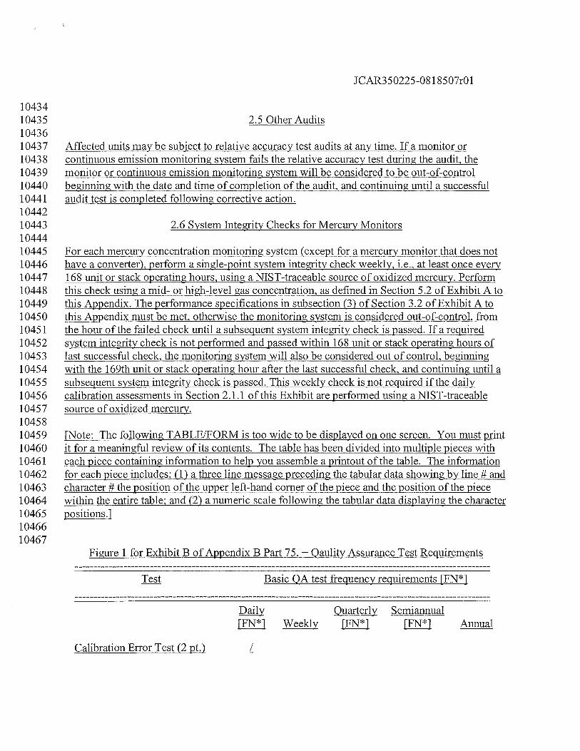
JCAR350225-08 1 8507r01
1043410435 2.5 Other Audits1043610437 Affected units may be subject to relative accuracy test audits at any time. If a monitor or10438 continuous emission monitoring system fails the relative accuracy test during the audit, the10439 monitor or continuous emission monitoring system will be considered to be out-of-control10440 beginning with the date and time of completion of the audit, and continuing until a successful10441 audit test is completed following corrective action.1044210443 2.6 System Integrity Checks for Mercury Monitors1044410445 For each mercury concentration monitoring system (except for a mercury monitor that does not10446 have a converter), perform a single-point system integrity check weekly, i.e., at least once every10447 168 unit or stack operating hours, using a NIST-traceable source of oxidized mercury. Perform10448 this check using a mid- or high-level gas concentration, as defined in Section 5.2 of Exhibit A to10449 this Appendix. The performance specifications in subsection (3) of Section 3.2 of Exhibit A to10450 this Appendix must be met, otherwise the monitoring system is considered out-of-control, from10451 the hour of the failed check until a subsequent system integrity check is passed. If a required10452 system integrity check is not performed and passed within 168 unit or stack operating hours of10453 last successful check, the monitoring system will also be considered out of control, beginning10454 with the 169th unit or stack operating hour after the last successful check, and continuing until a10455 subsequent system integrity check is passed. This weekly check is not required if the daily10456 calibration assessments in Section 2.1.1 of this Exhibit are performed using a NIST-traceable10457 source of oxidized mercury.1045810459 [Note: The following TABLE/FORM is too wide to be displayed on one screen. You must print10460 it for a meaningful review of its contents. The table has been divided into multiple pieces with10461 each piece containing information to help you assemble a printout of the table. The information10462 for each piece includes: (1) a three line message preceding the tabular data showing by line # and10463 character # the position of the upper left-hand corner of the piece and the position of the piece10464 within the entire table; and (2) a numeric scale following the tabular data displaying the character10465 positions.]1046610467
Figure 1 for Exhibit B of Appendix B Part 75. — Qaulity Assurance Test Requirements
Basic QA test frequency requirements FFN*]
Daily Quarterly Semiannual[FN*] Weekly [FN*1 FFN*1 Annual
Calibration Error Test (2 Pt.) /
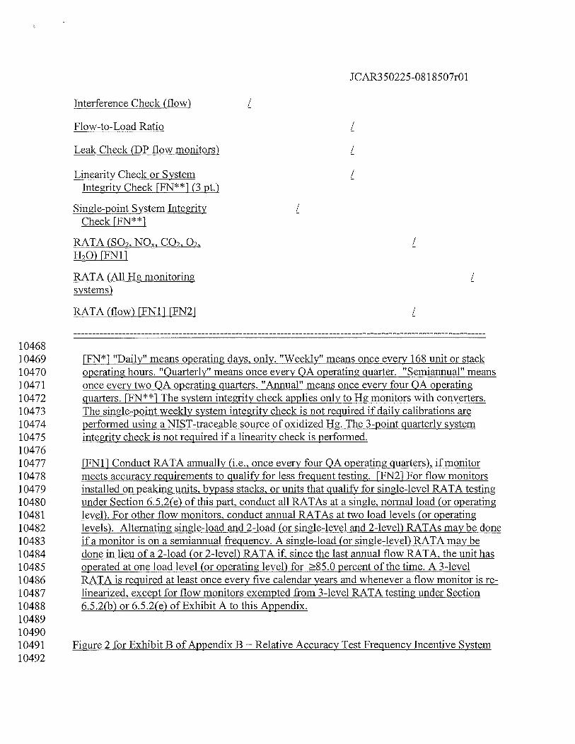
JCAR350225-08 1 8507r01
Interference Check (flow) /
Flow-to-Load Ratio /
Leak Check (DP flow monitors) /
Linearity Check or SystemIntegrity Check [FN**] (3 pt.)
Single-point System Integrity /Check FFN**1
RATA (SO2,NOXQ /O) [FN11
RATA (All Hg monitoring /systems)
RATA (flow) [FN1J [FN21 /
1046810469 [FN*1 “Daily” means operating days, only. “Weekly” means once every 168 unit or stack10470 operating hours. “Quarterly” means once every QA operating quarter. “Semiannual” means10471 once every two QA operating quarters. “Annual” means once every four QA operating10472 quarters. FFN**1 The system integrity check applies only to Hg monitors with converters.10473 The single-point weekly system integrity check is not required if daily calibrations are10474 performed using a NIST-traceable source of oxidized Hg. The 3-point quarterly system10475 integrity check is not required if a linearity check is performed.1047610477 [FN11 Conduct RATA annually (i.e., once every four QA operating quarters), if monitor10478 meets accuracy requirements to qualify for less frequent testing. FFN21 For flow monitors10479 installed on peaking units, bypass stacks, or units that qualify for single-level RATA testing10480 under Section 6.5.2(e) of this part, conduct all RATAs at a single, normal load (or operating10481 level). For other flow monitors, conduct annual RATAs at two load levels (or operating10482 levels). Alternating single-load and 2-load (or single-level and 2-level) RATAs may be done10483 if a monitor is on a semiannual frequency. A single-load (or single-level) RATA may be10484 done in lieu of a 2-load (or 2-level) RATA if, since the last annual flow RATA, the unit has10485 operated at one load level (or operating level) for 85.0 percent of the time. A 3-level10486 RATA is required at least once every five calendar years and whenever a flow monitor is re10487 linearized, except for flow monitors exempted from 3-level RATA testing under Section10488 6.5.2(b) or 6.5.2(e) of Exhibit A to this Appendix.104891049010491 Figure 2 for Exhibit B of Appendix B — Relative Accuracy Test Frequency Incentive System10492
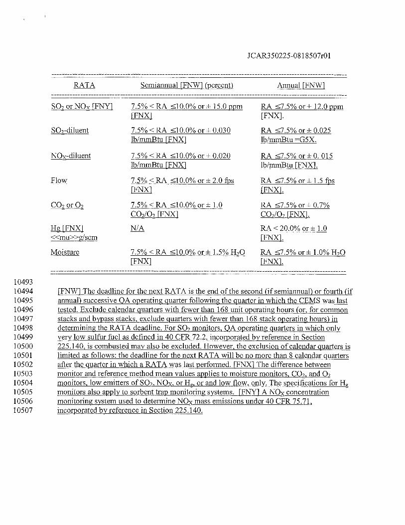
JCAR350225-081 8507r01
RATA Semiannual [FNW1 (percent) Annual FFNW1
SQ2 orNOx [FNY1 7.5% <RA lO.0% or* 15.0 ppm RA 7.5% or± 12.0 ppm[FNX1 FFNX1.
Q2-diluent 7.5% <RA 10.0% or ± 0.030 RA 7.5% or ± 0.025lb/mmBtu FFNX1 lb/mmBtu =G5X.
NOx-diluent 7.5% <RA 10.0% or ± 0.020 RA 7.5% or ± 0. 015lb/mmBtu FFNX] lb/mmBtu [FNX].
Flow 7.5% <RA 10.0% or± 2.0 fps RA 7.5% or± 1.5 fps[FNX] [FNX1.
C02or02 7.5%<RA 10.0%or± 1.0 RA 7.5%or±0.7%cQLQ2 FFNX1 cQLQ2 FFNX1.
HgFFNX1 N/A RA<20.0%or±l.0<<mu>>g/scm FFNX1.
Moisture 7.5%<RA 10.0%or± 1.5%H20 RA 7.5%or± 1.0%H20[FNX1 FFNX].
1049310494 [FNW] The deadline for the next RATA is the end of the second (if semiannual) or fourth (if10495 annual) successive QA operating quarter following the quarter in which the CEMS was last10496 tested. Exclude calendar quarters with fewer than 168 unit operating hours (or, for comi-non10497 stacks and bypass stacks, exclude quarters with fewer than 168 stack operating hours) in10498 determining the RATA deadline. For SO2 monitors, QA operating quarters in which only10499 very low sulfur fuel as defined in 40 CFR 72.2, incorporated by reference in Section10500 225.140, is combusted may also be excluded. However, the exclusion of calendar quarters is10501 limited as follows: the deadline for the next RATA will be no more than 8 calendar quarters10502 afler the quarter in which a RATA was last performed. FFNX] The difference between10503 monitor_and_reference method mean values applies to moisture monitors, CO2. and 0210504 monitors, low emitters of SO2, NON, or H, or and low flow, only. The specifications for Hg10505 monitors also apply to sorbent trap monitoring systems. [FWY1 A NOx concentration10506 monitoring system used to determine NO mass emissions under 40 CFR 75.71,10507 incorporated by reference in Section 225.140.
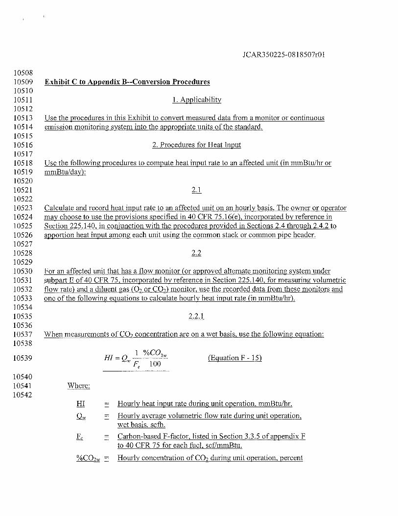
JCAR350225-081 8507r01
1050810509 Exhibit C to Appendix B--Conversion Procedures1051010511 1. Applicability1051210513 Use the procedures in this Exhibit to convert measured data from a monitor or continuous10514 emission monitoring system into the appropriate units of the standard.1051510516 2. Procedures for Heat Input1051710518 Use the following procedures to compute heat input rate to an affected unit (in mmBtu/hr or10519 mmBtu/day):1052010521 2.11052210523 Calculate and record heat input rate to an affected unit on an hourly basis. The owner or operator10524 may choose to use the provisions specified in 40 CFR 75.16(e), incorporated by reference in10525 Section 225.140, in conjunction with the procedures provided in Sections 2.4 through 2.4.2 to10526 apportion heat input among each unit using the common stack or common pipe header.1052710528 2.21052910530 For an affected unit that has a flow monitor (or approved alternate monitoring system under10531 subpart E of 40 CFR 75, incorporated by reference in Section 225.140, for measuring volumetric10532 flow rate) and a diluent gas (02 or CO) monitor, use the recorded data from these monitors and10533 one of the following equations to calculate hourly heat input rate (in mmBtu/hr).1053410535 2.2.11053610537 When measurements of CO2 concentration are on a wet basis, use the following equation:10538
1%CO10539 HI=Q — 2w (EquationF-15)
WF 100
1054010541 Where:10542
HI Hourly heat input rate during unit operation, mmBtulhr.
= Hourly average volumetric flow rate during unit operation,wet basis, seth.
= Carbon-based F-factor, listed in Section 3.3.5 of appendix Fto 40 CFR 75 for each fuel, scf/mmBtu.
%çQ Hourly concentration of CO2 during unit operation, percent
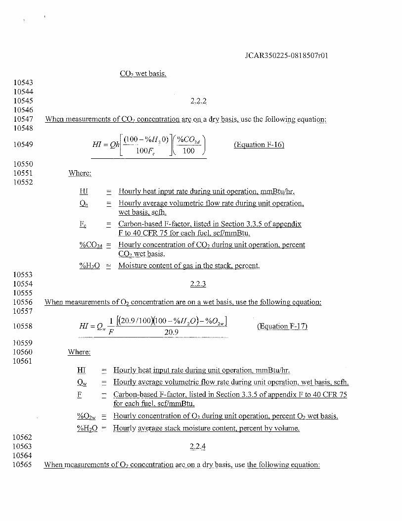
JCAR350225-081 8507r01
CO2 wet basis.105431054410545 2.2.21054610547 When measurements of CO2 concentration are on a dry basis, use the following equation:10548
10549 HI = Qhr(100 — %H20) %C02d
(Equation F- 16)L 100F ] 100 J
1055010551 Where:10552
ffl Hourly heat input rate during unit operation, mmBtu/hr.
Hourly average volumetric flow rate during unit operation,wet basis, scfh.
F Carbon-based F-factor, listed in Section 3.3.5 of appendixF to 40 CFR 75 for each fuel, scf/mniBtu.
%CO Hourly concentration of CO7 during unit operation, percentwet basis.
= Moisture content of gas in the stack, percent.1055310554 2.2.31055510556 When measurements of 02 concentration are on a wet basis, use the following equation:10557
10558 HI = Q__[(20.9/100X100/H2O)%O2Wl (Equation F-17)
1055910560 Where:10561
HI Hourly heat input rate during unit operation, mmBtu/hr.
= Hourly average volumetric flow rate during unit operation, wet basis, scth.
F Carbon-based F-factor, listed in Section 3.3.5 of appendix F to 40 CFR 75for each fuel, scf/mmBtu.
Hourly concentration of 02 during unit operation, percent O wet basis.
= Hourly average stack moisture content, percent by volume.1056210563 2.2.41056410565 When measurements of O concentration are on a dry basis, use the following equation:
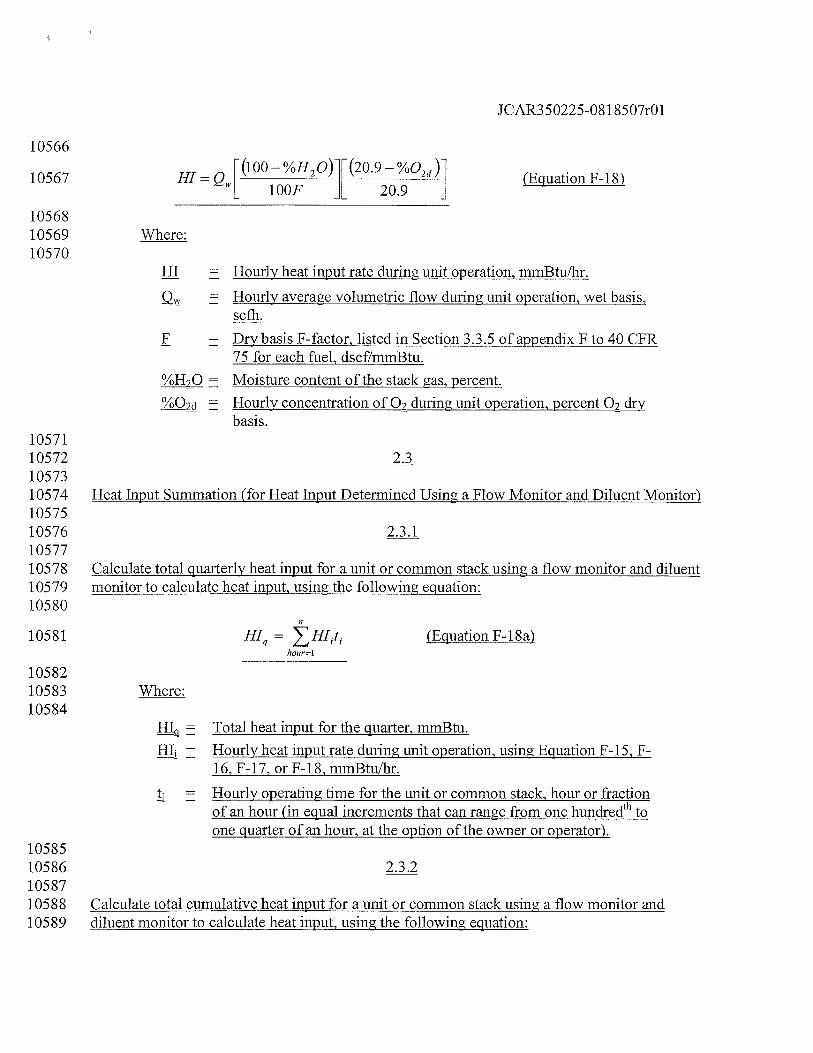
JCAR350225-081 8507r01
10566
10567 HI = Qw[(b00l20)1[(20.902u] (Equation F-18)
1056810569 Where:10570
ffl Hourly heat input rate during unit operation, mmBtu/hr.
= Hourly average volumetric flow during unit operation, wet basis,scfh.
F = Dry basis F-factor, listed in Section 3.3.5 of appendix F to 40 CFR75 for each fuel, dscf/mmBtu.
= Moisture content of the stack gas, percent.
= Hourly concentration of 02 during unit operation, percent Ocybasis.
10571105721057310574 Heat Input Summation (for Heat Input Detennined Using a Flow Monitor and Diluent Monitor)1057510576 2.3.11057710578 Calculate total quarterly heat input for a unit or common stack using a flow monitor and diluent10579 monitor to calculate heat input, using the following equation:10580
10581 HIq = HI1t (Equation F-18a)hour—I
1058210583 Where:10584
HIq = Total heat input for the quarter, mmBtu.
HI = Hourly heat input rate during unit operation, using Equation F-15, F16, F-17, orF-18, mmBtu/hr.
tj Hourly operating time for the unit or common stack, hour or fractionof an hour (in equal increments that can range from one hundredth toone quarter of an hour, at the option of the owner or operator).
1058510586 2.3.21058710588 Calculate total cumulative heat input for a unit or common stack using a flow monitor and10589 diluent monitor to calculate heat input, using the following equation:
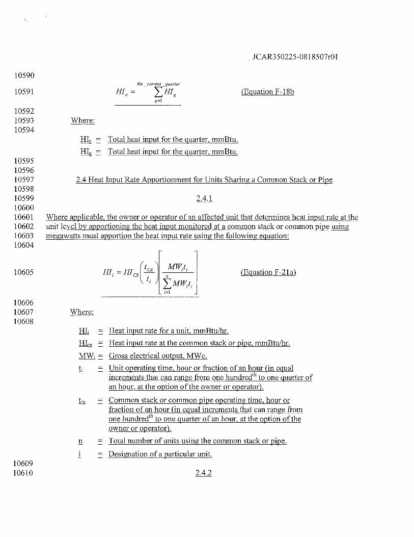
10590
JCAR350225-08 1 8507r01
HI =
the — current — quarter
HIqq=1
10591
105921059310594
10595105961059710598105991060010601106021060310604
10605
106061060710608
1060910610
(Equation F-i 8b
Where:
HI = Total heat input for the quarter, mmBtu.
HIq Total heat input for the quarter, mmBtu.
2.4 Heat Input Rate Apportionment for Units Sharing a Common Stack or Pipe
2.4.1
Where applicable, the owner or operator of an affected unit that determines heat input rate at theunit level by apportioning the heat input monitored at a common stack or common pipe usingmegawatts must apportion the heat input rate using the following equation:
(Equation F-2 1 a)
Where:
HI = Heat input rate for a unit, mmBtu/hr.
HI = Heat input rate at the common stack or pipe, mmBtu/hr.
MW = Gross electrical output, MWe.
tj = Unit operating time, hour or fraction of an hour (in equalincrements that can range from one hundredth to one quarter ofan hour, at the option of the owner or operator).
tCS = Common stack or common pipe operating time, hour orfraction of an hour (in equal increments that can range fromone hundredth to one quarter of an hour, at the option of theowner or operator).
n Total number of units using the common stack or pipe.
i = Designation of a particular unit.
2.4.2
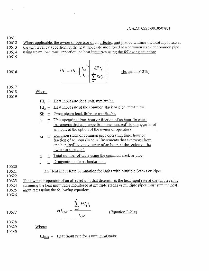
JCAR350225-08 1 8507r01
1061110612 Where applicable, the owner or operator of an affected unit that determines the heat input rate at10613 the unit level by apportioning the heat input rate monitored at a common stack or common pipe10614 using steam load must apportion the heat input rate using the following equation:10615
10616 (Equation F-21b)
1061710618 Where:10619
HI = Heat input rate for a unit, mmBtu/hr.
HIcs = Heat input rate at the common stack or pipe, mmBtu/hr.
SF = Gross steam load, lb/hi, or mmBtu/hr.
tj = Unit operating time, hour or fraction of an hour (in equalincrements that can range from one hundredth to one quarter ofan hour, at the option of the owner or operator).
= Common stack or common pipe operating time, hour orfraction of an hour (in equal increments that can range fromone hundredth to one quarter of an hour, at the option of theowner or operator).
n = Total number of units using the common stack or pipe.
i = Designation of a particular unit.1062010621 2.5 Heat Input Rate Summation for Units with Multiple Stacks or Pipes1062210623 The owner or operator of an affected unit that determines the heat input rate at the unit level by10624 summing the heat input rates monitored at multiple stacks or multiple pipes must sum the heat10625 input rates using the following equation:10626
— HIt
10627 — (Equation F-21c)tunit
1062810629 Where:10630
Heat input rate for a unit, mmBtu/hr.
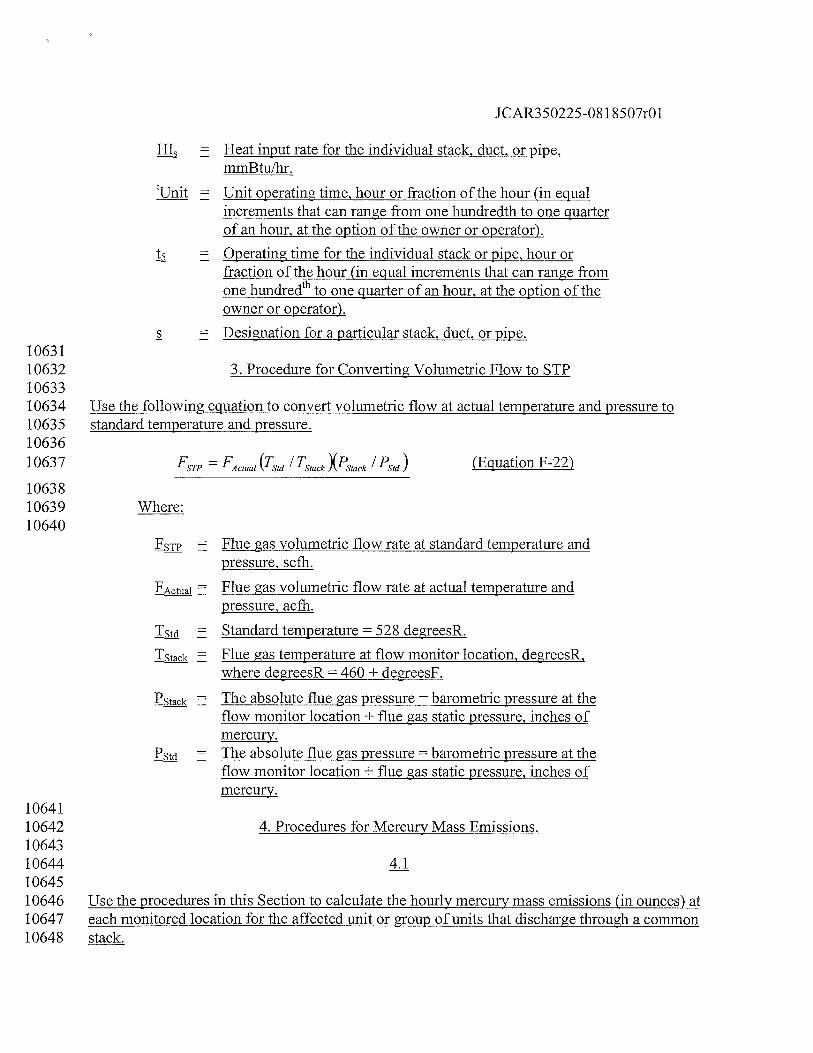
JCAR350225-08 1 8507r01
= Heat input rate for the individual stack, duct, or pipe,mmBtulhr.
____
Unit operating time, hour or fraction of the hour (in equalincrements that can range from one hundredth to one quarterof an hour, at the option of the owner or operator).
t5 = Operating time for the individual stack or pipe, hour orfraction of the hour (in equal increments that can range fromone hundredth to one quarter of an hour, at the option of theowner or operator).
s = Designation for a particular stack, duct, or pipe.1063110632 3. Procedure for Converting Volumetric Flow to STP1063310634 Use the following equation to convert volumetric flow at actual temperature and pressure to10635 standard temperature and pressure.1063610637 FSTP = FActual (TSfd I TStack XStack /Sd) (Equation F-22)
1063810639 Where:10640
= Flue gas volumetric flow rate at standard temperature andpressure, scth.
Ectuai Flue gas volumetric flow rate at actual temperature andpressure, acth.
Tst = Standard temperature 528 degreesR.
ISCk = Flue gas temperature at flow monitor location, degreesR,where degreesR = 460 + degreesF.
SCk = The absolute flue gas pressure = barometric pressure at theflow monitor location + flue gas static pressure, inches ofmercury.
P5t The absolute flue gas pressure = barometric pressure at theflow monitor location + flue gas static pressure, inches ofmercury.
1064110642 4. Procedures for Mercury Mass Emissions.1064310644 4.11064510646 Use the procedures in this Section to calculate the hourly mercury mass emissions (in ounces) at10647 each monitored location for the affected unit or group of units that discharge through a common10648 stack.
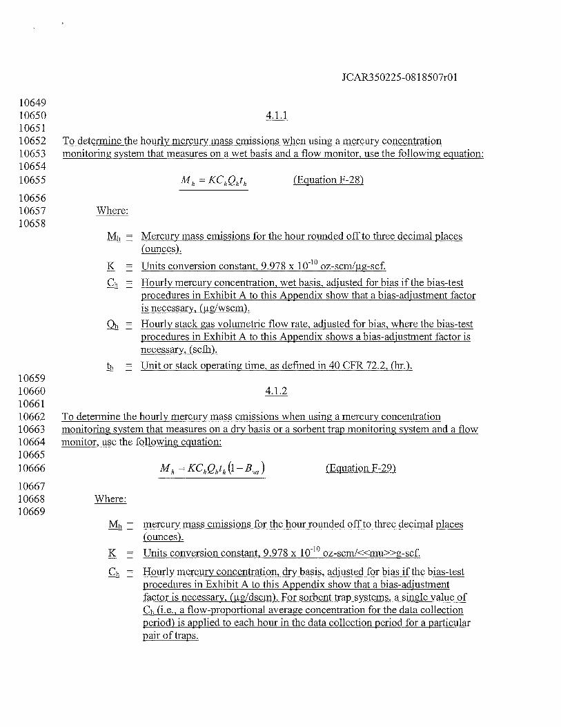
JCAR350225-08 1 8507r01
1064910650 4.1.11065110652 To determine the hourly mercury mass emissions when using a mercury concentration10653 monitoring system that measures on a wet basis and a flow monitor, use the following equation:1065410655 Mh —KChQhth (Equation F-28)
1065610657 Where:10658
Mb Mercury mass emissions for the hour rounded off to three decimal places(ounces).
K = Units conversion constant, 9.978 x 1 0b0 oz-scm/ig-scf.
Hourly mercury concentration, wet basis, adjusted for bias if the bias-testprocedures in Exhibit A to this Appendix show that a bias-adjustment factoris necessary, (ig/wscm).
Qh = Hourly stack gas volumetric flow rate, adjusted for bias, where the bias-testprocedures in Exhibit A to this Appendix shows a bias-adjustment factor isnecessary, (scifi).
Unit or stack operating time, as defined in 40 CFR 72.2, (hr.).1065910660 4.1.21066110662 To determine the hourly mercury mass emissions when using a mercury concentration10663 monitoring system that measures on a dry basis or a sorbent trap monitoring system and a flow10664 monitor, use the following equation:1066510666 Mh = KChQhth (1— B) (Equation F-29)
1066710668 Where:10669
Mb = mercury mass emissions for the hour rounded off to three decimal places(ounces).
K = Units conversion constant, 9.978 x 10b0 oz-scm/<<mu>>g-scf.
Hourly mercury concentration, dry basis, adjusted for bias if the bias-testprocedures in Exhibit A to this Appendix show that a bias-adjustmentfactor is necessary, (jig/dscm). For sorbent trap systems, a single value ofCh (i.e., a flow-proportional average concentration for the data collectionperiod) is applied to each hour in the data collection period for a particularpair of traps.
JCAR350225-08 1 8507r01
Qh = Hourly stack gas volumetric flow rate, adjusted for bias, where the bias-test procedures in Exhibit A to this Appendix shows a bias-adjustmentfactor is necessary, (seth).
Moisture fraction of the stack gas expressed as a decimal (equal to %H20100)
th = Unit or stack operating time as defined in 40 CFR 72.2, (hr.).1067010671 4.1.31067210673 For units that are demonstrated under Section 1.15(d) of this Appendix to emit less than 46410674 ounces of mercury per year, and for which the owner or operator elects not to continuously10675 monitor the mercury concentration, calculate the hourly mercury mass emissions using Equation10676 F-28 in Section 4.1 .1 of this Exhibit, except that “Ch” will be the applicable default mercury10677 concentration from Section 1.15(c), (d), or (e) of this Appendix, expressed in jig/scm. Correction10678 for the stack gas moisture content is not required when this methodology is used.1067910680 4.21068110682 Use the following equation to calculate quarterly and year-to-date mercury mass emissions in10683 ounces:10684
10685 Mtime period = (Equation F-30)
1068610687 Where:10688
Mtime period = Mercury mass emissions for the given time period, i.e., quarter or year-to-date rounded to the nearest thousandth. (ounces).
Mercury mass emissions for the hour rounded to three decimal places(ounces).
n The number of hours in the given time period (quarter or year-to-date).1068910690 4.3 If heat input rate monitoring is required, follow the applicable procedures for heat input10691 apportionment and summation in Sections 2.3, 2.4 and 2.5 of this Exhibit.1069210693 5. Moisture Determination From Wet and Dry O Readings1069410695 If a correction for the stack gas moisture content is required in any of the emissions or heat input10696 calculations described in this Exhibit, and if the hourly moisture content is determined from wet-10697 and dry-basis 02 readings, use Equation F-3 1 to calculate the percent moisture, unless a “Kr’10698 factor or other mathematical algorithm is developed as described in Section 6.5.6(a) of Exhibit A
JCAR350225-081 8507r01
10699 to this Appendix:10700
10701 %H20= (02d—02W) x 100 (Equation F-31)
1070210703 Where:10704
ll2O Hourly average stack gas moisture content, percentH20= Dry-basis hourly average oxygen concentration, percent 02= Wet-basis hourly average oxygen concentration, percent 02
1070510706 Exhibit D to Appendix B — Quality Assurance and Operating Procedures for Sorbent Trap10707 Monitoring Systems1070810709 1.0 Scope and Application1071010711 This Exhibit specifies sampling, and analytical, and quality-assurance criteria and procedures for10712 the performance-based monitoring of vapor-phase mercury (Hg) emissions in combustion flue10713 gas streams, using a sorbent trap monitoring system (as defined in Section 225.130). The10714 principle employed is continuous sampling using in-stack sorbent media coupled with analysis of10715 the integrated samples. The performance-based approach of this Exhibit allows for use of various10716 suitable sampling and analytical technologies while maintaining a specified and documented10717 level of data quality through performance criteria. Persons using this Exhibit should have a10718 thorough working knowledge of Methods 1, 2, 3, 4 and 5 in appendices A-i through A-3 to 4010719 CFR 60, incorporated by reference in Section 225.140, as well as the determinative technique10720 selected for analysis.1072110722 1.1 Analytes1072310724 The analyte measured by these procedures and specifications is total vapor-phase mercury in the10725 flue gas, which represents the sum of elemental mercury (Hg°, CAS Number 7439-97-6) and10726 oxidized forms of mercury, in mass concentration units of micrograms per dry standard cubic10727 meter (pg/dscm).1072810729 1.2 Applicability1073010731 These performance criteria and procedures are applicable to monitoring of vapor-phase mercury10732 emissions under relatively low-dust conditions (i.e., sampling in the stack after all pollution10733 control devices), from coal-fired electric utility steam generators which are subject to Sections10734 1.14 through 1.18 of Appendix B. Individual sample collection times can range from 30 minutes10735 to several days in duration, depending on the mercury concentration in the stack. The monitoring10736 system must achieve the performance criteria specified in Section 8 of this Exhibit and the10737 sorbent media capture ability must not be exceeded. The sampling rate must be maintained at a
1CAR350225-081 8507r01
10738 constant proportion to the total stack flow rate to ensure representativeness of the sample10739 collected. Failure to achieve certain performance criteria will result in invalid mercury emissions10740 monitoring data.1074110742 2.0 Principle1074310744 Known volumes of flue gas are extracted from a stack or duct through paired, in-stack, pre10745 spiked sorbent media traps at an appropriate nominal flow rate. Collection of mercury on the10746 sorbent media in the stack mitigates potential loss of mercury during transport through a10747 probe/sample line. Paired train sampling is required to determine measurement precision and10748 verify acceptability of the measured emissions data.1074910750 The sorbent traps are recovered from the sampling system, prepared for analysis, as needed, and10751 analyzed by any suitable determinative technique that can meet the performance criteria. A10752 section of each sorbent trap is spiked with Hg° prior to sampling. This section is analyzed10753 separately and the recovery value is used to correct the individual mercury sample for10754 measurement bias.1075510756 3.0 Clean Handling and Contamination1075710758 To avoid mercury contamination of the samples, special attention should be paid to cleanliness10759 during transport, field handling, sampling, recovery, and laboratory analysis, as well as during10760 preparation of the sorbent cartridges. Collection and analysis of blank samples (field, trip, lab) is10761 useful in verifying the absence of contaminant mercury.1076210763 4.0 Safety1076410765 4.1 Site hazards1076610767 Site hazards must be thoroughly considered in advance of applying these10768 procedures/specifications in the field; advance coordination with the site is critical to understand10769 the conditions and applicable safety policies. At a minimum, portions of the sampling system10770 will be hot, requiring appropriate gloves, long sleeves, and caution in handling this equipment.1077110772 4.2 Laboratory safety policies1077310774 Laboratory safety policies should be in place to minimize risk of chemical exposure and to10775 properly handle waste disposal. Personnel must wear appropriate laboratory attire according to a10776 Chemical Hygiene Plan established by the laboratory.1077710778 4.3 Toxicity or carcinogenicity1077910780 The toxicity or carcinogenicity of any reagents used must be considered. Depending upon the
JCAR350225-0818507r01
10781 sampling and analytical technologies selected, this measurement may involve hazardous10782 materials, operations, and equipment and this Exhibit does not address all of the safety problems10783 associated with implementing this approach. It is the responsibility of the user to establish10784 appropriate safety and health practices and determine the applicable regulatory limitations prior10785 performance. Any chemical should be regarded as a potential health hazard and exposure to10786 these compounds should be minimized. Chemists should refer to the Material Safety Data Sheet10787 (MSDS) for each chemical used.1078810789 4.4 Wastes1079010791 Any wastes generated by this procedure must be disposed of according to a hazardous materials10792 management plan that details and tracks various waste streams and disposal procedures.1079310794 5.0 Equipment and Supplies1079510796 The following list is presented as an example of key equipment and supplies likely required to10797 perform vapor-phase mercury monitoring using a sorbent trap monitoring system. It is10798 recognized that additional equipment and supplies may be needed. Collection of paired samples10799 is required. Also required are a certified stack gas volumetric flow monitor that meets the10800 requirements of Section 1.2 to this Appendix and an acceptable means of correcting for the stack10801 gas moisture content, i.e., either by using data from a certified continuous moisture monitoring10802 system or by using an approved default moisture value (see 40 CFR 75.11(b), incorporated by10803 reference in Section 225.140).1080410805 5.1 Sorbent Trap Monitoring System1080610807 A typical sorbent trap monitoring system is shown in Figure K-i. The monitoring system must10808 include the following components:1080910810 5.1.1 Sorbent Traps1081110812 The sorbent media used to collect mercury must be configured in a trap with three distinct and10813 identical segments or sections, connected in series, that are amenable to separate analyses.10814 Section 1 is designated for primary capture of gaseous mercury. Section 2 is designated as a10815 backup section for determination of vapor-phase mercury breakthrough. Section 3 is designated10816 for OAIOC purposes where this section must be spiked with a known amount of gaseous Hg°10817 prior to sampling and later analyzed to determine recovery efficiency. The sorbent media may be10818 any collection material (e.g., carbon, chemically-treated filter, etc.) capable of quantitatively10819 capturing and recovering for subsequent analysis, all gaseous forms of mercury for the intended10820 application. Selection of the sorbent media must be based on the material’s ability to achieve the10821 performance criteria contained in Section 8 of this Exhibit as well as the sorbent’s vapor-phase10822 mercury capture efficiency for the emissions matrix and the expected sampling duration at the10823 test site. The sorbent media must be obtained from a source that can demonstrate the quality
JCAR350225-08 1 8507r01
10824 assurance and control necessary to ensure consistent reliability. The paired sorbent traps are10825 supported on a probe (or probes) and inserted directly into the flue gas stream.1082610827 5.1.2 Sampling Probe Assembly1082810829 Each probe assembly must have a leak-free Exhibit to the sorbent traps. Each sorbent trap must10830 be mounted at the entrance of or within the probe such that the gas sampled enters the trap10831 directly. Each probe/sorbent trap assembly must be heated to a temperature sufficient to prevent10832 liquid condensation in the sorbent traps. Auxiliary heating is required only where the stack10833 temperature is too low to prevent condensation. Use a calibrated thermocouple to monitor the10834 stack temperature. A single probe capable of operating the paired sorbent traps may be used.10835 Alternatively, individual probe/sorbent trap assemblies may be used, provided that the individual10836 sorbent traps are co-located to ensure representative mercury monitoring and are sufficiently10837 separated to prevent aerodynamic interference.1083810839 5.1.3 Moisture Removal Device1084010841 A robust moisture removal device or system, suitable for continuous duty (such as a Peltier10842 cooler), must be used to remove water vapor from the gas stream prior to entering the gas flow10843 meter.1084410845 5.1.4 Vacuum Pump1084610847 Use a leak-tight, vacuum pump capable of operating within the candidate system’s flow range.1084810849 5.1.5 Gas Flow Meter1085010851 A gas flow meter (such as a dry gas meter, thermal mass flow meter, or other suitable10852 measurement device) must be used to determine the total sample volume on a dry basis, in units10853 of standard cubic meters. The meter must be sufficiently accurate to measure the total sample10854 volume to within 2 percent and must be calibrated at selected flow rates across the range of10855 sample flow rates at which the sorbent trap monitoring system typically operates. The gas flow10856 meter must be equipped with any necessary auxiliary measurement devices (e.g., temperature10857 sensors, pressure measurement devices) needed to correct the sample volume to standard10858 conditions.1085910860 5.1.6 Sample Flow Rate Meter and Controller1086110862 Use a flow rate indicator and controller for maintaining necessary sampling flow rates.1086310864 5.1.7 Temperature Sensor1086510866 Same as Section 6.1.1.7 of Method 5 in appendix A-3 to 40 CFR 60, incorporated by reference in
JCAR350225-08 1 8507r01
10867 Section 225.140.1086810869 5.1.8 Barometer1087010871 Same as Section 6.1.2 of Method 5 in appendix A-3 to 40 CFR 60, incorporated by reference in10872 Section 225.140.1087310874 5.1.9 Data Logger (Optional)1087510876 Device for recording associated and necessary ancillary information (e.g., temperatures,10877 pressures, flow, time, etc.).1087810879 5.2 Gaseous Hg° Sorbent Trap Spiking System1088010881 A known mass of gaseous Hg° must be spiked onto section 3 of each sorbent trap prior to10882 sampling. Any approach capable of quantitatively delivering known masses of Hg° onto sorbent10883 traps is acceptable. Several technologies or devices are available to meet this objective. Their10884 practicality is a function of mercury mass spike levels. For low levels, NIST-certified or NIST10885 traceable gas generators or tanks may be suitable, but will likely require long preparation times.10886 A more practical, alternative system, capable of delivering almost any mass required, makes use10887 of NIST-certified or NIST-traceable mercury salt solutions (e.g., Hg(N03)2). With this system,10888 an aliquot of known volume and concentration is added to a reaction vessel containing a10889 reducing agent (e.g., stannous chloride); the mercury salt solution is reduced to Hg° and purged10890 onto section 3 of the sorbent trap using an impinger sparging system.1089110892 5.3 Sample Analysis Equipment1089310894 Any analytical system capable of quantitatively recovering and quantifying total gaseous10895 mercury from sorbent media is acceptable provided that the analysis can meet the perfonnance10896 criteria in Section 8 of this procedure. Candidate recovery techniques include leaching, digestion,10897 and thermal desorption. Candidate analytical techniques include ultraviolet atomic fluorescence10898 (UV AF); ultraviolet atomic absorption (UV AA), with and without gold trapping; and in-situ X10899 ray fluorescence (XRF) analysis.1090010901 6.0 Reagents and Standards1090210903 Only NIST-certified or NIST-traceable calibration gas standards and reagents must be used for10904 the tests and procedures required under this Exhibit.1090510906 7.0 Sample Collection and Transport1090710908 7.1 Pre-Test Procedures10909
JCAR350225-08 1 8507r01
10910 7.1.1 Selection of Sampling Site1091110912 Sampling site information should be obtained in accordance with Method 1 in appendix A-i to10913 40 CFR 60, incorporated by reference in Section 225.140. Identify a monitoring location10914 representative of source mercury emissions. Locations shown to be free of stratification through10915 measurement traverses for gases such as SO and NOmay be one such approach. An estimation10916 of the expected stack mercury concentration is required to establish a target sample flow rate,10917 total gas sample volume, and the mass of Hg° to be spiked onto section 3 of each sorbent trap.1091810919 7.1.2 Pre-sampling Spiking of Sorbent Traps1092010921 Based on the estimated mercury concentration in the stack, the target sample rate and the target10922 sampling duration, calculate the expected mass loading for section 1 of each sorbent trap (for an10923 example calculation, see Section 11.1 of this Exhibit). The pre-sampling spike to be added to10924 section 3 of each sorbent trap must be within ± 50 percent of the expected section 1 mass10925 loading. Spike section 3 of each sorbent trap at this level, as described in Section 5.2 of this10926 Exhibit. For each sorbent trap, keep an official record of the mass of Hg° added to section 3. This10927 record must include, at a minimum, the ID number of the trap, the date and time of the spike, the10928 name of the analyst performing the procedure, the mass of Hg° added to section 3 of the trap10929 (jig), and the supporting calculations. This record must be maintained in a format suitable for10930 inspection and audit and must be made available to the regulatory agencies upon request.1093110932 7.1.3 Pre-test Leak Check1093310934 Perform a leak check with the sorbent traps in place. Draw a vacuum in each sample train.10935 Adjust the vacuum in the sample train to mercury. Using the gas flow meter, determine leak rate.10936 The leakage rate must not exceed 4 percent of the target sampling rate. Once the leak check10937 passes this criterion, carefully release the vacuum in the sample train then seal the sorbent trap10938 inlet until the probe is ready for insertion into the stack or duct.1093910940 7.1.4 Determination of Flue Gas Characteristics1094110942 Determine or measure the flue gas measurement environment characteristics (gas temperature,10943 static pressure, gas velocity, stack moisture, etc.) in order to determine ancillary requirements10944 such as probe heating requirements (if any), initial sample rate, proportional sampling10945 conditions, moisture management, etc.1094610947 7.2 Sample Collection1094810949 7.2.11095010951 Remove the plug from the end of each sorbent trap and store each plug in a clean sorbent trap10952 storage container. Remove the stack or duct port cap and insert the probes. Secure the probes and
JCAR350225-081 8507r01
10953 ensure that no leakage occurs between the duct and environment.1095410955 7.2.21095610957 Record initial data including the sorbent trap ID, start time, starting dry gas meter readings,10958 initial temperatures, set-points, and any other appropriate information.1095910960 7.2.3 Flow Rate Control1096110962 Set the initial sample flow rate at the target value from Section 7.1.1 of this Exhibit. Record the10963 initial gas flow meter reading, stack temperature (if needed to convert to standard conditions),10964 meter temperatures (if needed), etc. Then, for every operating hour during the sampling period,10965 record the date and time, the sample flow rate, the gas flow meter reading, the stack temperature10966 (if needed), the flow meter temperatures (if needed), temperatures of heated equipment such as10967 the vacuum lines and the probes (if heated), and the sampling system vacuum readings. Also,10968 record the stack gas flow rate, as measured by the certified flow monitor, and the ratio of the10969 stack gas flow rate to the sample flow rate. Adjust the sampling flow rate to maintain10970 proportional sampling, i.e., keep the ratio of the stack gas flow rate to sample flow rate constant,10971 to within ± 25 percent of the reference ratio from the first hour of the data collection period (see10972 Section 11 of this Exhibit). The sample flow rate through a sorbent trap monitoring system10973 during any hour (or portion of an hour) in which the unit is not operating must be zero.1097410975 7.2.4 Stack Gas Moisture Determination1097610977 Determine stack gas moisture using a continuous moisture monitoring system, as described in 4010978 CFR 75.11(b), incorporated by reference in Section 225.140. Alternatively, the owner or10979 operator may use the appropriate fuel-specific moisture default value provided in 40 CFR 75.11,10980 incorporated by reference in Section 225.140, or a site-specific moisture default value approved10981 by the Agency.1098210983 7.2.5 Essential Operating Data1098410985 Obtain and record any essential operating data for the facility during the test period, e.g., the10986 barometric pressure for correcting the sample volume measured by a dry gas meter to standard10987 conditions. At the end of the data collection period, record the final gas flow meter reading and10988 the final values of all other essential parameters.1098910990 7.2.6 Post Test Leak Check1099110992 When sampling is completed, turn off the sample pump, remove the probe/sorbent trap from the10993 port and carefully re-plug the end of each sorbent trap. Perform a leak check with the sorbent10994 traps in place, at the maximum vacuum reached during the sampling period. Use the same10995 general approach described in Section 7.1.3 of this Exhibit. Record the leakage rate and vacuum.
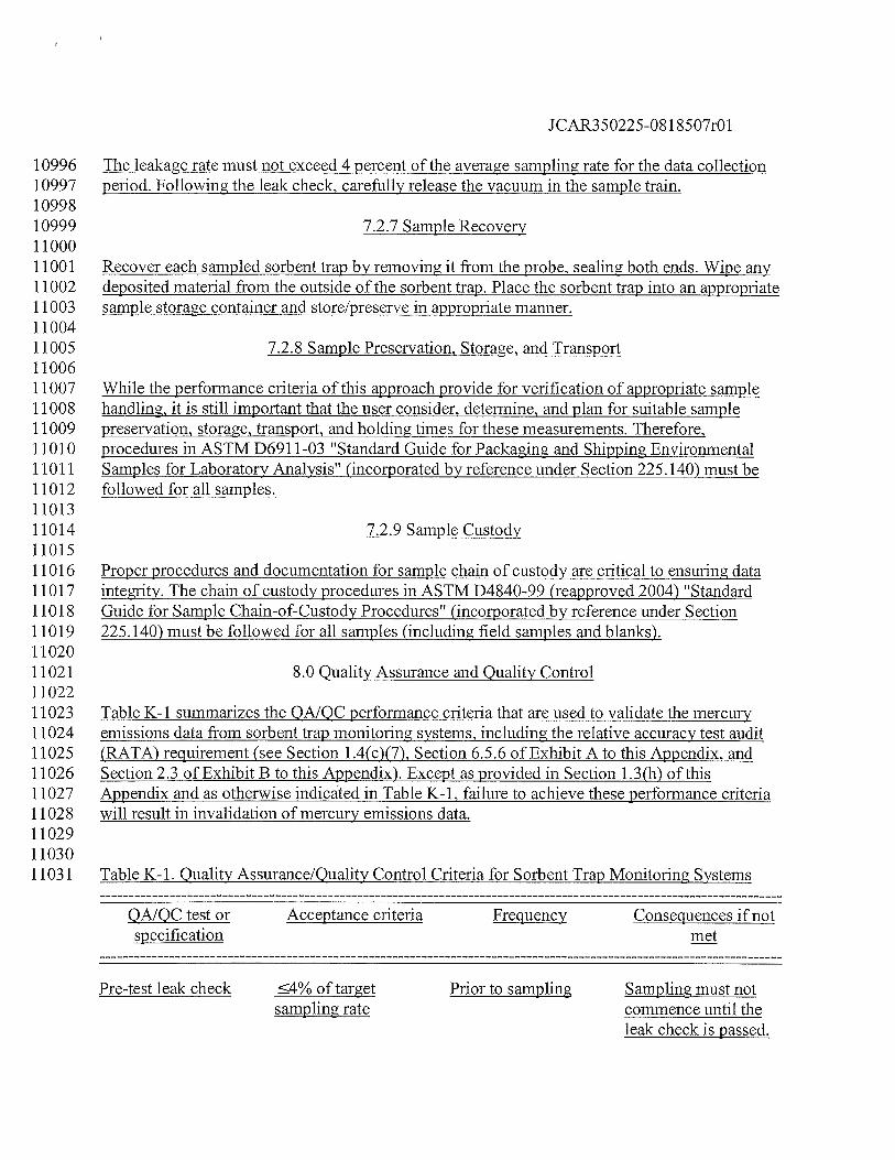
JCAR350225-08 1 8507r01
10996 The leakage rate must not exceed 4 percent of the average sampling rate for the data collection10997 period. Following the leak check, carefully release the vacuum in the sample train.1099810999 7.2.7 Sample Recovery1100011001 Recover each sampled sorbent trap by removing it from the probe, sealing both ends. Wipe any11002 deposited material from the outside of the sorbent trap. Place the sorbent trap into an appropriate11003 sample storage container and store/preserve in appropriate manner.1100411005 7.2.8 Sample Preservation, Storage, and Transport1100611007 While the performance criteria of this approach provide for verification of appropriate sample11008 handling, it is still important that the user consider, determine, and plan for suitable sample11009 preservation, storage, transport, and holding times for these measurements. Therefore,11010 procedures in ASTM D6911-03 “Standard Guide for Packaging and Shipping Environmental11011 Samples for Laboratory Analysis” (incorporated by reference under Section 225.140) must be11012 followed for all samples.1101311014 7.2.9 Sample Custody1101511016 Proper procedures and documentation for sample chain of custody are critical to ensuring data11017 integrity. The chain of custody procedures in ASTM D4840-99 (reapproved 2004) “Standard11018 Guide for Sample Chain-of-Custody Procedures” (incorporated by reference under Section11019 225.140) must be followed for all samples (including field samples and blanks).1102011021 8.0 Quality Assurance and Quality Control1102211023 Table K-i summarizes the QAIQC performance criteria that are used to validate the mercury11024 emissions data from sorb ent trap monitoring systems, including the relative accuracy test audit11025 (RATA) requirement (see Section 1.4(c)(7), Section 6.5.6 of Exhibit A to this Appendix, and11026 Section 2.3 of Exhibit B to this Appendix). Except as provided in Section 1.3(h) of this11027 Appendix and as otherwise indicated in Table K-i, failure to achieve these performance criteria11028 will result in invalidation of mercury emissions data.110291103011031 Table K-i. Quality Assurance/Quality Control Criteria for Sorbent Trap Monitoring Systems
OAIQC test or Acceptance criteria Frequency Consequences if notspecification met
Pre-test leak check 4% of target Prior to sampling Sampling must notsampling rate commence until the
leak check is passed.
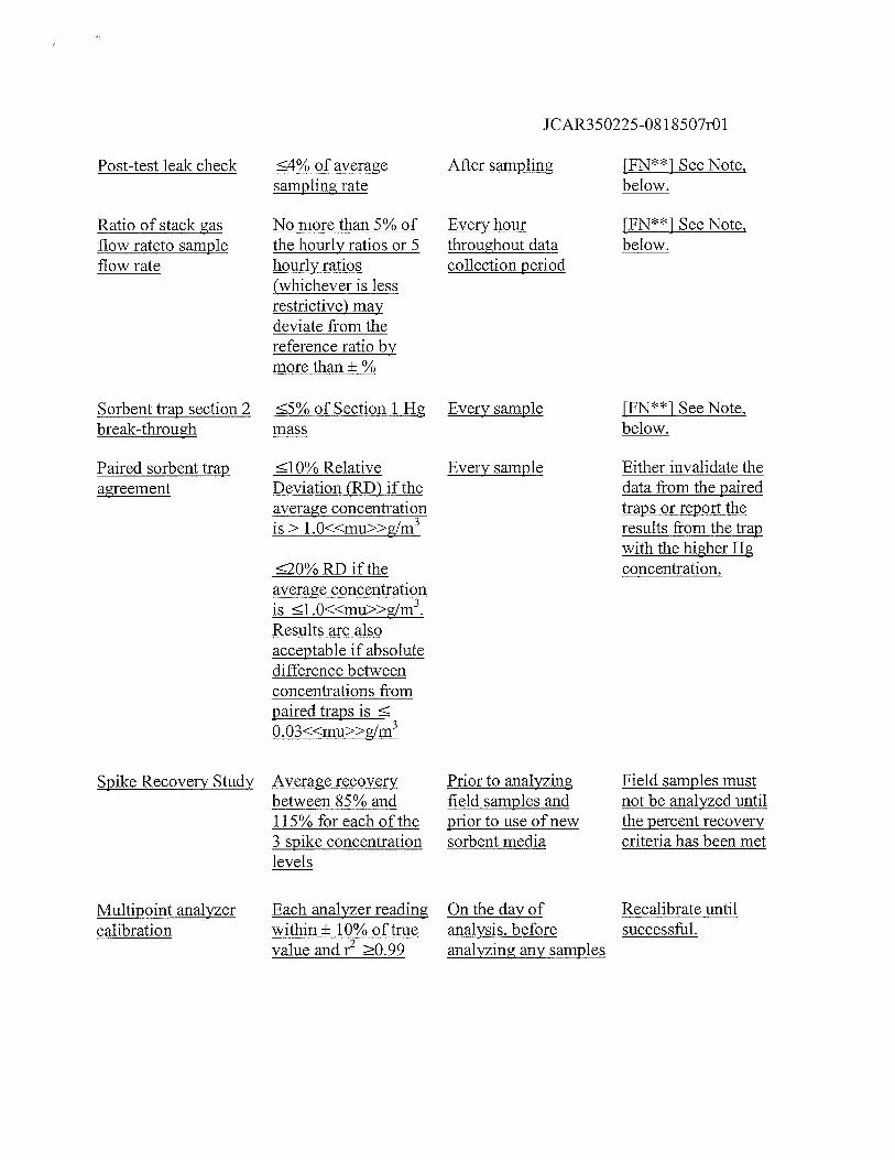
II
IC/)
IPI
IIC
/)t.
I.I
I10
10IP
IC-
Ilo
Hl
l1o
lolC
D
‘‘
I’I
Pl
0)
Ir
--÷l
InlC
DIC
)k-
Id)
I—-
ICP
I lCD
I0
lo10
I
IC)
IP
I-”
I
II
I-t
I
l‘‘‘‘
IC)
‘
ll
‘ii’
f’‘
ll
IPIL
tIQ
l+)
II
E[1Ii
II0
I1
PIpI
‘I
II
-I
II—
Id,)
II
CD
II
Iclo
IIA
I0l
‘‘•
L0
‘0‘I
lCD
II0
I-r-I-l
PI’
IClo
loI
I10
LL
,,
0
lI0
lL
tI0
NIP
loIO
II0
lC
L-”
IE
I0
P0
HI
10I.
IV0
I0l
I”lo
IIc
III
1<O
IdJ
1Q0
‘‘
IAo
Io
Ii
iio
v_
CO
-tl-I
lIC
D
I_Il
oI.
ii.
HIc
_
L0
0cc
I-.
Ici
I_I
IcJo
RJ‘t
loj
lCD
lCD
II
CD
PP
0‘‘t‘I
Iij
IT1
‘°I’
ItTi
II
.Io
II
CD—
Li
i10
00
0l-
t-
IIC
IP10
iiI
I tdP
lCD
I1°iI
lCDI
IIH
°I0
Ic-<
iolo
<I
IIp
INC
D
Cl)
C
pIo
Iilo
o’l
uI
IEI
IiI
I-lo
II
IIZ
I1C
IpH
II
II
IP
C)
I-III
IP
IIp-
1lC
DIC
’Ir-I
it
CDlo
I-t
II
II
II
II
I1
loI-+
II-
Iclo
IcI—
:I-I.
CDh
ll-t
lCD
i-t
I-+
loIIo
Cl)
ull
PIC
DI
-t
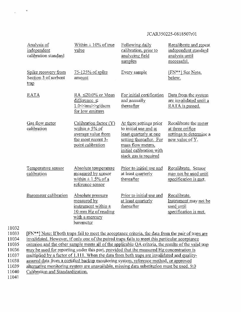
JCAR350225-08 1 8507r01
Analysis ofindependentcalibration standard
Within ± 10% of truevalue
Following dailycalibration, prior toanalyzing fieldsamples
Recalibrate and repeatindependent standardanalysis untilsuccessful.
Spike recovery fromSection 3 of sorbent
75-125% of spikeamount
Every sample [FN**] See Note,below.
RATA RA 20.0%orMeandifference1. 0<<mu>>g/dscmfor low emitters
For initial certificationand annuallythereafter
Data from the systemare invalidated until aRATA is passed.
Gas flow metercalibration
Calibration factor (Y)within ± 5% ofaverage value fromthe most recent 3-point calibration
At three settings priorto initial use and atleast quarterly at onesetting thereafter. Formass flow meters,initial calibration with
Recalibrate the meterat three orificesettings to determine anew value of Y.
stack gas is required
Temperature sensorcalibration
Absolute temperaturemeasured by sensorwithin± 1.5%ofareference sensor
Prior to initial use andat least quarterlythereafter
Recalibrate. Sensormay not be used untilspecification is met.
11032
Barometer calibration Absolute pressuremeasured byinstrument within ±
10 mm Hg of readingwith a mercurybarometer
Prior to initial use andat least quarterlythereafter
Recalibrate.Instrument may not beused untilspecification is met.
[FN**1 Note: If both traps fail to meet the acceptance criteria, the data from the pair of traps areinvalidated. However, if only one of the paired traps fails to meet this particular acceptancecriterion and the other sample meets all of the applicable QA criteria, the results of the valid trapmay be used for reporting under this part, provided that the measured Hg concentration ismultiplied by a factor of 1.111. When the data from both traps are invalidated and quality-assured data from a certified backup monitoring system, reference method, or approvedalternative monitoring system are unavailable, missing data substitution must be used. 9.0Calibration and Standardization.
110331103411035110361103711038110391104011041
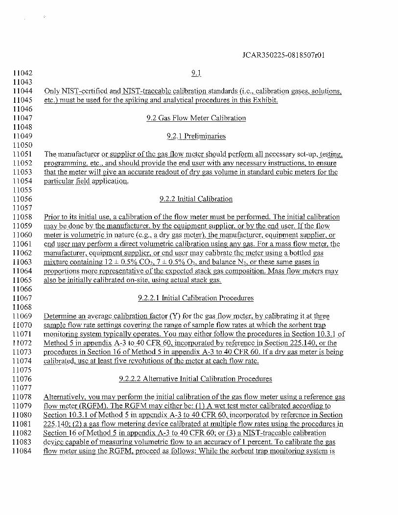
JCAR350225-081 8507r01
11042 9.11104311044 Only NIST-certified and NIST-traceable calibration standards (i.e., calibration gases, solutions,11045 etc.) must be used for the spiking and analytical procedures in this Exhibit.1104611047 9.2 Gas Flow Meter Calibration1104811049 9.2.1 Preliminaries1105011051 The manufacturer or supplier of the gas flow meter should perform all necessary set-up, testing,11052 programming, etc., and should provide the end user with any necessary instructions, to ensure11053 that the meter will give an accurate readout of dry gas volume in standard cubic meters for the11054 particular field application.1105511056 9.2.2 Initial Calibration1105711058 Prior to its initial use, a calibration of the flow meter must be performed. The initial calibration11059 may be done by the manufacturer, by the equipment supplier, or by the end user. If the flow11060 meter is volumetric in nature (e.g., a dry gas meter), the manufacturer, equipment supplier, or11061 end user may perform a direct volumetric calibration using any gas. For a mass flow meter, the11062 manufacturer, equipment supplier, or end user may calibrate the meter using a bottled gas11063 mixture containing 12 ± 0.5% CO2. 7 ± 0.5% 02, and balance N2, or these same gases in11064 proportions more representative of the expected stack gas composition. Mass flow meters may11065 also be initially calibrated on-site, using actual stack gas.1106611067 9.2.2.1 Initial Calibration Procedures1106811069 Determine an average calibration factor (Y) for the gas flow meter, by calibrating it at three11070 sample flow rate settings covering the range of sample flow rates at which the sorbent trap11071 monitoring system typically operates. You may either follow the procedures in Section 10.3.1 of11072 Method 5 in appendix A-3 to 40 CFR 60, incorporated by reference in Section 225.140, or the11073 procedures in Section 16 of Method 5 in appendix A-3 to 40 CFR 60. If a dry gas meter is being11074 calibrated, use at least five revolutions of the meter at each flow rate.1107511076 9.2.2.2 Alternative Initial Calibration Procedures1107711078 Alternatively, you may perform the initial calibration of the gas flow meter using a reference gas11079 flow meter (RGFM). The RGFM may either be: (1) A wet test meter calibrated according to11080 Section 10.3.1 of Method 5 in appendix A-3 to 40 CFR 60, incorporated by reference in Section11081 225.140; (2) a gas flow metering device calibrated at multiple flow rates using the procedures in11082 Section 16 of Method 5 in appendix A-3 to 40 CFR 60; or (3) a NIST-traceable calibration11083 device capable of measuring volumetric flow to an accuracy of 1 percent. To calibrate the gas11084 flow meter using the RGFM, proceed as follows: While the sorbent trap monitoring system is
JCAR350225-08 1 8507r01
11085 sampling the actual stack gas or a compressed gas mixture that simulates the stack gas11086 composition (as applicable), connect the RGFM to the discharge of the system. Care should be11087 taken to minimize the dead volume between the sample flow meter being tested and the RGFM.11088 Concurrently measure dry gas volume with the RGFM and the flow meter being calibrated the11089 for a minimum of 10 minutes at each of three flow rates covering the typical range of operation11090 of the sorbent trap monitoring system. For each 10-minute (or longer) data collection period,11091 record the total sample volume, in units of dry standard cubic meters (dscm), measured by the11092 RGFM and the gas flow meter being tested.1109311094 9.2.2.3 Initial Calibration Factor1109511096 Calculate an individual calibration factor Yi at each tested flow rate from Section 9.2.2.1 or11097 9.2.2.2 of this Exhibit (as applicable), by taking the ratio of the reference sample volume to the11098 sample volume recorded by the gas flow meter. Average the three Yi values, to determine Y, the11099 calibration factor for the flow meter. Each of the three individual values of Yi must be within ±
11100 0.02 of Y. Except as otherwise provided in Sections 9.2.2.4 and 9.2.2.5 of this Exhibit, use the11101 average Y value from the three level calibration to adjust all subsequent gas volume11102 measurements made with the gas flow meter.1110311104 9.2.2.4 Initial On-Site Calibration Check1110511106 For a mass flow meter that was initially calibrated using a compressed gas mixture, an on-site11107 calibration check must be performed before using the flow meter to provide data for this part.11108 While sampling stack gas, check the calibration of the flow meter at one intermediate flow rate11109 typical of normal operation of the monitoring system. Follow the basic procedures in Section11110 9.2.2.1 or 9.2.2.2 of this Exhibit. If the on-site calibration check shows that the value of Yi, the11111 calibration factor at the tested flow rate, differs by more than 5 percent from the value of Y11112 obtained in the initial calibration of the meter, repeat the full 3-level calibration of the meter11113 using stack gas to determine a new value of Y, and apply the new Y value to all subsequent gas11114 volume measurements made with the gas flow meter.1111511116 9.2.2.5 Ongoing Quality Assurance1111711118 Recalibrate the gas flow meter quarterly at one intermediate flow rate setting representative of11119 normal operation of the monitoring system. Follow the basic procedures in Section 9.2.2.1 or11120 9.2.2.2 of this Exhibit. If a quarterly recalibration shows that the value of Yi, the calibration11121 factor at the tested flow rate, differs from the current value of Y by more than 5 percent, repeat11122 the full 3-level calibration of the meter to determine a new value of Y, and apply the new Y11123 value to all subsequent gas volume measurements made with the gas flow meter.1112411125 9.3 Thermocouples and Other Temperature Sensors1112611127 Use the procedures and criteria in Section 10.3 of Method 2 in appendix A-i to 40 CFR 60,
JCAR350225-081 8507r01
11128 incorporated by reference in Section 225.140, to calibrate in-stack temperature sensors and11129 thermocouples. Dial thermometers must be calibrated against mercury-in-glass thermometers.11130 Calibrations must be performed prior to initial use and at least quarterly thereafter. At each11131 calibration point, the absolute temperature measured by the temperature sensor must agree to11132 within ± 1.5 percent of the temperature measured with the reference sensor, otherwise the sensor11133 may not cOntinue to be used.1113411135 9.4 Barometer1113611137 Calibrate against a mercury barometer. Calibration must be performed prior to initial use and at11138 least quarterly thereafter. At each calibration point, the absolute pressure measured by the11139 barometer must agree to within ± 10 mm mercury of the pressure measured by the mercury11140 barometer, otherwise the barometer may not continue to be used.1114111142 9.5 Other Sensors and Gauges1114311144 Calibrate all other sensors and gauges according to the procedures specified by the instrument11145 manufacturers.1114611147 9.6 Analytical System Calibration1114811149 See Section 10.1 of this Exhibit.1115011151 10.0 Analytical Procedures1115211153 The analysis of the mercury samples may be conducted using any instrument or technology11154 capable of quantifying total mercury from the sorbent media and meeting the performance11155 criteria in Section 8 of this Exhibit.1115611157 10.1 Analyzer System Calibration1115811159 Perform a multipoint calibration of the analyzer at three or more upscale points over the desired11160 quantitative range (multiple calibration ranges must be calibrated, if necessary). The field11161 samples analyzed must fall within a calibrated, quantitative range and meet the necessary11162 performance criteria. For samples that are suitable for aliquotting, a series of dilutions may be11163 needed to ensure that the samples fall within a calibrated range. However, for sorbent media11164 samples that are consumed during analysis (e.g., thermal desorption techniques), extra care must11165 be taken to ensure that the analytical system is appropriately calibrated prior to sample analysis.11166 The calibration curve ranges should be determined based on the anticipated level of mercury11167 mass on the sorbent media. Knowledge of estimated stack mercury concentrations and total11168 sample volume may be required prior to analysis. The calibration curve for use with the various11169 analytical techniques (e.g., UV AA, TJV AF, and XRF) can be generated by directly introducing11170 standard solutions into the analyzer or by spiking the standards onto the sorbent media and then
JCAR350225-08 1 8507r01
11171 introducing into the analyzer after preparing the sorbent/standard according to the particular11172 analytical technique. For each calibration curve, the value of the square of the linear correlation11173 coefficient, i.e., r2, must be 0.99, and the analyzer response must be within ± 10 percent of11174 reference value at each upscale calibration point. Calibrations must be performed on the day of11175 the analysis, before analyzing any of the samples. Following calibration, an independently11176 prepared standard (not from same calibration stock solution) must be analyzed. The measured11177 value of the independently prepared standard must be within ± 10 percent of the expected value.1117811179 10.2 Sample Preparation1118011181 Carefully separate the three sections of each sorbent trap. Combine for analysis all materials11182 associated with each section, i.e., any supporting substrate that the sample gas passes through11183 prior to entering a media section (e.g., glass wool, polyurethane foam, etc.) must be analyzed11184 with that segment.1118511186 10.3 Spike Recovery Study1118711188 Before analyzing any field samples, the laboratory must demonstrate the ability to recover and11189 quantify mercury from the sorbent media by performing the following spike recovery study for11190 sorbent media traps spiked with elemental mercury.1119111192 Using the procedures described in Sections 5.2 and 11.1 of this Exhibit, spike the third section of11193 nine sorbent traps with gaseous Hg°, i.e., three traps at each of three different mass loadings,11194 representing the range of masses anticipated in the field samples. This will yield a 3 x 3 sample11195 matrix. Prepare and analyze the third section of each spiked trap, using the techniques that will11196 be used to prepare and analyze the field samples. The average recovery for each spike11197 concentration must be between 85 and 115 percent. If multiple types of sorbent media are to be11198 analyzed, a separate spike recovery study is required for each sorbent material. If multiple ranges11199 are calibrated, a separate spike recovery study is required for each range.1120011201 10.4 Field Sample Analysis1120211203 Analyze the sorbent trap samples following the same procedures that were used for conducting11204 the spike recovery study. The three sections of each sorbent trap must be analyzed separately11205 (i.e., section 1, then section 2, then section 3). Quantify the total mass of mercury for each11206 section based on analytical system response and the calibration curve from Section 10.1 of this11207 Exhibit. Determine the spike recovery from sorbent trap section 3. The spike recovery must be11208 no less than 75 percent and no greater than 125 percent. To report the final mercury mass for11209 each trap, add together the mercury masses collected in trap sections 1 and 2.1121011211 11.0 Calculations and Data Analysis1121211213 11.1 Calculation of Pre-Samnling Snikina Level
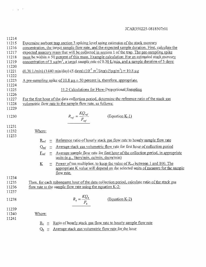
JCAR350225-081 8507r01
11214112151121611217112181121911220112211122211223112241122511226112271122811229
11230
112311123211233
11234112351123611237
11238
112391124011241
Determine sorbent trap section 3 spiking level using estimates of the stack mercuryconcentration, the target sample flow rate, and the expected sample duration. First, calculate theexpected mercury mass that will be collected in section 1 of the trap. The pre-sampling spikemust be within ± 50 percent of this mass. Example calculation: For an estimated stack mercuryconcentration of 5 ig/m3,a target sample rate of 0.30 L/min, and a sample duration of 5 days:
(0.30 L/min) (1440 minlday) (5 days) (10m3/liter) (5tg/m3) 10.8 ig
A pre-sampling spike of 10.8 .ig ± 50 percent is, therefore, appropriate.
11.2 Calculations for Flow-Proportional Sampling
For the first hour of the data collection period, detennine the reference ratio of the stack asvolumetric flow rate to the sample flow rate, as follows:
KQRref
= ref (Equation K-i)Frei
Where:
Reference ratio of hourly stack gas flow rate to hourly sample flow rate
Average stack gas volumetric flow rate for first hour of collection period
= Average sample flow rate for first hour of the collection period, in appropriateunits (e.g., liters/mm, cc/mm, dscm/min)
K = Power often multiplier, to keep the value of between 1 and 100. Theappropriate K value will depend on the selected units of measure for the sampleflow rate.
Then, for each subsequent hour of the data collection period, calculate ratio of the stack gasflow rate to the sample flow rate using the equation K-2:
R,1 = (Equation K-2)
Where:
= Ratio of hourly stack gas flow rate to hourly sample flow rate
Qh = Average stack gas volumetric flow rate for the hour
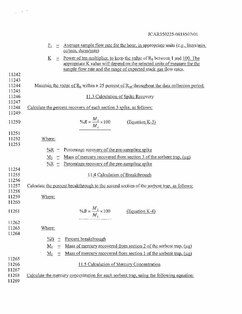
JCAR350225-081 8507r01
Fh = Average sample flow rate for the hour, in appropriate units (e.g., liters/mm,cc/mm, dscm/min)
K Power often multiplier, to keep the value of Rh between 1 and 100. Theappropriate K value will depend on the selected units of measure for thesample flow rate and the range of expected stack gas flow rates.
112421124311244 Maintain the value of Rh within + 25 percent ofR throughout the data collection period.1124511246 11.3 Calculation of Spike Recovery1124711248 Calculate the percent recovery of each section 3 spike, as follows:11249
11250 %R=ix100 (EguationK-3)
1125111252 Where:11253
Percentage recovery of the pre-sampling spike
M3 Mass of mercury recovered from section 3 of the sorbent trap, fig)
%R Percentage recovery of the pre-sampling spike1125411255 11.4 Calculation of Breakthrough1125611257 Calculate the percent breakthrough to the second section of the sorbent trap, as follows:1125811259 Where:11260
11261 %B=--x100 (EguationK-4)
1126211263 Where:11264
%B = Percent breakthrough
Mass of mercury recovered from section 2 of the sorbent trap, (jig)
M1 = Mass of mercury recovered from section 1 of the sorbent trap, fig)1126511266 11.5 Calculation of Mercury Concentration1126711268 Calculate the mercury concentration for each sorbent trap, using the following equation:11269
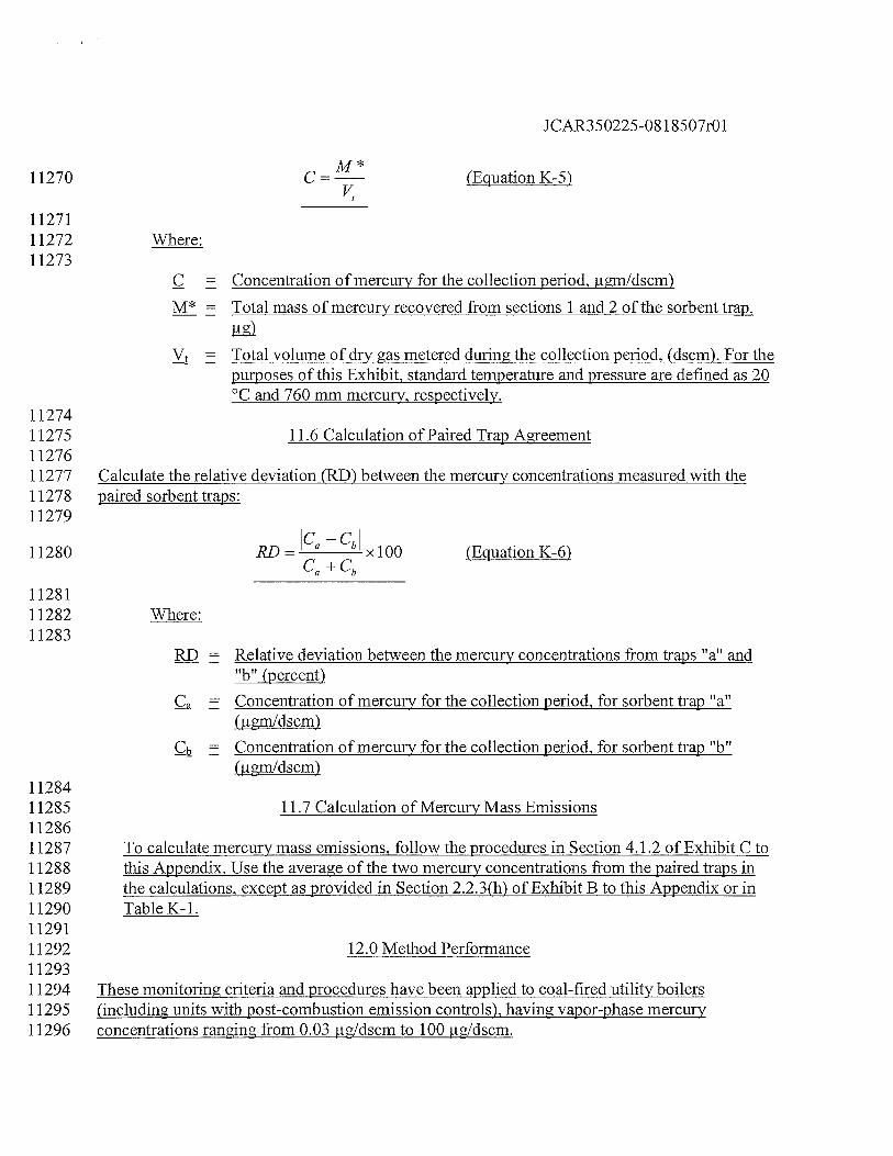
JCAR350225-08 1 8507r01
M*11270 C =— (EguationK-5)
1127111272 Where:11273
C Concentration of mercury for the collection period, igm1dscm)
M* = Total mass of mercury recovered from sections 1 and 2 of the sorbent trap,
= Total volume of dry gas metered during the collection period, (dscm). For thepurposes of this Exhibit, standard temperature and pressure are defined as 20°C and 760 mm mercury, respectively.
1127411275 11.6 Calculation of Paired Trap Agreement1127611277 Calculate the relative deviation (RD) between the mercury concentrations measured with the11278 paired sorbent traps:11279
jC -C
_______
11280 RD= a b xlOO fEguationK-6)Ca +Cb
1128111282 Where:11283
RD = Relative deviation between the mercury concentrations from traps ??atl andbtt (percent)
Ca = Concentration of mercury for the collection period, for sorbent trap tat(jigm/dscm)
Concentration of mercury for the collection period, for sorbent trap TTb”fligmldscm)
1128411285 11.7 Calculation of Mercury Mass Emissions1128611287 To calculate mercury mass emissions, follow the procedures in Section 4.1.2 of Exhibit C to11288 this Appendix. Use the average of the two mercury concentrations from the paired traps in11289 the calculations, except as provided in Section 2.2.3(h) of Exhibit B to this Appendix or in11290 Table K-i.1129111292 12.0 Method Performance1129311294 These monitoring criteria and procedures have been applied to coal-fired utility boilers11295 (including units with post-combustion emission controls), having vapor-phase mercury11296 concentrations ranging from 0.03 ig/dscm to 100 ig/dscm.
JCAR350225-08 1 8507r01
1129711298 (Source: Added at 33 Iii. Reg.
_______,
effective
_____________