J A E R I -M - International Nuclear Information System (INIS)
50
JAERI-M--94-052 JP9404131 J A E R I - M 94-052 COOLOD-N2 : A COMPUTER CODE, FOR THE ANALYSES OF STEADY-STATE THERMAL- HYDRAULICS IN RESEARCH REACTORS March 1994 Masanori KAMINAGA H * 15 ^ * »F £ 3f Japan Atomic Energy Research Institute
-
Upload
khangminh22 -
Category
Documents
-
view
0 -
download
0
Transcript of J A E R I -M - International Nuclear Information System (INIS)

JAERI-M--94-052
JP9404131
J A E R I -M 94-052
COOLOD-N2 : A COMPUTER CODE, FOR THE
ANALYSES OF STEADY-STATE THERMAL-
HYDRAULICS IN RESEARCH REACTORS
March 1994
Masanori KAMINAGA
H * 15 ^ * »F £ 3f Japan Atomic Energy Research Institute

JAERIMi-.?-. !- ; ; . II t̂ '!',' i' '.'WSV'"!'.'f-.i ».t|;'i; ) i ; ' - . • J « ^ I S ? , S ' <
Kfsifflttti'f.i. H-M5' l" ^W'^ ' ' , i ' * f f :1f i *8»t f t«t i t f * t . t T319 11 ^»«"Wi»;W;*,ht-1 .* ".
uni'_ :- \ , ' ; ?> . '.i;. : .•.;•'.•; MMMIJ. Vfr f ) j^ ,«f t#ln- - * f i i s 11 \tft»««;»«i«; * , * M H * ' « ' t" >jWt£'";l'l :&V.- t -: f » M i f l i « - l ; l •. T l ; " t <
JAfc-Rl M report1- art' issued irregularly Inquiries about availahihn of th»- reports shouM I T aHdrt^v»-il to Information lh\iM.»n I ̂ 'r-arlmont
of Technical Information. Japan Atomn Knotty fN'scarrh Institute. 1 okaimura. \aka gun. Iharaki ken 319 11. Japan
< Japan Atomir hneifc* Research Institute. 1994
m* *Sf.n I! *. 'ft r )j fit ti <*t

JAERI-M 94-052
C00L0D-N2: A Computer Code, for the Analyses of Steady-state Thermal-hydraulics
in Research Reactors
Masanori KAMINAGA
Department of Research Reactor Tokai Research Establishment
Japan Atomic Energy Research Institute Tokai-mura, Naka-gun, Ibaraki-ken
(Received February 15, 1994)
The C00L0D-N2 code provides a capability for the analyses of the steady-state thermal-hydraulics of research reactors. This code is revised version of the C00L0D-N code, and is applicable not only for research reactors in which plate-type fuel is adopted, but also for research reactors in which rod-type fuel is adopted. In the code, subroutines to calculate temperature distribution in rod-type fuel have been newly added to the COOLOD-N code. The C00L0D-N2 code can calculate fuel temperatures under both forced convection cooling mode and natural convection cooling mode as well as COOLOD-N code. In the C00L0D-N2 code, a "Heat Transfer package" is used for calculating heat transfer coefficient, DNB heat flux etc. The "Heat Transfer package" is subroutine program and is especially developed for research reactors in which plate-type fuel is adopted. In case of rod-type fuel, DNB heat flux is calculated by both the "Heat Transfer package" and Lund DNB heat flux correlation which is popular for TRIGA reactor. The C00L0D-N2 code also has a capability of calculating ONB temperature, the heat flux at onset of flow instability as well as DNB heat flux.
i

JAKRI-M 94-052
Keywords: COOLOD-N, COOLOD-N2, DNB, Flow Instability, Forced Convection, Natural Convection, ONB, Plate-type Fuel, Research Reactor, Rod-type Fuel, Steady-.'ilate, Thermal-hydraulic
II

JAERI-M 94-052
i 3 S * M f f l S : ' t M ^ « T 3 - K COOLOD-N 2
(1994*f 2/ ! lSHgg!)
* * £ - * « ; , 8f**3©ffi»«l**(IWf3-KCOOLOD-N2Koi»Tifi'<fc4>«)-e**o * 3 - Kti, «t««»*fieffl^-*WJ8*P©ffiff«l**llWf3- K COOLOD-N ©«£IIKT*&. WW*M44fflfflLfcW*#©IIWW COOLOD-N 3 - K(CI&H»i/,Affc<OT*.5o COOLOD-N2(i, «*(|ififi3^UJ&OfQJHiaSaB ^l©^f ,n©liJ&»tfciSffl'«'7<lfeT*So * a - KIC*Jl>tt) COOLOD-N a - K£M<*Kfc tt«SW*JHi »fcfflK**fflfcl«*3ftfclKieiSIQHM. DN B JRft4iAIWii;$ *» 4 tt * T»fciit
TRIGA^cDMtffTffll.^ttT^.5 Lund ©fflW*ti:J:SMt>&*>tfTit#*SJ; ?IC l f c 0 C ©ffeicli, f^^timm^mommcmmu. ONB8Affi, rtf«;*&5i! (Flow Instability) tt i*©It)MMIfc«ri-n»6.
*W«&* : T 319-11 *«^i5««l**Wl ,J-*"*t')«2-4
/r

JAKKI-M 9 4 - 0 5 2
Contents
1. Introduction 1 2. Description of the COOLOD-N2 Code 1 2.1 Fuel Plate Temperature Calculation 1 2.2 Fuel Rod Temperature Calculation 1 2.3 Cooling System Temperature Calculation 2 2.4 ONB Temperature, Flow Instability, DNB Heat Flux and
Pressure Drop 2 2.5 Natural Convection Cooling 2 2.6 Heat Transfer Package 2
3. Calculation Models 2 3.1 Calculation Model for Temperature Distribution in Fuel
Plates 2 3.2 Calculation Model for Temperature Distribution in Fuel Rods .. 4 3.3 Heat Transfer Calculation Model (Heat Transfer Correlations).. 4 3.A Pressure Drop Calculation Model , 9 3.5 Cooling Tower and Heat Exchanger Calculation Model 10 3.6 Natural Convection Cooling Calculation Model 12
4. Properties used in the Code 14 4.1 Thermal Conductivities of Fuel Meat 14 4.2 Thermal Conductivities of Aluminum 15 4.3 Thermal Conductivities of Bond Layer 15 4.4 Properties of Light Water and Heavy Water 15
5. Input Data Information for COOLOD-N2 17 6. Concluding Remarks 27 Acknowledgments 27 References 27 Appendix A. Sample Calculation Results 29 Appendix B. Sample JCL for CO0L0D-N2 40
V

JAERI-M 94-052
1. w- i 2. COOLOD-N2 n - KcOffil® 1
2. i mrm&kmm i 2.2 JHSttflSSAffiSl-ft 1 2.3 KiW&&m® 2 2.4 ONBiBK, tftii>RfcS£, DNBftisillJfc&»'U:2)8ifc 2 2.5 a$flg&#£[J 2 2.6 &fc i l^y y - -y 2
3. ItW-fcf'^ 2 3.1 «S|snKjUafl-W*f* 2 3.2 flSN*MHBi:,tt»*f* 4 3. 3 *MKiM|-W*fou (M(sitWIMA) 4 3.-1 JJifl tf iWW** * 9 3.5 ttfl]JR, iHS!«»Wt»*f* 10 3.6 aAS ;BS8»aJ|-W*f* 12
4. 3 - K-CfigHI IfclMfeffi 14 4.1 iS;tt£M0J!h{E*$ 14 4.2 T»i-V&.(Dl&fc&$ 15 4. 3 # y K»©J»fci*$ 15 4.4 «l*&tf£*<D«5tt« 15
5. A?J f -? l t -3 l .>T 17 6. m £ 27 m & 27 # % £ » : 27 ft Si A. ft*ttf l l®*j 29 ft m B. JCLCD0J 40
VI

JAEKI-M ( H - 0 5 2
Nomenclature
A Flow area (in2) A/i Heated area (in2) ('p Specific heat (kJ/kg K) /);/ Equivalent hurled diameter (m) lie Equivalent hydiaulic diameter (m) F. f Fnction loss coeUicicnt (-) Fh Bulk temperature rismg factor (-) FH : Bond temperature nsmg factor (-) F, Film temperature rising factor (-) Ff : Fuel meat temperature rising factor (-) /•a Clad temperature rising factor (-) G : Mass flow rate (kg/m 2 s) O' Dimensionless mass flow rate =-
T V.v w x v Z
K Acceleration of gravity (m/s 2 ) h Heal transfer coefficient (kW/nr K) h , x Heat of vaporization (kJ/kg) A/i, Inlet subcoolcd enthalpy (kJ/kg) k Thermal conductivity (kW/m K) /. Flow channel length fm) I.H Heated length (m) Aw Nusselt number P Press w c (kg/cm 2 a b s ) Pc Critical pressure (kg/cm 2 abs ) Pc . Pcclct number'-1 Pi/ : Heated perimeter (in) Pr Prandtl number (-) q Heat flux (kW/m 2 ) q' : Dimcnsionless heat flux :
q : Heat generation rate (kW) Re Reynolds number (•)
Temperature (°C) Velocity (m/s) Width of channel (m) Quality (-) Thickness (m) Distance from inlet of channel (m)
/> Volmetnc expansion cocQicient (I /K) f. Surface roughness (m) a Surface tension (N'mi
r • ~ — A Characteristic tength = j (m)
\Kpt-Pt)& v Dynamic \ i sc«vn\ (Ps - s ) > Kinematic viscosity (m 2 / s ) p Density (kg/m'l
VII

I \ i ivl \ l SM- U:
Resistance cocfTicicnt due to geometry change (-) 7 Subscnpt b
Bubble detachment parameter (-)
Bulk B Bond c cntical heat flux cvondition DNB f
Departure from Nucleate Boiling Film
R Steam I in
Liquid Inlet
out Outlet ONB s
Onset of Nucleate Boiling Saturated
sub Subcoolcd U Fuel meat W Clad or wall
vih

JAKRI-M 94-052
1. Introduction
In Japan Atomic Energy Research Institute (JAERI), COOLOD-N code was developed for steady state thermal-hydraulic analysis of research reactors in which plate type fuel is craptojed'1'. especially for steady state thermal-hvdraulic analysis under natural convection cooling, based on COOLOD code'2! Thermal-hydraulic analyses of the JRR-3M'3!. RSG-GAS in Indonesia!4'. MEX-15 planning in Mexico15', etc. have been performed, using the COOLOD-N code. COOLOD-N2 code is a revised version of the COOLOD-N code. The COOLOD-N2 is developed based on the COOLOD-N code and provides a capability for the analysis of the steady-state thermal-hydraulics of research reactors. The COOLOD-N2 is applicable not only for research reactors in which plate-type fuel is adopted, but also for research reactors in which rod-type (pin-type) fuel is adopted. In the code. subroutines to calculate temperature distribution in rod-type fuel have been newly added to the COOLOD-N code. The COOLOD-N2 code can calculate fuel temperatures under both forced convection cooling mode and natural convection cooling mode as well as COOLOD-N code. In the COOLOD-N2 code, a "Heat Transfer Package16'" which is subroutine program to calculate heat transfer coefficient and DNB heat flux etc., and was especially developed for research reactors in which plate type fuel is adopted, is also adopted, but in case of rod-type fuel, DNB heat flux is also calculated by Lund'7' correlation which is popular for TRIGA type fuels The COOLOD-N2 code also has a capability of calculating ONB temperature, the heat flux at onset of flow instability (for plate-type fuel only) as well as DNB heat flux.
2. Description of the COOLOD-N2 code
2.1 Fuel plate temperature calculation
Fuel plate temperatures are calculated by assuming that the heat generation in fuel meat is constant along the radial direction and considering one dimensional heat conduction. An axial fuel plate temperature distribution is calculated from local bulk temperatures of the coolant and axial peaking factors. In case of some kinds of fuel plates which have different heat generation rate one another, exist in a fuel element, or right-hand side and left-hand side of the fuel plate cooling conditions are different due to different configuration of coolant channels or different coolant velocities, the code can calculate temperature distribution of each fuel plate. In case of some kinds of fuel elements exist in a core, the code is also able to calculate temperature distribution of each fuel element by using power distribution factors etc..
Given the fuel meat material (choice U-AI-alloy, U-AL.-AI) and the uranium density, die code calculates thermal conductivities of the fuel meat. Thermal conductivities of the fuel meat can be also inputted by data table. The properties of light water, heavy water and aluminum alloy are already given in the code.
2.2 Fuel rod temperature calculation
Fuel rod (pin) temperatures are calculated by assuming that the heat generation in fuel meat (pellet) is constant along the radial direction and considering one dimensional heat conduction. An axial fuel rod (pin) temperature distribution is calculated from local bulk temperatures of the coolant and axial peaking factors. In case of some kinds of fuel rods (pins) which have different heat generation rate one another, exist in a fuel element, the code can calculate temperature distribution of each fuel rods (pins). In case of some kinds of fuel elements exist in a core, the code is also able to calculate temperature distribution of each fuel element by using power distribution factors etc..
Thermal conductivities of the fuel meat (pellet) must be inputted by data table. Thermal conductivities of the cladding must be also inputted by data table. The properties of light water, heavy
- 1 -

JAKRI M SM-052
water are already given in the code as described above
2.3 Cooling system temperature calculation
In addition to the fuel plate temperature calculation, coolant temperatures of the primary and thi secondary cooling system can be calculated by the COOLOD-N2 code In this calculation, heal loss from the surface of piping, heal exchanger and so on arc neglected
Counter flow t>pc cooling tower, and heat exchanger of counter flow type, parallel flow type and shell & tube type arc treated in the code
2.4 ONB temperature. Flow instability, DNB beat flux and Pressure drop
The code has capabilities of calculating the ONB temperature, heat flux at onset of flow instability and DNB heat flux which are important to confirm safety of the reactor The code also has a capability of calculating pressure drops and local pressures in the core which arc required to calculate above value As flow direction in the core, downward flow, upward flow and horizontal flow arc treated in the code
2.5 Natural convection cooling
In general, pool type research reactors have a natural convection cooling mode as well as a forced convection cooling mode In the natural convection cooling mode, the core flow is an upward flow, which is supplied by the dounflow through o natural circulation valve, through a core bypass and so on The driving force for the natural circulation is calculated by the difference between the outlet water density of the core flow hcatod by core power and the inlet water density through a core bypass or through a natural circulation valve, in the COOLOD-N2 code Sec section 3 <>
2.6 Heat transfer package
A "Heat Transfer Package" is a sub-program for calculating heat transfer coefficient. ONB temperature, heat flux at onset or flow instability and DNB heat flux The "Heal transfer package" was especially developed for research reactors which are operated under low pressure and low temperature conditions using plate-type fiH.1. just like as the JRR-3M''' Heat transfer correlations adopted in the "Heat Transfer Package" were obtained or estimated based on the heat transfer experiments in which thermal-hydraulic features of the upgraded JRR-3 core were propcrK reflected The "Heat Transfer Package" is applicable to. not only upward flow, but also downward flow Sec section 3.3
3. Calculation models
3.1 Calculation model Tor temperature distribution in fad plates
Assuming that the heat generation in fuel meat is constant along the radial (thickness I direction (qL. =<7,. /y,-= constant), and considering one dimensional heat conduction, temperature distnlmtici in fuel plates are calculated as follows Figure 1 shows calculation model of temperature distribution in fuel plates
(I) Coolant bulk temperature Ih
- 2 -

JAliRI-M iM-05^
T„ = Tm*Fh~—-i'iHZ)dZ t;.l ( pJ"
(2) Clad outer surface temperature 7 ( (
'<• =h+f-, — hw
(3) Clad inner surface temperature T^g
(4) Fuel meat surface temperature : Tg{-
(3 1 1)
(3 I 2)
(3 1 3)
TBL- = 7»B + ''B «7r .VB (3 14)
(5) Fuel meat maximum temperature : 7)-n
Trn=TBr+F,. •&->-, (3 I *)
It' the cooling condition of right hand side and left hand side of the fuel plate arc different, the COOLOD-N2 code calculates a fuel meat maximum temperature until the fuel meal maximum tcmpera'urc nf right hand side and left hand side arc equal by chamung the location of maximum temperature point If the cooling conditions of right hand side and left hand side of the fuel plate arc equal, then the fuel maximum temperature appears center of the fuel meal
Coolant channel
Coolant
Left hand side < Bond (Gap)
> Right hand side Bond (Gap)
Coolant channel
Coolant
Fig. 1 Fuel plate temperature calculation model
- 3 -

JAER1-M 94-U52
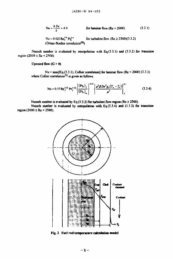
3.2 Calculation model for temperature distribution in fuel rods
Assuming that the heat generation in fuel meat is constant along the radial direction (<7c - 2ql: I yv = constant), and considering one dimensional heat conduction, temperature distribution in fuel rods are calculated as follows Figure 2 shows calculation model of tempcraturc distribution in fuel rods.
(I) Coolant bulk temperature Th
Th=Tm + Fh—l—\Q(Z)dZ (3.2.1)
(2) Clad outer surface temperature : T$-T -r +F ^
2xvr
2 * > • « •
(3) Clad inner surface temperature r » B
•nn - ' « • + 'ir - ; l n —
'* ir >'«
4*,.
(32.2)
(3 2 3)
(4) Fuel meat surface temperature . TBi •
TBV=Tull+FBf- (32 4)
(5) Fuel meat maximum temperature Tta
Tl:n = TBl-+Fr
(325)
2
3.3 Heat transfer calculation model (Heat transfer correlations)
ln the COOLOD-N2 code, the COOLOD code original heat transfer correlations as well as the "Heal Transfer Package" which was developed for thermal-hydraulic analysis of research nuclear reactors in which plate-type fuel is employed, can be selected by the input data Table 1 shows the COOLOD code original heat transfer correlations
The "Heat Transfer Package" used in the COOLOD-N2 code has been modified taking into account of the characteristics of rod type fuels and is shown as follows
(1) Single-phase forced-convection flow Downward flow (G < 0)
- 4 -
JAERI-M 94-052
Nu = = 4.0
Nu = 0.023Re?RPrA
04
for laminar flow (Re < 2000) (3.3 1)
for turbulent flow (Re 2 2500)(3 3.2) (Dittus-Boelter correlation'8')
Nusscit number is evaluated by interpolation with Eq.(3.3 1) and (3.3.2) for transition region (2000 < Re < 2500).
Upward flow (G > 0)
Nu = max[Eq.(3.3 1), Collier correlation] for laminar flow (Re < 2000) (3 3 3) where Collier correlation'9' is given as follows
*-™*r*,*ffir{**$T'-Ti) (3.3.4)
Nusselt number is evaluated by Eq (3 3 2) for turbulent flow region (Re 2: 2500) Nusselt number is evaluated by interpolation with Eq.(3.3.4) and (3.3.2) for transition
region (2000 £ Re < 2500).
Fig. 2 Fuel rod temperature cakalatioa model
- 5 -

JAER1-M 94-052
Table 1 COOLOD code original heat transfer correlation! CCS unit
Heal transfer mode Heat transfer correlation Note Single-phase forced' convection Nu = H, x (RC - / / , ) * Pr"
A. B.C. D and H,. H:. W, are given by input data
ONB temperature q= 0.025293 Pnf* Tl^aw ~ hat) Bergles-Rosenow
Nucleate boiling
Subcooled
9, =?c+9ft
qe = 0.023 A R e ° « Pr0 4(j7-„, +47^) Sato-Matsumura
g t=4.50e2o 36000
Saturated ATa,= 11.2951 q° ; 5 e««
Jens-Lottes
<?DVS = 478800(1 -t-0 0365 vKl +0.005074r„h) x(l+0.0131P)
Mirshak, Duranl and Towcll IHTC = 2(CARDGI)
loss = 10890—2L—+48—51—
DNB heat flux « ( M B - 6 h p - w - J ? T i s - l k * n - , r » » « . )
Bcmath IHTC = 3(CARDG1) De ;(ft) />w :(ft)
?O.VB ='4540, / M
1 + 2 5»-0, i n
i - ( - " ^ )
q P , = 0.99531/>'| I - £ - f
Labuntsov IHTC=1(CARDG1) toAfa; (w'em2) P (bar) P c (bar) v , (m/s) Q> ;(kJ/kgK)
(2) Nucleate boiling heat transfer ONB Temperature (Bergles-Rohsenow correlation1101)
q=911P"* {-(Ton-Ts ' J 1000
Subcooled nucleate boiling (Modified Chen correlation19'1"1)
( 335 )
* = 0 .023^" Ptf 4-£ r(7" I P-r,)
+ S 0.00122
where
(336)
- 6 -

JAERI-M 94-052
S - X
1 + 0.12 Re'"4
.S = ! 1 + 0.42 Re'07"
.V = 0.1
Re' < 32.5
32.5 S Re' < 70 0
70.0 <. Re'
R c ' = » , 10 *
Saturated nucleate boiling (Chen correlation'9!''"1)
q = F 0 023{R e / (1 - r)}° * Pr; 4 ^( Tw - Ts) 1 2 4 ,
.9 0 00122 */wO»r° V/*(r,r -Tsri^-P[ (337)
where
F = 10
F = 2.35|—+0.213
J S J S t 034 OM
i - , 0 1
- L > o «
OS, sO\
S =
I l+0.12Re , I H
1 I+0.42 Re'0 n
S = 0.i
Re' < 325
32 5 s Re' < 70.0
70.0 s Re'
Re ,_|G(1->)1, De
ff
(3)DNBheatflux' I 2l' , 3l
9 a V B J =0.005JG , | ,|fl611
lDXB.2 ~ A Ah, L M
*=0 .7 | — VwvT
"'{•+W4}"
K F , : ' K | 0 -
(33.8)
(33 9)
(3310)
Downward flow (G < 0) DNB heat flux is evaluated by nun|Eq (3 3 8). max[Eq (3 3 9). Eq (3 3 I0)|
Upward flow (G > 0) DNB heat flux is evaluated by maxf Eq (3 3 8). Eq (3.3 10)]
DNB heat flux for rod type fuels In subcooled boiling, die DNB heat flux is a function of die coolant velocity, die degree of
subcooling. and the pressure. The correlation used to predict DNB is Lund which was developed from empirical data gathered from an experiment conducted on a lest assembly dial confirmed to actual rod
- 7 -

JAERI-M 9 4 - 0 5 2
bundle in terms of dimension, flow and heat flux The cntical heat flux is given by' 7'.
qurt =o.5/ c pi m „ r c>(r c - r o w ) (33 in
where fc : Friction factor for the channel between fuel rods (-)
Re,„
s Dr V P Msat Cp 'out Tr
= 0.55Rc„,r : Reynolds number for the interred channel (•) = 2prmurDr(S-l)'P,« : Interred channel velocity (m/s) = r[l 0-0.98 e-"«*-'»]
Pitch-to-diameter ratio (-) Rod diameter (m) Average velocity- (m/s) Density (kg/m3) Viscosity at saturation temperature (Pa- s) Constant pressure specific heat (kJ/kg) Temperature at outlet of cooling channel (°C) Critical wall temperature (°C)
The critical wall temperature is given by Tc-Tm(l+6ft)
where Tsa,
P hfg
Saturation temperature (°C) qcOaat/PMiaghfo Saturation surface tension (N/m) Absolute pressure (kg/m2abs.) Heat of vaporization (kJ/kg)
(4) Heat flux at Onset of Flow Instability The criterion for the onset of flow instability (flow excursion) has been obtained for
rectangular channels by Whittle and Forgan'14'.
1 T _ T 'out 'in (3 3 12)
Energy- balance is given by
lA„=Cp(TM,-Tm)\G\
From Eq (3 3 12) and (3.3.13). a following correlation was obtained.
1 Cp(Ts-Tj^ CptT^ ]G.
(3313)
(3314)
The bubble detachment parameter q was determined empirically to be 25 ' M |
- 8 -

JAERI-M 94-052
3.4 Pressure drop calculation model
3.4.1 Friction loss coefficient'131
(1) Friction loss coefficient for laminar flow (Re £ 2500)
F = — (3.41) Re
where Cb is a factor which depends on the configuration of the channel.
O> = 64.0 for tube C2> = 56.9 for square Cb = 96.0 for rectangular
(2) Friction loss coefficient for turbulent flow (Re > 2500) Following correlations can be selected.
Blasius correlation
F = 0 .3 l64Rc o : 5 (3.4.2)
Karman-Nikuradse correlation
- , L = 2.0log|o(RcVF)-0.8 (3 4.3) IF
Cole-Brook correlation
(3 4.4) \[F - 7 = = 2.01og,0
elDe 2.51 +-371 ReVF
3.4.2 Pressure drop calculation model
A pressure drop calculation model for the COOLOD-N2 code is shown in Figure 3 In this calculation model, a pressure drop due to friction loss is calculated as a pressure drop inside the segment. A a pressure drop due to geometry change is calculated as a pressure drop between segment n and segment n+1 A local pressure Pnl and P„_2 of *»-th segment is calculated as follows by using Bernoulli's theorem
flu = P.-u +7- fe . - iv l , -PnK -fiA&i) 0-*.S)
• ~ "Demlg) P^ = P^+J,\LAZn-Fn^%-\ (34.6)
where p-£iL-£!L± Average density of the segment n
L : Row direction flag =-I : Upward flow = 0 : Horizontal flow - 1 : Downward flow
- 9 -

JAERI-M 94-052
v = max(i-n. v„.,)
and PQI = Pi„ is given by input data. In the non-heated channel. p„ = p„. j = p„
, P\ P.
De , A Z, Fi
£ 2 * _£i_
De2 AZi Fi
• V ^ 3
A P«
v
v
* - Z , - 0 "1.1
J*!? - z 2 = = Zi
segment 1
T 4 Z . ^2.1
- z 2 = = Zi
segment 1
T 4 Z . - z 2 = = Zi
segment 2
" - Z 3 = Z a - 4 Z 2
3,1
^ n - I ^ Z n - l F n - l
<W ,V ?m?
V
v„-i
jfjfcJLi-7 _
n.1 Z„ = Z n., - ^ Zn-I
segment n
- ^ - Z n . , = Z n - 4 Z „
segment n+1
^ Z . . 3 = Z . . r ^ n - l n-2.1
Fig. 3 Pressure drop calculation model for COOLOD-N2 code
3.5 Cooling tower and beat exchanger calculation model
3.S.1 Cooling tower temperature calculation model'14'
In case of considering a heat exchange between air and water at the cooling tower, transfer unit U of the cooling tower is expressed as follows.
G (351)
where
G V
: Overall volumetric heat transfer coefficient based on enthalpy difference (kcal/m'hd1)
: Air flow rate (kgVh)* : Volume of the cooling tower (m3)
Transfer unit U is also expressed as follows.
in
rout -dTb
K-*> (352)
where
- 1 0 -

JAER1-M 94-052
N : Water air ratio h Enthalpy of air (kcal/kg')' hh : Enthalpy of saturated air at water temperature Th
Tf, : Temperature at the cooling tower (°C)
* kg' means weight of dry air in the wet air
Inlet and outlet temperatures of the cooling tower are calculated from Eq (3 5 1) and Eq (3.5.2) by using a wet-bulb temperature, a water-air ratio N and dummy inlet and outlet temperature of the cooling tower Thm. Tbmi, until Eq. (3.5.1) equal to Eq. (3 5.2) where dTh (7",,,lrl - Thma) = constant
3.5.2 Heat exchanger temperature calculation model 1 ' 7 1
Inlet and outlet temperatures of the primary coolant in a heat exchanger are calculated from the temperature T | of the secondary coolant.
T„ = 7", + 4 ^ (3 5 3) i EA
where
T , = T -AT (3 5 4) 'out 'm " '
A T : Temperature difference between inlet and outlet temperature of primary coolant (°C) Inlet temperature of primary coolant (°C) Outlet temperature of primary coolant (°C) Exchanger effectiveness
Tm
'out
If a heat exchanger type is different, then EA has also different value EA is calculated as follows.
(1) Counter flow type heat exchanger
E l-cxp(-(NTU),(l-^)) ( 3 J 5 )
A l-«,exp(-(NTU) 4(l-«j)
(356)
(2) Parallel flow type heat exchanger
l-exp(-(NTU).(l-/fj) F — 2
(3) Sell and tube type heat exchanger (Shell side m pass, tube side 2m pass) l ) m = l
E<= 1— T— (3 5 7)
where r=(NTu),V«+^
- l i -

JAKKI-M 94-052
2)m>2
1-WA 1 , l-E
" -'• (3 5 8) l - E . / O " — ! - * A
where
i - £ . )
RA • Capacity rate ratio of primary coolant and secondary coolant =—L
(NTU),j : Number of transfer unit ° ' "
V W
Overall heat transfer coefficient (kcal/m2h°C) Heat capacity = GACp (kcal/h°C) Heat transfer area of the heal exchanger (nr)
3.6 Natural convection cooling calculation model
In the natural convection cooling model, m kinds of heated channels and n kinds of core bypass channels (non-heated channel) are considered in the COOLOD-N2 code. A basic equation used in this calculation model is a equation of conservation of mass between heated channels and non-heated channels
A sum of mass flow rates G, for core bypass channels is equal to a sum of mass flow rates G, for heated channels
Z G ' = Z G > = < 7 " ( 3 6 , )
I--I J--I
On the other hand, the relation between a pressure drop of the heated channel in the core A P„ (;=1 to /DUX) . a pressure drop of the non-heated channel (core bypass) &hf (j=\ to./„,„). and a driving force A?dl (i=l to J , ^ ) are expressed as shown below
APa(G,)+APhj(G,) = APjG,) (36.2)
APhj (G ; ) = APh (constant) (3 6 3)
The driving force APdl for the natural circulation is expressed with the difference between the water density p\ of heated channel and the water density p through non-heated channel (core bypass), and is shown below.
AP« = f(p-p',)dx Jo
= 2 > < - - ' - ' » > ( 3 6 4 )
"V.
12

JAKK1-M 94-052
where
L, : Heated length of /-th channel ( m ) = y \ l m
m-\ t m : Heated length of w-th segment of i-th channel (m)
The driving force is calculated by the coolant temperature distribution of the heated channel which depends on the core power.
If nucleate boiling would occur in the core, the right hand side of Eq.(3 6 4) will be replaced by following equation.
°'m fm =(l-am)Plm( tm /flim in (365)
where Pt,n : Saturated water density of m-th segment of i-th heated channel
(kg/m3) : Void fraction of m-th segment of '-th heated channel
In this calculation model, the condition of onset of nucleate boiling is defined as follows'"'.
qDt N u 8 = -
St« GCPb{Ts-Th)
2 455 Pe S 7000
&0.0065;Pe >7000
The void fraction is calculated by following correlation. (1) Void fraction under subcooled boiling region (AHMAD correlation'"')
(3 66)
(367)
x + 4l-x)pslpt
f \ 0 M V ..-0016
"k) (TT) (2) Void fraction under subcooled boiling region (Zuber correlation'20')
(368)
(3.6.9)
JxeLZ£L+eL)+Ct
{ Pe Pt) Pt\^Pi-Pt)g
Pi
(3.6.10)
(3) Void fraction under subcooled boiling region (Combination of Eq.(3.6.9) and
Eq.(3.6.10))
G < G^ <*** Eq.(3.6.9)
G 2 GUM then Eq (3 6 10)
- 1 3 -

JAERI-M 94-052
where. Guu (kg/s) is given by input data The range of GUM is 500 to 1500 (kg/m2s)
(4) Void fraction under nucleate boiling region (Zuber correlation'21')
M3, »:*+* l a p, Pt
(3 6.11)
where xcq ~ xtqB '
. * * ' • * • >
1-x. «<(B l - * * * • * • '
qwphZl{GA)-Cph(Ts-T,,B) ( 3 6 1 2 )
xeqB Qualit>- at the point of onset of nucleate boiling 7'hn Coolant temperature at the point of onset of nucleate boiling C O 7. Distance from the point of onset of nucleate boiling (m) Ph Heated perimeter (m) Ch Zubcr 's coefficient = 1 18 or 1 41
4. Properties used in the code
4.1 Thermal conductivities of fuel meat (plate-type-fuel)
Given the fuel meat material (choice U-AI-alloy. U-Al -Al) and the uranium density, the thermal conductivity of the fuel meat is calculated by the code Thermal conductivities used in the code are shown below
(I) Thermal conductivity of U-Al alloy' 2 2 ' kK0
t I l 0 = 0.415-1.0 x l O - T , A-u0 = 0.135
; (20<r i / <640°C) ; a . > 640 °C)
where kM Thermal conductivity of U-Al alloy (cal/s cm°C) Tu Temperature of U-Al alloy ( °C)
(2) Thennal conductivity of U-A1 X dispersion f u e l ' 2 3 ' kui
^ i = ^ i ( i - n " *'„, =2 16546-2 765*
where ^Bl Thennal conductivity of U-A1X dispersion fuel (W/cm°C)
Weight fraction of uranium in the fuel meat :
a.Sp+lMl-P) P P
Uranium density of U-A1 X dispersion fuel : Porositv
- 1 4 -

JAEKI-M y 4 - 0 5 2
Thcnnal conductivities of the fuel meat can be also inputted by data tabic
4.2 Thermal conductivities of aluminum'24' (platc-type-fuel) '-K;i
kM = 0.390 + 2.22 x lO"* TA, - 3.79 x I0"7 TA,2 + 2 42 x I 0 1 0 Tj . (20 < TM <649 °C)
A,,, = 0.170 . (r^/>649°C) where
TAI Temperature of aluminum clad (°C)
4.3 TbermaJ conductivities of bond layer'2 5' (plate-type-fuel) :kB
kB = 0 123804 x I0- 4 - 0.593896 x 10' 7 - 0.37228 x 1 0 1 0 TB
; ( l 8 < r B < 5 2 0 ° C ) where
T/j Temperature of bond layer (°C)
As for the thermal conductivity of bond layer, the thermal conductivity of Ac is used in the code
4.4 Properties of light water and heavy w a t e r 1 1 6 ' ' 2 7 1
T!ie properties of light water, heavy water used in the code arc listed in Table 2 and Tabic 3
- 1 5 -

JAFKI M V-i-052
Table 2 Properties of Light Water Temp Specific Specific Kinematic Thermal 'Thermal Dwiaiiuc ("O ueight heat viscosm Conductivity dilftisivitv viscosilv
(k.a/m') (kcal/kf°C) im-'/s) (kcal/mh°C) (in ;/ht (kes/m : ) N HI'" \ | ( ) ' \ 111 '
Surlacc Saluratcd l-jilhalpv (hcal/kgl tension pressure (kq/nil ikp/cm'l Saturated Saluraled \ It)' watei vanoi
0 9 9 9 9 1 008 1 79 0 489 4 8 5 1 829 ~72 0006228 ooo' 1 597 49"' 10 999 7 1 002 1 31 0 505 5 04 1 " H . 7 56 OOI25 I2 10 030 601 87 211 998 2 0 999 1 00 o MX 5o8 1 022 7 39 0(i2382<> 2 0 0 3 0 606 23 to 995 7 0 998 0 803 0.531 5.34 0 8 1 6 7 24 0 043251 30 014 610 57 4(1 992 3 (1 998 0.668 0 543 5.48 0.6/6 7 08 0.075204 39 995 614 88
50 988 1 0 999 0 555 0 552 5 59 II 559 6 90 0 12578 49 980 619 13 60 983.2 1 000 0 48(1 0 562 5 72 0 482 6 74 0 20313 59 972 623 32 70 977,8 1.001 0 4 1 7 0 571 5 85 0 416 6 55 031776 69 975 627 43 mi 971 8 1 003 0 368 0 578 5 93 0 365 6 37 0 48294 79 993 631 45 90 965 1 1 005 0 328 0 583 6 01 0 323 6 19 0 71491 90 031 635 36
100 958.4 1 007 0 297 0 586 6 08 0 290 6 00 1 03323 100 092 639 15 120 943 1 1 014 0 247 0 589 6 16 0 2 3 8 5 55 2 0246 120 311 646 31 140 926 1 1 023 (I 209 0 588 6 21 0 197 5 10 3 6850 140 705 652 78 lull 907 3 1 037 0 186 0 585 6 22 0 172 4 65 6 3025 161 334 658 43 180 886 9 1 054 0 168 0 578 6.25 0 152 4 1 7 10 224 182 267 663 Ml
200 864 7 1 075 0 155 (1 568 6 II 0 137 3 70 15 855 203 585 666 60 220 840 .1 1 102 0 146 0 544 5 98 0 125 3 24 23 656 225 393 668 75 240 814 1 136 II 1 39 0 537 5 81 0 115 2 78 34.138 247.827 669 30 260 784 1 183 II 133 0 517 5 57 'I 106 2 32 47 869 271 076 667 91 280 751 1 2<0 o 128 0 493 5 25 0 098 1 85 65 486 295 414 <>64 09
300 320
712 667
I 36 I 54
0 13 0 13
0462 0423
4.77 4.12
0.091 0*183
140 0 95
87621 115 12
321 261 349 337
657 07 645.76
•llOtJJf Table 3 Properties of Heavy Water
Temp Specific Specific Kinematic Thermal Thermal Pwiamic Surface Saturated Knthalpv (kcalftg) f°C) weight heat viscosity Condtictivm dilVusivuv viscosity tension pressure
(kg/m'i (kcal/kg'C'l (m ; /s i (kcal/mh°C) <m-/h) tkg s/m ; t <kg/m) (kg/cm-) Saturated Saturated \ H i x I 0 - J x 10 < x IO-» water vapor
0 1105 1 o |5 ll 7444 o 4782 4 266 0 7556 7 72 0(106954 1.2(11"' 554 65"' 10 1105 1 012 1 278 0 4882 4 3 6 4 1 319 7 5 6 001063 6.270 556 73 20 1105 1 009 1 135 0 503) 4 5 1 5 1 168 7 39 0 02067 16 373 560 83 30 1103 1.006 0 9044 0 5159 4 651 0 928 7 2 4 0 0 3 8 2 7 26 483 564 87 40 1100 1 003 0 7297 0 5268 4 7 7 4 0 746 7 0 8 0(16780 36.477 568 86
50 1 1 % 1 001 0 6034 (I 5360 4 885 0 616 6 90 0 1153 46 494 572 78 60 1091 0 9991 05105 0 5434 4 985 0 5 2 0 6 7 4 0 1890 56 492 576 60 70 1085 0 9974 0 4405 0 5 4 9 3 5 076 0.448 6 5 5 0 2994 66 473 580 37 80 1078 0 9959 0 3864 0 5537 5 1 5 7 0 392 6 37 0 4600 76 440 584 07 90 1071 0 9946 0 3438 0 5568 5 2 2 9 0 349 6 19 0 6871 86 393 587 68
100 1062 0 9 9 3 7 0.3095 0 5 5 8 6 5 291 0 314 6 0 0 1001 96331 591.22 120 1044 0 9932 0 2584 0 5 5 8 7 5 387 0 2 6 2 5 55 1 984 116 189 59X (HI 140 1024 0 9959 02225 0 5547 5 4 3 8 0.226 5 10 3641 136 061 604.38 160 1003 1 003 0 1963 0 5470 5 343 0.201 4 6 5 6 2 6 6 156 036 6 1 0 2 8 180 981 5 1 018 0 1765 0 5359 5 361 0 1 8 3 4 1 7 1022 176 237 6 1 5 6 5
200 959 6 1 (144 (I 1611 0 5 2 1 6 5 209 0 172 3 70 15 92 196 833 62(135 220 938 1 1.0X3 0 1489 05044 4.966 0 164 3.24 23 84 219016 623.27 240 917 1 1 140 0 1390 0 4841 4.630 0 144 2 7 8 34 51 239 985 623 46 260 897 0 1 220 0 1368 0 4607 4 2 1 0 0 163 2 32 48 47 262 938 623 01 280 8 7 8 0 1.328 0 1339 0 4339 3 722 0 168 185 66 31 287 036 619 85
300 8 6 0 3 1 470 0 1180 0 4034 3 191 0 177 1 4 0 88 72 312 704 612 14 320 844 I 1 652 0 1129 0 3688 2 645 0 190 0 95 1)6 50 .340 860 598 43
- 1 6 -*1»5 0°C

JAER1-M 94-052
5. Input data information for COOLOD-NZ
<CARD A> Title card (A72) TITL Title for the calculation
• C ARD Bl > Control card (Free format) INFORM Index for input data format (I)
= 0 : COOLOD original type input data (Plate-hpe-fiicl only) = 1 : COOLOD-N. N2 original type input data
FZ (CARD F4) arc defined as points = 2 : COOLOD-R N2 original type input data
FZ (CARD F4) are defined as segments.
<CARD B2> Contol card (Free format) IAMAX : Number of calculation cases (I) (l=<IAMAX<=IO)
(Number of <CardC> IMAX Number of calculation points in fuel meat radial direction (I) (1=<IMAX=<5) JMAX : Number of calculation points for fuel plate axial direction (I)
(l-<JMAX<=2I. INFORM = 0% 1 (CARD Bl)) (1=<JMAX<=20, INFORM = 2 (CARD Bl)) (Number of CARD F4)
NMAX Number of different fuel elements in the core (1) (1 «=<NMAX-<5) NPLOT Plot option of calculation results (I)
= 0 : No plot = 1 Plot of calculation results
KEY( 1) : Option for coolant temperature calculation (I) = 0 : Cooling Tower. Heat Exchanger and Fuel temperature calculation = I : Fuel temperature calculation only (Input data 'Tin' (primary coolant core
inlet temperature) is required for calculation) = -1 : Fuel temperature calculation skip
KEY(2) : Index for flow direction in the core (I) = -1 Upflow = 0 : Horizontal flow = 1 : Downflow = S . Natural circulation cooling mode
KEY(3) : Index for coolant (I) = 0 : Light water (H 20) = I : Heavy water (D 20)
IDMAX Number of division in cladding region (If IDMAX is positive value, rod type fuel calculation model will be selected.) <New>
<CARD C> Thermal-hydraulic parameter (Free format) QRR : Reactor thermal power (MW) (R) PFLOW : Primary coolant flow rate or average coolant velocity in the core (R)
' * If KVELO (CARD Gl )=0, then PFLOW is Volumetric flow rate (nrVmin)
* If KVELO (CARD Gl)=l. then PFLOW is Mass flow rate (kg/s) * If KVELO (CARD Gl)=2. then PFLOW is Average coolant velocity
in the core (cm/s) * If INFORM (CARD Bl )=0, then PFLOW is Volumetric flow rate
(nrVmin)
- 1 7 -

JAEKl-M 9 4 - U b i
TIN If KEY( I )= 1 then the Primary coolant core inlet temperature (°C) (R) If KEY(1 )=0 or -1 then the Wet bulb temperature (°C) (R)
DT Increment of inlet temperature "TIN" (°C) (R) JAMX : Number of calculation cases for "DT" (I) (Normally =|)
<CARD D> Cooling Tower and Heat Exchanger data (Free format) SFLOW : Secondary coolant flow rate (m3/mw) (R)
: Air flow rate of the cooling tower (mVmin) (R) Overall heat transfer coeflicient of the cooling tower (kcal/m3h .dh) (R) Heat transportation coeflicient of the heat exchanger (kcal/m2h°C) (R) Cross sectional area of the cooling tower (m2) (R) Effective height of the cooling tower (m) (R) Heat transfer area of the heat exchanger (m2) (R) Heat exchanger type (I) = -1 : Counter flow type = 0 : Parallel flow type = m : Shell side m pass and tube side 2*m pass type
* CARD D is only used in case of KEY( I )< I (CARD Bl)
<CARD El > Heat transfer correlation (Free format) H,, H:, Hj. A, B. CD, ITWC
H, -H3 and A-D (R) and ITWC (I) arc shown below
AFLOW CTKJ HEKI SSCT ZCT SSHE IHE
Nu=<ff, >x (Re" • • -< / / , >)xPr *•
(Single phase heat transfer correlation)
1.0+<ff, >\y- BL
Nu : Nussclt number (-) Re : Reynolds number (-) Pr : Prandtl number (-) De : Equivalent hydraulic diameter (cm) 2 : Distance from inlet of channel (cm) fit, : Dynamic viscosity at bulk water temperature (dynes/cm2) /A,. : Dynamic viscosity at wall water temperature
(Surface temperature of fuel plate) (dynes/cm2) ITWC : Standard temperature for property (I)
= 0 : Properties are evaluated by TWC(0) TWC(O) = (Core inlet temperature + core outlet temperature)/2 0
= 1 : Properties are evaluated by TWC(1) TWC( I) = Bulk coolant temperature at Z
= 2 : Properties are evaluated by TWC(2) TWC(2) = (TWC(O) + Fuel surface temperature at Z)I2 0
= 3 : Properties are evaluated by TWC(3) TWC(3) = (TWC( 1) + Fuel surface temperature at Z)/2 0
* CARD El is only used for the case of IHTC = 1-3 (CARD Gl). if IHTC = 4. then CARD El is not used m the calculation, but dummy data are required even in the case of IHTC = 4
<CARD E2> Core flow condition (Free formal) FRATE : FRATE = (Effective flow rate for fuel plates cooling)
/(Primary coolant flow rate) (-) (R) VIN : Coolant velocity in the inlet plenum (cm/s) (R)
- 1 8

JAERI-M 94-052
VOUT Coolant velocity in the outlet plenum (cm/s) (R) PRESSIN: Core inlet pressure (kg/cm2abs) (R) RAMF Index for straight pipe friction loss for turbulent flow (R)
= -1.0: Blasius correlation = 0.0 Karman-Nikuradse correlation = dDe. Cole-Brook correlation i/De is a relative roughness
<CARD Fl > Fuel element title card (A40) TITLN Title for fuel element
<CARD F2> Fuel element data (Free format) NPMX : Number of different fuel plates in this kind of fuel element (I)
(Different cooling condition, different configuration) (1=<NPMX=<15) (Number of CARD F51-CARD F53)
NFUEL : Number of this kind of fuel elements in the core (R) MA Index for fuel meat material (I)
= 0 U-AI alloy = I U-AIX dispersion type = 2 Fuel meal properties arc inputted by data table (CARD F22)
UDENST Uranium density in meat (g/cm?) (R) (For U-AI and U-Alx dispersion type tucll POROTY: Porosity (-) (R) (For U-AIX dispersion type fuel) IDPMX Number of different configuration fuel plates in this kind of fuel clement (I)
(I =<1DPMX=<5) (Number of CARD F6) IDCMX : Number of different configuration flow channels in this kind of fuel clement (I)
(I =<IDCMX=<5) (Number of CARD F70. CRAD F74 or CARD F76) E AREA Effective flow area for this kind of fuel element (cm ) (R) FRATEN : Flow rate distribution factor for tliis kind of fuel element (-) (R) FRATEN = (Flow rate of this kind of fuel elemenl)/(Average flow rate of fuel element)
<CARD FNEW> Rod type fuel element equivalent hydraulic diameter, rod-pitch rauo data card (Free format) <AVn»
WID0 Equivalent hydraulic diameter or D (diamcter)/2 0 (cm) (R) (for DNB heat flux calculation)
RD0 : Rod diameter (cm) (R) SSR0 Rod-pitch ratio (Rod-pitch/Rod diameter) (-) (R)
(for DNB heat flux calculation for Lund correlation)
<CARD F221 > Fuel pellet thermal conductivity data card (If rod-type fuel is selected (IDMAX on CARD B2 > 0 and MA =2 on CARD F2. then this card is required) <Ne*<>
N221 Number of data points (-) (I) T221 Temperature (°C) (R) K.221 Thermal conductivity for fuel pellet ((W/cm K) (R)
<CARD F222> Gap heat transfer dau card (If rod-type fuel is selected (IDMAX on CARD B2 > (I and MA =2 on CARD F2. then this card is required.) <Netv>
N222 Number of data points (-) (I) T222 : Temperature (°C) (R) K222 Thermal conductivity for fuel pellet ((W/cm2K)
<CARD F223> Cladding thermal conductivity data card (If rod-type fuel is selected (IDMAX on CARD B2 > 0 and MA =2 on CARD F2. then this card is required ) <Nen»
- 1 9 -

JAEKI-M 94-052
N223 T223 K223
Number of data points (-) (I) Temperature (°C) (R) Thermal conductivity for fuel pellet ((W/cm K) (R)
<CARD F22> Fuel meat data table (Free format) NUAL Number of data sets (I) TUAL : Temperature (°C) (R) UAL : Thermal conductivity of the fuel meat (W/cm K)
* If MA<>2(CARD F21). then this card is not required
<CARD F3> Hot channel factors (Free format) FR : Radial peaking factor (F R (radial) x F E (uncertainty)) (R) FCCOL : Engineering peaking factor for bulk coolant temperature nse (R) (Fb) FHFLX : Engineering peaking sub-factor for heat flux (R)
(This sub-factor is used in the calculation of DNBR) FFILM . Engineering peaking factor for film temperature rise (R) (Ff) FCLAD : Engineering peaking factor for clad temperature rise (R) FBOND ' Engincenng peaking factor for bond temperature rise (R) FMEAT Engincenng peaking factor for fuel meat temperature nsc (R)
<CARD F4> Axial peaking factors (Free format) FZ : Axial peaking factor (R)
* If INFORM = 0 or 1 (CARD Bl). then FZ is defined as a point (AM)).
* If INFORM = 2 (CARD Bl). then FZ is defined as a segment (ITS,)) * If INFORM = 0 (CARD Bl). then following data are not required
In this case, DDZ is calculated as follows DDZ = HB / (JMAX-1) HB CARD F6
DDZ Distance from point; (Mj) to pointy (Mj.j) or a segment length (R) MfINFORM = I (CARD Bl). then DDZ is distance from Mi to M,.,
(DDZ = JZj) In this case DDZJMAX (4ZJMAX) « dummy data * If INFORM = 2 (CARD Bl). then DDZ is a segment length
(DDZ = 4Z.) JMAX-I
* INFORM = 1 : ^ T D D Z ^ H B HB CARD F6
JMAX * INFORM = 2 ] T D D Z ) = HB
ZET : Resistance coefficient at pointj (Mj). (R) (Normally : = 0 0) * If INFORM = 2 (CARD Bl). then f(Mj) are calculated as follows,
using RS,) f(M,) = 2f(S,)-f(M,)
f(M :) = f(S,)+ / Z ' [f(S :)-f(S,)) dZ, + AZ-.'
f(M 3) = f ( S , > — ^ — [f(S,)-f(Sj]
f(M„. „ )= 2 £&.„„ . , )- f(M, .„„.,)
f (Mj = f(S„_,)+ J \ \ ? [f(S„)-f(Sn,)]
- 2 0 -

JAERI-M 94-052
<CARD F51 > Fuel plate title card (A20) TITLP : Title for fuel plate
<CARD F?2~ Fuel pl&ie data (Free format) NPLATI Number of tins kind of fuel plates in this kind of fuel element (R) FLOCL Local peaking factor (R) IDPL Identity number of fuel plate configuration (I) (See CARD F6) K.MX Index for cooling condition of fuel plate (I)
= I Right hand side of fuel plate cooling condition and left hand side of fuel plate cooling condition arc equal
= 2 Right hand side of fuel plate cooling condition and left hand side of fuel plate cooling condition are not equal
I PLOT Plot option for die calculation results (I) = 0 : No plot = I : Channel No. 1 side calculation results are plotted = 2 : Channel No.2 side calculation results arc plotted = 3 : Both of channel No 1 and No.2 sides calculation results are plotted
* Channel No means 1CHL of CARD F53 IOUT Print out option for pressure. ONB, DNB and Heat flux at onset of Flow
instability' calculation results (I) * 0 : No print - 1 : Print out of pressure. ONB and DNB calculation results
* If INFORM - 0 (CARD Bl), men meaning of IOUT is as follows. = 0 : No print - I : Print out of pressure, ONB. DNB and Heat flux at onset of Flow instability
calculation results. DNB heat flux is calculated by LABNTSOV correlation
= 2 : Print out of pressure, ONB, DNB and Heat flux at onset of Flow instability calculation results. DNB heat flux is calculated by MIRSHAK correlation
= 3 ; Print out of pressure, ONB, DNB and Heat flux at onset of Flow instability-calculation results, DNB heat flux is calculated by BERNATH correlation
<CARD F53> Coolant channel data (Free format) ICHL : Identity' number of channel configuration (I)
(See CARD F70, CARD F74 or CARD F76) NHEAT Coolant condition (R)
= 1.0 : Coolant is heated from one side = 2.0 : Coolant is heated from bom sides
FRATEC : Flow rate distribution factor for this kind of channel (R) FRATEC = (Flow rate of this kind of channel)/( Average flow rate of channel in
this kind of fuel clement) * This card is required KMX (CARD FS2) sets. * CARD FS1-CARD FS3 are required NPMX (CARD F21) sets
<CARD F6> Fuel plate configuration data (Free format) XA
XB
Half thickness of fuel meat for plate-type fuel (cm) (R) Radius of fuel pellet for rod-type fuel (cm) (R) Distance between fuel meat center and clad inner surface for plate-type fuel (cm) (R) (For plate-type fuel, normally : XA = XB) Gap thickness between pellet and cladding for rod-type fuel (cm) (R)
- 2 1 -

JAKKI -M 94-052
XC Distance between fuel meat center and clad outer surface for platc-t\pc fuel (cm) (R) (Half thickness of fuel plate) Cladding thickness for rod-type fuel (cm) (R)
YA : Width of fuel meat for plate-t>pe fuel (cm) (R) : = 0.0 for rod-t>pe fuel (R)
HA Distance between inlet of channel and top(bottom) of fuel meat (pellet) (cm) (R) HB Length of fuel meat (fueled region) tern) (R) HC Distance between outlet of channel and bottom(top) of fuel meat (pellet)
(cm) (R)
<CARD F70> Coolant channel configuration data (Free formal) (If INFORM = 0 (CARD Bl). then this card is required.)
YCHI : Gap( thickness) of coolant channel (cm) (R) XCHI Width of coolant channel (cm) (R)
<CARD F7I> Pressure loss calculation data (Fuel element entrance • plate entrance) (Free format) (If INFORM = 0 (CARD Bl). then this card is required)
ZETA(l) Resistance coefficient of fuel element entrance (STRETCH(1»(R) DH( I) Distance between fuel clement entrance and fuel plate entrance (cm) (R) HDE( 1) Equivalent hydraulic diameter of this region (cm) (R) AR( 1) Cross sectional area of this region (Flow area) (cm1) (R)
<CARD F72> Pressure loss calculation date (Fuel plate evil - fuel clement plug entrance) (Free format) (If INFORM - 0 (CARD Bl). then this card is required )
ZETA(2) Resistance coefficient of fuel clement plug entrance (STRETCH(3)> (R) DH(2) : Distance between fuel plate exit and fuel clement plug entrance (cm) (R) HDE(2) Equivalent hydraulic diameter of this region (cm) (R) AR(2) : Cross sectional a;ca of this region (Flow area) (cm2) (R^
<CARD F73> Pressure loss calculation dau (Fuel clement plug entrance - fuel element exit) (Free fonnat) (If INFORM = 0 (CARD Bl). then this card is required )
ZETA(3) : Resistance coefficient of fuel element plug exit (STRETCH(3)) (R) DH(3) : Distance between fuel clement plug entrance and fuel clement evil (cm) (R) HDE(3) Equivalent hydraulic diameter of this region (cm) (R) AR(3) : Cross sectional area of this region (Flow area) (cm2) (R)
• CARD F70 - CARD F73 are required IDCMX (CARD F21) sets * CARD Fl - CARD F73 are required NMAX (CARD B2) sets
<CARD F74> Coolant channel configuration dau (Free format) (If INFORM<>0 (CARD Bl) and KEY(2)<>5 (CARD B2). then this card is required.)
YCHI Gap (thickness) of coolant channel for plate-type fuel (cm) (R) : Equivalent hydraulic diameter for rod-type fuel (cm) (R)
XCHI : Width of coolant channel for platc-typc fuel (cm) (R) : Effective flow- area for one fuel rod for rod-iype fuel (cm2) (R)
MSFLW : Number of segments, except fuel plate region''. (Number of CARD F75)
<CARD F75> Pressure loss calculation data iFrec fonn.it) rlf !NFORM<>0 (CARD Bl) and KEY(2)<>5 (CARD B2). then this card is required.)
ZETA : Resistance coefficient of this region entrance (R) DH Length of flow area (cm) (R)
- 22
JAliKI-M 94-052
ZLAM Friction loss coefficient for laminar flow Cb 2 ' (R) HDE Equivalent hydraulic diameter of this region (cm) (R) AR Cross sectional area of this region (Flow area) (cm2) (R)
* CARD F74 - CARD F75 are required IDCMX (CARD F21) sets * CARD Fl - CARD F75 are required NMAX (CARD B2) sets
-CARD F76> Coolant channel coufigwation data (Free format) (If INFORM<>0 (CARD Bl) and KEY(2)=5 (CARD B2). then this card is required)
YCHI Gap (thickness) of coolant channel for plate-type fuel (cm) (R) . Equivalent hydraulic diameter for rod-type fuel (cm) (R)
XCHI Width of coolant channel for plate-type fticl (cm) (R) Effective flow area for one fuel rod for rod-type fuel (cm2) (R)
MSFLW Number of segments, include fuel plate region1> (In this case number of fuel plate region must be 1) (Number of CARD F77)
MSFUEL Fuel plate region segment number (From lop of segment) (1)
F77> Pressure loss calculation data (Free format) (If INFORM<>0(CARD Bl) and 5 (CARD B2). then this card is required ) ZETA Resistance coefficient of this region entrance (R) DH Length of flow area (cm) (R) ZLAM Friction loss coefficient for laminar flow Cb 2 > (R) HDE Equivalent hydraulic diameter of this region (cm) (R) AR Cross section; J area of thir region (Flow area) (cm2) (R)
» C ARD F76 - CARD F77 are required FDCMX (CARD F2I) sets • CARD Fl - CARD F77 are required NMAX (CARD B2) sets
<CARD GI > Control card ( Free format) (If INFORMoO (CARD Bl). then this card is required ) KVELO lndc.\ for prunarv coolant flow rate (I)
-• 0 Volumetrir flow rate (mJ/min) = 1 Mass flow rate (kg/s) = 2 Average coolant velocity in the core (cm/s)
JUM AX Number of non-heated flow segment of channel inlet side (I) J LM AX Number of non-heated flow segment of channel outlet side (I)
* If KEY(2)<>5 (CARD B2). then JUMAX + JLMAX = MSFLW (CARD F74) * If KEY(2)=5 (CARD B2). then JUMAX + JLMAX + 1 = MSFLW (CARD F76)
IHTC Index for heat transfer correlation (I) = 1-3 COOLOD code original heat transfer correlation Sec Table I
(Single-phase heat transfer correlation is defined by CARD EI ) =1 DNB heat flux is calculated by LABUNTSOV correlation =2 DNB heat flux is calculated by MIRSHAK correlation =3 DNB heat flux is calculated by BERNATH correlation = 4 "Heat Transfer Package"
KBFLG Index for void fuel ion calculation in the natural circulation cooling mode (I) = 0 Void fraction is calculated in onl\ nucleate boiling region (Zubcr
correlaivjp.i > 0 Void traction is calculated in both nucleate boiling and subcoolcd boiling
region. In subcoolcd boiling region, void fraction correlation is as follows = 1 AHMAD correlation = 2 : Zubcr correlation
23
JAl Kl M 9 4 - 1 ) 5 2
= 3 : If flow rate in the core G(kg/s) < GLIM (CARD C5). then AHMAD correlation If How rate in the core G(kg/s) >= GLIM (CARD G5). then Zuber correlation
* If forced convection cooling mode, then K.BFLG = 0 Number of non-heated chnnncl(Corc bypass) (I)
* If KEY(2)<>5 (CARD B2). then NCMAX must be « Option for flow rate calculation in the natural circulation cooling mode (I I = U : Hot channel factors are not used in the calculation of flow rate in the
natural circulation cooling mode = I : Hot channel factors arc used in the calculation of flow rale in the natural
circulation cooling mode * If KEY(2)<>5 (CARD B2). then NATIP must be 0
<CARD G2> Core b>pass data (I) (Free fonnat) (If INFORMoO (CARD Bl) and KEY(2) =5 (CARD B2). then this card is required)
MSFLOW Number of core b\pass segments (!)
<CARD G3> Core bypass data (2) (Free fonnat) (If INFORMoO (CARD Bl) and KEY(2) =5 (CARD B2). then this cord is required.)
ZETA Resistance coefficient of this region entrance (R) DH Length of flow area (cm) (R) ZLAM Friction loss coefficient for laminar flow Cb2> (R) HDE Equivalent hydraulic diameter of this region (cm) (R) AR Cross sectional area of this region (Flow area) (cm2) (R)
* This card is required MSFLOW (CARD G2) sets * CARD G2 and CARD G3 arc required NCMAC (CARD Gl) sets
<CARD G4> Coolant channel configuration identity data (Free fonnat) (If INFORMoO (CARD Bl). then this card is required.)
JMSH Flag for channel configuration (I) * ((JMSHfNP. k). NP = I.NPMX).K=I.KMX) * If REY(2) <> 5 (CARD B2). then this card is required MSFLW x
NMAX (CARD B2) sets (MSFLW (CARD F74)= JUMAX (CARD Gl) + JLMAX (CARD Gl)) • If KEY(2) = 5 (CARD B2). then this card is required MSFLW x (NMAX (CARD B2) + NCMAX (CARD Gl)) sets (MSFLW (CARD F76) = JUMAX (CARD Gl) + JLMAX (CARDGD+I)
<CARD G5> Void fraction calculation data (Free format) (If INFORMoO (CARD Bl) and KEY(2) =5 (CARD B2). then this card is required )
CB Zuber constant (R) * You had better to use CB = 1 IX or I 41
GLIM Standard flow rate for void fraction calculation (kg/s) (R) * GLIM is used only m the case of KBFLG = 3 (CARD Gl) * You had better to use GLIM = 500 - 1500 (kg/m2s)
<CARD G6> Debug control card (I) IDBG(l).I=l.25 IDBCKD. I = 26. 50
NCMAX
NATIP
- 2 4 -

JAERI-M 94-052
IDBG : If you need debug the subroutine I, please input IDBG >= See Table 4 (Normally: =0)
<CARD P1 > Plot control card < 1) WITHX WITHY TMIN TMAX PMIN PMAX HMIN HMAX
Length of X axial (Maximum 200 mm) (mm) (R) Length of Y axial (Maximum 230 mm) (mm) (R) Minimum value of temperature scale (°C) (R) Maximum value of temperature scale (°C) (R) Minimum value of pressure scale (kg/cm2abs.) (R) Maximum value of pressure scale (kg/cm2abs.) (R) Minimum value of heat flux scale (W/cm2) (R) Maximum value of heat flux scale (W/cm2) (R)
<CARD P2> Plot control card (2) (A4) NEWI : = "NEW" Plot on new page
= "OLD" Plot on same page • In the first figure NEWI must be "NEW"
<CARD P3> Figure title card (A40) TITLE : Title of figure
* If NEWI-"OLD", then this card is not required.
<CARD P4> Plot control card (3) (I) IDPLOT(l)-(7), NSMBL(l)-(7)
Plot items are listed as follows. (1) Coolant temperature (2) Clad surface temperature (3) Meat maximum temperature (4) Saturation temperature (5) ONB temperature (6) Pressure (7) Clad surface heat flux
IDPLOT(I) =0 No plot = 11-15 Solid line is used = 21-2S Doted line is used
NSMBL(I) =0 No symbol = 1 O t s plotted on the line = 2 A is plotted on die line = 3 + is plotted on the line = 4 x is plotted on the line = 11 * is plotted on the line
- 2 5 -

JAER1-M 94-052
Tabk 4 Debug flag for each subroutine
Subroutine name IDGB No Subroutine name IDBG No 1 26 2 ONBTE 27
CALCTL 3 CLADTE 28 4 BONDTE 29 5 FUELTE 30
INITLZ 6 HEATBL 31 POWER 7 QHFPKG 32 TMPrNL 8 33
9 PRESS 34 DISPWZ 10 QDNB(=>8) 35 ORATE II 36
TMPCAL 12 37 13 38 14 39 15 NATURE 40
VELOC. VELOC2 16 FLWGO 41 17 DLTPD 42 18 LOSTL 43 19 44
NEWTON (=>8) 20 G1CAL 45 21 46 22 PBPH 47 23 REN(=I) 48
COOLTE 24 UNITI 49 PRESDRP 25 UNITO 50
1) 2) <C* iRD F74> <CA LRD F76> _ Cb
F = — Rc
F Friction loss coefficient Re Reynolds number Cb Tube Cb-64 0
Fuel plate _._i
region % —
n2
Fuel plalc _̂ region
U2
Square Cb - 5'» 9 Rectangular Cb-9f><> (Giannel of fuel clement,
MSF :LW = n,+ n 2 MSF LW = n t + n 2 + 1 (Fuel plate region)
- 2 6 -

JAEK1-M 94-052
6. Concluding Remarks
In this report, information required for the COOLOD-N2 code users has been described The COOLOD-N2 was developed based on the COOLOD-N code and provides a capability for the analysis of the steady-state thermal-hydraulics of research reactors. The COOLOD-N2 is applicable not only for research reactors in which plate-type fuel is adopted, but also for research reactors in which rod-type (pin-type) fuel is adopted. This work has been done as a part of the thermal-hydraulic analysis of the JRJl-4 TRJGA fueled core. Thermal-hydraulic calculations for the JRR-4 TR1GA core were successfully conducted using COOLOD-N2 code.
Acknowledgments - The author would like to express his hearty gratitude to Mr. E. Shirai Director of Department of Research Reactor, to Mr. N. Ohnishi Deput}' Director of Department of Research Reactor to Dr. T. Kodaira General Manager of Research Reactor Technology Development Division and to Mr. H. Ichikawa Group Leader of Research and Development Group, Research Reactor Technology Development Division for their encouragements and suggestions
The author also would like to express his highest thanks to Mr. K. Yamamoto, JRR-4 Operation Division for providing Lund DNB heat flux correlation's subroutine for COOLOD-N2 code.
References
111 M Kaminaga, "COOLOD-N . A Computer Code, for the Analyses of Steady-State Thermal-Hydraulirs in Plate-T>pc Research Reactors", JAERI-M 90-021.1990
[2] S. Watana'oe. "COOLOD : Thermal and Hydraulic Analysis Code for Research Reactors with Plate Type Fuel Elements (in Japanese)". JAERI-M 84-162.1984.
[3) M. Kaminaga, H. Ikawa, S. Watanabe. H. Ando and Y. Sudo, "Thenuohydraulic Characteristics Analysis of Natural Convective Cooling Mode on the Steady State Condition of Upgraded JRR-3 Core" using COOLOD-N Code (in Japanese)", JAERI-M 87-055,1987
|4] M. Kaminaga, "Core Thermohydraulic Analysis of the Mtilti-Purpo<. ? Research Reactor RSG-GAS using COOLOD-N code", Internal Report, JAER1.1990.
[5] MA. Lucatero, M. Kaminaga, "Thermal-Hydraulic Conceptual Design of the Multiple Purpose Research Reactor MEX-15", JAERI-M 94-006,1994.
[6} Y. Sudo, H. Ikawa and M. Kaminaga, "Development of Heat Transfer Package for Core Thermal-hydraulic Design and Analysis of Upgraded JRR-3", in Proceeding of the International Meeting of Reduced Enrichment for Research and Test Reactors, Petlen, The Netherlands. October 14-16. 1985.
[7] General Atomics, "10 MW TRIGA-LEU Fuel and Reactor Design Description", UZR-14 (Rev). 1979.
[8] F. W. Dittus and L. M. K. Boelter, Univ. Calif. Pubs. Eng., 2.443,1930 [9] J. G. Collier, "Convective Boiling and Condensation", McGraw-Hill Book Co.. New York, 1972. [10] A. E. Bergles and W. H. Rohsenow. "The determination of forced-convection surface-boiling
heat transfer", ASME, Ser C, 86,365-372,1964. [ 111 J. C. Chen, "A correlation for boiling heat transfer to saturated fluids in convective flow", ASME
paper No.63-HT-34. [12] Y. Swln. K. Miyata, H. Ikawa, M. Kaminaga and M. Ohkawara, "Experimental Study of
Differences in DNB heat Flux between Upflow and Downflow in Vertical Rectangular Channel", J. Nucl. Sc. Trchnol, Vol 22, No S, 601-618,1985.
[13] K. Mislmna. "Boiling burnout at low flow rate and low pressure cemditiew" Dissertation Thesis, Kyoto Ua:\., 1981.
[ 14| R. H. Whittle and R. Forgan, "A correlation for the minima in the Pressure Drop versus Flow-rate Curves for Sub-cooled Water Flowing in Narrow Heated Channels", Nucl. Eng. Design, 6,
- 2 7 -

JAliRI-M 94-052
89-99,1967 (15) The Japan Society of Mechanical Engineers. "Handbook of Mechnical Engineering (6th Edition)
(in Japanese)", Section 8,13-15. [16] H Uchida. "Wei air and Cooling tower (in Japanese)". Shoukado. 1963 117] H Obana. "Handbook of Heat exchanger Design (in Japanese)". Kougaku-Tosho. 1977 [18] Saha, Zuber. "Point of net vapor generation and vapci toid fraction in subcoolcd boiling". Proc
5th Int Heat Trans Conf. Tokyo. 4.175-179.1974 [19] S Y Ahmad. "Axial distribution of bulk temperature and void fraction in a heated channel with
inlet subcooling". Trans. ASME. Scr C, 92-4,595-609.1970 (20| N Zuber. F W Stanb and G Bijwaard. "Vapor void fraction in subcooled boiling system". 3rd
Int Heat Transfer Conf.. 5,24-38. 1966 [21] P G Kroeger and N. Zuber. "An analysis of the effects of various parameters on the average
void fractions in subcooled boiling". Int. J. Heat Mass Transfer. II, 211-233.1968 [22] J. E. Houghtaling, Alain Sola and A. H. Spano, "Transient Temperature Distribution in the
SPERT1D-12/25 Fuel Plates during Short-Period Power Excursions". IDO-16884.1964 [23] S. Nazarc. G Ondracek and F. Thummler, "Investigation on UA1X-A1 Dispersion Fuels for High-
Flux Reactors". J Nucl Materials, 56.251-259.1975 [24] Y S Touloukian et al.. "Thermophysical Properties of Matter. Vol 1, Thermal Conductivity".
1970 [251 Y. S Touloukian ct al., "Therraophvsical Properties of Matter. Vol 3. Thermal Conductivity".
288-289.1970. [26] The Japan Society of Mechanical Engineers, "Dcnnctsu-kougaku shiryo (3rd Edition) (in
Japanese)". 1976. 127J J N. Elliott, "Tables of the Thermodynamic Properties of Heavy Water". AECL-1673,1963 [28] M Kaminaga "Steady-State GA Benchmark calculation for JRR-4 TRIGA-16 Fueled Core
(Steady-State Thermal-Hydraulic Analysis), (in Japanese)", private communication. 1993 1291 General Atomics, private communication [30| M Kaminaga "Steady-State Thermal-Hydraulic Analysis for JRR-4 TRiGA-25 Fueled Core (in
Japanese)", private communication, 1993. (31 ] M Kaminaga "Steady-State Thermal-Hydraulic Analysis for j'RR-4 TRIGA-16 Fueled Core (in
Japanese)", private communication. 1993 [32| General Atomics, private communication.
- 2 8 -

JAERI-M 94-052
Appendix A Sample calculation results
A. 1 JRR-4 TRIGA-16 core GA (Geaeral Atomics) benchmark calculation, iaput data descriptiM
Thermal hydraulic analysis for the JRR-4 TRIGA-16 core12*1 was carried out to verily the fuel rod temperature calculation model and Lund DNB heat flux correlation by comparing analysis results calculated by General Atomics using TIGER code'29' This analysis has been done as a part of the thermal-hydraulic analysis of the JRR-4 TRIGA fueled cons'2"'''30"31'.
Following input data were used for JRR-4 TRIGA-16 core thermal hydraulic analysis. Almost all of following input data used in the analysis were as same as those used by GA calculation'29'
a. Primary coolant flow rate through TRIGA fuel element is 81.12% (5.68 m3/mm) of the total primary coolant flow rate of 7 mVmin.
b. Hot pin factor (radial peaking factor x local peaking factor) is 1.7. c. Engineering hot cannel factors were not considered. d. Equivalent hydraulic diameter for TRIGA fuel element is calculated for a channel which is
surrounded by 4 fuel rods. e. Form loss coefficient at die fuel element inlet is taken from "10 MW TRIGA-LEU Fuel and
Reactor Design Description", General Atomics'7'. f. An axial power distribution is calculated by the following correlation which was used for the
thermal hydraulic design of 14 MW TRIGA reactor, Romania'32' Figure A. I shows die axial power distribution used in die analysis.
APF = l.35(l + 1.275e- 3 9 w-°)cos(1.325£) „ „ |=|l~2Z/i|
000 SOD 1000 1500 2000 2500 3000 3500 4000 4500 5000 S500
Distance from top of fuel region (cm)
Figure A.l Axial power distritMrtiM far JRR-4 TRIGA-16 cere
g. Thermal conductivities for fuel pellet and cladding, gap conductance are shown in Table A. 1.
Table A.l Thermal conductivities and gap heat transfer ceelficic* wed im the analysts
Fuel pellet thermal conductivity (W/m K) 0.196 Cladd^theraalcondiicbvity(W/mK) 0.162 Gap conductance (W/m2K) 0.804
- 2 9 -
JAERI-M 94-052
h Fuel pellet diameter : 1.2903 cm i. Fuel rod diameter : 1.3716 cm j Equivalent hydraulic diameter : 0.0406 cm k. Sub-channel flow area : I.1S98 cm2
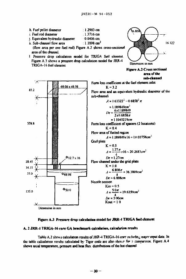
(flow area per one fuel rod) Figure A.2 shows cross-secuonal area of die channel.
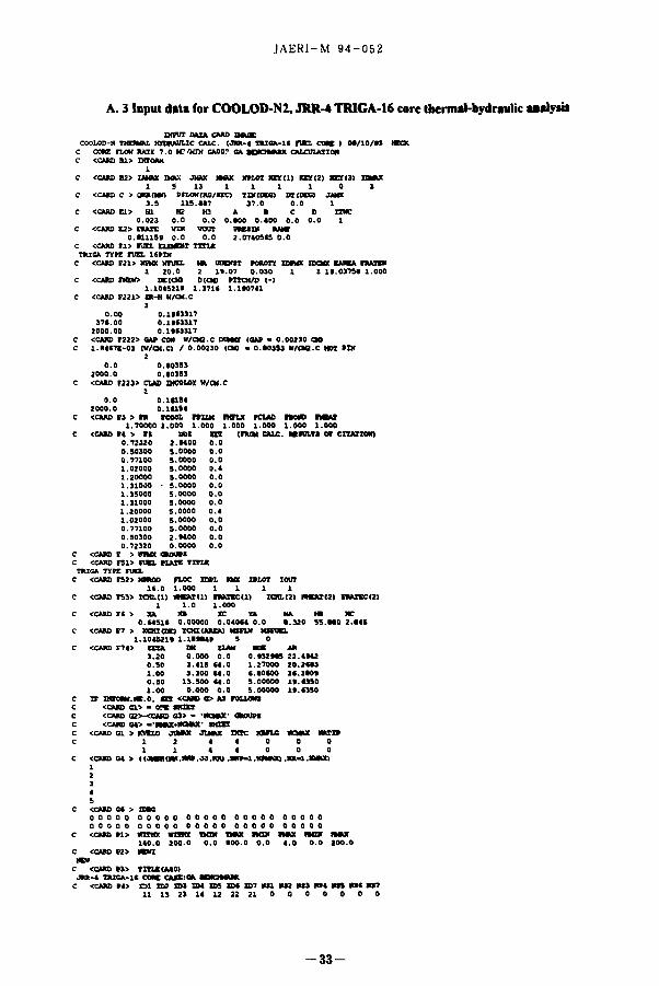
1. Pressure drop calculation model for TRIGA fuel element. Figure A3 shows a pressure drop calculation model for JRR-4 TRIGA-16 fuel element
16 322
Dimension in mm
7V"
83.2
-x-
558 8
| ^ 68.08x68 08
* 12.7x16
Figure A.2 Cross sectional area of the sub-channel
Form loss coefficient at the fuel element inlet K = 3.2
Flow area and an equivalent hydraulic diameter of the sub-channel
,4 = l63322 : -0 6858:>r = U89849cm;
_ 4*1189849 De =
2x0 6858* = 11045219cm
Form loss coefficient of spacers (2 locations) K = 0 4
Flow area of fueled region A = 1 189849x16 = 19 03758cm:
Grid plate K = 0.5
1.27* A= — -y|6^20 2683c»r De = 127cm
Flow channel under the grid plate K = 1 0 . 6808* = 36.3809cm-
De = 6 808cm Nozzle section
Kin = 0 5 5 0 * A=- = 19.6350cm-
De = 5 00cm Kout=10
Dimension in mm
Figure A J Pressure drop calculation modd for JRR-4 TRIGA fud dement
A. 2 JRR-4 TRIGA-16 core GA benchmark calculation, calculation results
Table A.2 shows calculation results of JRR-4 TRIGA-16 core inchriuv; major input date. In the table calculation results calculated by Tiger code arc also shnv.p for 3 comparison Figure A 4 shows axial temperature, pressure and heat flux distributions of the hot channel
- 3 0 -

JAKRI-M 9 4 - 0 5 2
Table A.2 Comparison of calculation results between COOLOD-N2 and Tiger code
Thermal power =35 MW Calculation results. Tiger Calculation results. code COOLOD-N2 code
Hot channel Hot channel Fuel Number of fuel elements 20 20
Number of rod / element 16 16 Pin diameter (m) 0.013716 0 013716 Flow area / element (m2) 1 904 x I0--1 1 904 x 10"3
Peaking Fr (Radial peaking factor) 1.7 1.7 factor (Hot pin factor)
Fz (Axial peaking factor) 1.34 1 35 Total 2.278 2.295
Coolant Core inlet pressure (kg/cm2) 2.074 2 074 Core flow rate (nv'/min) 700 7O0 Effective How rale for fuel cooling (m2/min) 5.68 5.68 Average coolant velocift (m/s) 250 2.50 Inlet temperature (°C) 37.0 37 0 Outlet temperature ("C) 519 52 1
Results Maximum fuel (cladding) surface temperature t°C) Maximum fuel (pellet) temperature (°C)
129.7 127.3 Maximum fuel (cladding) surface temperature t°C) Maximum fuel (pellet) temperature (°C) 476 3 474.2 Maximum fuel (cladding) surface heal fiux (W/m2) DNB heat flux(W/m2)
1.041 \ I0 6 1.042xl0 6 Maximum fuel (cladding) surface heal fiux (W/m2) DNB heat flux(W/m2) 2 507x l0 6 2 6 5 7 x l 0 6
DNBR 2.41 2.55
From the calculation results, calculation results calculated by COOLOD-N2 code show good agreement with those calculated by Tiger code while there is a little difference of fuel temperatures between the two codes The calculation results calculated by COOLOD-N2 code (including DNB heat flux) are a little bit higher than those calculated by Tiger code. Heat transfer calculation model of COOLOD-N2 code is considered to be the same with Tiger code, but at this moment, we do not have enough information of Tiger code and its input data. Therefore, it is difficult to investigate the reason of these difference furthermore
The calculation model for rod type fuel of COOLOD-N2 code was successfully verified by comparing the calculation results calculated by Tiger code.
- 3 1

°D.OO _ 8.00 , 18.00 t 24.00 _ 32 ;00 _ 40 ;00 t 48.00 _. SS "ft
I i /
I >'
y/
•COO 24.00 ' M.00 40-00 40.00 FUEL PLATE LENGTH (CHI
S *
8
S~
]i
CASE NO- I f l -1 Jfl=l N=l NP=I K:l TRIGfl TTPE FUEL
COOLRNT TEHPRRTURE CLRO SURFACE TEWRRTURE HERT nnxinun TEHPRRTURE SATURATION TEMPRATURE ONB TEHPRATURE PRESSURE AT X HEAT FLUX
T
i o
Figure A.4 Axial temperature, heat flux and pressure distribution in the hot channel o f JRR-4 TRIGA-16 core
JAER1-M 94-052
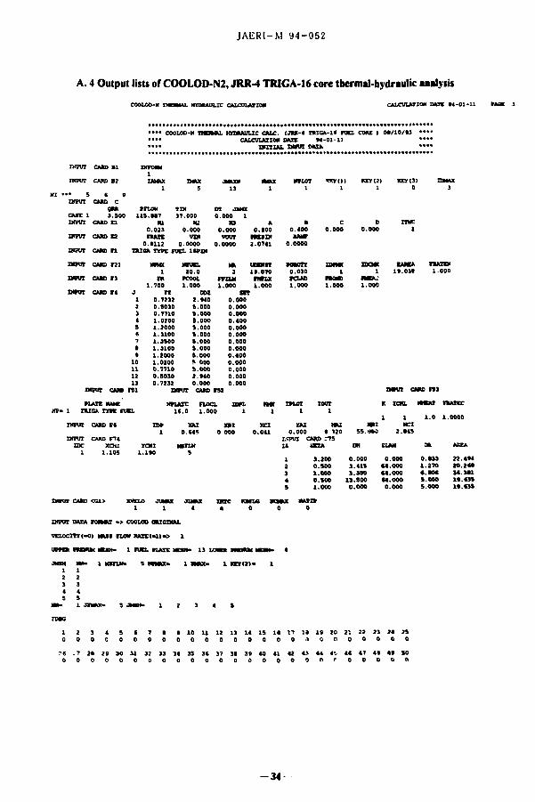
A. 3 Input data for COOLOD-N2, JRR-4 TRIGA-16 core thermal-hydraulic ualysis
XMWT DATA C U D m i x COOLOD-K B O W l KfCIIMILIC CALC. (JMt-4 TRIOA-K FUEL CMC > OC/10/13 WCK
C COW rLCW RATE 7 . 0 ICOCX GAO0? GA MBTMJIK CALCULAIION C <CARD Bl> IHTOIW
1 C <CARD B2> IAKUC OOX JMAX MAX K*LOT IX»(1) KEY(2) KEYM) HMOC
1 9 13 1 1 1 1 0 1 c <ctaat c > amnwi MIOW<KC/IEC> TDMDECI DT(DEG> JAMI
3 . 5 1 1 5 . 1 1 7 3 7 . 0 0 . 0 1 C <CARS El> HI H2 H3 A • C D IWC
0 . 0 2 3 0 . 0 0 . 0 0 . 1 0 0 0 . 4 0 0 0 . 0 0 . 0 1 C <CAKD E2> FIAXE VZM VOUT n E S W tAMF
0.C1115B O.O 0 . 0 2 .07405C5 0 . 0 c CCARD n > ran. ELEMENT TITLE
TRISA TYPE rUIX 1(PIH C <CARD F21> HVKX KFUEL HA ODDUT POUOTY HVKX XDCMX EAUEA RAICH
1 2 0 . 0 2 1 1 . 0 7 0 . 0 3 0 1 1 I t . 0 3 7 5 1 1 .000 C <CARD FXEH> DC<O0 D(CN1 IITCH/D <-)
1 . 1 0 4 5 2 1 1 1 . 3 7 1 * l . l t 0 7 4 1 C <CARD F22l> ER-H W/CM.C
3 0 . 0 0 0 .1113317
3 7 4 . 0 0 0 . 1 t l 3 3 1 7 2 0 0 0 . 0 0 0 . 1 t ( 3 3 1 7
C <CAW> F222> SAC COM W/CM2.C DtMtt (OAF - 0 . 0 0 2 1 0 CM) C 1 . M 4 7 X - 0 3 (W/CM.C) / 0 .00210 (CM) - 0 .40JSJ WCM2.C HOT ( H I
2 0 . 0 0 . ( 0 3 5 3
2 0 0 0 . 0 0 . 1 0 1 5 3 C <CAN> F221> CUD XMCOLOY W/Ctf.C
2 0 . 0 0 .141S4
2 0 0 0 . 0 0 . 1 ( 1 5 4 c <CAM> ri > n rcooL rrxut mrut roue note I M U
1 .70000 1 . 0 0 0 1 .000 1 .000 1 . 0 0 0 1 .000 1 . 0 0 0 <CAK> r» > i t nut t n tnuM CALC. RESULTS or cnAitoto
0.72120 2. MOO 0.0 O.S01OO J. 0000 0.0 0.77100 5.0000 0.0 1.02000 5.0000 0.4 1.20000 3.0000 0.0 1.31000 - 5.0000 0.0 1.35000 5.0000 0.0 1.31000 s.oooo 0.0 1.20000 5.0000 0.4 1.02000 s.oooo 0.0 0.77100 5.0000 0.0 0.50300 2.t400 0.0 0.72320 0.0000 0.0
o w e F > m e t atoms <CARD F51> FUEL FLAXE TITLE
r u e * TYPE run. <CAM) F52> MMO FLOC TOIL MX XtLOT I0UT
l f . 0 1 . 0 0 0 1 1 1 1 <CMB TS3> 100.(1) KHEAItl) FMXECU) 100.(2) BMEAXtt) rMXECtt)
1 1.0 1.000 <CARD Ft > XA XB xc YA HA Ml HC
0.(4514 0.00000 0.040(4 0.0 1.320 55.M0 2.(45 <CAK> F7 > x a a r o o Y C H I ( « E M KMTM MSFDEL
1.104521» l . l l M 4 t 5 0 <CAM> F74> ZETA OH (LAN HOC Alt
3.20 0.000 0.0 0.t32tCS 22.4M2 0.50 3.415 (4 .0 1.27000 20.2(13 1.00 3.300 (4 .0 (.10(00 3( .3 (0t 0.50 13.500 (4 .0 5.00000 It . (350 1.00 0.000 0.0 S.00000 11.(350
I F mront.HE.o, SET <CAK> O AS FOLLOW <CAH> Cl> - <ZK SHUT <CAK> Q2>-<CAK> 03> - ' R O M ' S M W S <CAK) G4> 'IKMCilTTWIT' SHXET
<CAKI 01 > RVEL0 JUMAX JLHAX HOC KHLG DCKOC RWIF 1 2 4 4 0 0 0 1 1 4 4 0 0 0
<CAK> C4 > <(JMPHI»,»W>.J3.IOO . H f f - l . l g X O O . m - l . M Q O
c <CMD c( > Que o o o o o o o o o o o o o o o o o o o o o o o o o o o o o o o o o o o o o o o o o o o o o o o o o o c <CAK> »i> m a x wirer T K S TMAX IKS> IHAX IKB* > M «
140.0 200.0 0.0 100.0 0.0 4.0 0.0 100.0 c <CAW) V2> wan
NTH C <CARD >3> TITLE(M0>
JRR>4 TRIGA-K COKC CASEtQA SjENQtMIK C <CAM) F(> Q l t B ! D>3 S H EOS UK S>7 M l MS2 HS3 MS4 KE5 KS( MS7
U 11 2 3 14 12 22 21 0 0 0 0 0 0 0
- 3 3 -
JAERl-M 94-052
A. 4 Output lists of COOLOO-N2, JRR-4 TRIGA-16 core thermal-hydraulic analysis
COOLOD-N THERMAL HYDRAULIC CALCULATION CALCULAT: KW DATE M - 0 1 - 1 1
• • • • COOLOD-N THERMAL HTDRAULIC CALC. (jRK-a TRieA- i f r u n . COME 1 0 9 / 1 0 / 9 1 .... .... CALCULATION DATE 9 4 - 0 1 - 1 ) ....
CAM) 11
• • » • INITIAL INPUT M I A .... INPUT CAM) 11 Diro iM
1 IAMUC n ipu i CARD B2
Diro iM 1 IAMUC saw JHUCN HHAX NPLOT XW(1) KEYI2) I 0 » ( 3 ) mux
1 5 13 1 1 1 1 0 i • • 5 a 9
INPUT CARD C am prion TSI DT JAMX
c u t i 3 . SOO 1 1 5 . 4 4 7 17 .000 0 . 0 0 0 1 w i n CAK) CI HI H2 HI A • C D ITXC
0 . 0 2 3 0 . 0 0 0 0 . 0 0 0 0 . 1 0 0 0 . 4 0 0 o.ooo 0 . 0 0 0 1 INPUT CARD E2 •HATE
0 . 0 1 1 2 vn«
0 . 0 0 0 0 VOUT
0 . 0 0 0 0 H D D 2 . 0 7 4 1
RAMT 0 . 0 0 0 0
SIPUT CARD n TRIOA TYPE FUEL 14PIN
INPUT CARD F21 MINX Nrmx MA UDDWT ffOROTY nunc nxaat EAREA niATCH 1 2 0 . 0 2 1 9 . 0 7 0 0 . 0 3 0 i 1 1 9 . 0 3 9 1 .000
INPUT CARD f l nt PCOOL I T U M fHIUC PCLAD nam USA.* 1 .700 1 . 0 0 0 1 . 0 0 0 1 . 0 0 0 1 . 0 0 0 1 .000 1 .000
INPUT CARD T4 J ri DDI m 1 2 > 4 S « 7 • •
10 1 1 1 2 1 3
0 . 7 2 1 2 O.S030 0 . 7 7 1 0 1 .0200 1 .2000 1 .3100 1 .3S00 1.31O0 1 .2000 1 .0200 0 . 7 7 1 0 O.S030 0 . 7 2 3 2
2 .S40 8 . 0 0 0 8 , 0 0 0 8 . 0 0 0 S.OOO S.OOO 8 . 0 0 0 S.OOO S.OOO S 000 s.ooo 2 . S 4 0 0 . 0 0 0
0 . 0 0 0 0 . 0 0 0 0 . 0 0 0 0 , 4 0 0 0 . 0 0 0 0 . 0 0 0 0 . 0 0 0 0 . 0 0 0 0 . 4 0 0 0 . 0 0 0 0 . 0 0 0 O.OOO o.ooo
DJPUT CAM rsi INPUT CARD rs: narar CARD rs i
PLATE HMC HKJOE n o a . ion . net IPLOT IOOT K t e n . HHEAT fHAXEC 1 TRIG* TYPE FUEL K . O 1 . 0 0 0 1 i 1 i
i i 1 . 0 1 .0000 INPUT CARD F ( n * XAI » t XCI TAI NAI RBI MCI
1 0.C4S 0 000 0 . 0 4 1 0 . 0 0 0 4 120 S S . M 0 2 . ( 4 5 IMPUT CARD F74 MPUT CARD 775
IDC xaa YCHI KtrLV IS SETA DM SLAM 98, AEEA 1 1 . 1 0 5 i . 1 9 0 s
1 2 3 4
3 . 2 0 0 0 . 5 0 0 1 . 0 0 0 o.soo
0. 3 , 3 .
13.
.000 0 . 0 0 0 41S ( 4 . 0 0 0
.300 ( 4 . 0 0 0
.SOO ( 4 . 0 0 0
0 . 1 3 3 2 2 . 4 * 4 1 . 2 7 0 2 0 . 2 ( * 4 . 9 0 4 3 4 . 3 * 1 S.OOO U . C 3 S
S 1 .000 0 . 0 0 0 0 . 0 0 0 S.OOO I * . 4 3 5
INPUT CARD <C1> KMXO JUMAX JLMAX 1 1 4 4 0 1
INPUT DATA rORHAI - > COOLOD ORIGINAL
VELOCIR(-O) MAM PlOU RATt ( - l> - > 1
JM- 1 rUCL PLATE MESH- 13 LONER I M W l I9IRW
i m r u t o s HPHkx- i n a m - i r x x ( 2 > - i
?6 . 7 0 0
* 10 11 12 13 14 IS 14 17 ia 19 20 21 22 2 3 24 2S 0 0 0 0 0 0 0 0 0 •l tt 0 0 0 0 0 0
14 15 3 ( 37 39 39 40 41 42 43 44 f j 4< 47 49 4* SO 0 0 0 0 0 0 0 0 0 0 n r 0 0 0 0 «
- 3 4

JAEKI-M 9 4 - 0 5 2
COOLOD-H THERMAL HYDRAULIC CALCULAIIOM CMC - (IA- 1 JA- 1) CALCOLMIOH DAK M - 0 1 - 1 1 M > 2
COOLOD-H THEMAI. KTDKAULIC CALC. ( J M - 4 T U O A - l f IVEL COM ) OR/IO/M • • •* REfULTt OF CALCOLUIOd AID UIED VALUER • •
• • •• • • • PRTMMUf COOLANT • • *
REACTOR TNLET TEMPERATURE - 1 7 . 0 0 C REACTOR OUTLET TEMPERATURE • « « . 2 3 C R U H K TEMPERATURE OUILMJKX- 7 . 2 3 C PRIMkRX COOLANT H.OW RATZ • 1 1 5 . • » KS/I
• • • REACTOR COK • * • • HEACTOR THERMAL POWER • 3 . SO Ml AREA OF TOTAL FUEL CHANNELS » 3 1 0 . 7 5 CM?
DUMBER OF FUEL ELEMCWTI - 2 0 . 0 ELBWTR
TRISA TXFE FUEL 1SPE* • 2 0 . 0 I B J M R S I AVERWZ WAX OEHERAIIOH • i«t.M or/ao) AVERAIZ MAM FLUX - 2 1 M . I 7 2 CKO/M2 SEC)
COOLANT I W . — ( I D A R A I D MODEL) KITE • 0
Average heat flux for plate type fuel = AVERAGE HEAT GENERATION xXA
(XA : Half thickness of fuel meat (CARD F6))
Average heat flux for rod type fuel XA 2«XA
= AVERAGE HEAT GENERATIONS x 2 2a(XA + XB + XC) (XA : Radius of fuel pellet (CARD F6)) (XB : Gap thickness between pellet and cladding (CARD P6)) (XC : Cladding thicknsss (CARD F6))
3 5 -

JAERI-M 9 4 - 0 5 2
COOLOD-N THERMAL HYDRAULIC CALCULATION CMC - (IA- 1 JA- 1)
•• TUSA iiPE run. I«PW
CALCULATION DATE 04-01-11
AVERAGE CHANNEL TD9ERAXURE DISTRIBUTION
FLOW CHANNEL AREA . 1 9 , 0 « O C ram OF ruEL PLATES
TUSA TYK FUEL
CLADDING CLADDING FUEL MEAT FOEL HEAT t 1 J COOLANT •URTACE II**LR OUTOt HAXXMM 1
(DEG.O (DEG.O (DES.Cl (DES.C1 COEG.C) 1 1 1 3 7 . 0 0 < 5 . M 7 4 . 4 4 117 . H 1 7 5 . 2 5 1 1 2 3 7 . 2 8 5 7 . 3 4 4 3 . 2 9 • 3 . 5 0 1 3 3 . 3 9 1 1 3 3 7 . 1 0 44 42 7 7 . 5 0 1 2 3 . 4 1 1 1 4 . 4 4 1 1 4 3 4 . 5 1 7 4 . 7 4 W . 7 7 1S2 .04 2 3 2 . 4 3 1 1 5 3 4 . 3 9 ( 4 . 3 * 1 0 0 . 4 * 1 7 2 . 5 7 2 4 7 . 7 3 1 1 ( 4 0 . 3 1 • 1 . 2 1 1 0 4 . ( 1 145 32 2 4 4 . 2 0 1 1 7 4 1 . 4 5 » 3 . 3 7 104 .17 1 * 0 . 3 * 2 ( 7 . 4 1 1 1 • 4 2 . SI • 2 44 107 .44 1 4 4 . 5 7 2 4 0 . 4 5 1 1 * 4 3 . 9 1 4 4 . M 1 0 3 . 0 1 1 7 5 . 0 4 2 7 0 . 2 4 1 1 10 4 4 . 4 0 4 2 . M W . 4 4 1 5 5 . 4 5 2 3 * . ( 4 1 1 11 4 S . 1 1 73.4)7 42 *5 1 2 4 . 2 4 1*0 .40 1 i I : 4 5 , 4 2 ( 4 . 1 0 7 0 . 2 2 1 0 0 . 4 3 1 4 0 . 3 2 1 i i > 45 »1 7 1 . 7 0 ( 1 . 2 1 124 . ( S 1 1 2 . 0 0 1
• • HOT CHANNEL FACTOR! (OtCETT Ft ) • • F (COOLANT) - 1 .000 F<FXLM>> 1 . 0 0 0 F(CLAD)- 1 .000 F < * 0 * » - 1 .000 F(MEATI- 1 .000
TRAXIFW H E A T F L U X M E A T 1 J Ft cocrxcmiT IM FLA1T 4VRFACE XAA 0XMMIX0N
woc.o woo> (RC/JO.MR) (CM (w/aoi i 1 0 . 7 2 3 1 . 1 ) 5 0 3 2 , 4 5 1 0 . 2 4 I 4 1 E . 0 4 0 . 0 0 0 10*.152 1 2 0 . 5 0 1 1 .1140 » . M * 0 . 1 M 4 I E . 0 4 0 . 0 4 0 75 Ml 1 3 0 . 7 7 1 1 . 1 4 ) 4 3S .022 0 . 3 0 i 0 * * > 0 4 0 . 0 9 0 l i t . 407 1 4 1 .020 1 .1510 4 4 . 3 3 2 0 , 3 9 4 3 1 1 . 0 4 0 . 0 0 0 152.(7* 1 S 1 .200 1 .1407 3 4 . 5 0 4 0 . 4 4 4 4 0 C . 0 4 0 . 0 0 0 17*.(11 | 4 1 .310 1 .1711 5 4 . 5 0 5 0 . 5 1 1 5 4 1 . 0 4 0 . 0 0 0 1*4 0*7 | 7 1 .350 1 .1411 41 322 0 . 3 2 7 1 4 C . 0 4 0 . 0 0 0 102.074 1 • 1 .310 1 .1915 5 9 . 5 0 5 0 . 5 1 1 5 4 K 0 4 0 . 0 0 0 1*4 0C' | • 1 .200 1 .2014 5 4 . 5 0 4 0 . 4 4 * 4 0 1 . 0 4 0 . 0 0 0 17*.(22 1
10 1 .020 1 . 2 1 0 5 4 4 . 3 3 2 0 . 1 H 3 I O K 0 . 0 0 0 152.474 (
11 0 . 7 7 1 1 . 2 1 7 9 3 5 . 0 2 2 0 . 3 0 1 0 4 O 0 C 0 . 0 0 0 115.407 1 12 0 . 5 0 3 1 .2233 2 2 . M l 0 . 1 4 4 4 2 E . 0 * 0 . 0 0 0 75.2*1 1 13 0 . 7 2 3 1 .2243 3 2 . 4 5 1 0 . 2 4 2 4 1 1 . 0 4 0 . 0 0 0 10*.252 1
ITERATION COUNT . $ • • • • CONVERGED. HERAT ION COUNT * 5 " « CONVERGED. ITERATION COUNT * 5***> CONVERGED ITERATION COUNT • 5**>* CONVERGED. ITERATION COUNT « S " » » CONVERGED. ITERATION COUNT • 5 * " » CONVERGED. ITERATION COUNT - 5*«*« CONVERGED. ZTERATIOH COUNT • 5**** CONVERGED. ITERATION COUNT * i " " CONVERGED. ITERATION COUNT •* S> • • • CONVERGED. ITERATION COUNT • 5**«« CONVERGED. ITERATION COUNT * 5 « « « . CONVERGED. ITERATION COUNT - 5 * • • CONVERGED.
H E A T F L U X = Average heat flax x FZ (FZ Axial peaking factor (CARD F4))
F(COOLANT) = FR x FLOCL x FCOOL (CARD F3) F(FILM) = FR x FLOCL x FFILM (CARD F3) F(CLAD) = FR x FLOCL x FCLAD (CARD F3) F(BOND) = FR x FLOCL x FBOND (CARD F3) F(MEAT) = FR x FLOCL x FMEAT (CARD F3)
- 3 6 -

JAERI-M 94-052
COOLOD-K TKOMU. HngHMTLIC CALCULUXOH CMC - ( I k - 1 JA- II CALCUIAIK* oat M-OI-II
nusk roc rutx < mitt m i run. i4»nt 1
awMD. DnnwoH - 1.105 • 1.1K <ao a w . VELOCITY • 241.10 (Oi/atci
cLuoon CLMODA (DEL KUI 18(2. XEU 1 t J COOIAMT rancc m o OOXBt Kucnm
(MEG.C| n».ci (Ma.cl (DSS.C) IDB.O 1 1 1 37.00 ( ( . 20 100.4* 174.51 272.02 1 1 2 17.40 71.54 (1 . (2 112. t* 200.(0 1 1 3 10.35 (0.15 105.50 1(4.12 2(4.24 1 1 4 10.57 107.12 127.71 2 U . ( ( 1(0.40 1 1 5 41.07 111.74 143.74 1W.II 421.04 1 1 6 42.77 125.4( 151.71 2 ( 5 . U 4(2.00 1 1 7 44.57 127.31 154.15 2(2.10 474.20 1 i r 44.17 114.11 112.41 2 ( ( . 1 ( 442.74 | i » 41.07 121.14 141.(4 2M.40 410.17 1 1 10 40.50 141.71 132.11 2 K . K 171.70 1 i i i 50.7* (7.11 112.74 1(1.40 214.4) 1 1 12 51.(5 ( 1 . ( 4 11.(1 1(1.17 211.00 1 1 13 12.14 ( f .40 100.(7 1(1.72 2(1.22 1
• • HOI OUKKL MCT0M (EXOH f t ) • • rtcooumi* 1.700 F i r m o - 1.700 C«MD> • 1.700 Tltom • 1,700 r o a m - 1.700
TMMinil H l t l H i l l • I I I 1 i J n COCTXClBn HI M B I M K i DA (•SMIXOII
wac.ei mtam (MUM .MM (CM vuaai i 1 1 0 721 i . i i i i n. (4 ( 0.4H10O04 o.ovo 1(4.021 | 1 1 0 101 1.1402 !(.(« t . n u i M i 0,000 127. OM | 1 > 0 771 1.14M (( .117 o.moooo 0.000 1(4.1(1 | 1 4 1 020 1.1414 7(.74» 0.(771K)»04 0.000 I K . t l l | 1 S 1 100 1.1710 ( 2 . M l 0.70MIOM 0.000 M t . l H 1 1 C 1. J10 1.2220 101.1(0 0 . (U«4O0< 0.000 111.147 | 1 7 1 110 1.21(7 104.240 0.0M20O04 0.000 141.124 1 1 • 1. no l . i c r a 101.1U 0.04(44004 0.000 111.147 1 1 • 1. 200 1.25(1 (2.441 0.7(442004 0.000 101.1S( | 1 10 1. 020 1.2474 70.74$ 0 . (771)004 0.000 1M.1S1 1 1" 11 0. 771 1.27*1 5*. 517 0.1U01O04 0.000 1*4.1(1 | 1 12 0. S01 1.20(0 M.M2 O.UIUOO* 0.000 127.0*5 | 1 13 0. 723 1.2(10 55,(44 0.4*010004 0.000 1*4.020 |,
H E A T F L U X« Average heat flux xFRxFFILMxFZ (FR: Radial peaking factor (CARD F4» (FFILM: Engineering factor for film temperature rise
(CARDF4)) (FZ: Axial peaking factor (CARD F4))
- 3 7 -

JAERI-M 94-052
COOLOD-N XHOMU. HTDTAULIC CMCUUIIOH CAJI - <IA- 1 JA- II GNJCUUIXOK DAII O4-01-11 FA0E 5
man i m nm < n i i n n . am t am COWITIOH >
i 1 r r x u u m nuiun TOTAL COOUMT WAT rum w/oci 1 AT I LOIf t o n VELOCITY TtAT TOW TCUD n o w CUD BOW sow aw* M 1 (KS/OCAJ ( K s / o e i (K8/OB1 ICX/IV-I <ei <CI rci IS
1 D U E T PLENUM 2 . 0 7 1 0 00 1 miciaiiii mux 1 . M 0 0 . 0 7 1 7 4 0 . 0 7 1 7 4 2 1 0 . 3 5 1 fTOTCKU) OUT l . H D 0 . 0 0 0 0 0 0 . 0 7 1 7 4 2 1 0 . 1 5 I r u n D R M I K C l . * 4 * 0 . 0 0 2 4 1 0 . 0 7 4 1 7 2 4 0 . 5 5 i r u n r u n c o w l 1 .172 0 .00522 0 . 0 7 0 3 * 2 4 * . 5 5 1 1 * . 1 ( 12C.4* • 4 . 2 0 4 0 . 2 * 5 5 . * 5 • 0 . 0 0 2 4 * . 5 * 4 45 1 . 0 I r u n r u n t o w 2 1 . 0 7 3 0 .00104 0 .0*122 2 4 * . S * 1 1 * . 1 * 1 2 5 . 3 5 7 1 . 5 * 5 3 . *0 3 * . * 4 • 0 . 0 0 2 4 * . 54 t . 4 0 1 . 0 1 r u n r u n t o w J 1 .175 0 . 0 0 3 1 3 0 . 0 * 4 3 4 2 4 * . 4 4 1 1 * . 2 1 1 2 4 . 7 5 N . 1 S ! « . «0 5 * . 54 • 0 . 0 0 1 4 * . 5 * 4 . 1 7 1 . 0 1 r u n r u n t o w 4 1 . I 7 < 0 .00312 0 .0*744 1 4 * . 7 7 1 1 * . 2 4 127 (,! 1 0 7 . 3 2 2 0 . 5 2 7* . 77 • 0 . 0 0 1 4 1 . 5 2 3 . l « 1 . 0 1 r u n r u n t o w 5 !.*(* 0 . 0 0 3 1 1 0 . 0 * 0 5 2 2 4 * . 12 1 1 * . 0 7 1 1 * 77 1 1 * . 7 4 * .C4 • 2 . ( 4 0 . 3 * 2 4 * . 1 7 ! H i . e 1 r u n r u n t o w < l . H i 0 . 0 0 3 1 1 0 . 0 * 3 5 * 2 4 * . 1 0 1 1 * . 1 0 1 2 ( . N 1 2 5 . 4 * 3 . 1 1 1 0 1 . 1 1 4 1 . 7 3 2 4 1 . 1 1 2 . 4 5 1 . 0 1 r u n r u n t o w 7 1 .070 0 . 0 0 3 1 0 0 . 0 * 4 4 3 2 4 * . 2 » 1 1 * . 1 5 1 1 * . 7 * 1 2 7 . 1 1 1 . ( 5 1 0 4 . 2 5 7 0 . • • 2 4 1 . 0 5 2 . 3 * 1 . 0 1 r u n r u n t o w • 1 .071 0 . 0 0 3 0 0 0 . 0 * * 4 4 2 4 1 . 4 * 1 1 * . 1 * 1 1 * 7 1 1 1 4 . 1 * 2 . 1 3 1 0 1 . 1 1 5 1 . 1 1 2*7 . M 2 . 4 5 1 . 0 1 r u n r u n t o w 1 1 . 0 7 3 0 . 0 0 3 0 0 0 . 1 0 2 W 2 4 * . 44 1 1 * . 1 * 1 2 * . 4 4 1 I 1 . M 4 . ( 2 M . 1 4 ( . 4 5 2 4 7 * 1 l . ( * 1 . 0 1 r u n r u n t o w 10 1 . M 3 0 . 0 0 3 0 0 0 . 1 0 5 7 0 2 4 * . 12 1 1 1 . 0 1 127 45 1 1 1 . 7 1 1 5 . *3 7* . 77 • 0 . 0 0 1*7.17 1 . 1 * * * 1 r u n r u n t o w 11 1 * 4 9 0 ,00307 0 . 1 0 ( 7 1 2 4 * . * t 1 1 * . 0 1 1 1 4 . ( 1 • 7 . 1 1 2 * . t ( !*.(* • 0 . 0 0 2 4 7 . ( 4 4 . 1 1 i t 1 r u n r u n t o w 12 1 . M 7 0.OO307 0 .11174 2 1 0 . 0 7 1 1 * . 0 * 1 1 5 , 2 4 • 1 . ( 4 4 3 . 4 3 !(.(( • 0 . 0 0 2 4 7 , 1 4 1 . 1 7 1 . 0 1 r u n r u n t o w 13 l . * M o.ooito 0 , 1 1 3 5 1 1 ( 0 . 1 1 1 1 * 10 1 K . 4 1 1 5 . 4 0 3 1 . 0 3 ( 5 . ( 5 • 0 . 0 0 1 4 7 . ( 4 4 . 4 1 i . : 1 •KOHJT c o m m o n * l . l t l 1 1 * . 0 2 114 14 1 0 4 , 1 5 • 0 . 0 0 1 4 7 . ( 4 1 . 1 7 i . O 1 r u n t x n l . l l l 0 . 0 0 1 7 4 0 . 1 1 1 2 4 2 ( 0 . 1 1 1 RIETCMd) D O R 1.072 0 .00011 0 . 1 1 1 1 7 1 1 * . M 1 fflURCMd) OUT 1 .074 0 . 0 0 1 0 3 0 . 1 1 4 * 0 1 1 * . N 1 I T W T C M O ) n a n 1 . 0 7 0 0 ,011*0 0 , 1 1 0 * 0 1 1 0 . ( 1 1 m n c H o i OUT 1 . M 3 0 .00007 0 .110*7 1 1 0 . ( • 1 n M R C N M ) DUET 1 . M 1 0 .01*12 0 . 1 4 0 ( 1 2 4 1 . 5 2 1 mCTCMIt) OUT 1 .144 0 . 0 0 1 2 2 0 . 1 4 1 7 1 1 4 1 . ( t 1 «TWTCH(5I DUET l l l l 0 . 0 1 4 1 1 0 .1745J 2 4 2 . 5 1 1 R M T O H S ) OUT l . U t O.OOOOO 0 . 1 7 4 5 2 1 ( 1 . ( 1 1 OUTLET rLDHM 1 . 0 2 0 0 . 0 3 1 ( 2 0 . 2 0 U 2 0 . 0 0
M U M Qi-0 .005«C» • 0 . 4 1 1 — - - DHHD-2 Q1>(A/AM) <WOVWei «0 B U M C M ?ik/wini«/K /urn • (KS.U.1 • • O . l t t - - •
. . . . teuo * MAT
WAI nnx or cue — o"T*ncn < K M W - HncURASSE KUATIOH WM UXEC FOR K l LOU CALCUUIIOH I
H E A T F L U X (CLOD) = Average beat flux x FR x FFILM x R OCL x FZ x (FHFLX/FFILM) = Average heat flux x FR x FHFLX x FLOCL x FZ
- 3 8 -
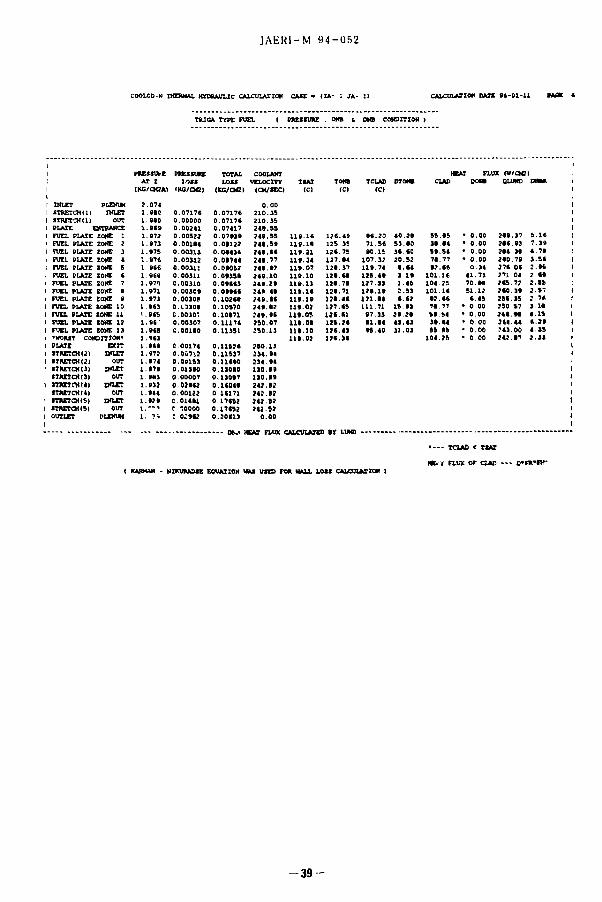
JAERl -M 94-052
COOLOD-N THSIMU. HYDRAULIC CALCULATION CASE • (IA- : JA- t ) CALCULATION DATE M - 0 1 - I 1 HOE «
TfUCA TYPE FUEL ( PRESSURE . ONB t DNB CONDITION I
PRE5SUI-E PRESSURE TOTAL AT E LOSS LOSS
(KG/CK2A1 <KG/QCI (KS/OC
1 INLET PLENUM 2 .074 I STREICHU) INLET 1 no 0 . 0 7 1 7 * 0 . 0 7 1 7 6 1 STRET3K1I OUT 1 990 0.OOOOO 0 . 0 7 1 7 * 1 PLATE ENTRANCE 1 9S» 0 . 0 0 2 4 1 0 .07417 1 FUEL PLATE ZONE I 1 072 0 .00522 0 . 0 7 9 3 9 > FUEL PLATE ZONE 2 1 973 0 . 0 0 1 9 4 0 . 0 1 1 2 2 1 FUEL PLATE ZONE 3 1 975 0 . 0 0 3 1 3 0 . 0 9 4 3 4 1 FUEL PLATE ZONE t 1 97* 0 ,00312 0 .09744 1 FUEL PLATE ZONE 5 1 9CC 0 .00311 0 . 0 9 0 5 2 1 FUEL PLATE ZONE « 1 B i t 0 .00311 0 . 0 9 3 5 9 1 FUEL PLATE ZONE 7 1 970 0 .00310 0 . 0 9 9 ( 3 1 FUEL PLATE ZONE e 1 971 0.003C9 0 . 0 9 9 4 9 1 FUEL PLATE ZONE a 1 973 0 .00309 0 . 1 0 2 ( 9 1 rUEL PLATE ZONE 10 1 9*3 0.1.3309 0 .10570 1 FUEL PLATE ZONE n ! an 0 . 0 0 3 0 : 0 . 1 0 9 7 1 1 FUEL PLATE ZONE 12 1 s i 0 .00307 0 . 1 1 1 7 4 1 FUEL PLATE ZONE 13 > ((( C.OOliO 0 .11351 1 'WORST CONDITION1 1 M l 1 PLATE EXIT 1 9 ( 9 C.00174 0 , 1 1 5 2 4 1 STRETCHU) INLET 1 972 o.oc?t: 0 .11537 1 STRETCKCI OUT 1 •74 0 . 0 0 1 9 3 0 . 1 1 ( 9 0 ! STRETCHtll INLET 1 • 79 0 .01390 0 11090 1 STRETCHO) OUT 1 •HI 0 .00007 0 . 1 3 0 9 7 1 STRETCHU) INLET 1 »3 i 0 . 0 ) 9 9 2 0 . 1 ( 0 ( 9 1 9TRRCHI4I OUT 1 944 0 .00112 0 . 1 ( 1 7 1 ' ITRETOMS) INLET 1 9? 9 0 .01491 0 . 1 7 ( 5 2 1 SIRETCH(5I OUT \ --̂ r IOOOO 0 . 1 7 ( 5 2 1 OUTLET PLENUM 1 79 : o:«2 0 . 2 0 ( 1 3 I
— O U HEAT FLUX CALCULATES »Y LUND
. . . . TOAD < TSAT
HE.* FLUX OF CLAD — O'FR'Br ( KARHAN - NHCURA3SE EQUATION HAS USES FOR HALL LOSS CALCULATION I
- 3 9 -
COOLANT HEAT FLUX (V/CM2I < VELOCITY TSAI TONS TCLAD DTONSJ CLAD SOMJ SLIIND DNS* 1
1 (CM/SECI <CI (CI (CI
0 . 0 0 2 1 0 . 3 5 2 1 0 . 3 5 2 4 9 . 5 5 2 4 9 . 5 5 119.1< 12S .49 9* . 20 4 0 . 2 9 5 5 . 9 5 • 0 . 0 0 2 ( 9 . 3 7 S . l l ; 2 4 9 . 5 9 LIB.19 125 35 7i.s« 5 3 . 9 0 39 94 • 0 . 0 0 2 « . 93 7 . 3 9 1 2 4 4 . ( ( L19.21 124 .75 90 .15 3 * «0 5 9 . 5 4 • 0 . 0 0 2 9 4 . 3 9 4 . 7 9 1 2 4 9 . 7 7 119.24 1 2 7 . 9 4 1 0 7 . 3 2 2 0 . 5 2 7 9 . 7 7 • O.00 2 9 0 . 7 9 3 . 5 * 1 2 4 4 . 9 2 119.07 1 2 4 . 3 7 1 1 9 . 7 4 (.«* 9 2 . ( « 0 . 3 4 2 7 * . 0 * ! . » t 1 2 4 9 . 1 0 119.10 1 2 9 . ( 9 1 2 5 . 4 9 I l l 1 0 1 . 1 * 4 1 . 7 3 271 04 7 . ( 9 1 2 4 9 . 2 9 119,13 1 2 9 . 7 9 1 2 7 . 3 3 1 .45 104 25 7 0 . 9 9 2 ( 5 . 7 2 2 . 5 5 1 249 49 1 9 . 1 4 129 .71 1 2 ( . 1 ( 2 . 5 3 1 0 1 . I t 5 1 . 1 2 2 ( 0 . 3 9 2 . 5 7 ( 2 4 9 . ( ( 1 9 . 1 9 1 2 9 . 4 9 1 2 1 . ( 4 ( ( 2 9 2 . 4 * ( . 4 5 2 5 5 . 3 5 2 . 7 * 1 2 4 9 . 9 2 1 9 . 0 2 1 2 7 . 4 5 111 .71 15 93 7 4 . 7 7 • O 00 250 57 I I I 1 2 4 9 . • ( 1 1 9 . 0 5 1 } ( . C 1 9 7 . 3 3 2 9 . 2 9 59 54 • 0 . 0 0 2 4 ( 9 9 4 . 1 5 1 2 5 0 . 0 7 L19.09 1 2 5 . 2 * ( 1 . 9 4 4 3 . 4 3 3 9 . ( 4 • o.oo 2 ( 4 . 4 4 ( . 2 9 1 2 5 0 . 1 3 1 9 . 1 0 1 2 ( . ( 3 9 5 . 4 0 3 1 . 0 3 55 45 • 0 , 0 0 . '43 .00 4 . 3 5 1
1 9 . 0 2 1 2 4 , 3 ( 1 0 4 . 2 5 " 0 00 2 4 2 . ( 7 J . 33 4 2 5 0 . 1 3 2 3 4 . 9 4 9 3 4 . 9 4 1 3 0 , ( 9 1 3 0 . 9 9 2 4 2 . 5 2 2 4 2 . 5 2 2 4 2 . 5 2 2 ( 2 . 5 2
0 . 0 0

JAERl-M 94-052
•—FLOT W n Q U A ROM (T05 - • 4 - 5 - • • 7'
HXTKX WITH* TKDI I W X MIM IWI HtDI IMMC 140.000 200.000 0.000 100.000 0.000 4.000 0.000 200.000
m m - ma
TITLE- m - 4 TIUGA-M COK CASE:CA •DKlMMtK
IDPLOT- X IDPLOT- 2 IDPLOT- 3 XDFLOT- 4 IDCLOT- 5 IDPLOT- C XDPLOI- 7 11 11 23 14 12 22 21
>MMU. • 1 HML • 2 I M l • 3 lUML - 4 HML • S NJML - ( IHML - 7 0 0 0 0 0 0 0
- » L O I m m DATA n u n m i - • — 4 — • — 5 — • « — • — 7 .
IX- 1 J * - 1 H- 1 Ht>- 1 K- 1
J X(J> TCOOWMT TOAD 9 4 C U T I M TOM H t t t l 1 0 . 0 0 0 3 7 . 0 0 4 4 . 2 0 2 7 2 . 0 2 1 1 1 . 1 4 1 2 ( . ( t 1 . 1 7 1 ( 2 2 2 . * 4 0 1 7 . 4 t 7 1 . SC 2 0 0 . 1 0 l l t . l t 1 2 5 . JS 1 .17270 1 7. N O 1 1 . » M . I S 2 4 8 . 2 4 1 1 1 . 2 1 1 2 4 . 7 5 1 .17455 4 1 2 . N O 1 » . S 7 1 0 7 . 1 2 1 ( 1 . 4 0 1 1 1 . 2 4 1 2 7 . 1 4 1 .17441 S 1 7 . N O 4 1 . 0 7 1 1 1 . 7 4 4>* .0< 1 1 1 . 0 7 l i t . 1 7 1 . M S 7 1
« 2 2 . NO 4 2 . 7 7 1 2 S . 4 * 4 ( 1 . 0 1 1 1 1 . 1 0 U I . H 1 . M 7 4 1 7 27 . NO 4 4 . 5 7 1 2 7 . 1 1 4 7 4 . 1 0 l i t . 1 3 1 1 1 . 7 1 l . M t l l
« 3 2 . N O 4 4 . 3 7 1 2 4 . l t 4 ( 2 . 7 4 l i t . 1 4 1 1 1 . 7 1 1 .17144
• 3 7 . 1 4 0 4 4 . 0 7 121 .14 4 1 0 . 1 7 l l t . l t 1 2 1 . 4 4 1 17114 10 4 2 . 1 4 0 4 1 . 9 1 1 1 1 . 7 1 1 7 1 . 7 1 l i t . 0 1 1 2 7 , ( 1 1 . 1 4 1 ( 7 11 47 . N O BO. 71 t 7 . 1 1 in.u l l l . O t I K . ( 1 1 . 1 4 4 ( 0 12 S 2 . 1 4 0 SI ,48 1 1 . 0 4 2 1 1 . 0 1 1 1 1 . 0 1 1 1 1 . 1 1 1 . 1 4 ( 1 1 1 ) ss. no 5 2 . 1 4 n , 4 0 1 1 1 . 2 1 l i t . 1 0 l i t . 4 1 1 . M 7 U
FLOT n n i , JMMO- i t IX « 1 »L0T BID II - 2 »U>T DO II - 1 PLOT DO II - 4 t l t t DO 11 - s n o r D O II - ( PLOT DO II - 7 HOT DO
H0MM. DO
Appendix B Sample JCL for COOLOD-N2
T(01) W(03) 1(03) C(03) GRP // EXEC LMGOEX,LM=*J3907.CLDN9305',Q=,.LOAD', // PRN=TEMPNAME,A=*ERRCUT=0",GOSYSIN='DDNAME=SYSIN* //FT05F001 DD DSN=J3907.JRR4ROD.DATA(GA002>,DISP=SHR // EXPAND DISK,DDN=FT11F001 // EXPAND GRNLPLIM,SYSOUT=U,OTLIM=300000 //
The COOLOD-N2 code is also available for NEC-PC9801 series and IBM PC-AT compatibles (PC version, there are some restrictions).
WU run ss 14 31 •4 51 .51 7* 75 12 (5
101 14 104.11 101 14
11 ( 5 71 71 1 1 t l 11 14 t t ( 4
- 4 0 -

\mwi& (si) tfo%& M I SI U t T I ' l I .•'MiHI'l'' li? s i ' mmAII •:.wo
• 1
1* \ H • < i\ HH
Hi
« .* m T i M r- H • <\ 1?
i id: «l
<* ftl i
>•• f l
k*
i . l
r i i . l
*1 - r '•' . «V . II ! nun. h. il ' » . ' • • . H ! . . •i i . . I. I. I ' i
4 * t i '. i ; <v
ifr rnwiH.-; t u I i.V l l>l'2 I8- in ".I ! H I »iMi',». In Ice
MS SIMuO.f
<«,t* I I i id.t . l ' V
| l ! • 1 T *« K 1'
!' ' I"
in
1 .1
' ' t
1 ,
M
k
ti
d»
113 I A H I . - . ^ I W * < SIHtVIM'
H
i.M •i IV
' i '1 . It ' ,
i / • I I .11 '(I. » «
1 ( . V< (f + * '.v M . « '-I «(. . iB ' i . UM'i # * rt H •* '.i III M ) 9 •> 5 J
m * gfi * *. 'tt ! 9 i ? . '
1- - « .U '8 •t *
tk'l >« w »! Kr «i « «S « w M l i «
<ia
-"; i t i * . " s i i r r
Mr. s N in kfi * I'n N in .1 \ - i i i
W .1 s C A -V W A r (' V 11 V A
s A V Wb V s T Wb m II Wb A
r lm <il sr U Im n\
liq s Uv J'kir S\ J k f i
* 4 SI ' «c fcCiTir «m •* #i - ; « I M >
i i i
i „, i \ •
i. ! A
i h
•i ; bur
'i 'i 1 ( i n l
i -• i
i 'i
) l<
m i l L / r»'it»
I A 0 1 nm Id m
I b innfnv in " m
I bar n 1 MJ'H UI' 1'a
1 ( ial 1 r m ' s ' Id m s -
ICi 3 . 7 . U I ' B q
I K 2 58 > in "i" kg
I rail l<<!y HI Uy
i rem 1 rSv 10 Sv
In in l( ' I
I A I ' . . ! 'MWIM.1' *• » ' . « « . I«W
'8 « * ( , . ) IHHS.'I I • x i, ft I , l * V
I. i:> I iWlrtmlMlAT^' l t lHBIHIS Kflc.l ,»•
.! A ' i * ( j * V | ' . • . '" ' i . - 1 *
* i . n i n Ti' j . vnfli '<pi7%vir.: • Cl lAQl t
i barU. JUS r<S4i(i</-m 'i*-*#>t«* rtr«|4i A L'oi•, , , i c > > t t j « i T t ' '3
•! ECiTilfllrTllfcfhfiriJbar. barnfcA 'J (ItlH fXPtt I irnnHfi U i m i t i ' l
r Ml - l ' i
'] Ni In'iiyn 1
kRf 1
Ibf
_ 1 II lniHTL' (1 224809
<l 80665 1 2.20462
; 1 44822 (1 AW.ti 1
W H n ' a - s ' N - s / m " HI P< t- r X . i R / < r m s
* l V . t l m / s Id'Si < v ' i i ' m i l s '
kRf (om
in i'.(72
I
103:c:i
I 35951 • 10
7 03070 • 10 •
aim <>86<C'3
n%784l
1
I 3IS7« • 1(1
fi80460 • III
mTnllgi Torr '
7«KW2« 10'
73S !>!W
7(i0
I
M 7 W
lbf' rin''p!)i'
14*038
14 2233
U6S59
1 93368 « 10 •'
1
I .1 1 0 ' e r s 1
kfcf- m 1 kW • h 4 ^
r a l 1 . 1 « r f . I D t u f t • Ib f v V
' I 1 l n i n i ' i v j 2 7777H . 10 ' 0 23KR89 S 4 7 8 1 3 - 10 ' 0 737562 6 24150 > I d "
i '< RWSh.'. i 2 72407 • 1(1 - 2 S4270 <* 2«4B7 • Hi ' 7 23301 6 120H2» 1(1'-
•
t l i • lil"
4 lHfiWi
HIS'ilK
ib7nt)K . | u '
n 42W.K
III , ' M»i
1
1 lh27'.l . i n '
.!'I'«I7.- - III '
KSWWI • 10'
1
2S2 042
3412 13
3 % 7 S ' » ' 1(1 '
1
2 f i 5 5 2 2 * 10*
.1 08747
778 172
2 24694 » I d '•
2 6 1 2 7 2 " 1 0 "
6 S 8 M 5 • 10 '
i i w ; n rtX2S'i Whf i lh • 111 II .123Km) 1 2BSW> • in ' 1 8 4 6 2 3 3 " i n "
... 1 WI218 • Hi • • 1 M' ,77 • in ' 4 «SdS(i - Ill ' (K2743 • II) " 1 ! i l8S7« in 1 18171 • 10 " 1
lral 4 1WK15 J (««,<*,}. I
4 184.1 Mt7>
4 1855,1 ' 1 S T
4 1868j'l»JBf»VA'.
<t'|l» 1 PSH.'.",';•
75 kpf m s
735 49H W
» H.| Ci »i 1 C.y 1 i r a d
»r , ' 2 7ll27(i 111 ' m i 1 1
inn * « 1 1 7 - 10'* ] 1
i II 111
I l
HI <"'ke R t* m i 3K76 * 2 58 • HI ' I
Sv
I
(I PI
100
I
i86q l2M26lH"fl l