Iterative Multiview Side Information for Enhanced Reconstruction in Distributed Video Coding
17
Hindawi Publishing Corporation EURASIP Journal on Image and Video Processing Volume 2009, Article ID 591915, 17 pages doi:10.1155/2009/591915 Research Article Iterative Multiview Side Information for Enhanced Reconstruction in Distributed Video Coding Mourad Ouaret, Fr´ ed´ eric Dufaux, and Touradj Ebrahimi (EURASIP Member) Multimedia Signal Processing Group (MMSPG), Ecole Polytechnique F´ ed´ erale de Lausanne (EPFL), 1015 Lausanne, Switzerland Correspondence should be addressed to Mourad Ouaret, mourad.ouaret@epfl.ch Received 30 May 2008; Revised 13 October 2008; Accepted 15 December 2008 Recommended by Anthony Vetro Distributed video coding (DVC) is a new paradigm for video compression based on the information theoretical results of Slepian and Wolf (SW) and Wyner and Ziv (WZ). DVC entails low-complexity encoders as well as separate encoding of correlated video sources. This is particularly attractive for multiview camera systems in video surveillance and camera sensor network applications, where low complexity is required at the encoder. In addition, the separate encoding of the sources implies no communication between the cameras in a practical scenario. This is an advantage since communication is time and power consuming and requires complex networking. In this work, different intercamera estimation techniques for side information (SI) generation are explored and compared in terms of estimating quality, complexity, and rate distortion (RD) performance. Further, a technique called iterative multiview side information (IMSI) is introduced, where the final SI is used in an iterative reconstruction process. The simulation results show that IMSI significantly improves the RD performance for video with significant motion and activity. Furthermore, DVC outperforms AVC/H.264 Intra for video with average and low motion but it is still inferior to the Inter No Motion and Inter Motion modes. Copyright © 2009 Mourad Ouaret et al. This is an open access article distributed under the Creative Commons Attribution License, which permits unrestricted use, distribution, and reproduction in any medium, provided the original work is properly cited. 1. Introduction Multiview video is attractive for a wide range of appli- cations such as free viewpoint television (FTV) [1] and video surveillance camera networks. The increased use of multiview video systems is mainly due to the improvements in video technology. In addition, the reduced cost of cameras encourages the deployment of multiview video systems. FTV is one of the promising applications of multiview. FTV is a 3D multiview system that allows viewing the scene from a view point chosen by the viewer. Video surveillance is another area where multiview can be beneficial for monitoring purposes. In addition, the multiple views can be used to improve the performance of event detection and recognition algorithms. However, the amount of data generated by multiview systems increases rapidly with the number of cameras. This makes data compression a key issue in such systems. In DVC [2], the source statistics are exploited at the decoder by computing the SI of the WZ frame using different techniques. In this paper, a review of different SI techniques for multiview DVC is first provided, including a thorough evaluation of their estimation quality, complexity, and RD performance. Moreover, all the SI techniques are combined in the ground truth (GT) fusion, which combines the different SIs using the original WZ frame at the decoder. Even though this is not feasible in practice, it gives the maximum achievable DVC performance. Further, a new technique called iterative multiview side information (IMSI) is proposed to improve the DVC RD performance especially for video with significant motion. IMSI uses an initial SI to decode the WZ frame and then constructs a final SI which is used in a second reconstruction iteration. Finally, the performance of multiview DVC is compared with respect to AVC/H.264 [3] Intra, Inter No Motion (i.e., zero motion vectors), and Inter Motion. The paper is structured as follows. First, the paradigm of distributed video coding is presented in Section 2. Multiview DVC is described in Section 3, whereas, Section 4 reviews the different intercamera estimation techniques. The IMSI
-
Upload
independent -
Category
Documents
-
view
0 -
download
0
Transcript of Iterative Multiview Side Information for Enhanced Reconstruction in Distributed Video Coding

Hindawi Publishing CorporationEURASIP Journal on Image and Video ProcessingVolume 2009, Article ID 591915, 17 pagesdoi:10.1155/2009/591915
Research Article
Iterative Multiview Side Information for EnhancedReconstruction in Distributed Video Coding
Mourad Ouaret, Frederic Dufaux, and Touradj Ebrahimi (EURASIP Member)
Multimedia Signal Processing Group (MMSPG), Ecole Polytechnique Federale de Lausanne (EPFL), 1015 Lausanne, Switzerland
Correspondence should be addressed to Mourad Ouaret, [email protected]
Received 30 May 2008; Revised 13 October 2008; Accepted 15 December 2008
Recommended by Anthony Vetro
Distributed video coding (DVC) is a new paradigm for video compression based on the information theoretical results of Slepianand Wolf (SW) and Wyner and Ziv (WZ). DVC entails low-complexity encoders as well as separate encoding of correlated videosources. This is particularly attractive for multiview camera systems in video surveillance and camera sensor network applications,where low complexity is required at the encoder. In addition, the separate encoding of the sources implies no communicationbetween the cameras in a practical scenario. This is an advantage since communication is time and power consuming and requirescomplex networking. In this work, different intercamera estimation techniques for side information (SI) generation are exploredand compared in terms of estimating quality, complexity, and rate distortion (RD) performance. Further, a technique callediterative multiview side information (IMSI) is introduced, where the final SI is used in an iterative reconstruction process. Thesimulation results show that IMSI significantly improves the RD performance for video with significant motion and activity.Furthermore, DVC outperforms AVC/H.264 Intra for video with average and low motion but it is still inferior to the Inter NoMotion and Inter Motion modes.
Copyright © 2009 Mourad Ouaret et al. This is an open access article distributed under the Creative Commons AttributionLicense, which permits unrestricted use, distribution, and reproduction in any medium, provided the original work is properlycited.
1. Introduction
Multiview video is attractive for a wide range of appli-cations such as free viewpoint television (FTV) [1] andvideo surveillance camera networks. The increased use ofmultiview video systems is mainly due to the improvementsin video technology. In addition, the reduced cost of camerasencourages the deployment of multiview video systems.
FTV is one of the promising applications of multiview.FTV is a 3D multiview system that allows viewing thescene from a view point chosen by the viewer. Videosurveillance is another area where multiview can be beneficialfor monitoring purposes. In addition, the multiple viewscan be used to improve the performance of event detectionand recognition algorithms. However, the amount of datagenerated by multiview systems increases rapidly with thenumber of cameras. This makes data compression a key issuein such systems.
In DVC [2], the source statistics are exploited at thedecoder by computing the SI of the WZ frame using different
techniques. In this paper, a review of different SI techniquesfor multiview DVC is first provided, including a thoroughevaluation of their estimation quality, complexity, and RDperformance. Moreover, all the SI techniques are combinedin the ground truth (GT) fusion, which combines thedifferent SIs using the original WZ frame at the decoder.Even though this is not feasible in practice, it gives themaximum achievable DVC performance. Further, a newtechnique called iterative multiview side information (IMSI)is proposed to improve the DVC RD performance especiallyfor video with significant motion. IMSI uses an initial SIto decode the WZ frame and then constructs a final SIwhich is used in a second reconstruction iteration. Finally,the performance of multiview DVC is compared with respectto AVC/H.264 [3] Intra, Inter No Motion (i.e., zero motionvectors), and Inter Motion.
The paper is structured as follows. First, the paradigm ofdistributed video coding is presented in Section 2. MultiviewDVC is described in Section 3, whereas, Section 4 reviewsthe different intercamera estimation techniques. The IMSI

2 EURASIP Journal on Image and Video Processing
RY (bits)
H(Y)
H(Y |X)
H(X|Y) H(X) RX (bits)
RX + RY = H(X ,Y)
Vanishing probability error
No errors
Figure 1: Achievable rate region defined by the Slepian-Wolfbounds.
technique is proposed in Section 5. Then, the test materialand simulation results are presented and discussed inSection 6. Finally, some concluding remarks are drawn inSection 7.
2. Distributed Video Coding (DVC)
2.1. Theoretical DVC. DVC is the result of the information-theoretic bounds established for distributed source coding(DSC) by Slepian and Wolf [4] for lossless coding, andby Wyner and Ziv [5] for lossy coding with SI at thedecoder. Lossless DSC refers to two correlated randomsources separately encoded and jointly decoded by exploitingthe statistical dependencies.
If we consider two statistically dependent randomsequences X and Y, rates RX and RY can be achieved byentropy coding such that RX ≥ H(X) and RY ≥ H(Y), whereH(X) and H(Y) are the entropies of X and Y, respectively.The Slepian-Wolf theorem proves that a better rate can beachieved with joint decoding and gives tighter bounds forthe total rate RX +RY . The admissible rate region establishedby SW, which corresponds to the shaded area depicted inFigure 1, is defined by
RX ≥ H(X|Y), RY ≥ H(Y |X),
RX + RY ≥ H(X ,Y).(1)
Decoding with SI is considered as a special case of DSC.In this case, the source X depends on some SI Y, whichcorresponds to the black dot on the region border inFigure 1. Later on, Wyner and Ziv established bounds forlossy compression with SI at the decoder as an extensionto the Slepian and Wolf theorem. In this case, the source Xis encoded without having access to the SI Y. On the otherhand, the decoder has access to the SI to produce X with acertain distortion D.
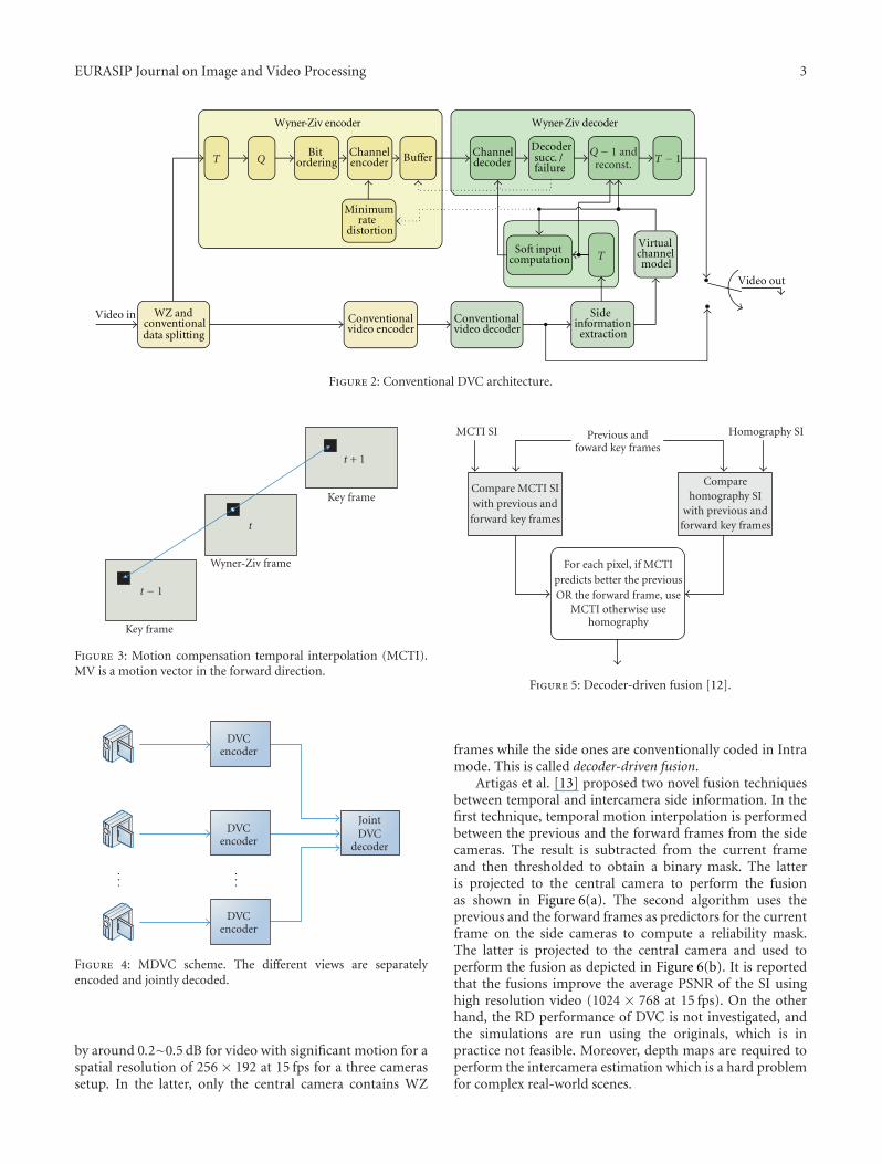
2.2. Practical DVC. Figure 2 shows the DVC architectureused in this work [6].
At the encoder, the frames are separated into two sets.The first one is the key frames which are fed to a conventionalAVC/H.264 Intra encoder. The second set is the WZ frames.The latter are transformed and then quantized prior to WZencoding. The same 4 × 4 separable integer transform as inAVC/H.264 is used with properties similar to the discretecosine transform (DCT) [7]. Then, the same bands aregrouped together and the different bit planes are extractedand then fed to a turbo encoder [8]. The latter offers near-channel capacity error correcting capability. Furthermore, acyclic redundancy check (CRC) [9] is computed for eachquantized bit plane and transmitted to the decoder. Thefrequency of the key frames is defined by the group ofpictures (GOPs).
At the decoder, the key frames are conventionallydecoded and then used to generate the SI for the WZ decoder.In the monoview case, motion compensation temporalinterpolation (MCTI) [10] is used to generate the SI. Forthis purpose, MCTI uses the key frames to perform motionestimation. The resulting motion vectors are interpolated atmidpoint as illustrated in Figure 3.
A virtual channel is used to model the correlationbetween the DCT coefficients of the original and SI frames. Itis shown that the residual of the DCT coefficients follows theLaplacian distribution [2]. The reconstruction process [11]uses the SI along with decoded bins to recover the originalframe up to a certain quality. The decoder accepts the SI DCTvalue as a reconstructed one if it fits into the quantizationinterval corresponding to the decoded bin. Otherwise, ittruncates the DCT value into the quantization interval. ThisDVC scheme is decoder driven as the request for parity bitsfrom the encoder is performed via a feedback channel untilsuccessful decoding. The decoding is considered successful ifthe decoded bit plane error probability is lower than 10−3 andits CRC matches the one received from the encoder.
The multiview DVC scheme used in this research isexactly the same as the monoview DVC described aboveexcept for the SI extraction module as it is explained furtherin Section 3.
3. Multiview DVC (MDVC)
MDVC is a solution that allows independent encoding of thecameras and joint decoding of the different video streams asshown in Figure 4.
It differs from monoview DVC in the decoder. Moreprecisely, the SI is constructed not only using the frameswithin the same camera but using frames from the othercameras as well.
A fusion technique between temporal and homography-based side information is introduced in [12]. The fusionconsiders the previous and the forward frames as predictorsof the WZ frame. The logical operation OR is used to com-bine the different predictors for each pixel. In other words,MCTI is chosen if it is a better predictor than homographyfor at least one of the two frames. Otherwise, homographyis chosen as predictor as illustrated in Figure 5. The resultsin [12] report that the fusion outperforms monoview DVC
EURASIP Journal on Image and Video Processing 3
Conventional video encoder
Minimum rate
distortion
Side information
extraction
Virtual channel model
WZ and conventional data splitting
Conventional video decoder
Soft input computation
Channel decoder
Decodersucc. /failure
Bit ordering
Channel encoder Buffer
Wyner-Ziv encoder Wyner-Ziv decoder
Video out
Video in
T − 1Q − 1 andreconst.
T
T Q
Figure 2: Conventional DVC architecture.
t + 1
t
t − 1
Key frame
Wyner-Ziv frame
Key frame
Figure 3: Motion compensation temporal interpolation (MCTI).MV is a motion vector in the forward direction.
JointDVC
decoder
DVCencoder
DVCencoder
DVCencoder
......
Figure 4: MDVC scheme. The different views are separatelyencoded and jointly decoded.
by around 0.2∼0.5 dB for video with significant motion for aspatial resolution of 256 × 192 at 15 fps for a three camerassetup. In the latter, only the central camera contains WZ
For each pixel, if MCTIpredicts better the previousOR the forward frame, use
MCTI otherwise usehomography
Compare MCTI SIwith previous and
forward key frames
Comparehomography SI
with previous andforward key frames
Previous andfoward key frames
MCTI SI Homography SI
Figure 5: Decoder-driven fusion [12].
frames while the side ones are conventionally coded in Intramode. This is called decoder-driven fusion.
Artigas et al. [13] proposed two novel fusion techniquesbetween temporal and intercamera side information. In thefirst technique, temporal motion interpolation is performedbetween the previous and the forward frames from the sidecameras. The result is subtracted from the current frameand then thresholded to obtain a binary mask. The latteris projected to the central camera to perform the fusionas shown in Figure 6(a). The second algorithm uses theprevious and the forward frames as predictors for the currentframe on the side cameras to compute a reliability mask.The latter is projected to the central camera and used toperform the fusion as depicted in Figure 6(b). It is reportedthat the fusions improve the average PSNR of the SI usinghigh resolution video (1024 × 768 at 15 fps). On the otherhand, the RD performance of DVC is not investigated, andthe simulations are run using the originals, which is inpractice not feasible. Moreover, depth maps are required toperform the intercamera estimation which is a hard problemfor complex real-world scenes.

4 EURASIP Journal on Image and Video Processing
WZcamera
Intracamera
Frame k − 1
Frame k
Frame k + 1
Frame k − 1
Frame k
Frame k + 1
Projection −
Mot
ion
esti
mat
ion
and
inte
rpol
atio
n
(a) Motion estimation is performed on the side camera to compute afusion mask for the central camera
WZcamera
Intracamera
Frame k − 1
Frame k
Frame k + 1
Frame k − 1
Frame k
Frame k + 1
Projection
−
−
(b) Frame difference w.r.t the previous and forward frameson the side camera is used to compute the fusion mask
Figure 6: Fusion techniques proposed by Artigas et al. [13].
In [14], the wavelet transform is combined with turbocodes to encode a multiview camera array in a distributedway. At the decoder, a fusion technique is introduced to com-bine temporal and homography-based side information. Itthresholds the motion vectors and the difference between thecorresponding backward and forward estimations to obtaina fusion mask. The mask assigns the regions with significantmotion vector and estimation error to homography SI, andthe rest is assigned to temporal SI (i.e., regions with lowmotion and relatively small prediction error). It is reportedthat the hybrid SI outperforms the temporal one by around1.5 dB in PSNR. In addition, it outperforms H.263+ Intra byaround 4.0∼7.0 dB. A video content with spatial resolution320× 240 is used in the evaluation.
Further, a flexible estimation technique that can jointlyutilize temporal and view correlations to generate sideinformation is proposed in [15]. More specifically, thecurrent pixel in the WZ frame is mapped using homographyto the left and right camera frames. Then, AVC/H.264decision modes are applied to the pixel blocks in the left andright camera frames. If both resulting modes are intermodes,the SI value is taken from temporal SI. Otherwise, it is takenfrom homography SI. The simulation results show that thistechnique significantly outperforms conventional H.263+Intra coding. Nevertheless, comparison with AVC/H.264Intra would be beneficial as it represents state-of-the-art forconventional coding.
A fusion technique based on some prior knowledgeof the original video is introduced in [16]. This is calledencoder-driven fusion. Initially, a binary mask is calculatedat the encoder as illustrated in Figure 7. It is compressedusing a bilevel image compression [17] encoder and thentransmitted to the decoder.
For each pixel, the mask informs the decoder whetherthe previous or the forward pixel is a better predictor of thesame pixel in the original frame to perform fusion at thedecoder (Figure 8). The results report a maximum gain upto 1.0 dB over monoview DVC in the same conditions as[12]. Furthermore, there is a slight increase in the encoder
With respect to the WZ pixeloutput:
1 if previous pixel is closeror
0 if forward pixel is closer
Previous key WZ frame Forward key
Binary mask
Figure 7: The encoder-driven fusion at the encoder side [16].
complexity as it has to perform the additional task ofcompressing the binary mask.
In [18], coding of multiview image sequences with videosensors connected to a central decoder is investigated. The Nsensors are organized in an array to monitor the same scenefrom different views as shown in Figure 9. Only decoders2 to N perform DVC using disparity compensated outputof decoder 1. In addition, the video sensors are able toexploit temporal correlation using a motion compensatedlifted wavelet transform [19] at the encoder. The proposedscheme reduces the bit rate by around 10% by performingjoint decoding when compared to separate decoding forvideo content at 30 fps and 256× 192 spatial resolution.
Finally, ways of improving the performance of multiviewDVC are explored in [20]. Several modes to generatehomography-based SI are introduced. The homography isestimated using a global motion estimation technique. Theresults show an improvement of SI quality by around 6.0 dBand a gain in RD performance by around 1.0∼2.0 dB forvideo content with a spatiotemporal resolution of 256 ×192 at 15 fps. However, the reported results assume anideal fusion mask, which requires the knowledge of theoriginal at the decoder. This is not feasible in a practicalscenario.

EURASIP Journal on Image and Video Processing 5
Binary mask
If mask is equal to oneuse the previous pixelas reference otherwiseuse the forward pixel
Output the pixel valuethat is closer to the
reference
Referenceframe
Previous keyframe
Forward keyframe
Homography SI MCTI SI
Figure 8: The encoder-driven fusion at the decoder side [16].
Un
Ui
U1
Un
Ui
U1
Encoder N
Encoder i
Encoder 1
Decoder N
Decoder i
Decoder 1
...
Disparitycompensation
Disparitycompensation
Figure 9: Distributed coding scheme with disparity compensationat the central decoder [18].
4. Intercamera Prediction
In this section, different SI techniques for multiview DVCare reviewed. The different techniques are described for 3cameras setup, where the central camera is predicted fromboth neighboring cameras, as depicted in Figure 10.
4.1. Disparity Compensation View Prediction (DCVP).DCVP [16] is based on the same idea as MCTI, but themotion compensation is performed between the frames fromthe side cameras. A slight modification is applied to DCVP toimprove the SI quality. Instead of interpolating the motionvectors at midpoint, an optimal weight is computed in
[16]. For this purpose, the first frame of each camera isconventionally decoded. Then, motion compensation is per-formed between the side camera frames. The motion vectorsare weighted with the weights 0.1, 0.2, . . . , 0.9. Further, theSI PSNR is computed for each weight. The weight withmaximum PSNR is maintained and used for the rest ofthe sequence. Nevertheless, the SI generated by DCVP hasusually a poorer quality than the one generated by MCTI.This is due to the larger disparity between the side cameraframes when compared to the one between the previous andforward frames.
4.2. Homography. The homography, H, is a 3 × 3 matrixtransforming one view camera plane to another one asshown in Figure 11.
It uses eight parameters a, b, c, d, e, f, g, and h. Thehomography maps a point (x1, y1) from one plane to a point(x2, y2) in the second plane up to a scale λ such that
λ
⎛⎜⎝x2
y2
1
⎞⎟⎠ =⎛⎜⎝a b cd e fg h 1
⎞⎟⎠⎛⎜⎝x1
y1
1
⎞⎟⎠ . (2)
This model is suitable when the scene can be approximatedby a planar surface, or when the scene is static and thecamera motion is a pure rotation around its optical center.The homography can be calculated using various techniques.In this work, we consider a global motion estimationtechnique introduced in [21] to compute the homography.The parameters are calculated such that the sum of squareddifferences E between the reference frame and the warpedside frame is minimized:
E =N∑i=1
e2i with ei = Iw
(xwi , ywi
)− I(xi, yi
), (3)
where Iw(xwi , ywi) and I(xi, yi) are the pixels from thewarped and reference frames, respectively. The problemis solved using the Levenberg-Marquardt gradient descentalgorithm to iteratively estimate the parameters. To removethe influence of such outliers, a truncated quadratic is used.In other words, only pixels for which the absolute value of theerror term is below a certain threshold are taken into accountin the estimation process, other pixels are ignored. Therefore,the algorithm will count mainly for global motion
E =N∑i=1
ρ(ei)
with ρ(ei) = e2
i if∣∣ei∣∣ ≥ T else 0, (4)
where T is a threshold.In multiview DVC, the warped frame is computed from
the left (HL) and right (HR) camera frames as shown inFigure 12. Therefore, three side information are possible.The one entirely warped from each side camera and theaverage (H) of both side cameras. The latter is the only oneconsidered in this work.
The advantage of this technique is that once the homog-raphy relating the central camera with the side ones isestimated, computing the SI becomes very simple in terms

6 EURASIP Journal on Image and Video Processing
I I I I
WZ I WZ I
I I I I Joint decoding
1
2
3
Figure 10: The multiview camera setup considered in this work. I stands for intraframe and WZ for Wyner-Ziv frame.
H
Warped frame Reference frame
Figure 11: Homography matrix H relating one view to another.
of computational complexity when compared to techniquesbased on exhaustive block-based motion estimation. More-over, this technique is suitable for scenarios, where the globalmotion is highly dominant with respect to local variationsas it would generate a good estimation in this case. Onthe other hand, if the scene has multiple significant objectsmoving in different directions, the estimation would be of apoor quality as the technique would only account for globalmotion.
4.3. View Synthesis Prediction (VSP). The previously men-tioned techniques do not take advantage of some importantfeatures of multiview. That is, the speed at which an objectis moving in a view depends on its depth information. Inaddition to this, rotations, zooms, and different intrinsicparameters are difficult to model using a motion vector,which is a simple translational model. Furthermore, thehomography tries to estimate a global motion and ignoreslocal motion using a truncated error function, which is notthe case of VSP [22]. In the latter, the camera parameters,intrinsic and extrinsic, are used to predict one camera viewfrom its neighbors.
For simplicity, the case of one neighboring camera isconsidered as shown in Figure 13. The view from camera c2
can be synthesized from camera c1. Each pixel I(c1, x, y) fromcamera c1 is projected into the 3D world reference using itsdepth information:
λ
⎛⎜⎝xy1
⎞⎟⎠ = A
(R T0 1
)⎛⎜⎜⎜⎝X3D
Y3D
Z3D
1
⎞⎟⎟⎟⎠ , (5)
where A is the intrinsic parameters matrix, and R and T arethe rotation and translation matrices with respect to the 3Dworld reference. Moreover, the depth information is equal to
Z3D, which corresponds to the Z coordinate of the point inthe 3D world coordinates. It is substituted in (5), and theresulting system is solved for X3D and Y3D. Then, the 3Dpoint is projected back to the 2D plane of camera c2. Thisprocess is performed for each pixel of camera c1.
In the multiview camera setup used in this research, thepixel in the central camera is mapped to both side cameras.The pixel value is taken as average of both side camera pixels.
The drawback of this technique is the difficulty toestimate depth for real-world complex scenes. In addition,the quality of the SI depends on the precision of the cameracalibration and depth estimation.
4.4. View Morphing (VM). Image morphing can generatecompelling 2D transitions between images. However, dif-ferences in object pose or viewpoint often cause unnaturaldistortions in image morphs. Using basic principles ofprojective geometry, one can perform a simple extension toimage morphing that correctly handles 3D projective cameraand scene transformations. The view morphing requiresthe computation of the fundamental matrix, which is thealgebraic representation of epipolar geometry. Suppose thatwe have a point P in the 3D world coordinates. This point isvisible in both cameras with optical centers C0 and C1 as P0
and P1, respectively. The three points P, C0, and C1 definea plane called the epipolar plane π. The line intersectionof the epipolar plane with each image plane is called anepipolar line as shown in Figure 14. The fundamental matrixis derived from the mapping between a point in one cameraand its epipolar line in the other camera. Therefore, matchingpoints should be calculated between the two images.
VM [23] is used to get an image from a virtual camerathat could be placed between two real cameras as shownin Figure 15. The input of the view morphing algorithmis two images from real cameras and information aboutthe correspondences between regions in the two imagesor projection matrices of the side cameras from 3D worldcoordinates to 2D coordinates in each camera plane. Theoutput of the algorithm is a synthesized image (i.e., a viewfrom the virtual camera).
The VM of a virtual camera with optical Cs is illustratedin Figure 16. Initially, both images I0 and I1 are warped acrossthe scanlines to get I0 and I1, respectively, which are in thesame plane. The latter are morphed across the position of

EURASIP Journal on Image and Video Processing 7
HL HR
Left viewat time t
Right viewat time tt
Figure 12: Homography-based SI.
x
y
z
Depth
c1
c2
2D point
2D point
Project from 2D to 3D
Project from 2D to 3D
3D point in the worldcoordinate
Figure 13: View synthesis prediction.
C1 C0
P1 P0
P
Epipolar plane π
Figure 14: The epipolar line and plane.
Right camera Virtual camera Left camera
Figure 15: The virtual camera in view morphing.
the virtual camera Cs to get Is. Finally, Is is unwarped to getIs. As in the case of DCVP, an optimal weight s is computedfor the virtual camera Cs such that the PSNR is maximizedfor the warped frame with respect to the central view frame.
The problem with VM is that it works very well for simplescenes with a central object infront a uniform background.In this case, extracting matched feature points with a highdegree of accuracy from the scene is simple as these pointsare used to compute the fundamental matrix. On the otherhand, VM fails for real-world scenes as the matched featurepoints task becomes a more challenging task.
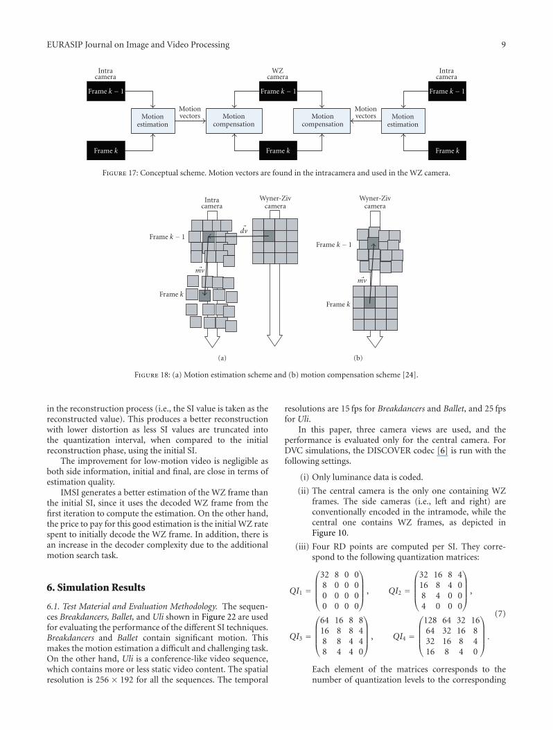
4.5. Multiview Motion Estimation (MVME). MVME [24]finds the motion vectors in the side cameras and then appliesthem to the central camera to estimate the WZ frame asshown in Figure 17. The motion vectors computed in oneview should be transformed before being used in anotherview. Nevertheless, they can be directly reused if all thecameras lie in the same plane and point in the same direction.
First, a disparity vector �dv is obtained by block-based fullsearch between the WZ and the intracameras for frame k−1.The vector �dv estimates the location of each block from theWZ camera in the intracamera. Then, the motion vector �mvis computed by searching in frame k in the intracamera forthe best match for the block obtained in the previous stepas illustrated in Figure 18(a). Finally, the motion vector �mv isapplied to the aligned block in frame k in the WZ camera asdepicted in Figure 18(b).
Figure 19 shows the possible motion paths to estimatethe WZ frame, which are a total of 8 paths, 4 innerpaths, and 4 outer paths, each generating one estimate. Theinner paths are computed as described above by performing

8 EURASIP Journal on Image and Video Processing
C1
Cs
C0
I1
I1
Is
Is
I0
I0
P
Figure 16: VM of a virtual camera with optical center Cs.
disparity estimation followed by motion estimation on theintracamera (Figure 19(a)). The outer paths are computed bydoing the opposite of inner paths computation, starting withmotion estimation on the intracamera followed by disparityestimation (Figure 19(b)). The simplest way to generate thefinal SI is by taking the average of these estimates. A betterstrategy is to compute a reliability measure for each path ona block or pixel basis and weight the estimates before takingthe sum. For this purpose, mean square error (MSE) or meanabsolute difference (MAD) computed between the originaland the candidate blocks is used as a reliability measure.
5. Iterative Multiview Side Information (IMSI)
We initially introduced iterative SI for the monoview sce-nario in [25], where the final SI depends not only on thekey frames but also on the WZ bits as well. This final SI isused to refine the reconstruction of the decoded WZ frame.This is done by running the reconstruction process in asecond iteration to enhance the quality of the decode frame.The process of IMSI is illustrated in Figure 20. IMSI differsfrom monoview iterative SI [25] in the fact that the initialSI depends on the input video in the multiview case. In thelatter, the refinement process is applied to all the blocks,while a threshold is used to select the refined blocks basedon the estimation error in [25].
Initially, the reconstruction process of DVC is describedin this section. Then, IMSI is introduced.
5.1. DVC Reconstruction. This stage in the decoding pro-cess is opposite to the quantization step at the encoder.After turbo decoding, the decoder knows perfectly thequantization bin of each decoded band. Relying on theassumption that the WZ frame is correlated with the SI, thereconstruction block uses the SI along with decoded binsto improve the reconstruction quality as described in [11].The principal consists in either accepting an SI value as areconstructed value if it fits into the quantization interval
corresponding to the decoded bin or truncating the SIvalue into this quantization interval. The reconstruction isperformed independently for every transform coefficient ofevery band.
Let Y be the SI value, d the decoded quantized index, Δthe quantization step, and X the reconstructed value. In thecase of the DC band, the reconstructed value X is computedas
X =
⎧⎪⎪⎨⎪⎪⎩Y if dΔ ≤ Y ≤ (d + 1)Δ,
dΔ if Y < dΔ,
(d + 1)Δ if Y > (d + 1)Δ.
(6)
For the AC bands, the reconstructed value X is computed ina similar way. The only difference is that a quantizer with adead zone is used for the AC coefficients as they take positiveand negative values. On the other hand, the DC coefficienttakes only positive value.
5.2. IMSI for Enhanced Reconstruction. Hereafter, the pro-posed IMSI is described.
(i) First, the initial SI to use in the WZ frame decodingis chosen depending on the nature of the video. Thisis done by computing the average luma variation perpixel between the key frames at the decoder, which iscompared to a threshold. If it is below the threshold,the motion is considered not significant and MCTI isused as the initial SI. Otherwise, MVME is taken asinitial SI. This is motivated by the results presentedfurther in Section 6.2. Namely, MCTI shows betterestimation quality for low-motion video content. Onthe other hand, MVME is shown to have a betterperformance for video with significant motion.
(ii) WZ decoding is performed using the initial SI,which implies turbo decoding followed by a firstreconstruction stage.
(iii) The decoded WZ frame from the first stage isthen predicted by block-based motion search andcompensation as in conventional video coding usingfour references: the previous, forward, left camera,and right camera frames. More specifically, for eachblock in the decoded frame, the best matching blockwith minimum distortion is selected using the squareabsolute difference (SAD) as the distortion metric asshown in Figure 21. This generates a final SI.
(iv) Finally, the final SI is used in a second iteration in thereconstruction block.
It is important to stress the fact that this method does notuse the original WZ but rather the decoded WZ frame usingthe initial SI. IMSI is expected to be efficient in situationswhere motion is significant as the difference in estimationquality between the initial and final SIs is more important.The reason is that the final SI is highly correlated withthe WZ frame in the case of high activity video content.Therefore, most of the SI values map into the decoded bin
EURASIP Journal on Image and Video Processing 9
WZcamera
Intracamera
Intracamera
Frame k − 1
Frame k
Frame k − 1
Frame k
Frame k − 1
Frame k
Motionestimation
Motioncompensation
Motioncompensation
Motionestimation
Motionvectors
Motionvectors
Figure 17: Conceptual scheme. Motion vectors are found in the intracamera and used in the WZ camera.
Wyner-Zivcamera
Intracamera
Frame k − 1
Frame k
�dv
�mv
(a)
Wyner-Zivcamera
Frame k − 1
Frame k
�mv
(b)
Figure 18: (a) Motion estimation scheme and (b) motion compensation scheme [24].
in the reconstruction process (i.e., the SI value is taken as thereconstructed value). This produces a better reconstructionwith lower distortion as less SI values are truncated intothe quantization interval, when compared to the initialreconstruction phase, using the initial SI.
The improvement for low-motion video is negligible asboth side information, initial and final, are close in terms ofestimation quality.
IMSI generates a better estimation of the WZ frame thanthe initial SI, since it uses the decoded WZ frame from thefirst iteration to compute the estimation. On the other hand,the price to pay for this good estimation is the initial WZ ratespent to initially decode the WZ frame. In addition, there isan increase in the decoder complexity due to the additionalmotion search task.
6. Simulation Results
6.1. Test Material and Evaluation Methodology. The sequen-ces Breakdancers, Ballet, and Uli shown in Figure 22 are usedfor evaluating the performance of the different SI techniques.Breakdancers and Ballet contain significant motion. Thismakes the motion estimation a difficult and challenging task.On the other hand, Uli is a conference-like video sequence,which contains more or less static video content. The spatialresolution is 256 × 192 for all the sequences. The temporal
resolutions are 15 fps for Breakdancers and Ballet, and 25 fpsfor Uli.
In this paper, three camera views are used, and theperformance is evaluated only for the central camera. ForDVC simulations, the DISCOVER codec [6] is run with thefollowing settings.
(i) Only luminance data is coded.
(ii) The central camera is the only one containing WZframes. The side cameras (i.e., left and right) areconventionally encoded in the intramode, while thecentral one contains WZ frames, as depicted inFigure 10.
(iii) Four RD points are computed per SI. They corre-spond to the following quantization matrices:
QI1 =
⎛⎜⎜⎜⎝32 8 0 08 0 0 00 0 0 00 0 0 0
⎞⎟⎟⎟⎠ , QI2 =
⎛⎜⎜⎜⎝32 16 8 416 8 4 08 4 0 04 0 0 0
⎞⎟⎟⎟⎠ ,
QI3 =
⎛⎜⎜⎜⎝64 16 8 816 8 8 48 8 4 48 4 4 0
⎞⎟⎟⎟⎠ , QI4 =
⎛⎜⎜⎜⎝128 64 32 1664 32 16 832 16 8 416 8 4 0
⎞⎟⎟⎟⎠ .
(7)
Each element of the matrices corresponds to thenumber of quantization levels to the corresponding

10 EURASIP Journal on Image and Video Processing
I
WZ
I
C
C
C
C
C
C
I
WZ
I
C
C
C
C
C
C
Intra cam WZ cam Intra cam
Frame k − 1
Frame k
Frame k + 1
(a) Inner paths
I
WZ
I
C
C
C
C
Intra cam WZ cam Intra cam
C CFrame k − 1
Frame k
Frame k + 1
(b) Outer paths
Figure 19: The 8 possible paths when using two intracameras and two reference frames in each camera [24].
Final SIconstruction
Initial SI
Initially decoded
WZ frame
Final SI
DCT
IDCT
DCT
IDCT
Average pixelvariation between
key frames
ReconstructionReconstructionFinally
decodedWZ frame
MCTIor
MVME
Key and sidecamera frames
Turbodecoder
WZ bits
Figure 20: The IMSI generation process.
coefficient band. For example, the DC coefficient has32, 32, 64, and 128 quantization levels, respectively,in the 1st, 2nd, 3rd, and 4th RD points, and so on.
(iv) The same quantization parameter (QP) is used forthe side cameras and the key frames of the centralcamera. A QP is defined per quantization matrix suchthat the decoded key and WZ frames have a similarquality.
(v) The GOP size is equal to 2.
For AVC/H.264 coding, the publicly available referencesoftware (JM 11.0) [26] is used with the following settings:
(a) Intra, Inter No Motion, and Inter Motion modes. Forthe Inter No Motion mode, each motion vector isequal to zero, which means that each block in a Pframe is predicted from the colocated block in theprevious I frame. For the Inter Motion mode, themotion search range is set to 32. In both modes, theGOP size is equal to 12;
(b) high profile with CABAC;
(c) the 8× 8 transform enabled.
6.2. Side Information Estimation Quality. In this section, theSI PSNR is evaluated for the SI techniques at the differentRD points. Uli is not provided with depth maps. In addition,
the feature point matching performs poorly due to highlytextured scene background in the sequence. For this reason,the VSP and VM techniques are not evaluated for Uli.
For IMSI, Figure 23 shows the luma pixel variationbetween the key frames for the three video sequences atthe highest RD point. By picking a threshold equal to 1.7,Breakdancers and Ballet are classified as sequences withsignificant motion (i.e., MVME is used as the initial SI) andUli is classified as a low-motion video content (i.e., MCTI isused as the initial SI) at all RD points.
Figures 24, 25, and 26 show the SI PSNR for Break-dancers, Ballet, and Uli, respectively. Obviously, the GTfusion and IMSI produce the best estimation for allsequences at all RD points as they use, respectively, theoriginal frame and the decoded WZ frame to construct theestimation. Thus, the comparison will mainly focus on theother SI techniques. For Breakdancers, MVME produces thebest SI quality followed by MCTI. On the other hand, theworst performance is for VSP. However, VSP requires twoinput parameters, camera calibration, and depth estimation.The quality of the SI depends on the precision of theseparameters. We can observe that most of the techniquesperform quite well in terms of SI quality for this sequenceas homography and DCVP are quite close to MCTI inestimation quality.
For Ballet, MVME produces the best SI quality followedby MCTI. Ballet contains motion but it is less significant

EURASIP Journal on Image and Video Processing 11
Previous frame
Right camera frame Decoded WZ frameafter the first iteration
Left camera frame
Forward frame
Figure 21: The final SI construction in IMSI.
(a) (b) (c)
Figure 22: Sequences Breakdancers, Ballet, and Uli.
0
2
4
6
8
10
12
Ave
rage
lum
ava
riat
ion
1 5 9 13 17 21 25 29 33 37 41 45 49
WZ frame index
Average pixel variation in GOP = 2 between key frames
BalletBreakdancersUli
Figure 23: Average luma pixel variation for Breakdancers, Ballet,and Uli at the highest RD point.
than in the Breakdancers case. This explains the increase inPSNR gap between MCTI and the other SI techniques. Asfor Breakdancers, we have homography followed by DCVP,then VM, and finally VSP in a decreasing order in terms of SIquality.
10
15
20
25
30
35
40
YP
SNR
(dB
)
1 2 3 4
RD point
SI quality for Breakdancers
GT fusionIMSIMCTIMVME
HDCVPVSPVM
Figure 24: Side information quality for Breakdancers.
Since Uli contains little motion, we expect MCTI andMVME to work very well, since MCTI performs a puretemporal interpolation and MVME performs an intercameradisparity estimation followed by a temporal motion estima-tion.

12 EURASIP Journal on Image and Video Processing
10
15
20
25
30
35
40
45
YP
SNR
(dB
)
1 2 3 4
RD point
SI quality for Ballet
GT fusionIMSIMCTIMVME
HDCVPVSPVM
Figure 25: Side information quality for Ballet.
0
5
10
15
20
25
30
35
40
YP
SNR
(dB
)
1 2 3 4
RD point
SI quality for Uli
GT fusionIMSIMCTI
MVMEHDCVP
Figure 26: Side information quality for Uli.
In summary, we can see clearly that MVME and MCTIproduce by far better estimations than other SI generationtechniques for Ballet and Uli. On the other hand, MVME,MCTI, homography, and DCVP are not very far from eachother in terms of SI quality for Breakdancers.
Figure 27 illustrates the contribution of the different sideinformation to the GT fusion for Breakdancers. It is obviousthat MCTI has the largest contribution around 43%∼55%out of the total number of frame pixels. It is followed byhomography-based SI. The homography is the one thatbrings most innovation to the GT fusion. MVME and DCVPare highly correlated with MCTI. This is explained by thefact that these methods are of the same block-based nature.Finally, VSP and VM have the worst contribution to the GTfusion.
The contribution of the different side information tothe GT fusion for Ballet is illustrated in Figure 28. As forBreakdancers, MCTI has the largest contribution, around45%∼64%. It is larger than in the Breakdancers case, sinceBallet contains less motion than Breakdancers. It is followedby homography-based SI. Then, MVME comes in the third
0
10
20
30
40
50
60
(%)
1 2 3 4
RD point
Breakdancers
MCTI
MVMEH
DCVPVSPVM
Figure 27: The percentage of contribution of the different sideinformation in the GT fusion for Breakdancers.
0
10
20
30
40
50
60
70
(%)
1 2 3 4
RD point
Ballet
MCTI
MVMEH
DCVPVSPVM
Figure 28: The percentage of contribution of the different sideinformation in the GT fusion for Ballet.
place followed by DCVP. Finally, VSP and VM are the worstin terms of contribution to the GT fusion.
Since Uli contains low-motion content, MCTI has thelargest contribution to the GT fusion, around 54%∼73%,out of all pixels. It is followed by homography-based SI andthen MVME. Furthermore, the rest of side information havea poor contribution to the GT fusion. This is illustrated inFigure 29.
For the three sequences, homography-based SI is theone that brings most innovations to the GT fusion as itis the least correlated SI with MCTI. Therefore, we canconclude that possible fusion algorithms combining MCTIand homography-based SI represent a good tradeoff betweenperformance improvement and complexity increase.
6.3. Side Information Complexity. The different techniquescomplexities are compared in terms of the total numberof arithmetic operations (i.e., additions, subtractions, mul-tiplications, and divisions) required to generate the sideinformation. The image dimensions are the height, H, and

EURASIP Journal on Image and Video Processing 13
0
10
20
30
40
50
60
70
(%)
1 2 3 4
RD point
Uli
MCTI MVMEH DCVP
Figure 29: The percentage of contribution of the different sideinformation in the GT fusion for Uli.
the width, W. For the block-based methods, a search range rand block size w are considered.
6.3.1. MCTI and DCVP. Both MCTI and DCVP havethe same complexity. The only difference between bothtechniques is the input frames. For each block match, w2
subtractions are required. Then, the error is computed,which requires w2 − 1 additions. This is performed foreach position within the search range. Thus, (2w2 − 1)r2
operations are required to find a match for each block.Finally, all the blocks should be processed. Therefore, (2w2−1)∗r2∗(H∗W/w2) ≈ 2∗H∗W∗r2 is the number ofoperations required to estimate the motion between the twoframes.
6.3.2. MVME. There is a maximum of 8 paths. For each one,motion estimation is performed twice with the Intracameraand then across the side and the central cameras. Therefore,2∗O(MCTI) operations are required for each path. Thus,a total of 16∗O(MCTI) operations is required for all thepaths. In other words, MVME is approximately 16 timesmore complex than MCTI.
6.3.3. Homography. Initially, the homography matrices arecomputed offline. A total of 15 operations is requiredto compute the mapping for each pixel using the 3 ×3 homography matrix. Therefore, the complexity of thehomography-based side information generation from bothview is 2∗15∗H∗W = 30∗H∗W .
6.3.4. VM. In VM, both side frames are warped, whichrequires 2∗15∗H∗W operations. Then, the resultingwarped frames are morphed across the virtual cameraposition. The latter needs 3∗H∗W operations. Finally, themorphed frame is unwarped to obtain the side information.Therefore, the total complexity is 3∗H∗W+3∗15∗H∗W =48∗H∗W operations.
6.3.5. VSP. For each pixel, the projection from the imageplane to the 3D world coordinates requires 38 operations.
30
32
34
36
38
40
42
PSN
RY
(dB
)
90 190 290 390 490 590 690
Bit rate (Kbits/s)
RD for Breakdancers
MCTIMVMEDCVP
HIMSI
Figure 30: RD performance for Breakdancers.
Moreover, the projection back to the central camera requires23 operations. This is performed for each pixel, which resultsin a total complexity of 61∗H∗W . It important to mentionthat this estimation does not take into account the depthestimation. This complexity applies given that the depth mapis already available.
6.3.6. IMSI. The complexity of IMSI depends on the initialSI used, which is either MVME or MCTI. Then, the finalSI generations requires O(MCTI) operations. This implies amaximum complexity of 9∗O(MCTI) when MVME is usedas the initial SI.
6.4. RD Performance. In this section, the RD plots forthe different sequences are presented for the different sideinformation. It is important to mention that only SI witha significant RD performance is presented. Therefore, theperformance of VM and VSP is not plotted for Breakdancersand Ballet. For Uli, only IMSI, MCTI, and MVME are plottedas they significantly outperform the other side information.On the other hand, the GT fusion combines all the sideinformation even the ones that are not plotted.
For Breakdancers, IMSI has the best RD performance outof all SI techniques as it is superior to MVME by around0.4 dB and 0.7 dB at low and high bit rates, respectively. TheSI quality is better for MVME than MCTI. This explains theperformance gap between MVME and MCTI in Figure 30.This gap is more or less constant and around 0.2 dB.Further, homography and DCVP are inferior to MCTI by amaximum gap of around 1.0 dB and 2.0 dB, respectively, athigh bit rates. At average bit rates, this gap is around 0.5 dBand 1.2 dB, respectively. The homography has a similarperformance to MCTI at low bit rates and DCVP is inferiorby 1.0 dB.
For IMSI, Figure 31 shows the quality of the recon-structed WZ frames for Breakdancers in the first and secondreconstruction iterations for the highest RD point. In theinitial one, around 13% of the SI values are truncated whilethis percentage is around 5% in the second reconstructioniteration resulting in a less-distorted reconstruction.
14 EURASIP Journal on Image and Video Processing
40
40.5
41
41.5
42
YP
SNR
(dB
)
1 5 9 13 17 21 25 29 33 37 41 45 49
WZ frame index
IMSI reconstructed WZ frame quality (Breakdancers)
Initial reconstructionFinal reconstruction
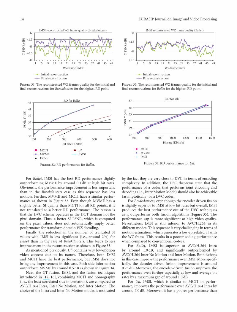
Figure 31: The reconstructed WZ frames quality for the initial andfinal reconstructions for Breakdancers for the highest RD point.
33
35
37
39
41
43
PSN
RY
(dB
)
100 200 300 400 500 600
Bit rate (Kbits/s)
RD for Ballet
MCTIMVMEDCVP
HIMSI
Figure 32: RD performance for Ballet.
For Ballet, IMSI has the best RD performance slightlyoutperforming MVME by around 0.1 dB at high bit rates.Obviously, the performance improvement is less importantthan in the Breakdancers case as this sequence has lessmotion. Further, MVME and MCTI have a similar perfor-mance as shown in Figure 32. Even though MVME has aslightly better SI quality than MCTI for all RD points, it isnot translated to a better RD performance. The reason isthat the DVC scheme operates in the DCT domain not thepixel domain. Thus, a better SI PSNR, which is computedon the pixel values, does not automatically imply betterperformance for transform domain WZ decoding.
Finally, the reduction in the number of truncated SIvalues with IMSI is less significant (i.e., around 2%) forBallet than in the case of Breakdancers. This leads to lessimprovement in the reconstruction as shown in Figure 33.
As mentioned previously, Uli contains very low-motionvideo content due to its nature. Therefore, both IMSIand MCTI have the best performance, but IMSI does notbring any improvement in this case. Both side informationoutperform MVME by around 0.5 dB as shown in Figure 34.
Next, the GT fusion, IMSI, and the fusion techniquesintroduced in [12, 16], combining MCTI and homography(i.e., the least correlated side information), are compared toAVC/H.264 Intra, Inter No Motion, and Inter Motion. Thechoice of the Intra and Inter No Motion modes is motivated
41.5
42
42.5
43
YP
SNR
(dB
)
1 5 9 13 17 21 25 29 33 37 41 45 49
WZ frame index
IMSI reconstructed WZ frame quality (Ballet)
Initial reconstructionFinal reconstruction
Figure 33: The reconstructed WZ frames quality for the initial andfinal reconstructions for Ballet for the highest RD point.
27
29
31
33
35
37
PSN
RY
(dB
)
400 600 800 1000 1200 1400 1600
Bit rate (Kbits/s)
RD for Uli
MCTIMVMEIMSI
Figure 34: RD performance for Uli.
by the fact they are very close to DVC in terms of encodingcomplexity. In addition, the DSC theorems state that theperformance of a codec that performs joint encoding anddecoding (i.e., Inter Motion Mode) should also be achievable(asymptotically) by a DVC codec.
For Breakdancers, even though the encoder driven fusionis slightly superior to IMSI at low bit rates but overall, IMSIproduces the best performance out of the DVC techniquesas it outperforms both fusion algorithms (Figure 35). Theperformance gap is more significant at high video quality.Nevertheless, IMSI is still inferior to AVC/H.264 in itsdifferent modes. This sequence is very challenging in terms ofmotion estimation, which generates a low-correlated SI withthe WZ frame. This results in a poorer coding performancewhen compared to conventional codecs.
For Ballet, IMSI is superior to AVC/H.264 Intraby around 1.0 dB, and significantly outperformed byAVC/H.264 Inter No Motion and Inter Motion. Both fusionsin this case improve the performance over IMSI. More specif-ically, the decoder-driven fusion improvement is around0.25 dB. Moreover, the encoder-driven fusion improves theperformance even further especially at low and average bitrates by a maximum gap of around 1.0 dB.
For Uli, IMSI, which is similar to MCTI in perfor-mance, improves the performance over AVC/H.264 Intra byaround 3.0 dB. Moreover, it has a poorer performance than

EURASIP Journal on Image and Video Processing 15
32
33
34
35
36
37
38
YP
SNR
(dB
)
90 110 130 150 170 190 210 230 250 270 290
Bit rate (Kbits/s)
Breakdancers
Decoder driven fusionGT fusionH.264 Inter No MotionEncoder driven fusion
H.264 IntraIMSIH.264 Inter
Figure 35: RD performance for Breakdancers.
33343536373839404142
YP
SNR
(dB
)
100 120 140 160 180 200 220 240 260
Bit rate (Kbits/s)
Ballet
Decoder driven fusionGT fusionH.264 Inter No MotionEncoder driven fusion
H.264 IntraIMSIH.264 Inter
Figure 36: RD performance for Ballet.
25
27
29
31
33
35
37
39
YP
SNR
(dB
)
300 500 700 900 1100 1300 1500 1700
Bit rate (Kbits/s)
Uli
Decoder driven fusionGT fusionH.264 Inter No MotionEncoder driven fusion
H.264 IntraIMSIH.264 Inter
Figure 37: RD performance for Uli.
AVC/H.264 Inter No Motion and Inter Motion. The fusionsdo not result in any improvements as the decision is alwaysmade in favor of MCTI for the decoder-driven fusion. Inother words, performing the fusion in this case is useless forUli. For the encoder-driven fusion, the improvement in SIestimation quality is insignificant, and since additional rate isspent to send the binary mask, the overall performance dropsbelow MCTI.
Overall, the performance of DVC is superior toAVC/H.264 Intra for two sequences out of three. On theother hand, it has a poorer performance than AVC/H.264Inter Inter No Motion and Inter Motion for all the sequences,even with the GT fusion. Concerning DVC, IMSI is betterfor video content with very significant motion occupying alarge part of the scene. MCTI is suitable for more or lessstatic video content as it generates highly correlated SI withthe WZ frame, resulting in superior compression efficiencythan intraconventional coding, but inferior to conventionalintercoding. For video with average motion, the encoderdriven fusion produces the best performance for the DVCcompression. Finally, the GT fusion shows that there still alarge gap for improvement as it reduces the bit rate for DVCup to 50% for video with significant motion with respect toMCTI.
7. Conclusion
In this work, different SI generation techniques are studiedfor multiview DVC. For video with significant motion, theproposed IMSI significantly improves the performance overother SI techniques. It is followed by MVME and then MCTI.On the other hand, IMSI is more complex than MVME,which is much more complex than MCTI. For videos withaverage and low motion, MCTI and MVME improve the RDperformance over AVC/H.264 Intra. Nevertheless, MCTI hasthe advantage of having a similar or better RD performanceand being less complex than MVME in this case.
Further, we show that it is possible to reduce up to 50%the bit rate with respect to monoview DVC (i.e., MCTI)with the GT fusion. Nevertheless, the GT fusion requiresthe original video at the decoder, which is not feasible butit shows the maximum possible gain when the different SIsare ideally combined. It shows as well that MCTI, MVME,and DCVP generate highly correlated side information sincethey belong to the same block-based category techniques. Onthe other hand, MCTI and homography represent a goodtradeoff between performance improvement and complexityincrease. Moreover, fusion techniques combining these twoside information show significant improvement for videowith high motion.
Many improvements are possible over this work. Initially,a better fusion algorithm should be found to exploit thecombination of the different side information withoutneeding the original frame and close the gap on the GTfusion. Moreover, fusion between MCTI and homographyshould be considered as they produce the least-correlatedside information, and represent a good tradeoff betweenperformance improvement and complexity increase.
Further, the MVME technique is very complex. There-fore, the complexity of this technique can be reduced byusing fast motion search techniques such as a multigrid [27]approach instead of a fixed block size in addition to an N-step [28] search instead of a full search.
Finally, the additional complexity in the IMSI techniquecan be significantly reduced by selecting the blocks forwhich the reestimation is performed as defined in [25].

16 EURASIP Journal on Image and Video Processing
More specifically, a block is reestimated in the final SI if theresidual error between the initially decoded WZ frame andthe initial SI is greater than a certain threshold for this block.Otherwise, the block from the initial SI is just copied into thefinal SI.
Acknowledgments
This work was partially supported by the Europeanproject Discover (http://www.discoverdvc.org) (IST Con-tract 015314) and the European Network of ExcellenceVISNET II (http://www.visnet-noe.org) (IST Contract 1-038398), both funded under the European Commission IST6th Framework Program. The authors also would like toacknowledge the use of the DISCOVER codec, a softwarewhich started from the IST WZ software developed atthe Image Group from Instituto Superior Tecnico (IST)of Lisbon by Catarina Brites, Joao Ascenso, and FernandoPereira.
References
[1] “Free Viewpoint Television (FTV),” http://www.tanimoto.nuee.nagoya-u.ac.jp/study/FTV.
[2] B. Girod, A. M. Aaron, S. Rane, and D. Rebollo-Monedero,“Distributed video coding,” Proceedings of the IEEE, vol. 93,no. 1, pp. 71–83, 2005.
[3] T. Wiegand, G. J. Sullivan, G. Bjøntegaard, and A. Luthra,“Overview of the H.264/AVC video coding standard,” IEEETransactions on Circuits and Systems for Video Technology, vol.13, no. 7, pp. 560–576, 2003.
[4] D. Slepian and J. Wolf, “Noiseless coding of correlated infor-mation sources,” IEEE Transactions on Information Theory, vol.19, no. 4, pp. 471–480, 1973.
[5] A. Wyner and J. Ziv, “The rate-distortion function forsource coding with side information at the decoder,” IEEETransactions on Information Theory, vol. 22, no. 1, pp. 1–10,1976.
[6] X. Artigas, J. Ascenso, M. Dalai, S. Klomp, D. Kubasov, and M.Ouaret, “The DISCOVER codec: architecture, techniques andevaluation,” in Proceedings of the Picture Coding Symposium(PCS ’07), Lisbon, Portugal, November 2007.
[7] H. S. Malvar, A. Hallapuro, M. Karczewicz, and L. Kerofsky,“Low-complexity transform and quantization in H.264/AVC,”IEEE Transactions on Circuits and Systems for Video Technology,vol. 13, no. 7, pp. 598–603, 2003.
[8] C. Berrou, A. Glavieux, and P. Thitimajshima, “Near Shannonlimit error-correcting coding and decoding: turbo-codes.1,” inProceedings of the IEEE International Conference on Communi-cations (ICC ’93), vol. 2, pp. 1064–1070, Geneva, Switzerland,May 1993.
[9] W. W. Peterson and D. T. Brown, “Cyclic codes for errordetection,” Proceedings of the IRE, vol. 49, no. 1, pp. 228–235,1961.
[10] J. Ascenso, C. Brites, and F. Pereira, “Improving frameinterpolation with spatial motion smoothing for pixel domaindistributed video coding,” in Proceedings of the 5th EURASIPConference on Speech and Image Processing, Multimedia Com-munications and Services, Smolenice, Slovak, July 2005.
[11] A. Aaron, R. Zhang, and B. Girod, “Wyner-ziv coding formotion video,” in Proceedings of the 36th Asilomar Conferenceon Signals, Systems and Computers, Pacific Grove, Calif, USA,November 2002.
[12] M. Ouaret, F. Dufaux, and T. Ebrahimi, “Fusion-basedmultiview distributed video coding,” in Proceedings of the 4thACM International Workshop on Video Surveillance and SensorNetworks (VSSN ’06), pp. 139–144, Santa Barbara, Calif, USA,October 2006.
[13] X. Artigas, E. Angeli, and L. Torres, “Side informationgeneration for multiview distributed video coding using afusion approach,” in Proceedings of the 7th Nordic SignalProcessing Symposium (NORSIG ’06), pp. 250–253, Reykjavik,Iceland, June 2007.
[14] X. Guo, Y. Lu, F. Wu, W. Gao, and S. Li, “Distributed multi-view video coding,” in Visual Communications and ImageProcessing (VCIP), vol. 6077 of Proceedings of SPIE, San Jose,Calif, USA, January 2006.
[15] X. Guo, Y. Lu, F. Wu, D. Zhao, and W. Gao, “Wyner-ziv-basedmultiview video coding,” IEEE Transactions on Circuits andSystems for Video Technology, vol. 18, no. 6, pp. 713–724, 2008.
[16] M. Ouaret, F. Dufaux, and T. Ebrahimi, “Multiview dis-tributed video coding with encoder driven fusion,” in Pro-ceedings of the European Conference on Signal Processing(EUSIPCO ’07), Poznan, Poland, September 2007.
[17] Joint Bi-Level Image Experts Group, http://www.jpeg.org/jbig.
[18] M. Flierl and B. Girod, “Coding of multi-view imagesequences with video sensors,” in Proceedings of the Interna-tional Conference on Image Processing (ICIP ’06), pp. 609–612,Atlanta, Ga, USA, October 2006.
[19] M. Flierl and B. Girod, “Video coding with motion-compensated lifted wavelet transforms,” Signal Processing:Image Communication, vol. 19, no. 7, pp. 561–575, 2004.
[20] F. Dufaux, M. Ouaret, and T. Ebrahimi, “Recent advancesin multiview distributed video coding,” in Mobile Multime-dia/Image Processing for Military and Security Applications, vol.6579 of Proceedings of SPIE, pp. 1–11, Orlando, Fla, USA, April2007.
[21] F. Dufaux and J. Konrad, “Efficient, robust, and fast globalmotion estimation for video coding,” IEEE Transactions onImage Processing, vol. 9, no. 3, pp. 497–501, 2000.
[22] E. Martinian, A. Behrens, J. Xin, and A. Vetro, “View synthesisfor multiview video compression,” in Proceedings of the 25thPicture Coding Symposium (PCS ’06), Beijing, China, April2006.
[23] S. M. Seitz and C. R. Dyer, “View morphing,” in Proceedingsof the 23rd Annual Conference on Computer Graphics andInteractive Techniques (SIGGRAPH ’96), pp. 21–30, NewOrleans, La, USA, August 1996.
[24] X. Artigas, F. Tarres, and L. Torres, “Comparison of dif-ferent side information generation methods for multiviewdistributed video coding,” in Proceedings of the InternationalConference on Signal Processing and Multimedia Applications(SIGMAP ’07), Barcelona, Spain, July 2007.
[25] S. Ye, M. Ouaret, F. Dufaux, and T. Ebrahimi, “Improvedside information generation with iterative decoding and frameinterpolation for distributed video coding,” in Proceedingsof the 15th International Conference on Image Processing(ICIP ’08), pp. 2228–2231, San Deigo, Calif, USA, October2008.
[26] “AVC/H.264 software,” http://iphome.hhi.de/suehring/tml.

EURASIP Journal on Image and Video Processing 17
[27] F. Dufaux, Multigrid Block Matching Motion Estimation forGeneric Video Coding, Ph.D. thesis, Ecole PolytechniqueFederale de Lausanne, Lausanne, Switzerland, 1994.
[28] M. Z. Coban and R. M. Mersereau, “Fast rate-constrained N-step search algorithm for motion estimation,” in Proceedingsof the IEEE International Conference on Acoustics, Speech andSignal Processing (ICASSP ’98), vol. 5, pp. 2613–2616, Seattle,Wash, USA, May 1998.