New Frontier - IQ December 2021(pdf) - International Swaps ...
Upload
khangminh22Category
view
2download
0
Electronic Self-Enclosed Submeters with
Wifi Ethernet Capability
User & Installation Manual
IM02601006E Rev 1.0
IQ 150S/250S

Copyright © 2012 by Eaton Corporation. All rights reserved.
Eaton, Power Xpert, PowerChain Management, Powerware, and X-Slot are regis-tered trademarks of Eaton Corporation or its subsidiaries and affiliates. Microsoft and Windows are registered trademarks of Microsoft Corporation. Modbus is a registered trademark of Schneider Electric.
EATON CORPORATION - CONFIDENTIAL AND PROPRIETARY NOTICE TO PER-SONS RECEIVING THIS DOCUMENT AND/OR TECHNICAL INFORMATION
THIS DOCUMENT, INCLUDING THE DRAWING AND INFORMATION CONTAINED THEREON, IS CONFIDENTIAL AND IS THE EXCLUSIVE PROPERTY OF EATON CORPORATION, AND IS MERELY ON LOAN AND SUBJECT TO RECALL BY EATON AT ANY TIME. BY TAKING POSSESSION OF THIS DOCUMENT, THE RECIPIENT ACKNOWLEDGES AND AGREES THAT THIS DOCUMENT CANNOT BE USED IN ANY MANNER ADVERSE TO THE INTERESTS OF EATON, AND THAT NO PORTION OF THIS DOCUMENT MAY BE COPIED OR OTHERWISE REPRODUCED WITHOUT THE PRIOR WRITTEN CONSENT OF EATON. IN THE CASE OF CONFLICTING CONTRACTUAL PROVISIONS, THIS NOTICE SHALL GOVERN THE STATUS OF THIS DOCUMENT.
DISCLAIMER OF WARRANTIES AND LIMITATION OF LIABILITY
The information, recommendations, descriptions and safety notations in this docu-ment are based on Eaton Electrical Inc. and/or Eaton Corporation’s (“Eaton”) experi-ence and judgment and may not cover all contingencies. If further information is required, an Eaton sales office should be consulted.
Sale of the product shown in this literature is subject to the terms and conditions outlined in appropriate Eaton selling policies or other contractual agreement be-tween Eaton and the purchaser.
THERE ARE NO UNDERSTANDINGS, AGREEMENTS, WARRANTIES, EXPRESSED OR IMPLIED, INCLUDING WARRANTIES OF FITNESS FOR A PARTICULAR PUR-POSE OR MERCHANTABILITY, OTHER THAN THOSE SPECIFICALLY SET OUT IN ANY EXISTING CONTRACT BETWEEN THE PARTIES. ANY SUCH CONTRACT STATES THE ENTIRE OBLIGATION OF EATON. THE CONTENTS OF THIS DOCU-MENT SHALL NOT BECOME PART OF OR MODIFY ANY CONTRACT BETWEEN THE PARTIES.
In no event will Eaton be responsible to the purchaser or user in contract, in tort (including negligence), strict liability or otherwise for any special, indirect, incidental or consequential damage or loss whatsoever, including but not limited to damage or loss of use of equipment, plant or power system, cost of capital, loss of power, additional expenses in the use of existing power facilities, or claims against the purchaser or user by its customers resulting from the use of the information, recom-mendations and descriptions contained herein.
Product Registration
PLEASE REGISTER YOUR PRODUCT
By registering your product you’re registering for the warranty in addition to receiving important update information.
You can register your product in one of three ways:
1. Go online to: www.eaton.com/powerxpert and click on Product Registration under Related Links
2. Fill out and return the product registration card that can be found in the packet of information you received.
3. Fill out the product registration information below and fax this page to 919-431-6240
Product:__________________________________________________________
Product Model or Version Number:_____________________________________
Product Serial or License Number:_____________________________________
Company:________________________________________________________
Your Name:_______________________________________________________
Address:_________________________________________________________
Address:_________________________________________________________
City:_________________________________ State:________ Zip:_______
Email:___________________________________________________________
Today’s Date:_____________________________________________________
Phone:___________________________________________________________
Eaton GO number (if known)_________________________________________

Product Registration
PLEASE REGISTER YOUR PRODUCT
By registering your product you’re registering for the warranty in addition to receiving important update information.
You can register your product in one of three ways:
1. Go online to: www.eaton.com/powerxpert and click on Product Registration under Related Links.
2. Fill out and return the product registration card that can be found in the packet of information you received.
3. Fill out the product registration information below and fax this page to 919-431-6240.
Product:__________________________________________________________
Product Model or Version Number:_____________________________________
Product Serial or License Number:_____________________________________
Company:________________________________________________________
Your Name:_______________________________________________________
Address:_________________________________________________________
Address:_________________________________________________________
City:_________________________________ State:________ Zip:_______
Email:___________________________________________________________
Today’s Date:_____________________________________________________
Phone:___________________________________________________________
Eaton GO number (if known)_________________________________________


IM02601006E www.eaton.com TOC-1
IQ 150S/250S Table of Contents
Table of Contents
1: Introduction 1-1
About This Manual 1-1
Warranty and Liability Information 1-1
Safety Precautions 1-2
FCC Information 1-2
2: IQ 150S/250S Submeter Overview and
Specifications 2-1
2.1: Hardware Overview 2-1
2.1.1: Ordering Information 2-3
2.1.2: Measured Values 2-4
2.1.3: Utility Peak Demand 2-5
2.2: Specifications 2-5
2.3: Compliance 2-10
2.4: Accuracy 2-10
3: Mechanical Installation 3-1
3.1: Overview 3-1
3.2: Install the Base 3-1
3.2.1:Mounting Diagrams 3-2
3.3: Secure the Cover 3-6
4: Electrical Installation 4-1
4.1: Considerations When Installing Meters 4-1
4.2: Electrical Connections 4-2
IM02601006E www.eaton.com TOC-2
IQ 150S/250S Table of Contents
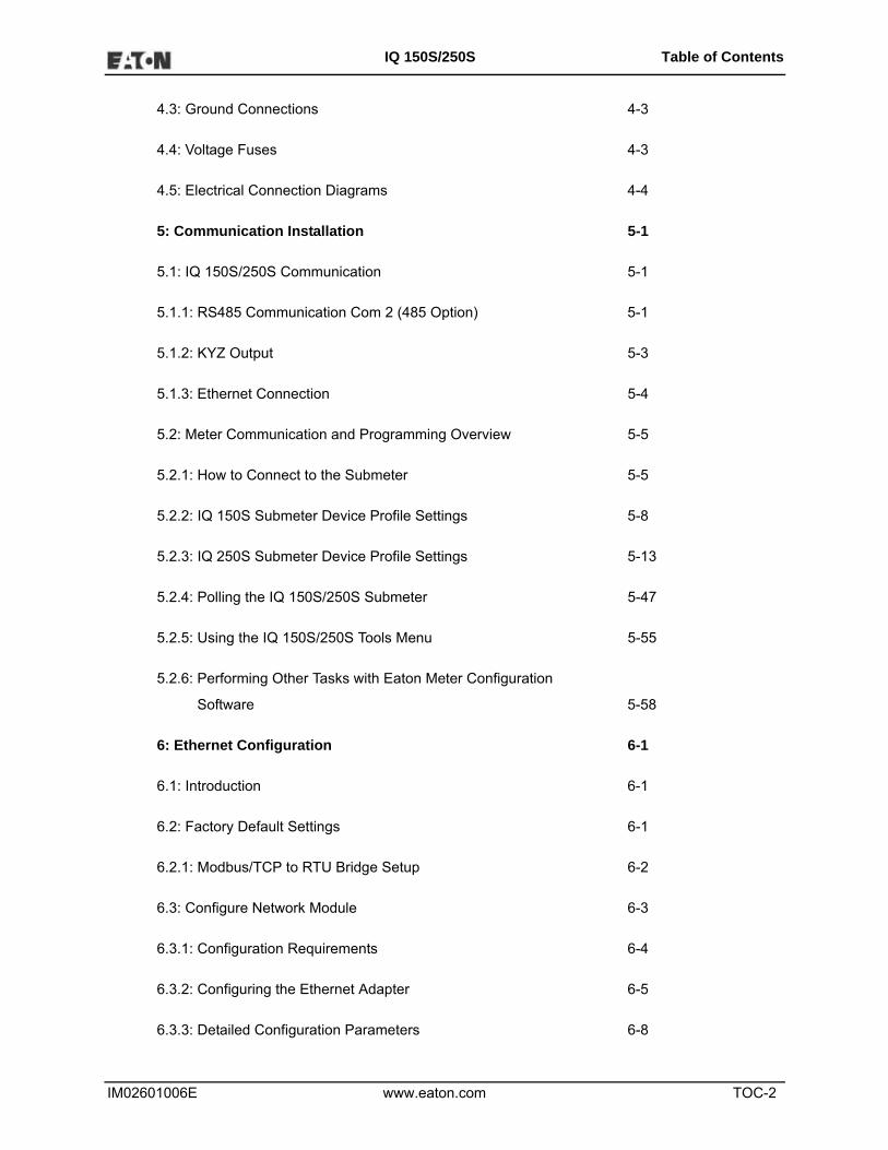
4.3: Ground Connections 4-3
4.4: Voltage Fuses 4-3
4.5: Electrical Connection Diagrams 4-4
5: Communication Installation 5-1
5.1: IQ 150S/250S Communication 5-1
5.1.1: RS485 Communication Com 2 (485 Option) 5-1
5.1.2: KYZ Output 5-3
5.1.3: Ethernet Connection 5-4
5.2: Meter Communication and Programming Overview 5-5
5.2.1: How to Connect to the Submeter 5-5
5.2.2: IQ 150S Submeter Device Profile Settings 5-8
5.2.3: IQ 250S Submeter Device Profile Settings 5-13
5.2.4: Polling the IQ 150S/250S Submeter 5-47
5.2.5: Using the IQ 150S/250S Tools Menu 5-55
5.2.6: Performing Other Tasks with Eaton Meter Configuration
Software 5-58
6: Ethernet Configuration 6-1
6.1: Introduction 6-1
6.2: Factory Default Settings 6-1
6.2.1: Modbus/TCP to RTU Bridge Setup 6-2
6.3: Configure Network Module 6-3
6.3.1: Configuration Requirements 6-4
6.3.2: Configuring the Ethernet Adapter 6-5
6.3.3: Detailed Configuration Parameters 6-8

IM02601006E www.eaton.com TOC-3
IQ 150S/250S Table of Contents
6.3.4: Setup Details 6-9
6.3.4.1: Encryption Key 6-11
6.4: Network Module Hardware Initialization 6-13
7: Using the Submeter 7-1
7.1: Introduction 7-1
7.1.A: Understanding Submeter Face Elements 7-1
7.1.B: Understanding Submeter Face Buttons 7-2
7.2: Using the Front Panel 7-3
7.2.1: Understanding Startup and Default Displays 7-3
7.2.2: Using the Main Menu 7-4
7.2.3: Using Reset Mode 7-5
7.2.4: Entering a Password 7-6
7.2.5: Using Configuration Mode 7-7
7.2.5.1: Configuring the Scroll Feature 7-9
7.2.5.2: Configuring CT Setting 7-10
7.2.5.3: Configuring PT Setting 7-11
7.2.5.4: Configuring Connection Setting 7-13
7.2.5.5: Configuring Communication Port Setting 7-13
7.2.6: Using Operating Mode 7-15
7.3: Understanding the % of Load Bar 7-16
7.4: Performing Watt-Hour Accuracy Testing (Verification) 7-17
A: IQ 150S/250S Meter Navigation Maps A-1
A.1: Introduction A-1
IM02601006E www.eaton.com TOC-4
IQ 150S/250S Table of Contents
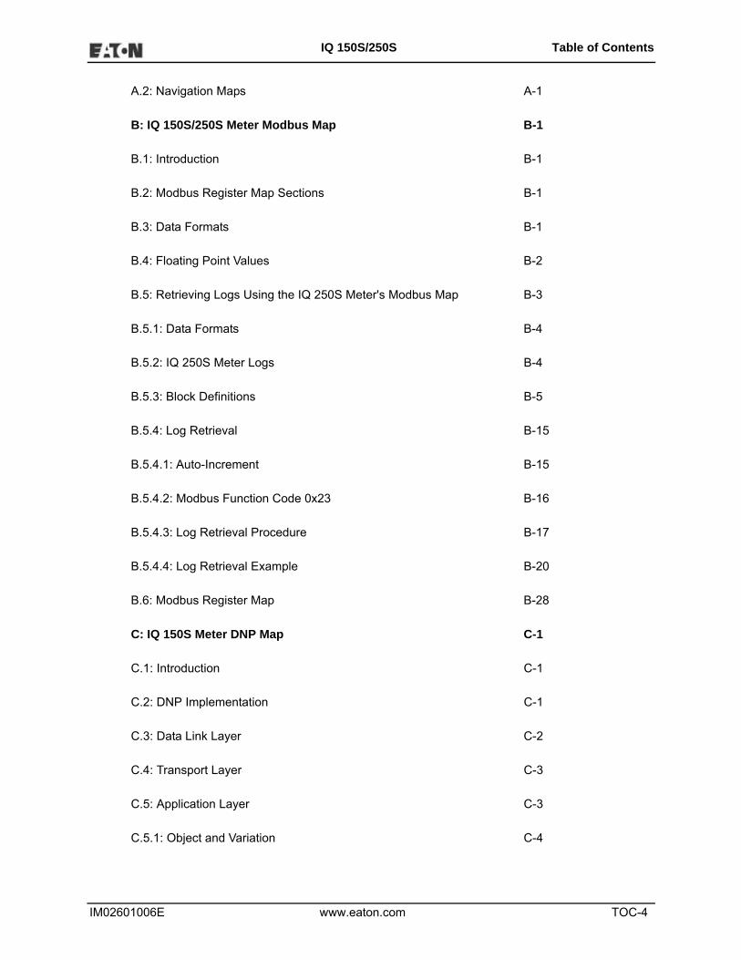
A.2: Navigation Maps A-1
B: IQ 150S/250S Meter Modbus Map B-1
B.1: Introduction B-1
B.2: Modbus Register Map Sections B-1
B.3: Data Formats B-1
B.4: Floating Point Values B-2
B.5: Retrieving Logs Using the IQ 250S Meter's Modbus Map B-3
B.5.1: Data Formats B-4
B.5.2: IQ 250S Meter Logs B-4
B.5.3: Block Definitions B-5
B.5.4: Log Retrieval B-15
B.5.4.1: Auto-Increment B-15
B.5.4.2: Modbus Function Code 0x23 B-16
B.5.4.3: Log Retrieval Procedure B-17
B.5.4.4: Log Retrieval Example B-20
B.6: Modbus Register Map B-28
C: IQ 150S Meter DNP Map C-1
C.1: Introduction C-1
C.2: DNP Implementation C-1
C.3: Data Link Layer C-2
C.4: Transport Layer C-3
C.5: Application Layer C-3
C.5.1: Object and Variation C-4
IM02601006E www.eaton.com TOC-5
IQ 150S/250S Table of Contents
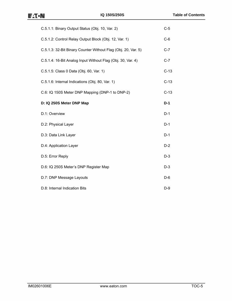
C.5.1.1: Binary Output Status (Obj. 10, Var. 2) C-5
C.5.1.2: Control Relay Output Block (Obj. 12, Var. 1) C-6
C.5.1.3: 32-Bit Binary Counter Without Flag (Obj. 20, Var. 5) C-7
C.5.1.4: 16-Bit Analog Input Without Flag (Obj. 30, Var. 4) C-7
C.5.1.5: Class 0 Data (Obj. 60, Var. 1) C-13
C.5.1.6: Internal Indications (Obj. 80, Var. 1) C-13
C.6: IQ 150S Meter DNP Mapping (DNP-1 to DNP-2) C-13
D: IQ 250S Meter DNP Map D-1
D.1: Overview D-1
D.2: Physical Layer D-1
D.3: Data Link Layer D-1
D.4: Application Layer D-2
D.5: Error Reply D-3
D.6: IQ 250S Meter’s DNP Register Map D-3
D.7: DNP Message Layouts D-6
D.8: Internal Indication Bits D-9

IM02601006E www.eaton.com TOC-6
IQ 150S/250S Table of Contents
This page intentionally left blank.

IM02601006E www.eaton.com 1-1
IQ 150S/250S 1: Introduction
1 Introduction
About This Manual
This document is the user manual for the installation, operation, and maintenance of the Eaton IQ
150S/250S Meter. It is intended for authorized and qualified personnel who use the IQ 150S/250S
Meter. Please refer to the specific WARNINGS and CAUTIONS in this section before proceeding.
For Technical Support and after hour emergencies, contact our Power Quality Technical Support
team at 1-800-809-2772, option 4 / sub-option 1 or by email at [email protected].
For those outside the United States and Canada, call 414-449-7100 option 4 / sub-option 1. You
can also visit us on the web at http://www.eaton.com and follow the Products link.
Warranty and Liability Information
NO WARRANTIES EXPRESSED OR IMPLIED, INCLUDING WARRANTIES OF FITNESS FOR A
PARTICULAR PURPOSE OF MERCHANTABILITY, OR WARRANTIES ARISING FROM
COURSE OR DEALING OR USAGE OF TRADE ARE MADE REGARDING THE INFORMA-
TION,RECOMMENDATIONS, AND DESCRIPTIONS CONTAINED HEREIN.
In no event will Eaton be responsible to the purchaser or user in contract, in tort (including negli-
gence), strict liability or otherwise for any special, indirect, incidental, or consequential damage or
loss of use of equipment, plant or power system, cost of capital, loss of power, additional expenses
in the use of existing power facilities, or claims against the purchaser or user by its customers
resulting from the use of the information and descriptions contained herein.
Eaton disclaims liability for any modifications or interfaces with other equipment that are not in
conformity with the specifications and information contained within this manual. Any unauthorized
action of this kind can jeopardize operation, safety, or reliability.
The information contained in this document is believed to be accurate at the time of publication,
however, Eaton assumes no responsibility for any errors which may appear here and reserves the
right to make changes without notice.

IM02601006E www.eaton.com 1-2
IQ 150S/250S 1: Introduction
Safety Precautions
All safety codes, safety standards, and/or regulations must be strictly observed in the installation,
operation, and maintenance of this device.
WARNINGS refer to instructions that, if not followed, can result in death or injury.
CAUTIONS refer to instructions that, if not followed, can result in equipment dam-
age.
WARNINGS
SHOCK HAZARDS:
IMPROPER INSTALLATION CAN CAUSE DEATH, INJURY, AND/OR EQUIP-
MENT DAMAGE.
Follow all Warnings and Cautions. Completely read and understood the information in this docu-
ment before attempting to install or operate the equipment. Improper wiring could cause death,
injury, or equipment damage. Only qualified personnel are to service the IQ 150S/250S Meter.
TROUBLESHOOTING PROCEDURES MAY REQUIRE PROXIMITY TO EXPOSED ENER-
GIZED(LIVE) ELECTRICAL WIRING AND/OR PARTS WHERE THE HAZARD OF FATAL ELEC-
TRIC SHOCK IS PRESENT. Exercise extreme care to avoid injury or death. Always disconnect,
lock-out, and tag the current and voltage sources and the control power supply circuit before
touching the connections or components on the rear face of the meter base unit.
FAILURE TO GROUND THE IQ 150S/250S METER MAY RESULT IN INJURY, DEATH, OR
EQUIPMENT DAMAGE. Properly ground the IQ 150S/250S Meter during installation.
FCC Information
Regarding the wireless module:
• This device complies with Part 15 of the FCC rules. Operation is subject to the following two
conditions: 1) this device may not cause harmful interference, and 2) this device must accept
any interference received, including interference that may cause undesired operation.
• The antenna provided must not be replaced with an different type. Attaching a different antenna
will void the FCC approval and the FCC ID can no longer be considered.

IM02601006E www.eaton.com 1-3
IQ 150S/250S 1: Introduction
Covered by one or more of the following patents:
US Patent Numbers D526920, D525893, 6751563, 6735535, 6636030.

IM02601006E www.eaton.com 1-4
IQ 150S/250S 1: Introduction
This page intentionally left blank.

IM02601006E www.eaton.com 2-1
IQ 150S/250S 2: Overview and Specifications
2: IQ 150S/250S Submeter Overview and Specifications
2.1: Hardware Overview
Eaton’s IQ 150S/250S submeter is designed to measure
revenue grade electrical energy usage and communicate
that information via various communication media. The unit
supports RS485, RJ45 wired Ethernet or IEEE 802.11 WiFi
Ethernet connections. This allows the submeter to be
placed anywhere within an industrial or commercial facility
and still communicate quickly and easily back to central
software.
The unit is designed with advanced measurement
capabilities, allowing it to achieve high performance
accuracy. The IQ 150S meter is specified as a 0.2% class
energy meter for billing applications (the IQ 250S is so
specified for Class 10 only). To verify the submeter’s perfor-
mance and calibration, power providers use field test stan-
dards to verify that the unit’s energy measurements are correct. The IQ 150S/250S meter is a
traceable revenue meter and contains a utility grade test pulse to verify rated accuracy.
The IQ 250S meter has up to 2 MegaBytes* for datalogging. It offers three
historical logs, a Limits (Alarm) log, and a System Events log.
*NOTE: Because the memory is flash-based rather than NVRAM (non-volatile
random-access memory), some sectors are reserved for overhead, erase procedures, and spare
sectors for long-term wear reduction.
IQ 150S/250S meter features detailed in this manual are:
• 0.2% Class Revenue Certifiable Energy and Demand Submeter (IQ 250S Class 10 only)
• Meets ANSI C12.20 (0.2%) and IEC 62053-22 (0.2%) Classes (IQ 250S Class 10 only)
• Multifunction Measurement including Voltage, Current, Power, Frequency, Energy, etc.
• Three line 0.56” bright red LED display
• 2 MegaBytes Memory for Datalogging (IQ 250S)

IM02601006E www.eaton.com 2-2
IQ 150S/250S 2: Overview and Specifications
• Real Time Clock for Time-Stamping of Logs (Logs are available only with the IQ 250S)
• Percentage of Load bar for Analog meter perception
• Modbus RTU (over Serial) and Modbus TCP (over Ethernet)
• Serial RS485 communication
• Ethernet and wireless Ethernet (WiFi)
• Easy to use faceplate programming
• Direct interface with most Building Management systems
The IQ 150S/250S submeter uses standard 5 or 1 Amp CTs (either split or donut). It surface
mounts to any wall and is easily programmed. The unit is designed specifically for easy installa-
tion and advanced communication.
IM02601006E www.eaton.com 2-3
IQ 150S/250S 2: Overview and Specifications
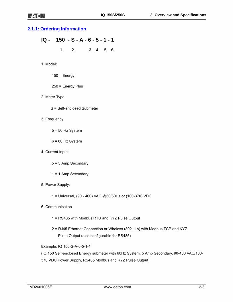
2.1.1: Ordering Information
IQ - 150 - S - A - 6 - 5 - 1 - 1
1 2 3 4 5 6
1. Model:
150 = Energy
250 = Energy Plus
2. Meter Type
S = Self-enclosed Submeter
3. Frequency:
5 = 50 Hz System
6 = 60 Hz System
4. Current Input:
5 = 5 Amp Secondary
1 = 1 Amp Secondary
5. Power Supply:
1 = Universal, (90 - 400) VAC @50/60Hz or (100-370) VDC
6. Communication
1 = RS485 with Modbus RTU and KYZ Pulse Output
2 = RJ45 Ethernet Connection or Wireless (802.11b) with Modbus TCP and KYZ
Pulse Output (also configurable for RS485)
Example: IQ 150-S-A-6-5-1-1
(IQ 150 Self-enclosed Energy submeter with 60Hz System, 5 Amp Secondary, 90-400 VAC/100-
370 VDC Power Supply, RS485 Modbus and KYZ Pulse Output)

IM02601006E www.eaton.com 2-4
IQ 150S/250S 2: Overview and Specifications
2.1.2: Measured Values
The IQ 150S/250S meter provides the following measured values all in real time and some addi-
tionally as average, maximum and minimum values.
IQ150S/250S Meter Measured Values
Measured Values Real Time Average Maximum Minimum
Voltage L-N X X X
Voltage L-L X X X
Current per Phase X X X X
Current Neutral X
Watts X X X X
VAR X X X X
VA X X X X
PF X X X X
+Watt-hr X
-Watt-hr X
Watt-hr Net X
+VAR-hr X
-VAR-hr X
VAR-hr Net X
VA-hr X
Frequency X X X
Voltage Angles X
Current Angles X
% of Load Bar X

IM02601006E www.eaton.com 2-5
IQ 150S/250S 2: Overview and Specifications
2.1.3: Utility Peak Demand
The IQ150S/250S meter provides user-configured Block (Fixed) window or Rolling window
Demand. This feature allows you to set up a customized Demand profile. Block window Demand is
Demand used over a user-configured Demand period (usually 5, 15 or 30 minutes). Rolling
window Demand is a fixed window Demand that moves for a user-specified subinterval period.
For example, a 15-minute Demand using 3 subintervals and providing a new Demand reading
every 5 minutes, based on the last 15 minutes.
Utility Demand features can be used to calculate kW, kVAR, kVA and PF readings. All other
parameters offer Max and Min capability over the user-selectable averaging period. Voltage pro-
vides an Instantaneous Max and Min reading which displays the highest surge and lowest sag
seen by the meter
2.2: Specifications
Power Supply
Range: Universal, (90 to 400)VAC
@50/60Hz or
(100 to 370)VDC
Power Consumption: 16 VA Maximum
Voltage Inputs (Measurement Category III)
Range: IQ 150S: Universal, Auto-ranging
up to 416VAC L-N, 721VAC L-L
IQ 250S: Universal, Auto-ranging
up to 576VAC L-N, 721VAC L-L
Supported hookups: 3 Element Wye, 2.5 Element Wye,
2 Element Delta, 4 Wire Delta
Input Impedance: 1M Ohm/Phase
Burden: 0.36VA/Phase Max at 600V,
0.0144VA/Phase at 120V
Pickup Voltage: 10VAC

IM02601006E www.eaton.com 2-6
IQ 150S/250S 2: Overview and Specifications
Connection: Screw terminal - #6 - 32 screws
See Figure 3.1
Input Wire Gauge: AWG#16 - 26
Fault Withstand: Meets IEEE C37.90.1 (Surge
Withstand Capability)
Reading: Programmable Full Scale to any PT
Ratio
Current Inputs
Class 10: 5A Nominal, 10 Amp Maximum
Class 2: 1A Nominal, 2 Amp Secondary
Burden: 0.005VA Per Phase Max at 11 Amps
Pickup Current: 0.1% of Nominal
Connections: Screw terminal - #6-32 screws
(Diagram 3.1)
Current Surge Withstand: 100A/10 seconds at 23o C
Reading: Programmable Full Scale to any CT
Ratio
Isolation
All Inputs and Outputs are galvanically isolated and tested to 2500VAC
Environmental Rating
Storage: (-20 to +70)o C
Operating: (-20 to +70)o C
Humidity: to 95% RH Non-condensing
Faceplate Rating: NEMA12 (Water Resistant)

IM02601006E www.eaton.com 2-7
IQ 150S/250S 2: Overview and Specifications
Measurement Methods
Voltage, Current: True RMS
Power: Sampling at 400+ Samples per
Cycle on All Channels Measured
Readings Simultaneously
A/D Conversion: 6 Simultaneous 24 bit Analog to
Digital Converters
Update Rate
Watts, VAR and VA: Every 6 cycles, e.g., 100
milliseconds (Ten times per
second) @60Hz
All other parameters: Every 60 cycles, e.g, 1 second
@60Hz
Communication Format
RS485
Protocols: Modbus RTU, Modbus ASCII, DNP
3.0, Modbus TCP (for Ethernet-
enabled)
Com Port Baud Rate: 9600 to 57600 b/s
Com Port Address: 001-247
Data Format: 8 Bit, No Parity
Wireless Ethernet (Optional)
802.11b Wireless or WiFi or RJ45 Connection
10/100BaseT Ethernet
128 bit WEP Encryption 128 bit Wireless Security
Modbus TCP Protocol

IM02601006E www.eaton.com 2-8
IQ 150S/250S 2: Overview and Specifications
Mechanical Parameters
Dimensions: (H7.9 x W7.6 x D3.2) inches,
(H200.7 x W193.0 x D81.3) mm
Weight: 4 pounds
KYZ/RS485 Port Specifications
RS485 Transceiver; meets or exceeds EIA/TIA-485 Standard:
Type: Two-wire, half duplex
Min. Input Impedance: 96kΩ
Max. Output Current: ±60mA
Wh Pulse
KYZ output contacts (and infrared LED light pulses through face plate; see Section 6.4 for Kh val-
ues):
Pulse Width: 40ms for IQ 150S; 90ms for IQ
250S
Full Scale Frequency: ~6Hz for IQ 150S; ~3Hz for IQ
250S
Contact type: Solid State – SPDT (NO – C – NC)
Relay type: Solid state
Peak switching voltage: DC ±350V
Continuous load current: 120mA
Peak load current: 350mA for 10ms
On resistance, max.: 35Ω
Leakage current: 1µA@350V
Isolation: AC 3750V
Reset State: (NC - C) Closed; (NO - C) Open
IM02601006E www.eaton.com 2-9
IQ 150S/250S 2: Overview and Specifications
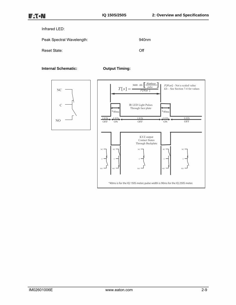
Infrared LED:
Peak Spectral Wavelength: 940nm
Reset State: Off
Internal Schematic: Output Timing:
NO
C
NC ][
3600
][ WattPpulseWatthourKh
sT][ [
=
*40ms *40ms
LEDON
LEDON
LEDOFF
LEDOFF
LEDOFF
IR LED Light PulsesThrough face plate
NO
C
NC
NO
C
NC
NO
C
NC
NO
C
NC
NO
C
NC
KYZ outputContact States
Through Backplate
P[Watt] - Not a scaled valueKh – See Section 7-4 for values
.

IM02601006E www.eaton.com 2-10
IQ 150S/250S 2: Overview and Specifications
2.3: Compliance
• IEC 62053-22 (0.2% Accuracy), IQ 250S - Class 10 only
• ANSI C12.20 (0.2% Accuracy), IQ 250S - Class 10 only
• ANSI (IEEE) C37.90.1 Surge Withstand
• ANSI C62.41 (Burst)
• IEC1000-4-2: ESD
• IEC1000-4-3: Radiated Immunity
• IEC1000-4-4: Fast Transient
• IEC1000-4-5: Surge Immunity
• UL Listed
• CE Compliant
2.4: Accuracy
For 23oC, 3 Phase balanced Wye or Delta load, at 50 or 60 Hz (as per order), 5A (Class 10) nom-
inal unit:
Parameter Accuracy Accuracy Input Range
Voltage L-N [V] 0.1% of reading2 (69 to 480)V
Voltage L-L [V] 0.1% of reading (120 to 600)V
Current Phase [A] 0.1% of reading1 (0.15 to 5)A
Current Neutral (calculated) [A]
2.0% of Full Scale1 (0.15 to 5)A @ (45 to 65)Hz
Active Power Total [W] 0.2% of reading1,2 (0.15 to 5)A @ (69 to 480)V @ +/- (0.5 to 1) lag/lead PF
Active Energy Total [Wh] 0.2% of reading1,2 (0.15 to 5)A @ (69 to 480)V @ +/- (0.5 to 1) lag/lead PF
Reactive Power Total [VAR] 0.2% of reading1,2 (0.15 to 5)A @ (69 to 480)V @ +/- (0 to 0.8) lag/lead PF
Reactive Energy Total [VARh]
0.2% of reading1,2 (0.15 to 5)A @ (69 to 480)V @ +/- (0 to 0.8) lag/lead PF
Apparent Power Total [VA] 0.2% of reading1,2 (0.15 to 5)A @ (69 to 480)V @ +/- (0.5 to 1) lag/lead PF

IM02601006E www.eaton.com 2-11
IQ 150S/250S 2: Overview and Specifications
1 For 2.5 element programmed units, degrade accuracy by an additional 0.5% of
reading.
• For 1A (Class 2) Nominal, degrade accuracy by an additional 0.5% of reading.
• For 1A (Class 2) Nominal, the input current range for Accuracy specification is 20% of the val-
ues listed in the table.
2 For unbalanced voltage inputs where at least one crosses the 150V auto-scale
threshold (for example, 120V/120V/208V system), degrade accuracy by additional
0.4%.
Apparent Energy Total [VAh]0.2% of reading1,2 (0.15 to 5)A @ (69 to 480)V @ +/- (0.5 to 1) lag/lead PF
Power Factor 0.2% of reading1,2 (0.15 to 5)A @ (69 to 480)V @ +/- (0.5 to 1) lag/lead PF
Frequency +/- 0.01Hz (45 to 65)Hz
Load Bar +/- 1 segment (0.005 to 6)A

IM02601006E www.eaton.com 2-12
IQ 150S/250S 2: Overview and Specifications
This page intentionally left blank.

IM02601006E www.eaton.com 3-1
IQ 150S/250S 3: Mechanical Installation
3: Mechanical Installation
3.1: Overview
The IQ 150S/250S meter can be installed on any wall See Chapter 4 for wiring diagrams.
Mount the meter in a dry location, which is free from dirt and corrosive substances.
Recommended Installation Tools
• #2 Phillips screwdriver
• Wire cutters
3.2: Install the Base
1. Determine where you want to install the submeter.
2. With the submeter power off, open the top of the submeter. Use the front cover support to keep
the cover open as you perform the installation (see Figure 3.1).
Figure 3.1: Submeter with Cover Open
Circuit Board
Opened
Front coversupport
Screw
Front coversupport base:
Front coversupport
ONLY insert Front cover supporthere

IM02601006E www.eaton.com 3-2
IQ 150S/250S 3: Mechanical Installation
CAUTIONS!
• Remove the antenna before opening the unit.
• Only use the front cover support if you are able to open the front cover to the extent that you can
fit the front cover support into its base. DO NOT rest the front cover support on the inside of the
meter, even for a short time - by doing so, you may damage components on the board assem-
bly. Always insert the front cover support into its base.
3. Find the 4 Installation Slots and insert screws through each slot into the wall or panel.
4. Fasten securely - DO NOT overtighten. Maximum recommended torque is
0.5/0.6 Nm (4.42/5.31 lbF in).
3.2.1:Mounting Diagrams
Figure 3.2: Mounting Plate Dimensions

IM02601006E www.eaton.com 3-3
IQ 150S/250S 3: Mechanical Installation
Figure 3.3: Front Dimensions

IM02601006E www.eaton.com 3-4
IQ 150S/250S 3: Mechanical Installation
Figure 3.4: Side Dimensions

IM02601006E www.eaton.com 3-5
IQ 150S/250S 3: Mechanical Installation
Figure 3.5: Open Cover Dimensions
Figure 3.6: Bottom View with Access Holes
12”/30.4cm

IM02601006E www.eaton.com 3-6
IQ 150S/250S 3: Mechanical Installation
3.3: Secure the Cover
1. Close the cover, making sure that power and communications wires exit the submeter through
the openings at the base (see Figure 3.6).
CAUTION! To avoid damaging components on the board assembly, make sure the front cover
support is in the upright position before closing the front cover.
2. Using the 3 enclosed screws, secure the cover to the base in three places - DO NOT over-
tighten (you may damage the cover). Maximum recommended torque is
0.5/0.6 Nm (4.42/5.31 lbF in).
3. The unit can be sealed after the front cover is closed. To seal the unit, thread a seal tag (not
supplied by Eaton) through the housing located between the bottom access holes (see figures
3.6 and 3.7).
4. Reattach the antenna, if applicable.
Figure 3.7: Submeter with Closed Cover
Closed
Lockable Revenue Seal
Screw

IM02601006E www.eaton.com 4-1
IQ 150S/250S 4: Electrical Installation
4: Electrical Installation
4.1: Considerations When Installing Meters
Installation of the IQ 150S/250S meter must be performed only by qualified per-
sonnel who follow standard safety precautions during all procedures. Those
personnel should have appropriate training and experience with high voltage
devices. Appropriate safety gloves, safety glasses and protective clothing is
recommended.
During normal operation of the IQ 150S/250S meter, dangerous voltages flow through many parts
of the meter, including: Terminals and any connected CTs (Current Transformers) and PTs (Poten-
tial Transformers), all I/O Modules (Inputs and Outputs) and their circuits. All Primary and Second-
ary circuits can, at times, produce lethal voltages and currents. Avoid contact with any current-
carrying surfaces.
Do not use the meter or any I/O Output Device for primary protection or in an energy-limit-
ing capacity. The meter can only be used as secondary protection.
Do not use the meter for applications where failure of the meter may cause harm or death.
Do not use the meter for any application where there may be a risk of fire.
All meter terminals should be inaccessible after installation.
Do not apply more than the maximum voltage the meter or any attached device can withstand.
Refer to meter and/or device labels and to the Specifications for all devices before applying volt-
ages.
Do not HIPOT/Dielectric test any Outputs, Inputs or Communications terminals.
Eaton recommends the use of Shorting Blocks and Fuses for voltage leads and power supply to
prevent hazardous voltage conditions or damage to CTs, if the meter needs to be removed from
service. CT grounding is optional.

IM02601006E www.eaton.com 4-2
IQ 150S/250S 4: Electrical Installation
IMPORTANT!
• IF THE EQUIPMENT IS USED IN A MANNER NOT SPECIFIED BY
THE MANUFACTURER, THE PROTECTION PROVIDED BY THE
EQUIPMENT MAY BE IMPAIRED.
• THERE IS NO REQUIRED PREVENTIVE MAINTENANCE OR
INSPECTION NECESSARY FOR SAFETY. HOWEVER, ANY REPAIR
OR MAINTENANCE SHOULD BE PERFORMED BY THE FACTORY.
DISCONNECT DEVICE: The following part is considered the equipment dis-
connect device. A SWITCH OR CIRCUIT-BREAKER SHALL BE INCLUDED IN
THE END-USE EQUIPMENT OR BUILDING INSTALLATION. THE SWITCH
SHALL BE IN CLOSE PROXIMITY TO THE EQUIPMENT AND WITHIN EASY
REACH OF THE OPERATOR. THE SWITCH SHALL BE MARKED AS THE
DISCONNECTING DEVICE FOR THE EQUIPMENT.
4.2: Electrical Connections
All wiring for the IQ 150S/250S is done through the front of the unit (lifting the cover with the power
to the unit OFF) so that the unit can be surface mounted. Connecting cables exit the unit via two
openings in the base plate (see figures 3.6 and 4.1).
DO NOT over-torque screws. Maximum recommended torque is
0.5/0.6 Nm (4.42/5.31 lbF in).

IM02601006E www.eaton.com 4-3
IQ 150S/250S 4: Electrical Installation
Figure 4.1: Submeter Connections
4.3: Ground Connections
The meter's Ground Terminal (PE) should be connected directly to the installation's protective
earth ground.
4.4: Voltage Fuses
Eaton recommends the use of fuses on each of the sense voltages and on the control power, even
though the wiring diagrams in this chapter do not show them.
• Use a 0.1 Amp fuse on each Voltage input.
• Use a 3 Amp fuse on the power supply.
Electronic Circuits
Ethernet, RJ45Jack
Ia Ia Ib Ib Ic Ic(+) (-) (+) (-) (+) (-)
Z K Y + - SHVa Vb Vc Vn L1 L2 PE RS-485
KYZ PulseOutput
Wireless Ethernet Connection
RS485 Output(Do not put the
Voltage on theseterminals!)
Power SupplyInputs (Inputsare unipolar)
VoltageInputs
CurrentInputs
Access Holes forWiring
(Do not over-torque screws)
* **
* CT, Voltage, Control Power, and Ground
* Communications and KYZ

IM02601006E www.eaton.com 4-4
IQ 150S/250S 4: Electrical Installation
4.5: Electrical Connection Diagrams
Choose the diagram that best suits your application. Make sure the CT polarity is
correct.
1. Three Phase, Four-Wire System Wye with Direct Voltage, 3 Element
a. Dual Phase Hookup
b. Single Phase Hookup
3. Three Phase, Four-Wire System Wye with Direct Voltage, 2.5 Element
4. Three-Phase, Four-Wire Wye with PTs, 3 Element
5. Three-Phase, Four-Wire Wye with PTs, 2.5 Element
6. Three-Phase, Three-Wire Delta with Direct Voltage (No PTs, 2 CTs)
7. Three-Phase, Three-Wire Delta with Direct Voltage (No PTs, 3 CTs)
8. Three-Phase, Three-Wire Delta with 2 PTs, 2 CTs
9. Three-Phase, Three-Wire Delta with 2 PTs, 3 CTs
10. Current Only Measurement (Three Phase)
11. Current Only Measurement (Dual Phase)
12. Current Only Measurement (Single Phase)

IM02601006E www.eaton.com 4-5
IQ 150S/250S 4: Electrical Installation
1. Service: WYE, 4-Wire with No PTs, 3 CTs
Select: "3 EL WYE" (3 Element Wye) in Meter Programming setup.
Electronic Circuits
Ia Ia Ib Ib Ic Ic(+) (-) (+) (-) (+) (-)
Va Vb Vc Vref L1 L2 PE
A B C N
A B C N
Ia
Ib
Ic
Power Supply Inputs
L2 is for Neutral

IM02601006E www.eaton.com 4-6
IQ 150S/250S 4: Electrical Installation
1a. Dual Phase Hookup
Electronic Circuits
Ia Ia Ib Ib Ic Ic(+) (-) (+) (-) (+) (-)
Va Vb Vc Vref L1 L2 PE
A B C N
A B C N
Ia
Ib
Ic
Power Supply Inputs

IM02601006E www.eaton.com 4-7
IQ 150S/250S 4: Electrical Installation
1b. Single Phase Hookup
Electronic Circuits
Ia Ia Ib Ib Ic Ic(+) (-) (+) (-) (+) (-)
Va Vb Vc Vref L1 L2 PE
A B C N
A B C N
Ia
Ib
Ic
Power Supply Inputs

IM02601006E www.eaton.com 4-8
IQ 150S/250S 4: Electrical Installation
2. Service: 2.5 Element WYE, 4-Wire with No PTs, 3 CTs
Select: "2.5 EL WYE" (2.5 Element Wye) in Meter Programming setup.
Electronic Circuits
Ia Ia Ib Ib Ic Ic(+) (-) (+) (-) (+) (-)
Va Vb Vc Vref L1 L2 PE
A B C N
A B C N
Ia
Ib
Ic
Power Supply Inputs

IM02601006E www.eaton.com 4-9
IQ 150S/250S 4: Electrical Installation
3. Service: WYE, 4-Wire with 3 PTs, 3 CTs
Select: "3 EL WYE" (3 Element Wye) in Meter Programming setup.
Electronic Circuits
Ia Ia Ib Ib Ic Ic(+) (-) (+) (-) (+) (-)
Va Vb Vc Vn L1 L2 PE
A B C N
A B C N
Ia
Ib
Ic
Power Supply Inputs
IM02601006E www.eaton.com 4-10
IQ 150S/250S 4: Electrical Installation
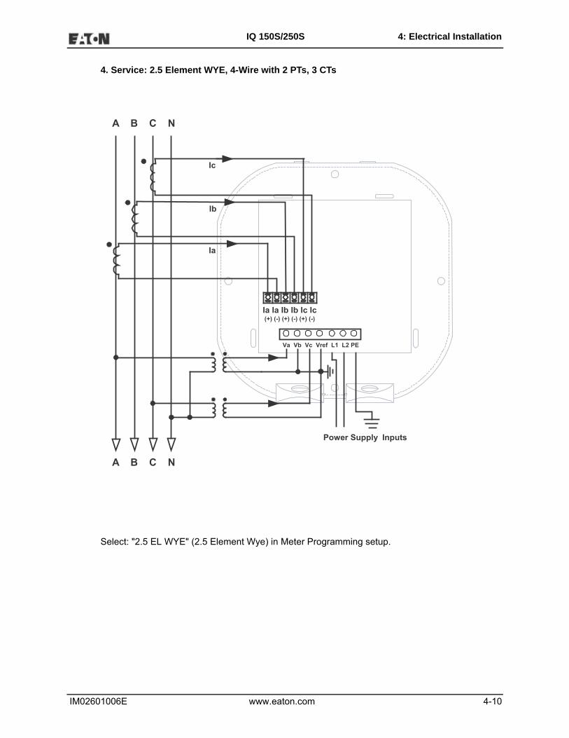
4. Service: 2.5 Element WYE, 4-Wire with 2 PTs, 3 CTs
Select: "2.5 EL WYE" (2.5 Element Wye) in Meter Programming setup.
Ia Ia Ib Ib Ic Ic(+) (-) (+) (-) (+) (-)
Va Vb Vc Vref L1 L2 PE
A B C N
A B C N
Ia
Ib
Ic
Power Supply Inputs
IM02601006E www.eaton.com 4-11
IQ 150S/250S 4: Electrical Installation
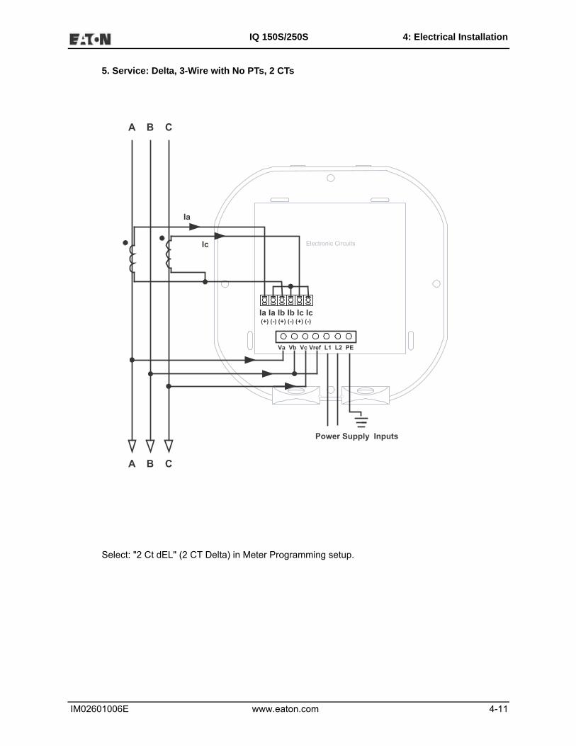
5. Service: Delta, 3-Wire with No PTs, 2 CTs
Select: "2 Ct dEL" (2 CT Delta) in Meter Programming setup.
Electronic Circuits
Ia Ia Ib Ib Ic Ic(+) (-) (+) (-) (+) (-)
Va Vb Vc Vref L1 L2 PE
A B C
A B C
Ia
Ic
Power Supply Inputs

IM02601006E www.eaton.com 4-12
IQ 150S/250S 4: Electrical Installation
6. Service: Delta, 3-Wire with No PTs, 3 CTs
Select: "2 Ct dEL" (2 CT Delta) in Meter Programming setup.
Electronic Circuits
Ia Ia Ib Ib Ic Ic(+) (-) (+) (-) (+) (-)
Va Vb Vc Vref L1 L2 PE
A B C
A B C
Ia
Ic
Ib
Power Supply Inputs

IM02601006E www.eaton.com 4-13
IQ 150S/250S 4: Electrical Installation
7. Service: Delta, 3-Wire with 2 PTs, 2 CTs
Select: "2 Ct dEL" (2 CT Delta) in Meter Programming setup.
Ia Ia Ib Ib Ic Ic(+) (-) (+) (-) (+) (-)
Va Vb Vc Vref L1 L2 PE
A B C
A B C
Ia
IcElectronic Circuits
Power Supply Inputs

IM02601006E www.eaton.com 4-14
IQ 150S/250S 4: Electrical Installation
8. Service: Delta, 3-Wire with 2 PTs, 3 CTs
Select: "2 Ct dEL" (2 CT Delta) in Meter Programming setup.
Ia Ia Ib Ib Ic Ic(+) (-) (+) (-) (+) (-)
Va Vb Vc Vref L1 L2 PE
A B C
A B C
Ic
Electronic CircuitsIb
Ia
Power Supply Inputs

IM02601006E www.eaton.com 4-15
IQ 150S/250S 4: Electrical Installation
9. Service: Current Only Measurement (Three Phase)
Select: "3 EL WYE" (3 Element Wye) in Meter Programming setup.
NOTE: Even if the meter is used for only Amp readings, the unit requires a Volts AN reference.
Please make sure that the Voltage input is attached to the meter. AC
Control Power can be used to provide the reference signal.
Electronic Circuits
Ia Ia Ib Ib Ic Ic(+) (-) (+) (-) (+) (-)
Va Vb Vc Vref L1 L2 PE
A B C N
A B C N
Ia
Ib
Ic
20VAC
Minimum*
Power Supply Inputs

IM02601006E www.eaton.com 4-16
IQ 150S/250S 4: Electrical Installation
10. Service: Current Only Measurement (Dual Phase)
Select: "3 EL WYE" (3 Element Wye) in Meter Programming setup.
NOTE: Even if the meter is used for only Amp readings, the unit requires a Volts AN reference.
Please make sure that the Voltage input is attached to the meter. AC
Control Power can be used to provide the reference signal.
Electronic Circuits
Ia Ia Ib Ib Ic Ic(+) (-) (+) (-) (+) (-)
Va Vb Vc Vref L1 L2 PE
A B N
A B N
Ia
Ib
20VAC
Minimum*
Power Supply Inputs

IM02601006E www.eaton.com 4-17
IQ 150S/250S 4: Electrical Installation
11. Service: Current Only Measurement (Single Phase)
Select: "3 EL WYE" (3 Element Wye) in Meter Programming setup.
NOTE: Even if the meter is used for only Amp readings, the unit requires a Volts AN reference.
Please make sure that the Voltage input is attached to the meter. AC
Control Power can be used to provide the reference signal.
Electronic Circuits
Ia Ia Ib Ib Ic Ic(+) (-) (+) (-) (+) (-)
Va Vb Vc Vref L1 L2 PE
A N
A N
Ia
20VAC
Minimum*Power Supply Inputs

IM02601006E www.eaton.com 4-18
IQ 150S/250S 4: Electrical Installation
This page intentionally left blank.

IM02601006E www.eaton.com 5-1
IQ 150S/250S 5: Communication
5: Communication Installation
5.1: IQ 150S/250S Communication
The IQ 150S/250S submeter provides a communication port plus a KYZ pulse output. The com-
munication port, Com 2, provides RS485 or RJ45 Ethernet or WiFi Ethernet communication (see
Chapter 6 for Ethernet communication).
5.1.1: RS485 Communication Com 2 (485 Option)
The IQ 150S/250S submeter's RS485 port uses standard 2-Wire, half duplex architecture. The
RS485 connector is located on the front of the meter, under the cover. A connection can easily be
made to a Master device or to other slave devices, as shown below.
NOTE: Care should be taken to connect + to + and - to - connections.
Electronic Circuits
Ia Ia Ib Ib Ic Ic(+) (-) (+) (-) (+) (-)
Z K Y + - SHVa Vb Vc Vn L1 L2 PERS485
Pulse Contacts
Wireless Ethernet Connection
To OtherDevices
JP2: Must be in position 1-2 for
RS485 **

IM02601006E www.eaton.com 5-2
IQ 150S/250S 5: Communication
The IQ150S/250S submeter's RS485 connection can be programmed with the buttons on the face
of the meter or by using Eaton Meter Configuration software.
Standard RS485 Port Settings
Address: 001 to 247
Baud Rate: 9600, 19200, 38400 or 57600 Baud
Protocol: Modbus RTU, Modbus ASCII, or DNP 3.0
** The position of Jumper 2 (JP2) must be set for either RS485 or Ethernet communication. See
the figure below. You put the jumper on positions 2 and 3 for LAN (Ethernet) communication, and
on 1 and 2 for RS485 communication.
41
31
318
7
87
87
WD
seirtsudnI ortcelEhceTeguaG/

IM02601006E www.eaton.com 5-3
IQ 150S/250S 5: Communication
5.1.2: KYZ Output
The KYZ pulse output provides pulsing energy values that verify the submeter's readings and
accuracy.
The KYZ Pulse Output is located on the face of the meter, under the cover and just below the
RS485 connection.
See Section 2.2 for the KYZ output specifications; see Section 7.4 for pulse constants.
Electronic Circuits
Ia Ia Ib Ib Ic Ic(+) (-) (+) (-) (+) (-)
Z K Y + - SHVa Vb Vc Vn L1 L2 PE RS-485
Pulse Contacts
Wireless Ethernet Connection
To OtherDevices

IM02601006E www.eaton.com 5-4
IQ 150S/250S 5: Communication
5.1.3: Ethernet Connection
In order to use the IQ 150S/250S submeter’s Ethernet capability, the Ethernet Module must be
installed in your meter, and the JP2 must be set to positions 2-3. You can use either wired
Ethernet, or WiFi.
For wired Ethernet, use Standard RJ45 10/100BaseT cable to connect to the IQ 150S/250S
submeter. The RJ45 line is inserted into the RJ45 port of the meter.
For WiFi connections, make sure you have the correct antenna attached to the meter.
Refer to Chapter 6 for instructions on how to set up the Network Module.
** See the JP2 figure and instructions on page 5-2.
Electronic Circuits
Ia Ia Ib Ib Ic Ic(+) (-) (+) (-) (+) (-)
Z K Y + - SHVa Vb Vc Vn L1 L2 PE RS-485
Wireless Ethernet Connection
To OtherDevices
JP2: Must be inposition 2-3 for
Ethernet (RJ45 or WiFi)
Ethernet Module
**

IM02601006E www.eaton.com 5-5
IQ 150S/250S 5: Communication
5.2: Meter Communication and Programming Overview
Programming and communication can utilize the RS485 connection shown in Section 5.1.1 or the
RJ45/WiFi connection shown in Section 5.1.3. Once a connection is established, Eaton Meter
Configuration software can be used to program the meter and communicate to other devices.
Meter Connection
To provide power to the meter, use one of the wiring diagrams in Chapter 4 or attach an Aux cable
to GND, L(+) and N(-).
The RS485 cable attaches to SH, - and + as shown in Section 5.1.1.
5.2.1: How to Connect to the Submeter
1. Open Eaton Meter Configuration software.
2. Click the Connect icon on the Icon bar.
The Connect screen opens, showing the Initial settings. Make sure your settings are the same as
those shown here, except for the IP Address field, which must be your device’s IP address. The
address shown here is the default Ethernet option address.
NOTE: The settings you make will depend on whether you are connecting to the meter via Serial
Port (screen on the left) or Network (screen on the right). Use the pull-down menus to make any
necessary changes.
IM02601006E www.eaton.com 5-6
IQ 150S/250S 5: Communication
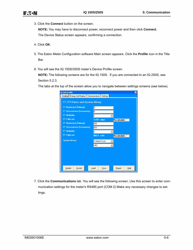
3. Click the Connect button on the screen.
NOTE: You may have to disconnect power, reconnect power and then click Connect.
The Device Status screen appears, confirming a connection.
4. Click OK.
5. The Eaton Meter Configuration software Main screen appears. Click the Profile icon in the Title
Bar.
6. You will see the IQ 150S/250S meter’s Device Profile screen.
NOTE: The following screens are for the IQ 150S. If you are connected to an IQ 250S, see
Section 5.2.3.
The tabs at the top of the screen allow you to navigate between settings screens (see below).
7. Click the Communications tab. You will see the following screen. Use this screen to enter com-
munication settings for the meter's RS485 port (COM 2) Make any necessary changes to set-
tings.

IM02601006E www.eaton.com 5-7
IQ 150S/250S 5: Communication
8. Valid Communication Settings are as follows:
COM2 (RS485)
Address (1-247)
Protocol (Modbus RTU, Modbus ASCII or DNP)
Baud Rate (9600 to 57600)
Response Delay (0-750 msec)
9. When changes are complete, click the Update button to send the new profile to the meter.
10. Click Exit to leave the Device Profile or click other menu items to change other aspects of the
Device Profile (see following section for instructions).

IM02601006E www.eaton.com 5-8
IQ 150S/250S 5: Communication
5.2.2: IQ 150S Submeter Device Profile Settings
NOTE: You can view this manual online by clicking Help>Contents from the Eaton Meter Config-
uration Software’s Main screen.
CT, PT Ratios and System Wiring (Scaling tab)
The screen fields and acceptable entries are as follows:
CT Ratios
CT Numerator (Primary): 1 - 9999
CT Denominator (Secondary): 5 or 1 Amp
NOTE: This field is display only.
CT Multiplier: 1, 10 or 100
Current Full Scale: Calculations based on selections. Click Recalculate to see the result of
changes.
PT Ratios
PT Numerator (Primary): 1 - 9999
PT Denominator (Secondary): 40 - 600

IM02601006E www.eaton.com 5-9
IQ 150S/250S 5: Communication
PT Multiplier: 1, 10, 100, or 1000
Voltage Full Scale: Calculations based on selections. Click Recalculate to see the result of
changes.
System Wiring
3 Element Wye; 2.5 Element Wye; 2 CT Delta
Phases Displayed
A, AB, or ABC
NOTE: Voltage Full Scale = PT Numerator x PT Multiplier
Example:
A 14400/120 PT would be entered as:
PT Numerator: 1440
PT Denominator: 120
Multiplier: 10
This example would display a 14.40kV.
Example CT Settings:
200/5 Amps: Set the Ct-n value for 200, Ct-Multiplier value for 1
800/5 Amps: Set the Ct-n value for 800, Ct-Multiplier value for 1
2,000/5 Amps: Set the Ct-n value for 2000, Ct-Multiplier value for 1
10,000/5 Amps: Set the Ct-n value for 1000, Ct-Multiplier value for 10
Example PT Settings:
277/277 Volts: Pt-n value is 277, Pt-d value is 277, Pt-Multiplier is 1
14,400/120 Volts: Pt-n value is 1440, Pt-d value is 120, Pt-Multiplier value is 10
138,000/69 Volts: Pt-n value is 1380, Pt-d value is 69, Pt-Multiplier value is 100
345,000/115 Volts: Pt-n value is 3450, Pt-d value is 115, Pt-Multiplier value is 100

IM02601006E www.eaton.com 5-10
IQ 150S/250S 5: Communication
345,000/69 Volts: Pt-n value is 345, Pt-d value is 69, Pt-Multiplier value is 1000
NOTE: Settings are the same for Wye and Delta configurations.
Energy and Display
The settings on this screen determine the display configuration of the meter’s faceplate.
The screen fields and acceptable entries are as follows:
Power and Energy Format
Power Scale: Unit, kilo (k), Mega (M), or auto.
Energy Digits: 5, 6, 7, or 8
Energy Decimal Places: 0-6
Energy Scale: Unit, kilo (k), or Mega (M)
For Example: a reading for Digits: 8; Decimals: 3; Scale: k would be formatted:
00123.456k
Power Direction: View as Load or View as Generator
IM02601006E www.eaton.com 5-11
IQ 150S/250S 5: Communication
Demand Averaging
Averaging Method: Block or Rolling
Interval (Minutes): 5, 15, 30, or 60
Sub Interval (if Rolling is selected): 1-4
Auto Scroll
Click to set On or Off.
Display Configuration:
Click Values to be displayed.
NOTE: You MUST select at least ONE.
NOTE: If incorrect values are entered on this screen the following message appears:WARNING:
Current, CT, PT and Energy Settings will cause invalid energy accumulator values.
Change the settings until the message disappears.

IM02601006E www.eaton.com 5-12
IQ 150S/250S 5: Communication
Settings
The screen fields are as follows:
Password
NOTE: The meter is shipped with Password Disabled. There is NO DEFAULT
PASSWORD.
Enable Password for Reset: click to Enable.
Enable Password for Configuration: click to Enable.
Change Password: click to Change.
Device Designation: optional user-assigned label.

IM02601006E www.eaton.com 5-13
IQ 150S/250S 5: Communication
5.2.3: IQ 250S Submeter Device Profile Settings
1. When you are connected to an IQ 250S meter and click Profile, you see the following screen.
The IQ 250S meter’s Profile screen features a Tree Menu on the left for Settings navigation,
and Buttons and a Title Bar that allow you to perform tasks, for example, updating the Device
Profile.
Selecting Settings
• The Tree Menu on the left side of the screen allows you to navigate between
Settings. The example screen pictured above shows the Tree Menu you see when you first
open the screen. Click on the + next to a Setting (for example, Revenue & Energy Settings)
to see additional Setting options.
• From the Tree Menu, click on the Setting you want to configure (for example, System Set-
tings) to display its screen in the right side of the Device Profile screen.

IM02601006E www.eaton.com 5-14
IQ 150S/250S 5: Communication
Performing Tasks
You can perform tasks from either the Device Profile screen Buttons or from the Title Bar.
The screen Buttons and their functions are as follows:
•·Update Device: Click to send the current settings to the meter.
NOTE: You must click the Update Device button after making changes to the Set-
tings screens, if you want to update the connected meter’s
settings.
• Save Profile: Click to save the Device Profile settings to a file. You will see the Save
Programmable Settings window, shown below. Give a name to the Device Profile
and click Save.

IM02601006E www.eaton.com 5-15
IQ 150S/250S 5: Communication
•·Load Profile: Click to load a previously saved Device Profile Settings file. You will
see the Load Programmable Settings window, shown below. Select the saved
Device Profile you want and click Open. The settings from that file will now appear in
the Settings screens; for example, the CT and PT Ratios will be those from the
saved Device Profile, rather than from the currently connected meter.
• View Report: Click to open a Notepad window containing the Device
Profile settings in a text file.
- Print the text file by selecting File>Print from the Notepad Title Bar.
- Save the text file by selecting File>Save from the Notepad Title Bar.
• Exit: Click to leave the Device Profile Editor.
2. Click the Communications tab. You will see the following screen. Use this screen to enter com-
munication settings for the meter's RS485 port (COM 2) Make any necessary changes to set-
tings.

IM02601006E www.eaton.com 5-16
IQ 150S/250S 5: Communication
3. Valid Communication Settings are as follows:
COM2 (RS485)
Address (1-247)
Protocol (Modbus RTU, Modbus ASCII or DNP)
Baud Rate (9600 to 57600)
Response Delay (0-750 msec)
4. When changes are complete, click the Update Device button to send the new
profile to the meter.
5. Click Exit to leave the Device Profile or click other menu items to change other aspects of the
Device Profile (see following section for instructions).

IM02601006E www.eaton.com 5-17
IQ 150S/250S 5: Communication
Additional Settings for the IQ250S
CT, PT Ratios and System Hookup
The screen fields and acceptable entries are as follows:
CT Ratios
CT Numerator (Primary): 1 - 9999
CT Denominator (Secondary): 5 or 1 Amp
NOTE: This field is display only.
CT Multiplier: 1, 10 or 100
Current Full Scale: Calculations based on selections. Click Recalculate to see the result of
changes.
PT Ratios
PT Numerator (Primary): 1 - 9999
PT Denominator (Secondary): 40 - 600

IM02601006E www.eaton.com 5-18
IQ 150S/250S 5: Communication
PT Multiplier: 1, 10, 100, or 1000
Voltage Full Scale: Calculations based on selections. Click Recalculate to see the result of
changes.
System Wiring
3 Element Wye; 2.5 Element Wye; 2 CT Delta
Phases Displayed
A, AB, or ABC
NOTE: Voltage Full Scale = PT Numerator x PT Multiplier
Example:
A 14400/120 PT would be entered as:
PT Numerator: 1440
PT Denominator: 120
Multiplier: 10
This example would display a 14.40kV.
Example CT Settings:
200/5 Amps: Set the Ct-n value for 200, Ct-Multiplier value for 1
800/5 Amps: Set the Ct-n value for 800, Ct-Multiplier value for 1
2,000/5 Amps: Set the Ct-n value for 2000, Ct-Multiplier value for 1
10,000/5 Amps: Set the Ct-n value for 1000, Ct-Multiplier value for 10
Example PT Settings:
277/277 Volts: Pt-n value is 277, Pt-d value is 277, Pt-Multiplier is 1
14,400/120 Volts: Pt-n value is 1440, Pt-d value is 120, Pt-Multiplier value is 10
138,000/69 Volts: Pt-n value is 1380, Pt-d value is 69, Pt-Multiplier value is 100
345,000/115 Volts: Pt-n value is 3450, Pt-d value is 115, Pt-Multiplier value is 100

IM02601006E www.eaton.com 5-19
IQ 150S/250S 5: Communication
345,000/69 Volts: Pt-n value is 345, Pt-d value is 69, Pt-Multiplier value is 1000
NOTE: Settings are the same for Wye and Delta configurations.
Time Settings
Use this setting to enable or disable Daylight Savings Time for the IQ 250S, and to set the begin-
ning and ending times for Daylight Savings Time. You can also set the Time Zone and enable
Clock Sync if supported by your meter.
1. From the Tree Menu, click General Settings>Time Settings.
2. Check or uncheck the box to Enable or Disable Daylight Savings time.
3. Use the entry fields to set the start and end times for the Daylight Savings Time feature, if
enabled. Select the values you want from the Month, Week, Day of the Week, and Hour fields.
4. Select the time Zone and Clock Sync options from the pull-down menus.
NOTE: The Hour field uses a 24-Hour clock.

IM02601006E www.eaton.com 5-20
IQ 150S/250S 5: Communication
System Settings
From the Tree Menu, click General Settings>System Settings. From this screen, you can do the
following:
• Enable or Disable Password for Resetting and/or Configuration: click the radio
button next to Yes or No. Enabling Password protection prevents unauthorized tampering with
devices.
IMPORTANT! You must set up a password before enabling Password Protection. Click the
Change button next to Change Password if you have not already set up a password.
When you click the Change button next to Change Password in the Settings screen, you will see
the Enter the New Password screen.
1. Type in the new password (0 - 9999).

IM02601006E www.eaton.com 5-21
IQ 150S/250S 5: Communication
2. Retype the password.
3. Click Change. The new password is saved and the meter restarts.
NOTE: If Password Protection has already been enabled for configuration and you attempt to
change the password, you will see the Enter Password screen (shown below) after you click
Change. Enter the old password and click OK to proceed with the password change.
You can enable or disable a Password for Resetting (Reset Max/Min Energy Settings) and Config-
uration (Device Profile) in the Systems Settings screen (see previous page).
NOTE: If you enable a Password for Resetting, you must also enable it for Configuration.
IMPORTANT! You must set up a password before enabling Password Protection. Click the
Change button next to Change Password if you have not already set up a password and follow the
above instructions.
When anyone attempts to make a change that is under Password protection, the Enter Password
screen opens. (See the example screen above.) If the correct Password is not entered, the change
does not take place.

IM02601006E www.eaton.com 5-22
IQ 150S/250S 5: Communication
Display Configuration
The settings on this screen determine the display configuration of the meter’s faceplate.
The screen fields and acceptable entries are as follows:
• Phases Displayed: A; A and B; A, B, and C. This field determines which phases
display on the faceplate. For example, if you select A and B, only those two phases
will be displayed on the faceplate.
• Auto Scroll Display: Yes or No. This field enables or disables the scrolling of selected
readings on the faceplate. If enabled, the readings scroll every 5 seconds.
• Enable on Face Plate of Display: Check the boxes of the Readings you want
displayed on the faceplate of the meter. You must select at least one reading.
• Power Direction: View as Load or View as Generator
• Flip Power Factor Sign: Yes or No.
• Current Display Auto-Scale: On or Off (no decimal places)

IM02601006E www.eaton.com 5-23
IQ 150S/250S 5: Communication
• Load Bar Custom Configuration: Click this bar to add Current scaling. Additional
fields open on the screen - see the figure below.
Enter the Current scale you want to use, The Primary Full Scale field will reflect your entry (as it
says on the screen, Primary Full Scale Current for the Load Bar is equal to the Current scale
multiplied by the CT multiplier.
Energy, Power Scaling, and Averaging
Use this setting to configure:
• The display of Power in the meter
• The display and storage of Energy in the meter
• The interval over which Average values are computed.
Functional Overview of Energy Settings and Averaging
Energy Scaling
Energy Setting includes:
• Digits (the number of digits in the reading)
• Decimals (the number of decimal places in the reading)
• Energy Scale: the scale of the reading – unit; kilo (number times 1000); Mega (number times 1
million).
Energy settings allow you to balance the resolution (or accuracy) of the energy stored, with the
interval over which energy rollover occurs. For example, the maximum resolution for a k scale
reading is: 99999.999k.

IM02601006E www.eaton.com 5-24
IQ 150S/250S 5: Communication
To calculate the speed at which the energy will rollover, you must know the Energy Full Scale,
which is computed from the CT and PT Full Scale values (see Section 9.2.4.1). The formula for
calculating Energy Full Scale is:
Wye system: CT Full Scale x PT Full Scale x 3
Delta system: CT Full Scale x PT Full Scale x 3 x 3
For example, for a CT Full Scale of 2000, PT Full Scale of 14400, Wye system:
2000 x 14400 x 3=86400000
In this example, the energy will increment at 86400000 Watts per hour, or 24000 Watts per sec-
ond.
This value allows you to determine the number of digits, decimal places, and energy scale you
want to configure for the Energy settings, when you take into account the rollover time. To deter-
mine the number of hours before rollover, use this formula:
[Max Resolution]/[Full Scale] = #Hours, where Max Resolution = maximum digits and decimals for
the Energy scale in use.
Using the example from above, with an energy scale of Mega, the formula would be:
99999.999 M/86.4 M = 1157.4074 hours or about 48 days until rollover.
NOTE: To increase the number of days until rollover, you can:
• Increase the number of digits (to 8)
• Decrease the number of decimal places (to 0)
• Increase the Energy Scale (to M).
Demand Averaging
Demand is the average rate of energy use over time. The IQ 250S supports two types of demand
averaging: Fixed demand and Sliding demand:
• Fixed demand records the average demand for time intervals that you define (usually 5, 15 or 30
minutes).

IM02601006E www.eaton.com 5-25
IQ 150S/250S 5: Communication
• Sliding demand functions like multiple, overlapping Fixed demand. You define the subintervals
at which an average of demand is calculated. An example of Sliding demand would be a 15-
minute Demand block using 5-minute subintervals, thus providing a new demand reading every
5 minutes, based on the last 15 minutes.
From the Tree Menu, click Energy Settings> Energy, Power Scaling, and Averaging.
The screen fields and acceptable entries are as follows:
• Energy Settings
Energy Digits: 5; 6; 7; 8
Energy Decimal Places: 0 - 6
Energy Scale: unit; kilo (K); Mega (M)
For example: a reading for Digits: 8; Decimals: 3; Scale: K would be formatted:
00123.456k

IM02601006E www.eaton.com 5-26
IQ 150S/250S 5: Communication
NOTE: Your selection in the Energy Settings fields determines the precision of energy stored
for display and polling. Refer to the Functional Overview at the beginning of this section for
more information.
• Power Settings:
Power Scale: Auto; unit; kilo (K); Mega (M)
Apparent Power (VA) Calculation Method: Arithmetic Sum or Vector Sum
• Demand Averaging:
Type: Fixed or Sliding
Interval (Fixed demand) or Sub-Interval (Sliding demand) in minutes: 5; 15; 30; 60
Number of Subintervals: 1; 2; 3; 4
Interval Window: This field is display only. It is the product of the values entered in the Sub-
Interval and Number of Subintervals fields.
NOTE: You will only see the Number of Subintervals and Interval Window fields if
you select Sliding Demand.

IM02601006E www.eaton.com 5-27
IQ 150S/250S 5: Communication
Transformer/Line Loss Compensation
Transformer/Line Loss Compensation allows you to add or subtract losses to meter registration.
From the Tree Menu, click Revenue & Energy Settings>Transformer/Line Loss
Compensation.
This screen displays the current values for the meter's Transformer Loss Compensation. The
screen fields and acceptable entries are as follows
• Percent Loss of Watts due to Iron and Copper/Positive Watts and Negative Watts
• Percent Loss of VARS due to Iron and Copper/Positive and Negative Watts
• Drop-down menu #1. Choose from: Disabled, Fe Only, Cu Only, Both Fe and Cu.
• Drop-down menu #2. Choose from: Add to Watts and VAR; Add to Watts and Subtract from VAR;
Subtract from Watts and Add to VAR; Add to Watts and VAR; Subtract from Watts and VAR.
1. Click TLC Calculator to find the values to enter into the Percent Loss fields. The TLC Calculator
button launches an Excel Spreadsheet that makes the calculations for you once you enter the
required data.
WARNING! Eaton Meter Configuration Software automatically launches the Excel Spreadsheet

IM02601006E www.eaton.com 5-28
IQ 150S/250S 5: Communication
when you click the TLC Calculator button. If you do not have Excel software installed on your
computer, a Warning message is displayed instead of the worksheet.
EXCEL NOTE: For most Excel users, the spreadsheet does run until you give the application per-
mission to run the Macros contained in the sheet. You give permission by changing the Excel
Security Setting from High to Medium, as follows:
a. From the Excel toolbar, click Tools>Security>Options.
b. On the Security Tab page, click the Macro Security button.
c. Select Medium Security.
4. Enter the percent Loss of Watts and VARS for copper and iron in the appropriate fields.

IM02601006E www.eaton.com 5-29
IQ 150S/250S 5: Communication
Configuring Limits (IQ 250S)
Use this screen to assign Limits for the meter.
Functional Overview for Limits:
Limits are transition points used to divide acceptable and unacceptable measurements. When a
value goes above or below the limit, an out-of-limit condition occurs. You can set and configure up
to eight Limits for the IQ 250S meter.
Once they are configured, you can view the out-of-Limits (or Alarm) conditions in the Limits Polling
screen.
You can assign the eight limits to readings from three groups of parameters:
• Readings (Instantaneous Voltage; Instantaneous Current; Total and Per Phase Power and
Power Factor; Frequency; and Neutral Current)
• Demand (Current; Per Phase, Total Power and Power Factor)
From the Tree Menu, click Power Quality and Alarm Settings>Limits.
The current settings for Limits are shown in the screen.

IM02601006E www.eaton.com 5-30
IQ 150S/250S 5: Communication
The bottom of the screen shows the Full Scale values for:
• Voltage
• Current
• Frequency
• Power
• Power Total
• Power Factor
• Phase Angles
1. Select a limit by double-clicking on the Assigned Channel field.
2. You will see the screen shown below.
Select a Group and an Item for the Limit.
3. Click OK.
4. To Configure a Limit, double-click on the Field to set the following values:
• Above and Below Setpoint:% of Full Scale (the point at which the reading goes out of limit)
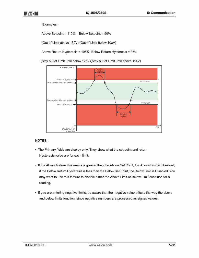
Examples:
100% of 120V Full Scale = 120V
90% of 120V Full Scale = 108V
• Above and Below Return Hysteresis: the point at which the reading goes back within limit
(see figure below)
IM02601006E www.eaton.com 5-31
IQ 150S/250S 5: Communication
Examples:
Above Setpoint = 110%; Below Setpoint = 90%
(Out of Limit above 132V);(Out of Limit below 108V)
Above Return Hysteresis = 105%; Below Return Hysteresis = 95%
(Stay out of Limit until below 126V)(Stay out of Limit until above 114V)
NOTES:
• The Primary fields are display only. They show what the set point and return
Hysteresis value are for each limit.
• If the Above Return Hysteresis is greater than the Above Set Point, the Above Limit is Disabled;
if the Below Return Hysteresis is less than the Below Set Point, the Below Limit is Disabled. You
may want to use this feature to disable either the Above Limit or Below Limit condition for a
reading.
• If you are entering negative limits, be aware that the negative value affects the way the above
and below limits function, since negative numbers are processed as signed values.
TIME
Above Limit condition
Below Limit condition
Above Limit Trigger point
Return point from Above Limit condition
Below Limit Trigger point
Return point from Below Limit condition
HYSTERESIS
HYSTERESIS
- MEASURED VALUE(if applicable)
+ MEASURED VALUE
0

IM02601006E www.eaton.com 5-32
IQ 150S/250S 5: Communication
Configuring Historical Logs (IQ250S)
Use this setting to select the parameters to be stored in each of the IQ 250S meter's three Histori-
cal Logs.
Functional Overview of Historical Logs:
Having three historical logs affords you the flexibility of programming each log with unique param-
eters. For example, you might program Historical Log 1 to record Power Quality parameters (for
example, Limits/Alarms), Log 2 to record Demand parameters, and Log 3 to record Energy param-
eters.
Historical Log parameters can be selected from eight groups:
• Measured Values (Instantaneous Voltage; Instantaneous Current; Total and Per Phase Power
and Power Factor; Frequency; Neutral Current; Symmetrical
Components and Voltage Unbalances)
• Demand (Current; Per Phase, Total Power and Power Factor)
• Maximums (Maximum values for all of the readings listed above)
• Minimums (Minimum values for all of the readings listed above)
• Energy (Watt-hours, VA-hours, VAR-hours)
• Short Term Min (Min value within the Demand Interval)
• Short Term Max (Max value within the Demand Interval)
• Uncompensated ((Watt-hours, VA-hours, VAR-hours)

IM02601006E www.eaton.com 5-33
IQ 150S/250S 5: Communication
From the Tree Menu, click Trending Profiles>Historical Log Profile (1-3).
This screen lets you select items to be stored in the historical log you selected. The Group field
determines the items that are available for selection.
1. Select a Group. The possible selections are: Measured Values, Demand, Maximums, Mini-
mums, Energy, Short Term Min, Short Term Max, and Uncompensated.
2. Select items for your log:
a. Highlight the item(s) you want in the Selectable Items box.
b. Click Add. The item(s) are added to the Selected Items box.
c. To remove item(s), highlight them in the Selected Items box and click Remove.
4. Set the Logging Interval (Minutes). The available choices are: 1, 3, 5, 10, 15, 30, 60. The Log-
ging Interval determines when the meter takes a snapshot.
NOTE: There are two display fields at the bottom of the Historical Log Profile screen. They show
the Total Bytes Used and the Bytes Remaining for this historical log. These fields are updated as

IM02601006E www.eaton.com 5-34
IQ 150S/250S 5: Communication
you make selections on the screen. The total number of bytes available per log record is approxi-
mately 234.
Configuring Historical Log Sectors (IQ250S)
Use this setting to increase or decrease the amount of records each of the IQ 250S meter's three
Historical logs can store, and the duration each log can run, before becoming filled.
From the Tree Menu, click Trending Profiles>Historical Log Sectors.
The screen shows the current space allocation for the meter's Historical logs, including:
• The number of bytes allocated to each log
• The number of records available for each log
• The duration of each log
To change the current allocation for a log:
1. Click on one of the double yellow lines dividing the individual logs.
IM02601006E www.eaton.com 5-35
IQ 150S/250S 5: Communication
2. You will see a line with arrows on each side. Drag the line in either direction to increase or
decrease the log allocation. The display fields for the logs will reflect any changes you make to
the allocation.
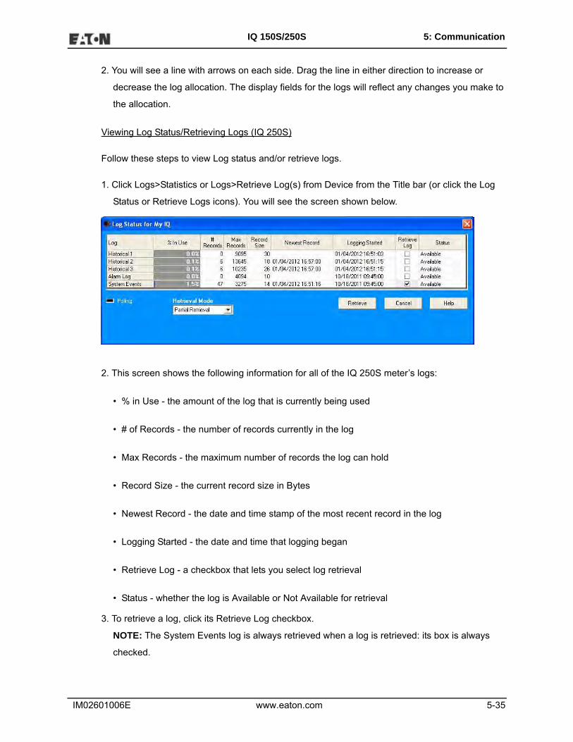
Viewing Log Status/Retrieving Logs (IQ 250S)
Follow these steps to view Log status and/or retrieve logs.
1. Click Logs>Statistics or Logs>Retrieve Log(s) from Device from the Title bar (or click the Log
Status or Retrieve Logs icons). You will see the screen shown below.
2. This screen shows the following information for all of the IQ 250S meter’s logs:
• % in Use - the amount of the log that is currently being used
• # of Records - the number of records currently in the log
• Max Records - the maximum number of records the log can hold
• Record Size - the current record size in Bytes
• Newest Record - the date and time stamp of the most recent record in the log
• Logging Started - the date and time that logging began
• Retrieve Log - a checkbox that lets you select log retrieval
• Status - whether the log is Available or Not Available for retrieval
3. To retrieve a log, click its Retrieve Log checkbox.
NOTE: The System Events log is always retrieved when a log is retrieved: its box is always
checked.

IM02601006E www.eaton.com 5-36
IQ 150S/250S 5: Communication
4. Use the pull-down menu for Retrieval Mode to select one of two options:
• Partial Retrieval (this is the default Retrieval mode)
• Time Range Retrieval
NOTES:
• In Partial Retrieval mode, only the newest records are retrieved. This increases
retrieval speed, since records that have previously been retrieved are ignored. When
the log is full, it will roll over. Partial Retrieval mode should be used for Billing and
continuous logging.
• The Time Range Retrieval mode is useful if you want to retrieve specific events. If
you select Use Time Range from the pull-down menu, date range fields will display,
allowing you to select the time range for data retrieval. Only records (within the spec-
ified time range) that are newer than the latest records in the log database can be
retrieved for any selected logs. For this reason, Time Range Retrieval should not be
used for Billing or continuous logging purposes. The only way to retrieve earlier
records using Time Range Retrieval is to delete the existing log database(s) before
retrieving the log(s).
5. Click Retrieve.
a. You will see a screen that shows the percent retrieved for each log, the time elapsed since
retrieval began, and any messages.
b. After the logs have been retrieved, you will see a screen which shows you the Mode, Start
time, and Status of Log Conversion.
c. The Log Viewer opens.
NOTES:
• Only one person at a time can download a log. If someone else is downloading a log, it will be
unavailable until the download is complete.
• Retrieve logs as often as you want. Each time you retrieve a log file, Eaton Meter
Configuration Software appends only the newest records and captures to the existing database.

IM02601006E www.eaton.com 5-37
IQ 150S/250S 5: Communication
Using the Log Viewer (IQ 250S)
To access Log Viewer, either:
• Retrieve logs from a connected meter, as shown in the previous section.
• Click the Open Log icon from the Eaton Meter Configuration Software’s Main screen. The
Retrieved Logs directory opens, allowing you to pick a previously stored log file.
• Run Log Viewer from the Windows® Start menu.
You will see the Log Viewer’s main screen, shown below.
1. Choose the log data file(s) you want to view in either of the following ways:
• If you have retrieved logs through Eaton Meter Configuration Software, the meter’s desig-
nated label is shown in the field above the Meter 1 button. Click the Log’s button on the right
side of the screen to view a log. (The buttons of unavailable logs are grayed out and
unselectable.)

IM02601006E www.eaton.com 5-38
IQ 150S/250S 5: Communication
• If you want to view a previously retrieved log, click either Meter button (1 or 2). Log Viewer
opens a window prompting you to select a log database (.db). See the example screen
below.
2. Select the file you want and click Open.
NOTE: You can choose a different log file (.db) for Meter 1 and for Meter 2.
3. Select the data points you want to view by clicking the Data Points button in Log Viewer’s Main
screen. You will see the screen shown below. Note that the number of data points you see
reflects the number of parameters in the log.

IM02601006E www.eaton.com 5-39
IQ 150S/250S 5: Communication
4. From the Available Data Points column, click on the data points you want to include when view-
ing the log file.
• To select multiple points, hold down the Ctrl key while clicking.
• To select points in sequence, hold down the Shift key while clicking.
• Click the Add button to move the Data Points to the Selected Data Points column.
• Click the Restore button to return the selection to its previous setting.
5. When you finish your selection, click OK to return to Log Viewer’s main screen.
6. Select the portion of the log you want to view by specifying a time range. Log Viewer bases its
time/date format on your computer’s Regional Settings (Windows® Control Panel). Click the
Time Range button. You will see the following screen.
• To select a specific time range, click the Between radio button and enter a date and time in
each field. You can also the arrows to open a calendar for the date and to increment the time
field.
• To select a range of hours, days, months or years only, click the appropriate radio button and
use the arrows to select the range.

IM02601006E www.eaton.com 5-40
IQ 150S/250S 5: Communication
7. Click OK. The time range you selected is displayed in the Log Viewer’s main screen.
8. Click on the Historical Trends button or View Data>Snapshots. Log Viewer displays trending
data for the selected log file based on the time range and data points you chose. See the exam-
ple screen shown below.
• The name of the log file and the type of data point are listed in the top row.
• You can move the columns, so that the most important data is most accessible. Right-click on
the column title and drag it to the desired location on the table.
• To save the data to your clipboard, right-click with the cursor positioned anywhere in the table.

IM02601006E www.eaton.com 5-41
IQ 150S/250S 5: Communication
• To sort the data by Date/Time or data point, in either ascending or descending order, click the
Sort button and use the pull-down menus to make your selection. See the screen shown
below.
9. To display Trending data as either an XY, Circular, or Advanced graph, click the Graph button.
You will see the following screen.
The Available Items column lists the log’s data points. (To add a new data point, return to Log
Viewer’s main screen and click the Data Points button.)
a. Click on the data points you want to graph.
b. Click the Add button. The items appear in the Graph Items column.

IM02601006E www.eaton.com 5-42
IQ 150S/250S 5: Communication
• To select multiple data points, hold down the Ctrl key while clicking.
• To select data points in sequence, hold down the Shift key while clicking.
NOTE: Only six data points in total can be graphed at one time. If there are two
open log files, you can only select three data points per file.
c. To view the graph, click either the Circular, XY, or Advanced Graph buttons. See the example
graphs below and on the next page.
Circular Graph

IM02601006E www.eaton.com 5-43
IQ 150S/250S 5: Communication
XY Graph
Advanced Graph

IM02601006E www.eaton.com 5-44
IQ 150S/250S 5: Communication
The following instructions pertain to all of the graphs:
• To change the starting point of the graph, choose a new date/time segment from the Starting
Date/Time to View pull-down menu.
• To change the amount of time represented on the graph, enter a value in the Number of Days to
View field and press Enter or click on the Redraw button.
• To change the scale of the graph, enter a value in the Minimum Value and Maximum Value fields
and press Enter or the Redraw button.
• To view one sample at a time, click in the Move by Sample box; then click on the Forward or
Reverse buttons each time you would like to view the next (or previous) sample.
• To view a continuous, sample-by-sample rendering of the graph, click the Move by Sample box
and the Auto Show box. Select a speed by sliding the Auto Show Speed bar left or right; click on
the Forward or Reverse buttons to determine the direction of the Auto Show. To stop Auto
Show, deselect the Auto Show box.
• To print the graph on a color printer, check the Color Printout box and click Print.
• To print the graph on a black-and-white printer, click the Use Symbols box and click Print.
• To copy the graph data to the computer’s clipboard, select Copy from the File menu. Paste the
data into a spreadsheet, such as Excel®.
• To export the graph’s data, select Export Data from the File menu.
• To change the graph’s color assignments, select Select Colors from the Options menu. You will
see the screen shown on the next page.

IM02601006E www.eaton.com 5-45
IQ 150S/250S 5: Communication
NOTES:
• The Advanced Graph also has a Color button which opens the Color Assignments
screen.
• The Color Assignments screen is slightly different for the Advanced Graph.
• The small squares under the Color heading represent the color currently
assigned to each component of the graph.
• To make adjustments to an Item’s color, click the radio button beside it and create a
new color by moving the red, green and blue sliders. Create black by moving all slid-
ers down, white by moving all sliders up. The large square on the right shows the
color you have created.
• Click OK to return to the graph; Log Viewer redraws the graph using the new color
scheme.
• Click the Restore button to return all color schemes to their default
values.
10.When you are finished using the Log Viewer, click the X button or File>Exit to close the screen.
NOTE: You can also view the Limits log (listing any alarms) and System Events log (listing firm-
ware changes, logging start and stop times, Runtime start, stop, and end times, resets, change
of meter’s programmable settings and other system events.) From the Log Viewer’s Main
screen:

IM02601006E www.eaton.com 5-46
IQ 150S/250S 5: Communication
• Click the Out of Limit button to view the Limits log (you need to download this log or select an
already downloaded log first. See the instructions beginning on page 5-35).
• Click the System Events button to view the System Events log.

IM02601006E www.eaton.com 5-47
IQ 150S/250S 5: Communication
5.2.4: Polling the IQ 150S/250S Submeter
The Real Time Poll features of Eaton Meter Configuration software are used to continuously view
instantaneous values within an IQ 150S/250S meter. The software provides tabular views of
metered values, circuit measurements, interval data, and pulse data.
The Real Time Poll features are divided into three groups, accessed by clicking Real-Time Poll in
the Title Bar:
• Real Time Readings
• Revenue, Energy and Demand Readings
• Power Quality
When you click Real Time Readings; Revenue, Energy and Demand Readings; and Power Qual-
ity, you will see a sub-menu that allows you to select individual polling screens.
NOTE: Clicking the Polling icon on the Title Bar is the same as selecting Instantaneous Polling
from the Real-Time Poll>Real Time Readings menu; clicking the Phasors icon on the Title Bar is
the same as selecting Phasors from the Real-Time Poll>Power Quality menu.

IM02601006E www.eaton.com 5-48
IQ 150S/250S 5: Communication
Instantaneous Polling
Click Real-Time Poll>Real Time Readings>Instantaneous Polling. You will see the screen shown
below.
NOTE: This screen capture is for an IQ 150S meter. If you are connected to an IQ 250S meter you
won’t see the THD% section of the screen.
• Click Print to print a copy of the screen.
• Click Help to view instructions for this screen.
• Click OK to return to the main screen.

IM02601006E www.eaton.com 5-49
IQ 150S/250S 5: Communication
Poll Max and Min Readings
Click Real-Time Poll>Real Time Readings>Poll Max and Min Readings. You will see the screen
shown below.
This screen displays the maximum and minimum values and the time of their
occurrence for all of the IQ 150S/250S Real-Time readings. Use the scroll bar to view readings not
displayed on the screen.
• Click Copy to copy the readings to the clipboard. You can then paste them into another docu-
ment, for example, an Excel file.
• Click OK to close the screen.

IM02601006E www.eaton.com 5-50
IQ 150S/250S 5: Communication
Uncompensated and Short Term Max and Min Readings
Click Real-Time Poll>Real Time Readings>Uncompensated and Short Term Max and Min Read-
ings. You will see the screen shown below.
The initial display shows the uncompensated readings for the meter. Click the Short Term Maxi-
mum and Minimum Voltages to see those readings.
• Click Copy to copy the readings to the clipboard. You can then paste them into another docu-
ment, for example, an Excel file.
• Click Close to close the screen.

IM02601006E www.eaton.com 5-51
IQ 150S/250S 5: Communication
Power and Energy
Click Real-Time Poll>Revenue, Energy and Demand Readings>Power and Energy. You will see
the screen shown below.
This screen displays the power and energy for Total power and all three phases.
1. Click the tabs at the top of the screen to select the view you want:
• Total
• Phase A
• Phase B
• Phase C
2. Click Print to print the readings.
3. Click OK to close the screen.

IM02601006E www.eaton.com 5-52
IQ 150S/250S 5: Communication
Poll Phasors
Click Real Time Poll>Power Quality>Phasors. You will see the screen shown below.
The Phasors screen displays the Phase relationships of the currently connected meter.
1. To adjust the Phasor display, click Options at the bottom of the screen.You will see the screen
shown below.

IM02601006E www.eaton.com 5-53
IQ 150S/250S 5: Communication
a. In the Display Angles Increasing and Phasor Rotation boxes, select either Clockwise or
Counter Clockwise.
b. From the pull-down menu at the bottom of the screen, select Vectors, Triangles, or Vectors
and Triangles to change the graphic representation of the data.
2. Click OK to save your selections and return to the Phasors screen.
3. From the Phasors screen:
• Click Copy to save a copy of the screen to the clipboard.
• Click Print to send a copy of the graph to a printer.
• Click Help to view instructions for this screen.
4. Click OK to return to the main screen.

IM02601006E www.eaton.com 5-54
IQ 150S/250S 5: Communication
Poll Limits (IQ 250S)
Click Real-Time Poll>Power Quality and Alarms>Limits. You will see the screen shown below.
This screen shows the current status of any Limits programmed in the Device Profile.
NOTE: See instructions for configuring Limits, earlier in this chapter.
1. The displayed fields are:
• Limit ID – the identification of the limit
• Label - the item the Limit is set for
• Value – the current reading for this item
• Status/Limit1/Limit2 – whether the current reading is “In” or “Out” for the Above
(Limit 1) and Below (Limit 2) Setpoints
• Limit 1/Setting/Point/Hysteresis – Above: the point above which the reading
goes out of limit (Setpoint) and the point at which it returns to within limit
(Hysteresis)
• Limit 2/Setting/Point/Hysteresis – Below: the point below which the reading goes
out of limit (Setpoint) and the point at which it returns to within limit
(Hysteresis).
2. Click Print to print the screen.
3. Click OK to close the screen.

IM02601006E www.eaton.com 5-55
IQ 150S/250S 5: Communication
5.2.5: Using the IQ 150S/250S Tools Menu
The Tools Menu allows you to access specific functions for the IQ 150S/250S meter. Click Tools
from the Title Bar to display the Tools Menu.
Accessing the Device Profile Screen
Click the first option, Edit Current Device Profile, to open the Device Profile screen. This menu
option performs the same function as clicking the Profile icon in the Title Bar.
Setting Device Time
Click Tools>Set Device Time. You will see the screen shown below.
This screen allows you to set the meter’s internal clock and/or synchronize it to your
PC’s time. The meter’s clock is used for logging and other time retrieval purposes.
• You can enter a new Month, Day, and Year in the Date fields.
• Check the box next to Use PC Time to synchronize the meter to your PC; uncheck the box if
you want to reset the time manually. You can then enter the Hour, Minute, and Seconds you
want in the Time fields.

IM02601006E www.eaton.com 5-56
IQ 150S/250S 5: Communication
• Click Send to send the new date and/or time to the meter; click Cancel to close the screen.
Retrieving Device Time
Click Tools>Retrieve Device Time. You will see the screen shown below.
This screen displays the meter’s internal time. If Daylight Savings Time is enabled, ‘DST’ displays
in one of the fields to the right of the Time field.
Click OK to close the screen.
Reset Device Information
Click this option to reset Max/Min values. You will see the screen shown below. Click the checkbox
and click Reset to reset max/min values; click Cancel to close the screen without resetting.
Retrieve Device Status

IM02601006E www.eaton.com 5-57
IQ 150S/250S 5: Communication
Click this option to see the Device status screen for the meter. this is the same screen that dis-
plays when you first connect to the meter.
Flash Update Firmware
Click this option to upgrade the meter’s firmware. You will see the screen shown below.
1. Click Browse to locate the flash file.
2. Click OK to update the firmware with the flash file.
3. When flashing is complete, click Exit to close the screen.
NOTE: Flash updating of firmware can only be done at a Baud Rate of 57600.

IM02601006E www.eaton.com 5-58
IQ 150S/250S 5: Communication
5.2.6: Performing Other Tasks with Eaton Meter Configuration Software
The following sections contain instructions for other tasks you can perform using the Eaton Meter
Configuration software.
Connection Manager
Use Connection Manager to add or remove connection locations and/or devices at locations.
1. Click Connection>Connection Manager or click on the Connect Mgr icon. You will see the
screen shown below.
List of Locations:
On the left side of the Connection Manager screen is a List of Locations. These are the locations
of one or more meters to which you can connect. You can add a location and/or a device; edit a
location and/or device; or remove a location and/or device.
• To add a location:

IM02601006E www.eaton.com 5-59
IQ 150S/250S 5: Communication
a. Click the Add button. You will see the Connection Manager Location Editor screen. On this
screen, you program the Communication settings for each new location.
b. Type a name for the new location.
c. Click Serial Port or Network.
d. Enter Communication settings:
• Com Port: COM 1 - 99
• Baud Rate: 1200 - 115200
• Flow Control: None or Hardware
• Data Bits: 8 (or 7)
• Parity: None (Even, Odd)
e. To add a device:

IM02601006E www.eaton.com 5-60
IQ 150S/250S 5: Communication
- Click Add Serial (to add a Serial Port connected device) or Add Net (to add a
Network connected device) in the Devices at Location box. You can add up to
255 devices (Serial Port and/or Network connected) at one location.
NOTES:
• All devices must have the same connection parameters: Baud, Parity and Flow Con-
trol.
• Multiple devices slow down polling.
• If you are connecting to a device through the Power Xpert® Gateway, the protocol
must be Modbus TCP.
f. To edit a device:
- Select the device from the Devices at Location box. (Scroll down to find all
devices.)
- Click Edit. You will see the Connection Manager Location Device Editor screen,
shown below.
- Use this screen to program the device properties for each device at a location.
If the device has a Serial Port device connection, you will see the example
screen on the left; if the device has a Network device connection, you will see
the example screen on the right.
NOTE: Click the Network or Serial button at the top of the screen to switch
connection screens.
- Enter Device Properties:

IM02601006E www.eaton.com 5-61
IQ 150S/250S 5: Communication
• Address: 1 - 247 (Unique Address)
• Name: Device Name
• Description: (Type and Number, for example)
• Protocol: Modbus RTU, ASCII, or Modbus TCP
• Device Type: IQ Meter
• Comm Port: 1 or 2 (Serial Port Only)
• IP Address:100.10.10.10 (for example) (Network Only)
• Port Number:502 (Default) (Network Only)
- Click Close to save settings and return to the Connection Manager Location
Editor screen.
g. To remove a device, select the device from the Devices at Location box and click
Remove.
h. Click Close to return to the Connection Manager screen.
• To edit a location:
a. Select a location from the List of Locations box.
b. Click the Edit button. The Connection Manager Location Editor screen appears, displaying
the current settings for the location.
c. Make any changes to settings and/or devices at the location.
d. Click Close to exit the screen.
• To remove a location:
a. Select a location from the List of Locations box.
b. Click Remove.
c. Click Yes in the Confirmation window.

IM02601006E www.eaton.com 5-62
IQ 150S/250S 5: Communication
• To sort the list of locations:
a. Select a sort method (A-Z, Z-A, Newest-Oldest or Oldest-Newest) from the pull-down menu.
b. Click Sort By.
• To connect to a location:
a. Select the location you want to connect to from the List of Locations box. NOTE: You may
only connect to one location at a time. To change to a different location, you must disconnect
from the current location by selecting it and clicking Disconnect.
b. Click Connect. When the connection is made, the selected location appears in the Con-
nected To Locations section of the screen.
c. Click Close. The Device Status screen opens, confirming the connection. The computer Sta-
tus bar at the bottom of the screen also confirms the computer’s connection parameters.
NOTE: If the connection fails, a popup screen alerts you. Check that all cables are secure, that
the RS232 cable is connected to the correct Com Port on the computer, and that the computer is
set to use the same baud rate and protocol as the meter to which the computer is connected.
Disconnecting from an IQ 150S/250S meter
To disconnect from a meter or from a location, do one of the following:
• Click on the Disconnect icon in the Title Bar.
• Select Connection>Disconnect from the Title Bar.
• From the Connection Manager screen, select the location from the Connected to Location field
and click the Disconnect button.

IM02601006E www.eaton.com 5-63
IQ 150S/250S 5: Communication
Changing the Primary Device/Address
Use this feature to select another meter as the primary device.
1. Click Connect>Change Primary Device/Address. You will see the screen shown below.
2. Enter the address of the device you want to designate as the new Primary Device.
3. Click OK.
Merging Connection Databases
Use this feature to combine two sets of cnexcom databases.
1. Click Connection>Merge Connection Databases. You will see the screen shown below. It allows
you to select the two databases to merge.
2. Click the Browse button next to each field to pick the databases. The Source cnexcom database
will be merged into the Destination cnexcom database.
3. Click the Merge button to proceed with the merge; click OK to exit the screen.
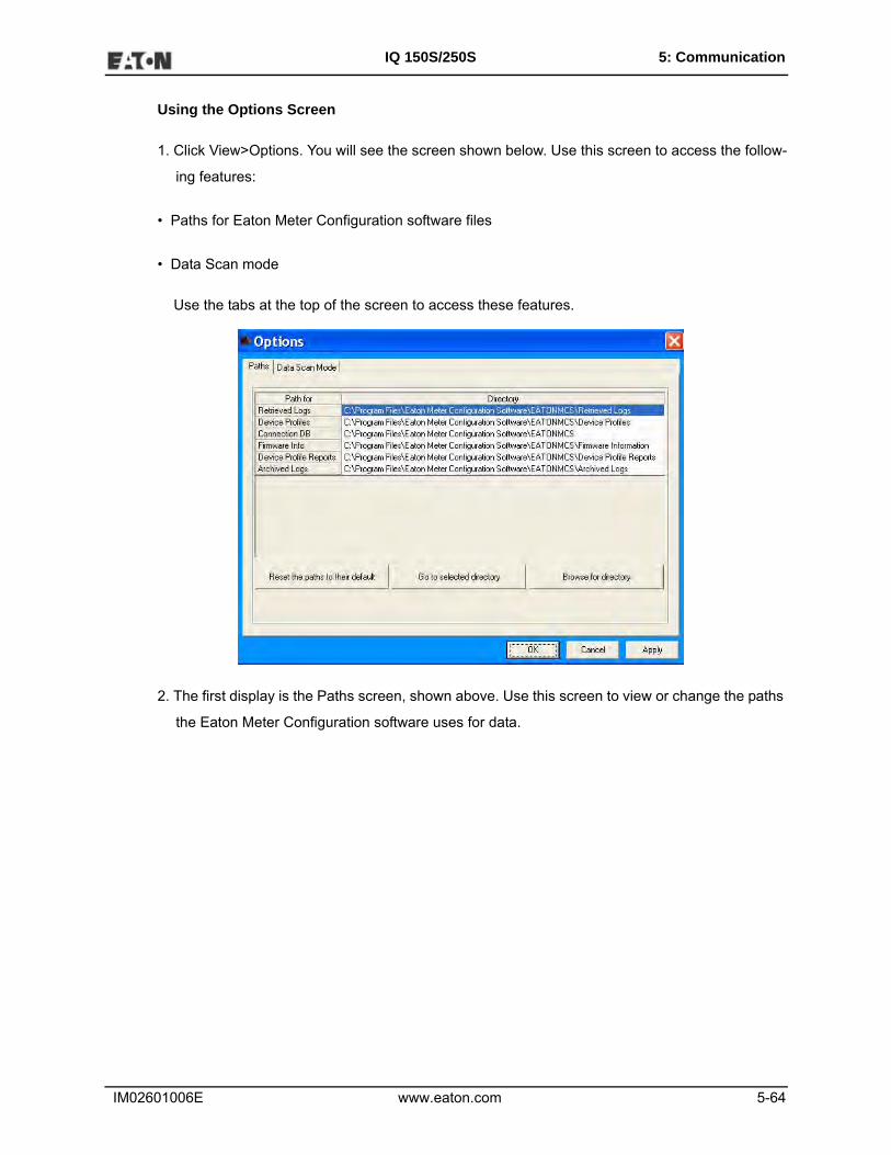
IM02601006E www.eaton.com 5-64
IQ 150S/250S 5: Communication
Using the Options Screen
1. Click View>Options. You will see the screen shown below. Use this screen to access the follow-
ing features:
• Paths for Eaton Meter Configuration software files
• Data Scan mode
Use the tabs at the top of the screen to access these features.
2. The first display is the Paths screen, shown above. Use this screen to view or change the paths
the Eaton Meter Configuration software uses for data.

IM02601006E www.eaton.com 5-65
IQ 150S/250S 5: Communication
3. Click the Data Scan Mode tab to see the screen shown below. Use this screen to select normal
scan rate or to enter a custom scan rate.
4. Click:
• Apply to apply your selection(s) and keep the Options screen open
• OK to apply your selection and close the Options screen
• Cancel to close the Options screen without saving any selections that have not been applied
Using the Help Menu
The Help menu, accessed by clicking Help in the Title Bar, allows you to:
• View this manual online: click Help>this User Manual.
• View information about the Eaton Meter Configuration software, including version number:
click Help>About Eaton Meter Configuration Software.

IM02601006E www.eaton.com 5-66
IQ 150S/250S 5: Communication
This page intentionally left blank.
IM02601006E www.eaton.com 6-1
IQ 150S/250S 6: Ethernet Configuration
6: Ethernet Configuration
6.1: Introduction
The IQ 150S/250S submeter has an option for a WiFi (Wireless) or RJ45 Ethernet connection.
This option allows the submeter to be set up for use in a LAN (Local Area Network), using stan-
dard WiFi base stations. Configuration for these connections is easily accomplished through your
PC using Telnet connections. Then you can access the submeter to perform meter functions
directly through any computer on your LAN: the IQ 150S/250S meter does not need to be directly
connected (wired) to these computers for it to be accessed.
This chapter outlines the procedures you use to set up the IQ 150S/250S submeter to function via
its Ethernet configuration.
6.2: Factory Default Settings
The settings shown in Section 6.2.1 are the default settings for the IQ 150S/250S submeter: they
are the settings programmed into your meter when it is shipped to you. You may need to modify
some of these settings when you set up your Ethernet configuration.
NOTES:
• Change Settings 1 and 6 ONLY. Settings 2, 3, and 4 must be the same as shown in Section
6.2.1. If they are not, reset them to the values shown in Section 6.2.1.
• If setting 3 is not CP0..! Defaults (In), the procedure for Network Module Hardware Initialization
(Section 6.3.4) will not work.

IM02601006E www.eaton.com 6-2
IQ 150S/250S 6: Ethernet Configuration
6.2.1: Modbus/TCP to RTU Bridge Setup
1) Network/IP Settings:
Network Mode…………Wired Only
IP Address .............10.0.0.1
Default Gateway .....--- not set ---
Netmask ...............255.255.255.0
2) Serial & Mode Settings:
Protocol ................Modbus/RTU,Slave(s) attached
Serial Interface ..... 57600,8,N,1,RS232,CH1
3) Modem/Configurable Pin Settings:
CP0..! Defaults (In) CP1..! GPIO (In) CP2..! GPIO (In)
CP3..! GPIO (In) CP4..! GPIO (In) CP5..! GPIO (In)
CP6..! GPIO (In) CP7..! GPIO (In) CP8..! GPIO (In)
CP9..! GPIO (In) CP10.! GPIO (In)
RTS Output ......... Fixed High/Active
4) Advanced Modbus Protocol settings:
Slave Addr/Unit Id Source .. Modbus/TCP header
Modbus Serial Broadcasts ...Disabled (Id=0 auto-mapped to 1)
MB/TCP Exception Codes ....Yes (return 00AH and 00BH)
Char, Message Timeout ...... 00050msec, 05000msec
6) WLAN Settings:
WLAN ............... Disabled, network:LTRX_IBSS
Topology……………. AdHoc, Country: US, Channel: 11

IM02601006E www.eaton.com 6-3
IQ 150S/250S 6: Ethernet Configuration
Security……………… none
TX Data rate…….. 11 Mbps auto fallback
Power management….. not supported in ad hoc mode
D)efault settings, S)ave, Q)uit without save
Select Command or parameter set (1..6) to change:
6.3: Configure Network Module
These procedures detail how to set up the IQ 150S/250S meter on the Network Module.
Only one person at a time can be logged into the network port. This eliminates the possibility of
several people trying to configure the Ethernet interface simultaneously.

IM02601006E www.eaton.com 6-4
IQ 150S/250S 6: Ethernet Configuration
6.3.1: Configuration Requirements
• You may want to consult your Network Administrator before performing these procedures, since
some functions may be restricted to the Network Administrator.
• If you have only one Ethernet adapter (network card), the screen displays only that configura-
tion. You will use this Ethernet adapter to access the IQ 150S/250S meter's Network Module.
You may have to configure the Ethernet adapter in order to use it with the IQ 150S/250S
meter's Network Module, using the instructions in Section 6.4.2.
• If you have multiple Ethernet adapters (network cards) installed on your computer, you must
choose, configure and use the correct one to access the Network Module.
• The Ethernet Adapter must be set up for point-to-point connection in order for it to connect to the
IQ 150S/250S meter's Network module, as follows:
IP Address should be 10.0.0.2
Subnet Mask should be 255.255.255.0
These settings can be made in the Ethernet Adapter. Follow the procedure in Section 6.3.2.

IM02601006E www.eaton.com 6-5
IQ 150S/250S 6: Ethernet Configuration
6.3.2: Configuring the Ethernet Adapter
1. From the PC’s Start Menu, select Settings>Network Connections or Control Panel>Net-
work Connections. You will see a screen like the one shown below.
2. Right click on the Local Area Network connection you will be using to connect to the IQ 150S/
250S submeter, and select Properties from the pull-down menu. You will see the screen shown
on the next page.

IM02601006E www.eaton.com 6-6
IQ 150S/250S 6: Ethernet Configuration
3. Select Internet Protocol [TCP/IP] from the middle of the screen and click the
Properties button. You will see the screen shown below.

IM02601006E www.eaton.com 6-7
IQ 150S/250S 6: Ethernet Configuration
4. Click the Use the Following IP Address radio button. The screen changes to allow you to enter
the IP Address and Subnet Mask.
a. Enter 10.0.0.2 in the IP Address field.
b. Enter 255.255.255.0 in the Subnet Mask field.
3. Click the OK button.
4. You can now close the Local Area Connection Properties and Network Connection windows.

IM02601006E www.eaton.com 6-8
IQ 150S/250S 6: Ethernet Configuration
6.3.3: Detailed Configuration Parameters
Certain parameters must be configured before the Ethernet interface can function on a network.
The following procedure can be locally or remotely configured.
Use a Telnet connection to configure the unit over the network. The Ethernet interface's configura-
tion is stored in meter memory and is retained without power. The configuration can be changed
at any time. The Ethernet interface performs a reset after the configuration has been changed and
stored.
Establish a Telnet connection to port 9999:
NOTE: If your PC is running
Windows 7, you need to enable Telnet
before using it.
1. Open the Control Panel.
2. Select Programs and Features.
3. Select Turn Windows features
on or off.
4. Check the box for Telnet Client.
5. Click OK. The Telnet client is
now available.
1. From the Windows Start menu, click Run and type 'cmd'.
2. Click the OK button to bring up Windows's Command Prompt window.
3. In the Command Prompt window, type:
telnet 10.0.0.1 9999 and press the Enter key.
NOTE: Be sure to include a space between the IP address and 9999.
The following parameters appear, for example:
Microsoft Windows XP [Version 5.1.2600] (C) Copyright 1985-2001 Microsoft Corp. C:\Documents and Settings\Administrator>telnet 10.0.0.1 9999

IM02601006E www.eaton.com 6-9
IQ 150S/250S 6: Ethernet Configuration
4. Press Enter again, quickly.
5. After entering Setup Mode (confirm by pressing Enter), you can configure the parameters for the
software you are using by entering one of the numbers on the Change Setup Menu, or you can
confirm default values by pressing Enter. Be sure to store new configurations when you are fin-
ished. The Ethernet Interface will then perform a power reset and the Factory Default Settings
will display again (refer to Section 6.2.1).
6.3.4: Setup Details
This section illustrates how each section of settings appears on the screen, if you press Y (Yes) to
change one or more of the settings.
CAUTION! Change Settings 1 and 6 ONLY. Settings 2, 3, and 4 must be the same as shown in
Section 6.2.1. If they are not, reset them to the values shown in Section 6.2.1.
Network IP Settings Detail (1) (Set device with static IP Address.)
Network Mode: 0=Wired only, 1=Wireless Only <0> ? 1
IP Address <010> 192.<000> 168.<000> .<000> .<001>
Set Gateway IP Address <N> ? Y
Gateway IP Address : <192> .<168> .<000> .<001>
Set Netmask <N for default> <Y> ? Y
<255> .<255> .<255> .<000>
Change telnet config password <N> ? N
Serial & Mode Settings (2) (Make sure these settings match those shown in Section 6.2.1.)
Attached Device (1=Slave 2=Master) (1) ? 1
Serial Protocol (1=Modbus/RTU 2=Modbus/ASCII) (1) ? 1
Serial Number 5415404 MAC Address 00:20:4A:54:3C:2C Software Version V01.2 (000719) Press Enter to go into Setup Mode

IM02601006E www.eaton.com 6-10
IQ 150S/250S 6: Ethernet Configuration
Use serial connector (1=CH1 2=CH2) (1) ? 1
Interface Type (1=RS232 2=RS422/RS485+4-wire 3=RS485+2-wire) (1) ? 1
Enter serial parameters (57600,8,N,1) 57600, 8, N, 1
Modem/Configurable Pin Settings (3) (Make sure these settings match those shown in Sec-
tion 6.2.1.)
CAUTION! You must configure this setting correctly in order to be able to use the Network Module
Hardware Initialization procedure (Section 6.4).
Press 3. The following appears on the screen:
CP0 Function (hit space to toggle) GPIO (In)
Press the Space bar until the following appears on the screen:
CP0 Function (hit space to toggle) Defaults(In)
Press Enter. The following appears on the screen:
Invert (active low) (Y) ?
Press Y.
Ignore other settings (press Enter through the rest of Setting 3).
Advanced Modbus Protocol settings (4) (Make sure these settings match those shown in
Section 6.2.1.)
Slave address (0 for auto, or 1..255 fixed otherwise) (0) ? 0
Allow Modbus Broadcasts (1=Yes 2=No) (2) ? 2
Use MB/TCP 00BH/00AH Exception Responses (1=No 2=Yes) (2) ? 2
Disable Modbus/TCP pipeline (1=No 2=Yes) (1) ? 1
Character Timeout (0 for auto, or 10-6950 msec) (50) 50
Message Timeout (200-65000 msec) (5000) 5000
Serial TX delay after RX (0-1275 msec) (0) 0

IM02601006E www.eaton.com 6-11
IQ 150S/250S 6: Ethernet Configuration
Swap 4x/0H to get 3x/1x (N) ? N
Local slave address for GPIO (0 to disable, or 1..255) (0) ? 0
WLAN Settings Detail (6) (The settings shown are recommended by Eaton for use with IQ
150S/250S submeter.)
Topology: 0=Infrastructure, 1=Ad-Hoc <1> ? 0
Network name <SSID> <LTRX_IBSS> ? Eaton_IQ150S_250S
Security suite: 0=none, 1=WEP, 2=WPA, 3=WPA2/802.11i <0> ? 0
TX Data rate: 0=fixed, 1=auto fallback <1> ? 1
TX Data rate: 0=1, 1=2, 2=5.5, 3=11, 4=18, 5=24, 6=36, 7=54 Mbps <3> ? 7
Enable power management <N> ? Y
IMPORTANT NOTES:
• The settings for the Wireless Access Point should be IDENTICAL to the settings for LWAN,
shown above. For programming, see the User's Manual for the Wireless Access Point in use.
• See Section 6.3.4.1 for information on using an Encryption key.
Exiting the screen
CAUTION! DO NOT PRESS 'D.'
Press 'S' to Save the settings you've entered.
6.3.4.1: Encryption Key
Eaton recommends that you use 128-bit encryption when setting up your Ethernet configuration.
In the WLAN Settings (6), set Security WEP (1), Authentication shared (1), WEP128 (1) and
Change Key (Y).
When Change Key (Y) is entered, you are required to enter an Encryption Key. You can manually
enter 26 hexadecimal characters (required for 128-bit encryption) or you can use a WEP Key pro-
vider online (example: www.powerdog.com/wepkey.cgi). WEP Key providers should note on their
website that their encryption algorithm is for the Wired Equivalent Privacy portion of
IEEE 802.11b/g.

IM02601006E www.eaton.com 6-12
IQ 150S/250S 6: Ethernet Configuration
WEP Key Provider Steps
1. Input 26 alphanumeric characters as your Passphrase.
IMPORTANT! Remember your Passphrase.
2. Click the Generate Keys button. Your Hexadecimal WEP Keys appear.
3. Input the 128-bit Key in the Change Key section of the WLAN Settings (6).
4. Continue inputting settings.
5. Press 'S' to Save your settings.
PASSPHRASE TO HEXADECIMAL WEP KEYS Enter the passphrase below. 1009egbck001036ab
Generate keys
PASSPHRASE TO HEXADECIMAL WEP KEYS The passphrase 1009egbcke001306ab produces the following keys: 64-BIT (40-BIT KEYS)
1. AA43FB768D 2. 637D8DB9CE 3. AFDE50AF61 4. 0c35E73E25
128-BIT (104-BIT) KEY 041D7773D8B2C1D97BE9531DC

IM02601006E www.eaton.com 6-13
IQ 150S/250S 6: Ethernet Configuration
6.4: Network Module Hardware Initialization
If you don't know your current Network Module settings, or if the settings are lost, you can use this
method to initialize the hardware with known settings you can then work with.
Main Board
1. Place a shorting block on JP3 and press the Reset button on the main board.
NOTE: JP3 is located on the right hand side, upper corner of the main board. The
shorting block can be "borrowed" from JP2, located at the middle, right hand side. See the fig-
ure shown above.
2. After you press the Reset button, move the jumper back to JP2.
3. Make sure your settings are the same as those in Section 6.2.1. Follow the steps in Section 6.3
to configure the Network Module.
41
31
31
87
87
87
WD
seirtsudnI ortcelEhceTeguaG/

IM02601006E www.eaton.com 6-14
IQ 150S/250S 6: Ethernet Configuration
This page intentionally left blank.

IM02601006E www.eaton.com 7-1
IQ 150S/250S 7: Using the Submeter
7: Using the Submeter
7.1: Introduction
The IQ 150S/250S submeter can be configured and a variety of functions can be accomplished by
using the Elements and the Buttons on the submeter face. This chapter reviews front panel
navigation. See Appendix A for complete Navigation maps.
7.1.A: Understanding Submeter Face Elements
Figure 7.1: Faceplate with Elements
The meter face features the following elements:
• Reading Type Indicator: e.g., Max (The meter shown above is an IQ 250S - the LM1 and LM2
indicators are not one the IQ 150S meter.)
• Parameter Designator: e.g., Volts L-N
• Watt-Hour Test Pulse: Energy pulse output to test accuracy
• Scaling Factor: Kilo or Mega multiplier of displayed readings
• % of Load Bar: Graphic Display of Amps as % of the Load (Refer to Section 7.3 for additional
information.)
0000
-
-
-
A
B
C
MENU ENTERMAX
MIN
LM1
LM2
PRG
VOLTS L-N
VOLTS L-L
AMPS
WNARP
VA/Hz
Wh
VARh
VAh
120%-
90%-
60%-
30%-
%LOADMEGA
KILO
Wh Pulse
ReadingType
Indicator
ParameterDesignator
Watt-hourTest Pulse
ScalingFactor
% of Load Bar

IM02601006E www.eaton.com 7-2
IQ 150S/250S 7: Using the Submeter
7.1.B: Understanding Submeter Face Buttons
Figure 7.2: Faceplate with Buttons
The meter face has Menu, Enter, Down and Right buttons, which let you perform the following
functions:
• View Meter Information
• Enter Display Modes
• Configure Parameters (may be Password Protected)
• Perform Resets (may be Password Protected)
• Perform LED Checks
• Change Settings
• View Parameter Values
• Scroll Parameter Values
• View Limit States (IQ 250S)
0000
-
-
-
A
B
C
MENU ENTERMAX
MIN
LM1
LM2
PRG
VOLTS L-N
VOLTS L-L
AMPS
WNARP
VA/Hz
Wh
VARh
VAh
120%-
90%-
60%-
30%-
%LOADMEGA
KILO
Wh Pulse
Menu Enter
Down Right

IM02601006E www.eaton.com 7-3
IQ 150S/250S 7: Using the Submeter
7.2: Using the Front Panel
You can access four modes using the IQ 150S/250S submeter’s front panel buttons:
• Operating mode (Default)
• Reset mode
• Configuration mode
• Information mode - Information mode displays a sequence of screens that show model informa-
tion, such as Frequency, Amps, etc.
Use the Menu, Enter, Down and Right buttons to navigate through each mode and its related
screens.
NOTES:
• See Appendix A for the complete display mode Navigation maps.
• The meter can also be configured using software; see Chapter 5 for instructions.
7.2.1: Understanding Startup and Default Displays
Upon Power Up, the meter displays a sequence of screens:
• Lamp Test screen where all LEDs are lit
• Lamp Test screen where all digits are lit
• Firmware screen showing build number
• Error screen (if an error exists)
After startup, if auto-scrolling is enabled, the IQ 150S/250S meter scrolls the parameter readings
on the right side of the front panel. The Kilo or Mega LED lights, showing the scale for the Wh,
VARh and VAh readings. Figure 7.3 shows an example of a Wh reading.

IM02601006E www.eaton.com 7-4
IQ 150S/250S 7: Using the Submeter
Figure 7.3: Display Showing Watt-hr Reading
The IQ 150S/250S meter continues to provide scrolling readings until one of the
buttons on the front panel is pressed, causing the meter to enter one of the other Modes.
7.2.2: Using the Main Menu
1. Press the Menu button. The Main Menu screen appears.
• The Reset: Demand mode (rStd) appears in the A window. Use the Down button to scroll, caus-
ing the Reset: Energy (rStE), Configuration (CFG), Operating (OPr), and Information (InFo)
modes to move to the A window.
• The mode that is currently flashing in the A window is the “Active” mode, which means it is the
mode that can be configured.
For example: Press Down Twice - CFG moves to A window. Press Down Twice - OPr moves to A window.
0.6590000
-
-
-
A
B
C
MENU ENTERMAX
MIN
LM1
LM2
PRG
VOLTS L-N
VOLTS L-L
AMPS
WNARP
VA/Hz
Wh
VARh
VAh
120%-
90%-
60%-
30%-
%LOADMEGA
KILO
Wh Pulse
A
B
C
-
-
-
MENU ENTER
A
B
C
-
-
-
MENU ENTER
A
B
C
-
-
-
MENU ENTER

IM02601006E www.eaton.com 7-5
IQ 150S/250S 7: Using the Submeter
2. Press the Enter button from the Main Menu to view the Parameters screen for the mode that is
currently active.
7.2.3: Using Reset Mode
Reset mode has two options:
• Reset: Demand (rStd): resets the Max and Min values.
• Reset: Energy (rStE): resets the energy accumulator fields.
1. Press the Enter button while either rStd or
rStE is in the A window. The Reset Demand
No or Reset Energy No screen appears.
• If you press the Enter button again, the
Main Menu appears, with the next mode in
the A window. (The Down button does not
affect this screen.)
• If you press the Right button, the Reset
Demand YES or Reset Energy YES screen
appears. Press Enter to perform a reset.
NOTE: If Password protection is enabled for
reset, you must enter the four digit password
before you can reset the meter (see Chapter 5 for
information on Password protection). To enter a
password, follow the instructions in Section 7.2.4.
CAUTION! Reset Demand YES resets all Max and Min values.
2. Once you have performed a reset, the screen displays either “rSt dMd donE” or
“rSt EnEr donE”and then resumes auto-scrolling parameters.
A
B
C
-
-
-
MENU ENTER
A
B
C
-
-
-
MENU ENTER
A
B
C
-
-
-
MENU ENTER
A
B
C
-
-
-
MENU ENTER

IM02601006E www.eaton.com 7-6
IQ 150S/250S 7: Using the Submeter
7.2.4: Entering a Password
If Password protection has been enabled in the software for reset and/or configuration (see
Chapter 5 for more information), a screen appears requesting a password when you try to reset
the meter and/or configure settings through the front panel.
• PASS appears in the A window and 4 dashes appear in the B window. The leftmost dash is
flashing.
1. Press the Down button to scroll numbers from 0 to 9 for the flashing dash. When the correct
number appears for that dash, use the Right button to move to the next dash.
Example: The left screen, below, shows four dashes. The right screen shows the display after the
first two digits of the password have been entered.
2. When all 4 digits of the password have been selected, press the Enter button.
• If you are in Reset Mode and you enter the correct password, “rSt dMd donE” or “rSt EnEr
donE”appears and the screen resumes auto-scrolling parameters.
• If you are in Configuration Mode and you enter the correct password, the display returns to
the screen that required a password.
• If you enter an incorrect password, “PASS ---- FAIL” appears and:
• The previous screen is re-displayed, if you are in Reset
Mode.
• The previous Operating mode screen is re-displayed, if
you are in Configuration mode.
A
B
C
-
-
-
MENU ENTER
A
B
C
-
-
-
MENU ENTER
PASS
12__
A
B
C
-
-
-
MENU ENTER

IM02601006E www.eaton.com 7-7
IQ 150S/250S 7: Using the Submeter
7.2.5: Using Configuration Mode
Configuration mode follows Reset: Energy on the Main Menu.
To access Configuration mode
1. Press the Menu button while the meter is auto-scrolling parameters.
2. Press the Down button until the Configuration Mode option (CFG) is in the A window.
3. Press the Enter button. The Configuration Parameters screen appears.
4. Press the Down button to scroll through the configuration parameters: Scroll (SCrL), CT, PT,
Connection (Cnct) and Port. The parameter currently ‘Active,” i.e., configurable, flashes in the A
window.
5. Press the Enter button to access the Setting screen for the currently active
parameter.
NOTE: You can use the Enter button to scroll through all of the Configuration parameters and their
Setting screens, in order.
Press Enter when CFG is in A window - Parameter screen appears -
Press Down- Press Enter when
Parameter you want is in A window
6. The parameter screen appears, showing the current settings. To change the settings:
• Use either the Down button or the Right button to select an option.
• To enter a number value, use the Down button to select the number value for a digit and the
Right button to move to the next digit.
A
B
C
-
-
-
MENU ENTER
A
B
C
-
-
-
MENU ENTER

IM02601006E www.eaton.com 7-8
IQ 150S/250S 7: Using the Submeter
NOTE: When you try to change the current setting and Password protection is enabled for the
meter, the Password screen appears. See Section 7.2.4 for instructions on entering a password.
7. Once you have entered the new setting, press the Menu button twice.
8. The Store ALL YES screen appears. You can either:
• Press the Enter button to save the new setting.
• Press the Right button to access the Store ALL no screen; then press the Enter button to
cancel the Save.
9. If you have saved the settings, the Store ALL done screen appears and the meter resets.
Press the Enter button to save Press the Enter button to The settings have been
the settings. Press the Right Cancel the Save. saved.
button for Stor All no screen.
A
B
C
-
-
-
MENU ENTER
A
B
C
-
-
-
MENU ENTER
A
B
C
-
-
-
MENU ENTER

IM02601006E www.eaton.com 7-9
IQ 150S/250S 7: Using the Submeter
7.2.5.1: Configuring the Scroll Feature
When in Auto Scroll mode, the meter performs a scrolling display, showing each parameter for 7
seconds, with a 1 second pause between parameters. The parameters that the meter displays
have been selected through Eaton Meter Configuration
software (refer to Chapter 5 for instructions).
To enable or disable Auto-scrolling:
1. Press the Enter button when SCrl is in the A window. The Scroll YES
screen appears.
2. Press either the Right or Down button if you want to access the
Scroll no screen. To return to the Scroll YES screen, press either but-
ton.
3. Press the Enter button on either the Scroll YES screen (to enable
auto-scrolling) or the Scroll no screen (to disable auto-scrolling).
4. The CT- n screen appears (this is the next Configuration mode
parameter).
NOTES:
• To exit the screen without changing scrolling options, press the Menu
button.
• To return to the Main Menu screen, press the Menu button twice.
• To return to the scrolling (or non-scrolling) parameters display, press the Menu button three
times.
A
B
C
-
-
-
MENU ENTER
A
B
C
-
-
-
MENU ENTER

IM02601006E www.eaton.com 7-10
IQ 150S/250S 7: Using the Submeter
7.2.5.2: Configuring CT Setting
The CT Setting has three parts: Ct-n (numerator), Ct-d (denominator), and Ct-S (scaling).
1. Press the Enter button when Ct is in the A window. The Ct-n screen appears. You can either:
• Change the value for the CT numerator.
• Access one of the other CT screens by pressing the Enter button: press Enter once to
access the Ct-d screen, twice to access the Ct-S screen.
NOTE: The Ct-d screen is preset to a 5 amp or 1 amp value at the factory and cannot be
changed.
a. To change the value for the CT numerator:
From the Ct-n screen:
• Use the Down button to select the number value for a digit.
• Use the Right button to move to the next digit.
b. To change the value for CT scaling
From the Ct-S screen:
Use the Right button or the Down button to choose the scaling you want. The Ct-S setting
can be 1, 10, or 100.
NOTE: If you are prompted to enter a password, refer to Section 7.2.4 for instructions on doing so.
2. When the new setting is entered, press the Menu button twice.
3. The Store ALL YES screen appears. Press Enter to save the new CT setting.
Example CT Settings:
200/5 Amps: Set the Ct-n value for 200 and the Ct-S value for 1.
800/5 Amps: Set the Ct-n value for 800 and the Ct-S value for 1.
2,000/5 Amps: Set the Ct-n value for 2000 and the Ct-S value for 1.
10,000/5 Amps: Set the Ct-n value for 1000 and the Ct-S value for 10.

IM02601006E www.eaton.com 7-11
IQ 150S/250S 7: Using the Submeter
NOTES:
• The value for Amps is a product of the Ct-n value and the Ct-S value.
• Ct-n and Ct-S are dictated by primary current; Ct-d is secondary current.
Press Enter Use buttons to set Ct-n Ct-d cannot be changed Use buttons to select
scaling
7.2.5.3: Configuring PT Setting
The PT Setting has three parts: Pt-n (numerator), Pt-d (denominator), and Pt-S (scaling).
1. Press the Enter button when Pt is in the A window. The PT-n screen appears. You can either:
• Change the value for the PT numerator.
• Access one of the other PT screens by pressing the Enter button: press Enter once to
access the Pt-d screen, twice to access the Pt-S screen.
a. To change the value for the PT numerator or denominator:
From the Pt-n or Pt-d screen:
• Use the Down button to select the number value for a digit.
• Use the Right button to move to the next digit.
A
B
C
-
-
-
MENU ENTER
A
B
C
-
-
-
MENU ENTER
A
B
C
-
-
-
MENU ENTER
A
B
C
-
-
-
MENU ENTER

IM02601006E www.eaton.com 7-12
IQ 150S/250S 7: Using the Submeter
b. To change the value for the PT scaling:
From the Pt-S screen:
Use the Right button or the Down button to choose the scaling you want. The Pt-S setting
can be 1, 10, 100, or 1000.
NOTE: If you are prompted to enter a password, refer to Section 7.2.4 for instructions on doing so.
2. When the new setting is entered, press the Menu button twice.
3. The STOR ALL YES screen appears. Press Enter to save the new PT setting.
Example PT Settings:
277/277 Volts: Pt-n value is 277, Pt-d value is 277, Pt-S value is 1.
14,400/120 Volts: Pt-n value is 1440, Pt-d value is 120, Pt-S value is 10.
138,000/69 Volts: Pt-n value is 1380, Pt-d value is 69, Pt-S value is 100.
345,000/115 Volts: Pt-n value is 3450, Pt-d value is 115, Pt-S value is 100.
345,000/69 Volts: Pt-n value is 345, Pt-d value is 69, Pt-S value is 1000.
NOTE: Pt-n and Pt-S are dictated by primary voltage; Pt-d is secondary voltage.
Use buttons to set Pt-n Use buttons to set Pt-d Use buttons to select scaling
A
B
C
-
-
-
MENU ENTER
A
B
C
-
-
-
MENU ENTER
A
B
C
-
-
-
MENU ENTER

IM02601006E www.eaton.com 7-13
IQ 150S/250S 7: Using the Submeter
7.2.5.4: Configuring Connection Setting
1. Press the Enter button when Cnct is in the A window. The Cnct screen appears.
2. Press the Right button or Down button to select a configuration. The choices are:
• 3 Element Wye (3 EL WYE)
• 2.5 Element Wye (2.5EL WYE)
• 2 CT Delta (2 Ct dEL)
NOTE: If you are prompted to enter a password, refer to Section 7.2.4 for instructions on doing so.
3. When you have made your selection, press the Menu button twice.
4. The STOR ALL YES screen appears. Press Enter to save the setting.
Use buttons to select configuration
7.2.5.5: Configuring Communication Port Setting
Port configuration consists of: Address (a three digit number), Baud Rate (9600; 19200; 38400; or
57600), and Protocol (DNP 3.0; Modbus RTU; or Modbus ASCII).
1. Press the Enter button when POrt is in the A window. The Adr (address) screen appears. You
can either:
• Enter the address.
• Access one of the other Port screens by pressing the Enter button: press Enter once to
access the bAUd screen (Baud Rate), twice to access the Prot screen (Protocol).
A
B
C
-
-
-
MENU ENTER

IM02601006E www.eaton.com 7-14
IQ 150S/250S 7: Using the Submeter
a. To enter the Address
From the Adr screen:
• Use the Down button to select the number value for a digit.
• Use the Right button to move to the next digit.
b. To select the Baud Rate:
From the bAUd screen:
Use the Right button or the Down button to select the setting you want.
c. To select the Protocol:
From the Prot screen:
Press the Right button or the Down button to select the setting you want.
NOTE: If you are prompted to enter a password, refer to Section 7.2.4 for instructions on doing so.
2. When you have finished making your selections, press the Menu button twice.
3. The STOR ALL YES screen appears. Press Enter to save the settings.
Use buttons to enter Address Use buttons to select Baud Rate Use buttons to select Protocol
A
B
C
-
-
-
MENU ENTER
A
B
C
-
-
-
MENU ENTER
A
B
C
-
-
-
MENU ENTER

IM02601006E www.eaton.com 7-15
IQ 150S/250S 7: Using the Submeter
7.2.6: Using Operating Mode
Operating mode is the IQ150S/250S submeter’s default mode, that is, the standard front panel dis-
play. After starting up, the meter automatically scrolls through the parameter screens, if scrolling is
enabled. Each parameter is shown for 7 seconds, with a 1 second pause between parameters.
Scrolling is suspended for 3 minutes after any button is pressed.
1. Press the Down button to scroll all the parameters in Operating mode. The currently “Active,”
i.e., displayed, parameter has the Indicator light next to it, on the right face of the meter.
2. Press the Right button to view additional readings for that parameter. The table below shows
possible readings for Operating mode. Sheet 2 in Appendix A shows the Operating mode Navi-
gation map.
NOTE: Readings or groups of readings are skipped if not applicable to the meter type or hookup,
or if they are disabled in the programmable settings.
OPERATING MODE PARAMETER READINGS
POSSIBLE READINGS
VOLTS L-N VOLTS_LN VOLTS_LN_MAX
VOLTS_LN_MIN
VOLTS_LN_THD
VOLTS L-L VOLTS_LL VOLTS_LL_MAX
VOLTS_LL_MIN
AMPS AMPS AMPS_NEUTRAL
AMPS_MAX AMPS_MIN AMPS_THD
W/VAR/PF W_VAR_PF W_VAR_PF_MAX_POS
W_VAR_PF_MIN_POS
W_VAR_PF_MIN_NEG
VA/Hz VA_FREQ VA_FREQ_MAX
VA_FREQ_MIN
Wh KWH_REC KWH_DEL KWH_NET KWH_TOT
VARh KVARH_POS
KVARH_NEG
KVARH_NET
KVARH_TOT
VAh KVAH

IM02601006E www.eaton.com 7-16
IQ 150S/250S 7: Using the Submeter
7.3: Understanding the % of Load Bar
The 10-segment LED bar graph at the bottom left of the IQ 150S/250S meter’s front panel pro-
vides a graphic representation of Amps. The segments light according to the load, as shown in the
table below.
When the Load is over 120% of Full Load, all segments flash “On” (1.5 secs) and “Off” (0.5 secs).
Segments Load >= % Full Load
none no load
1 1%
1-2 15%
1-3 30%
1-4 45%
1-5 60%
1-6 72%
1-7 84%
1-8 96%
1-9 108%
1-10 120%
All Blink >120%
0000
-
-
-
A
B
C
MENU ENTERMAX
MIN
LM1
LM2
PRG
VOLTS L-N
VOLTS L-L
AMPS
WNARP
VA/Hz
Wh
VARh
VAh
120%-
90%-
60%-
30%-
%LOADMEGA
KILO
Wh Pulse
1
10

IM02601006E www.eaton.com 7-17
IQ 150S/250S 7: Using the Submeter
7.4: Performing Watt-Hour Accuracy Testing (Verification)
To be certified for revenue metering, power providers and utility companies must
verify that the billing energy meter performs to the stated accuracy. To confirm the meter’s perfor-
mance and calibration, power providers use field test standards to ensure that the unit’s energy
measurements are correct. Since the IQ 150S/250S submeter is a traceable revenue meter, it
contains a utility grade test pulse that can be used to gate an accuracy standard. This is an essen-
tial feature required of all billing grade meters.
• Refer to Figure 7.5 for an example of how this process works.
• Refer to Table 7.1 for the Wh/Pulse constants for accuracy testing.
Figure 7.4: Watt-hour Test Pulse
0000
-
-
-
A
B
C
MENU ENTERMAX
MIN
LM1
LM2
PRG
VOLTS L-N
VOLTS L-L
AMPS
WNARP
VA/Hz
Wh
VARh
VAh
120%-
90%-
60%-
30%-
%LOADMEGA
KILO
Wh Pulse
Watt-hourTest Pulse

IM02601006E www.eaton.com 7-18
IQ 150S/250S 7: Using the Submeter
Figure 7.5: Using the Watt-hour Test Pulse
Table 7.1: Infrared & KYZ Pulse Constants for Accuracy Testing - Kh Watt-hour per pulse
NOTES:
• Minimum pulse width for the IQ 150S is 40 milliseconds; minimum pulse width for the IQ 250S is
90 milliseconds.
• Refer to Chapter 2, Section 2.2, for Wh Pulse specifications.
Meter Input Voltage Level
Class 10 Models Class 2 Models
IQ 150S Below 150V
0.2505759630
0.0501151926
Above 150V 1.0023038521 0.2004607704
IQ 250S Below 150V 0.500017776 0.1000035555
Above 150V 2.000071103 0.400014221
-
-
-
A
B
C
MENU ENTERMAX
MIN
LM1
LM2
%THD
PRG
VOLTS L-N
VOLTS L-L
AMPS
WNARP
VA/Hz
lrDA
Wh
VARh
VAh
120%-
90%-
60%-
30%-
%LOADMEGA
KILO
Wh Pulse
Comparator
Energy
Standard
Error
Results
Test Pulses Energy Pulses

IM02601006E www.eaton.com A-1
IQ 150S/250S A: Navigation Maps
A: IQ 150S/250S Meter Navigation Maps
A.1: Introduction
You can configure the IQ 150S/250S meter and perform related tasks using the buttons on the
meter face. Chapter 7 contains a description of the buttons on the meter face and instructions for
programming the meter using them. The meter can also be programmed using software (see
Chapter 5).
A.2: Navigation Maps (Sheets 1 to 4)
The IQ 150S/250S meter’s Navigation maps begin on the next page. The maps show in detail how
to move from one screen to another and from one display mode to another using the buttons on
the face of the meter. All display modes automatically return to Operating mode after 10 minutes
with no user activity.
IQ 150S/250S meter Navigation map titles
• Main Menu Screens (Sheet 1)
• Operating mode screens (Sheet 2)
• Reset mode screens (Sheet 3)
• Configuration mode screens (Sheet 4)

IM02601006E www.eaton.com A-2
IQ 150S/250S A: Navigation Maps
Main Menu Screens (Sheet 1)
MAIN MENU Screen
MAIN MENU:RSTD (blinking)RSTECFG
DOWN
DOWN
MAIN MENU screen scrolls through 4 choices,showing 3 at a time. The top choice is always the
"active" one, which is indicated by blinking the legend.
MAIN MENU:CFG (blinking)INFOOPR
MAIN MENU:OPR (blinking)RSTDRSTE
CONFIGURATION MODE
grid of meter settings screens withpassword-protected edit capability.
See page A-5
OPERATING MODE
grid of meter data screens.See pages A-3
ENTER
STARTUP
sequence run once at meter startup:2 lamp test screens, hardware information
screen, firmware version screen,(conditional) error screens
sequence completed
RESET DEMAND MODE
sequence of screens to get password, ifrequired, and reset max/min data.
See page A-4
single screen
all screensfor a display
mode
button
group ofscreens
MENU
ENTER
DOWN, RIGHT Navigation:
Editing:
Returns to previous menu from any screen in any mode
Indicates acceptance of the current screen and advances to thenext one
Navigation and edit buttonsNo digits or legends are blinking. On a menu, down advancesto the next menu selection, right does nothing. In a grid ofscreens, down advances to the next row, right advances to thenext column. Rows, columns, and menus all navigate circularly.A digit or legend is blinking to indicate that it is eligible forchange. When a digit is blinking, down increases the digitvalue, right moves to the next digit. When a legend is blinking,either button advances to the next choice legend.action taken
10 minuteswith no
user activity
Configuration Mode is notavailable during aProgrammable Settingsupdate via a COM port.
MAIN MENU:RSTE (blinking)CFGINFO
DOWN
ENTER
ENTER
ENTER
DOWN
RESET ENERGY MODE
sequence of screens to get password, ifrequired, and reset energy accumulators.
See page A-4
MENU
MENU
MENU
MENU
10 minutes with no user activity
SYMBOLS BUTTONS
MAIN MENU:INFO (blinking)OPRRSTD
DOWN
INFORMATION
sequence of screens to show modelinformation, same as STARTUP except
lamp tests omitted.
MENU
ENTER
sequencecompleted

IM02601006E www.eaton.com A-3
IQ 150S/250S A: Navigation Maps
Operating Mode Screens (Sheet 2)
See Notes 1 & 3
See Note 1
See Note 1
See Note 1
See Note 1
See Note 1
See Note 1
VOLTS_LN VOLTS_LN_MAX VOLTS_LN_MINRIGHT RIGHT
MENU(from any
operating modescreen)
VOLTS_LL VOLTS_LL_MAX VOLTS_LL_MINRIGHT
RIGHT
RIGHT
AMPS AMPS_MAX AMPS_MINRIGHT RIGHT
W_VAR_PF W_VAR_PF_MAX_POS
W_VAR_PF_MIN_POSRIGHT
RIGHT
RIGHT
VA_FREQ VA_FREQ_MAX VA_FREQ_MINRIGHT
RIGHT
RIGHT
KWH_REC KWH_DEL KWH_NETRIGHT
RIGHT
RIGHT
KVARH_POS KVARH_NEG KVARH_NETRIGHT RIGHT
DOWN2
(from any VOLTS_LL screen)
DOWN2
(from any W_VAR_PF screen)
DOWN2
(from any VA_FREQ screen)
DOWN2
(from any KWH screen)
DOWN2
to Main Menu
KWH_TOTRIGHT
KVARH_TOTRIGHT
RIGHT
W_VAR_PF_MAX_NEG
W_VAR_PF_MIN_NEGRIGHT RIGHT
See Note 1
KVAH
DOWN2
(from any KVARH screen)
Notes1 Group is skipped if not applicable to the meter type or hookup or if explicitly disabled viaprogrammable settings.2 DOWN occurs without user intervention every 7 seconds if scrolling is enabled.3 No Volts LN screens for Delta 2CT hookup.4 Scrolling is suspended for 3 minutes after any button press.
DOWN2
(from any VOLTS_LN screen)
DOWN2
(from any AMPS screen)
see page A-2
IN RIGHT
RIGHT
DOWN2
RIGHT
DOWN2

IM02601006E www.eaton.com A-4
IQ 150S/250S A: Navigation Maps
Reset Mode Screens (Sheet 3)
RESET_MM_NO:RSTDMDno (blinking)
is password required?
RIGHTRIGHT
ENTER
is passwordcorrect?
ENTER
2 sec
RIGHTDOWN
RESET_MM_YES:RSTDMDyes (blinking)
reset all max &min values
RESET_MM_CONFIRM:RSTDMDDONE
RESET_ENTER_PW:PASS#### (one # blinking)
make next digitblink
incrementblinking digit
from MAIN MENU(RSTD selected)
MENU(from any
reset modescreen)
RESET_PW_FAIL:PASS####FAIL
no
ENTER
2 sec.
to previous operatingmode screen
to Main Menu
see page A-2
see page A-3
RESET_ENERGY_NO:RSTENERno (blinking)
is password required?
RIGHTRIGHT
ENTER
RESET_ENERGY_YES:RSTENERyes (blinking)
from MAIN MENU(RSTE selected)
no
reset all max &min values
RESET_ENERGY_CONFIRM:RSTENERDONE
2 sec.
to previous operatingmode screen
see page A--3 orthis page, above
which reset?energy
which reset?
demand
energy
yes
yes
no
demand
ENTER
yes

IM02601006E www.eaton.com A-5
IQ 150S/250S A: Navigation Maps
Configuration Mode Screens (Sheet 4)
See Note 1
first DOWN or RIGHT in viewaccess (if password required)
CFG_ENTER_PW:PASS### (one # blinking)
is passwordcorrect?
ENTER
CONFIG_MENU:SCRL (blinking)CTPT
CONFIG_MENU:CT (blinking)PTCNCT
DOWN
CONFIG_MENU:PT (blinking)CNCTPORT
DOWN
CONFIG_MENU:CNCT (blinking)PORTPASS2
DOWN
CONFIG_MENU:PORT (blinking)PASS2
SCRL
DOWN
CONFIG_MENU:PASS2 (blinking)SCRLCT
DOWN2
DOWN
SCROLL_EDIT:SCRLyes or no(choice blinking if edit)
CTD_SHOW:CT-D1 or 5
PTN_EDIT:PT-N####(one # blinking if edit)
PTD_EDIT:PT-D####(one # blinking if edit)
CONNECT_EDIT:CNCT1 of 3 choices(choice blinking if edit)
ADDRESS_EDIT:ADR###(one # blinking if edit)
BAUD_EDIT:BAUD##.#(choice blinking if edit)
PROTOCOL_EDIT:PROT1 of 3 choices(choice blinking if edit)
PASSWORD_EDIT:PASS#### (one # blinking)
MENU
CONFIG_MENU screenscrolls through 6 choices,showing 3 at a time. Thetop choice is always the
"active" one, indicated byblinking the legend.
PT_MULT_EDIT:PT-S1 or 10 or 100 or 1000(choice blinking if edit)
to the originatingEDIT screen
any changes?
SAVE_NO:STORALL?no (blinking)
RIGHTRIGHT
ENTERSAVE_YES:STORALL?yes (blinking)
no
yes save newconfiguration
MENU
SAVE_CONFIRM:STORALLDONE
2 sec.
reboot
ENTER ENTER
CT_MULT_EDIT:CT-S1 or 10 or 100(choice blinking if edit)
CTN_EDIT:CT-N####(one # blinking if edit)
ENTER
ENTER ENTER
ENTER
ENTER
ENTER
ENTER
ENTER
ENTER
ENTER ENTER
DOWN RIGHT
DOWN RIGHT
DOWN orRIGHT
DOWN orRIGHT
RIGHT
DOWN orRIGHT3
ENTER
DOWN orRIGHT
DOWN orRIGHTRIGHT DOWN or
RIGHT
ENTER2
ENTER
DOWN RIGHT
ENTER
DOWN RIGHT
blinknextdigit
incrementblinking
digit
yes
Notes:1. Initial access is view-only. View access shows the existing settings. At thefirst attempt to change a setting (DOWN or RIGHT pressed), password isrequested (if enabled) and access changes to edit. Edit access blinks the digitor list choice eligible for change and lights the PRG LED.2. Skip over password edit screen and menu selection if access is view-onlyor if password is disabled.3. Scroll setting may be changed with view or edit access.4. ENTER accepts an edit; MENU abandons it.
ENTER
CNCT choices:3 EL WYE,2 CT DEL,2.5EL WYE
PROT choices:MOD RTU,MOD ASCI,
DNP
See Note 1
incrementblinking
digit
togglescroll
setting
incrementblinking
digit
shownext
choice
blinknextdigit
blinknextdigit
shownext
choice
blinknextdigit
shownext
choice
shownext
choice
blinknextdigit
shownext
choice
blinknextdigit
incrementblinking
digit
incrementblinking
digit
DOWN
DOWNincrementblinking
digit
MENU
MENU
MENU
MENU2
MENU
MENU
ENTER
MENU
MENU(per row of the originating screen)
no
to Main Menu
see page A-2see page A-3 or A-4
to previous operatingmode screen

IM02601006E www.eaton.com A-6
IQ 150S/250S A: Navigation Maps
This page intentionally left blank.
IM02601006E www.eaton.com B-1
IQ 150S/250S B: Modbus Map
B: IQ 150S/250S Meter Modbus Map
B.1: Introduction
The Modbus Map for the IQ 150S/250S Meter gives details and information about the possible
readings of the meter and about the programming of the meter. The IQ 150S/250S can be
programmed using the buttons on the face plate of the meter (Chapter 7). The meter can also be
programmed using software. For programming instructions, see Section 5.2.
B.2: Modbus Register Map Sections
The IQ 150S/250S Modbus Register Map includes the following sections:
Fixed Data Section, Registers 1- 47, details the Meter’s Fixed Information described in Section
7.2.
Meter Data Section, Registers 1000 - 5003, details the Meter’s Readings, including Primary
Readings, Energy Block, Demand Block, Maximum and Minimum Blocks, Phase Angle Block and
Status Block. Operating Mode readings are described in Section 7.2.6.
Commands Section, Registers 20000 - 26011, details the Meter’s Resets Block,
Programming Block, Other Commands Block and Encryption Block.
Programmable Settings Section, Registers 30000 - 30067, details the Meter’s Basic Setups.
Secondary Readings Section, Registers 40001 - 40100, details the Meter’s Secondary Readings
Setups.
IQ 250S Only - Log Retrieval Section, Registers 49997 - 51127, details log and retrieval. See Sec-
tion B.5 for instructions on retrieving logs.
B.3: Data Formats
ASCII: ASCII characters packed 2 per register in high,
low order and without any termination characters.
SINT16/UINT16: 16-bit signed/unsigned integer.
SINT32/UINT32: 32-bit signed/unsigned integer spanning 2
registers. The lower-addressed register is the
high order half.

IM02601006E www.eaton.com B-2
IQ 150S/250S B: Modbus Map
FLOAT: 32-bit IEEE floating point number spanning 2
registers. The lower-addressed register is the
high order half (i.e., contains the exponent).
B.4: Floating Point Values
Floating Point Values are represented in the following format:
The formula to interpret a Floating Point Value is:
-1sign x 2 exponent-127 x 1.mantissa = 0x0C4E11DB9
-1sign x 2 137-127 x 1· 1000010001110110111001
-1 x 210 x 1.75871956
-1800.929
Formula Explanation:
C4E11DB9 (hex) 11000100 11100001 00011101 10111001
(binary)
The sign of the mantissa (and therefore the number) is 1, which represents a negative value.
The Exponent is 10001001 (binary) or 137 decimal.
Register 0 1
Byte 0 1 0 1
Bit 7 6 5 4 3 2 1 0 7 6 5 4 3 2 1 0 7 6 5 4 3 2 1 0 7 6 5 4 3 2 1 0
Meaning s e e e e e e e e m m m m m m m m m m m m m m m m m m m m m m m
sign exponent mantissa
Register 0x0C4E1 0x01DB9
Byte 0x0C4 0x0E1 0x01D 0x0B9v
Bit 7 6 5 4 3 2 1 0 7 6 5 4 3 2 1 0 7 6 5 4 3 2 1 0 7 6 5 4 3 2 1 0
1 1 0 0 0 1 0 0 1 1 1 0 0 0 0 1 0 0 0 1 1 1 0 1 1 0 1 1 1 0 0 1
Meaning s e e e e e e e e m m m m m m m
m m m m m m m m m m m m m m m m
sign exponent mantissa
1 0x089 + 137 0b011000010001110110111001

IM02601006E www.eaton.com B-3
IQ 150S/250S B: Modbus Map
The Exponent is a value in excess 127. So, the Exponent value is 10.
The Mantissa is 11000010001110110111001 binary.
With the implied leading 1, the Mantissa is (1).611DB9 (hex).
The Floating Point Representation is therefore -1.75871956 times 2 to the 10.
Decimal equivalent: -1800.929
NOTES:
• Exponent = the whole number before the decimal point.
• Mantissa = the positive fraction after the decimal point.
B.5: Retrieving Logs Using the IQ 250S Meter's Modbus Map
This section describes the log interface system of the IQ 250S meter from a programming point of
view. It is intended for programmers implementing independent drivers for log retrieval from the
meter. It describes the meaning of the meter's Modbus Registers related to log retrieval and
conversion, and details the procedure for retrieving a log's records.
NOTES:
• All references assume the use of Modbus function codes 0x03, 0x06, and 0x10, where each reg-
ister is a 2 byte MSB (Most Significant Byte) word, except where otherwise noted.
• The carat symbol (^) notation is used to indicate mathematical "power." For example, 2^8
means 28; which is 2 x 2 x 2 x 2 x 2 x 2 x 2 x 2, which equals 256.

IM02601006E www.eaton.com B-4
IQ 150S/250S B: Modbus Map
B.5.1: Data Formats
Time stamp: Stores a date from 2000 to 2099. Time stamp has a Minimum resolution of 1 second.
The high bits of each time stamp byte are used as flags to record meter state information at the
time of the time stamp. These bits should be masked out, unless needed.
B.5.2: IQ 250S Meter Logs
The IQ 2500S meter has 5 logs: System Event, Alarm (Limits), and 3 Historical logs. Each log is
described below.
1. System Event (0): The System Event log is used to store events which happen in, and to, the
meter. Events include Startup, Reset Commands, Log Retrievals, etc. The System Event Log
Record takes 20 bytes, 14 bytes of which are available when the log is retrieved.
NOTE: The complete Systems Events table is shown in Section B.5.5, step 1, on page B-19.
2. Alarm Log (1): The Alarm Log records the states of the 8 Limits programmed in the meter.
• Whenever a limit goes out (above or below), a record is stored with the value that caused the
limit to go out.
• Whenever a limit returns within limit, a record is stored with the "most out of limit" value for
that limit while it was out of limit.
The Alarm Log Record uses 16 bytes, 10 bytes of which are available when the log is retrieved.
Byte 0 1 2 3 4 5
Value Year Month Day Hour Minute Second
Range 0-99 (+2000) 1-12 1-31 0-23 0-59 0-59
Mask 0x7F 0x0F 0x1F 0x1F 0x3F 0x3F
Byte 0 1 2 3 4 5 6 7 8 9 10 11 12 13
Value timestamp Group Event Mod Chan Param1 Param2 Param3 Param4
Byte 0 1 2 3 4 5 6 7 8 9
Value timestamp direction limit# Value%

IM02601006E www.eaton.com B-5
IQ 150S/250S B: Modbus Map
The limit # byte is broken into a type and an ID.
3. Historical Log 1 (2): The Historical Log records the values of its assigned registers at the pro-
grammed interval.
NOTE: See Section B.5.3, Number 1, for details on programming and interpreting the log.
4. Historical Log 2 (3): Same as Historical Log 1.
5. Historical Log 3 (4): Same as Historical Log 1.
B.5.3: Block Definitions
This section describes the Modbus Registers involved in retrieving and interpreting an IQ 250S
meter’s Log. Other sections refer to certain 'values' contained in this section. See the correspond-
ing value in this section for details.
NOTES:
• “Register” is the Modbus Register Address in 0-based Hexadecimal notation. To convert it to 1-
based decimal notation, convert from hex16 to decimal10 and add 1. For example: 0x03E7 =
1000.
• “Size” is the number of Modbus Registers (2 byte) in a block of data.
Historical Log Programmable Settings:
The Historical Logs are programmed using a list of Modbus Registers that will be copied into the
Historical Log record. In other words, Historical Log uses a direct copy of the Modbus Registers to
control what is recorded at the time of record capture.
To supplement this, the programmable settings for the Historical Logs contain a list of descriptors,
which group registers into items. Each item descriptor lists the data type of the item, and the num-
Bit 0 1 2 3 4 5 6 7
Value type 0 0 0 0 Limit ID
Byte 0 1 2 3 4 5 6 - - N
Value timestamp values . . .

IM02601006E www.eaton.com B-6
IQ 150S/250S B: Modbus Map
ber of bytes for that item. By combining these two lists, the Historical Log record can be inter-
preted.
For example: Registers 0x03E7 and 0x03E8 are programmed to be recorded by the historical log.
The matching descriptor gives the data type as float, and the size as 4 bytes. These registers pro-
gram the log to record "Primary Readings Volts A-N."
Historical Log Blocks:
Start Register: 0x7917 (Historical Log 1)
0x79D7 (Historical Log 2)
0x7A97 (Historical Log 3)
Block Size: 192 registers per log (384 bytes)
The Historical Log programmable settings are comprised of 3 blocks, one for each log. Each is
identical to the others, so only Historical Log 1 is described here. All register addresses in this sec-
tion are given as the Historical Log 1 address (0x7917).
Each Historical Log Block is composed of 3 sections: The header, the list of registers to log, and
the list of item descriptors.
Header:
Registers: 0x7917 - 0x7918
Size: 2 registers
• # Registers: The number of registers to log in the record. The size of the record in memory is [12
+ (# Registers x 2)]. The size during normal log retrieval is [6 + (# Registers x 2)]. If this value is
0, the log is disabled. Valid values are 0-117.
• # Sectors: The number of Flash Sectors allocated to this log. Each sector is 64kb, minus a sec-
tor header of 20 bytes. 15 sectors are available for allocation between Historical Logs 1, 2, and
3. The sum of all Historical Logs may be less than 15. If this value is 0, the log is disabled. Valid
values are 0-15.
Byte 0 1 2 3
Value # Registers # Sectors Interval

IM02601006E www.eaton.com B-7
IQ 150S/250S B: Modbus Map
• Interval: The interval at which the Historical Log's Records are captured. This value is an enu-
meration:
0x01 1 minute
0x02 3 minute
0x04 5 minute
0x08 10 minute
0x10 15 minute
0x20 30 minute
0x40 60 minute
Register List:
Registers: 0x7919 - 0x798D
Size: 1 register per list item, 117 list items
The Register List controls what Modbus Registers are recorded in each record of the Historical
Log. Since many items, such as Voltage, Energy, etc., take up more than 1 register, multiple regis-
ters need to be listed to record those items.
For example: Registers 0x03E7 and 0x03E8 are programmed to be recorded by the historical log.
These registers program the log to record "Primary Readings Volts A-N."
• Each unused register item should be set to 0x0000 or 0xFFFF to indicate that it should be
ignored.
• The actual size of the record, and the number of items in the register list which are used, is
determined by the # registers in the header.
• Each register item is the Modbus Address in the range of 0x0000 to 0xFFFF.
Item Descriptor List:
Registers: 0x798E - 0x79C8
Size: 1 byte per item, 117 bytes (59 registers)

IM02601006E www.eaton.com B-8
IQ 150S/250S B: Modbus Map
While the Register List describes what to log, the Item Descriptor List describes how to interpret
that information. Each descriptor describes a group of register items, and what they mean.
Each descriptor is composed of 2 parts:
• Type: The data type of this descriptor, such as signed integer, IEEE floating point, etc. This is the
high nibble of the descriptor byte, with a value in the range of 0-14. If this value is 0xFF, the
descriptor should be ignored.
0 ASCII: An ASCII string, or byte array
1 Bitmap: A collection of bit flags
2 Signed Integer: A 2's Complement integer
3 Float: An IEEE floating point
4 Energy: Special Signed Integer, where the value
is adjusted by the energy settings in the meter's
Programmable Settings.
5 Unsigned Integer
6 Signed Integer 0.1 scale: Special Signed Integer,
where the value is divided by 10 to give a 0.1
scale.
7-14 Unused
15 Disabled: used as end list marker.
• Size: The size in bytes of the item described. This number is used to determine the pairing of
descriptors with register items.
For example: If the first descriptor is 4 bytes, and the second descriptor is 2 bytes, then the first
2 register items belong to the 1st descriptor, and the 3rd register item belongs to the 2nd
descriptor.
NOTE: As can be seen from the example, above, there is not a 1-to-1 relation between the reg-
ister list and the descriptor list. A single descriptor may refer to multiple register items.
Register Items Descriptors
0x03C7/ Float, 4 byte

IM02601006E www.eaton.com B-9
IQ 150S/250S B: Modbus Map
0x03C8 0x1234 Signed Int, 2 byte
NOTE: The sum of all descriptor sizes must equal the number of bytes in the data portion of the
Historical Log record.
Log Status Block:
The Log Status Block describes the current status of the log in question. There is one header block
for each of the logs. Each log's header has the following base address:
Log Base Address
Alarms: 0xC737
System: 0xC747
Historical 1: 0xC757
Historical 2: 0xC767
Historical 3: 0xC777
• Max Records: The maximum number of records the log can hold given the record size, and sec-
tor allocation. The data type is an unsigned integer from 0 - 2^32.
Bytes Value Type Range # Bytes
0-3 Max Records UINT32 0 to 4,294,967,294 4
4-7 Number of Records Used UINT32 1 to 4,294,967,294 4
8-9 Record Size in Bytes UINT16 4 to 250 2
10-11 Log Availability UINT16 2
12-17 Timestamp, First Record TSTAMP 1Jan2000 - 31Dec2099 6
18-23 Timestamp, Last Record TSTAMP 1Jan2000 - 31Dec2099 6
24-31 Reserved 8

IM02601006E www.eaton.com B-10
IQ 150S/250S B: Modbus Map
• Records Used: The number of records stored in the log. This number will equal the Max Records
when the log has filled. This value will be set to 1 when the log is reset. The data type is an
unsigned integer from 1 - 2^32.
NOTE: The first record in every log before it has rolled over is a "dummy" record, filled with all
0xFF's. When the log is filled and rolls over, this record is overwritten.
• Record Size: The number of bytes in this record, including the timestamp. The data type is an
unsigned integer in the range of 14 - 242.
• Log Availability: A flag indicating if the log is available for retrieval, or if it is in use by another
port.
0 Log Available for retrieval
1 Not used
2 In use by COM2 (RS485)
0xFFFF Log Not Available - the log cannot be retrieved.
This indicates that the log is disabled.
NOTE: To query the port by which you are currently connected, use the Port ID register:
Register: 0x1193
Size: 1 register
Description: A value from 1-4, which enumerates the port that the requestor is currently con-
nected on.
NOTES:
• When Log Retrieval is engaged, the Log Availability value will be set to the port that engaged
the log. The Log Availability value will stay the same until either the log has been disen-
gaged, or 5 minutes have passed with no activity. It will then reset to 0 (available).
• Each log can only be retrieved by one port at a time.
• Only one log at a time can be retrieved.
• First Timestamp: Timestamp of the oldest record.

IM02601006E www.eaton.com B-11
IQ 150S/250S B: Modbus Map
• Last Timestamp: Timestamp of the newest record.
Log Retrieval Block:
The Log Retrieval Block is the main interface for retrieving logs. It is comprised of 2 parts: the
header and the window. The header is used to program the particular data the meter presents
when a log window is requested. The window is a sliding block of data that can be used to access
any record in the specified log.
Session Com Port: The IQ 250S meter's Com Port which is currently retrieving logs. Only one
Com Port can retrieve logs at any one time.
Registers: 0xC34E - 0xC34E
Size: 1 register
0 No Session Active
1 (Not used by the IQ 250S)
2 COM2 (RS485)
To get the current Com Port, see the NOTE on querying the port, on the previous page.

IM02601006E www.eaton.com B-12
IQ 150S/250S B: Modbus Map
Log Retrieval Header:
The Log Retrieval Header is used to program the log to be retrieved, the record(s) of that log to be
accessed, and other settings concerning the log retrieval.
Registers: 0xC34F - 0xC350
Size: 2 registers
• Log Number: The log to be retrieved. Write this value to set which log is being retrieved.
0 System Events
1 Alarms
2 Historical Log 1
3 Historical Log 2
4 Historical Log 3
Bytes Value Type Format Description # Bytes
0-1 Log Number, Enable, Scope
UINT16 nnnnnnnn esssssss nnnnnnnn - log to retrieve, e - retrieval session enablesssssss - retrieval mode
2
2-3 Records per Window, Number of Repeats
UINT16 wwwwwwww nnnnnnnn wwwww-www - records per window, nnnnnnnn - repeat count
2

IM02601006E www.eaton.com B-13
IQ 150S/250S B: Modbus Map
• Enable: This value sets if a log retrieval session is engaged (locked for retrieval) or disengaged
(unlocked, read for another to engage). Write this value with 1(enable) to begin log retrieval.
Write this value with 0(disable) to end log retrieval.
0 Disable
1 Enable
• Scope: Sets the amount of data to be retrieved for each record. The default should be 0 (nor-
mal).
0 Normal
1 Timestamp Only
2 Image
• Normal [0]: The default record. Contains a 6-byte timestamp at the beginning, then N data
bytes for the record data.
• Timestamp [1]: The record only contains the 6-byte timestamp. This is most useful to deter-
mine a range of available data for non-interval based logs, such as Alarms and System
Events.
• Image [2]: The full record, as it is stored in memory. Contains a 2-byte checksum, 4-byte
sequence number, 6-byte timestamp, and then N data bytes for the record data.
• Records Per Window: The number of records that fit evenly into a window. This value is set-able,
as less than a full window may be used. This number tells the retrieving program how many
records to expect to find in the window.
(RecPerWindow x RecSize) = #bytes used in the window.
This value should be ((123 x 2) \ recSize), rounded down.
For example, with a record size of 30, the RecPerWindow = ((123 x 2) \ 30) = 8.2 ~= 8
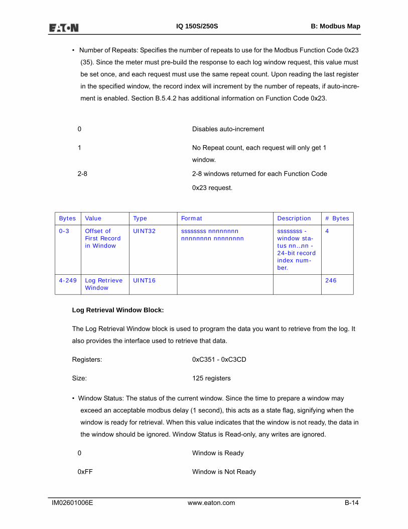
IM02601006E www.eaton.com B-14
IQ 150S/250S B: Modbus Map
• Number of Repeats: Specifies the number of repeats to use for the Modbus Function Code 0x23
(35). Since the meter must pre-build the response to each log window request, this value must
be set once, and each request must use the same repeat count. Upon reading the last register
in the specified window, the record index will increment by the number of repeats, if auto-incre-
ment is enabled. Section B.5.4.2 has additional information on Function Code 0x23.
0 Disables auto-increment
1 No Repeat count, each request will only get 1
window.
2-8 2-8 windows returned for each Function Code
0x23 request.
Log Retrieval Window Block:
The Log Retrieval Window block is used to program the data you want to retrieve from the log. It
also provides the interface used to retrieve that data.
Registers: 0xC351 - 0xC3CD
Size: 125 registers
• Window Status: The status of the current window. Since the time to prepare a window may
exceed an acceptable modbus delay (1 second), this acts as a state flag, signifying when the
window is ready for retrieval. When this value indicates that the window is not ready, the data in
the window should be ignored. Window Status is Read-only, any writes are ignored.
0 Window is Ready
0xFF Window is Not Ready
Bytes Value Type Format Description # Bytes
0-3 Offset of First Record in Window
UINT32 ssssssss nnnnnnnn nnnnnnnn nnnnnnnn
ssssssss - window sta-tus nn…nn - 24-bit record index num-ber.
4
4-249 Log Retrieve Window
UINT16 246

IM02601006E www.eaton.com B-15
IQ 150S/250S B: Modbus Map
• Record Number: The record number of the first record in the data window. Setting this value con-
trols which records will be available in the data window.
• When the log is engaged, the first (oldest) record is "latched." This means that record number
0 will always point to the oldest record at the time of latching, until the log is disengaged
(unlocked).
• To retrieve the entire log using auto-increment, set this value to 0, and retrieve the window
repeatedly, until all records have been retrieved.
NOTES:
• When auto-increment is enabled, this value will automatically increment so that the
window will "page" through the records, increasing by RecordsPerWindow each
time that the last register in the window is read.
• When auto-increment is not enabled, this value must be written-to manually, for
each window to be retrieved.
• Log Retrieval Data Window: The actual data of the records, arranged according to the above
settings.
B.5.4: Log Retrieval
Log Retrieval is accomplished in 3 basic steps:
1. Engage the log.
2. Retrieve each of the records.
3. Disengage the log.
B.5.4.1: Auto-Increment
In Eaton’s traditional Modbus retrieval system, you write the index of the block of data to retrieve,
then read that data from a buffer (window). To improve the speed of retrieval, the index can be
automatically incremented each time the buffer is read.
In the IQ 250S meter, when the last register in the data window is read, the record index is incre-
mented by the Records per Window.

IM02601006E www.eaton.com B-16
IQ 150S/250S B: Modbus Map
B.5.4.2: Modbus Function Code 0x23
QUERY
Field Name Example (Hex)
Slave Address 01
Function 23
Starting Address Hi C3
Starting Address Lo 51
# Points Hi 00
# Points Lo 7D
Repeat Count 04
RESPONSE
Field Name Example (Hex)
Slave Address 01
Function 23
# Bytes Hi 03
# Bytes Lo E0
Data ...
Function Code 0x23 is a user defined Modbus function code, which has a format similar to
Function Code 0x03, except for the inclusion of a "repeat count." The repeat count (RC) is used to
indicate that the same N registers should be read RC number of times. (See the Number of
Repeats bullet on page B-14.)

IM02601006E www.eaton.com B-17
IQ 150S/250S B: Modbus Map
NOTES:
• By itself this feature would not provide any advantage, as the same data will be returned RC
times. However, when used with auto-incrementing, this function condenses up to 8 requests
into 1 request, which decreases communication time, as fewer transactions are being made.
• Keep in mind that the contents of the response data is the block of data you requested, repeated
N times. For example, when retrieving log windows, you
normally request both the window index, and the window data. This means that the first couple
of bytes of every repeated block will contain the index of that
window.
• In the IQ 250S meter repeat counts are limited to 8 times for Modbus RTU, and 4 times for Mod-
bus ASCII.
The response for Function Code 0x23 is the same as for Function Code 0x03, with the data blocks
in sequence.
IMPORTANT! Before using Function Code 0x23, always check to see if the current connection
supports it. Some relay devices do not support user defined function codes; if that is the case, the
message will stall. Other devices don't support 8 repeat counts.
B.5.4.3: Log Retrieval Procedure
The following procedure documents how to retrieve a single log from the oldest record to the new-
est record, using the "normal" record type (see Scope). All logs are retrieved using the same
method. See Section B.5.4.4 for a Log Retrieval example.
NOTES:
• This example uses auto-increment.
• In this example, Function Code 0x23 is not used.
• You will find referenced topics in Section B.5.3. Block Definitions.
• Modbus Register numbers are listed in brackets.
1. Engage the Log:
a. Read the Log Status Block.

IM02601006E www.eaton.com B-18
IQ 150S/250S B: Modbus Map
i.. Read the contents of the specific logs' status block [0xC737+, 16 reg] (see Log
Headers).
ii. Store the # of Records Used, the Record Size, and the Log Availability.
iii. If the Log Availability is not 0, stop Log Retrieval; this log is not available at this
time. If Log Availability is 0, proceed to step 1b (Engage the log).
This step is done to ensure that the log is available for retrieval, as well as retrieving infor-
mation for later use.
b. Engage the log: write log to engage to Log Number, 1 to Enable, and the desired mode to
Scope (default 0 (Normal)) [0xC34F, 1 reg]. This is best done as a single-register write.
This step will latch the first (oldest) record to index 0, and lock the log so that only this port
can retrieve the log, until it is disengaged.
c. Verify the log is engaged: read the contents of the specific logs' status block [0xC737+, 16
reg] again to see if the log is engaged for the current port (see Log Availability). If the Log is
not engaged for the current port, repeat step 1b (Engage the log).
d. Write the retrieval information.
i. Compute the number of records per window, as follows:
RecordsPerWindow = (246 \ RecordSize)
• If using 0x23, set the repeat count to 2-8. Otherwise, set it to 1.
• Since we are starting from the beginning for retrieval, the first record index is
0.
ii. Write the Records per window, the Number of repeats (1), and Record Index (0)
[0xC350, 3 reg].
This step tells the IQ 250S meter what data to return in the window.
2. Retrieve the records:
a. Read the record index and window: read the record index, and the data window [0xC351,
125 reg].

IM02601006E www.eaton.com B-19
IQ 150S/250S B: Modbus Map
• If the meter Returns a Slave Busy Exception, repeat the request.
• If the Window Status is 0xFF, repeat the request.
• If the Window Status is 0, go to step 2b (Verify record index).
NOTES:
• We read the index and window in 1 request to minimize communication time, and to
ensure that the record index matches the data in the data window returned.
• Space in the window after the last specified record (RecordSize x RecordPerWin-
dow) is padded with 0xFF, and can be safely discarded.
b. Verify that the record index incremented by Records Per Window. The record index of the
retrieved window is the index of the first record in the window. This value will increase by
Records Per Window each time the window is read, so it should be 0, N, N x 2, N x 3 . . . for
each window retrieved.
• If the record index matches the expected record index, go to step 2c (Compute next
expected record index).
• If the record index does not match the expected record index, then go to step 1d
(Write the retrieval information), where the record index will be the same as the
expected record index. This will tell the IQ 250S meter to repeat the records you
were expecting.
c. Compute next Expected Record Index.
• If there are no remaining records after the current record window, go to step 3 (Dis-
engage the log).
• Compute the next expected record index by adding Records Per Window, to the cur-
rent expected record index. If this value is greater than the number of records, re-
size the window so it only contains the remaining records and go to step 1d (Write
the retrieval information), where the Records Per Window will be the same as the
remaining records.
3. Disengage the log: write the Log Number (of log being disengaged) to the Log Index and 0 to
the Enable bit [0xC34F, 1 reg].

IM02601006E www.eaton.com B-20
IQ 150S/250S B: Modbus Map
B.5.4.4: Log Retrieval Example
The following example illustrates a log retrieval session. The example makes the following
assumptions:
• Log Retrieved is Historical Log 1 (Log Index 2).
• Auto-Incrementing is used.
• Function Code 0x23 is not used (Repeat Count of 1).
• The Log contains Volts-AN, Volts-BN, Volts-CN (12 bytes).
• 100 Records are available (0-99).
• COM Port 2 (RS485) is being used (see Log Availability).
• There are no Errors.
• Retrieval is starting at Record Index 0 (oldest record).
• Protocol used is Modbus RTU. The checksum is left off for simplicity.
• The IQ 250S meter is at device address 1.
• No new records are recorded to the log during the log retrieval process.

IM02601006E www.eaton.com B-21
IQ 150S/250S B: Modbus Map
1. Read [0xC757, 16 reg], Historical Log 1 Header Block.
Send: 0103 C757 0010
Command:
Register Address: 0xC757
# Registers: 16
---------------------------------------------------
Receive: 010320 00000100 00000064 0012 0000
060717101511 060718101511
0000000000000000
Data:
Max Records: 0x100 = 256 records maximum.
Num Records: 0x64 = 100 records currently logged.
Record Size: 0x12 = 18 bytes per record.
Log Availability: 0x00 = 0, not in use, available for retrieval.
First Timestamp: 0x060717101511 = July 23, 2006, 16:21:17
Last Timestamp: 0x060717101511 = July 24, 2006, 16:21:17
NOTE: This indicates that Historical Log 1 is available for retrieval.
2. Write 0x0280 -> [0xC34F, 1 reg], Log Enable.
Send: 0106 C34F 0280
Command:
Register Address: 0xC34F
# Registers: 1 (Write Single Register Command)
Data:
Log Number: 2 (Historical Log 1)

IM02601006E www.eaton.com B-22
IQ 150S/250S B: Modbus Map
Enable: 1 (Engage log)
Scope: 0 (Normal Mode)
---------------------------------------------------
Receive: 0106C34F0280 (echo)
NOTE: This engages the log for use on this COM Port, and latches the oldest record as record
index 0.
3. Read [0xC757, 16 reg], Availability is 0.
Send: 0103 C757 0010
Command:
Register Address: 0xC757
# Registers: 16
---------------------------------------------------
Receive: 010320 00000100 00000064 0012 0002
060717101511 060718101511
0000000000000000
Data:
Max Records: 0x100 = 256 records maximum.
Num Records: 0x64 = 100 records currently logged.
Record Size: 0x12 = 18 bytes per record.
Log Availability: 0x02 = 2, In use by COM2, RS485 (the current
port)
First Timestamp: 0x060717101511 = July 23, 2006, 16:21:17
Last Timestamp: 0x060717101511 = July 24, 2006, 16:21:17
NOTE: This indicates that the log has been engaged properly in step 2. Proceed to retrieve the
log.

IM02601006E www.eaton.com B-23
IQ 150S/250S B: Modbus Map
4. Compute #RecPerWin as (246\18)=13. Write 0x0D01 0000 0000 -> [0xC350, 3 reg] Write
Retrieval Info. Set Current Index as 0.
Send: 0110 C350 0003 06 0D01 00 000000
Command:
Register Address: 0xC350
# Registers: 3, 6 bytes
Data:
Records per Window: 13. Since the window is 246 bytes, and the record
is 18 bytes, 246\18 = 13.66, which means that
13 records evenly fit into a single window. This is
234 bytes, which means later on, we only need to
read 234 bytes (117 registers) of the window to
retrieve the records.
# of Repeats: 1. We are using auto-increment (so not 0), but
not function code 0x23.
Window Status: 0 (ignore)
Record Index: 0, start at the first record.
----------------------------------------------------
Receive: 0110C3500003 (command ok)
NOTES:
• This sets up the window for retrieval; now we can start retrieving the records.
• As noted above, we compute the records per window as 246\18 = 13.66, which is rounded to 13
records per window. This allows the minimum number of requests to be made to the meter,
which increases retrieval speed.

IM02601006E www.eaton.com B-24
IQ 150S/250S B: Modbus Map
5. Read [0xC351, 125 reg], first 2 reg is status/index, last 123 reg is window data. Status OK.
Send: 0103 C351 007D
Command:
Register Address: 0xC351
# Registers: 0x7D, 125 registers
---------------------------------------------------
Receive: 0103FA 00000000
060717101511FFFFFFFFFFFFFFFFFFFFFFFF
06071710160042FAAACF42FAAD1842FAA9A8 . . .
Data:
Window Status: 0x00 = the window is ready.
Index: 0x00 = 0, The window starts with the 0'th record,
which is the oldest record.
Record 0: The next 18 bytes is the 0'th record (filler).
Timestamp: 0x060717101511, = July 23, 2006, 16:21:17
Data: This record is the "filler" record. It is used by the
meter so that there is never 0 records. It should
be ignored. It can be identified by the data being
all 0xFF.
NOTE: Once a log has rolled over, the 0'th record
will be a valid record, and the filler record will
disappear.
Record 1: The next 18 bytes is the 1'st record.
Timestamp: 0x060717101600 July 23, 2006, 16:22:00
Data:
Volts AN: 0x42FAAACF, float = 125.33~
Volts BN: 0x42FAAD18, float = 125.33~

IM02601006E www.eaton.com B-25
IQ 150S/250S B: Modbus Map
Volts CN: 0x42FAA9A8, float = 125.33~
. . . 13 records
NOTES:
• This retrieves the actual window. Repeat this command as many times as necessary to retrieve
all of the records when auto-increment is enabled.
• Note the filler record. When a log is reset (cleared) in the meter, the meter always adds a first
"filler" record, so that there is always at least 1 record in the log. This "filler" record can be iden-
tified by the data being all 0xFF, and it being index 0. If a record has all 0xFF for data, the time-
stamp is valid, and the index is NOT 0, then the record is legitimate.
• When the "filler" record is logged, its timestamp may not be "on the interval." The next record
taken will be on the next "proper interval," adjusted to the hour. For example, if the interval is 1
minute, the first "real" record will be taken on the next minute (no seconds). If the interval is 15
minutes, the next record will be taken at :15, :30, :45, or :00 - whichever of those values is next
in sequence.
6. Compare the index with Current Index.
NOTES:
• The Current Index is 0 at this point, and the record index retrieved in step 5 is 0: thus we go to
step 8.
• If the Current Index and the record index do not match, go to step 7. The data that was received
in the window may be invalid, and should be discarded.
7. Write the Current Index to [0xC351, 2 reg].
Send: 0110 C351 0002 04 00 00000D
Command:
Register Address: 0xC351
# Registers: 2, 4 bytes
Data:

IM02601006E www.eaton.com B-26
IQ 150S/250S B: Modbus Map
Window Status: 0 (ignore)
Record Index: 0x0D = 13, start at the 14th record.
----------------------------------------------------
Receive: 0110C3510002 (command ok)
NOTES:
• This step manually sets the record index, and is primarily used when an out-of-order record
index is returned on a read (step 6).
• The example assumes that the second window retrieval failed somehow, and we need to
recover by requesting the records starting at index 13 again.
8. For each record in the retrieved window, copy and save the data for later interpretation.
9. Increment Current Index by RecordsPerWindow.
NOTES:
• This is the step that determines how much more of the log we need to retrieve.
• On the first N passes, Records Per Window should be 13 (as computed in step 4), and the cur-
rent index should be a multiple of that (0, 13, 26, . . .). This amount will decrease when we
reach the end (see step 10).
• If the current index is greater than or equal to the number of records (in this case 100), then all
records have been retrieved; go to step 12. Otherwise, go to step 10 to check if we are nearing
the end of the records.
10. If number records - current index < RecordsPerWindow, decrease to match.
NOTES:
• Here we bounds-check the current index, so we don't exceed the records available.
• If the number of remaining records (#records - current index) is less than the Records per Win-
dow, then the next window is the last, and contains less than a full window of records. Make
records per window equal to remaining records (#records-current index). In this example, this

IM02601006E www.eaton.com B-27
IQ 150S/250S B: Modbus Map
occurs when current index is 91 (the 8'th window). There are now 9 records available (100-91),
so make Records per Window equal 9.
11. Repeat steps 5 through 10.
NOTES:
• Go back to step 5, where a couple of values have changed.
Pass CurIndex FirstRecIndex RecPerWindow
0 0 0 13
1 13 13 13
2 26 26 13
3 39 39 13
4 52 52 13
5 65 65 13
6 78 78 13
7 91 91 9
8 100 ------ -------
• At pass 8, since Current Index is equal to the number of records (100), log retrieval should stop;
go to step 12 (see step 9 Notes).
12. No more records available, clean up.

IM02601006E www.eaton.com B-28
IQ 150S/250S B: Modbus Map
13. Write 0x0000 -> [0xC34F, 1 reg], disengage the log.
Send: 0106 C34F 0000
Command:
Register Address: 0xC34F
# Registers: 1 (Write Single Register Command)
Data:
Log Number: 0 (ignore)
Enable: 0 (Disengage log)
Scope: 0 (ignore)
----------------------------------------------------
Receive: 0106C34F0000 (echo)
NOTES:
• This disengages the log, allowing it to be retrieved by other COM ports.
• The log will automatically disengage if no log retrieval action is taken for 5 minutes.
B.6: Modbus Register Map
The IQ 150S and 250S meters' Modbus register maps begin on the following page. The first map
is for the IQ 150S, and the second is for the IQ 250S.

IQ 150S B: Modbus Map
IM02601006E www.eaton.com MM-1
Description1 Format Range6Units or
Resolution Comments#
Reg
read-only0000 - 0007 1 - 8 Reserved none 80008 - 000F 9 - 16 Meter Serial Number ASCII 16 char none 80010 - 0010 17 - 17 Meter Type UINT16 bit-mapped -------t -------- t = transducer model (1=yes, 0=no) 1
0011 - 0012 18 - 19 Firmware Version ASCII 4 char none 20013 - 0013 20 - 20 Map Version UINT16 0 to 65535 none 10014 - 0014 21 - 21 Meter Configuration UINT16 bit-mapped -------- --ffffff
ffffff = calibration frequency (50 or 60)1
0015 - 0015 22 - 22 ASIC Version UINT16 0-65535 none 10016 - 0026 23 - 39 Reserved 170027 - 002E 40 - 47 Reserved 8
Block Size: 47
read-only0383 - 0384 900 - 901 Watts, 3-Ph total FLOAT -9999 M to +9999 M watts 2
0385 - 0386 902 - 903 VARs, 3-Ph total FLOAT -9999 M to +9999 M VARs 2
0387 - 0388 904 - 905 VAs, 3-Ph total FLOAT -9999 M to +9999 M VAs 2
Block Size: 6
read-only03E7 - 03E8 1000 - 1001 Volts A-N FLOAT 0 to 9999 M volts 203E9 - 03EA 1002 - 1003 Volts B-N FLOAT 0 to 9999 M volts 203EB - 03EC 1004 - 1005 Volts C-N FLOAT 0 to 9999 M volts 203ED - 03EE 1006 - 1007 Volts A-B FLOAT 0 to 9999 M volts 203EF - 03F0 1008 - 1009 Volts B-C FLOAT 0 to 9999 M volts 203F1 - 03F2 1010 - 1011 Volts C-A FLOAT 0 to 9999 M volts 203F3 - 03F4 1012 - 1013 Amps A FLOAT 0 to 9999 M amps 203F5 - 03F6 1014 - 1015 Amps B FLOAT 0 to 9999 M amps 203F7 - 03F8 1016 - 1017 Amps C FLOAT 0 to 9999 M amps 203F9 - 03FA 1018 - 1019 Watts, 3-Ph total FLOAT -9999 M to +9999 M watts 203FB - 03FC 1020 - 1021 VARs, 3-Ph total FLOAT -9999 M to +9999 M VARs 203FD - 03FE 1022 - 1023 VAs, 3-Ph total FLOAT -9999 M to +9999 M VAs 203FF - 0400 1024 - 1025 Power Factor, 3-Ph total FLOAT -1.00 to +1.00 none 20401 - 0402 1026 - 1027 Frequency FLOAT 0 to 65.00 Hz 2
Primary Readings Block, 6 cycles (IEEE Floating Point)
Modbus Address
Fixed Data Section
Hex Decimal
Identification Block
Meter Data Section 2
Primary Readings Block, 60 cycles (IEEE Floating Point)

IQ 150S B: Modbus Map
IM02601006E www.eaton.com MM-2
( ) pp p
Description1 Format Range6Units or
Resolution Comments#
Reg
Modbus Address
Hex Decimal0403 - 0404 1028 - 1029 Neutral Current FLOAT 0 to 9999 M amps 2
Block Size: 30
read-only044B - 044C 1100 - 1101 W-hours, Received SINT32 0 to 99999999 or
0 to -99999999Wh per energy format * Wh received & delivered always have
opposite signs2
044D - 044E 1102 - 1103 W-hours, Delivered SINT32 0 to 99999999 or 0 to -99999999
Wh per energy format 2
044F - 0450 1104 - 1105 W-hours, Net SINT32 -99999999 to 99999999 Wh per energy format 20451 - 0452 1106 - 1107 W-hours, Total SINT32 0 to 99999999 Wh per energy format * 5 to 8 digits 20453 - 0454 1108 - 1109 VAR-hours, Positive SINT32 0 to 99999999 VARh per energy format
* decimal point implied, per energy format2
0455 - 0456 1110 - 1111 VAR-hours, Negative SINT32 0 to -99999999 VARh per energy format 2
0457 - 0458 1112 - 1113 VAR-hours, Net SINT32 -99999999 to 99999999 VARh per energy format 2
0459 - 045A 1114 - 1115 VAR-hours, Total SINT32 0 to 99999999 VARh per energy format 2
045B - 045C 1116 - 1117 VA-hours, Total SINT32 0 to 99999999 VAh per energy format* see note 10
2
Block Size: 18
read-only07CF - 07D0 2000 - 2001 Amps A, Average FLOAT 0 to 9999 M amps 207D1 - 07D2 2002 - 2003 Amps B, Average FLOAT 0 to 9999 M amps 207D3 - 07D4 2004 - 2005 Amps C, Average FLOAT 0 to 9999 M amps 207D5 - 07D6 2006 - 2007 Positive Watts, 3-Ph, Average FLOAT -9999 M to +9999 M watts 207D7 - 07D8 2008 - 2009 Positive VARs, 3-Ph, Average FLOAT -9999 M to +9999 M VARs 207D9 - 07DA 2010 - 2011 Negative Watts, 3-Ph, Average FLOAT -9999 M to +9999 M watts 207DB - 07DC 2012 - 2013 Negative VARs, 3-Ph, Average FLOAT -9999 M to +9999 M VARs 207DD - 07DE 2014 - 2015 VAs, 3-Ph, Average FLOAT -9999 M to +9999 M VAs 207DF - 07E0 2016 - 2017 Positive PF, 3-Ph, Average FLOAT -1.00 to +1.00 none 207E1 - 07E2 2018 - 2019 Negative PF, 3-PF, Average FLOAT -1.00 to +1.00 none 2
Block Size: 20
read-only0BB7 - 0BB8 3000 - 3001 Volts A-N, Minimum FLOAT 0 to 9999 M volts 20BB9 - 0BBA 3002 - 3003 Volts B-N, Minimum FLOAT 0 to 9999 M volts 20BBB - 0BBC 3004 - 3005 Volts C-N, Minimum FLOAT 0 to 9999 M volts 20BBD - 0BBE 3006 - 3007 Volts A-B, Minimum FLOAT 0 to 9999 M volts 20BBF - 0BC0 3008 - 3009 Volts B-C, Minimum FLOAT 0 to 9999 M volts 2
Primary Demand Block (IEEE Floating Point)
Primary Minimum Block (IEEE Floating Point)
* Wh received is positive for "view as load", delivered is positive for "view as generator"
* resolution of digit before decimal point = units, kilo, or mega, per energy format
Primary Energy Block
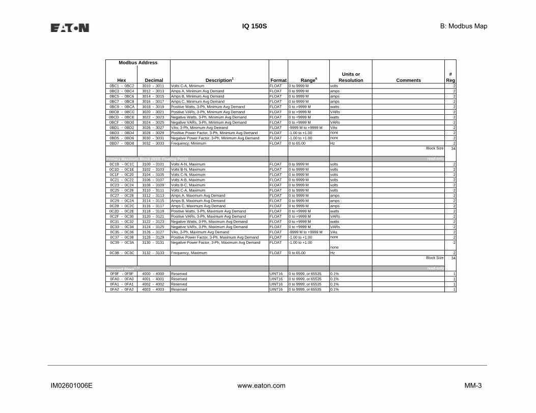
IQ 150S B: Modbus Map
IM02601006E www.eaton.com MM-3
Description1 Format Range6Units or
Resolution Comments#
Reg
Modbus Address
Hex Decimal0BC1 - 0BC2 3010 - 3011 Volts C-A, Minimum FLOAT 0 to 9999 M volts 20BC3 - 0BC4 3012 - 3013 Amps A, Minimum Avg Demand FLOAT 0 to 9999 M amps 20BC5 - 0BC6 3014 - 3015 Amps B, Minimum Avg Demand FLOAT 0 to 9999 M amps 20BC7 - 0BC8 3016 - 3017 Amps C, Minimum Avg Demand FLOAT 0 to 9999 M amps 20BC9 - 0BCA 3018 - 3019 Positive Watts, 3-Ph, Minimum Avg Demand FLOAT 0 to +9999 M watts 20BCB - 0BCC 3020 - 3021 Positive VARs, 3-Ph, Minimum Avg Demand FLOAT 0 to +9999 M VARs 20BCD - 0BCE 3022 - 3023 Negative Watts, 3-Ph, Minimum Avg Demand FLOAT 0 to +9999 M watts 20BCF - 0BD0 3024 - 3025 Negative VARs, 3-Ph, Minimum Avg Demand FLOAT 0 to +9999 M VARs 20BD1 - 0BD2 3026 - 3027 VAs, 3-Ph, Minimum Avg Demand FLOAT -9999 M to +9999 M VAs 20BD3 - 0BD4 3028 - 3029 Positive Power Factor, 3-Ph, Minimum Avg Demand FLOAT -1.00 to +1.00 none 20BD5 - 0BD6 3030 - 3031 Negative Power Factor, 3-Ph, Minimum Avg Demand FLOAT -1.00 to +1.00 none 20BD7 - 0BD8 3032 - 3033 Frequency, Minimum FLOAT 0 to 65.00 Hz 2
Block Size: 34
read-only0C1B - 0C1C 3100 - 3101 Volts A-N, Maximum FLOAT 0 to 9999 M volts 20C1D - 0C1E 3102 - 3103 Volts B-N, Maximum FLOAT 0 to 9999 M volts 20C1F - 0C20 3104 - 3105 Volts C-N, Maximum FLOAT 0 to 9999 M volts 20C21 - 0C22 3106 - 3107 Volts A-B, Maximum FLOAT 0 to 9999 M volts 20C23 - 0C24 3108 - 3109 Volts B-C, Maximum FLOAT 0 to 9999 M volts 20C25 - 0C26 3110 - 3111 Volts C-A, Maximum FLOAT 0 to 9999 M volts 20C27 - 0C28 3112 - 3113 Amps A, Maximum Avg Demand FLOAT 0 to 9999 M amps 20C29 - 0C2A 3114 - 3115 Amps B, Maximum Avg Demand FLOAT 0 to 9999 M amps 20C2B - 0C2C 3116 - 3117 Amps C, Maximum Avg Demand FLOAT 0 to 9999 M amps 20C2D - 0C2E 3118 - 3119 Positive Watts, 3-Ph, Maximum Avg Demand FLOAT 0 to +9999 M watts 20C2F - 0C30 3120 - 3121 Positive VARs, 3-Ph, Maximum Avg Demand FLOAT 0 to +9999 M VARs 20C31 - 0C32 3122 - 3123 Negative Watts, 3-Ph, Maximum Avg Demand FLOAT 0 to +9999 M watts 20C33 - 0C34 3124 - 3125 Negative VARs, 3-Ph, Maximum Avg Demand FLOAT 0 to +9999 M VARs 20C35 - 0C36 3126 - 3127 VAs, 3-Ph, Maximum Avg Demand FLOAT -9999 M to +9999 M VAs 20C37 - 0C38 3128 - 3129 Positive Power Factor, 3-Ph, Maximum Avg Demand FLOAT -1.00 to +1.00 none 20C39 - 0C3A 3130 - 3131 Negative Power Factor, 3-Ph, Maximum Avg Demand FLOAT -1.00 to +1.00
none2
0C3B - 0C3C 3132 - 3133 Frequency, Maximum FLOAT 0 to 65.00 Hz 2Block Size: 34
read-only0F9F - 0F9F 4000 - 4000 Reserved UINT16 0 to 9999, or 65535 0.1% 10FA0 - 0FA0 4001 - 4001 Reserved UINT16 0 to 9999, or 65535 0.1% 10FA1 - 0FA1 4002 - 4002 Reserved UINT16 0 to 9999, or 65535 0.1% 10FA2 - 0FA2 4003 - 4003 Reserved UINT16 0 to 9999, or 65535 0.1% 1
Primary Maximum Block (IEEE Floating Point)
Reserved Block7, 13

IQ 150S B: Modbus Map
IM02601006E www.eaton.com MM-4
Description1 Format Range6Units or
Resolution Comments#
Reg
Modbus Address
Hex Decimal0FA3 - 0FA3 4004 - 4004 Reserved 10FA4 - 0FA4 4005 - 4005 Reserved 10FA5 - 0FA5 4006 - 4006 Reserved 10FA6 - 0FA6 4007 - 4007 Reserved 10FA7 - 0FA7 4008 - 4008 Reserved 10FA8 - 0FA8 4009 - 4009 Reserved 10FA9 - 0FA9 4010 - 4010 Reserved 10FAA - 0FAA 4011 - 4011 Reserved 10FAB - 0FAB 4012 - 4012 Reserved 10FAC - 0FAC 4013 - 4013 Reserved 10FAD - 0FAD 4014 - 4014 Reserved 10FAE - 0FAE 4015 - 4015 Reserved 10FAF - 0FAF 4016 - 4016 Reserved 10FB0 - 0FB0 4017 - 4017 Reserved 10FB1 - 0FB8 4018 - 4025 Reserved 80FB9 - 0FBC 4026 - 4029 Reserved 40FBD - 0FC4 4030 - 4037 Reserved 80FC5 - 0FC8 4038 - 4041 Reserved 4
Block Size: 42
read-only1003 - 1003 4100 - 4100 Phase A Current SINT16 -1800 to +1800 0.1 degree 11004 - 1004 4101 - 4101 Phase B Current SINT16 -1800 to +1800 0.1 degree 11005 - 1005 4102 - 4102 Phase C Current SINT16 -1800 to +1800 0.1 degree 11006 - 1006 4103 - 4103 Angle, Volts A-B SINT16 -1800 to +1800 0.1 degree 11007 - 1007 4104 - 4104 Angle, Volts B-C SINT16 -1800 to +1800 0.1 degree 11008 - 1008 4105 - 4105 Angle, Volts C-A SINT16 -1800 to +1800 0.1 degree 1
Block Size: 6
read-only1387 - 1387 5000 - 5000 Meter Status UINT16 bit-mapped --exnpch ssssssss exnpch = EEPROM block OK flags
(e=energy, x=max, n=min, p=programmablesettings, c=calibration, h=header), ssssssss = state (1=Run, 2=Limp, 10=ProgSet Update via buttons, 12=Prog Set Update via COM2)
1
1388 - 1388 5001 - 5001 Reserved 11389 - 138A 5002 - 5003 Time Since Reset UINT32 0 to 4294967294 4 msec wraps around after max coun 2
Block Size: 4
Status Block
Phase Angle Block14
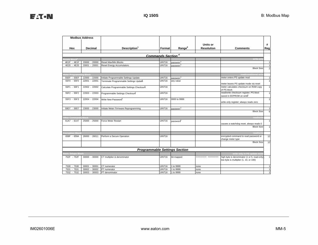
IQ 150S B: Modbus Map
IM02601006E www.eaton.com MM-5
Description1 Format Range6Units or
Resolution Comments#
Reg
Modbus Address
Hex Decimal
write-only4E1F - 4E1F 20000 - 20000 Reset Max/Min Blocks UINT16 password5 14E20 - 4E20 20001 - 20001 Reset Energy Accumulators UINT16 password5 1
Block Size: 2
read/conditional write55EF - 55EF 22000 - 22000 Initiate Programmable Settings Update UINT16 password5 meter enters PS update mode 155F0 - 55F0 22001 - 22001 Terminate Programmable Settings Update3 UINT16 any value
meter leaves PS update mode via reset1
55F1 - 55F1 22002 - 22002 Calculate Programmable Settings Checksum3 UINT16 meter calculates checksum on RAM copy of PS block
1
55F2 - 55F2 22003 - 22003 Programmable Settings Checksum3 UINT16 read/write checksum register; PS blocksaved in EEPROM on write8
1
55F3 - 55F3 22004 - 22004 Write New Password3 UINT16 0000 to 9999write-only register; always reads zero
1
59D7 - 59D7 23000 - 23000 Initiate Meter Firmware Reprogramming UINT16 password5 1Block Size: 6
read/write61A7 - 61A7 25000 - 25000 Force Meter Restart UINT16 password5
causes a watchdog reset, always reads 01
Block Size: 1
read/write658F - 659A 26000 - 26011 Perform a Secure Operation UINT16 encrypted command to read password or
change meter type12
Block Size: 12
write only in PS update mode752F - 752F 30000 - 30000 CT multiplier & denominator UINT16 bit-mapped dddddddd mmmmmmmm high byte is denominator (1 or 5, read-only),
low byte is multiplier (1, 10, or 100)1
7530 - 7530 30001 - 30001 CT numerator UINT16 1 to 9999 none 17531 - 7531 30002 - 30002 PT numerator UINT16 1 to 9999 none 17532 - 7532 30003 - 30003 PT denominator UINT16 1 to 9999 none 1
Basic Setups Block
Other Commands Block
Meter Programming Block
Commands Section 4
Programmable Settings Section
Resets Block9
Encryption Block
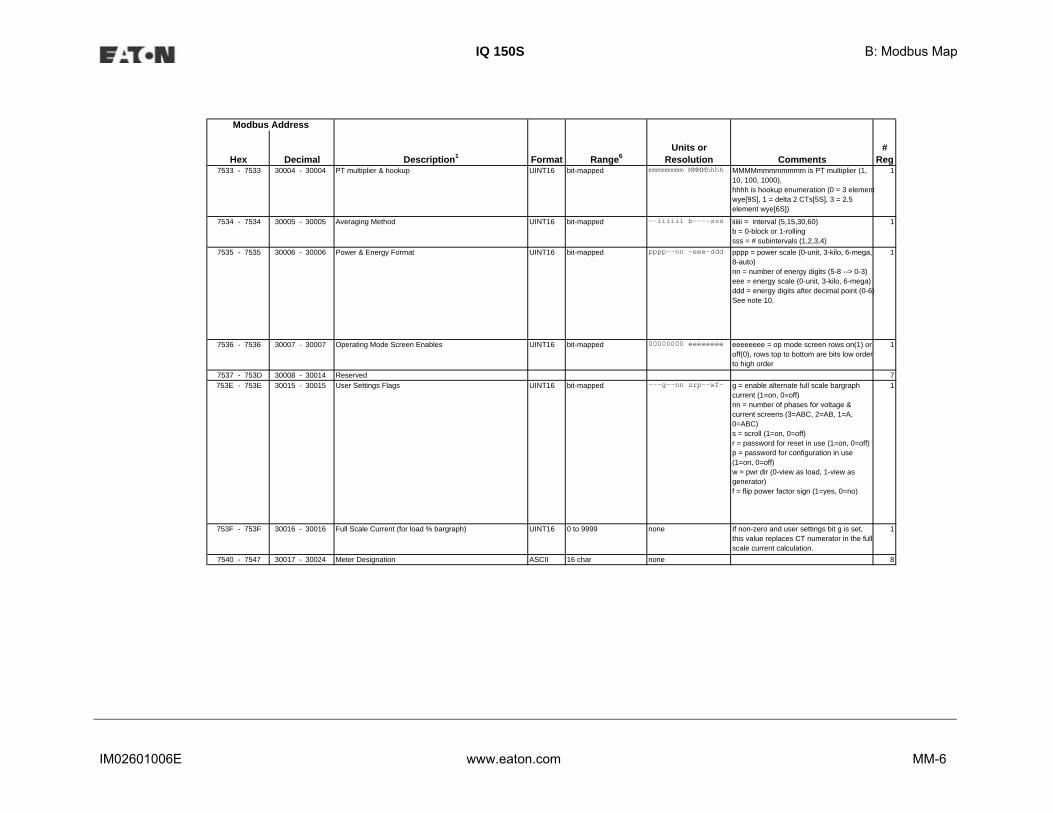
IQ 150S B: Modbus Map
IM02601006E www.eaton.com MM-6
Description1 Format Range6Units or
Resolution Comments#
Reg
Modbus Address
Hex Decimal7533 - 7533 30004 - 30004 PT multiplier & hookup UINT16 bit-mapped mmmmmmmm MMMMhhhh MMMMmmmmmmmm is PT multiplier (1,
10, 100, 1000),hhhh is hookup enumeration (0 = 3 element wye[9S], 1 = delta 2 CTs[5S], 3 = 2.5 element wye[6S])
1
7534 - 7534 30005 - 30005 Averaging Method UINT16 bit-mapped --iiiiii b----sss iiiiii = interval (5,15,30,60)b = 0-block or 1-rollingsss = # subintervals (1,2,3,4)
1
7535 - 7535 30006 - 30006 Power & Energy Format UINT16 bit-mapped pppp--nn -eee-ddd pppp = power scale (0-unit, 3-kilo, 6-mega, 8-auto)nn = number of energy digits (5-8 --> 0-3)eee = energy scale (0-unit, 3-kilo, 6-mega)ddd = energy digits after decimal point (0-6)See note 10.
1
7536 - 7536 30007 - 30007 Operating Mode Screen Enables UINT16 bit-mapped 00000000 eeeeeeee eeeeeeee = op mode screen rows on(1) or off(0), rows top to bottom are bits low order to high order
1
7537 - 753D 30008 - 30014 Reserved 7753E - 753E 30015 - 30015 User Settings Flags UINT16 bit-mapped ---g--nn srp--wf- g = enable alternate full scale bargraph
current (1=on, 0=off)nn = number of phases for voltage & current screens (3=ABC, 2=AB, 1=A, 0=ABC)s = scroll (1=on, 0=off)r = password for reset in use (1=on, 0=off)p = password for configuration in use (1=on, 0=off)w = pwr dir (0-view as load, 1-view as generator)f = flip power factor sign (1=yes, 0=no)
1
753F - 753F 30016 - 30016 Full Scale Current (for load % bargraph) UINT16 0 to 9999 none If non-zero and user settings bit g is set, this value replaces CT numerator in the full scale current calculation.
1
7540 - 7547 30017 - 30024 Meter Designation ASCII 16 char none 8

IQ 150S B: Modbus Map
IM02601006E www.eaton.com MM-7
Description1 Format Range6Units or
Resolution Comments#
Reg
Modbus Address
Hex Decimal7548 - 7548 30025 - 30025 Reserved 17549 - 7549 30026 - 30026 COM2 setup UINT16 bit-mapped ----dddd -ppp-bbb 1
754A - 754A 30027 - 30027 COM2 address UINT16 1 to 247 none 1754B - 754B 30028 - 30028 Reserved 1754C - 754C 30029 - 30029 Reserved 1754D - 754D 30030 - 30030 Reserved 1754E - 754E 30031 - 30031 Reserved 1754F - 754F 30032 - 30032 Reserved 17550 - 7554 30033 - 30037 57555 - 7559 30038 - 30042 5755A - 755E 30043 - 30047 5755F - 7563 30048 - 30052 57564 - 7568 30053 - 30057 57569 - 756D 30058 - 30062 5756E - 7572 30063 - 30067 5
Block Size: 68
read-only except as noted9C40 - 9C40 40001 - 40001 System Sanity Indicator UINT16 0 or 1 none 0 indicates proper meter operatio 19C41 - 9C41 40002 - 40002 Volts A-N UINT16 2047 to 4095 volts 2047= 0, 4095= +150 19C42 - 9C42 40003 - 40003 Volts B-N UINT16 2047 to 4095 volts 19C43 - 9C43 40004 - 40004 Volts C-N UINT16 2047 to 4095 volts 19C44 - 9C44 40005 - 40005 Amps A UINT16 0 to 4095 amps 0= -10, 2047= 0, 4095= +10 19C45 - 9C45 40006 - 40006 Amps B UINT16 0 to 4095 amps 19C46 - 9C46 40007 - 40007 Amps C UINT16 0 to 4095 amps 19C47 - 9C47 40008 - 40008 Watts, 3-Ph total UINT16 0 to 4095 watts 0= -3000, 2047= 0, 4095= +3000 19C48 - 9C48 40009 - 40009 VARs, 3-Ph total UINT16 0 to 4095 VARs watts, VARs, VAs = 19C49 - 9C49 40010 - 40010 VAs, 3-Ph total UINT16 2047 to 4095 VAs 3000 * (register - 2047) / 2047 19C4A - 9C4A 40011 - 40011 Power Factor, 3-Ph total UINT16 1047 to 3047 none 1047= -1, 2047= 0, 3047= +1
pf = (register - 2047) / 10001
9C4B - 9C4B 40012 - 40012 Frequency UINT16 0 to 2730 Hz 0= 45 or less, 2047= 60, 2730= 65 or more freq = 45 + ((register / 4095) * 30)
1
9C4C - 9C4C 40013 - 40013 Volts A-B UINT16 2047 to 4095 volts 2047= 0, 4095= +300 19C4D - 9C4D 40014 - 40014 Volts B-C UINT16 2047 to 4095 volts 19C4E - 9C4E 40015 - 40015 Volts C-A UINT16 2047 to 4095 volts 1
dddd = reply delay (* 50 msec)ppp = protocol (1-Modbus RTU, 2-Modbus ASCII, 3-DNP)
amps = 10 * (register - 2047) / 2047
12-Bit RTU Readings Section12-Bit RTU Block
volts = 150 * (register - 2047) / 2047
volts = 300 * (register - 2047) / 2047

IQ 150S B: Modbus Map
IM02601006E www.eaton.com MM-8
pp p
Description1 Format Range6Units or
Resolution Comments#
Reg
Modbus Address
Hex Decimal9C4F - 9C4F 40016 - 40016 CT numerator UINT16 1 to 9999 none 19C50 - 9C50 40017 - 40017 CT multiplier UINT16 1, 10, 100 none 19C51 - 9C51 40018 - 40018 CT denominator UINT16 1 or 5 none 19C52 - 9C52 40019 - 40019 PT numerator UINT16 1 to 9999 none 19C53 - 9C53 40020 - 40020 PT multiplier UINT16 1, 10, 100 none 19C54 - 9C54 40021 - 40021 PT denominator UINT16 1 to 9999 none 19C55 - 9C56 40022 - 40023 W-hours, Positive UINT32 0 to 99999999 Wh per energy format * 5 to 8 digits 29C57 - 9C58 40024 - 40025 W-hours, Negative UINT32 0 to 99999999 Wh per energy format
* decimal point implied, per energy format2
9C59 - 9C5A 40026 - 40027 VAR-hours, Positive UINT32 0 to 99999999 VARh per energy format 2
9C5B - 9C5C 40028 - 40029 VAR-hours, Negative UINT32 0 to 99999999 VARh per energy format 2
9C5D - 9C5E 40030 - 40031 VA-hours UINT32 0 to 99999999 VAh per energy format* see note 10
2
9C5F - 9C5F 40032 - 40032 Neutral Current UINT16 0 to 4095 amps see Amps A/B/C above 19C60 - 9CA2 40033 - 40099 Reserved N/A N/A none 679CA3 - 9CA3 40100 - 40100 Reset Energy Accumulators UINT16 password5 write-only register; always reads as 0 1
Block Size: 100
Notes12
34
5
* resolution of digit before decimal point = units, kilo, or mega, per energy format
ASCII ASCII characters packed 2 per register in high, low order and without any termination characters.
SINT32 / UINT32FLOAT
32-bit signed / unsigned integer spanning 2 registers. The lower-addressed register is the high order half.SINT16 / UINT16 16-bit signed / unsigned integer.
End of Map
32-bit IEEE floating point number spanning 2 registers. The lower-addressed register is the high order half (i.e., contains the exponent).
All registers not explicitly listed in the table read as 0. Writes to these registers will be accepted but won't actually change the register (since it doesn't exist).Meter Data Section items read as 0 until first readings are available or if the meter is not in operating mode. Writes to these registers will be accepted but won't actually change the register.
Register valid only in programmable settings update mode. In other modes these registers read as 0 and return an illegal data address exception if a write is attempted.Meter command registers always read as 0. They may be written only when the meter is in a suitable mode. The registers return an illegal data address exception if a write is attempted in an incorrect mode.
If the password is incorrect, a valid response is returned but the command is not executed. Use 5555 for the password if passwords are disabled in the programmable settings.
Data Formats
CT = numerator * multiplier / denominator
PT = numerator * multiplier / denominator

IQ 150S B: Modbus Map
IM02601006E www.eaton.com MM-9
(continued)678
91011121314
15
Not used.All 3 voltage angles are measured for Wye and Delta hookups. For 2.5 Element, Vac is measured and Vab & Vbc are calculated. If a voltage phase is missing, the two voltage angles in which it participates are set to zero. A and C phase current angles are measured for all hookups. B phase current angle is measured for Wye and is zero for other hookups. If a voltage phase is missing, its cuangle is zero.If any register in the programmable settings section is set to a value other than the acceptable value then the meter will stay in LIMP mode. Please read the comments section or the range for each register in programmable settings section for acceptable values.
Not used.
Energy registers should be reset after a format change.Reset commands make no sense if the meter state is LIMP. An illegal function exception will be returned.
Not used.M denotes a 1,000,000 multiplier.
Not used.
Writing this register causes data to be saved permanently in EEPROM. If there is an error while saving, a slave device failure exception is returned and programmable settings mode automatically terminates via reset.

IQ 150S B: Modbus Map
IM02601006E www.eaton.com MM-10
This page intentionally left blank.

IQ 250S B: Modbus Map
IM02601006E www.eaton.com MM-1
read-onlyDescription (Note 1) Format Range (Note 6) Units or Resolution Comments # Reg
read-onlyDescription (Note 1) Format Range (Note 6) Units or Resolution Comments # Reg
Modbus Address
Fixed Data SectionIdentification Block
Meter Data Section (Note 2)
Hex Decimal
Primary Readings BlockHex Decimal

IQ 250S B: Modbus Map
IM02601006E www.eaton.com MM-2
read-onlyDescription (Note 1) Format Range (Note 6) Units or Resolution Comments # Reg
Primary Energy BlockHex Decimal

IQ 250S B: Modbus Map
IM02601006E www.eaton.com MM-3
read-onlyDescription (Note 1) Format Range (Note 6) Units or Resolution Comments # Reg
Primary Demand BlockHex Decimal

IQ 250S B: Modbus Map
IM02601006E www.eaton.com MM-4
read-onlyDescription (Note 1) Format Range (Note 6) Units or Resolution Comments # Reg
Uncompensated Readings BlockHex Decimal

IQ 250S B: Modbus Map
IM02601006E www.eaton.com MM-5
read-onlyDescription (Note 1) Format Range (Note 6) Units or Resolution Comments # Reg
read-onlyDescription (Note 1) Format Range (Note 6) Units or Resolution Comments # Reg
read-onlyDescription (Note 1) Format Range (Note 6) Units or Resolution Comments # Reg
Status Block
Short term Primary Minimum Block
Phase Angle BlockHex Decimal
Hex Decimal
Hex Decimal
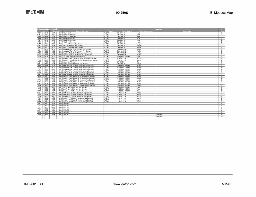
IQ 250S B: Modbus Map
IM02601006E www.eaton.com MM-6
read-onlyDescription (Note 1) Format Range (Note 6) Units or Resolution Comments # Reg
Primary Minimum BlockHex Decimal

IQ 250S B: Modbus Map
IM02601006E www.eaton.com MM-7
read-onlyDescription (Note 1) Format Range (Note 6) Units or Resolution Comments # Reg
Hex DecimalPrimary Minimum Timestamp Block

IQ 250S B: Modbus Map
IM02601006E www.eaton.com MM-8
read-onlyDescription (Note 1) Format Range (Note 6) Units or Resolution Comments # Reg
read-onlyDescription (Note 1) Format Range (Note 6) Units or Resolution Comments # Reg
HexShort term Primary Maximum Block
Primary Maximum Block
Decimal
Hex Decimal

IQ 250S B: Modbus Map
IM02601006E www.eaton.com MM-9
read-onlyDescription (Note 1) Format Range (Note 6) Units or Resolution Comments # RegHex Decimal
Primary Maximum Timestamp Block

IQ 250S B: Modbus Map
IM02601006E www.eaton.com MM-10
write-onlyDescription (Note 1) Format Range (Note 6) Units or Resolution Comments # Reg
conditional writeDescription (Note 1) Format Range (Note 6) Units or Resolution Comments # Reg
read/writeDescription (Note 1) Format Range (Note 6) Units or Resolution Comments # Reg
Resets Block (Note 9)
Privileged Commands Block
Hex Decimal
Hex
Commands Section (Note 4)
Encryption Block
Decimal
Hex Decimal

IQ 250S B: Modbus Map
IM02601006E www.eaton.com MM-11
write only in PS update modeDescription (Note 1) Format Range (Note 6) Units or Resolution Comments # Reg
Programmable Settings SectionHex Decimal
Basic Setups Block

IQ 250S B: Modbus Map
IM02601006E www.eaton.com MM-12
write only in PS update modeDescription (Note 1) Format Range (Note 6) Units or Resolution Comments # Reg
write only in PS update modeDescription (Note 1) Format Range (Note 6) Units or Resolution Comments # Reg
Basic Setups Block - continuedHex Decimal
Log Setups BlockHex Decimal

IQ 250S B: Modbus Map
IM02601006E www.eaton.com MM-13
read-only except as notedDescription (Note 1) Format Range (Note 6) Units or Resolution Comments # RegHex Decimal
12-Bit Readings Section12-Bit Block

IQ 250S B: Modbus Map
IM02601006E www.eaton.com MM-14
read/write except as notedDescription (Note 1) Format Range (Note 6) Units or Resolution Comments # Reg
read onlyDescription (Note 1) Format Range (Note 6) Units or Resolution Comments # Reg
Alarm Log Status Block
Decimal
End of Map
Hex
Hex Decimal
Log Retrieval Block
Log Status Block
Log Retrieval Section

IQ 250S B: Modbus Map
IM02601006E www.eaton.com MM-15
Notes
Data Formats

IQ 250S B: Modbus Map
IM02601006E www.eaton.com MM-16
This page intentionally left blank.

IM02601006E www.eaton.com C-1
IQ 150S C: DNP Map
C: IQ 150S Meter DNP Map
C.1: Introduction
The IQ 150S meter’s DNP map shows the client-server relationship in the meter’s use of DNP
Protocol.
C.2: DNP Implementation
PHYSICAL LAYER
The IQ 150S meter can use RS485 as the physical layer. This is accomplished by connecting a PC
to the meter using the meter’s RS485 connection (see Chapter 5).
RS485
RS485 provides multi-drop network communication capabilities. Multiple meters can be placed on
the same bus, allowing for a Master device to communicate with any of the other devices.
Appropriate network configuration and termination should be evaluated for each installation to
insure optimal performance (see Chapter 5).
Communication Parameters
IQ 150S meters communicate in DNP 3.0 using the following communication settings:
• 8 Data Bits
• No Parity
• 1 Stop Bit
• Baud Rates: 9600, 19200, 38400, 57600

IM02601006E www.eaton.com C-2
IQ 150S C: DNP Map
C.3: Data Link Layer
The Data Link Layer for IQ 150S meters is subject to the following considerations:
Control Field
The Control Byte contains several bits and a Function Code.
Control Bits
Communication directed to the meter should be Primary Master messages (DIR = 1, PRM = 1).
Response will be primary Non-Master messages (DIR = 0, PRM = 1). Acknowledgment will be
Secondary Non-Master messages (DIR = 0, PRM = 0).
Function Codes
IQ 150S meters support all of the Function Codes for DNP 3.0.
Reset of Data Link (Function 0)
Before confirmed communication with a master device, the Data Link Layer must be reset. This is
necessary after a meter has been restarted, either by applying power to the meter or reprogram-
ming the meter. The meter must receive a RESET command before confirmed communication can
take place. Unconfirmed communication is always possible and does not require a RESET.
User Data (Function 3)
After receiving a request for USER DATA, the meter generates a Data Link
CONFIRMATION, signaling the reception of the request, before the actual request is processed. If
a response is required, it is also sent as UNCONFIRMED USER DATA.
Unconfirmed User Data (Function 4)
After receiving a request for UNCONFIRMED USER DATA, if a response is required, it is sent as
UNCONFIRMED USER DATA.
Address
DNP 3.0 allows for addresses from 0 - 65534 (0x0000 - 0xFFFE) for individual device identifica-
tion, with the address 65535 (0xFFFF) defined as an all stations address. IQ 150S/250S meters'
addresses are programmable from 0 - 247 (0x0000 - 0x00F7), and address 65535 (0xFFFF) is
recognized as the all stations address.

IM02601006E www.eaton.com C-3
IQ 150S C: DNP Map
C.4: Transport Layer
The Transport Layer as implemented on IQ 150S meters is subject to the
following considerations:
Transport Header
Multiple-frame messages are not allowed for IQ 150S meters. Each Transport Header should
indicate it is both the first frame (FIR = 1) as well as the final frame
(FIN = 1).
C.5: Application Layer
The Application Layer contains a header (Request or Response Header, depending on direction)
and data.
Application Headers
Application Headers contain the Application Control Field and the Function Code.
Application Control Field
Multiple-fragment messages are not allowed for IQ 150S meters. Each Application Header should
indicate it is both the first fragment (FIR = 1) as well as the final fragment (FIN = 1).
Application-Level confirmation is not used by IQ 150S meters.
Function Codes
The following Function codes are implemented on IQ 150S meters.
Read (Function 1)
Objects supporting the READ function are:
• Binary Outputs (Object 10)
• Counters (Object 20)
• Analog Inputs (Object 30)
• Class (Object 60)

IM02601006E www.eaton.com C-4
IQ 150S C: DNP Map
These Objects can be read either by requesting a specific Variation available as listed in this
appendix, or by requesting Variation 0. READ requests for Variation 0 of an Object is fulfilled with
the Variation listed in this appendix.
Write (Function 2)
Objects supporting the WRITE function are:
• Internal Indications (Object 80)
Direct Operate (Function 5)
Objects supporting the DIRECT OPERATE function are:
• Control Relay Output Block (Object 12)
Direct Operate - No Acknowledgment (Function 6)
Objects supporting the DIRECT OPERATE - NO ACKNOWLEDGMENT function are:
• Change to MODBUS RTU Protocol
Response (Function 129)
Application responses from IQ 150S meters use the RESPONSE function.
Application Data
Application Data contains information about the Object and Variation, as well as the Qualifier and
Range.
C.5.1: Object and Variation
The following Objects (Obj.) and Variations (Var.) are supported by IQ 150S meters:
• Binary Output Status (Object 10, Variation 2) †
• Control Relay Output Block (Object 12, Variation 1)
• 32-Bit Binary Counter Without Flag (Object 20, Variation 5) †
• 16-Bit Analog Input Without Flag (Object 30, Variation 4) †
• Class 0 Data (Object 60, Variation 1) †

IM02601006E www.eaton.com C-5
IQ 150S C: DNP Map
• Internal Indications (Object 80, Variation 1)
† READ requests for Variation 0 are honored with the above Variations.
C.5.1.1: Binary Output Status (Obj. 10, Var. 2)
Binary Output Status supports the following function:
Read (Function 1)
A READ request for Variation 0 is responded to with Variation 2.
Binary Output Status is used to communicate the following data measured by IQ 150S meter:
Energy Reset State
Change to MODBUS RTU Protocol State
Energy Reset State (Point 0)
IQ 150S meters accumulate power generated or consumed over time as Hour Readings, which
measure positive VA Hours and positive and negative W Hours and VAR Hours. These readings
can be reset using a Control Relay Output Block object (Object 12). The Binary Output Status
point reports whether the Energy Readings are in the process of being reset, or are accumulating.
Normally, readings are being accumulated - the state of this point reads as '0'. If readings are in
the process of being reset, the state of this point reads as '1'.
Change to Modbus RTU Protocol State (Point 1)
IQ 150S meters can of change from DNP Protocol to Modbus RTU Protocol. This enables the user
to update the Device Profile of the meter (this does not change the meter’s Protocol setting). A
meter reset brings communication back to DNP. A status reading of "1" equals Open, or de-ener-
gized. A reading of "0" equals Closed, or energized.

IM02601006E www.eaton.com C-6
IQ 150S C: DNP Map
C.5.1.2: Control Relay Output Block (Obj. 12, Var. 1)
Control Relay Output Block supports the following functions:
Direct Operate (Function 5)
Direct Operate - No Acknowledgment (Function 6)
Control Relay Output Blocks are used for the following purposes:
Energy Reset
Change to MODBUS RTU Protocol
Energy Reset (Point 0)
As stated previously, IQ 150S meters accumulate power generated or consumed over time as
Hour Readings, which measure positive VA Hours and positive and negative W Hours and VAR
Hours. These readings may be reset using Point 0.
Change to Modbus RTU Protocol (Point 1)
Refer to Section C.5.1.1 on the previous page for the Change to Modbus Protocol information.
Use of the DIRECT OPERATE (Function 5) function will operate only with the settings of Pulsed
ON (Code = 1 of Control Code Field) once (Count = 0x01) for ON 1
millisecond and OFF 0 milliseconds.
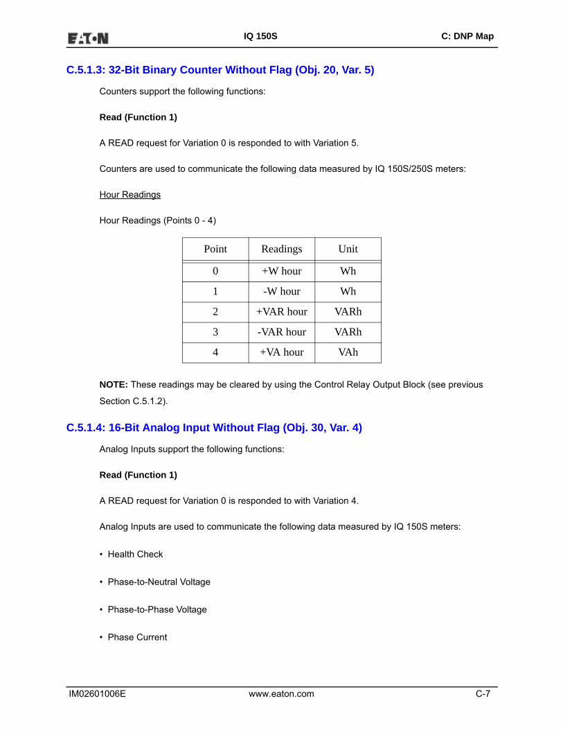
IM02601006E www.eaton.com C-7
IQ 150S C: DNP Map
C.5.1.3: 32-Bit Binary Counter Without Flag (Obj. 20, Var. 5)
Counters support the following functions:
Read (Function 1)
A READ request for Variation 0 is responded to with Variation 5.
Counters are used to communicate the following data measured by IQ 150S/250S meters:
Hour Readings
Hour Readings (Points 0 - 4)
NOTE: These readings may be cleared by using the Control Relay Output Block (see previous
Section C.5.1.2).
C.5.1.4: 16-Bit Analog Input Without Flag (Obj. 30, Var. 4)
Analog Inputs support the following functions:
Read (Function 1)
A READ request for Variation 0 is responded to with Variation 4.
Analog Inputs are used to communicate the following data measured by IQ 150S meters:
• Health Check
• Phase-to-Neutral Voltage
• Phase-to-Phase Voltage
• Phase Current
Point Readings Unit
0 +W hour Wh
1 -W hour Wh
2 +VAR hour VARh
3 -VAR hour VARh
4 +VA hour VAh

IM02601006E www.eaton.com C-8
IQ 150S C: DNP Map
• Total Power
• Three Phase Total VAs
• Three Phase Power Factor Total
• Frequency
• Three Phase +Watts Max Avg Demand
• Three Phase +VARs Max Avg Demand
• Three Phase -Watts Max Avg Demand
• Three Phase -VARs Max Avg Demand
• Three Phase VAs Max Avg Demand
• Angle, Phase Power
• Angle, Phase-to-Phase Voltage
• CT Numerator, Multiplier, Denominator
• PT Numerator, Multiplier, Denominator
Health Check (Point 0)
The Health Check point is used to indicate problems detected by the IQ 150S meter. A value of
zero (0x0000) indicates the meter does not detect a problem. Non-zero values indicate a detected
anomaly.
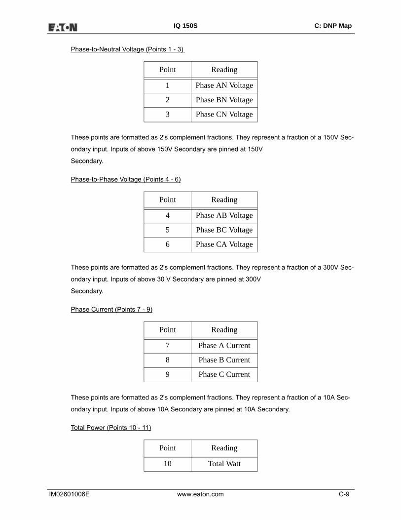
IM02601006E www.eaton.com C-9
IQ 150S C: DNP Map
Phase-to-Neutral Voltage (Points 1 - 3)
These points are formatted as 2's complement fractions. They represent a fraction of a 150V Sec-
ondary input. Inputs of above 150V Secondary are pinned at 150V
Secondary.
Phase-to-Phase Voltage (Points 4 - 6)
These points are formatted as 2's complement fractions. They represent a fraction of a 300V Sec-
ondary input. Inputs of above 30 V Secondary are pinned at 300V
Secondary.
Phase Current (Points 7 - 9)
These points are formatted as 2's complement fractions. They represent a fraction of a 10A Sec-
ondary input. Inputs of above 10A Secondary are pinned at 10A Secondary.
Total Power (Points 10 - 11)
Point Reading
1 Phase AN Voltage
2 Phase BN Voltage
3 Phase CN Voltage
Point Reading
4 Phase AB Voltage
5 Phase BC Voltage
6 Phase CA Voltage
Point Reading
7 Phase A Current
8 Phase B Current
9 Phase C Current
Point Reading
10 Total Watt

IM02601006E www.eaton.com C-10
IQ 150S C: DNP Map
These points are formatted as 2's complement fractions. They represent a fraction of 4500W Sec-
ondary in normal operation, or 3000W Secondary in Open Delta operation. Inputs above/below +/-
4500 or +/-3000W Secondary are pinned at +/-4500 or +/-3000W Secondary, respectively.
Total VA (Point 12)
This point is formatted as a 2's complement fraction. It represents a fraction of 4500W Secondary
in normal operation, or 3000W Secondary in Open Delta operation. Inputs above/below +/-4500 or
+/-3000W Secondary are pinned at +/-4500 or +/-3000W Secondary, respectively.
Power Factor (Point 13)
This point is formatted as a 2's complement integer. It represents Power Factors from -1.000
(0x0FC18) to +1.000 (0x003E8). In Open Delta operation, Total Power Factor (Point 13) is always
zero.
Frequency (Point 14)
This point is formatted as a 2's complement fraction. It represents the Frequency as measured on
Phase A Voltage in units of cHz (centiHertz, 1/100 Hz). Inputs below 45.00 Hz are pinned at 0
(0x0000); inputs above 75.00 Hz are pinned at 9999 (0x270F).
11 Total VAR
Point Reading
12 Total VA
Point Reading
13 Power Factor Total
Point Reading
14 Frequency
Point Reading

IM02601006E www.eaton.com C-11
IQ 150S C: DNP Map
Maximum Demands of Total Power (Points 15 - 19)
These points are formatted as 2's complement fractions. They represent a fraction of 4500W Sec-
ondary in normal operation, or 3000W Secondary in Open Delta operation. Inputs above/below +/-
4500 or +/-3000W Secondary are pinned at +/-4500 or +/-3000W Secondary, respectively.
Phase Angle (Points 20 - 25)
These points are formatted as 2's complement integers. They represent angles from -180.00
(0x0F8F8) to +180.00 (0x00708).
CT & PT Ratios (Points 26 - 31)
Point Reading
15 Maximum Positive Demand Total Watts
16 Maximum Positive Demand Total VARs
17 Maximum Negative Demand Total Watts
18 Maximum Negative Demand Total VARs
19 Maximum Average Demand VAs
Point Reading
20 Phase A Current Angle
21 Phase B Current Angle
22 Phase C Current Angle
23 Volts A-B Angle
24 Volts B-C Angle
25 Volts C-A Angle
Point Reading
26 CT Ratio Numerator
27 CT Ratio Multiplier
28 CT Ratio Denominator
29 PT Ratio Numerator
30 PT Ratio Multiplier

IM02601006E www.eaton.com C-12
IQ 150S C: DNP Map
These points are formatted as 2's complement integers. They can be used to convert from units in
terms of the Secondary of a CT or PT into units in terms of the Primary of a CT or PT. The ratio of
Numerator divided by Denominator is the ratio of Primary to Secondary.
IQ 150S meters typically use Full Scales relating Primary Current to 5A and Primary Voltage to
120V. However, these Full scales can range from mAs to thousands of kAs, and from mVs, to
thousands of kVs. Following are example settings:
CT Example Settings
200 Amps: Set the Ct-n value for 200 and the Ct-S value for 1.
800 Amps: Set the Ct-n value for 800 and the Ct-S value for 1.
2,000 Amps: Set the Ct-n value for 2000 and the Ct-S value for 1.
10,000 Amps:Set the Ct-n value for 1000 and the Ct-S value for 10.
NOTE: CT Denominator is fixed at 5 for 5A units; CT Denominator is fixed at 1 for 1A units.
PT Example Settings
277 Volts (Reads 277 Volts): Pt-n value is 277, Pt-d value is 277, Pt-S value is 1.
120 Volts (Reads 14,400 Volts): Pt-n value is 1440, Pt-d value is 120, Pt-S value is 10.
69 Volts (Reads 138,000 Volts): Pt-n value is 1380, Pt-d value is 69, Pt-S value is 100.
115 Volts (Reads 347,000 Volts): Pt-n value is 3470, Pt-d value is 115, Pt-S value is 100.
69 Volts (Reads 347,000 Volts): Pt-n value is 347, Pt-d value is 69, Pt-S value is 1000.
31 PT Ratio Denominator
Point Reading

IM02601006E www.eaton.com C-13
IQ 150S C: DNP Map
C.5.1.5: Class 0 Data (Obj. 60, Var. 1)
Class 0 Data supports the following functions:
Read (Function 1)
A request for Class 0 Data from a IQ 150S meter returns three Object Headers. Specifically, it
returns 16-Bit Analog Input Without Flags (Object 30, Variation 4), Points 0 - 31, followed by 32-Bit
Counters Without Flags (Object 20, Variation 5), Points 0 - 4, followed by Binary Output Status
(Object 10, Variation 2), Points 0 - 1. (There is NO Object 1.)
A request for Object 60, Variation 0 is treated as a request for Class 0 Data.
C.5.1.6: Internal Indications (Obj. 80, Var. 1)
Internal Indications support the following functions:
Write (Function 2)
Internal Indications may be indexed by Qualifier Code 0.
Device Restart (Point 0)
This bit is set whenever the meter resets. The polling device may clear this bit by Writing (Function
2) to Object 80, Point 0.
C.6: IQ 150S Meter DNP Mapping (DNP-1 to DNP-2)
The IQ 150S DNP Point Map follows.
Binary Output States, Control Relay Outputs, Binary Counters (Primary) and Analog Inputs are
described on Page 1.
Internal Indication is described on Page 2.

IM02601006E www.eaton.com C-14
IQ 150S C: DNP Map
This page intentionally left blank.

IQ 150S C:
IM02601006E www.eaton.com DNP-1
Object Point Var Description Format Range Multiplier Units Comments
Read via Class 0 only10 0 2 Reset Energy Counters BYTE Always 1 N/A none10 1 2 Change to Modbus RTU
ProtocolBYTE Always 1
N/A none
12 0 1 Reset Energy Counters N/A N/A
N/A none
Responds to Function 5 (Direct Operate), Qualifier Code 17x or 28x, Control Code 3, Count 0, On 0 msec, Off 1 msec ONLY.
12 1 1 Change to Modbus RTU Protocol
N/A N/A
N/A none
Responds to Function 6 (Direct Operate - No Ack), Qualifier Code 17x, Control Code 3, Count 0, On 0 msec, Off 1 msec ONLY.
Read via Class 0 only20 0 4 W-hours, Positive UINT32 0 to 99999999 W hr example:20 1 4 W-hours, Negative UINT32 0 to 99999999
W hr energy format = 7.2K and W-hours counter = 1234567
20 2 4 VAR-hours, Positive UINT32 0 to 99999999 VAR hr20 3 4 VAR-hours, Negative UINT32 0 to 99999999 VAR hr20 4 4 VA-hours, Total UINT32 0 to 99999999
VA hr
Read via Class 0 only30 0 5 Meter Health SINT16 0 or 1 N/A none 0 = OK30 1 5 Volts A-N SINT16 0 to 32767 (150 / 32768) V30 2 5 Volts B-N SINT16 0 to 32767 (150 / 32768) V30 3 5 Volts C-N SINT16 0 to 32767 (150 / 32768) V30 4 5 Volts A-B SINT16 0 to 32767 (300 / 32768) V30 5 5 Volts B-C SINT16 0 to 32767 (300 / 32768) V30 6 5 Volts C-A SINT16 0 to 32767 (300 / 32768) V30 7 5 Amps A SINT16 0 to 32767 (10 / 32768) A Values above 10A secondary read 32767.
30 8 5 Amps B SINT16 0 to 32767 (10 / 32768) A30 9 5 Amps C SINT16 0 to 32767 (10 / 32768) A
Binary Counters (Primary)
Control Relay Outputs
Binary Output States
Values above 150V secondary read 32767.
Values above 300V secondary read 32767.
n=3 (K scale), d=2 ( 2 digits after decimal point), multiplier = 10 (3-2) = 101 = 10, so energy is 1234567 * 10 Whrs, or 12345.67 KWhrs
multiplier = 10(n-d),where n and d are derived from the energy format. n = 0, 3, or 6 per energy format scale and d = number of decimal places.
Analog Inputs (Secondary)
Electro Industries/GaugeTech

IQ 150S C:
IM02601006E www.eaton.com DNP-2
Object Point Var Description Format Range Multiplier Units Comments30 10 5 Watts, 3-Ph total SINT16 -32768 to +32767 (4500 / 32768) W30 11 5 VARs, 3-Ph total SINT16 -32768 to +32767 (4500 / 32768) VAR30 12 5 VAs, 3-Ph total SINT16 0 to +32767 (4500 / 32768) VA30 13 5 Power Factor, 3-Ph total SINT16 -1000 to +1000 0.001 none30 14 5 Frequency SINT16 0 to 9999 0.01 Hz30 15 5 Positive Watts, 3-Ph,
Maximum Avg DemandSINT16 -32768 to +32767 (4500 / 32768) W
30 16 5 Positive VARs, 3-Ph, Maximum Avg Demand
SINT16 -32768 to +32767 (4500 / 32768) VAR
30 17 5 Negative Watts, 3-Ph, Maximum Avg Demand
SINT16 -32768 to +32767 (4500 / 32768) W
30 18 5 Negative VARs, 3-Ph, Maximum Avg Demand
SINT16 -32768 to +32767 (4500 / 32768) VAR
30 19 5 VAs, 3-Ph, Maximum Avg Demand
SINT16 -32768 to +32767 (4500 / 32768) VA
30 20 5 Angle, Phase A Current SINT16 -1800 to +1800 0.1 degree30 21 5 Angle, Phase B Current SINT16 -1800 to +1800 0.1 degree30 22 5 Angle, Phase C Current SINT16 -1800 to +1800 0.1 degree30 23 5 Angle, Volts A-B SINT16 -1800 to +1800 0.1 degree30 24 5 Angle, Volts B-C SINT16 -1800 to +1800 0.1 degree30 25 5 Angle, Volts C-A SINT16 -1800 to +1800 0.1 degree30 26 5 CT numerator SINT16 1 to 9999 N/A none CT ratio = 30 27 5 CT multiplier SINT16 1, 10, or 100 N/A none (numerator * multiplier) / denominator30 28 5 CT denominator SINT16 1 or 5 N/A none30 29 5 PT numerator SINT16 1 to 9999 N/A none PT ratio =30 30 5 PT multiplier SINT16 1, 10, or 100 N/A none (numerator * multiplier) / denominator30 31 5 PT denominator SINT16 1 to 9999 N/A none30 32 5 Neutral Current SINT16 0 to 32767 (10 / 32768) A For 1A model, multiplier is (2 / 32768) and
values above 2A secondary read 32767.
80 0 1 Device Restart Bit N/A N/A N/A none Clear via Function 2 (Write), Qualifier Code 0.
Internal Indication
Electro Industries/GaugeTech

IM02601006E www.eaton.com D-1
IQ 250S D: DNP Map
D: IQ 250S Meter DNP Map
D.1: Overview
This Appendix describes the functionality of the IQ250S meter's version of the DNP protocol. A
DNP programmer needs this information to retrieve data from the IQ 250S meter. The DNP ver-
sion used by the IQ 250S is a reduced set of the Distributed Network Protocol Version 3.0 subset
2; it gives enough functionality to get critical measurements from the IQ 250S meter.
The IQ 250S meter's DNP version supports Class 0 object/qualifiers 0,1,2,6, only. No event gener-
ation is supported. The IQ 250S meter always acts as a secondary device (slave) in DNP
communication.
D.2: Physical Layer
The IQ250S meter's DNP version uses serial communication. Port 2 (RS485 compliant port) is
used. Speed and data format is transparent for the IQ250S meter's DNP version: they can be set
to any supported value.
D.3: Data Link Layer
The IQ 250S meter can be assigned a value from 1 to 65534 as the target device address. The
data link layer follows the standard frame FT3 used by DNP Version 3.0 protocol, but only 4
functions are implemented: Reset Link, Reset User, Unconfirmed User Data, and Link Status, as
depicted in the following table.
Table D.1: Supported Link Functions
[dst] and [src] are the device address of the IQ 250S meter and Master device, respectively. Refer
to Section D.7 for more detail on supported frames for the data link layer.
Function Function Code
Reset Link 0
Reset User 1
Unconfirmed User Data 4
Link Status 9

IM02601006E www.eaton.com D-2
IQ 250S D: DNP Map
In order to establish optimal communication with the IQ 250S meter, we recommend that you per-
form the Reset Link and Reset User functions. The Link Status is not mandatory, but can be per-
formed as well. The inter-character time-out for DNP is 1 second. If this amount of time, or more,
elapses between two consecutive characters within a FT3 frame, the frame will be dropped.
D.4: Application Layer
The IQ 250S meter’s DNP version supports the Read, Write, Direct Operate and Direct Operate
Unconfirmed functions.
• The Read function (code 01) provides a means for reading the critical measurement data from
the meter. This function should be posted to read object 60 variation 1, which will read all the
available Class 0 objects from the DNP register map. See the register map in Section C.6. In
order to retrieve all objects with their respective variations, the qualifier must be set to ALL
(0x06). See Section D.7 for an example showing a read Class 0 request data from the meter.
• The Write function (code 02) provides a means for clearing the Device restart bit in the Internal
Indicator register only. This is mapped to Object 80, point 0 with variation 1. When clearing the
restart device indicator use qualifier 0. Section D.7 shows the supported frames for this func-
tion.
• The Direct Operate function (code 05) is intended for resetting the energy counters and the
Demand counters (minimum and maximum energy registers). These actions are mapped to
Object 12, points 0 and 2, which act as control relays. The relays must be operated (On) in 0
msec and released (Off) in 1 msec only. Qualifiers 0x17 or x28 are supported for writing the
energy reset. Sample frames are shown in Section D.7.
• The Direct Operate Unconfirmed (or Unacknowledged) function (code 06) is intended for asking
the communication port to switch to Modbus RTU protocol from DNP. This switching acts as a
control relay mapped into Object 12, point 1 in the meter. The relay must be operated with qual-
ifier 0x17, code 3 count 0, with 0 milliseconds on and 1 millisecond off, only. After sending this
request the current communication port will accept Modbus RTU frames only. To make this port
go back to DNP protocol, the unit must be powered down and up. Section D.7 shows the con-
structed frame to perform DNP to Modbus RTU protocol change.

IM02601006E www.eaton.com D-3
IQ 250S D: DNP Map
D.5: Error Reply
In the case of an unsupported function, or any other recognizable error, an error reply is generated
from the IQ 250S meter to the Primary station (the requester). The Internal Indicator field will
report the type of error: unsupported function or bad parameter.
The broadcast acknowledge and restart bit are also signaled in the Internal Indicator field, but they
do not indicate an error condition.
D.6: IQ 250S Meter’s DNP Register Map
Object 10 - Binary Output States
Object 12 - Control Relay Outputs
Object Point Var Description Format Range Multiplier Units Comments
10 0 2 Reset Energy Counters
BYTE Always 1 N/A None Read by Class 0 or with qualifier 0, 1, 2, or 6
10 1 2 Change to Modbus RTU Protocol
BYTE Always 1 N/A None Read by Class 0 or with qualifier 0, 1, 2, or 6
10 2 2 Reset Demand Cntrs (Max / Min )
BYTE Always 1 N/A None Read by Class 0 or with qualifier 0, 1, 2, or 6
Object Point Var Description Format Range Multiplier Units Comments
12 0 1 Reset Energy Counters
N/A N/A N/A none Responds to Function 5 (Direct Operate), Quali-fier Code 17x or 28x, Control Code 3, Count 0, On 0 msec, Off 1 msec ONLY.
12 1 1 Change to Modbus RTU Protocol
N/A N/A N/A none Responds to Function 6 (Direct Operate - No Ack), Qualifier Code 17x, Control Code 3, Count 0, On 0 msec, Off 1 msec ONLY.
12 2 1 Reset Demand Counters (Max / Min)
N/A N/A N/A none Responds to Function 5 (Direct Operate), Quali-fier Code 17x or 28x, Control Code 3, Count 0, On 0 msec, Off 1 msec ONLY.

IM02601006E www.eaton.com D-4
IQ 250S D: DNP Map
Object 20 - Binary Counters (Primary Readings) - Read via Class 0 or with qualifier 0, 1, 2,
or 6
Object 30 - Analog Inputs (Secondary Readings) - Read via Class 0 or with qualifier 0, 1, 2,
or 6
Object Point Var Description Format Range Multiplier Units Comments
20 0 5 W-hours, Positive
UINT32 0 to 99999999
Multiplier = 10(n-d), where n and d are derived from the energy format. n = 0, 3, or 6 per energy format scale and d = number of decimal places.
Whr example: energy format = 7.2K and W-hours counter = 1234567 n=3 (K scale), d=2 ( 2 digits after deci-mal point), mul-tiplier = 10(3-2) = 101 = 10, so energy is 1234567 * 10 Whrs, or 12345.67 KWhrs
20 1 5 W-hours, Negative
UINT32 0 to 99999999
Whr
20 2 5 VAR-hours, Positive
UINT32 0 to 99999999
VARhr
20 3 5 VAR-hours, Negative
UINT32 0 to 99999999
VARhr
20 4 5 VA-hours, Total
UINT32 0 to 99999999
VAhr
Object Point Var Description Format Range Multiplier Units Comments
30 0 4 Meter Health sint16 0 or 1 N/A None 0 = OK
30 1 4 Volts A-N sint16 0 to 32767 (150 / 32768) V Values above 150V secondary read 32767.
30 2 4 Volts B-N sint16 0 to 32767 (150 / 32768) V
30 3 4 Volts C-N sint16 0 to 32767 (150 / 32768) V
30 4 4 Volts A-B sint16 0 to 32767 (300 / 32768) V Values above 300V secondary read 32767.
30 5 4 Volts B-C sint16 0 to 32767 (300 / 32768) V
30 6 4 Volts C-A sint16 0 to 32767 (300 / 32768) V
30 7 4 Amps A sint16 0 to 32767 (10 / 32768) A Values above 10A secondary read 32767.
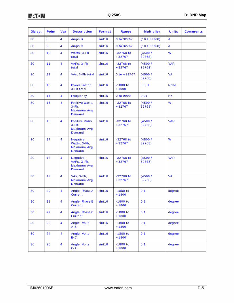
IM02601006E www.eaton.com D-5
IQ 250S D: DNP Map
30 8 4 Amps B sint16 0 to 32767 (10 / 32768) A
30 9 4 Amps C sint16 0 to 32767 (10 / 32768) A
30 10 4 Watts, 3-Ph total
sint16 -32768 to +32767
(4500 / 32768)
W
30 11 4 VARs, 3-Ph total
sint16 -32768 to +32767
(4500 / 32768)
VAR
30 12 4 VAs, 3-Ph total sint16 0 to +32767 (4500 / 32768)
VA
30 13 4 Power Factor, 3-Ph total
sint16 -1000 to +1000
0.001 None
30 14 4 Frequency sint16 0 to 9999 0.01 Hz
30 15 4 Positive Watts, 3-Ph, Maximum Avg Demand
sint16 -32768 to +32767
(4500 / 32768)
W
30 16 4 Positive VARs, 3-Ph, Maximum Avg Demand
sint16 -32768 to +32767
(4500 / 32768)
VAR
30 17 4 Negative Watts, 3-Ph, Maximum Avg Demand
sint16 -32768 to +32767
(4500 / 32768)
W
30 18 4 Negative VARs, 3-Ph, Maximum Avg Demand
sint16 -32768 to +32767
(4500 / 32768)
VAR
30 19 4 VAs, 3-Ph, Maximum Avg Demand
sint16 -32768 to +32767
(4500 / 32768)
VA
30 20 4 Angle, Phase A Current
sint16 -1800 to +1800
0.1 degree
30 21 4 Angle, Phase B Current
sint16 -1800 to +1800
0.1 degree
30 22 4 Angle, Phase C Current
sint16 -1800 to +1800
0.1 degree
30 23 4 Angle, Volts A-B
sint16 -1800 to +1800
0.1 degree
30 24 4 Angle, Volts B-C
sint16 -1800 to +1800
0.1 degree
30 25 4 Angle, Volts C-A
sint16 -1800 to +1800
0.1 degree
Object Point Var Description Format Range Multiplier Units Comments
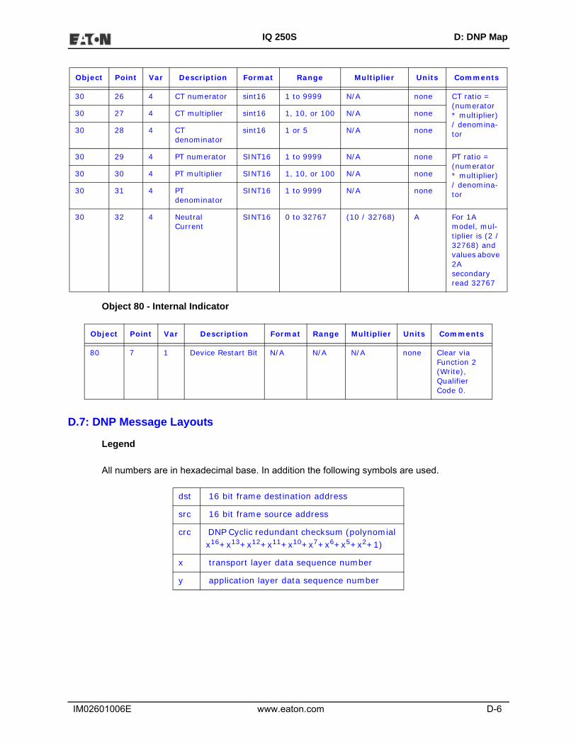
IM02601006E www.eaton.com D-6
IQ 250S D: DNP Map
Object 80 - Internal Indicator
D.7: DNP Message Layouts
Legend
All numbers are in hexadecimal base. In addition the following symbols are used.
30 26 4 CT numerator sint16 1 to 9999 N/A none CT ratio = (numerator * multiplier) / denomina-tor
30 27 4 CT multiplier sint16 1, 10, or 100 N/A none
30 28 4 CT denominator
sint16 1 or 5 N/A none
30 29 4 PT numerator SINT16 1 to 9999 N/A none PT ratio =(numerator * multiplier) / denomina-tor
30 30 4 PT multiplier SINT16 1, 10, or 100 N/A none
30 31 4 PT denominator
SINT16 1 to 9999 N/A none
30 32 4 Neutral Current
SINT16 0 to 32767 (10 / 32768) A For 1A model, mul-tiplier is (2 / 32768) and values above 2A secondary read 32767
Object Point Var Description Format Range Multiplier Units Comments
80 7 1 Device Restart Bit N/A N/A N/A none Clear via Function 2 (Write), Qualifier Code 0.
dst 16 bit frame destination address
src 16 bit frame source address
crc DNP Cyclic redundant checksum (polynomial x16+x13+x12+x11+x10+x7+x6+x5+x2+1)
x transport layer data sequence number
y application layer data sequence number
Object Point Var Description Format Range Multiplier Units Comments

IM02601006E www.eaton.com D-7
IQ 250S D: DNP Map
Link Layer related frames
Reset Link
Reset User
Link Status
Application Layer related frames
Clear Restart
Class 0 Data
Request 05 64 05 C0 dst src crc
Reply 05 64 05 00 src dst crc
Request 05 64 05 C1 dst src crc
Reply 05 64 05 00 src dst crc
Request 05 64 05 C9 dst src crc
Reply 05 64 05 0B src dst crc
Request 05 64 0E C4 dst src crcCx Cy 02 50 01 00 07 07 00 crc
Reply 05 64 0A 44 src dst crcCx Cy 81 int. ind. crc
Request 05 64 0B C4 dst src crcCx Cy 01 3C 01 06 crc
Request(alternate)
05 64 14 C4 dst src crcCx Cy 01 3C 02 06 3C 03 06 3C 04 06 3C 01 06 crc
Reply(same for either request)
05 64 72 44 src dst crcCx Cy 81 int. ind. 14 05 00 00 04 pt 0 pt 1 crcpt 1 pt 2 pt 3 pt 4 1E 04 crc00 00 20 pt 0 pt 1 pt 2 pt 3 pt 4 pt 5 pt6 crc
pt6 pt 7 pt 8 pt 9 pt 10 pt 11 pt 12 pt 13 crcpt 15 pt 16 pt 17 pt 18 pt 19 pt 20 pt 21 crcpt 23 pt 24 pt 25 pt 26 pt 27 pt 28 pt 29 crcpt 31 pt 32 0A 02 00 00 02 pt0 pt1 pt2 crc
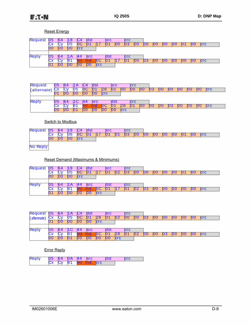
IM02601006E www.eaton.com D-8
IQ 250S D: DNP Map
Reset Energy
Switch to Modbus
Reset Demand (Maximums & Minimums)
Error Reply
Request 05 64 18 C4 dst src crcCx Cy 05 0C 01 17 01 00 03 00 00 00 00 00 01 00 crc00 00 00 crc
Reply 05 64 1A 44 src dst crcCx Cy 81 int. ind. 0C 01 17 01 00 03 00 00 00 00 00 crc01 00 00 00 00 crc
Request(alternate)
05 64 1A C4 dst src crcCx Cy 05 0C 01 28 01 00 00 00 03 00 00 00 00 00 crc01 00 00 00 00 crc
Reply 05 64 1C 44 src dst crcCx Cy 81 int. ind. 0C 01 28 01 00 00 00 03 00 00 00 crc00 00 01 00 00 00 00 crc
Request 05 64 18 C4 dst src crcCx Cy 06 0C 01 17 01 01 03 00 00 00 00 00 01 00 crc00 00 00 crc
No Reply
Request 05 64 18 C4 dst src crcCx Cy 05 0C 01 17 01 02 03 00 00 00 00 00 01 00 crc00 00 00 crc
Reply 05 64 1A 44 src dst crcCx Cy 81 int. ind. 0C 01 17 01 02 03 00 00 00 00 00 crc01 00 00 00 00 crc
Request(alternate)
05 64 1A C4 dst src crcCx Cy 05 0C 01 28 01 02 00 00 03 00 00 00 00 00 crc01 00 00 00 00 crc
Reply 05 64 1C 44 src dst crcCx Cy 81 int. ind. 0C 01 28 01 02 00 00 03 00 00 00 crc00 00 01 00 00 00 00 crc
Reply 05 64 0A 44 src dst crcCx Cy 81 int. ind. crc

IM02601006E www.eaton.com D-9
IQ 250S D: DNP Map
D.8: Internal Indication Bits
Bits implemented in the IQ 250S meter are listed below. All others are always reported as zeroes.
Bad Function
Occurs if the function code in a User Data request is not Read (0x01), Write (0x02), Direct Operate
(0x05), or Direct Operate, No Ack (0x06).
Object Unknown
Occurs if an unsupported object is specified for the Read function. Only objects 10, 20, 30, and 60
are supported.
Out of Range
Occurs for most other errors in a request, such as requesting points that don’t exist or direct
operate requests in unsupported formats.
Buffer Overflow
Occurs if a read request or a read response is too large for its respective buffer. In general, if the
request overflows, there will be no data in the response while if the response overflows at least the
first object will be returned. The largest acceptable request has a length field of 26, i.e. link header
plus 21 bytes more, not counting checksums. The largest possible response has 7 blocks plus the
link header.
Restart
All Stations
These 2 bits are reported in accordance with standard practice.

IM02601006E www.eaton.com D-10
IQ 250S D: DNP Map
This page intentionally left blank.
Copyright © 2022 FDOKUMEN


![SAP IQ Installation and Update Guide [Linux]](https://static.fdokumen.com/doc/165x107/6316cba2c72bc2f2dd053a67/sap-iq-installation-and-update-guide-linux.jpg)