
IOS Press Use of in-situ dynamic measurements to calibrate analytical models of RC-elevated water...
12
Shock and Vibration 19 (2012) 903–914 903 DOI 10.3233/SAV-2012-0698 IOS Press ISSN 1070-9622/12/$27.50 © 2012 – IOS Press and the authors. All rights reserved Use of in-situ dynamic measurements to calibrate analytical models of RC-elevated water tanks H.M. Lopes and C.S. Oliveira* Instituto Superior Técnico, Lisbon, Portugal Abstract. Before establishing the priority settings for the reduction of seismic risk of water supply infrastructures, it is necessary to understand the dynamic behavior of elevated water tanks, which are components of those infrastructures. Among other in- formation, the main frequencies of vibration of these structures must be estimated and the analytical models used in their analysis and design should reproduce the frequency values obtained by in-situ dynamic tests. This work focuses exclusively on reinforced concrete (RC) elevated water tanks (200−750 m 3 of water at heights of 30−40 m), which are very common structures in the water supply systems in Portugal since the mid XX th century. This type of structures can also be seen in many regions around the world. First, a nationwide survey was conducted to determine the most common typologies in the country in terms of structural layout. Second, an in-situ campaign using ambient vibration as input was performed for a group of selected structures to de- termine the main frequencies of vibration and to identify modal shapes and damping values. Third, a finite element model of several different typologies was developed using the water simply as a concentrated mass at the top; the elastic properties of the model of the structure including the foundation were calibrated, so that the frequencies of various mode shapes obtained by the analytical model would match the frequencies of the real structure. Finally, an expression was derived to estimate the funda- mental frequency of a group of elevated water tank typologies based on the total mass at the top of the supporting structure, which include the water, the global lateral stiffness, and the height of the tank. This study, providing important information on the frequencies of vibration of RC-elevated water tanks, contributes in a definite way to the analysis and design of such water tanks. Keywords: Dynamic analysis, RC elevated water tanks, identification of frequencies, analytical modeling 1. Introduction The determination of the seismic vulnerability of water supply networks is considered a national priority [1] in reducing the seismic impacts in Portugal. Specifically, this paper addresses the seismic vulnerability of reinforced concrete (RC)-elevated water tanks. When failed, this structure may become a constraint on the functionality of the existing water supply network in several municipalities throughout the country, especially in areas such as the Metropolitan Area of Lisbon and the Algarve, where the seismic hazard is moderate to strong [2,3]. The objectives of the paper are: (i) to recognize the most common typologies in the country and select a group of 44 structures to be characterized; 1 (ii) to perform an in-situ campaign under ambient vibration noise to identify the main frequencies of vibration for all of these structures and to determine the modal shapes and damping values in one case; (iii) to perform a linear finite element analysis of several structures and calibrate their mechanical properties to reproduce their dynamic behavior properly under low amplitude motion; and (iv) to establish correlations between measured *Corresponding author: C.S. Oliveira, Instituto Superior Técnico, Av. Rovisco Pais, 1049-001 Lisbon, Portugal. E-mail: csoliv@civil. ist.utl.pt. 1 We have seen that the typologies observed in Portugal do exist in many regions of the world, and they are still important equipments for water supply networks. AUTHOR COPY
Transcript of IOS Press Use of in-situ dynamic measurements to calibrate analytical models of RC-elevated water...

Shock and Vibration 19 (2012) 903–914 903
DOI 10.3233/SAV-2012-0698
IOS Press
ISSN 1070-9622/12/$27.50 © 2012 – IOS Press and the authors. All rights reserved
Use of in-situ dynamic measurements to
calibrate analytical models of RC-elevated
water tanks
H.M. Lopes and C.S. Oliveira*
Instituto Superior Técnico, Lisbon, Portugal
Abstract. Before establishing the priority settings for the reduction of seismic risk of water supply infrastructures, it is necessary
to understand the dynamic behavior of elevated water tanks, which are components of those infrastructures. Among other in-
formation, the main frequencies of vibration of these structures must be estimated and the analytical models used in their analysis
and design should reproduce the frequency values obtained by in-situ dynamic tests. This work focuses exclusively on reinforced
concrete (RC) elevated water tanks (200−750 m3 of water at heights of 30−40 m), which are very common structures in the water
supply systems in Portugal since the mid XXth century. This type of structures can also be seen in many regions around the world.
First, a nationwide survey was conducted to determine the most common typologies in the country in terms of structural
layout. Second, an in-situ campaign using ambient vibration as input was performed for a group of selected structures to de-
termine the main frequencies of vibration and to identify modal shapes and damping values. Third, a finite element model of
several different typologies was developed using the water simply as a concentrated mass at the top; the elastic properties of the
model of the structure including the foundation were calibrated, so that the frequencies of various mode shapes obtained by the
analytical model would match the frequencies of the real structure. Finally, an expression was derived to estimate the funda-
mental frequency of a group of elevated water tank typologies based on the total mass at the top of the supporting structure,
which include the water, the global lateral stiffness, and the height of the tank.
This study, providing important information on the frequencies of vibration of RC-elevated water tanks, contributes in a definite
way to the analysis and design of such water tanks.
Keywords: Dynamic analysis, RC elevated water tanks, identification of frequencies, analytical modeling
1. Introduction
The determination of the seismic vulnerability of water supply networks is considered a national priority [1] in
reducing the seismic impacts in Portugal. Specifically, this paper addresses the seismic vulnerability of reinforced
concrete (RC)-elevated water tanks. When failed, this structure may become a constraint on the functionality of the
existing water supply network in several municipalities throughout the country, especially in areas such as the
Metropolitan Area of Lisbon and the Algarve, where the seismic hazard is moderate to strong [2,3]. The objectives
of the paper are: (i) to recognize the most common typologies in the country and select a group of 44 structures to be
characterized;1 (ii) to perform an in-situ campaign under ambient vibration noise to identify the main frequencies of
vibration for all of these structures and to determine the modal shapes and damping values in one case; (iii) to
perform a linear finite element analysis of several structures and calibrate their mechanical properties to reproduce
their dynamic behavior properly under low amplitude motion; and (iv) to establish correlations between measured
*Corresponding author: C.S. Oliveira, Instituto Superior Técnico, Av. Rovisco Pais, 1049-001 Lisbon, Portugal. E-mail: csoliv@civil.
ist.utl.pt. 1We have seen that the typologies observed in Portugal do exist in many regions of the world, and they are still important equipments for water
supply networks.
AUTH
OR
COPY

904 H.M. Lopes and C.S. Oliveira / Use of in-situ dynamic measurements to calibrate RC-elevated water tank models
frequencies and the main geometric and material properties of the water tanks under study to make an overall static
and dynamic characterization of these types of structures. For a selected group of cases, it was possible to obtain an
expression to estimate the fundamental frequency of an elevated water tank based on the height of the tank, the total
mass at the top of the stack and the global lateral stiffness.
As a continuation of the present study, ongoing research aims at determining the seismic vulnerability of the most
typical RC-elevated water tanks based on non-linear pushover analysis [4].
1.1. Brief account of the RC-elevated water tank typologies in Portugal
The existing RC-elevated water tanks that were built 50 to 60 years ago in Portugal can be approximately grouped
into the following types distinguishable by basic parameters including tank height and capacity, design/construction
epoch and material. (In this study, only structures with identifiable main sub-types or classes were analyzed.)
(1) Hintze type,2 a RC 3-D frame formed by columns at a peripheral ring connected by ring beams at several
heights;3 (2) RC circular slender shaft with hollow section: − shaft diameter − thickness of the wall shaft; (3) RC
double structure, a combination of type (1) and type (2); (4) RC cylindrical shell with strong radial columns; (5)
special cases. Case (1) can be sub-divided into three classes. In (1a), the outer RC frame is filled with a wall in
masonry, in (1b) the filling is concrete shell and in (1c) there are slabs at the beam levels. To complete the classi-
fication, the foundation type and the geological and geotechnical conditions were also examined. In Fig. 1, examples
of the main typologies mentioned above are presented.
1-RC Hintze 1a-RC Hintze with
infilled masonry
2-RC circular shaft 3-RC double structure 4-RC shell with strong
columns
Fig. 1. Main typologies of elevated water tanks.
Based on the structural types presented, the major characteristics and descriptions of 44 different water tanks
located mostly in the southern bank of the Tagus River near Lisbon and many tanks in Algarve have been summa-
rized in Table 1. Similar typologies can be found in other areas of the Portuguese territories, both in the Continent
and in the Azores. In addition to the name and city of each structure, Table 1 presents the typology classes, the tank
capacity, the percent of water volume filling the tank at the time of the in-situ testing, the height from the ground
level to the base of the tank (stack-shaft or frame), the average external diameter and the frequencies determined
from in-situ testing. A reference is also made to the structures that were the object of analytical studies on fre-
quencies and on seismic vulnerability.
The database from which the parameters in Table 1 were taken contains more detailed information on the geo-
metric characterization of the structure. This information was obtained from the design drawings (if available) or
from direct measurements of the main structural elements.
2There is no clear definition for a Hintze structure: the name refers to the spatial frame or to the type of tank. This is also referred to in the
literature as Intze structures. 3A more detailed characterization would include information on: − number of columns, − shaft diameter, − number of levels of beams, −
number of levels of slabs, − openings filled or not with masonry.
AUTH
OR
COPY

H.M. Lopes and C.S. Oliveira / Use of in-situ dynamic measurements to calibrate RC-elevated water tank models 905
Table 1
Geometric characterization and first in-situ frequencies of various types of elevated water tanks
1.2. Damage observed in past earthquakes
Even though only RC-elevated tanks built the past 50 years in Portugal were analyzed, these structures were built
in many different regions around the world following the appropriate codes and standards developed not only in
countries with advanced technologies but also in countries with long traditions of using these types of structures.
France, USA, Turkey, and Haiti are just a few countries where elevated RC water tanks are in full function.
Past earthquakes are full of examples of cases showing the safe and unsafe behavior of elevated RC tanks during
shaking. The most common problems in RC Hintze typologies are the cracking of the beams around the
beam-column connections, as seen in the Lajes water tank in Terceira Island (Azores) during the 1980 earthquake.
Here the beam cracks appear at peak ground acceleration (PGA) of approximately 30 cm/s2 [5]. A similar occur-
rence was observed in Perú [6] during the 1996 earthquake (Fig. 2a). For cylindrical shafts, the main problem is the
rotation of the foundation [7], as occurred in Iran during the 1990 earthquake (Fig. 2b). Complete collapses of large
water tanks were also observed for the same earthquake. Other examples include the Friuli 1976 [8], Bhuj 2001 [9],
and Haiti 2010 [10] earthquakes. However, in many other earthquakes, these structures have behaved quite well in
contrast to the great destruction observed in the surrounding areas, such as in Sichuan (China) [11] during the 2008
earthquake.
Name Typology capacity water level height* φext 1st freq. 2nd freq. 3rd freq. 4th freq. 1st torsion 2nd torsion Comput.(m3) % (m) (m) (Hz) (Hz) (Hz) (Hz) (Hz) (Hz) analysis
Abelheira - Quarteira 1 150 100 25 6.5 1.95 4 9 2Alto Cavaquinho - Seixal 4 200 100 20 3.9 1.25 9.8 6.38 freqAlto Lazarim - Almada 2 430 70 22 4.8 1.86 6.98Alto Pacheco - Portimão 1a 500 100 28.6 8.7 1.56 8.2 17 5.2Alto Rodes - Faro 1b 1000 15 29.5 6.0 1.07 5.8 2Amoreiras - Portimão 1a 500 100 24.6 8.7 1.76 9.8 17 23 5.8Barrosa - Benavente 2 320 50 18 4.0 2.1 11.2Base Lajes - Terceira Açores 1 250 100 14 8.0 1.03 7.1 2.15 vulnerabBelverde - Seixal 2 90 80 24 2.0 0.49 4.5 12 freq & vulnerabBemposta - Portimão 1a 200 100 22 6.1 1.95 11.3 32 6.6Benavente Novo 3 750 100 19.5 3.0 1.27 8.3 2.9 10.9Benavente Velho 1 250 70 18 6.5 1.6 9.9 12.4 19.2 2.4Boavista - Portimão 1a 500 100 32 8.7 1.37 7 14 19 4Caparica - Almada 1 100 100 16 5.0 1.37Casal Marco - Seixal 4 200 25 20 3.9 1.46 3.6 11.3 6.54 freqCassapo - Almada 1a 500 60 24 7.8 1.95 11.3 16 8.7Centro - Aveiro 1a 750 100 27 10.6 2.53 8.9Cerro de Águia - Albufeira 1a 300 100 23 7.8 2.15 11.4Chão das Donas - Portimão 1a 500 100 30 8.7 1.56 8.5 16.9 23 5.2Corroios - Seixal 1a 300 0 17 5.0 2.64 14.2 11.3Depósito Univ. - Aveiro 5 100 50 30 5.0 0.78 4.7 freqEstrelinha - Almada 2 125 100 13 4.4 1.76 10 11.7 2.2Feijó - Almada 3 750 30 26 10.1 1.8 7Feijó Velho - Almada 1 100 0 11 6.0 1.66 8 8.9 9.3 2.06Fernão Ferro Casal Sapo - Seixal 4 700 50 12 9.9 3.71 5.1 11.9 10.9Grândola 1b 750 100 29.5 8.0 1.56 8.3 18.7 28.5 5.5 11.8Laranjeiro - Almada 4 500 80 24 8.0 1.3 3.1 9 4.8Mexilhoeira Grande 1a 300 100 12 7.8 4.2 19 9.8Miratejo - Seixal 1 500 26 8.2 0.96 4.3 8.3 11.2 1.36 5.6 modes & respMte Caparica (velho) Almada 1 100 0 11 5.7 1.8 4 8 2.1Porches - Porches 1b 200 80 11 4.0 3 13.7 9Praia da Luz - Lagos 2 100 100 19 2.4 0.98 8.6 13.7 6.4 9.5R4 - Vila Moura 4 400 100 18 6.0 2.34 5.8Radio Naval - Horta 1 10 0 9.5 3.0 1.46 10.9 2.5 freqRaposo - Almada 5 1000 50 25 18.0 2.44 3Samora Correia 2 500 100 31 4.0 0.68 4.9 14.1 7.9São Jacinto - Aveiro 1a 350 80 15 7.6 1.95 5.2Sines 4 250 0 18.8 6.6 1.82 5.3 14.4 2.48Silval - Oliveirinha-Aveiro 1a 500 100 27 8.7 1.66 8.5 13.7 4.8Sta. Comba Dão 1a 500 100 25.3 9.0 1.66 8.3 17.8 23.6 4.45 15.1Sta. Marta - Seixal 2 350 80 32 4.0 0.6 5.1 freqSto. António - Faro 2 200 0 38 5.0 0.98 5 2.2Stº. Estevão 2 150 100 16 3.3 1.66 7.5 11.7 2.5Torre Marinha - Seixal 1c 500 60 26 8.2 1.07 4.1 6.8 freq* from ground to base of tank1-Hintze; 1a-Hintze+Masonry infill; 1b-Hintze+RC inf; 1c-Hintze+slab;2-RC circ shaft; 3- Double struct; 4-RC shell+strong pillars; 5-special
AUTH
OR
COPY

906 H.M. Lopes and C.S. Oliveira / Use of in-situ dynamic measurements to calibrate RC-elevated water tank models
(a) City of Nasca (Peru) (b) City of Manjil Roudbar (Iran); tilted tower
Fig. 2. Damage inflicted to: (a) Hintze-type elevated water tanks, (b) cylindrical shaft.
The analysis and design of elevated water tanks under seismic action is a rather sophisticated topic due to the
large mass of water positioned at a high location. This water, depending on the shape of the tank, oscillates sepa-
rately from the tank during the transmitted moderate to strong motion and causes sloshing effects. The sloshing
phenomenon [12] and the determination of ductility of inverted pendulum structures have been investigated and are
considered in the codes of practice for the last 25 years [13−19].
Rai [9,20,21] has studied RC shaft-elevated water tanks affected by strong events, proposing techniques for their
rehabilitation and recommending alterations on world codes to significantly reduce the ductility of these types of
structures. These recommendations follow the same design philosophy of EC-8 [18], ACI [16], IBC [17] and
IITK-GSDMA [19], among other codes.
2. Frequencies of vibration from in-situ measurements
In-situ dynamic measurements similar to the ones described herein were already made for Hintze-type tanks by
Chandrasekaran and Krishna [22] in the mid 1960s, and their results do not differ significantly from those presented
below. Boyce [23] also made in-situ tests to verify the influence of water level in measured frequencies and the
sloshing effect; both effects are considered in modern codes. In the present work, no sloshing effect is considered
because only low amplitude motion is analyzed. Nevertheless, the water level is very important due to its additional
weight.
A series of in-situ ambient vibration tests were performed in different types of the 44 structures mentioned above
to determine the frequency and modes of vibration.
This technique was chosen instead of other excitation sources because it has been applied in many different sit-
uations; for flexible structures, such as elevated water tanks, the results are very robust [24]. The main idea of using
ambient vibration tests to determine the dynamic characteristics of a structure is essentially based on the principle
that this vibration acts at the foundation level as “white noise” being filtered by the structure along the height. The
measured signal is the vibration caused by wind, traffic and water pumping. In this case, (human) walking was also
used as the source of noise exciting the lower modes of vibration.
Therefore, the input signal is amplified at the natural frequencies of these structures at locations where modal
shapes exhibit higher expression. By placing instrumentation at several locations and recording the response sim-
ultaneously, it is possible to identify both the frequencies and the corresponding mode shapes [24]. However, for
slender structures, only the response measured at the top is necessary to determine the fundamental frequencies and
the frequencies of several higher modes. The results from ambient vibration tests compare very well with those from
AUTH
OR
COPY

H.M. Lopes and C.S. Oliveira / Use of in-situ dynamic measurements to calibrate RC-elevated water tank models 907
alternative techniques, such as the results from earthquake ground motion recorded by permanent monitoring
networks [24]. In this study, the frequencies were identified using only one accelerometric high-resolution station
with three components. For most of the 44 water tanks, it was possible to obtain the frequencies of the first five
modal shapes. In one case, three instruments with common timing were used to determine the modal shapes and
damping ratios.
In Fig. 3a, the periods of vibration (sec) of different modes were plotted as a function of height (m), and the
corresponding regression lines were plotted for typology 1a (a select subset of Hintze tanks with masonry infill) in
Fig. 3b shows similar results for all structures. One observes that, for type 1a water tanks, the scatter is low. The
frequency of the 2nd mode of translation is 5.5 times larger than the frequency of the first mode,4 while the fre-
quency in the torsion mode is only 3.8 times larger. Overall, (Fig. 3b) the results are very scattered; however, the
general trend is very similar to the trend seen in Fig. 3a.
(a) (b)
Fig. 3. Correlation of vibration period (y) with tank height (x) for different modes: a) Hintze type 1a; b) all types.
The contents of Fig. 3 (for frequencies) are replotted in Fig. 4a but only for the 1st mode for all types; this is to
show the great uncertainty in the fitting process if all data are assembled together. The scattering is very high,
meaning that more variables should be considered in the fitting process for the results to have any practical usage.
For example, if the data are grouped by typologies, the correlation is much higher, as seen in Fig. 4b where linear
fitting was performed only for the cases with more data points.
As mentioned in the beginning of this section, in-situ dynamic measurements for the first frequency were made in
India for Hintze-type tanks (typology 1) by Chandrasekaran and Krishna [22]. Figure 5 compares their measured
frequencies and the frequencies for this work (as in Fig. 4b). The tendencies are similar, but the Indian tanks show
lower frequencies and slightly larger dispersion; this phenomenon could be a result of differently defined tank
height. Damping in both experiments are identical.
3. Modeling the structure – linear analysis
In this section, numerical modeling was performed using the finite element method for six of the structures
identified in Table 1. Two structures were the Hintze-type with slabs (Type 1c); two were circular-shaft types (Type
2) and two were structures with shells and strong columns (Type 4). To illustrate the modeling process, the first
structure in Fig. 1 (the Miratejo water tank) is described in detail.
4Each frequency refers only to one direction of the horizontal plan because these structures are essentially symmetric. The mode in the or-
thogonal direction has the same frequency up to the second digit.
y = 0.0234x - 0.0314R² = 0.9613
y = 0.0042x - 0.0011R² = 0.9185
y = 0.0027x - 0.0184R² = 0.6201
y = 0.006x + 0.0299R² = 0.7301
0.01
0.1
1
10 15 20 25 30 35 40
pe
rio
d (s
ec)
height (m)
1st mode
2nd mode
3rd mode
1st torsion
Linear (1st mode)
Linear (2nd mode)
Linear (3rd mode)
Linear (1st torsion)
y = 0.0225x + 0.2222R² = 0.1897
0.01
0.1
1
10
10 15 20 25 30 35 40
oe
rid
(se
c)
height (m)
1st mode
2nd mode
3rd mode
1st torsion
Linear (1st mode)
AUTH
OR
COPY

908 H.M. Lopes and C.S. Oliveira / Use of in-situ dynamic measurements to calibrate RC-elevated water tank models
This RC Hintze-type tank, built in the 1970s, has a total height of 36 m and consists of a space frame with eight
6-story vertical columns supporting 0.15 m-thick slabs with peripheral beams and tank at the top, as shown in
Fig. 1a; the model of the structure is shown in Fig. 5a. The columns are arranged in a circle with a diameter of 8.2 m,
and the cross section of the columns varies linearly from 1.527 m at the base to 0.767 m at the top (radial dimen-
sion); the width of the columns (from top to bottom) is a constant 0.60 m. The height of the beams is constant on all
floors (0.27 m), and their widths vary from 0.68 m on the 1st floor to 0.41 m on the 5th floor. The tank has a capacity
of 500 m3. The foundation of the tank at the ground floor consists of a ring beam with a base of 2.5 m width, an
external diameter of 8.2 m, and a height of 1.2 m, supporting the columns. The bottom of the shaft between the
ground level and the first floor is enclosed by a wall of 0.26 m-thick brick masonry. The materials used to construct
the tank were C20/25 and A400 NR. The foundation in the Holocene consists of a thick, dense, and well-compacted
sand with a deformation modulus E of 106 MPa.
In all 6 cases studied, the design for seismic loads followed the seismic codes in use at the time of construction,
which corresponded to the RSCS code until 1961 [25], the RSEP code until 1985 [26] and the RSA code [2] since
then. The Miratejo tank in the present study was designed according to RSEP.
The numerical linear model was constructed using a finite element program “SAP2000®” [27] as follows: -
Columns were simulated such that the cross section varies linearly with height. Beams were simulated by bar el-
(a) (b)
Fig. 4. Correlation of vibration frequency with tank height for the first mode: a) for all types; b) sorted by more significant typologies.
Fig. 5. Comparison between in-situ measurements in India and Portugal for typology 1 (frequency of 1st mode).
AUTH
OR
COPY

H.M. Lopes and C.S. Oliveira / Use of in-situ dynamic measurements to calibrate RC-elevated water tank models 909
ements with a constant cross section. Low walls and slabs were simulated by the shell elements that are 0.15 m and
0.10 m thick, respectively. The ring foundation beam was simulated by bar elements. The interaction between the
structure and the soil was simulated using springs with a stiffness of approximately 290 MN/m. Masonry walls were
simulated by the shell elements with an elastic modulus of 8 GPa (the wall thickness is 0.26 m). The tank was
simulated as a point mass located at the center of mass of the tank (255.97 ton) plus the mass of the water at the time
of measurement (122.5 tons). This mass, considered as a concentrated translational mass with a polar moment of
inertia (Mpi) in three directions (Mpix, y = 6198.85 ton.m2, Mpiz = 8696.64 ton.m
2), was connected to the central
top node of the structure by a rigid lintel.
The other structures were modeled in a similar way using bar and shell elements.
In Fig. 6, the first 5 frequencies of the structures determined analytically and by in-situ testing are compared.
These frequencies correspond to the x and y directions and are equal by pairs due to the radial symmetry of the
structures. For the 6 cases studied, the torsion mode (T) fits between the first and the second pairs, corresponding, to
the 1st and 2nd modes in each horizontal direction, respectively. This was also the criterion taken into account in
setting up Table 1, in which only one horizontal direction was considered.
Miratejo – RC Hintze (Type 1c)
Torre da Marinha – RC Hintze (Type 1c)
Santa Marta – RC circular shaft (Type 2)
AUTH
OR
COPY
910 H.M. Lopes and C.S. Oliveira / Use of in-situ dynamic measurements to calibrate RC-elevated water tank models
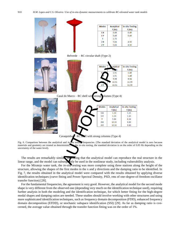
Belverde – RC circular shaft (Type 2)
Casal do Marco – RC shell with strong columns (Type 4)
Cavaquinhas – RC shell with strong columns (Type 4)
Fig. 6. Comparison between the analytical and in-situ testing frequencies. (The standard deviation of the analytical model is zero because
materials and geometry are treated as deterministic; for the in-situ testing, the standard deviation is on the order of 0.05 Hz depending on the uncertainty of the water level).
The results are remarkably similar, indicating that the analytical model can reproduce the real structure in the
linear range, and the model can subsequently be used in the nonlinear study, including vulnerability analysis.
For the Miratejo water tank, the in-situ testing was more complete using three stations along the height of the
structure, allowing the shapes of the first modes in the x and y directions and the damping ratio to be identified. In
Fig. 7, the results obtained in the analytical model were compared with the results obtained by applying diverse
identification techniques (curve fitting and Power Spectral Density, PSD, rms of one-degree-of-freedom oscillator
transfer function) [28].
For the fundamental frequencies, the agreement is very good. However, the analytical model for the second mode
shape is very different from the observed one (depending very much on the identification technique used), requiring
further analysis in both the modeling and the identification technique, for which better fitting for the high-degree
modal shapes and damping ratios are needed. These studies should involve working with other structures and using
more sophisticated identification techniques, such as frequency domain decomposition (FDD), enhanced frequency
domain decomposition (EFDD), or stochastic subspace identification (SSI) [29]. As far as damping ratio is con-
cerned, the average value obtained through the transfer function fitting was on the order of 1%.
AUTH
OR
COPY

H.M. Lopes and C.S. Oliveira / Use of in-situ dynamic measurements to calibrate RC-elevated water tank models 911
Fig. 7. Comparison among various methods used to determine the 1st and 2nd modes of translation (1 and 3) for the x and y directions.
The consistent disagreement (30% or more) between the in-situ and the numerical modeling frequency results
found when performing a similar analysis for buildings (see [30]) is due to the great uncertainties in the elastic
properties of several elements of those structures as well as the boundary conditions created by adjacent buildings.
The interaction of buildings in urban blocks, the existence of non-structural elements, such as infill walls, and the
uncertainties in modeling are among the most critical issues when dealing with building frequencies. However, if
modeling considers all structural and non-structural elements, the agreement is much better.
The elevated water tanks like the ones in this study are composed by more standard structures and, consequently,
the results from modeling are much better than with building.
4. Estimating the natural frequency of elevated water tanks
An empirical formula to compute the fundamental frequency of an RC-elevated water tank would be very useful
for a designer to quickly assess its response to ground motion.
The simplest idea would be to relate frequency or period of first mode with one single parameter characterizing
the RC tank. In buildings the height is the parameter used in all codes and studies [30].
Figure 4 was made based on this idea. In Fig. 4a all typologies were treated together and the dispersion is very
large. One realizes that it is impossible to mix very different structural typologies, such as space frames and shafts. If
AUTH
OR
COPY

912 H.M. Lopes and C.S. Oliveira / Use of in-situ dynamic measurements to calibrate RC-elevated water tank models
grouped by typologies, as represented in Fig. 4b, the results become much better with higher correlation value
between frequencies and heights. Based on these results future work may reduce the total number of typologies
considered in here to a smaller number.
An additional analysis was made to estimate more adequately the fundamental frequency of vibration of these
structures. Based on the data collected, a simple formula was developed knowing the equivalent inertia of the cross
section of a hypothetical shaft, the mass of tank with water, and the height of the tank.
According to Clough and Penzien [31], the first frequency of vibration (f ) for a cantilever (with continuous mass
and inertia) is given by Eq. (1) or Eq. (2) for the case of a concentrated mass m at the top of a mass-less cantilever:
2
4
11.875
2
EIf
mL (1)
3
1 3
2
EIf
mL
(2)
where E is the modulus of elasticity, I is the second moment of the cross section, m (= ρ × A) is the mass per unit of
length and L is the total height of the cantilever (with ρ and A being the mass density and the area of the cross section,
respectively). Therefore, the fundamental frequency of the tank is expected to be a function of the second moment of
area and the height of the tank. E and ρ are material properties.
The height of the tank H, which is relevant for the first frequency of vibration, was given by the length of the shaft
from the ground to the center of gravity of the tank with water. Based upon these parameters, a new equation
(Eq. (3)) was developed to account for this parameterization.
( etank water)f M I H (3) (3)
where M is the mass of the tank with water, and Ie is the equivalent inertia of the cross section of a shaft. α, β, γ, and
δ are parameters to obtain from data fitting. For the structures analyzed in this work, the value of I was obtained by
applying a force at the top of the structure in the analytical model and determining the corresponding horizontal
displacement. Using the mean square regression analysis, the constants were computed: α = 476.28, β = −0.2972,
= 0.2782, and δ = −1.4572. These values were determined through an iterative process that minimizes the dif-
ference between the experimental results and the empirical equation.
In Fig. 8, the results obtained with Eq. (3) and the in-situ experimental values are compared for the 6 cases studied
in detail.
Fig. 8. 1st Mode − analytical frequencies vs. in-situ frequencies.
The results presented in Fig. 8 show a good match between analytical and in-situ frequencies of the 1st mode. The
extension of formulae (Eq. (3)) to other situations requires further studies including the analysis of a larger number
of tanks, possibly leading to more robust values of the fitting parameters.
y = 0.9955x + 0.0036R² = 0.99
0.0
0.5
1.0
1.5
0.0 0.5 1.0 1.5 2.0
An
alyt
ical
val
ue
s
In-situ observations
Hz (in situ) M(ton) I(m4) H(m)
0.49 164 0.23 29.41
1.51 250 5.48 23.76
1.23 400 5.48 23.76
0.96 643 16.48 33
1.06 365 16.48 33
0.57 654 5.311 38.5
AUTH
OR
COPY

H.M. Lopes and C.S. Oliveira / Use of in-situ dynamic measurements to calibrate RC-elevated water tank models 913
5. Conclusions and final considerations
The main conclusions from this work can be summarized as follows:
− A large set of RC-elevated water tanks (44 tanks), covering the most common types and sizes existing in
Portugal, were studied and characterized in terms of geometry and frequency of vibration. Similar tanks are
in still in function in many countries.
− In-situ measurements with ambient noise led to the identification of the first frequencies of vibration of
various types of water tanks. Generally, up to 4 modes in one direction including the first torsion mode
could be identified. This was performed with a single 3-component accelerometric station. A damping ratio
on the order of 1.0% was obtained for several structures.
− The finite element analytical models developed for a group of 6 structures covering 3 different typologies
reproduce the results of the in-situ testing with great accuracy in terms of frequencies of several modes.
However, in terms of modal shapes, only the 1st modes (x and y) were reproduced adequately. Further
studies are needed to improve the modal shape fitting at higher frequencies by introducing slight correc-
tions on the structural modeling and using more sophisticated identification techniques [29].
− For several tanks, it was possible to obtain an expression to compute the 1st frequency based on the mass at
the top of the structure, the inertia, and the height of the supporting structure. Extension of this expression
to other situations should be the object of future work.
− This study, although based on small amplitude vibration, provides critical information on frequencies and
structural modeling of RC elevated water tanks which is of most relevance for their analysis and design.
The effect of sloshing of water and the effect of the nonlinear behavior of structural materials on frequencies of
vibration for larger amplitude motions is outside the scope of this paper, but should be analyzed in the future.
This work can be applied to study seismic vulnerability, such as the one conducted in [4], using pushover anal-
ysis [32], and address structural safety.
Acknowledgments
CSO acknowledges the partial financial support given by Fundação para a Ciência e a Tecnologia, Portugal
(FCT) through its Pluri-Annual Programme. The suggestions made by three anonymous reviewers are greatly
acknowledged.
References
[1] C.S. Oliveira, J.J. Azevedo, R. Delgado, A.G. Costa and A.C. Costa, O Sismo de Northridge Los Angeles, 17 de Janeiro de 1994 – Ensinamentos para Portugal, 1995. (in portuguese)
[2] RSA, Regulamento de Segurança e Acções para Estruturas de Edifícios e Pontes, Decreto-Lei n.º 235/83, de 31 de Maio, Imprensa
Nacional, Lisboa, 1983. (in portuguese) [3] E.C. Carvalho, C.S. Oliveira, A. Campos-Costa and M.L. Sousa, Definição da Acção Sísmica no âmbito do Documento Nacional de
Aplicação (DNA) do EC-8, Proceedings Sísmica-1999, Faro, 1999. (in portuguese)
[4] H.M. Lopes and C.S. Oliveira, Use of in-situ Dynamic Measurements to Calibrate Analytical Models of RC Elevated Water Tanks and to
Assess their Seismic Vulnerability, Proceedings, ICEDyn2011, 2011.
[5] C.S. Oliveira, A.R. Lucas and J.H. Correia Guedes, Monografia, 10 Anos após o Sismo dos Açores de 1 de Janeiro de 1980, volums 1 and 2, Lisboa, 1992. (in portuguese)
[6] J.E. Hurtado Alva, López and D. Vásques, Nasca Earthquake, November 12, 1996, Peru. (Personal Communication)
[7] M. Mermari, M.M. Ahmadi and B. Rezae, Behavior of Reinforced Concrete Water Towers During the Manjil-Roudbar Earthquake of June 1990, Proceedings, 10th World Conference on Earthquake Engineering, Balkema, 1992.
[8] Friuli earthquake, 1976: Performance of a Railway Water Tank, Courtesy A. Lopez-Arroyo, 2007.
[9] D.C. Rai, Performance of Elevated Tanks in Mw7.7 Bhuj Earthquake of January 26, 2001, Proceedings Indian Academy Science (Earth Planet Sciences) 112(3) (2003), 421–429.
[10] “Haiti earthquake, 2010: Performance of a Port-au-Prince Water Tank” (Courtesy C. S. Oliveira), 2010.
[11] A. Costa, C.S. Oliveira and M.A. Ferreira, The Sichuan Earthquake of 2008 and the Performance of main Structural Systems, (in prep-aration), 2012.
[12] G.W. Housner, The dynamic behavior of water tanks, Bulletin of Seismological Society of America 53 (1963), 381–387.
AUTH
OR
COPY

914 H.M. Lopes and C.S. Oliveira / Use of in-situ dynamic measurements to calibrate RC-elevated water tank models
[13] BIS, IS:11682, Criteria for Design of RC Staging for Overhead Water Tanks, New Delhi, 1985.
[14] M.J.N. Priestley, B.J. Davidson, G.D. Honey, D.C. Hopkins, R.J. Martin, G. Ramsey, J.V. Vessey and J.H. Wood, Seismic Design of
Storage Tanks: Recommendations of a Study Group of the New Zealand National Society of Earthquake Engineering, 1986. [15] IS:13920, Ductile Detailing of Reinforced Concrete Structures Subjected to Seismic Forces.- Code of Practice, Bureau of Indian Stand-
ards, New Delhi, 1993.
[16] ACI-371-R98, Guide for Analysis, Design, and Construction of Concrete-Pedestal Water Tanks, Farmington Hills, MI, 1998. [17] IBC 2000, International Building Code, International Conference of Building Officials, Whittier, CA, 2000.
[18] EC8, Eurocode 8, Design of structures for earthquake resistance – Part 6: Towers, masts and chimneys, EN 1998 Brussels, 2005.
[19] IITK-GSDMA, Guidelines for Seismic Design of Liquid Storage Tanks, Indian Institute of Technology, NICEE, Kanpur, 2005. [20] D.C. Rai, Seismic retrofitting of RC shaft support of elevated tanks, Earthquake Spectra 18(4) (2002), 745–760.
[21] D.C. Rai, Review Code for Design Forces for Shaft Support of Elevated Tanks, Proceedings of 12th Symposium on Earthquake Engi-
neering, IIT, Roorkee, 2002, pp. 1407–1418. [22] A.R. Chandrasekaran and J. Krishna, Water Towers in Seismic Zones, Proceedings 3rd World Conference on Earthquake Engineering,
New Zealand, IV, 1965, pp. 161–171.
[23] W.H. Boyce, Vibration Tests on a simple Water Tower, Proceedings 5th World Conference on Earthquake Engineering, Italy, I, 1974, pp. 220–225.
[24] C.S. Oliveira, E. Çaktı, D. Stengel and M. Branco, Minaret behavior under earthquake loading: The case of historical istanbul, Earthquake
Engineering and Structural Dynamics (2011), Published online in Wiley Online Library (wileyonlinelibrary.com). DOI: 10.1002/
eqe.1115.
[25] RSCS, Regulamento de Segurança das Construções Contra os Sismos, Imprensa Nacional, Lisboa, 1958. (in portuguese)
[26] RSEP, Regulamento de Solicitações em Edifícios e Pontes, Imprensa Nacional, 1961. (in portuguese) [27] SAP2000®, Integrated Software for Structural Analysis and Design, Computers and Structures, Inc: CA, 2008.
[28] H. Lopes, P. Ferreira, J.M. Proença and C.S. Oliveira, Modelação Sísmica de um Reservatório Elevado no Seixal, Proceedings,
Sísmica-2001, Ponta Delgada, Azores, 2001. (in portuguese) [29] ARTeMIS Extractor®, Ambient Response Testing and Model Identification Software, Structural Vibration Solutions”, A/S, 2009.
[30] C.S. Oliveira and M. Navarro, Fundamental periods of vibration of RC buildings in portugal from in-situ experimental and numerical
techniques, Bulletin of Earthquake Engineering 8(3) (2010), 609–642. (DOI 10.1007/s10518-009-9162-1) [31] R. Clough and J. Penzien, Dynamics of Structures, McGraw-Hill: U.S.A., 1975.
[32] Applied Technology Council, ATC 40, Seismic Evaluation and Retrofit of Concrete Buildings, Redwood City, California, 1996.
AUTH
OR
COPY