ion channels and electrical activity - Bio 5068 - Molecular Cell ...
36
1 10/8/2013 ION CHANNELS AND ELECTRICAL ACTIVITY Colin Nichols Department of Cell Biology and Physiology Center for Investigation of Membrane Excitability Diseases Box 8228 9611 BJC-IH 362-6630 [email protected] http://www.nicholslab.wustl.edu/nichols.htm http:www.cimed.wustl.edu Many of the figures in the following notes come from Hille, B. ‘Ion Channels of Excitable Membranes’ , Sinauer Associates, Sunderland, Mass. This is highly recommended to anyone interested in following up the lectures, and is essential reading to anyone interested in pursuing research on ion channel structure and function. Further background material can be found in: Lodish et al., Molecular Cell Biology , 4th ed, chapter 15 (p. 633-665) and chapter 21 (p. 925-965) and Alberts et al., Molecular Biology of the Cell , 4th ed, chapter 11 (p. 615-650) and p. 779-780. Overview These notes provide additional background to the lectures. The first section is an extended discussion of ion channel structure and function, followed by the classical description of the action potential and the role of ion channels in it.
-
Upload
khangminh22 -
Category
Documents
-
view
4 -
download
0
Transcript of ion channels and electrical activity - Bio 5068 - Molecular Cell ...
1
10/8/2013
ION CHANNELS AND ELECTRICAL ACTIVITY
Colin Nichols Department of Cell Biology and Physiology
Center for Investigation of Membrane Excitability Diseases Box 8228
9611 BJC-IH 362-6630
http://www.nicholslab.wustl.edu/nichols.htm http:www.cimed.wustl.edu
Many of the figures in the following notes come from Hille, B. ‘Ion Channels of Excitable
Membranes’, Sinauer Associates, Sunderland, Mass. This is highly recommended to anyone interested in following up the lectures, and is essential reading to anyone interested in pursuing research on ion channel structure and function. Further background material can be found in: Lodish et al., Molecular Cell Biology, 4th ed, chapter 15 (p. 633-665) and chapter 21 (p.
925-965) and Alberts et al., Molecular Biology of the Cell, 4th ed, chapter 11 (p. 615-650)
and p. 779-780.
Overview
These notes provide additional background to the lectures. The first section is an extended
discussion of ion channel structure and function, followed by the classical description of the
action potential and the role of ion channels in it.

2
1. Electrical principles
A. Electrical properties of membranes
In order to understand the electrical properties of cells we need to review the following principles of electricity:
1) Current, 2) Voltage, 3) Resistance/Conductance, 4) Capacitance
All matter is made up of charged particles - protons and electrons. Charge is symbolized Q and is measured in Coulombs. The elementary charge of one electron or proton is e = 1.602 X 10⁻¹⁹ Coulombs. Faraday's constant (F) is the number of Coulombs per mole of particles that bear a single + or - charge. F = 9.648 * 104 Coulombs / mole. Charged particles move. They attract and repel each other.
1) Current (I) measures the rate of movement of the charge:
I = Q / t = Coulombs / sec = Amps (A)
2) Voltage (V) is a measure of the difference in potential energy experienced by a charged particle in two locations. It is the work required to move a charge from point A to point B:
V = Joules / Coulomb = Volts (V)
3) Resistance/Conductance Ohm's Law states that Current through a piece of homogeneous material is proportional to the Voltage applied across the material. Conductance (G) is the proportionality factor between current and voltage. The unit for Conductance is the Siemen (S). Resistance (R) is the inverse of conductance. It is measured in Ohms (). G = 1 / R Conductance = 1 / Resistance
Ohm's Law I = G V or 1 Amp = 1 Siemen * 1 Volt
V = I R 1 Volt = 1 Amp * 1 Ohm Resistance and Conductance depend on the size and shape of the object that you are passing current through. Resistivity (units = cm) is an intrinsic property of a homogeneous material that reflects its ability to carry current. For a right circular cylinder: R = Resistivity (Length / Area of a Cross Section)
Sample Calculation - Consider a cylindrical pore 10 Angstroms in diameter and 50 Angstroms long that spans a lipid bilayer. The pore contains saline with resistivity of 60 cm (the resistivity of the bilayer is about 1015 cm). What is the resistance of this pore to axial current?

3
(Remember: 1 Angstrom = 10-10 m = 10-8 cm = 0.1 nm)
R = 2 8-
-8
cm)10 (5 3.1416cm 10 50 cm 60
= 4 X 10⁹ or 4 Giga
For Resistors "In Series" For Resistors "In Parallel" RTot = R1 + R2 + R3 . . . . + Rn 1 / RTot = (1 / R1) + (1 / R2) + (1 / R3) . . . . . + (1 / Rn) Separation of + and - charges produces a potential difference or Voltage.
4) Capacitance (C) is a measure of how much charge must be separated to give a particular voltage. C (Farads) = Q (Coulombs) / V (Volts) or Q = C V And I = Q / t = C V /
t The capacitance of a physical object depends on its geometry. For a parallel plate capacitor: C = o Area / distance between the plates where is the dielectric constant of the material between the plates and o is the permittivity of free space (8.85 X 10⁻¹² Coulomb / Volt Meter). Capacitance increases with increasing surface area and decreases as the separation between the plates becomes greater. The cell membrane with saline on both sides is very similar to a parallel plate capacitor. The lipid bilayer of most cells has a specific capacitance of 1.0 µFarad / cm2. By separating charge on either side of the membrane you develop a potential difference across the membrane. Only a small number of charges must be separated to result in a significant voltage. A simple model cell: Consider a spherical cell with several conducting pores. The cell contains saline and is bathed in saline. The equivalent circuit is a capacitor and a resistor in parallel. If we inject a square pulse of current into the cell with a microelectrode, some of it will charge the membrane capacitance and some will pass through the resistance of the conducting pores. ITot = IR + IC where IR = Vm / R and IC = C Vm / t Vm / t = (ITot / C) - (Vm / (RC)) The solution of this differential equation is: Vm = ITot R (1 - exp(-t / )) where = R C is the membrane time constant, the membrane potential of the cell will change along an exponential time course that is governed by . At equilibrium, when t >> Vm = ITot R , where R = 1 / Gpores is called the Input Resistance of the cell.
Since Q = C * V, for a 1 cm2 region of membrane to be charged to 60 mV would require: 1.0 µF * 0.060 V = 6 X 10⁻⁸ Coulombs or 375 X 109 ions or 0.622 pico moles.

4
Surface Area of a Sphere of Radius r is A = 4 r2
Modeling changes in Vm in a cell membrane
Physical diagrams and electrical equivalence circuits showing how current injection from an electrode (left) or current entry through channels selective for sodium (right) can change the membrane potential.
time (msec)
Vm
(mV)
I = 5 pA
C = 3.1 X 10 µF-4
t = 155 msec
R = 0.5 GOhms
Sample Calculation - Consider a spherical cell, 100 µm in diameter, that has 200 open channels, each with a conductance of 10 pS. Area = 4 3.1416 (50 X 10-4cm)2
= 3.1 X 10⁻⁴ cm2 and C = 3.1 X 10⁻⁴ µF GTot = 200 10 pS so Rin = 1 / GTot = 5 X 10⁸ and
= Rin C = 155 msec

5
The figures below, taken from Jack, Noble and Tsien Electric Current Flow in Excitable Cells (1983), illustrate the change in potential across a resistor and capacitor in parallel. The dashed and dotted lines in the figure on the right show the fraction of total current that is flowing through the resistor (IR) and charging the capacitor (IC), respectively. We said above that IR = Vm / Rm so the time course of IR will be identical to the change in membrane potential. IC = ITot - IR shows that initially all of the current goes to charging the capacitor. As charge builds up on the capacitor, the rate of addition of more charges decreases exponentially. Notice that at the end of the current pulse IC has the opposite sign.
B. The Resting Potential
An undisturbed cell at rest contains a slight excess of anions that produces a steady membrane potential, called the resting potential. The resting potential is usually in the range from -30 mV to -90 mV or so. Why do cells have ion channels and a resting potential? Cells live in an environment of dilute salt water. They contain within their cytoplasm a variety of impermeant solutes, including proteins and nucleic acids, but also smaller metabolites like amino acids, Kreb's cycle intermediates and so on. The sum total charge of these impermeant solutes is negative. Ion channels allow the cell to cope with the osmotic difficulties that result from confining these large charged ions inside the plasma membrane. The resting potential is an unavoidable consequence of the cell's strategy for handling changes in osmolarity. A cell needs to accommodate two physical facts -
1) The osmolarity of the cell's contents and the solution it is bathed in must be the same, otherwise water will flow into or out of the cell causing it to swell or contract. Cells will tolerate a bit of swelling, but not much. Since the environment may change at any moment, the cell needs to be able to adjust its internal osmolarity quickly.
2) There must be bulk neutrality of the two solutions - separation of tiny amounts of charge produce a substantial voltage across the membrane. An imbalance in the millimolar range is not physically sustainable.
Let's examine several possible strategies the cell could use: 1) The cell could simply make its membrane impermeable to everything - this will not work
because then slight changes in the external or internal osmolarity would exert great pressure on the membrane

6
2) The cell could be equally permeable to all ions - that won't work either because it would lead to osmotic imbalance. Ions will enter, causing the cell to expand and eventually burst.
If impermeable and freely permeable will not work then the membrane has to be selectively
permeable to a subset of ions. In order to allow for rapid adjustment of osmolarity, while preserving bulk neutrality, the membrane should be permeable to a cation and an anion. Most cell membranes are selectively permeable to potassium and chloride, but nearly impermeable to sodium ions, at rest. Consider the distribution of ions that might be typical for a frog neuron: (Concentration in mM) Out In Na+ 117 30 K+ 3 90 Cl- 120 4 Anions- 0 116 In addition to osmotic balance and bulk neutrality there is an additional thermodynamic restriction: All permeable ions will move toward electrochemical equilibrium. At equilibrium, there will be no net flux of ions across the membrane and no change in membrane potential. As the name electrochemical equilibrium implies, there are two components we need to consider: a chemical component and an electrical component. A charged ion in solution wants to flow down its concentration gradient but it also wants to flow down any electrical gradient that may be present. In our case the electrical gradient would be across the membrane in the form of a membrane potential. For K+ ions the concentration gradient indicates that they want to flow from inside to outside. However, the outward movement of K+ ions will produce an excess of negative charges inside and an excess of positive charges outside - an electrical gradient will develop that will tend to counteract the chemical gradient.
Once the two gradients are equal and opposite, there will be no more net movement of K+ ions. At that point the charge separation across the membrane capacitance will be stable and will result in a resting membrane potential. The Nernst Equation gives the membrane potential at which a given ion will be in electrochemical equilibrium. At electrochemical equilibrium the total energy for a K+ ion inside will equal the total energy outside. There is an electrical term (z*F*V) and a chemical energy term (RT*ln [K+]). Where z is the charge valence (+1 for Na and K, +2 for Ca and Mg, -1 for Cl); R is the gas constant (8.315 joules / kelvin mole); and T is the temperature in kelvin. z.F.Vin + R.T.ln[K+]in = z.F.Vout + R.T.ln[K+]out z F (Vin - Vout) = RT (ln [K+]out - ln[K+]in) Vin - Vout = EK = (RT/zF) ln ([K+]out / [K+]in) EK = (RT/F) ln ([K+]out / [K+]in) = 2.303 (RT/F) log10 ([K+]out / [K+]in)
EK = 60 mV log ([K+]out / [K
+]in) The Nernst Equation @30°C
Given the concentrations shown above.

7
EK = 60 mV log (3/90) = -1.477 * 60 = -89 mV. ECl = (60 mV / -1) log ([Cl-]out / [Cl-]in) = -89 mV
Intracellular and extracellular ion concentrations must satisfy osmotic balance and bulk neutrality. If the cell is permeable to ions, there will be a membrane potential.
Both Cl- and K+ are in electrochemical equilibrium when Vm = -89 mV. Any ion species that is freely permeable and passively distributed (not pumped) must be in equilibrium at steady state - if it were not initially in equilibrium, the ions would pass into or out of the cell until electrochemical equilibrium was achieved. Earlier, we calculated that only a minute amount of charge must cross the membrane to produce a significant potential. There will be no measurable change in the internal or external concentrations of K+ or Cl-. But, the potential across the membrane is great enough to prevent any further net efflux of K+ or influx of Cl-, down their respective concentration gradients.
In this simple system, K+ and Cl- are equally permeable and are the only permeable ions. However, this does not mean that both ions are equally important in determining the resting
potential. Consider the effect of doubling external [K+] from its initial value of 3 mM to 6 mM. Then we will consider what happens if we instead reduce external [Cl-] from 120 mM to 60 mM. Since both K+ and Cl- must be at electrochemical equilibrium EK = ECl or log ([K+]out / [K
+]in) = - log ([Cl-]out / [Cl-]in)
or
out
in
in
out
ClCl
KK
or [K+]out * [Cl-]out = [K+]in * [Cl-]in
This relationship is sometimes referred to as the Donnan Equilibrium. First raise [K+]out to 6 mM, and lower [Na+]out by 3 mM to compensate. K+ will want to enter the cell, making the inside more positive and causing Cl- to enter as well. How much KCl will come in? - enough to achieve a new equilibrium state. How can we calculate it? 6 * 120 = (90 + X) * (4 + X) or 720 = 360 + 94 * X + X2 this is a quadratic equation - the solution is for a * X2 + b * X + c = 0 , X = (-b + (b2 - 4 * a * c)1/2) / (2 * a) in our case X = (-94 + (942 + 4 * 360)1/2) / 2 so X = 3.685 that means initially [K+]in = 93.685 and [Cl-]in = 7.685 and [K+]in * [Cl-]in = 720, just as outside.

8
However, now the total ion concentration inside is 30 + 93.685 + 7.685 + 116 = 247.37 compared to 240 outside. Water will enter to bring the osmolarity into balance. The cell will swell to 247.37/240 = 1.031 times its original volume and the contents will be diluted by a factor of 240/247.37 = 0.970. So the final concentrations are: Na+ = 29.10 An- = 112.52 [total] = 239.94 K+ = 90.87 Cl- = 7.45 Or are these the final concentrations? Let's check for equilibrium 90.87 * 7.45 = 677 which is not 720 so we need to repeat the cycle 720 = 677 + 94 * X + X2 which gives X = 0.435 (the correction is getting smaller!) so [K+]in = 91.305 and [Cl-]in = 7.885 initially. The volume increased by 240.81/240 = 1.003 fold, so dilute by 0.997 to give Na+ = 29.01 An- = 112.18 [total] = 240 K+ = 91.03 Cl- = 7.86 91.03 * 7.86 = 715.5 which is much closer to 720 What is the new membrane potential? EK = 60 * log (6/91) = -71 mV ECl = -60 * log (120/7.9) = -71 mV Doubling [K+]out caused a significant depolarization. What if we cut [Cl-]out in half by replacing it with some impermeant anion. K+ and Cl- will flow out until 3 * 60 = (90 + X) * (4 + X) or X2 + 94 * X + 180 = 0 X = -1.96 so [K+]in = 88.04 and [Cl-]in = 2.04 and 236.08/240 = 0.984 is the relative volume after shrinkage which means a concentration by 1.016 fold to give Na+ = 30.5 An- = 117.9 [total] = 240 K+ = 89.5 Cl- = 2.1 89.5 * 2.1 = 188 which is not far from 3 * 60 = 180 EK = 60 * log (3/89.5) = -88 mV ECl = -60 * log (60/2.1) = -87 mV This dramatic change in [Cl-]out has had almost no effect at all on the resting potential. We have shown by our calculations that the resting membrane potential is much more sensitive to a change in [K+]out than to a change in [Cl-]out. It is commonly said that potassium determines the resting potential while chloride is passively distributed. Can we explain in words why this is so? Consider these four points -
1) The equilibrium potential for any ion depends on the ratio [Ion]out / [Ion]in. 2) [K+]in is high, so small changes in [K+]in will not change [K+]out / [K+]in. 3) [Cl-]in is low, so small changes in [Cl-]in will change [Cl-]out / [Cl-]in. 4) The external environment is so large that ion flux across the cell membrane will not change
external concentrations. (We will always assume this for our calculations but in a real tissue it

9
may not be true.) Notice that for the situation we have discussed so far, in which only K+ and Cl- ions are permeable, the magnitude of membrane permeability to K+ and Cl- does not affect the resting membrane potential. When both ions have reached electrochemical equilibrium, any change in permeability will not change the ion distribution or the membrane potential. Now consider Na+. ENa = 60 log (117/30) = +36 mV
Therefore Na+ is very far from electrochemical equilibrium when the membrane potential is at the resting potential of -89 mV. Both the concentration gradient and the electrical gradient will tend to drive Na+ into the cell. Since all cells have a finite permeability to sodium, this calculation illustrates the necessity for a pumping mechanism to actively maintain the sodium gradient.
In some cells the resting permeability to sodium is great enough to have a significant influence on the resting membrane potential (see inset figure). In this case, the resting potential will not be equal to the Nernst potential for potassium. The steady inward leak of Na+ ions will be balanced by a steady outward flow of K+ ions, and inward movement of Cl-. The resting potential will be the steady-state potential at which there is no net inward or outward current - it can be calculated with the Goldman, Hodgkin, Katz equation.
Goldman, Hodgkin, Katz equation. To derive this equation we make two assumptions:
1) The ions pass across the membrane independently. 2) Their movement involves passive diffusion along a potential gradient.
It is important to point out that the Nernst Equation is for an equilibrium situation - there is no net
flux and the mechanism of permeation does not matter. For the GHK Equation, the relative permeabilities and the permeation mechanism are important. There is net flux of the individual
ions but there is no net current at the resting potential.
The GHK Equation:
Vm = 60 mV * log
outinin
inoutout
[Cl]pCl [Na]pNa [K]pK[Cl]pCl [Na]pNa [K]pK

10
A second way to describe the ionic basis of the resting potential is the competing batteries model, which is derived from Ohm’s law, applied to each separate ion conductance: Ohm's Law: Vm = I.R, or I = Vm.G so INa = (Vm-ENa).gNa IK = (Vm-EK).gK ICl = (Vm-ECl).gCl at rest there is no net current :
INa + IK + ICl = 0 (Vm-ENa).gNa + (Vm-EK).gK + (Vm-ECl).gCl = 0
Which rearranges to:
The Competing Batteries Equation: Vm = g g g
E g E g E g
ClKNa
ClClKKNaNa
The equivalent circuit analysis and the GHK equation give similar results for VRest. It is important to realize that the relationship between current and voltage is linear in the equivalent circuit model:
Iion = gion * (Vm - Eion) Current through real ion channels, however, may not be linear due to unequal distribution of ions on the two sides of the membrane. If the concentration of the permeant ion is low enough, the current through the channel will be limited by the rate of ion entry.
Circuit Diagram for the Competing Batteries Model

2
2. Channel Structure and diversity 1. ION CHANNELS ARE (1) PORES, WITH (2) GATES. Introduction You probably know that action potentials are the electrical signals in excitable tissues. You may know that currents carried by sodium, potassium and other ions underlie them, and that the currents flow through specific conductance pathways called channels. We will now consider the functioning of ion channels from a theoretical perspective and see how the analysis of single channel function relates to the macroscopic analysis of currents and the generation of action potentials. The aim is to gain an understanding of the principles of analysis and interpretation to allow you to read the original literature on ion channels.
Ion channels and carriers serve essentially the same function. They facilitate the passive movement of ions across membranes. however, they do so in very different ways:
Since the 1970's it has become universally accepted that ion channels allow ion flow by forming a pore. Ion channels are essentially passive catalysts for ion movement across the membrane. They cannot determine the direction of ion flow. The direction of ion flow is determined by the concentration and electrical gradients existing across the membrane, defined by the Nernst equation. The rate, on the other hand, is determined by the pore properties. In thermodynamic terms, the channel effectively lowers the activation energy of

3
the transfer.
The nature of the channel pore For a simple analogy, we may consider an ion channel as being like a drain in the ground. The drain allows only certain sized particles to flow through it (it has selectivity), and it may have a lid over it (it can be gated). When the lid is open, the selected particles can flow through. Thus when we consider an ion channel, there are two fundamental components of its function : (1) Its pore properties - conductance, and selectivity; (2) Its gating - what causes the lid to open and close. External agents - drugs, temperature, pressure, act essentially on one component or the other, or both. We will now examine mechanistically these two components of ion channel function. We will consider them from a 'classical' view as separate components but as you read more about ion channels it will become apparent that these properties are not completely unrelated.
In the 'simplest' of channels, exemplified by the 'gap junctional' channels that allow ion passage between one cell and another, the pore is literally a water filled hole: There is one major limitation to such channels - they are unable to select between ions. So how do channels select for one ion over another? One obvious way would be to make the pore diameter small enough to discriminate on the basis of ion radius: Good idea, but cannot be the whole answer. We know that there are channels highly selective for Na over K, but there are also channels highly selective for K over Na. So, this would be alright for a Na channel, but not for a K channel: Ions are soluble in water because of electrostatic interactions with the dipolar water molecules. On the other hand, the almost non-existent interaction of ions with lipids makes phospholipid bilayers (as in

4
biological membranes) virtually impermeable to ions. In solution, ions are constantly binding and unbinding with water at rates of around 109 per second. Water molecules make and break bonds with each other about 100 times faster. Smaller ions, due to a higher charge density, bind water more tightly than do larger ions. Thus larger ions, such as K, can 'shed' their waters of hydration more 'easily' than can smaller ions such as Na.
Selectivity is achieved by a combination of a pore diameter that is only just wide enough for a dehydrated ion to pass through, and a pore lining with polar groups placed appropriately to aid the ion of choice in 'shedding' its waters of hydration, since an ion will not dehydrate spontaneously.
The lining of the pore provides polar groups, appropriately placed so that the ion of choice is compensated for the loss of the water of hydration. Thus even though a Na ion could flow through a K channel, the channel does not provide an energetically favorable environment for the Na ion to dehydrate. Conversely, the Na channel does specifically provide an energetically favorable environment for the dehydration of the ion:

5
3. Channel Structure and function
Ion channel nomenclature The naming of ion channels is not systematic. As you will learn, Hodgkin and Huxley recognized three different components of currents in the squid axon action potential, and today Na channel and K channel are used to refer to the respective current carrying pores in the membrane. It should be realized that although the term leak current and leak channel are also used, the leak current is probably carried by many distinct channels. Channels are typically named, as above, on the basis of the major ion carried by the channel. However, some channels discriminate poorly, or not at all between ions, and frequently several distinct channels conducting the same ion will be present and distinguishable only by their kinetics, conductance, or pharmacology. In these cases, various names and subscripts to names will be found. This functional nomenclature has been developed over the last forty years. In the last 15 years, since ion channel proteins have been cloned, the individual clones have been given names. This nomenclature generally parallels the functional nomenclature, but only in a few cases can a specific current from a given cell or tissue be attributed to a specific cloned channel. The cloning and sequencing of ion channels has shown that ion channels generally belong to families that have diverged into certain branches evolutionarily. Thus, most potassium channels are related to one another, and then more distantly to the Na and Ca channels. Similarly, many receptor-operated synaptic channels are shown to be structurally related. Ion channel structure – The Cation
channel superfamily The voltage-gated Na, Ca and K channels are both made up of four homologous domains (Na, Ca channel) or subunits (K channel). In each case the N- and C-termini are intracellular and each domain or subunit contains 6 transmembrane helices. The most coserved region in each case is the S5 through S6 helix, the S5-S6 linker consisting of a large loop with some hydrophobic character (B).
Hydropathy analysis suggested that each subunit consists of six hydrophobic regions (termed S1-S6 in the K channels), each long enough to span the membrane as an alpha-helix. The additional region between S5 and S6 originally conceived as a large extracellular loop (P-loop or H5) has been shown to be the site of internal and external TEA block of the pore of K channels as well as the binding sites for a number of pore blocking toxins in both Na

6
and K channels.
The crystal structure of KcsA – the prototype K channel structure
We now know that the simplest K channels contain only 2 transmembrane helices (termed M1 and M2, and equivalent to S5 and S6). In eukaryotes, ‘inward rectifier’ K channels (to be discussed below) have this structure. 1998 saw a breakthrough in understanding of ion channel structure with the determination of the first crystal structure of a bacterial 2 transmembrane domain K channel (KcsA), by Rod MacKinnon and colleagues. The crystal structure reveals critical features that are likely to be common to all K channels, Na, and Ca
channels.
Fig. 3. Views of the tetramer. (A) Stereoview of a ribbon
representation illustrating the three-dimensional fold of the KcsA
tetramer viewed from the extracellular side. The four subunits are
distin-guished by color. (B) Stereoview from another perspective,
perpendicular to that in (A).
Fig. 4. Mutagenesis studies on Shaker: Mapping onto the KcsA
structure. Mutations in the voltage-gated Shaker K 1 channel
that affect function are mapped to the equivalent positions in
KcsA based on the sequence alignment. Two subunits of KcsA
are shown. Mutation of any of the white side chains
significantly alters the affinity of agitoxin2 or charybdotoxin for
the Shaker K 1 channel (12). Changing the yellow side chain
af-fects both agitoxin2 and TEA binding from the extracellular
solution (14). This residue is the x-ternal TEA site. The
mustard-colored side chain at the base of the selectivity filter
affects TEA binding from the intracellular solution [the internal
TEA site (15)]. The side chains colored green, when mutat-ed
to cysteine, are modified by cysteine-reactive agents whether
or not the channel gate is open, whereas those colored pink
react only when the channel is open (16). Finally, the residues
colored red (GYG, main chain only) are absolutely required for

7
K 1 selectivity (4). This figure was prepared with MOLSCRIPT and RAS-TER- 3D.
The open K channel – the mechanism of gating..?
In 2002 MacKinnon-s group published the structure of another bacterial K channel (MthK), in which the cytoplasmic domain structure, which confers Ca-dependent gating is visible as well as the pore. Intriguingly, the pore structure differs from that of KcsA in only one important respect – the M2 helix splays open at the conserved glycine residue in the middle of the helix. It is proposed that MthK is open and KcsA is closed, and that the fundamental ‘gate’ in K channels and other cation channels is a pinching off
of the permeation pathway by these M2 motions.
Glutamate receptor channel structure
The major excitatory neurotransmitter in the CNS is glutamate, which binds to a whole class of receptors, that are themselves ion channels. Since the cloning of these channels and the determination of transmembrane topologies and localization of binding sites has revealed that these channels combine a large receptor domain joined to a transmembrane domain that forms the ion channel. Intriguingly, these glutamate receptor channels (functionally classified as AMPA-
kainate- and NMDA-receptors due to their
pharmacological sensitivity to activation by these three glutamate
analogs) actually contain a K- channel-like P-loop that is oriented on the intracellular face of the membrane, which establishes a likely 4- fold symmetry to the channel and gives rise to cation selectivity. Ach receptor channel structures
The subunit composition and amino acid sequence of nicotinic Ach receptors were the first to be established in the early 1980’s, based on classical protein purification from the Torpedo electroplax using the channel toxin bungarotoxin as a ligand. The channels have been viewed using electron micrographs, in
KcsA MthK

8
which it is clear that these channels are pentamers, consisting of a subunits arranged around a central axis. Hydropathy plots suggest that there are 4 transmembrane domains, and that the N-terminus encodes the ligand binding domain.
Other channel structures Although there are clearly ion channels that fall into the major cation and anion channel families described above, there are also ion channels that do not. In every case, they seem to be formed with membrane spanning alpha helices, but that is probably the only consistent feature. Ion channels that do not fall into the families above include CFTR, the cystic fibrosis transmembrane regulator, which form anion channels and may be a monomer with 12 transmembrane helices. Others are the bacterial toxins and Bcl-family of proteins that seem to induce, or protect against, apoptosis by forming ion channels in the mitochondrial outer membrane. Although we will not consider them here, many ion channels, including members of the above families
are associated with beta-subunits which may modulate pore properties, ligand- or voltage-sensitivities, or both. An important class of ion channels, that mediate ion and solute flow between cells, are the Gap Junctions, which are formed from two adjoining ‘hemi-channels’, each of which is a hexameric structure spanning the bilayer of one cell, and directly facing a hemi-channel in the bilayer of the communicating cell:
4. Channels are gated pores
How can we measure ion channel activities?
Ion channel activities were first directly measured 60 years ago with the two microelectrode voltage clamp circuit used by Andrew Hodgkin and Alan Huxley. In this circuit, two microelectrodes are impaled into a cell, one microelectrode senses the membrane potential which is compared to a desired voltage and the difference used as the command signal to inject current into the cell through a second electrode and hence control the voltage at the desired level. Approximately 20 years ago, the field was revolutionized by the development of the patch clamp by Erwin Neher, Bert Sakmann and colleagues.

9
Only one electrode is required for the patch clamp, and it can be applied to essentially any cell type for measurement of membrane currents. Two major developments were necessary for the patch clamp to work. Firstly glass microelectrodes made of soft borosilicate glass had to be developed that could form very high resistance (>109 ohm) seals when the glass is placed against a cell membrane. Secondly very low noise (electrical) amplifiers had to be developed for amplification of the tiny (<10-11 amp) currents that are generated by single channels. Four different arrangements of the patch clamp are shown in the figure. In the on-cell, inside-out
and outside-out configuration, we measure the currents flowing through the small patch of membrane at the tip of the electrode and this is where we see single channels. In the whole-cell mode, we measure currents flowing across the whole cell membrane, and obtain macroscopic records like those seen with the two microelectrode clamp. How does the patch clamp work?
Below is a simplified diagram of the two microelectrode circuit and the patch clamp circuit. In the two microelectrode circuit, the membrane potential (vm) is sensed, compared to a desired voltage (vc), and then clamped by current injection through a second electrode. In the patch clamp, the potential actually being clamped is the input to the amplifier. The clamp works because there is negligible resistance between this point and the membrane, so the potential at the membrane is the same as that at the amplifier input (vm=vc).
10
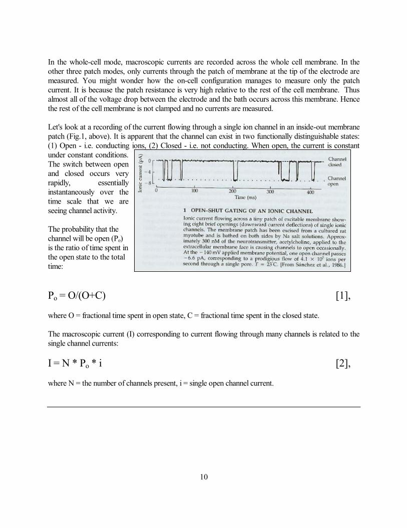
In the whole-cell mode, macroscopic currents are recorded across the whole cell membrane. In the other three patch modes, only currents through the patch of membrane at the tip of the electrode are measured. You might wonder how the on-cell configuration manages to measure only the patch current. It is because the patch resistance is very high relative to the rest of the cell membrane. Thus almost all of the voltage drop between the electrode and the bath occurs across this membrane. Hence the rest of the cell membrane is not clamped and no currents are measured. Let's look at a recording of the current flowing through a single ion channel in an inside-out membrane patch (Fig.1, above). It is apparent that the channel can exist in two functionally distinguishable states: (1) Open - i.e. conducting ions, (2) Closed - i.e. not conducting. When open, the current is constant under constant conditions. The switch between open and closed occurs very rapidly, essentially instantaneously over the time scale that we are seeing channel activity. The probability that the channel will be open (Po) is the ratio of time spent in the open state to the total time: Po = O/(O+C) [1], where O = fractional time spent in open state, C = fractional time spent in the closed state. The macroscopic current (I) corresponding to current flowing through many channels is related to the single channel currents: I = N * Po * i [2], where N = the number of channels present, i = single open channel current.
11
4. Channel gating – voltage gated channels The Theory of analysis
Radioactive decay - Macroscopic kinetics The simplest chemical reaction is an irreversible change from one state to another, exemplified by radioactive decay:
X -> Y
The rate (dX/dt) at which X atoms decay is directly proportional to the number of X atoms remaining: dX/dt = -X
Thus this simplest possible chemical reaction is described mathematically by a function whose derivative is proportional to the function itself. Integrating this function w.r.t. time gives: X(t) = Xoe
-t, where Xo constant' in units of atoms per second.
= 1/, where is the time constant in seconds per atom. Biological reactions are series of chemical reactions, and are thus described as sums of exponentials. The kinetics of ion channels are very well described as sums of exponential chemical decays. Radioactive decay - Microscopic kinetics
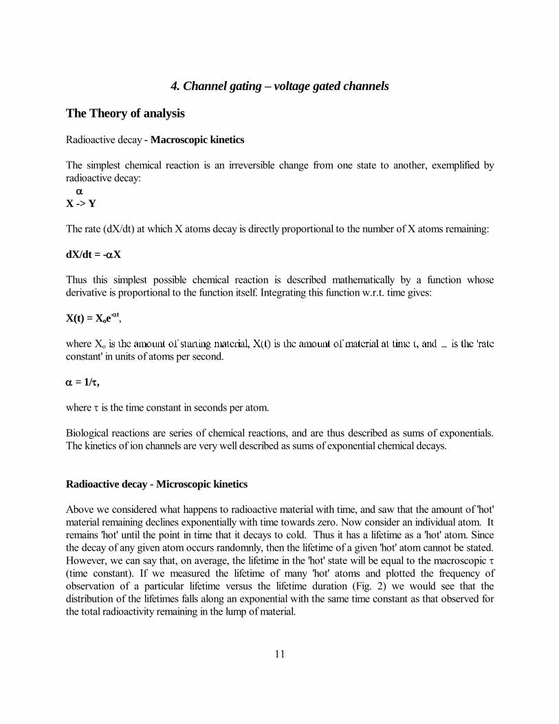
Above we considered what happens to radioactive material with time, and saw that the amount of 'hot' material remaining declines exponentially with time towards zero. Now consider an individual atom. It remains 'hot' until the point in time that it decays to cold. Thus it has a lifetime as a 'hot' atom. Since the decay of any given atom occurs randomnly, then the lifetime of a given 'hot' atom cannot be stated. However, we can say that, on average, the lifetime in the 'hot' state will be equal to the macroscopic (time constant). If we measured the lifetime of many 'hot' atoms and plotted the frequency of observation of a particular lifetime versus the lifetime duration (Fig. 2) we would see that the distribution of the lifetimes falls along an exponential with the same time constant as that observed for the total radioactivity remaining in the lump of material.

12
At this point, it is perhaps worth thinking about what is the significance of the average (or mean) lifetime of an individual member of an exponential distribution as opposed to the mean value in a Gaussian, or normal, distribution. Only in the latter case is the mean value also the most frequently observed value. Reversible reactions - Simple channel gating Let us consider the simplest model of the gating (opening and closing) of an ion channel. This is equivalent to a chemical reaction, such as isomerization, in which form A can change reversibly to form B:
where and , and k1and k-1, are rate constants for the indicated transitions. We can consider the reaction from a thermodynamic viewpoint. The two states of the channel (closed - C and open - O) are each associated with a potential energy level and there is an energy barrier to be overcome in changing from one state to the other: The rate constants for the transitions are inversely dependent on the chemical energy (G) needed to make the transition: G() = -RT(ln ), G() = -RT(ln ), The rate of the forward reaction is [C], where [C] is the concentration (i.e. the number) of closed channels; the rate of the back reaction is [O]. At infinite time, this system will reach equilibrium, and [C] = [O], so:
C = O
k1 A = B k-1

13
[O]/[C] = / The useful number is the fraction of channels in the open state at equilibrium. We'll call this O (this is also the open probability, Po): O = [O]/([C]+ [O]) = (/) * [C] /([C]+ (/) * [C]) (from eqn. *) = (/) /(1 + (/)) (divide by [C]) O= /(+) [3] (multiply by ) Now, let us consider the time course of the approach to this final state, i.e. the kinetics of the process. The rate of change of the fraction (O) of open channels is the forward rate minus the backwards rate: dO/dt = C - O, If we consider C and O as fractions of the total (C = 1-O), then we can write:
O, = - ( + )*O, which is a differential of the general form: dx/dt = A-Bx, where A and B are constants. 1/(A-Bx).dx = dt ln(A-Bx) + C = -bt A-Bx = c.e-Bt, - (+)*Ot = c.e-(+)t
(+)*Ot = -c.e-(+)t Ot = -c.e-(+)t + d O = 0 + d = d Oo = -c*1 + d, c = O - Oo Hence: Ot = -(O - Oo).e-t/ + O [4] where

14
= 1/(+) [5] Equations 3 and 5 can then be solved simultaneously to obtain the rate constants. In conclusion, the simple reversible reaction described above causes exponential changes in current (and number of open channels) when it proceeds. The exponential can be analyzed to get and , the forward and backward rate constants.
Microscopic analysis of more complex channels If a channel is described correctly by the simple 2-state model discussed, then we can directly measure and , since in the steady-state the (opening rate) = 1/closed time, and (closing rate) = 1/open time. Experimentally, one can measure the durations of openings and closings, then bin them and plot number of observations against the bin duration:
Real channels, such as the Na and K channels in the nerve action potential, are rarely, if ever as simple as the model above. It is clear that there are for many channels multiple closed states, prior to opening, and these are indistinguishable experimentally. Multiple closed states preceding the channel opening would be the current explanation for the four gates in the H-H descriptions. A further complication occurs, when multiple exit pathways from a given state exist. In this case, the mean open time is equal to the reciprocal of the sum of the rate constants leaving the state. This is a general rule for the lifetime of any state with mutiple exit pathways. A fuller description of these and other complications can be found in Colquhoun and Hawkes (1984).
1
C O C1 2

15
For this scheme the rate of leaving the open state = - [O] – [O]
= - ( + [O] and hence o, the mean open time = 1/( +

16
5. Na and K channels of nerve – Action potential generation
The Action Potential Although we now know excruciating detail about the structure and function of ion channels, their existence as discrete conductance pores was only demonstrated in real cells about 20 years ago using the patch-clamp technique. However, action potentials have been measured using intracellular microelectrodes for 50 years, and it is now 50 years since Andrew Huxley and Alan Hodgkin described the mechanistic basis in terms of gated Na and K selective channels, after analysis of macroscopic currents from the squid giant axon, using the two microelectrode technique. The development of a classical description of the action potential began with the realization of Cole and Curtis (1939, Fig. 3), that total
cellular conductance increased during the action potential, rather than decreasing. Since the action potential overshoots zero (typically nerve action potentials peak at around +40 mV), then this implies a selective increase in Na conductance (since ENa is ~+50 mV). This interpretation was supported by the experiments of Hodgkin and Katz (1949, Fig. 4), who showed that the peak of the action potential was reduced, when ENa was reduced by lowering the external [Na]. The voltage clamp allowed Hodgkin and Huxley to dissect the underlying conductance changes. To voltage-clamp means to control the voltage across the cell membrane. Under such conditions, conductance changes generate ionic current. In the giant axon, the resting potential is around –65 mV, so the current is zero at around –65 mV under voltage clamp. Hodgkin and Huxley observed that when the membrane was depolarized from this potential,

17
there was an initial inward current, followed by an outward current (Fig. 6). With successive depolarizations, the inward current component first becomes larger, then declines, while the outward current gets larger with each successive depolarization. By removing the external Na, it was shown that the inward current is carried by Na ions (Fig. 8).
By convention, inward current is defined (contrary to normal electronic conventions) as the inward movement of positive ions, or the outward movement of anions.By measuring the current amplitude at each point in time, and dividing by the driving force, H and H calculated the conductance change as a function of time and voltage (Fig. 11, 12).
Modeling the conductance changes - The Hodgkin-Huxley equations The earlier discussion showed how a single reversible reaction leads to exponential kinetics. However, neither the Na+ current nor the K+ current have simple exponential kinetics. Following a step in voltage to a potential at which the currents activate (i.e. channels open) the Na+ current first activates in a non-exponential (actually approximately sigmoidal) manner, and then decays (Fig. 14). In order to describe the current time course mathematically, Hodgkin and Huxley needed a function that provided a sigmoidal rise and then a fall back to zero. They chose the function m3h where m is a rising exponential and the h-term is a falling exponential. The K+ current activates in an even more sigmoidal manner, and this current is maintained. Hodgkin and Huxley chose the

18
function n4 where n is a rising exponential to describe the K+ current kinetics. Each of the three m, four n and one h were considered to be Na+ and K+ selective ion gates described by simple closed-open kinetics as for the hypothetical channel we considered in detail above. Hodgkin and Huxley did not know what the physical reality of the gates was, there was no knowledge of what ion channels were at the time, and although they went to some pains to point out that theirs was a mathematical formulation without implying any physical reality, a mechanism is implicit in the equations.
19
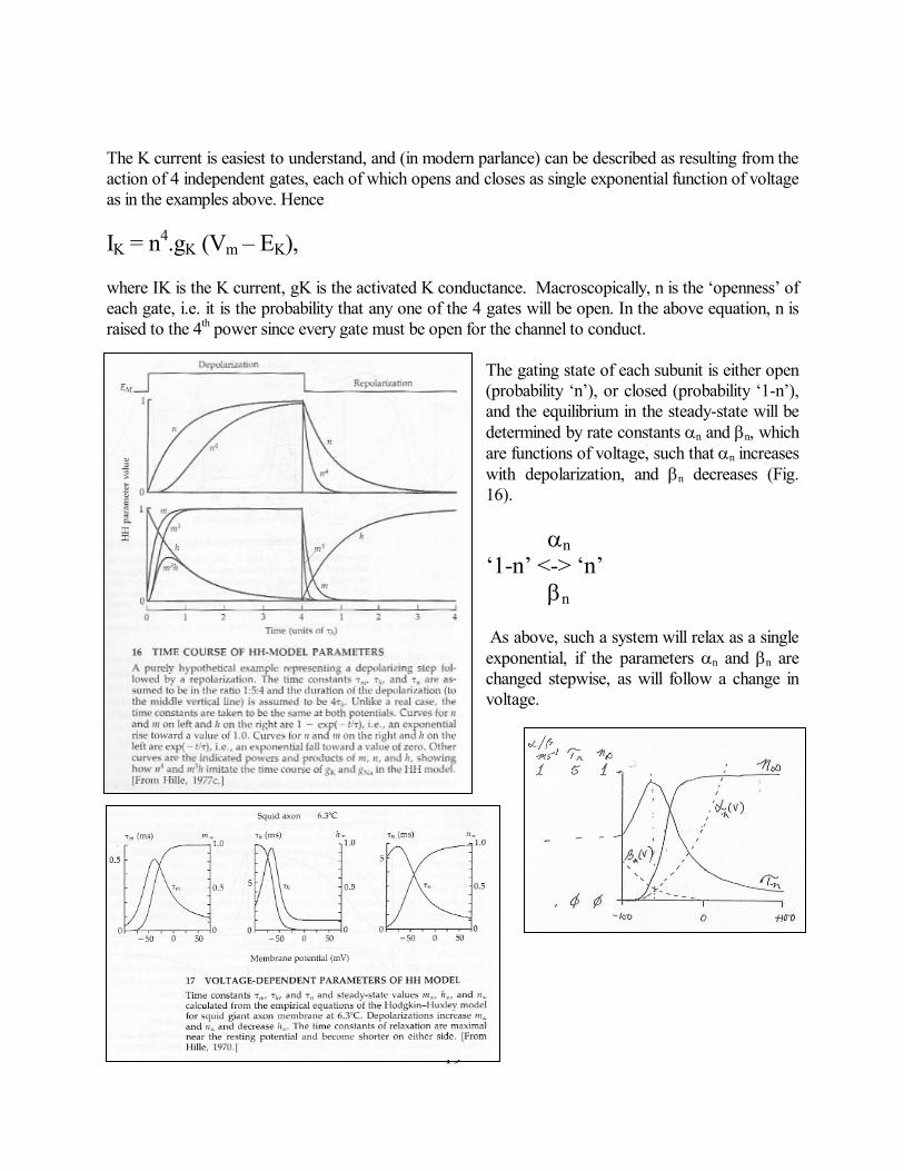
The K current is easiest to understand, and (in modern parlance) can be described as resulting from the action of 4 independent gates, each of which opens and closes as single exponential function of voltage as in the examples above. Hence IK = n4.gK (Vm – EK), where IK is the K current, gK is the activated K conductance. Macroscopically, n is the ‘openness’ of each gate, i.e. it is the probability that any one of the 4 gates will be open. In the above equation, n is raised to the 4th power since every gate must be open for the channel to conduct.
The gating state of each subunit is either open (probability ‘n’), or closed (probability ‘1-n’), and the equilibrium in the steady-state will be determined by rate constants n and n, which are functions of voltage, such that n increases with depolarization, and n decreases (Fig. 16). n ‘1-n’ <-> ‘n’ n As above, such a system will relax as a single exponential, if the parameters n and n are changed stepwise, as will follow a change in voltage.

20
A little more complex than for the K channel, the original HH explanation of the Na channel also involved 4 gating ‘particles’, but instead of identical ‘n’ probabilities, there are 3 ‘m’ probabilities that increase with depolarization, and 1 ‘h’ probability that decreases with depolarization. In this way the product m3h is very small at both positive and negative voltages in the steady state. However, the rate constants for movement of the h gate (h and h) are much smaller than for the m gates (Fig. 17), so that following a step depolarization, the increase in m occurs more quickly than the decrease of h, allowing a transient increase in channel opening before closure. The motivation for the H-H analysis was to explain the action potential. Therefore, having derived differential equations to explain the time-and voltage-dependence of the underlying conductances, they could, and people still do, integrate these equations to generate the electrical response of an unclamped membrane.
In the example in Fig. 18, action potentials are generated in a model membrane that contains the H-H K and Na channels, and a brief depolarizing current is injected to initiate the action potential at various distances along the axon. To the right is illustrated the behavior of the H-H parameters for a single non-voltage-clamped AP. (A) AP itself. (B) Underlying voltage-dependent conductances (gm is the sum of K and Na conductancesThe non-sigmoidalinactivation of the Na conductance and the prolonged elevation of the K conductance helps give rise to the undershoot and the prolonged refratoriness (C) The probability parameters that underlie the conductance changes. Note that both h and n remain different from rest for more than 6 msecs (the refractory period). It is important to realize that the action potential is an ‘all or nothing’ event. Once initiated, it continues through the same sequence of voltage changes and over the same time course each time. This is because of the voltage- and time-dependence of the Na channel gating. At the resting potential, m gates

21
are almost completely closed (i.e. the probability of being in the ‘open’ state for each subunit is very low, but the slow moving ‘h’ gate is open. When depolarization is initiated by a stimulus, m gates open and the channels conduct inward Na current. This inward movement causes further depolarization, and the ‘m’ probability increases further. A positive feedback situation is generated, and the membrane potential moves towards ENa very rapidly. More slowly, the probability n increases, and h decreases, resulting in increased (outward) K conductance and decreased (inward) Na conductance. The membrane then repolarizes back towards EK. Hodgkin and Huxley were aiming for the minimal model to describe their data, the Na activation could just as easily have been explained by 4 exponentials. We now know that the Na channel is made up of four homologous domains, and that the K channel is made up of four homologous subunits, each equivalent to a domain of the Na channel. It is then a simple conceptual jump to imagine that each domain of the Na channel, or subunit of the K channel, must 'gate' independently, for the channel to conduct (i.e. for the whole channel to be 'open). Such a mechanism is diagrammed here: One might then ask, what about the h-gate? If there is an h-gate on each subunit, why shouldn't inactivation be described by h4? If not, then where is it? We now have a very interesting explanation for this phenomena based on the structure of the channel - namely that it is the N-terminal ‘ball’ region of the channel that enters the pore and blocks it.. It appears that only one of the 'inactivation balls' needs to be in place to inactivate the channel. The kinetics will thus appear as the kinetics of a single ball, only four-fold faster.
22
6. Additional V-gated currents – Frequency coding In the above classical discussion of the action potential, we limited ourselves to discussing generic sodium channels, delayed rectifier potassium channels and rather poorly defined 'leak' channels. It is now obvious that there are many sub-types of sodium and potassium channels, and that leak channels come in many flavors. Na channels have essentially one function in the nervous system, and in other cells, to generate a rapid upstroke of the action potential, and hence show relatively little functional diversity. On the other hand, potassium channels, while universally causing hyperpolarization and reduced excitability, can be recruited under different conditions to serve quite different roles. As a consequence, the functional variability among potassium channels is enormous. Post-synaptic ion channels, gated by neurotransmitters, cause the post-synaptic depolarization that initiates the action potential. Diversity of response to synaptic input is generated by diversity of functional properties of these channels. Potassium channel diversity As we said initially, an ion channel is defined by its pore properties, and its gating. Potassium channels show an almost bewildering variability of both. Gating of potassium channels generates diversity of function: Inactivating IA channels allow
frequency encoding Probably the greatest functional diversity among potassium channels is generated by differences in gating. There are potassium channels that gate (i.e. open) in response to voltage, but other channels are almost insensitive to voltage and require chemical ligands to cause them to open. Among the voltage-gated potassium channels, we have become familiar with delayed rectifier channels (HH channels), and so-called IA channels, which activate very quickly upon depolarization, but then inactivate, like Na channels.
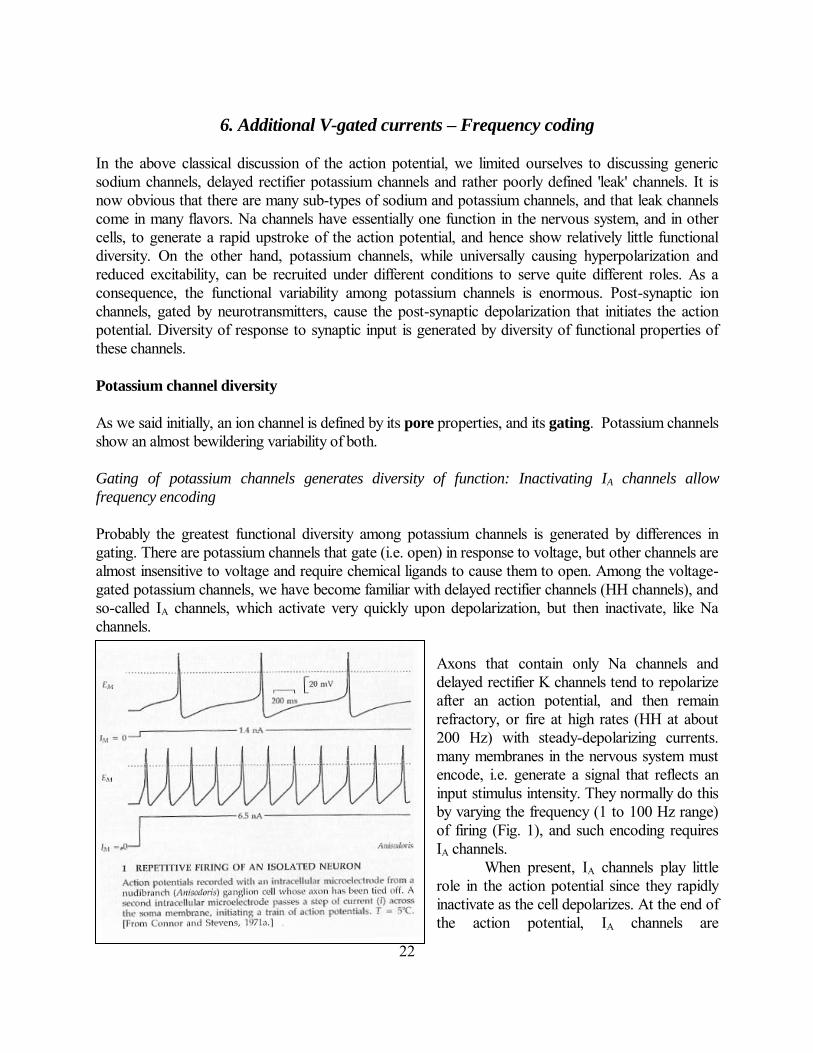
Axons that contain only Na channels and delayed rectifier K channels tend to repolarize after an action potential, and then remain refractory, or fire at high rates (HH at about 200 Hz) with steady-depolarizing currents. many membranes in the nervous system must encode, i.e. generate a signal that reflects an input stimulus intensity. They normally do this by varying the frequency (1 to 100 Hz range) of firing (Fig. 1), and such encoding requires IA channels.
When present, IA channels play little role in the action potential since they rapidly inactivate as the cell depolarizes. At the end of the action potential, IA channels are

23
inactivated, but delayed rectifier K (KDR) channels are open, hyperpolarizing the cell. Eventually, the maintained hyperpolarization causes KDR channels to deactivate (i.e. close, causing the membrane to
begin to depolarize). This allows the IA channels to recover from inactivation. As the cell depolarizes, the IA channels open again, and arrest the depolarization. Eventually, the IA channels begin to inactivate and allow depolarization to continue. Thus repetitive action potential firing is damped, allowing an interspike interval of hundreds of milliseconds.

24
KATP channels couple metabolism to electrical activity
Some potassium channels are not depolarization-activated (and lack S4-like segments in their primary structure). These channels can provide a feedback modulation of membrane excitability in response to changes in cell metabolic state or other ligands. When cells are made anoxic, it makes teleological sense that such cells may want to become inexcitable, stopping the cell from 'working', and conserving ATP. A mechanism to do this exists in many neurons and other cells. A class of voltage-independent K channels (KATP) are normally closed by the binding of ATP. In conditions of anoxia, as ATP begins to fall, these K channels open. They are time- and voltage-independent and so they act to hyperpolarize the cell towards EK and abolish action potential firing. Ca-activated K channels modulate bursting activity
Ca-activated K channels, known also as maxi-K, or BK (for big K), channels are high conductance voltage- and calcium activated K channels that provide a feedback link between intracellular calcium and membrane potential in many cells:
In bursting neurones, these channels are activated following the rise of calcium that occurs during a burst, and function to terminate the burst. Variable pore properties generate further
functional diversity All potassium channels contain K selectivity filters, and recent evidence suggests that only one or two amino acids within the pore form this filter. However, the pore is lined by many residues, contributing potential binding sites for other agents which may block the channel. Since the pore spans the voltage field, binding of a charged ion within the pore will be influenced by the voltage. Depending on the direction of the voltage, the ion will be either pulled into or pushed out of the pore. Several pharmacological
agents, notably TEA+ and derivatives, block channels in a voltage dependent manner. While some K channels are blocked by micromolar concentrations of TEA, others are virtually insensitive. Of significance physiologically, is pore blockade by internal Mg2+ and polyamines, which causes steeply voltage-dependent block of otherwise voltage-insensitive K channels:

25
Large currents are seen in the inward direction, but virtually no currents are observed in the outward direction. These K channels shows inward, or anomolous, rectification. In zero internal Mg2+, the I-V is linear. This figure is taken from data obtained on a cloned inward rectifier K channel from the hippocampus. The rectification results from a voltage dependent block of the channel by internal magnesium and polyamines. When the cell is depolarized, these cations are driven into the pore, blocking the channel.
In heart cells, these channels reduce the need for a large inward current to maintain the action potential at a depolarized potential, and hence minimizes the energetically expensive rundown of the ion gradients that would result from large opposing conductances during the a.p., whilst still allowing a large K conductance to stabilize the resting potential. Having a low resting K conductance in other cells would predispose them to depolarize and fire spontaneous action potentials of their own. Ectopic arrhythmias disturb the rhythm and interfere with the appropriately timed spread of excitation. Most neurons probably do not require such stability of the resting potential, obviating the need for inward rectifiers. However, glial cells have enormous inward rectifier conductances, and it is believed that such high conductance allows glial cells to buffer extracellular potassium concentrations against changes resulting from neuronal activity
ININ OUTOUT
Em = 0Em = +100spe
spd
put
0 mV0 mV-100 mV
+100 mV
K
~20 A
A B
26
Functional variety of ligand-gated receptor activated channels
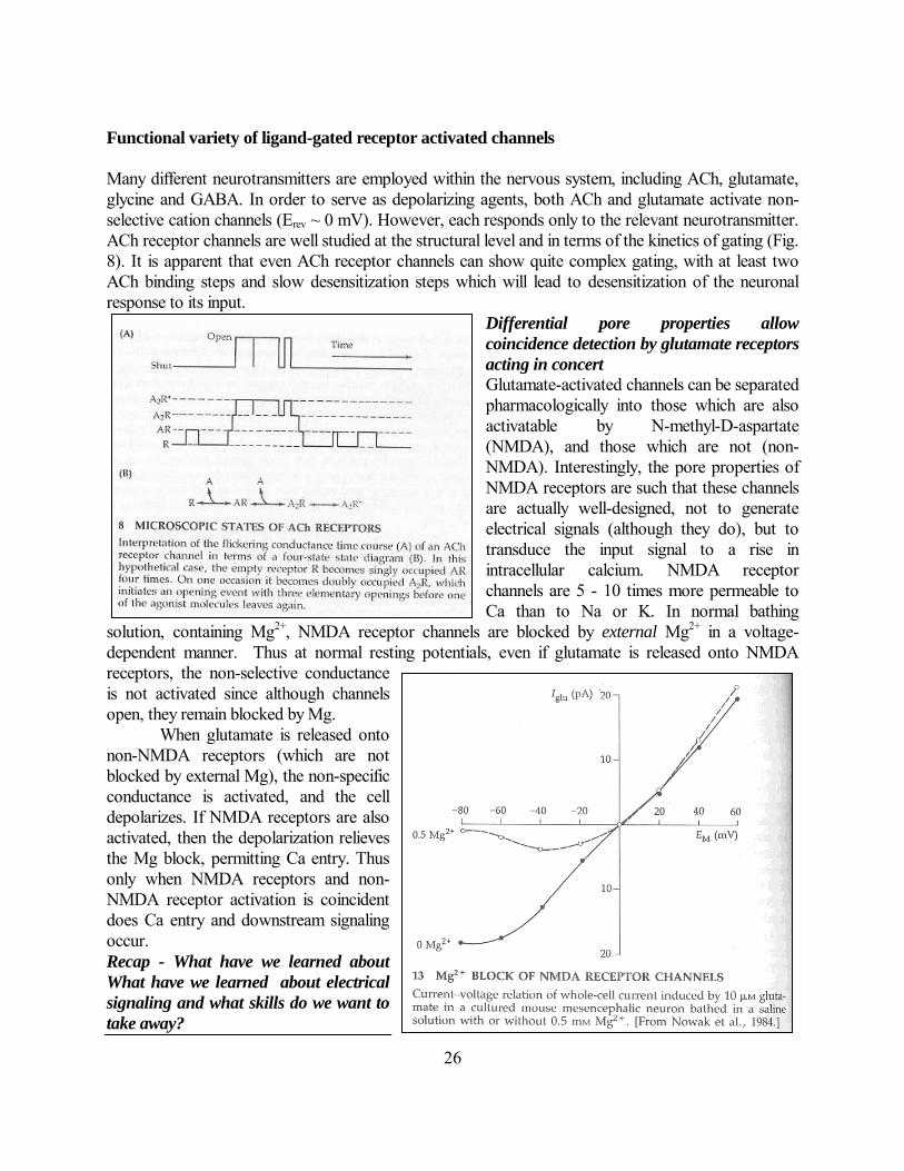
Many different neurotransmitters are employed within the nervous system, including ACh, glutamate, glycine and GABA. In order to serve as depolarizing agents, both ACh and glutamate activate non-selective cation channels (Erev ~ 0 mV). However, each responds only to the relevant neurotransmitter. ACh receptor channels are well studied at the structural level and in terms of the kinetics of gating (Fig. 8). It is apparent that even ACh receptor channels can show quite complex gating, with at least two ACh binding steps and slow desensitization steps which will lead to desensitization of the neuronal response to its input.
Differential pore properties allow
coincidence detection by glutamate receptors
acting in concert
Glutamate-activated channels can be separated pharmacologically into those which are also activatable by N-methyl-D-aspartate (NMDA), and those which are not (non-NMDA). Interestingly, the pore properties of NMDA receptors are such that these channels are actually well-designed, not to generate electrical signals (although they do), but to transduce the input signal to a rise in intracellular calcium. NMDA receptor channels are 5 - 10 times more permeable to Ca than to Na or K. In normal bathing
solution, containing Mg2+, NMDA receptor channels are blocked by external Mg2+ in a voltage-dependent manner. Thus at normal resting potentials, even if glutamate is released onto NMDA receptors, the non-selective conductance is not activated since although channels open, they remain blocked by Mg. When glutamate is released onto non-NMDA receptors (which are not blocked by external Mg), the non-specific conductance is activated, and the cell depolarizes. If NMDA receptors are also activated, then the depolarization relieves the Mg block, permitting Ca entry. Thus only when NMDA receptors and non-NMDA receptor activation is coincident does Ca entry and downstream signaling occur. Recap - What have we learned about
What have we learned about electrical
signaling and what skills do we want to
take away?

27
We have re-capped the principles of electricity, including all the common terms and physical
components, including current, voltage, resistance and capacitance. These same principles underlie all electric signaling, both in physical and biological systems. The cell membrane acts
as a capacitor. The energy-dependent separation of ions across this capacitor, by ATP driven
pumps, generates ‘batteries’, with energy stoed in the ion gradients, partiularly for Na and Ca.
These batteries can be discharged, by the opening of ion channels, conductors, across the
membrane. The membrane potential will depend on which ion conductors are ope, and can be
estimated using the GHK or Competing batteries equations.
We have considered radioactive decay as a simple example of an exponential process which underlies
every biological reaction. Unlike radioactive decay, biological reactions, including ion channel
gating have a finite possibility of reversal, and so we consider kinetic models of ion channels from a
thermodynamic and kinetic standpoint. There are a few simple conclusions and principles from this
analysis which should be mastered. Firstly, channel lifetimes are inversely proportional to the rate of
decay of that state, and hence the rate constants for the appropriate kinetic model can, in principle,
be determined from measurements of channel lifetimes, or from macroscopic time courses of current
change in response to a step change of voltage. With this approach, Hodgkin and Huxley, without
knowledge of the channel nature of the current carriers, derived empirical equations describing the
Na and K conductances underlying the action potential. Today, these empirical descriptions can be
interpreted in terms of kinetic models and even in relation to the molecular structure of the channel.
To complement electrophysiological analysis, high-resolution structures of ion channels are now
emerging, and future studies will further relate the structure of channels to their function. You should
now be able to read these papers and understand the measurements being made. In general,
electrophysiological studies of channels measure (1) channel lifetimes or macroscopic activation,
deactivation, or inactivation. In every case the underlying drive to measure these parameters is to
develop or refine a kinetic model, or to understand the effects of a modulator on a specific part of the
kinetic scheme; (2) current-voltage relationships, conductance, selectivity. Knowing the amount of
current flowing through the open channel under given sets of conditions helps to separate channels
from one another by their relative ability to distinguish one ion from another, or to separate channels
of similar ion selectivity by their conductance under similar conditions. Frequently, channels are
distinguished by their pharmacological profile, and many papers that you come across will be aimed
at interpreting the action of the pharmacological (or physiological) modifying agent on the channel.
Vice versa, many papers dealing with channel mutations will assume the action of the agent and
interpret the experimental results in terms of defining the site of action of the agent, or the role of
specific regions or residues of the channel in the action of the agent. The approach, in all cases is
still to measure (1) kinetics, or (2) conductance properties since all pharmacological, and
physiological modifiers effectively act on one of these two parameter sets, or both.