Investigation of the effect of the Coriolis force on a thin fluid film on a rotating disk
20
Int. J. Non-Linear Mechanics, Vol. 33, No. 6, pp. 1069—1088, 1998 ( 1998 Elsevier Science Ltd. All rights reserved Printed in Great Britain 0020—7462/98 $19.00#0.00 PII: S0020–7462(97)00071-1 INVESTIGATION OF THE EFFECT OF THE CORIOLIS FORCE ON A THIN FLUID FILM ON A ROTATING DISK E. Momoniat* and D. P. Mason Centre for Symmetry Analysis, Differential Equations and Applications, and Department of Computational and Applied Mathematics, University of the Witwatersrand, Private Bag 3, Wits 2050, Johannesburg, South Africa (Received for publication 30 October 1997) Abstract—The effect of the Coriolis force on the evolution of a thin film of Newtonian fluid on a rotating disk is investigated. The thin-film approximation is made in which inertia terms in the Navier—Stokes equation are neglected. This requires that the thickness of the thin film be less than the thickness of the Ekman boundary layer in a rotating fluid of the same kinematic viscosity. A new first-order quasi-linear partial differential equation for the thickness of the thin film, which describes viscous, centrifugal and Coriolis-force effects, is derived. It extends an equation due to Emslie et al. [J. Appl. Phys. 29, 858 (1958)] which was obtained neglecting the Coriolis force. The problem is formulated as a Cauchy initial-value problem. As time increases the surface profile flattens and, if the initial profile is sufficiently negative, it develops a breaking wave. Numerical solutions of the new equation, obtained by integrating along its characteristic curves, are compared with analytical solutions of the equation of Emslie et al. to determine the effect of the Coriolis force on the surface flattening, the wave breaking and the streamlines when inertia terms are neglected. ( 1998 Elsevier Science Ltd. All rights reserved Keywords: thin viscous fluid film, rotating disk, Coriolis force, characteristic curves, breaking surface profile, streamlines 1. INTRODUCTION Since the pioneering work of Emslie et al. [1] in 1958 a considerable amount of research has been undertaken on the flow of a thin fluid film on a rotating disk [2—19]. This is because of the important industrial applications of spin coating in, e.g. the manufacture of magnetic and optical disks, the production of phosphor coatings on television screens and photoresist films on silicon wafers. In spin coating a volume of fluid is placed on the disk. The fluid flows outwards when the disk is spun with constant angular velocity and the spinning is continued until the required thickness is attained. The thickness of the film produced in this way is extremely uniform. Investigations have been undertaken into the effect on spin coating of surface tension [5], evaporation of the solvent [3, 8, 11, 14], non-Newtonian fluid [2, 6, 7], interface slip between the liquid and the disk [9], air flow induced by the rotation of the disk [12], surface roughness of the disk [15], inertia and unsteady flow due to finite acceleration at start-up [10, 13] and heat transfer [17, 18]. The stability of a thin fluid film on a rotating disk has also been investigated [18]. However, comparatively little attention has been paid to the Coriolis force which is usually neglected. In this paper we will investigate the effect of the Coriolis force on the evolution of a thin fluid film on a rotating disk for thin films in which the inertia of the fluid can be neglected. We will see that the neglect of the inertia terms in the Navier-Stokes equation requires that the thickness of the thin film be less than the thickness of the Ekman boundary layer in a rotating fluid of the same kinematic viscosity and angular velocity [20, 21]. Emslie et al. [1], who considered a Newtonian fluid and neglected the Coriolis force, showed that if the slope of the initial surface profile of the thin film is sufficiently negative then the surface profile will develop a breaking wave. They also showed that an arbitrary initial surface profile will be smoothed by the rotation and a film of uniform thickness will be produced. We will investigate the effect of the Coriolis force on the breaking process and on the flattening process. We will also investigate the effect of the Coriolis force on the streamlines * Corresponding author. Tel.: # 27-11-716-3905; fax: # 27-11-403-9317; e-mail: ebrahim@gauss.cam.wits.ac.za. 1069
Transcript of Investigation of the effect of the Coriolis force on a thin fluid film on a rotating disk

Int. J. Non-Linear Mechanics, Vol. 33, No. 6, pp. 1069—1088, 1998( 1998 Elsevier Science Ltd. All rights reserved
Printed in Great Britain0020—7462/98 $19.00#0.00
PII: S0020–7462(97)00071-1
INVESTIGATION OF THE EFFECT OF THE CORIOLISFORCE ON A THIN FLUID FILM ON A ROTATING DISK
E. Momoniat* and D. P. Mason
Centre for Symmetry Analysis, Differential Equations and Applications, and Department ofComputational and Applied Mathematics, University of the Witwatersrand, Private Bag 3,
Wits 2050, Johannesburg, South Africa
(Received for publication 30 October 1997)
Abstract—The effect of the Coriolis force on the evolution of a thin film of Newtonian fluid ona rotating disk is investigated. The thin-film approximation is made in which inertia terms in theNavier—Stokes equation are neglected. This requires that the thickness of the thin film be less thanthe thickness of the Ekman boundary layer in a rotating fluid of the same kinematic viscosity. A newfirst-order quasi-linear partial differential equation for the thickness of the thin film, which describesviscous, centrifugal and Coriolis-force effects, is derived. It extends an equation due to Emslie et al.[J. Appl. Phys. 29, 858 (1958)] which was obtained neglecting the Coriolis force. The problem isformulated as a Cauchy initial-value problem. As time increases the surface profile flattens and, if theinitial profile is sufficiently negative, it develops a breaking wave. Numerical solutions of the newequation, obtained by integrating along its characteristic curves, are compared with analyticalsolutions of the equation of Emslie et al. to determine the effect of the Coriolis force on the surfaceflattening, the wave breaking and the streamlines when inertia terms are neglected. ( 1998 ElsevierScience Ltd. All rights reserved
Keywords: thin viscous fluid film, rotating disk, Coriolis force, characteristic curves, breakingsurface profile, streamlines
1 . INTRODUCTION
Since the pioneering work of Emslie et al. [1] in 1958 a considerable amount of research hasbeen undertaken on the flow of a thin fluid film on a rotating disk [2—19]. This is because ofthe important industrial applications of spin coating in, e.g. the manufacture of magneticand optical disks, the production of phosphor coatings on television screens and photoresistfilms on silicon wafers. In spin coating a volume of fluid is placed on the disk. The fluid flowsoutwards when the disk is spun with constant angular velocity and the spinning iscontinued until the required thickness is attained. The thickness of the film produced in thisway is extremely uniform. Investigations have been undertaken into the effect on spincoating of surface tension [5], evaporation of the solvent [3, 8, 11, 14], non-Newtonian fluid[2, 6, 7], interface slip between the liquid and the disk [9], air flow induced by the rotationof the disk [12], surface roughness of the disk [15], inertia and unsteady flow due to finiteacceleration at start-up [10, 13] and heat transfer [17, 18]. The stability of a thin fluid filmon a rotating disk has also been investigated [18]. However, comparatively little attentionhas been paid to the Coriolis force which is usually neglected.
In this paper we will investigate the effect of the Coriolis force on the evolution of a thinfluid film on a rotating disk for thin films in which the inertia of the fluid can be neglected.We will see that the neglect of the inertia terms in the Navier-Stokes equation requires thatthe thickness of the thin film be less than the thickness of the Ekman boundary layer ina rotating fluid of the same kinematic viscosity and angular velocity [20, 21]. Emslie et al.[1], who considered a Newtonian fluid and neglected the Coriolis force, showed that if theslope of the initial surface profile of the thin film is sufficiently negative then the surfaceprofile will develop a breaking wave. They also showed that an arbitrary initial surfaceprofile will be smoothed by the rotation and a film of uniform thickness will be produced.We will investigate the effect of the Coriolis force on the breaking process and on theflattening process. We will also investigate the effect of the Coriolis force on the streamlines
*Corresponding author. Tel.:#27-11-716-3905; fax:#27-11-403-9317; e-mail: [email protected].
1069

at the surface of the thin film. When the Coriolis force is neglected, the streamlines arepurely radial.
The disk is infinite in extent, is horizontal and rotates about a vertical axis with constantangular velocity. The effects of gravity are neglected. The thin film is axisymmetric about theaxis of rotation and the fluid is incompressible, Newtonian, non-volatile and isothermal.Surface tension and the surface stress due to the airflow induced by the rotation areneglected.
We will make the thin-film approximation [16, 20]. In thin-film theory the characteristicthickness of the thin film, h
0, is assumed to be much smaller than the characteristic length of
the film ¸:h0¸
@1. (1.1)
In addition the assumption is also made that
ReAh0¸B
2@1 , (1.2)
where Re"º¸/l is the Reynolds number of the flow, º is the characteristic velocity in theplane of the disk relative to the disk and l the kinematic viscosity of the fluid. A consequenceof equation (1.2) is that inertia terms in the Navier—Stokes equation can be neglected eventhough the Reynolds number itself may not be small. By considering the relation betweenthe characteristic velocity, º, which is not set by experiment and the other parameters of theflow, we will see that equation (1.2) can be expressed in terms of the ratio of the character-istic thickness of the thin film to the thickness of the Ekman boundary layer in a rotatingfluid with the same kinematic viscosity and angular velocity. The governing partial differen-tial equations are linear but the free surface boundary condition is non-linear.
An outline of the paper is as follows. In Section 2 the thin-film equations for anincompressible viscous fluid with respect to a frame of reference attached to the rotatingdisk are derived. In Section 3 a new first-order quasi-linear partial differential equation forthe height of the thin film on a rotating disk is obtained. In the derivation of the equation,the inertia terms in the Navier—Stokes equation are neglected but viscous-force terms, thecentrifugal-force term and the Coriolis-force terms in the Navier—Stokes equation areretained. In Section 4 the Coriolis force is neglected. This will clarify the effects of theCoriolis force when it is included in the next section. The first-order quasi-linear partialdifferential equation of Emslie et al. [1] is obtained as the lowest-order equation ina straightforward expansion of the new partial differential equation in powers of the ratio ofthe characteristic thickness of the thin film to the Ekman boundary layer thickness. Thecondition for breaking waves and the breaking time [16, 20] are rederived and illustrated byconsidering two specific initial surface profiles. The production of a film of uniformthickness from the two initial surface profiles is examined. In Section 5 the new partialdifferential equation is solved numerically for the same two initial surface profiles and theeffect of the Coriolis force on the wave breaking process, on the flattening process of theinitial surface profiles and on the streamlines when inertia effects are neglected, is studied bycomparing the results with those of Section 4. Finally, the approximations made arediscussed in Section 6.
2 . THIN-FILM EQUATIONS WITH RESPECT TO A ROTATING FRAME
In this section we will derive the equations describing flow in a thin film of viscousincompressible fluid on a rotating disk with respect to a reference frame attached to the disk.
If v(I) denotes the fluid velocity with respect to a fixed inertial frame and v(R) the fluidvelocity with respect to a reference frame with the same origin and rotating with angularvelocity X relative to the inertial frame, then
v(I)"v(R)#X]r , (2.1)
where r is the position vector of the fluid element. Suppose that the body force vanishes andthat X is a constant vector. For an incompressible fluid the Navier—Stokes and continuity
1070 E. Momoniat and D. P. Mason

equations with respect to the rotating reference frame are
oDv(R)
Dt"!gradP!2o X]v(R)#k+2v(R), (2.2)
div v(R)"0, (2.3)
where D/Dt denotes the material time derivative in the rotating frame and the ‘‘reducedpressure’’ P is related to the fluid pressure p by
P"p!12o (X]r)2. (2.4)
The Coriolis force is !2oX]v(R). The centrifugal force, !oX](X]r), has been incorpor-ated in the reduced pressure:
!oX](X]r)"grad (12o (X]r)2) . (2.5)
Consider now cylindrical polar coordinates (r, h, z) in the rotating frame with the z-axisperpendicular to the plane of the disk and along the axis of rotation of the disk, e
z:
X")ez. (2.6)
We express the Navier—Stokes and continuity equations in terms of cylindrical polarcoordinates and in dimensionless form. Let the characteristic length of the fluid film in theplane of the disk be ¸ and the characteristic length perpendicular to the plane be h
0which
may be the initial thickness of the fluid film at the origin. Consider now the charcteristicfluid velocity, º, relative to the disk in the plane of the disk. It is not an independentcharcteristic quantity that can be set in an experiment and therefore it must be related to theother parameters in the problem. We will determineº by balancing the centrifugal force perunit volume, which is O(o)2¸), with the viscous force unit volume, which is O(kº/h2
0). This
gives
º"
)2¸ h20
l, (2.7)
where l"k/o is the kinematic viscosity. Although Emslie et al. [1] did not use dimension-less equations the characteristic velocity (2.7) is implied in their work since they equated thecentrifugal force per unit volume with the viscous force per unit volume in the derivation oftheir governing partial differential equation. This characteristic velocity is appropriate todescribe the evolution of the thin film after the fluid has been spun up from rest and the diskis rotating with constant angular velocity ). It follows from the continuity equation (2.3)that the characteristic fluid velocity normal to the plane of the disk is h
0º/¸. The
corresponding characteristic time is ¸/º. The characteristic fluid pressure is determined bybalancing the pressure gradient force per unit volume in the plane of the disk, which isO (p/¸), with the viscous force per unit volume which is O(kº/h2
0). This gives for the
characteristic pressure kº¸/h20
which, using equation (2.7) for º, may be expressed aso)2¸2. This agrees with the characteristic pressure used in thin film theory [20]. A charac-teristic length which plays an important part in the subsequent analysis is the thickness, E,of the Ekman boundary layer in a rotating fluid:
E"Al)B
1@2. (2.8)
We introduce the dimensionless variables
rN"r
¸
, zN"z
h0
, vNr"
v(R)rº
, vN h"v(R)hº
, vNz"
¸v(R)z
h0º
,
tN"ºt
¸
, pN "h20
kº¸
p. (2.9)
Effect of the Coriolis force on a thin fluid film on a rotating disk 1071

Then the r, h, z-components of the Navier—Stokes equation (2.2) in dimensionless form are,respectively,
Ah0
EB4
ALvN
rLtN
#vNr
LvNr
LrN#
vN hr
LvNr
Lh#vN
z
LvNr
LzN!
vN 2hrN B
"2Ah0
EB2vN h#rN!
LpNLrN
#Ah0¸B
2
AL2vN
rLrN 2
#
1
rNLvN
rLrN
#
1
rN 2L2vN
rLh2
!
vNr
rN 2!
2
rN 2LvN hLhB#
L2vNr
LzN 2, (2.10)
Ah0
EB4
ALvN hLtN
#vNr
LvN hLrN
#
vN hrN
LvN hLh
#vNz
LvN hLzN
#
vNrvN hrN B
"!2Ah0
EB2vNr!
1
rNLpNLh
#Ah0¸B
2
AL2vN hLrN 2
#
1
rNLvN hLrN
#
L2vN hLh2
#
2
rN 2LvN
rLh
!
vN hrN 2B#
L2vN hLzN 2
, (2.11)
Ah0
EB4
ALvN
zLtN
#vNr
LvNz
LrN#
vN hrN
LvNz
Lh#vN
z
LvNz
LzN B"!A
¸
h0B2 LpNLzN
#Ah0¸B
2 L2vNz
LrN 2#A
h0¸B
2 1
rNLvN
zLrN
#Ah0¸B
2 1
rN 2L2vN
zLh2
#
L2vNz
LzN 2, (2.12)
and the continuity equation (2.3) in dimensionless form is
1
rNLLrN
(rN vNr)#
1
rNLvN hLh
#
LvNz
LzN"0 . (2.13)
The ratio (h0/E)4 may be expressed in terms of the Reynolds number, Re, given by
Re"º¸
l"
¸2h20
E4. (2.14)
We have
ReAh0¸B
2"A
h0
EB4. (2.15)
We will make the thin film approximation (1.1) and (1.2):
ReAh0¸B
2"A
h0
EB4@1 ,
h0¸
@1. (2.16)
In equations (2.10)—(2.12) we will neglect terms O((h0/¸)4) but we will retain terms
O((h0/E)2). Terms O((h
0/¸)2) will also be neglected. We are therefore assuming that
h0@E@¸. (2.17)
The thickness of the thin film, h0, must therefore be less than the thickness of the Ekman
boundary layer in a rotating fluid. If h0'E, the non-linear inertia terms cannot be
neglected. Equations (2.10)—(2.12) reduce to
LpNLrN
"
L2vNr
LzN 2#2A
h0
EB2vN h#rN , (2.18)
1
rNLpNLh
"
L2vN hLzN 2
!2Ah0
EB2
vNr, (2.19)
LpNLzN
"0. (2.20)
Equation (2.13) is unchanged. The terms of O((h0/E)2) are the Corolis force terms which
were neglected by Emslie et al. [1]. Equations (2.18)— (2.20) and (2.13) can be used todetermine the first correction to the results of Emslie et al. [1] in an asymptotic expansion inpowers of (h
0/E)2. They cannot be used to investigate the effect of the Corolis force in thin
films for which h0'(l/))1@2 because the inertia terms, which were neglected, then become
the dominant terms.
1072 E. Momoniat and D. P. Mason

Finally, we consider the Cauchy stress tensor, qij, some components of which will be
required in the boundary conditions. Equation (2.1), expressed in cylindrical polar coordi-nates, is
v(I)r"v(R)
r, v(I)h "v(R)h #)r, v(I)
z"v(R)
z, (2.21)
and by using equation (2.21) it is readily verified that the Cauchy stress components incylindrical polar coordinates [20] are unchanged in form when expressed relative to therotating reference frame. The characteristic stress, like the characteristic pressure, is kº¸/h2
0and we define
q6ik"
h20
kº¸
q(R)ik
. (2.22)
Expressed in dimensionless from and relative to the rotating reference frame, we have
qNrr"!pN #2A
h0¸B
2LvNr
LrN, (2.23)
qNrh"A
h0¸B
2
ArNLLrN A
vN hrN B#
1
rNLvN
rLhB , (2.24)
qNrz"
h0¸
LvNr
LzN#A
h0¸B
3LvNz
LrN, (2.25)
qN hh"!pN #2Ah0¸B
2
A1
rNLvN hLh
#
vNrrN B , (2.26)
qN hz"h0¸
LvN hLzN
#Ah0¸B
31
rNLvN
zLh
, (2.27)
qNzz"!pN #2A
h0¸B
2LvNz
LzN. (2.28)
We neglect terms O((h0/¸)2). Equations (2.23)— (2.28) reduce to
q6rr"!pN , q6 hh"!pN , q6
zz"!pN ,
q6rh"0, q6
rz"
h0¸
LvNr
LzN, q6 hz"
h0¸
LvN hLzN
. (2.29)
This completes the derivation of the equations describing the flow of a viscous incompress-ible fluid in a thin film relative to a rotating reference frame. Dimensionless quantities willbe used in the remainder of the paper. To simplify the notation the overhead bar will besuppressed.
3. FIRST-ORDER PARTIAL DIFFERENTIAL EQUATION FOR THE
THIN-FILM THICKNESS
Consider a thin axisymmetric film of viscous incompressible fluid on a rotating disk.Cylindrical polar coordinates (r, h, z) are attached to the disk which rotates with constantangular velocity X about the z-axis. The effects of gravity and surface tension are neglected.Because the flow is axisymmetric all quantities are independent of h :
vr"v
r(r, z, t), vh"vh(r, z, t), v
z"v
z(r, z, t), p"p (r, z, t), (3.1)
where v is the fluid velocity relative to the disk. The thin-film equations (2.18)—(2.20) and thecontinuity equation (2.13), reduce to
Lp
Lr"
L2vr
Lz2#2A
h0
EB2vh#r , (3.2)
0"L2vhLz2
!2Ah0
EB2vr, (3.3)
Effect of the Coriolis force on a thin fluid film on a rotating disk 1073

Lp
Lz"0, (3.4)
1
r
L(rvr)
Lr#
Lvz
Lz"0. (3.5)
The terms proportional to vh and vrin equations (3.2) and (3.3) are the Coriolis force terms
and r in equation (3.2) is the centrifugal force term. The flow is subject to boundaryconditions at the surface of the disk, z"0, and at the free surface of the fluid, z"h(r, t). Atz"0 the viscous fluid sticks to the disk and there is no flow normal to the surface of thedisk:
z"0: vr(r, 0, t)"0, (3.6)
z"0: vh(r, 0, t)"0, (3.7)
z"0: vz(r, 0, t)"0. (3.8)
At the free surface the fluid pressure equals the constant atmospheric pressure, p0, and the
tangential stress components vanish:
z"h (r, t): p (r, h, t)"p0, (3.9)
z"h (r, t): qzr"
h0¸
Lvr
Lz"0, (3.10)
z"h (r, t): qzh"
h0¸
LvhLz
"0. (3.11)
Also, fluid particles on the free surface must remain on the surface [20]. Thus for anyparticular particle on the surface, z!h (r, t) must remain zero following the motion of thatparticle:
z"h (r, t):D
Dt(z!h (r, t))"0, (3.12)
which can be written as
z"h (r, t): vz(r, h, t)"
Lh
Lt(r, t)#v
r(r, h, t)
Lh
Lr(r, t). (3.13)
We now derive without further approximation a partial differential equation for thethickness of the thin film, h (r, t), from equations (3.2)— (3.5) subject to the boundaryconditions (3.6)— (3.11) and (3.13).
We first integrate equation (3.4) with respect to z and by imposing the boundarycondition (3.9) we find that
p (r, z, t)"p0. (3.14)
Equations (3.2) and (3.3) become
L2vr
LZ2#2vh"!A
E
h0B2
r , (3.15)
L2vhLZ2
!2vr"0, (3.16)
where
Z"
h0
Ez . (3.17)
If equation (3.16) is multiplied by i where i"J!1 and added to equation (3.15) then weobtain
L2fLZ2
!2i f"!AE
h0B2
r , (3.18)
1074 E. Momoniat and D. P. Mason

where
f (r,Z, t)"vr(r,Z, t)#ivh(r, Z, t) . (3.19)
The general solution of equation (3.18) is
f (r,Z, t)"A(r, t) exp[(1#i)Z]#B (r, t) exp[!(1#i)Z]!i
2AE
h0B2r , (3.20)
which may be expressed more conveniently in the form
f (r, Z, t)"[C(r, t) cosh Z#D(r, t) sinhZ] cosZ
#iC(D(r, t) coshZ#C(r, t) sinhZ) sin Z!
1
2AE
h0B2rD , (3.21)
where C"A#B and D"A!B. The boundary conditions on f (r, Z, t) follow directlyfrom the boundary conditions (3.6), (3.7) and (3.10), (3.11):
Z"0: f (r, 0, t)"0, (3.22)
Z"H (r, t) :Lf
LZ(r,H, t)"0, (3.23)
where
H (r, t)"h0
Eh (r, t) . (3.24)
By imposing the boundary conditions (3.22) and (3.23) it can be verified that
C(r, t)"i
2AE
h0B2r , D(r, t)"
1
2AE
h0B2 (sin 2H!i sinh 2H)r
(cos 2H#cosh 2H), (3.25)
and therefore
f (r, Z, t)"r
2AE
h0B2 [sinhZ sin(2H!Z)#sinZ sinh(2H!Z )]
(cos 2H#cosh 2H)
#
ir
2 AE
h0B2
CcoshZ cos(2H!Z)#cosZ cosh(2H!Z)
(cos 2H#cosh 2H)!1D . (3.26)
By equating the real and imaginary parts of equation (3.26) it follows directly that
vr(r, Z, t)"
r
2AE
h0B2 [sinhZ sin(2H!Z)#sinZ sinh(2H!Z )]
(cos 2H#cosh 2H). (3.27)
vh(r, Z, t)"r
2AE
h0B2
CcoshZ cos(2H!Z)#cosZ cosh(2H!Z)
(cos 2H#cosh2H)!1D . (3.28)
The velocity component vr
will be required in the subsequent analysis; vh will not berequired to obtain the partial differential equation for H(r, t), but it will be needed laterwhen the streamlines are considered.
The third velocity component, vz, is obtained from the continuity equation (3.5). By
substituting equation (3.27) for vrinto equation (3.5) we obtain
Ah0
EB3 Lv
zLZ
"!
[sinhZ sin(2H!Z)#sinZ sinh(2H!Z)]
(cos 2H#cosh 2H)
#
r
(cosH#coshH)2[(!sin 2H#sinh 2H) MsinhZ sin(2H!Z)
#sinZ sinh(2H!Z)N!(cos 2H#cosh 2H) MsinhZ cos(2H!Z)
#sinZ cosh(2H!Z)N]LH
Lr. (3.29)
Effect of the Coriolis force on a thin fluid film on a rotating disk 1075

We integrate equation (3.29) with respect to Z from 0 to H because in the boundarycondition (3.13), which gives the partial differential equation for H, v
zonly at Z"H is
required. Now,
PH
0
sinhZ sin(2H!Z) dZ"12[coshH sinH#sinhH cosH!sin 2H], (3.30)
PH
0
sinh(2H!Z) sinZ dZ"12[!cosh H sinH!sinh H cosH#sinh 2H], (3.31)
PH
0
sinhZ cos(2H!Z) dZ"12[coshH cosH!sinhH sinH!cos 2H], (3.32)
PH
0
cosh(2H!Z) sinZ dZ"12[!sinhH sinH!coshH cosH#cosh 2H], (3.33)
and using also the boundary condition (3.8) it can be verified that
Ah0
EB2vz(r,H, t)"
sin 2H!sinh 2H
2(cos 2H#cosh 2H)
#
r[(cos 2H#cosh 2H) sin H sinhH!sin 2H sinh 2H]
(cos 2H#cosh2H )2
LH
Lr. (3.34)
Finally, consider the boundary condition (3.13) at z"h which may be rewritten in theform
LH
Lt#v
r(r,H, t)
LH
Lr"
h0
Evz(r, H, t) . (3.35)
We substitute equation (3.27) evaluated at Z"H and equation (3.34) into equation (3.35)and rescale the time by defining
¹"AE
h0B2t . (3.36)
The following first-order quasi-linear partial differential equation for H(r, t) is derived:
LH
L¹#
r sin 2H sinh 2H
(cos 2H#cosh2H)2LH
Lr"
sin 2H!sinh 2H
2(cos 2H#cosh 2H). (3.37)
If we define
G (H)"sinh 2H!sin 2H
4(cosh 2H#cos 2H), (3.38)
then equation (3.37) may be rewritten as
LH
L¹#r
dG(H)
dH
LH
Lr"!2G(H) , (3.39)
or alternatively as
LH
L¹#
1
r
LLr
(r2G (H))"0. (3.40)
Equation (3.37), where H (r, t) is related to h(r, t) by equation (3.24), is the required partialdifferential equation for h (r, t).
4 . NEGLECT OF THE CORIOLIS FORCE: ANALYTICAL SOLUTION
In order to investigate the effect of the Coriolis force on a thin film for which h0(E, we
first consider the solution for which the Coriolis force is neglected and then, in Section 5, weexamine how the properties of this solution are modified by including the Coriolis force.
1076 E. Momoniat and D. P. Mason

By expanding G(H) defined by equation (3.38) in powers of h0/E we find that
G (H)"1
3H3(1#O(H4))"
1
3Ah0
EB3h3A1#OAA
h0
EB4h4BB , (4.1)
as h0/EP0. Thus equation (3.39) becomes
Lh
Lt#rh2(1#OAA
h0
EB4h4BB
Lh
Lr"!
2
3h3A1#OAA
h0
EB4h4BB, (4.2)
as h0/EP0. Hence, correct to zero order in h
0/E, we obtain the first-order quasi-linear
partial differential equation
Lh
Lt#rh2
Lh
Lr"!
2
3h3 . (4.3)
Equation (4.3) was first derived by Emslie et al. [1]. It can be obtained directly by neglectingthe Coriolis force terms in equations (3.2) and (3.3), which are O((h
0/E)2).
We now consider the Cauchy initial value problem for the partial differential equation(4.3). We first rederive the general solution [1, 16] for an arbitrary initial surface profile andthen study particular solutions for two specific choices of the initial surface profile. Emslieet al. [1] considered four initial surface profiles chosen to illustrate mainly the flatteningprocess due to rotation. Two of the profiles were chosen so as not to steepen and forma breaking wave and all four were infinite in extent. We will consider one finite and oneinfinite fluid film and, as well as the flattening process, we will study in detail the breakingprocess.
4.1. General resultsSuppose that at t"0, h (r, 0)"F (r) where F (r) is the initial profile of the thin film. In
three-dimensional r, t, h space let p denote the parameter along the initial curve, h"F, andlet s denote the parameter along the characteristic curves. Then
t"t(p, s), r"r (p, s), h"h(p, s), (4.4)
where h is a different function of p, s than it was of r, t. The initial conditions at s"0 are
t (p, 0)"0, r(p, 0)"s, h (p, 0)"F (p). (4.5)
The differential equations of the characteristic curves are
dt
ds"1, (4.6)
dr
ds"rh2 , (4.7)
dh
ds"!
2
3h3 . (4.8)
The solutions of equations (4.6) and (4.8) subject to the initial conditions (4.5) are
t(p, s)"s , (4.9)
h (p, s)"F (p)
[1#43sF2(p)]1@2
. (4.10)
By substituting equation (4.10) into equation (4.7), integrating and imposing the initialcondition (4.5), we obtain
r (p, s)"p[1#43sF2(p)]3@4 . (4.11)
The solution for h(r, t) is obtained by solving equations (4.9) and (4.11) for (p, s) in terms of(r, t) and substituting into (4.10). The inverse transformation from (p, s) back to (r, t) will exist
Effect of the Coriolis force on a thin fluid film on a rotating disk 1077

and be unique provided the Jacobian of the transformation, J, is non-zero:
J"L(r, t)
L(p, s)"
1#43sA1#3
2p
F@(p)
F (p) BF(p)
(1#43s F2(p))1@4
O0. (4.12)
Since s"t, J"0 when t"t*(p), where
t*(p)"!
1
43A1#
3p2
F@(p)
F (p) BF2(p)
. (4.13)
The time t*(p)'0 provided [1, 16]
pF@(p)
F (p)(!
2
3. (4.14)
For equation (4.14) to be satisfied, the slope of the initial profile of h must be sufficientlynegative at r"p.
To examine the physical significance of these results consider the slope of the profile ofh at any given time t. Since h"h (p(r, t), s (t)) it follows that
Lh
Lr"
Lh
LpLpLr
"
F@(p)
(1#43s F2(p))3@2J
. (4.15)
Thus Lh/LrP!R as JP0 or equivalently as tPt*(p). At time t"t*(p) the part of theprofile emanating from r"p at t"0 develops an infinite slope. For t't*(p) the solutionbecomes multivalued and the profile of h forms a breaking wave. For breaking to occur theslope of the initial profile of h at r"p must be sufficiently negative to ensure that equation(4.14) is satisfied. Breaking will first occur in the profile of h at time t
B"t*(p
B), where
pB
satisfies
dt*
dp(p)"0. (4.16)
It is readily verified from equations (4.13) and (4.16) that pB
is given by
F (pB) F@(p
B)#3
7pB(F (p
B)F@(p
B))@"0. (4.17)
Thus pB
depends only on the initial profile F (p).The profile of h against r at any given time t is given in parametric form by equations
(4.10) and (4.11) with p as parameter. Consider the profile at the breaking time tB. From
equation (4.13) it follows that
tB"s
B"!
1
4
3A1#3p
B2
F@(pB)
F (pB) BF2(p
B)
(4.18)
and therefore the surface profile at the breaking time tB
is given in parametric form by
h (p, sB)"F (p) C1! F2(p)
A1#3p
B2
F@(pB)
F(pB)BF2(p
B)D
~1@2
, (4.19)
r(p, sB)"pC1! F2(p)
A1#3p
B2
F@(pB)
F (pB)BF2(p
B)D
3@4
. (4.20)
1078 E. Momoniat and D. P. Mason
By substituting p"pB
in equation (4.20) we find that rB, the position where the surface
profile first breaks, is given by
rB"p
BA3p
B2
F@(pB)
F (pB)
1#3p
B2
F@(pB)
F (pB) B
3@4
. (4.21)
From equation (4.18) we see that tB
depends only on the initial profile F(p) and a directconsequence of this result is that the surface profile at breaking time t
Band in particular the
breaking radius, rB, depend only on the initial profile F (r). The dimensional breaking time is
¸/º (tB)"[l/()2h2
0)] t
B; the wave breaks earlier if the angular speed of the disk, ), is
increased and breaks later for a fluid of higher viscosity.The breaking process of the surface profile may be represented graphically by considering
the projections of the characteristic curves on the (r, t)-plane. These curves are obtained byeliminating s between equations (4.9) and (4.11):
t"3
4F2(p)AAr
pB4@3
!1B . (4.22)
Equation (4.22) describes a one-parameter family of curves with p as curve parameter whichintersects the r-axis at the point (p, 0). The intersection of two neighbouring curves of thefamily at the point (r*(p), t*(p)) in the (r, t)-plane corresponds to the breaking of the part ofthe surface profile emanating from the point (p, 0). The envelope of the points of intersectionis obtained by first differentiating equation (4.22) partially with respect to p keeping r andt constant:
r*"pA3p2
F@(p)
F (p)
1#3p2
F@(p)
F (p) B3@4
. (4.23)
If equation (4.23) is substituted into equation (4.22) then t*(p) given by equation (4.13) isrederived. The envelope in parametric form with parameter p is given by equations (4.13)and (4.23). The breaking time t
B"t*(p
B) is represented graphically by the minimum point
on the graph of the envelope in the (r, t)-plane.
4.2. ¹hin film of finite radiusLet
F(r)"G1!r, 0)r)1,0, 1)r)R.
(4.24)
The surface profile at any instant t is given in parametric form by equations (4.10) and (4.11)where p is the parameter:
h(p, t)"G1!s
[1#43t(1!p)2]1@2
, 0)p)1,
0, 1)p)R.(4.25)
r (p, t)"Gp[1#4
3t (1!p)2]3@4 , 0)p)1,
p , 1)p)R.(4.26)
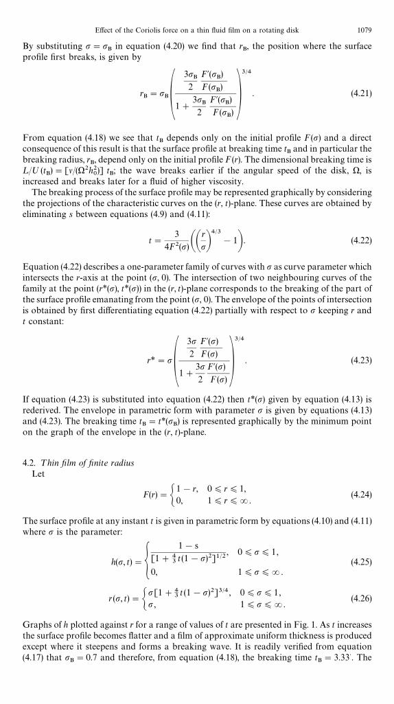
Graphs of h plotted against r for a range of values of t are presented in Fig. 1. As t increasesthe surface profile becomes flatter and a film of approximate uniform thickness is producedexcept where it steepens and forms a breaking wave. It is readily verified from equation(4.17) that p
B"0.7 and therefore, from equation (4.18), the breaking time t
B"3.33>. The
Effect of the Coriolis force on a thin fluid film on a rotating disk 1079

Fig. 1. Parametric solutions (4.25) and (4.26) of equation (4.3) for t"0, 1, 2, 3.33> and 5. The initialsurface profile is F(r)"1!r, 0)r)1, and F(r)"0, 1)r)R. The surface profile breaks at time
tB"3.33 and the breaking radius r
B"0.901.
surface profile at breaking time is given in parametric form by
h (p, tB)"
1!p[1#40
9(1!p)2]1@2
, 0)p)1 , (4.27)
r(p, tB)"p[1#40
9(1!p)2]3@4 , 0)p)1. (4.28)
By putting p"pB"0.7 in equation (4.28) we find that r
B"0.901 in agreement with Fig. 1.
The surface profile at breaking time and in particular the breaking radius rB
are indepen-dent of the angular velocity of the disk, ), and the kinematic viscosity of the fluid, l.
The projections of the characteristic curves on the (r, t)-plane are given by equation (4.22):
t"3
4(1!p)2AAr
pB4@3
!1B, 0(p)1,(4.29)
r"p, 1)p)R.
The curves are plotted in Fig. 2. The envelope of the points of intersection of neighbouringcharacteristic curves is given in parametric form by equations (4.13) and (4.23):
t*(p)"3
10(p!25) (1!p)
,2
5(p(1, (4.30)
r*(p)"pA3p
5(p!25)B
3@4,
2
5(p(1. (4.31)
The envelope is plotted in Fig. 2. The characteristic curves emanating from the r-axis with0)p(2
5do not intersect for t*(p)'0 and this is clearly illustrated in Fig. 2. The minimum
point of the envelope in the (r, t)-plane is (rB, t
B)"(0.901, 3.33> ) and represents the radial
position and time when the surface profile first breaks. We see also from Fig. 2 that theminimum point of the envelope (r
B, t
B) lies on the characteristic curve emanating from the
point r"pB"0.7 on the r-axis, in agreement with the theory.
1080 E. Momoniat and D. P. Mason

Fig. 2. Projection of the characteristic curves of equation (4.3) on the (r, t)-plane given by equation(4.29). The initial surface profile is F(r)"1!r, 0)r)1 and F(r)"0, 1)r)R. The envelope ofthe characteristic curves (. . . . . .) is given in parametric form by equations (4.30) and (4.31). Theminimum point of the envelope (0.901, 3.33) is the breaking point. It lies on the characteristic curve
emanating from pB"0.7.
4.3. ¹hin film of infinite radiusLet
F (r)"sech r , 0)r)R. (4.32)
From equations (4.10) and (4.11) the surface profile at any instant t is given in parametricform with parameter p by
h(p, t)"sech p
[1#43t sech2 p]1@2
, 0)p)R, (4.33)
r (p, t)"p [1#43t sech2p]3@4 , 0)p)R. (4.34)
The surface profiles for a range of values of t are plotted in Fig. 3. The surface profile againflattens and the thickness becomes approximately uniform by about t"6 except wherea breaking wave is formed. Equation (4.17) for p
Bbecomes
pB"
7 sinhpBcoshp
B3[2 sech2p
B!1]
, (4.35)
the solution of which gives pB"1.470. From equation (4.18) it is found that the breaking
time tB"3.997 and from equations (4.33) and (4.34) the surface profile at breaking time is
given by
h(p, tB)"
sech p[1#5.330 sech2p]1@2
, 0)p)R, (4.36)
r(s, tB)"p[1#5.330 sech2p]3@4 , 0)p)R. (4.37)
By substituting p"pB"1.470 in equation (4.37) it is found that r
B"2.488 in agreement
with Fig. 3. The surface profile first breaks at a greater distance from the axis of rotation andat a later time than for the initial profile F(r)"1!r.
Effect of the Coriolis force on a thin fluid film on a rotating disk 1081

Fig. 3. Parametric solutions (4.33) and (4.34) of equation (4.3) for t"0, 1, 2, 3, 3.997 and 6. Theinitial surface profile is F(r)"sech r, 0)r)R. The surface profile breaks at time t
B"3.997 and
the breaking radius rB"2.488.
The projections of the characteristic curves on the (r, t)-plane are given by equation (4.22):
t"3
4cosh2 pAA
r
pB3@4
!1B , 0(p)R. (4.38)
Graphs of the curves (4.38) are presented in Fig. 4. From equations (4.13) and (4.23), theenvelope of the points of intersection of neighbouring characteristic curves is given inparametric form by
t*(p)"3 cosh2p
2(3p tanhp!2), (4.39)
r*(p)"pA3p tanhp
3p tanhp!2B3@4
, (4.40)
where p*.*/
(p)R and p*.*/
satisfies
p"2
3 tanhp. (4.41)
It is found that p*.*/
"0.919. The characteristic curves emanating from the r-axis with0)p(p*
.*/do not intersect for t*(p) '0 as shown in Fig. 4. The radial position and time
when the surface profile first breaks is the minimum point of the envelope given by(rB, t
B)"(2.488, 3.997). This minimum point lies on the characteristic curve emanating from
the point r"pB"1.470 on the r-axis.
5. EFFECT OF THE CORIOLIS FORCE: NUMERICAL SOLUTION
Consider now the partial differential equation (3.37). In order to compare the results withthose of Section 4 we replace ¹ by t using equation (3.36). Equation (3.37) becomes
LH
Lt#A
E
h0B2 r sin 2H sinh 2H
(cos 2H#cosh 2H)2LH
Lr"
1
2 AE
h0B2(sin 2H!sinh 2H)
(cos 2H#cosh 2H). (5.1)
1082 E. Momoniat and D. P. Mason

Fig. 4. Projection of the characteristic curves of equation (4.3) on the (r, t)-plane given by equation(4.38). The initial surface profile is F(r)"sech r, 0)r)R. The envelope of the characteristiccurves (. . . . . .) is given in parametric form by equations (4.39) and (4.40) for 0.919(p)R. Theminimum point of the envelope (2.488, 3.997) is the breaking point. It lies on the characteristic curve
emanating from pB"1.470.
We formulate the problem as a Cauchy initial-value problem as in Section 4:
t"t(p, s), r"r(p, s), H"H (p, s), (5.2)
subject to the initial conditions
t(p, 0)"0, r(p, 0)"p, H (p, 0)"h0
EF (p) . (5.3)
The differential equations of the characteristic curves are
dt
ds"1, (5.4)
dr
ds"A
E
h0B2 r sin 2H sinh 2H
(cos 2H#cosh 2H)2, (5.5)
dH
ds"
1
2AE
h0B2 (sin 2H!sinh 2H)
(cos 2H#cosh2H). (5.6)
It follows directly from equations (5.6) and (5.3) that
s"2Ah0
EB2
PH(s,p)
(h0/E)F(p)
(cos 2H#cosh 2H)
(sin 2H!sinh 2H)dH . (5.7)
We are unable to proceed further analytically because we cannot evaluate the integral inequation (5.7).
We solve the differential equations (5.4)— (5.6) numerically subject to the initial conditions(5.3) by using the ODE 15s program, which can be used for stiff problems, from theMATLAB ODE suite [22]. The height h is obtained from H using equation (3.24).
Effect of the Coriolis force on a thin fluid film on a rotating disk 1083

Fig. 5. Comparison of the numerical solution of equation (5.1) (——) for h0/E"0.5 with the
analytical solution of equation (4.3) (. . . . . .). (a) Initial surface profile F(r)"1!r, 0)r)1 andF(r)"0, 1)r)R, breaking time t
B"3.442, breaking radius r
B"0.908. (b) Initial surface
profile F(r)"sech r, 0)r)R, breaking time tB"4.255, breaking radius r
B"2.554.
5.1. Surface profilesThe initial profiles F (r)"1!r, 0)r)1, and F(r)"sech r, 0)r)R, are again
considered. For each initial profile a numerical solution is obtained with h0/E"0.5 and the
numerical solutions of equation (5.1) are compared with the analytical solutions of equation(4.3) at the corresponding values of time. Graphs of the surface profiles are shown in Fig. 5.Breaking radii and breaking times are listed in Table 1.
1084 E. Momoniat and D. P. Mason

Table 1. Breaking times and breaking radii
Equation F(r) h0/E r
BtB
number
4.3 1!r 0.901 3.333>5.1 1!r 0.01 0.907 3.4285.1 1!r 0.5 0.908 3.4424.3 sech r 2.488 3.9975.1 sech r 0.01 2.502 4.0615.1 sech r 0.5 2.554 4.255
We see from Fig. 5 that when h0/E"0.5 the numerical solution of equation (5.1) is very
similar to the analytical solution of equation (4.3). We have from equation (4.2) that theterms neglected in equation (4.3) are O((h
0/E)4) and when h
0/E"0.5 the neglected terms
are of the order of magnitude 6]10~2. For smaller values of h0/E the magnitude of the
neglected terms is even smaller and there is even greater similarity between the solutions.We see from Table 1 that the breaking radius, r
B, increases slowly as h
0/E increases and that
the breaking time, tB, scaled by ¸/º"(E/h
0)2 (1/)), also increases slowly as h
0/E increases.
The breaking radius and the scaled breaking time therefore increase slowly as themagnitude of the Coriolis force increases, but the Coriolis force does not have a significanteffect on the evolution of the free surface when h
0/E(1. In this analysis the effects of inertia
were neglected.
5.2. StreamlinesConsider now the streamlines relative to the rotating disk. Since the velocity v is
measured relative to the rotating disk they are parallel to v at any instant. The Coriolis forceterms in equations (3.2) and (3.3) are the terms proportional to vh and v
rand when they are
neglected it is easily verified with the aid of the boundary conditions (3.6), (3.7), (3.10) and(3.11) that
vr"rz (h!1
2z) , vh"0. (5.8)
When the Coriolis force is neglected the streamlines lie in the (r, z)-plane and the fluid flowsin a radially outward direction relative to the disk. The Coriolis force !2oX]v(R) inequation (2.2) produces a deflection of the streamlines out of the (r, z)-plane in a directiontending to restore a fluid element to its original position [21]. Consider a streamline at thesurface z"h of the thin film. From equations (3.27) and (3.28)
vr(r, H, t)"A
E
h0B2 r sinH sinhH
(cos 2H#cosh2H)"
1
2r h2C1!
61
90Ah0
EB4h4#OAA
h0
EB8h8BD , (5.9)
vh(r, H, t)"!
1
2AE
h0B2rC1!
2 cosH coshH
(cos 2H#cosh 2H)D"!A
h0
EB2 5r
12h4C1!
277
420Ah0
EB4h4#OAA
h0
EB8h8BD . (5.10)
The velocity component vh is negative and by an order of magnitude (h0/E)2 smaller than v
r.
Let a be the angle which a streamline at the surface makes with the outward radius vectorfrom the centre of the disk. Then
tana"vhvr
"!
[cos 2H#cosh 2H!2 cosH coshH]
2 sinH sinhH
"!
5
6Ah0
EB2h2C1#
23
1260Ah0
EB4#OAA
h0
EB8
B h8D . (5.11)
Effect of the Coriolis force on a thin fluid film on a rotating disk 1085

Fig. 6. Streamlines at time t"3 on the surface of the thin film for h0/E"0.05, 0.1 and 0.5 for initial
surface profiles (a) F(r)"1!r, 0)r)1 and F(r)"0, 1)r)R, (b) F(r)"sech r, 0)r)R.
We see that tan a does not depend on r explicitly which is consistent with the observationthat the Coriolis force does not depend explicitly on the position of the axis-of-rotation[21]. For (h
0/¸)4@1 a is approximately proportional to h2 and the deflection will be
greatest where the thin-film thickness is greatest.The streamlines at the surface of the thin film emanating from a point next to the axis of
rotation for t"3 and h0/E"0.05, 0.1 and 0.5 are shown in Fig. 6 for the initial surface
profiles F (r)"1!r, 0)r)1 and F (r)"sech r, 0)r)R. The streamlines were ob-tained by integrating numerically
dhdr
"
vhrv
r
"!
[cos 2H#cosh 2H!2 cos H coshH]
2r sinH sinhH(5.12)
using a Taylor series expansion to first order in *r and the numerical solution for H asa function of r for t"3. The total angle of deflection of the streamline at r"1 for the initialprofile F (r)"1!r and at r"5 for the initial profile F (r)"sech r is given in Table 2 fora range of values of h
0/E. When h
0/E"0.05 the streamline deviates only a small amount
from the radial direction. As h0/E increases the Coriolis force becomes more important
relative to the viscous force. When h0/E"0.5 the total angle of deflection at r"1 for the
initial profile F (r)"1!r is !1.88° and at r"5 for the initial profile F (r)"sech r it is!5.47°. For large values of r the streamline is approximately radial. This is because theangle of deflection is approximately proportional to h2 and the thickness of the thin filmdecreases as r increases.
In the analysis of the deflection of streamlines, inertial effects were neglected.
1086 E. Momoniat and D. P. Mason

Table 2. Total angle of deflection of streamlines at the surfaceat time t"3
F(r) h0/E Radial distance Total deflection
1!r 0.05 1 !0.0187°1!r 0.1 1 !0.0752°1!r 0.5 1 !1.8805°sech r 0.05 5 !0.0547°sech r 0.1 5 !0.2188°sech r 0.5 5 !5.4722°
6. CONCLUDING REMARKS
In the Navier—Stokes equation we neglected the inertia terms which are O((h0/E)4) and
retained the Coriolis force terms which are O((h0/E)2). We then derived without further
approximation the first-order quasi-linear partial differential equation (5.1). This equationdetermines the evolution of the free surface of the thin fluid film due to the effect of viscous,centrifugal and Coriolis forces and exludes the effect of inertia forces. When equation (5.1)was expanded in powers of h
0/E the zero-order approximation gave the partial differential
equation derived by Emslie et al. [1], who neglected the Coriolis force terms. We see fromequation (4.2) that the terms neglected in the equation of Emslie et al. are O((h
0/E)4). The
Coriolis force terms therefore enter the partial differential equation for the free surface atO((h
0/E)4) even though they occur in the Naiver—Stokes equation at O((h
0/E)2). The
correction due to the Coriolis force to the height of the free surface is therefore of the sameorder of magnitude as the inertia terms which were neglected in the Navier—Stokesequation. The work described in this paper therefore gives only a first correction to theresults of Emslie et al. in which the effect of the Coriolis force is included fully but the effectof inertia is neglected. The inertial effects on the evolution of the free surface could beintroduced in an iterative way, e.g. by using the zero-order results in which the Coriolisforce is neglected to approximate the inertial terms in the Navier—Stokes equation.
The equation of Emslie et al. for the evolution of the free surface is extremely accuratewhen h
0/E is small as is clearly demonstrated in Fig. 5 for h
0/E"0.5. The reason for the
high degree of accuracy is that the terms neglected are O((h0/E)4).
The results obtained for the defection of the streamline on the surface relative to therotating disk describe completely the contribution due to the Coriolis force but neglectinertia effects. The result is correct to O((h
0/E)2). Inertia can affect the deflection only at the
next approximation, O((h0/E)4). In the analysis of Emslie et al. [1] the streamlines relative
to the rotating disk are purely radial.We found the following effects due to the Coriolis force on thin fluid films with
characteristic thickness h0
less than the Ekman boundary layer thickness, E. For the twoinitial surface profiles considered, the Coriolis force increased slightly the breaking radius,rB, and the breaking time, t
B, scaled by ¸/º"(E/h
0)2(1/)). The streamline at the surface
was deflected in a direction tending to restore a fluid element to its original position andwhen h
0/E is small, the angle of deflection is proportional to the square of the thickness of
the thin film. These observations may be of academic value only and may not have practicalapplication or generate appreciable deviation in the behaviour of thin fluid films within thenormal operational range of spin coating.
Acknowledgements—The authors would like to acknowledge valuable comments from two anonymous referees.They would like to thank Dr S. Abelman and Professor C. J. Wright for helpful guidance in the numerical work.The authors also thank the Foundation for Research Development, Pretoria, South Africa, for financial support.
REFERENCES
1. A. G. Emslie, F. T. Bonner and L. G. Peck, Flow of a viscous liquid on a rotating disk. J. Appl. Phys. 29, 858(1958).
2. A. Acrivos, M. G. Shah and E. E. Petersen, On the flow of a non-Newtonian liquid on a rotating disk. J. Appl.Phys. 31, 963 (1960).
3. D Meyerhofer, Characteristics of resist films produced by spinning. J. Appl. Phys. 49, 3993 (1978).4. F. L. Givens and W. J. Daughton, On the uniformity of thin films: a new technique applied to polyimides.
Electrochem. Soc. J. 126, 269 (1979).
Effect of the Coriolis force on a thin fluid film on a rotating disk 1087

5. Yih-O Tu, Depletion and retention of fluid on a rotating disk. J. ¸ub. ¹echnol. 105, 625 (1983).6. S. A. Jenekhe and S. B. Schuldt, Coating flow of non-Newtonian fluids on a flat rotating disk. Ind. Engng Chem.
Fundam. 23, 432 (1984).7. W. W. Flack, D. S. Soong, A. T. Bell and D. W. Hess, A mathematical model for spin coating of polymer resists.
J. Appl. Phys. 56, 1199 (1984).8. P. C. Sukanek, Spin coating. J. Imaging ¹echnol. 11, 184 (1985).9. M. Yanagisawa, Slip effect for thin liquid film on a rotating disk. J. Appl. Phys. 61, 1034 (1986).
10. B. G. Higgins, Film flow on a rotating disk. Phys. Fluids 29, 3522 (1986).11. D. E. Bornside, C. W. Macosko and L. E. Scriven, On the modeling of spin coating. J. Imaging ¹echnol. 13, 122
(1987).12. S. Middleman, The effect of induced air-flow on the spin coating of viscous liquids. J. Appl. Phys. 62, 2530
(1987).13. T. J. Rehg and B. G. Higgins, The effects of inertia and interfacial shear on film flow on a rotating disk. Phys.
Fluids 31, 1360 (1988).14. C. J. Lawrence, The mechanics of spin coating of polymer films. Phys. Fluids. 31, 2786 (1988).15. J. H. Hwang and F. Ma, On the flow of a thin liquid film over a rough rotating disk. J. Appl. Phys. 66, 388
(1989).16. F. S. Sherman, »iscous Flow, pp. 250—251. McGraw-Hill, New York (1990).17. B. S. Dandapat and P.C. Ray, Film cooling on a rotating disk. Int. J. Non-¸inear Mech. 25, 569 (1990).18. B. S. Dandapat and A. S. Gupta, Stability of a thin layer of a second-grade fluid on a rotating disk. Int. J.
Non-¸inear Mech. 26, 409 (1991).19. B. S. Dandapat and P. C. Ray, Flow of a thin liquid film over a cold/hot rotating disk. Int. J. Non-¸inear Mech.
28, 489 (1993).20. D. J. Acheson, Elementary Fluid Dynamics, pp. 238—251, 351—353, 65—66. Clarendon Press, Oxford (1990).21. G. K. Batchelor, An Introduction to Fluid Dynamics, pp. 555—557. Cambridge University Press, Cambridge
(1967).22. L. F. Shampine and M. W. Reichelt, The MATLAB ODE suit (1995).
1088 E. Momoniat and D. P. Mason