Hydrolic disk brack
89
INTRODUCTION Ever since the invention of the wheel, if there has been "go" there has been a need for "whoa." As the level of technology of human transportation has increased, the mechanical devices used to slow down and stop vehicles has also become more complex. In this report I will discuss the history of vehicularbraking technology and possible future developments. Before there was a "horse-less carriage," wagons, and other animal drawn vehicles relied on the animal’s power to both accelerate and decelerate the vehicle. Eventually there was the development of supplemental braking systems consisting of a hand lever to push a wooden friction pad directly against the metal tread of the wheels. In wet 1
-
Upload
independent -
Category
Documents
-
view
0 -
download
0
Transcript of Hydrolic disk brack

INTRODUCTION
Ever since the invention of the wheel, if there
has been "go" there has been a need for "whoa."
As the level of technology of human
transportation has increased, the mechanical
devices used to slow down and stop vehicles has
also become more complex. In this report I will
discuss the history
of vehicularbraking technology and possible
future developments.
Before there was a "horse-less carriage," wagons,
and other animal drawn vehicles relied on the
animal’s power to both accelerate and decelerate
the vehicle. Eventually there was the development
of supplemental braking systems consisting of a
hand lever to push a wooden friction pad directly
against the metal tread of the wheels. In wet
1

conditions these crude brakes would lose any
effectiveness.
The early years of automotive development were an
interesting time for the designing engineers, "a
period of innovation when there was no
established practice and virtually all ideas were
new ones and worth trying. Quite rapidly,
however, the design of many components stabilized
in concept and so it was with brakes; the
majority of vehicles soon adopted drum brakes,
each consisting of two shoes which could be
expanded inside a drum."
In this chaotic era is the first record of
the disk brake. Dr. F.W. Lanchester patented a
design for a disk brake in 1902 in England. It
was incorporated into the Lanchester car produced2
between 1906 through 1914. These early disk
brakes were not as effective at stopping as the
contemporary drum brakes of that time and were
soon forgotten. Another important development
occurred in the 1920’s when drum brakes were used
at all four wheels instead of a single brake to
halt only the back axle and wheels such as on the
Ford model T. The disk brake was again utilized
during World War II in the landing gear of
aircraft. The aircraft disk brake system was
adapted for use in automotive applications, first
in racing in 1952, then in production automobiles
in 1956. United States auto manufacturers did not
start to incorporate disk brakes in lower priced
non-high-performance cars until the late 1960’s.
3

HOW BRAKES WORK
We all know that pushing down on the brake pedal
slows a car to a stop. But how does this happen?
How does your car transmit the force from your
leg to its wheels? How does it multiply the force
so that it is enough to stop something as big as
a car?
BRAKE BASICS
When you depress your brake pedal, your car
transmits the force from your foot to its brakes
through a fluid. Since the actual brakes require
a much greater force than you could apply with
your leg, your car must also multiply the force
of your foot. It does this in two ways:
• Mechanical advantage (leverage)
• Hydraulic force multiplication
The brakes transmit the force to the tires using
friction, and the tires transmit that force to 4

the road using friction also. Before we begin our
discussion on the components of the brake system,
let's cover these thre
e
principles:
Leverage
5

Hydraulics
Friction
System operation[
In a hydraulic brake system, when the brake pedal
is pressed, a pushrod exerts force on the
piston(s) in the master cylinder, causing fluid
from the brake fluid reservoir to flow into a
pressure chamber through a compensating port.
This results in an increase in the pressure of
the entire hydraulic system. This forces fluid
through the hydraulic lines toward one or more
calipers where it acts upon one or two caliper
pistons sealed by one or more seated O-rings
which prevent the escape of any fluid from around
the piston.
The brake caliper pistons then apply force to the
brake pads, which pushes them against the
spinning rotor, and the friction between the pads
and the rotor causes a braking torque to be
6
generated, slowing the vehicle. Heat generated by
this friction is either dissipated through vents
and channels in the rotor or conducted through
the pads, which are made of specialized heat-
tolerant materials such as kevlar or sintered
glass.
Subsequent release of the brake pedal/lever
allows spring(s) to return the master piston(s)
back into position. This relieves the hydraulic
pressure on the caliper, allowing the brake
piston in the caliper assembly to slide back into
its housing and the brake pads to release the
rotor.
The hydraulic braking system is designed as a
closed system: unless there is a leak in the
system, none of the brake fluid enters or leaves
it, nor does the fluid get consumed through use.
An example of a hydraulic brake system[
Hydraulic brakes transfer energy to stop an 7
object, normally a rotating axle. In a very
simple brake system, with just two cylinders and
a disc brake, the cylinders could be connected
via tubes, with a piston inside the cylinders.
The cylinders and tubes are filled with
incompressible oil. The two cylinders have the
same volume, but different diameters, and thus
different cross-section areas. The one with the
smallest diameter is called the master cylinder.
The spinning disc brake will be placed down
at[clarification needed] the piston with the larger cross-
section. Suppose the diameter of the master
cylinder is half the diameter of the slave
cylinder, so the master cylinder has a cross-
section four times smaller. Now, if the piston in
the master cylinder is pushed down 40 mm, with
10 newtons (N) of force, the slave piston will
then move 10 mm, with a force of 40 N.
This force can be further increased by inserting
8
a lever connected between the master piston, a
pedal, and a pivot point. If the distance from
the pedal to the pivot is three times the
distance from the pivot to the connected piston,
then it multiplies the pedal force by a factor of
3, when pushing down on the pedal. Now, if we
push the pedal 120 mm down, with 10 N of force, a
force of 30 N will then be applied to the master
piston, and the slave piston will move the brake
pad by 10 mm, with a force of 120 N.
Component specifics[
(For typical light duty automotive braking
systems)
The brake pedal is a simple lever. One end is
attached to the framework of the vehicle, a
pushrod extends from a point along its length,
and the foot pad is at the other end of the
lever. The rod either extends to the master
cylinder (manual brakes) or to the vacuum booster
9
(power brakes).
In a four-wheel car, the FMVSS Standard 105,
1976; requires the master cylinder is divided
internally into two sections, each of which
pressurizes a separate hydraulic circuit. Each
section supplies pressure to one circuit.
Passenger vehicles typically have either a
front/rear split brake system or a diagonal split
brake system (the master cylinder in a motorcycle
or scooter may only pressurize a single unit,
which will be the front brake).
A front/rear split system uses one master
cylinder section to pressurize the front caliper
pistons and the other section to pressurize the
rear caliper pistons. A split circuit braking
system is now required by law in most countries
for safety reasons; if one circuit fails, the
other circuit can stop the vehicle.
Diagonal split systems were used initially
10
on American Motors automobiles in the 1967
production year. The right front and left rear
are served by one actuating piston while the left
front and the right rear are served, exclusively,
by a second actuating piston (both pistons
pressurize their respective coupled lines from a
single foot pedal). If either circuit fails, the
other, with at least one front wheel braking (the
front brakes provide most of the speed reduction)
remains intact to stop the mechanically-damaged
vehicle. Just before 1970, diagonally split
systems had become universal for automobiles sold
in the United States. This system was developed
with front wheel drive cars suspension design to
maintain better control and stability during a
system failure.
The diameter and length of the master cylinder
has a significant effect on the performance of
the brake system. A larger diameter master
11

cylinder delivers more hydraulic fluid to the
caliper pistons, yet requires more brake pedal
force and less brake pedal stroke to achieve a
given deceleration. A smaller diameter master
cylinder has the opposite effect.
A master cylinder may also use differing
diameters between the two sections to allow for
increased fluid volume to one set of caliper
pistons or the other.
Power brakes[
12
The vacuum booster or vacuum servo is used in
most modern hydraulic brake systems which contain
four wheels. The vacuum booster is attached
between the master cylinder and the brake pedal
and multiplies the braking force applied by the
driver. These units consist of a hollow housing
with a movable rubber diaphragm across the
center, creating two chambers. When attached to
the low-pressure portion of the throttle body or
intake manifold of the engine, the pressure in
both chambers of the unit is lowered. The
equilibrium created by the low pressure in both
chambers keeps the diaphragm from moving until
the brake pedal is depressed. A return spring
keeps the diaphragm in the starting position
until the brake pedal is applied. When the brake
pedal is applied, the movement opens an air valve
which lets in atmospheric pressure air to one
chamber of the booster. Since the pressure
13
becomes higher in one chamber, the diaphragm
moves toward the lower pressure chamber with a
force created by the area of the diaphragm and
the differential pressure. This force, in
addition to the driver's foot force, pushes on
the master cylinder piston. A relatively small
diameter booster unit is required; for a very
conservative 50% manifold vacuum, an assisting
force of about 1500 N (200n) is produced by a
20 cm diaphragm with an area of 0.03 square
meters. The diaphragm will stop moving when the
forces on both sides of the chamber reach
equilibrium. This can be caused by either the air
valve closing (due to the pedal apply stopping)
or if "run out" is reached. Run out occurs when
the pressure in one chamber reaches atmospheric
pressure and no additional force can be generated
by the now stagnant differential pressure. After
the run out point is reached, only the driver's
14
foot force can be used to further apply the
master cylinder piston.
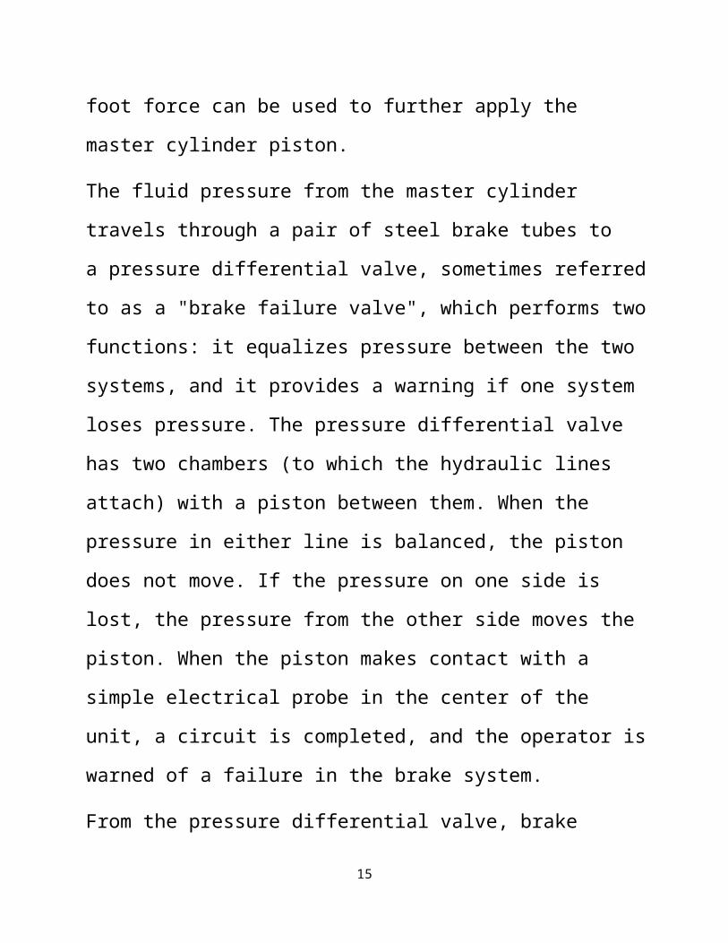
The fluid pressure from the master cylinder
travels through a pair of steel brake tubes to
a pressure differential valve, sometimes referred
to as a "brake failure valve", which performs two
functions: it equalizes pressure between the two
systems, and it provides a warning if one system
loses pressure. The pressure differential valve
has two chambers (to which the hydraulic lines
attach) with a piston between them. When the
pressure in either line is balanced, the piston
does not move. If the pressure on one side is
lost, the pressure from the other side moves the
piston. When the piston makes contact with a
simple electrical probe in the center of the
unit, a circuit is completed, and the operator is
warned of a failure in the brake system.
From the pressure differential valve, brake
15
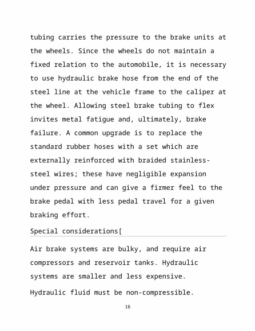
tubing carries the pressure to the brake units at
the wheels. Since the wheels do not maintain a
fixed relation to the automobile, it is necessary
to use hydraulic brake hose from the end of the
steel line at the vehicle frame to the caliper at
the wheel. Allowing steel brake tubing to flex
invites metal fatigue and, ultimately, brake
failure. A common upgrade is to replace the
standard rubber hoses with a set which are
externally reinforced with braided stainless-
steel wires; these have negligible expansion
under pressure and can give a firmer feel to the
brake pedal with less pedal travel for a given
braking effort.
Special considerations[
Air brake systems are bulky, and require air
compressors and reservoir tanks. Hydraulic
systems are smaller and less expensive.
Hydraulic fluid must be non-compressible.
16
Unlike air brakes, where a valve is opened and
air flows into the lines and brake chambers until
the pressure rises sufficiently, hydraulic
systems rely on a single stroke of a piston to
force fluid through the system. If any vapor is
introduced into the system it will compress, and
the pressure may not rise sufficiently to actuate
the brakes.
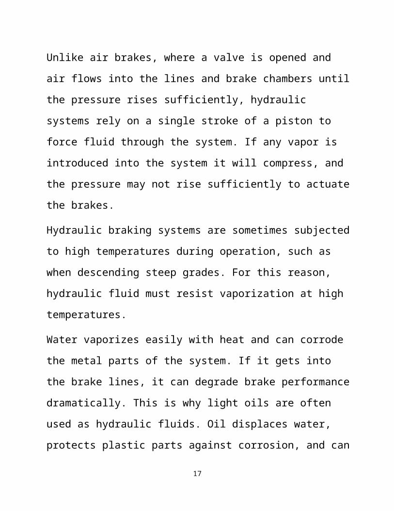
Hydraulic braking systems are sometimes subjected
to high temperatures during operation, such as
when descending steep grades. For this reason,
hydraulic fluid must resist vaporization at high
temperatures.
Water vaporizes easily with heat and can corrode
the metal parts of the system. If it gets into
the brake lines, it can degrade brake performance
dramatically. This is why light oils are often
used as hydraulic fluids. Oil displaces water,
protects plastic parts against corrosion, and can
17

tolerate much higher temperatures before
vaporizing.
"Brake fade" is a condition caused by overheating
in which braking effectiveness reduces, and may
be lost. It may occur for many reasons. The pads
which engage the rotating part may become
overheated and "glaze over", becoming so smooth
and hard that they cannot grip sufficiently to
slow the vehicle. Also, vaporization of the
hydraulic fluid under temperature extremes or
thermal distortion may cause the linings to
change their shape and engage less surface area
of the rotating part. Thermal distortion may also
cause permanent changes in the shape of the metal
components, resulting in a reduction in braking
capability that requires replacement of the
affected parts
18

LEVERAGE
The pedal is designed in such a way that it can
multiply the force from your leg several times
before any force is even transmitted to the brake
fluid.
In the figure above, a force F is being applied
to the left end of the lever. The left end of the
lever is twice as long (2X) as the right end (X).
Therefore, on the right end of the lever a force
of 2F is available, but it acts through half of
the distance (Y) that the left end moves (2Y).
Changing the relative lengths of the left and
right ends of the lever changes the multipliers.
HYDRAULIC SYSTEMS
The basic idea behind any hydraulic system is 19

very simple: Force applied at one point is
transmitted to another point using an
incompressible fluid, almost always an oil of
some sort. Most brake systems also multiply the
force in the process
FRICTION
Friction is a measure of how hard it is to slide
one object over another. Take a look at the
figure below. Both of the blocks are made from
the same material, but one is heavier. I think we
all know which one will be harder for the
bulldozer to push.
Friction force versus weight
To understand why this is, let's take a close
look at one of the blocks and the table:
Even though the blocks look smooth to the naked
eye, they are actually quite rough at the 20

microscopic level. When you set the block down on
the table, the little peaks and valleys get
squished together, and some of them may actually
weld together. The weight of the heavier block
causes it to squish together more, so it is even
harder to slide.
Different materials have different microscopic
structures; for instance, it is harder to slide
rubber against rubber than it is to slide steel
against steel.
The type of material determines the coefficient
of friction, the ratio of the force required to
slide the block to the block's weight. If the
coefficient were 1.0 in our example, then it
would take 100 pounds of force to slide the 100-
pound (45 kg) block, or 400 pounds (180 kg) of
force to slide the 400-pound block. If the
coefficient were 0.1, then it would take 10
pounds of force to slide to the 100-pound block
or 40 pounds of force to slide the 400-pound 21

block.
So the amount of force it takes to move a given
block is proportional to that block's weight. The
more weight, the more force required. This
concept applies for devices like brakes and
clutches, where a pad is pressed against a
spinning disc. The more force that presses on the
pad, the greater the stopping force.
A SIMPLE BRAKE SYSTEM
The distance from the pedal to the pivot is four
times the distance from the cylinder to the
pivot, so the force at the pedal will be
increased by a factor of four before it is
transmitted to the cylinder.
The diameter of the brake cylinder is three times
the diameter of the pedal cylinder. This further
multiplies the force by nine. All together, this
system increases the force of your foot by a
factor of 36. If you put 10 pounds of force on 22

the pedal, 360 pounds (162 kg) will be generated
at the wheel squeezing the brake pads.
There are a couple of problems with this simple
system. What if we have a leak? If it is a slow
leak, eventually there will not be enough fluid
left to fill the brake cylinder, and the brakes
will not function. If it is a major leak, then
the first time you apply the brakes all of the
fluid will squirt out the leak and you will have
complete brake failure.
TYPES OF BRAKES
1. DRUM BRAKES
2. DISC BRAKES (CALLIPER BRAKES)
DRUM BRAKES
The drum brake has two brake shoes and a piston.
When you hit the brake pedal, the piston pushes
the brake shoes against the drum This is where it23

gets a little more complicated. as the brake
shoes contact the drum, there is a kind of
wedging action, which has the effect of pressing
the shoes into the drum with more force. The
extra braking force provided by the wedging
action allows drum brakes to use a smaller piston
than disc brakes. But, because of the wedging
action, the shoes must be pulled away from the
drum when the brakes are released. This is the
reason for some of the springs. Other springs
help hold the brake shoes in place and return the
adjuster arm after it actuates.
DISK BRAKE BASICS:-
The disk brake has a metal disk instead of a
drum. It has a flat shoe, or pad, located on each
side of the disk. To slow or stop the car, these
two flat shoes are forced tightly against the
rotating disk, or rotor. Fluid pressure from the 24

master cylinder forces the pistons to move in.
This action pushes the friction pads of the shoes
tightly against the disk. The friction between
the shoes and the disk slows and stops the disk.
ADVANTAGES OF DISC BRAKES OVER DRUM BRAKES
As with almost any artifact of technology, drum
brakes and disk brakes both have advantages and
disadvantages. Drum brakes still have the edge in
cheaper cost and lower complexity. This is why
most cars built today use disk brakes in front
but drum brakes in the back wheels, four wheel
disks being an extra cost option or shouted as a
high performance feature. Since the weight shift
of a decelerating car puts most of the load on
the front wheels, the usage of disk brakes on
only the front wheels is accepted manufacturing
practice.
Drum brakes had another advantage compared to
early disk brake systems. The geometry of the 25
brake shoes inside the drums can be designed for
a mechanical self-boosting action. The rotation
of the brake drum will push a leading shoe brake
pad into pressing harder against the drum. Early
disk brake systems required an outside mechanical
brake booster such as a vacuum assist or
hydraulic pump to generate the pressure for
primitive friction materials to apply the
necessary braking force.
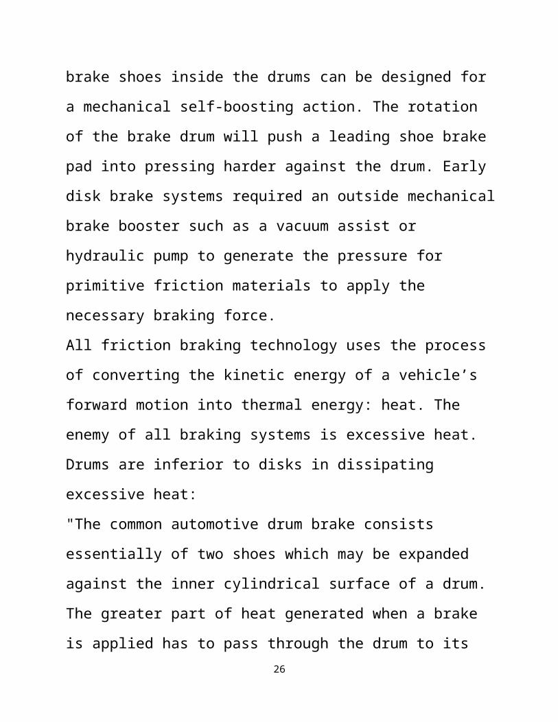
All friction braking technology uses the process
of converting the kinetic energy of a vehicle’s
forward motion into thermal energy: heat. The
enemy of all braking systems is excessive heat.
Drums are inferior to disks in dissipating
excessive heat:
"The common automotive drum brake consists
essentially of two shoes which may be expanded
against the inner cylindrical surface of a drum.
The greater part of heat generated when a brake
is applied has to pass through the drum to its 26

outer surface in order to be dissipated to
atmosphere, and at the same time (the drum is)
subject to quite severe stresses due to the
distortion induced by the opposed shoes acting
inside the open ended drum.
The conventional disk brake, on the other hand,
consists essentially of a flat disk on either
side of which are friction pads; equal and
opposite forces may be applied to these pads to
press their working surfaces into contact with
the braking path of the disks. The heat produced
by the conversion of energy is dissipated
directly from the surfaces at which it is
generated and the deflection of the braking path
of the disk is very small so that the stressing
of the material is not so severe as with the
drum."
The result of overheated brakes is brake 27

fade...the same amount of force at the pedal no
longer provides the same amount of stopping
power. The high heat decreases the relative
coefficient of friction between the friction
material and the drum or disk. Drum brakes also
suffer another setback when overheating: The
inside radii of the drum expands, the brake shoe
outside radii no longer matches, and the actual
contact surface is decreased.
Another advantage of disk brakes over drum brakes
is that of weight. There are two different areas
where minimizing weight is important. The first
is unsprung weight. This is the total amount of
weight of all the moving components of a car
between the road and the suspension mounting
points on the car’s frame.
Auto designs have gone to such lengths to reduce
unsprung weight that some, such as the E-type
Jaguar, moved the rear brakes inboard, next to 28

the differential, connected to the drive shafts
instead of on the rear wheel hubs. The second
"weighty" factor is more of an issue on
motorcycles: gyroscopic weight. The heavier the
wheel unit, the more gyroscopic resistance to
changing direction. Thus the bike’s steering
would be higher effort with heavier drum brakes
than with lighter disks. Modern race car disk
brakes have hollow internal vents, cross drilling
and other weight saving and cooling features.
Most early brake drums and disks were made out of
cast iron. Current OEM motorcycle disk brakes are
usually stainless steel for corrosion resistance,
but after-market racing component brake disks are
still made from cast iron for the improved
friction qualities. Other exotic materials have
been used in racing applications. Carbon fiber
composite disks gripped by carbon fiber pads were
common in formula one motorcycles and cars in the
early 1990’s, but were outlawed by the respective29
racing sanctioning organizations due to sometimes
spectacular failure. The carbon/carbon brakes
also only worked properly at the very high
temperatures of racing conditions and would not
get hot enough to work in street applications.
A recent Ducati concept show bike uses brake
disks of silesium, developed by the Russian
aerospace industry(3), which claim to have the
friction coefficient of cast iron with the light
weight of carbon fiber.
Another area of development of the disk brake is
the architecture of the brake caliper. Early
designs had a rigidly mounted caliper gripping
with opposed hydraulic pistons pushing the brake
pads against a disk mounted securely to the wheel
hub. Later developments included a single piston
caliper floating on slider pins. This system had
improved, more even pad wear. Most modern
automobiles and my 1982 Kawasaki motorcycle uses
this type caliper. Current design paradigm for 30

motorcycle brakes have up to six pistons, opposed
to grip both sides of a thin, large radius disk
that is "floating" on pins to provide a small
amount of lateral movement; two disks per front
wheel.
Improvements in control have been made available
with the application of Anti-Lock Brake
technology. Wheel sensors convey rotation speed
of each wheel to a computer that senses when any
of them are locked up or in a skid, and modulates
individual wheel brake hydraulic pressure to
avoid wheel skidding and loss of vehicular
control.
The use of exotic materials for additional weight
savings would be likely for the future of motor
vehicle braking. Disks mounted to the wheel’s rim
gripped by an internally located caliper is not
necessarily a new design (Porsche, 1963) (4) but
could be a futuristic looking option for
motorcycle wheels. Electric vehicles of the 31
future will likely utilize regenerative braking,
the electric motors become generators to convert
kinetic energy back to electricity to recharge
the batteries. As production vehicles become
increasingly quicker, the need for "whoa" will
always accompany the "go."
TYPES OF DISK BRAKES
The three types of disk brakes are:-
1. FLOATING CALIPER DISK BRAKES
2. FIXED CALIPER DISK BRAKES
3. SLIDING CALIPER DISK CALIPER
MAIN PARTS:
32
The main components of a disc brake are:
• The brake pads
• The caliper, which contains a piston
• The rotor, which is mounted to the hub
BRAKE PAD
CALIPER AND ROTOR
WORKING OF DISC BRAKES
FLOATING-CALIPER DISK BRAKES
The caliper is the part that holds the break
shoes on each side of the disk. In the floating-
caliper brake, two steel guide pins are threaded
into the steering-knuckle adapter. The caliper 33
floats on four rubber bushings which fit on the
inner and outer ends of the two guide pins. The
bushings allow the caliper to swing in or out
slightly when the brakes are applied
When the brakes are applied, the brake fluid
flows to the cylinder in the caliper and pushes
the piston out. The piston then forces the shoe
against the disk. At the same time, the pressure
in the cylinder causes the caliper to pivot
inward. This movement brings the other shoe into
tight contact with the disk. As a result, the two
shoes “pinch” the disk tightly to produce the
braking action
STAGES OF WORKING
.34

FIXED-CALIPER DISK BRAKE
This brake usually has four pistons, two on each
side of the disk. The reason for the name fixed-
caliper is that the caliper is bolted solidly to
the steering knuckle. When the brakes are
applied, the caliper cannot move. The four
pistons are forced out of their caliper bores to
push the inner and outer brake shoes in against
the disk. Some brakes of this type have used only
two pistons, one on each side of the disk
SLIDING-CALIPER DISK BRAKE
The sliding-caliper disk brake is similar to the
floating-caliper disk brake. The difference is
that sliding-caliper is suspended from rubber
bushings on bolts. This permits the caliper to 35
slide on the bolts when the brakes are applied.
Proper function of the brake depends on (1) the
rotor must be straight and smooth, (2) the
caliper mechanism must be properly aligned with
the rotor, (3) the pads must be positioned
correctly, (4) there must be enough "pad" left,
and (5) the lever mechanism must push the pads
tightly against the rotor, with "lever" to spare.
Most modern cars have disc brakes on the front
wheels, and some have disc brakes on all four
wheels. This is the part of the brake system that
does the actual work of stopping the car
The most common type of disc brake on modern cars
is the single-piston floating caliper. In this
article, we will learn all about this type of
disc brake design
SELF ADJUSTMENT OF DISK BRAKES:
Disk brakes are self adjusting. Each piston has a
seal on it to prevent fluid leakage. When the 36
brakes are applied, the piston moves toward the
disk. This distorts the piston seal. When the
brakes are released, the seal relaxes and returns
to its original position. This pulls the piston
away from the disk. As the brakes linings wear,
the piston over travels and takes a new position
in relation to the seal. This action provides
self adjustment of disk brakes.
EMERGENCY BRAKES
In cars with disc brakes on all four wheels, an
emergency brake has to be actuated by a separate
mechanism than the primary brakes in case of a
total primary brake failure. Most cars use a
cable to actuate the emergency brake.
Some cars with four-wheel disc brakes have a 37
separate drum brake integrated into the hub of
the rear wheels. This drum brake is only for the
emergency brake system, and it is actuated only
by the cable; it has no hydraulics.
DISK BRAKE VENTS
A moving car has a certain amount of kinetic
energy, and the brakes have to remove this energy
from the car in order to stop it. How do the
brakes do this? Each time you stop your car, your
brakes convert the kinetic energy to heat
generated by the friction between the pads and
the disc. Most car disc brakes are vented.
Vented disc brakes have a set of vanes, between
the two sides of the disc, that pumps air through
the disc to provide cooling.
WHY DISK BRAKES?
Why disk brakes in a truck or bus that travels 38
in excess of 65 mph?
Improved road handling, higher engine ratings and
torque, reduced drag and rolling resistance
resulting in faster acceleration and higher
average speeds
Higher vehicle speeds with full loads
Higher traffic density, greater chances of
emergency braking
Extremely high kinetic energy needed to brake on
wet roads, high front axle loads effecting
vehicle directional stability
The power and behavior of drum brakes cannot be
improved
Disk brakes provide optimum braking while 39

retaining directional stability
Why are disk brakes more efficient?
Flat brake disk (axial brake) under high pressure
versus round brake drum (radial brake) during
braking
Full friction surface of the brake pad on the
plane brake disk
No loss of brake power due to overheating or
partial contact from brake drum parts expansion
Disk brakes can withstand higher loads and its
efficiency is maintained considerably longer even
under the highest stresses
Higher residual brake force after repeating
braking 40

Brake disks can withstand extremely high
temperatures
Full contact of brake pads achieve maximum
effect
No vitrification of brake pads. Dangerous fading
or slipping is almost completely eliminated
Why do disk brakes have a better braking
behavior?
Driver friendly braking behavior. Sensitive
braking in all situations and better
Sensitive brake application and better brake
feeling
41

Uniform braking from small fluctuations in brake
forces
Retardation values retained even under heavy
stresses
Minimal "pulling to one side" due to uneven brake
forces
Disk brake axial arrangement permits a simple and
compact design
Linear characteristics lead to an even
progression of brake force
Basic design principle makes for higher
efficiency
Low hysteresis is particularly suitable to ABS
control cycles
42
Why are disk brakes more economical?
Clear economic benefits due to long service life
and reduced maintenance downtime
Long service life of disks and pads versus drum
brakes
Shorter service downtime due to quick pad
changes
Good access for visual brake components checks
Maintenance free brake components
Optimized installation space in the wheel rim
resulting in the largest possible brake disks and
pads
Optimized cooling resulting from open sliding
caliper design with internally ventilated brake
discs
Even and safe brake pad wear resulting from 43

simple pad guide with level braking faces
Why do disk brakes have higher safety
reserves?
Minimal braking effect from high temperatures and
extreme driving requirements
Minimal heat fading
No brake disk distortion from extreme heat due to
internal ventilation
with directional stability and large power
reserve under high stress
The decisive safety aspects of the disk brake
design are shorter braking distances
High power and safety reserves for emergencies
Constant braking power under high stresses
Shortened braking distance under emergency 44
braking with considerably improved directional
stability
LIMITATIONS
BRAKING SYSTEMS FAILS IF THERE IS LEAKAGE IN
THE BRAKE LINES
THE BRAKE SHOES ARE LIABLE TO GET RUINED IF THE
BRAKE FLUID LEAKES OUT
TESTING OF DISK BRAKES
The individual components are subjected to
extensive test on the test bed. The optimum
arrangement of components on the axle beam, 45

operational reliability and convincing
performance are requirements that must be met
prior series production.
Today, all MAN city, inter-city buses and coaches
utilize the MAN disk brake system on all wheels
with ABS. The disk brake system is used with and
without retarders
Brake performance is tested on the test track and
in racing to ensure their practice. Only after
these extensive tests can the disk brake be
cleared for production .
The brake disks are subjected to the highest
stresses from contact pressure. The broad brake
disks with radial cavities made of heat resistant
special gray cast iron, are still operational in
temperatures in excess of 1380 degrees F 46
DISK BRAKES IN PRACTICE...
All friction brakes (drum and disk) have wear
parts and are unsuitable for continuous braking,
i.e. on long down hill runs
Disk brakes are no substitute for an engine brake
or retarder. Economic driving with sensible use
of the engine brake or retarder optimizes the
service life of pads and disks that are equal to
those in comparable drum brakes
Economic use of technology means driving and
braking with anticipation and economic thinking.
Disk brakes offers safety in any situation
47

CONCLUSION
Many trucks and buses are equipped with air
actuated sliding caliper disk brakes
The high contact forces are transmitted
mechanically via needle mounted actuating device
Depending on size the actuating pressure is
transmitted evenly to the brake pads via one or
two plungers
The easy action, fully sealed guides between the
axially moving sliding caliper and fixed brake
anchor plate are maintenance free. Integrated
automatic adjustment with wear display. There are
no brake shafts, external levers or cylinder
brackets, as the brake cylinders are directly
attached.
The high efficiency of 95% is achieved by only a 48
few moving parts and low friction bearings
Asbestos free brake pads 19 to 23 mm thick,
depending on version extremely heat resistant
brake disks (34 to 45 mm) made of special gray
cast iron with internal ventilation
The brake disks are 330 to 432 mm in diameter andHydraulic fluids
Hydraulic fluids, also called hydraulic liquids,
are the medium by which power is transferred
in hydraulic machinery. Common hydraulic fluids
are based on mineral oil or water.[1] Examples of
equipment that might use hydraulic fluids
49

include excavators and backhoes, hydraulic
brakes, power
steering systems, transmissions, garbage
trucks, aircraft flight control systems, lifts,
and industrial machinery.
Hydraulic systems like the ones mentioned above
will work most efficiently if the hydraulic
fluid used has zero compressibility.
Functions and properties
The primary function of a hydraulic fluid is to
convey power. In use, however, there are other
important functions of hydraulic fluid such as
protection of the hydraulic machine components.
The table below lists the major functions of a
hydraulic fluid and the properties of a fluid
that affect its ability to perform that
function:[2]
Function Property
50

Medium for power
transfer and
control
Non compressible (high
bulk modulus)
Fast air release
Low foaming tendency
Low volatility
Medium for heat
transfer
Good thermal capacity and
conductivity
Sealing Medium
Adequate viscosity and vis
cosity index
Shear stability
Lubricant Viscosity for film
maintenance
Low temperature fluidity
Thermal and oxidative
stability
Hydrolytic stability /
water tolerance
Cleanliness and
51

filterability
Demulsibility
Antiwear characteristics
Corrosion control
Pump efficiency
Proper viscosity to
minimize internal leakage
High viscosity index
Special function
Fire resistance
Friction modifications
Radiation resistance
Environmental
impact
Low toxicity when new or
decomposed
Biodegradability
Functioning life Material compatibility
Composition[edit]
Base stock[edit]
The original hydraulic fluid, dating back to the
time of ancient Egypt, was water. Beginning in
52
the 1920s, mineral oil began to be used more
than water as a base stock due to its
inherentlubrication properties and ability to be
used at temperatures above the boiling point of
water. Today most hydraulic fluids are based on
mineral oil base stocks.
Natural oils such as rapeseed (also
called canola oil) are used as base stocks for
fluids where biodegradability and renewable
sources are considered important.
Other base stocks are used for specialty
applications, such as for fire
resistance and extreme temperature applications.
Some examples
include: glycol, esters, organophosphate
ester,polyalphaolefin, propylene glycol,
and silicone oils.
Other components
53

Hydraulic fluids can contain a wide range of
chemical compounds, including: oils, butanol,
esters (e.g. phthalates, like DEHP,
and adipates, like bis(2-ethylhexyl)
adipate), polyalkylene
glycols(PAG), organophosphate (e.g. tributylphos
phate), silicones, alkylated aromatic
hydrocarbons, polyalphaolefins (PAO)
(e.g. polyisobutenes), corrosion
inhibitors (incl acid scavengers), anti-
erosionadditives, etc.
Biodegradable hydraulic fluids
Environmentally sensitive applications
(e.g. farm tractors and marine dredging) may
benefit from using biodegradable hydraulic
fluids based upon rapeseed (Canola) vegetable
oil when there is the risk of an oil spill from
a ruptured oil line. Typically these oils are
available as ISO 32, ISO 46, and ISO 68
54
specification oils. ASTM standards ASTM-D-6006,
Guide for Assessing Biodegradability of
Hydraulic Fluids and ASTM-D-6046, Standard
Classification of Hydraulic Fluids for
Environmental Impact are relevant.
Brake fluid
Brake fluid is a subtype of hydraulic fluid with
high boiling point, both when new (specified by
the equilibrium boiling point) and after
absorption of water vapor (specified by wet
boiling point). Under the heat of braking, both
free water and water vapor in a braking system
can boil into a compressible vapor, resulting in
brake failure. Glycol-ether based fluids
are hygroscopic, and absorbed moisture will
greatly reduce the boiling point over time.
Silicone based fluids are not hygroscopic.
Safety
55
Because industrial hydraulic systems operate at
hundreds to thousands of PSI and temperatures
reaching hundreds of degrees Celsius, severe
injuries and death can result from component
failures and care must always be taken when
performing maintenance on hydraulic systems.
Fire resistance is a property available with
specialized fluids.
Trade names]
Some of the trade names for hydraulic fluids
include Arnica, Tellus, Durad, Fyrquel, Houghto-
Safe, Hydraunycoil, Lubritherm Enviro-Safe,
Pydraul, Quintolubric, Reofos, Reolube,Valvoline
Ultramax and Skydrol.
Aircraft hydraulic systems
As aircraft performance increased in mid-20th
century, the amount of force required to operate
mechanical flight controls became excessive, and
56
hydraulic systems were introduced to reduce
pilot effort. The hydraulic actuators are
controlled by valves; these in turn are operated
directly by input from the aircrew (hydro-
mechanical) or by computers obeying control laws
(fly by wire). See flight controls.
Hydraulic power is used for other purposes. It
can be stored in accumulators to start an
auxiliary power unit (APU) for self-starting the
aircraft's main engines. Many aircraft equipped
with the M61family of cannon use hydraulic power
to drive the gun system, permitting reliable
high rates of fire.
The hydraulic power itself comes from pumps
driven by the engines directly, or by
electrically driven pumps. In modern commercial
aircraft these are electrically driven pumps;
should all the engines fail in flight the pilot
will deploy a propeller-driven electric
57

generator called a Ram Air Turbine (RAT) which
is concealed under the fuselage.[3] This provides
electrical power for the hydraulic pumps and
control systems as power is no longer available
from the engines. In that system and others
electric pumps can provide both redundancy and
the means of operating hydraulic systems without
the engines operating, which can be very useful
during maintenance.
Specifications
Aircraft hydraulic fluids fall under various
specifications:
Common petroleum-based:
Mil-H-5606: Mineral base, flammable, fairly
low flashpoint, usable from −65 °F (−54 °C) to
275 °F (135 °C), red color
Mil-H-83282: Synthetic hydrocarbon base,
higher flashpoint, self-extinguishing,
58
backward compatible to -5606, red color, rated
to −40 °F (−40 °C) degrees.
Mil-H-87257: A development of -83282 fluid to
improve its low temperature viscosity.
Phosphate-ester based:
US/NATO Military Specification - MIL-H-8446
Boeing Seattle - BMS3-11
Boeing Long Beach - DMS2014
Boeing Long Island - CDS5478
Lockheed - LAC C-34-1224
Airbus Industrie - NSA307110
British Aerospace - BAC M.333.B
Bombardier - BAMS 564-003
SAE - Ac974
SAE - AS1241
Contamination[
Special, stringent care is required when
handling aircraft hydraulic fluid as it is
critical to flight safety that it stay free from59
contamination. It is also necessary to strictly
adhere to authorized references when servicing
or repairing any aircraft system. Samples from
aircraft hydraulic systems are taken during
heavy aircraft maintenance checks (primarily C
and D checks) to check contamination.
Hydraulic systems have reservoirs which can
usually be accessed by removing a cap from the
top of the brake lever. This reservoir and
bladder is an important feature of the system
because when the brake fluid heats up it expands
and needs somewhere to go. The reservoir acts as
a release for the excess fluid to prevent it
from splitting a cable.
Bleeding: This is a process to allow the trapped
air to escape from brake cables and callipers.
If you have air in the system it will result in
a much slower braking response as air can be
easily compressed whereas brake fluid can't.
60
Take care to keep all parts of the system clean,
especially the reservoir and the pads. Take off
the wheels being careful not to damage the discs
as they pass through the calliper. Remove the
brake pads and replace them with either
cardboard/wood spacer or some old pads. The bike
should be positioned so that the cable is
continually facing uphill between the calliper
and the reservoir. The top surface of the
reservoir should be parallel to a flat ground
(if not adjust the brake levers). Take the bleed
pipe and attach it to the bleed nipple on the
calliper. Use the elastic band to attach the
plastic bag to the other end of the pipe. Make
sure you wipe any dirt away from the brake lever
and around the reservoir. Unscrew the reservoir
tank cap and remove the cover and bladder. Fill
the reservoir tank to the top with the correct
brake fluid. Unscrew the bleed nipple with one
turn. Repeatedly pump the brake lever. The fluid61

in the tank will bubble and the level will
probably drop. Make sure the reservoir is topped
up as the level drops. Tap the cable to dislodge
any trapped air. Fluid will eventually start to
come out of the bleed nipple - close the nipple.
When you test the brakes they should eventually
become firm when applied. If not, open the bleed
nipple and continue. When firm, hold the brake
lever and keep the pressure applied. Use the
wrench to loosen the bleed nipple, opening and
closing in the space of a second whilst looking
at the fluid passing through the bleed pipe.
This should expel any remaining air bubbles. Let
go of the brake lever and top up the reservoir.
Pump the lever once again until firm. Top up the
reservoir. The system should now be free of air.
Replace the bladder and reservoir cap. Be ready
to wipe any overflowing fluid from the lever -
this is normal. Screw the cap on securely. Take
off the bleed pipe from the nipple and wipe any 62
fluid off the calliper. Replace the pads and
wheels. Finally check the brakes work.
Replacing Brake Fluid: Carry out all the steps
mentioned above but leave the nipple open when
pumping the levers, and keep topping up the
reservoir. Eventually the new fluid will replace
the older fluid.
That's it, your brakes should now be air free
and fully topped up with new fluid.
Pascal's Principle and Hydraulics
SUBJECT: Physics
TOPIC: Hydraulics
DESCRIPTION: A set of mathematics problems
dealing with hydraulics.
CONTRIBUTED BY: Carol Hodanbosi
EDITED BY: Jonathan G. Fairman - August 1996
63

Hydraulic systems use a incompressible fluid,
such as oil or water, to transmit forces from
one location to another within the fluid. Most
aircraft use hydraulics in the braking systems
and landing gear. Pneumatic systems use
compressible fluid, such as air, in their
operation. Some aircraft utilize pneumatic
systems for their brakes, landing gear and
movement of flaps.
Pascal's law states that when there is an
increase in pressure at any point in a confined
fluid, there is an equal increase at every other
point in the container.
A container, as shown below, contains a fluid.
There is an increase in pressure as the length
of the column of liquid increases, due to the
increased mass of the fluid above.64

For example, in the figure below, P3 would be
the highest value of the three pressure
readings, because it has the highest level of
fluid above it.
If the above container had an increase in
overall pressure, that same added pressure would
affect each of the gauges (and the liquid
throughout) the same. For example P1, P2, P3
were originally 1, 3, 5 units of pressure, and 5
units of pressure were added to the system, the
new readings would be 6, 8, and 10.
Applied to a more complex system below, such as
a hydraulic car lift, Pascal's law allows forces65
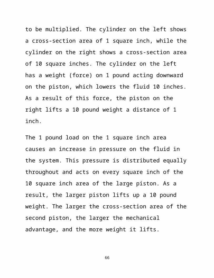
to be multiplied. The cylinder on the left shows
a cross-section area of 1 square inch, while the
cylinder on the right shows a cross-section area
of 10 square inches. The cylinder on the left
has a weight (force) on 1 pound acting downward
on the piston, which lowers the fluid 10 inches.
As a result of this force, the piston on the
right lifts a 10 pound weight a distance of 1
inch.
The 1 pound load on the 1 square inch area
causes an increase in pressure on the fluid in
the system. This pressure is distributed equally
throughout and acts on every square inch of the
10 square inch area of the large piston. As a
result, the larger piston lifts up a 10 pound
weight. The larger the cross-section area of the
second piston, the larger the mechanical
advantage, and the more weight it lifts.
66
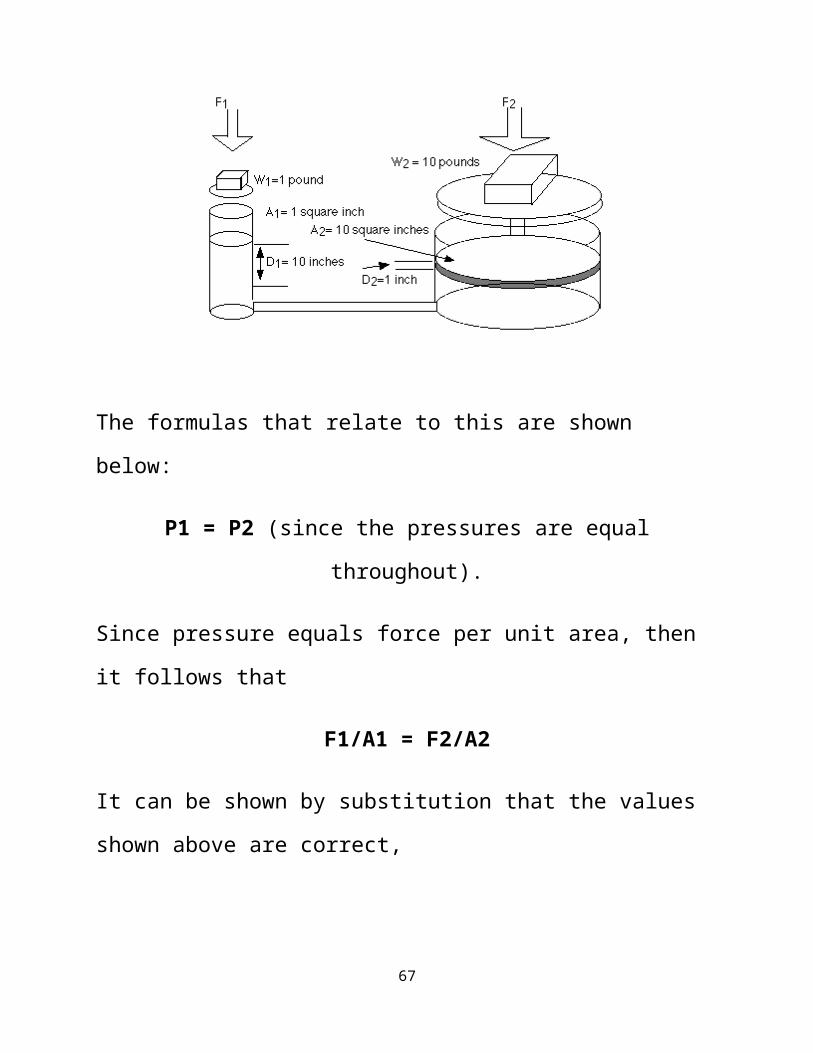
The formulas that relate to this are shown
below:
P1 = P2 (since the pressures are equal
throughout).
Since pressure equals force per unit area, then
it follows that
F1/A1 = F2/A2
It can be shown by substitution that the values
shown above are correct,
67
1 pound / 1 square inches = 10 pounds / 10 square
inches
Because the volume of fluid pushed down on the
left side equals the volume of fluid that is
lifted up on the right side, the following
formula is also true.
V1 = V2
by substitution,
A1 D1 = A2 D2
A = cross sectional area
D = the distance moved
or
A1/A2= D2/D1
This system can be thought of as a simple
machine (lever), since force is multiplied.The
68
mechanical advantage can be found by rearranging
terms in the above equation to
Mechanical Advantage(IMA) = D1/D2 = A2/A1
For the sample problem above, the IMA would be
10:1 (10 inches/ 1 inch or 10 square inches / 1
square inch).
Given these simple formulas, try to answer the
questions below.
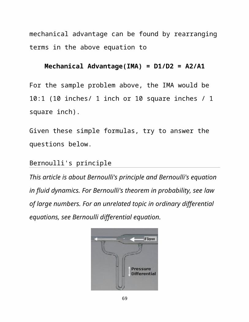
Bernoulli's principle
This article is about Bernoulli's principle and Bernoulli's equation
in fluid dynamics. For Bernoulli's theorem in probability, see law
of large numbers. For an unrelated topic in ordinary differential
equations, see Bernoulli differential equation.
69

A flow of air into a venturi meter. The kinetic
energy increases at the expense of the fluid
pressure, as shown by the difference in height
of the two columns of water.
In fluid dynamics, Bernoulli's principle states
that for an inviscid flow, an increase in the
speed of the fluid occurs simultaneously with a
decrease inpressure or a decrease in
the fluid's potential energy.[1][2] The principle
is named after Daniel Bernoulli who published it
in his book Hydrodynamica in 1738.[3]
Bernoulli's principle can be applied to various
types of fluid flow, resulting in what is
loosely denoted as Bernoulli's equation. In
fact, there are different forms of the Bernoulli
equation for different types of flow. The simple
form of Bernoulli's principle is valid
for incompressible flows (e.g.
70

most liquid flows) and also for compressible
flows (e.g. gases) moving at low Mach
numbers (usually less than 0.3). More advanced
forms may in some cases be applied to
compressible flows at higher Mach
numbers (see the derivations of the Bernoulli
equation).
Bernoulli's principle can be derived from the
principle of conservation of energy. This states
that, in a steady flow, the sum of all forms of
mechanical energy in a fluid along
a streamline is the same at all points on that
streamline. This requires that the sum of
kinetic energy and potential energy remain
constant. Thus an increase in the speed of the
fluid occurs proportionately with an increase in
both its dynamic pressure and kinetic energy,
and a decrease in its static
pressure and potential energy. If the fluid is
71
flowing out of a reservoir, the sum of all forms
of energy is the same on all streamlines because
in a reservoir the energy per unit volume (the
sum of pressure and gravitational potential ρ g h)
is the same everywhere.[4]
Bernoulli's principle can also be derived
directly from Newton's 2nd law. If a small
volume of fluid is flowing horizontally from a
region of high pressure to a region of low
pressure, then there is more pressure behind
than in front. This gives a net force on the
volume, accelerating it along the streamline.[5][6]
[7]
Fluid particles are subject only to pressure and
their own weight. If a fluid is flowing
horizontally and along a section of a
streamline, where the speed increases it can
only be because the fluid on that section has
moved from a region of higher pressure to a
72
region of lower pressure; and if its speed
decreases, it can only be because it has moved
from a region of lower pressure to a region of
higher pressure. Consequently, within a fluid
flowing horizontally, the highest speed occurs
where the pressure is lowest, and the lowest
speed occurs where the pressure is highest.
Contents
Incompressible flow equation[
In most flows of liquids, and of gases at
low Mach number, the density of a fluid parcel
can be considered to be constant, regardless of
pressure variations in the flow. Therefore, the
fluid can be considered to be incompressible and
these flows are called incompressible flow.
Bernoulli performed his experiments on liquids,
so his equation in its original form is valid
only for incompressible flow. A common form of
73
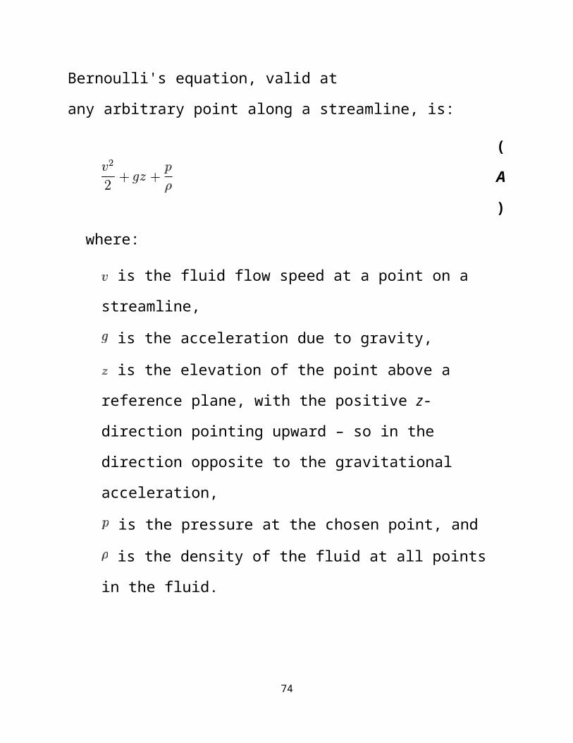
Bernoulli's equation, valid at
any arbitrary point along a streamline, is:
(
A
)
where:
is the fluid flow speed at a point on a
streamline,
is the acceleration due to gravity,
is the elevation of the point above a
reference plane, with the positive z-
direction pointing upward – so in the
direction opposite to the gravitational
acceleration,
is the pressure at the chosen point, and
is the density of the fluid at all points
in the fluid.
74

For conservative force fields,
Bernoulli's equation can be
generalized as:[8]
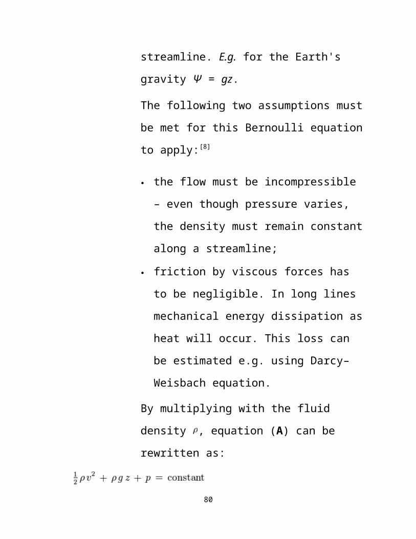
where Ψ is the force potential at
the point considered on the
streamline. E.g. for the Earth's
gravity Ψ = gz.
The following two assumptions must
be met for this Bernoulli equation
to apply:[8]
the flow must be incompressible
– even though pressure varies,
the density must remain constant
along a streamline;
friction by viscous forces has
to be negligible. In long lines
mechanical energy dissipation as
75
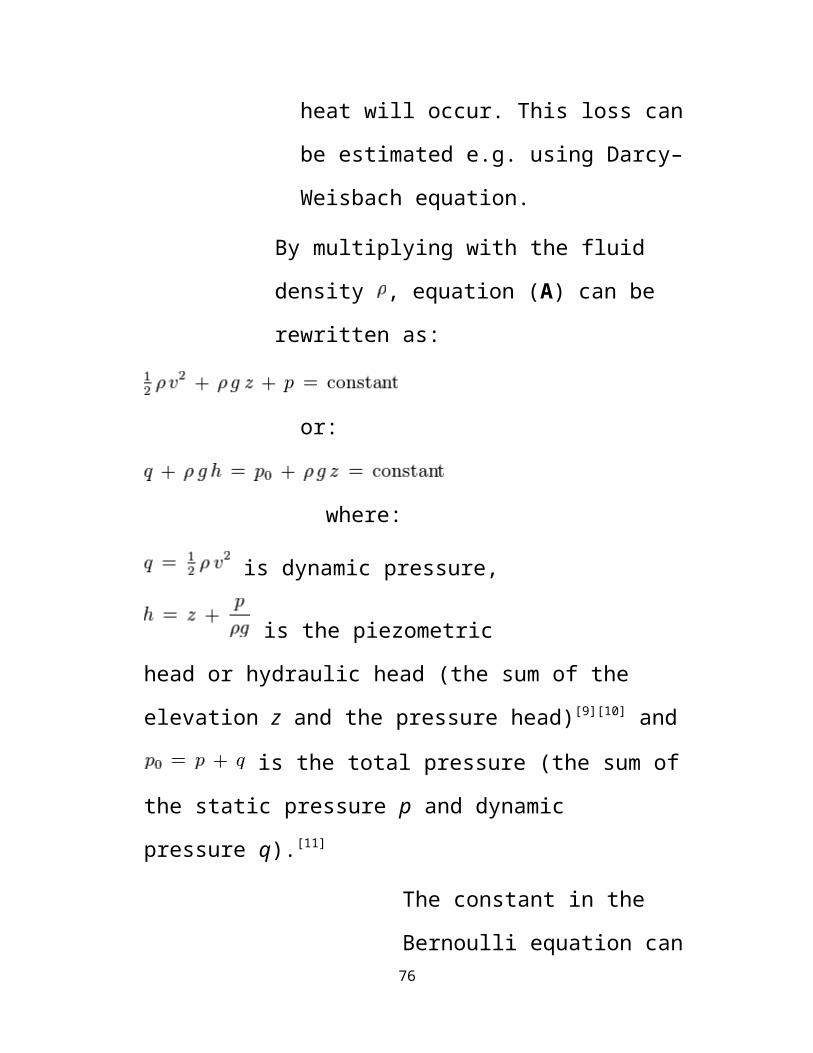
heat will occur. This loss can
be estimated e.g. using Darcy–
Weisbach equation.
By multiplying with the fluid
density , equation (A) can be
rewritten as:
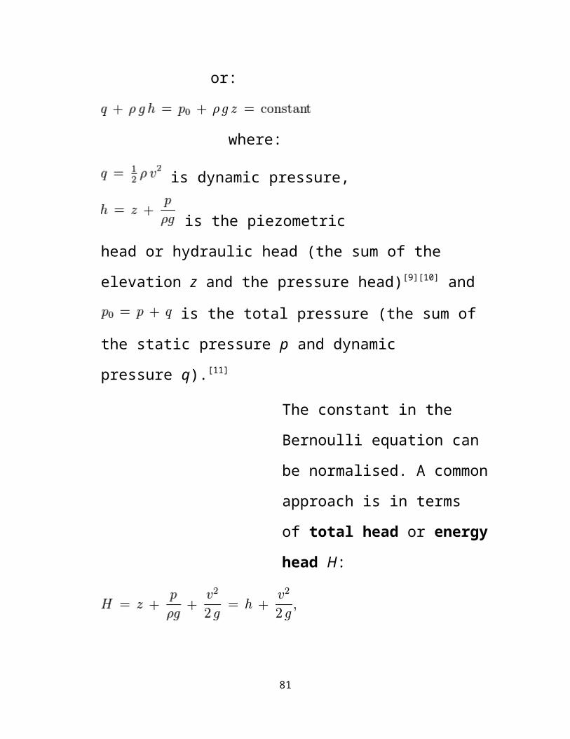
or:
where:
is dynamic pressure,
is the piezometric
head or hydraulic head (the sum of the
elevation z and the pressure head)[9][10] and
is the total pressure (the sum of
the static pressure p and dynamic
pressure q).[11]
The constant in the
Bernoulli equation can 76

be normalised. A common
approach is in terms
of total head or energy
head H:
The above equations suggest there is
a flow speed at which pressure is
zero, and at even higher speeds the
pressure is negative. Most often,
gases and liquids are not capable of
negative absolute pressure, or even
zero pressure, so clearly Bernoulli's
equation ceases to be valid before
zero pressure is reached. In liquids
– when the pressure becomes too low
– cavitation occurs. The above
equations use a linear relationship
between flow speed squared and
pressure. At higher flow speeds in
77

gases, or for sound waves in liquid,
the changes in mass density become
significant so that the assumption of
constant density is invalid.
Incompressible flow equation[edit]
In most flows of liquids, and of gases at
low Mach number, the density of a fluid parcel
can be considered to be constant, regardless of
pressure variations in the flow. Therefore, the
fluid can be considered to be incompressible and
these flows are called incompressible flow.
Bernoulli performed his experiments on liquids,
so his equation in its original form is valid
only for incompressible flow. A common form of
Bernoulli's equation, valid at
any arbitrary point along a streamline, is:
(
A
)
78

where:
is the fluid flow speed at a point on a
streamline,
is the acceleration due to gravity,
is the elevation of the point above a
reference plane, with the positive z-
direction pointing upward – so in the
direction opposite to the gravitational
acceleration,
is the pressure at the chosen point, and
is the density of the fluid at all points
in the fluid.
For conservative force fields,
Bernoulli's equation can be
generalized as:[8]
where Ψ is the force potential at
the point considered on the
79
streamline. E.g. for the Earth's
gravity Ψ = gz.
The following two assumptions must
be met for this Bernoulli equation
to apply:[8]
the flow must be incompressible
– even though pressure varies,
the density must remain constant
along a streamline;
friction by viscous forces has
to be negligible. In long lines
mechanical energy dissipation as
heat will occur. This loss can
be estimated e.g. using Darcy–
Weisbach equation.
By multiplying with the fluid
density , equation (A) can be
rewritten as:
80
or:
where:
is dynamic pressure,
is the piezometric
head or hydraulic head (the sum of the
elevation z and the pressure head)[9][10] and
is the total pressure (the sum of
the static pressure p and dynamic
pressure q).[11]
The constant in the
Bernoulli equation can
be normalised. A common
approach is in terms
of total head or energy
head H:
81
The above equations suggest there is
a flow speed at which pressure is
zero, and at even higher speeds the
pressure is negative. Most often,
gases and liquids are not capable of
negative absolute pressure, or even
zero pressure, so clearly Bernoulli's
equation ceases to be valid before
zero pressure is reached. In liquids
– when the pressure becomes too low
– cavitation occurs. The above
equations use a linear relationship
between flow speed squared and
pressure. At higher flow speeds in
gases, or for sound waves in liquid,
the changes in mass density become
significant so that the assumption of
constant density is invalid.
Simplified form[
82
In many applications of Bernoulli's equation,
the change in the ρ g z term along the streamline
is so small compared with the other terms that
it can be ignored. For example, in the case of
aircraft in flight, the change in height z along
a streamline is so small the ρ g z term can be
omitted. This allows the above equation to be
presented in the following simplified form:
where p0 is called 'total pressure', and q is
'dynamic pressure'.[12] Many authors refer to
the pressure p as static pressure to
distinguish it from total
pressure p0 and dynamic pressure q.
InAerodynamics, L.J. Clancy writes: "To
distinguish it from the total and dynamic
pressures, the actual pressure of the fluid,
which is associated not with its motion but
with its state, is often referred to as the
static pressure, but where the term pressure 83
alone is used it refers to this static
pressure."[13]
The simplified form of Bernoulli's equation
can be summarized in the following memorable
word equation:
static pressure + dynamic pressure = total pressure[13]
Every point in a steadily flowing fluid,
regardless of the fluid speed at that point,
has its own unique static pressure p and
dynamic pressure q. Their sum p + q is
defined to be the total pressurep0. The
significance of Bernoulli's principle can
now be summarized as total pressure is constant along
a streamline.
If the fluid flow is irrational, the total
pressure on every streamline is the same and
Bernoulli's principle can be summarized
as total pressure is constant everywhere in the fluid flow.[14] It is reasonable to assume that
84

irrotational flow exists in any situation
where a large body of fluid is flowing past
a solid body. Examples are aircraft in
flight, and ships moving in open bodies of
water. However, it is important to remember
that Bernoulli's principle does not apply in
the boundary layer or in fluid flow through
long pipes.
If the fluid flow at some point along a stream line is brought to rest, this point is called a stagnation point, and at this point the total pressure is equal to the stagnation pressure. Pressure appllied in a confined liquid is transmitted uniformly in all direction through out the liquid.
..to those who dontt undrstand the word ‘confined liquid’, take out a dictionary & applyits meaning in the context of this principle. Basically in B.M it means..”cecair yang berada dalam bekas tertutup”.
So if the liquid is trapped in a container and pressure is applied, according to the principle;this pressure will be transmitted equally in all
85
direction.
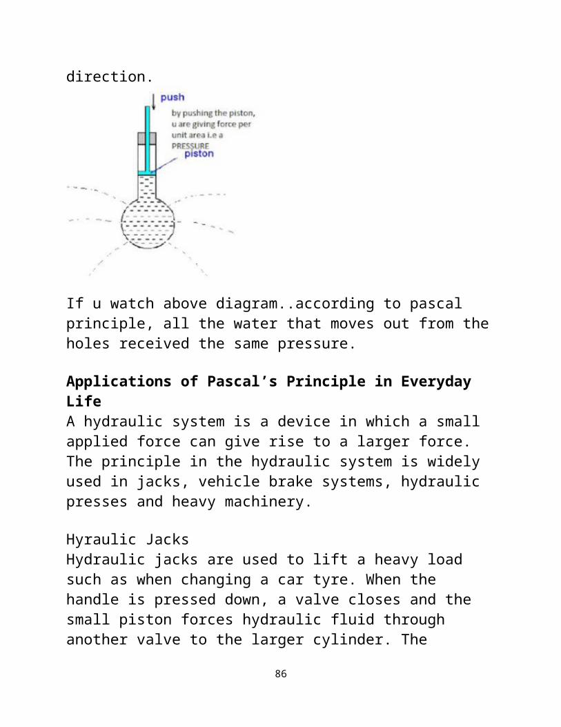
If u watch above diagram..according to pascal principle, all the water that moves out from theholes received the same pressure.
Applications of Pascal’s Principle in Everyday LifeA hydraulic system is a device in which a small applied force can give rise to a larger force.The principle in the hydraulic system is widely used in jacks, vehicle brake systems, hydraulic presses and heavy machinery.
Hyraulic JacksHydraulic jacks are used to lift a heavy load such as when changing a car tyre. When the handle is pressed down, a valve closes and the small piston forces hydraulic fluid through another valve to the larger cylinder. The
86
pressure transmitted results in a large force onthe load.
When the handle is raised, valve B closes and hydraulic fluid flows from the buffer tank through valve A into the small cylinder. The handle is moved up and down repeatedly until theload is sufficiently lifted up.The large piston can be lowered at the end by opening the release valve to allow all the hydraulic fluid to flow back into the buffer tank.
Hydraulic Brakes
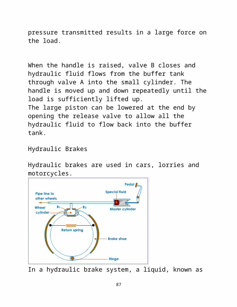
Hydraulic brakes are used in cars, lorries and motorcycles.
In a hydraulic brake system, a liquid, known as
87

brake fluid,is used to transmit pressure from the brake pedal to all the wheels of the vehicle.When the brake pedal is pressed, the piston of the control cylinder applies a pressure on the brake fluid and this pressure is transmitted, via a system of pipes, to each cylinder at the wheels.
The cylinder at the wheels cause a pair of pistons to push a pair of friction pads to pressagainst the surface of the brake discs or brake drums. The frictional forces between these brakecomponents cause the vehicle to slow down and stop.
When the brake pedal is released, a spring restores the brake discs to their original positions.
References[edit]
1. Jump up^ Csere, Csaba (January 1988), "10Best Engineering Breakthroughs", Car and Driver 33 (7): 61
2. Nice, Karim. "How Brakes Work". How StuffWorks. Retrieved 18 June 2010.
88

3. "Hydraulic Brakes". Integrated Publishing. Retrieved 18 June 2010.
89