Introductory guide to Bridgeport series I CNC milling, drilling ...
108
Copyright Warning & Restrictions The copyright law of the United States (Title 17, United States Code) governs the making of photocopies or other reproductions of copyrighted material. Under certain conditions specified in the law, libraries and archives are authorized to furnish a photocopy or other reproduction. One of these specified conditions is that the photocopy or reproduction is not to be “used for any purpose other than private study, scholarship, or research.” If a, user makes a request for, or later uses, a photocopy or reproduction for purposes in excess of “fair use” that user may be liable for copyright infringement, This institution reserves the right to refuse to accept a copying order if, in its judgment, fulfillment of the order would involve violation of copyright law. Please Note: The author retains the copyright while the New Jersey Institute of Technology reserves the right to distribute this thesis or dissertation Printing note: If you do not wish to print this page, then select “Pages from: first page # to: last page #” on the print dialog screen
-
Upload
khangminh22 -
Category
Documents
-
view
1 -
download
0
Transcript of Introductory guide to Bridgeport series I CNC milling, drilling ...

Copyright Warning & Restrictions
The copyright law of the United States (Title 17, United States Code) governs the making of photocopies or other
reproductions of copyrighted material.
Under certain conditions specified in the law, libraries and archives are authorized to furnish a photocopy or other
reproduction. One of these specified conditions is that the photocopy or reproduction is not to be “used for any
purpose other than private study, scholarship, or research.” If a, user makes a request for, or later uses, a photocopy or reproduction for purposes in excess of “fair use” that user
may be liable for copyright infringement,
This institution reserves the right to refuse to accept a copying order if, in its judgment, fulfillment of the order
would involve violation of copyright law.
Please Note: The author retains the copyright while the New Jersey Institute of Technology reserves the right to
distribute this thesis or dissertation
Printing note: If you do not wish to print this page, then select “Pages from: first page # to: last page #” on the print dialog screen

The Van Houten library has removed some of the personal information and all signatures from the approval page and biographical sketches of theses and dissertations in order to protect the identity of NJIT graduates and faculty.

INTRODUCTORY GUIDE TO
BRIDGEPORT SERIES I CNC
MILLING, DRILLING AND BORING MACHINE
Apurva Doshi
Thesis submitted to the Faculty of the Graduate School ofthe New Jersey Institute of Technology in partial fulfillment of
the requirements for the degree ofMaster of Science in Mechanical Engineering
1986
APPROVAL SHEET
Title of Thesis: Introductory Guide to Bridgeport SeriesCNC Milling, Drilling and Boring Machine
Name of Candidate: Apurva V. DoshiMaster of Science in MechanicalEngineering, 1986
Thesis and Abstract Approved: Dr. Sachio Nakamura DateAssistant ProfessorMechanical Engineering Department
Date
Date

VITA
Name: Apurva Vinodchandra Doshi.
Permanent Address:
Degree and date to be conferred: M.S.M.E., 1986
Date of birth:
Place of birth:
Secondary education: Himmat High School, 1979.
Collegiate institutions attended Dates Degree Date of Degree
Saurashtra University June,79-May,83
B.E.(Mech.) June,83
N. J. Institute of Technology Sept.,83-Dec.,85
M.S.M.E. May,86
Major: Mechanical Engineering

ABSTRACT
Title of Thesis: Introductory Guide to Bridgeport Series I
CNC Milling, Drilling and Boring Machine
Apurva Y. Doshi, Master of Science in Mechanical
Engineering, 1986
Thesis directed by: Dr. Sachio Nakamura
Assistant Professor
Mechanical Engineering Department
This thesis is intended to serve as an easy
introductory guide on how to work with Bridgeport Series I
CNC Milling, Drilling and Boring machine. An attempt has
been made to make the subject matter simpler to give the
reader a good start in programming and operating this
machine.
The spectrum of technological implementation of CNC
machine tools is extremely broad. Companies utilizing
advanced technologies such as computer graphics, DNC and
Group Technology are in this field for some time. Even
small shops are getting equipped with CNC machine tools. The
present CNC systems, which are less costly, more reliable
and far more capable than conventional automatic equipments,
have brought CNC within reach of even the smallest shop.
Considering their evergrowing demand and acceptance, almost
every mechanical engineer will have to deal with them at
one point.

The work presented in this thesis is a concise
introductory guide to Series I CNC Milling machine. Various
functions of NC machine have been linked with the main text
to provide a reasonably understandable introductory manual
for the particular CNC machine.


To my Mother,
without whom this would
not have been possible.
viii

TABLE OF CONTENTS
Chapter
Page
LIST OF FIGURES
xi
I. INTRODUCTION
1
1.1.
Introductory Comments
1
1.2.
Numerical Control (N/C) Machine
3
1.3.
Computer Numerical Control (CNC)
5
1.4.
Direct Numerical Control (DNC)
5
1.5. Scope of Thesis
7
II. OPERATION OF A NUMERICAL CONTROL INSTALLATION 8
2.1. Introductory Comments
8
2.2.
Operation of an NC Machine
8
III. PART PROGRAMMING FOR BRIDGEPORT SERIES I CNC
MACHINE
19
3.1.
Features and Functions of The Machine
19
3.2.
Coordinate System
21
3.3. Program Entries
23
IV. PROGRAMMING EXAMPLES 39
4.1. Introductory Comments
39
4.2.
Programming Examples
39
4.3. Looping
64
4.4. Macro Subroutines
65
V.
OPERATION OF BRIDGEPORT SERIES I CNC MACHINE
68
5.1. Introductory Comments
68
5.2. Operator's Main Control Panel
68
5.3. Spindle Control Panel
76

Chapter
Page
5.4.
Special Operations 78
5.5.
Operation In Set up
82
5.5.1
Positioning Along An Axis
82
5.5.2
Tool Length Offset
82
5.5.3
Tool Diameter
87
5.6.1
Normal Operation Procedure
88
5.6.2
Special Conditions
90
VI.
CONCLUSION
92
6.1.
Concluding Remarks
92
6.2.
Future Updating
92
BIBLIOGRAPHY
95

LIST OF FIGURES
Figure Page
I. Fig. 1-1 Bridgeport Series I CNC Machine 6
II. Fig. 2-1 Standard Tape................. ....... 11
III. Fig. 2-2 Standard BCD Formats 12
IV. Fig. 2-3 A CNC System Layout 16
V. Fig. 3-1 Part Coordinate System ...... 22
VI. Fig. 3-2 Table 3-1, Input Tape and Program Codes 24
VII. Fig. 3-3 CW or CCW Motion in Switchable Planes 30
VIII. Fig. 4-1 Manuscript Layout................ 40
IX. Fig. 4-2 Example 1 42
X. Fig. 4-3 Example 2.................. ........ 43
XI. Fig. 4-4 Arc Center Offsets........ ............. 4t
XII. Fig. 4-5 Example 3.. ........ ........ ...... 47
XIII. Fig. 4-6 Example 4 47
XIV. Fig. 4-7 Example 5.............
XV. Fig. 4-8 Example 6.......... .................
XVI. Fig. 4-9 Example 7... ........ ....... 5Z
XVII. Fig. 4-10 Example 8
XVIII. Fig. 4-11 G81 - Drilling Cycle ......... 5E
XIX. Fig. 4-12 G82 - Spotfacing Cycle 5E
XX. Fig. 4-13 Deep Hole Drilling Cycles 5E
XXI. Fig. 4-14 G84 - Tapping Cycle 5E
XXII. Fig. 4-15 G85 - Boring Cycle 60
XXIII. Fig. 4-16 G86 - Boring Cycle 60

Figure Page
XXIV. Fig. 4-17 689 - Boring Cycle GO
XXV. Fig. 4-18 Example 9 63
XXVI. Fig. 5-1 Operator's Main Control Panel.- ...... G9
XXVII. Fig. 5-2 Spindle Control Panel 77
XXVIII. Fig. 5-3 Special Operations Panel................79
XXIX. Fig. 5-4 Spindle Speed Changer and Brake 81
XXX. Fig. 5-5 Machine Coordinate System 83
XXXI. Fig. 5-6 Tool Length Offset 85
xii
CHAPTER I
INTRODUCTION
1.1. INTRODUCTORY COMMENTS
The first numerically controlled machine was born
shortly after World War II in 1952 at MIT. The machine used
for the Air Force was a three axis numerically controlled
profile milling machine. Since then, the NC technology has
advanced rapidly. By 1979, the percentage of numerical
control shipments as compared to the total dollar shipments
of all metal-cutting machine tools of a comparable type like
mills, drills, lathes, boring mills, machining centers has
reached the mark of 74% ( 1 ).
The definitions of Numerical Control are as varied as
its applications. The most simple definition is, a process
controlled automatically by coded instructions expressed as
numbers.' The most universally accepted definition is the
one offered by the Electronic Industries Association which
defines it as:" A system in which actions are controlled by
the direct insertion of numerical data at some point. The
system must interpret at least some portion of this
data." (1) Here the word "interpret" means translating
numerical data to distance, speed, feed, angle etc. which
can be expressed numerically.
The advantages of numerical control system are listed in
the following:
1

(1) Increased productivity
All machine functions are controlled automatically so
delays due to human element are reduced or eliminated.
Thus, it enables the machine to perform more work by keeping
it effectively useful for greater percentage of time.
(2) Better accuracy and uniformity of parts
As manual handling is virtually eliminated, the parts
manufactured using the same tape are practically identical.
Close tolerances are maintained. So, there are less parts to
be rejected and less inspection is required. Thus, it
improves quality control.
(3) Reduced tool and fixture cost
As jigs, fixtures and templates are eliminated and only
coded tape is required which is a lot cheaper and easier to
store, it reduces tooling and storage cost.
(4) Greater capability
It can produce parts which are very complex and almost
impossible or very difficult and time consuming as well to
be produced manually using conventional machine tools. It
allows the engineers to have more freedom to design parts.
Use of computer facilities speeds up the program
preparation and makes the job for the design engineer or the
programmer a lot easier.
The rapid climb of numerical control is speeded up by
availability and use of low cost mini/micro-computer, use
of automatic programming systems, development of softwares
for particular applications and computer graphics.
2

Using automatic programming systems like APT, COMPACT,
EXAPT etc., a set of instructions is prepared and then
passed through the computer. The computer handles the
required calculations and prepares the tape ready for input
in to the NC control system. Little or no calculation is
required. On the other hand, CNC systems accept a tape with
simple codes and the built in mini/micro computer handles
most of the calculations. Computer Aided-Design (CAD) which
involves computer graphics is one of the latest
developments. The programmer can interact with a computer by
developing part pictures on a CRT and moving a circle along
it representing a cutter. This illustrates the partenership
that can occur between the design engineer and the
manufacturing engineer and can be considered as a part of
Computer Aided Manufacturing (CAM) or Computer Integrated
Manufacturing (CIM).
A Bridgeport Series I CNC machine is installed at the
Mechanical Engineering Department of the New Jersey
Institute of Technology. It is used as a part of laboratory
work for undergraduate students. The author worked as a
Teaching Assistant for that laboratory course. However, due
to the lack of well documented beginner's guide, he had
difficulty in teaching the course. It is hoped that this
thesis would serve as an introductory manual the beginners.
1.2 NUMERICAL CONTROL (N/C) MACHINE
The main components of a conventional Numerical Control
system are as follows:
3

(1) Data input, (2) Control unit, (3) Feed-back
devices, (4) NC machine tool.
Data input is supplied manually or automatically.
Usually, the data is supplied automatically to the control
unit and the machine tool through a punched tape. The
sections of punched holes on a tape are called blocks and
contain coded instructions. The finalised tape is used over
and over again. The tape is punched on a typewriter with a
tape punching unit attachment or punching unit directly
connected to a computer.
Either mechanical or photo-electric type of tape
readers are used. Photo-electric type has silicon photo
diodes located in the head which detect the light passing
through the holes in the moving tape. The light beams are
then converted to electrical signals and amplified. These
signals are then sent to registers in the control unit and
thus, the data is received and stared. The control then
decodes and relays actuation signals to the machine tool
drives which direct the machine tool through the required
motions.
In a closed loop system, feed back devices are used to
eliminate the errors between the commanded position and the
actual location of the moving slides of NC machine tool. A
sensor records the position of the slides and relayes it
back to the control unit. Signals thus received are compared
to input signals on the tape and any discrepancies between
them are rectified.

1.3 COMPUTER NUMERICAL CONTROL (CNC)
Computer Numerical Control is more sophisticated than
straight NC and more common now a days. The control unit has
a built in mini/micro-computer which has subprograms of its
own. Because of this computer, the tape needs to be read
only once for unlimited number of runs. It also relieves
the programmer of many calculations and provides for
factors like cutter compensation.
1.4 DIRECT NUMERICAL CONTROL (DNC)
Direct Numerical Control is becoming more and more
popular. It does not use a punched tape as in NC or CNC. A
computer interfaced with the control unit provides the
information flow. The computer receives the equivalent of
punched tape information from a compiling facility and
directs its storage in a disk or a magnetic tape
storage unit. The computer may be a mini-computer,
several mini-computers linked together, a mini-computer
linked to a large computer or a large computer. All controls
originate from a remotely located control data processing
room. Connected to the data processing room is a small
console at the machine which operates as an input-output
device. A programmer or a production supervisor working at
the machine tool is thus able to make on the spot program
changes which are relayed to and stored in computer's
library. This arrangement of the control unit permits
program tryout, debugging and modification in less time than
is required with a tape system.
5

Figure 1-1 Bridgeport Series I CNC Lachine
6

1.5 SCOPE OF THESIS
Owing to faster production, reduced production cost,
capability to produce almost any part and low cost NC
machines, every big industry has NC machines installed and
even small shops are now getting equipped with them. Looking
at the growth and wide acceptance of NC machines it is very
likely that an engineer involved in design, manufacturing or
maintenance will have to deal with them at one point.
Therefore, it is essential for a mechanical engineer to be
familiar with NC or CNC operations.
This thesis gives an introduction and a good start to a
beginner on how to work with CNC machines. It is intended to
serve as a beginner's guide to Bridgeport Series I CNC
Milling, Drilling and Boring machine installed at the
Mechanical Engineering Department at WIT. Chapter 2 gives
general description of CNC equipment while, chapter 3, 4
and 5 describe how to program and work with Bridgeport
Series I CNC machine.
7

CHAPTER II
OPERATION OF A NUMERICAL CONTROL INSTALLATION
2.1 INTRODUCTORY COMMENTS
The general operation of Numerical Control was briefly
described in the previous chapter. In this chapter, all the
components of an NC installation are discussed with emphasis
on CNC system operation.
2.2 OPERATION OF AN NC MACHINE
Generally, a numerical control installation comprises
of following six elements:
(1) The control system, (2) The feedback unit, (3) The
drive unit, (4) The electrically operated control equipments
such as starters, relays etc., (5) The manual controls like
switches, dials, buttons, (6) The machine tool.
In the following, these elements are discussed.
(1) The Control System
So far there has been four generations of control
systems.
First generation systems used vacuum and gaseous tubes
for control and amplification of electronic data. Second
generation systems were almost entirely built of solid state
components like transistors. Third generation systems are
known as integrated circuitry in which, one relatively small
device combines the functions that would be performed by a
number of separate components like solid state diodes or

amplifiers.
Fourth generation uses the concept called Computer
Numerical Control in which , instead of wired or specially
designed circuits developed to perform NC functions and to
meet the electronic requirements of a particular machine
tool, a general purpose mini-computer is used. The
particular machine tool and system requirements are
programmed in to the computer. It offers advantages like,
ability to edit a program while in the control system and
the storage of a number of programs, canned cycles, macros,
programmable subroutines, maintenance diagnostics, cutter
compensation or lead screw error compansation.The machining
instructions punched on a tape are read only once by the
tape reader and then they are stored in the
mini/micro computer. Thus, the program can be repeated unlimited number
of times without reading the tape every time.
Mini-computers are being replaced by micro-computers
which are more compact, less costly, easier to maintain and
better suited to shop environment.
Ia. Circuit Boards
A circuit or modular board consists of electronic
circuits and components arranged with respect to a printed
circuit pattern on the board. A faulty board can easily be
detected and replaced reducing down-time. Most control
systems contain duplicate module boards which may be
interchanged between control systems of same manufacturer or
within the same control system.
9

lb. Tape
Tape is used as a permanent medium to store the machine
instructions. It is usually made of paper or Mylar film
coated. Mylar tape is more expensive and used where
repetitive runs are expected. The paper tape is more popular
with CNC. The standard tape as shown in fig. 2-1 is one inch
wide having eight rows of holes running along the length of
the tape.
The following terms are used to describe the numerical
contri tape:
Channel or level or track:- A path parallel to the edge of
the tape.
Row:- A path perpendicular to the edge of the tape.
Bit:- Presence or absence of a punched hole along a row.
Character:- A group of bits in a row.
Word:- An ordered string of characters.
Block:- A group of words that provides one complete
instruction to the control system.
As shown in fig. 2-2, two standard binary coded decimal
(BCD) formats RS-244-8 and RS-358-B are used for character
coding on the tape, the latter being popular with CNC
systems. But, most CNC systems can handle either code. The
number of holes across the tape are even and more for most
of the characters for RS-358-B compared to RS-244-B with odd
number of holes across the tape. The 8-level binary coded
decimal tape can express numerical values, address
characters like X, Y, Z and alphabetic and symbolic
10

Figure 2-1 Standard Tape
11
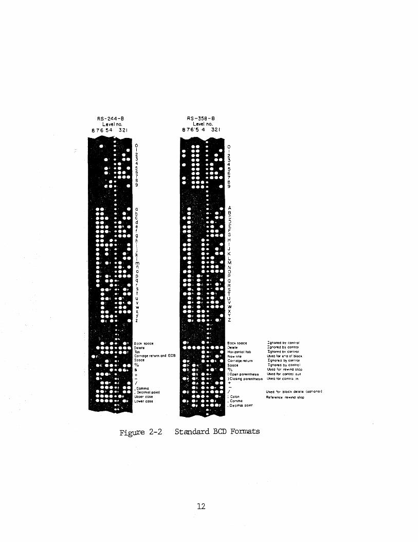
Figure 2-2 Standard BCD Formats
12

characters as well.
10. Tape Reader
Tape reader is the bridge between the coded punched
information and the electronic signals of the control
system. Usually, there are two types of tape readers,
mechanical and photoelectric type. Mechanical type readers
are used for slow speed reading and insert feelers or metal
prongs in to the holes. But with development of CNC,
photoelectric type has become more popular which are much
faster and more accurate. Holes are detected by light
passing through to a photoelectric cell. Readers with
spoolers to handle the tape have a feature to rewind the
tape automatically from a coded auxiliary instruction on the
tape.
Id. Data Storage
The coded data read is stored in electronic storage
sections. Sometimes, there are two storage sections; one
called 'Buffer storage' and the other called 'Active
storage'. Buffer storage may not be present with point-to-
point operation systems as there are fewer blocks to be
read. With CNC systems, it may or may not be required
depending on the speed of data transmission of the
mini/micro computer. Buffer storage accepts data from the
reader while the machine is operating under the
instructions stored in active storage. This arrangement is
very useful with contouring because the time required to
13

read the contouring information is relatively long. A
contour is usually expressed as a series of very short
segmented straight lines and each straight line needs a
block of data. So', the buffer enables the control to operate
on instructions from the active storage while the data for
the next movement are being read in to the buffer. The
transfer of data from buffer to active storage takes
millionths of a second and occurs at a precise moment that
the previous movement is completed for the block of
information in the active storage.
le. Pulse Generation
The number of pulses produced and their rate of
distribution depends on the distance to be moved in a
particular axis and the feed rate. Suppose, each pulse
represents a distance of 0.001 inch and it is desired to
move 3.456 inches at a rate of 10 ipm then, the pulses
produced will be 3456 and will be meterd out in 0.3456
minutes. While contouring, the movements in different axes
are very closely coordinated. At that time, the pulse train
is measured such that the required number of pulses for each
axis is completed precisely at the same time. If the result
of metering the pulses is a straight line, it is called
straight line interpolation and if it is an arc, it is
called circular interpolation. If it were desired to move at
the same rate along two axes such that the resultant is a 45
degree straight line, the number of pulses per a period of
time for each axis will be same. But, if one axis component
14

were twice that of the other, the number of pulses also
doubles for that axis.
Usually, pulses are generated and coordinated by a
pulse rate multiplier or a digital differential analyzer
(DDA). For pulse rate multiplier, pulses for all the axes
are generated by one common digital clock which keeps the
relationship of the pulses for different axes constant
if the clock changes its rate. With DDA, the pulses are fed
to a register which allows an 'overflow' at a reduced rate.
This rate is determined by the relationship of the movement
of the axes. They are sometimes called overflow counters.
(2) The Feedback Unit
The feedback unit is a device which 'feeds back' the
information about the actual position of the moving slides
of the NC tool to the control unit. The commanded position
is then compared with the actual position and if necessary,
an adjustment is made for the correction of the difference.
The feedback signals are generated by a 'resolver' or
an 'encoder' which is attached to the drive mechanism. When
there is a difference, a voltage is fed to the drive motor
such that the motor does not run too fast or the table does
not overshoot. For this purpose, a voltage generating
techometer is attached to the drive mechanism which
counteracts the voltage to the drive motor and keeps the
required feed rate in line. When the commanded position is
reached, voltage to the drive motor is cut down. For
commands like, to select a tool from automatic tool changer
15

Figure 2-3 A CNC Design. with Motion Control Provided by Software
Within the Minicomputer
16
or turning the spindle motor on, they are directly fed to
electrical controls where power is amplified and fed to the
control mechanism.
Considering this in terms of pulses, the metered pulse
train is fed to a 'modulator' where it is superimposed on a
constant rate pulse train. If the motion has to be positive,
these pulses are added but subtracted if the motion is
negative. These pulses are then passed through a 'frequency
divider' which reduces the number of the pulses and converts
the output to a square wave. This square wave is fed to a
'demodulator' whose function is to compare them with the
input from a rotary resolver connected to the driving
mechanism. The output from the demodulator, a d-c voltage
proportional to the phase difference between two inputs is
then amplified and fed to the drive motor.
With CNC systems digital encoder is more popular, which
feeds back the pulses generated by a rotary photo
arrangement to the control system. Here, quite often the
resolver's analog signal is converted to a digital feed back
form as a CNC system incorporates a digital computer.
(3) The Drive Unit
The function of this unit is to move a machine tool
table, head or other member. Most of the time, a precision
recirculating ball-nut lead screw is used as it offers
accuracy and low friction which allows for rapid feed back
response.
The drive could be hydraulic or electric power
17

depending on the size of the load to be moved. For less than
10 horsepower electric motor is preferred.

CHAPTER III
PART PROGRAMMING FOR BRIDGEPORT SERIES I CNC MACHINE
3.1 FEATURES AND FUNCTIONS OF THE MACHINE
This chapter is an introduction to the coordinate
system and function codes required for programming for
Bridgeport Series I CNC milling, drilling and boring
machine. All the general function codes are described with
emphasis on the codes for this particular machine.
Bridgeport Series I CNC machine incorporates micro-
computer and its Bridgeport Operating System Software
(BOSS) which provides the following features and functions:
- 3 axis continuous path contouring.
- 2 axis circular interpolation in switchable planes.
- Word address variable block format to EIA RS274C.
- Absolute/Incremental data input.
- Plus or minus programming. Zero referance can be at any
point.
Feedrate programmed directly in IPM (inch per minute)
at constant vector velocity.
- Manual feedrate override 1-120%, infinitely variable.
- Acceleration/Deceleration override.
- 8 canned Z axis cycles.
- Feed hold and restart without loss of position.
- Full jog control of any axis in any direction at 120
ipm (inch per minute).
- Jog increment control in steps of 1.0, .1, .01, .001
19

inch.
- Programmable mirror image capability.
- Block delete.
- Optional stop.
- Tool length offset (up to 24 values).
- Operating controls (like a 3 digit readout display of
sequence number, feedrate, spindle speed, tool number
and 5 digit readout for XYZ position, stored tool
length offset value, reference tool diameter and status
lamps to indicate control mode and operating
conditions).
The machine in the Mechanical Engineering Department
at WIT has Bridgeport Operating System Software 4.0
(BOSS 4.0) which provides following extended features:
- Part program storage:- A part program equivalent of
approximately 80 feet of paper tape can be stored by
the system.
- Macro subroutine:- Up to 16 subroutines can be defined,
each having variables that can be modified in the
subroutine call statement.
- Repetitive subprogram capability:- Looping techniques
can be used.
- Special canned cycles:- Three special canned cycles are
provided for face milling, pocket milling and an
internal bore.
- On line part program editing:- A part program editor in
the micro-computer memory enables text input,
20

manipulation and modification via a local data input
device. A 20ma serial line interface is provided to
handle the device.
- Inch/Metric programming (optional):- The normal state
is inch output from stored data in inch dimensions
(G70). The modal preparatory function G71 denotes that
the system is to output metric data from metric stored
data
3.2 COORDINATE SYSTEM
:artesian coordinate system is the basis for NC part
programming. Here two or three fixed lines perpendicular to
each other described as axes are used to locate a point. The
common point where all the axes intersect, is called origin.
The Bridgeport Series I CNC machine has three axes, X, Y and
Z. X dimensions to the right of the Y axis, Y dimension
above the X axis and Z dimensions above the plane formed by
the X and Y axes are considered positive. The positive
motions are shown in Fig. 3-1.
There are two modes of describing the coordinates of a
specific point. In absolute mode, which is more preferrable
because of less chances of error, all coordinates of a point
are given in reference to the origin which would be located
anywhere as desired. In incremental mode, the coordinates of
a point are given as distance to be moved in direction of
each axis from previous operating point.
For Bridgeport Series I CNC machine, the three axes
movement is achieved by combination of table and saddle
21
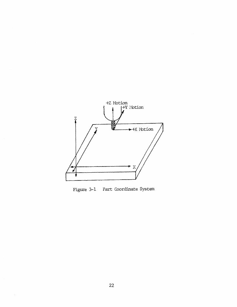
Figure 3-1 Part Coordinate System
22
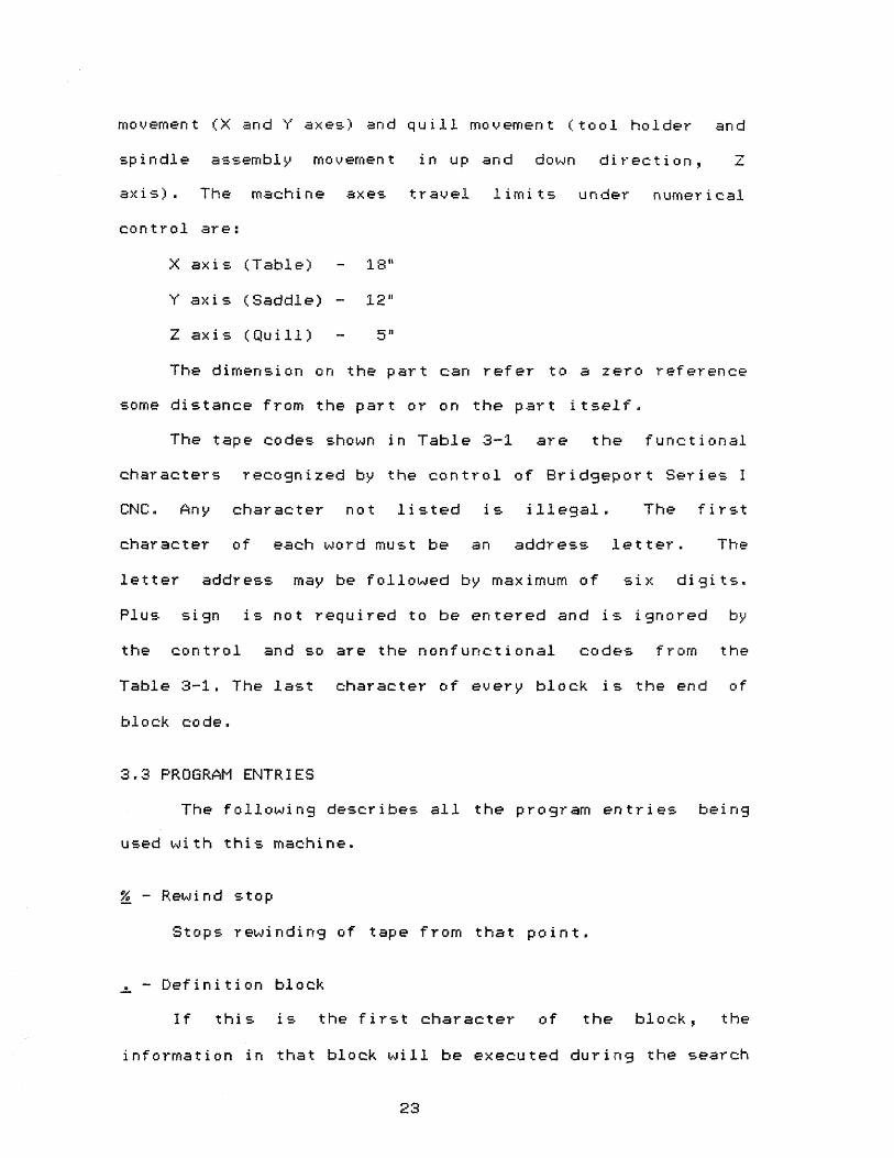
movement (X and Y axes) and quill movement (tool holder and
spindle assembly movement in up and down direction,
axis). The machine axes travel limits under numerical
control are:
X axis (Table) - 18"
V axis (Saddle) - 12"
Z axis (Quill) - 5
The dimension on the part can refer to a zero reference
some distance from the part or on the part itself.
The tape codes shown in Table 3-1 are the functional
characters recognized by the control of Bridgeport Series I
CNC. Any character not listed is illegal. The first
character of each word must be an address letter. The
letter address may be followed by maximum of six digits.
Plus sign is not required to be entered and is ignored by
the control and so are the nonfunctional codes from the
Table 3-1. The last character of every block is the end of
block code.
3.3 PROGRAM ENTRIES
The following describes all the program entries being
used with this machine.
- Rewind stop
Stops rewinding of tape from that point.
- Definition block
If this is the first character of the block, the
information in that block will be executed during the search
23

Figure 3-2 Input Tape and Program Codes24

mode for a particular block as well as during program
execution.
WARNING:- Motion words should not be programmed as the data
is executed during search mode.
/ - Block delete and value separation
If it is entered at the beginning of the block and the
DELETE ON-OFF switch on control console is ON, that block is
ignored by the tape reader while reading the tape. It is
also used for value separation with G 04/n and Ta/b commands
described later.
N - Sequence number letter address
It is used to identify blocks and is followed up to 5
digits ranging from 1 to 19999.
F Feedrate command
Feedrate in inches per minute can be directly
programmed using letter F and a three digit number ranging
from 2 to 320 which indicates feedrate from .2 to 32.0 i pm.
Higher feedrates programmed are set at 32.0 ipm. It is used
with 601, G02 and 603 commands and remains effective until a
GO0 command or another feedrate is encounterd. For circular
cuts, feedrate is modified as follows:
For cutting around the outside of a circle, the feedrate
should be increased by multiplying original feedrate by
(PR+CR)/PR and should be decreased by multiplying by (PR-
CR)/PR while cutting around the inside of a circle. Here, PR
25

denotes part surface radius and CR denotes the cutter
radius.
S - Spindle speed command
It is ignored by the system but can be programmed with
a four digit number to instruct the operator to set the
spindle speed manually.
T - Tool select command
It is followed by a two digit number ranging from 1 to
24. It is also used to store tool length offset values. The
format is Ta/b, where a is tool number (1 to 24) and b is Z
axis offset value. (NOTE:- Tool length offset - TL0 must be
entered up to third decimal point only. e.g. T3/1.2345 will
be stored as 12.345). Also tool diameter can be stored using
the format Tn//d, where n is tool number and d is tool
diameter.
M - Miscellaneous function commands
The following notations are used in describing the
function codes:
B - Activated before axis motion occurs.
W - Activated at the same time axis motion occurs.
A - Activated after axis motion is complete.
MOO - (A) Program stop
Used to stop program cycle for manual inspection or
adjustments like tool change. To continue, depress
START/CONTINUE button.
26
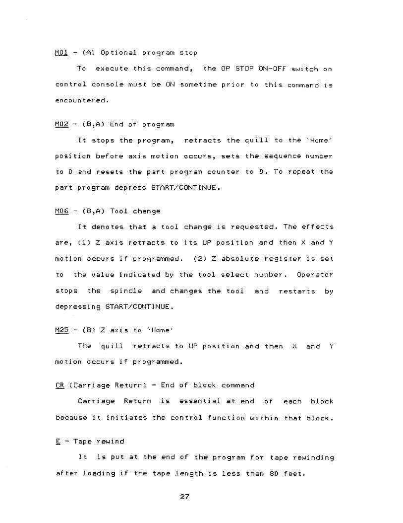
MO1 - (A) Optional program stop
To execute this command, the OP STOP ON-OFF switch on
control console must be ON sometime prior to this command is
encountered.
MO2 - (B,A) End of program
It stops the program, retracts the quill to the 'Home'
position before axis motion occurs, sets the sequence number
to U and resets the part program counter to 0. To repeat the
part program depress START/CONTINUE.
M06 - (B,A) Tool change
It denotes that a tool change is requested. The effects
are, (1) Z axis retracts to its UP position and then X and Y
motion occurs if programmed. (2) Z absolute register is set
to the value indicated by the tool select number. Operator
stops the spindle and changes the tool and restarts by
depressing START/CONTINUE.
M25 - (B) Z axis to 'Home'
The quill retracts to UP position and then X and Y
motion occurs if programmed.
CR (Carriage Return) - End of block command
Carriage Return is essential at end of each block
because it initiates the control function within that block.
E - Tape rewind
It is put at the end of the program for tape rewinding
after loading if the tape length is less than BO feet.
27

G - Preparatory functions
The letter address G followed by two digits indicates
the mode of operation. More than one G function can be
programmed in one block. A list of G functions and their
description is given below.
G00 - Rapid traverse, point-to-point positioning
This function causes the machine to operate in rapid
traverse positioning mode. Movement in XY axes towards
programmed point occurs first at 45 degrees f lowed by
continued motion of the major axis. If X, Y and Z moves are
programmed concurrently, the logic in control console splits
the XY motion and Z move. If Z move requires the quill to go
up, Z motion occurs first followed by X and/or Y move. If Z
move requires the quill to go down, Z motion occurs after X
and/or Y move. GOO cancels G01, G02 and G03 and will also
set the system in G80 mode. The programmed feedrate remains
in the feedrate register.
G01 - Linear interpolation, Feed
This function causes the machine to operate in feed
range. The axes travel in a straight line. Starting point is
defined by the H9 Y, Z coordinates of previous block and end
point coordinates are given in the block. G01 cancels GOO,
G02 and G03.
G02 - Circular interpolation, clockwise
This function defines that the arc is to be generated
in clockwise direction. The arc radius is defined by the
28

start point of the arc (from previous block), the end point
and arc center (I,J,K) coordinates. The arc motion could be
in any two of the three axes. GO2 cancels GOO, G01 and G03.
GO3 - Circular interpolation, counterclockwise
This function is same as G02 but defines the arc to be
generated in counterclockwise direction. GO3 cancels GOO,
GO1 and G02.
GO4 - Dwell
The format is G04/n where, n is an integer from 1 to
9999 giving a dwell time of .01 seconds to approximately 151
seconds. If dwell value is programmed earlier in the program
some Z cycles can execute this time. The programmed value is
counted as follows:
Programmed value, n = 6.6 x revolutions required
x rpm/60
For G17, G18 and G19 see Fig. 3-2.
G17 XY plane selection (Plan view)
This function sets up XY plane for cutting arc in XY
plane. Unless specified, this is the plane of operation with
machine start up. It cancles G18 or G19.
G18 ZX plane selection (Front elevation)
This function sets up ZX plane for cutting arc in ZX
plane. It is programmed after G02 or G03. The input must be
incremental input. It is cancelled by GOO, G01, G17 and G19.
29

Figure 3-3 C07 or CCW Motion in Switchable Planes
30

819 YZ plane selection (L.H. side elevation)
This function is same as 818, except it sets up YZ
plane for cutting arc in YZ plane. It is cancelled by GOO,
G01, G17 or G18.
G30 - Cancel sign reversal
This function sets plus and minus directions for X and
Y axes according to EIA standard RS-267. It is a normal
POWER ON state for the control. G30 is cancelled by G31 or
882.
G31 and G32 are used for what is called mirror image
programming. They must be programmed at axis of symmetry.
Q31 - Reverses the direction signs for the X axis.
G32 - Reverses the direction signs for the Y axis.
G31 or G32 are cancelled by G30.
G70 - Inch dimension system input
Unless specified, this is the normal POWER ON state for
control. It is cancelled by G71.
Q71 - Metric dimension system input (Optional with BOSS 4.0)
This function instructs the control unit to interpret
the following data as being in millimeter. It is cancelled
by G70.
Both G70 and G71 have resolution of seven digits.
(000.0000" or 0000.000 mm.)
G77, G78 and G79 are three special mill cycles.
31

G77 - Facing cycle
The format of the cycle is:
677 Xn1Yn2Yn3 Fv where,
n1 = incremental distance to be milled along X axis.
n2 = incremental distance to be milled along Y axis.
n3 = Y axis stepover value.
v = feedrate value.
G78 - Pocket milling cycle
The format of the cycle is:
678 Xn1Xn2Xn5Yn3Yn4 Fv1 Fv2 where,
n1 = Distance from the center of the pocket to the wall
along X axis minus cutter radius.
n2 = X axis stepover value.
n3 = Distance from the center of the pocket to the wall
along Y axis minus cutter radius.
n4 = Y axis stepover value. If not programmed, it is
set equal to n2.
n5 = Distance for the final boundary cut. If not
programmed, it is set at the default value of
0.02".
v1 = Feedrate for all roughing passes.
v2 = Feedrate for boundary cut. If not programmed, it
is set equal to 1.5V1.
G79 - Internal hole mill cycle
It is used to mill a hole to size. The format of the
cycle is:
32

679 JnFv where,
n = Radius of the hole to be milled minus cutter
radius.
v = Feedrate value.
680 - 689 are canned Z axis cycles. They reduce programming
by storing the following repetitive information:
a. The depth of Z motion to be under cycle control.
This must be incremental unsigned value.
b. The desired feedrate for Z motion.
c. The Z axis peck increments for 683-687. The sum of
peck increments need not to be equal to Z axis
depth to be drilled.
All of these cycles work as follows:
a. First rapid traverse to X-Y coordinate as designated
which can be either incremental (691) or absolute
(G90).
b. Then the Z axis cycle occurs.
After the fixed cycle is programmed, the system must
have an X and/or Y coordinate word. In absolute coordinates,
it could be a repeat of the existing position and in
incremental mode, it could be axis zero. When a change in Z.
depth or a rapid traverse Z move is required, the fixed
cycle has to be terminated, the change in depth or rapid
traverse inserted and then the cycle is reinstated with
fixed cycle code and Z increment value.
33

G80 - Fixed cycle cancel
This function cancels all fixed cycle codes.
G81 - Drilling cycle
This function provides for a feed in - rapid out
sequence for drilling a series of holes with same diameter
and depth.
G82 Spotfacing cycle
This function provides for a feed in - delay - rapid
out sequence for spotfacing, counterboring etc. . The length
of delay is set by DWELL command G04/n, previously
programmed.
083 - Deep hole drilling cycle
This function is programmed with Z1 - the total Z
depth, Z2 - incremental distance for first peck increment,
Z3 - peck distance for remaining increments. If Z3 is not
specified, Z2 becomes peck distance for all increments. This
function provides a feed in, rapid out, rapid in to bottom
of hole, feed in, rapid out etc. sequence until the
specified Z depth is reached.
084 - Tapping cycle
This function provides a feed in - feed out sequence
for tapping with a tapping attachment for non-reversing
spindles. The required spindle speed is calculated as
follows:
Spindle rpm = feed in i pm x thread/inch
34

A chart of feed and speed values for tapping various
pitches is given in operating manual for the Series I CNC
machine.
G85 - Boring cycle
This function provides a feed in - feed out sequence
suitable for boring or reaming.
686 - Boring cycle
This function provides a feed in, feed stop, wait for
operator command, rapid out, operator restart sequence for
boring. After the programmed Z depth is reached, the feed is
commanded to stop. Then the operator stops the spindle and
orients it. After pressing CONTINUE, the Z axis is rapid
traversed up and the programmed spindle direction is
reinitiated by the operator. This feature allows to position
the tool a suitable distance from the finished bore before
withdrawing the tool from the hole.
G87 - Chip breaking cycle
This function is programmed exactly like G83 - deep
hole drilling cycle, and performs the same function. But,
instead of rapid traverse out of the hole and back after a
feed move as in G83, the quill rapid traverses up and down
by 0.05" to break the chip.
G89 - Boring cycle
This function provides for a feed in - dwell - feed out
sequence for boring. The dwell time is set by previously
programmed 604/n command.
35
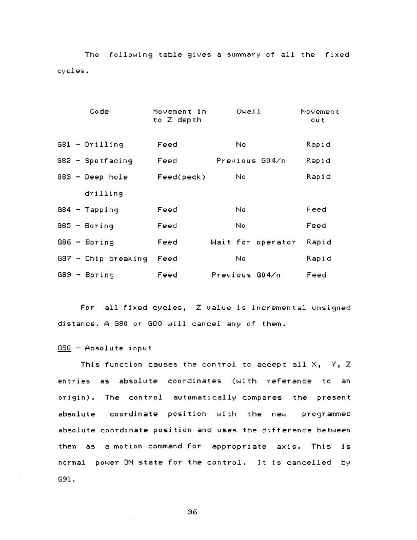
The following table gives a summary of all the fixed
cycles.
Code Movement into Z depth
Dwell Movementout
681 - Drilling Feed No Rapid
682 - Spotfacing Feed Previous 604/n Rapid
683 - Deep hole
drilling
Feed(peck) No Rapid
684 - Tapping Feed No Feed
685 - Boring Feed No Feed
686 - Boring Feed Wait for operator Rapid
087 - Chip breaking Feed No Rapid
689 - Boring Feed Previous 604/n Feed
For all fixed cycles, Z value is incremental unsigned
distance. A G80 or GOO will cancel any of them.
G90 - Absolute input
This function causes the control to accept all X, Y,
entries as absolute coordinates (with reference to an
origin). The control automatically compares the present
absolute coordinate position with the new programmed
absolute coordinate position and uses the difference between
them as a motion command for appropriate axis. This is
normal power ON state for the control. It is cancelled by
691.
36

1391 - Incremental distance input
This function causes the control to accept all X, Y,
entries as incremental distances (with referance to present
position). So, all motion entries are interpreted as
commands to move the programmed distance from the present
position and not an absolute position. It is cancelled by
690.
692 - Preset absolute registers
This function provides the ability to preset absolute
position registers to desired dimension. It allows
programming from a starting point on a part which is defined
by absolute coordinates specified in 692 command. It also
allows to translate an original coordinate system to a new
part coordinate system which is very useful for making
multiple parts on a fixture. As 692 command destroys the
previous contents of the absolute registers, a new 692
command and a positioning move will be necessary to return
to original coordinate system.
699 - Deceleration override
If the feedrate is higher than 2.8 ipm, the table
accelerates from and decelerates to the programmed value
during each block. Deceleration in a particular block can be
reduced by programming a 699 code in that block. If the
feedrate is over 8 ipm, some deceleration will still occur.
N0TE:- Do not use 699 when in rapid traverse (GOO) or when
in feed if the next block is rapid traverse (GO0).
37

The examples on use of the above described function
codes are given in the next chapter.
38

CHAPTER IV
PROGRAMMING EXAMPLES
4.1 INTRODUCTORY COMMENTS
This chapter contains programming examples on most of
the preparatory function codes (G commands). To a beginner,
they should give an easy understanding about how to use
these commands in a program. The explanation of these
function codes should be sufficient to write simple
programs. However, the operating manual for the Bridgeport
Series I CNC machine should be referred to when writing
programs for more complicated parts. This chapter is
intended to give a good start at programming this machine.
First, the blueprint or the part sketch should be
studied and a sequence of operations to be performed should
be laid out. Then, the coordinates of all the operating
points should be calculated. Following this, a manuscript
should be prepared. Fig. 4-1 shows a convenient manuscript
layout. A manuscript is a planning chart or list of
instructions which describes the detailed and precise step-
by - step operation of the machine. One should be able to
punch the tape directly from the manuscript.
4.2 PROGRAMMING EXAMPLES
With the existing software BOSS 4.0, the axis motion
(X0 Y, Z) can take one of the following forms:
(a) Rapid traverse, point to point positioning mode.
39

Figure 4-1 Manuscript Layout

(b) Linear interpolation, feed mode (cutting in a straight
line).
(c) Circular interpolation, feed mode (arc generation).
Any of the above mode can be programmed in either
(a) Absolute coordinates or (b) Incremental coordinates.
(a) Absolute coordinates
When a 690 command is used, the distance to be moved
for a particular axis is with respect to a zero reference
point. The zero reference can be set so that the axis motion
may occur in either plus or minus direction. The motion has
to be within the machine travel limits. Full four quadrant
plus and minus absolute programming in cartesian coordinate
system is standard. The X, Y or 7_ coordinate can be
described using up to a seven digit number with resolution
of 000.0001". The non-significant zeros, both to the left
and to the right of the decimal may be dropped. For example,
000.9000 can equally be written as .9 .
(b) Incremental coordinates
When a G91 command is used, the distance to be moved
for a particular axis is from the present position and not
an absolute coordinate. Each axis command consists of a
letter address X, Y or Z, algebraic sign to indicate
direction and up to a six digit number with a resolution of
00.0001".
41

Programming Rapid Traverse (point to point positioning)
Example 1
Move from (1, -1, 2.5) to point P1 (1, 1, -0.5) and
from point P1 to point P2 (3, 3, 0.5) as shown in Fig. 4-2.
X Y z
Initial absolute coordinates 1.0 -1.0 2.5
Move to point P1 1.0 1.0 -0.5
Move to point P2 3.0 3.0 0.5
The above moves can be programmed as follows:
(a) In absolute coordinates,
N1G90G00Y1.0Z-0.5
N5X3.0Y3.0Z0.5
(b) In incremental coordinates,
N1G91G00Z-3.0
N5X2.0Y4.0Z1.0
In rapid traverse, when a move has to occur in X, Y
and Z axes (as in moving from point P1 to point P2), it is
split in to two rapid traverse moves. If the Z motion is
minus (as in moving from initial point to point P1), the XY
rapid occurs first followed by negative Z move. But, if the
Z motion is positive (as in moving from point P1 to point
P2), the Z move occurs first followed by the XY move.
Programming Linear Interpolation, Feed Mode
For cutting in a straight line, G01 command is used.
Drilling a hole or cutting a slot is linear interpolation.
42

Figure 4-2 Example I
Figure 4-3 Example 2
43

Example 2
Cut a slot of 2" depth starting at (1, 1, 2.5) and
ending at (2, 2, 0.5) as shown in Fig. 4-3.
(a) In absolute coordinates,
(b) In incremental coordinates,
Programming Circular Interpolation, Feed Mode
602 and 603 commands are used to generate an arc. The
following arc center offset entries are used with these
commands. See Fig. 4-4.
I - The distance parallel to the X axis from the
starting point of the arc to the arc center.
J - The distance parallel to the Y axis from the
starting point of the arc to the arc center.
K - The distance parallel to the Z axis from the
starting point of the arc to the arc center.
Signs must not be used with arc center offset entries
and I0.0, J0.0 or K0.0 need not be programmed.
44

Figure 4-4 Arc Center Offsets45
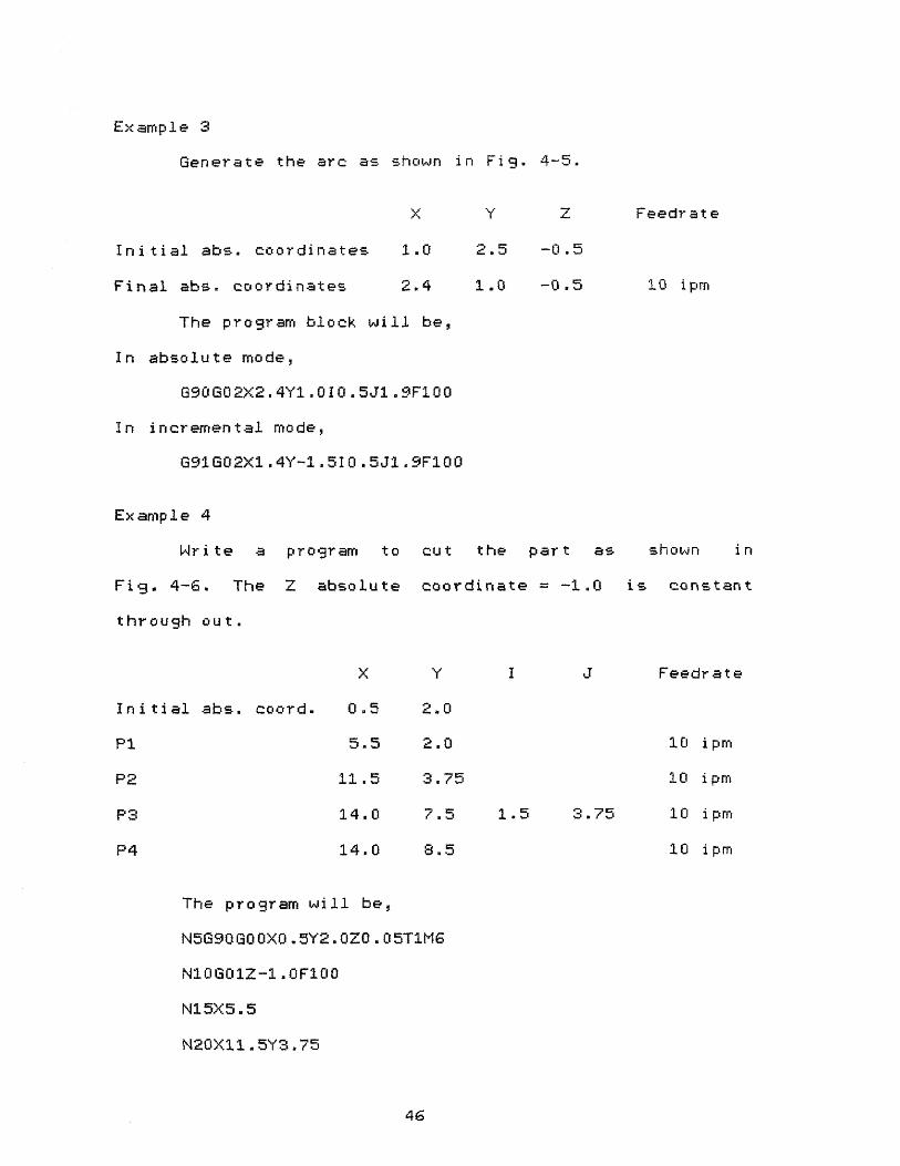
Example 3
Generate the arc as shown in Fig. 4-5.
X Feedrate
Initial abs. coordinates 1.0 2.5 -0.5
Final abs. coordinates 2.4 1.0 -0.5 10 ipm
The program block will be,
In absolute mode,
G90602X2.4Y1.010.5J1.9F100
In incremental mode,
Example 4
Write a program to cut the part as shown in
Fig. 4-6. The Z absolute coordinate = -1.0 is constant
through out.
X Y I J Feedrate
Initial abs. coord. 0.5 2.0
P1 5.5 2.0 10 i pm
P2 11.5 3.75 10 ipm
P3 14.0 7.5 1.5 3.75 10 i pm
P4 14.0 8.5 10 ipm
The program will be,
46

Figure 4-5 Example 3
Figure 4-6 Example 4
47

Sequence no. 5 is rapid traverse to starting point.
Sequence no. 10 wilL feed move the tool down to the required
Z depth. Sequence no. 15 and 20 will generate the slots from
initial point to P1 and from P1 to P2. Sequence no. 25 will
generate the arc P2P3 in counter clockwise direction.
Sequence no. 30 will generate the slot from P3 to P4.
Sequence no. 35 will move the tool back to the origin.
Programming Mirror Image
A 031 command reverses the direction signs of X axis
and 032 command reverses the direction signs of Y axis. 630
command cancels both, 031 and 632.
Example 5
As shown in Fig. 4-7, an L shape in the upper right
hand side of the axis of symmetry and its three mirror
images are to be produced. To program this, concept of macro
is required. Refer to section 4.4 for details. The program
will be:
48

Figure 4-8 Example 6
49

Return to axis of symmetry
End of macro
- Generate the shape in upper
right corner
- Generate the image in upper
left corner
- Generate the image in lower
right corner
- Generate the image in lower
left corner
- Cancel mirror image codes.
Go back to starting point.
Programming Special Mill Cycles
Commands 677, 678 and 679 give three special mill
cycles. The examples are given below.
677 - Facing cycle
The format is
n1 = incremental distance to be milled along the X
axis
n2 = incremental distance to be milled along the Y
axis
n3 = Y axis step over value
v = feedrate
50

Example 6
A block of 5.0" x 3.0" has to be facemilled with .5"
diameter end mill as shown in Fig. 4-8. The Z axis
coordinate will remain constant which is set according to
the desired depth. The program block will be:
677X5.6Y2.58Y0.43F100
Note:- Absolute coordinates must not be used in this block
but, the following block must be programmed in absolute
coordinates.
The effect of the above command will be as follows:
From the starting point at the bottom left hand
corner, the first move will be a +X axis move equal to 5.6"
(input value). The next move will be a +Y axis move equal to
0.43" (step over value) followed by a -X axis move of 5.6".
The next move again will be +Y axis move of 0.43" followed
by a +X axis move of 5.6". This zigzag pattern will continue
until the sum of step over values is equal to the input
Y distance of 2.58". Then the last X axis move will be made.
n1 = Distance from the center of the pocket to the
wall along X axis minus cutter radius
n2 = X axis step over value
n3 = Distance from the center of the pocket to the
wall along Y axis minus cutter radius
51

n4 = Y axis step over value. If riot programmed, it
is set equal to n2
n5 = Distance for the final boundary cut. If not
programmed, it is set at the default value of
0.02"
vi = Feedrate for all roughing passes
v2 = Feedrate for boundary cut. If not programmed,
it is set equal to 1.5v1
Example 7
Mill a pocket of dimensions 5" x 3" x 0 .5" using a
0.5" diameter cutter as shown in Fig. 4-9.
Here, X axis is major axis and Y axis is minor axis.
The maximum step over value for X axis can be 0.25" (radius
of the cutter). The step over value for Y axis for the most
efficient result should be 0.25" x (n3/n1).
The program will be:
52

Figure 4-9 Example 7
Figure 4-10 Example 8
53

N25G00G90X-1.0Y-1.0M2
Sequence no. 5 will move the tool to starting point
(-1,-1). Sequence no. 10 will move the tool to the center of
the pocket to be milled. Sequence no. 15 will out the hole
of the required depth (the tool will be in the workpiece to
that depth). The effect of the sequence no. 20 will be as
follows:
From the center of the pocket, the first move will be
to point 1 (X and Y axis step over). Then the cutter center
will move -X, -Y, +X, +Y at a value equal to twice the
accumulated step over distance (X axis = 0.5", Y axis =
0.278"). The cutter then will move to point 2. (Another X
and Y axis step over). This pattern will continue until the
cutter surface is within 0.02" of the pocket wall. Once an
axis reaches 0.02" from the pocket wall, it is no longer
incremented during step over move. The last step over move
will be 0.02" in both X and Y axes at a feedrate 12 ipm. All
the moves before, will be at a feedrate 10 ipm. Finally, the
cutter will feed at 12 ipm from point 6 to the center of the
pocket to end the cycle.
G79 - Internal Hole Mill cycle
This cycle is useful to mill an existing hole to size
i.e. required final diameter.
The format is:
G79 J (Value) F (Value) where,
J = Radius of hole to be milled minus cutter radius
54

Example 8
An existing hole has to be milled to size of 1" radius
with 0.5" diameter cutter as shown in Fig. 4-10. The command
will be:
07930.75F100
The numbers on the figure represent the sequence in
which the cutter will move. The entering and leaving tangent
small circle radius will be equal to 3/2 = 0.75/2 = 0.375".
Programming Canned Cycles
Commands 680-89 give different fixed cycles. The
examples are given below.
681 - Drilling cycle
This command will drill a series of holes of same
diameter and depth in a feed in - rapid out sequence. See
Fig. 4-11. The program will be:
N5GOOG9020.05
N10681X2.0Y1.0Z1.05F100
N15X3.0Y2.0
N20G00X0Y0
This will drill two holes of 1.0" depth at desired
locations as follows.
Sequence no. 5 will move the tool to 0.05" above zero
reference plene. Sequence no. 10 will move the X and Y axes
to the location of the first hole (X = 2.0", Y = 1.0") at
rapid traverse and the Z axis will feed 1.05" down at 10 ipm
giving 1" deep hole if the zero reference plane is at part
55

DR I LLING CYCLE G81
Figure 4-12 Spotfacing Cycle
56

upper surface. (1" depth of hole f 0.05" clearance = 1.05").
After the depth has been reached, the tool traverses out
1.05". Sequence no. 15 will have X and Y axes motion to the
location of the second hole (X = 3.0", Y = 2.0"). Z axis
will feed in 1.05" and rapid traverse out 1.05". Sequence
no. 20 denotes the end of fixed cycle (GOO) and rapid
traverse to X =0, Y = O.
882 - Spotfacing cycle
The sequence is same as G81. See Fig. 4-12. The only
difference is that a delay is forced when the Z axis reaches
the required depth. The length of the delay is set by Dwell
command previously programmed as G04/n.
883 - Deep Hole Drilling cycle
When a deep hole is to be drilled, this command is
used which gives feed in, rapid out, rapid in tm bottom of
hole, feed in, rapid out sequence until the required depth
is reached. See Fig. 4-13. The example is:
N5G83X2.0Y1.0Z2.5Z0.7Z0.3F100
This will drill a hole 2.5" deep at X = 2.0, Y = 1.0.
The first 2: axis feed in will be 0.7". Then it will rapid
traverse out 0.7", rapid traverse in 0.7". The Z axis will
then feed in 0.3", rapid traverse out 1.0" and rapid
traverse in 1.0". Again the feed in of additional 0.3" and
the sequence is continued until the required depth of 2.5"
is reached. The final feed in will be the remaining distance
to be drilled which may or may not be equal to 0.3".
57

DEEP HOLE CYCLE G83
Figure 4-14 Tapping Cycle
58

684 - Tapping cycle
According to the number of threads per inch and
required feedrate, the spindle speed is calculated. To
program 1/4-18 tap at 10.0 ipm, the required rpm will be
10 x 18 = 180 rpm. The rpm is set manually using the spindle
speed control panel. A hand held stroboscope is used to set
exact rpm. See Fig. 4-14.
685 - Boring cycle
This cycle has same format as 681 with a difference
that instead of rapid traverse out of the hole as in 681,
the Z axis feeds out of the hole at the programmed feedrate.
See Fig. 4-15.
686 - Boring cycle
This cycle has same format as 681. It provides feed
in, feed stop, wait for operator command, rapid out,
operator restrat cycle. See Fig. 4-16. The example is:
N5G86X1.0Y2.0Z0.6F25
After rapid traverse to X = 1.0, Y = 2.0, the Z axis
will feed in 0.6" at 2.5 ipm. After the required depth is
reached, the feed will stop. The operator stops the spindle
and orients it if necessary. He then presses CONTINUE. The Z
axis rapid traverses up and the programmed spindle direction
is reinitiated by the operator.
687 - Chip Breaking cycle
This cycle is programmed in exactly the same manner as
683 with only difference that instead of rapid traverse out
59

BORING CYCLE G85

of the hole and back in the hole after a feed move, the tool
rapid traverses up and down by 0.05" to break the chip. See
Fig. 4-13.
G89 - Boring cycle
This cycle has same format as 681 and has same feed
in - feed out sequence like 685 except that a dwell occurs
between the feed in and feed out moves. The dwell length is
set by G04/n previously programmed. See Fig. 4-17.
Programming Multihole Row Fixed cycle
When programmed in this format, the result is a row of
holes that may be programmed using looping technique
described in section 4.3. Any 681-89 fixed cycle can be
used. The format is:
where,
n1 = Total distance to be traveled along the X or
Y axis (maximum 16.0")
n2 = Incremental distance between holes (must be
in multiple of 0.0005")
n3 = Z axis incremental depth
v = Feedrate
Whenever initiated, the first hole will be drilled at
the existing position. Successive holes will be drilled at
61
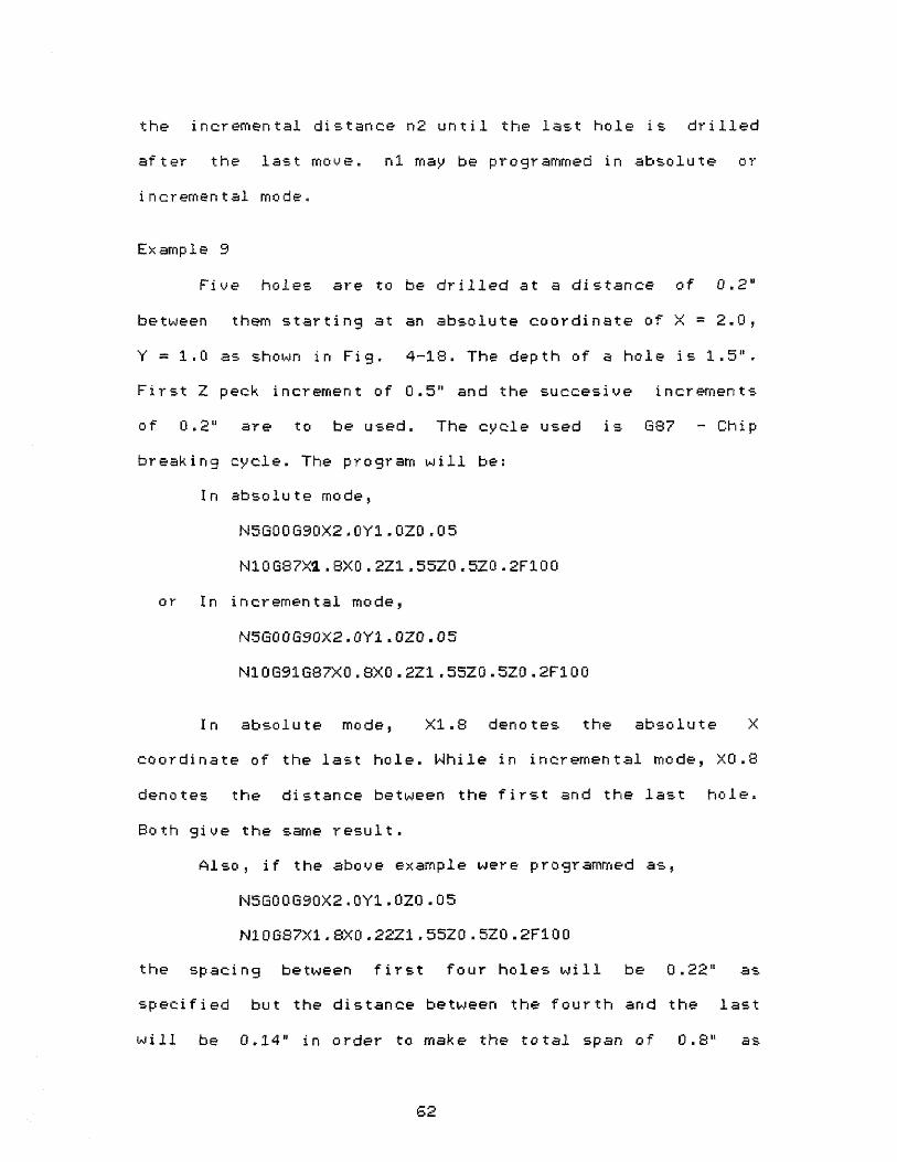
the incremental distance n2 until the last hole is drilled
after the last move. n1 may be programmed in absolute or
incremental mode.
Example 9
Five holes are to be drilled at a distance of 0.2"
between them starting at an absolute coordinate of X = 2.0,
Y = 1.0 as shown in Fig. 4-18. The depth of a hole is
First Z peck increment of 0.5" and the successive increments
of 0.2" are to be used. The cycle used is G87 - Chip
breaking cycle. The program will be
In absolute mode, X1.8 denotes the absolute X
coordinate of the last hole. While in incremental mode, X0.8
denotes the distance between the first and the last hole.
Both give the same result.
Also if the above example were programmed as
the spacing between first four holes will be 0.22 as
specified but the distance between the fourth and the last
will be 0.14" in order to make the total span of 0.8" as
62

Figure 4-18 Example 9
63

programmed.
4.3 LOOPING
Looping is a technique which instructs the computer
to execute a set of blocks in the part program a number of
times specified by the programmer. It relieves the
programmer of writing a sequence of statements which has to
be repeated. The form is:
=Na/b where,
a = Loop end block sequence number
b = Number of times the loop has to be repeated
The range of the loop includes blocks following the
looping statement up to and including the block with the
loop end sequence number. All the blocks in the range are
executed following a loop statement. After executing the
sequence for b number of times, the system falls through to
the next program block following the loop end block. Rules
for the looping technique are as follows:
(1) The loop end block sequence number must be in later
part of the program.
(2) All blocks following a loop statement must have a
sequence number.
(3) Nesting of the loops is possible up to 4 levels. The
range of an inner loop must be within the range of
next outer loop but they may have the same loop end
block sequence number.
(4) The loop end block must not be the last block of a
program.
64

(5) The maximum number of repeats is 19999.
(6) Metric data should not be programmed incrementally as
cumulative error could be high.
As an example of looping technique, the following
statements will cause 5 holes to be drilled, each 0.4" deep
and at a distance of 0.2" between them. The first hole will
be drilled at 0.2" away from the Y coordinate the system was
at before running the loop.
=N10/2
N10G91681Y0.2Z0.4F100
4.4 MACRO SUBROUTINES
This feature of Bridgeport CNC provides the programmer
with the ability to program an addressed parameter as a
variable parameter and execute a subprogram consisting of a
group of blocks with variable parameters. Here, the variable
parameters are assigned their values by the calling
statement. Thus, a subprogram with variable parameters can
be executed with different values of them. The form of a
macro is like:
N5GO0G90X*Y*
N10G01Z-0.5F*
$
Here, *n (range from 1 to 16) denotes the beginning and
$ denotes the end of the macro subprogram. The variable
parameters are followed by *. The macro call statement is of
the form:
65

Where, n is the macro subprogram to be executed and X*2.O,
Y*1.0, F*100 are the parameter values to be assigned for the
unspecified macro variables. Rules for macro subprogramming
are as follows:
(1) A macro subprogram must not be defined within another
macro subprogram.
(2) The number of unspecified parameters within the macro
and the number of specified parameters in the call
statement must be the same.
(3) A macro may include a loop and macro call may be
included within a loop. If the macro includes a loop,
the $ character must not be on the loop end block
number.
(4) A macro may call another macro. They can be nested up
to 4 levels.
(5) The macro call can contain maximum of 47 characters.
Also, the total number of active macro variables (*)
can not be more than 12. This is the limit for one
macro or a group of nested macros.
(6) The largest value a variable parameter can have is
+16.0000.
(7) If two macros with the same tag are defined within a
program, the call statement will execute the last
macro defined.
(8) If a macro variable has the same value in the next
call as was previously defined, it need not be
66

reentered. But this call must be the next call.
will call the same values of X = 1.0 and F = 100 but
in the following example,
the last call statement will call macro #1 but with
the values X = 2.0 and F = 120.
Use of looping and macro subprograms is a powerful
tool for an imaginative programmer.
67

CHAPTER V
OPERATION OF BRIDGEPORT SERIES I CNC MACHINE
5.1 INTRODUCTORY COMMENTS
This chapter gives familiarity with operator's
controls and indicators. The main components of the machine
control are as follows:
(1) Logic control cabinet, (2) Operator's main control
panel, (3) Power control cabinet, (4) Spindle control panel,
(5) Special operations panel.
5.2 OPERATOR'S MAIN CONTROL PANEL
Of all the components above, operator's main control
panel is the most important as far as operating the machine
is concerned. Familiarity with all controls available is
advised before attempting to operate the machine. The
function of each switch available on the panel is described
below. See Fig. 5-1 for the location of each of the
switches.
SET UP
It allows to use AXIS MOTION (X, Y, Z) set up controls
and ABS/TLO register controls. This is the mode type while
setting up the origin. Also, while loading paper tape and
68

Figure 5-1 Operator's Main Control Panel

using EDIT feature, switch has to be in SET UP.
BLOCK
While in this mode, everytime the START/C0NTINUE
pushbutton is depressed, one instruction block (one line)
from the program is executed. It is useful while checking
the part program.
AUTO
While in this mode, when the START/CONTINUE button is
depressed, the part program is automatically and
continuously executed.
MDI
It is used to input and execute a block of data
manually using the MDI keyboard.
MDI STORE
It allows the operator to store the block of data
inputted using the MDI keyboard and a part program can be
built up from successive blocks.
FUNCTION
There are two pushbutton switches, each with two
positions.
TOP SWITCH
RESTART
When depressed in this mode, the top switch resets
various system registers and flags and puts the system in
70
mode where part program can be executed from the beginning.
START/CONTINUE
When depressed, it begins the program execution if at
the beginning of the program or after an interruption, such
as a system H0LD or MO, Ml, MG. Also, while using BL0CK
mode, to execute next block depress the button in this
position.
BOTTOM SWITCH
EDIT
While depressed in this position, it transfers the
control to the system if the MODE switch is in SET UP
position. To use this feature, a local data input device is
required.
RDI
It transfers the control to a remote data link if the
MODE switch is in SET UP position. To use this feature, the
system must have this option.
AXIS MOTION
There are two selector switches and one pushbutton
under this title. By combining proper selection modes, a
motion in the selected axis, in a particular direction for a
particular distance can be obtained in rapid traverse. The
MODE switch has to be in SET UP position.
71
X/Y/Z
Controls the axis selected for motion.
MOVE +/-
This two position pushbutton controls the direction of
motion in the selected axis.
J0G/1/.1/.01/STEP
This selector switch controls the incremental distance
to be moved in rapid traverse. When it is in JOG position, a
continuous rapid traverse is obtained in the selected axis
as long as the MOVE +/- pushbutton is depressed. While,
depressing the MOVE +/- button once, 1/.1/.01/STEP positions
would give motion of 1", .1", .01", .001" respectively in
the selected axis.
ABSolute/Tool Length Offset (ABS/TLO)
This section has a five position selector switch which
works in conjuction with a selector pushbutton below it.
They are effective in SET UP mode only. The following chart
describes the result of different combination of the above
two, when the pushbutton is depressed.
72

MIT). Z/TNO
ZERO Zeros the XY ABS
registers. After
setting required X0,
YO, store that posi-
tion using this.
Retracts the quill all the wey
up("Home" position) and zeroes
Z ABS register.
GO TO Moves the table to
X0, YO position.
TNO
STORE
If the quill is "home", moves
it down the distance stored as
TLO. At this downpoint, ZABS=0
Sets the tool number=1. It
advances the tool number by 1
everytime it is depressed.
Stores the current contents of
ZAGS register as a tool length
offset (TLO).
GET
HOLD
Fetches the value stored as
tool length offset and sets
ZABS register to that value.
When depressed, this pushbutton provides with an
interruption of program execution without loss of position
and the unused portion of the block of the data. To
continue, depress START/CONTINUE.
LIMIT OVERRIDE
This is a lighted indicator pushbutton. When the power
is switched ON the first time, this light is illuminated.
73

Depress this pushbutton to get power to axis drive and to
operate the machine. When a motion in a particular axis
exceeds the limit for that axis, this light is illuminated
indicating power interruption. It clears active and buffer
storage but does not clear part program and X, Y, Z absolute
position and tool length offset values. For details on how
to resume the operation, see section 5.6.2.
FEEDRATE OVERRIDE
This is a variable potentiometer which allows
adjustment from 1 to 120% of the programmed feedrate.
STATUS
This section contains a bank of LED's (Light Emitting
Diodes) and two display windows which indicate the internal
set status of the control. The following describes the
meaning of each condition when that lamp is 0N:
RUN: System ready for input or part program ready to be
executed.
GO TO: Information in active storage (arithmetic)
registers.
HOLD: A condition when HOLD button is depressed or
spindle is interlocked. Output of data to the
drive system is temporarily stopped.
WAIT: Special case of HOLD. Occurs when an M is
encountered or computer is waiting for the quill
up switch to be closed externally.
ERR: An error found in start-up diagnostic test.
74
TOOL: An MG (Tool change) instruction is encountered.
CYCLE: A G81-89 cycle in process.
ABS: System is in ABS mode (690).
METRIC: System is in METRIC mode (671).
EDIT: System is in EDIT mode.
RDI: System is in RDI mode.
Display Windows
The three digit window displays sequence number (last
3 digits), feedrate, spindle speed (first 3 digits) or tool
number.
The five digit window displays X, Y, Z absolute (4- or
-) coordinates, tool length offset and tool diameter (for
operator's information).
MDI keyboard has different keys to display desired
functions. Until MDI is used, the display shows sequence
number and X absolute coordinate. When the MDI keyboard is
used to enter the data by depressing a letter key, the 5
digit display becomes blank and displays the numerals
entered starting from the right and shifted to the left.
When another letter key is depressed, the previous word is
stored and the display becomes blank egain.
MDI keyboard
This is a 20 button keyboard which allows the operator
to enter a block of data and store it. Depressing the black
key indicates end of block (DM), execute data. The CE key
will erese an incorrectly inputted numeric character.
75

(a) . In MDI mode, all keys as labeled in their center are
effective. Data should be entered in the order: N, G, X, Y,
Z, F, M, EOB(black key). The functions not necessary in the
block should be eliminated from the above order.
(b). In MDI store mode, the block entered by (EBB) is
automatically stored and executed. To delete the stored
block, depress the CE key before entering new block.
(0). In SET UP mode, the three keys in green field allow
to enter tool number T, tool length offset TLO and tool
diameter DIA (for operator's reference). To store them,
depress the black key.
(d). In AUTO mode, depressing the N key followed by a
number up to 5 digits causes an automatic rewind of stored
data and then a forward search for the punched in sequence
number. The search will stop at the end of the block before
the punched in sequence number.
For details on how to use MDI keyboard, refer to
Section 4.1 of Operating Manual for Bridgeport Series I CNC
machine.
5.3 SPINDLE CONTROL PANEL
The following describes the functions of the selector
switch and the pushbutton on the panel. Fig. 5-2 shows their
locations on the panel.
LO RANGE/OFF/HIGH RANGE
This selector switch is used to turn the spindle ON
and determine the direction of spindle rotation. If this
76

Figure 5-2 Spindle Control Panel
switch is on LOW position and the gear selector lever in LOW
or the switch on HIGH and the lever in HIGH, the spindle
rotates in clockwise direction. Any other combination of the
two gives anticlockwise direction of spindle rotation. If
the program contains a block of data with feedrate motion
but if the spindle is not ON, the operation is interrupted.
To resume, switch the spindle ON and depress START/CONTINUE
button.
EMERGENCY
This mushroom head pushbutton should not be used
unless it is a real emergency because it results in a non-
recoverable condition i.e. the control loses XY slide
position if the XY slides were moving. But the part program
and TLO are not lost. It deenergizes spindle motor and sets
the system in RESTART mode. The limit overide lamp will be
illuminated. To resume, pull the button out.
SPINDLE STOP Lamp
This lamp is illuminated when any of the command, MO,
MI, M2, MG is executed. It stops the spindle even if the drum
switch is showing spindle ON. To resume, switch the spindle
OFF and switch it ON again.
5.4 SPECIAL OPERATIONS PANEL
This is mounted inside the logic control cabinet. The
following is a description of the functions of all the
switches on this panel. Fig. 5-3 shows the panel with the
tape reader mounted on it.
78

Figure 5-3 Special Operations Panel
79

RESET/CLEAR
RESET destroys all program text stored, zeroes the XYZ
absolute registers and TLO registers.
CLEAR - It clears contents of buffer and active system
registers but does not clear XYZ absolute registers, TLO and
the part program storage.
LOAD
If the system is in SET UP mode, operating this switch
will load the paper tape. If a new tape is to be entered,
operate CLEAR. If a program is to be added to the existing
program, operate only the LOAD switch.
OP STOP ON/OFF
When it is on ON, the 1101 code in the program is
recognised otherwise it is ignored.
BLOCK DELETE ON/OFF
When this switch is on ON,it deletes all datafrom the
slash (/) to the end of the block character.
Spindle Speed Changer and Brake
When the spindle is rotating, by selecting INCREASE or
DECREASE and depressing that button the spindle speed can be
increased or decreased to desired value. See Fig. 5-4.
Because this is an air- turbine operating system from a
pneumetic solenoid valve, the air supply has to be between
60-80 psi. .
80

Figure 5-4 Spindle Speed Changer and Brake
:31

Spindle Brake
In AUTO position, the brake is applied when the
spindle is switched OFF and is released when it is ON. In
OFF position, it releases the brake for checking or for set
up operations.
5.5 OPERATION IN SET UP
After becoming familiar with the different controls,
one can use the following procedure to operate the machine.
5.5.1 POSITIONING ALONG AN AXIS
Refer to Fig. 5-5. Follow the sequence given below.
(1) Select the desired axis (X, Y, Z).
(2) Select the desired direction ( .4- f -).
(3) Select JOG, 1.0, .1, .01 or STEP . .
(4) Depress the axis direction pushbutton. 1.0 9 .1, .01,
STEP would give axis motion of 1", .1", .01" and .001"
respectively each time the button is depressed. While
in JOG, axis motion will continue until the button is
depressed. Fig. 5-5 shows total travel envelope.
NOTE:- If you exceed the limit in a particular axis, the
power interruption will occur and the LIMIT OVERRIDE lamp
will be illuminated. To resume, refer to LIMIT OVERRIDE in
section 5.6.2.
5.5.2 TOOL LENGTH OFFSET
The following definition explains the meaning of tool
length offset. Refer to Fig. 5-6.
82

Figure 5 -5 Machine Coordinate System
83
The tool length offset (TLO) is the distance from the
bottom of the tool (tool tip) in the quill (spindle) "home"
position (all the way up) to a point where ZABS is zero (the
origin on the part coordinate system). This logic is used to
accomodate different lengths of tools and allow the operator
to correct for any difference between programmed length and
actual length of the tool being used. When more than one
tools are used, the tool length offset for each tool is
stored in the memory. This TLO is automatically called out
with coded tool number at the end of a tool change command
code (MUG) and the Z axis absolute register is set to that
TLO value. The TLO value can be stored in three ways; in SET
UP mode, (a) Using ABS/TLO switch, (b) Using MDI keyboard
and (c) Using Tn/z command in the program.
While entering the TLO values, the following should be
kept in mind.
The TLO value is a volatile memory i.e. when the
power is switched OFF from the system, it is destroyed. When
the power is ON, operating the RESET switch on special
operations panel will set the TLO values to zero and new
values can be entered by any of the three methods above. The
TLO value entered by using the ABS/TLO switch or the MDI
keyboard will override the TLO value entered by the part
program. To enter the TLO value from part program, the
stored value of TLO must be zero. This can be achieved by
operating the RESET switch or by inputting a value of Z0
through (a) or (b) below in SET UP mode.
84
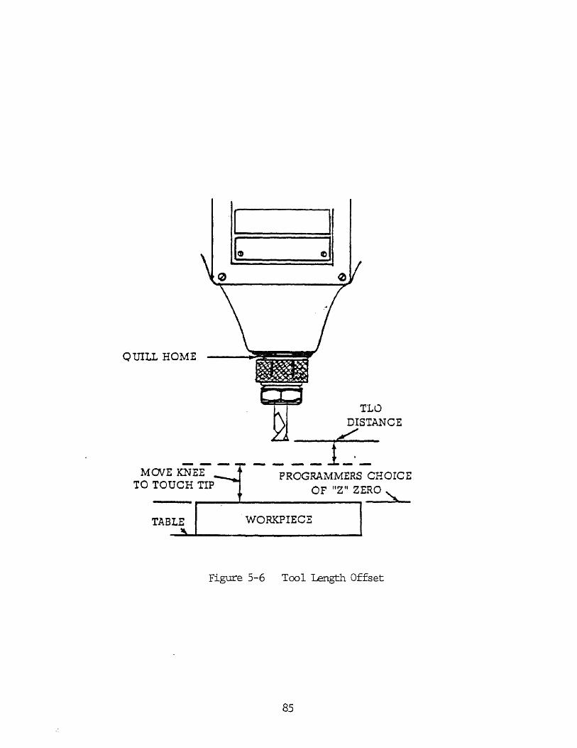
Figure 5-6 Tool Length Offset
85

NOTE:- The minimum TLO has to be 0.5".
(a) Using the ABS/TLO switch
(1) Mount the longest tool in the spindle.
(2) Set the MODE switch to SET UP.
(3) Set the selector switch to TNO and the pushbutton
below it to Z/TNO. By depressing the pushbutton
advance the tool number to desired value.
(4) Set the selector switch to ZERO and depress the
button. This will retract the quill (spindle) to
"home" position.
(5) Using the AXIS MOTION switches and pushbutton, move
the tool to the reference surface (origin, where ZABS
is zero). Use the combination of X/Y/Z selector switch
on Z axis, +/- pushbutton on - and the
JOG/1/.1/.01/STEP switch on the desired distance.
CAUTION:- While selecting this distance, check for the
distance between tool tip and pert surface so that you do
not damage the tool or the part surface.
(6) Set the selector switch to STORE and depress the
pushbutton. This will store this TLO value for this
tool number.
(7) To recheck the TLO value, set the selector switch to
ZERO and depress the pushbutton to move the quill
home. Select GO TO and depress the pushbutton. This
will move the tool down to the stored TLO point.
(8) Repeat steps 3-7 for each tool.
86

(b) Using the MDI keyboard
If the TLO values are known, they can be entered by
using the MDI keyboard as follows:
(1) Set the MODE switch to SET UP.
(2) Depress the N key (T).
(3) Using the numeric keys, enter the tool number.
(4) Depress the G key (TLO)"
(5) Enter the tool length offset value using the numeric
keys.
(6) Depress the black key (E08 to store this value.
(c) Using the Tn/Z command in the program
For details, refer to chapter-3 under T - Tool Select
Command.
5.5.3 TOOL DIAMETER
The tool diameter can be stored in the memory as
a reference for the operator. This memory is also volatile.
It can be entered by (a) Using the MDI keyboard or (b) Using
the Tn//d command in the program.
The diameter values are set to zero when the RESET
switch is operated. They can be coded in the program at the
beginning or they may be embedded in the program. The values
entered by the MDI keyboard will override the values from
the program if they are coded at the beginning of the program
but will not override them if they are embedded in the
program text.
87
(a) Using the MDI keyboard
(1) Set the MODE switch to SET UP.
(2) Depress the N key (T).
(3) Enter the tool number using the numeric keys.
(4) Depress the F key (DIA).
(5) Enter the tool diameter.
(6) Depress the black key (EOB) to store this value.
(b) Using the Tn//d command
Here, n is tool number and d is diameter.
For example: T1//.25
T2//.5
5.6.1 NORMAL OPERATION PROCEDURE
The reader is advised to go through complete chapter
before executing this sequence.
(1) Switch the power on. Before operating the machine make
sure that the air supply is between 60-80 psi. .
(2) Depress the LIMIT OVERRIDE pushbutton on the
operator's panel (illuminated in red).
(3) Set the MODE switch to SET UP.
(4) Switch the tape reader on which is mounted in the
logic control cabinet on the side of the machine.
(5) Operate the RESET switch if this is a new program or
the CLEAR switch if this is a program to be added to
the previously stored program.
(6) Mount the tape on the spool and operate the LOAD
switch to put the program in the memory. The
88
LOOP/LOAD/SPOOL switch on the tape reader should be on
LOOP.
(7) Mount the part on the table and mark the origin of the
part coordinate system.
(8) Use the AXIS MOTION selector switches and the
pushbutton to move the table to the XY zero point of
the part coordinate system (i.e. move the table to
match the zero point with tool center). For details,
refer to 5.5.1.
(9) Set ABS/TLO selector switch to ZERO and the pushbutton
below it to XY/T1 and depress it to store this value
of XY position as X0Y0. (When you are at a point other
than X0Y0, to return to the stored X0Y0, set the MODE
switch to SET UP, ABS/TL0 switch to GO TO and the
pushbutton below it to XY/T1 and depress it.)
NOTE:- If the set up point has value other than X0Y0, use
the MDI keyboard keys in this order to store that value: 892
X(value) Y(value) black key.
(10) Store the tool length offset value (TLO) by any one of
the methods described in 5.5.2. If the tool length
offset value is not known beforehand, use method (a).
(11) After storing >(0Y0 and TLO as above, set the MODE
switch to either BLOCK or AUTO position. If you are
executing the program for the first time, it is
advisable to use the BLOCK mode.
(12) In BLOCK mode, operation will be interrupted at the
89

end of every block (i.e. every line) i ,e. every time
the START/CONTINUE button depressed, only one line
from the program will be executed. This mode is useful
for checking the part program and debug it .
NOTE:- If the operator forgets to turn the spindle on, rapid
traverse (posi t i on i ng) moves will be executed but the
operation will be interrupted at the first FEED instruction.
To resume the operation, switch the spindle ON and depress
the START/CONTINUE button.
It is a good practice to note the readings on the
mechanical digital counters and the X, Y, Z . absolute
registers at the begining and the end of the run and compare
them.
5.6.2 SPECIAL CONDITIONS
There are some special conditions which the operator
may come across while operating the machine. The following
is a description of these special conditions.
LIMIT OVERRIDE
When a motion causes a travel limit to be exceeded for
that axis, the program will STOP and the LIMIT OVERRIDE lamp
will be illuminated. Because this is an abrupt stop, the
axes that were travelling could have "lost" up to .1" with
reference to the origin. To resume the operation:
(1) Set the mode switch to SET UP.
(2) Depress the LIMIT OVERRIDE button simultaneously with
the AXIS MOTION +/- button (distance selector switch
90
on JOG) to move in a direction opposite to the one
which caused the limit override.
(3) Once the LIMIT OVERRIDE lamp goes off, set ABS/TLO
switch to GO TO and the button below it to XY/T1 and
depress it. This will return the system to near X0Y0.
Compare that position with original X0YO (origin) and
make necessary moves using AXIS MOTION switches to
place the tool to original X0Y0.
(4) If the part program is not very long, set the FUNCTION
top switch to RESTART and depress it to resume from
the beginning of the program.
EMERGENCY STOP
If this pushbutton is depressed, the program operation
will STOP and the system will be cleared as above. To
resume, pull this button out and perform steps 3-4 as above
in LIMIT OVERRIDE.
HOLD
When this button is depresed, the program operation
will STOP without any memory loss. To resume, depress the
START/ CONTINUE button.
91

CHAPTER VI
CONCLUSION
6.1 CONCLUDING REMARKS
This thesis described basic operations and programming
technique for the Bridgeport Series I CNC machine installed
at the Department of Mechanical Engineering of New Jersey
Institute of Technology. It is intended to serve as a
beginner's guide for that particular machine as well as
introductory guide to CNC machines in general.
Looking at the growth and increasing acceptance of CNC
machines in the past few years, their demand should go up
rapidly. bright. Also, microprocessors have reduced the size
and lowered the cost of the CNC machines. Thus, CNC has
opened up whole new horizons for the N/C machines. The
author believes that an engineering school offering
a mechanical engineering program should include this subject
in their curriculum to keep up with today's industry.
6.2 FUTURE UPDATING
The CNC machine at the Mechanical Engineering
Department at NJIT incorporates Bridgeport Opereting System
Software (BOSS) 4.0. The ERS card containing the BOSS 4.0
can be replaced by an ERS card containing BOSS 5.0. The
additional chip required for floating point arithmetic on
the LSI-11 microcomputer is already there. This updating
would provide with the following additional features.
92

can be used which allows the interpolation parameters
I, J become the absolute coordinates of the circle
center and any arc of up to 360 degrees can be
programmed in a single block.
Polar coordinate commands:- This will allow the use of
polar coordinates. Milling around an arc or milling an
arc with increasing or decreasing Z depth (The Helix)
could be done with looping.
Cutter diameter compensation:- A 841 or 842 command
will form a new tool path equidistant from the
programmed path at all times. This separating distance
is the compensation dimension defined as half the
difference between the actual tool diameter and the
programmed tool diameter.
Cutter path transformation:- An entire cutter path and
thus, a part shape with a symmetry can be rotated
through an angle. The initial angle may be set and the
programmed part shape could be rotated an absolute
number of degrees. Also, using looping technique, the
rotating angle could be incremented a certain amount.
Also, the cutter path transformed could be scaled
relative to its progremmed dimensions.
Editor:- A data block can be executed from the
terminal.
Macro subroutines:- The number of macros increase from
16 to 36.

Manual data input:- Allows circular interpolation data
block to be inputted using MDI keyboard.
Remote computer data link:- A second 20ma serial line
interface can be provided to link the machine with
remote mass storage for down line part program
loading.
The updating of the present system should be
considered seriously so that, the students can learn updated
techniques of programming.
94

BIBLIOGRAPHY
(1) Childs, James J. , Principles of Numerical Control. New
York: Industrial Press, Inc., 1982, pp. 1-100.
(2) Operating Manual for the Series I CNC Milling, Drilling
and Boring Machine. Bridgeport Machines Division
of Textron Inc., April 1979.
(3) Ramamirtham Narayanaswamy, Role of NC Machines j,
Forming. Master's Thesis, Newark: New Jersey
Institute of Technology, 1982.
95