
Interplay between crystallization and particle growth during the isothermal annealing of colloidal...
7
Interplay between crystallization and particle growth during the isothermal annealing of colloidal iron oxide nanoparticles Paula S. Haddad a, * , Túlio R. Rocha a,b , Edvaldo A. Souza a , Tatiana M. Martins a,b , Marcelo Knobel b , Daniela Zanchet a, * a Laboratório Nacional de Luz Síncrotron (LNLS), CP 6192, CEP 13083-970, Campinas-SP, Brazil b Instituto de Física Gleb Wataghin (IFGW), Universidade Estadual de Campinas (UNICAMP), CP 6165, CEP 13083-970, Campinas-SP, Brazil article info Article history: Received 1 February 2009 Accepted 29 July 2009 Available online 4 August 2009 Keywords: Iron oxide nanoparticles Temperature Kirkendall effect TEM Thermal treatment Structure Morphology Ostwald ripening mechanism Polycrystalline abstract The relationship between crystallization and growth of colloidal iron oxide nanoparticles during isother- mal annealing was addressed in this work. The structural, morphological and chemical modifications of the nanoparticles during thermal treatments were followed by combination of electron microscopy, X-ray diffraction and spectroscopic methods. The initially monodisperse spherical nanoparticles with amorphous and partially oxidized structure evolved during the treatments, depending on the tempera- ture and treatment time. Core-void-shell nanoparticles or single crystal nanoparticles and hollow poly- crystalline nanoparticles, both with well defined Fe 3 O 4 oxide phase, are formed depending on the conditions. This evolution was interpreted as a result of the Kirkendall effect associated to mass redistri- bution and fragmentation of the nanoparticles, bringing new information about the effect of post-synthe- sis treatments on the crystallinity and morphology of colloidal nanoparticles. Ó 2009 Elsevier Inc. All rights reserved. 1. Introduction Colloidal nanoparticles (NPs) represent an attractive class of materials, which due to their small size exhibit novel properties that differ from bulk materials [1–6]. Crystalline metallic NPs such as the ferromagnetic Fe, Co and Ni NPs have attracted much inter- est because of their applications as magnetic fluids [7], magnetic recording media [8], biomedical applications [9,10] and catalysis [11]. Iron oxide nanoparticles are of particular interest for applica- tions such as Magnetic Resonance Image (MRI) [12] and cell separation due to their specific magnetic properties and biocom- patibility [13]. In the past years, many works have been directed to the devel- opment of synthesis procedures of size-controlled monodisperse nanoparticles [14–17]. However, the control over the crystalline structure has received much less attention because of the intrinsic difficulties in controlling the initial nucleation phase that seems to have a strong effect in the final structure of the nanoparticles [18,19]. For example, in the case of Ni nanoparticles, the lack of crystalline order was reported by many authors [20,21]. Control- ling the structure of nanoparticles is important not only for the study of structure dependent properties, such as magnetism [22,23], but also to the shape control of nanoparticles, as recently demonstrated in the literature [24]. One alternative to overcome the aforementioned difficulties in controlling the structure during the synthesis is the use of post-synthesis thermal treatments, particularly in the case of nanoparticles presenting disordered structures. For example, a case of success has been the work on PtFe nanoparticles [8]. In this work we present the effects of thermal treatments on the crystalline structure and size distribution of colloidal amorphous FeO x NPs produced by thermal decomposition methods. The thermal decom- position of Fe(CO) 5 in organic solvents in the presence of a surfac- tant is known to produce amorphous Fe NPs [25] in the 5–10 nm range with narrow size distribution. This synthesis is simple and a relatively large amount of material can be obtained (hundreds mg), making it highly attractive. The main drawback is the oxida- tion of the as-prepared nanoparticles, which leads to the formation of an amorphous iron oxide shell that continues to evolve for long periods. In order to obtain iron oxide nanoparticles with crystalline structures and stable chemical composition, thermal treatments were done under different conditions (temperature and time). The morphological and structural characterizations suggest that, in this system, the crystallization and morphological changes are strongly correlated. 0021-9797/$ - see front matter Ó 2009 Elsevier Inc. All rights reserved. doi:10.1016/j.jcis.2009.07.068 * Corresponding authors. Fax: +55 19 3512 1004. E-mail addresses: [email protected] (P.S. Haddad), [email protected] (D. Zanchet). Journal of Colloid and Interface Science 339 (2009) 344–350 Contents lists available at ScienceDirect Journal of Colloid and Interface Science www.elsevier.com/locate/jcis
-
Upload
independent -
Category
Documents
-
view
5 -
download
0
Transcript of Interplay between crystallization and particle growth during the isothermal annealing of colloidal...

Journal of Colloid and Interface Science 339 (2009) 344–350
Contents lists available at ScienceDirect
Journal of Colloid and Interface Science
www.elsevier .com/locate / jc is
Interplay between crystallization and particle growth during the isothermalannealing of colloidal iron oxide nanoparticles
Paula S. Haddad a,*, Túlio R. Rocha a,b, Edvaldo A. Souza a, Tatiana M. Martins a,b, Marcelo Knobel b,Daniela Zanchet a,*
a Laboratório Nacional de Luz Síncrotron (LNLS), CP 6192, CEP 13083-970, Campinas-SP, Brazilb Instituto de Física Gleb Wataghin (IFGW), Universidade Estadual de Campinas (UNICAMP), CP 6165, CEP 13083-970, Campinas-SP, Brazil
a r t i c l e i n f o
Article history:Received 1 February 2009Accepted 29 July 2009Available online 4 August 2009
Keywords:Iron oxide nanoparticlesTemperatureKirkendall effectTEMThermal treatmentStructureMorphologyOstwald ripening mechanismPolycrystalline
0021-9797/$ - see front matter � 2009 Elsevier Inc. Adoi:10.1016/j.jcis.2009.07.068
* Corresponding authors. Fax: +55 19 3512 1004.E-mail addresses: [email protected] (P
(D. Zanchet).
a b s t r a c t
The relationship between crystallization and growth of colloidal iron oxide nanoparticles during isother-mal annealing was addressed in this work. The structural, morphological and chemical modifications ofthe nanoparticles during thermal treatments were followed by combination of electron microscopy,X-ray diffraction and spectroscopic methods. The initially monodisperse spherical nanoparticles withamorphous and partially oxidized structure evolved during the treatments, depending on the tempera-ture and treatment time. Core-void-shell nanoparticles or single crystal nanoparticles and hollow poly-crystalline nanoparticles, both with well defined Fe3O4 oxide phase, are formed depending on theconditions. This evolution was interpreted as a result of the Kirkendall effect associated to mass redistri-bution and fragmentation of the nanoparticles, bringing new information about the effect of post-synthe-sis treatments on the crystallinity and morphology of colloidal nanoparticles.
� 2009 Elsevier Inc. All rights reserved.
1. Introduction
Colloidal nanoparticles (NPs) represent an attractive class ofmaterials, which due to their small size exhibit novel propertiesthat differ from bulk materials [1–6]. Crystalline metallic NPs suchas the ferromagnetic Fe, Co and Ni NPs have attracted much inter-est because of their applications as magnetic fluids [7], magneticrecording media [8], biomedical applications [9,10] and catalysis[11]. Iron oxide nanoparticles are of particular interest for applica-tions such as Magnetic Resonance Image (MRI) [12] and cellseparation due to their specific magnetic properties and biocom-patibility [13].
In the past years, many works have been directed to the devel-opment of synthesis procedures of size-controlled monodispersenanoparticles [14–17]. However, the control over the crystallinestructure has received much less attention because of the intrinsicdifficulties in controlling the initial nucleation phase that seems tohave a strong effect in the final structure of the nanoparticles[18,19]. For example, in the case of Ni nanoparticles, the lack ofcrystalline order was reported by many authors [20,21]. Control-
ll rights reserved.
.S. Haddad), [email protected]
ling the structure of nanoparticles is important not only for thestudy of structure dependent properties, such as magnetism[22,23], but also to the shape control of nanoparticles, as recentlydemonstrated in the literature [24].
One alternative to overcome the aforementioned difficulties incontrolling the structure during the synthesis is the use ofpost-synthesis thermal treatments, particularly in the case ofnanoparticles presenting disordered structures. For example, a caseof success has been the work on PtFe nanoparticles [8]. In this workwe present the effects of thermal treatments on the crystallinestructure and size distribution of colloidal amorphous FeOx NPsproduced by thermal decomposition methods. The thermal decom-position of Fe(CO)5 in organic solvents in the presence of a surfac-tant is known to produce amorphous Fe NPs [25] in the 5–10 nmrange with narrow size distribution. This synthesis is simple anda relatively large amount of material can be obtained (hundredsmg), making it highly attractive. The main drawback is the oxida-tion of the as-prepared nanoparticles, which leads to the formationof an amorphous iron oxide shell that continues to evolve for longperiods. In order to obtain iron oxide nanoparticles with crystallinestructures and stable chemical composition, thermal treatmentswere done under different conditions (temperature and time).The morphological and structural characterizations suggest that,in this system, the crystallization and morphological changes arestrongly correlated.

P.S. Haddad et al. / Journal of Colloid and Interface Science 339 (2009) 344–350 345
2. Experimental methods
The synthesis was carried out using standard airless proceduresand commercially available reagents. Colloidal Fe nanoparticleswere prepared by thermal decomposition of Fe(CO)5 in decalinsolution, in presence of oleylsarcosine surfactant [25]. Briefly, amixture of oleylsarcosine, decalin and Fe(CO)5 was placed in areaction flask under continuous N2 flow and vigorous stirring.The obtained mixture was heated up to 120 �C. After 2 h, the tem-perature was increased up to 180 �C with the Fe(CO)5 decomposi-tion liberating CO molecules and forming Fe NPs covered byoleylsarcosine. There is a change in color of the solution fromorange to black. This solution was refluxed for 3 h. Particle sizesof 6.5 nm were obtained using Fe: sarcosine molar ratio of about10:1. The colloidal solution was stored under N2.
For the thermal treatments, the nanoparticles were precipitatedby addition of ethanol and aliquots of 180 mg were separated. Atthis point, the Fe NPs are in powder form and partially oxidized.Despite the formation of metallic Fe NPs during the synthesis, theyare oxidized as soon as the sample is exposed to air, leading tothese partially oxidized NPs.
For the thermal treatments, these NPs were mixed with addi-tional sarcosine to obtain a paste. This mixture was quantified(NPs: sarcosine mass ratios 4:1) and submitted to thermal treat-ments in air atmosphere at 100 �C, 150 �C and 300 �C for 3 h or6 h. Henceforth, the as-synthesized sample is named FeAS and thetreated ones by the temperature and period of the thermal treat-ment, for example, Fe100 C
6 h .TEM experiments were performed in a JEM-3010 operating at
300 kV (1.7 Å point resolution), at the Electron Microscopy Labora-tory of the Brazilian Synchrotron Light Laboratory (LME-LNLS,Campinas-SP, Brazil). TEM samples were prepared by suspendingthe powder samples in a mixture of octane and octanol and stirringfor 10 min. Then a drop of this dispersion was deposited on anamorphous carbon coated copper grids.
Ex situ and in situ XRD measurements were performed at XRD1beamline at LNLS Campinas-SP, Brazil. The incident X-ray beamwas monochromatized by a Si (1 1 1) double crystal monochroma-tor to 7002 eV. Ex situ XRD data were recorded in 2h from 20� up to80� with 0.05� step width. For the in situ experiments, the sampleswere spread on a disoriented Si substrate mounted over an MMRheating device inside a small chamber with a beryllium window.The evolution of the (2 2 0) and (3 1 1) peaks of iron oxide were fol-lowed as a function of time at constant temperatures of 150 �C and300 �C. Both in situ and ex situ experiments were carried out in airatmosphere.
FTIR spectra in the range 4000–400 cm�1 were recorded on aBomen MB series FTIR spectrophotometer at Inorganic ChemistryLaboratory – UNICAMP, Campinas-SP, Brazil. The spectrum of aKBr pellet was taken as blank. Data were collected for samples inKBr pellets with 100 accumulative scans and 2 cm�1 resolution.
The TG/DTA curves of as-prepared sample were obtained by aUniversal V2.3C TA Instruments at a heating rate of 5 �C/min underair atmosphere from 25 �C to 800 �C at the Analytic Central of UNI-CAMP, Campinas, Brazil.
Magnetic measurements were done using a commercial Quan-tum Design MPMS XL7 SQUID magnetometer at LMBT – UNICAMP,Campinas-SP, Brazil. The measurements were carried out on driedsamples, slightly pressed and conditioned in Lucite cylindricalholders.
3. Results
Initially, the FeAS sample was characterized by TEM. Fig. 1ashows a representative image of the sample and the corresponding
size distribution histogram is presented in Fig. 2a. It can be seenthat the particles are spherical, with mean size (lAS) and standarddeviation (rAS) of 6.5 nm and 0.8 nm, respectively. As previouslyreported [25] these particles are amorphous and chemically unsta-ble, forming an amorphous oxide when exposed to air.
The morphological changes of nanoparticles after an isothermalannealing for 6 h were followed by TEM. Representative images areshown in Fig. 1b–d and Fig. 2b–d shows the corresponding histo-grams. It can be seen that the particles sizes are affected by thethermal treatment and a significant growth and broadening ofthe size distribution occurs after heating the nanoparticles at300 �C. The sample Fe300 C
6 h has approximately twice the size of FeAS.It is important to mention that the sarcosine starts to decompose at300 �C, forming a black powder, but the large excess used in thiswork was enough to keep most of the sample soluble in organicsolvents after the treatment. Up to 6 h, no aggregates or exceed-ingly large particles were detected.
The analysis of the size distribution histograms (Fig. 2) alsoshows that in addition to the growth of a population of large par-ticles, in particular in the Fe300 C
6 h sample, the fraction of smaller NPsalso increase, as observed in Fig. 2b ðFe100 C
6 h Þ. This sample showedthat the number of particles whose diameter is smaller thanlAS�rAS (d < 5.3 nm) increases from 11% for FeAS to 18% for Fe100 C
6 h .A careful observation of the contrast of the nanoparticles in the
TEM images (Fig. 1) reveals an interesting morphological evolution.FeAS sample (Fig. 1a) shows a dark-core light-shell type of contrast.This kind of contrast may be related to differences in the meanatomic number of the material in these two regions, suggestingthat the nanoparticles are partially oxidized, being formed by aFe-oxide shell with an inner oxygen-poor core. This core–shellmorphology is not surprise since despite the formation of metallicFe nanoparticles during the synthesis, they are oxidized as soon asthe sample is exposed to air, leading to these partially oxidizednanoparticles.
For the Fe100C6h sample (Fig. 1b), the larger nanoparticles show a
similar contrast to the FeAS nanoparticles but with an additionalslightly white ring between the darker core and lighter shell. Thesmaller nanoparticles, on the other hand, presented a core–shellwith inverted contrast, showing a lighter core and darker shell.This inverted contrast can also be seen in most of the nanoparticlesin sample Fe150 C
6 h (Fig. 1c). Finally, sample Fe300 C6 h (Fig. 1d) shows the
presence of small particles, similar to sample Fe100 C6 h , in addition to
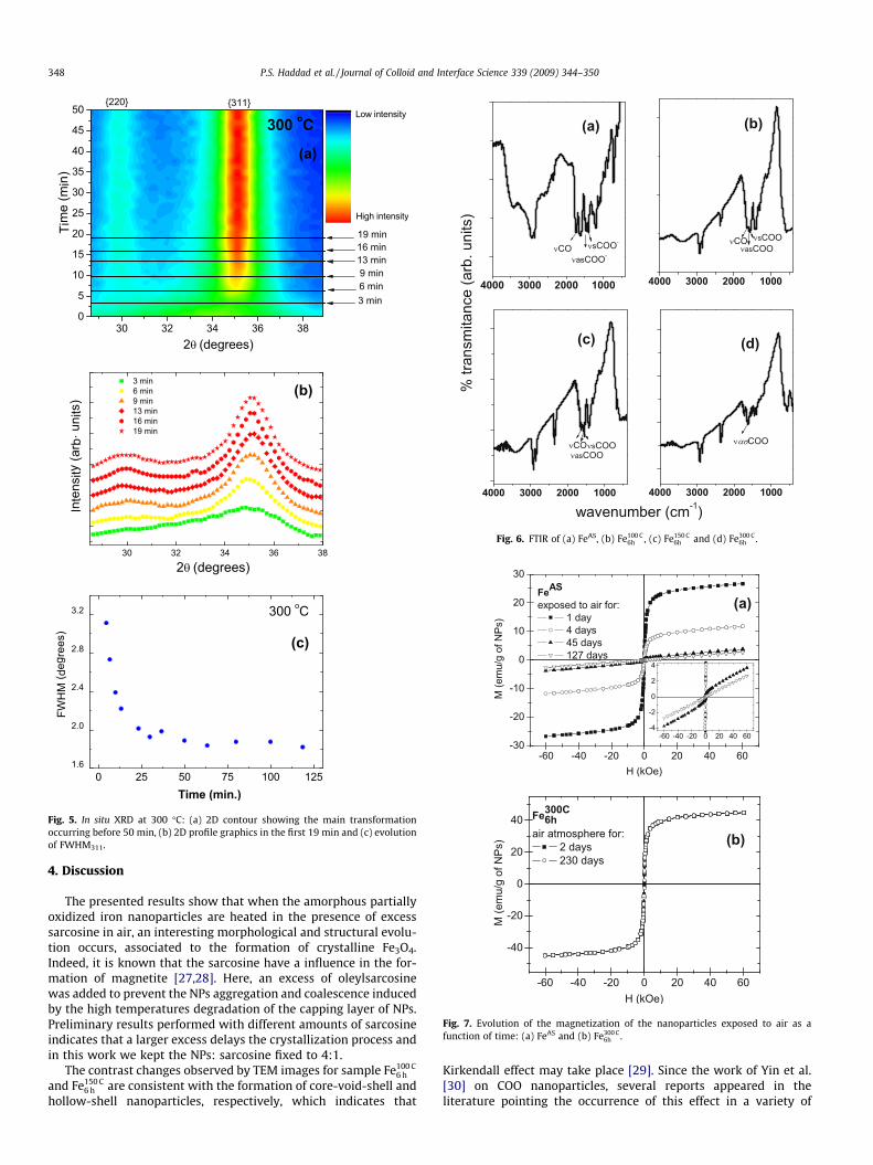
large particles, with homogenous contrast. To get further insightabout this modification, HRTEM characterization was performed.The core–shell structure of sample FeAS is confirmed in Fig. 3a aswell as the amorphous-like structure of these nanoparticles [25]since lattice fringes can be barely seen in small regions (�1 nm).A similar core–shell structure is verified in the Fe100 C
6 h image(Fig. 3b); in this case, however, a very small crystalline nucleusseparated from the shell can also be seen (core-void-shell nanopar-ticles). In the case of Fe150 C
6 h , this tiny nucleus seems to disappearleading to hollow nanoparticles. Interestingly, in samples Fe150 C
6 h
and Fe300 C6 h (Fig. 3c and d, respectively) an additional type of particle
was found, showing clear lattice fringes. This indicates that crystal-line nanoparticles (not-hollow) are formed at high temperaturetreatments. Others TEM and HRTEM images of Fe100 C
6 h , Fe150 C6 h ,
Fe300 C6 h samples are displayed as Figs. 1, 2 and 3 of Supporting infor-
mation file.To better address these structural changes, XRD measurements
were performed for the samples after 3 h (Fe100 C3 h , Fe150 C
3 h and Fe300 C3 h )
and 6 h (Fe100 C6 h , Fe150 C
6 h , Fe300 C6 h ) of isothermal treatment. As shown in
Fig. 4, the XRD pattern of the Fe100 C3 h is similar to the FeAS [25] and
typical of an amorphous phase, showing broad peaks that are inagreement with the presence of one or more phases of highly dis-ordered iron oxides. The XRD patterns of Fe100 C
6 h and Fe150 C3 h are also
very similar. Samples Fe150 C6 h ; Fe300 C
3 h and Fe300 C6 h , on the other hand,
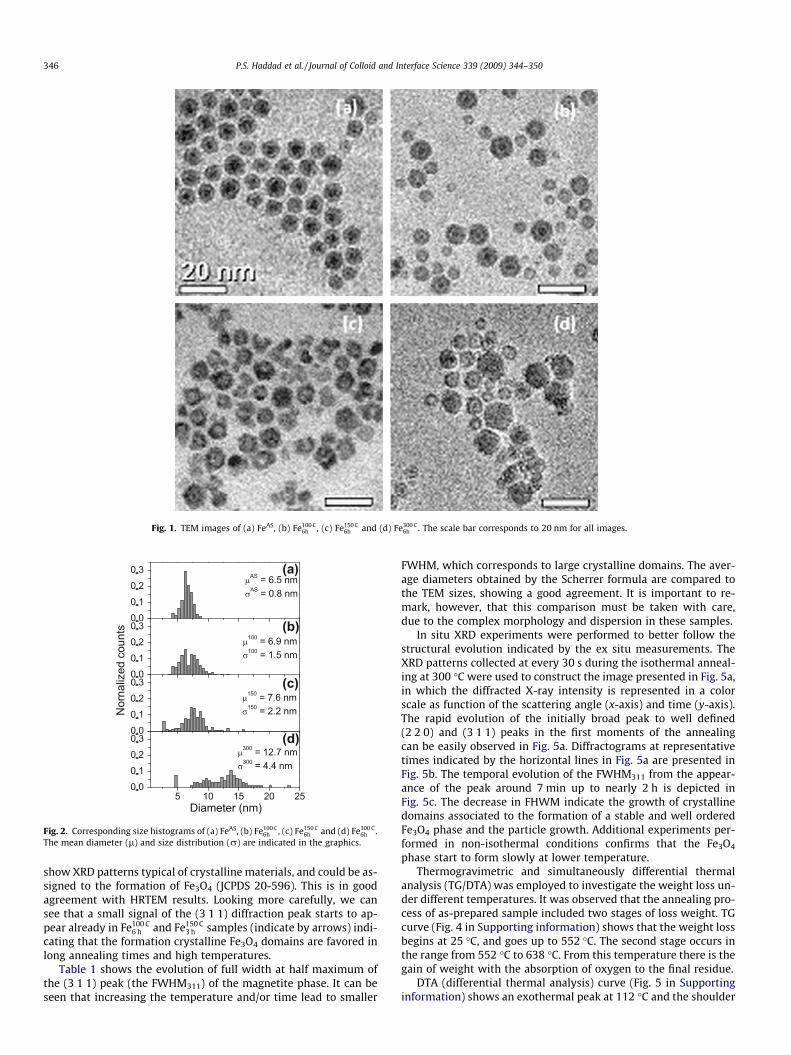
Fig. 1. TEM images of (a) FeAS, (b) Fe100 C6h , (c) Fe150 C
6h and (d) Fe300 C6h . The scale bar corresponds to 20 nm for all images.
(a)
(b)
(c)
(d)
Fig. 2. Corresponding size histograms of (a) FeAS, (b) Fe100 C6h , (c) Fe150 C
6h and (d) Fe300 C6h .
The mean diameter (l) and size distribution (r) are indicated in the graphics.
346 P.S. Haddad et al. / Journal of Colloid and Interface Science 339 (2009) 344–350
show XRD patterns typical of crystalline materials, and could be as-signed to the formation of Fe3O4 (JCPDS 20-596). This is in goodagreement with HRTEM results. Looking more carefully, we cansee that a small signal of the (3 1 1) diffraction peak starts to ap-pear already in Fe100 C
6 h and Fe150 C3 h samples (indicate by arrows) indi-
cating that the formation crystalline Fe3O4 domains are favored inlong annealing times and high temperatures.
Table 1 shows the evolution of full width at half maximum ofthe (3 1 1) peak (the FWHM311) of the magnetite phase. It can beseen that increasing the temperature and/or time lead to smaller
FWHM, which corresponds to large crystalline domains. The aver-age diameters obtained by the Scherrer formula are compared tothe TEM sizes, showing a good agreement. It is important to re-mark, however, that this comparison must be taken with care,due to the complex morphology and dispersion in these samples.
In situ XRD experiments were performed to better follow thestructural evolution indicated by the ex situ measurements. TheXRD patterns collected at every 30 s during the isothermal anneal-ing at 300 �C were used to construct the image presented in Fig. 5a,in which the diffracted X-ray intensity is represented in a colorscale as function of the scattering angle (x-axis) and time (y-axis).The rapid evolution of the initially broad peak to well defined(2 2 0) and (3 1 1) peaks in the first moments of the annealingcan be easily observed in Fig. 5a. Diffractograms at representativetimes indicated by the horizontal lines in Fig. 5a are presented inFig. 5b. The temporal evolution of the FWHM311 from the appear-ance of the peak around 7 min up to nearly 2 h is depicted inFig. 5c. The decrease in FHWM indicate the growth of crystallinedomains associated to the formation of a stable and well orderedFe3O4 phase and the particle growth. Additional experiments per-formed in non-isothermal conditions confirms that the Fe3O4
phase start to form slowly at lower temperature.Thermogravimetric and simultaneously differential thermal
analysis (TG/DTA) was employed to investigate the weight loss un-der different temperatures. It was observed that the annealing pro-cess of as-prepared sample included two stages of loss weight. TGcurve (Fig. 4 in Supporting information) shows that the weight lossbegins at 25 �C, and goes up to 552 �C. The second stage occurs inthe range from 552 �C to 638 �C. From this temperature there is thegain of weight with the absorption of oxygen to the final residue.
DTA (differential thermal analysis) curve (Fig. 5 in Supportinginformation) shows an exothermal peak at 112 �C and the shoulder
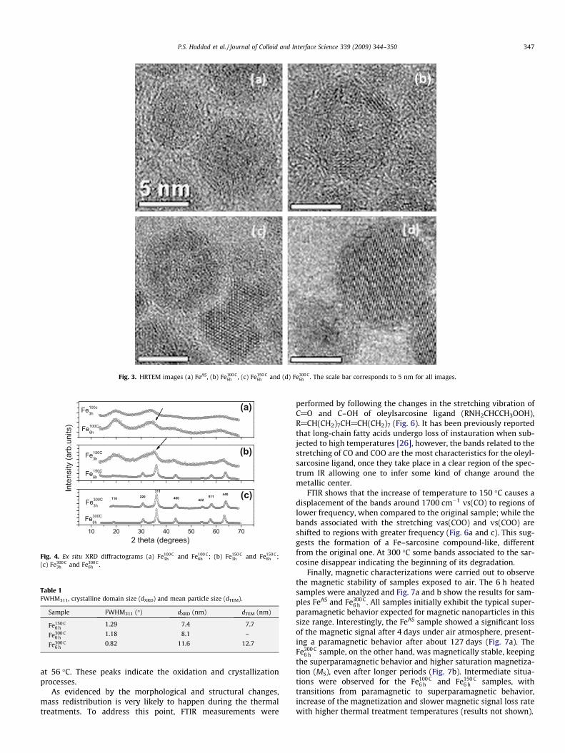
Fig. 3. HRTEM images (a) FeAS, (b) Fe100 C6h , (c) Fe150 C
6h and (d) Fe300 C6h . The scale bar corresponds to 5 nm for all images.
(a)
(b)
(c)
Fig. 4. Ex situ XRD diffractograms (a) Fe100 C3h and Fe100 C
6h ; (b) Fe150 C3h and Fe150 C
6h ;(c) Fe300 C
3h and Fe300 C6h .
Table 1FWHM311, crystalline domain size (dXRD) and mean particle size (dTEM).
Sample FWHM311 (�) dXRD (nm) dTEM (nm)
Fe150 C6 h
1.29 7.4 7.7
Fe300 C6 h
1.18 8.1 –
Fe300 C6 h
0.82 11.6 12.7
P.S. Haddad et al. / Journal of Colloid and Interface Science 339 (2009) 344–350 347
at 56 �C. These peaks indicate the oxidation and crystallizationprocesses.
As evidenced by the morphological and structural changes,mass redistribution is very likely to happen during the thermaltreatments. To address this point, FTIR measurements were
performed by following the changes in the stretching vibration ofC@O and C–OH of oleylsarcosine ligand (RNH2CHCCH3OOH),R@CH(CH2)7CH@CH(CH2)7 (Fig. 6). It has been previously reportedthat long-chain fatty acids undergo loss of instauration when sub-jected to high temperatures [26], however, the bands related to thestretching of CO and COO are the most characteristics for the oleyl-sarcosine ligand, once they take place in a clear region of the spec-trum IR allowing one to infer some kind of change around themetallic center.
FTIR shows that the increase of temperature to 150 �C causes adisplacement of the bands around 1700 cm�1 ms(CO) to regions oflower frequency, when compared to the original sample; while thebands associated with the stretching mas(COO) and ms(COO) areshifted to regions with greater frequency (Fig. 6a and c). This sug-gests the formation of a Fe–sarcosine compound-like, differentfrom the original one. At 300 �C some bands associated to the sar-cosine disappear indicating the beginning of its degradation.
Finally, magnetic characterizations were carried out to observethe magnetic stability of samples exposed to air. The 6 h heatedsamples were analyzed and Fig. 7a and b show the results for sam-ples FeAS and Fe300 C
6 h . All samples initially exhibit the typical super-paramagnetic behavior expected for magnetic nanoparticles in thissize range. Interestingly, the FeAS sample showed a significant lossof the magnetic signal after 4 days under air atmosphere, present-ing a paramagnetic behavior after about 127 days (Fig. 7a). TheFe300 C
6 h sample, on the other hand, was magnetically stable, keepingthe superparamagnetic behavior and higher saturation magnetiza-tion (MS), even after longer periods (Fig. 7b). Intermediate situa-tions were observed for the Fe100 C
6 h and Fe150 C6 h samples, with
transitions from paramagnetic to superparamagnetic behavior,increase of the magnetization and slower magnetic signal loss ratewith higher thermal treatment temperatures (results not shown).
(a)
(b)
(c)
Fig. 5. In situ XRD at 300 �C: (a) 2D contour showing the main transformationoccurring before 50 min, (b) 2D profile graphics in the first 19 min and (c) evolutionof FWHM311.
(a) (b)
(c) (d)
Fig. 6. FTIR of (a) FeAS, (b) Fe100 C6h , (c) Fe150 C
6h and (d) Fe300 C6h .
(a)
(b)
Fig. 7. Evolution of the magnetization of the nanoparticles exposed to air as afunction of time: (a) FeAS and (b) Fe300 C
6h .
348 P.S. Haddad et al. / Journal of Colloid and Interface Science 339 (2009) 344–350
4. Discussion
The presented results show that when the amorphous partiallyoxidized iron nanoparticles are heated in the presence of excesssarcosine in air, an interesting morphological and structural evolu-tion occurs, associated to the formation of crystalline Fe3O4.Indeed, it is known that the sarcosine have a influence in the for-mation of magnetite [27,28]. Here, an excess of oleylsarcosinewas added to prevent the NPs aggregation and coalescence inducedby the high temperatures degradation of the capping layer of NPs.Preliminary results performed with different amounts of sarcosineindicates that a larger excess delays the crystallization process andin this work we kept the NPs: sarcosine fixed to 4:1.
The contrast changes observed by TEM images for sample Fe100 C6 h
and Fe150 C6 h are consistent with the formation of core-void-shell and
hollow-shell nanoparticles, respectively, which indicates that
Kirkendall effect may take place [29]. Since the work of Yin et al.[30] on COO nanoparticles, several reports appeared in theliterature pointing the occurrence of this effect in a variety of
P.S. Haddad et al. / Journal of Colloid and Interface Science 339 (2009) 344–350 349
colloidal systems [31]. The Kirkendall effect relies on the fact thatatom diffusion in solid state is mediated by vacancies. In the case ofsurface oxidation of metal nanoparticles [30], there is an outwardnet flux of Fe0 atoms associated to an opposite inward flux ofvacancies that can lead to the formation of a void in the center ofthe nanoparticles, as verified in the Fe100 C
6 h and Fe150 C6 h samples.
Recently, Peng et al. [32] have nicely demonstrated the Kirkendalleffect in colloidal Fe oxide nanoparticles produced by a similarmethod than the one used in this work. They succeeded in synthe-sizing Fe nanoparticles in the presence of oleylamine [33] and byusing an oxygen-transfer reagent they succeeded in controllingthe oxidation of these core–shell nanoparticles in solution leadingto the formation of intermediate core-void-shell nanoparticles ofFe–Fe3O4, and further to hollow Fe3O4 nanoparticles. In our work,the morphological evolution seems not to be restricted to the con-sumption of the oxygen-poor core as in the case described by Peng[32], but we observed changes in size distribution as well as atomicordering, particularly the increase in the frequency of smaller NPs.
The evolution of the size distribution, as presented in Fig. 2,with the appearance of a population of nanoparticles with largersizes could be associated to the Kirkendall effect, since we havemass transfer from the core to the shell, associated to the largerlattice constant of the oxide. On the other hand, the presence ofa population of smaller nanoparticles not presented in the as-pre-pared sample cannot be explained by the same argument. Thepresence of this population of smaller nanoparticles suggests that,in this system, mass redistribution among nanoparticles may alsooccur during the isothermal annealing, in opposition to the pureKirkendall effect observed by others [32,33]. The driving force forthis ‘‘ripening-like” process is not yet clear, but it does not seemto be simply related to surface energy minimization like in theclassical Ostwald ripening mechanism. In this case, the energyand also entropy differences associated with the different oxidephases and crystalline structures, such as amorphous, polycrystal-line and single crystal might play an important role.
Another strong evidence is the presence of a new population ofcrystalline nanoparticles in the Fe150 C
6 h and Fe300 C6 h samples. In fact, in
sample Fe150 C6 h , it is possible to identify single crystal fragments that
probably originated in the fragmentation of polycrystalline emptyshell nanoparticles. In the Fe300 C
6 h sample, large single sphericalcrystals are clearly visible (Fig. 3d).
The analysis of these results suggest that as the thermal treat-ment is performed at higher temperatures and longer times, theformation of empty shell polycrystalline nanoparticles by the con-sumption of the initial oxygen-poor core is favored; this polycrys-talline shell is fragmented into smaller single crystal fragmentsthat grow as expense of smaller fragments or small empty shellsparticles, forming the larger single crystal nanoparticles. Thisgrowth process suggests that Ostwald ripening phenomenon alsois favored in these conditions [31,34]. As confirmed by XRD data,higher temperatures speed up this process and at 300 �C it takesplace in less than 30 min. TG/DTA curves indicate an oxidationand crystallization processes at the beginning of the NPs thermaltreatment.
FTIR is also in agreement with this mechanism, where the masstransfer among nanoparticles might be mediated by the formationof Fe–sarcosine complexes during the thermal treatments. Theshift in the vibration frequencies suggests the formation of a Fe–sarcosine compound-like, different from the original one, whichagrees with the mass transfer between the particles in the system.
Concerning the magnetic properties, the higher magnetic stabil-ity observed for the thermally treated Fe300 C
6 h sample may be relatedto the formation of a stable crystalline oxide phase, in contrast tothe amorphous partially oxidized FeAS sample, which might con-tinue evolves as a function of time towards a more oxidized butstill amorphous phase. Surface effects might also significantly con-
tribute to the magnetic signal in nanoparticles [35] that probablyaffects more FeAS sample.
The magnetic properties of Fe nanoparticles depend on the par-ticle size, amount of oxidation, shape and surface effects. Initially,the as-prepared amorphous partially oxidized iron nanoparticlespresent a superparamagnetic behavior and MS of about 28 emu/g,compatible with other authors results (MS = 25–190 emu/g for6–20 nm diameter Fe nanoparticles) [36]. When exposed to air,the highly disordered iron oxides surface layer increases with thetime, leading to the decrease of the magnetic signal towards aparamagnetic behavior after long periods. On the other hand, thesamples show an important increase of the particle effective mag-netic moment with higher thermal treatment temperature, inagreement with the progressively growth and crystallizationshown by HRTEM and XRD results. This is reflected in higher MS
values (MS = 45 emu/g for the Fe300 C6 h sample), compatible with
known values for iron oxides nanoparticles (MS = 30–60 emu/g)[37], superparamagnetic behavior and long term magnetic stabil-ity. It is worth to mention that the interpretation of the magneticbehavior as a function of these complex morphological and struc-tural changes is still a challenge but should produce interesting in-sights about the magnetism at nanoscale.
5. Conclusions
In this work we addressed the effects of post-synthesis thermaltreatments on the structure and morphology of colloidal iron oxidenanoparticles. Isothermal annealings were performed in order toobtain nanoparticles with higher degree of crystallinity anddefined oxide phase, which is highly desirable for magnetic andbiomedical applications. However, the structural, morphologicaland chemical changes observed during the treatments at differenttemperatures and times indicate that the evolution of the system isfar more complex than the initially expected crystallization of thenanoparticles. In this system, the crystallization is strongly coupledto morphological changes that occur during the thermal treat-ments, namely the formation of hollow polycrystalline nanoparti-cles, their posterior fragmentation and mass redistributionamong nanoparticles. This contrasts to bulk materials, for whichpost-synthesis annealing procedures are quite effective to increasethe crystallinity of samples. To better understand this system, fur-ther experiments and theoretical calculations are still required, forexample, the evaluation of the energetic barriers involved in theintra-particle and inter-particle mass transport, particle dissolu-tion and crystallization. Nevertheless, we believe that this workbrings new information that is useful not only to the understand-ing of re-crystallization under thermal treatments, but also in thearea of catalysis, in which metallic nanoparticles can be subjectedto high temperatures and oxidant atmospheres and the same evo-lution presented here might play a role in the particle stability andsintering behavior.
Acknowledgments
The authors thank CNPq and FAPESP for financial support andLME-LNLS for using its facilities.
Appendix A. Supplementary material
Supplementary data associated with this article can be found, inthe online version, at doi:10.1016/j.jcis.2009.07.068.
References
[1] C.B. Murray, C.R. Kagan, M.G. Bawendi, Annu. Rev. Mater. Sci. 30 (2000) 545.[2] M.P. Morales, S. Veintemillas-Verdaguer, M.I. Montero, C.J. Serna, A. Roig, L.
Casas, B. Martinez, F. Sandiumenge, Chem. Mater. 11 (1999) 3058.

350 P.S. Haddad et al. / Journal of Colloid and Interface Science 339 (2009) 344–350
[3] R.E.M. Newnham, H. Ikawa, Mater. Res. Soc. Symp. Proc. 175 (1990) 161.[4] D. Vollath, D.V. Szabo, R.D. Taylor, J.O. Willis, K.E. Sickafus, Nanostruct. Mater. 6
(1995) 941.[5] M.P. Morales, C. Pecharroman, T.G. Carreno, C.J. Serna, J. Solid State Chem. 108
(1994) 158.[6] E. Kroll, F.M. Winnik, R.F. Ziolo, Chem. Mater. 8 (1996) 1594.[7] M.P. Pileni, Adv. Funct. Mater. 11 (2001) 323.[8] S.H. Sun, C.B. Murray, D. Weller, L. Folks, A. Moser, Science 287 (2000) 1989.[9] K.B. Lee, S. Park, C.A. Mirkin, Angew. Chem. – Int. Ed. 43 (2004) 3048.
[10] Q.A. Pankhurst, J. Connolly, S.K. Jones, J. Dobson, J. Phys. D – Appl. Phys. 36(2003) R167.
[11] G.X. Zhu, X.W. Wei, S. Jiang, J. Mater. Chem. 17 (2007) 2301.[12] D. Hogemann, L. Josephson, R. Weissleder, J.P. Basilion, Bioconjugate Chem. 11
(2000) 941.[13] L. Josephson, J.M. Perez, R. Weissleder, Angew. Chem. – Int. Ed. 40 (2001) 3204.[14] J. Tang, J. Fabbri, R.D. Robinson, Y.M. Zhu, I.P. Herman, M.L. Steigerwald, L.E.
Brus, Chem. Mater. 16 (2004) 1336.[15] M. Yin, S. O’Brien, J. Am. Chem. Soc. 125 (2003) 10180.[16] H. Borchert, E.V. Shevehenko, A. Robert, I. Mekis, A. Kornowski, G. Grubel, H.
Weller, Langmuir 21 (2005) 1931.[17] W.W. Yu, J.C. Falkner, B.S. Shih, V.L. Colvin, Chem. Mater. 16 (2004) 3318.[18] I. Pastoriza-Santos, L.M. Liz-Marzan, J. Mater. Chem. 18 (2008) 1724.[19] L. Manna, D.J. Milliron, A. Meisel, E.C. Scher, A.P. Alivisatos, Nat. Mater. 2
(2003) 382.[20] H. Winnischofer, T.C.R. Rocha, W.C. Nunes, L.M. Socolovsky, M. Knobel, D.
Zanchet, ACS Nano 2 (2008) 1313.
[21] J. Park, E. Kang, S.U. Son, H.M. Park, M.K. Lee, J. Kim, K.W. Kim, H.J. Noh, J.H.Park, C.J. Bae, J.G. Park, T. Hyeon, Adv. Mater. 17 (2005) 429.
[22] Z.K. Wang, M.H. Kuok, S.C. Ng, D.J. Lockwood, M.G. Cottam, K. Nielsch, R.B.Wehrspohn, U. Gosele, Phys. Rev. Lett. 89 (2002) 27201.
[23] W.Q. Zhang, K.B. Tang, Y.K. Liu, Y.C. Zhu, W.C. Yu, Y.T. Qian, Carbon 45 (2007)1571.
[24] T.C.R. Rocha, D. Zanchet, J. Phys. Chem. C 111 (2007) 6989.[25] J.M. Vargas, L.M. Socolovsky, G.F. Goya, M. Knobel, D. Zanchet, IEEE Trans.
Magn. 39 (2003) 2681.[26] M.T. Rosado, M. Duarte, R. Fausto, Vib. Spectrosc. 16 (1998) 35.[27] F.D. Monte, M.P. Morales, D. Levy, A. Fernandez, M. Ocana, A. Roig, E. Molins, K.
O’Grady, C.J. Serna, Langmuir 13 (1997) 3627.[28] C. Cannas, M.F. Casula, G. Concas, A. Corrias, D. Gatteschi, A. Falqui, A. Musinu,
C. Sangregorio, G. Spano, J. Mater. Chem. 11 (2001) 3180.[29] W.C. Roberts-Austen, Phil. Trans. Roy. Soc. A 187 (1896) 383.[30] Y.D. Yin, R.M. Rioux, C.K. Erdonmez, S. Hughes, G.A. Somorjai, A.P. Alivisatos,
Science 304 (2004) 711.[31] M.F. Casula, Y.W. Jun, D.J. Zaziski, E.M. Chan, A. Corrias, A.P. Alivisatos, J. Am.
Chem. Soc. 128 (2006) 1675.[32] S. Peng, S.H. Sun, Angew. Chem. – Int. Ed. 46 (2007) 4155.[33] S. Peng, C. Wang, J. Xie, S.H. Sun, J. Am. Chem. Soc. 128 (2006) 10676.[34] G.W. Greenwood, Acta Metall. 4 (1956) 243.[35] E.D. Biasi, C.A. Ramos, R.D. Zysler, H. Romero, Phys. Rev. B 65 (2002) 144416.[36] S. Gangopadhyay, G.C. Hadjipanayis, B. Dale, C.M. Sorensen, K.J. Klabunde, V.
Papaefthymiou, A. Kostikas, Phys. Rev. B (1992) 9778.[37] G.F. Goya, T.S. Berquó, F.C. Fonseca, M.P. Morales, J. Appl. Phys. 94 (2003) 3520.