INTERNATIONAL JOURNAL OF RESEARCH IN AERONAUTICAL AND MECHANICAL ENGINEERING A REPORT ON NUMERICAL...
19
INTERNATIONAL JOURNAL OF RESEARCH IN AERONAUTICAL AND MECHANICAL ENGINEERING Vol.1 Issue.1, 2013 Pg: 7-25 Mohammad Salahuddin et al 7 ISSN (ONLINE): 2321-3051 INTERNATIONAL JOURNAL OF RESEARCH IN AERONAUTICAL AND MECHANICAL ENGINEERING A REPORT ON NUMERICAL INVESTIGATION OF WINGS: WITH AND WITHOUT WINGLET Mohammad Salahuddin 1 , Mohd Obaid-ur-Rahman 2 , Shaik Jaleel 3 123 Aeronautical department, MLRIT, Dundigal, Hyderabad, India 1 [email protected] Abstract The main goal of the proposed paper is the numerical investigation of Wings with and without winglet designs. This investigation shows the various performance and parameters for the wings when designed with a winglet and without a winglet and thus comparing the parameters for both the designs. The discussions were focused on the aerodynamics characteristics which include drag coefficient CD, lift coefficient CL, and lift-to-drag ratio L/D. In this investigation two Different wings are used: An Elliptical wing and a Short wing. The airfoil used in this investigation is NACA 2412 with which both the wings are designed. The Geometry of the models is carried out in the CATIA V5 R19 Software and is designed in Part and Wireframe and Surface Design. The airfoils of Different Chord length are designed with different Stations using the geometry given in the DESIGNFOIL Software. The winglet is then designed for both the wings. The investigation aims to produce better aerodynamic performance with the implementation of the winglet for both wing designs. One of the objectives of this work is reduce the induced drag formed on wing during the fight operation, thus improving the efficiency of the aircraft. The analysis part is done by using the ANSYS Software, flow parameters (like the lift and drag) are measured for different design configurations and are compared with the plane wing and the wing designed with winglet. Keywords: CATIA; Elliptical Wing; ANSYS 1. Introduction A winglet is a device used to improve the efficiency of aircraft by lowering the lift induced drag caused by wingtip vortices. It is a vertical or angled extension at the tips of each wing. Winglets improve efficiency by diffusing the shed wingtip vortex, which in turn reduces the drag due to lift and improves the wing’s lift over drag ratio Winglets increase the effective aspect ratio of a wing without adding greatly to the structural stress and hence necessary weight of its structure. Research into winglet technology for commercial aviation was pioneered by Richard Whitcomb in the mid 1970’s.
Transcript of INTERNATIONAL JOURNAL OF RESEARCH IN AERONAUTICAL AND MECHANICAL ENGINEERING A REPORT ON NUMERICAL...
INTERNATIONAL JOURNAL OF RESEARCH IN AERONAUTICAL AND MECHANICAL ENGINEERING Vol.1 Issue.1, 2013
Pg: 7-25
Mohammad Salahuddin et al 7
ISSN (ONLINE): 2321-3051
INTERNATIONAL JOURNAL OF RESEARCH IN
AERONAUTICAL AND MECHANICAL ENGINEERING
A REPORT ON NUMERICAL INVESTIGATION OF WINGS: WITH AND WITHOUT WINGLET Mohammad Salahuddin 1, Mohd Obaid-ur-Rahman 2, Shaik Jaleel 3
123Aeronautical department, MLRIT, Dundigal, Hyderabad, India [email protected]
Abstract
The main goal of the proposed paper is the numerical investigation of Wings with and without winglet designs. This investigation shows the various performance and parameters for the wings when designed with a winglet and without a winglet and thus comparing the parameters for both the designs. The discussions were focused on the aerodynamics characteristics which include drag coefficient CD, lift coefficient CL, and lift-to-drag ratio L/D. In this investigation two Different wings are used: An Elliptical wing and a Short wing. The airfoil used in this investigation is NACA 2412 with which both the wings are designed. The Geometry of the models is carried out in the CATIA V5 R19 Software and is designed in Part and Wireframe and Surface Design. The airfoils of Different Chord length are designed with different Stations using the geometry given in the DESIGNFOIL Software. The winglet is then designed for both the wings. The investigation aims to produce better aerodynamic performance with the implementation of the winglet for both wing designs. One of the objectives of this work is reduce the induced drag formed on wing during the fight operation, thus improving the efficiency of the aircraft. The analysis part is done by using the ANSYS Software, flow parameters (like the lift and drag) are measured for different design configurations and are compared with the plane wing and the wing designed with winglet. Keywords: CATIA; Elliptical Wing; ANSYS
1. Introduction A winglet is a device used to improve the efficiency of aircraft by lowering the lift induced drag caused by wingtip vortices. It is a vertical or angled extension at the tips of each wing. Winglets improve efficiency by diffusing the shed wingtip vortex, which in turn reduces the drag due to lift and improves the wing’s lift over drag ratio Winglets increase the effective aspect ratio of a wing without adding greatly to the structural stress and hence necessary weight of its structure. Research into winglet technology for commercial aviation was pioneered by Richard Whitcomb in the mid 1970’s.

INTERNATIONAL JOURNAL OF RESEARCH IN AERONAUTICAL AND MECHANICAL ENGINEERING Vol.1 Issue.1, 2013
Pg: 7-25
Mohammad Salahuddin et al 8
Small and nearly vertical fins were installed on a KC-135A and flights were tested in 1979 and 1980. Whitcomb revealed that in full size aircraft, winglets can provide improvements in efficiency of more than 7%. For airlines, this translates into millions of dollars in fuel costs. Winglets are being incorporated into most new transport aircraft, including business jets, the Boeing 747-400, airliners, and military transport. Many other researchers have investigated their behavior, designing winglets for commercial and general aviation aircraft as well as for sailplanes. Furthermore, the added friction and interference drag has to be cancelled out by the forward thrust generated by the winglet lift. The upward angle (or cant) of the winglet, its inward or outward angle (or toe), as well as its size and shape are critical for correct performance and are unique in each application.
2. Theory and Basic Definitions 2.1 WINGLET THEORY: Due to circulation about the horseshoe vortex, there exists an induced downwash-which in turn produces induced drag
Fig 2.1 Vortex Formations
Adding winglets alters the flow at the tip which in turn decreases the downwash, ultimately reducing induced drag.
Fig 2.2 Reduction of Induced Drag by adding Winglets 2.2 INDUCED DRAG:

INTERNATIONAL JOURNAL OF RESEARCH IN AERONAUTICAL AND MECHANICAL ENGINEERING Vol.1 Issue.1, 2013
Pg: 7-25
Mohammad Salahuddin et al 9
Induced drag is a force that occurs whenever a moving object redirects the airflow coming at it. It is also called as “Drag due to lift” as it a source of wing drag.
Fig 2.3 Induced Drag
2.3 WINGLET BENEFITS Winglets belong to the class of wingtip devices aimed to reduce induced drag. Selection of the wingtip device depends on the specific situation and the airplane model. In the case of winglets, the reduction of the induced drag is accomplished by acting like a small sail whose lift component generates a traction force, draining energy from the tip vortices. The wingtip might be considered a dead zone regarding to the aerodynamic efficiency, because it generates lots of drag and no significant lift. The winglet contributes to accelerate the airflow at the tip in such a way that it generates lift and improves the wing loading distribution, which is related to the induced drag. In addition, the aircraft will fly at a slightly lower angle of attack for the same lift coefficient. Thus, it should always be possible to obtain significant drag reductions by using wingtip devices even for high-aspect wings. Away to avoid this design issue is to employ raked wingtips like Boeing did for its 767-400 aircraft. Thanks to winglets the aircraft will climb to initial altitude faster and save fuel due to a more efficient climb profile. Otherwise, the aircraft can take off at lower thrust settings, which reduce the aircraft noise footprint and extend engine life.
2.4 TYPES OF WINGLETS In general any wingtips that not end the wing simply horizontally are considered as some kind of a winglet. Basically three types of winglets exists,
� BLENDED WINGLETS
� RAKED WINGTIPS
� WINGTIP FENCES

INTERNATIONAL JOURNAL OF RESEARCH IN AERONAUTICAL AND MECHANICAL ENGINEERING Vol.1 Issue.1, 2013
Pg: 7-25
Mohammad Salahuddin et al 10
2.4.1 BLENDED WINGLETS (the real Winglets): A blended winglet is attached to the wing with smooth curve instead of a sharp angle and is intended to reduce interference drag at the wing/winglet junction. A sharp interior angle in this region can interact with the boundary layer flow causing a drag inducing vortex, negating some of the benefit of the winglet. The blended winglet is used on business jets and sailplanes, where individual buyer preference is an important marketing aspect.
Fig 2.7Blended Winglets 2.4.2 WINGTIP FENCES: These are a special variant of winglets that extend both upward and downward from the tip of the wing. Preferred by European plane-maker Airbus, it is featured on their full product range (except the A330/340 family and the future A350).

INTERNATIONAL JOURNAL OF RESEARCH IN AERONAUTICAL AND MECHANICAL ENGINEERING Vol.1 Issue.1, 2013
Pg: 7-25
Mohammad Salahuddin et al 11
Fig 2.8 Wingtip Fences 2.4.3 RAKED WINGTIPS: These are the most recent winglet variants (they are probably better classified as special wings, though), where the tip of the wing has a higher degree of sweep than the rest of the wing. They are widely referred to as winglets, but they are better described as integrated wingtip extensions as they are (horizontal) additions to the existing wing, than the previously described(near)vertical solutions.

INTERNATIONAL JOURNAL OF RESEARCH IN AERONAUTICAL AND MECHANICAL ENGINEERING Vol.1 Issue.1, 2013
Pg: 7-25
Mohammad Salahuddin et al 12
Fig 2.9 Raked Wingtips
.
3. The Aerofoil 3.1 Aerofoil The Elliptical Wing and the Short wing are designed taking the NACA 2412 airfoil station points from the DESIGN FOIL software in the CATIA V5 R19 software.
Screenshot 3.1 NACA 2412 airfoil Stations 3.2 ELLIPTICAL WING An elliptical wing is a wing platform shape that minimizes induced drag. Elliptical taper shortens the chord near the

INTERNATIONAL JOURNAL OF RESEARCH IN AERONAUTICAL AND MECHANICAL ENGINEERING Vol.1 Issue.1, 2013
Pg: 7-25
Mohammad Salahuddin et al 13
wingtips in such a way that all parts of the wing experience equivalent downwash, and lift at the wing tips is essentially zero.
Fig 3.1 Elliptical Wing
For the Elliptical Wing, the root chord of the wing is taken as 370mm, the tip chord is 171.457mm and the wingspan is 1510mm, but here we are taking half of the length i.e., 755mm. The Elliptical wing is designed with total of four airfoils with decreasing chord lengths. Table 3.1 Geometrical characteristics of wings b
(mm) S (mm2)
Cr (mm)
Ct (mm)
AR
Elliptical (Total wing)
1510 452 370 171.457 10100
Short wing 1230 400 370 233 7600

INTERNATIONAL JOURNAL OF RESEARCH IN AERONAUTICAL AND MECHANICAL ENGINEERING Vol.1 Issue.1, 2013
Pg: 7-25
Mohammad Salahuddin et al 14
Screenshot 3.2 Designing of an elliptical wing Similarly, the Short wing with two airfoils is designed. The root chord is 370mm, the tip chord is 233mm and the wingspan is 615mm (half). The single classical Winglet is also designed using the airfoil geometry and are made to attach with the elliptical wing for the required investigation. The winglets were designed, using the indications obtained from the panel method analysis, with different sweep, twist and toe angles, see Figure 3.2 for definitions. In this case the aspect ratio was not the same of the elliptical wing (AR=1008mm), like in the previous case, but was slightly higher of the short wing (820mm compared to 760mm relative to the short wing).

INTERNATIONAL JOURNAL OF RESEARCH IN AERONAUTICAL AND MECHANICAL ENGINEERING Vol.1 Issue.1, 2013
Pg: 7-25
Mohammad Salahuddin et al 15
3.3: DESIGN OF WINGLET Geometry of Winglet 3.3.1: Winglet Airfoil Goal: Generate enough lift while maintaining the lowest possible drag, Should not stall before wing during low speed flight, and the Geometry driven by aerodynamic characteristics of the airfoil. 3.3.2: Chord Distribution If the Chord Distribution is too small then the airfoil will require a large lift coefficient and when it is too big then the high winglet loading causes outboard section of wing to stall prematurely. The Elliptical plan form will help with load distribution over a large range of flight regimes. 3.3.3: Winglet Height The Height of the Winglet is determined by the optimal induced drag and profile drag relationship. 3.3.4: Twist/Sweep The Twist /Sweep angles have similar effects on the winglet and They Tailor the load distribution. 3.3.5: Toe Angle It controls overall loading on winglet, Effects the load distribution on main wing and it is only optimum for one flight condition.
Fig 3.2Geometric quantities used to define a winglet The Geometrical characteristics of the elliptical wing are listed in the following tables (table 3.2, table 3.3, table 3.4 and table 3.5).

INTERNATIONAL JOURNAL OF RESEARCH IN AERONAUTICAL AND MECHANICAL ENGINEERING Vol.1 Issue.1, 2013
Pg: 7-25
Mohammad Salahuddin et al 16
Table 3.2–Station Points for the aerofoil of chord length 370mm
X=x/100*370 Y=y/100*370 X=x/100*370 (-Y)=y/100*370 0.124% 0.4588 0.8% 2.96 0.279% 1.0323 -0.76% -2.812 1.588% 5.8756 2.414% 8.9318 2.015% 7.4555 -2.062% -7.6294 4.642% 17.1754 3.991% 14.7667 5.266% 19.4842 -3.062% -11.3294
9.199% 34.0363 5.432% 20.0984 9.898% 36.6226 -3.75% -13.875 15.115% 55.9255 6.625% 24.5125 15.776% 58.3712 -4.133% -15.2921
22.197% 82.1289 7.467% 27.6279 22.71% 84.027 -4.237% -15.6769 30.201% 111.7437 7.883% 29.1671 30.491% 112.8167 -4.116% -15.2292 38.854% 143.7598 7.841% 29.0117 38.887% 143.8819 -3.844% -14.2228 47.8% 176.86 7.396% 27.3652 47.706% 176.5122 -3.463% -12.8131 56.796% 210.1452 6.668% 24.6716 56.617% 209.4829 -2.978% -11.0186
65.561% 242.5757 5.73% 21.201 65.33% 241.721 -2.45% -9.065 73.811% 273.1007 4.6625% 17.2494 73.564% 272.1868 -1.923% -7.1151 81.282% 300.7434 3.547% 13.1239 81.054% 299.8998 -1.431% -5.2947 87.738% 324.6306 2.472% 9.1464 87.554% 323.9498 -0.995% -3.6815 92.978% 344.0186 1.52% 5.624 92.851% 343.5487 -0.632% -2.3384 96.839% 358.3043 0.77% 2.849 96.768% 358.0416 -0.357% -1.3209 99.204% 367.0548 0.291% 1.0767 99.173% 366.9401 -0.184% -0.6808 100% 370 0.126% 0.4662 99.983% 369.9371 -0.126% -0.4662
The Station points are calculated as,
For x-coordinate
For y-coordinate Where C= chord length.
Table 3.3 –Station Points for aerofoil for chord length 353.49mm
X=x/100*353.49 Y=y/100*353.49 X=x/100*353.49 (-Y) =y/100*353.49
0.124% 0.438328 0.8% 2.828 0.279% 0.9862371 -0.76% -2.686524
1.588% 5.613 2.414% 8.533 2.015% 7.123 -2.062% -7.288938
4.642% 1.409 3.991% 14.108 5.266% 18.615 -3.062% -10.8238638
9.199% 32.518 5.432% 19.202 9.898% 34.988 -3.75% -13.255875
15.115% 53.43 6.625% 23.419 15.776% 55.767 -4.133% -14.6097417
22.197% 78.44 7.467% 26.395 22.71% 80.278 -4.237% -14.9773713
30.201% 10.76 7.883% 27.866 30.491% 107.78 -4.116% -14.5496932
38.854% 137.35 7.841% 27.717 38.887% 137.46 -3.844% -13.5881556
47.8% 168.97 7.396% 26.144 47.706% 168.64 -3.463% -12.2413587
56.796% 200.77 6.668% 23.571 56.617% 200.14 -2.978% -10.5269322
65.561% 231.75 5.73% 20.255 65.33% 230.94 -2.45% -8.660505
73.811% 260.91 4.668% 1.48 73.564% 260.04 -1.923% -6.7976127
81.282% 287.32 3.547% 12.538 81.054% 286.52 -1.431% -5.0584419

INTERNATIONAL JOURNAL OF RESEARCH IN AERONAUTICAL AND MECHANICAL ENGINEERING Vol.1 Issue.1, 2013
Pg: 7-25
Mohammad Salahuddin et al 17
87.738% 310.15 2.472% 8.738 87.554% 309.49 -0.995% -3.5172255
92.978% 328.67 1.52% 5.373 92.851% 328.22 -0.632% -2.2340568
92.839% 342.32 0.77% 2.722 96.768% 342.07 -0.357% -1.2619593
99.204% 350.68 0.291% 1.029 99.173% 350.57 -0.184% -0.6504216
100% 353.49 0.126% 0.4453974 99.983% 353.43 -0.126% -0.4453974
The Station points are calculated as,
For x-coordinate
For y-coordinate Where C= chord length.
Table 3.4 –Station points for the aerofoil of chord length 298.532mm
The Station points are calculated as,
For x-coordinate
For y-coordinate
X=x/100*298.532 Y=y/100*298.532 X=x/100*298.532 (-Y)=y/100*298.532
0.124% 0.37018 0.8% 2.388256 0.279% 0.832904 -0.76% -2.26884
1.588% 4.740688 2.414% 7.206562 2.015% 6.01542 -2.062% -6.15573 4.642% 13.85786 3.991% 11.91441 5.266% 15.7207 -3.062% -9.14105
9.199% 27.46196 5.432% 16.21626 9.898% 29.5487 -3.75% -11.195
15.115% 45.12311 6.625% 19.77775 15.776% 47.09641 -4.133% -12.3383
22.197% 66.26515 7.467% 22.29138 22.71% 67.79662 -4.237% -12.6488
30.201% 90.15965 7.883% 23.53328 30.491% 91.02539 -4.116% -12.2876
38.854% 115.9916 7.841% 23.40789 38.887% 116.0901 -3.844% -11.4756 47.8% 142.6983 7.396% 22.07943 47.706% 142.4177 -3.463% -10.3382
56.796% 169.5542 6.668% 19.90611 56.617% 169.0199 -2.978% -8.89028
65.561% 195.7206 5.73% 17.10588 65.33% 195.031 -2.45% -7.31403
73.811% 220.3495 4.662% 13.91756 73.564% 219.6121 -1.923% -5.74077
81.282% 242.6528 3.547% 10.58893 81.054% 241.9721 -1.431% -4.27199
87.738% 261.926 2.472% 7.379711 87.554% 261.3767 -0.995% -2.97039 92.978% 277.5691 1.52% 4.537686 92.851% 277.1899 -0.632% -1.88672
96.839% 289.0954 0.77% 2.298696 96.768% 288.8834 -0.357% -1.06576
99.204% 296.1557 0.291% 0.868728 99.173% 296.0631 -0.184% -0.5493
100% 298.532 0.126% 0.37615 99.983% 298.4812 -0.126% -0.37615
INTERNATIONAL JOURNAL OF RESEARCH IN AERONAUTICAL AND MECHANICAL ENGINEERING Vol.1 Issue.1, 2013
Pg: 7-25
Mohammad Salahuddin et al 18
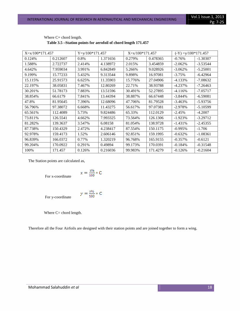
Where C= chord length. Table 3.5 –Station points for aerofoil of chord length 171.457
X=x/100*171.457 Y=y/100*171.457 X=x/100*171.457 (-Y) =y/100*171.457 0.124% 0.212607 0.8% 1.371656 0.279% 0.478365 -0.76% -1.30307 1.588% 2.722737 2.414% 4.138972 2.015% 3.454859 -2.062% -3.53544 4.642% 7.959034 3.991% 6.842849 5.266% 9.028926 -3.062% -5.25001 9.199% 15.77233 5.432% 9.313544 9.898% 16.97081 -3.75% -6.42964 15.115% 25.91573 6.625% 11.35903 15.776% 27.04906 -4.133% -7.08632 22.197% 38.05831 7.467% 12.80269 22.71% 38.93788 -4.237% -7.26463 30.201% 51.78173 7.883% 13.51596 30.491% 52.27895 -4.116% -7.05717 38.854% 66.6179 7.841% 13.44394 38.887% 66.67448 -3.844% -6.59081 47.8% 81.95645 7.396% 12.68096 47.706% 81.79528 -3.463% -5.93756 56.796% 97.38072 6.668% 11.43275 56.617% 97.07381 -2.978% -5.10599 65.561% 112.4089 5.73% 9.824486 65.33% 112.0129 -2.45% -4.2007 73.811% 126.5541 4.662% 7.993325 73.564% 126.1306 -1.923% -3.29712 81.282% 139.3637 3.547% 6.08158 81.054% 138.9728 -1.431% -2.45355 87.738% 150.4329 2.472% 4.238417 87.554% 150.1175 -0.995% -1.706 92.978% 159.4173 1.52% 2.606146 92.851% 159.1995 -0.632% -1.08361 96.839% 166.0372 0.77% 1.320219 96.768% 165.9155 -0.357% -0.6121 99.204% 170.0922 0.291% 0.49894 99.173% 170.0391 -0.184% -0.31548 100% 171.457 0.126% 0.216036 99.983% 171.4279 -0.126% -0.21604
The Station points are calculated as,
For x-coordinate
For y-coordinate Where C= chord length. Therefore all the Four Airfoils are designed with their station points and are joined together to form a wing.

INTERNATIONAL JOURNAL OF RESEARCH IN AERONAUTICAL AND MECHANICAL ENGINEERING Vol.1 Issue.1, 2013
Pg: 7-25
Mohammad Salahuddin et al 19
Screenshot 3.3 Four Airfoils of the Elliptical wing After plotting the points for all the four different chord length airfoils in the CATIA V5 software the airfoils are joined by the tool “Multi-section solid”. The below screenshot (2.4) shows the total structure of the elliptical wing.

INTERNATIONAL JOURNAL OF RESEARCH IN AERONAUTICAL AND MECHANICAL ENGINEERING Vol.1 Issue.1, 2013
Pg: 7-25
Mohammad Salahuddin et al 20
Screenshot 3.4 The designed Elliptical wing 3.4 WINGLET FOR ELLIPTICAL WING Now the winglet is designed with the given geometry on the wingtip of the elliptical wing in the “Wireframe and Surface design” tool of the CATIA Software.
Screenshot 3.5: WINGLET

INTERNATIONAL JOURNAL OF RESEARCH IN AERONAUTICAL AND MECHANICAL ENGINEERING Vol.1 Issue.1, 2013
Pg: 7-25
Mohammad Salahuddin et al 21
Screenshot 3.6: Winglet on elliptical wing 3.5 SHORT WING The Geometrical characteristics of the short wing are listed in the following tables (Table 3.6 and table 3.7).
Table 3.6 –Station Points for aerofoil for short wing of chord length 370mm
X=x/100*370 Y=y/100*370 X=x/100*370 (- Y)=y/100*370 0.124 0.4588 0.8 2.96 0.279 1.0323 -0.76 -2.812 1.588 5.8756 2.414 8.9318 2.015 7.4555 -2.062 -7.6294 4.642 17.1754 3.991 14.7667 5.266 19.4842 -3.062 -11.3294 9.199 34.0363 5.432 20.0984 9.898 36.6226 -3.75 -13.875 15.115 55.9255 6.625 24.5125 15.776 58.3712 -4.133 -15.2921 22.197 82.1289 7.467 27.6279 22.71 84.027 -4.237 -15.6769 30.201 111.7437 7.883 29.1671 30.491 112.8167 -4.116 -15.2292 38.854 143.7598 7.841 29.0117 38.887 143.8819 -3.844 -14.2228 47.8 176.86 7.396 27.3652 47.706 176.5122 -3.463 -12.8131 56.796 210.1452 6.668 24.6716 56.617 209.4829 -2.978 -11.0186 65.561 242.5757 5.73 21.201 65.33 241.721 -2.45 -9.065 73.811 273.1007 4.662 17.2494 73.564 272.1868 -1.923 -7.1151 81.282 300.7434 3.547 13.1239 81.054 299.8998 -1.431 -5.2947 87.738 324.6306 2.472 9.1464 87.554 323.9498 -0.995 -3.6815 92.978 344.0186 1.52 5.624 92.851 343.5487 -0.632 -2.3384 96.839 358.3043 0.77 2.849 96.768 358.0416 -0.357 -1.3209 99.204 367.0548 0.291 1.0767 99.173 366.9401 -0.184 -0.6808 100 370 0.126 0.4662 99.983 369.9371 -0.126 -0.4662

INTERNATIONAL JOURNAL OF RESEARCH IN AERONAUTICAL AND MECHANICAL ENGINEERING Vol.1 Issue.1, 2013
Pg: 7-25
Mohammad Salahuddin et al 22
The Station points are calculated as,
For x-coordinate
For y-coordinate Where C= chord length.
Table3.7 –Points for the aerofoil for short wing of chord length 233mm X=x/100*233 Y=y/100*233 X=x/100*233 (-Y)=y/100*233
0.124 0.28892 0.8 1.864 0.279 0.65007 -0.76 -1.7708
1.588 3.70004 2.414 5.62462 2.015 4.69495 -2.062 -4.80446
4.642 10.81586 3.991 9.29903 5.266 12.26978 -3.062 -7.13446
9.199 21.43367 5.432 12.65656 9.898 23.06234 -3.75 -8.7375
15.115 35.21795 6.625 15.43625 15.776 36.75808 -4.133 -9.62989
22.197 51.71901 7.467 17.39811 22.71 52.9143 -4.237 -9.87221
30.201 70.36833 7.883 18.36739 30.491 71.04403 -4.116 -9.59028
38.854 90.52982 7.841 18.26953 38.887 90.60671 -3.844 -8.95652
47.8 111.374 7.396 17.23268 47.706 111.155 -3.463 -8.06879
56.796 132.3347 6.668 15.53644 56.617 131.9176 -2.978 -6.93874
65.561 152.7571 5.73 13.3509 65.33 152.2189 -2.45 -5.7085
73.811 171.9796 4.662 10.86246 73.564 171.4041 -1.923 -4.48059
81.282 189.3871 3.547 8.26451 81.054 188.8558 -1.431 -3.33423
87.738 204.4295 2.472 5.75976 87.554 204.0008 -0.995 -2.31835
92.978 216.6387 1.52 3.5416 92.851 216.3428 -0.632 -1.47256
96.839 225.6349 0.77 1.7941 96.768 225.4694 -0.357 -0.83181
99.204 231.1453 0.291 0.67803 99.173 231.0731 -0.184 -0.42872
100 233 0.126 0.29358 99.983 232.9604 -0.126 -0.29358
The Station points are calculated as,
For x-coordinate
For y-coordinate Where C= chord length. Thus, the root chord and the tip chord with their station points are designed and are joined together to form the Short wing.

INTERNATIONAL JOURNAL OF RESEARCH IN AERONAUTICAL AND MECHANICAL ENGINEERING Vol.1 Issue.1, 2013
Pg: 7-25
Mohammad Salahuddin et al 23
Screenshot 3.7: The Designed Short wing 3.6 WINGLET FOR SHORT WING After designing the Short wing, the winglet is designed as for it similar to that of the previous one designed for the elliptical wing.
Screenshot 3.8: Winglet- Short wing

INTERNATIONAL JOURNAL OF RESEARCH IN AERONAUTICAL AND MECHANICAL ENGINEERING Vol.1 Issue.1, 2013
Pg: 7-25
Mohammad Salahuddin et al 24
Screenshot 3.9: Winglet on Short wing
4. Analysis of the Experiment The Analysis is carried out in the FOTRAN and STRUCTURAL analysis method of the ANSYS software and the flow and Structure analysis will be done on the elliptical wing and short wing with and without winglet. The analysis is done by measuring and comparing various aerodynamics characteristics which include drag coefficient CD, lift coefficient CL, and lift-to-drag ratio L/D. The Analysis Part of this dissertation is carried on in the Final Main Project.
5. Conclusion This project proposes alternatives in the design of winglet from the conventional designs. An improved winglet design will significantly yield a better performance of an aircraft and reduce the fuel consumption. Despite the benefits of winglets, there are some drawbacks that need to be addressed. For example, the bending moment at the wing root is higher, and may require additional structural reinforcement of the wing. Winglets although can produce a low drag wing, they add to the cost and complexity of construction. They also modify the handling and stability characteristics. The viscous drag of the winglet can be too big, nullifying the reduction of the induced drag. Winglets have to be carefully designed so that these and other problems can be overcome. Hence analysis is done and different aerodynamics characteristics are measured and compared for implementing a winglet on the wing, thus giving a better aspect of reducing the induced drag and increasing the performance of the aircraft with better efficiency.
References [1] D. P. Coiro, F. Nicolosi, F. Scherillo, U. Maisto Department of Aerospace Engineering (DIAS), University of Naples “Federico II”, 80125, Naples, Italy:SINGLE VERSUS MULTIPLE WINGLETS: NUMERICAL AND EXPERIMENTAL INVESTIGATION. [2] M. A Azlin, C.F Mat Taib, S. Kasolang and F.H Muhammad Proceedings of the World Congress on Engineering 2011 Vol I WCE 2011, July 6 - 8, 2011, London, U.K:.CFD Analysis of Winglets at Low Subsonic Flow. [3] Bento S. de MattosAntonini P. MacedoDurval H. da Silva FilhoEmpresaBrasileira de Aeronautica S.A. Av. BrigadeiroFaria Lima, 2170 12.227-901 Sao Jose dos campos– SP – Brazil:Considerations about Winglet Design. [4] D. P. COIRO, F. NICOLOSI , F. SCHERILLO, U. MAISTO, Dipartimento di IngegneriaAerospaziale(DIAS), UniversitàdeglStudi di Napoli Federico II, Napoli, ADAG research group (Aircraft Design and Aeroflightdynamics Group);

INTERNATIONAL JOURNAL OF RESEARCH IN AERONAUTICAL AND MECHANICAL ENGINEERING Vol.1 Issue.1, 2013
Pg: 7-25
Mohammad Salahuddin et al 25
DESIGN OF MULTIPLE WINGLETS TO IMPROVE TURNING ANDSOARING CHARACTERISTICS OF ANGELO D’ARRIGO’S HANGGLIDER:NUMERICAL AND EXPERIMENTAL INVESTIGATION. [5] Anderson J.D., Fundamentals of Aerodynamics, MC Graw Hill International Edition. [6] Daniel P. Raymer., Aircraft Design: A Conceptual Approach Fourth Edition.