
International Journal of Computer Science & Information ...
126
International Journal of Computer Science & Information Security © IJCSIS PUBLICATION 2013 IJCSIS Vol. 11 No. 11, November 2013 ISSN 1947-5500
-
Upload
khangminh22 -
Category
Documents
-
view
0 -
download
0
Transcript of International Journal of Computer Science & Information ...

International Journal of Computer Science
& Information Security
© IJCSIS PUBLICATION 2013
IJCSIS Vol. 11 No. 11, November 2013 ISSN 1947-5500


IJCSIS
ISSN (online): 1947-5500
Please consider to contribute to and/or forward to the appropriate groups the following opportunity to submit and publish original scientific results. CALL FOR PAPERS International Journal of Computer Science and Information Security (IJCSIS) January-December 2014 Issues The topics suggested by this issue can be discussed in term of concepts, surveys, state of the art, research, standards, implementations, running experiments, applications, and industrial case studies. Authors are invited to submit complete unpublished papers, which are not under review in any other conference or journal in the following, but not limited to, topic areas. See authors guide for manuscript preparation and submission guidelines. Indexed by Google Scholar, DBLP, CiteSeerX, Directory for Open Access Journal (DOAJ), Bielefeld Academic Search Engine (BASE), SCIRUS, Scopus Database, Cornell University Library, ScientificCommons, ProQuest, EBSCO and more.
Deadline: see web site Notification: see web siteRevision: see web sitePublication: see web site
For more topics, please see web site https://sites.google.com/site/ijcsis/
For more information, please visit the journal website (https://sites.google.com/site/ijcsis/)
Context-aware systems Networking technologies Security in network, systems, and applications Evolutionary computation Industrial systems Evolutionary computation Autonomic and autonomous systems Bio-technologies Knowledge data systems Mobile and distance education Intelligent techniques, logics and systems Knowledge processing Information technologies Internet and web technologies Digital information processing Cognitive science and knowledge
Agent-based systems Mobility and multimedia systems Systems performance Networking and telecommunications Software development and deployment Knowledge virtualization Systems and networks on the chip Knowledge for global defense Information Systems [IS] IPv6 Today - Technology and deployment Modeling Software Engineering Optimization Complexity Natural Language Processing Speech Synthesis Data Mining

Editorial Message from Managing Editor
International Journal of Computer Science and Information Security (IJCSIS – established since May 2009), is a prime venue to publicize research and development results of high significance in the theory, design, implementation, analysis, and application of computing and security. As a scholarly open access peer-reviewed international journal, the primary objective is to provide the academic community and industry a forum for sharing ideas and for the submission of original research related to Computer Science and Security. High caliber authors are solicited to contribute to this journal by submitting articles that illustrate research results, projects, surveying works and industrial experiences that describe latest advances in the Computer Science & Information Security.
IJCSIS archives all publications in major academic/scientific databases; abstracting/indexing, editorial board and other important information are available online on homepage. Indexed by the following International agencies and institutions: Google Scholar, Bielefeld Academic Search Engine (BASE), CiteSeerX, SCIRUS, Cornell’s University Library EI, Scopus, DBLP, DOI, ProQuest, EBSCO. Google Scholar reported a large amount of cited papers published in IJCSIS. IJCSIS supports the Open Access policy of distribution of published manuscripts, ensuring "free availability on the public Internet, permitting any users to read, download, copy, distribute, print, search, or link to the full texts of [published] articles". IJCSIS editorial board ensures a rigorous peer-reviewing process and consisting of international experts solicits your contribution to the journal with your research papers. IJCSIS is grateful for all the insights and advice from authors & reviewers. We look forward to your collaboration. For further questions please do not hesitate to contact us at [email protected]. A complete list of journals can be found at: http://sites.google.com/site/ijcsis/
IJCSIS Vol. 11, No. 11, November 2013 Edition
ISSN 1947-5500 © IJCSIS, USA.
Journal Indexed by (among others):

IJCSIS EDITORIAL BOARD Dr. Yong Li School of Electronic and Information Engineering, Beijing Jiaotong University, P. R. China Prof. Hamid Reza Naji Department of Computer Enigneering, Shahid Beheshti University, Tehran, Iran Dr. Sanjay Jasola Professor and Dean, School of Information and Communication Technology, Gautam Buddha University Dr Riktesh Srivastava Assistant Professor, Information Systems, Skyline University College, University City of Sharjah, Sharjah, PO 1797, UAE Dr. Siddhivinayak Kulkarni University of Ballarat, Ballarat, Victoria, Australia Professor (Dr) Mokhtar Beldjehem Sainte-Anne University, Halifax, NS, Canada Dr. Alex Pappachen James (Research Fellow) Queensland Micro-nanotechnology center, Griffith University, Australia Dr. T. C. Manjunath HKBK College of Engg., Bangalore, India.
Prof. Elboukhari Mohamed Department of Computer Science, University Mohammed First, Oujda, Morocco

TABLE OF CONTENTS
1. Paper 31101326: An Integrated Public Key Infrastructure Model Based on Certificateless Cryptography (pp. 1-10) Mohammed Hassouna(1), Bazara Barri (2), Nashwa Mohamed (2), Eihab Bashier (2)(3) (1) National Ribat University, Burri, Khartoum, Sudan (2) Faculty of Mathematical Sciences, University of Khartoum, Sudan (3) Faculty of Sciences and Arts, Albaha University, Saudi Arabia Abstract — In this paper an integrated Certificateless Public Key Infrastructure (CLPKI) that focuses on key management issues is proposed. The proposed scheme provides two-factor private key authentication to protect the private key in case of device theft or compromise. The private key in the proposed scheme is not stored in the device, but rather it is calculated every time the user needs it. It depends also on a user’s chosen password and then even if the device is stolen, the attacker cannot get the private key because he/she does not know the user’s secret password. The proposed model provides many other key management features like private key recovery, private key portability and private key archiving. 2. Paper 31101324: An Attribute-Based Public Key Infrastructure (pp. 11-18) Hendri Nogueira, Jean Everson Martina and Ricardo Felipe Custódio Federal University of Santa Catarina – Florianópolis - SC, Brazi Abstract — While X.509 Public Key Infrastructures (PKIs) and X.509 Attribute Certificates (ACs) enforce strong authentication and authorization procedures (respectively), they do not give the user management over his/her own attributes. This is especially important in regards to the users’ personal information when a service provider requests more than necessary, sensitive information such as medical data, and the users need control over the attributes they are sharing. We present an Attribute-Based Public Key Infrastructure that addresses the management of users’ attributes and giving more control to the users’ concerns in identity and access management system and in documents signatures. Our user-centric scheme also simplify the confidence of the attributes validity and the verification procedures. Index Terms — Attribute-Based, Public Key Infrastructure, Identity Management, Attributes, User-Centric. 3. Paper 31101325: Map Visualization of Shortest Path Searching of Government Agency Location Using Ant Colony Algorithm (pp. 19-23) Candra Dewi and Devi Andriati, Program of Information Technology and Computer Science, Brawijaya University Abstract — The case of the shortest path searching is an issue to get the destination with the efficient time and the shortest path. Therefore, some shortest path searching system has been developed as a tool to get the destination without spent a lot of time. This paper implements the visualization of searching result for shortest path of the government agency location on the map using ant colony algorithm. Ant colony algorithm is an algorithm which has a probabilistic technique that is affected by ant pheromone. The shortest path searching considers some factors such as traffic jam, road direction, departures time and vehicle type. The testing is done to obtain the ant tracking intensity controlling constant (α) for calculation probability of route that is selected by ant and visibility controlling constant (β), therefore the optimal route would be obtained. The testing result shows that the worst accuracy value was reach when α = 0 and β = 0. On the other hand, the accuracy value close to 100% on some combination of the parameter such as (α = 0, β = 1), (α = 2, β = 1), (α=0, β=2), (α=1, β= 2) to (α=2, β = 5). It shows that the accuracy

value is close to the best result. The change of parameter α and β are the main priority on the shortest path searching because the values have been produced will be used as probability value of pheromone. Keywords - shortest path; map visualization; Ant Colony algorithm; government agency location 4. Paper 31101328: Determination of Multipath Security Using Efficient Pattern Matching (pp. 24-33) James Obert, Cyber R&D Solutions, Sandia National Labs, Albuquerque, NM, USA Huiping Cao, Computer Science Department, New Mexico State University, Las Cruces, NM, USA Abstract — Multipath routing is the use of multiple potential paths through a network in order to enhance fault tolerance, optimize bandwidth use, and improve security. Selecting data flow paths based on cost addresses performance issues but ignores security threats. Attackers can disrupt the data flows by attacking the links along the paths. Denial-of-service, remote exploitation, and other such attacks launched on any single link can severely limit throughput. Networks can be secured using a secure quality of service approach in which a sender disperses data along multiple secure paths. In this secure multi-path approach, a portion of the data from the sender is transmitted over each path and the re-ceiver assembles the data fragments that arrive. One of the larg-est challenges in secure multipath routing is determining the se-curity threat level along each path and providing a commensu-rate level of encryption along that path. The research presented explores the effects of real-world attack scenarios in systems, and gauges the threat levels along each path. Optimal sampling and compression of network data is provided via compressed sensing. The probability of the presence of specific attack signatures along a network path is determined using machine learning techniques. Using these probabilities, information assurance levels are de-rived such that security measures along vulnerable paths are increased. Keywords-component; Mutli-path Security; Information Assurance; Anomaly Detection. 5. Paper 31101338: On the Information Hiding Technique Using Least Significant Bits Steganography (pp. 34-45) Samir El-Seoud, Faculty of Informatics and Computer Science, The British University in Egypt, Cairo, Egypt Islam Taj-Eddin, Faculty of Informatics and Computer Science, The British University in Egypt, Cairo, Egypt Abstract — Steganography is the art and science of hiding data or the practice of concealing a message, image, or file within another message, image, or file. Steganography is often combined with cryptography so that even if the message is discovered it cannot be read. It is mainly used to maintain private data and/or secure confidential data from misused through unauthorized person. In contemporary terms, Steganography has evolved into a digital strategy of hiding a file in some form of multimedia, such as an image, an audio file or even a video file. This paper presents a simple Steganography method for encoding extra information in an image by making small modifications to its pixels. The proposed method focuses on one particular popular technique, Least Significant Bit (LSB) Embedding. The paper uses the (LSB) to embed a message into an image with 24-bit (i.e. 3 bytes) color pixels. The paper uses the (LSB) of every pixel’s bytes. The paper show that using three bits from every pixel is robust and the amount of change in the image will be minimal and indiscernible to the human eye. For more protection to the message bits a Stego-Key has been used to permute the message bits before embedding it. A software tool that employ steganography to hide data inside of other files (encoding) as well as software to detect such hidden files (decoding) has been developed and presented. Key Words—Steganography, Hidden-Data, Embedding-Stego-Medium, Cover-Medium, Data, Stego-Key, Stego-Image, Least Significant Bit (LSB), 24-bit color pixel, Histogram Error (HE), Peak Signal Noise Ratio (PSNR), Mean Square Error (MSE). 6. Paper 30091320: Color and Shape Content Based Image Classification using RBF Network and PSO Technique: A Survey (pp. 46-50)

Abhishek Pandey, Dept. of CSE, UIT-RGPV Bhopal (M.P) Prof. Anjna Jayant Deen, Dept. of CSE,UIT-RGPV Bhopal (M.P) Dr. Rajeev Pandey, Dept. of CSE,UIT-RGPV Bhopal(M.P) Abstract - The improvement of the accuracy of image query retrieval used image classification technique. Image classification is well known technique of supervised learning. The improved method of image classification increases the working efficiency of image query retrieval. For the improvements of classification technique we used RBF neural network function for better prediction of feature used in image retrieval.Colour content is represented by pixel values in image classification using radial base function(RBF) technique. This approach provides better result compare to SVM technique in image representation.Image is represented by matrix though RBF using pixel values of colour intensity of image. Firstly we using RGB colour model. In this colour model we use red, green and blue colour intensity values in matrix.SVM with partical swarm optimization for image classification is implemented in content of images which provide better Results based on the proposed approach are found encouraging in terms of color image classification accuracy. Keywords: RBF network, PSO technique, image classification. 7. Paper 30091321: A Survey: Various Techniques of Image Compression (pp. 51-55) Gaurav Vijayvargiya, Dr. Rajeev Pandey, Dr. Sanjay Silakari UIT-RGPV, Bhopal Abstract — This paper addresses about various image compression techniques. On the basis of analyzing the various image compression techniques this paper presents a survey of existing research papers. In this paper we analyze different types of existing method of image compression. Compression of an image is significantly different then compression of binary raw data. To solve these use different types of techniques for image compression. Now there is question may be arise that how to image compress and which types of technique is used. For this purpose there are basically two types are method are introduced namely lossless and lossy image compression techniques. In present time some other techniques are added with basic method. In some area neural network genetic algorithms are used for image compression. Keywords-Image Compression; Lossless; Lossy; Redundancy; Benefits of Compression. 8. Paper 30091325: Optimization of Real-Time Application Network Using RSVP (pp. 56-62) Vikas Gupta (1), Baldev Raj (2) (1) Assistant Professor, Adesh Institute of Engineering and Technology, Faridkot, Punjab, India (2) Research Scholar, Adesh Institute of Engineering and Technology, Faridkot, Punjab, India Abstract — In this research work Resource Reservation Protocol (RSVP) – which works on receiver – oriented approach is used. Two different networks have been designed and implemented using OPNET. In the first scenario the client are available with and without the use of RSVP. In this scenario, the parameters that have been selected, simulated and analyzed are reservation status message, reservation and path states in all value mode, traffic delay experienced in the form of end-to-end delay parameter with and without the use of RSVP, packet delay variation with and without RSVP. The analysis reveal that the attempted reservation status was successful, the number of reservation and path states were one, the end-to-end delay with the use of RSVP was comparatively lower than with the use of RSVP and also the packet delay variation for node with RSVP was lower than that of the node not using RSVP. In another scenario the network was duplicated but the link used for connecting the subnets was changed from DS1 (1.544 Mbps) to DS3 (44.736 Mbps). The parametric analysis indicated that end-to-end delay, Packet delay variation for the network with DS3 as the link, was lower than the network with DS1. Keywords: RSVP, OPNET

9. Paper 30111149: A New Scalable and Efficient Image Encryption Scheme Using Poly substitution Method and Genetic Algorithm (pp. 63-65) G. Lokeshwari, Associate professor CSE, Aurora’s Engineering College, Bhongir Dr. S. Udaya Kumar, Principal, MVSR Engineering college, Nadergul. G. Aparna, Associate Professor ECE, Aurora’s Engineering College, Bhongir Abstract - In today’s world of information technology image encryption can be used for providing privacy and for protecting intellectual properties. During the transmission of images the threat of unauthorized access may increase significantly. Image encryption can be used to minimize these problems. In the proposed scheme of image encryption using poly substitution method we propose the possibility of taking the advantages of genetic algorithm features. In poly alphabetic substitution ciphers the plaintext letters are enciphered differently depending upon their placement in the text. As the name poly alphabetic suggests this is achieved by using several two, three keys and random keys combinations. Keywords: Image Encryption, Decryption, Genetic algorithm, poly substitution. 10. Paper 31071319: Local Intrusion Detection by Bluff Probe Packet (LIDBPP) in A mobile Ad Hoc Network (MANET) (pp. 66-69) Imad I. Saada and Majdi Z. Rashad Department of Computer Science, Faculty of Computer and Information Sciences, Mansoura University, Egypt Abstract - Mobile ad hoc network (MANET) is a collection of wireless nodes that are distributed without dependency on any permanent infrastructure. MANET security has been studied in recent years For example the black hole threats which make the source believes that the path to the destination being through it. Researchers have proposed their secure routing idea in order to encounter these threats, the problem is that the security threats still exists because it is not prevented or avoided completely in addition, some of the solutions adversely affected network performance, such as adding additional network overhead and time delay. The main objectives of this paper is to discuss some recent solutions that work to detect a black hole node by using different strategies, one of these solutions is S-ZRP, it will be developed in this paper to generate a new proposed solution called local intrusion detection by bluff probe packet (LIDBPP), it will locally begin detection by the previous node and not by the source node as in S-ZRP, this will decrease the negative impact n the performance of MANET such as network overhead and time delay in AODV based MANET. Keywords: LIDBPP, MANET, Black hole, AODV, Network security. 11. Paper 31101322: Design and Analysis of (M/G/1):(GD/∞/ ∞) and (Mi /Gi /1):(NPRP/∞/∞) Queueing Systems (pp. 70-75) G. T. Shakila Devi, Research Scholar, Department of Statistics, Manonmaniam Sundaranar University, Tirunelveli, India. Dr. C. Vijayalakshmi, Professor, School of Advance Sciences, Department of Mathematics Division, VIT University, Chennai, India. Abstract - There are many non Poisson queuing models. This paper mainly deals with the analysis of Non-Poisson queues (M/G/1): (GD/∞/ ∞) and (Mi /Gi/1): (NPRP/∞/∞) .The feasibility of the system is analyzed based on the numerical calculations and Graphical representations. When the mean system size and the queue size is high, optimized value is obtained so that the total expected cost is minimized. The outline here an approach that may be used to analyze a non-Poisson model which has job classes of multiple priorities. The priority discipline followed may be either non-preemptive or preemptive in nature. When the priority discipline is non-preemptive in nature, a job in service is allowed to complete its service normally even if a job of higher priority enters the queue while its service is going on. In the preemptive case, the service to the ongoing job will be preempted by the new arrival of higher priority. If the priority discipline is preemptive resume, then service to the interrupted job, when it restarts,

continues from the point at which the service was interrupted. For the preemptive non resume case, service already provided to the interrupted job is forgotten and its service is started again from the beginning. Note that there may be loss of work in the preemptive non-resume priority case. Such loss of work will not happen in the case of the other two priorities. Since the service times are assumed to be exponentially distributed, they will satisfy the memory-less property and that, therefore, the results will be the same both for the preemptive resume and preemptive non-resume cases. Keywords- Pollazek–Khintchine formula; Priority service discipline; Non-Poisson queues 12. Paper 31101307: Applying Data Mining Techniques for Customer Relationship Management: A Survey (pp.76-82) Ahmed M. El-Zehery, Hazem M. El-Bakry, Faculty of Computer Science & Information System, Mansoura University, Egypt Mohamed S. El-Ksasy, Faculty of Engineering, Mansoura University, Egypt Abstract — Data mining has various applications for customer relationship management. In this proposal, I am introducing a framework for identifying appropriate data mining techniques for various CRM activities. This Research attempts to integrate the data mining and CRM models and to propose a new model of Data mining for CRM. The new model specifies which types of data mining processes are suitable for which stages/processes of CRM. In order to develop an integrated model it is important to understand the existing Data mining and CRM models. Hence the article discusses some of the existing data mining and CRM models and finally proposes an integrated model of data mining for CRM. 13. Paper 31101317: MAC Address as a Key for Data Encryption (pp. 83-87) Dr. Mohammed Abbas Fadhil Al-Husainy Department of Multimedia Systems, Faculty of Science and Information Technology, Al-Zaytoonah University of Jordan, Amman, Jordan Abstract- In computer networking, the Media Access Control (MAC) address is a unique value associated with a network adapter. MAC addresses are also known as hardware addresses or physical addresses. TCP/IP and other mainstream networking architectures generally adopt the OSI model. MAC addresses function at the data link layer (layer 2 in the OSI model). They allow computers to uniquely identify themselves on a network at this relatively low level. In this paper, suggested data encryption technique is presented by using the MAC address as a key that is used to authenticate the receiver device like PC, mobile phone, laptop or any other devices that is connected to the network. This technique was tested on some data, visual and numerical measurements were used to check the strength and performance of the technique. The experiments showed that the suggested technique can be used easily to encrypt data that is transmitted through networks. Keywords: Crossover, Mutation, Information Security, Random, Distortion 14. Paper 31101336: Identification of Diabetic Retinopathy using Fuzzy Logic and Back Propagation Neural Network (pp. 88-95) C. Berin Jones, Research Scholar, Manonmaniam Sundaranar University, India-627012 Dr. S. Suresh Kumar, Principal, Vivekananda College of Technology for Woman, Tiruchencode, India-637205 Dr. Purushothaman S., Professor, PET Engineering College, Vallioor, India-627117 Abstract- Retinal exudates classification and identification of diabetic retinopathy to diagnose the eyes using fundus images requires automation. This research work proposes retinal exudates classification. Representative features are obtained from the fundus images using segmentation method. Fuzzy logic and back propagation algorithm are trained to identify the presence of exudates in fundus image. The presence of exudates is identified more clearly using Fuzzy logic and back propagation algorithm. By knowing the outputs of proposed algorithm during testing,

accurate diagnosis and prescription for treatment of the affected eyes can be done. Fifty fundus images are used for testing. The performance of proposed algorithm is 96% (48 images are classified). Simulation results show the effectiveness of proposed algorithm in retinopathy classification. Very large database can be created from the fundus images collected from the diabetic retinopathy patients that can be used for future work. Keywords: Diabetic retinopathy; fundus image; exudates detection; Fuzzy logic; back propagation algorithm.

An Integrated Public Key Infrastructure ModelBased on Certificateless Cryptography
Mohammed Hassouna #1, Bazara Barri ∗2, Nashwa Mohamed #2, Eihab Bashier #2,3
1 Faculty of Computer Studies, National Ribat University, P.O.Box 55, Khartoum, Sudan2 Faculty of Mathematical Sciences, University of Khartoum, Sudan
3 Faculty of Sciences and Arts, Albaha University, Saudi Arabia1 [email protected]
2 [email protected] [email protected]
Abstract—In this paper an integrated Certificateless PublicKey Infrastructure (CLPKI) that focuses on key managementissues is proposed. The proposed scheme provides two-factorprivate key authentication to protect the private key in case ofdevice theft or compromise. The private key in the proposedscheme is not stored in the device, but rather it is calculatedevery time the user needs it. It depends also on a user’s chosenpassword and then even if the device is stolen, the attackercannot get the private key because he/she does not know theuser’s secret password. The proposed model provides many otherkey management features like private key recovery, private keyportability and private key archiving.
I. INTRODUCTION
One main objective of the public key cryptography is toestablish secure system that provides integrity, confidentiality,authentication and non-repudiation. Integrity and confiden-tiality are provided via symmetric crypto-systems such asthe AES, and non-repudiation is provided through the digitalsignature. Any user within the system has public/private keypair, where the user’s public key is used for symmetric keygeneration and signature verification. At this point, a keyquestion is how the public key itself can be authenticated?,That is, who can insure that the particular public key belongsto the user that claims ownership. This problem is calledthe public key authentication and has remained a challengefor almost every secure system based on the public keycryptography technology.
The Public Key Infrastructure (PKI) is a complete systemto solve the above mentioned problem. It provides public keyauthentication by binding the entity information like subjectname, email address and its public key in standard formatteddocument called digital certificate. X.509 [1] is the one ofthe widely used digital certificate standard that is supportedby the International Telecommunication Union. This digitalcertificate is issued according to a set of procedures andpolicies and then signed by a trusted certificate authority’s(CA) private key. Each user within the system can use his/hercertificate to provide confidentiality through encryption orauthentication and non-repudiation through digital signature.
Within any PKI system, each certificate has a validity periodafter which it expires and consequently revoked. The PKI
provides a mechanism to check the validity of the certificateby different methods. The most popular methods are thecertificate revocation list(CRL) and the online certificate statusprotocol(OCSP).
The X.509 specifies public key certificates, certificate re-vocation lists, attribute certificates, and a certification pathvalidation algorithm. In the X.509 system, a certificationauthority(CA) issues a certificate binding a public key to aparticular distinguished name in the X.500[2] tradition, or toan alternative name such as an e-mail address or a DNS-entry.An organization’s trusted root certificates can be distributed toall employees so that they can use the company PKI system.Internet Browsers such as MS Internet Explorer, Firefox,Opera, Safari and Chrome come with a predetermined setof root certificates pre-installed, PKI certificates from largervendors will work instantly, in effect the browsers’ developersdetermine which CAs are trusted third parties for the browsers’users.
Also, the X.509 includes standards for certificate revocationlist (CRL) implementations, an often neglected aspect of PKIsystems. The IETF-approved way of checking a certificate’svalidity is the Online Certificate Status Protocol (OCSP).There are many security protocols based on the PKI likeSecure Socket Layer(SSL), IPSec, S/MIME, VPN, and SSHprotocols.
Generally, the PKI suffers two problems, namely: scalabil-ity and certificate management[3]. The Identity-based PublicKey Cryptography(ID-PKC) [4] came to address these twoproblems, but could not offer true non-repudiation due to thekey escrow problem[3],[5].In ID-PKC, an entity’s public keyis derived directly from certain aspects of its identity, forexample, an IP address belonging to a network host, or an e-mail address associated with a user. Private keys are generatedfor entities by a trusted third party called a private key gener-ator(PKG). The first fully practical and secure identity-basedpublic key encryption scheme was presented in[6]. Since then,rapid development of ID-PKC has taken place. Currently, thereexist Identity-based Key Exchange protocols (interactive[7]as well as non-interactive[8]), signature schemes [9], [10],[11], Hierarchical schemes[12] and a host of other primitives.
(IJCSIS) International Journal of Computer Science and Information Security, Vol. 11, No. 11, November 2013
1 http://sites.google.com/site/ijcsis/ ISSN 1947-5500

It has also been illustrated in [13], [14], [15] how ID-PKCcan be used as a tool to enforce what might be termed”cryptographic work-flows”, that is, sequences of operations(e.g. authentications) that need to be performed by an entity inorder to achieve a certain goal[3]. ID-PKC also suffers fromkey escrow problem that the PKG knows all users’s privatekeys in the system and furthermore can not offer true non-repudation.
In 2003 Al-Riyami and Paterson [3] introduced the conceptof Certificateless Public Key Cryptography (CL-PKC) to over-come the key escrow limitation of the identity-based publickey cryptography (ID-PKC). In CL-PKC a trusted third partycalled Key Generation Center (KGC) supplies a user with apartial private key. Then, the user combines the partial privatekey with a secret value (that is unknown to the KGC) to obtainhis full private key. In this way the KGC does not know theuser’s private key. Then the user combines his secret valuewith the KGC’s public parameters to compute his public key.
The certificateless cryptography is considered a combina-tion between PKI and identity based cryptography [3]. Itcombines the best features of the PKI and ID-PKC, suchas lack of certificates, no key escrow property, reasonabletrust to trust authority and lightweight infrastructure[16]. Itprovides a solution to the non-repudiation problem, throughenabling a user to generate his/her full long-term private key,where the trusted third party is unable to impersonate theuser. The use of certificateless cryptography schemes haveappeared in literature, this includes the uses of certificatelessencryption[5], [17]; certificateless signatures [18], [19] and[20] and certificateless signcryption[21],[22] and [23].
Almost all the CLPKC schemes found in the literature focuson algorithms of public parameters generation, public/privatekey generation of system’s parties, encryption and decryptionprocesses, but leaves many key problems without clear so-lutions. Such problems like how the system parameters arepublished and where, what the authentication method that canbe used between the users and the KGC server, what the usersshall do if the KGC updates it’s parameters and how they canbe notified, what is the format of the elements of the CLPKCsystem, and so forth.
Also there are other challenges regarding trust models, suchas to determining whether the traditional PKI trust modelscan be applied to CL-PKI, whether a PKI can be migratedto CLPKI, and whether an existing PKI-based system can beintegrated with another CLPKI-based system.
In this paper, an integrated model of Certificateless PublicKey Infrastructure(CLPKI) is proposed. It is assumed thatthere exists a Registration Authority(RA) which is responsiblefor user’s registration in the system, and a Key GenerationCenter(KGC) that is used to generate the system parametersand master secret and publish the system parameters on thepublic directory(PD) and keep the master secret secure. Theproposed model provides strong key management mechanismby separating the generation of public key from private key,this separation if it is controlled well provides private keyprotection from device theft or key compromise because the
private key is never stored in the user, but rather just thehashed value of the user’s secret key along with the user’spartial private key, this separation also provides private keyrecovery, private key archiving and private key portability, alsothe proposed model provides silent and transparent private keyrevocation in case of public key compromised or expired.
The rest of this paper is organized as follows. Section IIgives backgrounds about elliptic curve and pairing. In SectionIII, we introduce the concept of certificateless public keycryptography. In Section IV, we introduce the proposed certifi-cateless public key infrastructure model. Section V discussessecurity properties provided by the proposed model. Finally,Section VI concludes the paper.
II. BACKGROUNDS
In this section we give some backgrounds about pairing inelliptic curves, pairing-based cryptography, certificateless pub-lic key cryptography, password-based encryption, challenge-response authentication method and certificateless key agree-ment protocols.
A. Pairings in Elliptic CurveThroughout the paper, G1 denotes an additive group of
prime order q and G2 a multiplicative group of the same order.We let P denote a generator of G1. For us, a pairing is a mape : G1 × G1 −→ G2 with the following properties:
1) The map e is bilinear: given Q,W,Z ∈ G1, we have:e(Q,W +Z) = e(Q,W ) · e(Q,Z) and e(Q+W,Z) =e(Q,Z) · e(W,Z).Consequently, for any a, b ∈ Zq , we havee(aQ, bW ) = e(Q,W )ab = e(abQ,W ) etc.
2) The map e is non-degenerate: e(P, P ) 6= 1G2 .3) The map e is efficiently computable.
Typically, the map e will be derived from either the Weil orTate pairing on an elliptic curve over a finite field. We refer to[24], [25], [6], [26], [27], [28], [29], [30] for a more compre-hensive description of how these groups, pairings and otherparameters should be selected in practice for efficiency andsecurity. We also introduce here the computational problemsthat will form the basis of security for our CL-PKC schemes.
B. Bilinear Diffie-Hellman Problem(BDHP):Let G1, G2, P and e be as above. The BDHP in G1, G2, e
is as follows: Given P, aP, bP, cP with uniformly randomchoices of a, b, c ∈ Z∗q , compute e(P, P )abc ∈ G2. An al-gorithm A has advantage ε in solving the BDHP in G1, G2, eif:Pr[A(P, aP, bP, cP ) = e(P, P )abc] = ε. Here the probabilityis measured over the random choices of a, b, c ∈ Z∗q and therandom bits of A.
C. BDH Parameter Generator:As in [6], a randomized algorithm IG is a BDH parameter
generator if IG:1) takes security parameter k ≥ 1,2) runs in polynomial time in k, and
(IJCSIS) International Journal of Computer Science and Information Security, Vol. 11, No. 11, November 2013
2 http://sites.google.com/site/ijcsis/ ISSN 1947-5500

3) outputs the description of groups G1, G2 of prime orderq and a pairing e : G1×G1 −→ G2.
Formally, the output of the algorithm IG(1k) is (G1, G2, e).There are other computational hardness assumptions related topairings and are infeasible in polynomial time[6], [27].
1) Elliptic Curve Discrete Logarithm Problem: GivenP,Q ∈ G1, find an element a ∈ Z∗q such that Q = aP .
2) Computation Elliptic Curve Diffie-Hellman Problem:Given (P, aP, bP ) in G1 where a, b ∈ Z∗q , compute abP .
III. CERTIFICATELESS PUBLIC KEY CRYPTOGRAPHY(CL-PKC)
In 2003 Al-Riyami and Paterson [3] introduced the con-cept of Certificateless Public Key Cryptography (CL-PKC)to overcome the key escrow limitation of the Identity-basedCryptography. In CL-PKC a trusted third party called KeyGeneration Center (KGC) supplies a user with partial privatekey, the user then combine the partial private key with a secretvalue (unknown to the KGC) to obtain his/her full private key.In this way the KGC does not know users private keys. Thenthe user combines the same secret value with the KGC’s publicparameters to compute his/her public key.
Compared to Identity-based Public Key Cryptography (ID-PKC), the trust assumptions made of the trusted third partyin CL-PKC are much reduced. In ID-PKC, users must trustthe private key generator (PKG) not to abuse its knowledge ofprivate keys in performing passive attacks, while in CL-PKC,users need only trust the KGC not to actively propagate falsepublic keys [3].
In CL-PKC users can generate more than one pair ofkey (private and public) for the same partial private key. Toguarantee that KGC does not replace user’s public keys Al-Riyami and Paterson[3] introduced a binding technique to binda user’s public key with his/her private key. In their bindingscheme, the user first fixes his/her secret value and his/herpublic key and supplies the KGC his/her public key. Then theKGC redefine the identity of the user to be the user’s identityconcatenated with his/her public key. By this binding schemethe KGC replacement of a public key apparent, and equivalentto a CA forging a certificate in a traditional PKI.
A. Al-Riyami and Paterson SchemeIn this section we give a general description to Setup,
Set-Secret-Value, Partial-Private-Key-Extract, Set-Private-Keyand Set-Public-Key algorithms as introduced by Alriyami andPaterson [3].
Let k be a security parameter given to the Setup algorithmand IG be a Bilinear Diffie-Hellman Problem (BDH) param-eter generator with input k.
1) Setup (running by the KGC): this algorithm runs asfollows:
a) Run IG on input k to generate output <G1, G2, e > where G1 and G2 are groups of someorder q and e : G1 ×G1 −→ G2 is a pairing.
b) Choose an arbitrary generator P ∈ G1.
c) Select a master-key s uniformly at random fromZ∗q and set P0 = sP .
d) Choose cryptographic hash functions
H1 : {0, 1}∗ −→ G∗1
andH2 : G2 −→ {0, 1}n
where n is the bit-length of plaintexts taken fromsome message space M = {0, 1}n with a corre-sponding ciphertext space C = G1 × {0, 1}n.
Then, the KGC publishes the system parametersparams =< G1, G2, e, n, P, P0, H1, H2 >, while thesecret master-key s is saved secure by the KGC.
2) Set-Secret-Value (running by the user): The inputs ofthis algorithm are params and entity m’s identifier IDm.It selects xm ∈ Z∗q at random and output xm as m’ssecret value. Then, the entity m computes Xm = xmPand sends Xm to the KGC.
3) Partial-Private-Key-Extract (running by the KGC):The inputs of this algorithm are an identifier IDm ∈{0, 1}∗ and Xm. The algorithm carries out the followingsteps to construct the partial private key for entity mwith identifier IDm.• Compute Qm = H1(IDm||Xm).• Output the partial private key Dm = sQm ∈ G∗1.
Entity m when armed with it’s partial private key Dm,it can verify the correctness of the partial private keyDm by checking e(Dm, P ) = e(Qm, P0).
4) Set-Private-Key (running by the user): The inputs ofthis algorithm are params, Dm (the partial private keyof entity m) and xm ∈ Z∗q (the secret value of entity m.It transforms the partial private key Dm to a private keySm by computing Sm = xmDm = xmsQm ∈ G∗1.
5) Set-Public-Key (running by the user): The inputs ofthis algorithm are params and xm ∈ Z∗q -which is thesecrete value of entity m. It then constructs the publickey of identity m as Pm =< Xm, Ym >, where Xm =xmP and Ym = xmP0 = xmsP .
The purpose of binding technique used in Al-Riyami andPaterson[3] scheme is to enforce users to have one pub-lic/private key pairs in the system, and if there are two workingpublic keys of any user, then the other key was generated bythe KGC and this is equivalent to CA certificate forgery intraditional PKI. There are some modified schemes appearedin the literature from the original Al-Ryami and Patersonschme[3], for example Mokhtarnameh et al[31] proposedlittle modification on original scheme by setting the user’spublic key PA = xAQA and used the new public key inhis proposed two party key agreement protocol in the samepaper, Yang et al[16] showed that the two party key agree-ment protocol that proposed by Mokhtarnameh et al[31] isattackable by the man-in-the-middle attack and also explainedthat the Mokhtarnameh et al[31] did not provide one-to-onecorrespondence between the user’s identity and user’ public
(IJCSIS) International Journal of Computer Science and Information Security, Vol. 11, No. 11, November 2013
3 http://sites.google.com/site/ijcsis/ ISSN 1947-5500

key as they claimed, Mohammed et al [32] explained thatMokhtarnameh[31] and Yang et al[16] schemes suffer fromkey escrow problem by that the KGC can computer the user’sprivate key SA = sYA because the public key componentsYA = xAQA.
B. The Mohammed et. al’s authenticated key agreement pro-tocol
In [32], Mohammed et. al proposed a new modified cer-tificateless public key cryptography scheme and binding tech-nique and used their new scheme to create an authenticatedtwo party key agreement protocol without interaction betweenparties, in this section we will mention the algorithms ofMohammed et al[32] scheme.
1) Setup (running by the KGC): the KGC choosesa secret parameter k to generate G1, G2, P, e whereG1and G2 are two groups of a prime order q, P isa generator of G1 and e : G1 × G1 −→ G2 is abilinear map. The KGC randomly generates the system’smaster key s ∈ Z∗q and computes the system publickey Ppub = sP . Then the KGC chooses cryptographichash functions H1 and H2, where H1 : {0, 1}∗ ×G1 −→ G1 and H2 : G1 × G1 × G1 × G2 −→{0, 1}n. Finally, the KGC publishes the system param-eters params=< G1, G2, e, P, Ppub, H1, H2, n >, whilethe secret master-key is saved and secured by the KGC.
2) Set-Secret-Value (running by the user): the user mwith the identity IDm downloads the system’s publicparameters from the KGC. Then, he/she picks a tworandom secret values xm, x′m ∈ Z∗q . Then, the user mcomputes Xm = xmP and sends Xm to the KGC.
3) Partial-Private-Key-Extract (running by the KGC):on receiving Xm computed by user m with identityIDm, the KGC first computes Qm = H1(IDm||Xm),then it generates the partial private key of user m asDm = sQm. User m when armed with it’s partial privatekey Dm, he/she can verify the correctness of the partialprivate key Dm by checking e(Dm, P ) = e(Qm, P0).
4) Set-Private-Key (running by the user): when user mreceives Dm from the KGC, he/she computes his/herfull private key Sm = xmDm.
5) Set-Public-Key (running by the user): the user m withidentity IDm computes Qm = H1(IDm||Xm), Ym =xmx
′mQm and sets < Xm, Ym > as his/her long-term
public key Pm. Finally, user m sends Ym to the KGC.The purpose of the secret value x′m is to prevent the key
escrow problem that can be performed by the KGC.In our modified scheme we make slight modification on
Mohammed et al[32] scheme in terms of efficiency withoutchanging the level of the security the scheme has.
IV. The Proposed Certificateless Public KeyInfrastructure Model
The motivation of this paper is to propose a new CLPKImodel, the proposed model is based on modified version of
Mohammed et al[32] scheme that was introduced previouslyin section 3.2.
A. The Modified Certificateless Cryptography SchemeIn this scheme Setup and Partial-Private-Key-Extract algo-
rithms are the same as Mohammed et al[32] scheme.• Set-Secret-Value (running by the user): the user m with
the identity IDm downloads the system parameters, picksa two random secret values xm, x′m ∈ Z∗q . Then, the userm computes Xm = x′mP and sends Xm to the KGC.To provide two factor authentication and protecting theuser’s private key in case of device theft or compromise,the proposed scheme then enforce the user to choose astrong password pass, the system at client hashes thepassword to be zm = H(pass), multiplies the base pointP by the hashed password to be zmP (using special hashfunction to reserve the large size of the hashed value zmto prevent brute-force attack on the point zmP and bythat get the user’s hashed password), use the hashed valuezm as key along with the MAC function to encrypt thesecret value xm as MACzm(xm), sends copy of it to theKGC’s public directory and store copy of it along withthe point zmP locally. Note that here there is no need tostore the password pass or it’s hash value zm.
• Set-Public-Key (running by the user): the user m withidentity IDm computes Qm = H1(IDm||Xm), Ym =x′mQm and sets < Xm, Ym > as his/her long-term publickey Pm. Finally, user m sends Ym to the KGC.
• Set-Private-Key (running by the user): every time theuser needs to calculate and use his/her full private key,he/she enters his/her password, the system hashes it asz′m, calculates z′mP and comparing it with stored zmP ,if it is equals then the password is correct and the useris authentic, use it(zm) as key to decrypt the storedMACzm(xm), and after that use the extracted xm tocalculate the full private key by (xm+zm)Dm, otherwisethe system aborts the process. We must note here that theprivate key is never stored on the client and it will bedeleted after every usage.
Instead of multiplying both Xm and Ym by xm and x′m, theyshould be multiplied by x′m only. By this way, the numberof field multiplications is decreased. The proposed schemeassumes that the user uses his/her password every time he/sheneeds to use his/her full private key, calculates the privatekey as previous and use it and after that delete it, the privatekey is never stored on the device storage, this separationof calculating the public and private keys if it is controlledwell it will be very usefully feature in public key revocationwhen the private key is compromised or stolen, other featuresprovided by this separation are private key recovery, privatekey portability and private key archiving. Furthermore, theproposed scheme provides two authentication factor, sine theauthenticated user need to have the device that store thesecret number xm as first factor and after that authenticatehimself/herself to the device by correct password, because thehashed value of the user’s password is involved in private key
(IJCSIS) International Journal of Computer Science and Information Security, Vol. 11, No. 11, November 2013
4 http://sites.google.com/site/ijcsis/ ISSN 1947-5500

TABLE IRECORD 1: CONTAINS THE KGC’S SYSTEM PUBLIC PARAMETERS WITH
THE TIMESTAMP OF UPDATE
Timestamp System Parameters
calculation, even if the attacker somehow get the user’s device,he can’t calculate the private key because he/she does not knowthe user’s password.
We will use this modified scheme in our model to providestrong key management mechanisms based on certificatelesscryptography.
Regarding our scheme, user A can check the authentica-tion of KGC system parameters by validating the equalitye(DA, P ) = e(sQA, P ) = e(QA, sP ) = e(QA, P0) anduser B can check the authentication of user A′s public keyPA = (XA, YA) also by validating the equality e(XA, QA) =e(x′AP,QA) = e(P, x′AQA) = e(P, YA). Validating theuser’s partial private key that downloaded from the KGC andpublic key by using pairing in certificateless cryptographyis equivalent to verifying the CA′s signature on the user’scertificate in traditional PKI.
B. Components of the proposed CLPKIIn this section we describe the components of the proposed
CLPKI and their functions as follows:1) The Registration Authority(RA): It’s function like in
traditional PKI, the user may interact with this authorityand fill in registration form, provides with personalinformation like names, address, national ID number andemail address, after the RA authenticate the informationof the user, it gives the user a unique random generatedpassword for latter authentication purposes, in somecases the RA may give the user the system parameterswhich generated by the KGC server in a token or anyelectronic media.
2) The Key Generation Center(KGC): responsible forgenerating its master secret and the system parameters,keep it’s master secret in a secure storage and publish thesystem parameters in a public directory. KGC also hasdatabase that holds the user identities with their pass-word hashed by any strong cryptographic hash functionlike MD5 or SHA-1.
3) The KGC’s Public Directory(PD): it is a publicdirectory system that consists of the KGC’s publicparameters, users identities, users partial private keys,users public key and other user parameters. It should bewell controlled, updated only by the KGC, read only andaccessible just by authenticated users. The typical formatof the public directory records are given in Table I andTable II.Typically the RA has offline connection with KGC, andthe password that given to the user by RA is originallygenerated and stored with user’s Id by the KGC (the RAshould just bypass it to the user without knowing it).
To register a user in the system, the registration processstarts from the RA, where the user introduces his/her iden-
TABLE IIRECORD 2: CONTAINS THE USER’S IDENTITY INFORMATION ALONG WITH
USER’S PUBLIC KEY AND PARTIAL PRIVATE KEY, TIMESTAMP INDICATETHE UPDATE TIME
Timestamp UserID QID XID YID
tity proof together with the other needed information to theregistration authority. The RA then gives the user a passwordand the system’s parameters. another scenario is that the userdownloads the KGC’s system parameters from the publicdirectory. Both the user and the server need to authenticatethe identities of each other. Therefore, it is necessary to setupa robust authentication technique for both the user and theserver.
C. Authentication at first time access
In this part, we introduce two techniques for the clientto authenticate the server. The first technique is based onserver response to a client challenge to authenticate the server,whereas the second technique is based on authentication of theserver via a digital certificate. Bellow we detail each.
1) The challenge-response method:: The challenge-response method works as follows.
1) The user hashes his password and uses his/her hash valueas symmetric encryption key with any agreed symmetriccryptosystem with the KGC server like AES.
2) The user generates a random nounce n1, encrypts it us-ing the symmetric key and sends the encrypted messageto the KGC.
3) On receiving the encrypted message from the user,the KGC decrypts the message using the stored user’shashed password as decryption key to extract the nouncen′1. Then, the KGC concatenates the nounce n′1 with theURL of the download link url of the record in the publicdirectory. Finally, it encrypts the message n′1||url usingthe same user’s key and sends the encrypted messageback to the user.
4) The user decrypts the encrypted message to extract thenounce n′1 and the URL url. The user then verifies thevalidity of the nounce, if n′1 is equal to n1 then he/sheuses the url link to download the public parameters fromthe public directory (not necessarily in secure channel).
If the KGC server needs to authenticate the user (in caseof partial private key downloading), this mechanism can beextended to be:
1) The user hashes his/her password and uses this hashvalue as symmetric encryption key with any agreedsymmetric cryptosystem with the KGC server like AES.
2) The user generates a random nounce n1, encrypts itusing key and sends the encrypted message to the KGC.
3) The KGC receives the encrypted message from theuser. The KGC decrypts the message using the storeduser’s hashed password as decryption key to extract thenounce n′1. Then, the KGC generates another nouncen2, concatenates the nounce n2 with the nounce n′1. It
(IJCSIS) International Journal of Computer Science and Information Security, Vol. 11, No. 11, November 2013
5 http://sites.google.com/site/ijcsis/ ISSN 1947-5500

encrypts the message n′1||n2 using the same user’s keyand sends the encrypted message back to the user.
4) The user decrypts the encrypted message to extract thenounce n′1 and nounce n′2. The user then verifies thevalidity of the nounce, if n′1 equals to n1, he/she authen-ticates the KGC, the user encrypts the nounce n′2 andsends it back again to the KGC for user authentication.
5) The KGC decrypts the message n′′2 and compares it withit’s value n2, if they are equal, the server trusts the user,and finally sends him/her the download link url of therequested information (partial private key as example)to user encrypted with the user’s key.
6) The user decrypts the URL and uses it to download therequested information from the public directory.
Note that by using this method, the attacker cannot carryout a replay attack, because every time the user generates anew nounce. Also, the attacker cannot carry out a passworddictionary attack because the password is hashed and used asencryption/decryption key.
2) The certificate-based method:: The certificate-basedmethod is another method to authenticate the KGC server forthe users. It is a hybrid model that incorporates the traditionalPKI and the model originally used by Chen et al in [13]. Inthis model the trusted Certificate authority (CA) generates andsigns a digital certificate (typically X.509 format) for the KGCserver that contains the KGC identity information (in Subjectfield) with it’s public parameters(in the Public Key field), thenthe users authenticate the KGC by using this certificate asfollows:
1) The user sends a request to the KGC server.2) The KGC sends its certificate back to the user.3) The user checks the validity of the certificate, if it is
valid then the user authenticates the KGC and extractsthe public parameters from the certificate. Otherwise, theuser rejects the certificate and abort the process.
We note that this hybrid model utilizes the PKI at the KGClevels and the CLPKI at users level, and this model can beextended to be used also in the hierarchal CLPKI model,in which the root KGC and each intermediate KGC canhave a certificate. Hence, the user can authenticate the publicparameters and the users in other domains using the chain pathas in traditional hierarchal PKI.
D. Periodic update of passwords and system’s parametersThe KGC must have a policy for the periodic updates of
the users passwords to avoid any password learning attacks.One possible method is by determining a fixed period, whenreached the KGC generates a new password for a particularuser, encrypts it using the user’s old password and sends it tothe user, the user decrypts it to obtain the new one.
To enhance the security of the system, the KGC uses theTimestamp field in the public parameters record to indicateany update in its system parameters. When the KGC submitsnew parameters, it updates the Timestamp to the new one.The user must periodically check the Timestamp field in thepublic directory and compare it to the previously downloaded
one, if they do not match, the user downloads the new publicparameters and updates his key pairs accordingly and publishesthem to the public directory.
Another way to apply the policy of periodic system parame-ters update, the KGC can instead of submitting the Timestampof the parameters generation, it can submit the lifetime of thisparameters, therefore the application that installed on the userdevice must check the expiry date of the parameters. Whenthose parameters expire, each user shall get access to the publicdirectory and downloads the new system’s parameters. Also,the user shall complete the procedure of changing it’s key pairsas described above.
E. Generation of public-private key pairsWhen the user completes his/her registration process and
gets a copy of the KGC’s system parameters, he/she canproceed to generate his/her public/private key pairs as follows:
1) First, the user runs the Set-Secret-Value algorithms togenerate his/her two secret numbers xID, x
′ID. The
worthy notice here is that there shall be a method tocontrol the generation of the secret numbers x′ID. Thisdue to the fact that even if xID is same for many users,this will not result in collisions of the private keys ofthose users, for the private key of each user dependson his/her identity which is unique in the system. Butin the case of x′ID, in large-scale applications verylarge number of users, two users might use the samepseudo-random-generator (may be with different seeds)and generate the same secret number, leading to users’spublic key collusion which is not acceptable.The collusion may appear because all users generatetheir secret numbers independently (i.e the generationalgorithms are executed on the users devices not cen-trally on the server), and may be for some t users(t >=2) by accident have the same value of seed then it isstrongly possible in that case to generate the same secretvalue, we have three proposed solutions to this problem.Below we discuss each.
a) The KGC adds extra parameter to its public param-eters, this parameter may be the pseudo-random-generator(PRG), so that the KGC divides the usersdomains to sub-domains and submit different PRGfor each sub-domain, this can guarantee that eachuser generates unique secret value(x′ID) even if hehas same seed with other user(s).Also this extra public parameter may be the seeditself and by dividing the users domain to sub-domains this also can guarantee the uniqueness ofthe secret value.
b) The KGC adds new field to the user’s record in thepublic directory, this field holds the hash value ofthe user’s secret value H(x′ID) generated by theusers, when the new user generates his/her secretvalue, he/she must calculate its hash value andcompare it to the hash values existing in the publicdirectory, if any such match exists then he/she
(IJCSIS) International Journal of Computer Science and Information Security, Vol. 11, No. 11, November 2013
6 http://sites.google.com/site/ijcsis/ ISSN 1947-5500

generates new secret value until no matching exits,after he/she make sure that his/her secret valueis unique, he/she must adds his/her hash value tohis/her record of the directory, and by this way thedirectory in typical situation is growing up, so thenumbers of the records in the directory be equal tothe number of the users in the system, although thisdirectory is public, but the hash values attacks likedictionary attack are infeasible because the secretnumbers are very large.
c) Making the generation of the user’s seed dependson user’s identity ID so that we can develop aspecial hash function HID(ID||S) that accept theuser’s identity with some secure random param-eters S and return the seed that used latter togenerate the user’s secret value, we let this hashfunction generate the seed to allow the same userto use this seed to generate multiple secret valuesif the infrastructure policy support this scenario.This method is more efficient than the first twomethods because it does not need any KGC inter-vention through system parameters neither searchoperation before confirmation of the secret value.The security of the secret value in this methoddepends totally on the way of choosing the securerandom parameters S, therefore we need to controlthe parameters S and make it secure on each user,and also to protect this secret value we need at thistime not to support any oracle to this hash functionbecause this will trivially exposes the user’s secretvalue to the attacker and impact the security of thewhole protocol.
2) The user generates his/her public key XID, YID andpublishes them to the KGC server with his/her identityID, note that QID = H(ID||XID) and this guaranteesthe one-to-one correspondence between the user’s iden-tity and his/her public/private key but not one-to-onecorrespondence between the user’s public and privatekey.
3) The KGC accepts the user ID,QID, XID, YID, calcu-lates the user’s partial private key DID and publishesthis record with Timestamp T into the public directoryas (ID,QID, XID, YID, H(x′ID),MAC(xID), T ).
4) The user authenticates the public directory to downloadhis/her partial private key by one of three ways, either byusing his/her password and challenge-response methoddescribed previously, or by checking the equality ofthe pairing operation e(DID, P ) = e(QID, P0), or byverifying the certificate of the KGC, also the KGC canauthenticate the user by using the extended Challenge-Response method described previously.
5) The user’s private key SID is never stored in the deviceand it is calculated every time the user needs it.
By adding the MAC(xID) to the user’s record in the publicdirectory, our CLPKI model provides three important features,
Private-key Recovery, Private-key Portability and Private-keyArchiving. This can be viewed as follows.
1) Private-key Recovery:Private-key recovery is provided in case of file systemcorruption or key theft. Sine the value(MAC(xID))exists in the directory, the user can decrypt this MACvalue by his/her key to extract his/her secret values anduse them to calculate his/her private key again.
2) Private-key Portability:Also this mechanism provide infrastructure portabilitybecause sine the user’s secret value is stored in MACpublicly, then the user can calculate his/her private keyfrom any where if he/she knows the MAC’s secret key,we assume here that the MAC’s secret key is derivedfrom password chosen by the user.
3) Private-key Archiving:The KGC can make a backup of the user’s record(we mean here by user record his/her public key alongwith the MAC of his/her secret value xID) before anypublic/private key change request, therefore the KGChas multiple backups of user’s past public/MAC valueswith beginning dates of the use durations. On the otherhand, a user stores his/her passwords that the MAC keysdepend on at different times in a secure media. There-fore, when the user needs to return to any encryptedmessage in the past (for example in case of secure end-to-end mail system) he/she must retrieve the sets of keysused for the message encryption. He/She must first provehis/her identity to the KGC, and then requests the KGCto enable him/her to retrieve his/her public/MAC pair inthe specific period of time, decrypts the MAC by thestored password and extracts the secret value xID anduses it to calculate his private key at that time and finallyuses this private key for the message decryption. Alsothis backups records in the KGC allow the other usersto download a particular user’s public key in a particulartime for signature verification purposes.
F. Public Key RevocationOne of the biggest challenges in the traditional PKI is pubic
key revocation, key revocation problem includes periodic keyrenewal, key suspension and key revocation. By periodic keyrenewal we mean that the system policy should enforce keychange every specific period of time say after one weak, onemonth and even one year depending on the application itself.The KGC must send a renewal request to each user, then theuser generates new public/private key pairs and publishes themto the public directory.
The key suspension is temporarily key revocation that mighthappens when the user temporarily be out of the system. Forexample when the employee takes his/her annual vacation,his/her key must be revoked temporary(suspended) until he/shereturns back to the work and the system shall restore his/herkeys automatically without changing them.
The third issue is the permanent key revocation or simplykey revocation. This might happen when the employee quits
(IJCSIS) International Journal of Computer Science and Information Security, Vol. 11, No. 11, November 2013
7 http://sites.google.com/site/ijcsis/ ISSN 1947-5500

from the enterprise, and by then, the KGC must indicatehis/her key revocation.
1) The notification system for public key revocation: In allof the above cases, the biggest problem that encounters theproposed system, is the notification method, i.e the mean bywhich the system can notify the other users that a pubic keyof some user has been renewed, suspended or revoked. Thetraditional PKI has two known methods, Certificate RevocationList(CRL) and the Online Certificate Status Protocol(OCSP).In the first method the system publishes a list of revokedcertificates called the CRL that contains the serial numbersof all the certificates that has been revoked. A user mustdownload the CRL every time he/she needs to check a specificcertificate. The CRL method is practical in some small-scaleapplications, but when the number of the users grows thismethod becomes impractical and inefficient, because of theoverhead it puts at the user’s side and also because thedownload requests of the CRL is not bandwidth efficientmethod. A third reason is that the system becomes vulnerableto Denial of Service(DoS) attack.
The other method uses the OCSP protocol which simply isa web service, the user in this case does not need to downloadthe complete CRL to check the specific certificate. Instead,he/she only sends the serial number of the certificate thathe/she needs to check to the OCSP server, then the OCSPsends the certificate status to the user, which is signed by theOCSP private key. The user verifies the signature of the OCSPand checks the OCSP response. The response of the OCSPis logical value, true if the certificate is revoked and falseotherwise. This method is more efficient than the former one,but also vulnerable to DoS attacks. Moreover, the cost of thesignature sign/verify must be considered when the system runsin a large-scale application. Some recent enhancement to test-ing the revocation status of the certificate, has been introducedthrough using the Micalli’s NOVOMODO method[33] whichreplaced the signature by a hashing operation, and therefore,increases the efficiency of the OCSP protocol.
The public key revocation must include the following sce-narios:
1) Applying the periodic renewal of the public key deter-mined by the system’s policy.
2) A user shall request the change his/her public key whenits private key is stolen or compromised.
3) The system can suspend a particular user’s pubic keyfor a while.
4) The shared problem in all previous scenarios is thenotification mechanism, i.e how the system can notifythe other users in the system about the status of the givenuser’s public key in an efficient way.
The proposed model provides solutions to the key revocationand its notification problem, we can summarize these proposedsolutions as follows:
1) We can add a new field to each user’s record in the publicdirectory called status field that indicates the status ofthe user’s public key in a given time. The possible
values of the status field can be (VALID, EXPIRED,SUSPENDED, REVOKED). The KGC is responsibleof updating its users’ status fields according to thecurrent information, if the user’s public key is expired,the system will automatically changes his/her statusto EXPIRED, the user needs to send query about thespecific public key every time he/she needs to use it,the KGC responses by the corresponding status word asexplained.
2) The other proposed solution when we use the MACof the secret value that stored in the public directory,then when a given user needs to change his/her privatekey(in case of device theft or public key compromised),basically he/she does not need to do any thing, becausethe proposed model provides automatic key recovery byits nature, this because the stolen device does not storethe user’s private key, just the MAC with the pointzmP , so the attacker to get the user’s password(zm)needs either to cryptoanalysis the MAC function orsolve the Elliptic Curve Discrete Logarithm Problemwhich are assumed hard. The user also can make extrasecure step to further protecting his/her private key andmake the stolen device be useless by changing his/herpassword that latter converted to MAC key, calculatingnew MAC using the new key and publishes it into thepublic directory. Therefore, the private key that wasstolen becomes useless, because in the next trial of usingthe old private key, the client system will fail to decryptthe MAC after downloading it from the public directory.This will drop out the risk of using the stolen private keywithout needing to change the published and distributedpublic key and also without the need to notify other usersabout this change procedure. Hence, the key revocationis done in fully transparency from the other users, notethat this method required the client system to downloadthe MAC from the public directory every time.
V. Security AnalysisIn this section we mention the security services that our
infrastructure support:1) Confidentiality: we use any symmetric key cryptosys-
tem to provide confidentiality through message encryp-tion/decryption, the session key that is used for encryp-tion/decryption is agreed on previously between the twocommunicating parties before the session starts, the in-frastructure allow the sender and receiver to authenticateeach other using the pairing operation before the keyagreement protocol starts.
2) Integrity: we use either hash function or MAC toauthenticate the messages in each session, in case ofusing the MAC function, the two communicating partiesrun the key agreement protocol to generate anothersecret key other than the one that used for encryp-tion/decryption.
3) Authentication: here we mean entity authentication, thisis already provided in our model, sine the key agreement
(IJCSIS) International Journal of Computer Science and Information Security, Vol. 11, No. 11, November 2013
8 http://sites.google.com/site/ijcsis/ ISSN 1947-5500
protocol authenticate the parties first then generate thesecret key, so this insure that the only authenticatedparties can compute the secret sharing key.
4) Non-Repudiation: by adding the signature on eachmessage, the party can not deny that he/she was send themessage and so the non-repudiation becomes exists, wecan use any elliptic curve signature scheme like ECDSA.
5) Two-factor authentication since the private key de-pends on the user chosen password, then authentic userneed to have the device that has the MAC of the secretkey stored as first authentication factor, and also needsto enter the correct password to decrypt the MAC andcalculate the full private key as the second factor.
6) Private Key Protection since the private key is neverstored on the user’s device, then the proposed schemeprotect it in case of device theft, because the stolendevice be useless in other hand than the authenticateduser hand.
VI. CONCLUSIONS AND REMARKS
This paper discussed the weaknesses of the existing publickey cryptography infrastructures, particularly the PKI andIdentity-based Cryptography(IBC). It also addressed the pro-cedural issues that are related to the Certificateless Cryptog-raphy. A new model for Cerificateless Public Key Infrastruc-ture(CPKI) is proposed, where the public key and private keyare independent. This means that the public key is generatedfrom secret number other than the one that is used to calculatethe private key, this separation adds many features to theCLPKI schemes, these feature are private key protection incase the device is stolen or compromised, transparent privatekey revocation, private key recovery, private key portabilityand private key archiving. The proposed model also providestwo-factor authentication to access the private information andcalculate the private key, the private key is never stored inthe device and it is calculated every time the user needsit, the user needs a strong password to recover the privatekey and use it with other parameters to calculate the per-session symmetric key or signing the message to provide non-repudiation. The proposed model also addressed the publickey revocation problem, if the private key is compromised, theuser does not need to change his/her public key, he/she justneeds to change his/her password and calculate and publishnew MAC into the public directory, this will eliminates a lotof work regarding calculating new public key, publishing itand notifying the other users about his/her new public key. TheMAC that is used in the proposed scheme provides private keyportability, i.e the ability of user to calculate his/her private keyany time and from any where, this will be achieved becausethe MAC of the user’s secret value is stored into the publicdirectory, every time the user needs to recover his/her privatekey, simply he/she downloads his/her MAC from the publicdirectory, decrypts it to extract his/her secret number and useit to calculate his/her private key(assuming that he/she has thesystem public parameters).
REFERENCES
[1] R. Housley, W. Ford, W. Polk, and D. Solo, “Internet x.509 public keyinfrastructure certificate and crl profile,” Network Working Group, 1999,ftp://ftp.isi.edu/in-notes/rfc2459.txt.
[2] T. Howes, S. Kille, W. Yeong, and C. Robbins, “The x.500 stringrepresentation of standard attribute syntaxes,” Network Working Group,1993, http://www.apps.ietf.org/rfc/rfc1488.html.
[3] S. Al-Riyami and K. Paterson, “Certificateless public key cryptography,”in Asiacrypt 2003, ser. Lecture Notes in Computer Science, C. Laih, Ed.,2003, pp. 452–473, full version available at Cryptology ePrint Archive.
[4] A. Shamir, “Identity-based cryptosystems and signature schemes,” in InAdvances in Cryptology-CRYPTO’84, vol. 196, 1984, pp. 47–53.
[5] A. W. Dent, B. Libert, and K. G. Paterson, “Certificateless encryptionschemes strongly secure in the standard model,” in Public Key Cryptog-raphy, 2008, pp. 344–359.
[6] D. Boneh and M. Franklin, “Identity-based encryption from the weilpairing,” in Advances in Cryptology(CRYPTO 2001, volume 2139 ofLNCS, Springer-Verlag), 2001, pp. 213–229.
[7] R.Sakai, K.Ohgishi, and M.Kasahara, “Cryptosystems based on pairing,”in In The 2000 Symposium on Cryptography and Information Security,2000.
[8] N.P.Smart, “An identity based authenticated key agreement protocolbased on the weil pairing,” Electronics Letters, vol. 13, 2002.
[9] J.C.Cha and J.H.Cheon, “An identity-based signature from gap die-hellman groups,” in Public Key Cryptography - PKC 2003, Y. Desmedt,Ed., vol. 2567, 2002, pp. 18–30.
[10] F.Hess, “Efficient identity based signature schemes based on pairings,”in Selected Areas in Cryptography 9th Annual International Workshop,K. Nyberg and H. Heys, Eds., vol. 2595, 2003, pp. 310–324.
[11] K.G.Paterson, “Id-based signatures from pairings on elliptic curves,”Electronics Letters, vol. 18, pp. 1025–1026, 2002.
[12] C. Gentry and A. Silverberg, “Heirarchical id-based cryptography,” inASIACRYPT 2002, vol. 2501, 2002, pp. 548–566.
[13] L. Chen, K. Harrison, A. Moss, D. Soldera, and N. Smart, “Certificationof public keys within an identity based system,” in Information Security,5th International Conference, vol. 2433, 2002, pp. 322–333.
[14] K. Paterson, “Cryptography from pairings: a snapshot of current re-search,” Information Security Technical Report, vol. 3, pp. 41–54, 2002.
[15] N.P.Smart, “Access control using pairing based cryptography,” in Pro-ceedings CT-RSA 2003, vol. 2612, 2003, pp. 111–121.
[16] H. Yang, Y. Zhang, and Y. Zhou, “An improved certificateless au-thenticated key agreement protocol,” Cryptology ePrint Archive, Report2011/653, 2011, http://eprint.iacr.org/.
[17] S. S. D. Selvi, S. S. Vivek, and C. P. Rangan, “Cca2 secure certificatelessencryption schemes based on rsa,” IACR Cryptology ePrint Archive, vol.2010, p. 459, 2010.
[18] C. Wang, D. Long, and Y. Tang, “An efficient certificateless signaturefrom pairing,” International Journal of Network Security, vol. 8, no. 1,pp. 96–100, 2009.
[19] H. Xiong, Z. Qin, and F. Li, “An improved certificateless signaturescheme secure in the standard model,” Fundamenta Informaticae,vol. 88, 2008.
[20] L. Zhang and F. Zhang, “A new provably secure certificateless signaturescheme,” in 08 IEEE International Conference on Communications,2008, pp. 1685–1689.
[21] S. S. D. Selvi, S. S. Vivek, and C. P. Rangan, “Certificateless kem andhybrid signcryption schemes revisited,” in ISPEC, 2010, pp. 294–307.
[22] W. Xie and Z. Zhang, “Certificateless signcryption without pairing,”IACR Cryptology ePrint Archive, vol. 2010, p. 187, 2010.
[23] ——, “Efficient and provably secure certificateless signcryption frombilinear maps,” in WCNIS, 2010, pp. 558–562.
[24] P. Barreto, H. Kim, B. Lynn, , and M. Scott, “Efficient algorithms forpairing-based cryptosystems,” in In Advances in Cryptology(CRYPTO2002,volume 2442 of LNCS, Springer-Verlag), 2002, pp. 354–368.
[25] P. Barreto, B. Lynn, and M. Scott, “Constructing elliptic curves withprescribed embedding degrees,” in In Security in communication net-works(SCN’2002, volume 2576 of LNCS, Springer-Verlag), 2002, pp.263–273.
[26] D. Boneh and M. Franklin, “Identity-based encryption from the weilpairing,” pp. 586–615, 2003.
[27] D. Boneh, H. Shacham, and B. Lynn, “Short signatures from the weilpairing,” in In C. Boyd, editor, Advances in Cryptology(ASIACRYPT2001, volume 2248 of LNCS, Springer-Verlag), 2001, pp. 514–532.
(IJCSIS) International Journal of Computer Science and Information Security, Vol. 11, No. 11, November 2013
9 http://sites.google.com/site/ijcsis/ ISSN 1947-5500

[28] R. Dupont, A. Enge, and F. Morain, “Building curves with arbitrarysmall mov degree over finite prime fields,” 2002.
[29] S. Galbraith, “Supersingular curves in cryptography,” in In C. Boyd,editor, Advances in Cryptology(ASIACRYPT 2001, volume 2248 ofLNCS, Springer-Verlag), 2001, pp. 495–513.
[30] S. Galbraith, K. Harrison, and D. Soldera, “Implementing thetate pairing,” in In Algorithmic Number Theory 5th InternationalSymposium(ANTS-V, volume 2369 of LNCS, Springer-Verlag), 2002, pp.324–337.
[31] R. Mokhtarnameh, S. Ho, and N. Muthuvelu, “An enhanced certificate-less authenticated key agreement protocol,” in in Proc. of the 13th Inter-national Conference on Advanced Communication Technology(ICACT),2011, pp. 802–806.
[32] N. Mohamed, M. Hassouna, and E. Bashier, “A secure and efficient keyagreement protocol based on certificateless cryptography,” InternationalJournal of Intelligent Computing Research(IJICR), vol. 3, 2012.
[33] S. MICALI, “Novomodo : Scalable certificate validation and simplifiedpki management,” in Proc. 1st Annual PKI Research Workshop (2002),2002, pp. 15–25.
(IJCSIS) International Journal of Computer Science and Information Security, Vol. 11, No. 11, November 2013
10 http://sites.google.com/site/ijcsis/ ISSN 1947-5500

An Attribute-Based Public Key InfrastructureHendri Nogueira, Jean Everson Martina and Ricardo Felipe Custodio
Laboratory of Computer SecurityFederal University of Santa Catarina
Florianopolis-SC, BrazilEmail: {jimi, everson, custodio}@inf.ufsc.br
Abstract—While X.509 Public Key Infrastructures (PKIs) andX.509 Attribute Certificates (ACs) enforce strong authenticationand authorization procedures (respectively), they do not give theuser management over his/her own attributes. This is especiallyimportant in regards to the users’ personal information whena service provider requests more than necessary, sensitive infor-mation such as medical data, and the users need control overthe attributes they are sharing. We present an Attribute-BasedPublic Key Infrastructure that addresses the management ofusers’ attributes and giving more control to the users’ concernsin identity and access management system and in documentssignatures. Our user-centric scheme also simplify the confidenceof the attributes validity and the verification procedures.
Index Terms—Attribute-Based, Public Key Infrastructure,Identity Management, Attributes, User-Centric.
I. INTRODUCTION
The increase of Service Providers (SPs) available overthe Internet (e.g., social networks, e-mail, e-commerce, e-learnings, multimedia centers) and the facility to be accessedthrough smartphones and others mobile devices, demandsclose attention in the authentication and authorization proce-dures to the SPs and users. many Authentication and Autho-rization Infrastructures (AAIs) demand the users’ registration,the storage and management of users’ attributes in a databaseor directory. It is important that the attributes’ managementbe trustworthy and the attributes can not be used for otherpurposes than what was determined by the owner.
The X.509 Public Key Certificate (PKC), provides asym-metric cryptography functions and the advantage in bindinga key pair with the subject’s specific information. The PKCssupport a strong authentication method and digital signatures[1], [2]. The X.509 Attribute Certificate (AC) enables theuse of digital certificates for access control and delegationfunctions [3]. The management of a certificate’s life-cycle,provided by a X.509 Public Key Infrastructure (PKI) or aX.509 Privilege Management Infrastructure (PMI) for example[4], is criticized because of the amount of processes neededto verify the trust of a certificate and the management ofthe revocation procedures [5], [6]. Another drawback to PKIis the way that digital certificates are issued, which do notallow the owners to switch any personal information withinthe certificates. If any information needs to be changed, thena new certificate has to be requested and the previous onerevoked. This procedure may be costly for the users and forthe infrastructure.
The management of access control, roles and permissionattributes from the user’s digital certificates could be solved bythe use of attribute certificates. While these do provide somebenefits, ACs can only be used for authorization procedures.Attribute certificates can be used together with PKC to providea stronger authentication and authorization mechanism. Ifthe AC is linked to a public key certificate, the verificationprocedures’ complexity will be increased. Different from otherAAIs (e.g., Shibboleth [7], OpenID [8]), PKCs and ACs aresimpler for the entities involved but costly for users. Herewe consider a way to increase the attributes managementcapabilities from PKCs and ACs while also providing the samefunctions. This would improve identity management, accessmanagement and digital signatures.
a) Contribution: The aim of this paper is to propose anAttribute-Based Public Key Infrastructure for identity and ac-cess management (IAM) and documents signatures to improvethe management and the disclosure of users’ attributes. Ourmodel simplifies the way that users disclose their attributes,the verification procedures necessary, and the validation ofattributes and digital signatures by a trusted party. The ideais based on the use of asymmetric cryptographic functionsand self-signed assertions by the user. The assertion, whichcontains attributes claimed by the user, is verified and certifiedby a Notarial Authority (NA). The NA certifies the assertionby contacting the responsible authority for the management ofuser’s attributes life-cycle.
b) Outline: We start this paper by describing the diffi-culties related to X.509 PKI and PMI, and its usage as anauthentication and authorization mechanism. In Sect. III welist related works. Next, we present our proposal, followed bydefinitions and illustrated examples (Sect. IV). More practicaldescriptions of our idea, including a description of the pro-cedures that players in our scheme perform are also shown(Sect. IV-B). Afterwards, in Sect. V, we describe the analysisof the model through the comparison with the X.509 PKI andPMI model. Finally, we present our considerations and futureworks (Sect. VI).
II. PROBLEMS
Public key infrastructure emerged in order to manage thelife-cycle of public key certificates [1]. PKCs can be appliedto automated identification, authentication, digital signatures,access control and authorization functions in a digital envi-ronment. In contrast of the benefits provided by PKCs (the
(IJCSIS) International Journal of Computer Science and Information Security, Vol. 11, No. 11, November 2013
11 http://sites.google.com/site/ijcsis/ ISSN 1947-5500

asymmetric cryptography functions), a PKI architecture bringssome disadvantages. One of the disadvantage is the verificationprocedure of a certificate which a certification path is needed toknow which certificate authorities participated in the issuanceof the end user certificate [5]. This may not always beperformed easily and quickly, thus causing a problem in someenvironments and situations. Furthermore, it can also impactthe revocation and verification procedures of a certificate.
To avoid the security of PKCs’ functions, a revocationprocedure needs to be fast, efficient and timely for large in-frastructures, reducing the amount of data transmitted [5]. Theknowledge of the certificate’s revocation state needs to be pub-lished via certain techniques, e.g., Certificate Revocation List(CRL) [1] or On-line Certificate Status Protocol (OCSP) [9].The certificate’s validation is composed of verification pro-cesses, e.g., checking the certificate integrity, the validityperiod, the key usage (the applicability according to the PKIpolicies), getting the certification path and the revocation statusof all certificates in the path. The device which is being usedto verify a certificate requires a minimum of computational,storage and networking resources. For signature verification,the revocation status needs to be included into the signature.Sometimes, these procedures cannot be done off-line or indevices with limited resources.
Before the end of the certificate validity, if anything happensto the certificate (e.g., the loss of the private key, the keybeing stolen, a change in information) a revocation procedureis needed [10]. Since most attributes for access control, role,and permission do not have a long lifetime (i.e., more than acertificate valid period), it is not recommended to include thesetypes of information into a PKC. Additionally, the use of PKCsfor access control is not recommended because the certificationauthorities may not be the responsible for the management ofthose users’ attributes. In this case, attribute certificates couldbe a solution, however two different infrastructures will benecessary to manage PKCs and ACs, increasing the costs, thehuman and computational resources, and the security issues.
PKCs have the advantage of being supported and imple-mented with other authentication and authorization mecha-nisms. However, PKI is difficult and expensive to implement.It requires a lot of effort for its management and maintenance,leaving doubts as to the cost-benefit as regards its function-ality [11], [12]. Beyond the problems we have already statedabove, we explore the following problems related to PKI asan identity and access management.
Problem 1. The management of the users’ attributes to issueand maintain PKCs (or attribute certificates) is not optimal.The use of a PKC discloses some of the user’s informationthat may not be necessary in that particular situation. Theprocedure to issue certificates as well as in identity and accessmanagement, the users’ attributes must be managed and storedby trusted appropriated entities which are responsible for thoseattributes, avoiding copies and increasing the reliability. Ad-ditionally, the users must have more control in the disclosureof their attributes by claiming only the necessary ones.
Problem 2. The amount of procedures and the complexityrequired to implement a PKI and to maintain the PKC’s trust(and increased with the use of the AC) make a PKI costly tothe domain and to end-users. The functions provided by the useof PKCs (e.g., authentication, authorizations, digital signature)should maintains their strength, but reducing the complexityand the costs to have the same level of cost-benefits with othersidentity and access systems.
III. RELATED WORK
There are many proposals in literature to improve theconventional PKI. In this section we present the works inregard to the problems described in Sect. II.
Some works proposed alternatives to improve the certificaterevocation mechanisms, like the CRL based alternatives whichattempt to overcome the scalability problem [13], [14]. Otherworks provide revocation data that is smaller and easier toevaluate than CRL [15]–[17]. Some works aim to improvethe existing revocation mechanism [18], while others proposea PKI without revocation checking [19]. Faced with variousrevocation mechanisms, both existing and proposed, someworks aimed to analyze the cost of each mechanism [20]–[22].
Alternative PKI models and concepts were created to give adifferent architecture of a PKI. Moecke et al. [23] proposed achange to the form in which certificates are issued, by creatinga Validation Authority to replace the responsibility of thecertification authority and the Time Stamping Authority (TSA)function in digital signatures. To reduce the validation difficul-ties of a digital signature and the certificate chains, it uses self-signed certificates. Another PKI scheme is the SPKI (SimplePublic Key Infrastructure) [24]. It proposes and simplifies thePKI architecture and focus on authorization processes, bindingone key with a user’s authorization [25]. The SDSI (SimpleDistributed Security Infrastructure) combines the SPKI designand the definition of groups to issue certificates to groupmembership [26]. Despite its simplicity, SPKI/SDSI is limitedbecause there is no formal bondage of trust between entitiesinvolved and a member can make an inquiry on behalf of itsgroup, for example.
Focusing on digital signature issues, Custodio et al. [27]proposed the issue of a special certificate (optimized certifi-cate) to make certificate path verification and digital signingmore efficient, replacing the signer’s certificate and validity. Itcan also substitute the time-stamping service. Vigil et al. [28]extended on the work of Custodio et al. by using a newentity named “CryptoTime” to publish “Novomodo proofs”and presented the comparative costs to store and verify asigned document.
NBPKI (Notary Based PKI) focus on long-term signa-tures [29]. Based on the real world of handwritten signatures,notaries are responsible for certifying that a signer’s certificateis trustworthy by verifying a particular signature at a specifictime. The user issues their own PKC and it is validated andcertified by a notary. This model simplifies the maintenance of
(IJCSIS) International Journal of Computer Science and Information Security, Vol. 11, No. 11, November 2013
12 http://sites.google.com/site/ijcsis/ ISSN 1947-5500

a document’s signature and makes the process more intuitive,but does not focus on users’ attributes management.
Attribute-Based Cryptography (ABC) is based on Identity-Based Cryptography [30], which allows users to decrypt acipher-text by using their attributes and the policies associatedwith the message and the user [31], [32]. The users requeststheir private keys (like in IBC) based on attributes/policies.Anyone can create cipher-texts by incorporating attributes andpolicies. One negative point in ABC is the same in IBC, whereit is necessary a trusted third party to issue the users’ privatekeys and also there is the key escrow problem.
A. Identity and Access Management
Over the past few years many standards, paradigms, specifi-cations, frameworks and softwares have been implemented toaddress the improvement of the AAIs [33]. Jøsang and Pope’swork reports and concludes that the user-centric approaches forAAI improves the user experience and the security of on-lineservice provision as a whole [34]. The user-centric paradigmaims the user’s control at the different aspects of his identity,i.e., his “partial identities”.
Another common AAI paradigm is the federated one.Normally used for academic federations, (e.g., Shibbolethframework based on the SAML standard), is composed by anIdentity Provider (IdP) and Services Providers (SPs), where thefirst is responsible for managing the users’ attributes and theusers’ authentication for the SPs [35]. The SP authorizes usersto access a resource according to the users attributes receivedby the IdP. All entities in the federation form a “circle of trust”and they must agree to the same policies.
In on-line systems, where IdPs create access tokens ondemand (e.g., SAML, OpenID, WS-Federation) [35], [36],the impersonation of its users and the tracking of user’saccesses on-line is a possible consequence. Systems with off-line token creation, such as X.509 PKCs and some WS-Trustprofiles [37] force the user to reveal more attributes thanneeded (as otherwise the issuer’s signature cannot be verified).In order to minimize these effects, it would be desirable tomake a request to an IdP without the IdP knowing what SP theuser is accessing, with the use of a signed assertion claimingthe necessary attributes.
There are not many systems that support attribute certifi-cates. One of them is the PERMIS project (Privilege andRole Management Infrastructure Standards Validation) and itis an access control management system that complements anauthentication system [38]. This framework controls accessby using attribute certificates to store users’ roles. All accesscontrol decisions are driven by the authorization policy, whichis included in the attribute certificate, thus guaranteeing itsintegrity. The integrity with PKCs is possible, but it willincrease the complexity.
IV. ATTRIBUTE-BASED PUBLIC KEY INFRASTRUCTURE
Attribute-Based Public Key Infrastructure (ABPKI) aimsto manage users’ attributes in a way that gives the usermore control over the disclosure of his attributes to services
providers for authentication and authorization procedures. Themodel takes advantage of real world notarial responsibilitiesand services and helps users to be more aware of the servicepolicies and what attributes are shared with services providers.ABPKI also supports the document signature’ functions, en-abling the appropriate user’s attribute choice to be binded tothe signature and validated by a notary. In this section, it isdescribed the entities involved, the procedures’ flows when auser requests his attributes verified to get a resource to the SP,and how ABPKI works in the document signature procedure.
A. Components
In this subsection, we define the concepts involved in ourmodel. We define two main entities: Attribute Provider (AP)and Notarial Authority. ABPKI uses a Trust-service Status List(TSL) to manage trusted entities.
1) Attribute Provider: An Attribute Provider is an entityresponsible for registering attributes for the user (e.g., name,surname, e-mail address, occupation, public key), storingthe information in a trusted database system, and keepingattributes up to date. APs could be the entities already respon-sible for registering users’ attributes for governmental, profes-sional, or even business purposes. Each AP has an asymmetriccryptographic key pair to be used in the communication’s flow,and managed into a Trust-service Status List.
2) Notarial Authority: A Notarial Authority is a point oftrust responsible for receiving self-signed assertions from usersand validating users’ attributes. The NA communicates withthe attribute provider and, if the AP confirms the correctnessof the user’s attributes, the NA co-signs the assertion. Thisprocedure certifies the truthfulness of the user’s attributes. Tobe defined as a trust authority, each NA has an asymmetriccryptographic key pair used to sign the assertions and to makethe communication secure. The trust of the public keys tiedto each NA and AP is managed by a Trust-service StatusList. For document signature purposes, NA certifies the user’sinformation binded to the document’s signature.
3) Trust-service Status List: A Trust-service Status Listprovides an assessment structure which has an overseer rolewith respect to trust in the services and their providers.TSL makes trustworthy information about services and theirproviders available, along with a historical status and theassociated public keys [39]. A TSL may be composed of alist of TSLs and it is managed, signed, and published into atrust public repository by a trusted entity of its domain.
B. How it works
For the user to take advantage of ABPKI, he must create anasymmetric cryptographic key pair and register his public keyinto each AP’s database that already managed or will manageone or more of his attributes. The registration could be donepersonally or by a web service. If the AP already has anauthentication mechanism installed, then the registration of theuser’s public key is done after the user authentication. Then,the user authentication mechanism is migrated to the use of
(IJCSIS) International Journal of Computer Science and Information Security, Vol. 11, No. 11, November 2013
13 http://sites.google.com/site/ijcsis/ ISSN 1947-5500

asymmetric key pairs. Otherwise, the most secure way is forthe registration to be done personally.
The creation of a key pair can be done by an software,e.g., a local one (desktop), a web-service provided by the APwhich the private key must be generated at the user side. Thekeys are placed into a secure device (e.g., smartcard or USBtoken), which the public key can be easily extracted and theprivate one can only be used with a secret (e.g., password,PIN). The key pair is not associated with any digital certificate,consequently the keys can exist for much longer. However,their validity is equally associated with the cryptographicalgorithm, i.e., when the algorithm is not considered secure,the keys created will no longer be useful either. If somethinghappens to the user’s private key during the time of validity,a procedure to change the association with the user’s publickey and his attributes must be executed.
This procedure requires that the user purchases a code (asequence of characters) from the AP (e.g., by e-mail, paper,device) at the moment he registers his public key. This codeis a One Time Password (OTP) [40], and it is used only once.With this code, the user accesses a web service to change theassociation of his new public key. This process will requirea challenge-response mechanism to confirm the identity ofthe user, like a confirmation question about an attribute valueknown by that AP. We envisage that such an OTP code canbe initially printed on a paper document (like into a papercertification) and handed over to the user.
C. Getting Attributes Certified
Let us suppose that a user wants to request a resourcefrom an SP. First, the user has to create a data structurecontaining his attributes claimed by himself. We called thisdata structure an Attribute Authentication Assertion (AAA)and it is illustrated in Fig. 1a. An AAA contains: the user’spublic key; one or more tuples of attributes, which a tuple iscomposed by an Object Identifier (OID) of the attribute, theattribute’s value and a reference (e.g., URI) of the responsibleAP for that attribute; and an AAA’s validity (set by the AAA’sowner). The user’s public key is an identification attribute thatis associated with other attributes in the AP’s database. If theuser manages two or more different key pair registered indifferent set of AP, the AAA must contain the correct user’spublic key already registered to the corrected AP. The validityfield is set by the owner (the user) and its default value is aweek. The structure is signed by the user.
There are two modes in which a user can utilize an AAA:by sending it directly to an SP without being certified by anNA, or the user gets the AAA certified first and then sends itto the SP. Depending on the service’s policies, it may considerthat the user is trustworthy and has claimed the valid attributesvalues. However, the SP might want to check the veracity ofthe AAA and the user’s attributes by sending it to an NA.
To get an AAA certified by an NA, the AAA has to be sentto an NA, represented by 1 in Fig. 2. The NA verifies the user’sAAA signature using the user’s public key and verifies thevalidity. If the signature is correct and the expiration date has
AAA
pukuser
User Signature
validity
Att. OID/Value | URIAP
(a) Attribute AuthenticationAssertion.
AV
pukuser
NA Signature
Att. OID/Value | URIAP
(b) Attribute Validation.
Fig. 1. Data structures used in the workflow model.
not been exceeded, then the NA proceeds the user’s attributesverification by creating a data structure, called an AttributeValidation (AV). The AV’s structure is shown in Fig. 1b. AnAV is composed of the user’s public key, the attributes’ tuples(containing the OID, attribute’ value and the AP’s reference).The NA signs the AV with its private key. The AV is sent to theAP that is referenced in the tuple of attribute. This procedureis shown by 2 in Fig. 2. For each tuple with a different AP’sreference, a new AV is created by the NA to be sent to therespective AP.
As soon as the AP receives the attribute validation request,it verifies the NA signature and the truthfulness of the bindingof the user’s public key with the set of attributes’ valuesregistered in its records. If all the attributes’ values are correct,then the AP signs the AV and returns only the signature tothe NA (step 3). The NA verifies the AP’s signature of eachAV (if many) and if all correct, the NA co-signs the AAA andreturns it to the sender (could be a user or an SP) to be used forauthentication or authorization processes (step 4). The AAAco-signed by the NA means that the NA has verified, alongwith the responsible AP, the veracity of the attributes. If it isan SP which requested the AAA validation, consequently, theAAA’s signature done by the NA is also returned to the userby the SP. The user gets the NA’s signature of the AAA andconcatenates with his AAA to be reused in another moment.
As previously stated, an NA is a trust entity for society.However, the same does not necessarily occur with an AP, i.e.,there could exist an AP that was not delegated by the govern-ment and is not obligatorily trusted by all NA. Depending onthe policy of an NA, the NA might not accept the validity ofan attribute managed by a certain AP. In these cases, anotherprocedure could be done if there is an NA (at least one) thattrusts in the respective AP. When an NA receives an AAA(step 1) that contains an untrusted AP reference (for this NA),this NA should look for which NA trusts in that AP and sendsthe user’s AAA to that NA (the NA2 in step 5). To prevent apossible loop in this process, every NA manages and publishesits own TSL which contains the APs they trust. If there is noNA that trusts in that specific AP, the attributes claimed bythe user can not be verified. The NA2 communicates to therespective AP (the AP2 in step 6) and if the user’s attributeswere correct (step 7), the NA2 signs the AV and sends thesignature to the NA (step 8). As a result, the NA sends the
(IJCSIS) International Journal of Computer Science and Information Security, Vol. 11, No. 11, November 2013
14 http://sites.google.com/site/ijcsis/ ISSN 1947-5500

NA2’s signature to the user (step 9).
AAA(1) (2)
(3)(4)
NA AP
User
AV
AP SignatureNA Signature
NA2
(5)
(6) AV2
AP2 Signature
NA2 Signature
(7)
(8)
(9) AAA
AP2
Fig. 2. Workflow to certify an attribute set.
Each NA manages the trustworthiness with the APs, accord-ing to their policies. The AP’s information and its public keymust be included into the NA’s TSL if it is trustworthy or wasonce trustworthy. If the AP was once considered trustworthyby an NA but is no longer trusted, the TSL must indicate thatthe AP is no longer trustworthy and since when. Every NAhas its own TSL. A TSL can be composed of a list of TSLs,then every NA might have the TSL from other NAs and knowwhich APs everyone trusts. We consider that the domain’s TSLis managed by the point of trust of the domain (e.g., an entitydelegated by the government of a county). All TSL should besigned by the its manager.
D. Verifying an AAA
The user can send to a service provider an AAA just self-signed or already certified by an NA. If the SP receivedan AAA self-signed by the user, it verifies the AAA user’ssignature and the validity, and the SP can take an action basedon the user’s attributes. If the SP wants to get the AAA verifiedby a notarial authority, the SP should send it to an NA (cf.Sect. IV-C). The other method is having received an AAAalready verified by an NA from the user, which the SP verifiesthe NA’s signature included in the user’s AAA. The “validity”field is also verified by the SP, but it’s policy could require afresh AAA. To verify if the user who sent the AAA is the samethat created the AAA structure, the SP executes a challenge-response mechanism with the user in both methods, using apublic key challenge-response protocol. All communication ismade using a trust channel, like SSL/TLS.
E. Signing and Verifying Documents
The ABPKI can be used to validate and certify documentsignatures with less verification processes than PKI. To certifya document signature, the user signs a document using hisprivate key. Then he creates an AAA, where he includes thedocument’s signature and some other attributes from himself,e.g., that he is a lawyer or something that identify himas a lawyer. The NA verifies the user’s attributes with therespective AP and signs the AAA if they are valid. The NA’sAAA signature (i.e., the AAA co-signature) confirms that thesigner’s public key and the attributes were trustworthy andassociated with the document’s signature when the AAA was
co-signed. Thereafter, the user attaches the AAA certified bythe NA with the related document.
The verification of the document’s signature can be donein different steps. First, the mathematical verification of thedocument’s signature is done by the public key included inthe AAA. After, the semantic correctness is guaranteed if thesigner’s public key and his attributes were trustworthy at themoment that the NA co-signed the AAA. The verifier (whoreceives the AAA from the owner and the correlated signeddocument) gets the corresponding NA’s public key (in theTSL) and verifies the AAA’s co-signature. If the cryptographicalgorithm used is still valid, then the signer’s attributes, thesigner’s public key, the document’s signature are still valid andcertified by that NA. The verifier can calculate the document’sdigest and compare it to the digest in the document signa-ture’s values in the AAA as an attribute. If all verificationsfor mathematical and semantic correctness succeed, then theverifier infers that the document was correctly signed withthe trustworthy attributes and they existed at the time the NAco-signed the AAA.
F. Use Cases
The ABPKI aims to maintain the same features than PKCs,but with much more facilities for the user. This means thatwhen a user wants to prove personal information to a digitalservice, or in a physical place, ABPKI can facilitate therequirements for authentication and authorization necessities.The user maintains control over his own information, anddecisions about when, where and who can receive the set ofattributes. Take, for example, in a health care environment, aperson that has a disease (e.g., human immunodeficiency virus,cancer) and he needs a treatment medication, but does not wantto be identified by his name or to inform which disease he has.This person is allowed to get treatment (e.g., in a drugstore,medical center), but he needs to prove some attributes (e.g., themedication’s name, the dose, the doctor’s identifier who pre-scribed). The person creates an AAA claiming these attributes,sends to the medical center responsible sector, and the medicalcenter requests to an NA the verification of the AAA. The NAcommunicates with the related AP (e.g., the hospital that theuser was diagnosed). If the information was correct, an NA’ssignature of the user’s AAA is received and the medical centercan authorize the person to receive the treatment. The personcould present an AAA already validated by an NA and theverification processes could be shortened and faster.
Another use case could involve a Driver and Vehicle Licens-ing Authority (DVLA) acting as an AP and the user wantingto contract a insurance service for his vehicle. The user couldclaim to the insurance company any information about hisvehicle and the DVLA validates them and he could claim somepersonal name to be verified by a government responsible AP.The user signs the contract and the insurance company verifiesit like described in Sect. IV-D. This company could also giveto its users some kind of benefits (e.g., a charge discount)for those who claim that do not received any penalty duringlast years for example. The DVLA should confirm to an NA
(IJCSIS) International Journal of Computer Science and Information Security, Vol. 11, No. 11, November 2013
15 http://sites.google.com/site/ijcsis/ ISSN 1947-5500

the user’s claimed information and be validated to be usedby the company. In this last case, the user does not need tobe registered or even show his name or other unnecessaryattributes.
With the use of asymmetric keys, the user can access SPsthrough a public key challenge-response protocol. An AAAloads the user’s public key and his necessary attributes to allowaccess to a resource. The ABPKI aims to be used in simplerenvironments, where an X.509 PKI does not fit. The usercan manage his AAAs through smartphones or other mobiledevices, in order to be able to apply for access anytime andanywhere.
V. ANALYSIS
In this section we present the evaluation of ABPKI. For this,trust assumptions from X.509 PKI and identity managementsystems are described.
An NA is a trusted party in ABPKI and all NAs aredelegated by the government. We assume that the private keyof the NA cannot be compromised. If something happens to theNA’s private key, it must be reported to the domain’s TSL anda new key pair must be created. We assume that the publicationof an updated TSL is done as soon as the problem was reportedand resolved. The history of each authority must be describedin the TSL’s records. It is also assumed that the private keyof the AP is held securely. If something happens to the AP’sprivate key, then it must be reported to all NAs and a newkey pair must be created and registered. The trust of an APis managed by the NA. It may happen that an NA does notagree with the AP’s policies (e.g., the manner that the users’attributes are updated). On the other hand, other NAs couldagree and accept to validate the attributes managed by thatAP. It is important that one NA trusts at least one AP. If noAP is trusted by an NA, then that AP is considered untrustedby the ABPKI scheme.
In X.509 PKI, it is costly for the end-user to obtain a PKC.Moreover, the information included in users’ certificates maynot always be necessary or have the same validity period.An X.509 attribute certificate can not resolve these problemsbecause it will be necessary to be associated with the user’sPKC to provide a strong authentication. On the other hand, inABPKI the control is left for the user to decide which attributesare disclosed in each environment and situation. The user willnot have a cost for acquiring a certificate, neither a key pair.Otherwise, the NAs can earn something by charging who everrequests the verification of an AAA. With this intention, thosewho use the ABPKI functions more must spent more, whichdiffers in a PKI model.
We do not set a specific format type for the AAA, butit could be in XML. The SPs should specify a templateinforming to users which attributes are necessary to access theresources. The user could manage many AAAs validated by anNA, and with a different public key registered in each differentAP. Despite the advantage of increasing of the user’s privacyin association with public key and attributes, complexity forthe user is increased. If a user maintains more than one AAA
co-signed by an NA and different key pairs, we assume thathe could use software to manage the files. This software couldbe installed onto a desktop, mobile device, or in the cloud tofacilitate usability.
The trustworthiness of the user’s information is simplifiedby the verification of the NA’s signature in the AAA. If it isnecessary to authenticate the sender, the public key includedis used to perform a challenge-response protocol. There is nocertificate revocation mechanism in ABPKI, because there isno certificate. The AAA’s validity is set by the user and couldnot be more than one year, however the SP can decide if itwants to receive a newer AAA. The user’s key revocation isdone by using an OTP code and registering a new public keyin the AP’s records. This is realized in each AP in which theuser has an attribute. As a result, all PKI problems describedin Sect. II do not occur in ABPKI.
Compared with other AAIs, like the federated ones thatthere must be a “circle of trust” between all IdP and SPs, andthey must keep the same policies agreement. In the ABPKI, thepoint of trust is set by the NAs and how trustful APs manageusers’ attributes. The SPs inform users which attributes arenecessary and the users decide and claim which attributes’values they want to disclose. In some federation systems,the IdP just inform the user which attributes the SPs arerequesting, letting the user accepts the attributes transferenceto get the resource or do not accept and not be allowed to getthe resource. The IdPs do not allow the user in selecting whichone he wants to disclose or not. Another issue in the federatedidentity infrastructures is if the user belongs to many differentIdPs, he has to maintain more than one different authenticationinformation. Additionally, if the user’s IdPs manage the sameset of user’s attributes, the user’s attributes types may not havedifferent values.
In relation to document signatures in X.509 PKI, there arelimitations in terms of the management of the signer’s at-tributes in the signature. The signature information is the sameas what is in the signer’s public key certificate. The verificationprocedure is also complex, depending of the validity of thesigner’s PKC. On the other hand, in ABPKI the signer includesthe necessary attributes for each document signature. Theverification of the document signature is reduced in ABPKIthrough the validation by a NA. The signatures remain validuntil the validity of the cryptographic algorithm used becomesobsolete and, after that, only another co-signature from anotarial authority is required to maintain the validity.
VI. CONSIDERATIONS AND FUTURE WORK
We proposed an alternative public key infrastructure aimedat the management of users’ attributes. Our proposed modelkeeps the essence of the traditional X.509 PKI and PMI, im-proving the usage in identity management, access managementand document signatures. Instead of digital certificates and allthe verification processes needed (e.g., certificates in the certi-fication path, revocation lists), no public key certificate is usedin our approach. The notarial authority signature maintains thetrustworthiness of the user’s claimed attributes, simplifying the
(IJCSIS) International Journal of Computer Science and Information Security, Vol. 11, No. 11, November 2013
16 http://sites.google.com/site/ijcsis/ ISSN 1947-5500

verification processes and keeping the infrastructure lighter.The simplicity provided in ABPKI makes use possible in manyenvironments where X.509 PKI would not be possible.
Based on the real world, the notaries’ responsibilities areused as a trusted third party to prove users’ attributes. Wecan compare an NA to a Root CA (in X.509 PKI) or anAttribute Authority (in X.509 PMI), whose private key is usedto sign end user’s certificates. Through this, the NAs makesthe ABPKI a distributive scheme, which the scalability couldbe increased.
An attribute provider is comparable to an identity provider.Upon the request of an attribute’s validation to an AP, theusers’ attributes tend to be updated and trustworthy to bevalidated. No attribute needs to be copied to others APs,thus avoiding the problem of replication and incompatibilityof user’s information values that some identity providersmay suffer. The user-centric paradigm increases the users’control and knowledge about which attributes are importantand necessary for each time an authentication or authorizationprocedure is realized.
Devices and situations where there are not sufficient req-uisites to apply the X.509 PKI functions could work withABPKI. For future work, we suggest a calculation of howmuch simpler ABPKI is to focus in ubiquitous computing andenvironments. Another objective is to improve the anonymityof the model, where the public key would not be traceable,making the linkage of many AAAs difficult. A solution for thiscould be the use of Anonymous Credentials, which permit theowner of the AAA to prove the affirmation of the attributes’values without revealing any additional information about theuser [41].
REFERENCES
[1] D. Cooper, S. Santesson, S. Farrell, S. Boeyen, R. Housley, andW. Polk, “Internet X.509 Public Key Infrastructure Certificate andCertificate Revocation List (CRL) Profile,” RFC 5280 (ProposedStandard), Internet Engineering Task Force, May 2008. [Online].Available: http://www.ietf.org/rfc/rfc5280.txt
[2] W. Diffie and M. Hellman, “New directions in cryptography,” Infor-mation Theory, IEEE Transactions on, vol. 22, no. 6, pp. 644 – 654,November 1976.
[3] S. Farrell, R. Housley, and S. Turner, “An Internet AttributeCertificate Profile for Authorization,” RFC 5755 (Proposed Standard),Internet Engineering Task Force, 2010. [Online]. Available: http://www.ietf.org/rfc/rfc5755.txt
[4] I. T. Union, “ITU-T Recommendation X.509 — ISO/IEC 9594-8: In-formation Technology - Open Systems Interconnection - The Directory:Public-Key and Attribute Certificate Frameworks,” Tech. Rep., 2008.
[5] D. Berbecaru, A. Lioy, and M. Marian, “On the Complexity ofPublic-Key Certificate Validation,” in Information Security, ser. LectureNotes in Computer Science. Springer Berlin / Heidelberg, 2001,vol. 2200, pp. 183–203. [Online]. Available: http://dx.doi.org/10.1007/3-540-45439-X\ 13
[6] C. Ellison and B. Schneier, “Ten Risks of PKI: What You’re NotBeing Told About Public Key Infrastructure,” Computer SecurityJournal, vol. 16, no. 1, pp. 1–7, 2000. [Online]. Available:http://www.schneier.com/paper-pki.pdf
[7] S. Carmody, M. Erdos, K. Hazelton, W. Hoehn, R. Morgan,T. Scavo, and D. Wasley, “Shibboleth Architecture Protocolsand Profiles,” Liberty Alliance Project, 2005. [Online].Available: https://wiki.shibboleth.net/confluence/download/attachments/2162702/internet2-mace-shibboleth-arch-protocols-200509.pdf
[8] OpenID, “OpenID Authentication 2.0 - Final,” 2007. [Online].Available: http://openid.net/specs/openid-authentication-2\ 0.html
[9] M. Myers, R. Ankney, A. Malpani, S. Galperin, and C. Adams, “X.509Internet Public Key Infrastructure Online Certificate Status Protocol- OCSP,” RFC 2560 (Proposed Standard), Internet Engineering TaskForce, 1999. [Online]. Available: http://www.ietf.org/rfc/rfc2560.txt
[10] ETSI, “Electronic Signatures and Infrastructures (ESI); Policy require-ments for certification authorities issuing public key certificates,” Tech.Rep. TS 102 042, May 2009.
[11] A. Lioy, M. Marian, N. Moltchanova, and M. Pala, “Pki past, presentand future,” International Journal of Information Security, vol. 5,pp. 18–29, 2006, 10.1007/s10207-005-0077-9. [Online]. Available:http://dx.doi.org/10.1007/s10207-005-0077-9
[12] C. Adams and M. Just, “PKI: Ten Years Later,” in In 3rd Annual PKIR&D Workshop, 2004, pp. 69–84.
[13] P. McDaniel and S. Jamin, “Windowed Key Revocation in Public KeyInfrastructures,” 1998.
[14] D. Pinkas and R. Housley, “Delegated Path Validation and DelegatedPath Discovery Protocol Requirements,” RFC 3379 (Informational),Internet Engineering Task Force, 2002. [Online]. Available: http://www.ietf.org/rfc/rfc3379.txt
[15] M. Naor and K. Nissim, “Certificate revocation and certificate update,”Selected Areas in Communications, IEEE Journal on, vol. 18, no. 4, pp.561 –570, April 2000.
[16] T.-L. Lim, A. Lakshminarayanan, and V. Saksen, “A Practical andEfficient Tree-List Structure for Public-Key Certificate Validation,”in Applied Cryptography and Network Security, ser. Lecture Notesin Computer Science, S. Bellovin, R. Gennaro, A. Keromytis, andM. Yung, Eds. Springer Berlin / Heidelberg, 2008, vol. 5037,pp. 392–410, 10.1007/978-3-540-68914-0 24. [Online]. Available:http://dx.doi.org/10.1007/978-3-540-68914-0\ 24
[17] S. Micali, “NOVOMODO: Scalable Certificate Validation and SimplifiedPKI Management,” in Proceedings of the 1st Annual PKI ResearchWorkshop, NIST, Gaithersburg MD, USA, April 2002.
[18] J. Munoz, O. Esparza, J. Forne, and E. Pallares, “H-OCSP: A protocolto reduce the processing burden in online certificate status validation,”Electronic Commerce Research, vol. 8, pp. 255–273, 2008. [Online].Available: http://dx.doi.org/10.1007/s10660-008-9024-y
[19] K. Scheibelhofer, “PKI without Revocation Checking,” in 4th AnnualPKI R&D Workshop, NIST, Ed., 2005, pp. 48–61.
[20] M. Ofigsbo, S. Mjolsnes, P. Heegaard, and L. Nilsen, “Reducingthe Cost of Certificate Revocation: A Case Study,” in Public KeyInfrastructures, Services and Applications, ser. Lecture Notes inComputer Science, F. Martinelli and B. Preneel, Eds. SpringerBerlin Heidelberg, 2010, vol. 6391, pp. 51–66. [Online]. Available:http://dx.doi.org/10.1007/978-3-642-16441-5\ 4
[21] T. P. Hormann, K. Wrona, and S. Holtmanns, “Evaluation ofcertificate validation mechanisms,” Computer Communications, vol. 29,no. 3, pp. 291–305, 2006, internet Security. [Online]. Available:http://www.sciencedirect.com/science/article/pii/S0140366404004001
[22] S. Sufatrio and R. Yap, “Quantifying the Effects of More TimelyCertificate Revocation on Lightweight Mobile Devices,” in SecurityMeasurements and Metrics, Third International Workshop on, September2011, pp. 31–40.
[23] C. T. Moecke, R. F. Custodio, J. G. Kohler, and M. C. Carlos, “Uma ICPbaseada em certificados digitais autoassinados,” in Simposio Brasileiroem Seguranca da Informacao e de Sistemas Computacionais, Fortaleza-CE, Brazil, 2010, pp. 91–104.
[24] C. Ellison, B. Frantz, B. Lampson, R. Rivest, B. Thomas, andT. Ylonen, “SPKI Certificate Theory,” RFC 2693 (Experimental),Internet Engineering Task Force, 1999. [Online]. Available: http://www.ietf.org/rfc/rfc2693.txt
[25] T. Saito, K. Umesawa, and H. Okuno, “Privacy enhanced access controlby SPKI,” in Seventh International Conference on Parallel and Dis-tributed Systems: Workshops, October 2000, pp. 301–306.
[26] R. L. Rivest and B. Lampson, “SDSI – A Simple Distributed SecurityInfrastructure,” April 1996. [Online]. Available: http://groups.csail.mit.edu/cis/sdsi.html
[27] R. F. Custodio, M. A. G. Vigil, J. Romani, F. C. Pereira, and J. da SilvaFraga, “Optimized Certificates – A New Proposal for Efficient ElectronicDocument Signature Validation,” in EuroPKI, vol. 5057. Springer, 2008,pp. 49–59.
[28] M. A. G. Vigil, R. F. Custodio, N. da Silva, and R. Moraes, “Infra-estrutura de Chaves Publicas Otimizada: Uma ICP de Suporte a Assinat-uras Eficientes para Documentos Eletronicos,” in Simposio Brasileiro em
(IJCSIS) International Journal of Computer Science and Information Security, Vol. 11, No. 11, November 2013
17 http://sites.google.com/site/ijcsis/ ISSN 1947-5500

Seguranca da Informacao e de Sistemas Computacionais. Campinas-SP, Brazil: SBSEG, 2009, pp. 129–142.
[29] M. A. G. Vigil, C. T. Moecke, R. F. Custodio, and M. Volkamer, “TheNotary Based PKI – A Lightweight PKI for Long-term Signatures onDocuments,” in EuroPKI, September 2012.
[30] J. Baek, J. Newmarch, R. Safavi-naini, and W. Susilo, “A Survey ofIdentity-Based Cryptography,” in Proc. of Australian Unix Users GroupAnnual Conference, 2004, pp. 95–102.
[31] A. Sahai and B. Waters, “Fuzzy Identity-Based Encryption,” inAdvances in Cryptology – EUROCRYPT 2005, ser. Lecture Notes inComputer Science, R. Cramer, Ed. Springer Berlin Heidelberg, 2005,vol. 3494, pp. 457–473. [Online]. Available: http://dx.doi.org/10.1007/11426639 27
[32] V. Goyal, O. Pandey, A. Sahai, and B. Waters, “Attribute-basedencryption for fine-grained access control of encrypted data,”in Proceedings of the 13th ACM conference on Computer andcommunications security. ACM, 2006, pp. 89–98. [Online]. Available:http://doi.acm.org/10.1145/1180405.1180418
[33] J. Lopez, R. Oppliger, and G. Pernul, “Authentication and authorizationinfrastructures (AAIs): a comparative survey,” Computers & Security,vol. 23, no. 7, pp. 578–590, 2004. [Online]. Available: http://www.sciencedirect.com/science/article/pii/S0167404804001828
[34] A. Jøsang and S. Pope, “User centric identity management,” in InAustralian Computer Emergency Response Team Conference, 2005.
[35] E. Maler and D. Reed, “The Venn of Identity: Options and Issues inFederated Identity Management,” Security Privacy, IEEE, vol. 6, no. 2,pp. 16–23, March 2008.
[36] H. Nogueira, D. B. Santos, and R. F. Custodio, “Um Survey sobre Fer-ramentas para Single Sign-On,” in Workshop de Gestao de Identidades- WGID/SBSeg, Brazil, 2012, pp. 522–542.
[37] A. Nadalin, M. Goodner, M. Gudgin, A. Barbir, and H. Granqvist, “OasisWS-Trust 1.4,” Specification Version, vol. 1, 2008.
[38] D. Chadwick, G. Zhao, S. Otenko, R. Laborde, L. Su, and T. A. Nguyen,“PERMIS: a modular authorization infrastructure,” Concurrency andComputation: Practice and Experience, vol. 20, no. 11, pp. 1341–1357,2008. [Online]. Available: http://dx.doi.org/10.1002/cpe.1313
[39] ETSI, “Electronic Signatures and Infrastructures (ESI); Provision ofharmonized Trust-service status information,” Tech. Rep. ETSI TS 102231 V3.1.2, 2009.
[40] N. Haller, C. Metz, P. Nesser, and M. Straw, “A One-Time PasswordSystem,” RFC 2289 (Standard), Internet Engineering Task Force, Feb.1998. [Online]. Available: http://www.ietf.org/rfc/rfc2289.txt
[41] J. Camenisch, A. Shelat, D. Sommer, S. Fischer-Hubner, M. Hansen,H. Krasemann, G. Lacoste, R. Leenes, and J. Tseng, “Privacy andidentity management for everyone,” in Proceedings of the 2005workshop on Digital identity management. ACM, 2005, pp. 20–27.[Online]. Available: http://doi.acm.org/10.1145/1102486.1102491
(IJCSIS) International Journal of Computer Science and Information Security, Vol. 11, No. 11, November 2013
18 http://sites.google.com/site/ijcsis/ ISSN 1947-5500

(IJCSIS) International Journal of Computer Science and Information Security, Vol. 11, No. 11, November 2013
Map Visualization of Shortest Path Searching of Government Agency Location Using Ant Colony
Algorithm
Candra Dewi Informatics Department Brawijaya University
Malang, Indonesia
Devi Indriati Informatics Department Brawijaya University
Malang, Indonesia
Abstract— The case of the shortest path searching is an issue to get the destination with the efficient time and the shortest path. Therefore, some shortest path searching system has been developed as a tool to get the destination without spent a lot of time. This paper implements the visualization of searching result for shortest path of the government agency location on the map using ant colony algorithm. Ant colony algorithm is an algorithm which has a probabilistic technique that is affected by ant pheromone. The shortest path searching considers some factors such as traffic jam, road direction, departures time and vehicle type. The testing is done to obtain the ant tracking intensity controlling constant (α) for calculation probability of route that is selected by ant and visibility controlling constant (β), therefore the optimal route would be obtained. The testing result shows that the worst accuracy value was reach when α = 0 and β = 0. On the other hand, the accuracy value close to 100% on some combination of the parameter such as (α = 0, β = 1), (α = 2, β = 1), (α=0, β=2), (α=1, β= 2) to (α=2, β = 5). It shows that the accuracy value is close to the best result. The change of parameter α and β are the main priority on the shortest path searching because the values have been produced will be used as probability value of pheromone.
Keywords - shortest path; map visualization; Ant Colony algorithm; government agency location
I. INTRODUCTION
The development of means of transport volume results traffic in more compact, especially at certain hours. Congestion that occurs is influents in day-to-day activities of the community to reach a location with time. Therefore, to facilitate community activity then developed a shortest path search system so it will not drain a lot of time. One of the places that are frequently visited by community is the location of government agencies such as the governor's office, immigration office, tax office, liaison office and others.
To obtain the optimal path, much the shortest path algorithm developed. One of the algorithms that are often used is the Ant Colony. Based on the analysis was conducted by Nan Liu et al showed that the algorithm is quite stable against changes in the value of the parameter [1]. Ant Colony Algorithm is adopted from the behavior of an ant colony, known as the ant system to find the path of colony toward food source [2]. The path can be found because of the marking pheromone by other ants. When the paths found have the same distance, then the first route found will be chosen [3]. The location search using Ant Colony is influenced by the probability of ant pheromones in choosing the desired location. The higher the level of probability of ants choose the higher path probability of ants will move to that location [4].
Optimal path information has been generated is often stated in the order of street names that must be followed. This will make difficulty for residents or newcomers who do not know the location of the roads. For this purposes, it is necessary to visualize this result on a map. Based on the description, this study develops an application seeking the shortest route toward government agencies location using Ant Colony algorithm and visualize the route on the map. The shortest route search considers departure hour, traffic density, vehicles type and road direction.
II. DATA AND METHOD
A. Data
The data used in this study is a digital map city of Banda Aceh municipality in PNG (Portable Network Graphics) format and contain attribute data such as location government agencies and road data. The government agencies data consist of agency_name and agency_id attributes, while road data consists of some attributes such as street_id, street names, road_distance, road_width, road_direction and traffic density of each way per hour. This attributes are stored in XML format (eXtensible Markup Language). The data was fit manually road capacity made by the Directorate General Bina Marga [5].
19 http://sites.google.com/site/ijcsis/ ISSN 1947-5500

(IJCSIS) International Journal of Computer Science and Information Security, Vol. 11, No. 11, November 2013
B. General Flow of Application
In this application there are several stages namely initialization process of map data obtained from the XML format. After that calculate shortest path is done using Ant Colony algorithm. Input of the algorithm is the starting point, the point of destination, departure time and vehicle type. Then proceed with the showing of resulting route on the map. General flow diagram of application is shown in Figure 1.
Figure 1 General flow of application
C. Ant Colony Algorithm
Ant Colony Algorithm is a probabilistic computing technique that can be used to find the best path. In principle, this algorithm mimics ant colony in finding the shortest traces from the nest toward food sources. There are some steps of ant colony algorithm that are detailed discussed at subsection below. The steps and defining parameters are adopted from [2] [3] [6].
D. Parameter Initialization of Ant Colony Algorithm
The parameters needed to determine the shortest path is: 1. Ant trail intensity between the point and the changes
( ). This parameter is important in the selection of path will be traversed by ants.
2. Departure point and destination point 3. The value of ant intensity footprints (feromon) difference
(Q) 4. Constant of ant trail intensity controller (α), with α ≥ 0.
This parameter is used to calculate the probability of the route will be passed by ants.
5. Constant of visibility controller (β), where β ≥ 0. 6. Visibility between points = 1/dij. 7. The number of ants (m), stating the number of ants on the
resulting route.
8. Constant of ant trail evaporation ( ), is the intensity of the next ant trail. The value of ρ should be > 0 and < 1 to prevent an infinite trail of ants.
9. The maximum number of cycles (NCmax), a fixed parameter when the program is running.
E. Filling Point to Tabu List
Tabu list contains all the points that have been visited on each trip. Filling point to tabu list is done from the initialization of point, so the first point of the initialization will be populated with the certain index point. Tabu List (k) can contain a number of point index beetwen k to n initialization point.
F. Trip Route Selection
The selection of ant trip route to any point is by placing ant colony at every point. Then the colony move to points that are not available at Tabu (k) for the purpose of further points. Ant colonies perform continuous visiting at every point. If the original point is expressed as tabu(s) and the other points mentioned in {N-taboo}, then the probability of a point can be calculated by (1).
[ ] [ ]{ }[ ] [ ]∑ −∈
=βηατ
βα ητ
ikikktabuNk
ijijkijP
.
. (1)
}{ ktabuNjfor −∈
Where Pij is probability of point i to point j, i is ith point; j is jth point, τij is pheromone of point i to point j, β is constant of
visibility controller, α is ant trail intensity controller, ijη is
visibility from point i to point j and k is number of possible paths traversed.
G. Calculation of Path Distance and Ant Footprints Intensity Price Change Between Points.
The calculation of path distance is done when the ants has done one cycle (iteration) and visit every point that does not form a close cycle. This calculation is based on the value of tabu (k) and using (2).
∑−
=++=
1
1)1(),()1(),(
n
sstabustabutabuntabuk kkkk
ddL (2)
The calculation of ant footprints intensity changing can be done using (3).
kk
kij tabuonnodendestinatioandsourceji
L
Q ∈=∆ ),(,τ
),(0 jiothertheforkij =∆τ (3)
Where kijτ∆ is ant footprints intensity changing between
points, k is the number of ant, Q is ant cyclic constant, and Lk
is sum of all distances to be passed by the ants.
Ant footprints calculation between points with subsequent cycles has certain changes due to evaporation and the difference in the number of ants crossing the path. Therefore, it needs to calculate the price of footprints intensity on subsequent cycles using (4).
ijijij ττρτ ∆+= . (4)
20 http://sites.google.com/site/ijcsis/ ISSN 1947-5500

(IJCSIS) International Journal of Computer Science and Information Security, Vol. 11, No. 11, November 2013
Where
ijτ∆ is the changing of ant footprints intensity price
between points, and is a constant of ant footprints evaporation.
H. Discharging of Tabu List
The tabu list needs to be emptied before entering the next cycle. If the number of cycles / iteration (NCmax) and the convergence has not yet been reached, this step is repeated again until the process is stopped and reaches maximum iteration. This process uses the pheromone intensity between points that have been improved as the parameters.
I. The Accuracy of Ant Colony Algorithm
Base on [3] is obtained values of parameters to achieve the optimal solution are α=1, β=1 to5 and ρ = 0.5.
In this study, the values of the parameter to be tested are α, β, ρ and Q. Referring to the previous study [3] determined the value of the parameters are: α Є{0, 1, 2, 5}, β Є {0, 1, 2, 5}, ρ Є {0.3, 0.5, 0.7, 0.99} and Q Є {5, 10, 20}. The accuracy of Ant Colony algorithm can be calculated by using [5].
worstbest
bestAccuracy
+= (5)
Where best is the number of experiments close to the best solution and worst is the number of experiments close to the worst solution.
J. Completion Shortest Part Base on Travel Time
Solving the shortest route is a problem to obtain a route with the shortest weight or have a fastest journey time. To achieve the destination with the fastest time is influenced by several constraints such as traffic density.
The process to obtain journey time of the shortest path need distance between points (s). Here, S is the distance between points on each route of s1,s2,s3...sk. To calculate the total cost field by using (6).
∑=
=+++=n
kn DDDDfieldtTotal
121 ....(cos (6)
Where D is the selected route and N is the number of distances between points/segments. Once the distance is calculated, then the travel time taken by the route that considers vehicle speed is also calculated. Vehicle speed is denoted by Vaverage, i.e. the average of vehicle speed (km/h). To calculate the fastest travel time (hours) can be used (7).
speed
cedistCFfieldtFastest
tan)(cos == (7)
While the total cost field can be calculated by using (8).
∑=
=+++=n
kn EEEEfieldtTotal
121 ....(cos (8)
Where E is selected route at the fastest analysis
III. RESULT AND DISCUSSION
The interface of application is shown in Figure 1. Part A is used to select the point of origin and point of destination, vehicle used and the time of departure. In the B section shows the area where to fill in the values of the parameters used in the calculation. In section C there is a button to do the search process of shortest path. In section D are shown the investigation results of route to be traversed by the shortest distance and time required. On the E displayed the best path search results on the map.
Figure 1. The user interface of the application
In this research, testing is done to determine the effect of α and β values to find the distance changes and to find out the accuracy of Ant Colony algorithm.
The first test is done in a combination of α and β values to get the best value combination. Testing performed at the Q = 1, ρ = 0.1, cycle = 10 with a combination of parameter values α Є {0, 1, 2, 5}, β Є {0, 1, 2, 5}. In this study, each test with different combination α and β were done five times. The example of tested route searches was performed with origin point is Jln.Tengku Muda and destination point is the office of liaison agency at Jln. Mayjend. Hamzah Bandahara1.
TABLE 1 THE TESTING RESULT AT α Є {0, 1, 2, 5} AND β =0
β=0 Testing
α=0 α=1 Α=2 α=5 1 1,396 1,498 1,498 1,067 2 1,067 1,722 1,362 1,53 3 1,396 1,067 1,396 0,689 4 1,881 1,458 1,53 1,498 5 1,458 1,436 1,53 1,586
TABLE 1 shows the results of testing with test parameters
α Є {0, 1, 2, 5} and β = 0. Test results shows shortest path about 0689 km is obtained at 3rd experiment with the value α = 3 and β = 5.
E
A
D C
B
21 http://sites.google.com/site/ijcsis/ ISSN 1947-5500

(IJCSIS) International Journal of Computer Science and Information Security, Vol. 11, No. 11, November 2013
TABLE 2 THE TESTING RESULT AT α Є {0, 1, 2, 5} AND β =1
Β=1 Testing
α=0 α=1 α=2 α=5 1 1.067 1.601 0.595 1.067
2 1.067 1.897 1.067 1.067
3 1.067 0.595 1.067 1.067
4 1.067 0.595 0.987 1.067
5 1.067 1.067 0.696 1.396
TABLE 2 shows the results of testing with test parameters α
Є {0, 1, 2, 5} and β = 1. This test shows that the shortest distance is 0595 km were found at the first test with α = 1 and β = 2; third test with α = 1 and β = 1, also at the forth test with α = 1 and β = 1.
TABLE 3 THE TESTING RESULT AT α Є {0, 1, 2, 5} AND β =2
β=2 Testing
α=0 α=1 α=2 α=5 1 0.595 1.067 1.067 0.595 2 0.595 0.595 0.595 0.595 3 0.595 1.067 1.067 0.595 4 0.595 0.595 0.987 0.595 5 1.067 0.595 0.595 0.696
TABLE 3 shows the results of testing with the value of the
test parameter α Є {0.1.2.3.4.5} and β = 2. The test result shows that most of the combinations produce the shortest distance of 0.595 km.
TABLE 4 THE TESTING RESULT AT α Є {0, 1, 2, 5} AND β =5
β=5 Testing
α=0 α=1 α=2 α=5 1 0.595 0.595 0.595 0.595 2 0.595 0.595 0.595 0.595 3 0.595 0.595 0.595 0.595 4 0.595 0.595 0.595 1.601
5 0.595 0.595 0.595 0.595
TABLE 4 shows the results of test at the value of the parameter α Є {0.1.2.3.4.5} and β = 2. Based on The test results shows almost all of combination produces the shortest distance of 0.595 km. This suggests that the combination of this parameter approach stable ant algorithm.
Based on the results of tests on several combinations of parameters α and β above, it can be seen that the Ant Colony produces the same shortest distance when the β value of 1 to 5, and stable approach when β is worth 5.
Testing the accuracy of the results is represented by the best and the worst of the respective parameters have been tested. Accuracy of the test results in this study is shown in TABLE 5. Based on the test results can be seen that changes in the parameters of Ant Colony algorithm affects the accuracy resulted. At the time of the parameter α = 0 and β = 0
produced an accuracy of 20%, whereas when α = 2 and β = 0 accuracy decreases in the value of the worst. It also can be seen from the table that the Ant Colony produces the best accuracy approach on the optimal path at value of α = 0 and β = 1; α = 2 and β = 1; α = 0 and β = 2, α = 1 and β = 2 to the α = 2 and β = 5.
TABLE 5 ACCURACY TEST RESULTS OF ANT COLONY
Parameter
Α Β Accuracy
0 0 20%
1 0 20%
2 0 0%
5 0 40%
0 1 100%
1 1 60%
2 1 100%
5 1 80%
0 2 100%
1 2 100%
2 2 100%
5 2 100%
0 5 100%
1 5 100%
2 5 100%
5 5 80%
IV. CONCLUSION
In this study, the Ant Colony algorithm is implemented to search the shortest path of Government Agency location and visualize this path. Representation of the algorithm on the map is by taking the coordinates on the image map as a reference point. Based on the test results are known the best accuracy obtained on combined value of α = 0 and β = 1; α = 2 and β = 1; α = 0 and β = 2, α = 1 and β = 2 and with α = 2 and β = 5. While the worst accuracy obtained when α = 2 and β = 0.
)
REFERENCES
[1] Nan Liu. 2006. Optimal Siting of Fire Stations using GIS and ANT Algorithm. Singapore.
[2] A. Colorni, M. Dorigo and V. Maniezzo. 1992. Distributed Optimization by Ant Colonies. Proceedings of the First European Conference on Artificial Life, Paris, France, F.Varela and P.Bourgine (Eds.), Elsevier Publishing, 134-142.
[3] M. Dorigo and K. Socha. 1997. An Introduction to Ant Colony Optimization. IRIDIA - Technical Report Series, ISSN 1781-3794.
22 http://sites.google.com/site/ijcsis/ ISSN 1947-5500

(IJCSIS) International Journal of Computer Science and Information Security, Vol. 11, No. 11, November 2013
[4] A. Hertz and M. Widmer. 2003. Guidelines for the use of metaheuristics in combinatorial optimization. European Journal of Operational Research 151 (2003) 247–252.
[5] Directorate General Bina Marga. 1997. Indonesian Highway Capacity Manual. Directorate General Bina Marga
[6] Colorni A., M. Dorigo & V. Maniezzo (1992). An Investigation of some Properties of an Ant Algorithm. Proceedings of the Parallel Problem Solving from Nature Conference (PPSN 92), Brussels, Belgium, R.Männer and B.Manderick (Eds.), Elsevier Publishing, 509-520.
23 http://sites.google.com/site/ijcsis/ ISSN 1947-5500

(IJCSIS) International Journal of Computer Science and Information Security,
Vol. 11, No. 11, November 2013
Determination of Multipath Security Using Efficient
Pattern Matching
James Obert*
Cyber R&D Solutions
Sandia National Labs
Albuquerque, NM, USA
Huiping Cao, Hong Huang
Computer Science & Electrical Engineering Departments
New Mexico State University
Las Cruces, NM, USA
Abstract—Multipath routing is the use of multiple potential paths
through a network in order to enhance fault tolerance, optimize
bandwidth use, and improve security. Selecting data flow paths
based on cost addresses performance issues but ignores security
threats. Attackers can disrupt the data flows by attacking the
links along the paths. Denial-of-service, remote exploitation, and
other such attacks launched on any single link can severely limit
throughput. Networks can be secured using a secure quality of
service approach in which a sender disperses data along multiple
secure paths. In this secure multi-path approach, a portion of the
data from the sender is transmitted over each path and the re-
ceiver assembles the data fragments that arrive. One of the larg-
est challenges in secure multipath routing is determining the se-
curity threat level along each path and providing a commensu-
rate level of encryption along that path. The research presented
explores the effects of real-world attack scenarios in systems, and
gauges the threat levels along each path. Optimal sampling and
compression of network data is provided via compressed sensing.
The probability of the presence of specific attack signatures along
a network path is determined using machine learning techniques.
Using these probabilities, information assurance levels are de-
rived such that security measures along vulnerable paths are
increased.
Keywords-component; Mutli-path Security; Information
Assurance; Anomaly Detection.
I. INTRODUCTION
Typical network protocols select the least-cost path for routing data to destinations and thus address delivery efficiency along a single network path. On networks using single-path routing, attackers can launch attacks upon any link which seri-ously compromises data integrity, availability, and confidenti-ality along the path. Network countermeasures required along a compromised path include TCP resets of the offending attack node or nodes and involves disrupting the flow of traffic on the path for a period of time, and switching to an alternate path. Nevertheless, deploying these countermeasures generally re-quires manual intervention and an associated switching time [1]. Having multiple paths available for traffic propagation hinders an attacker’s ability to focus the attack on a single rout-ing path. However, multipath traffic propagation conversely introduces complexity into the system: using multiple paths requires sophisticated packet-reordering methods and buffering methods [2], [3]. In a fully secure multipath network a sender
simultaneously transmits data over multiple paths with varying levels of security enabled along each path. The level of security along each path should reflect a measured threat level on the path and be dynamically adjusted as the attack environment varies.
Despite the importance of associating and adjusting the se-curity level to each path in multipath routing, existing multi-path routing protocols such as Multipath TCP lack the ability to actively determine the level of security threats along a path [4], [31].
In this paper, we present a novel approach that utilizes compressed sensing (CS) [13] and machine learning techniques to determine the information assurance level of network paths in multipath networks. Compressed sensing (CS) allows net-work data to be optimally sampled below the normally required Nyquist 2X signal sampling frequency while simultaneously compressing data and lowering data dimensionality. CS data compression enables the storage of large data windows by up to a factor of 10X. The combination of data compression and data dimensionality reduction effectively filters out non-contributing network traffic features which increases the effi-ciency and data handling capabilities of anomaly detection al-gorithms used in network path security determination.
Compared to other types of multipath network security methods, the proposed approach is based on recognizing real-world attack patterns within compressed and dimension re-duced data sets. Additionally, most multipath security schemes are based on hypothetically derived trust models while the pro-posed approach finds the likelihood of the presence of real-world attack patterns in data event windows and assigns infor-mation assurance levels to paths that can be subsequently uti-lized to actively adjust path security measures [1-8].
The remainder of this paper is organized as follows. We
provide in Section II a review of related work. Section III
presents the compressed sensing - signature cluster path secu-
rity determination methods. In section IV evaluation results
are presented, and finally in section V conclusions are dis-
cussed.
II. BACKGROUND
In multipath routing, data is transmitted along multiple
paths to prevent fixed unauthorized nodes from intercepting or
injecting malicious data onto a network. Ideally, the simplest
24 http://sites.google.com/site/ijcsis/ ISSN 1947-5500
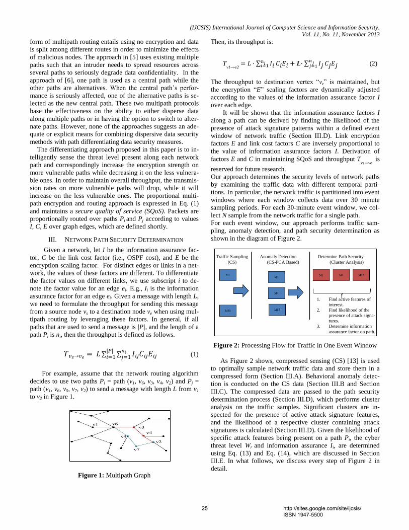
(IJCSIS) International Journal of Computer Science and Information Security,
Vol. 11, No. 11, November 2013
form of multipath routing entails using no encryption and data
is split among different routes in order to minimize the effects
of malicious nodes. The approach in [5] uses existing multiple
paths such that an intruder needs to spread resources across
several paths to seriously degrade data confidentiality. In the
approach of [6], one path is used as a central path while the
other paths are alternatives. When the central path’s perfor-
mance is seriously affected, one of the alternative paths is se-
lected as the new central path. These two multipath protocols
base the effectiveness on the ability to either disperse data
along multiple paths or in having the option to switch to alter-
nate paths. However, none of the approaches suggests an ade-
quate or explicit means for combining dispersive data security
methods with path differentiating data security measures.
The differentiating approach proposed in this paper is to in-
telligently sense the threat level present along each network
path and correspondingly increase the encryption strength on
more vulnerable paths while decreasing it on the less vulnera-
ble ones. In order to maintain overall throughput, the transmis-
sion rates on more vulnerable paths will drop, while it will
increase on the less vulnerable ones. The proportional multi-
path encryption and routing approach is expressed in Eq. (1)
and maintains a secure quality of service (SQoS). Packets are
proportionally routed over paths Pi and Pj according to values
I, C, E over graph edges, which are defined shortly.
III. NETWORK PATH SECURITY DETERMINATION
Given a network, let I be the information assurance fac-
tor, C be the link cost factor (i.e., OSPF cost), and E be the
encryption scaling factor. For distinct edges or links in a net-
work, the values of these factors are different. To differentiate
the factor values on different links, we use subscript i to de-
note the factor value for an edge ei. E.g., Ii is the information
assurance factor for an edge ei. Given a message with length L,
we need to formulate the throughput for sending this message
from a source node vs to a destination node ve when using mul-
tipath routing by leveraging these factors. In general, if all
paths that are used to send a message is |P|, and the length of a
path Pi is ni, then the throughput is defined as follows.
∑ ∑
(1)
For example, assume that the network routing algorithm
decides to use two paths Pi = path (v1, v6, v3, v4, v2) and Pj =
path (v1, v6, v5, v7, v2) to send a message with length L from v1
to v2 in Figure 1.
Figure 1: Multipath Graph
Then, its throughput is:
The throughput to destination vertex “ve” is maintained, but
the encryption “E” scaling factors are dynamically adjusted
according to the values of the information assurance factor I
over each edge.
It will be shown that the information assurance factors I
along a path can be derived by finding the likelihood of the
presence of attack signature patterns within a defined event
window of network traffic (Section III.D). Link encryption
factors E and link cost factors C are inversely proportional to
the value of information assurance factors I. Derivation of
factors E and C in maintaining SQoS and throughput Tvs→ve
is
reserved for future research.
Our approach determines the security levels of network paths
by examining the traffic data with different temporal parti-
tions. In particular, the network traffic is partitioned into event
windows where each window collects data over 30 minute
sampling periods. For each 30-minute event window, we col-
lect N sample from the network traffic for a single path.
For each event window, our approach performs traffic sam-
pling, anomaly detection, and path security determination as
shown in the diagram of Figure 2.
Figure 2: Processing Flow for Traffic in One Event Window
As Figure 2 shows, compressed sensing (CS) [13] is used
to optimally sample network traffic data and store them in a
compressed form (Section III.A). Behavioral anomaly detec-
tion is conducted on the CS data (Section III.B and Section
III.C). The compressed data are passed to the path security
determination process (Section III.D), which performs cluster
analysis on the traffic samples. Significant clusters are in-
spected for the presence of active attack signature features,
and the likelihood of a respective cluster containing attack
signatures is calculated (Section III.D). Given the likelihood of
specific attack features being present on a path Pi, the cyber
threat level Wr and information assurance Ii, are determined
using Eq. (13) and Eq. (14), which are discussed in Section
III.E. In what follows, we discuss every step of Figure 2 in
detail.
1. Find active features of
interest.
2. Find likelihood of the
presence of attack signa-
tures.
3. Determine information
assurance factor on path.
Traffic Sampling Anomaly Detection Determine Path Security
(CS) (CS-PCA Based) (Cluster Analysis)
Tv1→v2
∑ L ∑
(2)
25 http://sites.google.com/site/ijcsis/ ISSN 1947-5500

(IJCSIS) International Journal of Computer Science and Information Security,
Vol. 11, No. 11, November 2013
A. Traffic Sampling
Network packet header, network time, port, protocol, and
flags are collected at each router interface. An event window corresponds to a set of TCP/IP packet records for a path transit-ing a set of subnets or virtual LANs (VLAN) contained within an autonomous system.
For each event window, we first define several notations
used in the process of data sampling and the later discussions.
f: one feature that is abstracted from the network packet
records. When there are multiple features, we also use fi to
denote the i-th feature.
Nf: the total number of features that are of our interest. In
this research, a total of 19 features were extracted from the
captured network packets. These features correspond to a
specific subset of TCP, ICMP, HTTP, OSPF protocol
states which are most often associated with router and host
attacks.
Xf: samples for a feature f in one event window. It records
the number of samples of feature f at different sample mo-
ment. If there are N sample moments, then X is an N–
dimensional column vector.
N: the number of samples that we take for one event win-
dow.
Φ = (X1, X2, … XNf): a N×Nf matrix with the N samples that
are taken for an event window. Here, Xi is represented as a
N-dimensional column vector. Three separate network based suits, namely reconnaissance,
vulnerability scanning, and exploitation, were used in emulat-ing real-world host and network conditions. Each suite pos-sesses a unique signature (Sr). The threat level (Wr) is assigned to each attack suite type, which ranges from 1 for least severe to 5 for most severe. Table 1 shows the detailed information of the network attack suites that we used in this research.
Both compressed and uncompressed data in event windows were used in the analysis. Compressed data in event windows
were created by sampling the uncompressed data in the corre-sponding event window.
B. Data Compression Using Compressed Sensing
Compressed data for each event window are calculated us-
ing the CS technique [12, 13]. The theory of the CS technique is explained as follows.
Compressed sensing relations are listed below. For the ob-
served data x ∈ RN with Q representing the number of non-
zero elements. The value of Q is determined by finding those vectors where the sum of the absolute values of the columns is minimum. This otherwise known as the L-1 norm and repre-sented by 1.
1 subject to Y = Uv x (3)
In Eq. (3) Uv ∈ RM×N
is an M×N orthogonal matrix called the
sensing or measurement matrix, v is a random subset of the row indices, and Y is the linearly transformed compressed data.
We note that the |V| = M and dictates the level of compres-sion which is afforded when the linear transformation is per-formed on Φ .
|V| ≥ Const · µ2(U)·Q · log N (4)
( ) | (5)
Y = Uv x is a linear transformation reducing the data dimen-sionality from N to M with Uv columns normalized to unit norm. If the sparseness of x is considered, a dimension k repre-sents the components with high variance, and M is chosen such that M ≥ k.
From Eq. (4), the CS sampling rate which yields the best results is captured in Eq. (6) where ԑ is a constant proportional to the number of active features and M is the number of sam-ples to be taken.
√ (6)
C. Anomaly Detection
The previous step calculates the compressed data Y from the original traffic data Φ for each event window. Our anomaly detection component detects the event windows that may con-tain traffic with anomalous behavior. In this section, we first describe the detailed steps of this component. Then, we explain the theory behind each step. The anomaly detection component works as follows. The first step performs Principal Component Analysis (PCA) on the compressed data from one event window. I.e., PCA is per-formed on a covariance matrix of Y. The second step applies a residual analysis over the original data Φ and calculates a squared prediction error. If the prediction error for one feature is bigger than a threshold, then that event window is considered to contain anomalous behavior.
The compressed event window is represented by Y in Eq. (7).
Table 1 Network Attack Suites Suite
Signature
( Sr)
Description Active
Features
Threat
Level
(Wr)
1 Cloud Guest Recon-
naissance, Vulnera-
bilities & Exploita-
tion
6
{f1, f2, f3,
f4, f9, f11}
3
2 Cloud Infrastructure
Reconnaissance, Vul-
nerabilities & Exploi-
tation
6
{f1, f5, f6,
f7, f8, f9}
5
3 Cloud Services Re-
connaissance, Vul-
nerabilities & Exploi-
tation
5
{f1, f5, f8,
f9, f10}
4
26 http://sites.google.com/site/ijcsis/ ISSN 1947-5500

(IJCSIS) International Journal of Computer Science and Information Security,
Vol. 11, No. 11, November 2013
(7)
The sampling matrix projects to a residual subspace; however, eigenvalue decomposition of the covariance matrix of x and Y yields near-identical eigenvalue magnitudes from which anomaly detection can be derived [10]. This fact allows one to inspect the compressed data samples, Y, for anomalies reducing the computational complexity to ( ) and storage of the data to ( ) with ( ) This is a substan-tial running time reduction of the PCA analysis over the covar-iance matrix of x, which requires ( ) computations and memory storage of ( )
A residual analysis method [9] decomposes the observed data x (in our case, one row vector in Φ) into principal sub-space which is believed to govern the normal characteristics. Within the residual subspace in which Y resides, abnormal characteristics can be found. The residual method performs the eigenvalue decomposition of the covariance matrix of from which k principle eigenvectors E are obtained. The projection of a data instance onto the residual subspace is
z = (I – EET) (8)
Assuming the data is normal, the squared prediction error is
which follows a non-central chi-square distribution. Anomalous activity is detected when the squared prediction error
exceeds a certain threshold called Q-statistics which is the function of the non-principle eigenvalues in the residual subspace and is approximated by
[ √
( )
]
(9)
where
, ∑
for i = 1, 2, 3,
( ) percentile in a standard normal distribution and ,
and λj, i = 1,…., k are the eigenvalues of the covariance matrix.
Anomalies are detected when the prediction error .
[9]
D. Determination of Path Security
Using the approach discussed in Section III.C, volume-
based anomalous behavior within an event window is identi-fied. Such anomalous behavior provides an indication that an attack may exist within this event window. If anomalous be-havior exists in an event window with high probability, then this component attempts to determine the security level for paths in this event window by using hierarchical clustering techniques described in this section.
Agglomerative hierarchical clustering was chosen as the method for deriving anomalous and baseline models because of its ability to identify clusters without providing an initial esti-mate of the number of clusters present. Agglomerative hierar-chical clustering algorithm iteratively groups data points or clusters of points to form new clusters. Each iteration results in the previously found points and clusters being clustered with another point or cluster. Generally, the results of hierarchical clustering of sizable data sets are a large number of clusters, many of which contain a small fraction of the samples. A
straightforward approach to prioritizing clusters is to eliminate the minor clusters by cutting the hierarchical dendrogram lower tiers.
Once clusters are identified in an event window (Algorithm 1), determination of which clusters contain attack signature features of high magnitude is conducted (Algorithm 1). The path information assurance factor is calculated (Algorithm 2).
In order to lower computational complexity, only those event windows found to have volumetric anomalies in the re-sidual subspace are used in determining network path security. The relative magnitudes and spectral properties of each feature in principal subspace are calculated, and the uncompressed form of each anomalous event window is analyzed. A signature consisting of a distinct collection of significant features is asso-ciated with each attack suite; thus, the nature of significant fea-tures contained within the traffic data of an event window is captured in a hierarchical clustering as illustrated in Figure 3.
Figure 3: Hierarchical Clustering of Data Event Windows, vertical
axis distance, horizontal axis cluster number.
Algorithm 1 is used to generate the clustering dendrogram
as illustrated in Figure 3. Algorithm 1 implements a modified
hierarchical agglomerative clustering algorithm that merges
clusters until a minimum distance threshold between clusters
is reached or all the clusters are merged to only one. When a
minimum distance threshold is used, the algorithm ensures
maximum partitioning of data into feature-rich clusters and
increases the probability that the top-tier clusters contain a full
attack signature feature set.
Algorithm 1 takes as input (1) SSigattack, the set of attack sig-
natures, each of which consists of several features, (2) Φ with
the N samples, where each sample is a row vector in Φ, and
(3) δ, the distance threshold to stop cluster merging. This algo-
rithm groups the samples in one event window to c clusters
(Lines 3-8). Then, for each cluster, it finds the attack signature
that has the highest probability to match the cluster’s features
(Lines 10-21). The signatures and matching probabilities for
all the clusters are put into SSig and PProb respectively. This
algorithm outputs a triple (C, SSig, PProb) where C[i] is the i-
th derived cluster, SSig[i] contains the attack signature with
the highest probability (in PProb[i]) to match C[i]’s features.
27 http://sites.google.com/site/ijcsis/ ISSN 1947-5500

(IJCSIS) International Journal of Computer Science and Information Security,
Vol. 11, No. 11, November 2013
In this algorithm, c represents the total number of clusters
found so far, and is initialized to 0 (Line 2). Di is a cluster that
is being processed. Initially, Di is initialized to contain the i-th
sample in one event window. C is the set of clusters finally
derived, and is initialized as an empty set.
Algorithm 1: SignatureMatchProb(SSigattack, Φ, δ)
1 begin
2 initialize c = 0; C={}; D = {Di, …, DN} where Di is the i-th sample;
3 do /*merge cluasters*/
4 c = c + 1
5 find the two nearest clusters Di and Dj from D
6 merge Di and Dj to a new cluster and insert the new cluster to C
7 until dist(Di, Dj) > δ
8 end do
9 i = 0; PProb={}; SSig={};
/* for each cluster, find the attack signature
which matches this cluster’s features with the highest probability*/
10 for each cluster Di ( C) do
11 k=0; maxProbi=0; maxProbSigi ={};
12 for each attack signature Sk ( SSigattack)
13 Hi = extract features from Di that also exist in Sk
14 Ni = # of Hi feature with conditional entropy higher than H(F)
15 Nk = # features in Sk
16 if(Ni/ Nk> maxProbi)
17 maxProbi= Ni/ Nk
18 maxProbSigi = Sk
19 end if
20 k = k + 1
21 end for
22 PProb = PProb {maxProbi}
23 SSig = SSig {maxProbSigi}
24 i = i+1;
26 end for
27 return (C, SSig, PProb);
28 end
________________________________________________________
Lines 3-8 merges samples to c significant clusters. This cluster
merging process stops when the minimum distance between
two nearest clusters exceeds the distance threshold δ. In find-
ing the nearest clusters from all the existing ones, both Ward
and complete linkage methods can be utilized. Past research
[20] showed that the complete linkage method Eq. (10) yields
the best ratio between the within group sum of squares
(WGSS) and between groups sum of squares (BGSS); thus,
indicating tighter grouping between inter-cluster members and
optimal cluster-to-cluster spacing.
( ) ( ) Di , Dj } (10)
For each cluster Di out of the c clusters in C, Lines 10-21,
calculate the probability that its features match every attack
signature. The details of the signature matching are omitted in
the algorithm for simplicity purpose. We discuss the details
here. Identifying feature matches is performed by measuring
the entropy for each feature within an event window. As Fig-
ure 4 indicates, the entropy of an individual significant feature
fj increases when attack suite traffic is injected into the net-
work.
Figure 4: Features and entropy relationships.
The average entropy for features in the baseline traffic H(F)
is
( ) ∑ ( )
( ) ( )
The average conditional entropy for features in anomalous
traffic is
( ) ∑ (
) (
)
(12)
It is important to only classify valid clusters. Only clusters
with active feature frequencies greater than 2% of the total
number of samples in an event window become candidates for
classification. In addition, of the candidate clusters those with
the largest cophenetic distances and highest inconsistency fac-
tor are selected for feature entropy comparisons.
A feature f’k appearing in anomalous traffic is significant
if H(F’| ) is greater than H(F). Significant features are sub-
sequently used in determining the probability that a cluster is
associated with a specific attack suite
D1 D2 D5 D9
f1 x x x x
f2 x x x x
f3 x x x
f9 x x
Figure 5: Attack Signature Matching Probabilities
Let us look at an example for signature matching proba-
bilities. Assume that we are given an attack signature Sk (
SSigattack) which consists of four features, f1, f2, f3, f9, i.e., Sk
={f1, f2, f3, f9}. Algorithm 1 finds clusters and extracts the fea-
tures that exist in Sk. As shown in Figure 5, for candidate clus-
ters D1, D2, D5 and D9, the algorithm founds matching features
H1 ={f1, f2, f9}, H2 ={f1, f2, f3}, H5 ={f1, f2, f3}, and H9 ={f1, f2,
f3, f9}. They all have high (>=75%) feature matches to Sk.
Among these four clusters, D9 has the highest feature match
probability (100%). I.e., all the four features in the attack sig-
nature Sk exist in cluster.
After calculating the signature matching probability
(Lines 13-16), the attack signature with the highest feature-
28 http://sites.google.com/site/ijcsis/ ISSN 1947-5500

(IJCSIS) International Journal of Computer Science and Information Security,
Vol. 11, No. 11, November 2013
matching probability is recorded by maxProbSigi (Line 18)
and the matching probability is recorded by maxProbi (Line
17). When the highest matching probability maxProbi and the
matching attack signature maxProbSigi for each cluster is
found, they are put into sets PProb and SSig, respectively
(Line 22-23).
E. Calculate Assurance Level for a Path
Once the set of clusters C are derived and probabilities of
the presence of specific signatures in those clusters (PProb
and SSig) are calculated, the path information assurance factor
Ii for network path Pi is calculated using Eq. (13) and Eq. (14).
Based on domain specific cyber security threat models [30],
for each cyber threat level Wi, and a corresponding traffic
threat signature Si present in an event window, the likelihood
of cyber threat signatures being present is high if both Wi and
Prob(Si) are high. For a path Pi , which consists of c clusters
(discovered in the previous step), we can sum up the threat for
each cluster (Eq. (13)). Then the information assurance factor
Ii for Pi is derived using Eq. (14):
∑ ( )
(13)
(14)
Algorithm 2 calculates the information assurance factor I
for a path by utilizing Eq. (13) and (14).
Algorithm 2: PathInfoAssuranceLevel(C, SSig, PProb, Wr) 1 initialize O = 0; i=1;
2 begin
3 for the i-th cluster Di in C
4 Calculate its corresponding threat level Wi using
its attack signature Si ( SSig) and threat level Wr
5 Get its highest feature-matching probability Probi ( PProb)
6 O = O + Wi × Probi /* According to Eq. (12) */
7 i = i + 1
8 end for
9 I = 1/O /* According to Eq. (14) */
10 return I
11 end
________________________________________________________
The path information assurance factor Ii is calculated in Line
9.
F. Summary of Methodology
As mentioned in Section III.A, a total of 19 features were
extracted from the packet records. Network traffic, which con-
sists of the packet records, is partitioned into 30-minute event
windows. For each 30-minute event window, a traffic feature
frequency matrix Φ is extracted to contain the samples of the
19 features.
Algorithm 3 summarizes the complete algorithm to calcu-
late the information assurance measurement I for each event
window. It takes three parameters as input. The first parameter
is the N×Nf sample matrix Φ for an event window. Its traffic
data is composed of the baseline traffic and anomalies. The
second parameter is the set of attack threat signature SSigattack.
It consists of S signatures. The third parameter is the threat
level Wr.
Algorithm 3: PathInfoAssurance(Φ, SSigattack, Wr)
1 Uv ← GetSensingMatrix(N, M)
2 Y ← CSSample(U, M, Φ ) /* Section III.A*/
3 {Z1, …., ZNf } ← DetectAnomalies(Φ, Y) /* Section III.B*/
4 if Zi ({Z1, …., ZNf}) s.t. > then
5 (C, SSig, PProb) ← SignatureMatchProb (Φ, SSigattack, δ) /*Alg. 1*/
6 I ← PathInfoAssuranceLevel(C, SSig, PProb, Wr) /*Alg. 2 */
7 Store(Y)
8 else
9 Store(Y)
10 end if
_______________________________________________________
The algorithm works as follows. In Line 1, the sampled da-ta (feature frequency matrix) Φ is used to generate a CS sens-ing matrix Uv (, which is a M×N matrix). In Line 2, Φ and the sensing matrix Uv are multiplied to produce Y, an M×N
f matrix
using Eq. (3). In Line 3, the volume-based anomaly detection is performed on each column of the Y matrix, and the correspond-ing prediction error
is returned. In Line 4, if there exists any feature’s prediction error
>Qβ, it means that there is the likelihood that attack signatures are present in Φ. Then, Φ is analyzed for the presence of attack signatures (Line 5). Oth-erwise, the event window that produces Φ is determined to have a low probability of containing malicious content and is stored in compressed form for possible future analysis. In Line 5, the signature-matching component is called to determine the probability of the presence of specific attack signatures in this event window. It produces the attack signatures SSig, data clus-ters C, with highest signature presence of PProb. In Line 6, the information assurance value I for a path Pi is calculated using the set of signatures SSig, and their corresponding matching probability (in PProb) to attack signatures.
G. Complexity and Efficiency Gains
The overall computational complexity of PathInfoAssur-
ance expressed in Big O notation is as follows. Let N be the
number of samples, θ be the number of non-sparse compo-
nents, c be the number of clusters, S be the number of attack
signatures, and ( ).
GetSensingMatrix ( )
CSSample ( ) DetectAnomalies ( )
29 http://sites.google.com/site/ijcsis/ ISSN 1947-5500

(IJCSIS) International Journal of Computer Science and Information Security,
Vol. 11, No. 11, November 2013
SignatureMatchProb ( ) PathInfoAssuranceLevel ( )
The following assumptions are considered when performing
complexity analysis:
1. The number of signatures S can grow very large. 2. DetectAnomalies and its predecessors must always be
run in order to detect zero-day attack behaviors within
an event window. 3. The accuracy of DetectAnomalies is assumed high
enough that SignatureMatchProb is executed only
when anomalies are detected.
Taking into consideration that M and c are small while N is
very large, the computational complexity lies primarily in Get-
SensingMatrix, CSSample , and SignatureMatchProb. As it is
assumed that DetectAnomalies and its predecessors must pro-
cess each event window, the principal savings come when no
anomalies are detected and it is subsequently unnecessary to
call SignatureMatchProb.
IV. RESULTS
In this section, Section IV.A presents the strategies to collect traffic data and analyzes the characteristics of the network traf-fic. Section IV.B discusses the effect of applying the CS tech-nique. Section IV.C then shows the accuracy of our presented approach. Section IV.D explains the gains in running time of our approach.
A. Characterization of Sample Data
The goal of this research was to accurately model threats
encountered by modern cloud service providers and clients.
The most often used data sets, DARPA/Lincoln Labs packet
traces [26], [27] and the KDD Cup data set derived from them
[28], are found to be inadequate for such modeling as they are
both over a decade old and do not contain modern threats.
These data sets containing synthetic data that do not reflect
contemporary attacks, and have been studied so extensively
that members of the intrusion detection community find them
to be insignificant [29]. For these reasons, the data sets used in
this research consists of contemporary cloud service provider
attacks generated on large scale test networks. In order to establish the ground truth to evaluate the accura-
cy of anomaly detection, we conducted an analysis of the traf-fic in a baseline event window B, which is free of attacks, and the same window’s traffic Φ, which is injected with attack data. In particular, the baseline traffic event windows B without anomalies were fully sampled and descriptive statistics (e.g., mean, standard deviation, correlations) were calculated. Then, router and host node attacks were singly launched on the net-work where they were fully sampled. Descriptive statistics and signatures for each attack were calculated. This information established the ground truth for later analysis. The router and host attacks were injected into the baseline data in a random Poisson distribution to form anomalous event windows Φ.
Compressed event windows were assembled via compressed sensing of individual anomalous event windows.
We analyzed the characteristics of the normal baseline traf-fic data B and the traffic data with injected malicious traffic Φ. This analysis was conducted prior to CS sampling and subse-quent path information assurance level determination. Exam-ples of 30-minute event windows for B and Φ are shown in Figures 6 and 7. For the event window B with normal traffic (i.e., baseline), we plotted in Figure 6 the percentage of the frequencies of principal features.
Figure 6: Baseline Data Free of Attacks (B),
vertical axis percentage, horizontal samples.
These features are ICMP redirect (feature f1), HTTP reset
(feature f2), and synchronization (feature f3) packets.
Table 2 Principal Features for Baseline Network Traffic
Feature Indicator
f1 ICMP Redirect
f2 TCP http [RST]
f3 TCP http [SYN, ACK]
The principal features for the baseline data (in normal traf-
fic) all showed a large measure of variance over the sampling period. The large variance measurements indicate that these features can be adequately sensed during the CS sampling pro-cess. For the traffic data Φ in an event window with anomalous behavior, we plotted the percentage of major features in Figure 7.
Figure 7: Baseline Data Plus Injected Attacks (Φ),
vertical axis percentage, horizontal samples.
30 http://sites.google.com/site/ijcsis/ ISSN 1947-5500

(IJCSIS) International Journal of Computer Science and Information Security,
Vol. 11, No. 11, November 2013
Figure 7 shows that the number of significant features in Φ
increased, due to the addition of abnormally high Border
Gateway Protocol (BGP), HTTPS, OSPF, and SSH protocol
traffic resulting from router and host attack network traffic.
Figure 7 also shows that the variance for each feature is also
relatively high which indicate that CS sampling can effectively
capture data patterns.
Table 3 Principle Features for Network Traffic
with Attacks
Feature Indicator
f1 ICMP Redirect
f2 TCP http [RST]
f3 TCP http [SYN, ACK]
f6 TCP bgp [RST, ACK]
f7 TCP ospf-lite [RST, ACK]
f9 TCP https [RST, ACK]
f11 TCP ssh [RST, ACK]
f12 TCP telnet [RST, ACK]
Attack signature data was characterized prior to pro-
cessing. A router attack signature is shown in Figure 8, which
indicates that features f2, f6, f7, and f9 are significant features.
Figure 8: Router Attack Signature,
vertical axis percentage, horizontal samples.
B. Effect of Compressed Sensing (CS)
Using FFT generated frequency components of Φ to gen-
erate the sampling matrix , the restricted isometric constant
(RIC) δk with θ representing non-sparse components, was kept
very small. Keeping δk small guaranteed good linear transfor-
mation of Φ and high orthogonality of columns in .
( ) ≤
( ) (15)
The dimension M was optimally determined by using Eq.
(6), and the error rate was measured. Because is highly
orthogonal, the geometry preserving properties allow for the
detection of volumetric anomalies in the residual subspace.
The largest eigenvalues constituting 90% of the spectral pow-
er. With a probability of 1- conf where conf ( [0,1]) is the
confidence interval, the changes in the eigenvalues between
residual (ᴈi) and principle (λi) subspaces equal to | λi - ᴈi | and
are bound by:
√ (√
√
) (16)
Where is the largest eigenvalue found in the residual sub-
space, i = 1,.., nv.
The false alarm rate ∆F is bound by:
(√
√
) (17)
Traditionally, the confidence threshold 90% is used which
makes the √
term small when compared to√
. Thus,
a smaller M increases the probability of a false alarm and also
increases the compression error rate [10]. The obvious ad-
vantage in using a smaller M was a lower computational over-
head. Accordingly, M was chosen such that the intrinsic
sparseness of represented by √ in Eq. (6) yields the
lowest compression error with √ The optimal derivation of the constant in Eq. (6) was
achieved by identifying those feature components of x that had
the highest variance and magnitudes. The value of was found
to be directly proportional to the number of active features.
The compression mean squared error (MSE) was verified by
measuring the error contained in convex optimized reconstruc-
tion.
Figure 9: CS Reconstruction, Baseline + Injected Attacks
(G ← Y), vertical axis frequency, horizontal samples.
(a) M/N vs. % MSE (b) M/N vs. Exe Time (Sec)
Figure 10: Compression ratio M/N versus MSE where N is the
number of samples (without CS) and M is the number of sam-
0
2
4
6
8
10
0.24 0.25 0.26 0.27 0.28
80
85
90
95
100
105
0.24 0.25 0.26 0.27 0.28
31 http://sites.google.com/site/ijcsis/ ISSN 1947-5500

(IJCSIS) International Journal of Computer Science and Information Security,
Vol. 11, No. 11, November 2013
ples (with CS) (a) Recovered data fidelity and (b) Execution
Time.
Figure 11 shows the values calculated from the base-
line and anomalous event windows.
(a) Baseline (b) Anomalous
Figure 11: Detected Anomalies: QB – horizontal line Q-Statistics
threshold; horizontal axis represents network traffic features; vertical
axis .
The values for the baseline network traffic features
are all less than the QB, Q-Statistics threshold indicating an
absence of network attack traffic (a). Figure 11(b) shows
values which is greater than QB indicating an increase in the
number and magnitude of network traffic attack features and a
high possibility that network attack traffic is present in the
event window.
Table 4 shows the relationships exhibited between opti-
mally derived values for M, associated error, false positive
alarm rate, and execution time for a 24 hour testing period
with attack suites 1-3 randomly injected in a Poisson distribut-
ed. Each of the 3 attack suites discussed in Table 1 was ana-
lyzed resulting in an average effective anomaly detection per-
formance greater than 93%.
Table 4 Anomaly Detection Accuracy
Attack
Suite
No. of
instances
Detected
False
Pos.
False
Neg. 1 5269 4894 12 10
2 8020 7575 24 27
3 2920 2802 12 5
C. Overall Accuracy
The following table summarizes the observed accuracy of
Algorithms 1, 2, and 3 in correctly detecting event window
anomalies and in performing subsequent classifications.
Table 5 Cluster Signature Probability Accuracy
Attack
No. of
No. of
Classified
Avg. Threat
Suite Attack instances
Forwarded Attack
instances
Instances with
> 90%
Confidence
Measure % Accura-
cy
1 5269 4894 4635 87.96%
2 8020 7575 7194 89.70%
3 2920 2802 2703 93.14%
Out of a total of 16,209 attack instances, residual sub-
space anomaly detection correctly sensed 94.21% and for-
warded those attack instances for subsequent classification.
From the set of forwarded attack instances, Algorithm 1 cor-
rectly classified 95.16% with an average confidence greater
than 90%. In total, the DetectAnomalies-SignatureMatchProb
chain identified an average of 90.27% of all attack instances
injected along network paths with an average probability of
correct match greater than 90%.
D. Efficiency
Figure 12 illustrates the efficiency gains derived when
SignatureMatchProb is not called. The vertical axis represents
the execution time in seconds while the horizontal axis repre-
sents the ID of the data sets presented to the system. To illus-
trate the efficiency gains, each data set was presented to the
chain initially without removing non-anomalous event win-
dows. Then the same data set was presented to the chain, but
allowing non-anomalous windows to be dropped prior to clas-
sification. In the case of first data set, two out of the four event
windows were dropped, which leads to the corresponding effi-
ciency gain of 50% in the signature classification phase. Simi-
lar efficiency gains were recorded for all data sets.
Figure 12: CS Anomaly detection and Signature Classification:
horizontal axis represents tested data sets; vertical axis is run
time in seconds.
Summarizing, an acceptably high percentage of attack in-
stances were detected by anomaly detection (94.21%) of
which 95.16% of these forwarded instances were associated
with attack suite signatures with high confidence. Overall effi-
ciency gains of over 50% were observed when non-anomalous
event windows are dropped prior to classification. Additional-
ly, using this unique combination of methods, the information
assurance factor Ii on any path Pi was derived with greater
than 90% confidence.
15 15 13 13 14 14 18 18 16 16
25 14.5 27
18 24 6
24 12 23 17.25
0
50
1 1 2 2 3 3 4 4 5 5
Classification
AnomDetection
2/4 3/4 1/4
2/4 2/4
32 http://sites.google.com/site/ijcsis/ ISSN 1947-5500

(IJCSIS) International Journal of Computer Science and Information Security,
Vol. 11, No. 11, November 2013
V. CONCLUSION
In this paper, we studied the problem of determining the in-
formation assurance level for different paths in multipath net-works. We showed it was possible to intelligently sense and quantify threats along individual paths with a high degree of confidence. In the process, we devised a novel approach that combines optimal network data sampling (CS) with residual subspace PCA anomaly detection and probabilistic signature-based intrusion detection. This methodology was shown to simultaneously compress sampled network traffic and reduce data dimensionality by filtering out non-contributing network traffic features. On the compressed and dimension-reduced data set, our approach efficiently performs path threat detection and classification. This approach increases the efficiency and data handling capabilities of both the anomaly and signature-based detection algorithms.
We also derived a theoretical multipath SQoS relation, Eq. (1). This relationship allows for the dynamic adjustment of security measures along each path and maintains the overall throughput at the same time. The determination of the security measures using our newly developed approach solves the most technically challenging portion of the multipath SQoS relation Eq. (1). Our approach and the multipath SQoS relations lay a solid foundation for the future expansion of adaptive multipath security approaches.
REFERENCES
[1] Youcef Begriche, Houda Labiod, “A Bayesian Statistical Model for a
Multipath Trust-based Reactive Ad hoc Routing Protocol”, 2009.
[2] Stefano Paris, Cristina Nita-Rotaru, Fabio Martignon and Antonio Capone, “Cross-Layer Metrics for Reliable Routing in Wireless Mesh Networks”, 2009.
[3] Patrick P. C. Lee, Vishal Misra, and Dan Rubenstein, “Distributed Algorithms for Secure Multipath Routing”, 2004.
[4] Xia Wei-wei, Wang Hai-feng, “Prediction Model of Network Security Situation Based on Regression Analysis”, 2010.
[5] “SPREAD: Improving Security by Multipath Routing”, 2003.
[6] Zhi Li and Yu-Kwong Kwok, “A New Multipath Routing Approach to Enhancing TCP Security in Ad Hoc Wireless Networks”, 2004.
[7] Wenjing Lou and Yuguang Fang “A Multipath Routing Approach For Secure Data Delivery”, 2001.
[8] Zhi Li and Yu-Kwong Kwok Department of Electrical and Electronic Engineering The University of Hong Kong, “A New Multipath Routing Approach to Enhancing TCP Security in Ad Hoc Wireless Networks”, 2011.
[9] J. Edward Jackson and Govind S. Mudholkar Eastman Kodak Company , “Control Procedures for Residuals Associated With Principal Component Analysis”, 1979.
[10] Duc-Son Pham, Svetha Venkatesh, Mihai Lazarescu, Saha Budhaditya, “Anomaly detection in large-scale data stream networks”, 2012.
[11] Piotr Indyk and Eric Price, “K-Median Clustering, Model-Based Compressive Sensing, and Sparse Recovery for Earth Mover Distance”, 2011.
[12] Francis Bach and Rodolphe Jenatton, “Convex Optimization with Sparsity-Inducing Norms”, 2010.
[13] Emmanuel Cand´es, “The uniform uncertainty principle and compressed sensing”, 2008.
[14] Z. Ben-Haim, T. Michaeli, and Y. C. Eldar, “Performance bounds and design criteria for estimating finite rate of innovation signals”, January 2010.
[15] T. Blumensath and M. Davies, “Iterative hard thresholding for compressive sensing”, 2009.
[16] E. Cand`es and T. Tao, “Near optimal signal recovery from random projections: Universal encoding strategies?” IEEE Trans. Inform. Theory, 52(12):5406–5425, 2006.
[17] R. Coifman and M. Maggioni, “Diffusion wavelets”, 2006.
[18] Daniela Brauckhoff, Xenofontas Dimitropoulos, Arno Wagner, and Kavé Salamatian, “Anomaly Extraction in Backbone Networks Using Association Rules”, 2012.
[19] Michael Linderman, “An Introduction to Rclusterpp”, 2011
[20] Michael Steinbach, George Karypis, Vipin Kumar, “A Comparison of Document Clustering Techniques”, 2010.
[21] Mahlet G. TADESSE, Naijun SHA, and Marina VANNUCCI, ” Bayesian Variable Selection in Clustering High-Dimensional Data”, 2005.
[22] Charu C. Aggarwal, Joel L. Wolf, Philip S. Y, “Fast Algorithms for Projected Clustering, 2006.
[23] Vikneswaran Gopal, George Casella, “bayesclust: An R Package for Testing and Searching for Significant Clusters, 2012.
[24] Udaya Tupakula, Vijay Varadharajan, Naveen Akku, “Intrusion Detection Techniques for Infrastructure as a Service Cloud”, 2011.
[25] Liu Hui, “Research Intrusion Detection Techniques from the Perspective of Machine Learning”, 2010.
[26] R. Lippmann, R. K. Cunningham, D. J. Fried, I. Graf, K. R. Kendall, S. E. Webster, and M. A. Zissman, “Results of the 1998 DARPA Offline Intrusion Detection Evaluation,” in Proc. Recent Advances in Intrusion Detection, 1999.
[27] R. Lippmann, J. W. Haines, D. J. Fried, J. Korba, and K. Das, “The 1999 DARPA Off-line Intrusion Detection Evaluation,” Computer Networks, vol. 34, no. 4, pp. 579–595, October 2000.
[28] “KDD Cup Data,” http://kdd.ics.uci.edu/databases/kddcup99/ kddcup99.html.
[29] M. V. Mahoney and P. K. Chan, “An Analysis of the 1999 DARPA/Lincoln Laboratory Evaluation Data for Network Anomaly Detection,” in Proc. Recent Advances in Intrusion Detection, 2003.
[30] Jerry Archer, “Top Threats to Cloud Computing V1.0,” Cloud Security Alliance, 2010.
[31] Javier Diez, Marcelo Bagnulo, Francisco Valera and Ivan Vidal, “Security for Multipath TCP: a constructive approach”, in Int. J. Internet Protocol Technology, Vol. 6 No. 3, pp. 148-150, November 2011.
AUTHORS
James Obert the principle author, joined Sandia National Labs in 2009 as a
computer scientist and is actively involved in dynamic network defense and
trusted computing research and development. Prior to Sandia James was involved in cyber research at NASA, HP, and IBM. James received an
M.S.C.S and M.S.E.E from California State University University of Texas
respectively and is currently completing a Ph.D at New Mexico State University.
Huiping Cao received her Ph.D. in Computer Science from the University of Hong Kong. She is an Assistant Professor in Computer Science at New Mexi-
co State University (NMSU). Dr. Cao’s research interests are in the areas of
data mining and databases. She has published data management and data mining articles in highly competitive venues.
Hong Huang received his Ph.D. in Electrical Engineering from Georgia Insti-tute of Technology. He is currently an associate professor with the Klipsch
School of Electrical and Computer Engineering at the New Mexico State
University. Dr. Huang’s current research interests include wireless sensor networks, mobile ad hoc networks, network security, and optical networks.
33 http://sites.google.com/site/ijcsis/ ISSN 1947-5500

(IJCSIS) International Journal of Computer Science and Information Security, Vol. 11, No. 11, 2013
On the Information Hiding Technique Using Least
Significant Bits Steganography
Samir El-Seoud
Faculty of Informatics and Computer Science,
The British University in Egypt,
Cairo, Egypt
Islam Taj-Eddin
Faculty of Informatics and Computer Science,
The British University in Egypt,
Cairo, Egypt
Abstract—Steganography is the art and science of hiding data or
the practice of concealing a message, image, or file within another
message, image, or file. Steganography is often combined with
cryptography so that even if the message is discovered it cannot
be read. It is mainly used to maintain private data and/or secure
confidential data from misused through unauthorized person. In
contemporary terms, Steganography has evolved into a digital
strategy of hiding a file in some form of multimedia, such as an
image, an audio file or even a video file. This paper presents a
simple Steganography method for encoding extra information in
an image by making small modifications to its pixels. The
proposed method focuses on one particular popular technique,
Least Significant Bit (LSB) Embedding. The paper uses the
(LSB) to embed a message into an image with 24-bit (i.e. 3 bytes)
color pixels. The paper uses the (LSB) of every pixel’s bytes. The
paper show that using three bits from every pixel is robust and
the amount of change in the image will be minimal and
indiscernible to the human eye. For more protection to the
message bits a Stego-Key has been used to permute the message
bits before embedding it. A software tool that employ
steganography to hide data inside of other files (encoding) as well
as software to detect such hidden files (decoding) has been
developed and presented.
Key Words—Steganography, Hidden-Data, Embedding-Stego-
Medium, Cover-Medium, Data, Stego-Key, Stego-Image, Least
Significant Bit (LSB), 24-bit color pixel, Histogram Error (HE),
Peak Signal Noise Ratio (PSNR), Mean Square Error (MSE).
I. INTRODUCTION
One of the most important properties of digital
information is its easiness in producing and distributing
unlimited number of its copies (i.e. copies of text, audio and
video data) regardless of the protection of the intellectual
and production rights. That requires innovative ways of
embedding copyright information and serial numbers in those
copies.
Nowadays, the need for private and personal computer communication for sharing confidential information
between two parties has increased.
One such technique to solve the above mentioned
problems is Steganography [11][3]. It is the art of hiding
private information in public information used or sent on
public domain or communication from an unwanted party.
These private information need to be undetectable and/or
irremovable, especially for the audio and video data cases.
The art of hiding messages is an ancient one. Steganography (literally meaning covered writing) is a form of
security through obscurity. For example, a message might
be hidden within an image. One method to achieve that is by
changing the least significant bits to be the message bits. The
term steganography was introduced at the 15th century.
Historically, steganography was used for long time
ago. Messages were hidden (i.e. tattooed) on the scalp of
slaves. One famous example being Herodotus who in his
histories tells how Histiaeus shaved the head of his most
trusted slave and tattooed it with a message which disappeared
once the hair grew back again. Invisible ink has been for quite
some time. Microdots and microfilm technology used after the advance of the photography science and technology.
Steganography hides the private message but not the fact
that two parties are communicating. The process involves
placing a hidden message in a transport medium (i.e. the
carrier). The secret message is embedded in the carrier to form
the steganography medium. Steganography is generally
implemented by replacing bits of data, in regular computer
files, with bits of different, invisible information. Those
computer files could be graphics, sound, text or HTML. The
hidden information can be plain text, cipher text, or images.
In paper [2], the authors suggested an embedding
algorithm, using two least significant bits that minimize the
difference between the old value of the pixel in the cover and
the new value of the pixel in the stego-image in order to
minimize the distortion made to the cover file. Experimental
results of the modified method show that PSNR is greater than
the conventional method of LSBs replacement.
A distinguish between stegnography and cryptography
should be emphasized. Steganography is the science and art
of hiding information from a third party.
Cryptography is the science and art of making data
unreadable by a third party. Cryptography got more attention
from both academia and industry than steganography.
34 http://sites.google.com/site/ijcsis/ ISSN 1947-5500

(IJCSIS) International Journal of Computer Science and Information Security, Vol. 11, No. 11, 2013
Nowadays, steganography is becoming increasingly important
for both military and commercial communities [9].
II. STEGANALYSIS
Steganalysis is the science and art of detecting and
breaking steganography. Examining the color palette is one
method of the steganalysis to discover the presence of hidden
message in an image. Generally, there will be a unique binary
encoding of each individual color. If the image contains
hidden data, however, many colors in the palette will have duplicate binary encodings. If the analysis of the color
palette of a given image yields many duplicates, we might
conclude with high confidence of the presence of hidden
information.
Steganalysts have a tough job to do, because of the vast
amount of public files with different varieties (i.e. audio,
photo, video and text) they have to cover. Different varieties
require different techniques to be considered.
Steganalysis and cryptanalysis techniques can be classified in a much similar way, depending upon the known
prior information:
Steganography-only attack: Steganography medium is
available and nothing else.
Known-carrier attack: Carrier and steganography media
are both available.
Known-message attack: Hidden message is known.
Chosen-steganography attack: Steganography medium
as well as used steganography algorithm are available.
Chosen-message attack: A known message and steganography algorithm are used to create
steganography media for future analysis.
Known-steganography attack: Carrier and
steganography medium, as well as the
steganography algorithm, are available.
In [1] the author urges the steganalysis investigation of the
three least significant bits.
Until recently, information hiding techniques received very
much less attention from the research community and from
industry than cryptography, but this has changed rapidly. The
search of a safe and secret manner of communication is very
important nowadays, not only for military purposes, but also
for commercial goal related to the market strategy as well
as the copyright rights.
Steganography hides the covert message but not the fact
that two parties are communicating with each other. The
steganography process generally involves placing a hidden message in some transport medium, called the carrier. The
secret message is embedded in the carrier to form the
steganography medium. The use of a steganography key may
be employed for encryption of the hidden message and/or for
randomization in the steganography scheme.
III. HOW DOES IT WORK?
Without any loss of generality, the paper will use the
following equation to support us with a general undurstanding
of the steganographic process:
cover_medium + hidden_data + stego_key = stego_medium.
The cover_medium is the file to be used to hide the
hidden_data. A stego_key could be used if an encryption
scheme (i.e. private/public key cryptography) will be mixed
with the steganography process. The resultant file is the
stego_medium, which will be the same type of file as the
cover_medium. In this paper, we will refer to the
cover_image and stego_image, because the focus is on the
image files.
Classification of stenography techniques based on the cover
modifications applied in the embedding process is as follows:
A. Least significant bit (LSB) method This approach [19][6][5][4][14][12] is very simple. In this
method the least significant bits of some or all of the bytes inside an image is replaced with a bits of the secret
message. The least significant bit (LSB) substitution and
masking & filtering techniques are well known
techniques to data hiding in images. LSB is a simple
approach for embedding information in an image.
Replacement of LSBs in digital images is an extremely simple
form of information hiding.
B. Transform domain techniques This approach [7][10] embeds secret information in the
frequency domain of the signal. Transform domain methods hide messages in significant areas of the cover image which
make them more robust to attacks such as: compression,
cropping, and some image processing, compared to LSB
approach.
C. Statistical methods This approach [8] encodes information by changing
several statistical properties of a cover and uses a
hypothesis testing in the extraction process. The above process
is achieved by modifying the cover in such a way that some
statistical characteristics change significantly i.e. if "1" is
transmitted then cover is changed otherwise it is left as such.
D. Distortion techniques In this technique [13][18][17][16] the knowledge of
original cover in the decoding process is essential at the
receiver side. Receiver measures the differences with the
original cover in order to reconstruct the sequence of
modification applied by sender.
35 http://sites.google.com/site/ijcsis/ ISSN 1947-5500

(IJCSIS) International Journal of Computer Science and Information Security, Vol. 11, No. 11, 2013
Pixel 1= 10010101 00001101 11001001
Pixel 2= 10010110 00001111 11001010
Pixel 3= 10011111 00010000 11001011
Pixel 1= 10010100 00001101 11001000
Pixel 2= 10010110 00001111 11001010
Pixel 3= 10011110 00010000 11001011
The simplest approach to hiding data within an image file is
the least significant bit method (LSB). If a 24-bit color is used,
then the amount of change will be minimal and indiscernible
to the human eye.
In [15], authors mixed between strong cryptography
schemes and steganography, the time complexity of the
overall process increases but at the same time the security
achieved at this cost is well worth it. The cryptography
algorithm was used is the RSA public key cryptography
algorithm. The complexity of pure steganography combined
with RSA algorithm (three bits) increases by 15 to 40% in
comparison to two bit pure steganography combined with
RSA. The complexity of Pure Steganography and
steganography combined with Diffie Hellman algorithm is
nearly the same.
In this paper the presented steganography method is based
on the spatial domain for encoding private information in an
image by making small modifications to its pixels. The proposed method focuses on one particular popular technique,
Least Significant Bit Embedding. The paper emphasizes on
hiding information in online image. Example of a software
tool that uses steganography to hide private data inside of
public image file as well as to detect such hidden private data
will be presented. In this paper the cryptography used was
simple symmetric encryption and decryption. One of the main
goals is to show the robustness of using three bits least
significant bits per pixel.
IV. LEAST SIGNIFICANT BIT (LSB) INSERTION
Suppose we have an 8-bit binary number 11111111.
Changing the bit with the least value (i.e. the rightmost bit) will have the least effect on that binary number. That is why
the rightmost bit name is the Least Significant Bit (LSB). The
LSB of every byte can be replaced. The effect on overall file
will be minimal.
The binary data of the private information is broken up into
bits and inserted into the LSB of each pixel in the image file.
One way to implement that insertion is by special
rearrangement of the color bytes. Suppose we have an 8-bit
color image. A stego software tool can make a copy of an image palette. The copy is rearranged so that colors near each
other are also near each other in the palette. The LSB of each
pixel (i.e. 8-bit binary number) is replaced with one bit from
the hidden message. A new color in the copied palette is
found. The pixel is changed to the 8-bit binary number of the
new color.
The number of bits per pixel will determine the number of
distinct colors that can be represented. A 1 bit per pixel image
uses 1-bit for each pixel, so each pixel can be either 1 or 0.
Therefore we will have: 1 bit per pixel=21 = 2 colors, 2 bit per
pixel=22 = 4 colors, 3 bit per pixel=23 = 8 colors, 24 bit per
pixel=224 ≈ 16.8 million colors. In this paper we will assume
that the picture has 24 bit per pixel.
As an example, suppose that we have three adjacent
pixels (nine bytes) with the following encoding (see figure 1):
Fig. 1.
For example, in order to hide the following 8 bits of data
that represents character “H”: 01001000, we overlay these 8
bits over the LSB of the 9 bytes of figure 1 as a
consequence we get the following representation (see figure
2):
Fig. 2. The bits in bold have been changed
Note that we have successfully hid 8 bits at a cost of only changing 3 bits, or roughly 33%, of the LSBs. In this paper,
we are using 24-bit color. Therefore, the amount of change
will be minimal and unnoticeable to the human eye. We will
leave it as a further work to answer the question of what are
the maximum number of bits per pixel that could be used to
embed messages before noticing the difference? (see table 1).
TABLE I.
The mentioned LSB description is meant as an example.
At the case of gray-scale images, LSB insertion works well.
The gray-scale images has the benefit of hiding data in the least and second least significant bits with minimal effect on
the image.
Some techniques of image manipulation could make the
LSB insertion vulnerable. Converting a lossless
compression image (i.e. GIF or BMP) to a lossy
compression image (i.e. JPEG) and then converting them back
can destroy the data in the LSBs.
Message
Bit
1st
LSB
Effects
on
pixel
2nd
LSB
Effects
on
pixel
3rd
LSB
Effects on
pixel
0 0 None 0 None 0 None
1 1 None 1 None 1 None
0 1 -1 1 -256 1 -65536
1 0 +1 0 +256 0 +65536
36 http://sites.google.com/site/ijcsis/ ISSN 1947-5500

(IJCSIS) International Journal of Computer Science and Information Security, Vol. 11, No. 11, 2013
V. ENCODING AND DECODING STEPS IN (LSB)
Section (5.1) show the steps needed to get and set LSB bits
of very byte. Section (5.2) show the steps required to create
the stego file. Figure 4 represents the flow chart of the
encoding algorithm used in this paper. The decoding algorithm works in the opposite way round and the flow chart
for the decoding algorithm is given in figure 5.
A. Get and set bits at LSB algorithm (see figure 3) For each byte of the message, we have to:
1) Grab a pixel.
2) Get the first bit of the message byte. 3) Get one color component of the pixel.
4) Get the first bit from the color component.
5) If the color-bit is different from the message-bit,
set/reset it.
6) Do the same for the other seven bits.
B. Create stego file 1) Open the cover file into stream.
2) Check if the cover file is bitmap file.
3) Check if the cover file bitmap is 24 bits.
4) Write the header of cover file to stego file (new
stream)
5) Add the length of message at the first (4) bytes of
stego file (new stream)
6) Encrypt the message using simple symmetric
encryption key.
7) Hide the message by using LSB algorithm (i.e. get
and set).
Fig. 3.
Fig. 4. Encoding Algorithm
37 http://sites.google.com/site/ijcsis/ ISSN 1947-5500

(IJCSIS) International Journal of Computer Science and Information Security, Vol. 11, No. 11, 2013
C. Example (Please revise the previous section of least significant bit (LSB) insertion)
Plain Message character:H=72
Key=55
Encrypted Message character =127
01001000
00110111 XOR
01111111
Encrypted Message character=127
Get the first bit of encrypted message
Get the first byte in the cover image of
Pixel1
Set the first bit of the encrypted
message in the (LSB) of the first byte
of the cover image of Pixel 1.
Resulted first byte of Pixel1
01111111
00000001 AND
00000001
11001001
11001001
11111110 AND
11001000
00000001 OR
11001001
Encrypted Message character=127
Get the second bit of encrypted
message
Shift right once to put the second bit
as (LSB)
Get the second byte in the cover
image of Pixel1
Set the shifted second bit as (LSB) of
the encrypted message in the (LSB) of
the second byte of the cover image of
Pixel 1.
Resulted second byte of Pixel1
01111111
00000010 AND
00000010
00000001
00001101
00001101
11111110 AND
00001100
00000001 OR
00001101
Encrypted Message character=127
Get the third bit of encrypted
message
Shift right twice to put the third bit as
(LSB)
Get the third byte in the cover image
of Pixel1
Set the shifted third bit as (LSB) of the
encrypted message in the (LSB) of the
third byte of the cover image of
Pixel 1.
Resulted third byte of Pixel1
01111111
00000010 AND
00000100
00000001
10010100
10010100
11111110 AND
10010100
00000001 OR
10010101
Original Pixel 1= 10010100 00001101 11001001 Resulted Pixel 1= 10010101 00001101 11001001
Continue as above for the rest of the bits of the
encrypted message characters.
Fig. 5. Decoding Algorithm
38 http://sites.google.com/site/ijcsis/ ISSN 1947-5500

(IJCSIS) International Journal of Computer Science and Information Security, Vol. 11, No. 11, 2013
The C#-functions for getting and setting single bit are simple:
private static bool GetBit(byte b, byte position)
{return ((b & (byte)(1 << position)) != 0);}
private static byte SetBit(byte b, byte position,
bool newBitValue)
{byte mask = (byte)(1 << position); if(newBitValue){
return (byte)(b | mask);}
else
{return (byte)(b & ~mask);}
}
A proposed Pseudo-code for hiding messages:
A proposed Pseudo-code for extracting hidden messages:
VI. EXPERIMENTS
This Section explains the steganography application in order
to encode a text message into image file and decode that
message from the stegano file.
The following figure shows the Main Menu screen with three
buttons: the two buttons in the upper side of the screen used for
encrypting and decrypting a text message into image file, the
third button in the middle of lower side of the screen is used for
encrypting and decrypting images.
By pressing the Encrypt Text File text box button or Dealing
With Images text box button will lead you to the first screen
of the encoding process, after you finish the encoding process
click the button in the upper right side of the screen Decrypt
The Stegano File to continue the decoding process.
A. Encoding: 1) Step 1
In the first step, insert the path of the required image to be
encoded in the “Source Image File” text box, or click the
Browse button to select it. The selected image could be seen
in the “Source Image Preview” picture box (see figure 7).
The application shows the image size in bytes in the
“Image Size” text box, and it also shows how many bytes you
can hide inside this image. The maximum number of bytes you could hide will be displayed in the text box "You can hide up to" (see figure 7). Click button Next to proceed to the next
step.
Fig. 6. Main menu screen
Fig. 7. Encoding screen (step 1)
39 http://sites.google.com/site/ijcsis/ ISSN 1947-5500

(IJCSIS) International Journal of Computer Science and Information Security, Vol. 11, No. 11, 2013
2) Step 2 In the next step two options are available (see fig. 8):
a) Either write the required text message to be hide in
the image in the text box shown on the screen.
b) Or select the file that contains the text message to be
hide in the image by clicking the button Browse
and insert the path in the text box "File Name".
The number of bytes to be encoded in the image will be displayed in the text box "No. of Bytes". Click button "Next"
to proceed to the next step.
3) Step 3 In the third step (see fig. 9) type the output image name
that contains the encoded message in the text box "Stego File Name", and a security password in the text box "Password".
Finally, click button "Finish" to create the target file and
go to the next step.
Here below is the encoded message (text) into the source
image
4) Step 4 At this screen (see fig. 10), a comparison between the
original image before encoding (Cover Image) and the output
image after encoding (Stego Image) could be seen by the
naked eye.
Click button "Close" when finishing comparison.
If the button "Decrypt The Stegano File" at the Main
Menu screen (Figure 6) had been pressed, then the next screen
will leads the user through two steps to complete the decoding
stage. These two steps are explained below:
B. Decoding: 1) Step1
At this stage, the encoded message with the given stegofile
name is stored in main directory with the current path.
Now go to the main menu (see fig. 6) and click, this time, the
button “Decrypt”. Click button "Browse" to select the new
created image (encoded image) and the application will show the encoded image size in bytes in the text box "Stego Image Size". Also the encoded image will be shown in the
Fig. 8. Encoding screen (step 2)
Fig. 9. Encoding screen (step 3)
Fig. 10. Encoding screen (step 4)
40 http://sites.google.com/site/ijcsis/ ISSN 1947-5500

(IJCSIS) International Journal of Computer Science and Information Security, Vol. 11, No. 11, 2013
picture box "Stego Image Preview". Type the same password
that entered while encoding that message (see Figure 9). You
will be popped by the screen in figure 11.
2) Step 2 In this step, click the button "Decode" to decode the
message. The encoded message will be extracted and will be
shown in text box "The Extracted Message" (see fig. 12).
Either save the message to a file by pressing the button
"Save To File" or clear the message shown by pressing the
button "Clear". Click button "Exit" to exit the
application.
C. Results of Experiments Many changes could happen to an image due to applying
stenography techniques. Some of the finer details in the image
can be sacrificed due to embedding of a message. That
corruption to the original image is acceptable as long as the
error between the original and the stenography image is
tolerable. Three error metrics have been used in this paper to
compare the various image differences between original image
and stenography image techniques and to measure the degree
of corruption. These three error metrics are:
1) The Mean Square Error (MSE) is the mean of the cumulative
squared error between the stenography and the original image.
Given a noise-free m×n monochrome image I (i.e. original image) and its noisy approximation K (i.e. stenography
image), MSE is defined as:
A lower value for MSE means lesser error. So, it is a
target to find an image stenography scheme having a
lower MSE. That will be recognized as a better stenography.
2) The Peak Signal to Noise Ratio (PSNR) is a measure of the
peak error. (PSNR) is usually expressed in terms of the logarithmic decibel scale. (PSNR) is most commonly used to
measure the quality of stenography image. The signal in this case is the original data, and the noise is the error introduced
by stenography. PSNR is an approximation to human perception of stenography quality. Here, MAXI is the
maximum possible pixel value of the image. When the pixels are represented using 24 bits per sample, then MAXI
=16777215 (224
).
From the above equations, there are an inverse
relation between the (MSE) and (PSNR), this
translates to a high value of (PSNR). The higher the value
of (PSNR), the better is the stenography. 3) The Histogram Error (HE) is an image histogram (HE) is a
chart that shows the distribution of intensities in an indexed or grayscale image. The images used in this paper are
colored. In order to work on all the color channels, the colored images will be stretched into vectors before doing
image histogram function. The image histogram function creates a histogram plot by making equally spaced bins, each
representing a range of data values (i.e. grayscale). It then calculates the number of pixels within each range.
HE shows the distribution of data values. We intend to find the similarity of two images by measuring the
histogram error (HE) between them. The smaller the (HE), the
closer the similarity. It is calculated by measuring how far are
Fig. 11. Decoding screen (step 1)
Fig. 12. Decoding screen (step 2)
41 http://sites.google.com/site/ijcsis/ ISSN 1947-5500

(IJCSIS) International Journal of Computer Science and Information Security, Vol. 11, No. 11, 2013
the differences between two normalized histograms that
belong to two different images, from each other. That could
happen by subtracting the two normalized histograms vectors
from each other and then squaring the resulted vector. There
exist an inverse relationship between the value of (HE) and
how close the two normalized histograms are to each others.
It implies that the smaller the (HE) the closer to each other are
the images. Let the two histogram images Im1 (i.e. original
image) and Im2 (stenography image) be denoted by Im1 and Im2, respectively, and assuming the two images having the
same m×n size. Calculate the Normalized Histograms hn1 and
hn2 of Image 1 and Image 2, then finally calculate (HE) as the
following:
,
The following figure 13 and figure 13a are an example of
an image and it’s Histogram:
The experiment will be done by comparing (the original
image vs. the stegoimage) against (the original image vs.
corrupted original image) in order to discover how far is the
stegoimage from the original image.
The corrupted original image will be calculated by
adjusting the matrix entries of the original image (X) by a factor
of (0.40, 0.50, 0.90 & 0.9977) . The results corrupted image will
be (X*0.10, X*0.50, X*0.90 & X*0.9977). See figure 14 to
figure 19 for each image and its associated histogram, and see
also table 2.
Fig. 13. Example of an image
Fig. 14a. Histogram of the original image
Fig. 13a. Example of an image' histogram
Fig. 15. Corrupted image X*0.40
Fig. 14. Original Image
42 http://sites.google.com/site/ijcsis/ ISSN 1947-5500

(IJCSIS) International Journal of Computer Science and Information Security, Vol. 11, No. 11, 2013
Fig 15a. Histogram of X*0.40
Fig. 16. Corrupted image X*0.50
Fig. 17a. Histogram of X*0.90
Fig. 19. Stegoimage
Fig. 18a. Histogram of X*0.9977
Fig. 18. Corrupted image X*0.9977
Fig 16a. Histogram of X*0.50
Fig. 17. Corrupted image X*0.90
Fig. 19a. Histogram of Stegoimage
43 http://sites.google.com/site/ijcsis/ ISSN 1947-5500

(IJCSIS) International Journal of Computer Science and Information Security, Vol. 11, No. 11, 2013
Experimental results show that the Peak Signal to Noise Ratio
(PSNR) is substantially greater for a fair amount of input see
figure 8 and figure 12.
VII. CONCLUSION AND FURTHER WORK
This paper presents a Steganography method based on the Least Significant Bit Embedding. The paper emphasizes on hiding
private information in public image. Examples of software tool that employ steganography to hide private data inside of image
file as well as software to detect such hidden data were presented. The paper used simple symmetric encryption and
decryption. The paper shows the robustness of using three bits least significant bits per pixel.
As mentioned before, it remains as a further work to know what
are the maximum number of bits per pixel that could be used to
embed messages before noticing the difference? In other words, is
there a mathematical relationship between the numbers of bits per
pixel that make up the image's raster data and the number of bits
that could be used in each pixel of the cover image to embed
messages before noticing the difference? In our case, we used 3
least significant bits per pixel; each pixel has 24-bit to store the
digital image.
REFERENCES
[1] A. D. Ker, “Steganalysis of Embedding in Two Least-Significant
Bits”, IEEE Transactions on Information Forensics and Security,
Vol. 2, No. 1, March 2007.
[2] A. E.Mustafa, A.M.F.ElGamal, M.E.ElAlmi and A.BD, “A
Proposed Algorithm For Steganography In Digital Image Based on
Least Significant Bit”. Research Journal Specific Education,
Faculty of Specific Education, Mansoura University, Issue No. 21,
April 2011, Mansoura, Egypt
[3] B. Clair, “Steganography: How to Send a Secret Message”, 8 Nov,
2001. Retreived from:
(www.strangehorizons.com/2001/20011008/steganography.shtml).
[4] C. Kurak and J. McHughes, “A Cautionary Note On Image
Downgrading”, in IEEE Computer Security Applications
Conference 1992, Proceedings, IEEE Press, 1992, pp. 153-159.
[5] D. Gruhl, A. Lu and W. Bender, “Echo Hiding in Information
Hiding”, First International Workshop, Proceedings, vol. 1174 of
Lecture Notes in Computer Science, Springer, 1996, pp. 295-316.
[6] E. Franz, A. Jerichow, S. Moller, A. Pfitzmann and I. Stierand,
“Computer Based Steganography: How It Works and Why
Therefore Any Restrictions on Cryptography Are Nonsense, At
Best”, in Information Hiding: First International Workshop,
Proceedings, vol. 1174 of Lecture Notes in Computer Science,
Springer, 1996, pp. 7-21.
[7] G.B. Rhodas, “Method and Apparatus Responsive to a Code Signal
Conveyed Through a Graphic Image”, U.S. Patent 5,710,834,
1998.
[8] I. Pitas, “A Method for Signature Casting on Digital Images," in
International Conference on Image Processing, vol. 3, IEEE Press,
1996, pp. 215-218.
[9] J.M. Rodrigues, J.R. Rios and W. Puech, “SSB-4 System of
Steganography using bit 4”, Proc. 5th
International Workshop on
Image Analysis for Multimedia Interactive Services,
(WIAMIS’04), Lisboa, Portugal, April 2004.
[10] M.D. Swanson, B. Zhu and A. H. Tewk, “Transparent Robust
Image Watermarking", in Proceedings of the IEEE International
Conference on Image Processing, vol. 3, 1996, pp. 211-214.
[11] N.F. Johnson and S. Jajodia, "Steganalysis of Image Created Using
Current Steganography Software", Workshop of Information
Hiding Proceedings, Portland Oregon, USA,15-17 April,1998.
Lecture Notes in Computer Science, Vol.1525, Springer-Verlag
(1998).
[12] N.F. Johnson and S. Jajodia, “Exploring Steganography: Seeing
the Unseen", IEEE Computer, vol. 31, no. 2, 1998, pp. 26-34.
[13] N.F. Maxemchuk, “Electronic Document Distribution”, AT&T
Technical Journal, September/October 1994, pp. 73-80.
[14] R. G. van Schyndel, A. Tirkel and C. F. Osborne, “A Digital
Watermark”, in Proceedings of the IEEE International Conference
on Image Processing, vol. 2, 1994, pp. 86-90.
[15] S. Gupta , A. Goyal and B. Bhushan , “Information Hiding Using
Least Significant Bit Steganography and Cryptography”,
I.J.Modern Education and Computer Science, 2012, 6, 27-34
Published Online June 2012 in MECS (http://www.mecs-
press.org/) DOI:10.5815/ijmecs.2012.06.04
[16] S.H. Low and N. F. Maxemchuk, “Performance Comparison of
Two Text Marking Methods”, IEEE Journal on Selected Areas in
Communications, vol. 16, no. 4, 1998, pp. 561-572.
[17] S.H. Low, N. F. Maxemchuk and A. M. Lapone, “Document
Identification for Copyright Protection Using Centroid Detection”,
IEEE Transactions on Communications, vol. 46, no. 3, 1998, pp.
372-383.
[18] S.H. Low, N. F. Maxemchuk, J. T. Brassil, L. O'Gorman,
“Document Marking and Identifications Using Both Line and
Word Shifting", in Proceedings of Infocom'95, 1995, pp. 853-860.
[19] W. Bender, D. Gruhl and N. Morimoto, “Techniques for data
hiding”, IBM Systems Journal , vol. 35, no. 3/4, 1996, pp. 131-
336.
AUTHORS PROFILE
Samir El-Seoud received his BSc degree in Physics, Electronics and
Mathematics from Cairo University in 1967, his Higher Diploma in Computing
from the Technical University of Darmstadt (TUD) - Germany in 1975 and his
Doctor of Science from the same University (TUD) in 1979. Professor El-
Seoud held different academic positions at TUD Germany. He has been a Full-
Professor since 1987. Outside Germany Professor El-Seoud spent several years
as a Full-Professor of Computer Science at SQU – Oman, Qatar University,
PSUT-Jordan and acted as a Head of Computer Science for many years. With
industrial institutions, Professor El-Seoud worked as Scientific Advisor and
Consultant for the GTZ in Germany and was responsible for establishing a
postgraduate program leading to M.Sc. degree in Computations at Colombo
University, Sri-Lanka (2001 – 2003). He also worked as an Application
Consultant at Automatic Data Processing Inc., Division Network Services in
Frankfurt/Germany (1979 – 1980). Currently, Professor El-Seoud is with the
Faculty of Informatics and Computer Science of the British University in Egypt
(BUE). He published over 90 research papers in conference proceedings and
reputable international journals.
TABLE II THE PEAK SIGNAL TO NOISE RATIO (PSNR),
HISTOGRAM ERROR (HE) VALUES AND MEAN SQUARE ERROR
(MSE) VALUES
X vs. X*0.40 X vs. X*0.50 X vs. Y
PSNR 120.6227 120.6970 160.8882
HE 7.1e-03 3.9e-03 0.0016387e-03
MSE 243.8776 239.7416 0.0229
X vs. X*.90 X vs. X*.9977 X vs. Y
PSNR 123.7007 158.1746 160.8882
HE 0.85064e-03 0.023843e-03 0.0016387e-03
MSE 120.0511 0.0429 0.0229
44 http://sites.google.com/site/ijcsis/ ISSN 1947-5500

(IJCSIS) International Journal of Computer Science and Information Security, Vol. 11, No. 11, 2013
Islam Taj-Eddin received his Ph.D., M.Phil. M.S. all in computer science
from the City University of New York in fall 2007, spring 2007 and spring
2000 respectively. His BSc degree in Computer Science, from King Saud
University in Spring 1997. Dr. Taj-Eddin held different academic positions at
USA and Egypt. He was an Adjunct Assistant Lecturer at Lehman College of
the City University of New York, and Fordham College at Rose Hill of
Fordham University. He was a Lecturer at Alexandria Higher Institute of
Engineering & Technology at Alexandria city of Egypt. Currently he is a
Lecturer at the British University in Egypt. He has published almost a dozen
refereed research papers related to Algorithms, E-learning, Web-Based
Education, Software Engineering, Technology for special needs users. He is
interested also in the subject of quality assurance in research and education.
45 http://sites.google.com/site/ijcsis/ ISSN 1947-5500

Color and Shape Content Based Image
Classification using RBF Network and PSO
Technique: A Survey
Abhishek Pandey* Guided by Guided by
Dept. of CSE Prof. Anjna Jayant Deen Dr. Rajeev Pandey
UIT-RGPV Bhopal (M.P) Dept. of CSE Dept. of CSE
UIT-RGPV Bhopal (M.P) UIT-RGPV Bhopal(M.P)
Abstract
The improvement of the accuracy of image query
retrieval used image classification technique. Image
classification is well known technique of supervised
learning. The improved method of image classification
increases the working efficiency of image query
retrieval. For the improvements of classification
technique we used RBF neural network function for
better prediction of feature used in image
retrieval.Colour content is represented by pixel values
in image classification using radial base function(RBF)
technique. This approach provides better result
compare to SVM technique in image
representation.Image is represented by matrix though
RBF using pixel values of colour intensity of image.
Firstly we using RGB colour model. In this colour
model we use red, green and blue colour intensity values
in matrix.SVM with partical swarm optimization for
image classification is implemented in content of images
which provide better Results based on the proposed
approach are found encouraging in terms of color
image classification accuracy.
Keywords: RBF network, PSO technique, image
classification.
Introduction
classifying Image classification is defined as the task
of the number of images into (semantic) categories
based on the available supervised data. The main
objective of digital image classification procedure is
to categorize the pixels in an image into land over
cover classes. The output is thematic image with a
limited number of feature classes as opposed to a
continuous image with varying shades of gray or
varying colors representing a continuous range of
spectral reflectance [20].
RBF function is a neural network approach. It is
based on function values which is measure by origin.
The distance show colour intensity of image. Image
features are colour, texture, shape and size. Large
collections of images are becoming available to the
public, from photocollection to web pages or even
video databases. Sincevisual media requires large
amounts of memory andcomputing power for
processing and storage, there is aneed to efficiently
index and retrieve visual informationfrom image
database [21].
The idea of RBFderives from the theory of function
approximation. We have already seen how Multi-
Layer Perception (MLP) networkswith a hidden layer
of sigmoid units can learn to approximate functions.
RBF Networks take a slightly different approach [11,
17]. Their main features are: They are two-layer feed-
forward networks. The hidden nodes implement a set
of radial basis functions (e.g. Gaussian functions).
The output nodes implement linear summation
functions as in an MLP. The network training is
divided into two stages: first the weights from the
input tohidden layer are determined, and then the
weights from the hidden to output layer [16].
The Image classification using SVM classifier,RBF
classifier and POS optimization technique based on
content of image are providing comparatively result.
Efficient indexing and Extraction of large number of
color images, classification plays an important and
challenging role. The main aim of this research work
is devoted to finding suitable representation for
images and classification generally requires
comparison of images depending on the certain
useful features [5].
Literature Survey
(1) Xiao-Qing Shang, Guo-Xiang Song, Biao Hou in
China in 2003. They carried out work on “content
based texture image classification.” A new method
for content based texture image classification is
proposed using support vector machine of the image,
(IJCSIS) International Journal of Computer Science and Information Security, Vol. 11, No. 11, November 2013
46 http://sites.google.com/site/ijcsis/ ISSN 1947-5500

which combines the characteristics of Brushlet and
Wavelet transform.
(2) P. J.Gri ffi Ths, J. S. Marsland and W.Eccleston
in Leverpoolin 2003.They discussed work on “A
Study of Noise in PWM Neural Networks”. This
paper shows the effect of introducing noise to the
weight set and at the input to the neuron. The MLP
investigated is tolerant to noise added at the input to
the neuron and therefore could be implemented using
the PWM neural network with the RC time constant
set close to the PWM period.
(3) Keiji Yanai in Japan in 2003.They work out on
“Generic Image Classification Using Visual
Knowledge on the Web.” In this paper, They describe
a generic image classification system with an
automatic knowledge acquisition mechanism from
the World Wide Web.
(4) Luca Piras and Giorgio Jiacinto in University of
Cagliari in Italy in 2010. They proposed work on
“Unbalanced learning in content-based image
classification and retrieval.”In this paper we propose
a technique aimed at artificially increasing the
number of examples in the training set in order to
improve the learning capabilities, reducing the
unbalance between the semantic class of interest, and
all other images. The proposed approach is tailored to
classification and relevance feedback techniques
based on the Nearest-Neighbor paradigm. A number
of new points in the feature space are created based
on the available training patterns; so that they better
represent the distribution of the semantic class of
interest.
(5) Saurabh Agrawal, Nishchal K Verma, Prateek
Tamrakar, Pradip Sircar in Indian Institute
ofTechnology Kanpur, India at 2011.They work on
“Content Based Color Image Classification using
SVM.”They implement classification of image using
SVM classifier in the colour content of image. They
use optimal hyper planes technique thorough support
vector machine.In this paper, they use color image
classification on features extracted from histograms
of color components. The benefit of using color
image histograms are better efficiency, and
insensitivity to small changes in camera view-point
i.e. translation and rotation.
(6) Siu-Yeung Cho inthe University of Nottingham
Ningbo China in 2011.They research on“Content
Based Structural Recognition for Flower Image
Classification.” In this paper, a study was made on a
development of content based image retrieval system
to characterize flower images efficiently. In this
system, a method of structural pattern recognition
based on probabilistic based recursive model is
proposed to classify flower images.
(7) Giuseppe Amato, Fabrizio Falchi and Claudio
Gennaro in Pisa, Italy in 2011.They carried out work
on“Geometric consistency checks for kNN based
image classification relying on local features.” In this
paper In this paper we propose a technique that
allows one to use access methods for similarity
searching, such as those exploiting metric space
properties, in order to performKNN classification
with geometric consistency checks.
(8) Wang Xing Yuan, Chen Zhi feng and Yunjiao
Jiao in China in 2011.They carried out work on “An
effective method for colour image retrieval based on
texture.” They proposed thatan effective colour
image retrieval method based on texture, which uses
the colour occurrence matrix to extract the texture
feature and measure the similarity of two colour
images.
(9) Yu Zeng , Jixian Zhang , J.L. Van Genderen ,
Guangliang Wang Chinese Academy of Surveying
and Mapping, Beijing , P.R.China in 2012. They
research on“SVM-based Multi-textural Image
Classification and Its Uncertainty Analysis.”This
paper presents a supervised image classification
method which ismultiple and multi-scale texture
features and support vector machines (SVM).
(10)Masato Yonekawa and Hiroaki Kurokawa in the
School of Computer Science, Tokyo University of
Technology, Tokyo Japan in 2012.They proposed on
“The Content-Based Image Retrieval using the Pulse
Coupled Neural Network.” In this paper they
proposed a learning method to define the parameters
in the PCNN for image matching. The learning
method improves the performance of image matching
using thePCNN. On the other hand, recently, a lot of
researches on the Content-Based Image Retrieval
(CBIR) have been studied.
(11) Methaq Gaata ,Sattar Sadkhn, Saad Hasson
Montpellier, France in 2012.They work on“Reference
Quality Metric Based on Neural Network for
Subjective Image WatermarkingEvaluation.”In this
work the goal of IQA research is to design
computational models which have ability to provide
an automatic and efficient way to predict visual
quality in a way that is consistent with subjective
human evaluation.
(12) R. Venkata Ramana Chary, D. Rajya Lakshmi
and K.V.N. Sunitha Tiruvannamalai, TN., India In
(IJCSIS) International Journal of Computer Science and Information Security, Vol. 11, No. 11, November 2013
47 http://sites.google.com/site/ijcsis/ ISSN 1947-5500

December, 2012 carried out work on “Image
Searching Based on Image Mean Distance Method.”
They discussed that when the size of database is
increasing image similarity finding .It is big task for
the researchers to give the efficient solutions.
Content-Based Image Retrieval (CBIR) systems are
used in order to retrieve image from image dataset. In
our proposed method, we are utilizing clustering
method for retrieve the images.
(13) Mihir Jain,Rachid Benmokhtar,Patrick
GrosINRIA Rennes in 2012.They carried out work
on “Hamming Embedding Similarity-based Image
Classification.” They propose a novel image
classification frame- work based on patch matching.
More precisely, we adapt the Hamming Embedding
technique, first introduced for image search to
improve the bag-of-words representation. We
propose a mapping method to cast the scores output
by the Hamming technique into a proper similarity
space.
(14) Amel Znaidia, Aymen Shabou, Adrian Popescu,
Hervé le Borgne , Céline Hudelot in france in
2012.They carried out work on “Multimodal Feature
Generation Framework for Semantic Image”.
Classification unified framework which mixes textual
and visual information in a seamless manner.
(15)Feilong Cao,Bo liu and Dong Sun Park in china
in 2012. They research on “Image classification
based on effective extreme learning machine.” In this
work, a new image classification method is proposed
based on extreme k means (EKM) and effective
extreme learning machine. The proposed processes
has image decomposition with curve let transform,
reduces dimensiolity with discriminative locality
alignment (DLA).
(16)Yan leng, Xinyan Xu and Guanghui Qi in china
in 2013. They carried out work on “Combining active
learning and semi supervised learning to construct
SVM classifier.” In this work active semi supervised
SVM algorithm perform much better than the pure
SVM algorithm
(17) Ming Hui Cheng,Kao Shing Hwang Jyh Horng
Jeng and Nai Wei lin Taiwan in 2013. They work on
“classification based video super resolution using
artificial neural networks.” In this study, they
proposed to enhance low resolution to high resolution
frames. The proposed method consists of four main
steps classification motion trace volume collection
temporal adjustment and ANN prediction classifier is
designed based on the edge properties of a pixel in
the frame to identify the spatial information.
(18) Marko Tkalcic , AnteOdic, Andrej Kosir and
Jurij Tasic member of IEEE in feb 2013.They carried
out work on “ Affective Labeling in a Content-Based
Recommender System for Images.”In this paper we
present a methodology for the implicit acquisition of
affective labels for images.It is based on an cotent
detection technique that takes as input the video
sequences of users facial expressions. It extracts
Gabor low level features from the video frames and
employs a k nearest neighbor’s machine learning
technique to generate affective labels in the valence-
arousal-dominance space.
(19) Serdar Arslan, Adnan Yazici, Ahmet
Sacan,Ismail H,Toroslu Esra Acar in USA in
2013.They proposed work on “Comparison of
feature based and image registration based retrieval
of image data using multidimensional data access
methods” They proposed that multidimensional
scaling can achieve comparable accuracy while
speeding up the query times significantly by allowing
the use of spatial access methods.
Comparison between RBF network and other
classification technique:
(1)The classification techniques are not providing
better optimal result. Some techniques are traditional.
Radial basis function network technique is artificial
neural network technique. It is provide optical
classification which is based on supervised learning
and training data set.
(2) As a SVM classifier SVM suffering two
problems:
(i) How to choose optimal feature sub set
input.
(ii) How to set best kernel parameters.
These problems influence the performance and
accuracy of support vector machine. Now the pre-
sampling of feature reduced the feature selection
process of support vector machine for image
classification.
(3) For the improvements of classification technique
we used RBF neural network function for better
prediction of feature used in image retrieval. Our
proposed method optimized the feature selection
process and finally sends data to multiclass classifier
for classification of data.
(IJCSIS) International Journal of Computer Science and Information Security, Vol. 11, No. 11, November 2013
48 http://sites.google.com/site/ijcsis/ ISSN 1947-5500
Conclusion
After survey of papers we find that Image is
classified through its content like colour, texture,
shape and size. In this paper, feature extraction of
image is based on colour, shape and size content.
Feature extraction of image is optimal. Optimal
Feature of image is classified by RBF classifier.
Classification of image is using RBF neural network.
Radial basis network (RBF) is a artificial neural
network technique. It is provide supervised
classification of image features. The Gaussian
distributionfunction is used in hidden unit of RBF
network. Classifications of optimal feature of image
are implemented by RBF algorithm.In Radial basis
function, feature value is represented in matrix form.
In this technique distance of pixel is measured
optically with origin. This technique provides better
performance and accuracy of image compare to KNN
and SVM classification approach.For the
improvement of support vector machine classifier we
used RBF neural network and POS optimization
technique. Our empirical result shows better
efficiency instead of support vector machine
classifier.This approach provides better result of
colour feature of image classification.
Future scope of work
Radial basis function network have a hidden
processing unit where apply different type of training
algorithm. It increases image quality through
modification of algorithm. Timing of classification
can also improve compare to other classification
technique. RBF network can be applied to other type
of classification technique of image processing. The
Accuracy of classification of image play vital role in
medical field. RBF network and POS optimization
technique usingtrained feature so this technique can
be more enhancement are possible in the future.
References:
[1] Xiao-Qing Shang, Guo-Xiang Song, Biao Hou. Content based
texture image classification. IEEE,Proceedings of the Second
international conference on machine learning and cybernetics,
Xian, november2003.
[2] P. J.Gri, J. S. Marsland and W. Eccleston. A Study of Noise in
PWM Neural Networks. IEEE. Department of electrical
engineering, 2003.
[3] Keiji Yanai . Generic Image Classification Using Visual
Knowledge on the Web. ACM.Publication on Berkeley California, USA, November 2003.
[4] Luca Piras and Giorgio Giacinto. Unbalanced learning in content-based image classification and retrieval. IEEE, in
University of Cagliari in Italy, 2010.
[5] Saurabh Agrawal, Nishchal K Verma, Prateek Tamrakar and
Pradip Sircar .Content Based Color Image Classification using SVM. IEEE, Eight international conferences on information
technology: new generations, 2011.
[6] Siu-Yeung Cho. Content Based Structural Recognition for
Flower Image Classification. IEEE, University of Nottingham Ningbo China .Conference on industrial electronics application
(ICIEA),2011.
[7] Giuseppe Amato, Fabrizio Falchi and Claudio Gennaro .
Geometric consistency checks for KNN based image classification relying on local features. Pisa,Italy, ACM, 2011.
[8] Wang Xing Yuan, Chen Zhi Feng and Yunjiao Jiao. An
effective method for colour image retrieval based on
texture.Elsevier B.V. Publication, China ,2011.
[9]Yu Zeng , Jixian Zhang , J.L. Van Genderen , Guangliang Wang. SVM-based Multi-textural Image Classification and Its
Uncertainty Analysis. Chinese Academy of Surveying and
Mapping, Beijing , P.R.China .International Conference on industrial control and electronics engineering, 2012.
[10] Masato Yonekawa and Hiroaki Kurokawa .The Content-
Based Image Retrieval using the Pulse Coupled Neural Network.WCCI2012 IEEE World congress on Computational
intelligence, Brisbane. School of Computer Science, Tokyo
University of Technology, Tokyo,2012.
[11] Methaq Gaata, Sattar Sadkhn, Saad Hasson Montpellier. Reference Quality Metric Based on Neural Network for Subjective
Image Watermarking Evaluation.IEEE, , France 2012.
[12] R. Venkata Ramana Chary, D. Rajya Lakshmi and K.V.N.
Sunitha Tiruvannamalai, Image Searching Based on Image Mean Distance Method. TN. IEEE, India December, 2012 .
[13] Mihir Jain,Rachid Benmokhtar,Patrick .Hamming
Embedding Similarity-based Image Classification. ACM.INRIA
Rennes china 2012.
[14] Amel Znaidia, Aymen Shabou, Adrian Popescu, Hervé le Borgne , Céline Hudelot. Multimodal Feature Generation
Framework for Semantic Image. ACM, Hong cong,China,June
2012.
[15] Feilong Cao,Bo liu and Dong Sun Park. Image classification based on effective extreme learning machine.science vs sience
direct, published by Elsevier B.V. 2012.
[16] Yan Leng, Xinyan Xu and Guanghui Qi. Combining active
learning and semi supervised learning to construct SVM classifier. Science vs science direct,Elsivier B.V. China,2013.
[17]Ming Hui Cheng,Kao Shing Hwang Jyh Horng Jeng and Nai
wei lin . Classification based video super resolution using artificial
neural networks. Elsivier B.V. Taiwan , 2013.
(IJCSIS) International Journal of Computer Science and Information Security, Vol. 11, No. 11, November 2013
49 http://sites.google.com/site/ijcsis/ ISSN 1947-5500

[18] Marko Tkalcic , AnteOdic, Andrej Kosir and Jurij Tasic.
Affective Labeling in a Content-Based Recommender System for Images. IEEE,Transction on Multimedia vol no15, feb 2013.
[19] Serdar Arslan,Aadnan Yazici, Ahmet Sacan,Ismail H,Toroslu
Esra Acar. Comparison of feature based and image registration based retrieval of image data using multidimensional data access
methods. Sci. vs Sience direct,Elsivier B.V., USA,2013.
[20] Vivek Jain, Neha Sahu. Improved Content based Texture
Image Classification using Cascade RBF.International Journal of Software and Web Sciences (IJSWS), june- august2013.
[21]Adrian G. Bose. Introduction of Radial basis function(RBF) network. OSEE.
(IJCSIS) International Journal of Computer Science and Information Security, Vol. 11, No. 11, November 2013
50 http://sites.google.com/site/ijcsis/ ISSN 1947-5500

A Survey: Various Techniques of Image Compression
Abstract—This paper addresses about various image
compression techniques. On the basis of analyzing the various
image compression techniques this paper presents a survey of
existing research papers. In this paper we analyze different types
of existing method of image compression. Compression of an
image is significantly different then compression of binary raw
data. To solve these use different types of techniques for image
compression. Now there is question may be arise that how to
image compress and which types of technique is used. For this
purpose there are basically two types are method are introduced
namely lossless and lossy image compression techniques. In
present time some other techniques are added with basic method.
In some area neural network genetic algorithms are used for
image compression.
Keywords-Image Compression; Lossless; Lossy; Redundancy; Benefits of Compression.
I. INTRODUCTION
An image is an artifact that depicts or records visual
perception. Images are important documents today; to work
with them in some applications there is need to be compressed. Compression is more or less it depends on our
aim of the application. Image compression plays a very
important role in the transmission and storage of image data as
a result of and storage limitations. The main aim of image
compression is to represent an image in the fewest number of
bits without losing the essential information content within an
original image. Compression [3] techniques are being rapidly
developed for compress large data files such as images. With
the increasing growth of technology a huge amount of image
data must be handled to be stored in a proper way using
efficient techniques usually succeed in compressing images.
There are some algorithms that perform this compression in different ways; some are lossless and lossy. Lossless keep the
same information as the original image and in lossy some
information loss when compressing the image. Some of these
compression techniques are designed for the specific kinds of
images, so they will not be so good for other kinds of images.
In Some algorithms let us change few parameters they use to
adjust the compression better to the image. Image compression
is an application of data compression that encodes the original
image with fewer bits. The objective of image compression [1]
is to reduce the redundancy of the image and to store or
transmit data in an efficient form.
The compression ratio is defined as follows:
Cr= N1/N2
where N1 is the data of the actual image and N2 is the data of
compressed image.
II. IMAGE COMPRESSION
Image compression addresses the problem of reducing the
amount of information required to represent a digital image. It
is a process intended to yield a compact representation of an
image, thereby reducing the image storage transmission
requirements. Every image will have redundant data.
Redundancy means the duplication of data in the image. Either
it may be repeating pixel across the image or pattern, which is
repeated more frequently in the image.The image compression occurs by taking benefit of redundant information of in the
image. Reduction of redundancy provides helps to achieve a
saving of storage space of an image. Image compression is
achieved when one or more of these redundancies are reduced
or eliminated. In image compression, three basic data
redundancies can be identified and exploited. Compression is
achieved by the removal of one or more of the three basic data
redundancies.
A. Inter Pixel Redundancy
In image neighbouring pixels are not statistically independent.
It is due to the correlation between the neighboring pixels of
an image. This type of redundancy is called Inter-pixel
redundancy. This type of redundancy is sometime also called
spatial redundancy. This redundancy can be explored in
several ways, one of which is by predicting a pixel value based
on the values of its neighboring pixels. In order to do so, the
original 2-D array of pixels is usually mapped into a different format, e.g., an array of differences between adjacent pixels. If
the original image [20] pixels can be reconstructed from the
transformed data set the mapping is said to be reversible.
Identify applicable sponsor/s here. (sponsors)
Gaurav Vijayvargiya Dr. Sanjay Silakari Dr.Rajeev Pandey
Dept. of CSE Dept. of CSE Dept. of CSE
UIT- RGPV UIT- RGPV UIT- RGPV
Bhopal, India Bhopal, India Bhopal, India
(IJCSIS) International Journal of Computer Science and Information Security, Vol. 11, No. 11, November 2013
51 http://sites.google.com/site/ijcsis/ ISSN 1947-5500

B. Coding Redundancy
Consists in using variable length code words selected as to
match the statistics of the original source, in this case, the image itself or a processed version of its pixel values. This
type of coding is always reversible and usually implemented
using lookup tables (LUTs). Examples of image coding
schemes that explore coding redundancy are the Huffman
codes and the arithmetic coding technique.
C. Psycho Visual Redundancy
Many experiments on the psycho physical aspects of human
vision have proven that the human eye does not respond with
equal sensitivity to all incoming visual information; some
pieces of information are more important than others. Most of
the image coding algorithms in use today exploit this type of
redundancy, such as the Discrete Cosine Transform (DCT)
based algorithm at the heart of the JPEG encoding standard.
III. BENEFITS OF COMPRESSION
It provides a believable cost savings involved with
sending less data over the switched telephone network where the cost of the call is really usually based upon
its duration.
It not only reduces storage requirements but also
overall execution time.
It reduces the probability of transmission errors since
fewer bits are transferred.
It provides a level of security against unlawful
monitoring.
IV. COMPARISON BETWEEN LOSSLESS AND LOSSY
TECHNIQUES
In lossless compression schemes, the reconstructed image,
after compression, is numerically identical to the original
image. However lossless compression can only a achieve a
modest amount of compression. An image reconstructed
following lossy compression contains degradation relative to
the original. Often this is because the compression scheme
completely discards redundant information. However, lossy
schemes are capable of achieving much higher compression.
A. Types of Image Compression
On the bases of our requirements image compression
techniques are broadly bifurcated in following two major
categories.
Lossless image compression
Lossy image compression
1) Lossless Compression Techniques: Lossless compression compresses the image by encoding all the information from the original file, so when the image is
decompressed, it will be exactly identical to the original
image. Examples of lossless [2] image compression are PNG
and GIF. When to use a certain image compression format
really depends on what is being compressed.
a) Run Length Encoding: Run-length encoding (RLE) is a very simple form of image compression in which runs of
data are stored as a single data value and count, rather than as
the original run. It is used for sequential [19] data and it is
helpful for repetitive data. In this technique replaces sequences
of identical symbol (pixel), called runs. The Run length code
for a grayscale image is represented by a sequence { Vi , Ri }
where Vi is the intensity of pixel and Ri refers to the number of consecutive pixels with the intensity Vi as shown in the figure.
This is most useful on data that contains many such runs for
example, simple graphic images such as icons, line drawings,
and animations. It is not useful with files that don't have many runs as it could greatly increase the file size. Run-length
encoding performs lossless image compression [4]. Run-
length encoding is used in fax machines.
65 65 65 70 70 70 70 72 72 72
b) Entropy Encoding: In information theory an entropy encoding is a lossless data compression scheme that is
independent of the specific characteristics of the medium. One
of the main types of entropy coding creates and assigns a
unique prefix-free code for each unique symbol that occurs in
the input. These entropy encoders then compress the image by
replacing each fixed-length input symbol with the
corresponding variable-length prefix free output codeword.
c) Huffman Encoding: In computer science and information theory, Huffman coding is an entropy encoding
algorithm used for lossless data compression. It was developed
by Huffman. Huffman coding [8] today is often used as a
"back-end" to some other compression methods. The term
refers to the use of a variable-length code table for encoding a
source symbol where the variable-length code table has been
derived in a particular way based on the estimated probability of occurrence for each possible value of the source symbol.
The pixels in the image are treated as symbols. The symbols
which occur more frequently are assigned a smaller number of
bits, while the symbols that occur less frequently are assigned
a relatively larger number of bits. Huffman code is a prefix
code. This means that the (binary) code of any symbol is not
the prefix of the code of any other symbol.
d) Arithmetic Coding : Arithmetic coding is a form of entropy encoding used in lossless data compression. Normally,
a string of characters such as the words "hello there" is
represented using a fixed number of bits per character, as in
the ASCII code. When a string is converted to arithmetic
encoding, frequently used characters will be stored with little
{65,3} {70,4} {72,3}
(IJCSIS) International Journal of Computer Science and Information Security, Vol. 11, No. 11, November 2013
52 http://sites.google.com/site/ijcsis/ ISSN 1947-5500

bits and not-so-frequently occurring characters will be stored
with more bits, resulting in fewer bits used in total. Arithmetic
coding differs from other forms of entropy encoding such
as Huffman coding [10] in that rather than separating the input
into component symbols and replacing each with a code,
arithmetic coding encodes the entire message into a single
number.
e) Lempel–Ziv–Welch Coding: Lempel–Ziv–Welch (LZW) is a universal lossless data compression algorithm
created by Abraham Lempel, Jacob Ziv, and Terry Welch. It
was published by Welch in 1984 as an improved
implementation of the LZ78 algorithm published by Lempel and Ziv in 1978. LZW is a dictionary based coding. Dictionary
based coding can be static or dynamic. In static dictionary
coding, dictionary is fixed when the encoding and decoding
processes. In dynamic dictionary coding, dictionary is updated
on fly. The algorithm is simple to implement, and has the
potential for very high throughput in hardware
implementations. It was the algorithm of the widely used
UNIX file compression utility compress, and is used in the
GIF image format. LZW compression became the first widely
used universal image compression method on computers. A
large English text file can typically be compressed via LZW to
about half its original size.
2) Lossy Compression Techniques: Lossy compression as the name implies leads to loss of some
information. The compressed image is similar to the original uncompressed image but not just like the previous as in the
process of compression [9] some information concerning the
image has been lost. They are typically suited to images. The
most common example of lossy compression is JPEG. An
algorithm that restores the presentation to be the same as the
original image are known as lossy techniques. Reconstruction
of the image is an approximation of the original image,
therefore the need of measuring of the quality of the image for
lossy compression technique. Lossy compression technique
provides a higher compression ratio than lossless compression.
Major performance considerations of a lossy compression scheme include:
Compression ratio
Signal to noise ratio
Speed of encoding & decoding
Lossy image compression techniques include following
schemes:
a) Scalar Quantization: The most common type of
quantization is known as scalar quantization. Scalar
quantization, typically denoted as Y=Q (x), is the process of
using a quantization function Q to map a scalar (one-dimensional) input value x to a scalar output value Y. Scalar
quantization can be as simple and intuitive as rounding high-
precision numbers to the nearest integer, or to the nearest
multiple of some other unit of precision.
b) Vector Quantization: Vector quantization (VQ) is a classical quantization technique from signal processing which
allows the modeling of probability density functions by the
distribution of prototype vectors. It was originally used
for image compression. It works by dividing a large set of
points (vectors) into groups having approximately the same
number of points closest to them. The density matching
property of vector quantization is powerful, especially for
identifying the density of large and high-dimensioned data. Since data points are represented by the index of their closest
centroid, commonly occurring data have low error, and rare
data high error. This is why VQ is suitable for lossy data
compression. It can also be used for lossy data correction
and density estimation.
V. LITERATURE SURVEY
In 2010, Jau-Ji Shen et al presents vector quantization based
image compression technique [5]. In this paper they adjust the
encoding of the difference map between the original image
and after that it’s restored in VQ compressed version. Its
experimental results show that although there scheme needs to
provide extra data, it can substantially improve the quality of
VQ compressed images, and further be adjusted depending on
the difference map from the lossy compression to lossless compression.
In 2011, Suresh Yerva, et al presents the approach of the
lossless image compression using the novel concept of image
[6] folding. In this proposed method uses the property of
adjacent neighbor redundancy for the prediction. In this
method, column folding followed by row folding is applied
iteratively on the image till the image size reduces to a smaller
pre-defined value. The proposed method is compared with the
existing standard lossless image compression algorithms and
the results show comparative performance. Data folding
technique is a simple approach for compression that provides good compression efficiency and has lower computational
complexity as compared to the standard SPIHT technique for
lossless compression.
In 2012, Firas A. Jassim, et al presents a novel method for
image compression which is called five module method
(FMM). In this method converting each pixel value in 8x8
blocks [7] into a multiple of 5 for each of RGB array. After
that the value could be divided by 5 to get new values which
are bit length for each pixel and it is less in storage space than
the original values which is 8 bits. This paper demonstrates the potential of the FMM based image compression techniques.
The advantage of their method is it provided high PSNR (peak
signal to noise ratio) although it is low CR (compression
ratio). This method is appropriate for bi-level like black and
white medical images where the pixel in such images is
presented by one byte (8 bit). As a recommendation, a variable
module method (X) MM, where X can be any number, may be
constructed in latter research.
(IJCSIS) International Journal of Computer Science and Information Security, Vol. 11, No. 11, November 2013
53 http://sites.google.com/site/ijcsis/ ISSN 1947-5500

In 2012, Ashutosh Dwivedi, et al presents a novel hybrid
image compression technique. This technique inherits the
properties of localizing the global spatial and frequency
correlation from wavelets and classification and function
approximation tasks from modified forward-only counter
propagation neural network (MFOCPN) for image
compression. In this scheme several tests are used to
investigate the usefulness of the proposed scheme. In this
paper, they explore the use of MFO-CPN [11] networks to predict wavelet coefficients for image compression. In this
method, they combined the classical wavelet based method
with MFO-CPN. The performance of the proposed network is
tested for three discrete wavelet transform functions. In this
they analysis that Haar wavelet results in higher compression
ratio but the quality of the reconstructed image is not good. On
the other hand db6 with the same number of wavelet
coefficients leads to higher compression ratio with good
quality. Overall they found that the application of db6 wavelet
in image compression out performs other two.
In 2012, Yi-Fei Tan, et al presents image compression
technique based on utilizing reference points coding with
threshold values. This paper intends to bring forward an image
compression method which is capable to perform both lossy
and lossless compression. A threshold [12] value is associated
in the compression process, different compression ratios can
be achieved by varying the threshold values and lossless
compression is performed if the threshold value is set to zero.
The proposed method allows the quality of the decompressed
image to be determined during the compression process. In
this method If the threshold value of a parameter in the
proposed method is set to 0, then lossless compression is performed. Lossy compression is achieved when the threshold
value of a parameter assumes positive values. Further study
can be performed to calculate the optimal threshold value T
that should be used.
In 2012, S.Sahami, et al presents a bi-level image compression
techniques using neural networks‖. It is the lossy image
compression technique. In this method, the locations of pixels
of the image are applied to the input of a multilayer perceptron
neural network [13]. The output the network denotes the pixel
intensity 0 or 1. The final weights of the trained neural-network are quantized, represented by few bites, Huffman
encoded and then stored as the compressed image. Huffman
encoded and then stored as the compressed image. In the
decompression phase, by applying the pixel locations to the
trained network, the output determines the intensity. The
results of experiments on more than 4000 different images
indicate higher compression rate of the proposed structure
compared with the commonly used methods such as comite
consultatif international telephonique of telegraphique
graphique (CCITT) G4 and joint bi-level image expert group
(JBIG2) standards. The results of this technique provide High
compression ratios as well as high PSNRs were obtained using the proposed method. In the future they will use activity,
pattern based criteria and some complexity measures to
adaptively obtain high compression rate.
In 2013, C. Rengarajaswamy, et al presents a novel technique
in which done encryption and compression of an image. In this
method stream cipher is used for encryption of an image after
that SPIHT [14] is used for image compression. In this paper
stream cipher encryption is carried out to provide better
encryption used. SPIHT compression provides better compression as the size of the larger images can be
chosen and can be decompressed with the minimal or no
loss in the original image. Thus high and confidential
encryption and the best compression rate has been energized
to provide better security the main scope or aspiration of this
paper is achieved.
In 2013, S. Srikanth, et al presents a technique for image
compression which is use different embedded Wavelet based
image coding with Huffman-encoder for further compression.
In this paper they implemented the SPIHT and EZW algorithms with Huffman encoding [15] using different
wavelet families and after that compare the PSNRs and bit
rates of these families. These algorithms were tested on
different images, and it is seen that the results obtained by
these algorithms have good quality and it provides high
compression ratio as compared to the previous exist lossless
image compression techniques.
In 2013, Pralhadrao V Shantagiri, et al presents a new spatial
domain of lossless image compression algorithm for synthetic
color image of 24 bits. This proposed algorithm use reduction
of size of pixels for the compression of an image. In this the size of pixels [16] is reduced by representing pixel using the
only required number of bits instead of 8 bits per color. This
proposed algorithm has been applied on asset of test images
and the result obtained after applying algorithm is
encouraging. In this paper they also compared to Huffman,
TIFF, PPM-tree, and GPPM. In this paper, they introduce the
principles of PSR (Pixel Size Reduction) lossless image
compression algorithm. They also had shows the procedures
of compression and decompression of their proposed
algorithm. Future work of this paper uses the other tree based
lossless image compression algorithm.
In 2013, K. Rajkumar, et al presents an implementation of
multiwavelet transform coding for lossless image
compression. In this paper the performance of the IMWT
(Integer Multiwavelet Transform) for lossless studied. The
IMWT provides good result with the image reconstructed. In
this paper the performance of the IMWT [17] for lossless
compression of images with magnitude set coding have been
obtained. In this proposed technique the transform coefficient
is coded with a magnitude set of coding & run length encoding
technique. The performance of the integer multiwavelet
transform for the lossless compression of images was analyzed. It was found that the IMWT can be used for the
lossless image compression. The bit rate obtained using the
(IJCSIS) International Journal of Computer Science and Information Security, Vol. 11, No. 11, November 2013
54 http://sites.google.com/site/ijcsis/ ISSN 1947-5500

MS-VLI (Magnitude Set-Variable Length Integer
Representation) with RLE scheme is about 2.1 bpp (bits per
pixel) to 3.1 bpp less then that obtain using MS-VLI without
RLE scheme.
In 2013 S. Dharanidharan, et al presents a new modified
international data encryption algorithm to encrypt the full
image in an efficient secure manner, and encryption after the
original file will be segmented and converted to other image file. By using Huffman algorithm the segmented image files
are merged and they merge the entire segmented image to
compress into a single image. Finally they retrieve a fully
decrypted image. Next they find an efficient way to transfer
the encrypted images to multipath routing techniques. The
above compressed image has been sent to the single pathway
and now they enhanced with the multipath routing algorithm,
finally they get an efficient transmission and reliable, efficient
image.
VI. CONCLUSION
This paper presents various techniques of image
compression. These are still a challenging task for the
researchers and academicians. There are mainly two types of
image compression techniques exist. Comparing the
performance of compression technique is difficult unless
identical data sets and performance measures are used. Some
of these techniques are obtained good for certain applications
like security technologies. After study of all techniques it is
found that lossless image compression techniques are most
effective over the lossy compression techniques. Lossy
provides a higher compression ratio than lossless.
REFERENCES
[1] Uli Grasemann and Risto Miikkulainen,‖ Effective Image Compression
using Evolved Wavelets,‖ACM, pp. 1961-1968, 2005.
[2] Ming Yang and Nikolaos Bourbakis,‖ An Overview of Lossless Digital Image Compression Techniques,‖IEEE, pp. 1099-1102,2005.
[3] Mohammad Kabir Hossain, Shams MImam , Khondker Shajadul Hasan
and William Perrizo,‖ A Lossless Image Compression Technique Using Generic Peano Pattern Mask Tree,‖ IEEE, pp. 317-322,2008.
[4] Tzong Jer Chen and Keh-Shih Chuang,‖ A Pseudo Lossless Image
Compression Method,‖IEEE, pp. 610-615, 2010.
[5] Jau-Ji Shen and Hsiu-Chuan Huang,‖ An Adaptive Image Compression Method Based on Vector Quantization,‖IEEE, pp. 377-381, 2010.
[6] Suresh Yerva, Smita Nair and Krishnan Kutty,‖ Lossless Image
Compression based on Data Folding,‖IEEE, pp. 999-1004, 2011.
[7] Firas A. Jassim and Hind E. Qassim,‖ Five Modulus Method for Image
Compression,‖ SIPIJ Vol.3, No.5, pp. 19-28, 2012.
[8] Mridul Kumar Mathur, Seema Loonker and Dr. Dheeraj Saxena ―Lossless Huffman Coding Technique For Image Compression And
Reconstruction Using Binary Trees,‖IJCTA, pp. 76-79, 2012.
[9] V.K Padmaja and Dr. B. Chandrasekhar,‖Literature Review of Image Compression Algorithm,‖ IJSER, Volume 3, pp. 1-6, 2012.
[10] Jagadish H. Pujar and Lohit M. Kadlaskar,‖ A New Lossless Method Of
Image Compression and Decompression Using Huffman Coding Techniques,‖ JATIT, pp. 18-22, 2012.
[11] Ashutosh Dwivedi, N Subhash Chandra Bose, Ashiwani Kumar,‖A
Novel Hybrid Image Compression Technique: Wavelet-MFOCPN‖pp. 492-495, 2012.
[12] Yi-Fei Tan and Wooi-Nee Tan,‖ Image Compression Technique
Utilizing Reference Points Coding with Threshold Values,‖IEEE, pp. 74-77, 2012.
[13] S. Sahami and M.G. Shayesteh,‖ Bi-level image compression technique
using neural networks,‖ IET Image Process, Vol. 6, Iss. 5, pp. 496–506, 2012.
[14] C. Rengarajaswamy and S. Imaculate Rosaline,‖ SPIHT Compression of Encrypted Images,‖IEEE, pp. 336-341,2013.
[15] S.Srikanth and Sukadev Meher,‖ Compression Efficiency for Combining
Different Embedded Image Compression Techniques with Huffman Encoding,‖IEEE, pp. 816-820, 2013.
[16] Pralhadrao V Shantagiri and K.N.Saravanan,‖Pixel Size Reduction
Lossless Image Compression Algorithm,‖IJCSIT, Vol 5, 2013.
[17] K. Rajakumar and T. Arivoli,‖ Implementation of Multiwavelet Transform coding for lossless image compression,‖IEEE, pp. 634-637,
2013.
[18] S. Dharanidharan , S. B. Manoojkumaar and D. Senthilkumar,‖Modified International Data Encryption Algorithm using in Image Compression
Techniques,‖IJESIT , pp. 186-191,2013.
[19] Sonal, Dinesh Kumar,‖ A Study of Various Image Compression Techniques,‖pp. 1-5.
[20] Wei-Yi Wei,‖ An Introduction to Image Compression‖, pp1-29.
AUTHORS PROFILE
Gaurav Vijayvargiya received his Bachelor’s
degree in Computer Science & Engineering
from BIST-Bhopal, India in 2010.
At present he is pursuing his M.E. degree in
Computer Science & Engineering from UIT-
RGPV, Bhopal, M.P. India. His research
areas are Image Processing, Image
Compression, and Image Authentication.
Dr.Sanjay Silakari received his Bachelor’s
degree in Computer Science & Engineering
from SATI, Vidisha in 1991. M.E. (Computer
Science & Engineering) from DAVV, Indore
in 1998. Ph.D. (Computer Science &
Engineering) in 2006 from B.U. Bhopal, M.P.
India. He is a member of IEEE.
At present, he is working as Prof. & Head in
UIT-RGPV, Bhopal since 2007.
Dr. Rajeev Pandey received his Bachelor’s
degree in Computer Science & Engineering
from IET, DR. B.R.A. University Agra, U.P.
India.M.E. (Computer Science &
Engineering) from Dr. B.R.A. University,
Agra in 2004. Ph.D. in 2010 from Dr.B.R.A.
University, Agra, U.P. India. He is also
Pursuing Ph.D. (Computer Science &
Engineering) from RGPV, Bhopal, M.P.
India.
At present, he is working as an Assistant Prof. in UIT-RGPV, Bhopal since 2007.
(IJCSIS) International Journal of Computer Science and Information Security, Vol. 11, No. 11, November 2013
55 http://sites.google.com/site/ijcsis/ ISSN 1947-5500

(IJCSIS) International Journal of Computer Science and Information Security,
Vol. 11, No. 11, November 2013
OPTIMIZATION OF REAL-TIME APPLICATION
NETWORK USING RSVP
BALDEV RAJ* 1Research Scholar: Electronics and communication
Department
Adesh Institute of Engineering and Technology
Faridkot, Punjab, India
VIKAS GUPTA
Assistant Professor: Electronics and communication
Department
Adesh Institute of Engineering and Technology
Faridkot, Punjab, India
Abstract—In this research work Resource Reservation Protocol
(RSVP) – which works on receiver – oriented approach is used.
Two different networks have been designed and implemented
using OPNET. In the first scenario the client are available with
and without the use of RSVP. In this scenario, the parameters
that have been selected, simulated and analyzed are reservation
status message, reservation and path states in all value mode,
traffic delay experienced in the form of end-to-end delay
parameter with and without the use of RSVP, packet delay
variation with and without RSVP. The analysis reveal that the
attempted reservation status was successful, the number of
reservation and path states were one, the end-to-end delay with
the use of RSVP was comparatively lower than with the use of
RSVP and also the packet delay variation for node with RSVP
was lower than that of the node not using RSVP. In another
scenario the network was duplicated but the link used for
connecting the subnets was changed from DS1 (1.544 Mbps) to
DS3 (44.736 Mbps). The parametric analysis indicated that end-
to-end delay, Packet delay variation for the network with DS3 as
the link, was lower than the network with DS1.
Keywords: RSVP, OPNET
I. INTRODUCTION
An internetwork is a collection of individual networks,
connected by intermediate networking devices, that functions
as a single large network. Internetworking refers to the
industry, products, and procedures that meet the challenge of
creating and administering internetworks. Figure 1 illustrates
some different kinds of network technologies that can be
interconnected by routers and other networking devices to
create an internetwork. Implementing a functional internetwork
is no simple task. Many challenges must be faced, especially in
the areas of connectivity, reliability, network management, and
flexibility. Each area is a key in establishing an efficient and
effective internetwork. The challenge when connecting various
systems is to support communication among disparate
technologies. Different sites, for example, may use different
types of media operating at varying speeds, or may even
include different types of systems that need to communicate.
Because companies rely heavily on data communication,
internetworks must provide a certain level of reliability. This is
an unpredictable world; so many large internetworks include
redundancy to allow for communication even when problems
occur.
.
Figure 1: Internetwork using different Network Technologies
Furthermore, network management must provide centralized
support and troubleshooting capabilities in an internetwork.
Configuration, security, performance, and other issues must be
adequately addressed for the internetwork to function
smoothly. Security within an internetwork is essential. Because
nothing in this world is stagnant, internetworks must be flexible
enough to change with new demands.
I.1 ROUTING PROTOCOLS
The OSI model provides a conceptual framework for
communication between computers, but the model itself is not
a method of communication. Actual communication is made
possible by using communication protocols. In the context of
data networking, a protocol is a formal set of rules and
conventions that governs how computers exchange information
over a network medium. A protocol implements the functions
of one or more of the OSI layers. A wide variety of
communication protocols exist. Some of these protocols
include LAN protocols, WAN protocols, network protocols,
and routing protocols.
56 http://sites.google.com/site/ijcsis/ ISSN 1947-5500

(IJCSIS) International Journal of Computer Science and Information Security,
Vol. 11, No. 11, November 2013
Figure 2: LAN Protocols Mapped to the OSI Reference Model
Figure3: WAN Technologies in OSI Model
LAN protocols operate at the physical and data link layers of
the OSI model and define communication over the various
LAN media. WAN protocols operate at the lowest three layers
of the OSI model and define communication over the various
wide-area media. Routing protocols are network layer
protocols that are responsible for exchanging information
between routers so that the routers can select the proper path
for network traffic. Finally, network protocols are the various
upper-layer protocols that exist in a given protocol suite. Many
protocols rely on others for operation. For example, many
routing protocols use network protocols to exchange
information between routers. Figure 2 illustrates how several
popular LAN protocols map to the OSI reference model. Figure
3 illustrates the relationship between the common WAN
technologies and the OSI model. Routing algorithms often have
one or more of the following design goals:
Optimality
Simplicity and low overhead
Robustness and stability
Rapid convergence
Flexibility
II. ROUTED PROTOCOLS
Routed protocols are transported by routing protocols across an
internetwork. In general, routed protocols in this context also
are referred to as network protocols. These network protocols
perform a variety of functions required for communication
between user applications in source and destination devices,
and these functions can differ widely among protocol suites.
Network protocols occur at the upper five layers of the OSI
reference model: the network layer, the transport layer, the
session layer, the presentation layer, and the application layer.
Confusion about the terms routed protocol and routing protocol
is common. Routed protocols are protocols that are routed over
an internetwork. Examples of such protocols are the Internet
Protocol (IP), DECnet, AppleTalk, Novell NetWare, OSI,
Banyan VINES, and Xerox Network System (XNS). Routing
protocols, on the other hand, are protocols that implement
routing algorithms. Put simply, routing protocols are used by
intermediate systems to build tables used in determining path
selection of routed protocols. Examples of these protocols
include Interior Gateway Routing Protocol (IGRP), Enhanced
Interior Gateway Routing Protocol (Enhanced IGRP), Open
Shortest Path First (OSPF), Exterior Gateway Protocol (EGP),
Border Gateway Protocol (BGP), Intermediate System-to-
Intermediate System (IS-IS), and Routing Information Protocol
(RIP).
II.1 RSVP PROTOCOL
The Resource Reservation Protocol (RSVP) is a Transport
Layer protocol designed to reserve resources across a network
for an integrated services Internet. RSVP operates over an IPv4
or IPv6 Internet Layer and provides receiver-initiated setup of
resource reservations for multicast or unicast data flows with
scaling and robustness. It does not transport application data
but is similar to a control protocol, like Internet Control
Message Protocol (ICMP) or Internet Group Management
Protocol (IGMP). RSVP is described in RFC 2205. RSVP can
be used by either hosts or routers to request or deliver specific
levels of quality of service (QoS) for application data streams
or flows. RSVP defines how applications place reservations
and how they can relinquish the reserved resources once the
need for them has ended. RSVP operation will generally result
in resources being reserved in each node along a path. RSVP is
not a routing protocol and was designed to inter-operate with
current and future routing protocols. RSVP by itself is rarely
deployed in telecommunications networks today but the traffic
engineering extension of RSVP, or RSVP-TE, is becoming
more widely accepted nowadays in many QoS-oriented
networks. Next Steps in Signaling (NSIS) is a replacement for
RSVP. The Resource Reservation Protocol (RSVP) is a
network-control protocol that enables Internet applications to
57 http://sites.google.com/site/ijcsis/ ISSN 1947-5500

(IJCSIS) International Journal of Computer Science and Information Security,
Vol. 11, No. 11, November 2013
obtain differing qualities of service (QoS) for their data flows.
Such a capability recognizes that different applications have
different network performance requirements. Some
applications, including the more traditional interactive and
batch applications, require reliable delivery of data but do not
impose any stringent requirements for the timeliness of
delivery. Newer application types, including
videoconferencing, IP telephony, and other forms of
multimedia communications require almost the exact opposite:
Data delivery must be timely but not necessarily reliable. Thus,
RSVP was intended to provide IP networks with the capability
to support the divergent performance requirements of differing
application types.
Figure4: RSVP Data Flows
It is important to note that RSVP is not a routing protocol.
RSVP works in conjunction with routing protocols and installs
the equivalent of dynamic access lists along the routes that
routing protocols calculate. Thus, implementing RSVP in an
existing network does not require migration to a new routing
protocol. In RSVP, a data flow is a sequence of datagram’s that
have the same source, destination (regardless of whether that
destination is one or more physical machines), and quality of
service. QoS requirements are communicated through a
network via a flow specification, which is a data structure used
by internetwork hosts to request special services from the
internetwork. A flow specification describes the level of
service required for that data flow. This description takes the
form of one of three traffic types. These traffic types are
identified by their corresponding RSVP class of service:
1. Best-effort
2. Rate-sensitive
3. Delay-sensitive
Best-effort traffic is traditional IP traffic. Applications include
file transfer (such as mail transmissions), disk mounts,
interactive logins, and transaction traffic. These types of
applications require reliable delivery of data regardless of the
amount of time needed to achieve that delivery. Best-effort
traffic types rely upon the native TCP mechanisms to
re-sequence data-grams received out of order, as well as to
request retransmissions of any data-grams lost or damaged in
transit. Rate-sensitive traffic requires a guaranteed transmission
rate from its source to its destination. An example of such an
application is H.323 videoconferencing, which is designed to
run on ISDN (H.320) or ATM (H.310), but is also found on the
Internet and many IP-based intranets. H.323 encoding is a
constant (or nearly constant) rate, and it requires a constant
transport rate such as is available in a circuit-switched network.
By its very nature, IP is packet-switched. Thus, it lacks the
mechanisms to support a constant bit rate of service for any
given application's data flow. RSVP enables constant bit-rate
service in packet-switched networks via its rate-sensitive level
of service. This service is sometimes referred to as guaranteed
bit-rate service.
Delay-sensitive traffic is traffic that requires timeliness of
delivery and that varies its rate accordingly. MPEG-II video,
for example, averages about 3 to 7 Mbps, depending on the
amount of change in the picture. As an example, 3 Mbps might
be a picture of a painted wall, although 7 Mbps would be
required for a picture of waves on the ocean. MPEG-II video
sources send key and delta frames. Typically, 1 or 2 key frames
per second describe the whole picture, and 13 or 28 frames
(known as delta frames) describe the change from the key
frame. Delta frames are usually substantially smaller than key
frames. As a result, rates vary quite a bit from frame to frame.
A single frame, however, requires delivery within a specific
time frame or the CODEC (code-decode) is incapable of doing
its job. A specific priority must be negotiated for delta-frame
traffic. RSVP services supporting delay-sensitive traffic are
referred to as controlled-delay service (non-real-time service)
and predictive service (real-time service).
III. PRESENT WORK
The Resource Reservation Protocol (RSVP) is a Transport
Layer protocol designed to reserve resources across a network
for an integrated services approach. It works on the policy of
the receiver-oriented approach. In this approach the receivers
keep a track of their own resource requirements and they
periodically send refresh messages to keep the soft state in
place. RSVP uses the concept of a “soft state”, and that all
states are refreshed every “Refresh Interval” seconds. If the
routes do not change during the course of simulation (i.e. no
failure/recovery or load balancing is used in the system), and if
there is no packet loss in the network, then it can be assumed
that all Path and Reservation states will not change during the
lifetime of a session unless they are deleted. In such a scenario,
there is no need to send refresh messages. This decreases the
simulation time and memory requirements. RSVP Simulation
Efficiency attribute, if enabled, no refresh messages are sent,
and no Path and Reserve refreshes are scheduled. RSVP
58 http://sites.google.com/site/ijcsis/ ISSN 1947-5500

(IJCSIS) International Journal of Computer Science and Information Security,
Vol. 11, No. 11, November 2013
Simulation Efficiency attribute, if disabled, refresh messages
are generated. In this thesis different network scenarios have
been simulated that carries real-time applications. These
network scenarios utilize RSVP to provide QoS to different
types of applications like audio, video or data transfer. This
thesis focuses on how RSVP helps in optimizing the
performance of the applications utilizing this protocol. The
statistics which can be/are measured to study RSVP behavior
are:
RSVP Global Statistics capture the total amount of
RSVP traffic sent and received in the whole network. These
statistics show the message overhead of RSVP processing in
the network.
RSVP Node Statistics can be divided into three
groups: message statistics, state statistics, and reservation
statistics.
— Message statistics show the number of RSVP message
(Path, Resv, Confirmation and total) received or sent by a node.
— State statistics show the number of RSVP states (Path, Resv
and Blockade), collected as average value over a period of
time.
— Reservation statistics show the number of successful or
rejected reservations, collected as average values over a period
of time.
IP Interface RSVP Statistics show the RSVP
Allocated Bandwidth (bytes/sec) and Buffer Size (bytes) for
each interface.
The goal in this simple RSVP scenario is to:
• Observe whether traffic using RSVP reservation experiences
less delay than traffic that does not use RSVP reservations in a
heavily loaded network,
• Highlight some configuration aspects, and
• Collect and discuss selected RSVP statistics.
RSVP configuration has following certain configuration
aspects of this scenario should be noted:
• RSVP should be supported on all host interfaces and on the
active interfaces of routers that support RSVP. This is done by
editing the Interface Information table on the nodes.
• RSVP should be supported for the audio application. This is
configured in the Voice Application Definition table.
• RSVP should be supported on all receivers and on any
senders that will make reservations.
The proposed scenario is as shown in figure5.
Figure5: Scenario.
IV. RESULTS
RSVP is a transport layer protocol that enables a network to
provide differentiated levels of service to specific flows of data.
Ostensibly, different application types have different
performance requirements. RSVP acknowledges these
differences and provides the mechanisms necessary to detect
the levels of performance required by different applications and
to modify network behaviors to accommodate those required
levels. Over time, as time and latency-sensitive applications
mature and proliferate, RSVP's capabilities will become
increasingly important.
Reservation Status Messages: For any attempted reservation
you should obtain a log messages indicating whether or not the
reservation was successful.
Figure1: Simulation Log Message for a Successful Reservation
If the reservation was successful, the message gives the IP
address of the node which sent the Reservation Confirmation
message and the reservation parameters. If the reservation was
unsuccessful, the message gives the reason the reservation was
not made, the requested traffic parameters, and the IP address
of the node which refused the reservation.
59 http://sites.google.com/site/ijcsis/ ISSN 1947-5500

(IJCSIS) International Journal of Computer Science and Information Security,
Vol. 11, No. 11, November 2013
Figure2: Simulation Log Message for a Successful Reservation
Figure3: Reservation and Path States on Router
Figure4: End to End Delay for Traffic: with and Without RSVP
Figure5: Packet delay variation for Traffic: with and Without RSVP
As expected, each Path state was created before its
corresponding Reservation state. Since the reservation was
made for traffic in both directions, the number of Path and
Reservation states is one. The reservation was made for
bandwidth 5,000 bytes/sec, and buffer size 10,000 bytes.
Figure6: End to End Delay variation for DS1 (1.544 Mbps) and DS3 (44.736
Mbps) link
Figure7: Packet delay variation for DS1 (1.544 Mbps) and DS3 (44.736
Mbps) link
Figure8: End to End Delay variation for DS1 (1.544 Mbps) and DS3 (44.736
Mbps) link
Figure9: Packet delay variation for DS1 (1.544 Mbps) and DS3 (44.736
Mbps) link
60 http://sites.google.com/site/ijcsis/ ISSN 1947-5500

(IJCSIS) International Journal of Computer Science and Information Security,
Vol. 11, No. 11, November 2013
Figure10: End to End Delay variation for DS1 (1.544 Mbps) and DS3 (44.736 Mbps) link
Figure11: Packet delay variation for DS1 (1.544 Mbps) and DS3 (44.736 Mbps) link
The diagram shows the number of Reservation and Path States
on client Router. This statistics was collected in “All Values”
Mode. The following diagrams compare the traffic delay
experienced using RSVP with the delay experienced not using
RSVP. As expected, traffic using RSVP reservation
experienced less delay. The Packet delay variation i.e. Variance
among end to end delays for voice packets received by this
node. End to end delay for a voice packet is measured from the
time it is created to the time it is received. This statistic records
data from all the nodes in the network.
V. CONCLUSIONS & FUTURE SCOPE
The analysis reveal that the attempted reservation status was
successful, the number of reservation and path states were one,
the end-to-end delay with the use of RSVP was comparatively
lower than with the use of RSVP and also the packet delay
variation for node with RSVP was lower than that of the node
not using RSVP. In another scenario the network designed was
same as the previous scenario but the link used for connecting
the subnets was changed from DS1 (1.544 Mbps) to DS3
(44.736 Mbps). The parametric analysis on simulation
indicated that end-to-end delay, Packet delay variation for the
network with DS3 as the link was lower than the network with
DS1. The model does not support the features like Policy
control, • Static configuration of reservations, In order for
RSVP process to run on nodes, RSVP must be supported on the
interface, and either the WFQ or Custom Queuing scheme must
be used for packet scheduling. RSVP must be supported on the
sender and the receiver for RSVP session. The possible
modifications in this work can be to determine the non-RSVP
hop affect on the end-to-end delay and throughput, the effect of
different reservation parameters on delay and throughput, how
does making reservation in only one direction affect delay?
REFERENCES [1] Ayanoglu Ender, Paul Sanjay, Thomas F. Sabnami, Gitlin Richard D.,
(1995) “AIRMAIL: A link-layer protocol for wireless networks”, Wireless Networks, vol.1, 1, pp.47-60.
[2] Murthy Shree and J. J. Garcia-Luna-Aceves, (1996) “An efficient routing protocol for wireless networks”, Mobile Networks and Applications , vol.1, 2, pp. 183-197.
[3] Johnson David B. and Maltz David A., (1996) “Dynamic Source Routing in Ad Hoc Wireless Networks”, Wireless Networks, vol. 353, pp. 153-181.
[4] Royer EM and Toh Chai-Keong, (1999) “A review of current routing protocols for ad hoc mobile wireless networks”, Personal Communications, IEEE, vol. 6, 2, pp. 46-55.
[5] Young Bae Ko and Vaidya Nitin H., (2000) “Location Aided Routing in Mobile ad hoc networks”, Wireless networks, vol.6, 4, pp. 307-321.
[6] Corson M.Scott and Ephremides Anthony, (2001) “A distributed routing algorithm for mobile wireless networks”, Wireless networks, vol. 1, 1, pp. 61-81.
[7] Cao Yaxi and Li V.O.K., (2001) “Scheduling algorithms in broadband wireless networks”, Proceedings of the IEEE, vol.89, 1, pp. 76 – 87.
[8] Bose Prosenjit , Morin Pat , Stojmenovic Ivan, Urrutia Jorge , (2001) “Routing with Guaranteed Delivery in Ad Hoc Wireless Networks”, Wireless Networks ,vol. 7,6,pp. 609-616.
[9] Sinha Prasun, Nandagopal Thyagarajan, Venkitaraman Narayanan,Raghupathy Siva Kumar, Bharghavan Vaduvur, (2002) “WTCP: a reliable transport protocol for wireless wide-area networks”, Wireless Networks - Selected Papers from Mobicom'99 archive,vol.8,2,pp. 301 – 316.
[10] Perrig Adrian, Szewczyk Robert, Tygar J. D., Wen Victor, Culler David E., (2002) “SPINS: security protocols for sensor networks”, Wireless Networks, vol.8,5, pp. 521 – 534.
[11] De Couto Douglas S.J., Dguayo Daniel, Bicket John, Morris Robert, (2005) “A high throughput path metric for multi hop wireless routing”, Wireless Networks, vol.11, 4, pp. 419-434.
[12] Holland Gavin and Vaidya Nitin, (2002) “Analysis of TCP performance over mobile ad hoc networks”, Wireless Networks - Selected Papers from Mobicom'99 archive, vol.8, 2, pp. 275 – 288.
[13] Zhong Sheng, Li Erran Li, Liu Yanbin Grace , Yang Richard Yang, (2007)“On designing incentive-compatible routing and forwarding protocols in wireless ad-hoc networks”, Wireless Networks ,vol.13,6,pp.799-816.
[14] Rahul Malhotra, Vikas Gupta, R.K.Bansal “Simulation & Performance Analysis of Wired and Wireless Computer Networks,” International Journal of Computer Applications, IJCA (2011), Foundation of Computer Science, USA, vol 14 (7), February 2011.
[15] Rahul Malhotra, Vikas Gupta , R.K.Bansal, “Performance Analysis of Wired and Wireless LAN Using Soft Computing Techniques- A Review,” GJCST (2010),Global Journals Inc., United States, vol.10 (8), pp. 67-71, September 2010.
[16] Vikas Gupta, Yadhuvir Singh, “Comparative Analysis of Wireless Networks using OPNET,” in the proceedings of IEEE sponsored National conference on Signal Processing and Real Time Operating System (SPROTS–11), HBTI, Kanpur, U.P, India, March26–27, 2011.
[17] Vikas Gupta , Yadhuvir Singh , “Optimization of Wired Networks using Load Balancers,” in the proceedings of IEEE sponsored National conference on Signal Processing and Real Time Operating System (SPROTS–11), HBTI, Kanpur, U.P, India, March26–27, 2011.
[18] Rahul Malhotra, Vikas Gupta, “Impetus towards Fourth Generation Mobile Networks” in the proceedings of National Conference on Optical and Wireless Communication, DAVIET, Jalandhar, Punjab, India, pp. 28-31, November 27-28,2008.
61 http://sites.google.com/site/ijcsis/ ISSN 1947-5500

(IJCSIS) International Journal of Computer Science and Information Security,
Vol. 11, No. 11, November 2013
AUTHORS PROFILE
Baldev Raj* is a Master of technology student in the
Department of Electronics and Communication at Adesh Institute of engineering and Technology, Faridkot ,
affiliated with Punjab Technical University Jalandhar,
Punjab, India. Where his research area is “Optimization of real-time application network using RSVP”. He obtained
Bachelor of Technology Degree from Punjabi University
Patiala, Punjab India.
AUTHORS PROFILE
Er. Vikas Gupta is a researcher in the field of
Computer Networks, soft computing techniques and Image Processing. He has published over 10 research
papers in well known International Journals, National
conferences and International conferences.
62 http://sites.google.com/site/ijcsis/ ISSN 1947-5500

A NEW SCALABLE AND EFFICIENT IMAGE ENCRYPTION SCHEME USING POLY SUBSTITUTION METHOD AND GENETIC ALGORITHM
G. Lokeshwari, Associate professor CSE, Aurora’s
Engineering College, Bhongir
Dr. S. Udaya Kumar, Principal, MVSR Engineering college,
Nadergul.
G. Aparna, Associate Professor ECE, Aurora’s
Engineering College, Bhongir
Abstract- In today’s world of information technology image encryption can be used for providing privacy and for protecting intellectual properties. During the transmission of images the threat of unauthorized access may increase significantly. Image encryption can be used to minimize these problems. In the proposed scheme of image encryption using poly substitution method we propose the possibility of taking the advantages of genetic algorithm features. In poly alphabetic substitution ciphers the plaintext letters are enciphered differently depending upon their placement in the text. As the name poly alphabetic suggests this is achieved by using several two, three keys and random keys combinations. Key words: Image Encryption, Decryption, Genetic algorithm, poly substitution.
I. INTRODUCTION
The demand for effective network security is increasing exponentially day by day. Businesses have an obligation to protect sensitive data from loss or theft. Not only businesses see to the security needs; they have to understand where the computer is vulnerable and how to protect it. In the present scenario, where a user needs to be connected anyhow, anywhere, anytime. Network security research is focusing on four general security services that encompassing the various functions required of an information security facility [4]. Most useful classification of security services are a high level of confidentiality, integrity, non repudiation, access control, availability and authenticity to information that is exchanges over networks. A part from need for security as stated above image encryption also plays a vital role [6]. The advantages of digital images are that the processing of images is faster and cost effective, can be effectively stored and efficiently transmitted from one place to another, when shooting a digital image, one can immediately see if the image is good or not, copying a digital images is easy, the quality of the digital image will not be degraded even if it is copied for several times, finally digital technology offers plenty of scope for versatile image manipulation. With all this additive advantages keeping aside misuse of copyright has become easier because images can be copied from the internet just by clicking the mouse a couple of times so the security of the image processing has become a challenging task which is being achieved by image encryption.
II. PROPOSED METHOD
In this approach image is encrypted by using the Poly substitution method and genetic algorithm. This strengthens the confidentiality of the data, which is the prime necessity of any organization looking forward for data security. Figure 1 represents the block diagram of the encryption and decryption process of the biometric image of retina of an individual which is taken as input.
Figure 1 Block diagram of the proposed method. 2.1 Genetic Algorithm The genetic algorithm is employed for providing optimization solution. This is a search algorithm based on the mechanics of natural selection and natural genetics. The genetic algorithm belongs to the family of evolutionary algorithms, along with genetic programming, evolution strategies and evolutionary programming [3]. Evolutionary algorithms can be considered as a broad cast of stochastic optimization techniques. An evolutionary algorithm maintains a population of candidate’s solutions for the problem at hand. The population is then evolved by the iterative application of a set of stochastic operators. The set of operators usually consists of mutation, recombination, and selection or something very similar. 2.2 Poly Substitution Method 2.2.1 Encryption Process In poly alphabetic substitution ciphers the plaintext letters are enciphered differently depending upon their placement in the text. As the name poly alphabetic suggests this is achieved by using several two, three keys and random keys combinations instead of just one. Conceal the context of some message from all except the sender and recipient (privacy or secrecy), and/or verify the correctness of a message to the recipient (authentication) forms the basis of many technological solutions to computer
(IJCSIS) International Journal of Computer Science and Information Security, Vol. 11, No. 11, November 2013
63 http://sites.google.com/site/ijcsis/ ISSN 1947-5500

and communications security problems. Out of various classical encryption techniques different substitution ciphers types are existing namely Mono Alphabetic Substitution Cipher, Homophonic Substitution Cipher, PolyGram Substitution Cipher, Transposition Cipher, Poly Alphabetic Substitution Cipher[1]. Characteristics of poly alphabetic substitution • In general uses more than one substitution
alphabet this makes cryptanalysis harder • Since same plain text letter gets replaced by
several cipher ext letter depending on which alphabet is used this gives the added advantage of flattening the frequency distribution.
Example Consider a text word “welcome”, take e1, e2, e3 as keys which are assigned as a, b, c for e1, e2, e3 respectively. Let ASCII value of e1 be 97 and e2 be 98 and e3 be 99 and take the text , add ASCII value of e1 to value of first character, and e2 to second character and e3 to third character, alternatively add the value of e1 , e2, e3 to consecutive characters. Three layers to be applied to each three consecutive letters and same to be continued thru the remaining text. After adding ASCII value of all values of given text, the resultant text is an encrypted message, and it generate a combination of 3* (256 * 256 * 256) letters encrypted coded text with 128 bit manner. To embedded the randomness use the feature of genetic algorithm [2][3]. Transposition takes place in each character after all the process is over that is moves or change one bit either LSB or MSB, the end result is increasing security. Finally takes the decimal values of each updated character in the given text .this text can be called as cipher text [5]. Encryption results are shown in the table below. Encryption Result
Character
ASCII values
Added continuation .letter
Binary values Alter LSB Result
W 87 184 10111000 10111001 185 E 69 167 10100111 10100110 166 L 76 175 10101111 10101110 174 C 67 164 10100100 10100101 165 O 79 177 10110001 10110000 176 M 77 176 10110000 10110001 177 E 69 166 10100110 10100111 167
The Encrypted message is {185, 166, 174, 165, 176, 177, 167} 1.2 Decryption Process:
Consider the ASCII values of each updated character in the given text and converted into binary format. Transposition takes place in each character after all the processes are over that is moves or change one bit
either LSB or MSB. Subtract ASCII value of all values of given text, the resultant text is a decrypted messages, and it generate a combination of 3*(256 * 256 * 256) letters decrypted coded text. Three layers to be applied to each three consecutive letters and same to be continued thru the remaining text. Subtract ASCII value of e1 from the value of first character, and e2 from the second character and e3 from third character, alternatively subtract the value of e1, e2, e3 to consecutive characters. Transposition takes place in each character after all the process are over that is moves or change one bit either LSB or MSB , the end result is some binary value Finally takes the decimal values of each updated binary value in the given text and print. Decrypted message “Welcome ” and this process shown in table below. Decryption Results
Cipher result
Binary values
Alter LSB Subtract con. letter
Remaining ASCII values
Plain text
185 10111001 10111000 184 87 W 166 10100110 10100111 167 69 E 174 10101110 10101111 175 76 L 165 10100101 10100100 164 67 C 176 10110000 10110001 177 79 O 177 10110001 10110000 176 77 M 167 10100111 10100110 166 69 E The Plain text is “WELCOME”
III. EXPERIMENTAL RESULTS
Pixel SNO
Image pixel value
Added continuation letter
Binary representation
Alter MSB Result
1 00000000 A 01100001 11100001 225 2 00000111 b 01101001 11101001 233 3 11111111 c 01100010 11100010 226 4 11111111 d 01100011 11100011 227 5 00000000 e 01100101 11100101 229 6 00000111 a 01101000 11101000 232 7 11111111 b 01100001 11100001 225 8 11111111 c 01100010 11100010 226 9 00000000 d 01100100 11100100 228 10 00000111 e 01101100 11101100 236 11 11111111 a 01100000 11100000 224 12 11111111 b 01100001 11100001 225 13 00000000 c 01100011 11100011 227 14 00000001 d 01100101 11100101 229 15 11111111 e 01100100 11100100 228 16 11111111 a 01100000 11100000 224 17 00000000 b 01100010 11100010 226 18 00000000 c 01100011 11100011 227 19 00111111 d 10100011 00100011 35 20 11111111 e 01100100 11100100 228 21 00000000 a 01100001 11100001 225 22 00000000 b 01100010 11100010 226 23 00001111 c 01110010 11110010 242 24 11111111 d 01100011 11100011 227 25 00000000 e 01100101 11100101 229 26 00000000 a 01100001 11100001 225 27 00000011 b 01100101 11100101 229 28 11111111 c 01100010 11100010 226 29 00000000 d 01100100 11100100 228 30 00000000 e 01100101 11100101 229 31 00000001 a 01100010 11100010 226 32 11111111 b 01100001 11100001 225 33 00000000 c 01100011 11100011 227 34 00000000 d 01100100 11100100 228 35 00000001 e 01100110 11100110 230 36 11111111 a 01100000 11100000 224
(IJCSIS) International Journal of Computer Science and Information Security, Vol. 11, No. 11, November 2013
64 http://sites.google.com/site/ijcsis/ ISSN 1947-5500

Pixel SNO
Image pixel value
Added continuation letter
Binary representation
Alter MSB Result
37 00000000 b 01100010 11100010 226 38 00000000 c 01100011 11100011 227 39 00000001 d 01100101 11100101 229 40 11111111 e 01100100 11100100 228 41 00000000 a 01100001 11100001 225 42 00000000 b 01100010 11100010 226 43 00000001 c 01100100 11100100 228 44 11111111 d 01100011 11100011 227 45 00000000 e 01100101 11100101 229 46 00000000 a 01100001 11100001 225 47 00000001 b 01100011 11100011 227 48 11111111 c 01100010 11100010 226 49 00000000 d 01100100 11100100 228 50 00000000 e 01100101 11100101 229 51 00001111 a 01110000 11110000 240 52 11111111 b 01100001 11100001 225 53 00000000 c 01100011 11100011 227 54 00000000 d 01100100 11100100 228 55 00001111 e 01110100 11110100 244 56 11111111 a 01100000 11100000 224 57 00000000 b 01100010 11100010 226 58 00000000 c 01100011 11100011 227 59 11111111 d 01100011 11100011 227 60 00000011 e 01101000 11101000 232 61 00000000 a 01100001 11100001 225 62 00000000 b 01100010 11100010 226 63 00000101 c 01101000 11101000 232 64 11111111 d 01100011 11100011 227 65 01100000 e 11000101 01000101 69 66 00000000 a 01100001 11100001 225 67 00000011 b 01100101 11100101 229 68 11111111 c 01100010 11100010 226 69 11100000 d 01000100 11000100 196 70 00000000 e 01100101 11100101 229 71 00011001 a 01101101 11101101 237 72 11111111 b 01100001 11100001 225 73 11110000 c 01010011 11010011 211 74 00000000 d 01100100 11100100 228 75 00111101 e 10100010 00100010 34 76 11111111 a 01100000 11100000 224 77 11110000 b 01010010 11010010 210 78 00000000 c 01100011 11100011 227 79 00000111 d 01101011 11101011 235 80 11111111 e 01100100 11100100 228 81 11110000 a 01010001 11010001 209 82 00000000 b 01100010 11100010 226 83 00001111 c 01110010 11110010 242 84 11111111 d 01100011 11100011 227 85 11110000 e 01010101 11010101 213 86 00000000 a 01100001 11100001 225 87 00111111 b 10100001 10100001 161 88 11111111 c 01100010 11100010 226 89 11111000 d 01011100 11011100 220 90 00000000 e 01100101 11100101 229 91 00111111 a 10100000 10100000 160 92 11111111 b 01100001 11100001 225 93 11111100 c 01011111 11011111 223 94 00000000 d 01100100 11100100 228 95 00111111 e 10100100 00100100 36 96 11111111 a 01100000 11100000 224 97 11111110 b 01100000 11100000 224 98 00000000 c 01100011 11100011 227 99 00111111 d 10100011 00100011 35 100 11111111 e 01100100 11100100 228 101 11111110 a 01011111 11011111 223 102 00000000 b 01100010 11100010 226 103 00111111 c 10100010 00100010 34 104 11111111 d 01100011 11100011 227 105 11111110 e 01100011 11100011 227 106 00000000 a 01100001 11100001 225 107 00011111 b 10000001 00000001 1 108 00111111 c 10100010 00100010 34 109 11111111 d 01100011 11100011 227 110 00000000 e 01100101 11100101 229 111 00011111 a 10000000 00000000 0 112 11111111 b 01100001 11100001 225 113 11111111 c 01100010 11100010 226 114 00000000 d 01100100 11100100 228 115 00001111 e 01110100 11110100 244 116 11111111 a 01100000 11100000 224 117 11111111 b 01100001 11100001 225 118 00000000 c 01100011 11100011 227 119 00001111 d 01110011 11110011 243 120 11111111 e 01100100 11100100 228
Pixel SNO
Image pixel value
Added continuation letter
Binary representation
Alter MSB Result
121 11111111 a 01100000 11100000 224 122 00000000 b 01100010 11100010 226 123 00000111 c 01101010 11101010 234 124 11111111 d 01100011 11100011 227 125 11111111 e 01100100 11100100 228 126 00000000 a 01100001 11100001 225 127 00000111 b 01101001 11101001 233 128 11111111 c 01100010 11100010 226
Here 32X32 image is taken and applied the encryption process. First image is converted into the binary format. Each pixel of the image is taken and added the continuation letter. Here 5 letters are considered. Afterwards apply the transposition technique to generate randomness. Our experimental results show that in context of conversion of image in to cipher text where the result column are the elements from 1 to 128 respectively.
IV. CONCLUSION
The Proposed methodology will give the new area of research on cryptography and genetic algorithms. This new methodology for image encrypts and decrypt using genetic algorithm is definitely an effective method while compared with other cryptography systems.
V. FUTURE SCOPE The future of the proposed scheme is that it can be extended for encrypting the video messages as well as sound encryption process. ACKNOWLEDGEMENTS The first author is thankful to Dr. S. Udaya Kumar for his constant support and guidance. Special thanks for AEC organization for encouraging us to carry on this work as a part of research proposals. REFERENCES
[1] Information Security: Text Encryption and Decryption with Poly Substitution Method and Combining the Features of Cryptography IJCA volume 3- No 7, June 2010. [2] Bethany Delman, 'Genetic Algorithms in Cryptography' published in web; July 2004. [3]Darrell Whitley,. A Genetic Algorithm Tutorial', Computer Science Department, Colorado State University, Fort Collins, CO 80523. [4]N. Koblitz,'A course in number theory and Cryptography', Springer-Verlag, New York, INc, 1994. [5]William Stallings,” Cryptography and Network Security: Principles and Practice", 2/3e Prentice hall, 1999. [6] Digital image processing TMH publishers, Jayaraman, Esakkirajan, Veerakumar.
(IJCSIS) International Journal of Computer Science and Information Security, Vol. 11, No. 11, November 2013
65 http://sites.google.com/site/ijcsis/ ISSN 1947-5500

Local Intrusion Detection by Bluff Probe Packet (LIDBPP) in A mobile Ad Hoc Network (MANET)
1 Imad I. Saada 2 Majdi Z. Rashad 2,1 Department of Computer Science, Faculty of Computer and Information Sciences, Mansoura University, Egypt
Abstract - Mobile ad hoc network (MANET) is a collection of wireless nodes that are distributed without dependency on any permanent infrastructure. MANET security has been studied in recent years For example the black hole threats which make the source believes that the path to the destination being through it. Researchers have proposed their secure routing idea in order to encounter these threats, the problem is that the security threats still exists because it is not prevented or avoided completely in addition, some of the solutions adversely affected network performance, such as adding additional network overhead and time delay. The main objectives of this paper is to discuss some recent solutions that work to detect a black hole node by using different strategies, one of these solutions is S-ZRP, it will be developed in this paper to generate a new proposed solution called local intrusion detection by bluff probe packet (LIDBPP), it will locally begin detection by the previous node and not by the source node as in S-ZRP, this will decrease the negative impact on the performance of MANET such as network overhead and time delay in AODV based MANET.
Keywords; LIDBPP, MANET, Black hole, AODV, Network security.
I. INTRODUCTION MANET which includes a number of nodes connected by
wireless link, has many challenges such as security threats which hangover nodes, packets, and overall network. this network, used widely in military purposes, Disaster area, personal area network and so on, routing protocols are designed for MANET properties of a self-regulating environment without protection against any inside or outside network threats. many ideas are proposed to solve the security threats, unfortunately the problem has not avoided completely. in this paper, the main interest is in organizing the information of each technique, and proposing a new algorithm called LIDBPP, this algorithm can detect and block multiple black holes while maintaining the network performance in terms of network overhead and time delay.
The paper is organized as follow: - Section one: introducing the subject of the paper and the
main interest.
- Section two: display MANET routing protocols, and
discussing AODV. - Section three: defining black holes, types of black hole
attacks. - Section four: introducing the related works, the paper will
have a description of each technique, the advantages and disadvantages will be discussed by analyzing each paper.
- Section five: a local intrusion detection by bluff probe packet (LIDBPP) will be developed as a new solution.
- Section six: the paper contains a table with summarized information.
- Section seven: conclusion and the future work.
II. MANET ROUTING PROTOCOLS
Figure 1. MANET routing protocols
Since most of the secure routing ideas in this paper are applied on AODV routing protocol, the paper will discuss the algorithm of AODV as follows:
To find a route to the destination, the source broadcasts a route request packet (RREQ) immediately to the destination if there is a direct link between source and destination or the source send (RREQ) to the neighboring nodes. The neighbors broadcast (RREQ) to their neighbors till it reaches an intermediate node. Each node records in its tables the node from which the first RREQ came ( this information used for sending RREP). The destination or an intermediate node selects the fresher route to the destination based on the destination sequence number, the destination or the intermediate node responds by sending a route reply (RREP) packet to the source node using the path established when the RREQ was sent. When the source receives the RREP, it
(IJCSIS) International Journal of Computer Science and Information Security, Vol. 11, No. 11, November 2013
66 http://sites.google.com/site/ijcsis/ ISSN 1947-5500

establishes a forward path to the destination and sends a packet to the source through the path established when the source receives the RREP.
III. BLACK HOLES
Black hole is one of the most famous security threats, it is a node in the network that announces itself as a node that has the fresher path for the destination, black hole makes the source believe that the path to the destination being through it as follows:
Figure 2. MANET with black hole
When the source node sends RREQ to N1, N2 and N3 since N1 and N2 do not have any route to the destination it will not response RREQ, N3 does not have route to the destination so it will send RREQ to the neighboring node BH (black hole) which will send RREP to the source to make it believes that BH has the fresher route to the destination. Source node sends data packets to BH but these packets will not be sent to the destination, BH will kill this packet instead sending it to the destination.
Types of black hole attacks - Single black hole attack: if there is one black hole in the network.
- Multiple black holes attack: if there are more than one black hole in the network cooperate with each other against the network and cause grater negative influence on the network, the solution for multiple black hole is more complex.
IV. RELATED WORK: Some Black Hole Solutions
A. A Local Intrusion Detection Security Routing (LIDSR) mechanism
[1] LIDSR mechanism allows the detection of the attacker to be locally done, which means that when the suspected attacker node (node N5) unicasts the RREP towards the source node (node N1) the previous node (node N4)to the attacker node performs the process of detection, and not the source node (node N1) as in SIDSR mechanism [1]. First, the previous node (node N4) buffers the RREP packet. Second, it uses a new route to the next node (node N6) and sends a FRREQ packet to it. When the previous node (Node N4) receives the FRREP packet from the next node (Node N6), it
extracts the information from the FRREP packet and behaves according to following rules:
1. If the next node (N6) has a route to the attacker node (N5) and the destination node (N7). In this case, N4 assumes that N5 is trusted node and it discards the FRREP packet, then unicasts the RREP packet which received from N5 to the source node (N1).
2. If the next node (N6) has no route to the destination node (N7) or the attacker node (N5) or both of them (N5 and N7), the previous node (N4) discards the buffered RREP and the FRREP as well, at the same time broadcasting the alarm message to announce that there is no secure enough route available to the destination node (N7).
[1] The last case includes another scenario, such as the case in which the previous node (N4) does not receive any FRREP packet from the next node (N6). Here,N6 will discard the RREP packet and inform the source node to initiate new route discovery process to the destination.
Figure 3. MANET with black hole
Advantages and disadvantages The simulation compares LIDSR with SIDSR (source
intrusion detection security routing mechanism), it proves that LIDSR causes lower network overhead, time delay and increases throughput by changing the number of nodes, network size, and the transmission range, but LIDSR can support network with one black hole node and can not deal with the networks with multiple cooperative black hole nodes.
B. BDSR Scheme [2] This paper proposes BDSR which merges proactive
and reactive defense architecture in MANET. The BDSR bait the malicious node to reply RREP by using a virtual and nonexistent destination address. Finally the detected black hole node is listed in the black hole list and notices all other nodes in the network to stop any communication with them. BDSR use the same method as RREQ of DSR. The RREQ’ could only survive a period of time. We take advantage of black hole’s feature that it would fake shortest route information and reply the information to source node directly. Baited black hole node replies RREP by the above mentioned mechanism. Because RREP has the ability of showing the address of malicious node after modifying by us, it is able to wipe out malicious node among the network in the initial period.
Advantages and disadvantages The results of simulation show that the packet delivery
ratio (PDR) is higher than PDR in case of watchdog solution
(IJCSIS) International Journal of Computer Science and Information Security, Vol. 11, No. 11, November 2013
67 http://sites.google.com/site/ijcsis/ ISSN 1947-5500
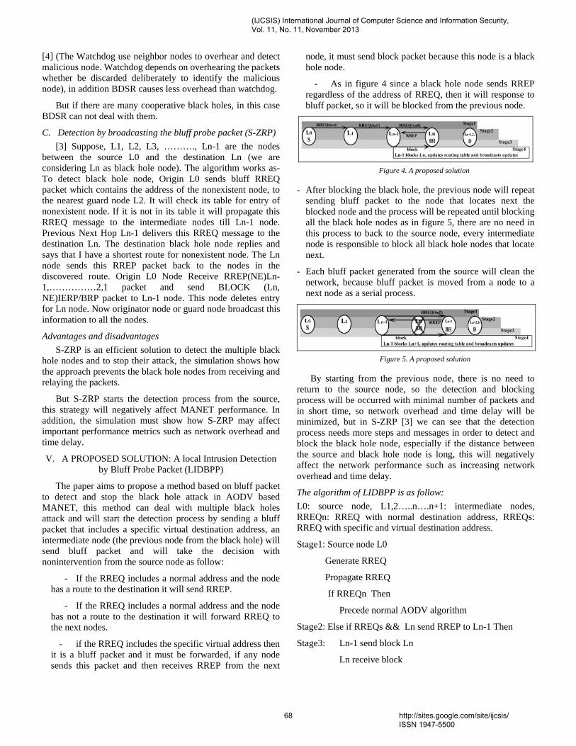
[4] (The Watchdog use neighbor nodes to overhear and detect malicious node. Watchdog depends on overhearing the packets whether be discarded deliberately to identify the malicious node), in addition BDSR causes less overhead than watchdog.
But if there are many cooperative black holes, in this case BDSR can not deal with them.
C. Detection by broadcasting the bluff probe packet (S-ZRP) [3] Suppose, L1, L2, L3, ………., Ln-1 are the nodes
between the source L0 and the destination Ln (we are considering Ln as black hole node). The algorithm works as-To detect black hole node, Origin L0 sends bluff RREQ packet which contains the address of the nonexistent node, to the nearest guard node L2. It will check its table for entry of nonexistent node. If it is not in its table it will propagate this RREQ message to the intermediate nodes till Ln-1 node. Previous Next Hop Ln-1 delivers this RREQ message to the destination Ln. The destination black hole node replies and says that I have a shortest route for nonexistent node. The Ln node sends this RREP packet back to the nodes in the discovered route. Origin L0 Node Receive RREP(NE)Ln-1,……………2,1 packet and send BLOCK (Ln, NE)IERP/BRP packet to Ln-1 node. This node deletes entry for Ln node. Now originator node or guard node broadcast this information to all the nodes.
Advantages and disadvantages S-ZRP is an efficient solution to detect the multiple black
hole nodes and to stop their attack, the simulation shows how the approach prevents the black hole nodes from receiving and relaying the packets.
But S-ZRP starts the detection process from the source, this strategy will negatively affect MANET performance. In addition, the simulation must show how S-ZRP may affect important performance metrics such as network overhead and time delay.
V. A PROPOSED SOLUTION: A local Intrusion Detection by Bluff Probe Packet (LIDBPP)
The paper aims to propose a method based on bluff packet to detect and stop the black hole attack in AODV based MANET, this method can deal with multiple black holes attack and will start the detection process by sending a bluff packet that includes a specific virtual destination address, an intermediate node (the previous node from the black hole) will send bluff packet and will take the decision with nonintervention from the source node as follow:
- If the RREQ includes a normal address and the node has a route to the destination it will send RREP.
- If the RREQ includes a normal address and the node has not a route to the destination it will forward RREQ to the next nodes.
- if the RREQ includes the specific virtual address then it is a bluff packet and it must be forwarded, if any node sends this packet and then receives RREP from the next
node, it must send block packet because this node is a black hole node.
- As in figure 4 since a black hole node sends RREP regardless of the address of RREQ, then it will response to bluff packet, so it will be blocked from the previous node.
Figure 4. A proposed solution
- After blocking the black hole, the previous node will repeat sending bluff packet to the node that locates next the blocked node and the process will be repeated until blocking all the black hole nodes as in figure 5, there are no need in this process to back to the source node, every intermediate node is responsible to block all black hole nodes that locate next.
- Each bluff packet generated from the source will clean the network, because bluff packet is moved from a node to a next node as a serial process.
Figure 5. A proposed solution
By starting from the previous node, there is no need to return to the source node, so the detection and blocking process will be occurred with minimal number of packets and in short time, so network overhead and time delay will be minimized, but in S-ZRP [3] we can see that the detection process needs more steps and messages in order to detect and block the black hole node, especially if the distance between the source and black hole node is long, this will negatively affect the network performance such as increasing network overhead and time delay.
The algorithm of LIDBPP is as follow: L0: source node, L1,2…..n….n+1: intermediate nodes, RREQn: RREQ with normal destination address, RREQs: RREQ with specific and virtual destination address.
Stage1: Source node L0
Generate RREQ
Propagate RREQ
If RREQn Then
Precede normal AODV algorithm
Stage2: Else if RREQs && Ln send RREP to Ln-1 Then
Stage3: Ln-1 send block Ln
Ln receive block
(IJCSIS) International Journal of Computer Science and Information Security, Vol. 11, No. 11, November 2013
68 http://sites.google.com/site/ijcsis/ ISSN 1947-5500

Stage4: Ln-1 updates routing table and broadcasts updates
Else
Ln sends RREQs to Ln+1
End if
VI. A SUMMARY TABLE
Table 1. A SUMMARY TABLE
VII. CONCLUSION
The paper introduced many recent solutions that worked to detect a black hole node by using different strategies, it explained how these methods worked and also it discussed the advantages and disadvantages of each solution, the paper has included a table to summarize the analyzed information of each solution, the paper also included a new solution to detect multiple black holes based on bluff probe packet (contains a specific virtual destination address) that tricks the black hole.
This approach begins the detection process from the previous node of black hole. This method will decrease the steps needed to detect and block the black holes if it is compared with the method that begins sending the bluff packet
from the source as in S-ZRP solution, so the process of developing this new method would detect and block the black hole nodes with high efficiency and less negative impact on MANET performance. In the future, the new solution (LIDBPP) must be simulated to study the performance of MANET and to compare it with the other solutions.
REFERENCES [1] Maha Abdelhaq, Sami Serhan, Raed Alsaqour, Anton Satria, “Security
Routing Mechanism for Black Hole Attack over AODV MANET Routing Protocol”, Australian Journal of Basic and Applied Sciences, 2011.
[2] Po-Chun TSOU, Jian-Ming CHANG, Yi-Hsuan LIN, Han-Chieh CHAO, Jiann-Liang CHEN, “Developing a BDSR Scheme to Avoid Black Hole Attack Based on Proactive and Reactive Architecture in MANETs”, ICACT 2011.
[3] Raj Shree, Sanjay Kr. Dwivedi, Ravi Prakash Pandey, “Design Enhancements in ZRP for Detecting Multiple Black Hole Nodes in Mobile Ad Hoc Networks”, International Journal of Computer, 2011.
[4] S. Marti, T. J. Giuli, K. Lai, and M. Baker, “Mitigating routing misbehavior in mobile ad hoc networks,” in Proceedings of the 6th Annual International Conference on Mobile Computing and Networking (MobiCom), pp. 255-265, 2000.
[5] Panagiotis Papadimitratos, Zygmunt J. Haas, “Secure Data Transmission in Mobile Ad Hoc Networks”, ACM Workshop on Wireless Security (WiSe 2003), San Diego, 2003.
[6] Chandni Garg, Preeti Sharma, Prashant Rewagad, “A Literature Survey of Black Hole Attack on AODV Routing Protocol”, International Journal of advancement in electronics and computer engineering (IJAECE), 2012.
[7] Akanksha Saini, Harish Kumar, “Comparison between Various Black hole Detection Techniques in MANET”, NCCI 2010 -National Conference on Computational Instrumentation, India, 2010.
[8] Panagiotis Papadimitratos, Zygmunt J. Haas, “Secure Routing for Mobile Ad hoc Networks”, the SCS Communication Networks and Distributed Systems Modeling and Simulation Conference (CNDS), 2002.
[9] Asis Nasipuri and Samir R. Das, “On-Demand Multipath Routing for Mobile Ad Hoc Networks”, ACM volume 6, 2001.
AUTHORS PROFILE
Imad I. Saada is a PHD student in computer science department in Mansoura University and a member of the academic staff at IT. department in AL-Quds Open University. His subject is in the distributed systems. Magdy Z. Rashad is an assistant professor and chairman of computer science department in Mansoura University. He is the decision support systems unit coordinator at faculty of computers &information in Mansoura University. He has supervised over 10 PhDs and 21 masters mostly specialized in artificial intelligence and its applications related to real life. As a result of his work he has published over 84 papers. current project is grid computing.
Solution Routing protocol
Black hole attack
Strategy
[1] SIDSR AODV Single Black hole
The source node is used for intrusion detection - source detection.
[1] LIDSR AODV Single Black hole
The previous node from the attacker node is used for intrusion detection - local detection
[2] BDSR DSR Single Black hole
Baiting a single black hole by using virtual and non-existent destination address.
[3] S-ZRP ZRP Multiple Black holes
Baiting a multiple black holes by broadcasting the bluff probe packet that contains virtual and non-existent destination address - source detection.
LIDBPP AODV Multiple Black holes
Baiting a multiple black holes by broadcasting the bluff probe packet that contains virtual and non-existent destination address - local detection
(IJCSIS) International Journal of Computer Science and Information Security, Vol. 11, No. 11, November 2013
69 http://sites.google.com/site/ijcsis/ ISSN 1947-5500

DESIGN AND ANALYSIS OF (M/G/1):(GD/∞/ ∞) AND (Mi /Gi
/1):(NPRP/∞/∞) QUEUEING SYSTEMS Dr. C.Vijayalakshmi , G.T.Shakila Devi
G.T.Shakila Devi Research Scholar, Department of Statistics,
Manonmaniam Sundaranar University, Tirunelveli, INDIA,
Dr. C.Vijayalakshmi Professor, School of Advance Sciences Department of Mathematics Division,,
VIT University, Chennai, INDIA,
ABSTRACT`-There are many non Poisson queuing models. This paper mainly deals with the analysis of Non-Poisson queues (M/G/1): (GD/∞/ ∞) and (Mi /Gi /1): (NPRP/∞/∞) .The feasibility of the system is analyzed based on the numerical calculations and Graphical representations. When the mean system size and the queue size is high , optimized value is obtained so that the total expected cost is minimized. The outline here an approach that may be used to analyze a non Poisson model which has job classes of multiple priorities. The priority discipline followed may be either non-preemptive or preemptive in nature. When the priority discipline is non-preemptive in nature, a job in service is allowed to complete its service normally even if a job of higher priority enters the queue while its service is going on. In the preemptive case, the service to the ongoing job will be preempted by the new arrival of higher priority. If the priority discipline is preemptive resume, then service to the interrupted job, when it restarts, continues from the point at which the service was interrupted. For the preemptive non resume case, service already provided to the interrupted job is forgotten and its service is started again from the beginning. Note that there may be loss of work in the preemptive non-resume priority case. Such loss of work will not happen in the case of the other two priorities. Since the service times are assumed to be exponentially distributed, they will satisfy the memory-less property and that, therefore, the results will be the same both for the preemptive resume and preemptive non-resume cases.
Key Words- Pollazek–Khintchine formula; Priority service discipline; Non-Poisson queues
I. INTRODUCTION
Queuing models are widely used in industry to improve customer service, for example in supermarkets, banks and motorway toll booths. In a market economy, customers[Movaghar, 1998] who have poor service go elsewhere; however, when hospital beds are unavailable, patients have no option but to wait at home, in accident and emergency departments or wards which are inappropriately staffed, possibly without access to appropriate specialized equipment. For a P priority system, we consider jobs of class 1 to be the lowest priority and jobs of class P to be the highest priority. We consider here queues with both preemptive and non-preemptive priority disciplines. The approach suggested may be applied to both single server and multi-server queues[Kimura ,1994, Whitt, 1992]. Moreover, queues with both finite and infinite buffers may be analyzed using the suggested approach. We outline the way in which such a queue may actually be analyzed by solving mean system size and queue size based on the numerical calculation and graphical representations. The Queues in which arrivals and / or departures may not follow the Poisson axioms are called Non-Poisson queues.
Fig The M/G/1 queue
(IJCSIS) International Journal of Computer Science and Information Security, Vol. 11, No. 11, November 2013
70 http://sites.google.com/site/ijcsis/ ISSN 1947-5500

II. RELATED WORK Markov chains with generator matrices or block matrices of this form are called M/G/1 type Markov chains a term coined by M. F. Neuts.[Meini, 1998).
III. MATERIALS AND METHODOLOGY
Table 1 (M/G/1):(GD/∞/ ∞)
Table 2 (Mi /Gi /1): (NPRP/∞/∞)
A. Techniques adopted for the development of Non-Poisson queues
I)Phase technique :-This technique is used when an arrival demands phases of service say k in number
II) Imbedded Markov chain technique: -The technique by which Non-Markovian queues are reduced to Markovian is termed as Imbedded Markov chain technique.
III) Supplementary variable technique: When one or more random variables are added to convert a Non-Markovian process into a Markovian process, the technique involved is called supplementary variable technique. This technique is used for the queuing models (M/G/1), (GI/G/C),(GI/M/S) and(GI/EK /1).
B. Description of Non-Poisson queues The aim of this study is to compare the properties,
namely mean and variance of the two queues. In this model ,
M Poisson arrivals
G General output distribution
∞ Waiting room capacity is infinite
GD General service discipline such as First Come First Served serves jobs in the order they arrive (FCFS),Last Come First Served non-preemptively serves the job that arrived the most recently. (LCFS).
To determine the mean queue length and mean waiting time for this system, following techniques are used
n → Number of customers in the system just after a customer departs
t Time to serve the customer following the one already departed
f(t) → Probability density function of service time distribution with mean E(t) and variance var (t)
k →number of new arrivals during ‘t
n’ → number of customer’s left behind the next departing customer
The result of this model can be applied to any one of the three service disciplines FCFS, &FCLS. .The derivation for a single server situation is based on the following assumptions:
• Poisson arrivals with arrival rate λ • General service time distribution with mean
mean E(t) and variance var (t) • Steady state conditions prevail with ρ = λ
E(t) < 1
(IJCSIS) International Journal of Computer Science and Information Security, Vol. 11, No. 11, November 2013
71 http://sites.google.com/site/ijcsis/ ISSN 1947-5500

Under the above assumptions, Pollazek-Khintchine formula is given by
Ls = λ E(t) +
[E2(t)+var(t)]
Thus Lq = Ls - λ E(t);
Ws = Ls / λ;
Wq= Lq / λ
In this model, queue and service together will represent the system. At the time (T+t) There are (n-1+k) customers are there in the system. When T represents the time when the jth customer departs and (T+t) represents the time when the next customer (j+1)st departs. It does not necessarily mean that the next customers are introduced into the service.
By the steady state assumptions
E(n) = E(n’)and E(n 2) = [E(n’)2]
From the above diagram,
Therefore n ‘ = n -1 + δ+ k
E(n’) = E(n)+ E(δ) +E(k) – 1
we have E( δ) = 1 – E(k)
(n’) 2 = [n+(k-1)+δ]2 = n2+k2+2n(k-1)+δ(2k-1)+1-2k ;[since δ2 = δ & δ n = 0]
ThereforeE(n) ={ E(k2) - 2 E(k) +E(δ) [2E(k)-1] +1 } / {2 [1-E(k)]} = —
Since the arrivals in time‘t’ follow the Poisson distribution
E(k/t) = λ andE( k2 / t) = (λt)2 +λ t
Hence E(k) = ∞ =λ E(t)
E(k2) = ∞ / = λ2 Var(t) + λ2E2(t) + λ E(t)
Thus L s = E(n) = λ E(t) +
(Mi /Gi /1): (NPRP/∞/∞)
Here we introduce the concept of priority service disciplines .Priority service discipline includes two rules :
1. Preemptive rule where the service of a low priority customer may be interrupted in favour of an arriving customer with higher priority
2. Non-preemptive rule where a customer once in service will continue until his service is completed and regardless of the priority of the arriving customer.
(Mi /Gi /1): (NPRP/∞/∞) is one of the non- preemptive models. These apply to single and multiple channel cases. The single channel model assumes Poisson arrival and arbitrary service distribution. In the multiple channel model both arrivals and departures are assumed to be Poisson. The symbol NPRP will be used with Kendall notation to represent the non-preemptive discipline while the symbols Mi and Gi will represent Poisson and arbitrary distributions for the ith queue for i =1,2,….m
Ei(t) -- mean;
Vari (t) variance ;
λI the arrival rate at the ith queue unit time
The results are given by [under the usual assumption] = ∑
`
E2 (t) +Var(t)
Lqk= λk ; = + Ek (t) ;
=Lqk + ρ kwhere ρ k = λk Ek (t)
Sk = ∑ < 1 ; k= 1 to m ; S0 = 0
The expected waiting time in the queue for any customer regardless of his priority is
Wq = ∑ Where λ = ∑ and λk / λ is the relative weight of Similarly for
F(t) be the CDF of the combined service time for the entire system
λ = ∑ is the combined arrival rate
Then F(t) = λF(t)= λ1 F1(t) + λ2F2(t)+..+λmFm(t)Which means that the effective number serviced in different priority queues.
Consequently,F(t) =∑ Fi(t)
E(t) = ∞ = ∑ Ei(t) and
E(t2) = ∑ [ Ei2(t) + var i(t)]
Tqk =t1 – t0 is the waiting time time in the
queue of a customer of the kth priority queue who arrives at t0 and starts service at t1.Let ξi be the service times of the customer in the queue 1 through
(IJCSIS) International Journal of Computer Science and Information Security, Vol. 11, No. 11, November 2013
72 http://sites.google.com/site/ijcsis/ ISSN 1947-5500

k. During his waiting time Tqk , other customers may
arrive in queues 1 through (k-1).Thus if ξ0 is the time to finish the service of the customer already in service and because each queue operates on FCFS discipline.
Tqk = ξ0 + ∑ + ∑ ′
and
E[Tqk ] = 2)
we have = E[ξ0 ] + ∑ + ∑ ′
E[ξi] = ρ i Wqi
where ρ i = λi Ei (t)
E[ξi ‘] = [expected number of arrivals in the ith queue during Tq
k ]x[expected service time per customer]= ρ i Wq
k
Hence Wqk =E ξ ∑ ρ W
where Sk = ∑ ρi
Using induction k,
we have Wqk = E ξ
and for the kth
queue
Lqk = W and Lsk = W
IV. RESULTS AND DISCUSSIONS
Model 1 (M/G/1):(GD/∞/ ∞)
Fig 2 Graphical Representation of the Effect of Improving the average number of customers (LS) on arrival Rate of customers(λ)
Fig 3 Figure shows arrival Rate of customers(λ)versus waiting line of the customers in the queue (Lq).
Fig 4 Graphical Representation of the Effect of Improving the arrival rate of Customer’s(λ) versus customers Waiting Time(Wq)
Fig 5 Graphical Representation of the Effect of Improving the Service Rate(Ws) on Customer’s arrival Time(λ)
‐100
‐80
‐60
‐40
‐20
0
20
40
1 3 5 7 9 11 13 15 17 λ
Ls
‐100
‐80
‐60
‐40
‐20
0
20
40
1 3 5 7 9 11 13 15 17
Lq
λ
‐30
‐20
‐10
0
10
20
30
1 3 5 7 9 11 13 15 17
Wq
λ
‐30
‐20
‐10
0
10
20
30
1 3 5 7 9 11 13 15 17
Ws
λ
(IJCSIS) International Journal of Computer Science and Information Security, Vol. 11, No. 11, November 2013
73 http://sites.google.com/site/ijcsis/ ISSN 1947-5500

Fig 6 shows the effect of improving customers Waiting Time (Wq), average number of customers (LS), Service Rate(Ws),
waiting line of the customers in the queue (Lq) versus average arrival rate of customers λ (lambda)
Model2:(Mi /Gi /1): (NPRP/∞/∞)
Fig 7 Graphical Representation of the Effect of Improving the average number of customers (LS) on arrival Rate of customers(λ)
Fig 8 shows the effect of average arrival rate of customers λ (lambda) on the waiting line of the customers in the queue (Lq).
Fig 9 Graphical Representation of the Effect of the arrival rate of Customer’s(λ) versus customers Waiting Time(Wq)
Fig 10 Graphical Representation of the Effect of the Service Rate(Ws) on Customer’s arrival Time(λ)
Fig 11 shows the effect of improving Service Rate(Ws), average number of customers (LS) , waiting line of the customers in the
queue (Lq). and average arrival rate of customers (λ)
V. CONCLUSION From the analysis of the above two queues,
the feasibility is comparatively admissible in the model (Mi /Gi/1): (NPRP/∞/∞) based on the numerical calculations and graphical representations. One can identify the transitions between states. This set of equations is solved to get the actual state probabilities. This is used to obtain the queue performance parameters required.
0
100
200
300
400
500
1 3 5 7 9 11131517
Ls
λ
0
100
200
300
400
500
1 4 7 10 13 16
Lq k
λ
0
10
20
30
40
50
1 3 5 7 9 11 13 15 17
Wqk
λ
0
10
20
30
40
50
1 4 7 10 13 16
Ws
λ
(IJCSIS) International Journal of Computer Science and Information Security, Vol. 11, No. 11, November 2013
74 http://sites.google.com/site/ijcsis/ ISSN 1947-5500

REFERENCES
1. Adan and M. Haviv , 2009 Conditional ages and residual service times in the M/G/1 queue. Stochastic Models, Vol.25,Issue.1.
2. Asmussen S, 2003, Applied probability and queues. Springer, New York
3. Bagchi TP, Templeton JGC ,1973,A note on the MX /GY /1, K bulk queueing system. J Appl Probab ,Vol.10,Issue 4,pp.901–906.
4. Burke PJ, 1975, Delays in single-server queues with batch inputs. Operation Research, Vol. 23, Issue.4, PP.830–833.
5. Daigle, John N. ,2005, "The Basic M/G/1 Queueing System". Queueing Theory with Applications to Packet Telecommunication. pp. 159–223. doi:10.1007/0-387-22859-4_5. ISBN 0-387-22857-8.
6. Fakinos D.. ,1982, The expected remaining service time in a single server queue. Operations Research, Vol.30, Issue.5.
7. Giambene G., “Queuing theory and telecommunications: Network and applications.”
8. Hall, R.W., 2006, Patient Flow; The new queuing theory for healthcare, OR/MS .
9. Kendall, D. G. ,1953, "Stochastic Processes Occurring in the Theory of Queues and their Analysis by the Method of the Imbedded Markov Chain". The Annals of Mathematical Statistics , Vol.24 , Issue.3,pp. 338. doi:10.1214/aoms/1177728975. JSTOR 2236285
10. Kleinrock L,1975,Queueing Systems, vol. 1. 11. Kumar K. H. and Majhi S., 2004 “Queuing theory
based open loop control of Web server,” IEEE Paper. 12. Lehoczky J. P., 1997 “Using real-time queuing theory
to control lateness in real-time systems,”.. 13. Meini, B.,1998, "Solving m/g/l type markov chains:
Recent advances and applications". Communications in Statistics. Stochastic Models, Vol. 14,pp. 479–496. doi:10.1080/15326349808807483
14. Medhi J ,2003, Stochastic models in queueing theory. Academic Press, San Diego
15. Preemptive priority queues by Muthuganapathy And Ayyappan .G ,Psjor Vol-4
16. Ramaswami, V.,1988, "A stable recursion for the steady state vector in markov chains of m/g/1 type". Communications in Statistics. Stochastic Models 4: 183–188. doi:10.1080/15326348808807077
17. Randolph Nelson.,1995 Probability, Stochastic Processes, and Queueing Theory. Springer-Verlag, New York.
18. Schellhaas H, 1983,Computation of the state dependent probabilities in M/G/1 queues with state dependent input and state dependent service. OR Spectr, Vol. 5,Issue.4,PP.223–228
19. Singh Vikas, Use of Queuing Models in Health Care,2006, University of Arkansas for Medical Sciences.
20. Spies F., 2003 “Modeling of optimal load balancing strategy using queuing theory,.
21. Takagi H ,1993, Queueing analysis: finite systems. North-Holland, Amsterdam.
22. Movaghar, A. , 1998, On queueing with customer impatience until the beginning of service, Queueing System ,Vol. 29,pp. 337–350.
23. Kimura T,1994, Approximation for multi-server queues: system interpolations, Queueing Systems 17 347-382, .
24. Whitt, W., 1992, Understanding the Efficiency of Multi-Server service systems. Management Science, 38 708-723.
AUTHORS BIOGRAPHY Dr. C. Vijayalakshmi is currently working as Professor in Mathematics Department, SAS, VIT University, Chennai, Tamilnadu. She has more than 17 years of teaching experience at Graduate and Post Graduate level.
She has published more than Twenty research papers in International and National Journals and authored three books for Engineering colleges, Anna University. She has received Bharat Jyothi Award for outstanding services, achievements and contributions, Best Teachers award for academic excellence. Her area of specialization is Stochastic Processes and their applications. Her other research interests include Optimization Techniques, Data mining and Bio-Informatics.
Mrs.G.T.shakila Devi is currently working as Asst .Professor in Mathematics Department, Kumararani Meena Muthiah College, Adyar, Chennai ‐ 20, Tamilnadu. She has 15 years of teaching experience. She has authored a book on Biostatistics. She has research papers to her credit.
(IJCSIS) International Journal of Computer Science and Information Security, Vol. 11, No. 11, November 2013
75 http://sites.google.com/site/ijcsis/ ISSN 1947-5500

(IJCSIS) International Journal of Computer Science and Information Security, Vol. 11, No. 11, November 2013
Applying Data Mining Techniques for Customer Relationship Management: A Survey
Ahmed M. El-Zehery, Hazem M. El-Bakry
Faculty of Computer Science & Information system
Mansoura University, EGYPT
Mohamed S. El-Ksasy
Faculty of Engineering
Mansoura University, EGYPT
Abstract— Data mining has various applications for customer relationship management. In this proposal, I am introducing a framework for identifying appropriate data mining techniques for various CRM activities. This Research attempts to integrate the data mining and CRM models and to propose a new model of Data mining for CRM. The new model specifies which types of data mining processes are suitable for which stages/processes of CRM. In order to develop an integrated model it is important to understand the existing Data mining and CRM models. Hence the article discusses some of the existing data mining and CRM models and finally proposes an integrated model of data mining for CRM.
Keywords-component; formatting; style; styling; insert (key words)
I. INTRODUCTION (HEADING 1) Value Creation for the customer is the key determinant of a successful business. Customer satisfaction ensures profitability for businesses in the long run. Customer bases built over a period of time proved to be of immense help in increasing the reach of a particular business's product or service. However, the recent increase in the operating costs of business made it more compelling for businesses to increase loyalty among existing customers while trying to attract new ones. The processes by which an organization creates value for the customer, is often referred to as Customer Relationship Management (CRM) [1]. According to Microsoft, CRM is “a customer-focused business strategy designed to optimize revenue, profitability, and customer loyalty. By implementing a CRM strategy, an organization can improve the business processes and technology solutions around selling, marketing, and servicing functions across all customer touch-points (for example: Web, e-mail, phone, fax, in-person)”. The overall objective of CRM applications is to attract, retain and manage a firm’s profitable (“right”) customers [1]. Business intelligence for CRM applications provides a firm with actionable information from the analysis and interpretation of vast quantities of customer/market related data. Databases for business intelligence include cus-tomer demographics, buying histories, cross-sales, service calls, website navigation experiences and online transac-tions. Through the appropriate use of analytical methods and software, a firm is able to turn data into information that leads
to greater insight and development of fact-based strategies which in turn helps the firm gain competitive advantage by creating greater value for the customer [1]. Analogous to traditional mining, which involves searching for an ore in a mountain, data mining involves searching for valuable information in large databases. Both these processes involve either groping through a vast amount of material or intelligently probing the data to find the true value that lies hidden in data. Data mining involves not only the extraction of previously unknown information from a database but also the discovery of relation-ships that did not surface in the previous methods of data analysis. The “jewels” discovered from the data mining process include these non-intuitive hidden predictive relationships between variables that explain customer behavior and preferences. The predictive capabilities of data mining enable the businesses to make proactive, knowledge-driven decisions. Data mining tools facilitate prospective analysis, which is an improvement over the analysis of past events provided by the retrospective tools. The emergence of large data warehouses and the availability of data mining software is creating opportunities for businesses to find innovative ways to implement effective customer relationship strategies [1]. The automation of data collection and the relative decrease in the costs of operating huge data warehouses has made customer data more accessible than ever. The analysis of data, which until a few years ago was associated with high-end computing power and algorithms decipherable by only professional statisticians, is increasing to become more popular with user-friendly tools available on desktops [Berger, 1999 #2]. Data mining plays an important role in the analytical phases of the CRM life cycle as well as the CRM process [1].
II. RESEARCH METHODOLOGY
As the nature of research in CRM and data mining are difficult to confine to specific disciplines, the relevant materials are scattered across various journals. Business intelligence and knowledge discovery are the most common academic discipline for data mining research in CRM. Consequently, the following online journal databases were searched to provide a
76 http://sites.google.com/site/ijcsis/ ISSN 1947-5500

(IJCSIS) International Journal of Computer Science and Information Security, Vol. 11, No. 11, November 2013
comprehensive bibliography of the academic literature on CRM and Data Mining: _ ABI/INFORM Database; _ Academic Search Premier; _ Business Source Premier; _ Emerald Fulltext; _ Ingenta Journals; _ Science Direct; and _ IEEE Transaction.
The literature search was based on the descriptor, ‘‘customer relationship management” and ‘‘data mining”, which originally produced approximately 900 articles. The full text of each article was reviewed to eliminate those that were not actually related to application of data mining techniques in CRM. The selection criteria were as follows: _ Only those articles that had been published in business intelligence, knowledge discovery or customer management related journals were selected, as these were the most appropriate outlets for data mining in CRM research and the focus of this review. _ Only those articles which clearly described how the mentioned data mining technique(s) could be applied and assisted in CRM strategies were selected. _ Conference papers, masters and doctoral dissertations, textbooks and unpublished working papers were excluded, as academics and practitioners alike most often use journals to acquire information and disseminate new findings. Thus, journals represent the highest level of research. Each article was carefully reviewed and separately classified according to the four categories of CRM dimensions and seven categories of data mining models. Although this search was not exhaustive, it serves as a comprehensive base for an understanding of data mining research in CRM.
III. RESEARCH CHALLENGES
Data Mining Challenges & Opportunities in CRM In this section, we build upon our discussion of CRM and Life Sciences to identify key data mining challenges and opportunities in these application domains. The following is a list of challenges for CRM [2]. a. Non-trivial results almost always need a combination of DM techniques. Chaining/composition of DM, and more generally data analysis, operations is important. In order to analyze CRM data, one needs to explore the data from different angles and look at its different aspects. This should require application of different types of DM techniques and their application to different “slices” of data in an interactive and iterative fashion. Hence, the need to use various DM operators and combine (chain) them into a single “exploration plan” [2].
b. There is a strong requirement for data integration before data mining. In both cases, data comes from multiple sources. For example in CRM, data needed may come from different departments of an organization. Since many interesting patterns span multiple data sources, there is a need to integrate these data before an actual data mining exploration can start [2]. c. Diverse data types are often encountered. This requires the integrated mining of diverse and heterogeneous data. In CRM, while dealing with this issue is not critical, it is nonetheless important. Customer data comes in the form of structured records of different data types (e.g., demographic data), temporal data (e.g., weblogs), text (e.g., emails, consumer reviews, blogs and chat-room data), (sometimes) audio (e.g., recorded phone conversations of service reps with customers) [2]. d. Highly and unavoidably noisy data must be dealt with. In CRM, weblog data has a lot of “noise” (due to crawlers, missed hits because of the caching problem, etc.). Other data pertaining to customer “touch points” has the usual cleaning problems seen in any business-related data [2]. e. Privacy and confidentiality considerations for data and analysis results are a major issue. In CRM, lots of demographic data is highly confidential, as are email and phone logs. Concern about inference capabilities makes other forms of data sensitive as well—e.g., someone can recover personally identifiable information (PII) from web logs [2].
f. Legal considerations influence what data is available for mining and what actions are permissible. In some countries it is not allowed to combine data from different sources or to use it for purposes different from those for which they have been collected. For instance, it may be allowed to use an external rating about credit worthiness of a customer for credit risk evaluation but not for other purposes. Ownership of data can be unclear, depending on the details of how and why it was collected, and whether the collecting organization changes hands [2].
g. Real-world validation of results is essential for acceptance. In CRM, as in many DM applications, discovered patterns are often treated as hypotheses that need to be tested on new data using rigorous statistical tests for the actual acceptance of the results. This is even more so for taking or recommending actions, especially in such high-risk applications as in the financial and medical domains. Example: recommending investments to customers (it is actually illegal in the US to let software give investment advice) [2,3].
77 http://sites.google.com/site/ijcsis/ ISSN 1947-5500

(IJCSIS) International Journal of Computer Science and Information Security, Vol. 11, No. 11, November 2013
h. Developing deeper models of customer behavior: One of the key issues in CRM is how to understand customers. Current models of customers mainly built based on their purchase patterns and click patterns at web sites. Such models are very shallow and do not have a deep understanding of customers and their individual circumstances. Thus, many predictions and actions about customers are wrong. It is suggested that information from all customer touch-points be considered in building customer models. Marketing and psychology researchers should also be involved in this effort. Two specific issues need to be considered here. First, what level should the customer model be built at, namely at the aggregate level, the segment level, or at the individual level? The deciding factor is how personalized the CRM effort needs to be. Second is the issue of the dimensions to be considered in the customer profile. These include demographic, psychographic, macro-behavior (buying, etc.), and micro-behavior (detailed actions in a store, e.g. individual clicks in an online store) features [2,3].
i. Acquiring data for deeper understanding in a non-intrusive, low-cost, high accuracy manner: In many industrial settings, collecting data for CRM is still a problem. Some methods are intrusive and costly. Datasets collected are very noisy and in different formats and reside in different departments of an organization. Solving these pre-requisite problems is essential for data mining applications [2].
j. Managing the “cold start/bootstrap” problem: At the beginning of the customer life cycle little is known, but the list of customers and the amount of information known for each customer increases over time. In most cases, a minimum amount of information is required for achieving acceptable results (for instance, product recommendations computed through collaborative filtering require a purchasing history of the customer). Being able to deal with cases where less than this required minimum is known is a therefore a major challenge [2].
k. Evaluation framework for distinguishing between correct/incorrect customer understanding: Apart from the difficulty of building customer models, evaluating them is also a major task. There is still no satisfactory metric that can tell whether one model is better than another and whether a model really reflects customer behaviors. Although there are some metrics for measuring quality of customer models (e.g., there are several metrics for measuring the quality of recommendations), they are quite rudimentary, and there is a strong need to work on better measures. Specifically, the recommender systems community has explored this area [2,3,6,7].
Figure 1. Classification framework for data mining techniques in CRM.
In the previous figure we can see how Data mining stages used
with all CRM lifecycle.
(1) Association rule; (2) Decision tree; (3) Genetic algorithm; (4) Neural networks; (5) K-Nearest neighbour; (6) Linear/logistic regression.
A graphical classification framework on data mining techniques in CRM is proposed and shown in Fig. 1; it is based on a review of the literature on data mining techniques in CRM. Critically reviewing the literature on data mining in CRM helped to identify the major CRM dimensions and data mining techniques for the application of data mining techniques in CRM. It describes CRM dimensions as: Customer Identification, Customer Attraction, Customer Retention and Customer Development. In addition, described the types of data mining model as Association, Classification, Clustering, Forecasting, Regression, Sequence Discovery and Visualization. We provide a brief description of these four dimensions and some references for further details, and each of them is discussed in the following sections [6].
IV. CLASSIFICATION FRAMEWORK – CRM DIMENSIONS
In this study, CRM is defined as helping organizations to better discriminate and more effectively allocate resources to the most profitable group of customers through the cycle of customer identification, customer attraction, customer retention and customer.
(i) Customer identification: CRM begins with customer
identification, which is referred to as customer acquisition in some articles. This phase involves targeting the population who are most likely to become customers or most profitable to the company. Moreover, it involves analyzing
78 http://sites.google.com/site/ijcsis/ ISSN 1947-5500

(IJCSIS) International Journal of Computer Science and Information Security, Vol. 11, No. 11, November 2013
customers who are being lost to the competition and how they can be won back . Elements for customer identification include target customer analysis and customer segmentation. Target customer analysis involves seeking the profitable segments of customers through analysis of customers’ underlying characteristics, whereas customer segmentation involves the subdivision of an entire customer base into smaller customer groups or segments, consisting of customers who are relatively similar within each specific segment .
(ii) Customer attraction: This is the phase following customer identification. After identifying the segments of potential customers, organizations can direct effort and resources into attracting the target customer segments. An element of customer attraction is direct marketing. Direct marketing is a promotion process which motivates customers to place orders through various channels. For instance, direct mail or coupon distribution are typical examples of direct marketing.
(iii) Customer retention: This is the central concern for CRM. Customer satisfaction, which refers to the comparison of customers’ expectations with his or her perception of being satisfied, is the essential condition for retaining customers . As such, elements of customer retention include one-to-one marketing, loyalty programs and complaints management. One-to-one marketing refers to personalized marketing campaigns which are supported by analysing, detecting and predicting changes in customer behaviours Thus, customer profiling, recommender systems or replenishment systems are related to one-to-one marketing. Loyalty programs involve campaigns or supporting activities which aim at maintaining a long term relationship with customers. Specifically, churn analysis, credit scoring, service quality or satisfaction form part of loyalty programs.
(iv) Customer development: This involves consistent expansion of transaction intensity, transaction value and individual customer profitability. Elements of customer development include customer lifetime value analysis, up/cross selling and market basket analysis. Customer lifetime value analysis is defined as the prediction of the total net income a company can expect from a customer. Up/Cross selling refers to promotion activities which aim at augmenting the number of associated or closely related services that a customer uses within a firm. Market basket analysis aims at maximizing the customer transaction intensity and value by revealing
regularities in the purchase behaviour of customers
a. Good actioning mechanisms: Once data mining has been conducted with promising results, how to use them in the daily performance task is critical and it requires significant research effort. It is common that after some data results are obtained, the domain users do not know how to use them in their daily work. This research may require the participation of business and marketing researchers. Another way to accommodate actioning mechanisms is to integrate them into the knowledge discovery process by focusing on the discoveries of actionable patterns in customer data. This would make easier for the marketers or other domain experts to determine which actions should be taken once the customer patterns are discovered [2].
b. Incorporating prior knowledge: This has always been a problem in practice. Data mining tends to find many pieces of patterns that are already known or redundant. Incorporating prior domain knowledge can help to solve these problems, and also to discover something novel. However, the difficulties of incorporating domain knowledge result in little progress in the past. There are a number of reasons for this. First of all, knowledge acquisition from domain experts is very hard. This is well documented in AI research, especially in the literature of expert systems building. Domain experts may know a lot but are unable to tell. Also, many times, domain experts are not sure what the relevant domain knowledge is, which can be very wide, although the data mining application itself is very narrow. Only after domain experts have seen some discovered patterns then they remember some domain knowledge. The second reason is the algorithmic issue. Many existing methods have difficulty to incorporate sophisticated domain knowledge in the mining algorithm. Also, once the new patterns are discovered, it is important to develop methods that integrate the newly discovered knowledge with the previous knowledge thus enhancing the overall knowledge base. Although there is some general work on knowledge enhancement, much more needs to be done to advance this area and adapt it to CRM problems. Also, integration of these methods with existing and novel Knowledge Management approaches constitutes a fruitful area of research [2].
Customer relationship management in its broadest sense simply means managing all customer interactions. In practice, this requires using information about your customers and prospects to more effectively interact with your customers in all stages of your relationship with them. We refer to these stages as the customer life cycle. The customer life cycle has three stages:
1. Acquiring customers 2. Increasing the value of customers 3. Retaining good customers
79 http://sites.google.com/site/ijcsis/ ISSN 1947-5500

(IJCSIS) International Journal of Computer Science and Information Security, Vol. 11, No. 11, November 2013
Data mining can improve your profitability in each of these stages when you integrate it with operational CRM systems or implement it as independent applications [4]. c. Acquiring new customers via data mining [4]
The first step in CRM is to identify prospects and convert them to customers. Let’s look at how data mining can help manage the costs and improve the effectiveness of a customer acquisition campaign. Big Bank and Credit Card Company (BB&CC) annually conducts 25 direct mail campaigns, each of which offers one million people the opportunity to apply for a credit card. The conversion rate measures the proportion of people who become credit card customers, which is about one percent per campaign for BB&CC. Getting people to fill out an application for the credit card is only the first step. Then, BB&CC must decide if the applicant is a good risk and accept them as a customer or decline the application. Not surprisingly, poor credit risks are more likely to accept the offer than are good credit risks. So while six percent of the people on the mailing list respond with an application, only about 16 percent of those are suitable credit risks; approximately one percent of the people on the mailing list become customers. BB&CC’s six percent response rate means that only 60,000 people out of one million names respond to the solicitation. Unless BB&CC changes the nature of the solicitation – using different mailing lists, reaching customers in different ways, altering the terms of the offer it is not going to receive more than 60,000 responses. And of those 60,000 responses, only 10,000 are good enough risks to become customers. The challenge BB&CC faces is reaching those 10,000 people most efficiently. BB&CC spends about $1.00 per piece, for a total cost of $1,000,000, to mail the solicitation. Over the next couple of years, the customers gained through this solicitation generate approximately $1,250,000 in profit for the bank (or about $125 each), for a net return of $250,000 from the mailing. Data mining can improve this return. Although data mining won’t precisely identify the 10,000 eventual credit card customers, data mining helps focus marketing efforts much more cost effectively. First, BB&CC sent a test mailing of 50,000 prospects and carefully analyzed the results, building a predictive model showing who would respond (using a decision tree) and a
credit scoring model (using a neural net). BB&CC then combined these two models to find the people who were both good credit risks and were most likely to respond to the offer. BB&CC applied the model to the remaining 950,000 people in the mailing list, from which 700,000 people were selected for the mailing. What was the result? From the 750,000 pieces mailed (including the test mailing), BB&CC received 9,000 acceptable applications for credit cards. In other words, the response rate rose from one percent to 1.2 percent, a 20 percent increase. While the targeted mailing only reaches 9,000 of the 10,000 prospects – no model is perfect – reaching the remaining 1,000 prospects is not profitable. Had they mailed the other 250,000 people on the mailing list, the cost of $250,000 would have resulted in another $125,000 of gross profit for a net loss of $125,000. Notice that the net profit from the mailing increased $125,000. Even when you include the $40,000 cost of the data mining software and the computer and employee resources used for this modeling effort, the net profit increased $85,000. This translates to a return on investment (ROI) for modeling of over 200 percent, which far exceeds BB&CC’s ROI requirements for a project. d. Increasing the value of your existing customers [4]
Cannons and Carnations (C&C) is a company that specializes in selling antique mortars and cannons as outdoor flower pots. It also offers a line of indoor flower pots made from large caliber antique pistols and a collection of muskets that have been converted to unique holders of long-stemmed flowers. The C&C catalog is sent to about 12 million homes. When a customer calls C&C to place an order, C&C identifies the caller using caller ID when possible; otherwise the C&C representative asks for a phone number or customer number from the catalog mailing label. Next, the representative looks up the customer in the database and then proceeds to take the order. C&C has an excellent chance of cross-selling, or selling the caller something additional. But C&C discovered that if the first suggestion fails and the representative suggests a second item, the customer might get irritated and hang up without ordering anything. And, there are some customers who resent any cross-selling attempts. Before implementing data mining, C&C was reluctant to cross-sell. Without a model, the odds of making the right recommendation were one in three. And, because making any recommendation is unacceptable for some customers, C&C wanted to be extremely sure that it never makes a recommendation when it should not. In a trial campaign, C&C had less than a one percent sales rate and received a
80 http://sites.google.com/site/ijcsis/ ISSN 1947-5500

(IJCSIS) International Journal of Computer Science and Information Security, Vol. 11, No. 11, November 2013
substantial number of complaints. C&C was reluctant to continue cross-selling for such a small gain. The situation changed dramatically once C&C used data mining. Now the data mining model operates on the data. Using the customer information in the database and the new order, it tells the customer service representative what to recommend. C&C successfully sold an additional product to two percent of the customers and experienced virtually no complaints. Developing this capability involved a process similar to what was used to solve the credit card customer acquisition problem. As with that situation, two models were needed. The first model predicted if someone would be offended by additional product recommendations. C&C learned how its customers reacted by conducting a very short telephone survey. To be conservative, C&C counted anyone who declined to participate in the survey as someone who would find recommendations intrusive. Later on, to verify this assumption, C&C made recommendations to a small but statistically significant subset of those who had refused to answer the survey questions. To C&C’s surprise, it discovered that the assumption was not warranted. This enabled C&C to make more recommendations and further increase profits. The second model predicted which offer would be most acceptable. In summary, data mining helped C&C better understand its customers’ needs. When the data mining models were incorporated in a typical cross-selling CRM campaign, the models helped C&C increase its profitability by two percent. e. Increasing the value of your existing customers:[4] personalization via data mining
Big Sam’s Clothing (motto: “Rugged outdoor gear for city dwellers”) developed a Web site to supplement its catalog. Whenever you enter Big Sam’s site, the site greets you by displaying “Howdy Pardner!” However, once you have ordered or registered with Big Sam’s, you are greeted by name. If you have a Big Sam’s ordering record, Big Sam’s will also tell you about any new products that might be of particular interest to you. When you look at a particular product, such as a waterproof parka, Big Sam’s suggests other items that might supplement such a purchase. When Big Sam’s first launched its site, there was no personalization. The site was just an online version of its catalog nicely and efficiently done but it didn’t take advantage of the sales opportunities the Web presents. Data mining greatly increased Big Sam’s Web site sales. Catalogs frequently group products by type to simplify the user’s task of selecting products. In an online store, however, the product groups may be quite different, often based on
complementing the item under consideration. In particular, the site can take into account not only the item you’re looking at, but what is in your shopping cart as well, thus leading to even more customized recommendations. First, Big Sam’s used clustering to discover which products grouped together naturally. Some of the clusters were obvious, such as shirts and pants. Others were surprising, such as books about desert hiking and snakebite kits. They used these groupings to make recommendations whenever someone looked at a product. Big Sam’s then built a customer profile to help identify customers who would be interested in the new products that were frequently added to the catalog. Big Sam’s learned that steering people to these selected products not only resulted in significant incremental sales, but also solidified its customer relationships. Surveys established that Big Sam’s was viewed as a trusted advisor for clothing and gear. To extend its reach further, Big Sam’s implemented a program through which customers could elect to receive e-mail about new products that the data mining models predicted would interest them. While the customers viewed this as another example of proactive customer service, Big Sam’s discovered it was a program of profit improvement. The personalization effort paid off for Big Sam’s, which experienced significant, measurable increases in repeat sales, average number of sales per customer and average size of sales. f. Retaining good customers via data mining [4]
For almost every company, the cost of acquiring a new customer exceeds the cost of keeping good customers. This was the challenge facing KnowService, an Internet Service Provider (ISP) who experiences the industry-average attrition rate, eight percent per month. Since KnowService has one million customers, this means 80,000 customers leave each month. The cost to replace these customers is $200 each or $16,000,000 – plenty of incentive to start an attrition management program. The first thing KnowService needed to do was prepare the data used to predict which customers would leave. KnowService needed to select the variables from its customer database and, perhaps, transform them. The bulk of KnowService’s users are dial-in clients (as opposed to clients who are always connected through a T1 or DSL line) so KnowService knows how long each user was connected to the Web. KnowService also knows the volume of data transferred to and from a user’s computer, the number of e mail accounts a user has, the number of e-mail messages sent and received along with the customer’s service and billing history. In addition, KnowService has demographic data that customers provided at sign-up.
81 http://sites.google.com/site/ijcsis/ ISSN 1947-5500

(IJCSIS) International Journal of Computer Science and Information Security, Vol. 11, No. 11, November 2013
Next, KnowService needed to identify who were “good” customers. This is not a data mining question but a business definition (such as profitability or lifetime value) followed by a calculation. KnowService built a model to profile its profitable customers and unprofitable customers. KnowService used this model not only for customer retention but to identify customers who were not yet profitable but might become so in the future. KnowService then built a model to predict which of its profitable customers would leave. As in most data mining problems, determining what data to use and how to combine existing data is much of the challenge in model development. For example, KnowService needed to look at time-series data such as the monthly usage. Rather than using the raw timeseries data, it smoothed the data by taking rolling three-month averages. KnowService also calculated the change in the three-month average and tried that as a predictor. Some of the factors that were good predictors, such as declining usage, were symptoms rather than causes that could be directly addressed. Other predictors, such as the average number of service calls and the change in the average number of service calls, were indicative of customer satisfaction problems worth investigating. Predicting who would churn, however, wasn’t enough. Based on the results of the modeling, KnowService identified some potential programs and offers that it believed would entice people to stay. For example, some churners were exceeding even the largest amount of usage available for a fixed fee and were paying substantial incremental usage fees. KnowService offered these users a higher-fee service that included more bundled time. Some users were offered more free disk space to store personal Web pages. KnowService then built models that would predict which would be the most effective offer for a particular user. To summarize, the churn project made use of three models. One model identified likely churners, the next model picked the profitable potential churners worth keeping and the third model matched the potential churners with the most
appropriate offer. The net result was a reduction in KnowService’s churn rate from eight percent to 7.5 percent, which allowed KnowService to save $1,000,000 per month in customer acquisition costs. KnowService discovered that its data mining investment paid off – it improved customer relationships and dramatically increased its profitability.
V. CONCOLUSION
Customer relationship management is essential to compete effectively in today’s marketplace. The more effectively you can use information about your customers to meet their needs, the more profitable you will be. We can conclude that operational CRM needs analytical CRM with predictive data mining models at its core. The route to a successful business requires that you understand your customers and their requirements, and data mining is the essential guide [4].
REFERENCES
[1] Savitha S kadiyala , Georgia State University , Alok Srivastava, Georgia
State University , Data Mining Techniques for Customer Relationship Management
[2] Jaideep Srivastava, Data Mining for Customer Relationship Management (CRM)
[3] E.W.T. Ngaia, Li Xiub, D.C.K. Chaua , Application of data mining techniques in customer relationship management
[4] Herb Edelstein, President , Two Crows Corporation , Building profitable customer relationships with data mining .
[5] Lee, S. C., Suh, Y. H., Kim, J. K., & Lee, K. J. (2004). A cross-national market segmentation of online game industry using SOM. Expert Systems with Applications, 27, 559–570.
[6] Application of data mining techniques in customer relationship management: A literature review and classification E.W.T. Ngai , Li Xiu , D.C.K. Chau , 2592-2605
[7] Lee, T. S., Chiu, C. C., Chou, Y. C., & Lu, C. J. (2006). Mining the customer credit using classification and regression tree and multivariate adaptive regression splines. Computational Statistics and Data Analysis, 50, 1113–1130.
82 http://sites.google.com/site/ijcsis/ ISSN 1947-5500

MAC Address as a Key for Data Encryption
Dr. Mohammed Abbas Fadhil Al-Husainy
Department of multimedia systems, faculty of science and information technology,
Al-Zaytoonah University of Jordan. Amman, Jordan
Abstract- In computer networking, the Media Access Control (MAC) address is a unique value associated with a network
adapter. MAC addresses are also known as hardware addresses or physical addresses. TCP/IP and other mainstream
networking architectures generally adopt the OSI model. MAC addresses function at the data link layer (layer 2 in the OSI
model). They allow computers to uniquely identify themselves on a network at this relatively low level. In this paper, suggested
data encryption technique is presented by using the MAC address as a key that is used to authenticate the receiver device like
PC, mobile phone, laptop or any other devices that is connected to the network. This technique was tested on some data, visual
and numerical measurements were used to check the strength and performance of the technique. The experiments showed
that the suggested technique can be used easily to encrypt data that is transmitted through networks.
Keywords: Crossover, Mutation, Information Security, Random, Distortion
I. INTRODUCTION
Because of greater demand in digital signal transmission in recent time, the problem of illegal data access from unauthorized persons becomes need intelligent and quick solution. Accordingly, the data security has become a critical and imperative issue in multimedia data transmission applications. In order to protect valuable information from undesirable users or against illegal reproduction and modifications, various types of cryptographic/encryption schemes are needed. Cryptography offers efficient solutions to protect sensitive information in a large number of applications including personal data security, medical records, network security, internet security, diplomatic and military communications security, etc. through the processes of encryption/decryption.
Cryptography contains two basic processes: one process is when recognizable data, called plain data, is transformed into an unrecognizable form, called cipher data. To transform data in this way is called to encipher the data or encryption. The second process is when the cipher data is transformed back to the original plain data, this is called to decipher, or decrypting the data. To be able to determine if a user is allowed to access information a key is often used. Once a key has been used to encipher information, only someone who knows the correct key can decipher the encrypted data. The key is the foundation of most data encryptions algorithms today. A good encryption algorithm should still be secure even if the algorithm is known [1-5].
Encryption is the process of transforming the information to insure its security. With the huge growth of computer networks and the latest advances in digital technologies, a huge amount of digital data is being exchanged over various types of networks. It is often true that a large part of this information is either confidential or private. As a result, different security techniques have been used to provide the required protection [6].
MAC addresses are 12-digit hexadecimal numbers (48 bits in length). By convention, MAC addresses are usually written in one of the following two formats:
MM:MM:MM:SS:SS:SS or MM-MM-MM-SS-SS-SS
The first half of a MAC address contains the ID number of the adapter manufacturer. These IDs are regulated by an Internet standards body (see sidebar). The second half of a MAC address represents the serial number assigned to the adapter by the manufacturer. In the example: (00:A0:C9:14:C8:29), The prefix 00A0C9 indicates the manufacturer is Intel Corporation.MAC address spoofing is a synonym for taking over the identity of network interface controllers (NIC). Every single networking device is equipped with a globally unique hardware address called MAC address. The uniqueness of MAC addresses is essential in all phases of network communication because they map all upper-layer identifiers, e.g. IP addresses, to particular network interfaces[7].
(IJCSIS) International Journal of Computer Science and Information Security, Vol. 11, No. 11, November 2013
83 http://sites.google.com/site/ijcsis/ ISSN 1947-5500

Most difficult thing in security area is to assure the entity’s identity. In many cases, string based pass phrases are used for this purpose. However, this kind of pass phrases is easily sniffed by a sophisticatedly architected key logging malware. Because of the reason, the highly security-sensitive services such as online finance and government issues are trying to restrict their operational environment in different ways. As an emphatic example of such approaches, Korean government has introduced the designated platform policy for online banking services where users are requested to use several limited number of PCs for renewing their public certificates. The problem in this approach is how to prove that the PC currently in use is one of the designated set of PCs. For this policy to be successful, it is essential to achieve the uniqueness of a PC platform to register it as a designated one [8].
The uniqueness of a hardware platform can be achieved by deriving platform-unique information from one or a combination of several hardware-dependent unique values. The Ethernet MAC address is considered the best one of such reasonable candidates as network IP address, serial numbers of hard disks, identifiers and mapping addresses of periphery devices and etc. because many people believe it is an un-modifiable and globally unique hardwired value. Although a MAC address needs to be unique only in a network segment, manufactures produce the Ethernet card with a pseudo globally-unique MAC address to eliminate the address conflicts when multiple cards are randomly deployed. In case of the designated platform solution [9], it utilizes the MAC address as a factor for constructing the platform-unique information. Therefore, this solution is somewhat for a kind of multi-factor authentication because the platform-unique information is used as an additional factor in proving both of the user identifier and the platform identifier. This approach can improve the security level of the services such as the online games, file repositories, financial transactions, etc. by restricting the locations (authenticated platforms) of the authenticated users. When a specific service is used, it registers the platform identifier to the management server. When the user tries to use this service back, the trials issued only on the platforms of which identifiers have registered are allowed and other requests are denied.
Practically, the MAC address is considered it should not be changed in an active service. Regarding the wireless gateway, it allows only the registered specific MAC addresses for network connections if configured especially in the case a mobile or vehicle machine makes an inquiry into a location in the dedicated network [10, 11].
With the advancements of multimedia and networks technologies, a vast number of digital images, video and other types of files now transmitted over Internet and through wireless networks for convenient accessing and sharing [5]. Multimedia security in general is provided by
a method or a set of methods used to protect the multimedia content. These methods are heavily based on cryptography and they enable either communication security, or security against piracy (Digital Rights Management and watermarking), or both. Communication security of digital images and textual digital media can be accomplished by means of standard symmetric key cryptography. Such media can be treated as binary sequence and the whole data can be encrypted using a cryptosystem such as Advanced Encryption Standard (AES) or Data Encryption Standard (DES) [12]. In general, when the multimedia data is static (not a real-time streaming) it can treated as a regular binary data and the conventional encryption techniques can be used. Deciding upon what level of security is needed is harder than it looks. To identify an optimal security level, the cost of the multimedia information to be protected and the cost of the protection itself are to be compared carefully.
As a result, protection of digital images against illegal copying and distribution has become an important issue [5, 13, 14, 15].
There have been various data encryption techniques [16, 17, 18] on multimedia data proposed in the literature. Genetic Algorithms are among such techniques. The genetic algorithm is a search algorithm based on the mechanics of natural selection and natural genetics.
The genetic algorithm uses two reproduction operators: crossover and mutation. Reproduction give genetic algorithms most of their searching power. To apply a crossover operator, parents are paired together. There are several different types of crossover operators, and the types available depend on what representation is used for the individuals. The one-point crossover means that the parent individuals exchange a random prefix when creating the child individuals. The purpose of the mutation operator is to simulate the effect of transcription errors that can happen with a very low probability when a chromosome is mutated.
Only few genetic algorithms based encryption have been proposed. Kumar and Rajpal described encryption using the concept of the crossover operator and pseudorandom sequence generator by NLFFSR (Nonlinear Feed Forward Shift Register). The crossover point is decided by the pseudorandom sequence and the fully encrypted data they are able to achieve [19]. Kumar, Rajpal, and Tayal extended this work and used the concept of mutation after encryption. Encrypted data are further hidden inside the stego-image [20].
Husainy proposed Image Encryption using Genetic Algorithm-based Image Encryption using mutation and crossover concept [21].
A. Tragha et al., describe a new symmetrical block ciphering system named ICIGA (Improved Cryptography Inspired by Genetic Algorithms) which generates a session key in a random process. The block sizes and the
(IJCSIS) International Journal of Computer Science and Information Security, Vol. 11, No. 11, November 2013
84 http://sites.google.com/site/ijcsis/ ISSN 1947-5500

key lengths are variable and can be fixed by the user at the beginning of ciphering. ICIGA is an enhancement of the system (GIC) “Genetic algorithms Inspired Cryptography” [22].
A different technique for secure and efficient data encryption has been presented in this paper. This technique employs the MAC address of the receiver as a key to encrypt data, crossover and mutation operations of the Genetic Algorithm (GA) are using here with the MAC address to produce a strong encrypted data that have a good immunity against the attackers.
II. MATERIALS AND METHODS
Whenever the sender want send a safe data to the receiver, and after establishing the communication session. The MAC address of the receiver's device is read by the encryption technique to use it as a key to encrypt the data. The six parts of the MAC address will be formed to represent a vector (chromosome) of 6 bytes (genes). For example: (00:A0:C9:14:C8:29) is represent (in decimal) as:
0 160 201 20 200 41
Digital data file will be treated as a set of N bytes. The data is read and splitting it into a set of (N/6) vectors (chromosomes) of 6 bytes (same length as the MAC address above). For example, if the source data file has 24 bytes as:
2 10 7 15 32 19
9 64 71 3 15 23
1 12 34 18 5 25
30 11 3 16 27 8
Then these bytes are represented as:
Now, the technique performs three main operations on the data vectors above:
1. Crossover or transposition the gene order in each vector. This is done by using a pseudo random number generation algorithm with different seed (initial) value for each vector (the vector number in this work). After doing this operation the data vectors become as follow:
2. Mutation or substitution the value of each gene in each vector. This is done by apply an eXclusive-OR (XOR) Boolean operation between the MAC address vector and each of the data vector. After finish this operation the data vectors become as follow:
3. Re-sequence or reorder the sequence of the vectors itself. To make extra distortion in the encrypted data vector, the technique reorders the sequence of the data vectors randomly to be as follow:
When the three main operations are completed, the technique produces the encrypted data file which is being as follow:
25 178 255 17 201 37
27 163 215 28 195 57
32 179 203 19 199 35
23 231 137 29 203 38
To ensure that the encryption technique really will happen enough distortion in the source data, the measurement of Signal to Noise Ratio (SNR) can be used here. The SNR is calculated by using the following
Vector # 1 2 10 7 15 32 19 2 9 64 71 3 15 23 3 1 12 34 18 5 25 4 30 11 3 16 27 8
Vector # 1 32 19 2 7 15 10 2 23 71 64 9 3 15 3 25 18 34 5 1 12 4 27 3 30 8 11 16
Vector # 1 32 179 203 19 199 35 2 23 231 137 29 203 38 3 25 178 255 17 201 37 4 27 163 215 28 195 57
Vector # 3 25 178 255 17 201 37 4 27 163 215 28 195 57 1 32 179 203 19 199 35 2 23 231 137 29 203 38
(IJCSIS) International Journal of Computer Science and Information Security, Vol. 11, No. 11, November 2013
85 http://sites.google.com/site/ijcsis/ ISSN 1947-5500

formula, where S and E represent the source and the encrypted image respectively:
(1)
For the numerical example above, SNR between the source and the encrypted data ≅ (1.200 db). This ratio is enough to make a good protection to the source data against the attackers.
III.RESULTS AND DISCUSSION
To give reader an ability to note the performance of the suggested technique, an experiment is implemented on an image of type (.bmp) to see strength of the encryption technique visually. The required programming codes to implement the proposed method are written using JAVA programming language.
Key space analysis, key sensitivity analysis, statistical analysis and Signal to Noise Ratio (SNR) are some of the security tests that are recommended to be used for testing the performance, strength and immunity of encryption methods.
A. Key space analysis
In any effective encryption system, the key space should be large enough to make brute-force attack infeasible. The secret key space (MAC address) in the suggested technique is (6bytes = 48bits), this means that the encryption system has relatively enough number of bits in the secret key. In this work, we note that the bits in the key are restricted by the MAC address and they cannot be increased or decreased.
B. Key sensitivity
To evaluate the key sensitivity feature of the proposed technique, a one bit change is made the secret key (MAC address) and then used it to decrypt the encrypted image. The decrypted image with the wrong key is completely different when it is compared with the decrypted image by using the correct key as shown in Fig. 1. It is the conclusion that the proposed encryption technique is highly sensitive to the key, even an almost perfect guess of the key does not reveal any information about the plain image/data.
C. Statistical analysis
Statistical attack is a commonly used method in cryptanalysis and hence an effective encryption system should be robust against any statistical attack. Calculating the histogram and the correlation between the neighbors pixels in the source and in the encrypted image are the statistical analysis to prove the strong of the proposed encryption system against any statistical attack.
Fig. 2 shows the histograms of the source image in Figure 1 and its encrypted image respectively. It’s clear from Fig. 2 that the histogram of the encrypted image is completely different from the histogram of the source image and does not provide any useful information to employ statistical attack.
The correlation coefficient r is calculating by using the following formula:
(2)
Where N is the number of pixel pairs,
(3)
And
(4)
The correlation coefficient for horizontal neighbor pixels of the source image in Fig. 1 is r=0.100231 while r=0.005561 for its encrypted image. It is clear from these two different values of the correlation coefficient that the strong correlation between neighbor pixels in source
(a) (b) (c)
Figure 1: (a) Source image (b) Encrypted image (c) Decrypted
image with wrong key
(a)
(b)
Figure 2: (a) Histogram of the source image in Fig. 1(a)
(b) Histogram of its encrypted image
(IJCSIS) International Journal of Computer Science and Information Security, Vol. 11, No. 11, November 2013
86 http://sites.google.com/site/ijcsis/ ISSN 1947-5500

image is greatly reduced in the encrypted image. The results of the correlation coefficient for vertical and diagonal neighbor pixels are similar to the horizontal neighbor pixels. The Signal to Noise Ratio (SNR) that is calculated for the above encrypted image in Fig. 1(b) is SNR=4.04401.
Some other images and data files were tested; the same behavior in the suggested encryption technique has been recorded.
From the above test, we note the following points:
The low value of SNR refer to that there is much distortion in the encrypted image. This means that the encrypted image has good immunity against the Human Visual System (HVS) attack.
The value of the correlation coefficient of the encrypted image is reducing heavily. And it is minimized greatly when comparing its value with the value of the correlation coefficient of the source image.
IV.CONCLUSIONS
In this paper, a technique for data encryption has been presented which employ the MAC address of the receiver device to use it as a key for encryption. This technique made a good immunity for the data that is transmitted through networks. The visual and analytical tests showed that the suggested technique is useful to use in the field of image/data encryption effectively in networks.
REFERENCES
[1] Petkovic, M., Jonker, W. Preface, (2009), “Special issue on secure data management,” Journal of Computer Security, 17(1), pp.1-3.
[2] Bernstein, D.J., Chen, T.R., Cheng, C.M., Lange, T. & Yang, B.Y. (2009), “ECM on graphics cards”. In A. Joux (Ed.), Advances in Cryptology - Eurocrypt 2009 (28th Annual International Conference on the Theory and Applications of Cryptographic Techniques, Cologne, Germany, April 26-30, 2009. Proceedings) Vol. 5479. Lecture Notes in Computer Science, pp. 483-501. Berlin: Springer.
[3] Bernstein, D.J., Lange, T., Peters, C.P. & Tilborg, H.C.A. van. (2009), “Explicit bounds for generic decoding algorithms for code-based cryptography”. In International Workshop on Coding and Cryptography (WCC 2009, Ullensvang, Norway, May 10-15, 2009. Pre-proceedings). pp. 168-180. Bergen: Selmer Center, University of Bergen.
[4] Stevens, M., Sotirov, A., Appelbaum, J., Lenstra, A.K., Molnar, D., Osvik, D.A. & Weger, B.M.M. de. (2009), “Short chosen-prefix collisions for MD5 and the creation of a 18 rogue CA certificate”. In S. Halevi (Ed.), Advances in Cryptology - CRYPTO 2009 (29th Annual International Cryptology Conference, Santa Barbara CA, USA, August 16-20, 2009. Proceedings) Vol. 5677. Lecture Notes in Computer Science. pp. 55-69. Berlin: Springer.
[5] Kahate A., (2008), “CRYPTOGRAPHY AND NETWORK SECURITY”, Tata-McGraw-Hill, 2nd edition.
[6] El-din H.. H. Ahmed, H. M. Kalash, and O. S. Farag Allah, (2006), "Encryption quality analysis of the RC5 block cipher algorithm for digital images," Menoufia University, Department of Computer Science and Engineering, Faculty of Electronic Engineering, Menouf-32952, Egypt.
[7] GÄuenther Lackner, Udo Payer, and Peter Teufl, (2009), “Combating Wireless LAN MAC-layer Address Spoofing with Fingerprinting Methods”, International Journal of Network Security, vol.9, no.2, pp.164-172, Sept.
[8] Kangwon Lee, Kyungroul Lee, Jaecheon Byun, Sunghoon Lee, (2012), “Extraction of Platform-unique Information as an Identifier”, Journal of Wireless Mobile Networks, Ubiquitous Computing, and Dependable Applications, vol. 3, no. 4, pp. 85-99.
[9] Lee K. and K. Yim, (2012), “A Guideline for the Fixed PC Solution,” in Proc. of the 2012 International Conference on Smart Convergence Technologies and Applications (SCTA ’12), Gwangju, Korea, August, pp. 74–76.
[10] K. R. P. Association, (2010), “WPAN Alliance,” September.
[11] Lei M., Z. Qi, X. Hong, and S. V. Vrbsky, (2007), “Protecting Location Privacy with Dynamic Mac Address Exchanging in Wireless Networks,” in Proc. of the 2007 Intelligence and Security Informatics (ISI’07), New Brunswick, New Jersey, USA. IEEE, May.
[12] Stinson D.R., (2002), "Cryptography Theory and Practice," CRC Press, Inc.,.
[13] Arnold EA, Avez A, (1968), “Ergodic Problems of Classical Mechanics”, Benjamin, W. A., New Jersey, Chap. 1, pp.6.
[14] Cheng-Hung Chuang, Zhi-Ye Yen, Guo-Shiang Lin, et al, (2011), “A Virtual Optical Encryption Software System for Image Security”, JCIT, vol. 6, no. 2, pp.357-364.
[15] Brahim Nini, Chafia Melloul, (2011), “Pixel Permutation of a Color Image Based on a Projection from a Rotated View”, JDCTA, vol. 5, no. 4, pp.302-312.
[16] Li Chang-Gang, Han Zheng-Zhi, and Zhang Hao-Ran, (2002), “Image Encryption Techniques: A Survey”, Journal of Computer Research and Development, Vol. 39, No. 10, pp. 1317-1324, Oct..
[17] Scharinger J, (2009), “Fast Encryption of Image Data Using Chaotic Kolmogorov Flows”, Journal of Electronic Imaging, Vol. 7, No. 2, pp.318-325.
[18] Behnia S, Akhshani A, Mahmodi H, et al, (2008), “A Novel Algorithm for Image Encryption Based on Mixture of Chaotic Maps”, Chaos Solutions & Fractals, Vol. 35, No. 2, pp.408-419.
[19] Kumar, A. and Rajpal, (2004), N. “Application of genetic algorithm in the field of steganography”, Journal of Information Technology, 2(1), pp. 12–15.
[20] Kumar, A., Rajpal, N., and Tayal, (2005), A. “New signal security system for multimedia data transmission using genetic algorithms”. NCC’05, January 20-28, IIT Kharagpur, pp. 579–583.
[21] Husainy, (2006), M. “Image encryption using genetic algorithm”. Information Technology Journal, 5(3), 516–519.
[22] Tragha, A., Omary, F., and Mouloudi, A. (2006), “ICIGA: Improved cryptography inspired by genetic algorithms”. International Conference on Hybrid Information Technology (ICHIT’06). pp. 335-341.
AUTHOR
Mohammed Abbas Fadhil Al-Husainy received the M.Sc. and Ph.D. degrees in 1996 and 2002, respectively. From 1997 to 2002, he was a lecturer in the Department of Computer Science, Al-Hadba University of Mosul. Since 2002 he has been an associate professor in the Departments: Computer Science and Multimedia Systems, Faculty of Science and Information Technology, Al-Zaytoonah University of Jordan. He lectures in the areas of microprocessors, data structures, algorithm design and analysis, digital design systems, operating systems, cryptography, computer organization, programming languages. His research interests are in the broad field of algorithm design, including multi-media data processing, scheduling algorithms, and cryptography algorithms.
(IJCSIS) International Journal of Computer Science and Information Security, Vol. 11, No. 11, November 2013
87 http://sites.google.com/site/ijcsis/ ISSN 1947-5500

IDENTIFICATION OF DIABETIC
RETINOPATHY USING FUZZY LOGIC AND
BACK PROPAGATION NEURAL
NETWORK
C. Berin Jones,
Research Scholar,
Manonmaniam Sundaranar
University, India-627012
Dr. S. Suresh Kumar,
Principal,
Vivekananda College of
Technology for Woman,
Tiruchencode, India-637205
Dr.Purushothaman S.,
Professor,
PET Engineering College,
Vallioor, India-627117,
ABSTRACT-Retinal exudates classification and
identification of diabetic retinopathy to diagnose the eyes
using fundus images requires automation. This research
work proposes retinal exudates classification.
Representative features are obtained from the fundus
images using segmentation method. Fuzzy logic and back
propagation algorithm are trained to identify the presence
of exudates in fundus image. The presence of exudates is
identified more clearly using Fuzzy logic and back
propagation algorithm. By knowing the outputs of proposed
algorithm during testing, accurate diagnosis and
prescription for treatment of the affected eyes can be done.
Fifty fundus images are used for testing. The performance
of proposed algorithm is 96 %(48 images are classified).
Simulation results show the effectiveness of proposed
algorithm in retinopathy classification. Very large database
can be created from the fundus images collected from the
diabetic retinopathy patients that can be used for future
work
Keywords: Diabetic retinopathy; fundus image;
exudates detection; Fuzzy logic; back propagation
algorithm.
I. INTRODUCTION
Diabetic Retinopathy (DR) cause blindness[1]. The prevalence of retinopathy varies with the age of onset of diabetes and the duration of the disease. Color fundus images are used by ophthalmologists to study eye diseases like diabetic retinopathy[2]. Big blood clots called hemorrhages are found. Hard exudates are yellow lipid deposits which appear as
bright yellow lesions. The bright circular region from where the blood vessels emanate is called the optic disk. The fovea defines the center of the retina, and is the region of highest visual acuity. The spatial distribution of exudates and microaneurysms and hemorrhages [3], especially in relation to the fovea can be used to determine the severity of diabetic retinopathy
Hard exudates are shinny and yellowish intraretinal protein deposits, irregular shaped, and found in the posterior pole of the fundus [4]. Hard exudates may be observed in several retinal vascular pathologies. Diabetic macular edema is the main cause of visual impairment in diabetic patients. Exudates are well contrasted with respect to the background that surrounds them and their shape and size vary considerably[5]. Hard and soft exudates can be distinguished because of their color and the sharpness of their borders. Various methods have been reported for the detection of Exudates. Efficient algorithms for the detection of the optic disc and retinal exudates have been presented in [6][7].
Thresholding and region growing methods were used to detect exudates[8][9], use a median filter to remove noise, segment bright lesions and dark lesions by thresholding, perform region growing, then identify exudates regions with Bayesian, Mahalanobis, and nearest neighbor (NN) classifiers. Recursive region growing segmentation (RRGS).[10], have been used for an automated
(IJCSIS) International Journal of Computer Science and Information Security, Vol. 11, No. 11, November 2013
88 http://sites.google.com/site/ijcsis/ ISSN 1947-5500

detection of diabetic retinopathy Adaptive intensity thresholding and combination of RRGS were used to detect exudates,[11-17], combine color and sharp edge features to detect exudate. First they find yellowish objects, then they find sharp edges using various rotated versions of Kirsch masks on the green component of the original image. Yellowish objects with sharp edges are classified as exudates.
Fig.1 Schematic diagram
II MATERIALS AND METHODS
This research work proposes Fuzzy logic and back propagation algorithm (BPA) for identifying the defect in the diabetic retinopathy image. Segmentation is used for feature extraction. The extracted features are input to the Fuzzy logic and the output is input to the BPA network. In order to achieve maximum percentage of identification of the exudates, proper data is input for Fuzzy logic, optimum topology of BPA and correct training of BPA with suitable parameters is a must.
A large amount of exudates and non exudates images are collected. Features are extracted from the images using segmentation. The features are input to the Fuzzy logic. The outputs of Fuzzy logic are given in the input layer of BPA. Labeling is given in the output layer of BPA. The labeling indicates the exudates. The final weights obtained after training the Fuzzy logic and BPA is used to identify the exudates. Figure 1 explains the overall sequence of proposed methodology.
A.FUZZY LOGIC
Fuzzy Logic (FL) is a multi-valued logic that allows intermediate values to be defined between conventional evaluations like true/false,
yes/no, high/low. Fuzzy systems are an alternative to traditional notions of set membership and logic.
The training (Figure 2) and testing (Figure 3) fuzzy logic is to map the input pattern with target output data. For this the inbuilt function has to prepare membership table and finally a set of number is stored. During testing, the membership function is used to test the pattern.
Figure 2 Training Fuzzy Logic
Figure 3 Testing Fuzzy Logic
(IJCSIS) International Journal of Computer Science and Information Security, Vol. 11, No. 11, November 2013
89 http://sites.google.com/site/ijcsis/ ISSN 1947-5500

B. BACK PROPAGATION ALGORITHM
Artificial neural network algorithm is used to estimate the exudates of retinopathy image. The ANN is trained using 3 values in the input layer two values in the output layer: stress and strain that are to be estimated during the testing stage of ANN algorithms. The number of nodes in the hidden layer varies depending upon the weight updating equations. Exact number of nodes, is fixed based on the trial and error method, in which the accuracy of estimation by the BPA is used as the criteria for the performance of ANN algorithm. The training of patterns used for the ANN are chosen from the segmented features. During the training process, depending upon the type of values present in the patterns, the learning capability of the ANN algorithms varies.
The concept of steepest-descent method is used in BPA to reach a global minimum. The number of layers is decided initially. The numbers of nodes in the hidden layers are decided.
It uses all the 3 layers (input, hidden and output). Input layer uses 3 nodes, hidden layer has 2 nodes and the output layer includes two nodes.
Random weights are used for the connections between nodes. Error at the output layer of the network is calculated by presenting a pattern to the input layer of the network. Weights are updated between the layers by propagating the error backwards till the input layer. All the training patterns are presented to the network for learning. This forms one-iteration. At the end of iteration, test patterns are presented to ANN and the prediction performance of ANN is evaluated. Further training of ANN is continued till the desired prediction performance is reached.
The concept of steepest-descent method is used in BPA to reach a global minimum. The number of layers are decided initially. The number of nodes in the hidden layers are decided. It uses all the 3 layers (input, hidden and output). Flow-chart for BPA is shown in Figure 4.
Steps Involved In Training Bpa
Forward Propagation
The hidden layer connections of the network are initialized with weights.
The inputs and outputs of a pattern are presented to the network.
The output of each node in the successive layers is calculated by using equation (1).
O(output of a node) =1/(1+exp(-wijxi)) (1)
Figure 4 Flow-chart of BPA
For each pattern, error is calculated using equation (2).
E(p) = (1/2) (d(p) – o(p))2 (2)
Reverse Propagation
For the nodes, the error in the output layer is calculated using equation (3).
(IJCSIS) International Journal of Computer Science and Information Security, Vol. 11, No. 11, November 2013
90 http://sites.google.com/site/ijcsis/ ISSN 1947-5500

(output layer)=o(1-o)(d-o) (3)
The weights between output layer and hidden layer are updated by using equation (4).
W(n+1) = W(n) + (output layer) o(hidden layer) (4)
The error for the nodes in the hidden layer is calculated by using equation (5).
(hidden layer)= o(1-o)(output layer)W(updated weights between
hidden & output layer) (5)
The weights between hidden and input layer are updated by using equation (6).
W(n+1) = W(n) + (hidden layer) o(input layer) (6)
The above steps complete one weight updation.
The above steps are followed for the second pattern for subsequent weight updation. When all the training patterns are presented, a cycle of iteration or epoch is completed. The errors of all the training patterns are calculated and displayed on the monitor as the MSE.
E(MSE) = E(p) (7)
II. EXPERIMENTAL WORK
Color retinal images obtained from Benajami Hospital, Nagarkoil(India). According to the National Screening Committee standards, all the images are obtained using a Canon CR6-45 Non-Mydriatic (CR6-45NM) retinal camera. A modified digital back unit (Sony PowerHAD 3CCD color video camera and Canon CR-TA) is connected to the fundus camera to convert the fundus image into a digital image. The digital images are processed with an image grabber and saved on the hard drive of a Windows 2000 based Pentium -IV.
The Sample images of normal (Figure 5) and abnormal types (Figure 6)are given.
Fig. 5 Normal fundus images
Figure 5 shows sample images of eyes in good condition
Fig.6 Hard exudates
Figure 6 shows sample images of eyes with hard
exudates.
III IMPLEMENTATION OF FUZZY LOGIC AND
BPA
The Fuzzy logic and BPA is trained with the data given in Table 1. Each row made up of 4 variables. A labeling is given in the last column. Eighteen patterns are considered for training. These 17patterns are taken from the segmented image. Additional hard exudate images can also be considered from which additional patterns can be obtained. A topology of
(IJCSIS) International Journal of Computer Science and Information Security, Vol. 11, No. 11, November 2013
91 http://sites.google.com/site/ijcsis/ ISSN 1947-5500

3(nodes in the input layer) X 5(nodes in the hidden layer) X 1(node in the
output layer) is used for training BPA. The final weights obtained are used for classification of the segmented exudates from the noise present in the segmented image.
Table 1 Data for training Fuzzy logic and BPA
Training Inputs Tar
get out
put
s
A
r
e
a
Fille
dAre
a
Sol
idit
y
Orien
tation
Lab
elin
g
55
59
61 64
69
75 78
89
100 104
109
139 165
167
214 251
5108
59
59
61 64
70
75 80
91
101 108
109
139 165
180
219 251
5117
0.6111
0.7024
0.5980 0.5161
0.6970
0.7732 0.6393
0.5973
0.5587 0.7324
0.8790
0.7128 0.9016
0.5860
0.7431 0.6452
0.8913
-16.5837
-29.5294
43.1644 -4.1202
20.1090
7.9202 82.4571
84.0033
-39.8444 -12.7048
42.4872
81.1306 45.6726
55.3490
40.4485 80.2676
91.3917
1
1
1 1
1
1 1
1
1 2
2
2 2
2
2 2
2
IV RESULTS AND DISCUSSION
For template matching and comparison purposes, representative exudates are isolated from the original retinopathy images in order to create exudates templates which are presented in Figure7.
Fig. 7 (a) Sample Hard Exudates
Fig. 7 (b) Segmented hard exudates
Figure 7a shows the sample templates out of fifty templates collected. Each template has varied scattering of the exudates. Figure 7b shows, the segmented exudates. The black indicates the background of the image and the white shows the hard exudates. Statistical features for the hard exudates templates are found. The statistical features considered are ‘Convex Area’,’Solidity’,’Orientation’ and ‘Filled Area’.
Fig. 8a A portion of the original true color image
Figure 8a presents a portion of the original diabetic retinopathy image in true color. The plane-1 information of the original image is shown in Figure 8b. The plane-2 (Figure 8c) and plane-3(Figure 8d) are shown. Identification of exudates is done using plane-2 information.
(IJCSIS) International Journal of Computer Science and Information Security, Vol. 11, No. 11, November 2013
92 http://sites.google.com/site/ijcsis/ ISSN 1947-5500

Fig. 8b Plane 1 of the image in Figure 8a
input
Fig. 8c Plane 2 of the image in Figure 8a
Fig.8d Plane 3 of the image in Figure 8a
Fig. 8e Plane 2 of the image segmented
The hard exudates are found scattered in the retinopathy image. The segmented image shows more noise. Figure 9a presents 9 pixel values summed versus the window number during scanning the image to be segmented. The average summed number is above 1500 which is an indication of slight white background appearance as can be seen from Figure 8c (plane 2).
0 2 4 6 8 10 12
x 104
0
500
1000
1500
2000
2500
3 X 3 window position
Sum
mation o
f th
e w
indow
Fig. 9a Total pixel values
(IJCSIS) International Journal of Computer Science and Information Security, Vol. 11, No. 11, November 2013
93 http://sites.google.com/site/ijcsis/ ISSN 1947-5500

0 2 4 6 8 10 12
x 104
0
50
100
150
200
250
300
3 X 3 window position
Mean o
f th
e w
indow
Fig. 9b Mean of each window
The mean (Figure 9b) is shown. The property of imfeature is applied to the segmented image. The area of the labeled objects in the segmented image is obtained. The optic disc in the image is removed by using a threshold. If the area of an object is greater than a value of 500, then it is treated as optic disc. Using the boundingbox concept, this object is filled with black. Hence the remaining objects could be either the noise or the exudates. Figure 10 shows the
eye disc removed by applying statistical features.
Fig.10 Eyedisc removed
The sample outputs of statistical area of the imfeature
is shown in Table 1.
V CONCLUSION
The main focus of this work is on segmenting the diabetic retinopathy image and classifies the exudates. Segmentation is done and classification of
the exudates is done using Fuzzy logic and back propagation algorithm (BPA) network. The performance classification of exudates by using BPA is better. The proposed Fuzzy logic and BPA classifies the segmented information of the image into hard exudates or not.
1. All the fundus images in this work have to be transformed to a standard template image condition. This corrects in the illumination effect on the images.
2. Only when the fundus image is taken with good quality, detection of exudates is more accurate.
REFERENCES
[1] XU Jin, HU Guangshu, HUANG Tianna, HUANG Houbin CHEN Bin “The Multifocal ERG in Early Detection of Diabetic Retinopathy” - Proceedings of the 2005 IEEE Engineering in Medicine and Biology 27th Annual Conference, Shanghai, China, September 1-4, 2005
[2] Akita K. and H. Kuga. A computer method of understanding ocular fundus images. Pattern Recognition, 15(6):431–443, 1982.
[3] Lili Xu and Shuqian Luo, A novel method for blood vessel detection from retinal images, BioMedical Engineering OnLine 2010, 9:14 doi:10.1186/1475-925X-9-14
[4] Walter, T.; Klevin, J.C.; Massin, P.; et al. A Contribution of Image Processing to the Diagnosis of Diabetic Retinopathy — Detection of Exudates in Color Fundus Images of the Human Retina. IEEE Transactions on Medical Imaging 2002, 21, 1236–1243
[5] Akara Sopharak and Bunyarit Uyyanonvara, “Automatic Exudates Detection From Non-Dilated Diabetic Retinopathy Retinal Images Using FCM Clustering Sensors 2009, 9, 2148-2161; doi:10.3390/s90302148
[6] Xiaohui Zhang, Opas Chutatape School Of Electrical & Electronic Engineering Nanyang Technological University, Singapore, Top-Down And Bottom-Up Strategies In Lesion Detection Of Background Diabetic Retinopathy. Proceedings Of The 2005 IEEE Computer Society Conference On Computer Vision And Pattern Recognition (CVPR’05), 2005.
[7] Vallabha, D., Dorairaj, R., Namuduri, K., and Thompson, H., Automated detection and classification of vascular abnormalities in diabetic retinopathy. Proceedings of Thirty-Eighth Asilomar Conference on Signals, Systems and Computers. 2:1625–1629, 2004.
[8] Liu, Z.; Chutatape, O.; Krishna, S.M. Automatic Image Analysis of Fundus Photograph. IEEE Conf. On Engineering in Medicine and Biology 1997, 2, 524–525.
[9] Christopher E. Hann, James A. Revie, Darren Hewett, Geoffrey Chase and Geoffrey M. Shaw, Screening for Diabetic Retinopathy Using Computer Vision and Physiological Markers, Journal of Diabetes Science and Technology Volume 3, Issue 4, July 2009
[10] Sinthanayothin, C.; Boyce, J.F.; Williamson, T.H.; Cook, H.L.; Mensah, E.; Lal, S.; et al. Automated Detection of Diabetic Retinopathy on Digital Fundus Image. J. Diabet. Med. 2002, 19, 105–112.
[11] Usher, D.; Dumskyj, M.; Himaga, M.; Williamson, T.H.; Nussey, S.; et al. Automated Detection of Diabetic Retinopathy in Digital Retinal Images: A Tool for Diabetic Retinopathy Screening. J. Diabet. Med. 2004, 21, 84–90.
[12] Sanchez, C.I.; Hornero, R.; Lopez, M.I.; et al. Retinal Image Analysis to Detect and Quantify Lesions Associated with Diabetic Retinopathy. IEEE Conf. on Engineering in Medicine and Biology Society 2004, 1, 1624–1627.
(IJCSIS) International Journal of Computer Science and Information Security, Vol. 11, No. 11, November 2013
94 http://sites.google.com/site/ijcsis/ ISSN 1947-5500

[13] García M, Sánchez CI, Poza J, López MI, Hornero R., Detection of hard exudates in retinal images using a radial basis function classifier, Ann Biomed Eng. 2009 Jul;37(7):1448-63. Epub 2009 May 9.
[14] J. Anitha; C. Kezi Selva Vijila; D. Jude Hemanth, Automated radial basis function neural network based image classification system for diabetic retinopathy detection in retinal images (Proceedings Paper) , Second International Conference on Digital Image Processing, Proceedings Vol. 7546, 26 February 2010, DOI: 10.1117/12.852746
[15]García M, Sánchez CI, López MI, Abásolo D, Hornero R. ,Neural network based detection of hard exudates in retinal images, Comput Methods Programs Biomed. 2009 Jan;93(1):9-19. Epub 2008 Sep 7.
[16] M. García, M. I. López, R. Hornero, A. Díez and J. Poza, Utility of a Radial Basis Function Classifier in the Detection of Red Lesions in Retinal Images, World Congress On Medical Physics And Biomedical Engineering, September 7 - 12, 2009, MUNICH, GERMANY IFMBE Proceedings, 2009, Volume 25/11, 21-24, DOI: 10.1007/978-3-642-03891-4_6
Mr. C. Berin Jones completed his
ME from Manonmaniam
Sundaranar University in 2005 and pursuing his Ph.D in the same
university. He has 10 years of
teaching experience, presently he is working in ROHINI College of
Engineering and Technology.
India-629401.
Dr. S. Suresh kumar is working as
Principal in Vivekananda College
Of Technology For Woman. He has 23 years of teaching
experience. He has presented
research papers in 25 international and national conferences. He has
published 20 research papers in
national and international journals.
Dr.S.Purushothaman completed
his PhD from Indian Institute of
Technology Madras, India in 1995. He has 129 publications to
his credit. He has 19 years of
teaching experience. Presently he is working as Professor in PET
Engineering College, India
(IJCSIS) International Journal of Computer Science and Information Security, Vol. 11, No. 11, November 2013
95 http://sites.google.com/site/ijcsis/ ISSN 1947-5500

(IJCSIS) International Journal of Computer Science and Information Security, Vol. 11 No. 11, November 2013
IJCSIS AUTHORS’ & REVIEWERS’ LIST Assist Prof (Dr.) M. Emre Celebi, Louisiana State University in Shreveport, USA
Dr. Lam Hong Lee, Universiti Tunku Abdul Rahman, Malaysia
Dr. Shimon K. Modi, Director of Research BSPA Labs, Purdue University, USA
Dr. Jianguo Ding, Norwegian University of Science and Technology (NTNU), Norway
Assoc. Prof. N. Jaisankar, VIT University, Vellore,Tamilnadu, India
Dr. Amogh Kavimandan, The Mathworks Inc., USA
Dr. Ramasamy Mariappan, Vinayaka Missions University, India
Dr. Yong Li, School of Electronic and Information Engineering, Beijing Jiaotong University, P.R. China
Assist. Prof. Sugam Sharma, NIET, India / Iowa State University, USA
Dr. Jorge A. Ruiz-Vanoye, Universidad Autónoma del Estado de Morelos, Mexico
Dr. Neeraj Kumar, SMVD University, Katra (J&K), India
Dr Genge Bela, "Petru Maior" University of Targu Mures, Romania
Dr. Junjie Peng, Shanghai University, P. R. China
Dr. Ilhem LENGLIZ, HANA Group - CRISTAL Laboratory, Tunisia
Prof. Dr. Durgesh Kumar Mishra, Acropolis Institute of Technology and Research, Indore, MP, India
Jorge L. Hernández-Ardieta, University Carlos III of Madrid, Spain
Prof. Dr.C.Suresh Gnana Dhas, Anna University, India
Mrs Li Fang, Nanyang Technological University, Singapore
Prof. Pijush Biswas, RCC Institute of Information Technology, India
Dr. Siddhivinayak Kulkarni, University of Ballarat, Ballarat, Victoria, Australia
Dr. A. Arul Lawrence, Royal College of Engineering & Technology, India
Mr. Wongyos Keardsri, Chulalongkorn University, Bangkok, Thailand
Mr. Somesh Kumar Dewangan, CSVTU Bhilai (C.G.)/ Dimat Raipur, India
Mr. Hayder N. Jasem, University Putra Malaysia, Malaysia
Mr. A.V.Senthil Kumar, C. M. S. College of Science and Commerce, India
Mr. R. S. Karthik, C. M. S. College of Science and Commerce, India
Mr. P. Vasant, University Technology Petronas, Malaysia
Mr. Wong Kok Seng, Soongsil University, Seoul, South Korea
Mr. Praveen Ranjan Srivastava, BITS PILANI, India
Mr. Kong Sang Kelvin, Leong, The Hong Kong Polytechnic University, Hong Kong
Mr. Mohd Nazri Ismail, Universiti Kuala Lumpur, Malaysia
Dr. Rami J. Matarneh, Al-isra Private University, Amman, Jordan
Dr Ojesanmi Olusegun Ayodeji, Ajayi Crowther University, Oyo, Nigeria
Dr. Riktesh Srivastava, Skyline University, UAE
Dr. Oras F. Baker, UCSI University - Kuala Lumpur, Malaysia
Dr. Ahmed S. Ghiduk, Faculty of Science, Beni-Suef University, Egypt
and Department of Computer science, Taif University, Saudi Arabia
Mr. Tirthankar Gayen, IIT Kharagpur, India
Ms. Huei-Ru Tseng, National Chiao Tung University, Taiwan

(IJCSIS) International Journal of Computer Science and Information Security, Vol. 11 No. 11, November 2013
Prof. Ning Xu, Wuhan University of Technology, China
Mr Mohammed Salem Binwahlan, Hadhramout University of Science and Technology, Yemen
& Universiti Teknologi Malaysia, Malaysia.
Dr. Aruna Ranganath, Bhoj Reddy Engineering College for Women, India
Mr. Hafeezullah Amin, Institute of Information Technology, KUST, Kohat, Pakistan
Prof. Syed S. Rizvi, University of Bridgeport, USA
Mr. Shahbaz Pervez Chattha, University of Engineering and Technology Taxila, Pakistan
Dr. Shishir Kumar, Jaypee University of Information Technology, Wakanaghat (HP), India
Mr. Shahid Mumtaz, Portugal Telecommunication, Instituto de Telecomunicações (IT) , Aveiro, Portugal
Mr. Rajesh K Shukla, Corporate Institute of Science & Technology Bhopal M P
Dr. Poonam Garg, Institute of Management Technology, India
Mr. S. Mehta, Inha University, Korea
Mr. Dilip Kumar S.M, University Visvesvaraya College of Engineering (UVCE), Bangalore University,
Bangalore
Prof. Malik Sikander Hayat Khiyal, Fatima Jinnah Women University, Rawalpindi, Pakistan
Dr. Virendra Gomase , Department of Bioinformatics, Padmashree Dr. D.Y. Patil University
Dr. Irraivan Elamvazuthi, University Technology PETRONAS, Malaysia
Mr. Saqib Saeed, University of Siegen, Germany
Mr. Pavan Kumar Gorakavi, IPMA-USA [YC]
Dr. Ahmed Nabih Zaki Rashed, Menoufia University, Egypt
Prof. Shishir K. Shandilya, Rukmani Devi Institute of Science & Technology, India
Mrs.J.Komala Lakshmi, SNR Sons College, Computer Science, India
Mr. Muhammad Sohail, KUST, Pakistan
Dr. Manjaiah D.H, Mangalore University, India
Dr. S Santhosh Baboo, D.G.Vaishnav College, Chennai, India
Prof. Dr. Mokhtar Beldjehem, Sainte-Anne University, Halifax, NS, Canada
Dr. Deepak Laxmi Narasimha, Faculty of Computer Science and Information Technology, University of
Malaya, Malaysia
Prof. Dr. Arunkumar Thangavelu, Vellore Institute Of Technology, India
Mr. M. Azath, Anna University, India
Mr. Md. Rabiul Islam, Rajshahi University of Engineering & Technology (RUET), Bangladesh
Mr. Aos Alaa Zaidan Ansaef, Multimedia University, Malaysia
Dr Suresh Jain, Professor (on leave), Institute of Engineering & Technology, Devi Ahilya University, Indore
(MP) India,
Dr. Mohammed M. Kadhum, Universiti Utara Malaysia
Mr. Hanumanthappa. J. University of Mysore, India
Mr. Syed Ishtiaque Ahmed, Bangladesh University of Engineering and Technology (BUET)
Mr Akinola Solomon Olalekan, University of Ibadan, Ibadan, Nigeria
Mr. Santosh K. Pandey, Department of Information Technology, The Institute of Chartered Accountants of
India
Dr. P. Vasant, Power Control Optimization, Malaysia
Dr. Petr Ivankov, Automatika - S, Russian Federation

(IJCSIS) International Journal of Computer Science and Information Security, Vol. 11 No. 11, November 2013
Dr. Utkarsh Seetha, Data Infosys Limited, India
Mrs. Priti Maheshwary, Maulana Azad National Institute of Technology, Bhopal
Dr. (Mrs) Padmavathi Ganapathi, Avinashilingam University for Women, Coimbatore
Assist. Prof. A. Neela madheswari, Anna university, India
Prof. Ganesan Ramachandra Rao, PSG College of Arts and Science, India
Mr. Kamanashis Biswas, Daffodil International University, Bangladesh
Dr. Atul Gonsai, Saurashtra University, Gujarat, India
Mr. Angkoon Phinyomark, Prince of Songkla University, Thailand
Mrs. G. Nalini Priya, Anna University, Chennai
Dr. P. Subashini, Avinashilingam University for Women, India
Assoc. Prof. Vijay Kumar Chakka, Dhirubhai Ambani IICT, Gandhinagar ,Gujarat
Mr Jitendra Agrawal, : Rajiv Gandhi Proudyogiki Vishwavidyalaya, Bhopal
Mr. Vishal Goyal, Department of Computer Science, Punjabi University, India
Dr. R. Baskaran, Department of Computer Science and Engineering, Anna University, Chennai
Assist. Prof, Kanwalvir Singh Dhindsa, B.B.S.B.Engg.College, Fatehgarh Sahib (Punjab), India
Dr. Jamal Ahmad Dargham, School of Engineering and Information Technology, Universiti Malaysia Sabah
Mr. Nitin Bhatia, DAV College, India
Dr. Dhavachelvan Ponnurangam, Pondicherry Central University, India
Dr. Mohd Faizal Abdollah, University of Technical Malaysia, Malaysia
Assist. Prof. Sonal Chawla, Panjab University, India
Dr. Abdul Wahid, AKG Engg. College, Ghaziabad, India
Mr. Arash Habibi Lashkari, University of Malaya (UM), Malaysia
Mr. Md. Rajibul Islam, Ibnu Sina Institute, University Technology Malaysia
Professor Dr. Sabu M. Thampi, .B.S Institute of Technology for Women, Kerala University, India
Mr. Noor Muhammed Nayeem, Université Lumière Lyon 2, 69007 Lyon, France
Dr. Himanshu Aggarwal, Department of Computer Engineering, Punjabi University, India
Prof R. Naidoo, Dept of Mathematics/Center for Advanced Computer Modelling, Durban University of
Technology, Durban,South Africa
Prof. Mydhili K Nair, M S Ramaiah Institute of Technology(M.S.R.I.T), Affliliated to Visweswaraiah
Technological University, Bangalore, India
M. Prabu, Adhiyamaan College of Engineering/Anna University, India
Mr. Swakkhar Shatabda, Department of Computer Science and Engineering, United International University,
Bangladesh
Dr. Abdur Rashid Khan, ICIT, Gomal University, Dera Ismail Khan, Pakistan
Mr. H. Abdul Shabeer, I-Nautix Technologies,Chennai, India
Dr. M. Aramudhan, Perunthalaivar Kamarajar Institute of Engineering and Technology, India
Dr. M. P. Thapliyal, Department of Computer Science, HNB Garhwal University (Central University), India
Dr. Shahaboddin Shamshirband, Islamic Azad University, Iran
Mr. Zeashan Hameed Khan, : Université de Grenoble, France
Prof. Anil K Ahlawat, Ajay Kumar Garg Engineering College, Ghaziabad, UP Technical University, Lucknow
Mr. Longe Olumide Babatope, University Of Ibadan, Nigeria
Associate Prof. Raman Maini, University College of Engineering, Punjabi University, India

(IJCSIS) International Journal of Computer Science and Information Security, Vol. 11 No. 11, November 2013
Dr. Maslin Masrom, University Technology Malaysia, Malaysia
Sudipta Chattopadhyay, Jadavpur University, Kolkata, India
Dr. Dang Tuan NGUYEN, University of Information Technology, Vietnam National University - Ho Chi Minh
City
Dr. Mary Lourde R., BITS-PILANI Dubai , UAE
Dr. Abdul Aziz, University of Central Punjab, Pakistan
Mr. Karan Singh, Gautam Budtha University, India
Mr. Avinash Pokhriyal, Uttar Pradesh Technical University, Lucknow, India
Associate Prof Dr Zuraini Ismail, University Technology Malaysia, Malaysia
Assistant Prof. Yasser M. Alginahi, College of Computer Science and Engineering, Taibah University,
Madinah Munawwarrah, KSA
Mr. Dakshina Ranjan Kisku, West Bengal University of Technology, India
Mr. Raman Kumar, Dr B R Ambedkar National Institute of Technology, Jalandhar, Punjab, India
Associate Prof. Samir B. Patel, Institute of Technology, Nirma University, India
Dr. M.Munir Ahamed Rabbani, B. S. Abdur Rahman University, India
Asst. Prof. Koushik Majumder, West Bengal University of Technology, India
Dr. Alex Pappachen James, Queensland Micro-nanotechnology center, Griffith University, Australia
Assistant Prof. S. Hariharan, B.S. Abdur Rahman University, India
Asst Prof. Jasmine. K. S, R.V.College of Engineering, India
Mr Naushad Ali Mamode Khan, Ministry of Education and Human Resources, Mauritius
Prof. Mahesh Goyani, G H Patel Collge of Engg. & Tech, V.V.N, Anand, Gujarat, India
Dr. Mana Mohammed, University of Tlemcen, Algeria
Prof. Jatinder Singh, Universal Institutiion of Engg. & Tech. CHD, India
Mrs. M. Anandhavalli Gauthaman, Sikkim Manipal Institute of Technology, Majitar, East Sikkim
Dr. Bin Guo, Institute Telecom SudParis, France
Mrs. Maleika Mehr Nigar Mohamed Heenaye-Mamode Khan, University of Mauritius
Prof. Pijush Biswas, RCC Institute of Information Technology, India
Mr. V. Bala Dhandayuthapani, Mekelle University, Ethiopia
Dr. Irfan Syamsuddin, State Polytechnic of Ujung Pandang, Indonesia
Mr. Kavi Kumar Khedo, University of Mauritius, Mauritius
Mr. Ravi Chandiran, Zagro Singapore Pte Ltd. Singapore
Mr. Milindkumar V. Sarode, Jawaharlal Darda Institute of Engineering and Technology, India
Dr. Shamimul Qamar, KSJ Institute of Engineering & Technology, India
Dr. C. Arun, Anna University, India
Assist. Prof. M.N.Birje, Basaveshwar Engineering College, India
Prof. Hamid Reza Naji, Department of Computer Enigneering, Shahid Beheshti University, Tehran, Iran
Assist. Prof. Debasis Giri, Department of Computer Science and Engineering, Haldia Institute of Technology
Subhabrata Barman, Haldia Institute of Technology, West Bengal
Mr. M. I. Lali, COMSATS Institute of Information Technology, Islamabad, Pakistan
Dr. Feroz Khan, Central Institute of Medicinal and Aromatic Plants, Lucknow, India
Mr. R. Nagendran, Institute of Technology, Coimbatore, Tamilnadu, India
Mr. Amnach Khawne, King Mongkut’s Institute of Technology Ladkrabang, Ladkrabang, Bangkok, Thailand

(IJCSIS) International Journal of Computer Science and Information Security, Vol. 11 No. 11, November 2013
Dr. P. Chakrabarti, Sir Padampat Singhania University, Udaipur, India
Mr. Nafiz Imtiaz Bin Hamid, Islamic University of Technology (IUT), Bangladesh.
Shahab-A. Shamshirband, Islamic Azad University, Chalous, Iran
Prof. B. Priestly Shan, Anna Univeristy, Tamilnadu, India
Venkatramreddy Velma, Dept. of Bioinformatics, University of Mississippi Medical Center, Jackson MS USA
Akshi Kumar, Dept. of Computer Engineering, Delhi Technological University, India
Dr. Umesh Kumar Singh, Vikram University, Ujjain, India
Mr. Serguei A. Mokhov, Concordia University, Canada
Mr. Lai Khin Wee, Universiti Teknologi Malaysia, Malaysia
Dr. Awadhesh Kumar Sharma, Madan Mohan Malviya Engineering College, India
Mr. Syed R. Rizvi, Analytical Services & Materials, Inc., USA
Dr. S. Karthik, SNS Collegeof Technology, India
Mr. Syed Qasim Bukhari, CIMET (Universidad de Granada), Spain
Mr. A.D.Potgantwar, Pune University, India
Dr. Himanshu Aggarwal, Punjabi University, India
Mr. Rajesh Ramachandran, Naipunya Institute of Management and Information Technology, India
Dr. K.L. Shunmuganathan, R.M.K Engg College , Kavaraipettai ,Chennai
Dr. Prasant Kumar Pattnaik, KIST, India.
Dr. Ch. Aswani Kumar, VIT University, India
Mr. Ijaz Ali Shoukat, King Saud University, Riyadh KSA
Mr. Arun Kumar, Sir Padam Pat Singhania University, Udaipur, Rajasthan
Mr. Muhammad Imran Khan, Universiti Teknologi PETRONAS, Malaysia
Dr. Natarajan Meghanathan, Jackson State University, Jackson, MS, USA
Mr. Mohd Zaki Bin Mas'ud, Universiti Teknikal Malaysia Melaka (UTeM), Malaysia
Prof. Dr. R. Geetharamani, Dept. of Computer Science and Eng., Rajalakshmi Engineering College, India
Dr. Smita Rajpal, Institute of Technology and Management, Gurgaon, India
Dr. S. Abdul Khader Jilani, University of Tabuk, Tabuk, Saudi Arabia
Mr. Syed Jamal Haider Zaidi, Bahria University, Pakistan
Dr. N. Devarajan, Government College of Technology,Coimbatore, Tamilnadu, INDIA
Mr. R. Jagadeesh Kannan, RMK Engineering College, India
Mr. Deo Prakash, Shri Mata Vaishno Devi University, India
Mr. Mohammad Abu Naser, Dept. of EEE, IUT, Gazipur, Bangladesh
Assist. Prof. Prasun Ghosal, Bengal Engineering and Science University, India
Mr. Md. Golam Kaosar, School of Engineering and Science, Victoria University, Melbourne City, Australia
Mr. R. Mahammad Shafi, Madanapalle Institute of Technology & Science, India
Dr. F.Sagayaraj Francis, Pondicherry Engineering College,India
Dr. Ajay Goel, HIET , Kaithal, India
Mr. Nayak Sunil Kashibarao, Bahirji Smarak Mahavidyalaya, India
Mr. Suhas J Manangi, Microsoft India
Dr. Kalyankar N. V., Yeshwant Mahavidyalaya, Nanded , India
Dr. K.D. Verma, S.V. College of Post graduate studies & Research, India
Dr. Amjad Rehman, University Technology Malaysia, Malaysia

(IJCSIS) International Journal of Computer Science and Information Security, Vol. 11 No. 11, November 2013
Mr. Rachit Garg, L K College, Jalandhar, Punjab
Mr. J. William, M.A.M college of Engineering, Trichy, Tamilnadu,India
Prof. Jue-Sam Chou, Nanhua University, College of Science and Technology, Taiwan
Dr. Thorat S.B., Institute of Technology and Management, India
Mr. Ajay Prasad, Sir Padampat Singhania University, Udaipur, India
Dr. Kamaljit I. Lakhtaria, Atmiya Institute of Technology & Science, India
Mr. Syed Rafiul Hussain, Ahsanullah University of Science and Technology, Bangladesh
Mrs Fazeela Tunnisa, Najran University, Kingdom of Saudi Arabia
Mrs Kavita Taneja, Maharishi Markandeshwar University, Haryana, India
Mr. Maniyar Shiraz Ahmed, Najran University, Najran, KSA
Mr. Anand Kumar, AMC Engineering College, Bangalore
Dr. Rakesh Chandra Gangwar, Beant College of Engg. & Tech., Gurdaspur (Punjab) India
Dr. V V Rama Prasad, Sree Vidyanikethan Engineering College, India
Assist. Prof. Neetesh Kumar Gupta, Technocrats Institute of Technology, Bhopal (M.P.), India
Mr. Ashish Seth, Uttar Pradesh Technical University, Lucknow ,UP India
Dr. V V S S S Balaram, Sreenidhi Institute of Science and Technology, India
Mr Rahul Bhatia, Lingaya's Institute of Management and Technology, India
Prof. Niranjan Reddy. P, KITS , Warangal, India
Prof. Rakesh. Lingappa, Vijetha Institute of Technology, Bangalore, India
Dr. Mohammed Ali Hussain, Nimra College of Engineering & Technology, Vijayawada, A.P., India
Dr. A.Srinivasan, MNM Jain Engineering College, Rajiv Gandhi Salai, Thorapakkam, Chennai
Mr. Rakesh Kumar, M.M. University, Mullana, Ambala, India
Dr. Lena Khaled, Zarqa Private University, Aman, Jordon
Ms. Supriya Kapoor, Patni/Lingaya's Institute of Management and Tech., India
Dr. Tossapon Boongoen , Aberystwyth University, UK
Dr . Bilal Alatas, Firat University, Turkey
Assist. Prof. Jyoti Praaksh Singh , Academy of Technology, India
Dr. Ritu Soni, GNG College, India
Dr . Mahendra Kumar , Sagar Institute of Research & Technology, Bhopal, India.
Dr. Binod Kumar, Lakshmi Narayan College of Tech.(LNCT)Bhopal India
Dr. Muzhir Shaban Al-Ani, Amman Arab University Amman – Jordan
Dr. T.C. Manjunath , ATRIA Institute of Tech, India
Mr. Muhammad Zakarya, COMSATS Institute of Information Technology (CIIT), Pakistan
Assist. Prof. Harmunish Taneja, M. M. University, India
Dr. Chitra Dhawale , SICSR, Model Colony, Pune, India
Mrs Sankari Muthukaruppan, Nehru Institute of Engineering and Technology, Anna University, India
Mr. Aaqif Afzaal Abbasi, National University Of Sciences And Technology, Islamabad
Prof. Ashutosh Kumar Dubey, Trinity Institute of Technology and Research Bhopal, India
Mr. G. Appasami, Dr. Pauls Engineering College, India
Mr. M Yasin, National University of Science and Tech, karachi (NUST), Pakistan
Mr. Yaser Miaji, University Utara Malaysia, Malaysia
Mr. Shah Ahsanul Haque, International Islamic University Chittagong (IIUC), Bangladesh

(IJCSIS) International Journal of Computer Science and Information Security, Vol. 11 No. 11, November 2013
Prof. (Dr) Syed Abdul Sattar, Royal Institute of Technology & Science, India
Dr. S. Sasikumar, Roever Engineering College
Assist. Prof. Monit Kapoor, Maharishi Markandeshwar University, India
Mr. Nwaocha Vivian O, National Open University of Nigeria
Dr. M. S. Vijaya, GR Govindarajulu School of Applied Computer Technology, India
Assist. Prof. Chakresh Kumar, Manav Rachna International University, India
Mr. Kunal Chadha , R&D Software Engineer, Gemalto, Singapore
Mr. Mueen Uddin, Universiti Teknologi Malaysia, UTM , Malaysia
Dr. Dhuha Basheer abdullah, Mosul university, Iraq
Mr. S. Audithan, Annamalai University, India
Prof. Vijay K Chaudhari, Technocrats Institute of Technology , India
Associate Prof. Mohd Ilyas Khan, Technocrats Institute of Technology , India
Dr. Vu Thanh Nguyen, University of Information Technology, HoChiMinh City, VietNam
Assist. Prof. Anand Sharma, MITS, Lakshmangarh, Sikar, Rajasthan, India
Prof. T V Narayana Rao, HITAM Engineering college, Hyderabad
Mr. Deepak Gour, Sir Padampat Singhania University, India
Assist. Prof. Amutharaj Joyson, Kalasalingam University, India
Mr. Ali Balador, Islamic Azad University, Iran
Mr. Mohit Jain, Maharaja Surajmal Institute of Technology, India
Mr. Dilip Kumar Sharma, GLA Institute of Technology & Management, India
Dr. Debojyoti Mitra, Sir padampat Singhania University, India
Dr. Ali Dehghantanha, Asia-Pacific University College of Technology and Innovation, Malaysia
Mr. Zhao Zhang, City University of Hong Kong, China
Prof. S.P. Setty, A.U. College of Engineering, India
Prof. Patel Rakeshkumar Kantilal, Sankalchand Patel College of Engineering, India
Mr. Biswajit Bhowmik, Bengal College of Engineering & Technology, India
Mr. Manoj Gupta, Apex Institute of Engineering & Technology, India
Assist. Prof. Ajay Sharma, Raj Kumar Goel Institute Of Technology, India
Assist. Prof. Ramveer Singh, Raj Kumar Goel Institute of Technology, India
Dr. Hanan Elazhary, Electronics Research Institute, Egypt
Dr. Hosam I. Faiq, USM, Malaysia
Prof. Dipti D. Patil, MAEER’s MIT College of Engg. & Tech, Pune, India
Assist. Prof. Devendra Chack, BCT Kumaon engineering College Dwarahat Almora, India
Prof. Manpreet Singh, M. M. Engg. College, M. M. University, India
Assist. Prof. M. Sadiq ali Khan, University of Karachi, Pakistan
Mr. Prasad S. Halgaonkar, MIT - College of Engineering, Pune, India
Dr. Imran Ghani, Universiti Teknologi Malaysia, Malaysia
Prof. Varun Kumar Kakar, Kumaon Engineering College, Dwarahat, India
Assist. Prof. Nisheeth Joshi, Apaji Institute, Banasthali University, Rajasthan, India
Associate Prof. Kunwar S. Vaisla, VCT Kumaon Engineering College, India
Prof Anupam Choudhary, Bhilai School Of Engg.,Bhilai (C.G.),India
Mr. Divya Prakash Shrivastava, Al Jabal Al garbi University, Zawya, Libya

(IJCSIS) International Journal of Computer Science and Information Security, Vol. 11 No. 11, November 2013
Associate Prof. Dr. V. Radha, Avinashilingam Deemed university for women, Coimbatore.
Dr. Kasarapu Ramani, JNT University, Anantapur, India
Dr. Anuraag Awasthi, Jayoti Vidyapeeth Womens University, India
Dr. C G Ravichandran, R V S College of Engineering and Technology, India
Dr. Mohamed A. Deriche, King Fahd University of Petroleum and Minerals, Saudi Arabia
Mr. Abbas Karimi, Universiti Putra Malaysia, Malaysia
Mr. Amit Kumar, Jaypee University of Engg. and Tech., India
Dr. Nikolai Stoianov, Defense Institute, Bulgaria
Assist. Prof. S. Ranichandra, KSR College of Arts and Science, Tiruchencode
Mr. T.K.P. Rajagopal, Diamond Horse International Pvt Ltd, India
Dr. Md. Ekramul Hamid, Rajshahi University, Bangladesh
Mr. Hemanta Kumar Kalita , TATA Consultancy Services (TCS), India
Dr. Messaouda Azzouzi, Ziane Achour University of Djelfa, Algeria
Prof. (Dr.) Juan Jose Martinez Castillo, "Gran Mariscal de Ayacucho" University and Acantelys research
Group, Venezuela
Dr. Jatinderkumar R. Saini, Narmada College of Computer Application, India
Dr. Babak Bashari Rad, University Technology of Malaysia, Malaysia
Dr. Nighat Mir, Effat University, Saudi Arabia
Prof. (Dr.) G.M.Nasira, Sasurie College of Engineering, India
Mr. Varun Mittal, Gemalto Pte Ltd, Singapore
Assist. Prof. Mrs P. Banumathi, Kathir College Of Engineering, Coimbatore
Assist. Prof. Quan Yuan, University of Wisconsin-Stevens Point, US
Dr. Pranam Paul, Narula Institute of Technology, Agarpara, West Bengal, India
Assist. Prof. J. Ramkumar, V.L.B Janakiammal college of Arts & Science, India
Mr. P. Sivakumar, Anna university, Chennai, India
Mr. Md. Humayun Kabir Biswas, King Khalid University, Kingdom of Saudi Arabia
Mr. Mayank Singh, J.P. Institute of Engg & Technology, Meerut, India
HJ. Kamaruzaman Jusoff, Universiti Putra Malaysia
Mr. Nikhil Patrick Lobo, CADES, India
Dr. Amit Wason, Rayat-Bahra Institute of Engineering & Boi-Technology, India
Dr. Rajesh Shrivastava, Govt. Benazir Science & Commerce College, Bhopal, India
Assist. Prof. Vishal Bharti, DCE, Gurgaon
Mrs. Sunita Bansal, Birla Institute of Technology & Science, India
Dr. R. Sudhakar, Dr.Mahalingam college of Engineering and Technology, India
Dr. Amit Kumar Garg, Shri Mata Vaishno Devi University, Katra(J&K), India
Assist. Prof. Raj Gaurang Tiwari, AZAD Institute of Engineering and Technology, India
Mr. Hamed Taherdoost, Tehran, Iran
Mr. Amin Daneshmand Malayeri, YRC, IAU, Malayer Branch, Iran
Mr. Shantanu Pal, University of Calcutta, India
Dr. Terry H. Walcott, E-Promag Consultancy Group, United Kingdom
Dr. Ezekiel U OKIKE, University of Ibadan, Nigeria
Mr. P. Mahalingam, Caledonian College of Engineering, Oman

(IJCSIS) International Journal of Computer Science and Information Security, Vol. 11 No. 11, November 2013
Dr. Mahmoud M. A. Abd Ellatif, Mansoura University, Egypt
Prof. Kunwar S. Vaisla, BCT Kumaon Engineering College, India
Prof. Mahesh H. Panchal, Kalol Institute of Technology & Research Centre, India
Mr. Muhammad Asad, Technical University of Munich, Germany
Mr. AliReza Shams Shafigh, Azad Islamic university, Iran
Prof. S. V. Nagaraj, RMK Engineering College, India
Mr. Ashikali M Hasan, Senior Researcher, CelNet security, India
Dr. Adnan Shahid Khan, University Technology Malaysia, Malaysia
Mr. Prakash Gajanan Burade, Nagpur University/ITM college of engg, Nagpur, India
Dr. Jagdish B.Helonde, Nagpur University/ITM college of engg, Nagpur, India
Professor, Doctor BOUHORMA Mohammed, Univertsity Abdelmalek Essaadi, Morocco
Mr. K. Thirumalaivasan, Pondicherry Engg. College, India
Mr. Umbarkar Anantkumar Janardan, Walchand College of Engineering, India
Mr. Ashish Chaurasia, Gyan Ganga Institute of Technology & Sciences, India
Mr. Sunil Taneja, Kurukshetra University, India
Mr. Fauzi Adi Rafrastara, Dian Nuswantoro University, Indonesia
Dr. Yaduvir Singh, Thapar University, India
Dr. Ioannis V. Koskosas, University of Western Macedonia, Greece
Dr. Vasantha Kalyani David, Avinashilingam University for women, Coimbatore
Dr. Ahmed Mansour Manasrah, Universiti Sains Malaysia, Malaysia
Miss. Nazanin Sadat Kazazi, University Technology Malaysia, Malaysia
Mr. Saeed Rasouli Heikalabad, Islamic Azad University - Tabriz Branch, Iran
Assoc. Prof. Dhirendra Mishra, SVKM's NMIMS University, India
Prof. Shapoor Zarei, UAE Inventors Association, UAE
Prof. B.Raja Sarath Kumar, Lenora College of Engineering, India
Dr. Bashir Alam, Jamia millia Islamia, Delhi, India
Prof. Anant J Umbarkar, Walchand College of Engg., India
Assist. Prof. B. Bharathi, Sathyabama University, India
Dr. Fokrul Alom Mazarbhuiya, King Khalid University, Saudi Arabia
Prof. T.S.Jeyali Laseeth, Anna University of Technology, Tirunelveli, India
Dr. M. Balraju, Jawahar Lal Nehru Technological University Hyderabad, India
Dr. Vijayalakshmi M. N., R.V.College of Engineering, Bangalore
Prof. Walid Moudani, Lebanese University, Lebanon
Dr. Saurabh Pal, VBS Purvanchal University, Jaunpur, India
Associate Prof. Suneet Chaudhary, Dehradun Institute of Technology, India
Associate Prof. Dr. Manuj Darbari, BBD University, India
Ms. Prema Selvaraj, K.S.R College of Arts and Science, India
Assist. Prof. Ms.S.Sasikala, KSR College of Arts & Science, India
Mr. Sukhvinder Singh Deora, NC Institute of Computer Sciences, India
Dr. Abhay Bansal, Amity School of Engineering & Technology, India
Ms. Sumita Mishra, Amity School of Engineering and Technology, India
Professor S. Viswanadha Raju, JNT University Hyderabad, India

(IJCSIS) International Journal of Computer Science and Information Security, Vol. 11 No. 11, November 2013
Mr. Asghar Shahrzad Khashandarag, Islamic Azad University Tabriz Branch, India
Mr. Manoj Sharma, Panipat Institute of Engg. & Technology, India
Mr. Shakeel Ahmed, King Faisal University, Saudi Arabia
Dr. Mohamed Ali Mahjoub, Institute of Engineer of Monastir, Tunisia
Mr. Adri Jovin J.J., SriGuru Institute of Technology, India
Dr. Sukumar Senthilkumar, Universiti Sains Malaysia, Malaysia
Mr. Rakesh Bharati, Dehradun Institute of Technology Dehradun, India
Mr. Shervan Fekri Ershad, Shiraz International University, Iran
Mr. Md. Safiqul Islam, Daffodil International University, Bangladesh
Mr. Mahmudul Hasan, Daffodil International University, Bangladesh
Prof. Mandakini Tayade, UIT, RGTU, Bhopal, India
Ms. Sarla More, UIT, RGTU, Bhopal, India
Mr. Tushar Hrishikesh Jaware, R.C. Patel Institute of Technology, Shirpur, India
Ms. C. Divya, Dr G R Damodaran College of Science, Coimbatore, India
Mr. Fahimuddin Shaik, Annamacharya Institute of Technology & Sciences, India
Dr. M. N. Giri Prasad, JNTUCE,Pulivendula, A.P., India
Assist. Prof. Chintan M Bhatt, Charotar University of Science And Technology, India
Prof. Sahista Machchhar, Marwadi Education Foundation's Group of institutions, India
Assist. Prof. Navnish Goel, S. D. College Of Enginnering & Technology, India
Mr. Khaja Kamaluddin, Sirt University, Sirt, Libya
Mr. Mohammad Zaidul Karim, Daffodil International, Bangladesh
Mr. M. Vijayakumar, KSR College of Engineering, Tiruchengode, India
Mr. S. A. Ahsan Rajon, Khulna University, Bangladesh
Dr. Muhammad Mohsin Nazir, LCW University Lahore, Pakistan
Mr. Mohammad Asadul Hoque, University of Alabama, USA
Mr. P.V.Sarathchand, Indur Institute of Engineering and Technology, India
Mr. Durgesh Samadhiya, Chung Hua University, Taiwan
Dr Venu Kuthadi, University of Johannesburg, Johannesburg, RSA
Dr. (Er) Jasvir Singh, Guru Nanak Dev University, Amritsar, Punjab, India
Mr. Jasmin Cosic, Min. of the Interior of Una-sana canton, B&H, Bosnia and Herzegovina
Dr S. Rajalakshmi, Botho College, South Africa
Dr. Mohamed Sarrab, De Montfort University, UK
Mr. Basappa B. Kodada, Canara Engineering College, India
Assist. Prof. K. Ramana, Annamacharya Institute of Technology and Sciences, India
Dr. Ashu Gupta, Apeejay Institute of Management, Jalandhar, India
Assist. Prof. Shaik Rasool, Shadan College of Engineering & Technology, India
Assist. Prof. K. Suresh, Annamacharya Institute of Tech & Sci. Rajampet, AP, India
Dr . G. Singaravel, K.S.R. College of Engineering, India
Dr B. G. Geetha, K.S.R. College of Engineering, India
Assist. Prof. Kavita Choudhary, ITM University, Gurgaon
Dr. Mehrdad Jalali, Azad University, Mashhad, Iran
Megha Goel, Shamli Institute of Engineering and Technology, Shamli, India

(IJCSIS) International Journal of Computer Science and Information Security, Vol. 11 No. 11, November 2013
Mr. Chi-Hua Chen, Institute of Information Management, National Chiao-Tung University, Taiwan (R.O.C.)
Assoc. Prof. A. Rajendran, RVS College of Engineering and Technology, India
Assist. Prof. S. Jaganathan, RVS College of Engineering and Technology, India
Assoc. Prof. (Dr.) A S N Chakravarthy, JNTUK University College of Engineering Vizianagaram (State
University)
Assist. Prof. Deepshikha Patel, Technocrat Institute of Technology, India
Assist. Prof. Maram Balajee, GMRIT, India
Assist. Prof. Monika Bhatnagar, TIT, India
Prof. Gaurang Panchal, Charotar University of Science & Technology, India
Prof. Anand K. Tripathi, Computer Society of India
Prof. Jyoti Chaudhary, High Performance Computing Research Lab, India
Assist. Prof. Supriya Raheja, ITM University, India
Dr. Pankaj Gupta, Microsoft Corporation, U.S.A.
Assist. Prof. Panchamukesh Chandaka, Hyderabad Institute of Tech. & Management, India
Prof. Mohan H.S, SJB Institute Of Technology, India
Mr. Hossein Malekinezhad, Islamic Azad University, Iran
Mr. Zatin Gupta, Universti Malaysia, Malaysia
Assist. Prof. Amit Chauhan, Phonics Group of Institutions, India
Assist. Prof. Ajal A. J., METS School Of Engineering, India
Mrs. Omowunmi Omobola Adeyemo, University of Ibadan, Nigeria
Dr. Bharat Bhushan Agarwal, I.F.T.M. University, India
Md. Nazrul Islam, University of Western Ontario, Canada
Tushar Kanti, L.N.C.T, Bhopal, India
Er. Aumreesh Kumar Saxena, SIRTs College Bhopal, India
Mr. Mohammad Monirul Islam, Daffodil International University, Bangladesh
Dr. Kashif Nisar, University Utara Malaysia, Malaysia
Dr. Wei Zheng, Rutgers Univ/ A10 Networks, USA
Associate Prof. Rituraj Jain, Vyas Institute of Engg & Tech, Jodhpur – Rajasthan
Assist. Prof. Apoorvi Sood, I.T.M. University, India
Dr. Kayhan Zrar Ghafoor, University Technology Malaysia, Malaysia
Mr. Swapnil Soner, Truba Institute College of Engineering & Technology, Indore, India
Ms. Yogita Gigras, I.T.M. University, India
Associate Prof. Neelima Sadineni, Pydha Engineering College, India Pydha Engineering College
Assist. Prof. K. Deepika Rani, HITAM, Hyderabad
Ms. Shikha Maheshwari, Jaipur Engineering College & Research Centre, India
Prof. Dr V S Giridhar Akula, Avanthi's Scientific Tech. & Research Academy, Hyderabad
Prof. Dr.S.Saravanan, Muthayammal Engineering College, India
Mr. Mehdi Golsorkhatabar Amiri, Islamic Azad University, Iran
Prof. Amit Sadanand Savyanavar, MITCOE, Pune, India
Assist. Prof. P.Oliver Jayaprakash, Anna University,Chennai
Assist. Prof. Ms. Sujata, ITM University, Gurgaon, India
Dr. Asoke Nath, St. Xavier's College, India

(IJCSIS) International Journal of Computer Science and Information Security, Vol. 11 No. 11, November 2013
Mr. Masoud Rafighi, Islamic Azad University, Iran
Assist. Prof. RamBabu Pemula, NIMRA College of Engineering & Technology, India
Assist. Prof. Ms Rita Chhikara, ITM University, Gurgaon, India
Mr. Sandeep Maan, Government Post Graduate College, India
Prof. Dr. S. Muralidharan, Mepco Schlenk Engineering College, India
Associate Prof. T.V.Sai Krishna, QIS College of Engineering and Technology, India
Mr. R. Balu, Bharathiar University, Coimbatore, India
Assist. Prof. Shekhar. R, Dr.SM College of Engineering, India
Prof. P. Senthilkumar, Vivekanandha Institue of Engineering and Techology for Woman, India
Mr. M. Kamarajan, PSNA College of Engineering & Technology, India
Dr. Angajala Srinivasa Rao, Jawaharlal Nehru Technical University, India
Assist. Prof. C. Venkatesh, A.I.T.S, Rajampet, India
Mr. Afshin Rezakhani Roozbahani, Ayatollah Boroujerdi University, Iran
Mr. Laxmi chand, SCTL, Noida, India
Dr. Dr. Abdul Hannan, Vivekanand College, Aurangabad
Prof. Mahesh Panchal, KITRC, Gujarat
Dr. A. Subramani, K.S.R. College of Engineering, Tiruchengode
Assist. Prof. Prakash M, Rajalakshmi Engineering College, Chennai, India
Assist. Prof. Akhilesh K Sharma, Sir Padampat Singhania University, India
Ms. Varsha Sahni, Guru Nanak Dev Engineering College, Ludhiana, India
Associate Prof. Trilochan Rout, NM Institute of Engineering and Technlogy, India
Mr. Srikanta Kumar Mohapatra, NMIET, Orissa, India
Mr. Waqas Haider Bangyal, Iqra University Islamabad, Pakistan
Dr. S. Vijayaragavan, Christ College of Engineering and Technology, Pondicherry, India
Prof. Elboukhari Mohamed, University Mohammed First, Oujda, Morocco
Dr. Muhammad Asif Khan, King Faisal University, Saudi Arabia
Dr. Nagy Ramadan Darwish Omran, Cairo University, Egypt.
Assistant Prof. Anand Nayyar, KCL Institute of Management and Technology, India
Mr. G. Premsankar, Ericcson, India
Assist. Prof. T. Hemalatha, VELS University, India
Prof. Tejaswini Apte, University of Pune, India
Dr. Edmund Ng Giap Weng, Universiti Malaysia Sarawak, Malaysia
Mr. Mahdi Nouri, Iran University of Science and Technology, Iran
Associate Prof. S. Asif Hussain, Annamacharya Institute of technology & Sciences, India
Mrs. Kavita Pabreja, Maharaja Surajmal Institute (an affiliate of GGSIP University), India
Mr. Vorugunti Chandra Sekhar, DA-IICT, India
Mr. Muhammad Najmi Ahmad Zabidi, Universiti Teknologi Malaysia, Malaysia
Dr. Aderemi A. Atayero, Covenant University, Nigeria
Assist. Prof. Osama Sohaib, Balochistan University of Information Technology, Pakistan
Assist. Prof. K. Suresh, Annamacharya Institute of Technology and Sciences, India
Mr. Hassen Mohammed Abduallah Alsafi, International Islamic University Malaysia (IIUM) Malaysia
Mr. Robail Yasrab, Virtual University of Pakistan, Pakistan

(IJCSIS) International Journal of Computer Science and Information Security, Vol. 11 No. 11, November 2013
Mr. R. Balu, Bharathiar University, Coimbatore, India
Prof. Anand Nayyar, KCL Institute of Management and Technology, Jalandhar
Assoc. Prof. Vivek S Deshpande, MIT College of Engineering, India
Prof. K. Saravanan, Anna university Coimbatore, India
Dr. Ravendra Singh, MJP Rohilkhand University, Bareilly, India
Mr. V. Mathivanan, IBRA College of Technology, Sultanate of OMAN
Assoc. Prof. S. Asif Hussain, AITS, India
Assist. Prof. C. Venkatesh, AITS, India
Mr. Sami Ulhaq, SZABIST Islamabad, Pakistan
Dr. B. Justus Rabi, Institute of Science & Technology, India
Mr. Anuj Kumar Yadav, Dehradun Institute of technology, India
Mr. Alejandro Mosquera, University of Alicante, Spain
Assist. Prof. Arjun Singh, Sir Padampat Singhania University (SPSU), Udaipur, India
Dr. Smriti Agrawal, JB Institute of Engineering and Technology, Hyderabad
Assist. Prof. Swathi Sambangi, Visakha Institute of Engineering and Technology, India
Ms. Prabhjot Kaur, Guru Gobind Singh Indraprastha University, India
Mrs. Samaher AL-Hothali, Yanbu University College, Saudi Arabia
Prof. Rajneeshkaur Bedi, MIT College of Engineering, Pune, India
Mr. Hassen Mohammed Abduallah Alsafi, International Islamic University Malaysia (IIUM)
Dr. Wei Zhang, Amazon.com, Seattle, WA, USA
Mr. B. Santhosh Kumar, C S I College of Engineering, Tamil Nadu
Dr. K. Reji Kumar, , N S S College, Pandalam, India
Assoc. Prof. K. Seshadri Sastry, EIILM University, India
Mr. Kai Pan, UNC Charlotte, USA
Mr. Ruikar Sachin, SGGSIET, India
Prof. (Dr.) Vinodani Katiyar, Sri Ramswaroop Memorial University, India
Assoc. Prof., M. Giri, Sreenivasa Institute of Technology and Management Studies, India
Assoc. Prof. Labib Francis Gergis, Misr Academy for Engineering and Technology (MET), Egypt
Assist. Prof. Amanpreet Kaur, ITM University, India
Assist. Prof. Anand Singh Rajawat, Shri Vaishnav Institute of Technology & Science, Indore
Mrs. Hadeel Saleh Haj Aliwi, Universiti Sains Malaysia (USM), Malaysia
Dr. Abhay Bansal, Amity University, India
Dr. Mohammad A. Mezher, Fahad Bin Sultan University, KSA
Assist. Prof. Nidhi Arora, M.C.A. Institute, India
Prof. Dr. P. Suresh, Karpagam College of Engineering, Coimbatore, India
Dr. Kannan Balasubramanian, Mepco Schlenk Engineering College, India
Dr. S. Sankara Gomathi, Panimalar Engineering college, India
Prof. Anil kumar Suthar, Gujarat Technological University, L.C. Institute of Technology, India
Assist. Prof. R. Hubert Rajan, NOORUL ISLAM UNIVERSITY, India
Assist. Prof. Dr. Jyoti Mahajan, College of Engineering & Technology
Assist. Prof. Homam Reda El-Taj, College of Network Engineering, Saudi Arabia & Malaysia
Mr. Bijan Paul, Shahjalal University of Science & Technology, Bangladesh

(IJCSIS) International Journal of Computer Science and Information Security, Vol. 11 No. 11, November 2013
Assoc. Prof. Dr. Ch V Phani Krishna, KL University, India
Dr. Vishal Bhatnagar, Ambedkar Institute of Advanced Communication Technologies & Research, India
Dr. Lamri LAOUAMER, Al Qassim University, Dept. Info. Systems & European University of Brittany, Dept.
Computer Science, UBO, Brest, France
Prof. Ashish Babanrao Sasankar, G.H.Raisoni Institute Of Information Technology, India
Prof. Pawan Kumar Goel, Shamli Institute of Engineering and Technology, India
Mr. Ram Kumar Singh, S.V Subharti University, India
Assistant Prof. Sunish Kumar O S, Amaljyothi College of Engineering, India
Dr Sanjay Bhargava, Banasthali University, India
Mr. Pankaj S. Kulkarni, AVEW's Shatabdi Institute of Technology, India
Mr. Roohollah Etemadi, Islamic Azad University, Iran
Mr. Oloruntoyin Sefiu Taiwo, Emmanuel Alayande College Of Education, Nigeria
Mr. Sumit Goyal, National Dairy Research Institute, India
Mr Jaswinder Singh Dilawari, Geeta Engineering College, India
Prof. Raghuraj Singh, Harcourt Butler Technological Institute, Kanpur
Dr. S.K. Mahendran, Anna University, Chennai, India
Dr. Amit Wason, Hindustan Institute of Technology & Management, Punjab
Dr. Ashu Gupta, Apeejay Institute of Management, India
Assist. Prof. D. Asir Antony Gnana Singh, M.I.E.T Engineering College, India
Mrs Mina Farmanbar, Eastern Mediterranean University, Famagusta, North Cyprus
Mr. Maram Balajee, GMR Institute of Technology, India
Mr. Moiz S. Ansari, Isra University, Hyderabad, Pakistan
Mr. Adebayo, Olawale Surajudeen, Federal University of Technology Minna, Nigeria
Mr. Jasvir Singh, University College Of Engg., India
Mr. Vivek Tiwari, MANIT, Bhopal, India
Assoc. Prof. R. Navaneethakrishnan, Bharathiyar College of Engineering and Technology, India
Mr. Somdip Dey, St. Xavier's College, Kolkata, India
Mr. Souleymane Balla-Arabé, Xi’an University of Electronic Science and Technology, China
Mr. Mahabub Alam, Rajshahi University of Engineering and Technology, Bangladesh
Mr. Sathyapraksh P., S.K.P Engineering College, India
Dr. N. Karthikeyan, SNS College of Engineering, Anna University, India
Dr. Binod Kumar, JSPM's, Jayawant Technical Campus, Pune, India
Assoc. Prof. Dinesh Goyal, Suresh Gyan Vihar University, India
Mr. Md. Abdul Ahad, K L University, India
Mr. Vikas Bajpai, The LNM IIT, India
Dr. Manish Kumar Anand, Salesforce (R & D Analytics), San Francisco, USA
Assist. Prof. Dheeraj Murari, Kumaon Engineering College, India
Assoc. Prof. Dr. A. Muthukumaravel, VELS University, Chennai
Mr. A. Siles Balasingh, St.Joseph University in Tanzania, Tanzania
Mr. Ravindra Daga Badgujar, R C Patel Institute of Technology, India
Dr. Preeti Khanna, SVKM’s NMIMS, School of Business Management, India
Mr. Kumar Dayanand, Cambridge Institute of Technology, India

(IJCSIS) International Journal of Computer Science and Information Security, Vol. 11 No. 11, November 2013
Dr. Syed Asif Ali, SMI University Karachi, Pakistan
Prof. Pallvi Pandit, Himachal Pradeh University, India
Mr. Ricardo Verschueren, University of Gloucestershire, UK
Assist. Prof. Mamta Juneja, University Institute of Engineering and Technology, Panjab University, India
Assoc. Prof. P. Surendra Varma, NRI Institute of Technology, JNTU Kakinada, India
Assist. Prof. Gaurav Shrivastava, RGPV / SVITS Indore, India
Dr. S. Sumathi, Anna University, India
Assist. Prof. Ankita M. Kapadia, Charotar University of Science and Technology, India
Mr. Deepak Kumar, Indian Institute of Technology (BHU), India
Dr. Dr. Rajan Gupta, GGSIP University, New Delhi, India
Assist. Prof M. Anand Kumar, Karpagam University, Coimbatore, India
Mr. Mr Arshad Mansoor, Pakistan Aeronautical Complex
Mr. Kapil Kumar Gupta, Ansal Institute of Technology and Management, India
Dr. Neeraj Tomer, SINE International Institute of Technology, Jaipur, India
Assist. Prof. Trunal J. Patel, C.G.Patel Institute of Technology, Uka Tarsadia University, Bardoli, Surat
Mr. Sivakumar, Codework solutions, India
Mr. Mohammad Sadegh Mirzaei, PGNR Company, Iran
Dr. Gerard G. Dumancas, Oklahoma Medical Research Foundation, USA
Mr. Varadala Sridhar, Varadhaman College Engineering College, Affiliated To JNTU, Hyderabad
Assist. Prof. Manoj Dhawan, SVITS, Indore
Assoc. Prof. Chitreshh Banerjee, Suresh Gyan Vihar University, Jaipur, India
Dr. S. Santhi, SCSVMV University, India
Mr. Davood Mohammadi Souran, Ministry of Energy of Iran, Iran
Mr. Shamim Ahmed, Bangladesh University of Business and Technology, Bangladesh
Mr. Sandeep Reddivari, Mississippi State University, USA
Assoc. Prof. Ousmane Thiare, Gaston Berger University, Senegal
Dr. Hazra Imran, Athabasca University, Canada
Dr. Setu Kumar Chaturvedi, Technocrats Institute of Technology, Bhopal, India
Mr. Mohd Dilshad Ansari, Jaypee University of Information Technology, India
Ms. Jaspreet Kaur, Distance Education LPU, India
Dr. D. Nagarajan, Salalah College of Technology, Sultanate of Oman
Dr. K.V.N.R.Sai Krishna, S.V.R.M. College, India
Mr. Himanshu Pareek, Center for Development of Advanced Computing (CDAC), India
Mr. Khaldi Amine, Badji Mokhtar University, Algeria
Mr. Mohammad Sadegh Mirzaei, Scientific Applied University, Iran
Assist. Prof. Khyati Chaudhary, Ram-eesh Institute of Engg. & Technology, India
Mr. Sanjay Agal, Pacific College of Engineering Udaipur, India
Mr. Abdul Mateen Ansari, King Khalid University, Saudi Arabia
Dr. H.S. Behera, Veer Surendra Sai University of Technology (VSSUT), India
Dr. Shrikant Tiwari, Shri Shankaracharya Group of Institutions (SSGI), India
Prof. Ganesh B. Regulwar, Shri Shankarprasad Agnihotri College of Engg, India
Prof. Pinnamaneni Bhanu Prasad, Matrix vision GmbH, Germany

(IJCSIS) International Journal of Computer Science and Information Security, Vol. 11 No. 11, November 2013
Dr. Shrikant Tiwari, Shri Shankaracharya Technical Campus (SSTC), India
Dr. Siddesh G.K., : Dayananada Sagar College of Engineering, Bangalore, India
Mr. Nadir Bouchama, CERIST Research Center, Algeria
Dr. R. Sathishkumar, Sri Venkateswara College of Engineering, India
Assistant Prof (Dr.) Mohamed Moussaoui, Abdelmalek Essaadi University, Morocco
Dr. S. Malathi, Panimalar Engineering College, Chennai, India
Dr. V. Subedha, Panimalar Institute of Technology, Chennai, India
Dr. Prashant Panse, Swami Vivekanand College of Engineering, Indore, India
Dr. Hamza Aldabbas, Al-Balqa’a Applied University, Jordan

CALL FOR PAPERS International Journal of Computer Science and Information Security
IJCSIS 2014 ISSN: 1947-5500
http://sites.google.com/site/ijcsis/ International Journal Computer Science and Information Security, IJCSIS, is the premier scholarly venue in the areas of computer science and security issues. IJCSIS 2011 will provide a high profile, leading edge platform for researchers and engineers alike to publish state-of-the-art research in the respective fields of information technology and communication security. The journal will feature a diverse mixture of publication articles including core and applied computer science related topics. Authors are solicited to contribute to the special issue by submitting articles that illustrate research results, projects, surveying works and industrial experiences that describe significant advances in the following areas, but are not limited to. Submissions may span a broad range of topics, e.g.: Track A: Security Access control, Anonymity, Audit and audit reduction & Authentication and authorization, Applied cryptography, Cryptanalysis, Digital Signatures, Biometric security, Boundary control devices, Certification and accreditation, Cross-layer design for security, Security & Network Management, Data and system integrity, Database security, Defensive information warfare, Denial of service protection, Intrusion Detection, Anti-malware, Distributed systems security, Electronic commerce, E-mail security, Spam, Phishing, E-mail fraud, Virus, worms, Trojan Protection, Grid security, Information hiding and watermarking & Information survivability, Insider threat protection, Integrity Intellectual property protection, Internet/Intranet Security, Key management and key recovery, Language-based security, Mobile and wireless security, Mobile, Ad Hoc and Sensor Network Security, Monitoring and surveillance, Multimedia security ,Operating system security, Peer-to-peer security, Performance Evaluations of Protocols & Security Application, Privacy and data protection, Product evaluation criteria and compliance, Risk evaluation and security certification, Risk/vulnerability assessment, Security & Network Management, Security Models & protocols, Security threats & countermeasures (DDoS, MiM, Session Hijacking, Replay attack etc,), Trusted computing, Ubiquitous Computing Security, Virtualization security, VoIP security, Web 2.0 security, Submission Procedures, Active Defense Systems, Adaptive Defense Systems, Benchmark, Analysis and Evaluation of Security Systems, Distributed Access Control and Trust Management, Distributed Attack Systems and Mechanisms, Distributed Intrusion Detection/Prevention Systems, Denial-of-Service Attacks and Countermeasures, High Performance Security Systems, Identity Management and Authentication, Implementation, Deployment and Management of Security Systems, Intelligent Defense Systems, Internet and Network Forensics, Large-scale Attacks and Defense, RFID Security and Privacy, Security Architectures in Distributed Network Systems, Security for Critical Infrastructures, Security for P2P systems and Grid Systems, Security in E-Commerce, Security and Privacy in Wireless Networks, Secure Mobile Agents and Mobile Code, Security Protocols, Security Simulation and Tools, Security Theory and Tools, Standards and Assurance Methods, Trusted Computing, Viruses, Worms, and Other Malicious Code, World Wide Web Security, Novel and emerging secure architecture, Study of attack strategies, attack modeling, Case studies and analysis of actual attacks, Continuity of Operations during an attack, Key management, Trust management, Intrusion detection techniques, Intrusion response, alarm management, and correlation analysis, Study of tradeoffs between security and system performance, Intrusion tolerance systems, Secure protocols, Security in wireless networks (e.g. mesh networks, sensor networks, etc.), Cryptography and Secure Communications, Computer Forensics, Recovery and Healing, Security Visualization, Formal Methods in Security, Principles for Designing a Secure Computing System, Autonomic Security, Internet Security, Security in Health Care Systems, Security Solutions Using Reconfigurable Computing, Adaptive and Intelligent Defense Systems, Authentication and Access control, Denial of service attacks and countermeasures, Identity, Route and

Location Anonymity schemes, Intrusion detection and prevention techniques, Cryptography, encryption algorithms and Key management schemes, Secure routing schemes, Secure neighbor discovery and localization, Trust establishment and maintenance, Confidentiality and data integrity, Security architectures, deployments and solutions, Emerging threats to cloud-based services, Security model for new services, Cloud-aware web service security, Information hiding in Cloud Computing, Securing distributed data storage in cloud, Security, privacy and trust in mobile computing systems and applications, Middleware security & Security features: middleware software is an asset on its own and has to be protected, interaction between security-specific and other middleware features, e.g., context-awareness, Middleware-level security monitoring and measurement: metrics and mechanisms for quantification and evaluation of security enforced by the middleware, Security co-design: trade-off and co-design between application-based and middleware-based security, Policy-based management: innovative support for policy-based definition and enforcement of security concerns, Identification and authentication mechanisms: Means to capture application specific constraints in defining and enforcing access control rules, Middleware-oriented security patterns: identification of patterns for sound, reusable security, Security in aspect-based middleware: mechanisms for isolating and enforcing security aspects, Security in agent-based platforms: protection for mobile code and platforms, Smart Devices: Biometrics, National ID cards, Embedded Systems Security and TPMs, RFID Systems Security, Smart Card Security, Pervasive Systems: Digital Rights Management (DRM) in pervasive environments, Intrusion Detection and Information Filtering, Localization Systems Security (Tracking of People and Goods), Mobile Commerce Security, Privacy Enhancing Technologies, Security Protocols (for Identification and Authentication, Confidentiality and Privacy, and Integrity), Ubiquitous Networks: Ad Hoc Networks Security, Delay-Tolerant Network Security, Domestic Network Security, Peer-to-Peer Networks Security, Security Issues in Mobile and Ubiquitous Networks, Security of GSM/GPRS/UMTS Systems, Sensor Networks Security, Vehicular Network Security, Wireless Communication Security: Bluetooth, NFC, WiFi, WiMAX, WiMedia, others This Track will emphasize the design, implementation, management and applications of computer communications, networks and services. Topics of mostly theoretical nature are also welcome, provided there is clear practical potential in applying the results of such work. Track B: Computer Science Broadband wireless technologies: LTE, WiMAX, WiRAN, HSDPA, HSUPA, Resource allocation and interference management, Quality of service and scheduling methods, Capacity planning and dimensioning, Cross-layer design and Physical layer based issue, Interworking architecture and interoperability, Relay assisted and cooperative communications, Location and provisioning and mobility management, Call admission and flow/congestion control, Performance optimization, Channel capacity modeling and analysis, Middleware Issues: Event-based, publish/subscribe, and message-oriented middleware, Reconfigurable, adaptable, and reflective middleware approaches, Middleware solutions for reliability, fault tolerance, and quality-of-service, Scalability of middleware, Context-aware middleware, Autonomic and self-managing middleware, Evaluation techniques for middleware solutions, Formal methods and tools for designing, verifying, and evaluating, middleware, Software engineering techniques for middleware, Service oriented middleware, Agent-based middleware, Security middleware, Network Applications: Network-based automation, Cloud applications, Ubiquitous and pervasive applications, Collaborative applications, RFID and sensor network applications, Mobile applications, Smart home applications, Infrastructure monitoring and control applications, Remote health monitoring, GPS and location-based applications, Networked vehicles applications, Alert applications, Embeded Computer System, Advanced Control Systems, and Intelligent Control : Advanced control and measurement, computer and microprocessor-based control, signal processing, estimation and identification techniques, application specific IC’s, nonlinear and adaptive control, optimal and robot control, intelligent control, evolutionary computing, and intelligent systems, instrumentation subject to critical conditions, automotive, marine and aero-space control and all other control applications, Intelligent Control System, Wiring/Wireless Sensor, Signal Control System. Sensors, Actuators and Systems Integration : Intelligent sensors and actuators, multisensor fusion, sensor array and multi-channel processing, micro/nano technology, microsensors and microactuators, instrumentation electronics, MEMS and system integration, wireless sensor, Network Sensor, Hybrid

Sensor, Distributed Sensor Networks. Signal and Image Processing : Digital signal processing theory, methods, DSP implementation, speech processing, image and multidimensional signal processing, Image analysis and processing, Image and Multimedia applications, Real-time multimedia signal processing, Computer vision, Emerging signal processing areas, Remote Sensing, Signal processing in education. Industrial Informatics: Industrial applications of neural networks, fuzzy algorithms, Neuro-Fuzzy application, bioInformatics, real-time computer control, real-time information systems, human-machine interfaces, CAD/CAM/CAT/CIM, virtual reality, industrial communications, flexible manufacturing systems, industrial automated process, Data Storage Management, Harddisk control, Supply Chain Management, Logistics applications, Power plant automation, Drives automation. Information Technology, Management of Information System : Management information systems, Information Management, Nursing information management, Information System, Information Technology and their application, Data retrieval, Data Base Management, Decision analysis methods, Information processing, Operations research, E-Business, E-Commerce, E-Government, Computer Business, Security and risk management, Medical imaging, Biotechnology, Bio-Medicine, Computer-based information systems in health care, Changing Access to Patient Information, Healthcare Management Information Technology. Communication/Computer Network, Transportation Application : On-board diagnostics, Active safety systems, Communication systems, Wireless technology, Communication application, Navigation and Guidance, Vision-based applications, Speech interface, Sensor fusion, Networking theory and technologies, Transportation information, Autonomous vehicle, Vehicle application of affective computing, Advance Computing technology and their application : Broadband and intelligent networks, Data Mining, Data fusion, Computational intelligence, Information and data security, Information indexing and retrieval, Information processing, Information systems and applications, Internet applications and performances, Knowledge based systems, Knowledge management, Software Engineering, Decision making, Mobile networks and services, Network management and services, Neural Network, Fuzzy logics, Neuro-Fuzzy, Expert approaches, Innovation Technology and Management : Innovation and product development, Emerging advances in business and its applications, Creativity in Internet management and retailing, B2B and B2C management, Electronic transceiver device for Retail Marketing Industries, Facilities planning and management, Innovative pervasive computing applications, Programming paradigms for pervasive systems, Software evolution and maintenance in pervasive systems, Middleware services and agent technologies, Adaptive, autonomic and context-aware computing, Mobile/Wireless computing systems and services in pervasive computing, Energy-efficient and green pervasive computing, Communication architectures for pervasive computing, Ad hoc networks for pervasive communications, Pervasive opportunistic communications and applications, Enabling technologies for pervasive systems (e.g., wireless BAN, PAN), Positioning and tracking technologies, Sensors and RFID in pervasive systems, Multimodal sensing and context for pervasive applications, Pervasive sensing, perception and semantic interpretation, Smart devices and intelligent environments, Trust, security and privacy issues in pervasive systems, User interfaces and interaction models, Virtual immersive communications, Wearable computers, Standards and interfaces for pervasive computing environments, Social and economic models for pervasive systems, Active and Programmable Networks, Ad Hoc & Sensor Network, Congestion and/or Flow Control, Content Distribution, Grid Networking, High-speed Network Architectures, Internet Services and Applications, Optical Networks, Mobile and Wireless Networks, Network Modeling and Simulation, Multicast, Multimedia Communications, Network Control and Management, Network Protocols, Network Performance, Network Measurement, Peer to Peer and Overlay Networks, Quality of Service and Quality of Experience, Ubiquitous Networks, Crosscutting Themes – Internet Technologies, Infrastructure, Services and Applications; Open Source Tools, Open Models and Architectures; Security, Privacy and Trust; Navigation Systems, Location Based Services; Social Networks and Online Communities; ICT Convergence, Digital Economy and Digital Divide, Neural Networks, Pattern Recognition, Computer Vision, Advanced Computing Architectures and New Programming Models, Visualization and Virtual Reality as Applied to Computational Science, Computer Architecture and Embedded Systems, Technology in Education, Theoretical Computer Science, Computing Ethics, Computing Practices & Applications Authors are invited to submit papers through e-mail [email protected]. Submissions must be original and should not have been published previously or be under consideration for publication while being evaluated by IJCSIS. Before submission authors should carefully read over the journal's Author Guidelines, which are located at http://sites.google.com/site/ijcsis/authors-notes .

© IJCSIS PUBLICATION 2013 ISSN 1947 5500
http://sites.google.com/site/ijcsis/