Manual_C4D.pdf - UNC Computer Science
1038
Reference Manual 3D FOR THE REAL WORLD
-
Upload
khangminh22 -
Category
Documents
-
view
0 -
download
0
Transcript of Manual_C4D.pdf - UNC Computer Science
Reference Manual
3 D F O R T H E R E A L W O R L D
CINEMA 4DProgramming Team Reinhard Hintzenstern, Tilo Kühn, Thomas Kunert, Richard Kurz, Christian Losch, Philip Losch, David O’Reilly.Additional Programming Wilfried Behne, Sven Behne, Michael Breitzke, Kiril Dinev, David Farmer, Jan Eric Hoffmann, Jamie Halmick, Nina Ivanova, Markus Jakubietz, Eduardo Olivares, Hendrik Steffen, Eric Sommerlade, Jens Uhlig, Thomas Zeier.Writers Oliver Becker, Arndt von Koenigsmarck, David Link, Stephen Marriott, Matthew O’Neill, David O’Reilly, Janine Pauke, Perry Stacy, Jeff Walker.Layout Heike Bauer, Harald Egel, Jeff Walker.Translation Oliver Becker, Michael Giebel, Arno Löwecke, Björn Marl, Janine Pauke, Luke Stacy, Marco Tillmann.Cover Graphic Heike Bauer, Onur Pekdemir.Special Thanks Kevin Aguirre, Phil ‘Captain 3D’ McNally, NAAM, Kai Pedersen, Christian Rambow, Holger Schlömann, Bunk Timmer.
Copyright © 2002 by MAXON Computer GmbH. All rights reserved.English Translation Copyright © 2002 by MAXON Computer GmbH / MAXON Computer Ltd. All rights reserved.
This manual and the accompanying software are copyright protected. No part of this document may be translated, reproduced, stored in a retrieval system or transmitted in any form or by any means, electronic or mechanical, for any purpose, without the express written permission of MAXON Computer.
Although every precaution has been taken in the preparation of the program and this manual, MAXON Computer assumes no responsibility for errors or omissions. Neither is any liability assumed for damages resulting from the use of the program or from the information contained in this manual.
This manual, as well as the software described in it, is furnished under license and may be used or copied only in accordance with the terms of such license. The content of this manual is furnished for informational use only, is subject to change without notice, and should not be construed as a commitment by MAXON Computer. MAXON Computer assumes no responsibility or liability for any errors or inaccuracies that may appear in this book.
MAXON Computer, the MAXON logo, CINEMA 4D, Hyper NURBS, and C.O.F.F.E.E. are trademarks of MAXON Computer GmbH or MAXON Computer Inc. Acrobat, the Acrobat logo, PostScript, Acrobat Reader, Photoshop and Illustrator are trademarks of Adobe Systems Incorporated registered in the U.S. and other countries. Apple, AppleScript, AppleTalk, ColorSync, Mac OS, QuickTime, Macintosh and TrueType are trademarks of Apple Computer, Inc. registered in the U.S. and other countries. QuickTime and the QuickTime logo are trademarks used under license. Microsoft, Windows, and Windows NT are either registered trademarks or trademarks of Microsoft Corporation in the U.S. and/or other countries. UNIX is a registered trademark only licensed to X/Open Company Ltd. All other brand and product names mentioned in this manual are trademarks or registered trademarks of their respective companies, and are hereby acknowledged.

MAXON Computer End User License Agreement
NOTICE TO USER
WITH THE INSTALLATION OF CINEMA 4D (THE “SOFTWARE”) A CONTRACT IS CONCLUDED BETWEEN YOU (“YOU” OR THE “USER”) AND MAXON COMPUTER GMBH ( THE “LICENSOR”), A COMPANY UNDER GERMAN LAW WITH RESIDENCE IN FRIEDRICHSDORF, GERMANY.
WHEREAS BY USING AND/OR INSTALLING THE SOFTWARE YOU ACCEPT ALL THE TERMS AND CONDITIONS OF THIS AGREEMENT. IN THE CASE OF NON-ACCEPTANCE OF THIS LICENSE YOU ARE NOT PERMITTED TO INSTALL THE SOFTWARE.
IF YOU DO NOT ACCEPT THIS LICENSE PLEASE SEND THE SOFTWARE TOGETHER WITH ACCOMPANYING DOCUMENTATION TO MAXON COMPUTER OR TO THE SUPPLIER WHERE YOU BOUGHT THE SOFTWARE.
1. General
Under this contract the Licensor grants to you, the User, a non-exclusive license to use the Software and its associated documentation. The Software itself, as well as the copy of the Software or any other copy you are authorized to make under this license, remain the property of the Licensor.
2. Use of the Software
You are authorized to copy the Software as far as the copy is necessary to use the Software. Necessary copies are the installation of the program from the original disk to the mass storage medium of your hardware as well as the loading of the program into RAM.
(2) Furthermore the User is entitled to make a backup copy. However only one backup copy may be made and kept in store. This backup copy must be identified as a backup copy of the licensed Software.
(3) Further copies are not permitted; this also includes the making of a hard copy of the program code on a printer as well as copies, in any form, of the documentation.
3. Multiple use and network operation
(1) You may use the Software on any single hardware platform, Macintosh or Windows, and must decide on the platform (Macintosh or Windows operating system) at the time of installation of the Software. If you change the hardware you are obliged to delete the Software from the mass storage medium of the hardware used up to then. A simultaneous installation or use on more than one hardware system is not permitted.
(2) The use of the licensed Software for network operation or other client server systems is prohibited if this opens the possibility of simultaneous multiple use of the Software. In the case that you intend to use the Software within a network or other client server system you should ensure that multiple use is not possible by employing the necessary access security. Otherwise you will be required to pay to the Licensor a special network license fee, the amount of which is determined by the number of Users admitted to the network.
(3) The license fee for network operation of the Software will be communicated to you by the Licensor immediately after you have indicated the number of admitted users in writing. The correct address of the Licensor is given in the manual and also at the end of this contract. The network use may start only after the relevant license fee is completely paid.
4. Transfer
(1) You may not rent, lease, sublicense or lend the Software or documentation. You may, however, transfer all your rights to use the Software to another person or legal entity provided that you transfer this agreement, the Software, including all copies, updates or prior versions as well as all documentation to such person or entity and that you retain no copies, including copies stored on a computer and that the other person agrees that the terms of this agreement remain valid and that his acceptance is communicated to the Licensor.
(2) You are obliged to carefully store the terms of the agreement. Prior to the transfer of the Software you should inform the new user of these terms. In the case that the new user does not have the terms at hand at the time of the transfer of the Software, he is obliged to request a second copy from the Licensor, the cost of which is born by the new licensee.
(3) After transfer of this license to another user you no longer have a license to use the Software.
5. Updates
If the Software is an update to a previous version of the Software, you must possess a valid licence to such previous version in order to use the update. You may continue to use the previous version of the Software only to help the transition to and the installation of the update. After 90 days from the receipt of the update your licence for the previous version of the Software expires and you are no longer permitted to use the previous version of the Software, except as necessary to install the update.
6. Recompilation and changes of the Software
(1) The recompilation of the provided program code into other code forms as well as all other types of reverse engineering of the different phases of Software production including any alterations of the Software are strictly not allowed.
(2) The removal of the security against copy or similar safety system is only permitted if a faultless performance of the Software is impaired or hindered by such security. The burden of proof for the fact that the performance of the program is impaired or hindered by the security device rests with the User.
(3) Copyright notices, serial numbers or other identifications of the Software may not be removed or changed. The Software is owned by the Licensor and its structure, organization and code are the valuable trade secrets of the Licensor. It is also protected by United States Copyright and International Treaty provisions. Except as stated above, this agreement does not grant you any intellectual property rights on the Software.
7. Limited warranty
(1) The parties to this agreement hereby agree that at present it is not possible to develop and produce software in such a way that it is fit for any conditions of use without problems. The Licensor warrants that the Software will perform substantially in accordance with the documentation. The Licensor does not warrant that the Software and the documentation comply with certain requirements and purposes of the User or works together with
other software used by the licensee. You are obliged to check the Software and the documentation carefully immediately upon receipt and inform the Licensor in writing of apparent defects 14 days after receipt. Latent defects have to be communicated in the same manner immediately after their discovery. Otherwise the Software and documentation are considered to be faultless. The defects, in particular the symptoms that occurred, are to be described in detail in as much as you are able to do so. The warranty is granted for a period of 6 months from delivery of the Software (for the date of which the date of the purchase according to the invoice is decisive). The Licensor is free to cure the defects by free repair or provision of a faultless update.
(2) The Licensor and its suppliers do not and cannot warrant the performance and the results you may obtain by using the Software or documentation. The foregoing states the sole and exclusive remedies for the Licensor’s or its suppliers’ breach of warranty, except for the foregoing limited warranty. The Licensor and its suppliers make no warranties, express or implied, as to noninfringement of third party rights, merchantability, or fitness for any particular purpose. In no event will the Licensor or its suppliers be liable for any consequential, incidental or special damages, including any lost profits or lost savings, even if a representative of the Licensor has been advised of the possibility of such damages or for any claim by any third party.
(3) Some states or jurisdictions do not allow the exclusion or limitation of incidental, consequential or special damages, or the exclusion of implied warranties or limitations on how long an implied warranty may last, so the above limitations may not apply to you. In this case a special limited warranty is attached as exhibit to this agreement, which becomes part of this agreement. To the extent permissible, any implied warranties are limited to 6 months. This warranty gives you specific legal rights. You may have other rights which vary from state to state or jurisdiction to jurisdiction. In the case that no special warranty is attached to your contract please contact the Licensor for further warranty information.
The user is obliged to immediately inform the transport agent in writing of any eventual damages in transit and has to provide the licensor with a copy of said correspondence, since all transportation is insured by the licensor if shipment was procured by him.
8. Damage in transit
You are obliged to immediately inform the transport agent in writing of any eventual damages in transit and you should provide the Licensor with a copy of said correspondence, since all transportation is insured by the Licensor if shipment was procured by him.
9. Secrecy
You are obliged to take careful measures to protect the Software and its documentation, in particular the serial number, from access by third parties. You are not permitted to duplicate or pass on the Software or documentation. These obligations apply equally to your employees or other persons engaged by you to operate the programs. You must pass on these obligations to such persons. You are liable for damages in all instances where these obligations have not been met. These obligations apply equally to your employees or other persons he entrusts to use the Software. The User will pass on these obligations to such persons. You are liable to pay the Licensor all damages arising from failure to abide by these terms.
10. Information
In case of transfer of the Software you are obliged to inform the Licensor of the name and full address of the transferee in writing. The address of the Licensor is stated in the manual and at the end of this contract.
11. Data Protection
For the purpose of customer registration and control of proper use of the programs the Licensor will store personal data of the Users in accordance with the German law on Data Protection (Bundesdatenschutzgesetz). This data may only be used for the above-mentioned purposes and will not be accessible to third parties. Upon request of the User the Licensor will at any time inform the User of the data stored with regard to him.
12. Other
(1) This contract includes all rights and obligations of the parties. There are no other agreements. Any changes or alterations of this agreement have to be performed in writing with reference to this agreement and have to be signed by both contracting parties. This also applies to the agreement on abolition of the written form.
(2) This agreement is governed by German law. Place of jurisdiction is the competent court in Frankfurt am Main. This agreement will not be governed by the United Nations Convention on Contracts for the International Sale of Goods, the application of which is expressly excluded.
(3) If any part of this agreement is found void and unenforceable, it will not affect the validity of the balance of the agreement which shall remain valid and enforceable according to its terms.
13. Termination
This agreement shall automatically terminate upon failure by you to comply with its terms despite being given an additional period to do so. In case of termination due to the aforementioned reason, you are obliged to return the program and all documentation to the Licensor. Furthermore, upon request of Licensor you must submit written declaration that you are not in possession of any copy of the Software on data storage devices or on the computer itself.
14. Information and Notices
Should you have any questions concerning this agreement or if you desire to contact MAXON Computer for any reason and for all notifications to be performed under this agreement, please write to:
MAXON Computer GmbH, Max-Planck-Str. 20, D-61381, Friedrichsdorf, Germany.
or for North and South America to:
MAXON Computer, Inc., 2640 Lavery Court Suite A, Newbury Park, CA 91320, USA.
or for the United Kingdom and Republic of Ireland to:
MAXON Computer Ltd, The Old School, Greenfield, Bedford MK45 5DE, United Kingdom.
We will also be pleased to provide you with the address of your nearest supplier.

Contents
1 Getting to Know CINEMA 4D.............................................................................3What’s New in R8.................................................................................................................................. 3Starting CINEMA 4D.............................................................................................................................. 5Quitting CINEMA 4D ............................................................................................................................. 6Mouse techniques ................................................................................................................................. 6Hotkeys 1 to 7 ....................................................................................................................................... 6The user interface.................................................................................................................................. 7A quick tour .......................................................................................................................................... 9
2 Views and Viewports ....................................................................................... 15Edit Menu .................................................................................................................................................16
Undo View / Redo View........................................................................................................................16Frame...................................................................................................................................................16Use as Render View ..............................................................................................................................16Redraw.................................................................................................................................................16Configure .............................................................................................................................................17
Cameras Menu ......................................................................................................................................... 20Scene Cameras .................................................................................................................................... 20Link Active Object ............................................................................................................................... 20Editor Camera ..................................................................................................................................... 20Projections .......................................................................................................................................... 20
Display Menu ........................................................................................................................................... 22Level of Detail...................................................................................................................................... 22Shading modes ................................................................................................................................... 22Use Shading Property .......................................................................................................................... 23Disable Backface Culling...................................................................................................................... 24Disable Textures .................................................................................................................................. 25X-ray ................................................................................................................................................... 26
View Menu............................................................................................................................................... 27Toggle Active View.............................................................................................................................. 27Views .................................................................................................................................................. 27
3 Configuration...................................................................................................31Configuration dialogs .......................................................................................................................... 31Configuration managers...................................................................................................................... 32Other settings ..................................................................................................................................... 32
Graphical User Interface ........................................................................................................................... 33Windows............................................................................................................................................. 33Tabs..................................................................................................................................................... 36Icon Palettes........................................................................................................................................ 37The Command Manager.......................................................................................................................41The Menu Manager............................................................................................................................. 43The Pin’s Menu.................................................................................................................................... 45
Preferences..........................................................................................................46Common ............................................................................................................................................. 46
Macintosh (Mac OS only) ............................................................................................................... 48Interface.............................................................................................................................................. 49Colors.................................................................................................................................................. 50Viewport ..............................................................................................................................................51
Software Shading........................................................................................................................... 53OpenGL Shading ............................................................................................................................ 54Colors............................................................................................................................................. 56
BodyPaint ............................................................................................................................................ 57Document ........................................................................................................................................... 573D Studio R4 Import / Export .............................................................................................................. 59Biovision BVH Import .......................................................................................................................... 59DEM Import ........................................................................................................................................ 60DXF Export .......................................................................................................................................... 60DXF Import.......................................................................................................................................... 61Direct3D Export .................................................................................................................................. 62Illustrator Import ................................................................................................................................. 63LightWave Import................................................................................................................................ 64Monzoom Import................................................................................................................................ 64QuickDraw 3D Export.......................................................................................................................... 65QuickDraw 3D Import ......................................................................................................................... 65STL Import / Export ............................................................................................................................. 66Shockwave 3D Export.......................................................................................................................... 66
Shockwave 3D limitations .............................................................................................................. 69UZR Export .......................................................................................................................................... 71
Filter Properties .............................................................................................................................. 72Integrating UZR files in HTML ......................................................................................................... 73Controlling the UZR browser display................................................................................................74The applet’s context menu ............................................................................................................ 75
VRML 1 Export .................................................................................................................................... 75VRML 1 Import.................................................................................................................................... 76VRML 2 Export .................................................................................................................................... 76VRML 2 Import.................................................................................................................................... 78

Wavefront Import / Export .................................................................................................................. 78Texture Paths....................................................................................................................................... 78Units ................................................................................................................................................... 79XPresso ............................................................................................................................................... 83
Colors / Gui .................................................................................................................................... 83Project Settings ........................................................................................................................................ 84
4 Workflow..........................................................................................................87New workflow enhancements ............................................................................................................. 88
Asynchronous access to parameters............................................................................................... 88Selection rays ................................................................................................................................. 88Smartpointer .................................................................................................................................. 89Multiple selection........................................................................................................................... 89Further enhancements ................................................................................................................... 90
Working with Layouts .............................................................................................................................. 91Window > Layout Submenu ............................................................................................................... 91
The Browser ............................................................................................................................................. 92File Menu ............................................................................................................................................ 96Edit Menu ........................................................................................................................................... 99Function Menu...................................................................................................................................101
Initialization Files .................................................................................................................................... 103
5 File Menu........................................................................................................ 107New ...................................................................................................................................................107Open..................................................................................................................................................107Merge ............................................................................................................................................... 108Revert to Saved ................................................................................................................................. 108Close ................................................................................................................................................. 108Close All ............................................................................................................................................ 109Save .................................................................................................................................................. 109Save As.............................................................................................................................................. 109Save All ............................................................................................................................................. 109Save Project........................................................................................................................................110Export ................................................................................................................................................110Recent Files ........................................................................................................................................ 111Quit.................................................................................................................................................... 111
6 Edit Menu....................................................................................................... 115The undo buffer .................................................................................................................................115The clipboard .....................................................................................................................................117Selection ............................................................................................................................................119

The drawing pipeline..........................................................................................................................119The display order...........................................................................................................................122
Settings..............................................................................................................................................123
7 Objects Menu................................................................................................. 127Attribute manager settings ...........................................................................................................127
Primitives.................................................................................................................................................129Cone ..................................................................................................................................................131Cube ..................................................................................................................................................135Cylinder ..............................................................................................................................................137Disc ................................................................................................................................................... 140Plane ..................................................................................................................................................142Polygon ............................................................................................................................................. 144Sphere................................................................................................................................................145Torus ..................................................................................................................................................147Capsule ..............................................................................................................................................149Oil Tank ..............................................................................................................................................151Tube .................................................................................................................................................. 154Pyramid..............................................................................................................................................157Platonic ..............................................................................................................................................159Figure.................................................................................................................................................161Landscape ..........................................................................................................................................162Relief ................................................................................................................................................. 166
NURBS.....................................................................................................................................................169HyperNURBS ......................................................................................................................................170
Weighting HyperNURBS models ....................................................................................................172Modeling with HyperNURBS..........................................................................................................174
Extrude NURBS...................................................................................................................................176Lathe NURBS ......................................................................................................................................178Loft NURBS........................................................................................................................................ 180Sweep NURBS ................................................................................................................................... 183Bézier NURBS .................................................................................................................................... 188
Caps and Rounding ................................................................................................................................ 189Different materials for the hull, caps and rounding ............................................................................192
Splines.....................................................................................................................................................193Spline Object......................................................................................................................................193Create Spline (Curves)........................................................................................................................ 201
Freehand...................................................................................................................................... 201Bézier, B-Spline, Linear, Cubic, Akima........................................................................................... 202
Spline Primitives ..................................................................................................................................... 203Arc .................................................................................................................................................... 205Circle ................................................................................................................................................. 207

Helix .................................................................................................................................................. 209n-Side ................................................................................................................................................212Rectangle ...........................................................................................................................................214Star ....................................................................................................................................................215Text ....................................................................................................................................................217Vectorizer...........................................................................................................................................2194-Sided ............................................................................................................................................. 221Cissoid............................................................................................................................................... 223Cogwheel.......................................................................................................................................... 225Cycloid .............................................................................................................................................. 227Formula............................................................................................................................................. 231Flower ............................................................................................................................................... 234Profile................................................................................................................................................ 235
Special Modeling Tools........................................................................................................................... 237Null Object ........................................................................................................................................ 237Polygon Object.................................................................................................................................. 240Array Object ...................................................................................................................................... 242Atom Array Object ............................................................................................................................ 243Boolean Object ................................................................................................................................. 245Instance Object ................................................................................................................................. 246Metaball Object ................................................................................................................................ 247Symmetry Object............................................................................................................................... 249Construction Plane Object..................................................................................................................251
Cameras ................................................................................................................................................. 253Camera Object .................................................................................................................................. 253Adjusting the camera interactively..................................................................................................... 255Cameras Menu .................................................................................................................................. 257
Scene Cameras ............................................................................................................................. 257Target Camera................................................................................................................................... 257
Lighting.................................................................................................................................................. 259Light Object ...................................................................................................................................... 259
Caustics........................................................................................................................................ 283Scene ........................................................................................................................................... 294
Target Light ....................................................................................................................................... 296Sun Light........................................................................................................................................... 297
Sun Expression ............................................................................................................................. 298Making gels....................................................................................................................................... 300
Particles.................................................................................................................................................. 301Baking Particles ................................................................................................................................. 303Emitter .............................................................................................................................................. 304Attractor ........................................................................................................................................... 307Deflector ........................................................................................................................................... 308
Destructor ..........................................................................................................................................310Friction...............................................................................................................................................311Gravity ...............................................................................................................................................312Rotation .............................................................................................................................................313Turbulence .........................................................................................................................................314Wind ..................................................................................................................................................315Examples............................................................................................................................................316
Particle animation with light sources .............................................................................................316Metaparticles ................................................................................................................................317
Deformers ...............................................................................................................................................319Bend ..................................................................................................................................................321Bone.................................................................................................................................................. 323
Laying out a bones hierarchy........................................................................................................ 326Bulge................................................................................................................................................. 332Explosion FX...................................................................................................................................... 334
Animating Explosion FX ............................................................................................................... 339Explosion........................................................................................................................................... 340FFD.................................................................................................................................................... 342Formula............................................................................................................................................. 343Melt .................................................................................................................................................. 345Polygon Reduction ............................................................................................................................ 347
Hints and tips ................................................................................................................................351Shatter .............................................................................................................................................. 355Shear................................................................................................................................................. 357Spherify............................................................................................................................................. 359Spline Deformer ................................................................................................................................ 360Spline Rail.......................................................................................................................................... 364Taper ..................................................................................................................................................371Twist ................................................................................................................................................. 373Wind ................................................................................................................................................. 375Wrap ................................................................................................................................................. 377
Managing your environment .................................................................................................................. 379Floor object ....................................................................................................................................... 379Sky object ......................................................................................................................................... 380Environment object ........................................................................................................................... 381Foreground object, Background object ............................................................................................. 383Stage object ...................................................................................................................................... 385Selection object ................................................................................................................................ 386
Sound .................................................................................................................................................... 387Playing and scrubbing sound........................................................................................................ 387
Loudspeaker...................................................................................................................................... 388Mono Microphone ............................................................................................................................ 390
Stereo Microphone............................................................................................................................ 393Stereo................................................................................................................................................ 394DTS 5.1.............................................................................................................................................. 395DDS EX 6.1 ........................................................................................................................................ 396SDDS 7.1............................................................................................................................................ 397
Object Library......................................................................................................................................... 399
8 Tools Menu.....................................................................................................403Move................................................................................................................................................. 403
Moving multiple objects............................................................................................................... 404Scale ................................................................................................................................................. 405
Scaling multiple objects ............................................................................................................... 406Rotate ............................................................................................................................................... 407
Rotating multiple objects ............................................................................................................. 409Move, Scale and Rotate with mouse and keyboard.............................................................................410Magnify..............................................................................................................................................411Selection tools....................................................................................................................................412
Selection options in the Active Tool manager................................................................................413Camera ..............................................................................................................................................414Object ................................................................................................................................................415Points .................................................................................................................................................416Edges .................................................................................................................................................417Polygons.............................................................................................................................................417Object Axis.........................................................................................................................................418Model ................................................................................................................................................419Texture ...............................................................................................................................................421Texture Axis....................................................................................................................................... 422Inverse Kinematics............................................................................................................................. 423Multi-target kinematics..................................................................................................................... 424Animation ......................................................................................................................................... 426The Axes ........................................................................................................................................... 426Coordinate System ............................................................................................................................ 427
9 Selection Menu ..............................................................................................433Selection Filter................................................................................................................................... 433
Select Tool.................................................................................................................................... 434Create Selection Object ................................................................................................................ 435
Display Filter ...................................................................................................................................... 436Select All, Deselect All ....................................................................................................................... 436Invert ................................................................................................................................................ 436Select Connected .............................................................................................................................. 437Grow Selection.................................................................................................................................. 437
Shrink Selection................................................................................................................................. 438Convert Selection .............................................................................................................................. 438Edge Loop ......................................................................................................................................... 439Edge Ring.......................................................................................................................................... 439Hide Selected .................................................................................................................................... 439Hide Deselected ................................................................................................................................ 440Unhide All ......................................................................................................................................... 440Set Selection ..................................................................................................................................... 440Set Vertex Weight.............................................................................................................................. 442
10 Structure Menu ............................................................................................445Edit Surface ....................................................................................................................................... 445
Array ............................................................................................................................................ 445Clone ........................................................................................................................................... 447Crumple ....................................................................................................................................... 449Disconnect ................................................................................................................................... 450Explode Segments........................................................................................................................ 450Matrix Extrude...............................................................................................................................451Quantize ...................................................................................................................................... 453Set Value ...................................................................................................................................... 454Split.............................................................................................................................................. 455Weld ............................................................................................................................................ 455
Edit Spline ......................................................................................................................................... 456Hard Interpolation........................................................................................................................ 456Soft Interpolation......................................................................................................................... 456Equal Tangent Length................................................................................................................... 457Equal Tangent Direction ............................................................................................................... 457Join Segment ............................................................................................................................... 458Break Segment ............................................................................................................................. 458Set First Point ............................................................................................................................... 458Reverse Sequence......................................................................................................................... 459Move Down Sequence, Move Up Sequence.................................................................................. 459Chamfer ....................................................................................................................................... 459Create Outline .............................................................................................................................. 460Cross Section................................................................................................................................ 461Line Up......................................................................................................................................... 462Round .......................................................................................................................................... 463Project.......................................................................................................................................... 463
Make Editable ................................................................................................................................... 465Add Points......................................................................................................................................... 466Bevel ................................................................................................................................................. 468
Beveling polygons ........................................................................................................................ 468
Beveling edges ..............................................................................................................................471Bridge ............................................................................................................................................... 472
Creating polygons using the Bridge tool....................................................................................... 472Create Polygon ...................................................................................................................................474Extrude ............................................................................................................................................. 475Extrude Inner .................................................................................................................................... 478Knife ................................................................................................................................................. 480Normal Move .................................................................................................................................... 481Normal Scale ..................................................................................................................................... 481Normal Rotate ................................................................................................................................... 482Magnet ............................................................................................................................................. 483Mirror................................................................................................................................................ 484Smooth Shift ..................................................................................................................................... 486Align Normals ................................................................................................................................... 487Reverse Normals................................................................................................................................ 488Optimize ........................................................................................................................................... 489Subdivide .......................................................................................................................................... 490Triangulate ........................................................................................................................................ 491Untriangulate .................................................................................................................................... 491Edge Cut ........................................................................................................................................... 491Edge Selection To Spline.................................................................................................................... 492Structure Context Menu .................................................................................................................... 492Snap Settings .................................................................................................................................... 493
Options tab .................................................................................................................................. 494World Grid tab ............................................................................................................................. 497Quantize tab ................................................................................................................................ 498
11 Functions Menu............................................................................................501Arrange............................................................................................................................................. 501Center ............................................................................................................................................... 502Connect ............................................................................................................................................ 503Current State To Object ..................................................................................................................... 503Duplicate........................................................................................................................................... 504Randomize ........................................................................................................................................ 506Reset System ..................................................................................................................................... 508Transfer ..............................................................................................................................................510
12 Plugins .......................................................................................................... 513Execute Last Plugin........................................................................................................................513
FlashEx ...............................................................................................................................................514General tab ...................................................................................................................................514Lines tab .......................................................................................................................................517
HTML tab ......................................................................................................................................519FlashEx Tag....................................................................................................................................519FlashEx FAQs .................................................................................................................................519
SpaceMouse.......................................................................................................................................521
13 Rendering .....................................................................................................525Render Alerts ............................................................................................................................... 525
Render Active Object......................................................................................................................... 525Render Region................................................................................................................................... 526Render To Picture Viewer................................................................................................................... 526Batch Rendering................................................................................................................................ 526Make Preview .................................................................................................................................... 527Render Settings ................................................................................................................................. 528New Render Settings ......................................................................................................................... 528Delete Render Settings ...................................................................................................................... 529Flush All Cached Solutions................................................................................................................. 529
Render Settings ...................................................................................................................................... 531General ............................................................................................................................................. 531Output .............................................................................................................................................. 534Save .................................................................................................................................................. 537
Antialiasing and adaptive raytracing............................................................................................. 550Radiosity, Caustics..............................................................................................................................551Effects............................................................................................................................................... 552
Animating post effects................................................................................................................. 558Options ............................................................................................................................................. 562Multi-Pass ......................................................................................................................................... 566QuickTime VR .................................................................................................................................... 572Movie Formats .................................................................................................................................. 575
14 Window Menu..............................................................................................579Layout ............................................................................................................................................... 579New View Panel ................................................................................................................................ 581Object Manager ................................................................................................................................ 581Material Manager.............................................................................................................................. 582Timeline ............................................................................................................................................ 582F-Curve Manager .............................................................................................................................. 582Attribute Manager ............................................................................................................................ 583Picture Viewer ................................................................................................................................... 583Coordinate Manager ......................................................................................................................... 584Structure Manager ............................................................................................................................ 584Browser............................................................................................................................................. 584Console ............................................................................................................................................. 585
Global Status Bar............................................................................................................................... 585Active Tool Manager ......................................................................................................................... 585Selection Info .................................................................................................................................... 585Structure Info .................................................................................................................................... 586Snap Settings .................................................................................................................................... 586Other Scene Windows....................................................................................................................... 586
15 Help Menu....................................................................................................589MAXON Online ................................................................................................................................. 589Help (CINEMA 4D)............................................................................................................................. 589Personalize ........................................................................................................................................ 589Info ................................................................................................................................................... 589
16 Coordinate Manager ....................................................................................593
17 Object Manager ...........................................................................................597File Menu .......................................................................................................................................... 600
New Tag....................................................................................................................................... 600New Expression.............................................................................................................................614Restore Selection.......................................................................................................................... 621Load Object ................................................................................................................................. 621Save Object As ............................................................................................................................. 621Display Tags.................................................................................................................................. 621Close ............................................................................................................................................ 621
Edit Menu ......................................................................................................................................... 622Undo............................................................................................................................................ 622Redo ............................................................................................................................................ 622Cut ............................................................................................................................................... 622Copy............................................................................................................................................. 622Paste ............................................................................................................................................ 622Delete .......................................................................................................................................... 622Select All, Deselect All.................................................................................................................. 622Select Children ............................................................................................................................. 622
Objects Menu.................................................................................................................................... 623Object Display .............................................................................................................................. 623Edit Object ................................................................................................................................... 624Rename Object............................................................................................................................. 624Group Objects.............................................................................................................................. 624Expand Object Group................................................................................................................... 625Make Editable .............................................................................................................................. 625Current State To Object ................................................................................................................ 625

Connect ....................................................................................................................................... 625Select Children ............................................................................................................................. 625Show Tracks ................................................................................................................................. 625Show F-Curves ............................................................................................................................. 625Object Information....................................................................................................................... 625Scene Information........................................................................................................................ 626Search First Active Object............................................................................................................. 626Fold All......................................................................................................................................... 626Unfold All..................................................................................................................................... 626Fix Bones ...................................................................................................................................... 626Reset Bones.................................................................................................................................. 627Bake Particles ............................................................................................................................... 627
Tags Menu ........................................................................................................................................ 628Edit Tag ........................................................................................................................................ 628Copy Tag To Children.................................................................................................................... 628Select Identical Child Tags ............................................................................................................ 628
Texture Menu .................................................................................................................................... 629Generate UVW Coordinates ......................................................................................................... 629Assign UVW Coordinates ............................................................................................................. 629Fit To Object, Fit To Image, Fit To Region...................................................................................... 630Adapt To Object Axis, Adapt To World Axis, Adapt To View......................................................... 631Mirror Horizontally, Mirror Vertically ............................................................................................ 631
18 Material Manager.........................................................................................635File Menu ............................................................................................................................................... 636
New Material..................................................................................................................................... 636bhodiNUT Volume............................................................................................................................. 636Shader............................................................................................................................................... 636Load Materials................................................................................................................................... 636Save Materials As .............................................................................................................................. 636Save All Materials As ......................................................................................................................... 636Close ................................................................................................................................................. 636
Edit Menu .............................................................................................................................................. 637Undo, Redo ....................................................................................................................................... 637Cut .................................................................................................................................................... 637Copy.................................................................................................................................................. 637Paste ................................................................................................................................................. 637Delete................................................................................................................................................ 637Select All, Deselect All ....................................................................................................................... 637Small Icons, Medium Icons, Large Icons ............................................................................................ 637
Function Menu....................................................................................................................................... 638Select Materials Of Active Objects..................................................................................................... 638

Find First Active Material ................................................................................................................... 638Render Materials, Render All Materials .............................................................................................. 638Sort Materials.................................................................................................................................... 638Edit ................................................................................................................................................... 638Apply ................................................................................................................................................ 639Rename ............................................................................................................................................. 639Remove Unused Materials ................................................................................................................. 639Remove Duplicate Materials .............................................................................................................. 639Select Texture Tags ............................................................................................................................ 639
The Material Editor ................................................................................................................................. 641Color pane ................................................................................................................................... 642Texture pane ................................................................................................................................ 642
Color ................................................................................................................................................. 649Diffusion ........................................................................................................................................... 650Luminance..........................................................................................................................................651Transparency ..................................................................................................................................... 652Reflection.......................................................................................................................................... 656Environment...................................................................................................................................... 658Fog.................................................................................................................................................... 659Bump ................................................................................................................................................ 660Alpha ................................................................................................................................................ 662Specular ............................................................................................................................................ 665Specular Color ................................................................................................................................... 666Glow ................................................................................................................................................. 667Displacement .................................................................................................................................... 669Illumination....................................................................................................................................... 670
The Shaders............................................................................................................................................ 673Channel shaders ................................................................................................................................ 673
Brick (2D) ..................................................................................................................................... 673Checkerboard (2D) ........................................................................................................................674Cloud (2D).....................................................................................................................................674Color (3D) .................................................................................................................................... 675Cyclone (2D)................................................................................................................................. 675Earth (3D) .................................................................................................................................... 676Fire (2D) ....................................................................................................................................... 676Flame (2D).................................................................................................................................... 677Galaxy (2D)................................................................................................................................... 677Gradient (2D) ............................................................................................................................... 678Marble (3D).................................................................................................................................. 679Metal (3D).................................................................................................................................... 679Noise (2D) .................................................................................................................................... 680Planet (2D) ................................................................................................................................... 680
Rust (3D) ...................................................................................................................................... 681Spectral (2D) ................................................................................................................................ 682Starfield (2D)................................................................................................................................ 684Stars (2D) ..................................................................................................................................... 685Sunburst (2D) ............................................................................................................................... 685Turbulence (2D)............................................................................................................................ 686Venus (3D) ................................................................................................................................... 686Water (2D) ................................................................................................................................... 687Wood (3D) ................................................................................................................................... 687
Material shaders................................................................................................................................ 688Fog (3D) ....................................................................................................................................... 688Terrain (3D) .................................................................................................................................. 689
The bhodiNUT Shaders........................................................................................................................... 691Common User Interface Elements ............................................................................................... 692
2D Noise............................................................................................................................................ 6943D Noise ........................................................................................................................................... 696Types of Noise ................................................................................................................................... 700Banj................................................................................................................................................... 701Brightness Contrast ........................................................................................................................... 703Colorizer............................................................................................................................................ 704Distorter............................................................................................................................................ 706Falloff................................................................................................................................................ 708Fresnel................................................................................................................................................710Fusion ................................................................................................................................................712Gradient .............................................................................................................................................715Hue ....................................................................................................................................................718Lumas.................................................................................................................................................719
Diffuse page..................................................................................................................................719Specular pages ............................................................................................................................. 720Anisotrophy page......................................................................................................................... 721
Posterizer .......................................................................................................................................... 723Projector ........................................................................................................................................... 724Proximal ............................................................................................................................................ 726Tiles................................................................................................................................................... 729
Types of Tile Pattern ..................................................................................................................... 731BANJI ................................................................................................................................................ 732
Diffuse page................................................................................................................................. 732Specular pages ............................................................................................................................. 734Transparency page ....................................................................................................................... 735Reflection page ............................................................................................................................ 735Environment page ........................................................................................................................ 737Ambient page .............................................................................................................................. 739
Roughness page........................................................................................................................... 740Anisotrophy page..........................................................................................................................742Illumination page ......................................................................................................................... 744Esoterica page...............................................................................................................................745
BANZI................................................................................................................................................ 746Wood page .................................................................................................................................. 746Diffuse page................................................................................................................................. 748Specular pages ..............................................................................................................................749Reflection page ............................................................................................................................ 750Environment page .........................................................................................................................751Ambient page .............................................................................................................................. 753Roughness page........................................................................................................................... 754Anisotrophy page......................................................................................................................... 755Illumination page ......................................................................................................................... 757
CHEEN............................................................................................................................................... 759Gradients page............................................................................................................................. 759Diffuse page................................................................................................................................. 760Specular pages ..............................................................................................................................761Transparency page ....................................................................................................................... 762Reflection page ............................................................................................................................ 762Environment page ........................................................................................................................ 763Ambient page .............................................................................................................................. 765Roughness page........................................................................................................................... 766Anisotrophy page......................................................................................................................... 768Illumination page ......................................................................................................................... 770Esoterica ...................................................................................................................................... 771
DANEL............................................................................................................................................... 772Diffuse page................................................................................................................................. 772Specular pages ............................................................................................................................. 773Reflection page .............................................................................................................................774Environment page ........................................................................................................................ 777Ambient page .............................................................................................................................. 779Roughness page........................................................................................................................... 780Anisotrophy page......................................................................................................................... 782Illumination page ......................................................................................................................... 783
MABEL .............................................................................................................................................. 785Veining page ................................................................................................................................ 785Diffuse page................................................................................................................................. 787Specular pages ............................................................................................................................. 788Reflection page ............................................................................................................................ 789Environment page ........................................................................................................................ 790Ambient page .............................................................................................................................. 792
Roughness page........................................................................................................................... 793Anisotrophy page......................................................................................................................... 795Illumination page ......................................................................................................................... 796
NUKEI................................................................................................................................................ 798Fusing page.................................................................................................................................. 798Diffuse page................................................................................................................................. 801Specular pages ............................................................................................................................. 802Reflection page ............................................................................................................................ 803Environment page ........................................................................................................................ 804Ambient page .............................................................................................................................. 806Roughness ................................................................................................................................... 807Anisotrophy page......................................................................................................................... 809Alpha page....................................................................................................................................811Illumination page ..........................................................................................................................811
Texture Mapping .....................................................................................................................................813Texture tag settings............................................................................................................................813
Attribute manager settings ...........................................................................................................813Types of mapping..........................................................................................................................818Mixing textures ............................................................................................................................ 823Putting a label on a bottle............................................................................................................ 826Different materials for the hull, caps and rounding ...................................................................... 826
19 Timeline ........................................................................................................829Key new features and enhancements ................................................................................................ 829
Control over elements shown....................................................................................................... 829New F-Curves............................................................................................................................... 829Time curves as tracks.................................................................................................................... 829Separate tracks for X, Y and Z ...................................................................................................... 829Enhanced time sliders................................................................................................................... 829New Attribute manager................................................................................................................ 830New ways to record hierarchies.................................................................................................... 830Special effects as expressions ....................................................................................................... 830
Loading XL R7 scenes ........................................................................................................................ 830Introduction ........................................................................................................................................... 831Animation Toolbar.................................................................................................................................. 832
Commands........................................................................................................................................ 832Options ............................................................................................................................................. 834
Animation Menu .................................................................................................................................... 836Record............................................................................................................................................... 836Keyframe........................................................................................................................................... 836Play Mode ......................................................................................................................................... 837
Working in the Timeline ......................................................................................................................... 838

Improving workflow.......................................................................................................................... 838Drag-and-drop ............................................................................................................................ 838Navigation.................................................................................................................................... 838Context menus ............................................................................................................................. 839Layer system................................................................................................................................. 839Timeline ruler and preview range ................................................................................................. 840Markers ........................................................................................................................................ 840
Recording animation ......................................................................................................................... 842Keyframing with the Record button ............................................................................................. 842Keyframing in the Attribute manager ........................................................................................... 843Autokeying (automatic recording) ................................................................................................ 844Keyframing in the Timeline........................................................................................................... 845
Selecting elements ............................................................................................................................ 847Rectangle selection ...................................................................................................................... 847Selecting individual vector components ....................................................................................... 847
Using drag-and-drop to copy and move ........................................................................................... 848Moving animations hierarchically ................................................................................................. 848Moving tracks, sequences and keys .............................................................................................. 848
File Menu ............................................................................................................................................... 850New Track > Parameter..................................................................................................................... 850New Track > Morph.......................................................................................................................... 853New Track > PLA............................................................................................................................... 856New Track > Sound .......................................................................................................................... 858New Track > Time ............................................................................................................................. 860
Why Time curves are useful .......................................................................................................... 862New Sequence .................................................................................................................................. 863New Key ............................................................................................................................................ 866New Marker ...................................................................................................................................... 8692D Sound Rendering ......................................................................................................................... 8703D Sound Rendering ......................................................................................................................... 871Close ................................................................................................................................................. 872Edit Menu ......................................................................................................................................... 873Undo................................................................................................................................................. 873Redo.................................................................................................................................................. 873Cut .................................................................................................................................................... 873Copy.................................................................................................................................................. 873Paste ................................................................................................................................................. 873Delete.................................................................................................................................................874Delete All Markers ..............................................................................................................................874Select All ............................................................................................................................................874Deselect All ........................................................................................................................................874Selections...........................................................................................................................................874
Arrange Mode................................................................................................................................... 875Show All Animated............................................................................................................................ 875Remove Object, Remove All............................................................................................................... 875Snap To Frame................................................................................................................................... 875Project Settings ................................................................................................................................. 876Link To Object Manager .................................................................................................................... 876Automatic Mode ............................................................................................................................... 876
View Menu............................................................................................................................................. 877Frame All ........................................................................................................................................... 877Frame Selection................................................................................................................................. 877Frame Start........................................................................................................................................ 877Frame End ......................................................................................................................................... 877Frame Active Time ............................................................................................................................. 877Frame Time ....................................................................................................................................... 877Frame Marker .................................................................................................................................... 877Frame Right Marker, Frame Left Marker............................................................................................. 877Zoom In, Zoom Out........................................................................................................................... 877
Filter Menu............................................................................................................................................. 878Objects Menu......................................................................................................................................... 879
Rename Object.................................................................................................................................. 879Search Active Object ......................................................................................................................... 879Fold All, Unfold All ............................................................................................................................ 879Bake Object....................................................................................................................................... 879Position Tracks To Spline.................................................................................................................... 879Spline To Position Tracks.................................................................................................................... 880Sequences Menu............................................................................................................................... 881Record Selected................................................................................................................................. 881Insert Preview Range ......................................................................................................................... 881Delete Preview Range ........................................................................................................................ 881Adjust ............................................................................................................................................... 881Connect ............................................................................................................................................ 882Divide................................................................................................................................................ 882Markers From Selection..................................................................................................................... 882Move/Scale........................................................................................................................................ 883Quantize ........................................................................................................................................... 883
Layer Menu ............................................................................................................................................ 884Color Selection.................................................................................................................................. 884Select Layer ....................................................................................................................................... 884Toggle Layer ...................................................................................................................................... 884Solo Layer.......................................................................................................................................... 884All Layers........................................................................................................................................... 884

20 F-Curve Manager .........................................................................................887F-Curves in the Timeline .................................................................................................................... 891
Edit Menu .............................................................................................................................................. 892Undo, Redo ....................................................................................................................................... 892Delete................................................................................................................................................ 892Select All, Deselect All, Invert All ....................................................................................................... 892Remove All ........................................................................................................................................ 892F-Curve List ....................................................................................................................................... 892Snap To Frame................................................................................................................................... 892Automatic Mode ............................................................................................................................... 892
View Menu............................................................................................................................................. 893Frame All ........................................................................................................................................... 893Frame Selection................................................................................................................................. 893Auto Relative ..................................................................................................................................... 893Reset Relative .................................................................................................................................... 893Crosshairs.......................................................................................................................................... 893Grid................................................................................................................................................... 893Velocity ............................................................................................................................................. 893
Curves Menu .......................................................................................................................................... 894Custom Tangents............................................................................................................................... 894Function............................................................................................................................................ 895Ease In, Ease Out ............................................................................................................................... 896Easy Ease........................................................................................................................................... 896Hold .................................................................................................................................................. 896Clamp................................................................................................................................................ 897Move................................................................................................................................................. 897Scale ................................................................................................................................................. 897Mirror X, Mirror Y.............................................................................................................................. 897Cycle.................................................................................................................................................. 897Cycle With Offset .............................................................................................................................. 898Bake Curve ........................................................................................................................................ 898Simplify Curve ................................................................................................................................... 898
21 Attribute Manager .......................................................................................901Editing parameters ............................................................................................................................ 902Navigating the Attribute manager ..................................................................................................... 902The Attribute manager’s context menu ............................................................................................. 903
Animation .................................................................................................................................... 904User Interface............................................................................................................................... 906Copy, Paste................................................................................................................................... 906Paste Identical .............................................................................................................................. 906

Select All, Deselect All.................................................................................................................. 907Edit Entry ..................................................................................................................................... 907Remove Entry ............................................................................................................................... 907Load Data, Save Data ................................................................................................................... 907
Multiple Selection ............................................................................................................................. 907The Attribute manager’s menu.......................................................................................................... 908
Mode ........................................................................................................................................... 908Edit .............................................................................................................................................. 909User Data ..................................................................................................................................... 909
22 XPresso Editor .............................................................................................. 915XGroups .............................................................................................................................................916Nodes.................................................................................................................................................916Ports ..................................................................................................................................................917Wires..................................................................................................................................................918Creating a new XPresso expression ....................................................................................................919
Setting the priority ........................................................................................................................919Choosing the data type ................................................................................................................ 920
Using gradients ................................................................................................................................. 923Context menu for gradients ......................................................................................................... 924
XPresso Editor Menus............................................................................................................................. 925File Menu .......................................................................................................................................... 925Edit Menu ......................................................................................................................................... 925Layout Menu ..................................................................................................................................... 926View Menu........................................................................................................................................ 926Custom Menu ................................................................................................................................... 927Calculate Menu ................................................................................................................................. 927
XPresso Context Menus.......................................................................................................................... 928Context menu for nodes and XGroups .............................................................................................. 928
New XGroup ................................................................................................................................ 928New Node.................................................................................................................................... 928Unpack XGroup............................................................................................................................ 929Convert To XGroup....................................................................................................................... 929Align To Grid ................................................................................................................................ 929View............................................................................................................................................. 929Content ........................................................................................................................................ 929Connections ................................................................................................................................. 929Ports ............................................................................................................................................ 930Delete .......................................................................................................................................... 930Rename........................................................................................................................................ 930Optimize ...................................................................................................................................... 930Disable ......................................................................................................................................... 931

Context menu for ports..................................................................................................................... 931Port Info....................................................................................................................................... 931Remove Wires .............................................................................................................................. 931Rename........................................................................................................................................ 931Delete Port ................................................................................................................................... 931
The XPresso Manager............................................................................................................................. 932The XPresso Pool .................................................................................................................................... 933
Edit Menu ......................................................................................................................................... 934XPresso Nodes........................................................................................................................................ 935
General Group................................................................................................................................... 935Object .......................................................................................................................................... 935Point ............................................................................................................................................ 938Constant ...................................................................................................................................... 938Random ....................................................................................................................................... 939Result, Spy.................................................................................................................................... 939Time............................................................................................................................................. 940Remark......................................................................................................................................... 940Memory ....................................................................................................................................... 940Freeze .......................................................................................................................................... 941Iteration ....................................................................................................................................... 941Polygon........................................................................................................................................ 942
Adapter Group .................................................................................................................................. 943Universal ...................................................................................................................................... 943Matrix2Vectors............................................................................................................................. 943Reals2Vector ................................................................................................................................ 943Vectors2Matrix............................................................................................................................. 944Vector2Reals................................................................................................................................. 944
Bool Group........................................................................................................................................ 944Bool ............................................................................................................................................. 944Switch .......................................................................................................................................... 946NOT.............................................................................................................................................. 946
Calculate Group ................................................................................................................................ 946Math ............................................................................................................................................ 946Invert ........................................................................................................................................... 947Negate ......................................................................................................................................... 947Cross Product ............................................................................................................................... 947Trigonometric............................................................................................................................... 947Clamp .......................................................................................................................................... 948Vector2Matrix............................................................................................................................... 948Matrix2HPB .................................................................................................................................. 948Distance ....................................................................................................................................... 949Mix............................................................................................................................................... 949

Formula........................................................................................................................................ 949Absolute....................................................................................................................................... 950Degree ......................................................................................................................................... 950Range Mapper.............................................................................................................................. 950FloatMath .................................................................................................................................... 953FloatFunc ..................................................................................................................................... 953
Logic Group ...................................................................................................................................... 954Order ........................................................................................................................................... 954Compare ...................................................................................................................................... 954Is Null ........................................................................................................................................... 955Equal............................................................................................................................................ 955Condition ..................................................................................................................................... 956
Set Driven Keys....................................................................................................................................... 957Relative Driven Keys...................................................................................................................... 958
23 Structure Manager.......................................................................................961Navigating the Structure manager..................................................................................................... 962
File Menu ............................................................................................................................................... 963New Line ........................................................................................................................................... 963Import ASCII Data ............................................................................................................................. 963Export ASCII Data.............................................................................................................................. 964Close ................................................................................................................................................. 964
Edit Menu .............................................................................................................................................. 965Undo, Redo ....................................................................................................................................... 965Select All, Deselect All, Invert All ....................................................................................................... 965Select Area........................................................................................................................................ 965
View Menu............................................................................................................................................. 965Jump Last Selection, Jump Next Selection ......................................................................................... 965Jump Page Up, Jump Page Down ...................................................................................................... 965Jump Home, Jump End...................................................................................................................... 965
Mode Menu ........................................................................................................................................... 966Points ................................................................................................................................................ 966Polygons............................................................................................................................................ 966UVW ................................................................................................................................................. 966Vertex Map........................................................................................................................................ 966
24 Picture Viewer..............................................................................................969File Menu ............................................................................................................................................... 970
Open................................................................................................................................................. 970Save Picture As .................................................................................................................................. 970Stop Rendering ................................................................................................................................. 970Close ................................................................................................................................................ 971

Edit Menu ............................................................................................................................................. 971Copy.................................................................................................................................................. 971
Channels Menu ...................................................................................................................................... 971Multi-Layer Display............................................................................................................................ 971Image................................................................................................................................................ 971Alpha ............................................................................................................................................... 971
Components Menu ................................................................................................................................ 972Red, Green, Blue ............................................................................................................................... 972Grayscale .......................................................................................................................................... 972
View Menu............................................................................................................................................. 972Fit To Size ......................................................................................................................................... 972Zoom Factors .................................................................................................................................... 972Zoom In, Zoom Out .......................................................................................................................... 972Show Renderline ............................................................................................................................... 972
Appendix...........................................................................................................975Formulae ................................................................................................................................................ 975Programming plugins ............................................................................................................................. 977
The COFFEE programming language ................................................................................................ 977The API.............................................................................................................................................. 977COFFEE support................................................................................................................................. 978
File Formats............................................................................................................................................ 978Image Formats .................................................................................................................................. 978Animation Formats............................................................................................................................ 9813D Formats........................................................................................................................................ 981Sound Formats .................................................................................................................................. 984
Support ................................................................................................................................................. 985
Index..................................................................................................................989


1 Getting to Know CINEMA 4D

GETTING TO KNOW CINEMA 4D • 32 • CHAPTER 1

GETTING TO KNOW CINEMA 4D • 3
What’s New in R8CINEMA 4D R8 provides an intuitive and innovative toolset for all types of 3D work and for all types of 3D artists, from beginners to professionals. The following features are new to this release of CINEMA 4D.
New modules
CINEMA 4D R8 lies at the core of a modular feature set that will grow with your needs and ambitions. This core module — CINEMA 4D — is an ideal entry point to the world of 3D. To customize CINEMA 4D, purchase the core application and add the specific modules you need. Advanced Render: Includes global illumination (radiosity), caustics, enhanced depth of field, enhanced glow and a highlight filter. MOCCA: Includes advanced tools for outstanding control over character animation. Thinking Particles: A highly advanced particle animation system; works closely with the new XPresso node editor. PyroCluster: Volumetric shaders for particle systems; works with the standard CINEMA 4D particle system, as well as with Thinking Particles. BodyPaint 3D: Provides ultimate control over the surfaces of your 3D object because you can paint directly onto the model itself in 3D. Dynamics: Enables you to augment animations with real-world dynamic forces including friction, gravity, collisions, springs, wind and more. NET Render: Speeds up the rendering of animations by using computers on your local network or the Internet.
Improved workflow
Nearly all objects, tags and shaders can be accessed asynchronously. Parameters can be changed interactively and animated. A new Attribute manager serves as the central manager for accessing the parameters of objects, tags, materials, shaders, nodes, timeline, and F-Curves; these may also be copied and pasted. New controls can be created for user data. Context menus enable quicker access to functions, including the ability to keyframe parameters. To help reduce screen clutter, a new selection filter and display filter has been implemented. For easier differentiation within the viewports, object colors can be set via the object properties, plus there is a special X-ray mode for bones and objects. The number of backup copies can be set. The camera scale now moves the perspective camera instead of modifying the focus. Quick access to predefined and customized layouts; predefined layouts include optimized arrangements for animation, modeling and texturing.
New multiple selection
The way objects are selected in the viewports is completely new. By holding down the Shift key while clicking, objects can be multi-selected either in the viewports or the Object manager. When objects of the same type are selected — for example, lights — you can set a parameter such as Brightness and it will be applied to all the selected lights. Likewise, all selected objects can be hidden at once, set to the same height and much more. Also, multiple materials can be selected, and again you can set a parameter to change all the selected materials at once. So if you have, say, a dozen types of stone in your medieval battle scene, set their specularity parameters in one go to save time. In addition, null objects now have new display options, so they, too, can be selected more easily.
1 Getting to Know CINEMA 4D

4 • CHAPTER 1 GETTING TO KNOW CINEMA 4D • 5
Faster OpenGL
The screen redraw is now much faster; especially with OpenGL cards there is a speed increase of 2-4 times over R7. OpenGL now supports features like adaptive plane redraw (PC only), genlocking for realtime texture mapping and improved texture interpolation.
New XPresso
XPresso is a new node editor that enables the visual building of expressions and entire scripts. Groups can be built from combinations of objects and modifiers in this system, saved, loaded and reused in even more complex set-ups. This system is also used to control the optional Thinking Particles module and will prove highly beneficial for character animation. The XPresso pool is a simple browser that enables the easy creation, saving and updating of new operators and presets. Additional Set Driver / Set Driven options from within the context menu of each parameter enables the quick and easy linking of two parameters without having to open XPresso.
Faster renders
CINEMA 4D R8 renders up to 40% faster than previous releases and takes advantage of several innovations in CPU technology, such as hyperthreading.
Improved Timeline
A major improvement brings drag-and-drop functionality to the Timeline, enabling you to drag objects and parameters directly into the Timeline window. X,Y,Z coordinates can now be animated separately and each track can also display F-Curves beneath. Time curves are displayed and can be copied as individual tracks in the Timeline and modified in the F-Curve Editor. The Timeline can also group and display objects independently of the Object manager. Keyframe interpolation is even more functional, with soft as well as ease-in and ease-out options. Keyframes can now be named. Lasso selections also work in the Timeline.
New F-Curves
The new F-Curve manager (for organizing display lists of curves) and F-Curve editor (for manipulating curves) replaces the old Time Curves and Space Curves. F-Curves provide a greater degree of freedom and enable the faster modification of keyframes. F-Curves can be displayed relatively to one another (grouping or individual viewing of curves) independently of the Object manager and the Timeline and can be assigned any color.
New automatic keyframing
Automatic keyframing keeps track of any changes made to the active object’s properties. Keyframes can also be restricted to individual objects with a new selection option.
New and improved modeling tools
New point-weighted and edge-weighted modeling. New edge selection tool. New edge ring and loop functions. New edge extrude and edge bevel functions. Edge selections can be converted to splines. Enhanced tube primitives. New AtomArray object. New Spherify object deformer. New object library menu.
4 • CHAPTER 1 GETTING TO KNOW CINEMA 4D • 5
New spline rail and spline deformers
New spline rail modeling enables the use of up to four splines to create skinned shapes out of spline profiles. New spline deformers enable splines to deform underlying geometry and to be animated.
Improved expressions
The Sun expression has new date and time options. The Vibrate and Look At Camera expressions have been improved.
New realtime sound
New scrubbing and playback directly from the Timeline. New import of AIFF sound files.
New light inclusions and exclusions
A new tag provides the ability to switch lights on or off for individual objects.
New smartpointer
The new smartpointer is a direct link to any object so that object names can be changed without having to worry about object links being broken.
New and improved shaders
Shaders now take advantage of new gradient functions. Post effects and shaders can be animated. A new spectral shader simulates spectral reflections.
New and improved import/export formats
New STL import/export. New UZR export enables 3D models to be viewed on the internet, without any additional software. Improved Shockwave 3D export delivers correct lighting, reflections and bone deformations. New Flash export creates SWF files for still images or animation. Improved After Effects 5.5 export includes support for type of light and camera target distance.
New community tools
New Turbo Squid installer and Turbo Squid launch from within CINEMA 4D.
Starting CINEMA 4DTo start CINEMA 4D, do one of the following:
- Double-click on the program icon.
- Double-click on a scene file.
- Use the Start menu (Windows).
Alternatively, drag-and-drop one or more CINEMA 4D files from Explorer (Windows) or Finder (Mac OS) onto the CINEMA 4D application icon or directly into the program.

6 • CHAPTER 1 GETTING TO KNOW CINEMA 4D • 7
Template.c4d
If the CINEMA 4D root folder contains a scene named ‘Template.c4d’, this is loaded during startup and all the settings defined there become effective.
Quitting CINEMA 4DFile > Quit quits the program. If any unsaved changes are detected, a dialog asks you if you wish to save these before quitting. Clicking on Cancel in this dialog returns you to the program.
To save the layout automatically each time you quit the program, open the Preferences and on the Common page enable the Save Layout At Program End option.
Mouse techniquesCINEMA 4D gives you these extra mouse features:
- You can simulate the right mouse button on the Macintosh with the Command key held down. Alternatively, use a two-button mouse with the appropriate driver.
- If you want to drag an object onto a window displayed as a tab but the window is concealed, drag and hold the object over the window’s tab. After a short delay, the window will be activated and you can drop the object on the target.
- If you are using a wheel mouse, you can rotate the wheel to scroll sliders (such as a material’s color and brightness sliders or the Time slider). You can also use the wheel to increment and decrement numbers in numerical text boxes.
Hotkeys 1 to 7To use a hotkey, hold down the key and drag the mouse. The default hotkeys for the view panel are:
Result Action
Move camera left/right/up/down 1 + drag
Move camera forwards/backwards 2 + drag
Zoom camera (changes focal length) 2 + right-drag (Windows) or 2 + Command-drag (Mac OS)
Rotate camera (X and Y axes) 3 + drag
Rotate camera (Z-axis) 3 + right-drag (Windows) or 3 + Command-drag (Mac OS)
Move selected objects 4 + drag
Scale selected objects (for animating) 5 + drag
Rotate selected objects 6 + drag
Scale selected objects (for modeling) 7 + drag
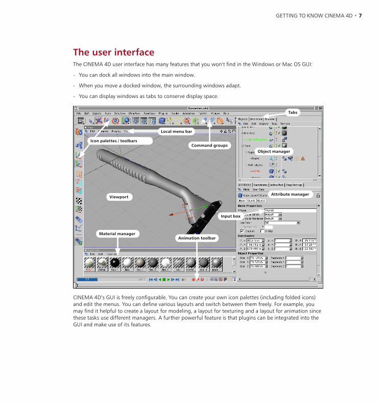
6 • CHAPTER 1 GETTING TO KNOW CINEMA 4D • 7
The user interfaceThe CINEMA 4D user interface has many features that you won't find in the Windows or Mac OS GUI:
- You can dock all windows into the main window.
- When you move a docked window, the surrounding windows adapt.
- You can display windows as tabs to conserve display space.
Icon palettes / toolbarsCommand groups
Object manager
Attribute manager
Tabs
Local menu bar
Viewport
Animation toolbarMaterial manager
Input box
CINEMA 4D’s GUI is freely configurable. You can create your own icon palettes (including folded icons) and edit the menus. You can define various layouts and switch between them freely. For example, you may find it helpful to create a layout for modeling, a layout for texturing and a layout for animation since these tasks use different managers. A further powerful feature is that plugins can be integrated into the GUI and make use of its features.
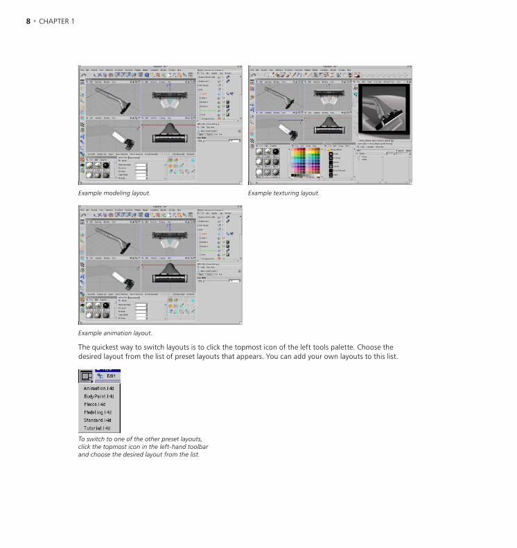
8 • CHAPTER 1 GETTING TO KNOW CINEMA 4D • 9
Example modeling layout. Example texturing layout.
Example animation layout.
The quickest way to switch layouts is to click the topmost icon of the left tools palette. Choose the desired layout from the list of preset layouts that appears. You can add your own layouts to this list.
To switch to one of the other preset layouts, click the topmost icon in the left-hand toolbar and choose the desired layout from the list.
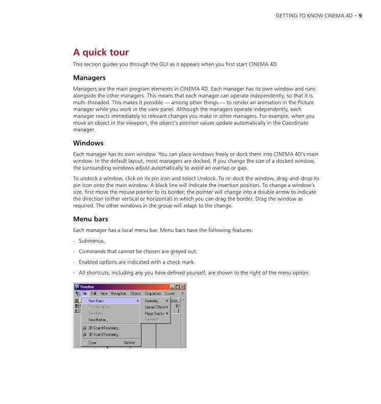
8 • CHAPTER 1 GETTING TO KNOW CINEMA 4D • 9
A quick tourThis section guides you through the GUI as it appears when you first start CINEMA 4D.
Managers
Managers are the main program elements in CINEMA 4D. Each manager has its own window and runs alongside the other managers. This means that each manager can operate independently, so that it is multi-threaded. This makes it possible — among other things — to render an animation in the Picture manager while you work in the view panel. Although the managers operate independently, each manager reacts immediately to relevant changes you make in other managers. For example, when you move an object in the viewport, the object’s position values update automatically in the Coordinate manager.
Windows
Each manager has its own window. You can place windows freely or dock them into CINEMA 4D’s main window. In the default layout, most managers are docked. If you change the size of a docked window, the surrounding windows adjust automatically to avoid an overlap or gap.
To undock a window, click on its pin icon and select Undock. To re-dock the window, drag-and-drop its pin icon onto the main window. A black line will indicate the insertion position. To change a window’s size, first move the mouse pointer to its border; the pointer will change into a double arrow to indicate the direction (either vertical or horizontal) in which you can drag the border. Drag the window as required. The other windows in the group will adapt to the change.
Menu bars
Each manager has a local menu bar. Menu bars have the following features:
- Submenus.
- Commands that cannot be chosen are greyed out.
- Enabled options are indicated with a check mark.
- All shortcuts, including any you have defined yourself, are shown to the right of the menu option.
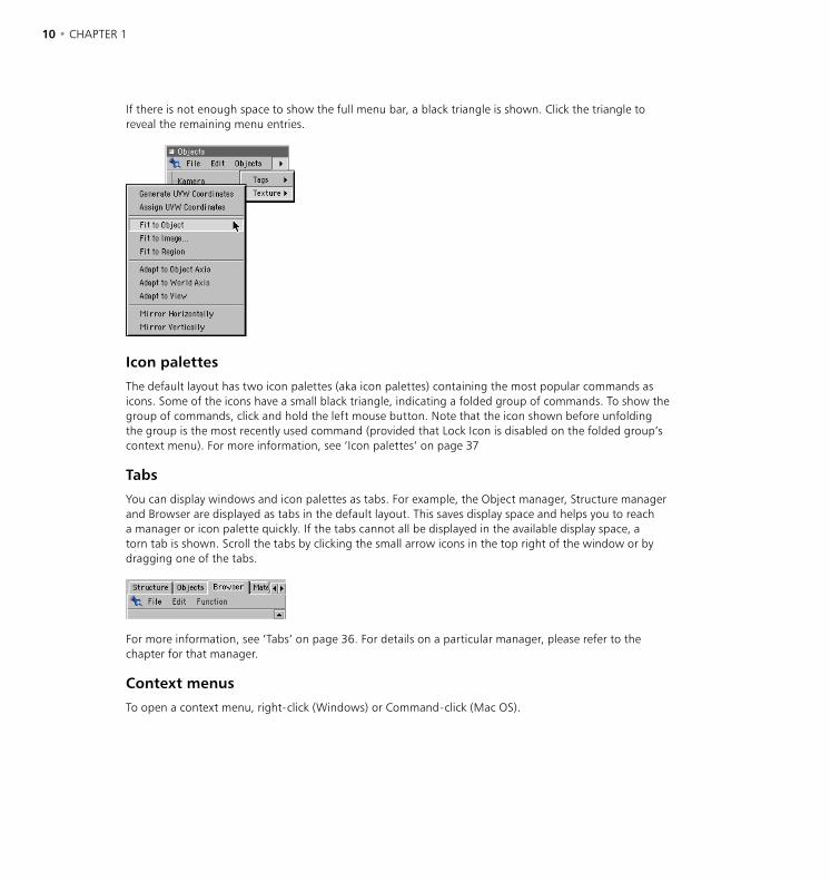
10 • CHAPTER 1 GETTING TO KNOW CINEMA 4D • 11
If there is not enough space to show the full menu bar, a black triangle is shown. Click the triangle to reveal the remaining menu entries.
Icon palettes
The default layout has two icon palettes (aka icon palettes) containing the most popular commands as icons. Some of the icons have a small black triangle, indicating a folded group of commands. To show the group of commands, click and hold the left mouse button. Note that the icon shown before unfolding the group is the most recently used command (provided that Lock Icon is disabled on the folded group’s context menu). For more information, see ‘Icon palettes’ on page 37
Tabs
You can display windows and icon palettes as tabs. For example, the Object manager, Structure manager and Browser are displayed as tabs in the default layout. This saves display space and helps you to reach a manager or icon palette quickly. If the tabs cannot all be displayed in the available display space, a torn tab is shown. Scroll the tabs by clicking the small arrow icons in the top right of the window or by dragging one of the tabs.
For more information, see ‘Tabs’ on page 36. For details on a particular manager, please refer to the chapter for that manager.
Context menus
To open a context menu, right-click (Windows) or Command-click (Mac OS).
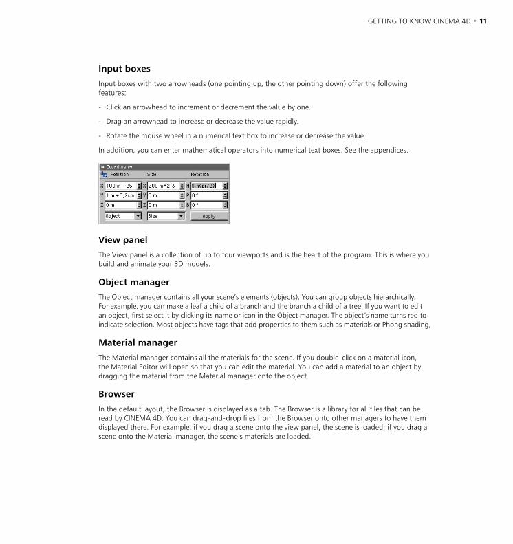
10 • CHAPTER 1 GETTING TO KNOW CINEMA 4D • 11
Input boxes
Input boxes with two arrowheads (one pointing up, the other pointing down) offer the following features:
- Click an arrowhead to increment or decrement the value by one.
- Drag an arrowhead to increase or decrease the value rapidly.
- Rotate the mouse wheel in a numerical text box to increase or decrease the value.
In addition, you can enter mathematical operators into numerical text boxes. See the appendices.
View panel
The View panel is a collection of up to four viewports and is the heart of the program. This is where you build and animate your 3D models.
Object manager
The Object manager contains all your scene’s elements (objects). You can group objects hierarchically. For example, you can make a leaf a child of a branch and the branch a child of a tree. If you want to edit an object, first select it by clicking its name or icon in the Object manager. The object’s name turns red to indicate selection. Most objects have tags that add properties to them such as materials or Phong shading,
Material manager
The Material manager contains all the materials for the scene. If you double-click on a material icon, the Material Editor will open so that you can edit the material. You can add a material to an object by dragging the material from the Material manager onto the object.
Browser
In the default layout, the Browser is displayed as a tab. The Browser is a library for all files that can be read by CINEMA 4D. You can drag-and-drop files from the Browser onto other managers to have them displayed there. For example, if you drag a scene onto the view panel, the scene is loaded; if you drag a scene onto the Material manager, the scene’s materials are loaded.
12 • CHAPTER 1
Coordinate manager
You can use the Coordinate manager for precision modeling or manipulation. For example, rather than scale an object in the view panel, you can enter the exact size in the Coordinate manager. As with all numerical text boxes, you can also enter mathematical operators.
Animation toolbar
This palette gives you simple animation controls. See ‘Animation Toolbar’ on page 832. For more advanced animation tools, open the Timeline.
Active Tool manager
This manager shows the settings for the active tool — the settings vary according to the tool being used. For a detailed description of the options, see the relevant chapter for the tool in question.
Snap settings
Many types of snapping are available. For example, you can snap to the grid or snap to other elements. For more information, see ‘Snap Settings’ on page 493.
Attribute manager
The Attribute manager gives you access to all properties of the selected objects, materials, shaders, tags, nodes, sequences and keys. See Chapter 21, ‘Attribute Manager’.

2 Views and Viewports

VIEWS AND VIEWPORTS • 15
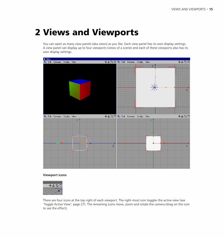
VIEWS AND VIEWPORTS • 15
You can open as many view panels (aka views) as you like. Each view panel has its own display settings. A view panel can display up to four viewports (views of a scene) and each of these viewports also has its own display settings.
Viewport icons
There are four icons at the top right of each viewport. The right-most icon toggles the active view (see ‘Toggle Active View’, page 27). The remaining icons move, zoom and rotate the camera (drag on the icon to see the effect).
2 Views and Viewports
16 • CHAPTER 2 VIEWS AND VIEWPORTS • 17
Edit MenuUndo View / Redo View
Each viewport has its own Undo View/Redo View functions (the Undo/Redo functions of the main window do not affect editor cameras, i.e. those in viewports).
The short-cut for Undo View is Ctrl+Shift+Z. For Redo View, use Ctrl+Shift+Y.
FrameFrame Selected Elements
The camera will move so that the selected elements (e.g. objects, polygons) fill the viewport and are centered.
Frame Active Object
The camera will move so that the active objects fill the viewport and are centered.
Frame Scene Without Camera/Light
The camera will move so that all objects, apart from lights and cameras, fill the active viewport and are centered.
Frame Scene
The camera will move so that all objects, including lights and cameras, fill the active viewport and are centered.
Frame Default
This function resets the viewport to the default values, as if you had just started CINEMA 4D.
Use as Render ViewIf this option is enabled, the active camera of the active viewport is used for the rendering in the Picture Viewer.
RedrawThis function redraws the scene. Usually, CINEMA 4D updates viewports automatically. Sometimes this is not possible, such as when you use several CPU-intensive commands in a short space of time.
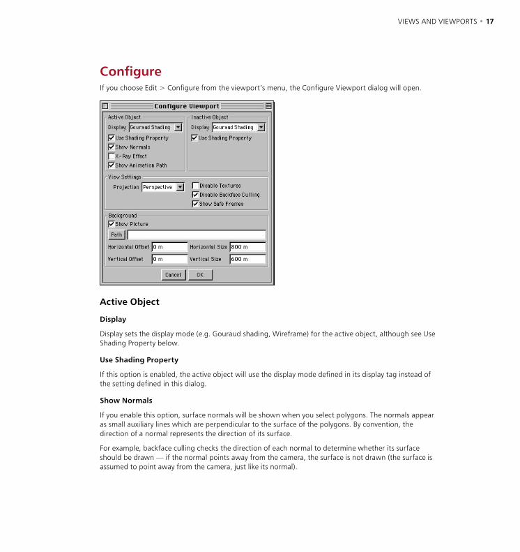
16 • CHAPTER 2 VIEWS AND VIEWPORTS • 17
ConfigureIf you choose Edit > Configure from the viewport’s menu, the Configure Viewport dialog will open.
Active Object
Display
Display sets the display mode (e.g. Gouraud shading, Wireframe) for the active object, although see Use Shading Property below.
Use Shading Property
If this option is enabled, the active object will use the display mode defined in its display tag instead of the setting defined in this dialog.
Show Normals
If you enable this option, surface normals will be shown when you select polygons. The normals appear as small auxiliary lines which are perpendicular to the surface of the polygons. By convention, the direction of a normal represents the direction of its surface.
For example, backface culling checks the direction of each normal to determine whether its surface should be drawn — if the normal points away from the camera, the surface is not drawn (the surface is assumed to point away from the camera, just like its normal).
18 • CHAPTER 2 VIEWS AND VIEWPORTS • 19
X-ray Effect
To enter X-ray mode, enable this option. If the active object is a polygon object, it will become semi-transparent so that you can see all of its points and edges.
Show Animation Path
Enable this option to see the active object’s animation path. The path then appears as a yellow curve in the viewport. Edit the animation path as you would a spline, i.e. drag curve points to new positions and edit their tangents.
Inactive Object
Display
Display sets the display mode (e.g. Gouraud shading, wireframe) for the inactive objects in the scene.
Use Shading Property
If this option is activated, the inactive objects will use the display mode defined in their display tags instead of the setting defined in this dialog.
View Settings
Projection
You can use this setting to change the projection type (e.g. to Perspective, Bird, Dimetric).
Disable Textures
To switch off realtime texture mapping, enable this option.
Disable Backface Culling
You can select this option to switch off backface culling.
Backface culling merely hides an object’s concealed points and edges. If you disable backface culling, you will still see objects behind other objects in wireframe display mode.
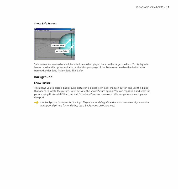
18 • CHAPTER 2 VIEWS AND VIEWPORTS • 19
Show Safe Frames
Render Safe
Action Safe
Safe frames are areas which will be in full view when played back on the target medium. To display safe frames, enable this option and also on the Viewport page of the Preferences enable the desired safe frames (Render Safe, Action Safe, Title Safe).
Background
Show Picture
This allows you to place a background picture in a planar view. Click the Path button and use the dialog that opens to locate the picture. Next, activate the Show Picture option. You can reposition and scale the picture using Horizontal Offset, Vertical Offset and Size. You can use a different picture in each planar viewport.
Use background pictures for ‘tracing’. They are a modeling aid and are not rendered. If you want a background picture for rendering, use a Background object instead.

20 • CHAPTER 2 VIEWS AND VIEWPORTS • 21
Cameras MenuEach viewport has its own independent camera, called the editor camera. The editor camera is active by default, but you can create and activate your own cameras. Unlike the editor camera, your own cameras are shown as objects in the Object manager.
Scene CamerasTo activate your own camera, choose it from this list. For more details on creating and using your own cameras, see ‘Cameras’ on page 253.
Link Active ObjectChoose this command to view the scene from the origin of the active object. Your view will point in the direction of the object’s Z-axis.
This command can be useful, among other things, for checking which objects a light source can 'see'. Keep in mind that in some display modes your view may be blocked by the active object’s surfaces.
Editor CameraThis command activates the editor camera.
ProjectionsHere you choose the projection mode for the camera. You can choose from over a dozen modes. An example of each projection mode is shown in the following pictures.
The camera’s position may change when you change the mode. To avoid this, select the view (e.g. View 3) from the View menu.
Perspective: The default projection mode for the viewport. It shows you the scene as though looking through a conventional camera.
Parallel: The vanishing point is infinitely distant. All lines are parallel.
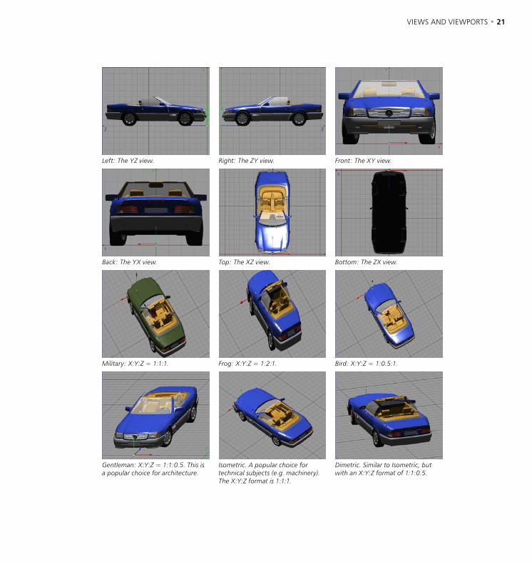
20 • CHAPTER 2 VIEWS AND VIEWPORTS • 21
Left: The YZ view. Right: The ZY view. Front: The XY view.
Back: The YX view. Top: The XZ view. Bottom: The ZX view.
Military: X:Y:Z = 1:1:1. Frog: X:Y:Z = 1:2:1. Bird: X:Y:Z = 1:0.5:1.
Gentleman: X:Y:Z = 1:1:0.5. This is a popular choice for architecture.
Isometric. A popular choice for technical subjects (e.g. machinery). The X:Y:Z format is 1:1:1.
Dimetric. Similar to Isometric, but with an X:Y:Z format of 1:1:0.5.
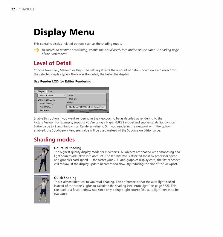
22 • CHAPTER 2 VIEWS AND VIEWPORTS • 23
Display MenuThis contains display-related options such as the shading mode.
To switch on realtime antialiasing, enable the Antialiased Lines option on the OpenGL Shading page of the Preferences.
Level of DetailChoose from Low, Medium or High. The setting affects the amount of detail shown on each object for the selected display type – the lower the detail, the faster the display.
Use Render LOD for Editor Rendering
Enable this option if you want rendering in the viewport to be as detailed as rendering to the Picture Viewer. For example, suppose you’re using a HyperNURBS model and you’ve set its Subdivision Editor value to 2 and Subdivision Renderer value to 5. If you render in the viewport with the option enabled, the Subdivision Renderer value will be used instead of the Subdivision Editor value.
Shading modesGouraud ShadingThe highest quality display mode for viewports. All objects are shaded with smoothing and light sources are taken into account. The redraw rate is affected most by processor speed and graphics card speed — the faster your CPU and graphics display card, the faster scenes will redraw. If the display update becomes too slow, try reducing the size of the viewport.
Quick ShadingThis is almost identical to Gouraud Shading. The difference is that the auto light is used instead of the scene’s lights to calculate the shading (see ‘Auto Light’ on page 562). This can lead to a faster redraw rate since only a single light source (the auto light) needs to be evaluated.

22 • CHAPTER 2 VIEWS AND VIEWPORTS • 23
WireframeObjects are shown as lines. The display is much faster than with Gouraud and Quick Shading. Wireframe is suitable for complex scenes, especially with Backface Culling on (see ‘Disable Backface Culling’ on page 24).
IsoparmsThis mode displays isoparm lines for objects that use them (e.g. NURBS objects). Other objects, such as polygon objects, will be displayed in wireframe. The isoparm display mode is very fast and particularly suited to complex scenes.
Shaded BoxThis mode displays each object as a shaded box. Each box has the same dimensions as the object it represents. This is a fast display mode that is suited to character animation or large scenes.
BoxThis mode displays each object as a wireframe box. Each wireframe box has the same dimensions as the object it represents. Box is the second fastest display mode available, making it useful for extremely demanding scenes.
SkeletonThis is the fastest display mode of all. It is only suitable for hierarchical structures. Each object origin is shown as a small dot and the dots are connected according to the hierarchy. This mode can be useful for character animation. Not only is it extremely fast, it also removes all non-critical lines to expose the skeleton.
Use Shading PropertyIf this option is enabled, objects use the display mode defined in their Display tags. Objects without a Display tag continue to use the viewport’s shading mode.
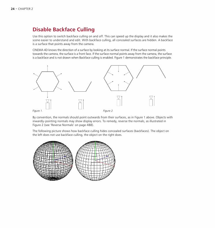
24 • CHAPTER 2 VIEWS AND VIEWPORTS • 25
Disable Backface CullingUse this option to switch backface culling on and off. This can speed up the display and it also makes the scene easier to understand and edit. With backface culling, all concealed surfaces are hidden. A backface is a surface that points away from the camera.
CINEMA 4D knows the direction of a surface by looking at its surface normal. If the surface normal points towards the camera, the surface is a front face. If the surface normal points away from the camera, the surface is a backface and is not drawn when Backface culling is enabled. Figure 1 demonstrates the backface principle.
Figure 1. Figure 2.
By convention, the normals should point outwards from their surfaces, as in Figure 1 above. Objects with inwardly-pointing normals may show display errors. To remedy, reverse the normals, as illustrated in Figure 2 (see ‘Reverse Normals’ on page 488).
The following picture shows how backface culling hides concealed surfaces (backfaces). The object on the left does not use backface culling, the object on the right does.
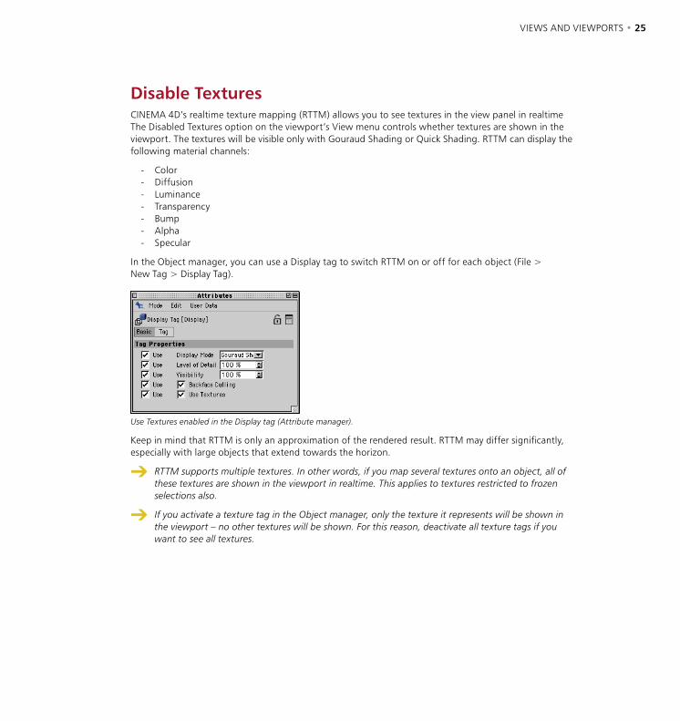
24 • CHAPTER 2 VIEWS AND VIEWPORTS • 25
Disable TexturesCINEMA 4D’s realtime texture mapping (RTTM) allows you to see textures in the view panel in realtime The Disabled Textures option on the viewport’s View menu controls whether textures are shown in the viewport. The textures will be visible only with Gouraud Shading or Quick Shading. RTTM can display the following material channels:
- Color- Diffusion- Luminance- Transparency- Bump- Alpha- Specular
In the Object manager, you can use a Display tag to switch RTTM on or off for each object (File > New Tag > Display Tag).
Use Textures enabled in the Display tag (Attribute manager).
Keep in mind that RTTM is only an approximation of the rendered result. RTTM may differ significantly, especially with large objects that extend towards the horizon.
RTTM supports multiple textures. In other words, if you map several textures onto an object, all of these textures are shown in the viewport in realtime. This applies to textures restricted to frozen selections also.
If you activate a texture tag in the Object manager, only the texture it represents will be shown in the viewport – no other textures will be shown. For this reason, deactivate all texture tags if you want to see all textures.
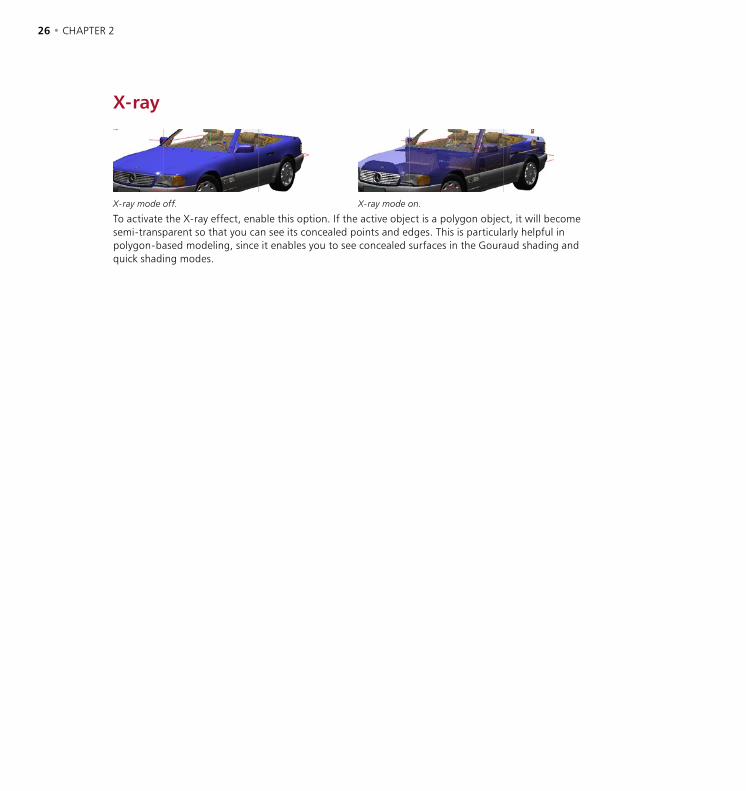
26 • CHAPTER 2 VIEWS AND VIEWPORTS • 27
X-ray
X-ray mode off. X-ray mode on.
To activate the X-ray effect, enable this option. If the active object is a polygon object, it will become semi-transparent so that you can see its concealed points and edges. This is particularly helpful in polygon-based modeling, since it enables you to see concealed surfaces in the Gouraud shading and quick shading modes.
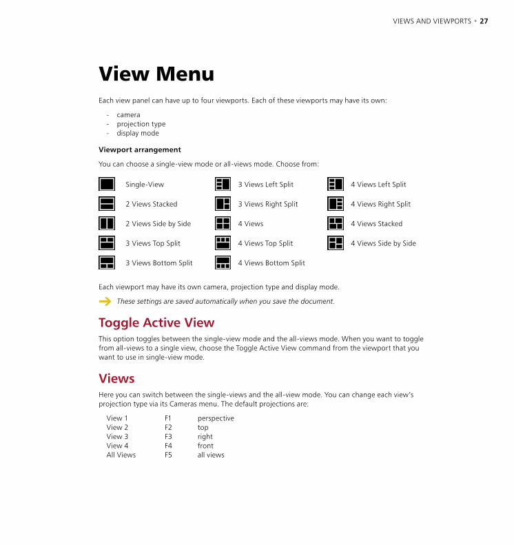
26 • CHAPTER 2 VIEWS AND VIEWPORTS • 27
View MenuEach view panel can have up to four viewports. Each of these viewports may have its own:
- camera- projection type- display mode
Viewport arrangement
You can choose a single-view mode or all-views mode. Choose from:
Single-View 3 Views Left Split 4 Views Left Split
2 Views Stacked 3 Views Right Split 4 Views Right Split
2 Views Side by Side 4 Views 4 Views Stacked
3 Views Top Split 4 Views Top Split 4 Views Side by Side
3 Views Bottom Split 4 Views Bottom Split
Each viewport may have its own camera, projection type and display mode.
These settings are saved automatically when you save the document.
Toggle Active ViewThis option toggles between the single-view mode and the all-views mode. When you want to toggle from all-views to a single view, choose the Toggle Active View command from the viewport that you want to use in single-view mode.
ViewsHere you can switch between the single-views and the all-view mode. You can change each view’s projection type via its Cameras menu. The default projections are:
View 1 F1 perspectiveView 2 F2 topView 3 F3 rightView 4 F4 frontAll Views F5 all views


3 Configuration

CONFIGURATION • 31

CONFIGURATION • 31
CINEMA 4D has hundreds of commands and a freely customizable GUI. This means that there are many settings also. To keep CINEMA 4D easy to use, the settings have been placed in various, relevant parts of the program. This chapter shows you where to find these settings and how to use them. Some of the settings are described in other chapters — where this is the case, you will see a reference to the relevant page.
Configuration dialogsPreferences
These settings control the general behavior of CINEMA 4D. For example, you can change the background color used by viewports. To access the preferences, choose Edit > Preferences from the main menu. See page 46 onwards for a full description of the preferences.
Project settings
These settings, such as the frame rate, apply to the active project only. To access the project settings, choose Edit > Project Settings from the main menu or Edit > Project Settings from the Timeline’s menu. The project settings are saved whenever you save the scene. See ‘Project Settings’ on page 84.
You can create your own default layout. To do this, arrange the layout as required, then save the scene using the filename ‘template.c4d’.
Viewport settings
Here you control aspects of viewport display — such as the shading mode used for selected objects and the shading mode used for other objects. Each viewport has its own settings. To access the viewport settings, in the viewport choose Edit > Configure. The viewport settings are saved when you save the scene. See ‘Configure’ on page 17 for a full account of the viewport settings.
Render settings
These settings define how the active scene will be rendered — e.g. you can set the save path and output resolution. To access the render settings, choose Render > Render Settings from the main menu. The render settings are saved when you save the scene. See ‘Render Settings’ on page 531.
Import / Export settings
These settings affect file import and file export. For example, 3DS files can be scaled up by a factor of ten on import. To access the import/export settings, choose Edit > Preferences from the main menu. See pages 59-78 for descriptions of all the import/export settings.
3 Configuration
32 • CHAPTER 3 CONFIGURATION • 33
Browser settings
Here you can control the display of thumbnails in the Browser — such as the size of the thumbnails and the file formats shown. To access the browser settings, choose Edit > Preferences from the Browser’s menu. The browser settings are saved when you save the scene. See ‘Preferences’ on page 99.
To prevent the Browser loading the settings, disable the Load Manager Settings option on the Document page of the preferences.
Snap settings
These settings control the behavior of snapping. For example, you can switch on point snapping. To access the snap settings, choose Window > Snap Settings from the main menu. The snap settings are saved when you save the scene. See ‘Snap Settings’ on page 493.
Configuration managersCommand manager
Use this manager to create or edit palettes and to create or edit short-cuts. To access the Command manager, choose Window > Layout > Command Manager from the main menu. The Command manager settings are saved when you quit CINEMA 4D. See ‘The Command Manager’ on page 41.
Short-cuts are saved automatically when you quit CINEMA 4D.
Menu manager
Here you can create your own menu structure for each manager. To access the Menu manager, choose Window > Layout > Menu Manager from the main menu. The Menu manager’s settings are saved when you quit CINEMA 4D. You can also save the settings by clicking the Save All Changes button in the Menu manager. See ‘The Menu Manager’ on page 43.
Other settingsThere are many settings in addition to those mentioned above. These settings are always saved in the scene file. To prevent them from being loaded into the managers with the scene, disable the Load Manager Settings option on the preferences (Document page). Each setting is documented in the relevant chapter.
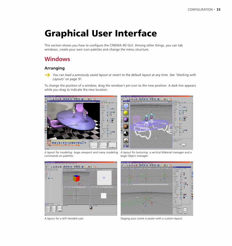
32 • CHAPTER 3 CONFIGURATION • 33
Graphical User InterfaceThis section shows you how to configure the CINEMA 4D GUI. Among other things, you can tab windows, create your own icon palettes and change the menu structure.
WindowsArranging
You can load a previously saved layout or revert to the default layout at any time. See ‘Working with Layouts’ on page 91.
To change the position of a window, drag the window’s pin icon to the new position. A dark line appears while you drag to indicate the new location.
A layout for modeling: large viewport and many modeling commands on palettes.
A layout for texturing: a vertical Material manager and a large Object manager.
A layout for a left-handed user. Staging your scene is easier with a custom layout.
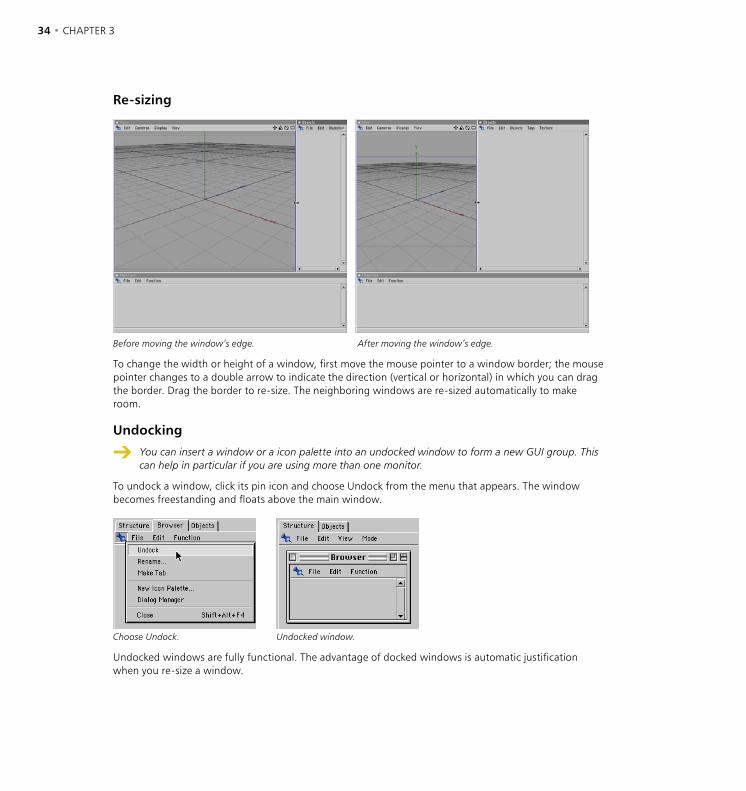
34 • CHAPTER 3 CONFIGURATION • 35
Re-sizing
Before moving the window’s edge. After moving the window’s edge.
To change the width or height of a window, first move the mouse pointer to a window border; the mouse pointer changes to a double arrow to indicate the direction (vertical or horizontal) in which you can drag the border. Drag the border to re-size. The neighboring windows are re-sized automatically to make room.
Undocking
You can insert a window or a icon palette into an undocked window to form a new GUI group. This can help in particular if you are using more than one monitor.
To undock a window, click its pin icon and choose Undock from the menu that appears. The window becomes freestanding and floats above the main window.
Choose Undock. Undocked window.
Undocked windows are fully functional. The advantage of docked windows is automatic justification when you re-size a window.

34 • CHAPTER 3 CONFIGURATION • 35
Docking
New windows are undocked by default. To dock a window, drag its pin icon to the docking position. A dark line appear while you drag to show where the window will be inserted.
To test the docking feature, first add a new view panel by choosing Main menu: Window > New View Panel. Drag the new view panel’s pin to the desired insertion position in the interface, such as between the Object manager and Attribute manager (check that you can see the dark line before you release the mouse).
New view, still undocked. Here the new view is docked.
To remove a window, click the window’s pin and choose Undock. Click the pin once more and this time choose Close.
Naming
The Rename function in the pin’s menu enables you to name a window or icon palette. An icon palette’s name is only shown if the palette is displayed as a tab.
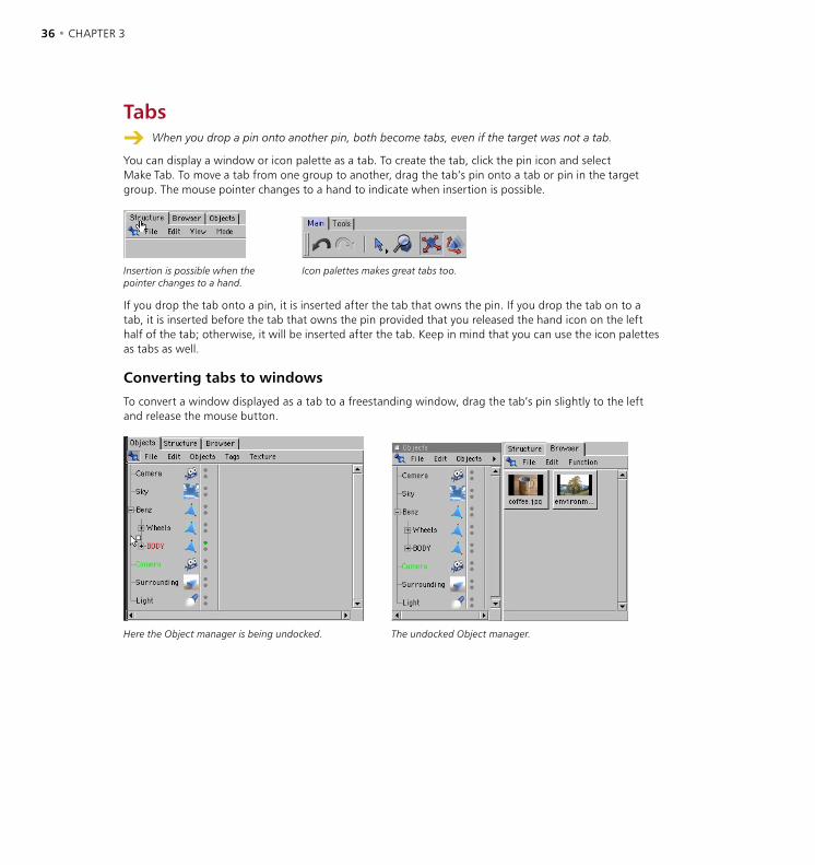
36 • CHAPTER 3 CONFIGURATION • 37
Tabs When you drop a pin onto another pin, both become tabs, even if the target was not a tab.
You can display a window or icon palette as a tab. To create the tab, click the pin icon and select Make Tab. To move a tab from one group to another, drag the tab’s pin onto a tab or pin in the target group. The mouse pointer changes to a hand to indicate when insertion is possible.
Insertion is possible when the pointer changes to a hand.
Icon palettes makes great tabs too.
If you drop the tab onto a pin, it is inserted after the tab that owns the pin. If you drop the tab on to a tab, it is inserted before the tab that owns the pin provided that you released the hand icon on the left half of the tab; otherwise, it will be inserted after the tab. Keep in mind that you can use the icon palettes as tabs as well.
Converting tabs to windows
To convert a window displayed as a tab to a freestanding window, drag the tab’s pin slightly to the left and release the mouse button.
Here the Object manager is being undocked. The undocked Object manager.

36 • CHAPTER 3 CONFIGURATION • 37
Icon Palettes An undocked palette is a window in its own right. For example, it can contain several icon palettes
and windows. This is especially useful if you are using more than one monitor.
Icon palettes, also known as toolbars, may contain any command that can be selected from a menu. Commands in palettes can be shown as icons, text or as icons and text. Icon palettes help you reach important commands quickly. You can edit the existing palettes and you can create new palettes as well as dock them into the layout.
Commands for saving, loading and changing the appearance of icon palettes are available from the icon palette’s context menu. To access a icon palette’s context menu, right-click (Windows) or Command-click (Mac OS) the icon palette.
Creating a new icon palette
New icon palette, still empty.
To create a new (empty) icon palette, do one of the following:
- Choose Window > Layout > New Icon Palette (main window).
- Click the pin of any window (near the window’s top-left corner) and choose New Icon Palette from the pin’s menu.
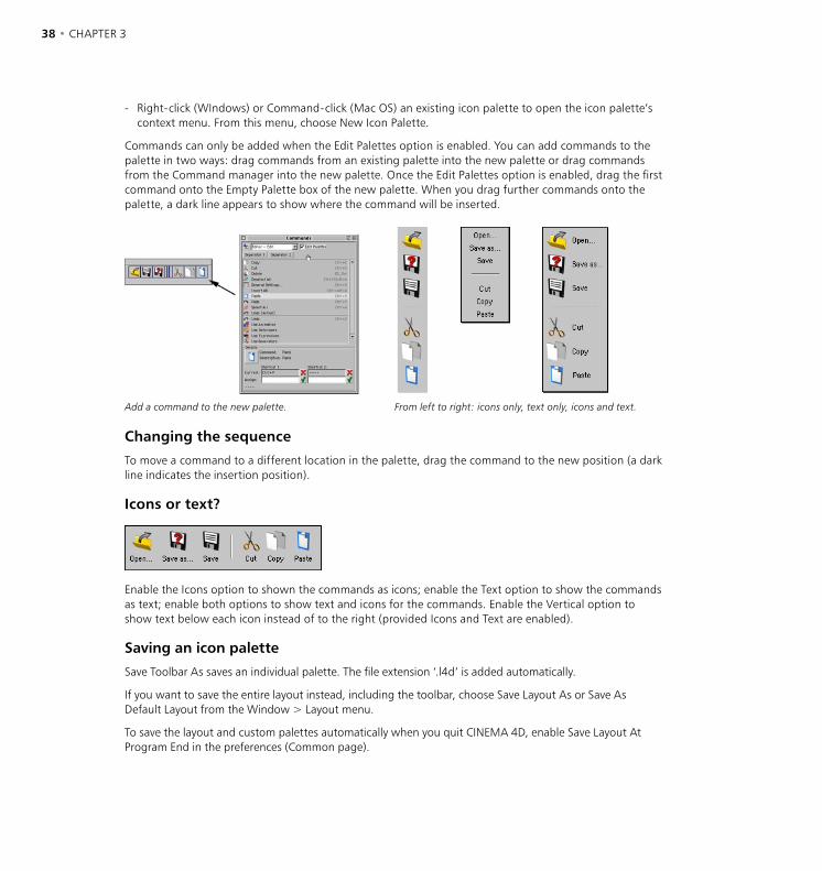
38 • CHAPTER 3 CONFIGURATION • 39
- Right-click (WIndows) or Command-click (Mac OS) an existing icon palette to open the icon palette’s context menu. From this menu, choose New Icon Palette.
Commands can only be added when the Edit Palettes option is enabled. You can add commands to the palette in two ways: drag commands from an existing palette into the new palette or drag commands from the Command manager into the new palette. Once the Edit Palettes option is enabled, drag the first command onto the Empty Palette box of the new palette. When you drag further commands onto the palette, a dark line appears to show where the command will be inserted.
Add a command to the new palette. From left to right: icons only, text only, icons and text.
Changing the sequence
To move a command to a different location in the palette, drag the command to the new position (a dark line indicates the insertion position).
Icons or text?
Enable the Icons option to shown the commands as icons; enable the Text option to show the commands as text; enable both options to show text and icons for the commands. Enable the Vertical option to show text below each icon instead of to the right (provided Icons and Text are enabled).
Saving an icon palette
Save Toolbar As saves an individual palette. The file extension ‘.l4d’ is added automatically.
If you want to save the entire layout instead, including the toolbar, choose Save Layout As or Save As Default Layout from the Window > Layout menu.
To save the layout and custom palettes automatically when you quit CINEMA 4D, enable Save Layout At Program End in the preferences (Common page).

38 • CHAPTER 3 CONFIGURATION • 39
Loading an icon palette
Use the Load Toolbar command to load a previously saved icon palette. The toolbar appears as a freestanding window which you can integrate into the layout as desired.
Vertical or horizontal?
Choose Transpose to toggle between vertical and horizontal alignment of commands.
Rows and columns
The values you select for Rows/Columns defines the number of rows or columns used for a palette. If Transpose is set to Vertical, this setting refers to the number of columns. If Transpose is set to Horizontal, this setting refers to the number of rows.
Think of this as the number of lines. For example, if you have 20 icons, setting this value to 2 will create two lines with 10 icons in each line. A value of 3 would create three lines, this time with 7 icons in the first two lines and 6 in the third line.
Icon size
If an icon is displayed at a different pixel size from its original size, it must be resampled. This may lead to a visible loss in picture quality.
Choose the size of icons from the Icon Size sub-menu: Large (32x32 pixels), Medium (24x24 pixels) or Small (16x16 pixels).
Large32 x 32 pixels.
Medium24 x 24 pixels.
Small16 x 16 pixels.
The original icon sizes are defined in the icon resource file (‘Resource/icons/c4d_icons.res’). The original sizes usually correspond to Large icons.
Creating folded command groups
You can group commands to form a folded palette. To do this, ensure that the Edit Palettes option is enabled, then position the mouse pointer over a command and right-click (Windows) or Command-click (Mac OS) to open the context menu. From this menu, choose Fold Palette. Now only one command is visible. This is called the visible command. The small arrow near the bottom right corner of the icon indicates that it contains other commands.

40 • CHAPTER 3 CONFIGURATION • 41
Next, disable the Edit Palettes option. Click and hold down the mouse button on the visible command. The folded palette appears. Either release the mouse button and select the desired command or position the mouse pointer over the desired command before you release the mouse button. Note that the visible command is also a hidden command.
If the Lock Icon command of the context menu is not selected, the visible command is always the most recently selected command. For example, if the visible command is Cube and you select the hidden Cone command, the Cone command becomes the visible command. The order of the commands in the folded palette corresponds to their order before they were folded. Therefore usually you’ll want to arrange the commands as desired before you fold them.
You can drag a visible command onto another palette. This enables you to use several folded command groups within the same palette. To create a palette with several folded command groups, firstly create two empty icon palettes. Use the first palette to create a folded command group, then drag the folded commands (i.e. the visible command) onto the second palette. Next, create the second folded group in the first palette, then drag it on to the second palette, and so on. Once the process is complete, close the redundant palette.
You can also use text-only display with folded palettes.
Unfolding command groups
You can unfold a folded group of commands into a palette of individual commands. Right-click (Windows) or Command-click (Mac OS) the visible command to open its context menu. From this menu, choose the Unfold command. You can only choose this command when the Edit Palettes option is enabled.
The lock icon
If the Lock Icon option in the context menu is disabled, the visible command for a folded group of commands is always the most recently selected command. For example, if the visible command is Cube and you select the hidden Cone command, the Cone command becomes the visible command. If this option is enabled, the current visible icon will be locked, meaning that no matter which tools you then use from the folded palette the visible command remains the same. This command can be selected only when the Edit Palettes option is enabled.
Deleting commands from palettes
To delete a command from a palette, position the mouse pointer on the command and right-click (Windows) or Command-click (Mac OS) to open the context menu. From this menu, choose Delete Command. This command can be selected only when the Edit Palettes option is enabled.
Editing a palette
Commands can only be added when the Edit Palettes option is enabled. Position the mouse pointer on a command and right-click (Windows) or Command-click (Mac OS). Choose Edit Palettes to enable/disable the option.
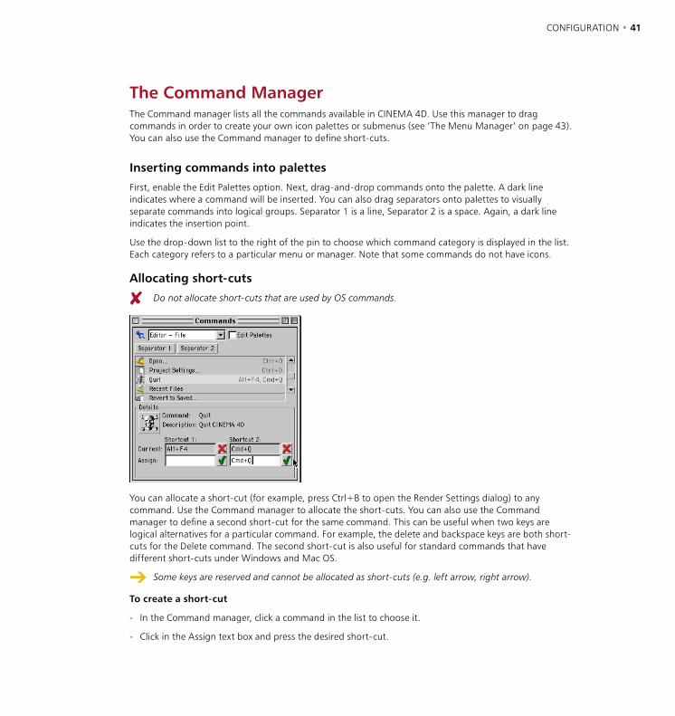
40 • CHAPTER 3 CONFIGURATION • 41
The Command ManagerThe Command manager lists all the commands available in CINEMA 4D. Use this manager to drag commands in order to create your own icon palettes or submenus (see ‘The Menu Manager’ on page 43). You can also use the Command manager to define short-cuts.
Inserting commands into palettes
First, enable the Edit Palettes option. Next, drag-and-drop commands onto the palette. A dark line indicates where a command will be inserted. You can also drag separators onto palettes to visually separate commands into logical groups. Separator 1 is a line, Separator 2 is a space. Again, a dark line indicates the insertion point.
Use the drop-down list to the right of the pin to choose which command category is displayed in the list. Each category refers to a particular menu or manager. Note that some commands do not have icons.
Allocating short-cuts
Do not allocate short-cuts that are used by OS commands.
You can allocate a short-cut (for example, press Ctrl+B to open the Render Settings dialog) to any command. Use the Command manager to allocate the short-cuts. You can also use the Command manager to define a second short-cut for the same command. This can be useful when two keys are logical alternatives for a particular command. For example, the delete and backspace keys are both short-cuts for the Delete command. The second short-cut is also useful for standard commands that have different short-cuts under Windows and Mac OS.
Some keys are reserved and cannot be allocated as short-cuts (e.g. left arrow, right arrow).
To create a short-cut
- In the Command manager, click a command in the list to choose it.
- Click in the Assign text box and press the desired short-cut.
42 • CHAPTER 3 CONFIGURATION • 43
- Click the green tick to the right of the text box. The short-cut appears in the Current box. To remove the short-cut, click the red cross icon.
Valid short-cuts are:
a single keyCtrl + a key Shift + a keyCtrl and Shift + a key
The short-cuts are saved in the layout.
CINEMA 4D’s built-in hotkeys are extremely useful. For example, if you hold down the 1 key you can move the camera no matter which tool is active. These hotkeys come at a price — you cannot use them for short-cuts, even if you combine them with Ctrl and/or Shift. If a short-cut has already been allocated, the command that uses the short-cut is displayed below the text boxes. You should remove the short-cut before reallocating it. (To remove the short-cut, select the command that currently uses the short-cut, then click the red cross).

42 • CHAPTER 3 CONFIGURATION • 43
The Menu Manager
Use the Menu manager to edit submenus and drop-down lists. You can also add new submenus. The Menu manager and the Command manager enable you to configure CINEMA 4D’s interface freely to the way you like to work.
The menus
CINEMA 4D has more than 25 menus. Use the drop-down list at the top of the manager to choose which menu is shown in the list. Submenus are prefixed with Submenu. To open or close a submenu, double-click it.
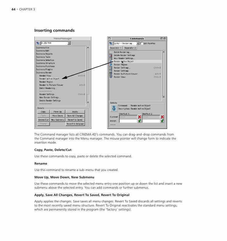
44 • CHAPTER 3 CONFIGURATION • 45
Inserting commands
The Command manager lists all CINEMA 4D’s commands. You can drag-and-drop commands from the Command manager into the Menu manager. The mouse pointer will change form to indicate the insertion mode.
Copy, Paste, Delete/Cut
Use these commands to copy, paste or delete the selected command.
Rename
Use this command to rename a sub-menu that you created.
Move Up, Move Down, New Submenu
Use these commands to move the selected menu entry one position up or down the list and insert a new submenu above the selected entry. You can add commands or further submenus.
Apply, Save All Changes, Revert To Saved, Revert To Original
Apply applies the changes. Save saves all menu changes. Revert To Saved discards all settings and reverts to the most recently saved menu structure. Revert To Original reactivates the standard menu settings, which are permanently stored in the program (the ‘factory’ settings).
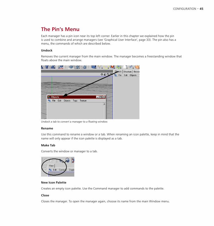
44 • CHAPTER 3 CONFIGURATION • 45
The Pin’s MenuEach manager has a pin icon near its top left corner. Earlier in this chapter we explained how the pin is used to combine and arrange managers (see ‘Graphical User Interface’, page 33). The pin also has a menu, the commands of which are described below.
Undock
Removes the current manager from the main window. The manager becomes a freestanding window that floats above the main window.
Undock a tab to convert a manager to a floating window.
Rename
Use this command to rename a window or a tab. When renaming an icon palette, keep in mind that the name will only appear if the icon palette is displayed as a tab.
Make Tab
Converts the window or manager to a tab.
New Icon Palette
Creates an empty icon palette. Use the Command manager to add commands to the palette.
Close
Closes the manager. To open the manager again, choose its name from the main Window menu.

46 • CHAPTER 3 CONFIGURATION • 47
Preferences To return CINEMA 4D to its factory settings, delete the file named ‘CINEMA 4D.prf’ within the Prefs
folder in the CINEMA 4D folder. The next time you start CINEMA 4D, the factory settings will be used and a new ‘CINEMA 4D.prf’ file will be created with these factory settings.
The Preferences settings enable you to change the editor’s appearance as well as influence the operation of commands. To open this dialog, choose Edit > Preferences.
Common
Language
Chose a language for CINEMA 4D’s interface from the installed language sets. After quitting and re-launching CINEMA 4D all messages, menus and dialogs will change to the new language.
Scheme
Choose one of the installed schemes from this drop-down list.
High Thread Priority
If you enable this option the system assigns a higher priority, i.e. more computing time, to CINEMA 4D than to other applications that are also running. If enabled, these other applications will run more slowly than usual. If you want to work in other applications while rendering in CINEMA 4D, you may find it useful to disable this option.
46 • CHAPTER 3 CONFIGURATION • 47
Use QuickTime
QuickTime may crash if you use damaged image files; this is not due to CINEMA 4D and hence we offer the option to disable QuickTime.
If you enable this option CINEMA 4D uses QuickTime, if installed on your system. Additional file formats will then be available to you. If the option is disabled the Browser will work slightly more quickly as it has fewer file formats to check.
Graphics Tablet, Use Hi-Res Coordinates
If you experience problems when using a graphics tablet with CINEMA 4D, enable the Graphics Tablet option. If you still experience problems and you’re using the latest driver for your tablet, disable Use Hi-Res Coordinates to use the tablet in mouse mode. Although you’ll lose some of the tablet’s resolution, you should barely notice the difference.
Save Layout At Program End
Always save a new layout using a unique name, even if you intend for it to be your normal layout. To save the layout, choose Window > Layout > Save Layout As.
If this option is enabled, the current layout will be saved when you quit CINEMA 4D. When you next start the program, the layout will be in the same state that you left it. This may possibly lead to unwelcome effects. For example, perhaps your usual layout is biased towards modeling (e.g. a large 3D viewport). You decide to create a layout specifically for texturing (e.g. a large Material manager). You save the texturing layout under its own name and quit the program. If the Save Layout At Program End option is enabled, the texturing layout will overwrite your usual layout.
Realtime Spinner
Disable this option to switch off realtime refresh in the viewport while you change the values of parameters in the Attribute manager. In other words, with this option off the viewport will only be refreshed once you’ve released the slider or mouse button. This is especially useful to prevent the viewport from slowing down when working with complex scenes.
Realtime Manager Update (During Animation)
If this option is enabled, animated parameters are shown in the Attribute manager in realtime when you play the animation.
Center Point Editing Axis
If you select points, edges or polygons when this option is enabled, a temporary axis system appears in the center of the selection.
Recalculate Scene On Rewind
This option affects only scenes which have been set up with Dynamics or Thinking Particles (optional CINEMA 4D modules). If you drag the time slider left while the option is enabled, the scene is recalculated from frame 0 to the current frame to ensure a correct result.
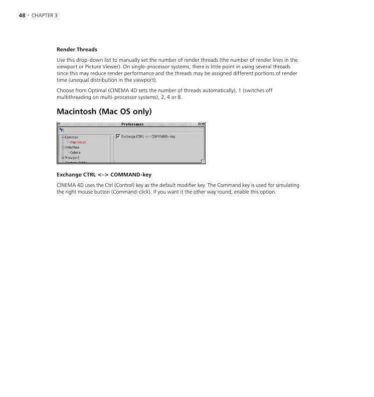
48 • CHAPTER 3 CONFIGURATION • 49
Render Threads
Use this drop-down list to manually set the number of render threads (the number of render lines in the viewport or Picture Viewer). On single-processor systems, there is little point in using several threads since this may reduce render performance and the threads may be assigned different portions of render time (unequal distribution in the viewport).
Choose from Optimal (CINEMA 4D sets the number of threads automatically), 1 (switches off multithreading on multi-processor systems), 2, 4 or 8.
Macintosh (Mac OS only)
Exchange CTRL <–> COMMAND-key
CINEMA 4D uses the Ctrl (Control) key as the default modifier key. The Command key is used for simulating the right mouse button (Command-click). If you want it the other way round, enable this option.
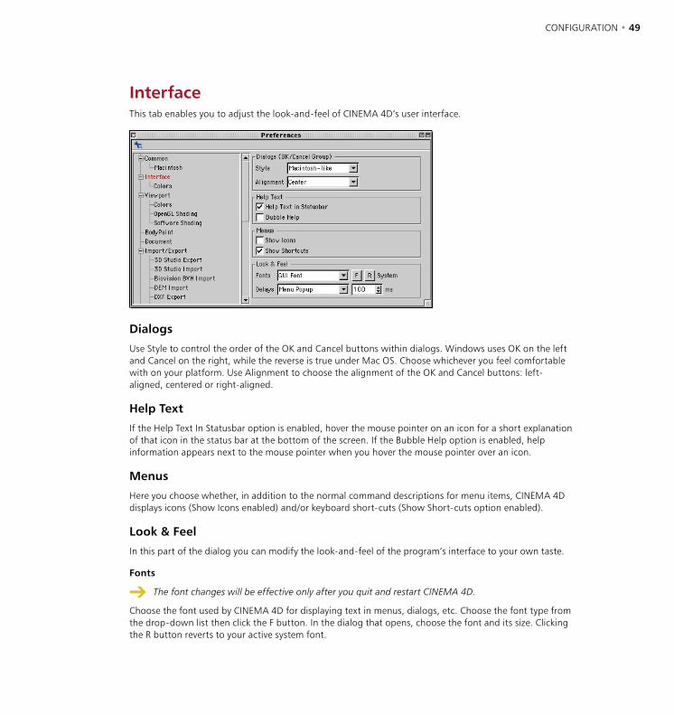
48 • CHAPTER 3 CONFIGURATION • 49
InterfaceThis tab enables you to adjust the look-and-feel of CINEMA 4D’s user interface.
Dialogs
Use Style to control the order of the OK and Cancel buttons within dialogs. Windows uses OK on the left and Cancel on the right, while the reverse is true under Mac OS. Choose whichever you feel comfortable with on your platform. Use Alignment to choose the alignment of the OK and Cancel buttons: left-aligned, centered or right-aligned.
Help Text
If the Help Text In Statusbar option is enabled, hover the mouse pointer on an icon for a short explanation of that icon in the status bar at the bottom of the screen. If the Bubble Help option is enabled, help information appears next to the mouse pointer when you hover the mouse pointer over an icon.
Menus
Here you choose whether, in addition to the normal command descriptions for menu items, CINEMA 4D displays icons (Show Icons enabled) and/or keyboard short-cuts (Show Short-cuts option enabled).
Look & Feel
In this part of the dialog you can modify the look-and-feel of the program’s interface to your own taste.
Fonts
The font changes will be effective only after you quit and restart CINEMA 4D.
Choose the font used by CINEMA 4D for displaying text in menus, dialogs, etc. Choose the font type from the drop-down list then click the F button. In the dialog that opens, choose the font and its size. Clicking the R button reverts to your active system font.

50 • CHAPTER 3 CONFIGURATION • 51
Delays
If you are a Windows user you may have noticed that windows and menus open much faster in CINEMA 4D than on your desktop. You can use the options under Delays to simulate this delayed reaction for various actions within CINEMA 4D. Choose the action from the drop-down list. Set the delay for this action in the text box to the right. (OK, so this isn’t exactly the most useful feature in CINEMA 4D :-)
Colors
Using the settings on this page, you can change the color of nearly all GUI elements in CINEMA 4D.
Live Refresh
The colors are changed in realtime. If this causes your system to slow down, disable the option and the color will be changed after you’ve released the mouse button.
RGB
Define the color of the GUI element using RGB sliders.
Bitmap
Enables you to load a 2D image as a background for the interface.
Reference
Choose Reference to open a list of presets for the GUI elements. In the list, click a preset’s name to enable its settings.
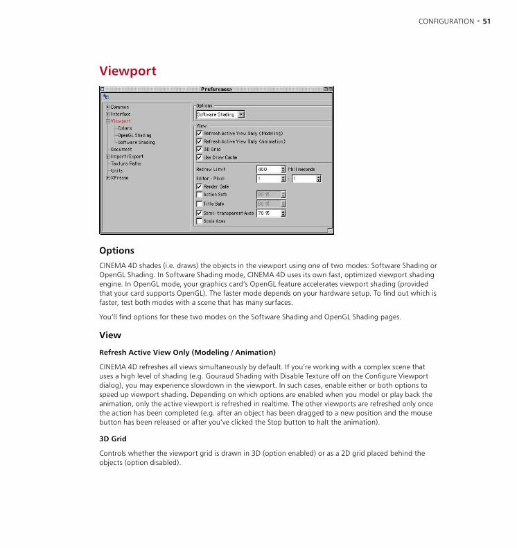
50 • CHAPTER 3 CONFIGURATION • 51
Viewport
Options
CINEMA 4D shades (i.e. draws) the objects in the viewport using one of two modes: Software Shading or OpenGL Shading. In Software Shading mode, CINEMA 4D uses its own fast, optimized viewport shading engine. In OpenGL mode, your graphics card’s OpenGL feature accelerates viewport shading (provided that your card supports OpenGL). The faster mode depends on your hardware setup. To find out which is faster, test both modes with a scene that has many surfaces.
You’ll find options for these two modes on the Software Shading and OpenGL Shading pages.
View
Refresh Active View Only (Modeling / Animation)
CINEMA 4D refreshes all views simultaneously by default. If you’re working with a complex scene that uses a high level of shading (e.g. Gouraud Shading with Disable Texture off on the Configure Viewport dialog), you may experience slowdown in the viewport. In such cases, enable either or both options to speed up viewport shading. Depending on which options are enabled when you model or play back the animation, only the active viewport is refreshed in realtime. The other viewports are refreshed only once the action has been completed (e.g. after an object has been dragged to a new position and the mouse button has been released or after you’ve clicked the Stop button to halt the animation).
3D Grid
Controls whether the viewport grid is drawn in 3D (option enabled) or as a 2D grid placed behind the objects (option disabled).
52 • CHAPTER 3 CONFIGURATION • 53
Use Draw Cache
Enable this option to speed up shading in the viewports. Keep in mind that RAM requirements rise slightly when you enable Use Draw Cache.
Redraw Limit
This process enables you to work smoothly in the viewports. With some complex scenes, you may be unable to move objects smoothly in the viewports with full shading due to hardware limitations such as processor speed. To help resolve this issue, CINEMA 4D estimates how long it will take to refresh the viewports. If the estimated time exceeds the redraw limit specified here, a faster display mode will be used automatically. For example, Quick Shading will be reduced to Wireframe. Or if the wireframe mode is still too slow, Box will be used instead.
The default value is 600 milliseconds. To prevent a less detailed display mode from being used, set Redraw Limit to a very high value such as 10000 milliseconds.
Editor : Pixel
These values specify the ratio of a pixel’s on-screen width to its on-screen height. The pixel ratio for most monitors is 1:1. However, some display media use a pixel ratio other than 1:1. This will lead to distortion unless the pixel ratio is adjusted accordingly. For example, circles will appear to be ellipses. To calculate the pixel ratio manually, expand the editor window to fill the entire screen. Select the side view and create a cube. Measure the width and height of the cube with a ruler and enter these values into the corresponding boxes.
Render Safe
You can set this option separately for each viewport using the viewport settings, which apply to the active viewport only. (See ‘Configure’, page 17.)
If this option is enabled, the boundaries of the film format are shown in the viewport.
Action Safe
You can set this option separately for each viewport using the viewport settings, which apply to the active viewport only. (See ‘Configure’, page 17.)
If this option is enabled, a frame appears in the 3D viewport to mark out the region in which it is safe for action to take place so that it will be in full view when played back on the target medium (monitor, TV screen, cinema screen). To adjust the size of the frame, enter a new percentage value into the box to the right. The percentage is based on the film format that is selected in the render settings.
If you’re a frequent moviegoer, you may have noticed that the screen’s curtains are pulled closer or further apart depending on the format of the film that’s playing. Even with TV screens, some of the picture may be lost. Use Action Safe to ensure the viewer sees everything that matters.
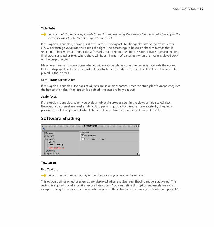
52 • CHAPTER 3 CONFIGURATION • 53
Title Safe
You can set this option separately for each viewport using the viewport settings, which apply to the active viewport only. (See ‘Configure’, page 17.)
If this option is enabled, a frame is shown in the 3D viewport. To change the size of the frame, enter a new percentage value into the box to the right. The percentage is based on the film format that is selected in the render settings. Title Safe marks out a region in which it is safe to place opening credits, final credits and other text, where there will be a minimum of distortion when the movie is played back on the target medium.
Many television sets have a dome-shaped picture-tube whose curvature increases towards the edges. Pictures displayed on these sets tend to be distorted at the edges. Text such as film titles should not be placed in these areas.
Semi-Transparent Axes
If this option is enabled, the axes of objects are semi-transparent. Enter the strength of transparency into the box to the right. If the option is disabled, the axes are fully opaque.
Scale Axes
If this option is enabled, when you scale an object its axes as seen in the viewport are scaled also. However, large or small axes make it difficult to perform quick actions (move, scale, rotate) by dragging a particular axis. If this option is disabled, the object axes retain their size when the object is scaled.
Software Shading
Textures
Use Textures
You can work more smoothly in the viewports if you disable this option.
This option defines whether textures are displayed when the Gouraud Shading mode is activated. This setting is applied globally, i.e. it affects all viewports. You can define this option separately for each viewport using the viewport settings, which apply to the active viewport only (see ‘Configure’, page 17).

54 • CHAPTER 3 CONFIGURATION • 55
Perspective Correction
If this option and Use Textures are both enabled, all material previews are corrected for perspective in the viewports.
OpenGL Shading
Refresh
Smart Window Refresh
The Smart Window Refresh function is not supported by all OpenGL cards. If display errors appear with the option enabled, your card does not support Smart Window Refresh.
When enabled, this option accelerates window refresh under OpenGL if, for example, you move an undocked manager over the viewports. If the option is disabled, OpenGL must refresh the entire screen each time.
Smart Live Selection
The Smart Live Selection function is not supported by all OpenGL cards. If display errors appear with the option enabled, your card does not support Smart Live Selection.
If this option is enabled, live selection under OpenGL is accelerated — only the selected polygons or points are redrawn, rather than the entire screen.
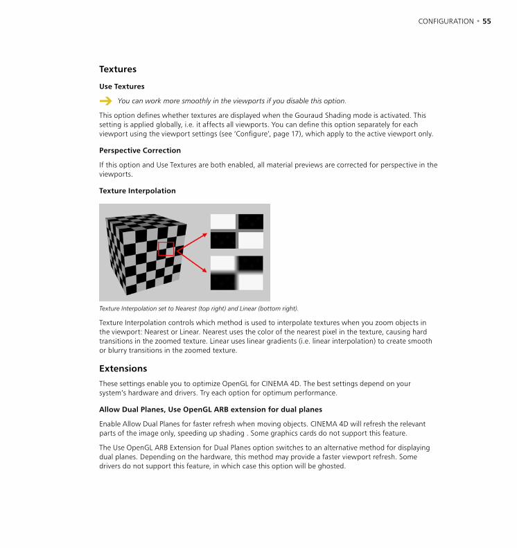
54 • CHAPTER 3 CONFIGURATION • 55
Textures
Use Textures
You can work more smoothly in the viewports if you disable this option.
This option defines whether textures are displayed when the Gouraud Shading mode is activated. This setting is applied globally, i.e. it affects all viewports. You can define this option separately for each viewport using the viewport settings (see ‘Configure’, page 17), which apply to the active viewport only.
Perspective Correction
If this option and Use Textures are both enabled, all material previews are corrected for perspective in the viewports.
Texture Interpolation
Texture Interpolation set to Nearest (top right) and Linear (bottom right).
Texture Interpolation controls which method is used to interpolate textures when you zoom objects in the viewport: Nearest or Linear. Nearest uses the color of the nearest pixel in the texture, causing hard transitions in the zoomed texture. Linear uses linear gradients (i.e. linear interpolation) to create smooth or blurry transitions in the zoomed texture.
Extensions
These settings enable you to optimize OpenGL for CINEMA 4D. The best settings depend on your system’s hardware and drivers. Try each option for optimum performance.
Allow Dual Planes, Use OpenGL ARB extension for dual planes
Enable Allow Dual Planes for faster refresh when moving objects. CINEMA 4D will refresh the relevant parts of the image only, speeding up shading . Some graphics cards do not support this feature.
The Use OpenGL ARB Extension for Dual Planes option switches to an alternative method for displaying dual planes. Depending on the hardware, this method may provide a faster viewport refresh. Some drivers do not support this feature, in which case this option will be ghosted.

56 • CHAPTER 3 CONFIGURATION • 57
Use Line Polygons
Enable this option for faster wireframe display. It affects wireframe display only.
Use OGL Points For Handles
Enable this option for faster display of object points (the points that are displayed when you select the Points tool). Some graphics cards do not support this feature.
Antialiased Lines
If this option is enabled, lines are smoothed (antialiased) by the OpenGL implementation provided the mode is supported.
Colors
Use this page to define the colors used in the viewports. Select the element that you wish to change from the list and change its color using the sliders or the system color dialog. You will see either three color sliders or a color table depending on the Color System setting on the Units page. The default setting is the RGB model with values specified as percentages. The color preview is shown to the left of the sliders. If you click on this color box, the system color dialog will open.
If you click the small triangle below the color box, a menu appears. Use this menu to change the color model or switch to the color table. This setting is retained for as long as the dialog is open. As soon as you close the dialog, the setting on the Units page is used.

56 • CHAPTER 3 CONFIGURATION • 57
BodyPaint
If you own the optional BodyPaint 3D module, use these settings to control BodyPaint 3D’s Undo Buffer, which enables you to undo changes to texture bitmaps.
Max Memory Usage
Sets the maximum amount of RAM reserved by BodyPaint 3D for undoing changes to texture bitmaps.
At Least
Defines the minimum number of changes that are stored in RAM and can be undone regardless of how much RAM is required. This parameter has a higher priority than Max Memory Usage.
Default Texture Format
Defines the default format used when you create a new texture. Change the texture’s format at any time using the Save As command.
Document
Save RTTM Textures
If you have enabled realtime texture mapping (i.e. the Disable Textures option in the Configure Viewport dialog is off), small temporary textures will be created so that you can see the textures in the viewports. These RTTM textures take a noticeable time to create and they must be calculated each time you load the scene. To speed up the loading process, enable Save RTTM Textures. The RTTM textures will then be saved within the scene file.

58 • CHAPTER 3 CONFIGURATION • 59
Save Particles
Suppose you’ve saved a scene containing particles whose time slider is past frame 0. When you next load the scene, the particle stream must be generated to match the current frame, slowing down the loading process. If you enable this option, the current particle data is saved when you save the scene. This speeds up the loading time for the scene (but increases the file size).
Load Manager Settings
Each manager also contains settings that are not represented in the settings dialog. You have the option either to load these settings when you load the scene or to use the current settings. If the option is enabled, the settings that were last used in the saved scene will be activated in the corresponding managers.
Create New Objects In View Center
By default, CINEMA 4D creates all new objects at the origin of the world coordinate system. However, If the origin is off-screen, a newly created object may be out of sight. If this option is enabled, new objects are created in the center of the active view instead, i.e. always within view.
Generate Backup Copies
When you save a scene with a filename that already exists in the destination folder, by default the original scene will be overwritten. If this option is enabled, CINEMA 4D renames the original file before creating the new file.
Backup Copies
This setting defines the maximum number of backup copies that can be saved for a scene (provided that Generate Backup Copies is enabled).
Undo Depth
Determines the maximum number of changes that can be undone consecutively. (See ‘The undo buffer’ on page 115.)
Recent Files List
Controls the maximum number of files shown on the File menu’s Recent Files list.
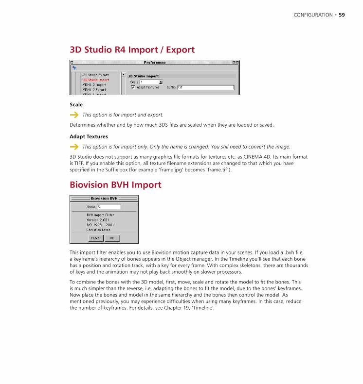
58 • CHAPTER 3 CONFIGURATION • 59
3D Studio R4 Import / Export
Scale
This option is for import and export.
Determines whether and by how much 3DS files are scaled when they are loaded or saved.
Adapt Textures
This option is for import only. Only the name is changed. You still need to convert the image.
3D Studio does not support as many graphics file formats for textures etc. as CINEMA 4D. Its main format is TIFF. If you enable this option, all texture filename extensions are changed to that which you have specified in the Suffix box (for example ‘frame.jpg’ becomes ‘frame.tif’).
Biovision BVH Import
This import filter enables you to use Biovision motion capture data in your scenes. If you load a .bvh file, a keyframe’s hierarchy of bones appears in the Object manager. In the Timeline you’ll see that each bone has a position and rotation track, with a key for every frame. With complex skeletons, there are thousands of keys and the animation may not play back smoothly on slower processors.
To combine the bones with the 3D model, first, move, scale and rotate the model to fit the bones. This is much simpler than the reverse, i.e. adapting the bones to fit the model, due to the bones’ keyframes. Now place the bones and model in the same hierarchy and the bones then control the model. As mentioned previously, you may experience difficulties when using many keyframes. In this case, reduce the number of keyframes. For details, see Chapter 19, ‘Timeline’.
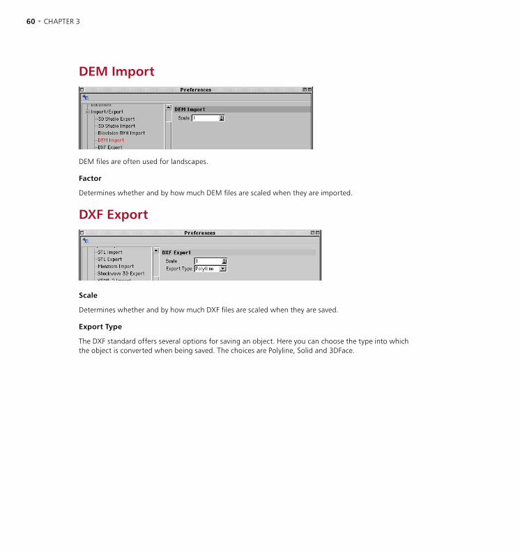
60 • CHAPTER 3 CONFIGURATION • 61
DEM Import
DEM files are often used for landscapes.
Factor
Determines whether and by how much DEM files are scaled when they are imported.
DXF Export
Scale
Determines whether and by how much DXF files are scaled when they are saved.
Export Type
The DXF standard offers several options for saving an object. Here you can choose the type into which the object is converted when being saved. The choices are Polyline, Solid and 3DFace.
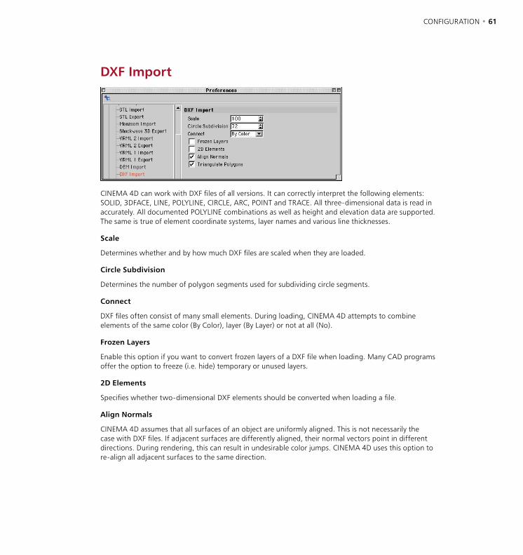
60 • CHAPTER 3 CONFIGURATION • 61
DXF Import
CINEMA 4D can work with DXF files of all versions. It can correctly interpret the following elements: SOLID, 3DFACE, LINE, POLYLINE, CIRCLE, ARC, POINT and TRACE. All three-dimensional data is read in accurately. All documented POLYLINE combinations as well as height and elevation data are supported. The same is true of element coordinate systems, layer names and various line thicknesses.
Scale
Determines whether and by how much DXF files are scaled when they are loaded.
Circle Subdivision
Determines the number of polygon segments used for subdividing circle segments.
Connect
DXF files often consist of many small elements. During loading, CINEMA 4D attempts to combine elements of the same color (By Color), layer (By Layer) or not at all (No).
Frozen Layers
Enable this option if you want to convert frozen layers of a DXF file when loading. Many CAD programs offer the option to freeze (i.e. hide) temporary or unused layers.
2D Elements
Specifies whether two-dimensional DXF elements should be converted when loading a file.
Align Normals
CINEMA 4D assumes that all surfaces of an object are uniformly aligned. This is not necessarily the case with DXF files. If adjacent surfaces are differently aligned, their normal vectors point in different directions. During rendering, this can result in undesirable color jumps. CINEMA 4D uses this option to re-align all adjacent surfaces to the same direction.
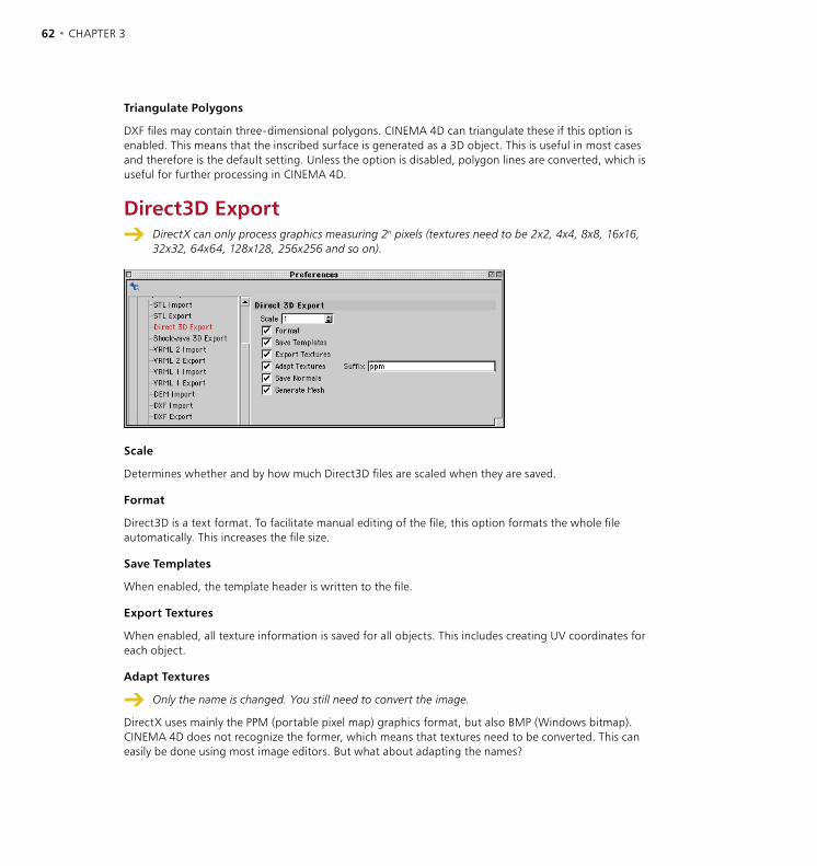
62 • CHAPTER 3 CONFIGURATION • 63
Triangulate Polygons
DXF files may contain three-dimensional polygons. CINEMA 4D can triangulate these if this option is enabled. This means that the inscribed surface is generated as a 3D object. This is useful in most cases and therefore is the default setting. Unless the option is disabled, polygon lines are converted, which is useful for further processing in CINEMA 4D.
Direct3D Export DirectX can only process graphics measuring 2n pixels (textures need to be 2x2, 4x4, 8x8, 16x16,
32x32, 64x64, 128x128, 256x256 and so on).
Scale
Determines whether and by how much Direct3D files are scaled when they are saved.
Format
Direct3D is a text format. To facilitate manual editing of the file, this option formats the whole file automatically. This increases the file size.
Save Templates
When enabled, the template header is written to the file.
Export Textures
When enabled, all texture information is saved for all objects. This includes creating UV coordinates for each object.
Adapt Textures
Only the name is changed. You still need to convert the image.
DirectX uses mainly the PPM (portable pixel map) graphics format, but also BMP (Windows bitmap). CINEMA 4D does not recognize the former, which means that textures need to be converted. This can easily be done using most image editors. But what about adapting the names?

62 • CHAPTER 3 CONFIGURATION • 63
If you enable this option, all texture filename extensions of scene materials are automatically changed when they are exported (so that ‘image.jpg’ becomes ‘image.ppm’). This has the benefit that you do not need to check for each material and for each attribute whether a change of name is required.
Save Normals
If this option is enabled, normal vectors are created for all surfaces. If not, calculating the normals is left to Direct3D.
Generate Mesh
Direct3D works with two types of model; Frame and Mesh. Frames, as with CINEMA 4D, consist of objects arranged in a hierarchical structure. Objects remain encapsulated. In a mesh, on the other hand, all objects are on the same level. The hierarchy disappears.
Illustrator Import
If you want a high-quality 2D vector graphic (e.g. a company logo) to be three-dimensional, then import it in the Illustrator format. Also vector graphics from other programs, such as Macromedia Freehand or CorelDraw, can be imported if saved in Illustrator format.
Scale
Determines whether and by how much Illustrator files are scaled when they are loaded.
Connect Splines
All shapes in the original Illustrator file are imported as a single, connected Spline object, if this option is enabled.
Group Splines
If enabled, each line is imported as a separate Spline object.

64 • CHAPTER 3 CONFIGURATION • 65
LightWave Import
When opening a LightWave file, not only the object geometry is imported but also the rest of the scene including the camera’s focal length (especially useful when used with 3D camera tracking software such as MatchMover or 3D-Equalizer), texture maps, animation sequences and bones information. Additionally, UV coordinates and weight maps of LightWave [6] are imported.
Scale
Determines whether and by how much LightWave files are scaled when they are loaded. The default value is 100 (LightWave uses a smaller construction scale than CINEMA 4D).
Textures
If enabled, LightWave object’s texture information is also loaded.
Lights
LightWave object’s light source information is also loaded when this option is on.
Split Selections
LightWave supports double sided polygons. When opening such an object CINEMA 4D creates double polygons, which may lead to rendering artifacts. If you have such objects in your LightWave scene, enable this option. Two grouped objects are created, one of which may be deleted if no longer required.
Monzoom Import
This import filter enables you to load objects, materials, textures, light sources and the cameras of a Monzoom/Reflections scene. Scale determines whether and by how much Monzoom files are scaled when they are loaded.

64 • CHAPTER 3 CONFIGURATION • 65
The earliest versions of Reflections are not supported. In these cases load the file into a more recent version of Reflections or Monzoom and save it out as a new file.
In Reflections/Monzoom, Phong shading can be assigned to individual polygons. For this reason you can choose when the imported objects are given a Phong shading tag: always, never, when most of the polygons are smoothed or when at least some of the polygons are smoothed. In most cases, Majority Of Faces is the best setting.
QuickDraw 3D Export
Scale
Determines whether and by how much QuickDraw 3D files are scaled when they are saved.
Save Textures
If this option is enabled, all objects are saved with their textures (including UV coordinates if present). If this option is disabled, objects are saved with basic color information only (i.e. without textures).
Maximum Size
You can use any size of texture provided your system has sufficient memory. However, in general avoid large textures since they add to the loading time. This option lets you restrict the size of QuickDraw 3D files. The material images are scaled to the specified value (in pixels); the proportions remain intact.
QuickDraw 3D Import
Scale
Determines whether and by how much QuickDraw 3D files are scaled when they are loaded.
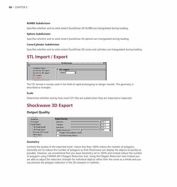
66 • CHAPTER 3 CONFIGURATION • 67
NURBS Subdivision
Specifies whether and to what extent QuickDraw 3D NURBS are triangulated during loading.
Sphere Subdivision
Specifies whether and to what extent QuickDraw 3D spheres are triangulated during loading.
Cone/Cylinder Subdivision
Specifies whether and to what extent QuickDraw 3D cones and cylinders are triangulated during loading.
STL Import / Export
The STL format is mostly used in the field of rapid prototyping to design moulds. The geometry is described as triangles.
Scale
Determines whether and by how much STL files are scaled when they are imported or exported.
Shockwave 3D ExportOutput Quality
Geometry
Controls the quality of the exported mesh. Values less than 100% reduce the number of polygons. Generally aim to reduce the number of polygons so that Shockwave can display the objects as quickly as possible. However, we recommend that you leave Geometry set to 100% and instead reduce the number of polygons using CINEMA 4D’s Polygon Reduction tool. Using the Polygon Reduction tool instead you are able to adjust the reduction strength for individual objects rather than the scene as a whole and you can preview the polygon reduction in the 3D viewport in realtime.
66 • CHAPTER 3 CONFIGURATION • 67
Textures
Sets the size and quality of the textures. 100% means slight compression only. Lower settings offer greater compression but poorer image quality.
Animation
The accuracy of position, scaling and rotation animation data is set here. The reduction in accuracy only takes place when the data is saved.
Shader Texture Size
Materials with procedural shaders are converted to textures. This value defines the size of these textures. Note that volume shaders look different when converted to textures.
Polygon Front And Back Visible
By default, Shockwave only shows polygons if their surface normals face the camera — polygons that face away from the camera are ignored and are not shown, to speed up the display. Usually this won’t cause problems provided that you’ve aligned the normals of your mesh correctly and you’re not using alpha or transparency textures.
If you want to use alpha or transparency textures, add a Shockwave 3D Double Sided tag to each object that uses these textures. Alternatively, enable the Polygon Front And Back Visible option to make all surfaces double sided. However, keep in mind that double sided polygons slow down the display of the objects in Shockwave. For this reason we recommend that you use tags in preference.
If you can’t see the fronts of surfaces in Shockwave, check if the normals in the CINEMA 4D scene are correctly aligned. Correct them as necessary using the Align Normals and Reverse Normals commands.
Substitute Group Objects
In Shockwave, null objects are called ‘group objects’. Since group objects cannot be animated in Shockwave, the export filter automatically converts animated Null objects to (dummy) mesh objects.
If animated nulls are converted to mesh objects automatically, what’s the point of the Substitute Group Objects option? If you enable the option, all Null objects are converted to mesh objects, not just the animated ones. This is useful if you intend to animate the exported scene in Director using Lingo. You’ll then be able to animate any of the converted Null objects, not just the ones originally animated in CINEMA 4D.

68 • CHAPTER 3 CONFIGURATION • 69
Texture Export Options
Enable the option for each material channel that you want to be exported: Export Alpha, Color, Environment, Luminance, Specular Color, Diffusion and Transparency. Keep in mind that Shockwave handles environment and specular textures differently.
Light Options
Light Sources
Choose the export mode for light sources. Do Not Export means lights are not exported. No Fall-Off means lights are exported without fall-off. Best Match means lights are converted during export to match their CINEMA 4D settings as closely as possible.
Global Light Intensity
Controls the intensity of the scene’s lighting. Increase or lower the value to brighten or darken the scene.
Animation Export Options
Export Animation
To export animation, enable this option and set the accuracy of the animation export using Sample Frequency. If you disable Export Animation, the scene is exported at the current frame (i.e. as currently seen in the viewport) and without animation.
Sample Frequency
Controls the accuracy of animation, defined as the number of keyframe groups per second. For example, if you set Sample Frequency to 15, 15 keys will be created for each position, scale and rotation track. Avoid using values higher than the scene’s Frame Rate (Edit > Project Settings) since this will add to the export time without improving the accuracy of animation.
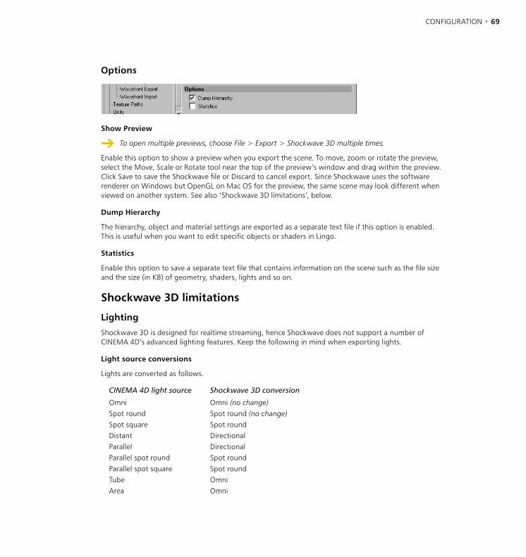
68 • CHAPTER 3 CONFIGURATION • 69
Options
Show Preview
To open multiple previews, choose File > Export > Shockwave 3D multiple times.
Enable this option to show a preview when you export the scene. To move, zoom or rotate the preview, select the Move, Scale or Rotate tool near the top of the preview’s window and drag within the preview. Click Save to save the Shockwave file or Discard to cancel export. Since Shockwave uses the software renderer on Windows but OpenGL on Mac OS for the preview, the same scene may look different when viewed on another system. See also ‘Shockwave 3D limitations’, below.
Dump Hierarchy
The hierarchy, object and material settings are exported as a separate text file if this option is enabled. This is useful when you want to edit specific objects or shaders in Lingo.
Statistics
Enable this option to save a separate text file that contains information on the scene such as the file size and the size (in KB) of geometry, shaders, lights and so on.
Shockwave 3D limitations
Lighting
Shockwave 3D is designed for realtime streaming, hence Shockwave does not support a number of CINEMA 4D’s advanced lighting features. Keep the following in mind when exporting lights.
Light source conversions
Lights are converted as follows.
CINEMA 4D light source Shockwave 3D conversion
Omni Omni (no change)Spot round Spot round (no change)Spot square Spot roundDistant DirectionalParallel DirectionalParallel spot round Spot roundParallel spot square Spot roundTube OmniArea Omni
70 • CHAPTER 3 CONFIGURATION • 71
Environment, Fog
Environment objects are converted to ambient lights. Fog is not supported.
Light fall-off
Lights cannot be clipped in Shockwave 3D.
Inverse Linear and Inverse Quadratic fall-off are copied if the inner distance is set to 0 (other values are not supported by Shockwave). There are no equivalents for the other modes (Linear, Inverse Cubic and Step) and they will instead be exported as Inverse Linear, Inverse Quadratic and No Fall-Off.
Shadows, noise, lens effects
Shadows, noise and lens effects are not supported by Shockwave.
Cameras
Projection
The current camera object is exported as the default view. The projections Parallel, Front, Back, Left, Right, Top and Bottom are exported as orthogonal projections. The Military, Frog, Bird, Gentleman, Isometric and Dimetric perspectives are exported as orthogonal projections (Front) since Shockwave has no equivalents.
Director camera
Director does not support multiple cameras. Only one camera is available, named ‘defaultView’. If there is no camera in your CINEMA 4D scene named ‘defaultView’, a camera is exported automatically that shows the current view.
Camera Animation
To export a camera animation for playback in Director, in CINEMA 4D change the camera’s name to ‘defaultView’. Since camera objects cannot have animation tracks in Shockwave, the export filter automatically adds a dummy mesh and makes the camera a child of the dummy mesh if necessary.
Shockwave Player
Shockwave Player supports up to eight bones and one root bone per mesh, and up to eight lights.
Known issues and other limitations
- Spotlights malfunction under Mac OS X 10.2 with the OpenGL renderer.
- According to Macromedia, specularity requires a special OpenGL extension; however, Macromedia is unaware of any OpenGL driver — for PC or Mac — that works with Shockwave’s specularity.
- Textures in the specular channel are incorrectly displayed under Mac OS X.
- Specular highlights are overexposed with the Direct X5 renderer. If available, use Direct X7 instead.
- Alpha channels are restricted to one texture unit only.
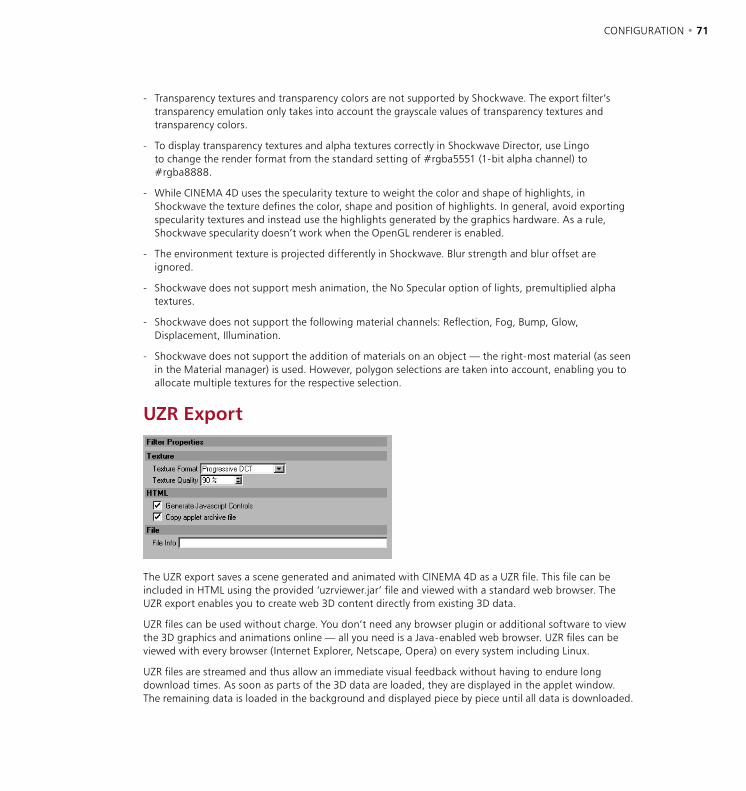
70 • CHAPTER 3 CONFIGURATION • 71
- Transparency textures and transparency colors are not supported by Shockwave. The export filter’s transparency emulation only takes into account the grayscale values of transparency textures and transparency colors.
- To display transparency textures and alpha textures correctly in Shockwave Director, use Lingo to change the render format from the standard setting of #rgba5551 (1-bit alpha channel) to #rgba8888.
- While CINEMA 4D uses the specularity texture to weight the color and shape of highlights, in Shockwave the texture defines the color, shape and position of highlights. In general, avoid exporting specularity textures and instead use the highlights generated by the graphics hardware. As a rule, Shockwave specularity doesn’t work when the OpenGL renderer is enabled.
- The environment texture is projected differently in Shockwave. Blur strength and blur offset are ignored.
- Shockwave does not support mesh animation, the No Specular option of lights, premultiplied alpha textures.
- Shockwave does not support the following material channels: Reflection, Fog, Bump, Glow, Displacement, Illumination.
- Shockwave does not support the addition of materials on an object — the right-most material (as seen in the Material manager) is used. However, polygon selections are taken into account, enabling you to allocate multiple textures for the respective selection.
UZR Export
The UZR export saves a scene generated and animated with CINEMA 4D as a UZR file. This file can be included in HTML using the provided ‘uzrviewer.jar’ file and viewed with a standard web browser. The UZR export enables you to create web 3D content directly from existing 3D data.
UZR files can be used without charge. You don’t need any browser plugin or additional software to view the 3D graphics and animations online — all you need is a Java-enabled web browser. UZR files can be viewed with every browser (Internet Explorer, Netscape, Opera) on every system including Linux.
UZR files are streamed and thus allow an immediate visual feedback without having to endure long download times. As soon as parts of the 3D data are loaded, they are displayed in the applet window. The remaining data is loaded in the background and displayed piece by piece until all data is downloaded.
72 • CHAPTER 3 CONFIGURATION • 73
Exporting a UZR File
The filter exports the cameras in the scene but not the current view.
The UZR export includes all 3D data that can be ‘polygonized’ (e.g. no particle systems). All materials and color textures (no transparencies) as well as all cameras, light sources and animations defined in CINEMA 4D are included in the exported UZR file.
When exporting to UZR, three files are written: the UZR file containing the 3D data, an HTML file containing the applet window as well as, if desired, JavaScript controls, and the Java applet file ‘uzrviewer.jar’ required to view the model in the browser.
Filter Properties
Texture
Texture Format
Defines the format of the exported texture. Progressive DCT streams the texture data. JPEG includes the texture as a JPEG file. Uncompressed RGB saves the textures as an uncompressed RGB file; you will see maximum texture quality using this format, but the UZR file size will considerably increase.
Texture Quality
Defines the exported texture’s quality. The larger this value, the higher the exported texture’s quality and the larger the UZR file will be.
HTML
Generate Javascript Controls
If this option is enabled, javascript controls are included in the HTML file exported during the UZR export. With these controls, the camera positions can be selected, the light sources can be (de-)activated and the animation can be started.
Copy Applet Archive File
If this option is enabled, the Java applet ‘uzrviewer.jar’ is copied to the same destination as the UZR and the HTML file.
File
File Info
Here you can enter copyrights or any additional file information. This text will be included in the UZR file and displayed if About This File is selected from the applet’s context menu.
72 • CHAPTER 3 CONFIGURATION • 73
Integrating UZR files in HTML
When editing the UZR filename, keep in mind that it is case sensitive.
Like standard image files, UZR files can be included in HTML web pages. To view the 3D model with a browser, the Java applet file ‘uzrviewer.jar’ must be provided. If you export to UZR, an HTML file is written. This file can be edited manually and the following parts of are of special interest.
<input type=”radio” checked=”checked” name=”Camera” onclick=”setCamera(this.value)” value=”Camera xy”> Camera xy<br>
The above part defines the JavaScript controls that activate the different exported cameras. You can edit the number and names of the available camera position JavaScript controls. The names given to the camera positions in CINEMA 4D are included automatically.
<input type=”checkbox” checked=”checked” name=”Lights” onclick=”toggleLight(this.value)” value=”Light xy”> Light xy<br>
The above part defines the JavaScript controls that activate the different exported light sources. You can edit the number and names of the available light sources JavaScript controls. The names given to the light sources in CINEMA 4D are included automatically.
<input type=”button” name=”Start” onclick=”startAnim()” value=”Start”><input type=”button” name=”Reset” onclick=”resetNodes()” value=”Reset”>
The above part is written if you include the JavaScript controls in the UZR export. Two buttons are integrated in the HTML file: a Start button which starts an existing animation, and a Reset button which resets the current camera to its original position. These buttons can also be edited manually. You can change the names of the buttons (e.g. Back instead of Reset). You can also delete one or both buttons, which is useful, for example, if no animation is available.
<applet name=”Viewer” archive=”uzrviewer.jar” code=”uzrviewer.Viewer.class” width=”600” height=”400”> <param name=”scene” value=”xy.uzr”></applet>
The above part defines the UZR file that is loaded into the applet window (the ‘scene’ parameter), as well as some display settings (‘width’ and ‘height’ parameters). Additionally, the following applet parameters can be defined:
<param name=”nocamrt” value=”true/false”><param name=”bgcolor” value=”#XXXXXX”><param name=”s_cameras” value=”xy”><param name=”s_lights” value=”xy”><param name=”s_reset” value=”xy”><param name=”s_start” value=”xy”><param name=”camera” value=”Camera XY”><param name=”anim” value=”true/false”><param name=”loop” value=”true/false”>
nocamrt
The UZR file display can be controlled with the mouse. If the ‘nocamrt’ parameter is set to true, a rotation of the cameras is disabled. If the ‘nocamrt’ parameter is set to false, the exported cameras can be rotated allowing the user an advanced 3D navigation.

74 • CHAPTER 3 CONFIGURATION • 75
bgcolor
The bgcolor parameter defines the color of the applet background. Enter any desired color value (e.g. #FFFFFFF for a white or #000000 for a black background).
s_cameras
This parameter defines the text of the applet’s context menu item which lists the available camera positions. If this parameter is not set, the default value ‘Cameras’ is used.
s_lights
This parameter defines the text of the applet’s context menu item which lists the available light sources. If this parameter is not set, the default value ‘Lights’ is used.
s_reset
This parameter defines the text of the applet’s context menu item which resets the current camera position. If this parameter is not set, the default value ‘Reset’ is used.
s_start
This parameter defines the text of the applet’s context menu item which starts an existing animation. If this parameter is not set, the default value ‘Start’ is used.
camera
This parameter defines the default camera that is displayed when the UZR file is first loaded. Simply enter the name of the camera.
anim
This parameter defines if an existing animation is automatically started after the UZR file is loaded.
loop
This parameter defines if an existing animation is looped.
Controlling the UZR browser displayWhen the HTML file is opened, the UZR file is automatically loaded into the applet window. The streamed data is displayed bit by bit until all data is downloaded.
If you enable the Generate Javascript Controls option during UZR export, a table containing the JavaScript controls is included in the exported HTML file, directly under the applet window code. You can use theses controls to activate the different camera positions and light sources, to start an existing animation and reset the position of the current camera.
The camera positions are activated by selecting the position in the table. If an animation is started, it will always be viewed from the current camera position.
If camera rotations are enabled (see ‘nocamrt’, above), the camera can be rotated by dragging. The camera’s zoom can be adjusted by Alt-dragging.
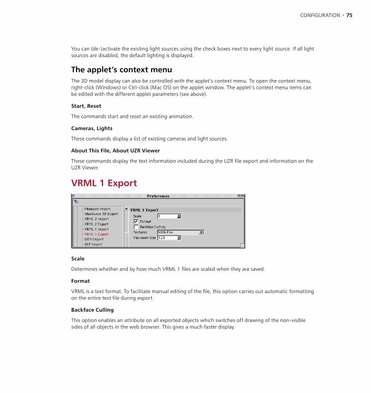
74 • CHAPTER 3 CONFIGURATION • 75
You can (de-)activate the existing light sources using the check boxes next to every light source. If all light sources are disabled, the default lighting is displayed.
The applet’s context menu The 3D model display can also be controlled with the applet’s context menu. To open the context menu, right-click (Windows) or Ctrl-click (Mac OS) on the applet window. The applet’s context menu items can be edited with the different applet parameters (see above).
Start, Reset
The commands start and reset an existing animation.
Cameras, Lights
These commands display a list of existing cameras and light sources.
About This File, About UZR Viewer
These commands display the text information included during the UZR file export and information on the UZR Viewer.
VRML 1 Export
Scale
Determines whether and by how much VRML 1 files are scaled when they are saved.
Format
VRML is a text format. To facilitate manual editing of the file, this option carries out automatic formatting on the entire text file during export.
Backface Culling
This option enables an attribute on all exported objects which switches off drawing of the non-visible sides of all objects in the web browser. This gives a much faster display.
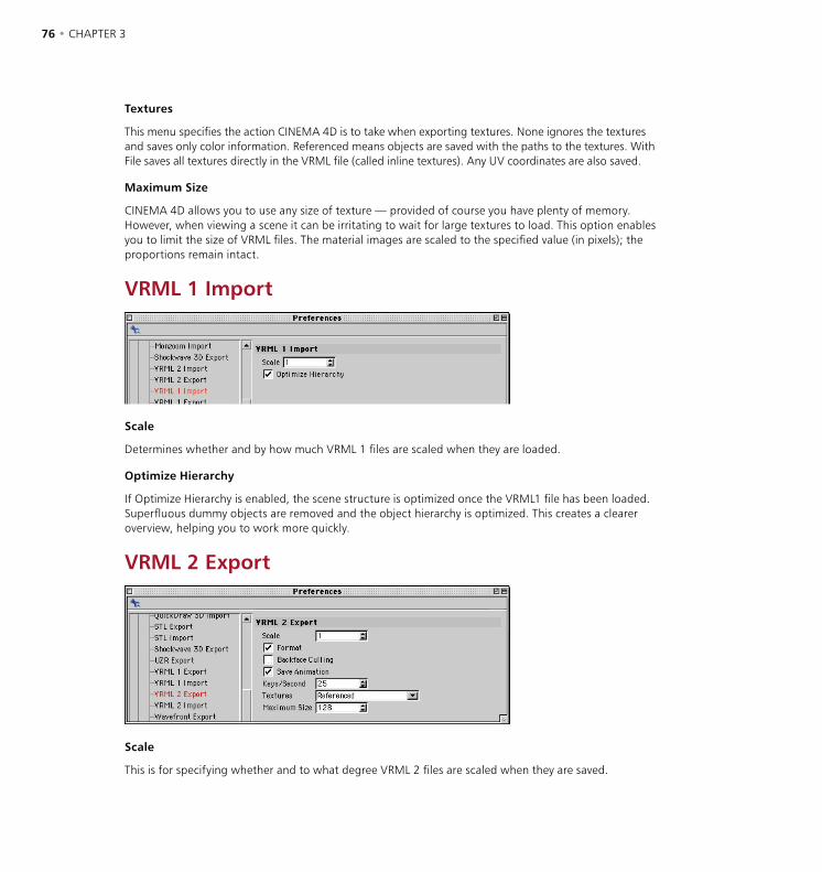
76 • CHAPTER 3 CONFIGURATION • 77
Textures
This menu specifies the action CINEMA 4D is to take when exporting textures. None ignores the textures and saves only color information. Referenced means objects are saved with the paths to the textures. With File saves all textures directly in the VRML file (called inline textures). Any UV coordinates are also saved.
Maximum Size
CINEMA 4D allows you to use any size of texture — provided of course you have plenty of memory. However, when viewing a scene it can be irritating to wait for large textures to load. This option enables you to limit the size of VRML files. The material images are scaled to the specified value (in pixels); the proportions remain intact.
VRML 1 Import
Scale
Determines whether and by how much VRML 1 files are scaled when they are loaded.
Optimize Hierarchy
If Optimize Hierarchy is enabled, the scene structure is optimized once the VRML1 file has been loaded. Superfluous dummy objects are removed and the object hierarchy is optimized. This creates a clearer overview, helping you to work more quickly.
VRML 2 Export
Scale
This is for specifying whether and to what degree VRML 2 files are scaled when they are saved.
76 • CHAPTER 3 CONFIGURATION • 77
Format Text
VRML is a text format. To facilitate manual editing of the file, this option carries out automatic formatting on the entire text file during export.
Backface Culling
This option enables an attribute on all exported objects which switches off drawing of the non-visible sides of all objects in the web browser. This gives a much faster display.
Save Animation
Enable this option to include animation information when you save scenes in the VRML 2 format.
Keys/Second
This defines the frequency of the keys for animation export. VRML 2 supports linear interpolation only. You may need to increase the setting for greater accuracy. Values from 5 to 25 are common.
Textures
This drop-down list specifies the action CINEMA 4D takes when exporting textures. None ignores the textures and saves only color information. Referenced means objects are saved with the paths to the textures. With File saves all textures directly in the VRML file (called inline textures). Any UV coordinates are also saved.
Maximum Size
VRML 2 provides two options for making textures available to their objects. The first option is identical to the one used in CINEMA 4D; a reference to the texture file is saved along with the VRML scene. If you want to go with this option, specify the value 0. The second option integrates the graphics data directly into the VRML 2 file.
Since the texture is written uncompressed, in text format, a texture of 1000x1000 pixels quickly reaches a file size of 4MB. To avoid such large files, specify a value (larger than 0) to limit the size of textures. The materials are then scaled to that value (in pixels). The proportions remain intact. For example, if you have a texture of 800x600 pixels and you set a maximum value of 100, the texture is proportionally scaled down to a size of 100x75 pixels before being saved.

78 • CHAPTER 3 CONFIGURATION • 79
VRML 2 Import
Scale
This specifies whether and to what extent VRML 2 files are scaled when they are loaded.
Optimize Hierarchy
If Optimize Hierarchy is enabled, the hierarchy is optimized once the VRML 2 file has been loaded. Superfluous dummy objects are removed and the object hierarchy is optimized. This creates a clearer overview, helping you to work more quickly.
Optimize Structure
Enable this option to optimize the scene’s structure during import.
Wavefront Import / Export
Factor
This specifies whether and to what extent Wavefront files are scaled during import and export.
Texture Paths
CINEMA 4D searches for texture files and animation files in the following locations: in the same folder as the scene; in the ‘Tex’ folder within the scene’s folder; in the ‘Tex’ folder within the CINEMA 4D folder. If a texture is in any of these folders, add the texture’s folder to this dialog.
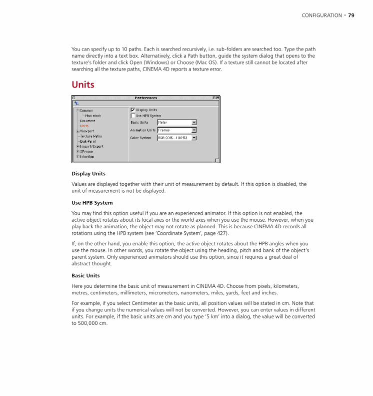
78 • CHAPTER 3 CONFIGURATION • 79
You can specify up to 10 paths. Each is searched recursively, i.e. sub-folders are searched too. Type the path name directly into a text box. Alternatively, click a Path button, guide the system dialog that opens to the texture’s folder and click Open (Windows) or Choose (Mac OS). If a texture still cannot be located after searching all the texture paths, CINEMA 4D reports a texture error.
Units
Display Units
Values are displayed together with their unit of measurement by default. If this option is disabled, the unit of measurement is not be displayed.
Use HPB System
You may find this option useful if you are an experienced animator. If this option is not enabled, the active object rotates about its local axes or the world axes when you use the mouse. However, when you play back the animation, the object may not rotate as planned. This is because CINEMA 4D records all rotations using the HPB system (see ‘Coordinate System’, page 427).
If, on the other hand, you enable this option, the active object rotates about the HPB angles when you use the mouse. In other words, you rotate the object using the heading, pitch and bank of the object’s parent system. Only experienced animators should use this option, since it requires a great deal of abstract thought.
Basic Units
Here you determine the basic unit of measurement in CINEMA 4D. Choose from pixels, kilometers, metres, centimeters, millimeters, micrometers, nanometers, miles, yards, feet and inches.
For example, if you select Centimeter as the basic units, all position values will be stated in cm. Note that if you change units the numerical values will not be converted. However, you can enter values in different units. For example, if the basic units are cm and you type ‘5 km’ into a dialog, the value will be converted to 500,000 cm.
80 • CHAPTER 3 CONFIGURATION • 81
If you set the basic units to Pixel, the unit of measurement will not be specified. It is then up to you to decide how to interpret the values. You can use the following abbreviations for units when entering values:
Abbreviation Unitsno units specified pixelskm kilometersm meterscm centimetersmm millimetersum micrometersnm nanometersmi milesyd yardsft feetin inches
Animation Units
Here you specify the time units used for animation. Your choice is from frames, seconds and SMPTE time codes which use the format: Min:Sec:Frame.
For example, 3:20:14 refers to the time 3 minutes, 20 seconds, 15th frame. The last value in the time code is the frame number of the current second (starting at frame 0). For example, if you are working with a frame rate of 25 fps, the frame value is in the range of 0 to 24. If the minutes value is 0, you can omit it when entering SMPTE time codes. For example, 15:14 means 15 seconds and the 15th frame.
You can use the following abbreviations when you enter time values:
Abbreviation UnitsF frameS secondsmin:sec:frame SMPTE
Color System
You can choose between the RGB model and the HSV model. You can also choose whether the values should be specified as a percentage, or in steps ranging from 0 to 255, or in steps ranging from 0 to 65535. A good choice of colors is essential for consistent photorealistic results. Photorealism is often a yardstick for programs such as CINEMA 4D.
The human eye can see several hundred thousand colors in the spectral range between 400 nm (blue) and 700 nm (red). This color sensitivity is the result of many thousands of receptors on the retina. Not all of these are equally sensitive, and not all are sensitive to the same range of wavelengths. Some of the receptors are particularly sensitive within the blue range, around 440 nm; others are far more sensitive in other ranges, while yet others are particularly receptive in the green range, around 540 or 580 nm.
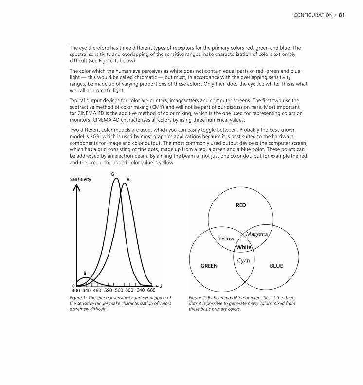
80 • CHAPTER 3 CONFIGURATION • 81
The eye therefore has three different types of receptors for the primary colors red, green and blue. The spectral sensitivity and overlapping of the sensitive ranges make characterization of colors extremely difficult (see Figure 1, below).
The color which the human eye perceives as white does not contain equal parts of red, green and blue light — this would be called chromatic — but must, in accordance with the overlapping sensitivity ranges, be made up of varying proportions of these colors. Only then does the eye see white. This is what we call achromatic light.
Typical output devices for color are printers, imagesetters and computer screens. The first two use the subtractive method of color mixing (CMY) and will not be part of our discussion here. Most important for CINEMA 4D is the additive method of color mixing, which is the one used for representing colors on monitors. CINEMA 4D characterizes all colors by using three numerical values.
Two different color models are used, which you can easily toggle between. Probably the best known model is RGB, which is used by most graphics applications because it is best suited to the hardware components for image and color output. The most commonly used output device is the computer screen, which has a grid consisting of fine dots, made up from a red, a green and a blue point. These points can be addressed by an electron beam. By aiming the beam at not just one color dot, but for example the red and the green, the added color value is yellow.
Figure 1: The spectral sensitivity and overlapping of the sensitive ranges make characterization of colors extremely difficult.
Figure 2: By beaming different intensities at the three dots it is possible to generate many colors mixed from these basic primary colors.
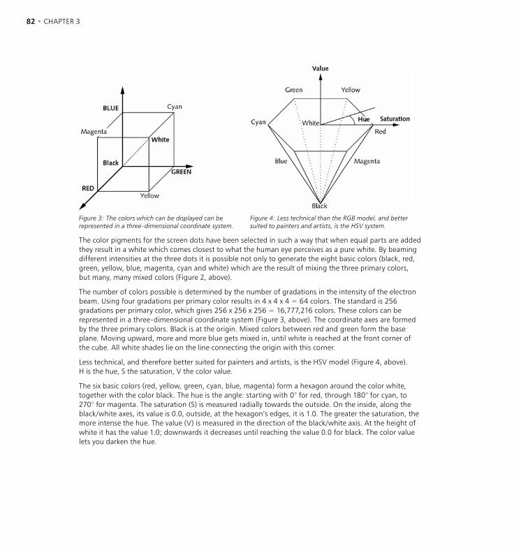
82 • CHAPTER 3 CONFIGURATION • 83
Figure 3: The colors which can be displayed can be represented in a three-dimensional coordinate system.
Figure 4: Less technical than the RGB model, and better suited to painters and artists, is the HSV system.
The color pigments for the screen dots have been selected in such a way that when equal parts are added they result in a white which comes closest to what the human eye perceives as a pure white. By beaming different intensities at the three dots it is possible not only to generate the eight basic colors (black, red, green, yellow, blue, magenta, cyan and white) which are the result of mixing the three primary colors, but many, many mixed colors (Figure 2, above).
The number of colors possible is determined by the number of gradations in the intensity of the electron beam. Using four gradations per primary color results in 4 x 4 x 4 = 64 colors. The standard is 256 gradations per primary color, which gives 256 x 256 x 256 = 16,777,216 colors. These colors can be represented in a three-dimensional coordinate system (Figure 3, above). The coordinate axes are formed by the three primary colors. Black is at the origin. Mixed colors between red and green form the base plane. Moving upward, more and more blue gets mixed in, until white is reached at the front corner of the cube. All white shades lie on the line connecting the origin with this corner.
Less technical, and therefore better suited for painters and artists, is the HSV model (Figure 4, above). H is the hue, S the saturation, V the color value.
The six basic colors (red, yellow, green, cyan, blue, magenta) form a hexagon around the color white, together with the color black. The hue is the angle: starting with 0° for red, through 180° for cyan, to 270° for magenta. The saturation (S) is measured radially towards the outside. On the inside, along the black/white axes, its value is 0.0, outside, at the hexagon’s edges, it is 1.0. The greater the saturation, the more intense the hue. The value (V) is measured in the direction of the black/white axis. At the height of white it has the value 1.0; downwards it decreases until reaching the value 0.0 for black. The color value lets you darken the hue.
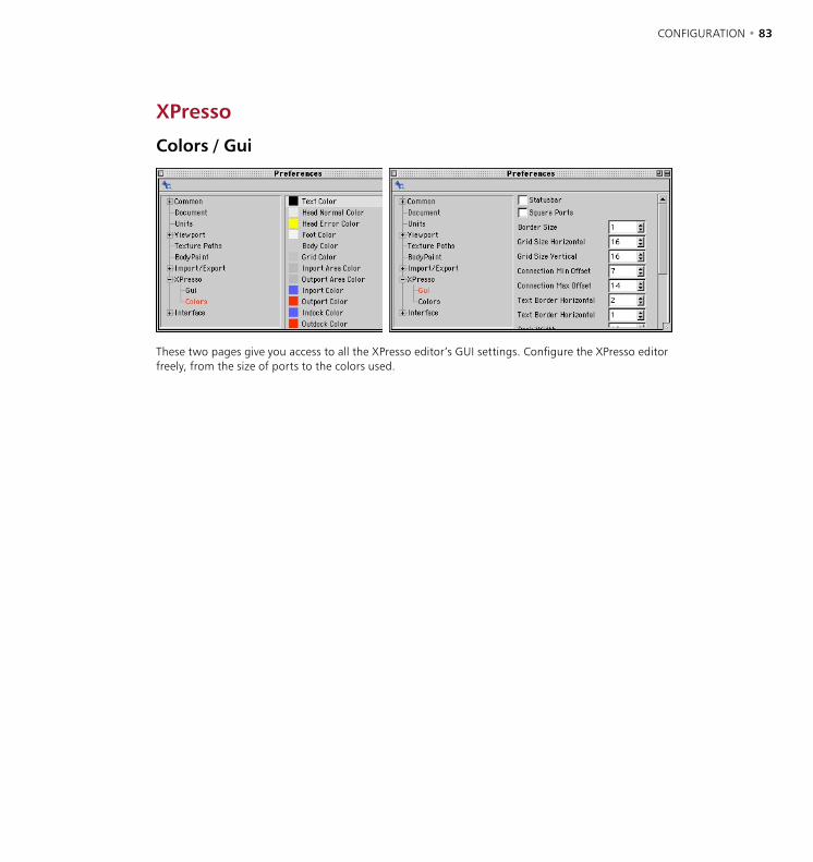
82 • CHAPTER 3 CONFIGURATION • 83
XPresso
Colors / Gui
These two pages give you access to all the XPresso editor’s GUI settings. Configure the XPresso editor freely, from the size of ports to the colors used.

84 • CHAPTER 3
Project SettingsThese settings apply to the active scene. To access these settings, choose Edit > Project Settings from the main menu or Edit > Project Settings from the Timeline’s menu.
Frame Rate
You can also set a frame rate in the render settings (see ‘Frame Rate’, page 536). However, the frame rate in the render settings is not used to recalculate the animation data. If the two frame rates differ, frames may be dropped or duplicated in the animation, leading to a reduction in animation quality.
Use this value to define the frame rate for the animation project. CINEMA 4D uses this value to calculate all animation data.
Minimum
This defines the starting frame for animation tracks in the Timeline. You can enter a negative or a positive value. A negative value can be useful if you want particles to be generated so that the stream is ready by frame 0. This value is decreased automatically when you drag a sequence past its boundary in the Timeline.
Maximum
This defines the last frame for animation tracks in the Timeline. This value is increased automatically when you drag a sequence past its boundary in the Timeline.
Level Of Detail
This value affects the setting of the same name in the Display menu of the View panel.
This value influences the display of all objects in the active scene that support a reduction in detail, such as metaballs and NURBS. However, any objects that have their own level of detail setting will continue to use their setting (see ‘Level Of Detail’, page 604). If the value is set to 100%, the objects will be displayed in full detail. If the value is set to 50%, the objects will be displayed with only half of their usual detail (subdivision). You can also enter values greater than 100% to increase the number of subdivisions used for the object.
Use Render LOD For Editor Rendering
If you enable this option, the view panel uses the level of detail specified in the render settings (Options tab) for rendering.

4 Workflow

WORKFLOW • 87
WORKFLOW • 87
If you’ve used a previous version of CINEMA 4D, you’ll probably want to know about the latest workflow enhancements that are new in Release 8. In this case see ‘New workflow enhancements’ on page 88.
There are many features in CINEMA 4D that help you to work more quickly, i.e. improve your workflow. These include:
- To move, zoom or rotate a camera, use the icons at the top right of the viewport (drag the desired icon). The fourth, right-most icon toggles the active view panel between single-view and all-views (see ‘Toggle Active View’ on page 27).
- Define shortcuts for the commands you use the most. Also, create an icon palette and populate it with the commands. You’ll then be able to reach the commands more quickly.
- Many commands can be performed with a quick drag-and-drop rather than a trek through the menus. For example, to allocate a material, drag it from the Material manager and drop it onto an object in the Object manager or viewport.
- What if the Object manager is not the active tab (see ‘Tabs’ on page 10) when you drag-and-drop a material from the Material manager? Simply drag the material on to the Object manager’s tab. After a short delay, the Object manager will become the active tab and you can drop the material onto the object.
- Many primitives have handles — e.g. to control the fillet radius. Drag these handles to change the values interactively in the viewport.
- To move several keys or sequences in the Timeline, select them all then drag to move them all at the same time. Likewise, you can copy multiple keys by selecting them and then Ctrl-dragging them.
- You can construct a spline by creating its points one by one. Alternatively, draw the spline and its points will be created automatically (see ‘Freehand’, page 201).
- There is no need to lock axes in order to move, scale or rotate an object along a specific axis. Instead, drag the small handle — an arrowhead, cube or sphere depending on whether the Move, Scale or Rotate tool is selected — that’s at the end of the desired object axis. You can also drag these handles to move, scale or rotate selected polygons, points or edges.
- To select several points or polygons, don’t click them one by one. Instead, select the Live Selection tool and ‘paint’ over the points or polygons to select them. Also, note that you can hold down the 9 key to temporarily select the Live Selection tool. As soon as you release the 9 key, you’ll be returned to the previous tool. This is an ideal way to select different elements while you’re in the middle of using a particular tool such as Knife or Polygon Extrude.
Besides the workflow tips above, there are many other ways to improve your workflow. Work through this reference manual whenever you have a spare moment and you’ll discover a wealth of workflow tips too numerous to mention here. In the next section, you’ll find details on the workflow enhancements that are new in CINEMA 4D Release 8.
4 Workflow
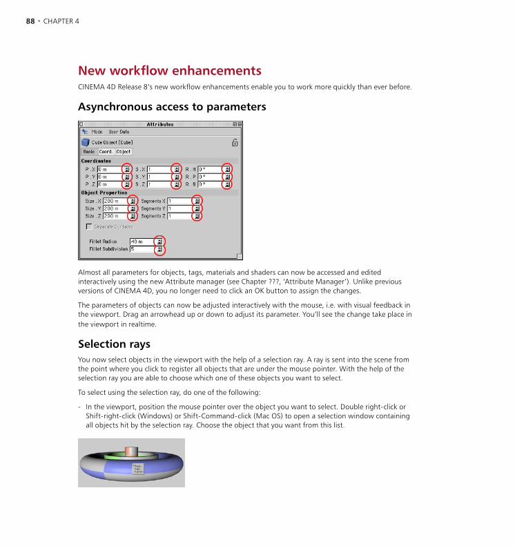
88 • CHAPTER 4 WORKFLOW • 89
New workflow enhancementsCINEMA 4D Release 8’s new workflow enhancements enable you to work more quickly than ever before.
Asynchronous access to parameters
Almost all parameters for objects, tags, materials and shaders can now be accessed and edited interactively using the new Attribute manager (see Chapter ???, ‘Attribute Manager’). Unlike previous versions of CINEMA 4D, you no longer need to click an OK button to assign the changes.
The parameters of objects can now be adjusted interactively with the mouse, i.e. with visual feedback in the viewport. Drag an arrowhead up or down to adjust its parameter. You’ll see the change take place in the viewport in realtime.
Selection raysYou now select objects in the viewport with the help of a selection ray. A ray is sent into the scene from the point where you click to register all objects that are under the mouse pointer. With the help of the selection ray you are able to choose which one of these objects you want to select.
To select using the selection ray, do one of the following:
- In the viewport, position the mouse pointer over the object you want to select. Double right-click or Shift-right-click (Windows) or Shift-Command-click (Mac OS) to open a selection window containing all objects hit by the selection ray. Choose the object that you want from this list.
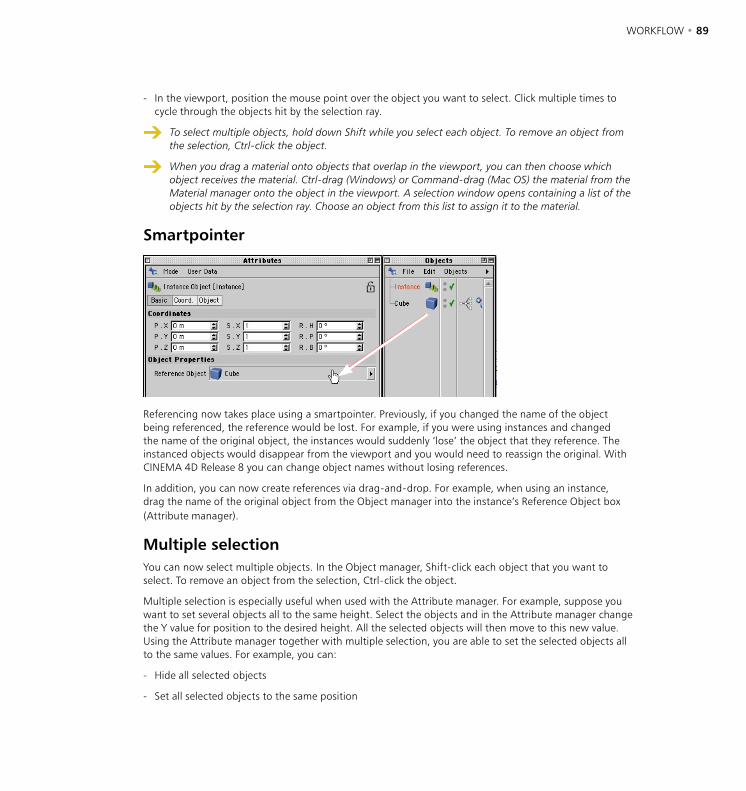
88 • CHAPTER 4 WORKFLOW • 89
- In the viewport, position the mouse point over the object you want to select. Click multiple times to cycle through the objects hit by the selection ray.
To select multiple objects, hold down Shift while you select each object. To remove an object from the selection, Ctrl-click the object.
When you drag a material onto objects that overlap in the viewport, you can then choose which object receives the material. Ctrl-drag (Windows) or Command-drag (Mac OS) the material from the Material manager onto the object in the viewport. A selection window opens containing a list of the objects hit by the selection ray. Choose an object from this list to assign it to the material.
Smartpointer
Referencing now takes place using a smartpointer. Previously, if you changed the name of the object being referenced, the reference would be lost. For example, if you were using instances and changed the name of the original object, the instances would suddenly ‘lose’ the object that they reference. The instanced objects would disappear from the viewport and you would need to reassign the original. With CINEMA 4D Release 8 you can change object names without losing references.
In addition, you can now create references via drag-and-drop. For example, when using an instance, drag the name of the original object from the Object manager into the instance’s Reference Object box (Attribute manager).
Multiple selectionYou can now select multiple objects. In the Object manager, Shift-click each object that you want to select. To remove an object from the selection, Ctrl-click the object.
Multiple selection is especially useful when used with the Attribute manager. For example, suppose you want to set several objects all to the same height. Select the objects and in the Attribute manager change the Y value for position to the desired height. All the selected objects will then move to this new value. Using the Attribute manager together with multiple selection, you are able to set the selected objects all to the same values. For example, you can:
- Hide all selected objects
- Set all selected objects to the same position
90 • CHAPTER 4 WORKFLOW • 91
- Move all selected objects by the same distance
- Rotate all selected objects about their individual axis systems
- Rotate all selected objects about a common axis
Further enhancementsFurther workflow enhancements that are new in Release 8 include:
- More context menus. Wherever you are in the program, check if there’s a context menu by right-clicking (Windows ) or Command-clicking (Mac OS).
- The Timeline’s display has been enhanced. To choose which objects are shown in the Timeline, drag the objects from the Object manager into the Timeline. Many other enhancements have been made to the Timeline. See Chapter ???, ‘Timeline’, for details.
- OpenGL performance is faster in the viewports (access the new OpenGL settings via the Preferences).
- Drag-and-drop functionality has been extended. For example, you can now drag-and-drop to reference objects.
90 • CHAPTER 4 WORKFLOW • 91
Working with LayoutsCINEMA 4D has numerous windows, commands and palettes and they can be arranged in countless ways, as explained in the previous chapter. In this chapter, you’ll learn how to work with layouts and how to configure the Browser. We’ll begin with layouts.
Changing the layout enables you to configure the layout to the way you like to work. For example, you can choose where toolbars should be placed or whether the Picture viewer should be open and tabbed. In addition, you’ll find that you can work more efficiently by using a different layout for particular tasks such as modeling, texturing and animating.
To load and save your layouts, use the commands on the Window > Layout submenu.
Window > Layout SubmenuLoad Layout
Loads a previously saved layout. Use the system dialog that opens to choose the layout file (layout files have a ‘.l4d’ extension).
Reset Layout
Resets the layout to the factory settings. This is especially useful if you’ve accidentally altered the layout and want to return to the default or if you need to contact technical support by phone (so that our technicians can advise you based on the standard layout).
Remember to save your customized layout if necessary before you reset it. Use the Save Layout As command.
Save As Default Layout
Saves the current layout in a special file. The next time you launch CINEMA 4D, the layout will be loaded automatically as the new default.
If you want the layout to be saved automatically when you quit CINEMA 4D, open the Preferences and on the Common page enable the Save Layout at Program End option.
Save Layout As
Saves the current layout. Layout files are given the extension ‘.l4d’ automatically.
Other menu items
The Window > Layout submenu also lists all the layout files (extension ‘.l4d’) in CINEMA 4D’s ‘prefs’ folder or in the ‘library/layout’ folder. To load a layout, choose one from the list.

92 • CHAPTER 4 WORKFLOW • 93
The Browser
The Browser is a powerful control center and is ideal for managing your 3D projects. With it you can create thumbnails for all your digital assets — be they textures, 3D models, movies, scene files etc. — and save them as catalog files. Using these catalog files, you can quickly locate and use your assets the next time you need them. For example, suppose that sometime last year you created a catalog file with thumbnails of 3D office furniture. Today you happen to need some furniture for an office scene. Load your office furniture catalog into the Browser and drag the thumbnails for the furniture that you want to add into the Object manager to add them to your office scene.
Or suppose you’ve created a catalog with thumbnails of all your previous scenes. For your latest project you need high-quality wood materials for print and you recall how well the wood materials worked in a previous project some months back — the one with an elephant and a well-known brand of lager. Load the catalog file of your previous scenes and drag the thumbnail that has a large elephant and pint of lager into the Material manager to load all the materials from that scene into your new project.
There are many other uses for the Browser, which you’ll learn about in the following pages. Take advantage of the Browser’s powerful management system to control your digital assets efficiently.
92 • CHAPTER 4 WORKFLOW • 93
The Browser enables you to capture scenes, materials, textures, pictures, animations, sound and even C.O.F.F.E.E. programs (those files ending with the extension ‘.cof’ and ‘.cob’, e.g. ‘undo.cof’). See the appendices for a list of all file formats supported by CINEMA 4D. Note that additional file formats may be supported if QuickTime is installed on your system.
The Browser will recognize a movie file only if the corresponding codec is installed on your system.
Creating a catalog
To create a catalog file:
- In the Browser, choose File menu > Import Directory. Use the system dialog that opens to choose the folder that contains the files you want to put in the catalog. If you need a folder to practice with, use the ‘Tex’ folder within the CINEMA 4D folder. CINEMA 4D automatically generates thumbnails for the files.
If the file read by the Browser contains only one single material (and nothing else), then the Browser will display only material pictures as in the Material manager (see ‘Material Manager’, page 635). In all other cases the raytracer renders a picture of the current view. (See also Save Materials As on page 636.)
- Once the Browser has finished cataloging the data you are free to add personal notes, comments, copyright notices and so on to the individual files. Click a thumbnail to select it (its sides will turn red) and choose Info from the Function menu. Enter your own text into the text field then click OK. After a short delay, the information you entered appears in CINEMA 4D’s status bar, at the bottom left of the default layout.
- Choose Save Catalog As from the File menu. Again the system dialog appears. Enter a meaningful name, such as ‘Standard textures’ and the file ’Standard textres.cat’ will be created in the chosen folder. You’ll now be able to reload this catalog at a later date via the Open Catalog command.
Drag-and-drop with the Browser
So far we have seen the basic use of the Browser. The full potential of the Browser will become much clearer when it is used in combination with the various CINEMA 4D managers. Depending on where you drag a thumbnail, you may create new materials, load scenes, apply textures and so on. Simply drag a thumbnail onto a manager. You can also select and drag multiple thumbnails. Shift-click a thumbnail to add it to the selection. To remove a thumbnail from the selection, Shift-click it again. Selected thumbnails have red sides.
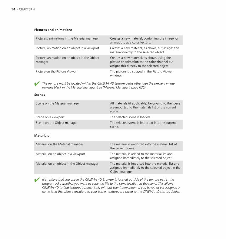
94 • CHAPTER 4 WORKFLOW • 95
Pictures and animations
Pictures, animations in the Material manager Creates a new material, containing the image, or animation, as a color texture.
Picture, animation on an object in a viewport Creates a new material, as above, but assigns this material directly to the selected object.
Picture, animation on an object in the Object manager
Creates a new material, as above, using the picture or animation as the color channel but assigns this directly to the selected object.
Picture on the Picture Viewer The picture is displayed in the Picture Viewer window.
The texture must be located within the CINEMA 4D texture paths otherwise the preview image remains black in the Material manager (see ‘Material Manager’, page 635).
Scenes
Scene on the Material manager All materials (if applicable) belonging to the scene are imported to the materials list of the current scene.
Scene on a viewport The selected scene is loaded.
Scene on the Object manager The selected scene is imported into the current scene.
Materials
Material on the Material manager The material is imported into the material list of the current scene.
Material on an object in a viewport The material is added to the material list and assigned immediately to the selected object.
Material on an object in the Object manager The material is imported into the material list and assigned immediately to the selected object in the Object manager.
If a texture that you use in the CINEMA 4D Browser is located outside of the texture paths, the program asks whether you want to copy the file to the same location as the scene. This allows CINEMA 4D to find textures automatically without user intervention. If you have not yet assigned a name (and therefore a location) to your scene, textures are saved to the CINEMA 4D startup folder.
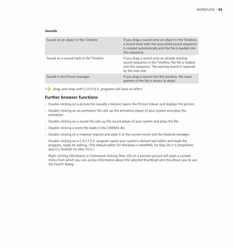
94 • CHAPTER 4 WORKFLOW • 95
Sounds
Sound on an object in the Timeline If you drag a sound onto an object in the Timeline, a sound track with the associated sound sequence is created automatically and the file is loaded into this sequence.
Sound on a sound track in the Timeline If you drag a sound onto an already existing sound sequence in the Timeline, the file is loaded into this sequence. The existing sound is replaced by the new one.
Sound in the Picture manager If you drag a sound into this window, the wave pattern of the file is shown in detail.
Drag-and-drop with C.O.F.F.E.E. programs will have no effect.
Further browser functions
- Double-clicking on a picture file (usually a texture) opens the Picture Viewer and displays the picture.
- Double-clicking on an animation file calls up the animation player of your system and plays the animation.
- Double-clicking on a sound file calls up the sound player of your system and plays the file.
- Double-clicking a scene file loads it into CINEMA 4D.
- Double-clicking on a material imports and adds it to the current scene and the Material manager.
- Double-clicking on a C.O.F.F.E.E. program opens your system’s default text editor and loads the program, ready for editing. (The default editor for Windows is NotePAD, for Mac OS it is SimpleText, and it is TextEdit for Mac OS X.)
- Right-clicking (Windows) or Command-clicking (Mac OS) on a preview picture will open a context menu from which you can access information about the selected thumbnail and this allows you to use the Search dialog.

96 • CHAPTER 4 WORKFLOW • 97
File MenuNew Catalog
Creates a new, empty catalog. Any existing catalog in the Browser will be replaced with the new one.
Open Catalog
Loads a previously saved catalog into the Browser.
Import File
Loads and adds a file (scene, picture, material...) to the current catalog. A preview picture is generated.
Import Directory
Loads and adds the contents of a folder to the current catalog. Depending on the Browser’s preferences, sub-folders are either searched or ignored.
Keep in mind that thumbnails use RAM, just like other pictures. 1,000 images from a CD would require a minimum 16MB of memory. In such cases, several smaller catalogs may be more economical of your system’s resources.
Save Catalog
Saves the current catalog. The catalog is saved using the name given in the Save Catalog As dialog. This name also appears in the Browser’s title bar. If your catalog is still yet to be named (in which case the Browser title bar will show 'Untitled'), the Save command acts in the same way as Save Catalog as (see below).
Save Catalog As, Make Catalog Relative
Save Catalog As always opens the File selector. The name you enter here will appear in the title bar of the Browser window. CINEMA 4D always adds the extension ‘.cat’ to the catalog’s filename.
Making catalog paths relative
Normally, when storing a preview image in a catalog, the exact location is also saved. This is essential when using the drag-and-drop technique to pass objects over to CINEMA 4D for processing. However, should you move, for example, a texture folder from your own system to the company’s network server, the location of the files is no longer the same as that of the saved catalog. Therefore the Browser will not find the required files.
A similar situation may arise when you compile a catalog for a CD-ROM collection (textures, objects, scenes etc.). These collections would normally be created locally on a computer, using the computer’s local path definitions and drive IDs (e.g. the drive could be D:\ , or even X:\ under Windows, or possibly 2184: or 1601 under Mac OS). This system would be unusable for catalogs, as the Browser would look for the various devices and paths of the computer, rather than the CD-ROM.

96 • CHAPTER 4 WORKFLOW • 97
The solution to this is to use relative paths. This option ensures that paths are not stored as complete path names, but instead as relative paths, starting from the catalog folder. Here, the location path of files is still used, but you are free to define where the system is to begin its search. This anchor folder can be anywhere on a hard disk or CD-ROM. But, starting from that anchor folder and moving down, the same path hierarchy as that of the catalog folder must exist. Here’s an example of anchor directories. Suppose that we want to list our winter background pictures. Let’s say these are located on our system hard drive in the following location:
Disk1/Texture/Backgrounds/Winter/...
So we define Texture as the anchor folder, the relative location then reads:
Backgrounds/Winter/...
This folder hierarchy can be now moved to any other location e.g. to the company’s server:
Server7/C4D/Resources/Tex/Backgrounds/Winter/...
The new anchor folder is now Tex. Starting from this location, the hierarchy sub-items now have the same path as before. To ensure that the Browser finds the required files requires one rule; the Browser catalog must always be in the anchor folder. In the above example the catalog would have been created in Texture and later copied to Tex.
Now for a more practical example: Suppose we need to collect together and write all of our textures, materials, objects and finished pictures, and all other useful items, to a CD. Firstly, a relevant catalog for the files is created. It is to contain all textures, objects and materials. In addition, the catalog will be located in the root folder of the CD so that we can view and archive it directly. We now create the entire archive on our computer. Only rarely should we require more than the 650MB limit of a CD-ROM for this work area. A possible CD structure for our hard drive might look like the following illustration:
98 • CHAPTER 4 WORKFLOW • 99
So this is how the structure could look. We have created and filled the folders with the relevant contents. As we are just concerned with browsing from here, only the three folders — Mat, Obj, and Tex — are of any interest to us. Or have we forgotten an important folder?
Of course ... we need to know where the anchor folder is located. Let’s look more closely. The CD will be called C4D Tools. Thus the folder of the same name within the mastering partition forms the anchor. This is also where the catalog is to be located, making it easily accessible. So, proceed as follows:
- Start CINEMA 4D and open the Browser.
- In the Browser, choose File > Preferences.
- Enable the Recurse Folders option (see above) as well as Pictures, Movies and Scenes. Depending on personal preference, from the drop-down menu to the right of Scenes choose Raytracer (which will cause a delay in catalog creation) Gouraud Shading or Wireframe.
- Choose File > New Catalog.
- Now each folder is added. Choose File > Import Folder. Use the dialog that opens to select, for example, the Mat folder. The catalog and the preview pictures are created. Use the Import Folder function twice more for the Obj and Tex folders.
- Now Select File > Save Catalog As.
- In the system dialog define ‘Disk3:Mastering:C4D Tools’ as the location and, say, ‘C4D Tools.cat’ as the name. This is the most crucial (and also most difficult) step. Now (and only now) does the Browser know where to create the relative paths.
- Select File > Make Catalog Relative, so that the Browser converts all information into relative paths.
- Save the catalog with File > Save Catalog.
- You are now ready to master the CD.
To summarize: If Make Catalog Relative is enabled, then complete paths are no longer saved, instead only the relative paths are used, starting from the catalog folder. From this location the current catalog folder and its sub-folders are scanned.
This method only works if you have named the catalog and assigned the path with the Save Catalog As command (see above) prior to searching the catalog.
Close
This command closes the Browser. The current catalog is removed from memory.
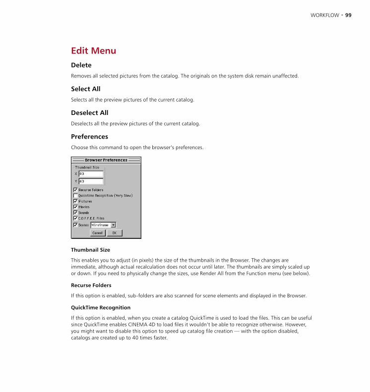
98 • CHAPTER 4 WORKFLOW • 99
Edit MenuDelete
Removes all selected pictures from the catalog. The originals on the system disk remain unaffected.
Select All
Selects all the preview pictures of the current catalog.
Deselect All
Deselects all the preview pictures of the current catalog.
Preferences
Choose this command to open the browser’s preferences.
Thumbnail Size
This enables you to adjust (in pixels) the size of the thumbnails in the Browser. The changes are immediate, although actual recalculation does not occur until later. The thumbnails are simply scaled up or down. If you need to physically change the sizes, use Render All from the Function menu (see below).
Recurse Folders
If this option is enabled, sub-folders are also scanned for scene elements and displayed in the Browser.
QuickTime Recognition
If this option is enabled, when you create a catalog QuickTime is used to load the files. This can be useful since QuickTime enables CINEMA 4D to load files it wouldn’t be able to recognize otherwise. However, you might want to disable this option to speed up catalog file creation — with the option disabled, catalogs are created up to 40 times faster.

100 • CHAPTER 4 WORKFLOW • 101
Pictures
If this option is enabled, pictures are displayed in the Browser. All image formats unknown to CINEMA 4D are ignored.
Movies
If this option is enabled, animations are displayed in the Browser. All animation formats unknown to CINEMA 4D are ignored.
Sounds
If this option is enabled, the waveforms of the sound files are displayed in the Browser. All sound formats unknown to CINEMA 4D are ignored.
C.O.F.F.E.E. Files
If this option is enabled, C.O.F.F.E.E. files are displayed in the Browser.
Scenes
If this option is enabled, scenes are shown in the Browser. All scene formats not recognized by CINEMA 4D are ignored. Use the drop-down list to the right of the option to set the shading mode for the thumbnails. Choose from Wireframe, Default (the mode that is saved in the scene’s file) and Raytracer. If Raytracer is selected, shadows and refraction are not rendered and only the floor and sky can be reflected. However, each scene is antialiased.
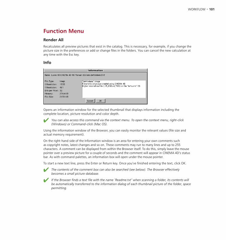
100 • CHAPTER 4 WORKFLOW • 101
Function MenuRender All
Recalculates all preview pictures that exist in the catalog. This is necessary, for example, if you change the picture size in the preferences or add or change files in the folders. You can cancel the new calculation at any time with the Esc key.
Info
Opens an information window for the selected thumbnail that displays information including the complete location, picture resolution and color depth.
You can also access this command via the context menu. To open the context menu, right-click (Windows) or Command-click (Mac OS).
Using the information window of the Browser, you can easily monitor the relevant values (file size and actual memory requirement).
On the right-hand side of the Information window is an area for entering your own comments such as copyright notes, latest changes and so on. These comments may run to many lines and up to 255 characters. A comment can be displayed from within the Browser itself. To do this, simply leave the mouse pointer over a preview picture for a couple of seconds and the comment will appear in CINEMA 4D’s status bar. As with command palettes, an information box will open under the mouse pointer.
To start a new text line, press the Enter or Return key. Once you’ve finished entering the text, click OK.
The contents of the comment box can also be searched (see below). The Browser effectively becomes a small picture database.
If the Browser finds a text file with the name ‘Readme.txt’ when scanning a folder, its contents will be automatically transferred to the information dialog of each thumbnail picture of the folder, space permitting.

102 • CHAPTER 4 WORKFLOW • 103
Search For
Scans the name and/or comment fields of the current database of the Browser for the text entered.
You can also access this command via the context menu. To open the context menu, right-click (Windows) or Command-click (Mac OS).
The Browser enables you to scan for filenames and/or comments. Enable the relevant options and enter the text and/or value you wish to search for in the field to the right. All thumbnails that match the find will be outlined in the catalog.
Sort By
Use the sub-entries of this menu to define the sort sequence of the current catalog in the Browser. Alternatively you may sort according to filename or file size. Items are sorted in ascending order, i.e. the list starts with the smallest images and ends with the largest.

102 • CHAPTER 4 WORKFLOW • 103
Initialization FilesCINEMA 4D loads several initialization files during startup. The content of these files is integrated into the layout.
template.c4d
During startup, CINEMA 4D checks its root folder for a file called ‘template.c4d’. If the file is present, its settings are loaded and used as default values. This can be very effective if you keep using the same scene-specific settings (e.g. several different render settings). For an overview of all the settings that are saved with the scene file, see ‘Project Settings’ on page 31.
new.c4d
When you create a new file (main menu File > New), CINEMA 4D checks its root folder for a file called ‘new.c4d’. If the file is present, its settings are loaded and used as default values. For example, to activate antialiasing permanently, create a new file, change the values in the Render Settings accordingly, then save the file into the same folder as the CINEMA 4D program under the filename ‘new’ (the ‘.c4d’ file extension is appended automatically).
template.cat
During startup, CINEMA 4D checks its root folder for a file called ‘Template.cat’. If the file is present, it is loaded into the Browser automatically. This can be useful, for example, when you are working on a large project and wish to have all the associated textures and/or scenes available immediately after startup. In this case, create a catalog that shows all the required files then save the catalog in CINEMA 4D’s root folder under the name ‘Template’ (CINEMA 4D appends ‘.CAT’ automatically). The Browser will contain the catalog the next time you launch CINEMA 4D. For more information on the Browser, see ‘The Browser’, page 92.
If the template catalog is very large (lots of preview pictures), expect a short delay during startup.
template.l4d
During startup, CINEMA 4D checks its root folder for a file called ‘Template.l4d’. If the file is present, it is loaded and used as the active layout. You can create this file in one of two ways:
- In the Preferences, on the Common page, enable the option Save Layout At Program End. The template layout will be created automatically when you quit CINEMA 4D — each time you quit, for as long as the option is enabled.
- Create the template layout manually using the function Window > Layout > Create Default Layout (main menu).

5 File Menu

FILE MENU • 107

FILE MENU • 107
To start CINEMA 4D, do one of the following:
- Double-click on the program icon.
- Double-click on a scene file.
- Drag one or more CINEMA 4D files in the Explorer (Windows) or the Finder (Mac OS) onto the CINEMA 4D icon (drag-and-drop).
template.c4d
During startup, CINEMA 4D checks its root folder for a file called ‘template.c4d’. If the file is present, its settings are loaded and used as default values. This can be very effective if you keep using the same scene-specific settings (e.g. several different render settings). For an overview of all the settings that are saved with the scene file, see ‘Project Settings’ page 31.
new.c4d
When you create a new file (main menu File > New), CINEMA 4D checks its root folder for a file called ‘new.c4d’. If the file is present, its settings are loaded and used as default values. For example, to activate antialiasing permanently, create a new file, change the values in the Render Settings accordingly, then save the file into the same folder as the CINEMA 4D program under the filename ‘new’ (the ‘.c4d’ file extension is appended automatically).
New
This command opens a new document and makes it the active (current) document. Until you save the new document and give it a name, the title bar of the document window will show ‘Untitled’. If you have several documents open you can switch quickly between them using the main Window menu.
Open
This command loads a file (a scene, a material, etc.) from a storage device (such as a hard disk) into memory and opens it in a new document window. If the current document window is empty, this is used instead. The following formats are understood and may be imported by CINEMA 4D:
- CINEMA 4D scenes (‘.c4d’), catalogs (‘.cat’), preferences (‘.prf’)
5 File Menu
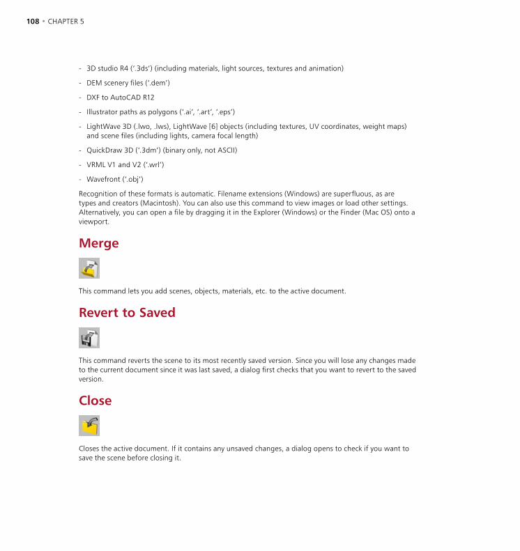
108 • CHAPTER 5 FILE MENU • 109
- 3D studio R4 (‘.3ds’) (including materials, light sources, textures and animation)
- DEM scenery files (‘.dem’)
- DXF to AutoCAD R12
- Illustrator paths as polygons (‘.ai’, ‘.art’, ‘.eps’)
- LightWave 3D (.lwo, .lws), LightWave [6] objects (including textures, UV coordinates, weight maps) and scene files (including lights, camera focal length)
- QuickDraw 3D (‘.3dm’) (binary only, not ASCII)
- VRML V1 and V2 (‘.wrl’)
- Wavefront (‘.obj’)
Recognition of these formats is automatic. Filename extensions (Windows) are superfluous, as are types and creators (Macintosh). You can also use this command to view images or load other settings. Alternatively, you can open a file by dragging it in the Explorer (Windows) or the Finder (Mac OS) onto a viewport.
Merge
This command lets you add scenes, objects, materials, etc. to the active document.
Revert to Saved
This command reverts the scene to its most recently saved version. Since you will lose any changes made to the current document since it was last saved, a dialog first checks that you want to revert to the saved version.
Close
Closes the active document. If it contains any unsaved changes, a dialog opens to check if you want to save the scene before closing it.
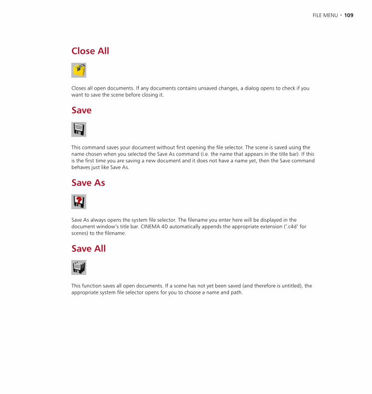
108 • CHAPTER 5 FILE MENU • 109
Close All
Closes all open documents. If any documents contains unsaved changes, a dialog opens to check if you want to save the scene before closing it.
Save
This command saves your document without first opening the file selector. The scene is saved using the name chosen when you selected the Save As command (i.e. the name that appears in the title bar). If this is the first time you are saving a new document and it does not have a name yet, then the Save command behaves just like Save As.
Save As
Save As always opens the system file selector. The filename you enter here will be displayed in the document window’s title bar. CINEMA 4D automatically appends the appropriate extension (‘.c4d’ for scenes) to the filename.
Save All
This function saves all open documents. If a scene has not yet been saved (and therefore is untitled), the appropriate system file selector opens for you to choose a name and path.
110 • CHAPTER 5 FILE MENU • 111
Save Project
Transferring scenes from one computer to another is always particularly challenging for a project leader. CINEMA 4D helps you to build complete scenes. Selecting this command opens the usual system file selector for saving files. Choose a folder and enter a name. CINEMA 4D creates a new folder in the specified path and saves the scene there. In addition, it creates a sub-folder, named Tex, into which it copies all the pictures and textures necessary for rendering the scene. You can now move the project to another system with confidence.
ExportA scene can also be exported to a foreign file format for subsequent work in other 3D software. The file types described below are available. CINEMA 4D automatically adds the relevant file extension to the file. Each 3D program works differently, therefore it is not always possible to convert all information within a scene. Further, the result will always differ according to the materials and lighting used, so a manual re-working may be necessary.
For information on the settings of the following and other formats, see ‘Import / Export’ in Chapter 3.
3D Studio R4 (.3DS)
Common data format under DOS/Windows. 3D Studio was the predecessor to 3D Studio MAX. The last freely available file format is release 4; the MAX data format is not available to other manufacturers. In principle the MAX format is not generally readable since MAX (like CINEMA 4D) uses parametric objects, which are useless without their associated specific algorithm. For example a teapot is not saved with points and surfaces, but only with the dimensions and the subdivision rate.
Direct3D / DirectX (X)
Direct3D is a Microsoft-specific 3D format, which is used by Windows (provided DirectX is installed). This export module is particularly useful to game developers.
DXF (DXF)
One of the most common graphics file formats, nearly all professional 3D packages support DXF. CINEMA 4D splines are generally written as polylines, independent of the surface settings for polygons.
QuickDraw 3D (3DM)
The standard format for three-dimensional graphics on the Apple Macintosh.
Shockwave 3D (W3D)
A format for transferring 3D content to Macromedia Director (Version 8.5 or later).
110 • CHAPTER 5 FILE MENU • 111
STL (STL)
Commonly used in the field of rapid prototyping, to create moulds.
UZR (UZR)
A format suitable for 3D streaming.
VRML 1 (WRL)
The Virtual Reality Modeling Language enables you to create platform-independent three-dimensional representation of objects and scenes for the Internet. It has also proved useful as an exchange format for CAD programs, since it contains more file information than the often-used DXF format.
VRML 2 (WRL)
Version 2 of the standard format for three-dimensional graphics files on the Internet enables you to display animation sequences. The advantages for data exchange with CAD software mentioned above also apply to VRML 2.
Wavefront (OBJ)
A common 3D data format in the UNIX world, developed by Alias.
Recent FilesCINEMA 4D remembers which files you opened recently and lists them on this submenu for quick access. Define the maximum number of files listed in Edit > Preferences.
QuitThis command quits CINEMA 4D.


6 Edit Menu

EDIT MENU • 115
EDIT MENU • 115
The Edit menu contains some of the most frequently used commands in CINEMA 4D such as Undo and Redo, hence you’ll find these commands on most of the local Edit menus. Besides giving details of these commands, this chapter also explains the significance of the internal buffers and the drawing pipeline. Understanding how these features work is critical to avoiding and/or solving various issues.
The undo buffer Some functions, such as Save and General Settings, are not recorded in the undo buffer and
subsequently cannot be undone.
CINEMA 4D’s multiple undo enables you to undo not just the last change you made but up to as many changes as RAM permits. The maximum number of undos is defined by the Undo Depth on the Document page of the preferences — the default it 10.
CINEMA 4D differentiates between memory-intensive actions and non-memory-intensive actions. Examples of memory-intensive actions include deleting an object and moving an object’s points. Non-memory-intensive actions include selecting and renaming objects. Non-memory-intensive actions can be recalled 10 times more than the Undo Depth value in the preferences. For example, with Undo Depth set to 12 you can undo 12 delete object actions or 120 select object actions. You can also mix both types of action, e.g. you can undo 6 delete object actions and 60 select object actions.
When you perform an action in CINEMA 4D, information about that action is written to an area of memory called the undo buffer. The Undo and Redo functions use the information in the undo buffer to undo changes.
Example
- You create an object and change its scale to (400/400/400) units. You move the object to coordinates (100/-300/0).
- At this point, the undo buffer contain the following action history:
1. Create object at position (0/0/0).
2. Scale object to (400/400/400) units.
3. Move object to position (100/–300/0).
- The buffer’s current state is step 3, the move action. If you use the Undo function, CINEMA 4D undoes the current state (move) then sets the current state to step 2 (scale).
- If you use the Undo function again, the scale action is undone and the current state is set to step 1 (create).
- Throughout the process the buffer content itself is not altered — nothing is deleted. This enables you to restore the changes with the Redo command. Use Undo to move backwards through the undo buffer (i.e. the changes) and Redo to advance through the buffer.
6 Edit Menu
116 • CHAPTER 6 EDIT MENU • 117
- Although nothing is deleted from the buffer, the buffer’s size must be prevented from taking up too much memory. This is the purpose of Undo Depth in the preferences — it specifies the maximum number of actions that can be undone.
Undo, Undo View
Undo View affects the editor camera only. It has no effect on your own camera objects.
Undoes the last change, restoring the scene to its previous state. For example, if you accidentally move an object, choose Undo to restore the object to its correct position. Choose Undo repeatedly to undo the previous changes on by one. By default, you can undo a maximum of 10 changes. The maximum number of changes that can be undone is defined by Undo Depth in the preferences (Document page). Note that the Undo command from the menu of a viewport undoes changes to the editor camera only. You can undo a maximum of 500 editor camera changes.
Redo, Redo View
Undo View affects the editor camera only. It has no effect on your own camera objects.
Redo redoes a change. Select Redo repeatedly to continue restoring the changes. You can traverse the recent development stages of your scene by using Undo to move backwards and Redo to move forwards. Naturally, the number of steps you can redo cannot possibly be greater than the number of actions you have undone. Therefore, there is no separate setting for the redo depth in the preferences. In a viewport, Redo View redoes changes to the editor camera only. You can redo a maximum of 500 editor camera changes.
Undo (Action)
This function differs from the conventional Undo command in that it ignores selection actions. Undo (Action) undoes the last change that did not involve selection.
Why does the command ignore selection actions? Suppose you’ve scaled an object then you used 10 selection actions to select points in various locations. Suddenly, you decide that the object is too large and you want to restore it to its original size. This would require you to call the conventional Undo command 11 times (you must undo the 10 selection actions and then finally the scale action). If, however, you use Undo (Action), it skips over the selection actions and undoes the scale action immediately.

116 • CHAPTER 6 EDIT MENU • 117
Let’s explore a couple of examples; in these example, A stands for a normal action such as moving an object and S stands for a selection action such as selecting edges.
Example 1
You’ve been editing for a while. The undo buffer contains the following sequence.
A S A S A A A S S S S
i.e. the buffer starts with a normal action, followed by a selection action, followed by a normal action, and so on. There are four consecutive selection actions at the end of the buffer. The final, most-recent, selection action is right-most and represents the current state of the undo buffer. If we call the normal undo function, the resulting buffer is:
A S A S A A A S S S
Only the final selection has been removed — there are still three selection actions at the end of the buffer. However, if we use the Undo (Action) function instead of the normal undo we get:
A S A S A A
The first normal action has been removed as well as all the selections that happened to be in front of it.
Example 2
In this example the undo buffer contains selection actions only:
S S S S
The final, most-recent, selection action is right-most and represents the current state of the undo buffer. If we call the normal undo function, the resulting buffer is:
S S S
However, if we use the Undo (Action) function instead of the normal undo, we get:
S S S S
Nothing has been undone. Why? The buffer contains selection actions only — there are no normal actions. Undo (Action) reverts the scene to its state prior to the last normal action. If there are no normal actions at all in the buffer, the buffer remains unchanged.
The clipboardWhen you use the Cut or Copy commands, the selected objects or elements are copied into a structure in memory known as the clipboard. When you select the Paste command, the data in the clipboard is inserted into the current scene. For example, to copy an object from one scene to another scene; open both scenes, activate the scene that contains the object, copy the object, activate the other scene and then paste.
118 • CHAPTER 6 EDIT MENU • 119
The size of the clipboard is determined by the size of the data stored there. If, for example, you copy an 18MB object, the clipboard will use 18MB of memory. You may want to purge the clipboard to free up memory, especially before you render. To purge the clipboard, cut a null object. The null object wastes only a few bytes.
Cut
Deletes the selected objects or elements from the current scene and copies them (including materials) to the clipboard. The objects can be copied back from the clipboard with the Paste command.
Copy
You can copy and paste objects using drag-and-drop in the Object manager. Ctrl-drag one of the selected object’s names to a new position within the Object manager.
Copies the selected objects or elements (including materials) to the clipboard. The objects can be copied from the clipboard to the active scene with the Paste command. You can paste repeatedly to create additional copies.
Paste
Inserts the contents of the clipboard (i.e. the last objects that were cut or copied there) into the active scene.
Delete
Deletes the selected objects or elements from the current scene without copying them to the clipboard.

118 • CHAPTER 6 EDIT MENU • 119
SelectionSelect All
Selects all objects in the scene.
Deselect All
Deselects all objects or elements. If the Points tool is active when you invoke Deselect All, all the points of the selected object will be deselected. Similarly, if the Polygon tool or Edge tool is active, all polygons or edges of the selected object will be deselected.
Select Children
Adds the children of the selected object(s) to the selection. This is especially useful when you want to record keyframes for the selected objects and their children.
The drawing pipeline Should you encounter unexpected results in CINEMA 4D, check the drawing pipeline first.
One of CINEMA 4D’s prime features is its realtime preview, e.g. realtime deformation editing in the viewports. To facilitate this feature, the various actions involved must take place in a predefined order. Suppose that you have created a Cube object. You then assign an expression, which distorts the cube in a particular way. Next, you assign a Bend deformation object to the cube. Which action should take place first? Should the cube be bent first, then distorted, or should the cube be distorted and then bent? Two entirely different outcomes are possible depending on which action takes place first.
Suppose you’ve animated an object to move from point A to point B, yet at the same time you have given it an expression that tells it to move to point C. The object cannot be in both places at the same time, so who wins? The winner is whichever one is evaluated last of all – if the expression is evaluated first, the animation overwrites the expression and the object comes to rest at point B; if the animation is evaluated first, the expression overwrites it and the object ends up at point C.
CINEMA 4D R8 enables you to assign priority levels to expressions to control exactly when the expression is evaluated. See ‘New Expression’ on page 614.
The order in which actions are processed is what we refer to as the ‘pipeline’ — actions take place one after the other, as though they are flowing through a pipe. Since the whole process determines what is ultimately drawn on the screen, the entire concept is termed ‘the drawing pipeline’. Be aware of the drawing pipeline so that you can predict the outcome of applying several functions simultaneously.
120 • CHAPTER 6 EDIT MENU • 121
The Use Animations, Use Expressions, Use Generators and Use Deformers functions (see below) turn on or off specific elements of the drawing pipeline. If an element is turned off, its data will no longer be evaluated in the viewports. For example, if you turn off deformers, all objects will appear in their non-deformed state.
Allocate a target expression to an object and enable Use Expressions. Now you will be unable to rotate the object manually.
Suppose you’ve created a simple position animation (movement from A to B) using keyframing (see ‘Recording animation’ on page 842). You will be unable to move the object from its path – it hops back immediately. If you want the object to pass through point C on its journey from A to B, disable Use Animation, move the object accordingly, record the new key for point C, then enable Use Animation.
Use Animation
Animation refers to any data stored in the Timeline. Although expressions can animate an object, expressions are treated as a separate data type.
Evaluation order
Tracks are evaluated from bottom to top in the Timeline, beginning with parent objects. The child objects (sub-objects) are then evaluated according to the hierarchy; to show the hierarchy in the Object manager, open the entire structure for a complex object group (see ‘Expand Object Group’, page 625). The objects are evaluated from top to bottom in the order you see in the structure.
What happens if you have allocated two different position tracks (e.g. one from A to B, the other from A to C) to the same object? The track which is top-most in the Timeline will be evaluated last of all and will overwrite the previous movement. If track A-to-B is above track A-to-C in the Timeline, the object will move from A to B.
Use Expressions
Expressions are evaluated from left to right as they appear in the Object manager. An expression is a behavioral property that can be added to an object. It gives instructions to the object. Expressions use C.O.F.F.E.E., CINEMA 4D’s built-in programming language, and thereby have access to all of an object’s parameters. An expression could, for example, change the color used by a house material according to the state of a sun object.
120 • CHAPTER 6 EDIT MENU • 121
Evaluation order
Expressions are evaluated from left to right as they appear in the Object manager. First the parent object is evaluated, then the order continues along the hierarchy tree; to see this tree, open the entire structure for a complex object group in the Object manager (see ‘Expand Object Group’, page 625). The objects are evaluated from top to bottom in the order you see them.
Use Generators
Generators are objects that create temporary hierarchical structures. For example, a NURBS object generates a temporary polygon object for display purposes. You can convert the temporary object into a real object if required using the Current State To Object command. Generators include NURBS objects, the particle system, the array, the symmetry object, polygon primitives, spline primitives, instances, metaballs and so on.
Evaluation order
Generators are evaluated starting with the child objects, then evaluation moves up the hierarchy tree; to see this tree, open the entire structure for a complex object group in the Object manager (see ‘Expand Object Group’, page 625). The objects are evaluated from top to bottom in the order you see them.
Use Deformers
Deformers are the functions listed in the Objects > Deformation menu and include Explosion, FFD, Bone and Magnet. A deformer deforms the (single) object that it is applied to. The deformation is applied to a virtual copy of the source object so that the original geometry is preserved and can always be restored. The Polygon Reduction command also performs in this way and is therefore classed as a deformer. The main difference between expressions and deformers is that expressions are processed before the (virtual) copy is created, whereas deformers are processed after the copy is created.
Evaluation order
Deformers are evaluated starting with the child objects, then evaluation moves up the hierarchy tree; to see this tree, open the entire structure for a complex object group in the Object manager (see ‘Expand Object Group’, page 625). The objects are evaluated from top to bottom in the order you see them.

122 • CHAPTER 6 EDIT MENU • 123
Here is an example to explain why the evaluation order for deformers and generators begins with child objects. A Loft NURBS creates a temporary polygon object for display purposes — it is a generator (see ‘Loft NURBS’, page 180). Imagine that the splines which describe the Loft NURBS are themselves deformed by several FFD objects (deformers). The hierarchy tree might look as in the illustration below.
It is only possible for the FFDs (sub-objects of the splines) to deform the splines before they are used by the NURBS object if the evaluation order is from the bottom of the hierarchy tree to the top.
The display orderWe have addressed the order in which elements of the same data type are evaluated, but what is the evaluation order for elements of differing types? Again, the display pipeline works to a strict order:
- First, all animation data is evaluated.
- Next, the expressions are evaluated (provided that you’ve not changed their priority).
- Finally, and with top priority, the generators and deformers are evaluated.
The drawing pipeline is evaluated each time you perform a new action in CINEMA 4D. Although this appears to be an overhead, it makes it possible, for example, to apply a target expression to an object then see it move automatically as you move the target object around in a viewport. You are able to work with objects live – there is no need to move the time slider or play back the animation to update the scene. This is especially useful with inverse kinematics since you can work with interactive (live) targets (see ‘Inverse Kinematics’, page 423).

122 • CHAPTER 6 EDIT MENU • 123
SettingsProject Settings
These are local settings which apply to the active project only. These settings are described on page 84.
Preferences
The preferences enable you to change the appearance and behavior of CINEMA 4D. These numerous options are explained in detail, starting on page 46.


7 Objects Menu

OBJECTS MENU • 127
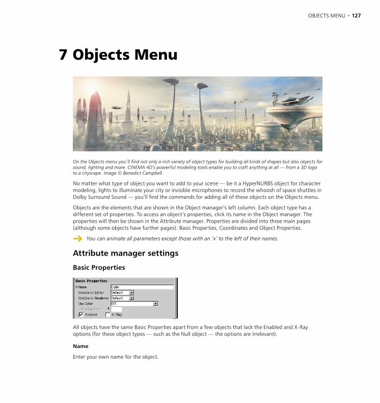
OBJECTS MENU • 127
7 Objects Menu
On the Objects menu you’ll find not only a rich variety of object types for building all kinds of shapes but also objects for sound, lighting and more. CINEMA 4D’s powerful modeling tools enable you to craft anything at all — from a 3D logo to a cityscape. Image © Benedict Campbell.
No matter what type of object you want to add to your scene — be it a HyperNURBS object for character modeling, lights to illuminate your city or invisible microphones to record the whoosh of space shuttles in Dolby Surround Sound — you’ll find the commands for adding all of these objects on the Objects menu.
Objects are the elements that are shown in the Object manager’s left column. Each object type has a different set of properties. To access an object’s properties, click its name in the Object manager. The properties will then be shown in the Attribute manager. Properties are divided into three main pages (although some objects have further pages): Basic Properties, Coordinates and Object Properties.
You can animate all parameters except those with an ‘x’ to the left of their names.
Attribute manager settings
Basic Properties
All objects have the same Basic Properties apart from a few objects that lack the Enabled and X-Ray options (for these object types — such as the Null object — the options are irrelevant).
Name
Enter your own name for the object.
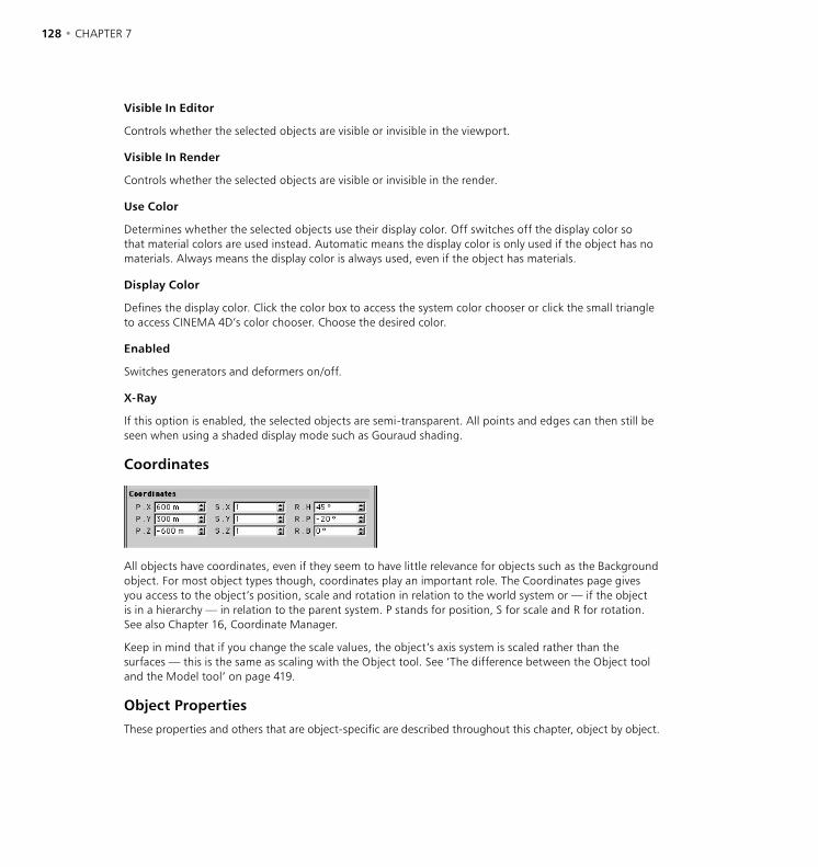
128 • CHAPTER 7
Visible In Editor
Controls whether the selected objects are visible or invisible in the viewport.
Visible In Render
Controls whether the selected objects are visible or invisible in the render.
Use Color
Determines whether the selected objects use their display color. Off switches off the display color so that material colors are used instead. Automatic means the display color is only used if the object has no materials. Always means the display color is always used, even if the object has materials.
Display Color
Defines the display color. Click the color box to access the system color chooser or click the small triangle to access CINEMA 4D’s color chooser. Choose the desired color.
Enabled
Switches generators and deformers on/off.
X-Ray
If this option is enabled, the selected objects are semi-transparent. All points and edges can then still be seen when using a shaded display mode such as Gouraud shading.
Coordinates
All objects have coordinates, even if they seem to have little relevance for objects such as the Background object. For most object types though, coordinates play an important role. The Coordinates page gives you access to the object’s position, scale and rotation in relation to the world system or — if the object is in a hierarchy — in relation to the parent system. P stands for position, S for scale and R for rotation. See also Chapter 16, Coordinate Manager.
Keep in mind that if you change the scale values, the object’s axis system is scaled rather than the surfaces — this is the same as scaling with the Object tool. See ‘The difference between the Object tool and the Model tool’ on page 419.
Object Properties
These properties and others that are object-specific are described throughout this chapter, object by object.
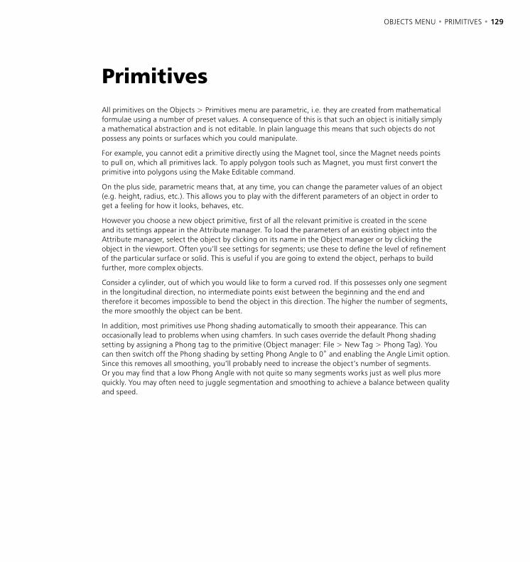
OBJECTS MENU • PRIMITIVES • 129
All primitives on the Objects > Primitives menu are parametric, i.e. they are created from mathematical formulae using a number of preset values. A consequence of this is that such an object is initially simply a mathematical abstraction and is not editable. In plain language this means that such objects do not possess any points or surfaces which you could manipulate.
For example, you cannot edit a primitive directly using the Magnet tool, since the Magnet needs points to pull on, which all primitives lack. To apply polygon tools such as Magnet, you must first convert the primitive into polygons using the Make Editable command.
On the plus side, parametric means that, at any time, you can change the parameter values of an object (e.g. height, radius, etc.). This allows you to play with the different parameters of an object in order to get a feeling for how it looks, behaves, etc.
However you choose a new object primitive, first of all the relevant primitive is created in the scene and its settings appear in the Attribute manager. To load the parameters of an existing object into the Attribute manager, select the object by clicking on its name in the Object manager or by clicking the object in the viewport. Often you’ll see settings for segments; use these to define the level of refinement of the particular surface or solid. This is useful if you are going to extend the object, perhaps to build further, more complex objects.
Consider a cylinder, out of which you would like to form a curved rod. If this possesses only one segment in the longitudinal direction, no intermediate points exist between the beginning and the end and therefore it becomes impossible to bend the object in this direction. The higher the number of segments, the more smoothly the object can be bent.
In addition, most primitives use Phong shading automatically to smooth their appearance. This can occasionally lead to problems when using chamfers. In such cases override the default Phong shading setting by assigning a Phong tag to the primitive (Object manager: File > New Tag > Phong Tag). You can then switch off the Phong shading by setting Phong Angle to 0˚ and enabling the Angle Limit option. Since this removes all smoothing, you’ll probably need to increase the object’s number of segments. Or you may find that a low Phong Angle with not quite so many segments works just as well plus more quickly. You may often need to juggle segmentation and smoothing to achieve a balance between quality and speed.
Primitives
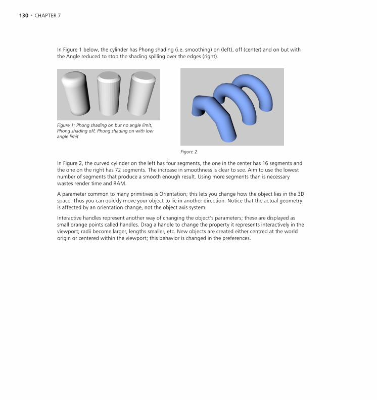
130 • CHAPTER 7 OBJECTS MENU • PRIMITIVES • 131
In Figure 1 below, the cylinder has Phong shading (i.e. smoothing) on (left), off (center) and on but with the Angle reduced to stop the shading spilling over the edges (right).
Figure 1: Phong shading on but no angle limit, Phong shading off, Phong shading on with low angle limit
Figure 2.
In Figure 2, the curved cylinder on the left has four segments, the one in the center has 16 segments and the one on the right has 72 segments. The increase in smoothness is clear to see. Aim to use the lowest number of segments that produce a smooth enough result. Using more segments than is necessary wastes render time and RAM.
A parameter common to many primitives is Orientation; this lets you change how the object lies in the 3D space. Thus you can quickly move your object to lie in another direction. Notice that the actual geometry is affected by an orientation change, not the object axis system.
Interactive handles represent another way of changing the object’s parameters; these are displayed as small orange points called handles. Drag a handle to change the property it represents interactively in the viewport; radii become larger, lengths smaller, etc. New objects are created either centred at the world origin or centered within the viewport; this behavior is changed in the preferences.

130 • CHAPTER 7 OBJECTS MENU • PRIMITIVES • 131
Cone
This command creates a cone, whose base lies in the XZ plane (but see below). The Cone object is more useful than it first appears. For example, you can quickly create a drop of water by adjusting a few parameters.
Attribute manager settings
Object Properties
Top Radius, Bottom Radius
These values define the cone’s top radius and bottom radius The top radius is set to 0 by default, i.e. the top of the cone ends in a single point (see illustration, left). If this value is set higher than zero, a truncated cone is formed (center). If the top radius is equal to the bottom radius, you get a cylinder (right).
Height
This value defines the overall height of the cone.
Height Segments
Defines the number of subdivisions of the object in the Y direction.
Rotation Segments
Defines the number of subdivisions of the object along its length. The greater this value, the smoother the cone appears.
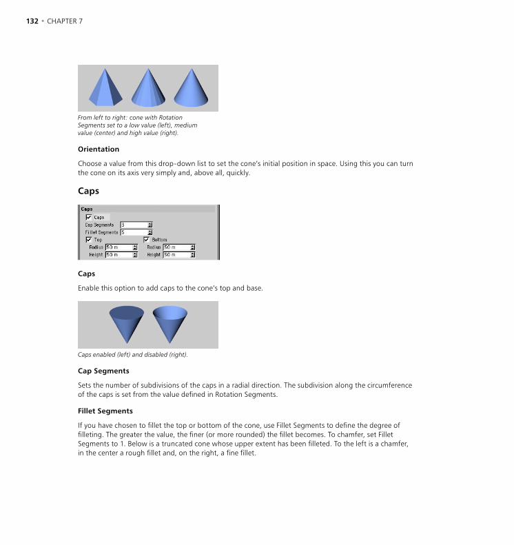
132 • CHAPTER 7 OBJECTS MENU • PRIMITIVES • 133
From left to right: cone with Rotation Segments set to a low value (left), medium value (center) and high value (right).
Orientation
Choose a value from this drop-down list to set the cone’s initial position in space. Using this you can turn the cone on its axis very simply and, above all, quickly.
Caps
Caps
Enable this option to add caps to the cone’s top and base.
Caps enabled (left) and disabled (right).
Cap Segments
Sets the number of subdivisions of the caps in a radial direction. The subdivision along the circumference of the caps is set from the value defined in Rotation Segments.
Fillet Segments
If you have chosen to fillet the top or bottom of the cone, use Fillet Segments to define the degree of filleting. The greater the value, the finer (or more rounded) the fillet becomes. To chamfer, set Fillet Segments to 1. Below is a truncated cone whose upper extent has been filleted. To the left is a chamfer, in the center a rough fillet and, on the right, a fine fillet.
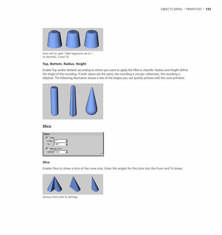
132 • CHAPTER 7 OBJECTS MENU • PRIMITIVES • 133
From left to right: Fillet Segments set to 1 (a chamfer), 3 and 10.
Top, Bottom, Radius, Height
Enable Top and/or Bottom according to where you want to apply the fillet or chamfer. Radius and Height define the shape of the rounding. If both values are the same, the rounding is circular; otherwise, the rounding is elliptical. The following illustration shows a few of the shapes you can quickly achieve with the cone primitive.
Slice
Slice
Enable Slice to show a slice of the cone only. Enter the angles for this slice into the From and To boxes.
Various From and To settings.
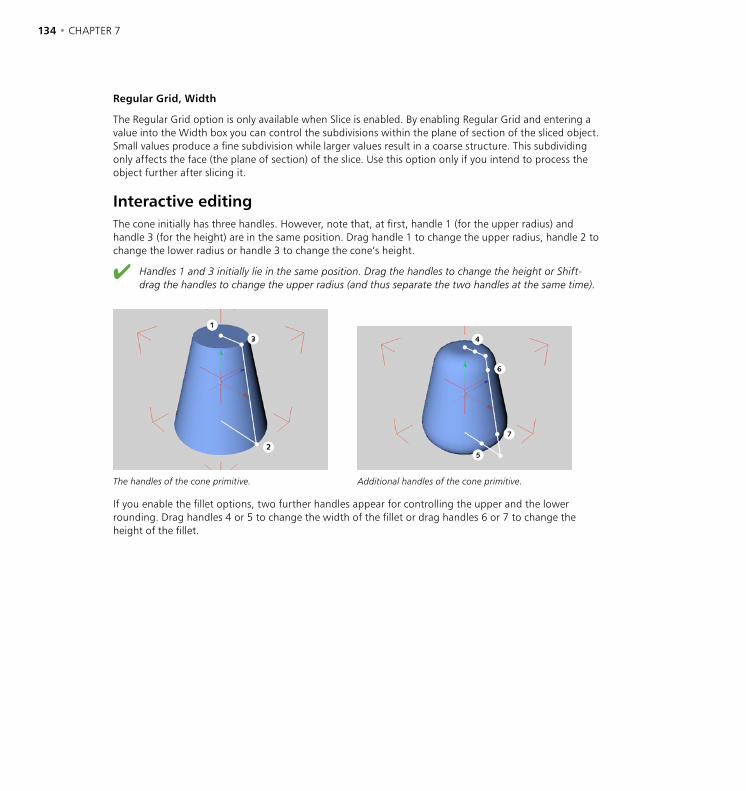
134 • CHAPTER 7 OBJECTS MENU • PRIMITIVES • 135
Regular Grid, Width
The Regular Grid option is only available when Slice is enabled. By enabling Regular Grid and entering a value into the Width box you can control the subdivisions within the plane of section of the sliced object. Small values produce a fine subdivision while larger values result in a coarse structure. This subdividing only affects the face (the plane of section) of the slice. Use this option only if you intend to process the object further after slicing it.
Interactive editingThe cone initially has three handles. However, note that, at first, handle 1 (for the upper radius) and handle 3 (for the height) are in the same position. Drag handle 1 to change the upper radius, handle 2 to change the lower radius or handle 3 to change the cone’s height.
Handles 1 and 3 initially lie in the same position. Drag the handles to change the height or Shift-drag the handles to change the upper radius (and thus separate the two handles at the same time).
The handles of the cone primitive. Additional handles of the cone primitive.
If you enable the fillet options, two further handles appear for controlling the upper and the lower rounding. Drag handles 4 or 5 to change the width of the fillet or drag handles 6 or 7 to change the height of the fillet.

134 • CHAPTER 7 OBJECTS MENU • PRIMITIVES • 135
Cube
This command creates, by default, a cube whose sides are parallel to the coordinate axes of the world system. You can create many arbitrary cuboids by adjusting the various options. Rounded edges are optional.
Attribute manager settings
Object Properties
Size X, Size Y, Size Z
The values for Size X (width), Size Y (height) and Size Z (depth) define the size of the object.
Segments X, Segments Y , Segments Z
These values for width, height and depth reflect how finely the particular side of the object is subdivided. You must consider the segmentation if you intend to edit the primitive with other tools. The finer the subdivision, the softer later deformations will appear. In particular you should subdivide an object quite finely before using boolean operations on it — generally, though, only subdivide when necessary.
Separate Surfaces
If you enable this option then, during a later transformation of the parameter object into a polygon object, a separate object will be created for each side of the cube and all will be combined into a group. This is useful if you want to be able to process elements of the cuboid separately. You can only select this option if Fillet is disabled.
Fillet, Fillet Radius, Fillet Subdivision
To fillet (i.e. round) the object’s edges, enable the Fillet option. Fillet Radius is the radius of the curvature, while Fillet Segments defines how finely the fillet appears. The more segments you specify, the smoother the fillet. To create a chamfer instead of a rounded fillet, set Fillet Segment to 1.
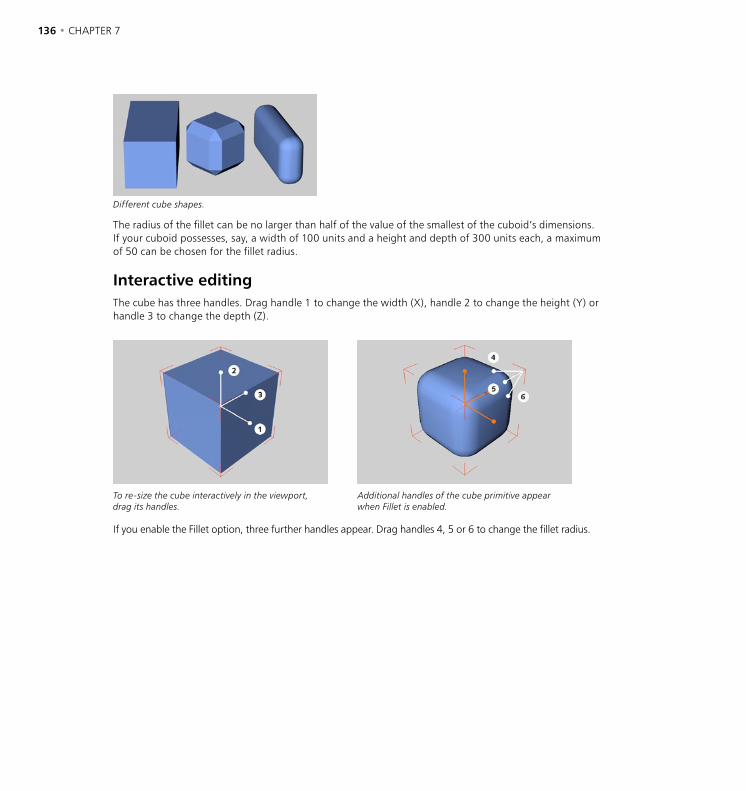
136 • CHAPTER 7 OBJECTS MENU • PRIMITIVES • 137
Different cube shapes.
The radius of the fillet can be no larger than half of the value of the smallest of the cuboid’s dimensions. If your cuboid possesses, say, a width of 100 units and a height and depth of 300 units each, a maximum of 50 can be chosen for the fillet radius.
Interactive editingThe cube has three handles. Drag handle 1 to change the width (X), handle 2 to change the height (Y) or handle 3 to change the depth (Z).
To re-size the cube interactively in the viewport, drag its handles.
Additional handles of the cube primitive appear when Fillet is enabled.
If you enable the Fillet option, three further handles appear. Drag handles 4, 5 or 6 to change the fillet radius.

136 • CHAPTER 7 OBJECTS MENU • PRIMITIVES • 137
Cylinder
This command creates a cylinder, whose ends (caps) are aligned parallel to the XZ plane.
Attribute manager settings
Object Properties
Radius, Height
These values define the basic dimensions of the cylinder.
Height Segments
Changes the number of subdivisions of the object in the Y direction (cylindrical part only).
Rotation Segments
Defines the number of subdivisions of the object along its circumference. The greater this value, the smoother the cylinder will appear.
Cylinder with different Rotation Segments settings.
Orientation
Choose a value from this drop-down list to set the cylinder’s initial position in space. Using this you can turn it on its axis very simply and, above all, quickly.
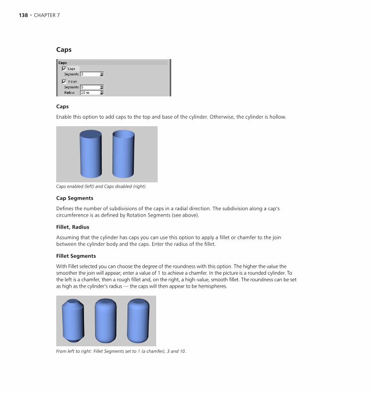
138 • CHAPTER 7 OBJECTS MENU • PRIMITIVES • 139
Caps
Caps
Enable this option to add caps to the top and base of the cylinder. Otherwise, the cylinder is hollow.
Caps enabled (left) and Caps disabled (right).
Cap Segments
Defines the number of subdivisions of the caps in a radial direction. The subdivision along a cap’s circumference is as defined by Rotation Segments (see above).
Fillet, Radius
Assuming that the cylinder has caps you can use this option to apply a fillet or chamfer to the join between the cylinder body and the caps. Enter the radius of the fillet.
Fillet Segments
With Fillet selected you can choose the degree of the roundness with this option. The higher the value the smoother the join will appear; enter a value of 1 to achieve a chamfer. In the picture is a rounded cylinder. To the left is a chamfer, then a rough fillet and, on the right, a high-value, smooth fillet. The roundness can be set as high as the cylinder’s radius — the caps will then appear to be hemispheres.
From left to right: Fillet Segments set to 1 (a chamfer), 3 and 10.
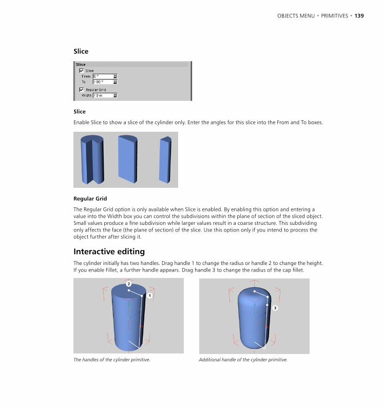
138 • CHAPTER 7 OBJECTS MENU • PRIMITIVES • 139
Slice
Slice
Enable Slice to show a slice of the cylinder only. Enter the angles for this slice into the From and To boxes.
Regular Grid
The Regular Grid option is only available when Slice is enabled. By enabling this option and entering a value into the Width box you can control the subdivisions within the plane of section of the sliced object. Small values produce a fine subdivision while larger values result in a coarse structure. This subdividing only affects the face (the plane of section) of the slice. Use this option only if you intend to process the object further after slicing it.
Interactive editingThe cylinder initially has two handles. Drag handle 1 to change the radius or handle 2 to change the height. If you enable Fillet, a further handle appears. Drag handle 3 to change the radius of the cap fillet.
The handles of the cylinder primitive. Additional handle of the cylinder primitive.

140 • CHAPTER 7 OBJECTS MENU • PRIMITIVES • 141
Disc
This creates a flat circular plate in the XZ plane.
Attribute manager settings
Object Properties
Inner Radius, Outer Radius
The value for the outer radius defines the overall size of the disc. A value for the inner radius of greater than zero generates a perforated disc. The inner radius can be no larger than the outer radius.
Disc Segments, Rotation Segments
Disc Segments gives the radial subdivision, Rotation Segments the subdivision along the circumference.
Discs with different subdivisions.
Orientation
Choose a value from this drop-down list to set the disc’s initial position in space. Using this you can turn it on its axis very simply and, above all, quickly.

140 • CHAPTER 7 OBJECTS MENU • PRIMITIVES • 141
Slice
Slice
Enable Slice to show a slice of the disc only. Enter the angles for this slice into the From and To boxes.
Different disc cutouts.
Interactive editingThe disc has two handles. Drag handle 1 to change the outer radius or handle 2 to change the inner radius.
The handles of the disk primitive.

142 • CHAPTER 7 OBJECTS MENU • PRIMITIVES • 143
Plane
This command creates a quadrangle in the XZ plane, which is divided into further quadrangle surfaces.
Attribute manager settings
Object Properties
Width, Height
Defines the size of the plane.
Width Segments, Height Segments
You can set the level of subdivision separately for the width and height. This is especially useful when you intend to convert the plane to polygons and edit it further. The more segments you use, the more smoothly you’ll be able to apply tools such as the Magnet.
Differently subdivided, deformed planes.
Orientation
Choose a value from this drop-down list to set the plane’s initial position in space. Using this you can turn it on its axis very simply and, above all, quickly.
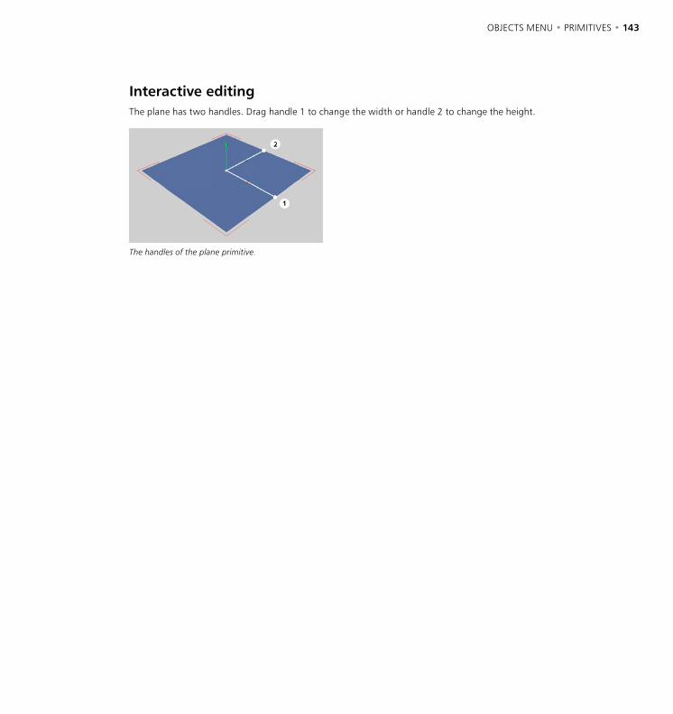
142 • CHAPTER 7 OBJECTS MENU • PRIMITIVES • 143
Interactive editingThe plane has two handles. Drag handle 1 to change the width or handle 2 to change the height.
The handles of the plane primitive.

144 • CHAPTER 7 OBJECTS MENU • PRIMITIVES • 145
Polygon
This command creates a single polygon (a triangle or rectangle) in the XZ plane.
Attribute manager settings
Object Properties
Width, Height
Define the size of the polygon.
Segments
Enables you to change the degree of subdivision of the object.
Triangle
Enable this option to create the polygon from triangular shapes instead of rectangular ones.
Orientation
Choose a value from this drop-down list to set the polygon’s initial position in space. Using this you can turn it on its axis very simply and, above all, quickly.
Interactive editingThe polygon has two handles. Drag handle 1 to change the width or handle 2 to change the height.
The handles of the polygon primitive.

144 • CHAPTER 7 OBJECTS MENU • PRIMITIVES • 145
Sphere
This command creates a sphere composed of triangles and squares. Spheres are especially useful for modeling when used as metaballs.
Attribute manager settings
Object Properties
Radius
Use this to define the size of the sphere.
Segments
Defines the degree of the subdivision of the sphere. The sphere is divided along its latitude and longitude. However, until you convert a sphere into a polygon object with Make Editable, a sphere is always generated by calculation, no matter by how much you subdivide it.
On the left a sphere primitive divided into six segments, on the right the same object, this time converted to a polygon.
Type
With this drop-down list you choose of which surfaces, and in which arrangement, a sphere is to be composed. With Standard the sphere surface is made up of triangles and squares, Hexahedron uses only squares and Icosahedron only triangles.
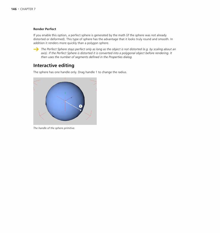
146 • CHAPTER 7 OBJECTS MENU • PRIMITIVES • 147
Render Perfect
If you enable this option, a perfect sphere is generated by the math (if the sphere was not already distorted or deformed). This type of sphere has the advantage that it looks truly round and smooth. In addition it renders more quickly than a polygon sphere.
The Perfect Sphere stays perfect only as long as the object is not distorted (e.g. by scaling about an axis). If the Perfect Sphere is distorted it is converted into a polygonal object before rendering. It then uses the number of segments defined in the Properties dialog.
Interactive editingThe sphere has one handle only. Drag handle 1 to change the radius.
The handle of the sphere primitive.
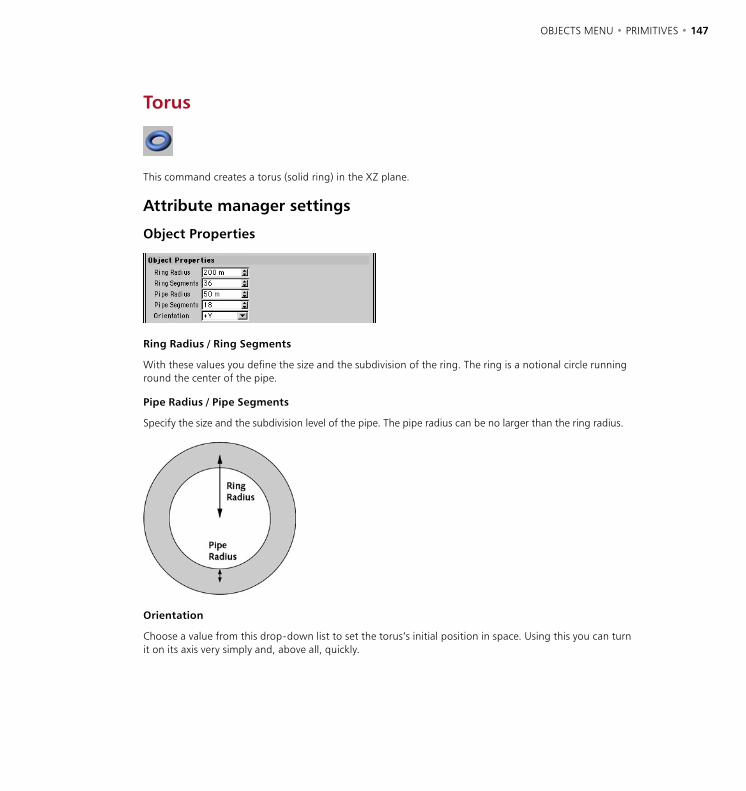
146 • CHAPTER 7 OBJECTS MENU • PRIMITIVES • 147
Torus
This command creates a torus (solid ring) in the XZ plane.
Attribute manager settings
Object Properties
Ring Radius / Ring Segments
With these values you define the size and the subdivision of the ring. The ring is a notional circle running round the center of the pipe.
Pipe Radius / Pipe Segments
Specify the size and the subdivision level of the pipe. The pipe radius can be no larger than the ring radius.
Orientation
Choose a value from this drop-down list to set the torus’s initial position in space. Using this you can turn it on its axis very simply and, above all, quickly.
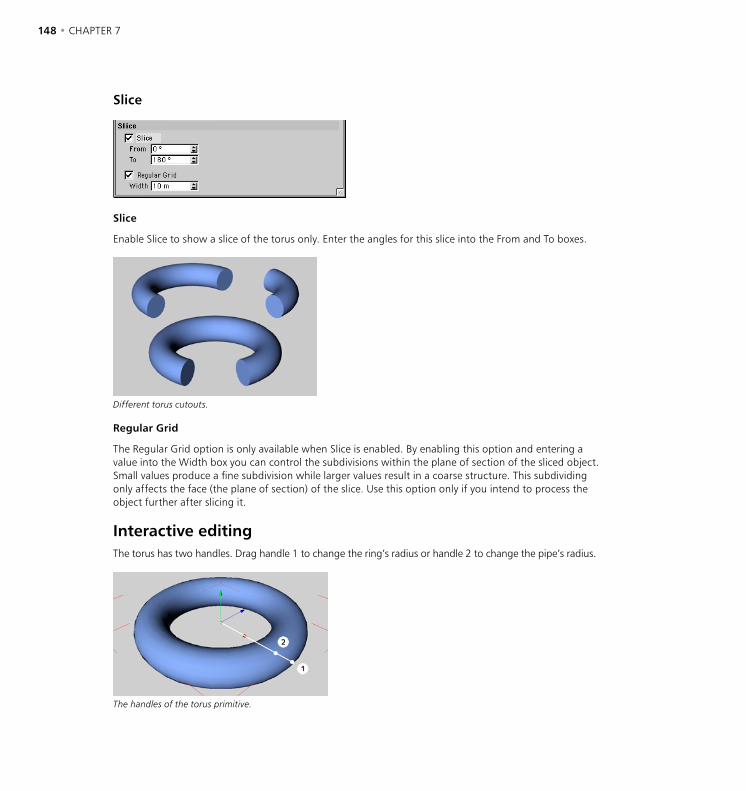
148 • CHAPTER 7 OBJECTS MENU • PRIMITIVES • 149
Slice
Slice
Enable Slice to show a slice of the torus only. Enter the angles for this slice into the From and To boxes.
Different torus cutouts.
Regular Grid
The Regular Grid option is only available when Slice is enabled. By enabling this option and entering a value into the Width box you can control the subdivisions within the plane of section of the sliced object. Small values produce a fine subdivision while larger values result in a coarse structure. This subdividing only affects the face (the plane of section) of the slice. Use this option only if you intend to process the object further after slicing it.
Interactive editingThe torus has two handles. Drag handle 1 to change the ring’s radius or handle 2 to change the pipe’s radius.
The handles of the torus primitive.
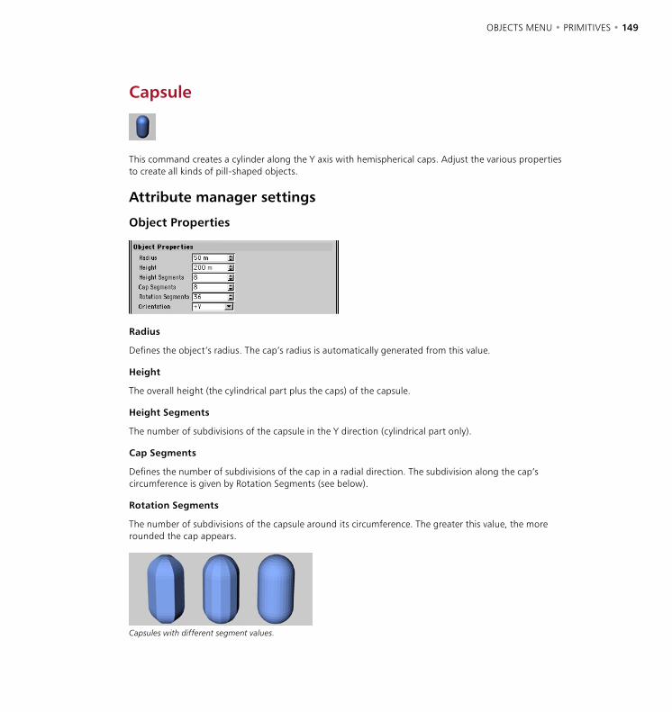
148 • CHAPTER 7 OBJECTS MENU • PRIMITIVES • 149
Capsule
This command creates a cylinder along the Y axis with hemispherical caps. Adjust the various properties to create all kinds of pill-shaped objects.
Attribute manager settings
Object Properties
Radius
Defines the object’s radius. The cap’s radius is automatically generated from this value.
Height
The overall height (the cylindrical part plus the caps) of the capsule.
Height Segments
The number of subdivisions of the capsule in the Y direction (cylindrical part only).
Cap Segments
Defines the number of subdivisions of the cap in a radial direction. The subdivision along the cap’s circumference is given by Rotation Segments (see below).
Rotation Segments
The number of subdivisions of the capsule around its circumference. The greater this value, the more rounded the cap appears.
Capsules with different segment values.

150 • CHAPTER 7 OBJECTS MENU • PRIMITIVES • 151
Orientation
Choose a value from this drop-down list to set the capsule’s initial position in space. Using this you can turn it on its axis very simply and, above all, quickly.
Slice
Slice
Enable Slice to show a slice of the capsule only. Enter the angles for this slice into the From and To boxes.
Regular Grid
The Regular Grid option is only available when Slice is enabled. By enabling this option and entering a value into the Width box you can control the subdivisions within the plane of section of the sliced object. Small values produce a fine subdivision while larger values result in a coarse structure. This subdividing only affects the face (the plane of section) of the slice. Use this option only if you intend to process the object further after slicing it.
Interactive editingThe capsule has two handles. Drag handle 1 to change the radius or handle 2 to change the height.
The handles of the capsule primitive.

150 • CHAPTER 7 OBJECTS MENU • PRIMITIVES • 151
Oil Tank
This creates a cylinder along the Y axis with curved caps. By adjusting the parameters many different objects can be made, such as the location pins or rivets frequently used in the car industry.
Attribute manager settings
Object Properties
Radius
Defines the object’s radius.
Cap Height
The cap height is defined as a percentage of the radius of the oil tank. 100% will give a hemispherical cap (a capsule, assuming the length is sufficiently large compared to the radius), 0% means no curvature (i.e. a cylinder). In contrast to the cone and capsule, the transition from the cylinder barrel to the cap is always sharp; the exception being if you have chosen 100% for this parameter.
Height
The overall length (the body plus the caps) of the oil tank.
Height Segments
Defines the number of subdivisions of the object in the Y direction (cylindrical part only).
Cap Segments
The subdivision level of the caps in a radial direction.
Rotation Segments
The number of subdivisions of the oil tank around its circumference. The greater this value, the more rounded the oil tank appears.
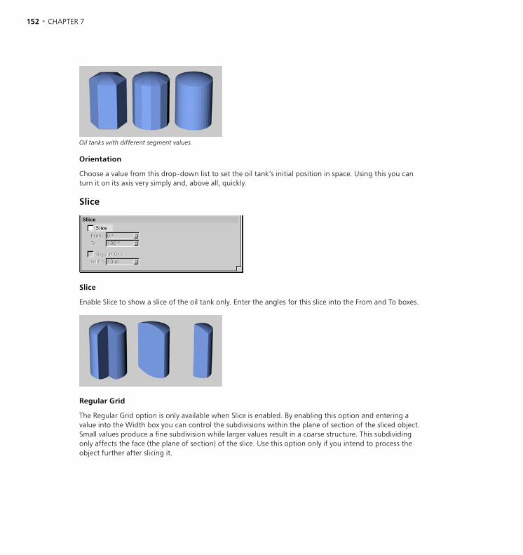
152 • CHAPTER 7 OBJECTS MENU • PRIMITIVES • 153
Oil tanks with different segment values.
Orientation
Choose a value from this drop-down list to set the oil tank’s initial position in space. Using this you can turn it on its axis very simply and, above all, quickly.
Slice
Slice
Enable Slice to show a slice of the oil tank only. Enter the angles for this slice into the From and To boxes.
Regular Grid
The Regular Grid option is only available when Slice is enabled. By enabling this option and entering a value into the Width box you can control the subdivisions within the plane of section of the sliced object. Small values produce a fine subdivision while larger values result in a coarse structure. This subdividing only affects the face (the plane of section) of the slice. Use this option only if you intend to process the object further after slicing it.
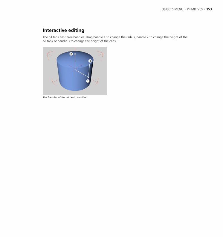
152 • CHAPTER 7 OBJECTS MENU • PRIMITIVES • 153
Interactive editingThe oil tank has three handles. Drag handle 1 to change the radius, handle 2 to change the height of the oil tank or handle 3 to change the height of the caps.
The handles of the oil tank primitive.
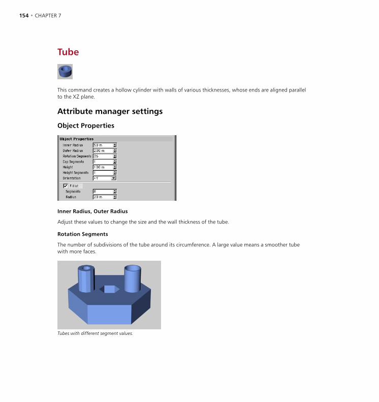
154 • CHAPTER 7 OBJECTS MENU • PRIMITIVES • 155
Tube
This command creates a hollow cylinder with walls of various thicknesses, whose ends are aligned parallel to the XZ plane.
Attribute manager settings
Object Properties
Inner Radius, Outer Radius
Adjust these values to change the size and the wall thickness of the tube.
Rotation Segments
The number of subdivisions of the tube around its circumference. A large value means a smoother tube with more faces.
Tubes with different segment values.

154 • CHAPTER 7 OBJECTS MENU • PRIMITIVES • 155
Cap Segments
Defines the number of subdivisions of the cap in a radial direction. The subdivision along the cap’s circumference is given by Rotation Segments (see above).
Height
The tube’s length.
Height Segments
The number of the tube’s subdivisions in the Y direction.
Orientation
Choose a value from this drop-down list to set the tube’s initial position in space. Using this you can turn it on its axis very simply and, above all, quickly.
Fillet, Segments, Radius
To fillet (i.e. round) the object’s edges, enable the Fillet option. Segments defines how finely the fillet appears while Radius is the radius of the curvature. The more segments you specify, the smoother the fillet. To create a chamfer instead of a smooth fillet, set Fillet Segment to 1.
Slice
Slice
Enable Slice to show a slice of the tube only. Enter the angles for this slice into the From and To boxes.
Different tubing cutouts.

156 • CHAPTER 7 OBJECTS MENU • PRIMITIVES • 157
Regular Grid
The Regular Grid option is only available when Slice is enabled. By enabling this option and entering a value into the Width box you can control the subdivisions within the plane of section of the sliced object. Small values produce a fine subdivision while larger values result in a coarse structure. This subdividing only affects the face (the plane of section) of the slice. Use this option only if you intend to process the object further after slicing it.
Interactive editingThe tube has three handles. Drag handle 1 to change the outer radius, handle 2 to change the inner radius or handle 3 to change the height (i.e. the tube’s length).
The handles of the tube primitive

156 • CHAPTER 7 OBJECTS MENU • PRIMITIVES • 157
Pyramid
This command creates a four-sided (5, if you count the base) pyramid. By default the base of the pyramid is parallel to the XZ plane of the world coordinate system.
Attribute manager settings
Object Properties
Size
These values give the object’s dimensions in the X, Y and Z directions.
Different pyramids.
Segments
The number of subdivisions applied to all surfaces.
Orientation
Choose a value from this drop-down list to set the pyramid’s initial position in space. Using this you can turn it on its axis very simply and, above all, quickly.

158 • CHAPTER 7 OBJECTS MENU • PRIMITIVES • 159
Interactive editingThe pyramid has three handles. Drag handle 1 to change the width, handle 2 to change the height (Y) or handle 3 to change the depth (Z).
The handles of the pyramid primitive.
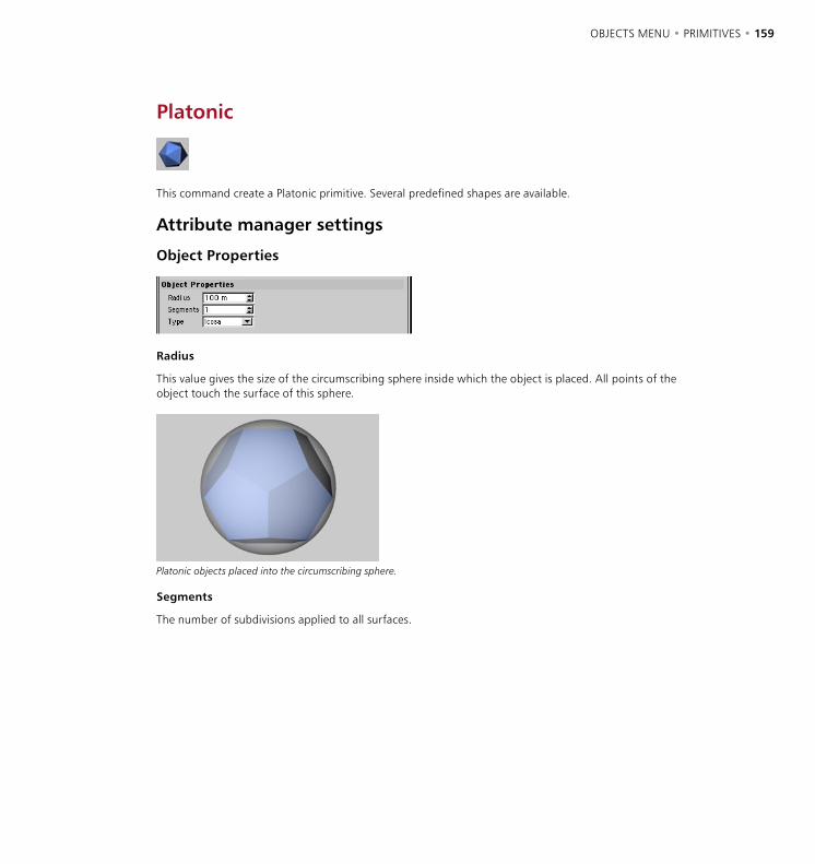
158 • CHAPTER 7 OBJECTS MENU • PRIMITIVES • 159
Platonic
This command create a Platonic primitive. Several predefined shapes are available.
Attribute manager settings
Object Properties
Radius
This value gives the size of the circumscribing sphere inside which the object is placed. All points of the object touch the surface of this sphere.
Platonic objects placed into the circumscribing sphere.
Segments
The number of subdivisions applied to all surfaces.
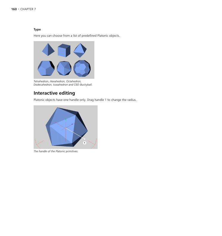
160 • CHAPTER 7 OBJECTS MENU • PRIMITIVES • 161
Type
Here you can choose from a list of predefined Platonic objects.
Tetrahedron, Hexahedron, Octahedron, Dodecahedron, Icosahedron and C60-Buckyball.
Interactive editingPlatonic objects have one handle only. Drag handle 1 to change the radius.
The handle of the Platonic primitives.
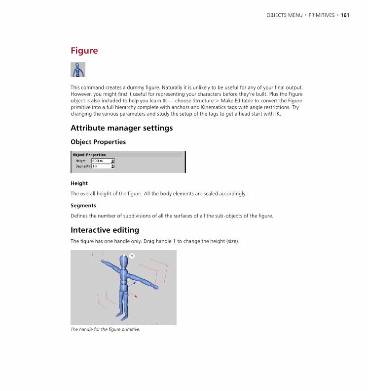
160 • CHAPTER 7 OBJECTS MENU • PRIMITIVES • 161
Figure
This command creates a dummy figure. Naturally it is unlikely to be useful for any of your final output. However, you might find it useful for representing your characters before they’re built. Plus the Figure object is also included to help you learn IK — choose Structure > Make Editable to convert the Figure primitive into a full hierarchy complete with anchors and Kinematics tags with angle restrictions. Try changing the various parameters and study the setup of the tags to get a head start with IK.
Attribute manager settings
Object Properties
Height
The overall height of the figure. All the body elements are scaled accordingly.
Segments
Defines the number of subdivisions of all the surfaces of all the sub-objects of the figure.
Interactive editingThe figure has one handle only. Drag handle 1 to change the height (size).
The handle for the figure primitive.
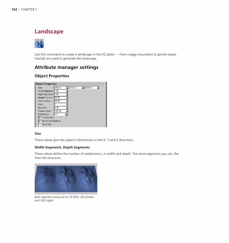
162 • CHAPTER 7 OBJECTS MENU • PRIMITIVES • 163
Landscape
Use this command to create a landscape in the XZ plane — from craggy mountains to gentle slopes. Fractals are used to generate the landscape.
Attribute manager settings
Object Properties
Size
These values give the object’s dimensions in the X, Y and Z directions.
Width Segments, Depth Segments
These values define the number of subdivisions, in width and depth. The more segments you use, the finer the structure.
Both segment values set to 10 (left), 50 (center) and 100 (right).

162 • CHAPTER 7 OBJECTS MENU • PRIMITIVES • 163
Rough Furrows, Fine Furrows
Change the cragginess of the landscape with these values. Low values result in gentle hills, high values rough mountains. In the following illustrations the Rough Furrows value is increased from left to right and the fine furrows value is increased from top to bottom.
Different landscapes (from left to right, 0%, 50%, 100%).
Scale
This controls the height of the fissures in the landscape. Large values result in deep valleys, small values give flatter landscapes.
Different scaling (from left to the right 0.1, 1, 1.5, 10).
Sea Level
This sets the height of the water. The higher the value, the further the landscape slips into the sea. With 100% Sea Level you have total flooding and thus nothing more than a simple plane.
Different sea levels (from left to the right 0%, 25%, 50%, 75%).
Water levels with borders not at sea level (from left to the right 0%, 25%, 50%, 75%).
If you disable Borders At Sealevel, you will see a rather different result. After being truncated at sea level the landscape is then lifted again to its full height, i.e. the parts rising from the water become steeper.
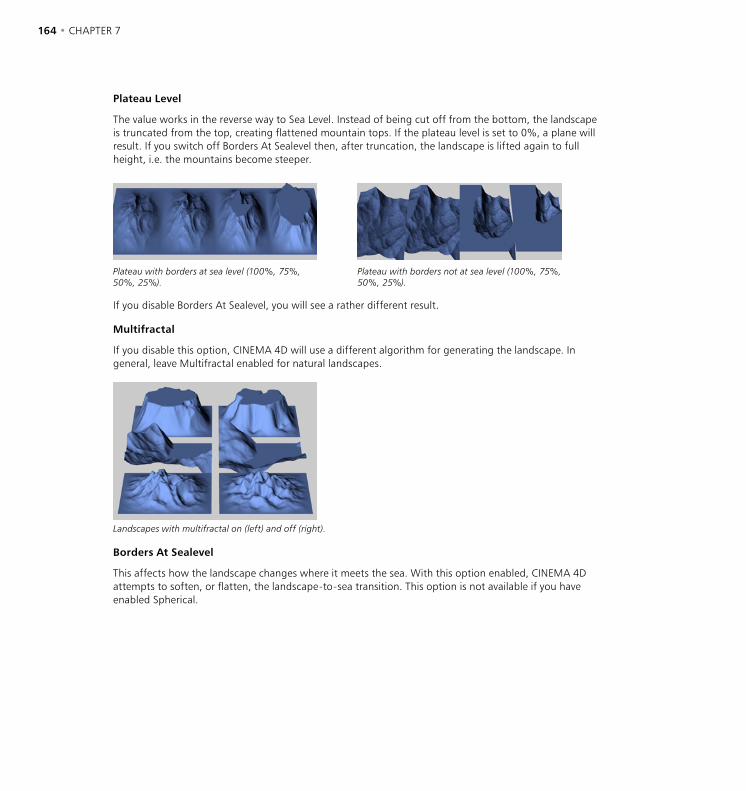
164 • CHAPTER 7 OBJECTS MENU • PRIMITIVES • 165
Plateau Level
The value works in the reverse way to Sea Level. Instead of being cut off from the bottom, the landscape is truncated from the top, creating flattened mountain tops. If the plateau level is set to 0%, a plane will result. If you switch off Borders At Sealevel then, after truncation, the landscape is lifted again to full height, i.e. the mountains become steeper.
Plateau with borders at sea level (100%, 75%, 50%, 25%).
Plateau with borders not at sea level (100%, 75%, 50%, 25%).
If you disable Borders At Sealevel, you will see a rather different result.
Multifractal
If you disable this option, CINEMA 4D will use a different algorithm for generating the landscape. In general, leave Multifractal enabled for natural landscapes.
Landscapes with multifractal on (left) and off (right).
Borders At Sealevel
This affects how the landscape changes where it meets the sea. With this option enabled, CINEMA 4D attempts to soften, or flatten, the landscape-to-sea transition. This option is not available if you have enabled Spherical.
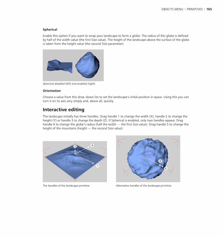
164 • CHAPTER 7 OBJECTS MENU • PRIMITIVES • 165
Spherical
Enable this option if you want to wrap your landscape to form a globe. The radius of this globe is defined by half of the width value (the first Size value). The height of the landscape above the surface of the globe is taken from the height value (the second Size parameter).
Spherical disabled (left) and enabled (right).
Orientation
Choose a value from this drop-down list to set the landscape’s initial position in space. Using this you can turn it on its axis very simply and, above all, quickly.
Interactive editingThe landscape initially has three handles. Drag handle 1 to change the width (X), handle 2 to change the height (Y) or handle 3 to change the depth (Z). If Spherical is enabled, only two handles appear. Drag handle 4 to change the globe’s radius (half the width — the first Size value). Drag handle 5 to change the height of the mountains (height — the second Size value).
The handles of the landscape primitive. Alternative handles of the landscape primitive.

166 • CHAPTER 7 OBJECTS MENU • PRIMITIVES • 167
Relief
This command creates an object in the XZ plane that is similar to the landscape primitive. However, in this case an image is used instead of fractals to generate the height. The relief map interprets the different grayscales within the chosen image as altitude values. If you choose a color image, the grayscale is formed from the average value of the red, green and blue components of the bitmap picture. The brighter the pixel, the higher the elevation; the darker the pixel, the deeper it lies within the scene. In other words, darkness defines valleys, brightness is for mountains.
Patterns (left) for different reliefs (right).
Although you can use color pictures as relief maps, we recommend that you use grayscale pictures only, since you’ll then be able to judge the brightness of the pixels more easily when you create the picture in your image-editing software (for example, reds tend to be darker than they appear).
Attribute manager settings
Object Properties
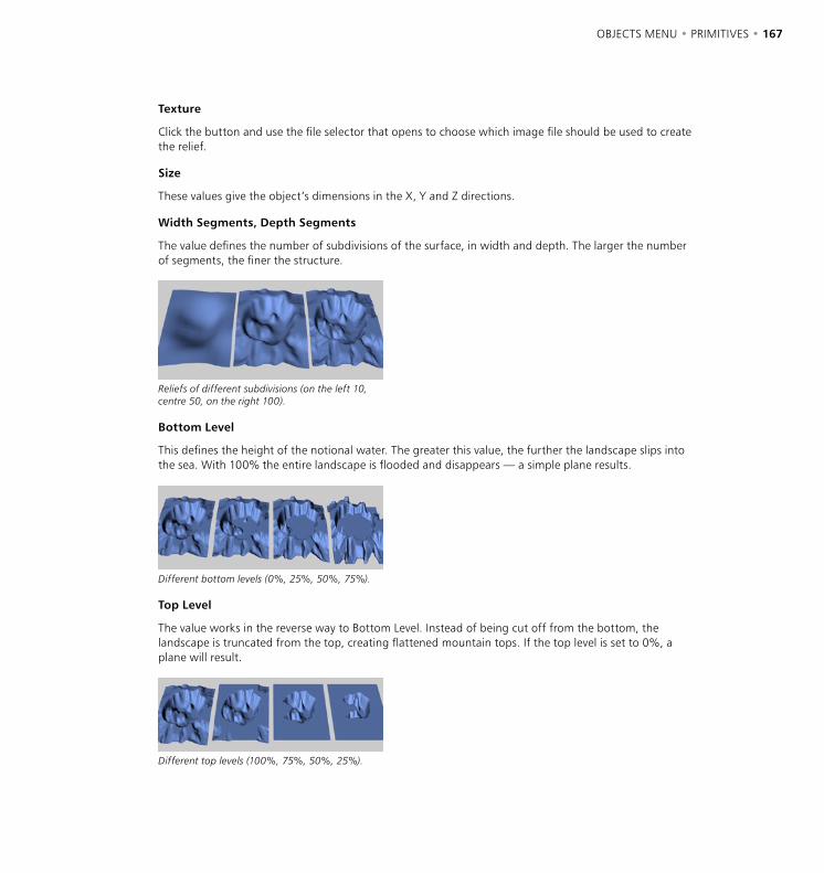
166 • CHAPTER 7 OBJECTS MENU • PRIMITIVES • 167
Texture
Click the button and use the file selector that opens to choose which image file should be used to create the relief.
Size
These values give the object’s dimensions in the X, Y and Z directions.
Width Segments, Depth Segments
The value defines the number of subdivisions of the surface, in width and depth. The larger the number of segments, the finer the structure.
Reliefs of different subdivisions (on the left 10, centre 50, on the right 100).
Bottom Level
This defines the height of the notional water. The greater this value, the further the landscape slips into the sea. With 100% the entire landscape is flooded and disappears — a simple plane results.
Different bottom levels (0%, 25%, 50%, 75%).
Top Level
The value works in the reverse way to Bottom Level. Instead of being cut off from the bottom, the landscape is truncated from the top, creating flattened mountain tops. If the top level is set to 0%, a plane will result.
Different top levels (100%, 75%, 50%, 25%).

168 • CHAPTER 7
Orientation
Choose a value from this drop-down list to set the relief map’s initial position in space. Using this you can turn it on its axis very simply and, above all, quickly.
Spherical
Select this option if you want to create a globe. The radius of this globe is defined by half of the width value (the first Size value). The height of the relief above the globe’s surface is taken from the height value (the second Size value).
Figure 1: An even relief (left) wound on a sphere (right).
Figure 2: The image used (top), the sphere relief from the front (left) and from the rear (right).
A general problem of this wrapping operation is that, depending on the image used, you may get discrepancies at the edge of the relief, especially when using a non-tileable texture. Figure 2, above, illustrates this problem. Choose your images carefully and be prepared to experiment.
Interactive editingThe relief initially has three handles. Drag handle 1 to change the width (X), handle 2 to change the height (Y) or handle 3 to change the depth (Z). If you enable Spherical, only two handles appear. Drag handle 4 to change the globe’s radius (half the width — the first Size value). Drag handle 5 to change the height of the elevation (height - the second Size value).
The handles of the relief primitive. Alternative handles for the relief primitive.

OBJECTS MENU • NURBS • 169
On the NURBS menu you’ll find some of CINEMA 4D’s most powerful modeling objects, including Extrude NURBS (for 3D logos etc.) and HyperNURBS (for any kind of model, especially smooth shapes such as characters).
NURBS objects are generators, meaning they use other objects to generate their surfaces. NURBS enable you to create surfaces quickly and easily using simple curves or objects. For example, to create a wine bottle you might draw half the bottle’s outline as a spline and make this spline a child of a Lathe NURBS. The spline will then be revolved through 360˚ to generate the bottle.
In addition to helping you model quickly, NURBS are faster and easier to edit than comparable polygon models that have thousands of points. For example, suppose you want to change the shape of that wine bottle. In the viewport, drag the spline’s points to form the new outline. The bottle updates in realtime as you drag the points and in just a few seconds you’ve carried out the changes.
Although NURBS modeling is generally more powerful than polygon modeling, there are still occasions when polygons are useful. For example, to use Polygon tools such as the Magnet you must work with polygons. Therefore, before you can use one of these tools on a NURBS object, you must first convert the NURBS to polygons. To do this, select the NURBS object and choose Structure > Make Editable. Keep in mind that the conversion is one-way only, i.e. you cannot convert the polygons back to NURBS.
NURBS
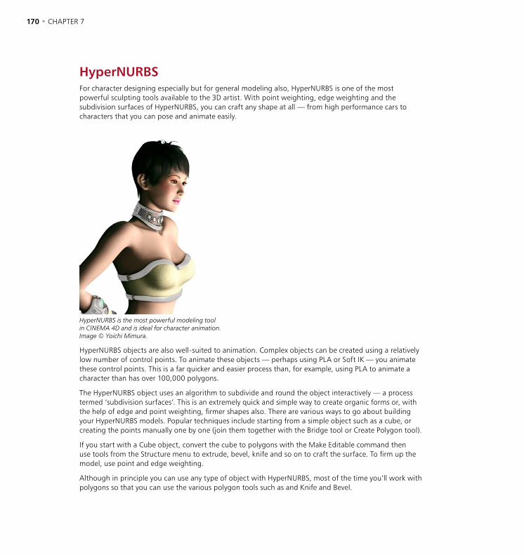
170 • CHAPTER 7 OBJECTS MENU • NURBS • 171
HyperNURBSFor character designing especially but for general modeling also, HyperNURBS is one of the most powerful sculpting tools available to the 3D artist. With point weighting, edge weighting and the subdivision surfaces of HyperNURBS, you can craft any shape at all — from high performance cars to characters that you can pose and animate easily.
HyperNURBS is the most powerful modeling toolin CINEMA 4D and is ideal for character animation.Image © Yoichi Mimura.
HyperNURBS objects are also well-suited to animation. Complex objects can be created using a relatively low number of control points. To animate these objects — perhaps using PLA or Soft IK — you animate these control points. This is a far quicker and easier process than, for example, using PLA to animate a character than has over 100,000 polygons.
The HyperNURBS object uses an algorithm to subdivide and round the object interactively — a process termed ‘subdivision surfaces’. This is an extremely quick and simple way to create organic forms or, with the help of edge and point weighting, firmer shapes also. There are various ways to go about building your HyperNURBS models. Popular techniques include starting from a simple object such as a cube, or creating the points manually one by one (join them together with the Bridge tool or Create Polygon tool).
If you start with a Cube object, convert the cube to polygons with the Make Editable command then use tools from the Structure menu to extrude, bevel, knife and so on to craft the surface. To firm up the model, use point and edge weighting.
Although in principle you can use any type of object with HyperNURBS, most of the time you’ll work with polygons so that you can use the various polygon tools such as and Knife and Bevel.

170 • CHAPTER 7 OBJECTS MENU • NURBS • 171
Make the source object (cage) a child of the HyperNURBS object.
HyperNURBS object and cage object visible (left) and only cage object visible (right).
Attribute manager settings
Object Properties
Use this page to specify the subdivision level for shading within the editor (i.e. the viewport) and for the renderer. The higher you set the resolution, the smoother the object becomes but the more memory it uses and the slower it renders.
Figure 1: From left to right: source object, Subdivisions set to 1, 2 and 5.

172 • CHAPTER 7 OBJECTS MENU • NURBS • 173
Figure 2: Use point and edge weighting to further refine your HyperNURBS models.
In Figure 2, above, a cube (left) has been made a child of a HyperNURBS object to produce a sphere (center). Edge and point weighting has then been applied to produce a complex shape (right). Weighting enables you to refine HyperNURBS models without having to add new points and is especially useful for creating hard edges or points.
Weighting HyperNURBS modelsYou can weight your HyperNURBS models in one of two ways: interactively or manually using the Live Selection tool.
Interactive weighting
Select the elements (i.e. points, edges or polygons) that you want to weight. Hold down the period key (‘.’) and drag left or right to set the weighting for the selected elements. The more weight you apply, the harder the surface will try to reach it.
To set the minimum and maximum weighting that you can apply by dragging, select the Live Selection tool and, in the Active Tool manager, enter the desired values into the Interactive Min and Max boxes.
Three modes are available: Point, Edge and Polygon.
Point mode
Selected points. . + drag. . + Shift-drag. . + Ctrl-drag.
To weight selected points, hold down the period key (‘.’) and drag. To weight selected points and all edges connected to them, hold down the period key and Shift-drag. To weight selected points and the edges between them, hold down the period key and Ctrl-drag.
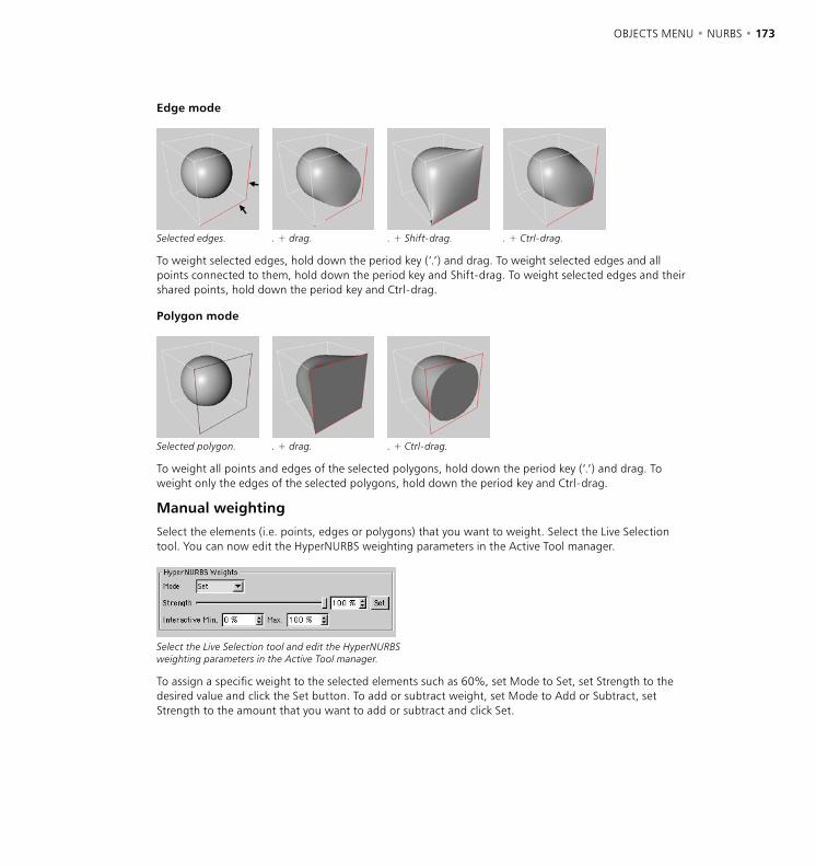
172 • CHAPTER 7 OBJECTS MENU • NURBS • 173
Edge mode
Selected edges. . + drag. . + Shift-drag. . + Ctrl-drag.
To weight selected edges, hold down the period key (‘.’) and drag. To weight selected edges and all points connected to them, hold down the period key and Shift-drag. To weight selected edges and their shared points, hold down the period key and Ctrl-drag.
Polygon mode
Selected polygon. . + drag. . + Ctrl-drag.
To weight all points and edges of the selected polygons, hold down the period key (‘.’) and drag. To weight only the edges of the selected polygons, hold down the period key and Ctrl-drag.
Manual weighting
Select the elements (i.e. points, edges or polygons) that you want to weight. Select the Live Selection tool. You can now edit the HyperNURBS weighting parameters in the Active Tool manager.
Select the Live Selection tool and edit the HyperNURBS weighting parameters in the Active Tool manager.
To assign a specific weight to the selected elements such as 60%, set Mode to Set, set Strength to the desired value and click the Set button. To add or subtract weight, set Mode to Add or Subtract, set Strength to the amount that you want to add or subtract and click Set.
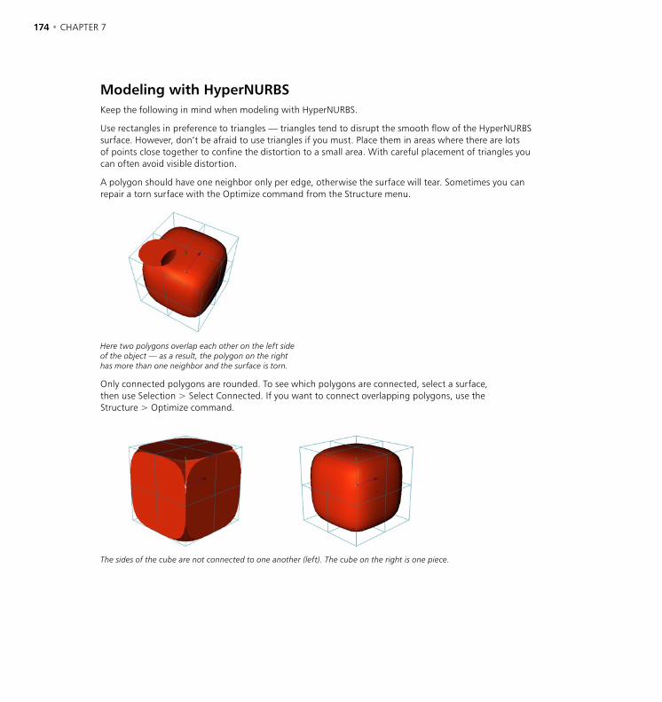
174 • CHAPTER 7 OBJECTS MENU • NURBS • 175
Modeling with HyperNURBSKeep the following in mind when modeling with HyperNURBS.
Use rectangles in preference to triangles — triangles tend to disrupt the smooth flow of the HyperNURBS surface. However, don’t be afraid to use triangles if you must. Place them in areas where there are lots of points close together to confine the distortion to a small area. With careful placement of triangles you can often avoid visible distortion.
A polygon should have one neighbor only per edge, otherwise the surface will tear. Sometimes you can repair a torn surface with the Optimize command from the Structure menu.
Here two polygons overlap each other on the left side of the object — as a result, the polygon on the right has more than one neighbor and the surface is torn.
Only connected polygons are rounded. To see which polygons are connected, select a surface, then use Selection > Select Connected. If you want to connect overlapping polygons, use the Structure > Optimize command.
The sides of the cube are not connected to one another (left). The cube on the right is one piece.

174 • CHAPTER 7 OBJECTS MENU • NURBS • 175
Two shortcuts are especially useful when modeling with HyperNURBS.
(1) Q switches the HyperNURBS on and off, i.e. toggles between cage display and subdivision surfaces display.
(2) Hold down the 9 key to temporarily switch on the Live Selection tool. Drag over points, edges or polygons (whichever mode is active) to select.
Hold down Shift at the same time to add to the selection or Ctrl to remove from the selection. As soon as you release the 9 key, you’ll be returned to your previous tool — ideal for quickly changing the selection while in the middle of using a polygon tool such as Extrude Inner.
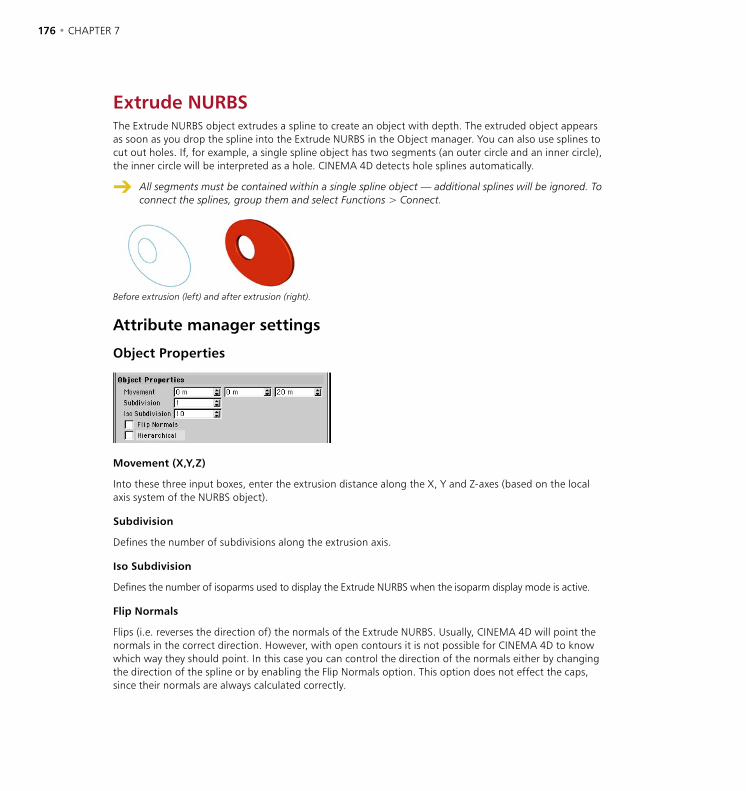
176 • CHAPTER 7 OBJECTS MENU • NURBS • 177
Extrude NURBSThe Extrude NURBS object extrudes a spline to create an object with depth. The extruded object appears as soon as you drop the spline into the Extrude NURBS in the Object manager. You can also use splines to cut out holes. If, for example, a single spline object has two segments (an outer circle and an inner circle), the inner circle will be interpreted as a hole. CINEMA 4D detects hole splines automatically.
All segments must be contained within a single spline object — additional splines will be ignored. To connect the splines, group them and select Functions > Connect.
Before extrusion (left) and after extrusion (right).
Attribute manager settings
Object Properties
Movement (X,Y,Z)
Into these three input boxes, enter the extrusion distance along the X, Y and Z-axes (based on the local axis system of the NURBS object).
Subdivision
Defines the number of subdivisions along the extrusion axis.
Iso Subdivision
Defines the number of isoparms used to display the Extrude NURBS when the isoparm display mode is active.
Flip Normals
Flips (i.e. reverses the direction of) the normals of the Extrude NURBS. Usually, CINEMA 4D will point the normals in the correct direction. However, with open contours it is not possible for CINEMA 4D to know which way they should point. In this case you can control the direction of the normals either by changing the direction of the spline or by enabling the Flip Normals option. This option does not effect the caps, since their normals are always calculated correctly.
176 • CHAPTER 7 OBJECTS MENU • NURBS • 177
Hierarchical
In the Extrude NURBS dialog there is an additional option, Hierarchical. If this option is enabled, you can group, say, several splines within a Null object and place this group in an Extrude NURBS. Each spline of this group is now extruded separately. This is important especially for a text spline when you have enabled its Separate Letters option. In this case a separate spline is created for each letter; these splines are in an object group. To extrude these letters, the Hierarchical option must be enabled.
Caps and Rounding
Use these settings to add caps and/or rounding to the Extrude NURBS. See ‘Caps and Rounding’ on page 189.
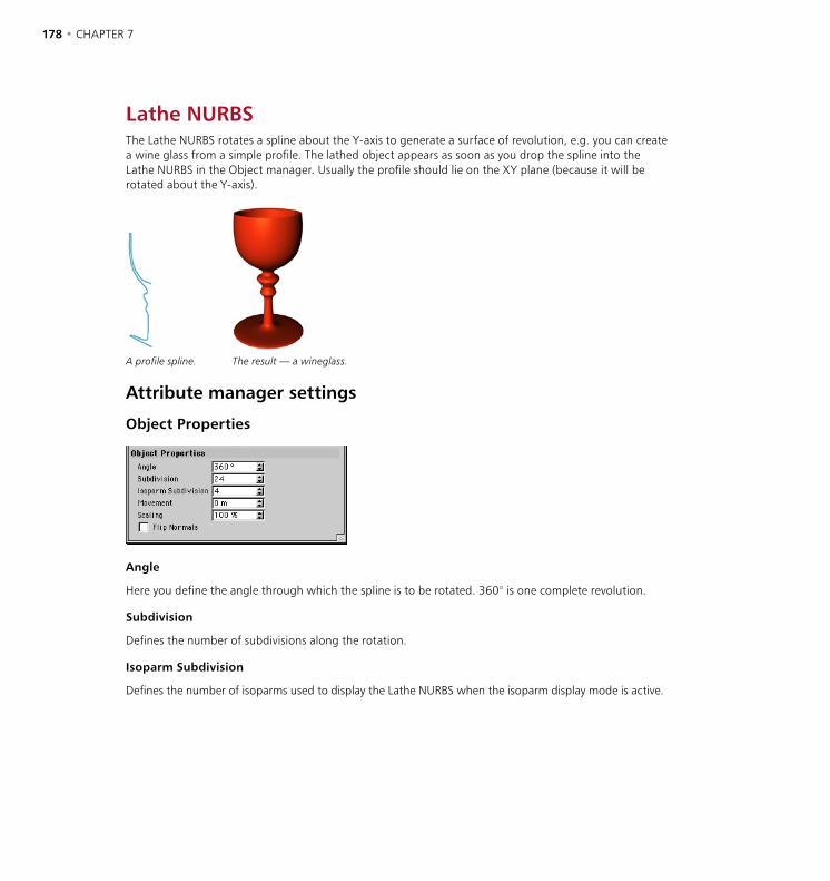
178 • CHAPTER 7 OBJECTS MENU • NURBS • 179
Lathe NURBSThe Lathe NURBS rotates a spline about the Y-axis to generate a surface of revolution, e.g. you can create a wine glass from a simple profile. The lathed object appears as soon as you drop the spline into the Lathe NURBS in the Object manager. Usually the profile should lie on the XY plane (because it will be rotated about the Y-axis).
A profile spline. The result — a wineglass.
Attribute manager settings
Object Properties
Angle
Here you define the angle through which the spline is to be rotated. 360° is one complete revolution.
Subdivision
Defines the number of subdivisions along the rotation.
Isoparm Subdivision
Defines the number of isoparms used to display the Lathe NURBS when the isoparm display mode is active.
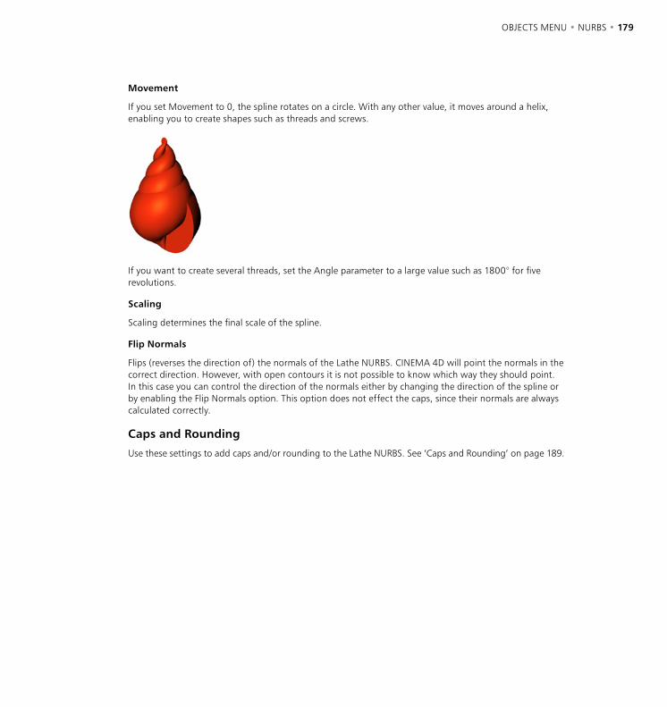
178 • CHAPTER 7 OBJECTS MENU • NURBS • 179
Movement
If you set Movement to 0, the spline rotates on a circle. With any other value, it moves around a helix, enabling you to create shapes such as threads and screws.
If you want to create several threads, set the Angle parameter to a large value such as 1800° for five revolutions.
Scaling
Scaling determines the final scale of the spline.
Flip Normals
Flips (reverses the direction of) the normals of the Lathe NURBS. CINEMA 4D will point the normals in the correct direction. However, with open contours it is not possible to know which way they should point. In this case you can control the direction of the normals either by changing the direction of the spline or by enabling the Flip Normals option. This option does not effect the caps, since their normals are always calculated correctly.
Caps and Rounding
Use these settings to add caps and/or rounding to the Lathe NURBS. See ‘Caps and Rounding’ on page 189.
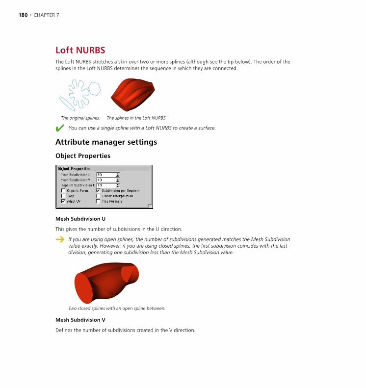
180 • CHAPTER 7 OBJECTS MENU • NURBS • 181
Loft NURBSThe Loft NURBS stretches a skin over two or more splines (although see the tip below). The order of the splines in the Loft NURBS determines the sequence in which they are connected.
The original splines. The splines in the Loft NURBS.
You can use a single spline with a Loft NURBS to create a surface.
Attribute manager settings
Object Properties
Mesh Subdivision U
This gives the number of subdivisions in the U direction.
If you are using open splines, the number of subdivisions generated matches the Mesh Subdivision value exactly. However, if you are using closed splines, the first subdivision coincides with the last division, generating one subdivision less than the Mesh Subdivision value.
Two closed splines with an open spline between.
Mesh Subdivision V
Defines the number of subdivisions created in the V direction.

180 • CHAPTER 7 OBJECTS MENU • NURBS • 181
Isoparm Subdivision U
Defines the number of isoparms used to display the Loft NURBS when the isoparm display mode is active.
Organic Form
If this option is disabled, the Loft NURBS lines pass directly though the spline points and the distances between the lines adapt to the spline points, resulting in a very tight form. If the option is enabled, the Loft NURBS lines no longer pass through the spline points exactly but maintain equal parametric distance to each other, creating a looser, more organic form.
Organic Form enabled. Organic Form disabled.
Subdivision Per Segment
You can use this option to choose whether the mesh subdivision is divided evenly over the entire length of the object or evenly per segment (a segment is the section between one spline and the next). Enabling this option gives you more control over the object’s appearance when splines are close to one another.
If the option is disabled the number of resultant subdivisions per segment is calculated using the average distance of the segments. This may be unsuitable for animation, but it generates more regular objects.
Subdivision Per Segment enabled. Subdivision Per Segment disabled.
Loop
If this option is enabled, the first spline is connected to the last spline in the V direction.
Linear Interpolation
Enable this option if you want linear interpolation between the splines; otherwise the interpolation is soft.

182 • CHAPTER 7 OBJECTS MENU • NURBS • 183
Adapt UV
Adapt UV is similar to Subdivision Per Segment — but refers to the texture instead. The texture must use UVW mapping for this option to have an effect (see ‘UVW Mapping’ on page 820). It is independent of the Subdivision Per Segment option. The texture is projected either per segment (enabled) or evenly over the entire object (disabled).
Adapt UV enabled. Adapt UV disabled.
Flip Normals
Flips (i.e. reverses the direction of) the normals of the Loft NURBS. Usually, CINEMA 4D will point the normals in the correct direction. However, with open contours it is not possible for CINEMA 4D to know which way they should point. In this case you can control the direction of the normals either by changing the direction of the spline or by enabling the Flip Normals option. This option does not effect the caps, since their normals are always calculated correctly.
Caps and Rounding
Use these settings to add caps and/or rounding to the Loft NURBS. See ‘Caps and Rounding’ on page 189.
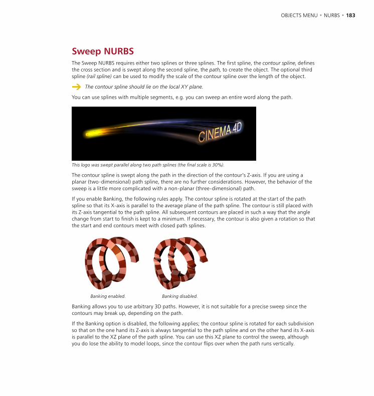
182 • CHAPTER 7 OBJECTS MENU • NURBS • 183
Sweep NURBSThe Sweep NURBS requires either two splines or three splines. The first spline, the contour spline, defines the cross section and is swept along the second spline, the path, to create the object. The optional third spline (rail spline) can be used to modify the scale of the contour spline over the length of the object.
The contour spline should lie on the local XY plane.
You can use splines with multiple segments, e.g. you can sweep an entire word along the path.
This logo was swept parallel along two path splines (the final scale is 30%).
The contour spline is swept along the path in the direction of the contour’s Z-axis. If you are using a planar (two-dimensional) path spline, there are no further considerations. However, the behavior of the sweep is a little more complicated with a non-planar (three-dimensional) path.
If you enable Banking, the following rules apply. The contour spline is rotated at the start of the path spline so that its X-axis is parallel to the average plane of the path spline. The contour is still placed with its Z-axis tangential to the path spline. All subsequent contours are placed in such a way that the angle change from start to finish is kept to a minimum. If necessary, the contour is also given a rotation so that the start and end contours meet with closed path splines.
Banking enabled. Banking disabled.
Banking allows you to use arbitrary 3D paths. However, it is not suitable for a precise sweep since the contours may break up, depending on the path.
If the Banking option is disabled, the following applies; the contour spline is rotated for each subdivision so that on the one hand its Z-axis is always tangential to the path spline and on the other hand its X-axis is parallel to the XZ plane of the path spline. You can use this XZ plane to control the sweep, although you do lose the ability to model loops, since the contour flips over when the path runs vertically.
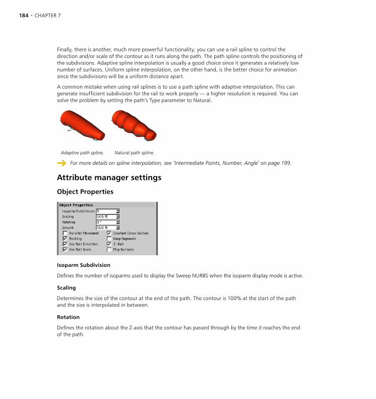
184 • CHAPTER 7 OBJECTS MENU • NURBS • 185
Finally, there is another, much more powerful functionality; you can use a rail spline to control the direction and/or scale of the contour as it runs along the path. The path spline controls the positioning of the subdivisions. Adaptive spline interpolation is usually a good choice since it generates a relatively low number of surfaces. Uniform spline interpolation, on the other hand, is the better choice for animation since the subdivisions will be a uniform distance apart.
A common mistake when using rail splines is to use a path spline with adaptive interpolation. This can generate insufficient subdivision for the rail to work properly — a higher resolution is required. You can solve the problem by setting the path’s Type parameter to Natural.
Adaptive path spline. Natural path spline.
For more details on spline interpolation, see ‘Intermediate Points, Number, Angle’ on page 199.
Attribute manager settings
Object Properties
Isoparm Subdivision
Defines the number of isoparms used to display the Sweep NURBS when the isoparm display mode is active.
Scaling
Determines the size of the contour at the end of the path. The contour is 100% at the start of the path and the size is interpolated in between.
Rotation
Defines the rotation about the Z-axis that the contour has passed through by the time it reaches the end of the path.
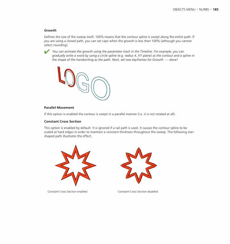
184 • CHAPTER 7 OBJECTS MENU • NURBS • 185
Growth
Defines the size of the sweep itself. 100% means that the contour spline is swept along the entire path. If you are using a closed path, you can set caps when the growth is less than 100% (although you cannot select rounding).
You can animate the growth using the parameter track in the Timeline. For example, you can gradually write a word by using a circle spline (e.g. radius 4, XY plane) as the contour and a spline in the shape of the handwriting as the path. Next, set two keyframes for Growth — done!
Parallel Movement
If this option is enabled the contour is swept in a parallel manner (i.e. it is not rotated at all).
Constant Cross Section
This option is enabled by default. It is ignored if a rail path is used. It causes the contour spline to be scaled at hard edges in order to maintain a constant thickness throughout the sweep. The following star-shaped path illustrates the effect.
Constant Cross Section enabled. Constant Cross Section disabled.
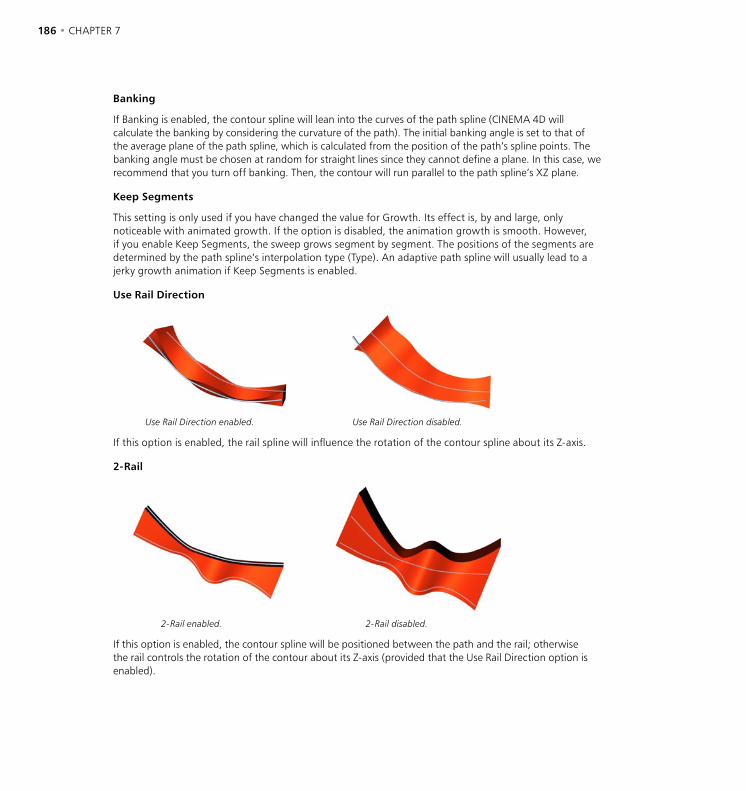
186 • CHAPTER 7 OBJECTS MENU • NURBS • 187
Banking
If Banking is enabled, the contour spline will lean into the curves of the path spline (CINEMA 4D will calculate the banking by considering the curvature of the path). The initial banking angle is set to that of the average plane of the path spline, which is calculated from the position of the path’s spline points. The banking angle must be chosen at random for straight lines since they cannot define a plane. In this case, we recommend that you turn off banking. Then, the contour will run parallel to the path spline’s XZ plane.
Keep Segments
This setting is only used if you have changed the value for Growth. Its effect is, by and large, only noticeable with animated growth. If the option is disabled, the animation growth is smooth. However, if you enable Keep Segments, the sweep grows segment by segment. The positions of the segments are determined by the path spline’s interpolation type (Type). An adaptive path spline will usually lead to a jerky growth animation if Keep Segments is enabled.
Use Rail Direction
Use Rail Direction enabled. Use Rail Direction disabled.
If this option is enabled, the rail spline will influence the rotation of the contour spline about its Z-axis.
2-Rail
2-Rail enabled. 2-Rail disabled.
If this option is enabled, the contour spline will be positioned between the path and the rail; otherwise the rail controls the rotation of the contour about its Z-axis (provided that the Use Rail Direction option is enabled).
186 • CHAPTER 7 OBJECTS MENU • NURBS • 187
Use Rail Scale
If this option is enabled, the rail spline can be used to alter the scale of the contour along the path.
Flip Normals
Flips (i.e. reverses the direction of) the normals of the Sweep NURBS. Usually, CINEMA 4D will point the normals in the correct direction. However, with open contours it is not possible for CINEMA 4D to know which way they should point. In this case you can control the direction of the normals either by changing the direction of the spline or by enabling the Flip Normals option. This option does not effect the caps, since their normals are always calculated correctly.
Caps and Rounding
Use these settings to add caps and/or rounding to the Sweep NURBS. See ‘Caps and Rounding’ on page 189.

188 • CHAPTER 7 OBJECTS MENU • NURBS • 189
Bézier NURBSThe Bézier NURBS differs from the other NURBS in the sense that it does not require any objects. Bézier NURBS stretches a surface over Bézier curves in the X and Y directions. The control points for these curves pull on the surface like small magnets (apart from the edge points, to which the surface is fixed). The Bézier NURBS is perfect for smooth, curvy surfaces such as car wings, nose-cones and sails.
Attribute manager settings
Object Properties
Subdivision X, Subdivision Y
These settings define the number of subdivisions in the X and Y directions.
Grid Points X, Grid Points Y
Enter the number of control points in the X and Y directions. The more points you set, the more control you have over the surface.
Closed X, Closed Y
Use these settings to close the surface in the X and/or Y direction.
If you change the subdivision, the Bézier NURBS is reset to its starting state. Therefore ensure you have enough subdivisions before you start.
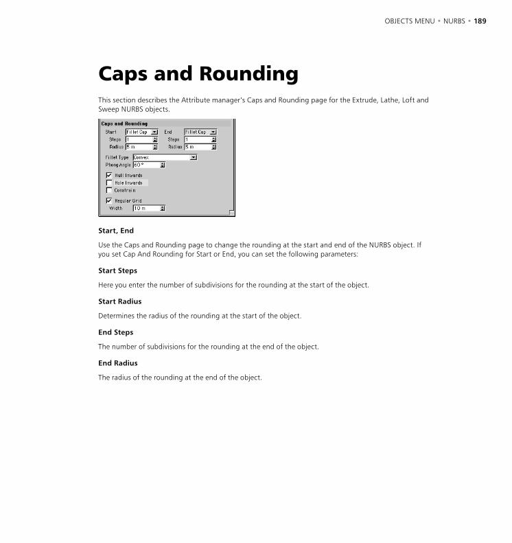
188 • CHAPTER 7 OBJECTS MENU • NURBS • 189
Caps and RoundingThis section describes the Attribute manager’s Caps and Rounding page for the Extrude, Lathe, Loft and Sweep NURBS objects.
Start, End
Use the Caps and Rounding page to change the rounding at the start and end of the NURBS object. If you set Cap And Rounding for Start or End, you can set the following parameters:
Start Steps
Here you enter the number of subdivisions for the rounding at the start of the object.
Start Radius
Determines the radius of the rounding at the start of the object.
End Steps
The number of subdivisions for the rounding at the end of the object.
End Radius
The radius of the rounding at the end of the object.
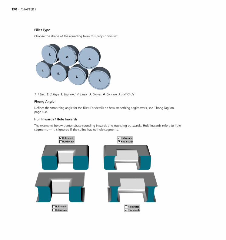
190 • CHAPTER 7 OBJECTS MENU • NURBS • 191
Fillet Type
Choose the shape of the rounding from this drop-down list.
1. 1 Step 2. 2 Steps 3. Engraved 4. Linear 5. Convex 6. Concave 7. Half Circle
Phong Angle
Defines the smoothing angle for the fillet. For details on how smoothing angles work, see ’Phong Tag’ on page 608.
Hull Inwards / Hole Inwards
The examples below demonstrate rounding inwards and rounding outwards. Hole Inwards refers to hole segments — it is ignored if the spline has no hole segments.
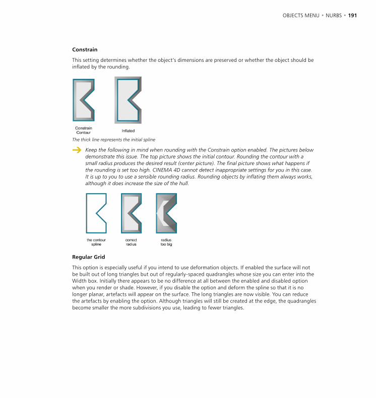
190 • CHAPTER 7 OBJECTS MENU • NURBS • 191
Constrain
This setting determines whether the object’s dimensions are preserved or whether the object should be inflated by the rounding.
The thick line represents the initial spline
Keep the following in mind when rounding with the Constrain option enabled. The pictures below demonstrate this issue. The top picture shows the initial contour. Rounding the contour with a small radius produces the desired result (center picture). The final picture shows what happens if the rounding is set too high. CINEMA 4D cannot detect inappropriate settings for you in this case. It is up to you to use a sensible rounding radius. Rounding objects by inflating them always works, although it does increase the size of the hull.
Regular Grid
This option is especially useful if you intend to use deformation objects. If enabled the surface will not be built out of long triangles but out of regularly-spaced quadrangles whose size you can enter into the Width box. Initially there appears to be no difference at all between the enabled and disabled option when you render or shade. However, if you disable the option and deform the spline so that it is no longer planar, artefacts will appear on the surface. The long triangles are now visible. You can reduce the artefacts by enabling the option. Although triangles will still be created at the edge, the quadrangles become smaller the more subdivisions you use, leading to fewer triangles.
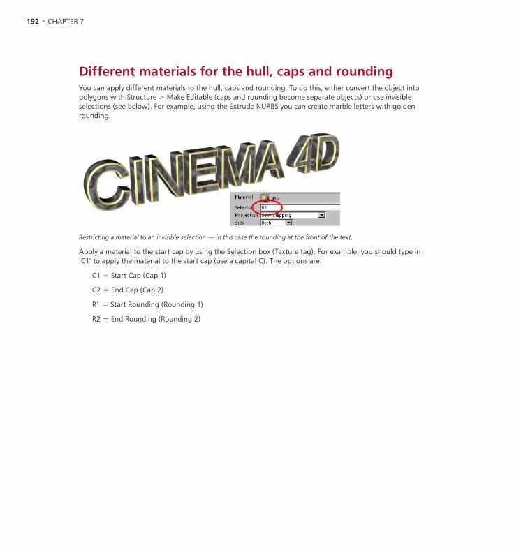
192 • CHAPTER 7
Different materials for the hull, caps and roundingYou can apply different materials to the hull, caps and rounding. To do this, either convert the object into polygons with Structure > Make Editable (caps and rounding become separate objects) or use invisible selections (see below). For example, using the Extrude NURBS you can create marble letters with golden rounding.
Restricting a material to an invisible selection — in this case the rounding at the front of the text.
Apply a material to the start cap by using the Selection box (Texture tag). For example, you should type in ‘C1’ to apply the material to the start cap (use a capital C). The options are:
C1 = Start Cap (Cap 1)
C2 = End Cap (Cap 2)
R1 = Start Rounding (Rounding 1)
R2 = End Rounding (Rounding 2)

OBJECTS MENU • SPLINES • 193
Spline Object
This command creates an empty spline object. Like the Polygon object, it is recognizable on screen only by its origin and axes. You can use this object for the construction of your own splines.
Curves
Splines are primarily a sequence of vertices, connected by lines, lying in 3D space. The shape of these connecting lines (straight or curved) defines the interpolation. Apart from the direct connection of the vertices with straight, rigid lines, there are other kinds of splines that use an interpolation method whereby the lines between the vertices are curved instead of straight. Such splines have a soft leading edge without sharp corners.
The spline itself is infinitely thin. We add some thickness to splines to help you visualize them better in the viewports. However, you should realize that you will never see a spline when rendered. The spline’s line has no three-dimensional depth, even though it occupies the 3D space. However, many complex 3D objects, among other things, can be constructed in seconds out of these curves.
After the spline is created it can be pulled along its depth in order to make tube-like objects. You can also rotate a spline around an axis and make circular objects (e.g. a wineglass). Or you can construct a skin over several splines, with the finished object simulating the contours on a map. More of these spline-modeling capabilities are discussed in the NURBS section.
To create a new spline curve:
- Choose Objects > Spline Object to create an empty spline.
- Select the Points tool (click the Points icon or choose Tools > Points) and select the Move tool (choose Tools > Move).
- Ctrl-click to create points for the spline. The first point defines the start of the spline. Each consecutive click, if clicked further away than the last point created, will add to the spline.
- If you Ctrl-click between two previously created points on the curve then the new point is placed on the spline between the points.
- If you hold down the Shift and Ctrl keys while clicking, the new point is created at the beginning of the spline, giving a new starting point.
- If you click the starting point, the spline will be closed (see below) provided that the Close Spline option was disabled before you clicked the point.
Splines
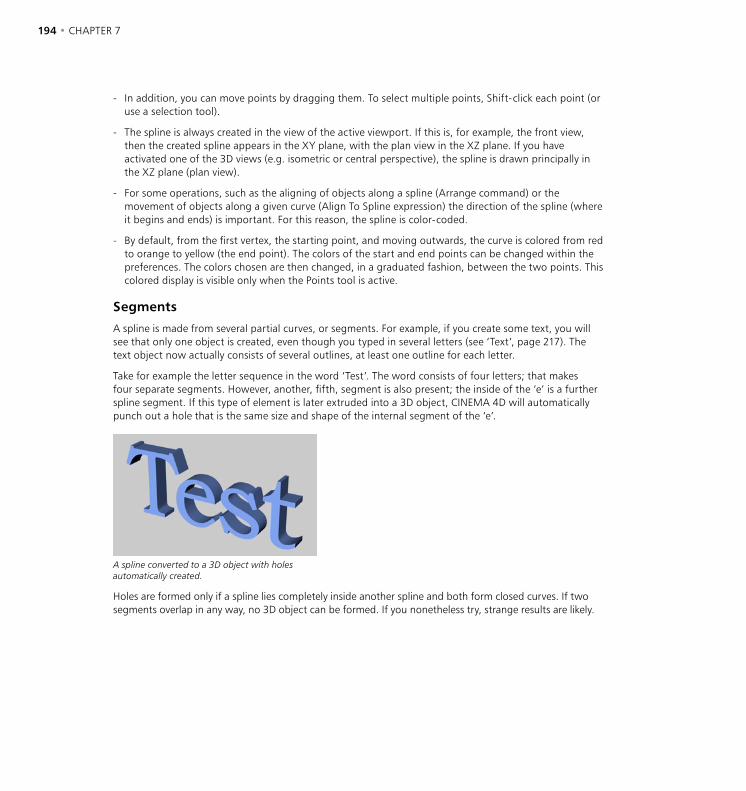
194 • CHAPTER 7 OBJECTS MENU • SPLINES • 195
- In addition, you can move points by dragging them. To select multiple points, Shift-click each point (or use a selection tool).
- The spline is always created in the view of the active viewport. If this is, for example, the front view, then the created spline appears in the XY plane, with the plan view in the XZ plane. If you have activated one of the 3D views (e.g. isometric or central perspective), the spline is drawn principally in the XZ plane (plan view).
- For some operations, such as the aligning of objects along a spline (Arrange command) or the movement of objects along a given curve (Align To Spline expression) the direction of the spline (where it begins and ends) is important. For this reason, the spline is color-coded.
- By default, from the first vertex, the starting point, and moving outwards, the curve is colored from red to orange to yellow (the end point). The colors of the start and end points can be changed within the preferences. The colors chosen are then changed, in a graduated fashion, between the two points. This colored display is visible only when the Points tool is active.
Segments
A spline is made from several partial curves, or segments. For example, if you create some text, you will see that only one object is created, even though you typed in several letters (see ‘Text’, page 217). The text object now actually consists of several outlines, at least one outline for each letter.
Take for example the letter sequence in the word ‘Test’. The word consists of four letters; that makes four separate segments. However, another, fifth, segment is also present; the inside of the ‘e’ is a further spline segment. If this type of element is later extruded into a 3D object, CINEMA 4D will automatically punch out a hole that is the same size and shape of the internal segment of the ‘e’.
A spline converted to a 3D object with holes automatically created.
Holes are formed only if a spline lies completely inside another spline and both form closed curves. If two segments overlap in any way, no 3D object can be formed. If you nonetheless try, strange results are likely.
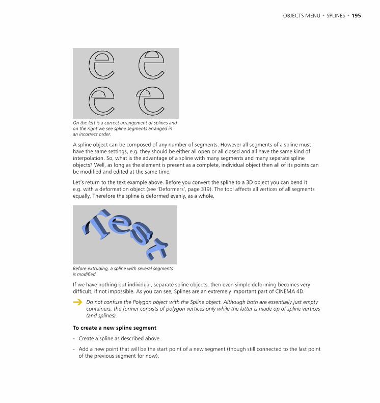
194 • CHAPTER 7 OBJECTS MENU • SPLINES • 195
On the left is a correct arrangement of splines and on the right we see spline segments arranged in an incorrect order.
A spline object can be composed of any number of segments. However all segments of a spline must have the same settings, e.g. they should be either all open or all closed and all have the same kind of interpolation. So, what is the advantage of a spline with many segments and many separate spline objects? Well, as long as the element is present as a complete, individual object then all of its points can be modified and edited at the same time.
Let’s return to the text example above. Before you convert the spline to a 3D object you can bend it e.g. with a deformation object (see ‘Deformers’, page 319). The tool affects all vertices of all segments equally. Therefore the spline is deformed evenly, as a whole.
Before extruding, a spline with several segments is modified.
If we have nothing but individual, separate spline objects, then even simple deforming becomes very difficult, if not impossible. As you can see, Splines are an extremely important part of CINEMA 4D.
Do not confuse the Polygon object with the Spline object. Although both are essentially just empty containers, the former consists of polygon vertices only while the latter is made up of spline vertices (and splines).
To create a new spline segment
- Create a spline as described above.
- Add a new point that will be the start point of a new segment (though still connected to the last point of the previous segment for now).
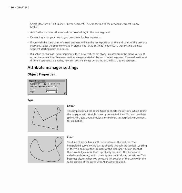
196 • CHAPTER 7 OBJECTS MENU • SPLINES • 197
- Select Structure > Edit Spline > Break Segment. The connection to the previous segment is now broken.
- Add further vertices. All new vertices now belong to the new segment.
- Depending upon your needs, you can create further segments.
- If you wish the start point of a new segment to lie in the same position as the end point of the previous segment, select the snap command in step 2 (see ‘Snap Settings’, page 493) , thus setting the new segment starting point as desired.
- If a spline consists of several segments, then new vertices are always created from the active vertex. If no vertices are active, then new vertices are generated at the last-created segment. If several vertices at different segments are active, new vertices are always generated at the first-created segment.
Attribute manager settings
Object Properties
Type
Linear
This simplest of all the spline types connects the vertices, which define the polygon, with straight, directly connected lines. You can use these splines to create angular objects or to simulate sharp jerky movements for animation.
Cubic
This kind of spline has a soft curve between the vertices. The interpolated curve always passes directly through the vertices. Looking at the two points at the top right of the diagram, you can see that the curve bulges more than is probably required. This behavior is called overshooting, and it often appears with closed curvatures. This becomes clearer when you compare this section of the curve with the same section of the curve with Akima interpolation.

196 • CHAPTER 7 OBJECTS MENU • SPLINES • 197
Akima
This spline type creates a soft curve between vertices. The interpolated curve always passes directly through the vertices. Overshooting does not happen with this type of curve. Akima interpolation adheres very closely to the path of the curve directly between the vertices but, because of this, it can sometimes appear somewhat hard. If this is not required, you should use Cubic interpolation.
B-Spline
This kind of spline also creates a soft curve between the vertices. The curve however does not pass directly through the vertices. This produces a very smooth curve. The vertices control only the approximate path of the curve. Distant points have less influence on the curve than those lying closer together.
Bézier
This spline type creates a soft curve path between the vertices, which can be controlled very precisely. The interpolated curve always passes through the vertices. Overshoot does not happen.
Compared to the other spline types available, Bézier splines are the most functional, offering the most control. Therefore CINEMA 4D uses Bézier splines for its animation system.
Working with a Bézier spline and its tangents
If you activate a vertex of the spline (i.e. by clicking on it), additional control points at the tangents to the curve become visible. Changing the direction of the tangent handles controls the direction of the curve at each vertex. To do this, drag the tangent end point. By adjusting the length of these tangent handles you can control the strength of the curvature. Drag the tangent end point towards the vertex point and observe the symmetrical movement of the opposite handle.

198 • CHAPTER 7 OBJECTS MENU • SPLINES • 199
In the previous illustrations all tangents lie horizontally. Now let’s rotate the tangent of the upper point through 180° so that the left tangent end point lies on the right, the right on the left.
You can see the result in this illustration.
You can change the lengths of the tangents separately from each other; Shift-drag a tangent end point.
You may set different tangent directions on the right and on the left of the vertex. With this approach you can make the otherwise smooth path of a curve produce sharp corners and peaks, if required. To do this, Shift-drag a tangent end point.
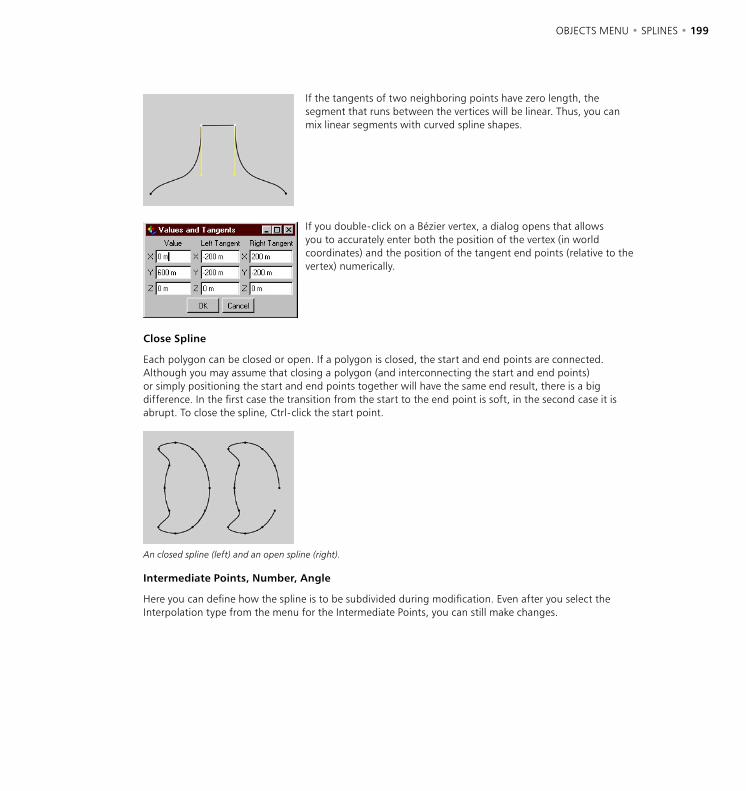
198 • CHAPTER 7 OBJECTS MENU • SPLINES • 199
If the tangents of two neighboring points have zero length, the segment that runs between the vertices will be linear. Thus, you can mix linear segments with curved spline shapes.
If you double-click on a Bézier vertex, a dialog opens that allows you to accurately enter both the position of the vertex (in world coordinates) and the position of the tangent end points (relative to the vertex) numerically.
Close Spline
Each polygon can be closed or open. If a polygon is closed, the start and end points are connected. Although you may assume that closing a polygon (and interconnecting the start and end points) or simply positioning the start and end points together will have the same end result, there is a big difference. In the first case the transition from the start to the end point is soft, in the second case it is abrupt. To close the spline, Ctrl-click the start point.
An closed spline (left) and an open spline (right).
Intermediate Points, Number, Angle
Here you can define how the spline is to be subdivided during modification. Even after you select the Interpolation type from the menu for the Intermediate Points, you can still make changes.
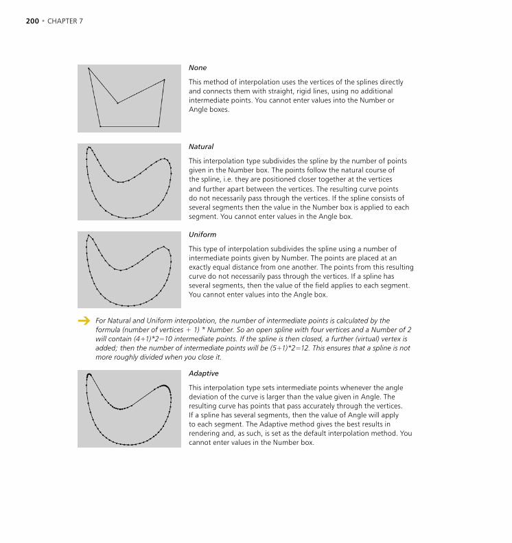
200 • CHAPTER 7 OBJECTS MENU • SPLINES • 201
None
This method of interpolation uses the vertices of the splines directly and connects them with straight, rigid lines, using no additional intermediate points. You cannot enter values into the Number or Angle boxes.
Natural
This interpolation type subdivides the spline by the number of points given in the Number box. The points follow the natural course of the spline, i.e. they are positioned closer together at the vertices and further apart between the vertices. The resulting curve points do not necessarily pass through the vertices. If the spline consists of several segments then the value in the Number box is applied to each segment. You cannot enter values in the Angle box.
Uniform
This type of interpolation subdivides the spline using a number of intermediate points given by Number. The points are placed at an exactly equal distance from one another. The points from this resulting curve do not necessarily pass through the vertices. If a spline has several segments, then the value of the field applies to each segment. You cannot enter values into the Angle box.
For Natural and Uniform interpolation, the number of intermediate points is calculated by the formula (number of vertices + 1) * Number. So an open spline with four vertices and a Number of 2 will contain (4+1)*2=10 intermediate points. If the spline is then closed, a further (virtual) vertex is added; then the number of intermediate points will be (5+1)*2=12. This ensures that a spline is not more roughly divided when you close it.
Adaptive
This interpolation type sets intermediate points whenever the angle deviation of the curve is larger than the value given in Angle. The resulting curve has points that pass accurately through the vertices. If a spline has several segments, then the value of Angle will apply to each segment. The Adaptive method gives the best results in rendering and, as such, is set as the default interpolation method. You cannot enter values in the Number box.
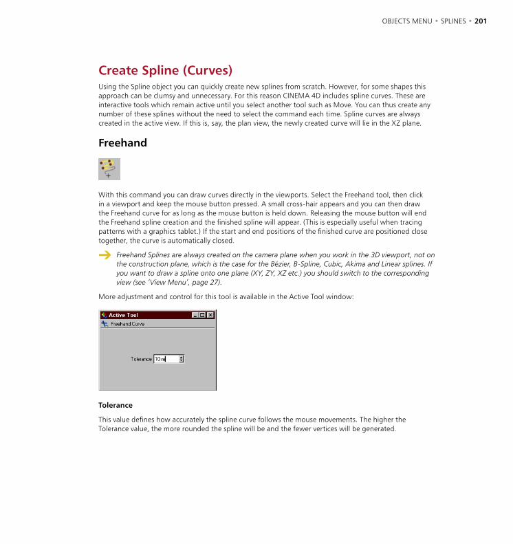
200 • CHAPTER 7 OBJECTS MENU • SPLINES • 201
Create Spline (Curves)Using the Spline object you can quickly create new splines from scratch. However, for some shapes this approach can be clumsy and unnecessary. For this reason CINEMA 4D includes spline curves. These are interactive tools which remain active until you select another tool such as Move. You can thus create any number of these splines without the need to select the command each time. Spline curves are always created in the active view. If this is, say, the plan view, the newly created curve will lie in the XZ plane.
Freehand
With this command you can draw curves directly in the viewports. Select the Freehand tool, then click in a viewport and keep the mouse button pressed. A small cross-hair appears and you can then draw the Freehand curve for as long as the mouse button is held down. Releasing the mouse button will end the Freehand spline creation and the finished spline will appear. (This is especially useful when tracing patterns with a graphics tablet.) If the start and end positions of the finished curve are positioned close together, the curve is automatically closed.
Freehand Splines are always created on the camera plane when you work in the 3D viewport, not on the construction plane, which is the case for the Bézier, B-Spline, Cubic, Akima and Linear splines. If you want to draw a spline onto one plane (XY, ZY, XZ etc.) you should switch to the corresponding view (see ‘View Menu’, page 27).
More adjustment and control for this tool is available in the Active Tool window:
Tolerance
This value defines how accurately the spline curve follows the mouse movements. The higher the Tolerance value, the more rounded the spline will be and the fewer vertices will be generated.
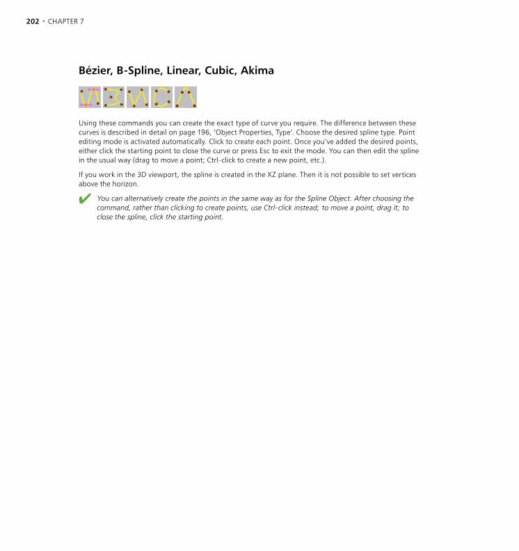
202 • CHAPTER 7 OBJECTS MENU • SPLINES • 203
Bézier, B-Spline, Linear, Cubic, Akima
Using these commands you can create the exact type of curve you require. The difference between these curves is described in detail on page 196, ‘Object Properties, Type’. Choose the desired spline type. Point editing mode is activated automatically. Click to create each point. Once you’ve added the desired points, either click the starting point to close the curve or press Esc to exit the mode. You can then edit the spline in the usual way (drag to move a point; Ctrl-click to create a new point, etc.).
If you work in the 3D viewport, the spline is created in the XZ plane. Then it is not possible to set vertices above the horizon.
You can alternatively create the points in the same way as for the Spline Object. After choosing the command, rather than clicking to create points, use Ctrl-click instead; to move a point, drag it; to close the spline, click the starting point.
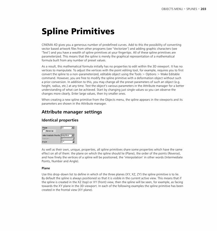
202 • CHAPTER 7 OBJECTS MENU • SPLINES • 203
Spline PrimitivesCINEMA 4D gives you a generous number of predefined curves. Add to this the possibility of converting vector based artwork files from other programs (see ‘Vectorizer’) and adding graphic characters (see ‘Text’) and you have a wealth of spline primitives at your fingertips. All of these spline primitives are parameterized. This means that the spline is merely the graphical representation of a mathematical formula built from any number of preset values.
As a result, this mathematical formula initially has no properties to edit within the 3D viewport. It has no vertices to manipulate. To adjust the vertices with the point editing tool, for example, requires you to first convert the spline to a non-parameterized, editable object using the Tools > Options > Make Editable command. However, you are free to modify the spline primitive with a deformation object without such a prior conversion. In addition to this, you may change all the preset parameters of such an object (e.g. height, radius, etc.) at any time. Test the object’s various parameters in the Attribute manager for a better understanding of what can be achieved. Start by changing just single values so you can observe the changes more clearly. Enter large values, then try smaller ones.
When creating a new spline primitive from the Objects menu, the spline appears in the viewports and its parameters are shown in the Attribute manager.
Attribute manager settings
Identical properties
As well as their own, unique, properties, all spline primitives share some properties which have the same effect on all of them: the plane on which the spline should lie (Plane), the order of the points (Reverse), and how finely the vertices of a spline will be positioned, the ‘interpolation’ in other words (Intermediate Points, Number and Angle).
Plane
Use this drop-down list to define in which of the three planes (XY, XZ, ZY) the spline primitive is to lie. By default the spline is always positioned so that it is visible in the current active view. This means that if the spline is created in the XZ (top) or XY (front) view, then the spline will be seen, for example, as facing towards the XY plane in the 3D viewport. In each of the following examples the spline primitive has been created in the frontal view (XY plane).
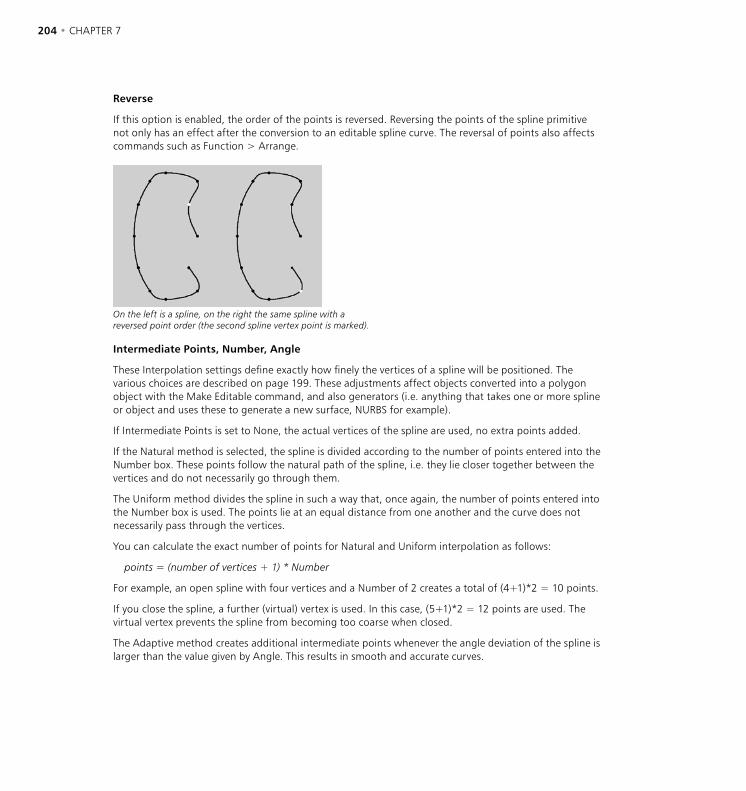
204 • CHAPTER 7 OBJECTS MENU • SPLINES • 205
Reverse
If this option is enabled, the order of the points is reversed. Reversing the points of the spline primitive not only has an effect after the conversion to an editable spline curve. The reversal of points also affects commands such as Function > Arrange.
On the left is a spline, on the right the same spline with a reversed point order (the second spline vertex point is marked).
Intermediate Points, Number, Angle
These Interpolation settings define exactly how finely the vertices of a spline will be positioned. The various choices are described on page 199. These adjustments affect objects converted into a polygon object with the Make Editable command, and also generators (i.e. anything that takes one or more spline or object and uses these to generate a new surface, NURBS for example).
If Intermediate Points is set to None, the actual vertices of the spline are used, no extra points added.
If the Natural method is selected, the spline is divided according to the number of points entered into the Number box. These points follow the natural path of the spline, i.e. they lie closer together between the vertices and do not necessarily go through them.
The Uniform method divides the spline in such a way that, once again, the number of points entered into the Number box is used. The points lie at an equal distance from one another and the curve does not necessarily pass through the vertices.
You can calculate the exact number of points for Natural and Uniform interpolation as follows:
points = (number of vertices + 1) * Number
For example, an open spline with four vertices and a Number of 2 creates a total of (4+1)*2 = 10 points.
If you close the spline, a further (virtual) vertex is used. In this case, (5+1)*2 = 12 points are used. The virtual vertex prevents the spline from becoming too coarse when closed.
The Adaptive method creates additional intermediate points whenever the angle deviation of the spline is larger than the value given by Angle. This results in smooth and accurate curves.
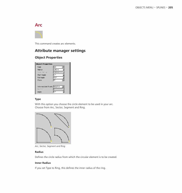
204 • CHAPTER 7 OBJECTS MENU • SPLINES • 205
Arc
This command creates arc elements.
Attribute manager settings
Object Properties
Type
With this option you choose the circle element to be used in your arc. Choose from Arc, Sector, Segment and Ring.
Arc, Sector, Segment and Ring
Radius
Defines the circle radius from which the circular element is to be created.
Inner Radius
If you set Type to Ring, this defines the inner radius of the ring.
206 • CHAPTER 7 OBJECTS MENU • SPLINES • 207
Start Angle, End Angle
Using these two values you can define the start and end point of the circle element. 0° defines the value as the positive X-axis, 90° the positive Y-axis, 180° the negative X-axis, etc. These examples assume you are working in the XY plane, as mentioned earlier.
Plane
With this drop-down list you choose in which of the three planes the spline primitive is created. See ‘Plane’ on page 203.
Reverse
Enabling this option will reverse the point order of the spline. See ‘Reverse’ on page 204.
Intermediate Points, Number, Angle
These interpolation settings define how the intermediate points of the spline are produced. See ‘Intermediate Points, Number, Angle’ on page 204.

206 • CHAPTER 7 OBJECTS MENU • SPLINES • 207
Circle
This command creates circles, rings, ellipses and ellipse rings. It is also suitable for the creation of hoses or tubes using NURBS objects.
Attribute manager settings
Object Properties
Radius
By default the Circle command creates a circle with a radius of Radius.
Ring, Inner Radius
If the Ring option is enabled, either circular rings or ellipse rings are created. Here the internal radius of the ring is given by Inner Radius. For ellipse rings this value is the internal radius along the ellipse’s X axis. The inner length along the Y-axis is automatically calculated from the outer ellipse’s dimensions.
Ellipse, Radius, Radius Y
If the Ellipse option is enabled, both Radius and Radius Y affect the shape, where Radius Y defines the length of the ellipse along the Z-axis.
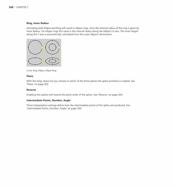
208 • CHAPTER 7 OBJECTS MENU • SPLINES • 209
Ring, Inner Radius
Activating both Ellipse and Ring will result in ellipse rings. Here the internal radius of the ring is given by Inner Radius. For ellipse rings this value is the internal radius along the ellipse’s X-axis. The inner length along the Y-axis is automatically calculated from the outer ellipse’s dimensions.
Circle, Ring, Ellipse, Ellipse Ring.
Plane
With this drop-down list you choose in which of the three planes the spline primitive is created. See ‘Plane’ on page 203.
Reverse
Enabling this option will reverse the point order of the spline. See ‘Reverse’ on page 204.
Intermediate Points, Number, Angle
These interpolation settings define how the intermediate points of the spline are produced. See ‘Intermediate Points, Number, Angle’ on page 204.

208 • CHAPTER 7 OBJECTS MENU • SPLINES • 209
Helix
This command creates a helix — a spiralled, spring-like spline.
Attribute manager settings
Object Properties
Start Radius, End Radius
Enter the two radius values for the start and the end of the helix.
Start Angle, End Angle
These values specify the start and end points of the helix. 0° here designates that the relevant point is on the positive X-axis, 90° the negative Y-axis, 180° the negative X-axis, etc.
Helix with 4 revolutions (left) and 3.5 revolutions (right).
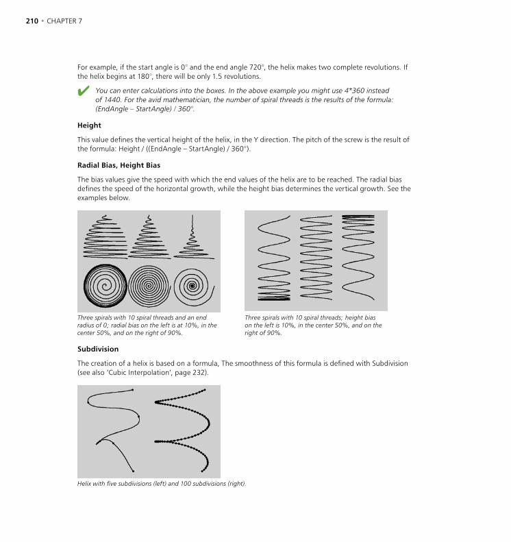
210 • CHAPTER 7 OBJECTS MENU • SPLINES • 211
For example, if the start angle is 0° and the end angle 720°, the helix makes two complete revolutions. If the helix begins at 180°, there will be only 1.5 revolutions.
You can enter calculations into the boxes. In the above example you might use 4*360 instead of 1440. For the avid mathematician, the number of spiral threads is the results of the formula: (EndAngle – StartAngle) / 360°.
Height
This value defines the vertical height of the helix, in the Y direction. The pitch of the screw is the result of the formula: Height / ((EndAngle – StartAngle) / 360°).
Radial Bias, Height Bias
The bias values give the speed with which the end values of the helix are to be reached. The radial bias defines the speed of the horizontal growth, while the height bias determines the vertical growth. See the examples below.
Three spirals with 10 spiral threads and an end radius of 0; radial bias on the left is at 10%, in the center 50%, and on the right of 90%.
Three spirals with 10 spiral threads; height bias on the left is 10%, in the center 50%, and on the right of 90%.
Subdivision
The creation of a helix is based on a formula, The smoothness of this formula is defined with Subdivision (see also ‘Cubic Interpolation’, page 232).
Helix with five subdivisions (left) and 100 subdivisions (right).
210 • CHAPTER 7 OBJECTS MENU • SPLINES • 211
Plane
With this drop-down list you choose in which of the three planes the helix is created. See ‘Plane’ on page 203.
Reverse
Enabling this option will reverse the point order of the spline. See ‘Reverse’ on page 204.
Intermediate Points, Number, Angle
These interpolation settings define how the intermediate points of the spline are produced. See ‘Intermediate Points, Number, Angle’ on page 204.
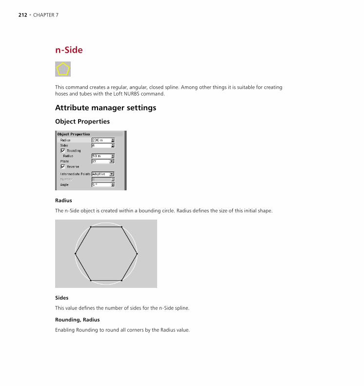
212 • CHAPTER 7 OBJECTS MENU • SPLINES • 213
n-Side
This command creates a regular, angular, closed spline. Among other things it is suitable for creating hoses and tubes with the Loft NURBS command.
Attribute manager settings
Object Properties
Radius
The n-Side object is created within a bounding circle. Radius defines the size of this initial shape.
Sides
This value defines the number of sides for the n-Side spline.
Rounding, Radius
Enabling Rounding to round all corners by the Radius value.

212 • CHAPTER 7 OBJECTS MENU • SPLINES • 213
Plane
With this drop-down list you choose in which of the three planes the spline primitive is created. See ‘Plane’ on page 203.
Reverse
Enabling this option will reverse the point order of the spline. See ‘Reverse’ on page 204.
Intermediate Points, Number, Angle
These interpolation settings define how the intermediate points of the spline are produced. See ‘Intermediate Points, Number, Angle’ on page 204.
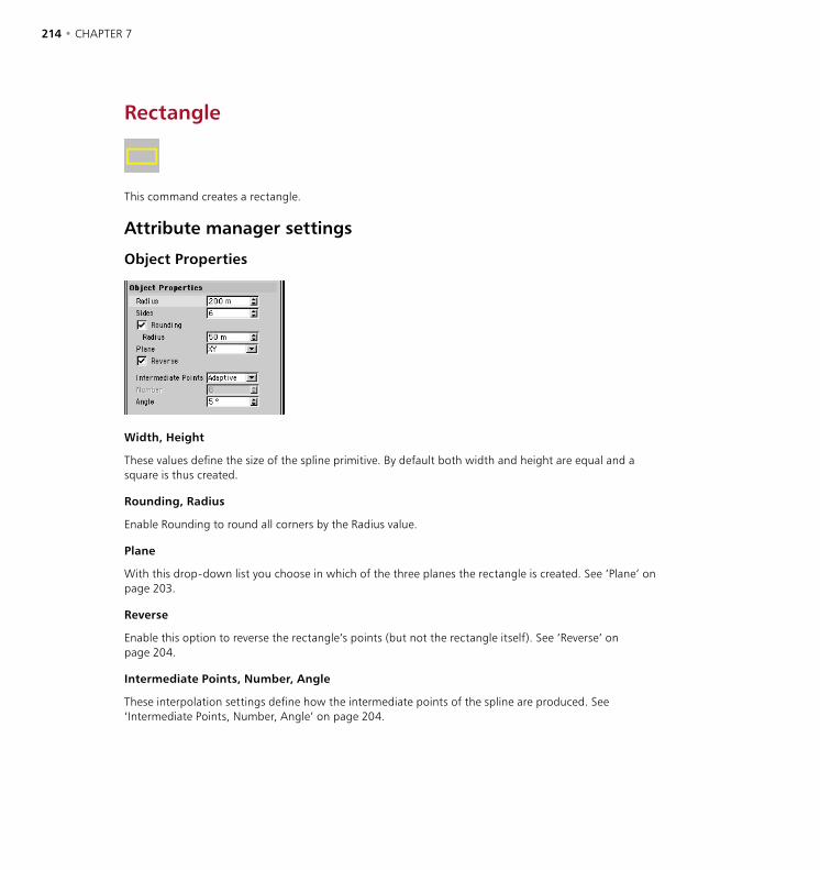
214 • CHAPTER 7 OBJECTS MENU • SPLINES • 215
Rectangle
This command creates a rectangle.
Attribute manager settings
Object Properties
Width, Height
These values define the size of the spline primitive. By default both width and height are equal and a square is thus created.
Rounding, Radius
Enable Rounding to round all corners by the Radius value.
Plane
With this drop-down list you choose in which of the three planes the rectangle is created. See ‘Plane’ on page 203.
Reverse
Enable this option to reverse the rectangle’s points (but not the rectangle itself). See ‘Reverse’ on page 204.
Intermediate Points, Number, Angle
These interpolation settings define how the intermediate points of the spline are produced. See ‘Intermediate Points, Number, Angle’ on page 204.
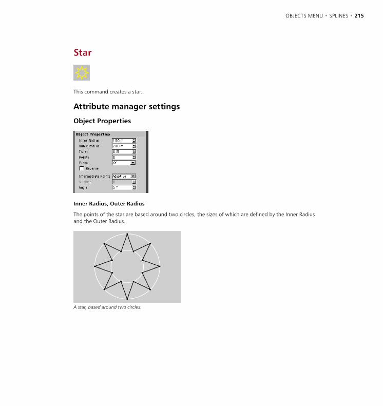
214 • CHAPTER 7 OBJECTS MENU • SPLINES • 215
Star
This command creates a star.
Attribute manager settings
Object Properties
Inner Radius, Outer Radius
The points of the star are based around two circles, the sizes of which are defined by the Inner Radius and the Outer Radius.
A star, based around two circles.
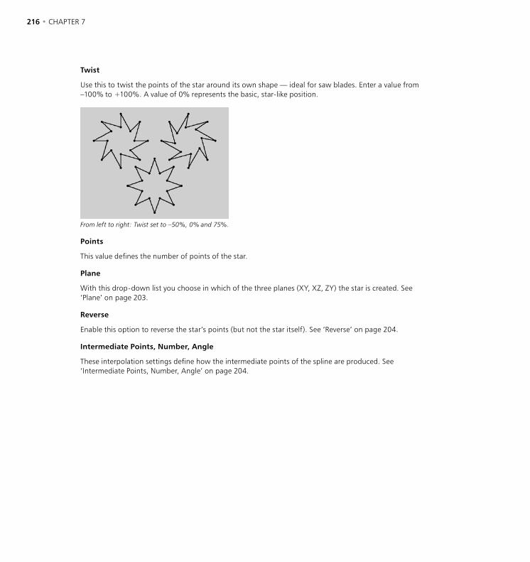
216 • CHAPTER 7 OBJECTS MENU • SPLINES • 217
Twist
Use this to twist the points of the star around its own shape — ideal for saw blades. Enter a value from –100% to +100%. A value of 0% represents the basic, star-like position.
From left to right: Twist set to –50%, 0% and 75%.
Points
This value defines the number of points of the star.
Plane
With this drop-down list you choose in which of the three planes (XY, XZ, ZY) the star is created. See ‘Plane’ on page 203.
Reverse
Enable this option to reverse the star’s points (but not the star itself). See ‘Reverse’ on page 204.
Intermediate Points, Number, Angle
These interpolation settings define how the intermediate points of the spline are produced. See ‘Intermediate Points, Number, Angle’ on page 204.
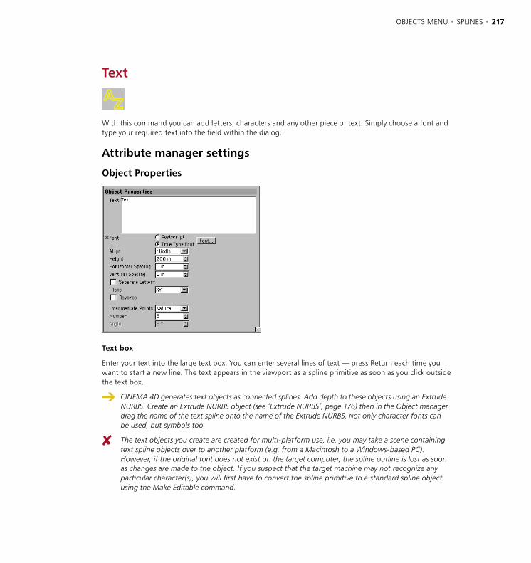
216 • CHAPTER 7 OBJECTS MENU • SPLINES • 217
Text
With this command you can add letters, characters and any other piece of text. Simply choose a font and type your required text into the field within the dialog.
Attribute manager settings
Object Properties
Text box
Enter your text into the large text box. You can enter several lines of text — press Return each time you want to start a new line. The text appears in the viewport as a spline primitive as soon as you click outside the text box.
CINEMA 4D generates text objects as connected splines. Add depth to these objects using an Extrude NURBS. Create an Extrude NURBS object (see ‘Extrude NURBS’, page 176) then in the Object manager drag the name of the text spline onto the name of the Extrude NURBS. Not only character fonts can be used, but symbols too.
The text objects you create are created for multi-platform use, i.e. you may take a scene containing text spline objects over to another platform (e.g. from a Macintosh to a Windows-based PC). However, if the original font does not exist on the target computer, the spline outline is lost as soon as changes are made to the object. If you suspect that the target machine may not recognize any particular character(s), you will first have to convert the spline primitive to a standard spline object using the Make Editable command.
218 • CHAPTER 7 OBJECTS MENU • SPLINES • 219
Postscript, TrueType Font
In CINEMA 4D you can choose between TrueType or PostScript Type 1 fonts by clicking the appropriate button. With TrueType fonts, a font selector window will open, allowing you to choose a character set. With PostScript fonts, a standard file selector window opens, from which you can locate and load any desired PostScript font. CINEMA 4D works with the PFB (PostScript Font Binary) format of Type 1 fonts.
Some fonts are poorly designed and will have noticeable overlapping edges. CINEMA 4D cannot improve these faults. Always use high quality fonts for best results.
Kerning information is not evaluated by CINEMA 4D. Therefore to shift individual text letters accurately, proceed as follows:
Convert the spline primitive with the Structure > Make Editable command.
Select the Points tool, select a vertex of the desired character (by clicking it), then choose Select Connected from the Selection menu. All points in this character object are now selected.
Select the Move tool and drag to move the entire character.
You can get a good result with 3D fonts by using the Bevel command on a font object and restricting the angle limit to approx. 20° (see ‘Bevel’ on page 468).
Align
The Align drop-down list enables you to set the text’s alignment to left-aligned, centered or right-aligned.
Horizontal Spacing
With this command you can insert additional space between the characters.
Vertical Spacing
Use this to insert additional space between the lines of text.
Separate Letters
Enable this option. Now choose Structure > Make Editable. A new object is created which has a separate spline child object for each letter of the text. The object axes of the separate letter splines are placed at the baseline of the chosen font. This option is especially useful when you want to arrange text (the separate letters) along a spline.
Plane
With this option you choose in which of the three planes the text is created. See ‘Plane’ on page 203.
Reverse
Enable this option to reverse the text’s points (but not the text itself). See ‘Reverse’ on page 204.
Intermediate Points, Number, Angle
These interpolation settings define how the intermediate points of the spline are produced. See ‘Intermediate Points, Number, Angle’ on page 204.
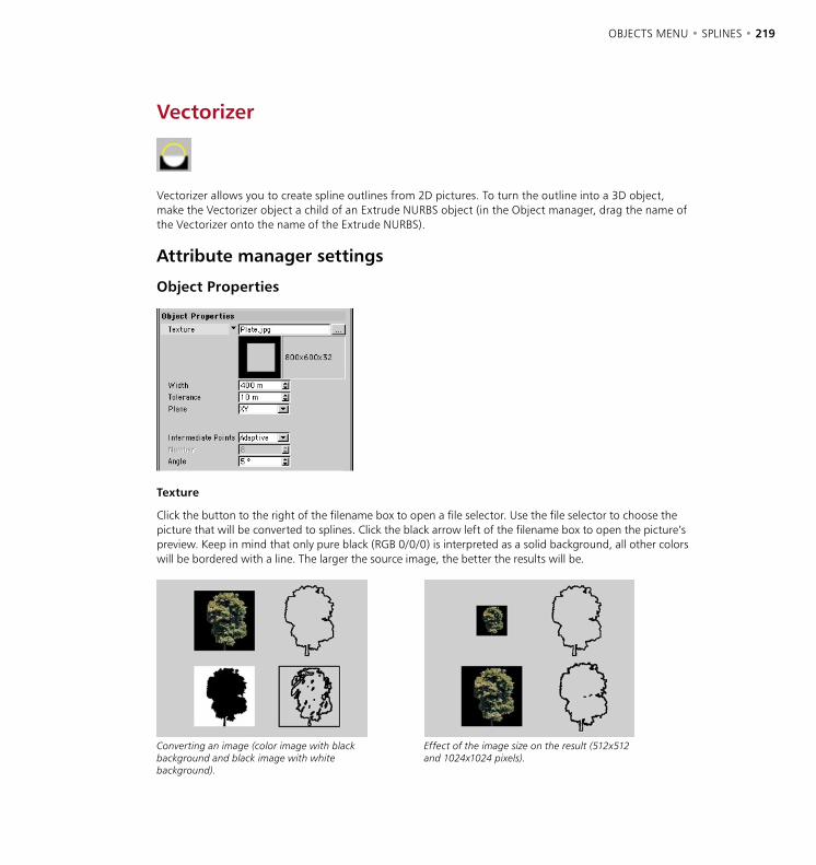
218 • CHAPTER 7 OBJECTS MENU • SPLINES • 219
Vectorizer
Vectorizer allows you to create spline outlines from 2D pictures. To turn the outline into a 3D object, make the Vectorizer object a child of an Extrude NURBS object (in the Object manager, drag the name of the Vectorizer onto the name of the Extrude NURBS).
Attribute manager settings
Object Properties
Texture
Click the button to the right of the filename box to open a file selector. Use the file selector to choose the picture that will be converted to splines. Click the black arrow left of the filename box to open the picture’s preview. Keep in mind that only pure black (RGB 0/0/0) is interpreted as a solid background, all other colors will be bordered with a line. The larger the source image, the better the results will be.
Converting an image (color image with black background and black image with white background).
Effect of the image size on the result (512x512 and 1024x1024 pixels).

220 • CHAPTER 7 OBJECTS MENU • SPLINES • 221
Width
This parameter defines the size in the X direction. The height (Y direction) is calculated automatically using the picture’s aspect ratio and the Width value.
Tolerance
This defines the smoothing of the conversion. The higher the value, the smoother the contour appears. However, more and more detail will also be lost. The smaller the value, the more detail of the original picture will appear in the result. However, this can lead to staircase-like jaggies at the spline’s edges.
Different tolerance values affect the accuracy of the spline.
Plane
With this option you choose in which of the three planes the spline primitive is created. See ‘Plane’ on page 203.
Reverse
Enable this option to reverse the spline’s points. See ‘Reverse’ on page 204.
Intermediate Points, Number, Angle
These interpolation settings define how the intermediate points of the spline are produced. See ‘Intermediate Points, Number, Angle’ on page 204.
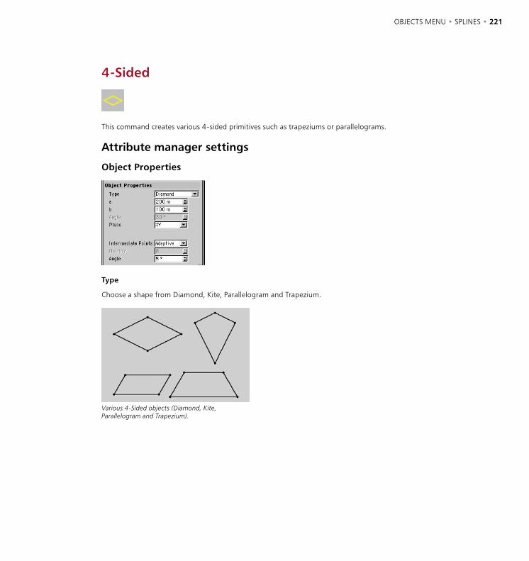
220 • CHAPTER 7 OBJECTS MENU • SPLINES • 221
4-Sided
This command creates various 4-sided primitives such as trapeziums or parallelograms.
Attribute manager settings
Object Properties
Type
Choose a shape from Diamond, Kite, Parallelogram and Trapezium.
Various 4-Sided objects (Diamond, Kite, Parallelogram and Trapezium).
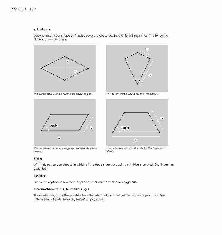
222 • CHAPTER 7 OBJECTS MENU • SPLINES • 223
a, b, Angle
Depending on your choice of 4-Sided object, these values have different meanings. The following illustrations show these:
The parameters a and b for the diamond object. The parameters a and b for the kite object.
The parameters a, b and angle for the parallelogram object.
The parameters a, b and angle for the trapezium object.
Plane
With this option you choose in which of the three planes the spline primitive is created. See ‘Plane’ on page 203.
Reverse
Enable this option to reverse the spline’s points. See ‘Reverse’ on page 204.
Intermediate Points, Number, Angle
These interpolation settings define how the intermediate points of the spline are produced. See ‘Intermediate Points, Number, Angle’ on page 204.
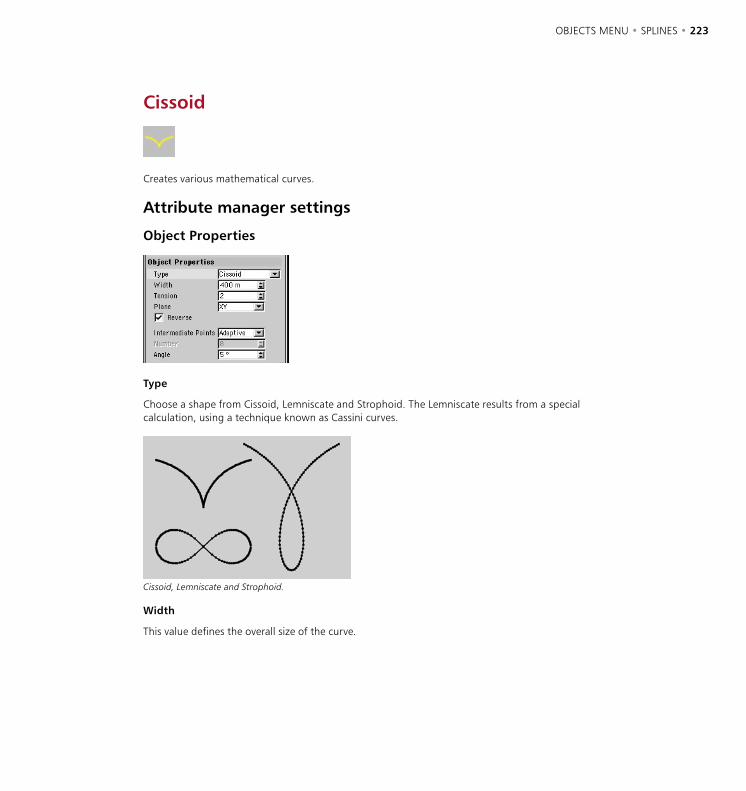
222 • CHAPTER 7 OBJECTS MENU • SPLINES • 223
Cissoid
Creates various mathematical curves.
Attribute manager settings
Object Properties
Type
Choose a shape from Cissoid, Lemniscate and Strophoid. The Lemniscate results from a special calculation, using a technique known as Cassini curves.
Cissoid, Lemniscate and Strophoid.
Width
This value defines the overall size of the curve.
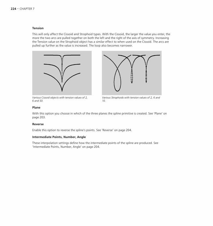
224 • CHAPTER 7 OBJECTS MENU • SPLINES • 225
Tension
This will only affect the Cissoid and Strophoid types. With the Cissoid, the larger the value you enter, the more the two arcs are pulled together on both the left and the right of the axis of symmetry. Increasing the Tension value on the Strophoid object has a similar effect to when used on the Cissoid. The arcs are pulled up further as the value is increased. The loop also becomes narrower.
Various Cissoid objects with tension values of 2, 6 and 50.
Various Strophoids with tension values of 2, 6 and 10.
Plane
With this option you choose in which of the three planes the spline primitive is created. See ‘Plane’ on page 203.
Reverse
Enable this option to reverse the spline’s points. See ‘Reverse’ on page 204.
Intermediate Points, Number, Angle
These interpolation settings define how the intermediate points of the spline are produced. See ‘Intermediate Points, Number, Angle’ on page 204.
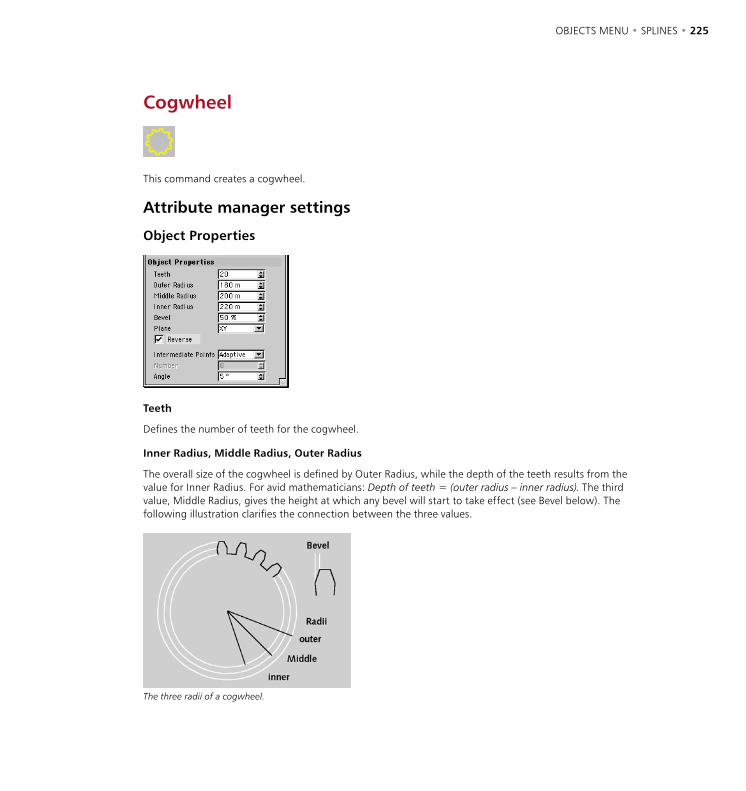
224 • CHAPTER 7 OBJECTS MENU • SPLINES • 225
Cogwheel
This command creates a cogwheel.
Attribute manager settings
Object Properties
Teeth
Defines the number of teeth for the cogwheel.
Inner Radius, Middle Radius, Outer Radius
The overall size of the cogwheel is defined by Outer Radius, while the depth of the teeth results from the value for Inner Radius. For avid mathematicians: Depth of teeth = (outer radius – inner radius). The third value, Middle Radius, gives the height at which any bevel will start to take effect (see Bevel below). The following illustration clarifies the connection between the three values.
The three radii of a cogwheel.
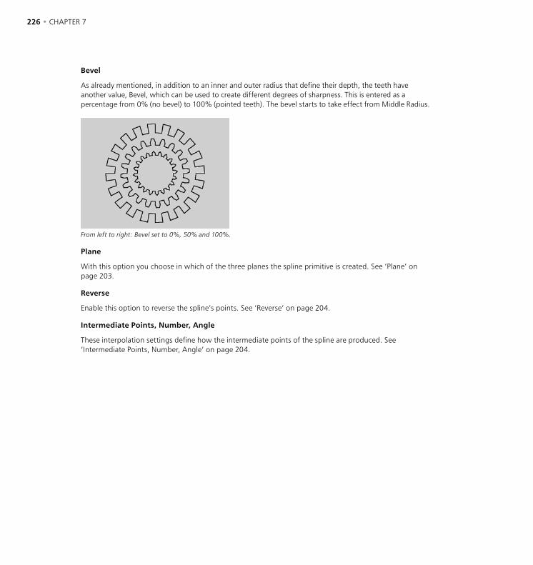
226 • CHAPTER 7 OBJECTS MENU • SPLINES • 227
Bevel
As already mentioned, in addition to an inner and outer radius that define their depth, the teeth have another value, Bevel, which can be used to create different degrees of sharpness. This is entered as a percentage from 0% (no bevel) to 100% (pointed teeth). The bevel starts to take effect from Middle Radius.
From left to right: Bevel set to 0%, 50% and 100%.
Plane
With this option you choose in which of the three planes the spline primitive is created. See ‘Plane’ on page 203.
Reverse
Enable this option to reverse the spline’s points. See ‘Reverse’ on page 204.
Intermediate Points, Number, Angle
These interpolation settings define how the intermediate points of the spline are produced. See ‘Intermediate Points, Number, Angle’ on page 204.
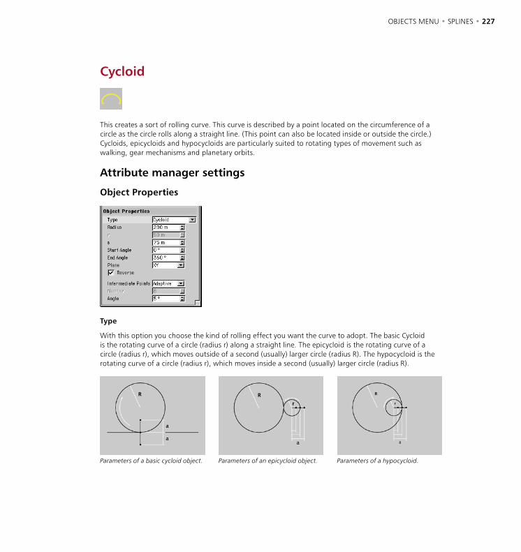
226 • CHAPTER 7 OBJECTS MENU • SPLINES • 227
Cycloid
This creates a sort of rolling curve. This curve is described by a point located on the circumference of a circle as the circle rolls along a straight line. (This point can also be located inside or outside the circle.) Cycloids, epicycloids and hypocycloids are particularly suited to rotating types of movement such as walking, gear mechanisms and planetary orbits.
Attribute manager settings
Object Properties
Type
With this option you choose the kind of rolling effect you want the curve to adopt. The basic Cycloid is the rotating curve of a circle (radius r) along a straight line. The epicycloid is the rotating curve of a circle (radius r), which moves outside of a second (usually) larger circle (radius R). The hypocycloid is the rotating curve of a circle (radius r), which moves inside a second (usually) larger circle (radius R).
Parameters of a basic cycloid object. Parameters of an epicycloid object. Parameters of a hypocycloid.
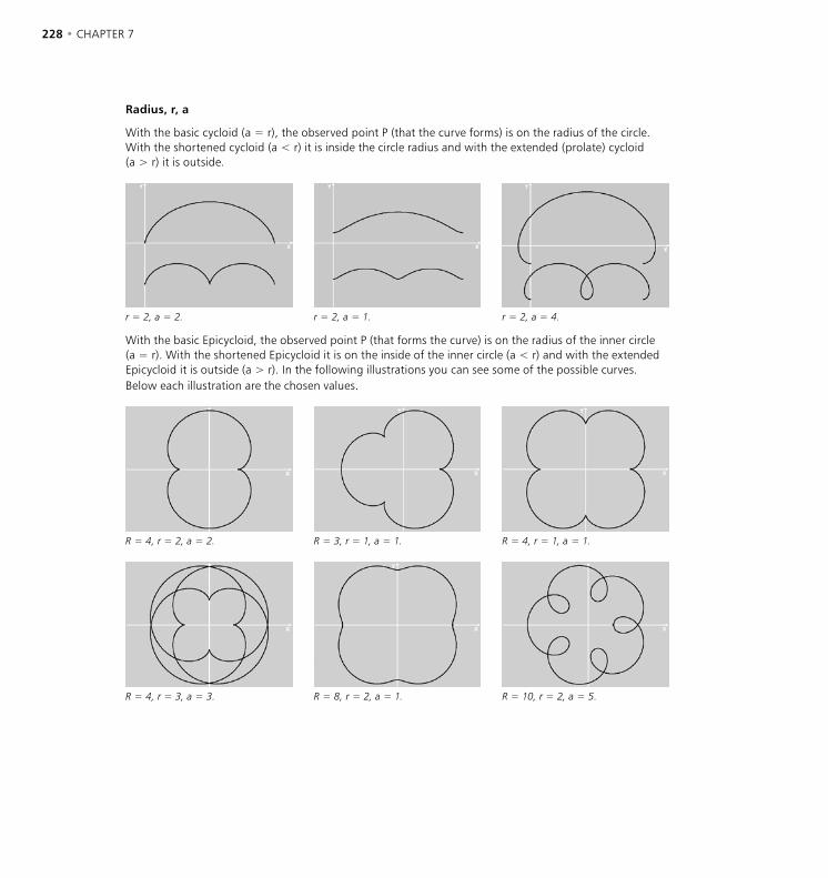
228 • CHAPTER 7 OBJECTS MENU • SPLINES • 229
Radius, r, a
With the basic cycloid (a = r), the observed point P (that the curve forms) is on the radius of the circle. With the shortened cycloid (a < r) it is inside the circle radius and with the extended (prolate) cycloid (a > r) it is outside.
r = 2, a = 2. r = 2, a = 1. r = 2, a = 4.
With the basic Epicycloid, the observed point P (that forms the curve) is on the radius of the inner circle (a = r). With the shortened Epicycloid it is on the inside of the inner circle (a < r) and with the extended Epicycloid it is outside (a > r). In the following illustrations you can see some of the possible curves. Below each illustration are the chosen values.
R = 4, r = 2, a = 2. R = 3, r = 1, a = 1. R = 4, r = 1, a = 1.
R = 4, r = 3, a = 3. R = 8, r = 2, a = 1. R = 10, r = 2, a = 5.
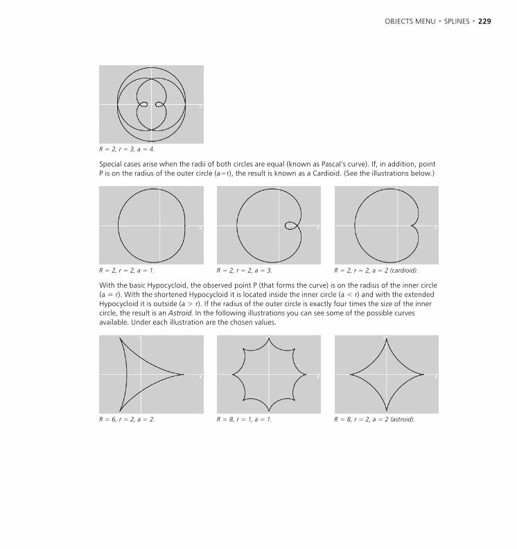
228 • CHAPTER 7 OBJECTS MENU • SPLINES • 229
R = 2, r = 3, a = 4.
Special cases arise when the radii of both circles are equal (known as Pascal’s curve). If, in addition, point P is on the radius of the outer circle (a=r), the result is known as a Cardioid. (See the illustrations below.)
R = 2, r = 2, a = 1. R = 2, r = 2, a = 3. R = 2, r = 2, a = 2 (cardioid).
With the basic Hypocycloid, the observed point P (that forms the curve) is on the radius of the inner circle (a = r). With the shortened Hypocycloid it is located inside the inner circle (a < r) and with the extended Hypocycloid it is outside (a > r). If the radius of the outer circle is exactly four times the size of the inner circle, the result is an Astroid. In the following illustrations you can see some of the possible curves available. Under each illustration are the chosen values.
R = 6, r = 2, a = 2. R = 8, r = 1, a = 1. R = 8, r = 2, a = 2 (astroid).
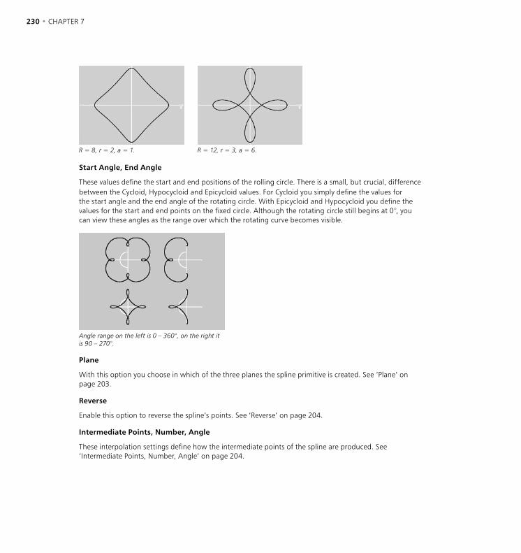
230 • CHAPTER 7 OBJECTS MENU • SPLINES • 231
R = 8, r = 2, a = 1. R = 12, r = 3, a = 6.
Start Angle, End Angle
These values define the start and end positions of the rolling circle. There is a small, but crucial, difference between the Cycloid, Hypocycloid and Epicycloid values. For Cycloid you simply define the values for the start angle and the end angle of the rotating circle. With Epicycloid and Hypocycloid you define the values for the start and end points on the fixed circle. Although the rotating circle still begins at 0°, you can view these angles as the range over which the rotating curve becomes visible.
Angle range on the left is 0 – 360°, on the right it is 90 – 270°.
Plane
With this option you choose in which of the three planes the spline primitive is created. See ‘Plane’ on page 203.
Reverse
Enable this option to reverse the spline’s points. See ‘Reverse’ on page 204.
Intermediate Points, Number, Angle
These interpolation settings define how the intermediate points of the spline are produced. See ‘Intermediate Points, Number, Angle’ on page 204.
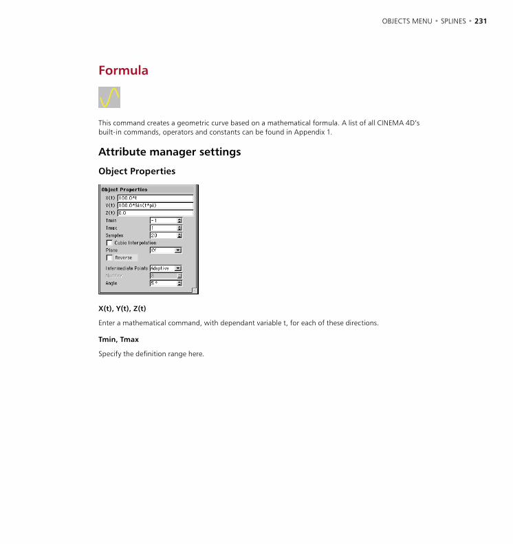
230 • CHAPTER 7 OBJECTS MENU • SPLINES • 231
Formula
This command creates a geometric curve based on a mathematical formula. A list of all CINEMA 4D’s built-in commands, operators and constants can be found in Appendix 1.
Attribute manager settings
Object Properties
X(t), Y(t), Z(t)
Enter a mathematical command, with dependant variable t, for each of these directions.
Tmin, Tmax
Specify the definition range here.
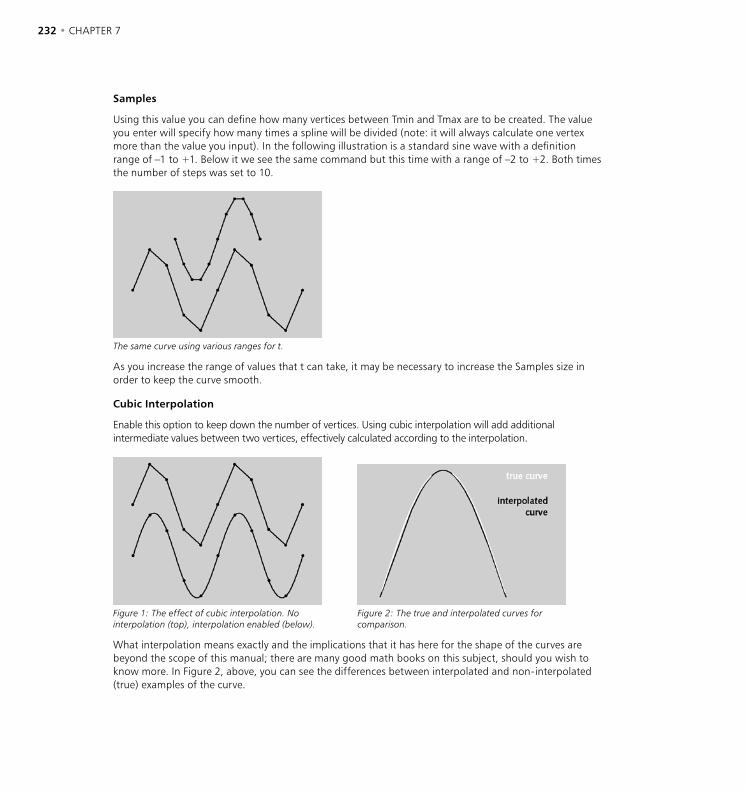
232 • CHAPTER 7 OBJECTS MENU • SPLINES • 233
Samples
Using this value you can define how many vertices between Tmin and Tmax are to be created. The value you enter will specify how many times a spline will be divided (note: it will always calculate one vertex more than the value you input). In the following illustration is a standard sine wave with a definition range of –1 to +1. Below it we see the same command but this time with a range of –2 to +2. Both times the number of steps was set to 10.
The same curve using various ranges for t.
As you increase the range of values that t can take, it may be necessary to increase the Samples size in order to keep the curve smooth.
Cubic Interpolation
Enable this option to keep down the number of vertices. Using cubic interpolation will add additional intermediate values between two vertices, effectively calculated according to the interpolation.
Figure 1: The effect of cubic interpolation. No interpolation (top), interpolation enabled (below).
Figure 2: The true and interpolated curves for comparison.
What interpolation means exactly and the implications that it has here for the shape of the curves are beyond the scope of this manual; there are many good math books on this subject, should you wish to know more. In Figure 2, above, you can see the differences between interpolated and non-interpolated (true) examples of the curve.
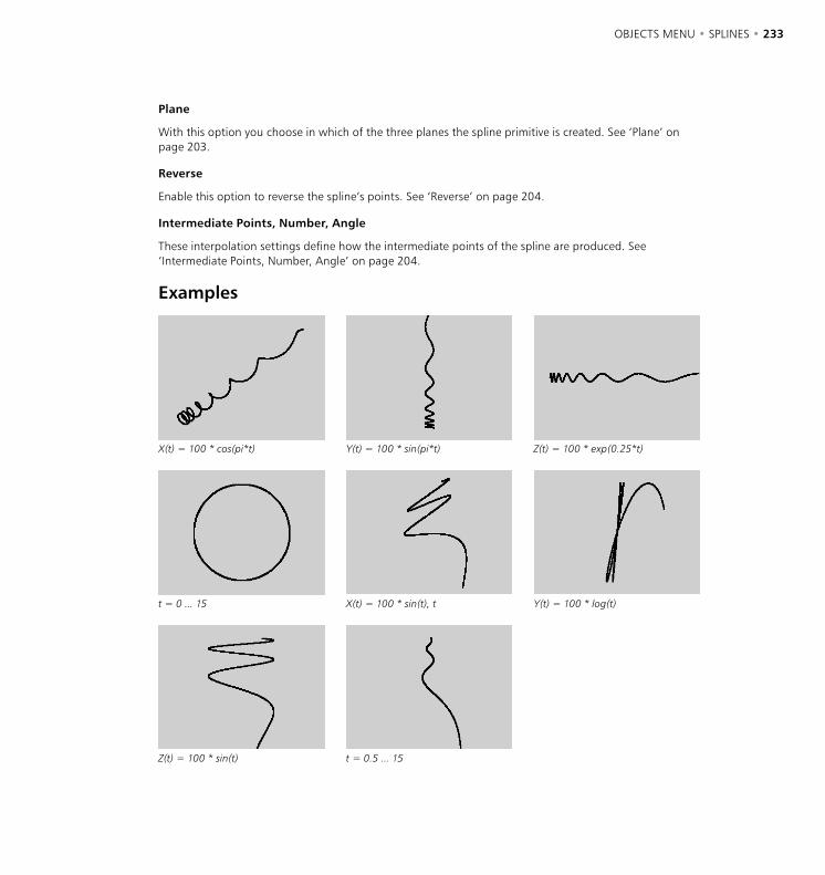
232 • CHAPTER 7 OBJECTS MENU • SPLINES • 233
Plane
With this option you choose in which of the three planes the spline primitive is created. See ‘Plane’ on page 203.
Reverse
Enable this option to reverse the spline’s points. See ‘Reverse’ on page 204.
Intermediate Points, Number, Angle
These interpolation settings define how the intermediate points of the spline are produced. See ‘Intermediate Points, Number, Angle’ on page 204.
Examples
X(t) = 100 * cos(pi*t) Y(t) = 100 * sin(pi*t) Z(t) = 100 * exp(0.25*t)
t = 0 ... 15 X(t) = 100 * sin(t), t Y(t) = 100 * log(t)
Z(t) = 100 * sin(t) t = 0.5 ... 15

234 • CHAPTER 7 OBJECTS MENU • SPLINES • 235
Flower
This command creates a flower-shaped object.
Attribute manager settings
Object Properties
Inner Radius, Outer Radius
The inner radius defines the size of the inner area from where the petals begin to grow. The petals extend from the inner to the outer radius.
Petals
This value gives the total number of petals.
Plane
With this option you choose in which of the three planes the spline primitive is created. See ‘Plane’ on page 203.
Reverse
Enable this option to reverse the spline’s points. See ‘Reverse’ on page 204.
Intermediate Points, Number, Angle
These interpolation settings define how the intermediate points of the spline are produced. See ‘Intermediate Points, Number, Angle’ on page 204.
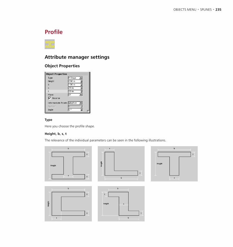
234 • CHAPTER 7 OBJECTS MENU • SPLINES • 235
Profile
Attribute manager settings
Object Properties
Type
Here you choose the profile shape.
Height, b, s, t
The relevance of the individual parameters can be seen in the following illustrations.

236 • CHAPTER 7
Plane
With this option you choose in which of the three planes the spline primitive is created. See ‘Plane’ on page 203.
Reverse
Enable this option to reverse the spline’s points. See ‘Reverse’ on page 204.
Intermediate Points, Number, Angle
These interpolation settings define how the intermediate points of the spline are produced. See ‘Intermediate Points, Number, Angle’ on page 204.

OBJECTS MENU • SPECIAL MODELING TOOLS • 237
Null Object
The null object might well mutter to itself “I cannot do anything, I’m nothing”. And that’s right ... almost. If you call this function, CINEMA 4D creates only an empty axis system in the 3D space. The object contains neither points nor surfaces and cannot be edited in the normal way.
So why use a null object?
Well, the null object can have other objects placed within it. So it is useful for grouping matching elements of a scene. Null objects are also created by an automatic grouping in the Object manager (see ‘Group Objects’ on page 624). A further possible application is as a handle in IK chains (see ‘Inverse Kinematics’ on page 423). Here you create a null object as the last part of an IK chain. Then use the null object rather than the true objects to move the inverse kinematics chain.
The advantage? Well, normally if you move, say, the hand at the end of an arm of a figure by IK, the hand itself remains rigid. This is avoided by the use of such a dummy object at the end of the chain.
Let’s not forget one of the most frequently used applications of the null object; its use as a dummy object for accurate rotation of previously rotated objects. As long as the axes of an object lie parallel to those of its parent system (with newly created objects the parent is the world coordinates system), an object rotates around its Y-axis (a heading rotation). However, if the object, or its local object coordinate system, is already rotated (so that its axes are not parallel to those of its parent), the result often astonishes even the most experienced 3D designers.
Left: rotation with parallel axes systems, Right: with an already rotated object system (in each case the final rotation is through 90°).
Special Modeling Tools
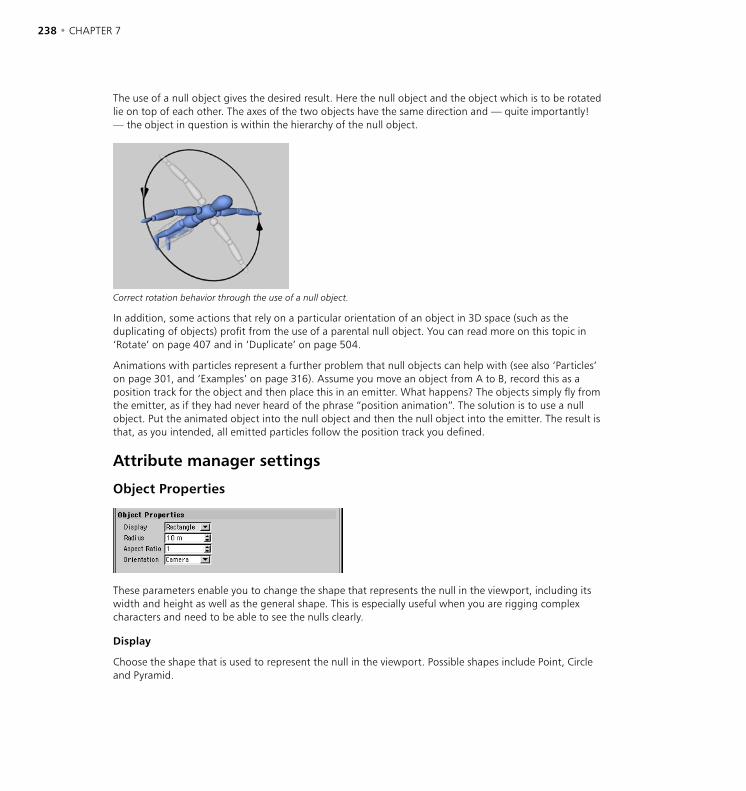
238 • CHAPTER 7 OBJECTS MENU • SPECIAL MODELING TOOLS • 239
The use of a null object gives the desired result. Here the null object and the object which is to be rotated lie on top of each other. The axes of the two objects have the same direction and — quite importantly! — the object in question is within the hierarchy of the null object.
Correct rotation behavior through the use of a null object.
In addition, some actions that rely on a particular orientation of an object in 3D space (such as the duplicating of objects) profit from the use of a parental null object. You can read more on this topic in ‘Rotate’ on page 407 and in ‘Duplicate’ on page 504.
Animations with particles represent a further problem that null objects can help with (see also ‘Particles’ on page 301, and ‘Examples’ on page 316). Assume you move an object from A to B, record this as a position track for the object and then place this in an emitter. What happens? The objects simply fly from the emitter, as if they had never heard of the phrase “position animation”. The solution is to use a null object. Put the animated object into the null object and then the null object into the emitter. The result is that, as you intended, all emitted particles follow the position track you defined.
Attribute manager settings
Object Properties
These parameters enable you to change the shape that represents the null in the viewport, including its width and height as well as the general shape. This is especially useful when you are rigging complex characters and need to be able to see the nulls clearly.
Display
Choose the shape that is used to represent the null in the viewport. Possible shapes include Point, Circle and Pyramid.

238 • CHAPTER 7 OBJECTS MENU • SPECIAL MODELING TOOLS • 239
Radius
Defines the radius of the shape that represents the null (choose the shape from the Display drop-down list).
Aspect Ratio
Defines the shape’s height as a ratio of height : width. For example, to make the pyramid shape twice the height of its width, set Aspect Ratio to 2.
Orientation
Defines the orientation of the shape. Choose from Camera, XY, ZY and XZ.
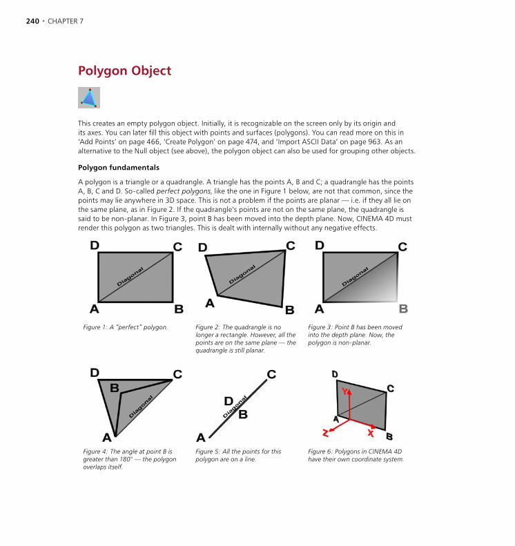
240 • CHAPTER 7 OBJECTS MENU • SPECIAL MODELING TOOLS • 241
Polygon Object
This creates an empty polygon object. Initially, it is recognizable on the screen only by its origin and its axes. You can later fill this object with points and surfaces (polygons). You can read more on this in ‘Add Points’ on page 466, ‘Create Polygon’ on page 474, and ‘Import ASCII Data’ on page 963. As an alternative to the Null object (see above), the polygon object can also be used for grouping other objects.
Polygon fundamentals
A polygon is a triangle or a quadrangle. A triangle has the points A, B and C; a quadrangle has the points A, B, C and D. So-called perfect polygons, like the one in Figure 1 below, are not that common, since the points may lie anywhere in 3D space. This is not a problem if the points are planar — i.e. if they all lie on the same plane, as in Figure 2. If the quadrangle’s points are not on the same plane, the quadrangle is said to be non-planar. In Figure 3, point B has been moved into the depth plane. Now, CINEMA 4D must render this polygon as two triangles. This is dealt with internally without any negative effects.
Figure 1: A “perfect” polygon. Figure 2: The quadrangle is no longer a rectangle. However, all the points are on the same plane — the quadrangle is still planar.
Figure 3: Point B has been moved into the depth plane. Now, the polygon is non-planar.
Figure 4: The angle at point B is greater than 180° — the polygon overlaps itself.
Figure 5: All the points for this polygon are on a line.
Figure 6: Polygons in CINEMA 4D have their own coordinate system.
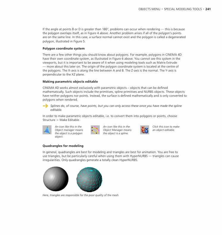
240 • CHAPTER 7 OBJECTS MENU • SPECIAL MODELING TOOLS • 241
If the angle at points B or D is greater than 180°, problems can occur when rendering — this is because the polygon overlaps itself, as in Figure 4 above. Another problem arises if all of the polygon’s points are on the same line. In this case, a surface normal cannot exist and the polygon is called a degenerated polygon, illustrated in Figure 5.
Polygon coordinate system
There are a few other things you should know about polygons. For example, polygons in CINEMA 4D have their own coordinate system, as illustrated in Figure 6 above. You cannot see this system in the viewports, but it is important to be aware of it when using modeling tools such as Matrix Extrude — more about this later on. The origin of the polygon coordinate system is located at the centre of the polygons. The X-axis is along the line between A and B. The Z-axis is the normal. The Y-axis is perpendicular to the XZ plane.
Making parametric objects editable
CINEMA 4D works almost exclusively with parametric objects – objects that can be defined mathematically. Such objects include the primitives, spline primitives and NURBS objects. These objects have neither polygons nor points. Instead, the surface is defined mathematically and is only converted to polygons when rendered.
Splines do, of course, have points, but you can only access these once you have made the spline editable.
In order to make parametric objects editable, i.e. to convert them into polygons or points, choose Structure > Make Editable.
An icon like this in the Object manager means the object is a polygon object.
An icon like this in the Object Manager means the object is a spline.
Click this icon to make an object editable.
Quadrangles for modeling
In general, quadrangles are best for modeling and triangles are best for animation. You are free to use triangles, but be particularly careful when using them with HyperNURBS — triangles can cause irregularities. Only quadrangles generate a totally clean HyperNURBS.
Here, triangles are responsible for the poor quality of the mesh.

242 • CHAPTER 7 OBJECTS MENU • SPECIAL MODELING TOOLS • 243
Array ObjectThe array object is in the Objects > Modeling submenu. It creates copies of an object and arranges them in a spherical form and in a wave form. The wave (amplitude) can be animated. The original object must be a child of the array. The copies are placed around the array object’s origin. The simplest way to understand the Array object is to see it in action. Open the “Array.c4d” scene, which you can find on the CINEMA 4D CD. Play back the animation in the view panel for a demonstration.
Attribute manager settings
Object Properties
Radius
Defines the distance of the objects in the array (in this case, the spheres) from the array object’s origin.
Copies
Defines the number of copies of the original object. Note that the original object remains visible, so the total number of objects in the array equals this value plus one.
Amplitude
The maximum movement in the Y direction.
Frequency
Use this setting to determine the wave velocity.
Array Frequency
The Array Frequency defines the number of waves.
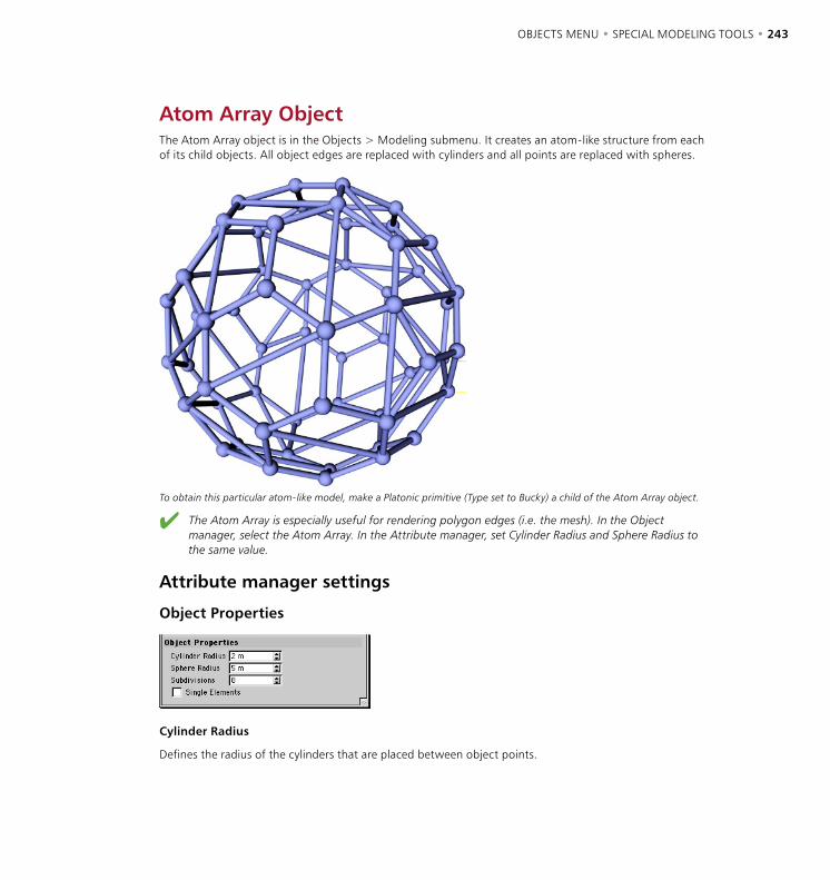
242 • CHAPTER 7 OBJECTS MENU • SPECIAL MODELING TOOLS • 243
Atom Array ObjectThe Atom Array object is in the Objects > Modeling submenu. It creates an atom-like structure from each of its child objects. All object edges are replaced with cylinders and all points are replaced with spheres.
To obtain this particular atom-like model, make a Platonic primitive (Type set to Bucky) a child of the Atom Array object.
The Atom Array is especially useful for rendering polygon edges (i.e. the mesh). In the Object manager, select the Atom Array. In the Attribute manager, set Cylinder Radius and Sphere Radius to the same value.
Attribute manager settings
Object Properties
Cylinder Radius
Defines the radius of the cylinders that are placed between object points.
244 • CHAPTER 7 OBJECTS MENU • SPECIAL MODELING TOOLS • 245
Sphere Radius
Defines the radius of the spheres that are placed at each object point.
Subdivisions
Defines the number of subdivisions for the cylinders and spheres. You may need to increase this value to ensure smooth edges depending on how close the camera is to the atom array.
Single Elements
This option only matters when you make the Atom Array object editable (press the C key or choose Structure > Make Editable). If the option is enabled, each sphere and cylinder becomes a separate parametric object. If the option is disabled, a single editable object is created.
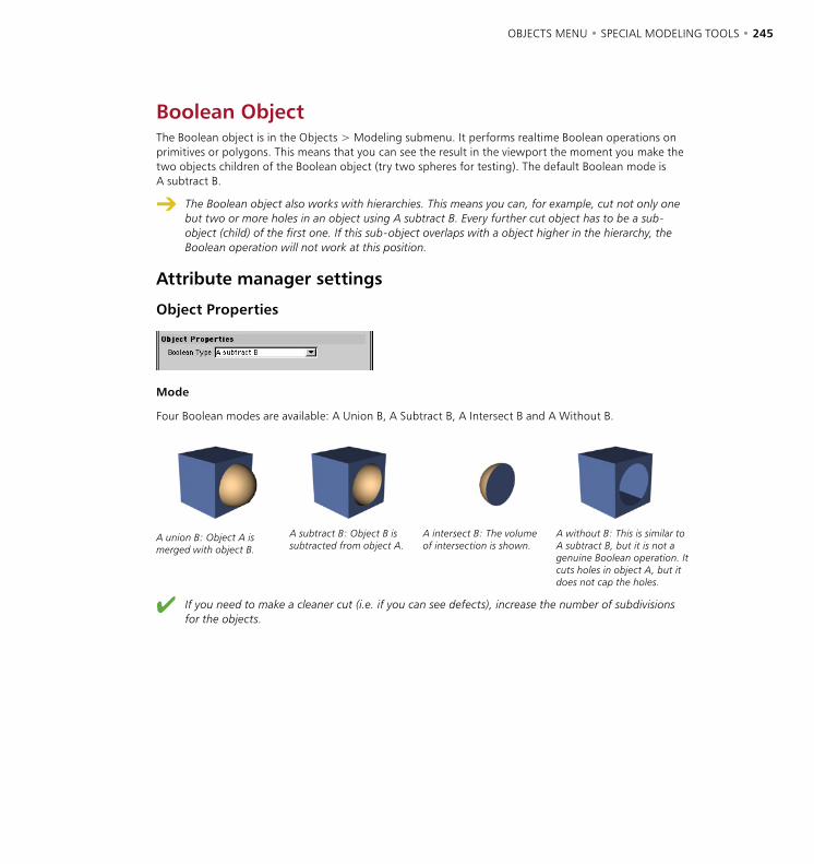
244 • CHAPTER 7 OBJECTS MENU • SPECIAL MODELING TOOLS • 245
Boolean ObjectThe Boolean object is in the Objects > Modeling submenu. It performs realtime Boolean operations on primitives or polygons. This means that you can see the result in the viewport the moment you make the two objects children of the Boolean object (try two spheres for testing). The default Boolean mode is A subtract B.
The Boolean object also works with hierarchies. This means you can, for example, cut not only one but two or more holes in an object using A subtract B. Every further cut object has to be a sub-object (child) of the first one. If this sub-object overlaps with a object higher in the hierarchy, the Boolean operation will not work at this position.
Attribute manager settings
Object Properties
Mode
Four Boolean modes are available: A Union B, A Subtract B, A Intersect B and A Without B.
A union B: Object A is merged with object B.
A subtract B: Object B is subtracted from object A.
A intersect B: The volumeof intersection is shown.
A without B: This is similar to A subtract B, but it is not a genuine Boolean operation. It cuts holes in object A, but it does not cap the holes.
If you need to make a cleaner cut (i.e. if you can see defects), increase the number of subdivisions for the objects.
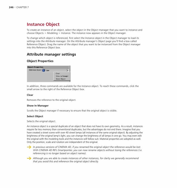
246 • CHAPTER 7 OBJECTS MENU • SPECIAL MODELING TOOLS • 247
Instance ObjectTo create an instance of an object, select the object in the Object manager that you want to instance and choose Objects > Modeling > Instance. The instance now appears in the Object manager.
To change which object is referenced, first select the Instance object in the Object manager to load its settings into the Attribute manager. On the Attribute manager’s Object page you’ll find a box called Reference Object. Drag the name of the object that you want to be instanced from the Object manager into this Reference Object box.
Attribute manager settings
Object Properties
In addition, three commands are available for the Instance object. To reach these commands, click the small arrow to the right of the Reference Object box.
Clear
Removes the reference to the original object.
Show In Manager
Scrolls the Object manager if necessary to ensure that the original object is visible.
Select Object
Selects the original object.
An instance object is a special duplicate of an object that does not have its own geometry. As a result, instances require far less memory than conventional duplicates, but the advantages do not end there. Imagine that you have created a street scene with over 40 street lamps (all instances of the same original object). By adjusting the brightness of the original lamp’s light, you can change the brightness of all lamps in one go. You may even edit the original with the modeling tools and the instances will follow suit. Material properties are adopted as well. Only the position, scale and rotation are independent of the original.
In previous versions of CINEMA 4D, if you renamed the original object the reference would be lost. With CINEMA 4D R8’s Smartpointer, you can now rename objects without losing the references (i.e. referencing is no longer based on object names).
Although you are able to create instances of other instances, for clarity we generally recommend that you avoid this and reference the original object directly.
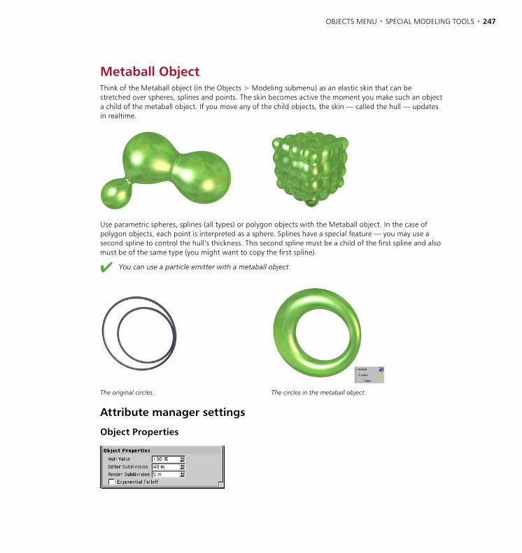
246 • CHAPTER 7 OBJECTS MENU • SPECIAL MODELING TOOLS • 247
Metaball ObjectThink of the Metaball object (in the Objects > Modeling submenu) as an elastic skin that can be stretched over spheres, splines and points. The skin becomes active the moment you make such an object a child of the metaball object. If you move any of the child objects, the skin — called the hull — updates in realtime.
Use parametric spheres, splines (all types) or polygon objects with the Metaball object. In the case of polygon objects, each point is interpreted as a sphere. Splines have a special feature — you may use a second spline to control the hull’s thickness. This second spline must be a child of the first spline and also must be of the same type (you might want to copy the first spline).
You can use a particle emitter with a metaball object.
The original circles. The circles in the metaball object.
Attribute manager settings
Object Properties
248 • CHAPTER 7 OBJECTS MENU • SPECIAL MODELING TOOLS • 249
Hull Value
Defines how tightly the hull is applied. Higher values mean that the hull is wrapped more tightly around the objects.
Editor Subdivision
Defines the number of subdivisions that are displayed in the viewport. The subdivision is specified in distance units. This means that you should lower the value to increase the number of subdivisions and mesh-smoothness. Increasing the value will reduce the number of subdivisions. It makes sense to use a high value here (e.g. 40), otherwise the redraw rate may slow down noticeably.
Render Subdivision
Defines the number of subdivisions that are rendered. The subdivision is specified in distance units. This means that you should lower the value to increase the number of subdivisions and mesh-smoothness. Increasing the value will reduce the number of subdivisions. You should choose a low setting here (e.g. 5), so that the surface is rendered smoothly.
Exponential Falloff
The force of attraction of metaballs to each other is linear by default. You can change this with the Exponential Falloff which, if enabled, has the effect that metaballs will melt together not linearly but somewhat jerkily.
Metaball Tag
You can assign a metaball tag to child objects of the metaball for further control. In the Object manager select the child object that you want to fine-tune and choose File > New Tag > Metaball Tag. The tag is added to the object and the tag’s settings are loaded into the Attribute manager.
Negative Influence
Normally, objects attract the metaball hull and make it expand. However, if you activate this option, the object will repel the hull and cause it to shrink.
Strength
You can use Strength to define how strongly the object affects the hull relative to the other objects.
Radius
This value determines the radius used by the object to affect the hull.
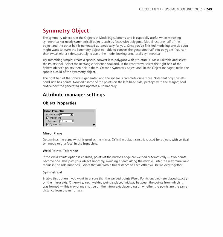
248 • CHAPTER 7 OBJECTS MENU • SPECIAL MODELING TOOLS • 249
Symmetry ObjectThe symmetry object is in the Objects > Modeling submenu and is especially useful when modeling symmetrical (or nearly symmetrical) objects such as faces with polygons. Model just one half of the object and the other half is generated automatically for you. Once you’ve finished modeling one side you might want to make the Symmetry object editable to convert the generated half into polygons. You can then tweak either side separately to avoid the model looking unnaturally symmetrical.
Try something simple: create a sphere, convert it to polygons with Structure > Make Editable and select the Points tool. Select the Rectangle Selection tool and, in the Front view, select the right half of the Sphere object’s points then delete them. Create a Symmetry object and, in the Object manager, make the sphere a child of the Symmetry object.
The right half of the sphere is generated and the sphere is complete once more. Note that only the left-hand side has points. Now edit some of the points on the left-hand side, perhaps with the Magnet tool. Notice how the generated side updates automatically.
Attribute manager settings
Object Properties
Mirror Plane
Determines the plane which is used as the mirror. ZY is the default since it is used for objects with vertical symmetry (e.g. a face) in the front view.
Weld Points, Tolerance
If the Weld Points option is enabled, points at the mirror’s edge are welded automatically — two points become one. This joins your object smoothly, avoiding a seam along the middle. Enter the maximum weld radius in the Tolerance box. Points that are within this distance to each other will be welded together.
Symmetrical
Enable this option if you want to ensure that the welded points (Weld Points enabled) are placed exactly on the mirror axis. Otherwise, each welded point is placed midway between the points from which it was formed — this may or may not be on the mirror axis depending on whether the points are the same distance from the mirror axis.
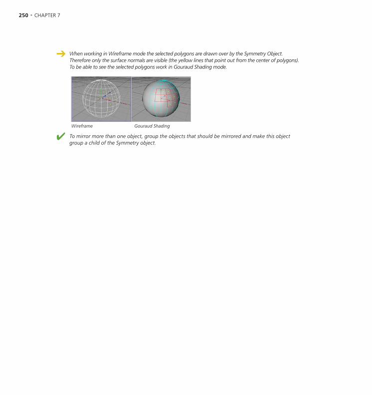
250 • CHAPTER 7 OBJECTS MENU • SPECIAL MODELING TOOLS • 251
When working in Wireframe mode the selected polygons are drawn over by the Symmetry Object. Therefore only the surface normals are visible (the yellow lines that point out from the center of polygons). To be able to see the selected polygons work in Gouraud Shading mode.
Wireframe Gouraud Shading
To mirror more than one object, group the objects that should be mirrored and make this object group a child of the Symmetry object.
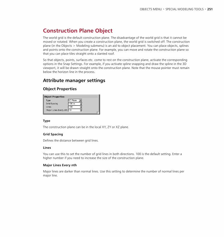
250 • CHAPTER 7 OBJECTS MENU • SPECIAL MODELING TOOLS • 251
Construction Plane ObjectThe world grid is the default construction plane. The disadvantage of the world grid is that it cannot be moved or rotated. When you create a construction plane, the world grid is switched off. The construction plane (in the Objects > Modeling submenu) is an aid to object placement. You can place objects, splines and points onto the construction plane. For example, you can move and rotate the construction plane so that you can place tiles straight onto a slanted roof.
So that objects, points, surfaces etc. come to rest on the construction plane, activate the corresponding options in the Snap Settings. For example, if you activate spline snapping and draw the spline in the 3D viewport, it will be drawn straight onto the construction plane. Note that the mouse pointer must remain below the horizon line in the process.
Attribute manager settings
Object Properties
Type
The construction plane can be in the local XY, ZY or XZ plane.
Grid Spacing
Defines the distance between grid lines.
Lines
You can use this to set the number of grid lines in both directions. 100 is the default setting. Enter a higher number if you need to increase the size of the construction plane.
Major Lines Every nth
Major lines are darker than normal lines. Use this setting to determine the number of normal lines per major line.

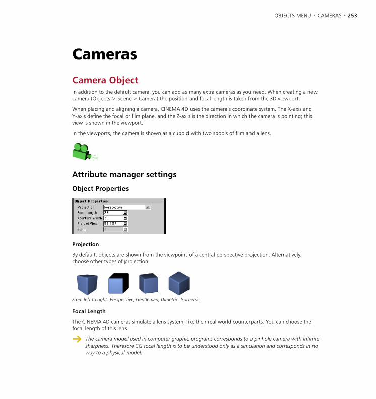
OBJECTS MENU • CAMERAS • 253
Camera ObjectIn addition to the default camera, you can add as many extra cameras as you need. When creating a new camera (Objects > Scene > Camera) the position and focal length is taken from the 3D viewport.
When placing and aligning a camera, CINEMA 4D uses the camera’s coordinate system. The X-axis and Y-axis define the focal or film plane, and the Z-axis is the direction in which the camera is pointing; this view is shown in the viewport.
In the viewports, the camera is shown as a cuboid with two spools of film and a lens.
Attribute manager settings
Object Properties
Projection
By default, objects are shown from the viewpoint of a central perspective projection. Alternatively, choose other types of projection.
From left to right: Perspective, Gentleman, Dimetric, Isometric
Focal Length
The CINEMA 4D cameras simulate a lens system, like their real world counterparts. You can choose the focal length of this lens.
The camera model used in computer graphic programs corresponds to a pinhole camera with infinite sharpness. Therefore CG focal length is to be understood only as a simulation and corresponds in no way to a physical model.
Cameras
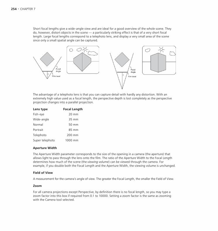
254 • CHAPTER 7 OBJECTS MENU • CAMERAS • 255
Short focal lengths give a wide-angle view and are ideal for a good overview of the whole scene. They do, however, distort objects in the scene — a particularly striking effect is that of a very short focal length. Large focal lengths correspond to a telephoto lens, and display a very small area of the scene since only a small spatial angle can be captured.
The advantage of a telephoto lens is that you can capture detail with hardly any distortion. With an extremely high value used as a focal length, the perspective depth is lost completely as the perspective projection changes into a parallel projection.
Lens type Focal Length
Fish-eye 20 mm
Wide-angle 35 mm
Normal 50 mm
Portrait 85 mm
Telephoto 200 mm
Super telephoto 1000 mm
Aperture Width
The Aperture Width parameter corresponds to the size of the opening in a camera (the aperture) that allows light to pass through the lens onto the film. The ratio of the Aperture Width to the Focal Length determines how much of the scene (the viewing volume) can be viewed through the camera. For example, if you double both the Focal Length and the Aperture Width, the viewing volume is unchanged.
Field of View
A measurement for the camera’s angle of view. The greater the Focal Length, the smaller the Field of View.
Zoom
For all camera projections except Perspective, by definition there is no focal length, so you may type a zoom factor into this box if required from 0.1 to 10000. Setting a zoom factor is the same as zooming with the Camera tool selected.
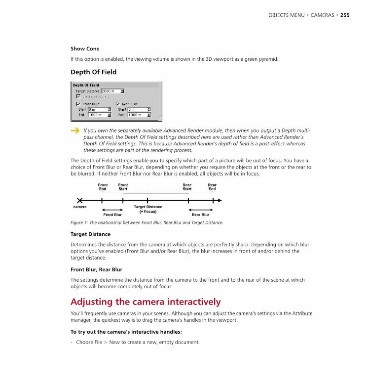
254 • CHAPTER 7 OBJECTS MENU • CAMERAS • 255
Show Cone
If this option is enabled, the viewing volume is shown in the 3D viewport as a green pyramid.
Depth Of Field
If you own the separately available Advanced Render module, then when you output a Depth multi-pass channel, the Depth Of Field settings described here are used rather than Advanced Render’s Depth Of Field settings. This is because Advanced Render’s depth of field is a post-effect whereas these settings are part of the rendering process.
The Depth of Field settings enable you to specify which part of a picture will be out of focus. You have a choice of Front Blur or Rear Blur, depending on whether you require the objects at the front or the rear to be blurred. If neither Front Blur nor Rear Blur is enabled, all objects will be in focus.
Figure 1: The relationship between Front Blur, Rear Blur and Target Distance.
Target Distance
Determines the distance from the camera at which objects are perfectly sharp. Depending on which blur options you’ve enabled (Front Blur and/or Rear Blur), the blur increases in front of and/or behind the target distance.
Front Blur, Rear Blur
The settings determine the distance from the camera to the front and to the rear of the scene at which objects will become completely out of focus.
Adjusting the camera interactivelyYou’ll frequently use cameras in your scenes. Although you can adjust the camera’s settings via the Attribute manager, the quickest way is to drag the camera’s handles in the viewport.
To try out the camera’s interactive handles:
- Choose File > New to create a new, empty document.

256 • CHAPTER 7 OBJECTS MENU • CAMERAS • 257
- Choose Objects > Scene > Camera to create a Camera object. On the Attribute manager’s Depth page, enable Front Blur and Rear Blur. Set the End value for Front Blur to 500 and the End value for Rear Blur to 1000.
- Now take a look at the camera object in the 3D viewport.
- In the 3D viewport, choose Edit > Frame Scene. Hold down the 2 key and drag left to zoom out, then hold down the 3 key and drag left or right to rotate the camera until you can see the camera object fully, as illustrated in Figure 1.
Figure 1: Ensure that you can see all of the camera’s planes. The point that we’ve enclosed in a circle is the camera’s Target Distance. Drag this point — called a handle — to rotate the camera and/or change the Target Distance value.
- To rotate the camera about its origin, drag the handle for the Target Distance (the one circled in Figure 1). By dragging this handle you can also adjust the Target Distance value itself.
- On the same plane as the target point there are four further handles, each one midway along a side of the plane. This plane represents the camera’s Focal Length. Drag one of these handles to adjust the Focal Length interactively.
- There are two further, optional, planes that run parallel to the focal length plane, one in front and one at the back. These two planes (or just one of them) are available only if you select a depth of field (Front Blur, Rear Blur). At the center of each plane you will see another orange handle. Use this handle to shift the depth of field plane interactively along the camera’s Z-axis. Again, you can see these realtime adjustments in the viewport.
- You may also adjust the focal range i.e. the area that is shown in focus.
If you Shift-drag the handles, the entire plane, rather than just the focal length, is moved along the camera’s Z-axis. As you see, interactive control of the camera is very easy. As mentioned earlier, you may create as many cameras in CINEMA 4D as you wish.
Keep in mind that it is always the active camera that is used for rendering.
To switch cameras during animation, use a Stage object.
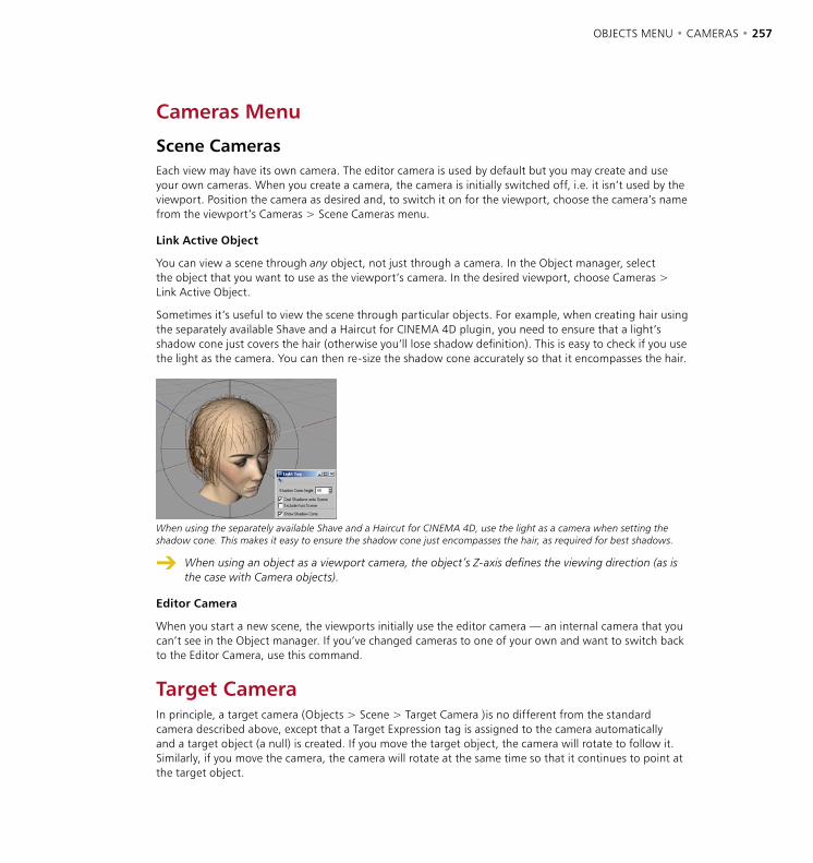
256 • CHAPTER 7 OBJECTS MENU • CAMERAS • 257
Cameras Menu
Scene CamerasEach view may have its own camera. The editor camera is used by default but you may create and use your own cameras. When you create a camera, the camera is initially switched off, i.e. it isn’t used by the viewport. Position the camera as desired and, to switch it on for the viewport, choose the camera’s name from the viewport’s Cameras > Scene Cameras menu.
Link Active Object
You can view a scene through any object, not just through a camera. In the Object manager, select the object that you want to use as the viewport’s camera. In the desired viewport, choose Cameras > Link Active Object.
Sometimes it’s useful to view the scene through particular objects. For example, when creating hair using the separately available Shave and a Haircut for CINEMA 4D plugin, you need to ensure that a light’s shadow cone just covers the hair (otherwise you’ll lose shadow definition). This is easy to check if you use the light as the camera. You can then re-size the shadow cone accurately so that it encompasses the hair.
When using the separately available Shave and a Haircut for CINEMA 4D, use the light as a camera when setting the shadow cone. This makes it easy to ensure the shadow cone just encompasses the hair, as required for best shadows.
When using an object as a viewport camera, the object’s Z-axis defines the viewing direction (as is the case with Camera objects).
Editor Camera
When you start a new scene, the viewports initially use the editor camera — an internal camera that you can’t see in the Object manager. If you’ve changed cameras to one of your own and want to switch back to the Editor Camera, use this command.
Target CameraIn principle, a target camera (Objects > Scene > Target Camera )is no different from the standard camera described above, except that a Target Expression tag is assigned to the camera automatically and a target object (a null) is created. If you move the target object, the camera will rotate to follow it. Similarly, if you move the camera, the camera will rotate at the same time so that it continues to point at the target object.


OBJECTS MENU • LIGHTING • 259
Light ObjectWhen building a new scene in CINEMA 4D a default light is used called the auto light. If you want to change the default lighting setup for all future scenes, build a new scene that contains only the lights that you require for your default lighting and save this scene within the CINEMA 4D folder under the name ‘new.c4d’. This setup will be opened automatically each time you start a new CINEMA 4D scene.
You can also save other CINEMA 4D scene/environment attributes (Sky, Floor, Environment and so on) in the ‘new.c4d’ file.
Keep in mind that CINEMA 4D’s auto light will switch on automatically when you switch off lights during an animation unless you disable Auto Light in the render settings (Options page).
Creating a light
To create a light, choose the desired light from the Objects > Scene menu or click the light icon in the top toolbar.
Displaying lights in a viewport
The lighting within a scene can be easily previewed by turning on the Gouraud shading option. This option will update your lighting in realtime, even adjusting the lighting and updating your scene as you move the lights around.
To change the name of a light, double-click the light’s name in the Object manager and enter the new name into the dialog that opens.
Lighting
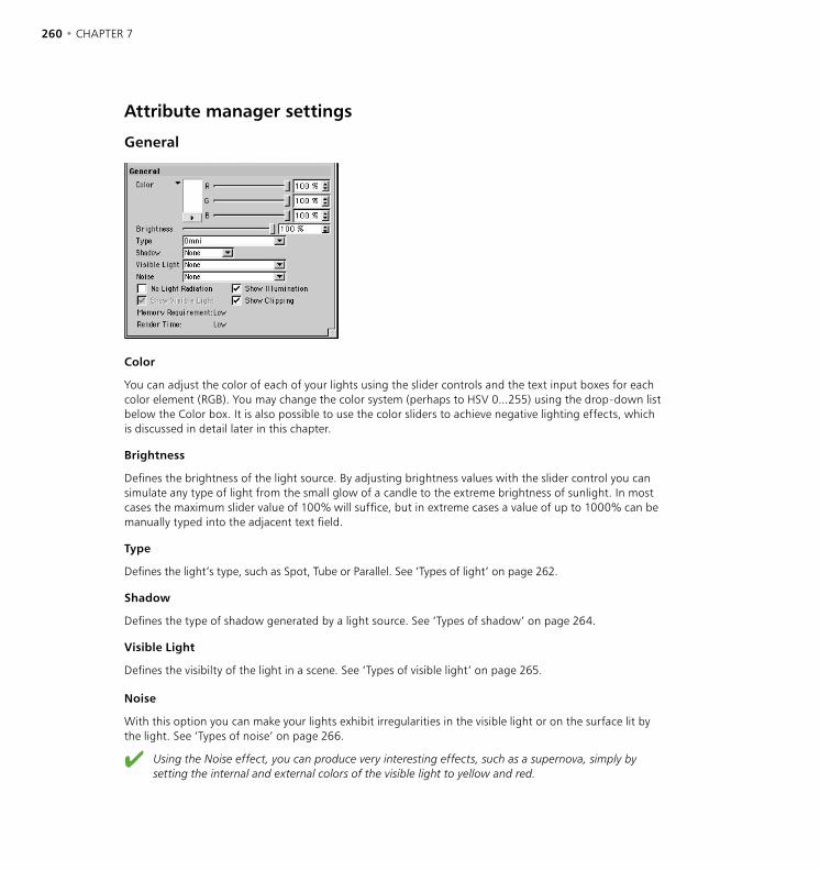
260 • CHAPTER 7 OBJECTS MENU • LIGHTING • 261
Attribute manager settings
General
Color
You can adjust the color of each of your lights using the slider controls and the text input boxes for each color element (RGB). You may change the color system (perhaps to HSV 0...255) using the drop-down list below the Color box. It is also possible to use the color sliders to achieve negative lighting effects, which is discussed in detail later in this chapter.
Brightness
Defines the brightness of the light source. By adjusting brightness values with the slider control you can simulate any type of light from the small glow of a candle to the extreme brightness of sunlight. In most cases the maximum slider value of 100% will suffice, but in extreme cases a value of up to 1000% can be manually typed into the adjacent text field.
Type
Defines the light’s type, such as Spot, Tube or Parallel. See ‘Types of light’ on page 262.
Shadow
Defines the type of shadow generated by a light source. See ‘Types of shadow’ on page 264.
Visible Light
Defines the visibilty of the light in a scene. See ‘Types of visible light’ on page 265.
Noise
With this option you can make your lights exhibit irregularities in the visible light or on the surface lit by the light. See ‘Types of noise’ on page 266.
Using the Noise effect, you can produce very interesting effects, such as a supernova, simply by setting the internal and external colors of the visible light to yellow and red.

260 • CHAPTER 7 OBJECTS MENU • LIGHTING • 261
No Light Radiation
If you need to see just the visible light and/or its lens effects without the light source actually illuminating objects, enable this option. Should you need your light sources for special effects (such as the exhaust gas of a jet engine) disable this box for faster rendering.
Show Illumination
If this option is enabled, a wireframe approximation of the light’s illumination range is shown in the viewports. This range can then be adjusted by dragging the handles of the wireframe representation.
Show Visible Light
Enable this option to show an approximation of the light’s visible range in the viewports, not to be confused with the illumination range. It may become confusing if both indicators are switched on in the viewport so this option is turned off by default. Again, this range can be interactively adjusted via its handles.
Show Clipping
Enabling this option shows an approximation of the selected light’s clipping range (the restriction of the light range) in the viewports and can also be interactively adjusted with the wireframe’s handles.
Memory Requirement
This indicator shows the amount of memory needed for the selected light sources in your scene. Here is an overview of the memory requirements of light sources:
- Hard shadows and area shadows need memory-intensive raytracing calculations.
- As more objects are added to a reflection/refraction dependent scene, additional memory will be required.
- A soft-shadowed visible light will need a shadow map of at least 250KB X-resolution by 250KB Y-resolution.
- Omni lights require six times as much memory for their shadow maps.
- When used with textured transparencies (light maps), up to 20 times more memory may be needed.
Render Time
This indicator gives an approximate render time for the selected light source. Here is a short overview.
- Soft shadows are calculated far more quickly than hard shadows, hard shadows being much faster to calculate than area shadows.
- Making a light visible in a rendered scene adds a negligible amount to its render time. Using a volumetric light increases render time, sometimes substantially, according to the Sample Distance.
- Noise adds to render time, with hard and soft turbulence requiring more calculations than basic noise, while wavy turbulence roughly doubles rendering time over that of basic noise.
- Using a high sample radius will increase the render time of soft shadows.
- Tube lights and area lights also increase render time, although not to the same extent as the processor-intensive volumetric light.
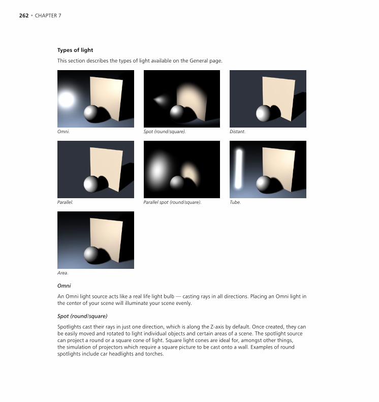
262 • CHAPTER 7 OBJECTS MENU • LIGHTING • 263
Types of light
This section describes the types of light available on the General page.
Omni. Spot (round/square). Distant.
Parallel. Parallel spot (round/square). Tube.
Area.
Omni
An Omni light source acts like a real life light bulb — casting rays in all directions. Placing an Omni light in the center of your scene will illuminate your scene evenly.
Spot (round/square)
Spotlights cast their rays in just one direction, which is along the Z-axis by default. Once created, they can be easily moved and rotated to light individual objects and certain areas of a scene. The spotlight source can project a round or a square cone of light. Square light cones are ideal for, amongst other things, the simulation of projectors which require a square picture to be cast onto a wall. Examples of round spotlights include car headlights and torches.
262 • CHAPTER 7 OBJECTS MENU • LIGHTING • 263
Distant
Owing to its characteristics, the distant light source itself cannot radiate visible light.
The Distant light type is so called because it mimics the light that is cast from an infinite distance. Using a Distant light would, for example, evenly illuminate the whole of a floor (provided the floor is flat). Since a Distant light is infinite, the light has no actual origin. Thus the exact position of a Distant light, near or far, has no effect on your scene’s objects. Only the actual direction in which the light is facing is important with this light source. Distant light sources are very suitable for the simulation of sunlight.
Parallel
Like the Distant light, Parallel lights cannot be rendered as a visible light.
Parallel lights resemble a very distant light source. Unlike the Distant light source however, the Parallel light has an origin and simulates a large, single axis wall of light. By default, all Parallel lights when created will radiate light rays along the Z-axis. These lights take the appearance of an infinitely large surface, radiating parallel light in a single direction; anything behind the point of origin will not be illuminated.
Parallel spot (round/square)
Parallel spotlights resemble the regular spotlight but do not have light cones to define falloff or distance. Instead, light rays are cast along cylinders and/or bars. The origin is important in defining which objects in a scene will be affected by this light. The radius of the spotlight can also be modified using the adjustment handles.
Tube
Tube lights are especially useful when you want objects to show long, drawn-out highlights.
Tube lights do not have a single point of origin, but a linear one. The Tube light is represented by a line, from which light is radiated in all directions. When used as a visible light, this is a very quick and easy way to make neon tubes. A classic example of the use of the Tube light is the laser sword.
Area
As with the Distant and Parallel lights, an Area light cannot be rendered as a visible light source.
The light rays from an Area light expand from its origin outwards in all directions. A rectangular computer screen is a good example of such a light. The resultant lighting and specular effects are somewhat different from those of an Omni light; specular highlights are more angular and the surface illumination is richer. The closer the light source is to the object, the more apparent this becomes.
However, an Area light with a small radius that is placed far away in a scene will hardly seem to differ from an Omni light source.

264 • CHAPTER 7 OBJECTS MENU • LIGHTING • 265
Types of shadow
This section describes the different types of shadow you can select for the Shadow option on the General page. The Shadow page itself is described on page 279.
Soft shadow. Hard shadow. Area shadow.
You can combine all light source types with all shadow types in CINEMA 4D. For example an area light can cast not only area shadows, but hard shadows as well. And a parallel light can easily cast soft shadows. There are no restrictions to this mixing of lights and shadows.
None
Select None if your light is to cast no shadow. This is a very helpful option in a scene with many lights, allowing you to turn on shadow-casting for the main lights only. Any real world photographer will envy you this option and its possibilities.
Soft shadow
In reality all objects — whether they are trees growing in the wild, or a vase in a room — are lit by several partial light sources. The result of this is a gradual transition of light to shadow. This soft edge, or umbra, can be simulated in CINEMA 4D by using a shadow map. A shadow map is a greyscale picture of the scene as viewed from the light source. Contained in this are all the objects lit by the light source.
During the render calculation the renderer will determine exactly which objects will fall into this shadow of the light source. The major advantage of this method is the high computing speed and the soft shadow’s natural appearance. However, the one downside to soft shadows is the memory needed. Depending on the size of the shadow map, a great deal of additional memory may be needed. So be careful in your allocation of shadow maps or you may find your scenes wasting precious memory.
Hard shadow
Traditionally in raytracers, genuinely raytraced scenes contained hard shadows. As this technique needed to compute many more additional rays, this method increases the render time dramatically. Hard shadows, because of their abrupt, sharp appearance, are of particular interest for technical illustrations. However, in other more natural pictures they look rather unrealistic because such hard, sharp shadow borders are rarely found in real world environments.
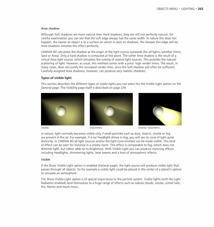
264 • CHAPTER 7 OBJECTS MENU • LIGHTING • 265
Area shadow
Although Soft shadows are more natural than Hard shadows, they are still not perfectly natural. On careful examination you can see that the soft edge always has the same width. In nature this does not happen; the nearer an object is to a surface on which it casts its shadows, the sharper this edge will be. Area shadows simulate this effect perfectly.
CINEMA 4D calculates the shadow at the origin of the light source outwards (for all lights, whether Omni, Spot or Area). Only a hard shadow is computed at this point. The softer Area shadow is the result of a virtual Area light source, which simulates the overlay of several light sources. This provides the natural scattering of light. However, as usual, this method comes with a price: high render times. The result, in many cases, does not justify the increased render time, since the Soft shadow will often be sufficient. Carefully assigned Area shadows, however, can produce very realistic shadows.
Types of visible light
This section describes the different types of visible lights you can select for the Visible Light option on the General page. The Visibility page itself is described on page 274.
Visible. Volumetric. Inverse Volumetric.
In nature, light normally becomes visible only if small particles such as dust, insects, smoke or fog are present in the air. For example, if a car headlight shines in fog, you will see its cone of light quite distinctly. In CINEMA 4D all light sources and/or the light cone emitted can be made visible. This kind of effect can be seen for instance in a smoky room. This effect is comparable to fog, which does not diminish light, but rather adds to its brightness. With Visible Light you can produce stunning effects including headlights, shimmering lights, laser beams and a host of atmospheric effects.
Visible
If the Show Visible Light option is enabled (General page), the light source will produce visible light that passes through all objects. So for example a visible light could be placed in the center of a planet’s sphere to simulate an atmosphere.
The Show Visible Light option is of special importance to the particle system. Visible lights (with No Light Radiation enabled) lend themselves to a huge range of effects such as nebula clouds, smoke, comet tails, fire, flames and much more..
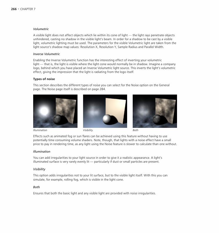
266 • CHAPTER 7 OBJECTS MENU • LIGHTING • 267
Volumetric
A visible light does not affect objects which lie within its cone of light — the light rays penetrate objects unhindered, casting no shadow in the visible light’s beam. In order for a shadow to be cast by a visible light, volumetric lighting must be used. The parameters for the visible Volumetric light are taken from the light source’s shadow map values: Resolution X, Resolution Y, Sample Radius and Parallel Width.
Inverse Volumetric
Enabling the Inverse Volumetric function has the interesting effect of inverting your volumetric light — that is, the light is visible where the light cone would normally be in shadow. Imagine a company logo, behind which you have placed an Inverse Volumetric light source. This inverts the light’s volumetric effect, giving the impression that the light is radiating from the logo itself.
Types of noise
This section describes the different types of noise you can select for the Noise option on the General page. The Noise page itself is described on page 284.
Illumination Visibility Both
Effects such as animated fog or sun flares can be achieved using this feature without having to use potentially time consuming volume shaders. Note, though, that lights with a noise effect have a small price to pay in rendering time, as any light using the Noise feature is slower to calculate than one without.
Illumination
You can add irregularities to your light source in order to give it a realistic appearance. A light’s illuminated surface is very rarely evenly lit — particularly if dust or small particles are present.
Visibility
This option adds irregularities not to your lit surface, but to the visible light itself. With this you can simulate, for example, rolling fog, which is visible in the light cone.
Both
Ensures that both the basic light and any visible light are provided with noise irregularities.
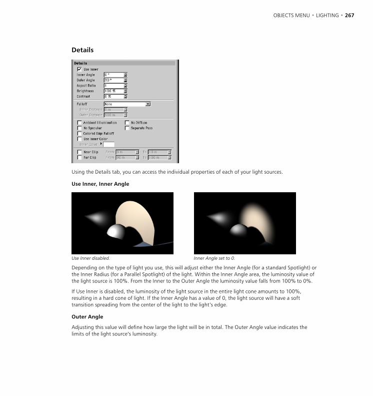
266 • CHAPTER 7 OBJECTS MENU • LIGHTING • 267
Details
Using the Details tab, you can access the individual properties of each of your light sources.
Use Inner, Inner Angle
Use Inner disabled. Inner Angle set to 0.
Depending on the type of light you use, this will adjust either the Inner Angle (for a standard Spotlight) or the Inner Radius (for a Parallel Spotlight) of the light. Within the Inner Angle area, the luminosity value of the light source is 100%. From the Inner to the Outer Angle the luminosity value falls from 100% to 0%.
If Use Inner is disabled, the luminosity of the light source in the entire light cone amounts to 100%, resulting in a hard cone of light. If the Inner Angle has a value of 0, the light source will have a soft transition spreading from the center of the light to the light’s edge.
Outer Angle
Adjusting this value will define how large the light will be in total. The Outer Angle value indicates the limits of the light source’s luminosity.
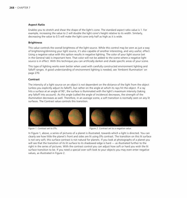
268 • CHAPTER 7 OBJECTS MENU • LIGHTING • 269
Aspect Ratio
Enables you to stretch and shear the shape of the light’s cone. The standard aspect ratio value is 1. For example, increasing the value to 2 will double the light cone’s height relative to its width. Similarly, decreasing the value to 0.5 will make the light cone only half as high as it is wide.
Brightness
This value controls the overall brightness of the light source. While this control may be seen as just a way of brightening/dimming your light source, it’s also capable of another interesting, and very useful, effect. Using a negative value with this option results in negative lighting. The color of your light source (set in the General tab) is important here. That color will not be added to the scene where a negative light source is in effect. With this technique you can artificially darken and shade specific areas of your scene.
This type of lighting works even better when used with carefully constructed environment lighting and falloff ranges. A good understanding of environment lighting is needed, see ‘Ambient Illumination’ on page 270.
Contrast
The intensity of a light source on an object is not dependent on the distance of the light from the object (unless you explicitly adjust its falloff), but rather on the angle at which its rays hit the object. If a ray hits a surface at an angle of 90°, the surface is illuminated with the light’s maximum intensity (taking any falloff into account). As this angle (called the angle of incidence) decreases, the strength of the illumination decreases as well. Therefore, in an average scene, a soft transition is normally seen on any lit surfaces. The Contrast value controls this transition.
Figure 1. Contrast set to 0%. Figure 2. Contrast set to a negative value.
In Figure 1, above, a series of pictures of a planet is illustrated, towards which a light is directed. You can clearly see how little the planet’s front and sides are lit using 0% contrast. The transition on this lit surface is not very soft; this surface contrast is not natural for planets. If you look at photographs of a planet you will see that the transition of its lit surface to its shadowed edge is hard — as illustrated further to the right in the series of pictures. With the contrast control you can adjust how soft or hard you wish the lit surface transition to be. If you need a special over-soft look to your objects you may even enter negative values, as illustrated in Figure 2.

268 • CHAPTER 7 OBJECTS MENU • LIGHTING • 269
Falloff
A normal virtual light source will illuminate its surrounding environment with a continuous, linear brightness. However, this is not how all lights work in reality; real light sources will have their luminosity absorbed. Just as in nature, CINEMA 4D light sources are able to have their luminosity reduced over any distance. To achieve this, several falloff functions are available from this drop-down list and are illustrated below.
Inner Distance
Within the Inner Distance there is no falloff. Up to this point, the brightness of the light remains constant. Outside of this boundary is where the Inner Distance Falloff begins.
Outer Distance
The range between the Inner Distance and the Outer Distance is where the brightness of the source light changes from 100% to 0%. This Outer Distance value indicates the maximum range that will be illuminated by the source light.
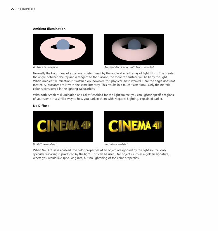
270 • CHAPTER 7 OBJECTS MENU • LIGHTING • 271
Ambient Illumination
Ambient illumination. Ambient illumination with Falloff enabled.
Normally the brightness of a surface is determined by the angle at which a ray of light hits it. The greater the angle between the ray and a tangent to the surface, the more the surface will be lit by the light. When Ambient Illumination is switched on, however, this physical law is waived. Here the angle does not matter. All surfaces are lit with the same intensity. This results in a much flatter look. Only the material color is considered in the lighting calculations.
With both Ambient Illumination and Falloff enabled for the light source, you can lighten specific regions of your scene in a similar way to how you darken them with Negative Lighting, explained earlier.
No Diffuse
No Diffuse disabled. No Diffuse enabled.
When No Diffuse is enabled, the color properties of an object are ignored by the light source; only specular surfacing is produced by the light. This can be useful for objects such as a golden signature, where you would like specular glints, but no lightening of the color properties.

270 • CHAPTER 7 OBJECTS MENU • LIGHTING • 271
No Specular
This bottle is lit by two light sources, causing more highlights to develop than you’d normally want.
No Specular option is enabled for one light source only. Now the highlights are fine.
When this option is enabled, the light source produces no specular highlights on your scene’s objects. Imagine you have a bottle on a table with two or more light sources in the scene. The bottle may show too many specular highlights, with the glass material looking too busy. To avoid this, enable No Specular for some of the light sources.
Separate Pass
If you enable this option, separate diffuse, specular and shadow layers will be created for the light source when you render (provided you have set the appropriate multi-pass parameters – see ‘Separate Lights, Mode’ on page 570).
Colored Edge Falloff
Colored Edge Falloff disabled. Colored Edge Falloff enabled.
This option is only available when using a spotlight with Use Inner Color enabled. The normal behaviour of the inner color is to spread in a linear direction along only the Z-axis of the spotlight, from its origin to the light source’s color (selected on the General page). If you select Colored Edge Falloff, however, the Inner Color will also radiate outwards from the Inner Angle through to the light source’s general color.
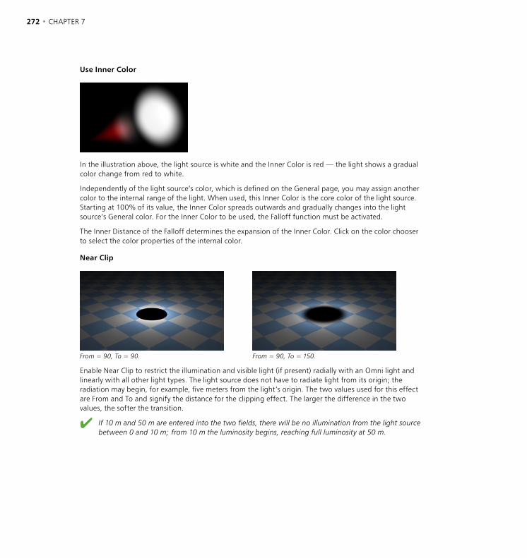
272 • CHAPTER 7 OBJECTS MENU • LIGHTING • 273
Use Inner Color
In the illustration above, the light source is white and the Inner Color is red — the light shows a gradual color change from red to white.
Independently of the light source’s color, which is defined on the General page, you may assign another color to the internal range of the light. When used, this Inner Color is the core color of the light source. Starting at 100% of its value, the Inner Color spreads outwards and gradually changes into the light source’s General color. For the Inner Color to be used, the Falloff function must be activated.
The Inner Distance of the Falloff determines the expansion of the Inner Color. Click on the color chooser to select the color properties of the internal color.
Near Clip
From = 90, To = 90. From = 90, To = 150.
Enable Near Clip to restrict the illumination and visible light (if present) radially with an Omni light and linearly with all other light types. The light source does not have to radiate light from its origin; the radiation may begin, for example, five meters from the light’s origin. The two values used for this effect are From and To and signify the distance for the clipping effect. The larger the difference in the two values, the softer the transition.
If 10 m and 50 m are entered into the two fields, there will be no illumination from the light source between 0 and 10 m; from 10 m the luminosity begins, reaching full luminosity at 50 m.
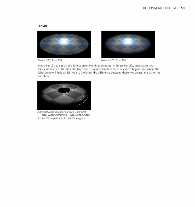
272 • CHAPTER 7 OBJECTS MENU • LIGHTING • 273
Far Clip
From = 300, To = 300. From = 220, To = 300.
Enable Far Clip to cut off the light source’s illumination abruptly. To use Far Clip, once again two values are needed. This time the From and To values denote where the cut off begins, and where the light source will fully vanish. Again, the larger the difference between these two values, the softer the transition.
Individual clipping ranges using an Omni light. 1 = Near Clipping (from); 2 = Near Clipping (to); 3 = Far Clipping (from); 4 = Far Clipping (to).

274 • CHAPTER 7 OBJECTS MENU • LIGHTING • 275
Visibility
Use Falloff, Falloff
100% Falloff. 0% Falloff.
Falloff is the percentage reduction in the light’s density. The axial falloff of the visible light is set to a standard 100%. This means that from the origin of the light to its outer distance, the density of the visible light falls from 100% to 0%. So, if a value of 10% is entered into the Falloff box, the outside edge will be at 90% visibility. Enable or disable the Use Falloff option to switch falloff on or off.
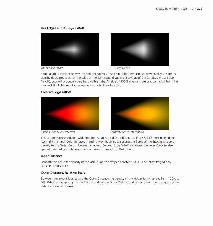
274 • CHAPTER 7 OBJECTS MENU • LIGHTING • 275
Use Edge Falloff, Edge Falloff
100 % Edge Falloff. 0 % Edge Falloff.
Edge falloff is relevant only with Spotlight sources. The Edge Falloff determines how quickly the light’s density decreases towards the edge of the light cone. If you enter a value of 0% (or disable Use Edge Falloff), you will produce a very hard visible light. A value of 100% gives a more gradual falloff from the inside of the light cone to its outer edge, until it reaches 0%.
Colored Edge Falloff
Colored Edge Falloff disabled. Colored Edge Falloff enabled.
This option is only available with Spotlight sources, and in addition, Use Edge Falloff must be enabled. Normally the Inner Color behaves in such a way that it travels along the Z-axis of the Spotlight source linearly to the Outer Color. However, enabling Colored Edge Falloff will cause the Inner Color to also spread outwards radially from the Inner Angle to meet the Outer Color.
Inner Distance
Beneath this value the density of the visible light is always a constant 100%. The falloff begins only outside this distance.
Outer Distance, Relative Scale
Between the Inner Distance and the Outer Distance the density of the visible light changes from 100% to 0%. When using spotlights, modify the scale of the Outer Distance value along each axis using the three Relative Scale text boxes.

276 • CHAPTER 7 OBJECTS MENU • LIGHTING • 277
Sample Distance
The Sample Distance is only relevant for visible volumetric lights. Adjusting this value defines how finely the visible light’s volumetric shadow will be computed. Larger values lead to a somewhat rough (but swift) calculation, while smaller values lead to a much finer, but more time-consuming, result.
Take care with your Sample Distance values. Finding a happy medium (small for fine detail, but as large as possible for reducing render time) is the key here.
The value of this Sample Distance is measured in world units. This value thus determines how finely the shadows within a visible light will be sampled. Values will usually be from 1/10th to 1/1000th of the light source radius. By increasing the value your scene will render noticeably faster but certain parts of your scene will be sampled very roughly, resulting in sampling artefacts. To reduce these sampling artefacts requires a reduction in your sampling value too. The smaller the value, however, the higher the cost in rendering time.
CINEMA 4D contains an integrated antialiasing technique for surface shine, ensuring even the roughest surfaces render smoothly, allowing you to set the Sample Distance value somewhat higher than without this feature.
Sample Distance tips
If you wish to produce fine shafts of light, like those produced when light beams radiate through cracks or from behind stone columns, you need to set your sample distance relatively small. On the other hand, a light that is completely covered and allows no beams of light to break through may be sampled at a much higher value. To clarify this, here’s a small example; the pumpkin in the pictures below has a radius of 150 units, the visible volumetric light a radius (Outer Distance) of 700 units.
Sample Distance: 10. Render time: 105 s. The pumpkin looks perfect.
Sample Distance: 20. Render time: 60 s. Here the rays emitting from the mouth and the right eye are showing the first signs of artifacts.
Sample Distance: 40. Render time: 35 s. You can clearly see now how the rays in the visible light are losing their fine edges.
Sample Distance: 80. Render time: 23 s. The picture has, quite literally, been rendered useless.
So why is volumetric lighting so time-consuming for the renderer?
When a beam hits a light cone, it is not only the intensity of the light that needs to be computed. Additionally, for each part of the beam, CINEMA 4D needs to look for other objects within the light cone that might be casting shadows. So for every part of the beam of light, an extra raytracer ray needs to be initiated and emitted. But as it is not possible to shrink segments in the fog below a certain length, an approximation has to be used; the length of the light cone is subdivided into equal parts.

276 • CHAPTER 7 OBJECTS MENU • LIGHTING • 277
Let’s say the raytracer ray hits the light cone and the distance between the entry and the exit points of the light cone is 1,000 units. So a sample distance of 50 units will mean that an intensity value and a shadow beam will have to be calculated 20 times (1,000 divided by 50).
The shorter the sample distance, the longer the calculation is going to take. Even if you have only five subdivisions (so a sample distance of 200 in the above example) this will require a five-fold increase per raytracer ray and per contact with the light cone than without volumetric lighting. Using progressively finer subdivisions, the processing time involved will very quickly become astronomical.
Alas, this is an inherent problem with computer graphics which cannot be resolved or accelerated other than by throwing processor power at it.
Volumetric lighting needs a lot of calculation time, therefore render such light sources only when it is absolutely necessary. If you use a volumetric light as a particle (which is perfectly possible), then perhaps you should consider buying a second computer which you can leave to render that scene over a period of days.
So why can’t you input a fixed value for the number of samples?
Well, if the raytracer beam hits the light cone at its beginning, the distance between the entry and exit points might be, for example, 100 units. But if the beam hits the cone further from the light source, this distance might grow to 5,000 units or more. So if you used a fixed number of samples, at the narrow end of the cone a lot of unnecessary calculations would be made and later too few (which would result in ugly artefacts).
Brightness
This value is the brightness of the visible light source.
Dust
Determines the darkness of the light cone. With a Dust value of more than 0% Brightness is not added, but subtracted. To ensure you see the full effect of this, lower the light’s brightness accordingly. The difference between a normal bright light and a dust-assigned light can be seen clearly in the following illustration. To the left is a bright, visible light. To the right a dark, dusty, somewhat sooty light.
In principle, you can use an accumulation of dust in conjunction with particles for convincing simulation of fire and smoke.

278 • CHAPTER 7 OBJECTS MENU • LIGHTING • 279
Dithering
This produces irregularities in the visible light which, in certain cases, can help prevent unwanted banding or contouring in the visible light source.
With certain light source combinations, such as visible lights that overlap, you may find that the 24-bit picture depth of your output device is insufficient and it may display color gradients in large steps. This display problem is known as ‘contouring’. To avoid this problem use the Dithering option to give your visible light a certain irregularity and help to smooth the color graduations.
Custom Colors
With this option you can assign your own colors to the visible light — independently of the actual color of the light source (General page) and the inner color (Details page).
Outer Color, Inner Color
Use the color selector to define colors for the light’s outer edge and inner edge.
Additive
This setting exists primarily for compatibility with CINEMA 4D R5, in which light sources were additive. Your light beam will look more realistic if this option is left disabled.
Additive enabled. Additive disabled.
Enable this option if you want to mix the light beam additively with other light sources.
Adapt Brightness
Adapt Brightness enabled. Adapt Brightness disabled.
This option prevents a light beam from being over-exposed. The brightness is reduced until the over-exposed effect disappears.
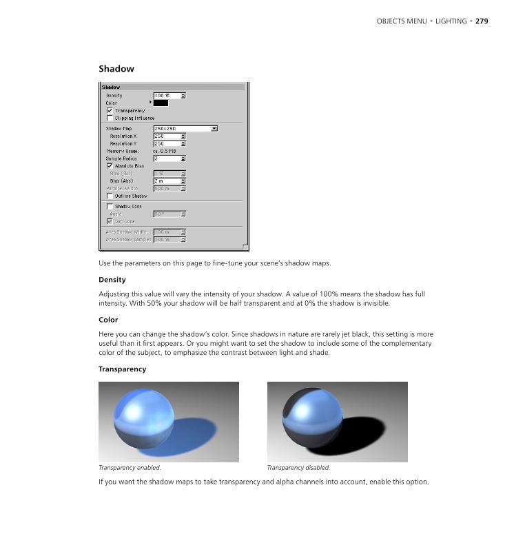
278 • CHAPTER 7 OBJECTS MENU • LIGHTING • 279
Shadow
Use the parameters on this page to fine-tune your scene’s shadow maps.
Density
Adjusting this value will vary the intensity of your shadow. A value of 100% means the shadow has full intensity. With 50% your shadow will be half transparent and at 0% the shadow is invisible.
Color
Here you can change the shadow’s color. Since shadows in nature are rarely jet black, this setting is more useful than it first appears. Or you might want to set the shadow to include some of the complementary color of the subject, to emphasize the contrast between light and shade.
Transparency
Transparency enabled. Transparency disabled.
If you want the shadow maps to take transparency and alpha channels into account, enable this option.
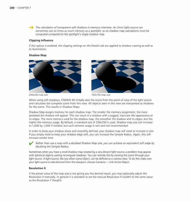
280 • CHAPTER 7 OBJECTS MENU • LIGHTING • 281
The calculation of transparent soft shadows is memory-intensive. An Omni light source can sometimes use six times as much memory as a spotlight, as six shadow map calculations must be computed compared to the spotlight’s single shadow map.
Clipping Influence
If this option is enabled, the clipping settings on the Details tab are applied to shadow-casting as well as to illumination.
Shadow Map
250x250 map size. 750x750 map size.
When using soft shadows, CINEMA 4D initially sees the scene from the point of view of the light source and calculates the complete scene from this view. All objects seen in this view are interpreted as shadows for the scene. This results in Shadow Maps.
Shadow Map assigns memory for each shadow map. The smaller the memory assignment, the more pixelated the shadow will appear. This can result in a shadow with a jagged, staircase-like appearance at its edges. The more memory used for the shadow map, the smoother the shadow and its edges, but the higher the memory usage. By default, a standard size of 250x250 is used. Shadow map size can increase to 1,000 by 1,000 if needed, but such extreme usage is rare and not recommended.
In order to keep your shadow sharp and smoothly defined, your shadow map will need to increase in size. If you simply need to keep your shadow edge soft, you can increase the Sample Radius. Again, this will increase render time.
Rather than use a map with a doubled Shadow Map size, you can achieve an equivalent soft edge by doubling the Sample Radius.
Sometimes when you have a small shadow map created by a very distant light source, a problem may appear with spherical objects casting rectangular shadows. You can remedy this by viewing the scene through your light source. A light source, like any other scene object, can be defined as a camera view. To do this make sure your light source is selected and from the viewport, choose Cameras > Link Active Object.
Resolution X
If the preset value of the map size is not giving you the desired result, you may optionally adjust the Resolution X manually. In general it is standard to set the manual Resolution X (width) to the same value as the Resolution Y (height)
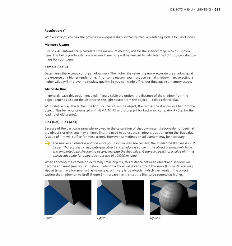
280 • CHAPTER 7 OBJECTS MENU • LIGHTING • 281
Resolution Y
With a spotlight, you can also provide a non-square shadow map by manually entering a value for Resolution Y.
Memory Usage
CINEMA 4D automatically calculates the maximum memory use for the shadow map, which is shown here. This helps you to estimate how much memory will be needed to calculate the light source’s shadow maps for your scene.
Sample Radius
Determines the accuracy of the shadow map. The higher the value, the more accurate the shadow is, at the expense of a higher render time. If, for some reason, you must use a small shadow map, selecting a higher value will improve the shadow quality. So you can trade off render time against memory usage.
Absolute Bias
In general, leave this option enabled. If you disable the option, the distance of the shadow from the object depends also on the distance of the light source from the object — called relative bias.
With relative bias, the farther the light source is from the object, the farther the shadow will be from the object. This behavior originated in CINEMA 4D R5 and is present for backward compatibility (i.e. for the loading of old scenes).
Bias (Rel), Bias (Abs)
Because of the particular principle involved in the calculation of shadow maps (shadows do not begin at the object’s origin), you may at times find the need to adjust the shadow’s position using the Bias value. A value of 1 m will suffice for most scenes. However, sometimes an adjustment may be necessary.
The smaller an object is and the more you zoom in with the camera, the smaller the Bias value must be set. This ensures no gap between object and shadow is visible. If the object is excessively large and unwanted self-shadowing occurs, increase the Bias value. Generally speaking, a value of 1 m is usually adequate for objects up to a size of 10,000 m wide.
When zooming the camera on extremely small objects, this distance between object and shadow will become apparent (see Figure1, below). Entering a lower value can correct this error (Figure 2). You may also at times have too small a Bias value (e.g. with very large objects), which can result in the object casting the shadow on to itself (Figure 3). In a case like this, set the Bias value somewhat higher.
Figure 1. Figure 2. Figure 3.
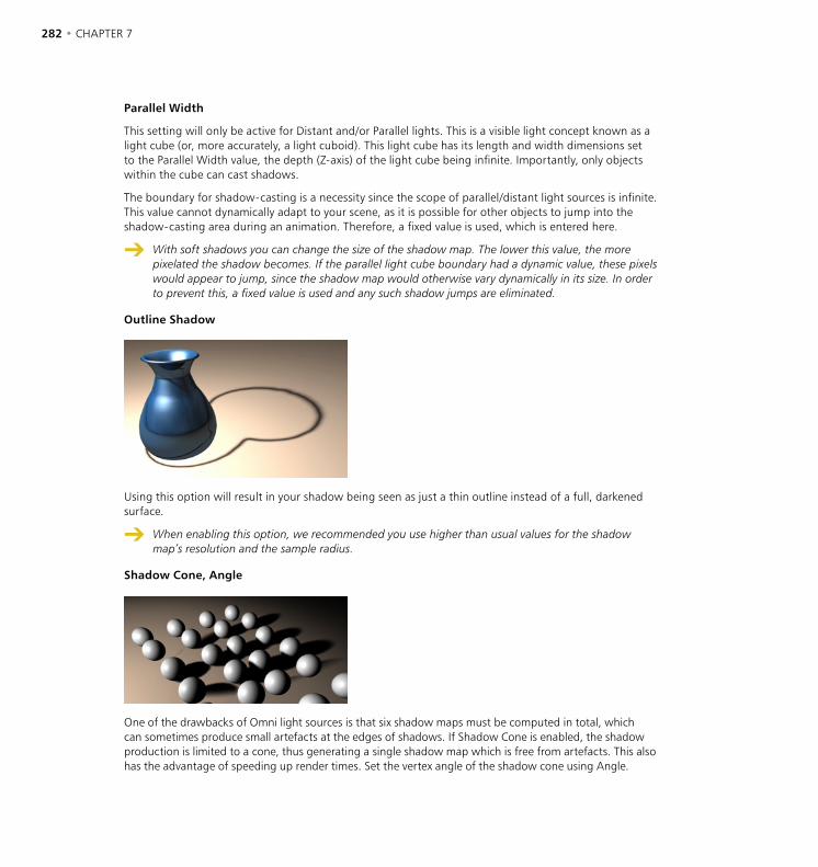
282 • CHAPTER 7 OBJECTS MENU • LIGHTING • 283
Parallel Width
This setting will only be active for Distant and/or Parallel lights. This is a visible light concept known as a light cube (or, more accurately, a light cuboid). This light cube has its length and width dimensions set to the Parallel Width value, the depth (Z-axis) of the light cube being infinite. Importantly, only objects within the cube can cast shadows.
The boundary for shadow-casting is a necessity since the scope of parallel/distant light sources is infinite. This value cannot dynamically adapt to your scene, as it is possible for other objects to jump into the shadow-casting area during an animation. Therefore, a fixed value is used, which is entered here.
With soft shadows you can change the size of the shadow map. The lower this value, the more pixelated the shadow becomes. If the parallel light cube boundary had a dynamic value, these pixels would appear to jump, since the shadow map would otherwise vary dynamically in its size. In order to prevent this, a fixed value is used and any such shadow jumps are eliminated.
Outline Shadow
Using this option will result in your shadow being seen as just a thin outline instead of a full, darkened surface.
When enabling this option, we recommended you use higher than usual values for the shadow map’s resolution and the sample radius.
Shadow Cone, Angle
One of the drawbacks of Omni light sources is that six shadow maps must be computed in total, which can sometimes produce small artefacts at the edges of shadows. If Shadow Cone is enabled, the shadow production is limited to a cone, thus generating a single shadow map which is free from artefacts. This also has the advantage of speeding up render times. Set the vertex angle of the shadow cone using Angle.
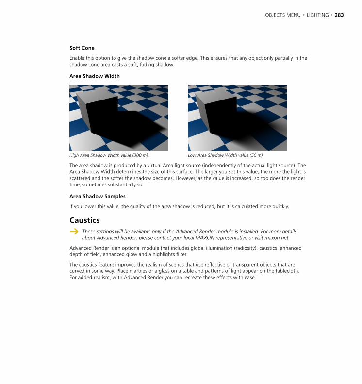
282 • CHAPTER 7 OBJECTS MENU • LIGHTING • 283
Soft Cone
Enable this option to give the shadow cone a softer edge. This ensures that any object only partially in the shadow cone area casts a soft, fading shadow.
Area Shadow Width
High Area Shadow Width value (300 m). Low Area Shadow Width value (50 m).
The area shadow is produced by a virtual Area light source (independently of the actual light source). The Area Shadow Width determines the size of this surface. The larger you set this value, the more the light is scattered and the softer the shadow becomes. However, as the value is increased, so too does the render time, sometimes substantially so.
Area Shadow Samples
If you lower this value, the quality of the area shadow is reduced, but it is calculated more quickly.
Caustics
These settings will be available only if the Advanced Render module is installed. For more details about Advanced Render, please contact your local MAXON representative or visit maxon.net.
Advanced Render is an optional module that includes global illumination (radiosity), caustics, enhanced depth of field, enhanced glow and a highlights filter.
The caustics feature improves the realism of scenes that use reflective or transparent objects that are curved in some way. Place marbles or a glass on a table and patterns of light appear on the tablecloth. For added realism, with Advanced Render you can recreate these effects with ease.

284 • CHAPTER 7 OBJECTS MENU • LIGHTING • 285
Noise
Type
Noise produces dark and bright areas. Chose from four types, including three types of turbulence that change the characteristics of the noise by adding cloud-like effects.
Noise. Soft Turbulence.
Hard Turbulence. Wavy Turbulence.
Octaves
Only relevant for the Turbulence types above. The Octaves value determines the graininess of the noise. The higher the value, the grittier the appearance.
284 • CHAPTER 7 OBJECTS MENU • LIGHTING • 285
Velocity
Sets the speed of the irregularities.
Brightness
Using this you can raise the overall brightness of the irregularities. You may also enter a negative percentage to reduce the brightness.
Contrast
Higher values increase the contrast of the noise, lower values reduce it.
Local
Enabling this option ensures that the local coordinates of the light source are nailed down. If the light source is moved now, the turbulence/noise will move also. For normal use, leave this option disabled, since dust and particles in the real world move due to the forces of nature, not simply because the light itself moves.
Visbibility Scale
These values determine the size of the irregularities in the X, Y and Z directions in relation to the scene’s absolute Cartesian coordinates. If the noise effect is too severe, try reducing these values.
Illumination Scale
The general intensity of the noise.
Wind, Wind Velocity
Here you define the wind properties for the noise, This will add realism to your animation since wind will appear to blow the dust. The three Wind values define the vectors of the wind direction in absolute Cartesian coordinates (and/or local coordinates if the Local option is enabled). Use the Wind Velocity value to change the wind’s strength.
Lens Effects
Owing to the way QuickTime VR panoramas are calculated, lens effects cannot be displayed in them.
CINEMA 4D is a powerful tool when it comes to producing the aberrations of real-world camera lens systems and film material. Basic sunbeams are brought to life with a solar corona or a halo. A lens reflection of a low-quality camera lens can be easily simulated, as rainbow colored circles develop and run diagonally across the screen. A welcome flaw in an otherwise too perfect virtual world.
Why not build a library of lens effects? You can produce many types of light sources with different effects that can then be saved as individual objects in the Object manager. When you require one of these specific lights for your scene simply load it from your light source library.
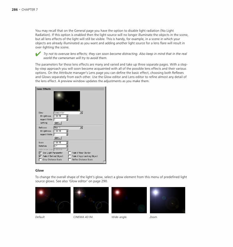
286 • CHAPTER 7 OBJECTS MENU • LIGHTING • 287
You may recall that on the General page you have the option to disable light radiation (No Light Radiation). If this option is enabled then the light source will no longer illuminate the objects in the scene, but all lens effects of the light will still be visible. This is handy, for example, in a scene in which your objects are already illuminated as you want and adding another light source for a lens flare will result in over-lighting the scene.
Try not to overuse lens effects; they can soon become distracting. Also keep in mind that in the real world the cameraman will try to avoid them.
The parameters for these lens effects are many and varied and take up three separate pages. With a step-by-step approach you will soon become acquainted with all of the possible lens effects and their various options. On the Attribute manager’s Lens page you can define the basic effect, choosing both Reflexes and Glows separately from each other. Use the Glow editor and Lens editor to refine almost any detail of the lens effect. A preview window updates the adjustments as you make them.
Glow
To change the overall shape of the light’s glow, select a glow element from this menu of predefined light source glows. See also ‘Glow editor’ on page 290.
Default. CINEMA 4D R4. Wide-angle. Zoom.
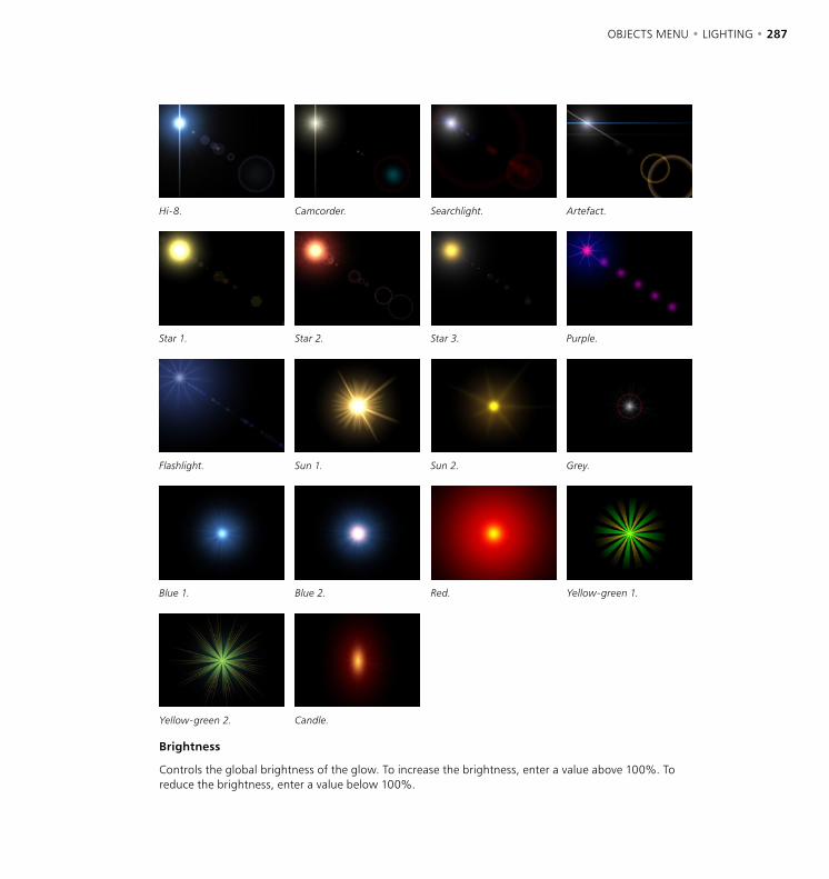
286 • CHAPTER 7 OBJECTS MENU • LIGHTING • 287
Hi-8. Camcorder. Searchlight. Artefact.
Star 1. Star 2. Star 3. Purple.
Flashlight. Sun 1. Sun 2. Grey.
Blue 1. Blue 2. Red. Yellow-green 1.
Yellow-green 2. Candle.
Brightness
Controls the global brightness of the glow. To increase the brightness, enter a value above 100%. To reduce the brightness, enter a value below 100%.

288 • CHAPTER 7 OBJECTS MENU • LIGHTING • 289
Aspect Ratio
Modifying this value allows you to change the aspect ratio of the glow. At its default size of 1 the glow appears circular. Smaller or larger values shrink or stretch the glow’s aspect to a horizontal or vertical ellipse.
Edit
Click the Glow Edit button to open the Glow editor. See ‘Glow editor’ on page 290.
Reflexes
Select the desired reflexes from this menu of presets.
Brightness
Controls the global brightness of the reflexes. Values below 100% reduce the brightness of the effect; values greater than 100% increase the brightness.
Aspect Ratio
At the default size of 1 the reflexes appear circular. Smaller or larger values shrink or stretch the reflexes to a horizontal or vertical ellipse.
Edit
Click the Refelxes Edit button to open the Lens editor. See ‘Lens editor’ on page 293.
Scale
This value adjusts the size of the entire lens effect (rays, glows and reflexes). This saves you from adjusting each effect individually.
Rotation
Use this value to rotate the lens effect to any angle.
Reference Size
With this setting you can adjust the distance value with which the glow and reflex effects are calculated. The lower the value the more distant, thus smaller, the effect appears. Increasing the value makes the effect appear closer, thus larger.
Lens reflexes normally have a constant size no matter how far removed from the camera they are. However, if for example you want a spaceship model to fire torpedoes under the camera, the lens reflexes and glows must become larger as the torpedoes near the camera.
Use Light Parameters
If this option is enabled, the properties defined on the light’s General page also affect the glow/reflex effects. For example, if the light source color is red then the glow/reflex effect also appears red.

288 • CHAPTER 7 OBJECTS MENU • LIGHTING • 289
Fade If Near Border
Enabling this option will make the lens effect fade the nearer it is to the edge of the image. When at the center of the screen, the lens effect will have maximum intensity. This corresponds to a light’s physical behaviour in the real world.
Fade If Behind Object
Enabling this option will determine whether light sources that lie behind objects are still to produce their effects or not. Lens flares do not occur if light sources are behind objects, but glows or radiation can produce pleasing effects.
Fade If Approaching Object
Normally, if a light source with a lens effect starts to disappear behind an object, the effects are still at maximum strength until the light source origin is fully behind the object. With this option enabled, the effect’s strength gradually fades as the light source approaches the object.
A good example of this effect is the gradual fading of a sun behind a planet, complete with atmosphere.
Glow Distance Scale
If this option is enabled, the glow effect is scaled according to its distance from the camera. The farther away the glow is from the camera, the smaller the glow.
Reflex Distance Scale
The same as Glow Distance Scale only for reflexes. If this option is enabled, the reflexes are scaled depending on their distance from the camera. The farther away the reflexes are from the camera, the smaller they are shown.
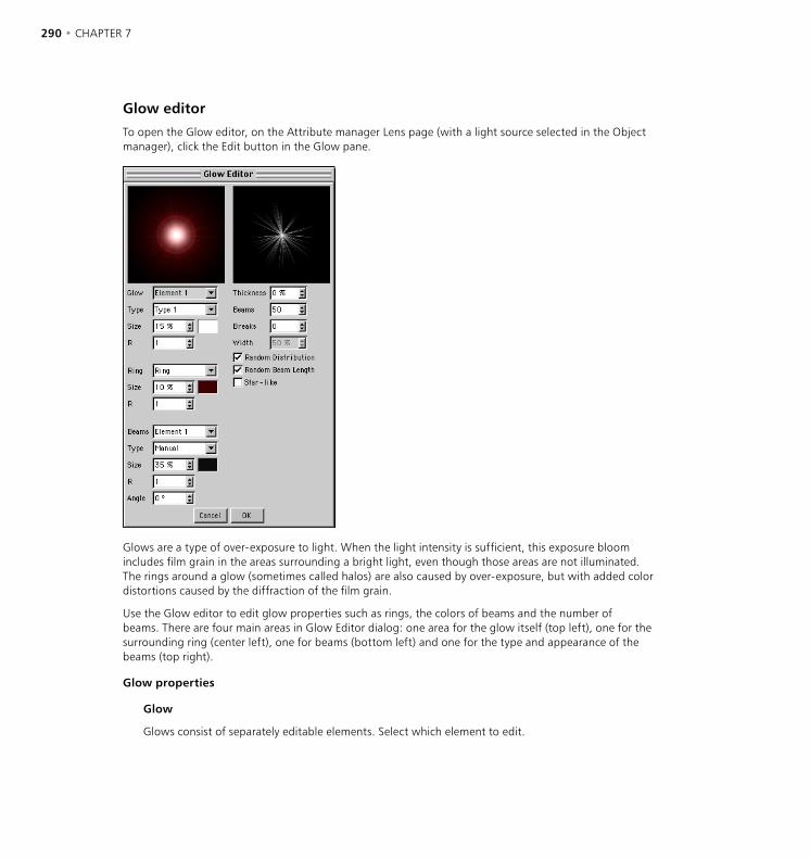
290 • CHAPTER 7 OBJECTS MENU • LIGHTING • 291
Glow editor
To open the Glow editor, on the Attribute manager Lens page (with a light source selected in the Object manager), click the Edit button in the Glow pane.
Glows are a type of over-exposure to light. When the light intensity is sufficient, this exposure bloom includes film grain in the areas surrounding a bright light, even though those areas are not illuminated. The rings around a glow (sometimes called halos) are also caused by over-exposure, but with added color distortions caused by the diffraction of the film grain.
Use the Glow editor to edit glow properties such as rings, the colors of beams and the number of beams. There are four main areas in Glow Editor dialog: one area for the glow itself (top left), one for the surrounding ring (center left), one for beams (bottom left) and one for the type and appearance of the beams (top right).
Glow properties
Glow
Glows consist of separately editable elements. Select which element to edit.

290 • CHAPTER 7 OBJECTS MENU • LIGHTING • 291
Type
Choose a type of glow type for the currently selected element. This defines the distribution of brightness for the element.
Size
Here you set the overall size of the glow element as a percentage of the screen’s size. A value of 100% represents the distance from the center of the screen to the edge of the screen.
Color
To set the color for the glow element, click the box to the right of Size. The system color chooser opens. Select the desired color.
R
This value defines the aspect ratio for the glow. A value of 1 results in a circular glow, whereas values greater or less than 1 produce a horizontal or vertical ellipse.
Ring properties
Ring
Choose one of the following Ring settings from the drop-down list: Inactive (no ring), Ring (set the ring’s color using the color box next to Size) or Rainbow Ring (multi-colored ring).
Size
Here you set the overall size of the ring element as a percentage of the screen’s size. A value of 100% represents the distance from the center of the screen to the edge of the screen.
Color
To set the color for the ring element, click the box to the right of Size. The color picker for your operating system will open. Pick the desired color.
R
This value defines the aspect ratio for the ring. A value of 1 results in a circular ring, whereas values greater or less than 1 produce a horizontal or vertical ellipse.
Beam properties
Beams
Beams consist of separately editable elements. Use the drop-down list to choose which element you want to edit.
Type
Choose a beam type for the element from the drop-down list. This defines the distribution of brightness for the element.

292 • CHAPTER 7 OBJECTS MENU • LIGHTING • 293
Size
Here you set the overall size of the beam element as a percentage of the screen’s size. A value of 100% represents the distance from the center of the screen to the edge of the screen.
Color
To set the color of the beam element, click the box to the right of Size. The system color picker opens. Pick the desired color.
R
This value defines the aspect ratio for the beam element. A value of 1 results in a circular shape, whereas values greater or less than 1 produce a horizontal or vertical ellipse.
Angle
To rotate the beam element to a particular angle, enter the value for the angle here.
Other properties
Thickness
Defines the width of beams as a percentage. The lower the value, the narrower the beams will appear.
Beams
Defines the total number of beams. Up to 200 beams are allowed per light source.
Breaks, Width
You can add breaks to the beams by entering the number of breaks into the Breaks box. The breaks will be added to the gaps that already exist between beams. Use the Width parameter to control the size of the breaks.
Random Distribution
For a random arrangement of beams, enable this option.
Random Beam Length
Enable this option if you want the beams to vary in length.
Star-like
To have the beams arranged in a star-like pattern, enable this option. The beams will thicken towards the center. For a realistic star, use a low number of thick beams.

292 • CHAPTER 7 OBJECTS MENU • LIGHTING • 293
Lens editor
To open the Lens editor, on the Attribute manager Lens page (with a light source selected in the Object manager), click the Edit button in the Reflexes pane.
Lens reflections, the technical term for which is ‘reflexes’, are caused by the focal image of poor quality lenses. The colored shape produced is an artefact of the lens surface, the shape resulting from the shape of the lens. Large apertures produce small reflections, small apertures produce larger ones. Use the Lens editor to change the reflexes as desired. The small preview shows the Lens Type while the large preview shows the entire lens effect.
Element, Add, Rem
Choose which reflex you want to edit.
To add or remove reflexes, click the Add or Rem buttons. You can use up to 40 reflexes.
Lens Type
Defines the shape of the reflexes. Only in the rarest case, if at all, should different reflex types be used in the same scene. For example, apply only circular or only hexagonal types in the same scene. Keep in mind that your scene is shot through one simulated real-world lens — these lens reflections depend upon that lens system, not on your existing scene lights. Here are some examples:
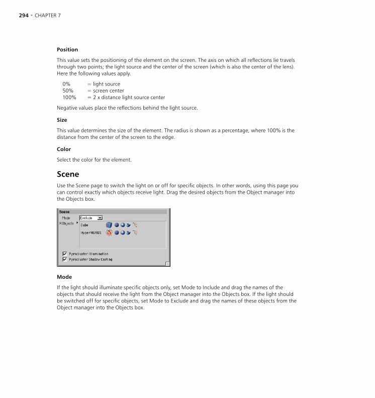
294 • CHAPTER 7 OBJECTS MENU • LIGHTING • 295
Position
This value sets the positioning of the element on the screen. The axis on which all reflections lie travels through two points; the light source and the center of the screen (which is also the center of the lens). Here the following values apply.
0% = light source50% = screen center100% = 2 x distance light source center
Negative values place the reflections behind the light source.
Size
This value determines the size of the element. The radius is shown as a percentage, where 100% is the distance from the center of the screen to the edge.
Color
Select the color for the element.
SceneUse the Scene page to switch the light on or off for specific objects. In other words, using this page you can control exactly which objects receive light. Drag the desired objects from the Object manager into the Objects box.
Mode
If the light should illuminate specific objects only, set Mode to Include and drag the names of the objects that should receive the light from the Object manager into the Objects box. If the light should be switched off for specific objects, set Mode to Exclude and drag the names of these objects from the Object manager into the Objects box.
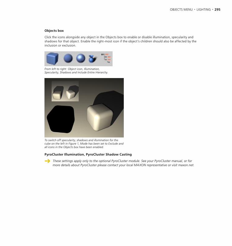
294 • CHAPTER 7 OBJECTS MENU • LIGHTING • 295
Objects box
Click the icons alongside any object in the Objects box to enable or disable illumination, specularity and shadows for that object. Enable the right-most icon if the object’s children should also be affected by the inclusion or exclusion.
From left to right: Object icon, Illumination, Specularity, Shadows and Include Entire Hierarchy.
To switch off specularity, shadows and illumination for the cube on the left in Figure 1, Mode has been set to Exclude and all icons in the Objects box have been enabled.
PyroCluster Illumination, PyroCluster Shadow Casting
These settings apply only to the optional PyroCluster module. See your PyroCluster manual, or for more details about PyroCluster please contact your local MAXON representative or visit maxon.net.

296 • CHAPTER 7 OBJECTS MENU • LIGHTING • 297
Target LightWhen you choose Objects > Scene > Target Light, a light source and a Null object are created. The latter is the target object to which the light is tied at all times. The light source can be any light type of your choosing and you simply move the null into the hierarchy of the object towards which the light should point. Now, when you move this object, the light automatically remains pointing at it.
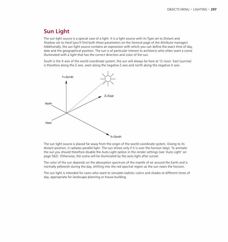
296 • CHAPTER 7 OBJECTS MENU • LIGHTING • 297
Sun LightThe sun light source is a special case of a light. It is a light source with its Type set to Distant and Shadow set to Hard (you’ll find both these parameters on the General page of the Attribute manager). Additionally, the sun light source contains an expression with which you can define the exact time of day, date and the geographical position. The sun is of particular interest to architects who often want a scene illuminated with a light that has the correct direction and color of the sun.
South is the X-axis of the world coordinate system; the sun will always be here at 12 noon. East (sunrise) is therefore along the Z-axis, west along the negative Z-axis and north along the negative X-axis.
The sun light source is placed far away from the origin of the world coordinate system. Owing to its distant position, it radiates parallel light. The sun shines only if it is over the horizon (day). To animate the sun you should therefore disable the Auto Light option in the render settings (see ‘Auto Light’ on page 562). Otherwise, the scene will be illuminated by the auto light after sunset.
The color of the sun depends on the absorption spectrum of the mantle of air around the Earth and is normally yellowish during the day, shifting into the red spectral region as the sun nears the horizon.
The sun light is intended for users who want to simulate realistic colors and shades at different times of day, appropriate for landscape planning or house building.

298 • CHAPTER 7 OBJECTS MENU • LIGHTING • 299
Sun Expression
In the Object manager, select the Sun Expression tag to load its settings into the Attribute manager.
Attribute manager settings
Tag Properties
Latitude
Enter the latitude of the desired location such as 51.3˚ for London, 40.4˚ for New York, 35.4˚ for Tokyo, 48.5˚ for Paris or 50.1˚ for Friedrichsdorf.
Longitude
Enter the longitude of the desired location. 0˚ runs through Greenwich, UK. Negative values are west of Greenwich, positive values east.
Distance
Here you enter the distance of the sun light source from the center of the world axes. The smaller this value, the smaller the circular arc on which the sun travels.
Time
Enter the local time for the sun light using the upper three Time boxes (from left to right: hours, minutes, seconds). Enter the date using the lower three Time boxes (from left to right: day, month, year). You can also set the date with the help of a calendar. To show the calendar, click the small triangle to the left of the input boxes. Local summer time and other time zone corrections are ignored. For example, subtract one hour from the time during the summer months to obtain Central European Time. To use the system’s current time, click the Now button.
298 • CHAPTER 7 OBJECTS MENU • LIGHTING • 299
Interpolate Time, Interpolate Date
Use these options to control whether the time and date are interpolated.
Examples
1 You want to simulate three days — the sun should fall and rise three times. Enable both options.
2 You want to animate several months with the clock always at 12 o’clock in the daytime. Disable Interpolate Time. Enable Interpolate Date. This prevents the time from being animated while still allowing the data to change.
Set Light Color
If this option is enabled, CINEMA 4D automatically adjusts the sun light’s color to match the geographical position, time and date.
Using the Sun expression with other object types
Since the sun uses an expression tag, you can drag the tag onto other object types. For example, drag the tag onto a sphere to simulate a moon.

300 • CHAPTER 7
Making gels
A gel (also known as a lightmap) is produced by assigning a material with a transparency map texture to a light source. The light’s colored areas are then filtered by this texture and colored in exactly the same way as a slide projector projects a still picture.
You can assign as many gels as you wish to each light object. Thus you are able to produce many complex picture effects with ease. For example, the striped-shadow effect of a Venetian blind can be simulated without the complicated and time-consuming shadow calculations normally associated with such an effect, simply by assigning a black-and-white striped gel to a light object.
Lights do not take on the material properties of a parent object.

OBJECTS MENU • PARTICLES • 301
Ever wanted to create shark-infested waters, an intergalactic fleet with hundreds of starships or just swirly cigarette smoke? CINEMA 4D’s particle system will do all of this for you, and much more, in a very easy and intuitive way.
The optional Thinking Particles module enables you to create high-end, studio-quality particle effects directly within CINEMA 4D. Thinking Particles gives you astonishing control over particle streams with features such as nodes, spawning, object-based collision and much more. For full details on Thinking Particles, please contact your local MAXON representative or visit www.maxon.net.
The heart of CINEMA 4D’s particle system is the emitter, which ejects a stream of particles. These particles and their shapes can be modified by various parameters and controls to produce, amongst other effects, rotating, deflecting and decelerating particles. It’s a simple as this:
- Create an emitter (Objects > Particle Emitter).
- Click the Play icon in the animation toolbar and view the default particle system in the viewport.
- Drag an object into the emitter (a basic small sphere is suitable for now). In the Attribute manager, ensure that the emitter’s Show Objects option is enabled.
CINEMA 4D enables you to use any object as particles. Not only simple spheres but also complex, grouped objects with hierarchies may be used (e.g. a jointed bird or a car). Even light sources can be used as particles. Employing the visible light function you can create fire or smoke effects very easily and particles can even cast lights and shadows. All objects in the emitter can be fully animated to create, for example, flying birds and swimming fish.
Particles
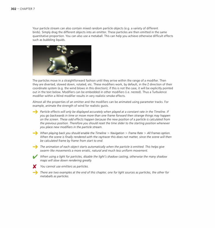
302 • CHAPTER 7 OBJECTS MENU • PARTICLES • 303
Your particle stream can also contain mixed random particle objects (e.g. a variety of different birds). Simply drag the different objects into an emitter. These particles are then emitted in the same quantitative proportion. You can also use a metaball. This can help you achieve otherwise difficult effects such as bubbling liquids.
The particles move in a straightforward fashion until they arrive within the range of a modifier. Then they are diverted, slowed down, rotated, etc. These modifiers work, by default, in the Z direction of their coordinate system (e.g. the wind blows in this direction); if this is not the case, it will be explicitly pointed out in the text below. Modifiers can be embedded in other modifiers (i.e. nested). Thus a Turbulence modifier within a Wind modifier results in very realistic smoke effects.
Almost all the properties of an emitter and the modifiers can be animated using parameter tracks. For example, animate the strength of wind for realistic gusts.
Particle effects will only be displayed accurately when played at a constant rate in the Timeline. If you go backwards in time or move more than one frame forward then strange things may happen on the screen. These odd effects happen because the new position of a particle is calculated from the previous position. Therefore you should reset the time slider to the starting position whenever you place new modifiers in the particle stream.
When playing back you should enable the Timeline > Navigation > Frame Rate > All Frames option. When the scene is finally rendered with the raytracer this does not matter, since the scene will then be calculated frame by frame from start to end.
The animation of each object starts automatically when the particle is emitted. This helps give swarm-like movements a more erratic, natural and much less uniform movement.
When using a light for particles, disable the light’s shadow casting, otherwise the many shadow maps will slow down rendering greatly.
You cannot use emitters as particles.
There are two examples at the end of this chapter, one for light sources as particles, the other for metaballs as particles.
302 • CHAPTER 7 OBJECTS MENU • PARTICLES • 303
Baking ParticlesUnder certain conditions it may become necessary to use the Bake Particles command for particle streams. What does this mean? Under normal conditions particle streams are rendered dynamically and sequentially, i.e. the position of a particle in the next frame depends on its position in the previous one. But this can cause problems in two ways ...
First of all let’s consider rendering within mixed networks. With CINEMA 4D NET Render module, the rendering of an animation within a network can be distributed over several computers for faster results. For this type of network rendering a variety of different platforms can be combined, e.g. Power PC, AMD and Pentium processors. Since the floating-point units (FPU) of these processors work slightly differently, the sequential nature of the particle rendering can produce different results on the different platforms. The final output could be a non-continuous particle stream with jumps in the positions of particles. The solution is to bake the particles before rendering them over the network.
The second problem occurs when using several independent particle systems in a scene. In principle all modifiers will always affect all particles of a scene, no matter what the source. If this is not what you want, remedy it by baking the particles.
To bake particles
- In the Object manager, select the emitter and choose Objects > Bake Particles.
Since it is an object property rather than an object, the Bake Particles command is in the Object manager’s Objects menu. It is referred to again in Chapter 19, ‘Object Manager’.
When baked, a particle stream will become frozen in its present condition, i.e. the position, rotation and size for each particle for each frame of the animation is fixed (also in the Timeline, although you won’t notice it). All computers in a NET Render network will now render the particles correctly.
As you might expect, these extra particle options are not without a cost; high memory consumption is the price you pay. For each particle and for each animation frame the data, such as position, speed, situation, lifetime etc. must be saved. You can therefore quite easily build a scene that requires several megabytes of memory. To check the memory consumption of the baked objects, in the Object manager choose Objects > Object Information.
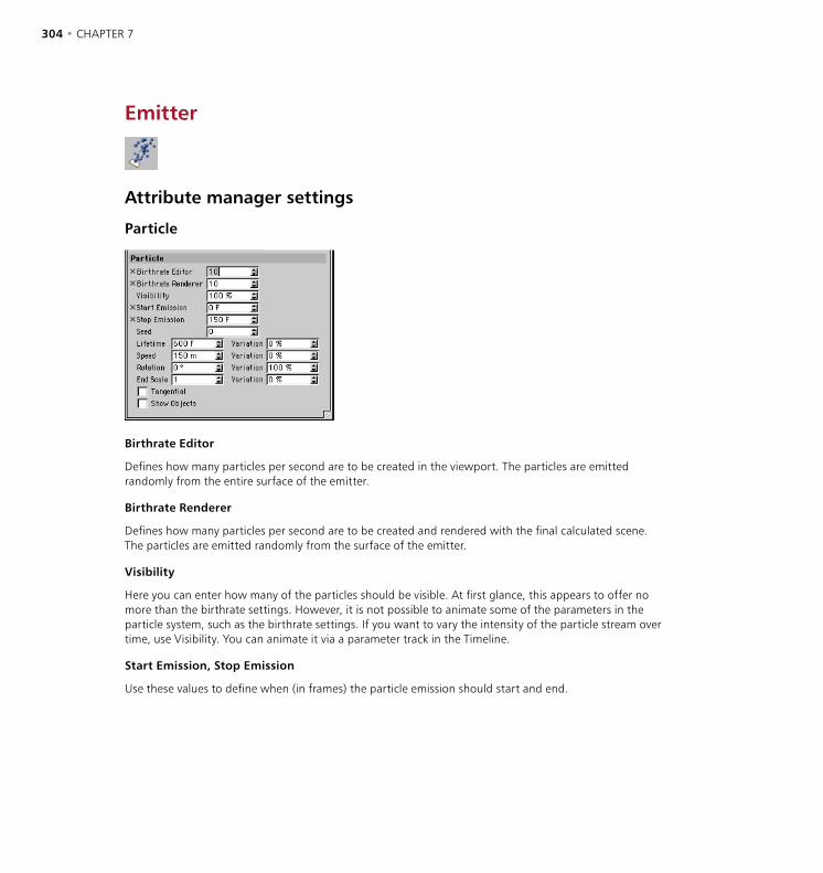
304 • CHAPTER 7 OBJECTS MENU • PARTICLES • 305
Emitter
Attribute manager settings
Particle
Birthrate Editor
Defines how many particles per second are to be created in the viewport. The particles are emitted randomly from the entire surface of the emitter.
Birthrate Renderer
Defines how many particles per second are to be created and rendered with the final calculated scene. The particles are emitted randomly from the surface of the emitter.
Visibility
Here you can enter how many of the particles should be visible. At first glance, this appears to offer no more than the birthrate settings. However, it is not possible to animate some of the parameters in the particle system, such as the birthrate settings. If you want to vary the intensity of the particle stream over time, use Visibility. You can animate it via a parameter track in the Timeline.
Start Emission, Stop Emission
Use these values to define when (in frames) the particle emission should start and end.

304 • CHAPTER 7 OBJECTS MENU • PARTICLES • 305
Seed
Seed is used to create the pattern of the particle stream. If you copy an emitter, you will notice that both emitters generate exactly the same pattern. This may or may not matter depending on the nature of your scene. To ensure that each stream is unique, enter a different seed value for each emitter. For example, a seed value of 1 will create a completely different stream to a seed value of 0.
Lifetime
Gives the length of time a particle will be visible. So if flying sparks, for example, are set to be visible for 20 frames, the particles will disappear after this time. This value also controls the length of the animation sequence in the Timeline. Variation adds a deviation factor to the Lifetime value; i.e. individual particles can live for a longer or shorter time, according to the size of the Variation value.
Speed
Indicates the speed of the individual particles. The speed is shown in units per second. The larger the value, the longer is the particle line displayed in the viewport. Variation introduces randomness to the speed. A value of 100% can make individual particles twice as fast, or twice as slow.
A speed of 0 is allowed. With this value set, the emitter leaves a particle trail behind itself when the emitter is moved. Negative values can also be used. The emitter will then emit the particle stream in the negative Z direction.
Rotation
Specifies the amount by which the particles will revolve around a spatial axis. Variation will add a deviation factor to the value.
End Scale
Defines the final size of the particles relative to their starting size. A value of 0.5, for example, will shrink the particles to half their initial size. Variation (in the second column) defines a variable factor for the scaling so that the particles are sometimes larger or smaller at the end of the animation.
Tangential
The trajectory of the individual particles may be curved by enabling this option. The Z-axis of the particles will be aligned along the trajectory of the emitter; you would need this to simulate exhaust gases emitting from the engines of an aeroplane flying on a curve, say.
This option takes additional render time and should be disabled for objects with no direction such as spheres or light sources.
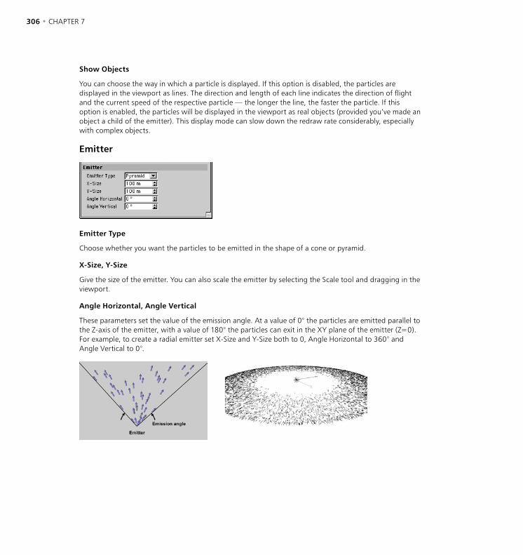
306 • CHAPTER 7 OBJECTS MENU • PARTICLES • 307
Show Objects
You can choose the way in which a particle is displayed. If this option is disabled, the particles are displayed in the viewport as lines. The direction and length of each line indicates the direction of flight and the current speed of the respective particle — the longer the line, the faster the particle. If this option is enabled, the particles will be displayed in the viewport as real objects (provided you’ve made an object a child of the emitter). This display mode can slow down the redraw rate considerably, especially with complex objects.
Emitter
Emitter Type
Choose whether you want the particles to be emitted in the shape of a cone or pyramid.
X-Size, Y-Size
Give the size of the emitter. You can also scale the emitter by selecting the Scale tool and dragging in the viewport.
Angle Horizontal, Angle Vertical
These parameters set the value of the emission angle. At a value of 0° the particles are emitted parallel to the Z-axis of the emitter, with a value of 180° the particles can exit in the XY plane of the emitter (Z=0). For example, to create a radial emitter set X-Size and Y-Size both to 0, Angle Horizontal to 360° and Angle Vertical to 0°.
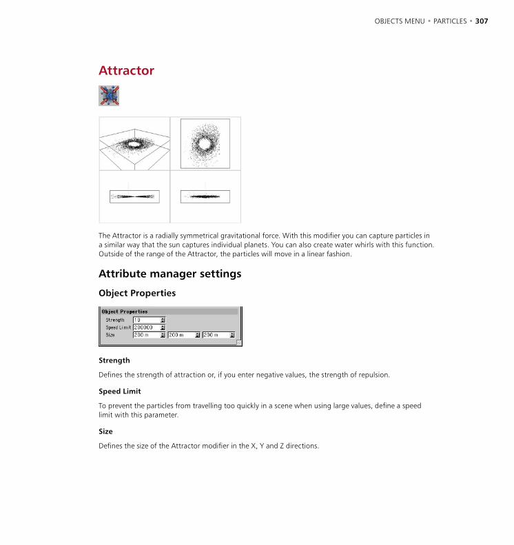
306 • CHAPTER 7 OBJECTS MENU • PARTICLES • 307
Attractor
The Attractor is a radially symmetrical gravitational force. With this modifier you can capture particles in a similar way that the sun captures individual planets. You can also create water whirls with this function. Outside of the range of the Attractor, the particles will move in a linear fashion.
Attribute manager settings
Object Properties
Strength
Defines the strength of attraction or, if you enter negative values, the strength of repulsion.
Speed Limit
To prevent the particles from travelling too quickly in a scene when using large values, define a speed limit with this parameter.
Size
Defines the size of the Attractor modifier in the X, Y and Z directions.
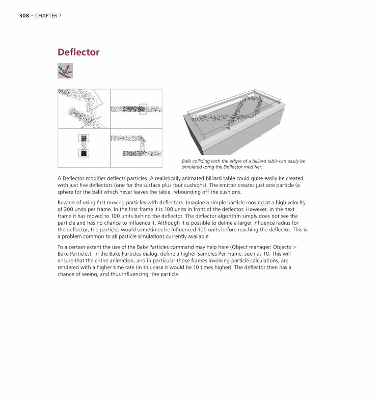
308 • CHAPTER 7 OBJECTS MENU • PARTICLES • 309
Deflector
Balls colliding with the edges of a billiard table can easily be simulated using the Deflector modifier.
A Deflector modifier deflects particles. A realistically animated billiard table could quite easily be created with just five deflectors (one for the surface plus four cushions). The emitter creates just one particle (a sphere for the ball) which never leaves the table, rebounding off the cushions.
Beware of using fast moving particles with deflectors. Imagine a simple particle moving at a high velocity of 200 units per frame. In the first frame it is 100 units in front of the deflector. However, in the next frame it has moved to 100 units behind the deflector. The deflector algorithm simply does not see the particle and has no chance to influence it. Although it is possible to define a larger influence radius for the deflector, the particles would sometimes be influenced 100 units before reaching the deflector. This is a problem common to all particle simulations currently available.
To a certain extent the use of the Bake Particles command may help here (Object manager: Objects > Bake Particles). In the Bake Particles dialog, define a higher Samples Per Frame, such as 10. This will ensure that the entire animation, and in particular those frames involving particle calculations, are rendered with a higher time rate (in this case it would be 10 times higher). The deflector then has a chance of seeing, and thus influencing, the particle.
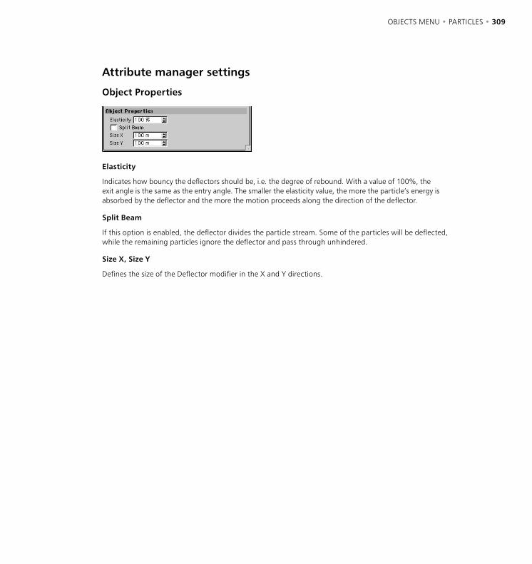
308 • CHAPTER 7 OBJECTS MENU • PARTICLES • 309
Attribute manager settings
Object Properties
Elasticity
Indicates how bouncy the deflectors should be, i.e. the degree of rebound. With a value of 100%, the exit angle is the same as the entry angle. The smaller the elasticity value, the more the particle’s energy is absorbed by the deflector and the more the motion proceeds along the direction of the deflector.
Split Beam
If this option is enabled, the deflector divides the particle stream. Some of the particles will be deflected, while the remaining particles ignore the deflector and pass through unhindered.
Size X, Size Y
Defines the size of the Deflector modifier in the X and Y directions.

310 • CHAPTER 7 OBJECTS MENU • PARTICLES • 311
Destructor
The Destructor modifier enables you to destroy (i.e. remove) particles from the particle stream.
So that the destructor has a definite effect, i.e. destroys particles, it must have a minimum thickness greater than the distance covered per frame by the particles. For example, if a particle is in front of the destructor at frame 20 and then past the destructor at frame 21, it will not be destroyed, even though it has effectively passed though the destructor. The particle must be inside the destructor to be killed at that frame.
Attribute manager settings
Object Properties
Randomness
Affects how many particles will survive.
0% All particles are destroyed.
n% n% of the particles remain.
100% All particles pass through the destructor.
Size
Defines the size of the Destructor modifier in the X, Y and Z directions.
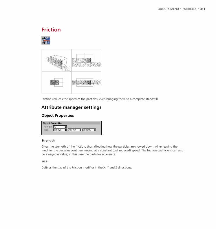
310 • CHAPTER 7 OBJECTS MENU • PARTICLES • 311
Friction
Friction reduces the speed of the particles, even bringing them to a complete standstill.
Attribute manager settings
Object Properties
Strength
Gives the strength of the friction, thus affecting how the particles are slowed down. After leaving the modifier the particles continue moving at a constant (but reduced) speed. The friction coefficient can also be a negative value; in this case the particles accelerate.
Size
Defines the size of the Friction modifier in the X, Y and Z directions.

312 • CHAPTER 7 OBJECTS MENU • PARTICLES • 313
Gravity
The gravitational force acts in the negative Y direction only (unlike the Attractor modifier). In the viewport a small, downward-pointing arrow indicates this.
Attribute manager settings
Object Properties
Acceleration
Defines the strength of the acceleration due to gravity.
Size
Defines the size of the Gravity modifier in the X, Y and Z directions.
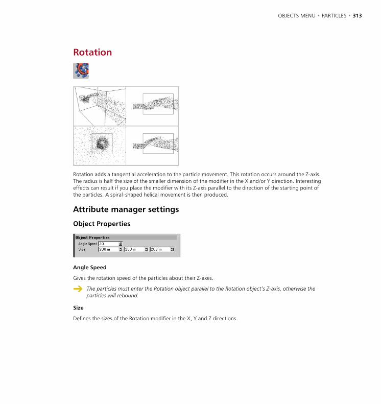
312 • CHAPTER 7 OBJECTS MENU • PARTICLES • 313
Rotation
Rotation adds a tangential acceleration to the particle movement. This rotation occurs around the Z-axis. The radius is half the size of the smaller dimension of the modifier in the X and/or Y direction. Interesting effects can result if you place the modifier with its Z-axis parallel to the direction of the starting point of the particles. A spiral-shaped helical movement is then produced.
Attribute manager settings
Object Properties
Angle Speed
Gives the rotation speed of the particles about their Z-axes.
The particles must enter the Rotation object parallel to the Rotation object’s Z-axis, otherwise the particles will rebound.
Size
Defines the sizes of the Rotation modifier in the X, Y and Z directions.
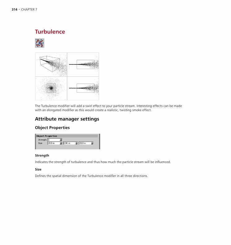
314 • CHAPTER 7 OBJECTS MENU • PARTICLES • 315
Turbulence
The Turbulence modifier will add a swirl effect to your particle stream. Interesting effects can be made with an elongated modifier as this would create a realistic, twisting smoke effect.
Attribute manager settings
Object Properties
Strength
Indicates the strength of turbulence and thus how much the particle stream will be influenced.
Size
Defines the spatial dimension of the Turbulence modifier in all three directions.
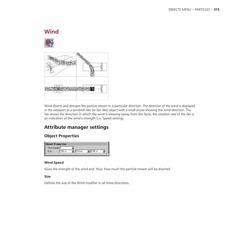
314 • CHAPTER 7 OBJECTS MENU • PARTICLES • 315
Wind
Wind diverts and disrupts the particle stream in a particular direction. The direction of the wind is displayed in the viewport as a windmill-like (or fan-like) object with a small arrow showing the wind direction. The fan shows the direction in which the wind is blowing (away from the face); the rotation rate of the fan is an indication of the wind’s strength (i.e. Speed setting).
Attribute manager settings
Object Properties
Wind Speed
Gives the strength of the wind and, thus, how much the particle stream will be diverted.
Size
Defines the size of the Wind modifier in all three directions.
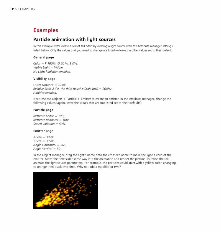
316 • CHAPTER 7 OBJECTS MENU • PARTICLES • 317
Examples
Particle animation with light sourcesIn this example, we’ll create a comet tail. Start by creating a light source with the Attribute manager settings listed below. Only the values that you need to change are listed — leave the other values set to their default.
General page
Color = R 100%, G 50 %, B 0%;Visible Light = Visible;No Light Radiation enabled.
Visibility page
Outer Distance = 10 m;Relative Scale Z (i.e. the third Relative Scale box) = 200%;Additive enabled.
Next, choose Objects > Particle > Emitter to create an emitter. In the Attribute manager, change the following values (again, leave the values that are not listed set to their defaults):
Particle page
Birthrate Editor = 100;Birthrate Renderer = 100;Speed Variation = 50%.
Emitter page
X-Size = 30 m;Y-Size = 30 m;Angle Horizontal = 30°;Angle Vertical = 30°.
In the Object manager, drag the light’s name onto the emitter’s name to make the light a child of the emitter. Move the time slider some way into the animation and render the picture. To refine the tail, animate the light source parameters. For example, the particles could start with a yellow color, changing to orange then black over time. Why not add a modifier or two?

316 • CHAPTER 7 OBJECTS MENU • PARTICLES • 317
MetaparticlesIn this example, you’ll learn how to combine particles with metaballs. Start by choosing Objects > Modeling > Metaball to create a Metaball object. Now edit the settings in the Attribute manager. As with the first example, only the values that you need to change are listed — leave the other values set to their default.
Object page
Hull Value = 70%;Editor Subdivision = 15 m;Render Subdivision = 5 m.
Next, choose Objects > Particle > Emitter to create an emitter. In the Attribute manager, change the following values (again, leave the values that are not listed set to their defaults):
Particle page
Birthrate (Editor & Renderer) = 15;Lifetime = 100 F (Variation = 50%);Speed = 500 m (Variation = 50%);End Scale = 0 (Variation 100%).
Choose Objects > Primitive > Sphere to create a sphere. In the Attribute manager, set the sphere’s Radius to 35 m. In the Object manager, drag the sphere’s name onto the emitter’s name to make the sphere a child of the emitter. Now drag the name of the emitter onto the name of the metaball.
Move the time slider some way into the animation and render the picture. Now experiment!
You must render to the Picture Viewer (Render > Render to Picture Viewer) in order to see a smooth movement of the metaballs — this smoothness relates to the metaball’s Render Subdivision value.


OBJECTS MENU • DEFORMERS • 319
The deformation objects deform the geometry of other objects. You can use deformers on primitive objects, NURBS objects, polygon objects and splines. To have an effect, the deformer must either be at the same hierarchy level as the recipient object, or a direct child of the recipient — the recipient being the object that is to be deformed. You can use several deformers on the same recipient. Their order of evaluation is from top to bottom in the Object manager. The evaluation order matters — a twist followed by a bend produces a different result from a bend followed by a twist!
The deformer can only work with what you give it. For example, if you wish to twist the recipient smoothly, ensure that it has a sufficiently high number of segments/subdivisions along the twist axis.
In the Object manager, this means a deformer is active.
In the Object manager, this means a deformer is inactive.
Clicking this icon turn deformers on and off.
All deformers apart from bones are activated automatically when you create them. If a deformer is activated, you will see a green checkmark icon in the Object manager. To deactivate the deformer, click the green checkmark. The icon changes to a red cross. A deformation object has no effect when deactivated. You can also switch off the deformer using the Enabled option on the Attribute manager’s Basic Properties page.
There are two ways to activate or deactivate all deformers at once. Either toggle the Use Deformers option from the Edit menu (main window) or click the drawing pipeline icon shown above (by default, in the left-hand toolbar).
The deformer cage
A deformer cage is cyan colored with orange handles.
Use the orange handles to apply the deformer interactively to an object.
The Taper deformer’s cage, after some work.
All deformers in CINEMA 4D are represented by a cage within the viewport; by default, this cage is colored cyan (light blue). This represents how the deformation effect will be applied to your object when the deformer is used.
Deformers
320 • CHAPTER 7 OBJECTS MENU • DEFORMERS • 321
The deformer’s cage can be modified in several ways. The two most common ways are by dragging its handles in the viewport or by adjusting its values on the Object page of the Attribute manager. The following sections on the individual deformer objects give more detail on the relevance of this cage and how it can be adjusted.
Animating deformation parameters
All deformation parameters can be animated. To animate a deformation parameter do one of the following:
- In the Object manager, click the deformer’s name to select the deformer and load its settings into the Attribute manager. In the Attribute manager, right-click (Windows) or Command-click (Mac OS) the parameter that you want to animate. From the menu that appears, choose Animation > Add Keyframe (the parameter’s current value is recorded). Repeat this process at a different frame for the same parameter but with a different parameter value. The parameter is now animated.
- In the Timeline, choose the name of the parameter that you want to animate from the File > New Track > Parameter menu. Add the desired keys to this track.
You can restrict a deformer’s influence using vertex maps and polygon selections — see ‘Restricting bones using polygon selections or vertex maps’ on page 326 for an example with bones. See also ‘Set Vertex Weight’ on page 442, and ‘Polygon Selection’ on page 412.
Activate UVW mapping before you deform objects. This will prevent textures from ‘slipping’.
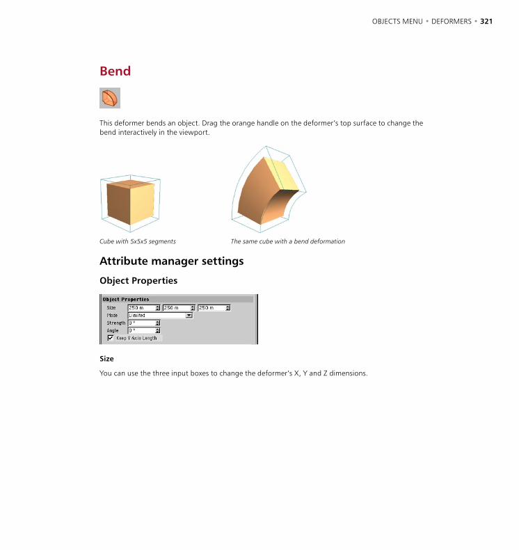
320 • CHAPTER 7 OBJECTS MENU • DEFORMERS • 321
Bend
This deformer bends an object. Drag the orange handle on the deformer’s top surface to change the bend interactively in the viewport.
Cube with 5x5x5 segments The same cube with a bend deformation
Attribute manager settings
Object Properties
Size
You can use the three input boxes to change the deformer’s X, Y and Z dimensions.

Mode
There are three modes for bend deformation.
Limited Within Box Unlimited
Limited
The entire object is affected. Surfaces within the cyan box are bent and the other surfaces move and rotate if necessary to accommodate the bend.
Within Box
Surfaces within the cyan box are bent. Surfaces outside the box remain exactly where they are (they are unaffected).
Unlimited
The entire object is bent.
Strength
Defines the strength of bending. To change this value interactively, drag the orange handle in the viewport.
Angle
Defines the direction of bending. 0° is the deformer’s local X-axis.
Keep Y-Axis Length
If this option is enabled, the object keeps its original length.

Bone
Modeling characters and moving their limbs and clothes realistically is one of the most challenging and rewarding tasks in 3D.
One approach is to divide the character object into several objects and apply inverse kinematics. Unfortunately, this method involves unattractive splits in the joint areas.
A better solution is to mimic nature by placing a skeleton (i.e. a hierarchy of bones objects) inside a single character mesh. The character is then posed by moving the bones. The skin (i.e. the surface) bends and stretches as the bones move. This approach avoids the problem of split joints and, since the bones are completely separate of the object itself, you can use the same skeleton again with other characters.
The optional MOCCA module gives you outstanding control over character animation. Creating complex, custom character rigs and skeletons is made simple with MOCCA. You can create and edit preset poses and quickly create elaborate character animations by mixing these poses. A new IK system (Soft IK) with built-in dynamics and constraints allows more fluid motion. Easily add secondary motion to your characters or gain even more control over animation parameters. For full details on MOCCA, contact your local MAXON representative or visit www.maxon.net.
Bones can be used with all object types including parametric objects, NURBS objects, polygon objects and splines. You can even apply bones to other deformation objects!
HyperNURBS and bones
You can apply bones to a HyperNURBS object. There is no need to convert the HyperNURBS object into a polygon object. Rather than work with a high-poly object, you can apply the bones directly to the low-poly cage of the HyperNURBS. The bones deform the cage, which in turn deforms the HyperNURBS object. The object is smoothed after the deformation.
This method avoids the polygon errors, torn mesh and kinks that are associated with high-poly characters. Animate the cage and the result is a smooth, kink-free surface. In addition, it is much easier and more flexible to work with a low-poly object when using limited radii or even vertex maps.

324 • CHAPTER 7 OBJECTS MENU • DEFORMERS • 325
Attribute manager settings
Object Properties
Null
If this option is enabled, the bone becomes a null bone. You can use this null bone as a parent bone — in other words, a parent axis system.
Length
Here you enter the length of the bone. The length extends from the bone’s origin to the orange handle.
Function
The function defines how loose or tight the bend at the joints should be. The higher the power of 1/r, the greater the pull on the surrounding points, as shown in these examples:
Function 1/r 2̂ Function 1/r 1̂0
This illustrates how the bend becomes tighter in the joint region with increasing power for the radius setting. Lower settings are more suited to tube-like objects such as snakes; higher settings are more suited to anatomical joints such as elbows. The function must be defined in the bone at the top of the hierarchy (topmost in the Object manager). This will define the function for all the bones in the hierarchy, regardless of the function value set in those bones.
Strength
This lets you specify the influence that a bone exerts on a point in comparison to all other bones.
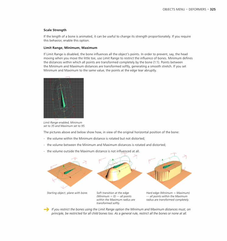
324 • CHAPTER 7 OBJECTS MENU • DEFORMERS • 325
Scale Strength
If the length of a bone is animated, it can be useful to change its strength proportionately. If you require this behavior, enable this option.
Limit Range, Minimum, Maximum
If Limit Range is disabled, the bone influences all the object’s points. In order to prevent, say, the head moving when you move the little toe, use Limit Range to restrict the influence of bones. Minimum defines the distances within which all points are transformed completely by the bone (1:1). Points between the Minimum and Maximum distances are transformed softly, generating a smooth stretch. If you set Minimum and Maximum to the same value, the points at the edge tear abruptly.
Limit Range enabled, Minimum set to 35 and Maximum set to 95.
The pictures above and below show how, in view of the original horizontal position of the bone:
- the volume within the Minimum distance is rotated but not distorted;
- the volume between the Minimum and Maximum distances is rotated and distorted;
- the volume outside the Maximum distance is not influenced at all.
Starting object; plane with bone. Soft transition at the edge (Minimum = 0) — all points within the Maximum radius are transformed softly.
Hard edge (Minimum = Maximum) — all points within the Maximum radius are transformed completely.
If you restrict the bones using the Limit Range option the Minimum and Maximum distances must, on principle, be restricted for all child bones too. As a general rule, restrict all the bones or none at all.
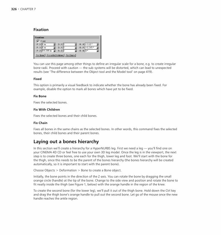
326 • CHAPTER 7 OBJECTS MENU • DEFORMERS • 327
Fixation
You can use this page among other things to define an irregular scale for a bone, e.g. to create irregular bone radii. Proceed with caution — the sub-systems will be distorted, which can lead to unexpected results (see ‘The difference between the Object tool and the Model tool’ on page 419).
Fixed
This option is primarily a visual feedback to indicate whether the bone has already been fixed. For example, disable the option to mark all bones which have yet to be fixed.
Fix Bone
Fixes the selected bones.
Fix With Children
Fixes the selected bones and their child bones.
Fix Chain
Fixes all bones in the same chains as the selected bones. In other words, this command fixes the selected bones, their child bones and their parent bones.
Laying out a bones hierarchyIn this section we’ll create a hierarchy for a HyperNURBS leg. First we need a leg — you’ll find one on your CINEMA 4D CD or feel free to use your own 3D leg model. Once the leg is in the viewport, the next step is to create three bones, one each for the thigh, lower leg and foot. We’ll start with the bone for the thigh, since this needs to be the parent of the bones hierarchy (the bones hierarchy will be created automatically, so it is important to start with the parent bone).
Choose Objects > Deformation > Bone to create a Bone object.
Initially, the bone points in the direction of the Z-axis. You can rotate the bone by dragging the small orange circle (handle) at the tip of the bone. Change to the side view and position and rotate the bone to fit neatly inside the thigh (see Figure 1, below) with the orange handle in the region of the knee.
To create the second bone (for the lower leg), we’ll pull it out of the thigh bone. Hold down the Ctrl key and drag the thigh bone’s orange handle to pull out the second bone. Let go of the mouse once the new handle reaches the ankle region.

326 • CHAPTER 7 OBJECTS MENU • DEFORMERS • 327
Change to the front view and ensure that both bones run down the middle of the lower leg (if you need to correct their positions, drag the orange handle of the thigh bone then the orange handle of the lower leg bone). When a new bone is created by being pulled out of an existing parent bone, the new bone is automatically a child of the parent bone (Figure 2).
Figure 1 Figure 2 Figure 3
We need just one more bone, the foot bone. In the side view, pull the foot bone out from the lower leg bone (Figure 3). Move into the top view and ensure that the bone runs through the middle of the foot.
The bone may spin around its Z-axis when you drag its handle. If this happens, rotate the bone about the Y-axis of the world coordinate system using the Rotate tool instead, otherwise problems may occur later when the bone is animated.
Using the Limit Range option
The next stage is to restrict the influence of each bone, otherwise each bone will pull on all parts of the leg. For example, when moving the foot bone the thigh would also be distorted! There are three ways to restrict the influence of bones — the first and most simple way is to use the Limit Range option (see ‘Limit Range, Minimum, Maximum’ on page 325).
In the Object manager, hold down Shift and click all three bones to select them all and load their settings into the Attribute manager. On the Attribute manager’s Object page, enable Limit Range and set Minimum and Maximum to 30 and 50. In fact, the exact values do not matter since we shall adjust them interactively in the viewport later. What is important is that we enter a value greater than 0 for Minimum, otherwise its handle will not appear in the viewport.
Now each bone is surrounded by two capsule-shaped cages in the viewport. This looks a little confusing with the cages of all three bones shown on at once — that’s because all the bones are still selected. So in the Object manager, click the name of one of the bones to select it and show only that bone’s cages. You can enlarge or scale down the cages by dragging their orange handles. When using a HyperNURBS object you can often set both radii to the same value, since the points of the HyperNURBS cage are usually so far apart that a soft transition occurs automatically.

328 • CHAPTER 7 OBJECTS MENU • DEFORMERS • 329
In the Object manager, select the foot bone if it isn’t already selected by clicking its name. The radii for the foot appear in the viewport. Adjust the radii so that they enclose the foot completely (Figure 5).
Now adjust the radii for the lower leg bone until they enclose the entire lower leg and part of the foot.
Next, adjust the radii for the thigh bone so that they enclose the entire thigh and part of the knee (Figure 6). Slight overlaps are fine. What is important is that all parts of the leg are influenced by at least one bone, otherwise uninfluenced points will be left behind when the bones are animated, causing the leg to tear.
Figure 4 Figure 5 Figure 6
Now it’s time to test the bones. In the Object manager, drag the name of the thigh bone onto the name of the leg to make the bone hierarchy a child of the leg.
Lastly, we need to fix the bones. In the Object manager, select the thigh bone (the topmost bone) by clicking its name. On the Attribute manager’s Fixation page, click the Fix With Children button to fix the bone. (Keep in mind that you can also fix bones by choosing Objects > Fix bones in the Object manager). Notice that the Attribute manager’s Fixed option is now enabled, indicating that the bones are fixed.
The position in which the bones are fixed is their starting position. You can return the bones to their starting position at any time by choosing Objects > Reset Bones in the Object manager. Resetting the bones deactivates their influence at the same time, i.e. they will no longer be fixed. You can fix bones again in the usual way (Object manager: Objects > Fix Bones or click Fix with Children in the Attribute manager). This enables you to change the starting position (move the bones to their new starting position before fixing them again).

328 • CHAPTER 7 OBJECTS MENU • DEFORMERS • 329
You can tell if a bone is active by its activation icon in the Object manager:
Bones are activated automatically when you fix them. However, just activating the bones will not fix them! You must fix the bones before activating them. Once you have fixed the bones, you can activate and deactivate them as required. You may be wondering what happens if you activate a bone before it is fixed. The answer is simple — the default fixing values of 0,0,0 will be used as the starting position and the object will be deformed accordingly (probably causing extreme distortion of the mesh).
Try rotating the bones using the Rotate tool. If some parts of the leg are not moving properly, try increasing the radii for one or more of the bones. You can change the radii interactively even though the bones are fixed. Even if the leg is moving properly, try changing the radii to see how easy it is.
The bend at the knee isn’t quite right — the Function setting is too soft (see ‘Function’, page 324). In the Object manager, click the name of the thigh bone (topmost bone). In the Attribute manager, on the Object page, change the Function value to 1/r 1̂0 for a perfect bend. You can learn how to apply inverse kinematics to bones and how to animate the leg in ‘Inverse Kinematics’ on page 423.
Restricting bones using polygon selections or vertex maps
In the previous section we used the Limit Range option to restrict the influence of bones. Bones can also be restricted using polygon selections or vertex maps; in fact you can use polygon selections and vertex maps to restrict the effect of any type of deformation object. (To learn how to create polygon selections and vertex maps, see ‘Polygon Selection’ on page 412 and ‘Set Vertex Weight’ on page 442.)
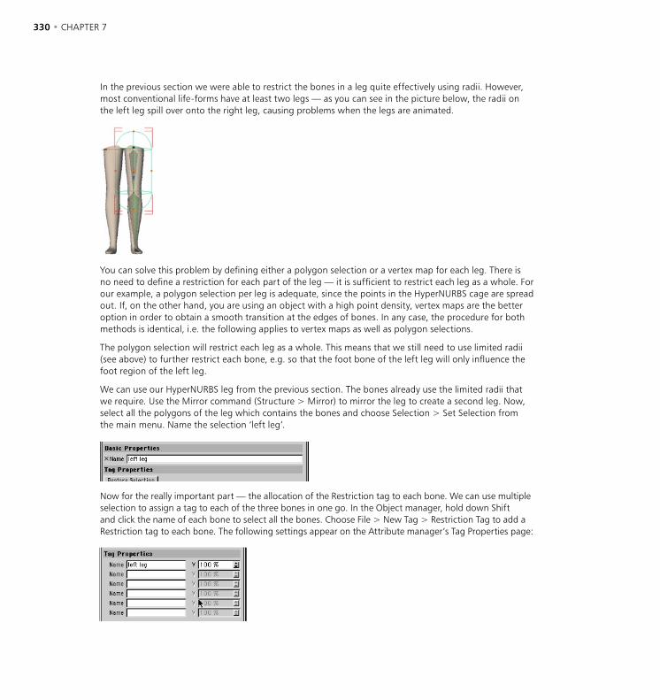
330 • CHAPTER 7 OBJECTS MENU • DEFORMERS • 331
In the previous section we were able to restrict the bones in a leg quite effectively using radii. However, most conventional life-forms have at least two legs — as you can see in the picture below, the radii on the left leg spill over onto the right leg, causing problems when the legs are animated.
You can solve this problem by defining either a polygon selection or a vertex map for each leg. There is no need to define a restriction for each part of the leg — it is sufficient to restrict each leg as a whole. For our example, a polygon selection per leg is adequate, since the points in the HyperNURBS cage are spread out. If, on the other hand, you are using an object with a high point density, vertex maps are the better option in order to obtain a smooth transition at the edges of bones. In any case, the procedure for both methods is identical, i.e. the following applies to vertex maps as well as polygon selections.
The polygon selection will restrict each leg as a whole. This means that we still need to use limited radii (see above) to further restrict each bone, e.g. so that the foot bone of the left leg will only influence the foot region of the left leg.
We can use our HyperNURBS leg from the previous section. The bones already use the limited radii that we require. Use the Mirror command (Structure > Mirror) to mirror the leg to create a second leg. Now, select all the polygons of the leg which contains the bones and choose Selection > Set Selection from the main menu. Name the selection ‘left leg’.
Now for the really important part — the allocation of the Restriction tag to each bone. We can use multiple selection to assign a tag to each of the three bones in one go. In the Object manager, hold down Shift and click the name of each bone to select all the bones. Choose File > New Tag > Restriction Tag to add a Restriction tag to each bone. The following settings appear on the Attribute manager’s Tag Properties page:
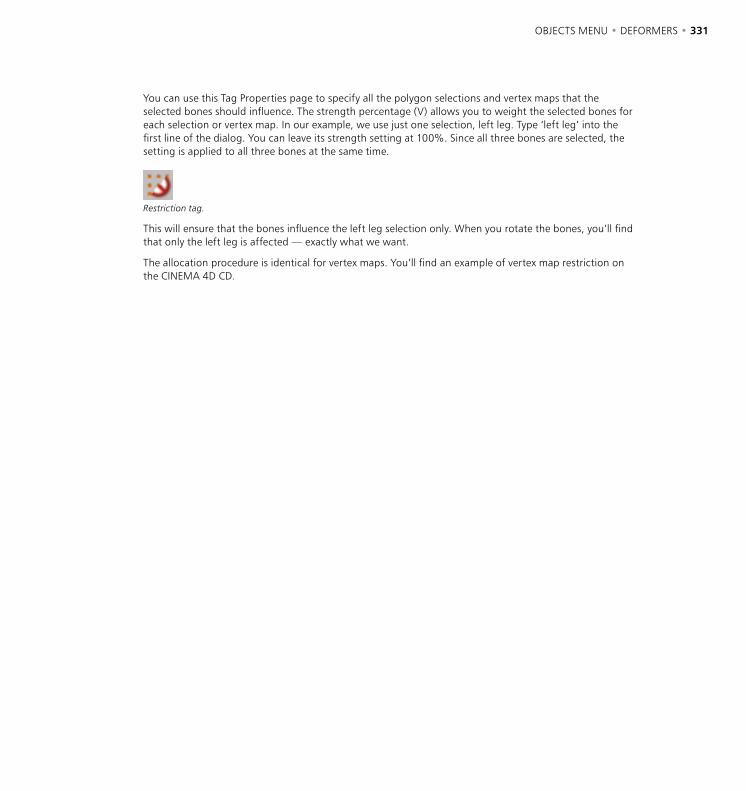
330 • CHAPTER 7 OBJECTS MENU • DEFORMERS • 331
You can use this Tag Properties page to specify all the polygon selections and vertex maps that the selected bones should influence. The strength percentage (V) allows you to weight the selected bones for each selection or vertex map. In our example, we use just one selection, left leg. Type ‘left leg’ into the first line of the dialog. You can leave its strength setting at 100%. Since all three bones are selected, the setting is applied to all three bones at the same time.
Restriction tag.
This will ensure that the bones influence the left leg selection only. When you rotate the bones, you’ll find that only the left leg is affected — exactly what we want.
The allocation procedure is identical for vertex maps. You’ll find an example of vertex map restriction on the CINEMA 4D CD.
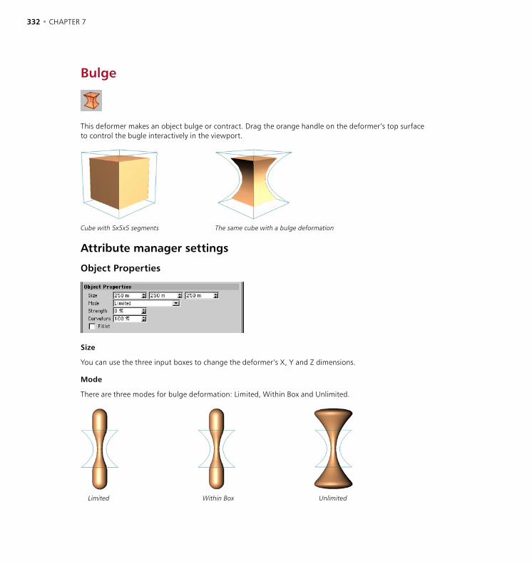
332 • CHAPTER 7 OBJECTS MENU • DEFORMERS • 333
Bulge
This deformer makes an object bulge or contract. Drag the orange handle on the deformer’s top surface to control the bugle interactively in the viewport.
Cube with 5x5x5 segments The same cube with a bulge deformation
Attribute manager settings
Object Properties
Size
You can use the three input boxes to change the deformer’s X, Y and Z dimensions.
Mode
There are three modes for bulge deformation: Limited, Within Box and Unlimited.
Limited Within Box Unlimited
332 • CHAPTER 7 OBJECTS MENU • DEFORMERS • 333
Limited
The entire object is affected. Surfaces within the cyan box bulge and the other surfaces move and rotate if necessary to accommodate the bulge. In the example, the result is the same as Within Box. However, the effect differs when the bulge deformer is moved or rotated.
Within Box
Surfaces within the cyan box bulge. Surfaces outside the box remain exactly where they are (they are unaffected).
Unlimited
The entire object bulges.
Strength
This is the strength of the bulge. To change this value interactively, drag the orange handle in the viewport.
Curvature
This value affects the curvature of the bulge. The higher its value, the more curved the bulge.
Fillet
If this option is enabled, the deformation is softened near the top and bottom.

334 • CHAPTER 7 OBJECTS MENU • DEFORMERS • 335
Explosion FX
With Explosion FX, you can quickly create and animate realistic explosion effects. It produces clusters out of the object it is deforming, over which you have a great deal of control.
Attribute manager settings
Object Properties
Time
Drag the Time parameter’s arrowheads to preview the explosion’s animation in the viewport.
To create a slider for the Time parameter, in the Attribute manager right-click (Windows) or Command-click (Mac OS) on the Time parameter name. From the context menu that opens, choose User Interface > Float Slider.
Explosion
Strength
Strength defines the force used to accelerate the clusters. The value needed for a good effect depends on the size and density of the clusters. Use Decay to set a fall-off for the Strength. 0% means no fall-off, 100% means the Strength falls to 0 by the time it reaches the edge of the blast range. Use Variation to vary the Strength for each cluster. 0% means no variation, 100% means the Strength can vary from zero to twice its entered value.
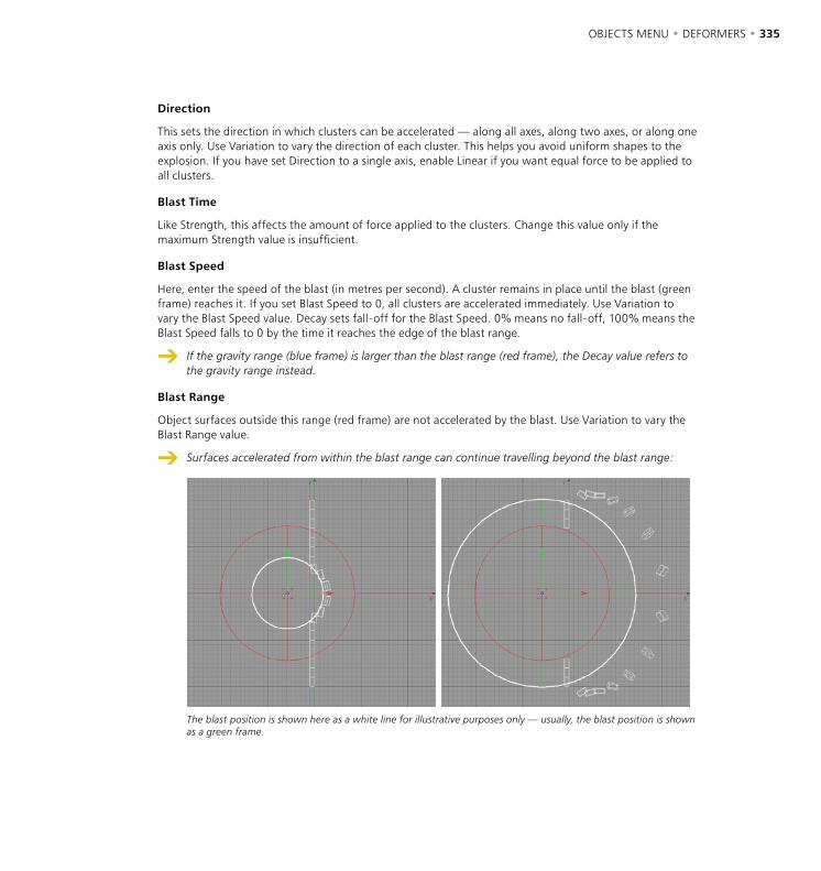
334 • CHAPTER 7 OBJECTS MENU • DEFORMERS • 335
Direction
This sets the direction in which clusters can be accelerated — along all axes, along two axes, or along one axis only. Use Variation to vary the direction of each cluster. This helps you avoid uniform shapes to the explosion. If you have set Direction to a single axis, enable Linear if you want equal force to be applied to all clusters.
Blast Time
Like Strength, this affects the amount of force applied to the clusters. Change this value only if the maximum Strength value is insufficient.
Blast Speed
Here, enter the speed of the blast (in metres per second). A cluster remains in place until the blast (green frame) reaches it. If you set Blast Speed to 0, all clusters are accelerated immediately. Use Variation to vary the Blast Speed value. Decay sets fall-off for the Blast Speed. 0% means no fall-off, 100% means the Blast Speed falls to 0 by the time it reaches the edge of the blast range.
If the gravity range (blue frame) is larger than the blast range (red frame), the Decay value refers to the gravity range instead.
Blast Range
Object surfaces outside this range (red frame) are not accelerated by the blast. Use Variation to vary the Blast Range value.
Surfaces accelerated from within the blast range can continue travelling beyond the blast range:
The blast position is shown here as a white line for illustrative purposes only — usually, the blast position is shown as a green frame.
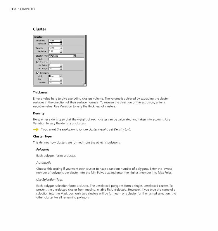
336 • CHAPTER 7 OBJECTS MENU • DEFORMERS • 337
Cluster
Thickness
Enter a value here to give exploding clusters volume. The volume is achieved by extruding the cluster surfaces in the direction of their surface normals. To reverse the direction of the extrusion, enter a negative value. Use Variation to vary the thickness of clusters.
Density
Here, enter a density so that the weight of each cluster can be calculated and taken into account. Use Variation to vary the density of clusters.
If you want the explosion to ignore cluster weight, set Density to 0.
Cluster Type
This defines how clusters are formed from the object’s polygons.
Polygons
Each polygon forms a cluster.
Automatic
Choose this setting if you want each cluster to have a random number of polygons. Enter the lowest number of polygons per cluster into the Min Polys box and enter the highest number into Max Polys.
Use Selection Tags
Each polygon selection forms a cluster. The unselected polygons form a single, unselected cluster. To prevent the unselected cluster from moving, enable Fix Unselected. However, if you type the name of a selection into the Mask box, only two clusters will be formed – one cluster for the named selection, the other cluster for all remaining polygons.
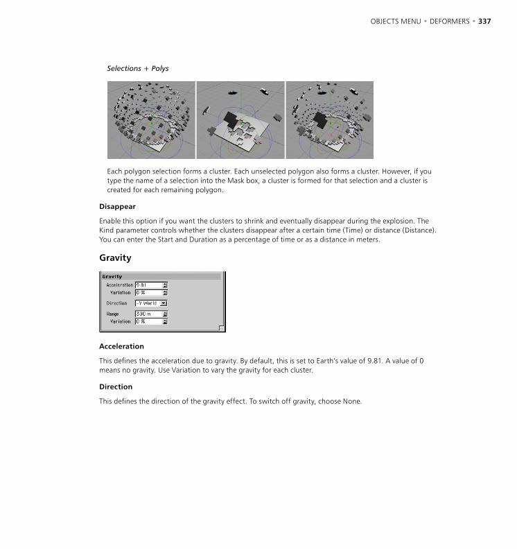
336 • CHAPTER 7 OBJECTS MENU • DEFORMERS • 337
Selections + Polys
Each polygon selection forms a cluster. Each unselected polygon also forms a cluster. However, if you type the name of a selection into the Mask box, a cluster is formed for that selection and a cluster is created for each remaining polygon.
Disappear
Enable this option if you want the clusters to shrink and eventually disappear during the explosion. The Kind parameter controls whether the clusters disappear after a certain time (Time) or distance (Distance). You can enter the Start and Duration as a percentage of time or as a distance in meters.
Gravity
Acceleration
This defines the acceleration due to gravity. By default, this is set to Earth’s value of 9.81. A value of 0 means no gravity. Use Variation to vary the gravity for each cluster.
Direction
This defines the direction of the gravity effect. To switch off gravity, choose None.
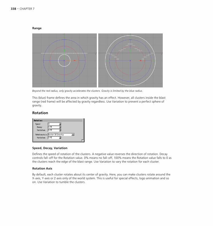
338 • CHAPTER 7 OBJECTS MENU • DEFORMERS • 339
Range
Beyond the red radius, only gravity accelerates the clusters. Gravity is limited by the blue radius.
This (blue) frame defines the area in which gravity has an effect. However, all clusters inside the blast range (red frame) will be affected by gravity regardless. Use Variation to prevent a perfect sphere of gravity.
Rotation
Speed, Decay, Variation
Defines the speed of rotation of the clusters. A negative value reverses the direction of rotation. Decay controls fall-off for the Rotation value. 0% means no fall-off, 100% means the Rotation value falls to 0 as the clusters reach the edge of the blast range. Use Variation to vary the rotation for each cluster.
Rotation Axis
By default, each cluster rotates about its center of gravity. Here, you can make clusters rotate around the X-axis, Y-axis or Z-axis only of the world system. This is useful for special effects, logo animation and so on. Use Variation to tumble the clusters.
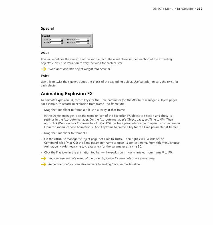
338 • CHAPTER 7 OBJECTS MENU • DEFORMERS • 339
Special
Wind
This value defines the strength of the wind effect. The wind blows in the direction of the exploding object’s Z-axis. Use Variation to vary the wind for each cluster.
Wind does not take object weight into account.
Twist
Use this to twist the clusters about the Y-axis of the exploding object. Use Variation to vary the twist for each cluster.
Animating Explosion FXTo animate Explosion FX, record keys for the Time parameter (on the Attribute manager’s Object page). For example, to record an explosion from frame 0 to frame 90:
- Drag the time slider to frame 0 if it isn’t already at that frame.
- In the Object manager, click the name or icon of the Explosion FX object to select it and show its settings in the Attribute manager. On the Attribute manager’s Object page, set Time to 0%. Then right-click (Windows) or Command-click (Mac OS) the Time parameter name to open its context menu. From this menu, choose Animation > Add Keyframe to create a key for the Time parameter at frame 0.
- Drag the time slider to frame 90.
- On the Attribute manager’s Object page, set Time to 100%. Then right-click (Windows) or Command-click (Mac OS) the Time parameter name to open its context menu. From this menu choose Animation > Add Keyframe to create a key for the parameter at frame 90.
- Click the Play icon in the animation toolbar — the explosion is now animated from frame 0 to 90.
You can also animate many of the other Explosion FX parameters in a similar way.
Remember that you can also animate by adding tracks in the Timeline.

340 • CHAPTER 7 OBJECTS MENU • DEFORMERS • 341
Explosion
The Explosion deformer explodes an object into its constituent polygons. The recipient object explodes from the deformer’s origin. Drag the orange handle to control the state of the explosion interactively in the viewport.
The Explosion object does not support vertex maps.
To animate the explosion, use a parameter track in the Timeline (see ‘New Track > Parameter’ on page 850) or animate via the Attribute manager (See ‘Animation’, page 904). For a complete explosion, set Strength for the first key to 0% and Strength for the second key to 100%. To reverse the explosion (an implosion), swap the keys around. Implosion is especially useful for logo animation.
A normal sphere. The same sphere with an explosion deformation.
Attribute manager settings
Object Properties
Strength
This value defines the state of the explosion. 0% is the start of the explosion, 100% is the end of the explosion. To change this value interactively, drag the orange handle in the viewport (at the default value of 0%, the orange handle is at the Explosion object’s origin).
Speed
This value defines the speed of the polygons during the explosion.
340 • CHAPTER 7 OBJECTS MENU • DEFORMERS • 341
Angle Speed
This value defines the angle through which each polygon rotates during the entire explosion.
End Size
This value defines the relative size of each polygon at the end of the explosion. If the value is set to 1, the polygons will remain the same size throughout the explosion. If the value is set to 0, the polygons will disappear by the end of the explosion. If the value is 2, the polygons will double in size.
Randomness
This value defines the percentage by which the speed and angle speed may vary.
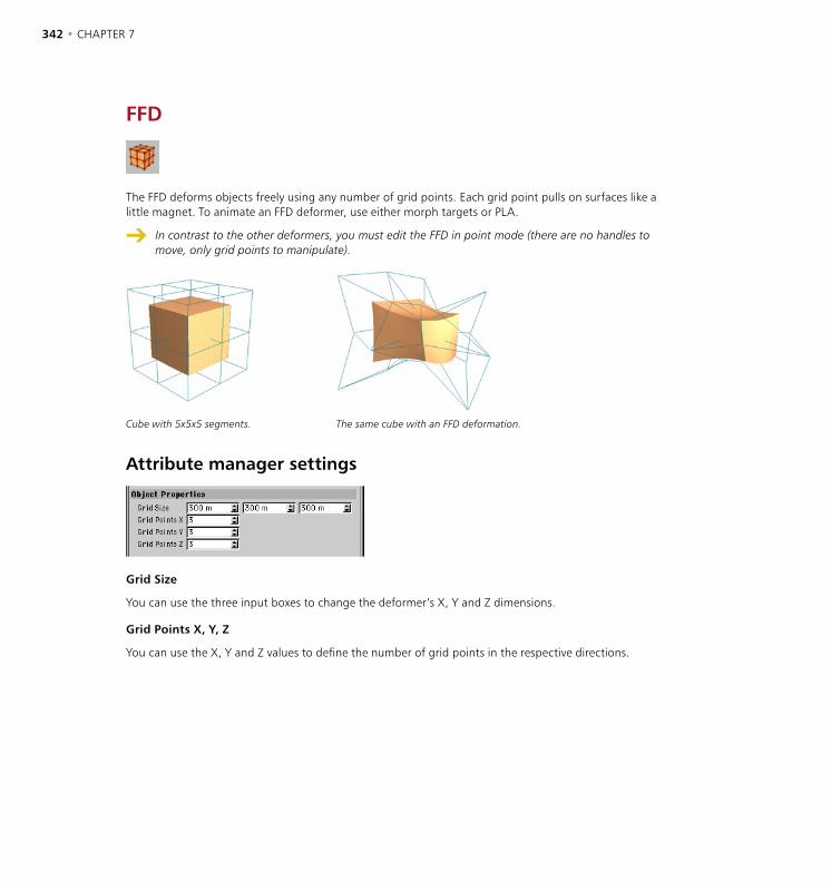
342 • CHAPTER 7 OBJECTS MENU • DEFORMERS • 343
FFD
The FFD deforms objects freely using any number of grid points. Each grid point pulls on surfaces like a little magnet. To animate an FFD deformer, use either morph targets or PLA.
In contrast to the other deformers, you must edit the FFD in point mode (there are no handles to move, only grid points to manipulate).
Cube with 5x5x5 segments. The same cube with an FFD deformation.
Attribute manager settings
Grid Size
You can use the three input boxes to change the deformer’s X, Y and Z dimensions.
Grid Points X, Y, Z
You can use the X, Y and Z values to define the number of grid points in the respective directions.

342 • CHAPTER 7 OBJECTS MENU • DEFORMERS • 343
Formula
The Formula object uses mathematical formulae to deform other objects. Drag the handles to control the size of the deformer. All surfaces — including those outside the cyan box — are affected. The default formula creates circular waves. Try dropping the Formula deformer into a sphere and then drag the time slider on the animation toolbar.
Plane with 40x40 segments.
Attribute manager settings
Object Properties
Size
You can use the X, Y and Z values to change the deformer’s dimensions.
Effect
This value defines how the formula deformation should be applied.
Manual
You can enter separate formulae for the X, Y and Z directions. This enables you to combine several formulae.
344 • CHAPTER 7 OBJECTS MENU • DEFORMERS • 345
Spherical
The effect radiates from the deformer’s origin outwards.
Cylindrical
The effect starts from the deformer’s Y-axis and travels along its X-axis and Z-axis.
X Radial
The effect starts from the deformer’s origin and travels along its X-axis only.
Y Radial
The effect starts from the deformer’s origin and travels along its Y-axis only.
Z Radial
The effect starts from the deformer’s origin and travels along its Z-axis only.
d(u,v,x,y,z,t)
This is where you enter the formula for all effects apart from Manual.
X(x,y,z,t), Y(x,y,z,t), Z(x,y,z,t)
Enter the formula for the X, Y and Z directions here when you have selected a Manual effect.
Example
cos(4*sqrt(x*x+z*z)-2*t)/sqrt(1+4*sqrt(x*x+z*z))
This formula creates damped circular waves. The time parameter (t) has been introduced so that the waves are animated over time. CINEMA 4D handles this animation automatically when t (time) is present in the formula.
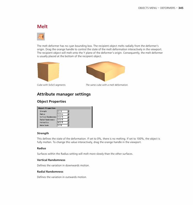
344 • CHAPTER 7 OBJECTS MENU • DEFORMERS • 345
Melt
The melt deformer has no cyan bounding box. The recipient object melts radially from the deformer’s origin. Drag the orange handle to control the state of the melt deformation interactively in the viewport. The recipient object will melt onto the Y plane of the deformer’s origin. Consequently, the melt deformer is usually placed at the bottom of the recipient object.
Cube with 5x5x5 segments. The same cube with a melt deformation.
Attribute manager settings
Object Properties
Strength
This defines the state of the deformation. If set to 0%, there is no melting. If set to 100%, the object is fully molten. To change this value interactively, drag the orange handle in the viewport.
Radius
Surfaces within the Radius setting will melt more slowly than the other surfaces.
Vertical Randomness
Defines the variation in downwards motion.
Radial Randomness
Defines the variation in outwards motion.
Melted Size
Defines the final width of the recipient object relative to its original width. The default value is 400%. Imagine a melting ice cube — the width of the puddle left behind is naturally much larger than the original width of the ice cube.
Noise Scale
The higher you set this value, the more irregular the surface becomes during the melt deformation.
Polygon Reduction
The Polygon Reduction deformer enables you to reduce the number of polygons of any CINEMA 4D geometric object and operates in a flexible and intuitive way. Polygon Reduction is available from the Objects > Deformation menu and behaves like any other deformer – just choose Polygon Reduction and place the resultant object into the Object manager hierarchy of the object that you want to affect.
Why use polygon reduction?
Many 3D tasks demand models that use as few polygons as possible. Unfortunately, the various techniques used to create models often means that more polygons are created than are necessary. Worse still, without polygon reduction tools, these models must be reduced by hand. Here are a few examples to show the importance of polygon reduction:
- Modern 3D games need characters with low polygon counts for smooth animation in realtime.
- Models for the Internet, in formats such as VRML, need a low polygon count for quick download.
- Models created by 3D scanners often have an extremely high number of polygons; reducing the number of polygons makes these objects easier to handle.
To summarize: reducing the number of polygons means faster render times and lower memory requirements.
What does polygon reduction do?
The Polygon Reduction deformer works hard to reduce the number of polygons in the chosen object quickly and accurately – this is its mission in life. It always tries to reduce the polygon count according to your wishes and provides many options for user control.
Polygon Reduction works with triangles (not quads) and, if necessary, an automatic triangulation of the object will be performed before reduction.
Polygon Reduction is great for simplifying an object mesh, taking care of any resulting mesh inconsistencies (e.g. fold-overs, boundary cracks) but it does not create a dynamic map of this process (for multiple LODs — levels of detail).
Polygon Reduction manages and diminishes the number of polygons in an object but it cannot take care of the exact number of points in the object.
Using Polygon Reduction
To apply CINEMA 4D’s polygon reduction to an existing object, proceed as follows.
- Choose Objects > Deformation > Polygon Reduction to create a new object in the root of the Object manager, named Polygon Reduction.
- Rename this object if you wish.

348 • CHAPTER 7 OBJECTS MENU • DEFORMERS • 349
- Now move this object into the hierarchy of the object that you wish to affect; you can place the Polygon Reduction object anywhere within an object’s hierarchy – polygon reduction will take place on this object and all its children. It works as a deformer.
While the polygon reduction is taking place, information on the process (including the original and the expected final polygon count) will appear in CINEMA 4D’s status bar (bottom left).
Attribute manager settings
Object Properties
Reduction Strength
You can use this value to interactively vary the amount of polygon reduction that takes place. The reduction is expressed as a percentage of the original number of polygons (triangles, remember) in the object so that if you choose 50% for an object with 500 triangle polygons, the tool will attempt to reduce the object to 250 triangle polygons.
Do not expect this to be an exact science; there may be further reductions due to, for example, any co-planar areas (i.e. faces with polygons all in the same plane) which are always reduced as far as possible. But the Reduction Strength is a great way to quickly reduce or increase the poly count.
There are a number of options that allow you to adjust the trade-off between the speed and the accuracy of the reduction. These are now described.
Mesh Quality Factor
The value assigned here affects the final result of the optimization by determining how much fold-over checking is done; a low value reduces the number of checks made while the mesh is reduced, a high value increases the number of checks.
You can enter any value between 0 and 20000; use a high value if you have a complex mesh with a high reduction strength, a low value should suffice for simple meshes and/or low reduction values. In general, the value you choose does not affect the speed of the reduction process with the exception that a value of 0 will lead to a faster reduction, since this turns off any checks.
As with other options the checks work during the entire reduction process and monitor the appearance of overlapping polygons in the mesh of the object. Here is an example that shows how an overlapped (i.e. folded over) mesh can result from a bad reduction decision and therefore why such checks are necessary.
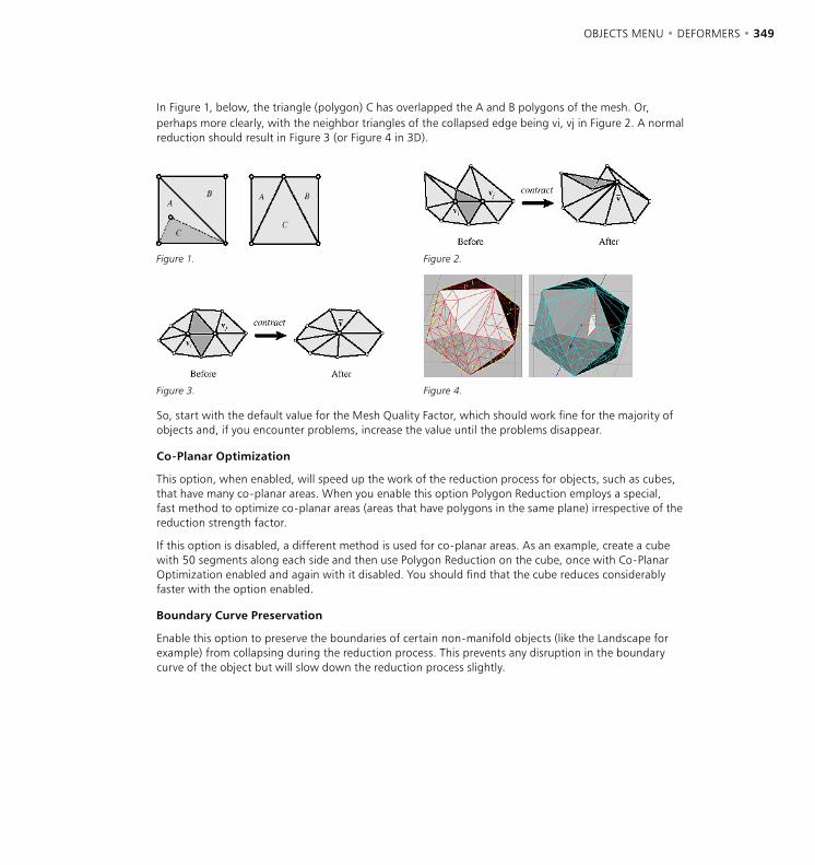
348 • CHAPTER 7 OBJECTS MENU • DEFORMERS • 349
In Figure 1, below, the triangle (polygon) C has overlapped the A and B polygons of the mesh. Or, perhaps more clearly, with the neighbor triangles of the collapsed edge being vi, vj in Figure 2. A normal reduction should result in Figure 3 (or Figure 4 in 3D).
Figure 1. Figure 2.
Figure 3. Figure 4.
So, start with the default value for the Mesh Quality Factor, which should work fine for the majority of objects and, if you encounter problems, increase the value until the problems disappear.
Co-Planar Optimization
This option, when enabled, will speed up the work of the reduction process for objects, such as cubes, that have many co-planar areas. When you enable this option Polygon Reduction employs a special, fast method to optimize co-planar areas (areas that have polygons in the same plane) irrespective of the reduction strength factor.
If this option is disabled, a different method is used for co-planar areas. As an example, create a cube with 50 segments along each side and then use Polygon Reduction on the cube, once with Co-Planar Optimization enabled and again with it disabled. You should find that the cube reduces considerably faster with the option enabled.
Boundary Curve Preservation
Enable this option to preserve the boundaries of certain non-manifold objects (like the Landscape for example) from collapsing during the reduction process. This prevents any disruption in the boundary curve of the object but will slow down the reduction process slightly.
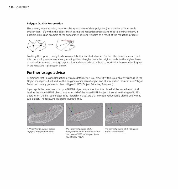
350 • CHAPTER 7 OBJECTS MENU • DEFORMERS • 351
Polygon Quality Preservation
This option, when enabled, monitors the appearance of sliver polygons (i.e. triangles with an angle smaller than 15˚) within the object mesh during the reduction process and tries to eliminate them, if possible. Here is an example of the appearance of sliver triangles as a result of the reduction process:
Enabling this option usually leads to a much better distributed mesh. On the other hand be aware that this check will preserve any already existing sliver triangles (from the original mesh) to the highest levels of reduction. A more thorough explanation and some advice on how to work with these options is given in the Hints and Tips section below.
Further usage adviceRemember that Polygon Reduction acts as a deformer i.e. you place it within your object structure in the Object manager – it will reduce the polygons of its parent object and all its children. You can use Polygon Reduction on any geometric object (HyperNURBS, Object Primitive, Array etc.).
If you apply the deformer to a HyperNURBS object make sure that it is placed at the same hierarchical level as the HyperNURBS object, not as a child of the HyperNURBS object. Also, since the HyperNURBS operates on the first sub-object in its hierarchy, make sure that Polygon Reduction is placed below that sub-object. The following diagrams illustrate this.
A HyperNURBS object before applying Polygon Reduction.
The incorrect placing of the Polygon Reduction deformer within the HyperNURBS sub-object leads to a strange result.
The correct placing of the Polygon Reduction deformer.
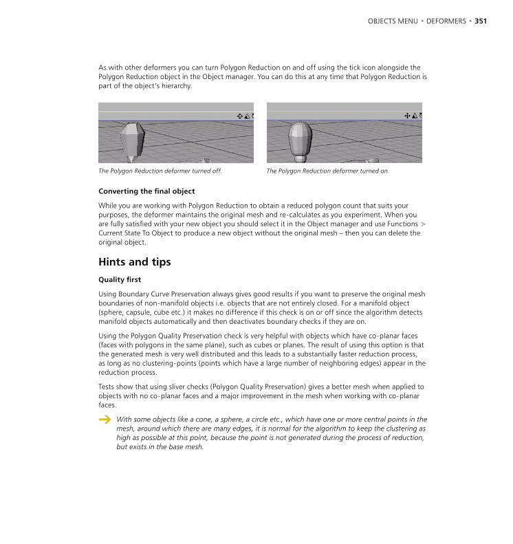
350 • CHAPTER 7 OBJECTS MENU • DEFORMERS • 351
As with other deformers you can turn Polygon Reduction on and off using the tick icon alongside the Polygon Reduction object in the Object manager. You can do this at any time that Polygon Reduction is part of the object’s hierarchy.
The Polygon Reduction deformer turned off. The Polygon Reduction deformer turned on.
Converting the final object
While you are working with Polygon Reduction to obtain a reduced polygon count that suits your purposes, the deformer maintains the original mesh and re-calculates as you experiment. When you are fully satisfied with your new object you should select it in the Object manager and use Functions > Current State To Object to produce a new object without the original mesh – then you can delete the original object.
Hints and tipsQuality first
Using Boundary Curve Preservation always gives good results if you want to preserve the original mesh boundaries of non-manifold objects i.e. objects that are not entirely closed. For a manifold object (sphere, capsule, cube etc.) it makes no difference if this check is on or off since the algorithm detects manifold objects automatically and then deactivates boundary checks if they are on.
Using the Polygon Quality Preservation check is very helpful with objects which have co-planar faces (faces with polygons in the same plane), such as cubes or planes. The result of using this option is that the generated mesh is very well distributed and this leads to a substantially faster reduction process, as long as no clustering-points (points which have a large number of neighboring edges) appear in the reduction process.
Tests show that using sliver checks (Polygon Quality Preservation) gives a better mesh when applied to objects with no co-planar faces and a major improvement in the mesh when working with co-planar faces.
With some objects like a cone, a sphere, a circle etc., which have one or more central points in the mesh, around which there are many edges, it is normal for the algorithm to keep the clustering as high as possible at this point, because the point is not generated during the process of reduction, but exists in the base mesh.
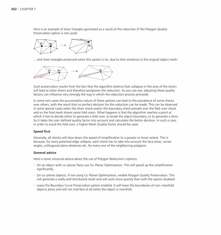
352 • CHAPTER 7 OBJECTS MENU • DEFORMERS • 353
Here is an example of sliver triangles generated as a result of the reduction (if the Polygon Quality Preservation option is not used):
... and sliver triangles preserved when this option is on, due to their existence in the original object mesh:
Such preservation results from the fact that the algorithm detects that collapses in the area of the slivers will lead to other slivers and therefore postpones the reduction. As you can see, adjusting these quality factors can influence very strongly the way in which the reduction process proceeds.
In some rare cases the accumulative nature of these options can lead to the prevalence of some checks over others, with the result that no perfect decision for the reduction can be made. This can be observed in some special cases when the sliver check and/or the boundary check prevails over the fold-over check and so the final mesh shows some fold-overs. What happens is that the algorithm reaches a point at which it has to decide either to generate a fold-over, to break the object boundary, or to generate a sliver. So it takes the user-defined quality factor into account and calculates the better decision. In such a case, in order to avoid the fold-over, a higher Mesh Quality Factor should be used.
Speed first
Generally, all checks will slow down the speed of simplification to a greater or lesser extent. This is because, for every potential edge collapse, each check has to take into account the face areas, vector angles, orthogonal plane distances etc. for every one of the neighboring polygons.
General advice
Here is some universal advice about the use of Polygon Reduction’s options:
- On an object with co-planar faces use Co-Planar Optimization. This will speed up the simplification significantly.
- On co-planar objects, if not using Co-Planar Optimization, enable Polygon Quality Preservation. This will generate a really well distributed mesh and will work more quickly than with the option disabled.
- Leave the Boundary Curve Preservation option enabled. It will leave the boundaries of non-manifold objects alone and will not interfere at all when the object is manifold.

352 • CHAPTER 7 OBJECTS MENU • DEFORMERS • 353
Here are some results generated with Polygon Reduction:
A 3D head with 6876 triangles, reduced to 3437 triangles .
The head rendered with 6876 triangles, 3437 triangles and 1715 triangles.
A 3D plane with 998 triangles (front) and 20 000 triangles (rear).
The same 3D planes showing the object mesh.
A reduced sphere with 528 triangles (front) and the original sphere with 8448 triangles (rear).
A 3D co-planar object with a complex boundary – originally with 1792 triangles (rear); reducing with the Co-planar optimization on results in 20 triangles (front).
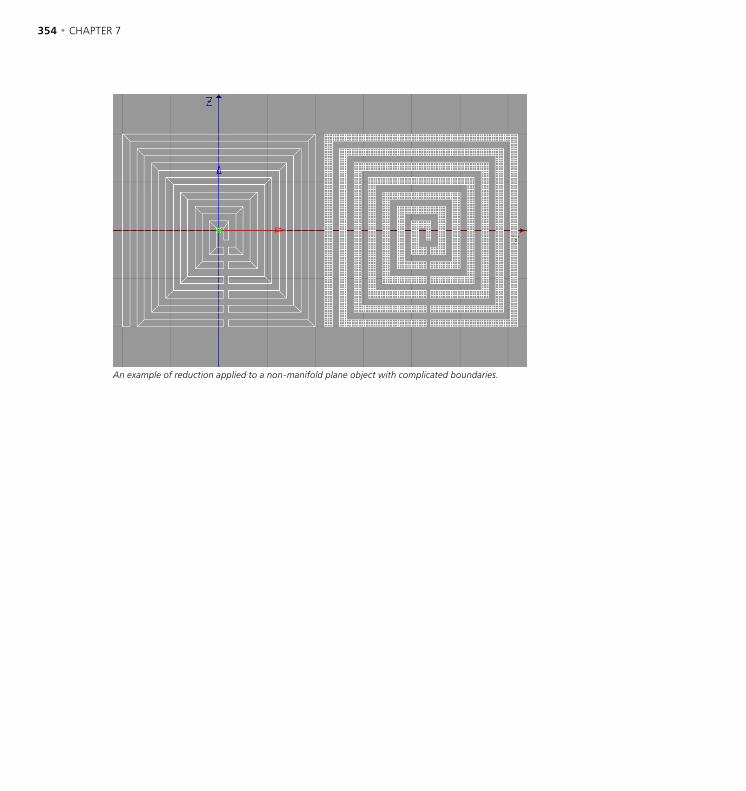
354 • CHAPTER 7 OBJECTS MENU • DEFORMERS • 355
An example of reduction applied to a non-manifold plane object with complicated boundaries.
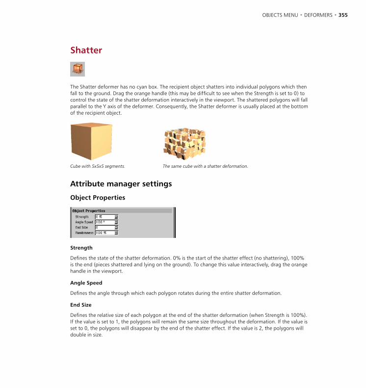
354 • CHAPTER 7 OBJECTS MENU • DEFORMERS • 355
Shatter
The Shatter deformer has no cyan box. The recipient object shatters into individual polygons which then fall to the ground. Drag the orange handle (this may be difficult to see when the Strength is set to 0) to control the state of the shatter deformation interactively in the viewport. The shattered polygons will fall parallel to the Y axis of the deformer. Consequently, the Shatter deformer is usually placed at the bottom of the recipient object.
Cube with 5x5x5 segments. The same cube with a shatter deformation.
Attribute manager settings
Object Properties
Strength
Defines the state of the shatter deformation. 0% is the start of the shatter effect (no shattering), 100% is the end (pieces shattered and lying on the ground). To change this value interactively, drag the orange handle in the viewport.
Angle Speed
Defines the angle through which each polygon rotates during the entire shatter deformation.
End Size
Defines the relative size of each polygon at the end of the shatter deformation (when Strength is 100%). If the value is set to 1, the polygons will remain the same size throughout the deformation. If the value is set to 0, the polygons will disappear by the end of the shatter effect. If the value is 2, the polygons will double in size.

356 • CHAPTER 7 OBJECTS MENU • DEFORMERS • 357
Randomness
Defines the percentage by which the speed and angle speed may vary.
The Shatter object does not support vertex maps.

356 • CHAPTER 7 OBJECTS MENU • DEFORMERS • 357
Shear
This deformer shears an object. Drag the orange handle on the deformer’s top surface to control the shear deformation interactively in the viewport.
Cube with 5x5x5 segments. The same cube with a shear deformation.
Attribute manager settings
Object Properties
Size
You can use the three input boxes to change the deformer’s X, Y and Z dimensions.
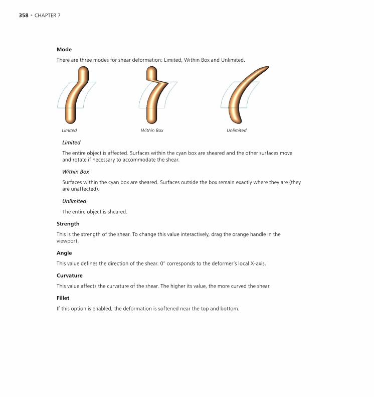
358 • CHAPTER 7 OBJECTS MENU • DEFORMERS • 359
Mode
There are three modes for shear deformation: Limited, Within Box and Unlimited.
Limited Within Box Unlimited
Limited
The entire object is affected. Surfaces within the cyan box are sheared and the other surfaces move and rotate if necessary to accommodate the shear.
Within Box
Surfaces within the cyan box are sheared. Surfaces outside the box remain exactly where they are (they are unaffected).
Unlimited
The entire object is sheared.
Strength
This is the strength of the shear. To change this value interactively, drag the orange handle in the viewport.
Angle
This value defines the direction of the shear. 0° corresponds to the deformer’s local X-axis.
Curvature
This value affects the curvature of the shear. The higher its value, the more curved the shear.
Fillet
If this option is enabled, the deformation is softened near the top and bottom.
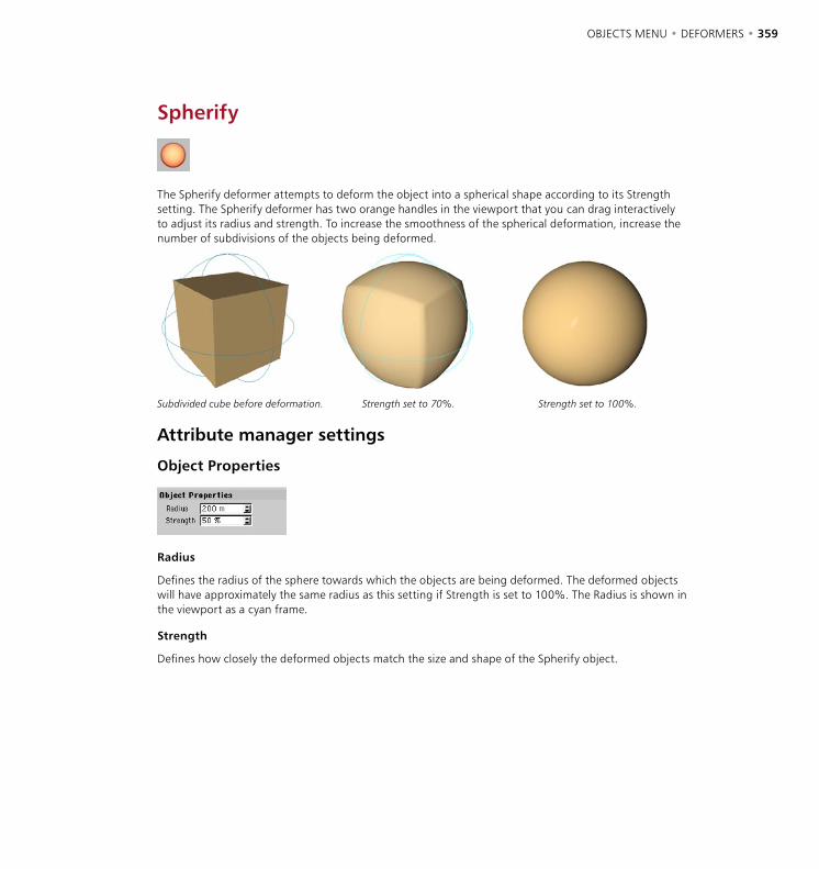
358 • CHAPTER 7 OBJECTS MENU • DEFORMERS • 359
Spherify
The Spherify deformer attempts to deform the object into a spherical shape according to its Strength setting. The Spherify deformer has two orange handles in the viewport that you can drag interactively to adjust its radius and strength. To increase the smoothness of the spherical deformation, increase the number of subdivisions of the objects being deformed.
Subdivided cube before deformation. Strength set to 70%. Strength set to 100%.
Attribute manager settings
Object Properties
Radius
Defines the radius of the sphere towards which the objects are being deformed. The deformed objects will have approximately the same radius as this setting if Strength is set to 100%. The Radius is shown in the viewport as a cyan frame.
Strength
Defines how closely the deformed objects match the size and shape of the Spherify object.
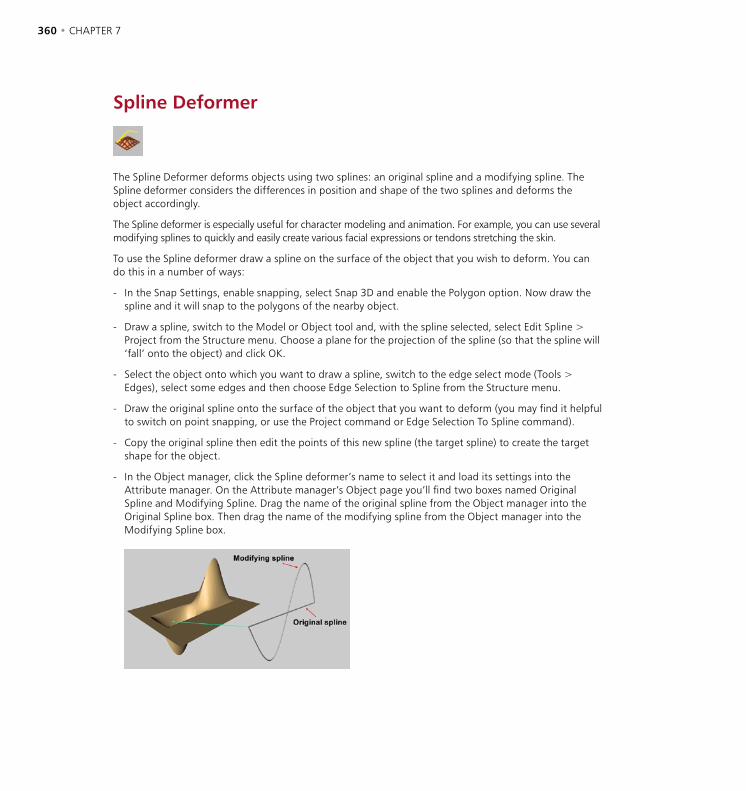
360 • CHAPTER 7 OBJECTS MENU • DEFORMERS • 361
Spline Deformer
The Spline Deformer deforms objects using two splines: an original spline and a modifying spline. The Spline deformer considers the differences in position and shape of the two splines and deforms the object accordingly.
The Spline deformer is especially useful for character modeling and animation. For example, you can use several modifying splines to quickly and easily create various facial expressions or tendons stretching the skin.
To use the Spline deformer draw a spline on the surface of the object that you wish to deform. You can do this in a number of ways:
- In the Snap Settings, enable snapping, select Snap 3D and enable the Polygon option. Now draw the spline and it will snap to the polygons of the nearby object.
- Draw a spline, switch to the Model or Object tool and, with the spline selected, select Edit Spline > Project from the Structure menu. Choose a plane for the projection of the spline (so that the spline will ‘fall’ onto the object) and click OK.
- Select the object onto which you want to draw a spline, switch to the edge select mode (Tools > Edges), select some edges and then choose Edge Selection to Spline from the Structure menu.
- Draw the original spline onto the surface of the object that you want to deform (you may find it helpful to switch on point snapping, or use the Project command or Edge Selection To Spline command).
- Copy the original spline then edit the points of this new spline (the target spline) to create the target shape for the object.
- In the Object manager, click the Spline deformer’s name to select it and load its settings into the Attribute manager. On the Attribute manager’s Object page you’ll find two boxes named Original Spline and Modifying Spline. Drag the name of the original spline from the Object manager into the Original Spline box. Then drag the name of the modifying spline from the Object manager into the Modifying Spline box.

360 • CHAPTER 7 OBJECTS MENU • DEFORMERS • 361
Attribute manager settings
Object Properties
Original Spline
Drag the name of the original spline from the Object manager into this box. Keep in mind that the original spline should rest on the surface of the object you want to deform.
Modifying Spline
Drag the name of the new spline from the Object manager into this box. The Spline deformer calculates the difference in distance and shape between the splines and moves the points that are near the original spline accordingly.
B-Spline Approximation
If the original spline is a B-Spline, you can use this parameter to define the spline’s subdivision. Increase the value for greater accuracy, keeping in mind that higher values take longer to calculate.

362 • CHAPTER 7 OBJECTS MENU • DEFORMERS • 363
Radius
Low Radius value High Radius value
The Radius value defines the deformation distance at right angles to the splines.
Use Length
Enable this option if the two splines have a different number of points. The Spline deformer then spreads out the points internally to improve the accuracy of the deformation.
Full Polygons
If artefacts appear when the object is deformed, enable Full Polygons. Then full polygons will be taken into account rather than points only.
Shape
Use the Shape graph to control the function used for the deformation within the radius. To draw a Shape spline, click within the graph to create each spline point. The first two points are locked to the right and left edge of the graph. Further points can be placed freely on the graph. To move a point, drag it to its new position. To delete a point, drag it out of the graph. To select multiple points, Shift-click each point that you want to select before deleting.
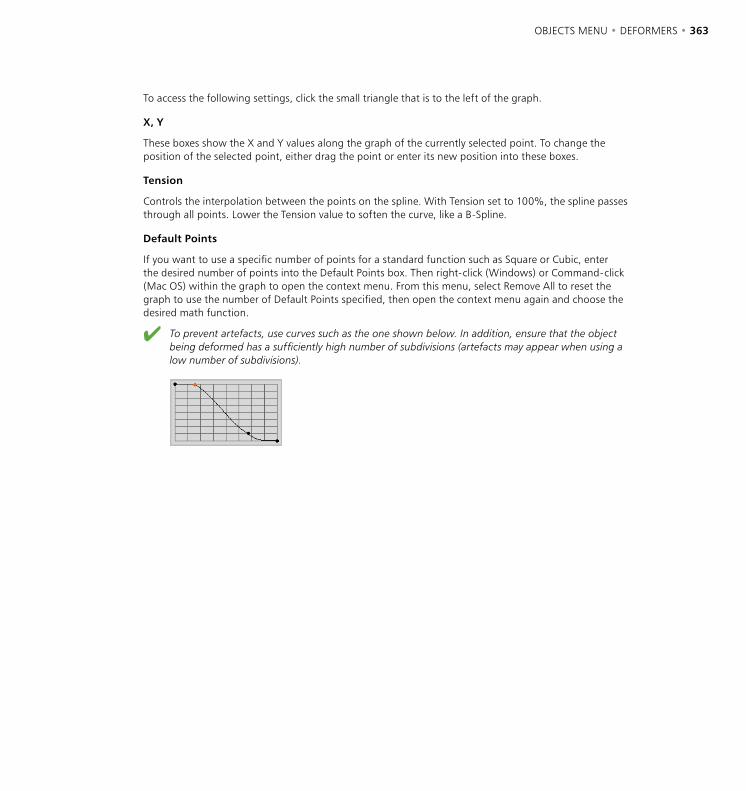
362 • CHAPTER 7 OBJECTS MENU • DEFORMERS • 363
To access the following settings, click the small triangle that is to the left of the graph.
X, Y
These boxes show the X and Y values along the graph of the currently selected point. To change the position of the selected point, either drag the point or enter its new position into these boxes.
Tension
Controls the interpolation between the points on the spline. With Tension set to 100%, the spline passes through all points. Lower the Tension value to soften the curve, like a B-Spline.
Default Points
If you want to use a specific number of points for a standard function such as Square or Cubic, enter the desired number of points into the Default Points box. Then right-click (Windows) or Command-click (Mac OS) within the graph to open the context menu. From this menu, select Remove All to reset the graph to use the number of Default Points specified, then open the context menu again and choose the desired math function.
To prevent artefacts, use curves such as the one shown below. In addition, ensure that the object being deformed has a sufficiently high number of subdivisions (artefacts may appear when using a low number of subdivisions).
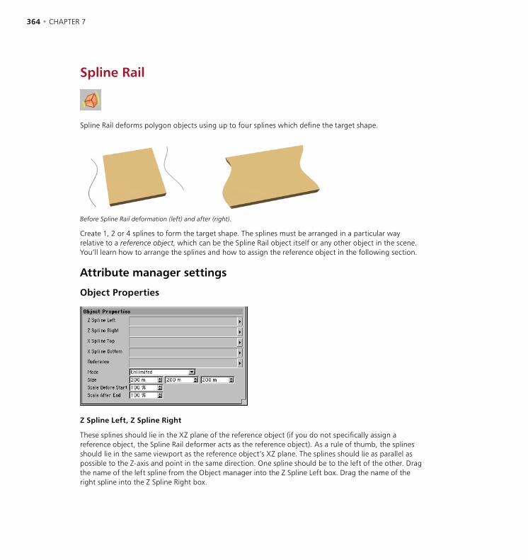
364 • CHAPTER 7 OBJECTS MENU • DEFORMERS • 365
Spline Rail
Spline Rail deforms polygon objects using up to four splines which define the target shape.
Before Spline Rail deformation (left) and after (right).
Create 1, 2 or 4 splines to form the target shape. The splines must be arranged in a particular way relative to a reference object, which can be the Spline Rail object itself or any other object in the scene. You’ll learn how to arrange the splines and how to assign the reference object in the following section.
Attribute manager settings
Object Properties
Z Spline Left, Z Spline Right
These splines should lie in the XZ plane of the reference object (if you do not specifically assign a reference object, the Spline Rail deformer acts as the reference object). As a rule of thumb, the splines should lie in the same viewport as the reference object’s XZ plane. The splines should lie as parallel as possible to the Z-axis and point in the same direction. One spline should be to the left of the other. Drag the name of the left spline from the Object manager into the Z Spline Left box. Drag the name of the right spline into the Z Spline Right box.

364 • CHAPTER 7 OBJECTS MENU • DEFORMERS • 365
X Spline Top, X Spline Bottom
These splines should also lie in the XZ plane of the reference object and should be as parallel as possible to the X-axis. One spline should be above the other and the splines should point in the same direction as the reference object’s X-axis or Z-axis. Drag the names of the splines from the Object manager into the appropriate boxes.
Reference
The reference object’s Z-axis defines the direction of the Spline Rail deformation. You can use any object as the reference — drag the name of the desired object from the Object manager into the Reference box. If you leave the Reference box empty, the Spline Rail itself is used as the reference object.
Mode
There are three modes for Spline Rail deformation: Limited, Within Box and Unlimited.
Before deformation Limited Within Box Unlimited
Limited
Polygons within the cyan box are fitted to the splines. All other polygons are cut off.
Within Box
Polygons within the cyan box are fitted to the splines. Surfaces outside the box remain exactly where they are (they are unaffected).
Unlimited
The entire object is deformed. Polygons between the splines are fitted to the splines. Polygons before or after the splines take the size of the opening.
Size
Defines the size of the Spline Rail object. The object being deformed must be fully inside the Spline Rail object if you want the polygons to fit the splines completely.
Scale Before Start, Scale After End
When Mode is set to Unlimited, the deformation also affects polygons that are outside the cyan box. Use these two parameters to control the scale of the deformation outside the box.
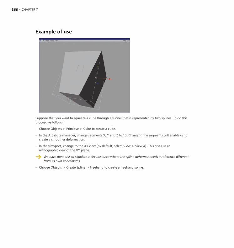
366 • CHAPTER 7 OBJECTS MENU • DEFORMERS • 367
Example of use
Suppose that you want to squeeze a cube through a funnel that is represented by two splines. To do this proceed as follows:
- Choose Objects > Primitive > Cube to create a cube.
- In the Attribute manager, change segments X, Y and Z to 10. Changing the segments will enable us to create a smoother deformation.
- In the viewport, change to the XY view (by default, select View > View 4). This gives us an orthographic view of the XY plane.
We have done this to simulate a circumstance where the spline deformer needs a reference different from its own coordinates.
- Choose Objects > Create Spline > Freehand to create a freehand spline.

366 • CHAPTER 7 OBJECTS MENU • DEFORMERS • 367
- Hold down the Ctrl key and click to create the first point in the viewport. Ctrl-click and make a second point to create a diagonal line as shown in the picture below.
- In the Attribute manager, disable Close Spline on the Object page. This is very important.
- Double click on the spline’s name in the Object manager and name it Left.

368 • CHAPTER 7 OBJECTS MENU • DEFORMERS • 369
- Select the Left spline in the Object manager and duplicate it by pressing Ctrl-C (Windows) or Command-C (Mac OS), then Ctrl-V (Windows) or Command-V (Mac OS). This will create a new spline named Left.1.
- Select the Model tool and in the Coordinates manager change H to 180. Your splines should now look like those in the picture below.
- In the Object manager, double click the Left.1 spline’s name and name it Right.
- Choose Objects > Null Object to create a null object.
- In the Coordinates manager, change P to 90. This rotates the Null object so that its Z axis now points in the same direction as the Y axis of the cube. We will use this null’s coordinates as the reference for our Spline Rail deformer in a moment.
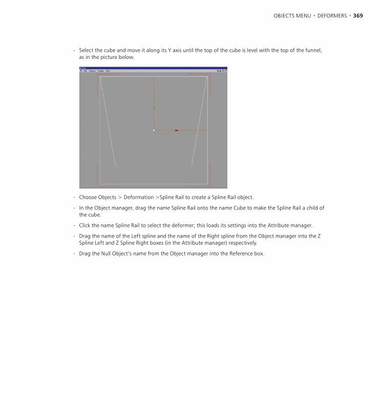
368 • CHAPTER 7 OBJECTS MENU • DEFORMERS • 369
- Select the cube and move it along its Y axis until the top of the cube is level with the top of the funnel, as in the picture below.
- Choose Objects > Deformation >Spline Rail to create a Spline Rail object.
- In the Object manager, drag the name Spline Rail onto the name Cube to make the Spline Rail a child of the cube.
- Click the name Spline Rail to select the deformer; this loads its settings into the Attribute manager.
- Drag the name of the Left spline and the name of the Right spline from the Object manager into the Z Spline Left and Z Spline Right boxes (in the Attribute manager) respectively.
- Drag the Null Object’s name from the Object manager into the Reference box.
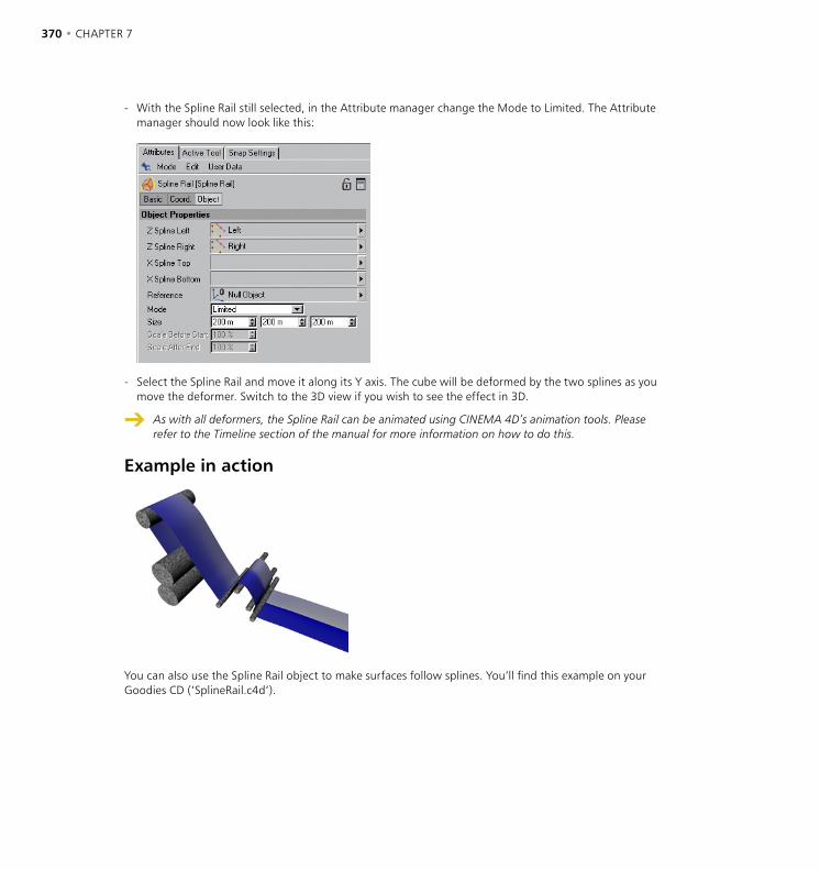
370 • CHAPTER 7 OBJECTS MENU • DEFORMERS • 371
- With the Spline Rail still selected, in the Attribute manager change the Mode to Limited. The Attribute manager should now look like this:
- Select the Spline Rail and move it along its Y axis. The cube will be deformed by the two splines as you move the deformer. Switch to the 3D view if you wish to see the effect in 3D.
As with all deformers, the Spline Rail can be animated using CINEMA 4D’s animation tools. Please refer to the Timeline section of the manual for more information on how to do this.
Example in action
You can also use the Spline Rail object to make surfaces follow splines. You’ll find this example on your Goodies CD (‘SplineRail.c4d’).
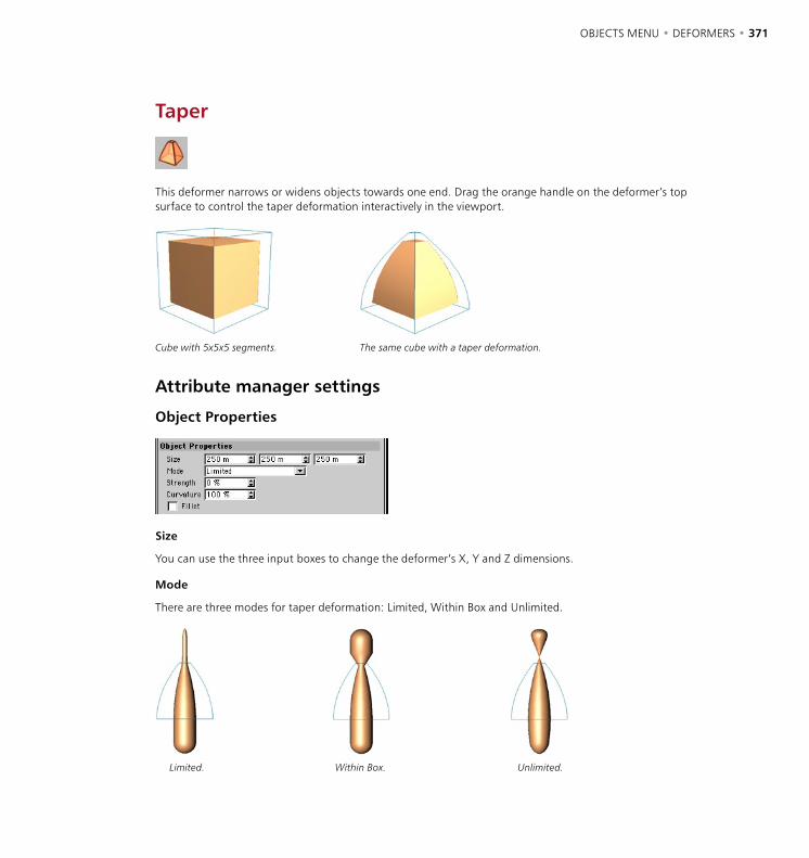
370 • CHAPTER 7 OBJECTS MENU • DEFORMERS • 371
Taper
This deformer narrows or widens objects towards one end. Drag the orange handle on the deformer’s top surface to control the taper deformation interactively in the viewport.
Cube with 5x5x5 segments. The same cube with a taper deformation.
Attribute manager settings
Object Properties
Size
You can use the three input boxes to change the deformer’s X, Y and Z dimensions.
Mode
There are three modes for taper deformation: Limited, Within Box and Unlimited.
Limited. Within Box. Unlimited.
372 • CHAPTER 7 OBJECTS MENU • DEFORMERS • 373
Limited
The entire object is affected. Surfaces within the cyan box are tapered and the other surfaces move and rotate if necessary to accommodate the taper.
Within Box
Surfaces within the cyan box are tapered. Surfaces outside the box remain exactly where they are (they are unaffected).
Unlimited
The entire object is tapered.
Strength
This is the strength of the taper. To change this value interactively, drag the orange handle in the viewport.
Curvature
This value affects the curvature of the taper. The higher its value, the more curved the taper.
Fillet
If you enable this option, the deformation is softened near the top and bottom.
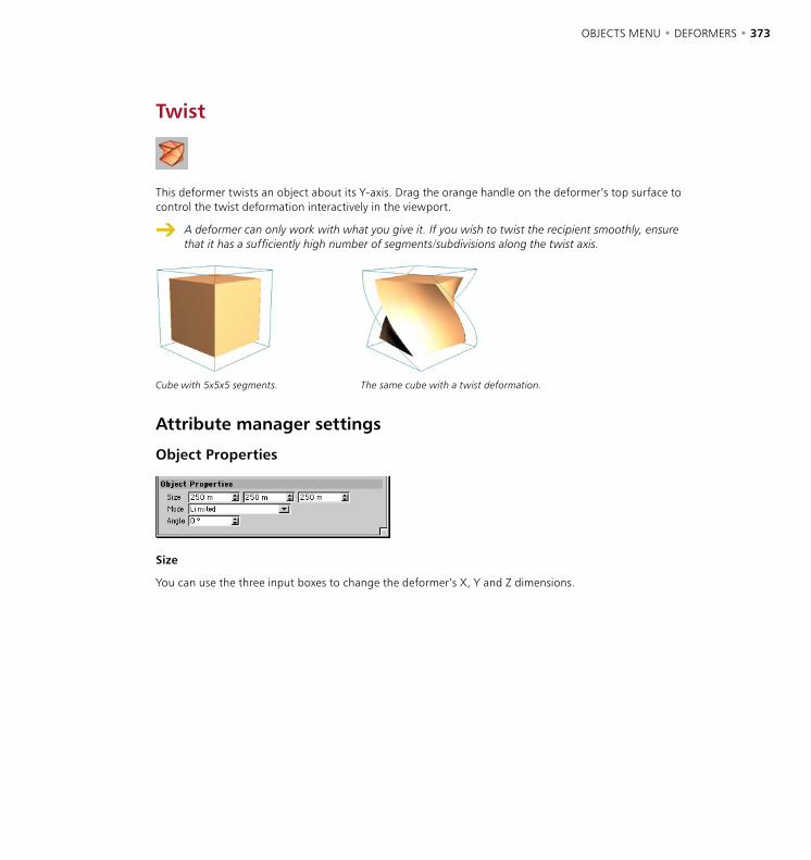
372 • CHAPTER 7 OBJECTS MENU • DEFORMERS • 373
Twist
This deformer twists an object about its Y-axis. Drag the orange handle on the deformer’s top surface to control the twist deformation interactively in the viewport.
A deformer can only work with what you give it. If you wish to twist the recipient smoothly, ensure that it has a sufficiently high number of segments/subdivisions along the twist axis.
Cube with 5x5x5 segments. The same cube with a twist deformation.
Attribute manager settings
Object Properties
Size
You can use the three input boxes to change the deformer’s X, Y and Z dimensions.

374 • CHAPTER 7 OBJECTS MENU • DEFORMERS • 375
Mode
There are three modes for twist deformation: Limited, Within Box and Unlimited.
Limited. Within Box. Unlimited.
Limited
The entire object is affected. Surfaces within the cyan box are twisted and the other surfaces move and rotate if necessary to accommodate the twist.
Within Box
Surfaces within the cyan box are twisted. Surfaces outside the box remain exactly where they are (they are unaffected).
Unlimited
The entire object is twisted.
Angle
This value is the angle through which the recipient object is twisted. To change this value interactively, drag the orange handle in the viewport.

374 • CHAPTER 7 OBJECTS MENU • DEFORMERS • 375
Wind
This deformer generates waves on an object. The wind blows in the deformer’s positive X direction. The wind deformer is animated automatically (click on the play button). Drag the orange handle on the Z-axis to change the amplitude of the waves interactively in the viewport. Drag the orange handle on the X-axis to change the size of the waves in the X and Y directions.
Flag with wind deformation.
Attribute manager settings
Object Properties
Amplitude
This value defines the size of the waves in the Z direction. To change this value interactively, drag the orange handle on the Z-axis.
Size
This value determines the size of the waves in the X and Y directions.
Frequency
The frequency determines the speed of the waves.

376 • CHAPTER 7 OBJECTS MENU • DEFORMERS • 377
Turbulence
This setting creates secondary waves which run in the direction of the deformer’s Y-axis. The percentage defines the size of these secondary waves relative to the main waves.
fx, fy
These values determine the number of waves in the X and Y directions.
Flag
If you enable this option, all points along the deformer’s Y-axis remain still (fixed). For example, you can use this to simulate a flag on a pole — one end of the flag flaps freely in the wind, while the other end is fixed to the pole and does not move (place the deformer’s Y-axis along this end of the flag).
Flag activated — the wind deformer’s Y-axis is located at the left end of the flag. The left end of the flag is fixed.
Flag deactivated — the entire flag flaps freely in the wind. The left end is no longer fixed.
If you have attached a flag to a rope, place the wind deformer in an object group with the rope and the flag. Then, both the rope and flag will move in the wind.

376 • CHAPTER 7 OBJECTS MENU • DEFORMERS • 377
Wrap
In the viewport, you will see that the wrap deformer has a flat surface and a curved surface. The curved surface represents the part of the sphere or cylinder around which the recipient object will be wrapped. The straight surface represents the total area which can be wrapped around the curved surface. If the recipient object is larger than the flat surface, then only the part that lies within the flat surface’s borders will deform correctly onto the curved surface.
Drag the orange handles on the X-axis and Y-axis to change the dimensions of the flat surface interactively in the viewport. Drag the handle on the Z-axis to change the radius of the sphere or cylinder.
Attribute manager settings
Object Properties
Width, Height
These settings define the width and height of the flat surface. If the recipient is larger than the flat surface, it will wrap onto and beyond the cyan curved surface. If the recipient is smaller than the flat surface, it will wrap on to and within the curved surface (it will not cover the entire curved surface). To change the transform area interactively, drag the orange handles on the X-axis and Y-axis.
Radius
This value defines the radius of the cylinder or sphere (see below) around which the recipient is wrapped.

378 • CHAPTER 7
Wrap
Cylindrical wrap. Spherical wrap.
You can use this value to determine whether the recipient is wrapped around a sphere or a cylinder.
Longitude Start, Longitude End
These angles define the horizontal span of the curved surface. If Start is set to 180° and End to 360°, the curved surface forms half of the cylinder or sphere in the horizontal direction.
Latitude Start, Latitude End
These angles define the vertical span of the curved surface. If Start is set to -45° and End to 45°, the curved surface forms the middle half of the cylinder or sphere in the vertical direction.
Movement
You can use this value to specify a movement in the Y direction. This causes the object to wrap in a spiral fashion. You can use a positive value to spiral up or a negative value to spiral down.
Scale Z
Use this value to simulate the flattening that usually happens when a real-life flexible object is stretched. If you enter 50% instead of 100%, the object will be flattened by 50% in the Z direction. You can enter values greater than 100% if you would like the object to expand on wrapping.
Tension
This setting enables you to define the strength of the wrap effect. You can set values from 0% to 100%. To animate a wrap deformation, use a parameter track in the Timeline (see ‘New Track > Parameter’ on page 850) or animate via the Attribute manager (See ‘Animation’, page 904). To wrap the object completely, set Tension for the first key to 0% and Tension for the second key to 100%. To reverse the wrap effect, swap the keys around.
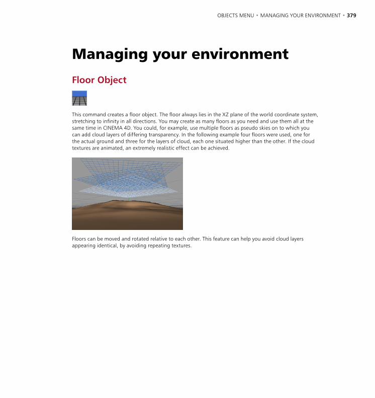
OBJECTS MENU • MANAGING YOUR ENVIRONMENT • 379
Floor Object
This command creates a floor object. The floor always lies in the XZ plane of the world coordinate system, stretching to infinity in all directions. You may create as many floors as you need and use them all at the same time in CINEMA 4D. You could, for example, use multiple floors as pseudo skies on to which you can add cloud layers of differing transparency. In the following example four floors were used, one for the actual ground and three for the layers of cloud, each one situated higher than the other. If the cloud textures are animated, an extremely realistic effect can be achieved.
Floors can be moved and rotated relative to each other. This feature can help you avoid cloud layers appearing identical, by avoiding repeating textures.
Managing your environment
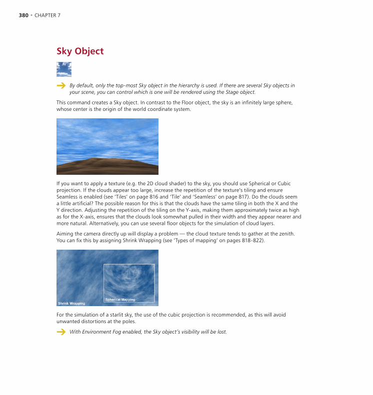
380 • CHAPTER 7 OBJECTS MENU • MANAGING YOUR ENVIRONMENT • 381
Sky Object
By default, only the top-most Sky object in the hierarchy is used. If there are several Sky objects in your scene, you can control which is one will be rendered using the Stage object.
This command creates a Sky object. In contrast to the Floor object, the sky is an infinitely large sphere, whose center is the origin of the world coordinate system.
If you want to apply a texture (e.g. the 2D cloud shader) to the sky, you should use Spherical or Cubic projection. If the clouds appear too large, increase the repetition of the texture’s tiling and ensure Seamless is enabled (see ‘Tiles’ on page 816 and ‘Tile’ and ‘Seamless’ on page 817). Do the clouds seem a little artificial? The possible reason for this is that the clouds have the same tiling in both the X and the Y direction. Adjusting the repetition of the tiling on the Y-axis, making them approximately twice as high as for the X-axis, ensures that the clouds look somewhat pulled in their width and they appear nearer and more natural. Alternatively, you can use several floor objects for the simulation of cloud layers.
Aiming the camera directly up will display a problem — the cloud texture tends to gather at the zenith. You can fix this by assigning Shrink Wrapping (see ‘Types of mapping’ on pages 818-822).
For the simulation of a starlit sky, the use of the cubic projection is recommended, as this will avoid unwanted distortions at the poles.
With Environment Fog enabled, the Sky object’s visibility will be lost.
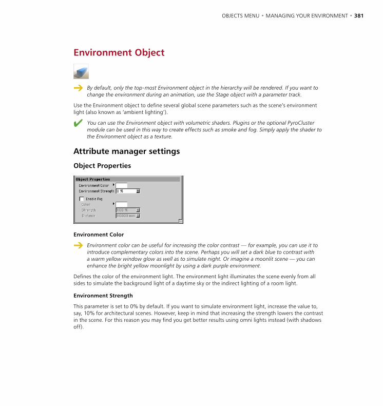
380 • CHAPTER 7 OBJECTS MENU • MANAGING YOUR ENVIRONMENT • 381
Environment Object
By default, only the top-most Environment object in the hierarchy will be rendered. If you want to change the environment during an animation, use the Stage object with a parameter track.
Use the Environment object to define several global scene parameters such as the scene’s environment light (also known as ‘ambient lighting’).
You can use the Environment object with volumetric shaders. Plugins or the optional PyroCluster module can be used in this way to create effects such as smoke and fog. Simply apply the shader to the Environment object as a texture.
Attribute manager settings
Object Properties
Environment Color
Environment color can be useful for increasing the color contrast — for example, you can use it to introduce complementary colors into the scene. Perhaps you will set a dark blue to contrast with a warm yellow window glow as well as to simulate night. Or imagine a moonlit scene — you can enhance the bright yellow moonlight by using a dark purple environment.
Defines the color of the environment light. The environment light illuminates the scene evenly from all sides to simulate the background light of a daytime sky or the indirect lighting of a room light.
Environment Strength
This parameter is set to 0% by default. If you want to simulate environment light, increase the value to, say, 10% for architectural scenes. However, keep in mind that increasing the strength lowers the contrast in the scene. For this reason you may find you get better results using omni lights instead (with shadows off).
382 • CHAPTER 7 OBJECTS MENU • MANAGING YOUR ENVIRONMENT • 383
Enable Fog
Switches fog on or off.
Color, Strength
These parameters define the color and brightness of the fog.
Distance
Environment fog fills the entire screen, stretching to infinity. Distance refers to the fog’s intensity by specifying the distance over which a light beam will lose its intensity completely. As the light loses intensity, the fog color is added. If, for example, you have entered a value of 500 for Distance, a light beam that starts off with 100% intensity will reduce to 20% after travelling 400 units; at the end of a further 100 units, the light will have faded out completely, giving way to the fog color. The shorter the distance, the thicker the fog.
Beams that penetrate the fog beyond the limit defined in Distance are absorbed completely by the fog color — if you enable environment fog, you cannot see a sky or a background image.
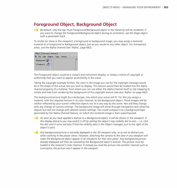
382 • CHAPTER 7 OBJECTS MENU • MANAGING YOUR ENVIRONMENT • 383
Foreground Object, Background Object By default, only the top-most Foreground/Background object in the hierarchy will be rendered. If
you want to change the Foreground/Background object during an animation, use the Stage object with a parameter track.
To render (or show in the viewport) a foreground or background image, you may assign a textured material to a Foreground or Background object, just as you would to any other object. For transparent areas, use the Alpha channel (see ‘Alpha’, page 662).
The Foreground object could be a cockpit and instrument display, or simply a notice of copyright or authorship that you want to appear prominently in the scene.
Taking the copyright example further, the color in the image you use for the copyright message would be in the shape of the actual text you wish to display. This texture would then be loaded into the Alpha channel property of a material, from where you can use either the Alpha channel itself or clip mapping to isolate and hide from rendering the background of the copyright texture (see also ‘Alpha’ on page 662).
The background picture might be a landscape, into which your scene will fit. For this you assign a material, with the required texture in its color channel, to the Background object. These images will be neither reflected by your scene’s reflective objects nor lit in any way by the scene. Nor will they change with any change of camera settings. The background image will show through transparent and refractive objects but will not change with altered camera settings. You could compare it to a background layer generated by the Alpha Channel feature, on which the rendered image is then superimposed.
As soon as you have applied a texture to a Background object, it will be shown in the viewport. If this display distracts you may switch it off by setting the object’s top visibility dot to red — i.e. click the dot until it turns red (you’ll find the visibility dots in the Object manager, just to the right of the object’s icon).
Any background picture is normally displayed in the 3D viewport only, so as not to distract you when working in the planar views. However, attaching the camera to the view in any viewport will make the Background object appear in all viewports for that view panel. Any background picture already displayed will then be covered by the Background object’s texture. The picture must be loaded in the material’s Color channel. If instead you load the picture into another channel such as Luminance, the picture won’t appear in the viewport.
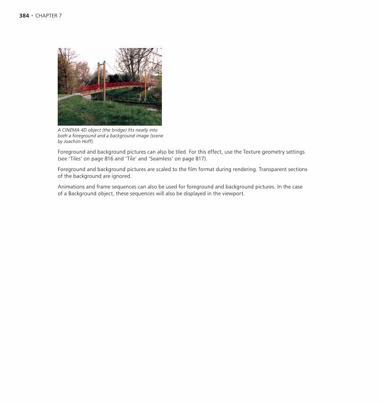
384 • CHAPTER 7 OBJECTS MENU • MANAGING YOUR ENVIRONMENT • 385
A CINEMA 4D object (the bridge) fits neatly into both a foreground and a background image (scene by Joachim Hoff).
Foreground and background pictures can also be tiled. For this effect, use the Texture geometry settings (see ‘Tiles’ on page 816 and ‘Tile’ and ‘Seamless’ on page 817).
Foreground and background pictures are scaled to the film format during rendering. Transparent sections of the background are ignored.
Animations and frame sequences can also be used for foreground and background pictures. In the case of a Background object, these sequences will also be displayed in the viewport.

384 • CHAPTER 7 OBJECTS MENU • MANAGING YOUR ENVIRONMENT • 385
Stage Object
The Stage object behaves like a movie director. It determines when a camera, an environment, a background and so on are used within an animation. For example, you can create many different cameras in your scene and use the Stage object to decide when to cut to a particular camera. You can also use the Stage object to switch between Sky, Foreground, Background, and Environment objects.
You can animate the Stage object to change which objects are used over time. This is especially useful for switching cameras during an animation. For example, you can switch from one camera to another as follows.
- Move the time slider to the start of the animation. Drag the first camera’s name from the Object manager into the Stage object’s Camera box (Attribute manager).
- In the Attribute manager, right-click (Windows) or Command-click (Mac OS) the parameter name Camera to open its context menu. From this menu, choose Animation > Add Keyframe to create a key that assigns the first camera to the Stage object at the start of the animation.
- Move the time slider to the frame at which you want to switch to the second camera. Drag the second camera’s name from the Object manager into the Stage object’s Camera box (Attribute manager).
- In the Attribute manager, right-click (Windows) or Command-click (Mac OS) the parameter name Camera to open its context menu. From this menu, choose Animation > Add Keyframe to create a key that assigns the second camera to the Stage object at the current frame.
If you now play the animation, the animation starts with the first camera and switches to the second camera at the second key.
Attribute manager settings
Object Properties
Camera, Sky, Foreground, Background, Environment
To assign an object to the Stage object, drag a Camera, Sky, Foreground, Background or Environment object into the appropriate box.

386 • CHAPTER 7
Selection Object
When recording keys in autokeying mode, you can restrict the recording to specific objects by using a Selection object. Then, only those objects that are assigned to the Selection object can be animated. See ‘Selection Filter’ on page 433 for more information.
Attribute manager settings
Object Properties
hierarchy icon
Restore Selection
If you click this button, all objects that are assigned to the Selection object (i.e. all those in the List box) are selected in the Object manager.
List
To assign objects to the Selection object, drag them from the Object manager into this box. In addition, select the Hierarchy icon for each object whose children should be recorded in autokeying mode as well. The hierarchy icon is shown to the right of each object in the list and is red when selected.
You can also choose which objects are assigned as follows:
- In the Object manager, select the objects that should be assigned to the Selection object.
- Choose either Objects > Scene > Selection or Selection > Selection Filter > Create Selection Object.
A new Selection object is created and is assigned the selected objects automatically.

OBJECTS MENU • SOUND • 387
See also ‘2D Sound Rendering’ on page 870 and ‘3D Sound Rendering’ on page 871.
CINEMA 4D provides sound rendering within your scenes. Two different options are available: 2D Sound Rendering and 3D Sound Rendering.
With 2D sound rendering you use the Timeline like a multi-track audio mixer (as in many video editing programs). You can create any number of sound tracks, assign WAV files to them and adjust the timing, the volume and the balance, depending upon your requirements. This procedure is suitable for synchronization (e.g. lip-synch, footsteps, a slamming door, an explosion, etc.).
3D sound rendering takes a quite different approach. With this you work with virtual acoustic sources (loudspeakers) and pickups (microphones) as objects. These virtual objects can be positioned freely within the 3D space and also can be animated. CINEMA 4D calculates the appropriate sound data on the basis of the spatial position of these objects, their speed and the preset sound parameters. You can merge this data afterwards with surround sound data in an external program.
3D sound rendering is a most versatile method of sound production and offers many, almost infinite, applications. From a car driving from left to right to an enormous space ship battle with laser beams and explosions in Dolby surround sound; everything is feasible.
Playing and scrubbing sound
CINEMA 4D enables you to play sound tracks in realtime — backwards as well as forwards. You can also drag the time slider manually to ‘scrub’ the sound. To switch on sound, enable the Play Sound During Animation icon in the animation toolbar.
Sound
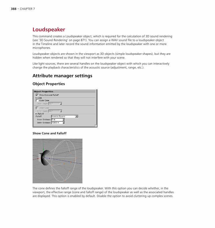
388 • CHAPTER 7 OBJECTS MENU • SOUND • 389
LoudspeakerThis command creates a Loudspeaker object, which is required for the calculation of 3D sound rendering (see ‘3D Sound Rendering’ on page 871). You can assign a WAV sound file to a loudspeaker object in the Timeline and later record the sound information emitted by the loudspeaker with one or more microphones.
Loudspeaker objects are shown in the viewport as 3D objects (simple loudspeaker shapes), but they are hidden when rendered so that they will not interfere with your scene.
Like light sources, there are several handles on the loudspeaker object with which you can interactively change the playback characteristics of the acoustic source (adjustment, range, etc.).
Attribute manager settings
Object Properties
Show Cone and Falloff
The cone defines the falloff range of the loudspeaker. With this option you can decide whether, in the viewport, the effective range (cone and falloff range) of the loudspeaker as well as the associated handles are displayed. This option is enabled by default. Disable the option to avoid cluttering up complex scenes.
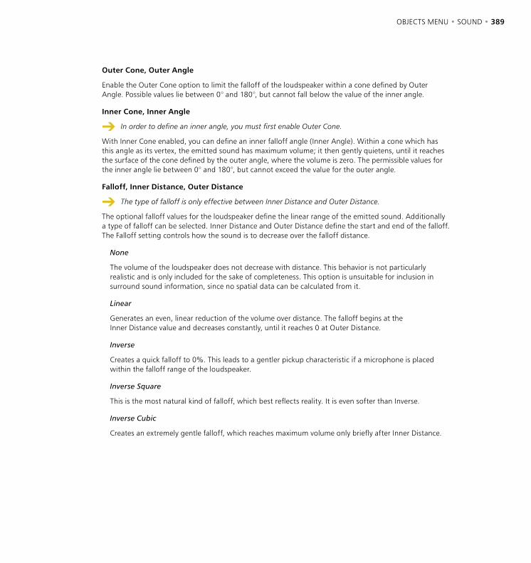
388 • CHAPTER 7 OBJECTS MENU • SOUND • 389
Outer Cone, Outer Angle
Enable the Outer Cone option to limit the falloff of the loudspeaker within a cone defined by Outer Angle. Possible values lie between 0° and 180°, but cannot fall below the value of the inner angle.
Inner Cone, Inner Angle
In order to define an inner angle, you must first enable Outer Cone.
With Inner Cone enabled, you can define an inner falloff angle (Inner Angle). Within a cone which has this angle as its vertex, the emitted sound has maximum volume; it then gently quietens, until it reaches the surface of the cone defined by the outer angle, where the volume is zero. The permissible values for the inner angle lie between 0° and 180°, but cannot exceed the value for the outer angle.
Falloff, Inner Distance, Outer Distance
The type of falloff is only effective between Inner Distance and Outer Distance.
The optional falloff values for the loudspeaker define the linear range of the emitted sound. Additionally a type of falloff can be selected. Inner Distance and Outer Distance define the start and end of the falloff. The Falloff setting controls how the sound is to decrease over the falloff distance.
None
The volume of the loudspeaker does not decrease with distance. This behavior is not particularly realistic and is only included for the sake of completeness. This option is unsuitable for inclusion in surround sound information, since no spatial data can be calculated from it.
Linear
Generates an even, linear reduction of the volume over distance. The falloff begins at the Inner Distance value and decreases constantly, until it reaches 0 at Outer Distance.
Inverse
Creates a quick falloff to 0%. This leads to a gentler pickup characteristic if a microphone is placed within the falloff range of the loudspeaker.
Inverse Square
This is the most natural kind of falloff, which best reflects reality. It is even softer than Inverse.
Inverse Cubic
Creates an extremely gentle falloff, which reaches maximum volume only briefly after Inner Distance.
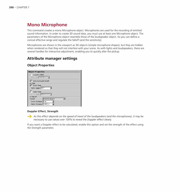
390 • CHAPTER 7 OBJECTS MENU • SOUND • 391
Mono MicrophoneThis command creates a mono Microphone object. Microphones are used for the recording of emitted sound information. In order to create 3D sound data, you must use at least one Microphone object. The parameters of the Microphone object resemble those of the loudspeaker object. So you can define a conical effective range and regulate the falloff (and the sensitivity).
Microphones are shown in the viewport as 3D objects (simple microphone shapes), but they are hidden when rendered so that they will not interfere with your scene. As with lights and loudspeakers, there are several handles for interactive adjustment, enabling you to quickly alter the pickup.
Attribute manager settings
Object Properties
Doppler Effect, Strength
As this effect depends on the speed of travel of the loudspeakers (and the microphones), it may be necessary to use values over 100% to reveal the Doppler effect clearly.
If you want a Doppler effect to be calculated, enable this option and set the strength of the effect using the Strength parameter.
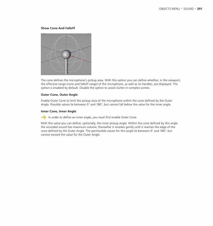
390 • CHAPTER 7 OBJECTS MENU • SOUND • 391
Show Cone And Falloff
The cone defines the microphone’s pickup area. With this option you can define whether, in the viewport, the effective range (cone and falloff range) of the microphone, as well as its handles, are displayed. The option is enabled by default. Disable the option to avoid clutter in complex scenes.
Outer Cone, Outer Angle
Enable Outer Cone to limit the pickup area of the microphone within the cone defined by the Outer Angle. Possible values lie between 0° and 180°, but cannot fall below the value for the inner angle.
Inner Cone, Inner Angle
In order to define an inner angle, you must first enable Outer Cone.
With this value you can define, optionally, the inner pickup angle. Within the cone defined by this angle the recorded sound has maximum volume, thereafter it recedes gently until it reaches the edge of the cone defined by the Outer Angle. The permissible values for this angle lie between 0° and 180°, but cannot exceed the value for the Outer Angle.

392 • CHAPTER 7 OBJECTS MENU • SOUND • 393
Falloff, Inner Distance, Outer Distance
The type of falloff is only effective between Inner Distance and Outer Distance.
The optional falloff values of the microphone define the range of the pickup area. Additionally a type of falloff can be selected. Inner Distance and Outer Distance define the start and end of the falloff. The falloff controls how the sensitivity of the pickup is to decrease over distance.
This shows the various types of microphone falloff, graphically. Pickup sensitivity is shown vertically, time horizontally.
None
If you set Falloff to None for loudspeakers as well as microphones, 3D sound data cannot be calculated. Therefore use this setting only if your loudspeakers already have a falloff behavior assigned.
Means that the pickup sensitivity of the microphone does not change with distance. This is the default setting for microphones.
Linear
Generates an even, linear falloff of the pickup sensitivity. The falloff begins at Inner Distance and decreases constantly until it reaches zero at Outer Distance.
Inverse
Creates a quick falloff sinking to 0%. Thus leads to a gentler pickup characteristic, if the microphone enters the falloff range of a loudspeaker.
Inverse Square
This is the most natural kind of falloff, which best reflects reality. It is even softer than Inverse.
Inverse Cubic
Creates an extremely gentle falloff, which reaches maximum pickup sensitivity only briefly before Inner Distance.
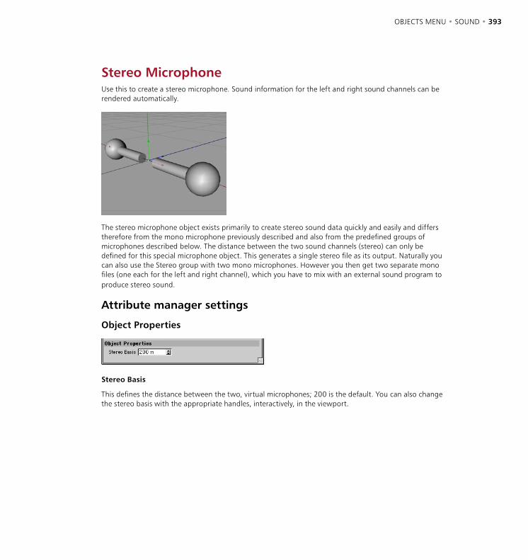
392 • CHAPTER 7 OBJECTS MENU • SOUND • 393
Stereo MicrophoneUse this to create a stereo microphone. Sound information for the left and right sound channels can be rendered automatically.
The stereo microphone object exists primarily to create stereo sound data quickly and easily and differs therefore from the mono microphone previously described and also from the predefined groups of microphones described below. The distance between the two sound channels (stereo) can only be defined for this special microphone object. This generates a single stereo file as its output. Naturally you can also use the Stereo group with two mono microphones. However you then get two separate mono files (one each for the left and right channel), which you have to mix with an external sound program to produce stereo sound.
Attribute manager settings
Object Properties
Stereo Basis
This defines the distance between the two, virtual microphones; 200 is the default. You can also change the stereo basis with the appropriate handles, interactively, in the viewport.
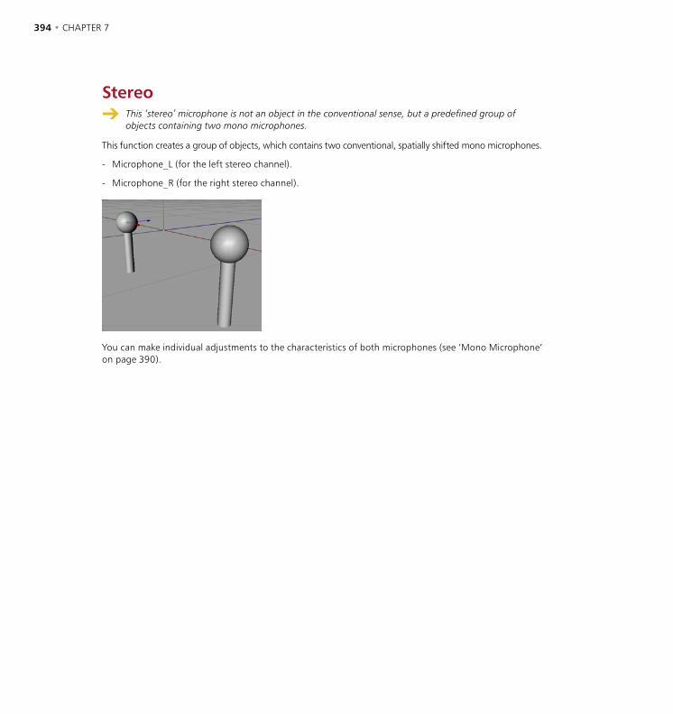
394 • CHAPTER 7 OBJECTS MENU • SOUND • 395
Stereo This ‘stereo’ microphone is not an object in the conventional sense, but a predefined group of
objects containing two mono microphones.
This function creates a group of objects, which contains two conventional, spatially shifted mono microphones.
- Microphone_L (for the left stereo channel).
- Microphone_R (for the right stereo channel).
You can make individual adjustments to the characteristics of both microphones (see ‘Mono Microphone’ on page 390).
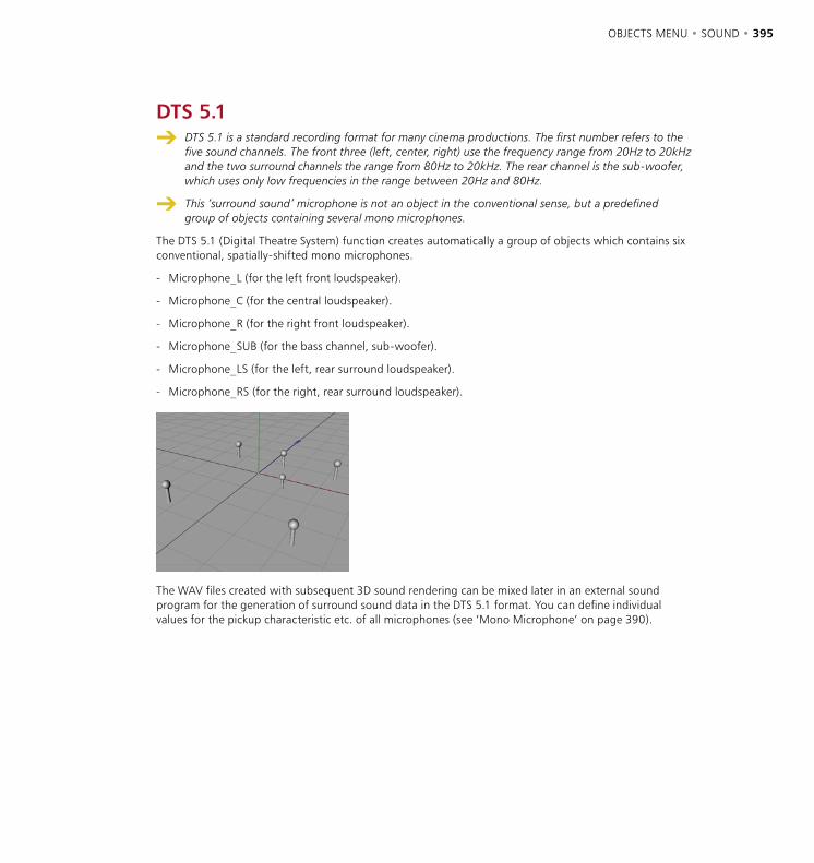
394 • CHAPTER 7 OBJECTS MENU • SOUND • 395
DTS 5.1 DTS 5.1 is a standard recording format for many cinema productions. The first number refers to the
five sound channels. The front three (left, center, right) use the frequency range from 20Hz to 20kHz and the two surround channels the range from 80Hz to 20kHz. The rear channel is the sub-woofer, which uses only low frequencies in the range between 20Hz and 80Hz.
This ‘surround sound’ microphone is not an object in the conventional sense, but a predefined group of objects containing several mono microphones.
The DTS 5.1 (Digital Theatre System) function creates automatically a group of objects which contains six conventional, spatially-shifted mono microphones.
- Microphone_L (for the left front loudspeaker).
- Microphone_C (for the central loudspeaker).
- Microphone_R (for the right front loudspeaker).
- Microphone_SUB (for the bass channel, sub-woofer).
- Microphone_LS (for the left, rear surround loudspeaker).
- Microphone_RS (for the right, rear surround loudspeaker).
The WAV files created with subsequent 3D sound rendering can be mixed later in an external sound program for the generation of surround sound data in the DTS 5.1 format. You can define individual values for the pickup characteristic etc. of all microphones (see ‘Mono Microphone’ on page 390).

396 • CHAPTER 7 OBJECTS MENU • SOUND • 397
DDS EX 6.1 DDS EX 6.1 is a modern method from Lucasfilm TXH and Dolby Laboratories Inc. It uses an
additional middle surround channel to offer the listener a particularly good localization of auditory perspectives. Otherwise it is compatible with Dolby digital 5.1. The number ‘6’ from the name refers to the six available channels. The front three (left, center, right) use the frequency range from 20Hz to 20kHz and the three surround channels the range from 80Hz to 20kHz. The rear channel is the sub-woofer, which uses only low frequencies in the range between 20Hz and 120Hz.
This ‘surround sound’ microphone is not an object in the conventional sense, but a predefined group of objects containing several mono microphones.
The DDS EX 6.1 (Dolby Digital Surround) function creates, automatically, a group of objects which contains seven conventional, spatially-shifted mono microphones.
- Microphone_L (for the left front loudspeaker).
- Microphone_C (for the central loudspeaker).
- Microphone_R (for the right front loudspeaker).
- Microphone_SUB (for the bass channel, sub-woofer).
- Microphone_LS (for the left, rear surround loudspeaker).
- Microphone_S (for the middle, rear surround loudspeaker).
- Microphone_RS (for the right, rear surround loudspeaker).
The WAV files created with subsequent 3D sound rendering can be mixed later in an external sound program for the generation of surround sound data in the DDS EX 6.1 format. You can define individual values for the pickup characteristic etc. of all microphones (see ‘Mono Microphone’ on page 390).
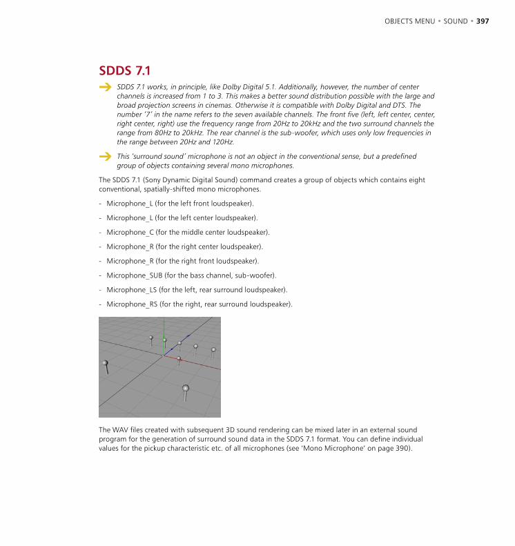
396 • CHAPTER 7 OBJECTS MENU • SOUND • 397
SDDS 7.1 SDDS 7.1 works, in principle, like Dolby Digital 5.1. Additionally, however, the number of center
channels is increased from 1 to 3. This makes a better sound distribution possible with the large and broad projection screens in cinemas. Otherwise it is compatible with Dolby Digital and DTS. The number ‘7’ in the name refers to the seven available channels. The front five (left, left center, center, right center, right) use the frequency range from 20Hz to 20kHz and the two surround channels the range from 80Hz to 20kHz. The rear channel is the sub-woofer, which uses only low frequencies in the range between 20Hz and 120Hz.
This ‘surround sound’ microphone is not an object in the conventional sense, but a predefined group of objects containing several mono microphones.
The SDDS 7.1 (Sony Dynamic Digital Sound) command creates a group of objects which contains eight conventional, spatially-shifted mono microphones.
- Microphone_L (for the left front loudspeaker).
- Microphone_L (for the left center loudspeaker).
- Microphone_C (for the middle center loudspeaker).
- Microphone_R (for the right center loudspeaker).
- Microphone_R (for the right front loudspeaker).
- Microphone_SUB (for the bass channel, sub-woofer).
- Microphone_LS (for the left, rear surround loudspeaker).
- Microphone_RS (for the right, rear surround loudspeaker).
The WAV files created with subsequent 3D sound rendering can be mixed later in an external sound program for the generation of surround sound data in the SDDS 7.1 format. You can define individual values for the pickup characteristic etc. of all microphones (see ‘Mono Microphone’ on page 390).

OBJECTS MENU • OBJECT LIBRARY • 399
On the Objects > Object Library menu you’ll find a useful collection of pre-built models, including some outstanding human characters made with CINEMA 4D’s HyperNURBS tool. If you’re new to HyperNURBS (subdivision surface modeling) and you want to find out why it’s the favorite tool of many expert modelers, check out these brilliant characters, which you can also use in your own projects.
Adding models to the object libraryGot some useful models that you use time and again? Then add them to the Object Library menu so that you can quickly add them to your scenes.
To add your own model to the Object Library menu
- Place the scene of the model in CINEMA 4D’s ‘library/object’ folder.
Turbo Squid communityChoose Objects > Object Library > Turbo Squid to access the world’s largest online collection of digital assets. Turbo Squid is now home to a CINEMA 4D community where you can buy and sell assets including fully-textured and ready-to-use 3D models in the native C4D format.
Object Library


8 Tools Menu

TOOLS MENU • 403
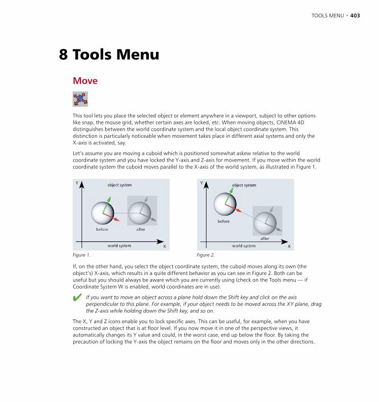
TOOLS MENU • 403
Move
This tool lets you place the selected object or element anywhere in a viewport, subject to other options like snap, the mouse grid, whether certain axes are locked, etc. When moving objects, CINEMA 4D distinguishes between the world coordinate system and the local object coordinate system. This distinction is particularly noticeable when movement takes place in different axial systems and only the X-axis is activated, say.
Let’s assume you are moving a cuboid which is positioned somewhat askew relative to the world coordinate system and you have locked the Y-axis and Z-axis for movement. If you move within the world coordinate system the cuboid moves parallel to the X-axis of the world system, as illustrated in Figure 1.
Figure 1. Figure 2.
If, on the other hand, you select the object coordinate system, the cuboid moves along its own (the object’s) X-axis, which results in a quite different behavior as you can see in Figure 2. Both can be useful but you should always be aware which you are currently using (check on the Tools menu — if Coordinate System W is enabled, world coordinates are in use).
If you want to move an object across a plane hold down the Shift key and click on the axis perpendicular to this plane. For example, if your object needs to be moved across the XY plane, drag the Z-axis while holding down the Shift key, and so on.
The X, Y and Z icons enable you to lock specific axes. This can be useful, for example, when you have constructed an object that is at floor level. If you now move it in one of the perspective views, it automatically changes its Y value and could, in the worst case, end up below the floor. By taking the precaution of locking the Y-axis the object remains on the floor and moves only in the other directions.
8 Tools Menu

404 • CHAPTER 8 TOOLS MENU • 405
A left/right movement of the mouse while holding down the mouse button moves the object horizontally on the screen; an up/down drag moves it vertically. Dragging left and right with the right mouse button (Windows) or Command key (Mac OS) held down moves the object into the screen and out of it.
To constrain movement to one axis only, drag the arrowhead at the end of the desired axis. This saves you from having to lock axes manually.
To move the selected object without its children, Ctrl-drag the object in the viewport.
When editing textures, mouse movements have a somewhat different effect. A left/right drag of the mouse moves the texture along its X-axis, an up/down drag moves the texture along its Y-axis.
Moving multiple objectsWhen multiple objects are selected, a shared axis system appears in the viewport between the selected objects. You can move the objects using the shared axis system or you can move the objects using any one of their object axis systems.
When multiple objects are selected, a shared axis system appears in the center.
Click the origin of the object whose axis system you want to use; this object’s axis system then appears.
To move multi-selected objects using the shared axis system
- Ensure the Move tool is selected. If you want to move the objects freely, drag from an empty space within the viewport. If you want to constrain movement to a particular axis, drag the appropriate arrowhead of the shared axis system. For example, to move along the X-axis only, drag the red arrowhead.
To move multi-selected objects using one of their object axis systems
- Ensure the Move tool is selected and click the origin of the object whose axis system you want to use. This object’s axis system appears in place of the shared axis system, as shown below (we clicked the pyramid’s origin). Note that all three objects are still selected (indicated by their red frames).
- If you want to move the objects freely, drag from an empty space within the viewport. If you want to constrain movement to a particular axis, drag the appropriate arrowhead of the object axis system. For example, to move in the direction of the Z-axis only, drag the blue arrowhead.
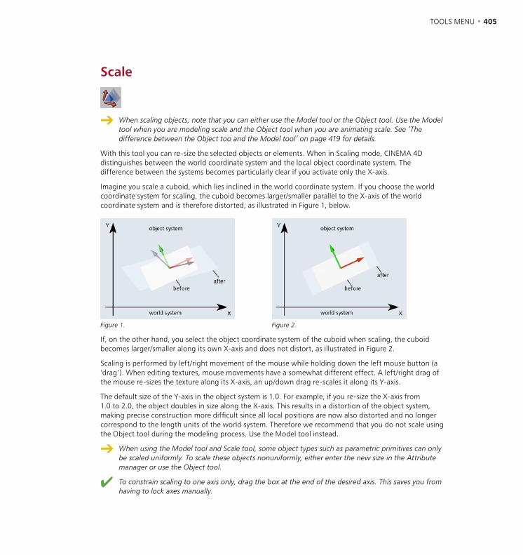
404 • CHAPTER 8 TOOLS MENU • 405
Scale
When scaling objects, note that you can either use the Model tool or the Object tool. Use the Model tool when you are modeling scale and the Object tool when you are animating scale. See ‘The difference between the Object too and the Model tool’ on page 419 for details.
With this tool you can re-size the selected objects or elements. When in Scaling mode, CINEMA 4D distinguishes between the world coordinate system and the local object coordinate system. The difference between the systems becomes particularly clear if you activate only the X-axis.
Imagine you scale a cuboid, which lies inclined in the world coordinate system. If you choose the world coordinate system for scaling, the cuboid becomes larger/smaller parallel to the X-axis of the world coordinate system and is therefore distorted, as illustrated in Figure 1, below.
Figure 1. Figure 2.
If, on the other hand, you select the object coordinate system of the cuboid when scaling, the cuboid becomes larger/smaller along its own X-axis and does not distort, as illustrated in Figure 2.
Scaling is performed by left/right movement of the mouse while holding down the left mouse button (a ‘drag’). When editing textures, mouse movements have a somewhat different effect. A left/right drag of the mouse re-sizes the texture along its X-axis, an up/down drag re-scales it along its Y-axis.
The default size of the Y-axis in the object system is 1.0. For example, if you re-size the X-axis from 1.0 to 2.0, the object doubles in size along the X-axis. This results in a distortion of the object system, making precise construction more difficult since all local positions are now also distorted and no longer correspond to the length units of the world system. Therefore we recommend that you do not scale using the Object tool during the modeling process. Use the Model tool instead.
When using the Model tool and Scale tool, some object types such as parametric primitives can only be scaled uniformly. To scale these objects nonuniformly, either enter the new size in the Attribute manager or use the Object tool.
To constrain scaling to one axis only, drag the box at the end of the desired axis. This saves you from having to lock axes manually.
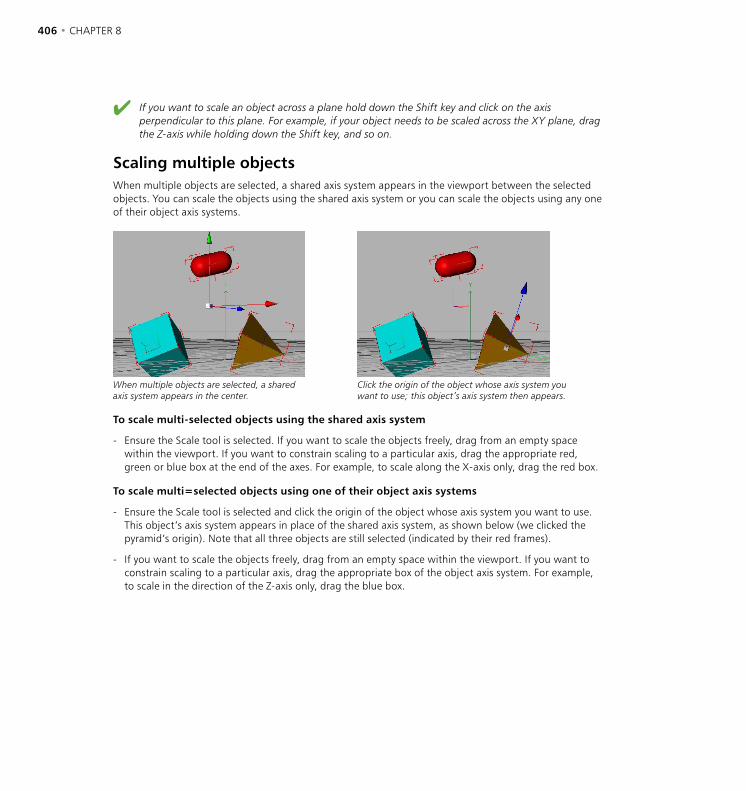
406 • CHAPTER 8 TOOLS MENU • 407
If you want to scale an object across a plane hold down the Shift key and click on the axis perpendicular to this plane. For example, if your object needs to be scaled across the XY plane, drag the Z-axis while holding down the Shift key, and so on.
Scaling multiple objectsWhen multiple objects are selected, a shared axis system appears in the viewport between the selected objects. You can scale the objects using the shared axis system or you can scale the objects using any one of their object axis systems.
When multiple objects are selected, a shared axis system appears in the center.
Click the origin of the object whose axis system you want to use; this object’s axis system then appears.
To scale multi-selected objects using the shared axis system
- Ensure the Scale tool is selected. If you want to scale the objects freely, drag from an empty space within the viewport. If you want to constrain scaling to a particular axis, drag the appropriate red, green or blue box at the end of the axes. For example, to scale along the X-axis only, drag the red box.
To scale multi=selected objects using one of their object axis systems
- Ensure the Scale tool is selected and click the origin of the object whose axis system you want to use. This object’s axis system appears in place of the shared axis system, as shown below (we clicked the pyramid’s origin). Note that all three objects are still selected (indicated by their red frames).
- If you want to scale the objects freely, drag from an empty space within the viewport. If you want to constrain scaling to a particular axis, drag the appropriate box of the object axis system. For example, to scale in the direction of the Z-axis only, drag the blue box.
406 • CHAPTER 8 TOOLS MENU • 407
Rotate
This tool rotates the selected objects or elements when you drag the mouse from an empty space within the viewport. When rotating objects, CINEMA 4D distinguishes between the world coordinate system and the local object coordinate system and you can choose to rotate in either system. As long as the object lies parallel to the axes of the world coordinate system you will not notice a difference when you rotate in either system. But when the object is askew, there can be large differences between rotating in the world or object systems — see ‘Scale’ on page 405 and consider your needs.
Drag left or right to rotate the object about its Y-axis. An up/down drag rotates it around its X-axis, and right-drag (Windows) or Command-drag (Mac OS) rotates about the Z-axis.
To constrain rotation to one axis only, drag the small sphere at the end of the desired axis. This saves you from having to lock axes manually.
The behavior of the rotation is entirely different if you have switched on the HPB system (Use HPB System enabled on the Units page of the preferences). A left/right drag will now change the heading, an up/down drag changes the pitch and right-dragging (Windows) or Command-dragging Mac OS) left or right will change the bank. The HPB angles here refer to the object’s parent system i.e. if the object being rotated is within a hierarchy, the parent object functions as the world coordinates.
If you are using HPB for rotating the rotation axes behave according to the HPB designators (see ‘Use HPB System’, page 79).
Virtual Rotation Circle
When rotating an object you can also use the virtual rotation circle. It is displayed as a yellow circle which is always parallel to the view plane. Drag from an empty part within the circle to rotate in any direction or from an empty part outside the circle to rotate on the same plane as the circle (rather like the circle is a spinning potter’s wheel).
Preventing tumbling
When you want to animate an object rotating about one of its axes, you may find that instead it tumbles in a seemingly haphazard fashion. After working through this section, you’ll understand why this can happen and how to avoid the tumbles... It’s all to do with HPB.
The best way to understand the tumbles issue is to see it in action. What we want to do here is tilt a cube and then animate the cube rotating about its Y-axis.
- Choose File > New to start a new scene.
- Choose Objects > Primitive > Cube to create a cube.
- In the Coordinate manager, under Rotation, set B (bank) to 30 and click Apply to apply the angle to the cube.
- In the animation toolbar, disable the Position, Scale and Parameter icons so that only Rotation is active.

408 • CHAPTER 8 TOOLS MENU • 409
- Click Record. Open the Timeline (if it isn’t already open) and you’ll see that a new rotation sequence with a key at frame 0 has been created for each rotation track (H, P and B).
- Drag the time slider to frame 90.
- In the Coordinate manager, under Rotation, set H (Heading) to 360 and click Apply to apply the angle to the cube.
- Click Record. A new key is added to each rotation sequence at frame 90.
- Click Play to view the animation.
Although the cube now rotates, it doesn’t rotate about its local Y-axis. Instead it’s tumbling. Why? As mentioned earlier, HPB rotations refer to the object’s parent system. In this case, the cube isn’t in a hierarchy as so its parent is the world coordinate system. Thus the cube rotates based on the world system’s Y-axis rather than its local Y-axis.
The solution is to use a Null object as the cube’s parent. Then the rotation will take place about the null’s coordinate system. Unlike the world coordinate system, we can tilt the null to the desired angle but first we need to ‘un-tilt’ the cube. This is because later we’ll want to tilt the null parent, which in turn will restore the cube’s tilt.
- Drag the time slider to frame 0.
- In the Coordinate manager, set the cube’s B (Bank) to 0, click Apply then click Record.
- Drag the time slider to frame 90.
- Once again, in the Coordinate manager, set B (Bank) to 0°, click Apply then click Record.
- Click Play to view the animation.
The cube should now rotate without any tilt (we’ll add this later). If it doesn’t, check the two Bank angles once more — they should both be set to 0°. Next we need to add the null, make it the cube’s parent and tilt it, so...
- Choose Objects > Null Object to create a Null object.
- In the Object manager, drag the name of the cube onto the name of the null, to make the null the cube’s parent.
- Ensure that the null is selected and drag the time slider to frame 90.
- In the Coordinate manager set B (Bank) to 30° and click Apply to tilt the null and its child (i.e. the cube).
- Click Play to view the animation.
The cube now rotates about its Y-axis as desired. It no longer tumbles.
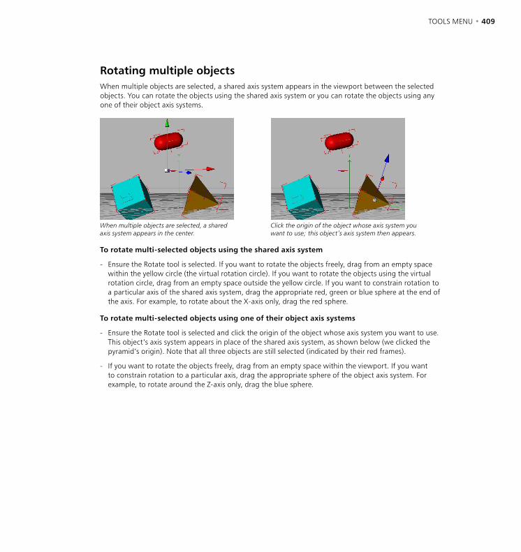
408 • CHAPTER 8 TOOLS MENU • 409
Rotating multiple objectsWhen multiple objects are selected, a shared axis system appears in the viewport between the selected objects. You can rotate the objects using the shared axis system or you can rotate the objects using any one of their object axis systems.
When multiple objects are selected, a shared axis system appears in the center.
Click the origin of the object whose axis system you want to use; this object’s axis system then appears.
To rotate multi-selected objects using the shared axis system
- Ensure the Rotate tool is selected. If you want to rotate the objects freely, drag from an empty space within the yellow circle (the virtual rotation circle). If you want to rotate the objects using the virtual rotation circle, drag from an empty space outside the yellow circle. If you want to constrain rotation to a particular axis of the shared axis system, drag the appropriate red, green or blue sphere at the end of the axis. For example, to rotate about the X-axis only, drag the red sphere.
To rotate multi-selected objects using one of their object axis systems
- Ensure the Rotate tool is selected and click the origin of the object whose axis system you want to use. This object’s axis system appears in place of the shared axis system, as shown below (we clicked the pyramid’s origin). Note that all three objects are still selected (indicated by their red frames).
- If you want to rotate the objects freely, drag from an empty space within the viewport. If you want to constrain rotation to a particular axis, drag the appropriate sphere of the object axis system. For example, to rotate around the Z-axis only, drag the blue sphere.

410 • CHAPTER 8 TOOLS MENU • 411
Move, Scale and Rotate with mouse and keyboardMoving, scaling and rotating with the mouse
To move, scale or rotate the selected objects without their children, hold down Ctrl while you drag.
You can use the mouse for moving, scaling and rotating. A left/right drag manipulates the X-axis while a back-and-forth drag controls the Y-axis. For the Z-axis you have to use the right mouse button. Macintosh users; as usual, use the Command key to simulate the right mouse button. You can toggle instantly between the left and right mouse buttons. If you are currently pressing the left button, press the right one before releasing the left and vice versa.
Moving, scaling and rotating with the cursor keys
On the keyboard, use the cursor keys for moving, scaling and rotating.
Move/Scale/Rotate along... Cursor key
Positive X-axis Right
Negative X-axis Left
Positive Y-axis Up
Negative Y-axis Down
Positive Z-axis Shift + Up or Right
Negative Z-axis Shift + Down or Left
If you are working with the Camera tool selected, it is the camera that is affected. In all other cases the object currently selected is moved, scaled or rotated.
Moving, scaling and rotating with the hotkeys
Using the built-in hotkeys you can move, scale or rotate either the camera or the selected objects.
Result Action
Move camera left/right/up/down 1 + drag
Move camera forwards/backwards 2 + drag
Zoom camera (changes focal length) 2 + right-drag (Windows) or 2 + Command-drag (Mac OS)
Rotate camera (X and Y axes) 3 + drag
Rotate camera (Z-axis) 3 + right-drag (Windows) or 3 + Command-drag (Mac OS)
Move selected objects 4 + drag
Scale selected objects (for animating) 5 + drag
Rotate selected objects 6 + drag
Scale selected objects (for modeling) 7 + drag
410 • CHAPTER 8 TOOLS MENU • 411
Magnify
Use the Magnify command to zoom in on a particular region of the work area. To define that area, drag a rectangle around it. Alternatively, click to zoom in by 25% or Ctrl-click to zoom out by 25%. You can also zoom in and out using the ‘+’ and ‘-’ keys.

412 • CHAPTER 8 TOOLS MENU • 413
Selection tools When using the Move, Scale or Rotate tools, you can click to select individual points.
Live Selection. Rectangle Selection. Freehand Selection. Polygon Selection.
The four selection tools on the Tools menu — Live, Rectangle, Freehand and Polygon Selection — enable you to select points, edges and polygons in various ways. You can use the selection tools with polygon objects, splines and with some deformation objects such as the FFD object. The following applies:
Adding to or removing from the selection:
- To add an element to the selection, hold down Shift while you select.
- To deselect a selected element, hold down Ctrl while you use the selection tool.
In the viewports:
- In polygon mode, selected polygons have red edges.
- In edge mode, selected edges are red.
- In point mode, selected points are red and are larger than unselected points.
Live Selection
Live Selection is like a paintbrush mode where you paint over the points, edges or polygons that you want to select. Set the size of this ‘selection brush’ using the Radius setting in the Active Tool manager. You can increase this radius with the ‘+’ key and make it smaller with the ‘-’ key. With a trackball the radius can be changed with the wheel.
Rectangle Selection
This tool enables you to select points, edges or polygons by dragging a frame over the elements.
Freehand Selection
Freehand selection behaves like a lasso. Drag to draw a loop around the elements you want to select. As soon as you release the mouse button, the loop is closed automatically.
Polygon Selection
This selection tool enables you to draw an n-sided shape to frame the elements that you want to select. The first click defines the starting point of the n-side and subsequent clicks define the n-side’s corners. To complete the n-side, click the starting point or right-click (Windows) or Command-click (Mac OS).
412 • CHAPTER 8 TOOLS MENU • 413
Selection options in the Active Tool managerTolerant Selection
This option makes sense only in polygon mode. Enabling this option means that a polygon is selected as soon as a corner point of the polygon is within the selection marquee. If this option is disabled, a polygon is included only if all corner points of the polygon are within the marquee.
Only Select Visible Elements
When using the Live Selection tool, keep in mind that it uses more RAM when Only Select Visible Elements is disabled. Therefore, only disable this option when necessary.
When this option is enabled you can select only polygons that aren’t behind other polygons.For example, if you’re selecting polygons at the front of a sphere, polygons at the back of the sphere will not be selected, even if you’re working in wireframe mode and can see the polygons at the back.
Another way to prevent polygons at the back from being selected is to switch on backface culling, which hides these polygons from the viewport. In addition, you can also hide polygons to prevent them from being selected using the Hide Selected and Hide Unselected commands from the Selection menu. Lastly, set an object’s top visibility dot to red to hide that object and to prevent its elements from being selected. (You’ll find the visibility dots in the Object manager, just to the right of the object’s icon.)
Radius
This determines the radius of the Live Selection brush. You can increase this radius with the ‘+’ key and make it smaller with the ‘-’ key. With a trackball the radius can be changed with the wheel.
Vertex Painting
See also ‘Set Vertex Weight’ on page 442.
You can use the Live Selection tool not only to select but also to paint vertex maps or weights. To activate the vertex map paint mode, first select the Points tool then enable the Enabled option and drag over the vertices to paint them.
To see the weighting in color, choose Display > Gouraud Shading or Display > Quick Shading from the viewport’s menu. In addition, you can choose if the Live Selection should paint a specific weight or whether it should lighten or darken the existing weighting (set Mode to the desired operation). Note that a new vertex map is created when you paint unless an existing vertex map is selected in the Object manager. Therefore if you want to paint an existing vertex map, select this map in the Object manager before you paint the vertices with the Live Selection tool.
HyperNURBS Weights
A further use of the Live Selection tool is to paint weights for HyperNURBS models. This gives you a quick and easy way to refine the HyperNURBS without having to add points. In addition, weighting enables you to firm up the mesh in places if you wish, such as to give hard edges. See also ‘Weighting HyperNURBS models’ on page 172.
414 • CHAPTER 8 TOOLS MENU • 415
Camera
With this tool you work with the camera that is being used in the active viewport. All subsequent actions affect the camera in this viewport. In the planar viewports (XY, ZY, XZ) you can move and magnify the displayed area; in the 3D viewport you can change the Editor camera or the Object camera. You can move in the following ways.
Keyboard short-cuts
Action Result
1 + drag Move camera left/right/up/down.
2 + drag Move camera forwards/backwards.
2 + drag Zoom by moving camera.
2 + right-drag (Windows)2 + command-drag (Mac OS)
Zoom by changing focal length.
3 + drag Rotate camera (X and Y axes)
3 + right-drag (Windows)3 + command-drag (Mac OS)
Rotate camera (Z-axis)
Moving the camera
To move the camera, select the Move tool and drag from an empty space within the viewport. To move the camera backwards or forwards, right-drag (Windows) or Command-drag (Mac OS) left and right.
The camera always moves in the opposite direction to the mouse. For example, when you move to the left, this will shift the camera to the right. This is the most intuitive method and easiest to learn.
When moving objects you can choose which axis system you wish to use. Normally, this will have no effect, since the X, Y and Z symbols are all selected. However, if you switch certain axes on or off, you will observe that certain actions will show different results. If for example you have activated the X symbol only and you are working with the world coordinate system, the camera will move parallel to the X-axis of the world system. If on the other hand the object system is selected, the camera will move left and right within its own camera coordinate system.
No grid is applied for the camera or the visible section of the document so that you can reach any position, even if a motion grid is active. Movements, scaling and rotation processes may be cancelled at any time by pressing the Esc key.
414 • CHAPTER 8 TOOLS MENU • 415
Zooming the camera
You can zoom the viewport in one of two ways: by changing the camera’s focal length (just like a real camera’s zoom — note that the perspective will change) or by moving the camera forwards or backwards (just like you might move closer to or further away from the subject that you’re photographing or filming).
To zoom by moving the camera forwards or backwards
- Select the Scale tool and drag left or right.
To zoom by changing the focal length
- Select the Scale tool and right-drag (Windows) or Command-drag (Mac OS).
Rotating the camera
The 2D viewports cannot be rotated.
To rotate the camera, select the Rotate tool and drag. To rotate about the camera’s Z-axis (its Bank value), right-drag (Windows) or Command-drag (Mac OS).
If an object is selected, the camera also changes its position while it rotates. This occurs in such a way that the centre of the selected object remains in the same position on the screen. This is especially useful when you want to move around an object. If no objects are selected, rotation is about the world origin.
Object See also ‘The difference between the Object tool and the Model tool’ on page 419.
Select this tool when you want to move, scale or rotate an object during the animating stage only. If you want to move, scale or rotate during the modeling stage, use the Model tool instead.
To move, scale or rotate the selected object, select the Move, Scale or Rotate tool from the Tools menu (or click the appropriate icon on the left toolbar) and drag from an empty space within the viewport. You can also move, scale or rotate by entering new values for these parameters in the Coordinate manager or the Attribute manager.
Note that when you scale with the Object tool, the object’s axis system is scaled. This is in contrast to the Model tool, which scales the surfaces.
To avoid problems, always make it a habit to use the Object tool when animating.
416 • CHAPTER 8 TOOLS MENU • 417
Points
You can quickly access commands for points from the context menu by right-clicking (Windows) or Command-clicking (Mac OS) on a point.
Select this tool when you want to edit an object’s points. All subsequent actions such as rotation and scaling will affect the points. In addition, the Delete function in the Edit menu now refers to the points of the object rather than to the object itself. As soon as the tool is selected, all points of the object are represented by small squares. Selected points are highlighted in color.
You can select points using the selection tools in the Tools menu or by clicking the points one by one. To add points to the selection in this way, hold down Shift while you click the points. To remove points from the selection, Shift-click the points again. To select all points, choose Edit > Select All. Use Edit > Deselect All to deselect all the points. To create new points, Ctrl-click or use the Add Points tool.
If the object you are editing is not a 2D/3D object but a spline, the following rules apply:
- Ctrl-click to add a point to the end of the spline.
- Shift-Ctrl-click to add a point to the start of the spline.
- Ctrl-click on the line between two control points to add a new point between them.
- To move a point, drag it to the new position. To delete the selected points, choose Edit > Delete or press the Del key or Backspace key.
If you are editing a Bézier spline and you select a point, the associated tangent will be displayed. You can edit the tangent’s ends by dragging them with the mouse. Holding down the Shift key allows you to edit them independently of each other.
You can also edit a point by double-clicking on it. A dialog opens in which you can change the position of the point. If you are using a Bézier spline, you can also edit the tangent values here. Alternatively you can edit the points with the Structure manager.

416 • CHAPTER 8 TOOLS MENU • 417
Edges
You can quickly access commands for edges from the context menu by right-clicking (Windows) or Command-clicking (Mac OS) on an edge.
Click this tool when you want to edit the edges of polygons. Selected edges are red. You select and edit edges in much the same way as you do points.
To select an edge, drag over the edges with the Live Selection tool, just as you would to select points (or use any other selection tool). To add edges to the selection, hold down Shift while you select. To remove edges from the selection, hold down Ctrl while you select. To select all edges, choose Selection > Select All. To deselect all edges, choose Selection > Deselect All or drag the selection tool over an empty space within the viewport.
You can use the Move, Scale and Rotate tools to edit the selected edges. And to delete the selected edges (including their polygons) press Delete.
Polygons
You can quickly access commands for polygons from the context menu by right-clicking (Windows) or Command-clicking (Mac OS) on a polygon.
CINEMA 4D works with two types of polygon: triangle and quadrangle. Polygons are edited in much the same way as points and edges. As soon as you activate the Polygon tool, the polygons of the selected object are displayed. Select a polygon by clicking on it with the mouse; selected polygons have red edges.
To select multiple polygons (or to add to the selection), Shift-click each polygon that you want to select. Shift-click a polygon a second time to deselect it. Or select polygons using a selection tool such as Live Selection from the Tools menu.
To create new polygons, choose Objects > Polygon Object. Now add points to this object with Structure > Add Points or import the points into the Structure manager with File > Import ASCII Data. See also ‘Polygon Object’ on page 240.
To delete the selected polygons, use either the Delete command from the Edit menu or press the Del key or Backspace key.
418 • CHAPTER 8 TOOLS MENU • 419
Object Axis
Use the Object axis tool if you want to set move and rotation points for Inverse Kinematics or to align objects created with Duplicate or to create a Lathe NURBS object with a spline contour.
The Object Axis tool enables you to modify the axes of the selected object without affecting the object’s points or polygons. Reasons why you may want to do this include (to name just a few):
- to help you navigate the selected object easily (the camera rotates around the origin of the selected object’s axis system)
- to define the center of rotation for an IK object (IK objects rotate around the origin of their axis system)
- to define the center of an object for mirroring (the Mirror command can mirror points based on the position of the object axis system’s origin)
Only a few possibilities are given above because there is no need to learn them — they will suggest themselves as you become more familiar with CINEMA 4D.
The current position of the axes of the selected object is shown in the Coordinate manager, where you can change all values individually. When rotating or moving the axes of a hierarchical object, all axes of the child objects will be changed. If these child objects have animation tracks, errors will occur in the animation, since the axes of the parent system will have changed. This is why, before creating the animation, it is so important to first define the axes.
Scaling object axes is a rather special case. Here, it is not only the axes that are re-sized, but also the points and the textures of the selected object. This is the only method for creating a scale animation. In contrast, model scaling changes points and textures, but does not re-size the axes.
418 • CHAPTER 8 TOOLS MENU • 419
Model
If you want to scale during the animating stage, use the Object tool. To avoid problems, always make it a habit to use the Object tool when animating.
Select this tool when you want to move, scale or rotate an object during the modeling stage. To move, scale or rotate the selected object, select the Move, Scale or Rotate tool from the Tools menu (or click the appropriate icon on the left toolbar) and drag from an empty space within the viewport. You can also move, scale or rotate by entering new values for these parameters in the Coordinate manager or the Attribute manager.
The difference between the Object tool and the Model tool
There are two very similar tools in CINEMA 4D which can both be used to move, scale and rotate objects. One is called the Model tool and the other one is the Object tool. Before you start animating it is important that you understand the difference between the two and when to use which.
The rule of thumb is this: The Model tool is for modeling, the Object tool is for animation.
You notice the difference only when scaling an object, but if you do use the wrong tool, the result can be puzzling. When scaling an object with the Object tool, you are not only scaling the geometry, you are also scaling its axes. And, especially when scaling an object’s axes non-uniformly (stretched more on one axis than another), the result is that child objects get squashed or stretched when you rotate them and you may begin to wonder what is happening to your objects.
If something strange happens to your objects when you rotate them, then there are most likely scaled axes involved. So when modeling, use the Model tool.
If your model distorts, you can repair the damage with the Reset System tool.
It is different for animation, however. If you want to animate the size of an object over time, you need to use the Object tool. When animating, CINEMA 4D looks only at the object axes, not the geometry. So here it is necessary to scale the axes. If you accidentally use the Model tool and try to record keyframes for an object’s size, nothing will happen because the axes aren’t scaled.
So if you are animating the size of an object and you realize that nothing is actually recorded, you probably have the Model tool selected. For animation, use the Object tool.

420 • CHAPTER 8 TOOLS MENU • 421
Example
Figure 1. Figure 2.
Figure 3. Figure 4.
Consider a scene with two objects, a (polygon) sphere and a cube (Figure 1, above). The cube is a child (sub-object) of the sphere. The axial length of both objects is 1/1/1 (the default).
- Now choose Tools > Object to select the Object tool. Select the Sphere. In the Coordinate manager’s Size column, set the drop-down list to Scale and set X (Scale) to 2. As we would expected, both the sphere and cube are distorted, as illustrated in Figure 2.
- Select the cube. Choose Tools > Rotate to select the Rotate tool (or click Rotate in the top toolbar). Disable the X and Y axes by clicking their icons in the top palette. Now drag from an empty space within the viewport to rotate the cube about its Z-axis. The cube distorts when rotated (Figure 3).
The points of the cube no longer obey a circular trajectory while they are rotated in the XY plane. Instead, the distorted parent system causes this movement to be elliptical. And here we have the classic distortion problem. It invariably occurs when objects exist in a distorted parent system.
Effects of this type are encountered by each and every 3D application, since it is a fundamental problem. Some users of other 3D software may not encounter this problem because their software uses separate editors for modeling and animating. However, these users lose the convenience of integrated modeling and must switch back to the modeler each time they want to edit the model.
To prevent this problem, simply use the Model tool for scaling the sphere. If the damage is already done, choose Functions > Reset System and select the two options, Normalize Axes and Offsets.
In either case, the cube will then rotate without distortion (Figure 4).

420 • CHAPTER 8 TOOLS MENU • 421
Texture
You can edit one texture at a time only. If multiple Texture tags are selected, the grid lines will not appear and cannot be edited.
This enables you to edit the active texture. As soon as you choose this tool the texture of the object is shown and cyan grid lines appear. The mapping (i.e. the type of projection) is taken into account (see ‘Types of mapping’ on page 818).
The grid lines will not appear if the selected object uses UVW mapping and textures in the viewport are switched on (you’ll find the Disable Textures option on the viewport’s Display menu).
The grid lines are drawn according to the type of projection chosen, e.g. spherical mapping is shown with a spherical cyan grid. An exception is UVW mapping. Here the grid is displayed over the entire viewport.
If the texture uses UVW mapping, you’ll be unable to move, scale or rotate the texture. For advanced UVW editing, the optional BodyPaint 3D module is available. BodyPaint 3D provides ultimate control over the surfaces of your 3D object because you can paint them right on the model.
The texture axes of the object are shown with an envelope on whose surface the texture can be moved by using the familiar Move and Scale functions. However, note that if you want to rotate the texture, you must use the Texture Axis tool instead of the Rotate tools.
A left/right drag of the mouse will move the texture along its X-axis, an up/down drag will move it along its Y-axis. The Scale function uses the same principle, only here the texture does not get moved but re-sized.
The data for X and Y — referring to the positioning and dimensions of the texture in the Coordinate manager — are always given as percentages, since the actual size is irrelevant. A size of 100% for both coordinates means that the texture covers the surfaces completely.
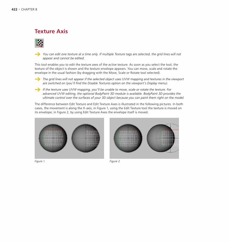
422 • CHAPTER 8 TOOLS MENU • 423
Texture Axis
You can edit one texture at a time only. If multiple Texture tags are selected, the grid lines will not appear and cannot be edited.
This tool enables you to edit the texture axes of the active texture. As soon as you select the tool, the texture of the object is shown and the texture envelope appears. You can move, scale and rotate the envelope in the usual fashion (by dragging with the Move, Scale or Rotate tool selected).
The grid lines will not appear if the selected object uses UVW mapping and textures in the viewport are switched on (you’ll find the Disable Textures option on the viewport’s Display menu).
If the texture uses UVW mapping, you’ll be unable to move, scale or rotate the texture. For advanced UVW editing, the optional BodyPaint 3D module is available. BodyPaint 3D provides the ultimate control over the surfaces of your 3D object because you can paint them right on the model.
The difference between Edit Texture and Edit Texture Axes is illustrated in the following pictures. In both cases, the movement is along the X-axis; in Figure 1, using the Edit Texture tool the texture is moved on its envelope; in Figure 2, by using Edit Texture Axes the envelope itself is moved.
Figure 1. Figure 2.

422 • CHAPTER 8 TOOLS MENU • 423
Inverse Kinematics
Ensure that only one object is selected before using the Inverse Kinematics tool. If multiple objects are selected, the IK tool will be unable to move them.
This tool enables you to move hierarchical objects interactively using inverse kinematics (IK). For example, you can grab the hand of an arm and move it to the required position. The arm will follow automatically, obeying any rotation restrictions you have applied to the joints.
The optional MOCCA module features advanced tools to achieve outstanding control over character animation, including a new IK system (Soft IK) with built-in dynamics and constraints that allow more fluid motion. For full details on MOCCA, please contact your local MAXON representative or visit www.maxon.net.
Not only is the IK tool useful for animation, it’s also ideal for posing characters. You will need to arrange the objects into a hierarchy and assign Kinematic tags (see ‘Kinematic Tag’, page 605). If you select an object at the end of a hierarchy and move the mouse, CINEMA 4D calculates the distance between the joints automatically and keeps it constant. This prevents the chain (e.g. an arm with several joints) from pulling apart.
mousemovement
CINEMA 4D’s Figure object is superb for learning IK. To see all the Anchor and Kinematic tags, you first need to make the figure editable (Structure > Make Editable).
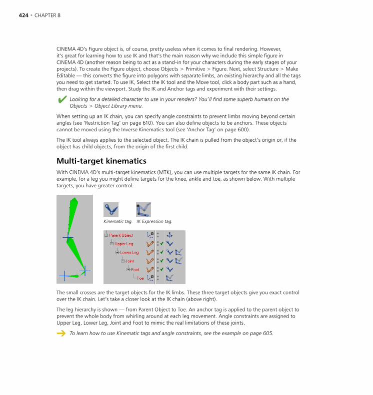
424 • CHAPTER 8 TOOLS MENU • 425
CINEMA 4D’s Figure object is, of course, pretty useless when it comes to final rendering. However, it’s great for learning how to use IK and that’s the main reason why we include this simple figure in CINEMA 4D (another reason being to act as a stand-in for your characters during the early stages of your projects). To create the Figure object, choose Objects > Primitive > Figure. Next, select Structure > Make Editable — this converts the figure into polygons with separate limbs, an existing hierarchy and all the tags you need to get started. To use IK, Select the IK tool and the Move tool, click a body part such as a hand, then drag within the viewport. Study the IK and Anchor tags and experiment with their settings.
Looking for a detailed character to use in your renders? You’ll find some superb humans on the Objects > Object Library menu.
When setting up an IK chain, you can specify angle constraints to prevent limbs moving beyond certain angles (see ‘Restriction Tag’ on page 610). You can also define objects to be anchors. These objects cannot be moved using the Inverse Kinematics tool (see ‘Anchor Tag’ on page 600).
The IK tool always applies to the selected object. The IK chain is pulled from the object’s origin or, if the object has child objects, from the origin of the first child.
Multi-target kinematicsWith CINEMA 4D’s multi-target kinematics (MTK), you can use multiple targets for the same IK chain. For example, for a leg you might define targets for the knee, ankle and toe, as shown below. With multiple targets, you have greater control.
Kinematic tag. IK Expression tag.
The small crosses are the target objects for the IK limbs. These three target objects give you exact control over the IK chain. Let’s take a closer look at the IK chain (above right).
The leg hierarchy is shown — from Parent Object to Toe. An anchor tag is applied to the parent object to prevent the whole body from whirling around at each leg movement. Angle constraints are assigned to Upper Leg, Lower Leg, Joint and Foot to mimic the real limitations of these joints.
To learn how to use Kinematic tags and angle constraints, see the example on page 605.
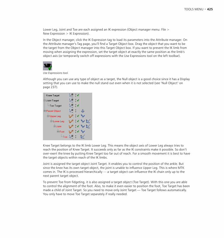
424 • CHAPTER 8 TOOLS MENU • 425
Lower Leg, Joint and Toe are each assigned an IK expression (Object manager menu: File > New Expression > IK Expression).
In the Object manager, click the IK Expression tag to load its parameters into the Attribute manager. On the Attribute manager’s Tag page, you’ll find a Target Object box. Drag the object that you want to be the target from the Object manager into this Target Object box. If you want to prevent the IK limb from moving when assigning the expression, set the target object at exactly the same position as the limb’s object axis (or temporarily switch off expressions with the Use Expressions tool on the left toolbar).
Use Expressions tool.
Although you can use any type of object as a target, the Null object is a good choice since it has a Display setting that you can use to make the null stand out even when it is not selected (see ‘Null Object’ on page 237).
Knee Target belongs to the IK limb Lower Leg. This means the object axis of Lower Leg always tries to reach the position of Knee Target. It succeeds only as far as the IK constraints make it possible. So don’t over-exert the knee by putting Knee Target too far out of reach. For a smooth movement it is best to have the target objects within reach of the IK limbs.
Joint is assigned the target object Joint Target. It enables you to control the position of the ankle. But since the knee has its own target object, the joint is unable to influence Upper Leg. This is where MTK comes in. The IK is processed hierarchically — a target object can influence the IK chain only up to the next parent target object.
To prevent Toe from fidgeting, it is also assigned a target object (Toe Target). With this one you are able to control the alignment of the foot. Also, to make it even easier to position the foot, Toe Target has been made a child of Joint Target. So you need to move only Joint Target — Toe Target follows automatically. You only have to move Toe Target separately if really needed.

426 • CHAPTER 8 TOOLS MENU • 427
Animation
Ensure that only one object is selected before using the Animation tool. If multiple objects are selected, you’ll be unable to edit their paths.
Selecting this tool lets you edit the animation path of the selected object. You can drag the path’s points to new positions and you can use the Move, Scale and Rotate tools to move, scale or rotate the entire path.
The Axes
Using these options, you can restrict movement, scaling or rotation to specific axes. For example, to allow movement along the Y-axis only, enable Y-axis and disable X-axis and Z-axis. Now, when you drag with the Move tool selected, the movement will be along the Y-axis only.
Use the Coordinate System setting, also on the Tools menu, to choose whether the angles refer to the world coordinate system or the object coordinate system.
If Use HPB System is enabled in the preferences (Units page), the HPB designators apply. (The letters HPB stand for heading, pitch and bank.)
For each type of operation, CINEMA 4D remembers the state of the axes (locked or unlocked). For example, if you have made a movement along the Y-axis while X and Z were locked, and subsequently change to Rotate, all axes are unlocked again. When you change back to Move, the program remembers that only the Y-axis was unlocked.

426 • CHAPTER 8 TOOLS MENU • 427
Coordinate System
Here you decide in which coordinate system an operation will take place. Not all options work with both systems. Scaling of object axes for example can occur only within the object coordinate system. The object coordinate system is the local system of an object, shown in the viewports by the colored axes; X (red), Y (green) and Z (blue). Each object has its own object coordinate system.
The difference between the coordinate systems is very important to animation. If HPB System is enabled in the preferences (Units page), HPB angles will be used for the rotation, independently of the axis system chosen. Internally CINEMA 4D works exclusively in the HPB system. HPB is an abbreviation for heading, pitch and bank.
You may have come across the terms heading, pitch and bank in connection with aircraft. An aeroplane rotates left or right to change its heading; up or down to changes its pitch; and rolls to changes its bank. When you are changing angles you may find it helpful to think of an aeroplane.
Unlike HPB, XYZ rotations are non-commutative. In other words, the order in which you rotate the axes matters. For example, rotating by the X value then the Y value may produce a different result to rotating Y first. This makes the XYZ system unsuitable for animation.
On the other hand, in the HPB system the angles are disassociated. You can first change the heading and then the pitch, or the other way round. Moreover, the HPB angles create naturally interpolated movements which are particularly useful for aeroplanes, cars or cameras. When you rotate around a particular axis in the XYZ system this may cause all three HPB components to change. The result is a tumbling animation. With the HPB system this cannot happen.

428 • CHAPTER 8 TOOLS MENU • 429
Although the HPB system is excellent for animation, it is useless when it comes to constructing objects. HPB angles are specified relative to the parent system, which demands a high level of abstraction. So CINEMA 4D offers you the choice. For rotations in the 3D viewport you have the HPB system and the (local or global) XYZ system. You’ll find the Use HPB System option on the Units page of the preferences. However, note that all numeric input is in HPB angles, even if Use HPB System is disabled.
Why use HPB?
In this section you’ll learn more about why CINEMA 4D uses the HPB system. However, if you’re the kind of artist who hates math, you’ll want to skip these additional details.
Some people do not understand why rotations around the Z-axis (the bank angle) are performed in the object system whereas rotations around Y and X axes (heading and pitch) are always made in the world system. With animation, even switching to XYZ rotations doesn’t help since CINEMA 4D is using the HPB system internally. The HPB system is a so-called Euler system where the HPB angles do not refer in principle to the axes of the object itself.
Consider this example
- Take an object whose angle system is initially 0/0/0. First make a rotation of 30° around heading, so that the X and Z axes of the object system are now rotated compared to the X and Z axes of the world system. Call these new axes X’ and Z’ (Y’ is identical to Y).
- A pitch of 20° now causes the object system to be rotated upward around the world system’s X’ axis. Z’ becomes Z’’ and Y’ becomes Y’’ (now X’ and X’’ are identical).
- Lastly, we rotate around a bank angle of -45°. This rotation causes the rotated object system to be tilted around the Z’’ axis. X’’ becomes X’’’ and Y’’ becomes Y’’’ (this time Z’’ and Z’’’ are identical).
- The object has now achieved an angle system of 30/20/-45 by consecutive rotations around H, P and B on a system in each case already rotated. Thus, HPB rotates neither around object nor around world axes. That bank is identical to a rotation around an object axis is purely coincidental. There are several different Euler systems, each one with a particular rotation order.
While this all seems rather impractical, the Euler system has a major advantage: rotations of objects are decoupled from one another as much as possible, which is not the case with rotations around object axes. Heading does not affect bank, bank does not affect pitch. Imagine if the X position of an object always affected the Y and Z positions ...
A further example clarifies the decoupling problem
This example should clarify why CINEMA 4D uses the Euler system. Once you become familiar with this system, you’ll find it easy to use.
- Let’s pretend CINEMA 4D does not use Euler angles. Imagine a point on the X-axis in position 100/0/0.
- Rotate the point 90° around the Y-axis. It then lies exactly on the Z-axis at 0/0/100. Now keep rotating, this time for 30° around the X-axis. The point now lies in the ZY plane at 0/87/50.
428 • CHAPTER 8 TOOLS MENU • 429
- So far, so good. Now, however, you reverse the rotation order. The point at 100/0/0 is still at the position 100/0/0 after a rotation of 30° around the X-axis. Subsequently, you rotate again around the Y-axis for 90°. The point is now at 0/0/100, a completely different position.
- So, due to the mathematical properties of rotations, the sequence of rotations around the object axes is not commutative (i.e. rotation A plus rotation B does not equal rotation B plus rotation A). This leads to unexpected results with animation.
And finally
If this part of the chapter seems complicated to you, we’d agree. Angle systems are not easy to understand. However, CINEMA 4D is one of the very few programs to fully integrate both object hierarchies and local coordinates. Other programs tend to compromise on functionality; either they do not have real object hierarchies, or they have a separate modeler and animator with limited integration, or they have difficulty in creating complex, hierarchical animation.
CINEMA 4D is a fully integrated product, providing you with a multitude of fascinating possibilities and features which simply are not possible in many other animation packages. Let your imagination take over!


9 Selection Menu

SELECTION MENU • 433
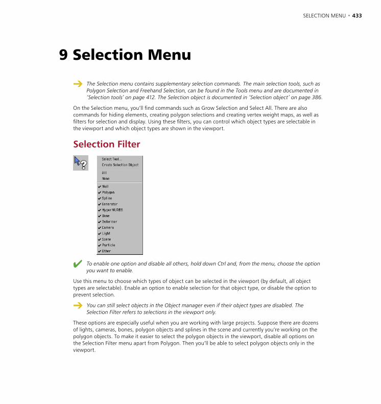
SELECTION MENU • 433
The Selection menu contains supplementary selection commands. The main selection tools, such as Polygon Selection and Freehand Selection, can be found in the Tools menu and are documented in ‘Selection tools’ on page 412. The Selection object is documented in ‘Selection object’ on page 386.
On the Selection menu, you’ll find commands such as Grow Selection and Select All. There are also commands for hiding elements, creating polygon selections and creating vertex weight maps, as well as filters for selection and display. Using these filters, you can control which object types are selectable in the viewport and which object types are shown in the viewport.
Selection Filter
To enable one option and disable all others, hold down Ctrl and, from the menu, choose the option you want to enable.
Use this menu to choose which types of object can be selected in the viewport (by default, all object types are selectable). Enable an option to enable selection for that object type, or disable the option to prevent selection.
You can still select objects in the Object manager even if their object types are disabled. The Selection Filter refers to selections in the viewport only.
These options are especially useful when you are working with large projects. Suppose there are dozens of lights, cameras, bones, polygon objects and splines in the scene and currently you’re working on the polygon objects. To make it easier to select the polygon objects in the viewport, disable all options on the Selection Filter menu apart from Polygon. Then you’ll be able to select polygon objects only in the viewport.
9 Selection Menu
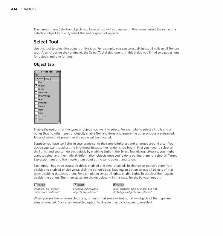
434 • CHAPTER 9 SELECTION MENU • 435
The names of any Selection objects you have set-up will also appear in this menu. Select the name of a Selection object to quickly select that entire group of objects.
Select ToolUse this tool to select like objects or like tags. For example, you can select all lights, all nulls or all Texture tags. After choosing the command, the Select Tool dialog opens. In this dialog you’ll find two pages: one for objects and one for tags.
Object tab
Enable the options for the types of objects you want to select. For example, to select all nulls and all bones (but no other types of object), enable Null and Bone and ensure the other options are disabled. Types of object not present in the scene will be ghosted.
Suppose you have ten lights in your scene set to the same brightness and arranged around a car. You decide you want to adjust the brightness because the render is too bright. First you need to select all the lights, and you can do this quickly by enabling Light in the Select Tool dialog. Likewise, you might want to select and then hide all deformation objects once you’re done editing them, or select all Target Expression tags and then make them point at the same object, and so on.
Each option has three states: disabled, enabled and semi-enabled. To change an option’s state from disabled to enabled or vice versa, click the option’s box. Enabling an option selects all objects of that type, disabling deselects them. For example, to select all lights, enable Light. To deselect them again, disable the option. The three states are shown below — in this case, for the Polygon option.
Disabled. All Polygon objects are deslected.
Enabled. All Polygon objects are selected.
Semi-enabled. One or more, but not all, Polygon objects are selected.
When you see the semi-enabled state, it means that some — but not all — objects of that type are already selected. Click a semi-enabled option to disable it, and click again to enable it.
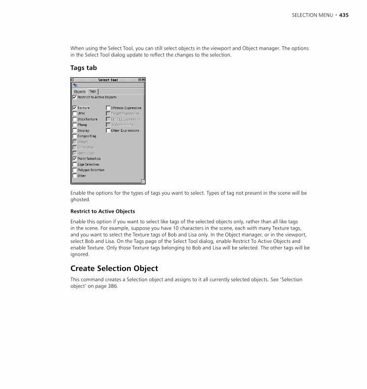
434 • CHAPTER 9 SELECTION MENU • 435
When using the Select Tool, you can still select objects in the viewport and Object manager. The options in the Select Tool dialog update to reflect the changes to the selection.
Tags tab
Enable the options for the types of tags you want to select. Types of tag not present in the scene will be ghosted.
Restrict to Active Objects
Enable this option if you want to select like tags of the selected objects only, rather than all like tags in the scene. For example, suppose you have 10 characters in the scene, each with many Texture tags, and you want to select the Texture tags of Bob and Lisa only. In the Object manager, or in the viewport, select Bob and Lisa. On the Tags page of the Select Tool dialog, enable Restrict To Active Objects and enable Texture. Only those Texture tags belonging to Bob and Lisa will be selected. The other tags will be ignored.
Create Selection ObjectThis command creates a Selection object and assigns to it all currently selected objects. See ‘Selection object’ on page 386.
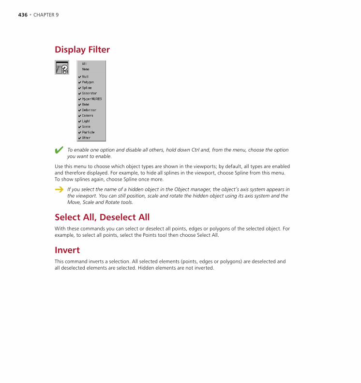
436 • CHAPTER 9 SELECTION MENU • 437
Display Filter
To enable one option and disable all others, hold down Ctrl and, from the menu, choose the option you want to enable.
Use this menu to choose which object types are shown in the viewports; by default, all types are enabled and therefore displayed. For example, to hide all splines in the viewport, choose Spline from this menu. To show splines again, choose Spline once more.
If you select the name of a hidden object in the Object manager, the object’s axis system appears in the viewport. You can still position, scale and rotate the hidden object using its axis system and the Move, Scale and Rotate tools.
Select All, Deselect AllWith these commands you can select or deselect all points, edges or polygons of the selected object. For example, to select all points, select the Points tool then choose Select All.
InvertThis command inverts a selection. All selected elements (points, edges or polygons) are deselected and all deselected elements are selected. Hidden elements are not inverted.
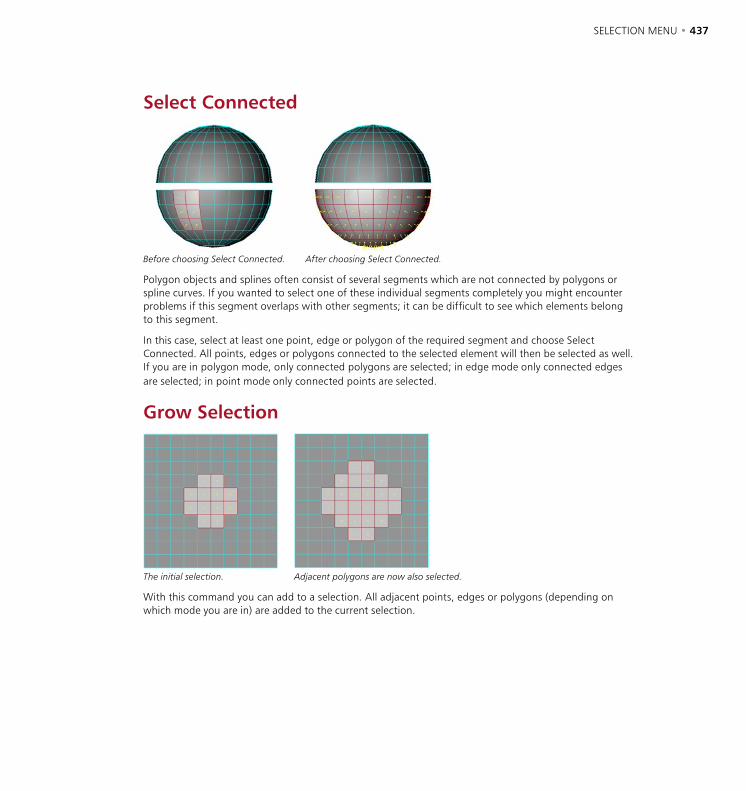
436 • CHAPTER 9 SELECTION MENU • 437
Select Connected
Before choosing Select Connected. After choosing Select Connected.
Polygon objects and splines often consist of several segments which are not connected by polygons or spline curves. If you wanted to select one of these individual segments completely you might encounter problems if this segment overlaps with other segments; it can be difficult to see which elements belong to this segment.
In this case, select at least one point, edge or polygon of the required segment and choose Select Connected. All points, edges or polygons connected to the selected element will then be selected as well. If you are in polygon mode, only connected polygons are selected; in edge mode only connected edges are selected; in point mode only connected points are selected.
Grow Selection
The initial selection. Adjacent polygons are now also selected.
With this command you can add to a selection. All adjacent points, edges or polygons (depending on which mode you are in) are added to the current selection.
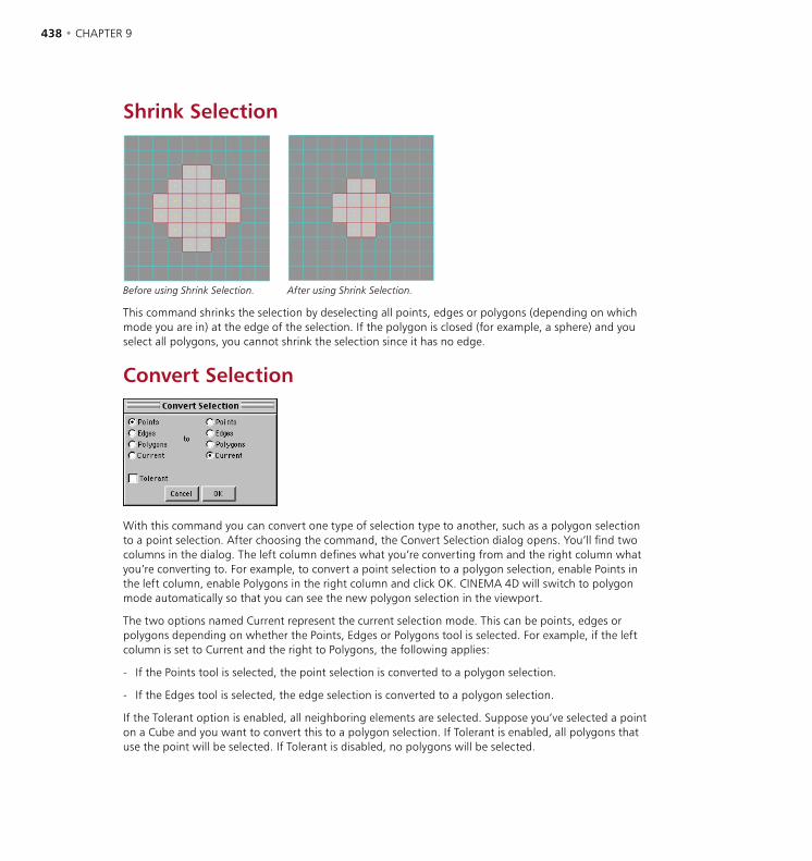
438 • CHAPTER 9 SELECTION MENU • 439
Shrink Selection
Before using Shrink Selection. After using Shrink Selection.
This command shrinks the selection by deselecting all points, edges or polygons (depending on which mode you are in) at the edge of the selection. If the polygon is closed (for example, a sphere) and you select all polygons, you cannot shrink the selection since it has no edge.
Convert Selection
With this command you can convert one type of selection type to another, such as a polygon selection to a point selection. After choosing the command, the Convert Selection dialog opens. You’ll find two columns in the dialog. The left column defines what you’re converting from and the right column what you’re converting to. For example, to convert a point selection to a polygon selection, enable Points in the left column, enable Polygons in the right column and click OK. CINEMA 4D will switch to polygon mode automatically so that you can see the new polygon selection in the viewport.
The two options named Current represent the current selection mode. This can be points, edges or polygons depending on whether the Points, Edges or Polygons tool is selected. For example, if the left column is set to Current and the right to Polygons, the following applies:
- If the Points tool is selected, the point selection is converted to a polygon selection.
- If the Edges tool is selected, the edge selection is converted to a polygon selection.
If the Tolerant option is enabled, all neighboring elements are selected. Suppose you’ve selected a point on a Cube and you want to convert this to a polygon selection. If Tolerant is enabled, all polygons that use the point will be selected. If Tolerant is disabled, no polygons will be selected.
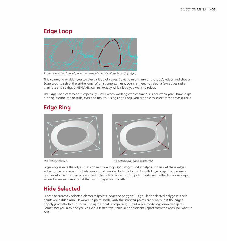
438 • CHAPTER 9 SELECTION MENU • 439
Edge Loop
An edge selected (top left) and the result of choosing Edge Loop (top right).
This command enables you to select a loop of edges. Select one or more of the loop’s edges and choose Edge Loop to select the entire loop. With a complex mesh, you may need to select a few edges rather than just one so that CINEMA 4D can tell exactly which loop you want to select.
The Edge Loop command is especially useful when working with characters, since often you’ll have loops running around the nostrils, eyes and mouth. Using Edge Loop, you are able to select these areas quickly.
Edge Ring
The initial selection. The outside polygons deselected.
Edge Ring selects the edges that connect two loops (you might find it helpful to think of these edges as being the cross-sections between a small loop and a large loop). As with Edge Loop, the command is especially useful when working with characters, since most popular modeling methods involve loops around areas such as around the nostrils, eyes and mouth.
Hide SelectedHides the currently selected elements (points, edges or polygons). If you hide selected polygons, their points are hidden also. However, in point mode, only the selected points are hidden, not the edges or polygons attached to them. Hiding elements is especially useful when modeling complex objects. Sometimes you may find you can work faster if you hide all the elements apart from the ones you want to edit.

440 • CHAPTER 9 SELECTION MENU • 441
Hide DeselectedThis command hides all unselected elements. If you hide unselected polygons, their points are hidden also. However, in point mode, only the deselected points are hidden, not the polygons attached to them.
Unhide AllThis command makes all hidden elements visible again.
Invert VisibilityThe visibility of all elements is inverted. Visible elements are hidden and hidden elements are made visible.
Set Selection You can change the name of a set or ‘frozen’ selection in the Attribute manager on the Basic
Properties page; see ‘Attribute manager commands’, below.
Here you can set or ‘freeze’ selections for the long term and store them in one of three tags. You can set either point, edge or polygon selections. You can then manipulate frozen selections at any time using these tags in the Object manager.
Point Selection tag.
Edge Selection tag.
Polygon Selection tag.
To set or ‘freeze’ a selection
- Select the elements (points, edges or polygons) that you want to freeze.
- If you want the selection to replace an existing frozen selection, select the frozen selection’s tag in the Object manager. Otherwise, ensure that no selection tags are selected.
- Choose Selection > Set Selection.
To learn how to apply separate material properties to selections, see ‘Selection’ on page 814. Selections that have been frozen are also useful for deformation objects; see ‘Restricting bones using polygon selections or vertex maps’ on page 329.
Although you can freeze more than 10 selections per object, many commands operate on the first 10 only. For example, if you subdivide the object, only the surfaces in the first 10 selections are subdivided. For bones, up to 50 frozen selections can be assigned.
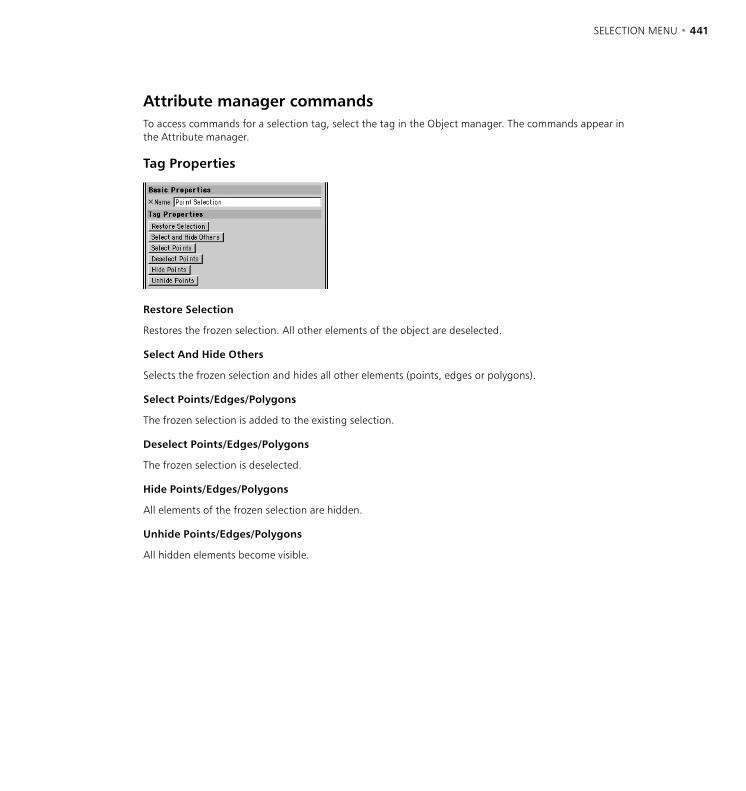
440 • CHAPTER 9 SELECTION MENU • 441
Attribute manager commandsTo access commands for a selection tag, select the tag in the Object manager. The commands appear in the Attribute manager.
Tag Properties
Restore Selection
Restores the frozen selection. All other elements of the object are deselected.
Select And Hide Others
Selects the frozen selection and hides all other elements (points, edges or polygons).
Select Points/Edges/Polygons
The frozen selection is added to the existing selection.
Deselect Points/Edges/Polygons
The frozen selection is deselected.
Hide Points/Edges/Polygons
All elements of the frozen selection are hidden.
Unhide Points/Edges/Polygons
All hidden elements become visible.

442 • CHAPTER 9
Set Vertex Weight
This command is especially useful when working with deformation objects. You can use it to restrict a deformation object’s influence with precision. For example, you can use it so that a twist deformer twists the head of a figure only, not the entire body. The most powerful application for this command is to create vertex maps or weight maps for bones. Therefore, the steps involved in using vertex maps is described in the section on bones (see ‘Restricting bones using polygon selections or vertex maps’ on page 329.)
Points with weighting are colored. The entire object is colored as well (provided that the viewport’s display is set to Gouraud Shading or Quick Shading). Yellow indicates 100% influence, red indicates 0% influence. The vertex map is represented in the Object manager as a Vertex Map tag:
To create a vertex map, first select the Points tool or the Polygons tool from the left-hand toolbar, then select the points or polygons you want to weight. Next, choose Selection > Set Vertex Weight.
Value
This is the amount of weight that is used by the Mode setting.
Mode
Set means the weight in the Value box is assigned to the points. Brighten will cause the weight in the Value box to be added to the points. Darken will subtract the weight in the Value box from the points.
To blend out the influence of a deformation object smoothly, create a ramp from yellow to red. The following picture shows such a ramp: the first row of points is set to 100%, the second to 50% and the third to 0%. There is a smooth transition from yellow to red.

10 Structure Menu

STRUCTURE MENU • 445
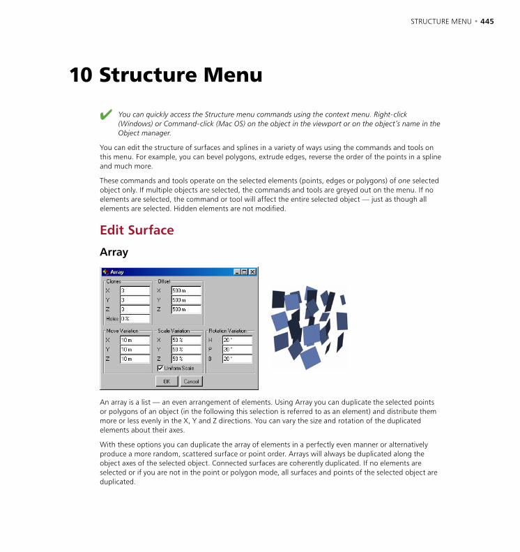
STRUCTURE MENU • 445
You can quickly access the Structure menu commands using the context menu. Right-click (Windows) or Command-click (Mac OS) on the object in the viewport or on the object’s name in the Object manager.
You can edit the structure of surfaces and splines in a variety of ways using the commands and tools on this menu. For example, you can bevel polygons, extrude edges, reverse the order of the points in a spline and much more.
These commands and tools operate on the selected elements (points, edges or polygons) of one selected object only. If multiple objects are selected, the commands and tools are greyed out on the menu. If no elements are selected, the command or tool will affect the entire selected object — just as though all elements are selected. Hidden elements are not modified.
Edit Surface
Array
An array is a list — an even arrangement of elements. Using Array you can duplicate the selected points or polygons of an object (in the following this selection is referred to as an element) and distribute them more or less evenly in the X, Y and Z directions. You can vary the size and rotation of the duplicated elements about their axes.
With these options you can duplicate the array of elements in a perfectly even manner or alternatively produce a more random, scattered surface or point order. Arrays will always be duplicated along the object axes of the selected object. Connected surfaces are coherently duplicated. If no elements are selected or if you are not in the point or polygon mode, all surfaces and points of the selected object are duplicated.
10 Structure Menu
446 • CHAPTER 10 STRUCTURE MENU • 447
If just points alone are selected then they will be duplicated without their adjacent surfaces. To create surfaces for these points, use the Bridge tool or Create Polygon tool.
Imagine a blade of grass. You could easily use the Duplicate tool from the Functions menu to copy the blade of grass and then randomly distribute these copies with the Randomize function. The disadvantage of this method is the many individual objects that result from it. With the Array tool you duplicate just the surfaces (or points) and not the complete object. Thus you can produce a complete meadow from a single blade of grass.
Clones
Defines the number of clones along each object axis. This value also includes the original element. For example, if you enter the value of 2 for all three axes, it results in a total number of 2x2x2=8. In effect, however, only 7 actual clones are produced.
Holes
This value adds a random factor to the number of elements that are created. You may enter values between 0% and 100%. A value of 0% means the complete number of elements that has been input is created. With 50% only half of the elements are created — which elements are omitted is selected randomly. With 100% no new elements will be created.
Offset
Defines the size of the array. You can enter different values for each of the X, Y and Z directions. These values are absolute — they refer to the entire size of the array (including the start element).
Move Variation
These parameters define how the positions of the duplicated elements vary. This arrangement enables you to assign either accurate or uneven positioning. If the values for all axes are set to 0 then an accurate position is assigned to each duplicated element. If you set the X value to 100, however, the individual elements can deviate from -100 to +100 units from their position in the X direction.
Scale Variation
Defines the variation of the element size. The values are shown as a percentage. 100% means that the size is not affected. For example, entering 50% for the X value results in the X size of the individual elements varying between 50% and 100%. With 0% the size varies between 0% and 100%. Should you enter 200% then the variation will be between 100% and 200%.
Uniform Scale
If this option is enabled, the percentage values chosen for X, Y and Z will also be used for relative scaling. For example: X = 200%, Y = 100%, Z = 50% results in a relation of 2:1:0.5. The individual elements can then be scaled only according to this relative scaling. If this option is disabled, the axes of the individual elements can be scaled independently.
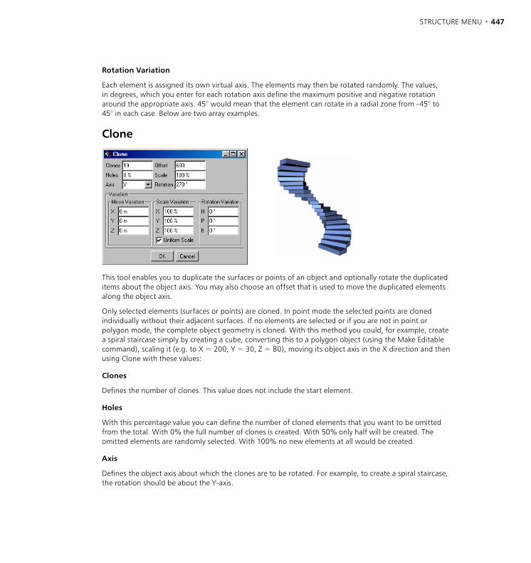
446 • CHAPTER 10 STRUCTURE MENU • 447
Rotation Variation
Each element is assigned its own virtual axis. The elements may then be rotated randomly. The values, in degrees, which you enter for each rotation axis define the maximum positive and negative rotation around the appropriate axis. 45° would mean that the element can rotate in a radial zone from -45° to 45° in each case. Below are two array examples.
Clone
This tool enables you to duplicate the surfaces or points of an object and optionally rotate the duplicated items about the object axis. You may also choose an offset that is used to move the duplicated elements along the object axis.
Only selected elements (surfaces or points) are cloned. In point mode the selected points are cloned individually without their adjacent surfaces. If no elements are selected or if you are not in point or polygon mode, the complete object geometry is cloned. With this method you could, for example, create a spiral staircase simply by creating a cube, converting this to a polygon object (using the Make Editable command), scaling it (e.g. to X = 200, Y = 30, Z = 80), moving its object axis in the X direction and then using Clone with these values:
Clones
Defines the number of clones. This value does not include the start element.
Holes
With this percentage value you can define the number of cloned elements that you want to be omitted from the total. With 0% the full number of clones is created. With 50% only half will be created. The omitted elements are randomly selected. With 100% no new elements at all would be created.
Axis
Defines the object axis about which the clones are to be rotated. For example, to create a spiral staircase, the rotation should be about the Y-axis.
448 • CHAPTER 10 STRUCTURE MENU • 449
Offset
Gives the distance from the start element to the last clone along the selected object axis. All intermediate clones are distributed evenly over this distance.
Scale
This parameter enables you to scale the clones. The scale of the clones will increase gradually all the way to the last clone. Enter the size of the final clone as a percentage of the start element’s size. For example, if you want the last clone to be twice as large as the start element, set Scale to 200%.
Rotation
Defines the angle through which the clones are rotated. With 180° the object would rotate half a revolution from start to finish; with 360° a full rotation is made.
Move Variation
By default, all clones are assigned a fixed position that depends on the above settings. You may vary these positions using Move Variation. For example, if you set the Move Variation value for Y to 10, each clone can deviate from -10 to 10 units in their Y position.
Scale Variation
Defines the variation in the size of the clones as a percentage. At 100% the size is not varied. Entering 50% for the X value means that the X size of the individual elements can vary between 50% and 100%. With 0% the size varies between 0% and 100%. If you enter 200% then the value will vary between 100% and 200%.
Uniform Scale
If this option is enabled, the percentages entered for X, Y and Z are used for relative scaling. For example, with Uniform Scale enabled, X set to 200%, Y to 100% and Z to 50%, the ratio of scaling is 2:1:0.5; the individual elements can then be scaled only according to this ratio. If this option is disabled, the axes of the individual elements can be varied in scale independently.
Rotation Variation
Each element is assigned its own virtual axis. The element may then be rotated randomly around its axis with the value entered here. The value, in degrees, which you enter for each rotation axis defines the maximum positive and negative rotation about the appropriate axis. 45° would indicate that the clones can vary in their radial rotation from -45° to 45° at each clone.
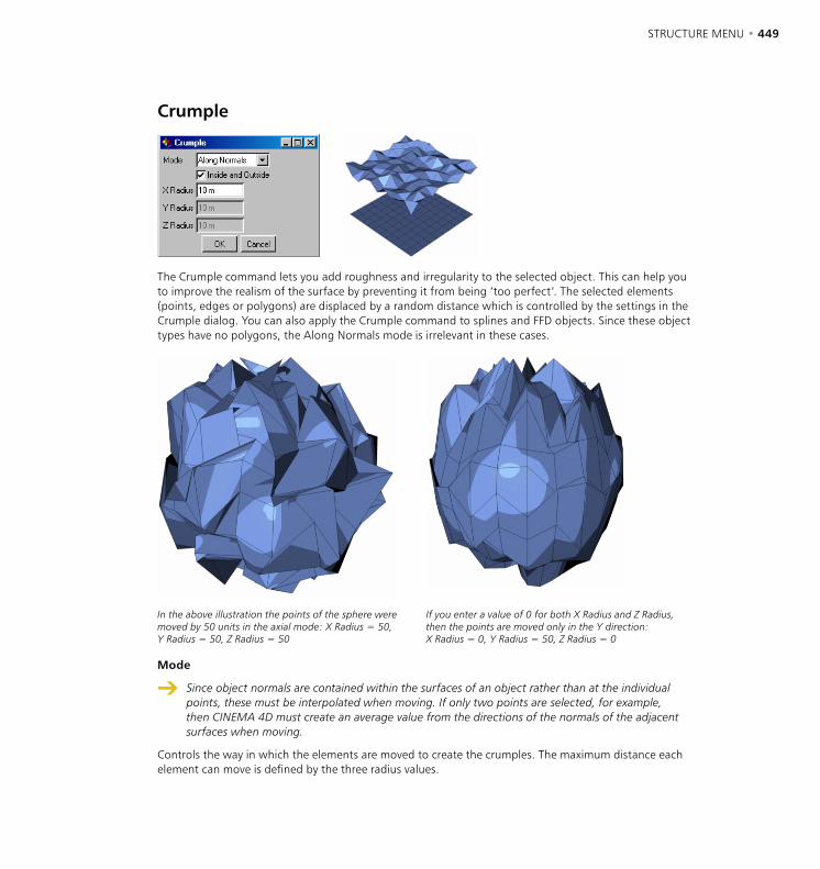
448 • CHAPTER 10 STRUCTURE MENU • 449
Crumple
The Crumple command lets you add roughness and irregularity to the selected object. This can help you to improve the realism of the surface by preventing it from being ‘too perfect’. The selected elements (points, edges or polygons) are displaced by a random distance which is controlled by the settings in the Crumple dialog. You can also apply the Crumple command to splines and FFD objects. Since these object types have no polygons, the Along Normals mode is irrelevant in these cases.
In the above illustration the points of the sphere were moved by 50 units in the axial mode: X Radius = 50, Y Radius = 50, Z Radius = 50
If you enter a value of 0 for both X Radius and Z Radius, then the points are moved only in the Y direction: X Radius = 0, Y Radius = 50, Z Radius = 0
Mode
Since object normals are contained within the surfaces of an object rather than at the individual points, these must be interpolated when moving. If only two points are selected, for example, then CINEMA 4D must create an average value from the directions of the normals of the adjacent surfaces when moving.
Controls the way in which the elements are moved to create the crumples. The maximum distance each element can move is defined by the three radius values.

450 • CHAPTER 10 STRUCTURE MENU • 451
Along Normals means the elements are moved in the direction of the surface normals; since this allows movement in one direction only (along the X-axis) you can enter one radius value only. Axial means the elements are moved along the object axes. Radial means the elements are moved radially from the object’s origin.
Inside And Outside
The Inside and Outside option cannot be used in the Axial mode.
If this option is enabled, each element may move inwards or outwards. With the option disabled, the elements will move outwards only. This option is ghosted when Mode is set to Axial.
X Radius, Y Radius, Z Radius
These parameters define the maximum distance each element can be moved by the Crumple command.
Disconnect
At the seams of disconnected surfaces, the Phong shading disappears and a ridge appears, since now there are two edges. (See also ‘Phong Tag’, page 608.)
This command enables you to disconnect polygons or points from the selected object. Select some polygons and choose Disconnect to see the results. The separated surfaces will still be at the same position, but physically they are no longer connected to the object. The original object still contains the points of these separated surfaces, so the geometry is not destroyed. This tool normally needs a selection of polygons and polygon mode enabled. A good example of using Disconnect would be to cut a hole into an object and keep the disconnected surface to use as a cap.
This tool can also be applied to splines. In contrast to the Break Segment tool, the start and end points of the disconnected segment are duplicated (as is the case with polygon objects) and are not deleted from the original spline. Thus the order of the spline remains intact both before and after disconnection. When using Disconnect on splines, a selection of points and point mode are needed.
Preserve Groups
If this option is enabled, the elements are disconnected from the object in one piece (provided they were connected to begin with). If the option is disabled, the elements are separated from one other as well as from the object.
Explode SegmentsUsing this command, you can split the individual segments of a spline into separate objects. An individual spline object is created from each segment of the original. Only the first segment of the original spline remains. You do not need to have a selection and you do not need to be in point mode. The new spline objects become sub-objects of the original spline and are given the names ‘<objectname>.<number>’.
So for example, a text spline object can easily be split into individual letters. (Bear in mind, though, that certain letters, such as ‘e’, may be exploded into two or more segments because of holes in their structure. You may want to group these segments to re-create the entire letter.)
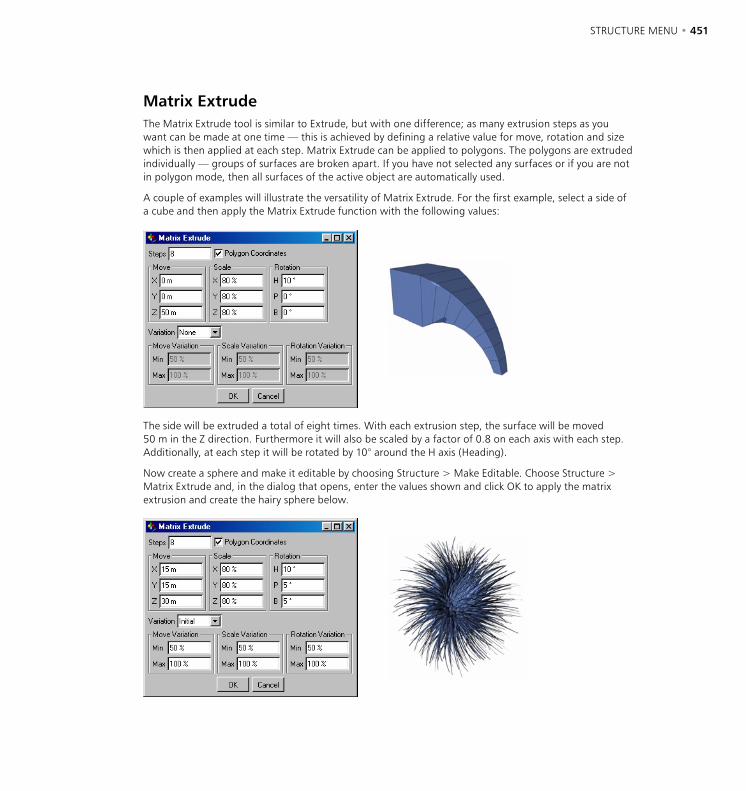
450 • CHAPTER 10 STRUCTURE MENU • 451
Matrix ExtrudeThe Matrix Extrude tool is similar to Extrude, but with one difference; as many extrusion steps as you want can be made at one time — this is achieved by defining a relative value for move, rotation and size which is then applied at each step. Matrix Extrude can be applied to polygons. The polygons are extruded individually — groups of surfaces are broken apart. If you have not selected any surfaces or if you are not in polygon mode, then all surfaces of the active object are automatically used.
A couple of examples will illustrate the versatility of Matrix Extrude. For the first example, select a side of a cube and then apply the Matrix Extrude function with the following values:
The side will be extruded a total of eight times. With each extrusion step, the surface will be moved 50 m in the Z direction. Furthermore it will also be scaled by a factor of 0.8 on each axis with each step. Additionally, at each step it will be rotated by 10° around the H axis (Heading).
Now create a sphere and make it editable by choosing Structure > Make Editable. Choose Structure > Matrix Extrude and, in the dialog that opens, enter the values shown and click OK to apply the matrix extrusion and create the hairy sphere below.
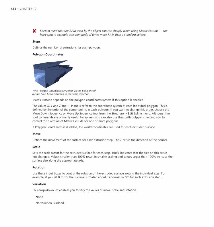
452 • CHAPTER 10 STRUCTURE MENU • 453
Keep in mind that the RAM used by the object can rise sharply when using Matrix Extrude — the hairy sphere example uses hundreds of times more RAM than a standard sphere.
Steps
Defines the number of extrusions for each polygon.
Polygon Coordinates
With Polygon Coordinates enabled, all the polygons of a cube have been extruded in the same direction.
Matrix Extrude depends on the polygon coordinates system if this option is enabled.
The values X, Y and Z and H, P and B refer to the coordinate system of each individual polygon. This is defined by the order of the corner points in each polygon. If you want to change this order, choose the Move Down Sequence or Move Up Sequence tool from the Structure > Edit Spline menu. Although the tool commands are primarily useful for splines, you can also use then with polygons, helping you to control the direction of Matrix Extrude for one or more polygons.
If Polygon Coordinates is disabled, the world coordinates are used for each extruded surface.
Move
Defines the movement of the surface for each extrusion step. The Z-axis is the direction of the normal.
Scale
Sets the scale factor for the extruded surface for each step. 100% indicates that the size on this axis is not changed. Values smaller than 100% result in smaller scaling and values larger than 100% increase the surface size along the appropriate axis.
Rotation
Use these input boxes to control the rotation of the extruded surface around the individual axes. For example, if you set B to 10, the surface is rotated about its normal by 10° for each extrusion step.
Variation
This drop-down list enables you to vary the values of move, scale and rotation.
None
No variation is added.
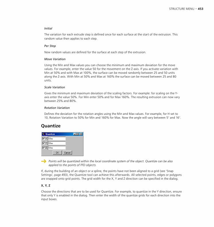
452 • CHAPTER 10 STRUCTURE MENU • 453
Initial
The variation for each extrude step is defined once for each surface at the start of the extrusion. This random value then applies to each step.
Per Step
New random values are defined for the surface at each step of the extrusion.
Move Variation
Using the Min and Max values you can choose the minimum and maximum deviation for the move values. For example, enter the value 50 for the movement on the Z-axis. If you activate variation with Min at 50% and with Max at 100%, the surface can be moved randomly between 25 and 50 units along the Z-axis. With Min at 50% and Max at 160% the surface can be moved between 25 and 80 units.
Scale Variation
Gives the minimum and maximum deviation of the scaling factors. For example: for scaling on the Y-axis enter the value 50%. For Min enter 50% and for Max 160%. The resulting extrusion can now vary between 25% and 80%.
Rotation Variation
Defines the deviation for the rotation angles using the Min and Max values. For example, for H set to 10, Rotation Variation to 50% for Min and 160% for Max. Now the angle will vary between 5° and 16°.
Quantize
Points will be quantized within the local coordinate system of the object. Quantize can be also applied to the points of FFD objects.
If, during the building of an object or a spline, the points have not been aligned to a grid (see ‘Snap Settings’, page 493), the Quantize tool can achieve this afterwards. All selected points, edges or polygons are snapped onto grid points. The grid width for the X, Y and Z direction can be specified in the dialog.
X, Y, Z
Choose the directions that are to be used for Quantize. For example, to quantize in the Y direction, ensure that only Y is enabled in the dialog. Then enter the width of the quantize grids for each direction into the input boxes.
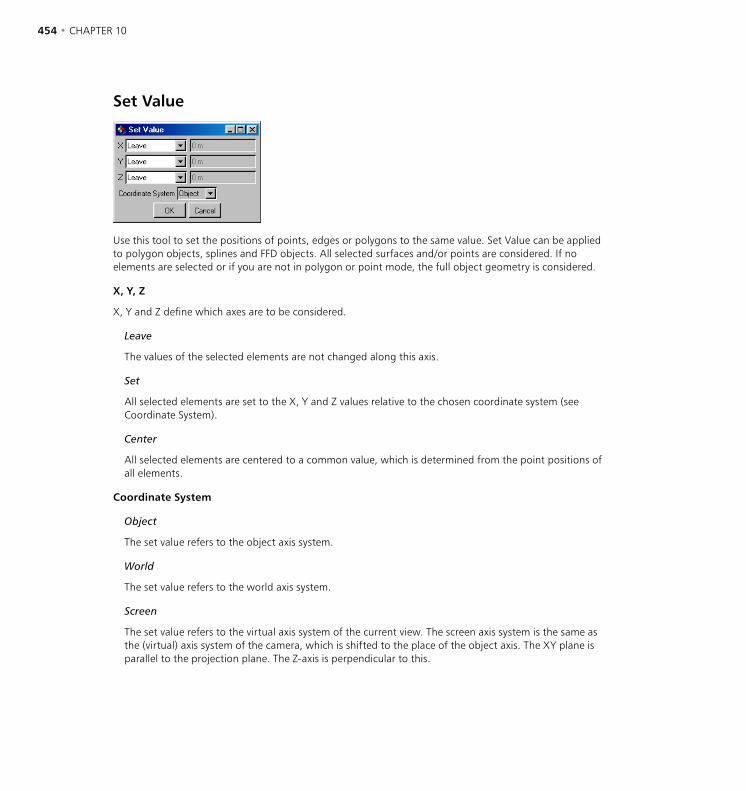
454 • CHAPTER 10 STRUCTURE MENU • 455
Set Value
Use this tool to set the positions of points, edges or polygons to the same value. Set Value can be applied to polygon objects, splines and FFD objects. All selected surfaces and/or points are considered. If no elements are selected or if you are not in polygon or point mode, the full object geometry is considered.
X, Y, Z
X, Y and Z define which axes are to be considered.
Leave
The values of the selected elements are not changed along this axis.
Set
All selected elements are set to the X, Y and Z values relative to the chosen coordinate system (see Coordinate System).
Center
All selected elements are centered to a common value, which is determined from the point positions of all elements.
Coordinate System
Object
The set value refers to the object axis system.
World
The set value refers to the world axis system.
Screen
The set value refers to the virtual axis system of the current view. The screen axis system is the same as the (virtual) axis system of the camera, which is shifted to the place of the object axis. The XY plane is parallel to the projection plane. The Z-axis is perpendicular to this.
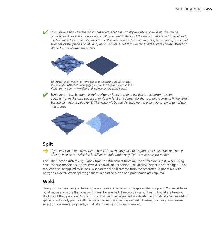
454 • CHAPTER 10 STRUCTURE MENU • 455
If you have a flat XZ plane which has points that are not all precisely on one level, this can be resolved easily in at least two ways. Firstly you could select just the points that are out of level and use Set Value to set their Y values to the Y value of the rest of the plane. Or, more simply, you could select all of the plane’s points and, using Set Value, set Y to Center. In either case choose Object or World for the coordinate system.
Before using Set Value (left) the points of this plane are not at the same height. After Set Value (right) all points are positioned on the Y axis, set to a common value, and are now at the same height.
Sometimes it can be more useful to align surfaces or points parallel to the current camera perspective. In this case select Set or Center for Z and Screen for the coordinate system. If you select Set you can enter a value for Z. This value will be the distance from the camera to the origin of the object axis.
Split
If you want to delete the separated part from the original object, you can choose Delete directly after Split since the selection is still active (this works only if you are in polygon mode).
The Split function differs very slightly from the Disconnect function; the difference is that, when using Split, the disconnected surfaces leave a separate object behind. The original object is not changed. This tool can also be applied to splines. A separate spline is created from the separated segment (as with polygon objects). When splitting splines, a point selection and point mode are required.
WeldUsing this tool enables you to weld several points of an object or a spline into one point. You must be in point mode and more than one point must be selected. The coordinates of the first point are taken as the base of the operation. Any polygons that become redundant are deleted automatically. When editing spline objects, only points within a particular segment can be welded. However, you may have several selections on several segments, all of which can be individually welded.
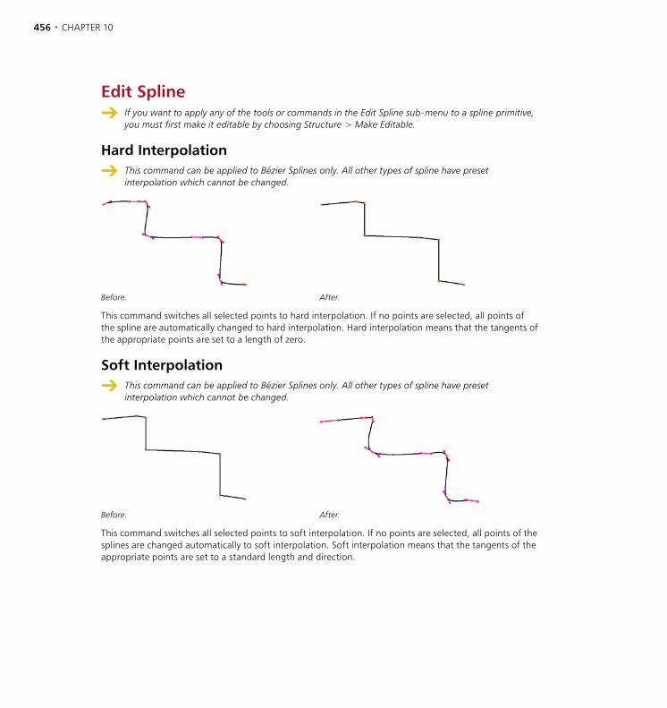
456 • CHAPTER 10 STRUCTURE MENU • 457
Edit Spline If you want to apply any of the tools or commands in the Edit Spline sub-menu to a spline primitive,
you must first make it editable by choosing Structure > Make Editable.
Hard Interpolation
This command can be applied to Bézier Splines only. All other types of spline have preset interpolation which cannot be changed.
Before. After.
This command switches all selected points to hard interpolation. If no points are selected, all points of the spline are automatically changed to hard interpolation. Hard interpolation means that the tangents of the appropriate points are set to a length of zero.
Soft Interpolation
This command can be applied to Bézier Splines only. All other types of spline have preset interpolation which cannot be changed.
Before. After.
This command switches all selected points to soft interpolation. If no points are selected, all points of the splines are changed automatically to soft interpolation. Soft interpolation means that the tangents of the appropriate points are set to a standard length and direction.

456 • CHAPTER 10 STRUCTURE MENU • 457
Equal Tangent Length
This command can be applied to Bézier Splines only. All other types of spline have preset interpolation which cannot be changed.
Before. After.
For each selected point, the shorter tangent handle is set to the same length as its partner tangent. If no points are selected, all points are automatically included in the action.
Equal Tangent Direction
This command can be applied to Bézier Splines only. All other types of spline have preset interpolation which cannot be changed.
Before. After.
While editing splines, by dragging with the Shift key held down, a tangent handle can be moved independently of its partner handle, forming a sharp corner at that point along the spline’s curve. If you change your mind later on and want to restore smoothness, you can do so using this command. The left tangent will remain where it is, while the right tangent will be rotated until it is equal and opposite in direction, forming the straight tangent pair that guarantees a smooth spline curve. If no points are selected, all points are included automatically.

458 • CHAPTER 10 STRUCTURE MENU • 459
Join Segment
Before. After.
A spline can consist of several unconnected segments (a text spline is a good example of this). If you want to connect two of these segments, select one or more points of each segment and use the Join Segment command. The start points of each spline are joined to the end points of the other spline. If you directly select the end points of the two segments, however, these are also joined. If these end points have the same position, one of them will be deleted when joining.
You can join either two or all segments at the same time. If more than two segments are selected then only the first two are joined. If no points are selected, all segments of a spline are joined.
Break Segment
This command requires a point selection and works in point mode only.
With this command you can create a new spline segment. Select one of the points that you want to separate. After using Break Segment you will have a new segment and all points on either side of the separated segment will become a new segment. If the selected points are not consecutive, a number of spline segments will be created, one for each of any consecutive points and one from the remaining points.
To add a new segment to an existing spline, you must first create the first point of the new segment. Before the break it is still connected to the old segment. If you now use Break Segment then the new segment will start here; you can now add new points using the Add Points command.
Set First Point
This command requires a point selection and works in point mode only.
When you choose this command, the selected point of a spline is defined as the new start point of the spline, around which all points of the spline are re-sorted accordingly. If there are several segments within the spline you can select a point or points within each segment; then each segment will be re-ordered according to the chosen point(s) within it. If more than one point per segment is selected, the first point within the spline order is defined as the start point.
Remember that the start of a spline is colored yellow while the end is reddish in color.
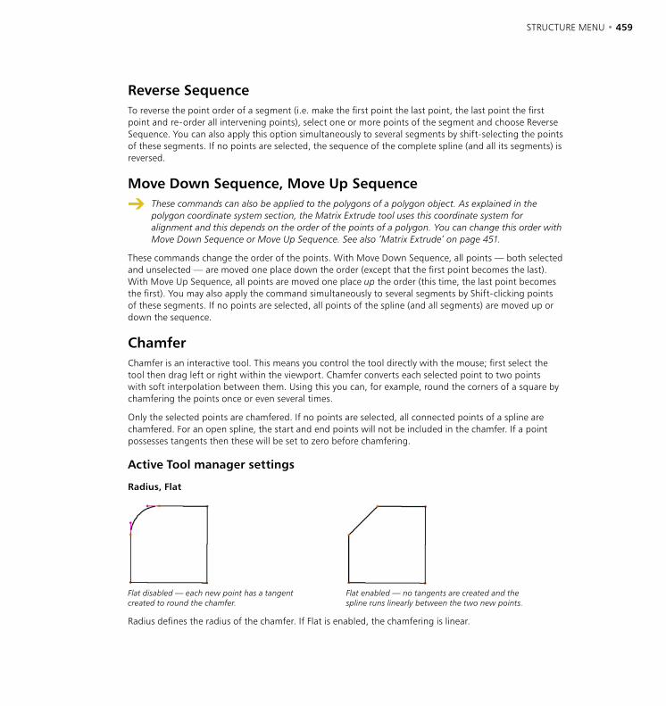
458 • CHAPTER 10 STRUCTURE MENU • 459
Reverse SequenceTo reverse the point order of a segment (i.e. make the first point the last point, the last point the first point and re-order all intervening points), select one or more points of the segment and choose Reverse Sequence. You can also apply this option simultaneously to several segments by shift-selecting the points of these segments. If no points are selected, the sequence of the complete spline (and all its segments) is reversed.
Move Down Sequence, Move Up Sequence
These commands can also be applied to the polygons of a polygon object. As explained in the polygon coordinate system section, the Matrix Extrude tool uses this coordinate system for alignment and this depends on the order of the points of a polygon. You can change this order with Move Down Sequence or Move Up Sequence. See also ‘Matrix Extrude’ on page 451.
These commands change the order of the points. With Move Down Sequence, all points — both selected and unselected — are moved one place down the order (except that the first point becomes the last). With Move Up Sequence, all points are moved one place up the order (this time, the last point becomes the first). You may also apply the command simultaneously to several segments by Shift-clicking points of these segments. If no points are selected, all points of the spline (and all segments) are moved up or down the sequence.
ChamferChamfer is an interactive tool. This means you control the tool directly with the mouse; first select the tool then drag left or right within the viewport. Chamfer converts each selected point to two points with soft interpolation between them. Using this you can, for example, round the corners of a square by chamfering the points once or even several times.
Only the selected points are chamfered. If no points are selected, all connected points of a spline are chamfered. For an open spline, the start and end points will not be included in the chamfer. If a point possesses tangents then these will be set to zero before chamfering.
Active Tool manager settings
Radius, Flat
Flat disabled — each new point has a tangent created to round the chamfer.
Flat enabled — no tangents are created and the spline runs linearly between the two new points.
Radius defines the radius of the chamfer. If Flat is enabled, the chamfering is linear.
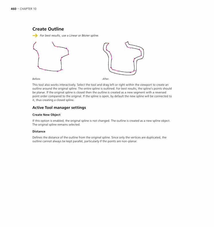
460 • CHAPTER 10 STRUCTURE MENU • 461
Create Outline
For best results, use a Linear or Bézier spline.
Before. After.
This tool also works interactively. Select the tool and drag left or right within the viewport to create an outline around the original spline. The entire spline is outlined. For best results, the spline’s points should be planar. If the original spline is closed then the outline is created as a new segment with a reversed point order compared to the original. If the spline is open, by default the new spline will be connected to it, thus creating a closed spline.
Active Tool manager settings
Create New Object
If this option is enabled, the original spline is not changed. The outline is created as a new spline object. The original spline remains selected.
Distance
Defines the distance of the outline from the original spline. Since only the vertices are duplicated, the outline cannot always be kept parallel, particularly if the points are non-planar.

460 • CHAPTER 10 STRUCTURE MENU • 461
Cross Section
The splines must be grouped in the Object manager (use the Group Objects command in the Object manager’s Object menu) and the group of objects must be selected.
Figure 1 Figure 2
Figure 3 Figure 4
With this interactive tool you can create cross sections for a group of splines; we’ll refer to these as ‘rail splines’.
Cross sections are always created at right angles to the current view. You should therefore select a view in which you can see the rail splines directly from the side.
Figure 1 shows some splines before any cross sections have been created. If you activate the Cross Section tool you can drag to draw a line where a cross section is to be created.
In Figure 2, three cross-sections have been created. In the 3D viewport you will can that this has created circles (more or less) which are wrapped around the four rail splines (Figure 3). These cross sections are new splines with Bézier type interpolation. These cross sections are especially useful when used as children of a Loft NURBS object. The order of these rail splines within the Loft NURBS is important. If you work with more than two rail splines, make sure that these are placed in the right order within themselves in the Object manager, because CINEMA 4D uses this object order when creating the cross sections. The start point of the cross section spline is located on the first rail spline and the end point on the last.
If the rail splines wind around themselves, giving a cross section spline that overlaps with the rail splines, then CINEMA 4D selects the first intersection in the direction of travel of the spline (Figure 4).
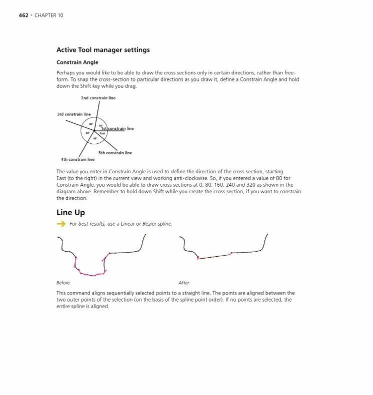
462 • CHAPTER 10 STRUCTURE MENU • 463
Active Tool manager settings
Constrain Angle
Perhaps you would like to be able to draw the cross sections only in certain directions, rather than free-form. To snap the cross-section to particular directions as you draw it, define a Constrain Angle and hold down the Shift key while you drag.
The value you enter in Constrain Angle is used to define the direction of the cross section, starting East (to the right) in the current view and working anti-clockwise. So, if you entered a value of 80 for Constrain Angle, you would be able to draw cross sections at 0, 80, 160, 240 and 320 as shown in the diagram above. Remember to hold down Shift while you create the cross section, if you want to constrain the direction.
Line Up
For best results, use a Linear or Bézier spline.
Before. After.
This command aligns sequentially selected points to a straight line. The points are aligned between the two outer points of the selection (on the basis of the spline point order). If no points are selected, the entire spline is aligned.
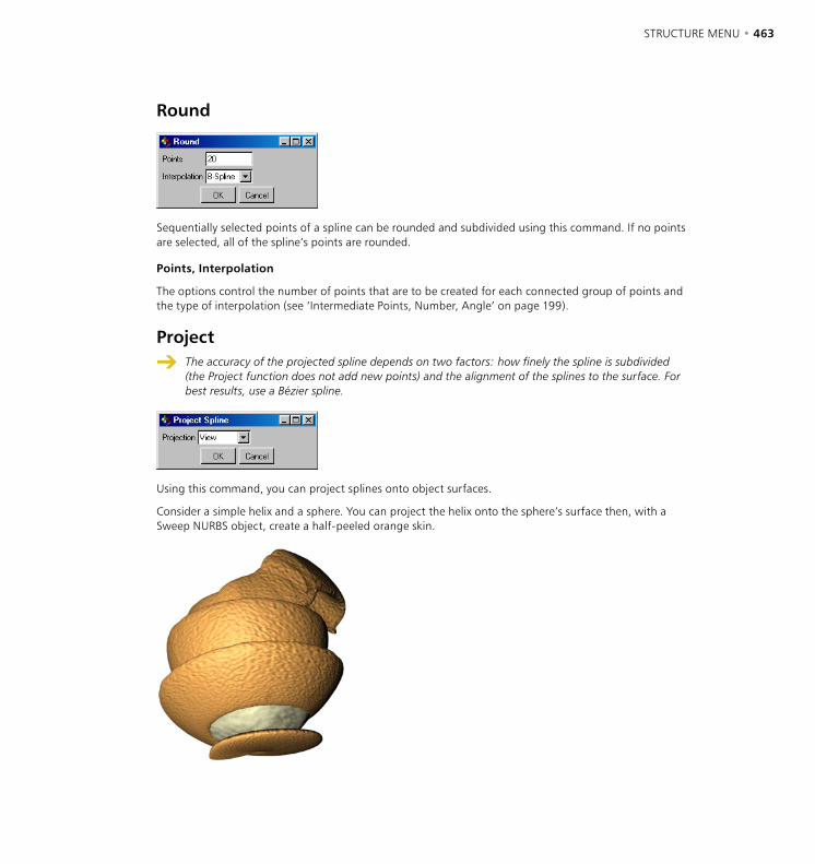
462 • CHAPTER 10 STRUCTURE MENU • 463
Round
Sequentially selected points of a spline can be rounded and subdivided using this command. If no points are selected, all of the spline’s points are rounded.
Points, Interpolation
The options control the number of points that are to be created for each connected group of points and the type of interpolation (see ‘Intermediate Points, Number, Angle’ on page 199).
Project
The accuracy of the projected spline depends on two factors: how finely the spline is subdivided (the Project function does not add new points) and the alignment of the splines to the surface. For best results, use a Bézier spline.
Using this command, you can project splines onto object surfaces.
Consider a simple helix and a sphere. You can project the helix onto the sphere’s surface then, with a Sweep NURBS object, create a half-peeled orange skin.
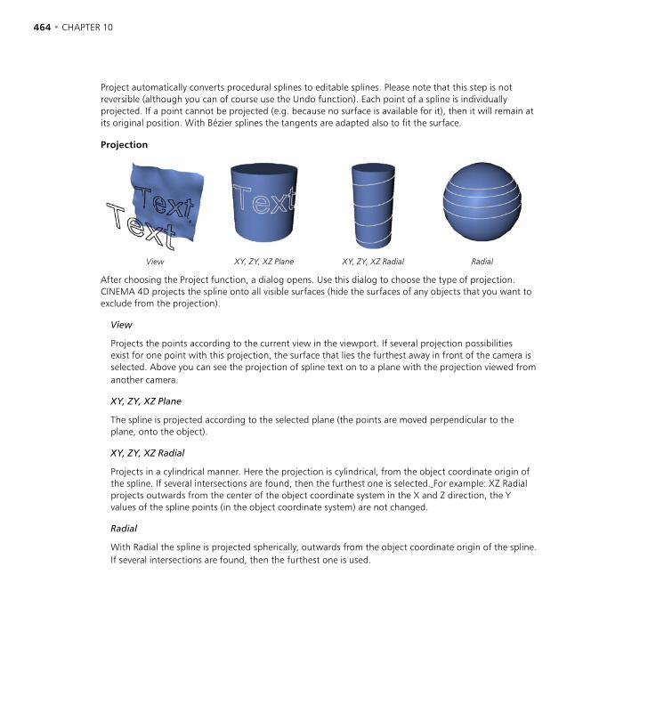
464 • CHAPTER 10 STRUCTURE MENU • 465
Project automatically converts procedural splines to editable splines. Please note that this step is not reversible (although you can of course use the Undo function). Each point of a spline is individually projected. If a point cannot be projected (e.g. because no surface is available for it), then it will remain at its original position. With Bézier splines the tangents are adapted also to fit the surface.
Projection
View XY, ZY, XZ Plane XY, ZY, XZ Radial Radial
After choosing the Project function, a dialog opens. Use this dialog to choose the type of projection. CINEMA 4D projects the spline onto all visible surfaces (hide the surfaces of any objects that you want to exclude from the projection).
View
Projects the points according to the current view in the viewport. If several projection possibilities exist for one point with this projection, the surface that lies the furthest away in front of the camera is selected. Above you can see the projection of spline text on to a plane with the projection viewed from another camera.
XY, ZY, XZ Plane
The spline is projected according to the selected plane (the points are moved perpendicular to the plane, onto the object).
XY, ZY, XZ Radial
Projects in a cylindrical manner. Here the projection is cylindrical, from the object coordinate origin of the spline. If several intersections are found, then the furthest one is selected. For example: XZ Radial projects outwards from the center of the object coordinate system in the X and Z direction, the Y values of the spline points (in the object coordinate system) are not changed.
Radial
With Radial the spline is projected spherically, outwards from the object coordinate origin of the spline. If several intersections are found, then the furthest one is used.
464 • CHAPTER 10 STRUCTURE MENU • 465
Make Editable
CINEMA 4D’s primitive objects and spline primitives are parametric, i.e. they have no points or polygons and are instead created using math formulae and parameters. Since these objects have no points or polygons, you can’t edit them in the same way you can normal polygon objects and splines. For example, you can’t select and move points, nor can you apply commands like Extrude and Create Outline.
However, you can edit these objects if you first convert them to points and polygons. To do this, select the desired primitives and choose Structure > Make Editable. Note that, other than using the Undo command, this conversion is one-way only. You cannot edit the points and then convert back to a primitive object.
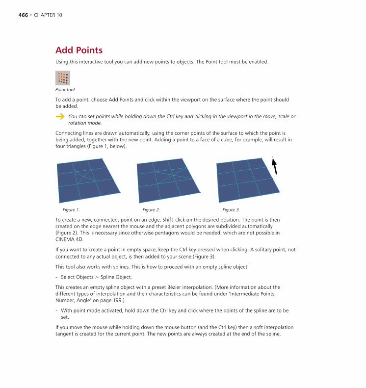
466 • CHAPTER 10 STRUCTURE MENU • 467
Add PointsUsing this interactive tool you can add new points to objects. The Point tool must be enabled.
Point tool.
To add a point, choose Add Points and click within the viewport on the surface where the point should be added.
You can set points while holding down the Ctrl key and clicking in the viewport in the move, scale or rotation mode.
Connecting lines are drawn automatically, using the corner points of the surface to which the point is being added, together with the new point. Adding a point to a face of a cube, for example, will result in four triangles (Figure 1, below).
Figure 1. Figure 2. Figure 3.
To create a new, connected, point on an edge, Shift-click on the desired position. The point is then created on the edge nearest the mouse and the adjacent polygons are subdivided automatically (Figure 2). This is necessary since otherwise pentagons would be needed, which are not possible in CINEMA 4D.
If you want to create a point in empty space, keep the Ctrl key pressed when clicking. A solitary point, not connected to any actual object, is then added to your scene (Figure 3).
This tool also works with splines. This is how to proceed with an empty spline object:
- Select Objects > Spline Object.
This creates an empty spline object with a preset Bézier interpolation. (More information about the different types of interpolation and their characteristics can be found under ‘Intermediate Points, Number, Angle’ on page 199.)
- With point mode activated, hold down the Ctrl key and click where the points of the spline are to be set.
If you move the mouse while holding down the mouse button (and the Ctrl key) then a soft interpolation tangent is created for the current point. The new points are always created at the end of the spline.

466 • CHAPTER 10 STRUCTURE MENU • 467
- To create a point on an already existing curve, select the Add Points function and click directly with the mouse on the curve.
You can now keep the mouse button pressed to drag the point around, before letting it drop by releasing the mouse button in its final position. The shape of the curve does not change, since the tangents are adapted automatically (although when using the Cubic, Akima and B-Spline types of interpolation, by their very nature, the shape of the curve cannot be precisely maintained).
- If you wish to insert a new point into a curve and simultaneously affect the shape of the curve (with Bézier you can affect only the tangents and with the other types of interpolation you can affect only the position of the point itself), hold the Ctrl key down while clicking directly on the spline. Moving the mouse with the mouse button pressed will now change the curve.
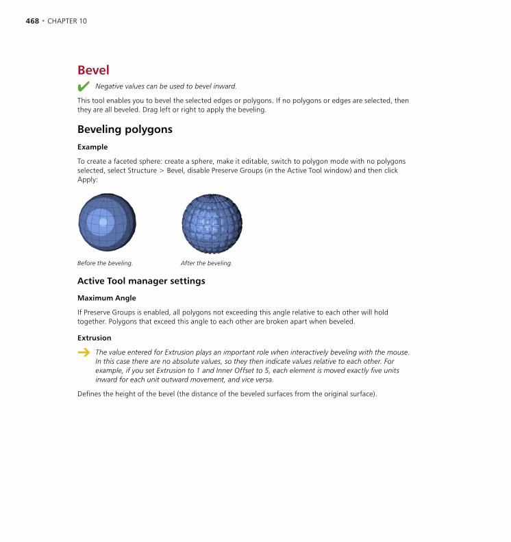
468 • CHAPTER 10 STRUCTURE MENU • 469
Bevel Negative values can be used to bevel inward.
This tool enables you to bevel the selected edges or polygons. If no polygons or edges are selected, then they are all beveled. Drag left or right to apply the beveling.
Beveling polygonsExample
To create a faceted sphere: create a sphere, make it editable, switch to polygon mode with no polygons selected, select Structure > Bevel, disable Preserve Groups (in the Active Tool window) and then click Apply:
Before the beveling. After the beveling.
Active Tool manager settings
Maximum Angle
If Preserve Groups is enabled, all polygons not exceeding this angle relative to each other will hold together. Polygons that exceed this angle to each other are broken apart when beveled.
Extrusion
The value entered for Extrusion plays an important role when interactively beveling with the mouse. In this case there are no absolute values, so they then indicate values relative to each other. For example, if you set Extrusion to 1 and Inner Offset to 5, each element is moved exactly five units inward for each unit outward movement, and vice versa.
Defines the height of the bevel (the distance of the beveled surfaces from the original surface).
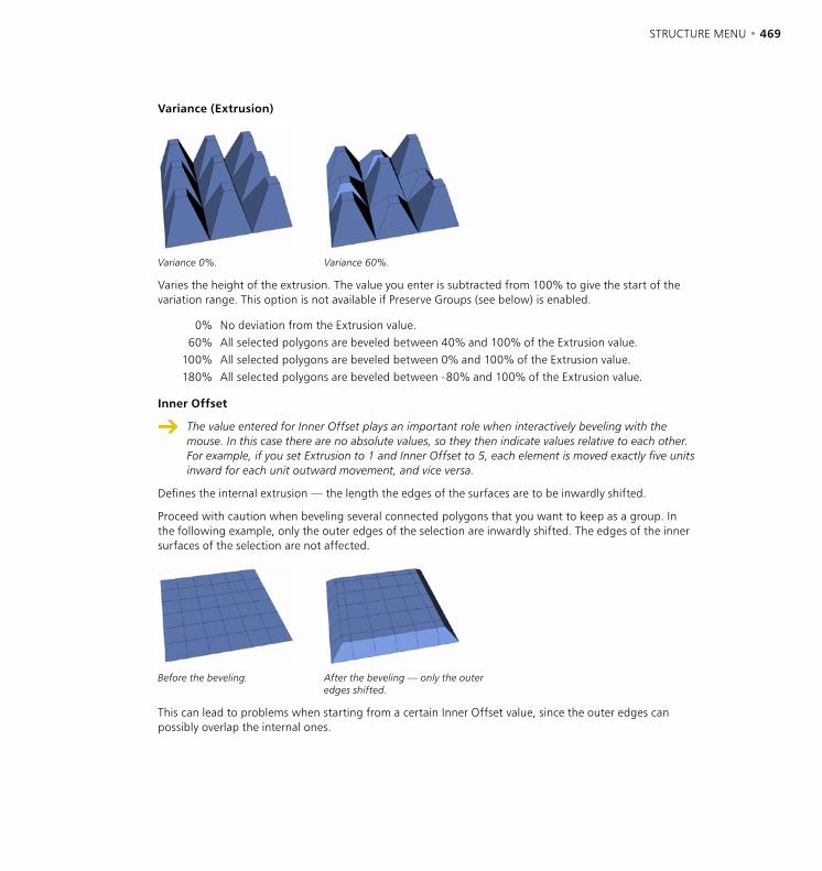
468 • CHAPTER 10 STRUCTURE MENU • 469
Variance (Extrusion)
Variance 0%. Variance 60%.
Varies the height of the extrusion. The value you enter is subtracted from 100% to give the start of the variation range. This option is not available if Preserve Groups (see below) is enabled.
0% No deviation from the Extrusion value.60% All selected polygons are beveled between 40% and 100% of the Extrusion value.
100% All selected polygons are beveled between 0% and 100% of the Extrusion value.180% All selected polygons are beveled between -80% and 100% of the Extrusion value.
Inner Offset
The value entered for Inner Offset plays an important role when interactively beveling with the mouse. In this case there are no absolute values, so they then indicate values relative to each other. For example, if you set Extrusion to 1 and Inner Offset to 5, each element is moved exactly five units inward for each unit outward movement, and vice versa.
Defines the internal extrusion — the length the edges of the surfaces are to be inwardly shifted.
Proceed with caution when beveling several connected polygons that you want to keep as a group. In the following example, only the outer edges of the selection are inwardly shifted. The edges of the inner surfaces of the selection are not affected.
Before the beveling. After the beveling — only the outer edges shifted.
This can lead to problems when starting from a certain Inner Offset value, since the outer edges can possibly overlap the internal ones.
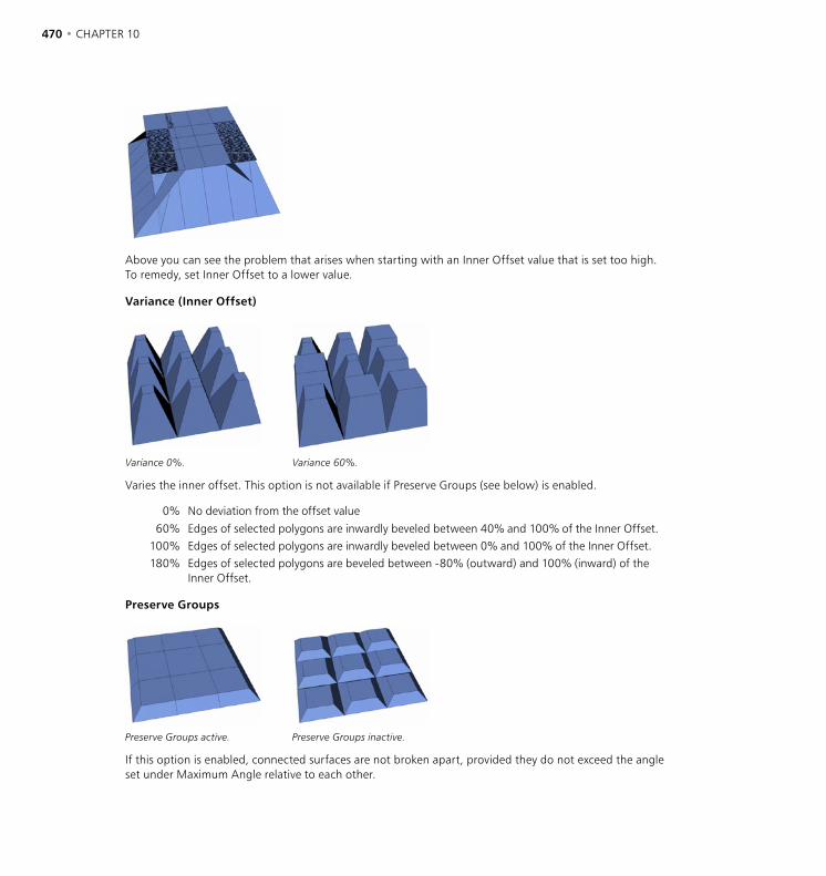
470 • CHAPTER 10 STRUCTURE MENU • 471
Above you can see the problem that arises when starting with an Inner Offset value that is set too high. To remedy, set Inner Offset to a lower value.
Variance (Inner Offset)
Variance 0%. Variance 60%.
Varies the inner offset. This option is not available if Preserve Groups (see below) is enabled.
0% No deviation from the offset value
60% Edges of selected polygons are inwardly beveled between 40% and 100% of the Inner Offset.100% Edges of selected polygons are inwardly beveled between 0% and 100% of the Inner Offset.180% Edges of selected polygons are beveled between -80% (outward) and 100% (inward) of the
Inner Offset.
Preserve Groups
Preserve Groups active. Preserve Groups inactive.
If this option is enabled, connected surfaces are not broken apart, provided they do not exceed the angle set under Maximum Angle relative to each other.

470 • CHAPTER 10 STRUCTURE MENU • 471
Apply
Use this button to execute the bevel function. Alternatively, drag left or right within the viewport. You can click the button repeatedly to bevel multiple times.
Beveling edges
Active Tool manager settings
Inner Offset
edge to be extruded
Before extrusion. After extrusion.
When beveling edges, only one Active tool parameter is available: Inner Offset. This determines the length of the inner extrusion.
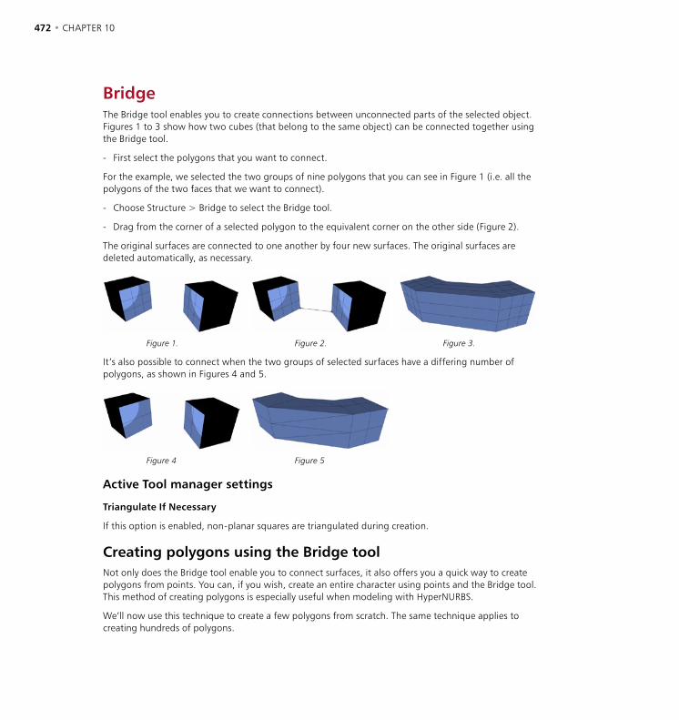
472 • CHAPTER 10 STRUCTURE MENU • 473
BridgeThe Bridge tool enables you to create connections between unconnected parts of the selected object. Figures 1 to 3 show how two cubes (that belong to the same object) can be connected together using the Bridge tool.
- First select the polygons that you want to connect.
For the example, we selected the two groups of nine polygons that you can see in Figure 1 (i.e. all the polygons of the two faces that we want to connect).
- Choose Structure > Bridge to select the Bridge tool.
- Drag from the corner of a selected polygon to the equivalent corner on the other side (Figure 2).
The original surfaces are connected to one another by four new surfaces. The original surfaces are deleted automatically, as necessary.
Figure 1. Figure 2. Figure 3.
It’s also possible to connect when the two groups of selected surfaces have a differing number of polygons, as shown in Figures 4 and 5.
Figure 4 Figure 5
Active Tool manager settings
Triangulate If Necessary
If this option is enabled, non-planar squares are triangulated during creation.
Creating polygons using the Bridge toolNot only does the Bridge tool enable you to connect surfaces, it also offers you a quick way to create polygons from points. You can, if you wish, create an entire character using points and the Bridge tool. This method of creating polygons is especially useful when modeling with HyperNURBS.
We’ll now use this technique to create a few polygons from scratch. The same technique applies to creating hundreds of polygons.
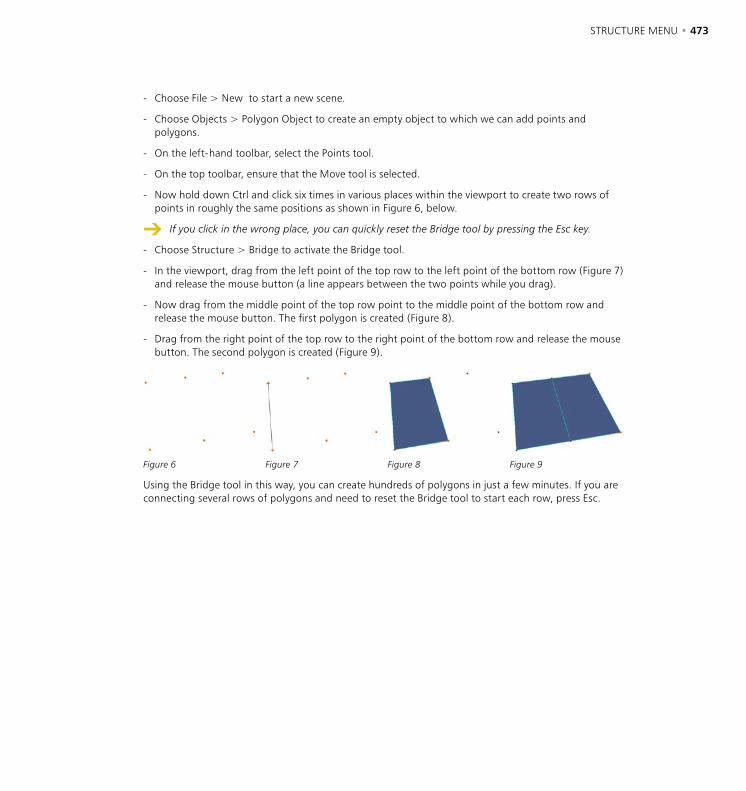
472 • CHAPTER 10 STRUCTURE MENU • 473
- Choose File > New to start a new scene.
- Choose Objects > Polygon Object to create an empty object to which we can add points and polygons.
- On the left-hand toolbar, select the Points tool.
- On the top toolbar, ensure that the Move tool is selected.
- Now hold down Ctrl and click six times in various places within the viewport to create two rows of points in roughly the same positions as shown in Figure 6, below.
If you click in the wrong place, you can quickly reset the Bridge tool by pressing the Esc key.
- Choose Structure > Bridge to activate the Bridge tool.
- In the viewport, drag from the left point of the top row to the left point of the bottom row (Figure 7) and release the mouse button (a line appears between the two points while you drag).
- Now drag from the middle point of the top row point to the middle point of the bottom row and release the mouse button. The first polygon is created (Figure 8).
- Drag from the right point of the top row to the right point of the bottom row and release the mouse button. The second polygon is created (Figure 9).
Figure 6 Figure 7 Figure 8 Figure 9
Using the Bridge tool in this way, you can create hundreds of polygons in just a few minutes. If you are connecting several rows of polygons and need to reset the Bridge tool to start each row, press Esc.
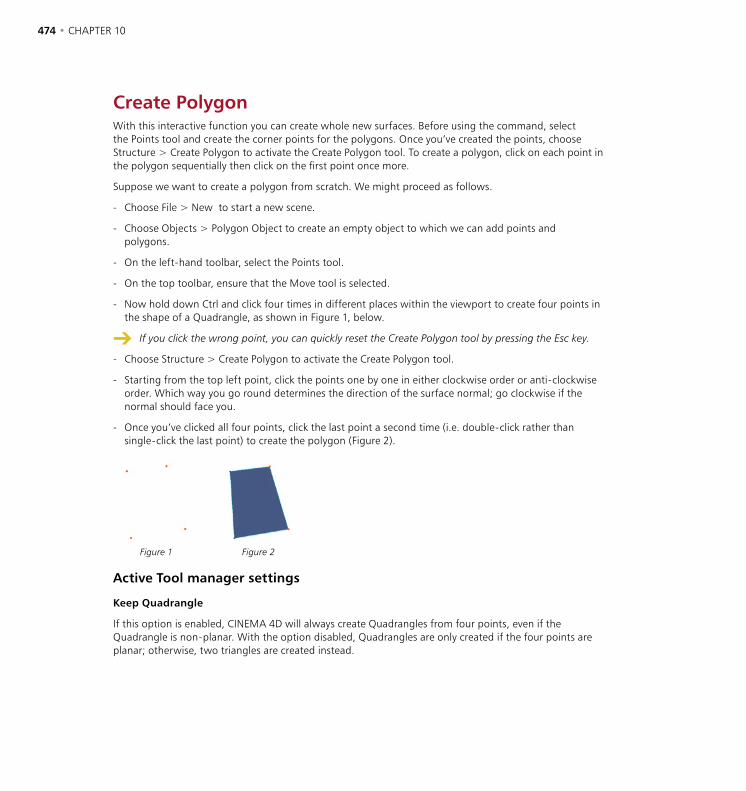
474 • CHAPTER 10 STRUCTURE MENU • 475
Create PolygonWith this interactive function you can create whole new surfaces. Before using the command, select the Points tool and create the corner points for the polygons. Once you’ve created the points, choose Structure > Create Polygon to activate the Create Polygon tool. To create a polygon, click on each point in the polygon sequentially then click on the first point once more.
Suppose we want to create a polygon from scratch. We might proceed as follows.
- Choose File > New to start a new scene.
- Choose Objects > Polygon Object to create an empty object to which we can add points and polygons.
- On the left-hand toolbar, select the Points tool.
- On the top toolbar, ensure that the Move tool is selected.
- Now hold down Ctrl and click four times in different places within the viewport to create four points in the shape of a Quadrangle, as shown in Figure 1, below.
If you click the wrong point, you can quickly reset the Create Polygon tool by pressing the Esc key.
- Choose Structure > Create Polygon to activate the Create Polygon tool.
- Starting from the top left point, click the points one by one in either clockwise order or anti-clockwise order. Which way you go round determines the direction of the surface normal; go clockwise if the normal should face you.
- Once you’ve clicked all four points, click the last point a second time (i.e. double-click rather than single-click the last point) to create the polygon (Figure 2).
Figure 1 Figure 2
Active Tool manager settings
Keep Quadrangle
If this option is enabled, CINEMA 4D will always create Quadrangles from four points, even if the Quadrangle is non-planar. With the option disabled, Quadrangles are only created if the four points are planar; otherwise, two triangles are created instead.
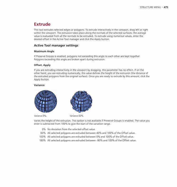
474 • CHAPTER 10 STRUCTURE MENU • 475
ExtrudeThis tool extrudes selected edges or polygons. To extrude interactively in the viewport, drag left or right within the viewport. The extrusion takes place along the normals of the selected surfaces; the average value is evaluated from all the normals to be extruded. To extrude using numerical values, enter the desired offset in the Active Tool manager and click the Apply button.
Active Tool manager settings
Maximum Angle
If Preserve Groups is enabled, polygons not exceeding this angle to each other are kept together. Polygons exceeding this angle are broken apart during extrusion.
Offset, Apply
If you are extruding interactively in the viewport by dragging, this parameter has no effect. If on the other hand, you are extruding numerically, this value defines the height of the extrusion (the distance of the extruded polygons from the original surface). Once you are ready to extrude by this amount, click the Apply button.
Variance
Variance 0%. Variance 60%.
Varies the height of the extrusion. This option is not available if Preserve Groups is enabled. The value you enter is subtracted from 100% to give the start of the variation range.
0% No deviation from the selected offset value.60% All selected polygons are extruded between 40% and 100% of the Offset value.
100% All selected polygons are extruded between 0% and 100% of the Offset value.180% All selected polygons are extruded between -80% and 100% of the Offset value.
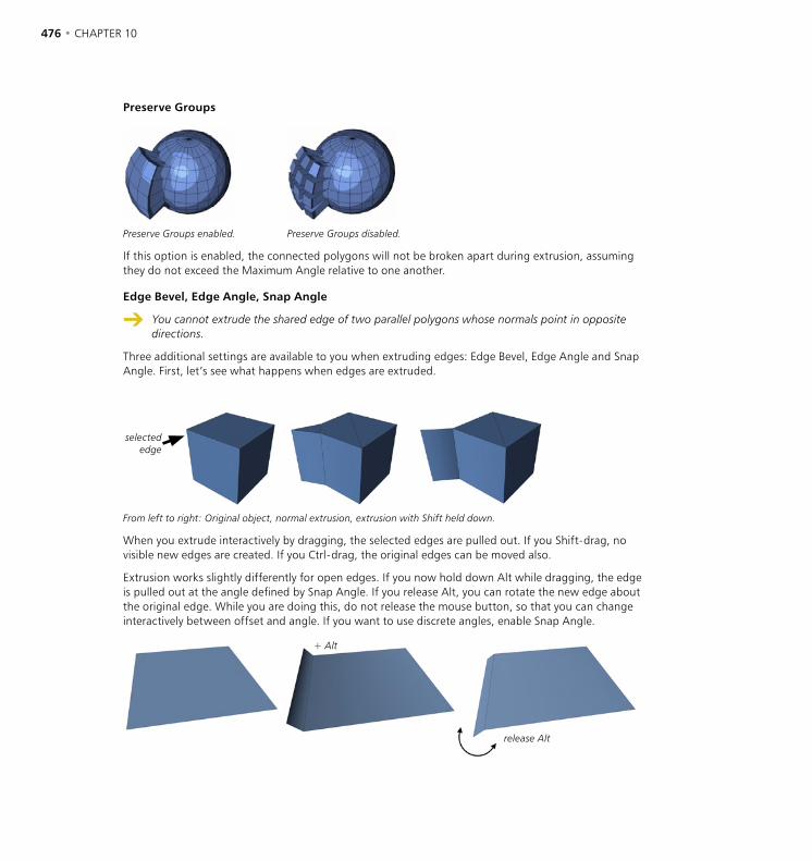
476 • CHAPTER 10 STRUCTURE MENU • 477
Preserve Groups
Preserve Groups enabled. Preserve Groups disabled.
If this option is enabled, the connected polygons will not be broken apart during extrusion, assuming they do not exceed the Maximum Angle relative to one another.
Edge Bevel, Edge Angle, Snap Angle
You cannot extrude the shared edge of two parallel polygons whose normals point in opposite directions.
Three additional settings are available to you when extruding edges: Edge Bevel, Edge Angle and Snap Angle. First, let’s see what happens when edges are extruded.
selectededge
From left to right: Original object, normal extrusion, extrusion with Shift held down.
When you extrude interactively by dragging, the selected edges are pulled out. If you Shift-drag, no visible new edges are created. If you Ctrl-drag, the original edges can be moved also.
Extrusion works slightly differently for open edges. If you now hold down Alt while dragging, the edge is pulled out at the angle defined by Snap Angle. If you release Alt, you can rotate the new edge about the original edge. While you are doing this, do not release the mouse button, so that you can change interactively between offset and angle. If you want to use discrete angles, enable Snap Angle.
+ Alt
release Alt
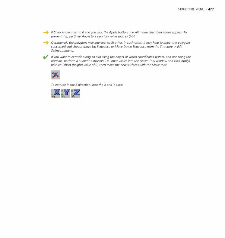
476 • CHAPTER 10 STRUCTURE MENU • 477
If Snap Angle is set to 0 and you click the Apply button, the Alt mode described above applies. To prevent this, set Snap Angle to a very low value such as 0.001.
Occasionally the polygons may intersect each other. In such cases, it may help to select the polygons concerned and choose Move Up Sequence or Move Down Sequence from the Structure > Edit Spline submenu.
If you want to extrude along an axis using the object or world coordinates system, and not along the normals, perform a numeric extrusion (i.e. input values into the Active Tool window and click Apply) with an Offset (height) value of 0; then move the new surfaces with the Move tool:
To extrude in the Z direction, lock the X and Y axes:
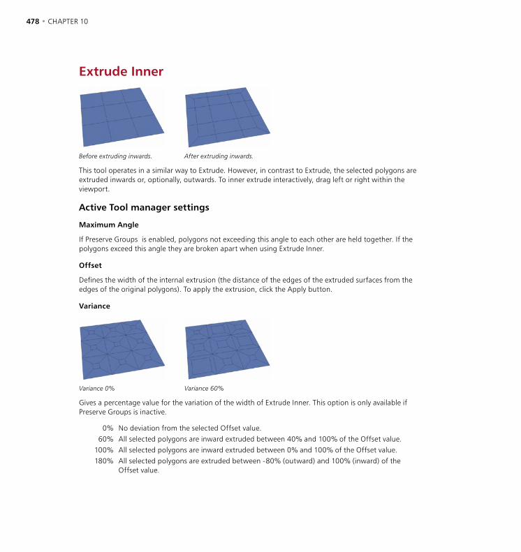
478 • CHAPTER 10 STRUCTURE MENU • 479
Extrude Inner
Before extruding inwards. After extruding inwards.
This tool operates in a similar way to Extrude. However, in contrast to Extrude, the selected polygons are extruded inwards or, optionally, outwards. To inner extrude interactively, drag left or right within the viewport.
Active Tool manager settings
Maximum Angle
If Preserve Groups is enabled, polygons not exceeding this angle to each other are held together. If the polygons exceed this angle they are broken apart when using Extrude Inner.
Offset
Defines the width of the internal extrusion (the distance of the edges of the extruded surfaces from the edges of the original polygons). To apply the extrusion, click the Apply button.
Variance
Variance 0% Variance 60%
Gives a percentage value for the variation of the width of Extrude Inner. This option is only available if Preserve Groups is inactive.
0% No deviation from the selected Offset value.60% All selected polygons are inward extruded between 40% and 100% of the Offset value.
100% All selected polygons are inward extruded between 0% and 100% of the Offset value.180% All selected polygons are extruded between -80% (outward) and 100% (inward) of the
Offset value.
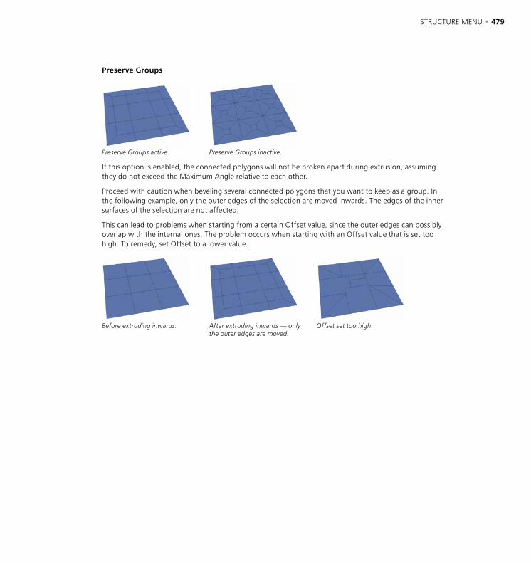
478 • CHAPTER 10 STRUCTURE MENU • 479
Preserve Groups
Preserve Groups active. Preserve Groups inactive.
If this option is enabled, the connected polygons will not be broken apart during extrusion, assuming they do not exceed the Maximum Angle relative to each other.
Proceed with caution when beveling several connected polygons that you want to keep as a group. In the following example, only the outer edges of the selection are moved inwards. The edges of the inner surfaces of the selection are not affected.
This can lead to problems when starting from a certain Offset value, since the outer edges can possibly overlap with the internal ones. The problem occurs when starting with an Offset value that is set too high. To remedy, set Offset to a lower value.
Before extruding inwards. After extruding inwards — only the outer edges are moved.
Offset set too high.
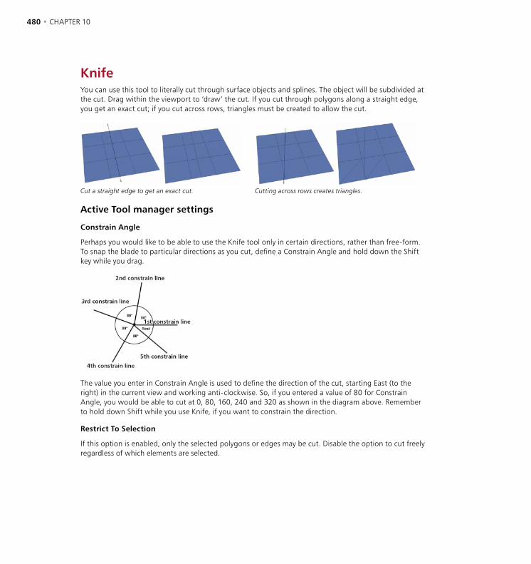
480 • CHAPTER 10 STRUCTURE MENU • 481
KnifeYou can use this tool to literally cut through surface objects and splines. The object will be subdivided at the cut. Drag within the viewport to ‘draw’ the cut. If you cut through polygons along a straight edge, you get an exact cut; if you cut across rows, triangles must be created to allow the cut.
Cut a straight edge to get an exact cut. Cutting across rows creates triangles.
Active Tool manager settings
Constrain Angle
Perhaps you would like to be able to use the Knife tool only in certain directions, rather than free-form. To snap the blade to particular directions as you cut, define a Constrain Angle and hold down the Shift key while you drag.
The value you enter in Constrain Angle is used to define the direction of the cut, starting East (to the right) in the current view and working anti-clockwise. So, if you entered a value of 80 for Constrain Angle, you would be able to cut at 0, 80, 160, 240 and 320 as shown in the diagram above. Remember to hold down Shift while you use Knife, if you want to constrain the direction.
Restrict To Selection
If this option is enabled, only the selected polygons or edges may be cut. Disable the option to cut freely regardless of which elements are selected.
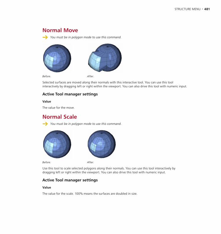
480 • CHAPTER 10 STRUCTURE MENU • 481
Normal Move You must be in polygon mode to use this command.
Before. After.
Selected surfaces are moved along their normals with this interactive tool. You can use this tool interactively by dragging left or right within the viewport. You can also drive this tool with numeric input.
Active Tool manager settings
Value
The value for the move.
Normal Scale You must be in polygon mode to use this command.
Before. After.
Use this tool to scale selected polygons along their normals. You can use this tool interactively by dragging left or right within the viewport. You can also drive this tool with numeric input.
Active Tool manager settings
Value
The value for the scale. 100% means the surfaces are doubled in size.
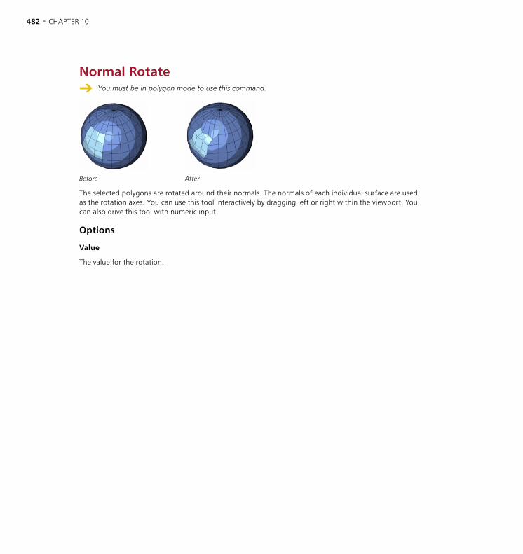
482 • CHAPTER 10 STRUCTURE MENU • 483
Normal Rotate You must be in polygon mode to use this command.
Before After
The selected polygons are rotated around their normals. The normals of each individual surface are used as the rotation axes. You can use this tool interactively by dragging left or right within the viewport. You can also drive this tool with numeric input.
Options
Value
The value for the rotation.
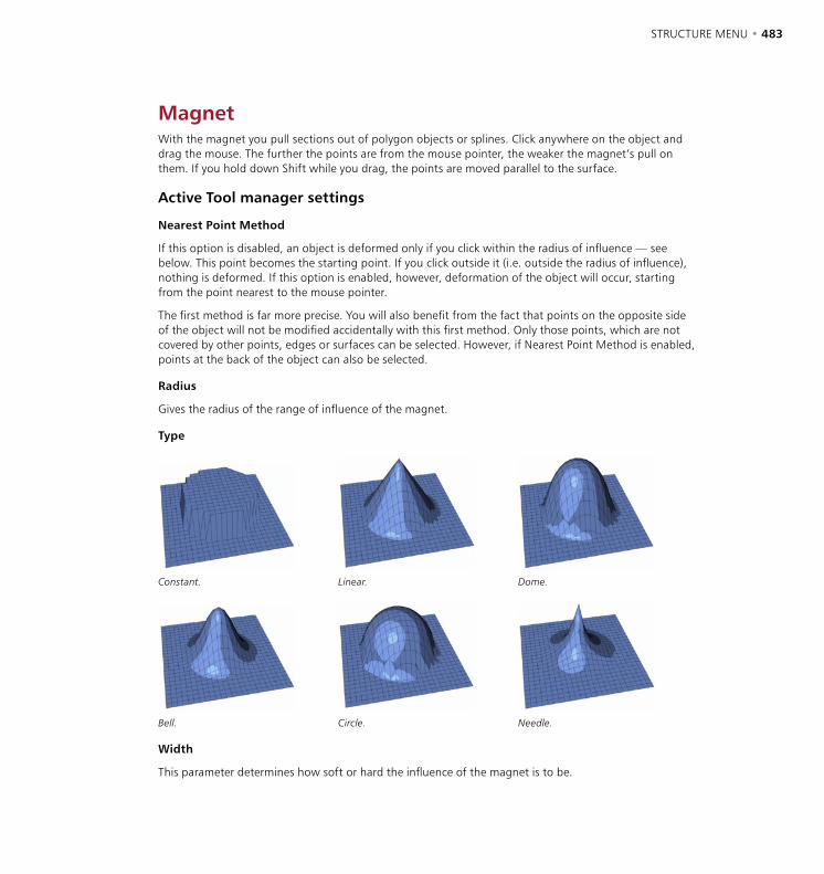
482 • CHAPTER 10 STRUCTURE MENU • 483
MagnetWith the magnet you pull sections out of polygon objects or splines. Click anywhere on the object and drag the mouse. The further the points are from the mouse pointer, the weaker the magnet’s pull on them. If you hold down Shift while you drag, the points are moved parallel to the surface.
Active Tool manager settings
Nearest Point Method
If this option is disabled, an object is deformed only if you click within the radius of influence — see below. This point becomes the starting point. If you click outside it (i.e. outside the radius of influence), nothing is deformed. If this option is enabled, however, deformation of the object will occur, starting from the point nearest to the mouse pointer.
The first method is far more precise. You will also benefit from the fact that points on the opposite side of the object will not be modified accidentally with this first method. Only those points, which are not covered by other points, edges or surfaces can be selected. However, if Nearest Point Method is enabled, points at the back of the object can also be selected.
Radius
Gives the radius of the range of influence of the magnet.
Type
Constant. Linear. Dome.
Bell. Circle. Needle.
Width
This parameter determines how soft or hard the influence of the magnet is to be.

484 • CHAPTER 10 STRUCTURE MENU • 485
MirrorUsing the Mirror tool, points and polygons of an object can be mirrored. This tool functions in point or polygon mode. In point mode only the selected points are mirrored (without their surfaces). If no points are selected, all points are mirrored. In polygon mode the selected surfaces are mirrored. If no surfaces are selected, all surfaces are mirrored.
Mirror can also be applied to splines. The selected points are mirrored as a new segment.
Mirror functions interactively. This means you can control the mirroring directly with the mouse; to select the axis for mirroring, click and drag until you see the axis you want, then release the mouse button.
Active Tool manager settings
Coordinate System
Selects the coordinate system for the tool. In all the modes below remember to keep the mouse button pressed. You will then be able to choose the mirror axis by dragging it with the mouse to where you want the mirroring to occur. When you release the mouse button, the mirroring is applied.
Object
In this mode the object is mirrored about the object axes. You can set the mirror axis using the mouse by clicking directly on a point of the object. The mirror axis automatically locates itself on the nearest point. The object is then mirrored exactly through this point. You do not necessarily have to be in point mode; the points are also located in this way in polygon mode. The object mode also allows the input of numeric values (see Value).
World
This mode behaves exactly like the object mode, except that the element is mirrored over the selected world axis. Like the object system, the world mode also allows the input of numeric values (see Value ).
Screen
In this mode the object is mirrored in the current projection plane. If you first click in the area of the upper or lower window border, you get a horizontal mirror axis. If you first click in the area of the right or left window border, you get a vertical mirror axis.
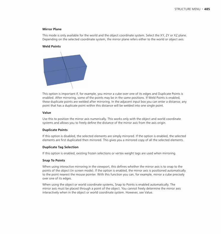
484 • CHAPTER 10 STRUCTURE MENU • 485
Mirror Plane
This mode is only available for the world and the object coordinate system. Select the XY, ZY or XZ plane. Depending on the selected coordinate system, the mirror plane refers either to the world or object axis.
Weld Points
This option is important if, for example, you mirror a cube over one of its edges and Duplicate Points is enabled. After mirroring, some of the points may be in the same positions. If Weld Points is enabled, these duplicate points are welded after mirroring. In the adjacent input box you can enter a distance; any point that has a duplicate point within this distance will be welded into one single point.
Value
Use this to position the mirror axis numerically. This works only with the object and world coordinate systems and allows you to freely define the distance of the mirror axis from the axis origin.
Duplicate Points
If this option is disabled, the selected elements are simply mirrored. If the option is enabled, the selected elements are first duplicated then mirrored. This gives you a mirrored copy of all the selected elements.
Duplicate Tag Selection
If this option is enabled, existing frozen selections or vertex weight tags are used when mirroring.
Snap To Points
When using interactive mirroring in the viewport, this defines whether the mirror axis is to snap to the points of the object (in screen mode). If the option is enabled, the mirror axis is positioned automatically to the point nearest the mouse pointer. With this function you can, for example, mirror a cube precisely over one of its edges.
When using the object or world coordinate systems, Snap to Points is enabled automatically. The mirror axis must be placed through a point of the object. You cannot freely determine the mirror axis interactively when in the object or world coordinate system. However, see Value.
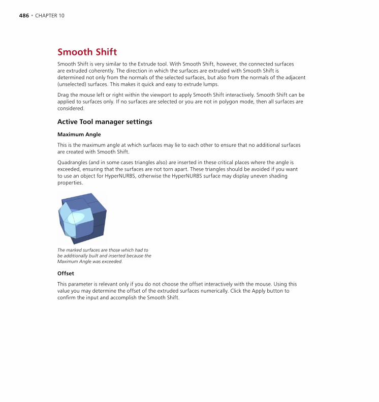
486 • CHAPTER 10 STRUCTURE MENU • 487
Smooth ShiftSmooth Shift is very similar to the Extrude tool. With Smooth Shift, however, the connected surfaces are extruded coherently. The direction in which the surfaces are extruded with Smooth Shift is determined not only from the normals of the selected surfaces, but also from the normals of the adjacent (unselected) surfaces. This makes it quick and easy to extrude lumps.
Drag the mouse left or right within the viewport to apply Smooth Shift interactively. Smooth Shift can be applied to surfaces only. If no surfaces are selected or you are not in polygon mode, then all surfaces are considered.
Active Tool manager settings
Maximum Angle
This is the maximum angle at which surfaces may lie to each other to ensure that no additional surfaces are created with Smooth Shift.
Quadrangles (and in some cases triangles also) are inserted in these critical places where the angle is exceeded, ensuring that the surfaces are not torn apart. These triangles should be avoided if you want to use an object for HyperNURBS, otherwise the HyperNURBS surface may display uneven shading properties.
The marked surfaces are those which had to be additionally built and inserted because the Maximum Angle was exceeded.
Offset
This parameter is relevant only if you do not choose the offset interactively with the mouse. Using this value you may determine the offset of the extruded surfaces numerically. Click the Apply button to confirm the input and accomplish the Smooth Shift.

486 • CHAPTER 10 STRUCTURE MENU • 487
Align NormalsWhen creating surfaces you may sometimes inadvertently create surfaces whose normals point in the wrong direction. Using Align Normals, you can quickly correct the direction. When you use Align Normals CINEMA 4D will adjust and re-align the incorrect surface normals to the correct direction. CINEMA 4D adjusts the orientation of the normals according to the normal direction of the first surface of the currently selected group of surfaces. If no surfaces are selected then all normals are aligned.
Why exactly are these normals needed? CINEMA 4D cannot easily recognize an object’s inner and outer surface without extra information. A basic sphere has an inner and an outer side, but only one surface level, which can be confusing. We need a better definition. Let’s define this single surface level to have an inner and an outer property. Outer designates, in principle, the direction in which the surface normals point and inner is therefore the opposite direction. This plays a role with texture projection, where you can project textures from only the front or the back.
So, if as many normals point one way as the other way, how do we decide which is the outer surface? We could either choose randomly or, perhaps, look at the first polygon in the sequence and use its normal as the basis of our calculation — CINEMA 4D does the latter.
Why change the direction of the normals? As described above, the direction of the normals defines the interior and the exterior of an object. This is important, among other things, for displaying an object in the viewport. Occasionally, when building certain objects, a situation can arise in which some polygons seem invisible. This can happen if backface culling is on and the reason is as follows. To save on processor performance you may have enabled backface culling for your scene; this is where only the polygons visible from the front of an object are displayed in the viewport. The polygons positioned directly at the back of an object are not drawn.
When displaying a sphere and other volume objects in the Gouraud Shading mode you may notice no difference, simply because you do not see the back of the sphere anyway. But should you select all the polygons of this sphere and reverse the normals (see next section), you will now see only the back of the sphere; the front is now transparent since you have inverted the sphere. The inside is now the outside, and this becomes invisible because of the backface culling.
Should you find yourself inadvertently in a situation like this you should switch off backface culling and reverse the normals of these polygons.
The adjustment of these normals also plays an important role with tools such as Smooth Shift and Extrude. These model tools always move in the direction of the normals by default. If you should need to move several surfaces with different normal alignments using Smooth Shift you will obtain useless results, since the surfaces are moved in their own respective — and opposite — directions.
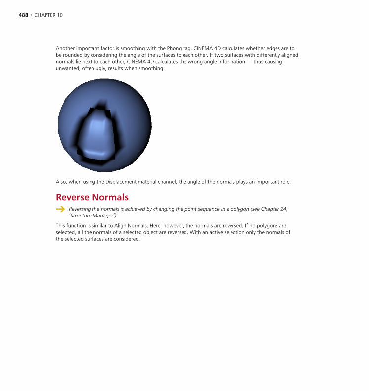
488 • CHAPTER 10 STRUCTURE MENU • 489
Another important factor is smoothing with the Phong tag. CINEMA 4D calculates whether edges are to be rounded by considering the angle of the surfaces to each other. If two surfaces with differently aligned normals lie next to each other, CINEMA 4D calculates the wrong angle information — thus causing unwanted, often ugly, results when smoothing:
Also, when using the Displacement material channel, the angle of the normals plays an important role.
Reverse Normals Reversing the normals is achieved by changing the point sequence in a polygon (see Chapter 24,
‘Structure Manager’).
This function is similar to Align Normals. Here, however, the normals are reversed. If no polygons are selected, all the normals of a selected object are reversed. With an active selection only the normals of the selected surfaces are considered.

488 • CHAPTER 10 STRUCTURE MENU • 489
Optimize
If you were to build an object from many individual triangles and Quadrangles, for example by using the Connect function, very often some points and surfaces will be duplicated (see ‘Connect’ on page 503). For example, the parametric primitives can contain some duplicate points after being converted into polygon objects. You can eliminate these double elements with the Optimize function. The appearance of the object will not change, or only slightly change, when using this function.
Caution is required with objects that intentionally contain these double points in certain places. Such points can be intended, for example, to produce hard edges despite an active Phong tag or in connection with a HyperNURBS object (see ‘Phong Tag’ on page 608 and ‘HyperNURBS’ on page 170).
The selected elements to be optimized can be points, edges or polygons. If you select polygons or edges, then the associated points are also considered. If you select points only, then just the points are considered. This tool can be applied to splines also. In this case, however, only the points can be optimized, since a spline has no surfaces.
Polygons
When enabled this will eliminate one- or two-point surfaces.
Unused Points
Enable this option if you want unused points to be deleted.
Points
Specifies whether duplicated points are to be eliminated.
Tolerance
When eliminating points you may enter a tolerance value. This defines the maximum distance that must lie between the two coinciding points for them to be deleted when optimizing. If points are closer to each other than this value, then they are merged into one point. If polygons become redundant (e.g. if all three corner points of the polygon occupy the same point), CINEMA 4D will automatically delete them.
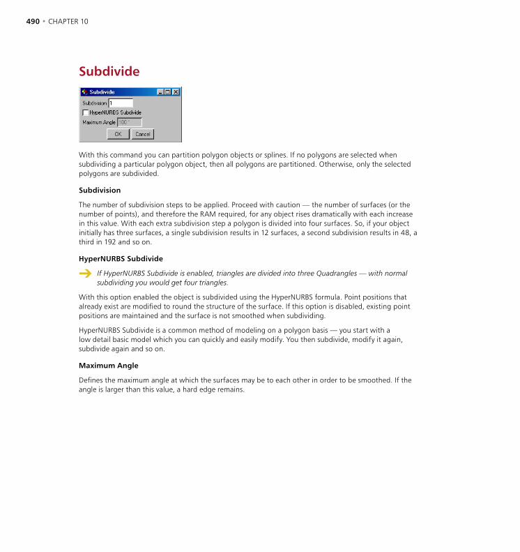
490 • CHAPTER 10 STRUCTURE MENU • 491
Subdivide
With this command you can partition polygon objects or splines. If no polygons are selected when subdividing a particular polygon object, then all polygons are partitioned. Otherwise, only the selected polygons are subdivided.
Subdivision
The number of subdivision steps to be applied. Proceed with caution — the number of surfaces (or the number of points), and therefore the RAM required, for any object rises dramatically with each increase in this value. With each extra subdivision step a polygon is divided into four surfaces. So, if your object initially has three surfaces, a single subdivision results in 12 surfaces, a second subdivision results in 48, a third in 192 and so on.
HyperNURBS Subdivide
If HyperNURBS Subdivide is enabled, triangles are divided into three Quadrangles — with normal subdividing you would get four triangles.
With this option enabled the object is subdivided using the HyperNURBS formula. Point positions that already exist are modified to round the structure of the surface. If this option is disabled, existing point positions are maintained and the surface is not smoothed when subdividing.
HyperNURBS Subdivide is a common method of modeling on a polygon basis — you start with a low detail basic model which you can quickly and easily modify. You then subdivide, modify it again, subdivide again and so on.
Maximum Angle
Defines the maximum angle at which the surfaces may be to each other in order to be smoothed. If the angle is larger than this value, a hard edge remains.

490 • CHAPTER 10 STRUCTURE MENU • 491
Triangulate
Triangulate converts all the Quadrangles of an object to triangles. The entire object is triangulated. Generally when modeling, try to use Quadrangles as much as possible since they are quicker to render than triangles and in addition they tend to shade better.
UntriangulateIf you have an object built only of triangles (e.g. imported from another program), CINEMA 4D can try to convert the triangles into Quadrangles. This works only as long as the triangles that you want to convert will result in a planar Quadrangle. Triangles that cannot be converted are left in their original state. So, Untriangulate works only for triangles which result in planar quadrangles. If Evaluate Angle is disabled CINEMA 4D tries to convert all triangles into quadrangles. This can result in unwanted edges and shading errors. In such cases, enable Evaluate Angle.
Edge Cut
This tool enables you to cut selected edges evenly. After choosing the command, a dialog opens. Set the parameters as desired then click OK to cut the edges.
Subdivisions
Defines the number of subdivisions to be created for each selected edge. These divisions will be created equal distances apart, cutting the edge into smaller, like-sized edges. If you cut individual edges, triangles will often be created for neighboring polygons. To prevent this, select the edges that ‘belong’ to each other before you cut (the Edge Ring command may help here. You’ll find this command on the Selection menu).
Keep Sections
Once the edges have been cut, either the originally selected edges are selected (option enabled) or the new edges are selected (option disabled).

492 • CHAPTER 10 STRUCTURE MENU • 493
Edge Selection To SplineThis command creates a spline from an edge selection.
A spline (right) is created from the selected edges (left).
Structure Context MenuYou can quickly access commands for points, edges and polygons from the context menu. Different commands are available depending on whether you’re in points, edges or polygons mode. The menu shown is for points mode. To access the context menu, right-click (Windows) or Command-click (Mac OS) within the viewport.
The context menu for points.
One especially useful command on the context menus is Frame Selected Elements. Choose this command to zoom the selection in the active viewport.
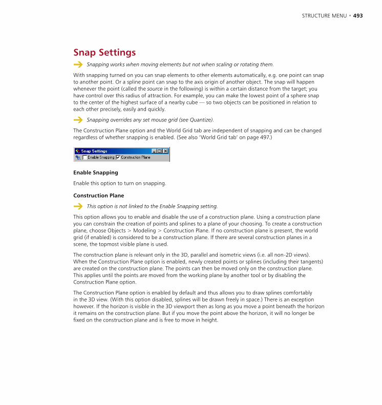
492 • CHAPTER 10 STRUCTURE MENU • 493
Snap Settings Snapping works when moving elements but not when scaling or rotating them.
With snapping turned on you can snap elements to other elements automatically, e.g. one point can snap to another point. Or a spline point can snap to the axis origin of another object. The snap will happen whenever the point (called the source in the following) is within a certain distance from the target; you have control over this radius of attraction. For example, you can make the lowest point of a sphere snap to the center of the highest surface of a nearby cube — so two objects can be positioned in relation to each other precisely, easily and quickly.
Snapping overrides any set mouse grid (see Quantize).
The Construction Plane option and the World Grid tab are independent of snapping and can be changed regardless of whether snapping is enabled. (See also ‘World Grid tab’ on page 497.)
Enable Snapping
Enable this option to turn on snapping.
Construction Plane
This option is not linked to the Enable Snapping setting.
This option allows you to enable and disable the use of a construction plane. Using a construction plane you can constrain the creation of points and splines to a plane of your choosing. To create a construction plane, choose Objects > Modeling > Construction Plane. If no construction plane is present, the world grid (if enabled) is considered to be a construction plane. If there are several construction planes in a scene, the topmost visible plane is used.
The construction plane is relevant only in the 3D, parallel and isometric views (i.e. all non-2D views). When the Construction Plane option is enabled, newly created points or splines (including their tangents) are created on the construction plane. The points can then be moved only on the construction plane. This applies until the points are moved from the working plane by another tool or by disabling the Construction Plane option.
The Construction Plane option is enabled by default and thus allows you to draw splines comfortably in the 3D view. (With this option disabled, splines will be drawn freely in space.) There is an exception however. If the horizon is visible in the 3D viewport then as long as you move a point beneath the horizon it remains on the construction plane. But if you move the point above the horizon, it will no longer be fixed on the construction plane and is free to move in height.
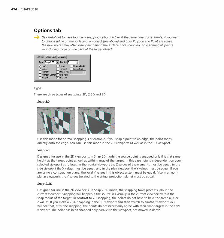
494 • CHAPTER 10 STRUCTURE MENU • 495
Options tab
Be careful not to have too many snapping options active at the same time. For example, if you want to draw a spline on the surface of an object (see above) and both Polygon and Point are active, the new points may often disappear behind the surface since snapping is considering all points — including those on the back of the target object.
Type
There are three types of snapping: 2D, 2.5D and 3D.
Snap 3D
Use this mode for normal snapping. For example, if you snap a point to an edge, the point snaps directly onto the edge. You can use this mode in the 2D viewports as well as in the 3D viewport.
Snap 2D
Designed for use in the 2D viewports, in Snap 2D mode the source point is snapped only if it is at same height as the target point as well as within range of the target. In this case height is dependent on your selected viewport as follows: in the frontal viewport the Z values of the elements must be equal; in the side viewport the X values must be equal; and in the plan viewport the Y values must be equal. If you are using a construction plane, the local Y values in this object system must be equal. Also in all non-planar viewports the Y values (related to the virtual projection plane) must be equal.
Snap 2.5D
Designed for use in the 2D viewports, in Snap 2.5D mode, the snapping takes place visually in the current viewport. Snapping will happen if the source lies visually in the current viewport within the snap radius of the target. In contrast to 2D snapping, the points do not have to have the same X, Y or Z values. If you make a 2.5D snapping in the 3D viewport and then switch to another viewport you will see that, after the snapping, the points do not necessarily agree with their snap targets in the new viewport. The point has been snapped only parallel to the viewport, not moved in depth.

494 • CHAPTER 10 STRUCTURE MENU • 495
Suppose you have activated a World Grid with a grid spacing of 100 units and you have a selected point at (53/62/91) that you wish to snap to and you are working in the frontal (XY) view. Also, only the Grid Point snapping option (see below) is enabled and the snap Radius is 30.
Snap 2D: If you move the point, it is never snapped to the nearest grid point since the neighboring grid points lie at (x/y/0) and (x/y/100) and therefore have different Z coordinates from our source point. Since the Z component never agrees, it will never be snapped. This would be different if the source point had a Z coordinate of 100, for example.
Snap 2.5D: If you move the point, it is snapped to the neighboring grid points when they come within range. However, since it is moved only perpendicularly to the camera in this mode, it keeps its Z component. The snapped point is moved, for example, to the coordinates (0/0/91), (100/0/91), (100/100/91) or (0/100/91).
Snap 3D: In this mode the source point snaps within the complete 3D space. The point can therefore be moved for example to the coordinates (0/0/100), (100/0/100), (100/100/100) or (0/100/100).
Radius
This is the radius of attraction for the particular target you have selected. The larger this radius, the more quickly the source will be snapped to the target as the source is moved towards the target.
Point
If this option is enabled, the source is snapped to the points of the active or other objects. All visible, polygonal objects and splines in the scene are considered. As primitives have no points, they cannot be considered as snap targets for this option.
Edge
Points have higher snapping priorities than edges.
With this option enabled, the source is snapped to polygon edges. All visible, polygonal objects in the scene are considered.
Polygon
If you enable this option, the source is snapped to the surface of the target polygon. All visible polygonal objects in the scene are considered. This is particularly well suited to drawing splines on to polygon objects, for example. To do this you should disable all other options and use Snap 3D. If you now create (or move) the points of the splines, they are snapped automatically to the polygons behind the spline.
Polygon Center
With this option enabled, the source will be snapped to the center of the target polygon.
Midpoint
Use this option together with other options to, for example, snap to the midpoint of a polygon edge or to the centre of the spline distance between two points.
496 • CHAPTER 10 STRUCTURE MENU • 497
Spline
With this option enabled, the source will snap to any part of a visible spline curve.
Tangent
This option makes sense only if you want to let a spline curve (at a point just edited) snap tangentially on to another, target, spline. This option can be very time-consuming.
Perpendicular
Here the source is not snapped if the source and target spline curves are tangential to each other, but only if the curves are perpendicular to each other. This option can be very time-consuming.
Spline Grid
If you enable this option you can effectively use an existing spline as a snap grid and snap to the nth part of the spline; here nth part means the total length of the spline divided equally into n elements. You choose this value in the box below the option. For example, if the spline is 200 units long and you have entered a Spline Grid of 5, the snapping will be to the nearest 40 unit segment (independent of the actual spline points).
Object Axis
Enable this option to snap to the object axis origin of any visible object.
Grid Point
With this option enabled the source is snapped to the grid points of the construction plane.
Grid Line
The source snaps to the construction plane’s grid lines when this option is enabled.
Snapping in different modes
Snapping works in the following modes; object, model, texture axis, point, polygon and animation for keys. Say you have selected several points (or polygons) and want to move them with snapping activated, when does the snap happen? In other words, which selected point or polygon is taken to be the source item, i.e. the one that when it gets within the range of the target will snap to it? The item that is closest to the mouse pointer when you start to move the selection is taken to be the source item; when that gets within range of the target it is snapped to it and all other selected points or polygons move accordingly. For example, if you want the edge of a selection to snap, place the mouse pointer outside the selection before moving. It’s best to try this out to see how it works.
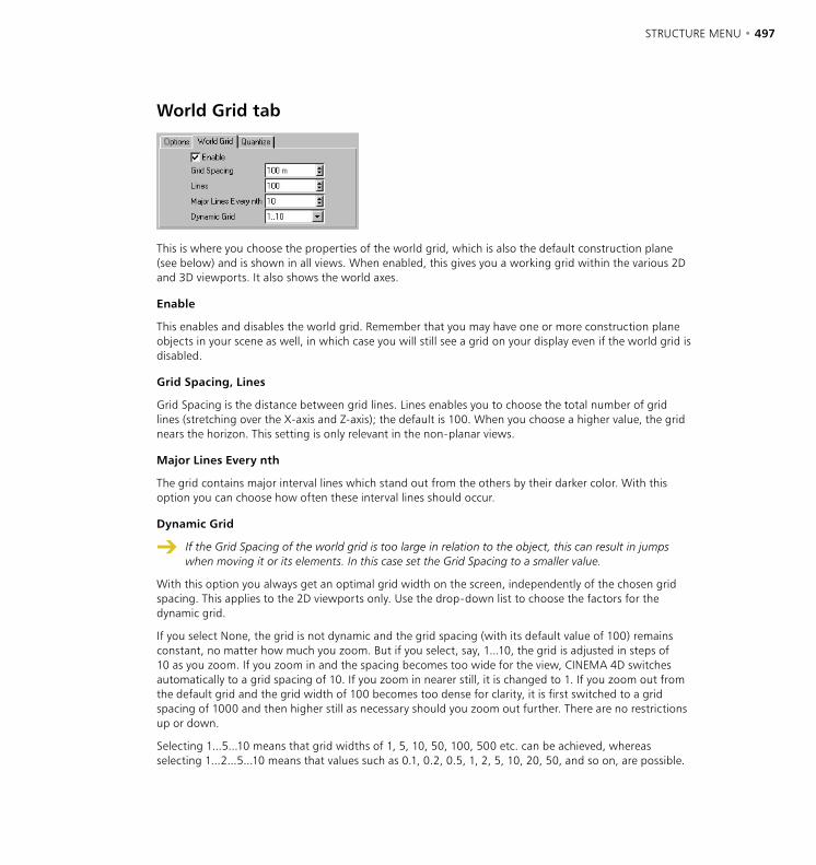
496 • CHAPTER 10 STRUCTURE MENU • 497
World Grid tab
This is where you choose the properties of the world grid, which is also the default construction plane (see below) and is shown in all views. When enabled, this gives you a working grid within the various 2D and 3D viewports. It also shows the world axes.
Enable
This enables and disables the world grid. Remember that you may have one or more construction plane objects in your scene as well, in which case you will still see a grid on your display even if the world grid is disabled.
Grid Spacing, Lines
Grid Spacing is the distance between grid lines. Lines enables you to choose the total number of grid lines (stretching over the X-axis and Z-axis); the default is 100. When you choose a higher value, the grid nears the horizon. This setting is only relevant in the non-planar views.
Major Lines Every nth
The grid contains major interval lines which stand out from the others by their darker color. With this option you can choose how often these interval lines should occur.
Dynamic Grid
If the Grid Spacing of the world grid is too large in relation to the object, this can result in jumps when moving it or its elements. In this case set the Grid Spacing to a smaller value.
With this option you always get an optimal grid width on the screen, independently of the chosen grid spacing. This applies to the 2D viewports only. Use the drop-down list to choose the factors for the dynamic grid.
If you select None, the grid is not dynamic and the grid spacing (with its default value of 100) remains constant, no matter how much you zoom. But if you select, say, 1...10, the grid is adjusted in steps of 10 as you zoom. If you zoom in and the spacing becomes too wide for the view, CINEMA 4D switches automatically to a grid spacing of 10. If you zoom in nearer still, it is changed to 1. If you zoom out from the default grid and the grid width of 100 becomes too dense for clarity, it is first switched to a grid spacing of 1000 and then higher still as necessary should you zoom out further. There are no restrictions up or down.
Selecting 1...5...10 means that grid widths of 1, 5, 10, 50, 100, 500 etc. can be achieved, whereas selecting 1...2...5...10 means that values such as 0.1, 0.2, 0.5, 1, 2, 5, 10, 20, 50, and so on, are possible.
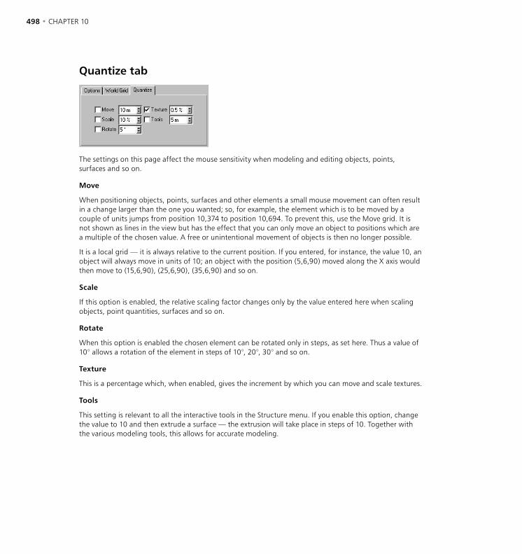
498 • CHAPTER 10
Quantize tab
The settings on this page affect the mouse sensitivity when modeling and editing objects, points, surfaces and so on.
Move
When positioning objects, points, surfaces and other elements a small mouse movement can often result in a change larger than the one you wanted; so, for example, the element which is to be moved by a couple of units jumps from position 10,374 to position 10,694. To prevent this, use the Move grid. It is not shown as lines in the view but has the effect that you can only move an object to positions which are a multiple of the chosen value. A free or unintentional movement of objects is then no longer possible.
It is a local grid — it is always relative to the current position. If you entered, for instance, the value 10, an object will always move in units of 10; an object with the position (5,6,90) moved along the X axis would then move to (15,6,90), (25,6,90), (35,6,90) and so on.
Scale
If this option is enabled, the relative scaling factor changes only by the value entered here when scaling objects, point quantities, surfaces and so on.
Rotate
When this option is enabled the chosen element can be rotated only in steps, as set here. Thus a value of 10° allows a rotation of the element in steps of 10°, 20°, 30° and so on.
Texture
This is a percentage which, when enabled, gives the increment by which you can move and scale textures.
Tools
This setting is relevant to all the interactive tools in the Structure menu. If you enable this option, change the value to 10 and then extrude a surface — the extrusion will take place in steps of 10. Together with the various modeling tools, this allows for accurate modeling.
11 Functions Menu

FUNCTIONS MENU • 501
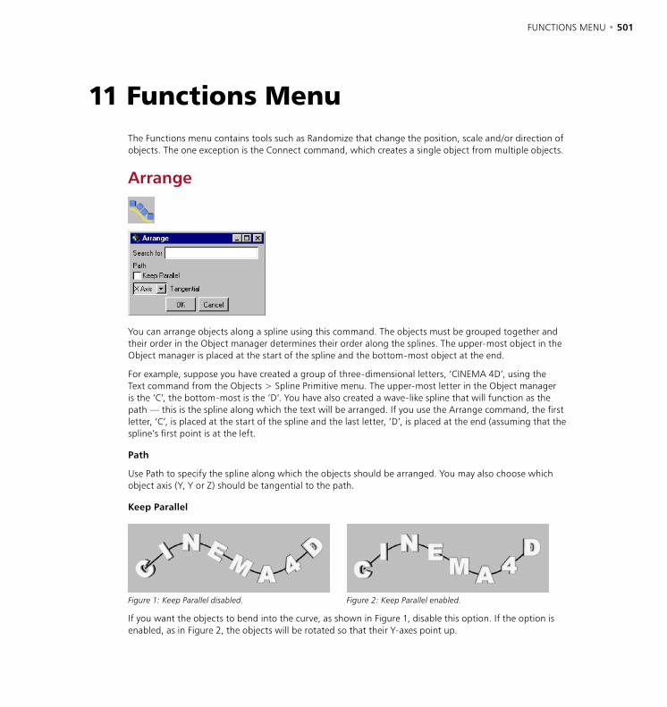
FUNCTIONS MENU • 501
The Functions menu contains tools such as Randomize that change the position, scale and/or direction of objects. The one exception is the Connect command, which creates a single object from multiple objects.
Arrange
You can arrange objects along a spline using this command. The objects must be grouped together and their order in the Object manager determines their order along the splines. The upper-most object in the Object manager is placed at the start of the spline and the bottom-most object at the end.
For example, suppose you have created a group of three-dimensional letters, ‘CINEMA 4D’, using the Text command from the Objects > Spline Primitive menu. The upper-most letter in the Object manager is the ‘C’, the bottom-most is the ‘D’. You have also created a wave-like spline that will function as the path — this is the spline along which the text will be arranged. If you use the Arrange command, the first letter, ‘C’, is placed at the start of the spline and the last letter, ‘D’, is placed at the end (assuming that the spline’s first point is at the left.
Path
Use Path to specify the spline along which the objects should be arranged. You may also choose which object axis (Y, Y or Z) should be tangential to the path.
Keep Parallel
Figure 1: Keep Parallel disabled. Figure 2: Keep Parallel enabled.
If you want the objects to bend into the curve, as shown in Figure 1, disable this option. If the option is enabled, as in Figure 2, the objects will be rotated so that their Y-axes point up.
11 Functions Menu
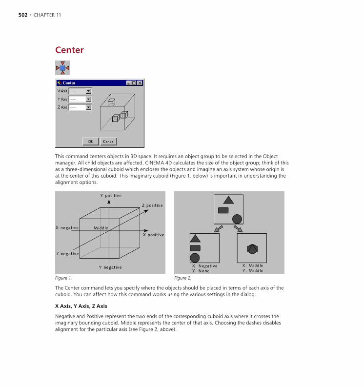
502 • CHAPTER 11 FUNCTIONS MENU • 503
Center
This command centers objects in 3D space. It requires an object group to be selected in the Object manager. All child objects are affected. CINEMA 4D calculates the size of the object group; think of this as a three-dimensional cuboid which encloses the objects and imagine an axis system whose origin is at the center of this cuboid. This imaginary cuboid (Figure 1, below) is important in understanding the alignment options.
Figure 1. Figure 2.
The Center command lets you specify where the objects should be placed in terms of each axis of the cuboid. You can affect how this command works using the various settings in the dialog.
X Axis, Y Axis, Z Axis
Negative and Positive represent the two ends of the corresponding cuboid axis where it crosses the imaginary bounding cuboid. Middle represents the center of that axis. Choosing the dashes disables alignment for the particular axis (see Figure 2, above).
502 • CHAPTER 11 FUNCTIONS MENU • 503
Connect
Using this command you can create a single object from multiple objects. For example, you might connect a fence consisting of hundreds of individual planks to form just a single fence object. Not only does the connected object take up less display space in the Object manager, it is also renders more quickly even though it has the same number of polygons. You can connect Polygon objects or Spline objects.
To connect objects, select the objects that you want to connect and choose Structure > Connect. Note that the original objects are preserved. Delete these if they are no longer required. Use the command only if you are certain that the object will not need separating later; although you can separate the object into its original parts manually, it is a time-consuming process.
Current State To Object
If the original object is parametric, the function creates a polygon copy (taking into account any deformers and hierarchies). Child objects are ignored — the function must be called separately for each child object that you require.
This command creates a polygon copy of the selected object. For example, if you are using several deformers on an object, you can copy the resultant shape into a normal polygon object (the deformers will not be required for the copy). Or perhaps you have defined an animation (e.g. using PLA) and you want to create a polygon copy of the shape at a particular frame — simply move the time slider to the required frame, select the object and choose this command. This function is particularly useful for fine-tuning morph animation manually.
Animation data is not copied to the new object. The original object (including its animation data) is preserved.
Create and animate an object, e.g. with PLA. Move the time slider until the object is in the state that you want to copy. Choose Functions > Current State To Object.
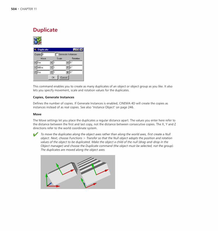
504 • CHAPTER 11 FUNCTIONS MENU • 505
Duplicate
This command enables you to create as many duplicates of an object or object group as you like. It also lets you specify movement, scale and rotation values for the duplicates.
Copies, Generate Instances
Defines the number of copies. If Generate Instances is enabled, CINEMA 4D will create the copies as instances instead of as real copies. See also ‘Instance Object’ on page 246.
Move
The Move settings let you place the duplicates a regular distance apart. The values you enter here refer to the distance between the first and last copy, not the distance between consecutive copies. The X, Y and Z directions refer to the world coordinate system.
To move the duplicates along the object axes rather than along the world axes, first create a Null object. Next, choose Functions > Transfer so that the Null object adopts the position and rotation values of the object to be duplicated. Make the object a child of the null (drag-and-drop in the Object manager) and choose the Duplicate command (the object must be selected, not the group). The duplicates are moved along the object axes.
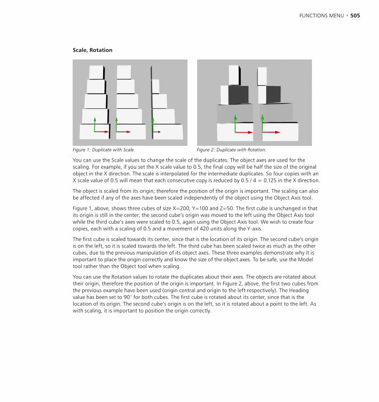
504 • CHAPTER 11 FUNCTIONS MENU • 505
Scale, Rotation
Figure 1: Duplicate with Scale. Figure 2: Duplicate with Rotation.
You can use the Scale values to change the scale of the duplicates. The object axes are used for the scaling. For example, if you set the X scale value to 0.5, the final copy will be half the size of the original object in the X direction. The scale is interpolated for the intermediate duplicates. So four copies with an X scale value of 0.5 will mean that each consecutive copy is reduced by 0.5 / 4 = 0.125 in the X direction.
The object is scaled from its origin; therefore the position of the origin is important. The scaling can also be affected if any of the axes have been scaled independently of the object using the Object Axis tool.
Figure 1, above, shows three cubes of size X=200, Y=100 and Z=50. The first cube is unchanged in that its origin is still in the center; the second cube’s origin was moved to the left using the Object Axis tool while the third cube’s axes were scaled to 0.5, again using the Object Axis tool. We wish to create four copies, each with a scaling of 0.5 and a movement of 420 units along the Y-axis.
The first cube is scaled towards its center, since that is the location of its origin. The second cube’s origin is on the left, so it is scaled towards the left. The third cube has been scaled twice as much as the other cubes, due to the previous manipulation of its object axes. These three examples demonstrate why it is important to place the origin correctly and know the size of the object axes. To be safe, use the Model tool rather than the Object tool when scaling.
You can use the Rotation values to rotate the duplicates about their axes. The objects are rotated about their origin, therefore the position of the origin is important. In Figure 2, above, the first two cubes from the previous example have been used (origin central and origin to the left respectively). The Heading value has been set to 90° for both cubes. The first cube is rotated about its center, since that is the location of its origin. The second cube’s origin is on the left, so it is rotated about a point to the left. As with scaling, it is important to position the origin correctly.
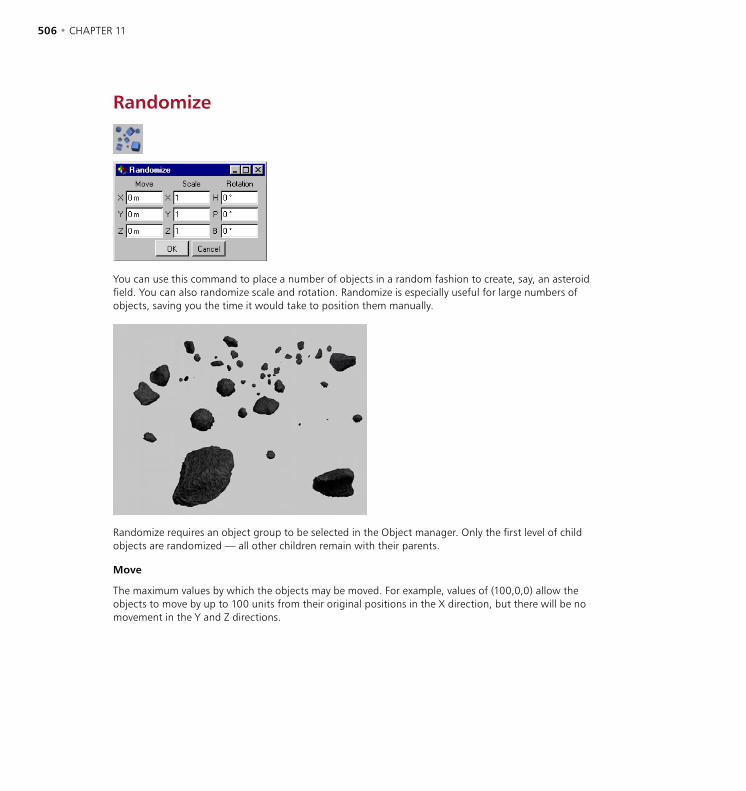
506 • CHAPTER 11 FUNCTIONS MENU • 507
Randomize
You can use this command to place a number of objects in a random fashion to create, say, an asteroid field. You can also randomize scale and rotation. Randomize is especially useful for large numbers of objects, saving you the time it would take to position them manually.
Randomize requires an object group to be selected in the Object manager. Only the first level of child objects are randomized — all other children remain with their parents.
Move
The maximum values by which the objects may be moved. For example, values of (100,0,0) allow the objects to move by up to 100 units from their original positions in the X direction, but there will be no movement in the Y and Z directions.
506 • CHAPTER 11 FUNCTIONS MENU • 507
Scale
The objects are scaled from their origins, therefore the position of the origin is important. The scaling can also be affected if any of the axes has been scaled independently of the object using the Object Axis tool. To be safe, use the Model tool rather than the Object tool when scaling.
The maximum values by which the objects may be scaled. For example, values of (3,1,1) allow the objects to be scaled by up to three times their original sizes along the X axis, but there will be no scaling in the Y and Z directions.
Rotation
Check that none of the objects overlap after being randomized. This tends to occur when the original objects are close together before the Randomize command is used. Corrective positioning of overlapping objects may be required.
The maximum values by which the objects may be rotated. For example, values of (0°,85°,0°) allow the objects to be rotated by up to 85° about the pitch axis, but there will be no rotation about the heading and bank axes.
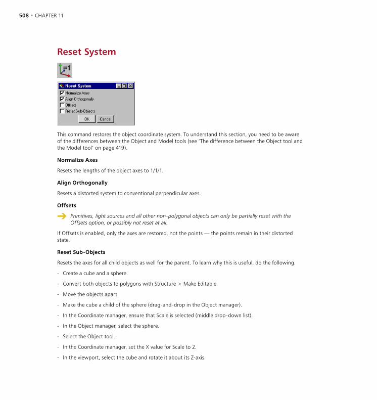
508 • CHAPTER 11 FUNCTIONS MENU • 509
Reset System
This command restores the object coordinate system. To understand this section, you need to be aware of the differences between the Object and Model tools (see ‘The difference between the Object tool and the Model tool’ on page 419).
Normalize Axes
Resets the lengths of the object axes to 1/1/1.
Align Orthogonally
Resets a distorted system to conventional perpendicular axes.
Offsets
Primitives, light sources and all other non-polygonal objects can only be partially reset with the Offsets option, or possibly not reset at all.
If Offsets is enabled, only the axes are restored, not the points — the points remain in their distorted state.
Reset Sub-Objects
Resets the axes for all child objects as well for the parent. To learn why this is useful, do the following.
- Create a cube and a sphere.
- Convert both objects to polygons with Structure > Make Editable.
- Move the objects apart.
- Make the cube a child of the sphere (drag-and-drop in the Object manager).
- In the Coordinate manager, ensure that Scale is selected (middle drop-down list).
- In the Object manager, select the sphere.
- Select the Object tool.
- In the Coordinate manager, set the X value for Scale to 2.
- In the viewport, select the cube and rotate it about its Z-axis.
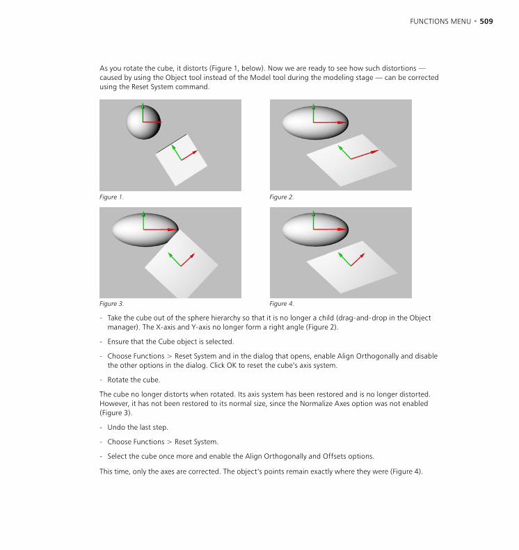
508 • CHAPTER 11 FUNCTIONS MENU • 509
As you rotate the cube, it distorts (Figure 1, below). Now we are ready to see how such distortions — caused by using the Object tool instead of the Model tool during the modeling stage — can be corrected using the Reset System command.
Figure 1. Figure 2.
Figure 3. Figure 4.
- Take the cube out of the sphere hierarchy so that it is no longer a child (drag-and-drop in the Object manager). The X-axis and Y-axis no longer form a right angle (Figure 2).
- Ensure that the Cube object is selected.
- Choose Functions > Reset System and in the dialog that opens, enable Align Orthogonally and disable the other options in the dialog. Click OK to reset the cube’s axis system.
- Rotate the cube.
The cube no longer distorts when rotated. Its axis system has been restored and is no longer distorted. However, it has not been restored to its normal size, since the Normalize Axes option was not enabled (Figure 3).
- Undo the last step.
- Choose Functions > Reset System.
- Select the cube once more and enable the Align Orthogonally and Offsets options.
This time, only the axes are corrected. The object’s points remain exactly where they were (Figure 4).
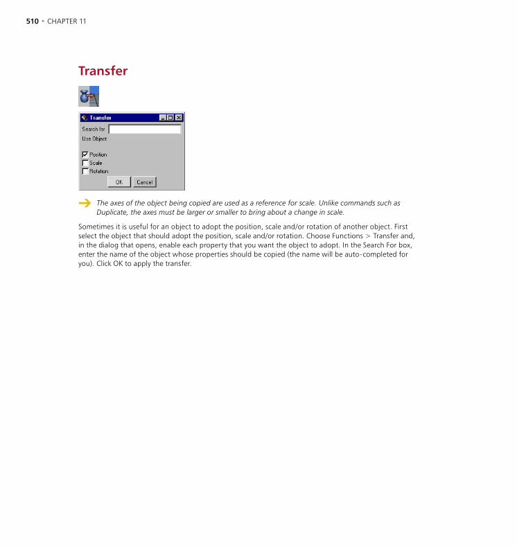
510 • CHAPTER 11
Transfer
The axes of the object being copied are used as a reference for scale. Unlike commands such as Duplicate, the axes must be larger or smaller to bring about a change in scale.
Sometimes it is useful for an object to adopt the position, scale and/or rotation of another object. First select the object that should adopt the position, scale and/or rotation. Choose Functions > Transfer and, in the dialog that opens, enable each property that you want the object to adopt. In the Search For box, enter the name of the object whose properties should be copied (the name will be auto-completed for you). Click OK to apply the transfer.

12 Plugins

PLUGINS • 513
PLUGINS • 513
Plugins are auxiliary modules which extend the function range of a program. In CINEMA 4D, plugins are able, for example, to automate particular functions, to make new tools available (perhaps for modeling or animation), to extend import and export filters or to add new shaders. For this purpose CINEMA 4D includes a powerful programming language, C.O.F.F.E.E., available to both developers and end-users.
C.O.F.F.E.E. is an object-oriented programming language closely related to C++ and Java. Full information and the SDK is available at www.plugincafe.com, where you’ll also find links to many plugins.
Plugins can be developed freely by anyone and offered for sale. However, MAXON, as the manufacturer of CINEMA 4D, has no influence on the quality of these plugins and you should assure yourself as to the value-for-money and usefulness of a plugin before purchase.
We give as much support as possible to all vendors and developers of plugins — however, if a problem should arise with one of these products, please contact the manufacturer of the plugin directly. Please understand that MAXON can give no information on, or provide technical support for, products from other manufacturers.
As already mentioned, plugins can solve many diverse tasks and therefore, after installation, your new plugin may appear in different places within the CINEMA 4D menu structure. Please always consult the vendor’s documentation that was supplied with your plugin. If there is no special information to be found in the documentation, a plugin will probably be found in the Plugins menu.
You cannot add new plugins while CINEMA 4D is running, Instead, quit CINEMA 4D first, then install the plugins. When you next start CINEMA 4D, the plugins will load automatically.
Certain CINEMA 4D modules (such as Dynamics, Thinking Particles and MOCCA) also appear in the Plugins menu. Many of the tools and settings of these modules can be selected and adjusted here. You’ll also find the FlashEx plugin, which enables you to export Shockwave Flash files (SWF), and a plugin for SpaceMouse support (Windows only).
Execute Last PluginThis command gives you a quick way to call the last plugin that you used, especially is you assign a shortcut to this command using the Command manager.
12 Plugins

514 • CHAPTER 12 PLUGINS • 515
FlashExFlashEx exports single objects or entire scenes in Macromedia’s Shockwave Flash format (SWF files). Using this format you can save entire animations for use on the Internet or in CD-ROM applications. The most important reason for using the SWF format is to save and animate vector lines. Although you can also export SWF files with embedded bitmapped graphics, the main strength is the vector output (for animations that include embedded bitmapped graphics, use .avi, .mov or .mpg instead of SWF).
When producing vector output, FlashEx converts the three-dimensional data to two-dimensional vector lines, optimizes them and saves them while maintaining the smallest possible SWF file size. Bitmapped textures and procedural shaders are ignored, as are bump maps, fog, transparencies and anything else that can’t be displayed as vectors, such as Sky objects.
Camera settings such as zoom are supported. However, note that FlashEx supports the Perspective camera view only.
General tab
Duration, Frame Rate, File
On this page you’ll find settings much like the ones on the Output page of the render settings. Here you can set the duration, frame rate and choose the filename and save location for the SWF file that will be created. If you want to use the same settings as defined in the render settings, click the Render Setting button. These settings will then be loaded into the FlashEx dialog.
Generate HTML
In addition to creating an SWF file, you can also generate a HTML page which includes the SWF file. You can cut-and-paste the HTML code from this page directly into your own HTML pages or edit the code. (See also ‘HTML tab’ on page 519.)
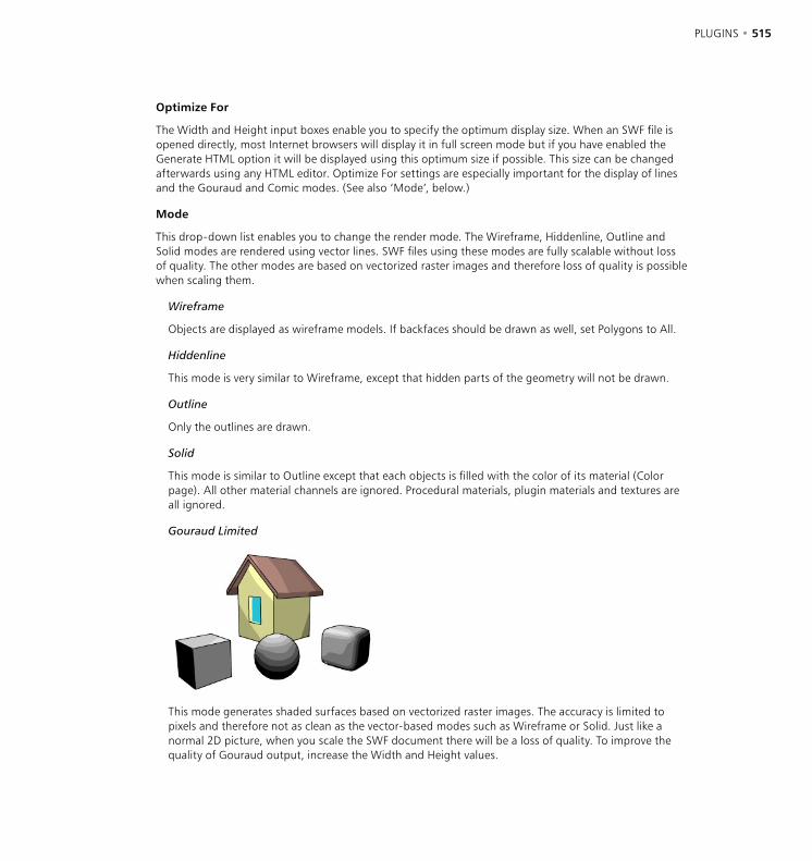
514 • CHAPTER 12 PLUGINS • 515
Optimize For
The Width and Height input boxes enable you to specify the optimum display size. When an SWF file is opened directly, most Internet browsers will display it in full screen mode but if you have enabled the Generate HTML option it will be displayed using this optimum size if possible. This size can be changed afterwards using any HTML editor. Optimize For settings are especially important for the display of lines and the Gouraud and Comic modes. (See also ‘Mode’, below.)
Mode
This drop-down list enables you to change the render mode. The Wireframe, Hiddenline, Outline and Solid modes are rendered using vector lines. SWF files using these modes are fully scalable without loss of quality. The other modes are based on vectorized raster images and therefore loss of quality is possible when scaling them.
Wireframe
Objects are displayed as wireframe models. If backfaces should be drawn as well, set Polygons to All.
Hiddenline
This mode is very similar to Wireframe, except that hidden parts of the geometry will not be drawn.
Outline
Only the outlines are drawn.
Solid
This mode is similar to Outline except that each objects is filled with the color of its material (Color page). All other material channels are ignored. Procedural materials, plugin materials and textures are all ignored.
Gouraud Limited
This mode generates shaded surfaces based on vectorized raster images. The accuracy is limited to pixels and therefore not as clean as the vector-based modes such as Wireframe or Solid. Just like a normal 2D picture, when you scale the SWF document there will be a loss of quality. To improve the quality of Gouraud output, increase the Width and Height values.
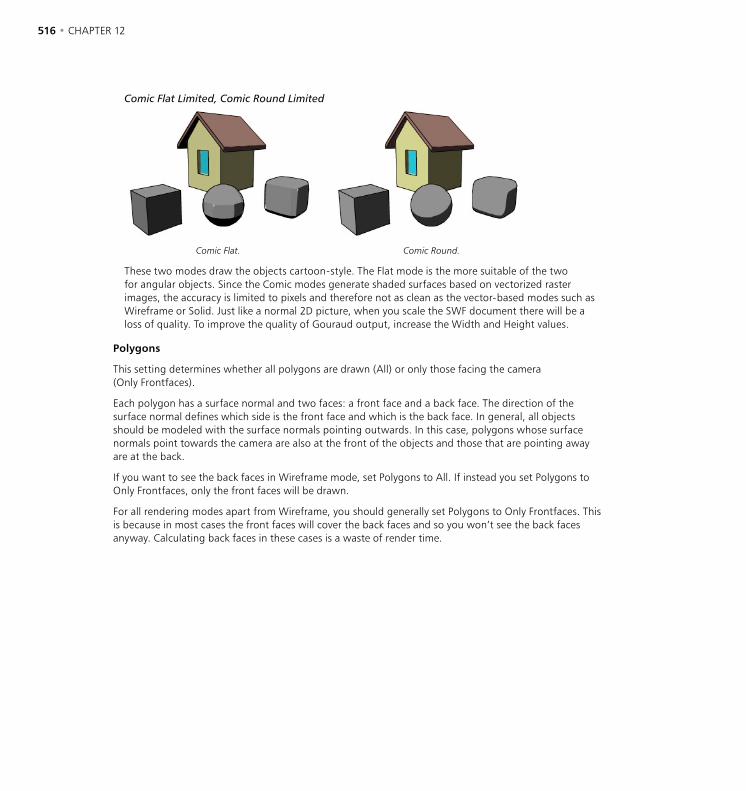
516 • CHAPTER 12 PLUGINS • 517
Comic Flat Limited, Comic Round Limited
Comic Flat. Comic Round.
These two modes draw the objects cartoon-style. The Flat mode is the more suitable of the two for angular objects. Since the Comic modes generate shaded surfaces based on vectorized raster images, the accuracy is limited to pixels and therefore not as clean as the vector-based modes such as Wireframe or Solid. Just like a normal 2D picture, when you scale the SWF document there will be a loss of quality. To improve the quality of Gouraud output, increase the Width and Height values.
Polygons
This setting determines whether all polygons are drawn (All) or only those facing the camera (Only Frontfaces).
Each polygon has a surface normal and two faces: a front face and a back face. The direction of the surface normal defines which side is the front face and which is the back face. In general, all objects should be modeled with the surface normals pointing outwards. In this case, polygons whose surface normals point towards the camera are also at the front of the objects and those that are pointing away are at the back.
If you want to see the back faces in Wireframe mode, set Polygons to All. If instead you set Polygons to Only Frontfaces, only the front faces will be drawn.
For all rendering modes apart from Wireframe, you should generally set Polygons to Only Frontfaces. This is because in most cases the front faces will cover the back faces and so you won’t see the back faces anyway. Calculating back faces in these cases is a waste of render time.

516 • CHAPTER 12 PLUGINS • 517
Background tab
The background color is defined on this page of the FlashEx dialog. When importing SWF files into certain applications such as Macromedia Director, this background color can be made transparent.
Lines tab
Outline
If this option is enabled, lines are drawn for all outer edges and intersecting lines.
Edges Angle
If this option is enabled and two polygons face each other at an angle greater than the one entered, they are drawn as edges.
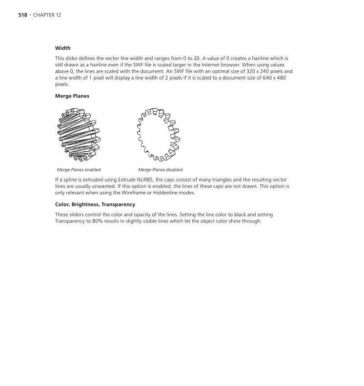
518 • CHAPTER 12 PLUGINS • 519
Width
This slider defines the vector line width and ranges from 0 to 20. A value of 0 creates a hairline which is still drawn as a hairline even if the SWF file is scaled larger in the Internet browser. When using values above 0, the lines are scaled with the document. An SWF file with an optimal size of 320 x 240 pixels and a line width of 1 pixel will display a line width of 2 pixels if it is scaled to a document size of 640 x 480 pixels.
Merge Planes
Merge Planes enabled. Merge Planes disabled.
If a spline is extruded using Extrude NURBS, the caps consist of many triangles and the resulting vector lines are usually unwanted. If this option is enabled, the lines of these caps are not drawn. This option is only relevant when using the Wireframe or Hiddenline modes.
Color, Brightness, Transparency
These sliders control the color and opacity of the lines. Setting the line color to black and setting Transparency to 80% results in slightly visible lines which let the object color shine through.
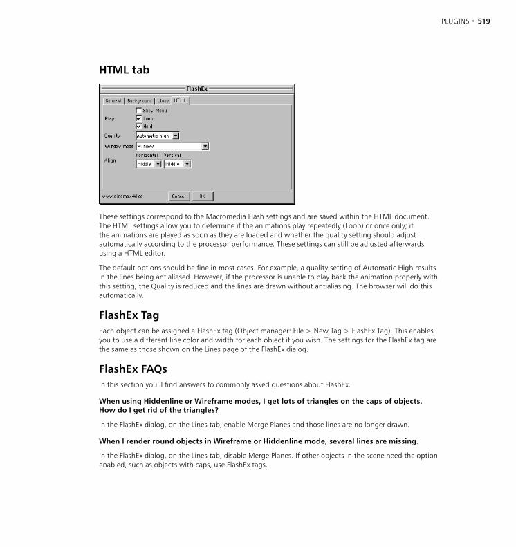
518 • CHAPTER 12 PLUGINS • 519
HTML tab
These settings correspond to the Macromedia Flash settings and are saved within the HTML document. The HTML settings allow you to determine if the animations play repeatedly (Loop) or once only; if the animations are played as soon as they are loaded and whether the quality setting should adjust automatically according to the processor performance. These settings can still be adjusted afterwards using a HTML editor.
The default options should be fine in most cases. For example, a quality setting of Automatic High results in the lines being antialiased. However, if the processor is unable to play back the animation properly with this setting, the Quality is reduced and the lines are drawn without antialiasing. The browser will do this automatically.
FlashEx TagEach object can be assigned a FlashEx tag (Object manager: File > New Tag > FlashEx Tag). This enables you to use a different line color and width for each object if you wish. The settings for the FlashEx tag are the same as those shown on the Lines page of the FlashEx dialog.
FlashEx FAQsIn this section you’ll find answers to commonly asked questions about FlashEx.
When using Hiddenline or Wireframe modes, I get lots of triangles on the caps of objects. How do I get rid of the triangles?
In the FlashEx dialog, on the Lines tab, enable Merge Planes and those lines are no longer drawn.
When I render round objects in Wireframe or Hiddenline mode, several lines are missing.
In the FlashEx dialog, on the Lines tab, disable Merge Planes. If other objects in the scene need the option enabled, such as objects with caps, use FlashEx tags.

520 • CHAPTER 12 PLUGINS • 521
In Wireframe mode, I can’t see the backs of objects.
In the FlashEx dialog, on the General tab, set Polygons to All. Now back faces will be shown as well as front faces.
There are holes in the objects and I can see right through to the geometry inside.
Check if the surface normals of your objects are all pointing outwards. Use the Structure > Reverse Normals or Structure > Align Normals commands from the main menu to correct this. Alternatively, in the FlashEx dialog, on the General tab, set Polygons to All.
Using the FlashEx tag on a HyperNURBS object doesn’t work.
Drag the FlashEx tag onto the child object of the HyperNURBS. The HyperNURBS uses the settings of its child objects.
My full screen SWF file looks awful. I’m using the Gouraud mode.
If you want to play back a SWF Gouraud file in full screen you should adjust the values for Width and Height in the FlashEx dialog on the General tab to give you the desired size. To keep the file size compact, FlashEx merges lines which are visually at the same position. The Gouraud and Comic modes are generally not suitable for scaling.
The FlashPlayer can’t display my SWF file properly in realtime.
The scene is probably too complex. The player needs to draw all the vector lines in realtime and the processor speed determines how well it manages to do that. You need to simplify the scene. In 3D video games, characters often have less than a thousand polygons.
How can I make the lines a similar color to the object color?
Do one of the following:
1. Use FlashEx tags and define the line color manually per object.
2. Set the line color to black and in the FlashEx dialog, on the Lines tab, set Transparency to 80%
The lines get thicker when I scale the SWF document. How do I get the lines to stay the same thickness?
Set the line width to 0 (hairline). The player will then always display a thin, 1-pixel line, no matter how much the SWF document is scaled.
Sometimes I can’t see planes and single polygons from the side. How can I make them show up as lines?
In the FlashEx dialog, on the General tab, set Polygons to All. Now all polygons will be visible regardless of whether they point at the camera.

520 • CHAPTER 12 PLUGINS • 521
SpaceMouseThis command is available only if you are using Windows. The SpaceMouse is an input device especially designed for 3D applications. Use this command to access controls that enable you to fine-tune this device.


13 Rendering

RENDERING • RENDER MENU • 525

RENDERING • RENDER MENU • 525
The Render menu contains all the options you need to render a picture or animation. You can define several render presets such as for preview and for final rendering; this saves you having to change the settings one by one each time. Using the render settings, you can also switch on effects such as multi-pass rendering.
Render Alerts
Missing textures
If CINEMA 4D is unable to find any textures when you render, an alert will appear. If you choose to continue rendering, the materials will be used without the missing texture maps. CINEMA 4D searches for textures in the following locations: in the scene’s folder; in the scene’s ‘Tex’ folder; in CINEMA 4D’s ‘Tex’ folder; in the Texture Paths (and sub-folders) specified in the preferences.
Render View
If you want to save the picture or animation, you must render to the Picture Viewer instead (see ‘Render to Picture Viewer’ on page 526). If an alert appears when you render, see ‘Render Alerts’ above.
Use this command to render the scene in the active viewport. A render progress bar will appear in the bottom left corner of the view panel. To cancel rendering, press Esc or click the mouse button. To access the options that control rendering, choose Render > Render Settings from the main menu (see ‘Render Settings’, page 531).
Render Active Object
If you want to save the picture or animation, you must render to the Picture Viewer instead (see ‘Render to Picture Viewer’ on page 526). If an alert appears when you render, see ‘Render Alerts’ above.
This command renders the selected objects and their children in the active viewport. A render progress bar will appear in the bottom left corner of the screen. To cancel rendering, press Esc or click the mouse button. To access the options that control rendering, choose Render > Render Settings from the main menu (see ‘Render Settings’, page 531).
13 Rendering
526 • CHAPTER 13 RENDERING • RENDER MENU • 527
Render Region
If you want to save the picture or animation, you must render to the Picture Viewer instead (see ‘Render to Picture Viewer’, below). If an alert appears when you render, see ‘Render Alerts’ above.
Use this command to render a region in a viewport. Once you have chosen the command, drag a box in a viewport to define the region that you want to be rendered. A render progress bar will appear in the bottom left corner of the screen. To cancel rendering, press Esc or click the mouse button. To access the options that control rendering, choose Render > Render Settings from the main menu (see ‘Render Settings’, page 531).
Render To Picture Viewer
The Picture Viewer includes display options such as the ability to switch off specific color channels and the ability to change the viewing size. See Chapter 24, ‘Picture Viewer’ on page 969.
This command renders the scene to the Picture Viewer. If you want to save the picture or animation, enter a filename in the render settings before you use this function — see ‘Save Image, Path’ on page 537. Once rendering starts, a progress bar appears at the bottom left of the window. The bar shows the time elapsed since the render started. If you are rendering an animation, the bar also shows you the current frame number and the total number of frames.
If an alert appears when you render, see ‘Render Alerts’ above.
To cancel the rendering, press Esc. To access the options that control rendering, choose Render > Render Settings from the main menu (see ‘Render Settings’, page 531).
Batch Rendering
Before you batch render, ensure each scene has a save path in its Render Settings. Also, render each scene individually as a precaution — you can abort each test as soon as the picture starts to appear. This is to check that no alerts (such as the missing textures alert) will interrupt batch rendering.
This command enables you to queue up to ten scenes for rendering. The scenes will be rendered one after the other automatically. When you select the command, the Batch Rendering window opens. Either type the paths into the text boxes or click the Job buttons one at a time to choose the folder and file. Once you have added all the scenes, click OK to start rendering.
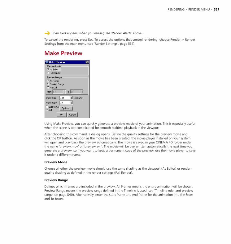
526 • CHAPTER 13 RENDERING • RENDER MENU • 527
If an alert appears when you render, see ‘Render Alerts’ above.
To cancel the rendering, press Esc. To access the options that control rendering, choose Render > Render Settings from the main menu (see ‘Render Settings’, page 531).
Make Preview
Using Make Preview, you can quickly generate a preview movie of your animation. This is especially useful when the scene is too complicated for smooth realtime playback in the viewport.
After choosing this command, a dialog opens. Define the quality settings for the preview movie and click the OK button. As soon as the movie has been created, the movie player installed on your system will open and play back the preview automatically. The movie is saved in your CINEMA 4D folder under the name ‘preview.mov’ or ‘preview.avi.’. The movie will be overwritten automatically the next time you generate a preview, so if you want to keep a permanent copy of the preview, use the movie player to save it under a different name.
Preview Mode
Choose whether the preview movie should use the same shading as the viewport (As Editor) or render-quality shading as defined in the render settings (Full Render).
Preview Range
Defines which frames are included in the preview. All Frames means the entire animation will be shown. Preview Range means the preview range defined in the Timeline is used (see ‘Timeline ruler and preview range’ on page 840). Alternatively, enter the start frame and end frame for the animation into the From and To boxes.

528 • CHAPTER 13 RENDERING • RENDER MENU • 529
Image Size, Frame Rate
CINEMA 4D lets you use mathematical formulae in input boxes. For example, if you want the preview resolution to be a quarter of 640 x 480, you can enter ‘640/4’ into the Image Size input box.
Enter the width for the preview movie. The height is calculated automatically using the Film Format ratio defined on the render settings Output page. The resolution is shown to the right of the input box.
Frame Rate
Defines the frame rate for the preview. Values as low as 10 will be enough for you to check the animation, or you may prefer to enter the same rate that will be used for the final render.
QuickTime, AVI, Options
The preview is rendered as a QuickTime or an AVI movie depending on which option is enabled. To choose a particular codec and edit its settings, click Options.
Render Settings
See also ‘Render Settings’ on page 531.
A project can have several render settings. This command opens the active settings (indicated by a check mark on the Render menu). For details on using multiple settings, see ‘New Render Settings’, below.
New Render Settings
To add default render settings, start a new scene and use New Render Settings to create the settings. Save this empty scene in CINEMA 4D’s root folder using the filename ‘template.c4d’ (see also ‘Initialization Files’ on page 102).
You can use this command to create new render settings. The Render Settings dialog opens. On the General page, enter a name for the new settings into the Name box — enter a name that will make it easy to distinguish these settings from others on the Render menu, such as ‘Modeling’. Once you have finished creating the settings, the new name will appear in the lower section of the Render menu.
You can create settings for a variety of purposes. Perhaps you will create settings with low antialiasing, no reflections and no shadows for preview rendering, called ‘Preview’. You might also create settings with high antialiasing, reflections and shadows called ‘Final Rendering’. You can create as many settings as you like. To choose which settings are active, select the corresponding name from the Render menu. The check mark will then appear in front of that name.

528 • CHAPTER 13 RENDERING • RENDER MENU • 529
Delete Render Settings
This command deletes the active render settings (the active settings are indicated by a check mark on the Render menu). The name of the settings will be removed from the Render menu.
Flush All Cached SolutionsThis command is only of interest if you own the optional Advanced Render module. If you enable Save Solution on the Caustics or Radiosity pages, files are saved in the scene’s ‘Illum’ folder so that subsequent renders can reuse the data. Choose Flush All Cached Solutions to delete these files.

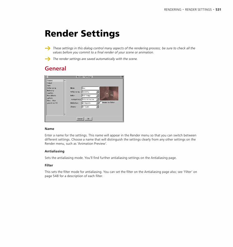
RENDERING • RENDER SETTINGS • 531
These settings in this dialog control many aspects of the rendering process; be sure to check all the values before you commit to a final render of your scene or animation.
The render settings are saved automatically with the scene.
General
Name
Enter a name for the settings. This name will appear in the Render menu so that you can switch between different settings. Choose a name that will distinguish the settings clearly from any other settings on the Render menu, such as ‘Animation Preview’.
Antialiasing
Sets the antialiasing mode. You’ll find further antialiasing settings on the Antialiasing page.
Filter
This sets the filter mode for antialiasing. You can set the filter on the Antialiasing page also; see ‘Filter’ on page 548 for a description of each filter.
Render Settings
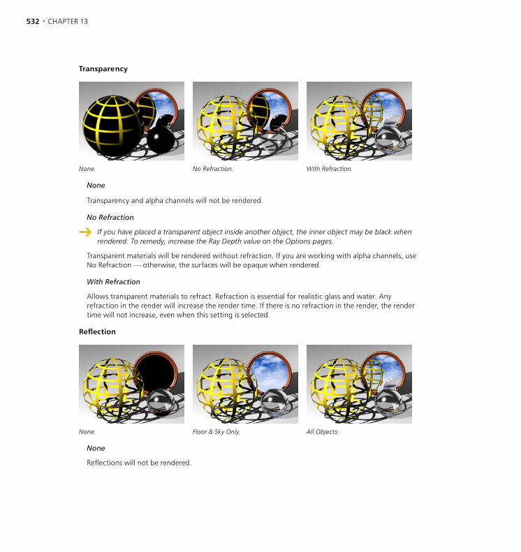
532 • CHAPTER 13 RENDERING • RENDER SETTINGS • 533
Transparency
None. No Refraction. With Refraction.
None
Transparency and alpha channels will not be rendered.
No Refraction
If you have placed a transparent object inside another object, the inner object may be black when rendered. To remedy, increase the Ray Depth value on the Options pages.
Transparent materials will be rendered without refraction. If you are working with alpha channels, use No Refraction — otherwise, the surfaces will be opaque when rendered.
With Refraction
Allows transparent materials to refract. Refraction is essential for realistic glass and water. Any refraction in the render will increase the render time. If there is no refraction in the render, the render time will not increase, even when this setting is selected.
Reflection
None. Floor & Sky Only. All Objects.
None
Reflections will not be rendered.
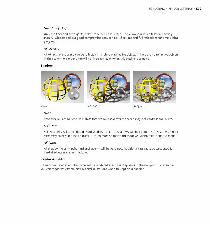
532 • CHAPTER 13 RENDERING • RENDER SETTINGS • 533
Floor & Sky Only
Only the floor and sky objects in the scene will be reflected. This allows for much faster rendering than All Objects and is a good compromise between no reflections and full reflections for time-critical projects.
All Objects
All objects in the scene can be reflected in a relevant reflective object. If there are no reflective objects in the scene, the render time will not increase, even when this setting is selected.
Shadow
None. Soft Only. All Types.
None
Shadows will not be rendered. Note that without shadows the scene may lack contrast and depth.
Soft Only
Soft shadows will be rendered. Hard shadows and area shadows will be ignored. Soft shadows render extremely quickly and look natural — often more so than hard shadows, which take longer to render.
All Types
All shadow types — soft, hard and area — will be rendered. Additional rays must be calculated for hard shadows and area shadows.
Render As Editor
If this option is enabled, the scene will be rendered exactly as it appears in the viewport. For example, you can render wireframe pictures and animations when this option is enabled.
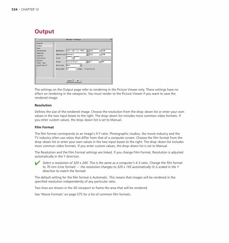
534 • CHAPTER 13 RENDERING • RENDER SETTINGS • 535
Output
The settings on the Output page refer to rendering in the Picture Viewer only. These settings have no effect on rendering in the viewports. You must render to the Picture Viewer if you want to save the rendered image.
Resolution
Defines the size of the rendered image. Choose the resolution from the drop-down list or enter your own values in the two input boxes to the right. The drop-down list includes most common video formats. If you enter custom values, the drop-down list is set to Manual.
Film Format
The film format corresponds to an image’s X:Y ratio. Photographic studios, the movie industry and the TV industry often use ratios that differ from that of a computer screen. Choose the film format from the drop-down list or enter your own values in the two input boxes to the right. The drop-down list includes most common video formats. If you enter custom values, the drop-down list is set to Manual.
The Resolution and the Film Format settings are linked. If you change Film Format, Resolution is adjusted automatically in the Y direction.
Select a resolution of 320 x 240. This is the same as a computer’s 4:3 ratio. Change the film format to 70 mm (cine format) — the resolution changes to 320 x 145 automatically (it is scaled in the Y direction to match the format).
The default setting for the film format is Automatic. This means that images will be rendered in the specified resolution independently of any particular ratio.
Two lines are shown in the 3D viewport to frame the area that will be rendered.
See ‘Movie Formats’ on page 575 for a list of common film formats.
534 • CHAPTER 13 RENDERING • RENDER SETTINGS • 535
Pixel
The two values specified here define the ratio of a pixel’s on-screen width (left box) to its on-screen height (right box). The pixel ratio for most monitors is 1:1, so usually you do not need to change this setting. However, some display media use a pixel ratio other than 1:1 and the setting must be adjusted to avoid distortions such as circles appearing as ellipses.
If you need to calculate the pixel ratio manually, expand the side viewport to fit the entire screen and create a cube. Using a ruler, measure the cube’s width and height and enter these values in the two input boxes for Pixel.
Frame
Manual
If you stop the rendering of an AVI or QuickTime movie, all frames will be lost. You cannot resume. Alternatively, render short sequences and assemble the clips in a suitable video editor.
If you want to render a frame sequence, but not the entire animation, enter the first frame for the sequence in the left input box and the last frame in the right input box. The Frame drop-down list will change to Manual automatically. If you want to save the animation, enter a save path on the Save page.
Current Frame
Only the current frame will be rendered. If you want the frame to be saved automatically after rendering, enter a save path on the Save page.
All Frames
If you stop the rendering of an AVI or QuickTime movie, all frames will be lost. You cannot resume. Alternatively, render short sequences and assemble the clips in a suitable video editor.
All the frames will be rendered, either as a picture sequence or as a movie (AVI, QuickTime). If you want the animation to be saved automatically after rendering, enter a save path on the Save page.
Preview Range
If you stop the rendering of an AVI or QuickTime movie, all frames will be lost. You cannot resume. Alternatively, render short sequences and assemble the clips in a suitable video editor.
Only the preview range will be rendered (see ‘Timeline ruler and preview range’ on page 840). The frames are rendered either as a picture sequence or as a movie (AVI, QuickTime). If you want the animation to be saved automatically after rendering, enter a save path on the Save page.
Field Rendering
When field rendering, use a non-lossy compressor or no compression at all. Lossy compressors (e.g. JPEG, M-JPEG) blur the fields and are not suitable for field rendering. Poor results are likely with such compressors.

536 • CHAPTER 13 RENDERING • RENDER SETTINGS • 537
Use field rendering for smoother playback when working with video. With field rendering, each frame is split into two fields. The two fields are interlaced, with one field containing the odd lines (the odd field) and the next field containing the even lines (the even field).
PAL video (used in e.g. Europe) runs at 25 frames per second, which equals 50 fields per second. NTSC video (used in e.g. USA) runs at 30 frames per second, which equals 60 fields per second.
Do not use field rendering for stills — it is intended for video output only.
None
Only complete frames are rendered. Use this setting if you are rendering stills or movies that will not be viewed on a video system.
Even Field First. Odd Field First
The even field or odd field will be rendered first. Check which setting your video system requires.
Frame Rate
Sets the frame rate for the render. This is independent of the frame rate defined in the project settings. The number of frames that will be rendered is shown to the right of the text box.
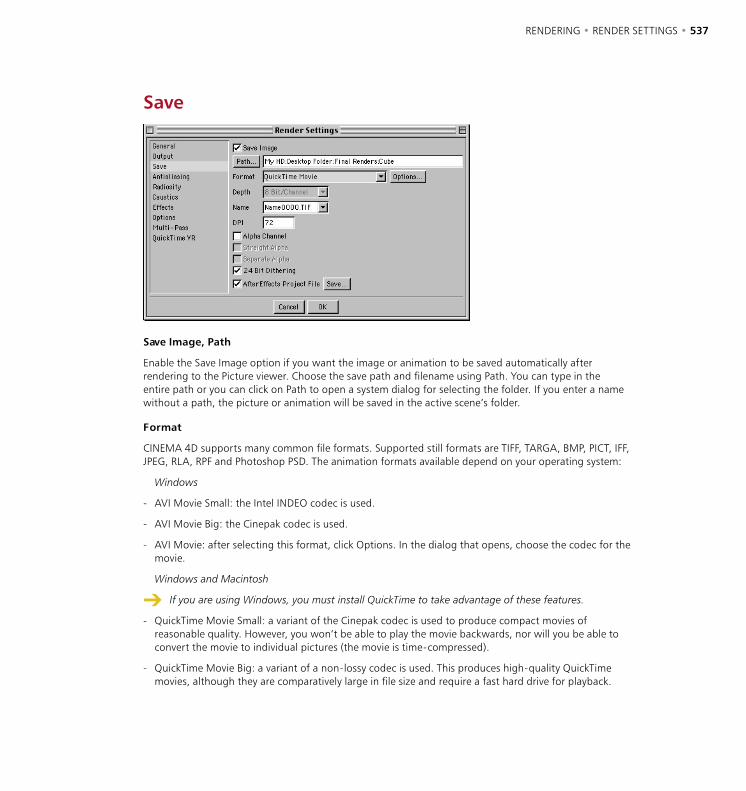
536 • CHAPTER 13 RENDERING • RENDER SETTINGS • 537
Save
Save Image, Path
Enable the Save Image option if you want the image or animation to be saved automatically after rendering to the Picture viewer. Choose the save path and filename using Path. You can type in the entire path or you can click on Path to open a system dialog for selecting the folder. If you enter a name without a path, the picture or animation will be saved in the active scene’s folder.
Format
CINEMA 4D supports many common file formats. Supported still formats are TIFF, TARGA, BMP, PICT, IFF, JPEG, RLA, RPF and Photoshop PSD. The animation formats available depend on your operating system:
Windows
- AVI Movie Small: the Intel INDEO codec is used.
- AVI Movie Big: the Cinepak codec is used.
- AVI Movie: after selecting this format, click Options. In the dialog that opens, choose the codec for the movie.
Windows and Macintosh
If you are using Windows, you must install QuickTime to take advantage of these features.
- QuickTime Movie Small: a variant of the Cinepak codec is used to produce compact movies of reasonable quality. However, you won’t be able to play the movie backwards, nor will you be able to convert the movie to individual pictures (the movie is time-compressed).
- QuickTime Movie Big: a variant of a non-lossy codec is used. This produces high-quality QuickTime movies, although they are comparatively large in file size and require a fast hard drive for playback.
538 • CHAPTER 13 RENDERING • RENDER SETTINGS • 539
- QuickTime Movie: after selecting this format, click Options. In the dialog that opens, choose the codec for the movie. If the dialog doesn’t open, check that you have the latest version of QuickTime installed (visit www.quicktime.com).
QuickTime 4 upwards supports the following single picture formats: BMP, Photoshop PSD, SGI, JPEG, PICT, PNG, TIFF and QuickTime Image. It also supports any new codecs you have added to it. You can create QuickTime VR panorama and object movies under both Windows and Macintosh.
Options
This button is ghosted unless you’ve set Format to AVI Movie (Windows) or QuickTime Movie (Windows and Macintosh). If you click this button, a dialog opens that gives you access to various codecs and their settings. If the dialog doesn’t open, check that you have the latest version of QuickTime installed (visit www.quicktime.com).
Depth
Defines the bit depth per color channel. Choose either 8 bits per channel (for 24-bit color) or 16 bits per channel (for 48-bit color). File formats that support 16 bits per channel are TIFF, PSD, RPF, RLA and B3D.
Name
Many editing programs accept picture sequences. However, they tend to use different naming conventions. Some programs expect the filename to end with a number, others an extension. Some programs can cope only with three-digit numbers. Use this menu to set the sequential numbering and/or lettering style required by your editor. In the example names below, ‘0000’ represents any sequential number, ‘TIF’ represents any three-letter extension.
Example name Example resultName0000.TIF Test1234.JPGName0000 Test1234Name.0000 Test.1234Name000.TIF Test123.TGAName000 Test123Name.000 Test.123
DPI
Use this setting to choose the DPI (dots per inch) for the following picture formats: BMP, TIF, PICT. The DPI affects a picture’s print size and, in certain applications, its display size. The DPI setting does not affect a picture’s Resolution (Output tab); the picture’s pixel dimensions remain the same, only the calculation regarding how many of those pixels (dots) should be printed or displayed per inch is changed.
You render a picture that is 720 x 900 pixels. If you save the picture with 72 DPI, the print size will be 10 in x 12.5 in (25.4 cm x 31.75 cm). If you save the picture with 300 DPI, the print size will be 2.4 in x 3 in (6.1 cm x 7.62 cm). To calculate the print size in inches, divide the pixel dimensions (Resolution on the Output page) by the DPI setting to get the print size in inches; multiply the inches by 2.54 to get the print size in centimeters.
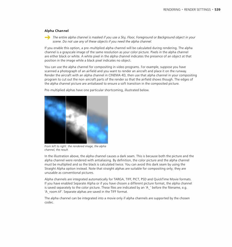
538 • CHAPTER 13 RENDERING • RENDER SETTINGS • 539
Alpha Channel
The entire alpha channel is masked if you use a Sky, Floor, Foreground or Background object in your scene. Do not use any of these objects if you need the alpha channel.
If you enable this option, a pre-multiplied alpha channel will be calculated during rendering. The alpha channel is a grayscale image of the same resolution as your color picture. Pixels in the alpha channel are either black or white. A white pixel in the alpha channel indicates the presence of an object at that position in the image while a black pixel indicates no object.
You can use the alpha channel for compositing in video programs. For example, suppose you have scanned a photograph of an airfield and you want to render an aircraft and place it on the runway. Render the aircraft with an alpha channel in CINEMA 4D, then use that alpha channel in your compositing program to cut out the non-aircraft parts of the render so that the airfield shows though. The edges of the alpha channel picture are antialiased to ensure a soft transition in the composited picture.
Pre-multiplied alphas have one particular shortcoming, illustrated below.
From left to right: the rendered image, the alpha channel, the result.
In the illustration above, the alpha channel causes a dark seam. This is because both the picture and the alpha channel were rendered with antialiasing. By definition, the color picture and the alpha channel must be multiplied and so the black is calculated twice. You can avoid this dark seam by using the Straight Alpha option instead. Note that straight alphas are suitable for compositing only; they are unusable as conventional pictures.
Alpha channels are integrated automatically for TARGA, TIFF, PICT, PSD and QuickTime Movie formats. If you have enabled Separate Alpha or if you have chosen a different picture format, the alpha channel is saved separately to the color picture. These files are indicated by an ‘A_’ before the filename, e.g. ‘A_room.tif’. Separate alphas are saved in the TIFF format.
The alpha channel can be integrated into a movie only if alpha channels are supported by the chosen codec.

540 • CHAPTER 13 RENDERING • RENDER SETTINGS • 541
Straight Alpha
The entire alpha channel is masked if you use a Sky, Floor, Foreground or Background object in your scene. Do not use any of these objects if you need the alpha channel.
You can use this option if straight alphas are supported by your compositing program to avoid the dark seam associated with pre-multiplied alphas. Note that straight alphas are suitable for compositing only; they are unusable as conventional pictures.
From left to right: the rendered image, the alpha channel, the result.
Alpha channels are integrated automatically for TARGA, TIFF, PICT, PSD and QuickTime Movie formats. If you have enabled Separate Alpha or if you have chosen a different picture format, the alpha channel is saved separately to the color picture. These files are indicated by an ‘A_’ before the filename, e.g. ‘A_room.tif’. Separate alphas are saved in the TIF format.
The alpha channel can be integrated into a movie only if alpha channels are supported by the chosen codec.
Separate Alpha
Alpha channels are usually integrated into TARGA, TIFF or PICT pictures — that is, they are saved as part of the image file. However, if you want to save the alpha channel as a separate file, enable this option. In addition to your color picture (e.g. ‘room.tif’), you will also have a file containing the alpha channel (e.g. ‘A_room.tif’). Alpha channels are always saved in the TIFF format.
24 Bit Dithering
Dithering is a process that adds a random pattern to colors to prevent color banding. Although dithering enhances image quality, it increases file size also. For web graphics in particular, you may want to disable dithering to reduce image file size.
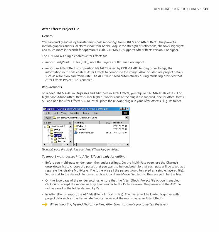
540 • CHAPTER 13 RENDERING • RENDER SETTINGS • 541
After Effects Project File
General
You can quickly and easily transfer multi-pass renderings from CINEMA to After Effects, the powerful motion graphics and visual effects tool from Adobe. Adjust the strength of reflections, shadows, highlights and much more in seconds for optimum visuals. CINEMA 4D supports After Effects version 5 or higher.
The CINEMA 4D plugin enables After Effects to:
- import BodyPaint 3D files (B3D); note that layers are flattened on import.
- import an After Effects composition file (AEC) saved by CINEMA 4D. Among other things, the information in this file enables After Effects to composite the image. Also included are project details such as resolution and frame rate. The AEC file is saved automatically during rendering provided that After Effects Project File is enabled.
Requirements
To render CINEMA 4D multi-passes and edit them in After Effects, you require CINEMA 4D Release 7.3 or higher and Adobe After Effects 5.0 or higher. Two versions of the plugin are supplied, one for After Effects 5.0 and one for After Effects 5.5. To install, place the relevant plugin in your After Affects Plug-ins folder.
To install, place the plugin into your After Effects Plug-ins folder.
To import multi-passes into After Effects ready for editing
- Before you multi-pass render, open the render settings. On the Multi-Pass page, use the Channels drop-down list to choose the passes that you want to be rendered. So that each pass will be saved as a separate file, disable Multi-Layer File (otherwise all the passes would be saved as a single, layered file). Set Format to the desired file format such as QuickTime Movie. Set Path to the save path for the files.
- On the Save page of the render settings, ensure that the After Effects Project File option is enabled. Click OK to accept the render settings then render to the Picture viewer. The passes and the AEC file will be saved in the folder defined by Path.
- In After Effects, import the AEC file (File > Import > File). The passes will be loaded together with project data such as the frame rate. You can now edit the multi-passes in After Effects.
When importing layered Photoshop files, After Effects prompts you to flatten the layers.
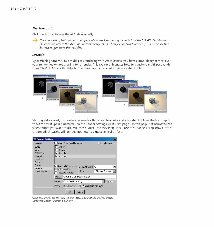
542 • CHAPTER 13 RENDERING • RENDER SETTINGS • 543
The Save button
Click this button to save the AEC file manually.
If you are using Net Render, the optional network rendering module for CINEMA 4D, Net Render is unable to create the AEC files automatically. Thus when you network render, you must click this button to generate the AEC file.
Example
By combining CINEMA 4D’s multi-pass rendering with After Effects, you have extraordinary control over your renderings without having to re-render. This example illustrates how to transfer a multi-pass render from CINEMA 4D to After Effects. The scene used is of a cube and animated lights.
Starting with a ready-to-render scene — for this example a cube and animated lights — the first step is to set the multi-pass parameters on the Render Settings Multi-Pass page. On this page, set Format to the video format you want to use. We chose QuickTime Movie Big. Next, use the Channels drop-down list to choose which passes will be rendered, such as Specular and Diffuse.
Once you’ve set the Format, the next step is to add the desired passes using the Channels drop-down list.

542 • CHAPTER 13 RENDERING • RENDER SETTINGS • 543
If you want a separate pass for each light source, set Separate Lights to All and Mode to 1 Channel. This will enable you to adjust each light separately in After Effects, helping you to achieve the optimum contrast. You could achieve even more control by setting Mode to 3 Channels. Then, three passes would be created for each light: Diffuse, Specular and Shadow. For this simple example, the 1 Channel setting will give ample post-editing power.
On the Save page of the render settings, ensure that After Effects Project File is enabled. With this option enabled, the AEC file will be created automatically when you render. Later on you will import this essential AEC file into After Effects, where its data will be used to import the passes automatically.
Render to the Picture Viewer. The passes you selected from the Channels list will be rendered and saved; the vital AEC file will be created automatically. Note that if you are using NET Render to render the passes over a network, you must create the AEC file manually — see ‘The Save button’ on page 542.
After rendering to the Picture Viewer, the passes and the AEC file are calculated and saved. Later you will import the AEC file into After Effects to load the multi-passes.
In After Effects, import the AEC file (File > Import > File). The QuickTime passes are loaded into the Project window automatically and animation data such as resolution and frame rate is also read.
In After Effects, import the AEC file to load rendered passes into the Project window.

544 • CHAPTER 13 RENDERING • RENDER SETTINGS • 545
Usually there would be a separate folder for each light source containing the passes. We’ve omitted these for reasons of clarity.
The Special Passes folder stores passes that are not needed to form the composite image. In this case, there is one special pass: cube.mov.
In the Projects window, double-click CINEMA 4D Composition. The composition appears in the Timeline with each pass shown as a separate layer. You can now edit your multi-pass rendering in After Effects.
After double-clicking CINEMA 4D Composition in the Projects window, the composition appears in the Timeline. Each pass is a separately editable layer. You are now ready to post-edit the multi-passes.
Limitations
- NET Render is unable to write AEC files automatically. For network rendering, generate the AEC file manually by clicking the Save button on the Save page of the render settings. You can save the AEC file at any time, even before you have rendered the passes. Missing passes are represented by stand-in frames in After Effects, which you can replace at any stage.
- QTVR cannot be used with AEC files (QTVR does not support multi-passes).
- B3D image sequences are not supported.
Transferring the camera and lights to After Effects
The AEC file that is generating after rendering (After Effects Project file enabled) includes the CINEMA 4D camera and lights. You can use or even edit this camera and lighting directly in After Effects and apply it to any 3D layers. This ensures that items added during post-editing match the lighting and camera angles of the original render, for seamless compositing.
A perfect export of CINEMA 4D’s camera and lights is not always possible. After Effects has fewer lighting properties than CINEMA 4D and non-perspective cameras are converted to perspective cameras.
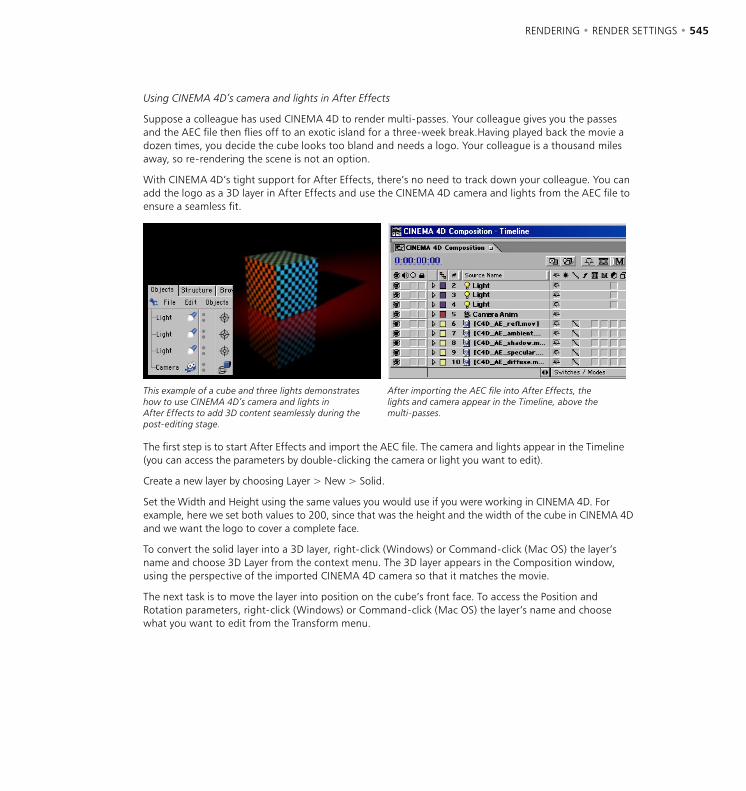
544 • CHAPTER 13 RENDERING • RENDER SETTINGS • 545
Using CINEMA 4D’s camera and lights in After Effects
Suppose a colleague has used CINEMA 4D to render multi-passes. Your colleague gives you the passes and the AEC file then flies off to an exotic island for a three-week break.Having played back the movie a dozen times, you decide the cube looks too bland and needs a logo. Your colleague is a thousand miles away, so re-rendering the scene is not an option.
With CINEMA 4D’s tight support for After Effects, there’s no need to track down your colleague. You can add the logo as a 3D layer in After Effects and use the CINEMA 4D camera and lights from the AEC file to ensure a seamless fit.
This example of a cube and three lights demonstrates how to use CINEMA 4D’s camera and lights in After Effects to add 3D content seamlessly during the post-editing stage.
After importing the AEC file into After Effects, the lights and camera appear in the Timeline, above the multi-passes.
The first step is to start After Effects and import the AEC file. The camera and lights appear in the Timeline (you can access the parameters by double-clicking the camera or light you want to edit).
Create a new layer by choosing Layer > New > Solid.
Set the Width and Height using the same values you would use if you were working in CINEMA 4D. For example, here we set both values to 200, since that was the height and the width of the cube in CINEMA 4D and we want the logo to cover a complete face.
To convert the solid layer into a 3D layer, right-click (Windows) or Command-click (Mac OS) the layer’s name and choose 3D Layer from the context menu. The 3D layer appears in the Composition window, using the perspective of the imported CINEMA 4D camera so that it matches the movie.
The next task is to move the layer into position on the cube’s front face. To access the Position and Rotation parameters, right-click (Windows) or Command-click (Mac OS) the layer’s name and choose what you want to edit from the Transform menu.

546 • CHAPTER 13 RENDERING • RENDER SETTINGS • 547
Once a solid layer has been created and converted to a 3D layer, it appears in the viewport using the correct perspective via the imported CINEMA 4D camera. Using the Position and Rotation settings, the layer is moved to the desired position on the front face of the cube.
Enter the same values that you would use in CINEMA 4D. For this example, the front of the cube in CINEMA 4D was at 100,0,0 (X,Y,Z), so we entered these same values for the 3D layer’s position in After Effects. However, note that the direction of the Y-axis in After Effects is reversed compared to CINEMA 4D. For example, a Y value of 200 in CINEMA 4D corresponds to a Y value of -200 in After Effects.
After Effects applies the camera motion and lighting to the logo layer. The logo stays locked onto the cube’s front surface throughout the animation and uses the same lighting as the cube.
These changes have been made in a few minutes without having to re-render the CINEMA 4D scene. CINEMA 4D’s tight integration with After Effects opens up countless possibilities for adjusting your renders quickly and easily, to carry out major changes or simply to produce a better-looking movie.
The logo has been added in After Effects. The logo uses the same lighting and camera as the rendered CINEMA 4D movie, avoiding the need to re-render.

546 • CHAPTER 13 RENDERING • RENDER SETTINGS • 547
Antialiasing
Antialiasing removes jagged edges from your images. It works by breaking down each pixel into sub-pixels; rather than calculate just one color for a pixel, several color values are calculated and averaged to produce the final color for the pixel.
Using the settings on the Antialiasing page, you can remove jagged edges. The top right inset box shows jagged edges without antialiasing, the bottom right inset box shows the smoothed result of applying antialiasing.
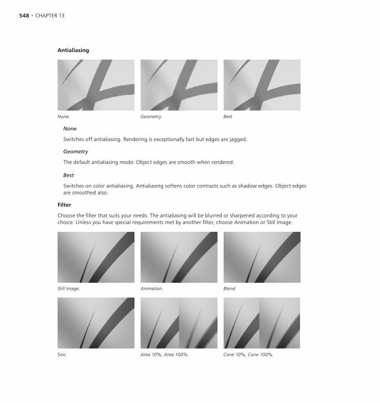
548 • CHAPTER 13 RENDERING • RENDER SETTINGS • 549
Antialiasing
None. Geometry. Best.
None
Switches off antialiasing. Rendering is exceptionally fast but edges are jagged.
Geometry
The default antialiasing mode. Object edges are smooth when rendered.
Best
Switches on color antialiasing. Antialiasing softens color contrasts such as shadow edges. Object edges are smoothed also.
Filter
Choose the filter that suits your needs. The antialiasing will be blurred or sharpened according to your choice. Unless you have special requirements met by another filter, choose Animation or Still Image.
Still Image. Animation. Blend.
Sinc. Area 10%, Area 100%. Cone 10%, Cone 100%.
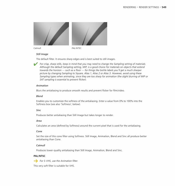
548 • CHAPTER 13 RENDERING • RENDER SETTINGS • 549
Catmull. PAL/NTSC.
Still Image
The default filter. It ensures sharp edges and is best suited to still images.
For crisp, sharp stills, keep in mind that you may need to change the Sampling setting of materials. Although the default Sampling setting, MIP, is a good choice for materials on objects that extend towards the horizon — such as a floor — for things like bottle labels you’ll get a much sharper picture by changing Sampling to Square, Alias 1, Alias 2 or Alias 3. However, avoid using these Sampling types when animating, since they are too sharp for animation (the slight blurring of MIP or SAT sampling is essential to prevent flicker).
Animation
Blurs the antialiasing to produce smooth results and prevent flicker for film/video.
Blend
Enables you to customize the softness of the antialiasing. Enter a value from 0% to 100% into the Softness box (see also ‘Softness’, below).
Sinc
Produces better antialiasing than Still Image but takes longer to render.
Area
Calculates an area (defined by Softness) around the current pixel that is used for the antialiasing.
Cone
Set the size of this cone filter using Softness. Still Image, Animation, Blend and Sinc all produce better antialiasing than Cone.
Catmull
Produces lower-quality antialiasing than Still Image, Animation, Blend and Sinc.
PAL/NTSC
For S-VHS, use the Animation filter.
This very soft filter is suitable for VHS.
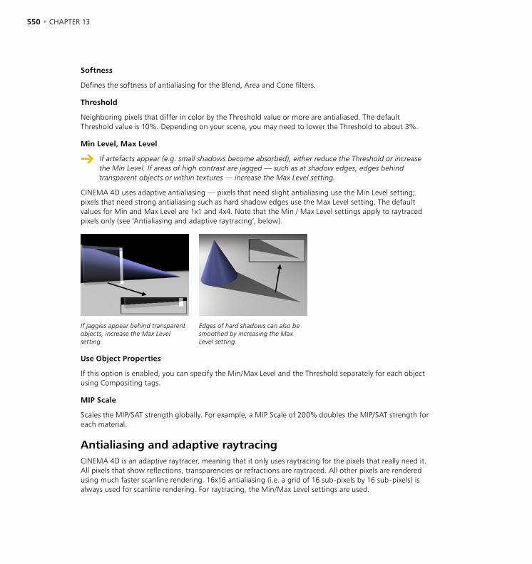
550 • CHAPTER 13 RENDERING • RENDER SETTINGS • 551
Softness
Defines the softness of antialiasing for the Blend, Area and Cone filters.
Threshold
Neighboring pixels that differ in color by the Threshold value or more are antialiased. The default Threshold value is 10%. Depending on your scene, you may need to lower the Threshold to about 3%.
Min Level, Max Level
If artefacts appear (e.g. small shadows become absorbed), either reduce the Threshold or increase the Min Level. If areas of high contrast are jagged — such as at shadow edges, edges behind transparent objects or within textures — increase the Max Level setting.
CINEMA 4D uses adaptive antialiasing — pixels that need slight antialiasing use the Min Level setting; pixels that need strong antialiasing such as hard shadow edges use the Max Level setting. The default values for Min and Max Level are 1x1 and 4x4. Note that the Min / Max Level settings apply to raytraced pixels only (see ‘Antialiasing and adaptive raytracing’, below).
If jaggies appear behind transparent objects, increase the Max Level setting.
Edges of hard shadows can also be smoothed by increasing the Max Level setting.
Use Object Properties
If this option is enabled, you can specify the Min/Max Level and the Threshold separately for each object using Compositing tags.
MIP Scale
Scales the MIP/SAT strength globally. For example, a MIP Scale of 200% doubles the MIP/SAT strength for each material.
Antialiasing and adaptive raytracingCINEMA 4D is an adaptive raytracer, meaning that it only uses raytracing for the pixels that really need it. All pixels that show reflections, transparencies or refractions are raytraced. All other pixels are rendered using much faster scanline rendering. 16x16 antialiasing (i.e. a grid of 16 sub-pixels by 16 sub-pixels) is always used for scanline rendering. For raytracing, the Min/Max Level settings are used.

550 • CHAPTER 13 RENDERING • RENDER SETTINGS • 551
Radiosity, Caustics These settings will be available only if the Advanced Render module is installed. For more details
about Advanced Render, please contact your local MAXON representative or visit maxon.net.
Advanced Render is an optional module that includes global illumination (radiosity), caustics, enhanced depth of field, enhanced glow and a highlights filter.
Natural lighting is easy using the radiosity features of the Advanced Render module. Radiosity leads to new levels of realism by simulating the way light really works, so that your pictures and animations can be as photographic as you want them to be.
The caustics feature improves the realism of scenes that use reflective or transparent objects that are curved in some way. Place marbles or a glass on a table and patterns of light appear on the tablecloth. For added realism, with Advanced Render you can recreate these effects with ease.
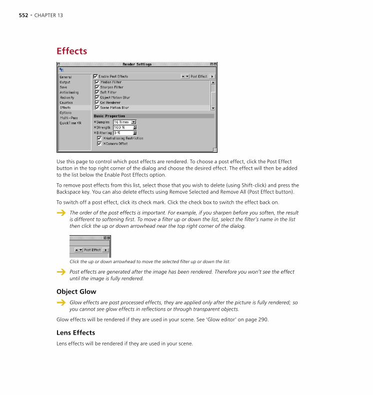
552 • CHAPTER 13 RENDERING • RENDER SETTINGS • 553
Effects
Use this page to control which post effects are rendered. To choose a post effect, click the Post Effect button in the top right corner of the dialog and choose the desired effect. The effect will then be added to the list below the Enable Post Effects option.
To remove post effects from this list, select those that you wish to delete (using Shift-click) and press the Backspace key. You can also delete effects using Remove Selected and Remove All (Post Effect button).
To switch off a post effect, click its check mark. Click the check box to switch the effect back on.
The order of the post effects is important. For example, if you sharpen before you soften, the result is different to softening first. To move a filter up or down the list, select the filter’s name in the list then click the up or down arrowhead near the top right corner of the dialog.
Click the up or down arrowhead to move the selected filter up or down the list.
Post effects are generated after the image has been rendered. Therefore you won’t see the effect until the image is fully rendered.
Object Glow
Glow effects are post processed effects, they are applied only after the picture is fully rendered; so you cannot see glow effects in reflections or through transparent objects.
Glow effects will be rendered if they are used in your scene. See ‘Glow editor’ on page 290.
Lens Effects
Lens effects will be rendered if they are used in your scene.
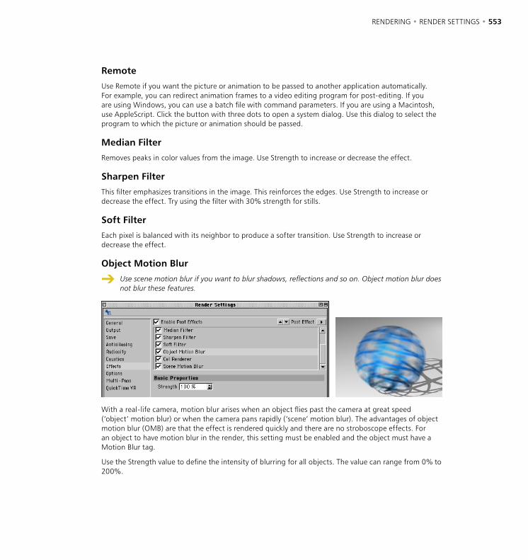
552 • CHAPTER 13 RENDERING • RENDER SETTINGS • 553
Remote
Use Remote if you want the picture or animation to be passed to another application automatically. For example, you can redirect animation frames to a video editing program for post-editing. If you are using Windows, you can use a batch file with command parameters. If you are using a Macintosh, use AppleScript. Click the button with three dots to open a system dialog. Use this dialog to select the program to which the picture or animation should be passed.
Median Filter
Removes peaks in color values from the image. Use Strength to increase or decrease the effect.
Sharpen Filter
This filter emphasizes transitions in the image. This reinforces the edges. Use Strength to increase or decrease the effect. Try using the filter with 30% strength for stills.
Soft Filter
Each pixel is balanced with its neighbor to produce a softer transition. Use Strength to increase or decrease the effect.
Object Motion Blur
Use scene motion blur if you want to blur shadows, reflections and so on. Object motion blur does not blur these features.
With a real-life camera, motion blur arises when an object flies past the camera at great speed (‘object’ motion blur) or when the camera pans rapidly (‘scene’ motion blur). The advantages of object motion blur (OMB) are that the effect is rendered quickly and there are no stroboscope effects. For an object to have motion blur in the render, this setting must be enabled and the object must have a Motion Blur tag.
Use the Strength value to define the intensity of blurring for all objects. The value can range from 0% to 200%.

554 • CHAPTER 13 RENDERING • RENDER SETTINGS • 555
A few limitations are associated with object motion blur. For example, only position, scale and rotation animation can be blurred (so a beating wing animated using bones cannot have motion blur applied to it). Also, anomalies may appear at the frame’s border and the animation may flicker.
Object motion blur is limited to a maximum frame size of 2000 x 2000 pixels and is automatically disabled at resolutions higher than this. Also note that particles cannot be blurred. Furthermore, avoid using OMB with post-processing effects (e.g. lens flares), since this may lead to unexpected results.
These limitations notwithstanding, motion blur can create a very natural effect with its analytical blurring. Object motion blur can create superb results with stills as well as with animation.
Scene Motion Blur
Scene motion blur will also blur shadows, reflections and so on. Object motion blur, on the other hand, does not blur these.
With a real-life camera, motion blur arises when an object flies past the camera at great speed (‘object’ motion blur) or when the camera pans rapidly (‘scene’ motion blur). This motion blur helps to create the illusion of real motion rather than a sequence of still pictures and so it is of great use to animation software. Animation software does not use real shutters and real film, so the motion blur must be faked, see Figure 1, below.
Figure 1. Figure 2. Figure 3.
You can activate Scene Motion Blur (SMB) to simulate a camera panning swiftly.
554 • CHAPTER 13 RENDERING • RENDER SETTINGS • 555
Think carefully before using field rendering and scene motion blur together, since the field effect is often nullified. Not only that, but the quality of the automatic SMB antialiasing is better without fields and you’ll save render time.
Samples
With SMB, intermediate images are calculated and overlapped in the corresponding frame with varying brightness. Choose the number of intermediate images for each frame using this drop-down list. The higher you set this value, the longer it takes to render.
If the motion is rapid, you may need to use a high setting to avoid a stroboscope effect (Figure 2, above).
If you use scene motion blur in your scene you may be able to reduce the amount of antialiasing. Stationary elements in the frame are antialiased perfectly, whereas moving elements are not antialiased. Usually, objects in motion do not require antialiasing — consider a 16-times motion blur where there are 16 intermediate frames; in this case, the missing antialiasing makes no visible difference. You can, of course, add antialiasing, although with a motion blur of 9-times or higher it is not necessary and does little but increase the rendering time.
Strength
Defines the strength of the motion blur effect. In Figure 3, above, the pictures were rendered with 25-times SMB with Strength set to (from left to right) 20%, 40%, 60%, 80% and 100%.
Dithering
You can use this option to dither the scene motion blur. This helps you to avoid stroboscope effects and in addition you can often use a lower SMB setting. However, the dithering may create slight noise. You can reduce the memory requirements for rendering by disabling dithering (set the value to 0%).
Antialiasing Restriction
If this option is enabled, CINEMA 4D automatically switches Antialiasing (Antialiasing page) from Best to Geometry if Samples is set to 9 Times or higher. This is because Geometry antialiasing is quicker to render and Best is rarely required when a high Samples value.
Camera Offset
CINEMA 4D creates an antialiasing effect by offsetting the camera slightly for each intermediate image. This causes slight blurring. If you want to switch off this effect — for example, if you’re creating a picture for print — disable this option.

556 • CHAPTER 13 RENDERING • RENDER SETTINGS • 557
Cel Renderer
Using this post effect, you can render pictures and animations in a cartoon style.
Color disabled (left) and enabled (right). Illumination enabled (left) and disabled (right).
Outline enabled (left) and disabled (right). Edges disabled (left) and enabled (right).
Edge Color black (left) and white (right). Background Color white (left) and black (right).
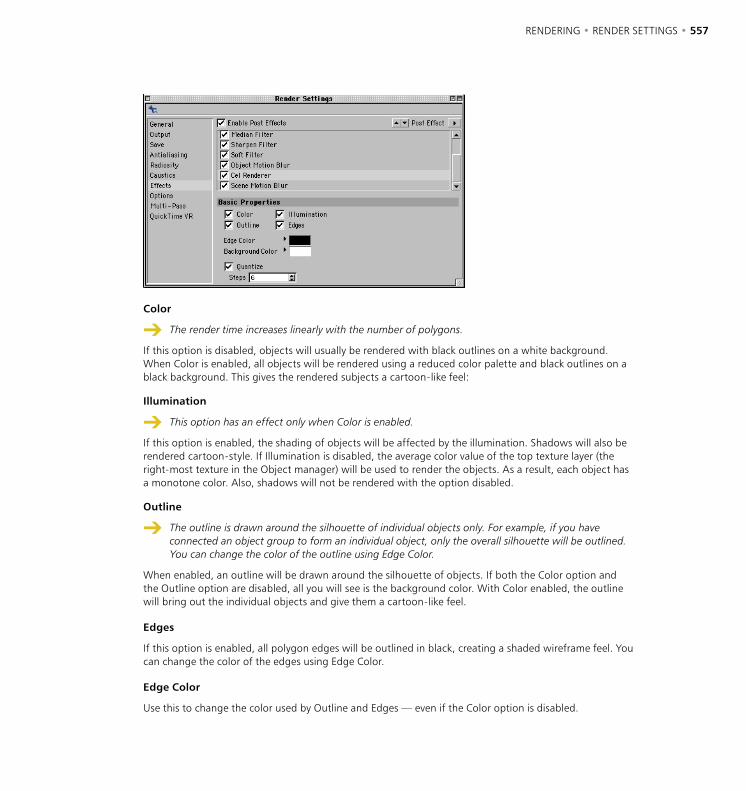
556 • CHAPTER 13 RENDERING • RENDER SETTINGS • 557
Color
The render time increases linearly with the number of polygons.
If this option is disabled, objects will usually be rendered with black outlines on a white background. When Color is enabled, all objects will be rendered using a reduced color palette and black outlines on a black background. This gives the rendered subjects a cartoon-like feel:
Illumination
This option has an effect only when Color is enabled.
If this option is enabled, the shading of objects will be affected by the illumination. Shadows will also be rendered cartoon-style. If Illumination is disabled, the average color value of the top texture layer (the right-most texture in the Object manager) will be used to render the objects. As a result, each object has a monotone color. Also, shadows will not be rendered with the option disabled.
Outline
The outline is drawn around the silhouette of individual objects only. For example, if you have connected an object group to form an individual object, only the overall silhouette will be outlined. You can change the color of the outline using Edge Color.
When enabled, an outline will be drawn around the silhouette of objects. If both the Color option and the Outline option are disabled, all you will see is the background color. With Color enabled, the outline will bring out the individual objects and give them a cartoon-like feel.
Edges
If this option is enabled, all polygon edges will be outlined in black, creating a shaded wireframe feel. You can change the color of the edges using Edge Color.
Edge Color
Use this to change the color used by Outline and Edges — even if the Color option is disabled.
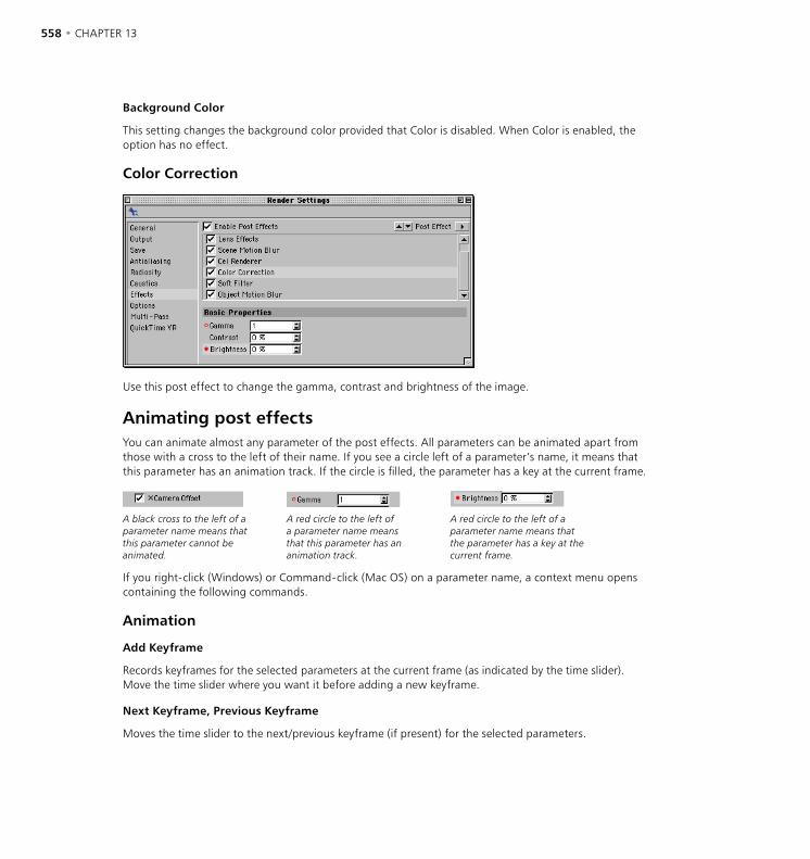
558 • CHAPTER 13 RENDERING • RENDER SETTINGS • 559
Background Color
This setting changes the background color provided that Color is disabled. When Color is enabled, the option has no effect.
Color Correction
Use this post effect to change the gamma, contrast and brightness of the image.
Animating post effectsYou can animate almost any parameter of the post effects. All parameters can be animated apart from those with a cross to the left of their name. If you see a circle left of a parameter’s name, it means that this parameter has an animation track. If the circle is filled, the parameter has a key at the current frame.
A black cross to the left of a parameter name means that this parameter cannot be animated.
A red circle to the left of a parameter name means that this parameter has an animation track.
A red circle to the left of a parameter name means that the parameter has a key at the current frame.
If you right-click (Windows) or Command-click (Mac OS) on a parameter name, a context menu opens containing the following commands.
Animation
Add Keyframe
Records keyframes for the selected parameters at the current frame (as indicated by the time slider). Move the time slider where you want it before adding a new keyframe.
Next Keyframe, Previous Keyframe
Moves the time slider to the next/previous keyframe (if present) for the selected parameters.
558 • CHAPTER 13 RENDERING • RENDER SETTINGS • 559
Delete Keyframe
Each parameter with a filled red circle next to its name has a keyframe at the current frame.
Deletes all of the selected parameters’ keyframes at the current frame.
Add Track
Creates tracks in the Timeline for the selected parameters.
Copy Track, Paste Track
Use these commands to copy tracks between parameters. First select the parameters whose tracks you want to copy. Choose Copy Track. Now select the parameters that should receive the tracks and choose Paste Track.
Delete Track
Deletes all tracks of the selected parameters.
Show Track
Shows all animation tracks of the selected parameters in the Timeline.
Show F-Curve
Shows all F-Curves of the selected parameters in the F-Curve manager.
Set Driver, Set Driven
Using these commands you can create set driven keys without having to open the XPresso editor. A set driven key uses one parameter to drive (i.e. control) another parameter. For example, you might use a set driven key to switch off a light when a character presses a model of a light switch. You’ll find an example of a set driven key in the chapter about the Attribute manager on page 905.
Set driven keys also enable you to drive object parameters using your own sliders (see ‘User Data’ on page 909).
Add Keyframe Selection
To create a keyframe selection, select several parameters then choose Add Keyframe Selection. The selected parameters’ names are shown in red to indicate that they belong to the keyframe selection. When you use CINEMA 4D’s autokeying mode, all parameters in the keyframe selection are recorded (provided that their values actually change).
Remove Keyframe Selection
Removes the selected parameters from the keyframe selection.
Clear Keyframe Selection
Deletes all keyframe selections for the selected parameters.
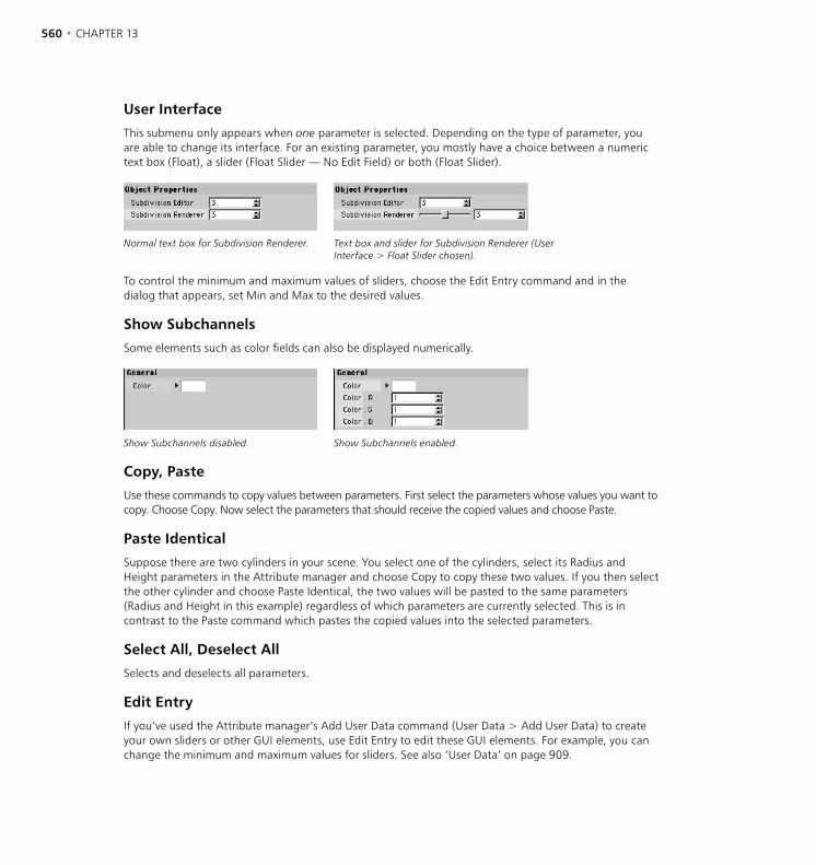
560 • CHAPTER 13 RENDERING • RENDER SETTINGS • 561
User Interface
This submenu only appears when one parameter is selected. Depending on the type of parameter, you are able to change its interface. For an existing parameter, you mostly have a choice between a numeric text box (Float), a slider (Float Slider — No Edit Field) or both (Float Slider).
Normal text box for Subdivision Renderer. Text box and slider for Subdivision Renderer (User Interface > Float Slider chosen).
To control the minimum and maximum values of sliders, choose the Edit Entry command and in the dialog that appears, set Min and Max to the desired values.
Show Subchannels
Some elements such as color fields can also be displayed numerically.
Show Subchannels disabled. Show Subchannels enabled.
Copy, Paste
Use these commands to copy values between parameters. First select the parameters whose values you want to copy. Choose Copy. Now select the parameters that should receive the copied values and choose Paste.
Paste Identical
Suppose there are two cylinders in your scene. You select one of the cylinders, select its Radius and Height parameters in the Attribute manager and choose Copy to copy these two values. If you then select the other cylinder and choose Paste Identical, the two values will be pasted to the same parameters (Radius and Height in this example) regardless of which parameters are currently selected. This is in contrast to the Paste command which pastes the copied values into the selected parameters.
Select All, Deselect All
Selects and deselects all parameters.
Edit Entry
If you’ve used the Attribute manager’s Add User Data command (User Data > Add User Data) to create your own sliders or other GUI elements, use Edit Entry to edit these GUI elements. For example, you can change the minimum and maximum values for sliders. See also ‘User Data’ on page 909.

560 • CHAPTER 13 RENDERING • RENDER SETTINGS • 561
Remove Entry
To delete a slider or other GUI element that you’ve created, select the element and choose Remove Entry.
Load Data, Save Data
The Save Data command enables you to save the values of the selected parameters. To load saved data, select the parameters that should receive the data and choose Load Data. Use your system’s file selector to choose the data file. Note that the saved data and the selected parameters must be of the same data type. For example, you cannot load real values into parameters whose data types are set to Integer.

562 • CHAPTER 13 RENDERING • RENDER SETTINGS • 563
Options
Active Objects Only
If this option is enabled, only the selected objects will be included when you render the scene.
Auto Light
When enabled, if there are no lights in your scene, CINEMA 4D uses its auto light (a standard light source) during rendering so that you can at least see the objects.
Log File
If this option is enabled, a render log will be recorded in ‘Renderlog.txt’ in the CINEMA 4D folder. The render log contains a complete history of the render process including system resource information. Check this log if you need to identify problems that occurred while rendering. The information in the log file is not overwritten by subsequent renders. Rather, new log information is appended. As a result, this file can grow to a fair size over time. You may wish to delete the file manually every now and then — a new file will be created the next time the log is recorded.
Textures
Using this option, you can enable or disable textures when rendering. For example, you can disable the textures for a test render or when using the cel renderer. If this option is enabled, textures will be rendered. If Textures is disabled, the average color value of the top texture layer (the right-most texture in the Object manager) will be rendered for each object.
Cancel If Texture Error
If CINEMA 4D cannot find a texture when rendering the scene, an alert dialog will appear. If this option is disabled and you confirm the alert, the rendering continues without the missing texture. If you enable this option, rendering will be cancelled after the alert. If you are rendering several scenes (batch rendering), the next render task will then be started.
Blurry Effects
Use this option to enable/disable the blur effect for the Reflection and Transparency material channels.
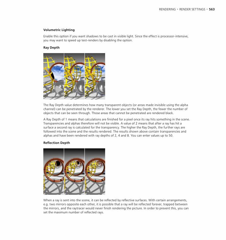
562 • CHAPTER 13 RENDERING • RENDER SETTINGS • 563
Volumetric Lighting
Enable this option if you want shadows to be cast in visible light. Since the effect is processor-intensive, you may want to speed up test-renders by disabling the option.
Ray Depth
The Ray Depth value determines how many transparent objects (or areas made invisible using the alpha channel) can be penetrated by the renderer. The lower you set the Ray Depth, the fewer the number of objects that can be seen through. Those areas that cannot be penetrated are rendered black.
A Ray Depth of 1 means that calculations are finished for a pixel once its ray hits something in the scene. Transparencies and alphas therefore will not be visible. A value of 2 means that after a ray has hit a surface a second ray is calculated for the transparency. The higher the Ray Depth, the further rays are followed into the scene and the results rendered. The results shown above contain transparencies and alphas and have been rendered with ray depths of 2, 4 and 8. You can enter values up to 50.
Reflection Depth
When a ray is sent into the scene, it can be reflected by reflective surfaces. With certain arrangements, e.g. two mirrors opposite each other, it is possible that a ray will be reflected forever, trapped between the mirrors, and the raytracer would never finish rendering the picture. In order to prevent this, you can set the maximum number of reflected rays.
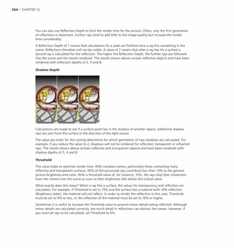
564 • CHAPTER 13 RENDERING • RENDER SETTINGS • 565
You can also use Reflection Depth to limit the render time for the picture. Often, only the first generation of reflections is important. Further rays tend to add little to the image quality but increase the render time considerably.
A Reflection Depth of 1 means that calculations for a pixel are finished once a ray hits something in the scene. Reflections therefore will not be visible. A value of 2 means that after a ray has hit a surface a second ray is calculated for the reflection. The higher the Reflection Depth, the further rays are followed into the scene and the results rendered. The results shown above contain reflective objects and have been rendered with reflection depths of 2, 4 and 8.
Shadow Depth
Calculations are made to see if a surface point lies in the shadow of another object; additional shadow rays are sent from the surface in the direction of the light source.
The value you enter for this setting determines for which generation of rays shadows are calculated. For example, if you reduce the value to 2, shadows will not be rendered for reflected, transparent or refracted rays. The results shown above contain reflective and transparent objects and have been rendered with shadow depths of 2, 4 and 8
Threshold
This value helps to optimize render time. With complex scenes, particularly those containing many reflective and transparent surfaces, 90% of the processed rays contribute less than 10% to the general picture brightness and color. With a threshold value of, for instance, 15%, the rays stop their movement from the camera into the scene as soon as their brightness falls below this critical value.
What exactly does this mean? When a ray hits a surface, the values for transparency and reflection are calculated. For example, if Threshold is set to 15% and the surface has a material with 10% reflection (Brightness slider), the material will not reflect. In order to render the reflection in this case, Threshold must be set to 9% or less, or the reflection of the material must be set to 16% or higher.
Sometimes it is useful to increase the Threshold value to prevent minor details being reflected. Although minor details are calculated correctly, too much detail in reflections can distract the viewer. However, if you want all rays to be calculated, set Threshold to 0%.

564 • CHAPTER 13 RENDERING • RENDER SETTINGS • 565
Level of Detail
If you render into a viewport, the viewport’s level of detail value (Display menu) is used in preference. The Level of Detail value here in the render settings is only used for rendering to the Picture Viewer.
This value influences all objects in the active scene that support a reduction in detail, such as metaballs, primitives and NURBS. However, objects that have their own Level of Detail setting defined in a Display tag will continue to use their setting. If the value is set to 100%, the objects will be rendered in full detail. If the value is set to 50%, the objects will be rendered with only half their usual detail.
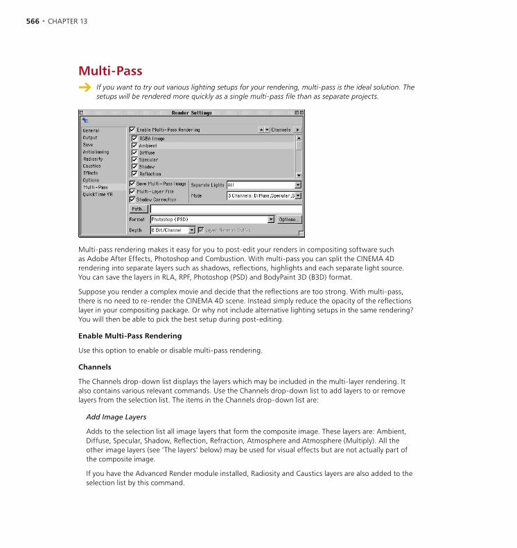
566 • CHAPTER 13 RENDERING • RENDER SETTINGS • 567
Multi-Pass If you want to try out various lighting setups for your rendering, multi-pass is the ideal solution. The
setups will be rendered more quickly as a single multi-pass file than as separate projects.
Multi-pass rendering makes it easy for you to post-edit your renders in compositing software such as Adobe After Effects, Photoshop and Combustion. With multi-pass you can split the CINEMA 4D rendering into separate layers such as shadows, reflections, highlights and each separate light source. You can save the layers in RLA, RPF, Photoshop (PSD) and BodyPaint 3D (B3D) format.
Suppose you render a complex movie and decide that the reflections are too strong. With multi-pass, there is no need to re-render the CINEMA 4D scene. Instead simply reduce the opacity of the reflections layer in your compositing package. Or why not include alternative lighting setups in the same rendering? You will then be able to pick the best setup during post-editing.
Enable Multi-Pass Rendering
Use this option to enable or disable multi-pass rendering.
Channels
The Channels drop-down list displays the layers which may be included in the multi-layer rendering. It also contains various relevant commands. Use the Channels drop-down list to add layers to or remove layers from the selection list. The items in the Channels drop-down list are:
Add Image Layers
Adds to the selection list all image layers that form the composite image. These layers are: Ambient, Diffuse, Specular, Shadow, Reflection, Refraction, Atmosphere and Atmosphere (Multiply). All the other image layers (see ‘The layers’ below) may be used for visual effects but are not actually part of the composite image.
If you have the Advanced Render module installed, Radiosity and Caustics layers are also added to the selection list by this command.

566 • CHAPTER 13 RENDERING • RENDER SETTINGS • 567
Add Material Layers, Add All
These commands are useful to plugin developers only.
Remove Selected
To select a layer, click on its name in the selection list. To add a layer to those already selected, Shift-click or Ctrl-click the layer’s name.
Removes the selected layers from the list.
Remove All
Empties the selection list.
Blend Channel
Creates a blended layer. For example, you can blend Shadow, Radiosity and Caustics as a single layer. After choosing this command a dialog opens: enable the channels you want to blend then click OK.
Object Buffer
This creates a mask layer for objects that use a specified ID number in their Compositing tags. After choosing this command, the Object Buffer dialog open. Enter the desired ID number then click OK.
To assign an ID to an object, use a Compositing tag.
The sphere appears in both object buffers since its Compositing tag has two IDs (ID=1 and ID=2).

568 • CHAPTER 13 RENDERING • RENDER SETTINGS • 569
The layers
RGBA Image. Shadow. Depth.
Reflection. Refraction. Specular.
The lower part of the Channels drop-down list shows the layers that you can add to the multi-pass rendering, a selection of which is illustrated above. These are RGBA Image, Ambient, Diffuse, Specular, Shadow, Reflection, Refraction, Radiosity, Caustics, Atmosphere, Atmosphere Multiply, Illumination and Depth (the remaining layers in the list — i.e. those whose names begin with ‘Material’, are of use to plugin developers only).
The Radiosity and Caustics layers contain the effects created by radiosity and caustics and are of use only if the optional Advanced Render module is installed.
The RGBA layer is the complete image — the same image as with normal rendering. An alpha channel will be included if Alpha Channel is enabled on the Save page of the render settings.
The Ambient layer shows the illumination generated by an Environment object if used.
Atmosphere adds a layer for environment fog and volumetric effects such as volumetric light. Atmosphere (Multiply) can be used optionally with Atmosphere to help conceal objects that are behind the volumetric effects (a multiplied atmosphere layer is used).
Illumination adds a layer for the color and brightness of surfaces illuminated by light sources.
Depth adds a depth map — object surfaces are shaded in grayscale according to their distance from the camera. The closer a surface is to the camera, the darker its shading in the depth map.
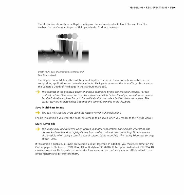
568 • CHAPTER 13 RENDERING • RENDER SETTINGS • 569
The illustration above shows a Depth multi-pass channel rendered with Front Blur and Rear Blur enabled on the Camera’s Depth of Field page in the Attribute manager.
Depth multi-pass channel with Front Blur and Rear Blur enabled.
The Depth channel defines the distribution of depth in the scene. This information can be used in compositing applications to create visual effects. Black parts represent the focus (Target Distance on the Camera’s Depth of Field page in the Attribute manager).
The contrast of the grayscale Depth channel is controlled by the camera’s blur settings. For full contrast, set the Start value for Front Focus to immediately before the object closest to the camera. Set the End value for Rear Focus to immediately after the object farthest from the camera. The easiest way to set these values is to drag the camera’s handles in the viewport.
Save Multi-Pass Image
You can view specific layers using the Picture viewer’s Channels menu.
Enable this option if you want the multi-pass image to be saved when you render to the Picture viewer.
Multi-Layer File
The image may look different when viewed in another application. For example, Photoshop has no true Add mode and so highlights may look washed out and need correcting. Differences are also possible when using a combination of colored lights, especially when using Brightness settings above 100%.
If this option is enabled, all layers are saved in a multi-layer file. In addition, you must set Format on the Output page to Photoshop (PSD), RLA, RPF or BodyPaint 3D (B3D). If the option is disabled, CINEMA 4D creates a separate file for each pass using the Format setting on the Save page. A suffix is added to each of the filenames to differentiate them.
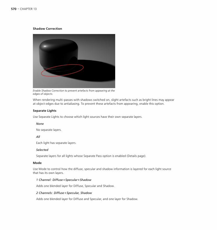
570 • CHAPTER 13 RENDERING • RENDER SETTINGS • 571
Shadow Correction
Enable Shadow Correction to prevent artefacts from appearing at the edges of objects.
When rendering multi-passes with shadows switched on, slight artefacts such as bright lines may appear at object edges due to antialiasing. To prevent these artefacts from appearing, enable this option.
Separate Lights
Use Separate Lights to choose which light sources have their own separate layers.
None
No separate layers.
All
Each light has separate layers.
Selected
Separate layers for all lights whose Separate Pass option is enabled (Details page).
Mode
Use Mode to control how the diffuse, specular and shadow information is layered for each light source that has its own layers.
1 Channel: Diffuse+Specular+Shadow
Adds one blended layer for Diffuse, Specular and Shadow.
2 Channels: Diffuse+Specular, Shadow
Adds one blended layer for Diffuse and Specular, and one layer for Shadow.
570 • CHAPTER 13 RENDERING • RENDER SETTINGS • 571
3 Channels: Diffuse, Specular, Shadow
Adds one Diffuse layer, one Specular layer and one Shadow layer.
Path
Multi-layer files require much more space than single-layer files. Prior to rendering, check that you have sufficient storage space, especially when rendering multi-pass animations.
This is where you set the save path for the file.
Format
Here, choose the file format. For a multi-layer file, choose Photoshop (PSD), RLA, RPF or BodyPaint 3D (B3D).
Options
This button is greyed out unless the format chosen has extra options. To access these, click Options.
Depth
Sets the channel depth to 8 bits or 16 bits.
Layer Name As Suffix
If your chosen format does not support multi-layers, each layer will be saved as a separate file. If this option is enabled, the name of the layer, such as ‘_diffuse’ or ‘_refraction’, is added after the filenames.
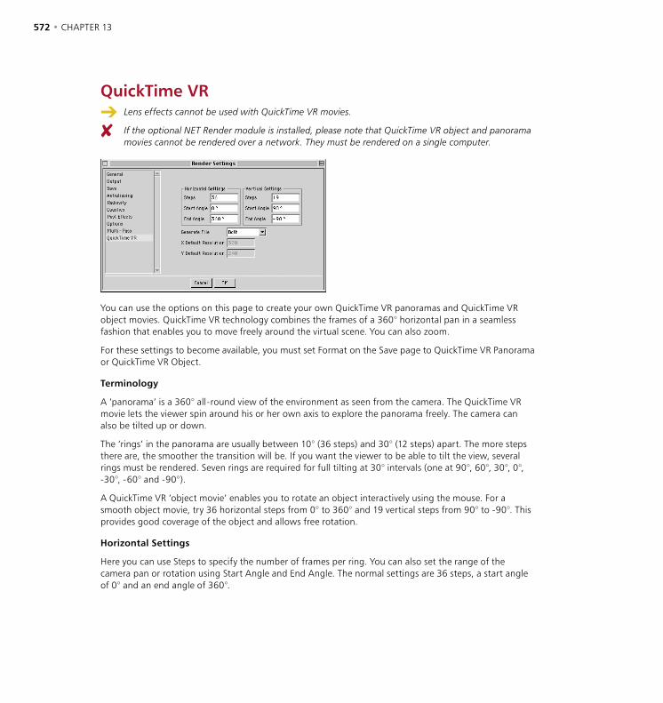
572 • CHAPTER 13 RENDERING • RENDER SETTINGS • 573
QuickTime VR Lens effects cannot be used with QuickTime VR movies.
If the optional NET Render module is installed, please note that QuickTime VR object and panorama movies cannot be rendered over a network. They must be rendered on a single computer.
You can use the options on this page to create your own QuickTime VR panoramas and QuickTime VR object movies. QuickTime VR technology combines the frames of a 360° horizontal pan in a seamless fashion that enables you to move freely around the virtual scene. You can also zoom.
For these settings to become available, you must set Format on the Save page to QuickTime VR Panorama or QuickTime VR Object.
Terminology
A ‘panorama’ is a 360° all-round view of the environment as seen from the camera. The QuickTime VR movie lets the viewer spin around his or her own axis to explore the panorama freely. The camera can also be tilted up or down.
The ‘rings’ in the panorama are usually between 10° (36 steps) and 30° (12 steps) apart. The more steps there are, the smoother the transition will be. If you want the viewer to be able to tilt the view, several rings must be rendered. Seven rings are required for full tilting at 30° intervals (one at 90°, 60°, 30°, 0°, -30°, -60° and -90°).
A QuickTime VR ‘object movie’ enables you to rotate an object interactively using the mouse. For a smooth object movie, try 36 horizontal steps from 0° to 360° and 19 vertical steps from 90° to -90°. This provides good coverage of the object and allows free rotation.
Horizontal Settings
Here you can use Steps to specify the number of frames per ring. You can also set the range of the camera pan or rotation using Start Angle and End Angle. The normal settings are 36 steps, a start angle of 0° and an end angle of 360°.
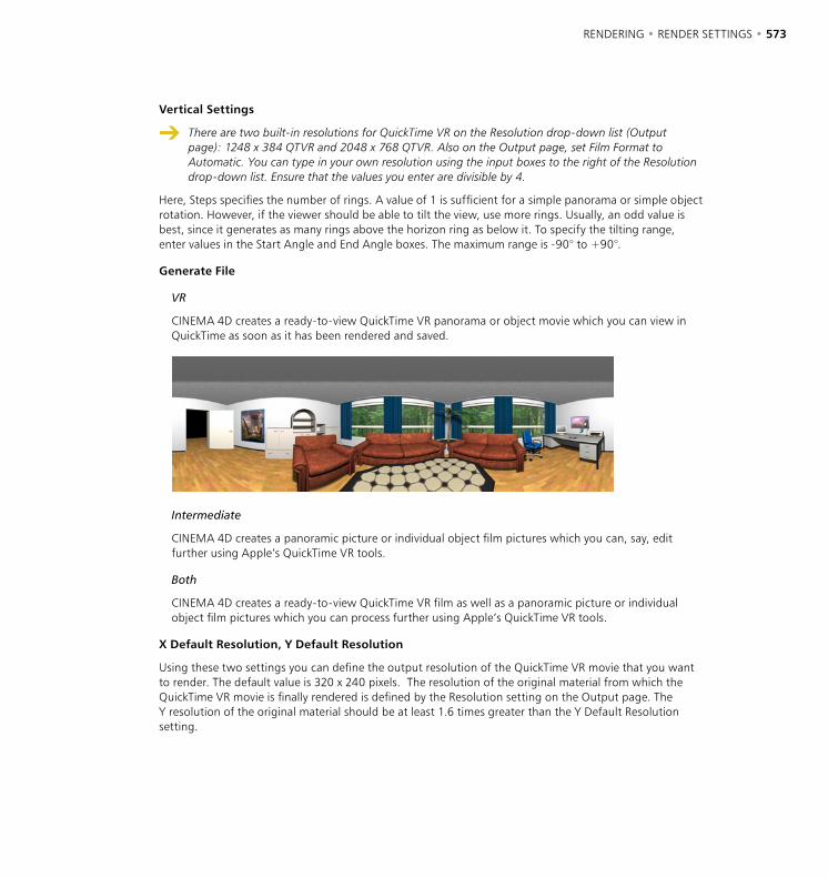
572 • CHAPTER 13 RENDERING • RENDER SETTINGS • 573
Vertical Settings
There are two built-in resolutions for QuickTime VR on the Resolution drop-down list (Output page): 1248 x 384 QTVR and 2048 x 768 QTVR. Also on the Output page, set Film Format to Automatic. You can type in your own resolution using the input boxes to the right of the Resolution drop-down list. Ensure that the values you enter are divisible by 4.
Here, Steps specifies the number of rings. A value of 1 is sufficient for a simple panorama or simple object rotation. However, if the viewer should be able to tilt the view, use more rings. Usually, an odd value is best, since it generates as many rings above the horizon ring as below it. To specify the tilting range, enter values in the Start Angle and End Angle boxes. The maximum range is -90° to +90°.
Generate File
VR
CINEMA 4D creates a ready-to-view QuickTime VR panorama or object movie which you can view in QuickTime as soon as it has been rendered and saved.
Intermediate
CINEMA 4D creates a panoramic picture or individual object film pictures which you can, say, edit further using Apple’s QuickTime VR tools.
Both
CINEMA 4D creates a ready-to-view QuickTime VR film as well as a panoramic picture or individual object film pictures which you can process further using Apple’s QuickTime VR tools.
X Default Resolution, Y Default Resolution
Using these two settings you can define the output resolution of the QuickTime VR movie that you want to render. The default value is 320 x 240 pixels. The resolution of the original material from which the QuickTime VR movie is finally rendered is defined by the Resolution setting on the Output page. The Y resolution of the original material should be at least 1.6 times greater than the Y Default Resolution setting.

574 • CHAPTER 13 RENDERING • RENDER SETTINGS • 575
Apple recommends:
These are Apple’s recommended settings (from ‘The QuickTime FAQ’):
- Use focal lengths of 15 mm, 28 mm or 35 mm.
- Do not use fish-eye lenses.
- For interior shots, use a 15 mm lens. This gives you a vertical visibility range of 97°.
- Use a 15 mm lens. This lets you reduce the number of shots in one pan to 12.
- If you are using 35 mm lenses, create additional rings for the view upward and downward.
- For determining the number of frames in a horizontal ring, two adjacent frames should overlap by 30% to 50%.
For a QuickTime Object Movie, place the object at 0,0,0 (world coordinates) and ensure the object is selected in the Object manager.
If Generate is set to VR or Both, you will create a QuickTime Movie of all frames in the sequence.
When you render QTVR panoramas and QTVR movies, the following limitations apply with regard to antialiasing:
The Max Level parameter determines the maximum antialiasing for colors and edges.
The Max Level cannot be exceeded, even if higher settings are specified in Compositing tags. Compositing tags work within the Min Level to Max Level range only.
The render time depends largely on the Max Level setting. For this reason, avoid using a setting higher than 4x4.
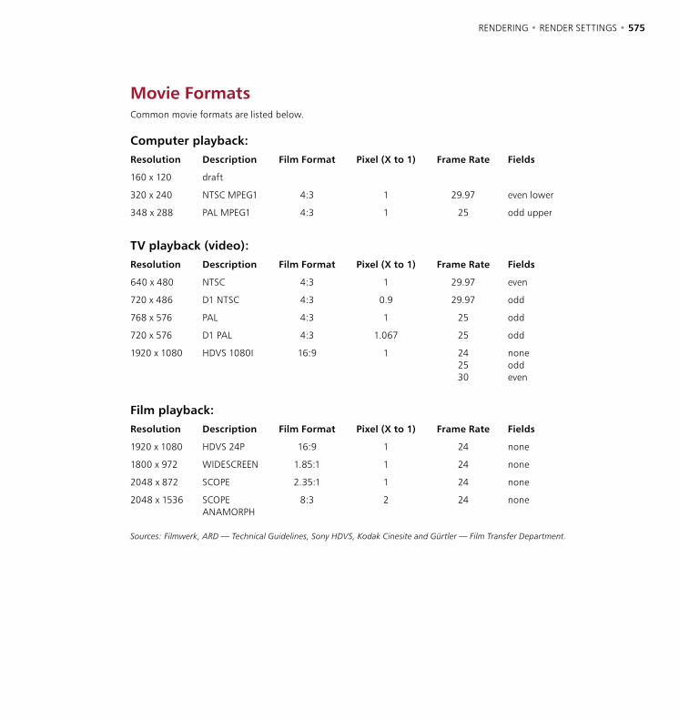
574 • CHAPTER 13 RENDERING • RENDER SETTINGS • 575
Movie FormatsCommon movie formats are listed below.
Computer playback:Resolution Description Film Format Pixel (X to 1) Frame Rate Fields
160 x 120 draft
320 x 240 NTSC MPEG1 4:3 1 29.97 even lower
348 x 288 PAL MPEG1 4:3 1 25 odd upper
TV playback (video):Resolution Description Film Format Pixel (X to 1) Frame Rate Fields
640 x 480 NTSC 4:3 1 29.97 even
720 x 486 D1 NTSC 4:3 0.9 29.97 odd
768 x 576 PAL 4:3 1 25 odd
720 x 576 D1 PAL 4:3 1.067 25 odd
1920 x 1080 HDVS 1080I 16:9 1 242530
noneoddeven
Film playback:Resolution Description Film Format Pixel (X to 1) Frame Rate Fields
1920 x 1080 HDVS 24P 16:9 1 24 none
1800 x 972 WIDESCREEN 1.85:1 1 24 none
2048 x 872 SCOPE 2.35:1 1 24 none
2048 x 1536 SCOPE ANAMORPH
8:3 2 24 none
Sources: Filmwerk, ARD — Technical Guidelines, Sony HDVS, Kodak Cinesite and Gürtler — Film Transfer Department.


14 Window Menu

WINDOW MENU • 579

WINDOW MENU • 579
Most of the following menu entries activate a window or manager. If the window or manager is already open, the call brings it to the front. Otherwise the window or manager appears in a new, freestanding window. To dock this into the interface, drag the window’s pin icon and drop it where you want the window to be docked. A black line appears while you drag to indicate the docking position.
LayoutIn this menu you’ll find commands that enable you to modify the workspace to suit the way you like to work. See ‘Graphical User Interface’ on page 33 and ‘Working with Layouts’ on page 91.
New Icon Palette
Opens a new, empty toolbar in its own window. You can then populate this toolbar with icons from the Command manager. See ‘Icon Palettes’ on page 37 and ‘Inserting commands into palettes’ on page 41.
New Group Window
Opens a new group window. A group window is a window such as the F-Curve manager that contains two or more managers whose shared border you can drag to re-size. To place a manager inside the group window, drag the manager’s pin icon and drop it within the group window. A black line appears while you drag to indicate where the manager will be placed.
Load Toolbar
If you’ve saved a toolbar (aka command palette), you can load it using this command. Optional modules such as MOCCA and Dynamics include their own toolbars that you can integrate into the interface.
Edit Palettes
Enables the Edit Palettes mode and opens the Command manager. The icons are shown with blue edges to indicate that you can edit them. For example, you can drag icons from the Command manager and drop them onto any palette. To exit the Edit Palettes mode, close the Command manager or disable this option.
Load Layout
Use this command to load a layout that you have previously saved.
Reset Layout
This command resets your CINEMA 4D layout to the original, preset layout. This is particularly useful if you need to call our support team since you and they then have a common interface from which to work. Your own customized layouts can increase your workflow enormously but when searching for an elusive problem a common, standardized layout is essential.
14 Window Menu
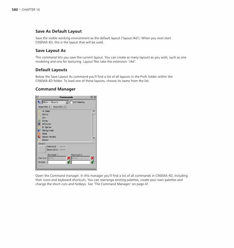
580 • CHAPTER 14 WINDOW MENU • 581
Save As Default Layout
Save the visible working environment as the default layout (‘layout.l4d’). When you next start CINEMA 4D, this is the layout that will be used.
Save Layout As
This command lets you save the current layout. You can create as many layouts as you wish, such as one modeling and one for texturing. Layout files take the extension ‘.l4d’.
Default Layouts
Below the Save Layout As command you’ll find a list of all layouts in the Prefs folder within the CINEMA 4D folder. To load one of these layouts, choose its name from the list.
Command Manager
Open the Command manager. In this manager you’ll find a list of all commands in CINEMA 4D, including their icons and keyboard shortcuts. You can rearrange existing palettes, create your own palettes and change the short-cuts and hotkeys. See ‘The Command Manager’ on page 41.
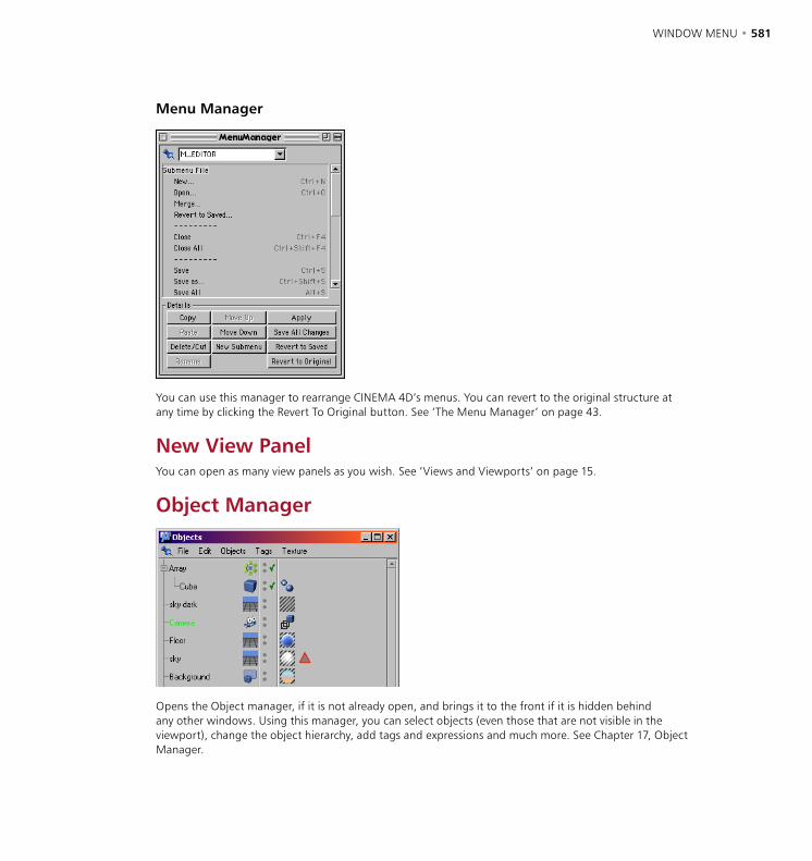
580 • CHAPTER 14 WINDOW MENU • 581
Menu Manager
You can use this manager to rearrange CINEMA 4D’s menus. You can revert to the original structure at any time by clicking the Revert To Original button. See ‘The Menu Manager’ on page 43.
New View PanelYou can open as many view panels as you wish. See ‘Views and Viewports’ on page 15.
Object Manager
Opens the Object manager, if it is not already open, and brings it to the front if it is hidden behind any other windows. Using this manager, you can select objects (even those that are not visible in the viewport), change the object hierarchy, add tags and expressions and much more. See Chapter 17, Object Manager.
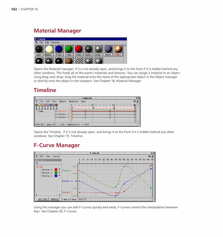
582 • CHAPTER 14 WINDOW MENU • 583
Material Manager
Opens the Material manager, if it is not already open, and brings it to the front if it is hidden behind any other windows. This holds all of the scene’s materials and textures. You can assign a material to an object using drag-and-drop; drag the material onto the name of the appropriate object in the Object manager or directly onto the object in the viewport. See Chapter 18, Material Manager.
Timeline
Opens the Timeline, if it is not already open, and brings it to the front if it is hidden behind any other windows. See Chapter 19, Timeline.
F-Curve Manager
Using this manager you can edit F-Curves quickly and easily. F-Curves control the interpolation between keys. See Chapter 20, F-Curves.
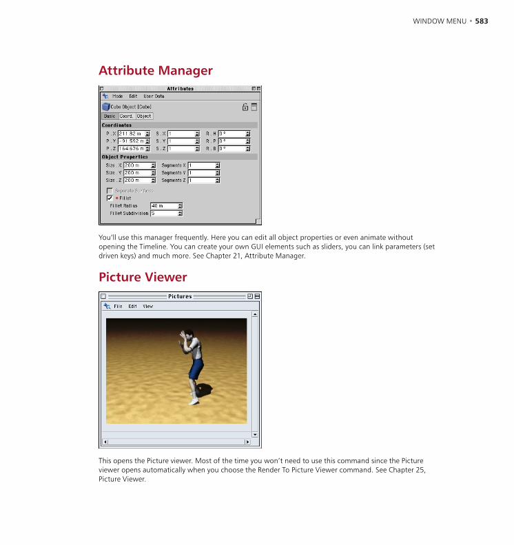
582 • CHAPTER 14 WINDOW MENU • 583
Attribute Manager
You’ll use this manager frequently. Here you can edit all object properties or even animate without opening the Timeline. You can create your own GUI elements such as sliders, you can link parameters (set driven keys) and much more. See Chapter 21, Attribute Manager.
Picture Viewer
This opens the Picture viewer. Most of the time you won’t need to use this command since the Picture viewer opens automatically when you choose the Render To Picture Viewer command. See Chapter 25, Picture Viewer.
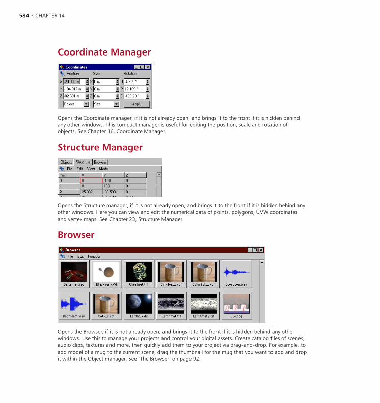
584 • CHAPTER 14 WINDOW MENU • 585
Coordinate Manager
Opens the Coordinate manager, if it is not already open, and brings it to the front if it is hidden behind any other windows. This compact manager is useful for editing the position, scale and rotation of objects. See Chapter 16, Coordinate Manager.
Structure Manager
Opens the Structure manager, if it is not already open, and brings it to the front if it is hidden behind any other windows. Here you can view and edit the numerical data of points, polygons, UVW coordinates and vertex maps. See Chapter 23, Structure Manager.
Browser
Opens the Browser, if it is not already open, and brings it to the front if it is hidden behind any other windows. Use this to manage your projects and control your digital assets. Create catalog files of scenes, audio clips, textures and more, then quickly add them to your project via drag-and-drop. For example, to add model of a mug to the current scene, drag the thumbnail for the mug that you want to add and drop it within the Object manager. See ‘The Browser’ on page 92.
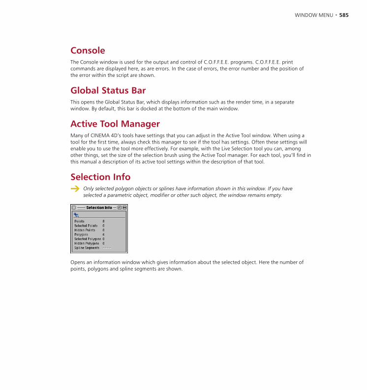
584 • CHAPTER 14 WINDOW MENU • 585
ConsoleThe Console window is used for the output and control of C.O.F.F.E.E. programs. C.O.F.F.E.E. print commands are displayed here, as are errors. In the case of errors, the error number and the position of the error within the script are shown.
Global Status BarThis opens the Global Status Bar, which displays information such as the render time, in a separate window. By default, this bar is docked at the bottom of the main window.
Active Tool ManagerMany of CINEMA 4D’s tools have settings that you can adjust in the Active Tool window. When using a tool for the first time, always check this manager to see if the tool has settings. Often these settings will enable you to use the tool more effectively. For example, with the Live Selection tool you can, among other things, set the size of the selection brush using the Active Tool manager. For each tool, you’ll find in this manual a description of its active tool settings within the description of that tool.
Selection Info Only selected polygon objects or splines have information shown in this window. If you have
selected a parametric object, modifier or other such object, the window remains empty.
Opens an information window which gives information about the selected object. Here the number of points, polygons and spline segments are shown.
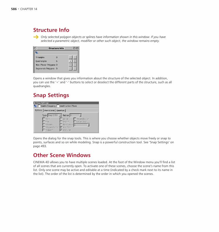
586 • CHAPTER 14
Structure Info Only selected polygon objects or splines have information shown in this window. If you have
selected a parametric object, modifier or other such object, the window remains empty.
Opens a window that gives you information about the structure of the selected object. In addition, you can use the ‘+’ and ‘-’ buttons to select or deselect the different parts of the structure, such as all quadrangles.
Snap Settings
Opens the dialog for the snap tools. This is where you choose whether objects move freely or snap to points, surfaces and so on while modeling. Snap is a powerful construction tool. See ‘Snap Settings’ on page 493.
Other Scene WindowsCINEMA 4D allows you to have multiple scenes loaded. At the foot of the Window menu you’ll find a list of all scenes that are currently open. To activate one of these scenes, choose the scene’s name from this list. Only one scene may be active and editable at a time (indicated by a check mark next to its name in the list). The order of the list is determined by the order in which you opened the scenes.

15 Help Menu

HELP MENU • 589
HELP MENU • 589
MAXON OnlineGet the latest CINEMA 4D updates, news, support issues, tutorials and more using these links to the MAXON website. An Internet browser and Internet connection are required.
Help (CINEMA 4D)This opens the online manual copied to your hard drive during the standard installation process.
Personalize Your initial serial number will expire after three months of use, after which you will no longer be
able to use the program. Please register at the earliest opportunity.
This opens the Registration dialog so you can enter the final serial number of CINEMA 4D and/or one or more of the CINEMA 4D modules. You will receive your final serial number(s) once you have registered your purchase with MAXON Computer or your local MAXON distributor. You can register by completing the registration card that was included with your MAXON software, or you can register online at register.maxon.net.
Under Windows NT (SP4), Windows 2000 or Windows XP Professional, you must have Administrator privileges in order to properly install software, otherwise you will be prompted to enter the serial number each time you start CINEMA 4D or one of its modules. You may need to ask your system administrator for assistance.
InfoThis opens the same info screen that appears while the program loads. Use this screen to check the version number of CINEMA 4D — please quote this when contacting our Technical Support department. To close the window, click on it.
15 Help Menu


16 Coordinate Manager

COORDINATE MANAGER • 593
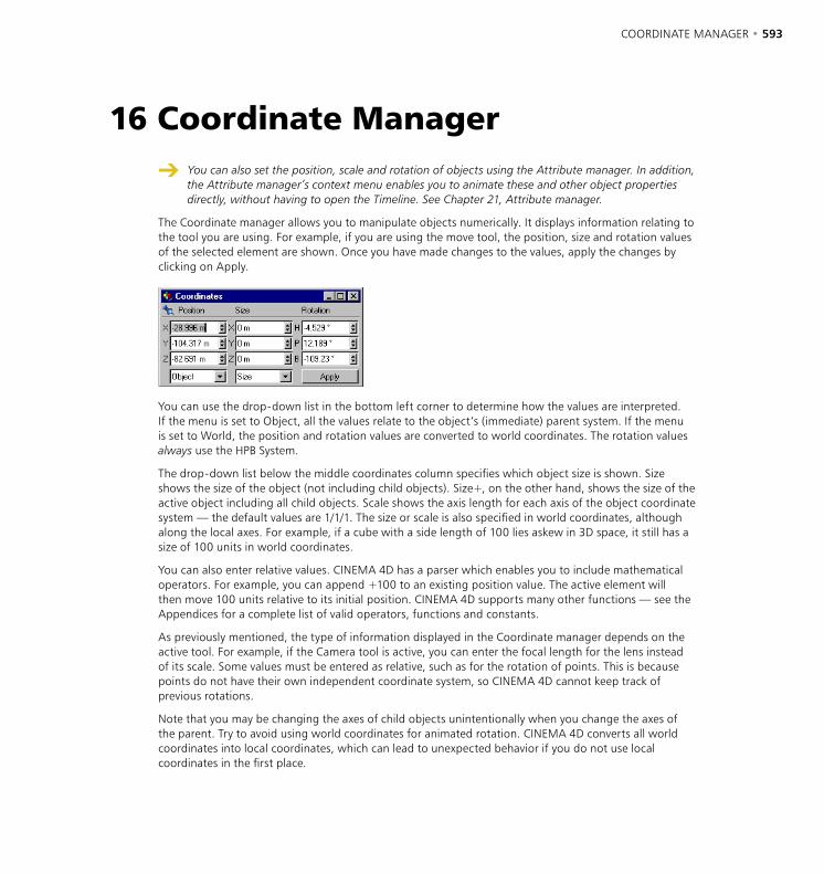
COORDINATE MANAGER • 593
You can also set the position, scale and rotation of objects using the Attribute manager. In addition, the Attribute manager’s context menu enables you to animate these and other object properties directly, without having to open the Timeline. See Chapter 21, Attribute manager.
The Coordinate manager allows you to manipulate objects numerically. It displays information relating to the tool you are using. For example, if you are using the move tool, the position, size and rotation values of the selected element are shown. Once you have made changes to the values, apply the changes by clicking on Apply.
You can use the drop-down list in the bottom left corner to determine how the values are interpreted. If the menu is set to Object, all the values relate to the object’s (immediate) parent system. If the menu is set to World, the position and rotation values are converted to world coordinates. The rotation values always use the HPB System.
The drop-down list below the middle coordinates column specifies which object size is shown. Size shows the size of the object (not including child objects). Size+, on the other hand, shows the size of the active object including all child objects. Scale shows the axis length for each axis of the object coordinate system — the default values are 1/1/1. The size or scale is also specified in world coordinates, although along the local axes. For example, if a cube with a side length of 100 lies askew in 3D space, it still has a size of 100 units in world coordinates.
You can also enter relative values. CINEMA 4D has a parser which enables you to include mathematical operators. For example, you can append +100 to an existing position value. The active element will then move 100 units relative to its initial position. CINEMA 4D supports many other functions — see the Appendices for a complete list of valid operators, functions and constants.
As previously mentioned, the type of information displayed in the Coordinate manager depends on the active tool. For example, if the Camera tool is active, you can enter the focal length for the lens instead of its scale. Some values must be entered as relative, such as for the rotation of points. This is because points do not have their own independent coordinate system, so CINEMA 4D cannot keep track of previous rotations.
Note that you may be changing the axes of child objects unintentionally when you change the axes of the parent. Try to avoid using world coordinates for animated rotation. CINEMA 4D converts all world coordinates into local coordinates, which can lead to unexpected behavior if you do not use local coordinates in the first place.
16 Coordinate Manager


17 Object Manager

OBJECT MANAGER • 597
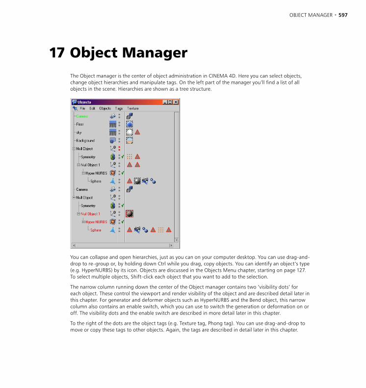
OBJECT MANAGER • 597
The Object manager is the center of object administration in CINEMA 4D. Here you can select objects, change object hierarchies and manipulate tags. On the left part of the manager you’ll find a list of all objects in the scene. Hierarchies are shown as a tree structure.
You can collapse and open hierarchies, just as you can on your computer desktop. You can use drag-and-drop to re-group or, by holding down Ctrl while you drag, copy objects. You can identify an object’s type (e.g. HyperNURBS) by its icon. Objects are discussed in the Objects Menu chapter, starting on page 127. To select multiple objects, Shift-click each object that you want to add to the selection.
The narrow column running down the center of the Object manager contains two ‘visibility dots’ for each object. These control the viewport and render visibility of the object and are described detail later in this chapter. For generator and deformer objects such as HyperNURBS and the Bend object, this narrow column also contains an enable switch, which you can use to switch the generation or deformation on or off. The visibility dots and the enable switch are described in more detail later in this chapter.
To the right of the dots are the object tags (e.g. Texture tag, Phong tag). You can use drag-and-drop to move or copy these tags to other objects. Again, the tags are described in detail later in this chapter.
17 Object Manager

598 • CHAPTER 17 OBJECT MANAGER • 599
Many commands can be reached in the Object manager, using the context menu. To access the context menu, right-click (Windows) or Command-click (Mac OS) an element such as a type icon, a tag or a visibility dot. The commands shown will depend on the type of element from which you selected the menu.
When you select a command in the Object manager, it is applied to the selected object or objects.
Drag-and-drop
Drag-and-drop is the technique of clicking on an object, holding down the mouse button and dragging the object to another position; when the target location is reached, you release the mouse button and the object will be dropped there. Depending on the target location, this may have different results.
Rearranging objects
There are many ways to re-arrange objects in the Object manager and these are described below. The icon on the left shows how the mouse pointer changes while doing the action described on the right.
Drag an object between two others or to the end of the list.
If you want drag to create a copy, use Ctrl-drag.
To change the object hierarchy, drag the object on top of an existing one in the list. This makes the dragged object a child of the other.
If you want to create a copy and make it a child of another object, use Ctrl-drag and move the mouse pointer over an object.
You can also drag-and-drop tags. To transfer a tag from one object to another, drag the tag icon on to the line of the other object.
If you want to create a copy, use Ctrl-drag.
If an operation is not available, this icon appears.
You can select multiple tags and move them all at the same time. However, note that for some tag types, only one tag may be used per object. For example, an object may have one Phong tag only. These tags are known as ‘lone’ tags. A lone tag will not be moved or copied if a tag of the same type exists for the destination object.
Each object in CINEMA 4D, such as Polygon object or Spline object, has a set of properties. To access an object’s settings, select the object and its parameters will be shown in the Attribute manager. These settings are described in Chapter 7, Objects Menu.
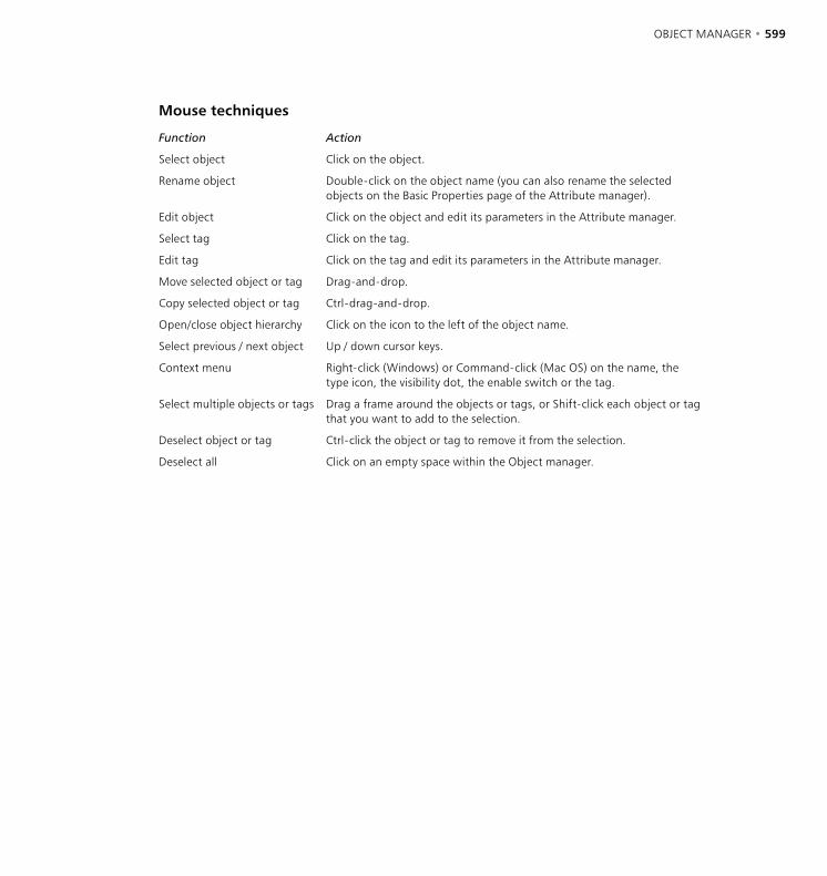
598 • CHAPTER 17 OBJECT MANAGER • 599
Mouse techniques
Function Action
Select object Click on the object.
Rename object Double-click on the object name (you can also rename the selected objects on the Basic Properties page of the Attribute manager).
Edit object Click on the object and edit its parameters in the Attribute manager.
Select tag Click on the tag.
Edit tag Click on the tag and edit its parameters in the Attribute manager.
Move selected object or tag Drag-and-drop.
Copy selected object or tag Ctrl-drag-and-drop.
Open/close object hierarchy Click on the icon to the left of the object name.
Select previous / next object Up / down cursor keys.
Context menu Right-click (Windows) or Command-click (Mac OS) on the name, the type icon, the visibility dot, the enable switch or the tag.
Select multiple objects or tags Drag a frame around the objects or tags, or Shift-click each object or tag that you want to add to the selection.
Deselect object or tag Ctrl-click the object or tag to remove it from the selection.
Deselect all Click on an empty space within the Object manager.
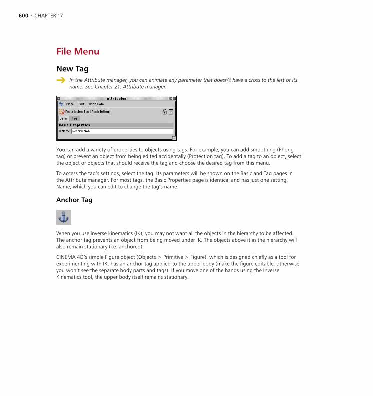
600 • CHAPTER 17 OBJECT MANAGER • 601
File Menu
New Tag
In the Attribute manager, you can animate any parameter that doesn’t have a cross to the left of its name. See Chapter 21, Attribute manager.
You can add a variety of properties to objects using tags. For example, you can add smoothing (Phong tag) or prevent an object from being edited accidentally (Protection tag). To add a tag to an object, select the object or objects that should receive the tag and choose the desired tag from this menu.
To access the tag’s settings, select the tag. Its parameters will be shown on the Basic and Tag pages in the Attribute manager. For most tags, the Basic Properties page is identical and has just one setting, Name, which you can edit to change the tag’s name.
Anchor Tag
When you use inverse kinematics (IK), you may not want all the objects in the hierarchy to be affected. The anchor tag prevents an object from being moved under IK. The objects above it in the hierarchy will also remain stationary (i.e. anchored).
CINEMA 4D’s simple Figure object (Objects > Primitive > Figure), which is designed chiefly as a tool for experimenting with IK, has an anchor tag applied to the upper body (make the figure editable, otherwise you won’t see the separate body parts and tags). If you move one of the hands using the Inverse Kinematics tool, the upper body itself remains stationary.
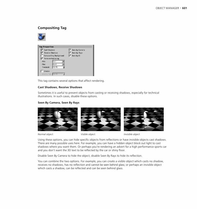
600 • CHAPTER 17 OBJECT MANAGER • 601
Compositing Tag
This tag contains several options that affect rendering.
Cast Shadows, Receive Shadows
Sometimes it is useful to prevent objects from casting or receiving shadows, especially for technical illustrations. In such cases, disable these options.
Seen By Camera, Seen By Rays
Normal object. Visible object. Invisible object.
Using these options, you can hide specific objects from reflections or have invisible objects cast shadows. There are many possible uses here. For example, you can have a hidden object block out light to cast shadows where you want them. Or perhaps you’re rendering an advert for a high performance sports car and you don’t want the 3D text to be reflected by the car or shiny floor.
Disable Seen By Camera to hide the object; disable Seen By Rays to hide its reflection.
You can combine the two options. For example, you can create a visible object which casts no shadow, receives no shadows, has no reflection and cannot be seen behind glass; or perhaps an invisible object which casts a shadow, can be reflected and can be seen behind glass.
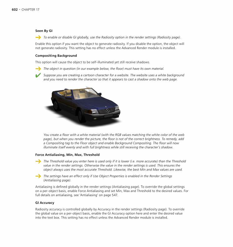
602 • CHAPTER 17 OBJECT MANAGER • 603
Seen By GI
To enable or disable GI globally, use the Radiosity option in the render settings (Radiosity page).
Enable this option if you want the object to generate radiosity. If you disable the option, the object will not generate radiosity. This setting has no effect unless the Advanced Render module is installed.
Compositing Background
This option will cause the object to be self-illuminated yet still receive shadows.
The object in question (in our example below, the floor) must have its own material.
Suppose you are creating a cartoon character for a website. The website uses a white background and you need to render the character so that it appears to cast a shadow onto the web page.
You create a floor with a white material (with the RGB values matching the white color of the web page), but when you render the picture, the floor is not of the correct brightness. To remedy, add a Compositing tag to the Floor object and enable Background Compositing. The floor will now illuminate itself evenly and with full brightness while still receiving the character’s shadow.
Force Antialiasing, Min, Max, Threshold
The Threshold value you enter here is used only if it is lower (i.e. more accurate) than the Threshold value in the render settings. Otherwise the value in the render settings is used. This ensures the object always uses the most accurate Threshold. Likewise, the best Min and Max values are used.
The settings have an effect only if Use Object Properties is enabled in the Render Settings (Antialiasing page).
Antialiasing is defined globally in the render settings (Antialiasing page). To override the global settings on a per-object basis, enable Force Antialiasing and set Min, Max and Threshold to the desired values. For full details on antialiasing, see ‘Antialiasing’ on page 547.
GI Accuracy
Radiosity accuracy is controlled globally by Accuracy in the render settings (Radiosity page). To override the global value on a per-object basis, enable the GI Accuracy option here and enter the desired value into the text box. This setting has no effect unless the Advanced Render module is installed.
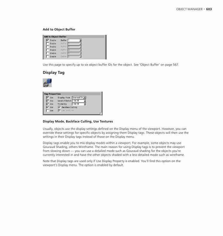
602 • CHAPTER 17 OBJECT MANAGER • 603
Add to Object Buffer
Use this page to specify up to six object buffer IDs for the object. See ‘Object Buffer’ on page 567.
Display Tag
Display Mode, Backface Culling, Use Textures
Usually, objects use the display settings defined on the Display menu of the viewport. However, you can override these settings for specific objects by assigning them Display tags. These objects will then use the settings in their Display tags instead of those on the Display menu.
Display tags enable you to mix display modes within a viewport. For example, some objects may use Gouraud Shading, others Wireframe. The main reason for using Display tags is to prevent the viewport from slowing down — you can use a detailed mode such as Gouraud shading for the objects you’re currently interested in and have the other objects shaded with a less detailed mode such as wireframe.
Note that Display tags are used only if Use Display Property is enabled. You’ll find this option on the viewport’s Display menu. The option is enabled by default.
604 • CHAPTER 17 OBJECT MANAGER • 605
Level Of Detail
If the tag’s Level Of Detail option is enabled, it is always used in a viewport, even if Use Display Property is disabled on the viewport’s Display menu.
This has the same effect as the command of the same name in the Project Settings (see ‘Project Settings’ on page 84). You can use it to control the level of detail for generators and deformers. The tag’s value is used in preference to the value in the Project Settings. For example, you can set the Level of Detail in the Project Settings to 50% and assign a display tag with Level of Detail set to 100% to the object that you are currently working on. This will ensure the object is shaded in full detail while the other, currently less important objects use a reduced level of detail. This makes for faster redraw in the viewport.
Visibility
This parameter controls the visibility of the object when rendered. For example, if you set Visibility to 0%, the object will be invisible when rendered. With a setting of 50%, the object will be partially visible (50% opaque). At 100%, the object will be fully visible when rendered. Note that when you set Visibility to 0%, the object becomes invisible in the viewport.
FlashEx Tag
This tag is used by the FlashEx plugin for SWF export. As soon as you assign a FlashEx tag to an object, a dialog opens that is a duplicate of the Lines tab in the FlashEx plugin settings. This enables you to choose a different line color and width for each object you are exporting. See ‘Lines tab’ on page 517.
HyperNURBS Weight Tag
This tag stores weighting information. It is created automatically when you weight a HyperNURBS object. See ‘Object Properties’ on page 171 and ‘Weighting HyperNURBS models’ on page 172.
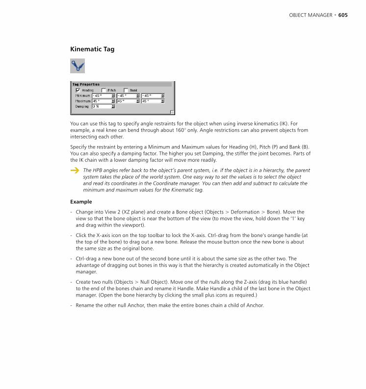
604 • CHAPTER 17 OBJECT MANAGER • 605
Kinematic Tag
You can use this tag to specify angle restraints for the object when using inverse kinematics (IK). For example, a real knee can bend through about 160° only. Angle restrictions can also prevent objects from intersecting each other.
Specify the restraint by entering a Minimum and Maximum values for Heading (H), Pitch (P) and Bank (B). You can also specify a damping factor. The higher you set Damping, the stiffer the joint becomes. Parts of the IK chain with a lower damping factor will move more readily.
The HPB angles refer back to the object’s parent system, i.e. if the object is in a hierarchy, the parent system takes the place of the world system. One easy way to set the values is to select the object and read its coordinates in the Coordinate manager. You can then add and subtract to calculate the minimum and maximum values for the Kinematic tag.
Example
- Change into View 2 (XZ plane) and create a Bone object (Objects > Deformation > Bone). Move the view so that the bone object is near the bottom of the view (to move the view, hold down the ‘1’ key and drag within the viewport).
- Click the X-axis icon on the top toolbar to lock the X-axis. Ctrl-drag from the bone’s orange handle (at the top of the bone) to drag out a new bone. Release the mouse button once the new bone is about the same size as the original bone.
- Ctrl-drag a new bone out of the second bone until it is about the same size as the other two. The advantage of dragging out bones in this way is that the hierarchy is created automatically in the Object manager.
- Create two nulls (Objects > Null Object). Move one of the nulls along the Z-axis (drag its blue handle) to the end of the bones chain and rename it Handle. Make Handle a child of the last bone in the Object manager. (Open the bone hierarchy by clicking the small plus icons as required.)
- Rename the other null Anchor, then make the entire bones chain a child of Anchor.
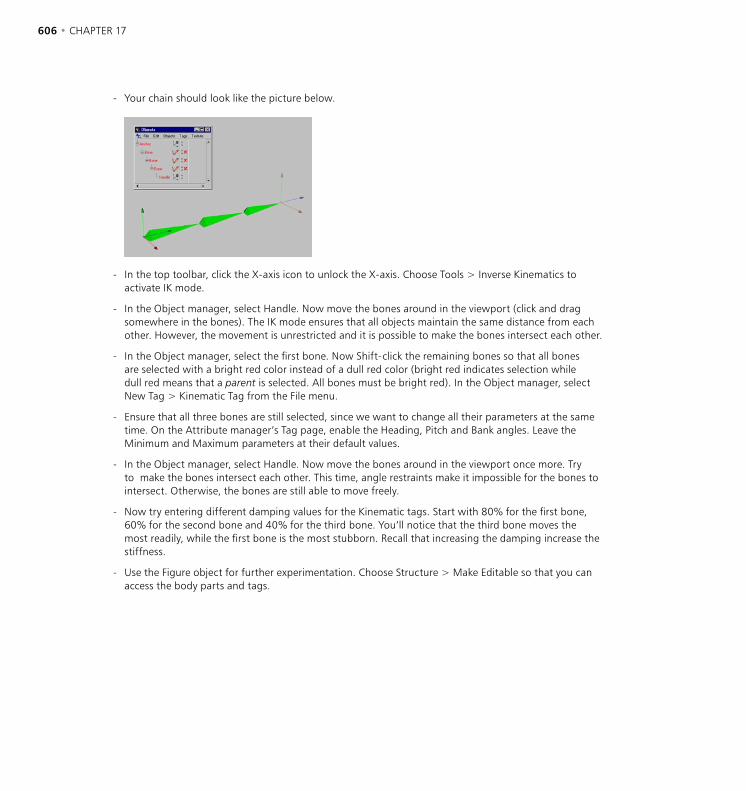
606 • CHAPTER 17 OBJECT MANAGER • 607
- Your chain should look like the picture below.
- In the top toolbar, click the X-axis icon to unlock the X-axis. Choose Tools > Inverse Kinematics to activate IK mode.
- In the Object manager, select Handle. Now move the bones around in the viewport (click and drag somewhere in the bones). The IK mode ensures that all objects maintain the same distance from each other. However, the movement is unrestricted and it is possible to make the bones intersect each other.
- In the Object manager, select the first bone. Now Shift-click the remaining bones so that all bones are selected with a bright red color instead of a dull red color (bright red indicates selection while dull red means that a parent is selected. All bones must be bright red). In the Object manager, select New Tag > Kinematic Tag from the File menu.
- Ensure that all three bones are still selected, since we want to change all their parameters at the same time. On the Attribute manager’s Tag page, enable the Heading, Pitch and Bank angles. Leave the Minimum and Maximum parameters at their default values.
- In the Object manager, select Handle. Now move the bones around in the viewport once more. Try to make the bones intersect each other. This time, angle restraints make it impossible for the bones to intersect. Otherwise, the bones are still able to move freely.
- Now try entering different damping values for the Kinematic tags. Start with 80% for the first bone, 60% for the second bone and 40% for the third bone. You’ll notice that the third bone moves the most readily, while the first bone is the most stubborn. Recall that increasing the damping increase the stiffness.
- Use the Figure object for further experimentation. Choose Structure > Make Editable so that you can access the body parts and tags.

606 • CHAPTER 17 OBJECT MANAGER • 607
Metaball Tag
You can assign this tag to the children of a Metaball object for further control of the metaball mesh. See ‘Metaball Object’ on page 247.
Negative Influence
The object will repel the hull rather than attract it.
Strength
Defines the size of the meta-hull. A value of 100% means that the meta-hull is as large as the original object; at 50% it is half the size of the original object; at 200%, the meta-hull is double the size of the original object.
Radius
Traditionally, metaballs are based on spheres. However, CINEMA 4D enables you to use polygon objects and splines to create the hull. A meta-sphere will be created for each object point. For example, if you use a cube with eight points, eight meta-spheres will be created, one for each corner of the cube. Radius defines the radius for these spheres.
Motion Blur Tag
You can use this tag to apply motion blur to an object. Add the tag to the desired object or objects. Open the render settings and on the Effects page, click the Post Effect drop-down list (you’ll find this in the top right corner of the dialog). From this list, choose Object Motion Blur.
Note that the object must be animated and moving at a reasonable speed for object motion blur to be seen; you must also render to the Picture Viewer — motion blur won’t be shown when you render to the viewport.
Strength
Strength is the degree of blurring. A value of 100% will blur the object for the entire distance between one frame and the next. To reverse the direction of the motion, enter a negative value. For extra blurring, enter a value greater than 100%.
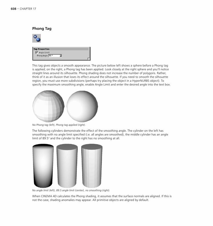
608 • CHAPTER 17 OBJECT MANAGER • 609
Phong Tag
This tag gives objects a smooth appearance. The picture below left shows a sphere before a Phong tag is applied; on the right, a Phong tag has been applied. Look closely at the right sphere and you’ll notice straight lines around its silhouette. Phong shading does not increase the number of polygons. Rather, think of it as an illusion that loses its effect around the silhouette. If you need to smooth the silhouette region, you must use more subdivisions (perhaps try placing the object in a HyperNURBS object). To specify the maximum smoothing angle, enable Angle Limit and enter the desired angle into the text box.
No Phong tag (left), Phong tag applied (right).
The following cylinders demonstrate the effect of the smoothing angle. The cylinder on the left has smoothing with no angle limit specified (i.e. all angles are smoothed), the middle cylinder has an angle limit of 89.5° and the cylinder to the right has no smoothing at all.
No angle limit (left), 89.5 angle limit (center), no smoothing (right).
When CINEMA 4D calculates the Phong shading, it assumes that the surface normals are aligned. If this is not the case, shading anomalies may appear. All primitive objects are aligned by default.
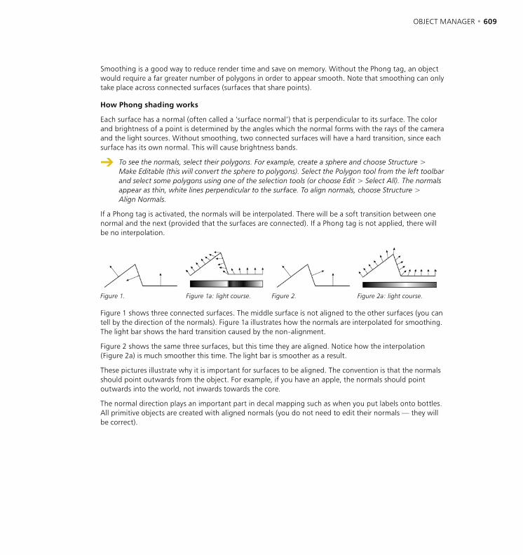
608 • CHAPTER 17 OBJECT MANAGER • 609
Smoothing is a good way to reduce render time and save on memory. Without the Phong tag, an object would require a far greater number of polygons in order to appear smooth. Note that smoothing can only take place across connected surfaces (surfaces that share points).
How Phong shading works
Each surface has a normal (often called a ‘surface normal’) that is perpendicular to its surface. The color and brightness of a point is determined by the angles which the normal forms with the rays of the camera and the light sources. Without smoothing, two connected surfaces will have a hard transition, since each surface has its own normal. This will cause brightness bands.
To see the normals, select their polygons. For example, create a sphere and choose Structure > Make Editable (this will convert the sphere to polygons). Select the Polygon tool from the left toolbar and select some polygons using one of the selection tools (or choose Edit > Select All). The normals appear as thin, white lines perpendicular to the surface. To align normals, choose Structure > Align Normals.
If a Phong tag is activated, the normals will be interpolated. There will be a soft transition between one normal and the next (provided that the surfaces are connected). If a Phong tag is not applied, there will be no interpolation.
Figure 1. Figure 1a: light course. Figure 2. Figure 2a: light course.
Figure 1 shows three connected surfaces. The middle surface is not aligned to the other surfaces (you can tell by the direction of the normals). Figure 1a illustrates how the normals are interpolated for smoothing. The light bar shows the hard transition caused by the non-alignment.
Figure 2 shows the same three surfaces, but this time they are aligned. Notice how the interpolation (Figure 2a) is much smoother this time. The light bar is smoother as a result.
These pictures illustrate why it is important for surfaces to be aligned. The convention is that the normals should point outwards from the object. For example, if you have an apple, the normals should point outwards into the world, not inwards towards the core.
The normal direction plays an important part in decal mapping such as when you put labels onto bottles. All primitive objects are created with aligned normals (you do not need to edit their normals — they will be correct).

610 • CHAPTER 17 OBJECT MANAGER • 611
Protection Tag
Use this tag to prevent accidental changes to an object. You’ll be unable to move, scale or rotate any object that has this tag. You’ll need to remove the tag before you can make any such changes.
Restriction Tag
You can use this tag to restrict a deformer’s effect to a selection of points. You can enter up to six selections for the tag and define the strength of the deformation in each case. See ‘Deformers’ on page 319 and ‘Set Selection’ on page 440.
Shockwave 3D Double Sided Tag
This tag is for Shockwave 3D export only. Assign this tag to any object that uses alpha or transparency textures. See ‘Polygon Front And Back Visible’ on page 67.

610 • CHAPTER 17 OBJECT MANAGER • 611
Stick Texture Tag
This tag pins down all textures onto the object’s surface so that when parts of the object are deformed in some way — such as lips smiling and then frowning — the texture is locked to the surface and deforms along with it.
The usual way to pin textures down is to use UVW mapping. However, UVW mapping is problematic when used with HyperNURBS, especially when the cage moves from an area of few points to an area of many points. This is illustrated in Figures 1 to 4, below. Figure 1 shows the polygon object before it is placed in the HyperNURBS. Figure 2 shows the object in a HyperNURBS and a texture applied with Flat projection. Compare Figure 2 with Figure 3 and you’ll notice that the UVW map in Figure 3 is warped for no apparent reason. Put simply, UVW mapping doesn’t work very well with HyperNURBS objects. In these cases, use a Stick Texture tag instead of UVW mapping to pin down the texture (Figure 4).
Figure 1. Figure 2. Figure 3. Figure 4.
How does this work exactly? When a Stick Texture tag is created, CINEMA 4D creates a reference of the object’s point and stores them in the Stick Texture tag. If you then distort the object, CINEMA 4D, compares the new state to the stored state and adjusts the projected texture accordingly to ensure is stays pinned down and moves with the mesh.
As soon as you add points to a Polygon object, the stored reference becomes invalid. However, this is usually not an issue when using deformation objects since a new reference is created automatically before every deformation.
612 • CHAPTER 17 OBJECT MANAGER • 613
The Stick Texture tag has an interesting side-effect: if you make a Polygon object a child of a symmetry object and texture one half, the texture is mirrored to the other side automatically. This enables you to, say, paint half a face, project it using flat mapping and let CINEMA 4D take care of the other half. If you want to be able to texture either side independently, put the Texture tag onto the Symmetry object.
Active
Here you can temporarily disable the Stick Texture tag without losing the stored reference.
Record
This button enables you to record the current point positions and defines them as a new reference.
Reset
Only polygonal objects can be reset and recorded. The reference is created directly. All other objects (NURBS, primitives etc.) cannot be reset or recorded because they have no points or polygons. Only if they are deformed are they internally converted to Polygon objects which can then be deformed. The reference for the Stick Texture tag is created from this internal Polygon object.
This button resets the object to its original state which is stored in the Stick Texture Tag.
Stop Tag
This tag prevents the object and its children from being affected by generators higher up the hierarchy. For example, suppose you have a group of objects, one nested inside the other. You place this group inside a HyperNURBS object. Without the Stop tag, the HyperNURBS object affects all objects in the group. If you add a Stop tag to one of the objects in this hierarchy, the effect of the HyperNURBS will stop at that object and will not affect objects lower down the hierarchy.
Texture Tag
If a child object has no Texture tags applied to it, it uses the Texture tag(s) of its parent. However, there is an exception. If a light has no Texture tag and is a child of another light, it will not inherit its parent’s Texture tags. This is to prevent child lights receiving gels automatically.
This command creates a new texture geometry. Initially, no material is assigned. To assign a material, drag the material’s preview from the Material manager and drop it into the tag’s Material box on the Tag page of the Attribute manager. You can also select multiple Texture tags and assign a material to all of them at the same time.
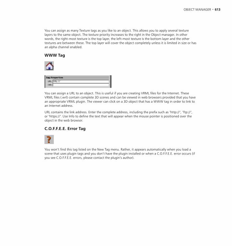
612 • CHAPTER 17 OBJECT MANAGER • 613
You can assign as many Texture tags as you like to an object. This allows you to apply several texture layers to the same object. The texture priority increases to the right in the Object manager. In other words, the right-most texture is the top layer, the left-most texture is the bottom layer and the other textures are between these. The top layer will cover the object completely unless it is limited in size or has an alpha channel enabled.
WWW Tag
You can assign a URL to an object. This is useful if you are creating VRML files for the Internet. These VRML files (.wrl) contain complete 3D scenes and can be viewed in web browsers provided that you have an appropriate VRML plugin. The viewer can click on a 3D object that has a WWW tag in order to link to an Internet address.
URL contains the link address. Enter the complete address, including the prefix such as ‘http://’, ‘ftp://’, or ‘https://’. Use Info to define the text that will appear when the mouse pointer is positioned over the object in the web browser.
C.O.F.F.E.E. Error Tag
You won’t find this tag listed on the New Tag menu. Rather, it appears automatically when you load a scene that uses plugin tags and you don’t have the plugin installed or when a C.O.F.F.E.E. error occurs (if you see C.O.F.F.E.E. errors, please contact the plugin’s author).

614 • CHAPTER 17 OBJECT MANAGER • 615
New ExpressionExpressions are small programs that give specific types of behavior to objects. For example, the Target expression makes an object point at another. Expressions are particularly useful for automating behavior. There are three types of expressions in CINEMA 4D; the built-in expressions, C.O.F.F.E.E. expressions and expressions created using CINEMA 4D’s powerful yet easy to use XPresso Editor. Expressions are evaluated in the viewport in realtime.
Priority
You can assign a priority to each expression. This is especially useful when working with C.O.F.F.E.E. or XPresso expressions that you have written yourself. Sometimes the priority is crucial for determining exactly when the expression is evaluated. The same expression can produce different results depending on whether it is executed before or after other expressions in the scene. Possible priority values range from -500 to 500 and apply to the chosen category on the left: Initial, Animation, Expressions, Dynamics or Generators. For example, say there are four expressions in your scene with the following priorities:
Expression A: Animation, 10
Expression B: Animation, 0
Expression C: Animation, -1
Expression D: Expression, 5
This results in the following order of execution:
Expression C (-1 being the lowest priority value of the four expressions).
All animated objects in the scene (all animated objects in CINEMA 4D have a priority of Animation, 0).
Expression B (although this has the same priority as all animated objects, animated objects are still preferred over expressions with the same priority).
Expression D.
Expression A (10 being the highest priority value of the four expressions).
Camera Dependent
This option determines whether the expression is calculated while the camera is being rotated. By enabling this option, you can speed up the redraw rate in the viewport dramatically for some expressions such as the Target expression.
Enable
This option switches the expression on or off.
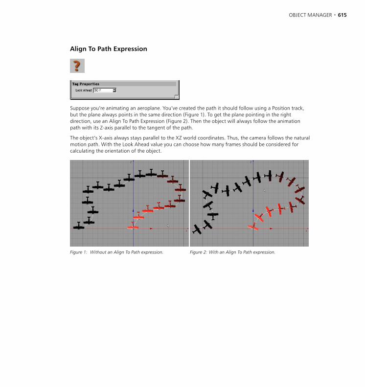
614 • CHAPTER 17 OBJECT MANAGER • 615
Align To Path Expression
Suppose you’re animating an aeroplane. You’ve created the path it should follow using a Position track, but the plane always points in the same direction (Figure 1). To get the plane pointing in the right direction, use an Align To Path Expression (Figure 2). Then the object will always follow the animation path with its Z-axis parallel to the tangent of the path.
The object’s X-axis always stays parallel to the XZ world coordinates. Thus, the camera follows the natural motion path. With the Look Ahead value you can choose how many frames should be considered for calculating the orientation of the object.
Figure 1: Without an Align To Path expression. Figure 2: With an Align To Path expression.
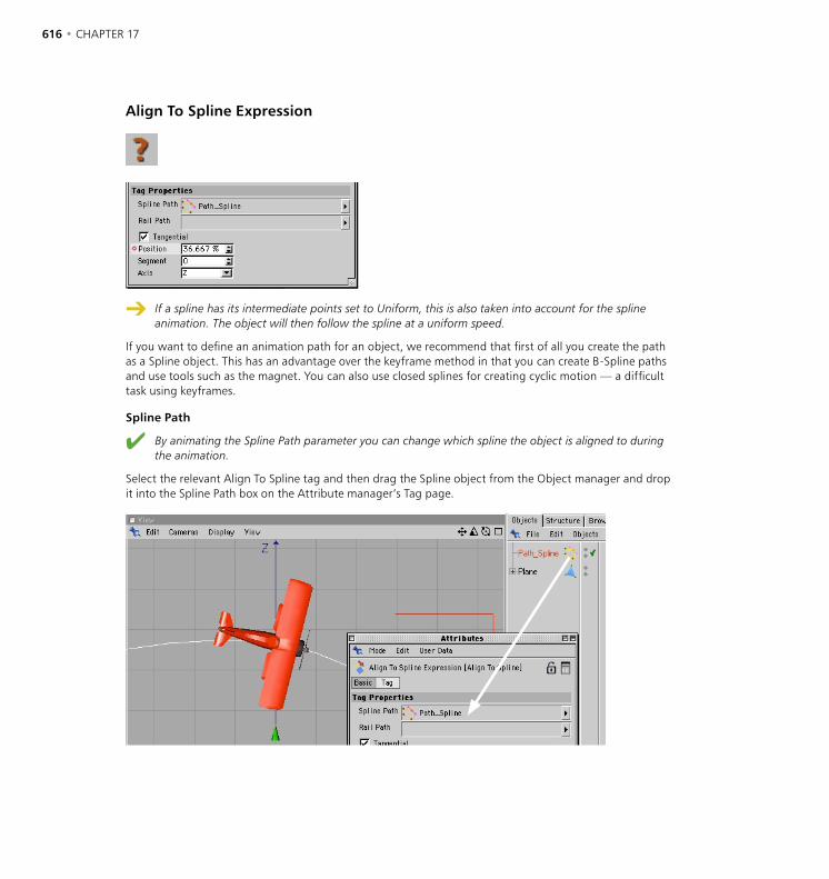
616 • CHAPTER 17 OBJECT MANAGER • 617
Align To Spline Expression
If a spline has its intermediate points set to Uniform, this is also taken into account for the spline animation. The object will then follow the spline at a uniform speed.
If you want to define an animation path for an object, we recommend that first of all you create the path as a Spline object. This has an advantage over the keyframe method in that you can create B-Spline paths and use tools such as the magnet. You can also use closed splines for creating cyclic motion — a difficult task using keyframes.
Spline Path
By animating the Spline Path parameter you can change which spline the object is aligned to during the animation.
Select the relevant Align To Spline tag and then drag the Spline object from the Object manager and drop it into the Spline Path box on the Attribute manager’s Tag page.
616 • CHAPTER 17 OBJECT MANAGER • 617
Position
If you animate the expression’s Position parameter, the object follows the path using the axis defined by Axis. If the object should follow, say, only the first half of the spline, animate Position from 0% to 50%. For more details on how to animate this Position parameter, see the Timeline chapter and/or the Attribute Manager chapter.
Rail Path
You can optionally use a rail path. Drag the spline that you want to act as the rail from the Object manager into the Rail Path box on the Attribute manager’s Tag page. This has a similar effect to the Align To Path expression in the sense that the object’s Z-axis remains parallel to the spline’s tangent at all times.
Tangential
If you enable Tangential, the effect is similar to that of the Align To Path expression, i.e. the object’s X, Y or Z-axis is aligned to the rail path.
Segment
Splines may consist of multiple segments. Use this parameter to choose which segment the spline follows.
Axis
This setting is available only when Tangential is enabled. It defines with which axis the object follows the spline.
C.O.F.F.E.E. Expression
You have two ways to create your own expressions. You can either program code using CINEMA 4D’S native C.O.F.F.E.E. programming language or you can use the powerful XPresso Editor to create expressions easily without typing a single line of code. XPresso is ideal if you’re the kind of 3D artist who has no interest in programming but would like almost infinite control over the behavior of your 3D models. To learn about XPresso, see Chapter 23, XPresso Editor. To learn about the C.O.F.F.E.E. programming language, visit www.plugincafe.com and download the SDK.
Fix Expression
This expression fixes an object’s position to the coordinates defined by Fixing Point. You can rotate and scale a fixed object, but you cannot change its position.
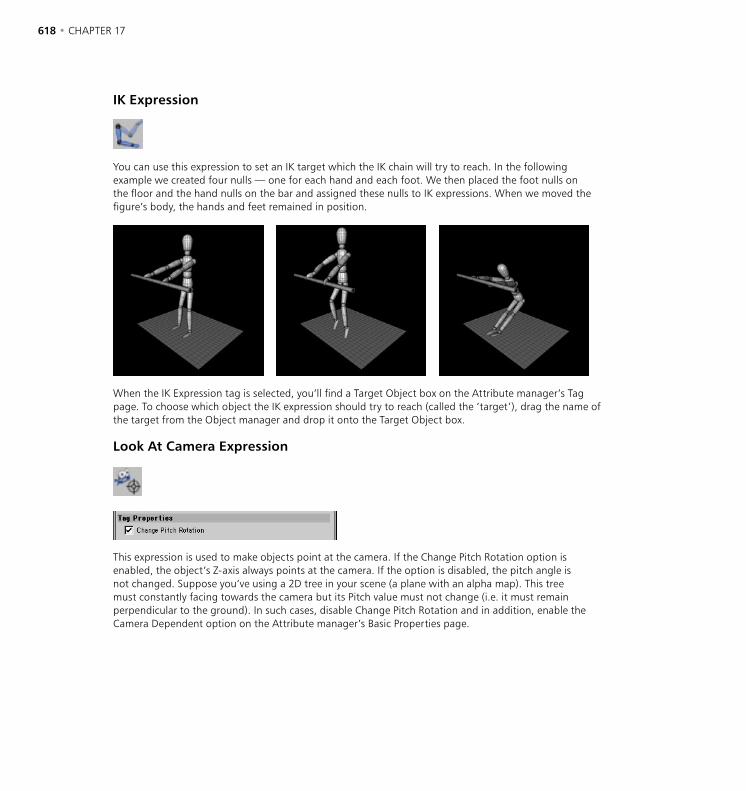
618 • CHAPTER 17 OBJECT MANAGER • 619
IK Expression
You can use this expression to set an IK target which the IK chain will try to reach. In the following example we created four nulls — one for each hand and each foot. We then placed the foot nulls on the floor and the hand nulls on the bar and assigned these nulls to IK expressions. When we moved the figure’s body, the hands and feet remained in position.
When the IK Expression tag is selected, you’ll find a Target Object box on the Attribute manager’s Tag page. To choose which object the IK expression should try to reach (called the ‘target’), drag the name of the target from the Object manager and drop it onto the Target Object box.
Look At Camera Expression
This expression is used to make objects point at the camera. If the Change Pitch Rotation option is enabled, the object’s Z-axis always points at the camera. If the option is disabled, the pitch angle is not changed. Suppose you’ve using a 2D tree in your scene (a plane with an alpha map). This tree must constantly facing towards the camera but its Pitch value must not change (i.e. it must remain perpendicular to the ground). In such cases, disable Change Pitch Rotation and in addition, enable the Camera Dependent option on the Attribute manager’s Basic Properties page.
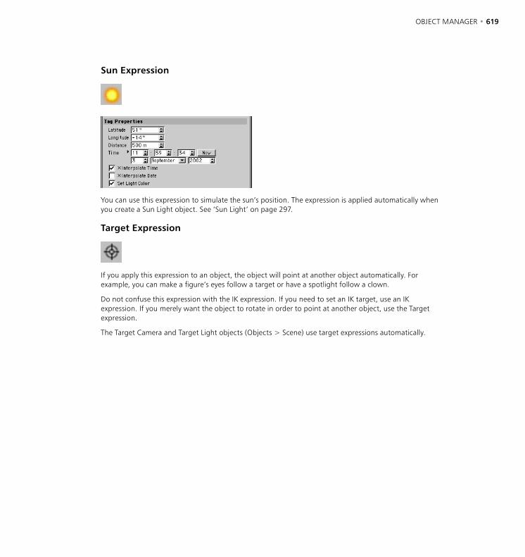
618 • CHAPTER 17 OBJECT MANAGER • 619
Sun Expression
You can use this expression to simulate the sun’s position. The expression is applied automatically when you create a Sun Light object. See ‘Sun Light’ on page 297.
Target Expression
If you apply this expression to an object, the object will point at another object automatically. For example, you can make a figure’s eyes follow a target or have a spotlight follow a clown.
Do not confuse this expression with the IK expression. If you need to set an IK target, use an IK expression. If you merely want the object to rotate in order to point at another object, use the Target expression.
The Target Camera and Target Light objects (Objects > Scene) use target expressions automatically.
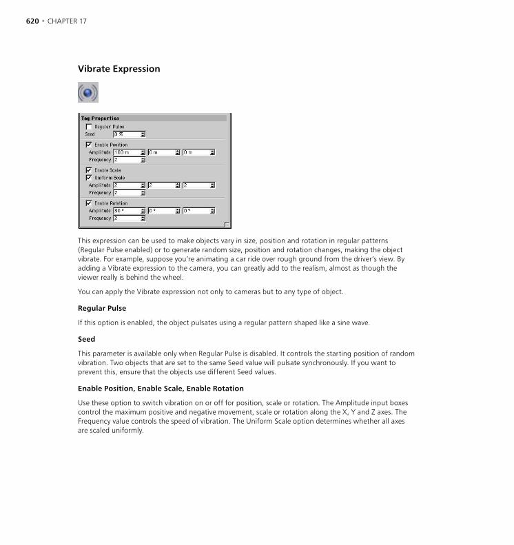
620 • CHAPTER 17 OBJECT MANAGER • 621
Vibrate Expression
This expression can be used to make objects vary in size, position and rotation in regular patterns (Regular Pulse enabled) or to generate random size, position and rotation changes, making the object vibrate. For example, suppose you’re animating a car ride over rough ground from the driver’s view. By adding a Vibrate expression to the camera, you can greatly add to the realism, almost as though the viewer really is behind the wheel.
You can apply the Vibrate expression not only to cameras but to any type of object.
Regular Pulse
If this option is enabled, the object pulsates using a regular pattern shaped like a sine wave.
Seed
This parameter is available only when Regular Pulse is disabled. It controls the starting position of random vibration. Two objects that are set to the same Seed value will pulsate synchronously. If you want to prevent this, ensure that the objects use different Seed values.
Enable Position, Enable Scale, Enable Rotation
Use these option to switch vibration on or off for position, scale or rotation. The Amplitude input boxes control the maximum positive and negative movement, scale or rotation along the X, Y and Z axes. The Frequency value controls the speed of vibration. The Uniform Scale option determines whether all axes are scaled uniformly.
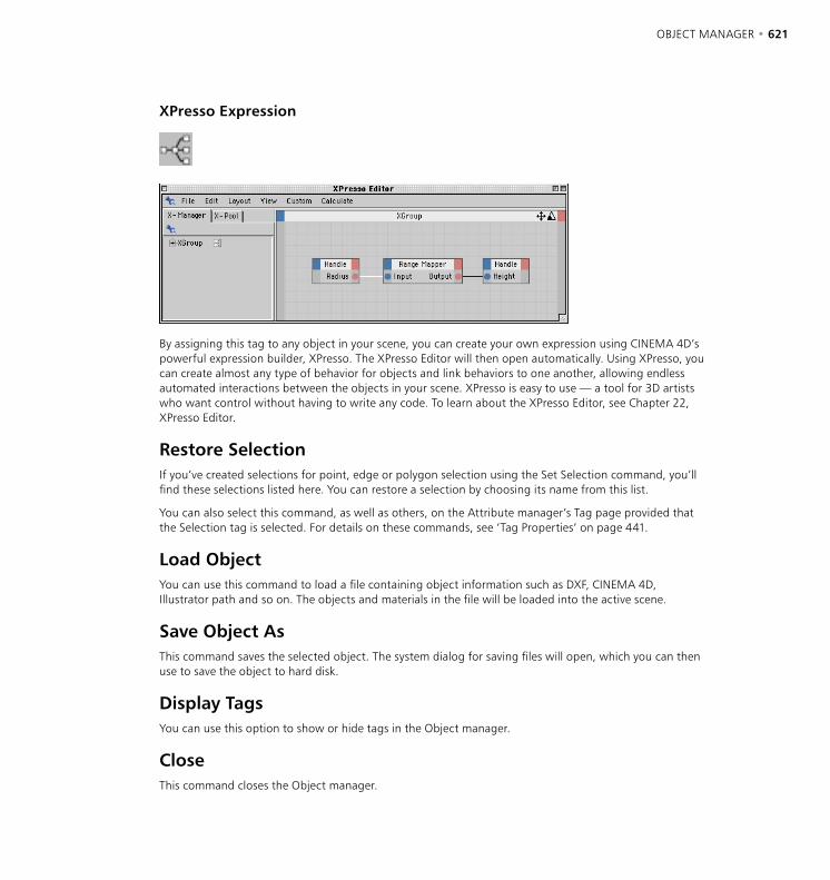
620 • CHAPTER 17 OBJECT MANAGER • 621
XPresso Expression
By assigning this tag to any object in your scene, you can create your own expression using CINEMA 4D’s powerful expression builder, XPresso. The XPresso Editor will then open automatically. Using XPresso, you can create almost any type of behavior for objects and link behaviors to one another, allowing endless automated interactions between the objects in your scene. XPresso is easy to use — a tool for 3D artists who want control without having to write any code. To learn about the XPresso Editor, see Chapter 22, XPresso Editor.
Restore SelectionIf you’ve created selections for point, edge or polygon selection using the Set Selection command, you’ll find these selections listed here. You can restore a selection by choosing its name from this list.
You can also select this command, as well as others, on the Attribute manager’s Tag page provided that the Selection tag is selected. For details on these commands, see ‘Tag Properties’ on page 441.
Load ObjectYou can use this command to load a file containing object information such as DXF, CINEMA 4D, Illustrator path and so on. The objects and materials in the file will be loaded into the active scene.
Save Object AsThis command saves the selected object. The system dialog for saving files will open, which you can then use to save the object to hard disk.
Display TagsYou can use this option to show or hide tags in the Object manager.
CloseThis command closes the Object manager.
622 • CHAPTER 17 OBJECT MANAGER • 623
Edit Menu
UndoUndoes the last change, restoring the scene to its previous state. For example, if you accidentally move an object, choose Undo to restore the object to its correct position. Choose Undo repeatedly to undo the changes one by one.
RedoRedo redoes a change. Select Redo repeatedly to continue restoring the changes. You can traverse the recent development stages of your scene by using Undo to move backwards and Redo to move forwards.
CutDeletes the selected objects or elements from the current scene and copies them (including materials) to the clipboard. The objects can be copied back from the clipboard with the Paste function.
Copy
You can copy and paste objects using drag-and-drop in the Object manager. Ctrl-drag one of the selected object’s names to a new position within the Object manager.
Copies the selected objects or elements (including materials) to the clipboard. The objects can be copied from the clipboard to the active scene with the Paste command. You can paste repeatedly to create additional copies.
PasteInserts the contents of the clipboard (i.e. the last objects that were cut or copied there) into the active scene.
DeleteDeletes the selected objects or elements from the current scene without copying them to the clipboard.
Select All, Deselect AllThese commands select or deselect all objects.
Select ChildrenAdds the children of the selected object(s) to the selection. This is especially useful when you want to record keyframes for the selected objects and their children. Regardless of whether you record using the Animation toolbar, Timeline or Attribute manager, keys are only recorded for child objects if they are also selected. This command gives you a quick way to select them.
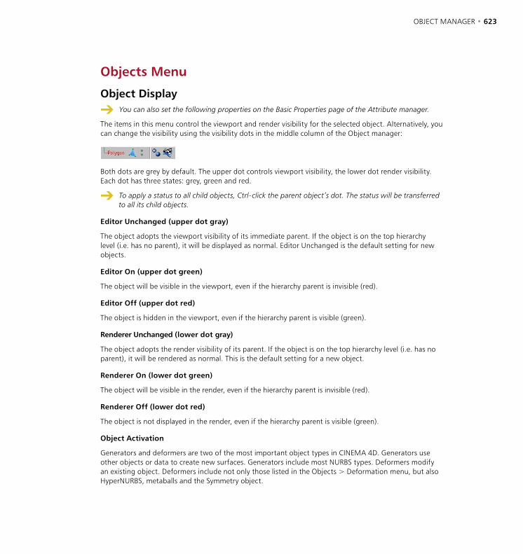
622 • CHAPTER 17 OBJECT MANAGER • 623
Objects Menu
Object Display
You can also set the following properties on the Basic Properties page of the Attribute manager.
The items in this menu control the viewport and render visibility for the selected object. Alternatively, you can change the visibility using the visibility dots in the middle column of the Object manager:
Both dots are grey by default. The upper dot controls viewport visibility, the lower dot render visibility. Each dot has three states: grey, green and red.
To apply a status to all child objects, Ctrl-click the parent object’s dot. The status will be transferred to all its child objects.
Editor Unchanged (upper dot gray)
The object adopts the viewport visibility of its immediate parent. If the object is on the top hierarchy level (i.e. has no parent), it will be displayed as normal. Editor Unchanged is the default setting for new objects.
Editor On (upper dot green)
The object will be visible in the viewport, even if the hierarchy parent is invisible (red).
Editor Off (upper dot red)
The object is hidden in the viewport, even if the hierarchy parent is visible (green).
Renderer Unchanged (lower dot gray)
The object adopts the render visibility of its parent. If the object is on the top hierarchy level (i.e. has no parent), it will be rendered as normal. This is the default setting for a new object.
Renderer On (lower dot green)
The object will be visible in the render, even if the hierarchy parent is invisible (red).
Renderer Off (lower dot red)
The object is not displayed in the render, even if the hierarchy parent is visible (green).
Object Activation
Generators and deformers are two of the most important object types in CINEMA 4D. Generators use other objects or data to create new surfaces. Generators include most NURBS types. Deformers modify an existing object. Deformers include not only those listed in the Objects > Deformation menu, but also HyperNURBS, metaballs and the Symmetry object.
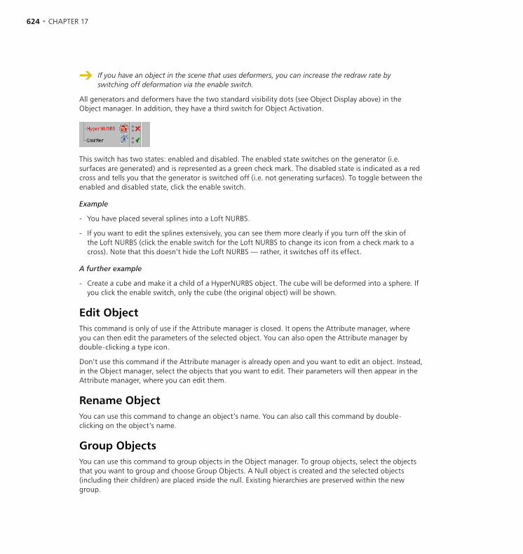
624 • CHAPTER 17 OBJECT MANAGER • 625
If you have an object in the scene that uses deformers, you can increase the redraw rate by switching off deformation via the enable switch.
All generators and deformers have the two standard visibility dots (see Object Display above) in the Object manager. In addition, they have a third switch for Object Activation.
This switch has two states: enabled and disabled. The enabled state switches on the generator (i.e. surfaces are generated) and is represented as a green check mark. The disabled state is indicated as a red cross and tells you that the generator is switched off (i.e. not generating surfaces). To toggle between the enabled and disabled state, click the enable switch.
Example
- You have placed several splines into a Loft NURBS.
- If you want to edit the splines extensively, you can see them more clearly if you turn off the skin of the Loft NURBS (click the enable switch for the Loft NURBS to change its icon from a check mark to a cross). Note that this doesn’t hide the Loft NURBS — rather, it switches off its effect.
A further example
- Create a cube and make it a child of a HyperNURBS object. The cube will be deformed into a sphere. If you click the enable switch, only the cube (the original object) will be shown.
Edit ObjectThis command is only of use if the Attribute manager is closed. It opens the Attribute manager, where you can then edit the parameters of the selected object. You can also open the Attribute manager by double-clicking a type icon.
Don’t use this command if the Attribute manager is already open and you want to edit an object. Instead, in the Object manager, select the objects that you want to edit. Their parameters will then appear in the Attribute manager, where you can edit them.
Rename ObjectYou can use this command to change an object’s name. You can also call this command by double-clicking on the object’s name.
Group ObjectsYou can use this command to group objects in the Object manager. To group objects, select the objects that you want to group and choose Group Objects. A Null object is created and the selected objects (including their children) are placed inside the null. Existing hierarchies are preserved within the new group.
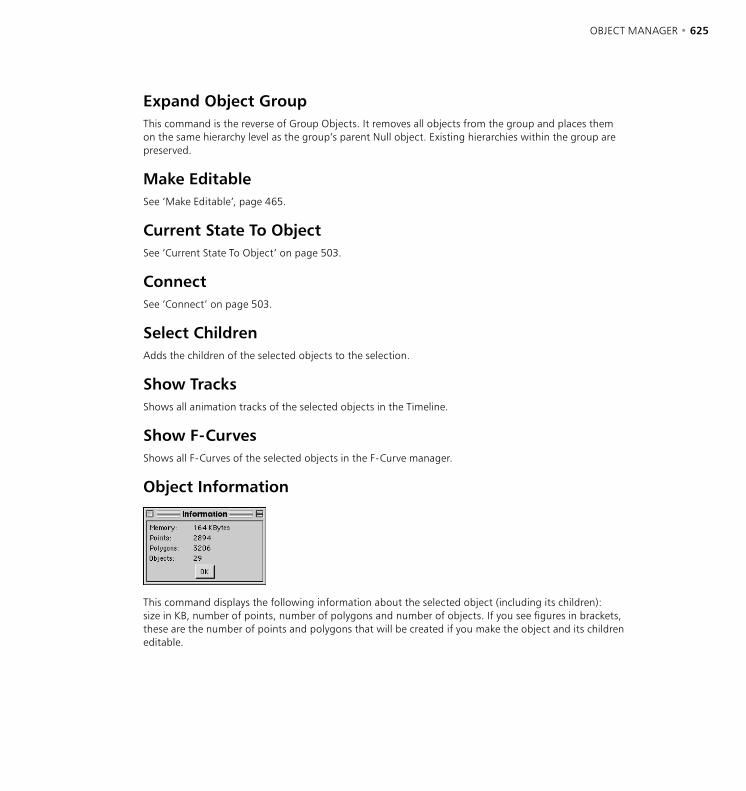
624 • CHAPTER 17 OBJECT MANAGER • 625
Expand Object GroupThis command is the reverse of Group Objects. It removes all objects from the group and places them on the same hierarchy level as the group’s parent Null object. Existing hierarchies within the group are preserved.
Make EditableSee ‘Make Editable’, page 465.
Current State To ObjectSee ‘Current State To Object’ on page 503.
ConnectSee ‘Connect’ on page 503.
Select ChildrenAdds the children of the selected objects to the selection.
Show TracksShows all animation tracks of the selected objects in the Timeline.
Show F-CurvesShows all F-Curves of the selected objects in the F-Curve manager.
Object Information
This command displays the following information about the selected object (including its children): size in KB, number of points, number of polygons and number of objects. If you see figures in brackets, these are the number of points and polygons that will be created if you make the object and its children editable.
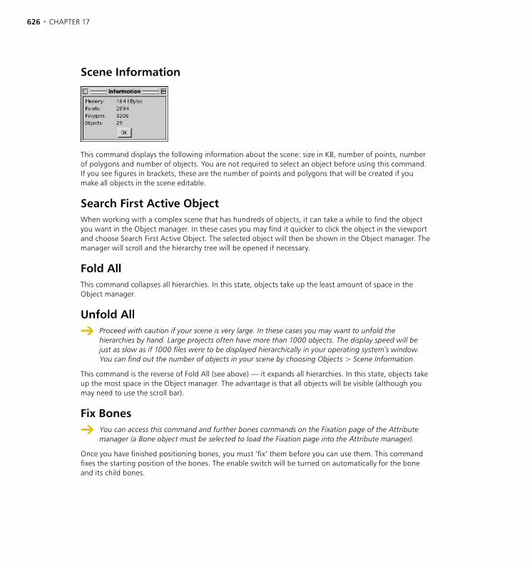
626 • CHAPTER 17 OBJECT MANAGER • 627
Scene Information
This command displays the following information about the scene: size in KB, number of points, number of polygons and number of objects. You are not required to select an object before using this command. If you see figures in brackets, these are the number of points and polygons that will be created if you make all objects in the scene editable.
Search First Active ObjectWhen working with a complex scene that has hundreds of objects, it can take a while to find the object you want in the Object manager. In these cases you may find it quicker to click the object in the viewport and choose Search First Active Object. The selected object will then be shown in the Object manager. The manager will scroll and the hierarchy tree will be opened if necessary.
Fold AllThis command collapses all hierarchies. In this state, objects take up the least amount of space in the Object manager.
Unfold All
Proceed with caution if your scene is very large. In these cases you may want to unfold the hierarchies by hand. Large projects often have more than 1000 objects. The display speed will be just as slow as if 1000 files were to be displayed hierarchically in your operating system’s window. You can find out the number of objects in your scene by choosing Objects > Scene Information.
This command is the reverse of Fold All (see above) — it expands all hierarchies. In this state, objects take up the most space in the Object manager. The advantage is that all objects will be visible (although you may need to use the scroll bar).
Fix Bones
You can access this command and further bones commands on the Fixation page of the Attribute manager (a Bone object must be selected to load the Fixation page into the Attribute manager).
Once you have finished positioning bones, you must ‘fix’ them before you can use them. This command fixes the starting position of the bones. The enable switch will be turned on automatically for the bone and its child bones.

626 • CHAPTER 17 OBJECT MANAGER • 627
Reset BonesThis command resets the bones to their fixing (start) position. The object will return to its state at the time of the fixing. The enable switch will be turned off automatically for the bone and its child bones.
Bake ParticlesBaking particles means freezing the particle stream, including all its modifiers. This can be useful for several reasons:
- In extreme cases, very fast particles may behave unexpectedly due to processor inaccuracies — for example, they may pass through deflectors. Baked particle streams avoid this problem since they are calculated much more accurately.
- You may want to mix several particle streams but prevent modifiers affecting particles in the other streams. To do this, create one particle stream and its modifiers and bake the stream. Delete the modifiers before you start the next stream and continue in the same manner.
- If you are using NET Render to render across a network, jumps may occur in particle streams due to differences between the CPUs. To remedy this problem, bake the particles.
Example
Ensure you are familiar with the section on the particle system (starting on page 301) before proceeding with this example, otherwise you may find it difficult to follow.
- Start a new scene and create an emitter and a few modifiers. In the Object manager, ensure that the emitter is selected and choose the Bake Particles command. The following dialog opens.
- Use the From and To values to mark the period over which the particles will be baked (the default values cover the entire project length).
- Click OK once you are ready to bake the particles — a Baked Particles icon appears in the Object manager, to the right of the emitter.
You cannot edit the settings that were used to bake the particles. If you need to re-bake the particles — for example, because you’ve increased the project length — first delete the Baked Particles icon in the Object manager, then bake the particles afresh.
628 • CHAPTER 17 OBJECT MANAGER • 629
Tags Menu
Edit TagThis command is only of use if the Attribute manager is closed. It opens the Attribute manager, where you can then edit the parameters of the selected tag. You can also open the Attribute manager by double-clicking a tag.
Don’t use this command if the Attribute manager is already open and you want to edit a tag. Instead, in the Object manager, select the tag or tags that you want to edit. Their parameters will then appear in the Attribute manager, where you can edit them.
Copy Tag To ChildrenIf you select this command, the selected tag will be copied to all child objects of the active object. If a child object already has a tag of the same type, its tag will be overwritten with that of the parent. There is one exception, the Texture tag. This tag is still copied, but the child will keep its own tag as well (an object can have more than one Texture tag).
Select Identical Child TagsUsing this command, you can select like child tags. For example, suppose you want to change the material used by a parent object and all its children. To do this the most efficient way, you first need to select all of these tags, and this command gives you a quick way to do this. Select the Texture tag of the parent and choose the command to select the Texture tags of the relevant children as well. You can now proceed to assign the new material to all the tags — drag the desired material from the Object manager and drop it into the Material box on the Attribute manager’s Tag page.
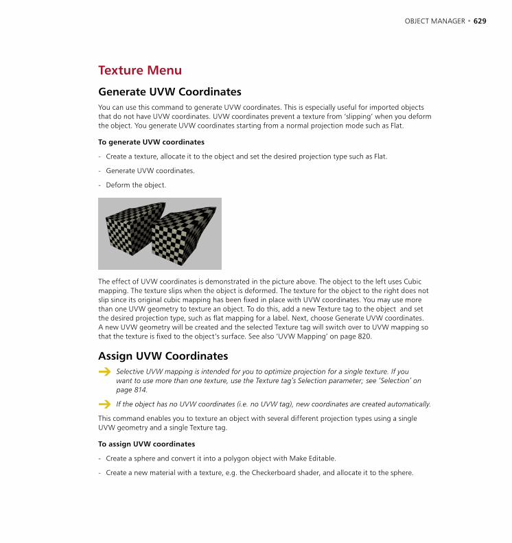
628 • CHAPTER 17 OBJECT MANAGER • 629
Texture Menu
Generate UVW CoordinatesYou can use this command to generate UVW coordinates. This is especially useful for imported objects that do not have UVW coordinates. UVW coordinates prevent a texture from ‘slipping’ when you deform the object. You generate UVW coordinates starting from a normal projection mode such as Flat.
To generate UVW coordinates
- Create a texture, allocate it to the object and set the desired projection type such as Flat.
- Generate UVW coordinates.
- Deform the object.
The effect of UVW coordinates is demonstrated in the picture above. The object to the left uses Cubic mapping. The texture slips when the object is deformed. The texture for the object to the right does not slip since its original cubic mapping has been fixed in place with UVW coordinates. You may use more than one UVW geometry to texture an object. To do this, add a new Texture tag to the object and set the desired projection type, such as flat mapping for a label. Next, choose Generate UVW coordinates. A new UVW geometry will be created and the selected Texture tag will switch over to UVW mapping so that the texture is fixed to the object’s surface. See also ‘UVW Mapping’ on page 820.
Assign UVW Coordinates
Selective UVW mapping is intended for you to optimize projection for a single texture. If you want to use more than one texture, use the Texture tag’s Selection parameter; see ‘Selection’ on page 814.
If the object has no UVW coordinates (i.e. no UVW tag), new coordinates are created automatically.
This command enables you to texture an object with several different projection types using a single UVW geometry and a single Texture tag.
To assign UVW coordinates
- Create a sphere and convert it into a polygon object with Make Editable.
- Create a new material with a texture, e.g. the Checkerboard shader, and allocate it to the sphere.
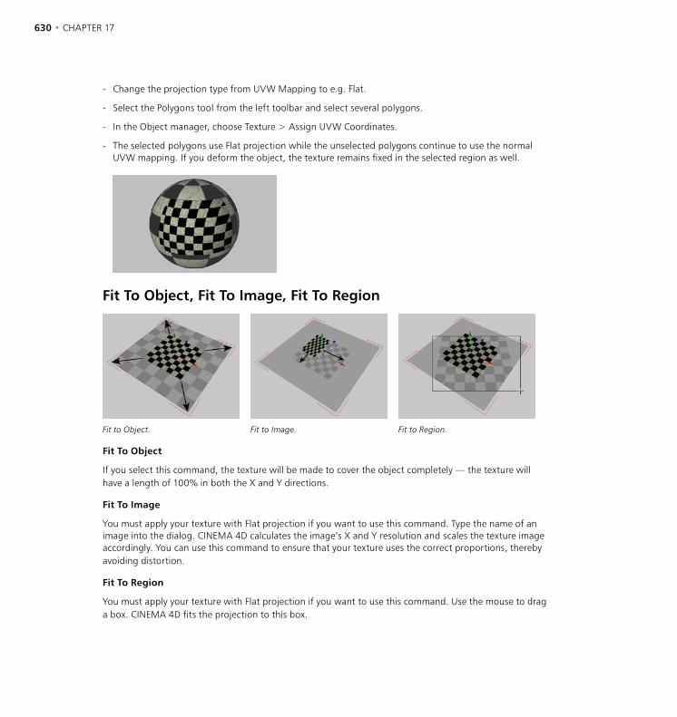
630 • CHAPTER 17 OBJECT MANAGER • 631
- Change the projection type from UVW Mapping to e.g. Flat.
- Select the Polygons tool from the left toolbar and select several polygons.
- In the Object manager, choose Texture > Assign UVW Coordinates.
- The selected polygons use Flat projection while the unselected polygons continue to use the normal UVW mapping. If you deform the object, the texture remains fixed in the selected region as well.
Fit To Object, Fit To Image, Fit To Region
Fit to Object. Fit to Image. Fit to Region.
Fit To Object
If you select this command, the texture will be made to cover the object completely — the texture will have a length of 100% in both the X and Y directions.
Fit To Image
You must apply your texture with Flat projection if you want to use this command. Type the name of an image into the dialog. CINEMA 4D calculates the image’s X and Y resolution and scales the texture image accordingly. You can use this command to ensure that your texture uses the correct proportions, thereby avoiding distortion.
Fit To Region
You must apply your texture with Flat projection if you want to use this command. Use the mouse to drag a box. CINEMA 4D fits the projection to this box.
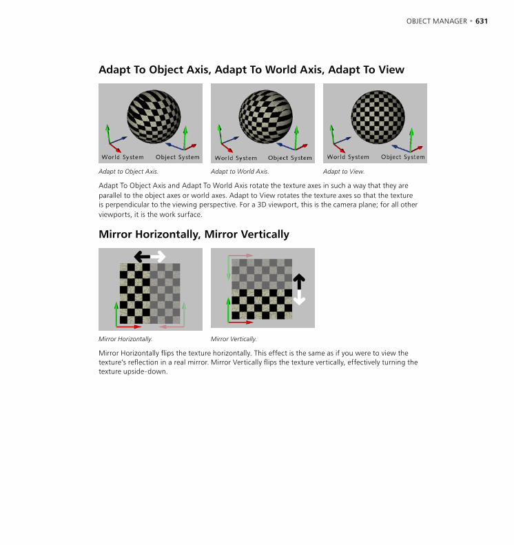
630 • CHAPTER 17 OBJECT MANAGER • 631
Adapt To Object Axis, Adapt To World Axis, Adapt To View
Adapt to Object Axis. Adapt to World Axis. Adapt to View.
Adapt To Object Axis and Adapt To World Axis rotate the texture axes in such a way that they are parallel to the object axes or world axes. Adapt to View rotates the texture axes so that the texture is perpendicular to the viewing perspective. For a 3D viewport, this is the camera plane; for all other viewports, it is the work surface.
Mirror Horizontally, Mirror Vertically
Mirror Horizontally. Mirror Vertically.
Mirror Horizontally flips the texture horizontally. This effect is the same as if you were to view the texture’s reflection in a real mirror. Mirror Vertically flips the texture vertically, effectively turning the texture upside-down.


18 Material Manager

MATERIAL MANAGER • 635
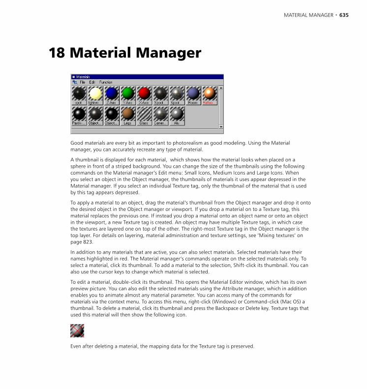
MATERIAL MANAGER • 635
Good materials are every bit as important to photorealism as good modeling. Using the Material manager, you can accurately recreate any type of material.
A thumbnail is displayed for each material, which shows how the material looks when placed on a sphere in front of a striped background. You can change the size of the thumbnails using the following commands on the Material manager’s Edit menu: Small Icons, Medium Icons and Large Icons. When you select an object in the Object manager, the thumbnails of materials it uses appear depressed in the Material manager. If you select an individual Texture tag, only the thumbnail of the material that is used by this tag appears depressed.
To apply a material to an object, drag the material’s thumbnail from the Object manager and drop it onto the desired object in the Object manager or viewport. If you drop a material on to a Texture tag, this material replaces the previous one. If instead you drop a material onto an object name or onto an object in the viewport, a new Texture tag is created. An object may have multiple Texture tags, in which case the textures are layered one on top of the other. The right-most Texture tag in the Object manager is the top layer. For details on layering, material administration and texture settings, see ‘Mixing textures’ on page 823.
In addition to any materials that are active, you can also select materials. Selected materials have their names highlighted in red. The Material manager’s commands operate on the selected materials only. To select a material, click its thumbnail. To add a material to the selection, Shift-click its thumbnail. You can also use the cursor keys to change which material is selected.
To edit a material, double-click its thumbnail. This opens the Material Editor window, which has its own preview picture. You can also edit the selected materials using the Attribute manager, which in addition enables you to animate almost any material parameter. You can access many of the commands for materials via the context menu. To access this menu, right-click (Windows) or Command-click (Mac OS) a thumbnail. To delete a material, click its thumbnail and press the Backspace or Delete key. Texture tags that used this material will then show the following icon.
Even after deleting a material, the mapping data for the Texture tag is preserved.
18 Material Manager
636 • CHAPTER 18 MATERIAL MANAGER • 637
File MenuNew MaterialThis command creates a new material with default values (white with specularity). The new material is placed at the start of the material list.
bhodiNUT VolumeUse this menu to create bhodiNUT volume (3D) shaders. See ‘The bhodiNUT Shaders’ on page 691.
ShaderThis menu lists the built-in material shaders. See ‘Material shaders’ on page 688.
Material shaders are complete materials in their own right, as opposed to channel shaders (see ‘Channel shaders’ on page 673) which can be loaded into various channels of a material via the Material Editor or Attributes manager.
Load MaterialsThis command loads materials, adding them to any materials already in the scene. You can also import materials from another scene by loading the scene file.
A word of caution regarding textures; when CINEMA 4D renders the scene, it must locate all the textures. CINEMA 4D will look for the textures in the same folder as the scene, as well as in a sub-folder called ‘Tex’. In addition, you can specify up to 10 alternative texture paths (see ‘Texture Paths’ on page 78). When the scene is to be used on another computer (perhaps by a colleague) we recommend that you save the scene using the Save Project command. This will save all of the textures used by the scene in a ‘Tex’ sub-folder.
Save Materials AsSaves the selected materials. The standard system dialog for saving files will open. Once you have saved the materials, you can reload them at any time using the Load Materials command.
Save All Materials AsSaves all the materials in the active scene. Use the Load Materials command when you want to load the materials.
CloseCloses the Material manager.
636 • CHAPTER 18 MATERIAL MANAGER • 637
Edit MenuUndo, RedoUndo undoes the last change, restoring the last change you made to a material. Choose Undo repeatedly to undo the changes one by one. Redo redoes a change. Select Redo repeatedly to continue restoring the changes.
CutCut deletes the selected materials from the Material manager and copies it to the clipboard. You can use the Paste function to retrieve the material from the clipboard, even if you have changed the active scene (i.e. you can paste between scenes).
Copy You can quick-copy materials by using drag-and-drop with the Ctrl key held down. Drop the copy
and drop it at the desired position in the material list. The first copy will be called ‘name.1’, the second copy will be called ‘name.2’ and so on.
Deletes the selected materials and copies them to the clipboard. The materials can be copied back from the clipboard with the Paste function.
PasteInserts the materials that are stored in the clipboard (i.e. the last materials that were cut or copied there) into the active scene.
DeleteDeletes the selected materials without copying them to the clipboard. Alternatively, press the Backspace or Delete key.
Select All, Deselect AllThese commands select or deselect all materials.
Small Icons, Medium Icons, Large IconsSelect one of these three settings to determine the size of the material previews (the default is Small). Small icons are 45 x 45 pixels, medium icons 60 x 60 pixels, large icons 90 x 90 pixels.

638 • CHAPTER 18 MATERIAL MANAGER • 639
Function MenuSelect Materials Of Active ObjectsUse this command to select the materials used by the selected objects or Texture tags. The Material manager will scroll if necessary in order to show these materials.
Find First Active MaterialShows the first selected material in the Material manager.
Render Materials, Render All Materials To abort the rendering of the thumbnails, press the Esc key.
These commands redraw the thumbnails of the selected materials or all materials. Most of the time you won’t need to use this command since new materials are rendered automatically. However, when you save a scene, the thumbnails are compressed to reduce the scene’s file size. When you load a scene, you may notice artefacts in some of the thumbnails. In such cases, use this command to redraw the thumbnails. You’ll also need to use this command when importing foreign data formats such as DXF and 3D Studio R4.
If you render the materials and only the base color is shown, it probably means that CINEMA 4D was unable to find the textures. The best way to avoid missing textures when moving scenes from one computer to another is to use the Save Project command. This saves all of the textures used by the scene in a ‘Tex’ folder within the scene’s folder.
Sort MaterialsArranges the material list in alphabetical order. You can also sort materials manually using drag-and-drop. Drag the material that you want to reposition and drop it in the new position. The insertion is right-justified. In other words, the material will be placed to the right of the material onto which you drop it. If the target position of the material is outside the visible range of the Material manager, you can scroll by moving the mouse to the upper or lower edge of the window.
EditThis command opens the Material Editor if it is not already open and makes the Material Editor the active window. You can use the Material Editor to change the properties of the selected material. You can also open up the Material Editor by double-clicking on a material’s thumbnail. For full details on the Material Editor see page 641.
638 • CHAPTER 18 MATERIAL MANAGER • 639
You can also edit materials using the Attribute manager. The advantage of the Attribute manager is that you can edit multiply-selected materials at the same time. For example, if you have several similar wood materials and want to set their specular properties all to the same values, select all the wood materials and change the specular values as desired. The settings will be applied to all the selected materials. In addition, you can animate material properties directly within the Attribute manager. For details on using the Attribute manager for animation, see ‘Animation’ on page 904.
ApplyCreates a Texture tag for each selected object. Each of these tags is assigned the selected material. You can also apply materials using drag-and-drop. If you drop the material on to an existing Texture tag ...
... the tag’s previous material is replaced by the new one. However, if you drop the material onto the object name, a new Texture tag is created for the material.
RenameUse this command to change the name of the selected material. You can also rename a material by double-clicking on its name, which is just below the material’s thumbnail, or by selecting the material and entering the new name on the Basic Properties page of the Attribute manager.
Remove Unused MaterialsDeletes all unused materials.
Remove Duplicate MaterialsDeletes all materials of the same name that have identical parameters.
Select Texture TagsSelects all Texture tags that use the selected materials.

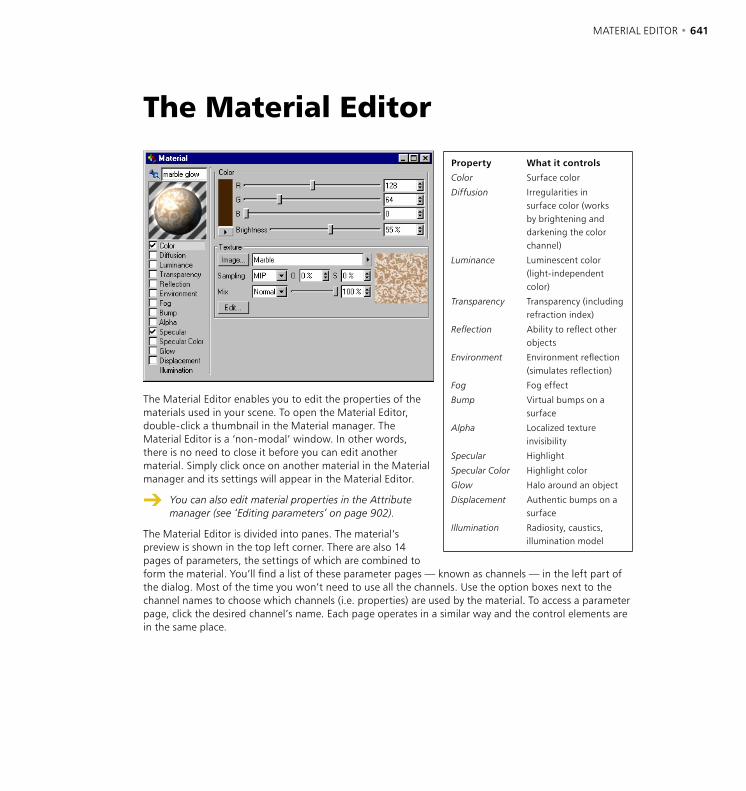
MATERIAL EDITOR • 641
The Material Editor enables you to edit the properties of the materials used in your scene. To open the Material Editor, double-click a thumbnail in the Material manager. The Material Editor is a ‘non-modal’ window. In other words, there is no need to close it before you can edit another material. Simply click once on another material in the Material manager and its settings will appear in the Material Editor.
You can also edit material properties in the Attribute manager (see ‘Editing parameters’ on page 902).
The Material Editor is divided into panes. The material’s preview is shown in the top left corner. There are also 14 pages of parameters, the settings of which are combined to form the material. You’ll find a list of these parameter pages — known as channels — in the left part of the dialog. Most of the time you won’t need to use all the channels. Use the option boxes next to the channel names to choose which channels (i.e. properties) are used by the material. To access a parameter page, click the desired channel’s name. Each page operates in a similar way and the control elements are in the same place.
The Material Editor
Property What it controls
Color Surface color
Diffusion Irregularities in surface color (works by brightening and darkening the color channel)
Luminance Luminescent color (light-independent color)
Transparency Transparency (including refraction index)
Reflection Ability to reflect other objects
Environment Environment reflection (simulates reflection)
Fog Fog effect
Bump Virtual bumps on a surface
Alpha Localized texture invisibility
Specular Highlight
Specular Color Highlight color
Glow Halo around an object
Displacement Authentic bumps on a surface
Illumination Radiosity, caustics, illumination model

642 • CHAPTER 18 MATERIAL EDITOR • 643
Color paneMost parameter pages have a color that you can adjust. Depending on the color system chosen in the preferences, you adjust the color using either a color table or sliders. The meaning of each slider also depends on the setting in the preferences —you can use either the HSV color system or the RGB color system and you can choose whether the units should run from 0-100%, 0-255 bits or 0-65,535 bits.
Use the Brightness slider, which is below the three color sliders (R red, G green, B blue or H hue, S saturation, V value) to adjust the overall brightness of the color. Note that if you are using the HSV system, the Brightness slider has the same effect as the V slider (i.e. you do not have to use the Brightness slider; you can leave it at 100% and control the brightness using the V slider).
The color preview is shown to the left of the sliders. Click this color box if you want to pick the color using the system color chooser. If you click the arrowhead that is just below the color preview, you can choose the color system from the drop-down list that appears. The Material Editor will use the new system (or color table) for as long as it is open. The moment you close the Material Editor, it reverts to the color system that is selected in the preferences.
Texture paneUse the Texture pane to select a two-dimensional picture or shader. Your selection will be used as a texture. CINEMA 4D recognizes these formats: JPEG, IFF (ILBM), TIFF, TGA, BMP, PICT, Photoshop PSD, MOV, AVI. If QuickTime is installed on your system, other formats will also be available via QuickTime.
Once you have selected a texture, its preview appears to the right with three numbers shown immediately below. These are the width, height and color depth of the texture. If you click within the preview picture, the color of the pixel that you clicked is copied to the Color pane.
Image
Use the Image button to load a texture into the Texture pane. Use the system dialog to load an image file from either your scene’s folder, your scene’s ‘Tex’ sub-folder or a texture path that you have specified in the preferences. A dialog warns if the image file is not in a search path and asks if you want to copy the image to the document’s folder or, if your scene doesn’t have its own folder yet, to the CINEMA 4D root folder.
Once you have loaded a texture, its path name appears in the input box. To the right you can see the texture’s preview picture.
CINEMA 4D searches for textures in the ‘CINEMA 4D/Tex’ folder, the scene’s folder, the scene’s ‘Tex’ sub-folder and the texture paths specified in the preferences (including sub-folders). If CINEMA 4D cannot find a texture when rendering, a message will appear to tell you which textures are missing and which materials use these textures. You can still render the scene without the missing textures by clicking OK.
To load a shader into the Texture pane, click the arrowhead that is to the right of the image text box and choose the desired channel from the drop-down list that appears. On this drop-down list, you’ll also find two commands called Copy Channel and Paste Channel. Use these when you want to copy and paste shader settings from one material channel to another.
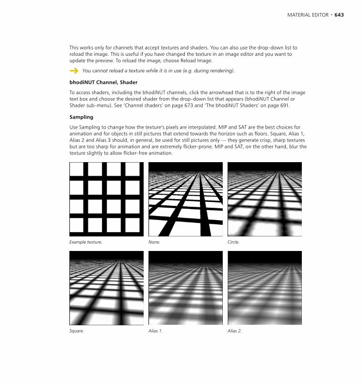
642 • CHAPTER 18 MATERIAL EDITOR • 643
This works only for channels that accept textures and shaders. You can also use the drop-down list to reload the image. This is useful if you have changed the texture in an image editor and you want to update the preview. To reload the image, choose Reload Image.
You cannot reload a texture while it is in use (e.g. during rendering).
bhodiNUT Channel, Shader
To access shaders, including the bhodiNUT channels, click the arrowhead that is to the right of the image text box and choose the desired shader from the drop-down list that appears (bhodiNUT Channel or Shader sub-menu). See ‘Channel shaders’ on page 673 and ‘The bhodiNUT Shaders’ on page 691.
Sampling
Use Sampling to change how the texture’s pixels are interpolated. MIP and SAT are the best choices for animation and for objects in still pictures that extend towards the horizon such as floors. Square, Alias 1, Alias 2 and Alias 3 should, in general, be used for still pictures only — they generate crisp, sharp textures but are too sharp for animation and are extremely flicker-prone. MIP and SAT, on the other hand, blur the texture slightly to allow flicker-free animation.
Example texture. None. Circle.
Square. Alias 1. Alias 2.
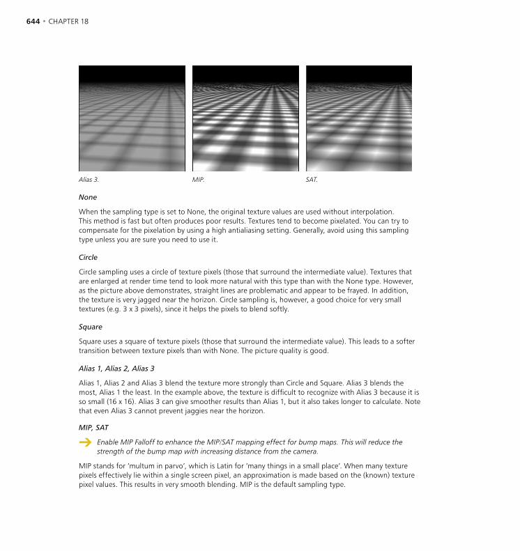
644 • CHAPTER 18 MATERIAL EDITOR • 645
Alias 3. MIP. SAT.
None
When the sampling type is set to None, the original texture values are used without interpolation. This method is fast but often produces poor results. Textures tend to become pixelated. You can try to compensate for the pixelation by using a high antialiasing setting. Generally, avoid using this sampling type unless you are sure you need to use it.
Circle
Circle sampling uses a circle of texture pixels (those that surround the intermediate value). Textures that are enlarged at render time tend to look more natural with this type than with the None type. However, as the picture above demonstrates, straight lines are problematic and appear to be frayed. In addition, the texture is very jagged near the horizon. Circle sampling is, however, a good choice for very small textures (e.g. 3 x 3 pixels), since it helps the pixels to blend softly.
Square
Square uses a square of texture pixels (those that surround the intermediate value). This leads to a softer transition between texture pixels than with None. The picture quality is good.
Alias 1, Alias 2, Alias 3
Alias 1, Alias 2 and Alias 3 blend the texture more strongly than Circle and Square. Alias 3 blends the most, Alias 1 the least. In the example above, the texture is difficult to recognize with Alias 3 because it is so small (16 x 16). Alias 3 can give smoother results than Alias 1, but it also takes longer to calculate. Note that even Alias 3 cannot prevent jaggies near the horizon.
MIP, SAT
Enable MIP Falloff to enhance the MIP/SAT mapping effect for bump maps. This will reduce the strength of the bump map with increasing distance from the camera.
MIP stands for ‘multum in parvo’, which is Latin for ‘many things in a small place’. When many texture pixels effectively lie within a single screen pixel, an approximation is made based on the (known) texture pixel values. This results in very smooth blending. MIP is the default sampling type.
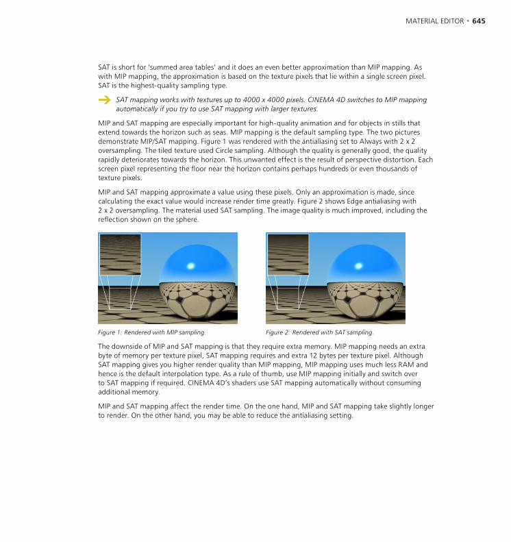
644 • CHAPTER 18 MATERIAL EDITOR • 645
SAT is short for ‘summed area tables’ and it does an even better approximation than MIP mapping. As with MIP mapping, the approximation is based on the texture pixels that lie within a single screen pixel. SAT is the highest-quality sampling type.
SAT mapping works with textures up to 4000 x 4000 pixels. CINEMA 4D switches to MIP mapping automatically if you try to use SAT mapping with larger textures.
MIP and SAT mapping are especially important for high-quality animation and for objects in stills that extend towards the horizon such as seas. MIP mapping is the default sampling type. The two pictures demonstrate MIP/SAT mapping. Figure 1 was rendered with the antialiasing set to Always with 2 x 2 oversampling. The tiled texture used Circle sampling. Although the quality is generally good, the quality rapidly deteriorates towards the horizon. This unwanted effect is the result of perspective distortion. Each screen pixel representing the floor near the horizon contains perhaps hundreds or even thousands of texture pixels.
MIP and SAT mapping approximate a value using these pixels. Only an approximation is made, since calculating the exact value would increase render time greatly. Figure 2 shows Edge antialiasing with 2 x 2 oversampling. The material used SAT sampling. The image quality is much improved, including the reflection shown on the sphere.
Figure 1: Rendered with MIP sampling. Figure 2: Rendered with SAT sampling.
The downside of MIP and SAT mapping is that they require extra memory. MIP mapping needs an extra byte of memory per texture pixel, SAT mapping requires and extra 12 bytes per texture pixel. Although SAT mapping gives you higher render quality than MIP mapping, MIP mapping uses much less RAM and hence is the default interpolation type. As a rule of thumb, use MIP mapping initially and switch over to SAT mapping if required. CINEMA 4D’s shaders use SAT mapping automatically without consuming additional memory.
MIP and SAT mapping affect the render time. On the one hand, MIP and SAT mapping take slightly longer to render. On the other hand, you may be able to reduce the antialiasing setting.
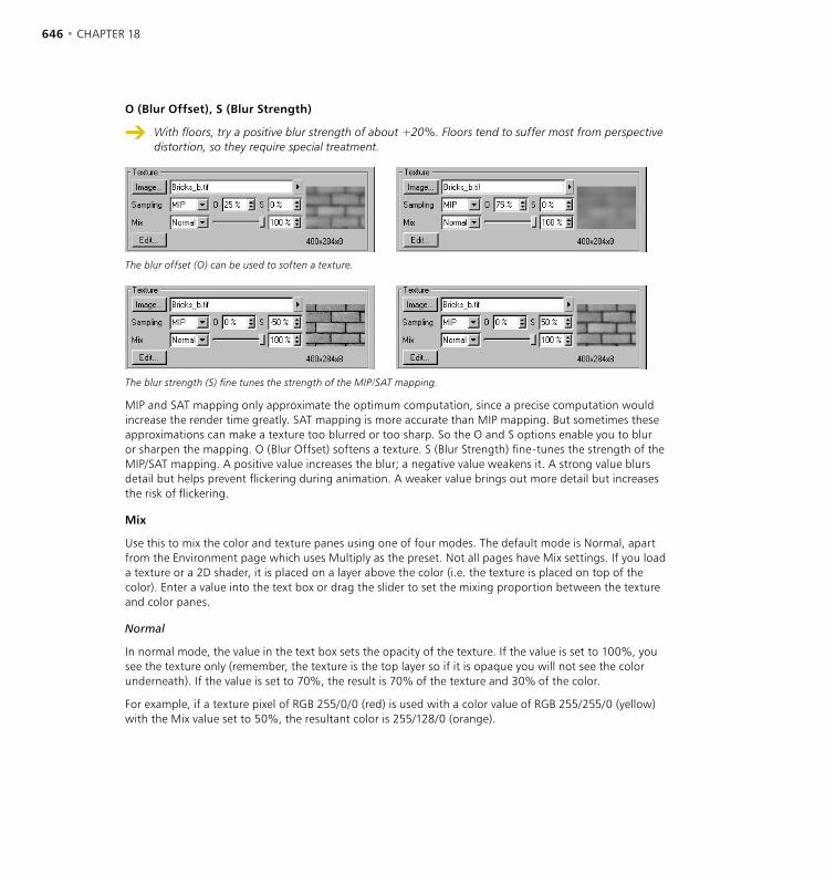
646 • CHAPTER 18 MATERIAL EDITOR • 647
O (Blur Offset), S (Blur Strength)
With floors, try a positive blur strength of about +20%. Floors tend to suffer most from perspective distortion, so they require special treatment.
The blur offset (O) can be used to soften a texture.
The blur strength (S) fine tunes the strength of the MIP/SAT mapping.
MIP and SAT mapping only approximate the optimum computation, since a precise computation would increase the render time greatly. SAT mapping is more accurate than MIP mapping. But sometimes these approximations can make a texture too blurred or too sharp. So the O and S options enable you to blur or sharpen the mapping. O (Blur Offset) softens a texture. S (Blur Strength) fine-tunes the strength of the MIP/SAT mapping. A positive value increases the blur; a negative value weakens it. A strong value blurs detail but helps prevent flickering during animation. A weaker value brings out more detail but increases the risk of flickering.
Mix
Use this to mix the color and texture panes using one of four modes. The default mode is Normal, apart from the Environment page which uses Multiply as the preset. Not all pages have Mix settings. If you load a texture or a 2D shader, it is placed on a layer above the color (i.e. the texture is placed on top of the color). Enter a value into the text box or drag the slider to set the mixing proportion between the texture and color panes.
Normal
In normal mode, the value in the text box sets the opacity of the texture. If the value is set to 100%, you see the texture only (remember, the texture is the top layer so if it is opaque you will not see the color underneath). If the value is set to 70%, the result is 70% of the texture and 30% of the color.
For example, if a texture pixel of RGB 255/0/0 (red) is used with a color value of RGB 255/255/0 (yellow) with the Mix value set to 50%, the resultant color is 255/128/0 (orange).
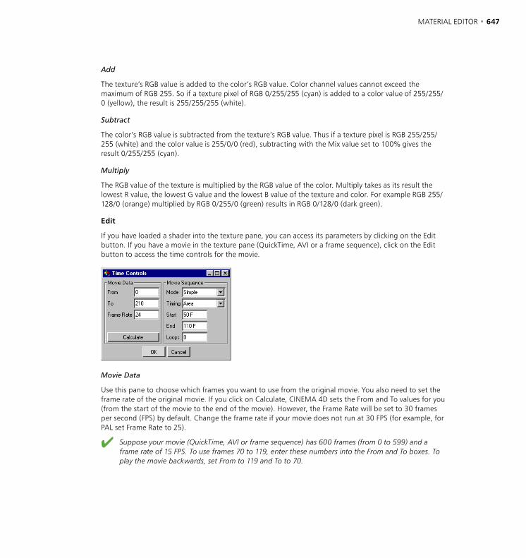
646 • CHAPTER 18 MATERIAL EDITOR • 647
Add
The texture’s RGB value is added to the color’s RGB value. Color channel values cannot exceed the maximum of RGB 255. So if a texture pixel of RGB 0/255/255 (cyan) is added to a color value of 255/255/0 (yellow), the result is 255/255/255 (white).
Subtract
The color’s RGB value is subtracted from the texture’s RGB value. Thus if a texture pixel is RGB 255/255/255 (white) and the color value is 255/0/0 (red), subtracting with the Mix value set to 100% gives the result 0/255/255 (cyan).
Multiply
The RGB value of the texture is multiplied by the RGB value of the color. Multiply takes as its result the lowest R value, the lowest G value and the lowest B value of the texture and color. For example RGB 255/128/0 (orange) multiplied by RGB 0/255/0 (green) results in RGB 0/128/0 (dark green).
Edit
If you have loaded a shader into the texture pane, you can access its parameters by clicking on the Edit button. If you have a movie in the texture pane (QuickTime, AVI or a frame sequence), click on the Edit button to access the time controls for the movie.
Movie Data
Use this pane to choose which frames you want to use from the original movie. You also need to set the frame rate of the original movie. If you click on Calculate, CINEMA 4D sets the From and To values for you (from the start of the movie to the end of the movie). However, the Frame Rate will be set to 30 frames per second (FPS) by default. Change the frame rate if your movie does not run at 30 FPS (for example, for PAL set Frame Rate to 25).
Suppose your movie (QuickTime, AVI or frame sequence) has 600 frames (from 0 to 599) and a frame rate of 15 FPS. To use frames 70 to 119, enter these numbers into the From and To boxes. To play the movie backwards, set From to 119 and To to 70.
648 • CHAPTER 18 MATERIAL EDITOR • 649
Movie Sequence
Use this pane to define how the animated texture should be played back by CINEMA 4D. Mode sets the general playback mode: Simple will play the movie once from start to finish; Loop will play the movie from start to finish repeatedly; Ping-Pong will play the movie from start to finish to start repeatedly. With Loop, the texture remains on the last frame of the movie once it has finished playing.
Use Timing to set the timing of the movie. Exact Frame will use one frame of the movie per frame of your animation. No frames will be dropped. If the movie and your animation use a different FPS setting, the movie will play back either more slowly or more quickly than the original. Exact Second matches each second of the movie against each second of your animation, which ensures that the movie will be played back at the same speed as the original. If you choose Area, CINEMA 4D will play the movie once over a specified frame range (From and To) of your animation. Use this option if you do not want the texture to start playing immediately.
You can use Loops to repeat the movie a finite number of times. If you set Loops to 1, the movie will be repeated once.
You want to play a movie (QuickTime, AVI or frame sequence).Select the movie in the Texture pane of the Material Editor.Click the Edit button to open the Time Controls.Click Calculate.Click OK.Result: the movie is played back once and is second-synchronized.
You want to play a movie from frame 25 to frame 350 of your animation, forwards and backwards (ping-pong) twice.Select the movie in the Texture pane of the Material Editor.Click the Edit button to open the Time Controls.Click Calculate.Set Mode to Ping-Pong.Set Timing to Area.Set Start to 25 and End to 350.Set Loops to 1 (with one loop, the movie will be played twice).Click OK.Result: the movie is played forwards and backwards, then backwards and forwards using frame 25 to frame 350 of your animation.
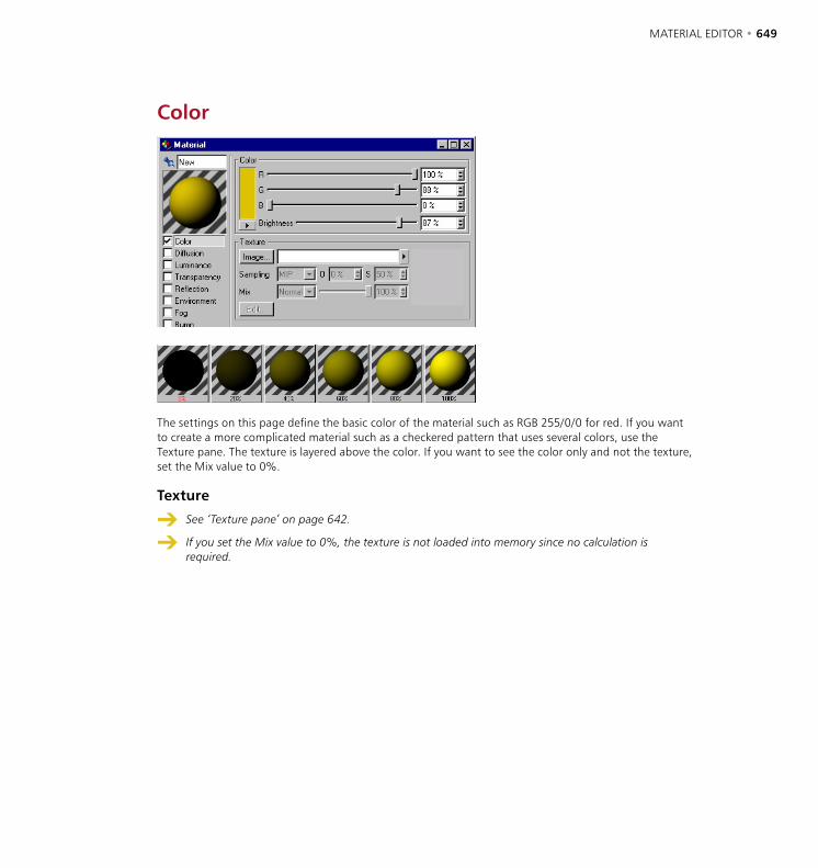
648 • CHAPTER 18 MATERIAL EDITOR • 649
Color
The settings on this page define the basic color of the material such as RGB 255/0/0 for red. If you want to create a more complicated material such as a checkered pattern that uses several colors, use the Texture pane. The texture is layered above the color. If you want to see the color only and not the texture, set the Mix value to 0%.
Texture
See ‘Texture pane’ on page 642.
If you set the Mix value to 0%, the texture is not loaded into memory since no calculation is required.

650 • CHAPTER 18 MATERIAL EDITOR • 651
Diffusion
The Diffusion page lets you darken and lighten the material in specific areas using a diffusion map. One reason for using a diffusion map is to dirty-up materials — a must for photorealism. You can use either a normal texture or a shader as the diffusion map. (If the texture is colored, it will still be treated as a grayscale map.) The darker a pixel in the diffusion map, the darker the corresponding region of the material.
Affect
Enable the Luminance option if you want the diffusion map to affect the luminance property. The darker a pixel in the diffusion map, the darker the corresponding region of the luminance. This helps you add irregularities to the luminance to achieve a more natural look.
If the Specular option is enabled, the diffusion map is applied to the specular property as well. This will reduce the material’s specular values where the diffusion map is dark. This option is enabled by default since it adds to the realism considerably.
Enable Reflection if you want to apply the diffusion map to the reflection and environment properties for an even more natural look. The darker a pixel in the diffusion map, the darker the corresponding region of the reflection.
Texture
See ‘Texture pane’ on page 642.
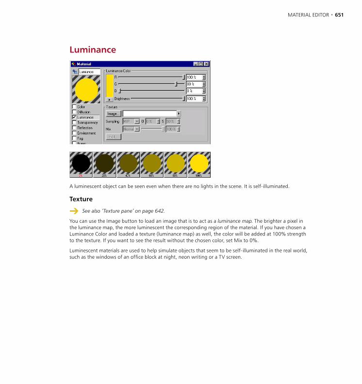
650 • CHAPTER 18 MATERIAL EDITOR • 651
Luminance
A luminescent object can be seen even when there are no lights in the scene. It is self-illuminated.
Texture
See also ‘Texture pane’ on page 642.
You can use the Image button to load an image that is to act as a luminance map. The brighter a pixel in the luminance map, the more luminescent the corresponding region of the material. If you have chosen a Luminance Color and loaded a texture (luminance map) as well, the color will be added at 100% strength to the texture. If you want to see the result without the chosen color, set Mix to 0%.
Luminescent materials are used to help simulate objects that seem to be self-illuminated in the real world, such as the windows of an office block at night, neon writing or a TV screen.
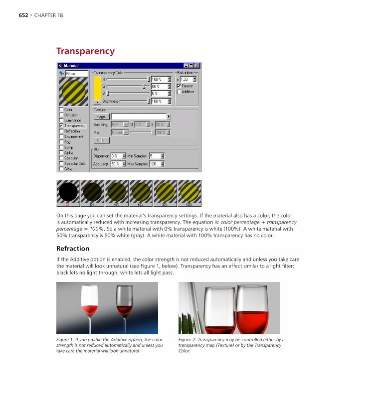
652 • CHAPTER 18 MATERIAL EDITOR • 653
Transparency
On this page you can set the material’s transparency settings. If the material also has a color, the color is automatically reduced with increasing transparency. The equation is: color percentage + transparency percentage = 100% . So a white material with 0% transparency is white (100%). A white material with 50% transparency is 50% white (gray). A white material with 100% transparency has no color.
Refraction
If the Additive option is enabled, the color strength is not reduced automatically and unless you take care the material will look unnatural (see Figure 1, below). Transparency has an effect similar to a light filter; black lets no light through, white lets all light pass.
Figure 1: If you enable the Additive option, the color strength is not reduced automatically and unless you take care the material will look unnatural.
Figure 2: Transparency may be controlled either by a transparency map (Texture) or by the Transparency Color.
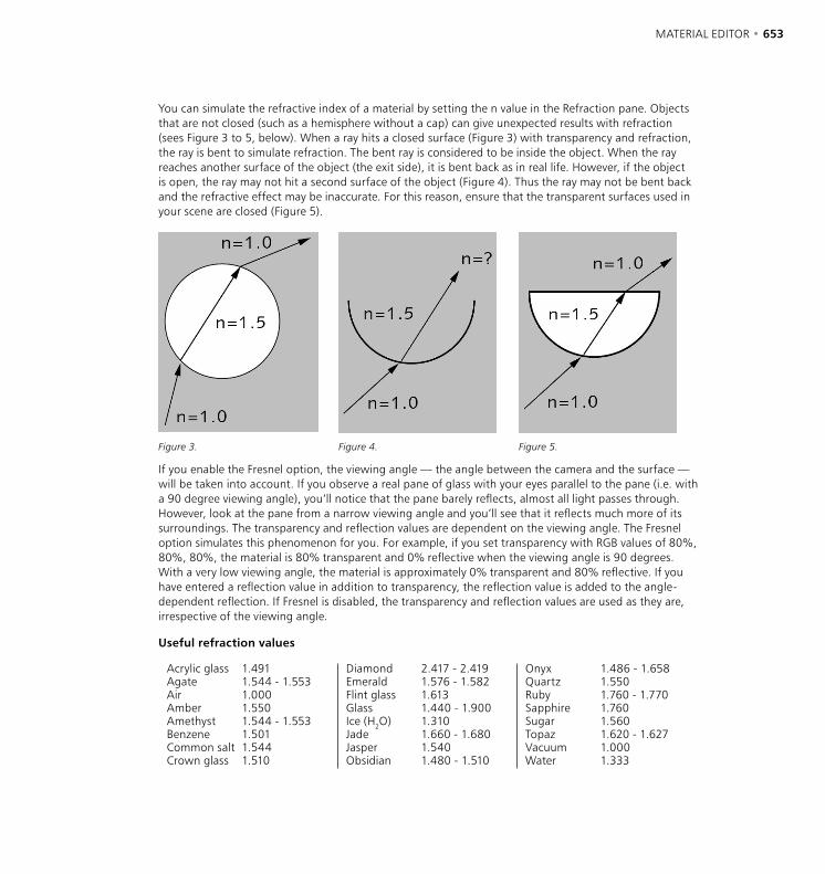
652 • CHAPTER 18 MATERIAL EDITOR • 653
You can simulate the refractive index of a material by setting the n value in the Refraction pane. Objects that are not closed (such as a hemisphere without a cap) can give unexpected results with refraction (sees Figure 3 to 5, below). When a ray hits a closed surface (Figure 3) with transparency and refraction, the ray is bent to simulate refraction. The bent ray is considered to be inside the object. When the ray reaches another surface of the object (the exit side), it is bent back as in real life. However, if the object is open, the ray may not hit a second surface of the object (Figure 4). Thus the ray may not be bent back and the refractive effect may be inaccurate. For this reason, ensure that the transparent surfaces used in your scene are closed (Figure 5).
Figure 3. Figure 4. Figure 5.
If you enable the Fresnel option, the viewing angle — the angle between the camera and the surface — will be taken into account. If you observe a real pane of glass with your eyes parallel to the pane (i.e. with a 90 degree viewing angle), you’ll notice that the pane barely reflects, almost all light passes through. However, look at the pane from a narrow viewing angle and you’ll see that it reflects much more of its surroundings. The transparency and reflection values are dependent on the viewing angle. The Fresnel option simulates this phenomenon for you. For example, if you set transparency with RGB values of 80%, 80%, 80%, the material is 80% transparent and 0% reflective when the viewing angle is 90 degrees. With a very low viewing angle, the material is approximately 0% transparent and 80% reflective. If you have entered a reflection value in addition to transparency, the reflection value is added to the angle-dependent reflection. If Fresnel is disabled, the transparency and reflection values are used as they are, irrespective of the viewing angle.
Useful refraction values
Acrylic glass 1.491 Diamond 2.417 - 2.419 Onyx 1.486 - 1.658Agate 1.544 - 1.553 Emerald 1.576 - 1.582 Quartz 1.550Air 1.000 Flint glass 1.613 Ruby 1.760 - 1.770Amber 1.550 Glass 1.440 - 1.900 Sapphire 1.760Amethyst 1.544 - 1.553 Ice (H2O) 1.310 Sugar 1.560Benzene 1.501 Jade 1.660 - 1.680 Topaz 1.620 - 1.627Common salt 1.544 Jasper 1.540 Vacuum 1.000Crown glass 1.510 Obsidian 1.480 - 1.510 Water 1.333
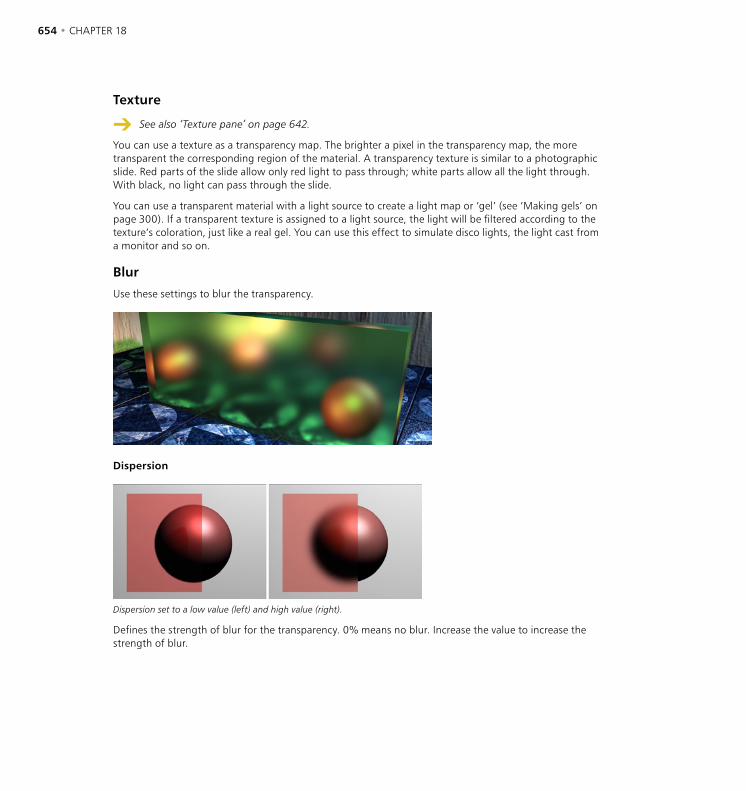
654 • CHAPTER 18 MATERIAL EDITOR • 655
Texture
See also ‘Texture pane’ on page 642.
You can use a texture as a transparency map. The brighter a pixel in the transparency map, the more transparent the corresponding region of the material. A transparency texture is similar to a photographic slide. Red parts of the slide allow only red light to pass through; white parts allow all the light through. With black, no light can pass through the slide.
You can use a transparent material with a light source to create a light map or ‘gel’ (see ‘Making gels’ on page 300). If a transparent texture is assigned to a light source, the light will be filtered according to the texture’s coloration, just like a real gel. You can use this effect to simulate disco lights, the light cast from a monitor and so on.
Blur
Use these settings to blur the transparency.
Dispersion
Dispersion set to a low value (left) and high value (right).
Defines the strength of blur for the transparency. 0% means no blur. Increase the value to increase the strength of blur.
654 • CHAPTER 18 MATERIAL EDITOR • 655
Accuracy
Increasing the Accuracy value gives a more accurate blur but a longer render time also.
Affects the accuracy of the blur effect by controlling the number of samples per shading point. With a value of 100%, the number of samples defined under Max Samples will be used. Lower the value to reduce the number of samples used.
Min Samples / Max Samples
Increasing Min Samples and/or Max Samples gives a higher quality blur, but a longer render time also.
CINEMA 4D uses samples to create the blur effect. Rather than take samples at even distances, the samples are concentrated where they are most needed. Max Samples defines the number of samples used for the most critical areas. Min Samples defines the number of samples used for the least important areas.
If you see black areas when rendering overlapping transparency objects, increase the Ray Depth value on the Options page of the render settings. If you can’t see weak reflections in the render, ensure that Threshold is set to 0%. You’ll also find this parameter on the Options page of the render settings.
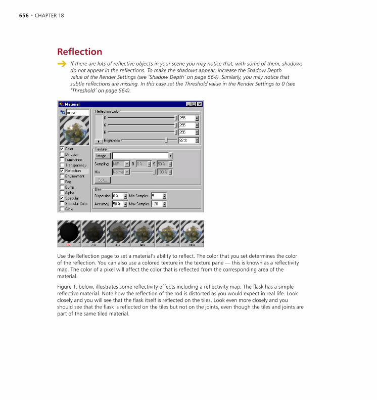
656 • CHAPTER 18 MATERIAL EDITOR • 657
Reflection If there are lots of reflective objects in your scene you may notice that, with some of them, shadows
do not appear in the reflections. To make the shadows appear, increase the Shadow Depth value of the Render Settings (see ‘Shadow Depth’ on page 564). Similarly, you may notice that subtle reflections are missing. In this case set the Threshold value in the Render Settings to 0 (see ‘Threshold’ on page 564).
Use the Reflection page to set a material’s ability to reflect. The color that you set determines the color of the reflection. You can also use a colored texture in the texture pane — this is known as a reflectivity map. The color of a pixel will affect the color that is reflected from the corresponding area of the material.
Figure 1, below, illustrates some reflectivity effects including a reflectivity map. The flask has a simple reflective material. Note how the reflection of the rod is distorted as you would expect in real life. Look closely and you will see that the flask itself is reflected on the tiles. Look even more closely and you should see that the flask is reflected on the tiles but not on the joints, even though the tiles and joints are part of the same tiled material.

656 • CHAPTER 18 MATERIAL EDITOR • 657
Figure 1: Some reflectivity effects including a reflectivity map.
Figure 2: Blur Dispersion values of 85% (left), 0% (back) and 65% (right).
This effect was created by using a grayscale reflectivity map. The reflectivity map was based on the original tile and joint texture. In the areas covered by a tile the reflectivity map is white. In the joint areas the reflectivity map is black. The resultant map means that only the tiled areas, not the joints, are reflective. This is just one example of how you can combine several properties to create more realistic materials.
Texture
See ‘Texture pane’ on page 642.
Blur
Use these settings to blur reflections.
Dispersion
This defines how diffusely the object reflects. In other words, this defines how blurred reflections are. 0% means no blur. Increase the value to increase the strength of the blur effect (see Figure 2, above).
Accuracy
Increasing the Accuracy value gives a more accurate blur but a longer render time also.
This affects the accuracy of the blur — it works by controlling the number of samples used per shading point. If you enter a value of 100%, the number of samples defined under Max Samples will be used. Lower the value to reduce the number of samples used.
Min Samples / Max Samples
Increasing Min Samples and/or Max Samples gives a higher quality blur, but a longer render time also.
CINEMA 4D uses samples to create the blur effect and, rather than take samples at even distances, it concentrates the samples where they are most needed. Max Samples defines the number of samples used for the most critical areas. Min Samples defines the number of samples used for the least important areas.
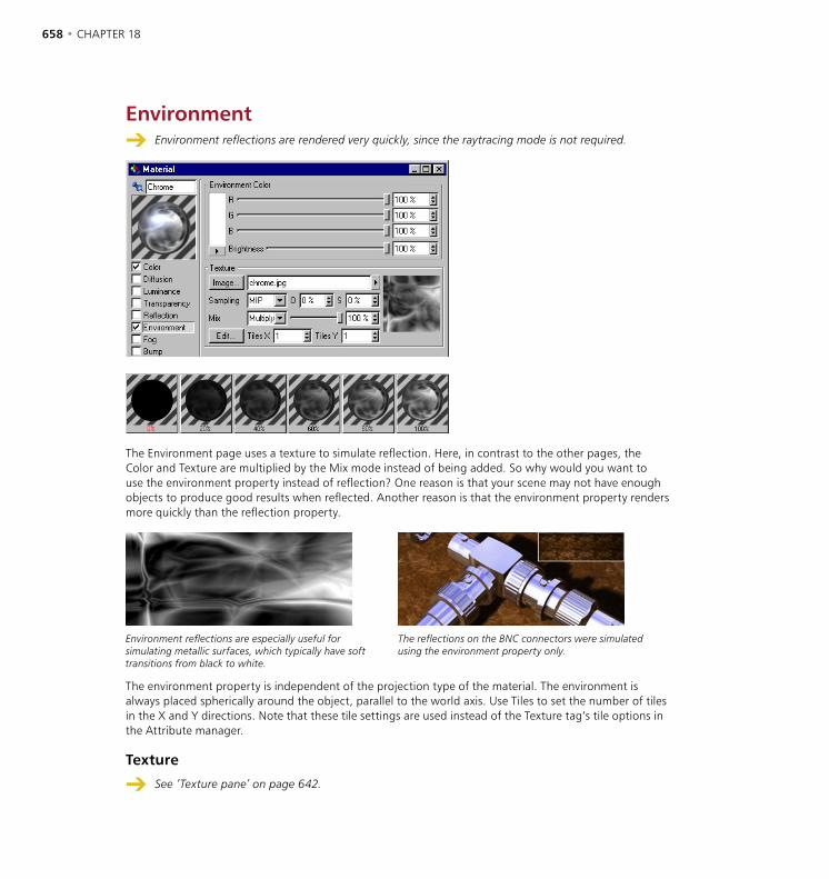
658 • CHAPTER 18 MATERIAL EDITOR • 659
Environment Environment reflections are rendered very quickly, since the raytracing mode is not required.
The Environment page uses a texture to simulate reflection. Here, in contrast to the other pages, the Color and Texture are multiplied by the Mix mode instead of being added. So why would you want to use the environment property instead of reflection? One reason is that your scene may not have enough objects to produce good results when reflected. Another reason is that the environment property renders more quickly than the reflection property.
Environment reflections are especially useful for simulating metallic surfaces, which typically have soft transitions from black to white.
The reflections on the BNC connectors were simulated using the environment property only.
The environment property is independent of the projection type of the material. The environment is always placed spherically around the object, parallel to the world axis. Use Tiles to set the number of tiles in the X and Y directions. Note that these tile settings are used instead of the Texture tag’s tile options in the Attribute manager.
Texture
See ‘Texture pane’ on page 642.

658 • CHAPTER 18 MATERIAL EDITOR • 659
Fog Fog uses the refractive index defined on the Transparency page (Refraction pane) and disables the
transparency. Fog and transparency are thus never rendered together. You can render either fog or transparency, but not both for the same material.
With these parameters you can simulate fog or gas clouds. Objects with such materials are translucent but weaken the light that shines through them, according to their density. If a light ray penetrates into the fog, it is weakened. You can control this weakening with Distance. The larger this value, the thinner the fog. Distance indicates at which distance a light ray is completely weakened.
You can color the fog and this also affects its visibility. The further you look into the fog, the less the objects are visible and the more the fog color becomes visible. The fog color therefore also depends on the distance value. If you choose, say, a Distance of 500 units, a light ray of originally 100% intensity has an intensity of 50% after a distance of 250 units and is extinguished completely after a further 250 units. The shorter the distance, the thicker the fog appears. In addition to this effect, after 250 units half the fog color is added to the light and after 500 units the full fog color is added.
This foggy effect was created by applying a fog material to a cube.
Use fog materials with closed objects only. Fog is a volume effect applied to the inside of an object. For non-closed objects, CINEMA 4D cannot determine the inside and the outside of the object so, if you use a fog material on such an object, strange things may happen.
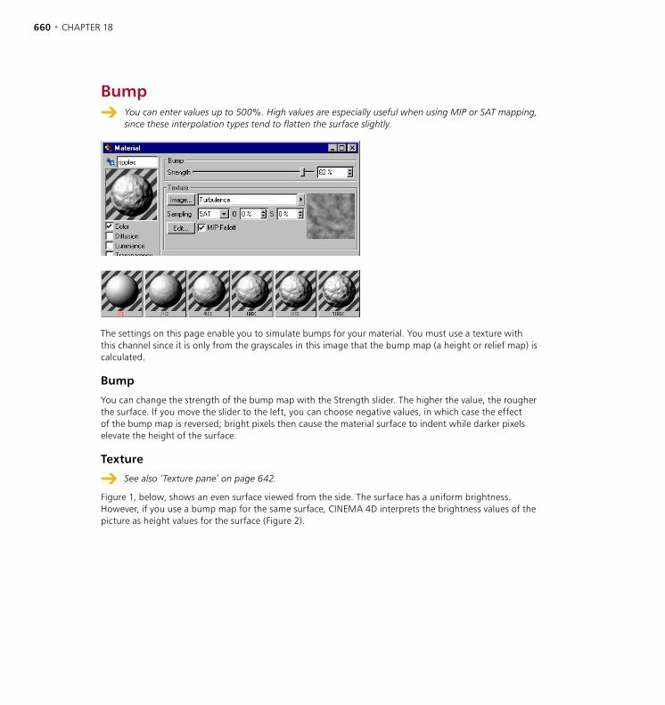
660 • CHAPTER 18 MATERIAL EDITOR • 661
Bump You can enter values up to 500%. High values are especially useful when using MIP or SAT mapping,
since these interpolation types tend to flatten the surface slightly.
The settings on this page enable you to simulate bumps for your material. You must use a texture with this channel since it is only from the grayscales in this image that the bump map (a height or relief map) is calculated.
Bump
You can change the strength of the bump map with the Strength slider. The higher the value, the rougher the surface. If you move the slider to the left, you can choose negative values, in which case the effect of the bump map is reversed; bright pixels then cause the material surface to indent while darker pixels elevate the height of the surface.
Texture
See also ‘Texture pane’ on page 642.
Figure 1, below, shows an even surface viewed from the side. The surface has a uniform brightness. However, if you use a bump map for the same surface, CINEMA 4D interprets the brightness values of the picture as height values for the surface (Figure 2).
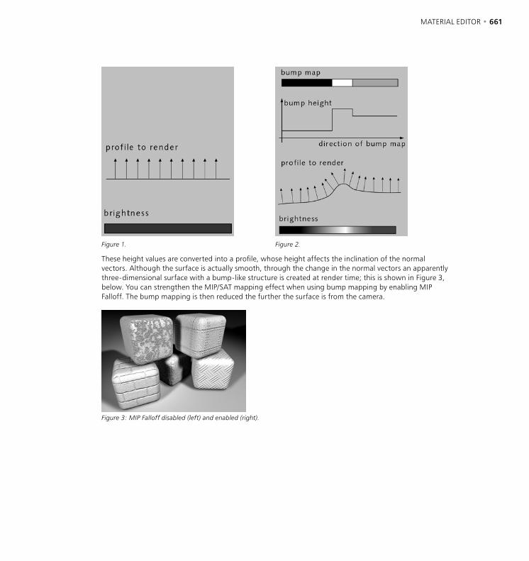
660 • CHAPTER 18 MATERIAL EDITOR • 661
Figure 1. Figure 2.
These height values are converted into a profile, whose height affects the inclination of the normal vectors. Although the surface is actually smooth, through the change in the normal vectors an apparently three-dimensional surface with a bump-like structure is created at render time; this is shown in Figure 3, below. You can strengthen the MIP/SAT mapping effect when using bump mapping by enabling MIP Falloff. The bump mapping is then reduced the further the surface is from the camera.
Figure 3: MIP Falloff disabled (left) and enabled (right).
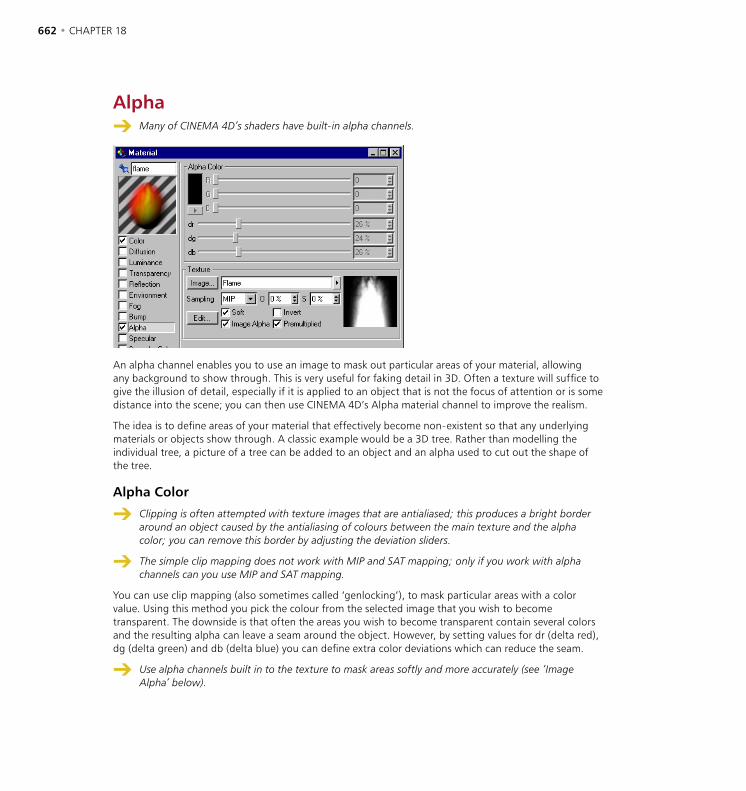
662 • CHAPTER 18 MATERIAL EDITOR • 663
Alpha Many of CINEMA 4D’s shaders have built-in alpha channels.
An alpha channel enables you to use an image to mask out particular areas of your material, allowing any background to show through. This is very useful for faking detail in 3D. Often a texture will suffice to give the illusion of detail, especially if it is applied to an object that is not the focus of attention or is some distance into the scene; you can then use CINEMA 4D’s Alpha material channel to improve the realism.
The idea is to define areas of your material that effectively become non-existent so that any underlying materials or objects show through. A classic example would be a 3D tree. Rather than modelling the individual tree, a picture of a tree can be added to an object and an alpha used to cut out the shape of the tree.
Alpha Color
Clipping is often attempted with texture images that are antialiased; this produces a bright border around an object caused by the antialiasing of colours between the main texture and the alpha color; you can remove this border by adjusting the deviation sliders.
The simple clip mapping does not work with MIP and SAT mapping; only if you work with alpha channels can you use MIP and SAT mapping.
You can use clip mapping (also sometimes called ‘genlocking’), to mask particular areas with a color value. Using this method you pick the colour from the selected image that you wish to become transparent. The downside is that often the areas you wish to become transparent contain several colors and the resulting alpha can leave a seam around the object. However, by setting values for dr (delta red), dg (delta green) and db (delta blue) you can define extra color deviations which can reduce the seam.
Use alpha channels built in to the texture to mask areas softly and more accurately (see ‘Image Alpha’ below).
662 • CHAPTER 18 MATERIAL EDITOR • 663
Texture
See ‘Texture pane’ on page 642.
Soft
This enables you to fade textures and materials from one to another, which gives you even more ways of creating realistic-looking objects. With Soft enabled (the default setting) the color and delta sliders lose their meaning. The texture map is now used to decide which ranges should be faded. A white texture pixel within the image means that here the material is to be 100% opaque. If the texture pixel is black the underlying material shines through 100%.
Image Alpha
If you notice black areas when rendering objects that have multiple alpha materials, increase the Ray Depth value on the Options page of the render settings.
If you apply a material with a CINEMA 4D Alpha channel to an object and the object has no underlying material, the object will be non-existent at the points where the alpha allows the underlying material to show through.
With Image Alpha enabled, you can use any existing alpha channel of the loaded image. Alpha channels of the TIF, TGA, PICT, Photoshop PSD and QuickTime MOV image formats are supported (as well as all QuickTime supported formats). If no alpha channel is present in the image, the option Image Alpha will be ignored. Use the Invert function to invert the alpha channel without having to rework the texture in your image editor.
Invert
This option simply inverts the alpha, so transparent and solid areas are reversed. This works for both clipped images and images with built-in alpha channels.
Premultiplied
Enable this option if you are using a texture with a premultiplied alpha channel. Certain graphics applications only produce this type of alpha channel.
Example
Let’s say that you want to place a scanned picture of a tree into a scene. Firstly, you should create a material, enable the Color channel, choose a picture of a tree as the color texture/image and then assign this material to, perhaps, a rectangular polygon.
If you render this scene you should see the tree on the rectangle polygon. However the area around the tree is probably not transparent but may well be blue if the scanned picture has a blue sky background (Figure 1, below).
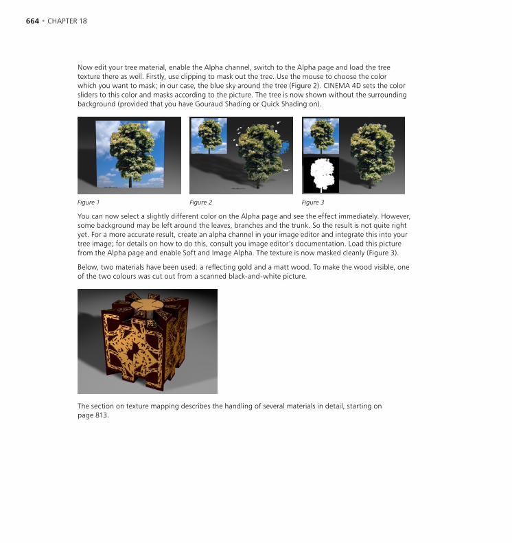
664 • CHAPTER 18 MATERIAL EDITOR • 665
Now edit your tree material, enable the Alpha channel, switch to the Alpha page and load the tree texture there as well. Firstly, use clipping to mask out the tree. Use the mouse to choose the color which you want to mask; in our case, the blue sky around the tree (Figure 2). CINEMA 4D sets the color sliders to this color and masks according to the picture. The tree is now shown without the surrounding background (provided that you have Gouraud Shading or Quick Shading on).
Figure 1 Figure 2 Figure 3
You can now select a slightly different color on the Alpha page and see the effect immediately. However, some background may be left around the leaves, branches and the trunk. So the result is not quite right yet. For a more accurate result, create an alpha channel in your image editor and integrate this into your tree image; for details on how to do this, consult you image editor’s documentation. Load this picture from the Alpha page and enable Soft and Image Alpha. The texture is now masked cleanly (Figure 3).
Below, two materials have been used: a reflecting gold and a matt wood. To make the wood visible, one of the two colours was cut out from a scanned black-and-white picture.
The section on texture mapping describes the handling of several materials in detail, starting on page 813.

664 • CHAPTER 18 MATERIAL EDITOR • 665
Specular You can enter a Height value up to 1000%. High values can be very effective in Metal mode.
Here you can adjust the width, height and falloff of highlights on the material. For a matt surface, use broad and low specular values; for shiny surfaces, narrow and high values are appropriate. Three modes are available: Plastic, Metal and Colored.
Plastic lighting model. Metal lighting model. Colored lighting model.
With Plastic, the color of the highlights is independent of the material’s color and will be white unless you define a different color on the Specular Color page. Use Plastic mode for materials such as plastics, glass or wood, all of which tend to have white highlights. For matt metal surfaces such as brass, silver and gold, the Metal mode is the best setting. The color of highlights is then based on the material’s color. With the Colored mode, you influence the specular diffusion (see the description of the Specular option under ‘Affect’ on page 650). You can adjust the shape of the falloff curve using the Falloff slider. Needle, bell and even rectangular shapes are possible. In addition, the Inner Width slider enables you to define an area inside the specular that has no brightness falloff.
Falloff set to 10 (left) and 90 (right).

666 • CHAPTER 18 MATERIAL EDITOR • 667
Specular Color
Here you can select the color of the highlights. The strengths of the colors on the Color page and the Specular Color page are added together. The total color here is multiplied with the normal color of the highlight. For example, if you have a white plastic highlight, you can define its color here directly.
With metallic effects in particular, any highlight color other than white greatly adds to the realistic appearance of the material as demonstrated by this spaceship.
Texture
See also ‘Texture pane’ on page 642.
The intensity of the specular is affected by any chosen texture image (color or grayscale); click the Image button to load a texture. The brighter a pixel in the image, the more evident the highlight is at that point.

666 • CHAPTER 18 MATERIAL EDITOR • 667
Glow Glows cannot be seen through transparent objects, nor in reflections. The glow you specify here
does not act as a light; other parts of the scene will not be lit by the glow, nor will any shadows be cast.
This page enables you to create a soft glow. Inner Strength specifies the intensity of the glow above the material surface; Outer Strength is the intensity of the glow at the edges (see Figure 1, below). The Radius determines how far the glow extends from the surface. This value is rendered relative to the distance of the object from the camera. The further the object is, the smaller the glow and vice versa.
Glows are restricted to a maximum image resolution of 4,000 x 4,000 pixels.
Figure 1. Figure 2.

668 • CHAPTER 18 MATERIAL EDITOR • 669
If a random percentage is defined, the intensity of the glow in each animation frame is increased and decreased in a random pattern, as follows:
0% No change 100% Maximum change
Frequency specifies how often the glow changes. The amplitude of the change is given by the Random value.
1Hz The glow reaches a new random value after 1 second 25Hz The glow has a new value for each frame (for 30 fps), which causes a flicker
If Use Material Color is enabled, the glow is calculated on the basis of the material color rather than the color specified here. If the option is disabled, the object and glow colors are mixed. For example, green objects will appear yellowish under a red glow.
Figure 2 illustrates two examples of using glow. The glowing areas of the burning coals were created with Use Material Color enabled. For the neon sign, only an outer glow was used.
When using object motion blur, glow applied to lights may cause colors to overlap.
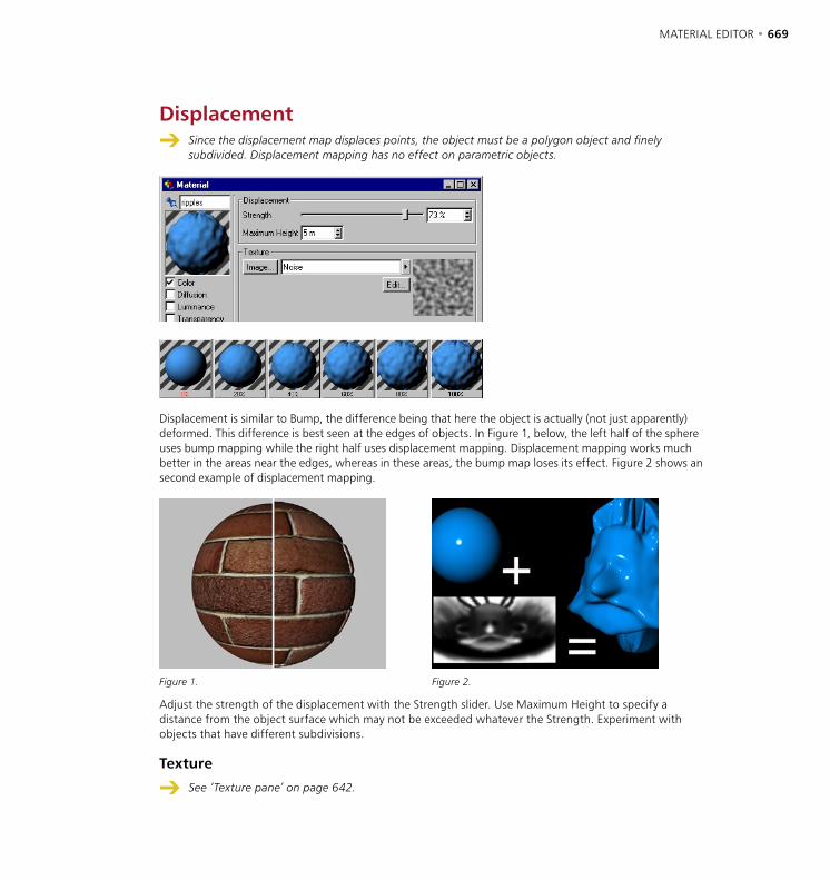
668 • CHAPTER 18 MATERIAL EDITOR • 669
Displacement Since the displacement map displaces points, the object must be a polygon object and finely
subdivided. Displacement mapping has no effect on parametric objects.
Displacement is similar to Bump, the difference being that here the object is actually (not just apparently) deformed. This difference is best seen at the edges of objects. In Figure 1, below, the left half of the sphere uses bump mapping while the right half uses displacement mapping. Displacement mapping works much better in the areas near the edges, whereas in these areas, the bump map loses its effect. Figure 2 shows an second example of displacement mapping.
Figure 1. Figure 2.
Adjust the strength of the displacement with the Strength slider. Use Maximum Height to specify a distance from the object surface which may not be exceeded whatever the Strength. Experiment with objects that have different subdivisions.
Texture
See ‘Texture pane’ on page 642.
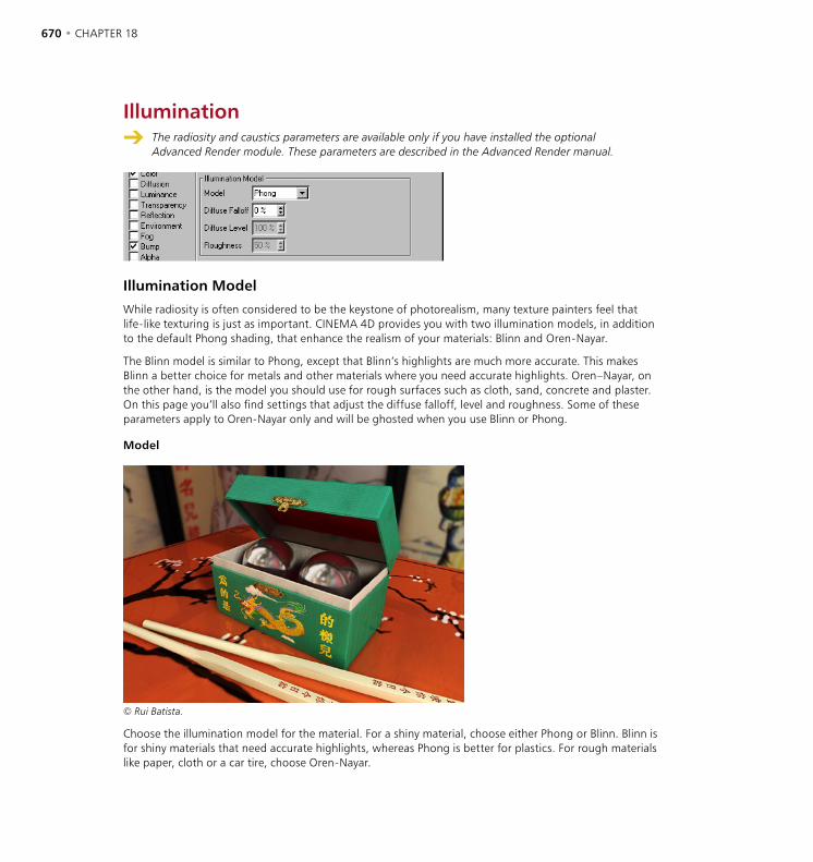
670 • CHAPTER 18 MATERIAL EDITOR • 671
Illumination The radiosity and caustics parameters are available only if you have installed the optional
Advanced Render module. These parameters are described in the Advanced Render manual.
Illumination Model
While radiosity is often considered to be the keystone of photorealism, many texture painters feel that life-like texturing is just as important. CINEMA 4D provides you with two illumination models, in addition to the default Phong shading, that enhance the realism of your materials: Blinn and Oren-Nayar.
The Blinn model is similar to Phong, except that Blinn’s highlights are much more accurate. This makes Blinn a better choice for metals and other materials where you need accurate highlights. Oren–Nayar, on the other hand, is the model you should use for rough surfaces such as cloth, sand, concrete and plaster. On this page you’ll also find settings that adjust the diffuse falloff, level and roughness. Some of these parameters apply to Oren-Nayar only and will be ghosted when you use Blinn or Phong.
Model
© Rui Batista.
Choose the illumination model for the material. For a shiny material, choose either Phong or Blinn. Blinn is for shiny materials that need accurate highlights, whereas Phong is better for plastics. For rough materials like paper, cloth or a car tire, choose Oren-Nayar.
670 • CHAPTER 18 MATERIAL EDITOR • 671
Diffuse Falloff
Use this parameter to adjust the falloff of diffuse reflection. The default value of 0% means normal falloff.
Diffuse Level (Oren-Nayar only)
You can use this parameter to alter the strength of diffuse reflection for Oren–Nayar. The default of 100% means normal diffuse reflection — enter a lower value to reduce the amount of reflection.
Roughness (Oren-Nayar only)
Adjust this value to match the roughness of your material. The default setting is 50%.

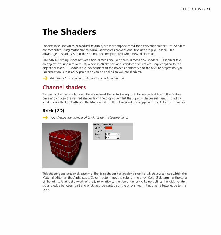
THE SHADERS • 673
Shaders (also known as procedural textures) are more sophisticated than conventional textures. Shaders are computed using mathematical formulae whereas conventional textures are pixel-based. One advantage of shaders is that they do not become pixelated when viewed close-up.
CINEMA 4D distinguishes between two-dimensional and three-dimensional shaders. 3D shaders take an object’s volume into account, whereas 2D shaders and standard textures are simply applied to the object’s surface. 3D shaders are independent of the object’s geometry and the texture projection type (an exception is that UVW projection can be applied to volume shaders).
All parameters of 2D and 3D shaders can be animated.
Channel shadersTo open a channel shader, click the arrowhead that is to the right of the Image text box in the Texture pane and choose the desired shader from the drop-down list that opens (Shader submenu). To edit a shader, click the Edit button in the Material editor. Its settings will then appear in the Attribute manager.
Brick (2D)
You change the number of bricks using the texture tiling.
This shader generates brick patterns. The Brick shader has an alpha channel which you can use within the Material editor on the Alpha page. Color 1 determines the color of the brick. Color 2 determines the color of the joints. Joint is the width of the joint relative to the size of the brick. Ramp defines the width of the sloping edge between joint and brick, as a percentage of the brick’s width; this gives a fuzzy edge to the brick.
The Shaders

674 • CHAPTER 18 THE SHADERS • 675
Checkerboard (2D)
This shader creates checkerboard patterns. Color 1 and Color 2 determine the colors of the two tiles. U Frequency and V Frequency determine the size of tiling, the fineness of the structure, in two independent directions. Higher values result in a smaller tiles and vice versa. If you use unequal values instead of square tiles, such as U=1 and V=2, you’ll get rectangular ones.
Cloud (2D)
Effective Cirrus-like clouds can be created with asymmetrical UV parameters (e.g. 0.25, 1).
This shader simulates simple cloud structures. The Cloud shader has an alpha channel which you can use within the Material editor on the Alpha page. The gradient determines the color of the clouds. U Frequency and V Frequency determine the fineness and shape of the structure. Thus U=1 and V=2 results in rather regular cloud structures, U=1 and V=0.25 gives rather rectangular clouds and the higher the value, the finer (less wispy) the clouds. Clouds affects the number of clouds in the sky.
The Compatibility Mode option ensures that scenes loaded from older versions of CINEMA 4D using this shader look the same.
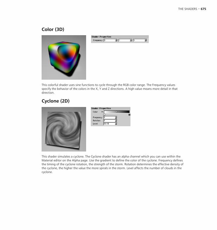
674 • CHAPTER 18 THE SHADERS • 675
Color (3D)
This colorful shader uses sine functions to cycle through the RGB color range. The Frequency values specify the behavior of the colors in the X, Y and Z directions. A high value means more detail in that direction.
Cyclone (2D)
This shader simulates a cyclone. The Cyclone shader has an alpha channel which you can use within the Material editor on the Alpha page. Use the gradient to define the color of the cyclone. Frequency defines the timing of the cyclone rotation, the strength of the storm. Rotation determines the effective density of the cyclone, the higher the value the more spirals in the storm. Level affects the number of clouds in the cyclone.
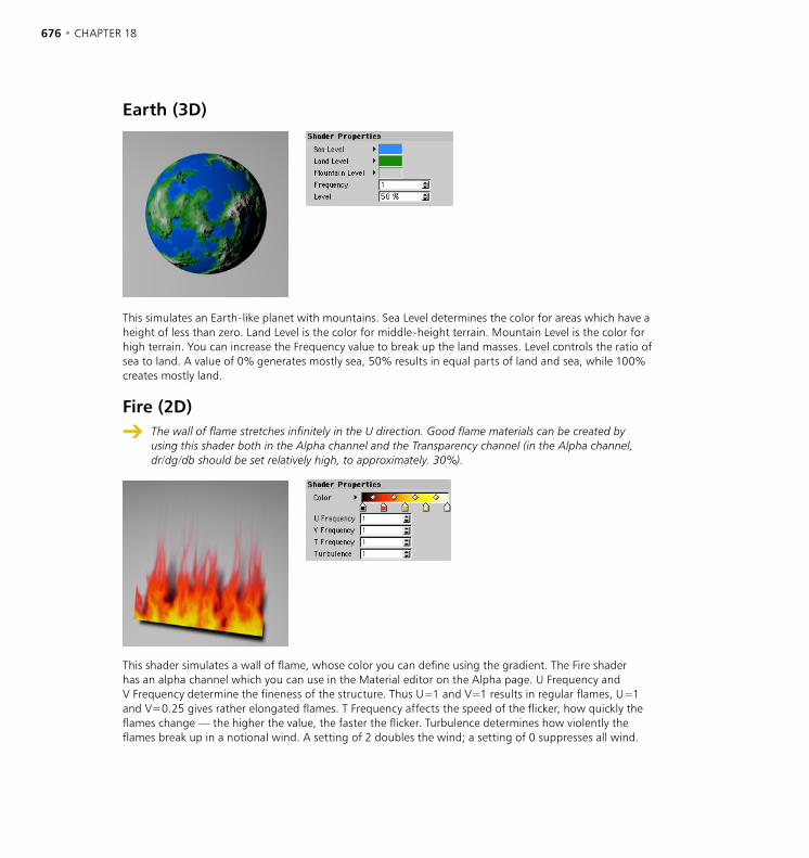
676 • CHAPTER 18 THE SHADERS • 677
Earth (3D)
This simulates an Earth-like planet with mountains. Sea Level determines the color for areas which have a height of less than zero. Land Level is the color for middle-height terrain. Mountain Level is the color for high terrain. You can increase the Frequency value to break up the land masses. Level controls the ratio of sea to land. A value of 0% generates mostly sea, 50% results in equal parts of land and sea, while 100% creates mostly land.
Fire (2D)
The wall of flame stretches infinitely in the U direction. Good flame materials can be created by using this shader both in the Alpha channel and the Transparency channel (in the Alpha channel, dr/dg/db should be set relatively high, to approximately. 30%).
This shader simulates a wall of flame, whose color you can define using the gradient. The Fire shader has an alpha channel which you can use in the Material editor on the Alpha page. U Frequency and V Frequency determine the fineness of the structure. Thus U=1 and V=1 results in regular flames, U=1 and V=0.25 gives rather elongated flames. T Frequency affects the speed of the flicker, how quickly the flames change — the higher the value, the faster the flicker. Turbulence determines how violently the flames break up in a notional wind. A setting of 2 doubles the wind; a setting of 0 suppresses all wind.
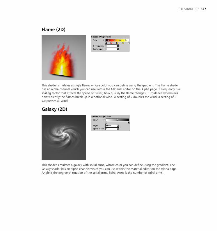
676 • CHAPTER 18 THE SHADERS • 677
Flame (2D)
This shader simulates a single flame, whose color you can define using the gradient. The Flame shader has an alpha channel which you can use within the Material editor on the Alpha page. T Frequency is a scaling factor that affects the speed of flicker, how quickly the flame changes. Turbulence determines how violently the flames break up in a notional wind. A setting of 2 doubles the wind; a setting of 0 suppresses all wind.
Galaxy (2D)
This shader simulates a galaxy with spiral arms, whose color you can define using the gradient. The Galaxy shader has an alpha channel which you can use within the Material editor on the Alpha page. Angle is the degree of rotation of the spiral arms. Spiral Arms is the number of spiral arms.
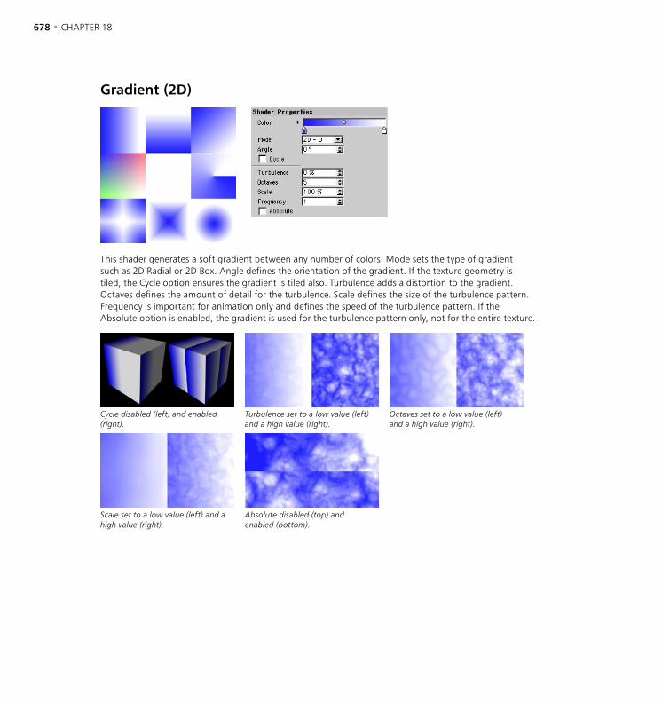
678 • CHAPTER 18 THE SHADERS • 679
Gradient (2D)
This shader generates a soft gradient between any number of colors. Mode sets the type of gradient such as 2D Radial or 2D Box. Angle defines the orientation of the gradient. If the texture geometry is tiled, the Cycle option ensures the gradient is tiled also. Turbulence adds a distortion to the gradient. Octaves defines the amount of detail for the turbulence. Scale defines the size of the turbulence pattern. Frequency is important for animation only and defines the speed of the turbulence pattern. If the Absolute option is enabled, the gradient is used for the turbulence pattern only, not for the entire texture.
Cycle disabled (left) and enabled (right).
Turbulence set to a low value (left) and a high value (right).
Octaves set to a low value (left) and a high value (right).
Scale set to a low value (left) and a high value (right).
Absolute disabled (top) and enabled (bottom).
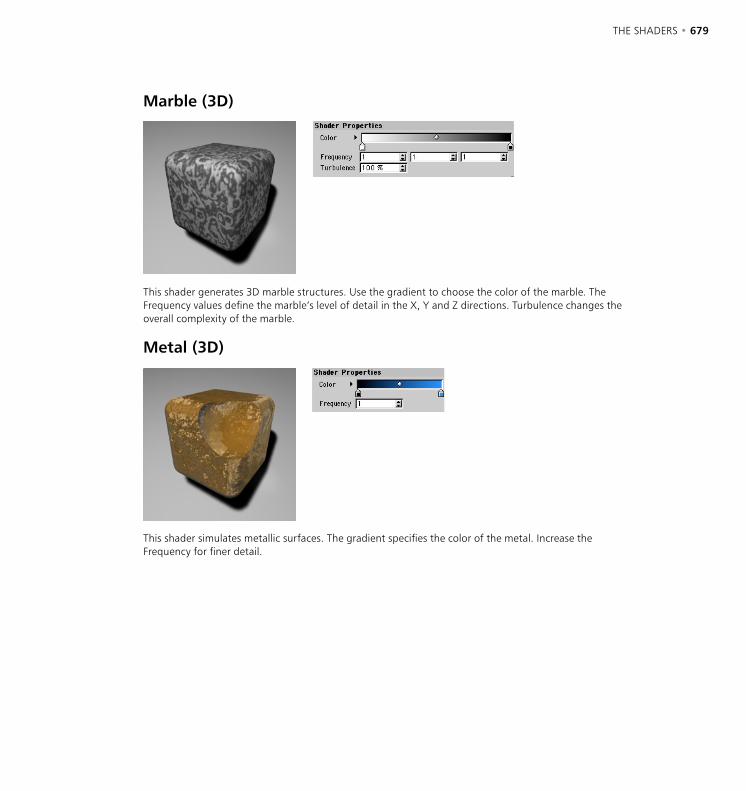
678 • CHAPTER 18 THE SHADERS • 679
Marble (3D)
This shader generates 3D marble structures. Use the gradient to choose the color of the marble. The Frequency values define the marble’s level of detail in the X, Y and Z directions. Turbulence changes the overall complexity of the marble.
Metal (3D)
This shader simulates metallic surfaces. The gradient specifies the color of the metal. Increase the Frequency for finer detail.
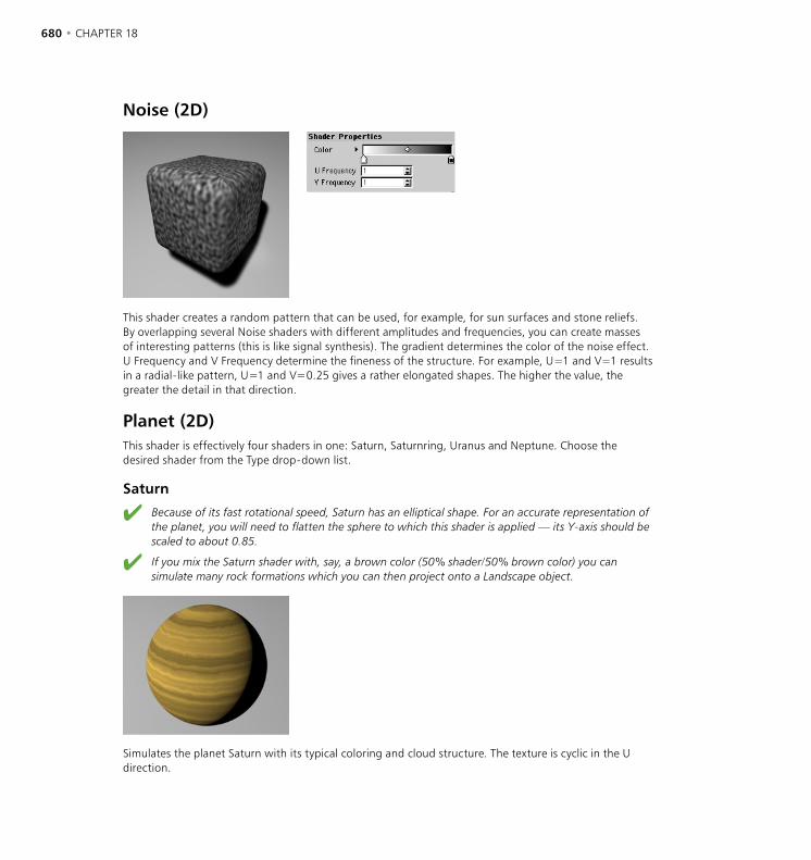
680 • CHAPTER 18 THE SHADERS • 681
Noise (2D)
This shader creates a random pattern that can be used, for example, for sun surfaces and stone reliefs. By overlapping several Noise shaders with different amplitudes and frequencies, you can create masses of interesting patterns (this is like signal synthesis). The gradient determines the color of the noise effect. U Frequency and V Frequency determine the fineness of the structure. For example, U=1 and V=1 results in a radial-like pattern, U=1 and V=0.25 gives a rather elongated shapes. The higher the value, the greater the detail in that direction.
Planet (2D)This shader is effectively four shaders in one: Saturn, Saturnring, Uranus and Neptune. Choose the desired shader from the Type drop-down list.
Saturn
Because of its fast rotational speed, Saturn has an elliptical shape. For an accurate representation of the planet, you will need to flatten the sphere to which this shader is applied — its Y-axis should be scaled to about 0.85.
If you mix the Saturn shader with, say, a brown color (50% shader/50% brown color) you can simulate many rock formations which you can then project onto a Landscape object.
Simulates the planet Saturn with its typical coloring and cloud structure. The texture is cyclic in the U direction.
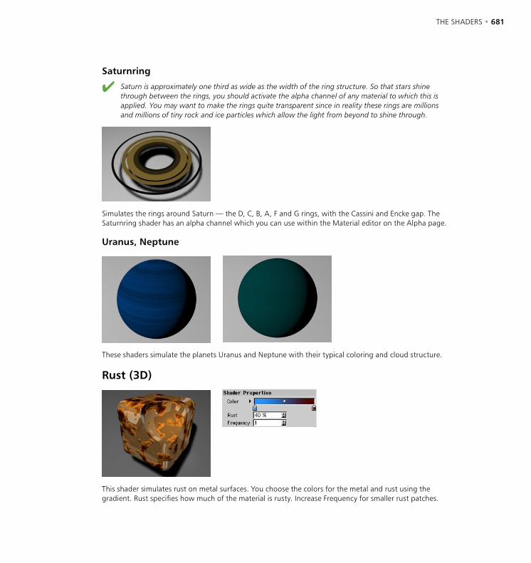
680 • CHAPTER 18 THE SHADERS • 681
Saturnring
Saturn is approximately one third as wide as the width of the ring structure. So that stars shine through between the rings, you should activate the alpha channel of any material to which this is applied. You may want to make the rings quite transparent since in reality these rings are millions and millions of tiny rock and ice particles which allow the light from beyond to shine through.
Simulates the rings around Saturn — the D, C, B, A, F and G rings, with the Cassini and Encke gap. The Saturnring shader has an alpha channel which you can use within the Material editor on the Alpha page.
Uranus, Neptune
These shaders simulate the planets Uranus and Neptune with their typical coloring and cloud structure.
Rust (3D)
This shader simulates rust on metal surfaces. You choose the colors for the metal and rust using the gradient. Rust specifies how much of the material is rusty. Increase Frequency for smaller rust patches.
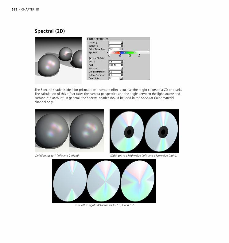
682 • CHAPTER 18 THE SHADERS • 683
Spectral (2D)
The Spectral shader is ideal for prismatic or iridescent effects such as the bright colors of a CD or pearls. The calculation of this effect takes the camera perspective and the angle between the light source and surface into account. In general, the Spectral shader should be used in the Specular Color material channel only.
Variation set to 1 (left) and 2 (right). Width set to a high value (left) and a low value (right).
From left to right: W Factor set to 1.5, 1 and 0.7.
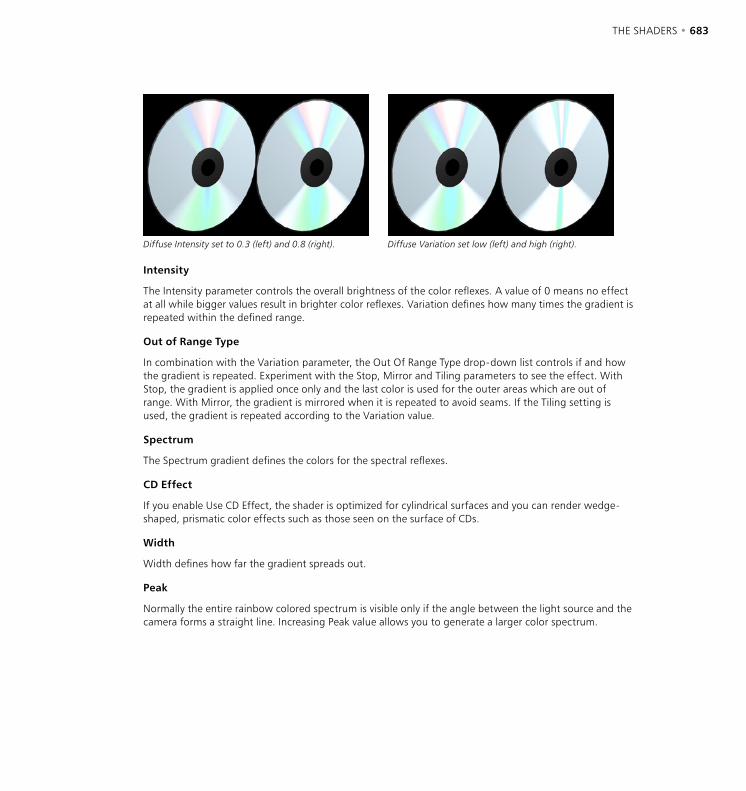
682 • CHAPTER 18 THE SHADERS • 683
Diffuse Intensity set to 0.3 (left) and 0.8 (right). Diffuse Variation set low (left) and high (right).
Intensity
The Intensity parameter controls the overall brightness of the color reflexes. A value of 0 means no effect at all while bigger values result in brighter color reflexes. Variation defines how many times the gradient is repeated within the defined range.
Out of Range Type
In combination with the Variation parameter, the Out Of Range Type drop-down list controls if and how the gradient is repeated. Experiment with the Stop, Mirror and Tiling parameters to see the effect. With Stop, the gradient is applied once only and the last color is used for the outer areas which are out of range. With Mirror, the gradient is mirrored when it is repeated to avoid seams. If the Tiling setting is used, the gradient is repeated according to the Variation value.
Spectrum
The Spectrum gradient defines the colors for the spectral reflexes.
CD Effect
If you enable Use CD Effect, the shader is optimized for cylindrical surfaces and you can render wedge-shaped, prismatic color effects such as those seen on the surface of CDs.
Width
Width defines how far the gradient spreads out.
Peak
Normally the entire rainbow colored spectrum is visible only if the angle between the light source and the camera forms a straight line. Increasing Peak value allows you to generate a larger color spectrum.
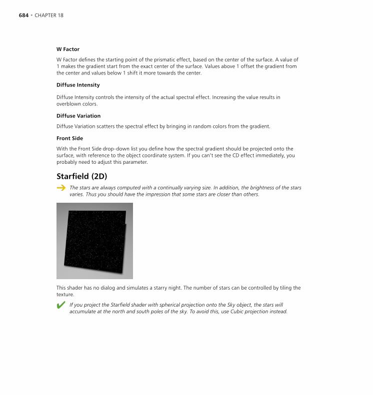
684 • CHAPTER 18 THE SHADERS • 685
W Factor
W Factor defines the starting point of the prismatic effect, based on the center of the surface. A value of 1 makes the gradient start from the exact center of the surface. Values above 1 offset the gradient from the center and values below 1 shift it more towards the center.
Diffuse Intensity
Diffuse Intensity controls the intensity of the actual spectral effect. Increasing the value results in overblown colors.
Diffuse Variation
Diffuse Variation scatters the spectral effect by bringing in random colors from the gradient.
Front Side
With the Front Side drop-down list you define how the spectral gradient should be projected onto the surface, with reference to the object coordinate system. If you can’t see the CD effect immediately, you probably need to adjust this parameter.
Starfield (2D)
The stars are always computed with a continually varying size. In addition, the brightness of the stars varies. Thus you should have the impression that some stars are closer than others.
This shader has no dialog and simulates a starry night. The number of stars can be controlled by tiling the texture.
If you project the Starfield shader with spherical projection onto the Sky object, the stars will accumulate at the north and south poles of the sky. To avoid this, use Cubic projection instead.

684 • CHAPTER 18 THE SHADERS • 685
Stars (2D)
This shader creates a star-filled wallpaper. Color 1 is the color of the wallpaper. Color 2 is the color of the stars. Streaks is the number of star tips or points. Inner Radius and Outer Radius determine the dimension of each star, given as a percentage of a UV unit. Stars is the average number of stars per UV unit.
Although we use the term UV unit above accurately, you may want to think of the preview as an element that is one UV unit in each direction — this will help you visualize the changes you make.
Sunburst (2D)
This shader generates sun flares and eruptions. The gradient determines the color of the sunburst. The Sunburst shader has an alpha channel which you can use within the Material editor on the Alpha page. R Frequency determines the radial frequency; a value of 0 yields an attractive aurora. A Frequency gives the angular disturbance; 0 gives individual layers. T Frequency defines the speed of the sunburst; 2 doubles it, 0 prevents all movement. Turbulence changes the appearance of the eruption; the higher the value, the more fragmented this region appears. Radius defines where the eruption begins, as a percentage of the overall size. Height defines the width of the eruption region relative to the radius.
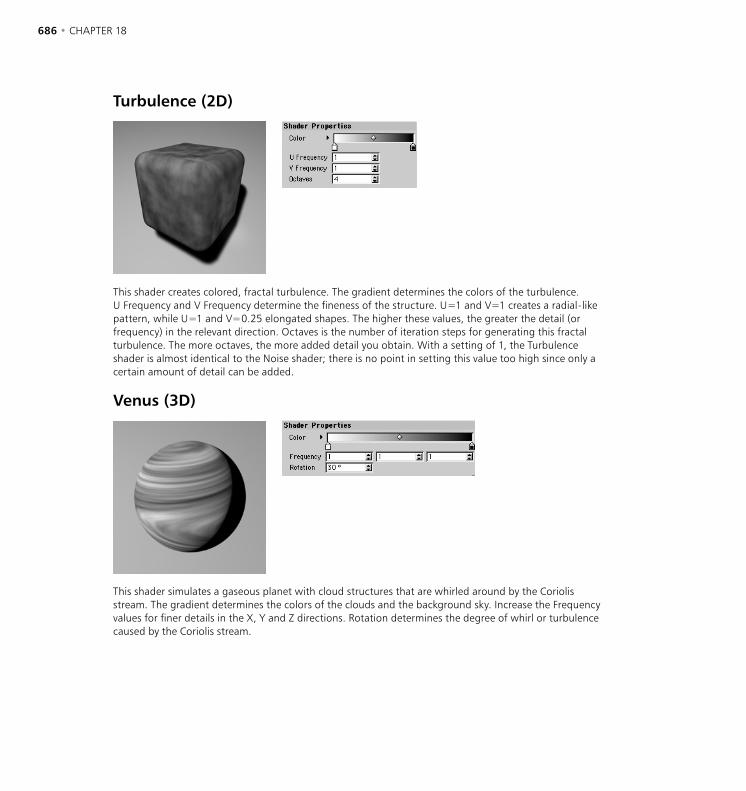
686 • CHAPTER 18 THE SHADERS • 687
Turbulence (2D)
This shader creates colored, fractal turbulence. The gradient determines the colors of the turbulence. U Frequency and V Frequency determine the fineness of the structure. U=1 and V=1 creates a radial-like pattern, while U=1 and V=0.25 elongated shapes. The higher these values, the greater the detail (or frequency) in the relevant direction. Octaves is the number of iteration steps for generating this fractal turbulence. The more octaves, the more added detail you obtain. With a setting of 1, the Turbulence shader is almost identical to the Noise shader; there is no point in setting this value too high since only a certain amount of detail can be added.
Venus (3D)
This shader simulates a gaseous planet with cloud structures that are whirled around by the Coriolis stream. The gradient determines the colors of the clouds and the background sky. Increase the Frequency values for finer details in the X, Y and Z directions. Rotation determines the degree of whirl or turbulence caused by the Coriolis stream.
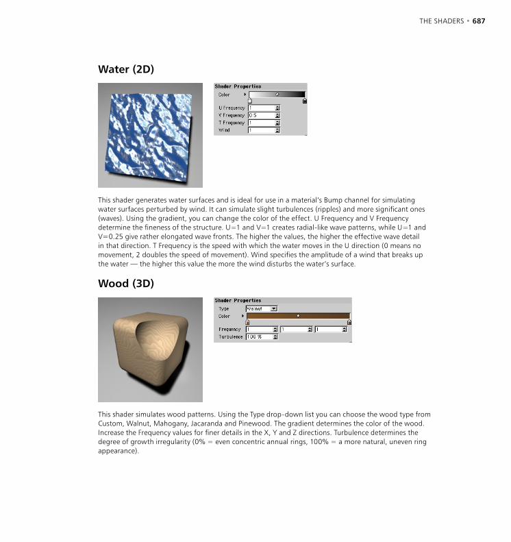
686 • CHAPTER 18 THE SHADERS • 687
Water (2D)
This shader generates water surfaces and is ideal for use in a material’s Bump channel for simulating water surfaces perturbed by wind. It can simulate slight turbulences (ripples) and more significant ones (waves). Using the gradient, you can change the color of the effect. U Frequency and V Frequency determine the fineness of the structure. U=1 and V=1 creates radial-like wave patterns, while U=1 and V=0.25 give rather elongated wave fronts. The higher the values, the higher the effective wave detail in that direction. T Frequency is the speed with which the water moves in the U direction (0 means no movement, 2 doubles the speed of movement). Wind specifies the amplitude of a wind that breaks up the water — the higher this value the more the wind disturbs the water’s surface.
Wood (3D)
This shader simulates wood patterns. Using the Type drop-down list you can choose the wood type from Custom, Walnut, Mahogany, Jacaranda and Pinewood. The gradient determines the color of the wood. Increase the Frequency values for finer details in the X, Y and Z directions. Turbulence determines the degree of growth irregularity (0% = even concentric annual rings, 100% = a more natural, uneven ring appearance).
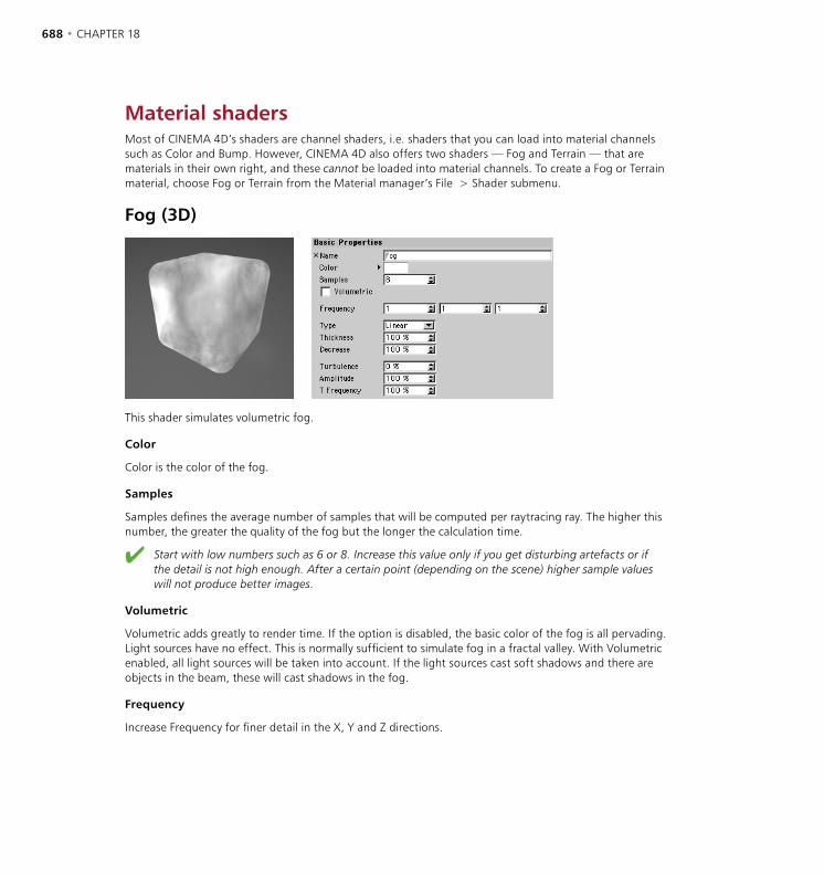
688 • CHAPTER 18 THE SHADERS • 689
Material shadersMost of CINEMA 4D’s shaders are channel shaders, i.e. shaders that you can load into material channels such as Color and Bump. However, CINEMA 4D also offers two shaders — Fog and Terrain — that are materials in their own right, and these cannot be loaded into material channels. To create a Fog or Terrain material, choose Fog or Terrain from the Material manager’s File > Shader submenu.
Fog (3D)
This shader simulates volumetric fog.
Color
Color is the color of the fog.
Samples
Samples defines the average number of samples that will be computed per raytracing ray. The higher this number, the greater the quality of the fog but the longer the calculation time.
Start with low numbers such as 6 or 8. Increase this value only if you get disturbing artefacts or if the detail is not high enough. After a certain point (depending on the scene) higher sample values will not produce better images.
Volumetric
Volumetric adds greatly to render time. If the option is disabled, the basic color of the fog is all pervading. Light sources have no effect. This is normally sufficient to simulate fog in a fractal valley. With Volumetric enabled, all light sources will be taken into account. If the light sources cast soft shadows and there are objects in the beam, these will cast shadows in the fog.
Frequency
Increase Frequency for finer detail in the X, Y and Z directions.
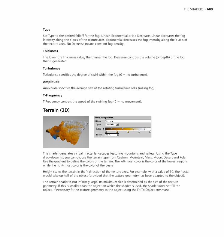
688 • CHAPTER 18 THE SHADERS • 689
Type
Set Type to the desired falloff for the fog: Linear, Exponential or No Decrease. Linear decreases the fog intensity along the Y-axis of the texture axes. Exponential decreases the fog intensity along the Y-axis of the texture axes. No Decrease means constant fog density.
Thickness
The lower the Thickness value, the thinner the fog. Decrease controls the volume (or depth) of the fog that is generated.
Turbulence
Turbulence specifies the degree of swirl within the fog (0 = no turbulence).
Amplitude
Amplitude specifies the average size of the rotating turbulence cells (rolling fog).
T-Frequency
T Frequency controls the speed of the swirling fog (0 = no movement).
Terrain (3D)
This shader generates virtual, fractal landscapes featuring mountains and valleys. Using the Type drop-down list you can choose the terrain type from Custom, Mountain, Mars, Moon, Desert and Polar. Use the gradient to define the colors of the terrain. The left-most color is the color of the lowest regions while the right-most color is the color of the peaks.
Height scales the terrain in the Y direction of the texture axes. For example, with a value of 50, the fractal would take up half of the object (provided that the texture geometry has been adapted to the object).
The Terrain shader is not infinitely large. Its maximum size is determined by the size of the texture geometry. If this is smaller than the object on which the shader is used, the shader does not fill the object. If necessary fit the texture geometry to the object using the Fit To Object command.


THE BHODINUT SHADERS • 691
The bhodiNUT shaders, collectively known as Smells Like Almonds, allow you to create textures that simply are not possible with texture maps or other methods. Things like anisotropic surfaces, multiple specular highlights, volumetric woods and more are just not achievable any other way. Although they can be complex, with a little practice and study you should be creating new materials on your own using the shading engines very soon.
The shaders included in Smells Like Almonds are procedural, meaning that the color you see is calculated by a program based on the location in space and other factors in the scene. This allows them to do things not possible with texture maps because the shader knows things like light intensity, direction of the surface, where the camera is etc. so it can use these things to change the surface. Shaders can also do things to change the way CINEMA 4D would normally render a surface by changing illumination, surface normals and more.
Figure 1. Figure 2.
Figure 3. Figure 4.
The shaders in Smells Like Almonds give you control of the attributes of a surface that they affect through their parameters. You edit the parameters in the dialog boxes that come up when you double-click the material or click Edit in the Material editor. Most of the shaders have similar controls for the usual attributes of a surface. There are two types of shaders in this package, volume (3D) and channel (2D). Channel shaders work similarly to image maps. You load them by choosing a shader in a channel (such as color, transparency etc.) of the Material editor by clicking on the pop down menu beside the Image text box (see Figure 1, above).
The bhodiNUT Shaders
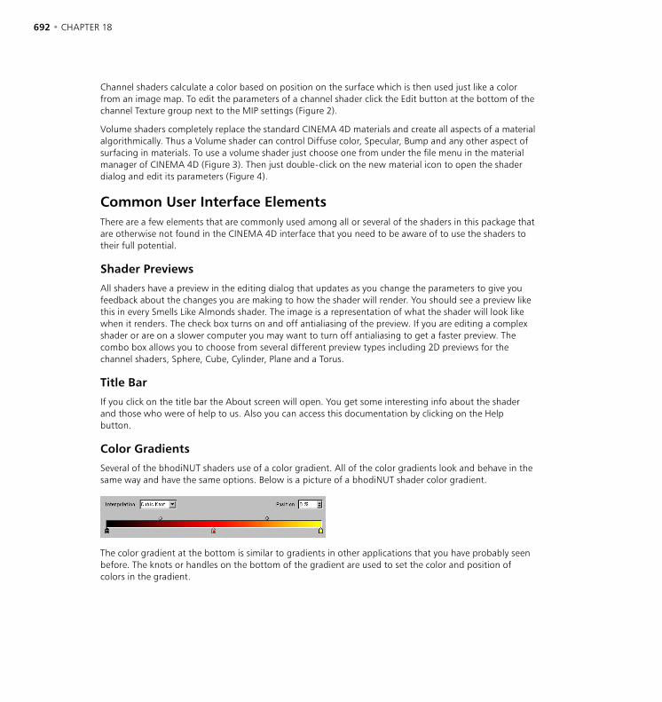
692 • CHAPTER 18 THE BHODINUT SHADERS • 693
Channel shaders calculate a color based on position on the surface which is then used just like a color from an image map. To edit the parameters of a channel shader click the Edit button at the bottom of the channel Texture group next to the MIP settings (Figure 2).
Volume shaders completely replace the standard CINEMA 4D materials and create all aspects of a material algorithmically. Thus a Volume shader can control Diffuse color, Specular, Bump and any other aspect of surfacing in materials. To use a volume shader just choose one from under the file menu in the material manager of CINEMA 4D (Figure 3). Then just double-click on the new material icon to open the shader dialog and edit its parameters (Figure 4).
Common User Interface Elements There are a few elements that are commonly used among all or several of the shaders in this package that are otherwise not found in the CINEMA 4D interface that you need to be aware of to use the shaders to their full potential.
Shader Previews
All shaders have a preview in the editing dialog that updates as you change the parameters to give you feedback about the changes you are making to how the shader will render. You should see a preview like this in every Smells Like Almonds shader. The image is a representation of what the shader will look like when it renders. The check box turns on and off antialiasing of the preview. If you are editing a complex shader or are on a slower computer you may want to turn off antialiasing to get a faster preview. The combo box allows you to choose from several different preview types including 2D previews for the channel shaders, Sphere, Cube, Cylinder, Plane and a Torus.
Title Bar
If you click on the title bar the About screen will open. You get some interesting info about the shader and those who were of help to us. Also you can access this documentation by clicking on the Help button.
Color Gradients
Several of the bhodiNUT shaders use of a color gradient. All of the color gradients look and behave in the same way and have the same options. Below is a picture of a bhodiNUT shader color gradient.
The color gradient at the bottom is similar to gradients in other applications that you have probably seen before. The knots or handles on the bottom of the gradient are used to set the color and position of colors in the gradient.
692 • CHAPTER 18 THE BHODINUT SHADERS • 693
To add a knot just click in an empty area below the gradient and a knot of the color at that position will be added. To remove a knot just click on it and drag it away from the gradient. To change the color of a knot double-click on it and the system color chooser will open. The handles on the top of the gradient are bias handles and they pull the interpolation of the color knots from side to side for more control over how the gradient changes.
Interpolation
Cubic Knot
Interpolates the knots with a CatMull - Rom interpolation while using the bias handles to offset the interpolated value (good for several knots).
Cubic Bias
Uses a Bézier interpolation algorithm to interpolate between the knot previous to the sample point, a weighted bias to the left, a weighted bias to the right, and the knot to the right of the sample position (good for few knots and accurate control).
Smooth
Uses a SmoothStep function to weight an interpolation between the knot to the left of the sample point and the knot to the right of the sample point. It uses the bias handles to offset the interpolated value.
Linear
Uses a BoxStep function to weight an interpolation between the knot to the left of the sample point and the knot to the right of the sample point. It uses the bias handles to offset the interpolated value.
None
Uses the color of the knot to the left of the sample point.
Position
The position of the currently selected knot or bias handle on the gradient. You can type a value in the edit text field or drag the up/down arrows at the right to move the currently selected knot or bias handle.
Keyboard short-cuts
• Cmd / Ctrl - I: Inverts the order of the color knots.
• Cmd / Ctrl - Arrow: Changes the currently selected knot or bias handle to the nearest one in the direction pressed.
• Shift - Left or Right Arrow: Moves the selected knot or bias handle in the left or right direction.
• Cmd / Ctrl - D: Doubles the current gradient by duplicating it and shrinking it to half and making another copy directly adjacent.
• Option / Alt - Mouse Drag: Duplicates the currently selected knot or bias handle under the mouse cursor.
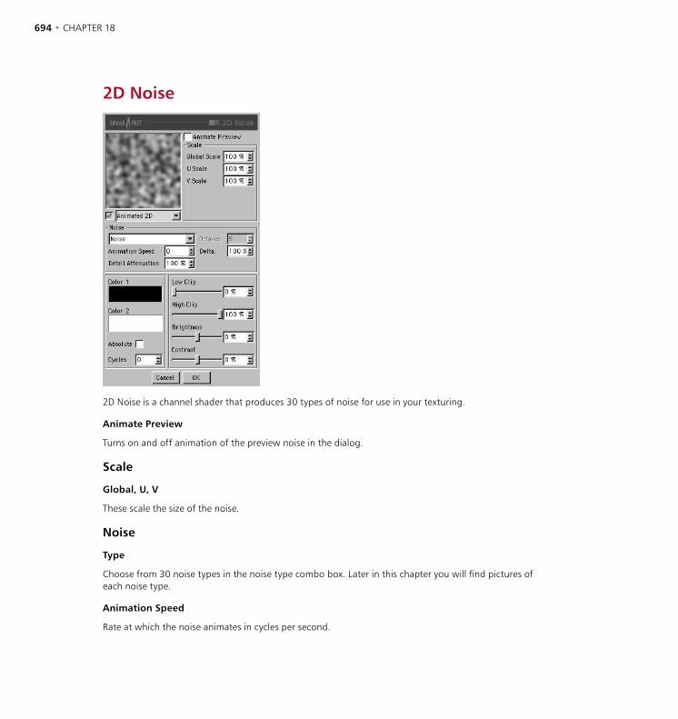
694 • CHAPTER 18 THE BHODINUT SHADERS • 695
2D Noise
2D Noise is a channel shader that produces 30 types of noise for use in your texturing.
Animate Preview
Turns on and off animation of the preview noise in the dialog.
Scale
Global, U, V
These scale the size of the noise.
Noise
Type
Choose from 30 noise types in the noise type combo box. Later in this chapter you will find pictures of each noise type.
Animation Speed
Rate at which the noise animates in cycles per second.
694 • CHAPTER 18 THE BHODINUT SHADERS • 695
Detail Attenuation
Used for antialiasing. For most applications it should be left at 100%. If you are animating and are getting a lot of texture flicker then try setting this higher. If you are rendering a still and want crisp detail then set it lower.
Octaves
Octaves of detail in the noise.
Delta
Delta is a scaling factor to use in sampling the noise for evaluating slope to be used in the bump channel. This allows you to get very sharp bump with minute detail that is not possible with the standard bump delta.
Color
Color 1, Color 2
Color 1 is the color of the noise at value 0, Color 2 at 100%
Absolute
On makes the value of the noise absolute, causing it to fold about its midpoint.
Cycles
Number of cycles the noise makes between zero and one.
Low Clip, High Clip
Low Clip controls the bottom clipping value of the noise; any value less low clip will be clipped to zero. High Clip controls the top clipping value of the noise; any value greater than High Clip will be clipped to 100%.
Brightness
Brightness controls the overall brightness or value of the noise. Values greater than zero increase brightness and values less than zero decrease brightness.
Contrast
Contrast controls the overall contrast or range of the noise. Values greater than zero increase contrast of the noise and values less than zero decrease contrast.

696 • CHAPTER 18 THE BHODINUT SHADERS • 697
3D Noise
3D Noise is a special kind of channel shader. Just like 2D Noise it produces 30 types of noise, however the noise is calculated in 3D space instead of UV. The advantage of this is that you don’t have to worry about mapping or seams in the texture.
Animate Preview
Turns on and off animation of the preview noise in the dialog.
Use As Environment
Causes the noise to be calculated as if it were an environment around the object being reflected.
Project Environment
Causes the 3D Noise environment to be calculated based on a UV environment projection.

696 • CHAPTER 18 THE BHODINUT SHADERS • 697
Scale
Global, X, Y, Z
These change the size of the noise.
Noise
Type
Choose from 30 noise types in the noise type combo box. See ‘Types of Noise’ on page 700.
Octaves
Octaves of detail in the noise.
Animation Speed
Rate at which the noise animates in cycles per second.
Detail Attenuation
Used for antialiasing. For most applications it should be left at 100%. If you are animating and are getting a lot of texture flicker then try setting this higher. If you are rendering a still and want crisp detail then set it lower.
Space
What space to calculate the noise in.
Texture
The Noise is calculated in object space and remains the same regardless of object position or orientation and takes into account the projection modifications of the Texture Tag.
World
The Noise is calculated in world coordinates and is not affected by the objects orientation or position. This allows the object being shaded to move through the Noise.
Object
The Noise is calculated in object space and remains the same regardless of object position or orientation but does not use the attributes of the Texture Tag.
Camera
The Noise is calculated in the space of the camera and will stay oriented relative to the camera. The object can move through the Noise and camera moves will also affect the Noise.
698 • CHAPTER 18 THE BHODINUT SHADERS • 699
Screen
The Noise is calculated in the space of the screen including Z depth. The object can move through the Noise and camera moves will also affect the Noise.
Raster
The Noise is calculated in the space screen pixels and has no depth information so no matter how far the object moves away, the texture is calculated the same. The object can move through the Noise and camera moves will also affect the Noise.
Hard Bump
If activated when the noise is in the bump channel, a different algorithm is used for calculating the bump slope that results in a harder bump result.
Delta
Delta is a scaling factor to use in sampling the noise for evaluating the slope that is to be used in the bump channel. This allows you to get very sharp bump with minute detail that is not possible with the standard bump delta.
Movement
Allows the Noise to constantly move through 3D space based upon the vector created by X, Y, and Z.
X, Y, Z
These define the translation to be applied to the noise per second.
Speed
The Speed parameter is multiplied with the movement vector to allow the user to alter the speed of translation with minimal effort. This allows for things such as water and fire effects.
Color
Color 1, Color 2
Color 1 is the color of the noise at value 0, Color 2 at 100%
Absolute
On makes the value of the noise absolute, causing it to fold about its midpoint.
Cycles
Number of cycles the noise makes between zero and one.
698 • CHAPTER 18 THE BHODINUT SHADERS • 699
Low Clip, High Clip
Low Clip controls the bottom clipping value of the noise; any value less low clip will be clipped to zero. High Clip controls the top clipping value of the noise; any value greater than High Clip will be clipped to 100%.
Brightness
Brightness controls the overall brightness or value of the noise. Values greater than zero increase brightness and values less than zero decrease brightness.
Contrast
Contrast controls the overall contrast or range of the noise. Values greater than zero increase the contrast of the noise and values less than zero decrease the contrast.

700 • CHAPTER 18 THE BHODINUT SHADERS • 701
Types of Noise
Blistered Turbulence Box Noise Buya Cell Noise Cell Voroni
Cranal Dents Displaced Turbulence Displaced Vornoi FBM
Hama Luka Mod Noise Naki Noise
Nutous Ober Pezo Poxo Random
Sema Sparse Convolution Stupl Turbulence VL Noise
Voronoi 1 Voronoi 2 Voronoi 3 Wavy Turbulence Zada
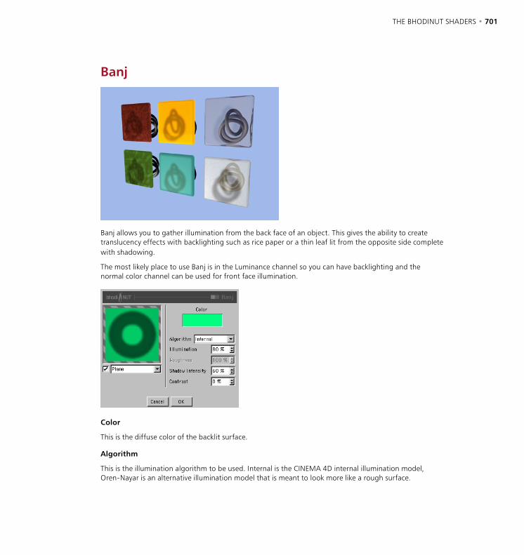
700 • CHAPTER 18 THE BHODINUT SHADERS • 701
Banj
Banj allows you to gather illumination from the back face of an object. This gives the ability to create translucency effects with backlighting such as rice paper or a thin leaf lit from the opposite side complete with shadowing.
The most likely place to use Banj is in the Luminance channel so you can have backlighting and the normal color channel can be used for front face illumination.
Color
This is the diffuse color of the backlit surface.
Algorithm
This is the illumination algorithm to be used. Internal is the CINEMA 4D internal illumination model, Oren-Nayar is an alternative illumination model that is meant to look more like a rough surface.

702 • CHAPTER 18 THE BHODINUT SHADERS • 703
Illumination
Maximum illumination intensity.
Roughness
Only applies to the Oren-Nayar illumination algorithm. The higher the value the rougher the surface appears.
Shadow Intensity
The opacity of the shadow. At 0 there is no shadow and at 100% the shadow is full opacity with no illumination.
Contrast
Contrast is applied to the illumination to make it break sharper or falloff more smoothly.

702 • CHAPTER 18 THE BHODINUT SHADERS • 703
Brightness Contrast
The Brightness Contrast shader is a filter that is used to adjust another shader or image. It allows you to adjust the brightness and contrast of the texture and also adds clipping of the value.
Brightness
Brightness controls the overall brightness or value of the image. Values greater than 0 increase brightness and values less than 0 decrease brightness. A value of -100% is totally black and 100% is totally white.
Contrast
Contrast controls the overall contrast or range of the image. Values greater than zero increase the contrast of the image and values less than zero decrease contrast. A value of -100% is totally neutral grey with no contrast and 100% is fully contrasted between full saturation and no saturation.
Low Clip, High Clip
Low Clip controls the bottom clipping value of the image; any color less in saturation than low clip will be clipped to zero saturation. High Clip controls the top clipping value of the image; any color greater in saturation than high clip will be clipped to 100% saturation.
Texture
The texture group at the bottom of the dialog is a standard CINEMA 4D texture channel. This is the source image or shader to affect with the Brightness Contrast filter. You can bring in and affect any image or 2D shader available to CINEMA 4D.

704 • CHAPTER 18 THE BHODINUT SHADERS • 705
Colorizer
Colorizer takes the value of an input channel and remaps it based on a color spline. This is very useful for colorizing shaders such as noise.
Input
The aspect of the input texture to remap. You can remap input Luminance, Hue, Saturation, Lightness, red, green or blue channels.
Interpolation
Is the interpolation type of the gradient knots.
Cubic Knot
Interpolates the knots with a CatMull - Rom interpolation while using the bias handles to offset the interpolated value (good for several knots).
Cubic Bias
Uses a Bézier interpolation algorithm to interpolate between the knot previous to the sample point, a weighted bias to the left, a weighted bias to the right, and the knot to the right of the sample position (good for few knots and accurate control).
Smooth
Uses a SmoothStep function to weight an interpolation between the knot to the left of the sample point and the knot to the right of the sample point. It uses the bias handles to offset the interpolated value.
Linear
Uses a BoxStep function to weight an interpolation between the knot to the left of the sample point and the knot to the right of the sample point. It uses the bias handles to offset the interpolated value.
704 • CHAPTER 18 THE BHODINUT SHADERS • 705
None
Uses the color of the knot to the left of the sample point.
Position
This is the position of the currently selected knot or bias handle on the gradient. You can type a value in the edit text field or drag the up/down arrows at the right.
Texture
The texture group at the top of the dialog is a standard CINEMA 4D texture channel. This is the source image or shader to remap with the colorizer gradient. You can bring in and affect any image or 2D shader available to CINEMA 4D.
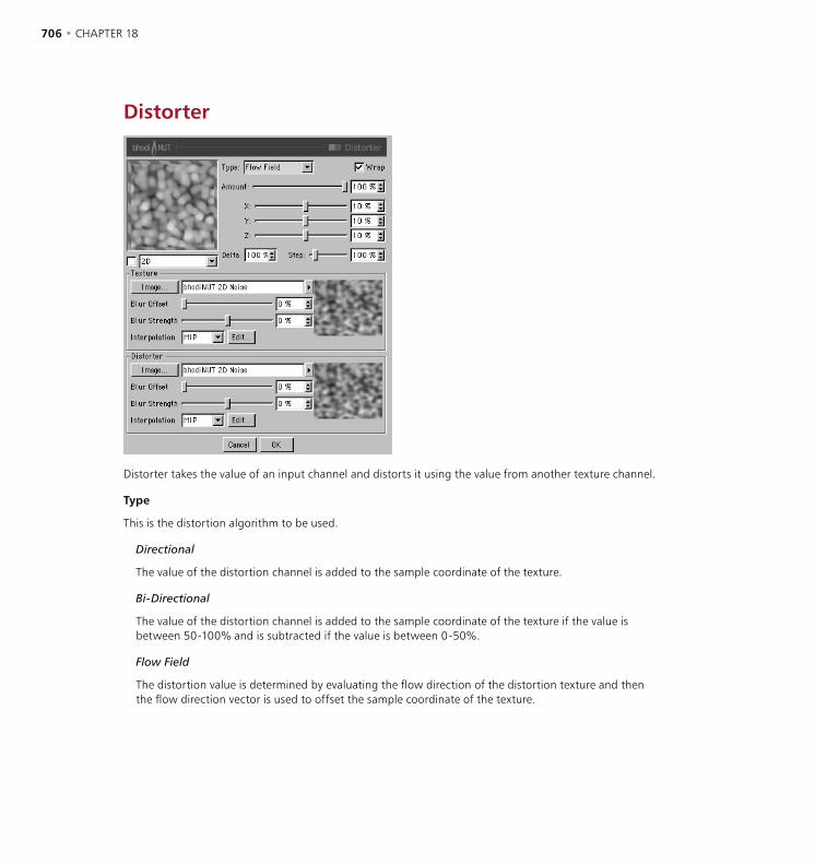
706 • CHAPTER 18 THE BHODINUT SHADERS • 707
Distorter
Distorter takes the value of an input channel and distorts it using the value from another texture channel.
Type
This is the distortion algorithm to be used.
Directional
The value of the distortion channel is added to the sample coordinate of the texture.
Bi-Directional
The value of the distortion channel is added to the sample coordinate of the texture if the value is between 50-100% and is subtracted if the value is between 0-50%.
Flow Field
The distortion value is determined by evaluating the flow direction of the distortion texture and then the flow direction vector is used to offset the sample coordinate of the texture.

706 • CHAPTER 18 THE BHODINUT SHADERS • 707
Wrap
If enabled then distorted coordinates greater than 1 or less than 0 are wrapped around to the other side. For example 1.1 would become 0.1. If not enabled then values are clamped between 0 and 1 and the edge of the texture is just repeated.
Amount
Global distortion amount. 100% means that distortion values go from 0 to 1 in UV and 0 to 10 in 3D.
X, Y, Z
X is the distortion amount in U for 2D and X for 3D. Y is the distortion amount in V for 2D and Y for 3D. Z is the distortion amount in Z for 3D.
Delta
Delta is a scaling factor to use in sampling the texture for evaluating slope to be used in the bump channel. This allows you to get very sharp bump with minute detail that is not possible with the standard bump delta.
Step
Relative step size to be used in evaluating the flow direction in Flow Field distortion type.
Texture
The texture group on top is a standard CINEMA 4D texture channel. This is the source image or shader to distort with the Distorter texture group. You can bring in and affect any image or 2D shader available to CINEMA 4D.
Distorter
The texture group at the bottom of the dialog is used to distort the texture in the top group. The value of the distorter image or shader is used in the distortion algorithm to offset the sampling of the texture.
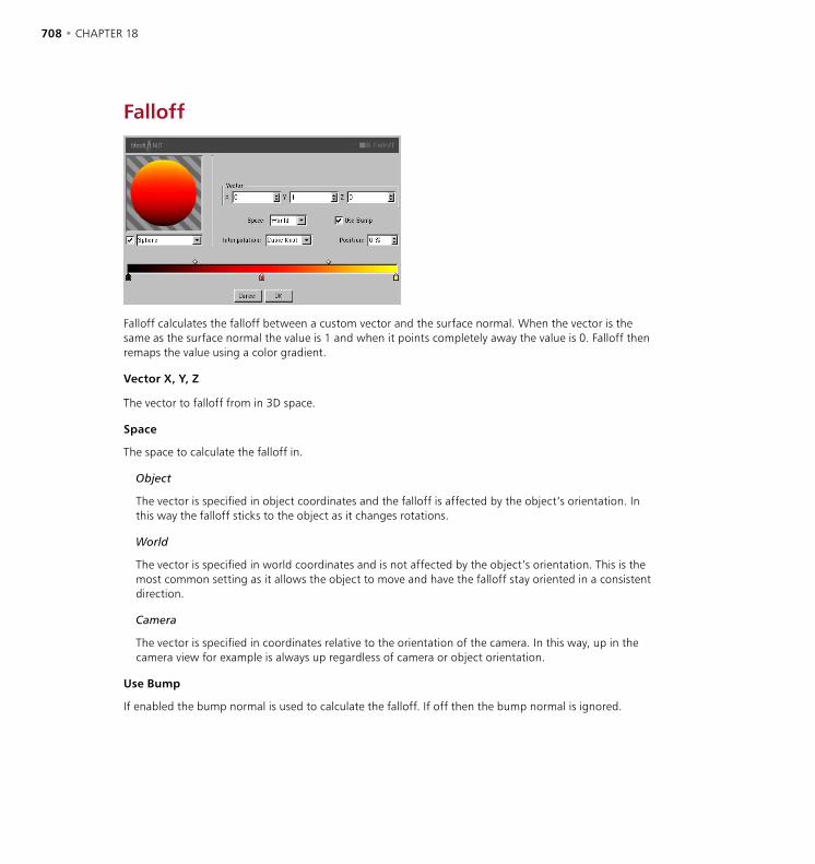
708 • CHAPTER 18 THE BHODINUT SHADERS • 709
Falloff
Falloff calculates the falloff between a custom vector and the surface normal. When the vector is the same as the surface normal the value is 1 and when it points completely away the value is 0. Falloff then remaps the value using a color gradient.
Vector X, Y, Z
The vector to falloff from in 3D space.
Space
The space to calculate the falloff in.
Object
The vector is specified in object coordinates and the falloff is affected by the object’s orientation. In this way the falloff sticks to the object as it changes rotations.
World
The vector is specified in world coordinates and is not affected by the object’s orientation. This is the most common setting as it allows the object to move and have the falloff stay oriented in a consistent direction.
Camera
The vector is specified in coordinates relative to the orientation of the camera. In this way, up in the camera view for example is always up regardless of camera or object orientation.
Use Bump
If enabled the bump normal is used to calculate the falloff. If off then the bump normal is ignored.

708 • CHAPTER 18 THE BHODINUT SHADERS • 709
Interpolation
Is the interpolation type of the gradient knots.
Cubic Knot
Interpolates the knots with a CatMull - Rom interpolation while using the bias handles to offset the interpolated value (good for several knots).
Cubic Bias
Uses a Bézier interpolation algorithm to interpolate between the knot previous to the sample point, a weighted bias to the left, a weighted bias to the right, and the knot to the right of the sample position (good for few knots and accurate control).
Smooth
Uses a SmoothStep function to weight an interpolation between the knot to the left of the sample point and the knot to the right of the sample point. It uses the bias handles to offset the interpolated value.
Linear
Uses a BoxStep function to weight an interpolation between the knot to the left of the sample point and the knot to the right of the sample point. It uses the bias handles to offset the interpolated value.
None
Uses the color of the knot to the left of the sample point.
Position
This is the position of the currently selected knot or bias handle on the gradient. You can type a value in the edit text field or drag the up/down arrows at the right.

710 • CHAPTER 18 THE BHODINUT SHADERS • 711
Fresnel
The Fresnel shader is used in any of the channels of a material. It has no effect upon the bump channel or the displacement channel unless utilized as a secondary channel within bhodiNUT Fusion or something similar.
The shader calculates the falloff of the surface normal in world space from the incoming surface ray which is also in world space. Then it utilizes the parameters of the shader to attenuate the output.
Preview Type
You can change the preview type and turn on and off antialiasing for the rendered previews using the combo box and the check box under the preview.
The Gradient
The gradient is a standard implementation of a color gradient. To change the color of a knot double-click it. To invert the order of knots, press Ctrl+I (Windows) or Command+I (Mac OS). You are currently limited to 50 knots.
Use Bump
Dictates whether the output of the bump channel will be used in the calculation of the falloff.
Render
Front Only
Calculates the falloff for the front of the object and then sets the back of the object to black if it can be seen.
Front Only - Trans
Calculates the falloff for the front of the object and then sets the back of the object to white if it can be seen (good for use in the transparency channel).
710 • CHAPTER 18 THE BHODINUT SHADERS • 711
Back Only
Calculates the falloff for the back of the object and then sets the front of the object to black if it can be seen.
Back Only - Trans
Calculates the falloff for the back of the object and then sets the front of the object to white if it can be seen.
Front & Back
Calculates the falloff for all surfaces intercepted.
Interpolation
Is the interpolation type of the knots.
Cubic Knot
Interpolates the knots with a CatMull - Rom interpolation while using the bias handles to offset the interpolated value (good for several knots).
Cubic Bias
Uses a Bézier interpolation algorithm to interpolate between the knot previous to the sample point, a weighted bias to the left, a weighted bias to the right, and the knot to the right of the sample position (good for few knots and accurate control).
Smooth
Uses a SmoothStep function to weight an interpolation between the knot to the left of the sample point and the knot to the right of the sample point. It uses the bias handles to offset the interpolated value.
Linear
Uses a BoxStep function to weight an interpolation between the knot to the left of the sample point and the knot to the right of the sample point. It uses the bias handles to offset the interpolated value.
None
Uses the color of the knot to the left of the sample point.
Position
This is the position of the currently selected knot or bias handle. You can type a value in the edit text field or drag the up/down arrows at the right.

712 • CHAPTER 18 THE BHODINUT SHADERS • 713
Fusion
Fusion allows you to combine two textures with a mask using the blending modes standard in photo editing applications, as if they were layers. Using a blend you can set the opacity of the Blend channel to mix with the Base channel and also modify the mixing with the Mask channel.
Mode
The blend mode that it used to combine Blend channel with the Base channel.
Normal
Normal blending, the Blend channel is just mixed with the Base channel.
Multiply
The value of the Blend channel and Base channel are multiplied together.
Screen
Lightens the Base channel by multiplying the inverse of the Blend and Base colors. The result is a color that is the same as, or a lightened version, of the Base color.
Overlay
If the Base channels’s color value is less than half of the maximum value, the Multiply blend mode is used. If the color value is greater than or equal to half the maximum value, the Screen blend mode is used. This shows patterns or colors of the Blend channel while preserving the shadows and highlights of the Base channel.

712 • CHAPTER 18 THE BHODINUT SHADERS • 713
Hard Light
If the Blend channel’s color value is less than half of the maximum value, the Multiply blend mode is used. If the Blend channel’s color value is greater than or equal to half the maximum value, the Screen blend mode is used. This mode is generally used to add highlights or shadows.
Soft Light
If the Blend channel’s color value is less than half the maximum value, the Burn blend mode is used. If the Blend channel’s color value is greater than the or equal to half the maximum value, the Dodge blend mode is used. This mode is generally used to add soft highlights or shadows.
Dodge
The lightness values of the colors in the Blend channel lighten the colors of the Base channel, lightening the image. Light colors produce the most lightening effect and black has no effect.
Burn
The lightness values of the colors of the Blend channel reduce the lightness of the Base channel darkening the image.
Darken
Only values of the Blend channel that are darker than the Base channel are mixed.
Lighten
Only values of the Blend channel that are lighter than the Base channel are mixed.
Add
The Blend channel is added to the Base channel.
Subtract
The Blend channel is subtracted from the Base channel.
Difference
Subtracts the Blend channel’s color from the color of the Base channel, depending on which is lighter.
Exclusion
Similar to Difference mode, but the effect is softer. This mode is the equivalent of Screen - Multiply.
Hue
The hue of the Blend channel is applied to the Base channel.
Saturation
The saturation of the Blend channel is applied to the Base channel.

714 • CHAPTER 18 THE BHODINUT SHADERS • 715
Color
The hue and saturation of the Blend channel is applied to the Base channel.
Luminance
The luminance of the Blend channel is applied to the Base channel.
Levr
The value of the Blend channel is used to apply contrast to the Base channel and is affected by the Blend amount.
Blend
The opacity level of the Blend channel to be applied to the Base channel.
Use Mask
Enables the Mask channel.
Invert Mask
If enabled, the Mask channel value is inverted so that black becomes white and vice-versa.
Blend Channel
The texture group at the top of the dialog is a standard CINEMA 4D texture channel. You can bring in and affect any image or 2D shader available to CINEMA 4D. This channel is the top layer in the fusing.
Mask Channel
The texture group in the middle of the dialog is used as a mask when combining the Blend channel with the Base channel.
Base Channel
The texture group at the bottom of the dialog is the bottom layer in the fusing. The Blend channel is combined with the Base channel at the opacity set in Blend and modified by the Mask channel.
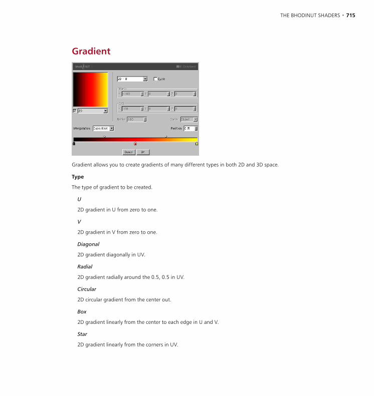
714 • CHAPTER 18 THE BHODINUT SHADERS • 715
Gradient
Gradient allows you to create gradients of many different types in both 2D and 3D space.
Type
The type of gradient to be created.
U
2D gradient in U from zero to one.
V
2D gradient in V from zero to one.
Diagonal
2D gradient diagonally in UV.
Radial
2D gradient radially around the 0.5, 0.5 in UV.
Circular
2D circular gradient from the center out.
Box
2D gradient linearly from the center to each edge in U and V.
Star
2D gradient linearly from the corners in UV.

716 • CHAPTER 18 THE BHODINUT SHADERS • 717
Four Corner
2D gradient where the first 4 gradient knot colors are used as the colors at the UV corners.
Linear
3D gradient linearly from start point to end point.
Cylindrical
3D gradient cylindrically around the vector defined by start and end point of radius.
Spherical
3D gradient spherically around the start point of radius.
Cycle
If turned on, this causes a 3D gradient to cycle its gradient after it passes the end or exceeds the radius.
Start X, Y, Z
For 3D gradients this defines the start point of the gradient. For cylindrical this is the start of the center vector.
End X, Y, Z
For 3D gradients this defines the end point of the gradient. For cylindrical this is the end of the center vector.
Radius
For 3D gradients spherical and cylindrical this is the radius of the gradient from the center.
Space
For 3D gradients this defines space that the gradient is calculated in.
Texture
The gradient is calculated in object space and remains the same regardless of object position or orientation and takes into account the projection modifications of the Texture tag.
Object
The gradient is calculated in object space and remains the same regardless of object position or orientation but does not use the attributes of the Texture tag.
World
The gradient is calculated in world coordinates and is not affected by the objects orientation or position. This allows the object being shaded to move through the gradient.

716 • CHAPTER 18 THE BHODINUT SHADERS • 717
Camera
The gradient is calculated in the space of the camera and will stay oriented relative to the camera. The object can move through the gradient and camera moves will also affect the gradient.
Screen
The gradient is calculated in the space of the screen including z depth. The object can move through the gradient and camera moves will also affect the gradient.
Raster
The gradient is calculated in screen pixels and has no depth information so no matter how far the object gets away the texture is calculated in the same way. The object can move through the gradient and camera moves will also affect the gradient.
Interpolation
Is the interpolation type of the gradient knots.
Cubic Knot
Interpolates the knots with a CatMull - Rom interpolation while using the bias handles to offset the interpolated value (good for several knots).
Cubic Bias
Uses a Bézier interpolation algorithm to interpolate between the knot previous to the sample point, a weighted bias to the left, a weighted bias to the right, and the knot to the right of the sample position (good for few knots and accurate control).
Smooth
Uses a SmoothStep function to weight an interpolation between the knot to the left of the sample point and the knot to the right of the sample point. It uses the bias handles to offset the interpolated value.
Linear
Uses a BoxStep function to weight an interpolation between the knot to the left of the sample point and the knot to the right of the sample point. It uses the bias handles to offset the interpolated value.
None
Uses the color of the knot to the left of the sample point.
Position
This is the position of the currently selected knot or bias handle on the gradient. You can type a value in the edit text field or drag the up/down arrows at the right.

718 • CHAPTER 18 THE BHODINUT SHADERS • 719
Hue
The Hue shader is really a filter that is used to adjust another shader or image. It allows you to adjust the Hue, Saturation and Lightness of the texture in a similar way to many photo editing applications.
Hue
Adjusts the hue angle of the texture around the color wheel.
Saturation
Adjusts the overall saturation of the colors in the texture.
Lightness
Adjusts the lightness of the texture.
Colorize
If enabled, the image is turned to grayscale and colorized based on the hue angle.
Texture
The texture group at the bottom of the dialog is a standard CINEMA 4D texture channel. This is the source image or shader to affect with the Hue filter. You can bring in and affect any image or 2D shader available to CINEMA 4D. For more information on texture groups please see ‘Texture pane’ on page 642.

718 • CHAPTER 18 THE BHODINUT SHADERS • 719
LumasLumas is an illumination shader. It is useful in combination with Fusion and other channel shaders or images. This includes three specular highlights with anisotropic scratches.
Diffuse page
Diffuse Color
R, G, B, Brightness
Sets the base diffuse color of the surface.
Diffuse Attributes
Algorithm
Specifies which illumination model Lumas will use. The drop-down list provides for two choices including Internal which is the standard Lambertian model and the Oren-Nayar model which provides for a roughness variable allowing the user to go from simple surfaces (0 Roughness, identical to Lambertian), to complex rough surface (1+ Roughness which provides a surface like linen or dirt).
Illumination
Scales the Diffuse Color to produce attenuation in the illumination of the surface (this simply means it makes the color darker when the value is close to zero and brighter when the value is closer to 100% or above).
If you are utilizing the Oren-Nayar illumination algorithm you may want to bump up the illumination about 10% to 20% because it renders darker usually. Appropriate values are between 0% to 200%.
Roughness
Dictates how rough the Oren-Nayar illumination model will be. Zero is no roughness while 100% or greater is very rough. Experimentation is required to fully understand this parameter. This option is only available if Oren-Nayar is selected in the Algorithm drop-down list.
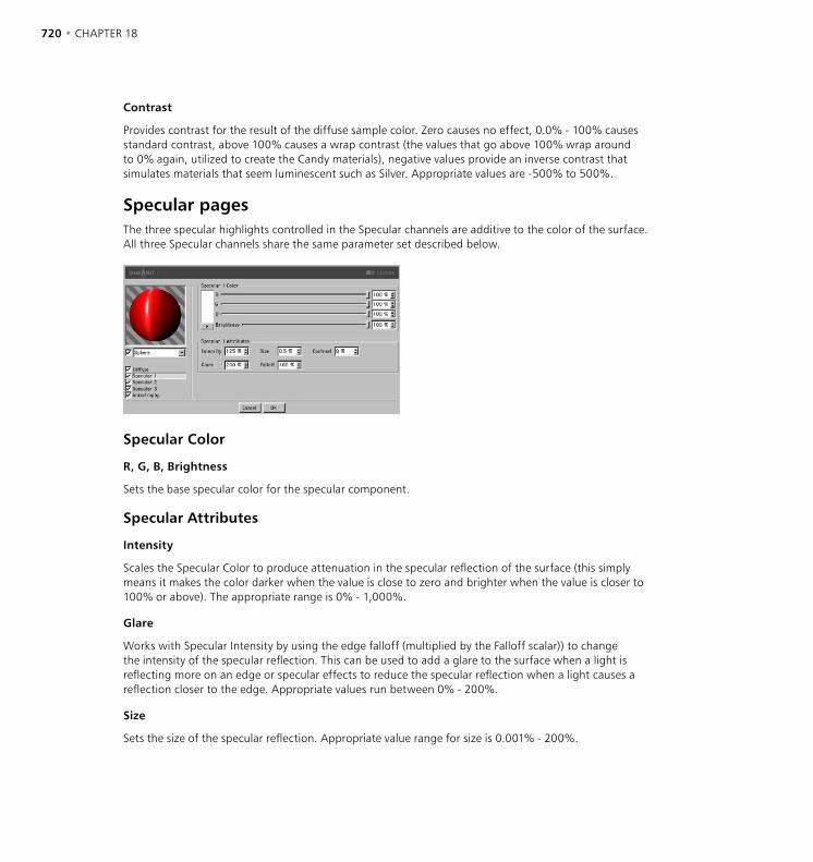
720 • CHAPTER 18 THE BHODINUT SHADERS • 721
Contrast
Provides contrast for the result of the diffuse sample color. Zero causes no effect, 0.0% - 100% causes standard contrast, above 100% causes a wrap contrast (the values that go above 100% wrap around to 0% again, utilized to create the Candy materials), negative values provide an inverse contrast that simulates materials that seem luminescent such as Silver. Appropriate values are -500% to 500%.
Specular pagesThe three specular highlights controlled in the Specular channels are additive to the color of the surface. All three Specular channels share the same parameter set described below.
Specular Color
R, G, B, Brightness
Sets the base specular color for the specular component.
Specular Attributes
Intensity
Scales the Specular Color to produce attenuation in the specular reflection of the surface (this simply means it makes the color darker when the value is close to zero and brighter when the value is closer to 100% or above). The appropriate range is 0% - 1,000%.
Glare
Works with Specular Intensity by using the edge falloff (multiplied by the Falloff scalar)) to change the intensity of the specular reflection. This can be used to add a glare to the surface when a light is reflecting more on an edge or specular effects to reduce the specular reflection when a light causes a reflection closer to the edge. Appropriate values run between 0% - 200%.
Size
Sets the size of the specular reflection. Appropriate value range for size is 0.001% - 200%.
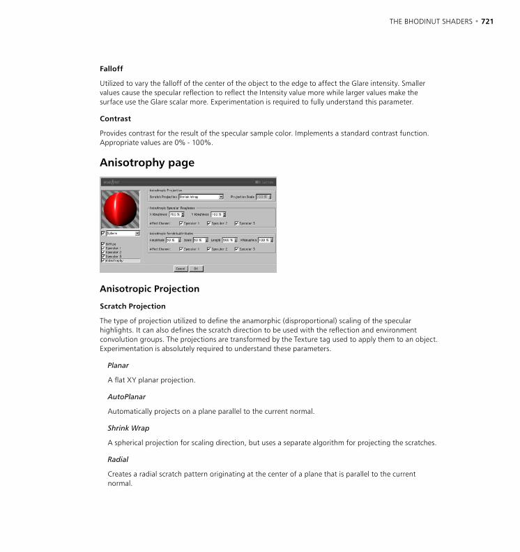
720 • CHAPTER 18 THE BHODINUT SHADERS • 721
Falloff
Utilized to vary the falloff of the center of the object to the edge to affect the Glare intensity. Smaller values cause the specular reflection to reflect the Intensity value more while larger values make the surface use the Glare scalar more. Experimentation is required to fully understand this parameter.
Contrast
Provides contrast for the result of the specular sample color. Implements a standard contrast function. Appropriate values are 0% - 100%.
Anisotrophy page
Anisotropic Projection
Scratch Projection
The type of projection utilized to define the anamorphic (disproportional) scaling of the specular highlights. It can also defines the scratch direction to be used with the reflection and environment convolution groups. The projections are transformed by the Texture tag used to apply them to an object. Experimentation is absolutely required to understand these parameters.
Planar
A flat XY planar projection.
AutoPlanar
Automatically projects on a plane parallel to the current normal.
Shrink Wrap
A spherical projection for scaling direction, but uses a separate algorithm for projecting the scratches.
Radial
Creates a radial scratch pattern originating at the center of a plane that is parallel to the current normal.
722 • CHAPTER 18 THE BHODINUT SHADERS • 723
Radial Pattern
Creates a multi-origin radial scratch pattern that is parallel to the current normal.
Projection Scale
Scales the scratch algorithms that have an actual pattern (Radial Pattern is the only current algorithm of this type to which scale applies).
Anisotropic Specular Roughness
X Roughness
Scales the highlights in the X direction defined by the Scratch Projection algorithm. The appropriate range is 0.1% to 10,000%. If the X & Y roughness are the same, the standard internal specular algorithm is used.
Y Roughness
Scales the highlights in the Y direction defined by the Scratch Projection algorithm. The appropriate range is 0.1% to 10,000%. If the X & Y roughness are the same, the standard internal specular algorithm is used.
Affect Channel
These check boxes specify which specular channels will be affected by the anisotropic algorithm.
Anisotropic Scratch Attributes
Amplitude
Scales the effect of the scratch of the specular highlights. The higher the value the more scratched the speculars will look. The appropriate range is 0% - 100%.
Scale
Scales the scratch pattern itself. This applies to all scratch algorithms.
Length
Defines the scratch length in the space of the scratch pattern. Smoother milled surfaces would use a higher scratch length and rougher surfaces would use smaller values. The appropriate range is 1% - 1,000%.
Attenuation
Scales the amount of detail of the scratches based upon the sample’s angle to the camera and the distance from the camera. The larger the values the greater the attenuation, causing less scratching (better for animation), the smaller the value the greater the detail (better for still images). The appropriate range is 0% - 10,000%.
Affect Channel
These check boxes specify which specular channels will be affected by the anisotropic scratches.

722 • CHAPTER 18 THE BHODINUT SHADERS • 723
Posterizer
The Posterizer shader is really a filter that is used to adjust another shader or image. It allows you to adjust the number of levels per color channel of the texture for posterization effects.
Levels
Number of levels of color, between zero and maximum intensity.
Filter Width
Adjusts the softness of the posterization by widening and smoothing the edges between levels.
Texture
The texture group at the bottom of the dialog is a standard CINEMA 4D texture channel. This is the source image or shader to affect with the Posterizer filter. You can bring in and affect any image or 2D shader available to CINEMA 4D.
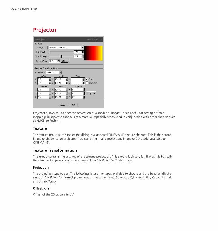
724 • CHAPTER 18 THE BHODINUT SHADERS • 725
Projector
Projector allows you to alter the projection of a shader or image. This is useful for having different mappings in separate channels of a material especially when used in conjunction with other shaders such as NUKEI or Fusion.
Texture
The texture group at the top of the dialog is a standard CINEMA 4D texture channel. This is the source image or shader to be projected. You can bring in and project any image or 2D shader available to CINEMA 4D.
Texture Transformation
This group contains the settings of the texture projection. This should look very familiar as it is basically the same as the projection options available in CINEMA 4D’s Texture tags.
Projection
The projection type to use. The following list are the types available to choose and are functionally the same as CINEMA 4D’s normal projections of the same name: Spherical, Cylindrical, Flat, Cubic, Frontal, and Shrink Wrap.
Offset X, Y
Offset of the 2D texture in UV.

724 • CHAPTER 18 THE BHODINUT SHADERS • 725
Position X, Y, Z
Offset of the 3D texture space.
Length X, Y
Scaling of the 2D texture in UV.
Size X, Y, Z
Scaling of the 3D texture space.
Tiles X, Y
Tiling of the 2D texture in UV.
Rotation H, P, B
Orientation of the 3D texture space.
Tile
If enabled the 2D texture will tile in UV the number of times specified in the Tiles parameter.
Seamless
If tiling is enabled then enabling Seamless causes the tiles to be mirrored so that they tile seamlessly.
Copy Tag
Pressing the Copy Tag button causes the settings of the currently selected Texture tag in the Object manager to be copied into Projector’s parameters. This makes it easier for you to create a projection and then just copy it in.

726 • CHAPTER 18 THE BHODINUT SHADERS • 727
Proximal
Proximal allows you to select an object in the scene and the shader will calculate the luminance based on how close that object’s axis (or each single point — see below) is to the surface of the object being shaded.
Effector
Search
Type the name of the object in the Object manager you want to Proximal to find. Proximal will use all objects with the chosen name in the current document.
Object
Name of the object that will be used to calculate Proximal.
Exclude Parent Object
If Include Subobjects is enabled and Exclude Parent Object is checked then the parent object is disregarded in the Proximal calculations.
Include Subobjects
If enabled, the children of the found object will be included in the proximal calculations.
Use Vertices
Allows the user to specify that the sampling points for the Proximal shader to use are defined by the vertices of the named polygon object. This allows for effects such as one object passing through another object. The object must be a polygon object.

726 • CHAPTER 18 THE BHODINUT SHADERS • 727
Polygon Radius
Is similar to Use Vertices except it uses the center of each polygon and makes the maximum distance (End Distance at 100%) the radius of the polygon. This helps with the problem of vertices being spread unevenly and gaps happening when an object passes through another.
Falloff
Function
Falloff function to be used to calculate the Proximal intensity.
Linear
Intensity is 100% of the Intensity value at Start Distance, 0% at End Distance and falls off linearly in between.
Square
Intensity is 100% of the Intensity value at Start Distance, 0% at End Distance and falls off by the square of the distance in between.
Cubic
Intensity is 100% of the Intensity value at Start Distance, 0% at End Distance and falls off distance cubed in between.
Step
Intensity is 100% of the Intensity value between Start Distance and End Distance and 0% everywhere else.
Inverse
Intensity is 100% of the Intensity value at Start Distance and falls off as the inverse of distance and is clamped to 0% at End Distance.
Inverse Square
Intensity is 100% of the Intensity value at Start Distance and falls off as the inverse of distance squared and is clamped to 0% at End Distance.
Inverse Cubic
Intensity is 100% of the Intensity value at Start Distance and falls off as the inverse of distance cubed and is clamped to 0% at End Distance.
Soft
This gives a smoother falloff when using Proximal for bump mapping or displacement.
728 • CHAPTER 18 THE BHODINUT SHADERS • 729
Start Distance
The distance at which the object causes 100% luminance.
End Distance
The distance at which the object no longer affects the surface luminance. A value of 100% means 100 m. However, when using Polygon Radius the percentage value is the same as the polygon radius, which of course can be different for each polygon.
Blend Mode
Allows for different possibilities when blending each sampled point together. For instance the Add type of blend makes very blown out values, necessitating the user to tweak the values to achieve a good result. The modes Lighten, Screen, Difference and Exclusion increase the ease of achieving the desired effect. The Screen blend type is in most cases the best choice, as it yields aesthetically pleasing results.
Intensity
Maximum intensity that each object / particle adds.
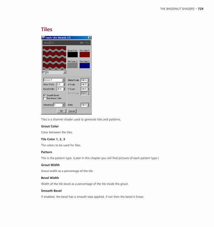
728 • CHAPTER 18 THE BHODINUT SHADERS • 729
Tiles
Tiles is a channel shader used to generate tiles and patterns.
Grout Color
Color between the tiles.
Tile Color 1, 2, 3
The colors to be used for tiles.
Pattern
This is the pattern type. (Later in this chapter you will find pictures of each pattern type.)
Grout Width
Grout width as a percentage of the tile.
Bevel Width
Width of the tile bevel as a percentage of the tile inside the grout.
Smooth Bevel
If enabled, the bevel has a smooth step applied, if not then the bevel is linear.

730 • CHAPTER 18 THE BHODINUT SHADERS • 731
Randomize Color
If activated the tile color becomes a random mix of the three tile colors.
Orientation
Orientation of the tile pattern in U or V.
Global Scale
Scaling of the tile pattern.
U Scale
Scaling in the U direction.
V Scale
Scaling in the V direction.
Radial Scale
Scaling radially for the patterns that are radial types of patterns such as radial lines etc.
Delta
Delta is a scaling factor to use in sampling the texture for evaluating the slope to be used in the bump channel. This allows you to get very sharp bump with minute detail that is not possible with the standard bump delta.

730 • CHAPTER 18 THE BHODINUT SHADERS • 731
Types of Tile Pattern
Brick 1 Brick 2 Circles 1 Circles 2 Circles 3
Hexagons Lines 1 Lines 2 Parquet Planks
Radial Lines 1 Radial Lines 2 Rings 1 Rings 2 Sawtooth 1
Sawtooth 2 Scales 1 Scales 2 Spiral 1 Spiral 2
Squares Triangles 1 Triangles 2 Triangles 3 Waves 1
Waves 2 Weave

732 • CHAPTER 18 THE BHODINUT SHADERS • 733
BANJI
BANJI was created to fill a couple of different needs in texturing. First BANJI allows the rendering of translucent lighting from the back side of a surface complete with shadows. The other main use of BANJI is the creation of good refractive, transparent materials such as glass.
Diffuse pageBANJI has separate diffuse color and illumination settings for both the front surface and the volume of an object to allow for translucency and backlighting effects.
Front Surface tab
R, G, B, Brightness
Sets the base diffuse color of the surface.
Algorithm
Specifies which illumination model BANJI will use. The drop-down list provides for two choices including Internal which is the standard Lambertian model and the Oren-Nayar model which provides for a roughness variable allowing the user to go from simple surfaces (0% Roughness, identical to Lambertian), to complex rough surfaces (100%+ Roughness which provides a surface like linen or dirt).
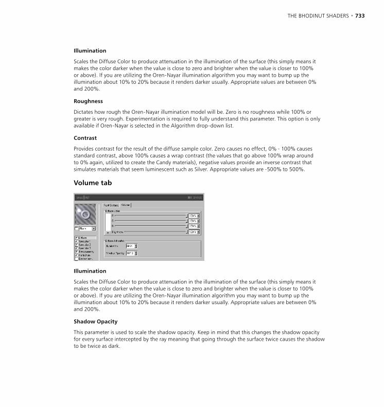
732 • CHAPTER 18 THE BHODINUT SHADERS • 733
Illumination
Scales the Diffuse Color to produce attenuation in the illumination of the surface (this simply means it makes the color darker when the value is close to zero and brighter when the value is closer to 100% or above). If you are utilizing the Oren-Nayar illumination algorithm you may want to bump up the illumination about 10% to 20% because it renders darker usually. Appropriate values are between 0% and 200%.
Roughness
Dictates how rough the Oren-Nayar illumination model will be. Zero is no roughness while 100% or greater is very rough. Experimentation is required to fully understand this parameter. This option is only available if Oren-Nayar is selected in the Algorithm drop-down list.
Contrast
Provides contrast for the result of the diffuse sample color. Zero causes no effect, 0% - 100% causes standard contrast, above 100% causes a wrap contrast (the values that go above 100% wrap around to 0% again, utilized to create the Candy materials), negative values provide an inverse contrast that simulates materials that seem luminescent such as Silver. Appropriate values are -500% to 500%.
Volume tab
Illumination
Scales the Diffuse Color to produce attenuation in the illumination of the surface (this simply means it makes the color darker when the value is close to zero and brighter when the value is closer to 100% or above). If you are utilizing the Oren-Nayar illumination algorithm you may want to bump up the illumination about 10% to 20% because it renders darker usually. Appropriate values are between 0% and 200%.
Shadow Opacity
This parameter is used to scale the shadow opacity. Keep in mind that this changes the shadow opacity for every surface intercepted by the ray meaning that going through the surface twice causes the shadow to be twice as dark.

734 • CHAPTER 18 THE BHODINUT SHADERS • 735
Specular pages
The three specular highlights controlled in the Specular channels are additive to the color of the surface. All three Specular channels share the same parameter set described below.
Specular Color
R, G, B, Brightness
Sets the base specular color for the specular component.
Specular Attributes
Intensity
Scales the Specular Color to produce attenuation in the specular reflection of the surface (this simply means it makes the color darker when the value is close to zero and brighter when the value is closer to 100% or above). The appropriate range is 0% - 1,000%.
Glare
Works with Specular Intensity by using the edge falloff (multiplied by the Falloff scalar)) to change the intensity of the specular reflection. This can be used to add a glare to the surface when a light is reflecting more on an edge or specular effects to reduce the specular reflection when a light causes a reflection closer to the edge. Appropriate values run between 0% - 200%.
Size
Sets the size of the specular reflection. Appropriate value range for Size is 0.001% - 200%.
Falloff
Utilized to vary the falloff of the center of the object to the edge to affect the Glare intensity. Smaller values cause the specular reflection to reflect the Intensity value more while larger values make the surface use the Glare scalar more. Experimentation is required to fully understand this parameter.
Contrast
Provides contrast for the result of the specular sample color. Implements a standard contrast function. Appropriate values are 0% - 100%.
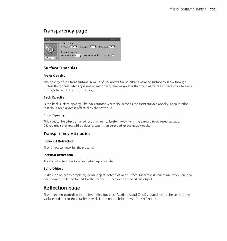
734 • CHAPTER 18 THE BHODINUT SHADERS • 735
Transparency page
Surface Opacities
Front Opacity
The opacity of the front surface. A value of 0% allows for no diffuse color or surface to show through (unless Roughness Intensity is not equal to zero). Values greater than zero allow the surface color to show through (which is the diffuse color).
Back Opacity
Is the back surface opacity. The back surface works the same as the front surface opacity. Keep in mind that the back surface is affected by shadows also.
Edge Opacity
This causes the edges of an object that points further away from the camera to be more opaque. 0% creates no effect while values greater than zero add to the edge opacity.
Transparency Attributes
Index Of Refraction
The refractive index for the material.
Internal Reflection
Allows refracted rays to reflect when appropriate.
Solid Object
Makes the object a completely dense object instead of one surface. Disallows illumination, reflection, and environment to be evaluated for the second surface intercepted of the object.
Reflection pageThe reflection controlled in the two reflection tabs (Attributes and Color) are additive to the color of the surface and add to the opacity as well, based on the brightness of the reflection.
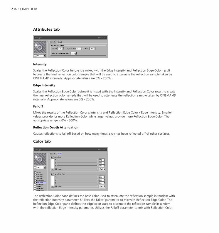
736 • CHAPTER 18 THE BHODINUT SHADERS • 737
Attributes tab
Intensity
Scales the Reflection Color before it is mixed with the Edge Intensity and Reflection Edge Color result to create the final reflection color sample that will be used to attenuate the reflection sample taken by CINEMA 4D internally. Appropriate values are 0% - 200%.
Edge Intensity
Scales the Reflection Edge Color before it is mixed with the Intensity and Reflection Color result to create the final reflection color sample that will be used to attenuate the reflection sample taken by CINEMA 4D internally. Appropriate values are 0% - 200%.
Falloff
Mixes the results of the Reflection Color x Intensity and Reflection Edge Color x Edge Intensity. Smaller values provide for more Reflection Color while larger values provide more Reflection Edge Color. The appropriate range is 0% - 500%.
Reflection Depth Attenuation
Causes reflections to fall off based on how many times a ray has been reflected off of other surfaces.
Color tab
The Reflection Color pane defines the base color used to attenuate the reflection sample in tandem with the reflection Intensity parameter. Utilizes the Falloff parameter to mix with Reflection Edge Color. The Reflection Edge Color pane defines the edge color used to attenuate the reflection sample in tandem with the reflection Edge Intensity parameter. Utilizes the Falloff parameter to mix with Reflection Color.
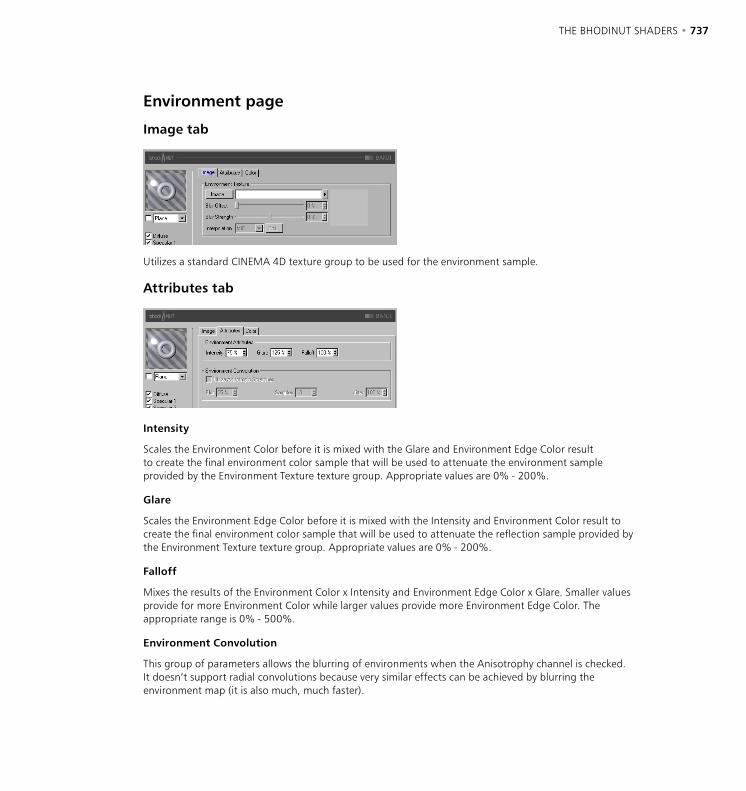
736 • CHAPTER 18 THE BHODINUT SHADERS • 737
Environment page
Image tab
Utilizes a standard CINEMA 4D texture group to be used for the environment sample.
Attributes tab
Intensity
Scales the Environment Color before it is mixed with the Glare and Environment Edge Color result to create the final environment color sample that will be used to attenuate the environment sample provided by the Environment Texture texture group. Appropriate values are 0% - 200%.
Glare
Scales the Environment Edge Color before it is mixed with the Intensity and Environment Color result to create the final environment color sample that will be used to attenuate the reflection sample provided by the Environment Texture texture group. Appropriate values are 0% - 200%.
Falloff
Mixes the results of the Environment Color x Intensity and Environment Edge Color x Glare. Smaller values provide for more Environment Color while larger values provide more Environment Edge Color. The appropriate range is 0% - 500%.
Environment Convolution
This group of parameters allows the blurring of environments when the Anisotrophy channel is checked. It doesn’t support radial convolutions because very similar effects can be achieved by blurring the environment map (it is also much, much faster).
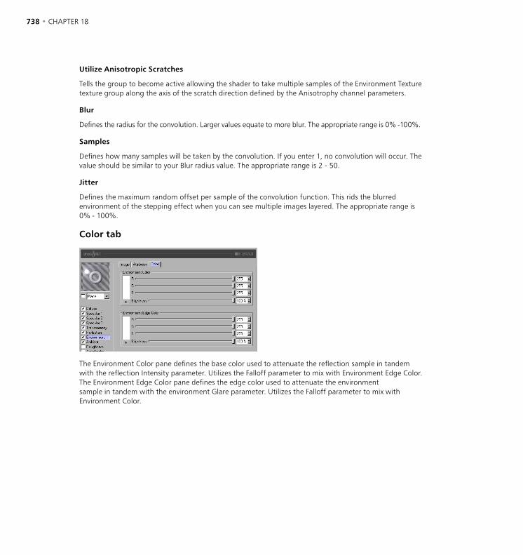
738 • CHAPTER 18 THE BHODINUT SHADERS • 739
Utilize Anisotropic Scratches
Tells the group to become active allowing the shader to take multiple samples of the Environment Texture texture group along the axis of the scratch direction defined by the Anisotrophy channel parameters.
Blur
Defines the radius for the convolution. Larger values equate to more blur. The appropriate range is 0% -100%.
Samples
Defines how many samples will be taken by the convolution. If you enter 1, no convolution will occur. The value should be similar to your Blur radius value. The appropriate range is 2 - 50.
Jitter
Defines the maximum random offset per sample of the convolution function. This rids the blurred environment of the stepping effect when you can see multiple images layered. The appropriate range is 0% - 100%.
Color tab
The Environment Color pane defines the base color used to attenuate the reflection sample in tandem with the reflection Intensity parameter. Utilizes the Falloff parameter to mix with Environment Edge Color. The Environment Edge Color pane defines the edge color used to attenuate the environment sample in tandem with the environment Glare parameter. Utilizes the Falloff parameter to mix with Environment Color.

738 • CHAPTER 18 THE BHODINUT SHADERS • 739
Ambient page
R, G, B, Brightness
Defines the base ambient color used to attenuate (multiply by) the scene ambient color provided by CINEMA 4D. You must have an Environment object active in your scene for this to affect your surface at all.
Intensity
Scales the Ambient Color before it is mixed with the Edge Intensity result to create the final ambient color sample that will be used to attenuate the ambient sample taken by CINEMA 4D internally. Appropriate values are 0% - 100%.
Edge Intensity
Mixes with Intensity to scale the Ambient Color to create the final ambient color sample that will be used to attenuate the ambient sample taken by CINEMA 4D internally. Appropriate values are 0% - 100%.
Falloff
Mixes Intensity and Edge Intensity to attenuate the Ambient Color. Smaller values provide for more Intensity while larger values provide more Edge Intensity. The appropriate range is 0% - 500%.
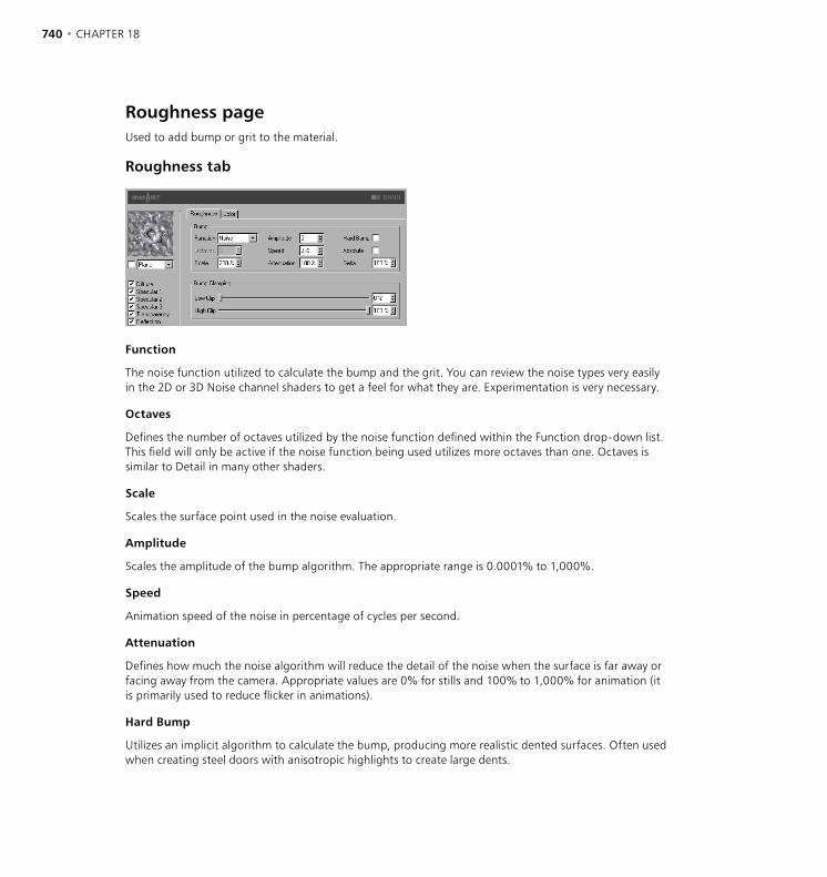
740 • CHAPTER 18 THE BHODINUT SHADERS • 741
Roughness pageUsed to add bump or grit to the material.
Roughness tab
Function
The noise function utilized to calculate the bump and the grit. You can review the noise types very easily in the 2D or 3D Noise channel shaders to get a feel for what they are. Experimentation is very necessary.
Octaves
Defines the number of octaves utilized by the noise function defined within the Function drop-down list. This field will only be active if the noise function being used utilizes more octaves than one. Octaves is similar to Detail in many other shaders.
Scale
Scales the surface point used in the noise evaluation.
Amplitude
Scales the amplitude of the bump algorithm. The appropriate range is 0.0001% to 1,000%.
Speed
Animation speed of the noise in percentage of cycles per second.
Attenuation
Defines how much the noise algorithm will reduce the detail of the noise when the surface is far away or facing away from the camera. Appropriate values are 0% for stills and 100% to 1,000% for animation (it is primarily used to reduce flicker in animations).
Hard Bump
Utilizes an implicit algorithm to calculate the bump, producing more realistic dented surfaces. Often used when creating steel doors with anisotropic highlights to create large dents.
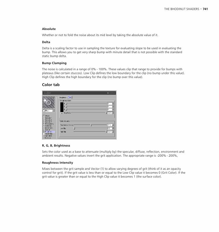
740 • CHAPTER 18 THE BHODINUT SHADERS • 741
Absolute
Whether or not to fold the noise about its mid level by taking the absolute value of it.
Delta
Delta is a scaling factor to use in sampling the texture for evaluating slope to be used in evaluating the bump. This allows you to get very sharp bump with minute detail that is not possible with the standard static bump delta.
Bump Clamping
The noise is calculated in a range of 0% - 100%. These values clip that range to provide for bumps with plateaus (like certain stuccos). Low Clip defines the low boundary for the clip (no bump under this value). High Clip defines the high boundary for the clip (no bump over this value).
Color tab
R, G, B, Brightness
Sets the color used as a base to attenuate (multiply by) the specular, diffuse, reflection, environment and ambient results. Negative values invert the grit application. The appropriate range is -200% - 200%,
Roughness Intensity
Mixes between the grit sample and Vector (1) to allow varying degrees of grit (think of it as an opacity control for grit). If the grit value is less than or equal to the Low Clip value it becomes 0 (Grit Color). If the grit value is greater than or equal to the High Clip value it becomes 1 (the surface color).
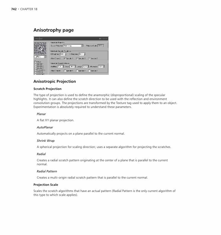
742 • CHAPTER 18 THE BHODINUT SHADERS • 743
Anisotrophy page
Anisotropic Projection
Scratch Projection
The type of projection is used to define the anamorphic (disproportional) scaling of the specular highlights. It can also define the scratch direction to be used with the reflection and environment convolution groups. The projections are transformed by the Texture tag used to apply them to an object. Experimentation is absolutely required to understand these parameters.
Planar
A flat XY planar projection.
AutoPlanar
Automatically projects on a plane parallel to the current normal.
Shrink Wrap
A spherical projection for scaling direction; uses a separate algorithm for projecting the scratches.
Radial
Creates a radial scratch pattern originating at the center of a plane that is parallel to the current normal.
Radial Pattern
Creates a multi-origin radial scratch pattern that is parallel to the current normal.
Projection Scale
Scales the scratch algorithms that have an actual pattern (Radial Pattern is the only current algorithm of this type to which scale applies).

742 • CHAPTER 18 THE BHODINUT SHADERS • 743
Anisotropic Specular Roughness
X Roughness
Scales the specular highlights in the X direction defined by the Scratch Projection algorithm. The appropriate range is 0.1% to 10,000%. If the X & Y roughness are the same the standard internal specular algorithm is used.
Y Roughness
Scales the highlights in the Y direction defined by the Scratch Projection algorithm. The appropriate range is 0.1% to 10,000%. If the X & Y roughness are the same the standard internal specular algorithm is used.
Anisotropic Scratch Attributes
Amplitude
Scales the effect of the scratch of the specular highlights. The higher the value the more scratched the speculars will look. The appropriate range is 0% - 100%.
Scale
Scales the scratch pattern itself. This applies to all scratch algorithms.
Length
Defines the scratch length in the space of the scratch pattern. Smoother milled surfaces would use a higher scratch length and rougher surfaces would use smaller values. The appropriate range is 1% - 1,000%.
Attenuation
Scales the amount of detail of the scratches based upon the sample’s angle to the camera and the distance from the camera. The larger the values the greater the attenuation, causing less scratching (better for animation); the smaller the value the greater the detail (better for still images). The appropriate range is 0% - 10,000%.
Affect Channel
These check boxes specify which specular channels will be affected by the anisotropic scratches.

744 • CHAPTER 18 THE BHODINUT SHADERS • 745
Illumination page
Use this channel to control aspects of material illumination. Here, you can switch on/off radiosity and caustics for the material (both are enabled by default).
Global Illumination
Generate
When the option is enabled, the material will generate radiosity. Use the input box to set the strength of the radiosity - you can enter values from 0 to 10,000%. 100% represents normal strength.
Receive
If this option is enabled, the material will receive radiosity. The value in the input box defines the strength of the radiosity effect.
Caustics
Generate
The material must be transparent and/or reflective in order to create a caustics effect.
Use this option to enable the generation of caustics by the material. The input box defines the strength of the caustics generated.
Receive
The Receive option has no effect for volume caustics.
This enables or disables the reception of surface caustics by the material. Use the input box to set the strength of the effect.
Sample Radius
In order to calculate the brightness of the caustics effect, photons within a certain distance of the pixel to be rendered are interpolated to calculate the brightness. The Sample Radius defines this distance. Sample Radius = 1; individual photons can be seen as points of light because they are not interpolated together.

744 • CHAPTER 18 THE BHODINUT SHADERS • 745
Samples
This defines the maximum number of photons within the Sample Radius that are used for calculating the effect. For example, if you enter a value of 100, up to 100 photons will be evaluated - any photons beyond this number are ignored. Samples and Sample Radius both affect the quality of the effect. To summarize: more samples per sample radius means a more accurate image. Increasing the sample radius means more blur, but a longer render time also.
Esoterica page
Shadow Attributes
Global Shadow Opacity
This parameter is used to scale the shadow opacity. Keep in mind that this changes the shadow opacity for every surface intercepted by the ray meaning that going through the surface twice causes the shadow to be twice as dark.
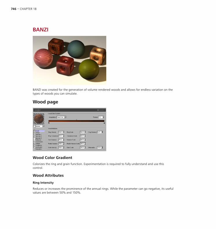
746 • CHAPTER 18 THE BHODINUT SHADERS • 747
BANZI
BANZI was created for the generation of volume rendered woods and allows for endless variation on the types of woods you can simulate.
Wood page
Wood Color Gradient
Colorizes the ring and grain function. Experimentation is required to fully understand and use this control.
Wood Attributes
Ring Intensity
Reduces or increases the prominence of the annual rings. While the parameter can go negative, its useful values are between 50% and 150%.

746 • CHAPTER 18 THE BHODINUT SHADERS • 747
Ring Turbulence
Stirs the annual rings so they may have a more natural look. Turbulence Scale — simply scales the noise used for the ring turbulence.
Core Variance
Disturbs the origin of the rings so it looks as if the tree the wood came from did not grow perfectly straight.
Radial Variance
Causes the rings to become non-symmetrical around their origin. Trees rarely grow perfectly circular rings because they are rarely perfectly round. This parameter allows for the natural deformation of the annual rings.
Grain Intensity
Amplifies the grain pattern within the wood. A percent value of zero removes the grain totally while a value of 100 gives a very amplified grain pattern (this also affects bump).
Ring Scale
Scales the rings of the wood before being stirred by the turbulence function.
Variance Scale
Scale of the noise used to disturb the origin of the rings.
Radial Variance Scale
Scales the noise used for the Radial Variance.
Grain Scale
Scales the grain.
Ring Variance
Varies the width of the rings without changing their respective positions.
Attenuation
Is the amount of detail reduction caused by the function becoming smaller (whether being scaled or being further away from the camera) and facing away from the camera. For still imagery it is good to keep this value low (often we use zero), but keep it high for animation (anywhere between 100% to 1,000%+).
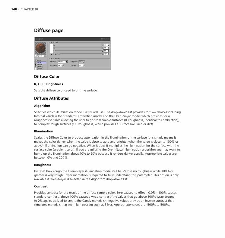
748 • CHAPTER 18 THE BHODINUT SHADERS • 749
Diffuse page
Diffuse Color
R, G, B, Brightness
Sets the diffuse color used to tint the surface.
Diffuse Attributes
Algorithm
Specifies which illumination model BANZI will use. The drop-down list provides for two choices including Internal which is the standard Lambertian model and the Oren-Nayar model which provides for a roughness variable allowing the user to go from simple surfaces (0 Roughness, identical to Lambertian), to complex rough surfaces (1+ Roughness, which provides a surface like linen or dirt).
Illumination
Scales the Diffuse Color to produce attenuation in the illumination of the surface (this simply means it makes the color darker when the value is close to zero and brighter when the value is closer to 100% or above). Illumination can go negative. When it does it multiplies the illumination for the surface with the surface color (gradient color). If you are utilizing the Oren-Nayar illumination algorithm you may want to bump up the illumination about 10% to 20% because it renders darker usually. Appropriate values are between 0% and 200%.
Roughness
Dictates how rough the Oren-Nayar illumination model will be. Zero is no roughness while 100% or greater is very rough. Experimentation is required to fully understand this parameter. This option is only available if Oren-Nayar is selected in the Algorithm drop-down list.
Contrast
Provides contrast for the result of the diffuse sample color. Zero causes no effect, 0.0% - 100% causes standard contrast, above 100% causes a wrap contrast (the values that go above 100% wrap around to 0% again, utilized to create the Candy materials), negative values provide an inverse contrast that simulates materials that seem luminescent such as Silver. Appropriate values are -500% to 500%.

748 • CHAPTER 18 THE BHODINUT SHADERS • 749
Specular pages
The three specular highlights controlled in the Specular channels are additive to the color of the surface. All three Specular channels share the same parameter set described below.
Specular Color
R, G, B, Brightness
Sets the base specular color for the specular component.
Specular Attributes
Intensity
Scales the Specular Color to produce attenuation in the specular reflection of the surface (this simply means it makes the color darker when the value is close to zero and brighter when the value is closer to 100% or above). The appropriate range is 0% - 1,000%.
Glare
Works with Specular Intensity by using the edge falloff (multiplied by the Falloff scalar)) to change the intensity of the specular reflection. This can be used to add a glare to the surface when a light is reflecting more on an edge or specular effects to reduce the specular reflection when a light causes a reflection closer to the edge. Appropriate values run between 0% - 200%.
Size
Sets the size of the specular reflection. Appropriate value range for Size is 0.001% - 200%.
Falloff
Utilized to vary the falloff of the center of the object to the edge to affect the Glare intensity. Smaller values cause the specular reflection to reflect the Intensity value more while larger values make the surface use the Glare scalar more. Experimentation is required to fully understand this parameter.
Contrast
Provides contrast for the result of the specular sample color. Implements a standard contrast function. Appropriate values are 0% - 100%.
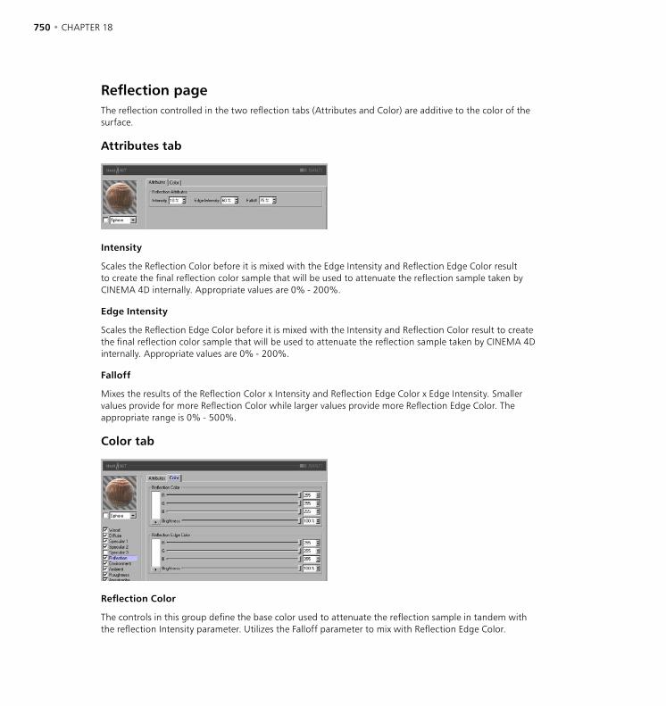
750 • CHAPTER 18 THE BHODINUT SHADERS • 751
Reflection pageThe reflection controlled in the two reflection tabs (Attributes and Color) are additive to the color of the surface.
Attributes tab
Intensity
Scales the Reflection Color before it is mixed with the Edge Intensity and Reflection Edge Color result to create the final reflection color sample that will be used to attenuate the reflection sample taken by CINEMA 4D internally. Appropriate values are 0% - 200%.
Edge Intensity
Scales the Reflection Edge Color before it is mixed with the Intensity and Reflection Color result to create the final reflection color sample that will be used to attenuate the reflection sample taken by CINEMA 4D internally. Appropriate values are 0% - 200%.
Falloff
Mixes the results of the Reflection Color x Intensity and Reflection Edge Color x Edge Intensity. Smaller values provide for more Reflection Color while larger values provide more Reflection Edge Color. The appropriate range is 0% - 500%.
Color tab
Reflection Color
The controls in this group define the base color used to attenuate the reflection sample in tandem with the reflection Intensity parameter. Utilizes the Falloff parameter to mix with Reflection Edge Color.

750 • CHAPTER 18 THE BHODINUT SHADERS • 751
Reflection Edge Color
The controls in this group define the edge color used to attenuate the reflection sample in tandem with the reflection Edge Intensity parameter. Utilizes the Falloff parameter to mix with Reflection Color.
Environment page
Image tab
Utilizes a standard CINEMA 4D texture group to be used for the environment sample.
Attributes tab
Intensity
Scales the Environment Color before it is mixed with the Glare and Environment Edge Color result to create the final environment color sample that will be used to attenuate the environment sample provided by the Environment Texture texture group. Appropriate values are 0% - 200%.
Glare
Scales the Environment Edge Color before it is mixed with the Intensity and Environment Color result to create the final environment color sample that will be used to attenuate the reflection sample provided by the Environment Texture texture group. Appropriate values are 0% - 200%.
Falloff
Mixes the results of the Environment Color x Intensity and Environment Edge Color x Glare. Smaller values provide for more Environment Color while larger values provide more Environment Edge Color. The appropriate range is 0% - 500%.
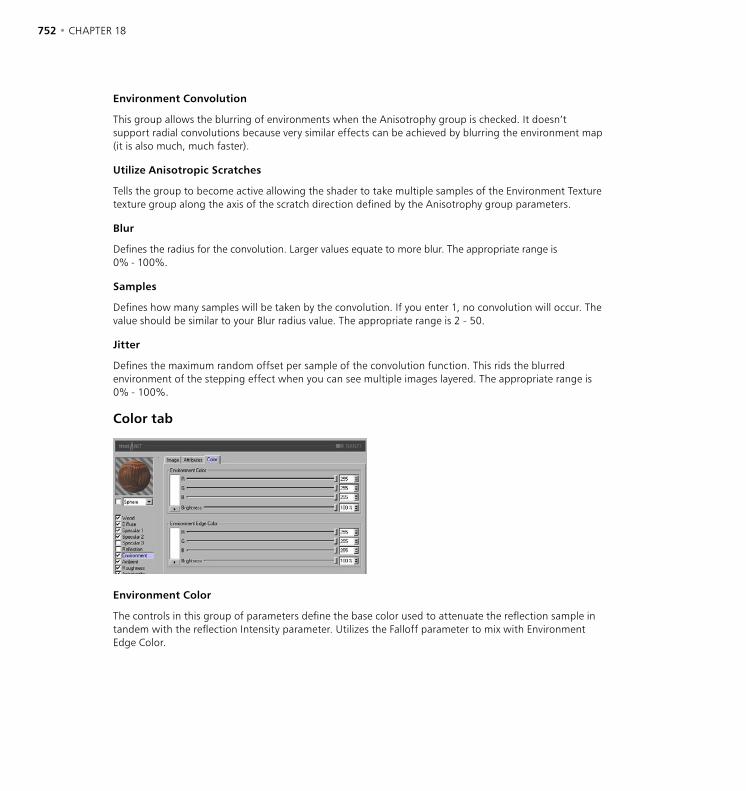
752 • CHAPTER 18 THE BHODINUT SHADERS • 753
Environment Convolution
This group allows the blurring of environments when the Anisotrophy group is checked. It doesn’t support radial convolutions because very similar effects can be achieved by blurring the environment map (it is also much, much faster).
Utilize Anisotropic Scratches
Tells the group to become active allowing the shader to take multiple samples of the Environment Texture texture group along the axis of the scratch direction defined by the Anisotrophy group parameters.
Blur
Defines the radius for the convolution. Larger values equate to more blur. The appropriate range is 0% - 100%.
Samples
Defines how many samples will be taken by the convolution. If you enter 1, no convolution will occur. The value should be similar to your Blur radius value. The appropriate range is 2 - 50.
Jitter
Defines the maximum random offset per sample of the convolution function. This rids the blurred environment of the stepping effect when you can see multiple images layered. The appropriate range is 0% - 100%.
Color tab
Environment Color
The controls in this group of parameters define the base color used to attenuate the reflection sample in tandem with the reflection Intensity parameter. Utilizes the Falloff parameter to mix with Environment Edge Color.
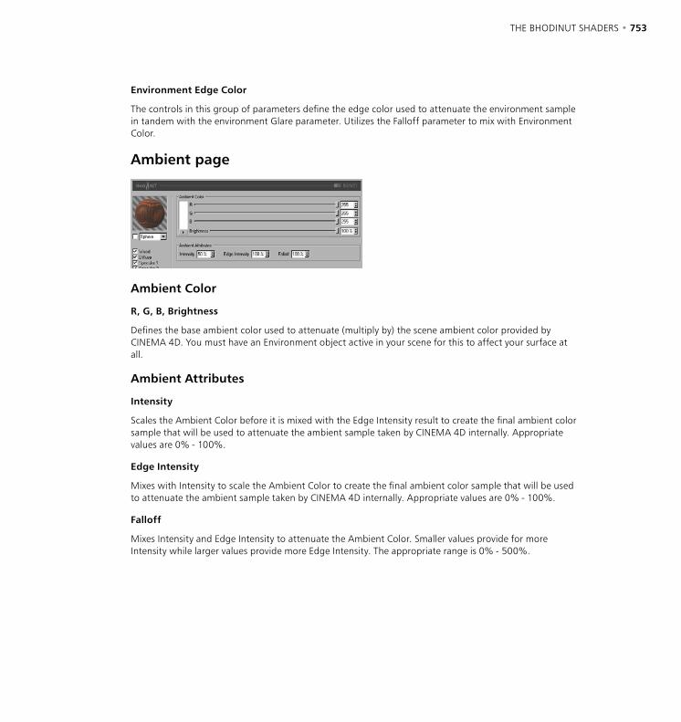
752 • CHAPTER 18 THE BHODINUT SHADERS • 753
Environment Edge Color
The controls in this group of parameters define the edge color used to attenuate the environment sample in tandem with the environment Glare parameter. Utilizes the Falloff parameter to mix with Environment Color.
Ambient page
Ambient Color
R, G, B, Brightness
Defines the base ambient color used to attenuate (multiply by) the scene ambient color provided by CINEMA 4D. You must have an Environment object active in your scene for this to affect your surface at all.
Ambient Attributes
Intensity
Scales the Ambient Color before it is mixed with the Edge Intensity result to create the final ambient color sample that will be used to attenuate the ambient sample taken by CINEMA 4D internally. Appropriate values are 0% - 100%.
Edge Intensity
Mixes with Intensity to scale the Ambient Color to create the final ambient color sample that will be used to attenuate the ambient sample taken by CINEMA 4D internally. Appropriate values are 0% - 100%.
Falloff
Mixes Intensity and Edge Intensity to attenuate the Ambient Color. Smaller values provide for more Intensity while larger values provide more Edge Intensity. The appropriate range is 0% - 500%.
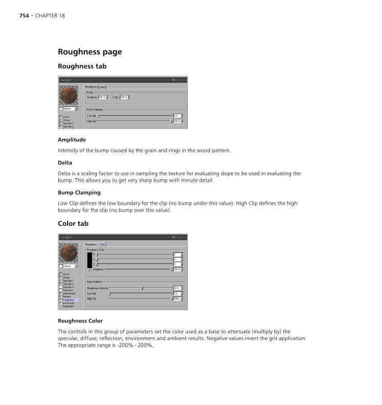
754 • CHAPTER 18 THE BHODINUT SHADERS • 755
Roughness page
Roughness tab
Amplitude
Intensity of the bump caused by the grain and rings in the wood pattern.
Delta
Delta is a scaling factor to use in sampling the texture for evaluating slope to be used in evaluating the bump. This allows you to get very sharp bump with minute detail.
Bump Clamping
Low Clip defines the low boundary for the clip (no bump under this value). High Clip defines the high boundary for the clip (no bump over this value).
Color tab
Roughness Color
The controls in this group of parameters set the color used as a base to attenuate (multiply by) the specular, diffuse, reflection, environment and ambient results. Negative values invert the grit application. The appropriate range is -200% - 200%,
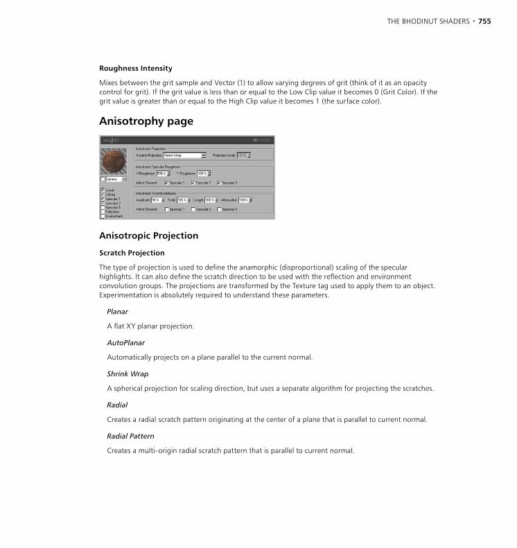
754 • CHAPTER 18 THE BHODINUT SHADERS • 755
Roughness Intensity
Mixes between the grit sample and Vector (1) to allow varying degrees of grit (think of it as an opacity control for grit). If the grit value is less than or equal to the Low Clip value it becomes 0 (Grit Color). If the grit value is greater than or equal to the High Clip value it becomes 1 (the surface color).
Anisotrophy page
Anisotropic Projection
Scratch Projection
The type of projection is used to define the anamorphic (disproportional) scaling of the specular highlights. It can also define the scratch direction to be used with the reflection and environment convolution groups. The projections are transformed by the Texture tag used to apply them to an object. Experimentation is absolutely required to understand these parameters.
Planar
A flat XY planar projection.
AutoPlanar
Automatically projects on a plane parallel to the current normal.
Shrink Wrap
A spherical projection for scaling direction, but uses a separate algorithm for projecting the scratches.
Radial
Creates a radial scratch pattern originating at the center of a plane that is parallel to current normal.
Radial Pattern
Creates a multi-origin radial scratch pattern that is parallel to current normal.

756 • CHAPTER 18 THE BHODINUT SHADERS • 757
Projection Scale
Scales the scratch algorithms that have an actual pattern (Radial Pattern is the only current algorithm of this type to which scale applies).
Anisotropic Specular Roughness
X Roughness
Scales the highlights in the X direction defined by the Scratch Projection algorithm. The appropriate range is 0.1% to 10,000%. If the X & Y roughness are the same the standard internal specular algorithm is used.
Y Roughness
Scales the highlights in the Y direction defined by the Scratch Projection algorithm. The appropriate range is 0.1% to 10,000%. If the X & Y roughness are the same, the standard internal specular algorithm is used.
Affect Channel
These check boxes specify which specular channels will be affected by the anisotropic algorithm.
Anisotropic Scratch Attributes
Amplitude
Scales the effect of the scratch of the specular highlights. The higher the value the more scratched the speculars will look. The appropriate range is 0% - 100%.
Scale
Scales the scratch pattern itself. This applies to all scratch algorithms.
Length
Defines the scratch length in the space of the scratch pattern. Smoother milled surfaces would use a higher scratch length, rougher surfaces would use smaller values. The appropriate range is 1% - 1,000%.
Attenuation
Scales the amount of detail of the scratches based upon the samples, angle to the camera and the distance from the camera. The larger the values the greater the attenuation, causing less scratching (better for animation); the smaller the value the greater the detail (better for still images). The appropriate range is 0% - 10,000%.
Affect Channel
These check boxes specify which specular channels will be affected by the anisotropic scratches.
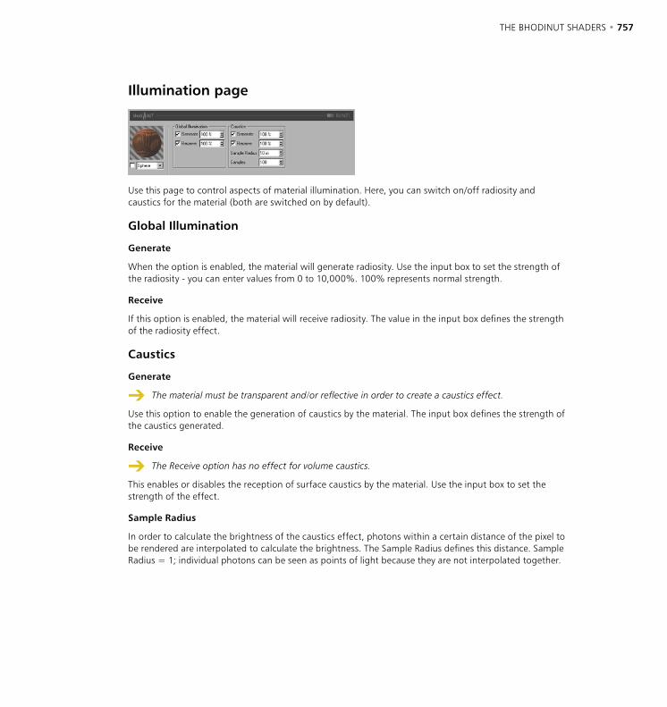
756 • CHAPTER 18 THE BHODINUT SHADERS • 757
Illumination page
Use this page to control aspects of material illumination. Here, you can switch on/off radiosity and caustics for the material (both are switched on by default).
Global Illumination
Generate
When the option is enabled, the material will generate radiosity. Use the input box to set the strength of the radiosity - you can enter values from 0 to 10,000%. 100% represents normal strength.
Receive
If this option is enabled, the material will receive radiosity. The value in the input box defines the strength of the radiosity effect.
Caustics
Generate
The material must be transparent and/or reflective in order to create a caustics effect.
Use this option to enable the generation of caustics by the material. The input box defines the strength of the caustics generated.
Receive
The Receive option has no effect for volume caustics.
This enables or disables the reception of surface caustics by the material. Use the input box to set the strength of the effect.
Sample Radius
In order to calculate the brightness of the caustics effect, photons within a certain distance of the pixel to be rendered are interpolated to calculate the brightness. The Sample Radius defines this distance. Sample Radius = 1; individual photons can be seen as points of light because they are not interpolated together.

758 • CHAPTER 18 THE BHODINUT SHADERS • 759
Samples
This defines the maximum number of photons within the Sample Radius that are used for calculating the effect. For example, if you enter a value of 100, up to 100 photons will be evaluated - any photons beyond this number are ignored. Samples and Sample Radius both affect the quality of the effect. To summarize: more samples per sample radius means a more accurate image. Increasing the sample radius means more blur, but a longer render time also.
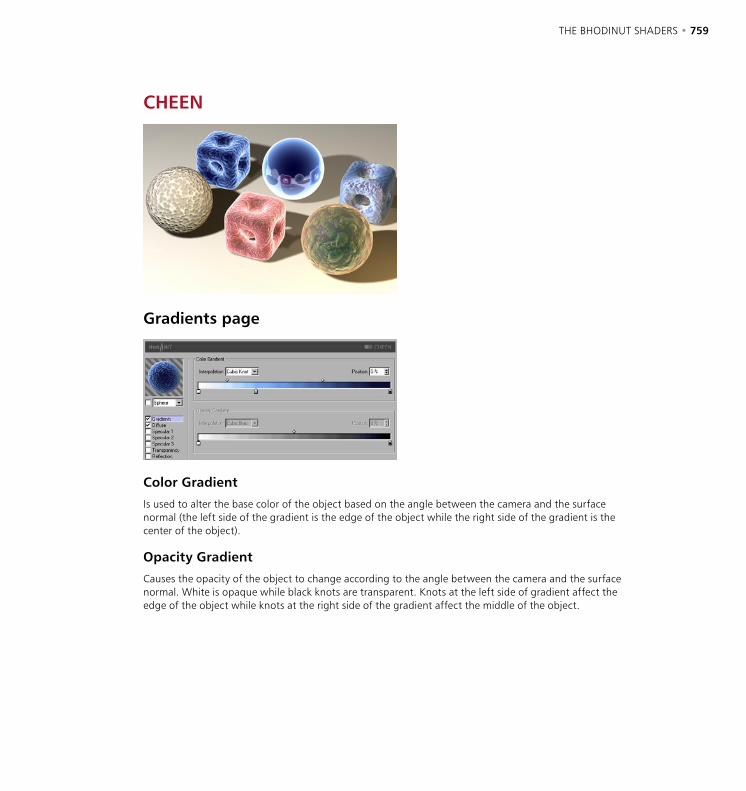
758 • CHAPTER 18 THE BHODINUT SHADERS • 759
CHEEN
Gradients page
Color Gradient
Is used to alter the base color of the object based on the angle between the camera and the surface normal (the left side of the gradient is the edge of the object while the right side of the gradient is the center of the object).
Opacity Gradient
Causes the opacity of the object to change according to the angle between the camera and the surface normal. White is opaque while black knots are transparent. Knots at the left side of gradient affect the edge of the object while knots at the right side of the gradient affect the middle of the object.
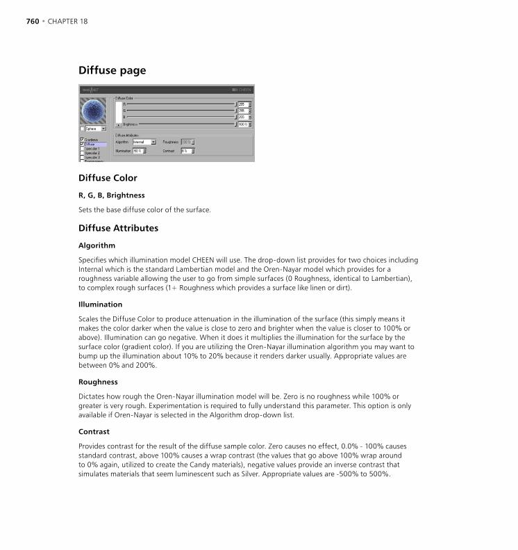
760 • CHAPTER 18 THE BHODINUT SHADERS • 761
Diffuse page
Diffuse Color
R, G, B, Brightness
Sets the base diffuse color of the surface.
Diffuse Attributes
Algorithm
Specifies which illumination model CHEEN will use. The drop-down list provides for two choices including Internal which is the standard Lambertian model and the Oren-Nayar model which provides for a roughness variable allowing the user to go from simple surfaces (0 Roughness, identical to Lambertian), to complex rough surfaces (1+ Roughness which provides a surface like linen or dirt).
Illumination
Scales the Diffuse Color to produce attenuation in the illumination of the surface (this simply means it makes the color darker when the value is close to zero and brighter when the value is closer to 100% or above). Illumination can go negative. When it does it multiplies the illumination for the surface by the surface color (gradient color). If you are utilizing the Oren-Nayar illumination algorithm you may want to bump up the illumination about 10% to 20% because it renders darker usually. Appropriate values are between 0% and 200%.
Roughness
Dictates how rough the Oren-Nayar illumination model will be. Zero is no roughness while 100% or greater is very rough. Experimentation is required to fully understand this parameter. This option is only available if Oren-Nayar is selected in the Algorithm drop-down list.
Contrast
Provides contrast for the result of the diffuse sample color. Zero causes no effect, 0.0% - 100% causes standard contrast, above 100% causes a wrap contrast (the values that go above 100% wrap around to 0% again, utilized to create the Candy materials), negative values provide an inverse contrast that simulates materials that seem luminescent such as Silver. Appropriate values are -500% to 500%.

760 • CHAPTER 18 THE BHODINUT SHADERS • 761
Specular pages
The three specular highlights controlled in the Specular channels are additive to the color of the surface. All three Specular channels share the same parameter set described below.
Specular Color
R, G, B, Brightness
Sets the base specular color for the specular component.
Specular Attributes
Intensity
Scales the Specular Color to produce attenuation in the specular reflection of the surface (this simply means it makes the color darker when the value is close to zero and brighter when the value is closer to 100% or above). The appropriate range is 0% - 1,000%.
Glare
Works with Specular Intensity by using the edge falloff (multiplied by the Falloff scalar) to change the intensity of the specular reflection. This can be used to add a glare to the surface when a light is reflecting more on an edge or specular effects to reduce the specular reflection when a light causes a reflection closer to the edge. Appropriate values run between 0% - 200%.
Size
Sets the size of the specular reflection. Appropriate value range for Size is 0.001% - 200%.
Falloff
Utilized to vary the falloff of the center of the object to the edge to affect the Glare intensity. Smaller values cause the specular reflection to reflect the Intensity value more while larger values make the surface use the Glare scalar more.
Contrast
Provides contrast for the result of the specular sample color. Implements a standard contrast function. Appropriate values are 0% - 100%.

762 • CHAPTER 18 THE BHODINUT SHADERS • 763
Transparency page
Transparency Attributes
Index Of Refraction
Defines the refractive index of the material.
Internal Reflection
Allows refracted rays to reflect when appropriate.
Solid Object
Makes the object a completely dense object instead of one surface. Disallows illumination, reflection, and environment to be evaluated for the second surface intercepted of the object.
Reflection pageThe reflection controlled in the two reflection tabs (Attributes and Color) are additive to the color of the surface.
Attributes tab
Intensity
Scales the Reflection Color before it is mixed with the Edge Intensity and Reflection Edge Color result to create the final reflection color sample that will be used to attenuate the reflection sample taken by CINEMA 4D internally. Appropriate values are 0% - 200%.
Edge Intensity
Scales the Reflection Edge Color before it is mixed with the Intensity and Reflection Color result to create the final reflection color sample that will be used to attenuate the reflection sample taken by CINEMA 4D internally. Appropriate values are 0% - 200%.
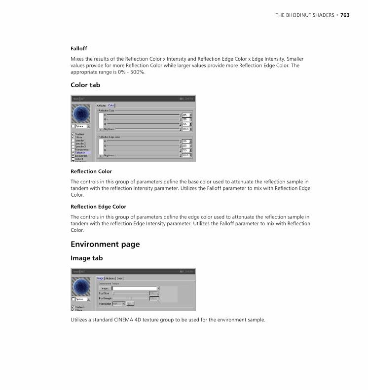
762 • CHAPTER 18 THE BHODINUT SHADERS • 763
Falloff
Mixes the results of the Reflection Color x Intensity and Reflection Edge Color x Edge Intensity. Smaller values provide for more Reflection Color while larger values provide more Reflection Edge Color. The appropriate range is 0% - 500%.
Color tab
Reflection Color
The controls in this group of parameters define the base color used to attenuate the reflection sample in tandem with the reflection Intensity parameter. Utilizes the Falloff parameter to mix with Reflection Edge Color.
Reflection Edge Color
The controls in this group of parameters define the edge color used to attenuate the reflection sample in tandem with the reflection Edge Intensity parameter. Utilizes the Falloff parameter to mix with Reflection Color.
Environment page
Image tab
Utilizes a standard CINEMA 4D texture group to be used for the environment sample.
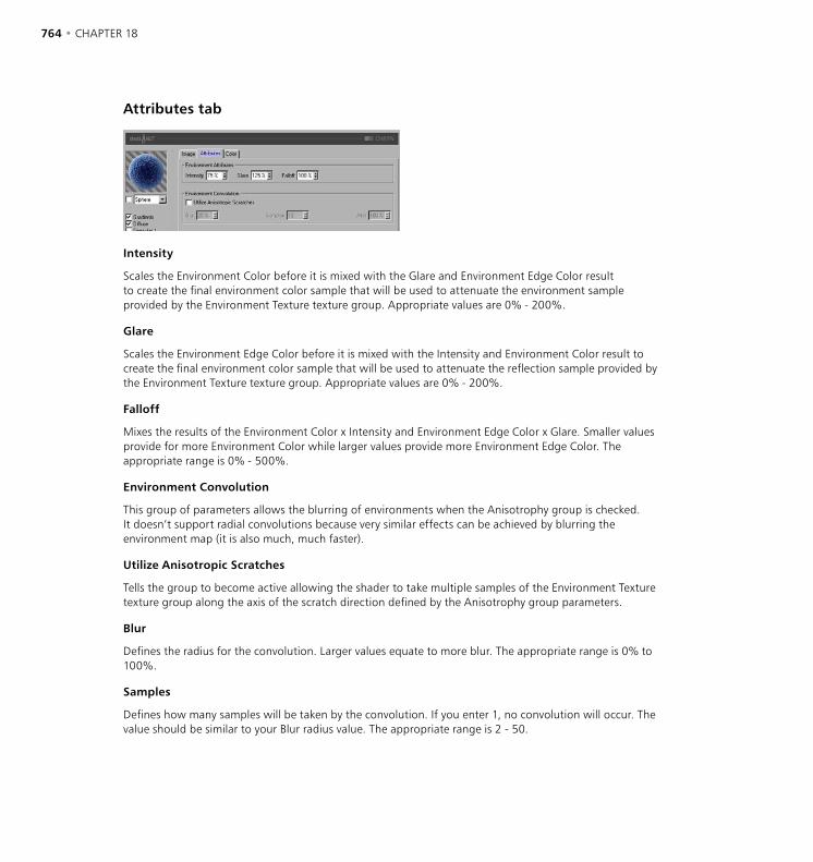
764 • CHAPTER 18 THE BHODINUT SHADERS • 765
Attributes tab
Intensity
Scales the Environment Color before it is mixed with the Glare and Environment Edge Color result to create the final environment color sample that will be used to attenuate the environment sample provided by the Environment Texture texture group. Appropriate values are 0% - 200%.
Glare
Scales the Environment Edge Color before it is mixed with the Intensity and Environment Color result to create the final environment color sample that will be used to attenuate the reflection sample provided by the Environment Texture texture group. Appropriate values are 0% - 200%.
Falloff
Mixes the results of the Environment Color x Intensity and Environment Edge Color x Glare. Smaller values provide for more Environment Color while larger values provide more Environment Edge Color. The appropriate range is 0% - 500%.
Environment Convolution
This group of parameters allows the blurring of environments when the Anisotrophy group is checked. It doesn’t support radial convolutions because very similar effects can be achieved by blurring the environment map (it is also much, much faster).
Utilize Anisotropic Scratches
Tells the group to become active allowing the shader to take multiple samples of the Environment Texture texture group along the axis of the scratch direction defined by the Anisotrophy group parameters.
Blur
Defines the radius for the convolution. Larger values equate to more blur. The appropriate range is 0% to 100%.
Samples
Defines how many samples will be taken by the convolution. If you enter 1, no convolution will occur. The value should be similar to your Blur radius value. The appropriate range is 2 - 50.
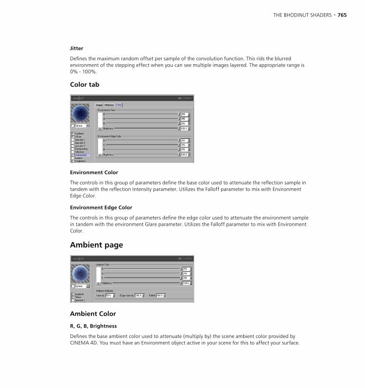
764 • CHAPTER 18 THE BHODINUT SHADERS • 765
Jitter
Defines the maximum random offset per sample of the convolution function. This rids the blurred environment of the stepping effect when you can see multiple images layered. The appropriate range is 0% - 100%.
Color tab
Environment Color
The controls in this group of parameters define the base color used to attenuate the reflection sample in tandem with the reflection Intensity parameter. Utilizes the Falloff parameter to mix with Environment Edge Color.
Environment Edge Color
The controls in this group of parameters define the edge color used to attenuate the environment sample in tandem with the environment Glare parameter. Utilizes the Falloff parameter to mix with Environment Color.
Ambient page
Ambient Color
R, G, B, Brightness
Defines the base ambient color used to attenuate (multiply by) the scene ambient color provided by CINEMA 4D. You must have an Environment object active in your scene for this to affect your surface.

766 • CHAPTER 18 THE BHODINUT SHADERS • 767
Ambient Attributes
Intensity
Scales the Ambient Color before it is mixed with the Edge Intensity result to create the final ambient color sample that will be used to attenuate the ambient sample taken by CINEMA 4D internally. Appropriate values are 0% - 100%.
Edge Intensity
Mixes with Intensity to scale the Ambient Color to create the final ambient color sample that will be used to attenuate the ambient sample taken by CINEMA 4D internally. Appropriate values are 0% - 100%.
Falloff
Mixes Intensity and Edge Intensity to attenuate the Ambient Color. Smaller values provide for more Intensity while larger values provide more Edge Intensity. The appropriate range is 0% - 500%.
Roughness pageUsed to add bump or grit to the material.
Roughness tab
Function
The noise function utilized to calculate the bump and the grit. You can review the noise types very easily in the 2D or 3D Noise channel shaders to get a feel for what they are.
Octaves
Defines the number of octaves utilized by the noise function defined within the Function drop-down list. This field will only be active if the noise function being used utilizes more octaves than one. Octaves is similar to Detail in many other shaders.
Scale
Scales the surface point used in the noise evaluation.
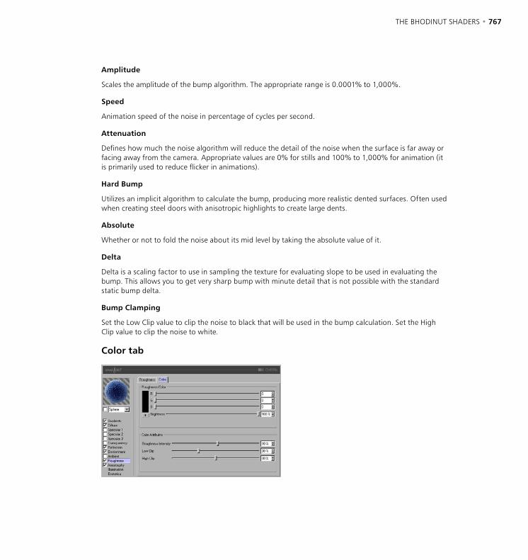
766 • CHAPTER 18 THE BHODINUT SHADERS • 767
Amplitude
Scales the amplitude of the bump algorithm. The appropriate range is 0.0001% to 1,000%.
Speed
Animation speed of the noise in percentage of cycles per second.
Attenuation
Defines how much the noise algorithm will reduce the detail of the noise when the surface is far away or facing away from the camera. Appropriate values are 0% for stills and 100% to 1,000% for animation (it is primarily used to reduce flicker in animations).
Hard Bump
Utilizes an implicit algorithm to calculate the bump, producing more realistic dented surfaces. Often used when creating steel doors with anisotropic highlights to create large dents.
Absolute
Whether or not to fold the noise about its mid level by taking the absolute value of it.
Delta
Delta is a scaling factor to use in sampling the texture for evaluating slope to be used in evaluating the bump. This allows you to get very sharp bump with minute detail that is not possible with the standard static bump delta.
Bump Clamping
Set the Low Clip value to clip the noise to black that will be used in the bump calculation. Set the High Clip value to clip the noise to white.
Color tab

768 • CHAPTER 18 THE BHODINUT SHADERS • 769
Roughness Color
The controls in this group of parameters set the color used as a base to attenuate (multiply by) the specular, diffuse, reflection, environment and ambient results. Negative values invert the grit application. The appropriate range is -200% - 200%,
Roughness Intensity
Mixes between the grit sample and Vector (1) to allow varying degrees of grit (think of it as an opacity control for grit). If the grit value is less than or equal to the Low Clip value it becomes 0 (Grit Color). If the grit value is greater than or equal to the High Clip value it becomes 1 (the surface color).
Anisotrophy page
Anisotropic Projection
Scratch Projection
The type of projection is used to define the anamorphic (disproportional) scaling of the specular highlights. It can also define the scratch direction to be used with the reflection and environment convolution groups. The projections are transformed by the Texture tag used to apply them to an object. Experimentation is absolutely required to understand these parameters.
Planar
A flat XY planar projection.
AutoPlanar
Automatically projects on a plane parallel to the current normal.
Shrink Wrap
A spherical projection for scaling direction, but uses a separate algorithm for projecting the scratches.
Radial
Creates a radial scratch pattern originating at the center of a plane that is parallel to the current normal.
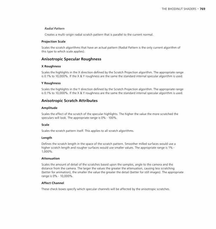
768 • CHAPTER 18 THE BHODINUT SHADERS • 769
Radial Pattern
Creates a multi-origin radial scratch pattern that is parallel to the current normal.
Projection Scale
Scales the scratch algorithms that have an actual pattern (Radial Pattern is the only current algorithm of this type to which scale applies).
Anisotropic Specular Roughness
X Roughness
Scales the highlights in the X direction defined by the Scratch Projection algorithm. The appropriate range is 0.1% to 10,000%. If the X & Y roughness are the same the standard internal specular algorithm is used.
Y Roughness
Scales the highlights in the Y direction defined by the Scratch Projection algorithm. The appropriate range is 0.1% to 10,000%. If the X & Y roughness are the same the standard internal specular algorithm is used.
Anisotropic Scratch Attributes
Amplitude
Scales the effect of the scratch of the specular highlights. The higher the value the more scratched the speculars will look. The appropriate range is 0% - 100%.
Scale
Scales the scratch pattern itself. This applies to all scratch algorithms.
Length
Defines the scratch length in the space of the scratch pattern. Smoother milled surfaces would use a higher scratch length and rougher surfaces would use smaller values. The appropriate range is 1% - 1,000%.
Attenuation
Scales the amount of detail of the scratches based upon the samples, angle to the camera and the distance from the camera. The larger the values the greater the attenuation, causing less scratching (better for animation), the smaller the value the greater the detail (better for still images). The appropriate range is 0% - 10,000%.
Affect Channel
These check boxes specify which specular channels will be affected by the anisotropic scratches.
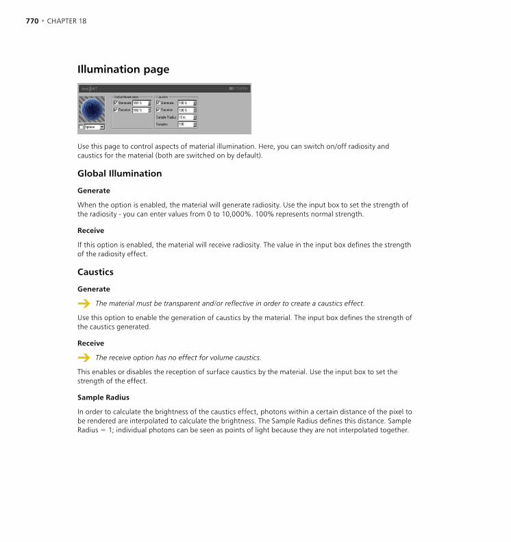
770 • CHAPTER 18 THE BHODINUT SHADERS • 771
Illumination page
Use this page to control aspects of material illumination. Here, you can switch on/off radiosity and caustics for the material (both are switched on by default).
Global Illumination
Generate
When the option is enabled, the material will generate radiosity. Use the input box to set the strength of the radiosity - you can enter values from 0 to 10,000%. 100% represents normal strength.
Receive
If this option is enabled, the material will receive radiosity. The value in the input box defines the strength of the radiosity effect.
Caustics
Generate
The material must be transparent and/or reflective in order to create a caustics effect.
Use this option to enable the generation of caustics by the material. The input box defines the strength of the caustics generated.
Receive
The receive option has no effect for volume caustics.
This enables or disables the reception of surface caustics by the material. Use the input box to set the strength of the effect.
Sample Radius
In order to calculate the brightness of the caustics effect, photons within a certain distance of the pixel to be rendered are interpolated to calculate the brightness. The Sample Radius defines this distance. Sample Radius = 1; individual photons can be seen as points of light because they are not interpolated together.
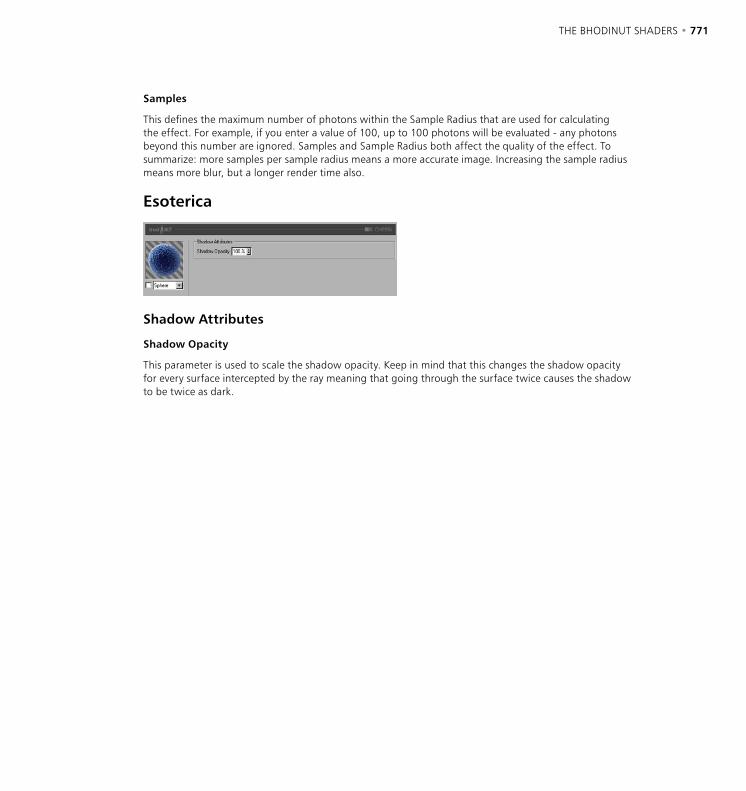
770 • CHAPTER 18 THE BHODINUT SHADERS • 771
Samples
This defines the maximum number of photons within the Sample Radius that are used for calculating the effect. For example, if you enter a value of 100, up to 100 photons will be evaluated - any photons beyond this number are ignored. Samples and Sample Radius both affect the quality of the effect. To summarize: more samples per sample radius means a more accurate image. Increasing the sample radius means more blur, but a longer render time also.
Esoterica
Shadow Attributes
Shadow Opacity
This parameter is used to scale the shadow opacity. Keep in mind that this changes the shadow opacity for every surface intercepted by the ray meaning that going through the surface twice causes the shadow to be twice as dark.

772 • CHAPTER 18 THE BHODINUT SHADERS • 773
DANEL
DANEL was conceived to allow users the ability to create surfaces that include metallic, gloss, painted, and anisotropic materials.
Diffuse page
Diffuse Color
R, G, B, Brightness
Sets the base diffuse color of the surface.
Diffuse Attributes
Algorithm
Specifies which illumination model DANEL will use. The drop-down list provides for two choices including Internal which is the standard Lambertian model and the Oren-Nayar model which provides for a roughness variable allowing the user to go from simple surfaces (0 Roughness, identical to Lambertian), to complex rough surfaces (100% + Roughness which provides a surface like linen or dirt).
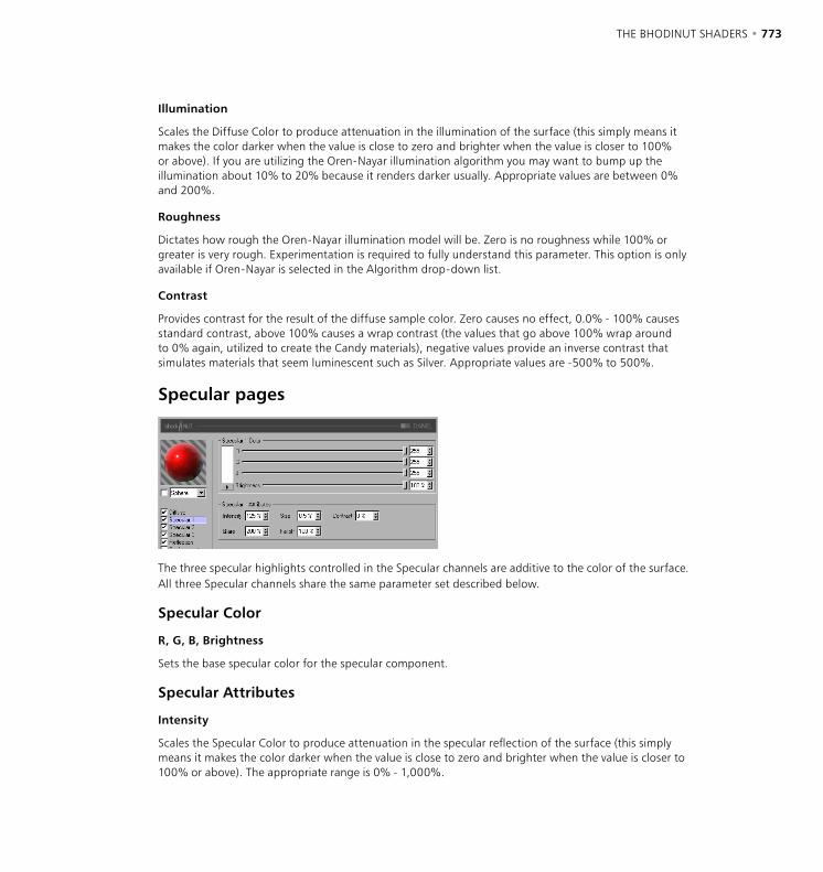
772 • CHAPTER 18 THE BHODINUT SHADERS • 773
Illumination
Scales the Diffuse Color to produce attenuation in the illumination of the surface (this simply means it makes the color darker when the value is close to zero and brighter when the value is closer to 100% or above). If you are utilizing the Oren-Nayar illumination algorithm you may want to bump up the illumination about 10% to 20% because it renders darker usually. Appropriate values are between 0% and 200%.
Roughness
Dictates how rough the Oren-Nayar illumination model will be. Zero is no roughness while 100% or greater is very rough. Experimentation is required to fully understand this parameter. This option is only available if Oren-Nayar is selected in the Algorithm drop-down list.
Contrast
Provides contrast for the result of the diffuse sample color. Zero causes no effect, 0.0% - 100% causes standard contrast, above 100% causes a wrap contrast (the values that go above 100% wrap around to 0% again, utilized to create the Candy materials), negative values provide an inverse contrast that simulates materials that seem luminescent such as Silver. Appropriate values are -500% to 500%.
Specular pages
The three specular highlights controlled in the Specular channels are additive to the color of the surface. All three Specular channels share the same parameter set described below.
Specular Color
R, G, B, Brightness
Sets the base specular color for the specular component.
Specular Attributes
Intensity
Scales the Specular Color to produce attenuation in the specular reflection of the surface (this simply means it makes the color darker when the value is close to zero and brighter when the value is closer to 100% or above). The appropriate range is 0% - 1,000%.

774 • CHAPTER 18 THE BHODINUT SHADERS • 775
Glare
Works with Specular Intensity by using the edge falloff (multiplied by the Falloff scalar) to change the intensity of the specular reflection. This can be used to add a glare to the surface when a light is reflecting more on an edge or specular effects to reduce the specular reflection when a light causes a reflection closer to the edge. Appropriate values run between 0% and 200%.
Size
Sets the size of the specular reflection. Appropriate value range for Size is 0.001% - 200%.
Falloff
Utilized to vary the falloff of the center of the object to the edge to affect the Glare intensity. Smaller values cause the specular reflection to reflect the Intensity value more while larger values make the surface use the Glare scalar more. Experimentation is required to fully understand this parameter.
Contrast
Provides contrast for the result of the specular sample color. Implements a standard contrast function. Appropriate values are 0% - 100%.
Reflection pageThe reflection controlled in the two reflection tabs (Attributes and Color) are additive to the color of the surface.
Attributes tab
Intensity
Scales the Reflection Color before it is mixed with the Edge Intensity and Reflection Edge Color result to create the final reflection color sample that will be used to attenuate the reflection sample taken by CINEMA 4D internally. Appropriate values are 0% - 200%.
774 • CHAPTER 18 THE BHODINUT SHADERS • 775
Edge Intensity
Scales the Reflection Edge Color before it is mixed with the Intensity and Reflection Color result to create the final reflection color sample that will be used to attenuate the reflection sample taken by CINEMA 4D internally. Appropriate values are 0% - 200%.
Falloff
Mixes the results of the Reflection Color x Intensity and Reflection Edge Color x Edge Intensity. Smaller values provide for more Reflection Color while larger values provide more Reflection Edge Color. The appropriate range is 0% - 500%.
Distance Falloff
Turns on or off distance falloff for reflections. Doing so does slow the shader down about 20% because the reflections rays are calculated by customized algorithms.
Min
If the distance of the reflected surface is less than or equal to the Min distance the reflection will be 100%. The Distance Falloff check box must be checked for this value to be utilized or available.
Max
If the distance of the reflected surface is greater than the Min distance and less than the Max distance then the reflection intensity of the sample will be attenuated by a value produced by retrieving the parameterized distance of the intercepted position relating to the Min and Max distances ((intercepted_Point - min_Point) / (max_Point - min_Point)). If the distance of the intercepted surface is greater than the Max parameter then the surface has 0% intensity.
Reflection Convolution
This collection of parameters was added because of numerous requests from users. It is not fast, and requires large sampling rates to provide acceptable results. Distance Falloff will effect blurred reflection samples, producing very beautiful results in many cases.
Utilize Anisotropic Scratches
This check box is only active when the Anisotrophy group is checked. It allows the reflection to take into account the scratch directions when evaluating blurred reflections. Very effective for milled machinery. Anisotropic scratches are only convoluted along one axis so they require far fewer samples than does the radial convolution algorithm.
If this check box is inactive, the Blur radius is greater than 0% and Samples is greater than 1 the radial convolution algorithm is used (this is what the majority would consider Blurred Reflections).
Blur
This defines the radius of the convolution (blur) that will be used during the evaluation of blurred reflections. If Utilize Anisotropic Scratches is checked it will use the scratch direction defined by the parameters in the Anisotrophy group, otherwise it will use a radial convolution algorithm to sample the reflections. Appropriate value range is 0% - 100%.

776 • CHAPTER 18 THE BHODINUT SHADERS • 777
Samples
Sets the number of samples taken when the Blur radius percentage is greater that 0%. When Utilize Anisotropic Scratches is checked it is good to start with a value equal to the Blur radius. If Utilize Anisotropic Scratches is not checked then you should usually double the Blur radius, sometimes having to go as large as 100 to 200 samples (very slow).
Jitter
Defines the maximum random offset of the reflection convolution associated with the anisotropic scratch convolution algorithm. This parameter is only active when Utilize Anisotropic Scratches is checked because the radial convolution is a completely stochastic function (jitters 100% all the time to the boundary of the radius). Jittering is very similar to dithering in effect. Appropriate value range is 0% - 100%.
Color tab
Reflection Color
The controls in this group of parameters define the base color used to attenuate the reflection sample in tandem with the reflection Intensity parameter. Utilizes the Falloff parameter to mix with Reflection Edge Color.
Reflection Edge Color
The controls in this group of parameters define the edge color used to attenuate the reflection sample in tandem with the reflection Edge Intensity parameter. Utilizes the Falloff parameter to mix with Reflection Color.
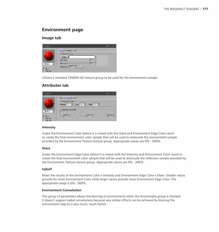
776 • CHAPTER 18 THE BHODINUT SHADERS • 777
Environment page
Image tab
Utilizes a standard CINEMA 4D texture group to be used for the environment sample.
Attributes tab
Intensity
Scales the Environment Color before it is mixed with the Glare and Environment Edge Color result to create the final environment color sample that will be used to attenuate the environment sample provided by the Environment Texture texture group. Appropriate values are 0% - 200%.
Glare
Scales the Environment Edge Color before it is mixed with the Intensity and Environment Color result to create the final environment color sample that will be used to attenuate the reflection sample provided by the Environment Texture texture group. Appropriate values are 0% - 200%.
Falloff
Mixes the results of the Environment Color x Intensity and Environment Edge Color x Glare. Smaller values provide for more Environment Color while larger values provide more Environment Edge Color. The appropriate range is 0% - 500%.
Environment Convolution
This group of parameters allows the blurring of environments when the Anisotrophy group is checked. It doesn’t support radial convolutions because very similar effects can be achieved by blurring the environment map (it is also much, much faster).
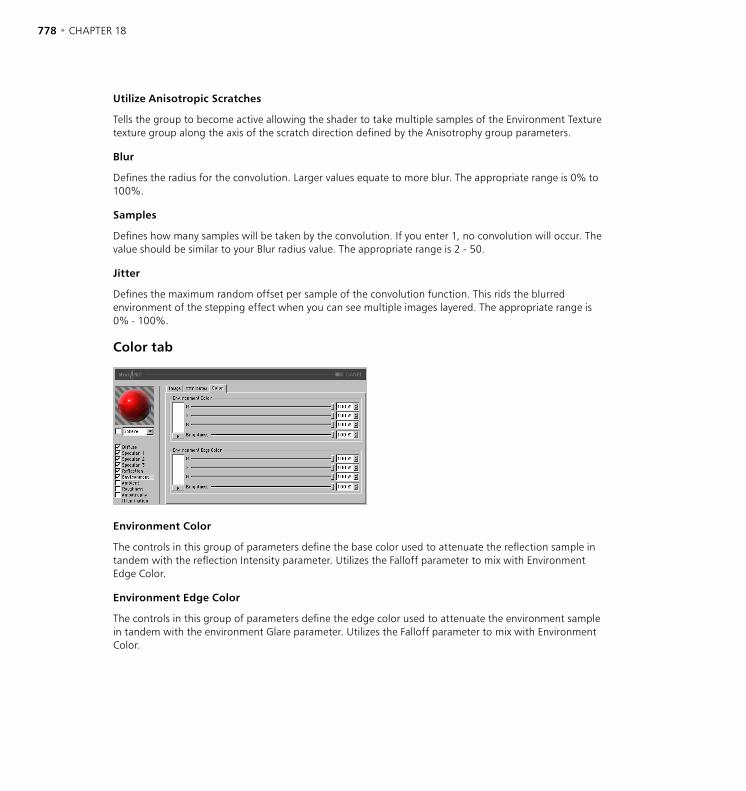
778 • CHAPTER 18 THE BHODINUT SHADERS • 779
Utilize Anisotropic Scratches
Tells the group to become active allowing the shader to take multiple samples of the Environment Texture texture group along the axis of the scratch direction defined by the Anisotrophy group parameters.
Blur
Defines the radius for the convolution. Larger values equate to more blur. The appropriate range is 0% to 100%.
Samples
Defines how many samples will be taken by the convolution. If you enter 1, no convolution will occur. The value should be similar to your Blur radius value. The appropriate range is 2 - 50.
Jitter
Defines the maximum random offset per sample of the convolution function. This rids the blurred environment of the stepping effect when you can see multiple images layered. The appropriate range is 0% - 100%.
Color tab
Environment Color
The controls in this group of parameters define the base color used to attenuate the reflection sample in tandem with the reflection Intensity parameter. Utilizes the Falloff parameter to mix with Environment Edge Color.
Environment Edge Color
The controls in this group of parameters define the edge color used to attenuate the environment sample in tandem with the environment Glare parameter. Utilizes the Falloff parameter to mix with Environment Color.

778 • CHAPTER 18 THE BHODINUT SHADERS • 779
Ambient page
Ambient Color
R, G, B, Brightness
Defines the base ambient color used to attenuate (multiply by) the scene ambient color provided by CINEMA 4D. You must have an Environment object active in your scene for this to affect your surface at all.
Ambient Attributes
Intensity
Scales the Ambient Color before it is mixed with the Edge Intensity result to create the final ambient color sample that will be used to attenuate the ambient sample taken by CINEMA 4D internally. Appropriate values are 0% - 100%.
Edge Intensity
Mixes with Intensity to scale the Ambient Color to create the final ambient color sample that will be used to attenuate the ambient sample taken by CINEMA 4D internally. Appropriate values are 0% - 100%.
Falloff
Mixes Intensity and Edge Intensity to attenuate the Ambient Color. Smaller values provide for more Intensity while larger values provide more Edge Intensity. The appropriate range is 0% - 500%.
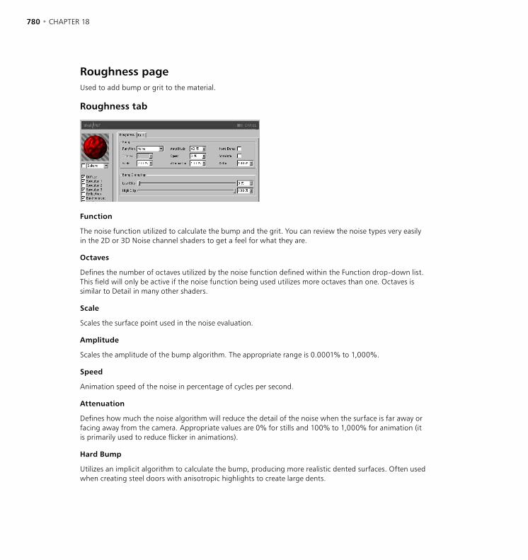
780 • CHAPTER 18 THE BHODINUT SHADERS • 781
Roughness pageUsed to add bump or grit to the material.
Roughness tab
Function
The noise function utilized to calculate the bump and the grit. You can review the noise types very easily in the 2D or 3D Noise channel shaders to get a feel for what they are.
Octaves
Defines the number of octaves utilized by the noise function defined within the Function drop-down list. This field will only be active if the noise function being used utilizes more octaves than one. Octaves is similar to Detail in many other shaders.
Scale
Scales the surface point used in the noise evaluation.
Amplitude
Scales the amplitude of the bump algorithm. The appropriate range is 0.0001% to 1,000%.
Speed
Animation speed of the noise in percentage of cycles per second.
Attenuation
Defines how much the noise algorithm will reduce the detail of the noise when the surface is far away or facing away from the camera. Appropriate values are 0% for stills and 100% to 1,000% for animation (it is primarily used to reduce flicker in animations).
Hard Bump
Utilizes an implicit algorithm to calculate the bump, producing more realistic dented surfaces. Often used when creating steel doors with anisotropic highlights to create large dents.
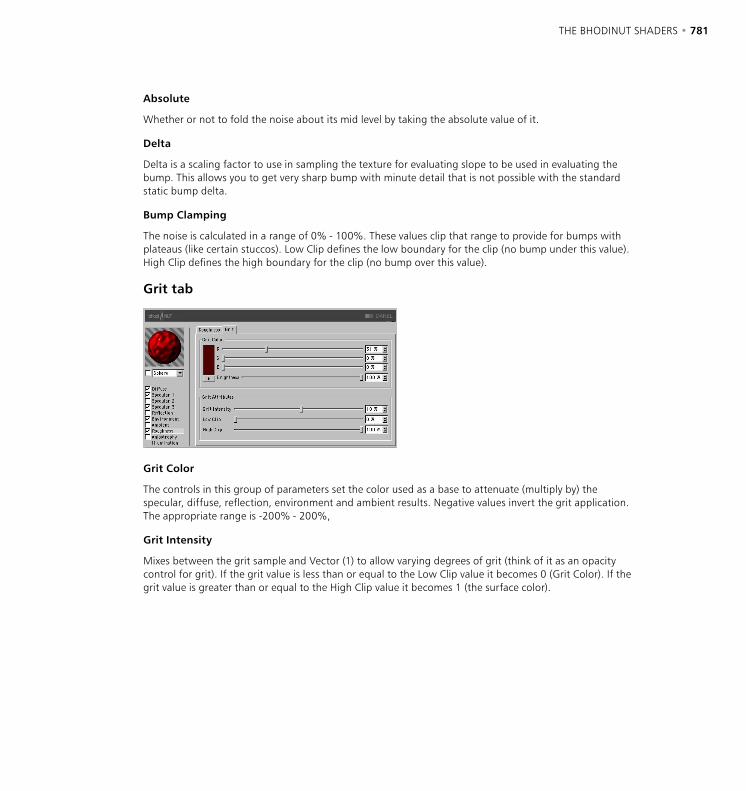
780 • CHAPTER 18 THE BHODINUT SHADERS • 781
Absolute
Whether or not to fold the noise about its mid level by taking the absolute value of it.
Delta
Delta is a scaling factor to use in sampling the texture for evaluating slope to be used in evaluating the bump. This allows you to get very sharp bump with minute detail that is not possible with the standard static bump delta.
Bump Clamping
The noise is calculated in a range of 0% - 100%. These values clip that range to provide for bumps with plateaus (like certain stuccos). Low Clip defines the low boundary for the clip (no bump under this value). High Clip defines the high boundary for the clip (no bump over this value).
Grit tab
Grit Color
The controls in this group of parameters set the color used as a base to attenuate (multiply by) the specular, diffuse, reflection, environment and ambient results. Negative values invert the grit application. The appropriate range is -200% - 200%,
Grit Intensity
Mixes between the grit sample and Vector (1) to allow varying degrees of grit (think of it as an opacity control for grit). If the grit value is less than or equal to the Low Clip value it becomes 0 (Grit Color). If the grit value is greater than or equal to the High Clip value it becomes 1 (the surface color).
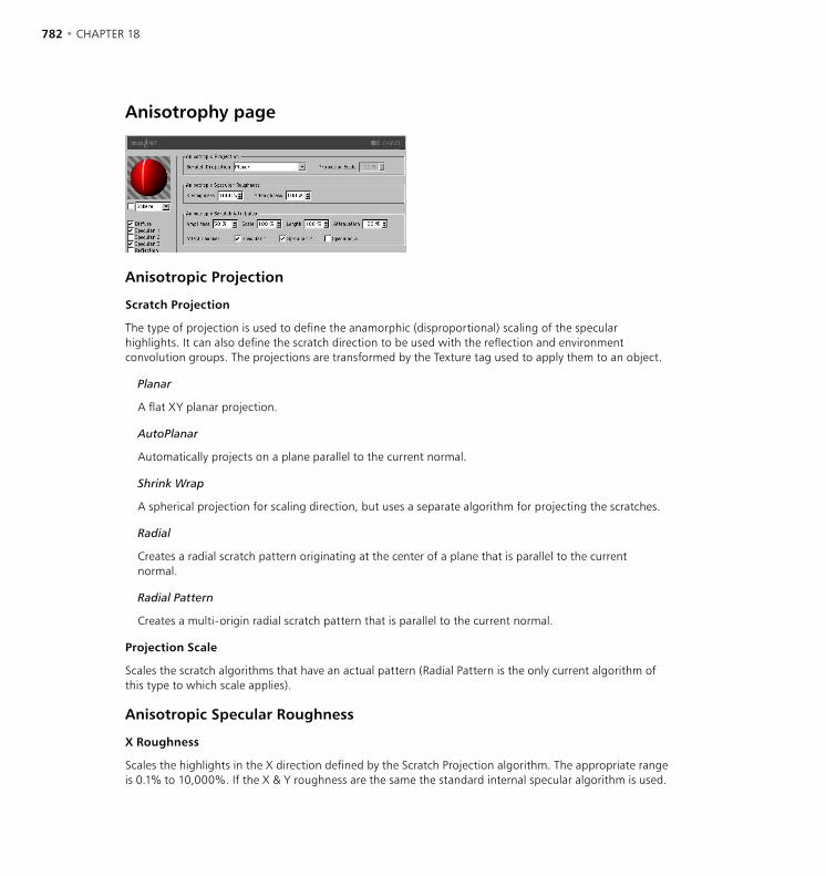
782 • CHAPTER 18 THE BHODINUT SHADERS • 783
Anisotrophy page
Anisotropic Projection
Scratch Projection
The type of projection is used to define the anamorphic (disproportional) scaling of the specular highlights. It can also define the scratch direction to be used with the reflection and environment convolution groups. The projections are transformed by the Texture tag used to apply them to an object.
Planar
A flat XY planar projection.
AutoPlanar
Automatically projects on a plane parallel to the current normal.
Shrink Wrap
A spherical projection for scaling direction, but uses a separate algorithm for projecting the scratches.
Radial
Creates a radial scratch pattern originating at the center of a plane that is parallel to the current normal.
Radial Pattern
Creates a multi-origin radial scratch pattern that is parallel to the current normal.
Projection Scale
Scales the scratch algorithms that have an actual pattern (Radial Pattern is the only current algorithm of this type to which scale applies).
Anisotropic Specular Roughness
X Roughness
Scales the highlights in the X direction defined by the Scratch Projection algorithm. The appropriate range is 0.1% to 10,000%. If the X & Y roughness are the same the standard internal specular algorithm is used.
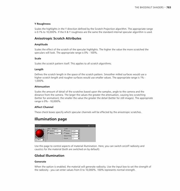
782 • CHAPTER 18 THE BHODINUT SHADERS • 783
Y Roughness
Scales the highlights in the Y direction defined by the Scratch Projection algorithm. The appropriate range is 0.1% to 10,000%. If the X & Y roughness are the same the standard internal specular algorithm is used.
Anisotropic Scratch Attributes
Amplitude
Scales the effect of the scratch of the specular highlights. The higher the value the more scratched the speculars will look. The appropriate range is 0% - 100%.
Scale
Scales the scratch pattern itself. This applies to all scratch algorithms.
Length
Defines the scratch length in the space of the scratch pattern. Smoother milled surfaces would use a higher scratch length and rougher surfaces would use smaller values. The appropriate range is 1% - 1,000%.
Attenuation
Scales the amount of detail of the scratches based upon the samples, angle to the camera and the distance from the camera. The larger the values the greater the attenuation, causing less scratching (better for animation); the smaller the value the greater the detail (better for still images). The appropriate range is 0% - 10,000%.
Affect Channel
These check boxes specify which specular channels will be effected by the anisotropic scratches.
Illumination page
Use this page to control aspects of material illumination. Here, you can switch on/off radiosity and caustics for the material (both are switched on by default).
Global Illumination
Generate
When the option is enabled, the material will generate radiosity. Use the input box to set the strength of the radiosity - you can enter values from 0 to 10,000%. 100% represents normal strength.
784 • CHAPTER 18 THE BHODINUT SHADERS • 785
Receive
If this option is enabled, the material will receive radiosity. The value in the input box defines the strength of the radiosity effect.
Caustics
Generate
The material must be transparent and/or reflective in order to create a caustics effect.
Use this option to enable the generation of caustics by the material. The input box defines the strength of the caustics generated.
Receive
The Receive option has no effect for volume caustics.
This enables or disables the reception of surface caustics by the material. Use the input box to set the strength of the effect.
Sample Radius
In order to calculate the brightness of the caustics effect, photons within a certain distance of the pixel to be rendered are interpolated to calculate the brightness. The Sample Radius defines this distance. Sample Radius = 1; individual photons can be seen as points of light because they are not interpolated together.
Samples
This defines the maximum number of photons within the Sample Radius that are used for calculating the effect. For example, if you enter a value of 100, up to 100 photons will be evaluated - any photons beyond this number are ignored. Samples and Sample Radius both affect the quality of the effect. To summarize: more samples per sample radius means a more accurate image. Increasing the sample radius means more blur, but a longer render time also.
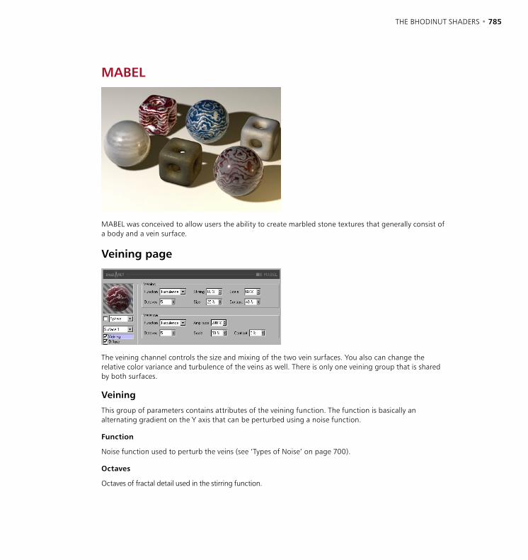
784 • CHAPTER 18 THE BHODINUT SHADERS • 785
MABEL
MABEL was conceived to allow users the ability to create marbled stone textures that generally consist of a body and a vein surface.
Veining page
The veining channel controls the size and mixing of the two vein surfaces. You also can change the relative color variance and turbulence of the veins as well. There is only one veining group that is shared by both surfaces.
Veining
This group of parameters contains attributes of the veining function. The function is basically an alternating gradient on the Y axis that can be perturbed using a noise function.
Function
Noise function used to perturb the veins (see ‘Types of Noise’ on page 700).
Octaves
Octaves of fractal detail used in the stirring function.
786 • CHAPTER 18 THE BHODINUT SHADERS • 787
Stirring
Amount of distortion applied to the veins.
Size
Size of the veins (Surface1) to the body (Surface 2).
Scale
The scale of the stirring noise function.
Contrast
Contrast applied to the veins to make them blend smoothly or separate distinctly.
Variance
This group of parameters contains attributes of a second noise to add variance to the blend of the veins and body caused by the veining function.
Function
Noise function used to vary the veining.
Octaves
Octaves of fractal detail used in the variance function.
Amplitude
Amount of variance applied to the veins.
Scale
The scale of the variance noise function.
Contrast
Contrast applied to the variance noise.
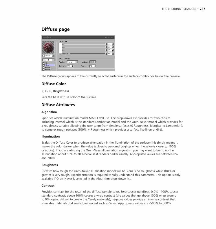
786 • CHAPTER 18 THE BHODINUT SHADERS • 787
Diffuse page
The Diffuse group applies to the currently selected surface in the surface combo box below the preview.
Diffuse Color
R, G, B, Brightness
Sets the base diffuse color of the surface.
Diffuse Attributes
Algorithm
Specifies which illumination model MABEL will use. The drop-down list provides for two choices including Internal which is the standard Lambertian model and the Oren-Nayar model which provides for a roughness variable allowing the user to go from simple surfaces (0 Roughness, identical to Lambertian), to complex rough surfaces (100% + Roughness which provides a surface like linen or dirt).
Illumination
Scales the Diffuse Color to produce attenuation in the illumination of the surface (this simply means it makes the color darker when the value is close to zero and brighter when the value is closer to 100% or above). If you are utilizing the Oren-Nayar illumination algorithm you may want to bump up the illumination about 10% to 20% because it renders darker usually. Appropriate values are between 0% and 200%.
Roughness
Dictates how rough the Oren-Nayar illumination model will be. Zero is no roughness while 100% or greater is very rough. Experimentation is required to fully understand this parameter. This option is only available if Oren-Nayar is selected in the Algorithm drop-down list.
Contrast
Provides contrast for the result of the diffuse sample color. Zero causes no effect, 0.0% - 100% causes standard contrast, above 100% causes a wrap contrast (the values that go above 100% wrap around to 0% again, utilized to create the Candy materials), negative values provide an inverse contrast that simulates materials that seem luminescent such as Silver. Appropriate values are -500% to 500%.
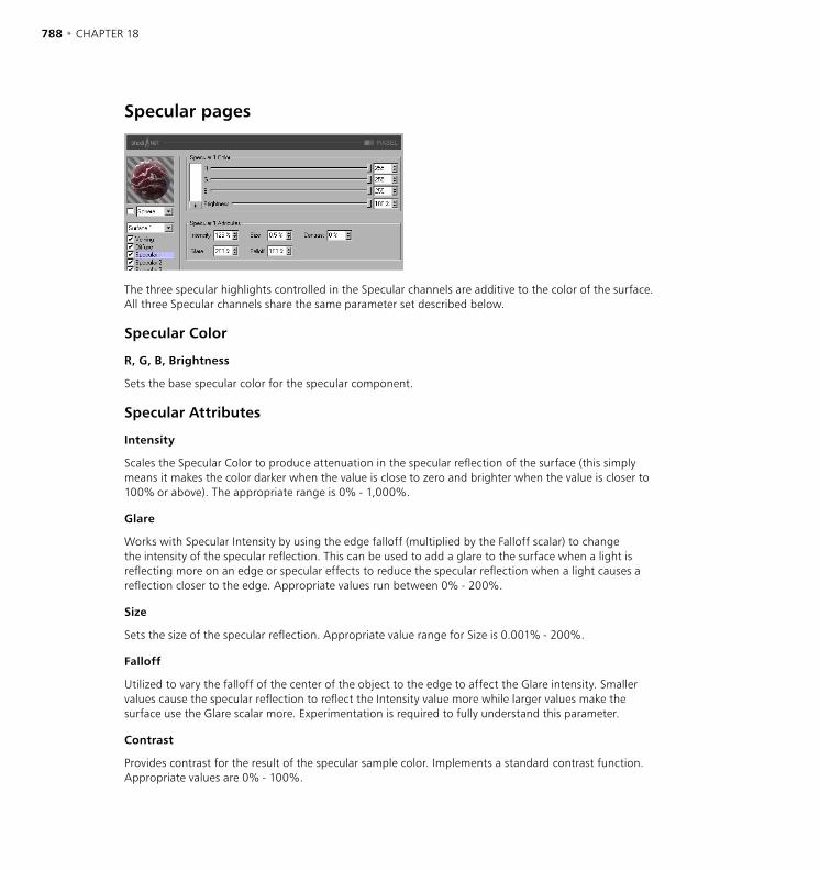
788 • CHAPTER 18 THE BHODINUT SHADERS • 789
Specular pages
The three specular highlights controlled in the Specular channels are additive to the color of the surface. All three Specular channels share the same parameter set described below.
Specular Color
R, G, B, Brightness
Sets the base specular color for the specular component.
Specular Attributes
Intensity
Scales the Specular Color to produce attenuation in the specular reflection of the surface (this simply means it makes the color darker when the value is close to zero and brighter when the value is closer to 100% or above). The appropriate range is 0% - 1,000%.
Glare
Works with Specular Intensity by using the edge falloff (multiplied by the Falloff scalar) to change the intensity of the specular reflection. This can be used to add a glare to the surface when a light is reflecting more on an edge or specular effects to reduce the specular reflection when a light causes a reflection closer to the edge. Appropriate values run between 0% - 200%.
Size
Sets the size of the specular reflection. Appropriate value range for Size is 0.001% - 200%.
Falloff
Utilized to vary the falloff of the center of the object to the edge to affect the Glare intensity. Smaller values cause the specular reflection to reflect the Intensity value more while larger values make the surface use the Glare scalar more. Experimentation is required to fully understand this parameter.
Contrast
Provides contrast for the result of the specular sample color. Implements a standard contrast function. Appropriate values are 0% - 100%.
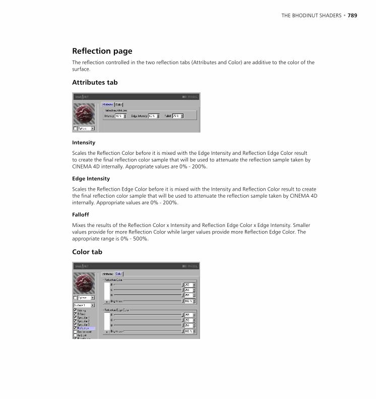
788 • CHAPTER 18 THE BHODINUT SHADERS • 789
Reflection pageThe reflection controlled in the two reflection tabs (Attributes and Color) are additive to the color of the surface.
Attributes tab
Intensity
Scales the Reflection Color before it is mixed with the Edge Intensity and Reflection Edge Color result to create the final reflection color sample that will be used to attenuate the reflection sample taken by CINEMA 4D internally. Appropriate values are 0% - 200%.
Edge Intensity
Scales the Reflection Edge Color before it is mixed with the Intensity and Reflection Color result to create the final reflection color sample that will be used to attenuate the reflection sample taken by CINEMA 4D internally. Appropriate values are 0% - 200%.
Falloff
Mixes the results of the Reflection Color x Intensity and Reflection Edge Color x Edge Intensity. Smaller values provide for more Reflection Color while larger values provide more Reflection Edge Color. The appropriate range is 0% - 500%.
Color tab
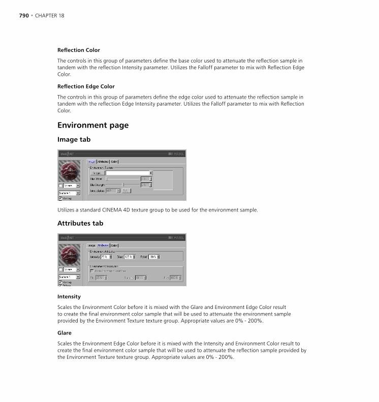
790 • CHAPTER 18 THE BHODINUT SHADERS • 791
Reflection Color
The controls in this group of parameters define the base color used to attenuate the reflection sample in tandem with the reflection Intensity parameter. Utilizes the Falloff parameter to mix with Reflection Edge Color.
Reflection Edge Color
The controls in this group of parameters define the edge color used to attenuate the reflection sample in tandem with the reflection Edge Intensity parameter. Utilizes the Falloff parameter to mix with Reflection Color.
Environment page
Image tab
Utilizes a standard CINEMA 4D texture group to be used for the environment sample.
Attributes tab
Intensity
Scales the Environment Color before it is mixed with the Glare and Environment Edge Color result to create the final environment color sample that will be used to attenuate the environment sample provided by the Environment Texture texture group. Appropriate values are 0% - 200%.
Glare
Scales the Environment Edge Color before it is mixed with the Intensity and Environment Color result to create the final environment color sample that will be used to attenuate the reflection sample provided by the Environment Texture texture group. Appropriate values are 0% - 200%.
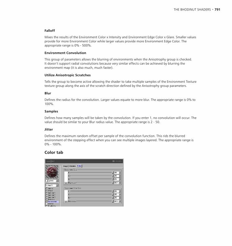
790 • CHAPTER 18 THE BHODINUT SHADERS • 791
Falloff
Mixes the results of the Environment Color x Intensity and Environment Edge Color x Glare. Smaller values provide for more Environment Color while larger values provide more Environment Edge Color. The appropriate range is 0% - 500%.
Environment Convolution
This group of parameters allows the blurring of environments when the Anisotrophy group is checked. It doesn’t support radial convolutions because very similar effects can be achieved by blurring the environment map (it is also much, much faster).
Utilize Anisotropic Scratches
Tells the group to become active allowing the shader to take multiple samples of the Environment Texture texture group along the axis of the scratch direction defined by the Anisotrophy group parameters.
Blur
Defines the radius for the convolution. Larger values equate to more blur. The appropriate range is 0% to 100%.
Samples
Defines how many samples will be taken by the convolution. If you enter 1, no convolution will occur. The value should be similar to your Blur radius value. The appropriate range is 2 - 50.
Jitter
Defines the maximum random offset per sample of the convolution function. This rids the blurred environment of the stepping effect when you can see multiple images layered. The appropriate range is 0% - 100%.
Color tab

792 • CHAPTER 18 THE BHODINUT SHADERS • 793
Environment Color
The controls in this group of parameters define the base color used to attenuate the reflection sample in tandem with the reflection Intensity parameter. Utilizes the Falloff parameter to mix with Environment Edge Color.
Environment Edge Color
The controls in this group of parameters define the edge color used to attenuate the environment sample in tandem with the environment Glare parameter. Utilizes the Falloff parameter to mix with Environment Color.
Ambient page
Ambient Color
R, G, B, Brightness
Defines the base ambient color used to attenuate (multiply by) the scene ambient color provided by CINEMA 4D. You must have an Environment object active in your scene for this to effect your surface at all.
Ambient Attributes
Intensity
Scales the Ambient Color before it is mixed with the Edge Intensity result to create the final ambient color sample that will be used to attenuate the ambient sample taken by CINEMA 4D internally. Appropriate values are 0% - 100%.
Edge Intensity
Mixes with Intensity to scale the Ambient Color to create the final ambient color sample that will be used to attenuate the ambient sample taken by CINEMA 4D internally. Appropriate values are 0% - 100%.
Falloff
Mixes Intensity and Edge Intensity to attenuate the Ambient Color. Smaller values provide for more Intensity while larger values provide more Edge Intensity. The appropriate range is 0% - 500%.
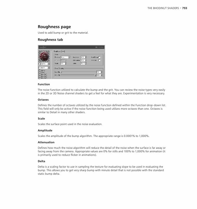
792 • CHAPTER 18 THE BHODINUT SHADERS • 793
Roughness pageUsed to add bump or grit to the material.
Roughness tab
Function
The noise function utilized to calculate the bump and the grit. You can review the noise types very easily in the 2D or 3D Noise channel shaders to get a feel for what they are. Experimentation is very necessary.
Octaves
Defines the number of octaves utilized by the noise function defined within the Function drop-down list. This field will only be active if the noise function being used utilizes more octaves than one. Octaves is similar to Detail in many other shaders.
Scale
Scales the surface point used in the noise evaluation.
Amplitude
Scales the amplitude of the bump algorithm. The appropriate range is 0.0001% to 1,000%.
Attenuation
Defines how much the noise algorithm will reduce the detail of the noise when the surface is far away or facing away from the camera. Appropriate values are 0% for stills and 100% to 1,000% for animation (it is primarily used to reduce flicker in animations).
Delta
Delta is a scaling factor to use in sampling the texture for evaluating slope to be used in evaluating the bump. This allows you to get very sharp bump with minute detail that is not possible with the standard static bump delta.
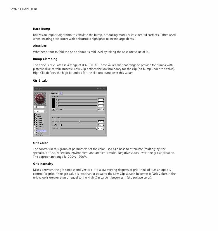
794 • CHAPTER 18 THE BHODINUT SHADERS • 795
Hard Bump
Utilizes an implicit algorithm to calculate the bump, producing more realistic dented surfaces. Often used when creating steel doors with anisotropic highlights to create large dents.
Absolute
Whether or not to fold the noise about its mid level by taking the absolute value of it.
Bump Clamping
The noise is calculated in a range of 0% - 100%. These values clip that range to provide for bumps with plateaus (like certain stuccos). Low Clip defines the low boundary for the clip (no bump under this value). High Clip defines the high boundary for the clip (no bump over this value).
Grit tab
Grit Color
The controls in this group of parameters set the color used as a base to attenuate (multiply by) the specular, diffuse, reflection, environment and ambient results. Negative values invert the grit application. The appropriate range is -200% - 200%,
Grit Intensity
Mixes between the grit sample and Vector (1) to allow varying degrees of grit (think of it as an opacity control for grit). If the grit value is less than or equal to the Low Clip value it becomes 0 (Grit Color). If the grit value is greater than or equal to the High Clip value it becomes 1 (the surface color).
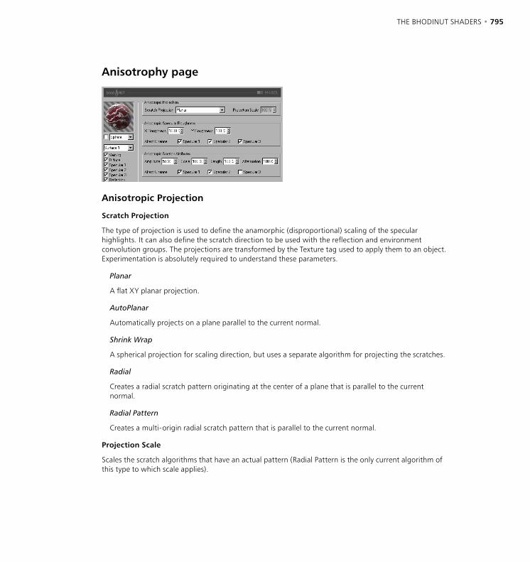
794 • CHAPTER 18 THE BHODINUT SHADERS • 795
Anisotrophy page
Anisotropic Projection
Scratch Projection
The type of projection is used to define the anamorphic (disproportional) scaling of the specular highlights. It can also define the scratch direction to be used with the reflection and environment convolution groups. The projections are transformed by the Texture tag used to apply them to an object. Experimentation is absolutely required to understand these parameters.
Planar
A flat XY planar projection.
AutoPlanar
Automatically projects on a plane parallel to the current normal.
Shrink Wrap
A spherical projection for scaling direction, but uses a separate algorithm for projecting the scratches.
Radial
Creates a radial scratch pattern originating at the center of a plane that is parallel to the current normal.
Radial Pattern
Creates a multi-origin radial scratch pattern that is parallel to the current normal.
Projection Scale
Scales the scratch algorithms that have an actual pattern (Radial Pattern is the only current algorithm of this type to which scale applies).
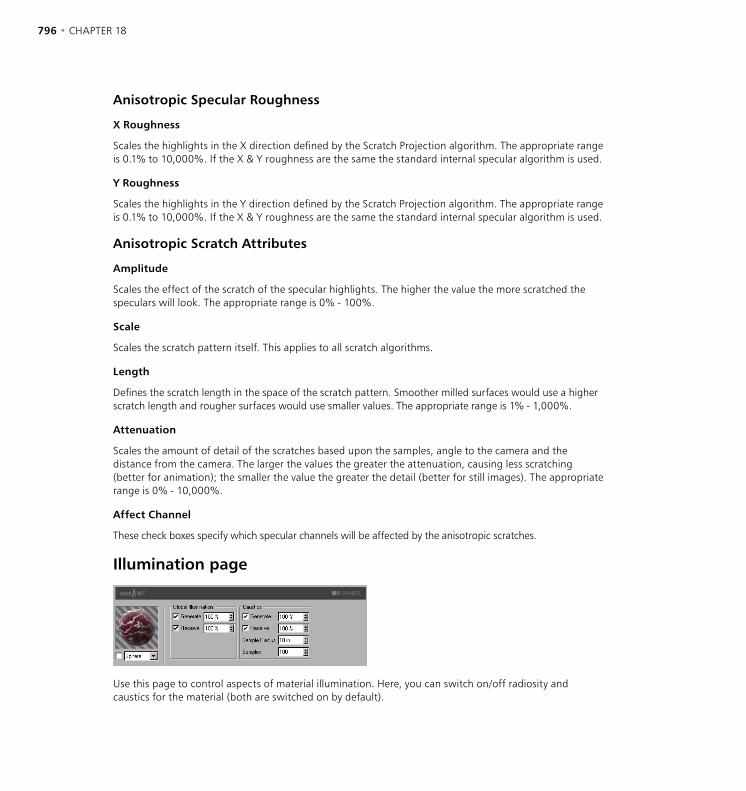
796 • CHAPTER 18 THE BHODINUT SHADERS • 797
Anisotropic Specular Roughness
X Roughness
Scales the highlights in the X direction defined by the Scratch Projection algorithm. The appropriate range is 0.1% to 10,000%. If the X & Y roughness are the same the standard internal specular algorithm is used.
Y Roughness
Scales the highlights in the Y direction defined by the Scratch Projection algorithm. The appropriate range is 0.1% to 10,000%. If the X & Y roughness are the same the standard internal specular algorithm is used.
Anisotropic Scratch Attributes
Amplitude
Scales the effect of the scratch of the specular highlights. The higher the value the more scratched the speculars will look. The appropriate range is 0% - 100%.
Scale
Scales the scratch pattern itself. This applies to all scratch algorithms.
Length
Defines the scratch length in the space of the scratch pattern. Smoother milled surfaces would use a higher scratch length and rougher surfaces would use smaller values. The appropriate range is 1% - 1,000%.
Attenuation
Scales the amount of detail of the scratches based upon the samples, angle to the camera and the distance from the camera. The larger the values the greater the attenuation, causing less scratching (better for animation); the smaller the value the greater the detail (better for still images). The appropriate range is 0% - 10,000%.
Affect Channel
These check boxes specify which specular channels will be affected by the anisotropic scratches.
Illumination page
Use this page to control aspects of material illumination. Here, you can switch on/off radiosity and caustics for the material (both are switched on by default).
796 • CHAPTER 18 THE BHODINUT SHADERS • 797
Global Illumination
Generate
When the option is enabled, the material will generate radiosity. Use the input box to set the strength of the radiosity - you can enter values from 0 to 10,000%. 100% represents normal strength.
Receive
If this option is enabled, the material will receive radiosity. The value in the input box defines the strength of the radiosity effect.
Caustics
Generate
The material must be transparent and/or reflective in order to create a caustics effect.
Use this option to enable the generation of caustics by the material. The input box defines the strength of the caustics generated.
Receive
The Receive option has no effect for volume caustics.
This enables or disables the reception of surface caustics by the material. Use the input box to set the strength of the effect.
Sample Radius
In order to calculate the brightness of the caustics effect, photons within a certain distance of the pixel to be rendered are interpolated to calculate the brightness. The Sample Radius defines this distance. Sample Radius = 1; individual photons can be seen as points of light because they are not interpolated together.
Samples
This defines the maximum number of photons within the Sample Radius that are used for calculating the effect. For example, if you enter a value of 100, up to 100 photons will be evaluated - any photons beyond this number are ignored. Samples and Sample Radius both affect the quality of the effect. To summarize: more samples per sample radius means a more accurate image. Increasing the sample radius means more blur, but a longer render time also.
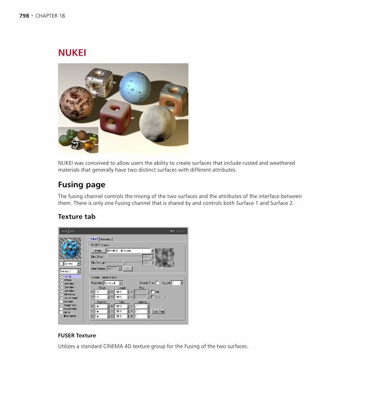
798 • CHAPTER 18 THE BHODINUT SHADERS • 799
NUKEI
NUKEI was conceived to allow users the ability to create surfaces that include rusted and weathered materials that generally have two distinct surfaces with different attributes.
Fusing pageThe fusing channel controls the mixing of the two surfaces and the attributes of the interface between them. There is only one Fusing channel that is shared by and controls both Surface 1 and Surface 2.
Texture tab
FUSER Texture
Utilizes a standard CINEMA 4D texture group for the Fusing of the two surfaces.
798 • CHAPTER 18 THE BHODINUT SHADERS • 799
Texture Transformation
This group of parameters contains the settings of the texture projection. This should look very familiar as it is basically the same as the projection options available in CINEMA 4D.
Projection
The projection type to use. The following are available to choose from and are functionally the same as CINEMA 4D’s normal projections: Spherical, Cylindrical, Flat, Cubic, Frontal and Shrink Wrap.
Overide Time
If enabled then the Time in seconds is overridden and can be keyframed in the CINEMA 4D Timeline.
Speed
If Overide Time is enabled then the time entered here overrides the CINEMA 4D time and can be keyframed. If Overide Time is not enabled then you can enter a Speed scaling to scale time used for animating the texture / shader.
Offset, Length, Tiles
Offset is the offset of the 2D texture in UV. Length is the scaling of the 2D texture in UV. Tiles is the tiling of the 2D texture in UV.
Tile
If enabled, the 2D texture will tile in UV the number of times specified in the Tiles X and Y values.
Seamless
If Tiles is enabled then enabling Seamless causes the tiles to be mirrored so that they tile seamlessly.
Position, Size, Rotation
Position is the offset of the 3D texture space. Size is the scaling of the 3D texture space. Rotation is the orientation of the 3D texture space.
Copy Tag
Pressing the Copy Tag button causes the settings of the currently selected Texture tag in the Object manager to be copied into NUKEI’s parameters. This makes it easier for you to create a projection using Real Time Texture Mapping and then just copy it in to use in NUKEI.
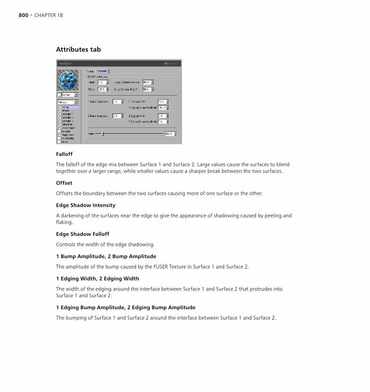
800 • CHAPTER 18 THE BHODINUT SHADERS • 801
Attributes tab
Falloff
The falloff of the edge mix between Surface 1 and Surface 2. Large values cause the surfaces to blend together over a larger range, while smaller values cause a sharper break between the two surfaces.
Offset
Offsets the boundary between the two surfaces causing more of one surface or the other.
Edge Shadow Intensity
A darkening of the surfaces near the edge to give the appearance of shadowing caused by peeling and flaking.
Edge Shadow Falloff
Controls the width of the edge shadowing.
1 Bump Amplitude, 2 Bump Amplitude
The amplitude of the bump caused by the FUSER Texture in Surface 1 and Surface 2.
1 Edging Width, 2 Edging Width
The width of the edging around the interface between Surface 1 and Surface 2 that protrudes into Surface 1 and Surface 2.
1 Edging Bump Amplitude, 2 Edging Bump Amplitude
The bumping of Surface 1 and Surface 2 around the interface between Surface 1 and Surface 2.
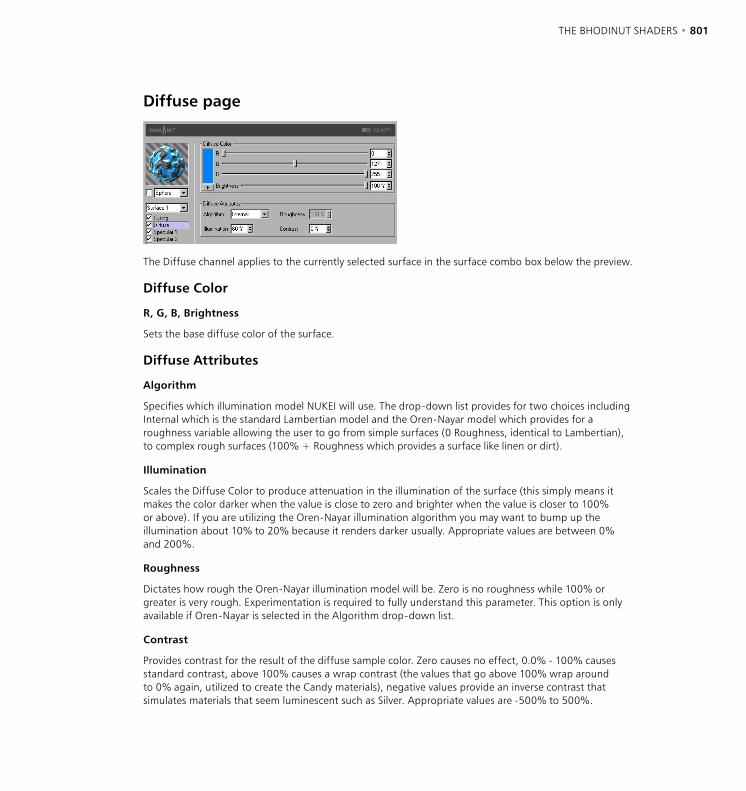
800 • CHAPTER 18 THE BHODINUT SHADERS • 801
Diffuse page
The Diffuse channel applies to the currently selected surface in the surface combo box below the preview.
Diffuse Color
R, G, B, Brightness
Sets the base diffuse color of the surface.
Diffuse Attributes
Algorithm
Specifies which illumination model NUKEI will use. The drop-down list provides for two choices including Internal which is the standard Lambertian model and the Oren-Nayar model which provides for a roughness variable allowing the user to go from simple surfaces (0 Roughness, identical to Lambertian), to complex rough surfaces (100% + Roughness which provides a surface like linen or dirt).
Illumination
Scales the Diffuse Color to produce attenuation in the illumination of the surface (this simply means it makes the color darker when the value is close to zero and brighter when the value is closer to 100% or above). If you are utilizing the Oren-Nayar illumination algorithm you may want to bump up the illumination about 10% to 20% because it renders darker usually. Appropriate values are between 0% and 200%.
Roughness
Dictates how rough the Oren-Nayar illumination model will be. Zero is no roughness while 100% or greater is very rough. Experimentation is required to fully understand this parameter. This option is only available if Oren-Nayar is selected in the Algorithm drop-down list.
Contrast
Provides contrast for the result of the diffuse sample color. Zero causes no effect, 0.0% - 100% causes standard contrast, above 100% causes a wrap contrast (the values that go above 100% wrap around to 0% again, utilized to create the Candy materials), negative values provide an inverse contrast that simulates materials that seem luminescent such as Silver. Appropriate values are -500% to 500%.

802 • CHAPTER 18 THE BHODINUT SHADERS • 803
Specular pages
The three specular highlights controlled in the Specular channels are additive to the color of the surface. All three Specular channels share the same parameter set described below.
Specular Color
R, G, B, Brightness
Sets the base specular color for the first specular component.
Specular Attributes
Intensity
Scales the Specular Color to produce attenuation in the specular reflection of the surface (this simply means it makes the color darker when the value is close to zero and brighter when the value is closer to 100% or above). The appropriate range is 0% - 1,000%.
Glare
Works with Specular Intensity by using the edge falloff (multiplied by the Falloff scalar) to change the intensity of the specular reflection. This can be used to add a glare to the surface when a light is reflecting more on an edge or specular effects to reduce the specular reflection when a light causes a reflection closer to the edge. Appropriate values run between 0% - 200%.
Size
Sets the size of the specular reflection. Appropriate value range for Size is 0.001% - 200%.
Falloff
Utilized to vary the falloff of the center of the object to the edge to affect the Glare intensity. Smaller values cause the specular reflection to reflect the Intensity value more while larger values make the surface use the Glare scalar more. Experimentation is required to fully understand this parameter.
Contrast
Provides contrast for the result of the specular sample color. Implements a standard contrast function. Appropriate values are 0% - 100%.
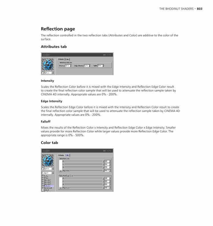
802 • CHAPTER 18 THE BHODINUT SHADERS • 803
Reflection pageThe reflection controlled in the two reflection tabs (Attributes and Color) are additive to the color of the surface.
Attributes tab
Intensity
Scales the Reflection Color before it is mixed with the Edge Intensity and Reflection Edge Color result to create the final reflection color sample that will be used to attenuate the reflection sample taken by CINEMA 4D internally. Appropriate values are 0% - 200%.
Edge Intensity
Scales the Reflection Edge Color before it is mixed with the Intensity and Reflection Color result to create the final reflection color sample that will be used to attenuate the reflection sample taken by CINEMA 4D internally. Appropriate values are 0% - 200%.
Falloff
Mixes the results of the Reflection Color x Intensity and Reflection Edge Color x Edge Intensity. Smaller values provide for more Reflection Color while larger values provide more Reflection Edge Color. The appropriate range is 0% - 500%.
Color tab
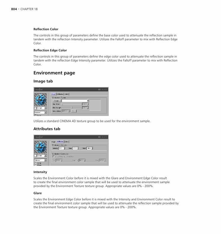
804 • CHAPTER 18 THE BHODINUT SHADERS • 805
Reflection Color
The controls in this group of parameters define the base color used to attenuate the reflection sample in tandem with the reflection Intensity parameter. Utilizes the Falloff parameter to mix with Reflection Edge Color.
Reflection Edge Color
The controls in this group of parameters define the edge color used to attenuate the reflection sample in tandem with the reflection Edge Intensity parameter. Utilizes the Falloff parameter to mix with Reflection Color.
Environment page
Image tab
Utilizes a standard CINEMA 4D texture group to be used for the environment sample.
Attributes tab
Intensity
Scales the Environment Color before it is mixed with the Glare and Environment Edge Color result to create the final environment color sample that will be used to attenuate the environment sample provided by the Environment Texture texture group. Appropriate values are 0% - 200%.
Glare
Scales the Environment Edge Color before it is mixed with the Intensity and Environment Color result to create the final environment color sample that will be used to attenuate the reflection sample provided by the Environment Texture texture group. Appropriate values are 0% - 200%.
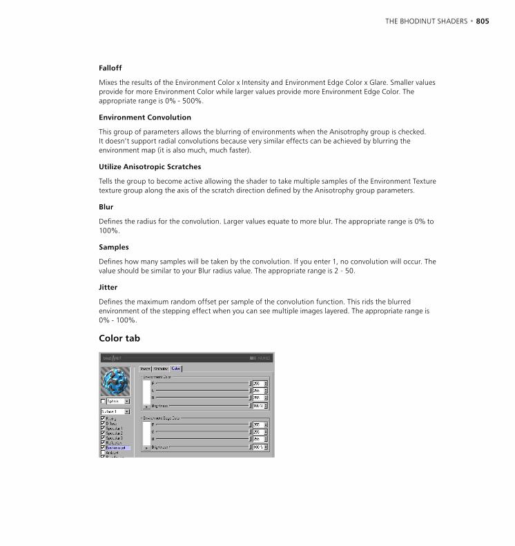
804 • CHAPTER 18 THE BHODINUT SHADERS • 805
Falloff
Mixes the results of the Environment Color x Intensity and Environment Edge Color x Glare. Smaller values provide for more Environment Color while larger values provide more Environment Edge Color. The appropriate range is 0% - 500%.
Environment Convolution
This group of parameters allows the blurring of environments when the Anisotrophy group is checked. It doesn’t support radial convolutions because very similar effects can be achieved by blurring the environment map (it is also much, much faster).
Utilize Anisotropic Scratches
Tells the group to become active allowing the shader to take multiple samples of the Environment Texture texture group along the axis of the scratch direction defined by the Anisotrophy group parameters.
Blur
Defines the radius for the convolution. Larger values equate to more blur. The appropriate range is 0% to 100%.
Samples
Defines how many samples will be taken by the convolution. If you enter 1, no convolution will occur. The value should be similar to your Blur radius value. The appropriate range is 2 - 50.
Jitter
Defines the maximum random offset per sample of the convolution function. This rids the blurred environment of the stepping effect when you can see multiple images layered. The appropriate range is 0% - 100%.
Color tab
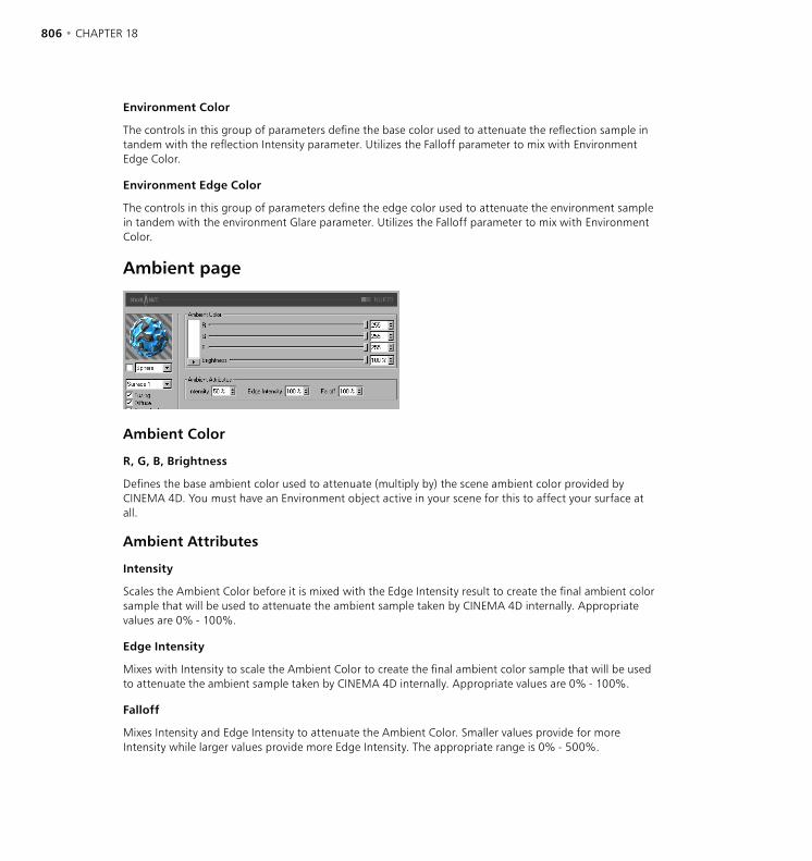
806 • CHAPTER 18 THE BHODINUT SHADERS • 807
Environment Color
The controls in this group of parameters define the base color used to attenuate the reflection sample in tandem with the reflection Intensity parameter. Utilizes the Falloff parameter to mix with Environment Edge Color.
Environment Edge Color
The controls in this group of parameters define the edge color used to attenuate the environment sample in tandem with the environment Glare parameter. Utilizes the Falloff parameter to mix with Environment Color.
Ambient page
Ambient Color
R, G, B, Brightness
Defines the base ambient color used to attenuate (multiply by) the scene ambient color provided by CINEMA 4D. You must have an Environment object active in your scene for this to affect your surface at all.
Ambient Attributes
Intensity
Scales the Ambient Color before it is mixed with the Edge Intensity result to create the final ambient color sample that will be used to attenuate the ambient sample taken by CINEMA 4D internally. Appropriate values are 0% - 100%.
Edge Intensity
Mixes with Intensity to scale the Ambient Color to create the final ambient color sample that will be used to attenuate the ambient sample taken by CINEMA 4D internally. Appropriate values are 0% - 100%.
Falloff
Mixes Intensity and Edge Intensity to attenuate the Ambient Color. Smaller values provide for more Intensity while larger values provide more Edge Intensity. The appropriate range is 0% - 500%.

806 • CHAPTER 18 THE BHODINUT SHADERS • 807
RoughnessUsed to add bump or grit to the material.
Roughness tab
Function
The noise function utilized to calculate the bump and the grit. You can review the noise types very easily in the 2D or 3D Noise channel shaders to get a feel for what they are.
Octaves
Defines the number of octaves utilized by the noise function defined within the Function drop-down list. This field will only be active if the noise function being used utilizes more octaves than one. Octaves is similar to Detail in many other shaders.
Scale
Scales the surface point used in the noise evaluation.
Amplitude
Scales the amplitude of the bump algorithm. The appropriate range is 0.0001% to 1,000%.
Speed
Animation speed of the noise in percentage of cycles per second.
Attenuation
Defines how much the noise algorithm will reduce the detail of the noise when the surface is far away or facing away from the camera. Appropriate values are 0% for stills and 100% to 1,000% for animation (it is primarily used to reduce flicker in animations).
Hard Bump
Utilizes an implicit algorithm to calculate the bump, producing more realistic dented surfaces. Often used when creating steel doors with anisotropic highlights to create large dents.
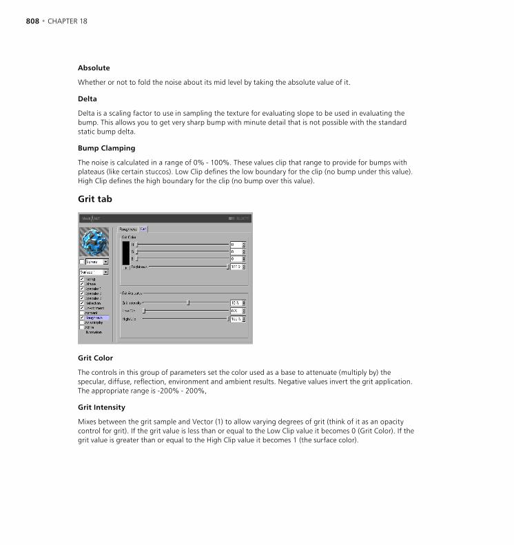
808 • CHAPTER 18 THE BHODINUT SHADERS • 809
Absolute
Whether or not to fold the noise about its mid level by taking the absolute value of it.
Delta
Delta is a scaling factor to use in sampling the texture for evaluating slope to be used in evaluating the bump. This allows you to get very sharp bump with minute detail that is not possible with the standard static bump delta.
Bump Clamping
The noise is calculated in a range of 0% - 100%. These values clip that range to provide for bumps with plateaus (like certain stuccos). Low Clip defines the low boundary for the clip (no bump under this value). High Clip defines the high boundary for the clip (no bump over this value).
Grit tab
Grit Color
The controls in this group of parameters set the color used as a base to attenuate (multiply by) the specular, diffuse, reflection, environment and ambient results. Negative values invert the grit application. The appropriate range is -200% - 200%,
Grit Intensity
Mixes between the grit sample and Vector (1) to allow varying degrees of grit (think of it as an opacity control for grit). If the grit value is less than or equal to the Low Clip value it becomes 0 (Grit Color). If the grit value is greater than or equal to the High Clip value it becomes 1 (the surface color).

808 • CHAPTER 18 THE BHODINUT SHADERS • 809
Anisotrophy page
Anisotropic Projection
Scratch Projection
The type of projection is used to define the anamorphic (disproportional) scaling of the specular highlights. It can also define the scratch direction to be used with the reflection and environment convolution groups. The projections are transformed by the Texture tag used to apply them to an object. Experimentation is absolutely required to understand these parameters.
Planar
A flat XY planar projection.
AutoPlanar
Automatically projects on a plane parallel to the current normal.
Shrink Wrap
A spherical projection for scaling direction, but uses a separate algorithm for projecting the scratches.
Radial
Creates a radial scratch pattern originating at the center of a plane that is parallel to current normal.
Radial Pattern
Creates a multi-origin radial scratch pattern that is parallel to current normal.
Projection Scale
Scales the scratch algorithms that have an actual pattern (Radial Pattern is the only current algorithm of this type to which scale applies).
810 • CHAPTER 18 THE BHODINUT SHADERS • 811
Anisotropic Specular Roughness
X Roughness
Scales the specular highlights in the X direction defined by the Scratch Projection algorithm. The appropriate range is 0.1% to 10,000%. If the X & Y roughness are the same the standard internal specular algorithm is used.
Y Roughness
Scales the highlights in the Y direction defined by the Scratch Projection algorithm. The appropriate range is 0.1% to 10,000%. If the X & Y roughness are the same the standard internal specular algorithm is used.
Anisotropic Scratch Attributes
Amplitude
Scales the effect of the scratch of the specular highlights. The higher the value the more scratched the speculars will look. The appropriate range is 0% - 100%.
Scale
Scales the scratch pattern itself. This applies to all scratch algorithms.
Length
Defines the scratch length in the space of the scratch pattern. Smoother milled surfaces would use a higher scratch length and rougher surfaces would use smaller values. The appropriate range is 1% - 1,000%.
Attenuation
Scales the amount of detail of the scratches based upon the samples, angle to the camera and the distance from the camera. The larger the values the greater the attenuation causing less scratching (better for animation); the smaller the value the greater the detail (better for still images). The appropriate range is 0% - 10,000%.
Affect Channel
These check boxes specify which specular channels will be affected by the anisotropic scratches.

810 • CHAPTER 18 THE BHODINUT SHADERS • 811
Alpha page
Opacity
The opacity for the surface. With Alpha you can layer NUKEI over other shaders and textures.
Illumination page
Use this page to control aspects of material illumination. Here, you can switch on/off radiosity and caustics for the material (both are switched on by default).
Global Illumination
Generate
When the option is enabled, the material will generate radiosity. Use the input box to set the strength of the radiosity - you can enter values from 0 to 10,000%. 100% represents normal strength.
Receive
If this option is enabled, the material will receive radiosity. The value in the input box defines the strength of the radiosity effect.
Caustics
Generate
The material must be transparent and/or reflective in order to create a caustics effect.
Use this option to enable the generation of caustics by the material. The input box defines the strength of the caustics generated.
812 • CHAPTER 18
Receive
The Receive option has no effect for volume caustics.
This enables or disables the reception of surface caustics by the material. Use the input box to set the strength of the effect.
Sample Radius
In order to calculate the brightness of the caustics effect, photons within a certain distance of the pixel to be rendered are interpolated to calculate the brightness. The Sample Radius defines this distance. Sample Radius = 1; individual photons can be seen as points of light because they are not interpolated together.
Samples
This defines the maximum number of photons within the Sample Radius that are used for calculating the effect. For example, if you enter a value of 100, up to 100 photons will be evaluated - any photons beyond this number are ignored. Samples and Sample Radius both affect the quality of the effect. To summarize: more samples per sample radius means a more accurate image. Increasing the sample radius means more blur, but a longer render time also.
TEXTURE MAPPING • 813
You can apply a texture to an object in the following ways:
- Drag the desired material from the Material manager and drop it on to the name of the object in the Object manager. The texture settings will appear in the Attribute manager. The mouse pointer will change during this process to indicate the add state:
- Select the object in the Object manager and select the material in the Material manager. In the Material manager, choose Function > Apply. The texture settings will appear in the Attribute manager.
- You can drop a new material on to an existing Texture tag. The new material will replace the old one but will inherit the existing texture settings.
Texture tag settingsWhen you assign a material to an object, a Texture tag is created and the tag’s settings appear in the Attribute manager. These texture settings define how the texture is mapped (i.e. placed) onto the object’s surface. For example, you may want the texture to be tiled (i.e. repeated) or you may want to place the texture on a specific part of the object. You can also have the texture mapped on one side only (decal mapping). In this chapter we will explain all the texture settings.
Attribute manager settings
Basic Properties
Name
Here you can enter a new name for the Texture tag. This is especially useful when you want to animate tags (and their materials), since the tag’s name will appear in the Timeline. Always give your Texture tags meaningful names.
Texture Mapping

814 • CHAPTER 18 TEXTURE MAPPING • 815
Tag Properties
Material
To choose which material the Texture tag uses, drag the desired material from the Object manager and drop it into this box. If multiple Texture tags are selected, the material will be applied to all of them. If you click the arrowhead that is to the right of the Material box, a menu opens:
Clear
Removes the Texture tag’s material.
Show In Manager
Shows the Texture tag’s material in the Material manager.
Select Material
Selects the Texture tag’s material in the Material manager.
Selection
Selection enables you to use different materials on different parts of the same object. This is a convenient way to add, for example, labels to objects. First of all you need a Selection tag:
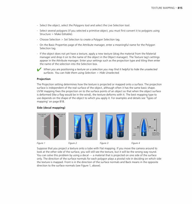
814 • CHAPTER 18 TEXTURE MAPPING • 815
- Select the object, select the Polygons tool and select the Live Selection tool.
- Select several polygons (if you selected a primitive object, you must first convert it to polygons using Structure > Make Editable).
- Choose Selection > Set Selection to create a Polygon Selection tag.
- On the Basic Properties page of the Attribute manager, enter a meaningful name for the Polygon Selection tag.
- If the object does not yet have a texture, apply a new texture (drag the material from the Material manager and drop it on to the name of the object in the Object manager). The Texture tag’s settings appear in the Attribute manager. Enter your settings such as the projection type and tiling then enter the name of the selection into the Selection box.
When you are positioning a texture on a selection you may find it helpful to hide the unselected surfaces. You can hide them using Selection > Hide Unselected.
Projection
The Projection setting determines how the texture is projected or mapped onto a surface. The projection surface is independent of the real surface of the object, although often it has the same basic shape. UVW mapping fixes the projection on to the surface points of an object so that when the object surface is deformed (like a flag would be in the wind), the texture deforms with it. The best mapping type to use depends on the shape of the object to which you apply it. For examples and details see ‘Types of mapping’ on page 818.
Side (decal mapping)
Figure 1 Figure 2 Figure 3 Figure 4
Suppose that you project a texture onto a tube with Flat mapping. If you move the camera around to look at the other side of the surface, you will still see the texture, but it will be the wrong way round. You can solve this problem by using a decal — a material that is projected on one side of the surface only. The direction of the surface normals for each polygon plays a pivotal role in deciding on which side the texture is mapped. Front is in the direction of the surface normals and Back means in the opposite direction to the surface normals (see Figure 1, above).
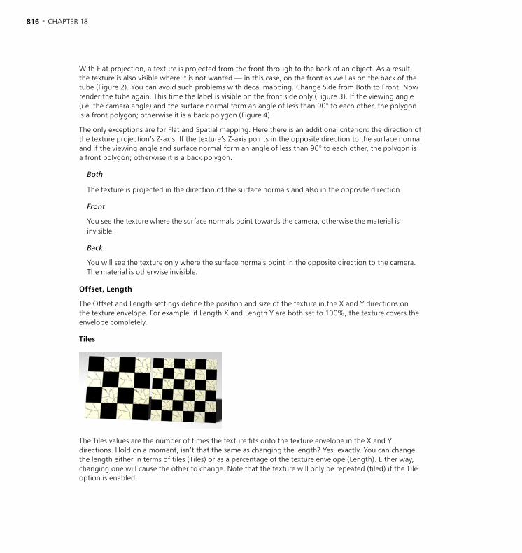
816 • CHAPTER 18 TEXTURE MAPPING • 817
With Flat projection, a texture is projected from the front through to the back of an object. As a result, the texture is also visible where it is not wanted — in this case, on the front as well as on the back of the tube (Figure 2). You can avoid such problems with decal mapping. Change Side from Both to Front. Now render the tube again. This time the label is visible on the front side only (Figure 3). If the viewing angle (i.e. the camera angle) and the surface normal form an angle of less than 90° to each other, the polygon is a front polygon; otherwise it is a back polygon (Figure 4).
The only exceptions are for Flat and Spatial mapping. Here there is an additional criterion: the direction of the texture projection’s Z-axis. If the texture’s Z-axis points in the opposite direction to the surface normal and if the viewing angle and surface normal form an angle of less than 90° to each other, the polygon is a front polygon; otherwise it is a back polygon.
Both
The texture is projected in the direction of the surface normals and also in the opposite direction.
Front
You see the texture where the surface normals point towards the camera, otherwise the material is invisible.
Back
You will see the texture only where the surface normals point in the opposite direction to the camera. The material is otherwise invisible.
Offset, Length
The Offset and Length settings define the position and size of the texture in the X and Y directions on the texture envelope. For example, if Length X and Length Y are both set to 100%, the texture covers the envelope completely.
Tiles
The Tiles values are the number of times the texture fits onto the texture envelope in the X and Y directions. Hold on a moment, isn’t that the same as changing the length? Yes, exactly. You can change the length either in terms of tiles (Tiles) or as a percentage of the texture envelope (Length). Either way, changing one will cause the other to change. Note that the texture will only be repeated (tiled) if the Tile option is enabled.
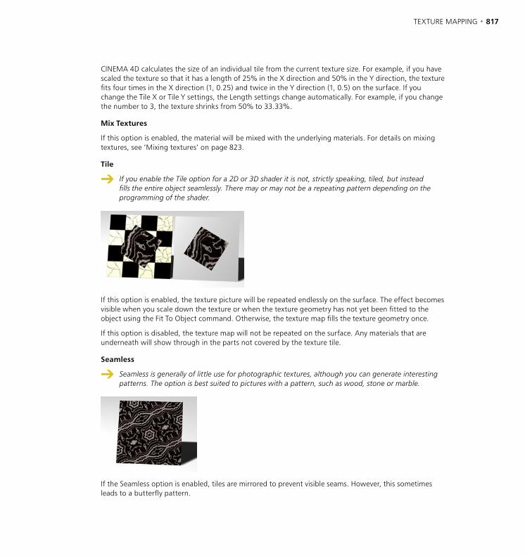
816 • CHAPTER 18 TEXTURE MAPPING • 817
CINEMA 4D calculates the size of an individual tile from the current texture size. For example, if you have scaled the texture so that it has a length of 25% in the X direction and 50% in the Y direction, the texture fits four times in the X direction (1, 0.25) and twice in the Y direction (1, 0.5) on the surface. If you change the Tile X or Tile Y settings, the Length settings change automatically. For example, if you change the number to 3, the texture shrinks from 50% to 33.33%.
Mix Textures
If this option is enabled, the material will be mixed with the underlying materials. For details on mixing textures, see ‘Mixing textures’ on page 823.
Tile
If you enable the Tile option for a 2D or 3D shader it is not, strictly speaking, tiled, but instead fills the entire object seamlessly. There may or may not be a repeating pattern depending on the programming of the shader.
If this option is enabled, the texture picture will be repeated endlessly on the surface. The effect becomes visible when you scale down the texture or when the texture geometry has not yet been fitted to the object using the Fit To Object command. Otherwise, the texture map fills the texture geometry once.
If this option is disabled, the texture map will not be repeated on the surface. Any materials that are underneath will show through in the parts not covered by the texture tile.
Seamless
Seamless is generally of little use for photographic textures, although you can generate interesting patterns. The option is best suited to pictures with a pattern, such as wood, stone or marble.
If the Seamless option is enabled, tiles are mirrored to prevent visible seams. However, this sometimes leads to a butterfly pattern.
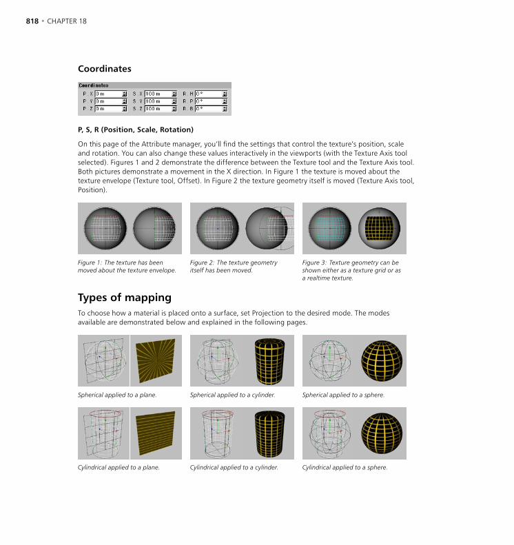
818 • CHAPTER 18 TEXTURE MAPPING • 819
Coordinates
P, S, R (Position, Scale, Rotation)
On this page of the Attribute manager, you’ll find the settings that control the texture’s position, scale and rotation. You can also change these values interactively in the viewports (with the Texture Axis tool selected). Figures 1 and 2 demonstrate the difference between the Texture tool and the Texture Axis tool. Both pictures demonstrate a movement in the X direction. In Figure 1 the texture is moved about the texture envelope (Texture tool, Offset). In Figure 2 the texture geometry itself is moved (Texture Axis tool, Position).
Figure 1: The texture has been moved about the texture envelope.
Figure 2: The texture geometry itself has been moved.
Figure 3: Texture geometry can be shown either as a texture grid or as a realtime texture.
Types of mappingTo choose how a material is placed onto a surface, set Projection to the desired mode. The modes available are demonstrated below and explained in the following pages.
Spherical applied to a plane. Spherical applied to a cylinder. Spherical applied to a sphere.
Cylindrical applied to a plane. Cylindrical applied to a cylinder. Cylindrical applied to a sphere.
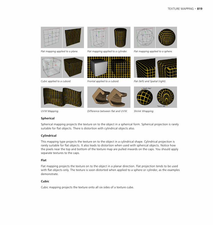
818 • CHAPTER 18 TEXTURE MAPPING • 819
Flat mapping applied to a plane. Flat mapping applied to a cylinder. Flat mapping applied to a sphere.
Cubic applied to a cuboid. Frontal applied to a cuboid. Flat (left) and Spatial (right).
UVW Mapping. Difference between flat and UVW. Shrink Wrapping.
Spherical
Spherical mapping projects the texture on to the object in a spherical form. Spherical projection is rarely suitable for flat objects. There is distortion with cylindrical objects also.
Cylindrical
This mapping type projects the texture on to the object in a cylindrical shape. Cylindrical projection is rarely suitable for flat objects. It also leads to distortion when used with spherical objects. Notice how the pixels near the top and bottom of the texture map are pulled inwards on the caps. You should apply separate textures to the caps.
Flat
Flat mapping projects the texture on to the object in a planar direction. Flat projection tends to be used with flat objects only. The texture is soon distorted when applied to a sphere or cylinder, as the examples demonstrate.
Cubic
Cubic mapping projects the texture onto all six sides of a texture cube.

820 • CHAPTER 18 TEXTURE MAPPING • 821
Frontal
The texture is projected from the camera position onto the object. This ensures that, it you project the texture onto a Polygon object and onto a Background object, the two textures match exactly (assuming the texture geometry for both objects use the same Offset and Length values).
You can create engaging special effects using Frontal mapping. You can even perform compositing directly in CINEMA 4D. You have probably seen science fiction films where characters or spaceships gradually disappear into the background or are only partially visible. Use Frontal mapping for such effects. For another interesting effect, remove the Background object and move the polygon around.
Spatial
Spatial mapping is similar to Flat projection. However, with Spatial mapping, the texture is pulled up and to the right as it passes through the object. Spatial mapping does, however, cause some distortion and as such it is not suitable for photographic images. Spatial mapping is more suitable for structural textures such as plaster and marble.
UVW Mapping
If an object has UVW coordinates, you can select them as the projection type. In this case, the texture geometry is fixed to the object surface and is subject to all subsequent movement and deformation applied to the object. An example of UVW mapping is the page of a book as it is being turned. First you must fix the texture (e.g. ornate text and a pretty picture) to the page using UVW mapping. Next, animate the turn of the page with a deformation. The texture bends with the page.
All of CINEMA 4D’s primitive objects and NURBS objects have UVW coordinates. If you apply a new texture to these objects, the projection type in the Texture tag will default to UVW mapping. All Polygon objects with UVW coordinates display a UVW coordinates icon in the Object manager.
Primitive objects and NURBS objects have internal UVW coordinates and do not display a UVW icon in the Object manager. You can still use UVW mapping with these objects. If you convert a Primitive object or a NURBS object to a Polygon object, a UVW coordinates icon will appear in the Object manager.
You may be wondering why there are three coordinates (UVW). What is the third coordinate for? Conventional textures have two coordinates, one for the horizontal position X and one for the vertical position Y. In order to make it clear that the coordinates refer to a texture, X is renamed U, and Y is renamed V. Two coordinates (U and V) would be sufficient were it not for 3D shaders. These are three dimensional textures and as such they require a third coordinate (W) in order to be fixed to the object.
You can apply more than one UVW texture geometry to an object. Create a new Texture tag for the object, then set the projection you require such as Flat mapping for a label texture. Next, create new UVW coordinates for the active texture by choosing Generate UVW Coordinates from the Texture menu in the Object manager. The selected Texture tag will be set to UVW mapping and will deform together with the object.

820 • CHAPTER 18 TEXTURE MAPPING • 821
What is the structure of UVW coordinates? Imagine a grid divided into a U direction and a V direction (see Figure 1, below). The UV range starts at 0, 0 and ends at 1, 1. For an upright polygon, 0, 0 describes the top left; 0, 1 the bottom left; 1, 0 the top right and 1, 1 the bottom right. A texture is stretched out between these four coordinates (Figure 2).
Figure 1. Figure 2.
But where is the W coordinate in this system? Recall that conventional textures are two-dimensional — the W coordinate is created only when* needed. Once created, the W coordinate behaves in the same way as the UV coordinates.
Selective UVW Mapping
Selective UVW mapping is designed to allow you to allocate an optimum projection type to specific areas. If you want to use different materials in these areas, use Selection (see ‘Selection’, page 814).
CINEMA 4D has two ways of allocating texture projections to polygon selections (rather than to the whole object as described above). The first method is described below. The second method, using Selection, is described on page 814.
Selective UVW mapping allows you to apply a different projection type to several regions of the object using the same texture geometry. Proceed as follows:
- Create a sphere and convert it into a polygon object using Make Editable.
- Create a new material with a texture, e.g. the checkerboard shader and set the projection to Flat.
- Select the Polygons tool and select several polygons in various locations.
- In the Object manager, choose Texture > Generate UVW Coordinates.
The selected polygons use Flat projection while the unselected polygons continue to use the normal UVW mapping. If you deform the object, the texture remains fixed in the selected region.
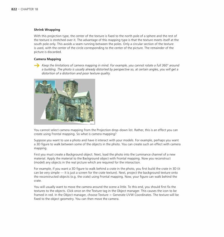
822 • CHAPTER 18 TEXTURE MAPPING • 823
Shrink Wrapping
With this projection type, the center of the texture is fixed to the north pole of a sphere and the rest of the texture is stretched over it. The advantage of this mapping type is that the texture meets itself at the south pole only. This avoids a seam running between the poles. Only a circular section of the texture is used, with the center of the circle corresponding to the center of the picture. The remainder of the picture is discarded.
Camera Mapping
Keep the limitations of camera mapping in mind. For example, you cannot rotate a full 360° around a building. The photo is usually already distorted by perspective so, at certain angles, you will get a distortion of a distortion and poor texture quality.
You cannot select camera mapping from the Projection drop-down list. Rather, this is an effect you can create using Frontal mapping. So what is camera mapping?
Suppose you want to use a photo and have it interact with your models. For example, perhaps you want a 3D figure to walk between some of the objects in the photo. You can create such an effect with camera mapping.
First you must create a Background object. Next, load the photo into the Luminance channel of a new material. Apply the material to the Background object with Frontal mapping. Now you reconstruct (model) any objects in the real picture which are required for the interaction.
For example, if you want a 3D figure to walk behind a crate in the photo, you first build the crate in 3D (it can be very simple — it is just a screen for the crate texture). Next, project the background texture onto the reconstructed objects (e.g. the crate) using Frontal mapping. Now, your figure can walk behind the crate.
You will usually want to move the camera around the scene a little. To this end, you should first fix the textures to the objects. Click once on the Texture tag in the Object manager. This causes the icon to be framed in red. In the Object manager, choose Texture > Generate UVW Coordinates. The texture will be fixed to the object geometry. You can then move the camera.
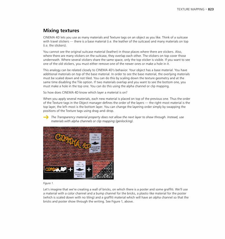
822 • CHAPTER 18 TEXTURE MAPPING • 823
Mixing texturesCINEMA 4D lets you use as many materials and Texture tags on an object as you like. Think of a suitcase with travel stickers — there is a base material (i.e. the leather of the suitcase) and many materials on top (i.e. the stickers).
You cannot see the original suitcase material (leather) in those places where there are stickers. Also, where there are many stickers on the suitcase, they overlap each other. The stickers on top cover those underneath. Where several stickers share the same space, only the top sticker is visible. If you want to see one of the old stickers, you must either remove one of the newer ones or make a hole in it.
This analogy can be related closely to CINEMA 4D’s behavior. Your object has a base material. You have additional materials on top of the base material. In order to see the base material, the overlying materials must be scaled down and not tiled. You can do this by scaling down the texture geometry and at the same time disabling the Tile option. If two materials overlap and you want to see the bottom one, you must make a hole in the top one. You can do this using the alpha channel or clip mapping.
So how does CINEMA 4D know which layer a material is on?
When you apply several materials, each new material is placed on top of the previous one. Thus the order of the Texture tags in the Object manager defines the order of the layers — the right-most material is the top layer, the left-most is the bottom layer. You can change the layering order simply by swapping the positions of the Texture tags using drag-and-drop.
The Transparency material property does not allow the next layer to show through. Instead, use materials with alpha channels or clip mapping (genlocking).
Figure 1.
Let’s imagine that we’re creating a wall of bricks, on which there is a poster and some graffiti. We’ll use a material with a color channel and a bump channel for the bricks, a plastic-like material for the poster (which is scaled down with no tiling) and a graffiti material which will have an alpha channel so that the bricks and poster show through the writing. See Figure 1, above.
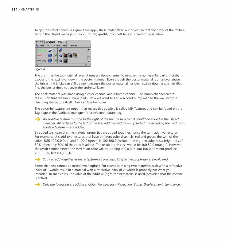
824 • CHAPTER 18 TEXTURE MAPPING • 825
To get the effect shown in Figure 1 we apply these materials to our object so that the order of the texture tags in the Object manager is bricks, poster, graffiti (from left to right). See Figure 4 below.
Figure 4.
The graffiti is the top material layer; it uses an alpha channel to remove the non-graffiti parts, thereby exposing the next layer down, the poster material. Even though the poster material is on a layer above the bricks, the bricks can still be seen because the poster material has been scaled down and is not tiled (i.e. the poster does not cover the entire surface).
The brick material was made using a color channel and a bump channel. The bump channel creates the illusion that the bricks have joints. Now we want to add a second bump map to the wall without changing the texture itself. How can this be done?
The powerful texture tag option that makes this possible is called Mix Textures and can be found on the Tag page in the Attribute manager, for a selected texture tag.
An additive texture must be to the right of the texture to which it should be added in the Object manager. All textures to the left of the first additive texture — up to but not including the next non-additive texture — are added.
By added we mean that the material properties are added together, hence the term additive textures. For example, let’s add two textures that have different color channels, red and green; the sum of the colors RGB 100,0,0 (red) and 0,100,0 (green) is 100,100,0 (yellow). If the green color has a brightness of 50%, then only 50% of the color is added. The result in this case would be 100,50,0 (orange). However, the result cannot exceed the maximum color values. Adding 100,0,0 to 100,100,0 does not produce 200,100,0, but 100,100,0.
You can add together as many textures as you wish. Only active properties are evaluated.
Some channels cannot be mixed meaningfully. For example, mixing two materials each with a refractive index of 1 would result in a material with a refractive index of 2, which is probably not what you intended. In such cases, the value of the additive (right-most) material is used (provided that the channel is active).
Only the following are additive: Color, Transparency, Reflection, Bump, Displacement, Luminance.

824 • CHAPTER 18 TEXTURE MAPPING • 825
Figure 2. Figure 3.
Back to the wall example. Figures 2 and 3 above show the results of mixing in some dirt into the brick, poster and graffiti textures. This was accomplished by using the Mix Textures option. The illustrations below show how this was done.
On the left, the bump10 texture has been mixed with the poster and the brick textures, which are to its left in the Object manager, to dirty them up. On the right, the bump22 texture has been added just to the graffiti texture (it won’t be added to the poster and brick textures because of the bump10 additive texture).
826 • CHAPTER 18
Putting a label on a bottleTo put a label on a bottle
- Select the Texture tag to show its settings in the Attribute manager.
- In the Attribute manager, disable the Tile option.
- Ensure that only one tile is being created in the X and Y directions.
Done. The texture probably covers the entire object but now you can scale it down. Select the Scale tool, then select the Texture Axis tool. You can drag to reduce the scale of the texture. Next, select the Move tool and place the texture in the desired position on the object’s surface.
The texture is often slightly out of proportion after scaling. Select the Texture tag and, in the Attribute manager, set the Length values as desired. Since the length cannot exceed 100%, you may need to divide both values. For example, if your texture is 800 x 600 pixels, you might set the lengths as follows:
Length X Length Y Conversion Factor
80 60 / 10 8 6 / 100 32 24 / 100 x 4 etc.
Different materials for the hull, caps and roundingYou can apply different materials to the hull, the caps and the rounding of an object. You can either convert the object into polygons with Structure > Make Editable, or you can use the invisible selections. For example, you can use Extrude NURBS to create marble letters with a golden, rounded or bevelled edge.
You can use existing invisible selections for the caps and rounding of a NURBS object. For example, you can apply a material to the start cap by using the Selection function (see ‘Selection’, page 814). You should type in ‘C1’ to apply the material to the start cap (you must use a capital C). The options are:
C1 = Start Cap (Cap 1)C2 = End Cap (Cap 2)R1 = Start Rounding (Rounding 1)R2 = End Rounding (Rounding 2)

19 Timeline

TIMELINE • 829

TIMELINE • 829
Animate quickly and easily with CINEMA 4D’s powerful Timeline. You’ll find the latest improvements listed below. If you’re new to CINEMA 4D, we recommend that you read the Introduction on page 831.
Key new features and enhancementsCINEMA 4D R8’s improved Timeline offers dozens of new features and enhancements. In this section you’ll learn about the key changes.
Control over elements shownFor flexibility of use, the Timeline now has two modes of operation and display — automatic and manual. The padlock icon at the top right of the Timeline window shows and controls the mode — an unlocked padlock shows the automatic mode in which every object added to the scene is also added to the Timeline while a locked icon shows the manual mode in which you can add only the objects you need into the Timeline.
More details can be found under ‘Automatic Mode’ on page 876. See also ‘Manual mode and automatic mode’ on page 888.
To show the tracks of the selected objects’ children as well, hold down Shift while you drag.
New F-CurvesF-Curves replace the space curves in earlier releases of CINEMA 4D. F-Curves give you a more powerful way to control interpolation between keyframes, enabling you to adjust the motion of your objects quickly and flexibly. Thus you can use effects like ease-in and ease-out to create realistic movement. In addition, F-Curves give you improved control over any type of parameter animation, such as a light changing color or a Twist object’s degree of twist. See ‘F-Curve Manager’ on page 887.
Time curves as tracksTime curves are now created as tracks in the Timeline. See ‘New Track > Time’ on page 860.
Separate tracks for X, Y and ZFor improved control, each position, scale or rotation animation is now split into separate X, Y and Z tracks on the Timeline. To move a group of X, Y and Z keys, enable Vector Selection from the Timeline’s Edit menu and drag one of the keys.
Enhanced time slidersThe viewport display will not animate if you hold down Shift while dragging a time slider in the Timeline, in the F-Curve manager or in the animation toolbar. One advantage of this is that you can now record the current frame set-up at any other frame without actually having to go to that frame and set it up.
19 Timeline

830 • CHAPTER 19 TIMELINE • 831
New Attribute managerCINEMA 4D R8’s new Attribute manager improves almost all editing tasks including animation. You can use the Attribute manager in combination with the Timeline or you can even animate directly in the Attribute manager without ever opening the Timeline. The Attribute manager will help you to create animations more quickly than before. For full details see Chapter 20, ‘Attribute manager’.
Using the Attribute manager with the Timeline
You can now edit the data of keys or sequences in the Attribute manager.
Using the Attribute manager without the Timeline
In the Attribute manager, right-click (Windows) or Command-click (Mac OS) the parameter or parameter group that you want to animate. From the context menu that opens, use the commands on the Animation sub-menu to create tracks, record keys, delete keys, go to the parameter’s next key, and more.
New ways to record hierarchiesRecord a hierarchy’s keys in two new ways:
- Assign to a Selection object each object that should receive keys. See ‘Selection object’ on page 386.
- In the Timeline, select the parent object and choose Sequences > Record Selected. See ‘Record Selected’ on page 881.
Special effects as expressionsSpecial effects such as Pulsate and Vibrate are now implemented as expressions instead of as tracks (Object manager: File > New Expression).
Loading XL R7 scenesWhen loading animated scenes created in CINEMA 4D XL R7, please be aware of the following issues.
- Motion groups cannot be loaded. To remedy this, In CINEMA 4D XL R7 ungroup the motion groups (Timeline: Sequences > Ungroup Motion) and save the scene. Load this scene into CINEMA 4D R8.
- Plugin tracks will be loaded only if the plugin is compatible with CINEMA 4D R8 and is installed.
- Materials of texture tracks will always be morphed, even if Morph Materials was disabled in the original scene. To remedy this, create two keys next to each other.
- Time tracks are converted as accurately as possible. However, slight adjustments may be required.
- Velocity and acceleration time curves cannot be converted.
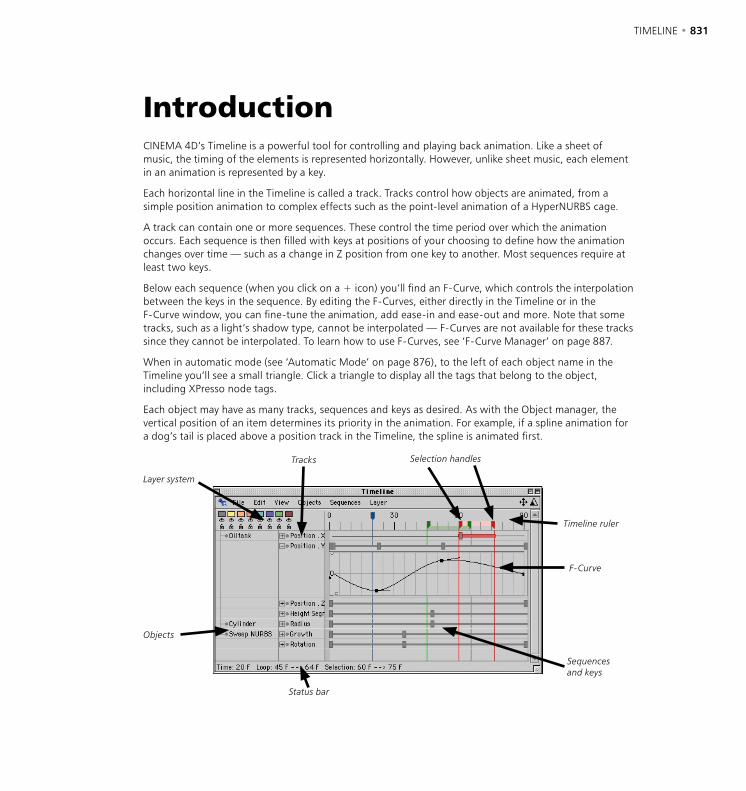
830 • CHAPTER 19 TIMELINE • 831
IntroductionCINEMA 4D’s Timeline is a powerful tool for controlling and playing back animation. Like a sheet of music, the timing of the elements is represented horizontally. However, unlike sheet music, each element in an animation is represented by a key.
Each horizontal line in the Timeline is called a track. Tracks control how objects are animated, from a simple position animation to complex effects such as the point-level animation of a HyperNURBS cage.
A track can contain one or more sequences. These control the time period over which the animation occurs. Each sequence is then filled with keys at positions of your choosing to define how the animation changes over time — such as a change in Z position from one key to another. Most sequences require at least two keys.
Below each sequence (when you click on a + icon) you’ll find an F-Curve, which controls the interpolation between the keys in the sequence. By editing the F-Curves, either directly in the Timeline or in the F-Curve window, you can fine-tune the animation, add ease-in and ease-out and more. Note that some tracks, such as a light’s shadow type, cannot be interpolated — F-Curves are not available for these tracks since they cannot be interpolated. To learn how to use F-Curves, see ‘F-Curve Manager’ on page 887.
When in automatic mode (see ‘Automatic Mode’ on page 876), to the left of each object name in the Timeline you’ll see a small triangle. Click a triangle to display all the tags that belong to the object, including XPresso node tags.
Each object may have as many tracks, sequences and keys as desired. As with the Object manager, the vertical position of an item determines its priority in the animation. For example, if a spline animation for a dog’s tail is placed above a position track in the Timeline, the spline is animated first.
Layer system
F-Curve
Tracks
Status bar
Sequences and keys
Objects
Selection handles
Timeline ruler
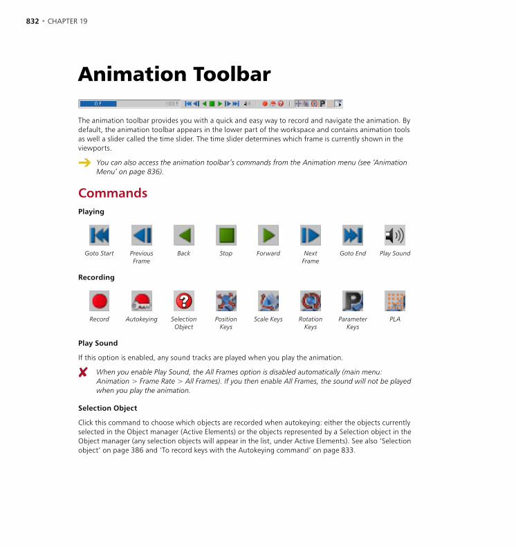
832 • CHAPTER 19 TIMELINE • 833
Animation Toolbar
The animation toolbar provides you with a quick and easy way to record and navigate the animation. By default, the animation toolbar appears in the lower part of the workspace and contains animation tools as well a slider called the time slider. The time slider determines which frame is currently shown in the viewports.
You can also access the animation toolbar’s commands from the Animation menu (see ‘Animation Menu’ on page 836).
CommandsPlaying
Goto Start PreviousFrame
Back Stop Forward NextFrame
Goto End Play Sound
Recording
Record Autokeying Selection Object
PositionKeys
Scale Keys RotationKeys
ParameterKeys
PLA
Play Sound
If this option is enabled, any sound tracks are played when you play the animation.
When you enable Play Sound, the All Frames option is disabled automatically (main menu: Animation > Frame Rate > All Frames). If you then enable All Frames, the sound will not be played when you play the animation.
Selection Object
Click this command to choose which objects are recorded when autokeying: either the objects currently selected in the Object manager (Active Elements) or the objects represented by a Selection object in the Object manager (any selection objects will appear in the list, under Active Elements). See also ‘Selection object’ on page 386 and ‘To record keys with the Autokeying command’ on page 833.
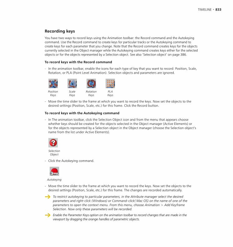
832 • CHAPTER 19 TIMELINE • 833
Recording keys
You have two ways to record keys using the Animation toolbar: the Record command and the Autokeying command. Use the Record command to create keys for particular tracks or the Autokeying command to create keys for each parameter that you change. Note that the Record command creates keys for the objects currently selected in the Object manager while the Autokeying command creates keys either for the selected objects or for the objects represented by a Selection object. See also ‘Selection object’ on page 386.
To record keys with the Record command
- In the animation toolbar, enable the icons for each type of key that you want to record: Position, Scale, Rotation, or PLA (Point Level Animation). Selection objects and parameters are ignored.
PositionKeys
Scale Keys
RotationKeys
PLA Keys
- Move the time slider to the frame at which you want to record the keys. Now set the objects to the desired settings (Position, Scale, etc.) for this frame. Click the Record button.
To record keys with the Autokeying command
- In The animation toolbar, click the Selection Object icon and from the menu that appears choose whether keys should be created for the objects selected in the Object manager (Active Elements) or for the objects represented by a Selection object in the Object manager (choose the Selection object’s name from the list under Active Elements).
Selection Object
- Click the Autokeying command.
Autokeying
- Move the time slider to the frame at which you want to record the keys. Now set the objects to the desired settings (Position, Scale, etc.) for this frame. The changes are recorded automatically.
To restrict autokeying to particular parameters, in the Attribute manager select the desired parameters and right-click (Windows) or Command-click( Mac OS) on the name of one of the parameters to open the context menu. From this menu, choose Animation > Add Keyframe Selection. Now only these parameters will be recorded.
Enable the Parameter Keys option on the animation toolbar to record changes that are made in the viewport by dragging the orange handles of parametric objects.
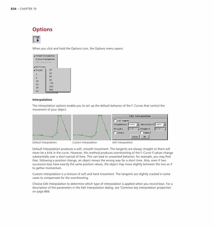
834 • CHAPTER 19 TIMELINE • 835
Options
When you click and hold the Options icon, the Options menu opens:
Interpolation
The interpolation options enable you to set-up the default behavior of the F-Curves that control the movement of your object.
Default Interpolation. Custom Interpolation Edit Interpolation.
Default Interpolation produces a soft, smooth movement. The tangents are always straight so there will never be a kink in the curve. However, this method produces overshooting of the F-Curve if values change substantially over a short period of time. This can lead to unwanted behavior; for example, you may find that, following a position change, an object moves the wrong way for a short time. Also, even if two successive keys have exactly the same position values, the object may move slightly between the two as if to gather momentum.
Custom interpolation is a mixture of soft and hard movement. The tangents are slightly cracked in some cases to compensate for the overshooting.
Choose Edit Interpolation to determine which type of interpolation is applied when you record keys. For a description of the parameters in the Edit Interpolation dialog, see ‘Common key interpolation properties’ on page 866.
834 • CHAPTER 19 TIMELINE • 835
All Frames
This setting ensures each frame is displayed when the animation is played in a viewport. Normally, frames are skipped when the computer is not fast enough to play the animation at the frame rate specified in the project settings. With the All Frames option enabled, all frames will always be played.
Project
This is the default setting. It ensures that the viewport frame rate is the same as the frame rate in the project settings. Keep in mind that frames will be skipped if the computer cannot play back the animation at the specified frame rate.
1 ... 500
The lower portion of the Options menu enables you to select from a number of playback rates. Keep in mind that frames will be skipped if the computer cannot play back the animation at the specified frame rate.

836 • CHAPTER 19 TIMELINE • 837
Animation Menu
The Animation menu on the main menu contains the same commands as the animation toolbar and, in addition, contains the following commands.
RecordLink XYZ Subchannels
When recording parameters that have subchannels — such as the R, G and B channels of a light source or the X, Y and Z channels of a Position track — use this option to choose whether all three subchannels are recorded (3 keys) or a single component only (1 key).
KeyframeRestrict Editor Selection
Using this option, you can restrict selection in the viewports to objects that belong to a Selection object. Enable this option and, from the same menu, choose the name of the desired Selection object. Now when you click on an object in a viewport, the object is selected only if it belongs to the chosen Selection object.
836 • CHAPTER 19 TIMELINE • 837
Play ModeUse the items in this sub-menu to define the animation’s playback mode.
Preview Range
Restricts the playback to the Timeline’s preview range (the frames between the two green markers).
Simple
The animation is played once only.
Cycle
As soon as the end of the animation is reached, the animation is played from the start.
Ping-Pong
The animation is played forwards and then backwards.

838 • CHAPTER 19 TIMELINE • 839
Working in the TimelineImproving workflow
Drag-and-drop
By default, the Timeline shows all objects for the active scene (see ‘Automatic Mode’ on page 876 for more details). If you change to Manual mode (by clicking the padlock icon at the top right of the Timeline window) you can choose which objects are displayed. Drag the objects whose tracks you want shown from the Object manager and drop them into the Timeline. If you want the tracks of the selected objects’ children to be included, hold down Shift while you drag.
Navigation
The Padlock icon (left); the Move icon (center) and the Scale icon (right).
To scroll the Timeline’s contents
- Drag the Move icon (see Figure 1) or hold down the ‘1’ key and drag within the Timeline.
- If you are using a wheel mouse, rotate the wheel on any part of the Timeline except the ruler.
To scale the Timeline’s contents
- Drag the Scale icon (see Figure 1) or hold down the ‘2’ key and drag within the Timeline.
- If you are using a wheel mouse, rotate the wheel on the Timeline ruler.
To vertically scroll an F-Curve that is displayed in the Timeline
- Hold down the ‘4’ key and drag within the F-Curve.
To vertically scale an F-Curve that is displayed in the Timeline
- Hold down the ‘5’ key and drag within the F-Curve.
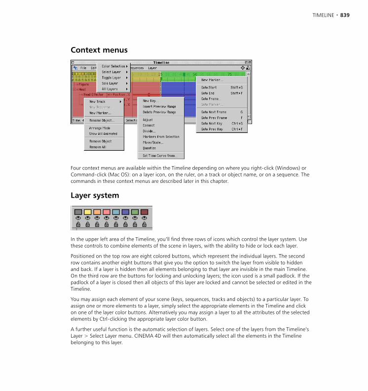
838 • CHAPTER 19 TIMELINE • 839
Context menus
Four context menus are available within the Timeline depending on where you right-click (Windows) or Command-click (Mac OS): on a layer icon, on the ruler, on a track or object name, or on a sequence. The commands in these context menus are described later in this chapter.
Layer system
In the upper left area of the Timeline, you’ll find three rows of icons which control the layer system. Use these controls to combine elements of the scene in layers, with the ability to hide or lock each layer.
Positioned on the top row are eight colored buttons, which represent the individual layers. The second row contains another eight buttons that give you the option to switch the layer from visible to hidden and back. If a layer is hidden then all elements belonging to that layer are invisible in the main Timeline. On the third row are the buttons for locking and unlocking layers; the icon used is a small padlock. If the padlock of a layer is closed then all objects of this layer are locked and cannot be selected or edited in the Timeline.
You may assign each element of your scene (keys, sequences, tracks and objects) to a particular layer. To assign one or more elements to a layer, simply select the appropriate elements in the Timeline and click on one of the layer color buttons. Alternatively you may assign a layer to all the attributes of the selected elements by Ctrl-clicking the appropriate layer color button.
A further useful function is the automatic selection of layers. Select one of the layers from the Timeline’s Layer > Select Layer menu. CINEMA 4D will then automatically select all the elements in the Timeline belonging to this layer.
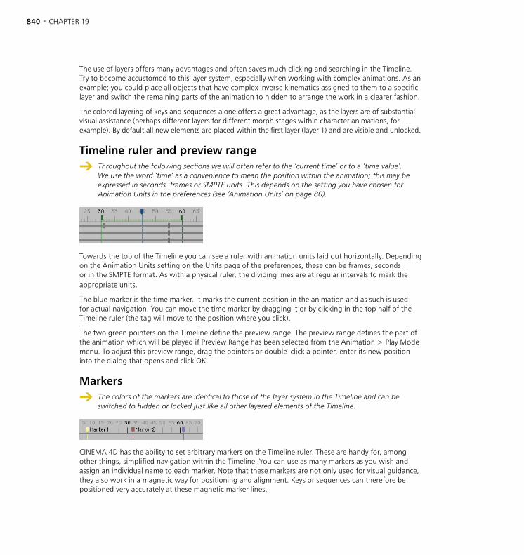
840 • CHAPTER 19 TIMELINE • 841
The use of layers offers many advantages and often saves much clicking and searching in the Timeline. Try to become accustomed to this layer system, especially when working with complex animations. As an example; you could place all objects that have complex inverse kinematics assigned to them to a specific layer and switch the remaining parts of the animation to hidden to arrange the work in a clearer fashion.
The colored layering of keys and sequences alone offers a great advantage, as the layers are of substantial visual assistance (perhaps different layers for different morph stages within character animations, for example). By default all new elements are placed within the first layer (layer 1) and are visible and unlocked.
Timeline ruler and preview range
Throughout the following sections we will often refer to the ‘current time’ or to a ‘time value’. We use the word ‘time’ as a convenience to mean the position within the animation; this may be expressed in seconds, frames or SMPTE units. This depends on the setting you have chosen for Animation Units in the preferences (see ‘Animation Units’ on page 80).
Towards the top of the Timeline you can see a ruler with animation units laid out horizontally. Depending on the Animation Units setting on the Units page of the preferences, these can be frames, seconds or in the SMPTE format. As with a physical ruler, the dividing lines are at regular intervals to mark the appropriate units.
The blue marker is the time marker. It marks the current position in the animation and as such is used for actual navigation. You can move the time marker by dragging it or by clicking in the top half of the Timeline ruler (the tag will move to the position where you click).
The two green pointers on the Timeline define the preview range. The preview range defines the part of the animation which will be played if Preview Range has been selected from the Animation > Play Mode menu. To adjust this preview range, drag the pointers or double-click a pointer, enter its new position into the dialog that opens and click OK.
Markers
The colors of the markers are identical to those of the layer system in the Timeline and can be switched to hidden or locked just like all other layered elements of the Timeline.
CINEMA 4D has the ability to set arbitrary markers on the Timeline ruler. These are handy for, among other things, simplified navigation within the Timeline. You can use as many markers as you wish and assign an individual name to each marker. Note that these markers are not only used for visual guidance, they also work in a magnetic way for positioning and alignment. Keys or sequences can therefore be positioned very accurately at these magnetic marker lines.
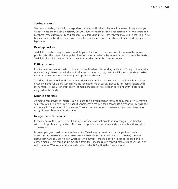
840 • CHAPTER 19 TIMELINE • 841
Setting markers
To create a marker, Ctrl-click at the position within the Timeline ruler (within the ruler lines) where you want to place the marker. By default, CINEMA 4D assigns the second layer color to all new markers and numbers these automatically and consecutively throughout. Alternatively you may also select File > New Marker from the Timeline menu and manually enter the position, your choice of name and your preferred layer color.
Deleting markers
To delete a marker, drag its pointer and drop it outside of the Timeline ruler. As soon as the mouse pointer takes the shape of a simplified trash can you can release the mouse button to delete the marker. To delete all markers, choose Edit > Delete All Markers from the Timeline menu.
Editing markers
Existing markers can be freely positioned on the Timeline ruler via drag-and-drop. To adjust the position of an existing marker numerically, or to change its name or color, double-click the appropriate marker, enter the new values into the dialog that opens and click OK.
The Time value determines the position of the marker on the Timeline ruler. In the Name box you can enter any name for the marker. This makes navigation much easier, especially for those projects with many markers. The Color drop-down list menu enables you to select one of eight layer colors to be assigned to the marker.
Magnetic markers
As mentioned previously, markers can be used to help you position keys and sequences. If you move a sequence or a key in the Timeline and it approaches a marker, the appropriate element will be snapped accurately to the position of this marker. This can be very useful, for example, if you want to position many different keys to a certain frame.
Navigation with markers
In the menus of the Timeline you’ll find various functions that enable you to navigate the Timeline with the help of existing markers. This can ease your workflow dramatically, especially with complex animations.
For example, you could center the view of the Timeline on a certain marker simply by choosing View > Frame Marker from the Timeline menu (see below for details on how to do this). Another useful command is Goto Marker, which sets the current Timeline position to the exact position of a chosen marker. This command is available from the Timeline ruler’s context menu, which you open by right-clicking (Windows) or Command-clicking (Mac OS) within the Timeline ruler.
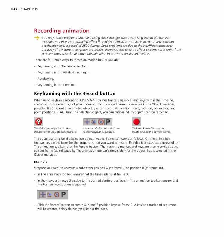
842 • CHAPTER 19 TIMELINE • 843
Recording animation You may notice problems when animating small changes over a very long period of time. For
example, you may see a pulsating effect if an object initially at rest starts to rotate with constant acceleration over a period of 2500 frames. Such problems are due to the insufficient processor accuracy of the current computer processors. However, this tends to affect extreme cases only. If the problem does arise, break down the animation into several smaller animations.
There are four main ways to record animation in CINEMA 4D:
- Keyframing with the Record button.
- Keyframing in the Attribute manager.
- Autokeying.
- Keyframing in the Timeline.
Keyframing with the Record buttonWhen using keyframe recording, CINEMA 4D creates tracks, sequences and keys within the Timeline, according to some settings of your choosing. For the object currently selected in the Object manager, provided that it is not a parametric object, you can record its position, scale, rotation, parameters and point positions (PLA). Using the Selection object, you can choose which objects can be recorded.
The Selection object is used to choose which objects are recorded.
Icons enabled in the animation toolbar appear depressed.
Click the Record button to create keys at the current frame.
The default setting for the Selection object, ‘Active Elements’, works as follows. On the animation toolbar, enable the icons for the properties that you want to record. Enabled icons appear depressed. In The animation toolbar, click the Record button. The tracks, sequences and keys are then recorded at the current frame (as indicated by The animation toolbar’s time slider) for the object that is selected in the Object manager.
Example
Suppose you want to animate a cube from position A (at frame 0) to position B (at frame 30).
- In The animation toolbar, ensure that the time slider is at frame 0.
- In the viewport, move the cube to the desired starting position. In The animation toolbar, ensure that the Position Keys option is enabled.
- Click the Record button to create X, Y and Z position keys at frame 0. A Position track and sequence will be created if they do not yet exist for the cube.
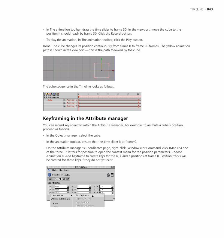
842 • CHAPTER 19 TIMELINE • 843
- In The animation toolbar, drag the time slider to frame 30. In the viewport, move the cube to the position it should reach by frame 30. Click the Record button.
- To play the animation, in The animation toolbar, click the Play button.
Done. The cube changes its position continuously from frame 0 to frame 30 frames. The yellow animation path is shown in the viewport — this is the path followed by the cube.
The cube sequence in the Timeline looks as follows:
Keyframing in the Attribute managerYou can record keys directly within the Attribute manager. For example, to animate a cube’s position, proceed as follows.
- In the Object manager, select the cube.
- In the animation toolbar, ensure that the time slider is at frame 0.
- On the Attribute manager’s Coordinates page, right-click (Windows) or Command-click (Mac OS) one of the three ‘P’ letters for position to open the context menu for the position parameters. Choose Animation > Add Keyframe to create keys for the X, Y and Z positions at frame 0. Position tracks will be created for these keys if they do not yet exist.

844 • CHAPTER 19 TIMELINE • 845
- Move the time slider to frame 30, move the cube to a different position and right-click (Windows) or Command-click (Mac OS) one of the ‘P’ letters again. From the context menu that appears, choose Animation > Add Keyframe.
- To play the animation, in The animation toolbar, click the Play button.
Done. The cube moves during frames 0 to 30. Using this method, you can record animation for almost any parameter. You can also use this method in the render settings to record keys for post effects.
Autokeying (automatic recording)
Autokeying mode does not work for Inverse Kinematics. For example, you cannot record the movement of a human arm IK chain by moving the hand in autokeying mode.
As an alternative to pressing the Record button each time you want to record a parameter, you can have the changes you make to objects recorded automatically. Keys are recorded intelligently, i.e. only for those parameters that change rather than for every single parameter. To activate autokeying, you select the Autokeying button in the animation toolbar.
Always remember to switch off autokeying (by deselecting the Autokeying option on The animation toolbar) as soon as you’re done recording. Should you forget, you may create dozens of unwanted keys while you edit objects, and ruin the animation.
Example
For this example, we’ll once again animate a cube’s changing position from frame 0 to 30.
- In the animation toolbar, ensure that the time slider is at frame 0. In the viewport, move the cube to the desired starting position. In the animation toolbar, ensure that the Position Keys option is enabled.
- Click the Autokeying button to switch on autokeying mode.
- Click the Record button to create keys and tracks for the X, Y and Z positions of the cube.
- In the animation toolbar, drag the time slider to frame 30. In the viewport, drag the cube to the position it should reach by frame 30. As soon as you release the mouse button, X, Y and Z position keys are created at frame 30.
- To play the animation, in The animation toolbar, click the Play button.
Done. As with the previous examples, the cube moves during frames 0 to 30. The advantage of autokeying is that you no longer need to click the Record button each time you change the object’s position — the recording process becomes automated. With autokeying mode (as with the manual modes), the procedure is to first move the time slider, then position the object. Autokeying improves your workflow.
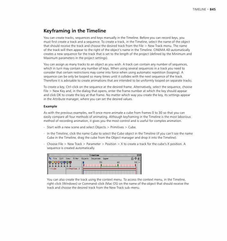
844 • CHAPTER 19 TIMELINE • 845
Keyframing in the TimelineYou can create tracks, sequences and keys manually in the Timeline. Before you can record keys, you must first create a track and a sequence. To create a track, in the Timeline, select the name of the object that should receive the track and choose the desired track from the File > New Track menu. The name of the track will then appear to the right of the object’s name in the Timeline. CINEMA 4D automatically creates a new sequence for the track that is set to the length of the project (defined by the Minimum and Maximum parameters in the project settings).
You can assign as many tracks to an object as you wish. A track can contain any number of sequences, which in turn may contain any number of keys. When using several sequences in a track you need to consider that certain restrictions may come into force when using automatic repetition (looping). A sequence can be only be looped so many times until it collides with the next sequence of the track. Therefore it is advisable to create animations that are intended to be uniformly looped on separate tracks.
To create a key, Ctrl-click on the sequence at the desired frame. Alternatively, select the sequence, choose File > New Key and, in the dialog that opens, enter the frame number at which the key should appear and click OK to create the key at that frame. No matter which way you create the key, its settings appear in the Attribute manager, where you can set the desired values.
Example
As with the previous examples, we’ll once more animate a cube from frames 0 to 30 so that you can easily compare all four methods of animating. Although keyframing in the Timeline is the most laborious method of recording animation, it gives you the most control and is useful for complex animation.
- Start with a new scene and select Objects > Primitives > Cube.
- In the Timeline, click the name Cube to select the Cube object in the Timeline (if you can’t see the name Cube in the Timeline, drag the cube from the Object manager and drop it into the Timeline).
- Choose File > New Track > Parameter > Position > X to create a track for the cube’s X position. A sequence is created automatically.
You can also create the track using the context menu. To access the context menu, in the Timeline, right-click (Windows) or Command-click (Mac OS) on the name of the object that should receive the track and choose the desired track from the New Track sub-menu.

846 • CHAPTER 19 TIMELINE • 847
- Ctrl-click anywhere on the position sequence. A key is created where you clicked and the key’s parameters are shown in the Attribute manager.
- In the Attribute manager, set Time to 0 and set Value to 0.
The Attribute manager also shows values for the selected key’s tangents. Although you can enter values for these parameters also, most of the time it’s quicker and easier to set these values using the F-Curve manager.
- In the Timeline, Ctrl-click anywhere on the position sequence to create a new key. In the Attribute manager, set Time to 30 and set Value to 700.
Done. As with the previous examples, the cube moves during frames 0 to 30, starting at position X=0 and ending at position X=700. Here also, a yellow animation path appears in the viewports. The cube sequence is identical to the two previous examples.
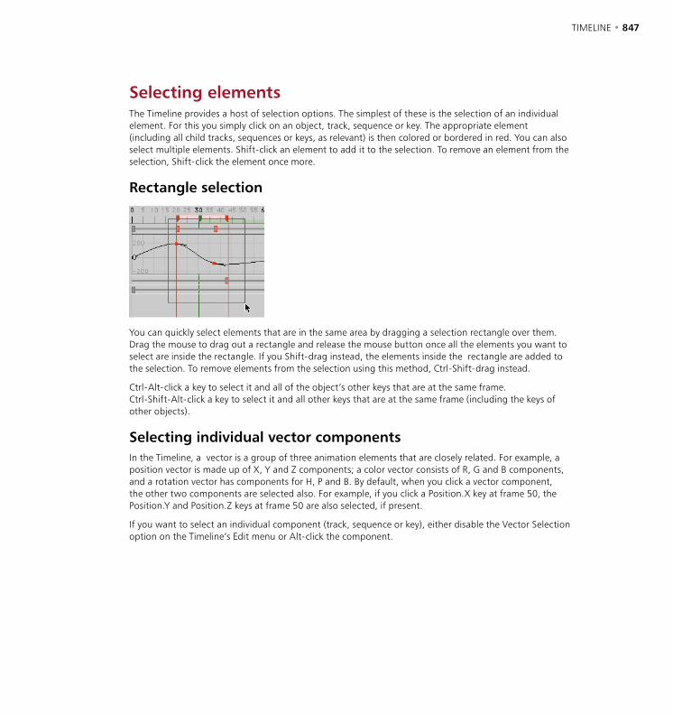
846 • CHAPTER 19 TIMELINE • 847
Selecting elementsThe Timeline provides a host of selection options. The simplest of these is the selection of an individual element. For this you simply click on an object, track, sequence or key. The appropriate element (including all child tracks, sequences or keys, as relevant) is then colored or bordered in red. You can also select multiple elements. Shift-click an element to add it to the selection. To remove an element from the selection, Shift-click the element once more.
Rectangle selection
You can quickly select elements that are in the same area by dragging a selection rectangle over them. Drag the mouse to drag out a rectangle and release the mouse button once all the elements you want to select are inside the rectangle. If you Shift-drag instead, the elements inside the rectangle are added to the selection. To remove elements from the selection using this method, Ctrl-Shift-drag instead.
Ctrl-Alt-click a key to select it and all of the object’s other keys that are at the same frame. Ctrl-Shift-Alt-click a key to select it and all other keys that are at the same frame (including the keys of other objects).
Selecting individual vector componentsIn the Timeline, a vector is a group of three animation elements that are closely related. For example, a position vector is made up of X, Y and Z components; a color vector consists of R, G and B components, and a rotation vector has components for H, P and B. By default, when you click a vector component, the other two components are selected also. For example, if you click a Position.X key at frame 50, the Position.Y and Position.Z keys at frame 50 are also selected, if present.
If you want to select an individual component (track, sequence or key), either disable the Vector Selection option on the Timeline’s Edit menu or Alt-click the component.
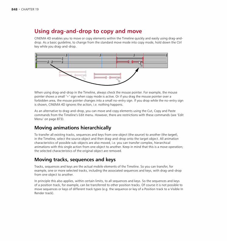
848 • CHAPTER 19 TIMELINE • 849
Using drag-and-drop to copy and moveCINEMA 4D enables you to move or copy elements within the Timeline quickly and easily using drag-and-drop. As a basic guideline, to change from the standard move mode into copy mode, hold down the Ctrl key while you drag-and-drop.
When using drag-and-drop in the Timeline, always check the mouse pointer. For example, the mouse pointer shows a small ‘+’ sign when copy mode is active. Or if you drag the mouse pointer over a forbidden area, the mouse pointer changes into a small no-entry sign. If you drop while the no-entry sign is shown, CINEMA 4D ignores the action, i.e. nothing happens.
As an alternative to drag-and-drop, you can move and copy elements using the Cut, Copy and Paste commands from the Timeline’s Edit menu. However, there are restrictions with these commands (see ‘Edit Menu’ on page 873).
Moving animations hierarchicallyTo transfer all existing tracks, sequences and keys from one object (the source) to another (the target), in the Timeline, select the source object and then drag-and-drop onto the target object. All animation characteristics of possible sub-objects are also moved, i.e. you can transfer complex, hierarchical animations with this single action from one object to another. Keep in mind that this is a move operation; the selected characteristics of the original object are removed.
Moving tracks, sequences and keysTracks, sequences and keys are the actual mobile elements of the Timeline. So you can transfer, for example, one or more selected tracks, including the associated sequences and keys, with drag-and-drop from one object to another.
In principle this also applies, within certain limits, to all sequences and keys. So the sequences and keys of a position track, for example, can be transferred to other position tracks. Of course it is not possible to move sequences or keys of different track types (e.g. the sequence or key of a Position track to a Visible In Render track).
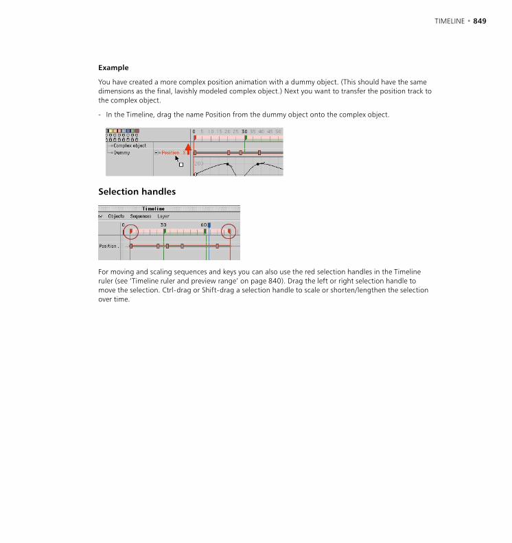
848 • CHAPTER 19 TIMELINE • 849
Example
You have created a more complex position animation with a dummy object. (This should have the same dimensions as the final, lavishly modeled complex object.) Next you want to transfer the position track to the complex object.
- In the Timeline, drag the name Position from the dummy object onto the complex object.
Selection handles
For moving and scaling sequences and keys you can also use the red selection handles in the Timeline ruler (see ‘Timeline ruler and preview range’ on page 840). Drag the left or right selection handle to move the selection. Ctrl-drag or Shift-drag a selection handle to scale or shorten/lengthen the selection over time.
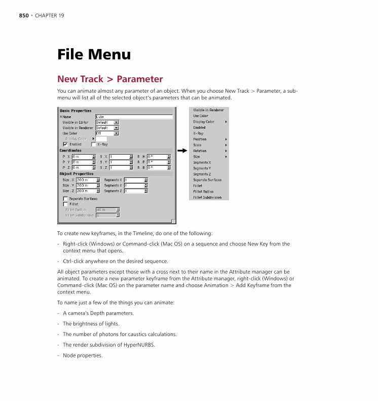
850 • CHAPTER 19 TIMELINE • 851
File MenuNew Track > ParameterYou can animate almost any parameter of an object. When you choose New Track > Parameter, a sub-menu will list all of the selected object’s parameters that can be animated.
To create new keyframes, in the Timeline, do one of the following:
- Right-click (Windows) or Command-click (Mac OS) on a sequence and choose New Key from the context menu that opens.
- Ctrl-click anywhere on the desired sequence.
All object parameters except those with a cross next to their name in the Attribute manager can be animated. To create a new parameter keyframe from the Attribute manager, right-click (Windows) or Command-click (Mac OS) on the parameter name and choose Animation > Add Keyframe from the context menu.
To name just a few of the things you can animate:
- A camera’s Depth parameters.
- The brightness of lights.
- The number of photons for caustics calculations.
- The render subdivision of HyperNURBS.
- Node properties.
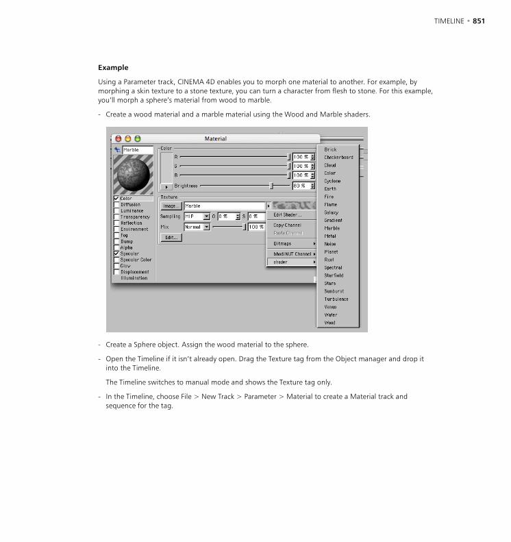
850 • CHAPTER 19 TIMELINE • 851
Example
Using a Parameter track, CINEMA 4D enables you to morph one material to another. For example, by morphing a skin texture to a stone texture, you can turn a character from flesh to stone. For this example, you’ll morph a sphere’s material from wood to marble.
- Create a wood material and a marble material using the Wood and Marble shaders.
- Create a Sphere object. Assign the wood material to the sphere.
- Open the Timeline if it isn’t already open. Drag the Texture tag from the Object manager and drop it into the Timeline.
The Timeline switches to manual mode and shows the Texture tag only.
- In the Timeline, choose File > New Track > Parameter > Material to create a Material track and sequence for the tag.
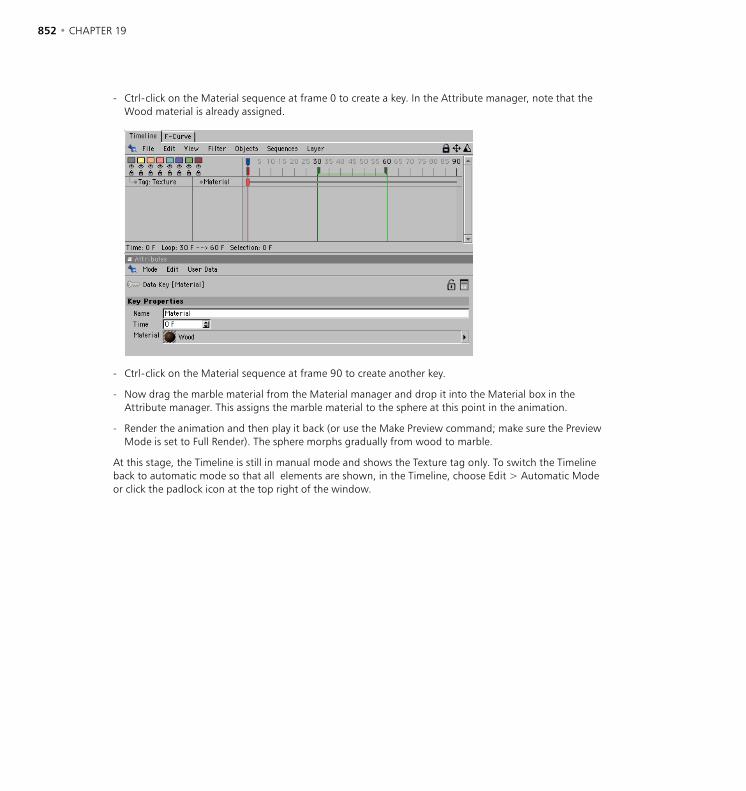
852 • CHAPTER 19 TIMELINE • 853
- Ctrl-click on the Material sequence at frame 0 to create a key. In the Attribute manager, note that the Wood material is already assigned.
- Ctrl-click on the Material sequence at frame 90 to create another key.
- Now drag the marble material from the Material manager and drop it into the Material box in the Attribute manager. This assigns the marble material to the sphere at this point in the animation.
- Render the animation and then play it back (or use the Make Preview command; make sure the Preview Mode is set to Full Render). The sphere morphs gradually from wood to marble.
At this stage, the Timeline is still in manual mode and shows the Texture tag only. To switch the Timeline back to automatic mode so that all elements are shown, in the Timeline, choose Edit > Automatic Mode or click the padlock icon at the top right of the window.

852 • CHAPTER 19 TIMELINE • 853
New Track > MorphUsing this track, you can smoothly transform one shape into another. You can morph Polygon objects and Spline objects; however, you cannot morph primitives or spline primitives. You can only morph between objects that have the same number of points. For example, you cannot morph a sphere into a cube when the sphere has many more points. Rather, you should morph between modified duplicates of an object. For example, if you use the magnet or another modeling tool to fashion a copy of a sphere into a cube, you can then morph between a sphere and a cube.
Before you can morph an object you need to create target objects (duplicates of the original object).
Target objects are copies of the original object. The original state of the object to be morphed must also exist as a target object.
When creating the target objects, if you want to scale the copies of the original object along an axis, be sure to use the Model tool and not the Object tool. This is the opposite of the normal advice for animation because you are scaling and animating the geometry here, not the object axes.
Example
- Create a sphere and, from the main menu, choose Structure > Make Editable to convert the sphere to polygons.
- Create the first copy (Edit > Copy, then Edit > Paste or Ctrl-drag within the Object manager). This is the first target object. On the Attribute manager’s Basic Properties page, name the object Target1.
- Select the Points or Polygons tool from the left-hand toolbar, then select the Magnet tool and in the Active tool window set Type to Needle.
- Now use the Magnet tool to shape the sphere into a drop (Figure 1, below).
Figure 1 Figure 2 Figure 3
- Make another copy of the original sphere and name this copy Target2. (You can hide Target1 to give yourself a better view in the viewport — see ‘Object Display’, page 623). Scale Target2 along the Y-axis to squash it, as illustrated in Figure 2, above.

854 • CHAPTER 19 TIMELINE • 855
- The next step is to create a morph target for a puddle. To this end create a third target object by copying the original. Name this new object Target3. This time, scale the target to flatten and widen it. Use the Magnet tool to tug at the edges to form an irregular puddle shape (Figure 3, above). Remember to have the Model tool selected before scaling.
- The target objects are now ready to be used. Hide the targets in the Object manager but keep the original sphere visible.
- Now, only the original sphere is visible. In the Timeline, assign a Morph track to the sphere.
- Create the first key at the start of the sequence. On the Attribute manager’s Key Properties page, you’ll find a box called Morph Target. Drag the name ‘Target1’ from the Object manager and drop it into this Morph Target box.
- In the Timeline, create the second key in the middle of the sequence. Drag the name ‘Target2’ from the Object manager and drop it into the Attribute manager’s Morph Target box.
- Add a third key at the end of the sequence and drag the name ‘Target3’ from the Object manager and drop it into the Attribute manager’s Morph Target box.
Now play the animation. You can, if you wish, fine-tune the morph by editing the target objects. If you wish to render the animation, ensure that you turn off the various targets in the render — click the lower visibility dot in the Object manager until it turns red.
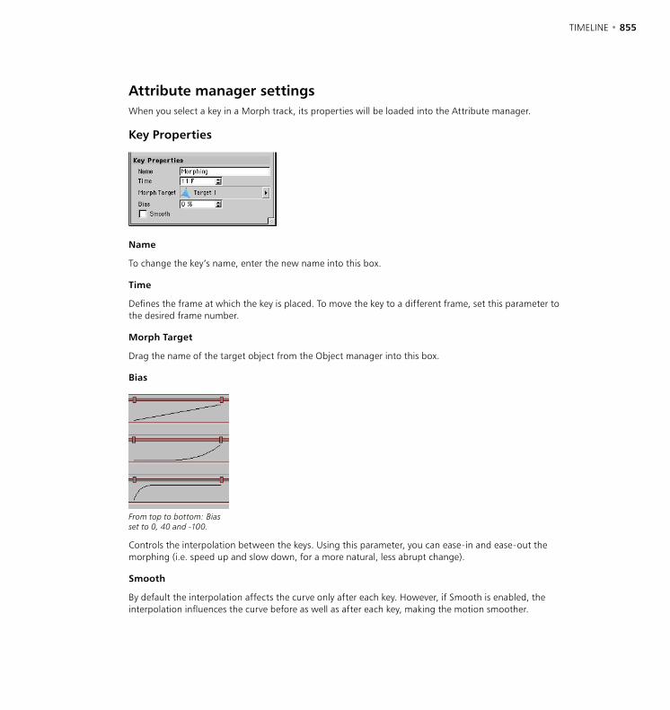
854 • CHAPTER 19 TIMELINE • 855
Attribute manager settingsWhen you select a key in a Morph track, its properties will be loaded into the Attribute manager.
Key Properties
Name
To change the key’s name, enter the new name into this box.
Time
Defines the frame at which the key is placed. To move the key to a different frame, set this parameter to the desired frame number.
Morph Target
Drag the name of the target object from the Object manager into this box.
Bias
From top to bottom: Bias set to 0, 40 and -100.
Controls the interpolation between the keys. Using this parameter, you can ease-in and ease-out the morphing (i.e. speed up and slow down, for a more natural, less abrupt change).
Smooth
By default the interpolation affects the curve only after each key. However, if Smooth is enabled, the interpolation influences the curve before as well as after each key, making the motion smoother.
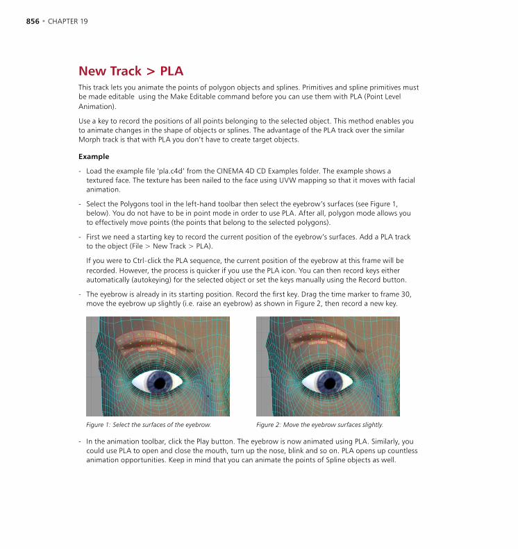
856 • CHAPTER 19 TIMELINE • 857
New Track > PLAThis track lets you animate the points of polygon objects and splines. Primitives and spline primitives must be made editable using the Make Editable command before you can use them with PLA (Point Level Animation).
Use a key to record the positions of all points belonging to the selected object. This method enables you to animate changes in the shape of objects or splines. The advantage of the PLA track over the similar Morph track is that with PLA you don’t have to create target objects.
Example
- Load the example file ‘pla.c4d’ from the CINEMA 4D CD Examples folder. The example shows a textured face. The texture has been nailed to the face using UVW mapping so that it moves with facial animation.
- Select the Polygons tool in the left-hand toolbar then select the eyebrow’s surfaces (see Figure 1, below). You do not have to be in point mode in order to use PLA. After all, polygon mode allows you to effectively move points (the points that belong to the selected polygons).
- First we need a starting key to record the current position of the eyebrow’s surfaces. Add a PLA track to the object (File > New Track > PLA).
If you were to Ctrl-click the PLA sequence, the current position of the eyebrow at this frame will be recorded. However, the process is quicker if you use the PLA icon. You can then record keys either automatically (autokeying) for the selected object or set the keys manually using the Record button.
- The eyebrow is already in its starting position. Record the first key. Drag the time marker to frame 30, move the eyebrow up slightly (i.e. raise an eyebrow) as shown in Figure 2, then record a new key.
Figure 1: Select the surfaces of the eyebrow. Figure 2: Move the eyebrow surfaces slightly.
- In the animation toolbar, click the Play button. The eyebrow is now animated using PLA. Similarly, you could use PLA to open and close the mouth, turn up the nose, blink and so on. PLA opens up countless animation opportunities. Keep in mind that you can animate the points of Spline objects as well.
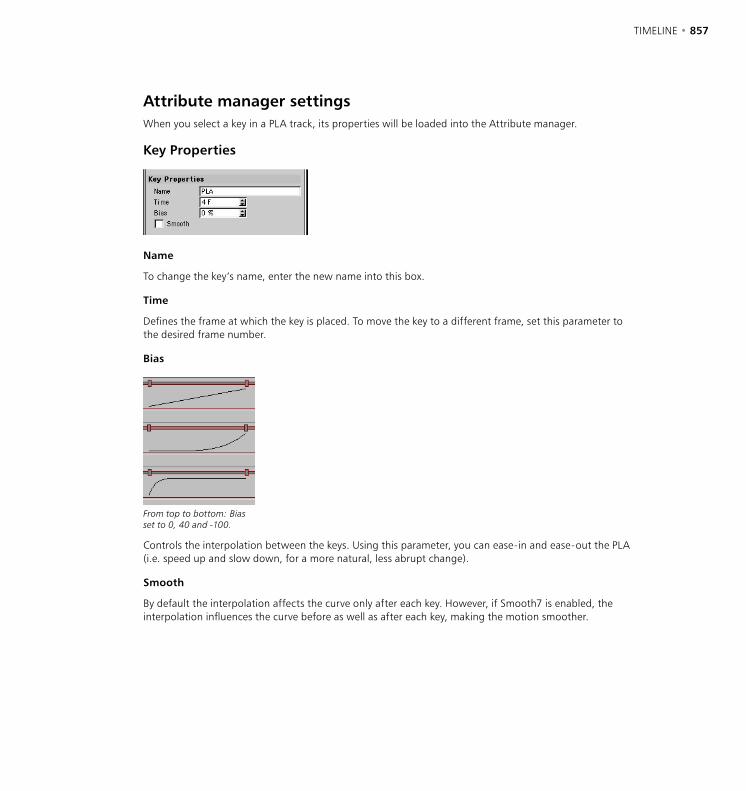
856 • CHAPTER 19 TIMELINE • 857
Attribute manager settingsWhen you select a key in a PLA track, its properties will be loaded into the Attribute manager.
Key Properties
Name
To change the key’s name, enter the new name into this box.
Time
Defines the frame at which the key is placed. To move the key to a different frame, set this parameter to the desired frame number.
Bias
From top to bottom: Bias set to 0, 40 and -100.
Controls the interpolation between the keys. Using this parameter, you can ease-in and ease-out the PLA (i.e. speed up and slow down, for a more natural, less abrupt change).
Smooth
By default the interpolation affects the curve only after each key. However, if Smooth7 is enabled, the interpolation influences the curve before as well as after each key, making the motion smoother.
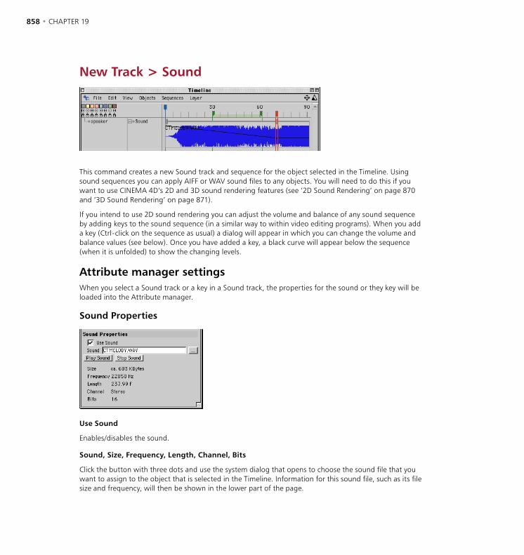
858 • CHAPTER 19 TIMELINE • 859
New Track > Sound
This command creates a new Sound track and sequence for the object selected in the Timeline. Using sound sequences you can apply AIFF or WAV sound files to any objects. You will need to do this if you want to use CINEMA 4D’s 2D and 3D sound rendering features (see ‘2D Sound Rendering’ on page 870 and ‘3D Sound Rendering’ on page 871).
If you intend to use 2D sound rendering you can adjust the volume and balance of any sound sequence by adding keys to the sound sequence (in a similar way to within video editing programs). When you add a key (Ctrl-click on the sequence as usual) a dialog will appear in which you can change the volume and balance values (see below). Once you have added a key, a black curve will appear below the sequence (when it is unfolded) to show the changing levels.
Attribute manager settingsWhen you select a Sound track or a key in a Sound track, the properties for the sound or they key will be loaded into the Attribute manager.
Sound Properties
Use Sound
Enables/disables the sound.
Sound, Size, Frequency, Length, Channel, Bits
Click the button with three dots and use the system dialog that opens to choose the sound file that you want to assign to the object that is selected in the Timeline. Information for this sound file, such as its file size and frequency, will then be shown in the lower part of the page.
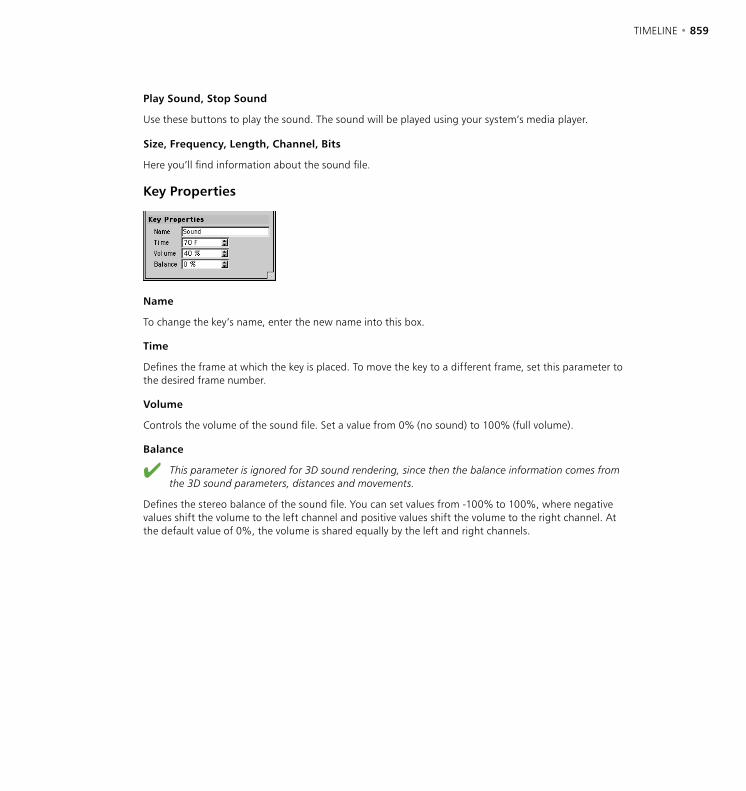
858 • CHAPTER 19 TIMELINE • 859
Play Sound, Stop Sound
Use these buttons to play the sound. The sound will be played using your system’s media player.
Size, Frequency, Length, Channel, Bits
Here you’ll find information about the sound file.
Key Properties
Name
To change the key’s name, enter the new name into this box.
Time
Defines the frame at which the key is placed. To move the key to a different frame, set this parameter to the desired frame number.
Volume
Controls the volume of the sound file. Set a value from 0% (no sound) to 100% (full volume).
Balance
This parameter is ignored for 3D sound rendering, since then the balance information comes from the 3D sound parameters, distances and movements.
Defines the stereo balance of the sound file. You can set values from -100% to 100%, where negative values shift the volume to the left channel and positive values shift the volume to the right channel. At the default value of 0%, the volume is shared equally by the left and right channels.
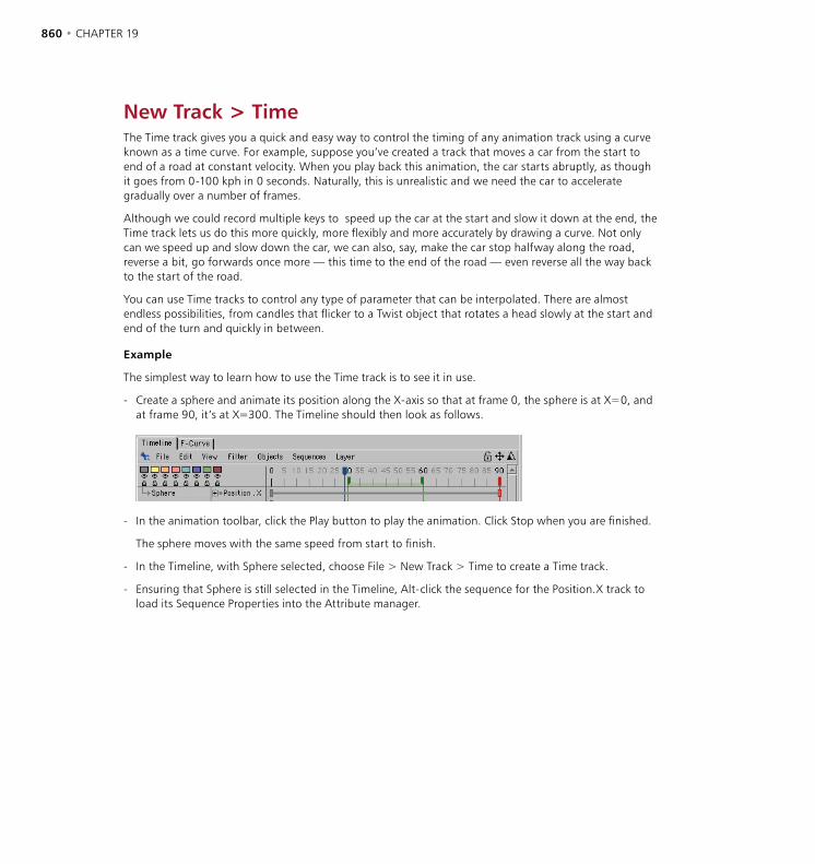
860 • CHAPTER 19 TIMELINE • 861
New Track > TimeThe Time track gives you a quick and easy way to control the timing of any animation track using a curve known as a time curve. For example, suppose you’ve created a track that moves a car from the start to end of a road at constant velocity. When you play back this animation, the car starts abruptly, as though it goes from 0-100 kph in 0 seconds. Naturally, this is unrealistic and we need the car to accelerate gradually over a number of frames.
Although we could record multiple keys to speed up the car at the start and slow it down at the end, the Time track lets us do this more quickly, more flexibly and more accurately by drawing a curve. Not only can we speed up and slow down the car, we can also, say, make the car stop halfway along the road, reverse a bit, go forwards once more — this time to the end of the road — even reverse all the way back to the start of the road.
You can use Time tracks to control any type of parameter that can be interpolated. There are almost endless possibilities, from candles that flicker to a Twist object that rotates a head slowly at the start and end of the turn and quickly in between.
Example
The simplest way to learn how to use the Time track is to see it in use.
- Create a sphere and animate its position along the X-axis so that at frame 0, the sphere is at X=0, and at frame 90, it’s at X=300. The Timeline should then look as follows.
- In the animation toolbar, click the Play button to play the animation. Click Stop when you are finished.
The sphere moves with the same speed from start to finish.
- In the Timeline, with Sphere selected, choose File > New Track > Time to create a Time track.
- Ensuring that Sphere is still selected in the Timeline, Alt-click the sequence for the Position.X track to load its Sequence Properties into the Attribute manager.
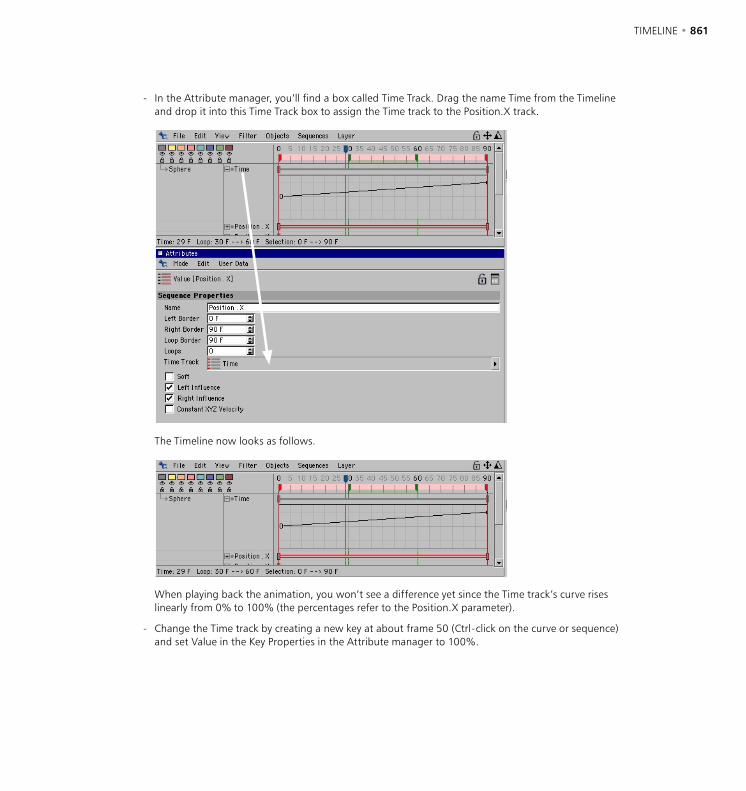
860 • CHAPTER 19 TIMELINE • 861
- In the Attribute manager, you’ll find a box called Time Track. Drag the name Time from the Timeline and drop it into this Time Track box to assign the Time track to the Position.X track.
The Timeline now looks as follows.
When playing back the animation, you won’t see a difference yet since the Time track’s curve rises linearly from 0% to 100% (the percentages refer to the Position.X parameter).
- Change the Time track by creating a new key at about frame 50 (Ctrl-click on the curve or sequence) and set Value in the Key Properties in the Attribute manager to 100%.
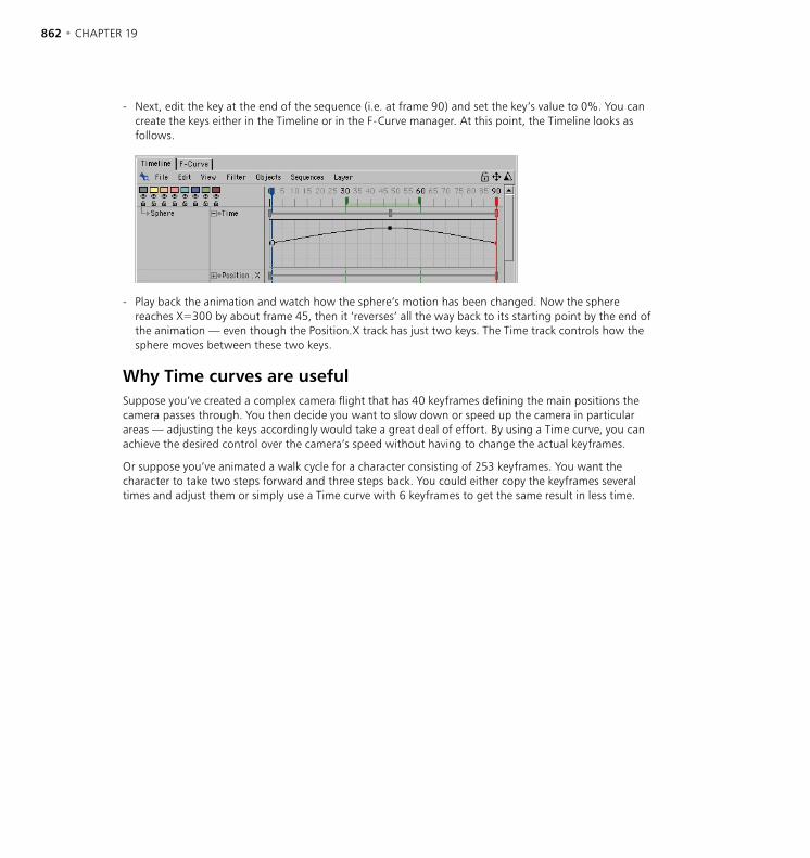
862 • CHAPTER 19 TIMELINE • 863
- Next, edit the key at the end of the sequence (i.e. at frame 90) and set the key’s value to 0%. You can create the keys either in the Timeline or in the F-Curve manager. At this point, the Timeline looks as follows.
- Play back the animation and watch how the sphere’s motion has been changed. Now the sphere reaches X=300 by about frame 45, then it ‘reverses’ all the way back to its starting point by the end of the animation — even though the Position.X track has just two keys. The Time track controls how the sphere moves between these two keys.
Why Time curves are usefulSuppose you’ve created a complex camera flight that has 40 keyframes defining the main positions the camera passes through. You then decide you want to slow down or speed up the camera in particular areas — adjusting the keys accordingly would take a great deal of effort. By using a Time curve, you can achieve the desired control over the camera’s speed without having to change the actual keyframes.
Or suppose you’ve animated a walk cycle for a character consisting of 253 keyframes. You want the character to take two steps forward and three steps back. You could either copy the keyframes several times and adjust them or simply use a Time curve with 6 keyframes to get the same result in less time.
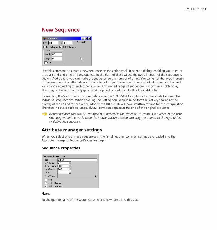
862 • CHAPTER 19 TIMELINE • 863
New Sequence
Use this command to create a new sequence on the active track. It opens a dialog, enabling you to enter the start and end time of the sequence. To the right of these values the overall length of the sequence is shown. Additionally you can make the sequence loop a number of times. You can enter the overall length of the loop period or alternatively the number of loops. These two values are linked to one another and will change according to each other’s value. Any looped range of sequences is shown in a lighter gray. This range is the automatically generated loop and cannot have further keys added to it.
By enabling the Soft option, you can define whether CINEMA 4D should softly interpolate between the individual loop sections. When enabling the Soft option, keep in mind that the last key should not be directly at the end of the sequence, otherwise CINEMA 4D will have insufficient time for the interpolation. Therefore, to avoid sudden jumps, always leave some space at the end of the original sequence.
New sequences can also be ‘dragged out’ directly in the Timeline. To create a sequence in this way, Ctrl-drag within the track. Keep the mouse button pressed and drag the pointer to the right or left to define the sequence.
Attribute manager settingsWhen you select one or more sequences in the Timeline, their common settings are loaded into the Attribute manager’s Sequence Properties page.
Sequence Properties
Name
To change the name of the sequence, enter the new name into this box.
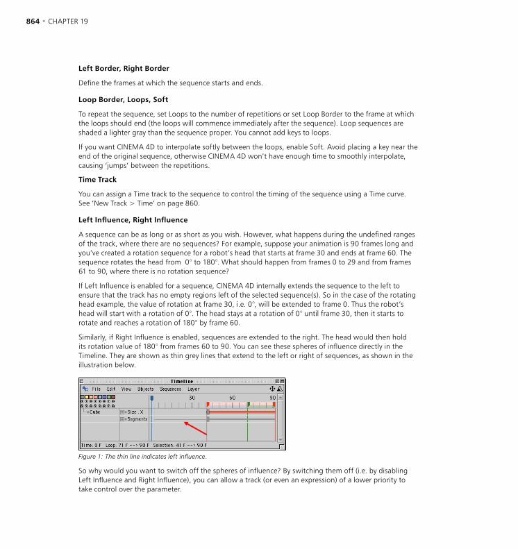
864 • CHAPTER 19 TIMELINE • 865
Left Border, Right Border
Define the frames at which the sequence starts and ends.
Loop Border, Loops, Soft
To repeat the sequence, set Loops to the number of repetitions or set Loop Border to the frame at which the loops should end (the loops will commence immediately after the sequence). Loop sequences are shaded a lighter gray than the sequence proper. You cannot add keys to loops.
If you want CINEMA 4D to interpolate softly between the loops, enable Soft. Avoid placing a key near the end of the original sequence, otherwise CINEMA 4D won’t have enough time to smoothly interpolate, causing ‘jumps’ between the repetitions.
Time Track
You can assign a Time track to the sequence to control the timing of the sequence using a Time curve. See ‘New Track > Time’ on page 860.
Left Influence, Right Influence
A sequence can be as long or as short as you wish. However, what happens during the undefined ranges of the track, where there are no sequences? For example, suppose your animation is 90 frames long and you’ve created a rotation sequence for a robot’s head that starts at frame 30 and ends at frame 60. The sequence rotates the head from 0° to 180°. What should happen from frames 0 to 29 and from frames 61 to 90, where there is no rotation sequence?
If Left Influence is enabled for a sequence, CINEMA 4D internally extends the sequence to the left to ensure that the track has no empty regions left of the selected sequence(s). So in the case of the rotating head example, the value of rotation at frame 30, i.e. 0°, will be extended to frame 0. Thus the robot’s head will start with a rotation of 0°. The head stays at a rotation of 0° until frame 30, then it starts to rotate and reaches a rotation of 180° by frame 60.
Similarly, if Right Influence is enabled, sequences are extended to the right. The head would then hold its rotation value of 180° from frames 60 to 90. You can see these spheres of influence directly in the Timeline. They are shown as thin grey lines that extend to the left or right of sequences, as shown in the illustration below.
Figure 1: The thin line indicates left influence.
So why would you want to switch off the spheres of influence? By switching them off (i.e. by disabling Left Influence and Right Influence), you can allow a track (or even an expression) of a lower priority to take control over the parameter.

864 • CHAPTER 19 TIMELINE • 865
For example, suppose you want the robot to look at a space ship before and after the rotation sequence. In other words, from frames 0 to 29, the robot will look at the space ship. From frames 30 to 60, the robot rotates its head as defined by the rotation sequence. Then from frame 61 onwards, the robot once more looks at the space ship.
You can achieve this as follows. First you create a Target expression that points the robot’s head at the space ship. You lower the priority of the Target expression (i.e. place it under the rotation track in the Timeline) so that the rotation keys have priority (otherwise the expression would override the rotation sequence and the robot would always look at the space ship).
This is where the spheres of influence come into play. If Left Influence and Right Influence are enabled for the rotation sequence, its influence is extended to cover the entire animation and the Target expression is not allowed to control the head during the empty regions. To allow the Target expression to control the head’s rotation during the empty regions, Left Influence and Right Influence must be disabled.
To summarize, disable Left Influence and Right Influence if you want a track or expression of lower priority to control the parameter during the empty regions.
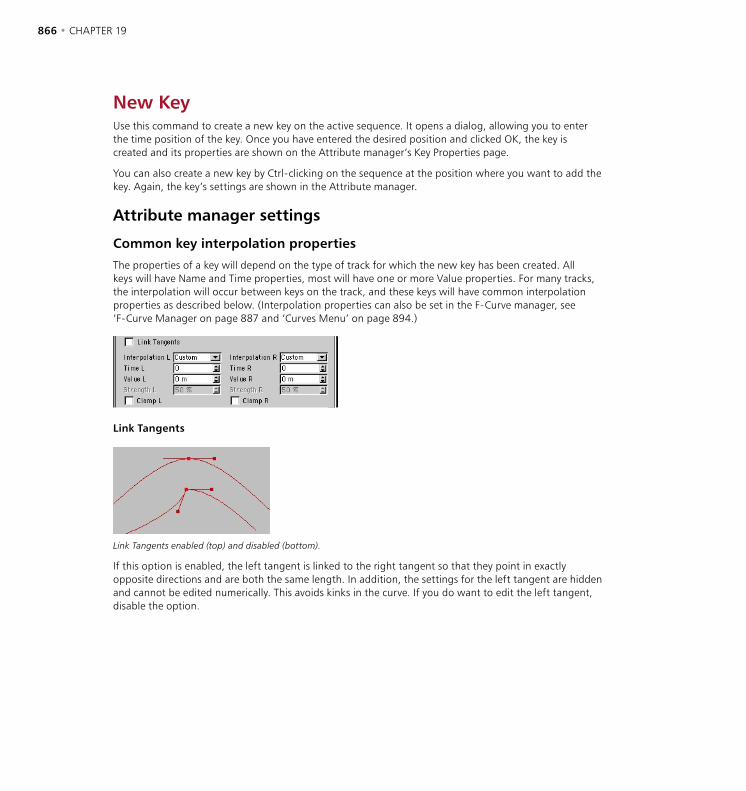
866 • CHAPTER 19 TIMELINE • 867
New KeyUse this command to create a new key on the active sequence. It opens a dialog, allowing you to enter the time position of the key. Once you have entered the desired position and clicked OK, the key is created and its properties are shown on the Attribute manager’s Key Properties page.
You can also create a new key by Ctrl-clicking on the sequence at the position where you want to add the key. Again, the key’s settings are shown in the Attribute manager.
Attribute manager settings
Common key interpolation properties
The properties of a key will depend on the type of track for which the new key has been created. All keys will have Name and Time properties, most will have one or more Value properties. For many tracks, the interpolation will occur between keys on the track, and these keys will have common interpolation properties as described below. (Interpolation properties can also be set in the F-Curve manager, see ‘F-Curve Manager on page 887 and ‘Curves Menu’ on page 894.)
Link Tangents
Link Tangents enabled (top) and disabled (bottom).
If this option is enabled, the left tangent is linked to the right tangent so that they point in exactly opposite directions and are both the same length. In addition, the settings for the left tangent are hidden and cannot be edited numerically. This avoids kinks in the curve. If you do want to edit the left tangent, disable the option.

866 • CHAPTER 19 TIMELINE • 867
Interpolation L / R
Using these drop-down lists, you can set separate interpolation types for the left and right tangents.
Custom
A handle is shown for the tangent in the F-Curve window, where you can drag the handle freely to rotate and scale the tangent. You can also enter values into the Time L / R and Value L / R boxes.
Soft
To make the bend in the curve softer or harder, adjust the tangent’s Strength L / R value.
Linear, Step, Slow, Fast
Linear Step Slow Fast
<--> (none)
Setting the left tangent to <--> uses the interpolation type of the key to the left, while setting the right tangent to <--> uses the interpolation type of the key to the right.
Time L / R, Value L / R
See, ‘Interpolation L / R, Custom’, above.
Strength L / R
See, ‘Interpolation L / R, Soft, above.
Clamp L / R
Clamp enabled (left) and disabled (right).
Clamping is a special function which helps avoid overshooting when using soft interpolation and is especially useful if several keys with the same values are next to each other, while a character places its foot on the ground, for example.
868 • CHAPTER 19 TIMELINE • 869
Taking the foot example a little further, while the foot is on the ground, you want to prevent it from sinking through the floor. Although you can do this by setting the interpolation between the keyframes to linear to straighten out the curve, this may cause problems later if you need to adjust the keys. The clamp function is used to straighten out the curve (just like linear interpolation would do) between keys that have the same values. However, as soon as one of the keys is set to a different value, the clamp is no longer applied and normal soft interpolation is used instead.

868 • CHAPTER 19 TIMELINE • 869
New Marker
This command creates a new marker on the Timeline ruler. Markers are ideal for simplifying the look and navigation of the Timeline. After calling this command, a dialog opens enabling you to define the timeframe position and the name and color of the marker.
You can also create new markers directly on the Timeline ruler. To do this, Ctrl-click on the lower half of the Timeline ruler. Markers that you create in this way have no name and are given the color of the second layer (yellow by default). To change a marker’s attributes, double-click the marker and, in the dialog that opens, set the parameters as desired.
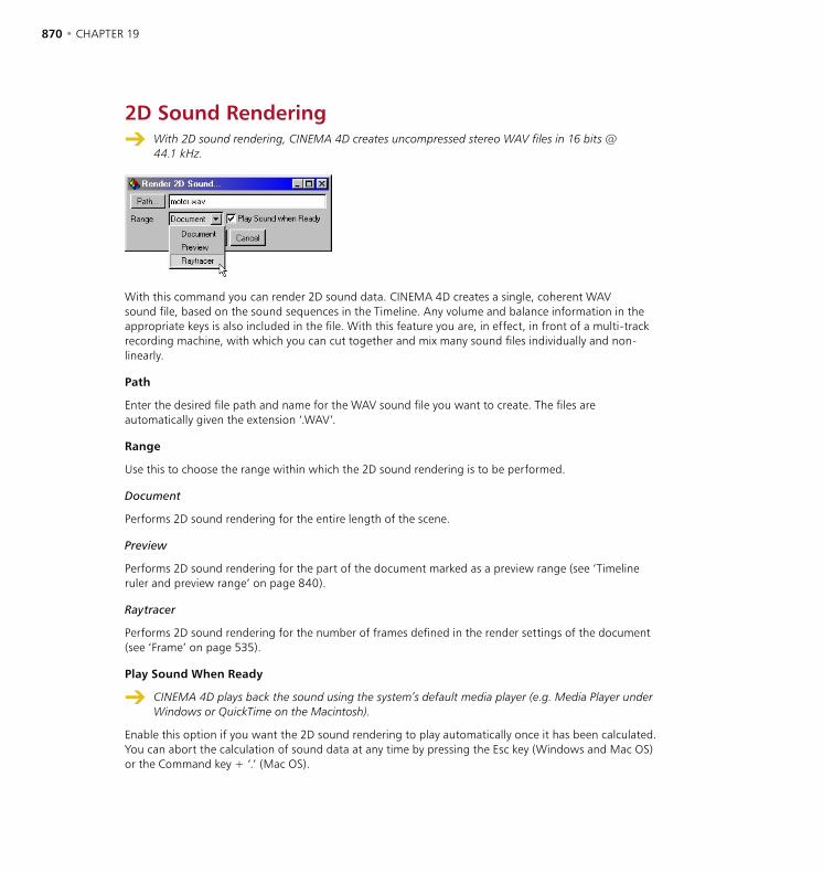
870 • CHAPTER 19 TIMELINE • 871
2D Sound Rendering With 2D sound rendering, CINEMA 4D creates uncompressed stereo WAV files in 16 bits @
44.1 kHz.
With this command you can render 2D sound data. CINEMA 4D creates a single, coherent WAV sound file, based on the sound sequences in the Timeline. Any volume and balance information in the appropriate keys is also included in the file. With this feature you are, in effect, in front of a multi-track recording machine, with which you can cut together and mix many sound files individually and non-linearly.
Path
Enter the desired file path and name for the WAV sound file you want to create. The files are automatically given the extension ‘.WAV’.
Range
Use this to choose the range within which the 2D sound rendering is to be performed.
Document
Performs 2D sound rendering for the entire length of the scene.
Preview
Performs 2D sound rendering for the part of the document marked as a preview range (see ‘Timeline ruler and preview range’ on page 840).
Raytracer
Performs 2D sound rendering for the number of frames defined in the render settings of the document (see ‘Frame’ on page 535).
Play Sound When Ready
CINEMA 4D plays back the sound using the system’s default media player (e.g. Media Player under Windows or QuickTime on the Macintosh).
Enable this option if you want the 2D sound rendering to play automatically once it has been calculated. You can abort the calculation of sound data at any time by pressing the Esc key (Windows and Mac OS) or the Command key + ‘.’ (Mac OS).
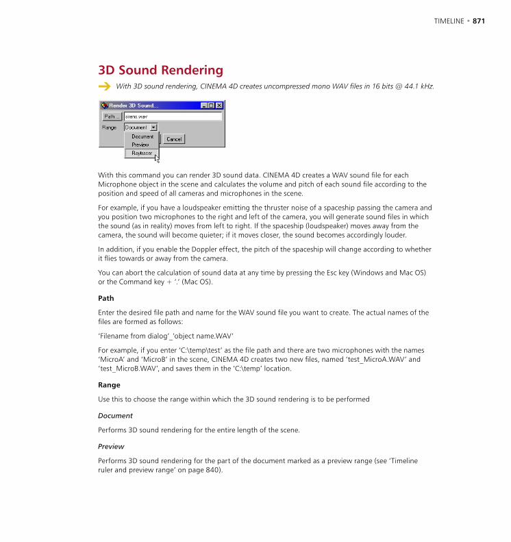
870 • CHAPTER 19 TIMELINE • 871
3D Sound Rendering With 3D sound rendering, CINEMA 4D creates uncompressed mono WAV files in 16 bits @ 44.1 kHz.
With this command you can render 3D sound data. CINEMA 4D creates a WAV sound file for each Microphone object in the scene and calculates the volume and pitch of each sound file according to the position and speed of all cameras and microphones in the scene.
For example, if you have a loudspeaker emitting the thruster noise of a spaceship passing the camera and you position two microphones to the right and left of the camera, you will generate sound files in which the sound (as in reality) moves from left to right. If the spaceship (loudspeaker) moves away from the camera, the sound will become quieter; if it moves closer, the sound becomes accordingly louder.
In addition, if you enable the Doppler effect, the pitch of the spaceship will change according to whether it flies towards or away from the camera.
You can abort the calculation of sound data at any time by pressing the Esc key (Windows and Mac OS) or the Command key + ‘.’ (Mac OS).
Path
Enter the desired file path and name for the WAV sound file you want to create. The actual names of the files are formed as follows:
‘Filename from dialog’_’object name.WAV’
For example, if you enter ‘C:\temp\test’ as the file path and there are two microphones with the names ‘MicroA’ and ‘MicroB’ in the scene, CINEMA 4D creates two new files, named ‘test_MicroA.WAV’ and ‘test_MicroB.WAV’, and saves them in the ‘C:\temp’ location.
Range
Use this to choose the range within which the 3D sound rendering is to be performed
Document
Performs 3D sound rendering for the entire length of the scene.
Preview
Performs 3D sound rendering for the part of the document marked as a preview range (see ‘Timeline ruler and preview range’ on page 840).

872 • CHAPTER 19 TIMELINE • 873
Raytracer
Performs 3D sound rendering for the number of frames defined in the render settings of the document (see ‘Frames’ on page 535’).
CloseCloses the Timeline. The animation created in the Timeline is preserved.

872 • CHAPTER 19 TIMELINE • 873
Edit MenuUndo
This command is used to undo the last change made to the animation. If you use this command several times, one after the other, first the last change you made will be undone, then the editing prior to that change is undone and so on. By default, CINEMA 4D saves the last ten edit steps internally and all of these steps may be undone. You may change the number of undo steps in the preferences, on the Document page.
Redo
If you have undone too many changes and want to restore them, you can do so using the Redo command. With Undo, you go backwards through the edit history of your scene, while with Redo, you go forwards.
Cut When several sequences and keys are selected in the Timeline, CINEMA 4D cuts the elements of the
topmost selected line only.
This command copies the keys and the sequence data that are currently selected in the Timeline to the clipboard and deletes them from the Timeline. Elements stored in the clipboard may be inserted into the Timeline again with the Paste command.
Copy When several sequences and keys are selected in the Timeline, CINEMA 4D cuts the elements of the
topmost selected line only.
This command copies the keys and the sequence data that are currently selected in the Timeline to the clipboard. Elements in the clipboard can then be copied to the Timeline with the Paste command.
PasteInserts the elements stored in clipboard into the active document. In the Timeline, the pasted elements stick to the mouse pointer and must be given a position in the Timeline. Do this by moving the mouse arrow to the position where you want to paste the elements and click to paste them.
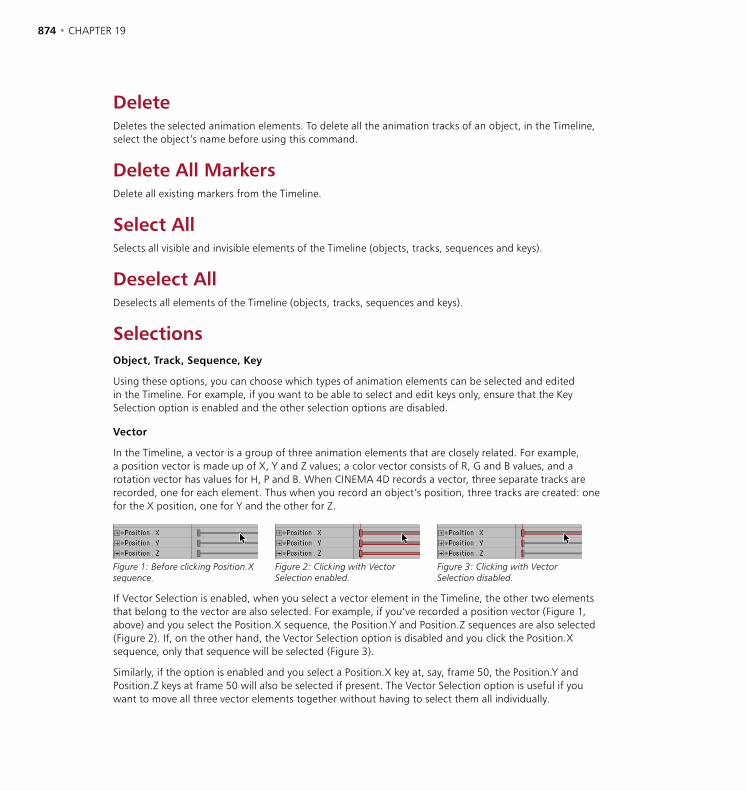
874 • CHAPTER 19 TIMELINE • 875
DeleteDeletes the selected animation elements. To delete all the animation tracks of an object, in the Timeline, select the object’s name before using this command.
Delete All MarkersDelete all existing markers from the Timeline.
Select AllSelects all visible and invisible elements of the Timeline (objects, tracks, sequences and keys).
Deselect AllDeselects all elements of the Timeline (objects, tracks, sequences and keys).
SelectionsObject, Track, Sequence, Key
Using these options, you can choose which types of animation elements can be selected and edited in the Timeline. For example, if you want to be able to select and edit keys only, ensure that the Key Selection option is enabled and the other selection options are disabled.
Vector
In the Timeline, a vector is a group of three animation elements that are closely related. For example, a position vector is made up of X, Y and Z values; a color vector consists of R, G and B values, and a rotation vector has values for H, P and B. When CINEMA 4D records a vector, three separate tracks are recorded, one for each element. Thus when you record an object’s position, three tracks are created: one for the X position, one for Y and the other for Z.
Figure 1: Before clicking Position.X sequence.
Figure 2: Clicking with Vector Selection enabled.
Figure 3: Clicking with Vector Selection disabled.
If Vector Selection is enabled, when you select a vector element in the Timeline, the other two elements that belong to the vector are also selected. For example, if you’ve recorded a position vector (Figure 1, above) and you select the Position.X sequence, the Position.Y and Position.Z sequences are also selected (Figure 2). If, on the other hand, the Vector Selection option is disabled and you click the Position.X sequence, only that sequence will be selected (Figure 3).
Similarly, if the option is enabled and you select a Position.X key at, say, frame 50, the Position.Y and Position.Z keys at frame 50 will also be selected if present. The Vector Selection option is useful if you want to move all three vector elements together without having to select them all individually.

874 • CHAPTER 19 TIMELINE • 875
Arrange ModeThis command is available only if the Timeline is set to manual mode (i.e. the lock in the top right corner of the Timeline is locked, the Automatic Mode option on the Edit menu is disabled). See Automatic Mode on page 876 for a discussion of these modes.
When the arrange mode is active, objects can be freely rearranged in the Timeline, allowing you to even change the hierarchy completely (without affecting the original hierarchy in the Object manager). However, note that you can’t edit keys or tracks while the arrange mode is active. As soon as the arrange mode is activated, the mouse pointer changes to a hand instead of the usual arrow.
Making one object a sub object of another using the arrange mode doesn’t mean that recording keyframes for the parent object in the Timeline records keyframes for the child object as well. To record keyframes for an entire hierarchy, in the Object manager, select the parent object and choose Edit > Select Children before you record. Alternatively, use a Selection object and autokeying.
Show All AnimatedWhile in manual mode (i.e. the lock in the top right corner of the Timeline is locked, the Automatic Mode option on the Edit menu is disabled), objects aren’t automatically displayed in the Timeline even if they are animated. To quickly load all animated objects and other animated elements such as materials and post effects into the Timeline, choose Show All Animated.
To activate the automatic mode so that all animated objects are shown automatically, in the Timeline, open the lock in the top right corner and choose Filter > Show Animated Objects.
Remove Object, Remove AllThese commands are available only if the Timeline is set to manual mode (i.e. the lock in the top right corner of the Timeline is locked, the Automatic Mode option on the Edit menu is disabled). The Remove Objects command removes the selected objects from the Timeline. The Remove All command removes all objects from the Timeline. Note that the removed objects are merely hidden from the Timeline — they aren’t deleted from the scene.
To show the removed objects once more, do one of the following:
- In the Timeline, open the lock in the top right corner to switch off manual mode.
- Drag-and-drop the objects from the Object manager into the Timeline.
- In the Timeline, choose Edit > Show All Animated when in manual mode.
Snap To FrameThis option is enabled by default and helps you to position keys and sequences accurately to frames when moving them with the mouse. If the option is disabled, all keys and sequences can be positioned freely between frames, without the use of time steps.

876 • CHAPTER 19 TIMELINE • 877
When you add a key to a sequence, the new key may replace an existing key, regardless of whether you place the key manually or whether you use autokeying. For example, suppose a sequence has an existing key at frame 12.23 and a new key is placed at frame 12. The original key (12.23) will be deleted and the new key will be snapped to frame 12.
CINEMA 4D also snaps sequences and keys when scaling them. This prevents keys from existing at non-integral positions such as frame 3.476532. However, keys can be lost in the process, as demonstrated in the following example:
- Create a sequence from frame 0 to frame 10 and create a key for each frame.
- Scale down the sequence so that runs from frames 0 to 3 (Ctrl-drag the red selection handle that is at the right edge of the sequence).
- Scale up the sequence so that it is 10 frames long again (once again, Ctrl-drag the selection handle).
The sequence now has just four keys, the others have been lost. The reason why is that when the sequence was scaled down the keys were snapped to integral frame numbers. Thus you can work on a frame basis or a time basis (as is necessary when converting a scene from PAL to NTSC).
Project SettingsThis command opens the project settings. See ‘Project Settings’ on page 84.
Link To Object ManagerIf this option is enabled, selection in the Timeline is linked to selection in the Object manager. In other words, the objects you select in the Timeline are selected in the Object manager also and vice versa.
Automatic Mode See also ‘Manual mode and automatic mode’ on page 888.
If this option is enabled, all objects and animation elements are shown in the Timeline. As objects are created in the Object manager, they are added to the Timeline. If you have lots of animation data in the scene, you might find it faster to work in manual mode., which enables you to choose which objects are shown in the Timeline. To switch between automatic mode and manual mode, enable or disable this option, or click the lock in the top right corner of the Timeline. You can also activate manual mode by dragging an object from the Object manager and dropping it into the Timeline.
Automatic mode vs manual mode
If you are working in automatic mode and drag an object or objects into the Timeline, the display will switch to manual mode, with only the selected objects shown in the Timeline. Tracks that were previously shown in manual mode will be lost and will need to be dragged into the manual mode again (there is no undo). You can also select Edit > Show All Animated in manual mode, which will add all animation tracks to the display. It is therefore a good idea to switch to manual mode before dragging objects etc. into the Timeline, just in case you destroy some carefully constructed animation set-up.

876 • CHAPTER 19 TIMELINE • 877
View MenuFrame AllThis command enables you to center the entire animation within the visible work area of the Timeline. If necessary, the view will be scaled horizontally.
Frame SelectionCenters the selected elements (sequences and keys) within the visible work area in the Timeline. If necessary, the view will be scaled horizontally.
Frame StartCenters the visible work area in the Timeline from the beginning of the animation. The view is not scaled.
Frame EndCenters the visible work area in the Timeline to the end of the animation. The view is not scaled.
Frame Active TimeCenters the visible work area in the Timeline starting at the current position of the time marker (the blue marker). The view is not scaled.
Frame TimeCenters the visible work area in the Timeline starting at a time value of your choosing. Enter the frame number into the dialog that opens and click OK. The view is not scaled.
Frame MarkerCenters the work area in the Timeline starting at a marker of your choosing. Enter the name of the desired marker into the dialog that opens and click OK. The view is not scaled.
Frame Right Marker, Frame Left MarkerThe commands center the work area in the Timeline starting at the nearest off-screen marker that is to the right or to the left (respectively). The view is not scaled.
Zoom In, Zoom OutYou can zoom in or out by a factor of 2 using these commands.
878 • CHAPTER 19 TIMELINE • 879
Filter MenuThe options on this menu control which element types are shown in the Timeline. The last four items on this menu — Show Position Tracks, Scale Tracks, Rotation Tracks and Other Tracks — apply to manual mode only. All items except Show Branches control whether a particular element type is shown.
Show Branches controls whether a triangle or circle is shown to the left of object names in the Timeline. If triangles are shown (Show Branches enabled), you can click a triangle to show the object’s tags.
878 • CHAPTER 19 TIMELINE • 879
Objects MenuRename ObjectRenames the object that is currently selected in the Timeline.
Search Active ObjectThis command scrolls the Timeline and opens a hierarchy if necessary to ensure that the object currently selected in the Timeline can be seen in the Timeline.
Fold All, Unfold AllThese commands close or open all hierarchies in the Timeline. This action is also applied to invisible and locked objects.
Bake Object Not all types of animation can be baked. You can convert into real keys, for example, only those
movements that alter the position, scaling or rotation of an object.
This command will convert animations which were not created using position, scale or rotation tracks (but nonetheless refer to the position or size of the object) into real position, scale or rotation tracks. This is especially useful when exporting an animation to a foreign file format, such as VRML, which does not support animation properties such as the Target expression.
Bake Object creates keys at regular intervals, paying no attention to any necessity for the positioning of the keys; very many keys are created. Therefore you should use this command sparingly and economically. Try to reduce the keys of the animation afterwards using the Simplify Curve command in the F-Curve window.
Position Tracks To SplineThis command converts an object’s animation path into a spline. First, select the object whose X, Y and Z position tracks you want to be converted to a spline. Next, choose this command. CINEMA 4D will create a Spline object that corresponds to the position path of the object. You can edit the spline and assign this to the object again using the Spline To Position Tracks command.
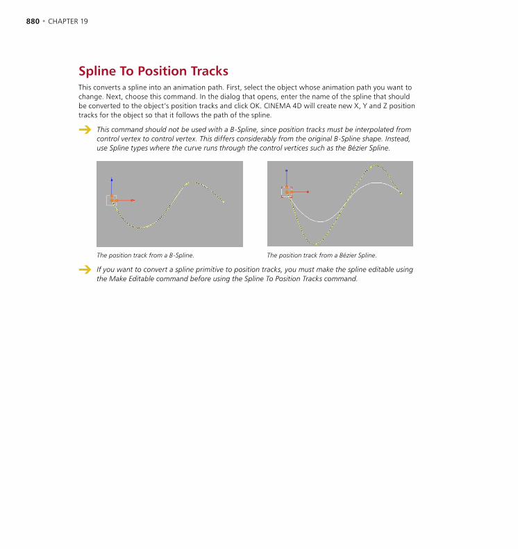
880 • CHAPTER 19 TIMELINE • 881
Spline To Position TracksThis converts a spline into an animation path. First, select the object whose animation path you want to change. Next, choose this command. In the dialog that opens, enter the name of the spline that should be converted to the object’s position tracks and click OK. CINEMA 4D will create new X, Y and Z position tracks for the object so that it follows the path of the spline.
This command should not be used with a B-Spline, since position tracks must be interpolated from control vertex to control vertex. This differs considerably from the original B-Spline shape. Instead, use Spline types where the curve runs through the control vertices such as the Bézier Spline.
The position track from a B-Spline. The position track from a Bézier Spline.
If you want to convert a spline primitive to position tracks, you must make the spline editable using the Make Editable command before using the Spline To Position Tracks command.
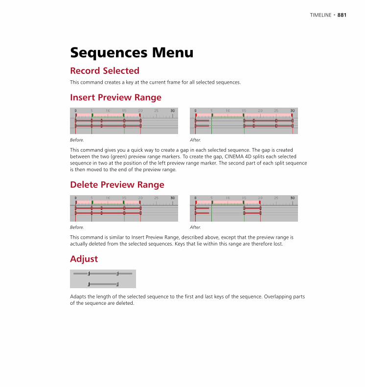
880 • CHAPTER 19 TIMELINE • 881
Sequences MenuRecord SelectedThis command creates a key at the current frame for all selected sequences.
Insert Preview Range
Before. After.
This command gives you a quick way to create a gap in each selected sequence. The gap is created between the two (green) preview range markers. To create the gap, CINEMA 4D splits each selected sequence in two at the position of the left preview range marker. The second part of each split sequence is then moved to the end of the preview range.
Delete Preview Range
Before. After.
This command is similar to Insert Preview Range, described above, except that the preview range is actually deleted from the selected sequences. Keys that lie within this range are therefore lost.
Adjust
Adapts the length of the selected sequence to the first and last keys of the sequence. Overlapping parts of the sequence are deleted.
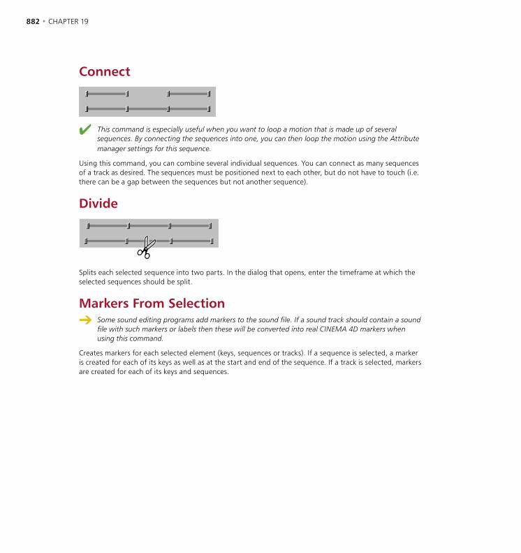
882 • CHAPTER 19 TIMELINE • 883
Connect
This command is especially useful when you want to loop a motion that is made up of several sequences. By connecting the sequences into one, you can then loop the motion using the Attribute manager settings for this sequence.
Using this command, you can combine several individual sequences. You can connect as many sequences of a track as desired. The sequences must be positioned next to each other, but do not have to touch (i.e. there can be a gap between the sequences but not another sequence).
Divide
Splits each selected sequence into two parts. In the dialog that opens, enter the timeframe at which the selected sequences should be split.
Markers From Selection Some sound editing programs add markers to the sound file. If a sound track should contain a sound
file with such markers or labels then these will be converted into real CINEMA 4D markers when using this command.
Creates markers for each selected element (keys, sequences or tracks). If a sequence is selected, a marker is created for each of its keys as well as at the start and end of the sequence. If a track is selected, markers are created for each of its keys and sequences.
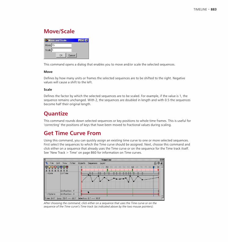
882 • CHAPTER 19 TIMELINE • 883
Move/Scale
This command opens a dialog that enables you to move and/or scale the selected sequences.
Move
Defines by how many units or frames the selected sequences are to be shifted to the right. Negative values will cause a shift to the left.
Scale
Defines the factor by which the selected sequences are to be scaled. For example, if the value is 1, the sequence remains unchanged. With 2, the sequences are doubled in length and with 0.5 the sequences become half their original length.
QuantizeThis command rounds down selected sequences or key positions to whole time frames. This is useful for ‘correcting’ the positions of keys that have been moved to fractional values during scaling.
Get Time Curve FromUsing this command, you can quickly assign an existing time curve to one or more selected sequences. First select the sequences to which the Time curve should be assigned. Next, choose this command and click either on a sequence that already uses the Time curve or on the sequence for the Time track itself. See ‘New Track > Time’ on page 860 for information on Time curves.
After choosing the command, click either on a sequence that uses the Time curve or on the sequence of the Time curve’s Time track (as indicated above by the two mouse pointers).
884 • CHAPTER 19
Layer MenuColor SelectionWith this menu you can assign one of the eight predefined colors to the elements (objects, tracks, sequences and keys) selected in the Timeline.
Select LayerChoose one of the eight layer entries from the Select Layer menu to select all elements that belong to this layer in the Timeline.
Toggle LayerChoose one of the eight layer entries from the Toggle Layer menu to both lock and hide the layer. Another call to the same layer toggles the layer to visible and unlocked.
Solo LayerChoose one of the eight layer entries from the Solo Layer menu to hide and lock all layers except the selected one.
All LayersUsing this menu, you can choose to show, hide, lock or unlock all layers.

20. F-Curves20 F-Curve Manager

F-CURVE MANAGER • 887
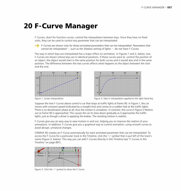
F-CURVE MANAGER • 887
F-Curves, short for function curves, control the interpolation between keys. Since they have no fixed units, they can be used to control any parameter that can be interpolated.
F-Curves are shown only for those animated parameters that can be interpolated. Parameters that cannot be interpolated — such as the Shadow setting of lights — do not have F-Curves.
The way in which keys are interpolated has a major effect on animation. In Figures 1 and 2, below, two F-Curves are shown whose keys are in identical positions. If these curves were to control the position of an object, the object would start in the same position for both curves and it would also end in the same position. The difference between the two curves affects what happens to the object between the start and the end.
Figure 1: Linear Interpolation. Figure 2: Ease In interpolation applied to the right-hand key.
Suppose the two F-Curves above control a car that stops at traffic lights at frame 90. In Figure 1, the car moves with constant speed (indicated by a straight line) and comes to a sudden halt at the traffic lights. There is no deceleration phase at all, thus the motion is unrealistic. In contrast, the curve in Figure 2 flattens out as frame 90 is approached. This causes the car to slow down gradually as it approaches the traffic lights, just as though a driver is applying the brakes. The resulting motion is realistic.
F-Curves give you an easy way to ease motion in and out, helping you to improve the realism of your animations. In addition, F-Curves give you a graphical way to control animation, using smooth curves to avoid abrupt, unnatural changes.
CINEMA 4D creates an F-Curve automatically for each animated parameter that can be interpolated. To access the F-Curve for a particular track in the Timeline, click the ‘+’ symbol that is just left of the track’s name (Figure 3, below). This way you can edit F-Curves directly in the Timeline (see ‘F-Curves in the Timeline’ on page 891).
Figure 3: Click the ‘+’ symbol to show the F-Curve.
20 F-Curve Manager

888 • CHAPTER 20 F-CURVE MANAGER • 889
However, most of the time, you’ll probably want to edit them using the F-Curve manager as it offers more display space, thus making it easier to edit the curves accurately. In addition, the F-Curve manager provides a number of commands that you cannot access from the Timeline. Also, when you open the F-Curve manager, the F-Curve List (to the left of the display) is integrated by default. Among other things, this list helps you to control which F-Curves are displayed in the F–Curve manager.
1
2
3
4
5
6
1. Curve has been made relative. 2. Tangent handles. 3. Current frame. 4. Clamped key. 5. End of sequence. 6. F-Curve list.
Manual mode and automatic mode
The F-Curve manager has two display modes: manual and automatic. A locked padlock at the top right of the F-Curve display shows that you are in manual mode, an unlocked padlock indicates automatic mode.
The automatic mode, which is enabled by default, displays the F-Curves of the currently selected objects, tags or materials. For example, if you want the F-Curves of three particular materials to be shown, multi-select these materials in the Material manager. Or to show the F-Curves of particular objects, multi-select these objects in the Object manager or Timeline. Similarly, you can select tags in the Object manager to load their F-Curves into the F-Curve manager.
In contrast, the manual mode enables you to control which F-Curves are shown in the F-Curve manager regardless of which objects are currently selected. To switch on manual mode, drag-and-drop the elements whose curves should be shown into the F-Curve manager or F-Curve List.
You can also switch between manual and automatic mode by clicking the lock icon that is situated in the top right corner of the F-Curve manager. Furthermore, the mode can also be changed by enabling or disabling the Automatic Mode option on the F-Curve manager’s Edit menu.
The changes that you make in manual mode are not remembered when you switch to automatic mode. Switching from automatic mode to manual mode initially shows whatever was shown in automatic mode.
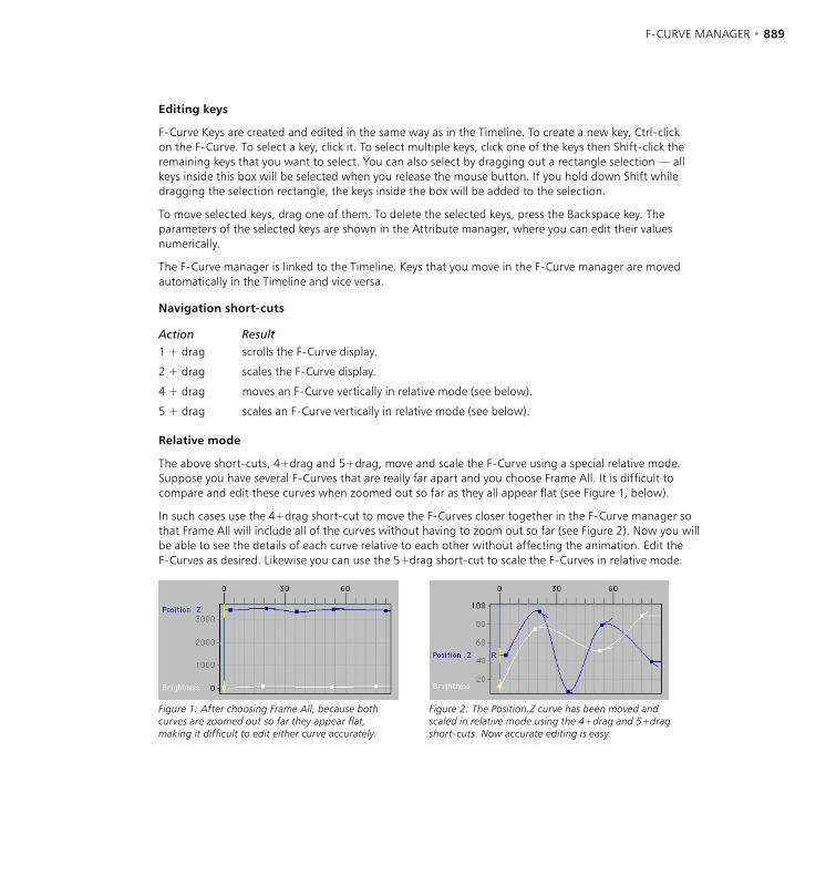
888 • CHAPTER 20 F-CURVE MANAGER • 889
Editing keys
F-Curve Keys are created and edited in the same way as in the Timeline. To create a new key, Ctrl-click on the F-Curve. To select a key, click it. To select multiple keys, click one of the keys then Shift-click the remaining keys that you want to select. You can also select by dragging out a rectangle selection — all keys inside this box will be selected when you release the mouse button. If you hold down Shift while dragging the selection rectangle, the keys inside the box will be added to the selection.
To move selected keys, drag one of them. To delete the selected keys, press the Backspace key. The parameters of the selected keys are shown in the Attribute manager, where you can edit their values numerically.
The F-Curve manager is linked to the Timeline. Keys that you move in the F-Curve manager are moved automatically in the Timeline and vice versa.
Navigation short-cuts
Action Result1 + drag scrolls the F-Curve display.
2 + drag scales the F-Curve display.
4 + drag moves an F-Curve vertically in relative mode (see below).
5 + drag scales an F-Curve vertically in relative mode (see below).
Relative mode
The above short-cuts, 4+drag and 5+drag, move and scale the F-Curve using a special relative mode. Suppose you have several F-Curves that are really far apart and you choose Frame All. It is difficult to compare and edit these curves when zoomed out so far as they all appear flat (see Figure 1, below).
In such cases use the 4+drag short-cut to move the F-Curves closer together in the F-Curve manager so that Frame All will include all of the curves without having to zoom out so far (see Figure 2). Now you will be able to see the details of each curve relative to each other without affecting the animation. Edit the F-Curves as desired. Likewise you can use the 5+drag short-cut to scale the F-Curves in relative mode.
Figure 1: After choosing Frame All, because both curves are zoomed out so far they appear flat, making it difficult to edit either curve accurately.
Figure 2: The Position.Z curve has been moved and scaled in relative mode using the 4+drag and 5+drag short-cuts. Now accurate editing is easy.
890 • CHAPTER 20 F-CURVE MANAGER • 891
When you move and scale F-Curves in relative mode, the real values of the keys are not changed. All that you’re doing is moving and scaling the F-Curves closer to each other so that you don’t have to scroll and zoom each time you want to edit a different F-Curve.
F-Curves that you’ve moved or scaled in this way are indicated by an ‘R’ just to the left of the F-Curve (see Figure 2). Keep in mind that the real values of these relative F-Curves no longer correspond to the values along the X-axis and Y-axis of the F-Curve manager. To return a relative F-Curve to its normal state so that its values once again correspond to the F-Curve manager’s X-axis and Y-axis, use the Reset Relative command.
F-Curve List
Using this list, you can quickly control which elements’ F-Curves are shown in the F-Curve manager. By default, the F-Curve List is integrated into the F-Curve manager, which you open by choosing Window > F-Curve Manager from the main menu or by clicking the F-Curve tab in the Timeline. If the F-Curve List isn’t shown in the F-Curve manager, open it by choosing Edit > F-Curve List from the F-Curve manager’s menu.
As with the Object manager, click the hierarchy symbol (+ or –) to open and close a hierarchy. Select the F-Curves that you want to be displayed in the F-Curve manager.
To select an F-Curve, click its name.
To add an F-Curve to the selection, Shift-click its name.
To remove an F-Curve from the selection, Ctrl-click its name.
You can also select object names — in which case all of the object’s F-Curves are selected. In addition, you can drag a selection rectangle over F-Curves and/or objects to select them. If you hold down Shift while you drag the selection rectangle, the elements within the rectangle will be added to the selection.
The Add Folder button creates a folder into which you can drag objects or F-Curves, for better organization. The Remove button removes the selected objects and F-Curves from the window.
The Add Folder and Remove buttons are available only in manual mode (see ‘Manual mode and automatic mode’ on page 888).
The small lock icon next to each F-Curve controls whether the F-Curve can be edited in the F-Curve manager. A white, open lock means its F-Curve is editable, while a black, closed lock prevents changes. To change a lock’s status, click the lock.
In addition, you can change the colors that are used to display the F-Curves in the F-Curve manager. In the F-Curve List, click an F-Curve’s color box. The system’s color picker opens. Choose the new color for the F-Curve and click OK.
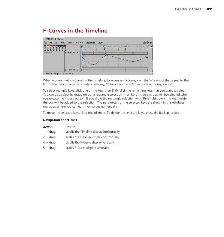
890 • CHAPTER 20 F-CURVE MANAGER • 891
F-Curves in the Timeline
When working with F-Curves in the Timeline, to access an F-Curve, click the ‘+’ symbol that is just to the left of the track’s name. To create a new key, Ctrl-click on the F-Curve. To select a key, click it.
To select multiple keys, click one of the keys then Shift-click the remaining keys that you want to select. You can also select by dragging out a rectangle selection — all keys inside this box will be selected when you release the mouse button. If you draw the rectangle selection with Shift held down, the keys inside the box will be added to the selection. The parameters of the selected keys are shown in the Attribute manager, where you can edit their values numerically.
To move the selected keys, drag one of them. To delete the selected keys, press the Backspace key.
Navigation short-cuts
Action Result1 + drag scrolls the Timeline display horizontally.
2 + drag scales the Timeline display horizontally.
4 + drag scrolls the F-Curve display vertically.
5 + drag scales F-Curve display vertically.
892 • CHAPTER 20 F-CURVE MANAGER • 893
Edit MenuUndo, RedoUndoes the last change you made in the F-Curve manager; select the command multiple times to undo the changes you’ve made one by one. Redo undoes the last undo.
DeleteDeletes the selected keys.
Select All, Deselect All, Invert AllUse these commands to select all keys, deselect all keys and invert the selected keys.
Remove AllHides the selected F-Curves. The curves still exist but are no longer shown.
F-Curve ListOpens the F-Curve List. Since the F-Curve List is integrated into the F-Curve manager by default, you’ll only need to use this command if you have previously undocked the F-Curve List.
Snap To FrameIf you want the keys to snap to frames when moved, enable this option.
Automatic ModeYou can use this option to switch between manual and automatic mode. See ‘Manual mode and automatic mode’ on page 888.

892 • CHAPTER 20 F-CURVE MANAGER • 893
View MenuFrame AllZooms all F-Curves to fit the window.
Frame SelectionZooms the selected keys to fit the window.
Auto RelativeAuto Relative scales each curve to fit the 0-100 range of the F-Curve manager’s Y-axis using a special relative mode. The real values of the keys are not changed. All that you’re doing is moving and scaling the F-Curves closer to each other so that you don’t have to scroll and zoom each time you want to edit a different F-Curve. These relative F-Curves are indicated by an ‘R’ just to the left of the F-Curve. Keep in mind that the real values of these relative F-Curves no longer correspond to the values along the X-axis and Y-axis of the F-Curve manager. To return the relative F-Curves to their normal state so that their values once again correspond to the F-Curve manager’s X-axis and Y-axis, use the Reset Relative command. See also ‘Relative mode’ on page 889 and ‘Reset Relative’, below.
Reset RelativeIf you’ve used the Auto Relative command or the 4+drag and 5+drag short-cuts to create relative F-Curves (indicated by an ‘R’ to the left of each F-Curve), the real values of the F-Curves no longer correspond to the values along the X-axis and Y-axis of the F-Curve manager. Choose Reset Relative to return the relative F-Curves to their normal state so that their values once again correspond to the F-Curve manager’s X-axis and Y-axis. See also ‘Relative mode’ on page 889 and ‘Auto Relative’, above.
CrosshairsSwitches on crosshairs for the selected keys. This makes it easier to read the values of selected keys along the X-axis and Y-axis.
GridSwitches on the F-Curve manager’s grid.
VelocityShows the velocity of all curves in the same color. You cannot edit the velocity of curves directly since it is derived from the F-Curves. To change the velocity, edit the F-Curves.

894 • CHAPTER 20 F-CURVE MANAGER • 895
Curves MenuCustom TangentsLinear Interpolation / Soft Interpolation
Linear Interpolation. Soft interpolation.
F-Curves are Bézier curves. Just like a Bézier spline, you can define hard or soft interpolation between points. Linear Interpolation sets the tangent lengths of the selected keys to 0, while Soft Interpolation creates tangents for the selected keys to ensure smooth curvature.
Unify
Before. After.
Use Unify if you’ve moved a tangent handle independently of its twin and you want to straighten up the tangent pair. The right tangent handle adapts to the position and size of the left handle.
To move a tangent handle independently of its twin, ensure that Link Tangents is disabled (Attribute manager) and Shift-drag the handle that you want to move.
Flat
Horizontally aligns the tangents of the selected keys.
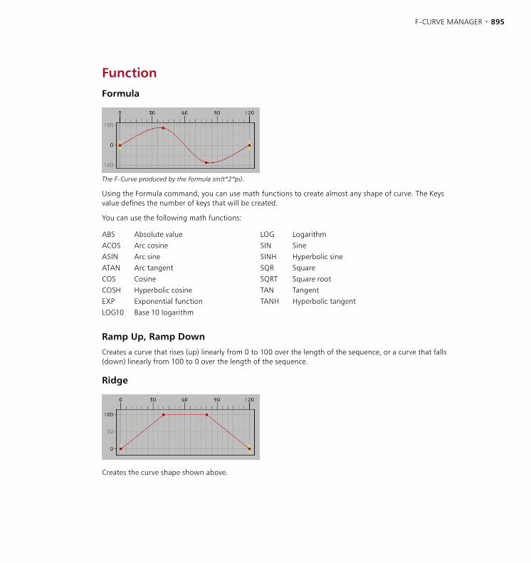
894 • CHAPTER 20 F-CURVE MANAGER • 895
FunctionFormula
The F-Curve produced by the formula sin(t*2*pi).
Using the Formula command, you can use math functions to create almost any shape of curve. The Keys value defines the number of keys that will be created.
You can use the following math functions:
ABS Absolute value LOG LogarithmACOS Arc cosine SIN SineASIN Arc sine SINH Hyperbolic sineATAN Arc tangent SQR SquareCOS Cosine SQRT Square rootCOSH Hyperbolic cosine TAN TangentEXP Exponential function TANH Hyperbolic tangentLOG10 Base 10 logarithm
Ramp Up, Ramp Down
Creates a curve that rises (up) linearly from 0 to 100 over the length of the sequence, or a curve that falls (down) linearly from 100 to 0 over the length of the sequence.
Ridge
Creates the curve shape shown above.
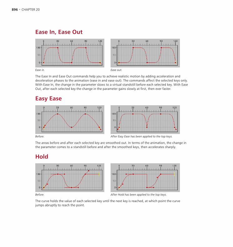
896 • CHAPTER 20 F-CURVE MANAGER • 897
Ease In, Ease Out
Ease in. Ease out.
The Ease In and Ease Out commands help you to achieve realistic motion by adding acceleration and deceleration phases to the animation (ease in and ease out). The commands affect the selected keys only. With Ease In, the change in the parameter slows to a virtual standstill before each selected key. With Ease Out, after each selected key the change in the parameter gains slowly at first, then ever faster.
Easy Ease
Before. After Easy Ease has been applied to the top keys.
The areas before and after each selected key are smoothed out. In terms of the animation, the change in the parameter comes to a standstill before and after the smoothed keys, then accelerates sharply.
Hold
Before. After Hold has been applied to the top keys.
The curve holds the value of each selected key until the next key is reached, at which point the curve jumps abruptly to reach the point.
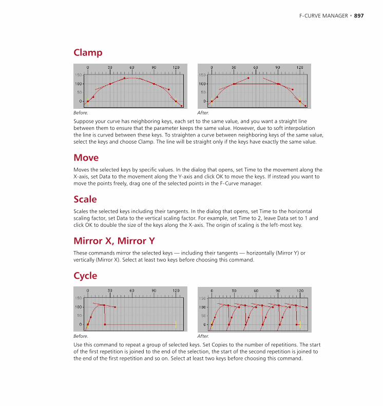
896 • CHAPTER 20 F-CURVE MANAGER • 897
Clamp
Before. After.
Suppose your curve has neighboring keys, each set to the same value, and you want a straight line between them to ensure that the parameter keeps the same value. However, due to soft interpolation the line is curved between these keys. To straighten a curve between neighboring keys of the same value, select the keys and choose Clamp. The line will be straight only if the keys have exactly the same value.
MoveMoves the selected keys by specific values. In the dialog that opens, set Time to the movement along the X-axis, set Data to the movement along the Y-axis and click OK to move the keys. If instead you want to move the points freely, drag one of the selected points in the F-Curve manager.
ScaleScales the selected keys including their tangents. In the dialog that opens, set Time to the horizontal scaling factor, set Data to the vertical scaling factor. For example, set Time to 2, leave Data set to 1 and click OK to double the size of the keys along the X-axis. The origin of scaling is the left-most key.
Mirror X, Mirror YThese commands mirror the selected keys — including their tangents — horizontally (Mirror Y) or vertically (Mirror X). Select at least two keys before choosing this command.
Cycle
Before. After.
Use this command to repeat a group of selected keys. Set Copies to the number of repetitions. The start of the first repetition is joined to the end of the selection, the start of the second repetition is joined to the end of the first repetition and so on. Select at least two keys before choosing this command.

898 • CHAPTER 20
Cycle With Offset
Before. After.
This command is similar to Cycle except that each repetition is offset by the value of the first selected key (called the start key). For example, if the start key has a position of 200, the first key of the repetition will have a position value of 400, the first key of the next cycle will have a position value of 600 and so on. Select at least two keys before choosing this command.
Bake CurveThis command lets you add keys to the curve without changing its shape. This is especially useful if you’ve created the general shape of the curve and you want to add fine details. In the dialog that opens, Frequency defines the number of frames between each key. For example, to create a key once every five frames, set Frequency to 5 and click OK. A Frequency of 1 generates the most keys — one key per frame.
Simplify Curve Proceed with caution when using the Simplify Curve command, to avoid ruining the curve. Approach
your optimal curve slowly and reject over-simplified results with the Undo command.
This command essentially does the reverse of Bake Curve. Use Simplify Curve to reduce your curve’s number of keys. This is especially useful when you’re working with motion capture data that has hundreds or even thousands of keys and you want to reduce the number of keys to make the curve easier to edit. The command opens the Simplify Curve dialog. The X and Y tolerance values define the gap between each key along the horizontal and vertical axes. For example:
- To reduce the curve to a key once every ten frames, set X to 10 and click OK.
- To reduce the keys to one key per 50 units along the Y-axis, set Y to 50 and click OK.
- To do both of the above at the same time, set X to 10, set Y to 50 and click OK.

21 Attribute Manager

ATTRIBUTE MANAGER • 901
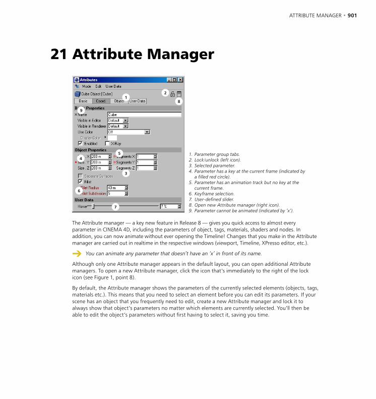
ATTRIBUTE MANAGER • 901
12
8
9
54
3
6
7
1. Parameter group tabs.2. Lock/unlock (left icon).3. Selected parameter.4. Parameter has a key at the current frame (indicated by
a filled red circle).5. Parameter has an animation track but no key at the
current frame.6. Keyframe selection.7. User-defined slider.8. Open new Attribute manager (right icon).9. Parameter cannot be animated (indicated by ‘x’).
The Attribute manager — a key new feature in Release 8 — gives you quick access to almost every parameter in CINEMA 4D, including the parameters of object, tags, materials, shaders and nodes. In addition, you can now animate without ever opening the Timeline! Changes that you make in the Attribute manager are carried out in realtime in the respective windows (viewport, Timeline, XPresso editor, etc.).
You can animate any parameter that doesn’t have an ‘x’ in front of its name.
Although only one Attribute manager appears in the default layout, you can open additional Attribute managers. To open a new Attribute manager, click the icon that’s immediately to the right of the lock icon (see Figure 1, point 8).
By default, the Attribute manager shows the parameters of the currently selected elements (objects, tags, materials etc.). This means that you need to select an element before you can edit its parameters. If your scene has an object that you frequently need to edit, create a new Attribute manager and lock it to always show that object’s parameters no matter which elements are currently selected. You’ll then be able to edit the object’s parameters without first having to select it, saving you time.
21 Attribute Manager
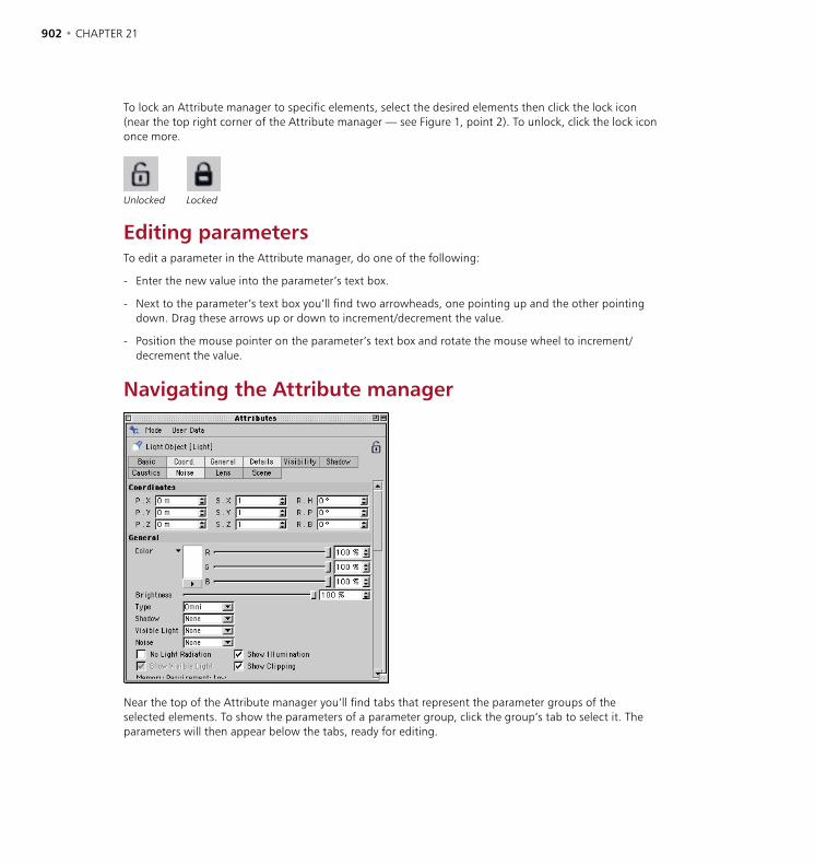
902 • CHAPTER 21 ATTRIBUTE MANAGER • 903
To lock an Attribute manager to specific elements, select the desired elements then click the lock icon (near the top right corner of the Attribute manager — see Figure 1, point 2). To unlock, click the lock icon once more.
Unlocked Locked
Editing parametersTo edit a parameter in the Attribute manager, do one of the following:
- Enter the new value into the parameter’s text box.
- Next to the parameter’s text box you’ll find two arrowheads, one pointing up and the other pointing down. Drag these arrows up or down to increment/decrement the value.
- Position the mouse pointer on the parameter’s text box and rotate the mouse wheel to increment/decrement the value.
Navigating the Attribute manager
Near the top of the Attribute manager you’ll find tabs that represent the parameter groups of the selected elements. To show the parameters of a parameter group, click the group’s tab to select it. The parameters will then appear below the tabs, ready for editing.
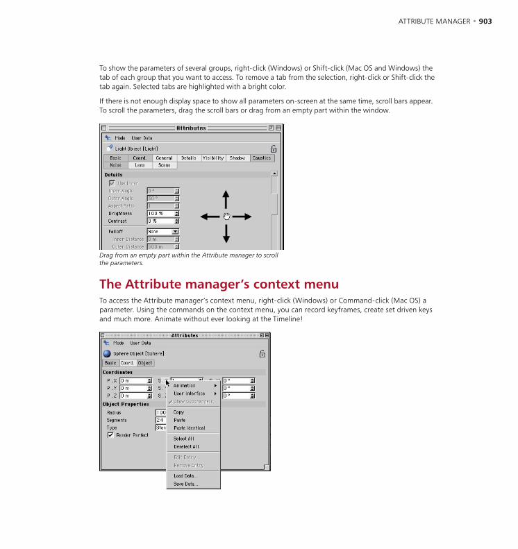
902 • CHAPTER 21 ATTRIBUTE MANAGER • 903
To show the parameters of several groups, right-click (Windows) or Shift-click (Mac OS and Windows) the tab of each group that you want to access. To remove a tab from the selection, right-click or Shift-click the tab again. Selected tabs are highlighted with a bright color.
If there is not enough display space to show all parameters on-screen at the same time, scroll bars appear. To scroll the parameters, drag the scroll bars or drag from an empty part within the window.
Drag from an empty part within the Attribute manager to scroll the parameters.
The Attribute manager’s context menuTo access the Attribute manager’s context menu, right-click (Windows) or Command-click (Mac OS) a parameter. Using the commands on the context menu, you can record keyframes, create set driven keys and much more. Animate without ever looking at the Timeline!
904 • CHAPTER 21 ATTRIBUTE MANAGER • 905
Animation
Add Keyframe
Records keyframes for the selected parameters at the current frame (as indicated by the Timeslider).
Next Keyframe, Previous Keyframe
Moves the Timeslider to the next/previous keyframe (if present) for the selected parameters.
Delete Keyframe
Deletes all of the selected parameters’ keyframes at the current frame.
Each parameter with a filled red circle next to its name has a keyframe at the current frame.
Add Track
Creates tracks for the selected parameters.
Copy Track, Paste Track
Use these commands to copy tracks between parameters. First select the parameters whose tracks you want to copy. Choose Copy Track. Now select the parameters that should receive the tracks and choose Paste Track.
Delete Track
Deletes all tracks of the selected parameters.
Show Track
Shows all animation tracks of the selected parameters in the Timeline.
Show F-Curve
Shows all f-curves of the selected parameters in the F-Curve manager.
Set Driver, Set Driven
Using these commands you can create set driven keys directly in the Attribute manager without having to open the XPresso editor. A set driven key uses one parameter to drive (i.e. control) another parameter. For example, you might use a set driven key to make a car’s electic windows wind down when a character presses the switches. Almost any type of set-driven relationship is possible, making it easier to manage complex motions or objects.

904 • CHAPTER 21 ATTRIBUTE MANAGER • 905
Example
- In the Object manager, create a sphere and a cube. We’ll use the sphere’s height to drive (i.e. control) the cube’s height. So that you can see the sphere clearly, move the cube along its X-axis until it’s side by side with the sphere.
- In the Object manager, click the sphere’s name to select it and load its settings into the Attribute manager.
- In the Attribute manager, right-click (Windows) or Command-click (Mac OS) the P.Y box to access its context menu. From this menu, choose Animation > Set Driver. (The P.Y box controls the sphere’s height, i.e. its Y position.)
- In the Object manager, click the cube’s name to select it and load its settings into the Attribute manager.
- In the Attribute manager, right-click (Windows) or Command-click (Mac OS) the P.Y box to access its context menu. From this menu, choose Animation > Set Driven (Absolute).
- Move the sphere in the viewport.
The cube automatically moves to the height of the sphere. If you open the XPresso editor by double-clicking the cube’s XPresso Expression tag, you’ll see that three nodes have been created: Sphere, Range Mapper and Cube. The Sphere node passes the sphere’s Y position to the Range Mapper which, in this case, simply passes the value straight on to the cube’s Y position. As a result, the cube continually adopts the sphere’s height.
For this simple example, the Range Mapper has no significance. However, the Range Mapper is useful in cases where the relationship between the driver and driven parameter is not 1:1. For example, using a Range Mapper you can remap brightness values within the range 0-100% to position Y values within the range 0-10,000m. When the light’s Brigthness is 80%, the Y position of the driven object will be 8,000m (80% of 10,000m). For more details on the Range Mapper node, see ‘Range Mapper’ on page 950.
Set driven keys also enable you to drive object parameters using your own sliders. To learn how to create your own sliders, see ‘User Data’ on page 909.
Set Driven (Absolute), Set Driven (Relative)
With Absolute, the driven parameter uses exactly the same value as the driver. For example, if one object drives the height of another, the driven object will move to exactly the same height as the driver.
Relative, on the other hand, only passes on relative changes from the driver to the driven parameter. For example, if the driver object is moved up 10 units in relative mode, the driven object also moves up 10 units from wherever it happens to be in the scene. Suppose the driver object has an initial height of Y=1000 and the driven object an initial height of Y=0. If you move the driver object to a height of 1,050 (a change of 50 units), the driven object also moves up 50 units, to Y=50.
Add Keyframe Selection
To create a keyframe selection, select several parameters then choose Add Keyframe Selection. The selected parameter names are shown in red to indicate that they belong to the keyframe selection. When you use CINEMA 4D’s autokeying mode, all parameters in the keyframe selection are recorded (provided that their values actually change).

906 • CHAPTER 21 ATTRIBUTE MANAGER • 907
Remove Keyframe Selection
Removes the selected parameters from the keyframe selection.
Clear Keyframe Selection
Deletes all keyframe selections for the selected objects.
User InterfaceThis sub-menu appears when only one parameter is selected. Depending on the type of parameter, you are able to change its interface. For an existing parameter, you mostly have a choice between a numeric text box (Float), a slider (Float Slider — No Edit Field) or both (Float Slider).
Normal text box for Subdivision Renderer. Text box and slider for Subdivision Renderer (User Interface > Float Slider chosen).
To control the minimum and maximum values of sliders, choose the Edit Entry command and in the dialog that appears, set Min and Max to the desired values.
Show Subchannels
Some elements such as color fields can also be displayed numerically.
Show Subchannels disabled. Show Subchannels enabled.
Copy, PasteUse these commands to copy values between parameters. First select the parameters whose values you want to copy. Choose Copy. Now select the parameters that should receive the copied values and choose Paste.
Paste IdenticalSuppose there are two cylinders in your scene. You select one of the cylinders, select its Radius and Height parameters in the Attribute manager and choose Copy to copy these two values. If you then select the other cylinder and choose Paste Identical, the two values will be pasted to the same parameters — Height and Radius — regardless of which parameters are currently selected. This is in contrast to the Paste command which pastes to the selected parameters.
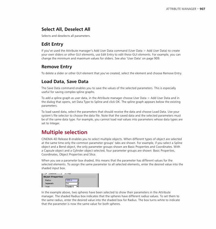
906 • CHAPTER 21 ATTRIBUTE MANAGER • 907
Select All, Deselect AllSelects and deselects all parameters.
Edit EntryIf you’ve used the Attribute manager’s Add User Data command (User Data > Add User Data) to create your own sliders or other GUI elements, use Edit Entry to edit these GUI elements. For example, you can change the minimum and maximum values for sliders. See also ‘User Data’ on page 909.
Remove EntryTo delete a slider or other GUI element that you’ve created, select the element and choose Remove Entry.
Load Data, Save DataThe Save Data command enables you to save the values of the selected parameters. This is especially useful for saving complex spline graphs.
To add a spline graph as user data, in the Attribute manager choose User Data > Add User Data and in the dialog that opens, set Data Type to Spline and click OK. The spline graph appears below the existing parameters.
To load saved data, select the parameters that should receive the data and choose Load Data. Use your system’s file selector to choose the data file. Note that the saved data and the selected parameters must be of the same data type. For example, you cannot load real values into parameters whose data types are set to Integer.
Multiple selectionCINEMA 4D Release 8 enables you to select multiple objects. When different types of object are selected at the same time only the common parameter groups’ tabs are shown. For example, if you select a Spline object and a Bend object, the only parameter groups shown are Basic Properties and Coordinates. With a Capsule object and a Cylinder object selected, four parameter groups are shown: Basic Properties, Coordinates, Object Properties and Slice.
When you see a parameter box shaded, this means that the parameter has different values for the selected elements. To assign the same parameter to all selected elements, enter the desired value into the shaded input box.
In the example above, two spheres have been selected to show their parameters in the Attribute manager. The shaded Radius box indicates that the spheres have different radius values. To set them to the same radius, enter the desired value into the shaded box for Radius. The box turns white to indicate that the parameter is now the same value for both spheres.
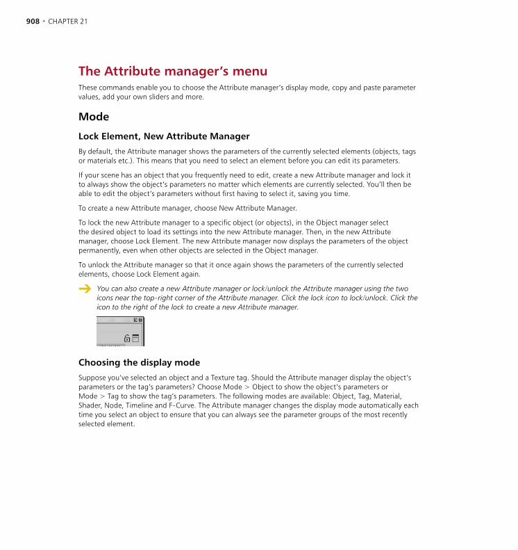
908 • CHAPTER 21 ATTRIBUTE MANAGER • 909
The Attribute manager’s menuThese commands enable you to choose the Attribute manager’s display mode, copy and paste parameter values, add your own sliders and more.
Mode
Lock Element, New Attribute Manager
By default, the Attribute manager shows the parameters of the currently selected elements (objects, tags or materials etc.). This means that you need to select an element before you can edit its parameters.
If your scene has an object that you frequently need to edit, create a new Attribute manager and lock it to always show the object’s parameters no matter which elements are currently selected. You’ll then be able to edit the object’s parameters without first having to select it, saving you time.
To create a new Attribute manager, choose New Attribute Manager.
To lock the new Attribute manager to a specific object (or objects), in the Object manager select the desired object to load its settings into the new Attribute manager. Then, in the new Attribute manager, choose Lock Element. The new Attribute manager now displays the parameters of the object permanently, even when other objects are selected in the Object manager.
To unlock the Attribute manager so that it once again shows the parameters of the currently selected elements, choose Lock Element again.
You can also create a new Attribute manager or lock/unlock the Attribute manager using the two icons near the top-right corner of the Attribute manager. Click the lock icon to lock/unlock. Click the icon to the right of the lock to create a new Attribute manager.
Choosing the display mode
Suppose you’ve selected an object and a Texture tag. Should the Attribute manager display the object’s parameters or the tag’s parameters? Choose Mode > Object to show the object’s parameters or Mode > Tag to show the tag’s parameters. The following modes are available: Object, Tag, Material, Shader, Node, Timeline and F-Curve. The Attribute manager changes the display mode automatically each time you select an object to ensure that you can always see the parameter groups of the most recently selected element.
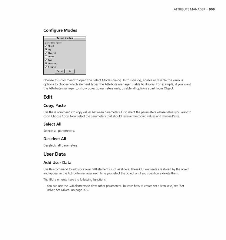
908 • CHAPTER 21 ATTRIBUTE MANAGER • 909
Configure Modes
Choose this command to open the Select Modes dialog. In this dialog, enable or disable the various options to choose which element types the Attribute manager is able to display. For example, if you want the Attribute manager to show object parameters only, disable all options apart from Object.
Edit
Copy, Paste
Use these commands to copy values between parameters. First select the parameters whose values you want to copy. Choose Copy. Now select the parameters that should receive the copied values and choose Paste.
Select All
Selects all parameters.
Deselect All
Deselects all parameters.
User Data
Add User Data
Use this command to add your own GUI elements such as sliders. These GUI elements are stored by the object and appear in the Attribute manager each time you select the object until you specifically delete them.
The GUI elements have the following functions:
- You can use the GUI elements to drive other parameters. To learn how to create set driven keys, see ‘Set Driver, Set Driven’ on page 909.

910 • CHAPTER 21 ATTRIBUTE MANAGER • 911
- You can add user data ports to the object’s node (in the XPresso Editor, via the node’s inputs and outputs menus). This enables you to pass the user data from node to node.
Name
Enter a name for the GUI element. This name will be used in the XPresso editor for the user data’s ports. To add a port for the user data, in the XPresso editor click the object node’s Inputs or Outputs menu. From the User Data submenu, choose the user data’s name.
Data Type
Choose the parameter’s data type from the drop-down list. For example, if you want the parameter to define a color, set Data Type to Color. For details on each data type, see ‘Choosing the data type’ on page 920.
Interface
If you’ve set Data Type to String, Integer or Float, use Interface to choose the parameter’s interface. For example, if Data Type is set to String, you can choose whether the parameter’s text box should have a single line or multiple lines. The options available depend on the Data Type setting.
String
Interface set to String (upper parameter) and Multi Line String (lower parameter).

910 • CHAPTER 21 ATTRIBUTE MANAGER • 911
Integer
Interface set to Integer (upper parameter) and Integer Slider (lower parameter)
Float
From top to bottom: Interface set to Float, Float Slider and Float (No Edit Field)
Unit
Choose the parameter’s units: Real, Percent, Degree or Meter.
Although nodes work in radians instead of degrees (360˚ = 2*pi radians), by setting Unit to Degree you are able to enter values in degrees. The values you enter are converted to radians automatically before being passed on to the nodes. For example, a value of 180˚ will be converted to 3.141952 radians (pi).
Percentage values are converted from within the range 0%-100% to within the range 0-1.
Min, Max
Define the minimum and maximum values for the GUI element, such as 0˚ and 360 .̊
Step
Defines the amount by which the parameter is incremented/decremented when you click its arrowheads. Also defines the snapping distance for the slider, i.e. the minimum change possible by dragging the slider.


22 XPresso Editor

XPRESSO EDITOR • 915

XPRESSO EDITOR • 915
In earlier releases of CINEMA 4D, to create extra interactions between objects required you to manually program C.O.F.F.E.E. expressions; and you can still do this if you like. However, with CINEMA 4D’s new node editor, XPresso, you can set up complex, automated object interactions simply by drawing lines between different objects. From muscles that bulge automatically to eyes that blink at random, from clock mechanisms to light switches that really work when your characters press them, XPresso enables you to automate your animations with ease. The XPresso Editor is the place where you build these behaviors, which are called expressions.
To create a new expression and open the XPresso Editor, in the Object manager, select any object and choose File > New Expression > XPresso Expression. You can close the editor at any time and reopen it by double-clicking the XPresso Expression tag.
Nodes are the building blocks of your XPresso expressions. Nodes can perform a wide variety of tasks, from reporting the animation’s current frame number to setting an object to a particular position. To build your expression, you create the necessary nodes and connect them to one another by drawing lines, called ‘wires’, between the node input and output ports. The nodes are then able to pass values to one another via these ports and wires.
The illustration above shows two nodes, one for a Cube object and one for a Cylinder object. The red and blue circles, both labelled Rotation, are ports. Red ports are output ports and send values to XGroups or other nodes. Blue ports are input ports and receive values from other nodes or XGroups. In this example, the cube’s rotation value is being sent to the cylinder. This will cause the cylinder to point in the same direction as the cube in the viewport.
To learn XPresso as quickly as possible, we recommend that you work through the tutorials in the CINEMA 4D Tutorial manual and, if something isn’t clear, look it up in this reference for a full description. In addition, you’ll also find a variety of example expressions on your CINEMA 4D CD, each documented with comments. Much can be learnt from these examples by reading the comments then trying out your own changes.
22 XPresso Editor

916 • CHAPTER 22 XPRESSO EDITOR • 917
XGroupsXGroups are containers for nodes, other XGroups and their wires. Like real containers, XGroups help you to put related items ‘in the same box’ for better organization. You’ll then find it easier to understand, navigate and modify the expression. In addition to acting as a container, an XGroup can be connected to nodes and other XGroups. You can save and load XGroups to reuse them in other projects.
Use XGroups to organize nodes into groups.
You can navigate the contents of an XGroup in a similar way to the CINEMA 4D viewport. To move or zoom the contents, drag the move or zoom icon in the top right corner of the XGroup. You can also move the contents by pressing the cursor keys. To add ports to the XGroup, choose the desired ports from the XGroup’s inputs menu (blue square) and outputs menu (red square). (See also ‘Ports’ on page 917.)
To minimize an XGroup to its title bar, double-click the title bar. To restore an XGroup window to full size, double-click the title bar again. To move an XGroup, drag its title bar or Shift-drag the window. To re-size an XGroup, drag a side or corner.
When creating your own expressions, you’ll often need to select an XGroup to, among other things, load its settings into the Attribute manager so that you can edit them. To select an XGroup, click the XGroup’s title bar. To select multiple XGroups, drag a marquee over them, or select one of the XGroups then Shift-click the other XGroups that you want to select; selected XGroups have red borders.
Inputs First
On the Attribute manager’s Node Properties page, you’ll find an option called Inputs First. If this option is enabled, nodes that are outside the selected XGroup are evaluated first. This is especially important when the XGroup receives values from the nodes, to ensure that the XGroup receives up-to-date values.
Nodes CINEMA 4D’s nodes work in radians. In other words, nodes use angular values from 0 to 2*Pi rather
than degrees from 0 to 360˚. If you want to work in degrees, use the Degree node to convert from radians to degrees, and vice versa.
Nodes are the primary building blocks of expressions and are designed to carry out the most diverse of tasks, from reporting an object’s current position to processing math operations. Depending on the node’s type, you can add various inputs and outputs to the node called ports. As with XGroups, you add these ports using the inputs menu and outputs menu (the blue and red squares in the node’s title bar).
Four nodes. The Result node shows the value 1 if the cone and cube are the same height.
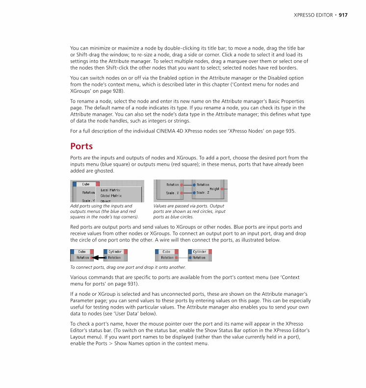
916 • CHAPTER 22 XPRESSO EDITOR • 917
You can minimize or maximize a node by double-clicking its title bar; to move a node, drag the title bar or Shift-drag the window; to re-size a node, drag a side or corner. Click a node to select it and load its settings into the Attribute manager. To select multiple nodes, drag a marquee over them or select one of the nodes then Shift-click the other nodes that you want to select; selected nodes have red borders.
You can switch nodes on or off via the Enabled option in the Attribute manager or the Disabled option from the node’s context menu, which is described later in this chapter (‘Context menu for nodes and XGroups’ on page 928).
To rename a node, select the node and enter its new name on the Attribute manager’s Basic Properties page. The default name of a node indicates its type. If you rename a node, you can check its type in the Attribute manager. You can also set the node’s data type in the Attribute manager; this defines what type of data the node handles, such as integers or strings.
For a full description of the individual CINEMA 4D XPresso nodes see ‘XPresso Nodes’ on page 935.
PortsPorts are the inputs and outputs of nodes and XGroups. To add a port, choose the desired port from the inputs menu (blue square) or outputs menu (red square); in these menus, ports that have already been added are ghosted.
Add ports using the inputs and outputs menus (the blue and red squares in the node’s top corners).
Values are passed via ports. Output ports are shown as red circles, input ports as blue circles.
Red ports are output ports and send values to XGroups or other nodes. Blue ports are input ports and receive values from other nodes or XGroups. To connect an output port to an input port, drag and drop the circle of one port onto the other. A wire will then connect the ports, as illustrated below.
To connect ports, drag one port and drop it onto another.
Various commands that are specific to ports are available from the port’s context menu (see ‘Context menu for ports’ on page 931).
If a node or XGroup is selected and has unconnected ports, these are shown on the Attribute manager’s Parameter page; you can send values to these ports by entering values on this page. This can be especially useful for testing nodes with particular values. The Attribute manager also enables you to send your own data to nodes (see ‘User Data’ below).
To check a port’s name, hover the mouse pointer over the port and its name will appear in the XPresso Editor’s status bar. (To switch on the status bar, enable the Show Status Bar option in the XPresso Editor’s Layout menu). If you want port names to be displayed (rather than the value currently held in a port), enable the Ports > Show Names option in the context menu.
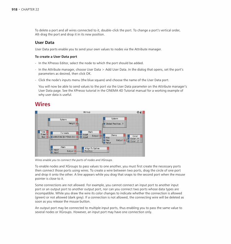
918 • CHAPTER 22 XPRESSO EDITOR • 919
To delete a port and all wires connected to it, double-click the port. To change a port’s vertical order, Alt-drag the port and drop it in its new position.
User Data
User Data ports enable you to send your own values to nodes via the Attribute manager.
To create a User Data port
- In the XPresso Editor, select the node to which the port should be added.
- In the Attribute manager, choose User Data > Add User Data. In the dialog that opens, set the port’s parameters as desired, then click OK.
- Click the node’s inputs menu (the blue square) and choose the name of the User Data port.
You will now be able to send values to the port via the User Data parameter on the Attribute manager’s User Data page. See the XPresso tutorial in the CINEMA 4D Tutorial manual for a working example of why user data is useful.
Wires
Wires enable you to connect the ports of nodes and XGroups.
To enable nodes and XGroups to pass values to one another, you must first create the necessary ports then connect those ports using wires. To create a wire between two ports, drag the circle of one port and drop it onto the other. A line appears while you drag that snaps to the second port when the mouse pointer is close to it.
Some connections are not allowed. For example, you cannot connect an input port to another input port or an output port to another output port, nor can you connect two ports whose data types are incompatible. While you draw the wire its color changes to indicate whether the connection is allowed (green) or not allowed (dark grey). If a connection is not allowed, the connecting wire will be deleted as soon as you release the mouse button.
An output port may be connected to multiple input ports, thus enabling you to pass the same value to several nodes or XGroups. However, an input port may have one connection only.
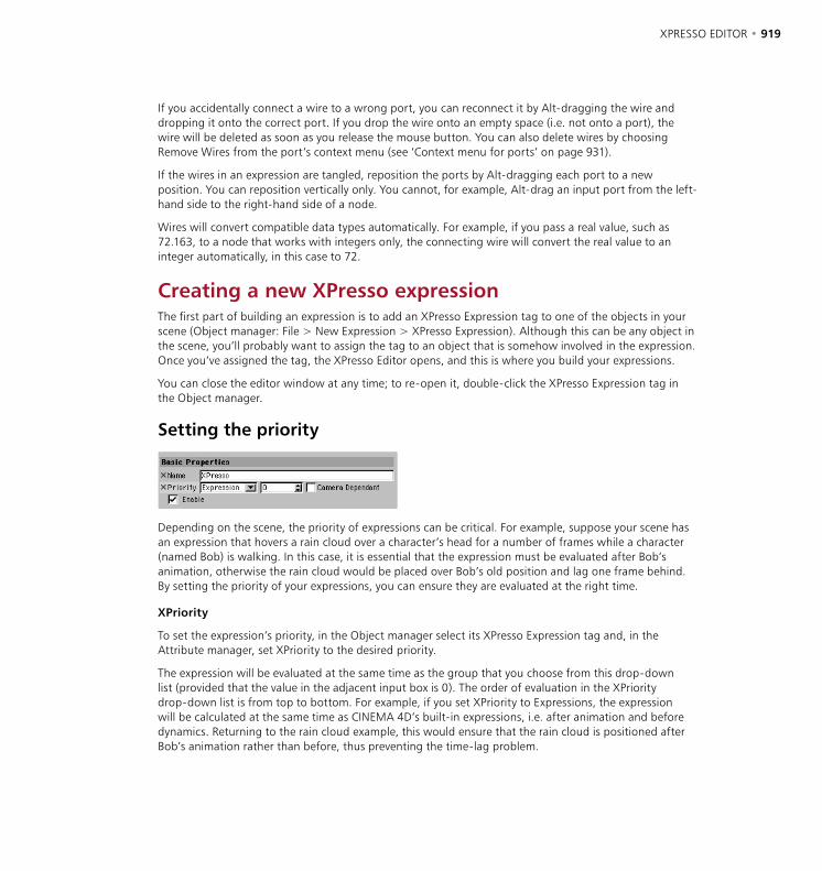
918 • CHAPTER 22 XPRESSO EDITOR • 919
If you accidentally connect a wire to a wrong port, you can reconnect it by Alt-dragging the wire and dropping it onto the correct port. If you drop the wire onto an empty space (i.e. not onto a port), the wire will be deleted as soon as you release the mouse button. You can also delete wires by choosing Remove Wires from the port’s context menu (see ‘Context menu for ports’ on page 931).
If the wires in an expression are tangled, reposition the ports by Alt-dragging each port to a new position. You can reposition vertically only. You cannot, for example, Alt-drag an input port from the left-hand side to the right-hand side of a node.
Wires will convert compatible data types automatically. For example, if you pass a real value, such as 72.163, to a node that works with integers only, the connecting wire will convert the real value to an integer automatically, in this case to 72.
Creating a new XPresso expressionThe first part of building an expression is to add an XPresso Expression tag to one of the objects in your scene (Object manager: File > New Expression > XPresso Expression). Although this can be any object in the scene, you’ll probably want to assign the tag to an object that is somehow involved in the expression. Once you’ve assigned the tag, the XPresso Editor opens, and this is where you build your expressions.
You can close the editor window at any time; to re-open it, double-click the XPresso Expression tag in the Object manager.
Setting the priority
Depending on the scene, the priority of expressions can be critical. For example, suppose your scene has an expression that hovers a rain cloud over a character’s head for a number of frames while a character (named Bob) is walking. In this case, it is essential that the expression must be evaluated after Bob’s animation, otherwise the rain cloud would be placed over Bob’s old position and lag one frame behind. By setting the priority of your expressions, you can ensure they are evaluated at the right time.
XPriority
To set the expression’s priority, in the Object manager select its XPresso Expression tag and, in the Attribute manager, set XPriority to the desired priority.
The expression will be evaluated at the same time as the group that you choose from this drop-down list (provided that the value in the adjacent input box is 0). The order of evaluation in the XPriority drop-down list is from top to bottom. For example, if you set XPriority to Expressions, the expression will be calculated at the same time as CINEMA 4D’s built-in expressions, i.e. after animation and before dynamics. Returning to the rain cloud example, this would ensure that the rain cloud is positioned after Bob’s animation rather than before, thus preventing the time-lag problem.
920 • CHAPTER 22 XPRESSO EDITOR • 921
Now suppose you create a new scene, this time of a mother hen walking and her two chicks following. You create two expressions: Follow Mum (to make the first chick follow the hen) and Follow Chick One (to make the second chick follow the first chick). So that the second chick follows the first chick’s current position, Follow Mum must be evaluated before Follow Chick One. Otherwise, the second chick would follow the first chick’s position from the previous frame, causing the time-lag problem.
In these cases use the input box to control the order in which expressions of the same XPriority are evaluated. Enter a number from -500 to 500 for each expression. The expressions will be evaluated in numerical order, lowest number first.
Recall that, provided the value in the input box is 0, the expression will be evaluated at the same time as the group that you choose from the XPriority drop-down list. If you enter a value less than 0, the expression will be evaluated before the group. A value greater than 0 will see the expression evaluated after the group.
Camera Dependent
This option determines whether the expression is calculated and its result displayed while the camera is being rotated or moved. By disabling this option you can dramatically speed up the redraw rate in the viewport for some expressions, such as the Target expression.
Choosing the data typeEach node and XGroup has a data type that defines the type of value it uses, such as Integer, Vector or Color. If you connect two nodes that use different data types, the wire between the nodes converts the data type automatically if the types are compatible. For example, if a Constant node passes a Real value of 3.45 to a Result node whose data type is set to Integer, the value will be converted to an integer automatically — in this case to 3.
Although some nodes have a fixed data type that cannot be changed, you can change the data type of most nodes in the Attribute manager.
Bool
The Bool data type has two possible states: True and False. These states are represented by the numeric values 1 (True) and 0 (False). Although you can use Bool values in math calculations, keep in mind that the Bool data type is able to hold a value of 0 or 1 only. When you want to combine several Bool values, use Logic nodes.
Color
This data type consists of the color components red, green and blue. The RGB values can also be interpreted as a vector — so the color R:10, G:75, B:0 would equate to the vector (10;75;0). This enables you, for example, to use a color to control an object’s position or rotation vector.
Date/Time
In contrast to the Time data type (see ‘Time’ on page 923), Date/Time queries your computer’s current system time (in the format hours:minutes:seconds) and system date. For example, you might create a Sun expression that changes a light’s position and color according to the current time.

920 • CHAPTER 22 XPRESSO EDITOR • 921
Font
The Font data type stores information for a chosen font, including whether it should be used as a TrueType or PostScript font. For example, you can use the Font data type to vary the appearance of a text spline. The Font data type cannot be converted to other types.
Gradient
The gradient data type consists of a large number of values that represent a gradient. It cannot be converted to other data types. (Although individual colors can be converted to vectors, there is no way to specify the color’s position in the gradient in order to access it.) See also ‘Using gradients’ on page 923.
Integer
The Integer data type supports whole numbers (not fractional numbers) that can be negative, zero or positive. Numbers after a decimal point will be ignored; this can lead to inaccurate results if fractions are involved. You can use the Integer data type with all numeric and vector formats.
When converting a vector to an integer or a real, the length of the vector is calculated automatically from the calculation SQRT(V.x*V.x+V.y*V.y+V.z*V.z), where V.x, V.y and V.z are the X, Y and Z components of the vector and SQRT is the square root function. On the other hand, when an integer or a real is converted to a vector, the value is used for the vector’s X, Y and Z components. For example, the real 12.5 is converted to the vector (12.5;12.5;12.5).
Lens Glow
The Lens Glow data type is a container for a complete set of data — in this case all the information needed to control the lens glow of light sources. This data type cannot be converted to other types.
Link
The Link data type contains information on the various elements in a CINEMA 4D scene, including information on tags and materials as well as objects. The Link type cannot be converted to other data types. The purpose of the Link data type is to allow you to select a scene element (such as an object, material or tag) for closer examination. For example, you can use the Link data type to add a user data box in the Attribute manager. You can then assign materials, tags and objects by dragging and dropping them into the box. See also ‘Object’ below.
Matrix
A matrix is a group of vectors, such as an object’s global matrix, which contains the object’s position vector and three vectors for each of the object’s axes. The axis vectors represent not only the direction of the object but its scale also (the scale is defined by the length of each axis vector). Therefore the global matrix gives you access to the object’s position, scale and rotation.
The four vectors are stored in the following registers of the global matrix: V0 for the position vector (called the Offset vector); V1 (X-axis); V2 (Y-axis) and V3 (Z-axis). Using these registers you can read or replace any vector, such as V2 for the object’s Y-axis.
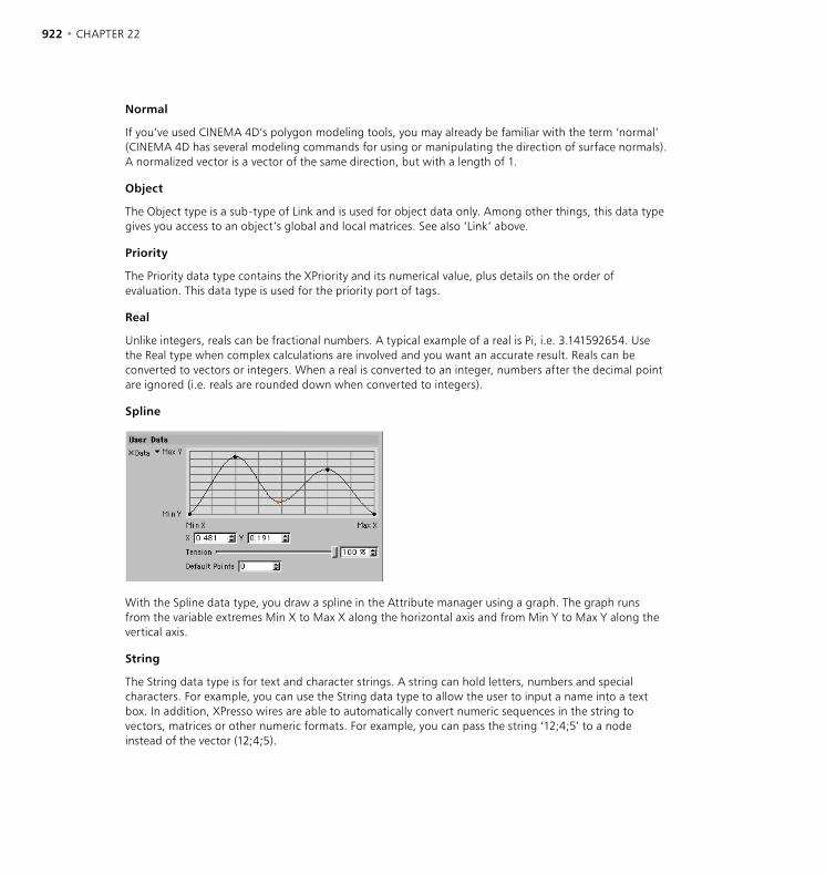
922 • CHAPTER 22 XPRESSO EDITOR • 923
Normal
If you’ve used CINEMA 4D’s polygon modeling tools, you may already be familiar with the term ‘normal’ (CINEMA 4D has several modeling commands for using or manipulating the direction of surface normals). A normalized vector is a vector of the same direction, but with a length of 1.
Object
The Object type is a sub-type of Link and is used for object data only. Among other things, this data type gives you access to an object’s global and local matrices. See also ‘Link’ above.
Priority
The Priority data type contains the XPriority and its numerical value, plus details on the order of evaluation. This data type is used for the priority port of tags.
Real
Unlike integers, reals can be fractional numbers. A typical example of a real is Pi, i.e. 3.141592654. Use the Real type when complex calculations are involved and you want an accurate result. Reals can be converted to vectors or integers. When a real is converted to an integer, numbers after the decimal point are ignored (i.e. reals are rounded down when converted to integers).
Spline
With the Spline data type, you draw a spline in the Attribute manager using a graph. The graph runs from the variable extremes Min X to Max X along the horizontal axis and from Min Y to Max Y along the vertical axis.
String
The String data type is for text and character strings. A string can hold letters, numbers and special characters. For example, you can use the String data type to allow the user to input a name into a text box. In addition, XPresso wires are able to automatically convert numeric sequences in the string to vectors, matrices or other numeric formats. For example, you can pass the string ‘12;4;5’ to a node instead of the vector (12;4;5).
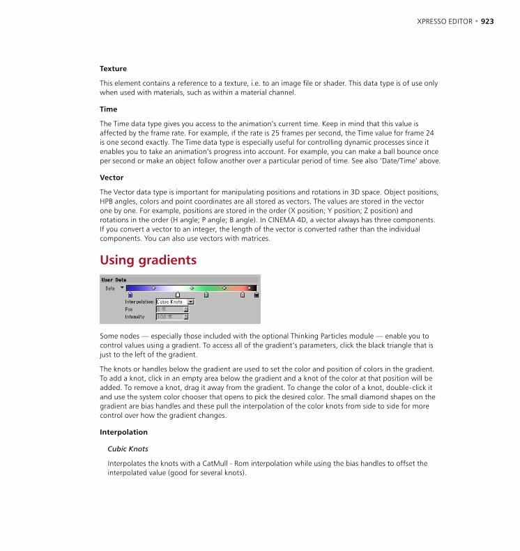
922 • CHAPTER 22 XPRESSO EDITOR • 923
Texture
This element contains a reference to a texture, i.e. to an image file or shader. This data type is of use only when used with materials, such as within a material channel.
Time
The Time data type gives you access to the animation’s current time. Keep in mind that this value is affected by the frame rate. For example, if the rate is 25 frames per second, the Time value for frame 24 is one second exactly. The Time data type is especially useful for controlling dynamic processes since it enables you to take an animation’s progress into account. For example, you can make a ball bounce once per second or make an object follow another over a particular period of time. See also ‘Date/Time’ above.
Vector
The Vector data type is important for manipulating positions and rotations in 3D space. Object positions, HPB angles, colors and point coordinates are all stored as vectors. The values are stored in the vector one by one. For example, positions are stored in the order (X position; Y position; Z position) and rotations in the order (H angle; P angle; B angle). In CINEMA 4D, a vector always has three components. If you convert a vector to an integer, the length of the vector is converted rather than the individual components. You can also use vectors with matrices.
Using gradients
Some nodes — especially those included with the optional Thinking Particles module — enable you to control values using a gradient. To access all of the gradient’s parameters, click the black triangle that is just to the left of the gradient.
The knots or handles below the gradient are used to set the color and position of colors in the gradient. To add a knot, click in an empty area below the gradient and a knot of the color at that position will be added. To remove a knot, drag it away from the gradient. To change the color of a knot, double-click it and use the system color chooser that opens to pick the desired color. The small diamond shapes on the gradient are bias handles and these pull the interpolation of the color knots from side to side for more control over how the gradient changes.
Interpolation
Cubic Knots
Interpolates the knots with a CatMull - Rom interpolation while using the bias handles to offset the interpolated value (good for several knots).

924 • CHAPTER 22 XPRESSO EDITOR • 925
Cubic Bias
Uses a Bézier interpolation algorithm to interpolate between the knot previous to the sample point, a weighted bias to the left, a weighted bias to the right, and the knot to the right of the sample position (good for few knots and accurate control).
Smooth Knot
Uses a SmoothStep function to weight an interpolation between the knot to the left of the sample point and the knot to the right of the sample point. It uses the bias handles to offset the interpolated value.
Linear Knot
Uses a BoxStep function to weight an interpolation between the knot to the left of the sample point and the knot to the right of the sample point. It uses the bias handles to offset the interpolated value.
Linear
Linear falloff/growth between the knots. No bias handles.
None
Uses the color of the knot to the left of the sample point.
Pos
The position of the currently selected knot or bias handle on the gradient. You can type a value into the box or drag the up/down arrows at the right to move the currently selected knot or bias handle.
Intensity
A measurement for the intensity of the currently selected knot.
Context menu for gradientsTo access the context menu for gradients, right-click (Windows) or Command-click (Mac OS) on the gradient. Three commands are available from this menu. Invert Knots reverses the direction of the gradient. Double Knots doubles the number of knots. Reset sets the gradient to a uniform white color with no knots.

924 • CHAPTER 22 XPRESSO EDITOR • 925
XPresso Editor MenusFile MenuVersion
This command displays the XPresso Editor’s version number in the status bar, which is located at the foot of the XPresso Editor. If the status bar is not visible, you can switch it on by enabling the Show Status Bar option in the Layout menu.
Load XGroup, Save XGroup As
Load XGroup imports a previously saved XGroup into the selected XGroup. If no XGroup is selected, the XGroup is loaded directly into the XPresso Editor. Once loaded, the XGroup uses its standard size setting, i.e. its contents will be hidden. To show the contents, right-click (Windows) or Command-click (Mac OS) the XGroup and choose either View > Extended or View > Fullscreen from the context menu.
Save XGroup As saves the selected XGroup. If no XGroup is selected, the entire contents of the XPresso Editor will be saved.
Close
This command closes the XPresso Editor. To reopen it, double-click an XPresso Expression tag in the Object manager.
Edit MenuUndo, Redo
Use Undo to undo the last change you made in the XPresso Editor; select Undo repeatedly to undo changes one by one. Select Redo to redo the last undo.
Cut, Copy, Paste
The Cut command moves the selected nodes or XGroups (including their wires) to the clipboard. The Copy command copies the selected nodes or XGroups (including their wires) to the Clipboard. The Paste command copies the nodes or XGroups that are stored in the clipboard to within the currently selected XGroup. If no XGroup is selected, the elements are placed directly within the XPresso Editor.
Delete
Deletes the selected nodes or XGroups.
Select All, Deselect All
These commands select or deselect all nodes and XGroups.

926 • CHAPTER 22 XPRESSO EDITOR • 927
Enable, Disable
If you disable a node or XGroup that is between two enabled nodes or XGroups, no values will be passed through. In effect, the enabled elements will be disconnected from each other. Nodes and XGroups with missing or disabled parameters have a yellow title bar.
Using these commands you can switch nodes and XGroups on or off so that you can test parts of an expression in isolation without having to disconnect wires. Select the elements that you want to switch off then choose the Disable command. To switch the elements on again, select them and choose Enable.
Layout MenuInputs
The Inputs setting determines whether inputs appear at the left edge or right edge of nodes and XGroups. Since the outputs always appear at the opposite edge to inputs, there is no separate setting for outputs.
Connections
Connections set to Direct (left), Straight (center) and Normal (right).
The Connections sub-menu controls the appearance of wires: Direct, Straight or Normal. For example, if you choose Direct each wire is displayed as a single, straight line.
Show Status Bar
Enable this option to show the XPresso Editor’s status bar. The status bar appears at the foot of the XPresso Editor and, when you hover over the port with the mouse pointer, provides useful information such as a port’s name.
Reset To Default
This command resets the XPresso Editor to its default layout. The Connections setting is set to Normal and the Inputs setting to At Left.
View MenuZoom
To magnify the contents of the XPresso Editor, choose a zoom factor from this sub-menu. Alternatively, click and drag on the zoom icon situated near the top-right corner of the XPresso Editor.

926 • CHAPTER 22 XPRESSO EDITOR • 927
Show All
Displays the entire expression in the XPresso Editor.
Align To Upper Left
Moves the entire expression to the top left corner of the XPresso Editor. No zooming takes place.
Center Nodes
Moves the center of the expression to the center of the XPresso Editor. No zooming takes place.
Align To Grid
Aligns the nodes and XGroups to the XPresso Editor’s grid.
Custom MenuThe commands in the Custom menu relate to plugins and modules. For example, if purchased and installed, from this menu you can access the settings of the Thinking Particles module.
In addition, on this menu you’ll find the commands for opening the XPresso Pool and XPresso manager. Since these two windows are integrated into the XPresso Editor by default, you’ll only need to use these commands if you’ve undocked the windows and closed them.
Calculate MenuStart XPresso Calculation
Choose this command if you want to test an expression. All nodes and connections will be calculated once only. Check the result and correct or refine the expression accordingly.
Animation Refresh
When this option is enabled, the expression is recalculated for each frame of the animation. This ensures that all data coming into the expression, such as the position of objects, is up-to-date.
Live Refresh
This option determines whether the expression is calculated while a parameter is changing (option enabled) or after the parameter has changed (option disabled). For example, suppose an expression makes a dog follow his owner. If Live Refresh is enabled, the dog will follow his owner while you drag the owner to a new position in the viewport. If, on the other hand, the option is disabled, the dog will wait for the mouse button to be released before catching up with his owner.

928 • CHAPTER 22 XPRESSO EDITOR • 929
XPresso Context MenusIn the XPresso Editor, the context menu provides quick access to commands that are specific to nodes, XGroups and ports. Note that some of these commands are available from the context menu only. The commands shown vary, depending on whether you access the context menu while the mouse pointer is on a node, XGroup or port.
If you access the context menu while the mouse pointer is over an empty space within the XPresso Editor, the commands for XGroups are also shown. This is because the XPresso Editor is filled by the base XGroup, which is created automatically for each new expression. The base XGroup’s title bar is shown just below the XPresso Editor’s menus.
To open a context menu
- Right-click (Windows) or Command-click (Mac OS) on a node, XGroup, port or empty space within the XPresso Editor.
Context menu for nodes and XGroupsSome of the following commands are shown for both nodes and XGroups, while the others are shown for nodes only or XGroups only.
New XGroupEmpty XGroup
This command creates an empty XGroup. To place nodes and other XGroups within the empty XGroup, drag them from the XPresso manager and drop them into the empty XGroup. Alternatively, cut or copy the elements, select the empty XGroup and then paste them into it.
New NodeTo create a new node, choose the desired node. Nodes that belong to the CINEMA 4D core application are listed in the XPresso sub-menu. Nodes installed by optional plugins and modules are listed in their own sub-menus. See ‘XPresso Nodes’ on page 935 for details of each node.
928 • CHAPTER 22 XPRESSO EDITOR • 929
Unpack XGroupThis command is the reverse of Convert To XGroup. The selected XGroup is deleted and its nodes and wires are moved to directly within the XPresso Editor.
Convert To XGroupThis command creates a new XGroup, and all selected nodes and XGroups, including their wires, are moved into the new XGroup.
Align To GridThe selected nodes and XGroups are aligned to the grid.
ViewUse the commands in the View sub-menu to set the windows of the selected nodes and XGroups to a particular size. For example, you might want to conserve display space in the XPresso Editor by minimizing an XGroup once you’re done editing its contents.
Minimized reduces the window to its title bar only; this has the same effect as double-clicking the title bar. Standard is the smallest window size at which all the window’s ports and its title are visible. Extended mode returns the window to the size it was before you last dragged a side or corner to re-size the window. With Fullscreen the window is magnified to fit the XPresso Editor window.
If Locked is selected, the contents of the XGroup are hidden and can no longer be edited. The XGroup is scaled to its Standard size. Use Locked when you want to protect the XGroup from accidental changes while you’re working on other parts of the expression. To unlock the XGroup, choose Locked once more.
ContentThis sub-menu provides access to the same commands as the XPresso Editor’s View menu. In particular, these commands enable you to center or align the nodes and XGroups within the XGroup. This can be especially useful for bringing back into view nodes and XGroups that are out of view.
Show All zooms the contents to fit the XGroup’s window. Center Nodes centers the contents in the XGroup’s window. Align To Upper Left moves the contents to the top left corner of the XGroup’s window. Align To Grid aligns the contents to the grid of the XGroup’s window.
ConnectionsRemove All
This command deletes the connections (i.e. the wires) of the selected nodes and XGroups.
930 • CHAPTER 22 XPRESSO EDITOR • 931
PortsRemove Unused
Proceed with caution when using this command since all unconnected ports are deleted, including any that may be in use and receiving values from the Attribute manager.
This command deletes all ports that are not connected to the selected node(s) and/or XGroup(s).
To delete ports individually, choose Delete Ports from the port’s context menu, or double-click each port that you want to delete.
Show Names
Some types of node show either port names or other information depending on whether Show Names is enabled. For example, a Result node can show either its port names or the value of its Input port, but not both at the same time.
If this option is enabled, the names of ports are displayed in the selected nodes and XGroups.
DeleteThis command deletes the selected nodes and XGroups, including their wires.
Rename
Renaming elements helps you to distinguish between individual nodes and XGroups, though keep in mind that the default name indicates the element’s type. If you’ve renamed a node and want to check its type, select the node and the type will be shown in the Attribute manager.
To rename a node or XGroup, choose this command and enter the new name into the dialog that opens. You can also rename nodes and XGroups using the Attribute manager.
OptimizeThis command has a different effect depending on whether you select it from a node, an XGroup or the XPresso Editor.
If Optimize is selected from a node’s context menu, the node is scaled to the smallest size at which its name and ports are visible.
If Optimize is selected from an XGroup’s context menu, the XGroup is scaled to the smallest size at which all its nodes and XGroups can be seen.
If Optimize is selected from the XPresso Editor’s context menu, the nodes and XGroups are aligned to the top left of the XPresso Editor window.
930 • CHAPTER 22 XPRESSO EDITOR • 931
DisableUse this option to disable or enable the selected nodes and XGroups. This can be especially useful for testing parts of an expression without having to disconnect wires. (You can also enable and disable nodes and XGroups from the XPresso Editor’s Edit menu.) Disabled elements have gray sides and are ignored when the expression is calculated.
If you disable a node or XGroup that is between two enabled nodes and/or XGroups, no values will be passed through. In effect, the enabled elements will be disconnected from each other. XPresso elements that cannot be calculated, whether due to disabled elements or incompatible data types, have a yellow title bar.
Context menu for portsUsing these commands you can delete ports and wires, rename ports and access the Port Info window.
To open a port’s context menu
- Right-click (Windows) or Command-click (Mac OS) on the desired port.
Port InfoThis command opens the Port Info window, which includes details such as the port’s name and data type.
Remove WiresThis command deletes all of the port’s wires.
RenameEnter a new name for the port in the dialog that opens. Meaningful names can help to make the expression easier to understand, especially if you are editing an expression you created some time ago and you’ve forgotten how it works.
Delete PortThe port and its wires are deleted. You can also delete a port by double-clicking it.
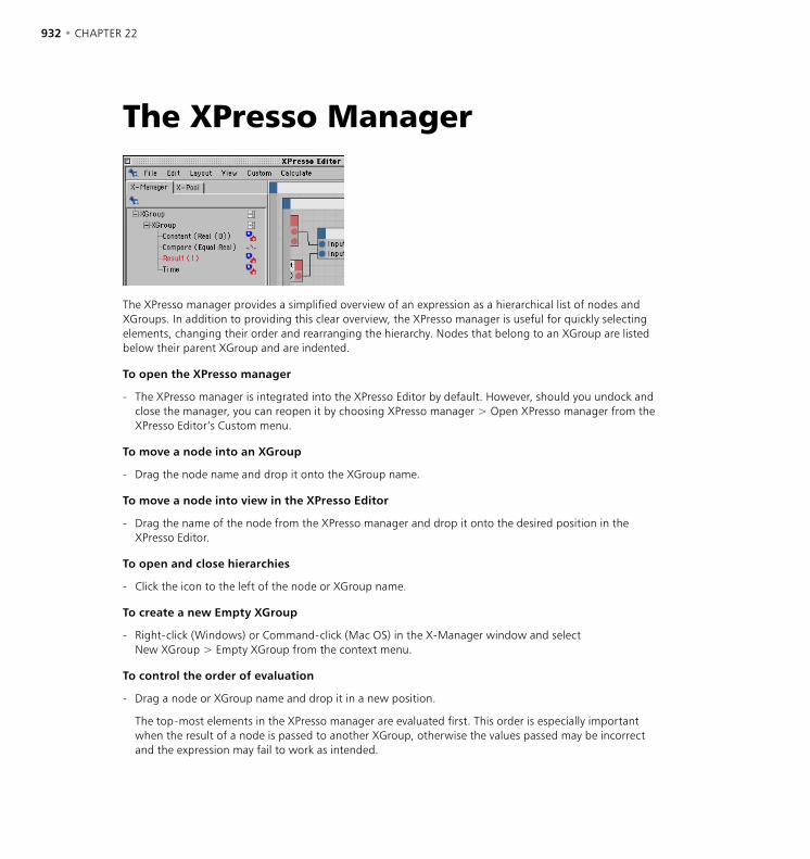
932 • CHAPTER 22 XPRESSO EDITOR • 933
The XPresso Manager
The XPresso manager provides a simplified overview of an expression as a hierarchical list of nodes and XGroups. In addition to providing this clear overview, the XPresso manager is useful for quickly selecting elements, changing their order and rearranging the hierarchy. Nodes that belong to an XGroup are listed below their parent XGroup and are indented.
To open the XPresso manager
- The XPresso manager is integrated into the XPresso Editor by default. However, should you undock and close the manager, you can reopen it by choosing XPresso manager > Open XPresso manager from the XPresso Editor’s Custom menu.
To move a node into an XGroup
- Drag the node name and drop it onto the XGroup name.
To move a node into view in the XPresso Editor
- Drag the name of the node from the XPresso manager and drop it onto the desired position in the XPresso Editor.
To open and close hierarchies
- Click the icon to the left of the node or XGroup name.
To create a new Empty XGroup
- Right-click (Windows) or Command-click (Mac OS) in the X-Manager window and select New XGroup > Empty XGroup from the context menu.
To control the order of evaluation
- Drag a node or XGroup name and drop it in a new position.
The top-most elements in the XPresso manager are evaluated first. This order is especially important when the result of a node is passed to another XGroup, otherwise the values passed may be incorrect and the expression may fail to work as intended.
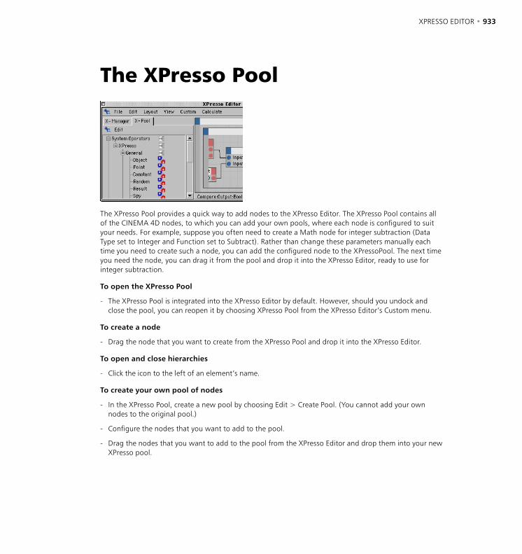
932 • CHAPTER 22 XPRESSO EDITOR • 933
The XPresso Pool
The XPresso Pool provides a quick way to add nodes to the XPresso Editor. The XPresso Pool contains all of the CINEMA 4D nodes, to which you can add your own pools, where each node is configured to suit your needs. For example, suppose you often need to create a Math node for integer subtraction (Data Type set to Integer and Function set to Subtract). Rather than change these parameters manually each time you need to create such a node, you can add the configured node to the XPressoPool. The next time you need the node, you can drag it from the pool and drop it into the XPresso Editor, ready to use for integer subtraction.
To open the XPresso Pool
- The XPresso Pool is integrated into the XPresso Editor by default. However, should you undock and close the pool, you can reopen it by choosing XPresso Pool from the XPresso Editor’s Custom menu.
To create a node
- Drag the node that you want to create from the XPresso Pool and drop it into the XPresso Editor.
To open and close hierarchies
- Click the icon to the left of an element’s name.
To create your own pool of nodes
- In the XPresso Pool, create a new pool by choosing Edit > Create Pool. (You cannot add your own nodes to the original pool.)
- Configure the nodes that you want to add to the pool.
- Drag the nodes that you want to add to the pool from the XPresso Editor and drop them into your new XPresso pool.
934 • CHAPTER 22 XPRESSO EDITOR • 935
Edit MenuCreate Pool
Choose this command to create a new pool for your own node configurations. Use the dialog that opens to define a save path for the pool; the pool is saved automatically and will be made available each time you restart CINEMA 4D. To add your own node configurations to the pool, first configure the nodes as desired in the XPresso Editor then drag and drop the nodes into the pool.
Remove Preset
You cannot remove nodes from the original pool.
Removes the selected preset or folder from the pool.
Rename Preset
Renames the preset. For example, if you have configured a Math node for the subtraction of integers, you may want to rename it to ‘Subtract Int’.
Create Folder
Creates a new folder. This enables you to arrange your own pool into folders for better organization. Drag the nodes that you want to place within the folder from the XPresso Pool or XPresso Editor and drop them onto the folder.
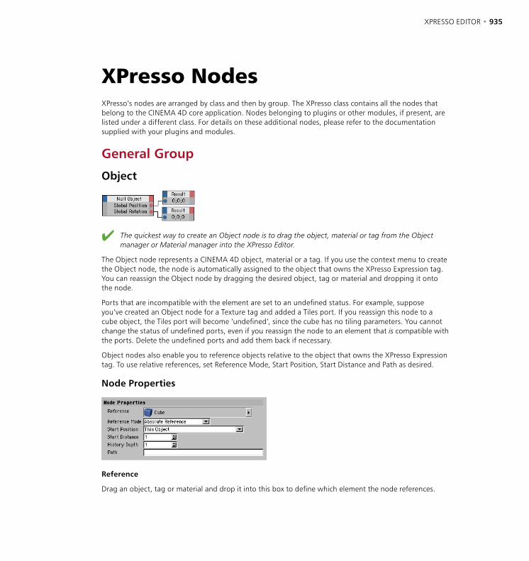
934 • CHAPTER 22 XPRESSO EDITOR • 935
XPresso NodesXPresso’s nodes are arranged by class and then by group. The XPresso class contains all the nodes that belong to the CINEMA 4D core application. Nodes belonging to plugins or other modules, if present, are listed under a different class. For details on these additional nodes, please refer to the documentation supplied with your plugins and modules.
General Group
Object
The quickest way to create an Object node is to drag the object, material or tag from the Object manager or Material manager into the XPresso Editor.
The Object node represents a CINEMA 4D object, material or a tag. If you use the context menu to create the Object node, the node is automatically assigned to the object that owns the XPresso Expression tag. You can reassign the Object node by dragging the desired object, tag or material and dropping it onto the node.
Ports that are incompatible with the element are set to an undefined status. For example, suppose you’ve created an Object node for a Texture tag and added a Tiles port. If you reassign this node to a cube object, the Tiles port will become ‘undefined’, since the cube has no tiling parameters. You cannot change the status of undefined ports, even if you reassign the node to an element that is compatible with the ports. Delete the undefined ports and add them back if necessary.
Object nodes also enable you to reference objects relative to the object that owns the XPresso Expression tag. To use relative references, set Reference Mode, Start Position, Start Distance and Path as desired.
Node Properties
Reference
Drag an object, tag or material and drop it into this box to define which element the node references.

936 • CHAPTER 22 XPRESSO EDITOR • 937
Reference Mode
The Reference Mode defines whether the reference is absolute, relative or based on a starting position.
Use Start Position
To reference an element relative to the object that owns the XPresso Expression tag, use either this mode or the more advanced Relative Reference mode. For example, to reference the element that is three positions before the object that owns the tag, set Reference Mode to Use Start Position, set Start Position to Predecessor On This Level and set Start Distance to 3. The Use First Position mode also enables you to reference the first or last object in the scene.
Absolute Reference
This is the default mode. The node references the object that is shown in the Reference box. If you want to use the expression in several places in your scene, avoid using the Absolute Reference mode, otherwise you’ll need to change the referencing of the objects each time.
Relative Reference
This mode is similar to Use Start Position. It enables you to reference an element relative to the object that owns the XPresso Expression tag. Unlike the Use Start Position mode, you enter a path that gives the node instructions on how to reach the element. The starting position is the object that owns the tag. For example, the path ‘UPPDS’ stands for ‘Up, Predecessor, Predecessor, Down, Successor’, where Predecessor and Successor represent a jump to the previous or next element on the same hierarchical level. Up and Down represent jumps one level up or one level down the hierarchy. The advantage of a relative reference is that it enables you to transfer the Object node from one hierarchy to another without problems. Edit the path using the Path box.
Start Position
This defines the Start Position when Reference Mode is set to Use Start Position. The setting is relative to the object that owns the XPresso Expression tag. For example, if you set Start Position to First In This Level, the node references the first element on the same hierarchical level as the object that owns the tag.
This Object
The object that owns the tag. The result is identical to the Absolute Reference mode.
Up In Hierarchy
Chooses the first object one level up the hierarchy.
Down In Hierarchy
Jumps to the first object one level down the hierarchy.
Successor On This Level
Chooses the next object on the same hierarchical level.
936 • CHAPTER 22 XPRESSO EDITOR • 937
Predecessor On This Level
Jumps to the previous object on the same hierarchical level.
First On This Level
Chooses the first element on the same hierarchical level.
Last On This Level
References the last element on the same hierarchical level.
First In Scene
Chooses the first object in the scene.
Last In Scene
Jumps to the scene’s last element.
Start Distance
With some Start Position modes you might want to jump several steps in the hierarchy in one go. In such cases, use Start Distance as a multiplier for the Start Position. For example, to reference an object that is three positions after the object that owns the XPresso Expression tag, set Start Position to Successor On This Level and set Start Distance to 3.
Path
This box is available only when Relative Mode is set to Relative Reference. Use the box to enter the path for the relative reference. For example, ‘UPPDS’ stands for ‘Up, Predecessor, Predecessor, Down, Successor’. (See also ‘Relative Reference’ above.)
History Depth
An Object node gives you access to all of the element’s parameters via ports. Choose the desired ports from the node’s inputs menu and outputs menu (the blue and red squares). For example, you can use an Object node to output an object’s global matrix, velocity, position, scale and rotation.
In addition you can access the object’s previous states via ports such as Previous Global Matrix. The History Depth value determines how many previous states the node stores. To recall a previous state add a History Level port to the node via the inputs menu and, in the Attribute manager, enter a number for how many states back you want to go. For example, a value of 3 retrieves the third last state.

938 • CHAPTER 22 XPRESSO EDITOR • 939
Point
This node gives you direct access to an object’s number of points and their positions. First create an Object node for the object whose point data you want to access. Click the Object node’s outputs menu (red square) and choose Object from the menu to create an Object port. Connect this Object port to the Point node’s Object port.
The Point node works with global or local point coordinates, depending on the Matrix Mode setting in the Attribute manager.
To set a point to a new position
- Connect an Object node to the Point node as described above, via the Object port.
- Pass the number of the point that should be output to the Point Index port. This index number corresponds to the polygon numbering shown in the Structure manager.
- The point’s position will be output at the Point Position port as a vector.
Constant
Provided the ports are unconnected, you can also pass values to other ports and XGroups by entering the values directly into the Attribute manager.
This node enables you to pass constant values — be they numbers, vectors or character strings — to other nodes and XGroups. Enter the value and set its data type in the Attribute manager.
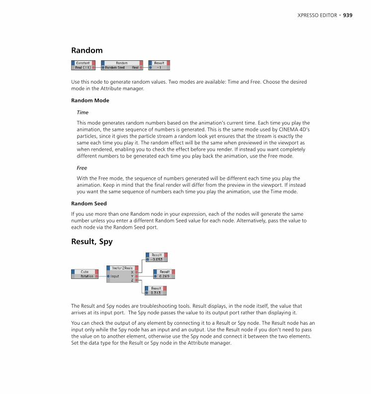
938 • CHAPTER 22 XPRESSO EDITOR • 939
Random
Use this node to generate random values. Two modes are available: Time and Free. Choose the desired mode in the Attribute manager.
Random Mode
Time
This mode generates random numbers based on the animation’s current time. Each time you play the animation, the same sequence of numbers is generated. This is the same mode used by CINEMA 4D’s particles, since it gives the particle stream a random look yet ensures that the stream is exactly the same each time you play it. The random effect will be the same when previewed in the viewport as when rendered, enabling you to check the effect before you render. If instead you want completely different numbers to be generated each time you play back the animation, use the Free mode.
Free
With the Free mode, the sequence of numbers generated will be different each time you play the animation. Keep in mind that the final render will differ from the preview in the viewport. If instead you want the same sequence of numbers each time you play the animation, use the Time mode.
Random Seed
If you use more than one Random node in your expression, each of the nodes will generate the same number unless you enter a different Random Seed value for each node. Alternatively, pass the value to each node via the Random Seed port.
Result, Spy
The Result and Spy nodes are troubleshooting tools. Result displays, in the node itself, the value that arrives at its input port. The Spy node passes the value to its output port rather than displaying it.
You can check the output of any element by connecting it to a Result or Spy node. The Result node has an input only while the Spy node has an input and an output. Use the Result node if you don’t need to pass the value on to another element, otherwise use the Spy node and connect it between the two elements. Set the data type for the Result or Spy node in the Attribute manager.

940 • CHAPTER 22 XPRESSO EDITOR • 941
Time
This node outputs the animation’s current time. Two output ports are added automatically when you create the node: Time and Real. Time gives the animation’s time in seconds, Real gives the time as a real number (i.e. with numbers after the decimal point). You can add further ports via the node’s outputs menu, including Frames (the current frame number), Frames Per Second (a constant), and Start and End (these are the Minimum and Maximum values from the Project Settings, expressed in seconds).
Remark
Use this node to document your expression with explanatory notes. Type the note into the Attribute manager’s Comment box.
Memory
The Memory node stores previous states and values. You can then use these values. The History Depth parameter (in the Attribute manager) defines the number of states stored. Set the data type in the Attribute manager.
If History Depth is set to 1, only the current state is stored, i.e. the current state is simply passed through. If History Depth is set to 2, the current state (position 1) and the previous state (position 2) are stored.
History Level defines which one of the stored states the node outputs. To set the History Level, either pass the value to the node’s History Level port or, if the port is unconnected, enter the value directly into the Attribute manager. If you set History Level to a higher value than History Depth, the node outputs the oldest stored state.
- If History Depth is set to 1, the value that arrives at the input is passed directly to the output regardless of the History Level setting.
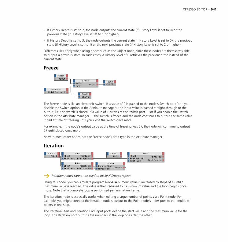
940 • CHAPTER 22 XPRESSO EDITOR • 941
- If History Depth is set to 2, the node outputs the current state (if History Level is set to 0) or the previous state (if History Level is set to 1 or higher).
- If History Depth is set to 3, the node outputs the current state (if History Level is set to 0), the previous state (if History Level is set to 1) or the next previous state (if History Level is set to 2 or higher).
Different rules apply when using nodes such as the Object node, since these nodes are themselves able to output a previous state. In such cases, a History Level of 0 retrieves the previous state instead of the current state.
Freeze
The Freeze node is like an electronic switch. If a value of 0 is passed to the node’s Switch port (or if you disable the Switch option in the Attribute manager), the input value is passed straight through to the output, i.e. the switch is closed. If a value of 1 arrives at the Switch port — or if you enable the Switch option in the Attribute manager — the switch is frozen and the node continues to output the same value it had at time of freezing until you close the switch once more.
For example, if the node’s output value at the time of freezing was 27, the node will continue to output 27 until closed once more.
As with most other nodes, set the Freeze node’s data type in the Attribute manager.
Iteration
Iteration nodes cannot be used to make XGroups repeat.
Using this node, you can simulate program loops. A numeric value is increased by steps of 1 until a maximum value is reached. The value is then reduced to its minimum value and the loop begins once more. Note that a complete loop is performed per animation frame.
The Iteration node is especially useful when editing a large number of points via a Point node. For example, you might connect the Iteration node’s output to the Point node’s Index port to edit multiple points in one step.
The Iteration Start and Iteration End input ports define the start value and the maximum value for the loop. The Iteration port outputs the numbers in the loop one after the other.
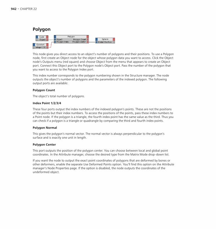
942 • CHAPTER 22 XPRESSO EDITOR • 943
Polygon
This node gives you direct access to an object’s number of polygons and their positions. To use a Polygon node, first create an Object node for the object whose polygon data you want to access. Click the Object node’s Outputs menu (red square) and choose Object from the menu that appears to create an Object port. Connect this Object port to the Polygon node’s Object port. Pass the number of the polygon that you want to access to the Polygon Index port.
This index number corresponds to the polygon numbering shown in the Structure manager. The node outputs the object’s number of polygons and the parameters of the indexed polygon. The following output ports are available:
Polygon Count
The object’s total number of polygons.
Index Point 1/2/3/4
These four ports output the index numbers of the indexed polygon’s points. These are not the positions of the points but their index numbers. To access the positions of the points, pass these index numbers to a Point node. If the polygon is a triangle, the fourth index point has the same value as the third. Thus you can check if a polygon is a triangle or quadrangle by comparing the third and fourth index points.
Polygon Normal
This gives the polygon’s normal vector. The normal vector is always perpendicular to the polygon’s surface and is exactly one unit in length.
Polygon Center
This port outputs the position of the polygon center. You can choose between local and global point coordinates. In the Attribute manager, choose the desired type from the Matrix Mode drop-down list.
If you want the node to output the exact point coordinates of polygons that are deformed by bones or other deformers, enable the separate Use Deformed Points option. You’ll find this option on the Attribute manager’s Node Properties page. If the option is disabled, the node outputs the coordinates of the undeformed object.

942 • CHAPTER 22 XPRESSO EDITOR • 943
Adapter GroupThe nodes in the Adapter group convert a value from one data type into another. Although XPresso’s wires convert various data types automatically, you can use an adapter node to force a particular conversion.
Universal
The Universal adapter enables you to convert from one data type to any other compatible type. For example, you can connect the Bool and Vector types using a Universal node whose data type is set to Real. Since the wires between nodes convert most data types automatically, most of the time you won’t need to use this node. The Universal node’s data type (Attribute manager) defines the format into which the input will be converted.
Matrix2Vectors
This adapter splits a matrix into its four components: the Offset (also known as V0) and the three vectors V1, V2 and V3. The Offset represents the position of the matrix while the three individual vectors define the rotation and scale of the axis system (the Scale is defined by the length of each vector).
Reals2Vector
This adapter converts three Real values to a vector. For example, you might convert an object’s X, Y and Z values into a single position vector.

944 • CHAPTER 22 XPRESSO EDITOR • 945
Vectors2Matrix
This adapter converts the four vectors Offset, V1, V2 and V3 into a matrix. This node performs the reverse operation of the Matrix2Vectors adapter.
Vector2Reals
This node works with radians (i.e. 0 to 2*Pi instead of 0 to 360 °). If you want to work in degrees, use a Degree node to convert radians to degrees and vice versa.
The Vector2Reals node performs the reverse operation of the Reals2Vector node — it splits a vector into its three component (Real) values. For example, a rotation vector is split into its H, P and B components.
Bool GroupThe nodes in the Bool group perform various Boolean functions. Each Bool node uses the Bool data type, which has two possible states only: True (represented by 1) and False (represented by 0).
BoolThe Bool node performs various Boolean functions. On the Attribute manager’s Node page, choose the desired function.
AND
The output is True if all inputs are True. Otherwise the output is False.
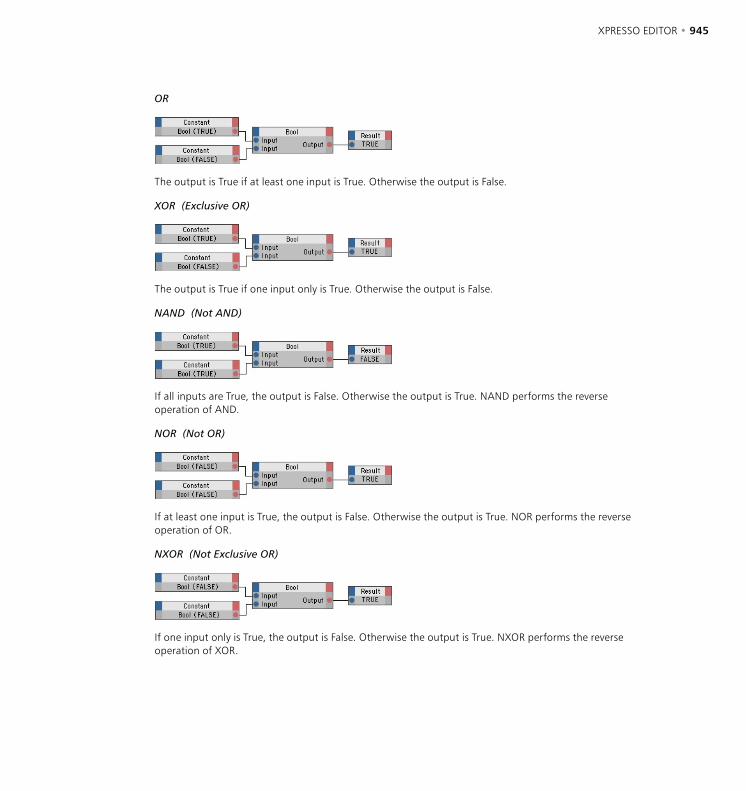
944 • CHAPTER 22 XPRESSO EDITOR • 945
OR
The output is True if at least one input is True. Otherwise the output is False.
XOR (Exclusive OR)
The output is True if one input only is True. Otherwise the output is False.
NAND (Not AND)
If all inputs are True, the output is False. Otherwise the output is True. NAND performs the reverse operation of AND.
NOR (Not OR)
If at least one input is True, the output is False. Otherwise the output is True. NOR performs the reverse operation of OR.
NXOR (Not Exclusive OR)
If one input only is True, the output is False. Otherwise the output is True. NXOR performs the reverse operation of XOR.

946 • CHAPTER 22 XPRESSO EDITOR • 947
Switch
This node outputs a Bool constant as defined in the Attribute manager, either True (Value enabled) or False (Value disabled).
NOT
This node negates a Bool value. If the input is True, the output is False. If the input if False (0), the output is True (1).
Calculate Group
Math
The Math node performs a math operation such as addition or multiplication. Choose the Function setting and data type in the Attribute manager.
Add
Adds the inputs together and outputs the result. This is the default function.
Subtract
Subtracts the second input from the first and outputs the result.
Multiply
Multiplies the inputs and outputs the result.
Divide
Divides the first input by the second input and outputs the result.
Modulo
Outputs the integral remainder of a division. For example, 11 modulo 10 = 1 and 23 modulo 10 = 3.
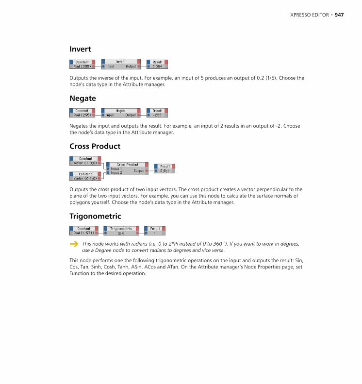
946 • CHAPTER 22 XPRESSO EDITOR • 947
Invert
Outputs the inverse of the input. For example, an input of 5 produces an output of 0.2 (1/5). Choose the node’s data type in the Attribute manager.
Negate
Negates the input and outputs the result. For example, an input of 2 results in an output of -2. Choose the node’s data type in the Attribute manager.
Cross Product
Outputs the cross product of two input vectors. The cross product creates a vector perpendicular to the plane of the two input vectors. For example, you can use this node to calculate the surface normals of polygons yourself. Choose the node’s data type in the Attribute manager.
Trigonometric
This node works with radians (i.e. 0 to 2*Pi instead of 0 to 360 °). If you want to work in degrees, use a Degree node to convert radians to degrees and vice versa.
This node performs one the following trigonometric operations on the input and outputs the result: Sin, Cos, Tan, Sinh, Cosh, Tanh, ASin, ACos and ATan. On the Attribute manager’s Node Properties page, set Function to the desired operation.
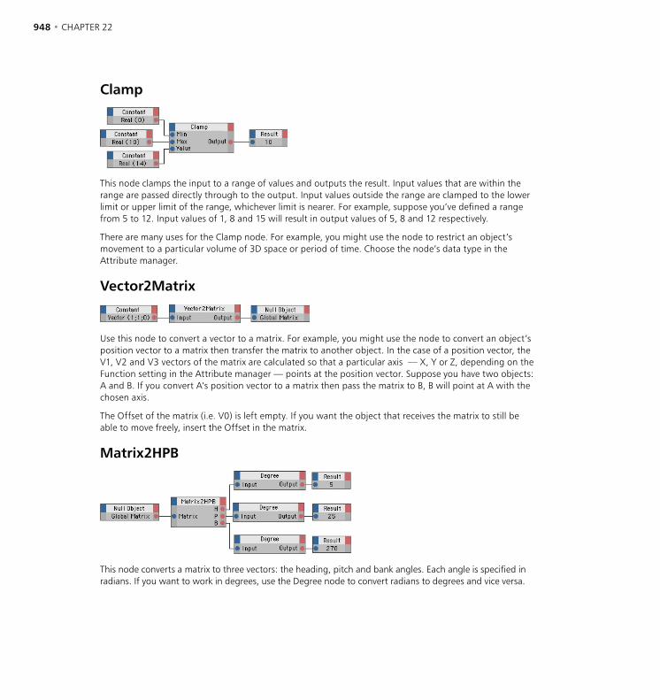
948 • CHAPTER 22 XPRESSO EDITOR • 949
Clamp
This node clamps the input to a range of values and outputs the result. Input values that are within the range are passed directly through to the output. Input values outside the range are clamped to the lower limit or upper limit of the range, whichever limit is nearer. For example, suppose you’ve defined a range from 5 to 12. Input values of 1, 8 and 15 will result in output values of 5, 8 and 12 respectively.
There are many uses for the Clamp node. For example, you might use the node to restrict an object’s movement to a particular volume of 3D space or period of time. Choose the node’s data type in the Attribute manager.
Vector2Matrix
Use this node to convert a vector to a matrix. For example, you might use the node to convert an object’s position vector to a matrix then transfer the matrix to another object. In the case of a position vector, the V1, V2 and V3 vectors of the matrix are calculated so that a particular axis — X, Y or Z, depending on the Function setting in the Attribute manager — points at the position vector. Suppose you have two objects: A and B. If you convert A’s position vector to a matrix then pass the matrix to B, B will point at A with the chosen axis.
The Offset of the matrix (i.e. V0) is left empty. If you want the object that receives the matrix to still be able to move freely, insert the Offset in the matrix.
Matrix2HPB
This node converts a matrix to three vectors: the heading, pitch and bank angles. Each angle is specified in radians. If you want to work in degrees, use the Degree node to convert radians to degrees and vice versa.
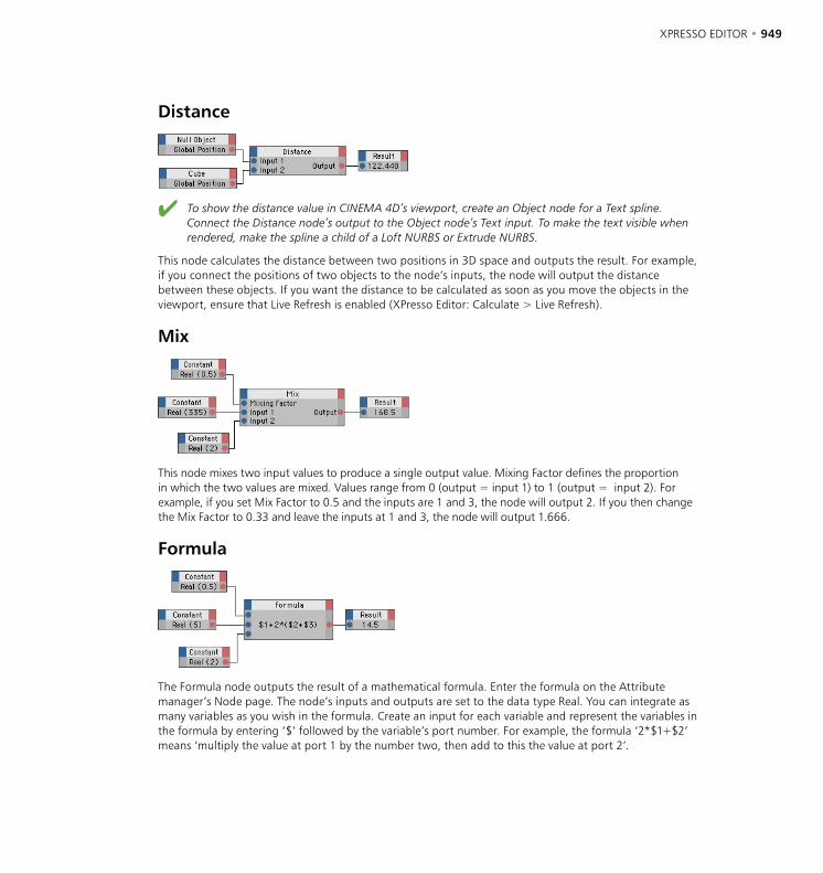
948 • CHAPTER 22 XPRESSO EDITOR • 949
Distance
To show the distance value in CINEMA 4D’s viewport, create an Object node for a Text spline. Connect the Distance node’s output to the Object node’s Text input. To make the text visible when rendered, make the spline a child of a Loft NURBS or Extrude NURBS.
This node calculates the distance between two positions in 3D space and outputs the result. For example, if you connect the positions of two objects to the node’s inputs, the node will output the distance between these objects. If you want the distance to be calculated as soon as you move the objects in the viewport, ensure that Live Refresh is enabled (XPresso Editor: Calculate > Live Refresh).
Mix
This node mixes two input values to produce a single output value. Mixing Factor defines the proportion in which the two values are mixed. Values range from 0 (output = input 1) to 1 (output = input 2). For example, if you set Mix Factor to 0.5 and the inputs are 1 and 3, the node will output 2. If you then change the Mix Factor to 0.33 and leave the inputs at 1 and 3, the node will output 1.666.
Formula
The Formula node outputs the result of a mathematical formula. Enter the formula on the Attribute manager’s Node page. The node’s inputs and outputs are set to the data type Real. You can integrate as many variables as you wish in the formula. Create an input for each variable and represent the variables in the formula by entering ‘$’ followed by the variable’s port number. For example, the formula ‘2*$1+$2’ means ‘multiply the value at port 1 by the number two, then add to this the value at port 2’.
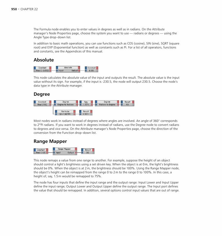
950 • CHAPTER 22 XPRESSO EDITOR • 951
The Formula node enables you to enter values in degrees as well as in radians. On the Attribute manager’s Node Properties page, choose the system you want to use — radians or degrees — using the Angle Type drop-down list.
In addition to basic math operations, you can use functions such as COS (cosine), SIN (sine), SQRT (square root) and EXP (Exponential function) as well as constants such as Pi. For a list of all operators, functions and constants, see the Appendices of this manual.
Absolute
This node calculates the absolute value of the input and outputs the result. The absolute value is the input value without its sign. For example, if the input is -230.5, the node will output 230.5. Choose the node’s data type in the Attribute manager.
Degree
Most nodes work in radians instead of degrees where angles are involved. An angle of 360° corresponds to 2*Pi radians. If you want to work in degrees instead of radians, use the Degree node to convert radians to degrees and vice versa. On the Attribute manager’s Node Properties page, choose the direction of the conversion from the Function drop-down list.
Range Mapper
This node remaps a value from one range to another. For example, suppose the height of an object should control a light’s brightness using a set driven key. When the object is at 0 m, the light’s brightness should be 0%. When the object is at 2 m, the brightness should be 100%. Using the Range Mapper node, the object’s height can be remapped from the range 0 to 2 m to the range 0 to 100%. In this case, a height of, say, 1.5 m would be remapped to 75%.
The node has four inputs that define the input range and the output range: Input Lower and Input Upper define the input range; Output Lower and Output Upper define the output range. The Input port defines the value that should be remapped. In addition, several options control input values that are out of range.
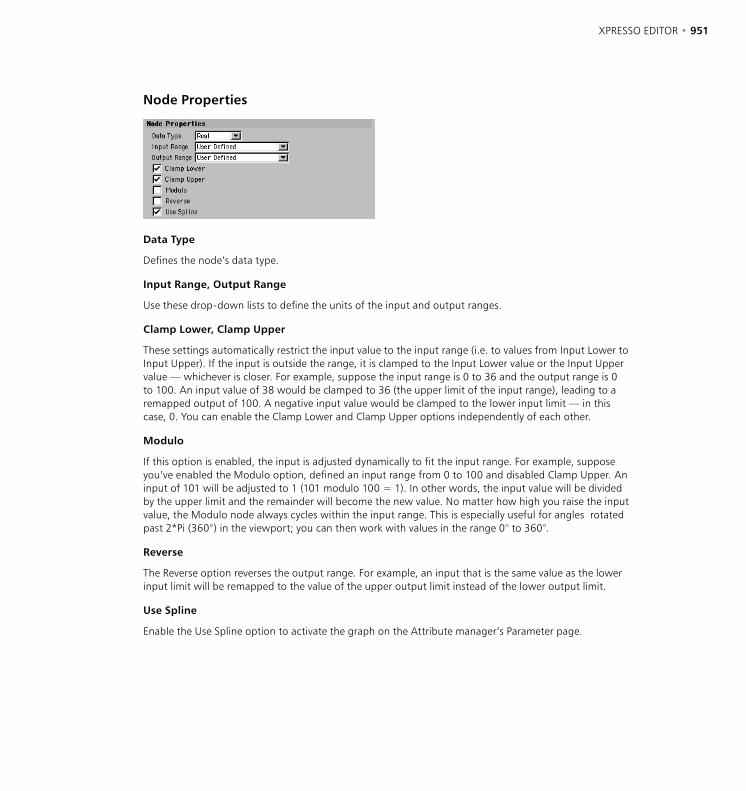
950 • CHAPTER 22 XPRESSO EDITOR • 951
Node Properties
Data Type
Defines the node’s data type.
Input Range, Output Range
Use these drop-down lists to define the units of the input and output ranges.
Clamp Lower, Clamp Upper
These settings automatically restrict the input value to the input range (i.e. to values from Input Lower to Input Upper). If the input is outside the range, it is clamped to the Input Lower value or the Input Upper value — whichever is closer. For example, suppose the input range is 0 to 36 and the output range is 0 to 100. An input value of 38 would be clamped to 36 (the upper limit of the input range), leading to a remapped output of 100. A negative input value would be clamped to the lower input limit — in this case, 0. You can enable the Clamp Lower and Clamp Upper options independently of each other.
Modulo
If this option is enabled, the input is adjusted dynamically to fit the input range. For example, suppose you’ve enabled the Modulo option, defined an input range from 0 to 100 and disabled Clamp Upper. An input of 101 will be adjusted to 1 (101 modulo 100 = 1). In other words, the input value will be divided by the upper limit and the remainder will become the new value. No matter how high you raise the input value, the Modulo node always cycles within the input range. This is especially useful for angles rotated past 2*Pi (360°) in the viewport; you can then work with values in the range 0° to 360°.
Reverse
The Reverse option reverses the output range. For example, an input that is the same value as the lower input limit will be remapped to the value of the upper output limit instead of the lower output limit.
Use Spline
Enable the Use Spline option to activate the graph on the Attribute manager’s Parameter page.

952 • CHAPTER 22 XPRESSO EDITOR • 953
Parameter Properties
The purpose of the spline graph is to allow nonlinear remapping. There are many cases where you might want the Range Mapper node’s output to rise gradually at first and then rise sharply as the upper limit is approached. One such case is a bicep’s muscle, the bulge of which depends on how far the elbow is bent. Most of the bulging occurs as the elbow approaches full bend. Splines give you an easy way to simulate these nonlinear dependencies.
To create a point, click on the graph; to move an existing point, drag the point; to delete a point, drag the point out of the graph. The graph’s X-axis represents the input value, the Y-axis the output value.
You can influence the spline’s curvature using a Tension slider, which you access by clicking the triangle to the right of ‘XSpline’. The strength of the Tension slider controls the interpolation between the spline’s points. With a high Tension setting, the spline curve passes through all its points. With a low setting, a soft curve is created and the points control only the approximate path of the curve (i.e. the curve won’t necessarily pass through the points). This soft curve is similar to a B-Spline.
The position of a selected point is shown in the X and Y boxes. You can enter new values for the point if desired. As with the Tension slider, click the triangle next to ‘XSpline’ to access the X and Y boxes. You can choose a particular shape for the graph’s curve using the context menu; right-click (Windows) or Command-click (Mac OS) within the graph and choose the desired curve shape such as Linear, Cubic or Sin. Default Points defines the number of points used to create the curve shape.
A straight line from the bottom left to the top right of the graph represents linear behavior (the same result as disabling Use Graph). If you add a point to the middle of the line and drag it up or down, the remapping becomes non-linear. If you want the output to increase gradually with low to medium input values then rise sharply as the input approaches its upper limit (such as for the biceps muscle mentioned earlier), draw a curve (by adding points and dragging them), from left to right, that is shallow at first then rises sharply towards the top right corner of the graph.

952 • CHAPTER 22 XPRESSO EDITOR • 953
FloatMath
The Float Math node compared with the Math node.
This node works in a similar way to the Math node except that it is able to perform math operations on two inputs that have different data types. For example, unlike a Math node, the Float Math node can multiply a vector by a scalar (an integer or real value).
If you were to use a Math node instead of a FloatMath node to multiply a vector by a scalar, the Math node would first convert the vector to a scalar or the scalar to a vector, depending on which input is topmost (the Math node’s topmost input is converted to the data type of the other input). Only then, once the values are of the same data type, does the Math node perform the operation. In the most extreme case, the Math node would convert the vector to a scalar (the scalar’s value would be the length of the vector). The Math node would then multiply this value by the scalar input, and output the result as a vector.
If you want the node to change the vector’s length only, the Math node won’t produce the desired result. In such cases, use the FloatMath node instead; each vector component would be multiplied by the scalar value to change the vector’s length as desired.
FloatFunc
This node gives you direct access to a number of math functions and is especially useful when used as an extension to the Formula node or to round values up or down. Choose the desired function on the Node Properties page of the Attribute manager.
Exp
Calculates the exponential function of the input value.
Ln
In this mode, the natural logarithm is calculated.
Ln10
Calculates the logarithm to the base 10.

954 • CHAPTER 22 XPRESSO EDITOR • 955
Sqrt
Calculates the square root of the input.
Floor
In this mode, the input is rounded down to the nearest integer value. For example, the input 4.95 produces the output 4.
Ceil
In this mode, the input is rounded up to the nearest integer value. For example, the input 4.01 produces the output 5.
Pow
This mode raises the input to the power of the input. For example, an input of 5 is raised to the power of 5, to produce the output value of 3125.
Pow2
In this mode, the input is squared. An input of 5 produces an output of 25.
Logic GroupThe Logic group nodes enable you to compare values. Most of these nodes use the Bool data type, which has two possible states only: True (represented by the value 1) and False (represented by 0).
Order
Use this node to find out the larger of two values. Possible outputs are 1 (first input is the larger value), -1 (second input is larger) and 0 (inputs are equal). Set the node’s data type in the Attribute manager.
Compare
This node compares two values using one of several comparison operators and outputs the result as a Bool. In the Attribute manager, choose the comparison operator from the Function drop-down list.
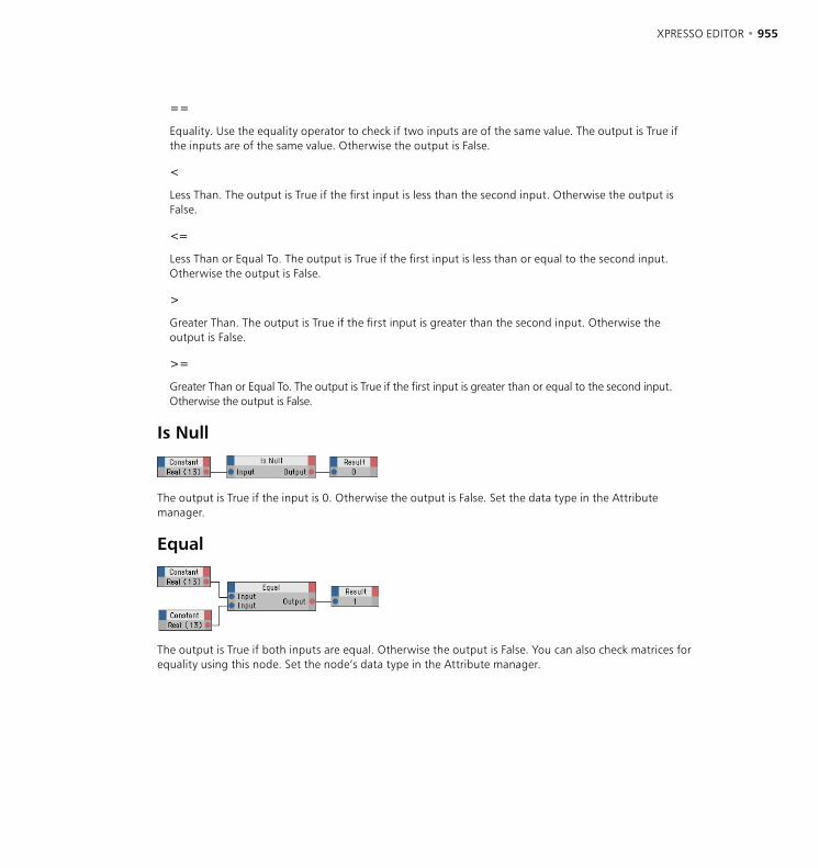
954 • CHAPTER 22 XPRESSO EDITOR • 955
==
Equality. Use the equality operator to check if two inputs are of the same value. The output is True if the inputs are of the same value. Otherwise the output is False.
<
Less Than. The output is True if the first input is less than the second input. Otherwise the output is False.
<=
Less Than or Equal To. The output is True if the first input is less than or equal to the second input. Otherwise the output is False.
>
Greater Than. The output is True if the first input is greater than the second input. Otherwise the output is False.
>=
Greater Than or Equal To. The output is True if the first input is greater than or equal to the second input. Otherwise the output is False.
Is Null
The output is True if the input is 0. Otherwise the output is False. Set the data type in the Attribute manager.
Equal
The output is True if both inputs are equal. Otherwise the output is False. You can also check matrices for equality using this node. Set the node’s data type in the Attribute manager.
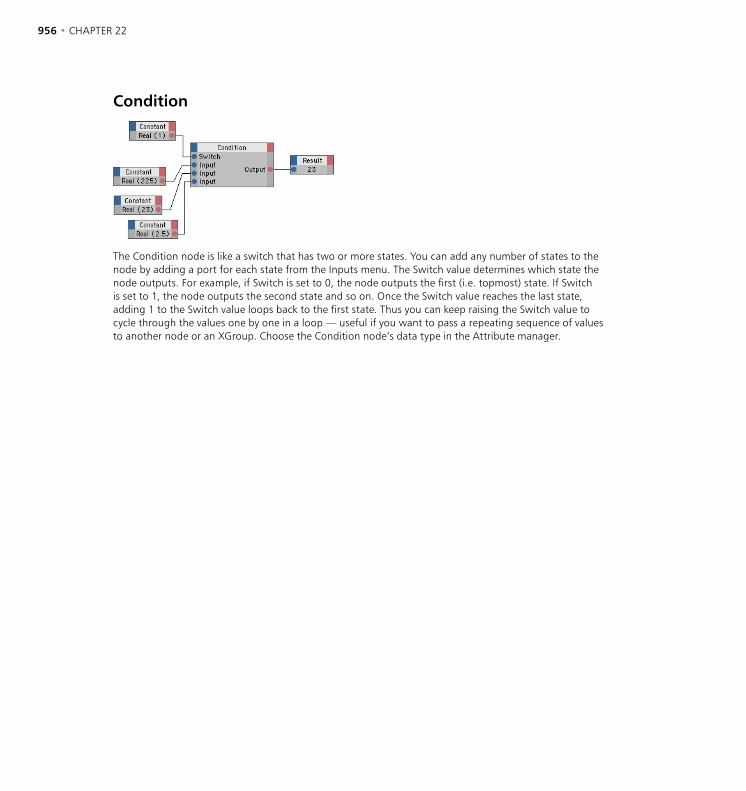
956 • CHAPTER 22 XPRESSO EDITOR • 957
Condition
The Condition node is like a switch that has two or more states. You can add any number of states to the node by adding a port for each state from the Inputs menu. The Switch value determines which state the node outputs. For example, if Switch is set to 0, the node outputs the first (i.e. topmost) state. If Switch is set to 1, the node outputs the second state and so on. Once the Switch value reaches the last state, adding 1 to the Switch value loops back to the first state. Thus you can keep raising the Switch value to cycle through the values one by one in a loop — useful if you want to pass a repeating sequence of values to another node or an XGroup. Choose the Condition node’s data type in the Attribute manager.
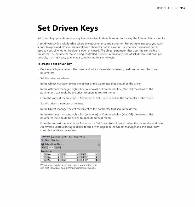
956 • CHAPTER 22 XPRESSO EDITOR • 957
Set Driven KeysSet driven keys provide an easy way to create object interactions without using the XPresso Editor directly.
A set driven key is a relationship where one parameter controls another. For example, suppose you want a door to open and close automatically as a character enters a room. The character’s position can be used to control whether the door is open or closed. The object parameter that does the controlling is the driver. The parameter that is being controlled is driven. Almost any kind of set-driven relationship is possible, making it easy to manage complex motions or objects.
To create a set driven key
- Decide which parameter is the driver and which parameter is driven (the driver controls the driven parameter).
- Set the driver as follows.
In the Object manager, select the object of the parameter that should be the driver.
In the Attribute manager, right-click (Windows) or Command-click (Mac OS) the name of the parameter that should be the driver to open its context menu.
From the context menu, choose Animation > Set Driver to define the parameter as the driver.
- Set the driven parameter as follows.
In the Object manager, select the object of the parameter that should be driven.
In the Attribute manager, right-click (Windows) or Command-click (Mac OS) the name of the parameter that should be driven to open its context menu.
From the context menu, choose Animation > Set Driven (Absolute) to define the parameter as driven. An XPresso Expression tag is added to the driven object in the Object manager and the driver now controls the driven parameter.
When selecting the driver and driven parameters, you can click individual parameters or parameter groups.
958 • CHAPTER 22
Relative Driven KeysA variation of set driven keys enables you to control the driven value using an XPresso Range Mapper node. The Range Mapper takes the driver’s value and remaps it to a new value. For example, driver values from 0 to 100 can be remapped to produce driven values from 0 to 5. In this case, a driver value of 80 would produce a driven value of 4.
Remapping the values in this way enables you to link the driver and driven parameters in a ratio other than 1:1. In addition, you can define non-linear remapping quickly by drawing a spline curve. For example, you can draw a curve that scales the value gradually at first then sharply towards the end of the range.
To create a relative set driven key
- Use the same procedure as for normal set driven keys (see above) except choose Animation > Set Driven (Relative) instead of Animation > Set Driven (Absolute) when you set the driven parameter. Once you’ve created the set driven key, edit the Range Mapper’s values as desired.
See also ‘Range Mapper’ on page 950.

23 Structure Manager

STRUCTURE MANAGER • 961
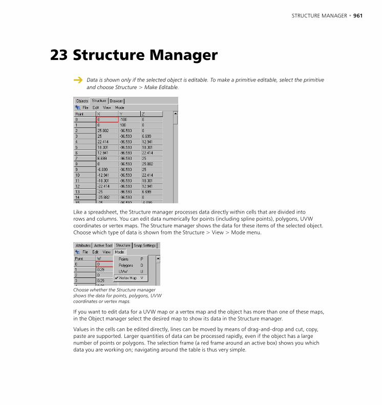
STRUCTURE MANAGER • 961
Data is shown only if the selected object is editable. To make a primitive editable, select the primitive and choose Structure > Make Editable.
Like a spreadsheet, the Structure manager processes data directly within cells that are divided into rows and columns. You can edit data numerically for points (including spline points), polygons, UVW coordinates or vertex maps. The Structure manager shows the data for these items of the selected object. Choose which type of data is shown from the Structure > View > Mode menu.
Choose whether the Structure manager shows the data for points, polygons, UVW coordinates or vertex maps.
If you want to edit data for a UVW map or a vertex map and the object has more than one of these maps, in the Object manager select the desired map to show its data in the Structure manager.
Values in the cells can be edited directly, lines can be moved by means of drag-and-drop and cut, copy, paste are supported. Larger quantities of data can be processed rapidly, even if the object has a large number of points or polygons. The selection frame (a red frame around an active box) shows you which data you are working on; navigating around the table is thus very simple.
23 Structure Manager
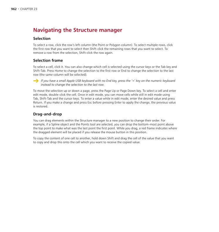
962 • CHAPTER 23 STRUCTURE MANAGER • 963
Navigating the Structure managerSelection
To select a row, click the row’s left column (the Point or Polygon column). To select multiple rows, click the first row that you want to select then Shift-click the remaining rows that you want to select. To remove a row from the selection, Shift-click the row again.
Selection frame
To select a cell, click it. You can also change which cell is selected using the cursor keys or the Tab key and Shift-Tab. Press Home to change the selection to the first row or End to change the selection to the last row (the same column will be selected).
If you have a small Apple USB keyboard with no End key, press the ‘+’ key on the numeric keyboard instead to change the selection to the last row.
To move the selection up or down a page, press the Page Up or Page Down key. To select a cell and enter edit mode, double-click the cell. Once in edit mode, you can move cells while still in edit mode using Tab, Shift-Tab and the cursor keys. To enter a value while in edit mode, enter the desired value and press Return. If you make a change and press Esc before pressing Enter to apply the change, the previous value is restored.
Drag-and-drop
You can drag elements within the Structure manager to a new position to change their order. For example, if a Spline object and the Points tool are selected, you can drop the bottom-most point above the top point to make what was the last point the first point. While you drag, a red frame indicates where the dragged element will be placed if you release the mouse button in this position.
To copy the content of one cell to another, hold down Shift and drag the cell of the value that you want to copy and drop this onto the cell which you want to receive the copied value.
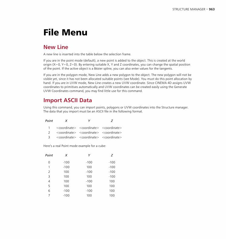
962 • CHAPTER 23 STRUCTURE MANAGER • 963
File MenuNew LineA new line is inserted into the table below the selection frame.
If you are in the point mode (default), a new point is added to the object. This is created at the world origin (X=0, Y=0, Z=0). By entering suitable X, Y and Z coordinates, you can change the spatial position of the point. If the active object is a Bézier spline, you can also enter values for the tangents.
If you are in the polygon mode, New Line adds a new polygon to the object. The new polygon will not be visible yet, since it has not been allocated suitable points (see Mode). You must do this point allocation by hand. If you are in UVW mode, New Line creates a new UVW coordinate. Since CINEMA 4D assigns UVW coordinates to primitives automatically and UVW coordinates can be created easily using the Generate UVW Coordinates command, you may find little use for this command.
Import ASCII DataUsing this command, you can import points, polygons or UVW coordinates into the Structure manager. The data that you import must be an ASCII file in the following format.
Point X Y Z
1 <coordinate> <coordinate> <coordinate>2 <coordinate> <coordinate> <coordinate>3 <coordinate> <coordinate> <coordinate>
Here’s a real Point mode example for a cube:
Point X Y Z
0 -100 -100 -1001 -100 100 -1002 100 -100 -1003 100 100 -1004 100 -100 1005 100 100 1006 -100 -100 1007 -100 100 100

964 • CHAPTER 23 STRUCTURE MANAGER • 965
The ASCII file must start with a header (the ‘Point X Y Z’ in the example above) and each row must start with the point number. The values within each line may be separated with a TAB character, a comma, a semicolon or a combination of these. Each line must end with the ASCII LF (linefeed) character or the CR (carriage return) character, or a combination of both. Thus the ASCII file can be created on a Macintosh, Windows or Unix computer.
If data already exists in the Structure manager, the imported data is inserted before the line containing the selection frame
To import a point cloud
- Choose Object > Polygon Object to create an empty Polygon object.
- In the Structure manager, choose Mode > Points (to be able to import points, you must first be in points mode).
- In the Structure manager, choose File > Import ASCII Data and use the system file selector that opens to select the desired ASCII file.
Point clouds are invisible when rendered since they do not included polygons. To create surfaces that you see, connect the cloud’s points together using the Bridge tool.
Export ASCII DataYou can export the data shown in the Structure manager as an ASCII file — perhaps for export to another 3D application. In Point mode, the X, Y and Z coordinates of each point are exported. If the selected object is a Bézier spline, its tangent values are exported also. In Polygon mode, the edge data for each polygon is exported. In UVW mode the UVW coordinates of each polygon (defined so far) are exported.
CloseCloses the Structure manager.
964 • CHAPTER 23 STRUCTURE MANAGER • 965
Edit MenuUndo, RedoUndo undoes the last change to the object’s structure. The previous values are restored to the cells. The undo level (i.e. how many changes are remembered) is set on the Document page of the preferences. Redo undoes (i.e. cancels) the last undo. The redo level is the same as the undo level set on the Document page of the preferences.
Cut, Copy, Paste, DeleteCut removes the selected row(s) from the table and copies this to the clipboard. Copy copies the selected row(s) from the table into the clipboard, without deletion. Paste inserts any data copied or cut into the clipboard back into the table, below the selection frame. Deletes the selected rows.
Select All, Deselect All, Invert AllThese commands select all rows, deselect all rows and inverts the selection.
Select AreaThe mouse pointer changes into a crosshair and you can draw a selection area with the mouse. All lines within the area you draw are selected. If some of the rows that you want to select are out of view, drag above or below the Structure manager window up or down. The window will then scroll until you drag within the window once more.
View MenuJump Last Selection, Jump Next SelectionThese commands move the selection frame to the previous or next selected row.
Jump Page Up, Jump Page DownThese commands move the selection frame up or down a page.
Jump Home, Jump EndUse these commands to move the selection frame to the first column of the first row (Jump Home) or last row (Jump End).

966 • CHAPTER 23
Mode Menu All modes operate independently of the tool that you are using in the viewport. For example, you
can process points in the Structure manager while working on polygons in the viewport. If you want the elements selected in the Structure manager to be shown in the viewport also, you must change to the appropriate tool. For example, if points are shown in the Structure manager, select the Points tool from the left toolbar.
PointsIn Point mode, the coordinates of the selected object’s points are shown in the Structure manager. If the selected object is a Bézier Spline, the tangent values are shown also. No units are displayed; the unit of measurement is selected in the preferences and is assumed here. The display is organized as follows:
X Y Z show the coordinates of the respective point in the world system.
<-X <-Y <-Z is the position of the end of any left tangent.
X-> Y-> Z is the position of the end of any right tangent.
Polygons If C and D are identical, CINEMA 4D interprets the polygon as a triangle.
If you are in Polygon mode, the number of each defining point is displayed, as follows. A, B, C, D correspond to the respective point numbers of the three (or four) corner points of the polygon.
UVWIn UVW mode, the UVW coordinates of the polygons of the object are displayed as follows:
U[A], U[B], U[C], U[D] are the U coordinates of the corner points of a polygon.
V[A], V[B], V[C], V[D] are the V coordinates of the corner points of a polygon.
W[A], W[B], W[C], W[D] are the W coordinates of the corner points of a polygon .
Vertex MapIf you are in Vertex Map mode, the weighting values for the points are shown. The value for a point ranges from 0 to 1.

24 Picture Viewer

PICTURE VIEWER • 969
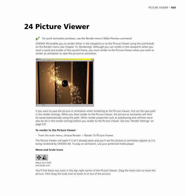
PICTURE VIEWER • 969
For quick animation previews, use the Render menu’s Make Preview command.
CINEMA 4D enables you to render either in the viewports or to the Picture Viewer using the commands on the Render menu (see Chapter 13, Rendering). Although you can render in the viewports when you want a quick test render of the current frame, you must render to the Picture Viewer when you want to render an animation or save the picture or animation.
If you want to save the picture or animation when rendering to the Picture Viewer, first set the save path in the render settings. When you then render to the Picture Viewer, the picture or animation will then be saved automatically using this path. Other render properties such as antialiasing and softness must also be set in the render settings before you render to the Picture Viewer. See also ‘Render Settings’ on page 531.
To render to the Picture Viewer
- From the main menu, choose Render > Render To Picture Viewer.
The Picture Viewer will open if it isn’t already open and you’ll see the picture or animation appear as it is being rendered by CINEMA 4D. To play an animation, use your preferred media player.
Move and Scale Icons
Move icon (left)and Scale icon.
You’ll find these two icons in the top-right corner of the Picture Viewer. Drag the move icon to move the picture. Click-drag the scale icon to zoom in or out of the picture.
24 Picture Viewer
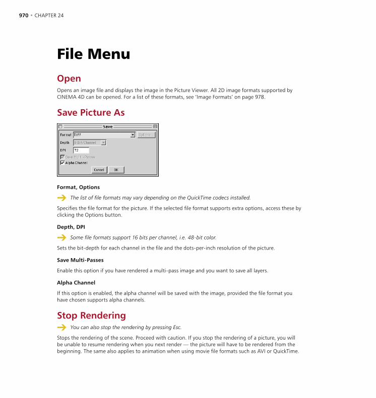
970 • CHAPTER 24 PICTURE VIEWER • 971
File MenuOpenOpens an image file and displays the image in the Picture Viewer. All 2D image formats supported by CINEMA 4D can be opened. For a list of these formats, see ‘Image Formats’ on page 978.
Save Picture As
Format, Options
The list of file formats may vary depending on the QuickTime codecs installed.
Specifies the file format for the picture. If the selected file format supports extra options, access these by clicking the Options button.
Depth, DPI
Some file formats support 16 bits per channel, i.e. 48-bit color.
Sets the bit-depth for each channel in the file and the dots-per-inch resolution of the picture.
Save Multi-Passes
Enable this option if you have rendered a multi-pass image and you want to save all layers.
Alpha Channel
If this option is enabled, the alpha channel will be saved with the image, provided the file format you have chosen supports alpha channels.
Stop Rendering You can also stop the rendering by pressing Esc.
Stops the rendering of the scene. Proceed with caution. If you stop the rendering of a picture, you will be unable to resume rendering when you next render — the picture will have to be rendered from the beginning. The same also applies to animation when using movie file formats such as AVI or QuickTime.
970 • CHAPTER 24 PICTURE VIEWER • 971
However, if you are rendering the animation as a sequence of still images such as TIFF, the frames already rendered are saved using the save path chosen in the render settings. If you want to keep these saved frames, you must change the save path in the render settings before you next render, otherwise these frames will be overwritten. Also, on the Output page of the rendering settings, set the left input box for Frame to the number of the frame that was being rendered when you stopped rendering. This will prevent the animation being rendered from the beginning.
Close Closes the Picture Viewer.
Edit Menu CopyCopies the image in the Picture Viewer to the clipboard. You can then paste the image into another application such as an image editor.
Channels MenuUse this menu to control which image channels are shown in the Picture Viewer. The menu lists all channels contained in the image — layers are listed also if you have rendered a multi-pass image.
Multi-Layer DisplayIf this option is enabled, you can enable as many of the channels in the Channels menu as you like; these enabled channels are combined to form a composite image in the Picture Viewer. If Multi-Layer Display is disabled, you can enable (and see) one channel at a time only.
ImageIf this option is enabled, the composite image is shown in the Picture Viewer.
Alpha This option appears only if the image has an integrated alpha channel. If the option is enabled, the Picture Viewer displays the image’s alpha channel instead of the image itself.
972 • CHAPTER 24
Components MenuRed, Green, Blue CINEMA 4D renders all images using the RGB color system. With these three options you can filter out the separate colors. This allows you to check the red separation of a render without needing to launch a separate image editor.
Grayscale If you enable this option, the image will be displayed not in color but in grayscale. This function is useful for checking aspects of the render such as contrast, which is generally much easier to judge in a grayscale image than in a color image.
View MenuFit To Size If this option is enabled, the image is fitted automatically to the size of the Picture Viewer window, assuming the window is smaller than the image itself. The aspect ratio is kept constant.
Zoom FactorsYou can display the image in different predefined zoom factors from 12.5% to 800%. At 100% the image is displayed actual size.
Zoom In, Zoom Out Use these commands to zoom in or out of the image, stepping through the predefined zoom factors.
Show RenderlineThe renderline is a white line that appears during rendering to indicate the progress of the render. Use this option to switch the renderline on and off.

Appendix

APPENDIX • 975
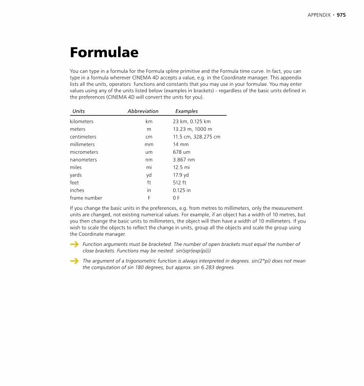
APPENDIX • 975
FormulaeYou can type in a formula for the Formula spline primitive and the Formula time curve. In fact, you can type in a formula wherever CINEMA 4D accepts a value, e.g. in the Coordinate manager. This appendix lists all the units, operators functions and constants that you may use in your formulae. You may enter values using any of the units listed below (examples in brackets) - regardless of the basic units defined in the preferences (CINEMA 4D will convert the units for you).
Units Abbreviation Examples
kilometers km 23 km, 0.125 kmmeters m 13.23 m, 1000 mcentimeters cm 11.5 cm, 328.275 cmmillimeters mm 14 mmmicrometers um 678 umnanometers nm 3.867 nmmiles mi 12.5 miyards yd 17.9 ydfeet ft 512 ftinches in 0.125 inframe number F 0 F
If you change the basic units in the preferences, e.g. from metres to millimeters, only the measurement units are changed, not existing numerical values. For example, if an object has a width of 10 metres, but you then change the basic units to millimeters, the object will then have a width of 10 millimeters. If you wish to scale the objects to reflect the change in units, group all the objects and scale the group using the Coordinate manager.
Function arguments must be bracketed. The number of open brackets must equal the number of close brackets. Functions may be nested: sin(sqr(exp(pi)))
The argument of a trigonometric function is always interpreted in degrees. sin(2*pi) does not mean the computation of sin 180 degrees, but approx. sin 6.283 degrees.
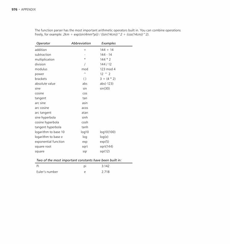
976 • APPENDIX APPENDIX • 977
The function parser has the most important arithmetic operators built in. You can combine operations freely, for example: 2km + exp(sin(4mm*pi)) / ((sin(14cm))̂ 2 + (cos(14cm))̂ 2).
Operator Abbreviation Examples
addition + 144 + 14subtraction - 144 - 14multiplication * 144 * 2division / 144 / 12modulus mod 123 mod 4power ^ 12 ^ 2brackets ( ) 3 + (4 * 2)absolute value abs abs(-123)sine sin sin(30)cosine costangent tanarc sine asinarc cosine acosarc tangent atansine hyperbola sinhcosine hyperbola coshtangent hyperbola tanhlogarithm to base 10 log10 log10(100)logarithm to base e log log(e)exponential function exp exp(5)square root sqrt sqrt(144)square sqr sqr(12)
Two of the most important constants have been built in:
Pi pi 3.142
Euler’s number e 2.718
976 • APPENDIX APPENDIX • 977
Programming pluginsThe built-in XPresso node editor gives you extensive control over how CINEMA 4D objects interact with one another. In addition to XPresso, CINEMA 4D provides you with a powerful programming language that enables you to produce plugins that can extend the core functionality of CINEMA 4D.
The COFFEE programming language COFFEE, CINEMA 4D’s plugin language, is not based on macros or scripts but is a complete and powerful programming language in its own right. It closely resembles C++ and Java so that if you are already familiar with these languages you will immediately feel at home with COFFEE; you simply have to learn the various functions implemented by CINEMA 4D.
To start programming you will need to get hold of the SDK (Source Development Kit) directly from MAXON; this can be obtained from www.plugincafe.com.
What is the advantage of writing plugins in COFFEE as opposed to using C++? Well, apart from the ease of integrating new functionality into CINEMA 4D, as you know, CINEMA 4D is a multi-platform program. Writing plugins in COFFEE means that your new CINEMA 4D function will work immediately on all those platforms, with no annoying re-compilation or reprogramming.
So that CINEMA 4D can find its COFFEE programs and load them automatically, they must be placed in the Plugins folder which should be in the root CINEMA 4D folder. If you check the contents of this folder, you will find some examples already there. However, you can also store COFFEE programs elsewhere on your hard disk. If you want to load such a program into CINEMA 4D just use the File > Open menu command — a file stored outside the Plugins folder cannot be automatically integrated into CINEMA 4D’s menu structure.
How do you create a plugin? Simply write your COFFEE programs in any text editor or word processor and save it as a regular ASCII text file; CINEMA 4D will happily process regular text, with no high-ASCII characters.
The APIPerhaps you do not want to use COFFEE as your programming language? As usual, CINEMA 4D allows you the flexibility to do it the way you want to; if you like, you can write your applications with any C or C++ compiler. Here you have access to the functionality of CINEMA 4D through pre-defined interfaces. These interfaces are in the form of an API (Application Programming Interface) library which is part of CINEMA 4D’s SDK. Note, however, that if you use an external compiler (as opposed to COFFEE) this will be platform dependent and you will need to re-compile your program for each platform on which you want your plugin to work. You may also need to do some reprogramming.
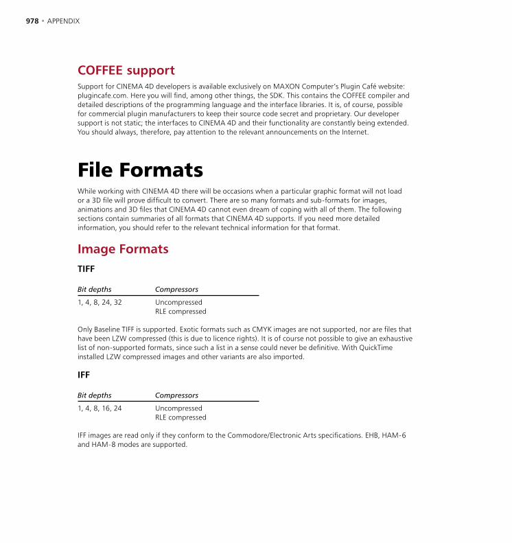
978 • APPENDIX APPENDIX • 979
COFFEE supportSupport for CINEMA 4D developers is available exclusively on MAXON Computer’s Plugin Café website: plugincafe.com. Here you will find, among other things, the SDK. This contains the COFFEE compiler and detailed descriptions of the programming language and the interface libraries. It is, of course, possible for commercial plugin manufacturers to keep their source code secret and proprietary. Our developer support is not static; the interfaces to CINEMA 4D and their functionality are constantly being extended. You should always, therefore, pay attention to the relevant announcements on the Internet.
File FormatsWhile working with CINEMA 4D there will be occasions when a particular graphic format will not load or a 3D file will prove difficult to convert. There are so many formats and sub-formats for images, animations and 3D files that CINEMA 4D cannot even dream of coping with all of them. The following sections contain summaries of all formats that CINEMA 4D supports. If you need more detailed information, you should refer to the relevant technical information for that format.
Image FormatsTIFF
Bit depths Compressors
1, 4, 8, 24, 32 UncompressedRLE compressed
Only Baseline TIFF is supported. Exotic formats such as CMYK images are not supported, nor are files that have been LZW compressed (this is due to licence rights). It is of course not possible to give an exhaustive list of non-supported formats, since such a list in a sense could never be definitive. With QuickTime installed LZW compressed images and other variants are also imported.
IFF
Bit depths Compressors
1, 4, 8, 16, 24 UncompressedRLE compressed
IFF images are read only if they conform to the Commodore/Electronic Arts specifications. EHB, HAM-6 and HAM-8 modes are supported.
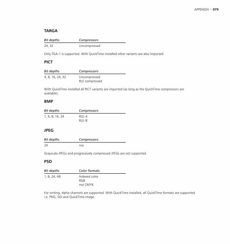
978 • APPENDIX APPENDIX • 979
TARGA
Bit depths Compressors
24, 32 Uncompressed
Only TGA-1 is supported. With QuickTime installed other variants are also imported.
PICT
Bit depths Compressors
4, 8, 16, 24, 32 UncompressedRLE compressed
With QuickTime installed all PICT variants are imported (as long as the QuickTime compressors are available).
BMP
Bit depths Compressors
1, 4, 8, 16, 24 RLE-4RLE-8
JPEG
Bit depths Compressors
24 n/a
Grayscale JPEGs and progressively compressed JPEGs are not supported.
PSD
Bit depths Color formats
1, 8, 24, 48 Indexed colorRGBnot CMYK
For writing, alpha channels are supported. With QuickTime installed, all QuickTime formats are supported i.e. PNG, SGI and QuickTime image.

980 • APPENDIX APPENDIX • 981
B3D
Bit depths Color formats
8, 24 n/a
B3D is the native file format of the BodyPaint 3D module. Layers, layer masks and channels are supported.
RLA, RPF
Save your multi-pass files in RLA or RPF format if you want to post-edit in compositing programs like After Effects and Combustion. RPF is an extension of the older RLA format. RPF supports all the channels listed below (RLA supports the channels from Z to Coverage):
– ZInformation on camera <-> object distance. Useful for depth-of-field effects.
– ObjectEnables different materials to be used in post-editing.
– UV CoordinatesInformation on UV coordinates so that new textures can be mapped correctly during post-editing.
– NormalDirection information regarding objects and textures.
– Non-Clamped ColorInformation on object color. Can extend beyond RGB gamut.
– CoverageAntialiasing information for object edges.
– Object ID (RPF only)Enables the clear identification of objects.
– Color (RPF only)Object color information.
– Transparency (RPF only)Object transparency information.
– Subpixel WeightInformation on the color of subpixels.
– Subpixel MaskInformation that links subpixels to their objects.
HDRI
HDRI images are converted to RGB upon loading.
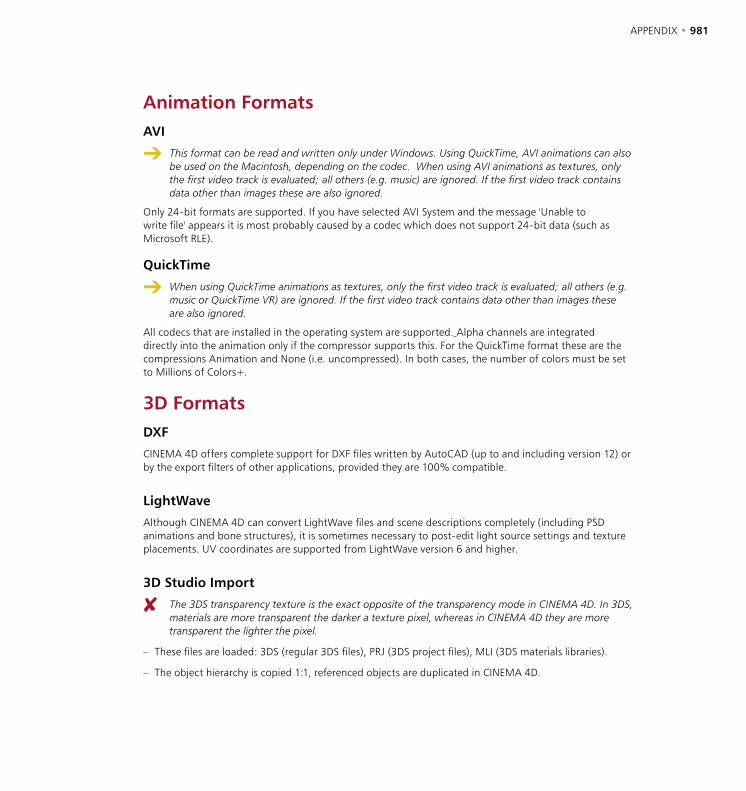
980 • APPENDIX APPENDIX • 981
Animation FormatsAVI
This format can be read and written only under Windows. Using QuickTime, AVI animations can also be used on the Macintosh, depending on the codec. When using AVI animations as textures, only the first video track is evaluated; all others (e.g. music) are ignored. If the first video track contains data other than images these are also ignored.
Only 24-bit formats are supported. If you have selected AVI System and the message 'Unable to write file' appears it is most probably caused by a codec which does not support 24-bit data (such as Microsoft RLE).
QuickTime
When using QuickTime animations as textures, only the first video track is evaluated; all others (e.g. music or QuickTime VR) are ignored. If the first video track contains data other than images these are also ignored.
All codecs that are installed in the operating system are supported. Alpha channels are integrated directly into the animation only if the compressor supports this. For the QuickTime format these are the compressions Animation and None (i.e. uncompressed). In both cases, the number of colors must be set to Millions of Colors+.
3D FormatsDXF
CINEMA 4D offers complete support for DXF files written by AutoCAD (up to and including version 12) or by the export filters of other applications, provided they are 100% compatible.
LightWave
Although CINEMA 4D can convert LightWave files and scene descriptions completely (including PSD animations and bone structures), it is sometimes necessary to post-edit light source settings and texture placements. UV coordinates are supported from LightWave version 6 and higher.
3D Studio Import
The 3DS transparency texture is the exact opposite of the transparency mode in CINEMA 4D. In 3DS, materials are more transparent the darker a texture pixel, whereas in CINEMA 4D they are more transparent the lighter the pixel.
– These files are loaded: 3DS (regular 3DS files), PRJ (3DS project files), MLI (3DS materials libraries).
– The object hierarchy is copied 1:1, referenced objects are duplicated in CINEMA 4D.

982 • APPENDIX APPENDIX • 983
– The following material channels are imported: environment light, specular color, specular settings (which are recalculated), transparency, luminance, color texture, specular texture, transparency texture, environment texture, relief (bump) texture, luminance texture.
– UV mapping is copied.
– Animation.
– Position, scaling, rotation and light sequences are adjusted to suit CINEMA 4D.
– Textures can be renamed automatically on loading.
– So-called target objects loaded from 3DS (from cameras and light sources) become axes (null objects) and are given the extension ‘t’, which is added to their object name.
– 3DS files are binary files and are not recognized by their extensions but by their identifier.
3D Studio Export
Regrettably, 3D Studio can cope only with filenames consisting of eight characters plus a three-letter extension. Therefore texture filenames will be truncated to conform with this restriction.
3D Studio accepts only one UV coordinate per point. Therefore texture mapping may appear different after exporting in this format.
– All polygon objects, light sources and cameras are exported, NURBS objects are transformed into polygon objects.
– Material export: color, luminance, transparency, environment, specular, specular color, relief (bump), all with any defined textures. The mean value of the texture channel is exported with the shader.
QuickDraw3D Import
– Light source and camera information cannot be read.
– The following objects are ignored:Torus, TriMesh (new with QD3D v1.5); NURBS can cause problems in certain cases.
– References (both internal and external) are not read.
– UV coordinates are not read.
– Textures are not read.
QuickDraw3D Export
QuickDraw 3D accepts only one UV coordinate per point. Therefore texture mapping may appear different after exporting in this format.
– Light source and camera information cannot be written.
– Texture export is supported.
– ASCII 3DM files cannot be written, only binary.
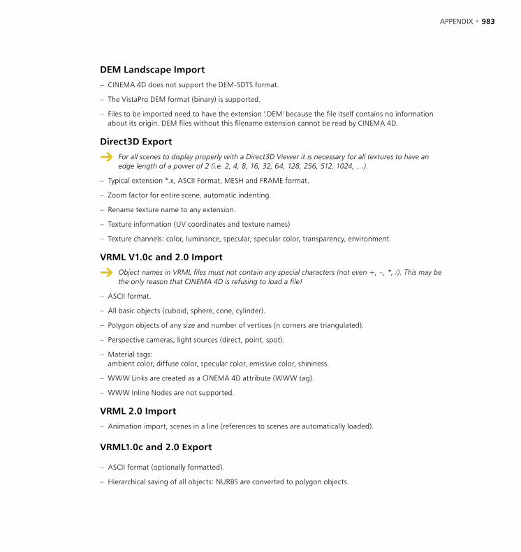
982 • APPENDIX APPENDIX • 983
DEM Landscape Import
– CINEMA 4D does not support the DEM-SDTS format.
– The VistaPro DEM format (binary) is supported.
– Files to be imported need to have the extension '.DEM' because the file itself contains no information about its origin. DEM files without this filename extension cannot be read by CINEMA 4D.
Direct3D Export
For all scenes to display properly with a Direct3D Viewer it is necessary for all textures to have an edge length of a power of 2 (i.e. 2, 4, 8, 16, 32, 64, 128, 256, 512, 1024, …).
– Typical extension *.x, ASCII Format, MESH and FRAME format.
– Zoom factor for entire scene, automatic indenting.
– Rename texture name to any extension.
– Texture information (UV coordinates and texture names)
– Texture channels: color, luminance, specular, specular color, transparency, environment.
VRML V1.0c and 2.0 Import
Object names in VRML files must not contain any special characters (not even +, –, *, /). This may be the only reason that CINEMA 4D is refusing to load a file!
– ASCII format.
– All basic objects (cuboid, sphere, cone, cylinder).
– Polygon objects of any size and number of vertices (n corners are triangulated).
– Perspective cameras, light sources (direct, point, spot).
– Material tags:ambient color, diffuse color, specular color, emissive color, shininess.
– WWW Links are created as a CINEMA 4D attribute (WWW tag).
– WWW Inline Nodes are not supported.
VRML 2.0 Import
– Animation import, scenes in a line (references to scenes are automatically loaded).
VRML1.0c and 2.0 Export
– ASCII format (optionally formatted).
– Hierarchical saving of all objects: NURBS are converted to polygon objects.

984 • APPENDIX APPENDIX • 985
– Object names are converted, special characters are filtered/converted.
– Textures:If there are any textures, the program looks for the color texture, the luminance texture and the environment texture (in that order). Color textures, even inline textures, are saved as files.
– WWW links and addresses are saved: when an object is selected in the web browser, the program branches to that link.
VRML 2.0 Export
– Additional available animation export option.
Wavefront OBJ Import
– ASCII format.
– Polygon objects are loaded.
– Objects are given a dummy material.
– UV mapping is supported.
– No object hierarchy can be created.
– Files to be imported need to have the extension '.OBJ' because the file itself contains no information about its origin. OBJ files without this file name extension cannot be read by CINEMA 4D.
Wavefront OBJ Export
– ASCII format.
– Polygon objects; NURBS are converted to polygon objects, UV coordinates.
Sound FormatsWAV Import
- Only uncompressed WAV files are supported.
- Markers included in the WAV files are imported into CINEMA 4D.
AIFF Import
- Mac sound files are also supported.

984 • APPENDIX APPENDIX • 985
Support What can you do when you are stuck and the manual does not appear to help? You may want to contact technical support. MAXON, and its distributors worldwide, will help you with any technical problems you encounter. So that we can help you as efficiently as possible, please keep in mind the following:
Please contact us (or your local distributor) in writing if possible, preferably by email.
We have telephone lines, of course, but problems with a package as complex as CINEMA 4D may take time to solve — it is not always possible to solve the problem while you are on the phone. With email, however, our technicians can consult with colleagues for assistance — even the programmers if necessary — and get back to you as soon as possible. Email is also convenient for attaching an example of the problem and, likewise, it may be helpful for us to send you a scene.
Please keep support enquiries separate to other enquiries, orders etc.
Orders are dealt with by our busy Sales staff, so your support question is unlikely to be passed onto a support technician.
Please allow for a reasonable response time.
We operate on a queuing system basis only. Our customers are equally important and we will respond to you at the earliest opportunity.
Please supply your telephone number and times when we may contact you on that number.
Occasionally, we may need to contact you for further details.
Please send an example scene to demonstrate the problem, if applicable.
“When I click this button, I get a mess”. It is difficult to solve problems with such limited detail and sometimes we need to examine the problem scene. After all, we and our hard-working beta testers, have tested the functions many-a-time without finding a fault.
Please keep any example scenes as small and as relevant as possible.
For example, if only an alloy wheel is required to demonstrate the problem, please delete the rest of the car — it merely gets in the way. This saves our time and in turn we can respond to your problem sooner.
Please supply us with a complete description of the relevant steps leading up to the problem.
Ideally, we would like a little ‘recipe’ that generates the problem consistently. Please keep this concise.
Include rendered images if relevant.
Please tell us which settings you used.
Please tell us which programs you have running at the same time as CINEMA 4D. If you are using Mac OS, please let us know which system extensions are loaded.
Sometimes, another program or a system extension (Mac OS) may cause a problem indirectly.
986 • APPENDIX
Please include details of your hardware configuration.
“I have a Macintosh/PC” is of little help on its own. Also, please let us know which version of CINEMA 4D you are using (choose Help > Info from the main menu; the version number is shown at the foot of the splash screen which appears; to close the splash screen, click it). If you have Internet access, please use the support form on our website (www.maxon.net). Tell us what other programs and system extensions you are running concurrently with CINEMA 4D.
If the program crashes, it will display an error message. Please let us know the exact message.
If you are using Windows, you will see many other details listed. Please ignore these extra details — they are as enlightening as the infamous Macintosh message 'Application Unknown has quit unexpectedly because of error -1'... Please let us know CINEMA 4D’s message.
If you have Internet access, please check the FAQs on our website before you contact technical support.
Often, you will find the answer in the FAQs.
Our service is limited to technical support only. We cannot undertake subcontracting.
“Can you build my spaceship model, please?”
We must concentrate our resources on helping customers with genuine problems that are within the bounds of technical support. However, there are numerous web addresses where you can find additional help. Please visit our website (www.maxon.net) for links to these valuable resources.

Index

INDEX • 989

INDEX • 989
Symbols2D Sound Rendering 870
range of 8703D Formats 9813D Sound Rendering 871
range of 8723D Studio 981, 982
AAbsolute
node 950Access
material shaders 636Accuracy
and radiosity 551, 602in network render, bake particles
627Action Safe 52Active
material, find first 638Active Object
search Timeline 879Active object
copy active tag to children 628link view to 20render 525search for first 626setting the display mode of 17shading property of 17
Active Tool manager 12, 585Adapter
nodes 943–944Adaptive antialiasing 550Add
object buffer for object 603Adjust
layers, in Timeline 884preview range 881view in Timeline 877
After Effectsand CINEMA 4D 541using cameras and lights 545
AIFF 984Alert
render 525Align
nodes in XPresso editor 927nodes to grid 929to path, expression 615to spline, expression 616
All Framesoption in Timeline 835
Alphabeticsort materials 638
Alpha channelin brick shader 673in cloud shader 674in cyclone shader 675in fire shader 676in flame shader 677in galaxy shader 677in Material Editor 662in Picture Viewer 971in Saturnring shader 681in sunburst shader 685render with 539save, in Picture Viewer 970separate alpha option 540when rendering 532
Anchortag, of object 600
Animated objectsshow in Timeline 875
Animated texture 648Animating
from the Attribute manager 843Animation
antialiasing filter 549cycle mode 837display animation path 18in the browser 100menu in Timeline 836moving within hierarchy 848number of frames when rendering
535of render post effect 558path, defining 616ping-pong mode 837playback rate in viewport 835preview 527record keys in the Timeline 845refresh, XPresso 927spline path 616time units 80using keyframes 842
Animation formats 981Animation path 616
displaying 18Animation Toolbar 832–884Animation toolbar
introduction 12Antialiasing 602
adaptive 550filter 548mode of 531threshold 550when rendering 547
APIfor C.O.F.F.E.E. 977
Applymaterial to object 635
Arrangeitems in the Timeline 875
ASCII Cloudload 963
Attribute manager 901adding user data 909animating parameters 904choosing the display mode 908context menus 903copying and pasting values 906creating a keyframe selection 905customizing the interface 906,
907description 901editing parameters 902Edit menu 909enable animated parameters 47introduction 12keyframing 843load parameter values 907lock 902Mode menu 908navigation 902open additional managers 901recording keyframes 843, 904save parameter values 907selecting multiple parameters
907set driven 904, 905set driver 904User Data menu 909
Autokeying 844in Timeline 833selection object 832
Automatickeyframing 844
Automatic backups 58Automatic mode
in Timeline 876Auto light 562AVI 981
animation format 981
BB3D 980Backface culling 17
disable 18, 24display tag in Object manager
603option for VRML 1 75

990 • INDEX INDEX • 991
Backgroundcolor 558compositing 602
Backgroundsdisplay 19for the interface 50
Backupsautomatic 58
Bakeobject, in Timeline 879particles 627
Bake Objectin Timeline 879
BanjibhodiNUT shader 732
Bank 427with kinematic tag in Object
manager 605Banzi
bhodiNUT shader 746Basic units
overriding 975Batch rendering 526Beveling
edges 471polygons 468
Bézier NURBS 188bhodiNUT shaders 691–812
accessing in Material Editor 643blending channels 712channel shaders
3D noise 696banj 701brightness contrast 703colorizer 704distorter 706falloff 708fresnel 710fusion 712gradient 715hue 718lumas 719posterizer 723projector 724proximal 726tiles 729
color gradients 692shader previews 692surface types
anisotropic 772backlighting 701, 732glass 732gloss 772marble 785metal 772
paint 772rust 798translucent 701, 732weathered 798
title bar 692volume shaders
accessing 636banji 732banzi 746danel 772mabel 785nukei 798
Bias handlesin XPresso gradients 923
Blinn 670Blur
motion, tag 607of transparency 654reflection 657render settings 562to soften a texture 645
BMP 979Bones 323
and HyperNURBS 323and Kinematic tag in Object
manager 605fixing 326, 626laying out a hierarchy 326limiting the influence 325, 327,
329reset 627setting the strength 324
Boolnode 944node group 944–946XPresso data type 920
Break Segment 458Brick 673Browser 92–95
Close 98creating a catalog 93–97delete pictures 99Deselect All 99drag-and-drop 93Edit menu 99example of use 97File menu 96Function menu 101Import Directory 96Import File 96information window 101introduction 11materials 94–97New Catalog 96Open Catalog 96
pictures and animations 94–97preferences 99QuickTime Recognition 99Recurse Folders 99relative paths 96Render All 101Save Catalog 96scenes 94–97searching 102Select All 99sorting 102sounds 95–97thumbnail size 99
Bubble helpenable/disable 49
Bufferobject 602object, add 603
Bump mapfor materials 660
CC++
and C.O.F.F.E.E. 977C.O.F.F.E.E.
and plugins 513and the Console Window 585API 977programming 977SDK 977support 978
Cached solutionsflush 529
Calculateexpression while camera being
rotated 614group of nodes 946–954menu, XPresso 927
Cameras 253Camera mapping 822Camera tool 414Dependency in XPresso 920Dependent, expression option
614Depth of field 255Editor 20Focal length 253Focus 255Frame
Active object 16Scene 16Scene without camera and
lights 16Selected elements 16

990 • INDEX INDEX • 991
Glows 286, 290Lens effects 285, 293
Render setting 552Look at, expression 618Mapping 822Motion blur 553, 554Move hotkey 6Moving 414Projection modes 20
Bird 21Dimetric 21Frog 21Gentleman 21Isometric 21Military 21Parallel 20Perspective 20XY (front) view 21XZ (top) view 21YX (back) view 21YZ view 21ZX (bottom) view 21ZY view 21
Rotate hotkey 6Rotating 415Scene cameras 257Target cameras 257Use for render view 16Using 255Using in After Effects 545Zooming 415Zoom hotkey 6
Cancelrender 526swap with OK button 49
Caps 189applying materials 192cone 132materials 826
Capsule object 149Cartoon
render setting 556Caustics 283
flush cached solutions 529render settings 551
Celrender setting 556
Center Point Editing Axis 47Change
name of material 639name of object 624object, prevent accidental 610
Channelrecord sub-channels 836
Channelsin Picture Viewer 971
Channel shaders 673Checkerboard 674Cheen
bhodiNUT shader 759Children
copy tag to 628of object, select 622
CINEMA 4D R7, loading scenes with animation 830
Circleinterpolation 644
Clampnode 948
Clipboard 117Clip mapping
for materials 662Close
all 109file 108Material manager 636the document 108the Structure manager 964the Timeline 872XPresso editor 925
Close All 109Clouds 674Coffee
error tag 613expression 617expression priority 614
Colorachromatic 81background 558chromatic 81correction, render setting 558HSV model 82of layers, in Timeline 884of XPresso ports 917page, in Material Editor 649pane, in Material Editor 642RGB model 81specular 666XPresso data type 920
Color correctionrender setting 558
Color depthof texture 642when rendering 538
Color system 80Combine
objects 624Command
text or icon 38
Commandson the Animation toolbar 832
Command keychange to control key 48
Command manager 41. See also Icon palettes
allocating keyboard short-cuts 41inserting commands 41
Command palette. See ToolbarsCompare
node 954Composite
image, in Picture Viewer 971Compositing
background 602tag, object 601
Conditionnode 956
Conecaps 132
Cone object 131Configuration
dialogs 31managers 32other settings 32
Connectsequence 882XPresso ports 918
Connectionsnodes, remove 929nodes, types of 926XGroups, remove 929
Consolewindow 585
Constantnode 938
Constants 976Construction plane 251Content
in XPresso editor 929Context menu
for ports 931for XPresso gradients 924introduction 10in Timeline 839modifier key 48XPresso 928
Convertmatrix to vectors, node 943nodes to XGroup 929position tracks to spline 879real to vector, node 943spline to position tracks 880
Coordinatesgenerate UVW 629
992 • INDEX INDEX • 993
manager 593UVW, assign to object 629
Coordinate manager 593–594introduction 12relative/absolute values 593
Coordinate system 427polygons 241reset 508
Copyactive object 622and move, in Timeline 848cells in Structure manager 965image in Picture Viewer 971in XPresso 925keys/sequences 873material 637tag to children 628to clipboard 117
Correctcolor, render setting 558
Cross productnode 947
Cube object 135Cubic mapping 819Current
scenes 586Custom
menu, XPresso 927Cut
active object 622cells in Structure manager 965in XPresso 925keys/sequences 873material 637to clipboard 117
Cyclone 675Cylinder object 137
caps 138Cylindrical mapping 819
DDanel
bhodiNUT shader 772Data type
of XPresso node 920Date
XPresso data type 920Decal mapping 815–818Default
interpolation in F-Curves 834layouts 580settings 107XPresso layout, reset to 926
Deformers 319
and level of detail 604and restriction tag 610and UVW coordinates 629animating deformation
parameters 320Bend 321Bone. See BonesBulge 332Explosion FX. See ExplosionsFFD 342Formula 343Melt 345Polygon Reduction. See Polygon
reductionSet Vertex Weights 442Shatter 355Shear 357Spherify 359Spline Deformer 360Spline Rail 364Taper 371Twist 373Use Deformers 121Wind 375–378Wrap 377
Degreenode 950
Degreesconvert to radians, node 950
Deleteactive object 622animation elements 874markers, in Timeline 874material 637nodes, XPresso 925port 930, 931preview range 881render settings 529Timeline marker 841XGroup 930
DEM 983Depth
color, save with picture 970color, when rendering 538
Depth of field 255Deselect
all objects 622materials 637
Deselect Allelements in Timeline 874
Diffusionmaterial 650
Direct3D format 983Disable
backface culling 24
expressions 614multi-pass rendering 566node 926nodes or XGroups 931object visibility in render 623object visibility in viewport 623textures, render setting 562XGroup 926
Disconnectsurfaces 449
Disc object 140Displacement
material 669Display
of objects, control of 623tag, level of detail 604tag, object 603
Display modefor active object 17for inactive objects 18
Display Tags option 621Display units 79Distance
between two positions, node 949Distorter
bhodiNUT shader 706Dither
when rendering 540Divide
sequence, in Timeline 882Document preferences 57DPI
save with picture 970when rendering 538
Drag-and-Dropin Timeline 838in Timeline, to copy and move
848Drag-and-drop
in the Object manager 598in the Structure manager
962–966Drawing pipeline 119Duplicate
materials, remove 639DXF 981
export 110load object 621
EEarth 676Edges
context menu 492convert to spline 492
992 • INDEX INDEX • 993
filter 553selection, restore 621
Edit2D shader 647animation path 18marker in Timeline 841material 635, 638, 641menu in Material manager 637menu in Object manager 622menu in Structure manager 965menu in XPresso 925object 624object tag 628palette 579tag 628
Editorcamera 20XPresso 915XPresso, close 925XPresso, menus 925XPresso, zoom 926
Editor window. See ViewportsEdit menu 115Effects
render settings 552Enable
expressions 614multi-pass rendering 566node 926object visibility in viewport 623object visibilty in render 623textures, render setting 562XGroup 926
Enterfinal serial number 589
Environmentmaterial 658
Equalnode 955
Errorcoffee tag 613
Even/Odd fields 536Expand
object group 625Explosions 334, 340
animating 339gravity 337rotation 338wind effect 339
Export3D Studio R4 110ASCII data 964DirectX 110Direct 3D 110DXF 110
Flash, tag 604QuickDraw 3D 110Shockwave 3D 110STL 111UZR 111VRML 1 111VRML 2 111Wavefront 111
Expressionalign to path 615align to spline 616camera dependent 614coffee 617disable 614enable 614evaluation order 121fix 617IK 618look at camera 618new 614new XPresso 915nodes 916priority 614sun 619target 619Use Expressions 120vibrate 620XPresso 621XPresso, camera dependency 920XPresso, new 919XPresso, priority 919
External compilerfor C.O.F.F.E.E. 977
Extrude NURBS 176caps and rounding 189
FF-Curves
automatic mode 888, 892baking 898create from function 895crosshairs 893default interpolation 834delete keys 892description of manager 888ease in and out 896editing keys 889F-Curve List 888, 890, 892F-Curve manager 887
Curves menu 894Edit menu 892View menu 893
grid 893hide selected 892
interpolation 894introduction to 887in the Timeline 891manual mode 888mirror keys 897move keys 897navigation short-cuts 889, 891redo 892relative mode 889, 893selecting keys 892show those of selected objects
625simplify 898snap keys to frame 892step and repeat keys 897, 898straighten with clamps 897tangents 894undo 892zoom 893
Falloffdiffuse 671
Field rendering 535File
Close 108Close All 109layout 580logfile example 562menu, main 107menu, Object manager 600menu, XPresso 925Merge 108New 107Open 107paths for WAV files 871recent files 111Revert to Saved 108Save 109Save All 109Save As 109Save Project 110
Filterantialiasing 548antialiasing when rendering 531edges when rendering 553in Picture Viewer 972menu, in Timeline 878
Finalserial number, entering 589
Findfirst active material 638first active object 626
Fire 676Fix
expression 617
994 • INDEX INDEX • 995
Fixingbones 626
Flame 677Flash
tag 604FlashEx
tag 604Flat mapping 819FloatFunc
node 953FloatMath
node 953Floor
and reflections 533Flush
all cached solutions 529Focal length 253
with QTVR 574Focus
of camera 255Fog 382, 688
material 659visible light 265
Foldhierarchy, in Timeline 879object hierarchy 626
FontXPresso data type 921
FontsPostScript 218TrueType 218used for the interface 49
Formatin Picture Viewer 970
Formulanode 949
Formula splinetypes of formula 975
Fractallandscapes 162turbulence 686
Frameplayback rate in viewport 835snap to, in Timeline 875view in Timeline 877
Framesnumber to render 535playing all in viewport 835
Frame ratefor project 84for render 536setting for movie material 647
Freezenode 941
Fresnel 653
bhodiNUT shader 710Frontal mapping 820Function
menu, Material manager 638Functions menu 501Fusion
bhodiNUT shader 712
GGalaxy 677Gels 300General
nodes 935–942Generate UVW coordinates 629Generators 121
stopping effect 612Use Generators 121
Genlocking. See Clip mappingGI
accuracy 602Glass
rendering 532Global status bar 585Glow
editor 290object, render setting 552page, in Material Editor 667
Gotocells, in Structure manager 965
Gouraud shadingdescription 22
GradientbhodiNUT shader 715XPresso data type 921
Gradientsusing within XPresso 923XPresso, context menu 924
GraphRange Mapper 952
Graphics tablet 47Grayscale
in Picture Viewer 972Grid
when slicing an object 134XPresso, align to 929
Groupexpand objects 625in XPresso 916objects 624
Groupspreserve when beveling 470
GUI 7, 33
HHandle
selection, in Timeline 849HDRI 980Heading 427
with Kinematic tag in Object manager 605
Help 589enable/disable 49menu 589–590
Hexahedron 145Hide
objects in render 623other than frozen selection 441tags in Object manager 621
Hierarchyarrange, in Timeline 875fold/unfold, in Timeline 879moving animations within 848object, changing 598object, fold 626object, unfold 626select children of object 622
Highlightcolor 666in material 665
Hotkeys 6HPB system 427, 428
use 79Hue
bhodiNUT shader 718HyperNURBS 170
modeling 174quads vs triangles 241subdivide polygons 490weighting 172weight tag 604
IIcon
material, render 638size, in Material manager 637
Icons in menus 49Icon palettes 37
alignment 39creating 37creating folded groups 39editing 40icon size 39introduction 10loading 39moving icons 38
994 • INDEX INDEX • 995
new 579removing icons 40saving 38the lock icon 40unfolding groups 40
IFF 978IK
Anchor tag 424, 600expression 618IK tag 605Inverse Kinematics tool 423Kinematic tag 605multi-target kinematics 424posing characters 423
Illuminationpage, in Material Editor 670
Illustratorload object 621
Imagealpha channel, in Picture Viewer
971composite, in Picture Viewer 971fit texture to 630formats 978using as texture 642
Image formats 978Image sequence
when rendering 538Import
ASCII cloud 963multi-pass into After Effects 541
Import/Exportsettings 111
Inactive objectdisplaying 18
Infoports 931
Informationabout current scene 626about selected object in Object
manager 625about structure 586object 625on CINEMA 4D 589on selected items 585on selected object 585
Initialization files 103Inputs
nodes, configuring 926Input boxes
introduction 11Insert
preview range 881Instances 246
generate with Duplicate command 504
IntegerXPresso data type 921
Interactive controlof objects 130
Interfacescheme 46
Interpolationcircle 644for bhodiNUT shaders 693in Timeline 834of keys in Timeline 866of knots in XPresso gradients 923of textures 643spline 199
Inverse Kinematics. See IKInvert
node 947Is Null
node 955Iteration
node 941
JJPEG 979
KKey
interpolation 866new, in Timeline 866selection, in Timeline 874
Keyboard short-cutsadding your own 41
Keyframeand layers, in Timeline 839autokeying 833recording 833
Keyframing 842in the Atrribute manager 843in the Timeline 845
Keysand Bake Object 879creating in Timeline 841move in Timeline 848
Kinematictag 605
Knife tool 480Knots
interpolation, XPresso gradients 923
LLandscape object 162Language
choose 46Lathe NURBS 178
caps and rounding 189Launching 5Layer
colors, in Timeline 884menu, in Timeline 884
Layersand the texture tag 613in Timeline 839multi-pass render 568texture 823
Layouts 8, 33, 579–581load 579loading 91menu, XPresso 926reset 91, 579reset to default 91reset to default, XPresso 926save 47save as 580save default 580saving 91working with 91
Lens effects 285, 293render setting 552
Lens GlowXPresso data type 921
Level of detail 84in Display tag 604in the viewport 22when rendering 565
Lifetimeof particles 305
Lighting 259Area light 263auto, render setting 562brightness 268caustics 283color 260contrast 268Displaying lights in a viewport
259Distant light 263falloff 269for individual objects 294gels 300Glows 286, 290Lens effects 285, 293lightmaps 300memory required 261
996 • INDEX INDEX • 997
Noise 266, 284Omni light 262Parallel light 263Parallel spotlight 263render time needed 261shadows. See ShadowsSpotlight 262Sun light 297Target light 296Tube light 263types of 262using in After Effects 545visible light 265, 274volumetric 266volumetric, render setting 563volumetric light 274
Lightmaps 300LightWave 981Link
objects with target expression 619
selection in Timeline to Object manager 876
XPresso data type 921List
of default layouts 580Load
layout 579material 107, 636object 621point cloud 963scene 107toolbar 579XGroup, in XPresso 925
Locktexture with stick texture tag 611
Lock iconin Timeline 876
Loft NURBS 180caps and rounding 189
Logicbool node 944group of nodes 954–958
Log file 562Look
at camera, expression 618Look & Feel 49Loop
nodes with iteration 941sequence, in Timeline 864
LumasbhodiNUT shader 719
Luminancematerial 651
MMabel
bhodiNUT shader 785Macintosh
simulating right mouse button 6Magnetic
markers, in Timeline 841Magnet tool 483Make Editable 465Make Preview 527Make Tab 45Managers
convert window to tab 45introduction 9load settings with scene 58pin icon 45renaming 45undocking 45
Manual modein Timeline 876
Mapvalues with Range Mapper node
950Mapping
camera 822decal 815–818flat 819frontal 820MIP 644SAT 644shrink wrapping 822spherical 819texture, disable 18textures 813UVW 820
Marble 679Marker
delete, in Timeline 874from selection 882in Timeline 840magnetic, in Timeline 841new, in Timeline 869Timeline, navigation 841
Materialsadd texture tag in Object manager
612alpha channel 662applying to object 635apply to object 639blur reflection 657blur transparency 654bump map 660clip mapping 662color 642
copy 637cubic mapping 819cut 637cylindrical mapping 819delete 637deselect all 637diffuse falloff 671diffusion 650displacement map 669edit 635, 638environment 658find first active 638fog 659fresnel 653glow 667highlights 665load 107, 636luminance 651mixing 646movie, setting frame rate 647natural-looking 652new 636of active object 638paste 637reflection 656remove duplicate 639remove unused 639rename 639render icon 638save 636select 635select all 637shaders, accessing 636sort 638specular 665tag, select 639texture 642transparency 652using movies 647
Material Editor 641–672color page 649color pane 642goto 638texture pane 642
Material manager 635–639close 636copy 637cut 637delete 637edit menu 637file menu 636function menu 638introduction 11paste 637redo 637

996 • INDEX INDEX • 997
thumbnail 635undo 637
Material shaders 688Math
node 946Matrix
convert to hpb, node 948to vectors, node 943XPresso data type 921
Matrix2HPBnode 948
Matrix2Vectorsnode 943
MAXONwebsite 589
Memorynode 940
Menuanimation, in Timeline 836filter, Timeline 878layer, in Timeline 884options, in Timeline 834
Menusediting 43introduction 9
Menu manager 43inserting commands 44revert to original 44
Mergefiles 108
Metaballs 247Metaball tag 607
Metal 679specular on material 665
MIP mapping 644strength when rendering 550
Mirror tool 484Missing textures 525Mix
material attributes 646node 949with other textures 823
Mixing textures 823Mode
menu in Structure manager 966of working, in Timeline 876
Modelscale hotkey 6
Motion blurobject 553scene 554tag 607
Mouseright mouse button, Macintosh 6using in Object manager 599
wheelmouse 6Move
animations hierarchically 848cells in Structure manager 961hotkeys 6in Picture Viewer 969items in Timeline 848sequence, in Timeline 883
Movieas a material 647creating (rendering) 537formats 575preview 527render as 537render formats 537sequence option in Material
manager 648using in a material 647
Multi-Passand After Effects 541rendering 566–575
enable/disable 566save 569save with picture 970
Multi-select. See Multiple selectionMultiple selection 89
NName
of port, show 930render settings 531
Naturalmaking material look 652
Navigationin Structure manager 962–966in Timeline 838in Timeline, with markers 841
Negatea bool value with the NOT node
946node 947
NET Renderbake particles 627
Newfeatures in Timeline 829key, in Timeline 866marker, in Timeline 869morph track 853parameter track 850pla track 856sequence, in Timeline 863sequence in Timeline 881sound track 858time track 860
new.c4d 103, 107New features 3Nodes 916, 935–956
align 927align to grid 929commenting with remark 940connections, types of 926context menu 928data type 920debugging via result and spy 939delete 925, 930disable 926, 931enable 926general 935–942gradients, using 923inputs, configuring 926new 928optimize 930remove connections 929select 925set view 929
Noise2D shader 6943D shader 696shader 680types, bhodiNUT 700types of for lighting 266
NormalXPresso data type 922
Normals 24align 487displaying 17general information 487move surfaces along 481reverse 488rotate polygons around 482scale polygons along 481
Notnode 946
NukeibhodiNUT shader 798–812
Null object 237Number
of frames to render 535of points/polygons in selected
object 625Numerical
input of coordinates 593NURBS 169. See also HyperNURBS
Bézier 188caps and rounding 189Extrude 176Lathe 178Loft 180Sweep 183
998 • INDEX INDEX • 999
OObject
selection, autokeying 832selection, in Timeline 874
Objectsadd points 466anchor tag 600and layers, in Timeline 839apply material to selected 639arrange along a spline 501Array 242assin UVW coordinates to 629Atom Array 243Background 383bake, in Timeline 879bevel 468Boolean 245Bridge tool 472buffer, add 603Camera 253casting shadows 601center (align) 502–510children, select 622coffee error tag 613compositing tag 601cone 131connect 472, 503Construction Plane 251controling display 623convert quads to triangles 491convert triangles to quads 491coordinates 128copy 622copy position, scale, rotation 510copy tag to children 628create a polygon copy 503crumple 449cube 135cut 622cut edges 491cylinder 137DDS EX 6.1 396Deformers. See Deformersdelete 622deselect all 119, 622disc 140disconnect points 450disconnect polygons 450display tag 603DTS 5.1 395duplicate 504duplicate points 447duplicate randomly 506duplicate surfaces 447
edit 624Environment 381expand group 625Extrude Inner tool 478Extrude tool 475
smooth shift 486figure 161fit texture to 630fix position with fix expression 617FlashEx tag 604Floor 379fold hierarchy 626Foreground 383generate UVW coordinates for
629glow, render setting 552group 624hierarchy, unfold 626hyperNURBS weight tag 604information 625Instance 246interaction, with Set Driven Keys
957kinematic tag 605Knife tool 480landscape 162Light 259. See also Lightinglink with target expression 619load 621Loudspeaker 388Magnet tool 483make editable 465Matrix Extrude tool 451menu, in Timeline 879menu, Object manager 623Metaball 247metaball tag 607Mono Microphone 390motion blur 553motion blur tag 607move hotkey 6moving 403, 410moving multiple objects 404new expression 614node 935object library 399oil tank 151Particles. See ParticlesParticle Emitter 301. See
also Particlespaste 622phong tag 608plane 142point at camera, expression 618polygon 144
prevent accidental change 610Primitives 129Properties
Basic 127Coordinates 128Object 128
protection tag 610pyramid 157rearrange 598relief 166remove from Timeline 875rename 624rename, in Timeline 879render active only 562render properties, compositing
tag 601render visibility 623restriction tag 610rotating 407, 410rotating multiple objects 409save selected 621scale hotkey 6scaling 405, 410scaling multiple objects 406SDDS 7.1 397search for first active 626Selection 386select all 119, 622select children 119select materials of 638Shockwave 3D tag 610show all animated, in Timeline
875show F-Curves of those selected
625size 625Sky 380Sound objects. See Soundsphere 145split surfaces 455Stage 385Stereo 394Stereo Microphone 393stick texture tag 611stop tag 612sun expression 619Symmetry 249tag, edit 628target expression 619texture tag 612torus 147tracks, show in Timeline 625tube 154vibrate expression 620viewport visibility 623
998 • INDEX INDEX • 999
visibility 623visibility when rendered 604weld points 455www tag 613XPresso data type 922XPresso expression 621
Objects menu 127Object buffer 602Object hierarchy 598Object manager 597–632
drag-and-drop 598edit menu 622file menu 600hide tags 621introduction 11link to Timeline 876new tag 600objects menu 623redo 622show tags 621tags menu 628texture menu 629undo 622using mouse 599
Odd/Even fields 536Oil Tank object 151OK button
swap with Cancel 49Open
file 107in Picture Viewer 970scene/file 107
Operatorsmathematical 976
Optimizenode or XGroup 930structure 489
Optionsin render settings 562menu in Timeline 834
Ordermaterials 638node 954
Oren-Nayar 670
PPalette
edit 579Panoramic
render with QuickTime VR 572Parameter
track 850Particles
Attractor 307
bake 627baking 303birthrate 304Deflector 308Destructor 310Emitter 304emitter type 306examples 316Friction 311Gravity 312lifetime 305metaparticles 317Rotation 313save with scene 58seeding 305speed 305Turbulence 314viewport display 306visibility 304Wind 315
Pastecells in Structure manager 965from Clipboard 117into Timeline 873in XPresso 925material 637object 622
Pathalign to, expression 615for WAV file 870spline, animation 616
Perfect sphere 146Personalize 589Phong
shading, how it works 609tag 608
PICT 979Picture Viewer 583, 969–972
alpha channel, save 970channels 971filter RGB 972fit image to size 972format image 970move 969open image 970render to 526saving color depth and dpi 970scale 969zoom 972
Ping-Ponganimation playback mode 837
pin menu, The 45Pitch 427
with Kinematic tag in Object manager 605
Pixelsinterpolating in Material Editor
643PLA
track 856Plane object 142Plastic
specular on material 665Platonic objects 159Play Mode
in Timeline 837Play sound 832Plugins
execute last plugin 513Flash export plugin 514Plugins menu 513programming 977SpaceMouse plugin 521
Pointat another object, expression 619node 938
Pointsadd 466align 453cloud 963context menu 492duplication 445mirror 484mode, in Structure manager 966number in scene 626number of in selected objects
625optimize 489selection, restore 621set position 454welding 455
Point Level Animation. See PLAPolygon
node 942Polygons 240
bevel 468context menu 492convert edges to spline 492convert quads to triangles 491convert triangles to quads 491coordinate system 241Create Polygon tool 474creating from triangles 144cut edges 491duplicate selected points 445information on selected 585information on structure 586mirror 484mode, in Structure manager 966number in scene 626

1000 • INDEX INDEX • 1001
number of in selected objects 625
quads vs triangles 241selection, restore 621subdivide 490
Polygon object 144, 240Polygon reduction
general advice 350–354hints and tips 351quality of mesh 348quality preservation 350using 347what does it do 347why use it 347
PoolXPresso 933
Portcontext menu 931delete 931info 931remove unused 930remove wires 931rename 930, 931show names 930user data, in XPresso 918
PortsXPresso 917
Positionof object, fix expression 617of object, vibrate expression 620of sun, expression 619tracks to spline 879
PosterizerbhodiNUT shader 723
PostScript fonts 218Post edit
multi-pass renders 566–575Post effects
animating 558render setting 552–561
Preferences 46BodyPaint 57Browser 99Common 46
Macintosh 48Document 57Import/Export
3D Studio R4 59Adobe Illustrator 63Biovision BVH 59DEM 60Direct3D 62DXF 60, 61LightWave 3D 64Monzoom 64
QuickDraw 3D 65Shockwave 3D 66STL 66UZR 71VRML 1 75, 76VRML 2 76, 78Wavefront 78
Interface 49Colors 50
Texture Paths 78Units 79Viewport 51XPresso 83
Premultiplied alpha 663Preserve Groups
when beveling 470Preview
animation 527restrict playback to, in Timeline
837size of in Material manager 637
Preview rangeadjust 881delete 881insert 881in Timeline 840
Primitives 129Priority
of expression 614of XPresso expression 919set 46XPresso data type 922
Programmingexpressions 617in C.O.F.F.E.E. 977
Projectsave 110
Projectiondifferent types with one texture
tag 629Projector
bhodiNUT shader 724Project settings 84Property
object, new 600Protect
objects from accidental change 610
Protectiontag 610
ProximalbhodiNUT shader 726
PSD 979
Pulseobject with vibrate expression
620Pyramid object 157
QQuantize
selections, in timeline 883QuickDraw 3D 982QuickTime 981
recognition in the Browser 99use 47
QuickTime VRrender setting 572
Quit 6
RR7
loading scenes with animation 830
Radiosity 551accuracy 602flush cached solutions 529render settings 551
Rail splineswith Sweep NURBS 184
Randomnode 939
Range Mappergraph 952node 950
Raytracingadaptive 550range for 2D sound rendering
870range for 3D sound 872samples in metal shader 688
Ray depthrender setting 563
Realto vector, node 943XPresso data type 922
Reals2Vectornode 943
Realtime texture mapping 25Save RTTM Textures 57with OpenGL shading 55with software shading 53
Rearrangeobjects, in Object manager 598
Recalculate Scene On Rewind 47Recent files 58, 111

1000 • INDEX INDEX • 1001
Recordautokeying 844automatic 844keyframe 833keys in the Timeline 845sequences, in Timeline 881sub-channels 836
Recordingusing keyframes 842
Recoverlast saved file 108
Redoin Material manager 637in Object manager 622in Timeline 873in XPresso 925
Reflectionsblur 657material property 656rendering 532
Reflection depthwhen rendering 563
Refractionwhen rendering 532
Refractive indices 653Refresh
animation, XPresso 927Region
fit texture to 630render 526
Registerfinal serial number 589
Relativeset driven keys 958values in Coordinate manager
593Relief map 166Relief object 166Remark
node 940Remove
connections, nodes and XGroups 929
duplicate materials 639objects from Timeline 875port 930unused materials 639unused ports 930wires from port 931XGroup 930
Renamematerial 639object 624objects, in Timeline 879port 931
ports and XGroups 930Render
2D sound 8703D sound 871across networks, bake particles
627active object 525active objects only 562alerts 525animate post effect 558batch 526cancel 526current view 525make preview 527material icons 638properties of object, compositing
tag 601region 526show line while 972stop, in Picture Viewer 970to Picture Viewer 526visibility of object 604visibility of objects 623
Renderlineduring render 972
Render Active Object 525Render menu 525–529Render Safe 52Render settings 531–576
alpha channel 539animate post effect 558antialiasing 531, 547as movie 537blur 562caustics 551cel renderer 556color correction 558color depth 538delete 529dither 540DPI 538edges filter 553effects 552fields 535filters 553frame rate 536image sequence 538lens effects 552level of detail 565multi-pass 566–575multi-pass to After Effects 541name 531new 528number of frames 535object glow 552
object motion blur 553options 562QuickTime VR 572radiosity 551ray depth 563reflections 532reflection depth 563resolution 534save formats 537scene motion blur 554separate alpha 540shadows 533shadow depth 564soft shadows 533straight alpha 540texture, enable/disable 562threshold 564transparency 532with refraction 532
Render Threads 48Reset
bones 627layout 91, 579XPresso layout 926
Resolutionsave with picture 970when rendering 534
Restoreselection 621
Restrictnode values 948
Restrictiontag 610
Resultnode 939
Revert to Original Menus 44Revert to Saved 108RGB
separating in Picture Viewer 972Right mouse button
on a Macintosh 6RLA 980Rotate
hotkeys 6Rotation
of object, vibrate expression 620Rounding 189
when filleting 133RPF 980RTTM. See Realtime texture
mappingRuler
Timeline 840Rust 681

1002 • INDEX INDEX • 1003
SSampling
of textures 643SAT mapping 644
strength when rendering 550Save
active object 621all files 109default layout 91, 580file 109layout as 580layout at program end 47material 636multi-pass image 569node values 940project 110scene 109when rendering 537XGroup 925
Save as 109Scale
hotkeys 6MIP/SAT strength when rendering
550Picture Viewer 969sequence, in Timeline 883Timeline window 838
Scenecamera 257information 626load 107number of polygons/points 626R7, loading 830size 626
Scenesthat are open 586
Scene Motion Blur 554Scheme
choosing for interface 46Scroll
Timeline window 838SDK 977Seamless tiles 817Search
paths 78, 525Segments
break spline 458Select
all elements, in Timeline 874all materials 637all objects 622children of object 622components in Timeline 847identical child tags 628
in Timeline 847layer, in Timeline 884material 635materials of active object 638node 925tags of selected materials 639XGroup 925
Selecteditems, information 585
Selectingwithin the Structure manager
962, 965Selection
get Time curve from 883handles, in Timeline 849in Timeline 874link Timeline to Object manager
876quantize, in Timeline 883
Selectionsconvert types 438displaying 436edge loops 439edge rings 439filtering 433Freehand Selection tool 412freeze selection 440grow selection 437hide 439, 440inverting 436Live Selection tool 412Polygon Selection tool 412Rectangle Selection tool 412restore 621selecting 434Selection menu 433Selection object 386, 435select all 436select connected 437set selection 440set vertex weight 442shrink selection 438Tolerant Selection 413unhide 440Vertex Painting 413
Selection menu 433. See also Selections
Selection Objectautokeying 832
Selective UVW Mapping 821Separate alpha
rendering 540Sequence
and layers, in Timeline 839connect, in Timeline 882
divide, in Timeline 882loop, in Timeline 864move/scale, in Timeline 883move in Timeline 848new, in Timeline 863, 881of images, when rendering 538record 881selection, in Timeline 874select all, in Timeline 874
Serial numberentering 589
Setmarker, in Timeline 841
Settings. See also Preferencesdefault 107import/export 111project 84ray depth 563render resolution 534
Set driven keys 904, 905, 957Shaders
accessing within Material Editor 643
bhodiNUT 691channel 673material 688
accessing 636Shader - 2D
brick 673checkerboard 674cloud 674cyclone 675fire 676flame 677galaxy 677gradient 678noise 680planet 680
Neptune 681Saturn 680Saturnring 681Uranus 681
starfield 684stars 685sunburst 685turbulence 686water 687
Shader - 3Dcolor 675Earth 676fog 688marble 679metal 679rust 681spectral 682

1002 • INDEX INDEX • 1003
terrain 689Venus 686wood 687
Shading modes 22Shading property 17, 18
use shading property 23Shadows 279
and objects 601Area shadow 265color 279density 279Hard shadow 264No shadow 264outline shadow 282rendering 533shadow cone 282shadow maps 280Soft shadow 264
rendering 533transparency 279types of 264
Shadow depthand materials 656when rendering 564
Shockwave 3Dexport 66, 110export, tag 610tag, double-sided 610
Showall animated objects, in Timeline
875F-Curves of selected objects 625name of port 930tags in Object manager 621
Show Animation Path 18Show Normals 17Shrinkwrap mapping 822Size
in Picture Viewer 972of icon in Material manager 637of object, vibrate expression 620of scene 626of selected objects 625
Skyand reflections 533
Sliceregular grid option 134
Smartpointer 89Smoothing
how it works 609phong tag 608with antialiasing on render 547
Snapto frame, in Timeline 875
Snap settings 493
introduction 12mouse sensitivity 498world grid 497–498
Sortmaterials 638
Sound 3872D 8703D 871DDS EX 6.1 object 396DTS 5.1 object 395formats 984Loudspeaker object 388Mono Microphone object 390playing 387play from animation toolbar 832scrubbing 387SDDS 7.1 object 397Stereo Microphone object 393Stereo object 394track 858
Specularapply diffusion map 650metal 665page, in Material Editor 665plastic 665
Specular Colorpage, in Material Editor 666
Sphere object 145Spherical mapping 819Spline
align to, expression 616path, align to 616segments
creating 195to position tracks 880XPresso data type 922
Splines4-sided 221adding points to 193Akima 197, 202align 462animation from position track
879Arc 205B-Spline 197, 202Bézier 197, 202breaking segments 458break segment 458built-in curves 201built-in primitives 203chamfer 459Circle 207Cissoid 223Cogwheel 225creating 193
creating outlines 460cross sections 461Cubic 196, 202Cycloid 227define first point 458Diamond 221editing 456Epicycloid 227explode segments 450Flower 234Formula 231Freehand 201Helix 209Hypocycloid 227information on selected 585information on structure 586information window 585interpolation 199, 204, 456joining segments 458Kite 221Knife tool 480Lemniscate 223Linear 196, 202Magnet tool 483n-Side 212outlines from 2D images 219Parallelogram 221Profile 235project onto surfaces 463Rectangle 214reverse order of points 459round 463segments 194spline rails 364Star 215Strophoid 223tangents 197, 457Text 217Trapezium 221types of 196using formulas 975Vectorizer 219
Spline object 193Spotlights 262, 263Spy
node 939Square
interpolation 644Starfield 684Stars 685Starting 5Status bar 585
XPresso 926Stick Texture
tag 611
1004 • INDEX INDEX • 1005
Stillantialiasing filter 549
Stoptag 612
Straight alpharendering 540
StringXPresso data type 922
Structureinformation 586optimize 489
Structure manager 961–966delete cells 965export ASCII data 964import ASCII data 963modes 966mode menu 966moving cells 961new line 963pasting 965selecting data 965view menu 965
Structure menu 445context menu 492
Subdivide 490Sun
expression 619Sunburst 685Surfaces
disconnect 449Surface Normals 24Sweep NURBS 183
caps and rounding 189Switch
node 946
TTabs
introduction 10Tags
Anchor 600COFFEE Error 613Compositing 601copy to children 628Display 603edit 628FlashEx 519, 604hide, in Object manager 621HyperNURBS weight 604Kinematic 423, 605material, apply 639menu in Object manager 628Metaball 248, 607Motion Blur 607
new 600of selected materials, select 639Phong 608Protection 610Restriction 330, 610select identical child 628Shockwave 3D 610show in Object manager 621Stick Texture 611Stop 612Sun Expression 298Target Expression 257Texture. See Texture tagWWW 613
TARGA 979Target
expression 619IK, set with expression 618
Technical Support 985template.c4d 6, 31, 103, 107template.cat 103template.l4d 103Terrain 689Test
for equality, node 955for null, node 955
Textures. See also Texture taganimated 648applying to one side only 815camera mapping 820, 822color 649color depth 642coordinates 818different projection types with
one tag 629enable/disable, render setting
562error, render setting 562fit to object/image/region 630hull, caps and rounding 826interpolation 643layers 823lock, with stick texture tag 611menu in Object manager 629missing 525mixing 823pane, in Material Editor 642path to 78position 818rotate 818sampling 643scale 818seamless tiles 817soften with blur 645stretching 822
tag 612tiling 816, 817types of mapping 818XPresso data type 923
Texture Axisadapt to object axis 631adapt to view 631mirror 631
Texture errorrender setting 562
Texture mapping 813Texture tag 813
choosing a material 814decal mapping 815naming 813projection 815, 818seamless tiles 817texture selected surface 814tiling 816, 817
Threshold 602antialiasing value 550when rendering 564
Thumbnailin Material manager 635
TIFF 978Tiles 816, 817
bhodiNUT shader 729seamless 817types of, bhodiNUT 731
Timenode 940track 860XPresso data type 920, 923
Timeline 829–884adjusting layers 884adjust preview range 881animation menu 836arrange mode 875autokeying 833automatic mode 876bake object 879context menu 839copy and move 848delete marker 841deselect all elements 874drag-and-drop 838F-Curves. See F-Curvesfile menu 850filter menu 878framing the view 877interpolation of keys 866keyframing 845layers 839link to Object manager 876manual mode 876
1004 • INDEX INDEX • 1005
markers 840morph track 853move/scale sequences 883navigation 838new features 829new key 866new marker 869new sequence 863, 881objects menu 879options menu 834parameter track 850pasting 873playing all frames in viewport 835play mode 837pla track 856preview range 840record keyframe 833remove objects 875ruler 840selecting elements 847selections 874select vector components 847show tracks of selected objects
625snap 875sound track 858spline convert 880time curves 860time track 860view options 877window, scroll and scale 838
Timeline ruler 840Time curve
get from selection 883Time Curves 860Title Safe 53
show in view 53Toggle
layer, in Timeline 884Toolbar
animation 832–835Toolbars. See also Icon palettes
load 579Tools. See also Structure menu
Animation 426Camera. See CamerasCoordinate System 427Edges 417Inverse Kinematics. See IKMagnify 411Model 419Move 403Object 415, 419Object Axis 418Points 416
Polygons 417Rotate 407Scale 405selection tools. See SelectionsTexture 421Texture Axis 422the axes tools 426
Tools menu 403. See also ToolsTorus object 147Track
and layers, in Timeline 839convert position to spline 879morph 853moving in Timeline 848parameter 850pla 856selection, in Timeline 874select all 874sound 858spline to position 880time 860
Tracksof object, show in Timeline 625
Translucent effect 701Transparency
blur 654for materials 652when rendering 532
Trianglecreate polygons from 144
Trigonometricnode 947
TrueType fonts 218Tube object 154Turbulence 686
shader 686Type
of illumination 670of noise, bhodiNUT 700of tiles, bhodiNUT 731
UUndo
depth of 58in Material manager 637in Object manager 622in Structure manager 965in Timeline 873in XPresso 925Redo 116Redo View 116the undo buffer 115Undo 116Undo (Action) 116
Undo View 116Undock
manager 45Unfold
object hierarchy 626Units 975
animation 80basic 79display 79
Universalnode 943
UnpackXGroup 929
Unusedmaterials, remove 639ports, remove 930
urlassigning to object 613
Useof mouse in Object manager 599
User Dataand XPresso 918
UVWmode in Structure manager 966
UVW coordinatesassign to object 629generate 629
UVW mapping 820selective 821
VValues
map with Range Mapper node 950
Vectorcomponents, select in Timeline
847convert to matrix, node 948to matrix, node 944to reals, node 944XPresso data type 923
Vector2Matrixnode 948
Vector2Realsnode 944
Vectorscross product of 947
Vectors2Matrixnode 944
Vertex Mapmode in Structure manager 966
Vibrateexpression 620
1006 • INDEX INDEX • 1007
Viewadjust in Timeline 877framing the Timeline 877menu, XPresso 926menu in Structure manager 965render 525setting for nodes and XGroups
929Viewport
animation playback rate 835Viewports 15
3D Grid 51Action Safe 52active object display 17active object shading 17arrangement 27Cameras menu 20colors 56configure 17Disable Backface Culling 24disable realtime refresh 47Disable Textures 25display animation path 18display control icons 15Display menu 22display order 122display textures 53Edit menu 16force redraw 16inactive object shading 18level of detail 22, 84magnification 411OpenGL shading 51, 54perspective correction of previews
54, 55pixel ratio 52preferences 51Redo 16Redraw Limit 52Refresh Active View Only 51Render Safe 52Scale Axes 53Semi-Transparent Axes 53shading modes
box 23gouraud shading 22isoparms 23quick shading 22shaded box 23skeleton 23wireframe 23
show normals 17Software shading 51, 53Title Safe 53Undo 16
Use Draw Cache 52View menu 27visibility of objects 623
View panels 15View Settings
disable backface culling 18disable textures 18projection type 18show safe frames 19
Visibilityof object 623of objects in render 604, 623of objects in viewport 623
Visible light 265, 274–300Volumetric
shaders, bhodiNUT 691Volumetric light 266
render setting 563Volume shader
bhodiNUT, accessing 636VRML 983
assigning www tag to object 613
WWater 687
rendering 532WAV 984Wavefront 984Website
MAXON 589Web browser
and the URL object tag 613Weight
hyperNURBS, tag 604Wind 375Window
Timeline, scroll and scale 838Windows
arranging 33console 585converting tabs to windows 36displaying as tabs 36docking 35introduction 9naming 35re-size 9re-sizing 34undocking 34
Window menu 579–586Wire
port, remove 931Wires
XPresso 918Wood 687
Workflow 87new features 88
World Grid 251www
tag 613
XX-ray effect
enable 18, 26XGroup 916
align to grid 929context menu 928convert nodes to 929delete 925, 930disable 926, 931enable 926load 925new 928optimize 930remove connections 929rename 930save as 925select 925set view 929unpack 929
XPressoand user data 918connections, changing 926cut, copy, paste 925data type of node 920editor 915editor, close 925edit menu 925expression 621expression, priority 614gradients 923menus, Editor 925new expression 915, 919nodes 915, 916ports 917priority of expression 919status bar 926version 925wires 918XGroup 916zoom editor 926
XPresso manager 932XPresso nodes 935–956XPresso Pool 933

1006 • INDEX INDEX • 1007
ZZoom
in Picture Viewer 972XPresso editor 926