Interaction of Relativistically Strong Electromagnetic Waves with a Layer of Overdense Plasma
12
ISSN 1063-7761, Journal of Experimental and Theoretical Physics, 2007, Vol. 105, No. 4, pp. 675–686. © Pleiades Publishing, Inc., 2007. Original Russian Text © A.V. Korzhimanov, V.I. Eremin, A.V. Kim, M.R. Tushentsov, 2007, published in Zhurnal Éksperimental’noœ i Teoreticheskoœ Fiziki, 2007, Vol. 132, No. 4, pp. 771–784. 675 1. INTRODUCTION In recent years, considerable attention has been given to the problem of interaction between super- strong laser fields and a plasma. First of all, this interest has been stimulated by the impressive development of laser technologies, which allow one to produce optical pulses of intensities up to 10 21 W/cm 2 under experimen- tal conditions [1]. Under such superhigh intensities, one should take into account that the oscillation energy of electrons in the field of radiation becomes compara- ble with their rest energy; therefore, one must take into account relativistic phenomena (see, for example, [2, 3] and the references cited therein). Similar investigations are of fundamental interest; however, they may also be useful in many practical applications, for example, in the problem of inertial nuclear fusion and the related problem of the so-called fast ignition [4]. Interestingly, under the conditions of strong relativistic interaction, plasma–field structures may arise in a plasma; in these structures, the incident field can be significantly ampli- fied or converted to a quasistatic field. This is one of possible methods for producing strong fields for the experimental verification of the phenomena related to the nonlinearity of vacuum [5, 6]. It is well known that the interaction between relativ- istically strong electromagnetic radiation and a plasma is accompanied by a number of nonlinear phenomena, which include, first, the self-focusing [7] and self-chan- neling of a laser beam in a transparent plasma, i.e., the formation of a channel along which energy can be transmitted to large distances with small losses [8], and, second, self-induced transparency, when the optical properties of an initially nontransparent (overdense) plasma can be substantially changed, so that it may become completely transparent [9, 10]. As is shown in a number of papers [11–14], quite extraordinary plasma–field structures may be excited in an unbounded or a semibounded plasma; these structures contain cavitation regions from which electrons can be completely removed under ponderomotive forces (pure ion regions). In the present study, we investigate plasma–field structures as applied to the practically important case of a finite-thickness plasma layer. Despite the fact that we do not touch upon the problem of realizability and stability of these structures in this paper, the knowledge of a full set of quasistationary solutions seems to be important and useful for predict- ing possible scenarios of the behavior of the system and estimating appropriate physical parameters, as well as from the viewpoint of the general theory of strongly nonlinear relativistic interactions between electromag- netic fields and a plasma. 2. BASIC EQUATIONS To facilitate the exposition, we present the deriva- tion of equations in a quasistationary approximation. These equations admit the formation of cavitation regions inside a plasma layer, from which electrons can be completely removed under ponderomotive forces. Similar equations can easily be derived in the case of nonzero temperature of electrons (T e ≠ 0); however, the order of the equations obtained in this way is higher than that in the case of T e = 0. In the latter case, the der- ivation is not so obvious, but it allows one to carry out a full analysis of all the solutions. One may simplify the ATOMS, MOLECULES, OPTICS Interaction of Relativistically Strong Electromagnetic Waves with a Layer of Overdense Plasma A. V. Korzhimanov a , V. I. Eremin a, *, A. V. Kim a , and M. R. Tushentsov b a Institute of Applied Physics, Russian Academy of Sciences, ul. Ul’yanova 46, Nizhni Novgorod, 603950 Russia *e-mail: [email protected] b University of Texas at Austin, Austin, Texas, 78712 USA Received December 28, 2006 Abstract—Plasma–field structures that arise under the interaction between a relativistically strong electromag- netic wave and a layer of overdense plasma are considered within a quasistationary approximation. It is shown that, together with known solutions, which are nonlinear generalizations of skin-layer solutions, multilayer structures containing cavitation regions with completely removed electrons (ion layers) can be excited when the amplitude of the incident field exceeds a certain threshold value. Under symmetric irradiation, these cavi- tation regions, which play the role of self-consistent resonators, may amplify the field and accumulate electro- magnetic energy. PACS numbers: 52.35.Mw, 52.38.-r, 52.50.Jm DOI: 10.1134/S1063776107100019
Transcript of Interaction of Relativistically Strong Electromagnetic Waves with a Layer of Overdense Plasma
ISSN 1063-7761, Journal of Experimental and Theoretical Physics, 2007, Vol. 105, No. 4, pp. 675–686. © Pleiades Publishing, Inc., 2007.Original Russian Text © A.V. Korzhimanov, V.I. Eremin, A.V. Kim, M.R. Tushentsov, 2007, published in Zhurnal Éksperimental’no
œ
i Teoretichesko
œ
Fiziki, 2007, Vol. 132, No. 4,pp. 771–784.
675
1. INTRODUCTION
In recent years, considerable attention has beengiven to the problem of interaction between super-strong laser fields and a plasma. First of all, this interesthas been stimulated by the impressive development oflaser technologies, which allow one to produce opticalpulses of intensities up to 10
21
W/cm
2
under experimen-tal conditions [1]. Under such superhigh intensities,one should take into account that the oscillation energyof electrons in the field of radiation becomes compara-ble with their rest energy; therefore, one must take intoaccount relativistic phenomena (see, for example, [2, 3]and the references cited therein). Similar investigationsare of fundamental interest; however, they may also beuseful in many practical applications, for example, inthe problem of inertial nuclear fusion and the relatedproblem of the so-called fast ignition [4]. Interestingly,under the conditions of strong relativistic interaction,plasma–field structures may arise in a plasma; in thesestructures, the incident field can be significantly ampli-fied or converted to a quasistatic field. This is one ofpossible methods for producing strong fields for theexperimental verification of the phenomena related tothe nonlinearity of vacuum [5, 6].
It is well known that the interaction between relativ-istically strong electromagnetic radiation and a plasmais accompanied by a number of nonlinear phenomena,which include, first, the self-focusing [7] and self-chan-neling of a laser beam in a transparent plasma, i.e., theformation of a channel along which energy can betransmitted to large distances with small losses [8], and,second, self-induced transparency, when the opticalproperties of an initially nontransparent (overdense)
plasma can be substantially changed, so that it maybecome completely transparent [9, 10]. As is shown ina number of papers [11–14], quite extraordinaryplasma–field structures may be excited in anunbounded or a semibounded plasma; these structurescontain cavitation regions from which electrons can becompletely removed under ponderomotive forces (pureion regions). In the present study, we investigateplasma–field structures as applied to the practicallyimportant case of a finite-thickness plasma layer.Despite the fact that we do not touch upon the problemof realizability and stability of these structures in thispaper, the knowledge of a full set of quasistationarysolutions seems to be important and useful for predict-ing possible scenarios of the behavior of the system andestimating appropriate physical parameters, as well asfrom the viewpoint of the general theory of stronglynonlinear relativistic interactions between electromag-netic fields and a plasma.
2. BASIC EQUATIONS
To facilitate the exposition, we present the deriva-tion of equations in a quasistationary approximation.These equations admit the formation of cavitationregions inside a plasma layer, from which electrons canbe completely removed under ponderomotive forces.Similar equations can easily be derived in the case ofnonzero temperature of electrons (
T
e
≠
0); however, theorder of the equations obtained in this way is higherthan that in the case of
T
e
= 0. In the latter case, the der-ivation is not so obvious, but it allows one to carry outa full analysis of all the solutions. One may simplify the
ATOMS, MOLECULES,OPTICS
Interaction of Relativistically Strong Electromagnetic Waves with a Layer of Overdense Plasma
A. V. Korzhimanov
a
, V. I. Eremin
a
,
*, A. V. Kim
a
, and M. R. Tushentsov
b
a
Institute of Applied Physics, Russian Academy of Sciences, ul. Ul’yanova 46, Nizhni Novgorod, 603950 Russia*e-mail: [email protected]
b
University of Texas at Austin, Austin, Texas, 78712 USA
Received December 28, 2006
Abstract
—Plasma–field structures that arise under the interaction between a relativistically strong electromag-netic wave and a layer of overdense plasma are considered within a quasistationary approximation. It is shownthat, together with known solutions, which are nonlinear generalizations of skin-layer solutions, multilayerstructures containing cavitation regions with completely removed electrons (ion layers) can be excited whenthe amplitude of the incident field exceeds a certain threshold value. Under symmetric irradiation, these cavi-tation regions, which play the role of self-consistent resonators, may amplify the field and accumulate electro-magnetic energy.
PACS numbers: 52.35.Mw, 52.38.-r, 52.50.Jm
DOI:
10.1134/S1063776107100019
676
JOURNAL OF EXPERIMENTAL AND THEORETICAL PHYSICS
Vol. 105
No. 4
2007
KORZHIMANOV et al.
equations by neglecting the thermal motion of elec-trons, because the energy of this motion in practicallyimportant cases is no higher than a few kiloelectron-volts, whereas the energy of the oscillatory motion canbe as high as hundreds or more kiloelectronvolts. Todescribe a plasma, we apply the approximation of“cold” relativistic hydrodynamics [2], which is stan-dard in problems of this type. Moreover, we willassume that the pulse length is less than the inverse ofthe ion plasma frequency; this allows us to neglect thedynamics of the ion component.
We will describe the electromagnetic field of a pulsein terms of vector
A
and scalar
ϕ
potentials using theconvenient Coulomb gauge. In this case, we can takethe following system of equations as the original equa-tions:
(1)
(2)
div
A
= 0, (3)
(4)
(5)
Here,
is the relativistic factor;
v
and
p
are the velocity and themomentum of an electron, respectively;
m
0
is the restmass of an electron;
c
is the speed of light in vacuum;and
N
i
is the concentration of ions. For simplicity, weassume that all ions are singly ionized. Note that, inview of the first three equations, the electron concentra-tion satisfies the following continuity equation:
(6)
Thus, the condition of the global quasineutrality of aplasma in a dynamic problem holds automatically.However, below we will show that the formal solutionsto the equations in a quasistationary approximation donot always possess this property, and this requirementshould be used for constructing a physical solution.
Next, using the identity transformation
(7)
∆A1
c2----∂2A
∂t2---------–
1c--- ∂
∂t-----∇ϕ 4π
c------eNev,+=
∆ϕ 4πe Ne N i–( ),=
∂p∂t------ v∇( )p+
ec--∂A
∂t------- e∇ϕ e
c-- v curlA×[ ],–+=
p γ m0v.=
γ 1 v 2
c2--------–⎝ ⎠
⎛ ⎞1/2–
1 p 2
m0c( )2----------------+
⎝ ⎠⎜ ⎟⎛ ⎞ 1/2
= =
∂Ne
∂t--------- div Nev( )+ 0.=
v∇( )p1
m0γ--------- p∇( )p=
= 1
m0γ--------- 1
2---∇ p 2 p curlp×–⎝ ⎠
⎛ ⎞
= m0c2∇γ v curlp,×–
we reduce the hydrodynamic equation (4) to the equa-tion for a generalized momentum of an electron:
(8)
Applying the curl operator to this relation, we obtain anequation for a generalized curl defined as
(9)
This equation is expressed as
(10)
If we assume that there is no vorticity at the initialmoment, then it is obvious that
Ω
≡
0 at any moment.Then, Eq. (8) reduces to
(11)
We will consider a one-dimensional problem alongthe direction of propagation
z
and neglect the depen-dence of all quantities on the transverse coordinates(
∇
⊥
≡
0). Then, the gauge condition (3) yields
∂
A
z
/
∂
z
= 0; therefore, we can assume without loss ofgenerality that
A
z
≡
0. Next, projecting Eq. (11) onto atransverse plane, we can see that the projection of thegeneralized momentum of electrons onto this plane isconserved:
(12)
In the absence of a field, there is no ordered motion ofelectrons; therefore, the constant is zero.
Now, consider the expression for the relativistic fac-tor. We can easily see that, in the case of arbitrary polar-ization of the field with regard to (12), this factor is acomplicated nonlinear function of time. However, if thefield is monochromatic and circularly polarized,
(13)
then γ becomes independent of time,
In this quasistationary approximation, the projection ofthe wave equation for the vector potential (1) onto the zaxis yields pz ≡ 0. This implies that, in the steady-stateregime, there is no ordered motion of electron fluid inthe longitudinal direction. Projecting Eq. (11) onto thez axis, we obtain a condition for the balance of electro-static and ponderomotive forces that act on the elec-trons:
∂∂t----- p
ec--A–⎝ ⎠
⎛ ⎞ v curl pec--A–⎝ ⎠
⎛ ⎞×–
= ∇ eϕ m0c2γ–( ).
Ω curl pec--A–⎝ ⎠
⎛ ⎞ .=
dΩdt------- Ω∇( )v Ω ∇v( ).–=
∂∂t----- p
ec--A–⎝ ⎠
⎛ ⎞ ∇ eϕ m0c2γ–( ).=
p⊥ec--A⊥– const.=
A⊥ z t,( ) A z( ) x0 iy0+( )eiωt,=
γ 1 e A 2/m0c2+( )1/2.=
JOURNAL OF EXPERIMENTAL AND THEORETICAL PHYSICS Vol. 105 No. 4 2007
INTERACTION OF RELATIVISTICALLY STRONG ELECTROMAGNETIC WAVES 677
(14)
The projection of the wave equation (1) onto a trans-verse plane yields an equation that describes a fielddistribution, that can be expressed, with regard to for-mulas (5), (12), and (13), as
(15)
For further analysis, it is convenient to reduce the equa-tions available to a dimensionless form by introducingthe following normalized variables:
(16)
In this case, the final system of equations takes the form
(17)
(18)
(19)
(20)
where we introduced a parameter that characterizes theoverdensity of plasma (in fact, this parameter is theratio of the unperturbed concentration of plasma to itscritical value for a given frequency of radiation): n0 =4πe2Ni/m0ω2.
Let us recall that is a complex amplitude and rep-resent it as
Then, Eq. (17) can be transformed to
(21)
where the quantity a2dϑ/dζ = s has the meaning of anormalized flux of electromagnetic energy in the waveand plays the role of another external parameter in ourproblem. Using Eqs. (18)–(20), we can obviouslyexpress the concentration n in terms of the field ampli-tude a:
(22)
With regard to this expression, the equation for the realamplitude of the field finally reduces to
edϕdz------ m0c2dγ
dz------.=
d2A
dz2---------
ω2
c2------ 1
4πe2Ne
γ m0ω2------------------–
⎝ ⎠⎜ ⎟⎛ ⎞
A+ 0.=
aeA
m0c2-----------, φ eϕ
m0c2-----------, n
Ne
N i------, ζ ω
c----z.= = = =
d2a
dζ2-------- 1
n0nγ
--------–⎝ ⎠⎛ ⎞ a+ 0,=
d2φdζ2-------- n0 n 1–( ),=
dφdζ------
dγdζ------,=
γ 1 a 2+ ,=
a
a ζ( ) a ζ( ) iϑ ζ( ) .exp=
d2a
dζ2-------- s2
a3-----– 1
n0nγ
--------–⎝ ⎠⎛ ⎞ a+ 0,=
n 11n0-----d2 1 a2+
dζ2------------------------.+=
(23)
Despite the simplicity of derivation of the mainequation of quasistationary approximation (23), it isbased on a very stringent requirement that the pondero-motive and electrostatic forces should be equal(Eq. (19)) in the entire domain of interaction. Indeed,the solutions of Eq. (23) do not completely specify theentire class of plasma–field structures. This is associ-ated with the fact that, as is shown in [10, 15], a certainclass of solutions of Eq. (23) corresponds to a domainof negative values of electron concentrations, which isphysically meaningless. It is also obvious that theseunphysical solutions arise due to the transition to thequasistationary approximation in the exact dynamicequations (1)–(5), in which it is assumed that the forcesacting on electrons vanish in the entire interactiondomain. These solutions can be avoided if one imposeson the system of Eqs. (17)–(20) in a quasistationaryapproximation an additional natural condition that theequality (19) of ponderomotive and electrostatic (asso-ciated with the separation of charges) forces acting onelectrons must hold only in the regions occupied byelectrons, i.e., where n(ζ) > 0. The regions with nega-tive values of n(ζ) < 0 must be replaced by “vacuum”(pure ion) layers with n(ζ) = 0, and the boundaries ofadjoining regions must be defined in a self-consistentway, based on the quasineutrality of a plasma–fieldstructure as a whole. The solutions thus constructed,which describe the penetration of relativistically strongradiation incident on a semibounded plasma (in whichcase s = 0), show that an extraordinary class of plasma–field structures can be formed in the self-induced trans-parency regime. These structures represent alternatinglayers of electron density separated by vacuum cavitieswith the size on the order of a quarter of a wavelength.The solutions constructed describe the penetration ofincident radiation over a certain depth, which increaseswith the intensity of incident radiation [13]. Next, weconsider an analogous problem as applied to a plasmalayer in two cases: s ≠ 0, wave incidence on the layer,and s = 0, symmetric irradiation. These cases are char-acterized by qualitatively different phase planes.
3. WAVE INCIDENCE ON A LAYER
3.1. Construction Principle of a Solution
It is convenient to carry out the analysis of plasma–field solutions on the phase plane (a, da/dζ). Whens ≠ 0, the field amplitude a cannot vanish at any pointof space; therefore, only one half of the phase plane isinformative. Assume, for definiteness, that a > 0. A typ-ical phase portrait of system (23) is represented in
d2a
dζ2--------
a
1 a2+-------------- da
dζ------⎝ ⎠
⎛ ⎞2
–
+ 1 a2 n0 1 a2+–s2
a4----- 1 a2+( )–+⎝ ⎠
⎛ ⎞ a 0.=
678
JOURNAL OF EXPERIMENTAL AND THEORETICAL PHYSICS Vol. 105 No. 4 2007
KORZHIMANOV et al.
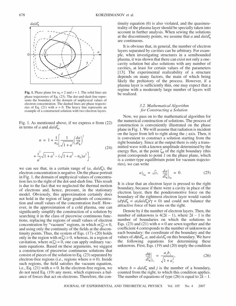
Fig. 1. As mentioned above, if we express n from (22)in terms of a and da/dζ,
(24)
we can see that, in a certain range of (a, da/dζ), theelectron concentration is negative. On the phase portraitin Fig. 1, the domain of unphysical values of concentra-tion lies to the right of the dot-and-dash line. This resultis due to the fact that we neglected the thermal motionof electrons and, hence, pressure, in the stationarymodel. Obviously, this approximation certainly doesnot hold in the region of large gradients of concentra-tion and small values of the concentration itself. How-ever, in the approximation of a cold plasma, one cansignificantly simplify the construction of a solution bysearching it in the class of piecewise continuous func-tions, replacing the regions of small values of electronconcentration by “vacuum” regions, in which n(ζ) = 0,and using only the continuity of the fields at the discon-tinuity points. Thus, the system of Eqs. (17)–(20) holdsonly in the region with n(ζ) > 0, whereas, in a region ofcavitation, where n(ζ) = 0, one can apply ordinary vac-uum equations. Based on these arguments, we suggesta construction of piecewise continuous solutions thatconsist of pieces of the solution to Eq. (23) separated byelectron-free regions (i.e., regions where n ≡ 0). Insidesuch regions, the field satisfies the vacuum equation,i.e., Eq. (21) with n = 0. In the electron-free region, wedo not need Eq. (19) any more, which expresses a bal-ance of forces that act on electrons. Therefore, the con-
n 11n0----- 1
1 a2+------------------ da
dζ------⎝ ⎠
⎛ ⎞2
+=
+s2
a2----- 1 a2+ 1 a2+ n0–( )a2– ,
tinuity equation (6) is also violated, and the quasineu-trality of the plasma layer should be specially taken intoaccount in further analysis. When sewing the solutionsat the discontinuity points, we assume that a and da/dζare continuous.
It is obvious that, in general, the number of electronlayers separated by cavities can be arbitrary. For exam-ple, when investigating structures in a semiboundedplasma, it was shown that there can exist not only a one-cavity solution but also solutions with any number ofcavities, at least for certain values of the parameters[13]. The experimental realizability of a structuredepends on many factors, the main of which beinglikely the prehistory of the process. However, if aplasma layer is sufficiently thin, one may expect that aregime with a moderately large number of layers willbe realized.
3.2. Mathematical Algorithmfor Constructing a Solution
Now, we pass on to the mathematical algorithm forthe numerical construction of solutions. The process ofconstruction is conveniently illustrated on the phaseplane in Fig. 1. We will assume that radiation is incidenton the layer from left to right along the z axis. Then, itis convenient to construct a solution starting from theright boundary. Since at the output there is only a trans-mitted wave with a known amplitude determined by theenergy flux, at the point ζR of the right boundary (thispoint corresponds to point 1 on the phase plane, whichis a center-type equilibrium point for vacuum trajecto-ries), we can write
(25)
It is clear that an electron layer is pressed to the rightboundary, because if there were a cavity in place of theelectron layer, then the ponderomotive force on theboundary of the rightmost electron layer would vanish(dγ/dζ = a(da/dζ)/γ = 0) and could not balance theattractive force of bare ions on the right.
Denote by k the number of electron layers. Then, thenumber of unknowns is 4(2k – 1), where 2k – 1 is thenumber of boundaries on which the solutions toEqs. (23) and (21) with n = 0 are sewn together and thecoefficient 4 corresponds to the number of unknowns ateach boundary: the coordinate of the boundary and thevalues of dφ/dζ, a, and da/dζ on this boundary. We havethe following equations for determining theseunknowns. First, Eqs. (19) and (20) imply the condition
(26)
where b = da/dζ and j is the number of a boundary,counted from the right, to which this condition applies.The number of equations of type (26) is equal to 2k – 1.
a ζRs, da
dζ------
ζR
0.= =
dφdζ------
ζ j
a jb j
1 a j2+
------------------,=
01
2
3
4
5
a
da/dζ
Fig. 1. Phase plane for n0 = 2 and s = 1. The solid lines arephase trajectories of Eq. (23). The dot-and-dash line repre-sents the boundary of the domain of unphysical values ofelectron concentration. The dashed lines are phase trajecto-ries of Eq. (21) with n = 0. The heavy line represents anexample of a constructed solution with two electron layers.
JOURNAL OF EXPERIMENTAL AND THEORETICAL PHYSICS Vol. 105 No. 4 2007
INTERACTION OF RELATIVISTICALLY STRONG ELECTROMAGNETIC WAVES 679
To obtain the following set of equations, we integratethe Poisson equation (18) over the vacuum regions (thesegments 2–3 and 4–5 on the phase plane):
(27)
Next, we integrate the same equation over the leftmostplane, which adjoins the left boundary ζL of the plasmalayer:
(28)
Now, if we integrate Eq. (19) over the entire plasmalayer and invoke the quasineutrality condition, then wecan easily obtain the following condition:
(29)
therefore,
(30)
Thus, we have another k equations. Further, we notethat Eqs. (23) and (21) with n = 0 have a Hamiltonianstructure with the Hamiltonian of the following form:
(31)
for electron layers (segments 1–2 and 3–4 on the phaseplane) and
(32)
for cavities (segments 2–3 and 4–5 on the phase plane).For neighboring discontinuity points, we can write thefollowing condition for the equality of Hamiltonians:
(33)
in this case, the type of the Hamiltonian is chosendepending on what is enclosed between ζj and ζj + 1, anelectron layer or a cavity. We can write out 2k – 1 con-ditions of the form (33), including the condition for therightmost electron layer:
(34)
To obtain the last 2k – 1 equations, we write out the fol-lowing identity for each pair of neighboring bound-aries:
(35)
dφdζ------
ζ j 1+
dφdζ------
ζ j
– n0 ζ j 1+ ζ j–( ).–=
dφdζ------
ζL
dφdζ------
ζ2k 1–
– n0 ζL ζ2k 1––( ).–=
dφdζ------
ζL
dφdζ------
ζR
0;= =
dφdζ------
ζ2k 1–
n0 ζL ζ2k 1––( ).=
H1 adadζ------,⎝ ⎠
⎛ ⎞ 1
2 1 a2+( )---------------------- da
dζ------⎝ ⎠
⎛ ⎞2
=
+12---a2 1
2--- s2
a2----- n0 1 a2+ ,–+
H2 adadζ------,⎝ ⎠
⎛ ⎞ 12--- da
dζ------⎝ ⎠
⎛ ⎞2 1
2---a2 1
2--- s2
a2-----+ +=
H a j b j,( ) H a j 1+ b j 1+,( );=
H1 a1 b1,( ) H1 s 0,( ).=
ζ j ζ j 1+–ad
b a H a j b j,( ),( )------------------------------------,
a j 1+
a j
∫=
where b(a, H(aj , bj)) is the derivative of the amplitudeexpressed as a function of the amplitude itself and thecorresponding Hamiltonian. To obtain the form ofthese functions, we should determine da/dζ from rela-tions (31) and (32). Note also that, in addition to theabove-listed relations, we can write another one, whichexpresses the following simple geometric relation:
(36)
where L is the thickness of the plasma layer underinvestigation, which is another parameter of the prob-lem.
Summing up, we have 7k – 3 equations in 8k – 4unknowns. Thus, there are k – 1 free parameters in total;depending on the values of these parameters, differentsolutions can be realized. In the experiment, specificvalues of these parameters are obviously determined bymany factors, which may be of a random nature.
3.3. Structures with a Single Electron Layer
The simplest structure that can exist in a given sys-tem is a stationary solution with one electron layerpressed to the right boundary and one cavity fromwhich electrons are removed by ponderomotive forces.In this case, the number of free parameters is equal tozero, and Eqs. (26), (30), and (35) imply the followingintegral relation for the amplitude a1 of the field at apoint of discontinuity:
(37)
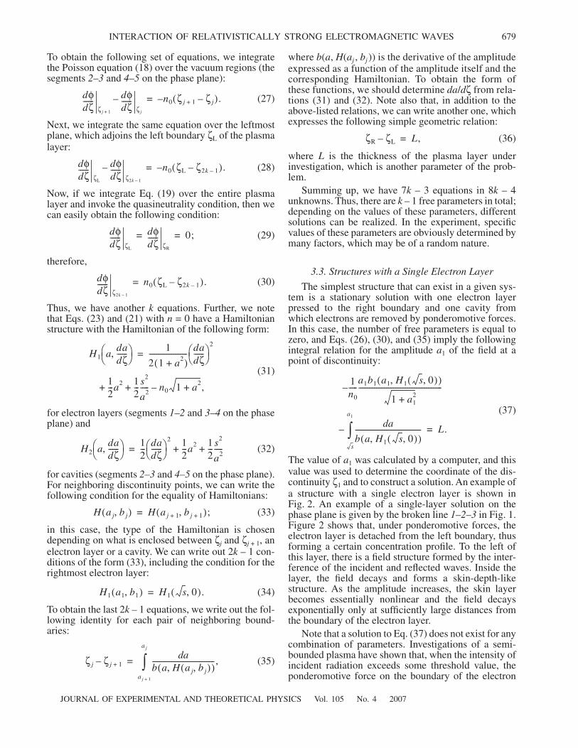
The value of a1 was calculated by a computer, and thisvalue was used to determine the coordinate of the dis-continuity ζ1 and to construct a solution. An example ofa structure with a single electron layer is shown inFig. 2. An example of a single-layer solution on thephase plane is given by the broken line 1–2–3 in Fig. 1.Figure 2 shows that, under ponderomotive forces, theelectron layer is detached from the left boundary, thusforming a certain concentration profile. To the left ofthis layer, there is a field structure formed by the inter-ference of the incident and reflected waves. Inside thelayer, the field decays and forms a skin-depth-likestructure. As the amplitude increases, the skin layerbecomes essentially nonlinear and the field decaysexponentially only at sufficiently large distances fromthe boundary of the electron layer.
Note that a solution to Eq. (37) does not exist for anycombination of parameters. Investigations of a semi-bounded plasma have shown that, when the intensity ofincident radiation exceeds some threshold value, theponderomotive force on the boundary of the electron
ζR ζL– L,=
1n0-----
a1b1 a1 H1 s 0,( ),( )
1 a12+
------------------------------------------------–
– ad
b a H1 s 0,( ),( )--------------------------------------
s
a1
∫ L.=
680
JOURNAL OF EXPERIMENTAL AND THEORETICAL PHYSICS Vol. 105 No. 4 2007
KORZHIMANOV et al.
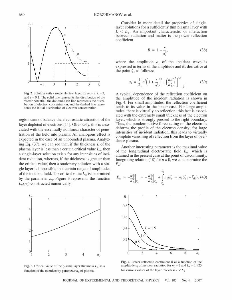
region cannot balance the electrostatic attraction of thelayer depleted of electrons [11]. Obviously, this is asso-ciated with the essentially nonlinear character of pene-tration of the field into plasma. An analogous effect isexpected in the case of an unbounded plasma. Analyz-ing Eq. (37), we can see that, if the thickness L of theplasma layer is less than a certain critical value L∗, thena single-layer solution exists for any intensities of inci-dent radiation, whereas, if the thickness is greater thanthe critical value, then a stationary solution with a sin-gle layer is impossible in a certain range of amplitudesof the incident field. The critical value L∗ is determinedby the parameter n0. Figure 3 represents the functionL∗(n0) constructed numerically.
Consider in more detail the properties of single-layer solutions for a sufficiently thin plasma layer withL < L∗. An important characteristic of interactionbetween radiation and matter is the power reflectioncoefficient
(38)
where the amplitude ai of the incident wave isexpressed in terms of the amplitude and its derivative atthe point ζ1 as follows:
(39)
A typical dependence of the reflection coefficient onthe amplitude of the incident radiation is shown inFig. 4. For small amplitudes, the reflection coefficienttends to its value in the linear case. For large ampli-tudes, there is virtually no reflection; this fact is associ-ated with the extremely small thickness of the electronlayer, which is strongly pressed to the right boundary.Thus, the ponderomotive force acting on the electronsdeforms the profile of the electron density; for largeintensities of incident radiation, this leads to virtuallycomplete vanishing of reflection from the layer of over-dense plasma.
Another interesting parameter is the maximal valueof the longitudinal electrostatic field Em, which isattained in the present case at the point of discontinuity.Integrating relation (18) for n ≡ 0, we can determine theEm:
(40)
R 1s
ai2
-----,–=
ai12--- a2 1 s
a2-----+⎝ ⎠
⎛ ⎞ 2 dadζ------⎝ ⎠
⎛ ⎞2
+1/2
ζ1
.=
Emdφdζ------
ζ1
– dφdζ------
ζR
– n0 ζd
ζR
ζ1
∫+ n0 ζ1 ζR–( ).= = =
3210–1 ζ
3
2
1
0
a, n
a
n
Fig. 2. Solution with a single electron layer for n0 = 2, L = 3,and s = 0.1. The solid line represents the distribution of thevector potential, the dot-and-dash line represents the distri-bution of electron concentration, and the dashed line repre-sents the initial distribution of electron concentration.
4321 n0
4
3
2
1
0
L*
Fig. 3. Critical value of the plasma layer thickness L∗ as afunction of the overdensity parameter n0 of plasma.
2 4 6 80 ai
0.2
0.4
0.6
0.8
R
0.5
1.0
L = 1.5
Fig. 4. Power reflection coefficient R as a function of theamplitude ai of incident radiation for n0 = 2 and L∗ = 1.925for various values of the layer thickness L < L∗.
JOURNAL OF EXPERIMENTAL AND THEORETICAL PHYSICS Vol. 105 No. 4 2007
INTERACTION OF RELATIVISTICALLY STRONG ELECTROMAGNETIC WAVES 681
Thus, this parameter is also of interest as a characteris-tic of the thickness of the detached layer. The longitu-dinal field as a function of the amplitude of incidentradiation is illustrated by the graphs in Fig. 5. Asexpected, the electron layer is smoothly detached fromthe boundary as the radiation intensity increases, and itsthickness tends to zero in the limit. The longitudinalelectrostatic field may reach values comparable withthe fields in the incident wave.
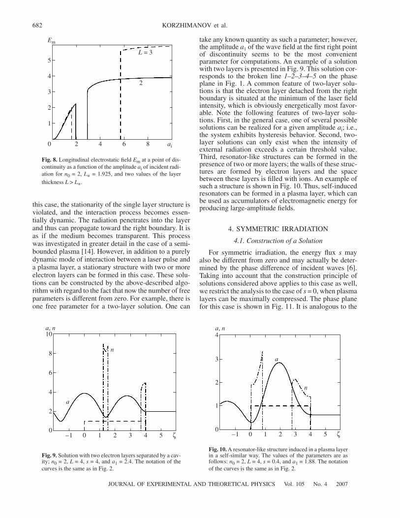
As mentioned above, when L is greater than the crit-ical value, a stationary single-layer solution cannotexist in a certain range of amplitudes of the externalradiation. Recall that a similar result was also obtainedin the case of a semibounded plasma; however, the dis-tinctive feature of the case of a finite-thickness layer isthe presence of two threshold values of the radiationamplitude. A stationary structure with a single electronlayer can only exist outside the interval between thesethresholds. The lower threshold is attributed to the fol-lowing fact. As the field intensity increases, the electronlayer gets more and more detached from the left bound-ary; this leads to the increase of the electrostatic forceacting on the layer (see Fig. 5), while the ponderomo-tive force, which exhibits complicated behavior, maystart to decrease at a certain amplitude of the incidentwave. The upper threshold is attributed to the fact that,as the intensity increases further, the longitudinal elec-trostatic field starts to vary slower and slower, tendingto its limit value n0L, as is clearly illustrated in Fig. 5.The ponderomotive force also starts to increase as theamplitude of the incident wave increases. Thus, the bal-ance equation (19) can again be fulfilled. Figure 6 rep-resents the threshold values of the incident-field ampli-tude as a function of the parameter n0 for several valuesof the plasma layer thickness L.
For layer thicknesses L > L∗, we can also constructthe reflection coefficient and the longitudinal field onthe boundary as a function of the amplitude of incidentradiation. These functions are represented in Figs. 7and 8. The characteristic feature of these functions isthe presence of a minimum in the range of amplitudeswhere stationary solutions do not exist. As for the rest,these functions are similar to those for L < L∗.
3.4. Structures with Two Electron Layers
The next problem to be elucidated is answering thequestion of what will happen if the amplitude slowlyreaches its threshold value or if a pulse with the fieldintensity in the interval between the threshold values,i.e., ath1 < ai < ath2, is incident on the plasma layer. In
8642 ai0
0.5
1.0
1.5
2.0
2.5
Em L = 1.5
1.0
0.5
Fig. 5. Longitudinal electrostatic field Em at a point of dis-continuity as a function of the amplitude ai of incident radi-ation for n0 = 2, L∗ = 1.925, and various values of the layerthickness L < L∗.
4321 n0
3
6
9
ath
L = 4
3
2
0
Fig. 6. Threshold values of the amplitude of incident radia-tion as a function of the overdensity parameter n0 for vari-ous values of the plasma layer thickness L.
8642 ai
0.2
0.4
0.6
0.8
1.0R
L = 2
3
0
Fig. 7. Power reflection coefficient R as a function of theamplitude ai of incident radiation for n0 = 2 and L∗ = 1.925for two values of the layer thickness L > L∗.
682
JOURNAL OF EXPERIMENTAL AND THEORETICAL PHYSICS Vol. 105 No. 4 2007
KORZHIMANOV et al.
this case, the stationarity of the single layer structure isviolated, and the interaction process becomes essen-tially dynamic. The radiation penetrates into the layerand thus can propagate toward the right boundary. It isas if the medium becomes transparent. This processwas investigated in greater detail in the case of a semi-bounded plasma [14]. However, in addition to a purelydynamic mode of interaction between a laser pulse anda plasma layer, a stationary structure with two or moreelectron layers can be formed in this case. These solu-tions can be constructed by the above-described algo-rithm with regard to the fact that now the number of freeparameters is different from zero. For example, there isone free parameter for a two-layer solution. One can
take any known quantity as such a parameter; however,the amplitude a1 of the wave field at the first right pointof discontinuity seems to be the most convenientparameter for computations. An example of a solutionwith two layers is presented in Fig. 9. This solution cor-responds to the broken line 1–2–3–4–5 on the phaseplane in Fig. 1. A common feature of two-layer solu-tions is that the electron layer detached from the rightboundary is situated at the minimum of the laser fieldintensity, which is obviously energetically most favor-able. Note the following features of two-layer solu-tions. First, in the general case, one of several possiblesolutions can be realized for a given amplitude ai; i.e.,the system exhibits hysteresis behavior. Second, two-layer solutions can only exist when the intensity ofexternal radiation exceeds a certain threshold value.Third, resonator-like structures can be formed in thepresence of two or more layers; the walls of these struc-tures are formed by electron layers and the spacebetween these layers is filled with ions. An example ofsuch a structure is shown in Fig. 10. Thus, self-inducedresonators can be formed in a plasma layer, which canbe used as accumulators of electromagnetic energy forproducing large-amplitude fields.
4. SYMMETRIC IRRADIATION
4.1. Construction of a Solution
For symmetric irradiation, the energy flux s mayalso be different from zero and may actually be deter-mined by the phase difference of incident waves [6].Taking into account that the construction principle ofsolutions considered above applies to this case as well,we restrict the analysis to the case of s = 0, when plasmalayers can be maximally compressed. The phase planefor this case is shown in Fig. 11. It is analogous to the
86420
1
2
3
4
5
Em
L = 3
2
ai
Fig. 8. Longitudinal electrostatic field Em at a point of dis-continuity as a function of the amplitude ai of incident radi-ation for n0 = 2, L∗ = 1.925, and two values of the layerthickness L > L∗.
543210–1 ζ
2
4
6
8
10a, n
a
n
0
Fig. 9. Solution with two electron layers separated by a cav-ity; n0 = 2, L = 4, s = 4, and a1 = 2.4. The notation of thecurves is the same as in Fig. 2.
543210–1 ζ
1
2
3
4a, n
a
n
0
Fig. 10. A resonator-like structure induced in a plasma layerin a self-similar way. The values of the parameters are asfollows: n0 = 2, L = 4, s = 0.4, and a1 = 1.88. The notationof the curves is the same as in Fig. 2.
JOURNAL OF EXPERIMENTAL AND THEORETICAL PHYSICS Vol. 105 No. 4 2007
INTERACTION OF RELATIVISTICALLY STRONG ELECTROMAGNETIC WAVES 683
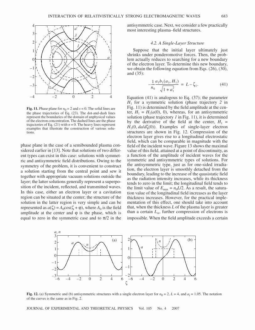
phase plane in the case of a semibounded plasma con-sidered earlier in [13]. Note that solutions of two differ-ent types can exist in this case: solutions with symmet-ric and antisymmetric field distributions. Owing to thesymmetry of the problem, it is convenient to constructa solution starting from the central point and sew ittogether with appropriate vacuum solutions outside thelayer; the latter solutions generally represent a superpo-sition of the incident, reflected, and transmitted waves.In this case, either an electron layer or a cavitationregion can be situated at the center; the structure of thesolution in the latter region is very simple and can berepresented as a(ζ) = A0cos(ζ + ϕ), where A0 is the fieldamplitude at the center and ϕ is the phase, which isequal to zero in the symmetric case and to π/2 in the
antisymmetric case. Next, we consider a few practicallymost interesting plasma–field structures.
4.2. A Single-Layer Structure
Suppose that the initial layer ultimately justshrinks under ponderomotive forces. Then, the prob-lem actually reduces to searching for a new boundaryof the electron layer. To determine this new boundary,we obtain the following equation from Eqs. (26), (30),and (35):
(41)
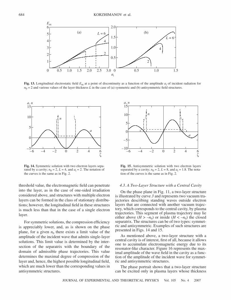
Equation (41) is analogous to Eq. (37); the parameterH1 for a symmetric solution (phase trajectory 2 inFig. 11) is determined by the field amplitude at the cen-ter, H1 = H1(a(0), 0), whereas, for an antisymmetricsolution (phase trajectory 1 in Fig. 11), it is determinedby the derivative of the field at the center, H1 =H1(0, da/dζ(0)). Examples of single-layer electronstructures are shown in Fig. 12. Compression of theelectron layer gives rise to a longitudinal electrostaticfield, which can be comparable in magnitude with thefield of the incident wave. Figure 13 shows the maximalvalue of this field, attained at a point of discontinuity, asa function of the amplitude of incident waves for thesymmetric and antisymmetric types of solutions. Forthe antisymmetric type, just as for one-sided irradia-tion, the electron layer is smoothly detached from theboundary, leading to the increase of the quasistatic fieldas the radiation intensity increases, while its thicknesstends to zero in the limit; the longitudinal field tends tothe limit value of Emax = n0L/2. As a result, the satura-tion value of the longitudinal field increases as the layerthickness increases. However, for the practical imple-mentation of this effect, one should take into accountthat, when the thickness L of the plasma layer is greaterthan a certain L∗, further compression of electrons isimpossible. When the field amplitude exceeds a certain
1n0-----
a1b1 a1 H1,( )
1 a12+
------------------------------– L ζ1.–=
20–2 4–4
–3
–2
–1
0
1
2
3
4
a
a'
12
3
Fig. 11. Phase plane for n0 = 2 and s = 0. The solid lines arethe phase trajectories of Eq. (23). The dot-and-dash linesrepresent the boundaries of the domain of unphysical valuesof the electron concentration. The dashed lines are the phasetrajectories of Eq. (21) with n = 0. The heavy lines representexamples that illustrate the construction of various solu-tions.
420–2–4 6–6
–2
–1
0
1
2
3
–3
a, n
(a)a n
420–2–4–6 6ζ
–1
0
1
2
–2
(b)
a
n
Fig. 12. (a) Symmetric and (b) antisymmetric structures with a single electron layer for n0 = 2, L = 4, and ai = 1.05. The notationof the curves is the same as in Fig. 2.
684
JOURNAL OF EXPERIMENTAL AND THEORETICAL PHYSICS Vol. 105 No. 4 2007
KORZHIMANOV et al.
threshold value, the electromagnetic field can penetrateinto the layer, as in the case of one-sided irradiationconsidered above, and structures with multiple electronlayers can be formed in the class of stationary distribu-tions; however, the longitudinal field in these structuresis much less than that in the case of a single electronlayer.
For symmetric solutions, the compression efficiencyis appreciably lower, and, as is shown on the phaseplane, for a given n0 there exists a limit value of theamplitude of the incident wave that admits single-layersolutions. This limit value is determined by the inter-section of the separatrix with the boundary of thedomain of admissible phase trajectories. This valuedetermines the maximal degree of compression of thelayer and, hence, the highest possible longitudinal field,which are much lower than the corresponding values inantisymmetric structures.
4.3. A Two-Layer Structure with a Central Cavity
On the phase plane in Fig. 11, a two-layer structureis illustrated by curve 3 and represents two vacuum tra-jectories describing standing waves outside electronlayers that are connected with another vacuum trajec-tory, which corresponds to the central cavity, by plasmatrajectories. This segment of plasma trajectory may lieeither above (H > –n0) or inside (H < –n0) the closedseparatrix. The structures can be of two types: symmet-ric and antisymmetric. Examples of such structures arepresented in Figs. 14 and 15.
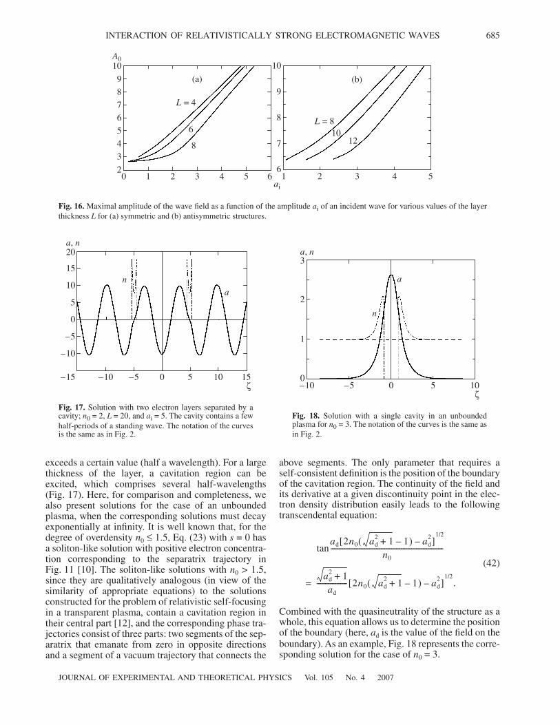
As mentioned above, a two-layer structure with acentral cavity is of interest, first of all, because it allowsone to accumulate electromagnetic energy due to itsresonator-like character. Figure 16 represents the max-imal amplitude of the wave field in the cavity as a func-tion of the amplitude of the incident wave for symmet-ric and antisymmetric structures.
The phase portrait shows that a two-layer structurecan be excited only in plasma layers whose thickness
2.52.01.51.00.50 3.0
1
2
3
4
5
6Em
(a) L = 6
4
2
1.00.50 1.5
0.5
1.0
1.5
2.0
(b)
L = 6
4
2
ai
Fig. 13. Longitudinal electrostatic field Em at a point of discontinuity as a function of the amplitude ai of incident radiation forn0 = 2 and various values of the layer thickness L in the case of (a) symmetric and (b) antisymmetric field structures.
420–2–4 6–6ζ
0
5
10
15
–5
a
n
a, n
Fig. 14. Symmetric solution with two electron layers sepa-rated by a cavity; n0 = 2, L = 4, and ai = 2. The notation ofthe curves is the same as in Fig. 2.
420–2–4–6 6ζ
–5
0
5
10
15
–10
a, n
a
n
Fig. 15. Antisymmetric solution with two electron layersseparated by a cavity; n0 = 2, L = 8, and ai = 1.8. The nota-tion of the curves is the same as in Fig. 2.
JOURNAL OF EXPERIMENTAL AND THEORETICAL PHYSICS Vol. 105 No. 4 2007
INTERACTION OF RELATIVISTICALLY STRONG ELECTROMAGNETIC WAVES 685
exceeds a certain value (half a wavelength). For a largethickness of the layer, a cavitation region can beexcited, which comprises several half-wavelengths(Fig. 17). Here, for comparison and completeness, wealso present solutions for the case of an unboundedplasma, when the corresponding solutions must decayexponentially at infinity. It is well known that, for thedegree of overdensity n0 ≤ 1.5, Eq. (23) with s = 0 hasa soliton-like solution with positive electron concentra-tion corresponding to the separatrix trajectory inFig. 11 [10]. The soliton-like solutions with n0 > 1.5,since they are qualitatively analogous (in view of thesimilarity of appropriate equations) to the solutionsconstructed for the problem of relativistic self-focusingin a transparent plasma, contain a cavitation region intheir central part [12], and the corresponding phase tra-jectories consist of three parts: two segments of the sep-aratrix that emanate from zero in opposite directionsand a segment of a vacuum trajectory that connects the
above segments. The only parameter that requires aself-consistent definition is the position of the boundaryof the cavitation region. The continuity of the field andits derivative at a given discontinuity point in the elec-tron density distribution easily leads to the followingtranscendental equation:
(42)
Combined with the quasineutrality of the structure as awhole, this equation allows us to determine the positionof the boundary (here, ad is the value of the field on theboundary). As an example, Fig. 18 represents the corre-sponding solution for the case of n0 = 3.
ad 2n0 ad2 1+ 1–( ) ad
2–[ ]1/2
n0-------------------------------------------------------------------tan
= ad
2 1+ad
------------------ 2n0 ad2 1+ 1–( ) ad
2–[ ]1/2
.
543210 6
3
4
5
6
7
8
9
2
10A0
(a)
L = 4
6
8
4321 5ai
7
8
9
10
6
(b)
L = 810
12
Fig. 16. Maximal amplitude of the wave field as a function of the amplitude ai of an incident wave for various values of the layerthickness L for (a) symmetric and (b) antisymmetric structures.
1050–5–10 15ζ
–10
–5
0
5
10
15
–15
20a, n
an
Fig. 17. Solution with two electron layers separated by acavity; n0 = 2, L = 20, and ai = 5. The cavity contains a fewhalf-periods of a standing wave. The notation of the curvesis the same as in Fig. 2.
50–5 10–10ζ
1
2
3
0
a
n
a, n
Fig. 18. Solution with a single cavity in an unboundedplasma for n0 = 3. The notation of the curves is the same asin Fig. 2.
686
JOURNAL OF EXPERIMENTAL AND THEORETICAL PHYSICS Vol. 105 No. 4 2007
KORZHIMANOV et al.
5. CONCLUSIONS
In this paper, we have described plasma–field struc-tures that can be formed under the interaction of relativ-istically strong electromagnetic radiation with a layerof overdense plasma. The simplest variant is a structurewith a single electron layer, that is pressed to the farboundary in the case of one-sided incidence of a wave,or situated at the center in the case of symmetric irradi-ation. However, the existence of such a solution is notpossible for any relation between the external parame-ters. If the plasma layer is sufficiently thick, a single-layer structure cannot exist in a certain range of ampli-tudes of incident radiation. Another structure that canbe realized in the system considered is a solution withtwo or more electron layers and cavities enclosedbetween these layers. For some values of parameters,such structures can have a resonator-like character andcan accumulate electromagnetic energy. A commonfeature of relativistic structures that can be realized in aplasma layer under one-sided irradiation is the fact thatthe reflection coefficient of the wave from the layertends to zero when the field intensity indefinitelyincreases.
REFERENCES
1. C. Joshi and T. Katsouleas, Phys. Today 56, 47 (2003).
2. A. V. Borovskiœ and A. L. Galkin, Laser Physics (IzdAt,Moscow, 1996), p. 230 [in Russian].
3. G. A. Mourou, T. Tajima, and S. V. Bulanov, Rev. Mod.Phys. 78, 309 (2006).
4. M. Tabak, J. Hammer, M. E. Glinsky, et al., Phys. Plas-mas 1, 1626 (1994).
5. J. Schwinger, Phys. Rev. 82, 664 (1951); P. Chen andT. Tajima, Phys. Rev. Lett. 83, 256 (1999).
6. B. Shen and J. Meyer-ter-Vehn, Phys. Plasmas 8, 1003(2001).
7. A. G. Litvak, Zh. Éksp. Teor. Fiz. 57, 629 (1970) [Sov.Phys. JETP 30, 344 (1970)].
8. G. Z. Sun, E. Ott, Y. C. Lee, and P. Guzdar, Phys. Fluids30, 526 (1987).
9. A. I. Akhiezer and R. V. Polovin, Zh. Éksp. Teor. Fiz. 30,915 (1956) [Sov. Phys. JETP 3, 696 (1956)]; P. Kaw andJ. Dawson, Phys. Fluids 13, 472 (1970).
10. J. H. Marburger and R. F. Trooper, Phys. Rev. Lett. 35,1001 (1975).
11. F. Cattani, A. Kim, D. Anderson, and M. Lisak, Phys.Rev. E 62, 1234 (2000).
12. F. Cattani, A. Kim, D. Anderson, and M. Lisak, Phys.Rev. E 64, 016412 (2001).
13. A. Kim, F. Cattani, D. Anderson, and M. Lisak, Pis’maZh. Éksp. Teor. Fiz. 72, 355 (2000) [JETP Lett. 72, 241(2000)].
14. M. Tushentsov, A. Kim, F. Cattani, et al., Phys. Rev. Lett.87, 275002 (2001).
15. C. S. Lai, Phys. Rev. Lett. 36, 966 (1976); F. S. Felberand J. H. Marburger, Phys. Rev. Lett. 36, 1176 (1976).
Translated by I. Nikitin


![4.1.1] plane waves](https://static.fdokumen.com/doc/165x107/6322513728c445989105b845/411-plane-waves.jpg)