Integrating a Grasp Exoskeleton Into a String-Based Interface for Human-Scale Interactions
9
Rasul Fesharakifard e-mail: [email protected] Maryam Khalili e-mail: [email protected] Laure Leroy e-mail: [email protected] Alexis Paljic e-mail: [email protected] Philippe Fuchs e-mail: [email protected] CAD and Robotic Center, Ecole Nationale Supérieure des Mines de Paris, 75272 Paris, France Integrating a Grasp Exoskeleton Into a String-Based Interface for Human-Scale Interactions A grasp exoskeleton actuated by a string-based platform is proposed to provide the force feedback for a user’s hand in human-scale virtual environments. The user of this interface accedes to seven active degrees of freedom in interaction with virtual objects, which comprises three degrees of translation, three degrees of rotation, and one degree of grasping. The exoskeleton has a light and ergonomic structure and provides the grasp gesture for five fingers. The actuation of the exoskeleton is performed by eight strings that are the parallel arms of the platform. Each string is connected to a block of motor, rotary encoder, and force sensor with a novel design to create the necessary force and precision for the interface. A hybrid control method based on the string’s tension measured by the force sensor is developed to resolve the ordinary problems of string-based interface. The blocks could be moved on a cubic frame around the virtual environment. Finally the results of preliminary experimentation of interface are presented to show its practical characteristics. Also the interface is mounted on an automotive model to demonstrate its industrial adaptability. DOI: 10.1115/1.3006304 1 Introduction Haptic interfaces are developed to produce the sense of touch with virtual objects in the immersive environments. This interac- tion provides a higher degree of realism for the user of these spaces. In this context, some exoskeletons are used to follow and restrain the fingers’ movement in interaction with virtual objects. In exoskeletons used for grasp tasks, each finger can become a gripper in itself. Since they augment the delicacy of virtual inter- action related to traditional haptic devices, recently there was a great deal of attention on their development. One of the most general gestures of the fingers in virtual environments is grasping and releasing the virtual objects. Springer and Ferrier 1 intro- duced a multifinger force reflecting interface for teleoperational grasping that had a lightweight and comfortable mechanism with a large workspace. CyberTouch™ is another force reflecting ex- oskeleton developed by Immersion Corporation that provides re- sistive force feedback for each finger 2. However, an exoskel- eton is not capable of providing the resistive force feedback like the weight for the hand. In this case, the exoskeleton should be mounted on a ground-based structure. Among different ground-based mechanisms, a string-actuated one seems to be the most appropriate for human-scale environ- ments. String-actuated haptic interface has the same mechanism of parallel manipulators. However, their workspaces are much larger as there is no internal mechanical structure to limit the movement of their end effectors. Also their rigidities are high, and due to lightweights of strings, inertias are relatively low. Because of these performances, they have been widely used with different degrees of force feedback in different virtual environments. The idea of using a 1DOF effector in a 6DOF tension based device, for a total of 7DOF, was presented in SPIDAR-G™ 3. Another ver- sion of this interface called SPIDAR-H™ was used in a human- scale environment with 3DOF 4. Also the integration of active force feedback and prop in immersive visual display with coloca- tion was proposed to provide realistic grasp information and 6DOF force feedback 5. Some researchers attempted to model the string-based manipu- lators and calculate the tension distribution in strings and work- space of their effectors. Krut et al. 6 presented a mathematical technique based on the Jacobian matrix and the use of the force polytope to establish the force characteristics of wire-driven par- allel manipulators. An algorithm to obtain the optimal tension distribution in a 6DOF tendon-based parallel manipulator is pro- posed that depends on workspace conditions, tension constraints, and actuator torque limits 7. Verhoeven et al. 8 developed a mathematical model for tendon-driven Stewart platform manipu- lators and gave the basic formulas concerning their workspace, tension limits, stiffness, and singularities. Lafourcade and Llibre 9 used the sketches to study the theoretical workspace of wire- driven manipulators. Brau et al. 10 showed why and how some cable-actuated manipulators could be used as haptic interfaces. They developed two approaches to calculate the maximum ten- sions in the cables depending on the position of point and the direction of output force. Also they described a way to choose the workspace in order to be able to control the interface in any point for a given set of motors. In this paper a 7DOF haptic interface for the hand of a user of large virtual environments is presented. Design and implementa- tion of the interface are based on the desired characteristics of force feedback in human-scale interactions. It is assumed that the maximum continuous force of the hand does not exceed 30 N, the maximum speed of the hand is 3 m/s, and the precision of the hand position should be 0.1 mm. Also the interface should provide a large workspace and its weight should be barely felt by the hand. Therefore we have opted to develop the interface in two parts: an exoskeleton for five fingertips and a parallel platform with eight strings that actuates the exoskeleton. Previously the SPIDAR-G has been used with a gripper for small scale environments. Else- where the SPIDAR-H developed for human-scale environments provides three degrees of freedom for each hand with a position measurement error of less than 1.5 cm. We attempt to achieve the desired parameters during the following parts. First the whole interface is modeled, and the coordination of exoskeleton and tension distribution in the strings are calculated. In Sec. 3 the mechanism of exoskeleton is introduced. Then a Contributed by the Engineering Simulation and Visualization Committee of ASME for publication in the JOURNAL OF COMPUTING AND INFORMATION SCIENCE IN ENGINEERING. Manuscript received September 1, 2007; revised manuscript received September 1, 2008; published online November 13, 2008. Guest Editors: J. Oliver, M. Omalley, and K. Kesavadas. Journal of Computing and Information Science in Engineering DECEMBER 2008, Vol. 8 / 041008-1 Copyright © 2008 by ASME Downloaded 19 Apr 2012 to 194.214.158.222. Redistribution subject to ASME license or copyright; see http://www.asme.org/terms/Terms_Use.cfm
Transcript of Integrating a Grasp Exoskeleton Into a String-Based Interface for Human-Scale Interactions
1
wtsrIgaggadgaosetm
omolmdodiass
AESM
J
Dow
Rasul Fesharakifarde-mail: [email protected]
Maryam Khalilie-mail: [email protected]
Laure Leroye-mail: [email protected]
Alexis Paljice-mail: [email protected]
Philippe Fuchse-mail: [email protected]
CAD and Robotic Center,Ecole Nationale Supérieure des Mines de Paris,
75272 Paris, France
Integrating a Grasp ExoskeletonInto a String-Based Interface forHuman-Scale InteractionsA grasp exoskeleton actuated by a string-based platform is proposed to provide the forcefeedback for a user’s hand in human-scale virtual environments. The user of this interfaceaccedes to seven active degrees of freedom in interaction with virtual objects, whichcomprises three degrees of translation, three degrees of rotation, and one degree ofgrasping. The exoskeleton has a light and ergonomic structure and provides the graspgesture for five fingers. The actuation of the exoskeleton is performed by eight strings thatare the parallel arms of the platform. Each string is connected to a block of motor, rotaryencoder, and force sensor with a novel design to create the necessary force and precisionfor the interface. A hybrid control method based on the string’s tension measured by theforce sensor is developed to resolve the ordinary problems of string-based interface. Theblocks could be moved on a cubic frame around the virtual environment. Finally theresults of preliminary experimentation of interface are presented to show its practicalcharacteristics. Also the interface is mounted on an automotive model to demonstrate itsindustrial adaptability. �DOI: 10.1115/1.3006304�
Introduction
Haptic interfaces are developed to produce the sense of touchith virtual objects in the immersive environments. This interac-
ion provides a higher degree of realism for the user of thesepaces. In this context, some exoskeletons are used to follow andestrain the fingers’ movement in interaction with virtual objects.n exoskeletons used for grasp tasks, each finger can become aripper in itself. Since they augment the delicacy of virtual inter-ction related to traditional haptic devices, recently there was areat deal of attention on their development. One of the mosteneral gestures of the fingers in virtual environments is graspingnd releasing the virtual objects. Springer and Ferrier �1� intro-uced a multifinger force reflecting interface for teleoperationalrasping that had a lightweight and comfortable mechanism withlarge workspace. CyberTouch™ is another force reflecting ex-
skeleton developed by Immersion Corporation that provides re-istive force feedback for each finger �2�. However, an exoskel-ton is not capable of providing the resistive force feedback likehe weight for the hand. In this case, the exoskeleton should be
ounted on a ground-based structure.Among different ground-based mechanisms, a string-actuated
ne seems to be the most appropriate for human-scale environ-ents. String-actuated haptic interface has the same mechanism
f parallel manipulators. However, their workspaces are mucharger as there is no internal mechanical structure to limit the
ovement of their end effectors. Also their rigidities are high, andue to lightweights of strings, inertias are relatively low. Becausef these performances, they have been widely used with differentegrees of force feedback in different virtual environments. Thedea of using a 1DOF effector in a 6DOF tension based device, fortotal of 7DOF, was presented in SPIDAR-G™ �3�. Another ver-
ion of this interface called SPIDAR-H™ was used in a human-cale environment with 3DOF �4�. Also the integration of active
Contributed by the Engineering Simulation and Visualization Committee ofSME for publication in the JOURNAL OF COMPUTING AND INFORMATION SCIENCE IN
NGINEERING. Manuscript received September 1, 2007; revised manuscript receivedeptember 1, 2008; published online November 13, 2008. Guest Editors: J. Oliver,
. Omalley, and K. Kesavadas.ournal of Computing and Information Science in EngineeCopyright © 20
nloaded 19 Apr 2012 to 194.214.158.222. Redistribution subject to ASM
force feedback and prop in immersive visual display with coloca-tion was proposed to provide realistic grasp information and6DOF force feedback �5�.
Some researchers attempted to model the string-based manipu-lators and calculate the tension distribution in strings and work-space of their effectors. Krut et al. �6� presented a mathematicaltechnique based on the Jacobian matrix and the use of the forcepolytope to establish the force characteristics of wire-driven par-allel manipulators. An algorithm to obtain the optimal tensiondistribution in a 6DOF tendon-based parallel manipulator is pro-posed that depends on workspace conditions, tension constraints,and actuator torque limits �7�. Verhoeven et al. �8� developed amathematical model for tendon-driven Stewart platform manipu-lators and gave the basic formulas concerning their workspace,tension limits, stiffness, and singularities. Lafourcade and Llibre�9� used the sketches to study the theoretical workspace of wire-driven manipulators. Brau et al. �10� showed why and how somecable-actuated manipulators could be used as haptic interfaces.They developed two approaches to calculate the maximum ten-sions in the cables depending on the position of point and thedirection of output force. Also they described a way to choose theworkspace in order to be able to control the interface in any pointfor a given set of motors.
In this paper a 7DOF haptic interface for the hand of a user oflarge virtual environments is presented. Design and implementa-tion of the interface are based on the desired characteristics offorce feedback in human-scale interactions. It is assumed that themaximum continuous force of the hand does not exceed 30 N, themaximum speed of the hand is 3 m/s, and the precision of thehand position should be 0.1 mm. Also the interface should providea large workspace and its weight should be barely felt by the hand.Therefore we have opted to develop the interface in two parts: anexoskeleton for five fingertips and a parallel platform with eightstrings that actuates the exoskeleton. Previously the SPIDAR-Ghas been used with a gripper for small scale environments. Else-where the SPIDAR-H developed for human-scale environmentsprovides three degrees of freedom for each hand with a positionmeasurement error of less than 1.5 cm. We attempt to achieve thedesired parameters during the following parts.
First the whole interface is modeled, and the coordination ofexoskeleton and tension distribution in the strings are calculated.
In Sec. 3 the mechanism of exoskeleton is introduced. Then aring DECEMBER 2008, Vol. 8 / 041008-108 by ASME
E license or copyright; see http://www.asme.org/terms/Terms_Use.cfm
hgspLnasm
2
aaAatpsatavfpdtotpiecdwdrcs
Afcctdr
ptrosce1mt
bostc
0
Dow
ybrid position-force control method is proposed to resolve someeneral problems of these systems such as instability and the re-ponse lag. Also the actuators and sensors of the interface areresented, and their design in the actuating units is explained.astly, the complete interface is experimented using two prelimi-ary tests to determine its precision and capability in practicalpplications. To exhibit the adaptability with the automotive de-ign domain, in Sec. 7 we integrate the interface on the virtualodel of a designed dashboard.
Modeling the InterfaceA string-based platform in a kinematics viewpoint has a parallel
rchitecture. However, the arms of a parallel mechanism couldpply the bidirectional forces, but the strings are just able to pull.
platform with m strings transforms m string tensions to n vari-bles of its effector’s DOF1 that determine the pose2 of the effec-or. It is shown that to have n controllable degree of freedom, thelatform needs at least m=n+1 strings. Additionally, to preventingularity in the mechanism, there should be any two collinear orny three coplanar strings �3,8�. The string-based interface utilizesraditionally not more than eight strings to permit the user to have
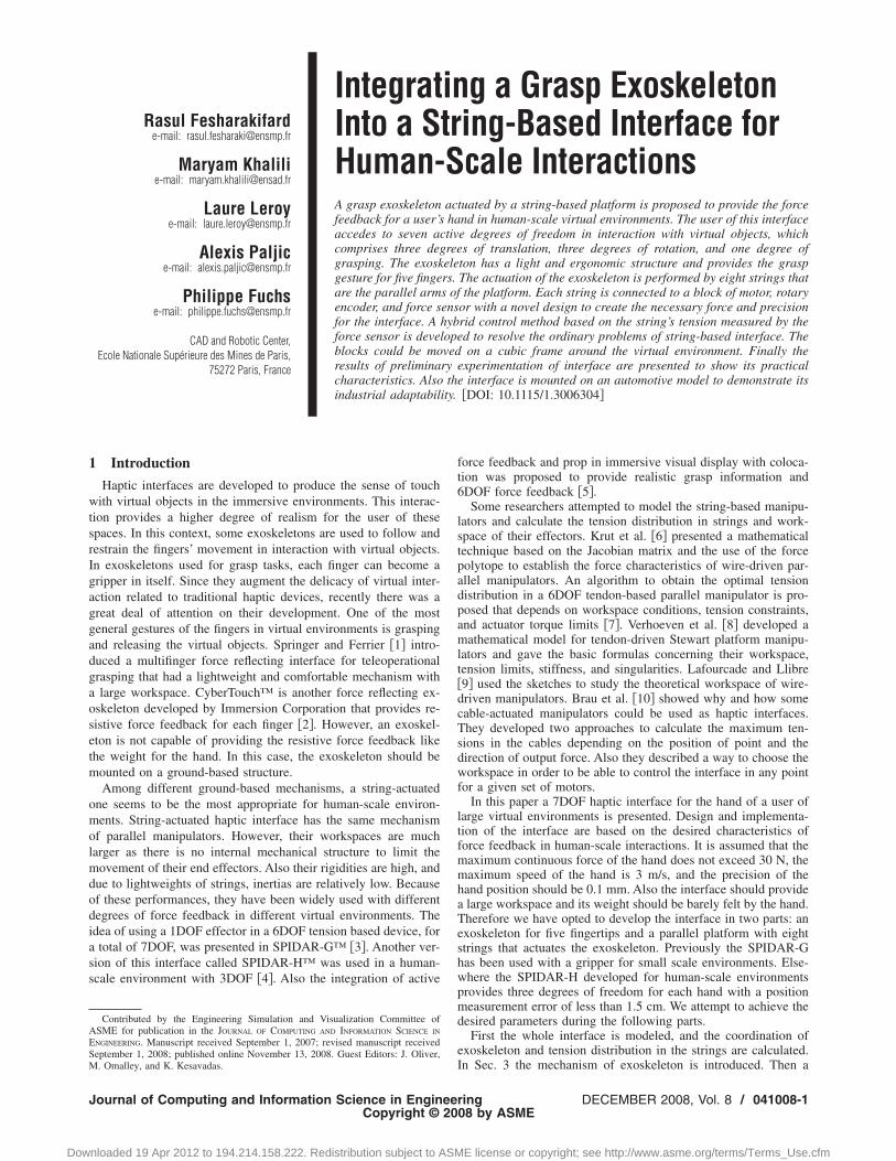
free movement in the space. Because of the cubic form of airtual space, we select eight strings for the platform and so 7DOFor the effector. These degrees of freedom should be distributed inosition, orientation, and scale of the effector. In the three-imensional space the effector is characterized by three coordina-ions of position and three coordinations of rotation. So it remainsne degree to specify its scale. A geometric shape that can modelhe fingertips of a hand and can be characterized just by onearameter is a circle. Also the fingertips take a circular form dur-ng the grasp of an object. So we consider a circular form for theffector, and the grasping gesture is demonstrated by scaling orhanging the radius of this circle. This similitude associates aifference of the proposed effector with those of the SPIDAR-G,here the grasp is represented by the change of an angle. Anotherifference is the continuity of this degree of freedom; i.e., theadius change of the proposed effector is continuous, but thehange in angle in effector of the SPIDAR-G contains just twoituations: open and close.
A schematic view of effector is shown schematically in Fig. 1.lso it is seen that there are two coordinate systems in the inter-
ace: RO�I J K �, the global coordinate system based on theenter of the space, and RP� i j k �, the local coordinate systemonnected to the effector’s center. The position and orientation ofhe effector are the vector �x y z � � � �T that is the sixegree of translations and rotations. This coordination and theadius of effector, r, are calculated in Sec. 2.1.
In Fig. 2 all the components of the string-based interface areresented. In this figure just the upper side of the effector, wherehe eight strings are connected to four points on its circular pe-imeter, is shown. These four points are actually the four cornersf a square inscribed in the circle. This type of connection oftrings guarantees the balance of the effector when it is in theube’s center and all strings apply the same tension. An exoskel-ton is developed to replace the effector and to accomplish theDOF of grasp. This exoskeleton has a conical structure and itsechanism is explained in the related section. Here we calculate
he pose of effector related to the parameters indicated in Fig. 2.
2.1 Calculate of Pose. The necessary equations are generatedetween coordinates of effector, the strings’ lengths, and the co-rdinates of the cube corners in RO. The index i� �1,8� is used topecify the number of a string in its length, li, its connection pointo the frame, Ai and its connection point to the effector, Pi. Theoordinates of Ai are A1= �+a +b +c �T, A2= �−a +b +c �T,
1DOF is the substitution of degree of freedom.2
Pose is an abbreviation for position, orientation, and scale of effector.41008-2 / Vol. 8, DECEMBER 2008
nloaded 19 Apr 2012 to 194.214.158.222. Redistribution subject to ASM
A3= �+a −b +c �T, A4= �+a −b −c �T, A5= �+a +b −c �T, A6
= �−a +b −c �T, A7= �−a −b −c �T, and A8= �−a −b +c �T.Since the effector’s center is on the origin of the localcoordinate system, we can write P= �x y z �T. To minimize thenumber of variables, the following coordinations are usedfor connection points of the effector: P1,2= �x1 y1 z1 �T,P3,4= �x2 y2 z2 �T, P5,6= �2x−x1 2y−y1 2z−z1 �T, andP7,8= �2x−x2 2y−y2 2z−z2 �T. There are a total of nine vari-ables to find. The lengths of the strings are the distance betweentheir connection points on the frame and the effector. So the gen-eral equation for all strings is as follows:
�AiPi� = li �1�
Equation �1� could be expanded into eight equations. We need toaddress one other equation. It could be obtained sinceP1,2P5,6 ·P3,4P7,8=0:
�x1 − x2��x1 + x2 − 2x� + �y1 − y2��y1 + y2 − 2y�
+ �z1 − z2��z1 + z2 − 2z� = 0 �2�
These equations give the nine variables of the effector. The vectorof pose is calculated through these variables �11�.
2.2 Optimal Tension Distribution in the Strings. The forcethat the effector applies to the hand is the resultant of string ten-sions, which are presented by ti , i� �1,8�. The interface is sup-posed to provide a seven dimensional force, which comprisesthree linear forces, three rotational couples, and one grasp force.This force is presented by F= �fx fy fz �T, M= �mx my mz �T,and g is the sum of the grasp force. So the objective is to solveT= �t1 ¯ t8 �1�8
T related to Q= �F M g �7�1T . The necessary
equations are associated here:
fx = �i=1
8
ti · i = �i=1
8
tiui · i = �i=1
8 xAi− xPi
liti
f y = �8
ti · j = �8
tiui · j = �8 yAi
− yPi
liti
Fig. 1 The circular effector and two coordinate systems
i=1 i=1 i=1
Transactions of the ASME
E license or copyright; see http://www.asme.org/terms/Terms_Use.cfm

EQrTPfwmietstf
erf
J
Dow
fz = �i=1
8
ti · k = �i=1
8
tiui · k = �i=1
8 zAi− zPi
liti �3�
Mx = �i=1
8 yPi�zAi
− zP� + yAi�zP − zPi
� + yP�zPi− zAi
�
liti
Fig. 2 Schema of the haptic int
or the other solutions we add the kernel factors.
ournal of Computing and Information Science in Enginee
nloaded 19 Apr 2012 to 194.214.158.222. Redistribution subject to ASM
My = �i=1
8 zPi�xAi
− xP� + zAi�xP − xPi
� + zP�xPi− xAi
�
liti
Mz = �i=1
8 xPi�yAi
− yP� + xAi�yP − yPi
� + xP�yPi− yAi
�
liti �4�
To calculate the grasp force, the equations are developed corre-sponding to parameters shown in Fig. 3:
ace and its analytic parameters
g = �i=1,2,5,6
ti
li���yPPiAi
�zPPiPi�� − yPPiPi�
�zPPiAi
��2 + �xPPiPi��zPPiAi
��2 + �xPPiPi��yPPiAi
��2�
+ �i=3,4,7,8
ti
li���yPPiAi
�zPPiPi���2 + �xPPiAi
�zPPiPi���2 + �xPPiAi
�yPPiPi�� − yPPiAi
�xPPiPi���2� �5�
quations �3�–�5� could be summarized in this matrix equation:7�1=K7�8T8�1. Kim et al. �3� developed a general approach to
esolve the matrix of tensions T related to the matrix of forces Q.hey used the inversion of nonsquare matrix K by the Moore–enrose method. But this approach is very time consuming andor a 7�8 matrix, it takes approximately 0.16 s for one turn. Soe use another method developed by Le Mesre de Pas �12�. Thisethod is originally used for a 6DOF interface with eight strings,
.e., there is no grasp force in the interface. It is the case when theffector is fixed on an arbitrary radius. So the above equation isransformed to Q6�1=K6�8T8�1. Therefore K has a two dimen-ional kernel in space of T, and the solution is a vector space withwo dimensions. First we should find a particular solution TP, and
The fastest way TP is to eliminate two columns of K to trans-form it to a squared matrix. Hereby we consider that the tension oftwo strings is 0 and then for the other tension we use the follow-ing equation: TP=K6�6
−1 �Q6�1. As the kernel of K has two di-mensions, it has two director vectors Ta and Tb. A fast method tocalculate the eigenvalues of K is the Gauss elimination method;i.e., K should be transformed to a subdiagonal matrix, and all ofthe elements under its diagonal are zero. This method finds twoindependent values to the kernel, and to find two kernel vectors,we set these values the vectors �1,0� and �0,1�. These vectorsassociate the kernel and this calculation takes 50 ns. At last, thevector of string tensions is found by the following equation: T=TP+aTa+bTb, where a and b are the arbitrary coefficients. The
acceptance condition of a solution is that ∀i� �1,8� 0� tpiring DECEMBER 2008, Vol. 8 / 041008-3
E license or copyright; see http://www.asme.org/terms/Terms_Use.cfm

+tssm=tz
3
oemntto
fimi
0
Dow
a · tai+b · tbi�Tmax, where Tmax is the maximum force of the ac-uator. Additionally, if the grasp force, g, is not zero, Eq. �5�hould be added to this condition. The tension distribution in thetrings is optimized when the maximum tension in the strings isinimized. It is demonstrated that with the function f�a ,b�max�tpi+a · tai+b · tbi , i� �1,8��, it is necessary to set two string
ensions on Tmax or one string tension on Tmax and the other onero �12�.
Exoskeleton MechanismA hand’s exoskeleton is developed to supply the one grasp DOF
f the effector. Since using the additional actuators on the exosk-leton sophisticates its mechanism and increases its weight, noore degree of force feedback is currently anticipated. The ergo-
omic analysis of the fingers shows that during grasping, the ro-ation axis of the thumb and annular is parallel and perpendicularo the rotation axis of the index finger. The rotation axis of twother fingers is approximately the same as the axis of annular.
If we connect the rotation of different fingers so that all thengers open and close simultaneously, the DOF will be their com-on rotation angle. So a mechanism is desired that not only takes
ts actuating force from the string tensions but also synchronizes
Fig. 3 Creation of grasp force in the effector
Fig. 4 Kinematics plan of the exoskeleton’s me
41008-4 / Vol. 8, DECEMBER 2008
nloaded 19 Apr 2012 to 194.214.158.222. Redistribution subject to ASM
all fingers’ rotation. Using a multigear mechanism seems appro-priate to fulfill these purposes. An exoskeleton is developed onthis base to connect the five fingers to eight strings.
Figure 4 �left� shows the kinematics plan of exoskeletonmechanism. The connections of eight strings to the exoskeletonare presented by number 6. As explained in Sec. 2, the four con-nection points construct a square inscribed in a circle with chang-ing radius. If we consider that the fingers of a right hand aresituated on number 5 positions, the mechanism provides the fol-lowing movement. The thumb is connected to a spur gear via rodnumber 1. The rotation axis of the thumb coincides with the rota-tion axis of the gear. This gear is engaged in a similar gear, whichis connected to annular, middle, and little fingers via rod number2. The rotation axis of these fingers is situated on the rotation axisof this gear. The lateral rotation of the index that is perpendicularto the first rotation is obtained by two conical gears. The first spurgear is coaxial with a conical gear, and a second conical geartransfers the principal rotation to the index via rod number 3. Itremains the fourth connection point of strings to the exoskeleton,which is the fourth corner of the square. This point does not con-tain a finger and its linkage to the principal rotation is similar tothe linkage of the index. Hereby, a conical gear is coaxial with thesecond spur gear, and another similar gear is engaged with it. Thisconical gear transfers the principal rotation to the fourth point viarod 4. Thus when the strings pull, they create a rotational effort onall fingers in the exoskeleton and so affect the hand’s grasping.The structure is seated on the user’s hand in position number 0. Ageneral computer aided design �CAD� scheme of the above-mentioned mechanism is shown in Fig. 4 �right�.
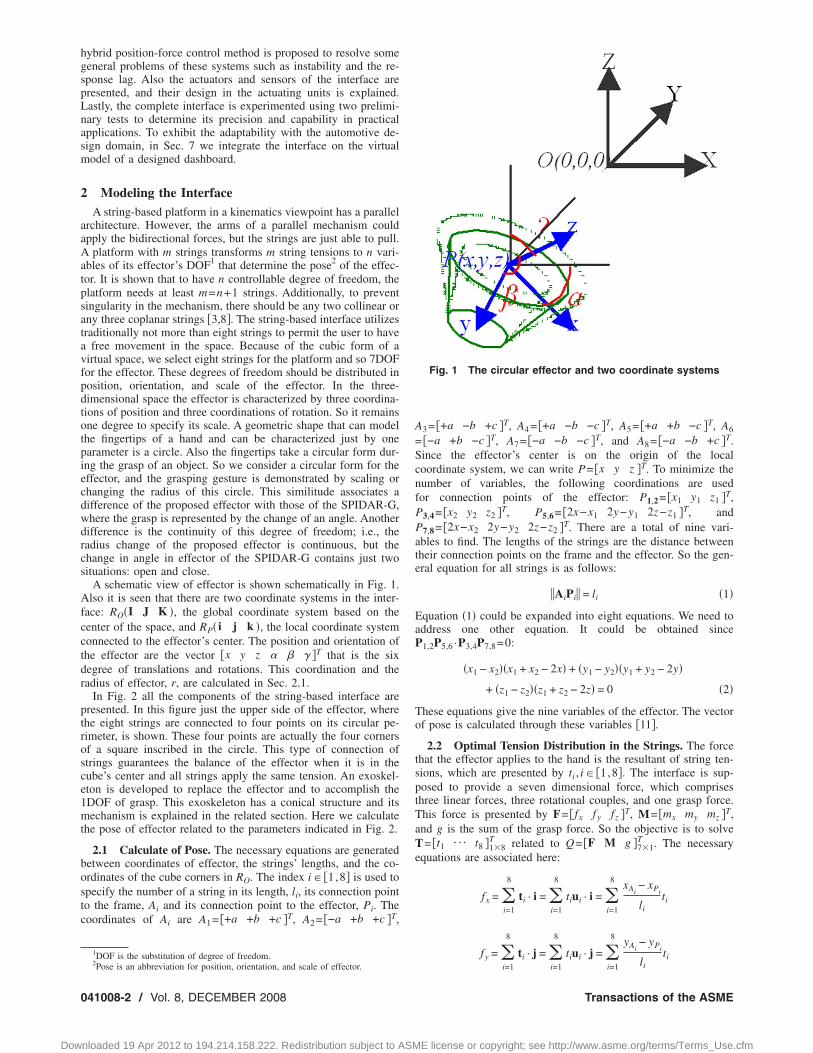
The model of exoskeleton’s mechanism in its open and close isrepresented, respectively, in Fig. 5 �right and left�. The five fingersof a hand could be positioned inside the circular perimeter in thefive brown fingerings. The fingerings could rotate in their posi-tions, and the strings’ connection to the exoskeleton remains out-side of the fingerings’ position. The mechanism’s core forms ahemisphere in the hand, and the gears are situated in this hemi-sphere.
In some cases we are to have just six degrees of force feedback,and the grasp degree is not necessary. So we develop the idea ofvoluntary fixation of the exoskeleton. That will allow us to have aconstant radius for the connection points to the strings during theoperation. Otherwise the exoskeleton is transformed to a fixed
chanism „left… and its general scheme „right…
Transactions of the ASME
E license or copyright; see http://www.asme.org/terms/Terms_Use.cfm
eftra
aedng12aapawwwcs
Fc
Fn
J
Dow
ffector that connects the strings to the user’s hand. The systemor blocking the exoskeleton contains a blocking rod that preventshe spur gears to turn. Two bars are connected to the spur gears’ods, and the blocking rod passes through the holes that are cre-ted on them.
A prototype of the exoskeleton is produced to verify differentspects of its performance, such as adaptability for the hand, us-r’s comfort, and functionality in a human-scale environment. Theimensions of the exoskeleton are selected with respect to ergo-omic characteristics of different hands. The maximum length ofrasping between thumb and ring finger varies between 15 cm and7 cm, and the diameter of the fingers varies between 1.5 cm and.5 cm. In Fig. 6 the developed prototype and the hand positioningre presented. To achieve a structure with a maximum of soliditynd minimum of weight, we used the materials such as aluminum,lastic, and wood in the exoskeleton. All of the rods and the barsre made of aluminum, the gears are of plastic, the fingerings areooden, and their internal layers are of polystyrene. So the totaleight of the exoskeleton is less than 500 g. To transfer thiseight to the hand’s back, we use an orthosis, which is made of
omposite, polystyrene, and polyvinyl chloride �PVC�. This ortho-is permits the fingers to touch and grasp the virtual objects with-
ig. 5 Model of the exoskeleton in its extreme open „left… andlose „right… situations
ig. 6 The prototype of the exoskeleton connected „left… andot connected „right… to the strings
Fig. 7 Position of the hand „left… an
controllerournal of Computing and Information Science in Enginee
nloaded 19 Apr 2012 to 194.214.158.222. Redistribution subject to ASM
out feeling the exoskeleton’s weight. The ergonomic form of theorthosis provides a regular movement, which is adapted to themovement of other parts of the exoskeleton.
4 Using a Hybrid Control MethodIn the present interface, the strings are long, and the actuators
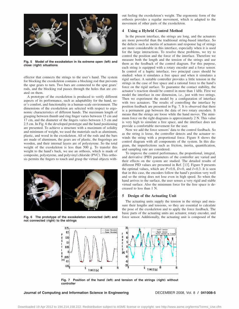
are more powerful than the traditional string-based interface. Sothe defects such as inertia of actuators and response lag of stringsare more considerable in this interface, especially when it is usedfor the large interactions. To resolve these problems, we try tocontrol the position and the force of the interface. Therefore wemeasure both the length and the tension of the strings and usethem as the feedback of the control diagram. For this purpose,each string is equipped with a rotary encoder and a force sensor.In control of a haptic interface, two principal cases should bestudied: when it simulates a free space and when it simulates arigid surface. A suitable controller provides a little tension in thestrings in the case of free space and a rational force to the hand’sforce on the rigid surface. To guarantee the contact stability, theactuator’s reaction should be control in more than 1 kHz. First wemodel the interface in one dimension, i.e., just with two strings.Then we experiment the model by a configuration of interfacewith two actuators. The results of controlling the interface byposition feedback are presented in Fig. 7. It is observed that thereis a permanent gap between the data of two rotary encoders. Itmeans that the strings are loose while the hand moves. The mini-mum force on the right diagrams is approximately 2 N. This valueis very high to simulate a free space, and the interface does notprovide a comfortable movement for the user.
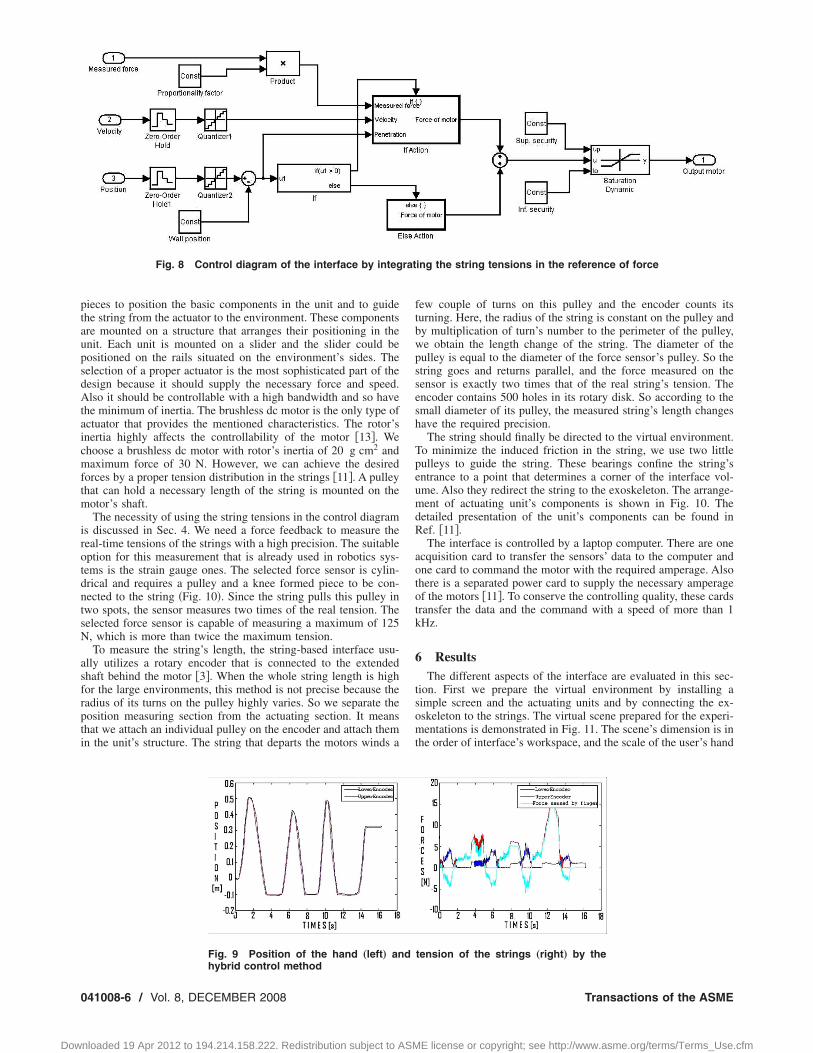
Now we add the force sensors’ data to the control feedback. Soas the string is loose, the controller detects and the actuator re-winds the string with a proportional force. Figure 8 shows thecontrol diagram with all components of the system. In this dia-gram, the imperfections such as friction, inertia, quantification,and sampling rate are considered.
To improve the control performance, the proportional, integral,and derivative �PID� parameters of the controller are varied andtheir effects on the system are studied. The detailed results ofdifferent PID values are presented in Ref. �13�. Figure 9 presentsthe optimal values, which are P=0.8, D=0, and I=0.3. It is seenthat in this case, the encoders follow the hand’s position very welland so the string does not lose even in high speed. So when thehand arrives to the surface, the user senses a very rigid and stablevirtual surface. Also the minimum force for the free space is de-creased to less than 1 N.
5 Design of the Actuating UnitThe actuating units supply the tension in the strings and mea-
sure their lengths and tensions, so they are essential to calculatethe pose of the exoskeleton and to apply the force feedback. Thebasic parts of the actuating units are actuator, rotary encoder, andforce sensor. Additionally, the actuating unit is composed of the
ension of the strings „right… without
d tring DECEMBER 2008, Vol. 8 / 041008-5
E license or copyright; see http://www.asme.org/terms/Terms_Use.cfm
ptaupsdAtaicmftm
irotdntsN
asfrpti
0
Dow
ieces to position the basic components in the unit and to guidehe string from the actuator to the environment. These componentsre mounted on a structure that arranges their positioning in thenit. Each unit is mounted on a slider and the slider could beositioned on the rails situated on the environment’s sides. Theelection of a proper actuator is the most sophisticated part of theesign because it should supply the necessary force and speed.lso it should be controllable with a high bandwidth and so have
he minimum of inertia. The brushless dc motor is the only type ofctuator that provides the mentioned characteristics. The rotor’snertia highly affects the controllability of the motor �13�. Wehoose a brushless dc motor with rotor’s inertia of 20 g cm2 andaximum force of 30 N. However, we can achieve the desired
orces by a proper tension distribution in the strings �11�. A pulleyhat can hold a necessary length of the string is mounted on the
otor’s shaft.The necessity of using the string tensions in the control diagram
s discussed in Sec. 4. We need a force feedback to measure theeal-time tensions of the strings with a high precision. The suitableption for this measurement that is already used in robotics sys-ems is the strain gauge ones. The selected force sensor is cylin-rical and requires a pulley and a knee formed piece to be con-ected to the string �Fig. 10�. Since the string pulls this pulley inwo spots, the sensor measures two times of the real tension. Theelected force sensor is capable of measuring a maximum of 125, which is more than twice the maximum tension.To measure the string’s length, the string-based interface usu-
lly utilizes a rotary encoder that is connected to the extendedhaft behind the motor �3�. When the whole string length is highor the large environments, this method is not precise because theadius of its turns on the pulley highly varies. So we separate theosition measuring section from the actuating section. It meanshat we attach an individual pulley on the encoder and attach themn the unit’s structure. The string that departs the motors winds a
Fig. 8 Control diagram of the interface by integ
Fig. 9 Position of the hand „left… an
hybrid control method41008-6 / Vol. 8, DECEMBER 2008
nloaded 19 Apr 2012 to 194.214.158.222. Redistribution subject to ASM
few couple of turns on this pulley and the encoder counts itsturning. Here, the radius of the string is constant on the pulley andby multiplication of turn’s number to the perimeter of the pulley,we obtain the length change of the string. The diameter of thepulley is equal to the diameter of the force sensor’s pulley. So thestring goes and returns parallel, and the force measured on thesensor is exactly two times that of the real string’s tension. Theencoder contains 500 holes in its rotary disk. So according to thesmall diameter of its pulley, the measured string’s length changeshave the required precision.
The string should finally be directed to the virtual environment.To minimize the induced friction in the string, we use two littlepulleys to guide the string. These bearings confine the string’sentrance to a point that determines a corner of the interface vol-ume. Also they redirect the string to the exoskeleton. The arrange-ment of actuating unit’s components is shown in Fig. 10. Thedetailed presentation of the unit’s components can be found inRef. �11�.
The interface is controlled by a laptop computer. There are oneacquisition card to transfer the sensors’ data to the computer andone card to command the motor with the required amperage. Alsothere is a separated power card to supply the necessary amperageof the motors �11�. To conserve the controlling quality, these cardstransfer the data and the command with a speed of more than 1kHz.
6 ResultsThe different aspects of the interface are evaluated in this sec-
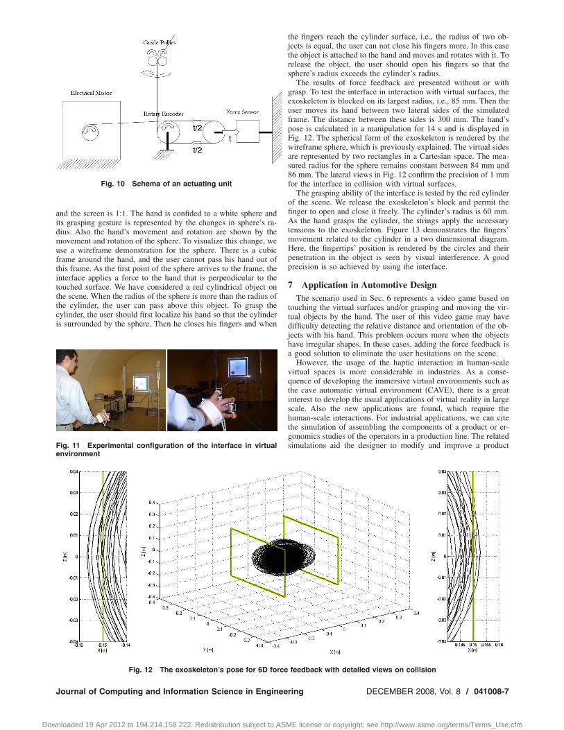
tion. First we prepare the virtual environment by installing asimple screen and the actuating units and by connecting the ex-oskeleton to the strings. The virtual scene prepared for the experi-mentations is demonstrated in Fig. 11. The scene’s dimension is inthe order of interface’s workspace, and the scale of the user’s hand
ing the string tensions in the reference of force
tension of the strings „right… by the
rat
d
Transactions of the ASME
E license or copyright; see http://www.asme.org/terms/Terms_Use.cfm
aidmuftitttci
Fe
J
Dow
nd the screen is 1:1. The hand is confided to a white sphere andts grasping gesture is represented by the changes in sphere’s ra-ius. Also the hand’s movement and rotation are shown by theovement and rotation of the sphere. To visualize this change, we
se a wireframe demonstration for the sphere. There is a cubicrame around the hand, and the user cannot pass his hand out ofhis frame. As the first point of the sphere arrives to the frame, thenterface applies a force to the hand that is perpendicular to theouched surface. We have considered a red cylindrical object onhe scene. When the radius of the sphere is more than the radius ofhe cylinder, the user can pass above this object. To grasp theylinder, the user should first localize his hand so that the cylinders surrounded by the sphere. Then he closes his fingers and when
Fig. 10 Schema of an actuating unit
ig. 11 Experimental configuration of the interface in virtualnvironment
Fig. 12 The exoskeleton’s pose for 6D force
ournal of Computing and Information Science in Enginee
nloaded 19 Apr 2012 to 194.214.158.222. Redistribution subject to ASM
the fingers reach the cylinder surface, i.e., the radius of two ob-jects is equal, the user can not close his fingers more. In this casethe object is attached to the hand and moves and rotates with it. Torelease the object, the user should open his fingers so that thesphere’s radius exceeds the cylinder’s radius.
The results of force feedback are presented without or withgrasp. To test the interface in interaction with virtual surfaces, theexoskeleton is blocked on its largest radius, i.e., 85 mm. Then theuser moves its hand between two lateral sides of the simulatedframe. The distance between these sides is 300 mm. The hand’spose is calculated in a manipulation for 14 s and is displayed inFig. 12. The spherical form of the exoskeleton is rendered by thewireframe sphere, which is previously explained. The virtual sidesare represented by two rectangles in a Cartesian space. The mea-sured radius for the sphere remains constant between 84 mm and86 mm. The lateral views in Fig. 12 confirm the precision of 1 mmfor the interface in collision with virtual surfaces.
The grasping ability of the interface is tested by the red cylinderof the scene. We release the exoskeleton’s block and permit thefinger to open and close it freely. The cylinder’s radius is 60 mm.As the hand grasps the cylinder, the strings apply the necessarytensions to the exoskeleton. Figure 13 demonstrates the fingers’movement related to the cylinder in a two dimensional diagram.Here, the fingertips’ position is rendered by the circles and theirpenetration in the object is seen by visual interference. A goodprecision is so achieved by using the interface.
7 Application in Automotive DesignThe scenario used in Sec. 6 represents a video game based on
touching the virtual surfaces and/or grasping and moving the vir-tual objects by the hand. The user of this video game may havedifficulty detecting the relative distance and orientation of the ob-jects with his hand. This problem occurs more when the objectshave irregular shapes. In these cases, adding the force feedback isa good solution to eliminate the user hesitations on the scene.
However, the usage of the haptic interaction in human-scalevirtual spaces is more considerable in industries. As a conse-quence of developing the immersive virtual environments such asthe cave automatic virtual environment �CAVE�, there is a greatinterest to develop the usual applications of virtual reality in largescale. Also the new applications are found, which require thehuman-scale interactions. For industrial applications, we can citethe simulation of assembling the components of a product or er-gonomics studies of the operators in a production line. The relatedsimulations aid the designer to modify and improve a product
feedback with detailed views on collision
ring DECEMBER 2008, Vol. 8 / 041008-7
E license or copyright; see http://www.asme.org/terms/Terms_Use.cfm

bptwi
nftcTpdcedd
t
F
0
Dow
efore establishing the production line. While there were theroper developments in visualization of these applications, usinghe force feedback was much more limited. In this section weant to evaluate the possibility of integrating the present haptic
nterface within automotive design.The automotive industries are the essential clients of this tech-
ology. For example, the PSA Co. is interested in integrating aorce feedback interface in the immersive environment to improvehe new automotive design. This interface serves to optimize theonfiguration of different elements on an automotive dashboard.his optimization contains the ergonomics of the operator in theroduction line as well as the ergonomics of the automotiveriver. Figure 14 presents a modeled dashboard with different ac-essories for the driver. The haptic interface is used in the virtualnvironment equipped with a large screen. A user situated in theriver position uses the interface to touch different surfaces of theashboard.
The user wants also to optimize the location of the red buttonhat is positioned under his hand. Figure 15 �left� shows that he
Fig. 13 The fingers are positioned in a gra
ig. 14 Integrating the haptic interface on a virtual dashboard
41008-8 / Vol. 8, DECEMBER 2008
nloaded 19 Apr 2012 to 194.214.158.222. Redistribution subject to ASM
covers the button with his hand and Fig. 15 �right� shows when hegrasps it. Then he is able to move and turn the button while hesenses the force feedback. Similarly he could interact with dash-board elements and find their optimized configuration with moreefficiency.
8 Conclusion and PerspectiveA new force feedback exoskeleton for five fingers and its string-
based platform has been introduced. This exoskeleton has beendeveloped for the human-scale interactions in a virtual environ-ment. To interact with 3D objects, six degrees of freedom havebeen considered for the user’s hand. Also to grasp virtual objectswith different sizes, one degree of force feedback has been con-sidered for the fingertips. The exoskeleton has been designed on agear-based mechanism and its prototype has been developed byrespecting the ergonomic parameters of different hand sizes. Theexoskeleton’s actuation was performed by a platform with eightstrings. The actuating platform has been developed to provideseven degrees of force feedback for the exoskeleton. So the ex-oskeleton comprised three active degrees of translation, three ac-tive degrees of rotation, and one active degree of grasp. The mea-surement of pose of the hand in virtual environment and actuatingthe strings has been performed by eight actuating units. A hybridcontrol method has been proposed to increase the stability of hap-tic interactions as well as to provide a comfortable hand move-ment in the free space. The attained force was situated between 1
ing configuration around a virtual cylinder
Fig. 15 The user’s gesture in grasping „left… and releasing
sp
„right… a cylindrical button
Transactions of the ASME
E license or copyright; see http://www.asme.org/terms/Terms_Use.cfm
Ntswrspbd
fctmfm
R
J
Dow
and 30 N. The components of the string platform were designedo provide a precise contact, and the mechanical imperfectionsuch as inertia and friction were minimized. The haptic interfaceas installed in a human-scale environment and its experimental
esults within preliminary tests have been demonstrated. The mea-ured precision for interface was 1 mm. Finally an industrial ap-lication was developed by implementing the interface on a dash-oard model. Hereby its performance in automotive design wasemonstrated.
Our further work concerns the implementation of the forceeedback interface in more sophisticated applications. Hereby wean develop its usage in different positional domains of applica-ion. Our researches also include the development of the new
echanisms of haptic interfaces to provide more degrees of forceeedback and, thus more realism for the users in virtual environ-ents.
eferences�1� Springer, S., and Ferrier, N., 2002, “Design and Control of a Force-Reflecting
Haptic Interface for Teleoperational Grasping,” ASME J. Mech. Des., 124�2�,pp. 277–283.
�2� CyberTouch Immersion Corporation, http://www.immersion.com/3d/products.�3� Kim, S., Koike, Y., and Sato, M., 2002, “Tension Based 7 DOFs Force Feed-
back Device: SPIDAR-G,” Transactions on Control, Automation, and SystemsEngineering, Vol. 4�1�, pp. 9–16.
�4� Choi, W., Zoo, S., Hashimoto, N., Hasegawa, S., Koike, Y., and Sato, M.,
2004, “A Development and Evaluation of Reactive Motion Capture Systemournal of Computing and Information Science in Enginee
nloaded 19 Apr 2012 to 194.214.158.222. Redistribution subject to ASM
With Haptic Feedback,” Sixth Conference on Automatic Face and GestureRecognition, Seoul, Korea.
�5� Ortega, M., and Coquillart, S., 2005, “Prop-Based Haptic Interaction WithCo-Location and Immersion: An Automotive Application,” IEEE InternationalWorkshop on Haptic Audio Visual Environments and Their Applications, Ot-tawa, ON, Canada, Oct.
�6� Krut, S., Company, O., and Pierrot, F., 2004, “Force Performance Indexes forParallel Mechanisms With Actuation Redundancy, Especially for ParallelWire-Driven Manipulators,” Proceedings of the 2004 IEEE/RSJ InternationalConference on Intelligent Robotics and Systems, Sendai, Japan, Oct.
�7� Fang, S., Franitza, D., Torlo, M., Bekes, F., and Hiller, M., 2004, “MotionControl of a Tendon-Based Parallel Manipulator Using Optimal Tension Dis-tribution,” IEEE/ASME Trans. Mechatron., 9�3�, pp. 561–568.
�8� Verhoeven, R., Hiller, M., and Tadokoro, S., 1998, “Workspace, Stiffness,Singularities and Classification of Tendon-Driven Stewart Platforms,” SixthInternational Symposium on Advances on Robot Kinematics, Strobl, Austria,pp. 105–114.
�9� Lafourcade, P., and Llibre, M., 2003, “First Steps Toward a Sketch-BasedDesign Methodology for Wire-Driven Manipulators,” IEEE/ASME Interna-tional Conference on Advanced and Intelligent Mechatronics, Kobe, Japan,Jul.
�10� Brau, E., Lallemand, J.-P., and Gosselin, F., 2005, “Analytic Determination ofthe Tension Capable Workspace of Cable Actuated Haptic Interface,” ICAT2005.
�11� Fesharakifard, R., 2007, “Conception et Réalisation d’une Interface à Retourd’effort Pour les Environnements Virtuels à échelle Humaine,” Ph.D. thesis,CAD and Robotic Center, Ecole Nationale Supérieur des Mines de Paris, Paris,France.
�12� Le Mesre de Pas, P., 2007, “Optimisation de la Configuration d’interfacesHaptiques à Câbles en Environnement Immersif,” Cad and Robotic Center,Ecole Nationale Supérieur des Mines de Paris, Internship report.
�13� Fesharakifard, R., Leroy, L., and Fuchs, P., 2007, “Development of a String-Based Haptic Interface by Using a Hybrid Control Approach,” World Haptic
Conference, Tsubuka, Japan, Mar.ring DECEMBER 2008, Vol. 8 / 041008-9
E license or copyright; see http://www.asme.org/terms/Terms_Use.cfm