Enabling Problem Based Learning through Web 2.0 Technologies: PBL 2.0
Upload
khangminh22Category
view
1download
0
M
an
ual
INSYS HSPA small 2.0


Copyright © August 11 INSYS MICROELECTRONICS GmbH
Any duplication of this manual is prohibited. All rights on this documentation and the devices are with INSYS MICROELECTRONICS GmbH Regensburg.
Trademarks
The use of a trademark not shown below is not an indication that it is freely avail-able for use.
MNP is a registered trademark of Microcom Inc.
IBM PC, AT, XT are registered trademarks of International Business Machine Cor-poration.
INSYS®, e-Mobility LSG® and e-Mobility PLC® are registered trademarks of INSYS MICROELECTRONICS GmbH.
Windows™ is a registered trademark of Microsoft Corporation.
Linux is a registered trademark of Linus Torvalds.
Publisher:
INSYS MICROELECTRONICS GmbH
Waffnergasse 8
D-93047 Regensburg, Germany
Phone: +49 (0)941/56 00 61
Fax: +49 (0)941/56 34 71
E-mail: [email protected]
Internet: http://www.insys-icom.com
Date: Aug-11
Item: 31-22-03.168
Version: 1.1
Language:
Content
1 Preface................................................................................................................. 6
1.1 Defects Liability Terms .......................................................................................................6
1.2 Marking of Warnings and Notes ........................................................................................7 1.2.1 Symbols and Key Words ...................................................................................................7
1.3 Symbols and the Formatting in this Manual .....................................................................8
2 Safety .................................................................................................................. 9
2.1 Usage According to the Regulations ..................................................................................9
2.2 Permissible Technical Limits.............................................................................................10
2.3 Responsibilities of the Operator.......................................................................................10
2.4 Qualification of the Personnel .........................................................................................10
2.5 Instructions for Transport and Storage............................................................................10
2.6 Markings on the Product ..................................................................................................11
2.7 Environmental Protection ................................................................................................11
2.8 Safety Instructions for Electrical Installation...................................................................11
2.9 General Safety Instructions ..............................................................................................12
3 Scope of Delivery .............................................................................................. 14
4 Technical Data................................................................................................... 15
4.1 Physical Features ..............................................................................................................15
4.2 Technological Features .....................................................................................................16
5 Display and Control Elements........................................................................... 17
5.1 Display Elements...............................................................................................................17
5.2 Control Elements ..............................................................................................................18
6 Connections....................................................................................................... 19
6.1 Front Panel Connections...................................................................................................19
6.2 Terminal Connections on the Top ....................................................................................20
6.3 Terminal Connections on the Bottom..............................................................................20
7 Function Overview............................................................................................ 21
8 Mounting .......................................................................................................... 22
9 Initial Operation................................................................................................ 26
10 Operating Principle ........................................................................................... 29
4 Aug-11

Contents
Aug-11 5
11 Functions ........................................................................................................... 30
11.1 Entering the PIN of the SIM Card......................................................................................30
11.2 Insert and Remove SIM Card ............................................................................................31
11.3 Checking the Status of the GSM Login.............................................................................33
11.4 Checking the GSM Signal Quality.....................................................................................34
11.5 Establishing or Accepting a CSD Data Connection ..........................................................35
11.6 Establishing a PPP Data Connection.................................................................................36
11.7 Automatic Call Acceptance...............................................................................................37
11.8 Querying a Digital Input ...................................................................................................37
11.9 Setting a Switch Output ...................................................................................................38
11.10 Sending an SMS Manually ................................................................................................39
11.11 Using USSD Codes.............................................................................................................39
11.12 Resetting the Device.........................................................................................................40
12 AT Command Reference ................................................................................... 41
13 GSM Service Center Numbers........................................................................... 42
14 APN Access Data................................................................................................ 43
15 Network Provider Codes ................................................................................... 44
16 Maintenance, Repair and Troubleshooting...................................................... 48
16.1 Maintenance .....................................................................................................................48
16.2 Troubleshooting................................................................................................................48
16.3 Repair ................................................................................................................................48
17 Waste Disposal.................................................................................................. 49
17.1 Repurchasing of Legacy Systems......................................................................................49
18 Declaration of Conformity................................................................................ 50
19 Tables and Diagrams......................................................................................... 51
19.1 List of Tables .....................................................................................................................51
19.2 List of Diagrams ................................................................................................................51
20 Index.................................................................................................................. 52
Preface INSYS HSPA small 2.0
1 Preface
This manual allows for the safe and efficient use of the product. The manual is part of the product and must always be stored accessible for installation, commissioning and operating personnel.
1.1 Defects Liability Terms A usage not according to the intended purpose, an ignorance of this documentation, the use of insufficiently qualified personnel as well as unauthorised modifications exclude the liability of the manufacturer for damages resulting from this. The liability of the manufacturer ceases to exist. The regulations of our Delivery and Purchasing Conditions are effective. These can be found on our website (www.insys-icom.de/imprint/) under “General Terms and Condi-tions“.
6

INSYS HSPA small 2.0 Preface
1.2 Marking of Warnings and Notes
1.2.1 Symbols and Key Words
Danger! Risk of severe or fatal injury
One of these symbols in conjunction with the key word Danger indicates an imminent danger. It will cause death or severe in-juries if not avoided.
Warning! Personal injury
This symbol in conjunction with the key word Warning indi-cates a possibly hazardous situation. It might cause death or severe injuries if not avoided.
Caution! Slight injury and / or material damage
This symbol in conjunction with the key word Caution indicates a possibly hazardous or harmful situation. It might cause slight or minor injuries or a damage of the product or something in its vicinity if not avoided.
Note Improvement of the application
This symbol in conjunction with the key word Note indicates hints for the user or very useful information. This information helps with installation, set-up and operation of the product to ensure a fault-free operation.
7

Preface INSYS HSPA small 2.0
1.3 Symbols and the Formatting in this Manual This section describes the definition, formatting and symbols used in this manual. The various symbols are meant to help you read and find the information relevant to you. The following text is structured like a typical operating instruction of this manual.
Bold print: This will tell you what the following steps will result in
After that, there will be a detailed explanation why you could perform the following steps to be able to reach the objective indicated first. You can de-cide whether the section is relevant for you or not.
An arrow will indicate prerequisites which must be fulfilled to be able to process the subsequent steps in a meaningful way. You will also learn which software or which equipment you will need.
1. One individual action step: This tells you what you need to do at this point. The steps are numbered for better orientation.
A result which you will receive after performing a step will be marked with a check mark. At this point, you can check if the previous steps were suc-cessful.
Additional information which you should consider are marked with a cir-cled "i". At this point, we will indicate possible error sources and tell you how to avoid them.
Alternative results and steps are marked with an arrow. This will tell you how to reach the same results performing different steps, or what you could do if you didn't reach the expected results at this point.
8
INSYS HSPA small 2.0 Safety
2 Safety
The Safety section provides an overview about the safety instructions, which must be observed for the operation of the product. The product is constructed according to the currently valid state-of-the-art technology and reliable in operation. It has been checked and left the factory in flawless condition concerning safety. In order to maintain this condition during the service life, the instruc-tions of the valid publications and certificates must be observed and followed. It is necessary to adhere to the general safety instructions must when operating the product. The descriptions of processes and operation procedures are provided with pre-cise safety instructions in the respective sections in addition to the general safety in-structions. Moreover, the local accident prevention regulations and general safety regulations for the operating conditions of the device are effective. An optimum protection of the personnel and the environment from hazards as well as a safe and fault-free operation of the product is only possible if all safety instructions are observed.
2.1 Usage According to the Regulations The product may only be used for the purposes specified in the function overview. In ad-dition, it may be used for the following purposes:
Usage and mounting in an industrial cabinet.
Data transmission functions in machines according to the machine direc-tive 2006/42/EC.
Usage as data transmission device for a PLC.
The product may not be used for the following purposes and used or operated under the following conditions:
Controlling or switching of machines and systems, which do not comply with the directive 2006/42/EC.
Usage, controlling, switching and data transmission of machines and sys-tems, which are operated in explosive atmospheres.
Controlling, switching and data transmission of machines, which may in-volve risks to life and limb due to their functions or when a breakdown oc-curs.
9
Safety INSYS HSPA small 2.0
2.2 Permissible Technical Limits The product is only intended for the use within the permissible technical limits specified in the data sheets. The following permissible limits must be observed:
The ambient temperature limits must not be fallen below or exceeded.
The supply voltage range must not be fallen below or exceeded.
The maximum humidity must not be exceeded and condensate formation must be prevented.
The maximum switching voltage and the maximum switching current lo-ad must not be exceeded.
The maximum input voltage and the maximum input current must not be exceeded.
2.3 Responsibilities of the Operator As a matter of principle, the operator must observe the legal regulations, which are valid in his country, concerning operation, functional test, repair and maintenance of electrical devices.
2.4 Qualification of the Personnel The installation, commissioning and maintenance of the product must only be per-formed by trained expert personnel, which has been authorised by the plant operator. The expert personnel must have read and understood this documentation and observe the instructions. Electrical connection and commissioning must only be performed by a person, who is able to work on electrical installations and identify and avoid possible hazards independ-ently, based on professional training, knowledge and experience as well as knowledge of the relevant standards and regulations.
2.5 Instructions for Transport and Storage The following instructions must be observed:
Do not expose the product to moisture and other potential hazardous en-vironmental conditions (radiation, gases, etc.) during transport and stor-age. Pack product accordingly.
Pack product sufficiently to protect it against shocks during transport and storage, e.g. using air-cushioned packing material.
Check product for possible damages, which might have been caused by improper trans-port, before installation. Transport damages must be noted down to the shipping docu-ments. All claims or damages must be filed immediately and before installation against the carrier or party responsible for the storage.
10

INSYS HSPA small 2.0 Safety
2.6 Markings on the Product The identification plate of the product is either a print or a label on a face of the product. Amongst other things, it contains the following markings, which are explained in detail here.
Observe manual
This symbol indicates that the manual of the product contains essential safety instructions that must be followed implicitly.
Dispose waste electronic equipment environmentally
This symbol indicates that waste electronic equipment must be disposed separately from residual waste via appropriate collect-ing points. See also Section Disposal in this manual.
CE marking
By applying a CE marking, the manufacturer confirms that the product complies with the European directives that apply prod-uct-specific.
Appliance Class II – double insulated
This symbol indicates that the product complies with Appliance Class II
2.7 Environmental Protection Dispose the product and the packaging according to the relevant environmental protec-tion regulations. The Waste Disposal section in this manual contains notes about dispos-ing the product. Separate the packaging components of cardboard and paper as well as plastic and deliver them to the respective collection systems for recycling.
2.8 Safety Instructions for Electrical Installation The electrical connection must only be made by authorised expert personnel according to the wiring diagrams. The notes to the electrical connection in the manual must be observed. Otherwise, the protection category might be affected. The safe disconnection of circuits, which are hazardous when touched, is only ensured if the connected devices meet the requirements of VDE T.101 (Basic requirements for safe disconnection). The supply lines are to be routed apart from circuits, which are hazardous when touched, or isolated additionally for a safe disconnection.
11

Safety INSYS HSPA small 2.0
2.9 General Safety Instructions
Caution! Moisture and liquids from the environment may seep into the interior of the product!
Fire hazard and damage of the product. The product must not be used in wet or damp environments, or
in the direct vicinity of water. Install the product at a dry loca-tion, protected from water spray. Disconnect the power supply before you perform any work on a device which may have been in contact with moisture.
Caution! Short circuits and damage due to improper repairs and modifi-cations as well as opening of maintenance areas.
Fire hazard and damage of the product. It is not permitted to open the product for repair or modifica-
tion.
Caution! Overcurrent of the device supply!
Fire hazard and damage of the product due to overcurrent.
The product must be secured with a suitable fuse against cur-rents exceeding 1.6 A.
Caution! Overvoltage and voltage peaks from the mains supply!
Fire hazard and damage of the product due to overvoltage.
Install suitable overvoltage protection.
Caution! Damage due to chemicals!
Ketones and chlorinated hydrocarbons dissolve the plastic housing and damage the surface of the device.
Never let the device come into contact with ketones (e.g. ace-tone) or chlorinated hydrocarbons, such as dichloromethane.
12

INSYS HSPA small 2.0 Safety
Caution! Distance from antennas to persons!
A too low distance from GSM antennas to persons can affect the health.
Please observe to keep a minimum distance of 20 cm between the GSM antenna and persons during operation.
13

Scope of Delivery INSYS HSPA small 2.0
3 Scope of Delivery
The scope of delivery for the INSYS HSPA small 2.0 includes all accessories listed below. Please check if all accessories are included in the box. If a part is missing or damaged, please contact your distributor.
INSYS HSPA small 2.0
Cable
USB cable to connect to the PC
CD ROM
User Manual INSYS HSPA small 2.0 (PDF)
Add-on manual INSYS GPRS/EDGE Devices as GPRS/EDGE Terminal (PDF)
Configuration software HSComm
Optional accessories
GSM antenna
Outside wall antenna, magnetic base antenna or patch antenna
14
INSYS HSPA small 2.0 Technical Data
4 Technical Data
4.1 Physical Features
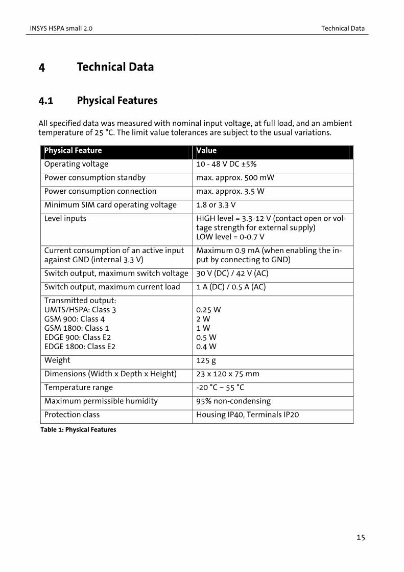
All specified data was measured with nominal input voltage, at full load, and an ambient temperature of 25 °C. The limit value tolerances are subject to the usual variations.
Physical Feature Value
Operating voltage 10 - 48 V DC ±5%
Power consumption standby max. approx. 500 mW
Power consumption connection max. approx. 3.5 W
Minimum SIM card operating voltage 1.8 or 3.3 V
Level inputs HIGH level = 3.3-12 V (contact open or vol-tage strength for external supply) LOW level = 0-0.7 V
Current consumption of an active input against GND (internal 3.3 V)
Maximum 0.9 mA (when enabling the in-put by connecting to GND)
Switch output, maximum switch voltage 30 V (DC) / 42 V (AC)
Switch output, maximum current load 1 A (DC) / 0.5 A (AC)
Transmitted output: UMTS/HSPA: Class 3 GSM 900: Class 4 GSM 1800: Class 1 EDGE 900: Class E2 EDGE 1800: Class E2
0.25 W 2 W 1 W 0.5 W 0.4 W
Weight 125 g
Dimensions (Width x Depth x Height) 23 x 120 x 75 mm
Temperature range -20 °C – 55 °C
Maximum permissible humidity 95% non-condensing
Protection class Housing IP40, Terminals IP20
Table 1: Physical Features
15

Technical Data INSYS HSPA small 2.0
4.2 Technological Features Technological Feature Description
Data formats of the serial interface
8N1, 7E1, 7O1, 7N2, 8E1, 8O1, 8N2
Fax class Fax group 3 Class 1
SMS features Text and PDU mode - Mobile Originated (MO) - Mobile Terminated (MT) - Cell Broadcast (CB)
Quad band GSM frequencies 850, 900, 1800, 1900 MHz
UMTS/HSPA frequency 2100 MHz
CSD GSM: up to 14.4 kbps
GPRS features Multislot class 12 Coding Scheme CS1 to CS4 GPRS terminal device class B (no simultaneous CSD and GPRS connect possible)
EDGE features Multislot class 12 Coding Scheme MCS1 to MCS9
HSPA features Max. uplink 5.76 Mbps Max. downlink 7.2 Mbps UE CAT (1-8), 11, 12 supported Compressed mode (3GPP TS25.212)
USB interface USB 2.0
Modulation types V.22bis, V.32 (4800/9600 bps), V.34, V.110 (4800/9600/14400 bps)
Serial interface speed 300, 600, 1220, 2400, 4800, 9600, 14400, 19200, 28800, 38400, 57600, 115200 bps
Table 2: Technological Features
Above information is subject to the support by the provider.
16

INSYS HSPA small 2.0 Display and Control Elements
5 Display and Control Elements
5.1 Display Elements
Figure 1: LEDs on the front panel
Position Description
1 Power LED
2 Net/Status LED
Table 3: Description of the LEDs on the front panel
The left LED (Power) indicates the status of the power supply. The right LED (Net/Status) indicates a sending activity into the GSM/UMTS network. The exact meaning of the dis-play elements is shown in the following table.
17

Display and Control Elements INSYS HSPA small 2.0
LED Colour On Blinking: Flashing: Off
green Power supply is present - - - - - -
orange Initialisation (following start or reset)
- - - - - - Power
red - - - - - - - - -
Power supply is not pre-sent
green - - - - - - Sending activity into the GSM/UMTS network
orange - - - Net/ Status
red Initialisation (following start or reset)
- - - - - -
Power supply is not pre-sent
Table 4: Meaning of the LED displays
5.2 Control Elements
Figure 2: Control elements on the bottom of the device
Position Description
1 SIM card holder eject key
2 SIM card holder insert
Table 5: Description of the control elements on the bottom of the device
18

INSYS HSPA small 2.0 Connections
6 Connections
6.1 Front Panel Connections
Figure 3: Connections on the front panel of the device
Position Description
1 USB interface
2 Antenna connection (FME socket)
Table 6: Description of the connections on the front panel of the device
19

Connections INSYS HSPA small 2.0
6.2 Terminal Connections on the Top
Figure 4: Connections on the top of the device
Terminal Description Description
1 10..48 VDC Power supply 10V - 48V DC
(voltage figures are limit values without tolerances)
2 GND Ground
3 Reset Reset input
4 Input 1 Digital input 1
Table 7: Description of the connections on the top of the device
6.3 Terminal Connections on the Bottom
Figure 5: Connections on the bottom of the device
Terminal Description Description
5 - Not connected
6 Out 1-NO Switch output 1 - normally open
7 Out 1 Switch output 1 - common contact
8 Out 1-NC Switch output 1 - normally closed
Table 8: Description of the connections on the bottom of the device
20

INSYS HSPA small 2.0 Function Overview
7 Function Overview
The INSYS HSPA small 2.0 provides you with the following functions:
Data buffering for serial data transmission
The INSYS HSPA small 2.0 provides rapid send and receive buffers to adjust the modem to the data processing speed of the application.
Bit direct mode
The INSYS HSPA small 2.0 can forward incoming data without having any influence on their transmission format.
Calling number identification
The INSYS HSPA small 2.0 transmits the phone number of an incoming call via the AT interface.
Automatic call acceptance for CSD data connections
The INSYS HSPA small 2.0 can be configured to accept incoming CSD data connections after a specified number of ring tones.
Automatic establishment of CSD data connections via the DTR control line
The INSYS HSPA small 2.0 can establish a CSD data connection to a config-ured number by activating the DTR control line.
Sending SMS messages on DTR activation
The INSYS HSPA small 2.0 can send a previously entered message to a con-figured recipient by activating the DTR control line.
Switch output
The INSYS HSPA small 2.0 has one switch output, which can be used to switch other functions in an application via AT commands.
Digital input
The INSYS HSPA small 2.0 has one digital input, which can be queried using an AT command.
Reset input
The INSYS HSPA small 2.0 can be reset by connecting the Reset input to ground. All saved settings are maintained with this.
Integrated real-time clock
The integrated real-time clock can be set and queried by the application.
HSPA functions
The INSYS HSPA small 2.0 provides the possibility to establish packet-switched IP connections via HSPA in addition.
21

Mounting INSYS HSPA small 2.0
8 Mounting
This section describes how to mount the INSYS HSPA small 2.0 to a DIN rail, connect the power supply and uninstall it again. Observe the instructions in the "Safety" section of this manual, in particular the "Safety Instructions for Electrical Installa-tion" for that purpose unconditionally.
Caution! Moisture and liquids from the environment may seep into the interior of the INSYS HSPA small 2.0!
Fire hazard and damage of the product. The INSYS HSPA small 2.0 must not be used in wet or damp en-
vironments, or in the direct vicinity of water. Install the INSYS HSPA small 2.0 at a dry location, protected from water spray. Disconnect the power supply before you perform any work on a INSYS HSPA small 2.0 which may have been in contact with moisture.
Caution! The device could be destroyed if the wrong power supply is used!
If the INSYS HSPA small 2.0 is operated with a power supply that supplies a voltage exceeding the permissible operating voltage of the INSYS HSPA small 2.0, the device will be de-stroyed.
Make sure that you use the suitable power supply. Refer to the Technical Data section for the proper voltage range of the IN-SYS HSPA small 2.0.
22

INSYS HSPA small 2.0 Mounting
Mounting the device to the DIN rail
How to mount the INSYS HSPA small 2.0 to a DIN rail:
1. Position the device at the DIN rail as seen in the following diagram. There are two snap-in hooks at the upper and lower edge of the DIN rail groove of INSYS HSPA small 2.0. Hook the upper one into place behind the upper edge of the DIN rail.
2. Lift the INSYS HSPA small 2.0 perpendicular to the DIN rail until the two lower, flexible snap-in hooks engage in the DIN rail.
The INSYS HSPA small 2.0 is now readily mounted.
Connecting the power supply
The device has already been mounted to the DIN rail.
The power supply is connected and switched off.
1. Connect the ground lead of the power supply to the terminal "GND".
2. Connect the plus pole of the power supply to the terminal for the power supply.
The INSYS HSPA small 2.0 is now connected to the power supply.
23
Mounting INSYS HSPA small 2.0
Disconnecting the power supply
The device is mounted to the DIN rail.
The power supply is connected and switched off.
1. Disconnect the ground lead of the power supply from the terminal "GND".
2. Disconnect the plus pole of the power supply from the terminal for the power supply.
The INSYS HSPA small 2.0 is disconnected from the power supply.
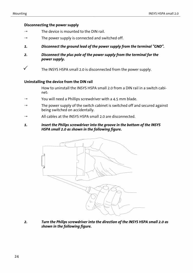
Uninstalling the device from the DIN rail
How to uninstall the INSYS HSPA small 2.0 from a DIN rail in a switch cabi-net:
You will need a Phillips screwdriver with a 4.5 mm blade.
The power supply of the switch cabinet is switched off and secured against being switched on accidentally.
All cables at the INSYS HSPA small 2.0 are disconnected.
1. Insert the Philips screwdriver into the groove in the bottom of the INSYS HSPA small 2.0 as shown in the following figure.
2. Turn the Philips screwdriver into the direction of the INSYS HSPA small 2.0 as shown in the following figure.
24

INSYS HSPA small 2.0 Mounting
The plastic spring of the snap-in hook is stretched.
3. While you hold the plastic spring apart with the lower snap-in hooks, pull the INSYS HSPA small 2.0 away from the DIN rail.
4. Un-hook the INSYS HSPA small 2.0 and take it off perpendicularly to the DIN rail.
The INSYS HSPA small 2.0 is now removed.
25

Initial Operation INSYS HSPA small 2.0
9 Initial Operation
This chapter describes how to put the INSYS HSPA small 2.0 in operation, i.e. how to install drivers on a (Windows) PC, connect the INSYS HSPA small 2.0 to a PC, register with a mobile network, and test it.
The driver file as well as further useful informationen (like for installing Linux driv-ers for example) can be found on the website of the mobile radio engine manufac-turer under http://developer.motorola.com/products/wirelessmodules/h24/, under http://www.insys-icom.com/driver/, or directly from the INSYS icom support de-partment ([email protected]).
Installing drivers on the PC
How to install the drivers for the INSYS HSPA small 2.0 on a Windows PC.
You will need the file with the Windows drivers (h24_drivers_installer.msi).
Install the drivers on your PC before connecting the INSYS HSPA small 2.0 for the first time.
2. Open the file "h24_drivers_installer.msi" on your PC.
3. Follow the instructions of the installation wizard until the installation is completed.
With this, the drivers are installed on your PC and the installation will be continued when the INSYS HSPA small 2.0 is connected for the first time.
Connecting the INSYS HSPA small 2.0 to a PC
How to connect the INSYS HSPA small 2.0 to a PC via the USB interface.
You will need the USB cable.
You will need a free USB interface at the PC.
The required drivers are installed on your PC.
1. Connect the USB cable with the INSYS HSPA small 2.0.
2. Connect the Ethernet cable to a free network interface of your PC.
The INSYS HSPA small 2.0 is connected to the PC with this.
The driver installation will be continued when the INSYS HSPA small 2.0 is connected for the first time. Follow the following steps for this.
The PC detects new hardware components and opens an installation wiz-ard.
26

INSYS HSPA small 2.0 Initial Operation
3. Follow the instructions of the installation wizard to install the drivers.
4. Repeat this step until all (three) drivers are installed.
You have installed the following drivers on you PC with this: Motorola USB Composite Device Motorola USB Modem Motorola AT COM Port
Inserting a SIM card into the INSYS HSPA small 2.0
You will need a SIM card
Please observe the notes in the Enter PIN of the SIM Card section of the Functions chapter concerning the PIN entry before inserting the SIM card to avoid an unintentional locking of the SIM card.
1. Insert the SIM card into the INSYS HSPA small 2.0 and proceed as described in the Insert and Remove SIM Card section of the Functions chapter.
You have inserted the SIM card into the INSYS HSPA small 2.0 with this.
Connecting a GSM antenna to the INSYS HSPA small 2.0
You will need a suitable GSM antenna
1. Connect the GSM antenna with the FME connection on the front of the INSYS HSPA small 2.0.
You have connected the GSM antenna to the INSYS HSPA small 2.0 with this.
27
Initial Operation INSYS HSPA small 2.0
Testing the INSYS HSPA small 2.0
The INSYS HSPA small 2.0 is connected to the PC.
The power supply of the INSYS HSPA small 2.0 is switched on (refer to the Installation section for the connection of the power supply).
A GSM antenna is connected to the INSYS HSPA small 2.0.
A terminal program (e.g. TeraTerm) is installed on the PC.
The Power LED light up green.
1. Open your terminal program.
2. Open the serial interface (COM port), to which the driver "Motorola AT COM Port" is connected.
You can find out this COM port by expanding the "Ports (COM & LPT)" entry in the Windows Device Manager.
3. Enter AT into your terminal program and confirm with the Enter key.
The response will be OK.
The INSYS HSPA small 2.0 is installed successfully and ready for configura-tion.
If you don't receive the response OK, check the connection, the configured COM port, and if the INSYS HSPA small 2.0 receives power. Repeat the test.
28

INSYS HSPA small 2.0 Operating Principle
10 Operating Principle
This section describes the basic procedures to operate and configure a INSYS HSPA small 2.0.
The INSYS HSPA small 2.0 is configured and operated via AT commands. You can enter these commands yourself with the help of a terminal program and the AT command ref-erence.
In general, any terminal program may be used. We recommend the program TeraTerm from T.Teranishi. It is available free in the Internet.
Configuring and operating the INSYS HSPA small 2.0 with a terminal program
How to configure and operate the INSYS HSPA small 2.0 with a terminal program.
The INSYS HSPA small 2.0 is connected to the PC and switched on.
A terminal program is installed on the PC.
1. Start your terminal program.
2. Open the serial interface (COM port), to which the driver "Motorola AT COM Port" is connected.
You can find out this COM port by expanding the "Ports (COM & LPT)" entry in the Windows Device Manager.
3. Type the character string AT into the terminal program. Complete the entry by pressing the Enter key.
Each command input starts with AT and is completed with the Enter key.
The INSYS HSPA small 2.0 replies with OK.
If you don't receive the response OK, check the connection, the configured COM port, and if the INSYS HSPA small 2.0 receives power.
4. Configure the INSYS HSPA small 2.0 using AT commands.
Notes to the reference of AT commands can be found in the AT Command Reference section.
29

Functions INSYS HSPA small 2.0
11 Functions
11.1 Entering the PIN of the SIM Card The INSYS HSPA small 2.0 requires a SIM card as well as the associated SIM card PIN to be able to log into a GSM network. The PIN is necessary that the device is able to use the SIM card for logging into the GSM network. If the SIM card requires no PIN, you don’t ha-ve to enter a PIN in the INSYS HSPA small 2.0 .
Note Loss of function of the SIM card!
An incorrectly entered PIN can cause that the SIM card will be locked after a wrong code has been entered for three times.
Take care, that the passed SIM PIN corresponds with the SIM card or disable the PIN request of the SIM card. A possibly con-figured PIN has no influence if the PIN request is disabled.
Configuration with AT commands
In order to pass the PIN, use the command
Replace <PIN> with the PIN of the SIM card. AT+CPIN=<PIN>
In order to check the status of the PIN request between device and SIM card, use the com-mand
AT+CPIN?
The following responses inform about the status of the PIN request:
No entry required READY
PIN of the SIM card is missing SIM PIN
PUK entry required (after repeated incorrect entry of the PIN)
SIM PUK
SIM card not or incorrectly inserted +CME Error: SIM not inserted
30

INSYS HSPA small 2.0 Functions
11.2 Insert and Remove SIM Card A SIM card must be inserted that your INSYS HSPA small 2.0 is able to log into the GSM network and transmit data. Moreover, the INSYS HSPA small 2.0 must know the PIN of the SIM card.
Insert SIM card
How to insert the SIM card into the INSYS HSPA small 2.0.
You will need a SIM card.
You will need a pointed object, e.g. a refill for a ballpoint pen.
1. Disable the power supply of the INSYS HSPA small 2.0.
2. Press the eject button of the SIM card holder with the pointed object.
(similar representation)
The SIM card holder will be ejected.
3. Remove the SIM card holder.
4. Insert the SIM card into the SIM card holder.
5. Push the SIM card holder with the inserted SIM card with the contacts of the SIM card facing left into the INSYS HSPA small 2.0.
The SIM card can now be used by the INSYS HSPA small 2.0.
Please observe that the correct PIN is passed to the INSYS HSPA small 2.0. A wrong PIN may cause that the SIM card will be locked after switching on the INSYS HSPA small 2.0.
31
Functions INSYS HSPA small 2.0
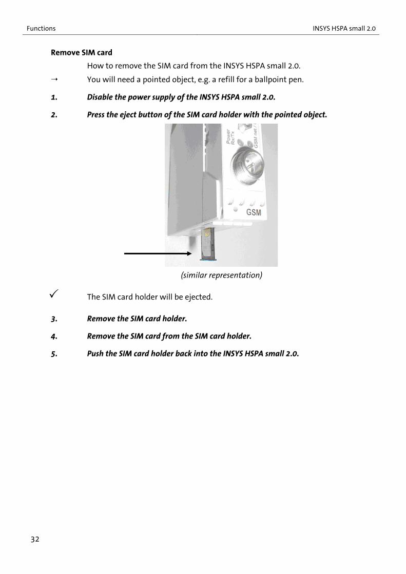
Remove SIM card
How to remove the SIM card from the INSYS HSPA small 2.0.
You will need a pointed object, e.g. a refill for a ballpoint pen.
1. Disable the power supply of the INSYS HSPA small 2.0.
2. Press the eject button of the SIM card holder with the pointed object.
(similar representation)
The SIM card holder will be ejected.
3. Remove the SIM card holder.
4. Remove the SIM card from the SIM card holder.
5. Push the SIM card holder back into the INSYS HSPA small 2.0.
32

INSYS HSPA small 2.0 Functions
11.3 Checking the Status of the GSM Login The INSYS HSPA small 2.0 logs in into the GSM network automatically with each device restart. You can query the login status for test purposes. Then, you can determine, whether the INSYS HSPA small 2.0 is currently logged in or not, a network search is cur-rently performed, a login has been rejected by the GSM network, or the device is logged in into a foreign network via roaming.
Configuration with AT commands
In order to request the Status of the GSM login, use the command
AT+CREG?
The status is indicated in the response by the second figure following the comma.
Response example +CREG: 0,3
The following status responses are possible:
Not logged in, no GSM network search 0
Registered with the standard provider 1
Not logged in, INSYS HSPA small 2.0 searches for GSM network
2
GSM network rejects a login 3
Registered with a foreign network via roaming 5
33

Functions INSYS HSPA small 2.0
11.4 Checking the GSM Signal Quality You can check the signal field strength at the location of the INSYS HSPA small 2.0. The signal quality has an essential influence on the data transmission speed. If the signal field strength is too low, the transmission speed can drop severely or the connection can be terminated at all.
Configuration with AT commands
In order to display the signal field strength, use the command
AT+CSQ
The signal quality is indicated in the response by the first figure before the comma.
Response example +CSQ: 13,0
The following is valid for the signal quality value:
0..10 Poor reception, change location
11..31 Good reception
99 Not detectable
The value following the comma indicates the bit error rate.
34

INSYS HSPA small 2.0 Functions
11.5 Establishing or Accepting a CSD Data Connection The INSYS HSPA small 2.0 can call another modem via the GSM network and establish a CSD data connection. After dialling a phone number, the INSYS HSPA small 2.0 synchro-nises with the called modem and opens a data connection with the transmission speed allowed by the GSM network. This is usually 9600 bit/s.
The speed, which is set at the serial interface of the INSYS HSPA small 2.0 at the time of connection establishment, will not be changed.
All incoming characters are transmitted to the other (called) modem during the active data connection. Therefore, AT commands are not processed during a connection. The INSYS HSPA small 2.0 must be changed to command mode again using an "Escape se-quence" that it processes AT commands again during an active connection. Then, the local INSYS HSPA small 2.0 processes the entered characters as AT commands and does not transmit them to the remote terminal. A remote INSYS HSPA small 2.0 can be changed to command mode during an active data connection using the function "Re-mote configuration".
The INSYS HSPA small 2.0 can accept an incoming connection in the same way. It an-swers after the configured number of ring tones and opens a connection.
Configuration with AT commands
In order to establish a data connection with the INSYS HSPA small 2.0, use the command
Replace <number> with the phone number of the remote terminal.
ATD<number>
If the remote terminal accepts the connection, the INSYS HSPA small 2.0 indicates
CONNECT
If the remote terminal is busy, the INSYS HSPA small 2.0 indicates
BUSY
If a connection to the remote terminal cannot be established, the INSYS HSPA small 2.0 indicates
NO CARRIER
An incoming call is indicated with RING
In order to change to command mode during a data connection, use the escape sequence
No data must be transmitted for 1 second before and after that the INSYS HSPA small 2.0 changes to command mode.
+++
In order to change from command mode to normal data transmission again, use the command
ATO
In order to accept an incoming connection, use the command
ATA
35

Functions INSYS HSPA small 2.0
In order to configure the number of ring tones after which the INSYS HSPA small 2.0 answers and ac-cepts the connection, use the command
Replace <n> with the number of ring tones (<n> = 2…255, <n> = 0 deactivates the function).
ATS0=<n>
In order to terminate a connection and cause the INSYS HSPA small 2.0 to hang up, use the command
ATH
11.6 Establishing a PPP Data Connection Information about establishing a PPP data connection can be found in the add-on man-ual INSYS GPRS/EDGE Devices as GPRS/EDGE Terminal on the enclosed CD.
36
INSYS HSPA small 2.0 Functions
11.7 Automatic Call Acceptance The automatic call acceptance enables the INSYS HSPA small 2.0 to accept each call after the configured number of ring tones.
Configuration with AT commands
In order to enable the automatic call accep-tance, use the command
ATS0=1
In order to disable the automatic call accep-tance, use the command
ATS0=0
In order to configure the number of ring tones after which the INSYS HSPA small 2.0 accepts the connection, use the command
Replace <n> with the number of ring tones (<n> = 2…255).
ATS=<n>
11.8 Querying a Digital Input The INSYS HSPA small 2.0 has one digital input (IN 1), whose state can be queried using an AT command.
If the digital input is used by the application, the application must initialise the digital input with every start, i.e. set the respective I/O as input.
Configuration with AT commands
In order to initialise the digital input, use the command
AT+MIOD=10,1
In order to query the state of the digital input, use the command
AT+MIOC?
The state is indicated in the response by the next to last digit <x>
Response example +MIOC: 1,1,1,1,1,0,x,y
The following states are possible for <x>:
Digital input to GND 0
Digital input open 1
37
Functions INSYS HSPA small 2.0
11.9 Setting a Switch Output The INSYS HSPA small 2.0 has one switch output (Out 1), that can be controlled accord-ingly using an AT command. The switch output (Out 1) is designed as change-over con-tact. The terminals 7 (Out 1) and 8 (Out 1-NC) are connected in idle position (relay not energised) and the terminals 7 (Out 1) and 6 (Out 1-NO) are connected in operated posi-tion (relay energised).
If the switch output is used by the application, the application must initial-ise the switch output with every start, i.e. set the respective I/O as output to a defined state.
Configuration with AT commands
In order to initialise the switch output or set it to idle position, use the command
AT+MIOD=1,0,0
In order to initialise the switch output or set it to operated position, use the command
AT+MIOD=1,0,1
In order to query the state of the switch out-put, use the command
AT+MIOC?
The state is indicated in the response by the last digit <y>
Response example +MIOC: 1,1,1,1,1,0,x,y
The following states are possible for <y>:
Relay of the switch input not energised (idle position)
0
Relay of the switch input energised (operated position)
1
38

INSYS HSPA small 2.0 Functions
11.10 Sending an SMS Manually It is possible to send an SMS manually with the INSYS HSPA small 2.0.
Configuration with AT commands
In order to configure SMS text mode, use the command
AT+CMGF=1
In order to configure the number of the short message center, use the command
Replace <SMSCno> with the number of the short message center (SMS Center) in interna-tional format in quotation marks (e.g. "+49172…").
AT+CSCA=<“SMSCno“>
In order to send an SMS message, enter the destination number using the command
Finish the destination number entry in inter-national format in quotation marks with the Enter key <CR>.
AT+CMGS=<“number“>
Following the prompt >, enter the text of the SMS and finish the entry with CTRL-Z (not with the Enter key!).
>SMS Text
The INSYS HSPA small 2.0 starts to send the SMS now.
11.11 Using USSD Codes You can use so-called USSD codes with the INSYS HSPA small 2.0. The USSD codes can be used to configure call forwarding or enable or disable the calling line identification pres-entation (CLIP) for example. The codes you can use depend on your mobile communica-tion operator / - provider. Refer to your provider for more information about the USSD codes.
Configuration with AT commands
In order to enter the USSD codes, use the command
Replace <code> by an USSD code. Note the semicolon at the end.
ATD<Code>;
In order to retrieve the IMEI of the INSYS HSPA small 2.0 for example, use the command
ATD*#06#;
39
Functions INSYS HSPA small 2.0
11.12 Resetting the Device The INSYS HSPA small 2.0 can be reset in several ways: by briefly cutting off the supply voltage, by connecting the reset input with GND, or by using an AT command.
Configuration with AT commands
In order to restart the INSYS HSPA small 2.0, use the command
AT+CFUN=1,1
In order to reset the INSYS HSPA small 2.0 to default settings, use the command
AT&F
40
INSYS HSPA small 2.0 AT Command Reference
12 AT Command Reference
A detailed reference of the AT commands for the mobile radio engine H24 is available on the website of the manufacturer: http://developer.motorola.com/products/wirelessmodules/h24/
41

GSM Service Center Numbers INSYS HSPA small 2.0
13 GSM Service Center Numbers
The following is an overview of the most important mobile phone providers in Germany, Austria and Switzerland. All information is without guarantee of correctness and com-pleteness. The specified numbers may only be valid for certain contracts with the mobile phone provider. More recent information and information about other providers can eas-ily be taken from the internet. You'll find the current data for your SIM card in your contract documents.
Country Operator Network Short message center number (SMSC)
Fax prefix Number of the e-mail gateway
D T-Mobile T-D1 +49 171 076 0000 +49 171 209 2522
99 (German) 98 (English)
8000
D Vodafone D2 D2 Vodafone +49 172 227 0000 +49 172 227 0042 +49 172 227 0111 +49 172 227 0010 +49 172 227 0222 +49 172 227 0333
99 3400
D E-Plus E-Plus +49 177 061 0000 +49 177 060 0000 +49 177 062 0000
1551 767 62 45
D O2 O2 +49 176 0000 443 +49 176 0000 433
329 6245
D Mobilcom D1 +49 171 076 0315 1091 1090
D Mobilcom D2 +49 172 227 0880 1091
D Mobilcom E-Plus +49 177 061 0000 1551
A Mobilkom A1 +43 334 0501 +43 664 0501
- -
A max.mobil +43 676 021 6762 6761
A One (Connect) +43 699 000 1999 - -
CH Orange Orange +41 78 777 7070
CH Swisscom Swiss GSM +41 79 499 900 0 +41 79 499 812 3
CH TDC sunrise +41 76 598 0000
42
INSYS HSPA small 2.0 APN Access Data
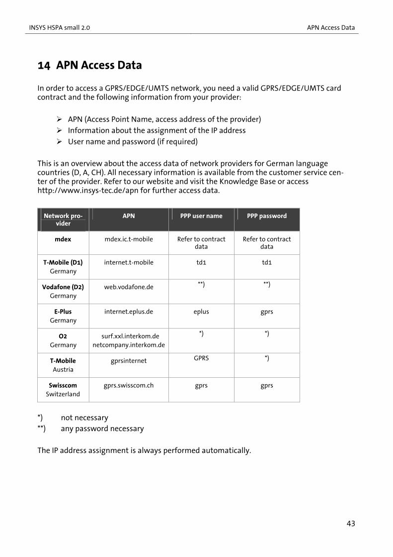
14 APN Access Data
In order to access a GPRS/EDGE/UMTS network, you need a valid GPRS/EDGE/UMTS card contract and the following information from your provider:
APN (Access Point Name, access address of the provider)
Information about the assignment of the IP address
User name and password (if required) This is an overview about the access data of network providers for German language countries (D, A, CH). All necessary information is available from the customer service cen-ter of the provider. Refer to our website and visit the Knowledge Base or access http://www.insys-tec.de/apn for further access data.
Network pro-vider
APN PPP user name PPP password
mdex mdex.ic.t-mobile Refer to contract data
Refer to contract data
T-Mobile (D1) Germany
internet.t-mobile td1 td1
Vodafone (D2) Germany
web.vodafone.de **) **)
E-Plus Germany
internet.eplus.de eplus gprs
O2 Germany
surf.xxl.interkom.de netcompany.interkom.de
*) *)
T-Mobile Austria
gprsinternet GPRS *)
Swisscom Switzerland
gprs.swisscom.ch gprs gprs
*) not necessary **) any password necessary The IP address assignment is always performed automatically.
43

Network Provider Codes INSYS HSPA small 2.0
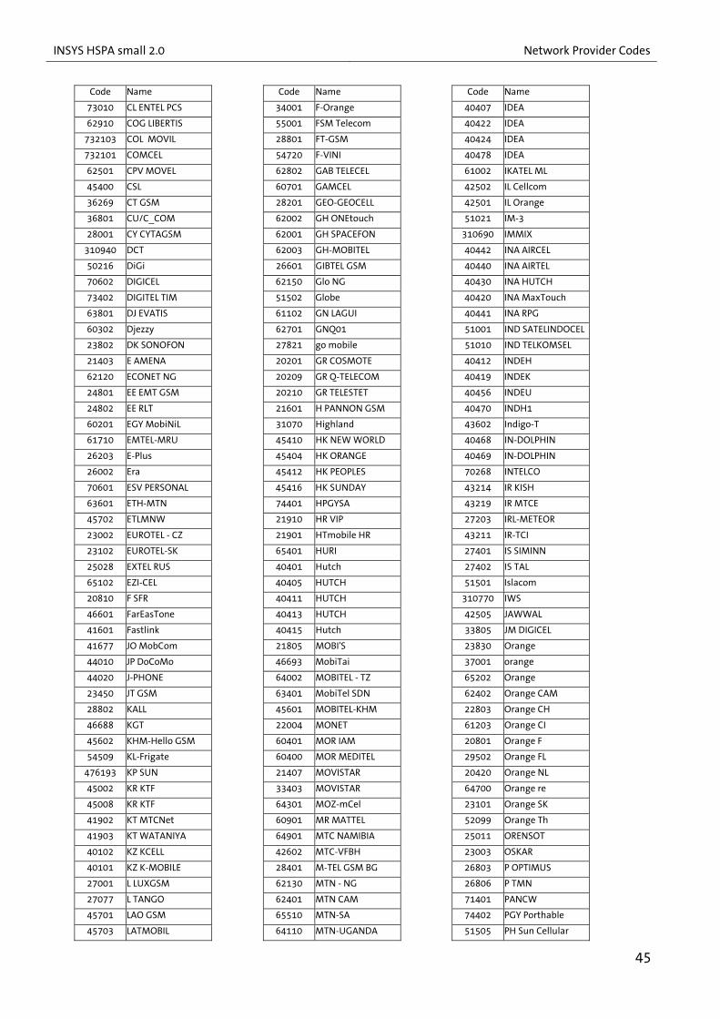
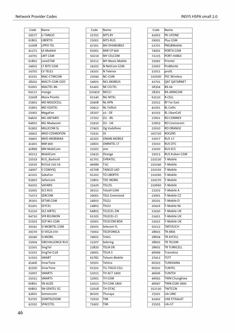
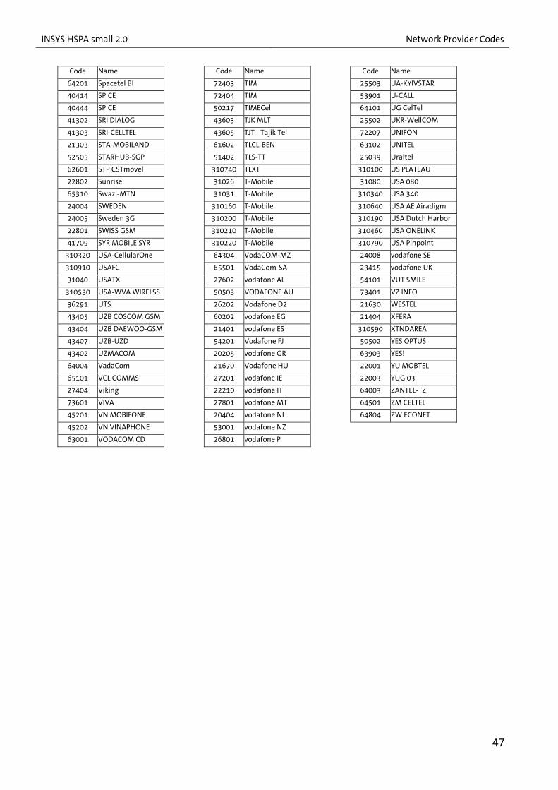
15 Network Provider Codes
Codes and names of the network providers (GSM Location Area Identification Number) for the GSM modules in alphabetic order for the command AT+COPS.
The following table may be output with the command AT^SPLM.
Code Name Code Name Code Name
23210 3 AT 3E+05 AT&T Wireless 40459 BSNL MOBILE
50506 3 AUS 40001 AZE-AZERCELL GSM 40462 BSNL MOBILE
45403 3 HK 20610 B mobistar 40464 BSNL MOBILE
22299 3 ITA 21803 BA-ERONET 40466 BSNL MOBILE
24002 3 SE 40002 BAKCELL GSM 2000 40471 BSNL MOBILE
23420 3 UK 20620 BASE 40472 BSNL MOBILE
41702 94 SYRIA 36439 BaTelCell 40473 BSNL MOBILE
23201 A1 42601 BATELCO 40474 BSNL MOBILE
46668 ACeS 61604 BBCOM 40475 BSNL MOBILE
51000 ACeS 47003 BD ShebaWorld 40476 BSNL MOBILE
51511 ACeS 25099 BEE LINE 40477 BSNL MOBILE
52020 ACeS 20601 BEL PROXIMUS 40479 BSNL MOBILE
41201 AF AWCC 61302 BF CELTEL 40480 BSNL MOBILE
41220 AF TDCA 28405 BG GLOBUL 40481 BSNL MOBILE
60702 AFRICELL 47002 BGD AKTEL 40211 BT B-Mobile
40402 AirTel 47001 BGD-GP 35002 BTC MOBILITY LTD
40403 AirTel 21890 BH GSMBIH 70267 BTL
40410 AirTel 43701 BITEL 65201 BW MASCOM
40431 AirTel 61603 BJ BENINCELL 25701 BY VELCOM
40445 AirTel 73602 BOMOV 20820 BYTEL
40449 AirTel 34020 BOUYGTEL-C 338180 C&W
40490 AirTel 40421 BPL MOBILE 342600 C&W
40492 AirTel 40427 BPL MOBILE 346140 C&W
40493 AirTel 40443 BPL MOBILE 23455 Cable & Wireless
40494 AirTel 40446 BPL MOBILE 45618 CAMSHIN
40495 AirTel 72405 BRA CL 63089 CD OASIS
40496 AirTel 52811 BRU-DSTCom 65507 CELL C
40497 AirTel 40434 BSNL MOBILE 310560 Cell One
40498 AirTel 40438 BSNL MOBILE 63004 CELLCO GSM
42001 ALJAWAL 40451 BSNL MOBILE 61701 CELLPLUS-MRU
27601 AMC-AL 40453 BSNL MOBILE 65010 CELTEL
60301 AMN 40454 BSNL MOBILE 62901 CELTEL CD
34430 APUA-PCS 40455 BSNL MOBILE 62803 CELTEL GA
72234 AR PERSONAL 40457 BSNL MOBILE 63002 CELTEL RC
722310 ARG CTI Movil 40458 BSNL MOBILE 61901 CELTEL SL
62201 CELTEL TCD 24414 FI AMT 40460 Hutch
64005 CELTEL TZ 24409 FI FINNET 40484 HUTCH
46000 China Mobile 24405 FI RADIOLINJA 40486 HUTCH
46001 China Unicom 24491 FI SONERA 45503 Hutchison MAC
61201 CI CORA 24403 FI TELIA 22201 I TIM
310410 Cingular 24412 FI2GFI12 22288 I WIND
310150 Cingular 302370 Fido 71201 I.C.E.
310170 Cingular 29505 FL1 26003 IDEA
73001 CL ENTEL PCS 64702 F-OMT 40404 IDEA
44
INSYS HSPA small 2.0 Network Provider Codes
Code Name Code Name Code Name
73010 CL ENTEL PCS 34001 F-Orange 40407 IDEA
62910 COG LIBERTIS 55001 FSM Telecom 40422 IDEA
732103 COL MOVIL 28801 FT-GSM 40424 IDEA
732101 COMCEL 54720 F-VINI 40478 IDEA
62501 CPV MOVEL 62802 GAB TELECEL 61002 IKATEL ML
45400 CSL 60701 GAMCEL 42502 IL Cellcom
36269 CT GSM 28201 GEO-GEOCELL 42501 IL Orange
36801 CU/C_COM 62002 GH ONEtouch 51021 IM-3
28001 CY CYTAGSM 62001 GH SPACEFON 310690 IMMIX
310940 DCT 62003 GH-MOBITEL 40442 INA AIRCEL
50216 DiGi 26601 GIBTEL GSM 40440 INA AIRTEL
70602 DIGICEL 62150 Glo NG 40430 INA HUTCH
73402 DIGITEL TIM 51502 Globe 40420 INA MaxTouch
63801 DJ EVATIS 61102 GN LAGUI 40441 INA RPG
60302 Djezzy 62701 GNQ01 51001 IND SATELINDOCEL
23802 DK SONOFON 27821 go mobile 51010 IND TELKOMSEL
21403 E AMENA 20201 GR COSMOTE 40412 INDEH
62120 ECONET NG 20209 GR Q-TELECOM 40419 INDEK
24801 EE EMT GSM 20210 GR TELESTET 40456 INDEU
24802 EE RLT 21601 H PANNON GSM 40470 INDH1
60201 EGY MobiNiL 31070 Highland 43602 Indigo-T
61710 EMTEL-MRU 45410 HK NEW WORLD 40468 IN-DOLPHIN
26203 E-Plus 45404 HK ORANGE 40469 IN-DOLPHIN
26002 Era 45412 HK PEOPLES 70268 INTELCO
70601 ESV PERSONAL 45416 HK SUNDAY 43214 IR KISH
63601 ETH-MTN 74401 HPGYSA 43219 IR MTCE
45702 ETLMNW 21910 HR VIP 27203 IRL-METEOR
23002 EUROTEL - CZ 21901 HTmobile HR 43211 IR-TCI
23102 EUROTEL-SK 65401 HURI 27401 IS SIMINN
25028 EXTEL RUS 40401 Hutch 27402 IS TAL
65102 EZI-CEL 40405 HUTCH 51501 Islacom
20810 F SFR 40411 HUTCH 310770 IWS
46601 FarEasTone 40413 HUTCH 42505 JAWWAL
41601 Fastlink 40415 Hutch 33805 JM DIGICEL
41677 JO MobCom 21805 MOBI'S 23830 Orange
44010 JP DoCoMo 46693 MobiTai 37001 orange
44020 J-PHONE 64002 MOBITEL - TZ 65202 Orange
23450 JT GSM 63401 MobiTel SDN 62402 Orange CAM
28802 KALL 45601 MOBITEL-KHM 22803 Orange CH
46688 KGT 22004 MONET 61203 Orange CI
45602 KHM-Hello GSM 60401 MOR IAM 20801 Orange F
54509 KL-Frigate 60400 MOR MEDITEL 29502 Orange FL
476193 KP SUN 21407 MOVISTAR 20420 Orange NL
45002 KR KTF 33403 MOVISTAR 64700 Orange re
45008 KR KTF 64301 MOZ-mCel 23101 Orange SK
41902 KT MTCNet 60901 MR MATTEL 52099 Orange Th
41903 KT WATANIYA 64901 MTC NAMIBIA 25011 ORENSOT
40102 KZ KCELL 42602 MTC-VFBH 23003 OSKAR
40101 KZ K-MOBILE 28401 M-TEL GSM BG 26803 P OPTIMUS
27001 L LUXGSM 62130 MTN - NG 26806 P TMN
27077 L TANGO 62401 MTN CAM 71401 PANCW
45701 LAO GSM 65510 MTN-SA 74402 PGY Porthable
45703 LATMOBIL 64110 MTN-UGANDA 51505 PH Sun Cellular
45
Network Provider Codes INSYS HSPA small 2.0
Code Name Code Name Code Name
29577 LI TANGO 25702 MTS BY 41003 PK-UFONE
62801 LIBERTIS 25001 MTS-RUS 26001 Plus GSM
51008 LIPPO TEL 47201 MV DHIMOBILE 53701 PNGBMobile
41371 LK Mobitel 65001 MW CP 900 74001 PORTA GSM
24701 LMT GSM 50219 MY CELCOM 72235 PORT-HABLE
61801 LoneSTAR 50212 MY Maxis Mobile 25092 Primtel
24602 LT BITE GSM 24202 N NetCom GSM 22002 ProMonte
24702 LV TELE2 24201 N Telenor 51011 proXL
45501 MAC-CTMGSM 25044 NC-GSM 310500 PSC Wireless
28202 MAGTI-GSM-GEO 54601 NCL MOBILIS 42701 QAT QATARNET
61001 MALITEL ML 61402 NE CELTEL 28304 RA 04
64111 mango 310450 NECCI 28301 RA-ARMGSM
23458 Manx Pronto 62140 NG NITEL 63510 R-CELL
25902 MD MOLDCELL 20408 NL KPN 25012 RF Far East
25901 MD VOXTEL 20412 NL Telfort 41501 RL Cellis
25002 MegaFon 26207 o2 - DE 41503 RL LibanCell
64602 MG ANTARIS 27202 O2 - IRL 22601 RO CONNEX
64601 MG Madacom 23410 O2 - UK 22603 RO Cosmorom
61902 MILLICOM SL 27403 Og Vodafone 22610 RO ORANGE
29402 MKD COSMOFON 72431 Oi 302720 ROGERS
29401 MKD-MOBIMAK 42202 OMAN MOBILE 25017 RUS 17
41401 MM 900 24601 OMNITEL LT 25010 RUS DTC
42899 MN MobiCom 23205 one 25020 RUS ECC
26213 MobilCom 23433 Orange 25013 RUS Kuban-GSM
25019 RUS_Bashcell 41701 SYRIATEL 310230 T-Mobile
25016 RUS16 250 16 46689 T3G 310240 T-Mobile
24007 S COMVIQ 45708 TANGO LAO 310250 T-Mobile
42101 SabaFon 62202 TD LIBERTIS 310260 T-Mobile
63902 Safaricom 23801 TDC MOBIL 310270 T-Mobile
64202 SAFARIS 33420 TELCEL 310660 T-Mobile
25005 SCS RUS 36251 Telcell GSM 23203 T-Mobile A
71073 SERCOM 29001 TELE Greenland 23001 T-Mobile CZ
36301 SETAR GSM 24603 TELE2 26201 T-Mobile D
63301 SEYCEL 24803 TELE2 20416 T-Mobile NL
63310 SEZ AIRTEL 64803 TELECEL ZW 23430 T-Mobile UK
64710 SFR REUNION 61205 TELECEL-CI 23431 T-Mobile UK
52503 SGP M1-GSM 35001 TELECOM BDA 23432 T-Mobile UK
29341 SI MOBITEL GSM 29501 telecom FL 50213 TMTOUCH
29370 SI VEGA 070 73002 TELEFONICA 28603 TR ARIA
29340 SI.MOBIL 74602 TeleG 28604 TR AYCELL
25004 SIBCHALLENGE RUS 23207 telering 28602 TR TELSIM
52501 SingTel 23820 TELIA DK 28601 TR TURKCELL
52502 SingTel-G18 24001 TELIA S 46699 TransAsia
51503 SMART 63782 Telsom Mobile 37412 TSTT
45406 SmarTone 50501 Telstra 60503 TUNISIANA
45500 SmarTone 61501 TG-TOGO CELL 60502 TUNTEL
25007 SMARTS 52015 TH ACT 1900 46606 TUNTEX
25015 SMARTS 52001 TH GSM 46692 TWN Chunghwa
60801 SN ALIZE 52023 TH GSM 1800 46697 TWN GSM 1800
60802 SN-SENTEL SG 52018 TH-DTAC 352130 TWTCGN
43601 Somoncom 90105 Thuraya 25501 UA UMC
63701 SOMTELESOM 71610 TIM 42402 UAE ETISALAT
42102 SPACETEL 72402 TIM 25505 UA-GT
46
INSYS HSPA small 2.0 Network Provider Codes
Code Name Code Name Code Name
64201 Spacetel BI 72403 TIM 25503 UA-KYIVSTAR
40414 SPICE 72404 TIM 53901 U-CALL
40444 SPICE 50217 TIMECel 64101 UG CelTel
41302 SRI DIALOG 43603 TJK MLT 25502 UKR-WellCOM
41303 SRI-CELLTEL 43605 TJT - Tajik Tel 72207 UNIFON
21303 STA-MOBILAND 61602 TLCL-BEN 63102 UNITEL
52505 STARHUB-SGP 51402 TLS-TT 25039 Uraltel
62601 STP CSTmovel 310740 TLXT 310100 US PLATEAU
22802 Sunrise 31026 T-Mobile 31080 USA 080
65310 Swazi-MTN 31031 T-Mobile 310340 USA 340
24004 SWEDEN 310160 T-Mobile 310640 USA AE Airadigm
24005 Sweden 3G 310200 T-Mobile 310190 USA Dutch Harbor
22801 SWISS GSM 310210 T-Mobile 310460 USA ONELINK
41709 SYR MOBILE SYR 310220 T-Mobile 310790 USA Pinpoint
310320 USA-CellularOne 64304 VodaCOM-MZ 24008 vodafone SE
310910 USAFC 65501 VodaCom-SA 23415 vodafone UK
31040 USATX 27602 vodafone AL 54101 VUT SMILE
310530 USA-WVA WIRELSS 50503 VODAFONE AU 73401 VZ INFO
36291 UTS 26202 Vodafone D2 21630 WESTEL
43405 UZB COSCOM GSM 60202 vodafone EG 21404 XFERA
43404 UZB DAEWOO-GSM 21401 vodafone ES 310590 XTNDAREA
43407 UZB-UZD 54201 Vodafone FJ 50502 YES OPTUS
43402 UZMACOM 20205 vodafone GR 63903 YES!
64004 VadaCom 21670 Vodafone HU 22001 YU MOBTEL
65101 VCL COMMS 27201 vodafone IE 22003 YUG 03
27404 Viking 22210 vodafone IT 64003 ZANTEL-TZ
73601 VIVA 27801 vodafone MT 64501 ZM CELTEL
45201 VN MOBIFONE 20404 vodafone NL 64804 ZW ECONET
45202 VN VINAPHONE 53001 vodafone NZ
63001 VODACOM CD 26801 vodafone P
47

Maintenance, Repair and Troubleshooting INSYS HSPA small 2.0
16 Maintenance, Repair and Troubleshooting
16.1 Maintenance The product is maintenance-free and does not require special regular maintenance.
16.2 Troubleshooting If a failure occurs during the operation of the product, you will find troubleshooting tips in the "Knowledge Base" on our web site (http://www.insys-icom.de/knowledge/). If you need further support, please contact the INSYS icom Support. You can contact our sup-port department via e-mail under [email protected] and via phone under +49 941 58692-0.
16.3 Repair Send defect devices with detailed failure description to the source of supply of your de-vice. If you have purchased the device directly from INSYS icom, send the device to: INSYS MICROELECTRONICS GmbH, Waffnergasse 8, 93047 Regensburg.
Caution! Short circuits and damage due to improper repairs and modifi-cations as well as opening of products.
Fire hazard and damage of the product. It is not permitted to open the product for repair or modifica-
tion.
48

INSYS HSPA small 2.0 Waste Disposal
17 Waste Disposal
17.1 Repurchasing of Legacy Systems According to the new WEEE guidelines, the repurchasing and recycling of legacy systems for our clients is regulated as follows: Please send those legacy systems to the following address, carriage prepaid: Frankenberg-Metalle Gaertnersleite 8 D-96450 Coburg Germany This regulation applies to all devices which were delivered after August 13, 2005.
49

Declaration of Conformity INSYS HSPA small 2.0
18 Declaration of Conformity
This device complies with the requirements set out in the Council Directive on the Ap-proximation of the Laws of the Member States relating to Electromagnetic Compatibility 2004/108/EC and the Council Directive relating to Low Voltage 2006/95/EC as well as the Council Directive R&TTE 1999/5/EC. We will gladly send you a copy of the declaration of conformity on request.
50
INSYS HSPA small 2.0 Tables and Diagrams
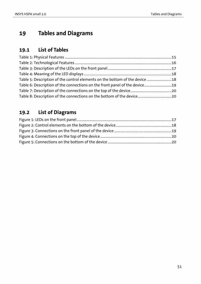
19 Tables and Diagrams
19.1 List of Tables Table 1: Physical Features .....................................................................................................................15 Table 2: Technological Features ..........................................................................................................16 Table 3: Description of the LEDs on the front panel......................................................................17 Table 4: Meaning of the LED displays ................................................................................................18 Table 5: Description of the control elements on the bottom of the device ...........................18 Table 6: Description of the connections on the front panel of the device..............................19 Table 7: Description of the connections on the top of the device.............................................20 Table 8: Description of the connections on the bottom of the device.....................................20
19.2 List of Diagrams Figure 1: LEDs on the front panel........................................................................................................17 Figure 2: Control elements on the bottom of the device.............................................................18 Figure 3: Connections on the front panel of the device ...............................................................19 Figure 4: Connections on the top of the device ..............................................................................20 Figure 5: Connections on the bottom of the device ......................................................................20
51

Index INSYS HSPA small 2.0
20 Index
Accessories ...................................................14 Additional information ............................... 8 Alternative results ........................................ 8 Ambient temperature ...............................15 Antenna connection ..................................19 AT command.................................. 21, 37, 41 AT Command Reference ...........................41 AT commands .......................................29, 35 Automatic call acceptance.......................37 Bit direct mode............................................21 Breakdown...................................................... 9 Calling number identification.................21 Checkmark...................................................... 8 COM port................................................28, 29 Command mode .........................................35 Connection ...................................................22 CSD data connection ..........................21, 35 Data buffering .............................................21 Data connection..........................................35 Default settings...........................................40 Defects liability terms ................................. 6 Digital input ................................... 20, 21, 37 DIN rail ....................................................23, 24 Driver..............................................................26 DTR activation .............................................21 DTR control line...........................................21 Electrical installation .................................11 Environment .........................................12, 22 Environmental Protection........................11 Error ................................................................30 Escape sequence .........................................35 Explosive atmosphere ................................. 9 Fire hazard ....................................................12 FME .................................................................19 FME connection...........................................27 Formatting...................................................... 8 General safety instructions .....................12 Ground...........................................................20 GSM antenna ...............................................27
GSM network ........................................33, 35 Housing..........................................................12 HSPA ...............................................................21 Initial Operation ..........................................26 Input voltage................................................15 Insert SIM card.............................................31 Key word.......................................................... 7 Linux ...............................................................26 Liquids .....................................................12, 22 Marking............................................................ 7 Modification..........................................12, 48 Modulation types........................................16 Moisture .................................................12, 22 Mounting ......................................................22 Net/Status LED ............................................17 Overcurrent ..................................................12 Overvoltage ..................................................12 Overvoltage protection .............................12 Permissible limit..........................................10 Personnel.......................................................10 Power consumption...................................15 Power LED ..............................................17, 28 Power supply................................................20 PPP data connection ..................................36 Preface ............................................................. 6 Prerequisites................................................... 8 Protection class ...........................................15 Qualification.................................................10 Real time clock.............................................21 Recycling........................................................49 Removal .........................................................22 Remove SIM card.........................................32 Repair ......................................................12, 48 Repurchasing ...............................................49 Reset ........................................................21, 40 Reset input......................................20, 21, 40 Responsibilities of the operator..............10 Restart ............................................................33 Ring tone ................................................35, 36
52

INSYS HSPA small 2.0 Index
53
Safety ............................................................... 9 Scope of Delivery ........................................14 Serial interface .............................. 16, 26, 29 Short-cut ................................................12, 48 Signal field strength ..................................34 Signal quality ...............................................34 SIM card........................................... 27, 31, 32 SIM card holder ...........................................18 SIM card holder - eject key.......................18 SIM card holder eject key ..................31, 32 SIM PIN...........................................................30 SIM PUK .........................................................30 Status of the PIN request .........................30 Storage...........................................................10
Surface ...........................................................12 Switch cabinet .............................................24 Switch output .......................................20, 21 Symbol .........................................................7, 8 Terminal program................................28, 29 Transport.......................................................10 Usage................................................................ 9 Usage according to the regulations ........ 9 USB cable................................................14, 26 USB interface................................................19 USSD codes ...................................................39 Water spray ...........................................12, 22 Windows........................................................26

Copyright © 2022 FDOKUMEN