
Installation plan Commercial Washing Machine PW 811 PW ...
36
Installation plan Commercial Washing Machine PW 811 PW 814 PW 818 To avoid the risk of accidents or damage to the machine, it is essential to read these instructions before it is installed and used for the first time. en-IE,ZA,AE M.-Nr. 10 683 150
-
Upload
khangminh22 -
Category
Documents
-
view
0 -
download
0
Transcript of Installation plan Commercial Washing Machine PW 811 PW ...

Installation planCommercial Washing MachinePW 811PW 814PW 818
To avoid the risk of accidents or damage to themachine, it is essential to read these instructionsbefore it is installed and used for the first time.
en-IE,ZA,AE
M.-Nr. 10 683 150

2 PW 811 / PW 814 / PW 818

Contents
3
Installation and planning notes .......................................................................................... 5Installation requirements ....................................................................................................... 5Storage/Transport.................................................................................................................. 5General operating conditions ................................................................................................ 5Installation ............................................................................................................................. 6
Installation on concrete plinth .......................................................................................... 6Levelling the machine............................................................................................................ 7Securing the machine............................................................................................................ 7Machine connections ............................................................................................................ 8
Models with detergent dispensing compartment (WEK) ................................................. 8Electrical connection ............................................................................................................. 9
Emergency switch-off .................................................................................................... 10Plumbing ............................................................................................................................. 11
Cold water connection ................................................................................................... 11Hot water connection ..................................................................................................... 12Dump valve..................................................................................................................... 13
Dispenser pump connections ............................................................................................. 14Optional accessories........................................................................................................... 16
Payment system............................................................................................................. 16XKM RS232 communication module ............................................................................. 16Plinth .............................................................................................................................. 16Weighing plinth............................................................................................................... 17Vapour and foam venting kit (BWS) ............................................................................... 17
Technical drawings............................................................................................................ 18PW 811................................................................................................................................ 18
Dimensions..................................................................................................................... 18PW 811 with Miele plinth (UG/UO) / weighing plinth (WI) .............................................. 19Installation ...................................................................................................................... 20
PW 814................................................................................................................................ 21Dimensions..................................................................................................................... 21PW 814 with Miele plinth (UG/UO) / weighing plinth (WI) .............................................. 22Installation ...................................................................................................................... 23
PW 818................................................................................................................................ 24Dimensions..................................................................................................................... 24PW 818 with Miele plinth (UG/UO) / weighing plinth (WI) .............................................. 25Installation ...................................................................................................................... 26
Anchoring the machine ....................................................................................................... 27Fixing to floor / concrete plinth ...................................................................................... 27Attaching to the floor / concrete plinth when installing in a run ..................................... 27Attaching to the floor with Miele plinth........................................................................... 28
Technical data.................................................................................................................... 29Plumbing ............................................................................................................................. 29
Models with detergent dispensing compartment (WEK)................................................ 29Dump valve..................................................................................................................... 29
Connection for equipotential bonding................................................................................. 29Anchoring ............................................................................................................................ 29
Attaching to the floor...................................................................................................... 29Attaching to the floor with Miele plinth........................................................................... 29Attaching to a concrete plinth (provided on-site) ........................................................... 29
Contents
4
PW 811................................................................................................................................ 30Voltage variants and electrical data ............................................................................... 30Installation dimensions................................................................................................... 30Transport data, weight and floor load ............................................................................ 31Emissions data ............................................................................................................... 31
PW 814................................................................................................................................ 32Voltage variants and electrical data ............................................................................... 32Installation dimensions................................................................................................... 32Transport data, weight and floor load ............................................................................ 33Emissions data ............................................................................................................... 33
PW 818................................................................................................................................ 34Voltage variants and electrical data ............................................................................... 34Installation dimensions................................................................................................... 34Transport data, weight and floor load ............................................................................ 35Emissions data ............................................................................................................... 35
Installation and planning notes
PW 811 / PW 814 / PW 818 5
Installation requirements
The washing machine must be installed and commissioned by aMiele Service technician or by an authorised dealer.
The washing machine must be installed in accordance withapplicable regulations and standards. Local energy supplier andwater authority regulations must also be observed.
This washing machine must only be operated in a room that hassufficient ventilation and which is frost-free.
This machine should not be installed or operated in any area wherethere is a risk of explosion!
Storage/TransportThe following conditions must be observed for transport and storage:
– Ambient temperature: 0-40 °C
– Humidity: non-condensing
General operating conditionsThis washing machine is intended only for use in a commercialenvironment and must only be operated indoors.
– Ambient temperature of location: 0-40 °C
– Relative humidity: non-condensing
– Maximum height above sea level of location site: 2000 m
Depending on the nature of the installation site, sound emissions andvibration may occur.
Tip: Have the installation site inspected and seek the advice of aprofessional in instances where increased noise may cause anuisance.
Installation and planning notes
6 PW 811 / PW 814 / PW 818
InstallationTransport the washing machine to its installation site using a suitablepallet truck and remove the transport packaging.
The washing machine must be set up on a level and firm surface withthe minimum stated load bearing capacity (see "Technical data").
The floor load created by the washing machine is concentrated andtransferred to the installation footprint via the machine feet.
Tip: A concrete floor is the most suitable installation surface, beingfar less prone to vibration during the spin cycle than woodenfloorboards or a carpeted surface.
The washing machine requires a gap of at least 50 mm at each sideto allow for movement during operation. To ensure suitable access forfurther maintenance and service work, please ensure a minimumdistance of 400 mm is maintained between the back of the machineand the wall.
Installation onconcrete plinth
The washing machine can be installed on a concrete plinth if desired.
The concrete materials and the durability of the concrete plinth mustbe assessed in accordance with the floor load bearing capacitygiven in "Technical data".
To guarantee the stability of the washing machine, make sure thatthe concrete plinth is sufficiently stable on the floor and that it iscapable of withstanding any burden or force from the washingmachine.
The washing machine must be secured to the concrete plinth usingthe fixtures and fastenings supplied.
The washing machine must be secured to the plinthimmediately after installation!There is a risk of the washing machine falling off a raised plinthduring a spin cycle if it is not secured.
Installation and planning notes
PW 811 / PW 814 / PW 818 7
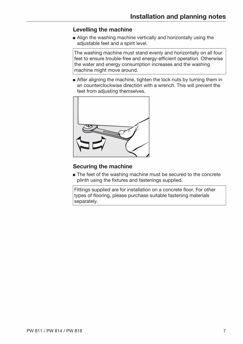
Levelling the machine Align the washing machine vertically and horizontally using the
adjustable feet and a spirit level.
The washing machine must stand evenly and horizontally on all fourfeet to ensure trouble-free and energy-efficient operation. Otherwisethe water and energy consumption increases and the washingmachine might move around.
After aligning the machine, tighten the lock nuts by turning them inan counterclockwise direction with a wrench. This will prevent thefeet from adjusting themselves.
Securing the machine The feet of the washing machine must be secured to the concrete
plinth using the fixtures and fastenings supplied.
Fittings supplied are for installation on a concrete floor. For othertypes of flooring, please purchase suitable fastening materialsseparately.
Installation and planning notes
8 PW 811 / PW 814 / PW 818
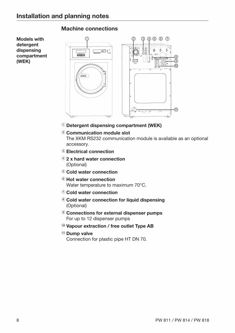
Machine connections
Models withdetergentdispensingcompartment(WEK)
⑥① ② ③ ④⑤ ⑦
⑧⑨⑩
⑪
a Detergent dispensing compartment (WEK)b Communication module slot
The XKM RS232 communication module is available as an optionalaccessory.
c Electrical connectiond 2 x hard water connection
(Optional)e Cold water connectionf Hot water connection
Water temperature to maximum 70°C.g Cold water connectionh Cold water connection for liquid dispensing
(Optional)i Connections for external dispenser pumps
For up to 12 dispenser pumpsj Vapour extraction / free outlet Type ABk Dump valve
Connection for plastic pipe HT DN 70.
Installation and planning notes
PW 811 / PW 814 / PW 818 9
Electrical connection
The electrical connection must only be carried out by a qualifiedelectrician who must ensure that all electrical work is carried out inaccordance with applicable electrical regulations and standards(BS 7671 in the UK).
This washing machine must be connected to an electrical mainssupply that complies with local and national regulations. Please alsoobserve your insurance and energy supplier's regulations as well asany health and safety at work regulations.
The required voltage, connected load and fusing rating can befound on the data plate on the washing machine. Before connectingthe machine to the power supply, please ensure that the mainssupply voltage complies with the values given on the data plate.
Connection to a supply voltage other than the one quoted on thedata plate can lead to functional faults and damage the washingmachine!If more than one voltage is quoted on the data plate, the washingmachine can be converted for connection to the voltages stated.
Conversion to a different voltage must only be carried out by aMiele Service engineer or by an authorised Service Dealer. The wiringinstructions given on the wiring diagram must be followed.
Tip: We recommend connection to the power supply via a suitablyrated plug and socket which must be easily accessible for servicingand maintenance work after the machine has been installed. Anelectrical safety test must be carried out after installation and afterany service work.
The machine can either be hard-wired or connected using a plug-and-socket connection in accordance with IEC 60309-1. For a hard-wired connection an all-pole isolation device must be installed onsite.
For hard-wired machines connection should be made via a suitablemains switch with all-pole isolation which, when in the off position,ensures a 3 mm gap between all open contacts. These includecircuit breakers, fuses and relays (IEC/EN 60947).
If the mains supply cannot be permanently disconnected, the isolatorswitch (including plug and socket) must be safeguarded againstbeing switched on either unintentionally or without authorisation.

Installation and planning notes
10 PW 811 / PW 814 / PW 818
Emergencyswitch-off
For washing machines without a separate emergency off switch,there must be a central emergency shut-off at the installation site!
The emergency switch-off puts the machine into a safe state in theevent of danger or in order to prevent danger. The emergency switch-off must be placed in such a way that the user can activate itimmediately in an emergency.
If it is necessary to install a residual current device (RCD) inaccordance with local regulations, a residual current device type B(sensitive to universal current) must be used.
An existing type A residual current device, (RCD) must be exchangedfor a type B RCD.
If necessary, equipotential bonding with good galvanic contactmust be guaranteed in compliance with all applicable local andnational installation specifications.
Equipotential bonding must have an earth current rating > 10 mAAccessories for equipotential bonding are not supplied and need tobe ordered separately.
Installation and planning notes
PW 811 / PW 814 / PW 818 11
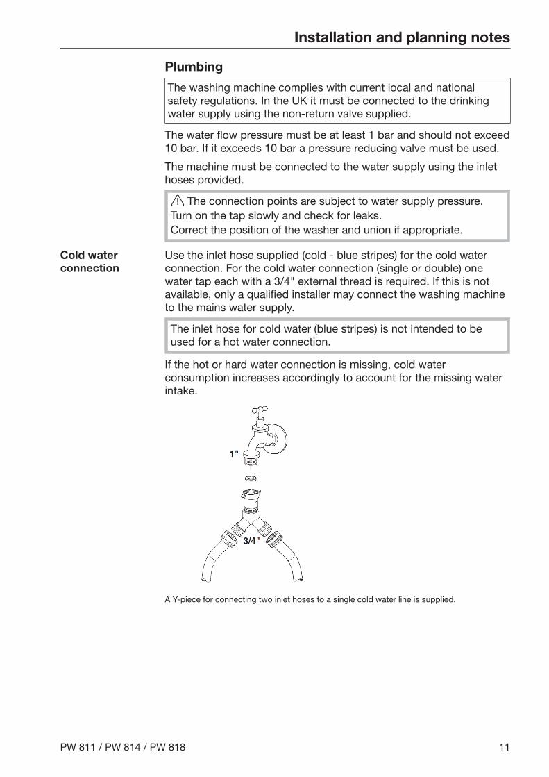
Plumbing
The washing machine complies with current local and nationalsafety regulations. In the UK it must be connected to the drinkingwater supply using the non-return valve supplied.
The water flow pressure must be at least 1 bar and should not exceed10 bar. If it exceeds 10 bar a pressure reducing valve must be used.
The machine must be connected to the water supply using the inlethoses provided.
The connection points are subject to water supply pressure.Turn on the tap slowly and check for leaks.Correct the position of the washer and union if appropriate.
Cold waterconnection
Use the inlet hose supplied (cold - blue stripes) for the cold waterconnection. For the cold water connection (single or double) onewater tap each with a 3/4" external thread is required. If this is notavailable, only a qualified installer may connect the washing machineto the mains water supply.
The inlet hose for cold water (blue stripes) is not intended to beused for a hot water connection.
If the hot or hard water connection is missing, cold waterconsumption increases accordingly to account for the missing waterintake.
A Y-piece for connecting two inlet hoses to a single cold water line is supplied.
Installation and planning notes
12 PW 811 / PW 814 / PW 818
Hot waterconnection
To minimise energy consumption during operation with hot water,the washing machine should be connected to a suitable hot waterring circuit if present.
So-called "transmission pipes" (single pipes to hot water generators)can result in cooling down of the water remaining in the pipes if notin constant use. More energy would then be consumed to heat theliquid up again.
Use the inlet hose supplied (hot - red stripes) for the hot waterconnection.
The temperature of the water intake must not exceed 70 °C.
If there is no hot water supply at the installation location for thewashing machine, the connection hose must be connected to thecold water supply. A Y-piece is required in this case. The cold waterconsumption increases accordingly to account for the missing hotwater intake.
For functional and technical reasons it is not possible to operatethe machine exclusively with a hot water connection (without aseparate cold water intake).Even if a hot water connection is present, the washing machinemust be connected to a cold water intake.
Installation and planning notes
PW 811 / PW 814 / PW 818 13
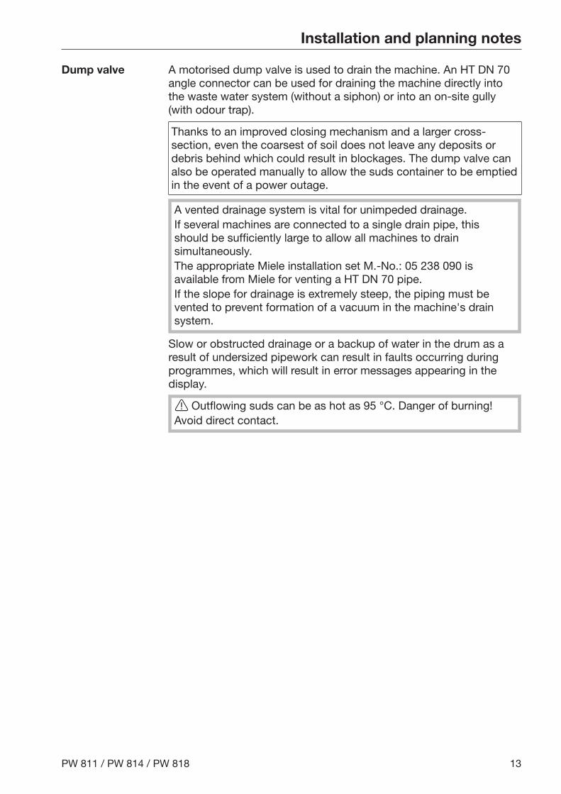
Dump valve A motorised dump valve is used to drain the machine. An HT DN 70angle connector can be used for draining the machine directly intothe waste water system (without a siphon) or into an on-site gully(with odour trap).
Thanks to an improved closing mechanism and a larger cross-section, even the coarsest of soil does not leave any deposits ordebris behind which could result in blockages. The dump valve canalso be operated manually to allow the suds container to be emptiedin the event of a power outage.
A vented drainage system is vital for unimpeded drainage.If several machines are connected to a single drain pipe, thisshould be sufficiently large to allow all machines to drainsimultaneously.The appropriate Miele installation set M.-No.: 05 238 090 isavailable from Miele for venting a HT DN 70 pipe.If the slope for drainage is extremely steep, the piping must bevented to prevent formation of a vacuum in the machine's drainsystem.
Slow or obstructed drainage or a backup of water in the drum as aresult of undersized pipework can result in faults occurring duringprogrammes, which will result in error messages appearing in thedisplay.
Outflowing suds can be as hot as 95 °C. Danger of burning!Avoid direct contact.
Installation and planning notes
14 PW 811 / PW 814 / PW 818
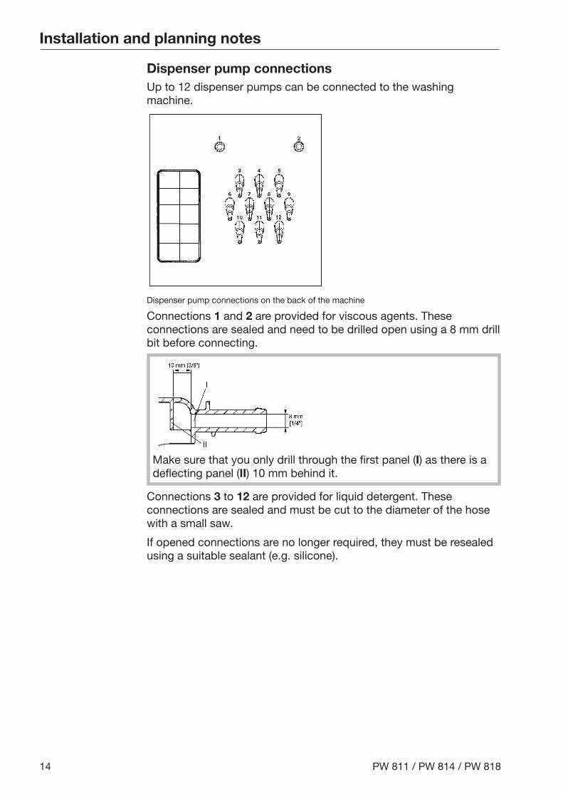
Dispenser pump connectionsUp to 12 dispenser pumps can be connected to the washingmachine.
Dispenser pump connections on the back of the machine
Connections 1 and 2 are provided for viscous agents. Theseconnections are sealed and need to be drilled open using a 8 mm drillbit before connecting.
Make sure that you only drill through the first panel (I) as there is adeflecting panel (II) 10 mm behind it.
Connections 3 to 12 are provided for liquid detergent. Theseconnections are sealed and must be cut to the diameter of the hosewith a small saw.
If opened connections are no longer required, they must be resealedusing a suitable sealant (e.g. silicone).
Installation and planning notes
PW 811 / PW 814 / PW 818 15
Connection terminals for five time-controlled dispenser pumps, whichcan be operated without a multifunction module, are located behindthe cover adjacent to the electrical connection.
Calibration of the dispenser pumps and regulation of dispensingquantities is carried out automatically for washing machines fittedwith a multifunction module.
A flowmeter or throughput sensors can be connected for precisemonitoring of the dosage quantity.
Connections for level monitoring are available for every agentdispensed. A message is displayed if empty.
Installation and planning notes
16 PW 811 / PW 814 / PW 818
Optional accessories
Only use genuine Miele spare parts and accessories with thismachine.Using spare parts or accessories from other manufacturers willinvalidate the guarantee, and Miele cannot accept liability.
Payment system The washing machine can be equipped with a payment system (e.g.in launderettes). This must be connected and programmed by a MieleService technician. Payment systems for cash-free transactions andpayment systems with mechanical or electronic coin validator areavailable from Miele as optional accessories for individual targetgroups.
The programming required for connecting a payment system mustbe carried out by Miele Service or an authorised Miele dealer only. Aseparate electrical connection is not required for a payment system.
XKM RS232communicationmodule
The serial interface RS-232 can be retrofitted to the washing machinevia an XKM RS 232 (optional accessory available from Miele). Thiscommunication module must only be used withMiele Professional machines that are fitted with an appropriate slotfor the module.
The data interface provided via communication moduleXKM RS232 complies with SELV (Safety Extra Low Voltage) inaccordance with EN 60950.Appliances connected to this interface must also be SELVcompliant.
Communication module XKM RS 232 is supplied with a connectioncable and a D-sub-connector.
Plinth The machine can be installed on a plinth (open or box plinth, availableas an optional Miele accessory).
Elevating the washing machine gives a better ergonomic workingposition when loading or unloading. It also simplifies the installationof a waste water connection.
The washing machine must be secured to the plinthimmediately after installation! The plinth must be secured to thefloor!There is a risk of the washing machine falling off a raised plinthduring a spin cycle if it is not secured.
Installation and planning notes
PW 811 / PW 814 / PW 818 17
Weighing plinth The washing machine is optionally available with a weighing plinth. Inthis version, the actual weight of the laundry load is displayed in0.2 kg increments during loading along with the maximum laundryload weight for the unit.
Make sure that the washing machine is not in contact with objectsor people located nearby or leaning against it. They could beweighed as well and falsify the load weight shown in the display.
Vapour and foamventing kit (BWS)
If excessive suds form, foam may escape from the vapour vent. Toremove the foam, an optional vapour and foam venting kit (BWS) canbe used.
Technical drawings
18 PW 811 / PW 814 / PW 818
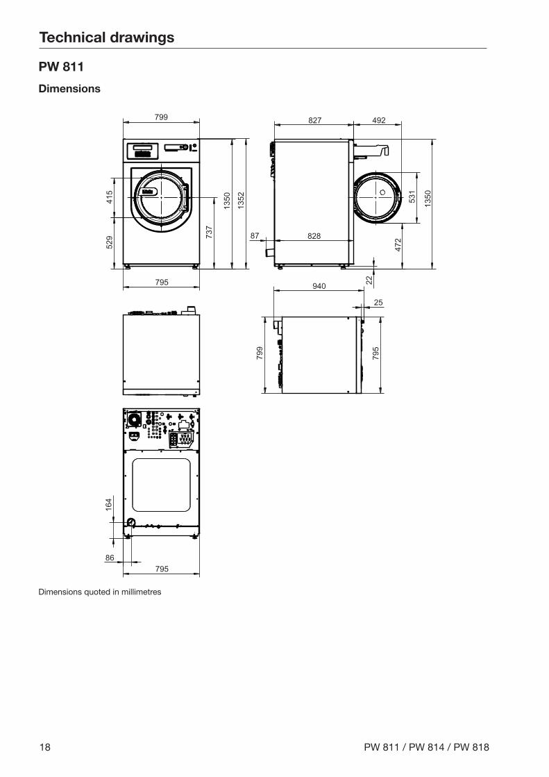
PW 811
Dimensions
415
529 737
1350
1352
799
795 940
25
799
795
86795
164
82887
827 492
1350
472
531
22
Dimensions quoted in millimetres
Technical drawings
PW 811 / PW 814 / PW 818 19
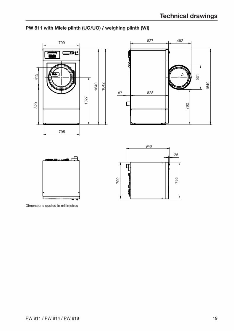
PW 811 with Miele plinth (UG/UO) / weighing plinth (WI)
799
820
415
795
827 492
82887
940
25
799
795
531
762
1640
1640
1642
1027
Dimensions quoted in millimetres
Technical drawings
20 PW 811 / PW 814 / PW 818
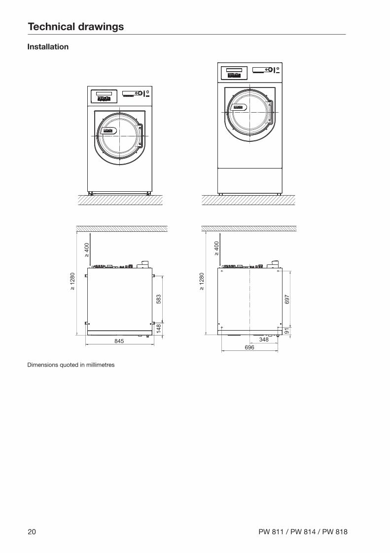
Installation
≥ 12
80
583
845
148
≥ 12
80
697
91
696348
≥ 40
0
≥ 40
0
Dimensions quoted in millimetres
Technical drawings
PW 811 / PW 814 / PW 818 21
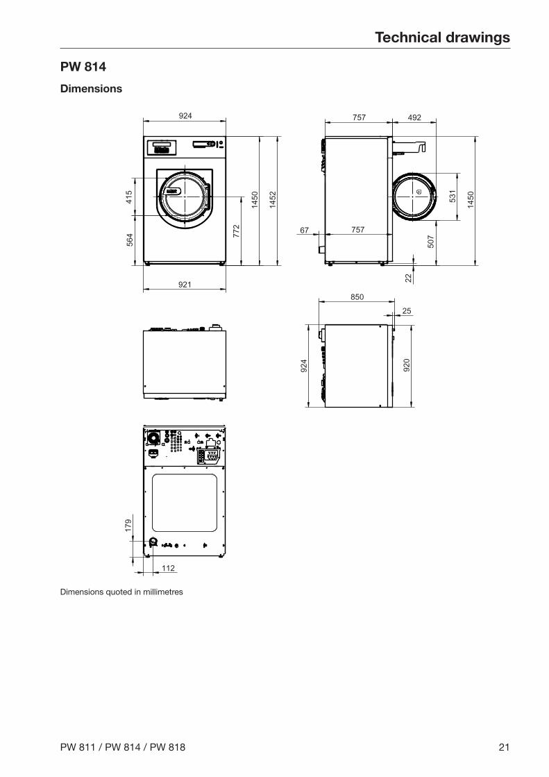
PW 814
Dimensions
415
924564
921
772
1450
1452
1450
757
75767
492
531
507
22
85025
112
179
924
920
Dimensions quoted in millimetres
Technical drawings
22 PW 811 / PW 814 / PW 818
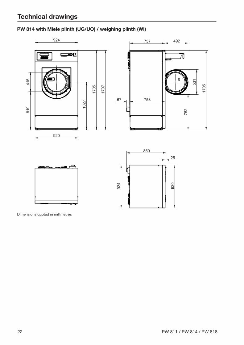
PW 814 with Miele plinth (UG/UO) / weighing plinth (WI)
924
819
415
920
1027
1705
1707
758
757
67
492
1705
762
531
920
924
850
25
Dimensions quoted in millimetres
Technical drawings
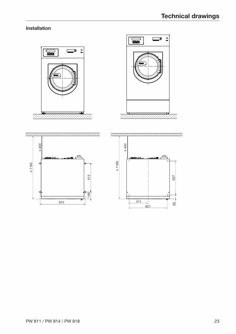
PW 811 / PW 814 / PW 818 23
Installation
970 411821
627
≥ 11
60
≥ 11
60
513
148
82
≥ 40
0
≥ 40
0

Technical drawings
24 PW 811 / PW 814 / PW 818
PW 818
Dimensions
924
920
857 492
85866
950
25
415
564 772
1450
1452 1450
531
507
22920
924
Dimensions quoted in millimetres

Technical drawings
PW 811 / PW 814 / PW 818 25
PW 818 with Miele plinth (UG/UO) / weighing plinth (WI)
924
920
819
415
1027
1705
1707
1705
762
531
857 492
85866
950
25
920
924
Dimensions quoted in millimetres
Technical drawings
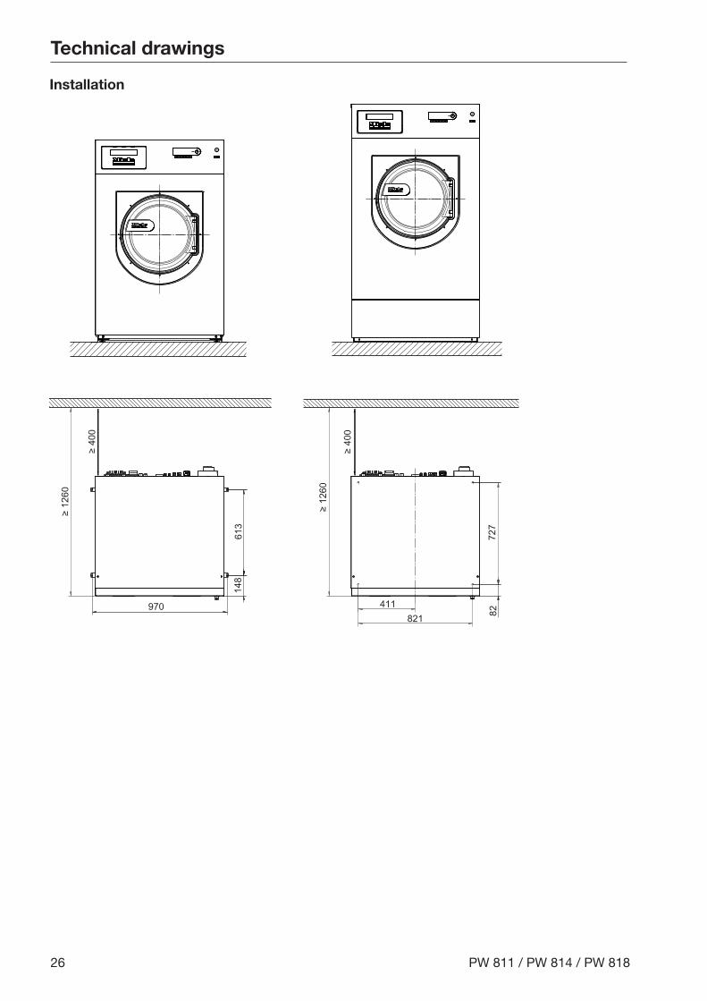
26 PW 811 / PW 814 / PW 818
Installation
970 411821
727
≥ 12
60
≥ 12
60
613
148
82
≥ 40
0
≥ 40
0

Technical drawings
PW 811 / PW 814 / PW 818 27
Anchoring the machine
Fixing to floor / concrete plinth~
90
Ø 12
Dimensions quoted in millimetres
Attaching to the floor / concrete plinth when installing in a run
~ 90
Ø 12
Dimensions quoted in millimetres
Technical drawings
28 PW 811 / PW 814 / PW 818
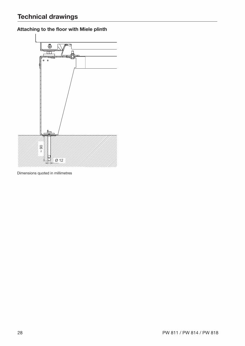
Attaching to the floor with Miele plinth
~ 90
Ø 12
Dimensions quoted in millimetres

Technical data
PW 811 / PW 814 / PW 818 29
Plumbing
Models with detergent dispensing compartment (WEK)
Permitted flow pressure 1-10 bar
Maximum intake rate 79.5 l/min
Cold water connection(to be provided on site, external thread according to DIN 44991, flat seal)
2x ¾" or 1x 1"
Optional cold water connection for liquid dispensing(to be provided on site, external thread according to DIN 44991, flat seal)
1 x ¾"
Optional cold-hard water connection(to be provided on site, external thread according to DIN 44991, flat seal)
2x ¾" or 1x 1"
Hot water connection ≤ 70 °C(on site external thread according to DIN 44991, flat seal)
1 x ¾"
Intake hose length 1.55 m
Y-piece connector for cold water 2 x ¾" to 1 x 1"
Dump valve
Maximum drain water temperature 95 °C
Waste water connection (on machine) Plastic pipe HT DN 70
Drain (on-site) DN 70 connection
Maximum drainage rate 200 l/min
Connection for equipotential bondingConnection with male thread (machine) 10 mm x 35 mm
Washers and nuts M 10
Anchoring
Attaching to the floor
Required anchor points 2
DIN 571 wood screw (diameter x length) 12 mm x 90 mm
Rawl plugs (diameter x length) 16 mm x 80 mm
Attaching to the floor with Miele plinth
Required anchor points 4
DIN 571 wood screw (diameter x length) 12 mm x 90 mm
Rawl plugs (diameter x length) 16 mm x 80 mm
Attaching to a concrete plinth (provided on-site)
Required anchor points 2
DIN 571 wood screw (diameter x length) 12 mm x 90 mm
Rawl plugs (diameter x length) 16 mm x 80 mm
Technical data
30 PW 811 / PW 814 / PW 818
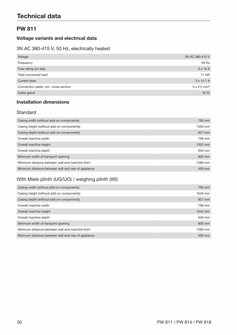
PW 811
Voltage variants and electrical data
3N AC 380-415 V, 50 Hz, electrically heated
Voltage 3N AC 380-415 V
Frequency 50 Hz
Fuse rating (on site) 3 x 16 A
Total connected load 11 kW
Current draw 3 x 14.1 A
Connection cable, min. cross-section 5 x 2.5 mm²
Cable gland M 25
Installation dimensions
Standard
Casing width (without add-on components) 795 mm
Casing height (without add-on components) 1350 mm
Casing depth (without add-on components) 827 mm
Overall machine width 799 mm
Overall machine height 1352 mm
Overall machine depth 940 mm
Minimum width of transport opening 805 mm
Minimum distance between wall and machine front 1280 mm
Minimum distance between wall and rear of appliance 400 mm
With Miele plinth (UG/UO) / weighing plinth (WI)
Casing width (without add-on components) 795 mm
Casing height (without add-on components) 1640 mm
Casing depth (without add-on components) 827 mm
Overall machine width 799 mm
Overall machine height 1642 mm
Overall machine depth 940 mm
Minimum width of transport opening 805 mm
Minimum distance between wall and machine front 1280 mm
Minimum distance between wall and rear of appliance 400 mm

Technical data
PW 811 / PW 814 / PW 818 31
Transport data, weight and floor load
With detergent dispensing compartment (WEK), without weighing plinth (WI)
Packaging width 1130 mm
Packaging height 1468 mm
Packaging depth 1090 mm
Gross volume 1808 l
Gross weight 294 kg
Net weight 267 kg
Max. floor load in operation 4243 N
With detergent dispensing compartment (WEK), with weighing plinth (WI)
Packaging width 1130 mm
Packaging height 1778 mm
Packaging depth 1090 mm
Gross volume 2190 l
Gross weight 345 kg
Net weight 315 kg
Max. floor load in operation 4714 N
Emissions data
Sound pressure level at workplace, washing 51 dB (A)
Sound power level, washing 59.7 dB (A)
Sound pressure level at workplace, spinning 65 dB (A)
Sound power level, spinning 76.8 dB (A)
Average heat dissipation to installation room 3.96 MJ/h
Technical data
32 PW 811 / PW 814 / PW 818
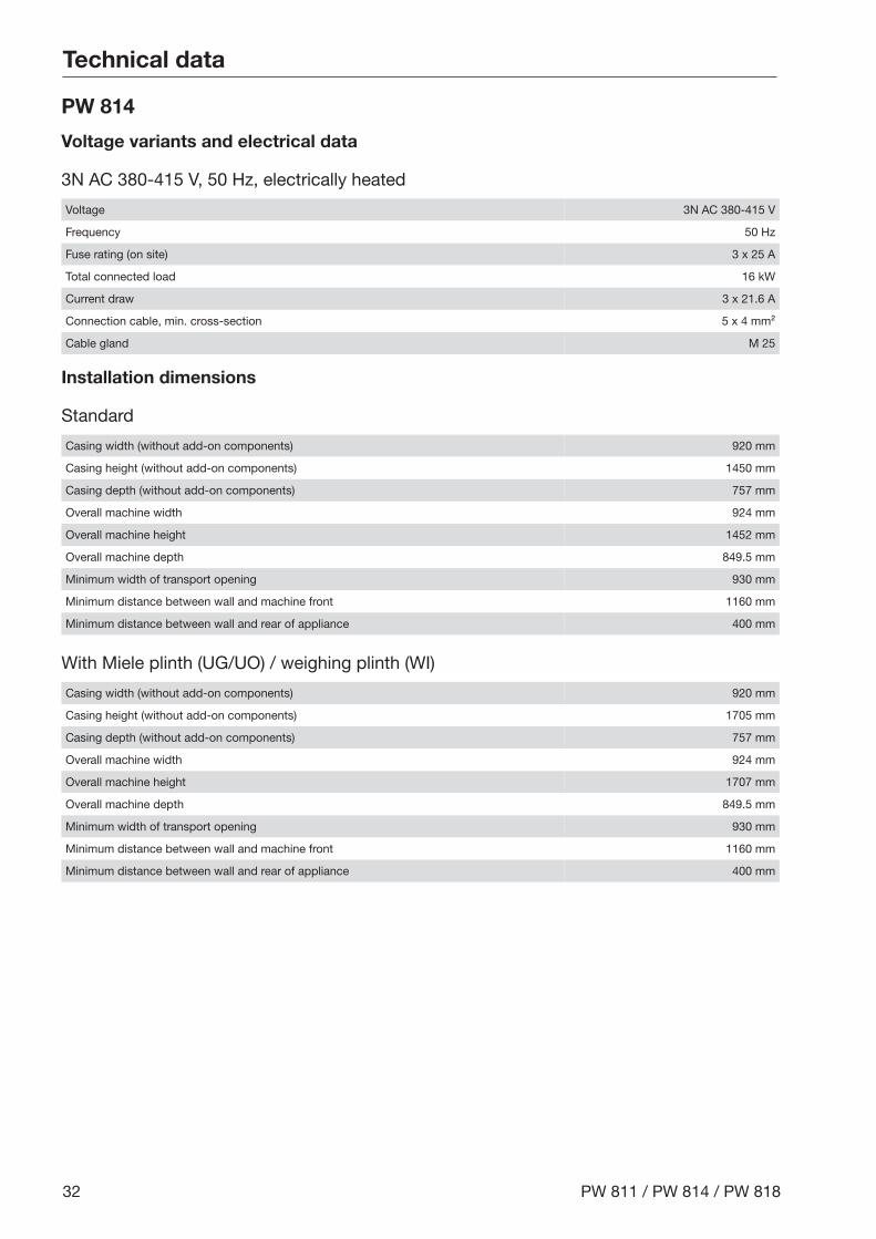
PW 814
Voltage variants and electrical data
3N AC 380-415 V, 50 Hz, electrically heated
Voltage 3N AC 380-415 V
Frequency 50 Hz
Fuse rating (on site) 3 x 25 A
Total connected load 16 kW
Current draw 3 x 21.6 A
Connection cable, min. cross-section 5 x 4 mm²
Cable gland M 25
Installation dimensions
Standard
Casing width (without add-on components) 920 mm
Casing height (without add-on components) 1450 mm
Casing depth (without add-on components) 757 mm
Overall machine width 924 mm
Overall machine height 1452 mm
Overall machine depth 849.5 mm
Minimum width of transport opening 930 mm
Minimum distance between wall and machine front 1160 mm
Minimum distance between wall and rear of appliance 400 mm
With Miele plinth (UG/UO) / weighing plinth (WI)
Casing width (without add-on components) 920 mm
Casing height (without add-on components) 1705 mm
Casing depth (without add-on components) 757 mm
Overall machine width 924 mm
Overall machine height 1707 mm
Overall machine depth 849.5 mm
Minimum width of transport opening 930 mm
Minimum distance between wall and machine front 1160 mm
Minimum distance between wall and rear of appliance 400 mm
Technical data
PW 811 / PW 814 / PW 818 33
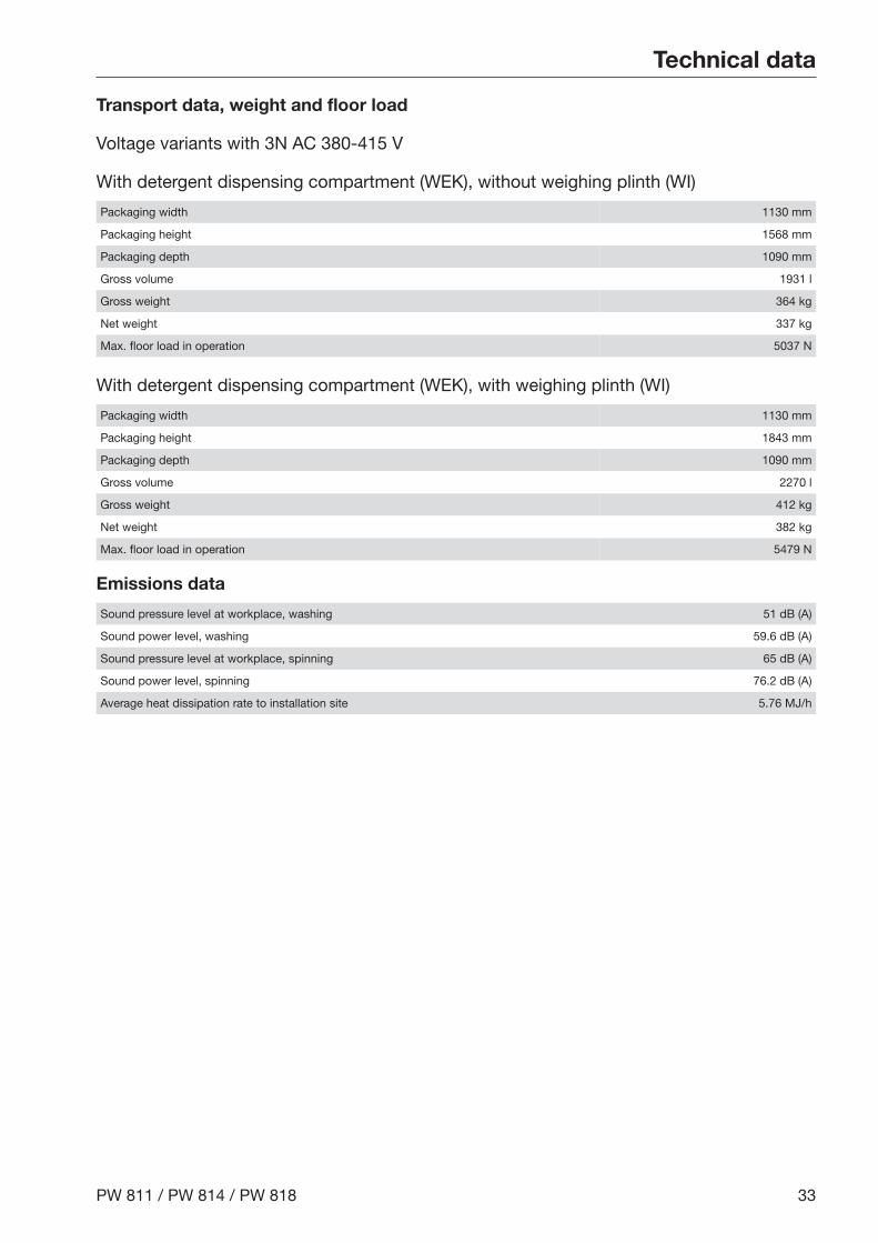
Transport data, weight and floor load
Voltage variants with 3N AC 380-415 V
With detergent dispensing compartment (WEK), without weighing plinth (WI)
Packaging width 1130 mm
Packaging height 1568 mm
Packaging depth 1090 mm
Gross volume 1931 l
Gross weight 364 kg
Net weight 337 kg
Max. floor load in operation 5037 N
With detergent dispensing compartment (WEK), with weighing plinth (WI)
Packaging width 1130 mm
Packaging height 1843 mm
Packaging depth 1090 mm
Gross volume 2270 l
Gross weight 412 kg
Net weight 382 kg
Max. floor load in operation 5479 N
Emissions data
Sound pressure level at workplace, washing 51 dB (A)
Sound power level, washing 59.6 dB (A)
Sound pressure level at workplace, spinning 65 dB (A)
Sound power level, spinning 76.2 dB (A)
Average heat dissipation rate to installation site 5.76 MJ/h

Technical data
34 PW 811 / PW 814 / PW 818
PW 818
Voltage variants and electrical data
3N AC 380-415 V, 50 Hz, electrically heated
Voltage 3N AC 380-415 V
Frequency 50 Hz
Fuse rating (on site) 3 x 35 A
Total connected load 21 kW
Current draw 3 x 27.8 A
Connection cable, min. cross-section 5 x 6 mm²
Cable gland M 32
Installation dimensions
Standard
Casing width (without add-on components) 920 mm
Casing height (without add-on components) 1450 mm
Casing depth (without add-on components) 857 mm
Overall machine width 924 mm
Overall machine height 1452 mm
Overall machine depth 950 mm
Minimum width of transport opening 930 mm
Minimum distance between wall and machine front 1260 mm
Minimum distance between wall and rear of appliance 400 mm
With Miele plinth (UG/UO) / weighing plinth (WI)
Casing width (without add-on components) 920 mm
Casing height (without add-on components) 1705 mm
Casing depth (without add-on components) 857 mm
Overall machine width 924 mm
Overall machine height 1707 mm
Overall machine depth 950 mm
Minimum width of transport opening 930 mm
Minimum distance between wall and machine front 1260 mm
Minimum distance between wall and rear of appliance 400 mm

Technical data
PW 811 / PW 814 / PW 818 35
Transport data, weight and floor load
Voltage variants with 3N AC 380-415 V
With detergent dispensing compartment (WEK), without weighing plinth (WI)
Packaging width 1130 mm
Packaging height 1568 mm
Packaging depth 1090 mm
Gross volume 1931 l
Gross weight 416 kg
Net weight 389 kg
Max. floor load in operation 5752 N
With detergent dispensing compartment (WEK), with weighing plinth (WI)
Packaging width 1130 mm
Packaging height 1843 mm
Packaging depth 1090 mm
Gross volume 2270 l
Gross weight 464 kg
Net weight 434 kg
Max. floor load in operation 6125 N
Emissions data
Sound pressure level at workplace, washing 54 dB (A)
Sound power level, washing 62.0 dB (A)
Sound pressure level at workplace, spinning 67 dB (A)
Sound power level, spinning 79.0 dB (A)
Average heat dissipation rate to installation site 7.56 MJ/h
Miele & Cie. KG, Carl-Miele-Straße 29, 33332 Gütersloh, GermanyManufacturer:
MalaysiaMiele Sdn BhdSuite 12-2, Level 12Menara Sapura Kencana PetroleumSolaris Dutamas No. 1, Jalan Dutamas 150480 Kuala Lumpur, MalaysiaPhone: +603-6209-0288Fax: +603-6205-3768
Miele New Zealand LimitedIRD 98 463 6318 College HillFreemans Bay, Auckland 1011, NZTel: 0800 464 353Internet: www.miele.com.au/professionalE-mail: [email protected]
New Zealand
Miele Pte. Ltd.29 Media Circle, #11-04 ALICE@MediapolisSingapore 138565Tel: +65 6735 1191, Fax: +65 6735 1161E-Mail: [email protected]: www.miele.sg
Singapore
Miele (Pty) Ltd63 Peter Place, Bryanston 2194P.O. Box 69434, Bryanston 2021Tel: (011) 875 9000, Fax: (011) 875 9035E-mail: [email protected]: www.miele.co.za
South Africa
Miele Appliances Ltd.Showroom 1, Eiffel 1 BuildingSheikh Zayed Road, Umm Al SheifP.O. Box 114782 - DubaiTel. +971 4 3044 999, Fax. +971 4 3418 852800-MIELE (64353)E-Mail: [email protected], Website: www.miele.ae
United Arab Emirates
United KingdomMiele Co. Ltd., Fairacres, Marcham RoadAbingdon, Oxon, OX14 1TWProfessional Sales, Tel: 0845 365 6608E-mail: [email protected]: www.miele.co.uk/professional
Miele Australia Pty. Ltd.ACN 005 635 398, ABN 96 005 635 3981 Gilbert Park Drive, Knoxfield, VIC 3180Tel: 1300 731 411Internet: www.miele.com.au/professionalE-mail: [email protected]
Australia
Miele Electrical Appliances Co., Ltd.1-3 Floor, No. 82 Shi Men Yi RoadJing' an District, 200040 Shanghai, PRCTel: +86 21 6157 3500, Fax: +86 21 6157 3511E-mail: [email protected], Internet: www.miele.cn
China Mainland
Miele (Hong Kong) Ltd.41/F - 4101, Manhattan Place23 Wang Tai Road, Kowloon Bay, Hong KongTel: (852) 2610 1025, Fax: (852) 3579 1404Email: [email protected]: www.miele.hk
Hong Kong, China
Miele India Pvt. Ltd.Ground Floor, Copia Corporate SuitesPlot No. 9, Jasola, New Delhi - 110025Tel: 011-46 900 000, Fax: 011-46 900 001E-mail: [email protected], Internet: www.miele.in
India
Miele Ireland Ltd.2024 Bianconi Ave., Citywest Business Campus, Dublin 24Tel: (01) 461 07 10, Fax: (01) 461 07 97E-Mail: [email protected], Internet: www.miele.ie
Ireland
M.-Nr. 10 683 150 / 01Alteration rights reserved / Publication date: 35.20