WM, Husqvarna, PW 235, PW 235R, 2017-11, PRESSURE ...
18
Workshop manual English PW 235 PW 235R
-
Upload
khangminh22 -
Category
Documents
-
view
1 -
download
0
Transcript of WM, Husqvarna, PW 235, PW 235R, 2017-11, PRESSURE ...

Workshop manual
English
PW 235PW 235R

2 – English
Workshop Manual
PW 235, PW 235R
Contents
1 Introduction and safety regulations ............... 31.1 General ..........................................................................31.2 Revisions ........................................................................31.3 Target group ...................................................................31.4 Safety instructions ..........................................................3
1.4.1 General safety instructions ...................................31.4.2 Special safety instructions ....................................3
2 Repair instructions ........................................... 42.1 Product overview, Cabinet torque ..................................42.2 Product overview, Pump unit torque ..............................52.3 To disassemble/assemble the front cabinet and accessory storage ...................................................62.4 To disassemble/assemble the control unit and/or wireless unit* .......................................................72.5 To pair the product and the handle* ...............................72.6 To exchange the battery in the handle* ..........................72.7 To disassemble/assemble the motor cover ....................82.8 To disassemble/assemble the start/stop valve ...............82.9 To disassemble/assemble the water/oil seal and valves ......................................................................9
3 Specifications ................................................. 113.1 Technical data ..............................................................11
4 Appendices and schemas ............................. 124.1 Operating supplies .......................................................12
4.1.1 Recommended oil types .....................................124.1.2 Recommended lubrication ..................................124.1.3 Recommended glue ............................................12
4.2 Start stop System guide ...............................................134.2.1 No pressure in system ........................................134.2.2 Start up-pressure build up ..................................134.2.3 Pressure build up-opening pressure/close gun ..144.2.4 Motor stop - standby pressure ............................144.2.5 Gun is activated ..................................................154.2.6 Machine run ........................................................15
4.3 Wiring diagram PW 235 ...............................................164.4 Wiring diagram PW 235R .............................................17

English – 3
1 Introduction and safety regulations1.1 GeneralThis workshop manual gives a full description of how to do troubleshooting, repair and test of the high pressure washer. It also gives safety instructions that the personnel must obey during repair work.
1.2 RevisionsIf there are changes to the product, these are gradually introduced into ongoing production. These changes can have an effect on servicing and/or spare parts. This can cause sections of the workshop manual to become out of date. Servicing information is sent out for each change. To make sure that the repair and servicing instructions are complete and up to date, always read the workshop manual together with all servicing information applicable for the high pressure washer.
1.3 Target groupThis workshop manual is written for personnel with a general knowledge of how to repair and do servicing on high pressure washers.All personnel that repair or do servicing on the high pressure washer must read and understand the workshop manual.
1.4 Safety instructionsWARNING: All personnel that repair or do servicing on the high pressure washer must read and understand the safety instructions.
1.4.1 General safety instructionsThe service center that repairs the high pressure washer must have safety devices that comply with local regulations.Warnings and cautions are used to point out specially important parts of the workshop manual.
WARNING: Used if there is a risk of injury or death if the instructions are not followed.
CAUTION: Used if there is a risk of material damage if the instructions are not followed.
Note: This information makes the product easier to use.
1.4.2 Special safety instructionsWARNING: Do not use accessories and/or do changes that are not approved by the manufacturer. This can cause injury or death to the operator or other persons.
WARNING: Always use original spare parts and accessories.
WARNING: Disconnect from electrical power supply before carrying out user maintenance.
WARNING: Use approved hearing protec-tion. Noise from the product can result in permanent hearing loss.
WARNING: High pressure jets can be dangerous. Never direct the water jet at persons pets, live electrical equipment or the machine.
WARNING: The operator and anyone in the immediate vicinity of the site of cleaning should take action to protect themselves from being struck by debris dislodged
during operation. Wear goggles during operation.
WARNING: Never try to clean clothes or footwear on yourself or other persons.
WARNING: Never use the machine in an environment where there could be a danger of explosion. If any doubt arises, contact
the local authorities..
WARNING: It is not allowed to clean asbes-tos- containing surfaces with high pres-sure.
WARNING: This high pressure washer must not be used at temperatures below 0°C.
WARNING: Never let any persons stay under the product when stored on the wall.
Introduction and safety regulations

4 – English
2 Repair instructionsRepair instructions
2.1 Product overview, Cabinet torque
1,2 Nm
1,2 Nm
1,5 Nm
1,5 Nm
1,5 Nm
English – 5
Repair instructions
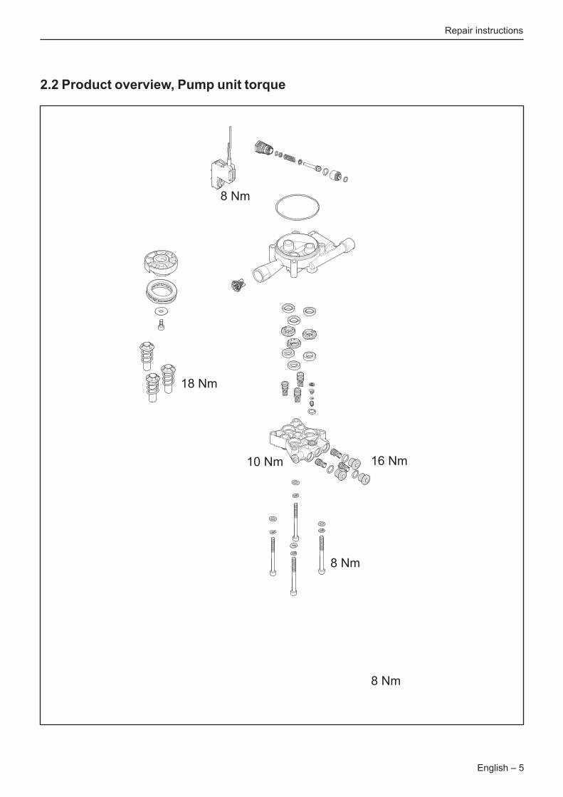
8 Nm
18 Nm
10 Nm
8 Nm
16 Nm
8 Nm
2.2 Product overview, Pump unit torque

6 – English
2.3 To disassemble/assemble the front cabinet and accessory storage1. Tools: Torx 20 screwdriver and flat screwdriver.
2. Remove the handle by pressing the 2 * 2 snap locks. Loosen one side first and then the other side.
3. Remove the 2 torx TX20 screws (A) from the rear side.
A
A
4. Loosen the front cabinet from the accessories storage. Use a screwdriver on both sides, see figure below. Remove the accessories storage.
5. Lift up the front cabinet to remove it.
Assembly: Place the accessories storage on the front cabinet and push it in place until you hear a “click”. Install
the 2 screws.
Repair instructions

English – 7
2.4 To disassemble/assemble the control unit and/or wireless unit*Tools: Torx 9 screwdriver.
1. Control unit: - Disconnect the cable (A) to the wireless unit. - Remove the 3 torx TX9 screws (B) screws. - Exchange the control unit. - Disconnect the 3 wires (C). - Install and tighten the 3 torx TX9 (B) screws, torque max 0.8 Nm. - Connect the cable (A) to the wireless unit. - Check the circuit diagram and install the 3 wires (C) accordingly on the control unit.
B
B
B
A
C
2. Wireless unit*: - Disconnect the cable (A) to the wireless unit. - Slide the wireless unit out (B). - Exchange the wireless unit. - Slide the wireless unit back (B). - Connect the cable (A) to the wireless unit.3. Reconfigure the pairing of the product and the handle, see section “2.5 To pair the product and the handle*”.
B
A
* PW 235R version only
2.5 To pair the product and the handle** PW 235R version onlyPairing of the wireless devices is needed if:• The handle has been exchanged.• The wireless unit of the handle has been exchanged.• The control unit in the product has been exchanged.• The wireless unit in the product has been
exchanged.• If the user has not paired the product and the handle.Pairing of the product and the handle:1. Make sure that the product is not switched on.2. Remove the battery and attach the battery again.3. The orange indicator on the handle is now flashing for approx. 2 minutes. This indicates that the handle is in pairing mode.4. Switch on the product within the 2 minute of pairing mode. When the orange indicator stops blinking, the handle and the product has been paired and can now be operated.
2.6 To exchange the battery in the handle** PW 235R version only1. Remove the screw (Philips) and the battery cover.2. Remove the old battery.3. Make sure that the new battery (type CR 2032) is placed with the correct polarity in the battery holder.4. Install the battery cover and the screw.
Repair instructions

8 – English
2.7 To disassemble/assemble the motor cover1. Put the product on the side and remove the 4 torx 20 screws. 2. Remove the wheel to remove the 5th screw.
3. Remove the cabinet. Take out the motor/pump unit.
The micro switch box can be removed by hand.4. Install the motor/pump unit: - Install the micro switch box by hand (alternatively use a plastic hammer). Make sure you install it in the correct position. - Install the motor/pump unit inside the cabinet.
2.8 To disassemble/assemble the start/stop valve1. Assemble the start/stop valve, see figure below.
2. Use a special tool to remove the seat of the start/stop valve. Use “Puller for valve seat M4” part number 592 94 50-01. NOTE: The seat of the start/stop valve is no longer usable after using the puller.
Repair instructions

English – 9
2. The figure below shows the pump after opening the cylinder head from the cylinder block.
CAUTION: Clean and lubricate the parts before assembly!
2.9 To disassemble/assemble the water/oil seal and valves1. To change the oil seals, water seals and pressure valve, use a screw driver to disassemble the parts. Alternatively use a puller, part number 592 94 49-01, to pull out the valves seats (pressure and suction valves). NOTE: The seat is no longer usable after using the puller.
Repair instructions

10 – English
CAUTION: Make sure to position the valve bodies correctly according to the water canals inside the cylinder head. This is to optimize the self suction mode. The “leg”
of the valve body must not be placed in front of a canal.
WRONG position:
CORRECT position:
3. Assemble all parts into the cylinder head, see figure below.
Repair instructions
English – 11
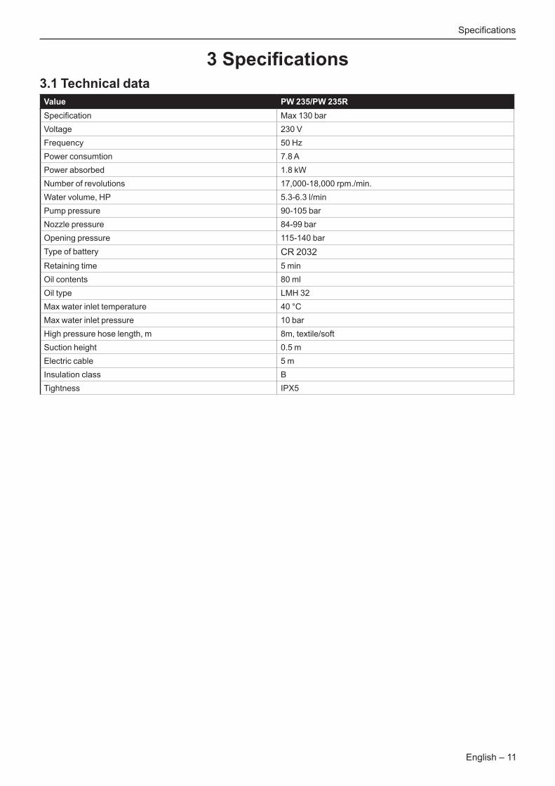
3 Specifications3.1 Technical dataValue PW 235/PW 235RSpecification Max 130 barVoltage 230 VFrequency 50 HzPower consumtion 7.8 APower absorbed 1.8 kWNumber of revolutions 17,000-18,000 rpm./min.Water volume, HP 5.3-6.3 l/minPump pressure 90-105 barNozzle pressure 84-99 barOpening pressure 115-140 barType of battery CR 2032Retaining time 5 minOil contents 80 mlOil type LMH 32Max water inlet temperature 40 °CMax water inlet pressure 10 barHigh pressure hose length, m 8m, textile/softSuction height 0.5 mElectric cable 5 mInsulation class BTightness IPX5
Specifications

12 – English
4.1 Operating supplies
4.1.1 Recommended oil typesThe pump is filled with 80 ml LHM 32 from the production.In case of service where the oil must be changed, Husqvarna recommends to use 80 ml Bartran HV 46.Alternative oil types that are allowed:• BP, Bartram HV 46• Shell, Tellus T 46• Exxon, Statoil Univis N 46• Mobil Oil Mobil DTE 25.
4.1.2 Recommended lubricationWhite grease for o-rings, sealings etc.:• Silicone grease,
DOW CORNING(R) 55 O-RING LUBRICANT
4.1.3 Recommended glue• Loctite 680, alternatively Loctite 270 or 271
4 Appendices and schemasAppendices and schedules
21 3 4 5
Item Description Used for Article number1 T-handle Torx T20 For screws with torx head 588 59 85-012 Puller M4 For valve seat 592 94 50-012 Puller M8 For valve seat 592 94 49-013 Screw driver PH2 For screws N/A4 Screw driver Torx T9 For screws with torx head N/A5 Screw driver, flat For screws N/A

English – 13
4.2 Start stop System guide
4.2.1 No pressure in system
No pressure in system - except inlet pressure 3 bar. Machine switch off.
Pump
3 BAR
InletNon return valve
Outlet 3 Bar3 BAR
4.2.2 Start up-pressure build up
Machine switch on / Start up - Pressure build up
Pump
>5 BAR
InletNon return valve
Outlet >5 Bar3 BAR
Appendices and schedules

14 – English
4.2.3 Pressure build up-opening pressure/close gun
4.2.4
Gun close. Pressure build up. Opening pressure. Micro switch is activated
Pump
130 BAR
InletNon return valve
Outlet 130 BAR3 BAR
Motor stop - standby pressure
Gun close. Motor stops. Pressure in hose decreases to standby pressurePump pressure is also standby pressure.
Pump
25 BAR
InletNon return valve
Outlet 25 BAR3 BAR
Appendices and schedules
English – 15
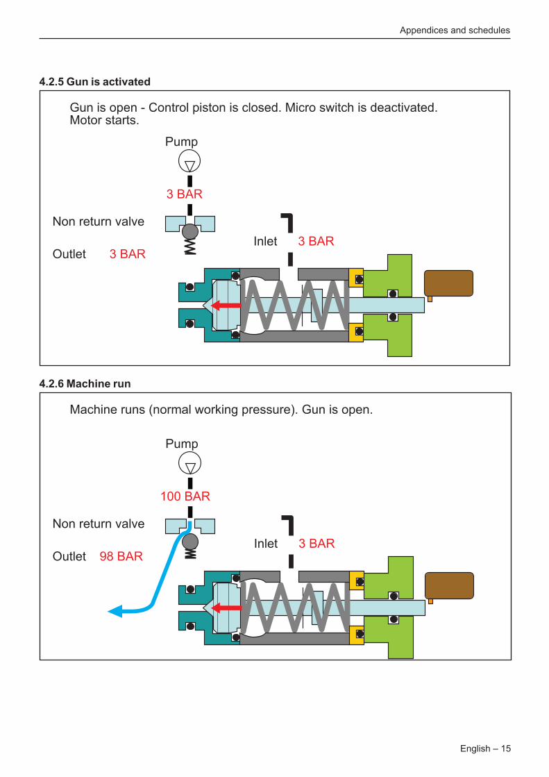
4.2.5 Gun is activated
Gun is open - Control piston is closed. Micro switch is deactivated.Motor starts.
Pump
3 BAR
InletNon return valve
Outlet 3 BAR3 BAR
4.2.6 Machine run
Machine runs (normal working pressure). Gun is open.
Pump
100 BAR
InletNon return valve
Outlet 98 BAR3 BAR
Appendices and schedules
16 – English
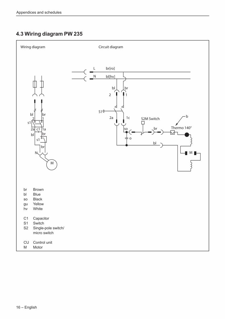
4.3 Wiring diagram PW 235
Wiring diagram Circuit diagram
bl2 1
bl
s1
2a c1
s1
1a
br
br
br
N
M
L br[ro]
bl[hv]
bl
2
S1
2a 1c S2M Switchb
M
Thermo 140°so br
blo
1
br
N
brblsoguhv
C1S1S2
CUM
BrownBlueBlackYellowWhite
CapacitorSwitchSingle-pole switch/micro switch
Control unitMotor
Appendices and schedules

English – 17
4.4 Wiring diagram PW 235R
br
Wiring diagram
2S1
S2
C12a 1a
br bl
bl
br
N
M
L
CUWU
1
bl
brblsoguhv
C1S1S2
CUM
BrownBlueBlackYellowWhite
CapacitorSwitchSingle-pole switch/micro switch
Control unitMotor
Circuit diagram
L br[so]
bl[hv]
br
2
S1
2a 1aS2M Switch
M
Thermo 140°bl bl
br
CU
WU so
N L
brbl
1
bl
N
Appendices and schedules

115 97 59-262017–11–23