Installation of Application - Eaton
38
1 2 3 4 5 6 7 8 9 10 Installation Define Build Add Place Auto Rack Port Device Alarm of Applicaton Navigation Floorplan Devices Floormount Discovery Building Mapping Settings Settings Installation of Application 1. Prepare the Server • Operating System: CentOS or Red Hat Enterprise Linux 7.3 (When using the ISO version of the application installer, the CentOS 7.3 OS will be installed automatically) • CPU: 4 Cores Intel® Xeon® E5-2407 V2 with Passmark 4575 or above • Physical Memory: 16GB • Hard Drive: 100GB free disk space or above • I/O Throughput: 125MB/second or above 2. Select the desired installation package Either an OS-included ISO application installer or an application-only installer can be used to install the application to a server. If the OS-included ISO application installer is selected, mount the ISO image file onto the CD/DVD drive, which is accessible by the server. Then, boot the server up using the ISO image. a. The installer will prompt the following 4 questions before starting the OS installation: 1) The time zone 2) The current clock time 3) The URL which will be used to access the application 4) The IP address for the server running the application b. After the OS installation is completed, login to the server as the root user to activate the network interface. Please ensure the IP address of the network interface matches the IP address specified during the OS installation. c. When the network interface is working, run the command “install_vpm” as the root user to start the application installation. No user input is required for this part of the installation of Visual Power Manager. d. To obtain a license activation key, wait until the application is fully installed, run the command “/opt/VDC/bin/vdckeyreq> /tmp/my.req” as the root user and email the /tmp/my.req file to the application support team to obtain a license activation key. 1 - Installation of Application 1/38
-
Upload
khangminh22 -
Category
Documents
-
view
1 -
download
0
Transcript of Installation of Application - Eaton

1 2 3 4 5 6 7 8 9 10 Installation Define Build Add Place Auto Rack Port Device Alarm
of Applicaton Navigation Floorplan Devices Floormount Discovery Building Mapping Settings Settings
Installation of Application
1. Prepare the Server
• Operating System: CentOS or Red Hat Enterprise Linux 7.3 (When using the ISO version of the application installer,the CentOS 7.3 OS will be installed automatically)
• CPU: 4 Cores Intel® Xeon® E5-2407 V2 with Passmark 4575 or above
• Physical Memory: 16GB
• Hard Drive: 100GB free disk space or above
• I/O Throughput: 125MB/second or above
2. Select the desired installation package
Either an OS-included ISO application installer or an application-only installer can be used to install the application to a server.
If the OS-included ISO application installer is selected, mount the ISO image file onto the CD/DVD drive, which is accessible by the server. Then, boot the server up using the ISO image.
a. The installer will prompt the following 4 questions before starting the OS installation:1) The time zone2) The current clock time3) The URL which will be used to access the application4) The IP address for the server running the application
b. After the OS installation is completed, login to the server as the root user to activate the network interface.Please ensure the IP address of the network interface matches the IP address specified during the OSinstallation.
c. When the network interface is working, run the command “install_vpm” as the root user to start the applicationinstallation. No user input is required for this part of the installation of Visual Power Manager.
d. To obtain a license activation key, wait until the application is fully installed, run the command“/opt/VDC/bin/vdckeyreq> /tmp/my.req” as the root user and email the /tmp/my.req file to the applicationsupport team to obtain a license activation key.
1 - Installation of Application
1/38

e. When the license activation key is received, upload it onto the server under /opt/VDC/.vdc directory, run“/opt/VDC/bin/setperm” and “reboot”.
If the application-only installer is selected, install an OS (RedHat or CentOS) which is supported by the application and configure the network interface properly. Check the Installation Guides for a list of supported Operating Systems.
a. Transfer (e.g. SCP) the application-only installer onto the server under the /tmp directory.
b. Login to the server as the root user and run thecommand: mkdir/opt/INSTALL
c. Extract the installation package by running command:tar -C /opt/INSTALL-xvf/tmp/[INSTALLATION_PACKAGE_NAME]
d. Invoke the installer by running command:/opt/INSTALL//[INSTALLATION_PACKAGE_DIRECTORY]/install
e. The installer will prompt the following questions before starting the application installation:1) The time zone2) The current clock time3) The application component to install (Select all-in-one if you are not sure)4) The URL used to access the application5) The IP Address for the server running the application.
Note, this IP address must exist on the current server or the installer will not continue.6) The Email notification Server IP Address or hostname (Hit the Enter key if you are not sure)7) The Email notification From address which populates the From field of system generated emails (Hit the
Enter key if you are not sure)8) The Email To address for system generated notifications (Hit the Enter key if you are not sure)9) Email server authentication requirements (Hit the Enter “no” if you are not sure)10) Preference to use Metric Unit or Imperial Units as a default in the application.
f. To obtain a license activation key, wait until the application is fully installed, run the command“/opt/VDC/bin/vdckeyreq> /tmp/my.req” as the root user and email the /tmp/my.req file to the applicationsupport team to obtain a license activation key.
When the license activation key is received, upload it onto the server under /opt/VDC/.vdc directory, run“/opt/VDC/bin/setperm” and “reboot”.
1 - Installation of Application
2/38

1. Select the Locations tab
Select the Locations link from the top of the Home Page of the application.
2. Create Country
a. Select the World node on the left navigation tree.b. Select a name of the country to be created from the dropdown list.c. Click the Save button.
2 - Define Navigation Tree
Define Navigation Tree The Location feature is designed to allow users to create and modify locations in the navigation tree. The Navigation tree
defines the various nodes of navigation from World to Floor and Area of the various sites managed in the application.
3/38

3. Create State
a. Select a Country node on the navigation tree.b. Select a State from the dropdown list. If there are no states defined for the country, the only option for State is All
areas.c. Click the Save button.
4. Create City
a. Select the State node on the navigation tree.b. Input the city name.c. Fill in the Latitude and Longitude of the city. This will position the Alarm LED for this location on the World map.d. Click the Save button.
2 - Define Navigation Tree
4/38

5. Create Building
a. Select the City node on the navigation tree.b. Input the building name.c. Fill in the Electricity Price and Number of Floors in Attributes for this building.d. Click the Save button.
6. Create Floor
a. Select the Building node on the navigation tree.b. Input the floor name.c. Select the floor index from the dropdown box. The options of the floor index are based on the Number of Floors of
its building. Each Floor Index can only be assigned to one floor in the building.d. Click the Save button.
2 - Define Navigation Tree
5/38

7. Create Area
a. Select the Floor node on the navigation tree.b. Input the area name.c. If multiple areas will be created then fill in Quantity. Use the options provided to name multiple floors with specific
prefix or suffix. Use the Preview button to confirm naming prior to saving.d. Click the Save button.
2 - Define Navigation Tree
6/38

Build Floorplan The Floors feature of the application allows users to manage the graphical floorplan details such as walls, raised floor
tiles, grid name references etc and allows users to mount devices onto the floor. Prior to using this feature, the floor
which needs to be configured must be defined in the navigation tree.
1. Select the Locations tab
Select the Floors link from the top of the Home Page.
2. Select a Floor in the Navigation Tree
3 - Build Floorplan
7/38

3. Upload Floor Image
Standard Windows picture file types such as PNG, BMP, GIF, etc are supported to upload to the application.
4. Create Anchor Points
Create anchor points for wall segments where two walls are connected on the floorplan image. Turn on the Anchor Point tool by selecting the icon and then left mouse click anchor points onto the image. The crosshair tool allows users to align anchor points. For a free-form anchor placement, turn off the crosshair tool by toggling this icon to the off position. The Escape key toggles out of the Anchor Point mode.
3 - Build Floorplan
8/38

Right click a wall to change the wall type from Solid, Cage or Glass. The color of the wall on the floorplan will indicate the wall type.
3 - Build Floorplan
5. Draw Wall Segments
Draw wall segments by joining anchor points. Turn on the Wall Draw tool by selecting the icon and then connect anchor points with walls by clicking them in order. Note, the Escape key will toggle the user out of the Wall Draw mode if the user needs to define more walls in a new area of the floor.
9/38

6. Draw Floor Shape
a. Turn on the Floor Shape tool by selecting the icon from the ribbon menu on the left of the floor image. This allowsthe user to define the full area of the entire floor where devices may be placed in the application. The cursor changesto indicate that the session is in the Edit mode. The Escape key will toggle the user out of Floor Shape mode.
b. Define the entire floor area by clicking the first anchor point which is part of the full floor perimeter area. Select theother anchor points in sequence to draw the full area of the floor. The graphics on the screen will update with theselection of each anchor point. Complete the floor definition by selecting the first anchor point once again which willclose the full perimeter of the floor.
c. When completed, the Floor configuration window will appear which allows the user to define raised floor and gridnaming conventions for the floor. Note, if there are multiple areas on the floor which have combinations of raisedfloor and/or grid names then define these settings at the Area and not at the Floor level.
3 - Build Floorplan
10/38

7. Draw Area Shape
a. Turn on the Area Shape tool by selecting the icon from the toolbar. This allows the user to define each area withinthe floor where devices may be placed in the application. The cursor changes to indicate that the session is in the Editmode. The Escape key will toggle the user out of Area Shape mode.
b. Define the area shape by clicking the first anchor point which is part of the area. Select the other anchor points insequence to draw the area. The graphics on the screen will update with the selection of each anchor point. Completethe area definition by selecting the first anchor point once again which will close the perimeter of the area.
c. The Area configuration window will provide area settings to be defined.1) Select the desired color for the area.2) If the area is a raised floor then turn on the Raised Floor checkbox.3) Set tile Tile size to standard or custom measurement.4) Adjust the Starting Corner settings if a partial tile is needed in the corner of the raised floor area.5) Enable the Coordinates checkbox if the area uses Row/Column grid naming conventions.6) Choose the Starting point for the grid definitions.7) Define the grid labels. Default settings are applied, but users may override the default values by editing the
list.
3 - Build Floorplan
11/38

8. Publish the floorplan
3 - Build Floorplan
12/38

Add Devices The application contains a list of over 20,000 models with which users can create devices to manage their properties,
attributes, locations, connections, etc. Devices can be created manually, cloned from other devices, imported using bulk
import (refer to User Guide for detailed instructions) or via auto discovery (see Step 6 of this Quick Start Guide).
1. Select the Admin tab
Select the Admin link on the top of the Home Page. By default, the Admin page shows the list of Devices in the application and allows users to easily manage the devices by selecting them in the device list.
2. Create a New Device
Complete the required fields in the device properties list and hit the Create New Device button. This will add the device to the device list. For example:
• Name= Rack001
• Type = Rack
• Manufacturer=HP
• Product Line=Rack System
• Model=7142
• Device Group=Public
4 - Add Devices
13/38
3. Find Devices in the List
a. Type a few characters from the beginning of the device name in the progressive search field. The list will be filteredusing “starts with” logic of the text entered to the search area.
4 - Add Devices
14/38
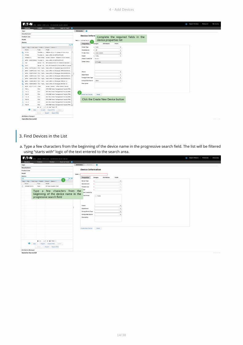
b. Use % or * as a wild card to match characters. For example, *001* will filter the list using “contains” logic for thefiltered device list.
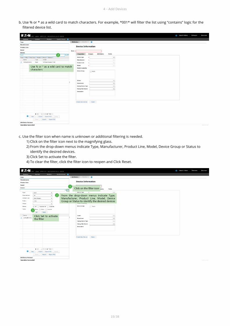
c. Use the filter icon when name is unknown or additional filtering is needed.1) Click on the filter icon next to the magnifying glass.2) From the drop-down menus indicate Type, Manufacturer, Product Line, Model, Device Group or Status to
identify the desired devices.3) Click Set to activate the filter.4) To clear the filter, click the filter icon to reopen and Click Reset.
4 - Add Devices
15/38

4. Use Clone to Create Additional Devices
a. In the device list select the device you want to replicate.b. Click the Clone button underneath the device list.c. In the popup window enter the desired quantity of cloned devices to create.
d. Cloned devices maintain the same name as the original device, but are appended with(#).
4 - Add Devices
16/38

5. Rename a device
a. Select the device from the device list.b. In the Name field change the text as desired.c. Click on the Modify button.
4 - Add Devices
17/38

Place Floormount Devices When floor configurations are completed and Rack/Facility devices have been created, users can place these devices on
the floorplans. The Floor tools provide easy ways to place, rotate, align, raise devices on the floors.
1. Select the Floors Page
Select the Floors link at the top of the Home Page.
2. Select the Floor Node in the Navigation Tree
5 - Place Floormount Devices
18/38

3. Mount Devices to the Floor
a. Click the Floor View menu.b. Search for the device name on the device list which will be placed on the floor.c. Click the desired device(s), hold the mouse key down and drag devices onto the floor. Release the mouse key to place
devices on the floor. Multiple devices can be selected using the Ctrl or Shift keys.d. Click the Save button.
4. Edit Device Positions
There are four primary functions performed on the floormount devices once they are placed on the floor. In all cases, multiple devices can be selected by holding the Shift key and selecting multiple devices on the floorplan. For the Align and Join features, the first device selected in the series will act as the reference for the join and align functions.
1) Move – Click and drag devices to move them on the floor.2) Rotate – Click devices and then choose the Rotate icon to rotate in 90 degree increments.3) Join – Select multiple devices and join devices to the left, right, top or bottom of the first device selected in the series.4) Align – Select multiple devices and join devices to the left, right, top and bottom of the first device selected in the
series
5 - Place Floormount Devices
19/38

1. Select the Discovery Page
Select the Admin link from the top of the Home Page and then select the Discovery link from the top of the Admin Page.
2. View Defined Discovery Jobs
Click the Edit button from the discovery status page.
6 - Auto Discovery
Auto Discovery The Discovery feature allows users to define discovery settings for polling networks to automatically find and activate
monitoring for devices to be managed in the application.
20/38

3. Add a Discovery Job
a. Click the Add button on the discovery job window.b. Enter the job name and Start/End ranges for the IP addresses to be polled for devices.
c. Select the discovery protocol check box. In most cases, this will be SNMP discovery only.d. Fill the SNMP version, Port and community to be used with the SNMP discovery settings. These should match the
configuration of the devices which will be discovered and added to the application.e. Select the Active check box to activate the new discovery job.f. Click the Save button on the top left corner of the page.
6 - Auto Discovery
21/38

4. Manage Discovered Devices
a. Return to the Discovery Status page by hitting the back button from the Discovery Job definition page.b. When the jobs Current Status is Completed, click the Manage button to view a list of devices found by the discovery
job.
c. Select the checkbox next to the discovered device or Select All devices by clicking the checkbox in the columnheading.
d. Select the “Move to Monitor” or “Move to Manage” buttons, choose the Device Group for the selected devices andclick the OK button. Note, Move to Monitor will add the device to the application and enable Monitoring datacollection, but Move to Manage will simply add the device to the device list with no active data collection.
6 - Auto Discovery
22/38

Rack Building The Racks feature allows users to manage devices within the rack and to view rack detail and capacity information.
1. Select the Racks Page
Select the Racks link from the top of the Home Page.
2. Choose a Rack to Manage
Find the rack in the list and single click to highlight the rack. Use the search and filter options to limit the racks listed if there are many racks in the list. This will display the rack detail image and rack dashboard. Use the mouse scroll wheel to zoom in/out or click and drag the rack image to pan the view to the desired view settings.
7 - Rack Building
23/38

4. Assign Device to U Position
Click, hold and drag the device to into the Rack. The position the device is when the mouse is released defines where the device will be mounted. A green highlight will indicate the positions to be occupied by the device if the user releases the mouse. Note, blades can be mounted directly into Enclosures in this view with the same user function.
7 - Rack Building
3. Find Devices to Place in Rack
Use the search and filter options on the Device list to find the device that needs to be placed into the rack. Note, the rack has available mount positions on the front, rear right and left of the rack. Left and right are typically reserved for 0U Rackmount PDU devices. For devices which mount to the outside of the rack, such as sensors or door locks, use the Show Enclosure checkbox to toggle the view with the rack enclosure.
24/38

5. Save the Rack
7 - Rack Building
25/38
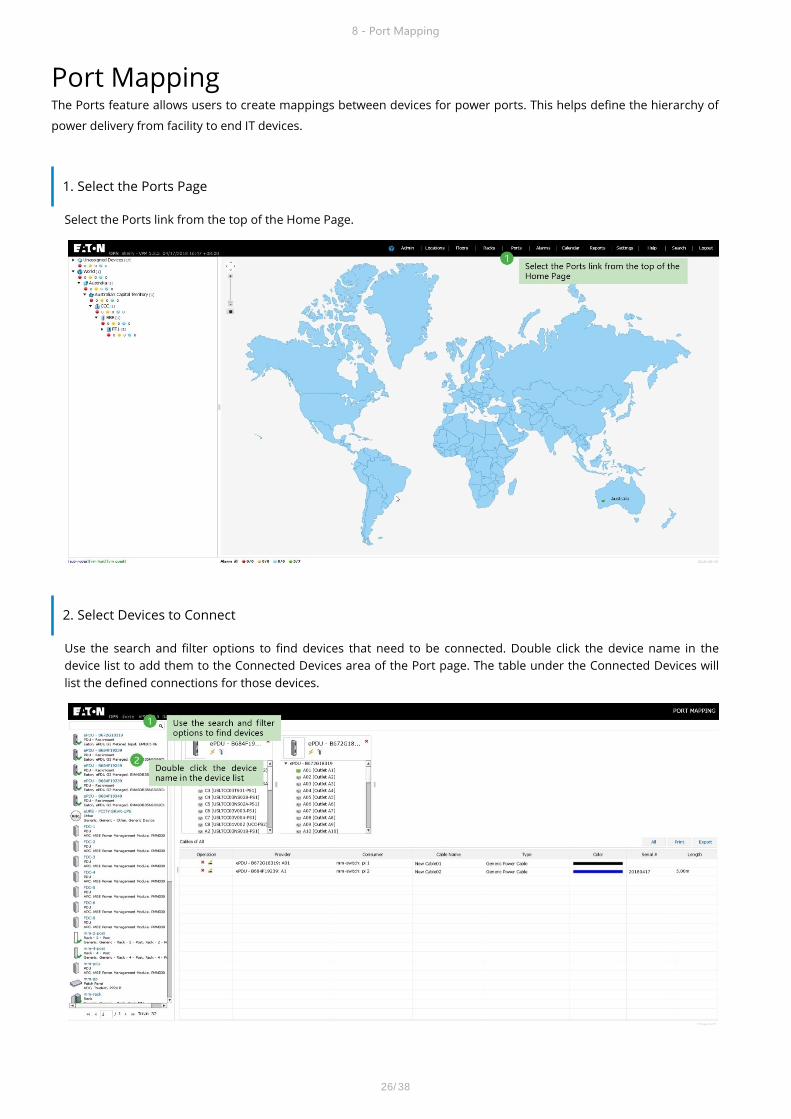
Port Mapping The Ports feature allows users to create mappings between devices for power ports. This helps define the hierarchy of
power delivery from facility to end IT devices.
1. Select the Ports Page
Select the Ports link from the top of the Home Page.
2. Select Devices to Connect
Use the search and filter options to find devices that need to be connected. Double click the device name in the device list to add them to the Connected Devices area of the Port page. The table under the Connected Devices will list the defined connections for those devices.
8 - Port Mapping
26/38

4. Create Port Connections
Connect ports from different devices by clicking the first port from a device in Candidate Devices, continue to hold down the mouse button, drag the mouse to the second port on the next device and release the mouse button. Complete the information in the Connection properties window including the Name, Serial Number, Length and Color.
8 - Port Mapping
3. Confirm Ports are listed
The model library contains 20,000+ models with a predefined list of ports which can be used to define connections. If the ports on the device are missing then users can manage the list of available ports for the device on the Admin page. Select the device in the Device list and choose the Ports sub tab. On this page, users can create any number of ports with a specific port type from the list.
27/38
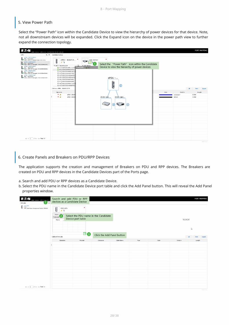
6. Create Panels and Breakers on PDU/RPP Devices
The application supports the creation and management of Breakers on PDU and RPP devices. The Breakers are created on PDU and RPP devices in the Candidate Devices part of the Ports page.
a. Search and add PDU or RPP devices as a Candidate Device.b. Select the PDU name in the Candidate Device port table and click the Add Panel button. This will reveal the Add Panel
properties window.
8 - Port Mapping
5. View Power Path
Select the “Power Path” icon within the Candidate Device to view the hierarchy of power devices for that device. Note, not all downstream devices will be expanded. Click the Expand icon on the device in the power path view to further expand the connection topology.
28/38

c. Complete the fields in the Panel properties window.1) View Mode:
• Double Table – Panel is composed of two columns with 21 circuits in each column.• Single Table – Panel is composed of a single column with all 42 circuits.
2) Numbering Scheme• 1, 3, 5… – Odd breakers on the left and even breakers on the right. This option is only available for theDouble Table view mode.• 1, 2, 3… –All circuits are listed in sequential order. This option is available for both Single and Double Tableviews. If this option is selected for a Double Table, then circuits 1-21 are in the left column and circuits 22-42 arein the right column
3) • Department:• Describes the department associated to all breakers within the panel. This setting is used to calculate theCustomer Power Report.
d. Add a breaker to the panel. Select the panel name in the table list and click the Add button.
8 - Port Mapping
29/38

e. The Breaker properties window will appear. Complete the Breaker information and click OK to save the breaker forthe panel.
7. Create Port Connections to PDU/RPP Breakers
Similar to the standard device port connections, users can connect the PDU and RPP breakers to ports of Rack PDU and Rack UPS devices. In some cases, these connections are created directly to end IT devices such as switch or server enclosures. Click the port from a device in Candidate Devices, continue to hold down the mouse button, drag the mouse to the Rack PDU and release the mouse button. Complete the information in the Connection properties window including the Name, Serial Number, Length and Color.
8 - Port Mapping
30/38

1. Select the Admin Page
Select the Admin link from the top of the Home Page.
2. Configure Rack PDU or Rack UPS Attributes.
a. Select the Device menub. Use search and filter to find the device in the device list.c. Select the Attributes tab for the selected device.d. Configure the A-B Side Power, Power-Derated and Power-Rated attributes. Note, Power Rated is typically defined at
the model level and Power Derated is set to equal Power Rated. Users can override these settings on each device orset these values at the Model to have them propagate to all devices based on that model.
e. Click the Modify button to save these configurations.
9 - Device Settings
Device Settings Many of the capacity tools and dashboards require the devices being monitored to be configured properly for A|B power
settings and derated values. These settings enable detailed tracking of capacity and failover capabilities for these devices.
31/38

3. View the Rack Dashboard
Power and Current data will now be displayed at the Rack dashboard where properly configured Rack PDU and Rack UPS devices are mounted.
9 - Device Settings
32/38

5. Configure Rack Attributes
Configuring the Rack attributes will enable the failover calculations which provide advanced notice to users about issues with phase level failover capabilities for power providing devices in the racks.
a. Select the Rack device in the device list on the Admin pageb. Configure the A Current Derated and B Current Derated attributes for the Rack.c. Click the Modify button to save changes.
9 - Device Settings
4. View the rack PDU and Rack UPS Dashboards
Rack PDU and Rack UPS dashboards will not correctly show the A|B Power setting and properly report phase level data for these devices. Power ratings will also be populated in the Power and Current gauges and tables.
33/38

6. View the Rack Dashboard
The rack dashboard will now list the A|B Derated Current values. In the phase level current dashboard gauge, the red “hashed” bars indicate there is an issue with A to B or B to A failover for those phases of power.
9 - Device Settings
34/38

Alarm Settings Alarm settings allow users to define thresholds for monitored data and capacity information along with notification
rules to deliver Email and SMS alarms to defined recipients.
1. Select the Admin Page
Select the Admin link from the top of the Home Page.
2. Open the Monitor Attributes Configuration Page
Monitor Attributes are the normalized data points in the application which are used to map raw data from various device sources to a common application reference scheme. By defining the alarm configuration at the application attribute level, profiles can be created to help reduce the administration of the settings.
a. Open the Monitor Tab.b. Access the Monitor Attributes section on the left menu.
10 - Alarm Settings
35/38

a. Select Device from the level dropdown to define a threshold for an individual device. Search the device name andselect it in the list.
b. Select the Alarm Thresholds tab.
c. Select the Layer-Temperature Monitor Attribute (MA). This is the product reference for Temperature.d. Select the Add Threshold button
10 - Alarm Settings
3. Configure Thresholds
Thresholds can be defined for multiple levels of the device hierarchy. The most common method is to define a threshold for either the Model or the individual Device. The example below uses a definition of a threshold for an individual Sensor devices using the Temperature data point.
36/38

e. Configure the threshold page and click the Add button. Note, multiple rules can be defined for the same data point,but number ranges can’t overlap for different alarm ranges.
1) Label – Name of the alarm which will be included in the alarm information and notifications.2) Type –If the data point is a number there is no option for this setting; an interval will be defined for the value of
the data. If the data point is a string then the user can define “starts with” or “contains” rules.3) Alarm Level – Defines the Warning or Critical alarm status if the value matches the rule definition.4) Inc | Not Inc – For Numeric values Inc is short for Inclusive and Not Inc is short for Not Inclusive. If the value box
is null then it is infinite.
f. Select the Save Table button to save this threshold. Alarms will appear in the Alarms page and other areas of theapplication where alarm status is presented when the values of the device cross into the defined ranges for thealarm rule.
10 - Alarm Settings
37/38
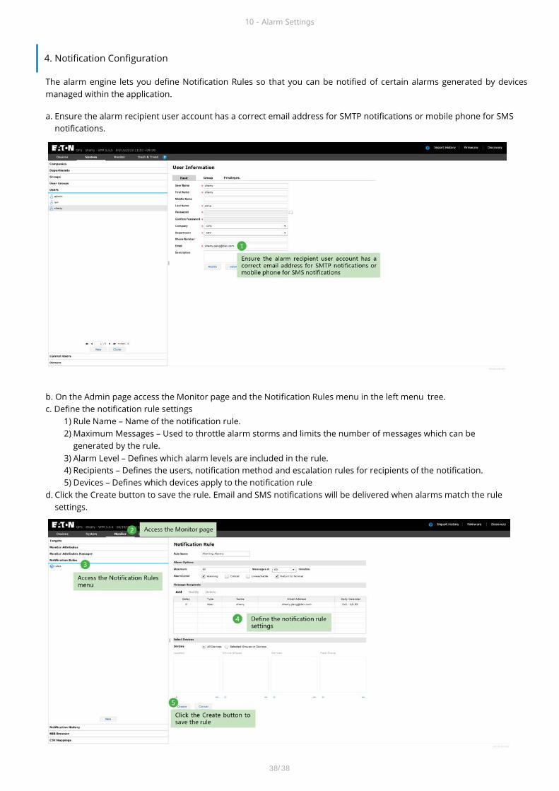
4. Notification Configuration
The alarm engine lets you define Notification Rules so that you can be notified of certain alarms generated by devices managed within the application.
a. Ensure the alarm recipient user account has a correct email address for SMTP notifications or mobile phone for SMSnotifications.
b. On the Admin page access the Monitor page and the Notification Rules menu in the left menu tree.c. Define the notification rule settings
1) Rule Name – Name of the notification rule.2) Maximum Messages – Used to throttle alarm storms and limits the number of messages which can be
generated by the rule.3) Alarm Level – Defines which alarm levels are included in the rule.4) Recipients – Defines the users, notification method and escalation rules for recipients of the notification.5) Devices – Defines which devices apply to the notification rule
d. Click the Create button to save the rule. Email and SMS notifications will be delivered when alarms match the rulesettings.
10 - Alarm Settings
38/38