Eaton Hydraulic Launch Assist (HLA) TRSM1200
108
Service Manual Eaton Hydraulic Launch Assist (HLA) TRSM1200 June 2012
-
Upload
khangminh22 -
Category
Documents
-
view
0 -
download
0
Transcript of Eaton Hydraulic Launch Assist (HLA) TRSM1200

Service Manual
Eaton Hydraulic Launch Assist (HLA)TRSM1200June 2012


Table of Contents
Warnings and Cautions DefinitionsHydraulic Launch Assist (HLA) Warningsand Cautions . . . . . . . . . . . . . . . . . . . . . . . 1Emergency Procedures . . . . . . . . . . . . . . . 2Accumulator Stored Energy Drain Procedure . . . . . . . . . . . . . . . . . . . . . . . . . 3Towing . . . . . . . . . . . . . . . . . . . . . . . . . . . 4
General InformationHow to Use This Manual . . . . . . . . . . . . . . 5HLA System Identification . . . . . . . . . . . . . 5Serial Tag Location . . . . . . . . . . . . . . . . . . 5Hydraulic Hybrid Overview . . . . . . . . . . . . 6Driver Display Module . . . . . . . . . . . . . . . . 6Startup Procedure . . . . . . . . . . . . . . . . . . . 7Bootstrapping . . . . . . . . . . . . . . . . . . . . . . 7Operation . . . . . . . . . . . . . . . . . . . . . . . . . 7Accumulator Inspection . . . . . . . . . . . . . . 9Accumulator Nitrogen Precharge . . . . . . . 9Typical Installation and Configuration . . . . 10HLA Hybrid Components and Connector Locations . . . . . . . . . . . . . . . . . . . . . . . . . 11
Maintenance
General Maintenance Tips . . . . . . . . . . . . . 13Service and Maintenance Shutdown Procedure . . . . . . . . . . . . . . . . . . . . . . . . . 13Accumulator Stored Energy Drain Procedure . . . . . . . . . . . . . . . . . . . . . . . . . 14Manual Relief Valve Drain Procedure . . . . 15Inspection Procedures . . . . . . . . . . . . . . . 15Maintenance and Inspection Intervals . . . . 17Warning Label Positions . . . . . . . . . . . . . . 19HLA System Oil Regular Maintenance . . . . 20Oil Sample Procedure . . . . . . . . . . . . . . . . 20HLA System Filter Maintenance . . . . . . . . 22HLA System Oil Fill . . . . . . . . . . . . . . . . . . 24Accumulator Precharge Procedure . . . . . . 25Transfer Case . . . . . . . . . . . . . . . . . . . . . . 29
Service Procedures
Service and Maintenance Shutdown Procedure . . . . . . . . . . . . . . . . . . . . . . . . . 31Accumulator Stored Energy Drain Procedure . . . . . . . . . . . . . . . . . . . . . . . . . 32System Overhaul . . . . . . . . . . . . . . . . . . . . 33
Swash Carrier Assembly . . . . . . . . . . . . . . 37Charge Pump Replacement . . . . . . . . . . . . 38Transfer Case Replacement . . . . . . . . . . . . 40Transfer Case . . . . . . . . . . . . . . . . . . . . . . . 41Warnings and Cautions. . . . . . . . . . . . . . . . 41Model Identification . . . . . . . . . . . . . . . . . . 42General Information . . . . . . . . . . . . . . . . . . 44Installation Instructions . . . . . . . . . . . . . . . 44Repair and Rebuilding Instructions . . . . . . 45Cleaning and Inspection Instructions . . . . . 46Reassembly Instructions . . . . . . . . . . . . . . 47Assembly of Shift Mechanism . . . . . . . . . . 50Preventative Maintenance . . . . . . . . . . . . . 51Oil Capacity . . . . . . . . . . . . . . . . . . . . . . . . 52Recommended Oil Type . . . . . . . . . . . . . . . 52General Information . . . . . . . . . . . . . . . . . . 52Input Shaft Seal Replacement . . . . . . . . . . 54Accumulator Replacement . . . . . . . . . . . . . 55Accumulator Bladder Repair . . . . . . . . . . . 56Electrical Enclosure . . . . . . . . . . . . . . . . . . 61Electronic Control Unit Replacement . . . . . 61Splice Packs . . . . . . . . . . . . . . . . . . . . . . . . 62Wire Harness . . . . . . . . . . . . . . . . . . . . . . . 63Connectors . . . . . . . . . . . . . . . . . . . . . . . . 64Reservoir Replacement . . . . . . . . . . . . . . . 65Reservoir Cover . . . . . . . . . . . . . . . . . . . . . 66Main Filter Assembly Replacement . . . . . . 67Return Manifold Replacement . . . . . . . . . . 68Cooler Replacement . . . . . . . . . . . . . . . . . . 70Hose Assemblies Replacement
Standard Reservoir Design . . . . . . . . . 71Offset Reservoir Design . . . . . . . . . . . . 71
Suction Hose . . . . . . . . . . . . . . . . . 72Case/Cooler Hose . . . . . . . . . . . . . 73High Pressure Hose . . . . . . . . . . . 75Low Pressure Return Hose . . . . . . 76
Sensors Replacement Swash Sensor . . . . . . . . . . . . . . . . . . . 77Accumulator Foot Valve ProximitySensor . . . . . . . . . . . . . . . . . . . . . . . . . 78Accumulator Pressure Sensor . . . . . . . 78Transfer Case Engagement ProximitySensor . . . . . . . . . . . . . . . . . . . . . . . . . 79Speed Sensor . . . . . . . . . . . . . . . . . . . . 79Filter Pressure Delta Sensor . . . . . . . . . 80
i

Table of Contents
Level Sensor . . . . . . . . . . . . . . . . . . . . 80Pump Temperature Sensor . . . . . . . . . 81Reservoir Temperature Sensor . . . . . . 81
Valves Replacement Mode Valve . . . . . . . . . . . . . . . . . . . . . 82Directional Control Valve . . . . . . . . . . 82Bypass Valve (Main Stage) . . . . . . . . . 83Charge Pump Bypass Valve . . . . . . . . 83Bypass Valve Pilot Cartridge . . . . . . . . 84Isolation Valve . . . . . . . . . . . . . . . . . . 84Manual Relief Valve . . . . . . . . . . . . . . 85Pneumatic Clutch Valve . . . . . . . . . . . 85
Wiring Repair Instructions . . . . . . . . . . . . 86Vehicle Harness Routing . . . . . . . . . . . . . . 86
Proper Routing Techniques . . . . . . . . 87Improper Routing Techniques . . . . . . 88
Wiring SchematicHydraulic System OEM Electrical Circuit . . 89
AppendixFault Codes . . . . . . . . . . . . . . . . . . . . . . . . 91Nitrogen Gas Precharge Pressure Chart . . 94HLA High Performance HydraulicFluid Data Sheet . . . . . . . . . . . . . . . . . . . . 94
Physical Characteristics . . . . . . . . . . . . 94Chemical Characteristics . . . . . . . . . . . 95
Hose Chart . . . . . . . . . . . . . . . . . . . . . . . . 95Sub-System Weights . . . . . . . . . . . . . . . . 95Special Tools . . . . . . . . . . . . . . . . . . . . . . 95Torque Specifications . . . . . . . . . . . . . . . . 96Connector List . . . . . . . . . . . . . . . . . . . . . 97HLA Maintenance Check Sheet . . . . . . . . . 100Real Time Warranty Pre-Call Checklist . . . 101
ii

Warnings and CautionsW
arnings and Cautions
Warnings and Cautions Definitions
Throughout this manual there are sections that are marked Warning, Caution or Important. These special paragraphs contain specific safety information and must be read, under-stood and heeded before continuing the procedure or per-forming the step(s).
Warning indicates you will be severely Injured or Killed if you do not follow the indicated procedure.
Caution indicates an Immediate Hazard, which could result in Severe Personal Injury if you do not follow the indicated procedure.
Important indicates Vehicle or Property Damage could occur if you do not follow the indicated procedure.
Note: Note indicates additional detail that will aid in the ser-vice or repair of component or system.
Hydraulic Launch Assist (HLA) Warnings and Cautions
Improper service and maintenance will cause vehicle dam-age or personal injury. Do not repair, service or mainte-nance the HLA system without the service manual or proper training and tools.
HLA system will not stop vehicle. Driver must be prepared to apply brakes anytime the HLA system is in regenerative braking.
Do not operate HLA system without body installed. HLA sys-tem is not designed for no-load operation. Wheel skid may occur.
Do not check accumulator precharge with key on and stored oil in accumulator.
Do not use liquid nitrogen, oxygen or compressed shop air to charge accumulator.
In the event of an accident, the accumulator should be removed for inspection and replacement.
WARNING
CAUTION
IMPORTANT
WARNING
1
Warnings and Cautions
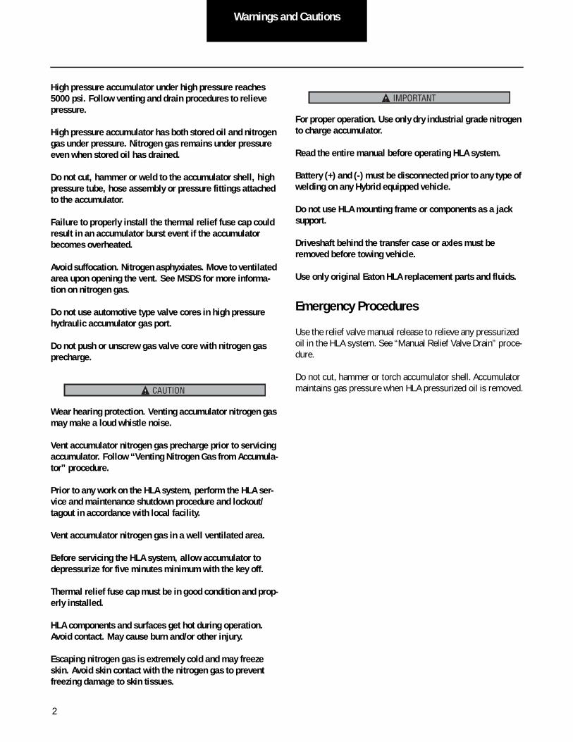
High pressure accumulator under high pressure reaches 5000 psi. Follow venting and drain procedures to relieve pressure.
High pressure accumulator has both stored oil and nitrogen gas under pressure. Nitrogen gas remains under pressure even when stored oil has drained.
Do not cut, hammer or weld to the accumulator shell, high pressure tube, hose assembly or pressure fittings attached to the accumulator.
Failure to properly install the thermal relief fuse cap could result in an accumulator burst event if the accumulator becomes overheated.
Avoid suffocation. Nitrogen asphyxiates. Move to ventilated area upon opening the vent. See MSDS for more informa-tion on nitrogen gas.
Do not use automotive type valve cores in high pressure hydraulic accumulator gas port.
Do not push or unscrew gas valve core with nitrogen gas precharge.
Wear hearing protection. Venting accumulator nitrogen gas may make a loud whistle noise.
Vent accumulator nitrogen gas precharge prior to servicing accumulator. Follow “Venting Nitrogen Gas from Accumula-tor” procedure.
Prior to any work on the HLA system, perform the HLA ser-vice and maintenance shutdown procedure and lockout/tagout in accordance with local facility.
Vent accumulator nitrogen gas in a well ventilated area.
Before servicing the HLA system, allow accumulator to depressurize for five minutes minimum with the key off.
Thermal relief fuse cap must be in good condition and prop-erly installed.
HLA components and surfaces get hot during operation. Avoid contact. May cause burn and/or other injury.
Escaping nitrogen gas is extremely cold and may freeze skin. Avoid skin contact with the nitrogen gas to prevent freezing damage to skin tissues.
For proper operation. Use only dry industrial grade nitrogen to charge accumulator.
Read the entire manual before operating HLA system.
Battery (+) and (-) must be disconnected prior to any type of welding on any Hybrid equipped vehicle.
Do not use HLA mounting frame or components as a jack support.
Driveshaft behind the transfer case or axles must be removed before towing vehicle.
Use only original Eaton HLA replacement parts and fluids.
Emergency Procedures
Use the relief valve manual release to relieve any pressurized oil in the HLA system. See “Manual Relief Valve Drain” proce-dure.
Do not cut, hammer or torch accumulator shell. Accumulator maintains gas pressure when HLA pressurized oil is removed.CAUTION
IMPORTANT
2

Warnings and CautionsW
arnings and Cautions
Accumulator Stored Energy Drain Procedure
High pressure accumulator has both stored oil and nitrogen gas under pressure. Nitrogen gas remains under pressure even when stored oil has drained.
WARNING
2 Wait 5 minutes.
3 Verify pressure has drained accumulator following these (3) methods:
a. Turn ignition switch to ON and check state of charge
bar on driver display.
b. Connect ServiceRanger to check accumulator pressure bar.
c. Open manual relief valve. See Manual Relief Valve
Drain Procedure.
1 Turn ignition switch to OFF. Note: System allows controlled drain of accumulator through
Fluid
Bladder
OFF
ON
START
OFF
ON
START
Manual Relief Valve
Protective Cap
5 Min
3

Warnings and Cautions
TowingWhen towing vehicle, do not allow output shaft of the HLA system to spin or turn. If vehicle is towed with drive wheels still in contact with road surface, remove or disconnect vehi-cle axle shafts or driveline.
Serious internal transmission damage and damage to HLA system can result from improper vehicle towing.
WARNING
Prefered
Must remove driveshaft between HLA transfercase and rear axle
4

General InformationGeneral Inform
ation
General Information
How to Use This Manual
For parts and technical support visit roadranger.com or call the Roadranger call center at 1-800-826-HELP.
HLA System IdentificationSerial Tag InformationThe HLA system serial tag contains very useful information and is the first place to look to identify the system. Being able to read the tag can help determine which service manual to use and the date the system was manufactured.
• Model Number: Identifies factors such as configura-tion and design level.
• Serial Number: Identifies number of build.
Product Serialization/Unique Identifier12 Digit Serial Number – SPMHMMDDYY@XX
• SP = common identifier for Spencer plant
• H = common identifier for hybrids
• MM = two (2) digit month code
• DD = two (2) digit date code
• YY = two (2) digit year code
• @ = unit build shift identifier (2, 3, 4)
• XX = unique subsystem number in shift (01, 02, 03, etc.)
Shift Identifier
• 2 = second shift – 7:00 am to 3:00 pm
• 3 = third shift – 3:00 pm to 11:00 pm
• 4 = fourth shift – 11:00 pm to 7:00 am
Serial Tag Location
Hydraulic Pump Tag
HLA System Tag
Reservoir Tag
Cooler Tag
Transfer Case Tag
Accumulator Tag (SN# on shell and Fab# on tag)
Part Number with Revision/Model Code
12-Digit Unique Serial Number
Information Line 1
Information Line 2
2D Data-Matrix Bar Code
6022017-001XXXXXXXXXXXXX
5

General Information
Hydraulic Hybrid OverviewParallel Hydraulic Hybrid ArchitectureThe Hydraulic Launch Assist (HLA) is a hybrid system designed to increase fuel economy and increase vehicle brake life in vehicles with heavy start-stop drive cycles, such as refuse trucks. The system does this by capturing energy dur-ing braking and then reusing the energy to launch the vehicle (braking regeneration). HLA is a parallel system which means both the engine and the HLA pump can turn the drive axle (together or independently). The parallel architecture allows the vehicle to continue driving if the HLA shuts down. The HLA attaches to existing drivelines and does not replace entire existing transmissions. It can be installed at any point during vehicle build and may be retro-fitted.
System Specifications
• 10-year design life
• Ambient operating temperature ranges
Full function range: -22°F to 122°F (-30°C to 50°C)
• Annual service
- System oil
- Main filter
- Point of use filter
- Reservoir breather
• Maximum rated pressure
- 345 bar
- 5000 psi
• System oil volume
- 80 liters
- 21 gallons
• Typical peak power per cycle
- 130 kW
- 175 HP
• Pump maximum revolutions per minute
3000 RPM
Driver Display Module
The driver display module is mounted in the dashboard as a visual aid for the driver and is used to monitor the HLA sys-tem operation. At key on, all lights will flash as self-check. Only those applicable will remain illuminated.
Diagnostic CodeThe fault number indicator will present a two-digit code that can be referenced in the troubleshooting manual. The display is blank when no fault is present and the system is functioning properly. Any fault code will disengage the HLA system.
State of Charge Bar (SOC)The state of charge bar has eight (8) segments which repre-sent the current amount of stored energy. All eight segments are illuminated at maximum stored energy. The illuminated portion of the bar will:
• Decrease when accelerating
• Increase when decelerating
Optimum use of the HLA system will occur when the state of charge indicator goes from empty to full during each braking event of the cycle.
Operational ModeOne of three lights will be lit to indicate the state of the sys-tem: OFF, ECON, or PROD (productivity). These states can only be changed using a service tool and are not a driver option.
ServiceWhen the amber service light is lit, it means the HLA system has been disabled—a fault code will appear. The HLA system requires service, but the vehicle may be driven. Record the fault number and conditions at time of fault.
HLA System
SERVICE
STOP
OFF ECON PRODE SOC F
Two-digit fault code indicator. Either SERVICE or STOP will also light.
State of Charge Bar:0 bars = empty8 bars = full
Operational Mode
6

General InformationGeneral Inform
ation
StopWhen the red stop light is lit, it means the HLA system mal-functioned—a fault code will appear. The transfer case is not disengaging as commanded, causing a mission stopping fault. This fault will put the engine in limp mode, not allowing the vehicle to exceed 7 mph. Do not drive the vehicle. Tow the vehicle to a service center.
The rear driveshaft must be removed prior to towing the vehicle.
Startup Procedure1. Turn ignition key to ON to power HLA system and
start engine. ECU does internal memory check.
2. Check driver display module for any fault codes.
3. Apply service brake.
4. Select drive gear on shift console.
5. Release service brake and apply accelerator.
Bootstrapping
Bootstrapping is the process of turning the pump shaft by driving the vehicle. This generates pump flow which pushes against the accumulator bladder, generating pressure used to control the system. It occurs automatically when the vehicle is turned on. During the initial pump rotation after startup, oil is pushed into the accumulator. This small amount of oil is used to shift valves and pistons to control the system.
Operation
The following section describes how the HLA functions during different states of operation.
DrivingHydraulic Launch Assist is automatic and will be active within the system parameters without driver interaction. The transfer case will only engage when:
• Engine is running.
• Vehicle is in drive.
• Vehicle is stopped (0 mph).
• No faults are present.
HLA will function only within these parameters:
• Vehicle speed is between 3-22 mph.
• No faults are present.
• Storage is available for pumping/regeneration.
• Stored energy is available for motoring/launch assist.
Note: HLA will only assist acceleration when accelerator pedal is pressed and there is stored energy available in the accumulator.
HLA will disengage when:
• Cruise control is on.
• Vehicle is not in drive.
• ABS sets a fault.
• Vehicle speed exceeds 25 mph.
Monitor the driver display module for HLA system operation or fault codes.
Coast FeatureHLA will slow the vehicle once the accelerator pedal is released. Lightly holding the accelerator pedal allows the vehi-cle to coast by keeping HLA regeneration on standby.
Note: If the vehicle speed exceeds HLA system limits, the sys-tem will disengage. The transfer case will not reengage until the vehicle has come to a complete stop unassisted by HLA. The speed of disengagement will vary depend-ing on gear ratio. Disengagement is typically set at 25 mph.
IMPORTANT
HLA System
SERVICE
STOP
OFF ECON PRODE SOC F
7

General Information
Note: HLA is not active in Reverse. HLA will disengage when not in drive, with cruise control on or with parking brake set. These vehicle conditions are monitored by the ECU over the J1939 data link.
Vehicle Braking/RegenerationThe HLA system on the vehicle uses regenerative braking to capture and store energy in the hydraulic accumulator. When the accelerator pedal is released, regenerative braking will start when HLA is active, has no faults and has available oil storage capacity. The regeneration will feel as if the brake pedal is being lightly applied. During regeneration, oil is being pumped into the accumulator, capturing the vehicle’s kinetic energy. The load on the pump helps slow the vehicle. The full power of the service brake is always available to the driver.
The HLA system will automatically shut off regenerative braking in the following situations. Driver must always be ready to apply service brake.
• When the accumulator is fully charged.
• If a system fault occurs.
• During an ABS (anti-lock brake) event; i.e. skidding on black ice while trying to brake the vehicle.
Be prepared to apply the service brakes any time HLA is in regenerative braking.
Pumping/Regeneration (Slowing)Releasing the accelerator pedal or pressing the brake pedal activates regeneration energy storage.
• Vehicle coasts by holding or pressing the accelerator pedal at 10% of travel or less, or about 3/4” (20 mm) down.
• Vehicle retardation rate for HLA regeneration is set with system diagnostic and service tool. The rate of vehicle deceleration to HLA pump torque is applied to the driveline through the transfer case.
Motoring/Launch AssistPressing the accelerator pedal sends a torque request com-mand to the ECU. The ECU commands the swash to motoring and the mode valve to open which turns the pump, providing torque to the driveline.
Within normal operating parameters, the HLA system will supply torque until normal energy is depleted. The ECU will command the swash to neutral when stored energy is gone.
Pump Over Speed ProtectionThe HLA system will disengage if the pump exceeds 3,000 rpm. Typically this pump speed occurs between 24-26 mph, depending on tire size and final drive ratio.
At 3,000 rpm, the ECU will command the transfer case to dis-engage. The ECU will compare pump speed to vehicle speed to confirm disengagement. If disengagement is not con-firmed, the pump will over speed and a diagnostic code will occur. The red stop lamp will illuminate on the driver display. The ECU will command the engine to limp mode and the vehi-cle will need to be towed for service.
Note: The driveshaft must be removed prior to towing.
Power Down
1. Select N (neutral) on shift control.
2. Set vehicle parking brakes.
3. Turn ignition key to OFF and allow engine to shut-down.
Note: Any oil stored in the accumulator as HLA energy will drain back to the reservoir once ignition is turned off.
ShutdownThe HLA system automatically drains the stored energy when the vehicle is turned off. No operator action is required. The high-pressure oil is automatically drained from the accumula-tor to the reservoir.
IMPORTANT
CAUTION
8

General InformationGeneral Inform
ation
Accumulator InspectionVisually inspect accumulator for:
• Thermal cap installation
• Secure straps
• Damage
Accumulator Nitrogen Precharge• Requires nitrogen charging kit.
• Follow the Accumulator Precharge Procedure on page 25.
9

General Information
Typical Installation and Configuration
Transfer Case
Pump/Motor Reservoir
Accumulator
Cooler
Filter
ECU
Secondary Filter(Point of Use)
Sight Level Gauge
Gas Port
Breather
10

General InformationGeneral Inform
ation
HLA Hybrid Components and Connector Locations
Electronic Control Unit
OEM Connection
Swash Sensor 1
Level Sensor
SpeedSensor
EngagementProximitySensor
Charge Pump Bypass Valve
Isolation ValveBypass ValvePilot Cartridge
Directional Control Valve
Front of Vehicle
Fan Relay
11

General Information
Mode Pilot Valve
Fill
Drain
PumpTemperatureSensor
Pneumatic Clutch ValveReservoirTemperatureSensor
Foot ValveProximity Sensor
PressureSensor
Swash Sensor 2
Filter PressureDelta Sensor
Oil SampleValve
Front of Vehicle
Relief Valve
12

13
MaintenanceM
aintenance
Maintenance
General Maintenance Tips
All parts must be clean, dry and free of chips and burrs prior to assembly.
All moving contact surfaces of components should be lubri-cated at the time of assembly with Roadranger HLA High Per-formance Hydraulic Fluid.
A thin covering of lubricant, such as petroleum jelly or Eaton silicon lube (part #71203), must be used on O-rings to assist in assembly.
Gaskets should be assembled dry.
Service and Maintenance Shutdown Procedure
1. Park vehicle in safe area on level ground.
2. Select N (neutral) on shift control and set vehicle parking brakes.
3. Turn ignition key to OFF. Allow accumulator to depressurize 5 minutes. Oil from accumulator will drain to the reservoir. See “Accumulator Stored Energy Drain Procedure.”
4. Allow accumulator temperature to stabilize when checking nitrogen gas precharge.
5. Use wheel chocks to block forward and reverse movement.
6. Prior to any work on HLA Electronic Control Unit (ECU), disconnect battery power to HLA system.
7. Check that accumulator pressure has vented com-pletely. Use ServiceRanger diagnostic tool or manual relief valve to check system pressure. See “Manual Relief Valve Drain Procedure.”
8. Lockout and tag vehicle under repair in accordance with your local policy.
9. Drain vehicle air system when working on pneumatic clutch valve or transfer case.

14
Maintenance
Accumulator Stored Energy Drain Procedure
High pressure accumulator has both stored oil and nitrogen gas under pressure. Nitrogen gas remains under pressure even when stored oil has drained.
WARNING
2 Wait 5 minutes.
3 Verify pressure has drained accumulator following these (3) methods:
a. Turn ignition switch to ON and check state of charge
bar on driver display.
b. Connect ServiceRanger to check accumulator pressure bar.
c. Open manual relief valve. See Manual Relief Valve
Drain Procedure.
1 Turn ignition switch to OFF. Note: System allows controlled drain of accumulator through
Fluid
Bladder
OFF
ON
START
OFF
ON
START
Manual Relief Valve
Protective Cap
5 Min

15
MaintenanceM
aintenance
Manual Relief Valve Drain Procedure
Use the system manual relief valve to drain any pressurized oil from the accumulator to the reservoir.
1. Follow “Service and Maintenance Shutdown Proce-dure.”
2. Using a 1/2” wrench, remove protective cap from manual relief valve.
3. Using a 1/8” hex wrench, slowly back out O-ring plug.
Note: Plug does not need to be removed from port. If plug is removed, shims must be kept in place.
4. If present, pressurized oil will be audible as it drains to tank. Allow accumulator to drain for 5 minutes minimum.
5. Tighten plug into port with shims in place. Torque to 5 ft-lb. See appendix “Torque Specifications.”
6. Install protective cap.
Inspection ProceduresInspect HLA System DailyInspect HLA system daily during vehicle pre-trip inspection. The following is a list of routine checks.
Note: Report and correct any defects prior to operation of HLA system. Additional inspections are listed in the appendix and “Maintenance and Inspection Intervals” table.
Manual Relief Valve Protective
Cap
Check reservoir oil level with ignition key off.
Check driver display for faults.
Check for loose or low hanging hoses or wires.
Check for oil leaks under vehicle.
Check reservoir breather indicator.
Check Cooler Screen and Clean/Remove any Debris
Check accumulator thermal relief cap is installed.

16
Maintenance
Check Reservoir for HLA System Oil LevelNote: Check oil level daily.
1. Warm up system to normal operating temperature. Check at end of shift if possible.
2. Follow “Service and Maintenance Shutdown Proce-dure.”
3. Visually inspect reservoir oil level. Level should be within specified range.
Note: System must be keyed off for proper oil level reading.
Note: Overfilling reservoir or topping off reservoir with accu-mulator full will cause an oil spill.
4. To top off oil, reservoir may be filled from the breather port.
Note: When changing system oil, fill using the pump quick disconnect following the HLS System oil fill procedure.
Reservoir Breather Check and ReplacementInspect breather cleanliness indicator on top of housing. When filter is clogged, indicator will show red. Replace breather if indicator is red or during regular maintenance schedule.
1. Follow “Service and Maintenance Shutdown Proce-dure.”
2. Remove breather from fill port by hand.
3. Visually inspect O-ring condition. Replace if dam-aged.
4. Install new breather and tighten against O-ring by hand.
Oil Level
BreatherClogged Filter
Clear Filter

17
MaintenanceM
aintenance
Maintenance and Inspection Intervals
Regular maintenance is important for safe and reliable opera-tion of the HLA system. A preventive maintenance (PM) schedule should be set up as indicated below.
Component Maintenance Note In Service(PDI)
Pre-trip Inspection
PM Interval (Hours)
300 600 1200 2400 4800 12000
Hose Visually inspect for hose abrasion or wear
X
Check for low hanging or loose hose
X
T-Case Oil Check oil level X X
Change transfer case oil (75W-90 Synthetic, 1.9 gallons)
FE 75W-90 Synthetic
X
Sub-Frame Visually inspect mounting frame and check for cracks in welds
X
Inspect mounting bolts, retorque as needed
X
Inspect absorbers for wear X
System Inspect pump and components for leakage
X X
Inspect warning labels, replace if damaged or missing
X
Check for driver display module function and no codes
X X X
Reservoir Breather
Check breather indicator; replace if red
X X X X
Replace breather Part # 5998865-001
X
Fittings Check for loose fittings, hose and connections
X
System Record Component Serial Number and submit to Real Time Warranty (RTW)
X

18
Maintenance
HLASystem Oil
Check oil level in reservoir X X X
Capture oil sample and analysis
Kit # 894276 X
Change oil) HLA Oil (21 gal)
X
RRHLADR (55 gal)
RRHLAPA (5 gal)
Filter Change system oil filter Part # 6025270-001
X
Change secondary (POU) oil filter
Part # 5994113-001
X
Accumulator Check dry nitrogen pre-charge
X X
Visually inspect accumulator X
Replace bladder X X
Mark bladder service tag with in service date
X
Check thermal relief cap installation and condition
X X X
Cooler Check intake screen and fan for debris and blockage; clean as needed
X X
Component Maintenance Note In Service(PDI)
Pre-trip Inspection
PM Interval (Hours)
300 600 1200 2400 4800 12000

19
MaintenanceM
aintenance
Warning Label Positions

20
Maintenance
HLA System Oil Regular MaintenanceAdd Oil to Reservoir (Top-off Only)
Note: Only use Roadranger HLA High Performance Hydraulic Fluid. Contact Roadranger Call Center to order oil, U.S. and Canada: 800-826-4357.
1. Follow “Service and Maintenance Shutdown Proce-dure.”
2. Use filter cart to clean oil before adding to reservoir.
3. Remove reservoir breather to access oil fill port.
4. Add oil and fill to mid-range on sight level gauge. (1" = 1 gallon of oil)
5. Replace breather on reservoir. See “Replace Reser-voir Breather.”
6. Recheck oil level after short period of operation.
Oil Sample ProcedureNote: Regular oil sampling in accordance with the mainte-
nance schedule is a good practice procedure.
Oil sample valve may be hot from operation. Use thermal protection.
1. Obtain Eaton Fluid Analysis Kit (part #894276). Con-tact Eaton Hydraulics or your local Eaton distributor. See www.eaton.com.
Note: Do not open sample bottle until ready to fill.
2. Fill out Test Sample Data Form as instructed on sheet:
• Include vehicle number/identifier, date, mileage and hours.
• Include your contact information, phone num-ber and email address for the analysis report.
3. Ensure system is at normal operating temperature by cycling HLA system for ten cycles minimum.
4. Follow “Service and Maintenance Shutdown Proce-dure.”
5. Place recycle pan under return manifold sample valve.
Oil Level
Breather
CAUTION
Oil Sample Valve
Return Manifold

21
MaintenanceM
aintenance
6. Clean around sample valve with parts cleaner.
7. Remove dust cover on discharge port.
8. Flush valve:
• Turn knurled knob ¼ turn right.
• Bleed approximately 250 ml [about 1 cup] of oil into recycle pan.
9. Place open sample bottle into oil stream and flush with oil.
10. Place sample bottle into oil stream and fill approxi-mately ¾ full.
Note: Make sure bottle stays clean.
11. Cap sample bottle.
12. Release knurled knob. Valve will close automatically.
13. Replace dust cover.
14. Properly dispose of oil from recycle pan.
15. If system oil level has dropped below minimum level mark on reservoir, add Roadranger HLA High Perfor-mance Hydraulic Fluid. See “Add Oil to Reservoir.”
16. Send oil sample to:
Eaton Corporation Innovation CenterVickers Fluid Analysis Service26201 Northwestern HwySouthfield, MI 48076
Drain and Replace HLA System Oil (Oil Change)
Note: System filters should be changed during any system oil drain.
1. Follow “Service and Maintenance Shutdown Proce-dure.”
2. Verify accumulator has depressurized for 5 minutes minimum.
3. Place 25-gallon drain recycling container under res-ervoir.
4. Use 14mm hex socket to remove drain plug from reservoir. Allow reservoir to fully drain into recycle pan.
5. Remove suction hose split flange and support suc-tion hose from work area.
6. Remove filter assembly.
7. Inspect and clean inside of reservoir.
8. Check suction port and diffuser for debris; clean as needed.
9. Check magnet for debris and clean.
10. Install new filter element. See “Change Main System Filter."
11. Reassemble filter assembly.
12. Reinstall suction hose and split flange. Torque flange bolts to 85 ± 6 ft-lb. See appendix “Torque Specifica-tions.”
13. Use filter cart to fill with oil through pump case port. See “Fill HLA System Oil.”
14. Fill to mid-range on sight level gauge.
15. Operate system to normal system temperature and recheck oil level. See “Check Reservoir for HLA Sys-tem Oil Level.”
Drain Plug (9/16" Hex Socket)

22
Maintenance
HLA System Filter Maintenance
Change Main System Filter
Note: The main filter replacement should be combined with the PM oil change. The filter is integral to the reservoir, which must be drained in order to replace the filter ele-ment.
1. Follow “Service and Maintenance Shutdown Proce-dure.”
2. Verify accumulator has depressurized for 5 minutes minimum.
3. Place 25-gallon drain recycling container under res-ervoir.
4. Use 14mm hex socket to remove drain plug from reservoir. Allow reservoir to fully drain into recycle pan.
5. Remove filter housing cover plate bolts.
6. Remove cover plate.
7. Use handle to pull out filter element.
8. Remove contamination bonnet and retain.
9. Clean contamination bonnet and housing. Check threads.
10. Examine sealing surfaces inside housing for dam-age.
11. Check O-rings on clogging indicator and cover plate. Replace parts as necessary.
12. Check magnet for debris and clean.
13. Lubricate with Roadranger HLA High Performance Hydraulic Fluid:
• Sealing surfaces and thread on cover plate and housing
• O-rings on cover plate and filter element
14. Fit old contamination bonnet onto new filter element by turning clockwise.
15. Insert filter element with bonnet into housing.
Filter Housing
Contamination Bonnet
Filter Element
Cover PlateReservoir
Return Block
Offset Reservoir Design
Standard Reservoir Design
23
MaintenanceM
aintenance
Note: Location spigot and element handle position must align.
16. Reinstall filter housing cover plate and hand tighten cover plate bolts.
17. Tighten bolts alternately and torque to 30 ft-lb. See appendix “Torque Specifications.”
18. Reinstall support hose and suction hose flange. Torque flange bolts to 85 ± 6 ft-lb. See appendix “Torque Specifications.”
19. Use filter cart to fill with oil through pump case port. See “Fill HLA System Oil.”
20. Fill to specified mid-range level on sight level gauge.
21. Operate system to normal system temperature and recheck oil level. See “Check Reservoir for HLA Sys-tem Oil Level.”
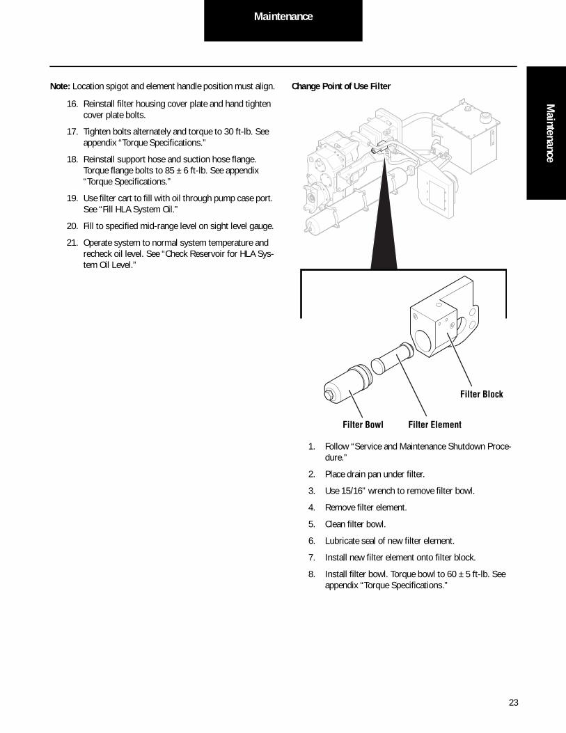
Change Point of Use Filter
1. Follow “Service and Maintenance Shutdown Proce-dure.”
2. Place drain pan under filter.
3. Use 15/16” wrench to remove filter bowl.
4. Remove filter element.
5. Clean filter bowl.
6. Lubricate seal of new filter element.
7. Install new filter element onto filter block.
8. Install filter bowl. Torque bowl to 60 ± 5 ft-lb. See appendix “Torque Specifications.”
Filter Block
Filter ElementFilter Bowl

24
Maintenance
HLA System Oil FillFill HLA System Oil
1. Follow “Service and Maintenance Shutdown Proce-dure.”
2. Use HLA filter cart to clean oil added to system.
3. Attach quick disconnect from filter cart to pump quick disconnect.
4. Use filter cart to fill system with oil.
5. For oil change and pump service, fill with oil to top of sight level gauge.
Note: Oil level will drop to mid-range level after start-up.
6. Disconnect filter cart quick disconnect.
Note: System must be keyed off for proper oil level reading.
Air Bleed Procedure
1. After filling the system, it is necessary to bleed air from the pump.
2. Push down on pump quick disconnect check valve seat to relieve air from system before start-up.
3. Install protective cap on pump quick disconnect.
Alternate Air Bleed Method
1. Tap -4 O-ring plug with hammer and drift punch prior to removal.
2. Use 3/16” hex bit to remove -4 O-ring plug from back of charge pump housing.
3. Allow air to vent for one minute minimum.
4. Reinstall -4 O-ring plug. Torque to 9 ± 1 ft-lb. See appendix “Torque Specifications.”
5. Recheck oil level after short period of operation. Oil level will be lower after initial operation and should be maintained at mid-range of sight level gauge.
Quick Disconnect
Push to Relieve Air
-4 O-Ring Plug

25
MaintenanceM
aintenance
Accumulator Precharge ProcedureHigh Pressure Accumulator Warnings and Cautions
Do not use oxygen or air for charging the accumulator. Explosion may result.
Failure to properly install thermal relief fuse cap could result in an accumulator burst event if accumulator becomes overheated.
Use only dry industrial grade nitrogen to charge the accu-mulator.
Accumulator IdentificationBladder tag should be marked with date of in service.
Accumulator Components
WARNING
IMPORTANT
BLADDER SERVICE DATE TAGINSTRUCTION:INDENT YEAR & MONTH WHENBLADDER IS PLACED INTO SERVICE
YEAR:
MONTH:
09 10 11 12 13 14
01 02 03 04 05 0607 08 09 10 11 12
Shell
Fluid Port
Anti-Extrusion Ring
Nitrogen Cap
Bladder Tag
Foot Valve Proximity Sensor
Pressure Sensor
Foot Valve
Gas Port
Nitrogen Cap/Thermal Fuse
Gas Valve

26
Maintenance
Accumulator Nitrogen Precharge Process
Note: The best time to measure accumulator pressure is at start of shift or after vehicle and accumulator cool down to ambient temperature.
For most accurate measurement, allow a minimum of 4 hours between operation and checking gas precharge.
1. Follow “Service and Maintenance Shutdown Proce-dure.”
2. Check temperature of the accumulator to get the cor-rect setting from the chart.
3. Clean dirt and debris from gas valve protective cap area of accumulator.
4. Remove gas valve protective cap to expose gas valve port.
5. Check for damage to the gas valve by looking for a bent valve core.
6. Before applying the charge kit, verify the stem is in good condition.
7. While the cap is off from the accumulator, check the thermal fuse pin for good condition.
8. Securely attach nitrogen charge kit gauge assembly to gas valve port.
9. Open pressure gauge valve per kit manufacturer’s instructions and read pressure.
10. Based on the measured temperature, compare pres-sure to pressure chart. See “Nitrogen Gas Precharge Pressure Chart.”
11. Add or vent nitrogen until pressure reaches level prescribed in chart.
12. Close pressure gauge valve.
13. Remove nitrogen charge kit gauge assembly from gas valve port.
14. Securely attach thermal relief fuse and gas valve pro-tective cap. Torque to 15 ft-lb. See appendix “Torque Specifications.”
Nitrogen Gas Precharge Pressure Chart
Note: Nitrogen gas pressure is affected by temperature and volume. After HLA system has been used, some oil will remain trapped inside accumulator.
Precharge Gas Pressure – PSI [bar = PSI*0.06895]
The formula for precharge pressure to temperature:P = 4.4(T)+1500
P = Gas Pressure (psi)T = Gas Temperature* (°F)*Gas pressure is most accurate after a long (4hrs+) down time allowing the gas temperature to equalize with the room air temperature.
Temperature Pressure
Fahrenheit (°F)
Celsius (°C)
lb/in2 (PSI) Bar
30 -1 1632 113
35 2 1654 114
40 4 1676 116
45 7 1698 117
50 10 1720 119
55 13 1742 120
60 16 1763 122
65 18 1785 123
68 20 1798 124
70 21 1807 125
75 24 1829 126
80 27 1851 128
85 29 1872 129
90 32 1894 131
95 35 1916 132
100 38 1938 134
105 41 1960 135
110 43 1982 137

27
MaintenanceM
aintenance
Failure to properly install thermal relief fuse cap could result in an accumulator burst event if accumulator becomes overheated.
Avoid suffocation. Nitrogen asphyxiates. Move to ventilated area upon opening the vent. See MSDS for more informa-tion on nitrogen gas.
Escaping nitrogen gas is extremely cold and may freeze skin. Avoid skin contact with the nitrogen gas to prevent freezing damage to skin tissues.
Vent Nitrogen Gas from Accumulator
1. Follow “Service and Maintenance Shutdown Proce-dure.”
2. Clean dirt and debris from gas valve protective cap area of accumulator.
3. Remove gas valve protective cap to expose gas valve port.
4. Check for damage to the gas valve by looking for a bent valve core.
5. Securely attach nitrogen charge kit gauge assembly to gas valve port.
6. Open pressure gauge valve per kit manufacturer’s instructions.
7. Vent nitrogen pressure to required level.
8. Close pressure gauge valve.
9. Remove nitrogen charge kit gauge assembly from gas valve port.
10. Securely attach thermal relief fuse and gas valve pro-tective cap. Torque to 15 ft-lb. See appendix “Torque Specifications.”
Avoid suffocation. Nitrogen asphyxiates. Move to ventilated area upon opening the vent. See MSDS for more informa-tion on nitrogen gas.
Do not cut, hammer or weld to the accumulator shell or high pressure fitting attached to the accumulator.
Do not use automotive type valve cores in high pressure hydraulic accumulators.
Escaping nitrogen gas is extremely cold and may freeze skin. Avoid skin contact with the nitrogen gas to prevent freezing damage to skin tissues.
Wear hearing protection. Venting accumulator nitrogen gas may make a loud whistle noise.
Add dry nitrogen slowly for first 7 bar (100 psi) to new or rebuilt accumulator. Do not exceed 2 bar (30 psi) per min-ute. Bladder damage may result if rapidly inflated.
Improper nitrogen gas pressure will result in reduced HLA system performance.
Precharge Accumulator with Nitrogen Gas (Adding Gas)
Note: Nitrogen gas pressure is affected by temperature and volume. After HLA system has been used, some oil will remain trapped inside accumulator.
1. Follow “Service and Maintenance Shutdown Proce-dure.”
2. Clean dirt and debris from gas valve protective cap area of accumulator.
WARNING
CAUTIONWARNING
CAUTION
IMPORTANT

28
Maintenance
3. Remove gas valve protective cap to expose gas valve port.
4. Remove O-ring and bladder service date tag.
5. Securely attach nitrogen charge kit gauge assembly to gas valve port.
6. Open pressure gauge valve per kit manufacturer’s instructions and read pressure.
7. Add dry nitrogen until pressure reaches level pre-scribed in chart. See “Nitrogen Gas Precharge Pres-sure Chart”:
• For new or rebuilt accumulators, add nitrogen slowly for first 7 bar (100 psi). Do not exceed 2 bar (30 psi) per minute.
• For all other accumulators, add nitrogen at any convenient rate.
Note: Accumulator will become warm during filling process.
8. Allow gas temperature to stabilize before reading pressure.
9. Close pressure gauge valve.
10. Remove nitrogen charge kit gauge assembly from gas valve port.
11. Securely attach thermal relief fuse and gas valve pro-tective cap. Torque to 15 ft-lb. See appendix “Torque Specifications.”
Typical Nitrogen Charge Kit

29
MaintenanceM
aintenance
Transfer Case
Check Transfer Case Oil Level and Fill
Note: Use only Roadranger FE 75W-90 or equivalent synthetic gear oil in transfer case.
1. Remove oil level plug and check oil level.
2. To fill transfer case:
• Remove oil fill plug and oil level plug.
• Add new clean oil through fill plug port until oil reaches bottom threads of oil level plug.
• Reinstall all plugs using thread sealer and tighten.
Change Transfer Case Oil
Note: Use only Roadranger FE 75W-90 or equivalent synthetic gear oil in transfer case.
1. Remove drain plug, oil fill plug and oil level plug.
2. Check for metal chips on drain plug magnet. Clean as required.
3. Allow oil to drain.
4. Reinstall drain plug using thread sealer and torque to 50 ft-lb. See appendix “Torque Specifications.”
5. Add new clean oil through fill plug port until oil reaches bottom threads of oil level plug (7.25 quarts/1.9 gallons).
6. Reinstall all plugs using thread sealer and tighten.
Oil LevelPlug
Breather
Oil Fill Plug
Drain Plug
(1" NPT)
(¾" NPT)(½" NPT)

30
Maintenance
Replace Transfer Case Breather
Note: The breather is located on front side (opposite hydraulic pump) of transfer case.
Removal and Installation
1. Follow “Service and Maintenance Shutdown Proce-dure.”
2. Using a 3/4” open end wrench, carefully remove breather.
3. Remove any dried thread sealant from mounting surface using putty knife or gasket scraper. Use care to keep debris out of port.
4. Apply thread sealant onto threads of new breather.
5. Thread new breather into mounting hole (3/8 NPT) and tighten securely.

Service ProceduresService Procedures
Service Procedures
Service and Maintenance Shutdown Procedure
1. Park vehicle in safe area on level ground.
2. Select N (neutral) on shift control and set vehicle parking brakes.
3. Turn ignition key to OFF. Allow accumulator to depressurize 5 minutes. Oil from accumulator will drain to the reservoir. See “Accumulator Stored Energy Drain Procedure.”
4. Allow accumulator temperature to stabilize when checking nitrogen gas precharge.
5. Use wheel chocks to block forward and reverse movement.
6. Prior to any work on HLA Electronic Control Unit (ECU), disconnect battery power to HLA system.
7. Check that accumulator pressure has vented com-pletely. Use ServiceRanger diagnostic tool or manual relief valve to check system pressure. See “Manual Relief Valve Drain Procedure.”
8. Lockout and tag vehicle under repair in accordance with your local policy.
9. Drain vehicle air system when working on pneumatic clutch valve or transfer case.
31

Service Procedures
Accumulator Stored Energy Drain Procedure
High pressure accumulator has both stored oil and nitrogen gas under pressure. Nitrogen gas remains under pressure even when stored oil has drained.
WARNING
2 Wait 5 minutes.
3 Verify pressure has drained accumulator following these (3) methods:
a. Turn ignition switch to ON and check state of charge
bar on driver display.
b. Connect ServiceRanger to check accumulator pressure bar.
c. Open manual relief valve. See Manual Relief Valve
Drain Procedure.
1 Turn ignition switch to OFF. Note: System allows controlled drain of accumulator through
Fluid
Bladder
OFF
ON
START
OFF
ON
START
Manual Relief Valve
Protective Cap
5 Min
32

Service ProceduresService Procedures
System Overhaul
The following instructions are listed for a complete system removal including all major system components.
Reservoir, Cooler and Hose Removal
1. Follow “Service and Maintenance Shutdown Proce-dure.”
2. Using ServiceRanger diagnostic tool, verify system has completely drained any pressurized oil from accumulator. If necessary, use manual relief valve to drain stored oil. See “Manual Relief Valve Drain Pro-cedure.”
3. Vent vehicle air system to pneumatic clutch valve.
4. Take oil sample. See “Capture Oil Sample Proce-dure.”
5. Drain oil from reservoir. See “Drain and Replace HLA System Oil.”
6. Use bottom port plug to drain oil from pump case.
7. Remove vehicle drivelines.
8. Disconnect wire harness from accumulator and res-ervoir sensors.
9. Remove hose bolts and hoses from accumulator, cooler and reservoir.
10. Remove cooler bolts and cooler from chassis.
11. Support reservoir with transmission jack.
12. Remove reservoir mounting bolts and reservoir.
Accumulator weighs approximately 460 pounds.
Accumulator Removal
Note: Measure the bracket center line to fluid port face prior to removal for proper placement during installation.
1. Remove middle bracket and strap from accumulator.
2. Support accumulator with transmission jack and strap to jack.
3. Remove outer bracket and straps from accumulator.
4. Slide accumulator toward rear and out of brackets.
5. Remove accumulator from under chassis.
Pump weighs approximately 350 pounds.
Pump/Motor and Transfer Case Removal
1. Follow “Service and Maintenance Shutdown Proce-dure.”
Note: Use the Eaton HLA Pump Tool (part# RR1024HY).
2. Disconnect chassis harness from HLA enclosure connector.
3. Use bottom port plug to drain oil from pump case.
4. Remove any hoses connected to pump/motor.
5. Tie HLA harness from cooler, reservoir and accumu-lator to top of pump/motor. Make sure sides are clear.
6. Remove vehicle driveshafts.
7. Drain vehicle air tanks.
8. Support pump/motor with transmission jack.
9. Disconnect air supply line to pneumatic clutch valve.
10. Tie off supply line away from pump sub-frame.
11. Remove 4 vibration mounting bolts from sub-frame chassis.
CAUTION
CAUTION
33

Service Procedures
12. Remove bolts and disconnect right side pump sub-frame.
13. Remove pump/motor from top side (for removal from bottom, go to step 14):
a. Thread 5/8" eyebolts into threaded holes on pump.
b. Attach hoist to eyebolts and transfer case lifting lugs.
c. Lift pump/motor and slide to right side.
d. Lift pump/motor and transfer case up and out of chassis.
14. Remove pump/motor from bottom side (for removal from top, go to step 13):
a. Use transmission jack to lift pump/motor and transfer case and slide forward.
b. Lower transmission jack.
Note: Make sure all HLA components are free from chassis.
c. Lift front of vehicle.
d. Remove pump/motor from under chassis.
Pre-install Checklist
1. Install one-inch 90º swivel fitting on pump cooler port.
2. Orient fitting straight down and torque to 110.5 ± 2.5 ft-lb. See appendix “Torque Specifications.”
3. Install one-inch 90º nut-washer O-ring seal fitting on return manifold cooler port:
• Thread fitting to O-ring.
• Orient fitting down.
Note: Do not tighten fitting.
4. Attach Warning, Caution and Important stickers to pump and components.
5. Fill transfer case with oil. See “Check Transfer Case Oil Level and Fill.”
6. Disconnect connector to transfer case proximity sensor and tie out of way of installation.
34

Service ProceduresService Procedures
Pump/Motor and Transfer Case Installation
1. Install pump/motor from top side (for installation from bottom, go to step 2) after installing accumula-tor.
Note: Use the Eaton HLA Pump Tool (part# RR1024HY).
2. Install pump/motor from bottom side (for installa-tion from top, go to step 1):
a. Position pump/motor on transmission and strap down.
b. Remove right side sub-frame from pump/motor.
c. Make sure vehicle front is lifted and position pump/motor under chassis.
d. Lower chassis onto pump/motor. Make sure no wires or frames are caught between.
e. Use transmission jack to lift pump/motor and push forward against front cross member.
f. Lift pump sub-frame above chassis frame mounts.
g. Move pump/motor toward rear over chassis frame mounts.
h. Lower pump/motor into place.
i. Reinstall right side sub-frame and torque bolts (see appendix “Torque Specifications.”):
• 5/8-11bolts = 188 ± 19 ft-lb
• 3/4-10 bolts = 336 ± 34 ft-lb
j. Install vibration mounting bolts and torque to 86-123 ft-lb. See appendix “Torque Specifica-tions.”
k. Reconnect transfer case proximity sensor con-nector.
3. Remove all shipping plugs and covers.
4. Remove ECU shipping plug.
5. Install vehicle drivelines.
6. Lube U-joints.
Accumulator Installation
1. Install accumulator into outer brackets straps and secure with bolts.
2. Adjust accumulator into for/aft position.
3. Rotate accumulator until proximity sensor port is horizontal and outwards of chassis.
4. Install middle bracket and strap and secure with bolts.
5. Torque all bracket strap bolts to 26 ft-lb. See appen-dix “Torque Specifications.”
Accumulator Shield
35
Service Procedures
Reservoir, Cooler and Hoses Installation
1. Install return manifold onto reservoir.
Note: Use 7/16” open end return manifold studs with O-ring on reservoir.
2. Mount reservoir onto chassis.
3. Install hoses:
Note: Lubricate suction, HP and return hose O-rings with petroleum jelly or Eaton silicon lube (part #71203).
a. Suction hose
b. Cooler hose on pump side
c. High pressure hose
d. Return hose:
• Install left side flange onto pump, return hose and right side flange.
• Pull return hose end into return manifold studs.
• Secure flanges with bolts.
e. Cooler outlet hose
4. Install cooler to return manifold hose.
5. Install foot valve proximity sensor to accumulator and torque to 95 ft-lb. See appendix “Torque Specifi-cations.”
6. Install pressor sensor to accumulator and torque to 56 ft-lb. See appendix “Torque Specifications.”
7. Connect wire harness to accumulator, cooler and reservoir sensors.
8. Securely tie down wire harness to hose and frame.
9. Fill transfer case with oil. See “Check Transfer Case Oil Level and Fill.”
10. Add oil to reservoir and fill to top of sight level gauge. See “Add Oil to Reservoir.”
Note: Refer to “Pump Fill Procedure” in Roadranger lubricant section at www.roadranger.com.
11. Open air bleed plug.
Note: Oil level will drop approximately 1" after start-up.
12. Reinstall plug on pump case port.
13. Make sure all wire and hose connections are secure.
14. Turn ignition key to ON and check for fault codes/lights.
36

Service ProceduresService Procedures
Swash Carrier Assembly
Removal
1. Remove 2 hex socket head cap screws (87), 2 Metric washers (150) and the feedback sensor (54).
2. Remove 4 UNF hex socket cap screws (55) and the swash sensor plug (153) from the housing subas-sembly. Remove the Nitrile o-ring from the swash sensor plug (153).
3. Loosen the hex socket cap screw and remove the magnet carrier (170).
Installation
1. Install the magnet carrier (170) and tighten to 26.5 ±1.5 in-lb.
Make sure the swash sensor plug (153) is orientated prop-erly during installation. If the swash sensor plug (153) will not fully install, remove and verify proper orientation.
2. Install the swash sensor plug (153) with lubricated Nitrile o-ring into the housing subassembly using 4 UNF hex socket cap screws (55). Torque screws to 11 ±1.1 ft-lb.
3. Install feedback sensor (54), sticker or other identifi-cation away from the pump, with 2 Metric washers (150) and 2 hex socket head cap screws (87) as shown. Before tightening screws, adjust feedback the sensor so the screws are located at the center of the slot in the feedback sensor (54). Torque the screws to 26.5 ±1.5 in.lb.
4. Swash sensor calibration will be required after installation is complete.
87
150
55
153
170
54
CAUTION
37

Service Procedures
Charge Pump Replacement
Removal
1. Remove fasteners and cover assembly from pump assembly.
2. Remove dowel pins from pump assembly.
3. Remove O-ring from groove in cover assembly.
4. Remove fasteners and impeller subassembly from pump assembly.
5. Remove zero-leak plug from mating port.
6. Remove internal retaining ring from cover machin-ing.
7. Remove seal sleeve from impeller.
8. Remove zero-leak plugs, fasteners from centrifugal pump housing subassembly.
9. Remove centrifugal pump housing subassembly.
10. Remove O-rings in end cover subassembly.
11. Remove transfer tube.
Installation
Note: Check ports for any blockage prior to installation. A blocked port will cause severe pump damage. Maintain clean environment to eliminate contaminants or debris in components during assembly.
1. Install O-ring onto transfer tube and lubricate.
2. Install transfer tube.
3. Install two O-rings in end cover subassembly.
4. Install centrifugal pump housing subassembly onto end cover subassembly.
5. Secure with fasteners and torque to 97 ± 9.7 ft-lb. See appendix “Torque Specifications.”
6. Install zero-leak plugs and torque to 63 ± 6.3 ft-lb. See appendix “Torque Specifications.”
7. Use installation tool provided to install seal sleeve onto impeller.
Note: Make sure seal sleeve is pressed to shoulder on impeller.
38

Service ProceduresService Procedures
8. Lubricate and install seal into cover machining.
Note: Make sure orientation is correct.
9. Install internal retaining ring into cover machining.
Note: Make sure retaining ring is fully seated into groove.
10. Install zero-leak plug into mating port and torque to 9.0 ± 1.0 ft-lb. See appendix “Torque Specifications.”
11. Install impeller subassembly onto pump assembly.
Note: Make sure impeller is engaged over splines.
Important: Do not reuse fastener when securing impeller subassembly. Replace old fastener with new.
12. Secure impeller subassembly with washer and fas-tener. Torque fasteners to 39 ± 3.9 ft-lb. See appen-dix “Torque Specifications.”
Note: Pump shaft will rotate if not secured prior to final tight-ening of fastener. A nylon strap wrench may be used to hold impeller subassembly while torquing fastener.
13. Install O-ring into groove in cover subassembly.
Note: Lubricate with petroleum jelly if necessary.
14. Install dowel pins into pump assembly.
15. Install cover subassembly onto pump assembly.
Note: Make sure O-ring has not fallen out of groove.
16. Install washers and fasteners and torque fasteners to 16 ± 1.6 ft-lb. See appendix “Torque Specifications.”
IMPORTANT
39

Service Procedures
Transfer Case Replacement
If pump/motor removal is also required, see “Pump/Motor and Transfer Case Removal” for correct procedure.
Transfer case weighs approximately 500 pounds.
Removal
1. Follow “Service and Maintenance Shutdown Proce-dure.”
2. Drain oil from transfer case.
3. Remove front and rear driveshafts connected to transfer case.
4. Disconnect harness connectors from transfer case.
5. Vent vehicle air system.
6. Disconnect airlines from pneumatic clutch valve to shift piston fittings.
7. Support transfer case with transmission jack.
8. Use 1-1/8" wrench to remove transfer case bolts from pump/motor.
9. Remove transfer case bolts from sub-frame.
10. Place oil pan under pump and transfer case.
11. Slide transfer case forward away from pump to free shaft.
12. Lower transfer case and remove from vehicle.
13. Check O-ring between transfer case and pump face for wear, cuts or damage. Replace as needed.
Installation
1. Lift new transfer case and install in vehicle.
2. Slide transfer case back toward pump.
Note: Make sure transfer case O-ring is in place.
3. Install transfer case to pump and secure with bolts.
4. Torque bolts to 336 ± 34 ft-lb. See appendix “Torque Specifications.”
5. Install transfer case onto sub-frame and secure with bolts.
6. Support transfer case with transmission jack.
7. Connect airlines from pneumatic clutch valve to shift piston.
8. Connect harness connectors to transfer case.
9. Reinstall front and rear driveshafts connected to transfer case.
10. Fill transfer case with Roadranger FE 75W-90 lubri-cant.
11. Reinstall air lines to transfer case shift piston fit-tings.
CAUTION
40

Service ProceduresService Procedures
Transfer Case
Warnings and CautionsImportant Information - Please Read CarefullyUpon receipt of product, immediately inspect for any indica-tion of rough handling or damage in transit. This includes but is not limited to: scuffed paint, broken or damaged containers, broken or cracked housings, bent shafts, metal deformation, or shift in alignment of components.
Any evidence of damage or missing parts should be reported immediately to the carrier and a claim entered.
All units are shipped without oil!
DO NOT OPERATE until unit has been filled to the proper level with the specified oil grade. Failure will occur if bearings and gears are not properly lubricated. Refer to Lubrication and Oil Filling Instructions.
The following WARNING and CAUTION information is sup-plied to the Buyer for their protection and to provide the Buyer with years of trouble free and safe operation of your product.
Read ALL instructions prior to operating transfer case. Injury to personnel or transfer case failure may be caused by improper installation, maintenance or operation.
Buyer shall be solely responsible for determining the ade-quacy of the product for any and all uses to which Buyer shall apply the product. The application by Buyer shall not be subject to any implied warranty of fitness for particular purpose.
For safety, Buyer or user should provide protective guards over all shaft extensions and any moving apparatus mounted thereon. The user is responsible for checking all applicable safety codes in their area and providing suitable guards. Failure to do so may result in bodily injury and/or damage to equipment.
Hot oil can cause severe burns. Use extreme care when removing lubrication plugs and vents.
Make certain that the power supply is disconnected before attempting to service or remove any components. Lockout the power supply and tag it to prevent unexpected applica-tion of power.
TORSIONAL VIBRATIONS, emanating from many modern diesel engines, can cause severe damage to power train components, resulting in premature failure. To insure the integrity of the power transmission system, a torsional vibration analysis should be performed and suitable vibra-tion dampening components utilized, when indicated by the analysis. We are not responsible for damage or failure resulting from diesel engine generated torsional vibrations.
Lifting supports including eyebolts are to be used for verti-cally lifting the gearbox only and no other associated attachments or motors.
If the transfer case cannot be located in a clear and dry area with access to adequate cooling air supply, precautions must be taken to avoid the ingestion of contaminates such as water, and the reduction in cooling ability due to exterior contaminates.
Mounting bolts should be routinely checked to ensure that the unit is firmly anchored for proper operation. Refer to torque chart in the Appendix for proper torque specifica-tions when tightening bolts.
In the event of the resale of any of the goods, in whatever form, Resellers/Buyers will include the following language in a conspicuous place and in a conspicuous manner in a written agreement covering such sale:
The manufacturer makes no warranties or representations, express or implied, by operation of law or otherwise, as to the merchantability or fitness for a particular purpose of the goods sold hereunder. Buyer acknowledges that it alone has determined that the goods purchased hereunder will suitably meet the requirements of their intended use. In no event will the manufacturer be liable for consequential, incidental or other damages. Even if the repair or replacement remedy shall be deemed to have failed of its essential purpose under Sec-tion 2-719 of the Uniform Commercial Code, the manufacturer shall have no liability to Buyer for consequential damages.
Resellers/Buyers agree to also include this entire document including the warnings and cautions above in a conspicuous place and in a conspicuous manner in writing to instruct users on the safe usage of the product.
This information should be read together with all other printed information.
CAUTION
WARNING
CAUTION
41

Service Procedures
Model Identification
42

Service ProceduresService Procedures
A name plate is mounted on every transfer case that is assem-bled at the factory. This nameplate provides the part number, the ratio and basic description, unit serial number, and date unit was assembled, and recommended oil type. Do not paint over, remove, or tamper with the name-plate, as this is the only type of identification for warranty repairs or replacement parts.
Figure 1. Transfer Case, Front View
43

Service Procedures
General Information
The transfer case incorporates AGMA class 10 helical gears that run on taper roller bearings.
SplinesThe transfer case has a 13T-8/16 internal spline on the input (motor/pump) gear. There are (2) 2-3/4 - 10 external splines (1) on each end of the input shaft supporting 1810, 1760, or 1710 series End Yokes.
Oil CirculationExtensive testing was done on this transfer case gearbox to optimize the quantity of oil. The transfer case has special oil port locations that cause the oil to flow thru the bearings with-out the need for external pumps. Oil volume is critical to make this feature work and the oil level should be checked fre-quently.
Motor/Pump PadThe motor/pump pad is integral to the transfer case unit.
Input/Output ShaftThe Input shaft of the transfer case is mounted on taper roller bearings which support the output gear via ball bearings. An intermediate shaft is located between the input and output shafts. A shift fork mounted on a parallel shaft engages and disengages the output gear thus driving the output shaft.
Motor/Pump ShaftThe motor/pump shaft of the transfer case is integral with the input gear mounted on taper roller bearings.
Installation Instructions
Figure 2. Showing Mounting Pads
This unit is designed to be driven with a short coupled drive line connection to the input shaft. The input WILL NOT accept any overhung loads (i.e. belt sheaves, sprockets, or severely angled drive lines). For over hung load applications, contact Engineering.
Mounting Procedures for Transfer CaseThe transfer case is to be supported on a rigid foundation using the mounting holes (4) each side (3/4-10 taps) pro-vided in the transfer case housing. Inadequate mounting foundation may result in misalignment or excessive stress on the transfer case housing. This can cause undue noise, over-heating, and possible failure.
Note: To prevent loosening and misalignment, bolts must be tightened to recommended torque specification shown in Table 1 on page 53.
Failure to mount the transfer case in the specified orienta-tion will cause premature failure!
Alignment and Installation of U-JointsTo realize the longest possible life of the transfer case, care in obtaining the best possible alignment must be maintained between the center line of the transfer case and the center line of drive/driven units.
1. It is extremely important that the forks of drive shafts between the transfer case and drive/driven units lie in the same plane. This will prevent severe vibrations from occurring.
2. The center lines of the transfer case and the drive/driven units must be within the acceptable offset lim-its as determined by the U-Joint manufacturer to prolong the life of the universal joint needle bearings.
3. It is extremely important that the center lines of the transfer case and drive/driven units are parallel. This will further prevent vibrations which cause prema-ture transfer case bearing failure.
Installation of Hydraulic Motor/Pump to Transfer CaseThe motor/pump pad on the transfer case is a four-bolt mounting, with 3/4-10 UNC threads. Tighten to the recom-mended torque specification shown in Table 1 on page 53.
Align the spline of the hydraulic motor/pump to the internal spline. DO NOT use the mounting holes to seat the hydraulic pump onto to the pump pad.
Note: O-rings must be replaced anytime the hydraulic pump is removed from the transfer case.
CAUTION
44
Service ProceduresService Procedures
Repair and Rebuilding InstructionsDisassembly Instruction
Make certain that the power supply is disconnected before attempting to service or remove any components.
1. Lockout the power supply and tag it to prevent unex-pected application of power.
2. Drain oil while unit is still warm.
HOT oil can cause severe burns. Use extreme care when removing lubrication plugs and vents.
3. Properly support the transfer case and remove all retaining bolts from the frame mounting bolts.
Note: Hydraulic motor/pump may remain connected however it is not recommended, for ease of disassembly and cleaning parts, that the motor/pump be removed.
4. Remove the hex nuts retaining the end yokes and remove from shafts on both sides.
To avoid oil leaks, all o-rings are to be replaced any time the motor/pump is removed.
5. Referring to Figure 3, place the transfer case on a flat surface with the pump pad facing down. Remove the two (2) dowel pins and all the cap screws before attempting to separate the housing halves. Use the cap screws in the threaded separating holes to split the housing halves. Slightly tap the front housing with a wooden mallet (or equal) to release the bear-ings and gears from the bearing cups.
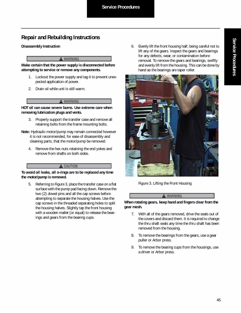
6. Evenly lift the front housing half, being careful not to lift any of the gears. Inspect the gears and bearings for any defects, wear, or contamination before removal. To remove the gears and bearings, swiftly and evenly lift from the housing. This can be done by hand as the bearings are taper roller.
Figure 3. Lifting the Front Housing
When rotating gears, keep hand and fingers clear from the gear mesh.
7. With all of the gears removed, drive the seals out of the covers and discard them. It is required to change the thru shaft seals any time the thru shaft has been removed from the housing.
8. To remove the bearings from the gears, use a gear puller or Arbor press.
9. To remove the bearing cups from the housings, use a driver or Arbor press.
WARNING
WARNING
CAUTION
WARNING
45

Service Procedures
Figure 4. Housing Half with Internal Assemblies Identified.
Cleaning and Inspection Instructions1. Replace all oil seals, o-rings, washers, snap rings
etc. as a part of any maintenance or overhaul proce-dure. Replace shims that are damaged or destroyed in disassembly.
2. Clean all parts using EPA/OSHA approved solvents or by steam cleaning. Parts must be dried and oiled immediately.
3. Examine all parts carefully for grit, dirt and abrasives and reclean them if necessary.
4. For faces that have been joined with a sealant, scrape off old sealant material. Clean these faces with a sol-vent.
5. De-burr with a stone or file the vicinity of pusher screw locations.
Bearing InspectionWe strongly recommends replacing all used bearings as a normal practice during repair or rebuild of the transfer case. However, if the bearings will be reused, the following provides pertinent information prior to reuse.
1. Thoroughly wash and soak the bearings as neces-sary in clean solvent.
Never dry bearings with compressed air. Do not spin bear-ings without lubrication.
2. Oil bearings with approved oil immediately after cleaning and protect them from contamination.
3. Inspect bearings for roughness of rotation. Replace the bearing if roughness is found.
4. Inspect bearing for corrosion, scored, scratched, cracked, pitted or chipped races, and for indication of excessive wear. Replace the bearing if any of these defects are found.
5. Handle new replacement bearings with care. Do not remove them from their packaging until immediately
before they are to be installed.
CAUTION
46

Service ProceduresService Procedures
Housings and Cast Parts Inspection
1. Replace cast parts or housings that are cracked.
2. Inspect bearing bores for grooved, burred or galled conditions that would indicate that the bearing has been turning in its housing. If the damage cannot be repaired to like-new condition with a fine crocus cloth, replace the part. Bore diameters must not exceed the maximum dimension shown in the wear limits Table 2 on page 53.
3. Inspect machined surfaces for burrs, nicks or scratches that have material that extends above the surface. Remove material with crocus cloth or soft stone. Replace part if necessary.
4. Inspect all threads for damage. Chase damaged threads with a tap.
Shaft, Gear, Sliding Collar, and Piston Inspection
1. Inspect bearing journals for grooved, burred or galled conditions that would indicate that the bearing inner race has been turning on the journal. Use cro-cus cloth to repair the damage, or replace the part. Bearing journals must not be less than the minimum diameters shown for the wear limits of Table 2.
2. Inspect seal ring grooves and ring grooves for wear or damage.
3. Inspect splines for stripped, twisted, chipped or burred conditions. Remove burrs with a soft stone. If wear or other defects exists on the sides of the tooth, replace the part.
4. Inspect gears for scuffed, nicked, burred or broken teeth. Inspect gear teeth for wear that may have changed the original profile. Replace the gears if defects are found.
Reassembly Instructions
Before reassembling the transfer case, make sure that clean-ing and inspection instructions have been followed.
1. Install the bearing cups into the rear housing half (item #2) Figure 5.
Figure 5. Rear Housing Half
2. Install the bearing cups into front housing half (item #1). Cups should be installed from the outside and be tapped into the housing until flush with the outer-machined surface for now.
3. Install o-ring (item #38) and bushing (item #21) into 1.375 dia. hole.
Note: Later in the assembly procedure when the housing halves are brought together and ready to set the bearing endplay will the bearing cups be driven further into the housing.
Figure 6. Picture showing cups installed in front housing half (item #1).
47

Service Procedures
Input Gear Assembly Instructions
1. Heat tapered bearing cones (item #23) to 250°F in an oven or induction coil.
Do not exceed 250°F.
2. Install the cones onto the pinion shaft (item #16) as shown in Figure 7. Apply a continuous force on the inner race until cooled to room temperature. This is necessary to ensure that it remains properly seated.
Figure 7. Input gear assembly
Intermediate Shaft/Gear Assembly Instructions
1. Heat intermediate gear (item #10) and bearings (item #22) to 250°F in an oven or use an induction coil.
Do not exceed 250°F.
2. Install the key (item #61), gear, and bearings onto the pinion/shaft (item #15) as shown in Figure 8. Apply a continuous force on the inner race until cooled to room temperature. This is necessary to ensure that the gear and cones remain properly seated
Figure 8. Intermediate Assembly
Output Gear/Thru Shaft Assembly
1. Place bearing (item #66) into gear (item #9). Install snap ring (item #46) into gear groove above bearing.
2. Place new slinger (item #39) onto the side of the shaft (item #13) that has one land.
3. Heat bearing cone (item #44) to 250°F in an oven or use an induction coil.
Do not exceed 250°F.
4. Install heated bearing onto shaft (item #13) holding the slinger in place. Apply a continuous force on the inner race until cooled to room temperature. This is necessary to ensure that the gear and cones remain properly seated.
5. Place shift collar (item #11) onto shaft pre-assembly with spline end as shown in Figure 9.
6. Press gear/bearing pre-assembly onto the second land using a bearing driver. Only apply force to the inside of the bearing race to insure there is no dam-age to bearing cage or bearing balls.
7. Place spacer (item #18) as shown in Figure 9.
CAUTION
CAUTION
CAUTION
48

Service ProceduresService Procedures
8. Press second ball bearing (item #66) onto shaft using a bearing driver into position shown in Figure 9. Only apply force to the inside of the bearing race.
9. Heat remaining bearing cone (item #44) to 250°F in an oven or use an induction coil.
Do not exceed 250°F.
10. Install heated bearing onto shaft (item #13). Apply continuous force on the inner race until cooled to room temperature.
Figure 9. Output Assembly
CAUTION
49

Service Procedures
Assembly of Shift MechanismCap and Piston Assembly (Figure 10)
1. Place the shifting shaft (item #14) into a clamp in an upright position with the female thread pointing up.
2. Insert the bushing (item #21) and o-ring (item #38) into the cap (item #5). Slide cap assembly onto the shaft as shown.
3. Nest both springs (items #32 and 33) into the open-ing of the cap.
4. Place piston (item #19) on top of the springs and cap assembly w/ 1" counter bore, face down and aligned with the shaft.
5. Secure the piston to the shaft using lock washer and bolt (items #24 and #28). Torque the bolt to 30-36 ft-lb.
Figure 10. Cap and Piston Assembly
Installation into Housing
1. Place o-ring (item #37) into the bottom o-ring grove in housing (item #2).
2. Slide the sleeve (item #3) into housing bore, chamfer first. Ensure sleeve bottoms out in the housing with-out displacing o-ring.
3. Place 2nd o-ring (item #37) into the top o-ring groove in the housing (item #2) just above the sleeve (item #3) and below the snap ring groove.
4. Place o-ring (item #36) on piston (item #19).
5. Slide piston assembly into piston housing (item #3).
6. Secure assembly with retaining ring (item #26).
7. Apply air pressure to check for air leaks.
8. Assemble lower shaft into position (see Figure 9) and place the fork (item #17) on to the air cylinder threaded shaft (item #14). Make sure the fork legs rest in the collar (item #11) groove.
9. Apply air pressure to the “air engage” port in order to move the cylinder to shift the fork and engage the collar with the gear.
10. Measure fork clearance with gear and add shims (items #47-49) to bring fork face in shifted gear position.010-.030 away from gear face (Figure 11 is shown in the disengaged position, however, the gap is actually for the engaged position).
11. After shim pack is determined, apply loctite #243 to female threads of shift shaft (item #12). Thread to air cylinder shaft (item #14) and torque to 100-120 ft-lbs.
Figure 11. Shift/Collar Assembly
50

Service ProceduresService Procedures
Housing Assembly
1. Install the input shaft/gear assembly (Figure 7) and intermediate shaft/gear assembly (Figure 8) into the rear housing half with the input side of the gear fac-ing down, or towards the pump/motor pad.
Tip: Apply a small coat of oil to the outside of the bearing cone and inside of cup to insure bearing lubrication at startup.
2. Place approximately a 1/8” bead of Loctite #587 or equivalent sealant, along the sealing surface of the housing half.
Applying too much sealant to sealing surfaces may cause excessive sealant to break loose inside gear box and dam-age gears, bearings, or splines.
3. Place the housing halves together. Housings must be oriented in the same direction for the dowel pins holes to line up properly.
4. Press in the two dowel pins (item #34) to insure proper alignment.
5. Install the cap screws (item #30) using Loctite #243 on threads, and torque to 45-54 ft-lb.
6. Shim covers to provide.003-.005 end play on all bearings.
7. Apply Loctite ultra blue #587 to bearing retainers and covers.
8. Install cover bolts (item #31), using Loctite #243 on the threads, and torque to 30-36 ft-lb.
9. Turn over the assembled transfer case to install the input seal. Apply a small amount of oil to seal lips to allow the seal to properly seat. Apply a thin coat of Loctite #609 to the seal O.D. and press into place.
Do not use sharp objects for pressing in seals. Press only the outer edges of the seal to keep from bending the seal casing.
10. Apply Silver Streak-200s" to thru shaft splines that mate with end yokes.
11. Both end yokes (ears or forks) must be in time with each other during assembly.
12. Apply Loctite #587 under nut washers.
13. Tighten yoke nuts to 200 ft-lb.
Preventative Maintenance
Oil flow and circulation in a transfer case is one of the most important features to give all internal parts the maximum life. The transfer case design incorporates several key features from previous designs. When filled to the proper level, oil will be circulated within the box to each set of bearings for smooth operation. Because the pump splines and the input shaft are exposed to the oil within the transfer case do not apply grease or any type of corrosion prevention materials to the internal spline, as these will contaminate the transfer case oil.
Note: All transfer cases are shipped without oil.
Verify that the drain plug is tightened to 50 ft-lb.
1. Fill the transfer case to MAX oil level of the oil level plug.
Do not over fill, as this will result in overheating and possi-ble failure of the transfer case.
2. It is recommended to maintain clean oil and make oil changes part of the preventative maintenance proce-dure. Refer to the appendix and “Maintenance and Inspection Intervals” table for oil change frequency.
3. Stop engine before attempting to check or add oil.
4. Clean around the oil fill hole before checking or add-ing oil.
5. Drain oil while the unit is still warm.
Hot oil can cause severe burns. Use extreme care when removing lubrication plugs and vents.
6. Inspect and clean magnetic drain plug for contami-nation or metal particles before replacing.
CAUTION
CAUTION
CAUTION
WARNING
51

Service Procedures
Oil Capacity
When changing the oil some residual is left in the box, this will require less oil to fill the box. Only fill to the MAX oil level, to the oil level plug otherwise overheating may occur.
Maximum Operating oil temperature for all standard oils: 210° F (99ºC).
Maximum Operating oil temperature for all synthetic oils: 250ºF (121ºC).
Recommended Oil Type
RoadRanger FE 75W90 or synthetic equivalent.
General InformationTools Needed
• Sockets: 1/2", 9/16", 24MM Deep, 2-3/4"
• Allen Wrench: 3/8"
• Eye Bolts: 3/4"
• Gear Pullers (5.625" diameter min.)
• Scraper Blade
• Loctite 243, 587, 609 or equivalent
• Wooden Mallet
• Snap Ring Pliers
• Expansion Plug Remover
• Torque Wrench
• Large Flat Head Punch
• Adjustable Open-end Wrench
• Large Screw Driver
• Crocus Cloth
• Seal Driver
• Bearing Driver
• Oven or Induction Coil
• Hot Gloves (300°F)
DefinitionsTip: Provides information that can help properly complete a specific procedure.
SAE: Society of Automotive Engineers. This group defines standards in the automotive industry to allow for interchange-ability between engine and component manufacturers.
TIR: Total Indicator Reading. This is a measurement to deter-mine endplay on a rotating element.
Increaser Ratio: When the output gears/shafts are turning faster than the input shaft.
Decreaser Ratio: When the output gears/shafts are turning slower than the input shaft.
52

Service ProceduresService Procedures
Table 1: Bolt Tightening Torques
SIZE GRADE 5 GRADE 8
5/16-18 20 ft-lb 29 ft-lb
3/8-16 36 ft-lb 54 ft-lb
1/2-13 75 ft-lb 105 ft-lb
5/8-11 150 ft-lb 210 ft-lb
3/4-10 270 ft-lb 375 ft-lb
Plug Tightening Torques
Breather 3/8-18 NPT 15 ft-lb
Drain Plug 12-14 NPT 50 ft-lb
Fill Plug 1-11.5 NPT 35 ft-lb
Table 2: Wear Tolerances*
Location Min Max
Input Bore 4.123” 4.124”
Intermed. Bore 4.748” 4.749”
Output Bore 6.2977” 6.2987”
Gear Bore 6.4960” 6.4985”
Input Shaft Dia. 2.2510” 2.2519”
Intermed. Shaft Dia. 2.2510” 2.2519”
Output Shaft Dia. 4.3317” 4.3327”
Gear Land Dia. 4.7245” 4.7251”
*Replace components if not to tolerance.
53

Service Procedures
Input Shaft Seal Replacement
Removal
Note: Transfer case shaft seals are located behind the drive-line end yokes on the input and output shafts.
1. Follow “Service and Maintenance Shutdown Proce-dure.”
2. Place clean recycle pan under drain plug to capture oil drained from unit.
Note: Drain plug is located on front side (opposite hydraulic pump) at bottom of unit.
3. Remove drain plug, 1/2 NPT using a 9/16" open end wrench and drain oil from unit.
4. If removing one seal:
a. Disconnect/remove driveline shaft of seal being replaced.
Note: Joint at transfer case end yoke must be disconnected to access end yoke securing nut.
b. Remove securing nut using either 1/2" or 3/4" air impact wrench with 2-3/4 socket and 2-1/2 extension.
Note: If air wrench is unavailable, use breaker bar with 2-1/2 extension to access recessed nut.
Note: If removing both seals, leave one driveline connected for easier removal of end yoke securing nut.
5. If removing both seals:
a. Loosen nut but do not remove totally.
b. Remove second driveline connected to end yoke.
6. Secure other end yoke to keep from rotating and remove second end yoke securing nut.
7. Remove securing nut from end yoke/yokes and slide yoke/yokes from shaft exposing seals on bearing retainer cover.
8. Use seal puller (cycle/crescent style) to remove input shaft seals from cover.
9. Clean seal cavity as necessary.
Seal
- OR -
Half RoundYoke (1760)
Full RoundYoke (1810)
54
Service ProceduresService Procedures
Installation
1. Follow “Service and Maintenance Shutdown Proce-dure.”
2. Using spray parts cleaner, clean splines of input shaft from any rust or contamination that may have accumulated.
3. Remove seal from packaging. Included within pack-age is cadmium plated “Seal Driver”. Using this seal driver, insert seal into bore of cover and seat seal by tapping perimeter of driver with hammer, using alter-nating strikes from side to side, top to bottom, then in a circular motion until seal is properly seated.
Note: Seal should be seated equally around its perimeter.
4. Apply thin coat of anti-seize to spline of input shaft.
5. Reinstall end yoke onto splined shaft.
Note: Make sure front and end rear yokes on transfer case are “in-time” with each other.
6. Thread securing nut onto shaft and tighten. Torque to 200 ft-lb. See appendix “Torque Specifications.”
7. Reinstall driveline shafts.
8. Refill unit with oil and check for leaks.
Accumulator Replacement
Accumulator weighs approximately 430 pounds.
Removal
1. Follow Service and Maintenance “Shutdown Proce-dure.”
2. Vent accumulator nitrogen gas precharge. See “Vent Nitrogen Gas from Accumulator.”
3. Disconnect wire harness from accumulator sensors.
4. Remove high pressure hose from accumulator.
Note: Approximately 1 gallon will drain from accumulator port and hose.
5. Measure and mark accumulator position from fluid port to mounting bracket.
6. Remove middle accumulator bracket.
7. Support accumulator with transmission jack and strap to jack.
8. Remove bolts and outer bracket straps.
9. Slide accumulator toward rear and out of brackets.
10. Remove accumulator from under chassis.
Installation
1. Install accumulator into outer brackets and straps and secure with bolts.
2. Adjust accumulator using measurement and marks into for/aft position.
3. Rotate accumulator until proximity port is horizontal and outwards of chassis.
4. Install middle bracket and secure with bolts.
5. Torque all bracket bolts to 26 ft-lb. See appendix “Torque Specifications.”
6. Install O-ring (new recommended) on high pressure hose with petroleum jelly or Eaton silicon lube (part #71203).
7. Reinstall high pressure hose.
8. Reconnect wire harness to accumulator sensors.
9. Install accumulator shield.
10. Check and stamp installation date tag.
CAUTION
55

Service Procedures
Accumulator Bladder Repair
Vent the accumulator nitrogen gas pre-charge prior to ser-vicing using the petcock on the nitrogen gage assembly.
Avoid suffocation. Nitrogen asphyxiates and causes oxygen to dissipate in the room. It is recommended that the service is completed in a well ventilated area.
Escaping nitrogen gas is extremely cold and may freeze skin. Avoid skin contact with the nitrogen gas to prevent freezing damage to skin tissues.
Be sure to allow time to complete the bladder replacement so that the interior of the accumulator is not open to the atmosphere for longer than one hour. Time exceeding one hour may allow corrosions to form on the interior surface, resulting in bladder failure during operation.
Tools
• Bladder service kit
• HLA Service Manual TRSM1200
• Lock nut Spanner wrenches
• Valve core torque wrench
• Torque wrench with 325 foot pounds
• Bladder pull rod kit
• Thermal indicator
• Degreaser and rags
• 1/16th adjustable wrench
• 2 ¾ inch wrench
Removal
1. Follow “Service and Maintenance Shutdown Proce-dure.”
2. Clean any dirt and debris from the gas valve protec-tive cap area of the accumulator.
3. Remove gas valve protective cap to expose gas valve port.
4. Remove O-ring and bladder service date tag.
5. Securely attach nitrogen charge kit gauge assembly to gas valve port.
6. Open the pressure gauge valve per the kit manufac-turer's instructions. Follow the nitrogen gas venting procedure. Open the petcock slowly to control the venting of the nitrogen gas.
7. Vent until pressure is zero.
8. Close the pressure gauge valve and remove the nitrogen charge kit gauge assembly from the gas valve port.
9. Remove gas valve core using gas valve tool. Do not reuse valve core.
10. Remove the accumulator from the vehicle, thor-oughly clean it to remove any dirt and debris, and secure it in a clean location to prevent movement and contamination.
WARNING
CAUTION
IMPORTANT
56

Service ProceduresService Procedures
11. Using a spanner wrench, remove the fluid port lock nut.
12. Remove spacer ring. If necessary, tap spacer ring with plastic hammer to loosen.
13. Loosen and push the fluid port into accumulator shell.
14. Reach into shell opening and remove O-ring, flat ring and backup ring from fluid port.
15. Reach into shell and remove anti-extrusion ring:
a. Pull ring off fluid port.
b. Fold in half.
c. Pull ring out of port through fluid side opening of shell.
16. Remove fluid port from shell.
17. Remove bladder stem lock nut from gas side of the accumulator.
18. Push gas valve stem into accumulator shell.
19. Using a shop rag or towel, firmly grab and pull and remove the bladder from the fluid port end. Discard the old bladder. A used bladder cannot be re-installed.
20. Clean any debris and contamination from the accu-mulator shell interior.
Visual Inspection
• Shell: Make sure the inside is free of any debris, rough spots or chafe marks. If any interior or exte-rior damage is found, contact Eaton for proper repair or replacement instructions.
• Fluid port: Make sure the poppet moves freely. Press the poppet and rotate it 90 degrees. If any damage is found, replace the fluid port.
• Anti-extrusion ring: Look on the rubber ring for any cracks, embrittlement, aging, or damage. If any defects or damage is found, replace the Anti-extru-sion ring.
• All other parts: Inspect for damage and replace as necessary.
57

Service Procedures
Always use new seals and a new bladder when reassem-bling the accumulator.
Use only dry industrial grade nitrogen to charge the accu-mulator.
Tools
• Bladder service kit
• Spanner wrenches
• HLA Service Manual TRSM1200
• Valve core torque wrench
• Torque wrench with 325 foot pounds
• Bladder pull rod kit
• Thermal indicator
• Degreaser and rags
• 1/16th adjustable wrench
• 2 ¾ wrench
Installation
1. Open up the bag from the bladder and use as a clean work surface on a clean work bench area.
2. Prepare the bladder by first removing the shipping protection caps from the gas valve.
3. Lubricate new bladder exterior and shell interior with filtered operating HLA fluid.
Note: Fluid volume should be approximately 10% of total accumulator volume.
Note: Do not use water.
a. Apply fluid evenly by hand to entire bladder sur-face.
b. Spray inside and roll shell to evenly lubricate the entire interior.
4. Place bladder stem lock nut over pull rod with male threads facing pull rod handle.
5. Insert pull rod into shell with threaded connection facing fluid side opening.
6. Press any residual air out of the bladder.
7. Thread pull rod onto gas valve.
IMPORTANT
58

Service ProceduresService Procedures
8. Fold bladder in half lengthwise, twice if necessary, as you push the bladder into the shell.
9. Pull the pull rod until gas valve emerges through gas port opening. Make sure bladder is not twisted as it enters shell.
10. Loosely attach bladder stem lock nut to gas valve.
Note: This prevents bladder from slipping back into shell.
11. Remove pull rod from gas valve.
12. Insert fluid port into shell.
13. Make sure bladder is fully extended in shell.
14. Fold anti-extrusion ring in half and insert into shell with steel seat facing fluid side opening:
a. Push fluid port further into shell.
b. Pull fluid port back through middle of anti-extru-sion ring.
Note: Do not allow fluid port to slip back into shell.
15. Slightly pull on fluid port and install flat ring into space between fluid port and shell.Note: If flat ring does not slide on properly, re-center fluid port in opening.
16. Install O-ring:
a. Use your fingers or a plastic seal tool.
b. Press at 90º intervals.
c. Carefully level O-ring onto seat.
17. Install backup ring with grooved surface facing O-ring.
18. Install spacer ring with “lip” inside shell.
19. Install fluid port lock nut and torque as specified in the service manual.
20. Remove bladder stem lock nut on gas side.
21. Install name plate.
RetainerRing
Collar
Backup Ring
Backup Ring
O-Ring
59

Service Procedures
22. Reinstall bladder stem lock nut and torque based on recommendations specification in the service man-ual.
23. Lubricate the gas valve core seal with a light coating of hydraulic fluid.
24. Insert the gas valve core and torque using the gas valve torque tool, which will torque it to 2.7 to 4.5 inch pounds.
Note: Make sure you are using a new valve core. A valve core cannot be re-used.
25. Securely attach pressure gauge hose to nitrogen port.
26. Install the hose to the pressure gauge and supply bottle.
27. Open pressure gauge valve per gauge manufac-turer’s instructions.
28. Add nitrogen until pressure reaches level prescribed in chart and temperature measurement ± 4 bar (58 psi). See “Nitrogen Gas Precharge Pressure Chart.”
29. Allow nitrogen to reach ambient temperature and adjust pressure as necessary.
Note: Nitrogen gas can take up to one hour to reach ambient temperature.
30. Indent bladder service date tag with correct month and year and install over gas valve.
31. Install O-ring over tag.
32. Securely attach the gas valve protective cap and torque to 15 ft-lb.
Note: The gas valve protection cap functions as a primary gas seal. Without proper assembly and torque, gas can leak out.
Nitrogen Gas Precharge Pressure Chart
Note: Nitrogen gas pressure is affected by temperature and volume. After HLA system has been used, some oil will remain trapped inside accumulator.
Precharge Gas Pressure – PSI [bar = PSI*0.06895]
Temperature Pressure
Fahrenheit (°F)
Celsius (°C)
lb/in2 (PSI) Bar
30 -1 1632 113
35 2 1654 114
40 4 1676 116
45 7 1698 117
50 10 1720 119
55 13 1742 120
60 16 1763 122
65 18 1785 123
68 20 1798 124
70 21 1807 125
75 24 1829 126
80 27 1851 128
85 29 1872 129
90 32 1894 131
95 35 1916 132
100 38 1938 134
105 41 1960 135
110 43 1982 137
60

Service ProceduresService Procedures
Electrical Enclosure
Electronic Control Unit Replacement
Always disconnect battery power before servicing ECU. See “Service and Maintenance Shutdown Procedure.”
Removal
1. Use ServiceRanger to retrieve and record calibration settings.
2. Follow “Service and Maintenance Shutdown Proce-dure.”
3. Disconnect battery power.
4. Disconnect vehicle OEM connector J06.
5. Disconnect ECU ground wire from sub-frame.
6. Remove bolts and ECU harness enclosure from sub-frame.
7. Disconnect ground wire from ECU case.
8. Disconnect harness connectors J02 and J04 from ECU.
9. Remove bolts and ECU from enclosure.
Installation
1. Follow “Service and Maintenance Shutdown Proce-dure.”
2. Install new ECU to enclosure and secure with bolts.
3. Connect ground wire to ECU case.
4. Reconnect harness connectors J02 and J04 to ECU.
5. Install ECU harness enclosure to sub-frame and secure with bolts.
6. Reconnect ECU ground wire to sub-frame.
7. Reconnect vehicle connector J06.
8. Reconnect battery power.
9. Use ServiceRanger to verify/flash latest software and update calibrations.
Note: If calibration retrieval was not available, perform swash calibration procedure.
J02
J04ECU
ECU ConnectorJ02
ECU ConnectorJ04
Ground and Splice PackGNDSPB (Gray)
WARNING
61

Service Procedures
Splice Packs
12 Volt Splice Pack12SPB1 (Red)
12 Volt Splice Pack
12SPB2 (Red)
5 Volt Splice Pack5SPB (Pink)
ECU ConnectorJ02
ECU ConnectorJ04
Ground and Splice PackGNDSPB (Gray)
62

Service ProceduresService Procedures
Wire Harness
63

Service Procedures
Connectors
J27 9900755-029J29, J85 9900755-031 J31, J97 9900755-032
J39A, J53, J89, J91 9900755-035
J43, J93 9900755-037 J45,J47, J49 9900755-038 J57 9900755-039 J82 9900755-043
J95 9900755-044 J96 9900755-030 J37 9900755-045J75, J76 9900755-040
J78 9900755-041 J79 9900755-042 J67 9900755-049 J69, J73 9900755-050
J27, J96 9900755-047
J31, J98 9900755-048
J35 9900755-034J83 9900755-052 J55 9900755-046 J37 9900755-054
J41B 9900755-036J81 9900755-051
J98 9900755-033J76 9900755-053
64

Service ProceduresService Procedures
Reservoir Replacement
Reservoir Removal
Note: Reservoir weighs approximately 180 pounds.
1. Follow “Service and Maintenance Shutdown Proce-dure.”
2. Drain oil from reservoir.
3. Disconnect HLA harness connector from oil level sensor and temperature sensor.
4. Disconnect suction hose.
5. Disconnect case drain and cooler hose from return manifold.
6. Disconnect return hose and remove return manifold.
7. Support reservoir with transmission jack and strap securely.
8. Unbolt reservoir from chassis frame.
9. Remove reservoir from chassis.
Reservoir Installation
1. Install new reservoir.
2. Reinstall all components to reservoir.
3. Secure reservoir to chassis frame with bolts.
4. Reinstall return manifold, check O-ring, replace if damaged and reconnect return hose.
5. Reconnect cooler hose and case drain.
6. Check O-ring, replace if damaged and reconnect suc-tion hose.
7. Reconnect HLA harness connector to oil level sensor and temperature sensor.
8. Fill reservoir with oil. See section “Drain and Replace HLA System Oil (Oil Change)”.
Offset Reservoir DesignStandard Reservoir Design
Reservoir Reservoir
65

Service Procedures
Reservoir Cover Reservoir Cover Removal
1. Follow “Service and Maintenance Shutdown Proce-dure.”
2. Disconnect HLA harness connector from oil level sensor.
3. Drill out any rivets in cover.
Note: Prevent metal chips from entering reservoir.
4. Unbolt and remove oil level sensor.
5. Remove breather.
6. Remove cover bolts and cover.
7. Remove gasket and clean surface.
Note: Prevent debris from entering reservoir. Clean as needed.
Reservoir Cover Installation
1. Install gasket dry.
2. Install cover on reservoir.
3. Clamp cover to reservoir to compress gasket.
4. Secure cover with bolts and torque bolts to 28 ± 2.8 ft-lb. See appendix “Torque Specifications.”
5. Install rivets with backup washers.
6. Bolts for cover must be double torqued for gasket compression. Retorque bolts to 28 ± 2.8 ft-lb. See appendix “Torque Specifications.”
7. Reinstall breather.
8. Reinstall oil level sensor.
9. Reconnect HLA harness connector to oil level sen-sor.
ReservoirCover
ReservoirCover
Bolts
Rivets
Gasket
Rivets
Gasket
ReservoirCover
Bolts
Standard Reservoir Design
Offset Reservoir Design
66
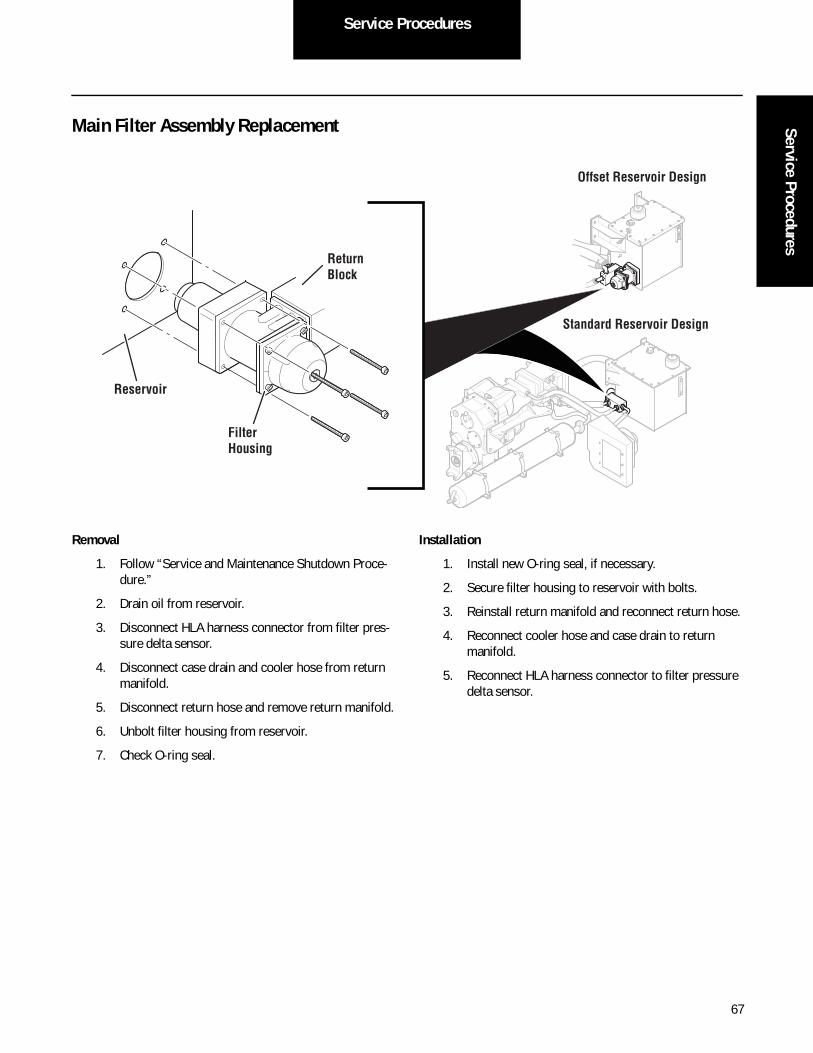
Service ProceduresService Procedures
Main Filter Assembly Replacement
Removal
1. Follow “Service and Maintenance Shutdown Proce-dure.”
2. Drain oil from reservoir.
3. Disconnect HLA harness connector from filter pres-sure delta sensor.
4. Disconnect case drain and cooler hose from return manifold.
5. Disconnect return hose and remove return manifold.
6. Unbolt filter housing from reservoir.
7. Check O-ring seal.
Installation
1. Install new O-ring seal, if necessary.
2. Secure filter housing to reservoir with bolts.
3. Reinstall return manifold and reconnect return hose.
4. Reconnect cooler hose and case drain to return manifold.
5. Reconnect HLA harness connector to filter pressure delta sensor.
Filter Housing
Reservoir
Return Block
Offset Reservoir Design
Standard Reservoir Design
67

Service Procedures
Return Manifold Replacement
Removal
1. Follow “Service and Maintenance Shutdown Proce-dure.”
2. Drain oil from reservoir.
3. Disconnect HLA harness connectors.
4. Disconnect case drain and cooler outlet hoses from return manifold.
5. Remove nuts from return hose flange and remove flange.
6. Disconnect return hose from return manifold.
7. Remove return manifold from studs.
8. Remove studs from filter housing.
Installation
1. Reinstall studs onto filter housing.
2. Lubricate O-ring with petroleum jelly and install onto new return manifold.
3. Install return manifold onto studs.
4. Lubricate O-ring with petroleum jelly and install onto return hose.
5. Install return hose flange and reconnect return hose to return manifold.
6. Install nuts onto return hose flange and torque nuts to 60 ± 6 ft-lb. See appendix “Torque Specifications.”
Offset Reservoir Design
Standard Reservoir Design
68

Service ProceduresService Procedures
7. Reconnect case drain and cooler outlet hoses. Torque fittings to 110 ± 2.5 ft-lb. See appendix “Torque Specifications.”
8. Fill reservoir with oil. See section “Drain and Replace HLA System Oil (Oil Change).”
9. Inspect assembly for leaks.
10. Reconnect HLA harness connectors.
69

Service Procedures
Cooler Replacement
Removal
1. Follow “Service and Maintenance Shutdown Proce-dure.”
2. Drain oil from reservoir.
3. Disconnect HLA harness connectors.
4. Disconnect inlet and outlet hoses.
5. Support cooler with transmission jack.
6. Unbolt cooler from chassis frame.
7. Remove fittings from cooler.
Note: Fan turns on at 85ºC and off at 60ºC. Fan also operates at < 80ºC with pump at < 30 rpm.
Installation
1. Reinstall fittings onto new cooler.
2. Support cooler with transmission jack and secure to chassis frame with bolts.
3. Reconnect inlet and outlet hoses.
4. Reconnect HLA harness connectors.
5. Fill cooler reservoir with oil. See section “Drain and Replace HLA System Oil (Oil Change)”.
Oil Cooler12V Fan
Air Flow
Cooler Outlet
Cooler Inlet
70

Service ProceduresService Procedures
Hose Assemblies Replacement Standard Reservoir Design
Offset Reservoir Design
Suction HoseHigh PressureHose
Cooler OutletHose
Cooler InletHose Return
Hose
Case Hose
Case Hose
Suction Hose
Cooler Inlet Hose Cooler Outlet Hose
Return Hose
High Pressure Hose
71

Service Procedures
Suction Hose Offset Reservoir Design
Removal
1. Drain oil from reservoir. See “Drain and Replace HLA System Oil.”
2. Use 3/4" wrench to remove bolts and split flange from charge pump.
3. Lift hose end to allow oil to drain from hose into res-ervoir.
4. Use 3/4" wrench to remove bolts and split flange from reservoir.
5. Remove hose.
Note: Protect hose ends from contamination during repairs and clean hose before reinstalling.
6. Inspect condition of O-rings and make sure they are:
• Soft and not deformed
• Free of nicks, cuts, damage
• Well lubricated with petroleum jelly
Note: Replace damaged (cracks or cuts) O-rings.
Installation
1. Install hose with O-rings.
2. Install split flange to reservoir and secure with bolts.
3. Install split flange to charge pump and secure with bolts at both the pump and reservoir ends. Torque to 85 ± 6 ft-lb. See appendix “Torque Specifications.”
End B
End A
72

Service ProceduresService Procedures
Case/Cooler Hose Offset Reservoir Design
Cooler Outlet Hose
Cooler Inlet Hose
End B
End A
End BEnd A
73

Service Procedures
Cooler Drain Hose
Offset Reservoir Design
Removal
1. Drain oil from reservoir. See “Drain and Replace HLA System Oil.”
2. Use 1-1/2" wrench to remove charge pump fitting.
3. Lift hose end to allow oil to drain from hose into return manifold.
4. Use 1-1/2" wrench to remove return manifold fitting.
5. Remove hose.
Note: Protect hose ends from contamination during repairs and clean hose before reinstalling.
6. Inspect condition of O-rings and make sure they are:
• Soft and not deformed
• Free of nicks, cuts, damage
• Well lubricated with petroleum jelly
Note: Replace damaged (cracks or cuts) O-rings.
InstallationInstall return manifold fitting.
End B
End A
74

Service ProceduresService Procedures
High Pressure Hose Offset Reservoir Design
Removal
1. Follow “Service and Maintenance Shutdown Proce-dure.”
2. Remove accumulator shield.
3. Use 15/16" wrench to remove bolts and split flange from accumulator.
4. Lift hose end to allow oil to drain from hose into drain pan.
5. Use 15/16" wrench to remove bolts and split flange from pump.
6. Remove hose.
Note: Protect hose ends from contamination during repairs and clean hose before reinstalling.
7. Inspect condition of O-rings and make sure they are:
• Soft and not deformed
• Free of nicks, cuts, damage
• Well lubricated with petroleum jelly or Eaton sil-icone lube (part #71203)
Note: Replace damaged (cracks or cuts) O-rings.
Installation
1. Install O-rings on hose.
2. Install hose end flange to pump and secure with bolts.
3. Install hose end to accumulator and secure with split flange and bolts.
4. Torque bolts to 125 ft-lb. See appendix “Torque Specifications.”
5. Reinstall accumulator shield.
End B
End A
75

Service Procedures
Low Pressure Return Hose Offset Reservoir Design
Removal
1. Drain oil from reservoir. See “Drain and Replace HLA System Oil.”
2. Use 3/4" wrench to remove bolts and split flange from pump.
3. Lift hose end to allow oil to drain from hose into res-ervoir.
4. Use 3/4" wrench to remove nuts and split flange from return manifold.
5. Remove hose.
Note: Protect hose ends from contamination during repairs and clean hose before reinstalling.
6. Inspect condition of O-rings and make sure they are:
• Soft and not deformed
• Free of nicks, cuts, damage
• Well lubricated with petroleum jelly or Eaton sil-icone lube (part #71203)
Note: Replace damaged (cracks or cuts) O-rings.
Installation
1. Install and lubricate O-rings.
2. Install split flange to pump and secure with bolts.
3. Install split flange to return manifold and secure with bolts.
4. Torque bolts to 60 ft-lb. See appendix “Torque Spec-ifications.”
End BEnd A
76

Service ProceduresService Procedures
Sensors ReplacementSwash Sensor Removal
1. Follow “Service and Maintenance Shutdown Proce-dure.”
2. Remove shield from pump.
3. Disconnect HLA harness connector from sensors.
4. Remove retaining cover (swash 2 only).
5. Remove socket head screws from sensors.
6. Remove sensors.
Installation
1. Replace sensors and install socket head screws. Torque to 26.5 ± 1.5 in-lb. See appendix “Torque Specifications.”
2. Replace retaining cover (swash 2 only). Torque screws to 60 in-lb and bolt to 44 ft-lb. See appendix “Torque Specifications.”
3. Use service tool to calibrate swash sensor.
4. Reconnect HLA harness connector to sensor.
5. Reinstall shield to pump.
6. Use zip ties to connect harness back to mount.
7. Swash calibration is required after sensor removal and installation.
Retaining Cover
Swash 1 Sensor
Swash 2 Sensor
(3mm Hex Socket Screw)
77

Service Procedures
Accumulator Foot Valve Proximity Sensor
Removal
1. Follow “Service and Maintenance Shutdown Proce-dure.”
2. Place drain pan under accumulator fluid port end.
3. Disconnect HLA harness connector from sensor.
4. Use 15/16" wrench to remove sensor.
Note: Oil will drain while port is open.
5. Check condition of sealing port surface and O-ring. Replace O-ring if damaged.
Installation
1. Clean sensor port and sealing surface.
2. Check condition of O-ring on sensor. Replace if dam-aged.
3. Apply blue removable thread lock to sensor threads.
4. Screw sensor into port.
5. Torque sensor to 95 ft-lb. See appendix “Torque Specifications.”
6. Reconnect HLA harness connector to sensor.
Accumulator Pressure Sensor
Removal
1. Follow “Service and Maintenance Shutdown Proce-dure.”
2. Place drain pan under accumulator fluid port end.
3. Cut tie strap from HLA harness connector to shield.
4. Loosen worm gear clamp from shield and remove shield.
5. Disconnect HLA harness connector from sensor.
6. Use 1-1/16" wrench to remove sensor.
Note: Oil will drain while port is open.
7. Check condition of sealing port surface and O-ring. Replace O-ring if damaged.
Installation
1. Clean sensor port and sealing surface.
2. Check condition of O-ring on sensor. Replace if dam-aged.
3. Apply blue removable thread lock to sensor threads.
4. Screw sensor into port.
5. Torque sensor to 56 ft-lb. See appendix “Torque Specifications.”
6. Reconnect HLA harness connector to sensor.
7. Reinstall shield.
Fluid Port
Pressure Sensor
Foot Valve Proximity Sensor
78

Service ProceduresService Procedures
Transfer Case Engagement Proximity Sensor
Removal
Note: Sensor is located on front side at 10 o'clock position, above output shaft and on cast boss retaining shift shaft.
1. Follow “Service and Maintenance Shutdown Proce-dure.”
2. Disconnect HLA harness connector from sensor.
3. Use a 15/16” wrench to remove sensor from shift shaft boss.
Installation
1. Insert new sensor into threaded hole and tighten. Torque to maximum 95 ft-lb. See appendix “Torque Specifications.”
2. Reconnect HLA harness connector to sensor.
Speed Sensor
Removal
1. Follow “Service and Maintenance Shutdown Proce-dure.”
2. Disconnect HLA harness connector from sensor.
3. Hold sensor in place using a 1/2” open end wrench and remove 5/16” serrated hex flange screw.
4. Pull out sensor from unit.
Note: Rotate sensor back and forth to loosen O-ring seal if necessary.
Installation
1. Apply light coating of petroleum jelly or anti-seize to O-ring seal.
2. Insert new sensor into hole:
• Protect O-ring from being cut or damaged.
• Push until sensor seats tight to mounting sur-face.
3. Insert 5/16" serrated flange screw into threaded hole and tighten. Torque to maximum 13 ft-lb. See appen-dix “Torque Specifications.”
Note: Overtightening may cause damage to sensor.
4. Reconnect HLA harness connector to sensor.
Engagement Proximity Sensor
Speed Sensor
79

Service Procedures
Filter Pressure Delta Sensor
Removal
1. Follow “Service and Maintenance Shutdown Proce-dure.”
2. Place drain pan under return manifold.
3. Disconnect HLA harness connector from sensor.
4. Use 1-1/16" wrench to remove sensor.
Note: Oil will drain from reservoir while port is open.
5. Check condition of sealing port surface and O-ring. Replace O-ring if damaged.
Installation
1. Clean sensor port and sealing surface.
2. Check condition of O-ring on sensor. Replace if dam-aged.
3. Screw sensor into port.
4. Torque sensor to 56 ft-lb. See appendix “Torque Specifications.”
5. Reconnect HLA harness connector to sensor.
Level Sensor
Removal
1. Follow “Service and Maintenance Shutdown Proce-dure.”
2. Disconnect HLA harness connector from sensor.
3. Remove 5 flange screws.
4. Pull out sensor and gasket.
Note: Body may need to be raised for sensor removal.
Installation
1. Slide gasket onto new sensor and align holes.
2. Insert new sensor into cover port.
3. Reinstall 5 flange screws.
4. Torque screws to 10-15 in-lb. See appendix “Torque Specifications.”
5. Reconnect HLA harness connector to sensor.
Filter Pressure Delta Sensor
Level Sensor
Gasket
80
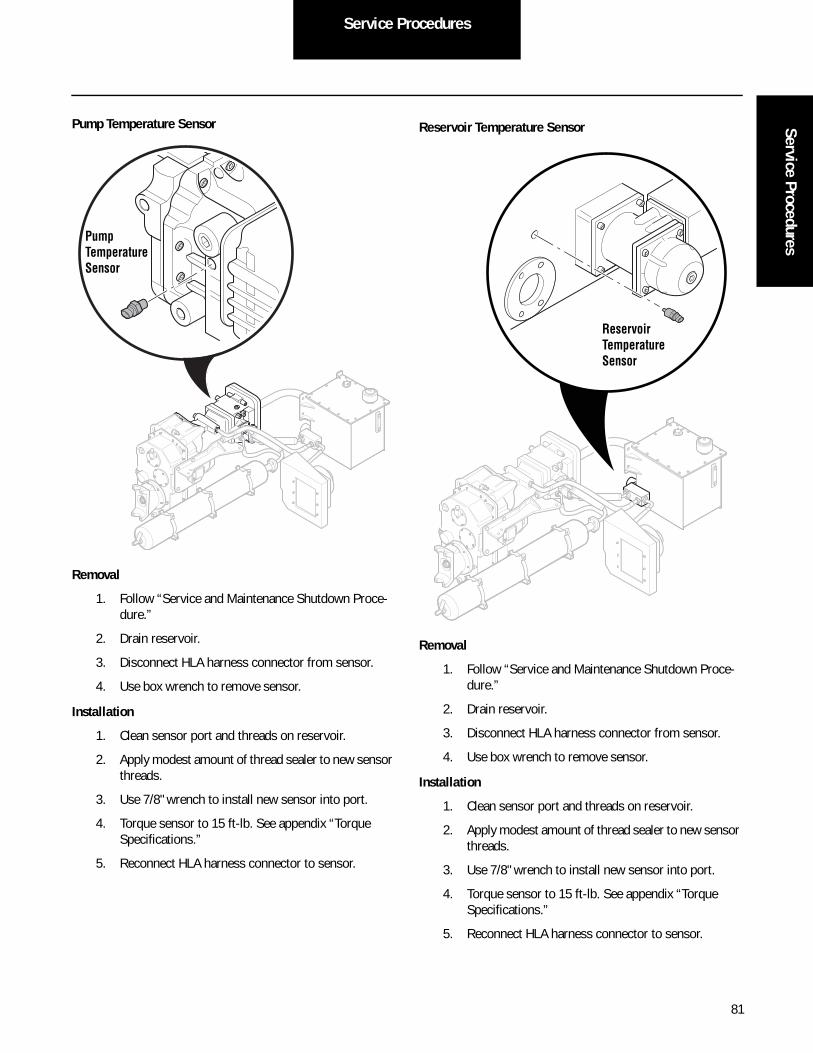
Service ProceduresService Procedures
Pump Temperature Sensor
Removal
1. Follow “Service and Maintenance Shutdown Proce-dure.”
2. Drain reservoir.
3. Disconnect HLA harness connector from sensor.
4. Use box wrench to remove sensor.
Installation
1. Clean sensor port and threads on reservoir.
2. Apply modest amount of thread sealer to new sensor threads.
3. Use 7/8" wrench to install new sensor into port.
4. Torque sensor to 15 ft-lb. See appendix “Torque Specifications.”
5. Reconnect HLA harness connector to sensor.
Reservoir Temperature Sensor
Removal
1. Follow “Service and Maintenance Shutdown Proce-dure.”
2. Drain reservoir.
3. Disconnect HLA harness connector from sensor.
4. Use box wrench to remove sensor.
Installation
1. Clean sensor port and threads on reservoir.
2. Apply modest amount of thread sealer to new sensor threads.
3. Use 7/8" wrench to install new sensor into port.
4. Torque sensor to 15 ft-lb. See appendix “Torque Specifications.”
5. Reconnect HLA harness connector to sensor.
Pump Temperature Sensor
Reservoir TemperatureSensor
81

Service Procedures
Valves ReplacementMode Valve
Removal
1. Follow “Service and Maintenance Shutdown Proce-dure.”
2. Remove solenoid coil retaining nut.
3. Remove solenoid coil.
4. Remove cartridge valve.
Installation
1. Check O-ring condition on cartridge valve. Replace if damaged.
2. Install new cartridge valve and torque to 28 ± 3 ft-lb. See appendix “Torque Specifications.”
3. Reinstall solenoid coil.
4. Reinstall solenoid coil retaining nut and torque with 5/8" wrench to 42 ± 6 in-lb. See appendix “Torque Specifications.”
Directional Control Valve
Removal
1. Follow “Service and Maintenance Shutdown Proce-dure.”
2. Remove four screws and valve from pump.
Installation
1. Check condition of O-ring seals. Replace if damaged.
2. Lightly lubricate O-rings with petroleum jelly or Eaton silicone lube (part #71203).
3. Install new valve on pump.
4. Reinstall screws and torque in cross pattern to 58 ± 4 in-lb. See appendix “Torque Specifications.”
Normally Closed 2-Way Drain Valve
Normally Open 2-Way Fill Valve
Solenoid Coils
Directional Control Valve Pump
Solenoid
Motor Solenoid
1START
4
3
2
82

Service ProceduresService Procedures
Bypass Valve (Main Stage)
Removal and Installation
1. Follow “Service and Maintenance Shutdown Proce-dure.”
2. Remove valve by unthreading from pump housing.
3. Check condition of O-ring on valve. Replace if dam-aged.
4. Check inside valve port for debris and thread condi-tion.
5. Install new valve on pump housing and torque to 134 ft-lb. See appendix “Torque Specifications.”
Charge Pump Bypass Valve
Removal
1. Follow “Service and Maintenance Shutdown Proce-dure.”
2. Disconnect harness from valve coil.
3. Remove coil hold-down nut and pull off coil.
4. Use 5/8" wrench to remove cartridge screw.
5. Check condition of O-ring seals. Replace if damaged.
Installation
1. Check and clean cartridge port.
2. Check for proper installation of O-ring on valve.
3. Install valve into port.
4. Torque valve to 28 ± 3 ft-lb. See appendix “Torque Specifications.”
5. Reinstall coil and hold-down nut. Torque hold-down nut to 42 in-lb. See appendix “Torque Specifica-tions.”
Bypass Valve (Main Stage)
Charge Pump Bypass Valve
3-Way, 2-Position N/O Valve
83

Service Procedures
Bypass Valve Pilot Cartridge
Removal and Installation
1. Follow “Service and Maintenance Shutdown Proce-dure.”
2. Remove valve by unthreading from pump housing.
3. Check condition of O-ring on valve. Replace if dam-aged.
4. Check inside valve port for debris, thread condition.
5. Install new valve on pump housing and torque to 134 ft-lb. See appendix “Torque Specifications.”
Isolation Valve
Removal and Installation
1. Follow “Service and Maintenance Shutdown Proce-dure.”
2. Remove valve by unthreading from pump housing.
3. Check condition of O-ring on valve. Replace if dam-aged.
4. Check inside valve port for debris and thread condi-tion.
5. Install new valve on pump housing and torque to 134 ft-lb. See appendix “Torque Specifications.”
Isolation Valve
Bypass Valve Pilot Cartridge
Normally Open 2-Way Valve
84

Service ProceduresService Procedures
Manual Relief Valve
Removal and Installation
1. Follow “Service and Maintenance Shutdown Proce-dure.”
2. Remove valve by unthreading from pump housing (1 1/4" hex).
3. Check condition of O-ring on valve. Replace if dam-aged.
4. Check inside valve port for debris and thread condi-tion.
5. Install new valve on pump housing and torque to 105 ± 5 ft-lb. See appendix “Torque Specifications.”
Pneumatic Clutch Valve
Note: The pneumatic clutch valve is located on right side of pump mounted to pump sub-frame.
Removal
1. Follow “Service and Maintenance Shutdown Proce-dure.”
2. Vent vehicle air system.
3. Mark and disconnect tubing from valve.
Note: Verify HLA system power is off before disconnecting coil connector.
4. Remove mounting screws and valve.
Installation
1. Install new valve.
2. Reinstall mounting screws and torque to 22 ft-lb. See appendix “Torque Specifications.”
3. Reconnect tubing to valve.
4. Reconnect harness connectors.
Manual Relief Valve
Engage
Disengage(-) Red
Engage(+) Black
NC
Supply
NC
NO
DisengageOEM Air Supply
(Green)
(Red)
85

Service Procedures
Wiring Repair Instructions1. Disconnect battery ground.
2. Disconnect connector from affected component. Remove and discard the tape and peal back the con-volute wire covering.
3. Cut the first wire approximately 3 inches from the connector. Leave enough wire to allow repairs to be staggered to minimize harness diameter and to maintain harness length. Excess wire from the har-ness can be folded back on itself to maintain harness length. Wire colors on the harness and the repair connectors should match.
4. Strip the insulation back .3"/7.6mm. Insert wire into barrel of splice. Make sure the insulation does not enter the splice.
5. Crimp with a tool designed to crimp insulated splices. Inspect the repair for an acceptable splice.
6. Repeat steps 4 and 5 for the matching color wire on the replacement connector.
7. Using a heat gun apply heat directly to the splice, working from the center out to the edges, until the tubing shrinks and the adhesive appears on the end of the splice. DO NOT use an open flame to heat the splice.
8. Repeat steps 4, 5, 6, and 7 for the remaining wires, staggering the repairs so the harness does not become too large.
9. Reapply convolute and tape.
10. Connect to affected component.
11. Reconnect battery ground.
Vehicle Harness Routing
This routing procedure applies to all connections including:
• Speed Sensor
• Temperature Sensors
• Pressure Sensors
• Valve Coils
• Oil Level
• Proximity Sensor
86

Service ProceduresService Procedures
Proper Routing Techniques
1 2 3 4 5 6
1 2 3 4 5 6 7 8 9 10 11 12
Verify clip is within 6" of connector.
Verify no more than 12" of space exists between clips.
Verify clips are attached to harness convoluted tubing only.
Make sure wires exit base and allows for strain relief.
87

Service Procedures
Improper Routing Techniques
Do not attach clips to bare wires.
Avoid bending wires at the connection. This strain may cause leakage at the seal.
88

89
Wiring SchematicW
iring Schematic
Wiring Schematic
Hydraulic System OEM Electrical Circuit

90
Wiring Schematic

AppendixAppendix
Appendix
Fault Codes
Fault Code v26
FMI Fault Description SPN ServiceLevel
LatchType *
EventTrigger
11 12 ECU Voltage Output, 5 volt supply out of range 629 Disengage Vol 5
11 12 ECU Non Volatile Memory Corruption 629 Disengage Vol 5
12 7 Tampered, Invalid Calibrations 629 Disengage Non 0
12 13 ECU Missing Calibrations 629 Disengage Non 0
13 13 Swash Sensor not Calibrated 520376 Disengage Non 0
13 14 Swash Calibration Monitor Failed 520376 Disengage Non 0
15 7 Air Purge Not Complete 520377 Disengage Non 0
20 9 ETC1 Fault, Electronic Transmission Controller not sending CAN message 300 ms
523 Disengage Non 0
20 9 ETC2 Fault, Electronic Transmission Controller not sending CAN message 1250 ms
523 Disengage Non 0
21 9 CCVS Fault, Cruise Control Vehicle Speed, not send-ing CAN message 450 ms
595 Disengage Non 0
22 9 EBC, Fault Electronic Brake Controller not sending CAN message 450 ms
563 Disengage Non 0
33 1 12 volt supply voltage out of range, Voltage input to ECU
168 Disengage Vol 5
36 14 EEC1 Fault, Electronic Engine Controller not sending CAN message 300 ms
639 Disengage Non 0
36 14 EEC2 Fault, Electronic Engine Controller not sending CAN message 225 ms
639 Disengage Non 0
40 5 Pump Solenoid Wiring Fault 520378 Disengage Vol 5
41 5 Motor Solenoid Wiring Fault 520379 Disengage Vol 5
42 5 Main Bypass Solenoid Wiring Fault 520380 Disengage Vol 5
43 7 Bypass Valve Not Closing 520381 Disengage Vol 5
44 5 Charge Bypass Solenoid Wiring Fault 520382 Disengage Vol 5
45 5 Isolation Valve Solenoid Wiring Fault 520383 Disengage Vol 5
46 5 Mode Valve Solenoid Wiring Fault 520384 Disengage Vol 5
47 5 Transfer Case Air Valve Solenoid Wiring Fault 520385 Disengage Vol 5
51 0 Swash Sensor 1Out of Range 520387 Disengage Vol 5
52 0 Swash Sensor 2 Out of Range 520388 Disengage Vol 5
* Non: Non Latching- Fault self clears when conditions to set code active are cleared. Vol: Latching Volatile- Code clears with key off and conditions to set active are cleared. NV: Latching Non Volatile- Serviceranger required to reset code after conditions are resolved.
91

Appendix
53 7 Swash Sensor Tracking Error >6 deg 520389 Disengage Vol 5
54 2 Swash Sensor 1 and 2 Miscompare > 3.5 deg 520390 Disengage Vol 5
55 0 Accumulator Pressure Sensor Out of Range <-40 or >525 Bar
520391 Disengage Vol 5
56 16 Accumulator Pressure Exceeded Maximum Operating Range >360 Bar
520392 Disengage Vol 5
57 0 Filter Pressure Sensor Out of Range <-10 or >150 PSI 520393 Disengage Vol 5
58 0 Oil Level Sensor Out of Range, Signal above or below normal level range
520394 Disengage Vol 5
59 7 Low Oil Level, system shut down 520395 Disengage Vol 5
59 17 Oil Level Low, Least Severe, fault code displayed 520395 Service Vol 5
60 7 Transfer Case Failed to Engage 520396 Disengage Vol 5
61 7 Accumulator Proximity Sensor State, Foot valve out of position for currant accumulator pressure
520397 Disengage Vol 5
62 0 Pump Overspeed >3200 rpm 520386 Disengage Vol 5
62 16 Pump Overspeed >3500 rpm 520386 Disengage Vol 1
63 0 Brake Pressure Sensor Out of Range <-35 or >10.5 Bar
520412 Disengage Vol 5
70 2 Pump Speed Sensor & (CAN) Output Shaft Speed Miscompare >500 RPM for 200 ms
520398 Disengage Vol 5
71 7 Transfer Case Failed to Disengage 520399 Disengage Vol 1
71 7 Transfer Case Failed to Disengage, Stop 520400 Stop Vol 5
72 1 HLA Failed to Bootstrap 520401 Disengage Vol 5
73 17 Pump not building pressure 520402 Disengage NV 1
74 2 Clutch Sensor State & Output Shaft Speed Signal Miscompare, Output shaft speed and not clutch engagement
520403 Disengage Vol 5
76 7 Case Pressure Ripple Detection 520404 Disengage NV 1
77 2 Clogged Filter Detection, Main System Element 520405 Disengage Vol 5
78 2 Oil Level Sensor Signal, Signal output delta < .5 gal-lon in last cycle
520406 Disengage Vol 1
78 2 Oil Level Sensor, Oil level too low while accumulator pressure is low
520406 Disengage Vol 5
78 2 Oil Level Sensor, Oil level too low while vehicle in motion
520406 Disengage Vol 5
Fault Code v26
FMI Fault Description SPN ServiceLevel
LatchType *
EventTrigger
* Non: Non Latching- Fault self clears when conditions to set code active are cleared. Vol: Latching Volatile- Code clears with key off and conditions to set active are cleared. NV: Latching Non Volatile- Serviceranger required to reset code after conditions are resolved.
92

AppendixAppendix
78 2 Oil Level Sensor, Oil level too low while vehicle sta-tionary
520406 Disengage Vol 5
79 7 Unexpected Disengagement 520407 Disengage Vol 5
85 0 Pump Oil Temperature High > 248F (120C) 520408 Disengage Vol 5
86 2 Pump and Reservoir Temperature Sensor Miscom-pare >70 deg C
520409 Disengage Vol 5
87 0 Reservoir Oil Temperature High > (110C) 520410 Disengage Vol 1
87 16 Reservoir Oil Temperature High > 212F (100C) 520410 Disengage NV 1
89 0 Accumulator Precharge Too High 139 Bar @ 68 F 520391 Disengage Vol 1
89 16 Accumulator Precharge Too Low Instantaneous 112 Bar @ 68 F
520391 Disengage Vol 1
89 17 Accumulator Precharge Too Low 119 Bar @ 68 F, Low severity fault code displayed
520391 Service Vol 1
89 18 Accumulator Precharge Too Low Average 112 Bar @ 68 F
520391 Disengage Vol 1
90 14 Pump Cycle Count 520411 Disengage NV 0
99 Driver Display Not Receiving CAN Data Disengage
Fault Code v26
FMI Fault Description SPN ServiceLevel
LatchType *
EventTrigger
* Non: Non Latching- Fault self clears when conditions to set code active are cleared. Vol: Latching Volatile- Code clears with key off and conditions to set active are cleared. NV: Latching Non Volatile- Serviceranger required to reset code after conditions are resolved.
93

Appendix
Nitrogen Gas Precharge Pressure ChartNote: Nitrogen gas pressure is affected by temperature and
volume. After HLA system has been used, some oil will remain trapped inside accumulator.
Precharge Gas Pressure – PSI [bar = PSI*0.06895]
HLA High Performance Hydraulic Fluid Data Sheet
Specifically engineered to work in conjunction with the Eaton® Hydraulic Launch Assist system.
Benefits:
• All temperature performance
- excellent cold temperature operation
- high temperature protection
• An engineered fluid developed in conjunction with Eaton’s HLA system resulting in optimal system per-formance including rust protection, seal and bladder compatibility, cleanliness and system durability.
• High viscosity index provides all season perfor-mance.
• Excellent shear stable viscosity modifier assures optimal viscometrics to protect equipment and mini-mize downtime.
• Demonstrated proof of performance through field testing.
• Product meets Eaton’s performance specification for HLA system based on rigorous laboratory testing.
Roadranger High Performance Hydraulic Fluid
Physical Characteristics
Temperature Pressure
Fahrenheit (°F)
Celsius (°C)
lb/in2 (PSI) Bar
30 -1 1632 113
35 2 1654 114
40 4 1676 116
45 7 1698 117
50 10 1720 119
55 13 1742 120
60 16 1763 122
65 18 1785 123
68 20 1798 124
70 21 1807 125
75 24 1829 126
80 27 1851 128
85 29 1872 129
90 32 1894 131
95 35 1916 132
100 38 1938 134
105 41 1960 135
110 43 1982 137
Product # Package Weight
RRHLADR Drum 375 lbs
RRHLAPA 5 gal 35 lbs
Characteristics Minimum Target Maximum
Flash Point, C, PMCC 173
Lbs. per U.S. Gal @ 15.6 C 7.10
Lbs. per IMP Gal @ 15.6 C 8.53
Pour Point, C -45
Specific Gravity @ 15.6C 0.832 0.852 0.872
Viscosity @ 100 C, CST 7.3 8.1 8.9
Viscosity @ 40 C, CST 42.8
94

AppendixAppendix
Chemical Characteristics
Hose Chart
Sub-System Weights
Special ToolsService and Diagnostic ToolsCharacteristics Minimum Target Maximum
Calcium 0.013 0.015 0.017
Nitrogen 0.030
Phosphorus 0.065 0.073 0.080
Sulfated Ash 0.19
Sulfur 0.18 0.20 0.22
Water 0.30
Zinc 0.081 0.090 0.099
Hose Size Flange Kit O-ring Torque
Case Drain
37 Deg -16
110.5 ± 2.5 ft-lb
Cooler Inlet
37 Deg -16
110.5 ± 2.5 ft-lb
Cooler Outlet
37 Deg -16
110.5 ± 2.5 ft-lb
High Pressure
Code 62 -24
FF595-24 -225 125 ± 8 ft-lb
Return Code 61 -32
FF593-32 -228 60 ± 6 ft-lb
Suction Code 61 -40
FF593-40 -232 85 ± 6 ft-lb
Component Weight in pounds (approximate)
Pump 350
Transfer Case 500
Accumulator 460
Reservoir 180
Cooler 60
Hose Kit 104
Description MFG Part Number Road-ranger PN#
Nitrogen Charge Kit Eaton 100AV00093A
Accumulator Fluid Port Spanner
Eaton 6024874-001 RR1025HY
Accumulator Gas Port Spanner Wrench
Eaton 6024873-001 RR1026HY
Accumulator Gas Valve Torque Wrench
Eaton 100AV00092A RR1020HY
Transfer Pump Filter Cart
Eaton CCOFRS60 05 part #5003889
Digital Pressure Gauge for Nitrogen Charge Kit ± 3 psi
Omega DPG8000-3K
ServiceRanger Diagnostic Tool
Eaton 3.0
Nexiq USB Data Link Nexiq 125032
Pump Tool Eaton XSCE RR1024HY
Torque Wrench 350 ft-lb
Non-contact Thermometer 1º Resolution
MetriPack 280 Connector Removal Tool
Delphi DP# 12180559-1
MetriPack 150 Connector Removal Tool
Delphi DP# 12094429
MetriPack Connector Crimping Tool
Power & Signal
HCT
Deutsch Connector Removal Tool
Ladd HDT-48-00
DTM 16-18 AWG Connector Crimping Tool
Deutsch 0411-204-1650
DTM 20-24 AWG Connector Crimping Tool
Deutsch 0411-240-2005
95

Appendix
Torque SpecificationsPart Torque Value
Accumulator Bracket Strap Bolts 26 ft-lb
Accumulator Foot Valve Proximity Sensor 95 ft-lb
Accumulator Gas Valve Core 2.7-4.5 in-lb
Accumulator Pressure Sensor 56 ft-lb
Bladder Stem Lock Nut 111 ft-lb
Bypass Valve Screw-in Cartridge 28 ± 3 ft-lb
Bypass Valve (Main Stage) 134 ± 13 ft-lb
Bypass Valve (Main Stage) Plug 85 - 90 ft-lb
Case -16 O-ring Plug 86 ft-lb
Charge Pump Housing Fasteners 97 ± 9.7 ft-lb
Charge Pump Housing -4 O-ring Plug 9 ± 1 ft-lb
Charge Pump Housing Zero-leak Plugs 63 ± 6.3 ft-lb
Charge Pump Mating Port Zero-leak Plug 9.0 ± 1.0 ft-lb
Charge Pump Valve Screw-in Cartridge 28 ± 3 ft-lb
Cooler/Case Hose Fitting 110.5 ± 2.5 ft-lb
Cover Assembly Fasteners 16 ± 1.6 ft-lb
Directional Control Valve Screws 58 ± 4 in-lb
Filter Bowl 60 ± 5 ft-lb
Fluid Port Lock Nut 325 ft-lb
High Pressure Hose Split Flange Bolts 125 ft-lb
Housing Cover Plate Bolts 30 ft-lb
Impeller Fasteners 39 ± 3.9 ft-lb
Isolation Valve Screw -in Cartridge 28 ± 3 ft-lb
Manual Relief Valve 105 ± 5 ft-lb
Manual Relief Valve O-ring Plug 5 ft-lb
Mode Valve Screw -in Cartridge 28 ± 3 ft-lb
One-inch 90º Swivel Fitting 110.5 ± 2.5 ft-lb
Pressure Sensor Filter Delta 56 ft-lb
Pneumatic Clutch Valve Mounting Bolts 22 ft-lb
Pump Temperature Sensor 15 ft-lb
Pump to Transfer Case 336 ± 34 ft-lb
Quick Disconnect:• 6 • 10
25 ± 2.5 ft-lb28 ± 2.8 ft-lb
Reservoir Cover Bolts 28 ± 2.8 ft-lb
Reservoir Level Sensor Flange Screws 10-15 in-lb
Reservoir Temperature Sensor 15 ft-lb
Return Hose Flange Nut 60 ± 6 ft-lb
Return Hose Split Flange Bolts 60 ft-lb
Screw In Cartridge Valve ISD Mode Bypass
28 ± 13 ft-lb
Solenoid Coil Hold Down Nuton Screw in Cartridge Valves
42 ± 6 in-lb
Sub-frame Bolts:• 5/8-11 • 3/4-10
188 ± 19 ft-lb336 ± 34 ft-lb
Suction Hose Split Flange Bolts 85 ± 6 ft-lb
Swash Sensor Retaining Cover Bolt 44 ft-lb
Swash Sensor Retaining Cover Screws 60 in-lb
Swash Sensor Socket Head Screws 26.5 ± 1.5 in-lb
Thermal Relief Fuse Cap 15 ft-lb
Transfer Case Drain Plug 50 ft-lb
Transfer Case Engagement Proximity Sensor
Max. 95 ft-lb
Transfer Case Input Shaft Securing Nut 200 ft-lb
Transfer Case Speed Sensor Mounting Screw
Max. 13 ft-lb
Vibration Mounting Bolts 86-123 ft-lb
Zero Leak Plugs:- 2 - 4- 6- 8- 10
60 ± 6 in-lb9 ± 1 ft-lb24 ± 2.4 ft-lb35 ± 3.5 ft-lb50 ± 5 ft-lb
Part Torque Value
96

AppendixAppendix
Connector ListDesignator Component Pin Connector
SeriesSensor Signal Description Pin Connector
Pin Level
12VSPB1 12V SPLICE BOX SOLENOID 12 DELPHI SENSOR SUPPLY A, B, C …
12VSPB2 12V SPLICE BOX SOLENOID 12 DELPHI SENSOR SUPPLY A, B, C …
5VSPB 5V SPLICE BOX 12 DELPHI SENSOR SUPPLY A, B, C …
GNDSPB ANALOG GND SPLICE BOX 12 DELPHI SENSOR SUPPLY A, B, C …
J02 ECU 24 TYCO 1,2,3 …
J04 ECU 24 TYCO 1,2,3 …
J05 OEM CONNECTOR 21 DEUTSCH HDP20 SERIES
A, B, C …
J27 RESERVOIR OIL LEVEL 3 DELPHI - METRIPACK 150 SERIES
ANALOG SENSORPowered by DRVP (12V) Non-ratiometric 0.5-4.5V output
A GND
B Out
C +12V
J29 RESERVOIR OIL TEMP 2 DELPHI - METRIPACK 150.2 SERIES
ANALOG SENSORThermistor resistance is 671 ohms at 60° setpoint
A Out
B GND
J31 HIGH PRESSURE Sensor 3 DEUTSCH DTM06-3S
ANALOG SENSORPowered by XDRP (+5V)25 ohms max impedance(0.5V to 4.5V ratiometric)
1 +5V
2 GND
3 Out
J33 ACCUM PROXIMITY 4 TURCK DISCRETE SENSORPowered by DRVP (+12V)PNP NO (discrete)<10uA output leakage<2V voltage drop (reference to DRVP)
1 +12V
2 ---
3 GND
4 Out
J35 ESP (SWASH) 1 3 DELPHI - METRIPACK 150 SERIES
ANALOG SENSORPowered by XDRP (+5V). Output is ratiometric.
A GND
B Out
C +5V
J37 SENSOR-NEUTRAL PRESSURE
3 DEUTSCH DTM06-3S
ANALOG SENSORPowered by XDRP (+5V)25 ohms max impedance(0.5V to 4.5V ratiometric)
1 +5v
2 GND
3 Out
J39A PUMP SOLENOID 2 DELPHI - METRIPACK 150 SERIES
PROPORTIONAL SOLENOID2A, 3 ohms
A +12V
B Out
J41B MOTOR SOLENOID 2 DELPHI - METRIPACK 150 SERIES
PROPORTIONAL SOLENOID2A, 3 ohms
A Out
B +12V
97

Appendix
J43 ISOLATION SOLENOID 2 DEUTSCH DT06-2S
ON/OFF SOLENOID12V, 6.13 ohms, 1.96A, 23.5W
1 +12V
2 Out
J45 MODE HP SOLENOID 2 DELPHI - METRIPACK 280 SERIES
ON/OFF SOLENOID12V, 4.97 ohms, 2.41A, 29W
A +12V
B Out
J47 BYPASS SOLENOID 2 DELPHI - METRIPACK 280 SERIES
ON/OFF SOLENOID12V, 6.13 ohms, 1.96A, 23.5W
A +12V
B Out
J49 CHARGE BYPASS SOL 2 DELPHI - METRIPACK 280 SERIES
ON/OFF SOLENOID12V, 6.13 ohms, 1.96A, 23.5W
A +12V
B Out
J51 T-CASE CLUTCH STATE 4 TURCK DISCRETE SENSORPowered by DRVP (+12V)PNP NO (discrete)<10uA output leakage<2V voltage drop (reference to DRVP)
1 +12V
2 ---
3 GND
4 Out
J53 T-CASE-NO-CLUTCH 2 DELPHI - METRIPACK 150 SERIES
ON/OFF SOLENOID3.6W
A +12V
B Out
J55 PUMP SPEED 2 DELPHI - METRIPACK 150.2 SERIES
SPEEDVariable reluctance sensor 2 - 4.5 ohms
A Out +
B Out -
J57 FILTER DELTA PRESSURE 3 DELPHI - METRIPACK 150 SERIES P2S
ANALOG SENSORPowered by XDRP (+5V)25 ohms max outputimpedance (0.5V to 4.5V ratiometric)
A GND
B +5V
C Out
J59 RING TERMINAL 1 1 MOLEX Ground
J63 RING TERMINAL 2 (ECU COVER)
1 MOLEX Ground
J65 RING TERMINAL 3 (CHASSIS SIDE)
1 MOLEX Ground
J69 COOLER FAN 2 A +Fan
B Bat -
J73 COOLER FAN POWER SUPPLY 2 A Bat +
B GND
J75 DATA CAN MOTOTRON ECU SIDE
3 DEUTSCH J1939
A CAN High
B CAN Low
C ---
Designator Component Pin Connector Series
Sensor Signal Description Pin Connector Pin Level
98

AppendixAppendix
J76 DATA CAN OEM SIDE 3 DEUTSCH J1939
A, B, C …
J77 RING TERMINAL 4 (ECU COVER)
1 MOLEX Ground
J78 DEUTSCH 3-WAY "T" RECEPTACLE
1 DEUTSCH - DT SERIES
A, B, C …
J79 DEUTSCH 3-WAY PLUG WITH TERMINATING RESISTOR
3 DEUTSCH - DT SERIES
A, B, C …
J82 COOLER FAN RELAYCONNECTOR
2 DELPHI - METRIPACK 150 SERIES
Cooler fan relay coil A Out
B +12 V
J83 ESP (SWASH) 2 3 DELPHI - METRIPACK 150 SERIES
ANALOG SENSORPowered by XDRP (+5V). Output is ratiometric.
A GND
B Out
C +5V
J85 OIL TEMP IN PUMP CASE 2 DELPHI - METRIPACK 150.2 SERIES
ANALOG SENSORThermistor resistance is 133 ohms at 110° setpoint.
A Out
B GND
SPEED SPLICE PACK
J88 6 DELPHI - METRIPACK 280 SERIES
A, B, C …
J89 T-CASE CLUTCH NC1 SOL 2 DELPHI - METRIPACK 150 SERIES
ON/OFF SOLENOID3.6W
A +12V
B Out
J91 T-CASE CLUTCH NC2 SOL 2 DELPHI - METRIPACK 150 SERIES
ON/OFF SOLENOID3.6W
A +12V
B Out
J93 MODE DRAIN SOLENOID 2 DEUTSCH DT06-2S
1 +12V
2 Out
J95 INTERMEDIATE CONNECTOR FOR OIL LEVEL SENSOR
4 DEUTSCH DTM06-4S
1,2,3 …
J96 INTERMEDIATE CONNECTOR FOR OIL LEVEL SENSOR
4 DEUTSCH DTM04-4P
1,2,3 …
J97 INTERMEDIATE CONNECTOR FOR HIGH PRESSURE SENSOR
3 DEUTSCH DTM06-3S
1,2,3 …
J98 INTERMEDIATE CONNECTOR FOR HIGH PRESSURE SENSOR
3 DEUTSCH DTM06-3S
1,2,3 …
R1 PULL DOWN RESISTOR FOR HIGH PRESSURE SENSOR
1 VISHAY 1,2
Designator Component Pin Connector Series
Sensor Signal Description Pin Connector Pin Level
99

Appendix
HLA Maintenance Check Sheet
Check cooler screen for debris and blockage. Clean as needed.
Check accumulator thermal relief cap is installed.
100

AppendixAppendix
Real Time Warranty Pre-Call Checklist
Customer/ Owner: Date of Incident:Dealer: Operator/ Driver:
Chassis VIN: Truck ID:Mileage: Hours:
So�ware Revision: Cycle Count:System In Service Date: Accumulator S/N:
HLA Pump S/N: Bladder In Service Date:Fault Codes: T-Case S/N:
FMI: Reservoir S/N:Service/ Stop Lamp: Cooler S/N:
InAc�ve Codes: Fault Count:
RO# Service Complete Date:Data files sent: Screen Shot:
Descrip�on of symtom/ work:
Parts Replaced: Parts Received Date:Part # Serial/ID #Descrip�on
101


Eaton Corporation1111 Superior Ave.Cleveland, OH 44114 www.eaton.com/greensolutions
Copyright Eaton Corporation, 2012. Eaton hereby grant their customers, vendors, or distributors permission to freely copy, reproduce and/or distribute this document in printed format. It may be copied only in its entirety without any changes or modifications. THIS INFORMATION IS NOT INTENDED FOR SALE OR RESALE, AND THIS NOTICE MUST REMAIN ON ALL COPIES.
Note: Features and specifications listed in this document are subject to change without notice and represent the maximum capabilities of the software and products with all options installed. Although every attempt has been made to ensure the accuracy of information contained within, Eaton makes no representation about the completeness, correctness or accuracy and assumes no responsibility for any errors or omissions. Features and functionality may vary depending on selected options.
For spec’ing or service assistance, call 1-800-826-HELP (4357) or visit our web site at:
www.roadranger.com. In Mexico, call 001-800-826-4357.