Service Manual - Eaton
92
Fuller ® Synchromesh Transmissions Service Manual Fuller Light-Duty Synchromesh Transmissions TRSM-2105 February 2012 FSO-2105 FSO-2505
-
Upload
khangminh22 -
Category
Documents
-
view
1 -
download
0
Transcript of Service Manual - Eaton
Fuller® Synchromesh Transmissions
Service ManualFuller Light-Duty Synchromesh Transmissions
TRSM-2105
February 2012
FSO-2105FSO-2505

Introduction
Purpose and Scope of the Manual .................................................................................................................... 1How to Use this Manual .................................................................................................................................... 1Warnings and Precautions ................................................................................................................................ 2Identification ...................................................................................................................................................... 3
Model designation ........................................................................................................................................ 3Gear Ratio .................................................................................................................................................... 4
Exploded Views ................................................................................................................................................. 5FSO-2105 Model .......................................................................................................................................... 5FSO-2505 Model ........................................................................................................................................ 10
Lubrication Information .................................................................................................................................... 15Operation ......................................................................................................................................................... 17
Gear shift lever pattern ............................................................................................................................... 17Power Flow ...................................................................................................................................................... 18Adhesive and Sealant Application ................................................................................................................... 20Torque Recommendation ................................................................................................................................ 21Precautions ..................................................................................................................................................... 23Troubleshooting ............................................................................................................................................... 25Tool Information ............................................................................................................................................... 30
Universal Tools ........................................................................................................................................... 30Essential Special Tools ............................................................................................................................... 31Complementary Tools ................................................................................................................................. 33
Installation Reference ...................................................................................................................................... 35
Gear Shift Lever Housing
Gear Shift Lever Housing Disassembly ........................................................................................................... 37Gear Shift Lever Housing Assembly ................................................................................................................ 38
Rear Section
Rear Section Disassembly .............................................................................................................................. 41Oil Seal Replacement ...................................................................................................................................... 46Rear Section Assembly ................................................................................................................................... 46
Table of Contents
Front SectionFront Section Disassembly .............................................................................................................................. 53
MainshaftDisassembly .......................................................................................................................................... 55Assembly ............................................................................................................................................... 55
CountershaftDisassembly .......................................................................................................................................... 59Assembly ............................................................................................................................................... 59
Input ShaftDisassembly .......................................................................................................................................... 60Assembly ............................................................................................................................................... 60
Shift Yoke BarsDisassembly .......................................................................................................................................... 61Assembly ............................................................................................................................................... 61
Expansion PlugsRemoval ................................................................................................................................................ 63Installation ............................................................................................................................................. 64
Permaglide BushingRemoval ................................................................................................................................................ 64Installation ............................................................................................................................................. 65
Reverse Shifting Interlocking SystemDescription ............................................................................................................................................ 65Disassembly .......................................................................................................................................... 66Assembly ............................................................................................................................................... 66
Double Gear Shifting Interlocking SystemDescription ............................................................................................................................................ 67Disassembly .......................................................................................................................................... 68Assembly ............................................................................................................................................... 68
Input Shaft Bearing CupRemoval ................................................................................................................................................ 69Installation ............................................................................................................................................. 69
Input Shaft Oil Baffle and Oil SealRemoval ................................................................................................................................................ 70Installation ............................................................................................................................................. 70
Countershaft Front Bearing CupRemoval ................................................................................................................................................ 71Installation ............................................................................................................................................. 71
Mainshaft and Countershaft Rear Bearing CupsRemoval ................................................................................................................................................ 72Installation ............................................................................................................................................. 72
Table of Contents
Synchronizer AssembliesDescription ............................................................................................................................................ 731st/2nd Speed Synchronizer ................................................................................................................. 733rd/4th Speed Synchronizer .................................................................................................................. 755th/Reverse Speed Synchronizer ......................................................................................................... 77
Front Section Assembly ................................................................................................................................... 78End Play Adjustment
Mainshaft End Play Measurement ........................................................................................................ 82Countershaft End Play Measurement ................................................................................................... 83Determining Shim Pack Thickness for End Play Adjustment ................................................................ 83
Table of Contents


IntroductionIntroduction
1
Purpose and Scope of the ManualThis manual is designed to provide detailed information necessary to service and repair Eaton® transmissions FSO-2105 and FSO-2505.
How to Use this ManualDisassembly and assembly instructions in this manual make use of a typical FSO-2105 or FSO-2505 transmission. Provided illustrations and pictures show parts that may differ from one transmission model to another, according to its application and serial number.
In addition, it is also assumed in the manual that the transmission has been removed from the vehicle and the lubricant has been drained.
The manual has been divided into two main groups as follows:
1. Information and technical references, placed all together into one section.
2. Disassembly and assembly instructions, by its turn, divided into sections gathering specific component assemblies.
For the complete disassembly and assembly of the transmission, follow the manual in its natural sequence. However, if only a component should be serviced, locate in the index the section to which the component belongs and the page number referring to it.
For more detailed information on product improvement, repair procedures and other subjects related to service, please contact:
Eaton Ltda. – Transmission DivisionAfter Sales & Service SupportRua Clark, 2061 – PO Box 304
13270 - Valinhos - São Paulo - BrazilPhone: 0800-170551
Fax: +55 19 3881-9858
WARNING! Eaton reserves the right to make modifications in its products and to change specifications included in this manual at any time without previous notice.

Warnings and Precautions
2
Warnings and Precautions
WARNINGBefore starting a vehicle always be seated in the driver’s seat, place the transmission in neutral, set the parking brakes and disengage the clutch.
Before working on a vehicle place the transmission in neutral, set the parking brakes and block the wheels.
Before towing the vehicle place the transmission in neutral, and lift the rear wheels off the ground, or remove the axle shafts, or disconnect the driveline to avoid damage to the transmission during towing.
The description and specifications contained in this service publication are current at the time of printing.
Eaton Corporation reserves the right to discontinue or modify its models and/or procedures and to change specifications at any time without notice.
Any reference to brand name in this publication is made as an example of the types of tools and materials recommended for use and should not be considered an endorsement. Equivalents may be used.
This symbol is used throughout this manual to call attention to procedures where carelessness or failure to follow specific instructions may result in personal injury and/or component damage.
Departure from the instructions, choice of tools, materials and recommended parts mentioned in this publication may jeopardize the personal safety of the service technician or vehicle operator.
WARNING: Failure to follow indicated procedures creates a high risk of personal injury to the servicing technician.
Caution: Failure to follow indicated procedures may cause component damage or malfunction.
Note: Additional service information not covered in the service procedures.
Tip: Helpful removal and installation procedures to aid in the service of this unit.
Always use genuine Eaton replacement parts.

IdentificationIdentification
3
FSO-2105/01
Model designationAll Eaton transmissions are identified by the model designation and serial number. This information is stamped on the identification plate fixed to the transmission case.
Eaton Synchronized Overdrive
FSO - 2105AGear ratio
Forward speeds
Design level
Nominal torque capacity (x100 Lb.ft)
WARNING! Do not remove or destroy the transmission identification plate.
Note: When ordering replacement parts or calling for service support, please inform identification plate numbers.
Identification
4
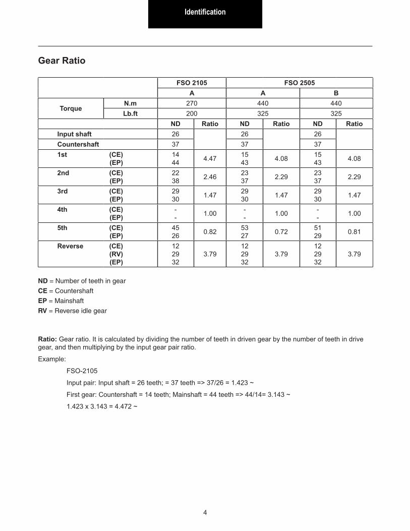
Ratio: Gear ratio. It is calculated by dividing the number of teeth in driven gear by the number of teeth in drive gear, and then multiplying by the input gear pair ratio.
Example:
FSO-2105
Input pair: Input shaft = 26 teeth; = 37 teeth => 37/26 = 1.423 ~
First gear: Countershaft = 14 teeth; Mainshaft = 44 teeth => 44/14= 3.143 ~
1.423 x 3.143 = 4.472 ~
FSO 2105 FSO 2505A A B
TorqueN.m 270 440 440Lb.ft 200 325 325
ND Ratio ND Ratio ND RatioInput shaft 26 26 26Countershaft 37 37 371st (CE) (EP)
14 44 4.47 15
43 4.08 15 43 4.08
2nd (CE) (EP)
22 38 2.46 23
37 2.29 23 37 2.29
3rd (CE) (EP)
29 30 1.47 29
30 1.47 29 30 1.47
4th (CE) (EP)
- - 1.00 -
- 1.00 - - 1.00
5th (CE) (EP)
45 26 0.82 53
27 0.72 51 29 0.81
Reverse (CE) (RV) (EP)
12 29 32
3.7912 29 32
3.7912 29 32
3.79
ND = Number of teeth in gear
CE = Countershaft
EP = Mainshaft
RV = Reverse idle gear
Gear Ratio

Exploded ViewsExploded Views
5
FSO-2105/explo5
FSO-2105 Model
Direct Control Assembly
1. Gear shift lever housing2. Threaded pin3. Locating pin4. Spring5. Threaded plug6. Gear shift lever pivoting
support
7. Thrust washer8. Boot9. Gear shift lever10. Pivot pin11. Gear shift lever bushing12. Shock-absorbing rubber
gasket
13. Flat washer14. Support spacer15. Shock-absorbing bushing16. Washer17. Screw M8 x 35
Exploded Views
6
FSO-2105/explo4
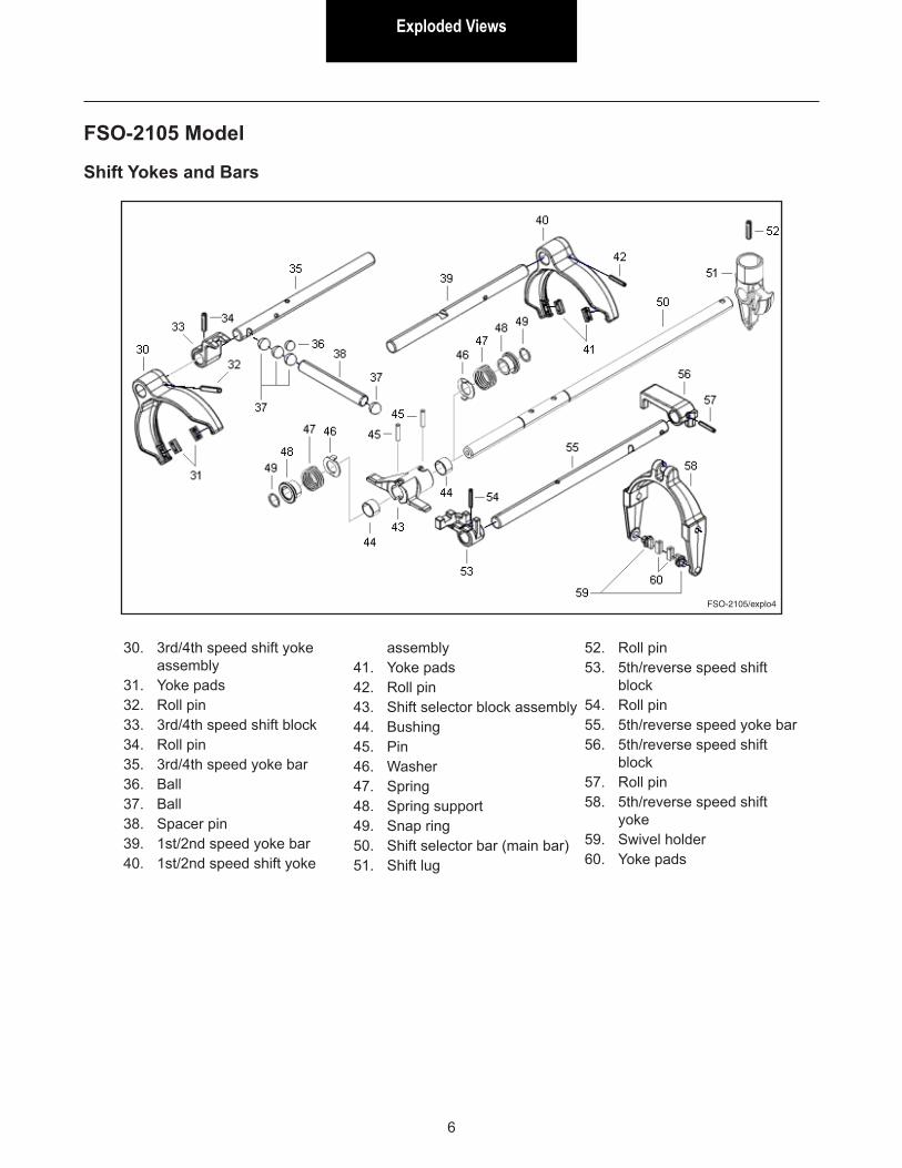
FSO-2105 Model
Shift Yokes and Bars
30. 3rd/4th speed shift yoke assembly
31. Yoke pads32. Roll pin33. 3rd/4th speed shift block34. Roll pin35. 3rd/4th speed yoke bar36. Ball37. Ball38. Spacer pin39. 1st/2nd speed yoke bar40. 1st/2nd speed shift yoke
assembly41. Yoke pads42. Roll pin43. Shift selector block assembly44. Bushing45. Pin46. Washer47. Spring48. Spring support49. Snap ring50. Shift selector bar (main bar)51. Shift lug
52. Roll pin53. 5th/reverse speed shift
block54. Roll pin55. 5th/reverse speed yoke bar56. 5th/reverse speed shift
block57. Roll pin58. 5th/reverse speed shift
yoke59. Swivel holder60. Yoke pads
Exploded ViewsExploded Views
7
FSO-2105/explo1
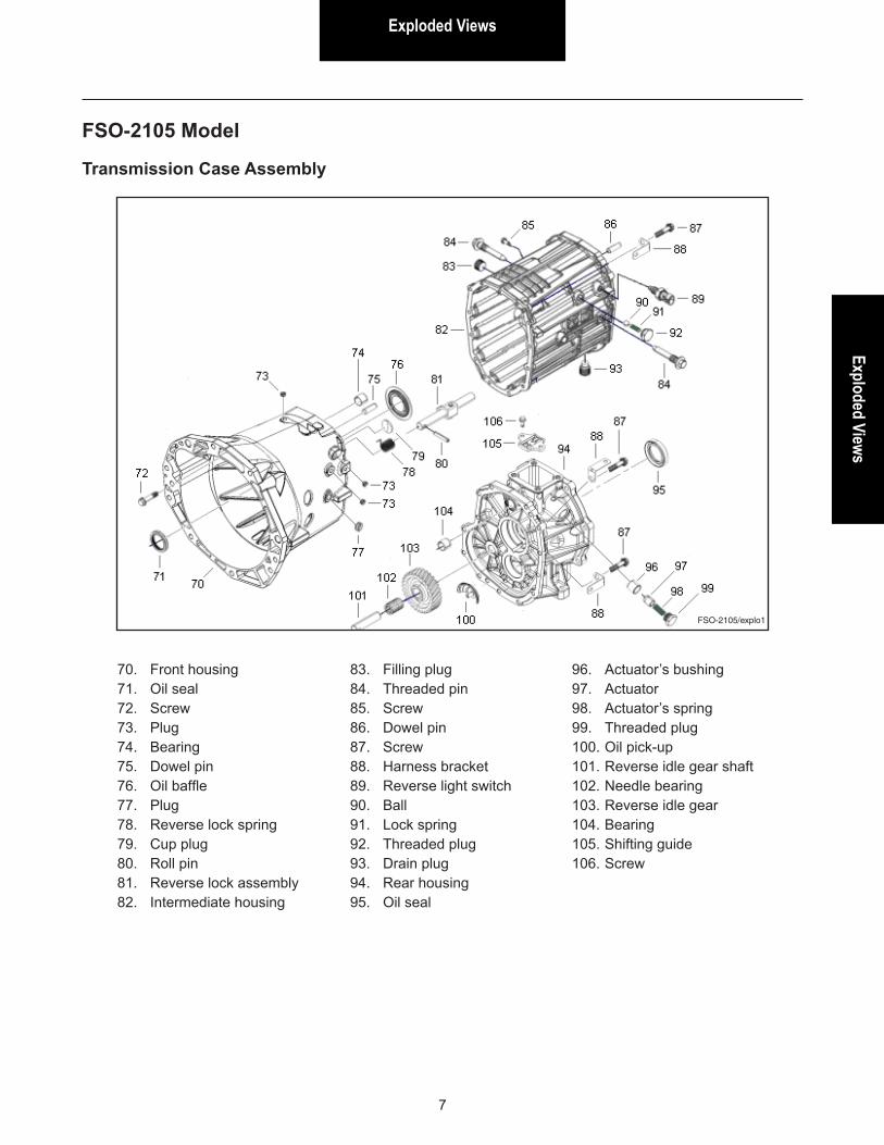
FSO-2105 Model
Transmission Case Assembly
70. Front housing71. Oil seal72. Screw73. Plug74. Bearing75. Dowel pin76. Oil baffle77. Plug78. Reverse lock spring79. Cup plug80. Roll pin81. Reverse lock assembly82. Intermediate housing
83. Filling plug84. Threaded pin85. Screw86. Dowel pin87. Screw88. Harness bracket89. Reverse light switch90. Ball91. Lock spring92. Threaded plug93. Drain plug94. Rear housing95. Oil seal
96. Actuator’s bushing97. Actuator98. Actuator’s spring99. Threaded plug100. Oil pick-up101. Reverse idle gear shaft102. Needle bearing103. Reverse idle gear104. Bearing105. Shifting guide106. Screw

Exploded Views
8
FSO-2105/explo2
FSO-2105 Model
Input Shaft / Mainshaft Assembly
110. Input shaft bearing cup111. Input shaft bearing cone112. Input shaft113. 4th speed synchronizer cone114. Snap ring115. 4th speed synchronizer ring116. Mainshaft front bearing cone117. Snap ring 2.175 mm117. Snap ring 2.250 mm117. Snap ring 2.325 mm118. 3rd/4th speed synchronizer
assembly119. Spring120. Key121. 3rd speed synchronizer ring122. Mainshaft 3rd speed gear
cone123. Mainshaft 3rd speed gear124. Needle bearing
125. Mainshaft126. Needle bearing127. Mainshaft 2nd speed gear128. Mainshaft 2nd speed gear
cone129. Snap ring130. 1st/2nd speed synchronizer
inner ring131. 1st/2nd speed synchronizer
middle ring132. 1st/2nd speed synchronizer
outer ring133. 1st/2nd speed synchronizer
assembly134. Key135. Mainshaft 1st speed gear136. Needle bearing137. Bushing
138. Mainshaft intermediate bearing cone
139. Mainshaft intermediate bearing cup
140. Shim 0.050 mm140. Shim 0.102 mm140. Shim 0.178 mm140. Shim 0.254 mm140. Shim 0.508 mm140. Shim 0.762 mm140. Shim 1.016 mm141. Mainshaft 5th speed gear142. Spacer143. Mainshaft reverse speed
gear144. Ball bearing145. Nut
Exploded ViewsExploded Views
9
FSO-2105/explo3
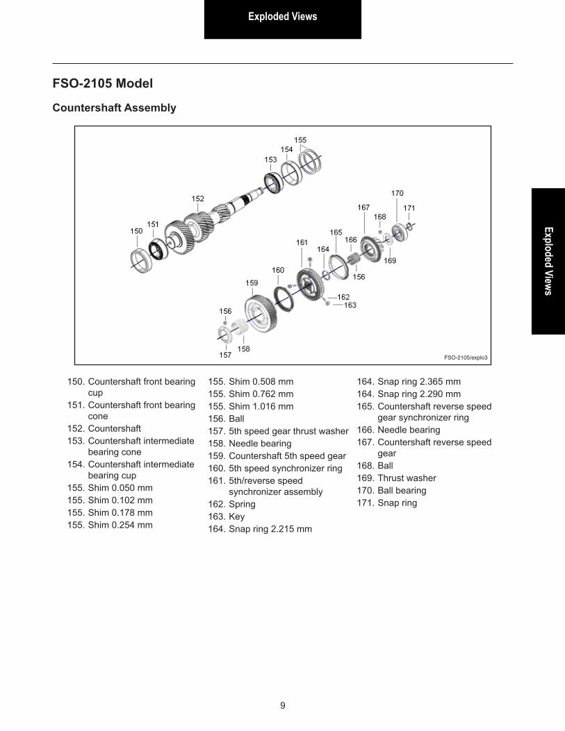
FSO-2105 Model
Countershaft Assembly
150. Countershaft front bearing cup
151. Countershaft front bearing cone
152. Countershaft153. Countershaft intermediate
bearing cone154. Countershaft intermediate
bearing cup155. Shim 0.050 mm155. Shim 0.102 mm155. Shim 0.178 mm155. Shim 0.254 mm
155. Shim 0.508 mm155. Shim 0.762 mm155. Shim 1.016 mm156. Ball157. 5th speed gear thrust washer158. Needle bearing159. Countershaft 5th speed gear160. 5th speed synchronizer ring161. 5th/reverse speed
synchronizer assembly162. Spring163. Key164. Snap ring 2.215 mm
164. Snap ring 2.365 mm164. Snap ring 2.290 mm165. Countershaft reverse speed
gear synchronizer ring166. Needle bearing167. Countershaft reverse speed
gear168. Ball169. Thrust washer170. Ball bearing171. Snap ring
Exploded Views
10
FSO-2105/explo5
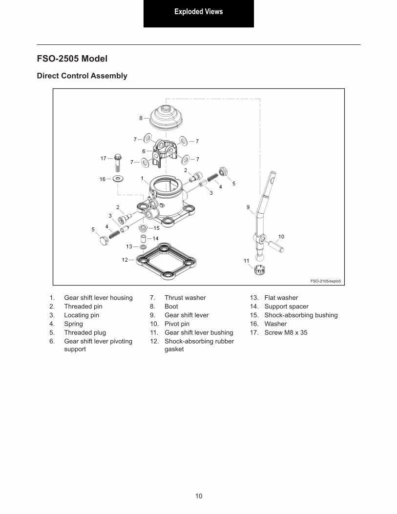
FSO-2505 Model
Direct Control Assembly
1. Gear shift lever housing2. Threaded pin3. Locating pin4. Spring5. Threaded plug6. Gear shift lever pivoting
support
7. Thrust washer8. Boot9. Gear shift lever10. Pivot pin11. Gear shift lever bushing12. Shock-absorbing rubber
gasket
13. Flat washer14. Support spacer15. Shock-absorbing bushing16. Washer17. Screw M8 x 35

Exploded ViewsExploded Views
11
FSO-2105/explo4
FSO-2505 Model
Shift Yokes and Bars
30. 3rd/4th speed shift yoke assembly
31. Yoke pads32. Roll pin33. 3rd/4th speed shift block34. Roll pin35. 3rd/4th speed yoke bar36. Ball37. Ball38. Spacer pin39. 1st/2nd speed yoke bar40. 1st/2nd speed shift yoke
assembly
41. Yoke pads42. Roll pin43. Shift selector block assembly44. Bushing45. Pin46. Washer47. Spring48. Spring support49. Snap ring50. Shift selector bar (main bar)51. Shift lug52. Roll pin
53. 5th/reverse speed shift block
54. Roll pin55. 5th/reverse speed yoke bar56. 5th/reverse speed shift
block57. Roll pin58. 5th/reverse speed shift
yoke59. Swivel holder60. Yoke pads

Exploded Views
12
FSO-2105/explo1
FSO-2505 Model
Transmission Case Assembly
70. Front housing71. Oil seal72. Screw73. Plug74. Bearing75. Dowel pin76. Oil baffle77. Plug78. Reverse lock spring79. Cup plug80. Roll pin81. Reverse lock assembly82. Intermediate housing
83. Filling plug84. Threaded pin85. Screw86. Dowel pin87. Screw88. Harness bracket89. Reverse light switch90. Ball91. Lock spring92. Threaded plug93. Drain plug94. Rear housing95. Oil seal
96. Actuator’s bushing97. Actuator98. Actuator’s spring99. Threaded plug100. Oil pick-up101. Reverse idle gear shaft102. Needle bearing103. Reverse idle gear104. Bearing105. Shifting guide106. Screw
Exploded ViewsExploded Views
13
FSO-2105/explo2
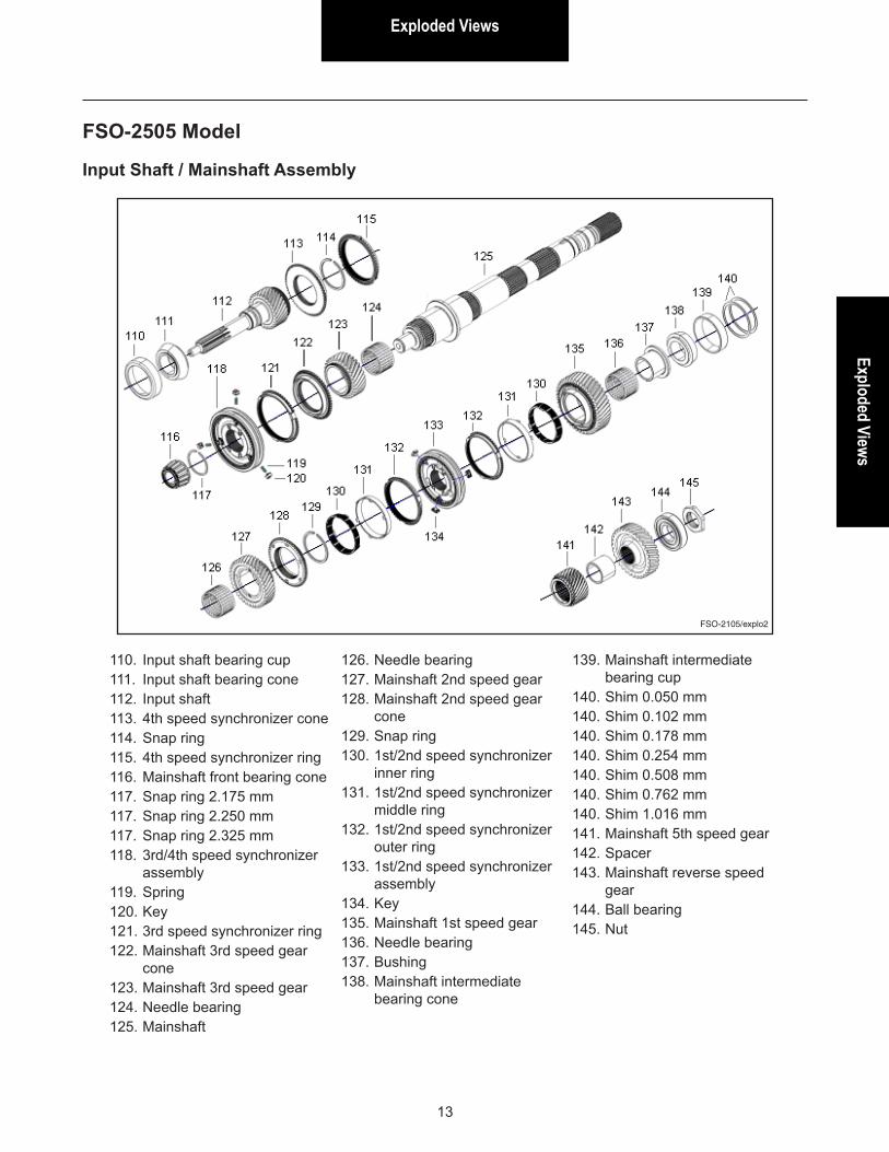
FSO-2505 Model
Input Shaft / Mainshaft Assembly
110. Input shaft bearing cup111. Input shaft bearing cone112. Input shaft113. 4th speed synchronizer cone114. Snap ring115. 4th speed synchronizer ring116. Mainshaft front bearing cone117. Snap ring 2.175 mm117. Snap ring 2.250 mm117. Snap ring 2.325 mm118. 3rd/4th speed synchronizer
assembly119. Spring120. Key121. 3rd speed synchronizer ring122. Mainshaft 3rd speed gear
cone123. Mainshaft 3rd speed gear124. Needle bearing125. Mainshaft
126. Needle bearing127. Mainshaft 2nd speed gear128. Mainshaft 2nd speed gear
cone129. Snap ring130. 1st/2nd speed synchronizer
inner ring131. 1st/2nd speed synchronizer
middle ring132. 1st/2nd speed synchronizer
outer ring133. 1st/2nd speed synchronizer
assembly134. Key135. Mainshaft 1st speed gear136. Needle bearing137. Bushing138. Mainshaft intermediate
bearing cone
139. Mainshaft intermediate bearing cup
140. Shim 0.050 mm140. Shim 0.102 mm140. Shim 0.178 mm140. Shim 0.254 mm140. Shim 0.508 mm140. Shim 0.762 mm140. Shim 1.016 mm141. Mainshaft 5th speed gear142. Spacer143. Mainshaft reverse speed
gear144. Ball bearing145. Nut
Exploded Views
14
FSO-2105/explo3
FSO-2505 Model
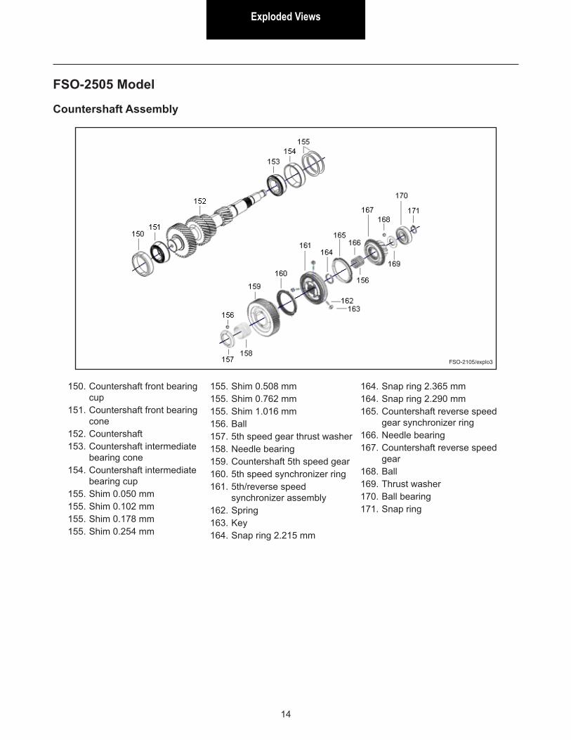
Countershaft Assembly
150. Countershaft front bearing cup
151. Countershaft front bearing cone
152. Countershaft153. Countershaft intermediate
bearing cone154. Countershaft intermediate
bearing cup155. Shim 0.050 mm155. Shim 0.102 mm155. Shim 0.178 mm155. Shim 0.254 mm
155. Shim 0.508 mm155. Shim 0.762 mm155. Shim 1.016 mm156. Ball157. 5th speed gear thrust washer158. Needle bearing159. Countershaft 5th speed gear160. 5th speed synchronizer ring161. 5th/reverse speed
synchronizer assembly162. Spring163. Key164. Snap ring 2.215 mm
164. Snap ring 2.365 mm164. Snap ring 2.290 mm165. Countershaft reverse speed
gear synchronizer ring166. Needle bearing167. Countershaft reverse speed
gear168. Ball169. Thrust washer170. Ball bearing171. Snap ring
Lubrication Information
Lubrication Information
15
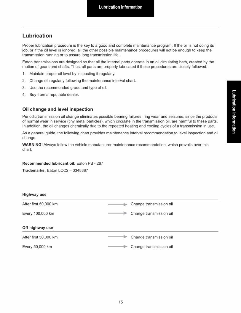
Highway use
After first 50,000 km Change transmission oil
Every 100,000 km Change transmission oil
Off-highway use
After first 50,000 km Change transmission oil
Every 50,000 km Change transmission oil
LubricationProper lubrication procedure is the key to a good and complete maintenance program. If the oil is not doing its job, or if the oil level is ignored, all the other possible maintenance procedures will not be enough to keep the transmission running or to assure long transmission life.
Eaton transmissions are designed so that all the internal parts operate in an oil circulating bath, created by the motion of gears and shafts. Thus, all parts are properly lubricated if these procedures are closely followed:
1. Maintain proper oil level by inspecting it regularly.
2. Change oil regularly following the maintenance interval chart.
3. Use the recommended grade and type of oil.
4. Buy from a reputable dealer.
Oil change and level inspectionPeriodic transmission oil change eliminates possible bearing failures, ring wear and seizures, since the products of normal wear in service (tiny metal particles), which circulate in the transmission oil, are harmful to these parts. In addition, the oil changes chemically due to the repeated heating and cooling cycles of a transmission in use.
As a general guide, the following chart provides maintenance interval recommendation to level inspection and oil change.
WARNING! Always follow the vehicle manufacturer maintenance recommendation, which prevails over this chart.
Recommended lubricant oil: Eaton PS - 267
Trademarks: Eaton LCC2 – 3348887
Lubrication Information
16
DrainingDrain transmission oil while the oil is warm. To drain oil, remove the magnetic drain plug.
Clean the drain plug before re-installing it.
Refilling
FSO-2105/02
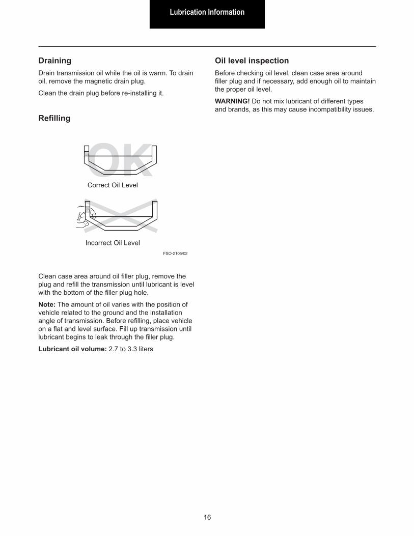
Clean case area around oil filler plug, remove the plug and refill the transmission until lubricant is level with the bottom of the filler plug hole.
Note: The amount of oil varies with the position of vehicle related to the ground and the installation angle of transmission. Before refilling, place vehicle on a flat and level surface. Fill up transmission until lubricant begins to leak through the filler plug.
Lubricant oil volume: 2.7 to 3.3 liters
Correct Oil Level
Incorrect Oil Level
Oil level inspectionBefore checking oil level, clean case area around filler plug and if necessary, add enough oil to maintain the proper oil level.
WARNING! Do not mix lubricant of different types and brands, as this may cause incompatibility issues.
OperationOperation
17
Gear shift lever pattern
FSO-2105/03
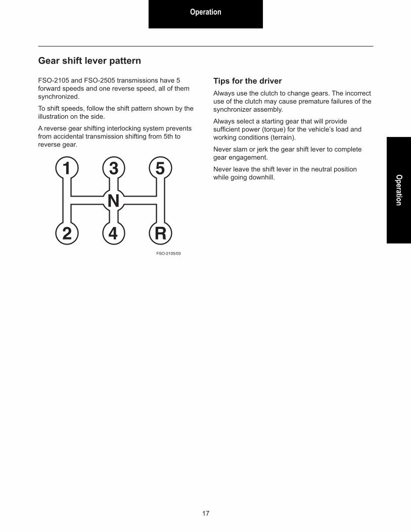
FSO-2105 and FSO-2505 transmissions have 5 forward speeds and one reverse speed, all of them synchronized.
To shift speeds, follow the shift pattern shown by the illustration on the side.
A reverse gear shifting interlocking system prevents from accidental transmission shifting from 5th to reverse gear.
Tips for the driverAlways use the clutch to change gears. The incorrect use of the clutch may cause premature failures of the synchronizer assembly.
Always select a starting gear that will provide sufficient power (torque) for the vehicle’s load and working conditions (terrain).
Never slam or jerk the gear shift lever to complete gear engagement.
Never leave the shift lever in the neutral position while going downhill.
Power Flow
18
Power FlowThe transmission must efficiently transfer the engine’s power or torque to the vehicle’s driveline.
It is essential to know what takes place in the transmission during torque transfer when troubleshooting or making repairs.
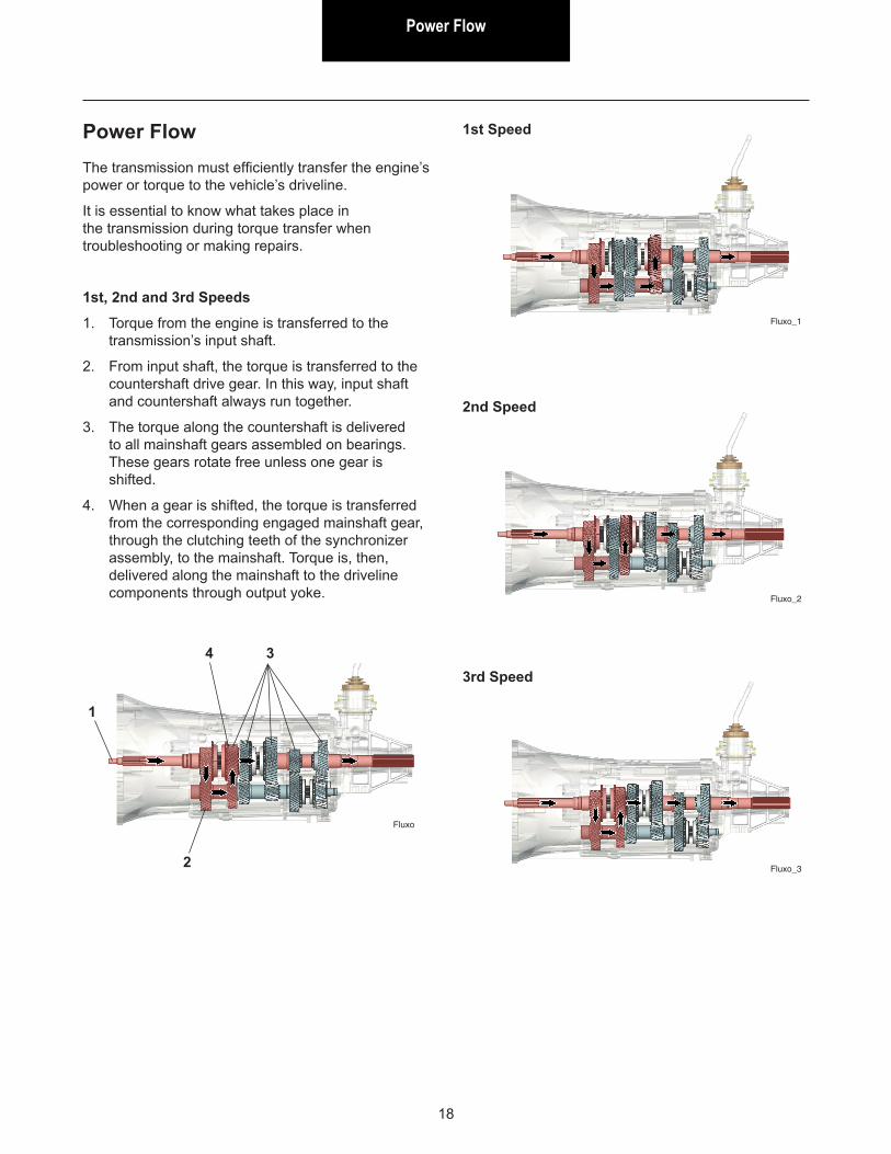
1st, 2nd and 3rd Speeds
1. Torque from the engine is transferred to the transmission’s input shaft.
2. From input shaft, the torque is transferred to the countershaft drive gear. In this way, input shaft and countershaft always run together.
3. The torque along the countershaft is delivered to all mainshaft gears assembled on bearings. These gears rotate free unless one gear is shifted.
4. When a gear is shifted, the torque is transferred from the corresponding engaged mainshaft gear, through the clutching teeth of the synchronizer assembly, to the mainshaft. Torque is, then, delivered along the mainshaft to the driveline components through output yoke.
Fluxo
1st Speed
1
2
34
Fluxo_1
2nd Speed
Fluxo_2
3rd Speed
Fluxo_3
Power FlowPower Flow
19
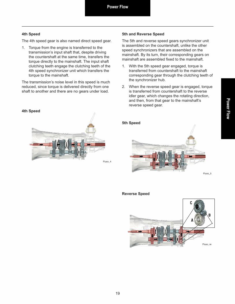
4th Speed
The 4th speed gear is also named direct speed gear.
1. Torque from the engine is transferred to the transmission’s input shaft that, despite driving the countershaft at the same time, transfers the torque directly to the mainshaft. The input shaft clutching teeth engage the clutching teeth of the 4th speed synchronizer unit which transfers the torque to the mainshaft.
The transmission’s noise level in this speed is much reduced, since torque is delivered directly from one shaft to another and there are no gears under load.
5th and Reverse Speed
The 5th and reverse speed gears synchronizer unit is assembled on the countershaft, unlike the other speed synchronizers that are assembled on the mainshaft. By its turn, their corresponding gears on mainshaft are assembled fixed to the mainshaft.
1. With the 5th speed gear engaged, torque is transferred from countershaft to the mainshaft corresponding gear through the clutching teeth of the synchronizer hub.
2. When the reverse speed gear is engaged, torque is transferred from countershaft to the reverse idler gear, which changes the rotating direction, and then, from that gear to the mainshaft’s reverse speed gear.
4th Speed
Fluxo_4
5th Speed
Fluxo_5
Reverse Speed
Fluxo_re
Adhesive and Sealant Application
20
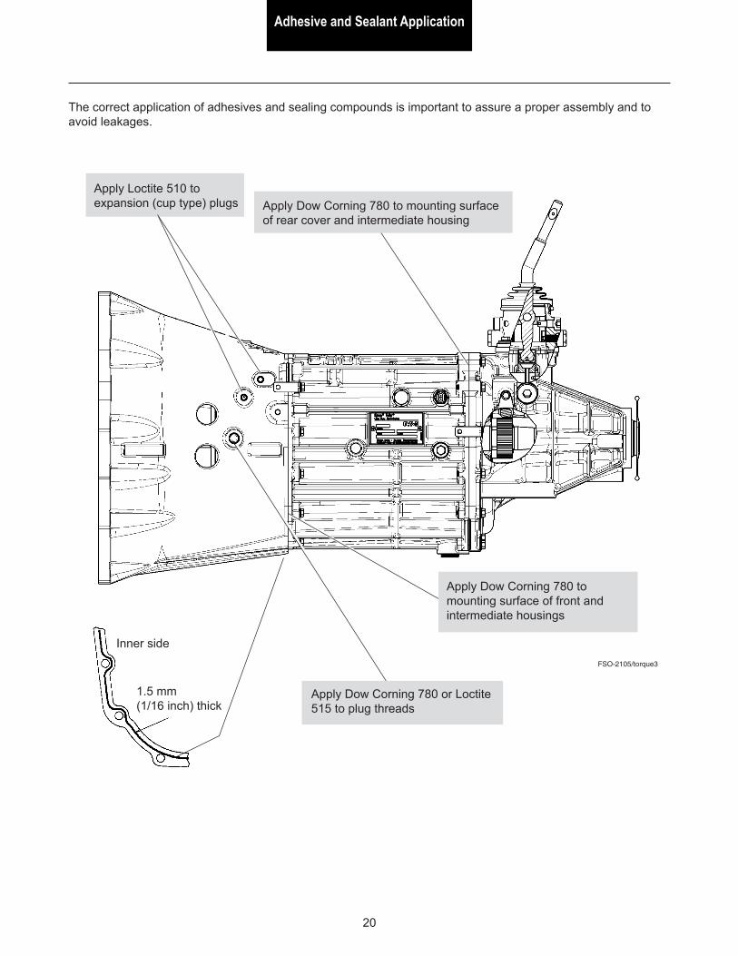
Inner side
1.5 mm (1/16 inch) thick
The correct application of adhesives and sealing compounds is important to assure a proper assembly and to avoid leakages.
FSO-2105/torque3
Apply Dow Corning 780 or Loctite 515 to plug threads
Apply Dow Corning 780 to mounting surface of rear cover and intermediate housing
Apply Dow Corning 780 to mounting surface of front and intermediate housings
Apply Loctite 510 to expansion (cup type) plugs
Torque Recomm
endationTorque Recommendation
21
FSO-2105/torque1 FSO-2105/torque2
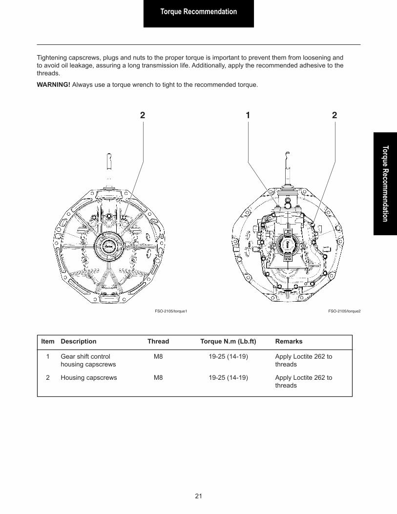
Tightening capscrews, plugs and nuts to the proper torque is important to prevent them from loosening and to avoid oil leakage, assuring a long transmission life. Additionally, apply the recommended adhesive to the threads.
WARNING! Always use a torque wrench to tight to the recommended torque.
2
Item Description Thread Torque N.m (Lb.ft) Remarks
1 Gear shift control M8 19-25 (14-19) Apply Loctite 262 to housing capscrews threads
2 Housing capscrews M8 19-25 (14-19) Apply Loctite 262 to threads
21

Torque Recommendation
22
FSO-2105/torque3
Item Description Thread Torque N.m (Lb.ft) Remarks
3 Oil fill plug 3/4” - 14 NPTF 40-47 (29-34) Apply Loctite 570 or 518 to threads 4 Reverse light switch M14 14-20 (10-15) Apply Dow Corning 780 to switch face 5 Gear shift control M12 10-16 (7-12) Apply Dow Corning 780 housing threaded pin to pin face only
6 Gear shift control M16 14-21 (10-15) Apply Dow Corning 780 housing threaded plug to thrust face
7 Shift control actuator M24 10-16 (7-12) Apply Dow Corning 780 plug to thrust face
8 Speedometer sensor 13-16” - 20 UNEF 10-16 (7-12) Apply Loctite 262 to threads
9 Mainshaft nut M37 217-270 (160-200) Lock the nut in position using a center punch
10 Oil drain plug 3/4” - 14 NPTF 40-47 (29-34) Apply Dow Corning 780 or Loctite 515 to threads
11 Threaded pin M12 19-26 (14-19) Apply Dow Corning 780 to contact face with housing
3 4 76
91011
5
8
5
PrecautionsPrecautions
23
Precautions during disassembly and assembly
In order to prevent damage to transmission parts during initial gear movement, it is important when assembling the transmission, to lubricate gear bearings, needle bearings, non sealed bearings and all other parts under friction conditions, with the same transmission lubricant oil.
Cleaning and handlingIn order to completely clean the parts, wash them into a bath of solvent (kerosene, for instance), moving every part up and down slowly until all the old lubricant and foreign material have been dissolved.
Care must be taken to avoid skin rashes, fire hazard and vapor inhalation when using solvents.
Non sealed bearingsImmerse the bearings in clean solvent. Move them up and down slowly in order to loosen the deposits. Dry the bearings by means of moisture free compressed-air. Repeat the operation until the bearings are thoroughly clean.
Never drive the air jet directly to bearings in order to rotate them in high speed. That can damage bearings.
Synchronizer assembliesAvoid bad handling of synchronizer assemblies. Either drops or bumps when disassembling or assembling may cause them to lock.
HousingsClean interior and exterior of cases, covers, etc., thoroughly. Cast parts may be cleaned in weak alkaline solution baths (we recommend a 7% soluble degreasing oil solution). The parts are to remain in the bath for the time it takes to become completely clean. The parts cleaned in alkaline solutions should be rinsed with clean water to remove any alkaline trace after cleaning process.
Care must to be taken to avoid vapor inhalation and skin rashes when using alkaline solutions. Every cleaned part must be totally dried at once by means of moisture free compressed-air, or else, by means of a lint free soft cloth, not containing any abrasive material such as metal filings, contaminated oil or polishing compounds.
InspectionA thorough and careful inspection of each part is very important for the transmission life. The replacement of parts showing either wear or fatigue will avoid future expensive and foreseen failures.
Gears, shafts and synchronizer assembliesWhenever magna-flux is available, this process should be used to check the parts.
Check carefully gear teeth for wear, pitting, chipping and cracks. If gear teeth show areas where the case hardening is worn through or cracked, the gear should be replaced.
Check shafts for warping and excessive wear or damaged splines.
Precautions
24
Cases, covers, etc.Make sure cases, covers, etc. are completely clean and that mounting surfaces and bearing bores are free from nicks or burrs. Check carefully every part for cracks, excessive wear or for any other condition that may cause oil leak or a future failure.
Needle roller bearingsCheck carefully every needle roller for wear, pitting or spalled areas to determine whether they are suitable for reuse or replacement. After inspection, dip the needle roller bearings in an oil bath and then wrap them in a lint free cloth or paper, so as to protect them until they are ready for assembling.
Parts replacementWhen replacement is necessary, use only genuine Eaton transmission parts to assure continued performance and extended life from the transmission. The use of either non-genuine or remanufactured parts, besides have not the factory’s warranty, may lead to severe damage of the unit.
Since the cost of a new part is generally a small fraction of the total cost of downtime and labor, do not reuse a questionable part which could lead to additional repairs and expense soon after assembly.
To aid in determining the reuse or replacement of any transmission part, consideration should also be given to the unit’s history, mileage, application, etc.
Oil seals and snap ringselásticosAny oil seal, snap ring, etc. damaged during maintenance, should be replaced by a new one. Replacement of oil seals and snap rings is cheaper when unit is disassembled than a premature overhaul to replace these parts in a future time.
An oil leakage through a worn seal may result in failures of other more expensive components of the transmission. The sealing elements should be handled carefully, particularly during assembly. Cuts, scratches or rolled up seal lips decrease the sealing efficiency.
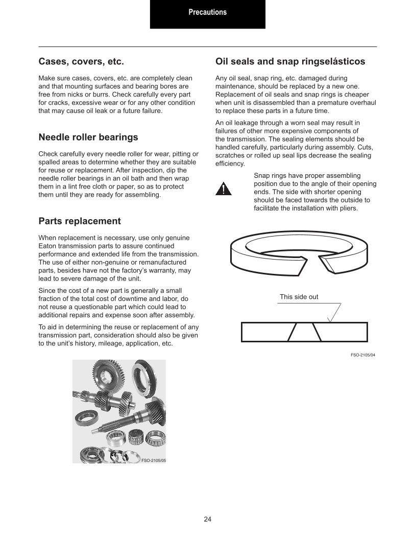
Snap rings have proper assembling position due to the angle of their opening ends. The side with shorter opening should be faced towards the outside to facilitate the installation with pliers.
FSO-2105/04
This side out
FSO-2105/05
TroubleshootingTroubleshooting
25
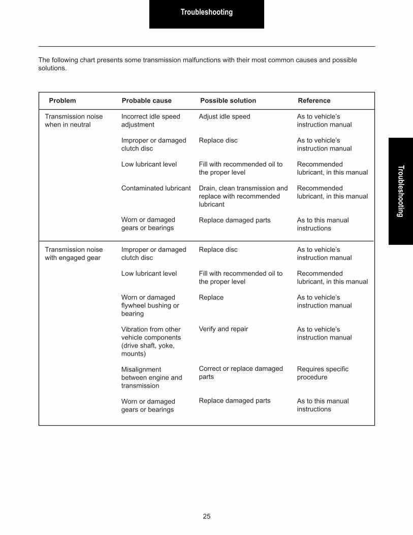
The following chart presents some transmission malfunctions with their most common causes and possible solutions.
Problem Probable cause Possible solution Reference
Transmission noise when in neutral
Incorrect idle speed adjustment
Improper or damaged clutch disc
Low lubricant level
Contaminated lubricant
Worn or damaged gears or bearings
Adjust idle speed
Replace disc
Fill with recommended oil to the proper level
Drain, clean transmission and replace with recommended lubricant
Replace damaged parts
As to vehicle’s instruction manual
As to vehicle’s instruction manual
Recommended lubricant, in this manual
Recommended lubricant, in this manual
As to this manual instructions
Transmission noise with engaged gear
Improper or damaged clutch disc
Low lubricant level
Worn or damaged flywheel bushing or bearing
Vibration from other vehicle components (drive shaft, yoke, mounts)
Misalignment between engine and transmission
Worn or damaged gears or bearings
Replace disc
Fill with recommended oil to the proper level
Replace
Verify and repair
Correct or replace damaged parts
Replace damaged parts
As to vehicle’s instruction manual
Recommended lubricant, in this manual
As to vehicle’s instruction manual
As to vehicle’s instruction manual
Requires specific procedure
As to this manual instructions

Troubleshooting
26
Problem Probable cause Possible solution Reference
Hard shifting Malfunction of clutch
Worn or damaged flywheel bushing or bearing
Non-recommended lubricant
Worn or damaged gear shift lever components
Worn or damaged synchronizer rings
Excessively worn or damaged synchronizer assemblies (springs, keys, sleeve or hub)
Worn or damaged shifting system components (shift yokes, nylon pads, bars, shift blocks)
Mainshaft or countershaft end play improperly
Verify and adjust clutch
Replace
Replace
Replace damaged parts
Replace rings
Replace synchronizer assemblies
Replace worn or damaged parts
Adjust end play
As to vehicle’s instruction manual
As to vehicle’s instruction manual
Recommended lubricant, in this manual
Gear shift lever housing, in this manual
Synchronizer assemblies, in this manual
Synchronizer assemblies, in this manual
As to this manual instructions
End play adjustment, in this manual
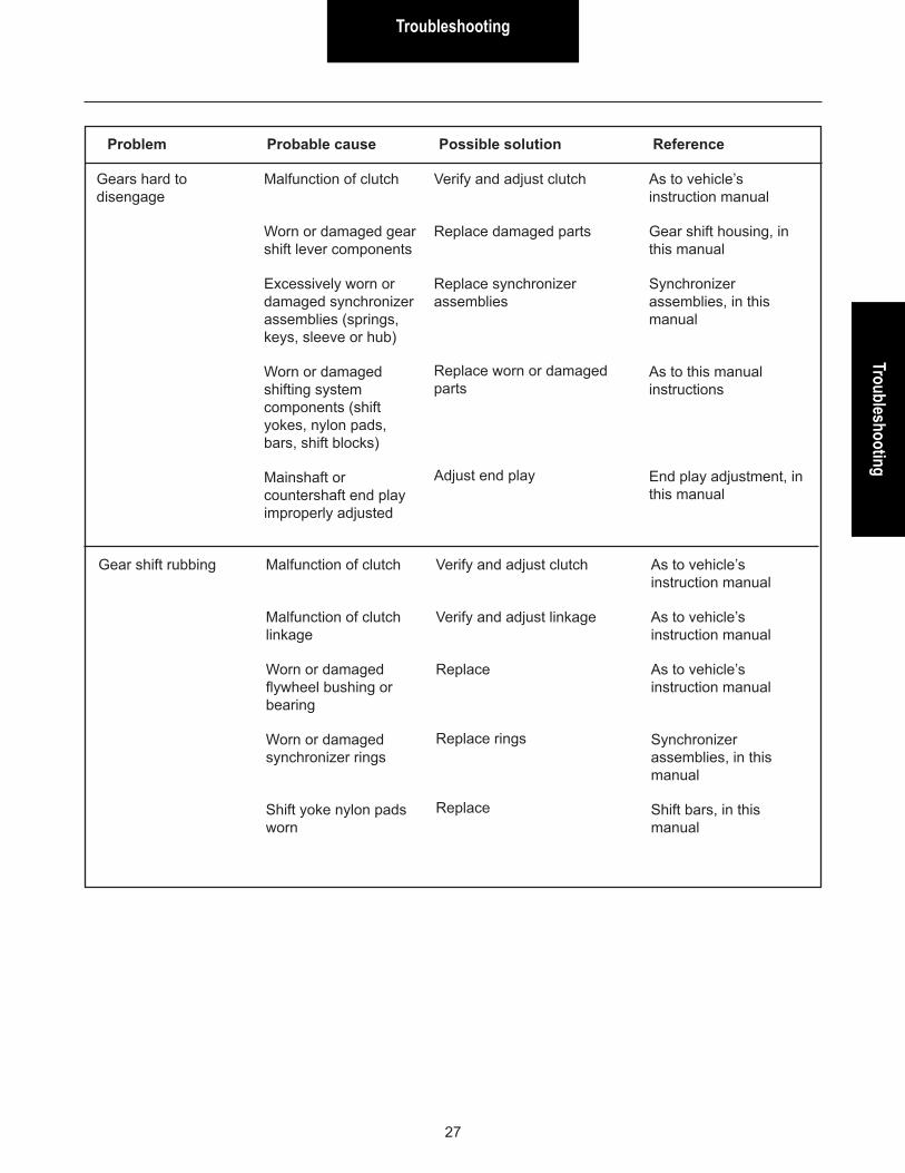
TroubleshootingTroubleshooting
27
Gears hard to disengage
Malfunction of clutch
Worn or damaged gear shift lever components
Excessively worn or damaged synchronizer assemblies (springs, keys, sleeve or hub)
Worn or damaged shifting system components (shift yokes, nylon pads, bars, shift blocks)
Mainshaft or countershaft end play improperly adjusted
Verify and adjust clutch
Replace damaged parts
Replace synchronizer assemblies
Replace worn or damaged parts
Adjust end play
As to vehicle’s instruction manual
Gear shift housing, in this manual
Synchronizer assemblies, in this manual
As to this manual instructions
End play adjustment, in this manual
Problem Probable cause Possible solution Reference
Gear shift rubbing Malfunction of clutch
Malfunction of clutch linkage
Worn or damaged flywheel bushing or bearing
Worn or damaged synchronizer rings
Shift yoke nylon pads worn
Verify and adjust clutch
Verify and adjust linkage
Replace
Replace rings
Replace
As to vehicle’s instruction manual
As to vehicle’s instruction manual
As to vehicle’s instruction manual
Synchronizer assemblies, in this manual
Shift bars, in this manual

Troubleshooting
28
Problem Probable cause Possible solution Reference
Oil leak Lubricant above proper level
Clogged breather
Worn or damaged oil seals
Housing capscrews not properly tightened or lack of sealant
Cracked or damaged housings
Correct to proper lubricant level
Verify an clean breather
Replace
Reassemble applying sealant and torque properly
Replace or repair damaged parts
Recommended lubricant, in this manual
As to this manual instructions
As to this manual instructions
Requires specific procedure
Transmission slips out of gear
Gear shift lever console out of position, forcing the lever
Worn or damaged synchronizer assemblies
1st/2nd and 3rd/4th synchronizer hub swapped (anti-escape relief)
Mainshaft or countershaft end play improperly adjusted
Worn or damaged shifting system components (gear shift lever, shift yokes, bars, shift blocks, etc.)
Adjust console
Replace synchronizer assemblies
Remove and assemble properly
Adjust end play
Replace worn or damaged parts
As to vehicle’s instruction manual
Synchronizer assemblies, in this manual
Synchronizer , in this manual
End play adjustment, in this manual
As to this manual instructions

TroubleshootingTroubleshooting
29
Problem Probable cause Possible solution Reference
Double shifting Double gear shifting interlocking system improperly assembled
Reassemble properly As to this manual instructions
Bearing failures Low lubricant level
Contaminated or non-recommended lubricant
Transmission components assembled improperly
Mainshaft or countershaft end play improperly adjusted
Bearings were not lubricated before assembling
Fill with recommended oil to the proper level
Drain and replace with recommended lubricant
Reassemble
Adjust end play
Replace damaged parts. Reassemble as to proper procedure
Recommended lubricant, in this manual
Recommended lubricant, in this manual
As to this manual instructions
End play adjustment, in this manual
As to this manual instructions
Tool Information
30
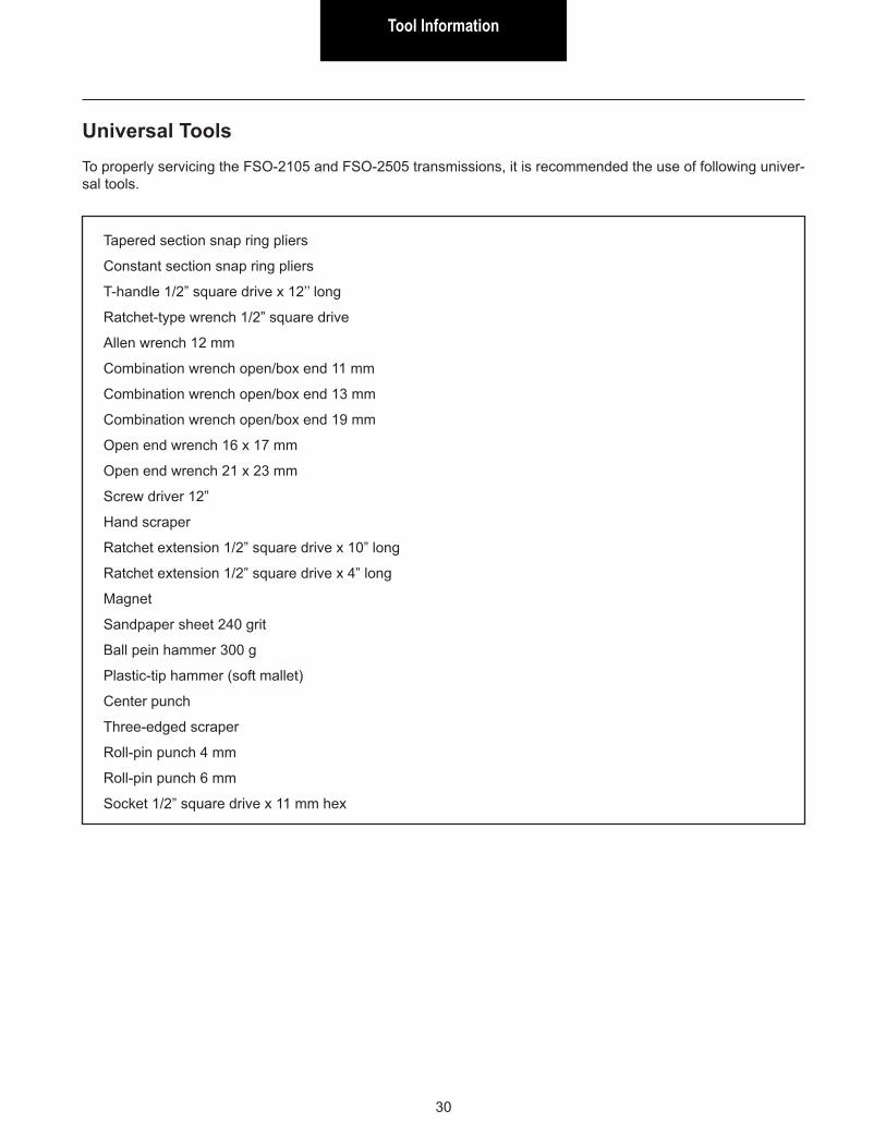
Universal ToolsTo properly servicing the FSO-2105 and FSO-2505 transmissions, it is recommended the use of following univer-sal tools.
Tapered section snap ring pliers
Constant section snap ring pliers
T-handle 1/2” square drive x 12’’ long
Ratchet-type wrench 1/2” square drive
Allen wrench 12 mm
Combination wrench open/box end 11 mm
Combination wrench open/box end 13 mm
Combination wrench open/box end 19 mm
Open end wrench 16 x 17 mm
Open end wrench 21 x 23 mm
Screw driver 12”
Hand scraper
Ratchet extension 1/2” square drive x 10” long
Ratchet extension 1/2” square drive x 4” long
Magnet
Sandpaper sheet 240 grit
Ball pein hammer 300 g
Plastic-tip hammer (soft mallet)
Center punch
Three-edged scraper
Roll-pin punch 4 mm
Roll-pin punch 6 mm
Socket 1/2” square drive x 11 mm hex

Tool Information
Tool Information
31
Illustration Tool Ref. DescriptionE001010 Permaglide bushing
installer
E001086 Front oil seal installer
E003001 Slide hammer (impact puller)
E004002 Slide hammer adapter end - for removing expansion plug
E005003 Pocket bearing cone puller
E006003 Special socket 54 mm (*)
E006004 Spline socket for input shaft – 23 splinesApplication: Ranger 4x2 / Ranger 4x4 / Crosslander
Illustration Tool Ref. DescriptionE006005 Spline socket for
input shaft – 10 splinesApplication: Frontier 4x2 / Frontier 4x4 / VM Motori / S10 4x2 / S10 4x4 / L200 RS 4x4 / Jinbei / Troller Jeep 4x4 / Troller Pickup 4x2
E007002 Input shaft bearing cone puller
E007007 Mainshaft bearing cone puller
E007008 Countershaft bearing cone puller
E012001 2-Hook puller
E012002 Reverse gear pullerNote: Use with E012001
E012003 Input shaft bearing pullerNote: Use with E012001
E012004 Front housing bearing cup remover
(*) Note: This tool is used as an option for locking the transmission mainshaft, allowing transmission disassembly and assembly by one mechanic only. The tool allows using transmission gear ratio as a means to help in removing and installing the mainshaft nut.
Essential Special ToolsFollowing tools are essential special tools, required for properly servicing the transmission. The non-use of these essential special tools, the higher are the chances of causing damage to the transmission during disassembly and assembly procedures.
Tool Information
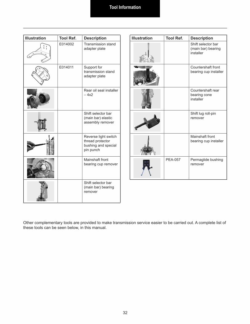
32
Illustration Tool Ref. DescriptionE014002 Transmission stand
adapter plate
E014011 Support for transmission stand adapter plate
Rear oil seal installer – 4x2
Shift selector bar (main bar) elastic assembly remover
Reverse light switch thread protector bushing and special pin punch
Mainshaft front bearing cup remover
Shift selector bar (main bar) bearing remover
Illustration Tool Ref. DescriptionShift selector bar (main bar) bearing installer
Countershaft front bearing cup installer
Countershaft rear bearing cone installer
Shift lug roll-pin remover
Mainshaft front bearing cup installer
PEA-057 Permaglide bushing remover
Other complementary tools are provided to make transmission service easier to be carried out. A complete list of these tools can be seen below, in this manual.
Tool Information
Tool Information
33
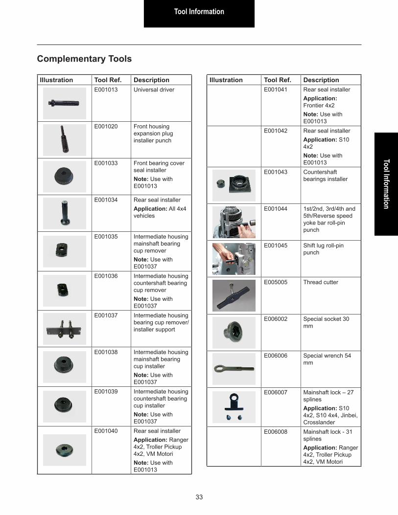
Complementary Tools
Illustration Tool Ref. DescriptionE001013 Universal driver
E001020 Front housing expansion plug installer punch
E001033 Front bearing cover seal installerNote: Use with E001013
E001034 Rear seal installerApplication: All 4x4 vehicles
E001035 Intermediate housing mainshaft bearing cup removerNote: Use with E001037
E001036 Intermediate housing countershaft bearing cup removerNote: Use with E001037
E001037 Intermediate housing bearing cup remover/installer support
E001038 Intermediate housing mainshaft bearing cup installerNote: Use with E001037
E001039 Intermediate housing countershaft bearing cup installerNote: Use with E001037
E001040 Rear seal installerApplication: Ranger 4x2, Troller Pickup 4x2, VM MotoriNote: Use with E001013
Illustration Tool Ref. DescriptionE001041 Rear seal installer
Application: Frontier 4x2Note: Use with E001013
E001042 Rear seal installerApplication: S10 4x2Note: Use with E001013
E001043 Countershaft bearings installer
E001044 1st/2nd, 3rd/4th and 5th/Reverse speed yoke bar roll-pin punch
E001045 Shift lug roll-pin punch
E005005 Thread cutter
E006002 Special socket 30 mm
E006006 Special wrench 54 mm
E006007 Mainshaft lock – 27 splinesApplication: S10 4x2, S10 4x4, Jinbei, Crosslander
E006008 Mainshaft lock - 31 splinesApplication: Ranger 4x2, Troller Pickup 4x2, VM Motori
Tool Information
34
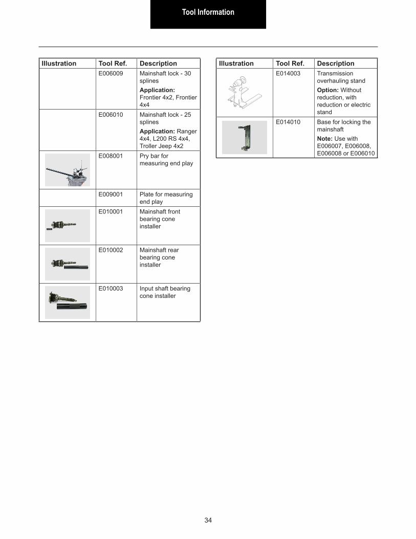
Illustration Tool Ref. DescriptionE006009 Mainshaft lock - 30
splinesApplication: Frontier 4x2, Frontier 4x4
E006010 Mainshaft lock - 25 splinesApplication: Ranger 4x4, L200 RS 4x4, Troller Jeep 4x2
E008001 Pry bar for measuring end play
E009001 Plate for measuring end play
E010001 Mainshaft front bearing cone installer
E010002 Mainshaft rear bearing cone installer
E010003 Input shaft bearing cone installer
Illustration Tool Ref. DescriptionE014003 Transmission
overhauling standOption: Without reduction, with reduction or electric stand
E014010 Base for locking the mainshaftNote: Use with E006007, E006008, E006008 or E006010
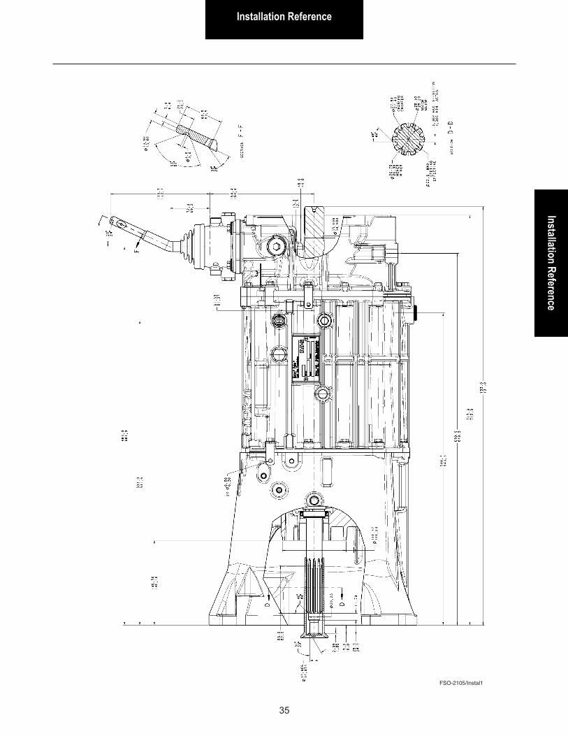
Installation ReferenceInstallation Reference
35
FSO-2105/Instal1

Installation Reference
36
FSO-2105/Instal2
Gear Shift Lever HousingGear Shift Lever Housing
37
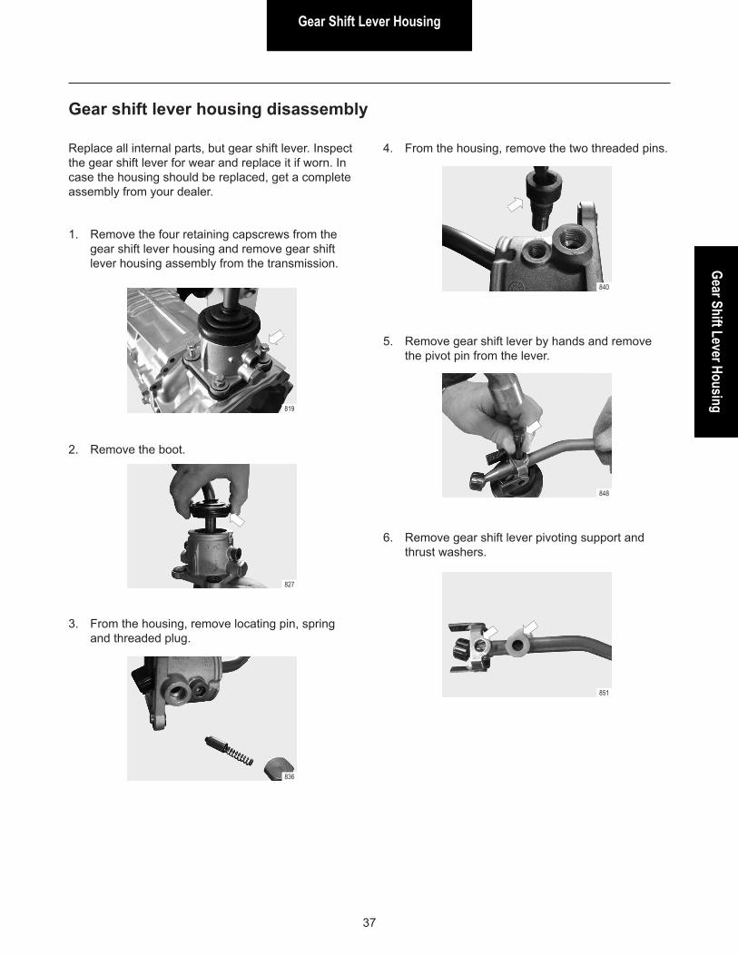
Gear shift lever housing disassembly
Replace all internal parts, but gear shift lever. Inspect the gear shift lever for wear and replace it if worn. In case the housing should be replaced, get a complete assembly from your dealer.
1. Remove the four retaining capscrews from the gear shift lever housing and remove gear shift lever housing assembly from the transmission.
2. Remove the boot.
3. From the housing, remove locating pin, spring and threaded plug.
4. From the housing, remove the two threaded pins.
819
827
836
840
5. Remove gear shift lever by hands and remove the pivot pin from the lever.
6. Remove gear shift lever pivoting support and thrust washers.
848
851
Gear Shift Lever Housing
38
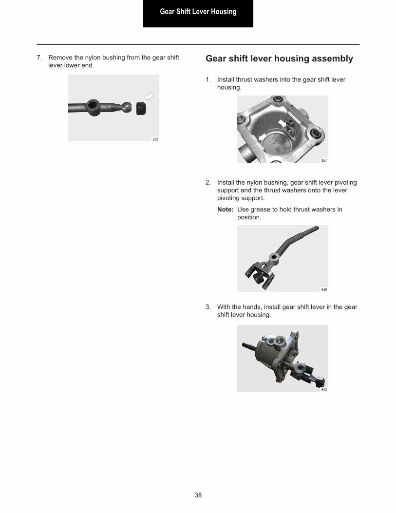
7. Remove the nylon bushing from the gear shift lever lower end.
852
Gear shift lever housing assembly
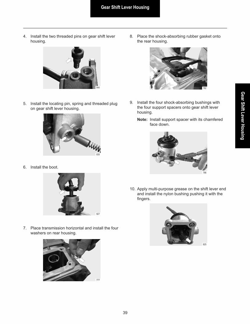
1. Install thrust washers into the gear shift lever housing.
2. Install the nylon bushing, gear shift lever pivoting support and the thrust washers onto the lever pivoting support.
Note: Use grease to hold thrust washers in position.
3. With the hands, install gear shift lever in the gear shift lever housing.
857
849
843
Gear Shift Lever HousingGear Shift Lever Housing
39
Gear shift lever housing assembly 4. Install the two threaded pins on gear shift lever housing.
840
5. Install the locating pin, spring and threaded plug on gear shift lever housing.
6. Install the boot.
7. Place transmission horizontal and install the four washers on rear housing.
8. Place the shock-absorbing rubber gasket onto the rear housing.
9. Install the four shock-absorbing bushings with the four support spacers onto gear shift lever housing.
Note: Install support spacer with its chamfered face down.
835
827
777
782
796
10. Apply multi-purpose grease on the shift lever end and install the nylon bushing pushing it with the fingers.
825
Gear Shift Lever Housing
40
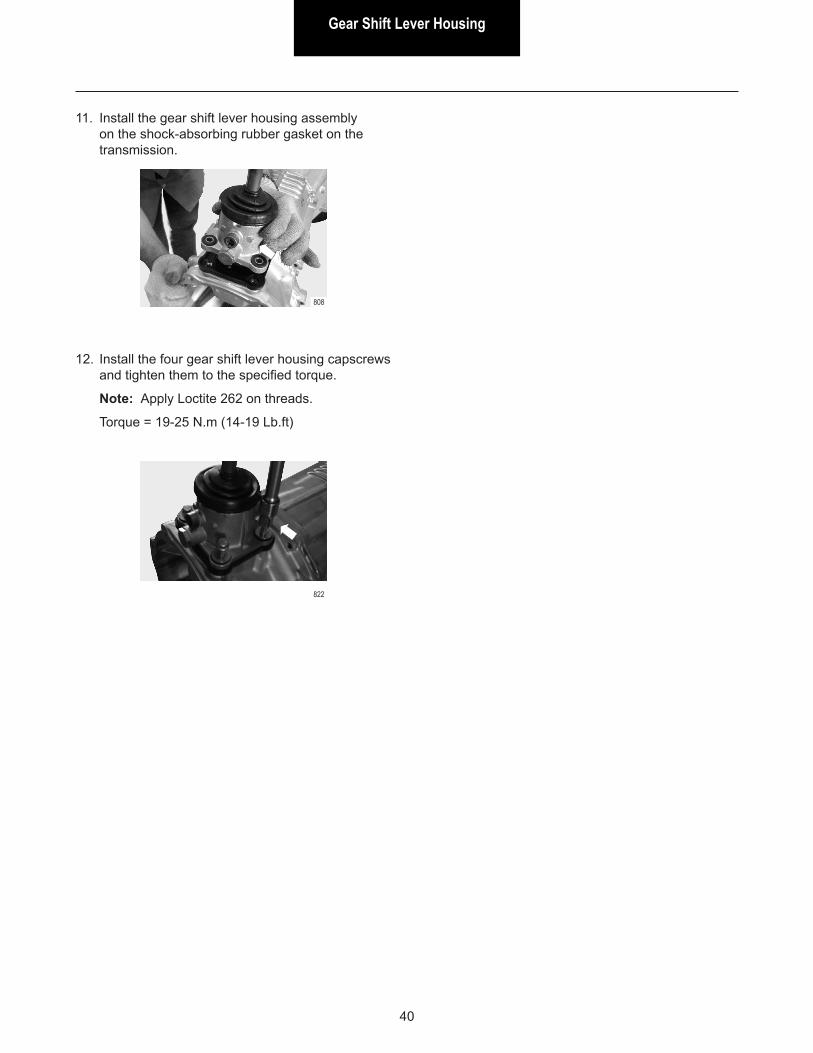
12. Install the four gear shift lever housing capscrews and tighten them to the specified torque.
Note: Apply Loctite 262 on threads.
Torque = 19-25 N.m (14-19 Lb.ft)
822
11. Install the gear shift lever housing assembly on the shock-absorbing rubber gasket on the transmission.
808
Rear SectionRear Section
41
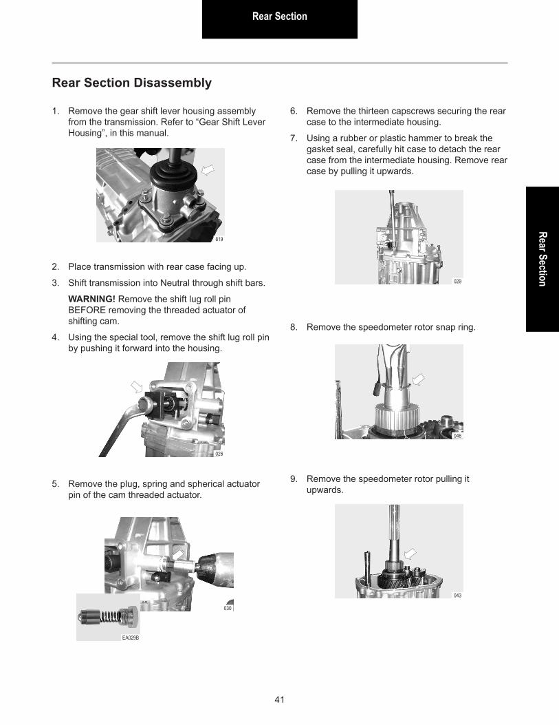
Rear Section Disassembly
2. Place transmission with rear case facing up.
3. Shift transmission into Neutral through shift bars.
WARNING! Remove the shift lug roll pin BEFORE removing the threaded actuator of shifting cam.
4. Using the special tool, remove the shift lug roll pin by pushing it forward into the housing.
029
6. Remove the thirteen capscrews securing the rear case to the intermediate housing.
7. Using a rubber or plastic hammer to break the gasket seal, carefully hit case to detach the rear case from the intermediate housing. Remove rear case by pulling it upwards.
8. Remove the speedometer rotor snap ring.
046
026
030
EA029B
1. Remove the gear shift lever housing assembly from the transmission. Refer to “Gear Shift Lever Housing”, in this manual.
819
5. Remove the plug, spring and spherical actuator pin of the cam threaded actuator.
9. Remove the speedometer rotor pulling it upwards.
043
Rear Section
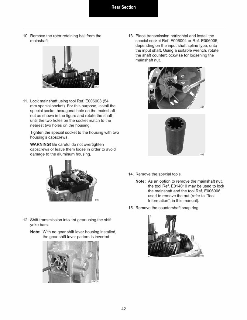
42
13. Place transmission horizontal and install the special socket Ref. E006004 or Ref. E006005, depending on the input shaft spline type, onto the input shaft. Using a suitable wrench, rotate the shaft counterclockwise for loosening the mainshaft nut.
080
082
14. Remove the special tools.
Note: As an option to remove the mainshaft nut, the tool Ref. E014010 may be used to lock the mainshaft and the tool Ref. E006006 used to remove the nut (refer to “Tool Information”, in this manual).
15. Remove the countershaft snap ring.
049
EA028
12. Shift transmission into 1st gear using the shift yoke bars.
Note: With no gear shift lever housing installed, the gear shift lever pattern is inverted.
10. Remove the rotor retaining ball from the mainshaft.
11. Lock mainshaft using tool Ref. E006003 (54 mm special socket). For this purpose, install the special socket hexagonal hole on the mainshaft nut as shown in the figure and rotate the shaft until the two holes on the socket match to the nearest two holes on the housing.
Tighten the special socket to the housing with two housing’s capscrews.
WARNING! Be careful do not overtighten capscrews or leave them loose in order to avoid damage to the aluminum housing.
052
078
Rear SectionRear Section
43
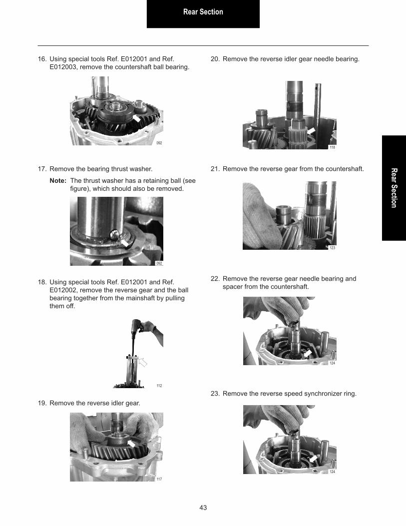
16. Using special tools Ref. E012001 and Ref. E012003, remove the countershaft ball bearing.
17. Remove the bearing thrust washer.
Note: The thrust washer has a retaining ball (see figure), which should also be removed.
092
092
18. Using special tools Ref. E012001 and Ref. E012002, remove the reverse gear and the ball bearing together from the mainshaft by pulling them off.
19. Remove the reverse idler gear.
112
117
20. Remove the reverse idler gear needle bearing.
21. Remove the reverse gear from the countershaft.
118
123
22. Remove the reverse gear needle bearing and spacer from the countershaft.
23. Remove the reverse speed synchronizer ring.
124
124
Rear Section
44
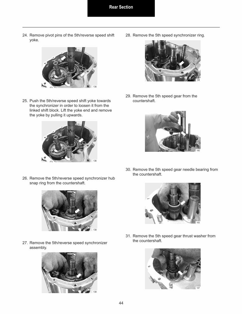
24. Remove pivot pins of the 5th/reverse speed shift yoke.
136
136
25. Push the 5th/reverse speed shift yoke towards the synchronizer in order to loosen it from the linked shift block. Lift the yoke end and remove the yoke by pulling it upwards.
138
26. Remove the 5th/reverse speed synchronizer hub snap ring from the countershaft.
27. Remove the 5th/reverse speed synchronizer assembly.
138
28. Remove the 5th speed synchronizer ring.
29. Remove the 5th speed gear from the countershaft.
139
140
30. Remove the 5th speed gear needle bearing from the countershaft.
31. Remove the 5th speed gear thrust washer from the countershaft.
143
147
Rear SectionRear Section
45
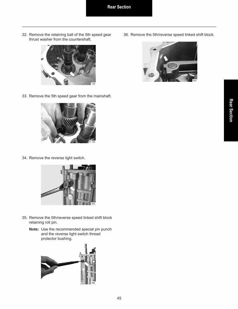
32. Remove the retaining ball of the 5th speed gear thrust washer from the countershaft.
33. Remove the 5th speed gear from the mainshaft.
148
145
055
060
34. Remove the reverse light switch.
35. Remove the 5th/reverse speed linked shift block retaining roll pin.
Note: Use the recommended special pin punch and the reverse light switch thread protector bushing.
36. Remove the 5th/reverse speed linked shift block.
663
Rear Section
46
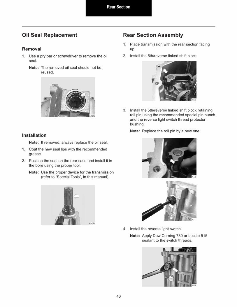
Oil Seal Replacement
Removal1. Use a pry bar or screwdriver to remove the oil
seal.
Note: The removed oil seal should not be reused.
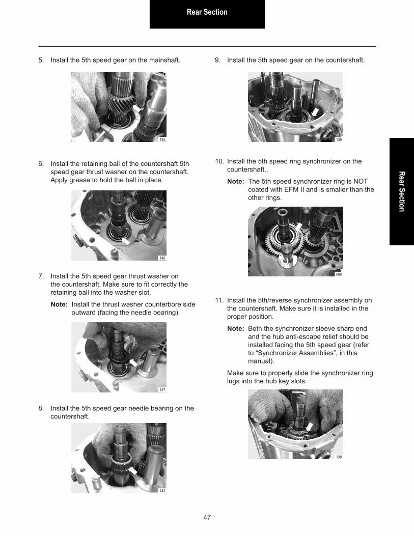
InstallationNote: If removed, always replace the oil seal.
1. Coat the new seal lips with the recommended grease.
2. Position the seal on the rear case and install it in the bore using the proper tool.
Note: Use the proper device for the transmission (refer to “Special Tools”, in this manual).
EA070
EA071
Rear Section Assembly1. Place transmission with the rear section facing
up.
2. Install the 5th/reverse linked shift block.
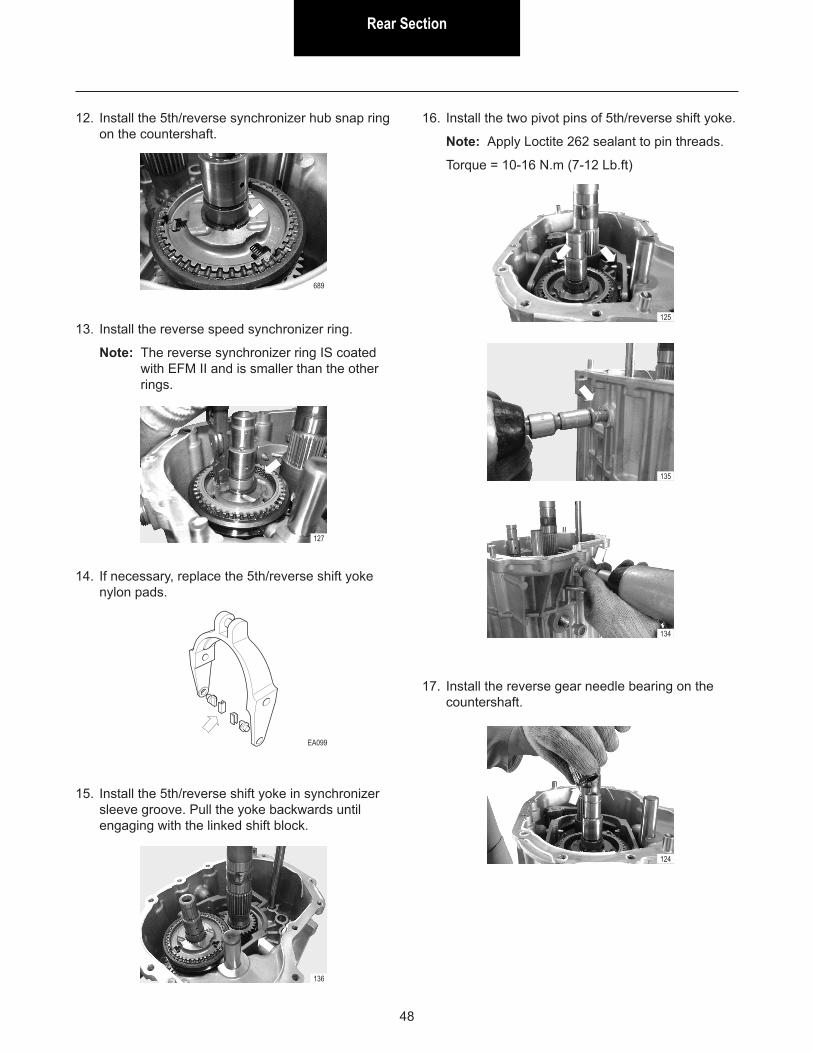
3. Install the 5th/reverse linked shift block retaining roll pin using the recommended special pin punch and the reverse light switch thread protector bushing.
Note: Replace the roll pin by a new one.
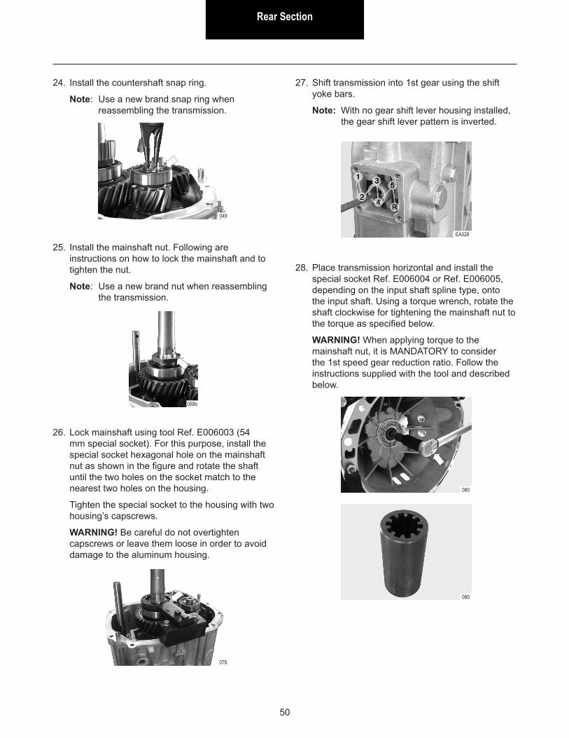
4. Install the reverse light switch.
Note: Apply Dow Corning 780 or Loctite 515 sealant to the switch threads.
663
672
055
671
Rear SectionRear Section
47
5. Install the 5th speed gear on the mainshaft.
145
6. Install the retaining ball of the countershaft 5th speed gear thrust washer on the countershaft. Apply grease to hold the ball in place.
7. Install the 5th speed gear thrust washer on the countershaft. Make sure to fit correctly the retaining ball into the washer slot.
Note: Install the thrust washer counterbore side outward (facing the needle bearing).
8. Install the 5th speed gear needle bearing on the countershaft.
148
147
143
9. Install the 5th speed gear on the countershaft.
139
10. Install the 5th speed ring synchronizer on the countershaft..
Note: The 5th speed synchronizer ring is NOT coated with EFM II and is smaller than the other rings.
11. Install the 5th/reverse synchronizer assembly on the countershaft. Make sure it is installed in the proper position.
Note: Both the synchronizer sleeve sharp end and the hub anti-escape relief should be installed facing the 5th speed gear (refer to “Synchronizer Assemblies”, in this manual).
Make sure to properly slide the synchronizer ring lugs into the hub key slots.
688
138
Rear Section
48
12. Install the 5th/reverse synchronizer hub snap ring on the countershaft.
13. Install the reverse speed synchronizer ring.
Note: The reverse synchronizer ring IS coated with EFM II and is smaller than the other rings.
689
127
14. If necessary, replace the 5th/reverse shift yoke nylon pads.
15. Install the 5th/reverse shift yoke in synchronizer sleeve groove. Pull the yoke backwards until engaging with the linked shift block.
EA099
136
16. Install the two pivot pins of 5th/reverse shift yoke.
Note: Apply Loctite 262 sealant to pin threads.
Torque = 10-16 N.m (7-12 Lb.ft)
125
135
134
17. Install the reverse gear needle bearing on the countershaft.
124

Rear SectionRear Section
49
Note: Use 1 (one) Eaton P/N 3348906 bearing.
18. Install the reverse gear on the countershaft.
19. Install the reverse idler gear needle bearing on the idler shaft.
EA155
123
118
20. Install the reverse idler gear on the shaft with the most protruding side of the hub facing the housing outside.
704
21. Install the reverse gear with the rear ball bearing together on the mainshaft with the most protruding side of the hub facing the housing inside.
22. Install the ball bearing thrust washer on the countershaft.
Note: The thrust washer has a retaining ball, which should be installed with the washer.
114
702
701b
23. Install the countershaft rear ball bearing using special tools Ref. E012001 and Ref. E012003.
088a704
Rear Section
50
24. Install the countershaft snap ring.
Note: Use a new brand snap ring when reassembling the transmission.
25. Install the mainshaft nut. Following are instructions on how to lock the mainshaft and to tighten the nut.
Note: Use a new brand nut when reassembling the transmission.
26. Lock mainshaft using tool Ref. E006003 (54 mm special socket). For this purpose, install the special socket hexagonal hole on the mainshaft nut as shown in the figure and rotate the shaft until the two holes on the socket match to the nearest two holes on the housing.
Tighten the special socket to the housing with two housing’s capscrews.
WARNING! Be careful do not overtighten capscrews or leave them loose in order to avoid damage to the aluminum housing.
049
088b
078
28. Place transmission horizontal and install the special socket Ref. E006004 or Ref. E006005, depending on the input shaft spline type, onto the input shaft. Using a torque wrench, rotate the shaft clockwise for tightening the mainshaft nut to the torque as specified below.
WARNING! When applying torque to the mainshaft nut, it is MANDATORY to consider the 1st speed gear reduction ratio. Follow the instructions supplied with the tool and described below.
080
080
27. Shift transmission into 1st gear using the shift yoke bars.
Note: With no gear shift lever housing installed, the gear shift lever pattern is inverted.
EA028
Rear SectionRear Section
51
WARNING! Check the vehicle’s Manual for the transmission specifications to make sure the 1st speed gear ratio matches to the gear ratio shown in the table above. If not, calculate the torque amount as follows.
• Specified torque for the nut: 217 to 270 N.m
Example:
Transmission 1st gear ratio: 4.473
• Divide 217 by 4.473 and round off to the higher nearest integer:
217 ÷ 4.473 = 48.51 use 49
• Divide 270 by 4,079 and round off to the lower nearest integer:
270 ÷ 4.473 = 60.36 use 60
Torque to be applied on the tool: 49 to 60 N.m
EA100
To tighten the nut, check the table below for the torque to be applied on the tool using the 1st speed reduction ratio.
Transmission Gear ratio at 1st speed Torque to be applied
FSO 2105A 4.473 49 to 60 N.mFSO 2505A/B 4.079 54 to 66 N.m
29. Remove the tools.
Note: As an option for the above procedure, the special tool Ref. E014010 may be used for locking the mainshaft and the tool Ref. E006006 to tighten the nut. In this case, the torque is applied directly to the nut and the specified amount is 217 to 270 N.m.
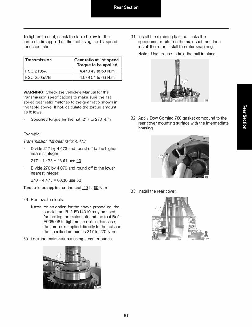
30. Lock the mainshaft nut using a center punch.
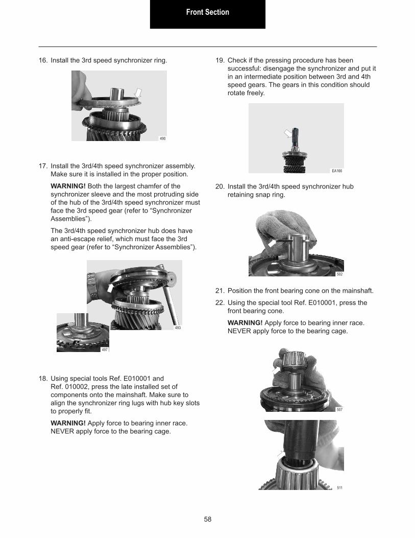
33. Install the rear cover.
029b
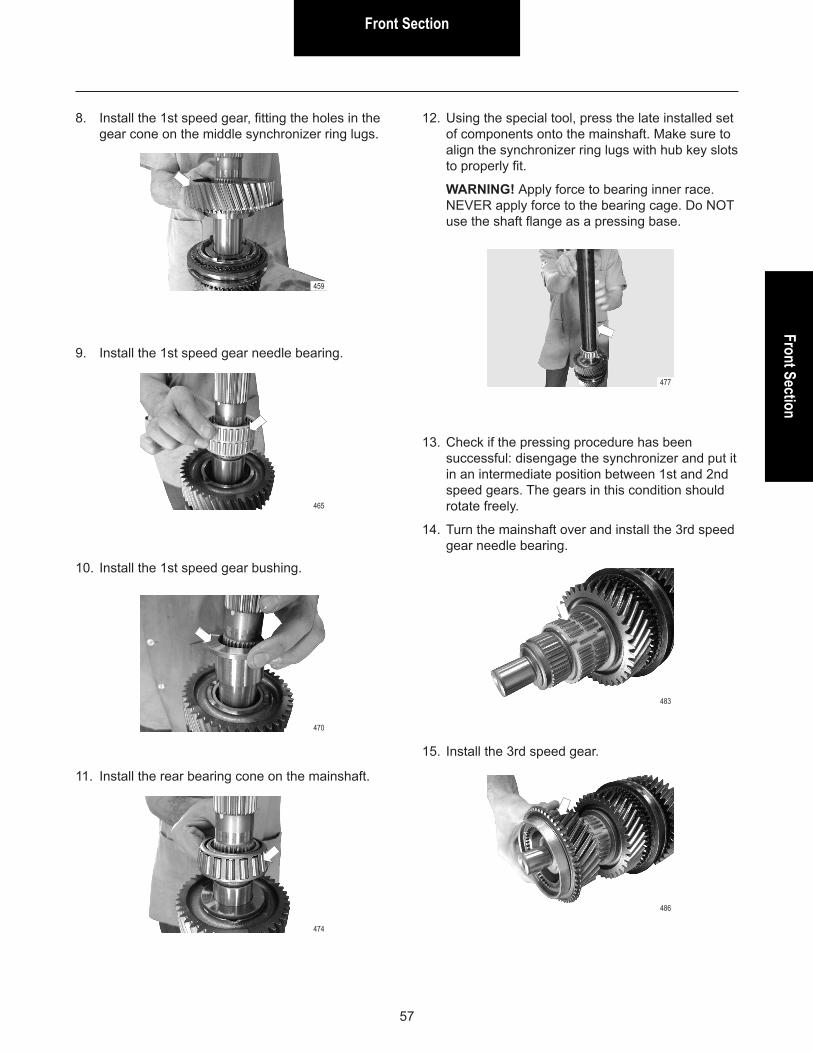
32. Apply Dow Corning 780 gasket compound to the rear cover mounting surface with the intermediate housing.
893
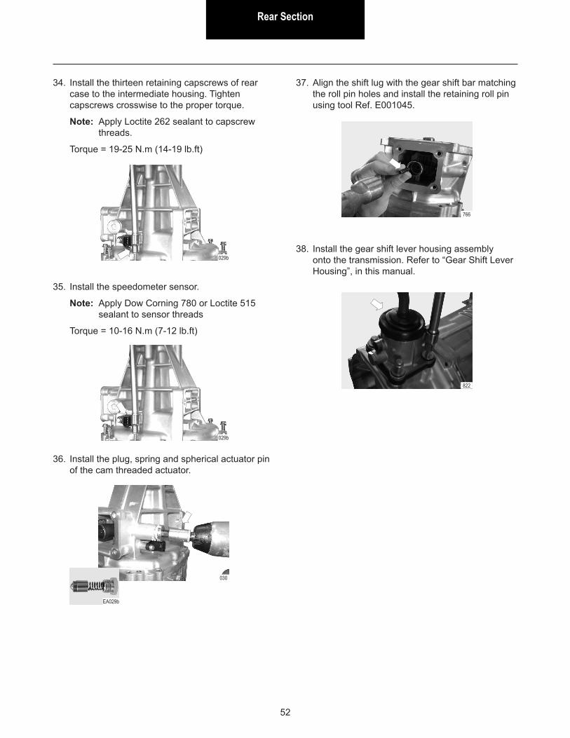
31. Install the retaining ball that locks the speedometer rotor on the mainshaft and then install the rotor. Install the rotor snap ring.
Note: Use grease to hold the ball in place.
043
Rear Section
52
34. Install the thirteen retaining capscrews of rear case to the intermediate housing. Tighten capscrews crosswise to the proper torque.
Note: Apply Loctite 262 sealant to capscrew threads.
Torque = 19-25 N.m (14-19 lb.ft)
35. Install the speedometer sensor.
Note: Apply Dow Corning 780 or Loctite 515 sealant to sensor threads
Torque = 10-16 N.m (7-12 lb.ft)
029b
029b
36. Install the plug, spring and spherical actuator pin of the cam threaded actuator.
030
EA029b
766
37. Align the shift lug with the gear shift bar matching the roll pin holes and install the retaining roll pin using tool Ref. E001045.
38. Install the gear shift lever housing assembly onto the transmission. Refer to “Gear Shift Lever Housing”, in this manual.
822

Front SectionFront Section
53
Front Section Disassembly
1. Disassemble the rear section (refer to “Rear Section Disassembly”).
2. Shift transmission into Neutral through shift bars.
3. Remove the shift positioning plug, spring and ball.
4. Remove the thirteen capscrews securing the intermediate housing to the front housing.
5. 5. From inside the front housing, remove capscrews securing the front housing to the intermediate housing.
152
154
156
003
6. Remove the intermediate housing.
Note: Use pry bars between the housing special bosses provided to detach the intermediate housing. If necessary, carefully hit housing’s capscrews area with a rubber or plastic hammer to brake the gasket seal and detach the housing.
WARNING! Do not support pry bar on housing’s contact surface in order to not damage the sealing surface.
157
7. Pull the 5th/reverse yoke bar upwards and remove it.
8. Rotate the shift selector bar counterclockwise and remove it pulling the bar upwards.
164
165

Front Section
54
9. Remove the 1st/2nd shift yoke roll pin.
Note: Use a 4 mm diameter roll-pin punch.
10. Hold the 1st/2nd shift yoke in its place on synchronizer groove and pull the yoke bar upwards. When the bar lower end rises over the housing surface (see detail), remove the bar and shift yoke assembly.
171
11. Simultaneously, remove from the housing the remaining assemblies of mainshaft, countershaft, 3rd/4th bar and shift yoke and input shaft, while grasping them all together and pulling them upwards.
173
EA037a
EA036b
EA037B
12. Take the assemblies apart.

Front SectionFront Section
55
Disassembly
1. Using the Pocket bearing puller Ref. E005003, remove the front bearing cone from mainshaft.
2. Remove the 3rd/4th synchronizer hub retaining snap ring.
3. Place mainshaft in the press, using either 2nd or 4th speed gear as a base.
4. Press mainshaft through and remove the set of components up to the rear bearing cone.
WARNING! Be careful NOT to use mainshaft flange as a pressing base when using the 3rd speed gear.
5. Turn the mainshaft over in the press and use the 3rd speed gear as a base.
6. Press mainshaft and remove the 3rd/4th synchronizer assembly, 3rd speed gear and the needle bearing.
180
186
190
EA041
183
Mainshaft
Assembly
1. Install the 2nd speed gear needle bearing.
2. Install the 2nd speed gear.
424
424

Front Section
56
3. Install the 2nd speed synchronizer rings, inner, middle and outer, in this order. Make sure they are installed in the proper position. The inner ring lugs must be facing to the synchronizer hub while the middle ring lugs must fit into the holes in the gear cone. Refer to “Synchronizer Assemblies” later in this manual.
4. Install the 1st/2nd speed synchronizer assembly. Make sure it is installed in the proper position.
WARNING! Both the largest chamfer of the synchronizer sleeve and the most protruding side of the hub of the 1st/2nd speed synchronizer must face the 1st speed gear (refer to “Synchronizer Assemblies”).
426
429
438
427
430
439
5. Align the center of the recess in the synchronizer sleeve teeth with the center of the key at the three positions and install the synchronizer sleeve.
6. Install the 1st speed outer and middle synchronizer rings. Make sure they are installed in the proper position. Refer to “Synchronizer Assemblies” later in this manual.
7. Install the 1st speed inner synchronizer ring. Make sure ring lugs fit into the hub slots.
448
441
454
352
451
Front SectionFront Section
57
8. Install the 1st speed gear, fitting the holes in the gear cone on the middle synchronizer ring lugs.
9. Install the 1st speed gear needle bearing.
10. Install the 1st speed gear bushing.
11. Install the rear bearing cone on the mainshaft.
459
465
470
474
12. Using the special tool, press the late installed set of components onto the mainshaft. Make sure to align the synchronizer ring lugs with hub key slots to properly fit.
WARNING! Apply force to bearing inner race. NEVER apply force to the bearing cage. Do NOT use the shaft flange as a pressing base.
13. Check if the pressing procedure has been successful: disengage the synchronizer and put it in an intermediate position between 1st and 2nd speed gears. The gears in this condition should rotate freely.
14. Turn the mainshaft over and install the 3rd speed gear needle bearing.
15. Install the 3rd speed gear.
477
483
486
Front Section
58
16. Install the 3rd speed synchronizer ring.
490
17. Install the 3rd/4th speed synchronizer assembly. Make sure it is installed in the proper position.
WARNING! Both the largest chamfer of the synchronizer sleeve and the most protruding side of the hub of the 3rd/4th speed synchronizer must face the 3rd speed gear (refer to “Synchronizer Assemblies”).
The 3rd/4th speed synchronizer hub does have an anti-escape relief, which must face the 3rd speed gear (refer to “Synchronizer Assemblies”).
19. Check if the pressing procedure has been successful: disengage the synchronizer and put it in an intermediate position between 3rd and 4th speed gears. The gears in this condition should rotate freely.
493
EA166
20. Install the 3rd/4th speed synchronizer hub retaining snap ring.
502
18. Using special tools Ref. E010001 and Ref. 010002, press the late installed set of components onto the mainshaft. Make sure to align the synchronizer ring lugs with hub key slots to properly fit.
WARNING! Apply force to bearing inner race. NEVER apply force to the bearing cage.
497
21. Position the front bearing cone on the mainshaft.
22. Using the special tool Ref. E010001, press the front bearing cone.
WARNING! Apply force to bearing inner race. NEVER apply force to the bearing cage.
507
511
Front SectionFront Section
59
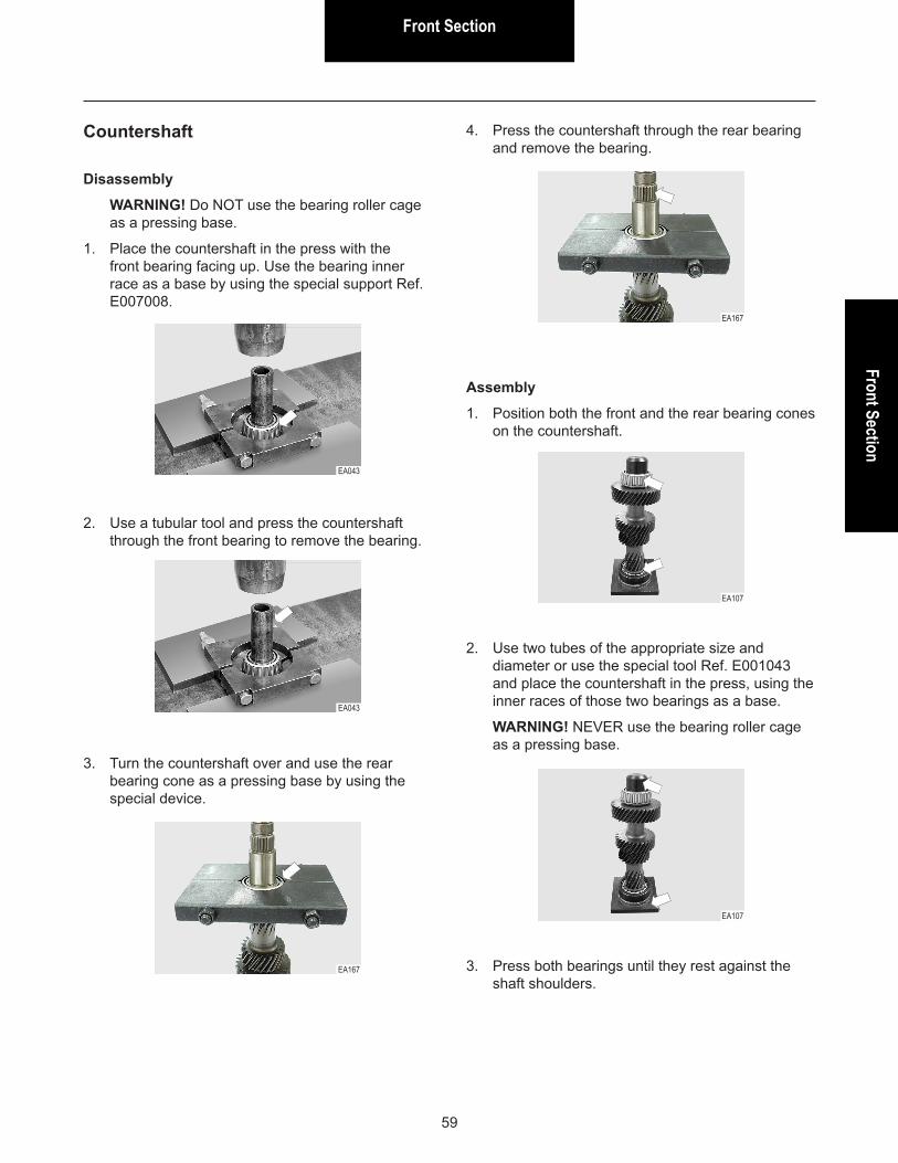
Disassembly
WARNING! Do NOT use the bearing roller cage as a pressing base.
1. Place the countershaft in the press with the front bearing facing up. Use the bearing inner race as a base by using the special support Ref. E007008.
Countershaft
2. Use a tubular tool and press the countershaft through the front bearing to remove the bearing.
3. Turn the countershaft over and use the rear bearing cone as a pressing base by using the special device.
4. Press the countershaft through the rear bearing and remove the bearing.
EA043
EA167
EA043
EA167
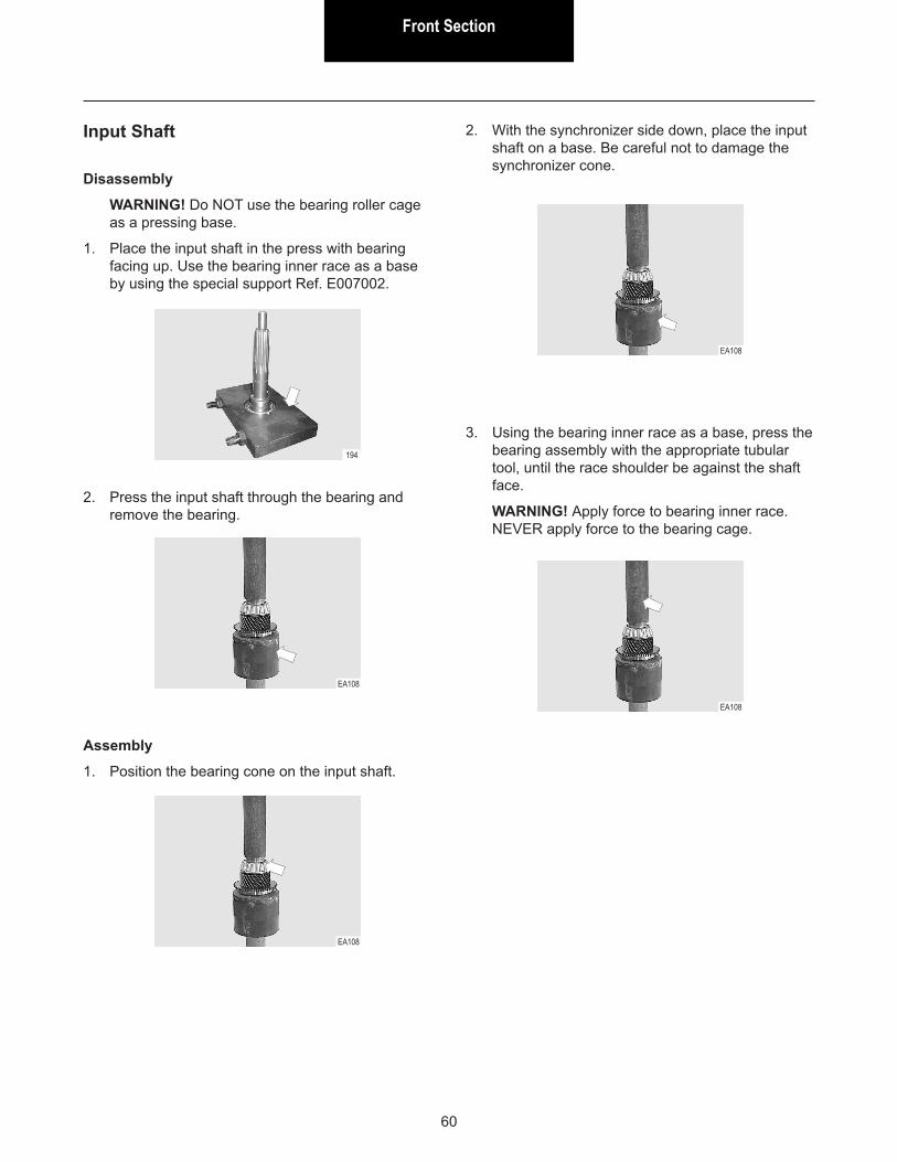
Assembly
1. Position both the front and the rear bearing cones on the countershaft.
2. Use two tubes of the appropriate size and diameter or use the special tool Ref. E001043 and place the countershaft in the press, using the inner races of those two bearings as a base.
WARNING! NEVER use the bearing roller cage as a pressing base.
EA107
EA107
3. Press both bearings until they rest against the shaft shoulders.
Front Section
60
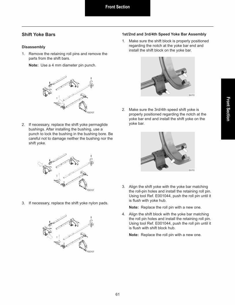
Disassembly
WARNING! Do NOT use the bearing roller cage as a pressing base.
1. Place the input shaft in the press with bearing facing up. Use the bearing inner race as a base by using the special support Ref. E007002.
Input Shaft
2. Press the input shaft through the bearing and remove the bearing.
Assembly
1. Position the bearing cone on the input shaft.
2. With the synchronizer side down, place the input shaft on a base. Be careful not to damage the synchronizer cone.
3. Using the bearing inner race as a base, press the bearing assembly with the appropriate tubular tool, until the race shoulder be against the shaft face.
WARNING! Apply force to bearing inner race. NEVER apply force to the bearing cage.
194
EA108
EA108
EA108
EA108
Front SectionFront Section
61
Disassembly
1. Remove the retaining roll pins and remove the parts from the shift bars.
Note: Use a 4 mm diameter pin punch.
Shift Yoke Bars
2. If necessary, replace the shift yoke permaglide bushings. After installing the bushing, use a punch to lock the bushing in the bushing bore. Be careful not to damage neither the bushing nor the shift yoke.
FSO107
FSO107
3. If necessary, replace the shift yoke nylon pads.
FSO107
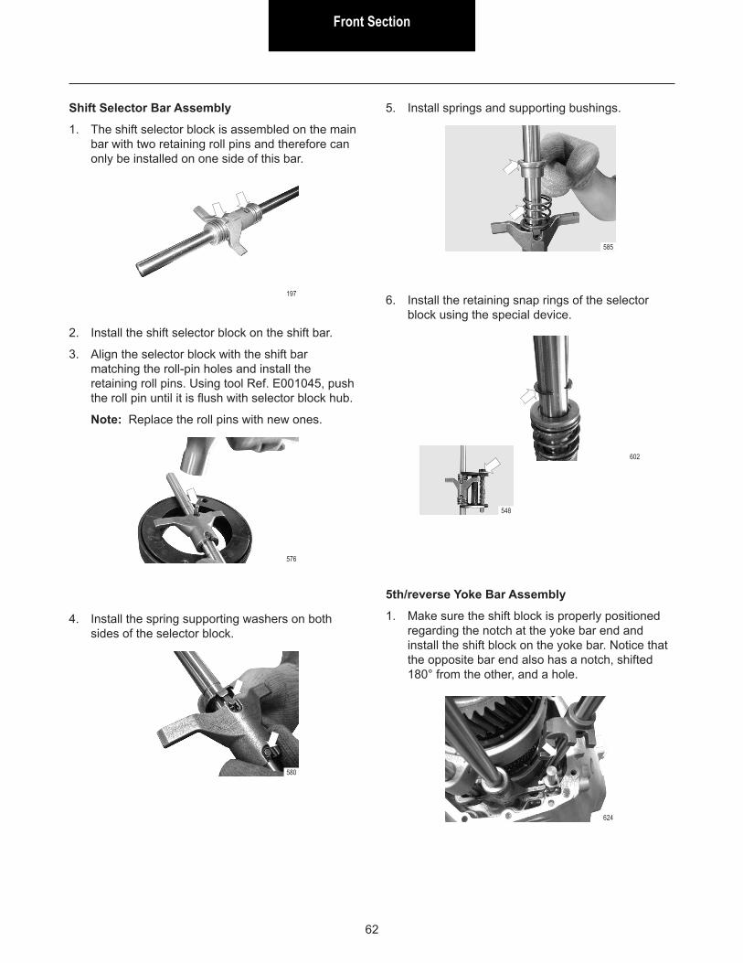
1st/2nd and 3rd/4th Speed Yoke Bar Assembly
1. Make sure the shift block is properly positioned regarding the notch at the yoke bar end and install the shift block on the yoke bar.
EA110
2. Make sure the 3rd/4th speed shift yoke is properly positioned regarding the notch at the yoke bar end and install the shift yoke on the yoke bar.
EA110
3. Align the shift yoke with the yoke bar matching the roll-pin holes and install the retaining roll pin. Using tool Ref. E001044, push the roll pin until it is flush with yoke hub.
Note: Replace the roll pin with a new one.
4. Align the shift block with the yoke bar matching the roll pin holes and install the retaining roll pin. Using tool Ref. E001044, push the roll pin until it is flush with shift block hub.
Note: Replace the roll pin with a new one.
Front Section
62
Shift Selector Bar Assembly
1. The shift selector block is assembled on the main bar with two retaining roll pins and therefore can only be installed on one side of this bar.
197
2. Install the shift selector block on the shift bar.
3. Align the selector block with the shift bar matching the roll-pin holes and install the retaining roll pins. Using tool Ref. E001045, push the roll pin until it is flush with selector block hub.
Note: Replace the roll pins with new ones.
576
4. Install the spring supporting washers on both sides of the selector block.
580
5. Install springs and supporting bushings.
585
6. Install the retaining snap rings of the selector block using the special device.
602
548
5th/reverse Yoke Bar Assembly
1. Make sure the shift block is properly positioned regarding the notch at the yoke bar end and install the shift block on the yoke bar. Notice that the opposite bar end also has a notch, shifted 180° from the other, and a hole.
624

Front SectionFront Section
63
2. Align the shift block with the shift bar matching the roll-pin holes and install the retaining roll pin. Using tool Ref. E001044, push the roll pin until it is flush with shift block hub.
Note: Replace the roll pin by a new one.
624
Some through holes in housings are drilled for machining purpose only and must be blocked later by using cup-type metal expansion plugs.
During the transmission life, it is possible to happen that some of those plugs should be removed and reinstalled when servicing the unit.
Removal
1. In the housing, locate the expansion plug that should be removed. Use the special device Ref. E005005 and make a thread in the plug.
Expansion Plugs
639b
2. Use one retaining capscrew removed from the housing and insert it into the plug, threading it until it stays firmly in place.
EA046
3. Use the impact puller Ref. E003001 and adapter Ref. E004002 to remove the capscrew and the plug comes along.
EA169
Front Section
64
Installation
WARNING! Always replace the removed plug with a new one to prevent leaks.
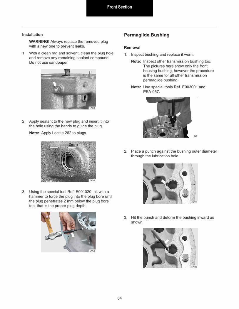
1. With a clean rag and solvent, clean the plug hole and remove any remaining sealant compound. Do not use sandpaper.
2. Apply sealant to the new plug and insert it into the hole using the hands to guide the plug.
Note: Apply Loctite 262 to plugs.
EA048
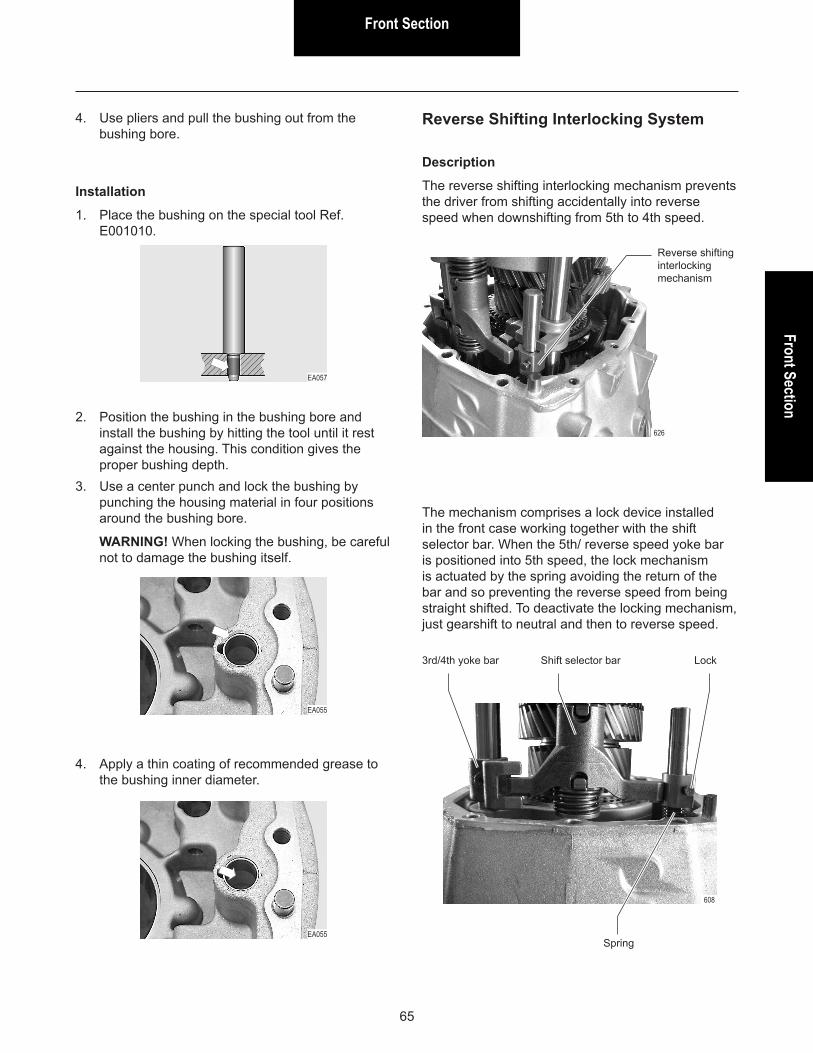
EA049
2mm
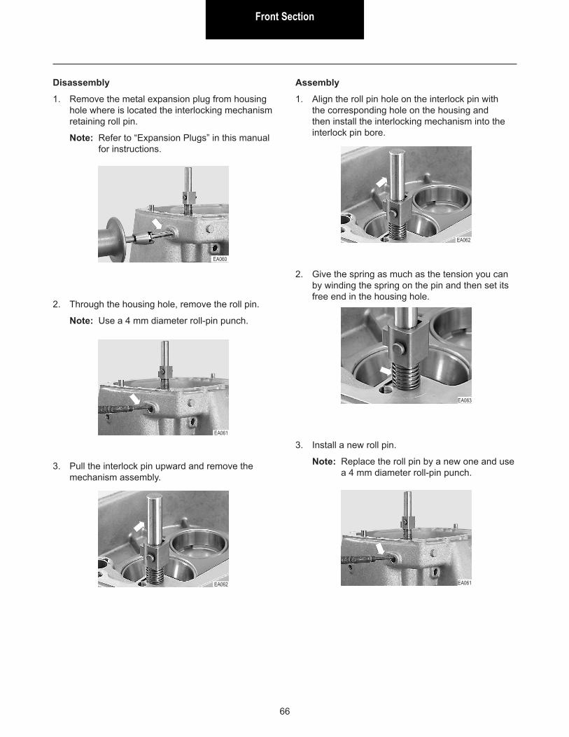
3. Using the special tool Ref. E001020, hit with a hammer to force the plug into the plug bore until the plug penetrates 2 mm below the plug bore top, that is the proper plug depth.
EA170
Removal
1. Inspect bushing and replace if worn.
Note: Inspect other transmission bushing too. The pictures here show only the front housing bushing, however the procedure is the same for all other transmission permaglide bushing.
Note: Use special tools Ref. E003001 and PEA-057.
Permaglide Bushing
247
2. Place a punch against the bushing outer diameter through the lubrication hole.
EA055
3. Hit the punch and deform the bushing inward as shown.
EA056
Front SectionFront Section
65
Description
The reverse shifting interlocking mechanism prevents the driver from shifting accidentally into reverse speed when downshifting from 5th to 4th speed.
Reverse Shifting Interlocking System
626
The mechanism comprises a lock device installed in the front case working together with the shift selector bar. When the 5th/ reverse speed yoke bar is positioned into 5th speed, the lock mechanism is actuated by the spring avoiding the return of the bar and so preventing the reverse speed from being straight shifted. To deactivate the locking mechanism, just gearshift to neutral and then to reverse speed.
608
4. Use pliers and pull the bushing out from the bushing bore.
Installation
1. Place the bushing on the special tool Ref. E001010.
2. Position the bushing in the bushing bore and install the bushing by hitting the tool until it rest against the housing. This condition gives the proper bushing depth.
3. Use a center punch and lock the bushing by punching the housing material in four positions around the bushing bore.
WARNING! When locking the bushing, be careful not to damage the bushing itself.
4. Apply a thin coating of recommended grease to the bushing inner diameter.
EA057
EA055
EA055
Reverse shifting interlocking mechanism
3rd/4th yoke bar
Spring
Shift selector bar Lock
Front Section
66
Disassembly
1. Remove the metal expansion plug from housing hole where is located the interlocking mechanism retaining roll pin.
Note: Refer to “Expansion Plugs” in this manual for instructions.
EA060
2. Through the housing hole, remove the roll pin.
Note: Use a 4 mm diameter roll-pin punch.
3. Pull the interlock pin upward and remove the mechanism assembly.
Assembly
1. Align the roll pin hole on the interlock pin with the corresponding hole on the housing and then install the interlocking mechanism into the interlock pin bore.
EA061
EA062
EA062
2. Give the spring as much as the tension you can by winding the spring on the pin and then set its free end in the housing hole.
3. Install a new roll pin.
Note: Replace the roll pin by a new one and use a 4 mm diameter roll-pin punch.
EA063
EA061

Front SectionFront Section
67
Description
The double gear shifting interlocking mechanism prevents shifting into two gears at the same time.
Such mechanism comprises one interlock pin and five interlock balls.
WARNING! One interlock ball has an 8.0 mm diameter while the other four interlock balls have a 9.5 mm diameter. A larger ball does not install into the smallest interlock bore.
When shifting any of the speed gears, the yoke bar of this specific speed pushes away the corresponding ball, displacing the remaining balls and locking the other yoke bars into the neutral position.
260
280
Double Gear Shifting Interlocking System
WARNING! Be careful when removing the yoke bars. Interlock balls may drop into the bar bores. Keep a close watch on the interlock balls when disassembling and assembling the transmission.
4. Install a new expansion plug in the housing hole.
Note: Refer to “Expansion Plugs” in this manual for instructions.
EA061
Double gear shifting interlocking mechanism
Three balls (9.5 mm diameter) aligned from the 3rd/4th yoke bar bore
Interlock pinOne ball (9.5 mm diameter) located in the 5th/reverse yoke bar bore
One ball (8.0 mm diameter) located in the 1st/2nd yoke bar bore.
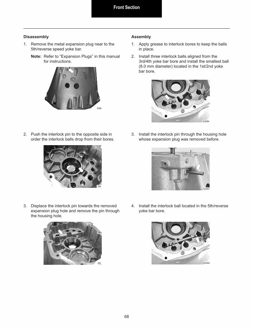
Front Section
68
Disassembly
1. Remove the metal expansion plug near to the 5th/reverse speed yoke bar.
Note: Refer to “Expansion Plugs” in this manual for instructions.
639b
2. Push the interlock pin to the opposite side in order the interlock balls drop from their bores.
3. Displace the interlock pin towards the removed expansion plug hole and remove the pin through the housing hole.
Assembly
1. Apply grease to interlock bores to keep the balls in place.
2. Install three interlock balls aligned from the 3rd/4th yoke bar bore and install the smallest ball (8.0 mm diameter) located in the 1st/2nd yoke bar bore.
280
292
EA084
3. Install the interlock pin through the housing hole whose expansion plug was removed before.
4. Install the interlock ball located in the 5th/reverse yoke bar bore.
EA067
EA064
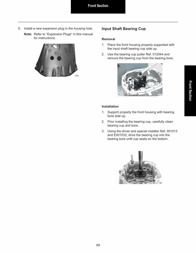
Front SectionFront Section
69
Removal
1. Place the front housing properly supported with the input shaft bearing cup side up.
2. Use the bearing cup puller Ref. 012044 and remove the bearing cup from the bearing bore.
Input Shaft Bearing Cup
Installation
1. Support properly the front housing with bearing bore side up.
2. Prior installing the bearing cup, carefully clean bearing cup and bore.
3. Using the driver and special installer Ref. 001013 and E001033, drive the bearing cup into the bearing bore until cup seats on the bottom.
5. Install a new expansion plug in the housing hole.
Note: Refer to “Expansion Plugs” in this manual for instructions.
639b
EA171
288
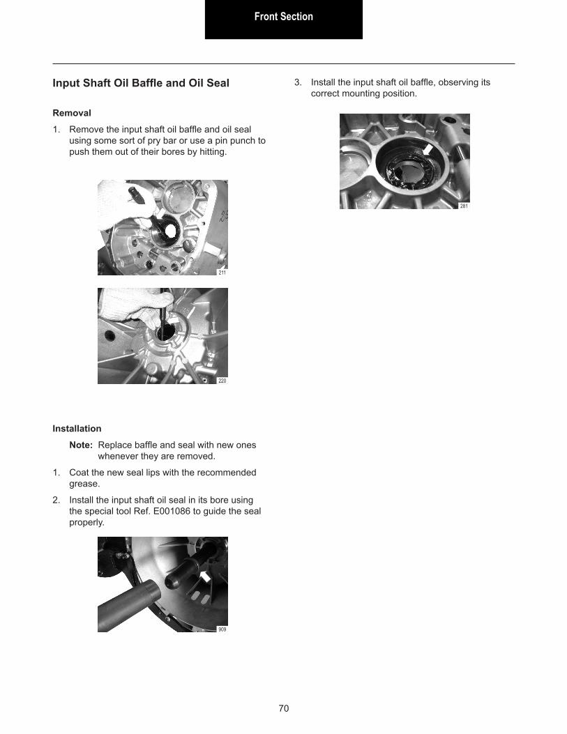
Front Section
70
Removal
1. Remove the input shaft oil baffle and oil seal using some sort of pry bar or use a pin punch to push them out of their bores by hitting.
Input Shaft Oil Baffle and Oil Seal
Installation
Note: Replace baffle and seal with new ones whenever they are removed.
1. Coat the new seal lips with the recommended grease.
2. Install the input shaft oil seal in its bore using the special tool Ref. E001086 to guide the seal properly.
909
211
3. Install the input shaft oil baffle, observing its correct mounting position.
220
281

Front SectionFront Section
71
Removal
1. Place the front housing properly supported with the countershaft bearing cup side up.
2. Use special puller Ref. E011001 fitted under the bearing cup counterbore at the cup bottom and remove the bearing cup.
Countershaft Front Bearing Cup
Installation
1. Support properly the front housing with bearing bore side up.
2. Prior to installing the bearing cup, carefully clean both bearing bore and cup.
3. Use the special tool and drive the bearing cup into the bearing bore until cup is completely seated on the bottom.
199
296

Front Section
72
Removal
1. Place the intermediate housing properly support-ed with the bearing cup removing side down.
2. Use special devices E001035 and E001036 along with the support Ref. E001037 and remove mainshaft and countershaft rear bearing cups from the bearing bores.
Mainshaft and Countershaft Rear Bearing Cups
3. Remove all existing shims from mainshaft and countershaft bearing bores.
Installation
1. Support properly the intermediate housing with bearing bore side up.
2. Prior to installing the bearing cup, carefully clean both bearing bore and cup.
WARNING! Dirt between the bearing cup and the bearing bore can lead to axial clearance (end play) adjustment error.
3. Install the bearing cups without any shim before adjusting the transmission end play.
WARNING! Refer to “End Play Adjustment” later in this manual.
4. Use special devices E001038 and E001039 along with the support Ref. E001037 and install the mainshaft and countershaft rear bearing cups, driving the bearing cup into the bearing bore until it is completely seated on the bottom.
EA173
EA124
EA174
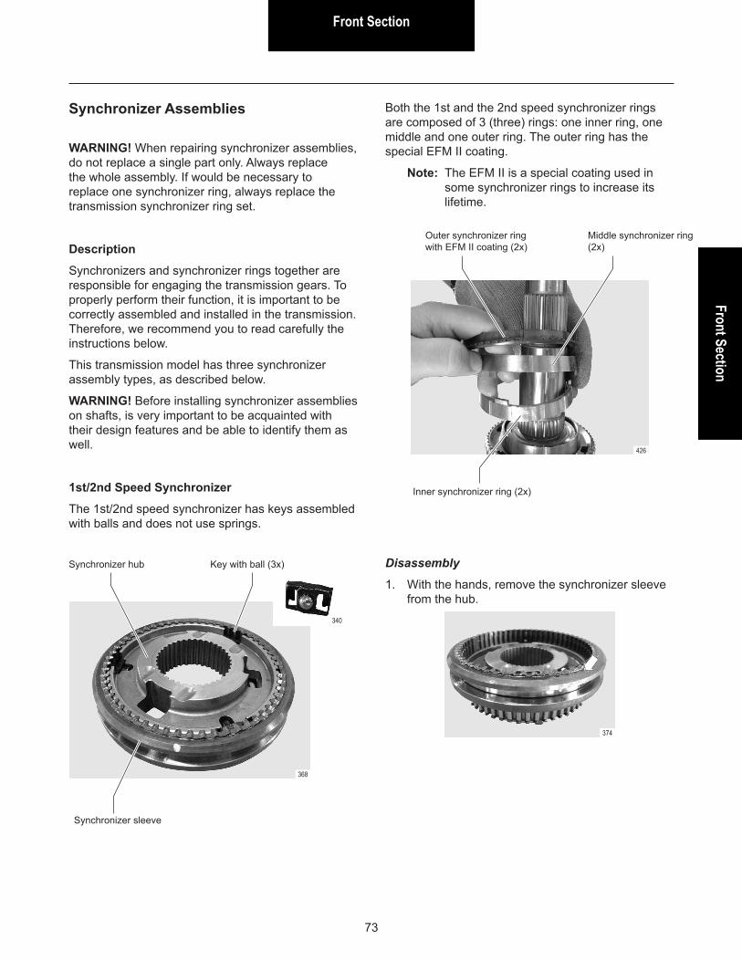
Front SectionFront Section
73
WARNING! When repairing synchronizer assemblies, do not replace a single part only. Always replace the whole assembly. If would be necessary to replace one synchronizer ring, always replace the transmission synchronizer ring set.
Description
Synchronizers and synchronizer rings together are responsible for engaging the transmission gears. To properly perform their function, it is important to be correctly assembled and installed in the transmission. Therefore, we recommend you to read carefully the instructions below.
This transmission model has three synchronizer assembly types, as described below.
WARNING! Before installing synchronizer assemblies on shafts, is very important to be acquainted with their design features and be able to identify them as well.
1st/2nd Speed Synchronizer
The 1st/2nd speed synchronizer has keys assembled with balls and does not use springs.
Synchronizer Assemblies Both the 1st and the 2nd speed synchronizer rings are composed of 3 (three) rings: one inner ring, one middle and one outer ring. The outer ring has the special EFM II coating.
Note: The EFM II is a special coating used in some synchronizer rings to increase its lifetime.
368
340
426
Synchronizer hub
Synchronizer sleeve
Key with ball (3x)
Inner synchronizer ring (2x)
Outer synchronizer ring with EFM II coating (2x)
Middle synchronizer ring (2x)
Disassembly
1. With the hands, remove the synchronizer sleeve from the hub.
374
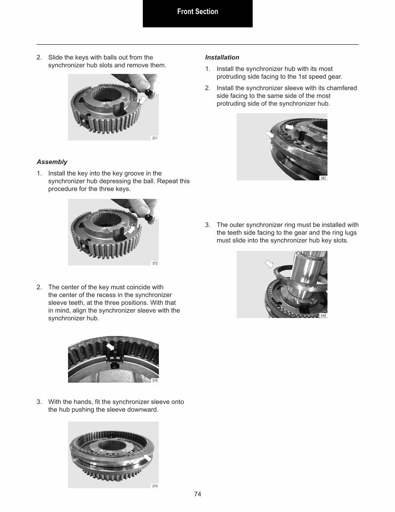
Front Section
74
2. Slide the keys with balls out from the synchronizer hub slots and remove them.
Assembly
1. Install the key into the key groove in the synchronizer hub depressing the ball. Repeat this procedure for the three keys.
371
372
3. With the hands, fit the synchronizer sleeve onto the hub pushing the sleeve downward.
Installation
1. Install the synchronizer hub with its most protruding side facing to the 1st speed gear.
2. Install the synchronizer sleeve with its chamfered side facing to the same side of the most protruding side of the synchronizer hub.
2. The center of the key must coincide with the center of the recess in the synchronizer sleeve teeth, at the three positions. With that in mind, align the synchronizer sleeve with the synchronizer hub.
376
374
3. The outer synchronizer ring must be installed with the teeth side facing to the gear and the ring lugs must slide into the synchronizer hub key slots.
382
448
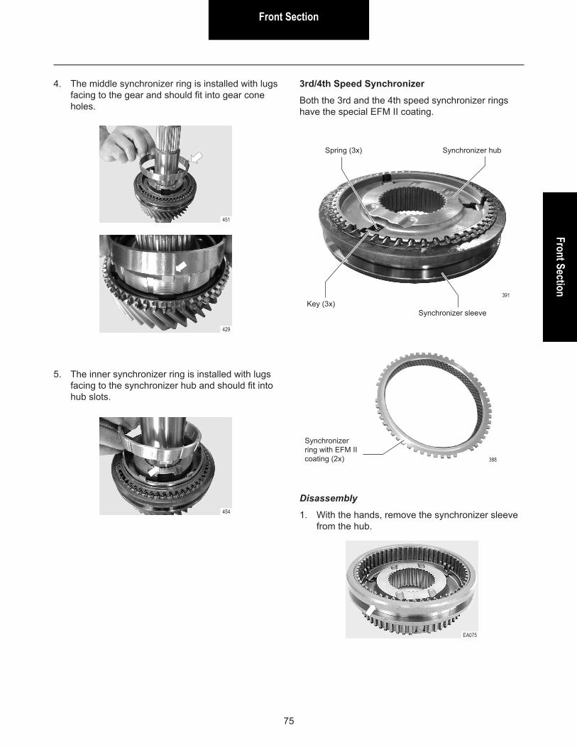
Front SectionFront Section
75
391
4. The middle synchronizer ring is installed with lugs facing to the gear and should fit into gear cone holes.
5. The inner synchronizer ring is installed with lugs facing to the synchronizer hub and should fit into hub slots.
451
429
454
3rd/4th Speed Synchronizer
Both the 3rd and the 4th speed synchronizer rings have the special EFM II coating.
Spring (3x)
Key (3x)
Synchronizer hub
Synchronizer sleeve
Disassembly
1. With the hands, remove the synchronizer sleeve from the hub.
EA075
388
Synchronizer ring with EFM II coating (2x)
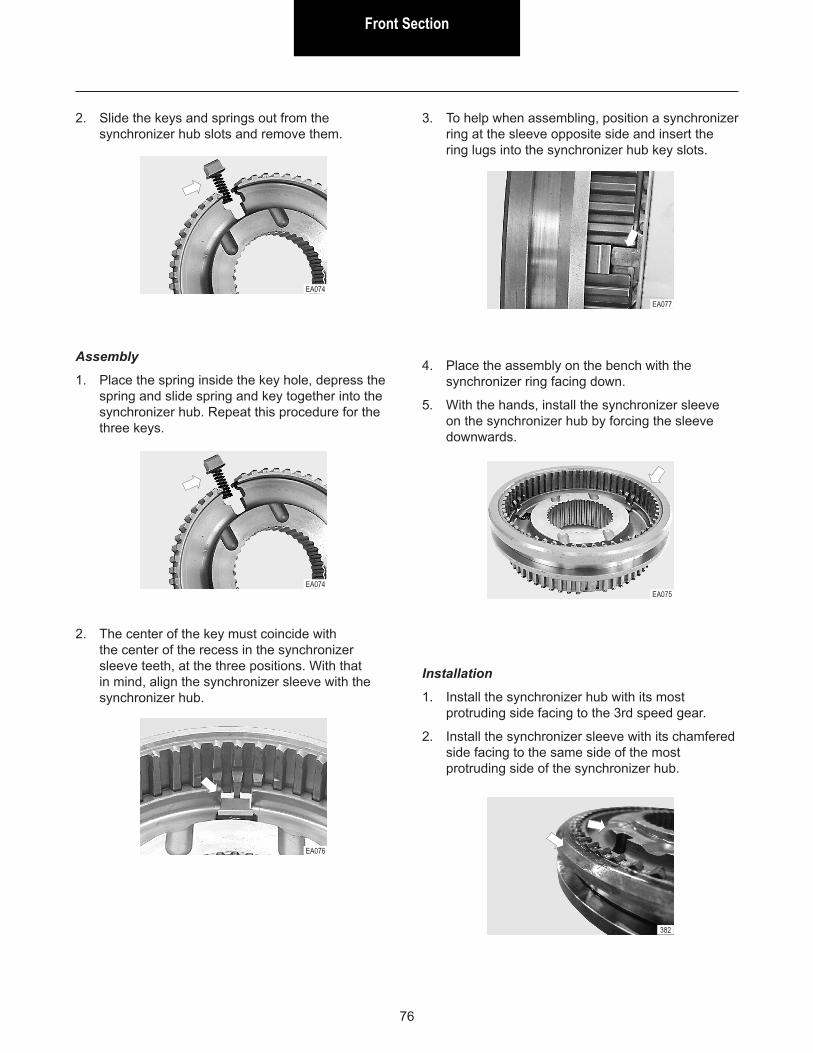
Front Section
76
2. Slide the keys and springs out from the synchronizer hub slots and remove them.
EA074
Assembly
1. Place the spring inside the key hole, depress the spring and slide spring and key together into the synchronizer hub. Repeat this procedure for the three keys.
EA074
2. The center of the key must coincide with the center of the recess in the synchronizer sleeve teeth, at the three positions. With that in mind, align the synchronizer sleeve with the synchronizer hub.
EA076
3. To help when assembling, position a synchronizer ring at the sleeve opposite side and insert the ring lugs into the synchronizer hub key slots.
EA077
4. Place the assembly on the bench with the synchronizer ring facing down.
5. With the hands, install the synchronizer sleeve on the synchronizer hub by forcing the sleeve downwards.
EA075
Installation
1. Install the synchronizer hub with its most protruding side facing to the 3rd speed gear.
2. Install the synchronizer sleeve with its chamfered side facing to the same side of the most protruding side of the synchronizer hub.
382
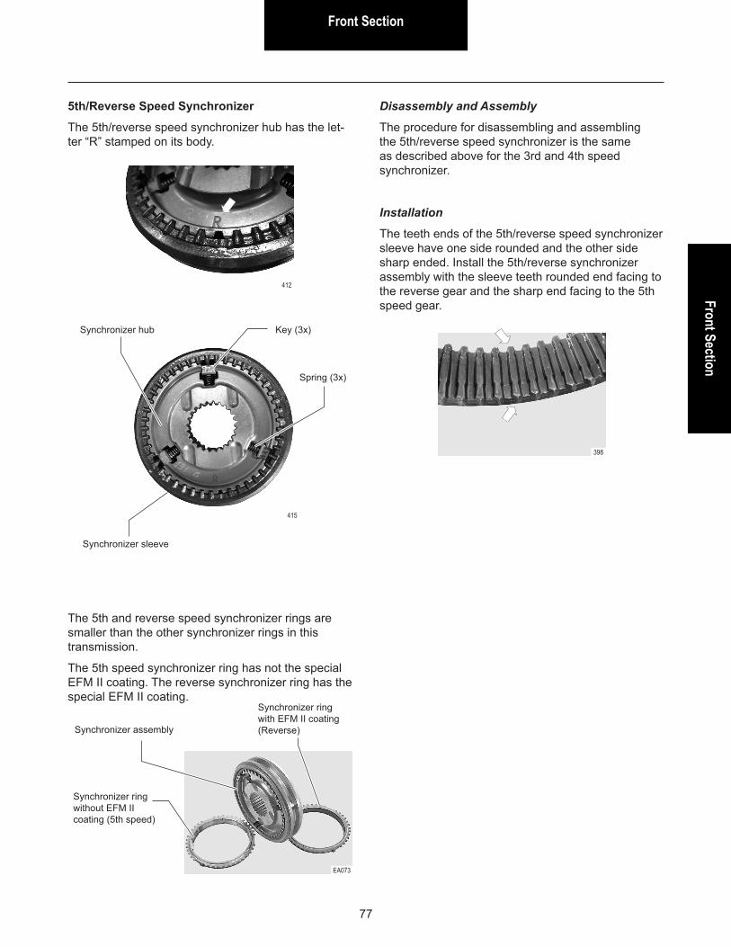
Front SectionFront Section
77
415
412
5th/Reverse Speed Synchronizer
The 5th/reverse speed synchronizer hub has the let-ter “R” stamped on its body.
Synchronizer hub
Synchronizer sleeve
Key (3x)
Spring (3x)
The 5th and reverse speed synchronizer rings are smaller than the other synchronizer rings in this transmission.
The 5th speed synchronizer ring has not the special EFM II coating. The reverse synchronizer ring has the special EFM II coating.
Disassembly and Assembly
The procedure for disassembling and assembling the 5th/reverse speed synchronizer is the same as described above for the 3rd and 4th speed synchronizer.
Installation
The teeth ends of the 5th/reverse speed synchronizer sleeve have one side rounded and the other side sharp ended. Install the 5th/reverse synchronizer assembly with the sleeve teeth rounded end facing to the reverse gear and the sharp end facing to the 5th speed gear.
EA073
Synchronizer assembly
Synchronizer ring without EFM II coating (5th speed)
Synchronizer ring with EFM II coating (Reverse)
398
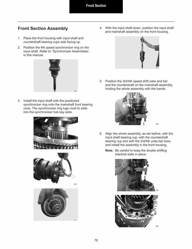
Front Section
78
1. Place the front housing with input shaft and countershaft bearing cups side facing up.
2. Position the 4th speed synchronizer ring on the input shaft. Refer to “Synchronizer Assemblies”, in this manual.
3. Install the input shaft with the positioned synchronizer ring onto the mainshaft front bearing cone. The synchronizer ring lugs must to slide into the synchronizer hub key slots.
526
493b
4. With the input shaft down, position the input shaft and mainshaft assembly on the front housing.
516
517
527
5. Position the 3rd/4th speed shift yoke and bar and the countershaft on the mainshaft assembly, holding the whole assembly with the hands.
6. Align the whole assembly, as set before, with the input shaft bearing cup, with the countershaft bearing cup and with the 3rd/4th yoke bar bore, and install the assembly in the front housing.
Note: Be careful to keep the double shifting interlock balls in place.
533
535
540
Front Section Assembly
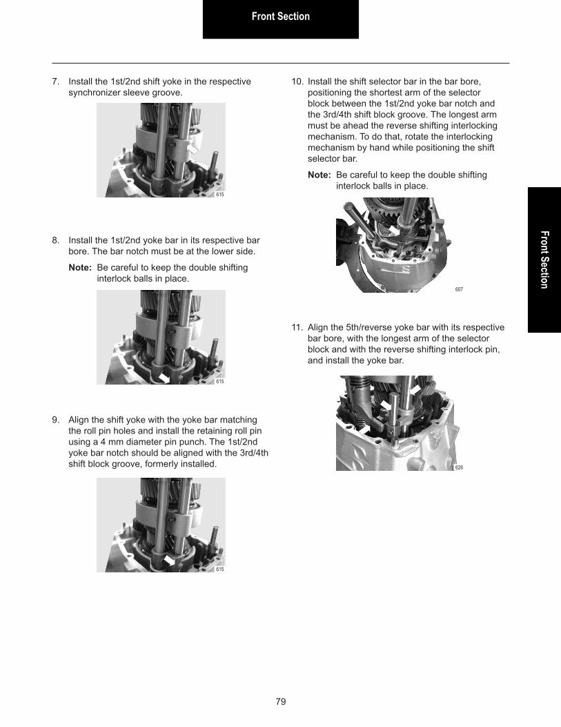
Front SectionFront Section
79
7. Install the 1st/2nd shift yoke in the respective synchronizer sleeve groove.
615
8. Install the 1st/2nd yoke bar in its respective bar bore. The bar notch must be at the lower side.
Note: Be careful to keep the double shifting interlock balls in place.
615
9. Align the shift yoke with the yoke bar matching the roll pin holes and install the retaining roll pin using a 4 mm diameter pin punch. The 1st/2nd yoke bar notch should be aligned with the 3rd/4th shift block groove, formerly installed.
615
10. Install the shift selector bar in the bar bore, positioning the shortest arm of the selector block between the 1st/2nd yoke bar notch and the 3rd/4th shift block groove. The longest arm must be ahead the reverse shifting interlocking mechanism. To do that, rotate the interlocking mechanism by hand while positioning the shift selector bar.
Note: Be careful to keep the double shifting interlock balls in place.
607
11. Align the 5th/reverse yoke bar with its respective bar bore, with the longest arm of the selector block and with the reverse shifting interlock pin, and install the yoke bar.
626

Front Section
80
WARNING! Do not apply sealant to both housing and retaining capscrews by now! Prior to finishing the transmission assembly is necessary to check the end play.
12. Install the intermediate housing on the front housing.
Note: If necessary, carefully hit the housing’s capscrews area with a plastic hammer to match the housings.
13. Install the intermediate housing retaining capscrews. Tighten capscrews crosswise to the recommended torque.
Note: Torque = 19-25 N.m (14-19 Lb.ft)
157
14. From inside the front housing, install capscrews securing the front housing to the intermediate housing. Tighten capscrews to the recommended torque.
Torque = 19-25 N.m (14-19 Lb.ft)
652
15. Proceed to mainshaft and countershaft end play adjustment as recommended in “End Play Adjustment”, later in this manual.
16. After determining the shim pack thickness necessary for adjusting both mainshaft and countershaft end play, remove intermediate housing.
17. Use the proper drive tool and remove the rear bearing cups (see “Mainshaft and Countershaft Rear Bearing Cups – Removal and Installation”).
WARNING! Be careful not to swap the adjustment shim packs between mainshaft and countershaft when installing them.
003
18. Install the necessary shim pack thickness to adjust the mainshaft end play in the mainshaft rear bearing bore and next, install the bearing cup.
Note: Use the proper drive tool to install the bearing cup (see “Mainshaft and Countershaft Rear Bearing Cups – Removal and Installation”).
EA173
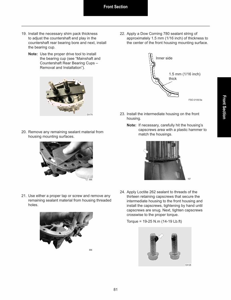
Front SectionFront Section
81
EA174
888
896
157
EA126
19. Install the necessary shim pack thickness to adjust the countershaft end play in the countershaft rear bearing bore and next, install the bearing cup.
Note: Use the proper drive tool to install the bearing cup (see “Mainshaft and Countershaft Rear Bearing Cups – Removal and Installation”).
20. Remove any remaining sealant material from housing mounting surfaces.
21. Use either a proper tap or screw and remove any remaining sealant material from housing threaded holes.
22. Apply a Dow Corning 780 sealant string of approximately 1.5 mm (1/16 inch) of thickness to the center of the front housing mounting surface.
Inner side
1.5 mm (1/16 inch) thick
FSO-2105/3a
23. Install the intermediate housing on the front housing.
Note: If necessary, carefully hit the housing’s capscrews area with a plastic hammer to match the housings.
24. Apply Loctite 262 sealant to threads of the thirteen retaining capscrews that secure the intermediate housing to the front housing and install the capscrews, tightening by hand until capscrews are snug. Next, tighten capscrews crosswise to the proper torque.
Torque = 19-25 N.m (14-19 Lb.ft)
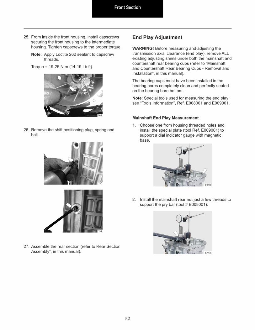
Front Section
82
003
25. From inside the front housing, install capscrews securing the front housing to the intermediate housing. Tighten capscrews to the proper torque.
Note: Apply Loctite 262 sealant to capscrew threads.
Torque = 19-25 N.m (14-19 Lb.ft)
26. Remove the shift positioning plug, spring and ball.
27. Assemble the rear section (refer to Rear Section Assembly”, in this manual).
152
154
End Play Adjustment
WARNING! Before measuring and adjusting the transmission axial clearance (end play), remove ALL existing adjusting shims under both the mainshaft and countershaft rear bearing cups (refer to “Mainshaft and Countershaft Rear Bearing Cups - Removal and Installation”, in this manual).
The bearing cups must have been installed in the bearing bores completely clean and perfectly seated on the bearing bore bottom.
Note: Special tools used for measuring the end play: see “Tools Information”, Ref. E008001 and E009001.
Mainshaft End Play Measurement
1. Choose one from housing threaded holes and install the special plate (tool Ref. E009001) to support a dial indicator gauge with magnetic base.
2. Install the mainshaft rear nut just a few threads to support the pry bar (tool # E008001).
EA176
EA176
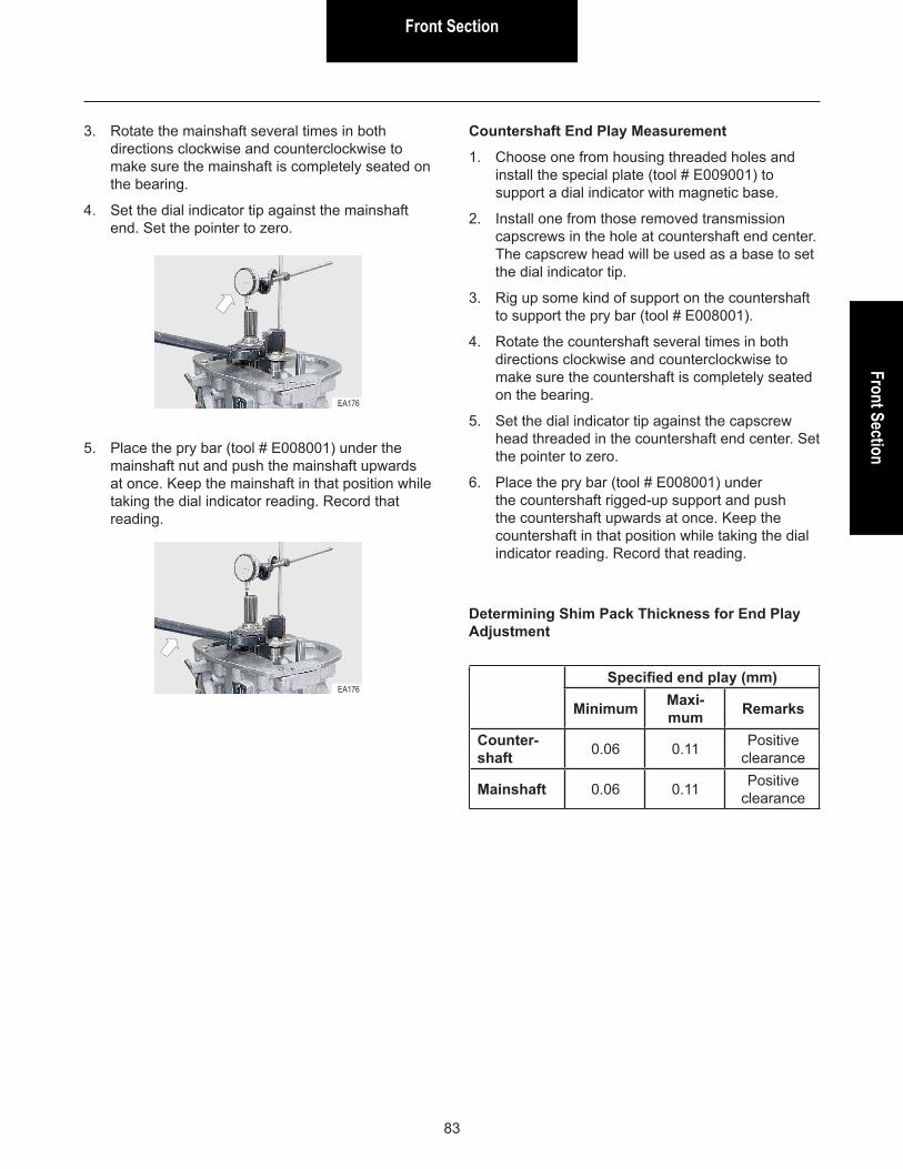
Front SectionFront Section
83
Countershaft End Play Measurement
1. Choose one from housing threaded holes and install the special plate (tool # E009001) to support a dial indicator with magnetic base.
2. Install one from those removed transmission capscrews in the hole at countershaft end center. The capscrew head will be used as a base to set the dial indicator tip.
3. Rig up some kind of support on the countershaft to support the pry bar (tool # E008001).
4. Rotate the countershaft several times in both directions clockwise and counterclockwise to make sure the countershaft is completely seated on the bearing.
5. Set the dial indicator tip against the capscrew head threaded in the countershaft end center. Set the pointer to zero.
6. Place the pry bar (tool # E008001) under the countershaft rigged-up support and push the countershaft upwards at once. Keep the countershaft in that position while taking the dial indicator reading. Record that reading.
Determining Shim Pack Thickness for End Play Adjustment
Specified end play (mm)
Minimum Maxi-mum Remarks
Counter-shaft 0.06 0.11 Positive
clearance
Mainshaft 0.06 0.11 Positive clearance
3. Rotate the mainshaft several times in both directions clockwise and counterclockwise to make sure the mainshaft is completely seated on the bearing.
4. Set the dial indicator tip against the mainshaft end. Set the pointer to zero.
5. Place the pry bar (tool # E008001) under the mainshaft nut and push the mainshaft upwards at once. Keep the mainshaft in that position while taking the dial indicator reading. Record that reading.
EA176
EA176

Front Section
84
Use the following flowchart and determine the shim pack thickness to adjust the transmission end play:
Measure the clearance
Is the measured value greater than the maximum specified?
Is the measured value greater than the minimum
specified?
No
Yes/No?
Yes Calculate:
Measured value minus Maximum specified = R1
Measured value minus Minimum specified = R2
Yes/No?
NoThe measured value is not a valid value. Verify if all existing shims were
removed, if the bearing cup is installed properly and if
the shaft is seated properly. Redo the measurement.
Use a shim pack thickness greater than R1 and less
than R2.
Yes
Shims are not necessary. End
Example #1: countershaft end play adjustment
Specified end play: 0.06 mm to 0.11 mm Measured end play: 0.47 mm
As the measured value is greater than 0,11 mm (maximum specified), calculate:
0.47 - 0.11 = 0.36 mm (R1) 0.47 - 0.06 = 0.41 mm (R2)
The shim pack thickness must be within 0.36 mm and 0.41 mm.
Example #2: countershaft end play adjustment
Specified end play: 0.06 mm to 0.11 mm Measured end play: 0.02 mm
In this case, it is not possible to calculate the shim thickness, since the measured clearance is already less than the minimum specified. This measured value is not a valid value. So, it is necessary to redo the measurement, verifying before if all existing shims were actually removed, if the bearing cup is perfectly seated on the bearing bore and free of any kind of dirt, and if the shaft is seated properly on the bearing, by rotating the shaft in both directions clockwise and counterclockwise.