Galileo Runtime System 4.20 - Eaton
68
MSystem Software Galileo Runtime System 4.20 User manual Galileo Runtime System 4.20 Micro Innovation AG Spinnereistrasse 8-14 CH-9008 St. Gallen Switzerland Tel. +41 (0)71 243 24 24 Fax +41 (0)71 243 24 90 www.microinnovation.com [email protected]
-
Upload
khangminh22 -
Category
Documents
-
view
1 -
download
0
Transcript of Galileo Runtime System 4.20 - Eaton

MSystem
Software Galileo Runtime System 4.20
User manual
Galileo Runtime System 4.20
Micro Innovation AG Spinnereistrasse 8-14 CH-9008 St. Gallen Switzerland Tel. +41 (0)71 243 24 24 Fax +41 (0)71 243 24 90 www.microinnovation.com [email protected]

User manual Galileo Runtime System 4.20 SoftwareCopyright
Copyright
Keep documentation for future use! This documentation is the intellectual property of Micro Innovation AG, which also has the exclusive copyright. Any modification of the content, dublication or reprinting of this documentation, as well as distribution to third parties can only be made with the express permission of Micro Innovation AG. Micro Innovation AG does not accept any liability for damages arising from the use of any incorrect or incomplete information contained in this documentation or any information missing therefrom. Micro Innovation AG reserves the right to male complete or partial modification to this document. All brand and product names are trademarks or registered trademarks of th owner concerned.
2
Technical subject to changeM000218-02.DOC
© by Micro Innovation

Software User manual Galileo Runtime System 4.20 Proper use
Proper use Hardware, software, operatingsystems and drivers must only be used for the applications specified in this description and only in conjunction with the components recommended by Micro Innovation AG. Warning ! No warranty claims will be recognized for faults arising from the improper handling of any device. Devices and communication should not be used for the implementation of any safety functions relating to the protection of personnel and machinery. No liability is accepted for claims for damages arising from a failure or functional defect. All data specified in this document does not represent guaranteed specifications in the legal sense.
Technical subject to change M000218-02.DOC © by Micro Innovation 3

User manual Galileo Runtime System 4.20 SoftwareContents
Contents 1 Galileo Runtime System (GRS).......................................................................... 6
1.1 General .................................................................................................................... 6 1.2 Differences between the Runtime Systems............................................................. 6
1.2.1 Differences between the Runtime Systems................................................................. 6 1.2.2 Memory module ........................................................................................................... 7 1.2.3 Project transfer (Galileo - Panel) ................................................................................. 8 1.2.4 Download mode........................................................................................................... 8 1.2.5 System data ................................................................................................................. 9 1.2.6 SRAM Backup.............................................................................................................. 9 1.2.7 Convert recipe data file (*.TAB) ................................................................................... 9 1.2.8 Recipe database limitation......................................................................................... 10 1.2.9 PCX Pictures............................................................................................................. 10 1.2.10 Backup recipe .......................................................................................................... 10 1.2.11 Comboard Loader.................................................................................................... 10 1.2.12 Special function "Save Mask As Bitmap"................................................................. 11 1.2.13 Special function "Set Touch Disable" ...................................................................... 11 1.2.14 Special function "Backlight Off" ............................................................................... 11 1.2.15 Special function "Brightness x%"............................................................................. 11 1.2.16 Bitmap Cache .......................................................................................................... 11 1.2.17 Serial number........................................................................................................... 11 1.2.18 EIB Communication ................................................................................................. 12 1.2.19 Mainboard Firmware/Windows CE Kernel............................................................... 12 1.2.20 Archive "Graph" data in files .................................................................................... 12 1.2.21 Ethernet Interface .................................................................................................... 12 1.2.22 Parallel Interface ...................................................................................................... 12
1.3 Program Structure ................................................................................................. 12 1.3.1 Program Structure...................................................................................................... 12 1.3.2 RUNTIME directory.................................................................................................... 13 1.3.3 DATA directory........................................................................................................... 13 1.3.4 APPL directory ........................................................................................................... 14
1.4 GRS on PC (GPI) .................................................................................................. 15 1.4.1 General ...................................................................................................................... 15 1.4.2 Communication Setup ............................................................................................... 16 1.4.3 Information about Product and Version ..................................................................... 16
1.5 Printing .................................................................................................................. 16 1.5.1 Printing....................................................................................................................... 16 1.5.2 Serial Port .................................................................................................................. 17 1.5.3 Parallel Port ............................................................................................................... 17 1.5.4 Ethernet Port.............................................................................................................. 18
1.6 Comboard Loader.................................................................................................. 18 1.6.1 Comboard Loader...................................................................................................... 18 1.6.2 Loading options.......................................................................................................... 18
1.7 SRAM .................................................................................................................... 19 1.7.1 SRAM......................................................................................................................... 19
1.8 Function of the Bitmap Cache ............................................................................... 20 1.8.1 Function of the Bitmap Cache ................................................................................... 20
1.9 Generating bitmaps from the screen(Screenshot)................................................. 20 1.9.1 Generating bitmaps from the screen(Screenshot) .................................................... 20
1.10 PLC Simulation (RK512 Protocol) ...................................................................... 20
4
Technical subject to changeM000218-02.DOC
© by Micro Innovation

Software User manual Galileo Runtime System 4.20 Inhaltsverzeichnis
1.10.1 PLC Simulation (RK512 Protocol) ............................................................................20 1.11 Description: Application Loader ..........................................................................21
1.11.1 Description: Application Loader................................................................................21 1.11.2 GRSW.......................................................................................................................21 1.11.3 GRSW1.....................................................................................................................22 1.11.4 GRSW2 / GRSW3 ....................................................................................................23
1.12 System Messages...............................................................................................24 1.12.1 System Messages ....................................................................................................24 1.12.2 Description of System Messages ............................................................................25
1.13 Comments for Panels with Windows CE.............................................................38 1.13.1 General .....................................................................................................................38 1.13.2 Ethernet ....................................................................................................................39
2 Communication .................................................................................................41 2.1 Basic Principles ......................................................................................................41
2.1.1 General .......................................................................................................................41 2.1.2 Data Synchronisation .................................................................................................42 2.1.3 Data block concept .....................................................................................................42
2.2 Special data block types.........................................................................................43 2.2.1 Special data block types.............................................................................................43 2.2.2 Control data block.......................................................................................................43 2.2.3 Status data block ........................................................................................................45 2.2.4 "Date_Time" data block ..............................................................................................47 2.2.5 "PLC to PLC" data block.............................................................................................48 2.2.6 "EIB_Date" data block ................................................................................................49 2.2.7 "EIB_Time" data block................................................................................................49
2.3 Initiating functions from the PLC ............................................................................49 2.3.1 Initiating functions from the PLC ................................................................................49 2.3.2 Initiating special functions (Function key)...................................................................50 2.3.3 Recipe commands from the plc..................................................................................51 2.3.4 Send PLC to PLC Message........................................................................................52 2.3.5 Updating error display ................................................................................................52 2.3.6 Renewed data synchronisation ..................................................................................52 2.3.7 Mask change ..............................................................................................................52 2.3.8 Time/Date Synchronisation ........................................................................................53 2.3.9 Transferring PLC text .................................................................................................53 2.3.10 Touch disable ...........................................................................................................53
3 Glossary .............................................................................................................55 3.1 GlossCompact Flash ..............................................................................................55 3.2 GRSW3 ..................................................................................................................56
4 Index...................................................................................................................63
Technical subject to change M000218-02.DOC © by Micro Innovation 5

User manual Galileo Runtime System 4.20 SoftwareGalileo Runtime System (GRS)
1 GALILEO RUNTIME SYSTEM (GRS)
1.1 GENERAL
The Galileo Runtime System or GRS for short is the operating system for executable projects that have been designed and compiled with the Galileo design software. User entries are made on the Touch Panel by pressing the appropriate objects on the screen. Entries via the mouse are also possible on a standard PC (see also GRS on PC (GPI)). The communication with the PLC is implemented either via communication modules, or via a serial or Ethernet interface, depending on the device concerned.
1.2 DIFFERENCES BETWEEN THE RUNTIME SYSTEMS
1.2.1 DIFFERENCES BETWEEN THE RUNTIME SYSTEMS
The following chapters use the abbreviation GRS as the general term for the runtime system. All Galileo runtime systems are based on WIN32, Windows CE® or Windows 95, 98 or NT. Four runtime systems have been developed since different platforms are supported with different hardware properties. These are as follows: GRSW Galileo Runtime
System Windows The GRSW can be run on a panel without a memory card. The data is stored in a permanent memory
GRSW1 Galileo Runtime System Windows
GRSW1 can be run on panel with a plug-in PCMCIA memory card. Linear flash cards can no longer be used. See also chapter Converting projects from Galileo versions < 2.80 in GALILGB.HLP
GRSW2 Galileo Runtime System Windows CE
The GRSW2 can only run on devices using an Ethernet interface and Windows CE. An X86-based processor is used.
GRSW3 Galileo Runtime System Windows CE
The GRSW3 can only run on MC2xxx devices with Windows CE. An ARM-based processor is used.
GPI Galileo Project Inspector
The GPI can be run on a PC with Win95, Win98, NT (from version 4.0) or 2000. This runtime system is started via a button in Galileo. It is designed for project developers as a fast testing tool. It is designed as a test environment for the project design phase and therefore only starts in DEMO mode. See also chapter Test the Project in GALILGB.HLP
WinGRS Galileo Runtime System for Windows
Like GPI, WinGRS can be run on a PC using Windows 95, 98, NT (from version 4.0) or 2000. A CBA must be present so that the program can be launched. This adapter is the runtime license. The documentation no longer distinguishes between GPI and WinGRS. The PC based visualization consisting of WinGRS and a communication card is labeled as GALILEO OPEN.
The different GRS have the following features:
GRSW GRSW1 GRSW2 GRSW3 GPI/ WinGRS
6
Technical subject to changeM000218-02.DOC
© by Micro Innovation

Software User manual Galileo Runtime System 4.20 Galileo Runtime System (GRS)
Memory module Permanent memory
ATA - PCMCIA Card
ATA – PCMCIA Card
Compact Flash card
Hard disk
Project transfer (Galileo - Panel)
X X X X
Download mode X X X
System data SRAM Sram Sram SRAM File SRAM Backup X X
Convert recipe data file (*.TAB)
X X X X
Recipe database limitation 2MByte 5MByte 5MByte 5MByte 5 Mbyte PCX Pictures X X X X X Beep X X X X
Backup recipe X
Comboard Loader X X X X
Special function "Save Mask As Bitmap"
X X X X
Special function "Set Touch Disable"
X X X X
Special function "Backlight Off"
X X X X
Special function "Brightness x%"
X X X X
Bitmap Cache X X X
Serial number X X X X
EIB Communication X X X X X (WinGRS with CBA)
Mainboard Firmware X X X X
Archive "Graph" data in files
X (manually)
X (manually or on external server))
X (manually or on external server)
X
Ethernet Interface X X Depending on the PC
USB interface X
Parallel Interface X X X
X
1.2.2 MEMORY MODULE
GRSW1 The compatible panel is not provided with a PCMCIA slot. A permanent memory is used for storing project data, fonts, pictures etc. There is no directory structure. The operator cannot see where particular data is stored. The GRSW manages all the data.
Technical subject to change M000218-02.DOC © by Micro Innovation 7

User manual Galileo Runtime System 4.20 SoftwareGalileo Runtime System (GRS)
A memory expansion can be added. The following permanent memories are available: Basic memory 2 and 4 Mbyte (320x240 and 640x480) Maximum memory
expansion 16 Mbyte
GRSW1, GRSW2 Data is stored on a plug-in PCMCIA card (ATA card). The directory structure (see also Program Structure) can be seen if the user has a PCMCIA card drive.
GRSW3 The data is stored on a plug-in Compact flash card. The directory structure (see program structure) can also be seen on the PC if the PC has a Compact flash card drive or a PCMCIA drive with the correct adapter.
GPI, WinGRS Data is stored on the standard hard disk of the PC.
1.2.3 PROJECT TRANSFER (GALILEO - PANEL)
Compiled projects can be transferred from Galileo to the Touch Panel in the following way: GRSW - serial download (see also Download mode) GRSW1 - serial download (see also Download mode)
- Transfer of project data to the ATA flash card via the PCMCIA card drive GRSW2 Transfer of project data directly to the ATA flash card via the PCMCIA card drive in the
PC or via FTP* onto the flash card in the device.. GRSW3 Transfer of project data directly to the Compact flash card using an adapter in the PC or
via FTP* to the flash card in the device. GPI No data needs to be transferred to the panel since the GPI is used as a test runtime
program on the PC. WinGRS The project data is transferred to the appropriate directory from which WinGRS is to start.
Note: The serial data transfer is considerably longer than the transfer via the PCMCIA card drive on the PC (approx. 4 minutes/MB).
Description: (see chapter Project Transfer to a PCMCIA Card and serial Transfer in GALILGB.HLP) With GRSW2 und GRSW3 data transfer is also possible via FTP. See "FTP Path" for information about the settings for the FTP path in Galileo. The IP address of the MMI can be set via the "Control Panel – Network" system function. Further information is provided in the documentation "Micro Panel with Windows CE".
1.2.4 DOWNLOAD MODE
The panel first needs to be switched to a particular operating mode for serial project transfers. This is called Download mode. GRSW Download mode is activated by pressing a button provided on the hardware
(see device description). There are three ways of pressing the Download button Button pressed when the panel is switched on: Internal mode (cannot be used). The screen stays black.
Press button after "Search Program" appears on the screen: Mainboard Firmware Press button during program runtime: Serial project transfer
See also Project transfer
GRSW1 To activate Download mode it is necessary to simulate or force a fatal error (see System Messages).
8
Technical subject to changeM000218-02.DOC
© by Micro Innovation
Software User manual Galileo Runtime System 4.20 Galileo Runtime System (GRS)
The simplest way of doing this is as follows: Place the palm of the hand flat on the screen when the panel is started. All the infrared channels will be scanned during the initialization phase. The hand will interrupt these channels so that the touch controller will evaluate them as faulty. A large area being detected as faulty will thus cause the normal program runtime to be aborted as a fatal error. The panel will then switch to Download mode. See also: 50) Touch is dirty or defect ! See also Project transfer
GRSW2,GRSW3 There is no Download mode available on this device. The serial download is not supported. Pressing the Download button will close GRSW2. This can also be carried out using the special function Shutdown. See also Project transfer (Galileo - Panel)
GPI No Download mode is required here since the GPI operates as a test runtime software on the PC.
WinGRS As the project data is copied directly to a working directory, a Download mode is not required.
1.2.5 SYSTEM DATA
See chapter SRAM for a more detailed description. GRSW, GRSW1, GRSW2,GRSW3
The data is stored in the panel in a retentive memory. This retains existing values when the device is restarted.
GPI GPI, WinGRS The system data is stored in the SRAM.DAT file.
1.2.6 SRAM BACKUP
See chapter Save/Restore SRAM for a more detailed description. GRSW File access is not possible since a permanent memory is used as the memory
medium. System data cannot be backed up. See also: System data GRSW1,GRSW2 GRSW3
The system data can be saved in the SRAM.DAT file on the Flash card.
GPI, WinGRS No SRAM backup is available.
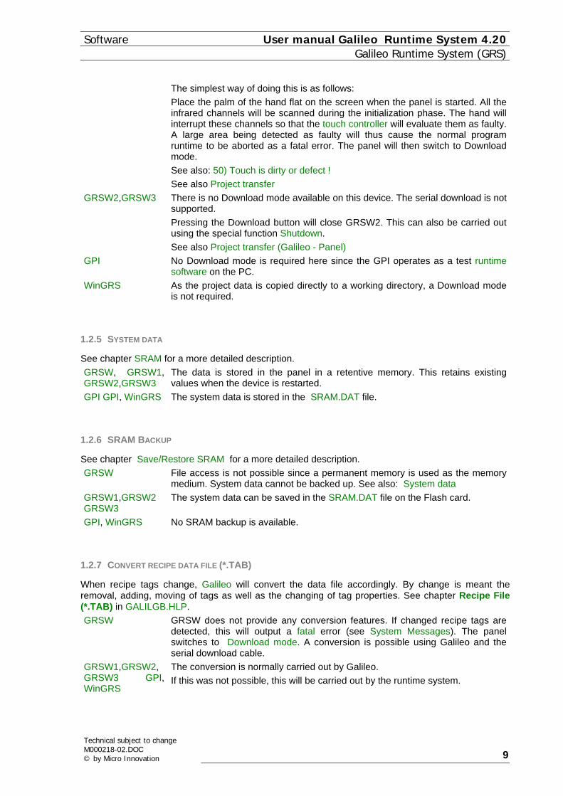
1.2.7 CONVERT RECIPE DATA FILE (*.TAB)
When recipe tags change, Galileo will convert the data file accordingly. By change is meant the removal, adding, moving of tags as well as the changing of tag properties. See chapter Recipe File (*.TAB) in GALILGB.HLP. GRSW GRSW does not provide any conversion features. If changed recipe tags are
detected, this will output a fatal error (see System Messages). The panel switches to Download mode. A conversion is possible using Galileo and the serial download cable.
GRSW1,GRSW2, GRSW3 GPI, WinGRS
The conversion is normally carried out by Galileo. If this was not possible, this will be carried out by the runtime system.
Technical subject to change M000218-02.DOC © by Micro Innovation 9
User manual Galileo Runtime System 4.20 SoftwareGalileo Runtime System (GRS)
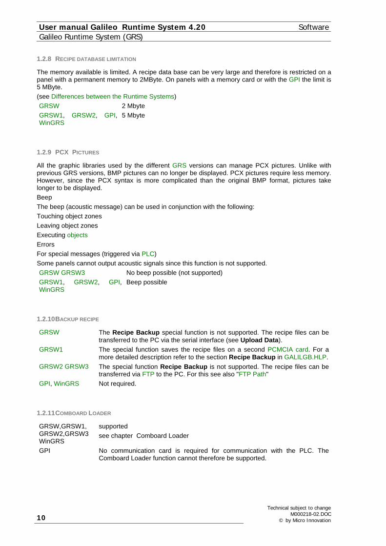
1.2.8 RECIPE DATABASE LIMITATION
The memory available is limited. A recipe data base can be very large and therefore is restricted on a panel with a permanent memory to 2MByte. On panels with a memory card or with the GPI the limit is 5 MByte. (see Differences between the Runtime Systems) GRSW 2 Mbyte GRSW1, GRSW2, GPI, WinGRS
5 Mbyte
1.2.9 PCX PICTURES
All the graphic libraries used by the different GRS versions can manage PCX pictures. Unlike with previous GRS versions, BMP pictures can no longer be displayed. PCX pictures require less memory. However, since the PCX syntax is more complicated than the original BMP format, pictures take longer to be displayed. Beep The beep (acoustic message) can be used in conjunction with the following: Touching object zones Leaving object zones Executing objects Errors For special messages (triggered via PLC) Some panels cannot output acoustic signals since this function is not supported. GRSW GRSW3 No beep possible (not supported) GRSW1, GRSW2, GPI, WinGRS
Beep possible
1.2.10 BACKUP RECIPE
GRSW The Recipe Backup special function is not supported. The recipe files can be transferred to the PC via the serial interface (see Upload Data).
GRSW1 The special function saves the recipe files on a second PCMCIA card. For a more detailed description refer to the section Recipe Backup in GALILGB.HLP.
GRSW2 GRSW3 The special function Recipe Backup is not supported. The recipe files can be transferred via FTP to the PC. For this see also "FTP Path"
GPI, WinGRS Not required.
1.2.11 COMBOARD LOADER
GRSW,GRSW1, GRSW2,GRSW3 WinGRS
supported see chapter Comboard Loader
GPI No communication card is required for communication with the PLC. The Comboard Loader function cannot therefore be supported.
10
Technical subject to changeM000218-02.DOC
© by Micro Innovation

Software User manual Galileo Runtime System 4.20 Galileo Runtime System (GRS)
1.2.12 SPECIAL FUNCTION "SAVE MASK AS BITMAP"
GRSW not supported GRSW1, GRSW2, GRSW3 GPI, WinGRS
supported See chapter Save Mask as Bitmap in GALILGB.HLP
1.2.13 SPECIAL FUNCTION "SET TOUCH DISABLE"
The Set Touch Disable function can only be used with panels with IR touch technology. GRSW, GRSW1, GRSW2, GRSW3 GPI, WinGRS
supported see chapter Set Touch Disable in GALILGB.HLP
1.2.14 SPECIAL FUNCTION "BACKLIGHT OFF"
GRSW, GRSW1, GRSW2 GRSW3
supported see chapter Backlight Off in GALILGB.HLP
GPI, WinGRS not supported
1.2.15 SPECIAL FUNCTION "BRIGHTNESS X%"
This function allows the panel backlight to be changed. This enables the lifespan of the backlight to be considerably increased. GRSW, GRSW1, GRSW2 GRSW3
supported see chapter Brightness 100% in GALILGB.HLP On Windows CE devices, the operating system also supports the screen settings ("Control Panel – Display"). Further information is provided in the documentation "Micro Panel with Windows CE".
GPI, WinGRS The brightness of the screen cannot be changed with the special function.
1.2.16 BITMAP CACHE
GRSW, GRSW1, GRSW2 GRSW3
supported see chapter Function of the Bitmap Cache
GPI, WinGRS The loading and display of a picture is not time critical on the PC. This feature has not therefore been provided.
1.2.17 SERIAL NUMBER
The hardware can be assigned a unique serial number for identification purposes. The Show Sysinfo special function can be used to show this number. See chapter Show Systeminfo in GALILGB.HLP GRSW, GRSW1, GRSW2 GRSW3
The hardware can be assigned a unique serial number for identification purposes. On Windows CE devices, the serial number is displayed during startup.
GPI, WinGRS No serial number can be shown
Technical subject to change M000218-02.DOC © by Micro Innovation 11

User manual Galileo Runtime System 4.20 SoftwareGalileo Runtime System (GRS)
1.2.18 EIB COMMUNICATION
GRSW, GRSW1, GRSW2, GRSW3 WinGRS
not available See Document Select PLC and device description "EIB - TP card description"
GPI not available
1.2.19 MAINBOARD FIRMWARE/WINDOWS CE KERNEL
GRSW, GRSW1, GRSW2 GRSW3
available see chapter Description: Application Loader
GPI, WinGRS not available See also chapter "Update Firmware" in GalilGB.hlp
1.2.20 ARCHIVE "GRAPH" DATA IN FILES
This file saves the collected values in a file. The values of these files can be loaded if necessary and viewed on the MMI in the "Graph" object. For further information refer to chapter "Define Graph Blocks", "Graph" and "Graph Functions" in GALILGB.HLP. GRSW not available GRSW1, GRSW2 GRSW3 The manual saving, loading and deleting of graph archive data on
the FLASH card is supported. GRSW2 and GRSW3 allows data to be saved on an external memory also via Ethernet. The save operation to an external server can also be called from a Loopscript. This makes it possible to carry out save operations periodically. See special functions Save Archive File , Save Archive File as, Load Archive File and Delete Archive File in GalilGB.hlp
GPI, WinGRS The automatic and manual saving of graphic archive data is supported. See also chapter "Graph Archive" in GALILGB.HLP
1.2.21 ETHERNET INTERFACE
In order to use the Ethernet interface, the device must be provided with a valid IP address and IP mask. The IP address can either be permanently assigned or assigned an address via a DHCP server. If you have other questions concerning the TCP/IP protocol or network settings, contact your network administrator. The currently set IP address and IP mask are displayed when the device is started (see Mainboard Firmware GRSW2). The network settings can be set via the "Control Panel – Network" system function. Further information is provided in the documentation "Micro Panel with Windows CE". See also Comments for Panels with Windows CE
1.2.22 PARALLEL INTERFACE
This interface can be used to print out project data. See also Printer special functions in Galileo.hlp and "Print"
1.3 PROGRAM STRUCTURE
1.3.1 PROGRAM STRUCTURE
The file directory structure is generated by the compiler of the GALILEO design software and must not be changed by the user, in order to ensure error-free program execution. The files created contain all the project data required by the GRS for the application concerned. The term "PROJECT" in the following documentation stands for the actual Project name concerned.
12
Technical subject to changeM000218-02.DOC
© by Micro Innovation

Software User manual Galileo Runtime System 4.20 Galileo Runtime System (GRS)
The directory structure is fixed and is defined as follows: (see also Memory module) See also chapter PCMCIA-Card Path in GALILGB.HLP autoexec.bat This file controls the startup behavior of devices running on Windows CE Galileo.lnk This file is only used with devices running on Windows CE RUNTIME\ GRS and help files DATA\ Project-related runtime data APPL\ Compiled GALILEO project APPL\BMP All pictures required in the project APPL\FONTS All fonts required in the project APPL\TXT All languages required in the project APPL\MGF All masks required in the project OS\ On Windows CE devices, this directory contains all the files required for the
operating system. See also: RUNTIME directory DATA directory APPL directory
1.3.2 RUNTIME DIRECTORY
If detailed information is available on the individual files, this is referred to in the brackets. GRSW.EXE, GRSW1.EXE, GRSW2.EXE, GRSW3.EXE GPI.EXE, GPICFG.DLL, WinGRS.EXE
GRS runtime software See chapter Differences between the Runtime Systems
GRS_LOG.GER GRS system messages in German (File format) GRS_LOG.ENG GRS system messages in English GRS_LOG.FRA GRS system messages in French GRS_LOG.SPA GRS system messages in Spanish GRS_LOG.ITA GRS system messages in Italian GRS_LOG.USR GRS system messages in a freely definable language MFCCE300.DLL This DLL is required by GRSW2 *.BIN Communication card driver *.DLL DLL files required by certain communications drivers.
1.3.3 DATA DIRECTORY
If detailed information is available on the individual files, this is referred to in the brackets. Data in this directory is not overwritten during a Galileo project download. Overwriting is only carried out if this is explicitly implemented by the project designer. SRAM.DAT Backup file for internal SRAM (SRAM) *.TAB File with the names and dates of the recipe entries. This file is saved in TAB
format and can be edited externally. See chapter Recipe File (*.TAB) in GALILGB.HLP
*.ACT File with the current basic definitions of the recipe object (Recipe name.act). The format of the TAB file corresponds to the recipe definitions contained in this ACT file. If recipe definitions such as number, order of tags, number of tags etc. have been changed, this information is needed to convert the TAB file to the new format. Changes can be detected by comparing the entries of *.ACT and *.REF. Both files are identical after conversion.
Technical subject to change M000218-02.DOC © by Micro Innovation 13

User manual Galileo Runtime System 4.20 SoftwareGalileo Runtime System (GRS)
PROJEKT.PWM This file is needed for password management. It contains the user and level definitions.
Note: On certain panel types, the recipe data can also be saved in a different path or even outside of the panel (e.g. in a data server), depending on the configuration in Galileo.
1.3.4 APPL DIRECTORY
APPL directory Several files with the same ending must not be stored in this directory (Exception: *.REF). In this case use the "Clear before download" switch in Galileo. *.PGF Standard color palette of 256 colors for Bitmaps PROJEKT.GF1 Project table with general data. This file contains the main project data. PROJEKT.FPR Definition of all forms for printing out variable tags PROJEKT.ILT Names of Bitmaps for Galileo e.g. B. 0.PCX = BUTTON.PCX *.REF File with the basic definitions of the recipe object (Recipe name.REF). The Ref
file is generated by GALILEO. If recipe definitions such as number, order of tags, number of tags etc. have been changed, this information is needed to convert the TAB file to the new format. Changes can be detected by comparing the entries of *.ACT and *.REF. Both files are identical after conversion.
*.PRV Printer definition file (see chapter Printer Driver (*.PRV) in GALILGB.HLP) See also: APPL\BMP directory APPL\FONTS directory APPL\MGF directory APPL\TXT directory
APPL\BMP directory System bitmaps are stored in this directory in addition to project-related Bitmaps. The effective names of the project-related bitmaps can be determined from the PROJEKT.ILT file *.PCX Project-related bitmaps always start with a number given by GALILEO WARNING.BMP Bitmap displayed for invalid or undefined object states QUESTION.PCX Display for invalid or undefined object states in conjunction with graph
functions. See also chapter Graph in GALILGB.HLP WAIT.BMP Bitmap displayed when GRS operation in progress for a long time NO_TOUCH.BMP Bitmap displayed when Touch Disable is active TOUCH_OK.BMP Bitmap displayed when changing from Touch disable to normal operation TCH_DIS.PCX Indication if TouchDisable is activated by the PLC. TCH_FLT.PCX Indication that a double touch with the fingers was not correctly detected R_LOAD.PCX, R_CHANGE.PCX
Recipe - Backup. Display during the loading of recipes, and indicates that the PCMCIA card must be changed. see also chapter Backup Recipe in GALILGB.HLP
ARROW_L.PCX, ARROW_R.PCX
These two bitmaps are required for Help windows consisting of several pages.
APPL\FONTS directory The system font must be stored in this directory together with all project-related fonts **.FN0 Project-related fonts *.TTF Project-specific fonts (only with units running on Windows CE and on GPI):
The system font (file ARIAL.TTF) must always be present!
14
Technical subject to changeM000218-02.DOC
© by Micro Innovation

Software User manual Galileo Runtime System 4.20 Galileo Runtime System (GRS)
APPL\MGF directory All objects defined in a mask are stored as mask-related object data in this directory. Refer to the chapter Mask Type in GALILGB.HLP for a description of the different types of masks available. The number in front of the ending ".MFG" corresponds to the mask number as assigned by Galileo. Note: Mask files with numbers >= 65000 are system masks such as numeric keyboards etc. APPL\TXT directory Several files with the same ending must not be stored in this directory. In this case use the "Clear before download" switch in Galileo. The number of the currently used language is entered instead of "xy". The appropriate texts are reloaded when changing the current language (see also PROJEKT.LNG). PROJEKT.Exy Single line error texts (for Error text window) PROJEKT.Txy All other texts used in the project other than help texts PROJEKT.Hxy All help texts defined (only loaded as required)
Archive - file See chapter Storage Settings in GALILGB.HLP GRAPHxy.GDB Graph archive as ASCII file. See chapter Graph Archive in GALILGB.HLP GRAPH.TDB Graph archive in binary form. This file is only used internally. This file only exists if
the graph data is automatically saved (see Archive "Graph" data in files).
1.4 GRS ON PC (GPI)
1.4.1 GENERAL
General The GPI is used for testing projects and is designed as a parameter and commissioning tool. Design time can be considerably reduced since the project does not have to be transferred to the panel after every compilation. See also chapter Differences between the Runtime Systems The project can be inspected and tested after it has been successfully compiled in GALILEO. For this select the appropriate menu point or button. (see chapter Test the Project in GALILGB.HLP) The communication interfaces must be specified the first time that the GPI is started. (see Communication Setup) The title bar can be hidden via the special function "GPI - Frame ON/OFF" so that only the project window is shown on the screen. The GPI is started as separate program. The title bar of the GPI window looks follows: {bmc TITLEBAR.BMP} see also: System menu GPI Project name
System Menu Double Click Exit GPI
Technical subject to change M000218-02.DOC © by Micro Innovation 15

User manual Galileo Runtime System 4.20 SoftwareGalileo Runtime System (GRS)
Single Click The system menu can also be called via the special function "GPI - Communic. dialog". {bmct sysmenu.bmp} - Move The window can be moved with the cursor keys - Minimize Removes the window. The entry is deactivated in the start bar. - Close Alt+F4 Exit GPI - Communication... See Communication Setup - Touch Disable The Touch Disable function (symbol moves over the screen) is deactivated.
The Touch Disable function in Galileo can be activated using a Time value or a Special Function in the Project.
- About GPI... See Information about Product and Version
GPI Galileo Project Inspector This is the runtime system for the PC. It requires a Windows 95, 98, NT (from version 4.0) or 2000 operating system. It was primarily designed for testing during the design phase.
Project name The name of the project is shown in the title bar. (e.g. "BIG_DEMO")
1.4.2 COMMUNICATION SETUP
Communication Setup This menu can be opened manually via the system menu or the dialog will appear automatically if the settings are not correct. These settings normally have to be made by the user when the GPI is started for the first time. {bmc COM_GPI.BMP}
Note: The same interface can only be used once. The device must be restarted to activate a new interface selection. The settings are retained even when the GPI is exited.
Connection x All protocols used (such as SUCOM-A or PMAC) appear in the title instead of 'Connection x', and only serial communications (see chapter 'Selecting the PLC' in GALILGB.HLP) are listed. A separate interface can be used for each communication connection, although only the currently unused interfaces of the PC can be selected. Printer Selection of the required interface for connecting the printer. See also 'Print Options1' in GALILGB.HLP.
1.4.3 INFORMATION ABOUT PRODUCT AND VERSION
Information about Product and Version This dialog can be called via the system menu or the special function "GPI - About Dialog". {bmc ABOUTGPI.BMP}
1.5 PRINTING
1.5.1 PRINTING
Depending on the runtime program used, different interfaces are available for printing out project data. Serial Parallel Ethernet
16
Technical subject to changeM000218-02.DOC
© by Micro Innovation
Software User manual Galileo Runtime System 4.20 Galileo Runtime System (GRS)
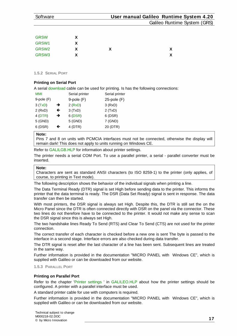
GRSW X GRSW1 X GRSW2 X X X GRSW3 X X
1.5.2 SERIAL PORT
Printing on Serial Port A serial download cable can be used for printing. Is has the following connections: MMI 9-pole (F)
Serial printer 9-pole (F)
Serial printer 25-pole (F)
3 (TxD) 2 (RxD) 3 (RxD) 2 (RxD) 3 (TxD) 2 (TxD) 4 (DTR) 6 (DSR) 6 (DSR) 5 (GND) 5 (GND) 7 (GND) 6 (DSR) 4 (DTR) 20 (DTR)
Note: Pins 7 and 8 on units with PCMCIA interfaces must not be connected, otherwise the display will remain dark! This does not apply to units running on Windows CE.
Refer to GALILGB.HLP for information about printer settings. The printer needs a serial COM Port. To use a parallel printer, a serial - parallel converter must be inserted.
Note: Characters are sent as standard ANSI characters (to ISO 8259-1) to the printer (only applies, of course, to printing in Text mode).
The following description shows the behavior of the individual signals when printing a line. The Data Terminal Ready (DTR) signal is set High before sending data to the printer. This informs the printer that the data terminal is ready. The DSR (Data Set Ready) signal is sent in response. The data transfer can then be started. With most printers, the DSR signal is always set High. Despite this, the DTR is still set the on the Micro Panel since the DTR is often connected directly with DSR on the panel via the connector. These two lines do not therefore have to be connected to the printer. It would not make any sense to scan the DSR signal since this is always set High. The two handshake lines Ready To Send (RTS) and Clear To Send (CTS) are not used for the printer connection. The correct transfer of each character is checked before a new one is sent The byte is passed to the interface in a second stage. Interface errors are also checked during data transfer. The DTR signal is reset after the last character of a line has been sent. Subsequent lines are treated in the same way. Further information is provided in the documentation "MICRO PANEL with Windows CE", which is supplied with Galileo or can be downloaded from our website.
1.5.3 PARALLEL PORT
Printing on Parallel Port Refer to the chapter 'Printer settings ' in GALILEO.HLP about how the printer settings should be configured. A printer with a parallel interface must be used. A standard printer cable for use with computers is required. Further information is provided in the documentation "MICRO PANEL with Windows CE", which is supplied with Galileo or can be downloaded from our website.
Technical subject to change M000218-02.DOC © by Micro Innovation 17

User manual Galileo Runtime System 4.20 SoftwareGalileo Runtime System (GRS)
1.5.4 ETHERNET PORT
Printing on Ethernet Port Printing via the Ethernet interface requires the use of a networkable printer. Or a server with an Ethernet connection must be available, to which the printer is connected. A user with the panel designation must be provided on this server. The user name is preset to "MI_PANEL". The program NETSETUP.EXE can be used to change the name of the panel. Further information is provided in the documentation "Micro Panel with Windows CE". If a printer is used via a printer server, it must be configured so that it can also be used by other network stations (sharing). Further information is provided in the documentation "MICRO PANEL with Windows CE", which is supplied with Galileo or can be downloaded from our website.
1.6 COMBOARD LOADER
1.6.1 COMBOARD LOADER
See also chapter Differences between the Runtime Systems Some communications cards allow the firmware to be loaded onto a retentive Flash memory, thus allowing the driver to be updated simply. Refer to the appropriate device description to see whether this download is possible with the communications card concerned. For older communication cards, the driver must be loaded with a separate program called COMLOAD.EXE. It is located in the TOOLS subdirectory in the Galileo directory. When using a card of this kind, during the download Galileo will always copy the latest driver file to the PCMCIA card. See also: Automatic Loading Manual Loading
1.6.2 LOADING OPTIONS
Automatic The current driver is then loaded virtually automatically, as described below. Detailed information on the COMLOADER is provided in the description of the communications card. No PLC must be connected during the driver update ! Remove the card from the Touch Panel (not when energized !) Set the jumper "J6" on the card to "PRG" Re-insert the card in the slot of the Touch Panel Switch on the power supply The "ERROR" LED of the card will light up and the "ACTIV" LED will flash 4 times in four seconds. Both LEDs will then go out and the card is then ready for programming. The GRS then automatically starts the integrated loader program and starts the programming of the firmware. {bmc COMBOARD.BMP} The download is successfully completed when the red "ERROR" LED on the card is not lit (indicates programming error). Switch off the power supply and remove the card again from the Touch Panel. Switch jumper "J6" on the card to "RUN". Re-insert the card in the slot of the Touch Panel and switch on the power supply again. The new driver is now active. Always check using the special function "Show System Info" the version of the new driver. Manual
18
Technical subject to changeM000218-02.DOC
© by Micro Innovation

Software User manual Galileo Runtime System 4.20 Galileo Runtime System (GRS)
On older communication cards the driver can only be updated via the external program COMLOAD.EXE. Remove the communication card from the Touch Panel (not when live!) Fit the "RUN/PRG" jumper of the card on position "PRG" Set the communication card to RS232 Refit the card in the Slot of the Touch Panel Connect PC and communication card via a serial cable (wiring as per standard null modem: 2-3, 3-2, 5-5, 4-6, 6-4). Start the COMLOAD.EXE program {bmct COMLOAD.BMP} "S" and "A" are used to load the appropriate driver for the card. The entire path must be specified if the driver file is not in the same directory. "T" is used to start the transfer The data transfer has been completed correctly if the red "ERROR" LED on the card is not lit. If the LED is lit, the driver could not be updated successfully. Switch off the power supply and remove the card from the Touch Panel. Refit the "RUN/PRG" jumper of the card in the "RUN" position. Refit the card in the touch panel slot and switch on the power supply. The new driver is now active. Always use the special function "Show Systeminfo" to check the version of the new driver.
1.7 SRAM
1.7.1 SRAM
See also the chapter Differences between the Runtime Systems System data SRAM Backup The SRAM is a non-volatile memory medium in the Touch Panel that is not accessible from the outside. System data that changes during the program runtime is stored in the memory and is retained even when the Touch Panel is switched off. If the GRS is used on a PC, the SRAM is emulated, i.e. a data file the size of the SRAM (32 KByte) is saved on the hard disk. Touch Panels with a PCMCIA can save data in a data file (SRAM.DAT) using the special function "Backup SRAM". This data is not used until the project is changed (see Save/Restore SRAM ). The following data is saved in the SRAM. History data Name of the last project Number compilations of the last project Current position of the individual system keyboard 1) Time setting US or European Summer / Winter time Current project language Basic setting of the display Current online printer information Settings of all units groups Recipe - Basic data Current plot status of graphs (Start / Stop)
Technical subject to change M000218-02.DOC © by Micro Innovation 19

User manual Galileo Runtime System 4.20 SoftwareGalileo Runtime System (GRS)
1) The keyboards can be moved by touching or dragging the value display. Save/Restore SRAM This function is not supported by all runtime programs. See chapter Differences between the Runtime Systems and SRAM Backup. Like all other data on the PCMCIA card, the data in the SRAM always relates to one project. The existing data in the internal SRAM is deleted when a new or modified project is started on the Touch Panel for the first time. This causes all system data to be reset. If a valid copy of SRAM.DAT is then found in the data directory on this new PCMCIA card, this data is copied to the internal SRAM. The file is also transferred if it comes from another project.
1.8 FUNCTION OF THE BITMAP CACHE
1.8.1 FUNCTION OF THE BITMAP CACHE
Not every runtime system supports this function. See chapter Differences between the Runtime Systems. The term "cache" is associated with the idea of speeding up the access to particular data and information by saving part of it in memory with faster access times than the actual data carrier itself. The cache is therefore used as a fast buffer memory, which reduces the disadvantages of the slow flash access. Since the normal main memory is used as a normal cache for the flash memory this is also called a third level cache. We have developed our cache specially to save as much time as possible in loading bitmaps. Before being displayed the data accessed is saved in a cache buffer especially allocated for this purpose. A more or less large number of bitmaps are kept available in the cache depending on the buffer size reserved. If the GRS cache program discovers that a picture to be loaded is already available in the buffer, it no longer needs to access the flash card but can obtain information directly from the cache memory, thus making a considerable saving in the time required. After all fonts and project data have been loaded, the size of the bitmap cache is defined and assigned before the first mask is displayed. The more texts and fonts that have been defined, the less cache memory is available. This means that picture displays will take longer because more data will have to be read from the flash. It is therefore advisable to restrict the number of different font types and sizes used.
1.9 GENERATING BITMAPS FROM THE SCREEN(SCREENSHOT)
1.9.1 GENERATING BITMAPS FROM THE SCREEN(SCREENSHOT)
Not every runtime software supports this function. See chapter Differences between the Runtime Systems. Use Special function "Save Mask As Bitmap"" to make a screenshot. The current screen is then saved in a BMP file, and the files stored in the RUNTIME directory. The first picture after the program has started is called "0.BMP", the second "1.BMP", etc. The files must be deleted by hand afterwards. The mouse cursor will occasionally disappear from the screen since the function takes a relatively long time. Any ongoing communication is interrupted during this time.
1.10 PLC SIMULATION (RK512 PROTOCOL)
1.10.1 PLC SIMULATION (RK512 PROTOCOL)
The simulation is necessary in order to show some changing values on the panel. This simulates the PLC with the panel. During the simulation the GRS behaves like a PLC via the specified interface and responds to received RK512 telegrams. The project must be configured for the Siemens RK512 protocol. The data blocks must be correctly addressed. The system port is connected to the communications port of the
20
Technical subject to changeM000218-02.DOC
© by Micro Innovation

Software User manual Galileo Runtime System 4.20 Galileo Runtime System (GRS)
card. A cable is used with the RxD and TxD lines crossed. The MPB interface must be configured for RS232. The STATUS, TIMEDATE and CONTROL data blocks must not be referenced. 1st DW Initial value (0x00) 2nd DW Counter 0...65535 (in seconds) 3rd DW Counter 65535...0 (in seconds) 4th DW Initial value (0xAA55) 5th DW Initial value (0x7733)
The data values will be repeated if more than five data words are requested.
1.11 DESCRIPTION: APPLICATION LOADER
1.11.1 DESCRIPTION: APPLICATION LOADER
This special function cannot be used on the PC. See Mainboard Firmware/Windows CE Kernel. The version number of the Application Loader is shown on the top right. An update in GalilGB.hlp of the loader is only obtainable from the manufacturer of the panel. The device must be returned to the manufacturer. The Application Loader is first started when the panel is switched on. The procedures are described in more detail in the chapters GRSW and GRSW1. Make a note of the version number of the mainboard firmware for any support enquiries. The version stands in the title line when the device is starting. "MAINBOARD FIRMWARE VERSION 3.02" see also: GRSW GRSW1
1.11.2 GRSW
While the device is starting up, first the Mainboard Firmware and then the runtime program is started if this is present.
Search Runtime Program (GRSW)
" - search program .." "ok" The file with the name GRSW.EXE is in the permanent memory. "not found" Meaning: The GRSW.EXE runtime program was not found. Solution: The Application Loader switches to Download mode. The missing file must be loaded into the permanent memory using GALILEO. (see chapter Serial Transfer in GALILGB.HLP)
Check and start GRS
"copy and check GRSW.EXE MM/DD/YYYY h:mm" A file with the name GRSW.EXE is in the RUNTIME directory . MM/DD/YYY h:mm
month / day / year hour : Minute The time display is used to show the current version of the program.
The GRSGlossGRS is checked and loaded from the PCMCIA card into the RAM. The runtimesoftwareGlossRuntimesoftware is then started. Date and time of the runtime program are shown on
Technical subject to change M000218-02.DOC © by Micro Innovation 21

User manual Galileo Runtime System 4.20 SoftwareGalileo Runtime System (GRS)
screen. Our Support department will require this information if you request assistance introubleshooting. This is used to determine the version of the GRS software.
1.11.3 GRSW1
When the device starts up, first the Mainboard Firmware is started and then the PCMCIA card is accessed. The GRSW1.EXE runtime program is then started if this is present.
Search an ATA - Card in the drive
"- search ATA card .." ".. ok" A correct card was found in the slot ".. nok <insert ATA card now and reboot>" Meaning: Card not found No ATA card fitted in the slot The ATA card is faulty or not correctly formatted Solution: Check whether the card is fitted correctly. It must be an ATA card. SRAM and linear PCMCIA cards cannot be used. The card should be returned to the manufacturers if the error persists after the card was formatted. See also Converting projects from Galileo versions < 2.80 in GALILGB.HLP
Search Runtime Program (GRSW1)
See RUNTIME directory " - search program .." ".. ok" A file with the name GRSW1.EXE is in the RUNTIME directory . ".. not found" Meaning: The GRSW1.EXE runtime program was not found. Solution: The missing file can be loaded on the card in the slot via the serial interface (see Download mode). The Application Loader can only request the runtime program via the serial interface. The project data cannot be transferred. The panel must be restarted afterwards. If a PC card drive was installed on the PC, the missing file can be written to the ATA card using GALILEO. The card is refitted in the panel after the download has been completed. The device mustthen be restarted.
Check and start GRS
"copy and check GRSW1.EXE MM/DD/YYYY h:mm" A file with the name GRSW1.EXE is in the RUNTIME directory . MM/DD/YYY h:mm
month / day / year hour : Minute The time display is used to show the current version of the program.
22
Technical subject to changeM000218-02.DOC
© by Micro Innovation
Software User manual Galileo Runtime System 4.20 Galileo Runtime System (GRS)
The GRS is checked and loaded from the memory card into the RAM. The runtime program is thenstarted. Date and time of the runtime software are shown on screen. Our Support department will require this information if you request assistance in troubleshooting. This is used to determine theversion of the GRS software.
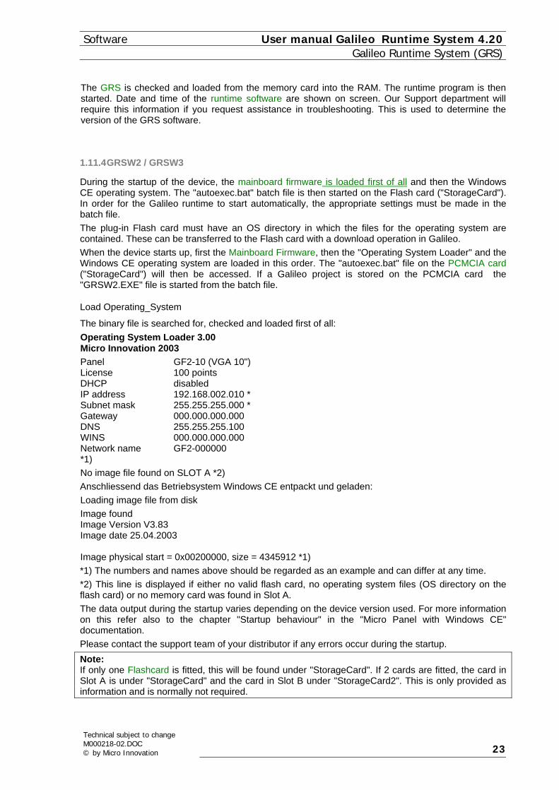
1.11.4 GRSW2 / GRSW3
During the startup of the device, the mainboard firmware is loaded first of all and then the Windows CE operating system. The "autoexec.bat" batch file is then started on the Flash card ("StorageCard"). In order for the Galileo runtime to start automatically, the appropriate settings must be made in the batch file. The plug-in Flash card must have an OS directory in which the files for the operating system are contained. These can be transferred to the Flash card with a download operation in Galileo. When the device starts up, first the Mainboard Firmware, then the "Operating System Loader" and the Windows CE operating system are loaded in this order. The "autoexec.bat" file on the PCMCIA card ("StorageCard") will then be accessed. If a Galileo project is stored on the PCMCIA card the "GRSW2.EXE" file is started from the batch file.
Load Operating_System
The binary file is searched for, checked and loaded first of all: Operating System Loader 3.00 Micro Innovation 2003 Panel GF2-10 (VGA 10") License 100 points DHCP disabled IP address 192.168.002.010 * Subnet mask 255.255.255.000 * Gateway 000.000.000.000 DNS 255.255.255.100 WINS 000.000.000.000 Network name GF2-000000 *1) No image file found on SLOT A *2) Anschliessend das Betriebsystem Windows CE entpackt und geladen: Loading image file from disk Image found Image Version V3.83 Image date 25.04.2003 Image physical start = 0x00200000, size = 4345912 *1) *1) The numbers and names above should be regarded as an example and can differ at any time. *2) This line is displayed if either no valid flash card, no operating system files (OS directory on the flash card) or no memory card was found in Slot A. The data output during the startup varies depending on the device version used. For more information on this refer also to the chapter "Startup behaviour" in the "Micro Panel with Windows CE" documentation. Please contact the support team of your distributor if any errors occur during the startup. Note: If only one Flashcard is fitted, this will be found under "StorageCard". If 2 cards are fitted, the card in Slot A is under "StorageCard" and the card in Slot B under "StorageCard2". This is only provided as information and is normally not required.
Technical subject to change M000218-02.DOC © by Micro Innovation 23

User manual Galileo Runtime System 4.20 SoftwareGalileo Runtime System (GRS)
1.12 SYSTEM MESSAGES
1.12.1 SYSTEM MESSAGES
System messages are output by the GRS as required. Messages are written on the screen in two different ways. Errors are shown in list form during the initialization phase. System messages are later shown in a window. This window disappears after a certain time.
Note: The display duration of errors can be set in the files (GRS_LOG.*) of the error messages. See chapter 99) Duration of error display
System messages are always divided up into error messages and information messages. Information Information messages are shown in green. These messages provide the operator
with information. Example.: 30) Wait while data synchronisation.
Error Errors are displayed in red. These messages appear in the event of a malfunction on the panel or an operator error Example: 37) Target mask does not exist in actual project !
Fatal Error Fatal errors are output if the conditions on the panel or in the project do not allow correct running of the program. In most cases a normal error message will be shown (see above). The panel will then switch to Download mode. The design engineer can then reload faulty project data onto the panel. Example : 9) Clean touch before restart !
The system messages are provided in five languages German, English, Italian, Spanish and French as well as any other language that has been defined. The language can be changed on the Touch Panel using a special function (see GALILGB.HLP). The files can be re-edited with any text editor in ASCII format. The formatting and numbers should not be modified (see File format). see also: File format File format Lines in this file have the following conventions: If the line begins with 99, the subsequent number is the number of seconds the system message is to be displayed. If the line begins with the characters "//", the subsequent characters in the line are comments. If the line begins with a number between 00 and 98, the remaining line is interpreted as a system message with formatting. The two parameters below are required to insert values during the program runtime. %d Number parameter %s Text Parameter
Section of the file GRS_LOG.ENG: No. 2nd
column 3rd column
Text
00 0 0 %s
24
Technical subject to changeM000218-02.DOC
© by Micro Innovation

Software User manual Galileo Runtime System 4.20 Galileo Runtime System (GRS)
02 1 0 Too many actual error entry's (limit %d) ! 03 0 0 Do not touch screen while initializing ! 04 1 0 Error in script %s ! 05 1 0 The function %s failed on execution !
The number column must not be changed and the texts should be relevant to any adaptions made to avoid any meaningless system messages from being output. The number in the 2nd column defines whether the message concerned is an error text displayed in a red window (value = 1) or an information text in a green window (value = 0). See also System Messages The number in the 3rd column defines whether the event is to be logged in the system history (value = 1) or not (value = 0). Further information is also provided in the files themselves.
Note: The space between the individual columns must be made using a tab. Only make changes to these files in the 3rd column or to the texts.
1.12.2 DESCRIPTION OF SYSTEM MESSAGES
0) %s Info Error Fatal Touch Panel PC X X X
Meaning: This information text is used for various system messages. The text is generated when the program is running.
1) This function is not supported - %s ! Info Error Fatal Touch Panel PC X X X
Meaning: The selected function is not supported by this panel or by GRS. The error source can be determined by means of the (%s) parameter. Solution: If a decimal number (incl. Hex number in brackets) is shown, this means an unknown special function was triggered. Not all functions are supported by all hardware types. Only selected functions can be executed by the PLC. A more detailed description of the individual special functions is provided in GALILGB.HLP (if necessary, set extended search options). All the relevant restrictions must be taken into account.
2) Too many actual error entries (limit %d) ! Info Error Fatal Touch Panel PC X X X
Meaning: No more errors, warnings or information messages can be shown at the same time than is defined under Limits. This is a default limit that is not user-defined. Solution: Acknowledge errors that are no longer present.
3) Do not touch screen while initializing ! Info Error Fatal Touch Panel PC
Technical subject to change M000218-02.DOC © by Micro Innovation 25
User manual Galileo Runtime System 4.20 SoftwareGalileo Runtime System (GRS)
X X
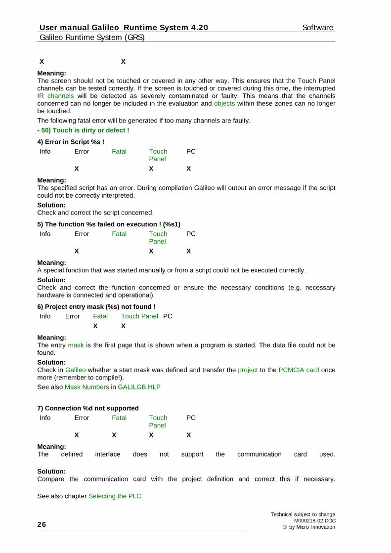
Meaning: The screen should not be touched or covered in any other way. This ensures that the Touch Panel channels can be tested correctly. If the screen is touched or covered during this time, the interrupted IR channels will be detected as severely contaminated or faulty. This means that the channels concerned can no longer be included in the evaluation and objects within these zones can no longer be touched. The following fatal error will be generated if too many channels are faulty. - 50) Touch is dirty or defect !
4) Error in Script %s ! Info Error Fatal Touch
Panel PC
X X X
Meaning: The specified script has an error. During compilation Galileo will output an error message if the script could not be correctly interpreted. Solution: Check and correct the script concerned.
5) The function %s failed on execution ! (%s1) Info Error Fatal Touch
Panel PC
X X X
Meaning: A special function that was started manually or from a script could not be executed correctly. Solution: Check and correct the function concerned or ensure the necessary conditions (e.g. necessary hardware is connected and operational).
6) Project entry mask (%s) not found ! Info Error Fatal Touch Panel PC X X
Meaning: The entry mask is the first page that is shown when a program is started. The data file could not be found. Solution: Check in Galileo whether a start mask was defined and transfer the project to the PCMCIA card once more (remember to compile!). See also Mask Numbers in GALILGB.HLP
7) Connection %d not supported Info Error Fatal Touch
Panel PC
X X X X
Meaning: The defined interface does not support the communication card used. Solution: Compare the communication card with the project definition and correct this if necessary. See also chapter Selecting the PLC
26
Technical subject to changeM000218-02.DOC
© by Micro Innovation

Software User manual Galileo Runtime System 4.20 Galileo Runtime System (GRS)
8) The FAT entry of the file %s is not correct ! Info Error Fatal Touch
Panel PC
X X
Cause: During startup the FAT of the project data was checked and the entries on the flash memory were found to be incorrect or faulty. Solution: Carry out another Download of the project. Note: This error message only occurs in GRSW (devices without PCMCIA memory card)
9) Clean touch before restart ! Info Error Fatal Touch Panel PC X X
Cause 1: The initialization phase of the Touch Panel (3) Do not touch screen while initializing !) detected that the Touch filter is too severely contaminated or too many IR channels are interrupted. Normal operation of the Touch Panel cannot be ensured since large areas of the screen can no longer be operated. Solution 1: Clean Touch filter and restart Touch Panel. Solution 2: If the Touch filter is not dirty or covered, the Touch Panel must be sent for repair.
10) Touch not initialized ! Info Error Fatal Touch Panel PC X X
Meaning: The initialization phase of the Touch Panel (3) Do not touch screen while initializing !) could not find any touch frame. The Touch Panel cannot be operated. Solution: The Touch Panel must be sent for repair.
11) Touch controller not found ! Info Error Fatal Touch Panel PC X X X
Meaning: During the initialization phase of the Touch Panel (3) Do not touch screen while initializing !) a touch controller could not be found. Solution: The Touch Panel must be sent for repair.
12) No project file found (*.GF1) ! Info Error Fatal Touch Panel PC X X X
Meaning: A project table could not be found in the APPL directory. Solution: Recompile the project in Galileo and reload the PCMCIA card (always format the PCMCIA card beforehand).
Technical subject to change M000218-02.DOC © by Micro Innovation 27

User manual Galileo Runtime System 4.20 SoftwareGalileo Runtime System (GRS)
Note: No more than one project file must be in the APPL directory.
13) This program runs only on an MMI system ! Info Error Fatal Touch Panel PC Oþ?þ
Meaning: The GRS cannot be run on the hardware used. A code is "engraved" in the panel. The runtime systems can only be run on these devices. Solution: Check whether the correct GRS is on the panel. For this read the points in chapter Differences between the Runtime Systems. Contact our Support department if this message persists after renewed compiling and download.
14) Program aborted by error ! Info Error Fatal Touch Panel PC X X X
Meaning: Different errors may cause the program to abort. The error source can be determined by means of the (%) parameter. Solution: Note the entire error message and contact our Support department.
15) System palette (%s) not found or defect ! Info Error Fatal Touch Panel PC X X X
Meaning: The standard palette (see APPL directory) was not found or the file format is incorrect. Solution: Recompile the project in Galileo and reload the PCMCIA card (always format the PCMCIA card beforehand). The PCMCIA card may have to be reformatted. The color palette contains all 256 color definitions.
16) Can't create or write to file %s ! Info Error Fatal Touch Panel PC X X X
Meaning: The stated file could not be saved because.. .. write protection on the PCMCIA card was activated .. the PCMCIA card is not fitted in the Touch Panel .. the PCMCIA card or hard disk is full Solution: .. Re-insert the PCMCIA card and restart the GRS .. Your project requires a larger PCMCIA card
17) Can't find or read from file %s ! Info Error Fatal Touch Panel PC X X X
Meaning: The stated file has been destroyed or is not present. Solution: Reload the PCMCIA card (always format the PCMCIA card beforehand). Delete the file if it is a file from the directory DATA (see DATA directory ).
28
Technical subject to changeM000218-02.DOC
© by Micro Innovation

Software User manual Galileo Runtime System 4.20 Galileo Runtime System (GRS)
18) File header of file %s is not correct ! Info Error Fatal Touch Panel PC X X X
Meaning: The stated file was not generated by the Galileo compiler. Solution: Recompile the project, load it onto the PCMCIA card (always format the card beforehand).
19) File size of file %s is not correct ! Info Error Fatal Touch Panel PC X X X
Meaning: The stated file is damaged or it was not generated by the Galileo Compiler. Solution: Recompile the project, load it onto the PCMCIA card (always format the card beforehand).
20) Firmware %s on %s1 Info Error Fatal Touch
Panel PC
X X X
Meaning: The firmware on the communication card is not the latest version. A newer version was found in the RUNTIME directory of the project. Solution: You can update the Firmware according to the instructions of the communication card concerned. There is no need to change the Firmware if your system is error-free.
22) The minimum length of the Password is %d characters ! Info Error Fatal Touch
Panel PC
X X X X
Cause: A minimum password length can be specified for Password management. This error message will appear if the password for a user is too short. Solution: You must enter the minimum Number of Characters specified for a password. 23) not defined This system message is not required. 24) not defined This system message is not required. 25) not defined This system message is not required. 26) not defined This system message is not required.
27) Can't find %s driver in slot %d ! Info Error Fatal Touch Panel PC X X X
Meaning: A communications card of the stated type could not be found on the slot stated. Or the driver is not compatible to the communication card.
Technical subject to change M000218-02.DOC © by Micro Innovation 29

User manual Galileo Runtime System 4.20 SoftwareGalileo Runtime System (GRS)
Solution: Check whether the correct card was fitted in the slot concerned and is ready for operation. The card required for the selected driver is defined in Galileo under "Select PLC". If you wish to run your project without communication, select "None" for all slots.
28) Communication disturbed: %s ! Info Error Fatal Touch
Panel PC
X X X
Meaning: Data could not be sent to the PLC or read from the PLC. The cause of the error is indicated in the form of a dynamic parameter. Information on the active communication driver is provided via the "Show SystemInfo" function or during the startup of the MMI (29) Board and driver %s selected on slot %d.). Solution: Check the connection cable between MMI and PLC. Check the parameters in your PLC and read the notes on Communication in description of the communication card used.
29) Board and driver %s selected on slot %d. Info Error Fatal Touch Panel PC X X X
Meaning: Message on system start if the driver could not be selected correctly.
30) Wait while data synchronisation. Info Error Fatal Touch Panel PC X X X
Meaning: The data synchronisation is carried out with every system start. During this phase all entry values are read from the PLC so that both devices operate with the same data.
Note: The data must be kept retentively by the PLC.
31) not defined This system message is not required.
32) No help window defined for actual mask (%s) !! Info Error Fatal Touch Panel PC X X X
Meaning: A help text should be displayed ("Help Button" object). However, a help window for displaying the text was not defined in the mask concerned. Solution: Define a "Help window" object in Galileo and reload the project on the PCMCIA card (don't forget to compile).
33) %s number %d not found ! Info Error Fatal Touch Panel PC X X X
Meaning: A help text, error text, general project text is to be displayed or a form with variable tags is to be printed. The entry with the corresponding number is not available. Solution: Check for possible warnings after compiling the project in Galileo.
30
Technical subject to changeM000218-02.DOC
© by Micro Innovation
Software User manual Galileo Runtime System 4.20 Galileo Runtime System (GRS)
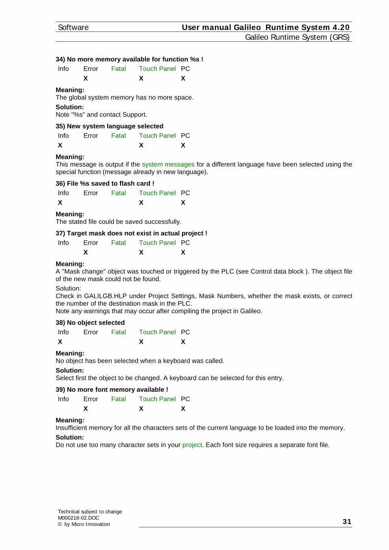
34) No more memory available for function %s ! Info Error Fatal Touch Panel PC X X X
Meaning: The global system memory has no more space. Solution: Note "%s" and contact Support.
35) New system language selected Info Error Fatal Touch Panel PC X X X
Meaning: This message is output if the system messages for a different language have been selected using the special function (message already in new language).
36) File %s saved to flash card ! Info Error Fatal Touch Panel PC X X X
Meaning: The stated file could be saved successfully.
37) Target mask does not exist in actual project ! Info Error Fatal Touch Panel PC X X X
Meaning: A "Mask change" object was touched or triggered by the PLC (see Control data block ). The object file of the new mask could not be found. Solution: Check in GALILGB.HLP under Project Settings, Mask Numbers, whether the mask exists, or correct the number of the destination mask in the PLC. Note any warnings that may occur after compiling the project in Galileo.
38) No object selected Info Error Fatal Touch Panel PC X X X
Meaning: No object has been selected when a keyboard was called. Solution: Select first the object to be changed. A keyboard can be selected for this entry.
39) No more font memory available ! Info Error Fatal Touch Panel PC X X X
Meaning: Insufficient memory for all the characters sets of the current language to be loaded into the memory. Solution: Do not use too many character sets in your project. Each font size requires a separate font file.
Technical subject to change M000218-02.DOC © by Micro Innovation 31

User manual Galileo Runtime System 4.20 SoftwareGalileo Runtime System (GRS)
40) Project language %d selected Info Error Fatal Touch Panel PC X X X
Meaning: A new project language was selected using the special function, and all texts are displayed and printed out in the new language.
Note: This message is still in the system language !
41) File %s was generated by old compiler ! Info Error Fatal Touch Panel PC X X X
Meaning: The stated file was made with a previous Galileo compiler and cannot be loaded. Solution: Recompile the project in Galileo. Reformat the PCMCIA card in all cases and reload the project. If the error occurs again, re-install Galileo or ask Support for an update.
42) No printer connected ! Info Error Fatal Touch Panel PC X X X
Meaning: A printer function was started. However, GRS was started without the printer option. Solution: Start the GRS with the activated printer option in the printer initialization file. (see chapter Printer Settings in GALILGB.HLP)
43) Printer is not ready ! Info Error Fatal Touch Panel PC X X X
Meaning: A printer function was started without the printer being connected or ready for operation. Solution: Connect the printer to the "SYSTEM PORT" of the Touch Panel and check the data cable. (See also Printing on the serial COM - Port) The ready signal of the printer is checked with the DTR signal of the hardware.
44) Printer is ready ! Info Error Fatal Touch Panel PC X X X
Meaning: The printer was connected for printing for the first time or after an error message.
45) Printer is busy ! Info Error Fatal Touch Panel PC X X X
Meaning: A printer function was started whilst the printer is still executing the previous print function. Action: Wait till the current printer function has been completed and start the printer again (see also Status data block).
32
Technical subject to changeM000218-02.DOC
© by Micro Innovation

Software User manual Galileo Runtime System 4.20 Galileo Runtime System (GRS)
46) Touch controller version %s required ! Info Error Fatal Touch Panel PC X X X
Meaning: Functions like "Touch disable" are not possible on previous versions of the Touch firmware. Solution: Note %s and the function selected and contact Support
47) BCI ready message on slot %d : %s ! Info Error Fatal Touch Panel PC X X X
Meaning: This message will appear if, after a communication error (48) BCI fault message on slot %d : %s !), a data package (tag/array/structure) could be transferred again successfully. The connection number and brief information on the cause of the previous fault are displayed as dynamic parameters. Information on the active communications driver is shown in the function "Show System Info" or during the startup of the MMI (message no. 29).
48) BCI fault message on slot %d : %s ! Info Error Fatal Touch Panel PC X X X
Meaning: A data package (tag/array/structure) could not be sent to the PLC or read by it. The name of the tag, array or structure and brief information on the cause of the fault are displayed as dynamic parameters. Information on the active communications driver is shown in the function "Show System Info" or during the startup of the MMI ( 29) Board and driver %s selected on slot %d.). Solution: Check the connection cable between the MMI and the PLC. Check the parameters in your PLC and read the Communication instructions in the description of the communication card used.
49) Not enough disk space available (<%d kB)! Info Error Fatal Touch Panel PC X X X X
Meaning: Insufficient memory available on the flash card or the hard disk to save the specified data size. This error may occur when converting a recipe data base since the recipe data must be stored temporarily on the memory medium. Solution: Use a flash card with additional memory capacity larger than the stated value. Galileo determines the size of the memory required during the download and shows it (see chapter Compiling in GALILGB.HLP).
50) Touch is dirty or defect ! Info Error Fatal Touch Panel PC X X
Meaning: Several dirty or faulty infrared strips were found when the panel was started up. Trouble-free operation is no longer ensured. With some panels this condition is used to switch to Download mode. For this place the palm of the hand flat on the screen when the panel is started. The current program running will be aborted. Solution: Clean the touch screen and the touch filter and restart GRS. Send the Touch Panel in for repair if this fault occurs again.
Technical subject to change M000218-02.DOC © by Micro Innovation 33

User manual Galileo Runtime System 4.20 SoftwareGalileo Runtime System (GRS)
51) The recipe file %s is damaged ! Info Error Fatal Touch Panel PC X X X X
Meaning: The file with the extension TAB has an unrecognized format. A conversion is carried out if the recipe size and definitions were changed in Galileo. A conversion is also carried out if the TAB file is edited externally. The number of columns, lines or the position of the tabulators do not fit the Galileo definitions. The GRS switches to Download mode since error-free operation is no longer possible. Solution: See also chapter Convert recipe data file (*.TAB). If you have defined meaningless recipe values, you can delete the TAB file. The next time that you start GRS, an empty recipe file will be generated automatically. Recipe data that has already been defined can be saved if the file is not badly damaged. This is only possible if the memory medium can be accessed (see Differences between the Runtime Systems). For this the file must be repaired manually. Check whether tabulators are provided between all values and whether a tabulator is provided at the end of each line. Also check whether the number of columns and lines is correct. Once the correction has been made, restart GRS. The conversion will then be carried out automatically.
52) Check and convert the file %s (%d%%)! Info Error Fatal Touch Panel PC X X X
Meaning: A check is made during startup whether the format of the recipe entry files has changed. The file is updated if the order and the number of recipe tabs has changed. The number of tabulators as well as the distance between them must also be checked and, if necessary, converted to the known format. See also chapter Convert recipe data file (*.TAB).
53) User name %s does not exist ! Info Error Fatal Touch Panel PC X X X
Meaning: No definitions can be found in the password file for the specified user. In practice, each password function must find or store user information. For this the program first searches for the location of the user data. This message will appear if this data cannot be found. User names beginning with "#" indicate that the information for level passwords could not be found. Solution: Ensure that you have not entered the password incorrectly. Observe the correct upper or lower case. Call the special function "Show All Users" (see GALILGB.HLP) to obtain information on all users.
54) User %s already exist ! Info Error Fatal Touch Panel PC X X X
Meaning: The user with this name could not be entered. This name was already entered in the password file. Solution: Use a different name for the new user. Use the special function "Show All Users" in GALILGB.HLP to check whether this user name already exists.
34
Technical subject to changeM000218-02.DOC
© by Micro Innovation

Software User manual Galileo Runtime System 4.20 Galileo Runtime System (GRS)
55) Wrong password entered (%d attempts left) ! Info Error Fatal Touch Panel PC X X X
Meaning: The user has entered an incorrect password. The incorrect login attempts have been registered. The counter assigned to each password that was entered incorrectly is incremented. Once this value has reached the limits defined in GALILEO the user can no longer log in - even with the valid password. The following error message will then appear 58) No user authorisation for %s !. Solution: Observe the correct upper or lower case. A higher-level user can reset the counter for incorrect password entry attempts or assign a new password to users on a lower level. This provides information on the number of possible attempts defined in GALILEO, or, if necessary, a new password. However, the user must be assigned to a level that provides the necessary authorization (see GALILGB.HLP). Exception: If a user on the highest level has lost his or her password, only a user with the same level of authorization can follow the procedures stated above. If no such user has been defined, the password data can be re-interpreted using GALILEO. Refer to GALILGB.HLP for a more detailed description of this procedure.
56) Wrong password entered ! Info Error Fatal Touch Panel PC X X X
Meaning: The user has entered an incorrect password. The incorrect login attempts were not registered. Further attempts are still possible. Solution: Observe the correct upper or lower case. A user on a higher level can assign a new password. However, the user must be assigned to a level that has the necessary authorization (see GALILGB.HLP). Exception: If a user on the highest level (0) has lost their password a user with a similar authorization can carry out the procedures described above. If no such user has been defined, password data can be re-interpreted using GALILEO. Refer to GALILGB.HLP for a more detailed description.
57) Wrong level ( %d) entered ! Info Error Fatal Touch Panel PC X X X
Meaning: You are not authorized to execute the selected function, since you have a lower authorization or the same authorization as the user on this level (exception: both users are on level 0). Solution: Select a lower user level or arrange for the function to be executed by a higher-level user.
58) No user authorisation for %s ! Info Error Fatal Touch Panel PC X X X
Meaning: You are not authorized to execute the selected function. You have either made too many incorrect login attempts, or your authorization is lower than or the same as the user on this level (exception: both users are on level 0). Solution: Select a lower level, arrange for your "Bad Login" counter to be reset or have a higher-level user execute the function (see GALILGB.HLP).
Technical subject to change M000218-02.DOC © by Micro Innovation 35

User manual Galileo Runtime System 4.20 SoftwareGalileo Runtime System (GRS)
59) Wrong password confirmation ! Info Error Fatal Touch Panel PC X X X
Meaning: If a new password is entered, a multiple confirmation is required. For this the same text or number must be entered a second time. Different password entries will cause this error message to appear. Solution: Observe upper and lower case. Enter the new password once more in the two lower fields. 60) Can't create user %s ! Info Error Fatal Touch Panel PC X X X
Meaning: The maximum number of users defined in GALILEO was reached. No more user data can be saved. Name entries that already exist will be indicated. Solution: Call the "Show All Users" special function to check that user names have not been entered more than once. If this is not the case, the "Maximum number of users" has been reached. A user name must be deleted before another user can be entered. The number of users can only be changed in GALILEO.
61) Can't delete user %s ! Info Error Fatal Touch Panel PC X X X
Meaning: It is not possible to delete one's own user definitions. This error message may also appear if an attempt was made to delete a non-existent user. Solution: Observe upper and lower case. Call the "Show All Users" special function to check that user names have not been entered more than once.
62) Incorrect registration code - %s ! Info Error Fatal Touch Panel PC X (X) X X
Meaning: When Galileo was being installed there was no registration code or an incorrect registration code entered. The panel or PC runs in Demo mode. This message will appear when the software is started. It has to be abandoned. After one hour, the message will appear again and finally GRS will abort with a fatal error message. Solution: Check in the "About..." dialog of Galileo to see if you have entered your registration code correctly. The code is supplied when the product is purchased.
63) No recipe %s found in mask ! Info Error Fatal Touch Panel PC X X X
Meaning: The special functions of the "Recipe" group require the recipe name as a parameter. The recipe object must be shown in the current mask. Solution: Check whether the correct recipe name is specified in Galileo. A recipe object (Enhanced) with this name must be in the current mask. Recompile the project and reload it onto the panel.
36
Technical subject to changeM000218-02.DOC
© by Micro Innovation

Software User manual Galileo Runtime System 4.20 Galileo Runtime System (GRS)
64) Recipe %s not defined ! Info Error Fatal Touch Panel PC X X X
Meaning: No recipe with this name in the project. Solution: Check whether the correct recipe name is specified in the special function in Galileo. Recompile the project and reload it onto the panel.
65) No enhanced recipe %s defined ! Info
Error Fatal Touch Panel PC
X X X
Meaning: No Enhanced recipe with this name in the project. Solution: Check whether the correct recipe name is specified in the special function in Galileo. Recompile the project and reload it onto the panel. Check whether this is an enhanced recipe. See chapter Recipe Management in GALILGB.HLP
66) Time elapsed for DEMO mode ! Info Error Fatal Touch Panel PC X X X
Meaning: When running the project on a PC, the correct Galileo registration code and a valid runtime license must be present on the PC otherwise the project will only run for a limited time. Solution: Check whether the registration code is correctly entered in Galileo (see "About Galileo" in the Help menu).
67) No valid runtime license found - DEMO mode ! Info Error Fatal Touch
Panel PC
X X X
Meaning: When the Project on is run a PC, a valid runtime license must be present, otherwise the project will only run for a limited time even though it is fully operative. Solution: Obtain a valid runtime license from your distributor.
68) No enhanced graph defined : %d ! Info Error Fatal Touch
Panel PC
X X X
Meaning: No Enhanced graph with this object number in your project. Solution: Check whether the correct graph number is specified in the special function in Galileo. Always Compile the project again and reload it onto the panel. Check whether this is an enhanced graph. See Chapter "Graph" in GALILGB.HLP
Technical subject to change M000218-02.DOC © by Micro Innovation 37

User manual Galileo Runtime System 4.20 SoftwareGalileo Runtime System (GRS)
99) Duration of error display This entry (in seconds) defines how long GRS displays an error message. Valid entries are between 1 and 9 seconds.
1.13 COMMENTS FOR PANELS WITH WINDOWS CE
1.13.1 GENERAL
Further information is provided in the documentation "MICRO PANEL with Windows CE", which is supplied with Galileo or can be downloaded from our website. Autoexec.bat A customized panel start can be set up using an 'Autoexec.bat' start file. This enables command lines and commands to be started without a keyboard. The file is located in the root directory of the PCMCIA card. After the operating system is started, a 10-second search is carried out for the file "\StorageCard\Autoexec.bat". If it is found, it is executed with a "CMD" shell. The following commands are available: ATTRIB Set/display file attributes CALL Call batch script CD Change directory CHDIR Same as CD CLS Clear the screen COPY Copy files DATE Display/set system date DEL Delete a file DIR Print contents of a directory ECHO Echo output on the screen or change echoing parameters ERASE Same as DEL EXIT Exit command interpreter HELP Print help for command interpreter or individual commands GOTO Transfer control to a label in batch processing IF Conditionally execute a command MD Create a directory MKDIR Same as MD MOVE Move/rename files PATH Alias for SET PATH PAUSE Suspend execution of a batch file PROMPT Reconfigure system prompt PWD Print current working directory RD Remove directory REM Record comments in batch file REN Change file name RENAME Same as REN RMDIR Same as RD SET Set or list environment variables SHIFT Shift arguments of a batch file START Start detached process TIME Display/change system time TITLE Set the window title for a CMD.EXE session TYPE Output contents of a file or files to the screen
38
Technical subject to changeM000218-02.DOC
© by Micro Innovation

Software User manual Galileo Runtime System 4.20 Galileo Runtime System (GRS)
A detailed explanation of the commands can be displayed using the HELP [command] instruction. Example of Autoexec.bat: ECHO OFF COPY \"StorageCard"\RUNTIME\Galileo.lnk \Windows\Desktop COPY \"StorageCard"\RUNTIME\ftpsvr.exe \temp COPY \"StorageCard"\RUNTIME\ftpsvr.lnk \Windows\Desktop START \"StorageCard"\RUNTIME\GRSW2.EXE Shortcuts on the Desktop The user can create shortcut links on the desktop. As the panel has no persistent registry, the links must be created with every start. The 'Autoexec.bat' file is therefore used to copy the link files (*.lnk) to the 'Windows/Desktop' directory. COPY \"StorageCard"\RUNTIME\Galileo.lnk \Windows\Desktop A link file can be created using a text editor. The following syntax must be observed: 0#"File with path" Example: 0#"\StorageCard\runtime\grsw2.exe" 1.13.2 ETHERNET
The Ethernet interface is implemented in accordance with the IEEE 802.3 (10/100BASE-T) standard. The networking is implemented using shielded twisted pair cable with shielded RJ45 connectors. The devices connected to the Micro Panel GF2 must also support shielded connections. When selecting the twisted pair cable for use in Ethernet networks, the cable specifications for the cable length and transmission speed must be observed. See also the specifications in accordance with EIA/TIA 568 TSB-36. The cables connected to the Ethernet interface must be laid separately from low-voltage cables. Further information is providedin the documentation "MICRO PANEL with Windows CE", which is supplied with Galileo or can be downloaded from our website. Safety Network names: Each panel has a unique network name in order to prevent conflicts within a network. The panel shows its IP address when it is started. User name/ password: The panel has a permanently defined user name: User name : MI_GF2 Password : No password defined Access on PC In order to access a PC (NT/2000) from the panel, an 'MI_GF2' user of type 'Guest' must be set up. The drives and directories that are to be accessed must also be enabled. Example: \\PC_User\temp\
Technical subject to change M000218-02.DOC © by Micro Innovation 39

User manual Galileo Runtime System 4.20 SoftwareGalileo Runtime System (GRS)
Graph data: When saving graph data on any directory (see GalilGB.hlp), it is also possible to define a directory on the network. This enables the graph data to be saved directly on a server or another PC and thus also to be evaluated. Example: \\PC_User\graphdaten\ IP Address The current IP address is displayed when the panel is started. The IP address and IP mask can be changed from another project using the special functions IP Address 0..3, IP Mask 0..3 and IP Gateway 0..3 (see GalilGB.hlp: Special functions).
Note: The device must be restarted in order to activate the new IP address. If all fields of the IP address are set to 0 (factory setting), the device will try to obtain the address from a DHCP server. Refer to your network administrator if you have any questions concerning DHCP servers and TCP/IP protocols.
FTP Server The FTP server (File Transfer Protocol) is used for transferring data via Ethernet. Use: Uploading/downloading the project Uploading/downloading password and recipe data Procedure: Start of the FTP server on the panel via the shortcut on the desktop, or start of file 'ftpsvr.exe' in directory '\Temp\'. Configuring an FTP connection in Galileo or another program. To do this, the IP address, the user name and the password must be known. The following settings are provided when a new panel is delivered: IP address: 0.0.0.0 (IP address of the DHCP server) User name: Ignored Password: Ignored Transferring files Exiting the FTP server
Note: Only files can be accessed that are not being processed during this time by a program on the panel. For safety and performance reasons, the FTP server should not be continuously active.
40
Technical subject to changeM000218-02.DOC
© by Micro Innovation

Software User manual Galileo Runtime System 4.20 Communication
2 COMMUNICATION
2.1 BASIC PRINCIPLES
2.1.1 GENERAL
General The key functions of an MMI depend on efficient and flexible communication. For the user this normally means the following requirements: 1. Intervention in the process must take place immediately (< 300ms) 2. The current process image must be really current (< 1000ms) However, in this respect the data transfer speed of the connection (baud rate) is often mistakenly considered as the most important criterion for data exchange. Efficiency, however, depends on other factors whilst the baud rate is only of secondary importance: 1. PLC cycle time Most PLCs can only process a data transfer once every cycle. This is irrespective of whether one bit, one byte or even 64 bytes are being transferred since the processing time within the PLC is very small. 2. MMI cycle time The same also applies to the MMI (at least with the GRS). GRS normally has a cycle time of approx. 2-5ms. The cycle time will be increased when data needs to be transferred or a parts of a mask need to be updated (new characters or refresh). The length of this cycle time then depends on how much data needs to be sent to the PLC and how many objects need to be updated (new characters or refresh) on the screen. 3. Data transfer protocol Regardless of the protocol used, data is transferred with control characters and headers (protocol overhead) so that when transferring a small volume of data, often more "protocol overhead" is transferred than actual data. 4. Baud rate The baud rate is often only a major factor in bus systems since a bus enable is required for these systems in addition to the even larger protocol overhead than required for point-to-point connections. With point-to-point connections normally a baud rate of 9600 (approx. 1Byte/ms) upwards is sufficient. 5.Transferrable data volume With point-to-point connections this is usually flexible. However, with some bus systems this is restricted and may cause problems. The transfer time required for 8 bytes is not much more than is required for a single bit and only depends on the baud rate. Data polling Let us consider the communication requirements from the point of view of the user, as mentioned at the beginning General 1. Intervention in the process must take place immediately (< 300ms) 2. The current process image must be really current (< 1000ms) As an intervention in the process is event-controlled, point 1 should not be a problem for an MMI and is normally faster with GRS. Let us now consider the real-time data and the polling of data from the PLC. Data polling has partly been considered to be an unsatisfactory alternative (particularly by some MMI manufacturers). However, it should be pointed out here that the majority of operations work on this principle. The reason for this is not only because most PLCs do not support event-triggered communication but also because, for the design engineer, it is the simplest and most reliable method. The simplicity of polling is based on the fact that the design engineer has virtual nothing to consider with regard to the communication (at least with the GRS). It is reliable because data is continuously refreshed and can therefore never contradict the data in the PLC.
Technical subject to change M000218-02.DOC © by Micro Innovation 41

User manual Galileo Runtime System 4.20 SoftwareCommunication
Note : Data polling is the most reliable and the simplest method for the design engineer and for the user. Polling is only considered unsatisfactory in applications where the data throughput for the user cannot be maintained (as per point 2.), or where the MMI is not able to meet the more demanding communication requirements. The reason for this is often because each single variable tag (bit, byte, word or double word) is polled separately from the PLC. Supposing a Mask displays 10 analog word values and 20 digital PLC states, the data can be transferred much quicker if the 10 words and 20 digital states are combined in two arrays or in one structure. This enables the data to be transferred between the MMI and PLC in two cycles or one. If all the values are transferred individually, this will considerably increase the total time required for data transmission.
Note: The data transferred for PLCs working with an image register should be combined into arrays or structures for optimum communication between the MMI and PLC.
The GRS data block concept therefore offers a high degree of communication performance (see Data block concept), whilst allowing optimum design freedom for the design engineer without any considerations about communication. GRS is also able to communicate with different PLCs or bus systems via four channels without any substantial increase in cycle time. The same type of communication is implemented for all PLCs. Adapting a project for use with a different PLC only takes a few minutes. Note: The total data transfer time must be below 2 seconds !
2.1.2 DATA SYNCHRONISATION
Data Synchronisation Data that needs to be retained when the system is switched off must always be saved in the PLC (retentive data range in PLC). The data synchronisation process is started automatically when the GRS is started (startup of the MMI). In this phase all the tags that can be altered by the Touch Panel ("write" and "read/write" data blocks) are read once from the PLC. When using more than one active communication to a PLC, "write" data blocks can be referenced for both PLCs. In this case data that is altered on the MMI is sent to all PLCs (see also information provided in Galileo "GALILGB.HLP"). During the data synchronisation the tags are read from the master PLC and sent to all other PLCs.
Note: The bit 1 of the 1st data word of the status data block is set to 1, after all tags are synchronized. Since all tags which are address to more than one PLC are first synchronized.
In scripts the state of this bit can read with the function 'OnPresetOK'. After successful data synchronisation, tags are only written to the PLC if there is a change on the touch panel (event-triggered). Tags with "read/write" data direction are only read if a tag of this type is used in the currently active Mask or if under certain conditions (e.g. data for a graph trending) it must be continuously polled. While the program is running it is also possible to carry out a data synchronisation again (see Renewed data synchronisation).
2.1.3 DATA BLOCK CONCEPT
Data block concept The GRS allows several tags to be combined in arrays or structures. Minimum and maximum block lengths depend on the PLC used. Most PLC communication supports data lengths between 2 and 64 bytes (maximum 128 bytes). With some communication procedures it is also possible to transfer individual bits (e.g. EIB installation bus or Allen Bradley ControlLogix).
42
Technical subject to changeM000218-02.DOC
© by Micro Innovation

Software User manual Galileo Runtime System 4.20 Communication
The maximum size of a data block is also partly restricted by the type of PLC used. "Write" tags (MMI to PLC), are always only transferred to the PLC if there is a change on the MMI (eve-triggered). Tags with data direction "read/write" (PLC to MMI) are normally read cyclically from the PLC (see also Data polling) or on request (see Control data block). The speed at which the data is read from the PLC can be set in Galileo under "Polling Rate". All addressed tags can be assigned a standard "fast" setting. All tags of the current mask that are set as "fast" are polled in sequence. The more tags are defined as "fast" the slower they will be read from the PLC. The GRS will use the tags used in the current mask to determine which tags have to be read.
Note: Communication can be considerably speeded up if the tags used within the same mask are combined into arrays or structures.
The cycle in which the data is read from the PLC can be set in Galileo via the "Polling Rate" parameter. All data blocks are set as standard to "fast". This means that all variable tags in a mask can be read from the PLC alternately. GRS determines which data blocks are to be read by means of the variable tags present in the mask. The "Polling Rate" can be defined specifically for every read data block. This is primarily used for variable tags that only change very slowly (e.g. variable data for a water level). This has the advantage that all other "fast" data blocks in a mask can be read accordingly faster. The effective refresh rate of variable tags in "fast" data block can be calculated per mask using the following formula: (total of all "fast" data blocks) * (total time of a data transfer) Always select "fast" for the "Polling Rate" of a read data block containing variable tags that change frequently (e.g. parts counter display). Always select "1 sec." for the "Polling Rate" of a read data block if you are not sure of the cycle time to be set.
2.2 SPECIAL DATA BLOCK TYPES
2.2.1 SPECIAL DATA BLOCK TYPES
Galileo automatically generates 3 data blocks per slot (i.e. per PLC) of the following type with every project: Control data block Status data block "Date_Time" Data Block These data blocks contain system variables with a wide range of functions. These blocks cannot be deleted.
Note: However, it is not necessary to assign any of these data blocks if none of them are required.
The following message is only available in some panel types "PLC to PLC" Message
2.2.2 CONTROL DATA BLOCK
Control data block The control data block contains 8 data words (16 data bytes) with functions that are described below. The block size is reduced accordingly if the selected PLC supports a maximum of 16 data bytes per data block. In this case the functions of the higher data words are omitted. The control data block is always polled irrespective of the mask currently displayed, and is always assigned the priority of a "fast" data block ("Polling Rate").
Technical subject to change M000218-02.DOC © by Micro Innovation 43

User manual Galileo Runtime System 4.20 SoftwareCommunication
The individual command bits of the control data block should not be set statically since this would cause the functions to be continuously repeated (see Initiating functions from the PLC). If the bits are allowed to be set statically, this will be stated specifically. The detailed description of how to trigger the functions correctly is provided in the chapter Initiating functions from the PLC. The individual bits and their functions are described below:
1st Data Word
Bit 0..4 Reserve Bit 5
If one of these bits is set to 1, the error tags are refreshed. These bits must only be set to 1 if bits 5,6,7 of the 1st data word of the Status data block are 0. See also Updating error display A detailed description on the correct procedure is provided in the chapter Initiating functions from the PLC. All 3 bits have the same function in order to ensure compatibility with previous versions.
Bit 8 Reserve Bit 9 Reserve Bit 10 Transfer the time and date from the PLC and set the internal clock of the MMI, by reading
the data from the PLC using the "Date_Time" Data Block. See also Time/Date Synchronisation
Bit 11 Write the time and date from the MMI to the PLC by transferring the data to the PLC using the "Date_Time" Data Block. See also Time/Date Synchronisation
Bit 12 Change to mask (number) according to entry in 2nd data word. See also Mask change
Bit 13 Reserve Bit 14 Reserve Bit 15 If this bit is set to 1, a Renewed data synchronisation will be carried out, i.e. all tags are
read from the PLC.
2nd Data Word
Number of the destination mask with an "External mask change". The number of the destination mask must be entered before the mask change is activated with bit 12 of the 1st data word. The numbers of the masks can be determined and set in Galileo, see chapter Mask Numbers.
3rd Data Word
Bit 0 Reserve Bit 1 If this bit is set to 1 no more entries are accepted from the Touch Panel and the Touch
Disable mode is activated. See also Touch disable
Bit 2..5 Reserve Bit 6, 7 These two bits are used for Recipe commands from the PLC. Bit 8 If this bit is set to 1, a data range is transferred from one PLC to another according to
the definition in the "PLC to PLC" Message. This function can only be executed if
44
Technical subject to changeM000218-02.DOC
© by Micro Innovation

Software User manual Galileo Runtime System 4.20 Communication
more than one communication interface is used. Bit 9..10 Reserve Bit 11 Reload all data blocks of type "PLC text".
See also Transferring PLC text Bit 12..13 Reserve Bit 14 Preset status (1=On or 0=Off) of the special function after processing (see bit 15). Bit 15 Process Special function (number) according to the entry in the 4th data word.
The preset status (On or Off) of the special function must be entered beforehand at bit 14. If the special function requires a parameter, this must be saved in the 5th data word. See also Initiating special functions (Function key) and the chapter "Special Functions in GALILGB.HLP
4th Data Word
Number of the special function that is to be processed with Bit 14 and 15 of the 3rd data word. The number of the special function must be entered before it can be processed. Particular special function parameters must also be entered beforehand in the 5th data word. 5th Data Word Parameter entry for special functions (see also Bit 14 and 15 of the 3rd data word and 4th data word). Example:
Special function "Print Form No. Xy" - Number of the print form (see Defining a print form in GALILGB.HLP).
6th Data Word This data word is used for implementing recipe changes or recipe read via the PLC. A recipe change is carried out by setting bit 7 of the 3rd data word. A recipe read is carried out by setting bit 6 of the 3rd data word. The differences are described in chapter Recipe commands from the plc. The special functions of the group recipe require the number of the recipe object and recipe management, as well as a recipe entry number. These two settings are saved in this data word as follows: Bit 0 .. 3 These bits define the number of the recipe object to be selected. In GALILEO these
objects can be assigned the values 0 to 15 (see GALILGB.HLP). Bit 4 .. 15
The number of this recipe entry is contained in these higher 12 bits. It must be ensured that the recipe object has at least this number of recipe entries.
7th and 8th Data Word
These data words are reserved for future functions.
2.2.3 STATUS DATA BLOCK
Status data block The status data block comprises 8 words (16 data bytes). These words contain the following functions. These are largely identical to the functions in the Control data block. If the selected PLC only supports up to 16 data bytes, the block size is reduced accordingly, which means that the functions of the higher data words are omitted. When there is a change, however, the block is sent directly (event-triggered). If there was no change in MMI status within the status refresh time (GALILGB.HLP), the status structure is transferred to the PLC anyway.
Technical subject to change M000218-02.DOC © by Micro Innovation 45

User manual Galileo Runtime System 4.20 SoftwareCommunication
The individual status bits are normally used for handling the control bit in the control data block (see Initiating functions from the PLC). The individual bits and their functions are described below.
1st Data Word
Bit 0 0 = No connection to MMI 1 = Connection to MMI OK This bit is always 1 and can therefore be used for monitoring the connection between the MMI and PLC (use as timeout on the PLC > status refresh time ).
Bit 1 0 = Data synchronisation could not be carried out 1 = Data synchronisation completed successfully
Bit 2 Reserve Bit 3 Reserve Bit 4 There is at least one error present in an error window, i.e. an error is still active or an error
was not yet acknowledged. Only error tags with the "Confirmation required" option are considered.
Bit 5, 6, 7
GRS will update the error tags for as long as these bits are set to 1. All 3 bits have the same function in order to ensure compatibility with previous versions. See also Updating error display.
Bit 8 Reserve Bit 9 Reserve Bit 10 GRS is synchronizing time and date for as long as this bit is set to 1. If the bit changes to
0, synchronisation is completed, i.e. the internal clock was set according to the data in the "Date_Time" Data Block. See Time/Date Synchronisation
Bit 11 GRS is synchronizing time and date for as long as this bit is set to 1. If the bit changes to 0, synchronisation is completed, i.e. the time and date were transferred to the PLC using the "Date_Time" Data Block. See Time/Date Synchronisation
Bit 12 GRS is carrying out the mask change for as long as this bit is set to 1. If the bit changes to 0, the external mask change has been carried out.
Bit 13 Reserve Bit 14 Reserve Bit 15 GRS is carrying out the renewed Data Synchronisation for as long as this bit is set to 1.
Data synchronisation is completed when the bit is reset to 0. 2nd Data Word This data word always contains the number of the current mask to be activated. The numbers of the masks concerned are shown in chapter Mask Numbers in Galileo.
3rd Data Word
Bit 0 Reserve Bit 1 Touch Disable mode activated (Touch entry disabled).
See also Touch disable Bit 2 Printer on "SYSTEM PORT" is active. Bit 3 Printer on "SYSTEM PORT" is not ready. Bit 4 Reserve Bit 5 History is full, from now on the oldest data will be overwritten. Bit 6 GRS is reading the recipe entry for as long as this bit is set to 1. The reading of the recipe
entry including the data communication to the PLC is completed when the bit is reset to 0.
46
Technical subject to changeM000218-02.DOC
© by Micro Innovation

Software User manual Galileo Runtime System 4.20 Communication
This bit is set only if the recipe function is released due to the bit 6 of the 3rd word of the control data block. See Recipe commands from the plc
Bit 7 GRS is executing the recipe function for as long as this bit is set to 1. The recipe function including the data communication to the PLC is completed when the bit is reset to 0. This bit is set to 1, if a recipe entry is loaded by the user (e.g. with the special function Load Recipe Entry) or by the bit 7 of the 3rd data word of the control data block. See Recipe commands from the plc
Bit 8 GRS is executing the copy operation as specified in the "PLC to PLC" Message job for as long as this bit is set to 1. The job is completed when the bit is reset to 0. If the copy operation was successful, bit 9 is set to 1.
Bit 9 The copy operation specified in the "PLC to PLC" Message job was successfully completed. See also bit 8
Bit 10 Reserve Bit 11 GRS reads all "Char array" tags again from the PLC for as long as this bit is set to 1. The
read operation is completed when the bit is reset to 0. Bit 12 Reserve Bit 13 Reserve Bit 14 Status (1=On or 0=Off) of special function after processing (see Bit 15). Bit 15 The special function is carried out according to the number in the 4th data word for as
long as this bit is set to 1. The special function is completed when the bit is reset to 0. The final status (On or Off) of the special function is defined at bit 14. If the special function requires a parameter, this is saved in the 5th data word.
4th Data Word This data word contains the number of the special function currently being processed (see also bit 14 and 15 of the 3rd data word). 5th Data Word Definition of the special function parameter used (see also Bit 14 and 15 of the 3rd data word and the 4th data word). Example:
Special function "Print Form No. Xy" - Number of the print form (see Defining a print form in GALILGB.HLP).
6th Data Word This data word stores the information of a recipe change or of the reading of a recipe. Bit 7 in the 3rd data word indicates that a change is currently being carried out. Bit 6 and 7 of the 3rd data word indicates that a recipe is currently read. Bit 0 .. 3 Number of the recipe object to be selected. Bit 4 .. 15
Recipe entry number of the recipe object defined above.
7th and 8th Data Word These data words are for future functions.
2.2.4 "DATE_TIME" DATA BLOCK
"Date_Time" Data Block
Technical subject to change M000218-02.DOC © by Micro Innovation 47

User manual Galileo Runtime System 4.20 SoftwareCommunication
The "Date_Time" system structure is used to synchronize the time and date between the PLC and MMI. The format of the time/date structure is fixed and is explained in the following table:
High Byte Low Byte
1st Data Word Minutes (0..59) Seconds (0..59) 2nd Data Word not used Hours (0..23) 3rd Data Word Month (1..12) Day (1..31) 4th Data Word Year (1980..2023)
With PLCs that only support 4 bytes per data block (see Data block concept) only the time can be read and synchronized. A detailed description of how the time and date are synchronized between the MMI and PLC is provided in chapters Time/Date Synchronisation and Initiating functions from the PLC.
2.2.5 "PLC TO PLC" DATA BLOCK
"PLC to PLC" Message The "PLC to PLC" data block can be used to copy memory ranges from one PLC to another.
Note: This structure can only be executed if more than one communication interface is used on the MMI. This structure cannot be used with communication involving an OPC server. See chapter Selecting the PLC in GalilGB.hlp.
Each PLC Unit has the possibility loading or storing data from or to PLC Units. The sending PLC Unit which sends messages (state / control) is identified by PLC A. On the other hand the receiving PLC which receives messages is identified by PLC B. The "PLC to PLC" data block consists of 8 data words (16 data bytes). Their functions are described below. The "PLC to PLC" data block is triggered with bit 8 of the 3rd data word in the Control data block. Bit 9 of the 3rd data word in the Status data block shows the status of the PLC to PLC data block. The bit is set if the job could be executed. The bit is cleared in the event of an abort. "Select PLC / PLC Data" in GALILEO can be used to show which bus, station and module number have to be specified for the currently selected PLC. The use of the control and status data blocks is described in chapter Initiating functions from the PLC . The source and destination address must be specified as follows: 1st data word Bit 0 - 7 Data type PLC A Bit 8 -13 Number of data words to be transferred
1 Data word Bit 8-13 = 0 64 Data words Bit 8-13 = 63
Bit 14 Reserve Bit 15 1 = write data to PLC B (PLC A to PLC B)
0 = read data from PLC B (PLC B to PLC A) 2nd data word Bit 0 -7 Bus number PLC A Bit 8 -15 Station number PLC A
3rd data word
48
Technical subject to changeM000218-02.DOC
© by Micro Innovation

Software User manual Galileo Runtime System 4.20 Communication
Bit 0 - 15
Module number PLC A
4th data word Bit 0 - 15
Data address PLC A
5th data word Bit 0 - 7 Data type PLC B Bit 8 - 10
Slot number PLC B (if bit 15 is set)
Bit 11-14
Reserve
Bit 15 0: - 1: Slot number PLC B used (bit 8 - 10) 6th data word Bit 0 - 7 Bus number PLC B Bit 8 -15 Station number PLC B
7th data word Bit 0 - 15
Module number PLC B
8th data word Bit 0 - 15
Data address PLC B
Note: With PLCs that support less than 16 bytes per data block (see Data block concept) the "PLC to PLC" structure cannot be used.
2.2.6 "EIB_DATE" DATA BLOCK
"EIB_Date" data block This system structure is only available with EIB protocols (from "EIB 3rd release" upwards) (see Select PLC in GalilGB.hlp). As soon as this date structure is addressed and received by the EIB bus, the date is accepted automatically by the system. The system structure has the EIB format EIS4 -- further details are provided in the EIB2-TP device description. See also "EIB_Time" Struct
2.2.7 "EIB_TIME" DATA BLOCK
"EIB_Time" data block This system structure is only available with EIB protocols (from "EIB 3rd release" upwards) (see Select PLC in GalilGB.hlp) and is used for synchronizing the time between the EIB and the device. ). As soon as this time structure is addressed and received by the EIB bus, the time is accepted automatically by the system. The system structure has the EIB format EIS3 -- further details are provided in the EIB2-TP device description. See also "EIB_Date" Struct
2.3 INITIATING FUNCTIONS FROM THE PLC
2.3.1 INITIATING FUNCTIONS FROM THE PLC
The procedure for initiating functions from the PLC is always the same and is described below.
Note: Control data = Data in the Control data block (with control bit)
Technical subject to change M000218-02.DOC © by Micro Innovation 49

User manual Galileo Runtime System 4.20 SoftwareCommunication
Status data = Data within the Status data block Status data block (with status bit) 1. Set control bit of the control data in the PLC. 2. As soon as GRS has detected the control bit in the control data block, this is copied to the
appropriate Status data block to the PLC. 3. As soon this status bit is detected in the PLC, the PLC must reset it via the control bit of the
control data. 4. As soon as GRS has executed the function, the status bit of the status data block is reset and
the status block is transferred to the PLC. 5. The function is not considered as completed until the status bit in the PLC has been reset. Not
until this can the same control bit be used again. {bmct controlStatus.bmp} Different functions can be activated at the same time or in succession. If several control bits are used at the same time, all functions will be carried out in the following order: Re-initialize data synchronisation (bit 15 in 1st data word) Initiate mask change (bit 12 in 1st data word) Time synchronization (Bit 10 in 1st data word) Send data block with date and time (bit 11 in 1st data word) Refresh error tags (bit 5, 6, 7 in 1st data word) Execute special function (bit 15 in 3rd data word) Read a recipe (bit 6 in 3rd data word) Execute a recipe change (bit 7 in 3rd data word) PLC to PLC Message (bit 8 in 3rd data word) Transfer PLC texts (bit 11 in 3rd data word)
Note: The control bits (except explicitly mentioned) must not be set statically, because GRS executes the function only due to a change of the bit!
see also: Initiating special functions (Function key) Recipe commands from the plc Send PLC to PLC Message Updating error display Renewed data synchronisation Mask change Time/Date Synchronisation Transferring PLC text Touch disable
2.3.2 INITIATING SPECIAL FUNCTIONS (FUNCTION KEY)
Not all special functions can be operated from the PLC. Refer to the GALILGB.HLP documentation to see whether a special function can be started by the PLC.
50
Technical subject to changeM000218-02.DOC
© by Micro Innovation

Software User manual Galileo Runtime System 4.20 Communication
The special function number entered in the 4th data word of the control data block is executed when bit 15 is set in the 3rd data word. Functions that cannot be initiated from the PLC are ignored. Bit 14 of the 3rd control data word is also used to define whether the special function is to be switched on (bit = 1) or off (bit = 0). If the function selected also requires parameters, these are stored in the 4th data word of the control data block. Functions that cannot be switched off but are simply carried out once (e.g. History printout) ignore the status of bit 14. A detailed description of all special functions and their parameters is provided in the GALILGB.HLP documentation. If the special function also requires a parameter, this must be entered in the 5th control data word. Special functions of the group recipe also require the definition of the recipe object and the recipe entry, which is entered in the 6th control data word. A detailed description on the correct procedure is provided in the chapter Initiating functions from the PLC.
2.3.3 RECIPE COMMANDS FROM THE PLC
With all recipe manipulations from the PLC, the 6th control data word of the Control data block must contain the number of the recipe object and the index of the required recipe entry. A recipe can be manipulated via Bits 6 and 7 of the 3rd control data word or via special functions of the 'Recipe' group (see chapter "Special Functions" in the GALILGB.HLP documentation). The functions available for recipes in Standard mode and Enhanced mode are also described in the chapter "Special Special Functions". There are three ways of selecting a new recipe entry: Using bit 6 of the 3rd data word of the Control data block Using bit 7 of the 3rd data word of the Control data block Using the special function "Load Recipe Entry"
Note: The special function "Load Recipe Entry" is recommended for recipes in enhanced mode!
With all three options, the recipe object and recipe entry number must be saved in the 6th control data word of the Control data block. In GALILEO the Recipe Object to be modified via PLC can be assigned a number from 0 to 15. An error message will be displayed and the operation aborted (no new tag values read) if the recipe entry number is higher than the maximum number of recipe entries. Differences between the options in both Standard and Enhanced mode: Recipes in Standard mode: Bit 6, 7: Only with Bit 7: This function first saves the current tag values in the recipe file under
the currently loaded recipe entry number. The tag values of the new recipe entry are read provided the new recipe entry has a name. If it does not have a name, this recipe entry is active but the current tag values are retained. No tag values are therefore transferred to the PLC. Only with Bit 7: This function is not executed, if in the 6th control data word the currently loaded recipe entry is specified again. Only with Bit 6: The function is executed always, even if the currently loaded recipe entry is specified again in the 6th control data word .
Load Recipe Entry:
This function is not available in Standard mode!
Recipes in Enhanced mode: Bit 6, 7: The tag values of the new recipe entry are read.
The tag values are read again from the recipe file if the currently loaded recipe entry is
Technical subject to change M000218-02.DOC © by Micro Innovation 51

User manual Galileo Runtime System 4.20 SoftwareCommunication
specified in the 6th control data word. The tag values are always read, even if the currently loaded recipe entry is specified again in the 6th control data word.
Load Recipe Entry:
The special function number (2050 or 802Hex) must be specified in the 4th data word. The function is initiated via bit 15 of the 3rd data word. Bits 6 and 7 of the 3rd data word must be 0! The tag values of the new recipe entry are read. The tag values are always read, even if the currently loaded recipe entry is specified again in the 6th control data word.
Note: The loop of the MMI is interrupted for loading of a recipe entry and continued only again if all recipe tags are transferred to the PLC!
A detailed description of how to manage the recipes is provided in chapter "Recipe Management" of the "GALILGB.HLP" documentation.
2.3.4 SEND PLC TO PLC MESSAGE
The "PLC to PLC" Message data block is used to transfer data from one PLC to another. The data concerned is entered in the data block. The function is initiated using bit 8 in the 3rd data word of the Control data block. See "PLC to PLC" Message
2.3.5 UPDATING ERROR DISPLAY
If one of bits 5, 6 or 7 is set to 1 in the 1st data word of the Control data block, all error tags are updated. In other words, the error tags are read from the PLC and then transferred to the error display and error history. The PLC must monitor the error tags so that GRS does not continuously overload communication by polling them. Any changes must be reported immediately via bits 5, 6 or 7 to the GRS. Only in this way can it be ensured that changes are not ignored and appropriate entries are made in the history. The following must be taken into account when updating error data: Error tags are only read from the PLC if one of these bits is set to 1. The update bits of the Control data block must only be set to 1 if the update bits of the Status data block are set to 0! Bits 5, 6 and 7 bits have the same function in order to ensure compatibility with previous Galileo versions. A detailed description on the correct procedure is provided in the chapter Initiating functions from the PLC.
2.3.6 RENEWED DATA SYNCHRONISATION
This function can be used for data synchronisation during normal MMI operation. The function is initiated by setting bit 15 of the 1st control data word. A detailed description on the correct procedure is provided in the chapter Initiating functions from the PLC.
2.3.7 MASK CHANGE
A mask change is initiated from the PLC in the following way: The number of the Mask to be activated must be entered in the 2nd data word Control data block. The mask change is initiated as soon as bit 12 of 1st data word is set to 1.
52
Technical subject to changeM000218-02.DOC
© by Micro Innovation

Software User manual Galileo Runtime System 4.20 Communication
The numbers of the masks can be displayed and changed in Galileo under chapter Mask Numbers. If the destination mask has not been entered, the following error message will be output: 37) Target mask does not exist in actual project ! A detailed description on the correct procedure is provided in the chapter Initiating functions from the PLC.
2.3.8 TIME/DATE SYNCHRONISATION
Time and date can be synchronized between MMI and PLC using the "Date_Time" Data Block and Bits 10 and 11 of the 1st data word of the Control data block. If Bit 10 is set, the MMI accepts the time and date from the PLC. Likewise, the time and date are transferred from the MMI to the PLC if bit 11 is set.
Note: The "Date_Time" Data Block must be addressed in order to ensure this function.
With PLCs that only support up to 4 bytes per data block (see Data block concept) only the time can be read and set. A detailed description of correct synchronisation procedures is provided in the chapter Initiating functions from the PLC.
Note: Bit 11 may be set permanently. In this case the "Date_Time" Data Block is transferred to the PLC every second so that the time and date are continuously written to the PLC.
2.3.9 TRANSFERRING PLC TEXT
There are several ways of reading the Char-Array Tags or text tags from the PLC: With Char-Array Tags define a Polling Rate. Initiate the reading of tags via bit 11 of the 3rd data word of Control data block. All char array tags are read irrespective of whether a polling rate was defined or not. The detailed description of the correct procedure is provided in Initiating functions from the PLC. With Data Synchronisation the char array tags are also read from the PLC. In the event of a change on the MMI the char array tags are transferred to the PLC (event-triggered).
2.3.10 TOUCH DISABLE
Following three touch modes are available to prevent touch manipulations: TouchEnable: The touch display is touchable by operator. TouchLock: Locking the touch display can be done ether by using Galileo's special function Set Touch Disable or in conjunction with the functions of the Screen saver (see GalilGB.hlp). In these touch mode no further single finger touch will be accepted. To reactivate the touch display (TouchEnable), it must be touched in two places that are diagonal to each other (double finger touch) with a minimum distance of about 5cm. TouchDisable: These touch mode is activated by setting the Bit 1 = 1 in the 3rd data word of the Control data block of the PLC unit. In these touch mode no further finger touch will be accepted. To reactivate the touch display (TouchEnable), set Bit 1 = 0.
Note: The Bit 1 of the 3rd data word can be set statically. While the bit is set, the touch display is in the 'TouchDisable' mode.
Following different bitmaps are displayed on the MMI at different positions in alternation, while one of the touch modes TouckLock and/or TouchDisable are activated:
Technical subject to change M000218-02.DOC © by Micro Innovation 53

User manual Galileo Runtime System 4.20 SoftwareCommunication
{bmc NO_TOUCH.BMP} For better understanding, see detailed description which is provided in chapter 'Initiating functions from the PLC unit'.
54
Technical subject to changeM000218-02.DOC
© by Micro Innovation

Software User manual Galileo Runtime System 4.20 Glossary
3 GLOSSARY Address references To assign or address a data range in the PLC (start address). ARIAL12.FNT System font Bitmap Pictures in the standard BMP format. However, GRS only uses BMP with up to 640*480 pixels and 256 colors. CBA Abbreviation for Communication Board Adapter. With WinGRS, this adapter is the runtime license. Color palette The color palette defines the RGB ratio for each of the 256 colors. Comboard Loader A loading program that is integrated in GRS for loading new firmware on certain cards. Communication Data exchange with the PLC.
3.1 GLOSSCOMPACT FLASH
Compact Flash card for the Touch Panel. Compiling Conversion of the project data in Galileo to a specific GRS format. Data block A data block contains a collection of variable tags that are exchanged with the PLC as an entire block. Data synchronisation Reading of all defined data blocks (write and read/write) from the PLC. Download Copying of the compiled project data to the PCMCIA card. Driver The conversion program used to establish the communication with different systems. DSR Data Set Ready. Sender ready to send data. DTR Data Terminal Ready. Receiver ready to receive data. Dynamic object Graphic element that shows the user PLC data or changes to data (e.g. button, value display, value entry, error window ...).
Error data block These data blocks are only read on request by the PLC and contain Error variable tags. Changes to these variables are shown in the error window and logged in the error history: - Occurrence of error - Removal of error - Acknowledgement of error
Technical subject to change M000218-02.DOC © by Micro Innovation 55

User manual Galileo Runtime System 4.20 SoftwareGlossary
FAT Abbreviation for File Allocation Table.
This system area contains specific internal file entries.
Fatal Errors that cause a program abort.
Firmware Operating system for microprocessor cards.
Flash Flash memory.
FTP Abbreviation for File Transfer Protocol
Galileo Galileo is the name of the panel design software used to create and manage projects.
GALILEO OPEN GALILEO OPEN is a PC based visualization which consisting of Galileo Runtime System (WinGRS) and the communication card. See also the user handbook of GALILEO OPEN (Nr. 9212000016)
GALILGB.HLP Documentation for the Galileo design software
GPI GPI is the name of the Galileo Project Inspector. This GRS is required for testing a compiled project on the PC. The GPI can be called in GALILEO via a button.
GRS Abbreviation for Galileo Runtime System. This program can be used to interpret the data compiled by Galileo.
GRSW A GRS that can be run on a panel without a memory card.
GRSW1 A GRS that can be run on panel with a plug-in ATA memory card.
GRSW2 This is the Galileo Runtime System GRS for a panel with an Ethernet interface. See also Comment for Panels with Windows CE
3.2 GRSW3
This is the Galileo runtime system GRS for a panel with an Ethernet interface and USB interface. See also notes on panels with Windows CE
56
Technical subject to changeM000218-02.DOC
© by Micro Innovation

Software User manual Galileo Runtime System 4.20 Glossary
GRS.INI Initialization or control file used when the GRS is started on a PC.
History Error and warning events that are saved when they occur.
Info data block These data blocks are only read on the request of the PLC and can only contain Error variables. Info messages are only logged in the Error window.
IR Infra-red
IR channels Infra-red matrix for touch evaluation.
Mask Sum of all static and dynamic objects of a screen.
MMI Abbreviation for Man Machine Interface. This is an interface between the user and the machine. It can display processes and enable interventions in the process to be made.
Objects Graphical elements that are used for mask design and process display. See also Static Object and Dynamic Object.
PCMCIA card PCMCIA memory card for the Touch Panel.
pcrun Parameter used to start GRS on a PC. See also GRS.INI
PLC Any programmable controller with which the MMI is connected via the communications card.
Polling Scanning of current PLC data. This can take place cyclically (as quickly as possible) or can be carried out at fixed intervals (per data block).
Project A project consists of the entire application including all masks, variable tags and other definitions.
Recipe entry Refers to a collection of values that can be stored in a recipe object under a defined name. Several recipe entries are combined to form an entire recipe object. The recipe entries can be edited in the *.TAB file. The name of the file corresponds to the name of the recipe object. Each entry is located in
Technical subject to change M000218-02.DOC © by Micro Innovation 57

User manual Galileo Runtime System 4.20 SoftwareGlossary
the second column of each line. Up to 1000 entries can be combined per recipe object (see GALILGB.HLP).
Recipe object Refers to a collection of recipe entries. The values of these variables can be stored under a specified name on the panel (see GALILGB.HLP).
Repair Unfortunately even the most reliable devices may sometimes need to be repaired.
Runtime data Data that is generated by GRS during operation.
Runtime software Runtime software or runtime is the general name given to GRS (Galileo Runtime System).
RxD Received Data
Show System Info Special function to display a window in GRS containing system data. See also GALILGB.HLP.
Shutdown Special function to switch off GRS.
Slot This is a location for a communications card.
SRAM.DAT Image of the internal SRAM as data file.
Static Object Graphical element (line, circle, rectangle, Bitmap, ...) that is only used for the design of the mask (background picture of a mask).
System font Font and size in which system messages are output.
System history It is possible to specify for each system message whether it is to be saved with time and date in the system history.
System messages These are system-specific and are output by the GRS. These are always divided into error messages and info messages. Errors are shown in a red window and Info messages in a green one. Fatal errors cause a program abort (see 14) Program aborted by error !).
58
Technical subject to changeM000218-02.DOC
© by Micro Innovation

Software User manual Galileo Runtime System 4.20 Glossary
SYSTEM PORT Serial interface on the Touch Panel.
Touch controller Signal preparation and evaluation of all IR elements.
Touch filter The plastic frame behind which the IR elements are located.
Touch frame This frame contains all the IR elements that are connected to the touch controller.
Touch Panel An MMI that allows interventions into the process by touching the objects on the screen. The data exchange between the PLC is implemented via a communications card.
Touch zone A freely definable rectangular area on the Touch Panel that enables the user to access the related dynamic object. The object definition can also determine whether it is a touch zone or simply a display.
Transfer mode Operating mode of the Touch Panel for the serial transfer of project data.
Transfer parameters Baud rate, data bit, start bit, stop bit and parity
Update Load a new software version.
User Machine operator.
Warning data block These data blocks are only read on request of the PLC and can only contain Error variables. Changes to these variables are shown in the error window and logged in the error history: - Occurrence of the error - Removal of the error
Windows CE Kernel Runtime system that is Windows-compatible, however requires the use of a suitable communication card as the license, so that it is fully operable.
WinGRS Runtime system that is Windows-compatible, however requires the use of a suitable communication card as the license, so that it is fully operable. See also GALILEO OPEN
Technical subject to change M000218-02.DOC © by Micro Innovation 59
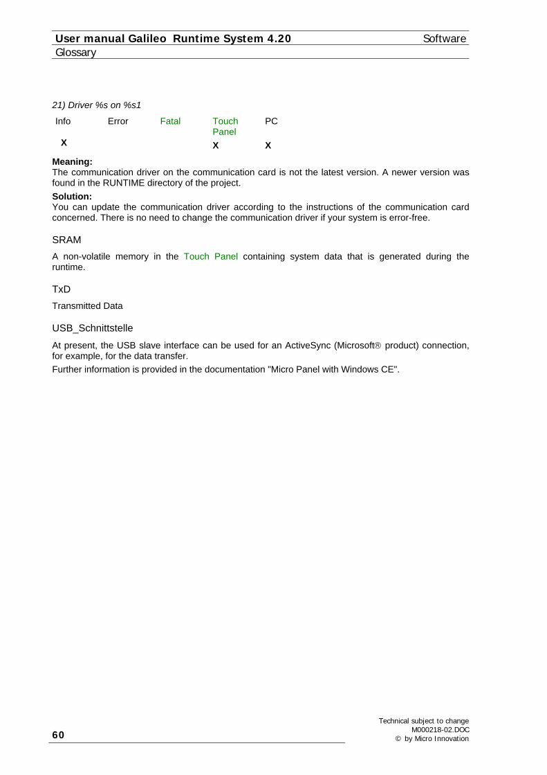
User manual Galileo Runtime System 4.20 SoftwareGlossary
21) Driver %s on %s1
Info Error Fatal Touch Panel
PC
X X X
Meaning: The communication driver on the communication card is not the latest version. A newer version was found in the RUNTIME directory of the project. Solution: You can update the communication driver according to the instructions of the communication card concerned. There is no need to change the communication driver if your system is error-free.
SRAM A non-volatile memory in the Touch Panel containing system data that is generated during the runtime.
TxD Transmitted Data
USB_Schnittstelle
At present, the USB slave interface can be used for an ActiveSync (Microsoft® product) connection, for example, for the data transfer. Further information is provided in the documentation "Micro Panel with Windows CE".
60
Technical subject to changeM000218-02.DOC
© by Micro Innovation

Software User manual Galileo Runtime System 4.20 Glossary
Technical subject to change M000218-02.DOC © by Micro Innovation 61
User manual Galileo Runtime System 4.20 SoftwareGlossary
62
Technical subject to changeM000218-02.DOC
© by Micro Innovation
Software User manual Galileo Runtime System 4.20 Index
4 INDEX "PLC to PLC" Message: 58 0) %s: 26 1) This function is not supported - %s !: 26 10) Touch not initialized !: 29 11) Touch controller not found !: 29 11) Touchcontroller not found !: 29 12) No project file found (*.GF1) !: 30 13) This program runs only on a MMI system !: 30 13) This program runs only on an MMI system !: 30 14) Program aborted by error !: 31 15) System palette (%s) not found or defect !: 31 16) Can't create or write to file %s !: 31 17) Can't find or read from file %s !: 32 18) File header of file %s is not correct !: 32 19) File size of file %s is not correct !: 32 2) Too many actual error entries (limit %d) !: 26 20 Firmware %s on %s1 32 21 not defined 70 21) Too many write messages in out buffer (limit %d) ! 70 23 not defined 33 23) PLC on slot %d is not running ! 33 24 not defined 33 24) Communication with PLC on slot %d disturbed ! 33 25 not defined 33 25) Communication with PLC on slot %d is ready. 33 26 not defined 33 26) There is no PLC connected on slot %d ! 33 27) Can't find %s board in slot %d !: 33 28) not defined!: 33 29) Board and driver %s selected on slot %d.: 34 3) Do not touch screen while initializing !: 27 30) Wait while data synchronisation.: 34 31 not defined 34 31) Problem while synchronising %s ! 34 32) No help window defined for actual mask (%s) !!: 34 32) No Help window defined for actual mask (%s) !: 34 33) %s number %d not found !: 35 34) No more memory available for function %s !: 35 35) New system language selected: 36 36) File %s saved to flash card !: 36 37) Target mask does not exist in actual project !: 36 38 No object selected 36 39) No more font memory available !: 37 4 Error in Script %s ! 27 4) not defined 27 4) not defined ! 27 40) Project language %d selected: 37 41) File %s was generated by old compiler !: 38 42) No printer connected !: 38 43) Printer is not ready !: 38 44) Printer is ready !: 38 45) Printer is busy !: 39 46) Touch controller version %s required !: 39 47) BCI ready message on slot %d
%s !: 39
Technical subject to change M000218-02.DOC © by Micro Innovation 63

User manual Galileo Runtime System 4.20 SoftwareIndex
47) BCI ready message on slot %d : 39 47) BCI ready message on slot %d : %s !: 39 48) BCI fault message on slot %d
%s !: 40 48) BCI fault message on slot %d : 40 48) BCI fault message on slot %d : %s !: 40 49) Not enough disk space available (<%d kB)!: 40 5 The function %s failed on execution ! %s1 27 5) not defined ! 27 50) Touch is dirty or defect !: 41 51) The recipe file %s is damaged !: 41 52) Check and convert the file %s (%d%%)!: 42 53) User name %s does not exist !: 42 54) User %s already exist !: 42 55) Wrong password entered (%d attempts left) !: 43 56) Wrong password entered !: 43 57) Wrong level ( %d) entered !: 44 58) No user authorisation for %s !: 44 59) Wrong password confirmation !: 44 6) Project entry mask (%s) not found !: 28 60) Can't create user %s !: 45 61) Can't delete user %s !: 45 62) Incorrect registration code - %s !: 45 63) No recipe %s found in mask !: 46 64) Recipe %s not defined !: 46 65) No enhanced recipe %s defined !: 46 66) Time elapsed for DEMO mode !: 47 67 No valid runtime license found - DEMO mode ! 47 68 No enhanced graph defined %d ! 47 7 Connection %d not supported 28 9) Clean touch before restart !: 29 99 Duration of error display 47 acoustic message: 10 APPL directory: 14, 15 APPL\BMP directory: 15 APPL\FONTS directory: 15 Application Loader 12 Application Loader: 22 APPL\MGF directory: 15 APPL\TXT directory: 15 Archive - file 16 Archive Graph data in files 12 Automatic 19 Backlight Off: 11 Backup recipe: 10 Beep: 10 Bitmap Cache: 12 Bridge: 58 Brightness: 11 Cache: 21 Comboard Loader: 10, 19 Communication Setup: 17 Control data block: 53 Convert recipe data file (*.TAB): 9 Data block concept: 52 DATA directory: 14 Data polling: 51 Data Synchronisation: 52 Date_Time Data Block 57
64
Technical subject to changeM000218-02.DOC
© by Micro Innovation

Software User manual Galileo Runtime System 4.20 Index
Description Application Loader: 22
Differences between the Runtime Systems: 6 Download mode: 8 EIB Communication 12 EIB_Date data block 59 EIB_Time data block 59 Error: 24 Ethernet 49, 50 Ethernet Interface 13 Fatal Error: 24 File format: 25 fromData 58 Function of the Bitmap Cache: 21 General 48 General: 6, 16, 51 Generating bitmaps from the screen(Screenshot): 21 GPI: 16 GRSW: 22 GRSW1: 22 GRSW2 24 Information about Product and Version: 17 Information: 24 Initiating functions from the PLC: 59 Initiating special functions (Function key): 60 Mainboard Firmware 12 Manual 19 Mask change: 62 Memory module: 7 Parallel Interface 13 PCMCIA: 7 PCX Pictures: 10 PLC Simulation (RK512 Protocol): 21 PLC to PLC: 58 Product information: 17 Program Structure: 13 Project name: 17 Project transfer (Galileo - Panel): 8 Recipe commands from the plc: 61 Recipe database limitation: 10 Renewed data synchronisation: 62 RUNTIME directory: 13 Save Mask As Bitmap: 11 Screenshot: 21 Send PLC to PLC Message: 62 Serial number: 12 serial Transfer: 8 Set Touch Disable: 11 Special data block types: 53 Special function "Backlight Off": 11 Special function "Brightness x%": 11 Special function "Save Mask As Bitmap": 11 Special function "Set Touch Disable": 11 Special function : 11 SRAM 70 SRAM Backup: 9 SRAM: 14, 20 Status data block: 55 System data: 9
Technical subject to change M000218-02.DOC © by Micro Innovation 65

User manual Galileo Runtime System 4.20 SoftwareIndex
System Menu 16 System Messages: 24 Time/Date Synchronisation 63 Touch disable: 11, 63 Transferring PLC text: 63 Updating error display: 62 Version information: 17
66
Technical subject to changeM000218-02.DOC
© by Micro Innovation

Software User manual Galileo Runtime System 4.20 Index
Technical subject to change M000218-02.DOC © by Micro Innovation 67
User manual Galileo Runtime System 4.20 SoftwareIndex
Micro Innovation AG Micro Innovation AG Spinnereistr 8-14 Spinnereistr 8-14 CH-9008 St. Gallen CH-9008 St. Gallen Switzerland Switzerland Tel : ++41- 71 243 24 24 Tel : ++41- 71 243 24 24 Fax : ++41- 71 243 24 90 Fax : ++41- 71 243 24 90 email : [email protected] email : [email protected] homepage : http://www.microinnovation.com homepage : http://www.microinnovation.com
User manual Galileo Runtime System 4.20 SoftwareIndex
68
Technical subject to changeM000218-02.DOC
© by Micro Innovation
68
Technical subject to changeM000218-02.DOC
© by Micro Innovation