INSTALLATION INSTRUCTIONS ! WARNING CAUTION ...
51
501 01 3004 00 11−08−10 INSTALLATION INSTRUCTIONS R−410A Split Condensing Units with RTPF Coils CAS072−121 These instructions must be read and understood completely before attempting installation Safety Labeling and Signal Words DANGER, WARNING, CAUTION, and NOTE The signal words DANGER, WARNING, CAUTION, and NOTE are used to identify levels of hazard seriousness. The signal word DANGER is only used on product labels to signify an immediate hazard. The signal words WARNING, CAUTION, and NOTE will be used on product labels and throughout this manual and other manual that may apply to the product. DANGER − Immediate hazards which will result in severe personal injury or death. WARNING −Hazards or unsafe practices which could result in severe personal injury or death. CAUTION − Hazards or unsafe practices which may result in minor personal injury or product or property damage. NOTE − Used to highlight suggestions which will result in enhanced installation, reliability, or operation. ! WARNING Signal Words in Manuals The signal word WARNING is used throughout this manual in the following manner: The signal word CAUTION is used throughout this manual in the following manner: ! CAUTION Signal Words on Product Labeling Signal words are used in combination with colors and/or pictures or product labels. SAFETY CONSIDERATIONS 2 ................. MODEL NOMENCLATURE 3 ................... INSTALLATION GUIDELINE 4 .................. Step 1 − Plan for Unit Location 10 ................ Step 2 − Complete Pre−Installation Checks 10 ..... Step 3 − Prepare Unit Mounting Support 11 ........ Step 4 − Rig and Mount Unit 11 .................. Step 5 − Complete Refrigerant Piping 11 .......... Step 6 − Install Accessories 16 ................... Step 7 − Complete Electrical Connections 17 ...... PRE−START−UP 23 ............................ START−UP 23 ................................. OPERATING SEQUENCE 34 .................... ROUTINE SYSTEM MAINTENANCE 35 .......... SERVICE 35 .................................. TROUBLESHOOTING 43 ....................... APPENDIX A, R−410A Quick Reference Guide 45 .. APPENDIX B, Wiring Diagram List 45 ............. APPENDIX C, Low Ambient Option 46 ............ START−UP CHECKLIST 50 ..................... TABLE OF CONTENTS ! WARNING PERSONAL INJURY, AND/OR PROPERTY DAMAGE HAZARD Failure to carefully read and follow this warning could result in equipment malfunction, property damage, personal injury and/or death. Installation or repairs made by unqualified persons could result in equipment malfunction, property damage, personal injury and/or death. The information contained in this manual is intended for use by a qualified service technician familiar with safety procedures and equipped with proper tools and test instruments. Installation must conform with local building codes and with the national Electrical Code NFPA70 current edition or Canadian Electrical Code part 1 CSA C.22.1.
-
Upload
khangminh22 -
Category
Documents
-
view
0 -
download
0
Transcript of INSTALLATION INSTRUCTIONS ! WARNING CAUTION ...

501 01 3004 00 11−08−10
INSTALLATION INSTRUCTIONSR−410A Split Condensing Units with RTPF Coils
CAS072−121
These instructions must be read and understood completely before attempting installation
Safety Labeling and Signal Words
DANGER, WARNING, CAUTION, and NOTE
The signal words DANGER, WARNING,CAUTION, and NOTE are used to identify levels ofhazard seriousness. The signal word DANGER isonly used on product labels to signify an immediatehazard. The signal words WARNING, CAUTION,and NOTE will be used on product labels andthroughout this manual and other manual that mayapply to the product.
DANGER − Immediate hazards which will result insevere personal injury or death.
WARNING −Hazards or unsafe practices whichcould result in severe personal injury or death.
CAUTION − Hazards or unsafe practices whichmay result in minor personal injury or product orproperty damage.
NOTE − Used to highlight suggestions which willresult in enhanced installation, reliability, oroperation.
! WARNING
Signal Words in ManualsThe signal word WARNING is used throughoutthis manual in the following manner:
The signal word CAUTION is used throughoutthis manual in the following manner:
! CAUTIONSignal Words on Product LabelingSignal words are used in combination withcolors and/or pictures or product labels.
SAFETY CONSIDERATIONS 2. . . . . . . . . . . . . . . . .MODEL NOMENCLATURE 3. . . . . . . . . . . . . . . . . . .INSTALLATION GUIDELINE 4. . . . . . . . . . . . . . . . . .Step 1 − Plan for Unit Location 10. . . . . . . . . . . . . . . .Step 2 − Complete Pre−Installation Checks 10. . . . .Step 3 − Prepare Unit Mounting Support 11. . . . . . . .Step 4 − Rig and Mount Unit 11. . . . . . . . . . . . . . . . . .Step 5 − Complete Refrigerant Piping 11. . . . . . . . . .Step 6 − Install Accessories 16. . . . . . . . . . . . . . . . . . .Step 7 − Complete Electrical Connections 17. . . . . .PRE−START−UP 23. . . . . . . . . . . . . . . . . . . . . . . . . . . .START−UP 23. . . . . . . . . . . . . . . . . . . . . . . . . . . . . . . . .OPERATING SEQUENCE 34. . . . . . . . . . . . . . . . . . . .ROUTINE SYSTEM MAINTENANCE 35. . . . . . . . . .SERVICE 35. . . . . . . . . . . . . . . . . . . . . . . . . . . . . . . . . .TROUBLESHOOTING 43. . . . . . . . . . . . . . . . . . . . . . .APPENDIX A, R−410A Quick Reference Guide 45. .APPENDIX B, Wiring Diagram List 45. . . . . . . . . . . . .APPENDIX C, Low Ambient Option 46. . . . . . . . . . . .START−UP CHECKLIST 50. . . . . . . . . . . . . . . . . . . . .
TABLE OF CONTENTS
! WARNINGPERSONAL INJURY, AND/OR PROPERTYDAMAGE HAZARDFailure to carefully read and follow this warningcould result in equipment malfunction, propertydamage, personal injury and/or death.Installation or repairs made by unqualifiedpersons could result in equipment malfunction,property damage, personal injury and/or death.
The information contained in this manual isintended for use by a qualified service technicianfamiliar with safety procedures and equippedwith proper tools and test instruments.
Installation must conform with local buildingcodes and with the national Electrical CodeNFPA70 current edition or Canadian ElectricalCode part 1 CSA C.22.1.

Split System CondensersInstallation Instructions
2 501 01 3004 00
SAFETY CONSIDERATIONSImproper installation, adjustment, alteration, service,maintenance, or use can cause explosion, fire, electricalshock, or other conditions which may cause death,personal injury, or property damage. Consult a qualifiedinstaller, service agency, or your distributor or branch forinformation or assistance. The qualified installer oragency must use factory−authorized kits or accessorieswhen modifying this product. Refer to the individualinstructions packaged with the kits or accessories wheninstalling.
Follow all safety codes. Wear safety glasses, protectiveclothing, and work gloves. Use quenching cloth forbrazing operations. Have fire extinguisher available.Read these instructions thoroughly and follow allwarnings or cautions included in literature and attachedto the unit. Consult local building codes, the currenteditions of the National Electrical Code (NEC) NFPA 70.
In Canada refer to the current editions of the CanadianElectrical Code CSA C22.1 Recognize safetyinformation. Recognize safety information. This is the
safety−alert symbol ! ! When you see this symbol on the
unit and in instructions or manuals, be alert to thepotential for personal injury. Understand these signalwords; DANGER, WARNING, and CAUTION. Thesewords are used with the safety−alert symbol. DANGERidentifies the most serious hazards which will result insevere personal injury or death. WARNING signifieshazards which could result in personal injury or death.CAUTION is used to identify unsafe practices which mayresult in minor personal injury or product and propertydamage. NOTE is used to highlight suggestions whichwill result in enhanced installation, reliability, oroperation.
! WARNING
ELECTRICAL SHOCK HAZARD
Failure to follow this warning could result in personal in-jury or death.
Before performing service or maintenance operationson unit, always turn off main power switch to unit and in-stall lockout tag. Unit may have more than one powerswitch.
! WARNING
UNIT OPERATION AND SAFETY HAZARD
Failure to follow this warning could cause personal in-jury, death and/or equipment damage.
R−410A systems operate at higher pressures than R−22systems. When working with R−410A systems, use onlyservice equipment and replacement components specif-ically rated or approved for R−410A service.
! WARNING
PERSONAL INJURY AND ENVIRONMENTALHAZARD
Failure to follow this warning could cause personal injuryor death.
Relieve pressure and recover all refrigerant before sys-tem repair or final unit disposal.Wear safety glasses and gloves when handling refriger-ants.Keep torches and other ignition sources away from refri-gerants and oils.
! CAUTIONCUT HAZARD
Failure to follow this caution may result in personal injury.
Sheet metal parts may have sharp edges or burrs. Usecare and war appropriate protective clothing, safetyglasses and gloves when handling parts and servicingunits.
! CAUTIONUNIT DAMAGE HAZARD
Failure to follow this caution may cause equipment dam-age.
Ensure voltage listed on unit data plate agrees with elec-trical supply provided for the unit.

Split System Condensers Installation Instructions
3501 01 3004 00
MODEL NOMENCLATUREMODEL SERIES C A S 0 9 1 H A A 0 A 0 0 APosition Number 1 2 3 4 5 6 7 8 9 10 11 12 13 14C = R-410A Condensing Unit
A = Air Conditioning (Cooling Only)H = Heat Pump Type
S = Standard ASHRAE 90.1-2010 Efficiency Efficiency
072 = 6 Tons091 = 7.5 Tons (1 circuit)120 = 10 Tons (2 circuits)121 = 10 Tons (1 circuit)
Nominal Cooling Capacity
H = 208/230-3-60L = 460/208/230-3-60S = 575-3-50 VOLTAGE
A = Single CircuitB = Single Circuit w/ Low Ambient ControlD = Dual CircuitE = Dual Circuit w/Low Ambient Control Refrigerant System Options
A = Copper / AluminumC = E-Coat Copper / Aluminum Outdoor Coil Options
0 = None1 = UnPowered C.O. Service Options
A = NoneC = Non-Fused Disconnect Electrical Options
0 = Elec-Mechanical Standard Base Unit Controls
0 = Future Use Future Use
A = Original Design Sales Code

Split System CondensersInstallation Instructions
4 501 01 3004 00
Installation GuidelineReplacement /Retrofit – R22 to R−410Areplacement/retrofit installations require change−out ofoutdoor unit, metering device, and filter driers. Change−outof indoor coil (evaporator) and interconnecting tubing isrecommended.
Existing evaporator coil – If the existing evaporator coil maybe re−used, check with the coil manufacturer to verify thecoil construction is suitable for operation with the higherpressures of R−410A. Also determine if the existing TXVvalve is compatible with R−410A, replace if necessary. Theminimum factory test pressure rating must be 250 psig(1725 kPa). Existing coil will need to be purged withNitrogen to remove as much mineral oil as possible toeliminate cross contamination of oil.Acid test – If the existing system is being replaced becauseof a compressor electrical failure, assume acid is in system.If system is being replaced for any other reason, use anapproved acid test kit to determine acid level. If even lowlevels of acid are detected, install a 100 percent activatedalumina suction−line filter drier in addition to thereplacement liquid−line filter drier. Remove the suction linefilter drier as soon as possible, with a maximum of 72 hoursof operation. Recommendation: Install a ball valve in theliquid line at the filter drier location when installing a suctionfilter in the suction line.
Existing refrigeration piping – Reuse of existingrefrigerant piping involves three issues: quality (strength) ofexisting tubing, cleanliness and tube size. Inspect all tubesegments and joints for signs of damage, corrosion or poorbrazing. Flush the interconnecting piping system with dryNitrogen to eliminate as much trace of mineral oil aspossible.
Same tube sizes are capable of handling higher flowrates(expressed as tons of cooling capacity) with R−410Arefrigerant compared to R−22 at constant pressure drops.For example, a 1/2−inch OD liquid line is rated at 33%higher tons with R−410A than with R−22 (at 5�F pressuredrop). A 1 1/8−inch OD suction line is rated at 53% highertons with R−410A than with R−22 (at 2�F pressure drop).Refrigeration lines selected for R−22 use are typicallyoversized for R−410A applications. Carefully check theexisting suction line size against the table for maximumsize (see Table 7); replace vertical riser segments ifnecessary. Check existing liquid line size against sizingdata in Table 5 or 6; replace with smaller lines whenfeasible.
Installation1. Remove the existing evaporator coil or fan coil and
install the replacement coil when appropriate.2. Drain oil from low points and traps in suction line
tubing and hot gas bypass tubing if appropriate) andevaporator if they were not replaced. Removing oilfrom evaporator coil may require purging of thetubing with dry nitrogen.
3. Unless indoor unit is equipped with a R−410Aapproved metering device, change the meteringdevice to a thermal expansion valve (TXV) designedfor R−410A.
4. Remove the existing outdoor unit. Install the newoutdoor unit according to these installationinstructions.
5. Install a new field−supplied liquid−line filter drier atthe indoor coil just upstream of the TXV or fix orificemetering device.
6. If a suction line filter drier is also to be installed,install suction line drier downstream of suction lineservice valve at condensing unit.
7. If required, install a 100% activated alumina suctionline filter drier at the outdoor unit.
8. Evacuate and charge the system according to theinstructions in this installation manual.
9. Operate the system for 10 hours. Monitor thepressure drop across the suction line filter drier. Ifpressure drop exceeds 3 psig (21kPa), replacesuction−line and liquid−line filter driers. Be sure topurge system with dry nitrogen and evacuate whenreplacing filter driers. Continue to monitor thepressure drop across suction−line filter drier. Repeatfilter changes is necessary. Never leavesuction−line filter drier in system longer than 72 hr(actual time).
NOTE: Do not use a torch to remove filter driers, use tubingcutters. Excess heat from the torch will drive the moisturecontained within the drier back out into the system.

Split System Condensers Installation Instructions
5501 01 3004 00
Unit Dimensions
072091121
120 1 - 1/8 [34.9] 1/2 [12.7]
(For dual compressor systems)
UNITCAS
STD. UNITWT. CORNER A CORNER B CORNER C CORNER D CENTER OF GRAVITY
UNITHEIGHT
lbs. kg. lbs. kg. lbs. kg. lbs. kg. lbs. kg. X Y Z H
072 389 176 141 64 96 44 62 28 91 4118
[457.2]24
[609.6]21
[533.4]42 3/8
[1076.0]
091 391 177 142 64 96 44 62 28 91 4118
[457.2]24
[609.6]21
[533.4]42 3/8
[1076.0]
121 490 222 177 80 120 54 78 35 114 5218
[457.2]24
[609.6]24
[609.6]50 3/8
[1279.2]
120 516 234 185 84 117 53 83 38 131 5919
[482.6]23
[584.2]24
[609.6]50 3/8
[1279.2]

Split System CondensersInstallation Instructions
6 501 01 3004 00
Table 1A — Physical Data —CAS072-121 Units — 60 Hz English
UNIT SIZE CAS 072 091 121
NOMINAL CAPACITY (tons) 6 7.5 10
OPERATING WEIGHTS (lb)
Round Tube/Plate Fin Coil (Cu/Al) 389 391 490
REFRIGERANT TYPE‡ R-410A
RTPF Operating Charge, Typical (lb)† 14.0 17.0 20.0
RTPF Shipping Charge (lb) 11.0 13.0 16.0
COMPRESSOR
Qty...Type 1...Scroll 1...Scroll 1...Scroll
Oil Charge (oz) 56 60 110
CONDENSER FANS
Qty...Rpm 2...1100
Motor Hp 1/4
Diameter 22
Nominal Airflow (Cfm Total) 6000
Watts (Total) 610
RTPF CONDENSER COIL
Material (Tube/Fin) Cu / Al
Coil Type 3/8−in RTPF
Rows/Fins per inch (FPI) 1 / 17
Face Area (sq ft total) 17.5 17.5 25.0
CONTROLS
Pressurestat Settings (psig)
High Cutout 630 ± 10
Cut-in 505 ± 20
Low Cutout 54 ± 3
Cut-in 117 ± 5
PIPING CONNECTIONS (in. ODS)
Qty...Suction 1...11/8 1...11/8 1...13/8
Qty...Liquid 1...3/8 1...1/2 1...1/2
LEGENDRTPF — Round Tube/Plate FinODS — Outside Diameter Sweat (socket)
‡ Unit is factory-supplied with partial charge only.† Typical operating charge with 25 ft of interconnecting piping.

Split System Condensers Installation Instructions
7501 01 3004 00
Table 1B — Physical Data — CAS072-121 Units — 60 Hz SI
UNIT SIZE CAS 072 091 121
NOMINAL CAPACITY (kW) 21.1 26.4 35.1
OPERATING WEIGHTS (lb)
Round Tube/Plate Fin Coil (Cu/Al) 176 177 222
REFRIGERANT TYPE‡ R-410A
RTPF Operating Charge, Typical (kg)† 6.4 7.7 9.1
RTPF Shipping Charge (kg) 5.0 5.9 7.3
COMPRESSOR
Qty...Type 1...Scroll 1...Scroll 1...Scroll
Oil Charge (oz) 1.7 1.8 3.3
CONDENSER FANS
Qty...r/s 2...18
Motor Hp NEMA 1/4
Diameter (mm) 560
Nominal Airflow (L/s) 2832
Watts (Total) 610
RTPF CONDENSER COIL
Material (Tube/Fin) Cu / Al
Coil Type 3/8−in RTPF
Rows/Fins per Meter (Fins/m) 1 / 670
Face Area (sq m total) 1.6 1.9 2.3
CONTROLS
Pressurestat Settings (kPa)
High Cutout 4347 ± 70
Cut-in 3482 ± 138
Low Cutout 372 ± 21
Cut-in 807± 34
PIPING CONNECTIONS (in. ODS)
Qty...Suction 1...11/8 1...11/8 1...13/8
Qty...Liquid 1...3/8 1...1/2 1...1/2
LEGENDRTPF — Round Tube/Plate FinNEMA — National Electrical Manufacturers AssociationODS — Outside Diameter Sweat (socket)
‡ Unit is factory-supplied with partial charge only.† Typical operating charge with 25 ft of interconnecting piping.

Split System CondensersInstallation Instructions
8 501 01 3004 00
Table 2A — Physical Data — CAS120 Units — 60 Hz English
UNIT SIZE CAS 120
NOMINAL CAPACITY (tons) 10
OPERATING WEIGHTS (lb)
Round Tube/Plate Fin Coil (Cu/Al) 516
REFRIGERANT TYPE‡ R-410A
RTPF Operating Charge A/B, Typical (lb)† 11.0 / 11.0
RTPF Shipping Charge A/B (lb) 8.0 / 8.0
COMPRESSOR
Qty...Type 2...Scroll
Oil Charge A/B (oz) 42
CONDENSER FANS
Qty...Rpm 2...1100
Motor Hp 1/4
Diameter 22
Nominal Airflow (Cfm Total) 6000
Watts (Total) 610
RTPF CONDENSER COIL
Material (Tube/Fin) Cu / Al
Coil Type 3/8−in RTPF
Rows/Fins per inch (FPI) 1/17
Face Area (sq ft total) 25.0
CONTROLS
Pressurestat Settings (psig)
High Cutout 630 ± 10
Cut-in 505 ± 20
Low Cutout 54 ± 3
Cut-in 117 ± 5
PIPING CONNECTIONS (in. ODS)
Qty...Suction A/B 1...11/8 / 1...11/8
Qty...Liquid A/B 1...3/8 / 1...3/8
LEGENDRTPF — Round Tube/Plate FinODS — Outside Diameter Sweat (socket)
‡ Unit is factory-supplied with partial charge only.† Typical operating charge with 25 ft of interconnecting piping.

Split System Condensers Installation Instructions
9501 01 3004 00
Table 2B — Physical Data — CAS120 Units — 60 Hz SI
UNIT SIZE CAS 120
NOMINAL CAPACITY (kW) 35.1
OPERATING WEIGHTS (kg)
Round Tube/Plate Fin Coil (Cu/Al) 234
REFRIGERANT TYPE‡ R-410A
RTPF Operating Charge A/B, Typical (kg)† 5.0 / 5.0
RTPF Shipping Charge A/B (kg) 3.6 / 3.6
COMPRESSOR
Qty...Type 2...Scroll
Oil Charge A/B (L) 1.2
CONDENSER FANS
Qty...r/s 2...1100
Motor Hp NEMA 1/4
Diameter (mm) 560
Nominal Airflow (Cfm Total) 6000
Watts (Total) 610
RTPF CONDENSER COIL
Material (Tube/Fin) Cu / Al
Coil Type 3/8−in RTPF
Rows/Fins per inch (FPI) 1/17
Face Area (sq ft total) 25.0
CONTROLS
Pressurestat Settings (kPa)
High Cutout 4347 ± 70
Cut-in 3482 ± 138
Low Cutout 372 ± 21
Cut-in 807 ± 34
PIPING CONNECTIONS (in. ODS)
Qty...Suction A/B 1...11/8 / 1...11/8
Qty...Liquid A/B 1...3/8 / 1...3/8
LEGENDRTPF — Round Tube/Plate FinNEMA — National Electrical Manufacturers AssociationODS — Outside Diameter Sweat (socket)
‡ Unit is factory-supplied with partial charge only.† Typical operating charge with 7.62 m of interconnecting piping.

Split System CondensersInstallation Instructions
10 501 01 3004 00
Matching CAS Model To Evaporator Coil
The CAS072, 091, 121 models have a single-circuit unitdesign, requiring one set of refrigeration piping. Thismodel can be connected to an evaporator coil with onecircuit or with two circuits (by manifolding the evaporatorconnections into a single piping system).
The CAS120 is a dual-circuit unit design that requirestwo sets of refrigeration piping between the outdoor unitand the evaporator coil (or coils). This model can only beconnected to an evaporator coil that has two refrigerationcircuits (or to two separate evaporator coils). TheCAS120 CANNOT be connected to a single-circuitevaporator coil and it CANNOT be field-converted to asingle-circuit design.
Table 3 – Evaporator Coil Connections
Evaporator Coil has Connect to Model Notes
Single Circuit CAS072, 091, 121
Two Circuits
CAS072, 091, 121Manifold evaporatorcircuits into single piping system
Or
CAS120Use two separate piping systems
Before unpacking this new CAS model, compare theevaporator coil design to the CAS model.
.INSTALLATION
Jobsite Survey
Complete the following checks before installation.
1. Consult local building codes and the NEC (NationalElectrical Code) ANSI/NFPA 70 for specialinstallation requirements.
2. Determine unit location (from project plans) or selectunit location.
3. Check for possible overhead obstructions which mayinterfere with unit lifting or rigging.
Step 1 — Plan for Unit Location
Select a location for the unit and its support system (pad,rails or other) that provides for the minimum clearancesrequired for safety. This includes the clearance tocombustible surfaces, unit performance and serviceaccess below, around and above unit as specified in unitdrawings. See Fig.1.
NOTE: Local codes may require different clearancesthan specified in Fig. 1. It is the responsibility of installersto be knowledgeable in local codes and to modify therecommended clearances to satisfy local codes.NOTE: Consider also the effect of adjacent units onairflow performance and control box safety clearance.
Do not install the outdoor unit in an area where fresh airsupply to the outdoor coil may be restricted or whenrecirculation from the condenser fan discharge is
possible. Do not locate the unit in a well or next to highwalls.
Evaluate the path and required line length forinterconnecting refrigeration piping, including suctionriser requirements (outdoor unit above indoor unit), liquidline lift (outdoor unit below indoor unit) and hot gasbypass line. Relocate sections to minimize the length ofinterconnecting tubing.
DO NOT BURY REFRIGERATION LINES.
Although unit is weatherproof, avoid locations that permitwater from higher level runoff and overhangs to fall ontothe unit.
Fig. 1 − Service Clearance Dimensional Drawing
REAR:Min 18” (457 mm)requried for service
Note: Observe requirements for 39” (914 mm) operating clearance on either Left or Rear coil opening.
RIGHT:Min 18” (457 mm)requried for service
LEFT:Min 18” (457 mm)requried for service FRONT:
42” (1067 mm)
Step 2 — Complete Pre-Installation Checks
Check Unit Electrical Characteristics: Confirm beforeinstallation of unit that voltage, amperage and circuitprotection requirements listed on unit data plate agree withpower supply provided.
Un−crate Unit: Remove unit packaging except for thetop skid assembly, which should be left in place untilafter the unit is rigged into its final location.
Inspect Shipment: File a claim with shipping company ifthe shipment is damaged or incomplete.
Consider System Requirements:
� Consult local building codes and National Electrical Code(NEC, U.S.A.) for special installation requirements.
� Allow sufficient space for airflow clearance, wiring,refrigerant piping, and servicing unit. See unitdimensions and weight distribution data on page 5.
� Locate the unit so that the outdoor coil (condenser)airflow is unrestricted on all sides and above.
� The unit may be mounted on a level pad directly on thebase channels or mounted on raised pads at supportpoints. See Tables 1A through 2B for unit operatingweights. See Fig. 1 for weight distribution based onrecommended support points.
NOTE: If vibration isolators are required for a particularinstallation, use the data in Fig. 1 to make the properselection.

Split System Condensers Installation Instructions
11501 01 3004 00
Step 3 — Prepare Unit Mounting Support
Slab Mount —
Provide a level concrete slab that extends a minimum of6 in. (150 mm) beyond unit cabinet. Install a gravel apronin front of condenser coil air inlet to prevent grass andfoliage from obstructing airflow.
Step 4 — Rig and Mount the Unit
UNIT DAMAGE HAZARD
Failure to follow this caution may result in equipmentdamage.
All panels must be in place when rigging. Unit is notdesigned for handling by fork truck.
CAUTION!
Rigging: These units are designed for overhead rigging.Refer to the rigging label for preferred rigging method.Spreader bars are not required if top crating is left on theunit. All panels must be in place when rigging. As furtherprotection for coil faces, plywood sheets may be placedagainst the sides of the unit, behind cables. Run cablesto a central suspension point so that the angle from thehorizontal is not less than 45 degrees. Raise and set theunit down carefully.
If it is necessary to roll the unit into position, mount theunit on longitudinal rails, using a minimum of 3 rollers.Apply force to the rails, not the unit. If the unit is to beskidded into position, place it on a large pad and drag itby the pad. Do not apply any force to the unit.
Raise from above to lift the unit from the rails or padwhen unit is in its final position.
After the unit is in position, remove all shipping materialsand top crating.
Step 5 — Complete Refrigerant PipingConnections
IMPORTANT: Do not bury refrigerant pipingunderground.
IMPORTANT: A refrigerant receiver is notprovided with the unit. Do not install a receiver.
Provide Safety Relief —
If local codes dictate an additional safety relief device,purchase locally and install locally. Installation willrequire the recovery of the factory shipping chargebefore the factory tubing can be cut and thesupplemental relief device is installed.
Model CAS120 has two separate refrigeration systems. Ifrequired, each circuit will require a field-supplied/installedsupplemental relief device.
Table 4 – Equivalent Lengths for Common Fittings(ft)
NominalTubeOD
Elbows
90° Std 90° Lrad 90° Street 45° Std 45° Street
3/8 1.3 0.8 2.2 0.6 11/2 1.4 0.9 2.3 0.7 1.15/8 1.6 1 2.5 0.8 1.33/4 1.8 1.2 2.9 0.9 1.57/
8 2 1.4 3.2 0.9 1.6
11/8 2.6 1.7 4.1 1.3 2.1
13/8 3.3 2.3 5.6 1.7 3
15/8 4 2.6 6.3 2.1 3.4
21/8 5 3.3 8.2 2.6 4.5
NominalTubeOD
Tees
BranchFlow
Straight-Thru
No Reduct Reduce 25% Reduce 50%
3/8 2.6 0.8 1.1 1.31/2 2.7 0.9 1.2 1.45/8 3 1 1.4 1.63/4 3.5 1.2 1.7 1.87/
8 4 1.4 1.9 2
11/8 5 1.7 2.3 2.6
13/8 7 2.3 3.1 3.3
15/8 8 2.6 3.7 4
21/8 10 3.3 4.7 5
Check CAS Model with Evaporator Coil Connections
Confirm before installation of unit that the evaporator coilconnections are consistent with this CAS model. SeeTable 3.
Determine Refrigerant Line Sizes —
Select the recommended line sizes for CAS072, 091,121 and CAS120 unit from the appropriate tables.
Determine the linear length of interconnecting pipingrequired between the outdoor unit and indoor unit(evaporator). Consider and identify also the arrangementof the tubing path (quantity and type of elbows in bothlines), liquid line solenoid size, filter drier and any otherrefrigeration specialties located in the liquid line. Refer tothe indoor unit installation instructions for additionaldetails on refrigeration specialties devices.
Determine equivalent line length adjustments for pathand components and add to linear line lengths. SeeTable 4, Equivalent Lengths for Common Fittings, forusual fitting types. Also identify adjustments forrefrigeration specialties. Refer to the indoor unitinstallation instructions for additional information.
NOTE: Equivalent line lengths will vary based on tubediameter. Calculate equivalent line length for each pipeby adding equivalent length adjustments to linear lengthsfor each pipe.

Split System CondensersInstallation Instructions
12 501 01 3004 00
Enter the appropriate table to select the recommendedline sizes.
Model:Line Sizes
TableQuantity of Line
Sets
CAS072, 091, 121 5 1
CAS120 6 2
Liquid Lift —
A liquid lift condition exists when the outdoor unit islocated below the indoor (evaporator) unit and liquidflows vertically up in a portion of the liquid line. Thevertical column of liquid reduces the available state pointsubcooling at the evaporator coil’s thermal expansionvalve. This effect reduces the length of liquid lift (feet ofelevation) that a liquid line size can accommodate.Longer linear tube lengths will also reduce the amount ofliquid lift possible.
Check Tables 5 (CAS072, 091, 121) and 6 (CAS120) formaximum liquid lift capabilities for line sizes. Reselect
the liquid line tube size if necessary. If maximumavailable tube size cannot provide the required liftdistance on this installation, relocate the outdoor unit toreduce the equivalent line length or the lift requirement.
Suction Riser —
A suction riser condition exists when the outdoor unit islocated above the indoor (evaporator) unit and suctionvapor must flow vertically up to return to the compressor.Oil return is a concern when the suction tube size is toolarge to produce the minimum refrigerant velocity toensure oil return at minimum load conditions.
Check Table 7 for maximum suction tube size for CASunits at minimum load conditions. Consider suctionspeed riser (reduced tube size for vertical segment only)or double suction riser arrangement if the recommendedsuction tube size does not provide necessary minimumflowrates for this riser.
Table 5 – CAS072-121 Piping Recommendations (Single-Circuit Unit)
R-410A Equivalent Length
Ft 0-38 38-75 75-113 113-150 150-188
m 0-12 12-23 23-34 34-46 46-57
Model Typ Linear ft 0-25 25-50 50-75 75-100 100-125
Typ Linear m 0-8 8-15 15-23 23-30 30-38
CAS072 Liquid Line 3/83/8
1/21/2
1/25/8
1/25/8
Max. Lift 25 50 50 75 100 100 125 125
Suction Line 7/87/8
7/8 1-1/8 1-1/8 1-1/8 1-1/8
Charge (lbs) 14.0 15.2 16.7 18.6 20.6 24.4 22.5 28.2
CAS091 Liquid Line 1/21/2
1/21/2
1/2
Max Lift 25 50 75 100 93
Suction Line 7/8 1-1/8 1-1/8 1-1/8 1-1/8 1-1/8
Charge (lbs) 18.6 19.7 21.7 23.8 25.5
CAS121 Liquid Line 1/21/2
1/25/8
1/25/8
1/25/8
Max Lift 25 50 57 75 61 100 47 99
Suction Line 1-1/8 1-1/8 1-1/8 1-1/8 1-3/8 1-1/8 1-3/8
Charge (lbs) 19.8 21.8 23.5 26.2 26.2 29.9 DNU 33.0
Legend:
Length LinLength Equiv
Linear tubing length, feetEquivalent tubing length, including effects of refrigeration specialties devices
Typ Linear Typical linear tubing length, Feet (50% added to linear to define Equivalent Length for this table)
Liquid Line Tubing size, inches OD.
Max Lift Maximum liquid lift (indoor unit ABOVE outdoor unit only), at maximum permitted liquid line pressure drop� Linear Length Less than 75 ft (23 m): Minimum 2.0°F subcooling entering TXV� Linear Length Greater than 75 ft (23m): Minimum 0.5°F subcooling entering TXV
Suction LineTube size, inches ODSee highlighted: Do not use with RTPF coil model
Charge Charge Quantity, lbs. Calculated for both liquid line sizes (where applicable), but only with larger suction line size (where applicable)
NOTE: For applications with equivalent length greater than 188 ft (57 m) and/0r linear length greater than 125 ft (38 m), contact your local Bryantrepresentative.

Split System Condensers Installation Instructions
13501 01 3004 00
Table 6 – CAS120 Piping Recommendations (Two-Circuit Unit)
NOTE: CAS120 requires TWO sets of refrigeration piping
R−410A Equivalent Length
Ft 0−38 38−75 75−113 113−150 150−188
m 0−12 12−23 23−34 34−46 46−57
Model Typ Linear ft 0−25 25−50 50−75 75−100 100−125
CAS120 Liquid Line 3/8 3/8 3/8 1/2 1/2 1/2
Max Lift 25 50 75 NR 83 100 62 125
Suction Line 7/8 7/8 11/8 11/8 11/8
Charge ea. (lbs) 13.1 14.3 15.8 NR 16.9 20.0 18.1 22.0
Legend:
Length Equiv Equivalent tubing length, including effects of refrigeration specialties devices
Typ Linear Typical linear tubing length, Feet (50% added to linear to define Equivalent Length for this table)
Liquid Line Tubing size, inches OD.
Max Lift Maximum liquid lift (indoor unit ABOVE outdoor unit only), at maximum permitted liquid line pressure drop C� Linear Length Less than 100 ft: Minimum 2.0°F subcooling entering TXV� Linear Length Greater than 100 ft: Minimum 0.5°F subcooling entering TXV
Suction Line Tube size, inches OD
Charge Charge Quantity, lbs. Calculated for both liquid line sizes (where applicable), but only with larger suction line size(where applicable)
NOTE: For applications with equivalent length greater than 188 ft (57 m) and/0r linear length greater than 125 ft (38 m), con-tact your local representative.
Table 7 – CAS Maximum Suction Pipe Size
Model: Maximum Tube Size
CAS072, 091, 121
13/8
15/8
15/8
21/8
CAS12013/8
15/8
Vertical Separation (outdoor unit above indoor unit)
Vertical elevation difference of 200 ft (60 m) is permittedwhen the outdoor unit (CAS) is located above the indoorunit.
Insulate Suction Lines —
Apply closed-cell tubular insulation to all suction linesbetween evaporator coil connection and CAS unit’ssuction service valve.
Hot Gas Bypass — (Not available on these models)
Hot gas bypass, if used, should be introduced before theevaporator. (A bypass route that also bypasses theevaporator circuit may lead to oil trapping in theevaporator circuit during low load conditions and then tooil slugging as evaporator load increases.) Model CASunits do not include a hot gas stub connection; a teemust be field-supplied and installed in the compressordischarge line. Run a 1/2-in OD line between outdoor unitand evaporator coil inlet. Install an Auxiliary SideConnector at the evaporator between TXV anddistributor (follow instructions for the side connectorpart). Insulate the hot gas line.
CAS120: Generally only one hot gas bypass system willbe applied on a two-circuit unit. Connect the hot gasbypass system to Circuit 1 (first-on/last-off, connected tothe evaporator coil’s bottom circuit).
CAS120 Piping Connections —
The CAS120 unit’s two circuits are designated Circuit 1and Circuit 2. Circuit 1 is controlled by the thermostat’sY1 (or TC1) contact and will be the first circuit on andlast circuit off. Circuit 2 is controlled by the thermostat’sY2 (or TC2) contact and this circuit is always the “lag”circuit.
See Fig. 2 for location of Circuit 1 and Circuit 2 servicevalves and field piping connections. Circuit 1 is on theleft-hand side of the service valve compartment; Circuit 2is on the right.
When a single piece evaporator coil with two separatecircuits is connected to a CAS120, the lower coil circuitshould be connected to the CAS120 unit’s Circuit 1 sothat the evaporator’s lower coil segment is first-on/last-off(to avoid re-evaporation of condensate on dry lower coilsegments).

Split System CondensersInstallation Instructions
14 501 01 3004 00
Fig. 2 − CAS120 Service Valve Locations
Circuit 1Connections
Circuit 2 Connections
CKT2 CKT
1
Plan the Circuit 1 and Circuit 2 tubing segmentscarefully, mark each segment and check constantly aspiping systems are assembled to avoid piping errors.
CAS120 unit cannot be field-piped as asingle-circuit/tandem system.
Connecting FAS to CAS120: The FAS fan coil in sizes10, 12.5, and 15 ton is a face-split coil design that alsohas its circuits designated as 1 and 2. See Fig. 3. Notethat the lower coil segment changes as the arrangementof the FAS changes. In a vertical arrangement, the FAS’slower coil segment is segment 2; this segment should beconnected to the CAS120’s Circuit 1. In a horizontalarrangement, the FAS’s lower segment is now segment1; this segment should be connected to the CAS120’sCircuit 1.
Note that refrigerant suction piping should be insulated.
FASArrangement
CoolingStage
FAS CoilSegment
Connect toCAS120
VerticalY1Y2
21
Circuit 1Circuit 2
HorizontalY1Y2
12
Circuit 1Circuit 2
Install Filter Drier(s) and Moisture Indicator(s) —
Every unit MUST have a filter drier in the liquid line.CAS120 models require two filter driers (one in eachliquid line). Locate the filter drier(s) at the indoor unit,close to the evaporator coil’s thermal expansion valve(TXV) inlets.
CAS units include one (CAS072, 091, 121) or two(CAS120) R−410A-duty filter drier(s), shipped in cartonsattached to the unit basepan. Remove the filter drier(s) andprepare to install in the liquid line(s) at the evaporator coil.Do not remove connection fitting plugs until ready toconnect and braze the filter drier into the liquid lineposition.
Fig. 3 − Typical Evaporator Coil Connections (FAS)
FIRST ON/LAST OFF = 2VERTICAL INSTALLATION
FIRST ON/LAST OFF = 1HORIZONTAL INSTALLATION
1
2
2
1
Table 8 – R−410A-duty Filter Drier(s)
Model-Size QtyLiquid
Line ODDesiccant
VolumePart
Number Ref
CAS072 1 3/8-in 8 cu. in. 1179492
CAS091 1 1/2-in 16 cu. in. 1179538
CAS121 1 1/2-in 16 cu. in. 1179538
CAS120 2 3/8-in 8 cu. in. 1179492
Installation of liquid line moisture indicating sightglass ineach circuit is recommended. Locate the sightglass(es)between the outlet of the filter drier and the TXV inlet.
Refer to Table 9 for recommendations on refrigerationspecialties.
Table 9 – Refrigerant Specialties Part Numbers
LIQUID LINESIZE (in.)
LIQUID LINESOLENOID VALVE (LLSV)
LLSVCOIL
SIGHTGLASS
FILTERDRIER
3/8 1179871 1179874 1179879provided with unit
see Table 81/2 1179872 1179874 1179878
5/8 1179873 1179874 1179877
CAS120 units require TWO sets of parts.

Split System Condensers Installation Instructions
15501 01 3004 00
Fig. 4 − Location of Sight Glass(es) and Filter DriersTypical CAS072, 091, 121 Systems
INDOORCOIL CKT 2
AIRFLOW
INDOORCOIL CKT 1
AIRFLOW
15 DIAMSMIN 10
DIAMS8 DIAMS
MIN
TXVSENSINGBULB
EQUALIZER LINE
SIGHT GLASSA LOCATION
SIGHT GLASSESB LOCATION
TXVCKT 2
FILTER DRIERA LOCATION
FILTER DRIERS B LOCATION
FLOWTXVSENSINGBULB
TXVCKT 1
8 DIAMSMIN
15 DIAMSMIN 10
DIAMS
Single Circuit Coil Piping ConfigurationFor single compressor condensing units
Dual Circuit Coil Piping ConfigurationFor single compressor condensing units
15 DIAMSMIN 10
DIAMS8 DIAMS
MIN
INDOORCOIL CKT
AIRFLOW
TXVSENSINGBULB
EQUALIZER LINE
SIGHT GLASSA LOCATION
TXV
FILTER DRIERA LOCATION
LIQUID LINESOLENOIDVALVE
FLOW
LIQUID LINESOLENOIDVALVE
Fig. 5 − Location of Sight Glasses and Filter DriersTypical CAS120 Systems
AIRFLOW
SUCTIONCIRCUIT 2
SUCTIONCIRCUIT 1
AIRFLOW
15 DIAMSMIN 10
DIAMS8 DIAMS
MIN
TXVSENSINGBULB
EQUALIZER LINE
SIGHT GLASSES
TXVCKT 2
FILTER DRIERS
LIQUID LINESOLENOID VALVECIRCUIT 2
FLOW
LIQUID LINESOLENOID VALVECIRCUIT 1
FLOW
TXVSENSINGBULB
TXVCKT 1
8 DIAMSMIN
15 DIAMSMIN 10
DIAMS
Dual Circuit Coil Piping ConfigurationFor two circuit condensing units
In some applications, depending on space andconvenience requirements, it may be desirable to install2 filter driers and sight glasses in a single circuitapplication. One filter drier and sight glass may beinstalled at A locations (see Fig. 4) or 2 filter driers andsight glasses may be installed at B locations (see Figs. 4and 5).
Select the filter drier for maximum unit capacity andminimum pressure drop. Complete the refrigerant pipingfrom the indoor unit to the outdoor unit before openingthe liquid and suction lines at the outdoor unit.
Install Liquid Line Solenoid Valve —
It is recommended that a solenoid valve be placed in themain liquid line (see Figs. 4 & 5) between thecondensing unit and the evaporator coil. Locate thesolenoid valve at the outlet end of the liquid line, near theevaporator coil connections, with flow direction arrowpointed at the evaporator coil. Refer to Table 9. (A liquidline solenoid valve is required when the liquid line lengthexceeds 75 ft [23 m].) This valve prevents refrigerantmigration (which causes oil dilution) to the compressorduring the off cycle, at low outdoor ambienttemperatures.
Solenoid drop control wiring: control the power to theliquid line solenoid through a Solenoid Valve Relay (SVR)in all units. Use part number 1178205 (field−supplied,installed). CAS072, 091, 121 units requires one SVR;CAS120 units requires two relays.
CAS120 units also requires a separate control powertransformer for the liquid solenoid valve loads. Selecttransformer part number according to unit power supply.
Unit Power Transformer Part #
208/230 1178027
460 1178077
575 1177852
Mount the SVR (and transformer TRAN3 when used) inunit control box. Connect per wiring schematic label onunit.
Capacity Control Liquid Line Solenoid Valve:Evaporator capacity staging control via direct thermostatcontrol of a liquid solenoid valve on the evaporator’ssecond stage circuit is not possible with CAS models. Ifthis installation is a retrofit for a unit that includedautomatic pressure−operated unloading, check theexisting thermostat and liquid solenoid valve wiring forpossible direct thermostat control of a solenoid valve;re−wire per Figs. 11 or 12 and 22 − 28.
Make Piping Connections —
Piping connections at the CAS072, 091, 121 units areball valves with stub tube extensions. Do not open theunit service valves until all interconnecting tube brazinghas been completed.
The stub tube connections include 1/4-in SAE servicefittings with Schrader valve cores (see Fig. 6). Beforemaking any brazed connections to the unit servicevalves, remove both Schrader valve caps and cores andsave for re-installation. Connect a source for nitrogen toone of these service fittings during tube brazing toprevent the formation of copper oxides inside the tubesat brazed joints.

Split System CondensersInstallation Instructions
16 501 01 3004 00
Fig. 6 − Typical Piping Connection Assembly
Factory High-FlowAccess Port
Service Valvewith Stem Cap
Field ServiceAccess Port(Schrader core)
SweatConnection
When connecting the field tubing to the CAS servicevalves, wrap the valves in wet rags to preventoverheating
Pressure-test all joints from outdoor unit connectionsover to the evaporator coil, using nitrogen as pressureand with soap-and-bubbles.
When pressure-testing is completed, remove thenitrogen source at the outdoor unit service valves andre-install the two Schrader valve cores. Torque the coresto 2-3 in-lbs (23-34 N-cm).
Evacuation/Dehydration —
Evacuate and dehydrate the connected refrigerationsystem(s) (excluding the CAS unit) to 500 microns usinga two-stage vacuum pump attached to the service portsoutside the CAS service valves, following description inGTAC II, Module 4, System Dehydration.
UNIT OPERATION AND SAFETY HAZARD
Failure to follow this warning could cause personalinjury, death and/or equipment damage.
R−410A refrigerant systems operate at higherpressure than standard R−22 systems. Do not useR−22 service equipment or components on R−410Arefrigerant equipment.
! WARNING
This unit is designed for use with R−410A refrigerant. Donot use any other refrigerant in this system.
R−410A refrigerant is provided in pink (rose) coloredcylinders. These cylinders are available with and withoutdip tubes; cylinders with dip tubes will have a labelindicating this feature. For a cylinder with a dip tube,place the cylinder in the upright position (access valve atthe top) when removing liquid refrigerant for charging.For a cylinder without a dip tube, invert the cylinder
(access valve on the bottom) when removing liquidrefrigerant.
Because R−410A refrigerant is a blend, it is stronglyrecommended that refrigerant always be removed fromthe cylinder as a liquid. Admit liquid refrigerant into thesystem in the discharge line. If adding refrigerant into thesuction line, use a commercial metering/expansiondevice at the gauge manifold; remove liquid from thecylinder, pass it through the metering device at thegauge set and then pass it into the suction line as avapor. Do not remove R−410A refrigerant from thecylinder as a vapor.
Preliminary Charge —
Before starting the unit, charge R-410A liquid refrigerantinto the high side of each CAS circuit through the liquidservice valve(s). The amount of refrigerant added mustbe at least 80% of the operating charge listed in Tables 5or 6 for LINEAR line length LESS the factory chargequantity (if factory shipping charge has not beenremoved). See example below.
Allow high and low side pressures to equalize. Ifpressures do not equalize readily, charge R-410A vapor(using special service manifold with expansion device)into the suction line service port for the low side ofsystem to assure charge in the evaporator. Refer toGTAC II, Module 5, Charging, Recover, Recycling, andReclamation for liquid charging procedures.
Example:
CAS121
60-ft (18.3 m) linear line length
Equivalent line length 90-ft (27.4 m)
Liquid Lift: 20-ft (6.1 m)
Select line sizes from Table 5 (CAS072, 091, 121):
Liquid 1/2 in
Suction 1-1/8 in.
Charge 21.8 lbs (at 75−ft linear length)
80% of Operating Charge:
0.80 x 21.8 = 17.4 lbs
Factory Shipping Charge: 6.3 lbs
Field-Charge quantity: 17.4 − 6.3 = 11.1 lbs
For linear line lengths longer than 125 ft (38 m), contactyour local representative for system charge value.
Step 6 — Install Accessories
Accessories requiring modifications to unit wiring shouldbe completed now. These accessories may includeWinter Start controls and Low Ambient controls. Refer tothe instructions shipped with the accessory.

Split System Condensers Installation Instructions
17501 01 3004 00
Step 7 — Complete Electrical Connections
ELECTRICAL SHOCK HAZARD
Failure to follow this warning could result in personalinjury or death.
Do not use gas piping as an electrical ground. Unitcabinet must have an uninterrupted, unbrokenelectrical ground to minimize the possibility of personalinjury if an electrical fault should occur. This groundmay consist of electrical wire connected to unit groundlug in control compartment, or conduit approved forelectrical ground when installed in accordance withNEC (National Electrical Code); ANSI/NFPA 70, latestedition (in Canada, Canadian Electrical Code CSA[Canadian Standards Association] C22.1), and localelectrical codes.
! WARNING
NOTE: Check all factory and field electrical connectionsfor tightness. Field-supplied wiring shall conform with thelimitations of 63°F (33°C) rise.
Field Power Supply —
Field power wires are connected to the unit at line-sidepressure lugs on compressor contactor C and TB1 (seewiring diagram label for control box componentarrangement) or at factory-installed option non-fuseddisconnect switch. Max wire size is #4 AWG (copperonly).
NOTE: TEST LEADS - Unit may be equipped with shortleads (pigtails) on the field line connection points oncontactor C or optional disconnect switch. These leadsare for factory run-test purposes only; remove anddiscard before connecting field power wires to unitconnection points. Make field power connections directlyto line connection pressure lugs only.
FIRE HAZARD
Failure to follow this warning could cause in personalinjury, death and/or equipment damage.
Do not connect aluminum wire between disconnectswitch and condensing unit. Use only copper wire.(See Fig. 7.)
! WARNING
Fig. 7 − Disconnect Switch and Unit
COPPER
WIRE ONLY
ELECTRICDISCONNECT
SWITCH
ALUMINUMWIRE
Units Without Factory-Installed Disconnect —
When installing units, provide a disconnect switch perNEC (National Electrical Code) of adequate size.Disconnect sizing data is provided on the unit informativeplate. Locate on unit cabinet or within sight of the unit pernational or local codes. Do not cover unit informativeplate if mounting the disconnect on the unit cabinet.
Units with Factory-Installed Disconnect —
The factory-installed option disconnect switch is locatedin a weatherproof enclosure located under the maincontrol box. The manual switch handle is accessiblethrough an opening in the access panel.
All Units —
All field wiring must comply with NEC and all local codes.Size wire based on MCA (Minimum Circuit Amps) on theunit informative plate. See Fig. 8 for power wiringconnections to the unit contactor and terminal block andequipment ground.
Provide a ground-fault and short-circuit over-currentprotection device (fuse or breaker) per NEC Article 440(or local codes). Refer to unit informative data plate forMOCP (Maximum Over-current Protection) device size.
All units except 208/230-v units are factory wired for thevoltage shown on the nameplate. If the 208/230-v unit isto be connected to a 208-v power supply, the controltransformer must be rewired by moving the black wirewith the ���-in. female spade connector from the 230-vconnection and moving it to the 208-v ���-in. maleterminal on the primary side of the transformer. Refer tounit label diagram for line-side information.

Split System CondensersInstallation Instructions
18 501 01 3004 00
Fig. 8 − Power Wiring Connections
11 13
L1 L2 L3
C TB1
208/230-3-60460-3-60575-3-60
Units Without Disconnect Option
Units With Disconnect Option
2
4
6
1
3
5
L1
L2
L3
OptionalDisconnect
Switch
Disconnect factory test leads; discard.
FactoryWiring
Disconnectper
NEC
Affix the crankcase heater warning sticker to the unitdisconnect switch.
Convenience Outlets —
ELECTRICAL OPERATION HAZARD
Failure to follow this warning could result inpersonal injury or death.
Units with convenience outlet circuits may usemultiple disconnects. Check convenience outletfor power status before opening unit for service.Locate its disconnect switch, if appropriate, andopen it. Tag-out this switch, if necessary.
! WARNING
Non−powered convenience outlets are offered on CASmodels that provide a 125-volt GFCI (ground-faultcircuit-interrupter) duplex receptacle rated at 15-A behinda hinged waterproof access cover, located on the endpanel of the unit. See Fig. 9.
Fig. 9 − Convenience Outlet Location
Control BoxAccess Panel
Pwd-COTransformer
ConvenienceOutletGFCI
Pwd-COFuse Switch
Non-powered type: This type requires the fieldinstallation of a general-purpose 125-volt 15-A circuitpowered from a source elsewhere in the building.Observe national and local codes when selecting wiresize, fuse or breaker requirements and disconnect switchsize and location. Route 125-v power supply conductorsinto the bottom of the utility box containing the duplexreceptacle.
ELECTRICAL OPERATION HAZARD
Failure to follow this warning could result in personalinjury or death.
Using unit-mounted convenience outlets: Units withunit-mounted convenience outlet circuits will oftenrequire that two disconnects be opened tode-energize all power to the unit. Treat all units aselectrically energized until the convenience outletpower is also checked and de-energization isconfirmed. Observe National Electrical Code Article210, Branch Circuits, for use of convenience outlets.
! WARNING
Installing Weatherproof Cover: A weatherproof while inuse cover for the factory installed convenience outlets isnow required by UL standards. This cover cannot befactory mounted due its depth; it must be installed at unitinstallation. For shipment, the convenience outlet iscovered with a blank cover plate.
The weatherproof cover kit is shipped in the unit’s controlbox. The kit includes the hinged cover, a backing plateand gasket.
DISCONNECT ALL POWER TO UNIT ANDCONVENIENCE OUTLET.
Remove the blank cover plate at the convenience outlet;discard the blank cover.

Split System Condensers Installation Instructions
19501 01 3004 00
Loosen the two screws at the GFCI duplex outlet, untilapproximately 1/2−in (13 mm) under screw heads areexposed. Press the gasket over the screw heads. Slipthe backing plate over the screw heads at the keyholeslots and align with the gasket; tighten the two screwsuntil snug (do not overtighten).
Mount the weatherproof cover to the backing plate asshown in Fig. 10. Remove two slot fillers in the bottom ofthe cover to permit service tool cords to exit the cover.Check for full closing and latching.
Fig. 10 − Weatherproof Cover Installation
All Units —
Voltage to compressor terminals during operation mustbe within voltage range indicated on unit nameplate. SeeTables 10 and 11. On 3-phase units, voltages betweenphases must be balanced within 2% and the currentwithin 10%. Use the formula shown in the legend forTables 10 and 11, Note 5 to determine the percent ofvoltage imbalance. Operation on improper line voltage orexcessive phase imbalance constitutes abuse and maycause damage to electrical components. Such operationwould invalidate any applicable Bryant warranty.
Field Control Wiring —
CAS unit control voltage is 24 v. See Fig. 20 − 25 fortypical field control connections and the unit’s labeldiagram for field-supplied wiring details. Route controlwires to the CAS unit through the opening in unit’s end
panel to the connections terminal board in the unit’scontrol box.
Remainder of the system controls connection will varyaccording to the specific construction details of theindoor section (air handler or packaged fan coil). Fig. 11(CAS072, 091, 121) and Fig. 12 (CAS120) depict typicalconnections to a FAS fan coil unit. Plan for fieldconnections carefully and install control wiring correctlyper the project plan. Additional components andsupplemental transformer accessory may be required.
The CAS unit requires an external temperature controldevice. This device can be a thermostat (field-supplied)or a thermostat emulation device provided as part of athird−party Building Management System.
Thermostat —
Install an approved accessory thermostat according toinstallation instructions included with the accessory.Locate the thermostat accessory on a solid wall in theconditioned space to sense average temperature inaccordance with the thermostat installation instructions.
The CAS072, 091, 121 unit is a single−stage cooling unit.If no economizer function is required, select a single−stagecooling thermostat. If an integrated economizer function isrequired, select a two−stage cooling thermostat.
The CAS120 is a dual−circuit, two-stage cooling unit.Select a two—stage cooling thermostat.
Select a thermostat cable or equivalent single leads ofdifferent colors with minimum of four leads for CAS072,091, 121 or five leads for CAS120 unit. Check thethermostat installation instructions for additional featureswhich might require additional conductors in the cable.
For wire runs up to 50 ft. (15 m), use no. 18 AWG(American Wire Gage) insulated wire (35°C minimum).For 50 to 75 ft. (15 to 23 m), use no. 16 AWG insulatedwire (35°C minimum). For over 75 ft. (23 m), use no. 14AWG insulated wire (35°C minimum). All wire sizeslarger than no. 18 AWG cannot be directly connected tothe thermostat and will require a junction box and spliceat the thermostat.

Split System CondensersInstallation Instructions
20 501 01 3004 00
Fig. 11 − Typical Remote Thermostat Connections— CAS072, 091, 121
Note 1: �Connect only if thermostat requires 24-vac power source.
Note 2: �Connect W1 and W2 if supplemental heaters are installed
�� �Field Wiring
(Note 1)
(Note 2)
(Note 2)
FAS CAS
Fig. 12 − Typical Remote Thermostat Connections— CAS120
Note 1: �Typical multi-function marking. Follow manufacturer's configuration
��� �instructions to select Y2.
Note 2: �Connect only if thermostat requires 24-vac power source.
Note 3: ��Connect W1 and W2 if supplemental heaters are installed
�� �Field Wiring
(Note 1)
(Note 2)
(Note 3)
(Note 3)
If the unit will be operating at 208-3-60 power, removethe black wire (BLK) from the transformer primaryconnection labelled “230” and move it to the connectionlabelled “208”. See Fig. 13.
Fig. 13 − Control Transformer Wiring
External Devices —
The CAS control transformers provide 24−v NEC Class 2power sources to energize external control devices. Thesedevices will include the indoor fan motor contactor (orcontrol relay). These devices may also include liquid linesolenoid valve (two on CAS120 model), economizer controlrelay, supplemental electric heater contactors or controlrelays and other devices selected by system designer.
Control transformer TRAN1 provides control power throughterminal R to C on the CTB’s field connection terminal stripfor supply fan motor interlock. This source may also beused to energize economizer control relay and electricheater contactors or relays. Maximum available power is20 va. Check concurrent loadings by external controldevices. If the maximum concurrent loading exceeds 20va, purchase and install the accessory Transformer−Relaypackage (available for 208/230 and 460−v units).
Control transformer TRAN3 provides control power throughterminals A1 (9) and A2 (10) to C for liquid line solenoids.Maximum available power is 75 va. These outputs areswitched ON/OFF by the Solenoid Valve Relays.

Split System Condensers Installation Instructions
21501 01 3004 00
Table 10 – Electrical Data — CAS072−121 60 Hz Units
WTIHOUT POWERED CONVENIENCE OUTLET
UNITCAS V-Ph-Hz
VOLTAGERANGE� COMPRESSOR 1 OFM (ea)
POWERSUPPLY
MIN MAX RLA LRA WATTS FLA MCA Fuse
072
208/230-3-60 187 253 19 123 325 1.5 26.7 40
460-3-60 414 506 9.7 62 325 0.8 13.7 20
575-3-60 518 633 7.4 50 325 0.7 10.6 15
091
208/230-3-60 187 253 25 164 325 1.5 34.2 50
460-3-60 414 506 12.2 100 325 0.8 16.8 25
575-3-60 518 633 9.0 78 325 0.7 12.6 20
121
208/230-3-60 187 253 30.1 225 325 1.5 40.6 60
460-3-60 414 506 16.7 114 325 0.8 22.5 40
575-3-60 518 633 12.2 80 325 0.7 16.6 30
NOTE: See “Legend and Notes for Tables 10 & 11” on page 22.
Table 11 – Electrical Data — CAS120 60 Hz Units
WTIHOUT POWERED CONVENIENCE OUTLET
UNITCAS V-Ph-Hz
VOLTAGERANGE� COMPRESSOR 1 COMPRESSOR 2 OFM (ea)
POWERSUPPLY
MIN MAX RLA LRA RLA LRA WATTS FLA MCA Fuse
120
208/230-3-60 187 253 16 110 16 110 325 1.5 40.6 60
460-3-60 414 506 7.8 52 7.8 52 325 0.8 22.5 40
575-3-60 518 633 5.7 39 5.7 39 325 0.7 16.6 30
NOTE: See “Legend and Notes for Tables 10 & 11” on page 22.

Split System CondensersInstallation Instructions
22 501 01 3004 00
Legend and Notes for Table 10 and 11LEGEND:FLA − Full Load AmpsLRA − Locked Rotor AmpsMCA − Minimum Circuit Amps
ProtectionMOCP − Maximum Overcurrent
ProtectionNEC − National Electrical CodeRLA − Rated Load Amps
� Units are suitable for use on electrical systems where voltagesupplied to the unit terminals is not below or above the listedlimits.
NOTES: 1. The MCA and MOCP values are calculated in accordance
with The NEC. Article 440.
2. Motor RLA and LRA values are established in accordancewith Underwriters' Laboratories (UL). Standard 1995.
3. The 575-v units are UL, Canada-listed only.
4. Unbalanced 3‐Phase Supply VoltageNever operate a motor where a phase imbalance in supplyvoltage is greater than 2%. Use the following formula to determine the percentage of voltage imbalance.
Example: Supply voltage is 230-3-60
% Voltage Imbalance = 100 xmax voltage deviation from average voltage
average voltage
AB = 224 vBC = 231 vAC = 226 v
Average Voltage =(224 + 231 + 226)
=681
3 3
= 227
Determine maximum deviation from average voltage.(AB) 227 – 224 = 3 v(BC) 231 – 227 = 4 v(AC) 227 – 226 = 1 vMaximum deviation is 4 v.Determine percent of voltage imbalance.
% Voltage Imbalance = 100 x4
227
= 1.76%
This amount of phase imbalance is satisfactory as it is below themaximum allowable 2%.IMPORTANT: If the supply voltage phase imbalance is more than 2%,contact your local electric utility company immediately.

Split System Condensers Installation Instructions
23501 01 3004 00
PRE-START-UPIMPORTANT: Before beginning Pre-Start-Up orStart-Up, review Start-Up Checklist at the back of thisbook. The Checklist assures proper start-up of a unitand provides a record of unit condition, applicationrequirements, system information, and operation atinitial start-up.
UNIT DAMAGE HAZARD
Failure to follow this caution may result in equipmentdamage.
Do not attempt to start the condensing unit, evenmomentarily, until the following steps have beencompleted. Compressor damage may result.
CAUTION!
System Check1.The electrical power source must agree with the unit’s
nameplate rating.2.Check all air handler(s) and other equipment auxiliary
components. Consult the manufacturer’s instructionsregarding any other equipment connected to thecondensing unit. If the unit has field-installedaccessories, be sure all are properly installed andcorrectly wired. If used, the airflow switch must beproperly installed.
3.Check tightness of all electrical connections.4.Be sure liquid line and low side of the system are
properly leak checked and dehydrated.5.Be sure the unit is properly charged. See “Preliminary
Charge”, below.6.Open the liquid line and suction line service valves.7.The crankcase heater must be firmly attached to the
compressor crankcase. Be sure the crankcase iswarm (heater must be on for 24 hours before startingcompressor).
Turn On Crankcase Heater —
Turn on the crankcase heater for 24 hours before startingthe unit to be sure all the refrigerant is out of the oil. Toenergize the crankcase heater, proceed as follows:
1.Set the space thermostat set point above the spacetemperature so there is no demand for cooling.
2.Close the field disconnect.
Preliminary Charge —
Before starting the unit, charge liquid refrigerant into thehigh side of the system through the liquid service valve.The amount of refrigerant added must be at least 80% ofthe operating charge listed in the Physical Data table(Tables 1A through 2B). Allow high and low side pressuresto equalize before starting compressor. If pressures do notequalize readily, charge vapor on low side of system toassure charge in the evaporator. Refer to GTAC II, Module5, Charging, Recover, Recycling, and Reclamation forliquid charging procedures.
UNIT DAMAGE HAZARD
Failure to follow this caution may result in equipmentdamage.
Prior to starting compressor, a preliminary charge ofrefrigerant must be added to avoid possiblecompressor damage.
CAUTION!
START-UPCAS Units: The compressor crankcase heater must beon for 24 hours before start-up. After the heater hasbeen on for 24 hours, the unit can be started. If no timeelapsed since the preliminary charge step wascompleted, it is unnecessary to wait the 24-hour period.
Preliminary Checks1.Check that electric power supply agrees with unit
nameplate data.2.Verify that the compressor crankcase heater is
securely in place.3.Check that the compressor crankcase heater has
been on at least 24 hours.4.Recheck for leaks using the procedure outlined in the
Pre-Start-Up section, Leak Test and Dehydration. Ifany leaks are detected, repair as required. Evacuateand dehydrate as described in the Leak Test andDehydration section.
5.Ensure that the preliminary charge has been added asdescribed in the Pre-Start-Up section, PreliminaryCharge.
6.All internal wiring connections must be tight, and allbarriers and covers must be in place.
NOTE: The CAS units are factory charged with therequired amount of oil. If recharging in required, useEmkarate RL 32-3MAF for the CAS units.
Compressor Rotation —
On 3−phase units with scroll compressors, it is important tobe certain that the compressor is rotating in the properdirection. CAS units are equipped with a Comfort AlertDiagnostic Module (CADM). Alert Code 7 indicates reversepower phasing.
To correct phase order:
1.Turn off power to the unit, tag disconnect.2.Reverse any two of the unit power leads.3.Reapply power to the compressor, verify correct
pressures.
To verify the compressor is rotating in the properdirection:
1.Connect service gages to the suction and liquidpressure fittings.
2.Energize the compressor.3.The suction pressure should drop and the liquid
pressure should rise, as is normal on any start−up.

Split System CondensersInstallation Instructions
24 501 01 3004 00
Compressor Overload —
This overload interrupts power to the compressor wheneither the current or internal motor winding temperaturebecomes excessive, and automatically resets when theinternal temperature drops to a safe level. This overloadmay require up to 60 minutes (or longer) to reset. If theinternal overload is suspected of being open, disconnectthe electrical power to the unit and check the circuitthrough the overload with an ohmmeter or continuitytester.
Advanced Scroll Temperature Protection (ASTP) —
A label located above the terminal box identifies CopelandScroll compressor models that contain this technology. SeeFig. 14. Advanced Scroll Temperature Protection (ASTP) isa form of internal discharge temperature protection, thatunloads the scroll compressor when the internaltemperature reaches approximately 149�C (300�F). At thistemperature, an internal bi−metal disk valve opens andcauses the scroll elements to separate, which stopscompression. Suction and discharge pressures balancewhile the motor continues to run. The longer thecompressor runs unloaded, the longer it must cool beforethe bi−metal disk resets. See Fig. 15.
Fig. 14 − Advanced Scroll Temperature ProtectionLabel
Fig. 15 − Recommended Minimum Cool-Down TimeAfter Compressor is Stopped
0
10
20
30
40
50
60
70
80
90
100
11�0
120
0����10�� ��20�� ��30�40������ �60�� �70�� ��80�� ��9050
Compressor Unloaded Run Time (Minutes)*
Recom
mended C
oolin
g T
ime
*
(Min
ute
s)
*Times are approximate.NOTE: Various factors, including high humidity, high ambient temperature,and the presence of a sound blanket will increase cool-down times.
To manually reset ASTP, the compressor should bestopped and allowed to cool. If the compressor is notstopped, the motor will run until the motor protector trips,which occurs up to 90 minutes later. Advanced ScrollTemperature Protection will reset automatically beforethe motor protector resets, which may take up to 2 hours.
Start Unit
Set the space thermostat to a set point above spacetemperature so that there is no demand for cooling.Close the CAS disconnect switch. Only the crankcaseheater will be energized.
Reset the space thermostat below ambient so that a callfor cooling is ensured.
UNIT DAMAGE HAZARD
Failure to follow this caution may result in equipmentdamage.
Never charge liquid into the low-pressure side ofsystem. Do not overcharge. During charging orremoval of refrigerant, be sure indoor-fan system isoperating. Ensure both outdoor fan motors arerunning; bypass any Motormaster function.
CAUTION!
Adjust Refrigerant Charge —
Refer to Cooling Charging Charts, Fig. 16 through Fig. 19.For applications with line lengths greater than 125 ft (38m), contact your service representative. Vary refrigerantuntil the conditions of the chart are met. Note that thecharging charts are different from the type normally used.The charts are based on charging the units to the correctsubcooling for the various operating conditions. Accuratepressure gage and temperature sensing device arerequired. Connect the pressure gage to the service port onthe liquid line service valve. Mount the temperaturesensing device on the liquid line close to the liquid lineservice valve, and insulate it so that outdoor ambienttemperature does not affect the reading. Indoor airflowmust be within the unit’s normal operating range. Operatethe unit for a minimum of 15 minutes. Ensure that pressureand temperature readings have stabilized. Plot the liquidpressure and temperature on chart and add or reduce thecharge to meet the curve. Adjust the charge to conformwith the charging chart, using the liquid pressure andtemperature to read the chart.
Using plotted operating point:
If plotted operating condition is−
Adjust charge by−
BELOW the curve REDUCE charge
ABOVE the curve ADD charge
Final Checks —
Ensure that all safety controls are operating, controlpanel covers are on, and the service panels are in place.

Split System Condensers Installation Instructions
25501 01 3004 00
Fig. 16 − CAS072 Charging Chart (RTPF)
6 TON CHARGING CHART R−410AALL CONDENSER FANS OPERATING
6 TONNE TABLEAU DE CHARGE R−410ATOUTES LES SOUFFLERIES DE CONDENSATION EN FONCTIONNEMENT
Fig. 17 − CAS091 Charging Chart (RTPF)
7.5 TON CHARGING CHART R−410AALL CONDENSER FANS OPERATING
7.5 TONNE TABLEAU DE CHARGE R−410ATOUTES LES SOUFFLERIES DE CONDENSATION EN FONCTIONNEMENT

Split System CondensersInstallation Instructions
26 501 01 3004 00
Fig. 18 − CAS121 Charging Chart (RTPF)
10 TON CHARGING CHART R−410AALL CONDENSER FANS OPERATING
10 TONNE TABLEAU DE CHARGE R−410ATOUTES LES SOUFFLERIES DE CONDENSATION EN FONCTIONNEMENT

Split System Condensers Installation Instructions
27501 01 3004 00
Fig. 19 − CAS120 Charging Chart (RTPF)
10 TON CHARGING CHART R−410A ALL CONDENSER FANS OPERATING
10 TONNE TABLEAU DE CHARGE R−410ATOUTES LES SOUFFLERIES DE CONDENSATION EN FONCTIONNEMENT
10 TON CHARGING CHART R−410A ALL CONDENSER FANS OPERATING
10 TONNE TABLEAU DE CHARGE R−410ATOUTES LES SOUFFLERIES DE CONDENSATION EN FONCTIONNEMENT

Split System CondensersInstallation Instructions
28 501 01 3004 00
Fig. 20 − Typical CAS072, 091, 121 − 208/230 Volt Wiring Diagram

Split System Condensers Installation Instructions
29501 01 3004 00
Fig. 21 − Typical CAS072, 091, 121 − 460 Volt Wiring Diagram

Split System CondensersInstallation Instructions
30 501 01 3004 00
Fig. 22 − Typical CAS072, 091, 121 − 575 Volt Wiring Diagram

Split System Condensers Installation Instructions
31501 01 3004 00
Fig. 23 − Typical CAS120 − 208/230 Volt Wiring Diagram

Split System CondensersInstallation Instructions
32 501 01 3004 00
Fig. 24 − Typical CAS120 − 460 Volt Wiring Diagram

Split System Condensers Installation Instructions
33501 01 3004 00
Fig. 25 − Typical CAS120 − 575 Volt Wiring Diagram

Split System CondensersInstallation Instructions
34 501 01 3004 00
OPERATING SEQUENCE
Base Unit Controls
Indoor (Supply) Fan —
The indoor fan contactor (IFC) is remotely located at thefan coil or fan section. If the thermostat fan operation isselected as Continuous, the IFC is energized and theindoor (supply) fan motor runs continuously. If thethermostat fan operation is selected as Automatic, the IFCwill be energized on a call for Cooling; indoor (supply) fanmotor runs. When thermostat call for Cooling is satisfied,the IFC is de-energized and indoor (supply) fan motorstops.
Cooling, Unit Without Economizer —
CAS072, 091, 121 (Single Circuit)
On a thermostat call for Cooling, IFC will be energizedand indoor (supply) fan motor runs. Thermostat outputY1 is energized; terminal Y1 at CAS072, 091, 121 unitsreceives 24-v. 24-v received at CADM1 terminal Y. Ifanti-recycle time delay period has not expired, CADM1relay will remain open, de-energizing Solenoid ValveRelay (SVR) and preventing compressor start. Whensafety pressure switches are closed and CADM1 timedelay expires, CADM1 relay closes, SVR andcompressor contactor C are energized; liquid linesolenoid valve LLSV opens, all outdoor fan motors startand Compressor starts.
As space cooling load is satisfied, thermostat output Y1is de−energized, removing 24-v at CAS072, 091, 121terminal Y1. On Y1 opening, Compressor stops, alloutdoor fan motors stop and SVR relay is de-energized.Liquid line solenoid valve is de-energized and valvecloses. CADM1 begins its three-minute anti-recycle timedelay.
CAS120 (Two Circuit)
On a thermostat call for Cooling, IFC will be energizedand indoor (supply) fan motor runs. Thermostat outputY1 is energized; terminal Y1 at CAS120 unit receives24-v. 24-v received at CADM1 terminal Y. If anti-recycletime delay period has not expired, CADM1 relay willremain open, de-energizing Solenoid Valve Relay 1(SVR1) and preventing compressor start. When safetypressure switches are closed and CADM1 time delayexpires, CADM1 relay closes, SVR1 and compressorcontactor C1 are energized; liquid line solenoid valveLLSV1 opens, all outdoor fan motors start and Circuit 1compressor starts.
On a thermostat calling for Stage 2 Cooling, thermostatoutput Y2 is energized; terminal Y2 at CAS120 unitreceives 24-v. 24-v received at CADM2 terminal Y. Ifanti-recycle time delay period has not expired, CADM2relay will remain open, de-energizing Solenoid ValveRelay 2 (SVR2) and preventing compressor start. Whensafety pressure switches are closed and CADM2 timedelay expires, CADM2 relay closes, SVR2 andcompressor contactor C2 are energized; liquid line
solenoid valve LLSV2 opens and Circuit 2 compressorstarts.
As space cooling load is satisfied, thermostat outputs Y2and Y1 are de−energized, removing 24-v at CAS120terminals Y2 and Y1. Circuit 2 compressor stops on Y2opening; SVR2 is de-energized and LLSV2 closes.CADM2 begins its three-minute anti-recycle time delay.On Y1 opening, Circuit 1 compressor stops, all outdoorfan motors stop and SVR1 relay is de-energized. Liquidline solenoid valve LLSV1 is de-energized and valvecloses. CADM1 begins its three-minute anti-recycle timedelay.
All Units
If either the Low Pressure Switch or High PressureSwitch opens while thermostat output Y1 or Y2 remainenergized, the compressor contactor is de-energized, thecompressor stops and liquid line solenoid isde-energized (valve closes). CADM initiates a TRIPevent (cooling demand sensed at CADM terminal Y butno current is measured at T1, T2, T3 motor sensors);CADM relay opens and RED LED is illuminated. TRIPcondition maintains lockout of compressor operation untilCADM is manually reset. Reset CADM by cycling unitmain power.
Complete system shutdown may be caused by loss ofmain power, open compressor internal overload, openlow-pressure or high-pressure switch, or a fault detectedby the CADM logic. Compressor operation withoutcooling may indicate the compressor’s ASTP feature isactive; disconnect unit power and allow compressor tocool. See Service section for further details.
Cooling, Unit With Economizer —
Refer to fan coil unit installation instructions andeconomizer accessory installation instructions foroperating sequences when system is equipped withaccessory economizer.
Heating —
Refer to fan coil unit installation instructions and accessoryheating device installation instructions for operatingsequences in heating mode.

Split System Condensers Installation Instructions
35501 01 3004 00
ROUTINE SYSTEM MAINTENANCEThese items should be part of a routine maintenanceprogram, to be checked every month or two, until a specificschedule for each can be identified for this installation:
Quarterly Inspection (and 30 days after initial start)—
Indoor section
� Condenser coil cleanliness checked.
� Return air filter replacement
� Outdoor hood inlet filters cleaned
� Belt tension checked
� Belt condition checked
� Pulley alignment checked
� Fan shaft bearing locking collar tightness checked
� Condensate drain checked
Seasonal Maintenance —
These items should be checked at the beginning of eachseason (or more often if local conditions and usagepatterns dictate):
Air Conditioning
� Condenser fan motor mounting bolts tightness
� Compressor mounting bolts
� Condenser fan blade positioning
� Control box cleanliness and wiring condition
� Wire terminal tightness
� Refrigerant charge level
� Evaporator coil cleaning
� Evaporator blower motor amperage
Heating
� Power wire connections
� Fuses ready
� Manual-reset limit switch is closed
Economizer or Outside Air Damper
� Inlet filters condition
� Check damper travel (economizer)
� Check gear and dampers for debris and dirt
SERVICERefrigeration System
EQUIPMENT DAMAGE HAZARD
Failure to follow this caution may result in damage toequipment.
This system uses R−410A refrigerant which hashigher pressures than R-22 and other refrigerants.No other refrigerant may be used in this system.Gage set, hoses, and recovery system must bedesigned to handle R−410A. If you are unsureconsult the equipment manufacturer.
CAUTION!
Compressor Oil —
EQUIPMENT DAMAGE HAZARD
Failure to follow this caution may result in damage toequipment.
The compressor in a R−410A system uses apolyolester (POE) oil. This oil is extremelyhygroscopic, meaning it absorbs water readily. POEoils can absorb 15 times as much water as other oilsdesigned for HCFC and CFC refrigerants. Take allnecessary precautions to avoid exposure of the oil tothe atmosphere.
CAUTION!
Servicing Systems on Roofs With Synthetic Materials
POE (polyolester) compressor lubricants are known tocause long term damage to some synthetic roofingmaterials. Exposure, even if immediately cleaned up, maycause embrittlement (leading to cracking) to occur in oneyear or more. When performing any service which may riskexposure of compressor oil to the roof, take appropriateprecautions to protect roofing. Procedures which risk oilleakage include but are not limited to compressorreplacement, repairing refrigerants leaks, replacingrefrigerant components such as filter drier, pressure switch,metering device, coil, accumulator, or reversing valve.
Synthetic Roof Precautionary Procedure:
1.Cover extended roof working area with animpermeable polyethylene (plastic) drop cloth or tarp.Cover an approximate 10 x 10 ft (3.3 x 3.3 m) area.
2.Cover area in front of the unit service panel with aterry cloth shop towel to absorb lubricant spills andprevent run-offs, and protect drop cloth from tearscaused by tools or components.
3.Place terry cloth shop towel inside unit immediatelyunder component(s) to be serviced and preventlubricant run-offs through the louvered openings in thebase pan.
4.Perform required service.5.Remove and dispose of any oil contaminated material
per local codes.

Split System CondensersInstallation Instructions
36 501 01 3004 00
Liquid Line Filter Drier —
The factory-provided filter drier is specifically designed tooperate with R−410A. Replace the filter drier withfactory-authorized components only with a filter drier withdesiccant made from 100% molecular sieve gradeXH-11. Filter drier must be replaced whenever therefrigerant system is opened.
When removing a filter drier, use a tubing cutter to cutthe drier from the system. Do not unsweat a filter drierfrom the system. Heat from unsweating will releasemoisture and contaminants from drier into system.
Field Refrigerant Access Ports —
Field service access to refrigerant pressures is throughthe access ports located at the service valves (see Figs29 and 31). These ports are 1/4-in SAE Flare couplingswith Schrader check valves and service caps. Use theseports to admit nitrogen to the field tubing during brazing,to evacuate the tubing and evaporator coil, to admit initialrefrigerant charge into the low-side of the system andwhen checking and adjusting the system refrigerantcharge. When service activities are completed, ensurethe service caps are in place and secure; check forleaks. If the Schrader check valve must be removed andre-installed, tighten to 2-3 in-lbs (23-34 N-cm).
Factory High-Flow Access Ports —
There are two additional access ports in the system - onthe suction tube between the compressor and thesuction service valve and on the liquid tube near theliquid service valve (see Figs 30 and 32). These arebrass fittings with black plastic caps. The hoseconnection fittings are standard 1/4-in SAE Male Flarecouplings.
The brass fittings are two-piece High Flow valves, with areceptacle base brazed to the tubing and an integralspring-closed check valve core screwed into the base.(See Fig. 26) This check valve is permanentlyassembled into this core body and cannot be servicedseparately; replace the entire core body if necessary.Service tools are available from FAST that allow thereplacement of the check valve core without having torecover the entire system refrigerant charge. Applycompressor refrigerant oil to the check valve core’sbottom o-ring. Install the fitting body with 96 ±-10 in-lbs(1085 ±23 N-cm) of torque; do not overtighten.
Fig. 26 − CoreMax Access Port Assembly
1/2-20 UNF RH
30°
0.596
SEAT CORE
WASHER DEPRESSOR PER ARI 720+�.01/�-.035FROM FACE OF BODY
7/16-20 UNF RH
O-RING
45°
1/2" HEX
This surface provides a metal to metal seal when torqued into the seat. Appropriate handling is required to not scratch or dent the surface.
(Part No. 1173177)
⅝ Hex .47

Split System Condensers Installation Instructions
37501 01 3004 00
Comfort Alert Diagnostic Module
The Comfort Alert Diagnostic Module (CADM) monitorsand analyzes data from the Copeland Scroll® three-phasecompressor and the thermostat demand. The CADM alsoprovides a 3-minute anti-recycle time delay to compressorcycling. Each compressor has a separate CADM module.
The CADM detects causes for electrical and systemrelated failures without any sensors. Flashing LEDscommunicate the Alert codes to guide servicetechnicians in accurately and quickly troubleshooting thesystem and determining root cause for the failure.
Inputs to the CADM include 24-vac power, thermostat Y1or Y2, compressor contactor coil (common side) andcompressor power leads (from the compressorcontactor).
Input Terminal Voltage
ControlPower R 24-V
ControlCommon C 24-V
Cooling Y 24-V
ContactorCoil P 24-V
Line A T1 Line
Line B T2 Line
Line C T3 Line
Control of the compressor contactor coil is through anormally-closed (power on the module) contact betweenterminals P and C.
Communications of status and alert conditions is throughthree LEDs located on the top edge of the modulehousing (see Fig. 27): POWER (green), ALERT (yellow),and TRIP (red).
The POWER LED indicates the presence of controlpower to the CADM.
The ALERT LED indicates an abnormal condition existsin the system through a flash code. The ALERT LED willblink a number of times consecutively, pause and therepeat the process. The number of blinks, defined inTable 12, correlates to a particular abnormal condition;troubleshooting tips are provided for each Alert code.Reset of the ALERT may be automatic or manual. If thefault condition causing the Alert is self-corrected, theAlert code will be removed and the CADM willautomatically reset and allow the system to restartnormally. Manual reset requires that main power to theCAS unit be recycled after the cause for the Alertcondition has been detected and corrected.
Fig. 27 − CADM Housing/LED LocationsPOWER(GRN)
ALERT(YEL)
TRIP(RED)
The TRIP LED indicates either a time-delay period iscurrently active (RED LED is blinking) or the module haslocked out the compressor (RED LED is on steady). Alockout condition will occur when the CADM detects athermostat demand at input Y but there is no power atthe compressor line terminals T1 or T2 or T3. Thislockout can occur due to a safety switch (LPS or HPS)opening and de-energizing the compressor contactor, thecompressor-motor internal overload opens, or otherinternal power interruption has occurred. Reset of theTRIP LED requires that unit main power be recycledafter the loss of power to the compressor condition hasbeen detected and corrected.
Simultaneous Blinking of YELLOW and RED LEDsindicates control power input to the CADM is low. Checkcontrol circuit transformer and wiring.
Troubleshooting the CADM Wiring – Flashing LEDs alsoindicate wiring problems to the CADM. See Table 13 fordiscussion of additional LED flash codes andtroubleshooting instructions.

Split System CondensersInstallation Instructions
38 501 01 3004 00
Table 12 – LED Status Codes
Status LED Status LED Description Status LED Troubleshooting Information
Green “POWER” Module has power Supply voltage is present at module terminals
Red “TRIP”LED On Solid
Thermostat demand signalY is present, but the com-pressor is not running.
1. Compressor protector is open
2. Condensing unit power disconnect is open
3. Compressor circuit breaker or fuse(s) is open
4. Broken supply wires or connector is not making contact
5. Compressor power wires not routed through Comfort Alert
6. Compressor contactor has failed open
Red “TRIP” LEDFlashing
The anti-short cycle timer (3 minutes) in module is preventing compressor restart.
Module locks out compressor when compressor damaging ALERT code appears.Lockout ALERT codes are noted in the Status LED Description.During a compressor lock out, 24VAC power must be removed from module to manually reset.
Yellow “ALERT”LED On Solid
A short circuit or over cur-rent condition exists onPROT terminal.
1. Compressor contactor coil shorted
2. Electrical load too high for PROT circuit (maximum 1 Amp)
3. 24 V AC wired directly to PROT terminal
Yellow “ALERT”Flash Code 2
System Pressure Trip Discharge pressure out oflimits or compressor over-load (if no high pressureswitch in system) LOCKOUT
1. High head pressure
2. Condenser coil poor air circulation (dirty, blocked, damaged)
3. Condenser fan is not running
4. If low pressure switch is open: Refer to Code 3 for troubleshooting
Yellow “ALERT”Flash Code 3
Short Cycling Compressor is running onlybriefly (four consecutivecycles of less than threeminutes each)LOCKOUT
1. If low pressure switch is open:
a. Low refrigerant charge
b. Evaporator blower is not running
c. Evaporator coil is frozen
d. Faulty metering device
e. Condenser coil is dirty
f. Liquid line restriction (filter drier blocked if present)
2. If high pressure switch is open, go to Flash Code 2 information
3. Intermittent thermostat demand signal
4. System or control board defective
Yellow “ALERT”Flash Code 4
Locked RotorLOCKOUT
1. Low line voltage to compressor
2. Excessive liquid refrigerant in compressor
3. Compressor bearings are seized
Yellow “ALERT”Flash Code 5
Open Circuit 1. Condensing unit power disconnect is open
2. Compressor circuit breaker or fuses are open
3. Compressor contactor has failed open
4. High pressure switch is open and requires manual reset
5. Broken supply wires or connector is not making contact
6. Unusually long compressor protector reset time due to extreme ambient temperature
7. Compressor windings are damaged
Yellow “ALERT”Flash Code 6
Missing PhaseLOCKOUT
1. Compressor fuse is open on one phase
2. Broken wire or connector on one phase
3. Compressor motor winding is damaged
4. Utility supply has dropped one phase
Yellow “ALERT”Flash Code 7
Reverse PhaseLOCKOUT
1. Compressor running backward due to supply phase reversal
Yellow “ALERT”Flash Code 8
Welded Contactor Compressor always runs
1. Compressor contactor has failed closed
2. Thermostat demand signal not connected to module
Yellow “ALERT”Flash Code 9
Low VoltageControl circuit < 18VAC
1. Control circuit transformer is overloaded
2. Low line voltage to compressor

Split System Condensers Installation Instructions
39501 01 3004 00
Table 13 – CADM Troubleshooting
Miswired Module Indication Recommended Troubleshooting Action
Green LED is not on, module does not power up
Determine if both R and C module terminals are connected. Verify voltage in present at module’s R and Cterminals.NOTE: The CADM requires a constant nominal 24VAC power supply. The wiring to the module’s R and Cterminals must be directly from the control transformer. The module cannot receive its power from anotherdevice that will interrupt the 24VAC power supply. See the CAS Wiring Diagram(s) (Fig. 33 and Fig. 34).
Green LED Intermittent, module powers up only when compressor runs
Determine if R and Y terminals are wired in reverse. Verify module’s R and C terminals have a constantsource. See “NOTE” above for details on R and C wiring.
TRIP LED is on but systemand compressor check OK
Verify Y terminal is wired properly per the CAS wiring diagram (see Fig. 33 and Fig. 34). Verify voltage atcontactor coil falls below 0.5VAC when off. Verify 24VAQC is present across Y and C when thermostatdemand signal is present. If not, R and C are reverse wired.
TRIP LED and ALERT LEDflashing together
Verify R and C terminals are supplied with 19-28VAC.
ALERT Flash Code 3(Compressor Short Cycling)displayed incorrectly
Verify Y terminal is connected to 24VAC at contactor coil. Verify voltage at contactor coil falls below0.5VAC when off.
ALERT Flash Code 5 or 6(Open Circuit, Missing Phase)displayed incorrectly
Check that compressor T1 and T3 wires are through module’s current sensing holes. Verify Y terminal isconnected to 24VAC at contactor coil. Verify voltage at contactor coil falls below 0.5VAC when off.
Alert Flash Code *(Welded Contactor)displayed incorrectly
Determine if module’s Y terminal is connected. Verify Y terminal is connected to 24VAC at contactor coil.Verify 24VAC is present across Y and C when thermostat demand signal is present. If not, R and C arereverse wired. Verify voltage at contactor coil falls below 0.5VAC when off.
Compressor Protection
Compressor Overtemperature Protection (IP) —
A thermostat installed on the compressor motor windingreacts to excessively high winding temperatures andshuts off the compressor.
Crankcase Heater —
The heater minimizes absorption of liquid refrigerant byoil in the crankcase during brief or extended shutdownperiods. The heater is wired to cycle with thecompressor; the heater is off when compressor isrunning, and on when compressor is off.
The crankcase heater will operate as long as the powercircuit is energized. The main disconnect must be on toenergize the crankcase heater.
IMPORTANT: Never open any switch ordisconnect that energizes the crankcase heaterunless unit is being serviced or is to be shut downfor a prolonged period. After a prolongedshutdown on a service job, energize thecrankcase heater for 24 hours before starting thecompressor.
Advanced Scroll Temperature Protection (ASTP) —
See “Advanced Scroll Temperature Protection (ASTP)”on page 24.
Low-Pressure Switch —
The CAS low-pressure switch is stem-mounted on thesuction line. Switches are all fixed, non-adjustable type.
High−Pressure Switch —
The high−pressure switch is stem mounted on thedischarge line. The switch is a fixed, non-adjustable type.
Outdoor Fans —
Each fan is supported by a formed-wire mount bolted tothe fan deck and covered with a wire guard. Fan motorshave permanently lubricated bearings.
1.Shut off unit power supply. Install lockout tag.2.Remove outdoor fan assembly (grille, motor, and fan).3.Loosen fan hub setscrews.4.Adjust fan height as shown in Fig. 28.5.Tighten setscrews to 84 in−lbs (949 N−cm).6.Replace outdoor fan assembly.
Fig. 28 − Outdoor Fan Blade Position
3.6 mm +0/0/-0.8
Lubrication —
Fan Motors: The fan motors have sealed bearings. Noprovisions are made for lubrication.
Compressor: The compressor has its own oil supply.Loss of oil due to a leak in the system should be the onlyreason for adding oil after the system has been inoperation.

Split System CondensersInstallation Instructions
40 501 01 3004 00
Fig. 29 − Typical Exterior, Single−Circuit Unit (CAS091 shown)
Condenser Fans
ServiceValves
Fig. 30 − Typical Interior, Single−Circuit Unit (CAS091 shown)
HPS
LPS
High FlowAccess Port
32LT SensorTypical Location
Outdoor Coil

Split System Condensers Installation Instructions
41501 01 3004 00
Fig. 31 − Typical Exterior, Two−Circuit Unit (CAS120 shown)Condenser Fans
ServiceValves
Fig. 32 − Typical Interior, Two−Circuit Unit (CAS120 shown)
HPS
LPS
High FlowAccess Ports
MotormasterSensor Location
Outdoor Coil
CKT2 CKT
1

Split System CondensersInstallation Instructions
42 501 01 3004 00
Routine Cleaning of Round-Tube Plate Fin (RTPF)Coils —
Periodic cleaning with environmentally sound coil cleaneris essential to extend the life of RTPF coils. This cleaner isavailable from FAST Parts. It is recommended that allRTPF coils be cleaned with the environmentally sound coilcleaner as described below.
Coil cleaning should be part of the unit’s regularlyscheduled maintenance procedures to ensure long life ofthe coil. Failure to clean the coils may result in reduceddurability in the environment.
Avoid the use of:
� coil brighteners
� acid cleaning prior to painting
� high pressure washers
� poor quality water for cleaning
Environmentally sound coil cleaner is non-flammable,hypoallergenic, non-bacterial, and a USDA acceptedbiodegradable agent that will not harm the coil orsurrounding components such as electrical wiring,painted metal surfaces, or insulation. Use ofnon-recommended coil cleaners is strongly discouragedsince coil and unit durability could be affected.
Environmentally Sound Coil Cleaner ApplicationEquipment —
� 21/2 gallon garden sprayer
� water rinse with low velocity spray nozzle
UNIT DAMAGE HAZARD
Failure to follow this caution may result in corrosionand damage to the unit.
Harsh chemicals, household bleach or acid or basiccleaners should not be used to clean outdoor orindoor coils or any kind. These cleaners can be verydifficult to rinse out of the coil and can acceleratecorrosion at the fin/tube interface where dissimilarmaterials are in contact. If there is dirt below thesurface of the coil use the environmentally sound coilcleaner as described above.
CAUTION!
UNIT RELIABILITY HAZARD
Failure to follow this caution may result in reducedunit performance.
High velocity water from a pressure washer, gardenhose, or compressed air should never be used toclean a coil. The force of the water or air jet will bendthe fin edges and increase airside pressure drop.
CAUTION!
Environmentally Sound Coil Cleaner ApplicationInstructions:
NOTE: Proper eye protection such as safety glasses isrecommended during mixing and application.1.Turn off unit power.2.Remove screws holding rear corner post and top cover
in place. Pivot top cover up 12 to 18 inches (305 to 457mm) and support with a rigid support.
3.Remove all surface loaded fibers and dirt with avacuum cleaner. If a vacuum cleaner is not available,a soft non-metallic bristle brush may be used. Ineither case, the tool should be applied in the directionof the fins. Coil surfaces can be easily damaged (finedges can be easily bent over and damage to thecoating of a protected coil) if the tool is appliedacross the fins.
NOTE: Use of a water stream, such as a garden hose,against surface loaded coil will drive the fibers and dirtinto the coil, making cleaning efforts more difficult.Surface loaded fibers must be completely removed priorto using low velocity clean water rinse.4.Using a low velocity garden hose thoroughly wet
finned surfaces with clean water. Be careful not tobend the fins.
5.Mix environmentally sound coil cleaner in a 21/2 gallongarden sprayer according to the instructions includedwith the cleaner. The optimum solution temperature is100°F (38°C).
NOTE: Do NOT USE water in excess of 130°F (54°C),as the enzymatic activity will be destroyed.6.Thoroughly apply environmentally sound coil cleaner
solution to all coil surfaces including the finned area,tube sheets and coil headers.
7.Hold garden sprayer nozzle close to finned areas andapply cleaner with a vertical, up-and-down motion.Avoid spraying in horizontal pattern to minimizepotential for fin damage.
8.Ensure cleaner thoroughly penetrates deep into finnedareas.
9.Interior and exterior finned areas must be thoroughlycleaned.
10.Finned surfaces should remain wet with cleaningsolution for 10 minutes.
11.Ensure surfaces are not allowed to dry before rinsing.Reapply cleaner as needed to ensure 10-minutesaturation is achieved.
12.Thoroughly rinse all surfaces with low velocity cleanwater using downward rinsing motion of water spraynozzle. Protect fins from damage from the spraynozzle.
13.Replace top cover and rear corner posts.

Split System Condensers Installation Instructions
43501 01 3004 00
FASTENER TORQUE VALUESTable 14 – Torque Values
Compressor mounting bolts65−75 in–lbs(734–847 N–cm)
Condenser fan motor mounting bolts20 ±2 in–lbs(226 ±23 N–cm)
Condenser fan hub setscrew84 ±2 in–lbs(949 ±136 N–cm)
High-flow service port96 ±10 in–lbs(1085 ±23 N–cm)
Schrader-type service check valve2–3 in–lbs(23–34 N–cm)
Compressor oil sightglass thread330 ±31 in–lbs(23–34 N–cm)
Compressor to Compressor rail torque120–168 in–lbs(1356–1898 N–cm)
Compressor rail to base pan torque70 ±5 in–lbs(791 ±57 N–cm)
TROUBLESHOOTINGPROBLEM SOLUTION
COMPRESSOR DOES NOT RUN
Contactor Open
1. Power off. 1. Restore power.
2. Fuses blown in field power circuit. 2. After finding cause and correcting, replace with correct size fuse.
3. No control power. 3. Check control transformer primary connections and circuit breaker.
4. Thermostat circuit open. 4. Check thermostat setting.
5. Safety device lockout circuit active. 5. Reset lockout circuit.
6. Low-pressure switch open. 6. Check for refrigerant undercharge, obstruction of indoor airflow. Make sure liquid line solenoid valve(s) is open.
7. High-pressure switch open. 7. Check for refrigerant overcharge, obstruction of outdoor airflow, air in system. Be sure outdoor fans are operating correctly.
8. Compressor overtemperature switch open. 8. Check for open condition. Allow for reset. Replace compressor if necessary.
9. Loose electrical connections. 9. Tighten all connections.
10. Compressor stuck. 10. See compressor service literature.
Contactor Closed
1. Compressor leads loose. 1. Check connections.
2. Motor windings open. 2. See compressor service literature.
3. Single phasing. 3. Check for blown fuse. Check for loose connection at compressor terminal.
COMPRESSOR STOPS ON HIGH-PRESSURE SWITCH
Outdoor Fan On
1. High-pressure switch faulty. 1. Replace switch.
2. Reversed fan rotation. 2. Confirm rotation, correct if necessary.
3. Airflow restricted. 3. Remove obstruction.
4. Air recirculating. 4. Clear airflow area.
5. Noncondensables in system. 5. Recover refrigerant and recharge as required.
6. Refrigerant overcharge. 6. Recover refrigerant as required.
7. Line voltage incorrect. 7. Consult power company.
8. Refrigerant system restrictions. 8. Check or replace filter drier, expansion valve, etc.
Outdoor Fan Off
1. Fan slips on shaft. 1. Tighten fan hub setscrews.
2. Motor not running. 2. Check power and capacitor.
3. Motor bearings stuck. 3. Replace bearings.
4. Motor overload open. 4. Check overload rating. Check for fan blade obstruction.
5. Motor burned out. 5. Replace motor.

Split System CondensersInstallation Instructions
44 501 01 3004 00
TROUBLESHOOTING (cont)
PROBLEM SOLUTION
COMPRESSOR CYCLES ON LOW-PRESSURE SWITCH
Indoor-Air Fan Running
1. Liquid line solenoid valve(s) fails to open. 1. Check liquid line solenoid valve(s) for proper operation. Replace if necessary.
2. Filter drier plugged. 2. Replace filter drier.
3. Expansion valve power head defective. 3. Replace power head.
4. Low refrigerant charge. 4. Add charge. Check low-pressure switch setting.
Airflow Restricted
1. Coil iced up. 1. Check refrigerant charge.
2. Coil dirty. 2. Clean coil fins.
3. Air filters dirty. 3. Clean or replace filters.
4. Dampers closed. 4. Check damper operation and position.
Indoor-Air Fan Stopped
1. Electrical connections loose. 1. Tighten all connections.
2. Fan relay defective. 2. Replace relay.
3. Motor overload open. 3. Power supply.
4. Motor defective. 4. Replace motor.
5. Fan belt broken or slipping. 5. Replace or tighten belt.
COMPRESSOR RUNNING BUT COOLING INSUFFICIENT
Suction Pressure Low
1. Refrigerant charge low. 1. Add refrigerant.
2. Head pressure low. 2. Check refrigerant charge. Check outdoor-air fan thermostat settings.
3. Air filters dirty. 3. Clean or replace filters.
4. Expansion valve power head defective. 4. Replace power head.
5. Indoor coil partially iced. 5. Check low-pressure setting.
6. Indoor airflow restricted. 6. Remove obstruction.
Suction Pressure High
1. Heat load excessive. 1. Check for open doors or windows in vicinity of fan coil.
UNIT OPERATES TOO LONG OR CONTINUOUSLY
1. Low refrigerant charge. 1. Add refrigerant.
2. Control contacts fused. 2. Replace control.
3. Air in system. 3. Purge and evacuate system.
4. Partially plugged expansion valve or filter drier. 4. Clean or replace.
SYSTEM IS NOISY
1. Piping vibration. 1. Support piping as required.
2. Compressor noisy. 2. Replace compressor if bearings are worn.
COMPRESSOR LOSES OIL
1. Leak in system. 1. Repair leak.
2. Crankcase heaters not energized during shutdown. 2. Check wiring and relays. Check heater and replace if defective.
3. Improper interconnecting piping design. 3. Check piping for oil return. Replace if necessary.
FROSTED SUCTION LINE
Expansion valve admitting excess refrigerant. Adjust expansion valve.
HOT LIQUID LINE
1. Shortage of refrigerant due to leak. 1. Repair leak and recharge.
2. Expansion valve opens too wide. 2. Adjust expansion valve.
FROSTED LIQUID LINE
1. Restricted filter drier. 1. Remove restriction or replace.
2. Liquid line solenoid valve partially closed. 2. Replace valve.

Split System Condensers Installation Instructions
45501 01 3004 00
APPENDIX AAir Conditioner & Heat Pump with R−410A— Quick Reference Guide� R−410A refrigerant operates at 50 percent to 70
percent higher pressures than R-22. Be sure thatservicing equipment and replacement components aredesigned to operate with R−410A.
� R−410A refrigerant cylinders are rose colored.
� Recovery cylinder service pressure rating must be 400psig, DOT 4BA400 or DOT BW400.
� R−410A systems should be charged with liquidrefrigerant. Use a commercial type metering device inthe manifold hose when charging into suction line withcompressor operating.
� Manifold sets should be 700 psig high side and 180psig low side with 550 psig low-side retard.
� Use hoses with 700 psig service pressure rating.
� Leak detectors should be designed to detect HFCrefrigerant.
� R−410A, as with other HFCs, is only compatible withPOE oils.
� Vacuum pumps will not remove moisture from oil.
� Use only factory specified liquid-line filter driers withrated working pressures greater than 600 psig.
� Do not install a suction-line filter drier in liquid-line.
� POE oils absorb moisture rapidly. Do not expose oil toatmosphere.
� POE oils may cause damage to certain plastics androofing materials.
� Wrap all filter driers and service valves with wet clothwhen brazing.
� A factory approved, liquid-line filter drier is required onevery unit.
� Do not use an R-22 TXV.
� If indoor unit is equipped with a TXV, it must bechanged to a R−410A TXV.
� Never open system to atmosphere while it is under avacuum.
� When system must be opened for service, recoverrefrigerant, break vacuum with dry nitrogen beforeopening system.
� Always replace filter drier after opening system forservice.
� Do not vent R−410A into the atmosphere.
� Do not use capillary tube coils.
� Observe all warnings, cautions, and bold text.
� All R−410A heat pumps must have indoor TXV.
� Do not leave R−410A suction line driers in place formore than 72 hours.
APPENDIX BWiring Diagram List
CAS Size Electrical Characterist-ics Diagram Number�
072
208/230−3−60 38AU500320
460−3−60 38AU500432
575−3−60 38AU500337
091
208/230−3−60 38AU500320
460−3−60 38AU500432
575−3−60 38AU500337
121
208/230−3−60 38AU500320
460−3−60 38AU500432
575−3−60 38AU500337
120
208/230−3−60 38AU500562
460−3−60 38AU500563
575−3−60 38AU500564

Split System CondensersInstallation Instructions
46 501 01 3004 00
APPENDIX C
Low Ambient Option — Factory Installed
Units with the factory installed low ambient option areequipped with a Motormaster� solid−state headpressure control which regulates fan speed. Atemperature sensor, mounted on circuit 1 of the outdoorcoil (see Figs. 33 and 34) controls the speed of approvedoutdoor fan motors in order to maintain a constant headpressure in the outdoor coil. The control maintains theappropriate head pressure at low ambient temperaturesdown to −20�F (−28�C).
Wind baffles are required to prevent wind cross currentsfrom causing abnormally low condensing temperatures.
Use 20−gauge sheet metal to fabricate wind baffles (seeFig. 35 and Table 15).
Operation —
Fan on/off control in cooling−only units (CAS) is providedby an outdoor fan relay (OFR).
In cooling mode, fan motor speed of outdoor motorsOFM1 and OFM3 is regulated by the speed controltemperature sensor on outdoor coil 1 for a minimum coilcondensing temperature of approximately 100�F (38�C)at higher outdoor ambient temperature and 80�F (27�C)at lower ambient. Additionally, outdoor fan motor OFM2and OFM4 are turned on/off by the low ambienttemperature switch, LAS, operating the low ambientrelay (LAR). The LAS control temperatures are open42�F +/− 5�F, close 57�F +/− 5�F (open 5.5�C +/−2.8�C, close 13.9�C +/− 2.8�C).
To override the speed control for full fan speed operationduring service or maintenance, either:
a. remove sensor and place in hot water >120�F (>49�C), or
b. rewire to bypass control by connecting speedcontrol input and output power wires.
Troubleshooting —
OBSERVATION POSSIBLE REMEDY
Fans won’t start All fans:Check power & wiringCheck outdoor fan relay (OFR)
OFM1, OFM3 only:Check speed control sensor locationCheck speed sensor resistance
OFM2, OFM4 only:Check low ambient switch (LAS)Check low ambient relay (LAR)
Cooling − Center outdoorfans (OFM2, OFM4) offbelow approximately 60�F(16�C) outdoor ambient.
Normal operation
Cooling − Center outdoorfans (OFM2, OFM4) noton above approximately60�F (16�C) outdoor ambi-ent
Check low ambient switch (LAS)Check low ambient relay (LAR)
Cooling − Slow fan speedfor outer fans (OFM1,OFM3) at start or duringlow outdoor ambient
Normal operation
Cooling − Slow fan speedfor outer fans (OFM1,OFM3) above 85�F(29�F) outdoor ambient(should be full speed)
Check speed control sensor locationCheck speed control sensor resistanceCheck fan motor capacitor
Cooling − motor currentinto speed control isgreater than motor name-plate FLA
Normal operationUp to 30% higher A at partial speedat low ambient
Speed Control Sensor Resistance —
TEMPERATURE RESISTANCE
�F +/−2�F� �C +/−1C Ohms, nominal
−22 −30 88350
−4 −20 48485
14 −10 27650
32 0 16325
50 10 9950
68 20 6245
77 25 5000
86 30 4028
104 40 2663
122 50 1801
140 60 1244
158 70 876

Split System Condensers Installation Instructions
47501 01 3004 00
Fig. 33 − CAS072, 091 Motormaster Sensor Location Fig. 34 − CAS121 Motormaster Sensor Locations

Split System CondensersInstallation Instructions
48 501 01 3004 00
Fig. 35 − Wind Baffles
D
KJ
HG
F
E
C B A
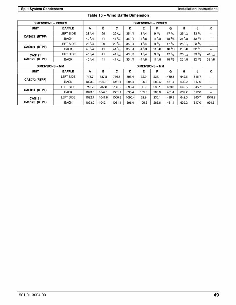
Split System Condensers Installation Instructions
49501 01 3004 00
Table 15 – Wind Baffle Dimension
DIMENSIONS − INCHES DIMENSIONS − INCHES
UNIT BAFFLE A B C D E F G H J K
CAS072 (RTPF)LEFT SIDE 28 1/4 29 29 3/4 35 1/4 1 1/4 9 1/4 17 1/4 25 1/4 33 1/4 −
BACK 40 1/4 41 41 3/4 35 1/4 4 1/8 11 1/8 18 1/8 25 1/8 32 1/8 −
CAS091 (RTPF)LEFT SIDE 28 1/4 29 29 3/4 35 1/4 1 1/4 9 1/4 17 1/4 25 1/4 33 1/4 −
BACK 40 1/4 41 41 3/4 35 1/4 4 1/8 11 1/8 18 1/8 25 1/8 32 1/8 −
CAS121CAS120 (RTPF)
LEFT SIDE 40 1/4 41 41 3/4 43 1/8 1 1/4 9 1/4 17 1/4 25 1/4 33 1/4 41 1/4
BACK 40 1/4 41 41 3/4 35 1/4 4 1/8 11 1/8 18 1/8 25 1/8 32 1/8 39 1/8
DIMENSIONS − MM DIMENSIONS − MM
UNIT BAFFLE A B C D E F G H J K
CAS072 (RTPF)LEFT SIDE 718.7 737.8 756.8 895.4 32.9 236.1 439.3 642.5 845.7 -
BACK 1023.0 1042.1 1061.1 895.4 105.8 283.6 461.4 639.2 817.0 -
CAS091 (RTPF)LEFT SIDE 718.7 737.8 756.8 895.4 32.9 236.1 439.3 642.5 845.7 -
BACK 1023.0 1042.1 1061.1 895.4 105.8 283.6 461.4 639.2 817.0 -
CAS121CAS120 (RTPF)
LEFT SIDE 1022.7 1041.8 1060.8 1095.4 32.9 236.1 439.3 642.5 845.7 1048.9
BACK 1023.0 1042.1 1061.1 895.4 105.8 283.6 461.4 639.2 817.0 994.8

Split System CondensersInstallation Instructions
50 501 01 3004 00
START-UP CHECKLISTI. PRELIMINARY INFORMATION
OUTDOOR: MODEL NO. SERIAL NO.
INDOOR: AIRHANDLER MANUFACTURER
MODEL NO. SERIAL NO.
ADDITIONAL ACCESSORIES
II. PRE-START-UPOUTDOOR UNITIS THERE ANY SHIPPING DAMAGE? (Y/N)
IF SO, WHERE:
WILL THIS DAMAGE PREVENT UNIT START-UP? (Y/N)
CHECK POWER SUPPLY. DOES IT AGREE WITH UNIT? (Y/N)
HAS THE GROUND WIRE BEEN CONNECTED? (Y/N)
HAS THE CIRCUIT PROTECTION BEEN SIZED AND INSTALLED PROPERLY? (Y/N)
ARE THE POWER WIRES TO THE UNIT SIZED AND INSTALLED PROPERLY? (Y/N)
CONTROLSARE THERMOSTAT AND INDOOR FAN CONTROL WIRING CONNECTIONS MADE AND CHECKED?
(Y/N)
ARE ALL WIRING TERMINALS (including main power supply) TIGHT? (Y/N)
HAS CRANKCASE HEATER BEEN ENERGIZED FOR 24 HOURS? (Y/N)
INDOOR UNITHAS WATER BEEN PLACED IN DRAIN PAN TO CONFIRM PROPER DRAINAGE? (Y/N)
ARE PROPER AIR FILTERS IN PLACE? (Y/N)
HAVE FAN AND MOTOR PULLEYS BEEN CHECKED FOR PROPER ALIGNMENT? (Y/N)
DO THE FAN BELTS HAVE PROPER TENSION? (Y/N)
HAS CORRECT FAN ROTATION BEEN CONFIRMED? (Y/N)
PIPINGARE LIQUID LINE SOLENOID VALVES LOCATED AT THE INDOOR COILS AS REQUIRED? (Y/N)
HAVE LEAK CHECKS BEEN MADE AT COMPRESSOR, OUTDOOR AND INDOOR COILS,TXVs (Thermostatic Expansion Valves), SOLENOID VALVES, FILTER DRIERS, AND FUSIBLE PLUGSWITH A LEAK DETECTOR? (Y/N)
LOCATE, REPAIR, AND REPORT ANY LEAKS.
HAVE LIQUID LINE SERVICE VALVES BEEN OPENED? (Y/N)
HAVE SUCTION SERVICE VALVES BEEN OPENED? (Y/N)

Split System Condensers Installation Instructions
51501 01 3004 00
CHECK VOLTAGE IMBALANCE
LINE-TO-LINE VOLTS: AB V AC V BC V
(AB + AC + BC)/3 = AVERAGE VOLTAGE = V
MAXIMUM DEVIATION FROM AVERAGE VOLTAGE = V
VOLTAGE IMBALANCE = 100 X (MAX DEVIATION)/(AVERAGE VOLTAGE) =
IF OVER 2% VOLTAGE IMBALANCE, DO NOT ATTEMPT TO START SYSTEM!CALL LOCAL POWER COMPANY FOR ASSISTANCE.
CHECK INDOOR UNIT FAN SPEED AND RECORD.
CHECK OUTDOOR UNIT FAN SPEED AND RECORD.
AFTER AT LEAST 10 MINUTES RUNNING TIME, RECORD THE FOLLOWING MEASUREMENTS:
SUCTION PRESSURE CIR 1: CIR 2:
SUCTION LINE TEMP CIR 1: CIR 2:
LIQUID PRESSURE CIR 1: CIR 2:
LIQUID LINE TEMP CIR 1: CIR 2:
ENTERING OUTDOOR UNIT AIR TEMP
LEAVING OUTDOOR UNIT AIR TEMP
INDOOR UNIT ENTERING-AIR DB (dry bulb) TEMP
INDOOR UNIT ENTERING-AIR WB (wet bulb) TEMP
INDOOR UNIT LEAVING-AIR DB TEMP
INDOOR UNIT LEAVING-AIR WB TEMP
COMPRESSOR 1 AMPS (L1/L2/L3) / /
COMPRESSOR 2 AMPS (L1/L2/L3) / /
NOTES: