Installation Guide (Single-Row Aisle Containment with 2200 ...
253
FusionModule5000 Smart Modular Data Center V100R001 Installation Guide (Single-Row Aisle Containment with 2200 mm High Cabinets, ECC800) Issue 01 Date 2019-03-05 HUAWEI TECHNOLOGIES CO., LTD.
-
Upload
khangminh22 -
Category
Documents
-
view
0 -
download
0
Transcript of Installation Guide (Single-Row Aisle Containment with 2200 ...

FusionModule5000 Smart Modular Data Center V100R001
Installation Guide (Single-Row Aisle Containment with 2200 mm High Cabinets, ECC800)
Issue 01
Date 2019-03-05
HUAWEI TECHNOLOGIES CO., LTD.

Issue 01 (2019-03-05) Huawei Proprietary and Confidential
Copyright © Huawei Technologies Co., Ltd.
i
Copyright © Huawei Technologies Co., Ltd. 2019. All rights reserved.
No part of this document may be reproduced or transmitted in any form or by any means without prior
written consent of Huawei Technologies Co., Ltd.
Trademarks and Permissions
and other Huawei trademarks are trademarks of Huawei Technologies Co., Ltd.
All other trademarks and trade names mentioned in this document are the property of their respective
holders.
Notice
The purchased products, services and features are stipulated by the contract made between Huawei and
the customer. All or part of the products, services and features described in this document may not be
within the purchase scope or the usage scope. Unless otherwise specified in the contract, all statements,
information, and recommendations in this document are provided "AS IS" without warranties, guarantees
or representations of any kind, either express or implied.
The information in this document is subject to change without notice. Every effort has been made in the
preparation of this document to ensure accuracy of the contents, but all statements, information, and
recommendations in this document do not constitute a warranty of any kind, express or implied.
Huawei Technologies Co., Ltd.
Address: Huawei Industrial Base
Bantian, Longgang
Shenzhen 518129
People's Republic of China
Website: http://e.huawei.com

FusionModule5000 Smart Modular Data Center
Installation Guide (Single-Row Aisle Containment with
2200 mm High Cabinets, ECC800) About This Document
Issue 01 (2019-03-05) Huawei Proprietary and Confidential
Copyright © Huawei Technologies Co., Ltd.
ii
About This Document
Purpose This document describes how to install the smart modular data center (smart module for
short) in the single-row aisle containment scenario.
Intended Audience This document is intended for:
Hardware installation engineers
Commissioning engineers
Maintenance engineers
Technical support engineers
Symbol Conventions The symbols that may be found in this document are defined as follows.
Symbol Description
Indicates an imminently hazardous situation which, if
not avoided, will result in death or serious injury.
Indicates a potentially hazardous situation which, if not
avoided, could result in death or serious injury.
Indicates a potentially hazardous situation which, if not
avoided, may result in minor or moderate injury.
Indicates a potentially hazardous situation which, if not
avoided, could result in equipment damage, data loss,
performance deterioration, or unanticipated results.
NOTICE is used to address practices not related to
personal injury.
Calls attention to important information, best practices
and tips.
NOTE is used to address information not related to
personal injury, equipment damage, and environment

FusionModule5000 Smart Modular Data Center
Installation Guide (Single-Row Aisle Containment with
2200 mm High Cabinets, ECC800) About This Document
Issue 01 (2019-03-05) Huawei Proprietary and Confidential
Copyright © Huawei Technologies Co., Ltd.
iii
Symbol Description
deterioration.
Change History
Changes between document issues are cumulative. The latest document issue contains all
updates made in previous issues.
Issue 01 (2019-03-05)
This issue is the first official release.

FusionModule5000 Smart Modular Data Center
Installation Guide (Single-Row Aisle Containment with
2200 mm High Cabinets, ECC800) Contents
Issue 01 (2019-03-05) Huawei Proprietary and Confidential
Copyright © Huawei Technologies Co., Ltd.
iv
Contents
About This Document ............................................................................................................ ii
1 Installation Preparations....................................................................................................... 1
1.1 Transportation and Placing Precautions .............................................................................................................................. 1
1.2 Unpacking and Acceptance .................................................................................................................................................. 2
1.3 Installation Environment Requirements .............................................................................................................................. 3
1.4 Site Requirements (Power Supply and Distribution Cabinet) ........................................................................................... 5
1.5 Site Requirements (New Main Way) ................................................................................................................................... 7
1.6 Documents ............................................................................................................................................................................. 9
1.7 Tools and Instruments ......................................................................................................................................................... 10
1.8 Tools Delivered with Equipment ....................................................................................................................................... 14
1.9 Personnel Requirements ..................................................................................................................................................... 16
1.10 Installation Process ........................................................................................................................................................... 16
2 Scenario Description (Power Supply and Distribution Cabinet) ................................... 18
3 Scenario Description (New Main Way) ............................................................................. 20
4 Hardware Installation Preparations................................................................................... 22
4.1 (Optional) Installing Bases ................................................................................................................................................. 22
4.1.1 Installing Adjustable Bases ............................................................................................................................................. 22
4.1.1.1 Base Specifications ....................................................................................................................................................... 22
4.1.1.2 Precautions for Installing the Base .............................................................................................................................. 22
4.1.1.3 (Optional) Installing the Support for a Cabinet .......................................................................................................... 23
4.1.1.3.1 Assembling a Base..................................................................................................................................................... 23
4.1.1.3.2 Positioning Bases....................................................................................................................................................... 25
4.1.1.3.3 Securing Bases ........................................................................................................................................................... 27
4.1.2 Installing Fixed-Size Bases ............................................................................................................................................. 29
4.1.2.1 Deploying a 300 mm Wide Air Conditioner Base ...................................................................................................... 29
4.1.2.2 Deploying Bases for a 600 mm wide IT Cabinet/Battery Cabinet/Network Cabinet .............................................. 31
4.1.2.3 Deploying the 600 mm Wide PDC Base ..................................................................................................................... 32
4.1.2.4 Deploying 800 mm Wide Fixed Bases ........................................................................................................................ 34
4.1.2.5 Securing Bases .............................................................................................................................................................. 35
4.2 Preparing for Installing Air Conditioners .......................................................................................................................... 37
4.2.1 Material Preparations....................................................................................................................................................... 37

FusionModule5000 Smart Modular Data Center
Installation Guide (Single-Row Aisle Containment with
2200 mm High Cabinets, ECC800) Contents
Issue 01 (2019-03-05) Huawei Proprietary and Confidential
Copyright © Huawei Technologies Co., Ltd.
v
4.2.2 Checking the Air Pressure ............................................................................................................................................... 44
4.2.3 Installing Water Pipe Adapters ........................................................................................................................................ 46
4.2.4 Removing Transportation Fasteners for the Air Conditioner ........................................................................................ 48
4.3 Removing Pallets ................................................................................................................................................................ 49
4.3.1 Removing the PDC Pallet ............................................................................................................................................... 50
4.3.2 Removing the IT Cabinet Pallet...................................................................................................................................... 52
4.3.3 Removing the Air Conditioner Pallet ............................................................................................................................. 52
4.4 Adjusting the Baffle Plate for the Air Conditioner ........................................................................................................... 54
4.5 (Optional) Adjusting IT Cabinet Side Plates ..................................................................................................................... 55
4.6 (Optional) Adjusting Battery Cabinet Side Plates ............................................................................................................ 56
4.7 (Optional) Installing the PDC Tail Frame ......................................................................................................................... 57
4.8 Routing Air Conditioner Pipes ........................................................................................................................................... 61
5 Installing the Cabinet.......................................................................................................... 63
5.1 Installing Cabinets (with Bases) ........................................................................................................................................ 63
5.2 Positioning Cabinets (Without Bases) ............................................................................................................................... 66
5.3 Installing Cabinets (Without Bases) .................................................................................................................................. 67
5.4 Installing Cabinet Accessories ........................................................................................................................................... 71
5.4.1 Installing the Top Frame.................................................................................................................................................. 71
5.4.1.1 Installing a 600 mm Wide Top Frame ......................................................................................................................... 71
5.4.1.2 Installing a 300 mm Wide Top Frame ......................................................................................................................... 72
5.4.1.2.1 Installing a Top Frame for the 300 mm Wide Air Conditioner (Bottom Pipe Routing) ....................................... 72
5.4.1.2.2 Installing a Top Frame for the 300 mm Wide Air Conditioner (Overhead Pipe Routing) .................................... 73
5.4.1.2.3 Installing a Top Frame for the 300 mm Wide Air Conditioner Adaptive Frame ................................................... 75
5.4.2 (Optional) Taking Out PDU2000 Cables and Industrial Connectors ........................................................................... 75
5.4.3 (Optional) Installing Branch Ground Copper Bars........................................................................................................ 77
5.4.4 (Optional) Installing the Vertical Ground Bar................................................................................................................ 78
5.4.5 (Optional) Setting a Mechanical Coded Lock ............................................................................................................... 79
6 Installing the Contained Aisles.......................................................................................... 82
6.1 Installing Sealing Plates ..................................................................................................................................................... 82
6.2 Installing Skylights ............................................................................................................................................................. 84
6.2.1 Skylight Overview ........................................................................................................................................................... 84
6.2.1.1 600 mm Wide Control Skylight ................................................................................................................................... 84
6.2.1.2 800 mm Wide Control Skylight ................................................................................................................................... 85
6.2.1.3 600 mm Wide Flat or Rotating Skylight ..................................................................................................................... 85
6.2.1.4 800 mm Wide Flat or Rotating Skylight ..................................................................................................................... 86
6.2.1.5 300 mm Wide Flat Skylight ......................................................................................................................................... 87
6.2.2 Securing Skylights ........................................................................................................................................................... 88
6.2.3 Installing a Rotating Skylight Magnetic Lock ............................................................................................................... 90
6.3 Installing End Doors ........................................................................................................................................................... 91
6.3.1 Installing a Cabinet Lower Mounting Kit ...................................................................................................................... 92
6.3.2 Installing a Revolving Door ............................................................................................................................................ 94

FusionModule5000 Smart Modular Data Center
Installation Guide (Single-Row Aisle Containment with
2200 mm High Cabinets, ECC800) Contents
Issue 01 (2019-03-05) Huawei Proprietary and Confidential
Copyright © Huawei Technologies Co., Ltd.
vi
6.4 Attaching Cabinet Labels .................................................................................................................................................101
6.5 (Optional) Installing Aisle Lights ....................................................................................................................................103
7 (Optional) Installing the New Main Way ....................................................................... 106
8 (Optional) Installing Cable Troughs ............................................................................... 107
8.1 Installing a 600 mm Wide Cable Trough.........................................................................................................................107
8.2 Installing a 300 mm Wide Cable Trough......................................................................................................................... 111
8.3 Installing an 800 mm Wide Cable Trough ...................................................................................................................... 113
8.4 Installing End Panels for Cable Troughs ......................................................................................................................... 113
9 Installing Monitoring Devices ......................................................................................... 115
9.1 Device Layout in the Network Cabinet ........................................................................................................................... 115
9.2 (Optional) Installing a Server ........................................................................................................................................... 116
9.3 (Optional) Installing a VCN500....................................................................................................................................... 118
9.4 (Optional) Installing a LAN Switch ................................................................................................................................ 119
9.5 Installing an ECC800........................................................................................................................................................121
9.6 (Optional) Installing a Rack Environment Unit ..............................................................................................................123
9.7 Installing Monitoring Components on a Control Skylight .............................................................................................124
9.7.1 Installing a Camera ........................................................................................................................................................125
9.7.2 (Optional) Installing a Smoke Detector........................................................................................................................129
9.7.3 (Optional) Installing the Multi-Functional Sensor ......................................................................................................129
9.8 (Optional) Installing Monitoring Components on the End Door ...................................................................................130
9.8.1 Monitoring Component Layout for the Revolving Door ............................................................................................130
9.8.2 Installing an Actuator or Converter ..............................................................................................................................131
9.8.3 Installing an Alarm Beacon ...........................................................................................................................................134
9.8.4 (Optional) Installing a Revolving Door Magnetic Lock .............................................................................................135
9.8.5 Installing Buttons ...........................................................................................................................................................140
9.8.6 Installing the Pad Mounting Kit....................................................................................................................................141
9.8.6.1 Installing a Fingerprint and Card Reader ..................................................................................................................142
9.8.6.2 Installing a Fingerprint and Card Reader with a Keypad.........................................................................................143
9.8.6.3 Installing a Card Reader with a Keypad ...................................................................................................................144
9.8.6.4 Installing an IC Card Reader......................................................................................................................................145
9.8.6.5 Installing a Pad Power Connector .............................................................................................................................147
9.8.6.6 Installing a Pad ...........................................................................................................................................................150
9.8.6.7 Securing the Pad Mounting Kit .................................................................................................................................151
9.9 (Optional) Installing a Smart ETH Gateway...................................................................................................................154
9.10 Installing Temperature Sensors ......................................................................................................................................157
9.11 Rules for Deploying T/H Sensors ..................................................................................................................................158
9.12 Installing a T/H Sensor ...................................................................................................................................................160
9.13 Installing a WLDS900 Water Sensor (Used in Intelligent Micro-Modular) ...............................................................162
9.13.1 Connecting a Cable to the WLDS900 Water Detector ..............................................................................................162
9.13.2 Laying Out the Water Detection Cable (Top Pipe Routing) .....................................................................................164
9.13.3 Laying Out the Water Detection Cable (Bottom Pipe Routing) ...............................................................................166

FusionModule5000 Smart Modular Data Center
Installation Guide (Single-Row Aisle Containment with
2200 mm High Cabinets, ECC800) Contents
Issue 01 (2019-03-05) Huawei Proprietary and Confidential
Copyright © Huawei Technologies Co., Ltd.
vii
10 (Optional) Installing In-Room Cable Trays .................................................................. 169
11 Installing Cabinet Sealing Plates ................................................................................... 170
12 Cable Routing .................................................................................................................. 172
12.1 System Cabling Rules.....................................................................................................................................................172
12.2 Cable Routes for the Single-Row Aisle Containment Scenario (Power Supply and Distribution Cabinet) .............177
12.3 Cable Routes for the Single-Row Aisle Containment Scenario (New Main Way) ....................................................178
12.4 Cable Routing for Cabinet Door Monitoring Components ..........................................................................................180
12.5 Cable Routing for the Network Cabinet ........................................................................................................................181
12.6 Cable Routes for Revolving Door Monitoring Components .......................................................................................181
12.7 Cable Routes for the Aisle Lighting System .................................................................................................................182
12.8 Installing an SMS Modem .............................................................................................................................................184
12.9 Connecting the Ground Cables for the Smart Module .................................................................................................186
12.9.1 Grounding Cabinets .....................................................................................................................................................186
12.9.2 (Optional) Connecting Base Ground Cables..............................................................................................................188
12.10 Cable Installation for the Power Supply and Distribution System ............................................................................190
12.10.1 Connecting Battery Cables .......................................................................................................................................190
12.10.2 Connecting Cables to Power Supply and Distribution Devices .............................................................................195
12.11 Connecting Cables for the Cooling System ................................................................................................................196
12.12 Connecting Cables for the Management System ........................................................................................................196
13 Installation Verification .................................................................................................. 197
14 Power-On Commissioning ............................................................................................. 198
14.1 Power-On Commissioning Process ...............................................................................................................................198
14.2 Commissioning the Power Supply and Distribution System (Power Supply and Distribution Cabinet) .................198
14.3 Commissioning the Power Supply and Distribution System (New Main Way) .........................................................199
14.4 Commissioning the Cooling System .............................................................................................................................199
14.5 Commissioning the Management System (Power Supply and Distribution Cabinet) ...............................................200
14.6 Commissioning the Management System (New Main Way) .......................................................................................201
A Appendix ........................................................................................................................... 202
A.1 Contacting Huawei Technical Support (Carrier)............................................................................................................202
A.2 Installing Expansion Sleeves...........................................................................................................................................202
A.3 Installing a Floating Nut ..................................................................................................................................................203
A.4 Preparing a Monitoring Cable .........................................................................................................................................204
A.5 Scenario with a Column (600 mm Wide IT Cabinets Scenario) ...................................................................................206
A.5.1 Scenario Description.....................................................................................................................................................206
A.5.2 Installation Process for Scenarios with Columns .......................................................................................................213
A.5.3 Installing a Cabinet Bottom Sealing Plate...................................................................................................................213
A.5.4 Installing Sealing Plates Near the Aisle ......................................................................................................................214
A.5.5 Installing the Adjustable Skylight ................................................................................................................................216
A.5.5.1 Installing the Skylight Connective Plate ..................................................................................................................217
A.5.5.2 Installing the Telescopic Edges .................................................................................................................................217

FusionModule5000 Smart Modular Data Center
Installation Guide (Single-Row Aisle Containment with
2200 mm High Cabinets, ECC800) Contents
Issue 01 (2019-03-05) Huawei Proprietary and Confidential
Copyright © Huawei Technologies Co., Ltd.
viii
A.5.5.3 Installing an Adjustable Skylight Side Sealing Plate ..............................................................................................219
A.5.5.4 Installing the PC Plate Support and PC Plate ..........................................................................................................221
A.5.6 Installing Cable Trays ...................................................................................................................................................224
A.5.7 Installing a Sealing Plates away the Aisle ...................................................................................................................227
A.6 (Optional) Connecting Cables to Industrial Connectors ...............................................................................................228
A.7 (Optional) Connecting PDU2000 Cables .......................................................................................................................229
A.8 Cable Routes Inside an IT Cabinet .................................................................................................................................233
A.9 (Optional) Connecting the Linkage Cables Between the Fire Extinguishing System and Access Actuator ..............237
B Common Screw Torques .................................................................................................. 238
C Installation Verification ................................................................................................... 240
D Acronyms and Abbreviation ........................................................................................... 243

FusionModule5000 Smart Modular Data Center
Installation Guide (Single-Row Aisle Containment with
2200 mm High Cabinets, ECC800) 1 Installation Preparations
Issue 01 (2019-03-05) Huawei Proprietary and Confidential
Copyright © Huawei Technologies Co., Ltd.
1
1 Installation Preparations
1.1 Transportation and Placing Precautions
Air Conditioner Transportation Precautions Only trained personnel are allowed to move the cabinet. Use a pallet truck to transport
the cabinet secured to a wooden support to the installation position. Insert the forks of
the pallet truck in the middle position to ensure balance.
Choose railways, sea, or a road with good condition during transportation. No excessive
tilt or jolt is allowed during the transportation, and the maximum tolerance of the tilting
angle during loading and unloading is 15°, as shown in Figure 1-1.
To prevent the cabinet from falling over, secure it to a pallet truck using ropes before
moving it.
To prevent shocks or falls, move the cabinet gently.
Move the equipment close to the installation site before unpacking. Unpack the
equipment with caution to avoid scratching or bumping. Take down the equipment from
the pallet only immediately before installation.
Figure 1-1 Transportation gradient
FusionModule5000 Smart Modular Data Center
Installation Guide (Single-Row Aisle Containment with
2200 mm High Cabinets, ECC800) 1 Installation Preparations
Issue 01 (2019-03-05) Huawei Proprietary and Confidential
Copyright © Huawei Technologies Co., Ltd.
2
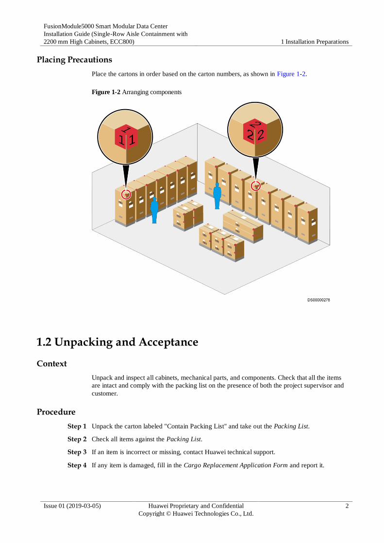
Placing Precautions
Place the cartons in order based on the carton numbers, as shown in Figure 1-2.
Figure 1-2 Arranging components
1.2 Unpacking and Acceptance
Context
Unpack and inspect all cabinets, mechanical parts, and components. Check that all the items
are intact and comply with the packing list on the presence of both the project supervisor and
customer.
Procedure
Step 1 Unpack the carton labeled "Contain Packing List" and take out the Packing List.
Step 2 Check all items against the Packing List.
Step 3 If an item is incorrect or missing, contact Huawei technical support.
Step 4 If any item is damaged, fill in the Cargo Replacement Application Form and report it.

FusionModule5000 Smart Modular Data Center
Installation Guide (Single-Row Aisle Containment with
2200 mm High Cabinets, ECC800) 1 Installation Preparations
Issue 01 (2019-03-05) Huawei Proprietary and Confidential
Copyright © Huawei Technologies Co., Ltd.
3
Step 5 Sign on the Packing List with the customer after verifying that all required items are
delivered.
Step 6 Store the items properly.
----End
Follow-up Procedure
Put the items to be installed immediately onto an ESD surface, such as a polyethylene (PE)
bag or an expandable polyethylene (EPE) foam. Pack the items not to be installed
immediately with their original packing materials. Put them in a dry and cool environment
without exposure to sunlight or electromagnetic radiation.
1.3 Installation Environment Requirements Ensure that the installation environment meets the requirements before installation.
Table 1-1 Installation environment checklist
Check Item Requirement Check Result
Floor bearing
capacity
Standard live load of the equipment
room: 8–12 kN/m2 (If the battery
cabinet is contained in the module,
use the standard live load of the
equipment room as a reference.)
Suspended load of the equipment
room: 1.2 kN/m2
Standard live load of the UPS room:
8–10 kN/m2
Standard live load of the battery
room: 16 kN/m2
Standard live load of the monitoring
center: 6 kN/m2
□ Compliant □
Incompliant
Equipment room net
height
See the field requirements for details. □ Compliant □
Incompliant
Device passage and
door height and
width
Height ≥ 2.2 m and width ≥ 1.2 m (If a
2200 mm high cabinet cannot go
through, tilt the cabinet.)
□ Compliant □
Incompliant
Floor levelness Allowed deviation: 3 mm/2000 mm □ Compliant □
Incompliant
Elevator Elevator bearing capacity > 1.5 t
Inner dimensions: height > 2.4 m or
depth > 2.7 m
□ Compliant □
Incompliant
Cable tray Preinstalled in the equipment room for
signal cables and power cables
□ Compliant □
Incompliant

FusionModule5000 Smart Modular Data Center
Installation Guide (Single-Row Aisle Containment with
2200 mm High Cabinets, ECC800) 1 Installation Preparations
Issue 01 (2019-03-05) Huawei Proprietary and Confidential
Copyright © Huawei Technologies Co., Ltd.
4
Check Item Requirement Check Result
Power supply 380–415 V AC, 3-phase, 50/60 Hz □ Compliant □
Incompliant
Fire extinguishing Indoor gaseous fire extinguisher □ Compliant □
Incompliant
Floor drain DN50 or larger, made of cast iron or
stainless steel
□ Compliant □
Incompliant
Module grounding The equipment room grounding
system must be a TN-S or TN-C-S
system
The equipment room ground grid
must have a ground resistance of 10
ohms at most (If the ground
resistance exceeds 10 ohms, ensure
that the equivalent ground radius of
the ground grid exceeds 5 m.)
Ground bars must be deployed over
the cable tray or under the raised
floor
□ Compliant □
Incompliant
Monitoring port One LAN switch Ethernet port:
connects to the customer subnet to
monitor devices inside the module.
(Optional) Two fire control dry
contacts (access actuator and PDC
fire control terminal): connect to the
fire extinguishing system of the
equipment room for interaction.
SIM card: supports 3G (WCDMA)
communication and is compatible
with 2G (GSM) communication. At
least one SIM card is available.
NOTE
The prerequisite for using a SIM card is that the site has signal coverage.
IP address: At least one IP address
for the ECC collector, the camera,
and the VCN respectively.
NOTE
An IP address is required for each camera.
□ Compliant □
Incompliant
If any of the requirements is not met, contact Huawei technical support.

FusionModule5000 Smart Modular Data Center
Installation Guide (Single-Row Aisle Containment with
2200 mm High Cabinets, ECC800) 1 Installation Preparations
Issue 01 (2019-03-05) Huawei Proprietary and Confidential
Copyright © Huawei Technologies Co., Ltd.
5
1.4 Site Requirements (Power Supply and Distribution Cabinet)
Equipment Room Height Requirement
Figure 1-3 shows the height of a module in single-row aisle containment if 2200 mm high
cabinets are used. The module height reaches the maximum value when skylights are open.
Therefore, the net height requirement for an equipment room is the same regardless of
whether a cable tray is deployed, as shown in Table 1-2.
The clearance for fire extinguishing nozzles is subject to specific fire extinguishing
requirements and is not considered in this section.
Table 1-2 Equipment room net height requirement
Scenario Net Height (Without Base)
2200 mm high cabinet > 2800 mm
When the base is configured, the equipment room net height equals the equipment room net
height (without base) plus the base height.

FusionModule5000 Smart Modular Data Center
Installation Guide (Single-Row Aisle Containment with
2200 mm High Cabinets, ECC800) 1 Installation Preparations
Issue 01 (2019-03-05) Huawei Proprietary and Confidential
Copyright © Huawei Technologies Co., Ltd.
6
Figure 1-3 Smart module height
Cabinet height L1: 2200 mm Open-skylight height L2: 550 mm
Smart module layout requirement
Figure 1-4 shows the layout requirement for the smart module.
Figure 1-4 Smart module layout requirement

FusionModule5000 Smart Modular Data Center
Installation Guide (Single-Row Aisle Containment with
2200 mm High Cabinets, ECC800) 1 Installation Preparations
Issue 01 (2019-03-05) Huawei Proprietary and Confidential
Copyright © Huawei Technologies Co., Ltd.
7
1.5 Site Requirements (New Main Way)
Equipment Room Height Requirement
Figure 1-5 shows the height of a smart module in single-row aisle containment if 2200 mm
high cabinets and the new main way are used.
The clearance for fire extinguishing nozzles is subject to specific fire extinguishing
requirements and is not considered in this section.
Table 1-3 Equipment Room Net Height Requirement (Without Base)
Scenario Equipment room net height
2200 mm high cabinet > 3000 mm
When the base is configured, the equipment room net height equals the equipment room net
height (without base) plus the base height.

FusionModule5000 Smart Modular Data Center
Installation Guide (Single-Row Aisle Containment with
2200 mm High Cabinets, ECC800) 1 Installation Preparations
Issue 01 (2019-03-05) Huawei Proprietary and Confidential
Copyright © Huawei Technologies Co., Ltd.
8
Figure 1-5 Smart module height
Cabinet height L1: 2200 mm First row new main way height L2: 455
mm
Second row new main way height L3: 675
mm
Smart module layout requirement
Figure 1-6 shows the layout requirement for the smart module.

FusionModule5000 Smart Modular Data Center
Installation Guide (Single-Row Aisle Containment with
2200 mm High Cabinets, ECC800) 1 Installation Preparations
Issue 01 (2019-03-05) Huawei Proprietary and Confidential
Copyright © Huawei Technologies Co., Ltd.
9
Figure 1-6 Smart module layout requirement
1.6 Documents Before installation, prepare the following documents in addition to this document.
Table 1-4 Documents for hardware installation
Documentation Purpose Obtaining Method (Remarks)
Onsite engineering layout
drawing
Describes the cabinet
layout.
Provided by the engineering
designer or technical support
engineer.
Quick Reference Guide to
the Smart Modular Data
Center
Smart Module Quick
Installation Guide
describes the unpacking
sequence, installation
procedure, and
installation precautions.
Smart Module
Management System
Wiring Diagram
describes how to route
cables for the
management system.
The document is delivered
with the device, or you can
click Download.
UPS5000-E-(40 kVA–128
kVA) Quick Guide
(Integrated UPS 2.0)
Describes the installation,
cable connection, and
power-on operations for the
integrated UPS.
The document is delivered
with the device, or you can
click Download.
PDU8000 Modular
Precision PDC Quick Guide
Describes the installation,
cable connection, and
The document is delivered
with the device, or you can

FusionModule5000 Smart Modular Data Center
Installation Guide (Single-Row Aisle Containment with
2200 mm High Cabinets, ECC800) 1 Installation Preparations
Issue 01 (2019-03-05) Huawei Proprietary and Confidential
Copyright © Huawei Technologies Co., Ltd.
10
Documentation Purpose Obtaining Method (Remarks)
(1100 mm Deep) power-on operations for the
PDU8000 Precision PDC.
click Download.
NetCol5000-C 30 kW
Chilled Water In-Row
Precision Air Conditioner
Quick Guide (Simplified
Edition)
Describes the installation
and cable connection for
the NetCol5000-C 30 kW
air conditioners.
The document is delivered
with the device, or you can
click Download.
New Main Way Quick
Guide
Describes how to install the
new main ways.
Delivered with new main
way.
Indoor Cable Tray
Installation Guide
Describes how to install the
in-room cable trays.
Click Download.
Smart Module Battery
Wiring Diagram
Provides guidance about
battery arrangement and
cable connections.
Delivered with battery
cables.
iBAT 2.0-CIM01C2 User
Manual
Describes the installation,
cable connection, and
power-on operations for the
CIM and BIM.
Click Download.
ECC800 Data Center
Controller (ECC Version)
User Manual
Describes the overview of
the ECC800 and its ports,
installation, commissioning,
user interfaces,
maintenance, and
troubleshooting.
The ECC version depends on
the version in use. Click
on the ECC800 WebUI to
obtain the ECC version in
use. Click Download.
iManager NetEco Device
Commissioning Guide-
(NetEco Version)
Describes how to connect
monitoring hardware to the
NetEco.
The NetEco version depends
on the version in use. Click
on the NetEco WebUI to
obtain the NetEco version in
use. Click Download.
iManager NetEco Product
Document - (NetEco
Version)
Describes how to install
monitoring hardware and
configure monitoring
software.
The NetEco version depends
on the version in use. Click
on the NetEco WebUI to
obtain the NetEco version in
use. Click Download.
1.7 Tools and Instruments This section lists the tools and instruments required for installation.

FusionModule5000 Smart Modular Data Center
Installation Guide (Single-Row Aisle Containment with
2200 mm High Cabinets, ECC800) 1 Installation Preparations
Issue 01 (2019-03-05) Huawei Proprietary and Confidential
Copyright © Huawei Technologies Co., Ltd.
11
Table 1-5 General tools
Name, Specifications, and Appearance
Protective gloves Marker Measuring tape (5
m)
Level
Step ladder (2 m) Phillips screwdriver
(M4, M6, and M8)
Phillips screwdriver
M4 (length < 100
mm)
Flat-head
screwdriver (2–5
mm)
Adjustable wrench
(6")
Socket wrench
M4/M6/M8/M12
Hex key Box-end wrench
(M6, M8, and M12)
Torque wrench (28
mm)
Solid wrench
(12#/13#/18#)
Cotton cloth Labels
Electric screwdriver Hand drill (Φ3,
Φ3.7, Φ4, Φ4.5, Φ5,
Φ6, Φ10, and Φ12
drill bits)
Hammer drill (Φ16
drill bit)
Heat gun
Laser locator Electrician's knife Impact tool Polyvinyl chloride
(PVC) insulation

FusionModule5000 Smart Modular Data Center
Installation Guide (Single-Row Aisle Containment with
2200 mm High Cabinets, ECC800) 1 Installation Preparations
Issue 01 (2019-03-05) Huawei Proprietary and Confidential
Copyright © Huawei Technologies Co., Ltd.
12
Name, Specifications, and Appearance
tape
Needle-nose pliers Diagonal pliers RJ45 crimping tool Crimping tool
Wire stripper Hydraulic pliers Wire clippers Cable ties
Multimeter Electroprobe Brush Claw hammer
Vacuum cleaner Hacksaw Handsaw Right angle
Heat shrink tubing Network cable tester Rubber mallet Adjustable socket
screwdriver
Flashlight Clamp meter Phase sequence
meter
Utility knife

FusionModule5000 Smart Modular Data Center
Installation Guide (Single-Row Aisle Containment with
2200 mm High Cabinets, ECC800) 1 Installation Preparations
Issue 01 (2019-03-05) Huawei Proprietary and Confidential
Copyright © Huawei Technologies Co., Ltd.
13
Name, Specifications, and Appearance
NOTE
This table may not list some tools required at specific sites. Onsite installation personnel and technical support personnel should prepare tools based on site requirements.
Table 1-6 Transportation and unpacking tools
Tool Appearance, Specifications, and Name
Pallet truck Diesel forklift Lifting rope (bearing
capacity ≥ 400 kg)
Lever (bearing
capacity ≥ 400 kg)
Table 1-7 Air conditioner tools
Tool Appearance, Specifications, and Name
36 mm adjustable
wrench (2 PCS)
Socket wrench
M10/M12
5 mm hex key Open end torque
wrench
Steel brush Hot melt device
(used when the
water pipes are
made of PPR or
aluminum-plastic
material)
Nitrogen cylinder Pressure gauge

FusionModule5000 Smart Modular Data Center
Installation Guide (Single-Row Aisle Containment with
2200 mm High Cabinets, ECC800) 1 Installation Preparations
Issue 01 (2019-03-05) Huawei Proprietary and Confidential
Copyright © Huawei Technologies Co., Ltd.
14
Tool Appearance, Specifications, and Name
Fluorine injection
hose
Reducing valve N/A N/A
N/A N/A
1.8 Tools Delivered with Equipment
Marking-off Template A marking-off template is used for drawing lines to determine an installation position.
There are two types of marking-off templates, which are available in the No. 0 package.
The two types of marking-off templates are used respectively for cabinets that are 1100
mm and 1200 mm deep.
For details about how to use a marking-off template, see Figure 1-9.

FusionModule5000 Smart Modular Data Center
Installation Guide (Single-Row Aisle Containment with
2200 mm High Cabinets, ECC800) 1 Installation Preparations
Issue 01 (2019-03-05) Huawei Proprietary and Confidential
Copyright © Huawei Technologies Co., Ltd.
15
Figure 1-7 Marking-off template for a 1100 mm deep cabinet
Figure 1-8 Marking-off template for a 1200 mm deep cabinet

FusionModule5000 Smart Modular Data Center
Installation Guide (Single-Row Aisle Containment with
2200 mm High Cabinets, ECC800) 1 Installation Preparations
Issue 01 (2019-03-05) Huawei Proprietary and Confidential
Copyright © Huawei Technologies Co., Ltd.
16
Figure 1-9 Usage of marking-off templates
(A) Properly located cabinet (B) Marking-off template edgefold
1.9 Personnel Requirements
Only trained and qualified personnel who fully understand basic safety precautions are
allowed to install and operate a modular data center.
Huawei will not be liable for any consequence caused by the violation of this document.
The requirements are as follows:
Customers' installation personnel must be trained by Huawei and understand how to
install and operate a modular data center.
The number of installation personnel varies depending on the project progress and the
installation environment. Typically, three to five persons are required.
People who need to work at heights must have the required work permit.
1.10 Installation Process Figure 1-10 shows the installation flowchart.

FusionModule5000 Smart Modular Data Center
Installation Guide (Single-Row Aisle Containment with
2200 mm High Cabinets, ECC800) 1 Installation Preparations
Issue 01 (2019-03-05) Huawei Proprietary and Confidential
Copyright © Huawei Technologies Co., Ltd.
17
Figure 1-10 Installation process

FusionModule5000 Smart Modular Data Center
Installation Guide (Single-Row Aisle Containment with
2200 mm High Cabinets, ECC800)
2 Scenario Description (Power Supply and Distribution
Cabinet)
Issue 01 (2019-03-05) Huawei Proprietary and Confidential
Copyright © Huawei Technologies Co., Ltd.
18
2 Scenario Description (Power Supply and Distribution Cabinet)
Figure 2-1 shows the floor plan of the smart module A single-row aisle containment. Figure 2-
2 shows the exterior of the single-row aisle containment of the smart module.
The floor plan and exterior diagrams only indicate the relative positions of components.
For the detailed installation position, see the onsite engineering layout diagram and actual
objects.
The PDC in smart module A is an integrated UPS, with batteries deployed inside the aisle
containment.
The PDC in smart module B is a precision PDC, with batteries and UPS deployed outside
the aisle containment.
The PDC in smart module A (with batteries deployed outside) is an integrated UPS, with
batteries deployed outside the aisle containment.
It is recommended that two air conditioners with the heating and humidification functions
be installed for the standard configuration. In the single-row aisle containment, the two air
conditioners should be placed at both ends of the aisle. If more than two air conditioners
with the heating and humidification functions are to be configured, distribute them evenly
in the aisle depending the actual condition.
To attach labels to the cabinets, name the single-row aisle containment row A, as shown in Figure 2-1.

FusionModule5000 Smart Modular Data Center
Installation Guide (Single-Row Aisle Containment with
2200 mm High Cabinets, ECC800)
2 Scenario Description (Power Supply and Distribution
Cabinet)
Issue 01 (2019-03-05) Huawei Proprietary and Confidential
Copyright © Huawei Technologies Co., Ltd.
19
Figure 2-1 Floor plan of the single-row aisle containment (1.2 m deep IT cabinet)
Figure 2-2 Exterior of the single-row aisle containment
(1) End door (2) Flat or rotating skylight (3) Control skylight
(4) Cable trough (5) Smart ETH gateway (6) Cabinet
(7) For the alarm beacon (8) For the pad (9) For the access control

FusionModule5000 Smart Modular Data Center
Installation Guide (Single-Row Aisle Containment with
2200 mm High Cabinets, ECC800) 3 Scenario Description (New Main Way)
Issue 01 (2019-03-05) Huawei Proprietary and Confidential
Copyright © Huawei Technologies Co., Ltd.
20
3 Scenario Description (New Main Way)
Figure 3-1 shows the floor plan of the smart module A single-row aisle containment. Figure 3-
2 shows the exterior of the single-row aisle containment of the smart module.
The floor plan and exterior diagrams only indicate the relative positions of components.
For the detailed installation position, see the onsite engineering layout diagram and actual
objects.
The PDC in smart module A is an integrated UPS, with batteries deployed inside the aisle
containment.
The PDC in smart module B is a precision PDC, with batteries and UPS deployed outside
the aisle containment.
The PDC in smart module A is an integrated UPS, with batteries deployed outside the aisle
containment.
It is recommended that two air conditioners with the heating and humidification functions
be installed for the standard configuration. In the single-row aisle containment, the two air
conditioners should be placed at both ends of the aisle. If more than two air conditioners
with the heating and humidification functions are to be configured, distribute them evenly
in the aisle depending the actual condition.
To attach labels to the cabinets, name the single-row aisle containment row A, as shown in Figure 3-1.

FusionModule5000 Smart Modular Data Center
Installation Guide (Single-Row Aisle Containment with
2200 mm High Cabinets, ECC800) 3 Scenario Description (New Main Way)
Issue 01 (2019-03-05) Huawei Proprietary and Confidential
Copyright © Huawei Technologies Co., Ltd.
21
Figure 3-1 Floor plan of the single-row aisle containment (1.2 m deep IT cabinet)
Figure 3-2 Exterior of the single-row aisle containment
(1) General input unit (2) Control skylight (3) For the alarm beacon
(4) Power distribution unit (5) Busbar trunking unit (6) Flat or rotating skylight
(7) Cable trough (8) Cabinet (9) For the pad
(10) For the access control (11) End door

FusionModule5000 Smart Modular Data Center
Installation Guide (Single-Row Aisle Containment with
2200 mm High Cabinets, ECC800) 4 Hardware Installation Preparations
Issue 01 (2019-03-05) Huawei Proprietary and Confidential
Copyright © Huawei Technologies Co., Ltd.
22
4 Hardware Installation Preparations
4.1 (Optional) Installing Bases If you do not use the bases provided by Huawei, choose bases of appropriate specifications
for various cabinets to ensure the matching between bases and cabinets. For detailed
dimensions requirements for bases, click Download.
If you do not use the bases provided by Huawei, design the bearing requirements for bases
according to the service plan.
4.1.1 Installing Adjustable Bases
4.1.1.1 Base Specifications
If you do not use the bases provided by Huawei, choose bases of appropriate specifications
for various cabinets to ensure the matching between bases and cabinets. For details about the
base dimensions, click Download.
4.1.1.2 Precautions for Installing the Base
The bearing capacity of each base is 2 tons or more.
Assume that each row of cabinets is configured with N bases:
− If N is less than 5, you can install all the bases at a time. After installation, check
that the total length of each row of bases is the sum of nominal widths of all bases
(tolerance –3 mm to 0 mm).
− When N is greater than or equal to 5, you are advised to install five bases at a time.
After installation, check that the total length of each row of bases is the sum of
nominal widths of all bases (tolerance –3 mm to 0 mm). After installing five bases,
check whether the total length of the five bases and the difference between their
diagonal lengths meet the requirements, as shown in Figure 4-1. If the difference
meets the requirements, tighten the bolts and continue to install next five bases. If
the difference does not meet the requirements, adjust the bases to meet the
requirements before tightening the bolts to prevent supports secured in a
parallelogram or trapezoid shape.

FusionModule5000 Smart Modular Data Center
Installation Guide (Single-Row Aisle Containment with
2200 mm High Cabinets, ECC800) 4 Hardware Installation Preparations
Issue 01 (2019-03-05) Huawei Proprietary and Confidential
Copyright © Huawei Technologies Co., Ltd.
23
To ensure accurate locations, you are advised to determine base locations using a laser
locator before installing bases.
|L1–L2| ≤ 5 mm, |L3–L4| ≤ 5 mm
Figure 4-1 Base layout (unit: mm)
4.1.1.3 (Optional) Installing the Support for a Cabinet
4.1.1.3.1 Assembling a Base
Before installing a base, assemble it first.
Procedure
Step 1 Adjust the base height.
1. Measure the distance (H) between the concrete floor and the upper surface of the ESD
floor using a ruler and record the value of H, as shown in Figure 4-2.

FusionModule5000 Smart Modular Data Center
Installation Guide (Single-Row Aisle Containment with
2200 mm High Cabinets, ECC800) 4 Hardware Installation Preparations
Issue 01 (2019-03-05) Huawei Proprietary and Confidential
Copyright © Huawei Technologies Co., Ltd.
24
Figure 4-2 Measuring the floor height
2. Adjust the base height to H based on the measured value, as shown by (1) in Figure 4-3.
3. Partially tighten the height-locking bolts on two sides, as shown by (2) in Figure 4-3.
Figure 4-3 Partially tightening the height-locking bolts
Step 2 Assemble the base, as shown in Figure 4-4.

FusionModule5000 Smart Modular Data Center
Installation Guide (Single-Row Aisle Containment with
2200 mm High Cabinets, ECC800) 4 Hardware Installation Preparations
Issue 01 (2019-03-05) Huawei Proprietary and Confidential
Copyright © Huawei Technologies Co., Ltd.
25
Figure 4-4 Assembling a base
1. Adjust the base depth based on the cabinet depth.
2. Tighten the six M8x20 bolt assemblies on the telescopic rod using a Phillips screwdriver,
as shown by (1) in Figure 4-4.
3. Assemble the telescopic rod and base using eight M8x20 bolt assemblies, and then
tighten all bolt assemblies using a Phillips screwdriver, as shown by (2) in Figure 4-4.
4. Tighten all height locking bolts using a torque wrench, as shown by (3) in Figure 4-4.
----End
4.1.1.3.2 Positioning Bases
Procedure
Step 1 Determine the correct installation position for the smart module based on the onsite
engineering layout diagram.
Step 2 Use a laser locator to mark two lines that are perpendicular to each other in a corner of the
planned installation position.
If no laser locator is available, use a right angle and thin rope for marking the two perpendicular lines.
Step 3 Use a marker to mark the outline of the cabinet on the floor and place one corner of the
outline at the crossing point of the perpendicular lines.

FusionModule5000 Smart Modular Data Center
Installation Guide (Single-Row Aisle Containment with
2200 mm High Cabinets, ECC800) 4 Hardware Installation Preparations
Issue 01 (2019-03-05) Huawei Proprietary and Confidential
Copyright © Huawei Technologies Co., Ltd.
26
Figure 4-5 Using a laser locator for positioning in the one-row cabinet scenario
(1) Cabinet outline (2) Laser locator
(3) Contained aisle
Step 4 Use a right angle to position the end cabinet base, and ensure that the outline of the upper
surface of the base aligns with the cabinet bottom outline on the floor, as shown in Figure 4-6.
Figure 4-6 Positioning the first base
Step 5 Use the end cabinet base as the reference and place other cabinet bases.
Step 6 Partially install the front and rear pallets on the base, as shown by (1) in Figure 4-7.

FusionModule5000 Smart Modular Data Center
Installation Guide (Single-Row Aisle Containment with
2200 mm High Cabinets, ECC800) 4 Hardware Installation Preparations
Issue 01 (2019-03-05) Huawei Proprietary and Confidential
Copyright © Huawei Technologies Co., Ltd.
27
Figure 4-7 Positioning combined bases
Step 7 Check that L1, L2, L3, and L4 meet the following requirements: |L1–L2| ≤ 5 mm and |L3–L4|
≤ 5 mm, as shown in Figure 4-8.
Figure 4-8 Base layout (unit: mm)
Step 8 Use a marker to mark the hole positions, as shown by (2) in Figure 4-7.
----End
4.1.1.3.3 Securing Bases
Prerequisites
The positions for installing bases have been determined.

FusionModule5000 Smart Modular Data Center
Installation Guide (Single-Row Aisle Containment with
2200 mm High Cabinets, ECC800) 4 Hardware Installation Preparations
Issue 01 (2019-03-05) Huawei Proprietary and Confidential
Copyright © Huawei Technologies Co., Ltd.
28
Procedure
Step 1 Move away the base and install expansion bolts, as shown in Figure 4-9.
Figure 4-9 Installing an expansion bolt (unit: mm)
Step 2 Measure the hole depths and distances. If any deviation is found, mark the positions again and
drill new holes.
Step 3 Deploy the base again, adjust the base position, and partially tighten the expansion bolts.
Step 4 Measure the levelness of the base using a level, as shown by (1) in Figure 4-10.
Step 5 If the base is not level, put spacers under it, as shown by (2) in Figure 4-10.
Step 6 Tighten the four expansion bolts using a torque wrench, as shown by (3) in Figure 4-10.
Figure 4-10 Leveling the fixed base
Step 7 Secure other bases in the same way.
Step 8 After securing bases, connect bases using connecting plates, as shown by (1) in Figure 4-11,
and secure the screws to the floor holders on the bases, as shown by (2) in Figure 4-11.

FusionModule5000 Smart Modular Data Center
Installation Guide (Single-Row Aisle Containment with
2200 mm High Cabinets, ECC800) 4 Hardware Installation Preparations
Issue 01 (2019-03-05) Huawei Proprietary and Confidential
Copyright © Huawei Technologies Co., Ltd.
29
Figure 4-11 Connecting bases
----End
Result
After securing bases, ensure that adjacent bases are in close contact with each other and the
gap is even.
4.1.2 Installing Fixed-Size Bases
4.1.2.1 Deploying a 300 mm Wide Air Conditioner Base
Context
A 300 mm wide fixed base adapts to a 300 mm wide air conditioner. The BOM number for a
300 mm wide fixed base is 21152146.
Figure 4-12 shows a 300 mm wide fixed base.

FusionModule5000 Smart Modular Data Center
Installation Guide (Single-Row Aisle Containment with
2200 mm High Cabinets, ECC800) 4 Hardware Installation Preparations
Issue 01 (2019-03-05) Huawei Proprietary and Confidential
Copyright © Huawei Technologies Co., Ltd.
30
When deploying the base, place the side marked FRONT facing upwards.
After deploying the base, check that the adjustable feet for the base should be installed at
the front door of the air conditioner.
Figure 4-12 300 mm wide fixed base
Procedure
Step 1 Adjust the adjustable feet for the base.
1. Remove the four M6 screws from the support to split the adjustable feet from the base,
as shown in Figure 4-13 and set aside the screws.
Figure 4-13 Removing adjustable feet
2. Move the adjustable feet to the mounting holes on the base according to the depth of the
air conditioner.

FusionModule5000 Smart Modular Data Center
Installation Guide (Single-Row Aisle Containment with
2200 mm High Cabinets, ECC800) 4 Hardware Installation Preparations
Issue 01 (2019-03-05) Huawei Proprietary and Confidential
Copyright © Huawei Technologies Co., Ltd.
31
3. Secure the adjustable feet to the base using the four M6 screws removed before, as
shown in Figure 4-14.
Figure 4-14 Reinstalling adjustable feet
4. Deploy the adjustable base on the concrete floor based on the site engineering layout
diagram.
----End
4.1.2.2 Deploying Bases for a 600 mm wide IT Cabinet/Battery Cabinet/Network Cabinet
The 600 mm wide fixed bases are used for the 600 mm wide IT cabinet, network cabinet, and
battery cabinet. The BOM number is 21151123.
Figure 4-15 shows a 600 mm wide fixed base. Deploy 600 mm wide fixed bases on the
concrete floor according to the installation layout.
When deploying the base, place the side marked FRONT facing upwards.

FusionModule5000 Smart Modular Data Center
Installation Guide (Single-Row Aisle Containment with
2200 mm High Cabinets, ECC800) 4 Hardware Installation Preparations
Issue 01 (2019-03-05) Huawei Proprietary and Confidential
Copyright © Huawei Technologies Co., Ltd.
32
Figure 4-15 600 mm wide fixed base
4.1.2.3 Deploying the 600 mm Wide PDC Base
Context
Figure 4-16 shows a 600 mm wide adjustable base.
Figure 4-16 600 mm wide adjustable base (used for a PDC)

FusionModule5000 Smart Modular Data Center
Installation Guide (Single-Row Aisle Containment with
2200 mm High Cabinets, ECC800) 4 Hardware Installation Preparations
Issue 01 (2019-03-05) Huawei Proprietary and Confidential
Copyright © Huawei Technologies Co., Ltd.
33
When deploying the base, place the side marked FRONT facing upwards.
Move the adjustable feet of the PDC base to the cabinet rear (close to the rear door of the
cabinet).
This section takes adjusting the adjustable legs of the PDC in hot aisle containment as an
example to illustrate how to adjust adjustable legs.
Procedure
Step 1 Remove the four M6 screws from the support to split the adjustable feet from the base, as
shown in Figure 4-17.
Figure 4-17 Removing adjustable feet
Step 2 Move the adjustable legs to the 1100 mm silkscreen at the FRONT end.
Step 3 Secure the adjustable feet to the base using the four M6 screws removed in Step 1, as shown
in Figure 4-18.

FusionModule5000 Smart Modular Data Center
Installation Guide (Single-Row Aisle Containment with
2200 mm High Cabinets, ECC800) 4 Hardware Installation Preparations
Issue 01 (2019-03-05) Huawei Proprietary and Confidential
Copyright © Huawei Technologies Co., Ltd.
34
Figure 4-18 Reinstalling the adjustable feet
Step 4 Deploy the adjusted 600 mm wide base on the concrete floor based on the installation layout.
Step 5 Deploy other 600 mm wide adjustable bases in the same way.
----End
4.1.2.4 Deploying 800 mm Wide Fixed Bases
The 800 mm wide fixed bases are used for 800 mm wide IT cabinets and network cabinets.
The BOM number is 21151125.
Figure 4-19 shows an 800 mm wide fixed base. Deploy 800 mm wide fixed bases on the
concrete floor according to the installation layout.
When deploying the base, place the side marked FRONT facing upwards.

FusionModule5000 Smart Modular Data Center
Installation Guide (Single-Row Aisle Containment with
2200 mm High Cabinets, ECC800) 4 Hardware Installation Preparations
Issue 01 (2019-03-05) Huawei Proprietary and Confidential
Copyright © Huawei Technologies Co., Ltd.
35
Figure 4-19 800 mm wide fixed base
4.1.2.5 Securing Bases
Prerequisites
Cabinet bases are placed on a concrete floor as planned.
Context
Table 4-1 describes how to secure bases.
Table 4-1 Securing bases
Support Securing Method
600 mm wide fixed base Drill holes at positions for installing the four
supports of the base, and secure the base to
the concrete floor using four expansion
bolts.
800 mm wide fixed base
300 mm wide fixed base Drill holes at positions for installing the six
supports of the base, and secure the base to
the concrete floor using six expansion bolts. 600 mm adjustable base
Procedure
Step 1 (Optional) If the ground is not flat, place a washer (0.5 mm, 1.0 mm, or 2.0 mm high) under
the base.
Step 2 Mark holes for installing expansion bolts on the concrete floor by using a marker.
Step 3 Remove the base, and drill holes in the marks by using a hammer drill with a Ф16 drill bit.
The hole depth must range from 52 mm to 60 mm.
Step 4 Use a vacuum cleaner to clean up dust in or around the holes, as shown in Figure 4-20.

FusionModule5000 Smart Modular Data Center
Installation Guide (Single-Row Aisle Containment with
2200 mm High Cabinets, ECC800) 4 Hardware Installation Preparations
Issue 01 (2019-03-05) Huawei Proprietary and Confidential
Copyright © Huawei Technologies Co., Ltd.
36
Figure 4-20 Drilling a hole (unit: mm)
Step 5 Measure the hole depths and distances. If any deviation is found, drill new holes.
Step 6 Installing an expansion bolt, as shown in Figure 4-21.
1. Vertically insert an expansion bolt into a hole, and drive the expansion bolt completely
into the hole using a rubber mallet.
2. Rotate the expansion bolt clockwise using a wrench until the expansion sleeve fully
expands.
3. Rotate the expansion bolt counterclockwise to remove it together with the spring washer
and flat washer.
Figure 4-21 Installing an expansion bolt
Step 7 Move the base back to the position so that expansion bolts are inserted into mounting holes on
supports. Secure the base to the concrete floor using expansion bolts obtained in Step 6.3, as
shown in Figure 4-22.

FusionModule5000 Smart Modular Data Center
Installation Guide (Single-Row Aisle Containment with
2200 mm High Cabinets, ECC800) 4 Hardware Installation Preparations
Issue 01 (2019-03-05) Huawei Proprietary and Confidential
Copyright © Huawei Technologies Co., Ltd.
37
Figure 4-22 Tightening expansion bolts
Step 8 Secure the base to the adjacent bases using two M8 screws and nuts, as shown in Figure 4-23.
Figure 4-23 Connecting the base to the adjacent bases
Step 9 Follow the preceding steps to install other bases.
----End
4.2 Preparing for Installing Air Conditioners
4.2.1 Material Preparations
Materials are classified to Huawei-provided, self-purchased, and onsite prepared materials,
which are marked as mandatory, optional, and engineering purchasing in this document.
Mandatory: materials that are provided by Huawei and can be obtained from delivered
fittings

FusionModule5000 Smart Modular Data Center
Installation Guide (Single-Row Aisle Containment with
2200 mm High Cabinets, ECC800) 4 Hardware Installation Preparations
Issue 01 (2019-03-05) Huawei Proprietary and Confidential
Copyright © Huawei Technologies Co., Ltd.
38
Optional: materials that can be purchased from Huawei or by yourself.
Engineering purchasing: materials that are not provided by Huawei and need to be
prepared by the customer.
Prepare the pipes and pipe fastenings listed in Table 4-2.
Table 4-2 Pipe requirements
Category Name Specifications Remarks
Pipe Branch
chilled water
supply and
return pipes
Recommended pipe when the
NetCol520 is connected: rubber
hose DN25
Recommended pipe when the
NetCol520 is not connected:
rubber hose DN25, galvanized
steel pipe DN25, PPR pipe
DN32 (inner diameter ≥ 25 mm)
Engineering
purchasing
Humidifier
water inlet
pipe
Connects to the hose: pagoda
connector, rubber hose, and hose
clamp
Connects to the rigid pipe:
connector, PPR pipe, or
galvanized pipe
Engineering
purchasing
Condensate
water pump
drainpipe
DN4 (external diameter Φ = 6 mm) Standard
configuration;
delivered with the
product
Automatic
condensate
drainpipe
Rubber hose, rigid PPR, or
aluminum-plastic pipe: DN19
(external diameter Φ = 26 mm)
Engineering
purchasing
Main chilled
water supply
and return
pipes
Flange steel pipe or seamless steel
pipe: DN80
Engineering
purchasing
Pipe
fastening
Pipe support See Figure 4-24 Engineering
purchasing
Thermal
insulation
foam
The thickness of thermal
insulation foam wrapping branch
chilled water supply and return
pipes (DN25): 15–20 mm.
The thickness of thermal
insulation foam wrapping
condensate water pump
drainpipe (DN4): 5 mm.
The thickness of thermal
insulation foam wrapping
automatic condensate drainpipe
(DN19): 10 mm.
Engineering
purchasing

FusionModule5000 Smart Modular Data Center
Installation Guide (Single-Row Aisle Containment with
2200 mm High Cabinets, ECC800) 4 Hardware Installation Preparations
Issue 01 (2019-03-05) Huawei Proprietary and Confidential
Copyright © Huawei Technologies Co., Ltd.
39
Category Name Specifications Remarks
The thickness of thermal
insulation foam wrapping main
chilled water supply and return
pipes (DN80): ≥ 40 mm.
Glue for
wrapping
pipes with
thermal
insulation
foam
Armaflex 820 Engineering
purchasing
Black rubber
adhesive with
thermal
insulation
foam
Recommended thickness > 3 mm Engineering
purchasing
Joint sealant The specifications of the sealant or
seal tape for screw threads are as
follows:
Applicable to all pipe materials
Anaerobic metal pipe thread
sealant with PTEF as the
padding
Glycol solution resistant, fit for
threads and pipes
Maximum gap: 0.5 mm
Pressure resistance: above 3
MPa
Compliant with the industry
standard JB/T7311-2008
Technical Specification for the
Application of Anaerobic Glue in
Engineering Machinery
Engineering
purchasing
Flange and
sealing gasket
DN80 Engineering
purchasing
Butterfly
valve
DN80, pressure resistance: 2.0 MPa
or more
Engineering
purchasing
Copper gate
valve
DN25, each for main chilled water
supply and return pipes, pressure
resistance: 2.0 MPa or more
Engineering
purchasing
Y-shaped
strainer
Recommended: pressure resistance
of 2.0 MPa or more, 20 filtration
pores, installed on the main chilled
water supply pipe
Engineering
purchasing, based on
pipes reserved onsite
Water
pressure
N/A Engineering
purchasing, based on

FusionModule5000 Smart Modular Data Center
Installation Guide (Single-Row Aisle Containment with
2200 mm High Cabinets, ECC800) 4 Hardware Installation Preparations
Issue 01 (2019-03-05) Huawei Proprietary and Confidential
Copyright © Huawei Technologies Co., Ltd.
40
Category Name Specifications Remarks
gauge bend the system solution
Water
pressure
gauge and
thermometer
Precision level: 2.5
Operating environment: –40°C
to +70°C
Temperature influence: ≤
0.4%/10°C (operating
temperature: 20°C±5°C)
Test pressure range: 1.2–2.5
MPa
Engineering
purchasing, based on
the system solution
Figure 4-24 Pipe support (unit: mm)
Height of the U-shaped clamp (H) = Pipe diameter (with thermal insulation foam) – 5 mm.
When the pipe is straight, add a support every 2500 mm. When the direction of the pipe is changed, add a support at the position that is 1000 mm away from the changing point.
The water inlet pipe can be connected for a humidifier in two ways, as shown in Figure 4-25.

FusionModule5000 Smart Modular Data Center
Installation Guide (Single-Row Aisle Containment with
2200 mm High Cabinets, ECC800) 4 Hardware Installation Preparations
Issue 01 (2019-03-05) Huawei Proprietary and Confidential
Copyright © Huawei Technologies Co., Ltd.
41
Figure 4-25 Installing the humidifier water inlet pipe
(1) Reserved port (3/4 inch BSPP)
(2) Rigid pipe connector (BSPT 3/4 inch threads connects to a rigid pipe with external
threads, to be purchased)
(3) Rigid pipe (PPR pipe or galvanized pipe. Inner diameter should match with rigid pipe
connector and at least be 1/2 inch, to be purchased)
(4) Pagoda connector (To be purchased)
(5) Hose clamp (To be purchased)
(6) Rubber hose (Inner diameter should match the pagoda connector and be at least 1/2
inch; made of EPDM or other materials; to be purchased)
Table 4-3 and Figure 4-26 illustrate how to connect water inlet and outlet pipes to reserved
ports in the cabinet.
Table 4-3 Method for connecting water inlet and outlet pipes
Category Required Materials Operation
A in Figure 4-
26
Pagoda connector, clamp Insert the lower part of the water pipe
conversion adapter into the rubber hose and
secure them using a clamp.
B in Figure 4-
26
Conversion adapter Cut the opening of the PPR rigid pipe
evenly, connect the even end to the PPR part
of the conversion adapter, heat-melt the
connection position to weld the conversion
adapter and PPR rigid pipe, and connect the
other end of the conversion adapter to the
reserved port using screw threads.
C in Figure 4-
26
Stainless corrugated hose,
sealing gasket
Select a stainless corrugated hose that is
appropriate for the distance between the
reserved port and steel pipe opening, and
connect the pipe to the steel pipe and

FusionModule5000 Smart Modular Data Center
Installation Guide (Single-Row Aisle Containment with
2200 mm High Cabinets, ECC800) 4 Hardware Installation Preparations
Issue 01 (2019-03-05) Huawei Proprietary and Confidential
Copyright © Huawei Technologies Co., Ltd.
42
Category Required Materials Operation
reserved port using conversion adapters at
both ends.
Figure 4-26 Connecting water inlet and outlet pipes
(1) Reserved port (1 inch, BSPT,
external threaded connector)
(2) Pagoda connector
(DN25, standard
configuration, delivered
with the product)
(3) Clamp (standard
configuration, delivered
with the product)
(4) Rubber hose (DN25
recommended, to be purchased)
(5) Conversion adapter (1
inch, BSPP, the inner
screw thread joint, to be
purchased)
(6) Rigid PPR or
aluminum-plastic pipe
(DN32 recommended, to
be purchased)
(7) Stainless corrugated hose (1
inch, BSPP, internal threaded
connector, DN25 recommended,
length 200 mm recommended, to
be purchased)
(8) Steel pipe (DN25,
recommended, to be
purchased)
Table 4-4 describes the cables specifications.

FusionModule5000 Smart Modular Data Center
Installation Guide (Single-Row Aisle Containment with
2200 mm High Cabinets, ECC800) 4 Hardware Installation Preparations
Issue 01 (2019-03-05) Huawei Proprietary and Confidential
Copyright © Huawei Technologies Co., Ltd.
43
Table 4-4 Required cables and circuit breakers
Name Specifications Quantity
Remarks
Power
cable
NetCol
5000-
C030H
6
NetCol
5000-
C030H
7
without
heating
and
humidif
ication
Power cable, 450 V/750 V,
H07RN-F, 2.5 mm2, black (3-core
cable colors: blue, brown, and
yellow-green)
2 PCS Optional;
same cable
parameters
for the active
and standby
routes
2.5 mm2 cord end terminal 4 PCS Standard
configuratio
n; delivered
with the
product
OT terminal: M4x2.5 mm2 2 PCS Standard
configuratio
n; delivered
with the
product
NetCol500
0-C030H7
with
heating
and
humidificat
ion
Common power cable: power
cable, 300 V/500 V, 3x6.0
mm2, black (3-core cable
colors: blue, brown, and
yellow-green)
Backup power cable: power
cable, 300 V/500 V, 3x2.5
mm2, black (3-core cable
colors: blue, brown, and
yellow-green)
2 PCS Optional
Cord end terminal of the
common power cable: 6.0 mm2
Cord end terminal of the
backup power cable: 2.5 mm2
4 PCS Standard
configuratio
n; delivered
with the
product
OT terminal of the common
power cable: M4x6.0 mm2
OT terminal of the backup
power cable: M4x2.5 mm2
2 PCS Standard
configuratio
n; delivered
with the
product
Remote shutdown cable Power cable, 300 V/500 V,
60227IEC53(RVV), 0.75 mm2,
black (core cables: brown and
blue), 7 A
1 PCS Engineering
purchasing
Bare crimp terminal, single cord-
end terminal, 1 mm2, 5 A, tin
plated, 6 mm insertion depth
2 PCS Standard
configuratio
n; delivered
with the
product

FusionModule5000 Smart Modular Data Center
Installation Guide (Single-Row Aisle Containment with
2200 mm High Cabinets, ECC800) 4 Hardware Installation Preparations
Issue 01 (2019-03-05) Huawei Proprietary and Confidential
Copyright © Huawei Technologies Co., Ltd.
44
Name Specifications Quantity
Remarks
External
circuit
breaker
NetCol
5000-
C030H
6
NetCol
5000-
C030H
7
without
heating
and
humidif
ication
Minimum specifications for the
active and standby routes: AC
circuit breaker, 230/400 V, 10 A,
2P, C feature
1 PCS Engineering
purchasing
NetCol500
0-C030H7
with
heating
and
humidificat
ion
Minimum specifications for the
common power cable: AC circuit
breaker, 230/400 V, 40 A, 2P, C
feature
1 PCS Engineering
purchasing
Minimum specifications for the
backup power cable: AC circuit
breaker, 230/400 V, 10 A, 2P, C
feature
1 PCS Engineering
purchasing
Teamwork networking
and monitoring cable
10 m 1 PCS Standard
configuratio
n; delivered
with the
product
PE cable (outside the
cabinet)
≥ 6 mm2 1 PCS Engineering
purchasing
4.2.2 Checking the Air Pressure
Context
The device has been injected with 0.3–0.5 MPa nitrogen before delivery. Check the air
pressure for Nitrogen leakage.
Procedure
Step 1 Open the rear door.
Step 2 Remove the air filters.
1. Unfasten the eight rotating check plates in the upper and lower positions of the air filters,
as shown in Figure 4-27.

FusionModule5000 Smart Modular Data Center
Installation Guide (Single-Row Aisle Containment with
2200 mm High Cabinets, ECC800) 4 Hardware Installation Preparations
Issue 01 (2019-03-05) Huawei Proprietary and Confidential
Copyright © Huawei Technologies Co., Ltd.
45
Figure 4-27 Removing air filters
2. Pull out the air filters.
Step 3 Take out the desiccant bag in the inner side of the post in the lower right corner of the rear
door.
Step 4 Open the exhaust valve shown in Figure 4-28 and release gas through the hose.
Before opening exhaust value, open the chilled water vale to the maximum scale.
If gas emits, the system is normal. Slowly open the exhaust valve to discharge nitrogen
and close the valve when there is no airflow through the valve.
If no gas emits out of the valve, contact Huawei technical support.

FusionModule5000 Smart Modular Data Center
Installation Guide (Single-Row Aisle Containment with
2200 mm High Cabinets, ECC800) 4 Hardware Installation Preparations
Issue 01 (2019-03-05) Huawei Proprietary and Confidential
Copyright © Huawei Technologies Co., Ltd.
46
Figure 4-28 Checking the air pressure
----End
Follow-up Procedure
Check that thermal insulation foam is in close contact with the pipes, there is no crack in each
cutting position, and the chilled water valve is tightly wrapped by thermal insulation foam.
4.2.3 Installing Water Pipe Adapters
Context
As illustrated in Table 4-3 and Figure 4-26, there are three methods to connect water inlet or
outlet pipes to reserved ports in the cabinet. Accordingly there are three methods to install
water pipe adapters. If the NetCol520 is deployed, use method A shown in Figure 4-26 to
connect water inlet or outlet pipes. If no NetCol520 is deployed, determine the appropriate
connection method based on site requirements.
This section describes how to install a pagoda connector using method A.
Procedure
Step 1 Remove the side panels, as shown by Figure 4-29.

FusionModule5000 Smart Modular Data Center
Installation Guide (Single-Row Aisle Containment with
2200 mm High Cabinets, ECC800) 4 Hardware Installation Preparations
Issue 01 (2019-03-05) Huawei Proprietary and Confidential
Copyright © Huawei Technologies Co., Ltd.
47
Figure 4-29 Removing the side panels
Step 2 Remove the plug and install a pagoda connector.
1. Remove the thermal insulation foam on the plug, as shown by (1) in Figure 4-30.
2. Heat the plug threads for about 10 minutes at a distance of 2 cm using a heat gun to
soften the thread sealant, as shown by (2) in Figure 4-30.
3. Use two adjustable wrenches when removing the plugs. Use one 36 mm wrench to
secure the drain plug and use the other 36 mm wrench to tighten the nut to avoid pipe
deformation. The wrench securing the plug is shown by (3) in Figure 4-30.
4. Remove the sealant residues from the threaded joints using a steel brush. Ensure that the
residues do not fall into the water pan. Clean the threaded connector, as shown by (4) in
Figure 4-30.
5. For internal screw threads, apply thread sealant to the first to third thread circles
counting from the pipe outlet inward. For external threads, apply thread sealant to the
third to second last thread circles counting from the pipe outlet inward. For details, see
(5) in Figure 4-30.
Based on the hardening property of thread sealant, perform leakage test with nitrogen only 8
hours after a conversion adapter is connected.
6. Apply thread sealant to the joints of external screw threads and install pagoda connectors
from inside to outside, as shown by (6) in Figure 4-30.

FusionModule5000 Smart Modular Data Center
Installation Guide (Single-Row Aisle Containment with
2200 mm High Cabinets, ECC800) 4 Hardware Installation Preparations
Issue 01 (2019-03-05) Huawei Proprietary and Confidential
Copyright © Huawei Technologies Co., Ltd.
48
When heating the screw threads, avoid burning the component and labels around.
Figure 4-30 Removing a plug and installing a conversion adapter
Routing pipes from the bottom is used as an example in Figure 4-30, and it is the same as routing pipes from the top.
Step 3 Install the side panels.
----End
4.2.4 Removing Transportation Fasteners for the Air Conditioner
Context
This step applies to the model with 1100 mm depth or 1200 mm depth, and electric heater or
water pump.

FusionModule5000 Smart Modular Data Center
Installation Guide (Single-Row Aisle Containment with
2200 mm High Cabinets, ECC800) 4 Hardware Installation Preparations
Issue 01 (2019-03-05) Huawei Proprietary and Confidential
Copyright © Huawei Technologies Co., Ltd.
49
Procedure
Step 1 (Optional) Remove the two transportation fasteners from the front door using a Phillips
screwdriver, as shown in Figure 4-31.
Figure 4-31 Removing transportation fasteners
----End
4.3 Removing Pallets
To avoid personal injury, three to four persons need to work together when moving a
cabinet.
When moving a cabinet, verify that any open doors do not fall off.
The cabinet with castors can be slid off its pallet using the PDC sliding panel.

FusionModule5000 Smart Modular Data Center
Installation Guide (Single-Row Aisle Containment with
2200 mm High Cabinets, ECC800) 4 Hardware Installation Preparations
Issue 01 (2019-03-05) Huawei Proprietary and Confidential
Copyright © Huawei Technologies Co., Ltd.
50
4.3.1 Removing the PDC Pallet
Context
Only trained personnel are allowed to move the PDC. Use a forklift truck to transport the
PDC box secured to a wooden support to the installation position.
To prevent the PDC from falling over, secure the PDC box to the forklift truck using ropes
before moving it.
Move the PDC with caution to avoid bumping or toppling, which may damage the PDC.
After placing the PDC in the installation position, unpack it with care to avoid scratches.
Keep the PDC steady during unpacking.
If the PDC installation environment is in poor condition and the PDC needs to be stored
for a long time after it is unpacked, take measures to prevent dust. It is recommended that
the PDC be wrapped with the original plastic coat.
Procedure
Step 1 Use a forklift truck to transport the PDC to the installation position.
Step 2 Check whether the PDC packing is intact.
Step 3 Cut and remove the binding tape, and remove the packing.
Step 4 Remove the plastic bag and take out the fittings box, sliding plates.
Step 5 Check whether the PDC is intact.
1. Check the exterior of the PDC and check whether the PDC is damaged during
transportation. If any damage is found, notify the carrier immediately.
2. Check that the fittings comply with the packing list. If some fittings are missing or do
not comply with the packing list, record the information and contact your local Huawei
office immediately.
Step 6 After confirming that the PDC is intact, remove the L-shaped bracket that secures the PDC
and the pallet, and insert the two sliding plates under the pallet, as shown in Figure 4-32.

FusionModule5000 Smart Modular Data Center
Installation Guide (Single-Row Aisle Containment with
2200 mm High Cabinets, ECC800) 4 Hardware Installation Preparations
Issue 01 (2019-03-05) Huawei Proprietary and Confidential
Copyright © Huawei Technologies Co., Ltd.
51
Figure 4-32 Removing the L-shaped bracket
Ensure that the sliding plates are properly installed in step 2 in Figure 4-32. Otherwise, the sliding plates may shift when the PDC is unloaded.
Step 7 Raise the four leveling feet using an adjustable wrench, as shown in Figure 4-33.
Figure 4-33 Raising the leveling feet
Step 8 Move the PDC over its castors to the installation position.
----End

FusionModule5000 Smart Modular Data Center
Installation Guide (Single-Row Aisle Containment with
2200 mm High Cabinets, ECC800) 4 Hardware Installation Preparations
Issue 01 (2019-03-05) Huawei Proprietary and Confidential
Copyright © Huawei Technologies Co., Ltd.
52
4.3.2 Removing the IT Cabinet Pallet
Context
The methods for removing pallets are the same for the network cabinet, battery cabinet, and
IT cabinet. Refer to this section when removing the cabinet pallets.
Procedure
Step 1 Move the cabinet to the planned installation position.
Step 2 Remove the screws that secure the cabinet to the pallet.
Figure 4-34 Removing the screws
If the cabinet needs to be secured, retain the screws you removed from the pallet for future use.
Step 3 Remove the cabinet from the pallet.
----End
4.3.3 Removing the Air Conditioner Pallet
Procedure
Step 1 Open the rear door and remove the kit connecting the pallet to the cabinet at the rear door, as
shown in Figure 4-35.

FusionModule5000 Smart Modular Data Center
Installation Guide (Single-Row Aisle Containment with
2200 mm High Cabinets, ECC800) 4 Hardware Installation Preparations
Issue 01 (2019-03-05) Huawei Proprietary and Confidential
Copyright © Huawei Technologies Co., Ltd.
53
Figure 4-35 Removing the connecting kit at the rear door of the cabinet
1. Remove the two M10 bolts securing the connecting kit at the rear door of the cabinet to
the pallet.
2. Remove the two M12 bolts securing the connecting kit at the rear door of the cabinet to
the cabinet.
3. Pull out the connecting kit.
Step 2 Open the front door. Use the method described in Step 1 to remove the kit connecting the
plate to the cabinet at the front door, as shown in Figure 4-35.
Properly store the bolts. If a support is required, use the screws to secure the support.
Step 3 Move the cabinet to the specified position. A manual pallet truck is usually used to transport
the equipment. If a pallet truck is unavailable or not allowed, transport the equipment by
manpower. Six persons are required to complete the handling. Remove the side panel. Four
persons carry the equipment. Force-bearing area is shown in Figure 4-36. The other two hold
it to prevent tilting. Then install the side panel.
Exercise caution when moving the cabinet to prevent falling down.

FusionModule5000 Smart Modular Data Center
Installation Guide (Single-Row Aisle Containment with
2200 mm High Cabinets, ECC800) 4 Hardware Installation Preparations
Issue 01 (2019-03-05) Huawei Proprietary and Confidential
Copyright © Huawei Technologies Co., Ltd.
54
Figure 4-36 Transport
----End
4.4 Adjusting the Baffle Plate for the Air Conditioner
Context
Perform the following procedure to change the position of the baffle plate if required.
Procedure
Step 1 Loosen the two screws shown by (1) in Figure 4-37.
Do not remove the screws.

FusionModule5000 Smart Modular Data Center
Installation Guide (Single-Row Aisle Containment with
2200 mm High Cabinets, ECC800) 4 Hardware Installation Preparations
Issue 01 (2019-03-05) Huawei Proprietary and Confidential
Copyright © Huawei Technologies Co., Ltd.
55
Figure 4-37 Relocating the baffle plate
Step 2 Remove the screw shown by (2) in Figure 4-37.
Step 3 Rotate the baffle plate 60 degrees. After the direction is adjusted, secure the removed screw to
the other reserved hole, and tighten the other two screws, as shown by (3) in Figure 4-37.
----End
4.5 (Optional) Adjusting IT Cabinet Side Plates
Context
IT cabinets are not furnished with all side plates.
Before installing an IT cabinet, adjust the side plate position based on the side plate
labels and ensure that plates are installed on the outer side of end cabinets.
Install two side plates for each end cabinet, one in the upper part and the other in the
lower part.
Procedure
Step 1 Install floating nuts.
Step 2 Secure a side plate to the cabinet using four M6 screws and the floating nuts.

FusionModule5000 Smart Modular Data Center
Installation Guide (Single-Row Aisle Containment with
2200 mm High Cabinets, ECC800) 4 Hardware Installation Preparations
Issue 01 (2019-03-05) Huawei Proprietary and Confidential
Copyright © Huawei Technologies Co., Ltd.
56
Step 3 Install other side plates in the same way.
Figure 4-38 Installing a cabinet side plate
----End
Follow-up Procedure
After adjusting side plates, remove the labels on the plates.
4.6 (Optional) Adjusting Battery Cabinet Side Plates If an auxiliary battery cabinet (no circuit breaker) is deployed in the smart module, remove
the plate on one side of the main battery cabinet and install the side plate on the outer side of
the auxiliary cabinet based on the label on the main battery cabinet. Ensure that there are side
plates on the outer sides of the main and auxiliary battery cabinets and there is no side plate
between the adjacent battery cabinets.
After adjusting the side plate of the battery cabinet, remove the label which indicates side plate adjustment from the main battery cabinet.

FusionModule5000 Smart Modular Data Center
Installation Guide (Single-Row Aisle Containment with
2200 mm High Cabinets, ECC800) 4 Hardware Installation Preparations
Issue 01 (2019-03-05) Huawei Proprietary and Confidential
Copyright © Huawei Technologies Co., Ltd.
57
4.7 (Optional) Installing the PDC Tail Frame
Context
A tail frame is used to increase the depth of a PDC to 1200 mm. Its bill of materials (BOM)
number is 21242025. Figure 4-39 shows the effect of tail frame installation.
Figure 4-39 Installed tail frame
(1) Tail frame
Procedure
Step 1 Use eight M5 tapping screws to secure the tail frame accessories to the tail frame, as shown in
Figure 4-40.

FusionModule5000 Smart Modular Data Center
Installation Guide (Single-Row Aisle Containment with
2200 mm High Cabinets, ECC800) 4 Hardware Installation Preparations
Issue 01 (2019-03-05) Huawei Proprietary and Confidential
Copyright © Huawei Technologies Co., Ltd.
58
Figure 4-40 Securing the tail frame accessories
Step 2 Use four M5 tapping screws to secure one upper sealing plate to the tail frame, as shown in
Figure 4-42.
There are two upper sealing plates, and the one used in this step has a gap. Figure 4-41 shows
the upper sealing plates of a tail frame.
Figure 4-41 Upper sealing plates of a tail frame

FusionModule5000 Smart Modular Data Center
Installation Guide (Single-Row Aisle Containment with
2200 mm High Cabinets, ECC800) 4 Hardware Installation Preparations
Issue 01 (2019-03-05) Huawei Proprietary and Confidential
Copyright © Huawei Technologies Co., Ltd.
59
Figure 4-42 Installing the upper sealing plates of a tail frame
Step 3 Open the PDC rear door, and remove it, as shown in Figure 4-43.
When removing the cabinet rear door, remove the ground cable between the cabinet and the
rear door from the cabinet.
Figure 4-43 Removing the cabinet rear door

FusionModule5000 Smart Modular Data Center
Installation Guide (Single-Row Aisle Containment with
2200 mm High Cabinets, ECC800) 4 Hardware Installation Preparations
Issue 01 (2019-03-05) Huawei Proprietary and Confidential
Copyright © Huawei Technologies Co., Ltd.
60
Step 4 Remove the hinges and connecting plates from the PDC rear door, as shown in Figure 4-44.
Put aside the hinges and connecting plates as they are needed in follow-up installation
processes.
Figure 4-44 Removing the PDC rear door mounting kit
Step 5 Move the tail frame installed with accessories and upper sealing plates to the cabinet rear
door, and adjust the anchor bolts of the tail frame so that the fail frame top is flush with the
cabinet top.
Step 6 Secure the tail frame to the PDC using eight M5 tapping screws, as shown in Figure 4-45.

FusionModule5000 Smart Modular Data Center
Installation Guide (Single-Row Aisle Containment with
2200 mm High Cabinets, ECC800) 4 Hardware Installation Preparations
Issue 01 (2019-03-05) Huawei Proprietary and Confidential
Copyright © Huawei Technologies Co., Ltd.
61
Align the upper and lower holes before tightening screws.
The tail frame side with anchor bolts should face the cabinet bottom.
Figure 4-45 Securing the tail frame
Step 7 Install the hinges and connecting plates removed in Step 4 on the corresponding positions on
the tail frame.
Step 8 Install the PDC rear door on the tail frame.
After installing the PDC rear door, ensure that ground cables are properly connected to the
cabinet and PDC rear door.
----End
4.8 Routing Air Conditioner Pipes Preinstall the air conditioner pipes by referring to the onsite engineering layout diagram and
NetCol5000-C 30 kW Chilled Water In-Row Precision Air Conditioner Quick Guide

FusionModule5000 Smart Modular Data Center
Installation Guide (Single-Row Aisle Containment with
2200 mm High Cabinets, ECC800) 4 Hardware Installation Preparations
Issue 01 (2019-03-05) Huawei Proprietary and Confidential
Copyright © Huawei Technologies Co., Ltd.
62
(Simplified Edition). (The documents are delivered with the product. You can also download
them by clicking Download.)

FusionModule5000 Smart Modular Data Center
Installation Guide (Single-Row Aisle Containment with
2200 mm High Cabinets, ECC800) 5 Installing the Cabinet
Issue 01 (2019-03-05) Huawei Proprietary and Confidential
Copyright © Huawei Technologies Co., Ltd.
63
5 Installing the Cabinet
5.1 Installing Cabinets (with Bases)
Prerequisites
The upper surface of the ESD floor is flush with the upper surface of the base.
Context
A 2000 mm high cabinet and a 2200 mm high cabinet are installed in the same way. This
section describes how to install a 2000 mm high cabinet.
Procedure
Step 1 Place a cabinet onto the base and adjust the cabinet position to ensure that the mounting holes
in the cabinet and base are aligned with each other.
Step 2 Use a measuring tape to check that the vertical distance between the top of the cabinet and the
floor is 2200 mm (+3 mm) for a 2200 mm high cabinet and 2000 mm (+3 mm) for a 2000 mm
high cabinet. Use a level to check that the cabinet is level.
Do not remove the anchor bolts. Otherwise, rework is required if the cabinet height does
not meet requirements.
Anchor bolt adjustment method: Wrench an anchor bolt clockwise to elevate a cabinet leg,
or wrench an anchor bolt anticlockwise to lower it. The anchor bolts can be adjusted
within a range of 0–8 mm.
Levelness check standard: Ensure that the cabinet is level in width and depth directions
when leveling the cabinet. Put a level at the bottom of the cabinet in width and depth
directions and check that the air bubble is in the middle between the two lines marked on
the glass tube, as shown in Figure 5-1.
When leveling the cabinet, use a socket wrench to adjust the anchor bolts.

FusionModule5000 Smart Modular Data Center
Installation Guide (Single-Row Aisle Containment with
2200 mm High Cabinets, ECC800) 5 Installing the Cabinet
Issue 01 (2019-03-05) Huawei Proprietary and Confidential
Copyright © Huawei Technologies Co., Ltd.
64
Figure 5-1 Leveling a cabinet
(1) Level
Step 3 Interconnect adjacent cabinets, as shown in Figure 5-2.
1. Remove the M5x10 tapping screws that secure the connecting kits and then remove the
connecting kits.
2. Remove M4x10 screw assemblies from the position for combining cabinets.
3. Secure the connecting kit using the M4x10 screw assemblies.

FusionModule5000 Smart Modular Data Center
Installation Guide (Single-Row Aisle Containment with
2200 mm High Cabinets, ECC800) 5 Installing the Cabinet
Issue 01 (2019-03-05) Huawei Proprietary and Confidential
Copyright © Huawei Technologies Co., Ltd.
65
Figure 5-2 Interconnecting cabinets
Step 4 Secure the cabinet.
Figure 5-3 Securing a cabinet

FusionModule5000 Smart Modular Data Center
Installation Guide (Single-Row Aisle Containment with
2200 mm High Cabinets, ECC800) 5 Installing the Cabinet
Issue 01 (2019-03-05) Huawei Proprietary and Confidential
Copyright © Huawei Technologies Co., Ltd.
66
----End
5.2 Positioning Cabinets (Without Bases)
Prerequisites
The floor levelness meets engineering requirements (levelness tolerance: 3 mm/2000 mm).
Procedure
Step 1 Determine the correct installation position for the smart module based on the onsite
engineering layout diagram.
Step 2 Use a laser locator to mark two lines that are perpendicular to each other in a corner of the
planned installation position.
If no laser locator is available, use a right angle and thin rope for marking the two perpendicular lines.
Step 3 Place one corner of the marking-off template at the crossing point of the perpendicular lines to
determine the position for an end cabinet. Use a marker to mark the outline of the marking-off
template and the mounting holes for the cabinet on the floor.

FusionModule5000 Smart Modular Data Center
Installation Guide (Single-Row Aisle Containment with
2200 mm High Cabinets, ECC800) 5 Installing the Cabinet
Issue 01 (2019-03-05) Huawei Proprietary and Confidential
Copyright © Huawei Technologies Co., Ltd.
67
When laying out the marking-off template, verify that the cabinet front door faces a cold
aisle or outside of the module in the case of a hot aisle.
If there is no need to secure the cabinet to the floor, mark only the outline of the marking-
off template.
Figure 5-4 Using a laser locator for positioning
(1) Marking-off template (2) Contained aisle (3) Laser locator
Step 4 Use a measuring tape to measure the aisle distance and mark the position for the end cabinet
in the other row in the same way.
Step 5 (Optional) Drill holes into the marked hole positions and install expansion bolts.
The M12 expansion bolts should be supplied by the customer. The M12 bolt must be at least 35 mm long for a 2200 mm high cabinet. The M12 bolt must be at least 80 mm long for a 2000 mm high cabinet.
----End
5.3 Installing Cabinets (Without Bases)
Context
A 2000 mm high cabinet and a 2200 mm high cabinet are installed in the same way. This
section describes how to install a 2000 mm high cabinet.

FusionModule5000 Smart Modular Data Center
Installation Guide (Single-Row Aisle Containment with
2200 mm High Cabinets, ECC800) 5 Installing the Cabinet
Issue 01 (2019-03-05) Huawei Proprietary and Confidential
Copyright © Huawei Technologies Co., Ltd.
68
Procedure
Step 1 Place end cabinets in the marked positions, as shown in Figure 5-5.
Figure 5-5 Placing a cabinet
Step 2 Use a measuring tape to check that the vertical distance between the top of the cabinet and the
floor is 2200 mm (+3 mm) for a 2200 mm high cabinet and 2000 mm (+3 mm) for a 2000 mm
high cabinet. Use a level to check that the cabinet is level.
Do not remove the anchor bolts. Otherwise, rework is required if the cabinet height does
not meet requirements.
Anchor bolt adjustment method: Wrench an anchor bolt clockwise to elevate a cabinet leg,
or wrench an anchor bolt anticlockwise to lower it. The anchor bolts can be adjusted
within a range of 0–8 mm.
Levelness check standard: Ensure that the cabinet is level in width and depth directions
when leveling the cabinet. Put a level at the bottom of the cabinet in width and depth
directions and check that the air bubble is in the middle between the two lines marked on
the glass tube, as shown in Figure 5-6.
When leveling the cabinet, use a socket wrench to adjust the anchor bolts.

FusionModule5000 Smart Modular Data Center
Installation Guide (Single-Row Aisle Containment with
2200 mm High Cabinets, ECC800) 5 Installing the Cabinet
Issue 01 (2019-03-05) Huawei Proprietary and Confidential
Copyright © Huawei Technologies Co., Ltd.
69
Figure 5-6 Leveling a cabinet
(1) Level
Step 3 Interconnect adjacent cabinets, as shown in Figure 5-7.
1. Remove the M5x10 tapping screws that secure the connecting kits and then remove the
connecting kits.
2. Remove M4x10 screw assemblies from the position for combining cabinets.
3. Secure the connecting kit using the M4x10 screw assemblies.

FusionModule5000 Smart Modular Data Center
Installation Guide (Single-Row Aisle Containment with
2200 mm High Cabinets, ECC800) 5 Installing the Cabinet
Issue 01 (2019-03-05) Huawei Proprietary and Confidential
Copyright © Huawei Technologies Co., Ltd.
70
Figure 5-7 Interconnecting cabinets
Step 4 Install other cabinets in a similar way.
Step 5 (Optional) Secure the cabinets, as shown in Figure 5-8.

FusionModule5000 Smart Modular Data Center
Installation Guide (Single-Row Aisle Containment with
2200 mm High Cabinets, ECC800) 5 Installing the Cabinet
Issue 01 (2019-03-05) Huawei Proprietary and Confidential
Copyright © Huawei Technologies Co., Ltd.
71
Figure 5-8 Securing a cabinet
----End
5.4 Installing Cabinet Accessories
5.4.1 Installing the Top Frame
5.4.1.1 Installing a 600 mm Wide Top Frame
Context
A 600 mm wide top frame increases the height of a 2000 mm x 600 mm x 1200 mm (H x W x
D) cabinet by 200 mm. Its BOM number is 21500986. There are 600 mm wide PDC and 600
mm battery cabinet in the 600 mm wide series of the smart module, and the methods for
installing a top frame for them are the same.
The 2000 mm x 600 mm x 1200 mm (H x W x D) cabinets include the cabinets whose depth is increased to 1200 mm by a tail or enclosure frame.
Procedure
Step 1 Remove the two M5x10 tapping screws that secure the front door sealing plate on the top of
the cabinet, as shown by (1) in Figure 5-9.

FusionModule5000 Smart Modular Data Center
Installation Guide (Single-Row Aisle Containment with
2200 mm High Cabinets, ECC800) 5 Installing the Cabinet
Issue 01 (2019-03-05) Huawei Proprietary and Confidential
Copyright © Huawei Technologies Co., Ltd.
72
Figure 5-9 Installing a top frame
Step 2 Place the top frame, with the side with FRONT facing upwards and the end with FRONT
facing the cabinet front door, as shown by (2) in Figure 5-9.
Step 3 Secure the top frame.
1. Use the four M8x20 screw assemblies to secure the top frame to the cabinet, as shown by
(3) and (4) in Figure 5-9.
2. Install two M5x10 tapping screws at the front of the top frame to set up equipotential
bonding between the cabinet and the top frame, as shown by (3) in Figure 5-9.
----End
5.4.1.2 Installing a 300 mm Wide Top Frame
A 300 mm wide top frame increases the height of a 2000 mm x 300 mm x 1200 mm (H x W x
D) cabinet by 200 mm. Its BOM number is 21500991.
The 2000 mm x 300 mm x 1200 mm (H x W x D) cabinets include the cabinet whose depth is increased to 1200 mm by using an enclosure frame and the 1200 mm deep air conditioner adaptive frame.
5.4.1.2.1 Installing a Top Frame for the 300 mm Wide Air Conditioner (Bottom Pipe Routing)
Procedure
Step 1 Remove the two M5x10 tapping screws that secure the front door sealing plate on the top of
the cabinet, as shown by (1) in Figure 5-10.

FusionModule5000 Smart Modular Data Center
Installation Guide (Single-Row Aisle Containment with
2200 mm High Cabinets, ECC800) 5 Installing the Cabinet
Issue 01 (2019-03-05) Huawei Proprietary and Confidential
Copyright © Huawei Technologies Co., Ltd.
73
Figure 5-10 Installing a top frame
Step 2 Place the top frame, with the side with FRONT facing upwards and the end with FRONT
facing the cabinet front door, as shown by (2) in Figure 5-10.
Step 3 Secure the top frame.
1. Use the four M8x20 screw assemblies to secure the top frame to the cabinet, as shown by
(3) and (4) in Figure 5-10.
2. Install two M5x10 tapping screws at the front of the top frame to set up equipotential
bonding between the cabinet and the top frame, as shown by (3) in Figure 5-10.
----End
5.4.1.2.2 Installing a Top Frame for the 300 mm Wide Air Conditioner (Overhead Pipe Routing)
Procedure
Step 1 Remove the two M5x10 tapping screws that secure the front door sealing plate on the top of
the cabinet, as shown by (1) in Figure 5-11.
Step 2 Remove the rear decorative plate for the top frame, and then remove the four M5x10 tapping
screws and the six M4x10 countersunk screws from the rear plate of the top frame, as shown
by (2) and (3) in Figure 5-11.
Step 3 Place the top frame, with the side with FRONT facing upwards and the end with FRONT
facing the cabinet front door, as shown by (4) in Figure 5-11.

FusionModule5000 Smart Modular Data Center
Installation Guide (Single-Row Aisle Containment with
2200 mm High Cabinets, ECC800) 5 Installing the Cabinet
Issue 01 (2019-03-05) Huawei Proprietary and Confidential
Copyright © Huawei Technologies Co., Ltd.
74
Figure 5-11 Placing a top frame
Step 4 Secure the top frame.
1. Use the four M5x10 tapping screws and the six M4x10 countersunk screws to secure the
rear plate to the top frame, and clamp the rear plate, as shown by (1) and (2) in Figure 5-
12.
2. Use the four M8x20 screw assemblies to secure the top frame to the cabinet, as shown by
(3) and (4) in Figure 5-12.
3. Install two M5x10 tapping screws at the front of the top frame to set up equipotential
bonding between the cabinet and the top frame, as shown by (3) in Figure 5-12.
Figure 5-12 Securing the top frame
----End

FusionModule5000 Smart Modular Data Center
Installation Guide (Single-Row Aisle Containment with
2200 mm High Cabinets, ECC800) 5 Installing the Cabinet
Issue 01 (2019-03-05) Huawei Proprietary and Confidential
Copyright © Huawei Technologies Co., Ltd.
75
5.4.1.2.3 Installing a Top Frame for the 300 mm Wide Air Conditioner Adaptive Frame
Procedure
Step 1 Place the top frame, with the side with FRONT facing upwards and the end with FRONT
facing the front of the adaptive frame, as shown by (1) in Figure 5-13.
Figure 5-13 Installing a top frame
Step 2 Use two M8x20 screw assemblies to secure the top frame to the adaptive frame, as shown by
(2) and (3) in Figure 5-13.
----End
5.4.2 (Optional) Taking Out PDU2000 Cables and Industrial Connectors
Prerequisites
PDU2000s are equipped with industrial connectors.
Procedure
Step 1 Remove the rodent-proof mesh on the top of the PDU2000 in a cabinet, and take out the two
PDU2000 industrial connectors from the top, as shown in Figure 5-14.

FusionModule5000 Smart Modular Data Center
Installation Guide (Single-Row Aisle Containment with
2200 mm High Cabinets, ECC800) 5 Installing the Cabinet
Issue 01 (2019-03-05) Huawei Proprietary and Confidential
Copyright © Huawei Technologies Co., Ltd.
76
Figure 5-14 Taking out PDU2000 industrial connectors
Step 2 Lay out the PDU2000 industrial connectors and cables on the cabinet top, and reinstall the
rodent-proof mesh, as shown in Figure 5-15.
Cut the rodent-proof mesh based on the cable thickness using diagonal pliers. If the opening is
too large, unwanted things may fall into the cabinet through the opening.
Figure 5-15 Laying out PDU2000 industrial connectors and cables
Repeat the preceding steps to take out and preinstall PDU2000 industrial connectors for all cabinets.
----End

FusionModule5000 Smart Modular Data Center
Installation Guide (Single-Row Aisle Containment with
2200 mm High Cabinets, ECC800) 5 Installing the Cabinet
Issue 01 (2019-03-05) Huawei Proprietary and Confidential
Copyright © Huawei Technologies Co., Ltd.
77
Follow-up Procedure
Before connecting the power plug of a device to the PDU2000, loosen the locking device on
the PDU2000. After connecting the power plug, tighten the locking device.
5.4.3 (Optional) Installing Branch Ground Copper Bars
Context
A main ground copper bar is provided in the PDC. Ground terminals of cabinets inside the
module are connected to the ground copper bar over ground cables with a minimum cross-
sectional area of 16 mm2. If many cabinets are deployed, branch ground copper bars can be
installed in certain cabinets so that nearby cabinets can be grounded by connecting to the
ground bars. Install one branch ground copper bar with a BOM number of 21170398 inside
the battery cabinet or IT cabinet closest to the PDC for each row of cabinets.
Procedure
Step 1 Remove the two M8 screws from a branch ground copper bar, as shown in Figure 5-16.
Figure 5-16 Removing M8 screws
Step 2 Open the cabinet rear door, install the branch ground copper bar on the topmost position of
the rack rail (outside), and secure the ground bar using the M8 screws removed earlier, as
shown in Figure 5-17.
Install the branch ground copper bar in the battery cabinet or IT cabinet adjacent to the PDC.

FusionModule5000 Smart Modular Data Center
Installation Guide (Single-Row Aisle Containment with
2200 mm High Cabinets, ECC800) 5 Installing the Cabinet
Issue 01 (2019-03-05) Huawei Proprietary and Confidential
Copyright © Huawei Technologies Co., Ltd.
78
Figure 5-17 Installing a ground bar
----End
5.4.4 (Optional) Installing the Vertical Ground Bar
Context
The BOM number for the vertical ground bar is 21241363.
Procedure
Step 1 Open the rear cabinet door, and secure the ground bar to the right rack rail by installing four
M4 screws respectively at the 04 U, 14 U, 29 U, and 39 U positions. Note that a screw should
be secured to the middle tapped hole of each U.

FusionModule5000 Smart Modular Data Center
Installation Guide (Single-Row Aisle Containment with
2200 mm High Cabinets, ECC800) 5 Installing the Cabinet
Issue 01 (2019-03-05) Huawei Proprietary and Confidential
Copyright © Huawei Technologies Co., Ltd.
79
Figure 5-18 Installing a vertical ground bar
----End
5.4.5 (Optional) Setting a Mechanical Coded Lock
Context
The mechanical coded lock for a cabinet can be unlocked with a key or password.
Unlocking with a Key
Step 1 Insert the cabinet key into the lock hole and turn it for 180 degrees counterclockwise to
unlock, as shown in Figure 5-19.

FusionModule5000 Smart Modular Data Center
Installation Guide (Single-Row Aisle Containment with
2200 mm High Cabinets, ECC800) 5 Installing the Cabinet
Issue 01 (2019-03-05) Huawei Proprietary and Confidential
Copyright © Huawei Technologies Co., Ltd.
80
Figure 5-19 Unlocking with a key
----End
Unlocking with a Password
Step 1 Enter the password and turn the knob for 180 degrees counterclockwise to unlock, as shown
in Figure 5-20.
The preset password is 0, 0, 0.
Figure 5-20 Unlocking with a password

FusionModule5000 Smart Modular Data Center
Installation Guide (Single-Row Aisle Containment with
2200 mm High Cabinets, ECC800) 5 Installing the Cabinet
Issue 01 (2019-03-05) Huawei Proprietary and Confidential
Copyright © Huawei Technologies Co., Ltd.
81
----End
Changing the Password
Step 1 Enter the old password and turn the knob to unlock.
If you forgot the password, use the cabinet key to unlock and change the password in the
same way.
Step 2 After the knob indicator indicates Open, turn the knob for 15 degrees counterclockwise to
change the password, as shown in Figure 5-21.
Figure 5-21 Changing the password
Step 3 Turn the knob for 15 degrees clockwise to finish password changing.
----End

FusionModule5000 Smart Modular Data Center
Installation Guide (Single-Row Aisle Containment with
2200 mm High Cabinets, ECC800) 6 Installing the Contained Aisles
Issue 01 (2019-03-05) Huawei Proprietary and Confidential
Copyright © Huawei Technologies Co., Ltd.
82
6 Installing the Contained Aisles
6.1 Installing Sealing Plates
Context
Sealing plates are used to seal the aisle. Different types of sealing plates are used for cabinets
with different sizes.
Sealing plates 21500939 apply to cabinets that are 300 mm wide and 2200 mm high.
Sealing plates 21500940 apply to cabinets that are 600 mm wide and 2200 mm high.
Sealing plates 21500941 apply to cabinets that are 800 mm wide and 2200 mm high.
If sealing plates should be less than 300 mm away from a wall, adjust the installation
sequence of the aisle containment.
1. Secure the sealing plates and skylight connective plates for the end cabinets.
2. Secure the sealing plates to the floor.
3. Install the skylights.
4. Install other sealing plates and skylights in the same way.
Procedure
Step 1 Determine the position for installing sealing plates using a measuring tape and marker based
on the engineering layout diagram, as shown in Figure 6-1.
When determining the position, verify that adjacent sealing plates will be in close contact with each
other.
The distance between the cabinet front frame and the outer sealing plate is 1290 mm.

FusionModule5000 Smart Modular Data Center
Installation Guide (Single-Row Aisle Containment with
2200 mm High Cabinets, ECC800) 6 Installing the Contained Aisles
Issue 01 (2019-03-05) Huawei Proprietary and Confidential
Copyright © Huawei Technologies Co., Ltd.
83
Figure 6-1 Installing sealing plates
Step 2 Place sealing plates.
When placing a sealing plate, keep the smooth plane facing the outside of the contained
aisle.
Keep the end with rivet nuts facing upward and the end with holes facing downward.
Ensure that the side of cabinets is on the same plane as the side of the sealing plates.
Step 3 (Optional) If the floor is uneven, add a 1.0 mm or 2.0 mm high pad under the lower sealing
plate, as shown by (1) in Figure 6-1.
Step 4 Secure the sealing plates to the floor using ST4.8x25 tapping screws or DKBA44091028
plastic expansion bolts and gaskets, as shown by (2) in Figure 6-1.

FusionModule5000 Smart Modular Data Center
Installation Guide (Single-Row Aisle Containment with
2200 mm High Cabinets, ECC800) 6 Installing the Contained Aisles
Issue 01 (2019-03-05) Huawei Proprietary and Confidential
Copyright © Huawei Technologies Co., Ltd.
84
If the floor is concrete, secure the 600 mm and 800 mm wide sealing plates to the floor
using M12x60 expansion bolts.
The number of screws for securing sealing plates must be same as the number of
corresponding holes in the lower end of the plates.
Step 5 Place adjacent sealing plates in the same way.
Step 6 Interconnect adjacent sealing plates using three M6x16 screws with flat washers and nuts, as
shown by (3) in Figure 6-1.
Step 7 Install other sealing plates in the same way.
----End
6.2 Installing Skylights
6.2.1 Skylight Overview
6.2.1.1 600 mm Wide Control Skylight
Figure 6-2 shows a 600 mm wide control skylight. Its BOM number is 21242009.
Figure 6-2 600 mm wide control skylight
(1) Skylight connective plate (2) Control skylight panel (3) Cable separation panel
The 600 mm wide control skylight is used to install monitoring components such as the camera,
multi-functional sensor, or smoke detector. It is used with 600 mm wide cabinets at the end of the smart module.
If the smart module is longer than 7.2 m, add one control skylight in the smart module for installing the multi-functional sensor or smoke detector.

FusionModule5000 Smart Modular Data Center
Installation Guide (Single-Row Aisle Containment with
2200 mm High Cabinets, ECC800) 6 Installing the Contained Aisles
Issue 01 (2019-03-05) Huawei Proprietary and Confidential
Copyright © Huawei Technologies Co., Ltd.
85
6.2.1.2 800 mm Wide Control Skylight
Figure 6-3 shows an 800 mm wide control skylight. Its BOM number is 21242012.
Figure 6-3 800 mm wide control skylight
(1) Skylight connective plate (2) Control skylight panel (3) Cable separation panel
The 800 mm wide control skylight is used to install monitoring components such as the camera, multi-functional sensor, or smoke detector. It is used with 800 mm wide cabinets at the end of the smart module.
6.2.1.3 600 mm Wide Flat or Rotating Skylight
The BOM numbers of 600 mm wide rotating and flat skylights are the same (21501038). The
rotating skylight requires a magnetic lock but the flat skylight does not. Figure 6-4 shows a
600 mm wide flat skylight. Figure 6-5 shows a 600 mm wide rotating skylight.

FusionModule5000 Smart Modular Data Center
Installation Guide (Single-Row Aisle Containment with
2200 mm High Cabinets, ECC800) 6 Installing the Contained Aisles
Issue 01 (2019-03-05) Huawei Proprietary and Confidential
Copyright © Huawei Technologies Co., Ltd.
86
Figure 6-4 600 mm wide flat skylight
(1) Magnetic lock fixing base (2) Skylight connective plate (3) Flat skylight panel
Figure 6-5 600 mm wide rotating skylight
(1) Magnetic lock (2) Skylight connective plate (3) Rotating skylight panel
6.2.1.4 800 mm Wide Flat or Rotating Skylight
The BOM numbers of 800 mm wide rotating and flat skylights are the same (21501039). The
rotating skylight requires a magnetic lock but the flat skylight does not. Figure 6-6 shows an
800 mm wide flat skylight. Figure 6-7 shows an 800 mm wide rotating skylight.

FusionModule5000 Smart Modular Data Center
Installation Guide (Single-Row Aisle Containment with
2200 mm High Cabinets, ECC800) 6 Installing the Contained Aisles
Issue 01 (2019-03-05) Huawei Proprietary and Confidential
Copyright © Huawei Technologies Co., Ltd.
87
Figure 6-6 800 mm wide flat skylight
(1) Magnetic lock fixing base (2) Skylight connective plate (3) Flat skylight panel
Figure 6-7 800 mm wide rotating skylight
(1) Magnetic lock (2) Skylight connective plate (3) Rotating skylight panel
6.2.1.5 300 mm Wide Flat Skylight
Figure 6-8 shows a 300 mm wide flat skylight. Its BOM number is 21501040.

FusionModule5000 Smart Modular Data Center
Installation Guide (Single-Row Aisle Containment with
2200 mm High Cabinets, ECC800) 6 Installing the Contained Aisles
Issue 01 (2019-03-05) Huawei Proprietary and Confidential
Copyright © Huawei Technologies Co., Ltd.
88
Figure 6-8 300 mm wide flat skylight
(1) Skylight connective plate (2) Flat skylight panel
The 300 mm wide flat skylight is used with a 300 mm wide air conditioner.
6.2.2 Securing Skylights
Context
Install skylights one by one from one end of the smart module based on the onsite engineering
layout diagram.
The recommended skylight layout is as follows:
Install control skylights at the outermost positions at both ends of the aisle.
Deploy rotating skylights and flat skylights alternately.
Preferentially deploy rotating skylights beside control skylights.
Procedure
Step 1 Keep the skylight connective plates flush with the end plane of the cabinet upper sealing plate
and the end plane of the enclosure plate in the aisle containment. Use four M8x20 screws to
partially secure the two skylight connective plates to the correct mounting holes, as shown by
(1) in Figure 6-9.

FusionModule5000 Smart Modular Data Center
Installation Guide (Single-Row Aisle Containment with
2200 mm High Cabinets, ECC800) 6 Installing the Contained Aisles
Issue 01 (2019-03-05) Huawei Proprietary and Confidential
Copyright © Huawei Technologies Co., Ltd.
89
Figure 6-9 Securing a skylight
Step 2 Lift the skylight panel to the top of the aisle and use M6x16 screws to secure the skylight
panel to the skylight connective plates, as shown by (2) and (3) in Figure 6-9.
The number of M6x16 screws must be the same as the number of rivet nuts on the end
plane of the skylight connective plates.
When placing a flat or rotating skylight panel, put the part with a magnetic lock fixing
base on the cabinet side.
Place the skylight based on the Keep direction label on the flat or rotating skylight.
Step 3 Install adjacent skylights in the same way.
Step 4 Keep the end planes of adjacent skylight connective plates flush with each other and connect
the adjacent skylight connective plates using two M6x16 screws with flat washers and nuts.

FusionModule5000 Smart Modular Data Center
Installation Guide (Single-Row Aisle Containment with
2200 mm High Cabinets, ECC800) 6 Installing the Contained Aisles
Issue 01 (2019-03-05) Huawei Proprietary and Confidential
Copyright © Huawei Technologies Co., Ltd.
90
Figure 6-10 Connecting adjacent skylight connective plates
Step 5 Install other skylights in the same way.
Step 6 Tighten the screws on the skylight connective plates.
----End
6.2.3 Installing a Rotating Skylight Magnetic Lock
Context
The BOM number of a rotating skylight magnetic lock is 02070140.
Procedure
Step 1 Remove the four M4x12 screws (set aside) from the magnetic lock base and take off the lock
base from the rotating skylight, as shown by (1) in Figure 6-11.

FusionModule5000 Smart Modular Data Center
Installation Guide (Single-Row Aisle Containment with
2200 mm High Cabinets, ECC800) 6 Installing the Contained Aisles
Issue 01 (2019-03-05) Huawei Proprietary and Confidential
Copyright © Huawei Technologies Co., Ltd.
91
Figure 6-11 Installing a skylight magnetic lock
Step 2 Secure the lock magnet to the magnet fixing base using one M4x10 countersunk screw, as
shown by (2) in Figure 6-11.
Step 3 Secure the magnetic lock to the lock base using one M6x16 screw, as shown by (3) in Figure
6-11.
Step 4 Secure the magnetic lock base to the rotating skylight using two M4x12 screws, as shown by
(4) in Figure 6-11.
----End
6.3 Installing End Doors Table 6-1 lists the items to be checked before end door installation.
Table 6-1 Pre-installation checklist
No. Check Item Result
1 The cabinets are leveled. The height between the cabinet top and
the floor surface is 2200 mm (+3 mm).
□ Compliant
□ Incompliant
2 The distance between cabinet doors and enclosure plates inside
the aisle containment is 1225 mm (±3 mm).
□ Compliant
□ Incompliant
3 The cabinets and enclosure plates at both ends of an smart module
are placed with a front-backward deviation no greater than 1.5
mm.
□ Compliant
□ Incompliant
4 The height deviation between the floor surface and support top is □ Compliant

FusionModule5000 Smart Modular Data Center
Installation Guide (Single-Row Aisle Containment with
2200 mm High Cabinets, ECC800) 6 Installing the Contained Aisles
Issue 01 (2019-03-05) Huawei Proprietary and Confidential
Copyright © Huawei Technologies Co., Ltd.
92
No. Check Item Result
within 3 mm, and no deviation is preferred. □ Incompliant
6.3.1 Installing a Cabinet Lower Mounting Kit
Context
Cabinet lower mounting kits are required only when 2000 mm high cabinets are placed at one
or both ends of an aisle containment, and can be obtained from the end door fitting bag.
Cabinet lower mounting kits are used to seal the bottom of a 2000 mm high cabinet placed at
the end of an aisle containment, and consist of five components, as shown in Figure 6-12.
Figure 6-12 Assembled cabinet lower mounting kits
(1) Side sealing plate (2) Front or rear sealing plate
The front and rear sealing plates are each assembled by two components. The length after assembly can be 600 mm or 800 mm.
Procedure
Step 1 Take the six components of the aisle door fittings out of the end door fitting bag, and
assemble four of them into front and real sealing plates with the same width as the cabinet, as
shown in Figure 6-13.
(1) in Figure 6-13 shows the individual front and rear sealing plates.
(2) in Figure 6-13 shows the assembled front and rear sealing plates for 600 mm wide cabinets.
(3) in Figure 6-13 shows the assembled front and rear sealing plates for 800 mm wide cabinets.

FusionModule5000 Smart Modular Data Center
Installation Guide (Single-Row Aisle Containment with
2200 mm High Cabinets, ECC800) 6 Installing the Contained Aisles
Issue 01 (2019-03-05) Huawei Proprietary and Confidential
Copyright © Huawei Technologies Co., Ltd.
93
Figure 6-13 Assembling the front and rear sealing plates
Step 2 Secure the front and rear sealing plates to the cabinet using four M5x10 tapping screws, as
shown by (1) in Figure 6-14.
Figure 6-14 Securing a sealing plate
Step 3 Place the side sealing plate with the side with dents upward, and snap the side sealing plate
into the front and rear sealing plates, as shown by (2) in Figure 6-14.
----End

FusionModule5000 Smart Modular Data Center
Installation Guide (Single-Row Aisle Containment with
2200 mm High Cabinets, ECC800) 6 Installing the Contained Aisles
Issue 01 (2019-03-05) Huawei Proprietary and Confidential
Copyright © Huawei Technologies Co., Ltd.
94
6.3.2 Installing a Revolving Door
Procedure
Step 1 Assemble the door frame.
1. Place the door posts and upper frame mounting kit on the floor, pull the post side plates
from the ends of the door posts, and remove the side plates, as shown by (1) and (2) in
Figure 6-15.
2. Assemble the door frame by connecting the two door posts and upper frame mounting kit
with eight M6 screw assemblies, as shown by (3) in Figure 6-15.
3. After the assembly is complete, verify that the posts are flush with the upper frame
mounting kit.
Figure 6-15 Assembling a door frame
Step 2 Install the door frame.
1. Stand the assembled door frame.
2. Partially secure (do not fully tighten the fasteners) left and right posts to the skylight
connective plates using four M6 screws, flat washers, and nuts (two at each side), as
shown by (1) in Figure 6-16.
3. Secure the bottom of one door post to the cabinet or enclosure frame using two M6
screws and square washers. The door posts on both sides require four screws, as shown
by (2) in Figure 6-16.
If the 2200 mm scenario, the end cabinets can be 2000 mm or 2200 mm high. The hole positions for
securing the door posts vary with these two types of cabinets. For details, see Figure 6-16.
Verify that the posts are flush with the cabinet frame.

FusionModule5000 Smart Modular Data Center
Installation Guide (Single-Row Aisle Containment with
2200 mm High Cabinets, ECC800) 6 Installing the Contained Aisles
Issue 01 (2019-03-05) Huawei Proprietary and Confidential
Copyright © Huawei Technologies Co., Ltd.
95
Figure 6-16 Installing a door frame
(A) Mounting holes for securing a door
frame to a 2000 mm high cabinet
(B) Mounting holes for securing a door
frame to a 2200 mm high cabinet
4. Tighten all screws on the door frame.
Step 3 Secure the door panels.
Before securing door panels, measure the door panel size. The door panels should be 2045 mm (±2 mm) long and 600.5 mm (±2 mm) wide.
1. Stand the door panels and remove the four rubber strips from the two door panels, as
shown in Figure 6-17.

FusionModule5000 Smart Modular Data Center
Installation Guide (Single-Row Aisle Containment with
2200 mm High Cabinets, ECC800) 6 Installing the Contained Aisles
Issue 01 (2019-03-05) Huawei Proprietary and Confidential
Copyright © Huawei Technologies Co., Ltd.
96
Figure 6-17 Removing rubber strips from door panels
2. Secure the door panels to the door posts using three M6 countersunk screws for each
hinge, as shown in Figure 6-18.
Secure the hinges on the upper part and then those on the lower part. This facilitates hinge
adjustment.
After fixing the door hinges, install the rubber covers onto the screws, as shown in Figure 6-18.

FusionModule5000 Smart Modular Data Center
Installation Guide (Single-Row Aisle Containment with
2200 mm High Cabinets, ECC800) 6 Installing the Contained Aisles
Issue 01 (2019-03-05) Huawei Proprietary and Confidential
Copyright © Huawei Technologies Co., Ltd.
97
Figure 6-18 Installing door panels
3. Secure each hinge on the side of the door post using two M4 screws, as shown in Figure
6-19.
Figure 6-19 Installing door panels

FusionModule5000 Smart Modular Data Center
Installation Guide (Single-Row Aisle Containment with
2200 mm High Cabinets, ECC800) 6 Installing the Contained Aisles
Issue 01 (2019-03-05) Huawei Proprietary and Confidential
Copyright © Huawei Technologies Co., Ltd.
98
Step 4 Adjust the gap between door panels.
After the door panels are installed and closed, the gap between panels may be uneven and
look ungraceful, as described in Table 6-2. If the gaps are even, skip this procedure.
Table 6-2 Door gap faults
Fault Type Root Cause Solution
Tilted door panel The left and right cabinets
onto which the upper frame
mounting kit is hung are not
on the same level, or the
upper frame mounting kit
and posts are tilted because
the floor is uneven.
For details about the
adjusting method, see Step
4.1.
Varying gap between door
panel and door header
One post has tilted, or the
door does not match with
the upper frame mounting
kit due to a manufacturing
error.
For details about the
adjusting method, see Step
4.2.
Door mismatch The left and right cabinets
onto which the upper frame
is hung are not on the same
level.
For details about the
adjusting method, see Step
4.3.
1. Figure 6-20 shows a tilted door. You can solve the problem in the following ways:
− If the door tilts by a large degree, adjust the anchor bolts of the cabinet. If a post is
lifted off the floor due to the adjustment, add a spacer under the post.
− If the door slightly tilts, add a pad under the corresponding post to correct the tilt.
Both methods must ensure that there is no gap between the post bottom and the floor.

FusionModule5000 Smart Modular Data Center
Installation Guide (Single-Row Aisle Containment with
2200 mm High Cabinets, ECC800) 6 Installing the Contained Aisles
Issue 01 (2019-03-05) Huawei Proprietary and Confidential
Copyright © Huawei Technologies Co., Ltd.
99
Figure 6-20 Door panels tilting at both sides
2. Figure 6-21 shows a door with a varying gap between the door panel and upper frame
mounting kit (a corner tilts downwards). You can push up the lower part of the post or
add a spacer between the upper frame mounting kit and the post. Pull the lower end of
the post outwards if a corner of a door panel tilts upwards.
Figure 6-21 Door panel tilting down

FusionModule5000 Smart Modular Data Center
Installation Guide (Single-Row Aisle Containment with
2200 mm High Cabinets, ECC800) 6 Installing the Contained Aisles
Issue 01 (2019-03-05) Huawei Proprietary and Confidential
Copyright © Huawei Technologies Co., Ltd.
100
If the door gap is still uneven after the preceding measures are taken, remove and reinstall the rubber strip on one door panel. Adjust the rubber strip positions during installation to verify that the door panel edges are in close contact.
3. If door panels mismatch, loosen screws between the posts and cabinets and insert
washers to make the door panels on the same plane when they are closed, as shown by
(3) in Figure 6-16. After adjustment, tighten all screws.
4. Tighten the screws connecting the door posts and the skylight connective plates.
Step 5 Install the door box.
Two types of door boxes are available: 1100 mm long and 1200 mm long. These two types of door
boxes are packed with the revolving door.
When installing the door boxes, pay attention to the left, right, and length labels on the door boxes.
The two types of door boxes can be installed in a similar way. The following installation procedure uses the 1200 mm long door box as an example.
1. Put the door box hanging kit on the cabinet, insert the tongue of the door box fastener
into the gap between cabinet frame and the top panel, and secure them using six M5
screws, as shown in Figure 6-22.
2. Mount the door box on the door box hanging kit, push the door box rightwards until it
touches the door post, and insert the two tongues on the right side into the stop holes on
the door post, as shown by (1) in Figure 6-23.
3. Secure the door box to the door box hanging kit using three M5 screws, as shown by (2)
in Figure 6-23.
Figure 6-22 Placing a door box

FusionModule5000 Smart Modular Data Center
Installation Guide (Single-Row Aisle Containment with
2200 mm High Cabinets, ECC800) 6 Installing the Contained Aisles
Issue 01 (2019-03-05) Huawei Proprietary and Confidential
Copyright © Huawei Technologies Co., Ltd.
101
Figure 6-23 Installing the door box
----End
6.4 Attaching Cabinet Labels
Prerequisites
Skylights and end doors are secured.
Context
Cabinet labels are useful for subsequent cable connections.
Procedure
Step 1 Take out cabinet labels from package 0.

FusionModule5000 Smart Modular Data Center
Installation Guide (Single-Row Aisle Containment with
2200 mm High Cabinets, ECC800) 6 Installing the Contained Aisles
Issue 01 (2019-03-05) Huawei Proprietary and Confidential
Copyright © Huawei Technologies Co., Ltd.
102
Figure 6-24 Cabinet labels
Step 2 Attach a label to the dented imprint on the skylight connective plate.
If there is no dented imprint on the skylight connective plate, attach a label at the accurate position shown in Figure 6-25.
Figure 6-25 Position for attaching a label
Ensure that labels are properly aligned.
----End

FusionModule5000 Smart Modular Data Center
Installation Guide (Single-Row Aisle Containment with
2200 mm High Cabinets, ECC800) 6 Installing the Contained Aisles
Issue 01 (2019-03-05) Huawei Proprietary and Confidential
Copyright © Huawei Technologies Co., Ltd.
103
6.5 (Optional) Installing Aisle Lights
Context
Install aisle lights in parallel. Connect the first and last light tubes on aisle sides in series.
Install the light tubes on the skylight plates. Figure 6-26 shows the layout of the aisle lights.
The BOM number for an aisle light tube is 52220134.
Figure 6-26 Layout of aisle lights
(1) Light tube
A light tube is 872 mm long. Determine the distance (W) between a light tube and a side of the aisle based on the actual length of the contained aisle in the module: W = (L – 872 x N)/2. L is the actual length of the contained aisle. N is the number (round down the value of L/872) of light tubes installed in a single row. Round down the value of W.
A maximum of 12 aisle lights can be connected in series. If the number exceeds 12, they should be installed in different groups.
Redundant LED indicators are delivered.
Grouping rule: Divide into equal groups if possible and ensure that the light cables are routed out of the nearby cable holes in skylight plates.
A light tube has male and female connectors at both ends for interconnection, as shown in
Figure 6-27. When installing lights, ensure that all the male connectors face the same
direction (also the female connectors) for serial connection of light tubes.

FusionModule5000 Smart Modular Data Center
Installation Guide (Single-Row Aisle Containment with
2200 mm High Cabinets, ECC800) 6 Installing the Contained Aisles
Issue 01 (2019-03-05) Huawei Proprietary and Confidential
Copyright © Huawei Technologies Co., Ltd.
104
Figure 6-27 Interconnecting light tubes
Procedure
Step 1 Secure light holders to the skylight plate using M3 screws, as shown by (1) in Figure 6-28.
Ensure that each light tube is secured by three holders.
Figure 6-28 Installing a light tube
Step 2 Install a light tube onto the holders, as shown by (2) in Figure 6-28.

FusionModule5000 Smart Modular Data Center
Installation Guide (Single-Row Aisle Containment with
2200 mm High Cabinets, ECC800) 6 Installing the Contained Aisles
Issue 01 (2019-03-05) Huawei Proprietary and Confidential
Copyright © Huawei Technologies Co., Ltd.
105
Step 3 Install other light tubes in the same way.
----End

FusionModule5000 Smart Modular Data Center
Installation Guide (Single-Row Aisle Containment with
2200 mm High Cabinets, ECC800) 7 (Optional) Installing the New Main Way
Issue 01 (2019-03-05) Huawei Proprietary and Confidential
Copyright © Huawei Technologies Co., Ltd.
106
7 (Optional) Installing the New Main Way
Install the new main way by referring to the documents delivered with it.

FusionModule5000 Smart Modular Data Center
Installation Guide (Single-Row Aisle Containment with
2200 mm High Cabinets, ECC800) 8 (Optional) Installing Cable Troughs
Issue 01 (2019-03-05) Huawei Proprietary and Confidential
Copyright © Huawei Technologies Co., Ltd.
107
8 (Optional) Installing Cable Troughs
8.1 Installing a 600 mm Wide Cable Trough
Context
Install two 600 mm cable troughs on the top of every 600 mm wide cabinet. Install two cable
troughs on the top of PDCs first, and then install cable troughs on the top of other cabinets
along the aisle in sequence.
Figure 8-1 shows a 600 mm wide cable trough. Its BOM number is 21501142.
Figure 8-1 600 mm wide cable trough
(1) Partition plate (2) Vertical plate (3) Tray
When installing cable troughs, be aware of PDU2000 cables and industrial connectors:
Cold aisle scenario: Install cable troughs above the front door of a cabinet first. When
installing cable troughs above the rear door, move the cables to the open area of the cable
troughs. After installing cable troughs above the rear door, place the PDU2000 cables
and industrial connectors inside the cable troughs above the front door. For details, see
Figure 8-2.
Hot aisle scenario: After cable troughs above the front and rear doors are installed, place
the PDU2000 cables and industrial connectors in the cable trough above the rear door.
After PDU2000 cables and industrial connectors are placed, bind the cables to the cable
trough using cable ties.

FusionModule5000 Smart Modular Data Center
Installation Guide (Single-Row Aisle Containment with
2200 mm High Cabinets, ECC800) 8 (Optional) Installing Cable Troughs
Issue 01 (2019-03-05) Huawei Proprietary and Confidential
Copyright © Huawei Technologies Co., Ltd.
108
The trough for routing strong-current cables must be close to the contained aisle.
Figure 8-2 PDU2000 cable routing on the top of a cabinet
(1) Weak-current cable trough (2) Strong-current cable trough
Procedure
Step 1 Keep a vertical plate of the cable trough flush with the top surface of the cabinet and clamp
the clasps into the mounting holes in the first row counting from the front door to the rear
door, as shown in Figure 8-3.
Figure 8-3 Clamping a vertical plate
Step 2 Rotate the vertical plate by 90 degrees to stand it on the top plate of the cabinet, as shown in
Figure 8-4.

FusionModule5000 Smart Modular Data Center
Installation Guide (Single-Row Aisle Containment with
2200 mm High Cabinets, ECC800) 8 (Optional) Installing Cable Troughs
Issue 01 (2019-03-05) Huawei Proprietary and Confidential
Copyright © Huawei Technologies Co., Ltd.
109
Figure 8-4 Rotating the vertical plate by 90 degrees
Step 3 Install the other vertical plate into the mounting hole in the second row counting from the
front door to the rear door in the same way. Install one M5x10 tapping screw inside each of
the two vertical plates to ensure equipotential bonding with the cabinet, as shown in Figure 8-
5.
Figure 8-5 Installing the other vertical plate
Step 4 Press a supporting plate along the two vertical plates down to the place between the four
clasps and the cable bridge, as shown in Figure 8-6. Ensure that the supporting plate is fully
into the clasps.
When installing the supporting plate, do not remove the grommet strip on the U-shaped trough.

FusionModule5000 Smart Modular Data Center
Installation Guide (Single-Row Aisle Containment with
2200 mm High Cabinets, ECC800) 8 (Optional) Installing Cable Troughs
Issue 01 (2019-03-05) Huawei Proprietary and Confidential
Copyright © Huawei Technologies Co., Ltd.
110
Figure 8-6 Installing a supporting plate
Step 5 Install a partition plate. Press both sides of the V-shaped partition plate with hands to decrease
the angle to a proper degree, and clamp the clasps at the bottom into the nearby holes, as
shown in Figure 8-7. (By default, clamp the clasps into the two holes in the middle. In actual
conditions, you can select holes as required.)
Figure 8-7 Installing a partition plate
Step 6 Install adjacent cable troughs in the same way.
Step 7 Rotate the interconnecting wrench and clamp it into the clasps until the wrench is horizontal,
as shown in Figure 8-8. This operation interconnects the cable troughs.

FusionModule5000 Smart Modular Data Center
Installation Guide (Single-Row Aisle Containment with
2200 mm High Cabinets, ECC800) 8 (Optional) Installing Cable Troughs
Issue 01 (2019-03-05) Huawei Proprietary and Confidential
Copyright © Huawei Technologies Co., Ltd.
111
Figure 8-8 Installing an interconnecting wrench
(1) Interconnecting wrench
Step 8 Install the cable trough above the rear door in a similar way.
----End
8.2 Installing a 300 mm Wide Cable Trough
Context
A 300 mm wide cable trough is installed on the top of a 300 mm wide cabinet after a 600 mm
wide cable trough is installed.
Figure 8-9 shows a 300 mm wide cable trough. Its BOM number is 21501141.

FusionModule5000 Smart Modular Data Center
Installation Guide (Single-Row Aisle Containment with
2200 mm High Cabinets, ECC800) 8 (Optional) Installing Cable Troughs
Issue 01 (2019-03-05) Huawei Proprietary and Confidential
Copyright © Huawei Technologies Co., Ltd.
112
Figure 8-9 300 mm wide cable trough
(1) Partition plate (2) Vertical plate (3) Tray
Procedure
Step 1 Place two vertical plates upright on the top of the 300 mm wide cabinet, and press a tray along
the two vertical plates down to the clasps at the bottom.
Step 2 Press both sides of the V-shaped partition plate with hands to decrease the angle to a proper
degree, and clamp the clasps at the bottom into the square holes nearby.
Step 3 Align the assembled cable trough with the adjacent 600 mm wide cable troughs, and rotate the
interconnecting wrench to connect the troughs in parallel.
Figure 8-10 Connecting a 300 mm wide cable trough to a 600 mm wide cable trough
(1) Interconnecting wrench
----End

FusionModule5000 Smart Modular Data Center
Installation Guide (Single-Row Aisle Containment with
2200 mm High Cabinets, ECC800) 8 (Optional) Installing Cable Troughs
Issue 01 (2019-03-05) Huawei Proprietary and Confidential
Copyright © Huawei Technologies Co., Ltd.
113
8.3 Installing an 800 mm Wide Cable Trough An 800 mm wide cable trough (BOM number: 21501140) is installed on the top of an 800
mm wide cabinet. The installation method is similar to the method for installing a 600 mm
wide cable trough. For details, see 8.1 Installing a 600 mm Wide Cable Trough.
8.4 Installing End Panels for Cable Troughs
Context
Typically, end panels are installed only on cable troughs of cabinets at the two ends of an
aisle. The end panels are marked by different colors to facilitate the identification of power
and signal cables. The red end panel should be installed on the trough for power cables, and
the blue end panel should be installed on the trough for signal cables. Generally, the power
cable trough is located close to the aisle containment, and the signal cable trough is located far
away from the aisle containment.
Procedure
Step 1 Hold the top of the end panel with both hands to keep it vertical. Press it from the top to the
bottom into the hooks at the end of the cable troughs until the top of the end panel is flush
with the top of the cable troughs, as shown in Figure 8-11.
During the installation, the interconnecting wrench is vertical.

FusionModule5000 Smart Modular Data Center
Installation Guide (Single-Row Aisle Containment with
2200 mm High Cabinets, ECC800) 8 (Optional) Installing Cable Troughs
Issue 01 (2019-03-05) Huawei Proprietary and Confidential
Copyright © Huawei Technologies Co., Ltd.
114
Figure 8-11 Pressing the end panels into the clasps
----End

FusionModule5000 Smart Modular Data Center
Installation Guide (Single-Row Aisle Containment with
2200 mm High Cabinets, ECC800) 9 Installing Monitoring Devices
Issue 01 (2019-03-05) Huawei Proprietary and Confidential
Copyright © Huawei Technologies Co., Ltd.
115
9 Installing Monitoring Devices
9.1 Device Layout in the Network Cabinet There are multiple types of monitoring components. Make installation plans based on the
configurations. Figure 9-1 shows the installation positions for some monitoring components
for your reference.
Figure 9-1 Device layout in the network cabinet
Relocate the cable manager in the rear door position as high as the device to be installed.
Use a flat-head screwdriver to insert floating nuts into the device mounting holes in the rack rails of the network cabinet. Ensure that the floating nuts on both sides are on the same horizontal line.
Before connecting power cables for the device, use the ground cable delivered with the device to connect from the device ground point to the cabinet ground point close to the device mounting holes, as shown in Figure 9-2. When there is a special grounding requirement and a cabinet ground bar can be deployed, use the ground cable prepared by the customer to connect from the device ground point to the cabinet ground bar.

FusionModule5000 Smart Modular Data Center
Installation Guide (Single-Row Aisle Containment with
2200 mm High Cabinets, ECC800) 9 Installing Monitoring Devices
Issue 01 (2019-03-05) Huawei Proprietary and Confidential
Copyright © Huawei Technologies Co., Ltd.
116
Figure 9-2 Connecting a device ground cable
9.2 (Optional) Installing a Server
Context
The following installation procedure uses an RH2288 V2 server as an example. For more
information, see the documents delivered with the server.
Procedure
Step 1 Install guide rails, as shown in Figure 9-3.

FusionModule5000 Smart Modular Data Center
Installation Guide (Single-Row Aisle Containment with
2200 mm High Cabinets, ECC800) 9 Installing Monitoring Devices
Issue 01 (2019-03-05) Huawei Proprietary and Confidential
Copyright © Huawei Technologies Co., Ltd.
117
Figure 9-3 Installing guide rails
1. Place the guide rails horizontally at the installation position in the cabinet, as shown by
(1) in Figure 9-3.
2. Fix the guide rails using rubber plugs, as shown by (2) in Figure 9-3.
− In front of the guide rails: If a server is installed using the upper mounting holes,
insert rubber plugs tightly into the holes at the middle. If a server is installed using
mounting holes at the middle, insert rubber plugs tightly into the upper holes.
− Behind the guide rails: Insert rubber plugs tightly into the upper mounting holes.
3. (Optional) To enhance the rigidness and seismic-proof performance of a server, you can
install bolts at the rear of flexible guide rails, as shown by (3) in Figure 9-3.
Step 2 Place the server on the guide rails and slide it along the guide rails into the cabinet.
Step 3 Align the two mounting ears of the server with the rack rail of the cabinet and tighten the
screws on the mounting ears.
Figure 9-4 Installing the server

FusionModule5000 Smart Modular Data Center
Installation Guide (Single-Row Aisle Containment with
2200 mm High Cabinets, ECC800) 9 Installing Monitoring Devices
Issue 01 (2019-03-05) Huawei Proprietary and Confidential
Copyright © Huawei Technologies Co., Ltd.
118
Step 4 Connect the server power cables to the PDU2000.
The server uses dual power supplies. Connect the two power cables to different PDU2000s.
Figure 9-5 Connecting power cables for the server
----End
9.3 (Optional) Installing a VCN500
Procedure
Step 1 Determine the mounting holes for the VCN500 based on the network cabinet device layout,
adjust the guide rails, and install floating nuts.
Step 2 Place the VCN500 into the network cabinet with caution, and gently press down buttons on
the mounting ears, as shown in Figure 9-6.

FusionModule5000 Smart Modular Data Center
Installation Guide (Single-Row Aisle Containment with
2200 mm High Cabinets, ECC800) 9 Installing Monitoring Devices
Issue 01 (2019-03-05) Huawei Proprietary and Confidential
Copyright © Huawei Technologies Co., Ltd.
119
Figure 9-6 Placing the VCN500
Step 3 Tighten the captive screws in the ears using a Phillips screwdriver, and close the mounting ear
buttons, as shown in Figure 9-7.
Figure 9-7 Installing the VCN500
Step 4 Connect the VCN500 power cable to the PDU2000.
----End
9.4 (Optional) Installing a LAN Switch
Procedure
Step 1 Determine the mounting holes for the LAN switch based on the network cabinet device
layout, adjust the guide rails, and install floating nuts.

FusionModule5000 Smart Modular Data Center
Installation Guide (Single-Row Aisle Containment with
2200 mm High Cabinets, ECC800) 9 Installing Monitoring Devices
Issue 01 (2019-03-05) Huawei Proprietary and Confidential
Copyright © Huawei Technologies Co., Ltd.
120
Step 2 Install the mounting ears delivered with the LAN switch and secure the LAN switch to the
rack rails in the front of the cabinet, as shown in Figure 9-8.
This section describes only the installation method. The actual product appearance prevails.
Figure 9-8 Installing a LAN switch
Step 3 Connect the LAN switch power cable to the PDU2000.
The positions of power cable ports vary depending on the LAN switch models. Connect the power cable based on the actual power port of the LAN switch.
----End
Follow-up Procedure
If a 24-port LAN switch is configured, two power modules need to be installed for the LAN
switch onsite. Insert the power modules into the power slots of the 24-port LAN switch, and
tighten the captive screws on the power module panel, as shown in Figure 9-9.
Figure 9-9 Installing the power modules for a 24-port LAN switch

FusionModule5000 Smart Modular Data Center
Installation Guide (Single-Row Aisle Containment with
2200 mm High Cabinets, ECC800) 9 Installing Monitoring Devices
Issue 01 (2019-03-05) Huawei Proprietary and Confidential
Copyright © Huawei Technologies Co., Ltd.
121
9.5 Installing an ECC800
Procedure
Step 1 Determine the mounting holes for an ECC800 based on the device layout of the network
cabinet, adjust the guide rails, and install floating nuts.
Step 2 Place the ECC800 in the network cabinet with caution, as shown by (1) in Figure 9-10.
Step 3 Secure the ECC800 in the network cabinet by tightening the M6 screws on the left and right
mounting ears clockwise, as shown by (2) in Figure 9-10.
Figure 9-10 Installing an ECC800
Step 4 (Optional) Remove the ECC800 main control module and install the SIM card in the correct
slot of the control module as required.
1. Loosen the captive screws on both sides of the ECC800 main control module, pull the
handles on both sides of the control module, and take out the module, as shown in Figure
9-11.
Figure 9-11 Removing an ECC800 main control module
2. Install the SIM card in the correct slot on the left side of the ECC800 main control
module, as shown in Figure 9-12.

FusionModule5000 Smart Modular Data Center
Installation Guide (Single-Row Aisle Containment with
2200 mm High Cabinets, ECC800) 9 Installing Monitoring Devices
Issue 01 (2019-03-05) Huawei Proprietary and Confidential
Copyright © Huawei Technologies Co., Ltd.
122
Figure 9-12 Installing a SIM card
3. Reinstall the ECC800 main control module in the ECC800 subrack, and tighten the
captive screws on both sides of the module.
Step 5 Install the antenna.
1. The antenna can be installed using the magnet on its base. Attach the 2.4G antenna
(RF_Z antenna) to the skylight connective plate above the top of the network cabinet in
the aisle containment. (Optional) Attach the 3G antenna to the skylight connective plate
or the network cabinet top plate outside the aisle containment, as shown in Figure 9-13.
2. Route the 2.4G antenna cable through the cable hole in the skylight plate, through the
rodent-proof mesh and sponge strip on the top of the cabinet, and into the correct port on
the ECC800. (Optional) Route the 3G antenna cable through the rodent-proof mesh and
sponge strip on the top of the cabinet and into the correct port on the ECC800, as shown
in Figure 9-13.
Figure 9-13 Installing an antenna
(1) 2.4G antenna (2) 3G antenna
3. Connect the 2.4G antenna cable to the RF_Z antenna port on the ECC800. (Optional)
Connect the 3G antenna cable to the 3G/4G antenna port on the ECC800, as shown in
Figure 9-14.

FusionModule5000 Smart Modular Data Center
Installation Guide (Single-Row Aisle Containment with
2200 mm High Cabinets, ECC800) 9 Installing Monitoring Devices
Issue 01 (2019-03-05) Huawei Proprietary and Confidential
Copyright © Huawei Technologies Co., Ltd.
123
Figure 9-14 Connecting an antenna cable
Figure 9-15 Antenna route inside a cabinet
Step 6 Connect the ECC800 power cable to the PDU2000.
----End
9.6 (Optional) Installing a Rack Environment Unit
Context Install a rack environment unit on the rack rail of the cabinet rear door.

FusionModule5000 Smart Modular Data Center
Installation Guide (Single-Row Aisle Containment with
2200 mm High Cabinets, ECC800) 9 Installing Monitoring Devices
Issue 01 (2019-03-05) Huawei Proprietary and Confidential
Copyright © Huawei Technologies Co., Ltd.
124
If a ground copper bar is installed on the top of the rack rail, install a rack environment
unit at the 45 U position. A cable manager should be installed between the rack
environment unit and the ground bar.
If no ground copper bar is installed on the top of the rack rail, install a rack environment
on the top of the rack rail.
Procedure
Step 1 Determine the mounting holes for the rack environment unit in the cabinet based on the
engineering layout diagram and install floating nuts.
Step 2 Secure the rack environment unit to the cabinet by tightening the M6 screws on the left and
right mounting ears clockwise, as shown in Figure 9-16.
Figure 9-16 Installing a rack environment unit
----End
9.7 Installing Monitoring Components on a Control Skylight
Monitoring components should be installed in the appropriate holes on the control skylight, as
shown in Figure 9-17.

FusionModule5000 Smart Modular Data Center
Installation Guide (Single-Row Aisle Containment with
2200 mm High Cabinets, ECC800) 9 Installing Monitoring Devices
Issue 01 (2019-03-05) Huawei Proprietary and Confidential
Copyright © Huawei Technologies Co., Ltd.
125
Figure 9-17 Control skylight
(1) Camera mounting
hole
(2) Mounting hole for the multi-functional sensor or smoke
detector
After monitoring components are installed on the control skylight plate and cables are routed, attach
a piece of sponge to each of the two monitoring component mounting holes outside the top of the control skylight plate to block the holes.
If no monitoring component is installed on the control skylight plate, attach sponge to the mounting holes outside the top of the control skylight plate to block the holes.
Black sponge is available in the fitting bag of the control skylight.
9.7.1 Installing a Camera
Prerequisites
A camera and tools for installing it have been prepared.
Context The current camera series support only micro SD cards.
For details about how to install a camera, see the documents delivered with it.
Procedure
Step 1 Install an SD card.
1. Use the wrench delivered with the camera to loosen the screws on the front cover of the
camera, remove the front cover, and take out the inner cover clipped on the lens, as
shown in Figure 9-18.

FusionModule5000 Smart Modular Data Center
Installation Guide (Single-Row Aisle Containment with
2200 mm High Cabinets, ECC800) 9 Installing Monitoring Devices
Issue 01 (2019-03-05) Huawei Proprietary and Confidential
Copyright © Huawei Technologies Co., Ltd.
126
Figure 9-18 Removing front and inner covers
2. Gently insert the micro SD card into the SD card slot, as shown in Figure 9-19.
Figure 9-19 Installing an SD card
Step 2 Align the holes in the camera base with those in the control skylight, and secure the camera to
the control skylight using three M3 screws, as shown in Figure 9-20.

FusionModule5000 Smart Modular Data Center
Installation Guide (Single-Row Aisle Containment with
2200 mm High Cabinets, ECC800) 9 Installing Monitoring Devices
Issue 01 (2019-03-05) Huawei Proprietary and Confidential
Copyright © Huawei Technologies Co., Ltd.
127
Figure 9-20 Installing the camera base
This camera model provides triple-axis adjustment design. Connect the auxiliary video cable delivered with the camera to a display device such as the monitor. Rotate the camera 0–355 degrees horizontally, 0–75 degrees vertically, or 0–355 degrees in the revolving direction to achieve an appropriate angle. Figure 9-21 shows the adjustment methods.
Figure 9-21 Triple-axis adjustment
Step 3 Before installing the inner cover, adjust the infrared light panel of the camera to keep the
photoresistor perpendicular to the camera base, so that the infrared light and photoresistor will
not be blocked. See Figure 9-22.

FusionModule5000 Smart Modular Data Center
Installation Guide (Single-Row Aisle Containment with
2200 mm High Cabinets, ECC800) 9 Installing Monitoring Devices
Issue 01 (2019-03-05) Huawei Proprietary and Confidential
Copyright © Huawei Technologies Co., Ltd.
128
Figure 9-22 Installing the inner cover
Step 4 Install the front cover of the camera in the direction shown in Figure 9-23, and tighten the
screws on the front cover.
Remove the protective film from the transparent cover.
Figure 9-23 Installing the front cover
----End

FusionModule5000 Smart Modular Data Center
Installation Guide (Single-Row Aisle Containment with
2200 mm High Cabinets, ECC800) 9 Installing Monitoring Devices
Issue 01 (2019-03-05) Huawei Proprietary and Confidential
Copyright © Huawei Technologies Co., Ltd.
129
9.7.2 (Optional) Installing a Smoke Detector
Context The screws for installing a smoke detector are located in the fitting bag of the supporting
object. For example, the screws for installing the smoke detector on the control skylight
are located in the fitting bag of the control skylight.
Prior to installing the smoke detector, properly connect the detector cables to avoid
unnecessary removal.
Procedure
Step 1 Secure the smoke detector base to the appropriate hole in the control skylight using M3x10
screws, as shown by (1) in Figure 9-24.
Figure 9-24 Installing the smoke detector
Step 2 Align the mounting holes in the smoke detector and its base with each other, and then rotate
the smoke detector until it is secured, as shown by (2) and (3) in Figure 9-24.
----End
9.7.3 (Optional) Installing the Multi-Functional Sensor
Context
The BOM number of a multi-functional sensor is 33010477.
Procedure
Step 1 Align the holes in the mounting base for the multi-functional sensor with the holes in the
control skylight, and use two M3x10 screw assemblies to secure the mounting base to the
control skylight, as shown by (1) in Figure 9-25.
Step 2 Route the cables of the multi-functional sensor through the cable holes in the control skylight,
as shown by (2) in Figure 9-25.
Step 3 Secure the multi-functional sensor to the mounting base, as shown by (3) in Figure 9-25.

FusionModule5000 Smart Modular Data Center
Installation Guide (Single-Row Aisle Containment with
2200 mm High Cabinets, ECC800) 9 Installing Monitoring Devices
Issue 01 (2019-03-05) Huawei Proprietary and Confidential
Copyright © Huawei Technologies Co., Ltd.
130
Figure 9-25 Installing a multi-functional sensor
----End
9.8 (Optional) Installing Monitoring Components on the End Door
9.8.1 Monitoring Component Layout for the Revolving Door
Figure 9-26 shows the installation positions for monitoring components on the revolving door.

FusionModule5000 Smart Modular Data Center
Installation Guide (Single-Row Aisle Containment with
2200 mm High Cabinets, ECC800) 9 Installing Monitoring Devices
Issue 01 (2019-03-05) Huawei Proprietary and Confidential
Copyright © Huawei Technologies Co., Ltd.
131
Figure 9-26 Installation positions for monitoring components on the revolving door
(1) For the exit button (2) For the emergency exit
button
(3) For the AC actuator
(4) For the access actuator (5) For the skylight actuator (6) For the WiFi
converter
(7) For the AC actuator (8) For the revolving door
magnetic lock
(9) For the pad power
connector
(10) For the alarm beacon (11) Pad mounting kit (12) For the pad
(13) For the access control
device
(14) For the light button
9.8.2 Installing an Actuator or Converter
Context This section describes how to install a monitoring actuator and converter. For the specific
component names and BOM numbers, see Table 9-1.
The monitoring components mentioned in this section can be installed in the same way.
The WiFi converter is used as an example.

FusionModule5000 Smart Modular Data Center
Installation Guide (Single-Row Aisle Containment with
2200 mm High Cabinets, ECC800) 9 Installing Monitoring Devices
Issue 01 (2019-03-05) Huawei Proprietary and Confidential
Copyright © Huawei Technologies Co., Ltd.
132
Table 9-1 Mapping between the names and BOM numbers of monitoring actuators and converters
Name BOM Number
Description
AC actuator 52271876 Install it at the upper frame mounting kit for the PDC in
the smart module.
Access
actuator
52271874 Install it at the upper frame mounting kit for the PDC or
network cabinet in the smart module.
WiFi
converter
50100888 Install it at the upper frame mounting kit for the PDC in
the smart module. Use it with the WiFi antenna (BOM
number: 27012015).
Skylight
actuator
52271875 If one skylight actuator is configured, install it in the
upper frame mounting kit for the network cabinet in the
smart module. If two skylight actuators are configured,
install them in the upper frame mounting kits for the
front and rear end doors respectively.
Procedure
Step 1 Remove the fastener, remove M4 screws, and take off the rear plate, as shown in Figure 9-27.
Figure 9-27 Removing the rear plate from the upper frame mounting kit
Step 2 Install the WiFi converter onto the guide rail. Determine the installation position for the WiFi
converter based on the label on the upper frame mounting kit. Align the upper slot on the rear
mounting kit of the WiFi converter with the upper part of the guide rail and then press the
lower part of the converter to clamp the lower slot of the converter to the guide rail, as shown
in Figure 9-28. Shake the WiFi converter in different directions to check that it is securely
installed.

FusionModule5000 Smart Modular Data Center
Installation Guide (Single-Row Aisle Containment with
2200 mm High Cabinets, ECC800) 9 Installing Monitoring Devices
Issue 01 (2019-03-05) Huawei Proprietary and Confidential
Copyright © Huawei Technologies Co., Ltd.
133
Figure 9-28 Installing the WiFi converter onto the guide rail
(1) Guide rail
Step 3 Install stop blocks. Install two stop blocks on the two sides of the WiFi converter to stop the
movement of the converter, as shown in Figure 9-29.
Figure 9-29 Installing stop blocks
Step 4 Install other actuators. Install other actuators in place in a similar way and secure them using
stop blocks.
Step 5 The WiFi antenna can be installed using the magnet on its base. Attach one WiFi antenna to
the upper frame mounting kit in the aisle containment and another WiFi antenna to the door
box on the right side (facing the aisle). Then connect the WiFi antennas to the RF_1 and RF_2
ports on the WiFi converter, as shown in Figure 9-30.

FusionModule5000 Smart Modular Data Center
Installation Guide (Single-Row Aisle Containment with
2200 mm High Cabinets, ECC800) 9 Installing Monitoring Devices
Issue 01 (2019-03-05) Huawei Proprietary and Confidential
Copyright © Huawei Technologies Co., Ltd.
134
Figure 9-30 Installing WiFi antennas
----End
Follow-up Procedure
After connecting actuator or converter cables, reinstall the rear plate for the upper frame
mounting kit, as shown in Figure 9-31.
Figure 9-31 Installing a rear panel
9.8.3 Installing an Alarm Beacon
Context
The BOM number of an alarm beacon is 22010028. By default, one micro-module is
equipped with one alarm beacon only.

FusionModule5000 Smart Modular Data Center
Installation Guide (Single-Row Aisle Containment with
2200 mm High Cabinets, ECC800) 9 Installing Monitoring Devices
Issue 01 (2019-03-05) Huawei Proprietary and Confidential
Copyright © Huawei Technologies Co., Ltd.
135
The alarm beacon must be installed on the visible side close to the equipment room door.
Procedure
Step 1 Remove the buckle from the alarm beacon mounting position.
Step 2 Route the alarm beacon cable through the door box cable hole.
Step 3 Secure the alarm beacon to the door box using two M3 screws.
Figure 9-32 Installing an alarm beacon
----End
9.8.4 (Optional) Installing a Revolving Door Magnetic Lock
Context
The BOM number for a revolving door magnetic lock is 02070037.
Procedure
Step 1 Remove the cover of the magnetic lock. The cover of the magnetic lock is located under the
mounting kit above the door. If no magnetic lock is configured, the cover is used to cover up
the magnetic lock installation position. If a magnetic lock is configured, remove the cover and
install the magnetic lock.

FusionModule5000 Smart Modular Data Center
Installation Guide (Single-Row Aisle Containment with
2200 mm High Cabinets, ECC800) 9 Installing Monitoring Devices
Issue 01 (2019-03-05) Huawei Proprietary and Confidential
Copyright © Huawei Technologies Co., Ltd.
136
After a magnetic lock is installed, the cover can be discarded.
1. Remove the cover at the rear of the mounting kit above the door, remove the four screws
at the bottom of the mounting kit, and keep the screws aside, as shown by (1) in Figure
9-33.
2. Remove the mounting plate of the magnetic lock cover, as shown by (2) in Figure 9-33.
3. Remove the four screws on the mounting plate of the magnetic lock cover, and remove
the cover of the magnetic lock, as shown by (3) in Figure 9-33.
Figure 9-33 Removing the cover of the magnetic lock
Step 2 Remove the magnetic lock fixing plate. Remove the fixing plate from the revolving door
magnetic lock using the hex key delivered with the magnetic lock.
Four hex socket screws need to be removed in this step.

FusionModule5000 Smart Modular Data Center
Installation Guide (Single-Row Aisle Containment with
2200 mm High Cabinets, ECC800) 9 Installing Monitoring Devices
Issue 01 (2019-03-05) Huawei Proprietary and Confidential
Copyright © Huawei Technologies Co., Ltd.
137
Figure 9-34 Removing the fixing plate of a magnetic lock
Step 3 Install the magnetic lock fixing plate. Secure the magnetic lock fixing plate to the upper frame
mounting kit using eight M4 countersunk screws, as shown by (1) in Figure 9-35.
Pay attention to the orientation of the magnetic lock fixing plate, and ensure that the protruded
surface of the magnetic lock faces the magnet.
Step 4 Install the magnetic lock. Route cables of the magnetic lock into the upper frame mounting
kit, and secure the magnetic lock to the fixing plate using the hex key delivered with the
magnetic lock, as shown by (2) in Figure 9-35.
Figure 9-35 Installing a magnetic lock
Step 5 Install the mounting plate of the magnetic lock cover, as shown in Figure 9-36.

FusionModule5000 Smart Modular Data Center
Installation Guide (Single-Row Aisle Containment with
2200 mm High Cabinets, ECC800) 9 Installing Monitoring Devices
Issue 01 (2019-03-05) Huawei Proprietary and Confidential
Copyright © Huawei Technologies Co., Ltd.
138
Figure 9-36 Installing the mounting plate of the magnetic lock cover
Step 6 Install the magnet.
1. Take out the magnet from the magnetic lock fitting bag, insert the positioning pins of the
magnetic into the magnet using a rubber mallet, as shown in Figure 9-37.
Figure 9-37 Installing positioning pins of the magnetic
2. Insert the assembled magnet into the magnetic lock base on the revolving door, and
secure the magnet to the door using the screws on the door and the white washer
delivered with the magnet lock, as shown in Figure 9-38.
When securing the magnetic to the door panel, do not over-tighten the screws so that the white rubber washer is elastic. The washer will adjust the magnetic to a correct position because of its elasticity.

FusionModule5000 Smart Modular Data Center
Installation Guide (Single-Row Aisle Containment with
2200 mm High Cabinets, ECC800) 9 Installing Monitoring Devices
Issue 01 (2019-03-05) Huawei Proprietary and Confidential
Copyright © Huawei Technologies Co., Ltd.
139
Figure 9-38 Installing the magnet
(1) White rubber washer
Step 7 (Optional) Adjust the magnet.
If the magnet does not work properly after power-on, check that:
1. The magnet provides magnetic force by attaching magnetizable iron parts to it.
2. The revolving door magnetic lock is aligned with the magnet face-to-face.
3. No gap exists between the revolving door magnetic lock and the magnet.
If any of the preceding conditions is not met, the magnetic lock fails to attract the magnet.
Troubleshoot the magnet as follows:
1. Check the circuit and rectify any circuit fault.
2. Adjust the magnet base and the door panel to align the magnetic lock with the magnet
face-to-face. Ensure that the deviation is minimum.
3. If a gap exists between the revolving door magnetic lock and the magnet, rectify the fault
as shown by (1) in Figure 9-39.
4. If the magnet is not level, use a spacer shown by (2) in Figure 9-39 to adjust the magnet
levelness.

FusionModule5000 Smart Modular Data Center
Installation Guide (Single-Row Aisle Containment with
2200 mm High Cabinets, ECC800) 9 Installing Monitoring Devices
Issue 01 (2019-03-05) Huawei Proprietary and Confidential
Copyright © Huawei Technologies Co., Ltd.
140
Figure 9-39 Adjusting the gap
----End
9.8.5 Installing Buttons
Context The light button and exit button (green) provide the automatic reset function. Its BOM
number is 16050101.
The emergency exit button (red) needs to be manually reset. Its BOM number is
16050102.
The light button, exit button and emergency exit button can be installed in the same way.
Procedure
Step 1 Remove the side panel from the post, as shown by (1) in Figure 9-40.
Step 2 Remove the buckle from the button mounting position, as shown by (2) in Figure 9-40.
Step 3 Secure the button to the post using the nut delivered with the button, as shown by (3) in
Figure 9-40.
Figure 9-40 Installing a button

FusionModule5000 Smart Modular Data Center
Installation Guide (Single-Row Aisle Containment with
2200 mm High Cabinets, ECC800) 9 Installing Monitoring Devices
Issue 01 (2019-03-05) Huawei Proprietary and Confidential
Copyright © Huawei Technologies Co., Ltd.
141
Step 4 Route the button cable out of the cable hole in the upper part of the post and then into the
upper frame mounting kit of the end door.
Step 5 Reinstall the side panel for the post, as shown by (4) in Figure 9-40.
----End
9.8.6 Installing the Pad Mounting Kit
The BOM number of the pad mounting kit is 21242016. Install the pad mounting kit on the
end door hanger at the PDC.
Figure 9-41 Pad mounting kit
Table 9-2 Pad mounting kit
No. Name Description
1 Pad mounting kit Provides the position for installing the pad
and access control.
2 Baffle plate with the cable
hole in the lower part
Used for installing the fingerprint and card
reader or the fingerprint and card reader
with a keypad.
3 Baffle plate with the cable
hole in the middle
Used for installing the card reader with a
keypad or the IC card reader.

FusionModule5000 Smart Modular Data Center
Installation Guide (Single-Row Aisle Containment with
2200 mm High Cabinets, ECC800) 9 Installing Monitoring Devices
Issue 01 (2019-03-05) Huawei Proprietary and Confidential
Copyright © Huawei Technologies Co., Ltd.
142
No. Name Description
4 Pad power connector
holder
Used for securing the pad power connector.
5 M5x10 tapping screw Used for securing the pad mounting kit.
6 M4x12 screw assembly Used for securing the pad power connector
holder.
7 M3x8 countersunk screw Used for securing the baseplate of the
fingerprint and card reader, the fingerprint
and card reader with a keypad, or the card
reader with a keypad.
8 M3x8 screw Used for securing the IC card reader.
9 Cable baffle Used for covering monitoring cables.
When securing monitoring components to the pad mounting kit, do not use the screws delivered with the monitoring components.
9.8.6.1 Installing a Fingerprint and Card Reader
Context
The BOM number of a fingerprint and card reader is 02070173.
Procedure
Step 1 Remove the M4 nuts, spring washers, and flat washers (set aside) from the baffle plate in the
target installation position and remove the baffle plate, as shown by (1) in Figure 9-42.

FusionModule5000 Smart Modular Data Center
Installation Guide (Single-Row Aisle Containment with
2200 mm High Cabinets, ECC800) 9 Installing Monitoring Devices
Issue 01 (2019-03-05) Huawei Proprietary and Confidential
Copyright © Huawei Technologies Co., Ltd.
143
Figure 9-42 Installing a fingerprint and card reader
Step 2 Secure the baffle plate with the cable hole in the lower part to the pad mounting kit using the
M4 nuts, spring washers, and flat washers, as shown by (2) in Figure 9-42.
Keep the protruding plane of the baffle plate flush with the end plane of the pad mounting kit.
Step 3 Remove the M2.5 screws (set aside) of the fingerprint and card reader and take off the
baseplate, as shown by (3) and (4) in Figure 9-42.
Step 4 Secure the baseplate to the baffle plate using two M3x8 countersunk screws, as shown by (5)
in Figure 9-42.
Step 5 Route the fingerprint and card reader cable through the cable hole in the baffle plate, as shown
by (6) in Figure 9-42.
Step 6 Secure the fingerprint and card reader to the baseplate, as shown by (7) and (8) in Figure 9-42.
----End
9.8.6.2 Installing a Fingerprint and Card Reader with a Keypad
Context
The BOM number of a fingerprint and card reader with a keypad is 02070174.
Procedure
Step 1 Remove the M4 nuts, spring washers, and flat washers (set aside) from the baffle plate in the
target installation position and remove the baffle plate, as shown by (1) in Figure 9-43.

FusionModule5000 Smart Modular Data Center
Installation Guide (Single-Row Aisle Containment with
2200 mm High Cabinets, ECC800) 9 Installing Monitoring Devices
Issue 01 (2019-03-05) Huawei Proprietary and Confidential
Copyright © Huawei Technologies Co., Ltd.
144
Figure 9-43 Installing a fingerprint and card reader with a keypad
Step 2 Secure the baffle plate with the cable hole in the lower part to the pad mounting kit using the
M4 nuts, spring washers, and flat washers, as shown by (2) in Figure 9-43.
Keep the protruding plane of the baffle plate flush with the end plane of the pad mounting kit.
Step 3 Remove the M2.5 screws (set aside) of the fingerprint and card reader with a keypad and take
off the baseplate, as shown by (3) and (4) in Figure 9-43.
Step 4 Secure the baseplate to the baffle plate using two M3x8 countersunk screws, as shown by (5)
in Figure 9-43.
Step 5 Route the cable of the fingerprint and card reader with a keypad through the cable hole in the
baffle plate, as shown by (6) in Figure 9-43.
Step 6 Secure the fingerprint and card reader with a keypad to the baseplate, as shown by (7) and (8)
in Figure 9-43.
----End
9.8.6.3 Installing a Card Reader with a Keypad
Context
The BOM number of a card reader with a keypad is 02070172.
Procedure
Step 1 Remove the M4 nuts, spring washers, and flat washers (set aside) from the baffle plate in the
target installation position and remove the baffle plate, as shown by (1) in Figure 9-44.

FusionModule5000 Smart Modular Data Center
Installation Guide (Single-Row Aisle Containment with
2200 mm High Cabinets, ECC800) 9 Installing Monitoring Devices
Issue 01 (2019-03-05) Huawei Proprietary and Confidential
Copyright © Huawei Technologies Co., Ltd.
145
Figure 9-44 Installing a card reader with a keypad
Step 2 Secure the baffle plate with the cable hole in the middle to the pad mounting kit using the M4
nuts, spring washers, and flat washers, as shown by (2) in Figure 9-44.
Keep the protruding plane of the baffle plate flush with the end plane of the pad mounting kit.
Step 3 Remove the M2x5 screws (set aside) of the card reader with a keypad and take off the
baseplate, as shown by (3) and (4) in Figure 9-44.
Step 4 Secure the baseplate to the baffle plate using two M3x8 countersunk screws, as shown by (5)
in Figure 9-44.
Step 5 Route the cable of the card reader with a keypad through the cable hole in the baffle plate, as
shown by (6) in Figure 9-44.
Step 6 Secure the card reader with a keypad to the baseplate, as shown by (7) and (8) in Figure 9-44.
----End
9.8.6.4 Installing an IC Card Reader
Context
The BOM number of an IC card reader is 06080327.
Procedure
Step 1 Remove the M4 nuts, spring washers, and flat washers (set aside) from the baffle plate in the
target installation position and remove the baffle plate, as shown by (1) in Figure 9-45.

FusionModule5000 Smart Modular Data Center
Installation Guide (Single-Row Aisle Containment with
2200 mm High Cabinets, ECC800) 9 Installing Monitoring Devices
Issue 01 (2019-03-05) Huawei Proprietary and Confidential
Copyright © Huawei Technologies Co., Ltd.
146
Figure 9-45 Installing an IC card reader
Step 2 Secure the baffle plate with the cable hole in the middle to the pad mounting kit using the M4
nuts, spring washers, and flat washers, as shown by (2) in Figure 9-45.
Keep the protruding plane of the baffle plate flush with the end plane of the pad mounting kit.
Step 3 Remove the screws from the IC card reader cover (set aside) and take off the cover, as shown
by (3) and (4) in Figure 9-45.
Step 4 Route the IC card reader cable through the cable hole in the baffle plate, as shown by (5) in
Figure 9-45.
Step 5 Keep the screw holes of the cover at the bottom and use two M3x8 screws to secure the IC
card reader to the baffle plate, as shown by (6) in Figure 9-45.
Step 6 Secure the cover to the IC card reader, as shown by (7) and (8) in Figure 9-45.
After the IC card reader has been installed properly, reinstall the cover on the card reader
immediately. Otherwise, the card reader will trigger an alarm after it is powered on.
----End

FusionModule5000 Smart Modular Data Center
Installation Guide (Single-Row Aisle Containment with
2200 mm High Cabinets, ECC800) 9 Installing Monitoring Devices
Issue 01 (2019-03-05) Huawei Proprietary and Confidential
Copyright © Huawei Technologies Co., Ltd.
147
9.8.6.5 Installing a Pad Power Connector
Prerequisites
Before installing a pad power connector, prepare the materials listed in Table 9-3.
Table 9-3 Material list
Name Exterior Description
Pad power connector
The BOM number is
14190892.
Pad power connector
The BOM number is
14190242.
Pad power connector holder
Obtain it from the pad
mounting kit materials
(BOM number: 21242016).
Procedure
Step 1 Assemble the pad power connector holder, as shown in the following figure.
1. Clamp the power connector to the guide rail of the holder.
2. Install the holder cover using two M4x12 screw assemblies.
3. Install the holder baffle plate using one M4x12 screw assembly.

FusionModule5000 Smart Modular Data Center
Installation Guide (Single-Row Aisle Containment with
2200 mm High Cabinets, ECC800) 9 Installing Monitoring Devices
Issue 01 (2019-03-05) Huawei Proprietary and Confidential
Copyright © Huawei Technologies Co., Ltd.
148
Figure 9-46 Assembling a pad power connector holder (BOM number: 14190892)
Figure 9-47 Assembling a pad power connector holder (BOM number: 14190242)
Step 2 Connect cables from the power connector to the AC actuator, and route the cables, as shown
in the following figure.

FusionModule5000 Smart Modular Data Center
Installation Guide (Single-Row Aisle Containment with
2200 mm High Cabinets, ECC800) 9 Installing Monitoring Devices
Issue 01 (2019-03-05) Huawei Proprietary and Confidential
Copyright © Huawei Technologies Co., Ltd.
149
Figure 9-48 Connecting power connector cables (BOM number: 14190892)
Figure 9-49 Connecting power connector cables (BOM number: 14190242)
Step 3 Secure the pad power connector holder, as shown in Figure 9-50.
1. Remove the baffle plate from the power connector mounting holes in the door box.
2. Secure the pad power connector holder to the door box using two M4x12 screw
assemblies.
Figure 9-50 Securing the pad power connector holder
(1) Door box

FusionModule5000 Smart Modular Data Center
Installation Guide (Single-Row Aisle Containment with
2200 mm High Cabinets, ECC800) 9 Installing Monitoring Devices
Issue 01 (2019-03-05) Huawei Proprietary and Confidential
Copyright © Huawei Technologies Co., Ltd.
150
----End
9.8.6.6 Installing a Pad
Context
The BOM number of a pad is 01091655. The BOM number of the pad mounting bracket is
21203286.
Procedure
Step 1 (Optional) If the feet in the lower part of the pad mounting bracket are not as wide as the pad,
adjust the feet, as shown in Figure 9-51.
1. Loosen the M4x12 screws on the foot (do not remove it), as shown by (1) in Figure 9-51.
2. Adjust the foot symmetrically until it is as wide as the pad, as shown by (2) in Figure 9-
51.
3. Tighten the M4x12 screws on the foot, as shown by (3) in Figure 9-51.
Figure 9-51 Adjusting the foot
Step 2 Remove the M4 nut, spring washer, and flat washer from the baffle plate on the first cable
hole counting down from the pad mounting kit, and take off the baffle plate, as shown by (1)
in Figure 9-52.
Step 3 Remove the nut from the pad mounting bracket and secure the bracket to the pad mounting kit
using the nut, as shown by (2) in Figure 9-52.
Step 4 Route the pad power cable through the cable hole in the pad mounting kit and connect it to the
pad, as shown by (3) in Figure 9-52.
Step 5 Adjust the foot in the upper part of the pad mounting bracket and clamp the pad into the
mounting bracket, as shown by (4) in Figure 9-52.

FusionModule5000 Smart Modular Data Center
Installation Guide (Single-Row Aisle Containment with
2200 mm High Cabinets, ECC800) 9 Installing Monitoring Devices
Issue 01 (2019-03-05) Huawei Proprietary and Confidential
Copyright © Huawei Technologies Co., Ltd.
151
Figure 9-52 Installing a pad
----End
9.8.6.7 Securing the Pad Mounting Kit
Procedure
Step 1 Lay out the cables of monitoring components on the pad mounting kit, as shown by (1) in
Figure 9-53.
Step 2 Clamp the pad mounting kit to the hanging kit, as shown by (2) in Figure 9-53.
Step 3 Secure the pad mounting kit to the hanging kit using two M5x10 tapping screws, as shown by
(3) in Figure 9-53.

FusionModule5000 Smart Modular Data Center
Installation Guide (Single-Row Aisle Containment with
2200 mm High Cabinets, ECC800) 9 Installing Monitoring Devices
Issue 01 (2019-03-05) Huawei Proprietary and Confidential
Copyright © Huawei Technologies Co., Ltd.
152
Figure 9-53 Securing the pad mounting kit
Step 4 Insert the pad power adapter into the power connector. Bind the access monitoring cable at
the bottom of the power connector holder. Route the access monitoring cable along the outer
side of the power connector holder and route the cable out through the cable hole in the door
box, as shown in Figure 9-54.
Skip this step if no pad is installed. Route the access monitoring cable from the cable hole in the door box baffle plate, as shown in Figure 9-55.

FusionModule5000 Smart Modular Data Center
Installation Guide (Single-Row Aisle Containment with
2200 mm High Cabinets, ECC800) 9 Installing Monitoring Devices
Issue 01 (2019-03-05) Huawei Proprietary and Confidential
Copyright © Huawei Technologies Co., Ltd.
153
Figure 9-54 Routing the access monitoring cable (a pad is configured)
(1) Access monitoring cable (2) Pad power adapter cable
Figure 9-55 Routing the access monitoring cable (no pad is configured)
Step 5 Tighten two M3 captive screws to secure the baffle plate to the hanging kit, as shown in
Figure 9-56.

FusionModule5000 Smart Modular Data Center
Installation Guide (Single-Row Aisle Containment with
2200 mm High Cabinets, ECC800) 9 Installing Monitoring Devices
Issue 01 (2019-03-05) Huawei Proprietary and Confidential
Copyright © Huawei Technologies Co., Ltd.
154
Figure 9-56 Securing a baffle plate
----End
9.9 (Optional) Installing a Smart ETH Gateway
Prerequisites You have prepared a smart ETH gateway and installation accessories such as the guide
rail (delivered with the smart ETH gateway) and screws.
The number of smart ETH gateways to be installed and their installation positions have
been specified.
Context
Components marked in the same background color should be connected to the same smart ETH gateway.
Table 9-4 Scenario 1
Scenario Rules for Deploying Smart ETH Gateways
No rack environment unit deployed
Module length ≤ 7 m; number of air
conditioners ≤ 4
Deploy 2 PCS for each end cabinet in the
smart module, not for other cabinets. A total
of 4 PCS should be deployed, as shown in
Figure 9-57.

FusionModule5000 Smart Modular Data Center
Installation Guide (Single-Row Aisle Containment with
2200 mm High Cabinets, ECC800) 9 Installing Monitoring Devices
Issue 01 (2019-03-05) Huawei Proprietary and Confidential
Copyright © Huawei Technologies Co., Ltd.
155
Figure 9-57 Layout of smart ETH gateways in scenario 1
Table 9-5 Scenario 2
Scenario Rules for Deploying Smart ETH Gateways
No rack environment unit deployed
Module length > 7 m; number of air
conditioners > 4
Deploy 2 PCS for each end cabinet and IT
cabinet in the middle in the smart module,
not for other cabinets. A total of 6 PCS
should be deployed, as shown in Figure 9-
58.
Figure 9-58 Layout of smart ETH gateways in scenario 2
Table 9-6 Scenario 3
Scenario Rules for Deploying Smart ETH Gateways
Rack environment unit deployed Deploy 2 PCS for each end cabinet and 1
PCS for every three cabinets among other
cabinets in the smart module, as shown in
Figure 9-59.

FusionModule5000 Smart Modular Data Center
Installation Guide (Single-Row Aisle Containment with
2200 mm High Cabinets, ECC800) 9 Installing Monitoring Devices
Issue 01 (2019-03-05) Huawei Proprietary and Confidential
Copyright © Huawei Technologies Co., Ltd.
156
Figure 9-59 Layout of smart ETH gateways in scenario 3
When the smart module is 4 meters long or less, no multi-functional sensor is deployed in the
network cabinet.
When the smart module is longer than 7 m, deploy one multi-functional sensor in the middle of the micro-module aisle (one more control skylight is deployed). The multi-functional sensor can be connected to any smart ETH gateway in the middle.
Procedure
Step 1 Use two M4x10 screw assemblies to secure the guide rail for the smart ETH gateway to the
planned position, as shown in Figure 9-60.
Step 2 Connect one end of the ground cable available in the smart ETH gateway package to the
ground point at the lower part of the cable trough using one M4 screw, and connect the other
end to the ground point on the side of the smart ETH gateway, as shown in Figure 9-60.
The M4 screw used for connecting the ground cable to the cable trough is available in the cable trough package.
Step 3 Install the smart ETH gateway to the guide rail, as shown in Figure 9-60.
1. Align the upper slot of the guide rail for the smart ETH gateway with the upper part of
the guide rail, and pre-mount it onto the guide rail.
2. Press the lower part of the smart ETH gateway to clamp the ETH gateway onto the guide
rail.
3. Shake the smart ETH gateway in different directions to ensure that it is reliably installed.

FusionModule5000 Smart Modular Data Center
Installation Guide (Single-Row Aisle Containment with
2200 mm High Cabinets, ECC800) 9 Installing Monitoring Devices
Issue 01 (2019-03-05) Huawei Proprietary and Confidential
Copyright © Huawei Technologies Co., Ltd.
157
Figure 9-60 Installing a smart ETH gateway
----End
9.10 Installing Temperature Sensors
Context
Temperature sensors should be installed inside cabinets. The number of temperature sensors
to be installed inside each cabinet depends on the customer requirement. This section
describes how to install six temperature sensors inside each cabinet.
Six temperature sensors should be respectively installed at the 9 U, 26 U, and 40 U positions
in the front and rear door frames of each cabinet.
Procedure
Step 1 Bind temperature sensors to the cabinet frames of corresponding cabinets using cable ties, as
shown in Figure 9-61.

FusionModule5000 Smart Modular Data Center
Installation Guide (Single-Row Aisle Containment with
2200 mm High Cabinets, ECC800) 9 Installing Monitoring Devices
Issue 01 (2019-03-05) Huawei Proprietary and Confidential
Copyright © Huawei Technologies Co., Ltd.
158
When installing temperature sensors on the front door, route the sensors through the
sponge strips between the rack rail and side plate, and then secure the sensors.
When installing temperature sensors, bind the cables behind the sensors to the cabinet,
keeping them 20 mm away from the sensor probes.
The temperature sensor must not be in touch with metal parts or cabinets.
Ensure that the temperature sensors are installed on the side without a PDU2000 on the
cabinet rear.
Keep the temperature sensors facing the inside of the cabinets to ensure accurate
measurement of cabinet interior temperatures.
Figure 9-61 Installing temperature sensors
(A) Rack environment unit
----End
9.11 Rules for Deploying T/H Sensors
Context Determine the number of T/H sensors to be deployed based on the number of air
conditioners.
Each air conditioner can be configured with three more external T/H sensors.

FusionModule5000 Smart Modular Data Center
Installation Guide (Single-Row Aisle Containment with
2200 mm High Cabinets, ECC800) 9 Installing Monitoring Devices
Issue 01 (2019-03-05) Huawei Proprietary and Confidential
Copyright © Huawei Technologies Co., Ltd.
159
Procedure
Step 1 Mark management areas based on the air conditioner layout.
Scenario 1: There is an odd number of IT cabinets between air conditioners. In this
scenario, categorize the cabinet in the middle of the two air conditioners to the area of
the air conditioner on the left (front view), as shown in Figure 9-62.
Components in the background with the same color belong to the same area.
Figure 9-62 Categorizing an odd number of cabinets
Scenario 2: There is an even number of IT cabinets between air conditioners. In this
scenario, categorize the cabinets evenly, as shown in Figure 9-63.
Components in the background with the same color belong to the same area.
Figure 9-63 Categorizing an even number of cabinets
Step 2 Assign T/H sensors by area.
Assign three T/H sensors to each area as follows:
1. Assign the first T/H sensor to the cabinet furthest from the air conditioner, as shown by
(1) in Figure 9-64 and Figure 9-65.
If there is the same number of cabinets on the two sides of an air conditioner (as shown by air conditioner 3 in Figure 9-64 and Figure 9-65), preferentially deploy a T/H sensor to the cabinet on the left side of the air conditioner.
2. Assign the second T/H sensor to the cabinet furthest from the other side of the air
conditioner, as shown by (2) in Figure 9-64 and Figure 9-65.
3. Assign the third T/H sensor to the cabinet that is between the first T/H sensor and the air
conditioner and near the air conditioner, as shown by (3) in Figure 9-64 and Figure 9-65.

FusionModule5000 Smart Modular Data Center
Installation Guide (Single-Row Aisle Containment with
2200 mm High Cabinets, ECC800) 9 Installing Monitoring Devices
Issue 01 (2019-03-05) Huawei Proprietary and Confidential
Copyright © Huawei Technologies Co., Ltd.
160
Figure 9-64 Assigning T/H sensors for an odd number of cabinets between air conditioners
Figure 9-65 Assigning T/H sensors for an even number of cabinets between air conditioners
----End
9.12 Installing a T/H Sensor
A T/H sensor collects the temperature and humidity data of the front and rear doors of IT
cabinets. The air conditioner controls the temperature and humidity in the contained aisles
based on the data collected by the T/H sensor.
Prerequisites
In the smart module scenario, the supply-air control and return-air control of the air conditioner are not recommended. When a cold aisle containment is configured, it is advised to adopt cold-aisle control; when a hot-aisle containment is configured, it is advised to adopt hot-aisle control.
Term description
Supply-air control by air conditioner: The air conditioner controls the temperature at
front doors of air conditioners so that the temperature is close to the temperature set on
the air conditioner.
Return-air control by air conditioner: The air conditioner controls the temperature at rear
doors of air conditioners so that the temperature is close to the temperature set on the air
conditioner.
Cold-aisle control by air conditioner: The air conditioner controls the temperature at
front doors of IT cabinets so that the temperature is close to the temperature set on the air
conditioner.
Hot-aisle control by air conditioner: The air conditioner controls the temperature at rear
doors of IT cabinets so that the temperature is close to the temperature set on the air
conditioner.

FusionModule5000 Smart Modular Data Center
Installation Guide (Single-Row Aisle Containment with
2200 mm High Cabinets, ECC800) 9 Installing Monitoring Devices
Issue 01 (2019-03-05) Huawei Proprietary and Confidential
Copyright © Huawei Technologies Co., Ltd.
161
Context A T/H sensor is installed on the cabinet door frame post 1.8 m above the ground, as
shown in Figure 9-66.
If the air conditioner implements cold-aisle control, install the temperature and humidity
sensor on the door frame of the IT cabinet front door. If the air conditioner implements
hot-aisle control, install the temperature and humidity sensor on the door frame of the IT
cabinet rear door.
Procedure
Step 1 Use two M5x10 tapping screws to secure the T/H sensor base to the IT cabinet door frame 1.8
m above the ground.
Step 2 Mount the T/H sensor onto the base.
Figure 9-66 Installing a T/H sensor
----End

FusionModule5000 Smart Modular Data Center
Installation Guide (Single-Row Aisle Containment with
2200 mm High Cabinets, ECC800) 9 Installing Monitoring Devices
Issue 01 (2019-03-05) Huawei Proprietary and Confidential
Copyright © Huawei Technologies Co., Ltd.
162
9.13 Installing a WLDS900 Water Sensor (Used in Intelligent Micro-Modular)
The water sensor mentioned in this section is configured for the smart module, rather than air
conditioners. If this water sensor is installed, you do not have to install the water sensor
configured for air conditioners.
9.13.1 Connecting a Cable to the WLDS900 Water Detector
Context The water sensor is composed of the water detection cable (BOM number: 33010445),
water detector (BOM number: 33010352), and conversion cable (packed with the water
detector).
When the air conditioner pipes are routed from the top, water detectors are installed in
the network cabinet and its opposite cabinet, and bound to the rack rail at the rear door
using cable ties. The binding position is 5 U away from the cabinet bottom.
When the air conditioner pipes are routed from the bottom, the water detector is installed
in the network cabinet, and bound to the rack rail at the rear door using cable ties. The
binding position is 5 U away from the cabinet bottom.
The water detection cable and water detector are interconnected using the conversion
cable. Figure 9-67 shows the connections of the components and cables.
A single water detection cable is 5 meters long. If a longer cable is required, connect the
male connector of a water detection cable to the female connector of another. One water
detector can be connected to a maximum of nine water detection cables.
Figure 9-67 Water sensor components
(1) Water detector (2) Conversion cable end A,
connected to the water detector
(3) Conversion
cable

FusionModule5000 Smart Modular Data Center
Installation Guide (Single-Row Aisle Containment with
2200 mm High Cabinets, ECC800) 9 Installing Monitoring Devices
Issue 01 (2019-03-05) Huawei Proprietary and Confidential
Copyright © Huawei Technologies Co., Ltd.
163
(4) Conversion cable end B,
connected to the water detection
cable
(5) Water detection cable end A,
connected to the conversion cable
(6) Water
detection cable
Procedure
Step 1 Connect the water detection cable to the conversion cable, as shown in Figure 9-68.
Figure 9-68 Connecting cables
(1) Conversion cable end B, connected to
the water detection cable
(2) Water detection cable end A, connected
to the conversion cable
The water detection cable and conversion cable are interconnected through the male and female connectors.
Step 2 Connect the other end of the conversion cable to the water detector, as shown in Figure 9-69.
Figure 9-69 Connecting the water detector
----End

FusionModule5000 Smart Modular Data Center
Installation Guide (Single-Row Aisle Containment with
2200 mm High Cabinets, ECC800) 9 Installing Monitoring Devices
Issue 01 (2019-03-05) Huawei Proprietary and Confidential
Copyright © Huawei Technologies Co., Ltd.
164
9.13.2 Laying Out the Water Detection Cable (Top Pipe Routing)
Context
When the air conditioner pipes are routed from the top, water detectors are installed in the
network cabinet and its opposite cabinet, and bound to the rack rail at the rear door using
cable ties. The binding position is 5 U away from the cabinet bottom.
Figure 9-70 shows how the water detection cable is laid out.
Figure 9-70 Laying out a water detection cable (top pipe routing)
(1) ECC800 (2) Network cable (3) Water detector (4) Water detection cable
Do not contact the water detection cable to metal, for this action will cause a false alarm. Take
protective measures when routing a water detection cable.
Procedure
Step 1 Plan the installation position for the fastener of the water detection cable. Ensure that the
water detection cable placed on the fastener is in good contact with the floor.
One fastener is provided for a 1 meter long water detection cable.

FusionModule5000 Smart Modular Data Center
Installation Guide (Single-Row Aisle Containment with
2200 mm High Cabinets, ECC800) 9 Installing Monitoring Devices
Issue 01 (2019-03-05) Huawei Proprietary and Confidential
Copyright © Huawei Technologies Co., Ltd.
165
Step 2 Tear off the protection paper from the rear of the fastener, and then securely attach the
fastener to the floor.
Figure 9-71 Installing a fastener
When securing the water detection cable to the concrete floor, use the cable nail clips delivered with the cable to secure the cable.
Figure 9-72 Installing a cable nail clip
Step 3 Place the water detection cable onto the fastener, secure the fastener, and keep the water
detection cable in close contact with the floor, as shown in Figure 9-73.
If multiple water detection cables need to be connected in series, connect the male connector of one cable to the female connector of another.
Figure 9-73 Securing a water detection cable
----End

FusionModule5000 Smart Modular Data Center
Installation Guide (Single-Row Aisle Containment with
2200 mm High Cabinets, ECC800) 9 Installing Monitoring Devices
Issue 01 (2019-03-05) Huawei Proprietary and Confidential
Copyright © Huawei Technologies Co., Ltd.
166
9.13.3 Laying Out the Water Detection Cable (Bottom Pipe Routing)
Context
When the air conditioner pipes are routed from the bottom, the water detector is installed in
the network cabinet, and bound to the rack rail at the rear door using cable ties. The binding
position is 5 U away from the cabinet bottom.
Figure 9-74 shows how the water detection cable is laid out.
Figure 9-74 Laying out a water detection cable (bottom pipe routing)
(1) ECC800 (2) Network cable (3) Water detector (4) Water detection cable
Do not contact the water detection cable to metal, for this action will cause a false alarm. Take
protective measures when routing a water detection cable.

FusionModule5000 Smart Modular Data Center
Installation Guide (Single-Row Aisle Containment with
2200 mm High Cabinets, ECC800) 9 Installing Monitoring Devices
Issue 01 (2019-03-05) Huawei Proprietary and Confidential
Copyright © Huawei Technologies Co., Ltd.
167
Procedure
Step 1 Plan the installation position for the fastener of the water detection cable. Ensure that the
water detection cable placed on the fastener is in good contact with the floor.
One fastener is provided for a 1 meter long water detection cable.
Step 2 Tear off the protection paper from the rear of the fastener, and then securely attach the
fastener to the floor.
Figure 9-75 Installing a fastener
When securing the water detection cable to the concrete floor, use the cable nail clips delivered with the cable to secure the cable.
Figure 9-76 Installing a cable nail clip
Step 3 Place the water detection cable onto the fastener, secure the fastener, and keep the water
detection cable in close contact with the floor, as shown in Figure 9-77.
If multiple water detection cables need to be connected in series, connect the male connector of one cable to the female connector of another.

FusionModule5000 Smart Modular Data Center
Installation Guide (Single-Row Aisle Containment with
2200 mm High Cabinets, ECC800) 9 Installing Monitoring Devices
Issue 01 (2019-03-05) Huawei Proprietary and Confidential
Copyright © Huawei Technologies Co., Ltd.
168
Figure 9-77 Securing a water detection cable
----End

FusionModule5000 Smart Modular Data Center
Installation Guide (Single-Row Aisle Containment with
2200 mm High Cabinets, ECC800) 10 (Optional) Installing In-Room Cable Trays
Issue 01 (2019-03-05) Huawei Proprietary and Confidential
Copyright © Huawei Technologies Co., Ltd.
169
10 (Optional) Installing In-Room Cable Trays
Install the in-room cable trays by referring to Indoor Cable Tray Installation Guide.
FusionModule5000 Smart Modular Data Center
Installation Guide (Single-Row Aisle Containment with
2200 mm High Cabinets, ECC800) 11 Installing Cabinet Sealing Plates
Issue 01 (2019-03-05) Huawei Proprietary and Confidential
Copyright © Huawei Technologies Co., Ltd.
170
11 Installing Cabinet Sealing Plates
Context
Cabinet sealing plates are used to seal the space under cabinets to ensure that an aisle is
airtight. Table 11-1 describes the specifications.
Table 11-1 Cabinet sealing plate specifications
Type BOM Number Description
600 mm wide cabinet
sealing plate
21242005 Applies to cabinets that are
600 mm wide and 2000 mm
high.
800 mm wide cabinet
sealing plate
21242301 Applies to cabinets that are
800 mm wide and 2000 mm
high.
300 mm wide air
conditioner sealing plate
Available in the materials
for 300 mm wide air
conditioners.
Applies to 300 mm wide air
conditioners.
Installing a 600 mm or an 800 mm Wide Cabinet Sealing Plate
Step 1 Install a sealing plate for the cabinet front door and secure it using two M5x10 tapping
screws, as shown in Figure 11-1.
Keep the edgefold of the sealing plate facing the cabinet.

FusionModule5000 Smart Modular Data Center
Installation Guide (Single-Row Aisle Containment with
2200 mm High Cabinets, ECC800) 11 Installing Cabinet Sealing Plates
Issue 01 (2019-03-05) Huawei Proprietary and Confidential
Copyright © Huawei Technologies Co., Ltd.
171
Figure 11-1 Installing a cabinet sealing plate
Step 2 Install another sealing plate for the cabinet rear door in the same way.
----End
Installing 300 mm Wide Air Conditioner Sealing Plates
Step 1 Use two M5x10 tapping screws to secure a 300 mm wide air conditioner sealing plate to a
cabinet, as shown in Figure 11-2.
Figure 11-2 Installing 300 mm Wide Air Conditioner Sealing Plates
Step 2 Install another sealing plate on the other side of the cabinet in the same way.
----End

FusionModule5000 Smart Modular Data Center
Installation Guide (Single-Row Aisle Containment with
2200 mm High Cabinets, ECC800) 12 Cable Routing
Issue 01 (2019-03-05) Huawei Proprietary and Confidential
Copyright © Huawei Technologies Co., Ltd.
172
12 Cable Routing
12.1 System Cabling Rules
Attaching Cable Labels
A cable label must be consistent with the corresponding IT cabinet number.
Find the corresponding cable based on the wiring diagram in the cable fitting bag, and attach
the corresponding cable label taken out from the cable fitting bag to both ends of the cable by
wrapping the ends.
The cable labels must completely wrap the cable without wrinkles.
Attach the cable labels 20 mm away from the plug except for special circumstances. For
example, a label shall not be attached to the bending part of a cable or attached in some
positions that may affect cable installation. If a label conflicts with a cable tie, attach the label
to the outer side of the cable tie.
Attach labels to both ends of a cable.
Requirements for Neatly Routing and Binding Cables
To route and bind cables in an appealing way, follow these rules:
1. Neatly organize exterior cables in a large bundle of cables and prevent cable tangles that
are avoidable, as shown in Figure 12-1.

FusionModule5000 Smart Modular Data Center
Installation Guide (Single-Row Aisle Containment with
2200 mm High Cabinets, ECC800) 12 Cable Routing
Issue 01 (2019-03-05) Huawei Proprietary and Confidential
Copyright © Huawei Technologies Co., Ltd.
173
Figure 12-1 Neatly organizing cables
2. Keep a large number of cables neat and appealing in a network cabinet by using cable
organizers. Locate the excess parts of cables in an unnoticeable position, as shown in
Figure 12-2.
Figure 12-2 Cable organizer
3. Route and lay out a larger number of cables in different areas to ensure neat cabling and
facilitate cable search and maintenance.
4. Route several flat cables along the same path or overlap them as one.
5. Arrange cables on distinct layers and prevent cable tangles that are avoidable when
cables in different colors are bound together, as shown in Figure 12-3. Also comply with
these rules when cables of different thickness are bound together. Arrange cables by
thickness when arrangement by thickness conflicts with arrangement by color.

FusionModule5000 Smart Modular Data Center
Installation Guide (Single-Row Aisle Containment with
2200 mm High Cabinets, ECC800) 12 Cable Routing
Issue 01 (2019-03-05) Huawei Proprietary and Confidential
Copyright © Huawei Technologies Co., Ltd.
174
Figure 12-3 Binding cables in different colors
Cable Spacing Requirements
Comply with the following requirements if possible to lay out different types of cables:
1. Separate AC power cables to the UPS from signal cables and DC power cables. Keep the
cable spacing greater than 100 mm or use ground metal for isolation purposes. Preferably
route the cables along different sides of cabinets. Separate other AC and DC power
cables from diverse non-shielded signal cables. Keep the cable spacing greater than 20
mm or use ground metal for isolation purposes. Do not bind the cables together.
Preferably route the cables along different sides of cabinets.
2. Do not bind AC or DC power cables with any non-shielded signal cables.
3. There is no limit on the spacing between diverse shielded signal cables.
Safety and Reliability Requirements for Routing and Binding Cables
1. Unless otherwise specified in a design file, ensure that the bend radius (R) of a cable
meets the following requirements:
− Common cable: R ≥ 3d
− Optical fiber: R ≥ 40 mm
R indicates the bend radius, and d indicates the cable diameter.
2. Provide slack at cable connection positions to facilitate connection and disconnection
and to prevent stress. Do not leave the cables tight and prevent connector misalignment,
as shown in Figure 12-4.
Figure 12-4 Cable connection positions

FusionModule5000 Smart Modular Data Center
Installation Guide (Single-Row Aisle Containment with
2200 mm High Cabinets, ECC800) 12 Cable Routing
Issue 01 (2019-03-05) Huawei Proprietary and Confidential
Copyright © Huawei Technologies Co., Ltd.
175
3. Before installing a semi-flexible cable, use a dedicated tool to shape the cable. Do not
shape the cable while holding the cable connector by hand.
4. If a number of wire terminals are connected to a multi-point connector, provide slack and
arrange them neatly to prevent stress on certain wires, as shown in Figure 12-5.
Figure 12-5 Cable connections
5. Protect cable holes in a metal kit with grommet strips. Alternatively, ensure that the
holes are rounded, free from burrs or sharp edges.
6. Keep cables far away from heat sources such as radiators and heat vents. If unavoidable,
take heat resistant measures.
7. Keep cables far away from operating components such as fan blades and do not bind
cables to an airflow path of fans.
8. Prevent rotating components such as doors from squeezing or pulling cables.
Cable Binding Requirements
Bind cables reliably along the route and ensure that the binding interval meets the
requirements in Table 12-1.
Table 12-1 Cable binding interval
Cable Diameter (mm) Binding Interval (mm)
< 10 150
10–30 200
> 30 300
1. Bind cables by a moderate force and ensure that cables are not misshapen to prevent
compromising the signal quality.
2. After binding cables, cut off the excess parts of cable ties and trim away any burrs, as
shown in Figure 12-6.

FusionModule5000 Smart Modular Data Center
Installation Guide (Single-Row Aisle Containment with
2200 mm High Cabinets, ECC800) 12 Cable Routing
Issue 01 (2019-03-05) Huawei Proprietary and Confidential
Copyright © Huawei Technologies Co., Ltd.
176
Figure 12-6 Cutting off the excess part of a cable tie
3. Do not use cable ties at a place where the cables are bent. Otherwise, the cable cores may
break due to strong stress, as shown in Figure 12-7.
Figure 12-7 Binding cables in a bending area
4. Ensure that the cable ties are wrapped and secured in the same direction and do not
generate interference with subsequent operations, as shown in Figure 12-8.

FusionModule5000 Smart Modular Data Center
Installation Guide (Single-Row Aisle Containment with
2200 mm High Cabinets, ECC800) 12 Cable Routing
Issue 01 (2019-03-05) Huawei Proprietary and Confidential
Copyright © Huawei Technologies Co., Ltd.
177
Figure 12-8 Direction for securing cable ties
12.2 Cable Routes for the Single-Row Aisle Containment Scenario (Power Supply and Distribution Cabinet)
Figure 12-9 shows how power cables and signal cables are routed in the single-row aisle
containment.
Ensure that strong-current cables and weak-current cables are at least 100 mm away from
each other.

FusionModule5000 Smart Modular Data Center
Installation Guide (Single-Row Aisle Containment with
2200 mm High Cabinets, ECC800) 12 Cable Routing
Issue 01 (2019-03-05) Huawei Proprietary and Confidential
Copyright © Huawei Technologies Co., Ltd.
178
Figure 12-9 Routing power cables and signal cables in the single-row aisle containment scenario
(1) Power cable (2) Signal cable (3) Optical fiber
(4) Smart ETH gateway (5) Network cabinet (6) PDC
12.3 Cable Routes for the Single-Row Aisle Containment Scenario (New Main Way)
Figure 12-10 shows how cables are routed in the single-row aisle containment scenario when
you are configuring the new main way.

FusionModule5000 Smart Modular Data Center
Installation Guide (Single-Row Aisle Containment with
2200 mm High Cabinets, ECC800) 12 Cable Routing
Issue 01 (2019-03-05) Huawei Proprietary and Confidential
Copyright © Huawei Technologies Co., Ltd.
179
Ensure that strong-current cables and weak-current cables are at least 100 mm away from
each other.
Connect the power cables from the general input unit side to the smart module.
Figure 12-10 Routing power cables and signal cables
(1) General input unit (2) Power distribution unit (3) Conversion unit
(4) Signal cable (5) Network cabinet (6) Power cable

FusionModule5000 Smart Modular Data Center
Installation Guide (Single-Row Aisle Containment with
2200 mm High Cabinets, ECC800) 12 Cable Routing
Issue 01 (2019-03-05) Huawei Proprietary and Confidential
Copyright © Huawei Technologies Co., Ltd.
180
12.4 Cable Routing for Cabinet Door Monitoring Components
Figure 12-11 and Figure 12-12 respectively show the cable routing for a cabinet electronic
door and door status sensor.
Figure 12-11 Cabling routing for an electronic lock
(A) To the COM1/12V or COM2/12V port on the rack environment unit
Figure 12-12 Cabling routing for a door status sensor
(A) To the AI/DI1 or AI/DI2 port on the rack environment unit

FusionModule5000 Smart Modular Data Center
Installation Guide (Single-Row Aisle Containment with
2200 mm High Cabinets, ECC800) 12 Cable Routing
Issue 01 (2019-03-05) Huawei Proprietary and Confidential
Copyright © Huawei Technologies Co., Ltd.
181
12.5 Cable Routing for the Network Cabinet Figure 12-13 shows the cable routing inside the network cabinet.
Route cables neatly inside the network cabinet by following instructions in 12.1 System Cabling Rules.
Figure 12-13 Cable routing for the network cabinet
(1) Power cable (2) Signal cable
12.6 Cable Routes for Revolving Door Monitoring Components
Figure 12-14 shows the cable routes for the exit button, emergency button, access control
device, and alarm beacon.
The cables must be routed out of the cable holes in the left and right posts.

FusionModule5000 Smart Modular Data Center
Installation Guide (Single-Row Aisle Containment with
2200 mm High Cabinets, ECC800) 12 Cable Routing
Issue 01 (2019-03-05) Huawei Proprietary and Confidential
Copyright © Huawei Technologies Co., Ltd.
182
Figure 12-14 Cable routes for monitoring components
(1) Alarm
beacon
(2) Pad (3) Access control (4) Light button
(5) Exit
button
(6) Emergency exit
button
(7) Revolving door
magnetic lock
(8) Actuator or
converter
12.7 Cable Routes for the Aisle Lighting System Figure 12-15 shows the cable routes for the aisle lighting system.

FusionModule5000 Smart Modular Data Center
Installation Guide (Single-Row Aisle Containment with
2200 mm High Cabinets, ECC800) 12 Cable Routing
Issue 01 (2019-03-05) Huawei Proprietary and Confidential
Copyright © Huawei Technologies Co., Ltd.
183
Figure 12-15 Cable routes for the aisle lighting system
(1) AC actuator (2) Light (3) Light button
After aisle lights are installed, connect cables by performing the following steps:
Interconnect the male and female connectors of lights in the same group.
For lights in the same group, only the light in either end needs to be connected to the
power supply.
For lights in different groups, power must be supplied to each group separately.
Figure 12-16 Cable connections to lights in the same group
(1) AC actuator (2) Light

FusionModule5000 Smart Modular Data Center
Installation Guide (Single-Row Aisle Containment with
2200 mm High Cabinets, ECC800) 12 Cable Routing
Issue 01 (2019-03-05) Huawei Proprietary and Confidential
Copyright © Huawei Technologies Co., Ltd.
184
1. Connect lights in series, and connect the light near the AC actuator to the cable delivered
with the light. Here, the female connector is used as an example, as shown by (1) in
Figure 12-17.
2. Cut off the connector at the other end of the cable delivered with the light, strip the
insulation layer from the cut end, and route the cable out of the aisle containment, as
shown by (2) in Figure 12-17.
The cable outlets for aisle lights are on the outermost skylight plate.
3. Connect the cut end to the multi-wire terminal onsite, as shown by (3) in Figure 12-17.
When connecting the cables, mark the L (brown) and N (blue) wires to ensure correct
connection.
4. Route the other end of the connected cable (as shown by B in Figure 12-17) through the
cable trough to obtain power from the AC actuator.
Figure 12-17 Cable connections to aisle lights
(A) Light (B) To the AC actuator
12.8 Installing an SMS Modem
Prerequisites
An idle serial port is available on the server.
Context
Bind an SMS modem (BOM number: 50030084) to the rack rail at the rear of the network
cabinet near the server using cable ties.

FusionModule5000 Smart Modular Data Center
Installation Guide (Single-Row Aisle Containment with
2200 mm High Cabinets, ECC800) 12 Cable Routing
Issue 01 (2019-03-05) Huawei Proprietary and Confidential
Copyright © Huawei Technologies Co., Ltd.
185
Figure 12-18 shows the ports on the SMS modem.
Figure 12-18 Ports on the SMS modem
(1) Connecting to the SIM card (2) Connecting to the antenna
(3) Connecting to the power cable (4) Serial port
Procedure
Step 1 Install a SIM card for the modem.
Use a tool such as the small screwdriver to press the yellow key. Put the SIM card on the
ejected tray, and insert the tray into the SMS modem.
Step 2 Attach the antenna (BOM number: 27010824) to the skylight connective plate or the top plate
of the network cabinet outside the contained aisle. Connect the antenna cable to the antenna
port on the modem.
Do not use the antenna delivered with the modem.
Step 3 Connect the serial cable.
Connect a cable from the modem to an idle serial port on the server. For the position of the
serial port, see the documents delivered with the server.
For the connection method, see the documents delivered with the modem.
If the serial port on the server does not match the connector of the serial cable, use the serial cable adapter delivered with the modem.
Step 4 Connect the power cable.
Use the power adapter delivered with the modem.
Connect one end of the power adapter to the modem. For the connection method, see the
documents delivered with the modem.
Connect the other end of the power adapter to the 220 V power supply through a power
connector (BOM number: 14190143).
After connecting the power cable, switch on the power supply. The modem indicator should
blink regularly. Table 12-2 describes the relationships between the indicator status and the
modem status.

FusionModule5000 Smart Modular Data Center
Installation Guide (Single-Row Aisle Containment with
2200 mm High Cabinets, ECC800) 12 Cable Routing
Issue 01 (2019-03-05) Huawei Proprietary and Confidential
Copyright © Huawei Technologies Co., Ltd.
186
Table 12-2 Relationships between the status of the indicator and the SMS modem
Indicator Modem
On The SMS modem is activated and is not registered with
the network.
Blinks slowly The SMS modem is connected to the network and is in
idle mode.
Blinks quickly The SMS modem is in transmission mode.
Off The SMS modem is deactivated.
Step 5 Install the modem drive program.
For details, see the documents delivered with the modem.
Normally there is no need to install the modem drive program. Install it if required according to the documents delivered with the modem.
----End
12.9 Connecting the Ground Cables for the Smart Module
The grounding system of the Smart Module must be a TN-S or TN-C-S system. The ground
resistor between the equipment ground cable and data center ground bar must be less than 0.1
ohm.
12.9.1 Grounding Cabinets
M-type Grounding
Cabinets are grounded by cables connected from the main ground copper bars shown by (2) in
Figure 12-20 to the nearby ground grid.

FusionModule5000 Smart Modular Data Center
Installation Guide (Single-Row Aisle Containment with
2200 mm High Cabinets, ECC800) 12 Cable Routing
Issue 01 (2019-03-05) Huawei Proprietary and Confidential
Copyright © Huawei Technologies Co., Ltd.
187
Figure 12-19 M-type grounding
S-type Grounding
This solution is applicable only to the PDC scenario. You need to customize it if you want to use this solution.
Figure 12-20 shows the cabinet ground points. Connect cabinet ground cables as follows:
Connect the cabinet ground bar or ground point to the branch ground bar of the battery
cabinet or IT cabinet near the PDC, and then connect the branch ground bar to the
general ground bar inside the PDC.
If no branch ground bar is installed, connect the cabinet ground copper bar or ground
point directly to the general ground bar inside the PDC.

FusionModule5000 Smart Modular Data Center
Installation Guide (Single-Row Aisle Containment with
2200 mm High Cabinets, ECC800) 12 Cable Routing
Issue 01 (2019-03-05) Huawei Proprietary and Confidential
Copyright © Huawei Technologies Co., Ltd.
188
Figure 12-20 Cabinet ground points
(1) Cabinet branch ground copper bar (2) Cabinet main ground copper bar
Figure 12-21 S-type grounding
12.9.2 (Optional) Connecting Base Ground Cables
Figure 12-22 shows the base ground points. Select either of the following base grounding
solution depending on the actual situation.

FusionModule5000 Smart Modular Data Center
Installation Guide (Single-Row Aisle Containment with
2200 mm High Cabinets, ECC800) 12 Cable Routing
Issue 01 (2019-03-05) Huawei Proprietary and Confidential
Copyright © Huawei Technologies Co., Ltd.
189
Figure 12-22 Base grounding diagram
(1) Base ground points
Connect one end of the base ground cable to any of the base ground points shown by (1)
in Figure 12-22, and connect the other end to the general ground copper bar of the
equipment room.
Connect one end of the base ground cable to any of the base ground points shown by (1)
in Figure 12-22, and connect the other end to the ground copper bar at the rear door
bottom inside the cabinet, as shown in Figure 12-23. Then connect the module ground
cables by following instructions in 12.9.1 Grounding Cabinets.
Figure 12-23 Connecting the ground cable between the base and cabinet

FusionModule5000 Smart Modular Data Center
Installation Guide (Single-Row Aisle Containment with
2200 mm High Cabinets, ECC800) 12 Cable Routing
Issue 01 (2019-03-05) Huawei Proprietary and Confidential
Copyright © Huawei Technologies Co., Ltd.
190
12.10 Cable Installation for the Power Supply and Distribution System
12.10.1 Connecting Battery Cables
Precautions for Connecting Battery Cables For details about how to connect battery cables, see the battery cable connection diagram
delivered with the cables.
Battery trays consist of supports and trays, with space reserved between supports and
trays on adjacent layers for operation. To remove the battery trays, perform the following
operations:
a. Remove the battery trays from top to bottom.
b. Install batteries and connect cables from bottom to top.
When installing batteries, install battery trays at first, and then place batteries onto the trays
and connect cables. Do not move all the batteries into the cabinet after placing them on the
trays and connecting cables.
When placing batteries, install separators between adjacent batteries, as shown in Figure
12-24. If the battery capacity is 65 Ah or more, there is no need to install a separator in
the depth direction of the battery cabinet. After placing the batteries, attach the battery
labels on the middle position at the battery top from positive terminals in sequence based
on the wiring diagram, as shown in Figure 12-25.
Figure 12-24 Installing a separator

FusionModule5000 Smart Modular Data Center
Installation Guide (Single-Row Aisle Containment with
2200 mm High Cabinets, ECC800) 12 Cable Routing
Issue 01 (2019-03-05) Huawei Proprietary and Confidential
Copyright © Huawei Technologies Co., Ltd.
191
Figure 12-25 Attaching the battery label
Route and secure cables between layers along the rack rail in the vertical direction, as
shown by (1) in Figure 12-26.
Route and secure cables between layers along the tray supporting beam in the horizontal
direction, as shown by (2) in Figure 12-26.
Figure 12-26 Cable routes
(Optional) When battery cabinets are installed adjacent to each other, remove the upper
side plates from the battery cabinets for routing cables to the corresponding ports.
Correct Method for Connecting Battery Cables When the length of a battery cable equals the distance between two battery terminals,
connect the cable straight through, as shown in Figure 12-27.

FusionModule5000 Smart Modular Data Center
Installation Guide (Single-Row Aisle Containment with
2200 mm High Cabinets, ECC800) 12 Cable Routing
Issue 01 (2019-03-05) Huawei Proprietary and Confidential
Copyright © Huawei Technologies Co., Ltd.
192
Figure 12-27 Directly connecting two batteries
When the length of a battery cable is longer than the distance between two battery
terminals, connect the cable in the way shown in Figure 12-28. To prevent misshaping
battery terminals, do not connect the cable in the way shown in Figure 12-29.
Figure 12-28 Correct battery cable connection method

FusionModule5000 Smart Modular Data Center
Installation Guide (Single-Row Aisle Containment with
2200 mm High Cabinets, ECC800) 12 Cable Routing
Issue 01 (2019-03-05) Huawei Proprietary and Confidential
Copyright © Huawei Technologies Co., Ltd.
193
Figure 12-29 Incorrect battery cable connection method
Connecting Cables to the Circuit Breaker in a Battery Cabinet
Before connecting cables, ensure that the circuit breaker is OFF.
Connect cables to the circuit breaker as follows:
1. (Optional) If the intelligent battery monitoring system is deployed, knock off the cover
on the CIM indicator hole on the circuit breaker panel, as shown by (1) in Figure 12-30.
2. Remove the circuit breaker panel, as shown by (2) in Figure 12-30.
3. Connect the battery cables +, N, and -, as shown by (3) in Figure 12-30.
4. Connect the UPS cables +, N, and -, as shown by (4) in Figure 12-30.
5. (Optional) If two battery strings are deployed, connect the UPS terminals +, N, and - for
one battery string to the UPS terminals +, N, and - for the other battery string.

FusionModule5000 Smart Modular Data Center
Installation Guide (Single-Row Aisle Containment with
2200 mm High Cabinets, ECC800) 12 Cable Routing
Issue 01 (2019-03-05) Huawei Proprietary and Confidential
Copyright © Huawei Technologies Co., Ltd.
194
Figure 12-30 Connecting power cables to the circuit breaker
6. (Optional) If the intelligent battery monitoring system is not deployed, use a 04080376
cable to connect the J1 port on the battery control board (BIB) to the corresponding port
on the UPS. Alternatively, use a 04080377 cable for cascading and use a 04080376 cable
for connecting to the corresponding port on the UPS.
Figure 12-31 Connecting monitoring cables for the circuit breaker
7. (Optional) If the intelligent battery monitoring system is deployed, for details about how
to install, connect cables, and power on the BIM and CIM, see iBAT 2.0-CIM01C2 User
Manual (Click Download.).

FusionModule5000 Smart Modular Data Center
Installation Guide (Single-Row Aisle Containment with
2200 mm High Cabinets, ECC800) 12 Cable Routing
Issue 01 (2019-03-05) Huawei Proprietary and Confidential
Copyright © Huawei Technologies Co., Ltd.
195
Installing Panels
1. Reinstall the circuit breaker panel.
2. Secure filler panels to the rack rails on the rear door, as shown in Figure 12-32.
Each filler panel occupies 2 U. Install them according to the U position markings on the cabinet. Ensure that filler panels fully cover the rack rails.
Figure 12-32 Installing filler panels
12.10.2 Connecting Cables to Power Supply and Distribution Devices
To connect cables to power supply and distribution devices, see the documents delivered with
the devices. Table 12-3 lists the reference documents.
Table 12-3 Reference documents for power supply and distribution devices
Device Name Reference
Industrial connector
cable connection
(optional)
A.6 (Optional) Connecting Cables to Industrial Connectors
PDU2000 cable
connection (optional)
A.7 (Optional) Connecting PDU2000 Cables
Integrated UPS UPS5000-E-(40 kVA–128 kVA) Quick Guide (Integrated UPS
2.0)
The document is delivered with the device, or you can click
Download.
Precision PDC PDU8000 Modular Precision PDC Quick Guide (1100 mm
Deep)
The document is delivered with the device, or you can click
Download.

FusionModule5000 Smart Modular Data Center
Installation Guide (Single-Row Aisle Containment with
2200 mm High Cabinets, ECC800) 12 Cable Routing
Issue 01 (2019-03-05) Huawei Proprietary and Confidential
Copyright © Huawei Technologies Co., Ltd.
196
12.11 Connecting Cables for the Cooling System To connect cables to cooling devices, see the documents delivered with the devices. Table 12-
4 lists the reference documents.
Table 12-4 Reference documents for the cooling system
Device Name Reference
NetCol5000-C 30 kW
Chilled Water In-Row
Precision Air
Conditioner
NetCol5000-C 30 kW Chilled Water In-Row Precision Air
Conditioner Quick Guide (Simplified Edition)
The document is delivered with the device, or you can click
Download.
12.12 Connecting Cables for the Management System See Smart Module Management System Wiring Diagram (The document is delivered with the
device, or you can click Download).

FusionModule5000 Smart Modular Data Center
Installation Guide (Single-Row Aisle Containment with
2200 mm High Cabinets, ECC800) 13 Installation Verification
Issue 01 (2019-03-05) Huawei Proprietary and Confidential
Copyright © Huawei Technologies Co., Ltd.
197
13 Installation Verification
C Installation Verification lists the items to be checked.

FusionModule5000 Smart Modular Data Center
Installation Guide (Single-Row Aisle Containment with
2200 mm High Cabinets, ECC800) 14 Power-On Commissioning
Issue 01 (2019-03-05) Huawei Proprietary and Confidential
Copyright © Huawei Technologies Co., Ltd.
198
14 Power-On Commissioning
14.1 Power-On Commissioning Process Figure 14-1 shows the power-on commissioning process.
Figure 14-1 Power-on commissioning process
14.2 Commissioning the Power Supply and Distribution System (Power Supply and Distribution Cabinet)
For details about how to commission each device in the power supply and distribution system,
see the documents delivered with it. Table 14-1 lists the reference documents.
Table 14-1
Device Reference
Integrated UPS UPS5000-E-(40 kVA–128 kVA) Quick
Guide (Integrated UPS 2.0)
The document is delivered with the device,
FusionModule5000 Smart Modular Data Center
Installation Guide (Single-Row Aisle Containment with
2200 mm High Cabinets, ECC800) 14 Power-On Commissioning
Issue 01 (2019-03-05) Huawei Proprietary and Confidential
Copyright © Huawei Technologies Co., Ltd.
199
Device Reference
or you can click Download.
Precision PDC PDU8000 Modular Precision PDC Quick
Guide (1100 mm Deep)
The document is delivered with the device,
or you can click Download.
14.3 Commissioning the Power Supply and Distribution System (New Main Way)
Commission the power-on new main way by referring to the documents delivered with it.
14.4 Commissioning the Cooling System
If the smart module is located in a humid environment and condensation appears outside the
doors of the cold aisle containment, lower the discharge air temperature of the air conditioner
or dehumidify the room.
To commission a cooling device, follow instructions in the documents delivered with it. Table
14-2 lists the reference documents.
Set the initial temperature to 20ºC and relative humidity to 50% for air conditioners. To adjust the temperature for air conditioners, follow instructions provided in the documents delivered with the air conditioners.
Table 14-2 Reference documents for the cooling system
Device Name Reference
NetCol5000-C 30 kW
Chilled Water In-Row
Precision Air
Conditioner
NetCol5000-C 30 kW Chilled Water In-Row Precision Air
Conditioner Quick Guide (Simplified Edition)
The document is delivered with the device, or you can click
Download.

FusionModule5000 Smart Modular Data Center
Installation Guide (Single-Row Aisle Containment with
2200 mm High Cabinets, ECC800) 14 Power-On Commissioning
Issue 01 (2019-03-05) Huawei Proprietary and Confidential
Copyright © Huawei Technologies Co., Ltd.
200
14.5 Commissioning the Management System (Power Supply and Distribution Cabinet)
For details about how to operate the devices deployed in the management system, see the
instructions in iManager NetEco Device Commissioning Guide-(NetEco Version) (The
NetEco version depends on the version in use. Click on the NetEco WebUI to obtain the
NetEco version in use. Click Download.). Table 14-3 lists the devices deployed in the
management system.
Table 14-3 Devices configured in the management system of the equipment room
Category Device Name
Power
distribution
Precision PDC
Integrated UPS
Cooling NetCol5000-C 30 kW
Monitoring VCN500
Server
LAN switch
ECC800
Smart ETH gateway
Access actuator
Cabinet electronic lock
Door status sensor
Access control
Camera
WiFi converter
Skylight actuator
AC actuator
Alarm beacon
Water sensor
Multi-functional sensor
Smoke detector
Pad
CIM
BIM

FusionModule5000 Smart Modular Data Center
Installation Guide (Single-Row Aisle Containment with
2200 mm High Cabinets, ECC800) 14 Power-On Commissioning
Issue 01 (2019-03-05) Huawei Proprietary and Confidential
Copyright © Huawei Technologies Co., Ltd.
201
14.6 Commissioning the Management System (New Main Way)
For details about how to configure devices in the management system, see iManager NetEco
Device Commissioning Guide-(NetEco Version) (The NetEco version depends on the version
in use. Click on the NetEco WebUI to obtain the NetEco version in use. Click Download.).
For details about devices configured in the management system, see Table 14-4.
Table 14-4 Devices configured in the management system of the equipment room
Category Device
New main way General input unit
Power distribution unit
Cooling NetCol5000-C 30 kW
Monitoring VCN500
Server
Switch
ECC800
Access actuator
Cabinet electronic lock
Door status sensor
Access control device
Camera
WiFi converter
Skylight actuator
AC actuator
Audible and Visual Alarm
Water Sensor
Multi-functional sensor
Smoke detector
Pad
CIM
BIM

FusionModule5000 Smart Modular Data Center
Installation Guide (Single-Row Aisle Containment with
2200 mm High Cabinets, ECC800) A Appendix
Issue 01 (2019-03-05) Huawei Proprietary and Confidential
Copyright © Huawei Technologies Co., Ltd.
202
A Appendix
A.1 Contacting Huawei Technical Support (Carrier) When contacting Huawei technical support, you need to provide the following information:
Full name of the site
Name and phone number of the contact person
Details about the symptom
You can obtain Huawei support over the network or telephone.
Table A-1 Obtaining technical support from Huawei
Method Operation
Telephone Log in to http://support.huawei.com to
obtain the hotline of the desired region.
Network Log in to http://support.huawei.com, and
click to obtain help.
Before logging in to http://support.huawei.com, register a device user account by entering
information about the Huawei product that you purchased.
If access to documents is unavailable, upgrade the access rights as prompted.
A.2 Installing Expansion Sleeves
Procedure
Step 1 Drill a hole at the position for installing the expansion bolt using a hammer drill with the hole
depth of 52 mm to 60 mm.
Step 2 Partially tighten the expansion bolt and vertically insert it into the hole. Knock the expansion
bolt using a rubber mallet until the expansion sleeve is fully inserted into the hole.
Step 3 Rotate the expansion bolt clockwise using a wrench until the expansion sleeve fully expands.

FusionModule5000 Smart Modular Data Center
Installation Guide (Single-Row Aisle Containment with
2200 mm High Cabinets, ECC800) A Appendix
Issue 01 (2019-03-05) Huawei Proprietary and Confidential
Copyright © Huawei Technologies Co., Ltd.
203
Step 4 Rotate the expansion bolt counterclockwise to remove it together with the spring washer and
flat washer.
Put aside the removed expansion bolt for securing the cabinet.
Figure A-1 Expansion bolt
(1) M12 bolt (2) Spring washer
(3) Flat washer (4) Expansion sleeve
Figure A-2 Drilling a hole and installing an expansion sleeve (unit: mm)
----End
A.3 Installing a Floating Nut Figure A-3 shows how to install a floating nut.

FusionModule5000 Smart Modular Data Center
Installation Guide (Single-Row Aisle Containment with
2200 mm High Cabinets, ECC800) A Appendix
Issue 01 (2019-03-05) Huawei Proprietary and Confidential
Copyright © Huawei Technologies Co., Ltd.
204
Figure A-3 Installing a floating nut
A.4 Preparing a Monitoring Cable
Prerequisites A network cable, cord end terminals, and RJ45 connectors are prepared.
The following tools are prepared:
− Wire stripper
− Crimping tool
− RJ45 crimping tool
− Electrician's knife
− Insulation tape
Preparing a Cord End Terminal
Figure A-4 shows how to prepare a cord end terminal.
1. Strip the insulation layer of cable B to expose cable core C.
2. Put cable core C through cord end terminal A.
3. Crimp the metal part of cord end terminal A using the crimping tool.

FusionModule5000 Smart Modular Data Center
Installation Guide (Single-Row Aisle Containment with
2200 mm High Cabinets, ECC800) A Appendix
Issue 01 (2019-03-05) Huawei Proprietary and Confidential
Copyright © Huawei Technologies Co., Ltd.
205
Figure A-4 Preparing a Cord End Terminal
(A) Cord end terminal connector (B) Insulation layer (C) Copper core wire
Preparing an RS485 Monitoring Cable
Figure A-5 shows how to prepare a monitoring cable for the ECC collector.

FusionModule5000 Smart Modular Data Center
Installation Guide (Single-Row Aisle Containment with
2200 mm High Cabinets, ECC800) A Appendix
Issue 01 (2019-03-05) Huawei Proprietary and Confidential
Copyright © Huawei Technologies Co., Ltd.
206
Figure A-5 Preparing an RS485 monitoring cable for the ECC collector
Preparing a Dry Contact Monitoring Cable
The method for preparing a dry contact monitoring cable is similar to the method for
preparing an RS485 monitoring cable. Prepare cord end terminals on both ends of each
required cable core based on the number of dry contacts.
A.5 Scenario with a Column (600 mm Wide IT Cabinets Scenario)
A.5.1 Scenario Description
This section describes the column position in the scenario with a column relative to the
adjustable skylight, sealing plates, and cable trays.
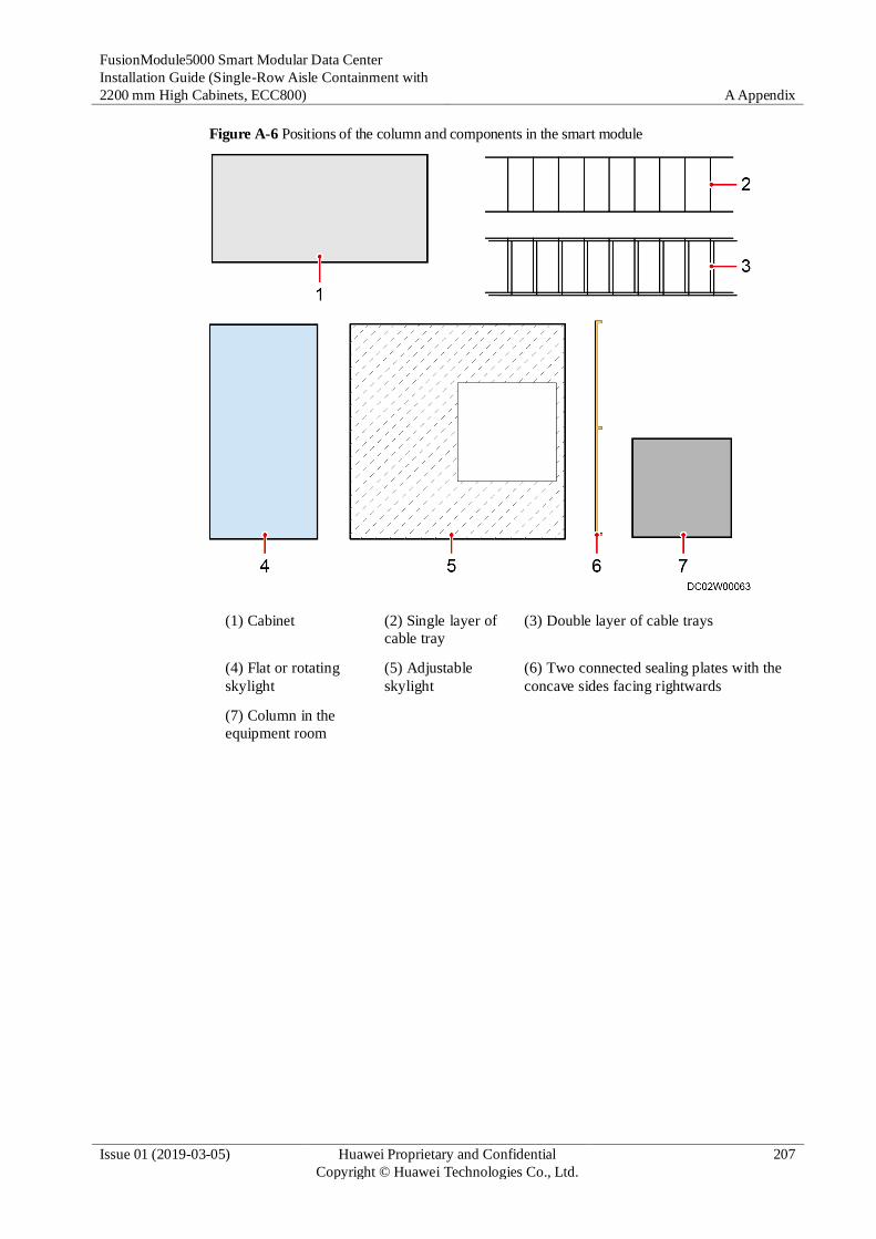
FusionModule5000 Smart Modular Data Center
Installation Guide (Single-Row Aisle Containment with
2200 mm High Cabinets, ECC800) A Appendix
Issue 01 (2019-03-05) Huawei Proprietary and Confidential
Copyright © Huawei Technologies Co., Ltd.
207
Figure A-6 Positions of the column and components in the smart module
(1) Cabinet (2) Single layer of
cable tray
(3) Double layer of cable trays
(4) Flat or rotating
skylight
(5) Adjustable
skylight
(6) Two connected sealing plates with the
concave sides facing rightwards
(7) Column in the
equipment room

FusionModule5000 Smart Modular Data Center
Installation Guide (Single-Row Aisle Containment with
2200 mm High Cabinets, ECC800) A Appendix
Issue 01 (2019-03-05) Huawei Proprietary and Confidential
Copyright © Huawei Technologies Co., Ltd.
208
Figure A-7 Column in the aisle containment (A < 800 mm)
Cabinet places on the column side are left blank and sealed by sealing plates. Directions of the
concave sides of the sealing plates are shown in Figure A-7.
Install cable trays over the cabinets on both sides of the blank cabinet place for routing strong-current and weak-current cables.
Install an adjustable skylight over the aisle containment. The area to be covered by the adjustable skylight is shown in Figure A-7.

FusionModule5000 Smart Modular Data Center
Installation Guide (Single-Row Aisle Containment with
2200 mm High Cabinets, ECC800) A Appendix
Issue 01 (2019-03-05) Huawei Proprietary and Confidential
Copyright © Huawei Technologies Co., Ltd.
209
Figure A-8 Column occupying part of a cabinet place (A < 800 mm and B ≥ 400 mm)
Cabinet places on the column side are left blank and sealed by sealing plates. Directions of the
concave sides of the sealing plates are shown in Figure A-8.
Install cable trays over the cabinets on both sides of the blank cabinet place for routing strong-current and weak-current cables.
Install an adjustable skylight over the aisle containment. The area to be covered by the adjustable skylight is shown in Figure A-8.

FusionModule5000 Smart Modular Data Center
Installation Guide (Single-Row Aisle Containment with
2200 mm High Cabinets, ECC800) A Appendix
Issue 01 (2019-03-05) Huawei Proprietary and Confidential
Copyright © Huawei Technologies Co., Ltd.
210
Figure A-9 Column occupying part of a cabinet place (A ≥ 800 mm and B ≥ 400 mm)
Cabinet places on the column side are left blank and sealed by sealing plates. Directions of the
concave sides of the sealing plates are shown in Figure A-9.
Install cable trays over the cabinets on both sides of the blank cabinet place. If the cable trays cannot be installed in combined mode, install them in layered mode, the upper for routing weak-current cables while the lower for routing strong-current cables.
Install an adjustable skylight over the aisle containment. The area to be covered by the adjustable skylight is shown in Figure A-9.

FusionModule5000 Smart Modular Data Center
Installation Guide (Single-Row Aisle Containment with
2200 mm High Cabinets, ECC800) A Appendix
Issue 01 (2019-03-05) Huawei Proprietary and Confidential
Copyright © Huawei Technologies Co., Ltd.
211
Figure A-10 Column in a row of cabinets (A < 70 mm and B ≥ 400 mm)
Cabinet places on the column side are left blank and sealed by sealing plates. Directions of the
concave sides of the sealing plates are shown in Figure A-10.
Install cable trays over the cabinets on both sides of the blank cabinet place. If the cable trays cannot be installed in combined mode, install them in layered mode, the upper for routing weak-current cables while the lower for routing strong-current cables.
Install an adjustable skylight over the aisle containment. The area to be covered by the adjustable skylight is shown in Figure A-10.

FusionModule5000 Smart Modular Data Center
Installation Guide (Single-Row Aisle Containment with
2200 mm High Cabinets, ECC800) A Appendix
Issue 01 (2019-03-05) Huawei Proprietary and Confidential
Copyright © Huawei Technologies Co., Ltd.
212
Figure A-11 Column in a row of cabinets (A ≥ 70 mm)
Seal both sides of the column using sealing plates. Directions of the concave sides of the sealing
plates are shown in Figure A-11.
Install cable trays over the cabinets on both sides of the blank cabinet place. If the cable trays cannot be installed in combined mode, install them in layered mode, the upper for routing weak-current cables while the lower for routing strong-current cables.
Install flat or rotating skylights over the aisle containment.
If sealing plates cannot be installed on both sides of the column, install sealing plates only near the aisle containment.

FusionModule5000 Smart Modular Data Center
Installation Guide (Single-Row Aisle Containment with
2200 mm High Cabinets, ECC800) A Appendix
Issue 01 (2019-03-05) Huawei Proprietary and Confidential
Copyright © Huawei Technologies Co., Ltd.
213
A.5.2 Installation Process for Scenarios with Columns
Figure A-12 Installation flowchart
A.5.3 Installing a Cabinet Bottom Sealing Plate
Context
The cabinet bottom sealing plate installed in the scenario with a column is the same as the
mounting kit installed under the end cabinet. The BOM number is 21242007.

FusionModule5000 Smart Modular Data Center
Installation Guide (Single-Row Aisle Containment with
2200 mm High Cabinets, ECC800) A Appendix
Issue 01 (2019-03-05) Huawei Proprietary and Confidential
Copyright © Huawei Technologies Co., Ltd.
214
Figure A-13 Installation position of the cabinet bottom sealing plate
(1) Column (2) Cabinet bottom sealing plate
Procedure
Step 1 Install the cabinet bottom sealing plate by following the instructions in 6.3.1 Installing a
Cabinet Lower Mounting Kit.
----End
A.5.4 Installing Sealing Plates Near the Aisle
Context
Because of the column, it is inevitable that several cabinet places in one or two rows of the
aisle containment are not suitable for installing cabinets. Therefore, sealing plates need to be
installed to ensure the air tightness of the aisle containment.
Table A-2 Sealing plate types
Sealing Plate BOM Number
300 mm wide, 2000 mm high sealing plate 21500707

FusionModule5000 Smart Modular Data Center
Installation Guide (Single-Row Aisle Containment with
2200 mm High Cabinets, ECC800) A Appendix
Issue 01 (2019-03-05) Huawei Proprietary and Confidential
Copyright © Huawei Technologies Co., Ltd.
215
Sealing Plate BOM Number
600 mm wide, 2000 mm high sealing plate 21500718
800 mm wide, 2000 mm high sealing plate 21500720
300 mm wide, 2200 mm high sealing plate 21500939
600 mm wide, 2200 mm high sealing plate 21500940
800 mm wide, 2200 mm high sealing plate 21500941
Procedure
Step 1 Determine the positions of sealing plates, directions of the concave sides of sealing plates, and
the area covered by the adjustable skylight based on the actual installation environment and
the description in A.5.1 Scenario Description.
Step 2 Install the sealing plates near the aisle.
Install the sealing plates near the aisle containment first, and then the sealing plates near the smart module exterior.
1. Secure the two sealing plates using three M6 screws and nuts.
2. Place the connected sealing plates at the specified installation position, facing the correct
direction.
3. Drill four holes in the floor through the four holes at the bottom of the sealing plate using
a hammer drill with a 15 mm drill bit. Secure the sealing plate to the floor using four
plastic expansion bolts labeled DKBA44091028 and four washers.
If drilling holes in the ESD floor is not supported onsite, use four ST4.8x25 self-drilling tapping screws and washers for securing.

FusionModule5000 Smart Modular Data Center
Installation Guide (Single-Row Aisle Containment with
2200 mm High Cabinets, ECC800) A Appendix
Issue 01 (2019-03-05) Huawei Proprietary and Confidential
Copyright © Huawei Technologies Co., Ltd.
216
Figure A-14 Installing sealing plates near the aisle
(1) Column
----End
A.5.5 Installing the Adjustable Skylight
An adjustable skylight comprises the following components.
Figure A-15 Components of an adjustable skylight
(1) Skylight connective plates (2) Polycarbonate (PC) plate fasteners
(3) L-shaped mounting bracket (4) PC plate clip
(5) PC plate supports (6) PC plate

FusionModule5000 Smart Modular Data Center
Installation Guide (Single-Row Aisle Containment with
2200 mm High Cabinets, ECC800) A Appendix
Issue 01 (2019-03-05) Huawei Proprietary and Confidential
Copyright © Huawei Technologies Co., Ltd.
217
(7) Telescopic edges
A.5.5.1 Installing the Skylight Connective Plate
Prerequisites
The sealing plates near the aisle have been installed and secured.
Procedure
Step 1 Secure skylight connective plates to sealing plates or cabinets using eight M8 bolts.
Figure A-16 Installing a skylight connective plate
(1) Column
----End
A.5.5.2 Installing the Telescopic Edges
Procedure
Step 1 Extend the two telescopic edges to an appropriate length and secure them using two M6
screws.

FusionModule5000 Smart Modular Data Center
Installation Guide (Single-Row Aisle Containment with
2200 mm High Cabinets, ECC800) A Appendix
Issue 01 (2019-03-05) Huawei Proprietary and Confidential
Copyright © Huawei Technologies Co., Ltd.
218
Figure A-17 Adjusting the length of a telescopic edge
Step 2 Secure the two telescopic edges to the skylight connective plate using four M6 screws.
Figure A-18 Installing telescopic edges
(1) Column
----End

FusionModule5000 Smart Modular Data Center
Installation Guide (Single-Row Aisle Containment with
2200 mm High Cabinets, ECC800) A Appendix
Issue 01 (2019-03-05) Huawei Proprietary and Confidential
Copyright © Huawei Technologies Co., Ltd.
219
A.5.5.3 Installing an Adjustable Skylight Side Sealing Plate
Prerequisites
A cut tool is prepared. This section cites a hook knife as an example.
Figure A-19 Hook knife
Context
An adjustable skylight side sealing plate is trimmed from a PC plate.
Figure A-20 shows the installation position of the adjustable skylight side sealing plate.
Figure A-20 Installation position of the adjustable skylight side sealing plate
(1) Adjustable skylight side sealing plate

FusionModule5000 Smart Modular Data Center
Installation Guide (Single-Row Aisle Containment with
2200 mm High Cabinets, ECC800) A Appendix
Issue 01 (2019-03-05) Huawei Proprietary and Confidential
Copyright © Huawei Technologies Co., Ltd.
220
Procedure
Step 1 Trim the PC plate to an appropriate size using a hook knife.
To ensure a neat section after trimming, trim the PC plate using the aisle check tool in the Num. 0 packing box.
Figure A-21 Trimming a PC plate
(1) PC plate
Step 2 Attach the PC plate fastener to the trimmed PC plate.
Figure A-22 Attaching a PC plate fastener to a trimmed PC plate
Step 3 Secure the PC plate fastener and the trimmed PC plate to the skylight connective plate.

FusionModule5000 Smart Modular Data Center
Installation Guide (Single-Row Aisle Containment with
2200 mm High Cabinets, ECC800) A Appendix
Issue 01 (2019-03-05) Huawei Proprietary and Confidential
Copyright © Huawei Technologies Co., Ltd.
221
Figure A-23 Securing an adjustable skylight side sealing plate
----End
A.5.5.4 Installing the PC Plate Support and PC Plate
Procedure
Step 1 Select positions for installing PC plate supports. As shown in Figure A-24, PC plate support 1
should be installed closely to the column, and PC plate support 2 should be installed in the
middle between PC plate support 1 and the edge of the adjustable skylight.
If the space between the right side of the column and the right side of the adjustable skylight is less than 600 mm, PC plate support 2 does not need to be installed.

FusionModule5000 Smart Modular Data Center
Installation Guide (Single-Row Aisle Containment with
2200 mm High Cabinets, ECC800) A Appendix
Issue 01 (2019-03-05) Huawei Proprietary and Confidential
Copyright © Huawei Technologies Co., Ltd.
222
Figure A-24 Adjustable skylight top view
(1) Column (2) PC plate support 1 (3) PC plate support 2
Step 2 Secure the two PC plate supports to the telescopic edges of the adjustable skylight using four
M6 screws and nuts.
Figure A-25 Installing PC plate supports
(1) Column
Step 3 Install L-shaped mounting brackets.

FusionModule5000 Smart Modular Data Center
Installation Guide (Single-Row Aisle Containment with
2200 mm High Cabinets, ECC800) A Appendix
Issue 01 (2019-03-05) Huawei Proprietary and Confidential
Copyright © Huawei Technologies Co., Ltd.
223
1. Trim the PC plate using a hook knife and place it on the adjustable skylight.
To ensure a neat section after trimming, trim the PC plate using the aisle check tool in the Num. 0 packing box.
2. Mark a line on the column where the PC plate closely attaches to the column using a
marker.
3. Move the PC plate. Drill holes on the column and secure the L-shaped mounting
brackets to the column using plastic expansion bolts.
Figure A-26 Securing L-shaped mounting brackets
(1) Column
Step 4 Install PC plates.
1. Pave PC plates on the adjustable skylight.
2. Secure PC plate fasteners to PC plate supports.

FusionModule5000 Smart Modular Data Center
Installation Guide (Single-Row Aisle Containment with
2200 mm High Cabinets, ECC800) A Appendix
Issue 01 (2019-03-05) Huawei Proprietary and Confidential
Copyright © Huawei Technologies Co., Ltd.
224
Figure A-27 Installing PC plates
(1) PC plate
----End
A.5.6 Installing Cable Trays
Prerequisites
Determine the position and mode (combined or layered) for installing cable trays based on the
actual installation environment and the description in A.5.1 Scenario Description.
Context
Cable trays can be installed in two modes:
Combined installation

FusionModule5000 Smart Modular Data Center
Installation Guide (Single-Row Aisle Containment with
2200 mm High Cabinets, ECC800) A Appendix
Issue 01 (2019-03-05) Huawei Proprietary and Confidential
Copyright © Huawei Technologies Co., Ltd.
225
Figure A-28 Combined installation
Layered installation

FusionModule5000 Smart Modular Data Center
Installation Guide (Single-Row Aisle Containment with
2200 mm High Cabinets, ECC800) A Appendix
Issue 01 (2019-03-05) Huawei Proprietary and Confidential
Copyright © Huawei Technologies Co., Ltd.
226
Figure A-29 Layered installation
Procedure
Step 1 Assemble cable trays. Place four cable tray supports at the coated positions on the cable trays.
Secure each support to the cable trays using four M8 screws.
Figure A-30 Assembling cable trays

FusionModule5000 Smart Modular Data Center
Installation Guide (Single-Row Aisle Containment with
2200 mm High Cabinets, ECC800) A Appendix
Issue 01 (2019-03-05) Huawei Proprietary and Confidential
Copyright © Huawei Technologies Co., Ltd.
227
Step 2 Secure cable trays to cabinets.
Figure A-31 Securing a cable tray
This section describes how to secure a single row of cable trays.
----End
A.5.7 Installing a Sealing Plates away the Aisle
Prerequisites
The adjustable skylight and cable tray have been installed.
Context
Secure the sealing plates away the aisle by combining them with the cabinet to keep the
elegance of the smart module. Stand outside the smart module during the installation.
Procedure
Step 1 Secure the two sealing plates using three M6 screws and nuts.

FusionModule5000 Smart Modular Data Center
Installation Guide (Single-Row Aisle Containment with
2200 mm High Cabinets, ECC800) A Appendix
Issue 01 (2019-03-05) Huawei Proprietary and Confidential
Copyright © Huawei Technologies Co., Ltd.
228
Step 2 Place the connected sealing plates at the specified installation position, facing the correct
direction.
Step 3 Secure the parallel plate obtained from the sealing plate fitting bag to the sealing plate using
M4 screws, and then secure the sealing plate to the cabinet.
Figure A-32 Installing the sealing plates away the aisle
(1) Column
----End
A.6 (Optional) Connecting Cables to Industrial Connectors
Figure A-33 to Figure A-34 show only the cable connection methods. The industrial connector
cable connections depend on the industrial connector type and wiring port silk screen.

FusionModule5000 Smart Modular Data Center
Installation Guide (Single-Row Aisle Containment with
2200 mm High Cabinets, ECC800) A Appendix
Issue 01 (2019-03-05) Huawei Proprietary and Confidential
Copyright © Huawei Technologies Co., Ltd.
229
Figure A-33 Connecting cables to the industrial connector (three-core cable)
Figure A-34 Connecting cables to the industrial connector (five-core cable)
A.7 (Optional) Connecting PDU2000 Cables
Context
If the PDU2000 is not provided with industrial connectors, connect the PDU2000 cables and
lay out the cables on the cabinet top. If new main ways are configured, connect cables to new
main ways, and then route the cables to the PDU2000s along cabinets.
Procedure
Step 1 Refer to Figure A-35–Figure A-37 to connect the PDU2000 cables.
Figure A-35–Figure A-37 show only the cable connection methods. PDU2000 cable
connections depend on the PDU2000 type and wiring port silk screen.

FusionModule5000 Smart Modular Data Center
Installation Guide (Single-Row Aisle Containment with
2200 mm High Cabinets, ECC800) A Appendix
Issue 01 (2019-03-05) Huawei Proprietary and Confidential
Copyright © Huawei Technologies Co., Ltd.
230
Figure A-35 Connecting PDU2000 cables (method 1)
Figure A-36 Connecting PDU2000 cables (method 2)

FusionModule5000 Smart Modular Data Center
Installation Guide (Single-Row Aisle Containment with
2200 mm High Cabinets, ECC800) A Appendix
Issue 01 (2019-03-05) Huawei Proprietary and Confidential
Copyright © Huawei Technologies Co., Ltd.
231
Figure A-37 Connecting PDU2000 cables (method 3)
Step 2 (Optional) Route cables for the half-sized PDU2000, as shown in Figure A-38.

FusionModule5000 Smart Modular Data Center
Installation Guide (Single-Row Aisle Containment with
2200 mm High Cabinets, ECC800) A Appendix
Issue 01 (2019-03-05) Huawei Proprietary and Confidential
Copyright © Huawei Technologies Co., Ltd.
232
Figure A-38 Routing half-sized PDU2000 cables
Step 3 Remove the rodent-proof mesh from the top of the cabinet, use diagonal pliers to cut openings
that allow cables to run through, and take out the PDU2000 cables through the openings, as
shown by (1), (2), and (3) in Figure A-39.
Figure A-39 Taking out PDU2000 cables

FusionModule5000 Smart Modular Data Center
Installation Guide (Single-Row Aisle Containment with
2200 mm High Cabinets, ECC800) A Appendix
Issue 01 (2019-03-05) Huawei Proprietary and Confidential
Copyright © Huawei Technologies Co., Ltd.
233
The number of cables and holes shown in the figure is for reference only.
Step 4 Lay out the PDU2000 cables on the top of the cabinet and reinstall the rodent-proof mesh, as
shown in (4) in Figure A-39.
Step 5 Connect the PDU2000 cables for other cabinets in the same way.
----End
Follow-up Procedure
Before connecting the power plug of a device to the PDU2000, loosen the locking device on
the PDU2000. After connecting the power plug, tighten the locking device.
A.8 Cable Routes Inside an IT Cabinet
Route cables neatly inside the IT cabinet by following instructions in 12.1 System Cabling Rules.
Signal cables or weak-current cables inside cabinets are sorted by cable managers, cable rings, and cable trays.
The cable colors shown in figures are for reference only.
Figure A-40, Figure A-41, and Figure A-42 show the routes of the cables out from the front of
customer equipment.
Figure A-40 Cable route along a horizontal cable manager
(1) Small cable ring (2) Cable manager
(3) Customer equipment

FusionModule5000 Smart Modular Data Center
Installation Guide (Single-Row Aisle Containment with
2200 mm High Cabinets, ECC800) A Appendix
Issue 01 (2019-03-05) Huawei Proprietary and Confidential
Copyright © Huawei Technologies Co., Ltd.
234
The small cable ring is optional and used to manage the cable routes in the vertical direction.
The cable manager is installed in the front of a cabinet by default. You can install it in the rear of a cabinet if necessary.
Figure A-41 Cable route along a cable tray
(1) Cable tray (2) Big cable ring
(3) Customer equipment
The cable tray is optional and used to lead cables from the cabinet front to the cabinet rear.

FusionModule5000 Smart Modular Data Center
Installation Guide (Single-Row Aisle Containment with
2200 mm High Cabinets, ECC800) A Appendix
Issue 01 (2019-03-05) Huawei Proprietary and Confidential
Copyright © Huawei Technologies Co., Ltd.
235
Figure A-42 Cable route along a depth-directed cable tray
(1) Cable tray (2) Depth-directed cable tray
(3) Big cable ring (4) Customer equipment
The cable tray is optional and used to lead cables from the cabinet front to the cabinet rear.
The depth-directed cable tray is optional and used to manage the cable routes on the side of a cabinet.
Figure A-43 and Figure A-44 show the routes of the cables out from the rear of customer
equipment.

FusionModule5000 Smart Modular Data Center
Installation Guide (Single-Row Aisle Containment with
2200 mm High Cabinets, ECC800) A Appendix
Issue 01 (2019-03-05) Huawei Proprietary and Confidential
Copyright © Huawei Technologies Co., Ltd.
236
Figure A-43 Power cable route
Figure A-44 Signal cable route

FusionModule5000 Smart Modular Data Center
Installation Guide (Single-Row Aisle Containment with
2200 mm High Cabinets, ECC800) A Appendix
Issue 01 (2019-03-05) Huawei Proprietary and Confidential
Copyright © Huawei Technologies Co., Ltd.
237
A.9 (Optional) Connecting the Linkage Cables Between the Fire Extinguishing System and Access Actuator
After linkage cables are connected between the fire extinguishing system and access actuator,
the access actuator opens data center doors when the fire extinguishing system generates an
alarm signal.
Fire alarm signals are dry contact signals generated by the fire extinguishing system
selected by the customer.
Fire alarm signals are valid only when the dry contact is ON.
Connect fire alarm signal cables to the DI– and DI+ terminals at AI/DI_1 port or AI/DI_2 port
on the access actuator, the following figure shows how the fire alarm signal cables connect to
the AI/DI_1 port.
Figure A-45 Connecting fire alarm signal cables to the access actuator

FusionModule5000 Smart Modular Data Center
Installation Guide (Single-Row Aisle Containment with
2200 mm High Cabinets, ECC800) B Common Screw Torques
Issue 01 (2019-03-05) Huawei Proprietary and Confidential
Copyright © Huawei Technologies Co., Ltd.
238
B Common Screw Torques
Application Scenario Screw Specifications Torque (Kgf·cm) (Tolerance: ±10%)
Board, module, or panel
installation
M2.5 captive screw 2.1–2.5
M3 captive screw 3.8–4.2
Captive M2.5 3
M3 6
Guide rail installation Cross recessed pan head
thread forming screw
M5 (GB/T 6560-1986)
30
Subrack or box-type
module installation
M3 screw assembly
(mounting ear)
6
M4 countersunk screw
(mounting ear)
12
M6 panel screw 20
Grounding M4 14
M6 48
M8 120
Cabinet or chassis
installation, cable tray,
upper fastener, or
antiseismic enhancement
installation, cabinet
combination, or outdoor
cable clip
ST3.5 tapping screw +
plastic expansion sleeve
3
M4 12
Cross recessed pan head
thread forming screw M5
(GB/T 6560-1986)
30
M6 30
M8/M8 expansion bolt
(tension/implosion)
130

FusionModule5000 Smart Modular Data Center
Installation Guide (Single-Row Aisle Containment with
2200 mm High Cabinets, ECC800) B Common Screw Torques
Issue 01 (2019-03-05) Huawei Proprietary and Confidential
Copyright © Huawei Technologies Co., Ltd.
239
Application Scenario Screw Specifications Torque (Kgf·cm) (Tolerance: ±10%)
M10/M10 expansion bolt
(tension/implosion)
250
M12/M12 expansion bolt
(tension/implosion)
450
DB style connector 2-56 (M2.5) 2.5
4-40 (M3) metal head or
plastic head
4
Positive and negative
battery terminals
M6 40–60
M8 130–150
M10 150–200
OT terminal for power
cables
M2 screw assembly 2.5
M3 screw assembly 6
M4 screw assembly 16
M5 screw assembly 40
M6 screw assembly 50
M8 screw assembly 80
M10 screw assembly 150
M12 screw assembly 260
M16 screw assembly 350
Cord end terminal block M2 2.2–2.5
M2.5 5–6
M3 6–8
M3.5 8–16
M4 15–18
M5 25–30
M6 32–37

FusionModule5000 Smart Modular Data Center
Installation Guide (Single-Row Aisle Containment with
2200 mm High Cabinets, ECC800) C Installation Verification
Issue 01 (2019-03-05) Huawei Proprietary and Confidential
Copyright © Huawei Technologies Co., Ltd.
240
C Installation Verification
Cabinet Installation Checklist
No. Check Item Check Result
1 The cabinet layout is consistent with the equipment room
layout diagram.
□ Compliant □
Incompliant
2 The height deviation of all cabinets and the depth
deviation of adjacent cabinets are less than 5 mm.
□ Compliant □
Incompliant
3 All bolts are tightened, especially the bolts used for
electric connection. Flat washers and spring washers are
installed properly.
□ Compliant □
Incompliant
4 The cabinet is clean. □ Compliant □
Incompliant
5 The cabinet is clear and complies with dustproof
requirements.
□ Compliant □
Incompliant
6 The paint on the cabinet exterior is intact. If paint flakes
off, repaint that area to avoid corrosion.
□ Compliant □
Incompliant
7 The cabinet door and lock work properly. □ Compliant □
Incompliant
8 All labels are correct, clear, and complete. □ Compliant □
Incompliant
9 There is no adhesive tape, cable tie, paper scrap, or
packing material around the cabinet.
□ Compliant □
Incompliant
10 The cabinet filler panels are in proper positions so that
the cold aisle and hot aisle are isolated.
□ Compliant □
Incompliant
Aisle Containment Checklist
No. Check Item Check Result
1 All aisle containment components are installed. □ Compliant □

FusionModule5000 Smart Modular Data Center
Installation Guide (Single-Row Aisle Containment with
2200 mm High Cabinets, ECC800) C Installation Verification
Issue 01 (2019-03-05) Huawei Proprietary and Confidential
Copyright © Huawei Technologies Co., Ltd.
241
No. Check Item Check Result
Incompliant
2 The sliding door works smoothly. □ Compliant □
Incompliant
3 The gap between end door panels is even. □ Compliant □
Incompliant
4 After the end door is closed, the rubber strip in the
middle seals the gap properly.
□ Compliant □
Incompliant
5 After the double revolving door is closed, the height
deviation of the two door panels is less than 5 mm.
□ Compliant □
Incompliant
6 The rotating skylights work smoothly. □ Compliant □
Incompliant
7 The end planes of skylight connective plates are flush
with each other.
□ Compliant □
Incompliant
8 The skylight electromagnet firmly suctions the skylight
when the power is on, and the skylight drops naturally
when the power is off.
□ Compliant □
Incompliant
9 All labels are correct, clear, and complete. □ Compliant □
Incompliant
10 There are no adhesive tape, cable ties, paper, or packing
materials left around the aisle.
□ Compliant □
Incompliant
11 The aisle is clean inside and outside. □ Compliant □
Incompliant
12 The paint on the cabinet exterior is intact. If paint flakes
off, repaint that area to avoid corrosion.
□ Compliant □
Incompliant
Cable Installation Checklist
No. Check Item Check Result
1 All cable joints are secured properly, especially the
cable joints between network cables and cables
inside cabinets.
□ Compliant □ Incompliant
2 Exposed parts near the wiring terminals and lugs
are wrapped with PVC insulation tape or heat
shrinking tubing.
□ Compliant □ Incompliant
3 Flat washers and spring washers of all wiring
terminals are securely installed.
□ Compliant □ Incompliant
4 Cables are bound neatly, and cable ties are secured
evenly and properly in the same direction.
□ Compliant □ Incompliant
5 Cables are routed in a way convenient for □ Compliant □ Incompliant

FusionModule5000 Smart Modular Data Center
Installation Guide (Single-Row Aisle Containment with
2200 mm High Cabinets, ECC800) C Installation Verification
Issue 01 (2019-03-05) Huawei Proprietary and Confidential
Copyright © Huawei Technologies Co., Ltd.
242
No. Check Item Check Result
maintenance and capacity expansion.
6 All labels at the cable ends are clear. □ Compliant □ Incompliant
7 Excess sections of cable ties are neatly cut. □ Compliant □ Incompliant
8 There is no unnecessary adhesive tape or cable tie
on cables.
□ Compliant □ Incompliant
9 All components are properly installed and no
component is left onsite.
□ Compliant □ Incompliant
Electric Installation Checklist
No. Check Item Check Result
1 All ground cables are copper cables with diameters
meeting the requirements. No switch or fuse is
installed at the middle of a ground cable, and no
short-circuit occurs.
□ Compliant □ Incompliant
2 Ground cables, AC input power cables, and
internal cables are connected in accordance with
the circuit diagram and screws are secured. No
short-circuit occurs on power inputs or outputs.
□ Compliant □ Incompliant
3 Power cables and ground cables are not coiled and
extra parts are cut off.
□ Compliant □ Incompliant
4 Lugs for power cables and protective ground
cables are soldered or crimped securely.
□ Compliant □ Incompliant
5 Power cables and ground cables are routed and
bundled separately from other cables.
□ Compliant □ Incompliant
6 Batteries are free from damage, cracks, and bulges. □ Compliant □ Incompliant
7 Batteries are neat and do not leak electrolyte. □ Compliant □ Incompliant
8 Wiring terminals of batteries are free from
damage, break, and acid leakage.
□ Compliant □ Incompliant
9 Battery safety valves are intact, without leakages. □ Compliant □ Incompliant
10 Battery cables are correctly connected, and the
terminal voltages of battery strings are normal.
□ Compliant □ Incompliant
11 DIP switches on devices are correctly set. □ Compliant □ Incompliant
Customer signature:
Check date:

FusionModule5000 Smart Modular Data Center
Installation Guide (Single-Row Aisle Containment with
2200 mm High Cabinets, ECC800) D Acronyms and Abbreviation
Issue 01 (2019-03-05) Huawei Proprietary and Confidential
Copyright © Huawei Technologies Co., Ltd.
243
D Acronyms and Abbreviation
A
AC Alternating Current
ATS Automatic Transfer Switch
B
BCB Battery Circuit Breaker
BIB Battery Control I/O Board
BIM Battery Interface Module
BSPP British Standard Pipe Parallel Thread
BSPT British Standard Taper Pipe Thread
C
CIM Communication Interface Module
D
DC Direct Current
E
ECC Energy Control Center
EPDM Ethylene-Propylene-Diene tripolymer
EPE Expandable Polyethylene
ETH Ethernet
F

FusionModule5000 Smart Modular Data Center
Installation Guide (Single-Row Aisle Containment with
2200 mm High Cabinets, ECC800) D Acronyms and Abbreviation
Issue 01 (2019-03-05) Huawei Proprietary and Confidential
Copyright © Huawei Technologies Co., Ltd.
244
FE Fast Ethernet
I
iBAT ibattery
IC Integrated Circuit
IT Internet Technology
N
NTC Negative Temperature Coefficient
P
PDF Power Distribution Frame
PDU Power Distribution Unit
PE Protective Earthing
PoE Power over Ethernet
PP-R Polypropylene Random
PVC Polyvinyl Chloride
S
SD Secure Digital
SIM Subscriber Identity Module
U
UPS Uninterruptible Power System
V
VCN Video Cloud Node
W
WiFi Wireless Fidelity