Installation Guide - GigaCrete
28
1 GENERAL INSTALLATION GUIDE GENERAL INSTALLATION GUIDE FOR GIGAPANELS
-
Upload
khangminh22 -
Category
Documents
-
view
1 -
download
0
Transcript of Installation Guide - GigaCrete
1
GENERAL INSTALLATION GUIDE
GENERAL INSTALLATION GUIDE FOR GIGAPANELS
2
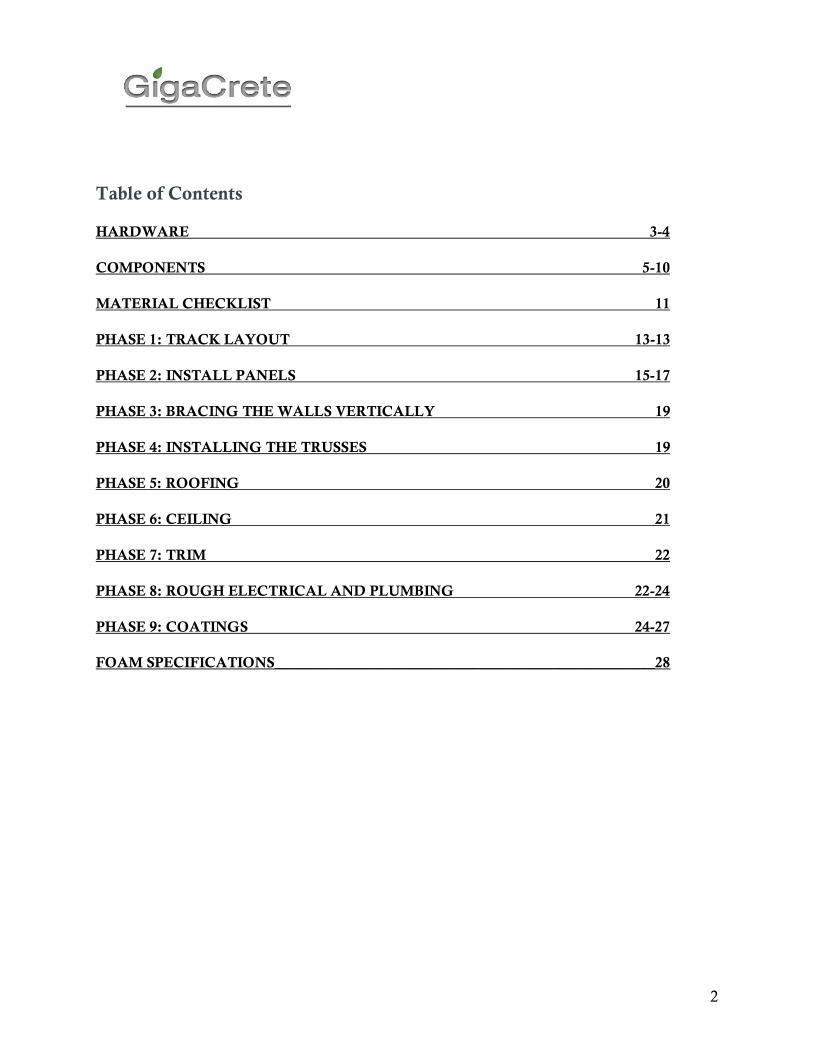
Table of Contents
HARDWARE 3-4
COMPONENTS 5-10
MATERIAL CHECKLIST 11
PHASE 1: TRACK LAYOUT 13-13
PHASE 2: INSTALL PANELS 15-17
PHASE 3: BRACING THE WALLS VERTICALLY 19
PHASE 4: INSTALLING THE TRUSSES 19
PHASE 5: ROOFING 20
PHASE 6: CEILING 21
PHASE 7: TRIM 22
PHASE 8: ROUGH ELECTRICAL AND PLUMBING 22-24
PHASE 9: COATINGS 24-27
FOAM SPECIFICATIONS____________________________________________________28
3
Required Materials Refer to Pictures
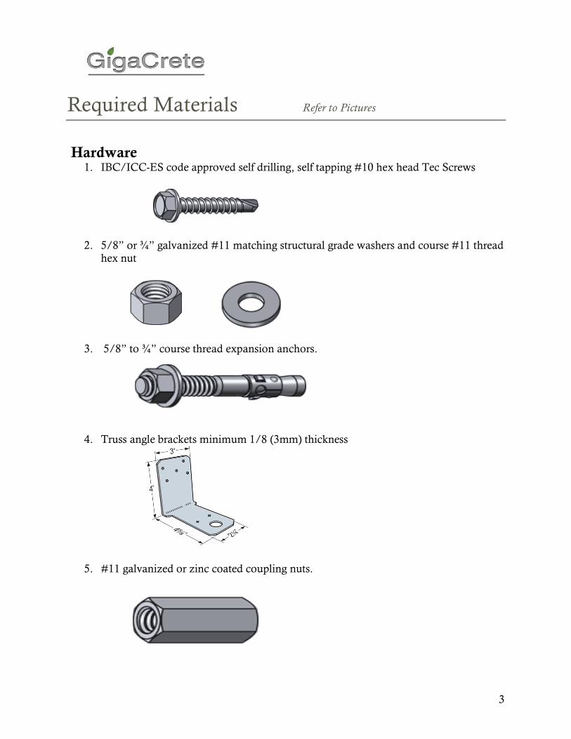
Hardware 1. IBC/ICC-ES code approved self drilling, self tapping #10 hex head Tec Screws
2. 5/8” or ¾” galvanized #11 matching structural grade washers and course #11 thread hex nut
3. 5/8” to ¾” course thread expansion anchors.
4. Truss angle brackets minimum 1/8 (3mm) thickness
5. #11 galvanized or zinc coated coupling nuts.
4
Required Materials Refer to Pictures
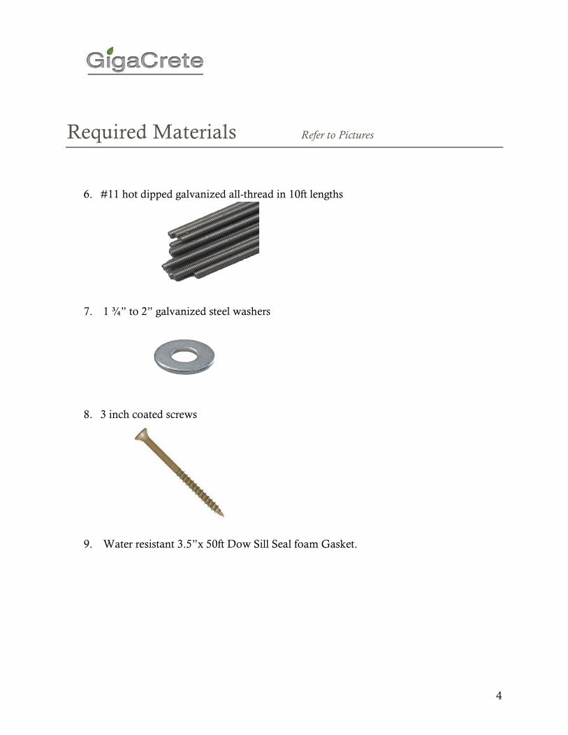
6. #11 hot dipped galvanized all-thread in 10ft lengths
7. 1 ¾” to 2” galvanized steel washers
8. 3 inch coated screws
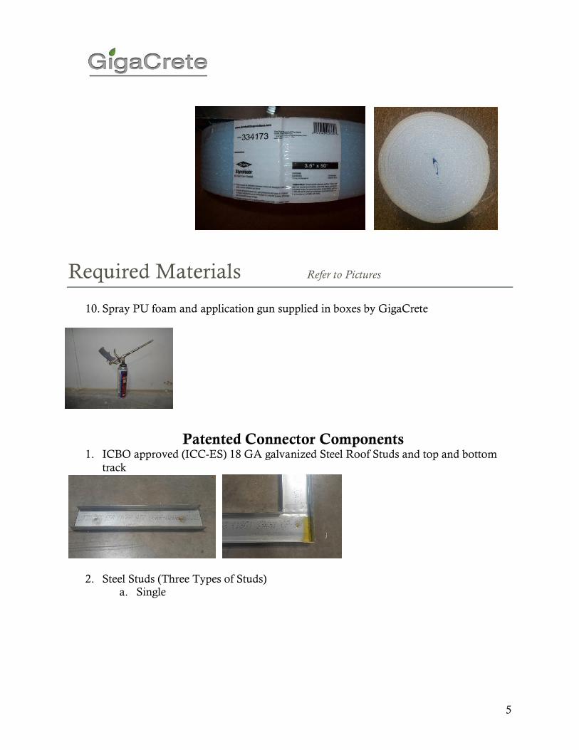
9. Water resistant 3.5”x 50ft Dow Sill Seal foam Gasket.
5
Required Materials Refer to Pictures
10. Spray PU foam and application gun supplied in boxes by GigaCrete
Patented Connector Components 1. ICBO approved (ICC-ES) 18 GA galvanized Steel Roof Studs and top and bottom
track
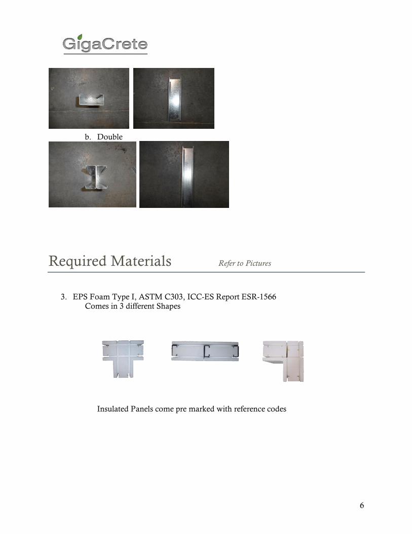
2. Steel Studs (Three Types of Studs) a. Single
6
b. Double
Required Materials Refer to Pictures
3. EPS Foam Type I, ASTM C303, ICC-ES Report ESR-1566
Comes in 3 different Shapes
Insulated Panels come pre marked with reference codes

7
“P” Flat Panels
“SP” shear panel “WH” window header panel
“WS” window sill panel. “DH” door header panel.
“C” Corner Panels
“T” Intersecting Panels
Required Materials Refer to Pictures
“R”: Roof Panels (consists of two pieces)
8
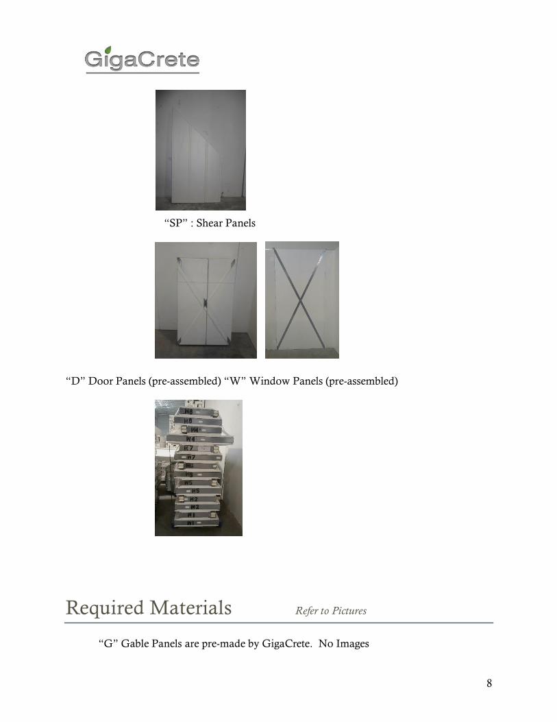
“SP” : Shear Panels
“D” Door Panels (pre-assembled) “W” Window Panels (pre-assembled)
Required Materials Refer to Pictures
“G” Gable Panels are pre-made by GigaCrete. No Images
9
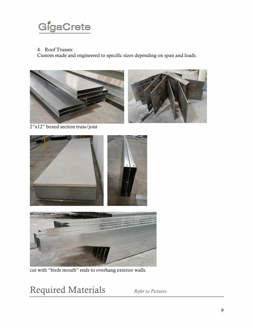
4. Roof Trusses:
Custom made and engineered to specific sizes depending on span and loads.
2”x12” boxed section truss/joist
cut with “birds mouth” ends to overhang exterior walls.
Required Materials Refer to Pictures
10
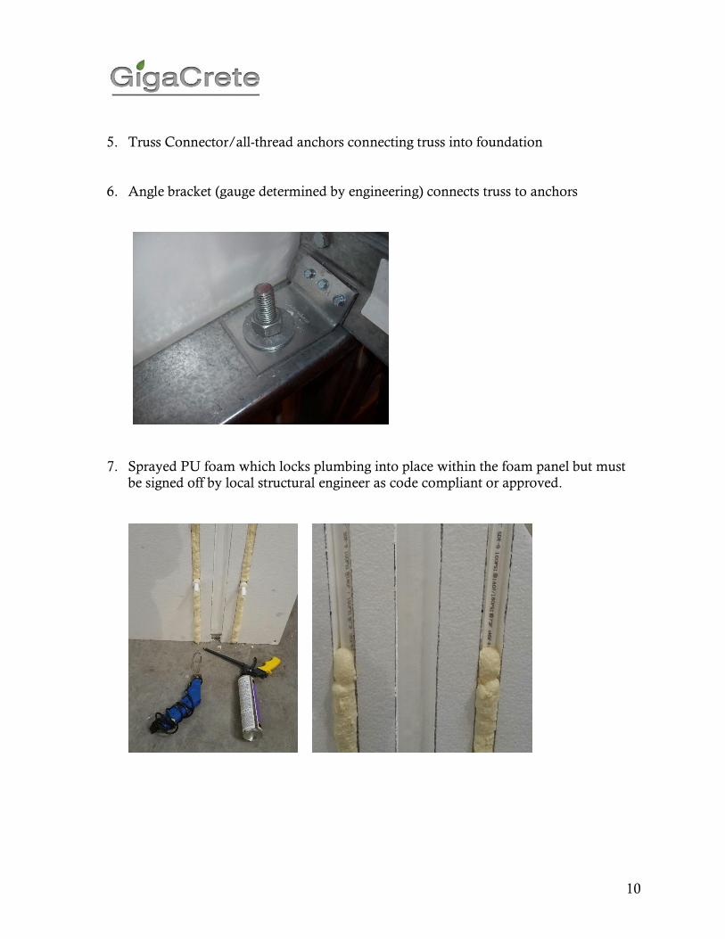
5. Truss Connector/all-thread anchors connecting truss into foundation
6. Angle bracket (gauge determined by engineering) connects truss to anchors
7. Sprayed PU foam which locks plumbing into place within the foam panel but must
be signed off by local structural engineer as code compliant or approved.
11
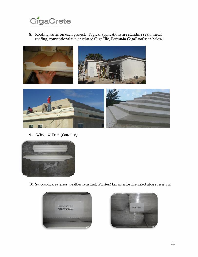
8. Roofing varies on each project. Typical applications are standing seam metal roofing, conventional tile, insulated GigaTile, Bermuda GigaRoof seen below.
9. Window Trim (Outdoor)
10. StuccoMax exterior weather resistant, PlasterMax interior fire rated abuse resistant
12
CHECKLIST
Item Qty Yes No
#10 Self tapping hex head Tec Screws
#11 Matching structural grade washers, course #11 thread hex nut
5/8” to ¾” course thread epoxy anchors 4.5” minimum
#11 Course thread Galvanized or zinc coated coupling nuts
#11 Course thread Hot dipped galvanized all-thread in 10ft lengths
Water resistant 3.5”x 50ft Dow Sill Seal PP foam Gasket Rolls.
Spray low expansion PU foam in cans with application gun
Steel Stud: Single “C” Section 18 gauge galvanized steel
Steel Stud: Double Inline Connectors
Steel Stud: L for 90 degree Corners
Steel Track: Bottom “U” section 18 gauge galvanized
Steel Track: Top “U” section 18 gauge galvanized
EPS Foam: Flat 1.0 lb density or higher EPS foam
EPS Foam: Curved “C” 1.0 lb density or higher EPS foam
EPS Foam: Corner “C” 1.0 lb density or higher EPS foam
EPS Foam: Intersecting “T” 1.0 lb density or higher EPS foam
EPS Foam: Roof Panel 1.0 lb density or higher EPS foam
EPS Foam: Shear Panel 1.0 lb density or higher EPS foam
EPS Foam: Door Header Panels
EPS Foam: Window Header Panels
EPS Foam: Window Sill Panels
Roof Trusses Steel
Window Trim
Ceiling Studs and track
Angle Brackets Top Track to Roof Truss or Floor Joists
Shear Panel Strapping steel strips
Roofing
PlasterMax and B2 Activator Crystals
StuccoMax
Gable Panel
Roof Studs
Truss Connector Brackets to all-thread anchors
1 ¾” to 2” plastic washers
3” screws
13
Assembly Instructions
Phase 1: Track Layout
Step 1: Acquire necessary materials
• Steel bottom and top tracks
• Water Resistant 3.5” by 50’ Dow Sill Seal Foam Gasket
• Course Thread Expansion Anchors (measurements will depend on wall panel heights)
Step 2: Acquire necessary tools
• Ramset Gun
• Tape Measure
• Wrench/Socket Driver
• Drill
• Hammer
• Metal Sheers
• Small Pry Bar
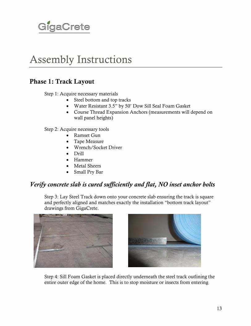
Verify concrete slab is cured sufficiently and flat, NO inset anchor bolts Step 3: Lay Steel Track down onto your concrete slab ensuring the track is square
and perfectly aligned and matches exactly the installation “bottom track layout” drawings from GigaCrete.
Step 4: Sill Foam Gasket is placed directly underneath the steel track outlining the
entire outer edge of the home. This is to stop moisture or insects from entering
14
anywhere where the slab may not be totally level. The gasket compresses as the house gets built.
Assembly Instructions
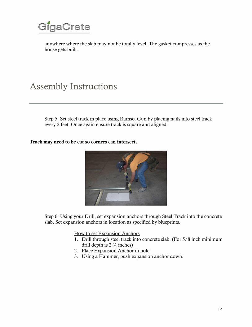
Step 5: Set steel track in place using Ramset Gun by placing nails into steel track every 2 feet. Once again ensure track is square and aligned.
Track may need to be cut so corners can intersect.
Step 6: Using your Drill, set expansion anchors through Steel Track into the concrete slab. Set expansion anchors in location as specified by blueprints.
How to set Expansion Anchors
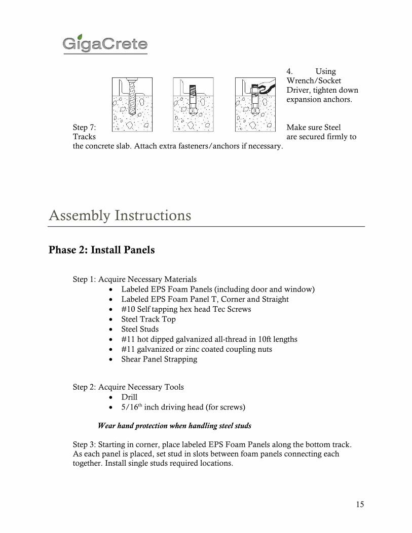
1. Drill through steel track into concrete slab. (For 5/8 inch minimum drill depth is 2 ¾ inches)
2. Place Expansion Anchor in hole. 3. Using a Hammer, push expansion anchor down.
15
4. Using Wrench/Socket
Driver, tighten down expansion anchors.
Step 7: Make sure Steel Tracks are secured firmly to the concrete slab. Attach extra fasteners/anchors if necessary.
Assembly Instructions
Phase 2: Install Panels
Step 1: Acquire Necessary Materials
• Labeled EPS Foam Panels (including door and window)
• Labeled EPS Foam Panel T, Corner and Straight
• #10 Self tapping hex head Tec Screws
• Steel Track Top
• Steel Studs
• #11 hot dipped galvanized all-thread in 10ft lengths
• #11 galvanized or zinc coated coupling nuts
• Shear Panel Strapping
Step 2: Acquire Necessary Tools
• Drill
• 5/16th inch driving head (for screws) Wear hand protection when handling steel studs
Step 3: Starting in corner, place labeled EPS Foam Panels along the bottom track. As each panel is placed, set stud in slots between foam panels connecting each together. Install single studs required locations.
16
Assembly Instructions
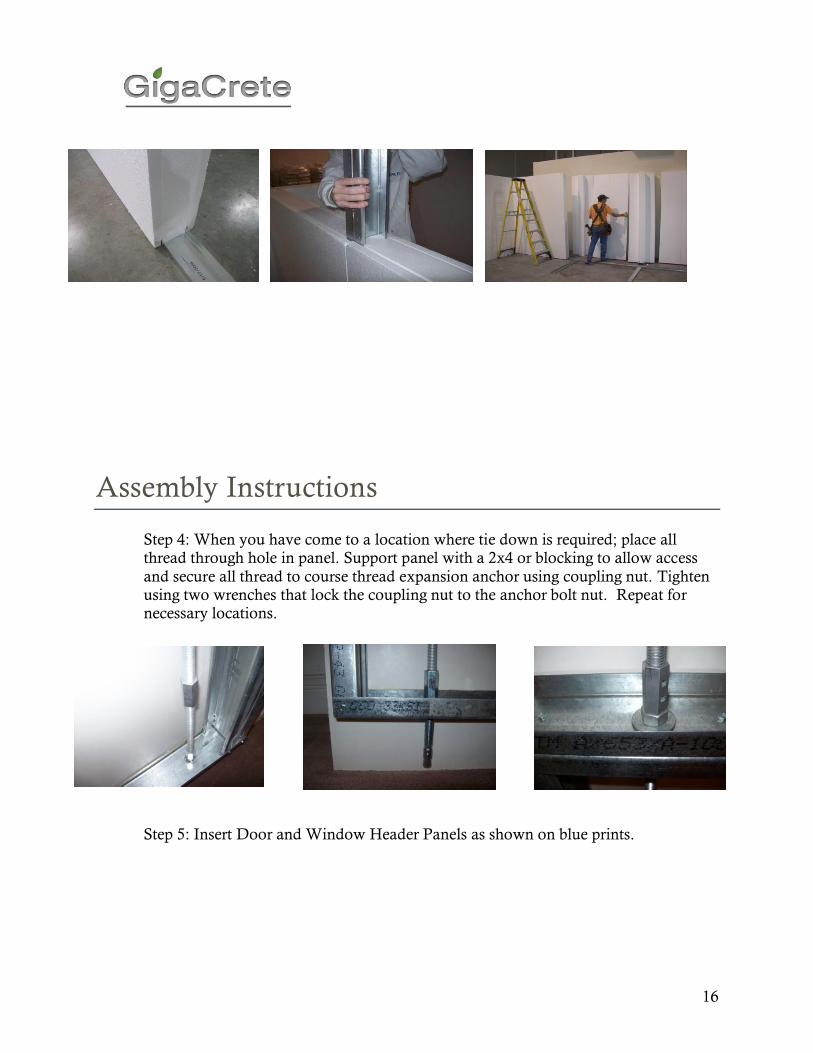
Step 4: When you have come to a location where tie down is required; place all thread through hole in panel. Support panel with a 2x4 or blocking to allow access
and secure all thread to course thread expansion anchor using coupling nut. Tighten using two wrenches that lock the coupling nut to the anchor bolt nut. Repeat for necessary locations.
Step 5: Insert Door and Window Header Panels as shown on blue prints.
17
Assembly Instructions
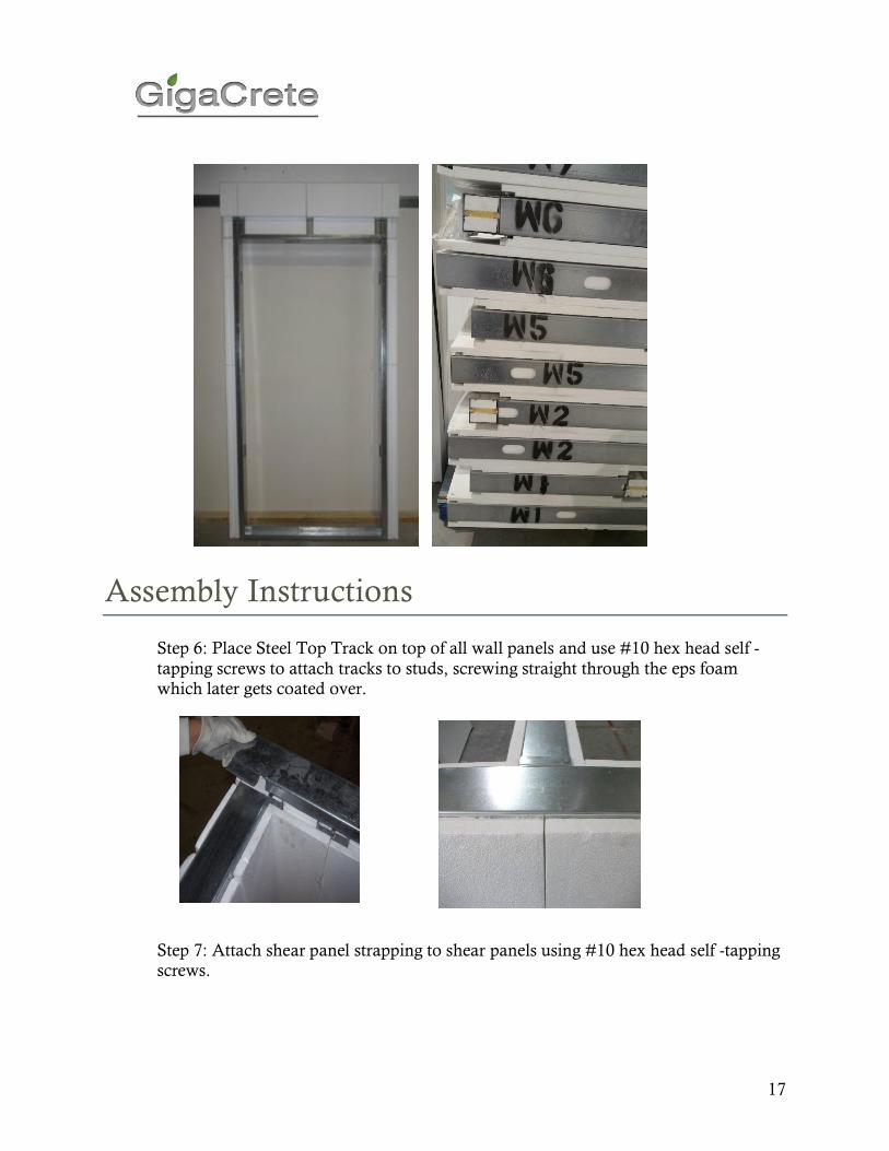
Step 6: Place Steel Top Track on top of all wall panels and use #10 hex head self -
tapping screws to attach tracks to studs, screwing straight through the eps foam
which later gets coated over.
Step 7: Attach shear panel strapping to shear panels using #10 hex head self -tapping screws.

18
Step 8: Using your Drill and screws; attach each stud to top and bottom track using
#10 Self tapping hex head Tec Screws. Ensure this is completed on inside and outside of walls.
Assembly Instructions
Step 9: FOR GABLES
Using Drill and screws, attach another track on top of the top track making a back to back track. This step will be completed only on the wall panels where gables are located. The pre-made gable now drops into this track.
19
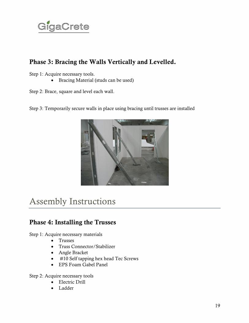
Phase 3: Bracing the Walls Vertically and Levelled. Step 1: Acquire necessary tools.
• Bracing Material (studs can be used) Step 2: Brace, square and level each wall.
Step 3: Temporarily secure walls in place using bracing until trusses are installed
Assembly Instructions
Phase 4: Installing the Trusses
Step 1: Acquire necessary materials
• Trusses
• Truss Connector/Stabilizer
• Angle Bracket
• #10 Self tapping hex head Tec Screws
• EPS Foam Gabel Panel Step 2: Acquire necessary tools
• Electric Drill
• Ladder
20
Step 3: Place EPS Foam Gable Panel in locations specified by blueprints. Trusses will be above these panels.
Step 4: Slide studs into Gabel Panel and put steel top track on top.
Step 5: Screw together firmly (refer to Phase 2 Step 9). Step 4: Carefully place truss into desired locations as specified by blueprints.
Step 5: Using drill and #10 Self tapping hex head Tec Screws, secure truss to the top steel track using the angle bracket.
Step 6: Repeat steps 3 through 5 for additional trusses as needed. Step 7: Place Truss Stabilizer on truss pairs opposite one another. Secure using drill and #10 Self tapping hex head Tec Screws.
Assembly Instructions
Phase 5: Roofing Step 1: Acquire necessary material.
• Roof Studs
• EPS Foam Roof Panels
• #10 Self tapping hex head Tec Screws
• Angle Bracket
• Roofing (outer roof) M4 boards or others supplied by GigaCrete Step 2: Acquire necessary tools.
• Drill
• Ladder
21
Step 3: Place roof panels in locations designated by blue prints.
Step 4: Slide studs into precut slots in each panel.
Step 5: Using drill, Tec screws and angle brackets, secure studs to trusses at intersection
points. Step 6: Install outer roof material onto roof as specified by blue prints.
Assembly Instructions
Phase 6: Ceiling Step 1: Acquire necessary materials
• Hard Cap Ceiling Studs (ceiling stud)
• #10 Self tapping hex head Tec Screws
• Angle Bracket
• Gypsum Board or alternate Step 2: Acquire necessary tools
• Ladder
• Drill
Step 3: Process for installing ceiling differs according to location within the house For Installing Ceiling from outside wall:
1. Using drill and Tec Screws, secure ceiling stud inside home on the outer wall. The bottom of the stud must be level with opposite inside wall. The wall the stud is secured on should be opposite of inside walls. Flat face of
stud should be against wall while open side should be facing inward.
Ensure stud spans entire length of one wall. 2. Lay ceiling studs on foam walls within the house. 3. Slide each stud to the stud secured to wall in #1. 4. Studs should now span from the stud secured to the wall in #1 to the inner
walls. Distance between studs should be equal. 5. Using Angle Bracket, secure ceiling studs to the inner walls.
6. Screw ceiling studs into stud secured to wall in #1.
For Installing Ceilings from Rooms within Home
22
1. Lay ceiling studs down on top of each side of wall. 2. Space studs evenly across top of walls.
a. Individual studs can be used for more than one room provided length and ceiling height are compatible.
b. Using angle brackets, secure ceiling studs to the top of each wall
Step 4: Attach 2” of EPS foam to the underside of ceiling with 3” screws and plastic washers.
Phase 7: Foam Trim
Step 1: Acquire necessary materials.
• EPS Foam Trim
• #10 Self tapping hex head Tec Screws
• Spray PU foam Step 2: Acquire necessary tools.
• Durabond
• Rasping Tool Step 3: Attach EPS Foam Trim in desired areas using Durabond.
Step 4: Fill in any holes or voids with Spray PU foam. Step 5: Prepare walls for coating by rasping walls flat. Also sweep up waste and foam beads before proceeding.
Assembly Instructions
Phase 8: Rough Electrical and Plumbing
Step 1: Acquire Materials (Gigacrete does not provide material)
• Designated electrical supplies
• Designated plumbing supplies Step 2: Acquire necessary tools
• Tools provided by installers of electrical and plumbing.
23
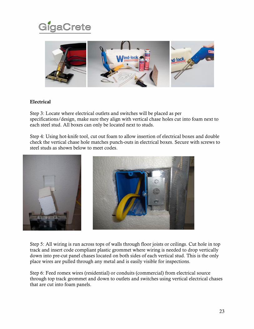
Electrical
Step 3: Locate where electrical outlets and switches will be placed as per specifications/design, make sure they align with vertical chase holes cut into foam next to each steel stud. All boxes can only be located next to studs.
Step 4: Using hot-knife tool, cut out foam to allow insertion of electrical boxes and double check the vertical chase hole matches punch-outs in electrical boxes. Secure with screws to steel studs as shown below to meet codes.
Step 5: All wiring is run across tops of walls through floor joists or ceilings. Cut hole in top
track and insert code compliant plastic grommet where wiring is needed to drop vertically down into pre-cut panel chases located on both sides of each vertical stud. This is the only place wires are pulled through any metal and is easily visible for inspections.
Step 6: Feed romex wires (residential) or conduits (commercial) from electrical source through top track grommet and down to outlets and switches using vertical electrical chases that are cut into foam panels.

24
Step 7: Fill voids around electrical boxes with supplied Spray PU foam. Rasp excessive foam flat and parallel to wall surface in preparation of coatings.
Step 8: Where wires are pulled through conduits in foam, the wiring or flex must be secured
at 48” centers. This is done with fast setting PU spray foam which is inserted into the vertical chase by pushing the nozzle of the spray foam through the EPS foam every 48”
penetrating the nozzle about 1.5” into the conduit void and releasing a shot of foam for about 2 seconds. The expanding foam will lock the wiring in place within the chase and will seal off the hole created by the foam gun nozzle.
Plumbing
Step 1: Locate where plumbing lines and vents will be placed as per specifications and
design. Make sure they are not where vertical steel studs are already located, lines should be between each steel stud as code requires lines and vents must be securely attached to studs. Step 2: Using hot-knife tool, cut out foam to allow insertion of all plumbing lines and vents.
Secure strapping with screws to steel studs as shown below to meet codes. Step 3: If copper tubing is used, protect the EPS foam from the heat which will melt the foam creating holes in the wall panels. This can be done with simple shielding using a piece
of gypsum board or plywood, but be careful not to cause a fire. Step 4: Once all lines are permanently located, there are two options to affix lines in place. #1, Spray PU foam into the voids where lines are placed and fill the voids with expanding
foam. Trim flush once foam is fully cured and have a structural engineer sign off that this is adequate to meet local codes. #2. Using plumbing strapping, tie back to studs and then
foam in place as per #1. Hot water will stay hotter and cold, colder. This will also help avoid freezing of plumbing lines in extremely cold weather. After the foam has cured, cut
off excess with a simple hand saw ready for GigaCrete coatings to be installed.
Assembly Instructions
Phase 9: Coatings Direct Application to EPS
25
Preparation Rasping is necessary to remove potential bond breakers and to ensure
good adhesion. Survey the substrate for irregularities that may
adversely affect the application such as minor protrusions and voids. Mechanical chase voids cut into the EPS need to be filled prior to the
PlasterMax™ or StuccoMax™ installation. Low expansion spray foam is applied into the void, allowed to cure and shaved flat with the surface. Wind-Lock’s Foam2Foam is recommended for this purpose.
Fiberglass Mesh 11-ounce fiberglass mesh supplied by GigaCrete is typically used and is
a critical part of the PlasterMax™ or StuccoMax™ application. A
rough 1/8” coat of PlasterMax™ or StuccoMax™ is applied to the EPS and worked reasonably flat. Precut the mesh which is hung vertically like wallpaper and with a trowel, press in the mesh imbedding the mesh into the first coat, working the coating material
through the open weaves in the mesh while ensuring that the mesh is flat and free of wrinkles. Ensure all open gaps in the mesh are filled with the coatings material prior to applying the second coat. Overlap adjoining mesh by a minimum of 2.5”. A second coat of
PlasterMax™ or StuccoMax™ is immediately applied over the mesh to the specified thickness. If additional working time is required in hot weather, use the retarder supplied by GigaCrete.
Spraying PlasterMax™ or StuccoMax™ may be applied by hawk and trowel
but spray application is recommended for best results on larger walls. Spray in a fashion that allows the trowel person to stay in close
proximity to the sprayer and allows a continuous wet edge. Working wall areas in sections from top to bottom works best.
Hawk & Trowel PlasterMax™ or StuccoMax™ is hand applied like most conventional
plaster material using the same tools, (see photos below)
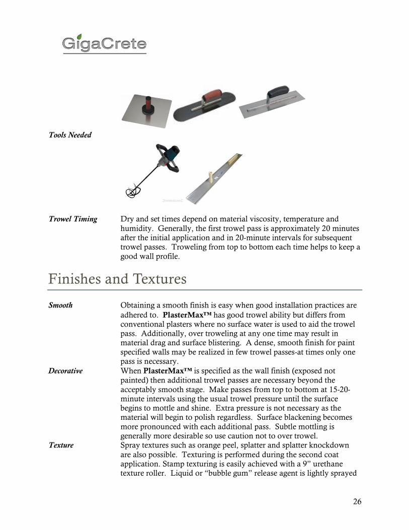
26
Tools Needed
Trowel Timing Dry and set times depend on material viscosity, temperature and
humidity. Generally, the first trowel pass is approximately 20 minutes after the initial application and in 20-minute intervals for subsequent trowel passes. Troweling from top to bottom each time helps to keep a
good wall profile.
Finishes and Textures
Smooth Obtaining a smooth finish is easy when good installation practices are
adhered to. PlasterMax™ has good trowel ability but differs from conventional plasters where no surface water is used to aid the trowel pass. Additionally, over troweling at any one time may result in material drag and surface blistering. A dense, smooth finish for paint
specified walls may be realized in few trowel passes-at times only one pass is necessary.
Decorative When PlasterMax™ is specified as the wall finish (exposed not
painted) then additional trowel passes are necessary beyond the
acceptably smooth stage. Make passes from top to bottom at 15-20-minute intervals using the usual trowel pressure until the surface begins to mottle and shine. Extra pressure is not necessary as the material will begin to polish regardless. Surface blackening becomes
more pronounced with each additional pass. Subtle mottling is generally more desirable so use caution not to over trowel.
Texture Spray textures such as orange peel, splatter and splatter knockdown
are also possible. Texturing is performed during the second coat application. Stamp texturing is easily achieved with a 9” urethane texture roller. Liquid or “bubble gum” release agent is lightly sprayed
27
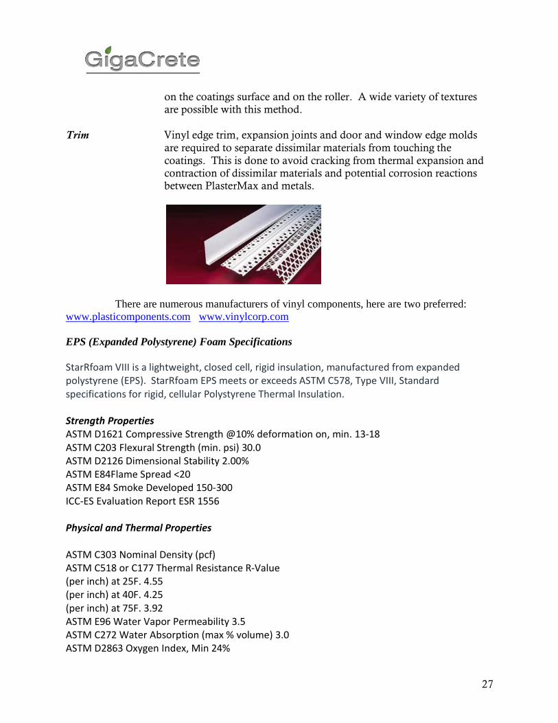
on the coatings surface and on the roller. A wide variety of textures are possible with this method.
Trim Vinyl edge trim, expansion joints and door and window edge molds
are required to separate dissimilar materials from touching the
coatings. This is done to avoid cracking from thermal expansion and contraction of dissimilar materials and potential corrosion reactions between PlasterMax and metals.
There are numerous manufacturers of vinyl components, here are two preferred:
www.plasticomponents.com www.vinylcorp.com
EPS (Expanded Polystyrene) Foam Specifications
StarRfoam VIII is a lightweight, closed cell, rigid insulation, manufactured from expanded polystyrene (EPS). StarRfoam EPS meets or exceeds ASTM C578, Type VIII, Standard specifications for rigid, cellular Polystyrene Thermal Insulation. Strength Properties ASTM D1621 Compressive Strength @10% deformation on, min. 13-18 ASTM C203 Flexural Strength (min. psi) 30.0 ASTM D2126 Dimensional Stability 2.00% ASTM E84Flame Spread <20 ASTM E84 Smoke Developed 150-300 ICC-ES Evaluation Report ESR 1556 Physical and Thermal Properties ASTM C303 Nominal Density (pcf) ASTM C518 or C177 Thermal Resistance R-Value (per inch) at 25F. 4.55 (per inch) at 40F. 4.25 (per inch) at 75F. 3.92 ASTM E96 Water Vapor Permeability 3.5 ASTM C272 Water Absorption (max % volume) 3.0 ASTM D2863 Oxygen Index, Min 24%

28